TBG 620 - Some Work of Gas-Gen & Equipment Ltd
291
Operation Manual TBG 620 0299 9084 EN, 02/2006 Engine Number: Please enter your engine number here. This will help us to serve you better in questions of repairs, spare parts and after-sales service generally. We reserve the right to make technical alterations to the drawings and particulars in this documentation package, if this should become necessary to improve the engines. Reprints and duplication of any kind, either in whole or in part, require our written permission.
-
Upload
khangminh22 -
Category
Documents
-
view
0 -
download
0
Transcript of TBG 620 - Some Work of Gas-Gen & Equipment Ltd

Operation Manual
TBG 620
0299 9084 EN, 02/2006
Engine Number:
Please enter your engine number here. This will help us to serve you better in questions of repairs, spareparts and after-sales service generally.
We reserve the right to make technical alterations to the drawings and particulars in this documentationpackage, if this should become necessary to improve the engines. Reprints and duplication of any kind,either in whole or in part, require our written permission.

This documentation is intended for the following engine
Please enter data. This will make it a lot easier for us to process after-sales support, repair work and spareparts orders.
The documentation should be presented to the responsible service partner for every service assignment.
Engine type:
Type of application:
System name:
Power: kW
Speed: min-1
Commissioned on:
© 02/2006
0299 9084 EN
Imprint:
DEUTZ Power Systems GmbH & Co. KG
Service MS
Carl-Benz-Straße 1
D-68167 Mannheim
Tel.:+49 (0) 6 21 3 84-0
Fax:+49 (0) 6 21 3 84-88 41
http://www.deutzpowersystems.com
Printed in Germany
All rights reserved
Publication date:
Ordering No:
OBJ_DOKU-3917-001.fm / 2 © 02/2006

OBJ_DOKU-4082-001.fm 0 / 1 © 0206
0T
BG
62
0In
tro
du
cti
onIntroduction
Please read and keep in mind...
Read and keep to the information in this documentation. You will avoid accidents, re-tain the manufacturer’s warranty and have a fully functional, ready-to-use engine atyour disposal.
This engine is built exclusively for the purpose intended according to the scope of de-livery as defined by the equipment manufacturer (use for the intended purpose). Anyuse above and beyond this is considered improper use. The manufacturer will not beliable for damages resulting from this. The user will bear the sole risk in this case.
Use for the intended purpose also includes observance of the operating, maintenanceand repair instructions specified by the manufacturer. The engine may only be used,maintained and repaired by persons who are familiar with it and instructed in the dan-gers.
Make sure that this documentation is available to everyone involved in the operation,maintenance and repair and that they have understood the contents.
Non-compliance with this documentation package may lead to malfunctions and dam-age to your engine, or even injury to persons, for which the manufacturer will not acceptany liability.
A prerequisite for proper maintenance and repair is the availability of all necessaryequipment, hand tools and special tools. All equipment and tools must be in perfectworking condition.
Engine parts such as springs, clamps, elastic retaining rings etc. constitute an in-creased risk of injury when not used properly.
The relevant rules for the prevention of accidents and other generally recognised safe-ty and industrial medicine rules must be followed.
Maximum cost-effectiveness, reliability and long life is only guaranteed when DEUTZPower Systems original parts are used.
Repair of the engine must comply with use for the intended purpose. Only parts re-leased for the purpose by the manufacturer may be used for conversion work. Unau-thorised modifications to the engine exclude manufacturer liability for resultingdamages.

OBJ_DOKU-4082-001.fm 0 / 2 © 0206
Intr
od
uc
tio
nT
BG
62
0 Take care when the engine is running
Carry out maintenance or repair work only when the engine is at a standstill. If you removeany protective features, fit them back in place on completion of the work concerned. Whenworking on the running engine, work clothing must be close-fitting.
Safety
Note
Asbestos
You will find this symbol next to all safety instructions. Follow these meticulously. The at-tention of operating personnel should be drawn to these safety instructions. In addition, general statutory safety and accident prevention regulations applying in your country must be complied with.
You will find this symbol next to instructions of a general nature.
Follow these meticulously.
Gaskets used in this engine are asbestos-free. Please use appropriate spare parts for maintenance and repair work.

OBJ_DOKU-4082-001.fm 0 / 3 © 0206
0T
BG
62
0In
tro
du
cti
onForeword
Dear Customer,
Deutz Power Systems engines are designed for a large number of applications. A widerange of variants ensures that the special requirements of each customer are met.
Your engine is appropriately equipped for your requirements, which means that not all ofthe components described in this manual are necessarily fitted to your engine.
We have endeavoured to highlight any differences so that you will be able to locate the op-erating and maintenance instructions relevant to your engine quickly and easily.
Please read this documentation before starting your engine, and always follow the operat-ing and maintenance instructions.
We are at your service for any questions you may have.
Your
DEUTZ Power Systems Service
The engines of DEUTZ Power Systems
DEUTZ Power Systems engines are the product of many years of research and develop-ment. The profound know-how gained in connection with high-quality requirements is ourguarantee for the manufacture of engines with a long life, high reliability and low fuel con-sumption. Naturally the high requirements for environmental protection are also met.
Maintenance and care
Good service and maintenance will ensure that the engine continues to satisfy your require-ments. Recommended service intervals must be observed and maintenance work carriedout conscientiously. If the engine becomes difficult to operate, or if operating conditions de-viate from normal, it is particularly important to take steps to find out the cause.
DEUTZ Power Systems Service
Please consult one of our service representatives responsible for operating faults and ques-tions on spare parts. Our trained specialist personnel ensures fast, professional repairs us-ing original parts in the event of damage.
Original parts from DEUTZ Power Systems are always manufactured according to the lat-est standards in technology.
Information about our service can be found at the end of this manual.

OBJ_DOKU-4082-001.fm 0 / 4 © 0206
Intr
od
uc
tio
nT
BG
62
0

TB
G 6
20
Co
nte
nts
Contents0 Introduction
Please read and keep in mind... ...................................................................................................... 0-1
Take care when the engine is running............................................................................................. 0-2
Foreword.......................................................................................................................................... 0-3
The engines of DEUTZ Power Systems .......................................................................................... 0-3
Maintenance and care .................................................................................................................. 0-3
DEUTZ Power Systems Service................................................................................................... 0-3
1 User notes
General ............................................................................................................................................ 1-3
Regulations...................................................................................................................................... 1-3
Safety Regulations / Rules for Accident Prevention ..................................................................... 1-3
Rules for disposal ......................................................................................................................... 1-4
Operating manual and workshop manual ........................................................................................ 1-5
Operating Manual ......................................................................................................................... 1-5
Workshop Manual......................................................................................................................... 1-6
Job cards ......................................................................................................................................... 1-7
Spare parts ...................................................................................................................................... 1-8
2 Description
Type and designations..................................................................................................................... 2-3
Type designation .......................................................................................................................... 2-3
Name plate ................................................................................................................................... 2-4
Position on the engine .................................................................................................................. 2-4
Figure, rating plate........................................................................................................................ 2-5
Designation of the engines sides, cylinder numbering and direction of rotation........................... 2-6
Engine and unit illustrations............................................................................................................. 2-7
Design and function ....................................................................................................................... 2-14
Cylinder head.............................................................................................................................. 2-14
Channel guide............................................................................................................................. 2-15
Drive system............................................................................................................................... 2-15
Crankcase................................................................................................................................... 2-15
Engine control and wheel drive................................................................................................... 2-16
Speed control.............................................................................................................................. 2-16
Actuator ...................................................................................................................................... 2-17
V12 and V16 engine with StG 30............................................................................................. 2-17
V20 engine with StG 2080 ....................................................................................................... 2-18
Installation location .................................................................................................................. 2-19
Charging ..................................................................................................................................... 2-20
Schematic diagram of turbocharging ....................................................................................... 2-20
Compressor bypass.................................................................................................................... 2-21
Gas system................................................................................................................................. 2-23
Gas control line........................................................................................................................... 2-23
Automatic shutoff process .......................................................................................................... 2-24
Assembly and testing.................................................................................................................. 2-24
Instructions for installation .......................................................................................................... 2-24
OBJ_BUCH-93-001IVZ.fm / 1 © TBG 620

Co
nte
nts
TB
G 6
20
Gas / air mixer, mixture formation............................................................................................... 2-26Lube oil system........................................................................................................................... 2-28
Lube oil level switch.................................................................................................................... 2-28
Crankcase bleed valve ............................................................................................................... 2-29
Model AS 500 - Dynapure ....................................................................................................... 2-29
Cooling system ........................................................................................................................... 2-30
Compressed air system .............................................................................................................. 2-31
Compressed air starter ............................................................................................................ 2-31
Electrical system......................................................................................................................... 2-32
Ignition system......................................................................................................................... 2-32
Electrical starter ....................................................................................................................... 2-33
Terminal assignment plans TEM Evolution ............................................................................. 2-34
Electrical components.............................................................................................................. 2-36
3 Operation
Work prior to first commissioning and after every inspection........................................................... 3-3
General ......................................................................................................................................... 3-3
Filling of coolant............................................................................................................................ 3-3
Filling of lube oil ............................................................................................................................ 3-3
Pre-lubrication............................................................................................................................... 3-4
Gas supply.................................................................................................................................... 3-4
Note for all heat transformers ....................................................................................................... 3-4
Exhaust side ................................................................................................................................. 3-4
Note for oxidation catalyst ............................................................................................................ 3-4
Commissioning / Starting................................................................................................................. 3-5
Starting ......................................................................................................................................... 3-5
Warming up .................................................................................................................................. 3-5
Room ventilation ........................................................................................................................... 3-5
Lube oil system............................................................................................................................. 3-5
Monitoring operation ........................................................................................................................ 3-6
System monitoring ........................................................................................................................ 3-6
Engine Peripheral Systems .......................................................................................................... 3-6
Coolant circuit ............................................................................................................................... 3-6
Batteries........................................................................................................................................ 3-6
4 Operating media
General ............................................................................................................................................ 4-3
Guarantee..................................................................................................................................... 4-3
Product selection .......................................................................................................................... 4-3
Mixability ....................................................................................................................................... 4-3
Fuel gas ........................................................................................................................................... 4-3
Lube oil ............................................................................................................................................ 4-3
Engine coolant ................................................................................................................................. 4-3
Aids.................................................................................................................................................. 4-5
Sealants and Locking Agents ....................................................................................................... 4-5
Gluing Agents ............................................................................................................................... 4-8
Lubricants ..................................................................................................................................... 4-9
Other Aids..................................................................................................................................... 4-9
OBJ_BUCH-93-001IVZ.fm / 2 © TBG 620

TB
G 6
20
Co
nte
nts
5 MaintenanceContinuous supervision ................................................................................................................... 5-3
Maintenance schedule..................................................................................................................... 5-3
General ......................................................................................................................................... 5-3
Selection and structure ................................................................................................................. 5-4
Deutz maintenance and service schedules .................................................................................. 5-4
Definition of activities in the maintenance schedule ..................................................................... 5-5
Gas groups ................................................................................................................................... 5-5
Silicon content .............................................................................................................................. 5-6
Overview of specific maintenance schedules .................................................................................. 5-7
Maintenance schedule 1................................................................................................................ 5-11
Maintenance work independent of operating hours.................................................................... 5-11
Maintenance work depending on operating hours...................................................................... 5-12
Maintenance work dependent on operating hours outside the DEUTZ maintenance and service schedules.................................................................................................................................... 5-14
Proof of maintenance performed ................................................................................................ 5-15
Copy form for maintenance work independent of operating hours .......................................... 5-15
Table for maintenance work dependent on operating hours ................................................... 5-16
Maintenance schedule 2................................................................................................................ 5-19
Maintenance work independent of operating hours.................................................................... 5-19
Maintenance work depending on operating hours...................................................................... 5-20
Maintenance work dependent on operating hours outside the DEUTZ maintenance and service schedules.................................................................................................................................... 5-22
Proof of maintenance performed ................................................................................................ 5-23
Copy form for maintenance work independent of operating hours .......................................... 5-23
Table for maintenance work dependent on operating hours ................................................... 5-24
Maintenance schedule 3................................................................................................................ 5-27
Maintenance work independent of operating hours.................................................................... 5-27
Maintenance work depending on operating hours...................................................................... 5-28
Maintenance work dependent on operating hours outside the DEUTZ maintenance and service schedules.................................................................................................................................... 5-30
Proof of maintenance performed ................................................................................................ 5-31
Copy form for maintenance work independent of operating hours .......................................... 5-31
Table for maintenance work dependent on operating hours ................................................... 5-32
Maintenance schedule 4................................................................................................................ 5-35
Maintenance work independent of operating hours.................................................................... 5-35
Maintenance work depending on operating hours...................................................................... 5-36
Maintenance work dependent on operating hours outside the DEUTZ maintenance and service schedules.................................................................................................................................... 5-38
Proof of maintenance performed ................................................................................................ 5-39
Copy form for maintenance work independent of operating hours .......................................... 5-39
Table for maintenance work dependent on operating hours ................................................... 5-40
Operating check log....................................................................................................................... 5-43
Operating check log (form for copying)....................................................................................... 5-44
Tools for competence class 1 ........................................................................................................ 5-45
Order address............................................................................................................................. 5-45
Tools sorted according to order numbers ................................................................................... 5-45
6 Troubleshooting
Fault table ........................................................................................................................................ 6-3
OBJ_BUCH-93-001IVZ.fm / 3 © TBG 620

Co
nte
nts
TB
G 6
20
Troubleshooting remedies ............................................................................................................... 6-4Engine fails to start ....................................................................................................................... 6-4
Engine does not reach the specified output or speed................................................................... 6-4
Engine fires irregularly .................................................................................................................. 6-4
Engine ”knocks” and runs intermittently........................................................................................ 6-5
Engine stops suddenly or is switched off by TEM after a fault ..................................................... 6-5
Engine gets too hot or TEM indicates “lack of coolant” ................................................................ 6-6
Lube oil pressure too low / TEM ”Lube oil pressure too low” or ”Lube oil level too low”............... 6-6
Coolant in lube oil ......................................................................................................................... 6-6
Lube oil in coolant......................................................................................................................... 6-7
7 Preservation
Technical Circular TC 0199-99-2116............................................................................................... 7-3
8 Specifications
Test and setting values.................................................................................................................... 8-3
Tightening specifications ................................................................................................................. 8-9
9 Job cards
Symbol description .......................................................................................................................... 9-3
Job card list...................................................................................................................................... 9-4
Service
OBJ_BUCH-93-001IVZ.fm / 4 © TBG 620

OBJ_DOKU-4083-001.fm 1 / 1 © 0206
1T
BG
62
0U
se
r n
ote
s

OBJ_DOKU-4083-001.fm 1 / 2 © 0206
Us
er
no
tes
TB
G 6
20

OBJ_DOKU-4083-001.fm 1 / 3 © 0206
1T
BG
62
0U
se
r n
ote
sUser notes
General
The maintenance and service work prescribed in the operation manual and the workshopmanual must be performed on schedule and in full.
The maintenance and service personnel must have the necessary technical knowledge toperform the work. Safety and protection devices which may have to be removed duringmaintenance and service work must be replaced afterwards.
The maintenance intervals can be taken from the maintenance schedules. These also pro-vide information about the work to be performed.
The job cards provide technical hints for performing the work.
Regulations
Safety Regulations / Rules for Accident Prevention
Detailed safety instructions have been compiled for various service groups in the
form of job cards, these precede the job cards of the respective service groups.
The legally prescribed rules for accident prevention (available from the appropriate
associations or technical publishers) must be observed. These will depend on the lo-
cation, the operating mode and the supplies and expendables used.
Special safety measures dependent on the respective work are specified and high-
lighted in the work description.
It generally applies among other things:
for personnel:
- Only instructed personnel may operate or maintain the engine. Unauthor-
ized persons must not enter the engine room.
- Wear tight fitting clothing and ear protectors in the engine room when en-
gines are running.
- Only employ qualified personnel for repairs or service work.
for the engine room:
- Make sure it is properly ventilated (do not cover the ventilation shafts).
- Provide a first aid kit and suitable fire extinguishers. Check filling and oper-
ational readiness at regular intervals.
- Only store inflammable materials in the engine room which are necessary
for operating the system.
- Smoking and naked lights are prohibited in the engine room.
for operation and maintenance of the engine:
- Only start the engine when all safety devices have been fitted and the turn-
ing gear has been removed. Make sure there is no-one in the danger zone.
The rules for the prevention of accidents and the safety regulations must be ob-
served at all times during maintenance and service work.
Please also observe the special safety regulations for the various service groups
which are listed in detail as work cards in the Job Cards chapter (cf. also chapter 1
Safety Regulations / Rules for Accident Prevention).
OBJ_DOKU-4083-001.fm 1 / 4 © 0206
Us
er
no
tes
TB
G 6
20 - Only perform cleaning, maintenance and repair work when the engine is
switched off and secured against starting up.
Rules for disposal
The work described in the operation manual and workshop manual necessitate the renewalof parts and operating media among other things. These renewed parts / operating mediamust be properly stored, transported and disposed of. The owner is responsible for this.
Disposal includes recycling and disposal of parts / operating media whereby recycling haspriority.
The details of disposal and its supervision are governed by regional, national and interna-tional laws and decrees which the plant owner is responsible for observing.

OBJ_DOKU-4083-001.fm 1 / 5 © 0206
1T
BG
62
0U
se
r n
ote
sOperating manual and workshop manual
To structure the information to suit the user, the service documentation is divided into op-erating manual and workshop manual.
Operating Manual
The Operating Manual contains a general description of the engine as well as instructionsfor the necessary maintenance measures and so on. The maintenance measures de-scribed in the Operation Manual can be performed by technically skilled personnel.
The chapters of the operating manual are as follows:
0 Introduction
Contents
1 User notes
2 Description (description of the engine and components)
3 Operation (operating the engine)
4 Operating media (operating media, auxiliary materials and operating media specifi-cations under "Technical Bulletin")
5 Maintenance (maintenance schedules and special tools up to Deutz maintenance and service schedule E40)
6 Troubleshooting
7 Preservation ("Technical Bulletin")
8 Technical data (technical data on the engine, tightening specifications and test and setting values up to Deutz maintenance and service schedule E40)
9 Job cards (job card list, job cards for maintenance work up to Deutz maintenance and service schedule E40 in numerical order)
10 Miscellaneous (this is an optional chapter only enclosed if needed, containing sup-plementary documentation)
Service
General safety regulations

OBJ_DOKU-4083-001.fm 1 / 6 © 0206
Us
er
no
tes
TB
G 6
20 Workshop Manual
The workshop manual contains all the same chapters as the operating manual, with the ad-dition of the instructions required for maintenance work from Deutz maintenance and serv-ice schedule E40 onwards. The maintenance measures from schedule E40 onwards, asdescribed in the workshop manual, may only be performed by authorised personnel.
The chapters of the workshop manual are as follows:
0 Introduction
Contents
1 User notes
2 Description (description of the engine and components)
3 Operation (operating the engine)
4 Operating media (operating media, auxiliary materials and operating media specifi-cations under "Technical Bulletin")
5 Maintenance (maintenance schedules, special tools as required by all Deutz main-tenance and service schedules)
6 Troubleshooting
7 Preservation ("Technical Bulletin")
8 Technical data (technical data of the engine, tightening specifications and test and setting values as required by all Deutz maintenance and service schedules)
9 Job cards (job card list, job cards for maintenance work from all Deutz maintenance and service schedules in numerical order)
10 Miscellaneous (this is an optional chapter only enclosed if needed, containing sup-plementary documentation)
Service
General safety regulations

OBJ_DOKU-4083-001.fm 1 / 7 © 0206
1T
BG
62
0U
se
r n
ote
sJob cards
All job cards have a job card number which is associated with a defined work procedure.An overview of the numbering system follows: The structure of the job card is shown in theillustration on the next page.
T 1-1 Numbering of job cards
Differentiation of the job cards
The first letter stands for the competence required to perform the maintenance work.
B
W
I
Operating manual: to be carried out by technically skilled personnel only
Workshop manual: to be carried out by authorised personnel only
Repair: to be carried out by authorised Service Centres only.
Maintenance group
0 General
1 Cylinder head
2 Drive system
3 Crankcase
4 Engine control
5 Speed governing
6 Exhaust system / Charging
7 Fuel system
8 Lube oil system
9 Coolant system
10 Compressed air system
11 Monitoring system
12 Other components
13 Electrical system
Subssystem (component)
The subsystem differs depending on the maintenance group.
Consecutive number
- Counting per subsystem (component)
- Different activities in the subsystem (component)
- Version differences

OBJ_DOKU-4083-001.fm 1 / 8 © 0206
Us
er
no
tes
TB
G 6
20
A 1-1 Structure of the job cards
1 Engine type or system
2 Number of the job card
3 Title of the job card
4 Tools, aids, spare parts and references
5 Safety instructions
6 General notes
7 Date of issue of the job card
Spare parts
Spares are available from DEUTZ Service. You will find a list of spares in the spare partslist of the engine or the system. You will find further information in the Service chapter atthe end of the Operation Manual or Workshop Manual.
For inquiries about job cards please always give the engine type or system 1, the number of the job card 2 and the date of issue 7.

2T
BG
62
0D
es
cri
pti
on
3 41 2
OBJ_DOKU-3933-001.fm 2 / 1 © 0206

De
sc
rip
tio
nT
BG
62
0
OBJ_DOKU-3933-001.fm 2 / 2 © 0206

2T
BG
62
0D
es
cri
pti
on
DescriptionType and designations
The engines in this series are water-cooled four-stroke, high-performance Otto gas engineswhich can be used in a wide range of drive applications with easy usability of the coolantand exhaust heat in force-heat coupling processes. A special low exhaust emission com-bustion process has been developed for environmental protection.
Type designation
See also rating plate T B G 620 V - K
Turbocharger T
Mixture charge cooling B
Gas engine G
Series 620
V-engine V
No. of cylinders 12, 16 or 20
Two circuit cooling K
OBJ_DOKU-3933-001.fm 2 / 3 © 0206

De
sc
rip
tio
nT
BG
62
0
Name platePosition on the engine
The rating plate is fixed to the engine. The engine number is punched additionally.
A 2-1 Position of the rating plate on the engine
A 2-2 Position of the engine number on the engine
OBJ_DOKU-3933-001.fm 2 / 4 © 0206

2T
BG
62
0D
es
cri
pti
on
Figure, rating plateA 2-3 Figure, rating plate
1 Engine type designation
2 Year
3 Engine number
4, 5, 6 Performance abbreviation according to DIN ISO 3046 Part 7 and abbreviation for the gas type1). A * or ** in front of the performance abbreviation refers to the corresponding NOx emission, see 13, 14.
7, 8, 9 Numeric value of the performance in kW
10, 11, 12 Engine speed in rpm
13, 14 NOx emission in mg
15 Height above sea level (conditions at installation site)
16 Air pressure px in mbar (conditions at installation site)
17 Charge air coolant temperature tcx in °C (conditions at installation site)
18 Relative humidityΦx in % (conditions at installation site)
19 Mixture coolant temperature tcx in °C (conditions at installation site)
20 Numeric value of performance of the oil pump in kW (F)
1) Abbreviation for gas type
n natural gas
s sewage gas
l methane gas
m pit gas
p propane gas
OBJ_DOKU-3933-001.fm 2 / 5 © 0206

De
sc
rip
tio
nT
BG
62
0
Designation of the engines sides, cylinder numbering and direction of rotationThe designation used in this operating manual is highlighted respectively in bold print andcorresponds with DIN ISO 1204.
The four sides of the engine normally carry the following designations in practice:
A 2-4 Designation of the engine sides and cylinders
Engine sides
Cylinder numbering
Counted and labelled from the drive side.
Direction of rotation:
Looking towards the drive side: In anticlockwise direction ”left-hand rotation”
1 Drive side Flywheel, clutch side
2 Left side Cylinder side A
3 Free side End, damper, fluid pump, opposite to clutch side
4 Right side Cylinder side B
© 81016-2
OBJ_DOKU-3933-001.fm 2 / 6 © 0206

2T
BG
62
0D
es
cri
pti
on
Engine and unit illustrationsV12 engine
A 2-5 80397-1 V12 engine
V16 engine
A 2-6 81043-1 V16 engine
OBJ_DOKU-3933-001.fm 2 / 7 © 0206

De
sc
rip
tio
nT
BG
62
0
V20 engineA 2-7 83831-1 V20 engine
OBJ_DOKU-3933-001.fm 2 / 8 © 0206

2T
BG
62
0D
es
cri
pti
on
V16 engine, left side1 Exhaust pipe after TC
2 Crankcase bleed valve
3 Oil separator
4 Oil filler neck
5 Gas mixing pipe
6 Mixer valve
7 Gas inlet gas mixer valve
8 Oil dipstick
9 Speed governor
10 Air filter
11 Ignition system
12 Flywheel
13 Engine mounting
14 Starter
15 Engine centre of gravity
16 Oil pan
OBJ_DOKU-3933-001.fm 2 / 9 © 0206

De
sc
rip
tio
nT
BG
62
0
V16 engine, drive sideA 2-8
1 Ignition system
2 Intercooler
OBJ_DOKU-3933-001.fm 2 / 10 © 0206

2T
BG
62
0D
es
cri
pti
on
V16 engine, right sideA 2-9
1 Feed to intercooler (low temperature circuit)
2 Flow from intercooler (low temperature circuit)
3 Lube oil filter
4 Lube oil cooler
OBJ_DOKU-3933-001.fm 2 / 11 © 0206

De
sc
rip
tio
nT
BG
62
0
V16 engine, free sideA 2-10
1 Coolant drain
2 Lube oil filter
3 Coolant feed
4 Pressure pipe from pre-lube pump
5 Pre-lube pump electric
OBJ_DOKU-3933-001.fm 2 / 12 © 0206

2T
BG
62
0D
es
cri
pti
on
V16 engine, top1 Gas throttle
2 Speed governor
3 Exhaust manifold (A-side)
4 Turbocharger
5 Exhaust pipe after TC
6 Feed to intercooler (low temperature circuit)
7 Flow from intercooler (low temperature circuit)
OBJ_DOKU-3933-001.fm 2 / 13 © 0206

De
sc
rip
tio
nT
BG
62
0
Design and functionCylinder head
The cylinder heads are made from a special alloyed casting like the crankcase. One singlecylinder head is installed per cylinder. Thanks to the excellent access and optimized design,the single cylinder head can be replaced in a very short time.
The cylinder heads are liquid-cooled and integrated into the engine cooling system.
The cylinder heads are multi-valve heads, i.e. two inlet valves per cylinder ensure optimumfilling and two outlet valves for fast exhaust discharge. The high heat-proof valves are lo-cated in the pressed-in and therefore easily replaceable valve seat rings. The valves arecontrolled by a proven valve bridge technique. The valve bridge control operates with par-ticularly low wear and is very maintenance-friendly.
A 2-11 Cylinder head
1 Rocker arm (inlet)
2 Rocker arm (outlet)
3 Stop rod
4 Valve bridge
5 Spark-plug shaft
6 Valve
7 Valve spring
8 Valve head
OBJ_DOKU-3933-001.fm 2 / 14 © 0206

2T
BG
62
0D
es
cri
pti
on
Channel guideThe channel guide is based on the cross current principle. The cylinder heads are suppliedwith the combusion gas through the charge mixture pipe from the one side. The two inletchannels 2 and 3 have different manifolds in the cylinder heads. They are divided into a fill-ing channel 2 and a twist channel 3. These ensure, by their shape, a combustion gas flowinto the combustion chamber which greatly improves the filing. The outlet channels 1 endin the exhaust system in which the exhaust gas energy is not lost but recycled.
A 2-12 Channel guide
Drive system
The machined crankshaft with bolted on counterweights is suspended in the crankcase.The bearing covers are held vertically by two studs and are fastened horizontally by twoadditional screws for cross bracing. The engine has forged light metal pistons which arecooled by lube-oil injection nozzles and double T-shank con-rods. The lube oil supply to themain bearing and con-rod bearing is provided by a lube oil pump which sucks the lube oilfrom the oil pan.
Crankcase
The crankcase is made of a specially alloyed casting. Torsional strength, breaking strainand casting tightness which enables a low weight and compactness distinguish this manu-facturing method. The side walls of the crankcase are pulled down to below the center ofthe crankshaft and therefore guarantee additional torsional strength. The small cylinder en-able a narrow design which is required in many applications.
OBJ_DOKU-3933-001.fm 2 / 15 © 0206

De
sc
rip
tio
nT
BG
62
0
Engine control and wheel driveA 2-13 Wheel drive
Speed control
The speed controller controls the performance of the engine by adjusting the throttle valveposition. This control takes place electronically via the TEM system. During electronicspeed control the actual speed is picked up by a magnetic pulse sensor (pickup). The pick-up signal is transferred to the TEM system and compared with the reference speed. In caseof deviations, the actuator is controlled by the TEM system. The actuator is connected withthe throttle valve and can adjust it.
In the V12 and V16 engines the actuator is connected to the throttle by the regulating leverand a linkage.
The V20 engine is equipped with two actuators whose output shafts act directly on the ro-tary disk valves.
1 Toothed wheel crankshaft (59 teeth)
2 Intermediate wheel (59 teeth)
3 Intermediate wheel (33 teeth)
4 Camshaft toothed wheel, B-side (66 teeth)
5 Camshaft toothed wheel, A-side (66 teeth)
6 Intermediate wheel to the lube oil pump (52 teeth)
7 Toothed wheel lube oil pump drive (40 teeth)
OBJ_DOKU-3933-001.fm 2 / 16 © 0206

2T
BG
62
0D
es
cri
pti
on
ActuatorThe V12 and V16 engines are equipped with the actuator StG 30, two actuators StG 2080are fitted to the V20 engine.
The actuators are distinguished by:
- high adjustment forces acting in both directions
- low power consumption
- Insensitivity at slow voltage change in the power supply, sudden changes lead to con-troller faults.
V12 and V16 engine with StG 30
A DC motor transfers the torque to the controller output shaft via intermediate gearing. Set-ting of the controller output shaft is achieved by the return probe, which carries out non-con-tact sampling of the return cams and passes the information to the TEM system.
On reaching the stop, current limitation is implemented after approx. 20 seconds, which re-duces the actuator current to such an extent that no damage is suffered by the actuator.
A 2-14 Actuator, Heinzmann StG 30
1 DC motor
2 Gearbox
3 Output shaft
4 Probe
5 Return cams
OBJ_DOKU-3933-001.fm 2 / 17 © 0206

De
sc
rip
tio
nT
BG
62
0
V20 engine with StG 2080On the shaft of the actuator is a multi-pole permanent magnet. Opposite the permanentmagnet is a coil body on which a working coil is mounted. If the working coils conduct,torque occurs in one direction, the reversal of the current provides torque in the oppositedirection.
A return spring is attached to the controller output shaft, the force of which is normally suf-ficient to pull the actuator to the stop position in the event of a power failure. Setting of thecontroller output shaft is achieved by the return probe, which carries out non-contact sam-pling of the return cams and passes the information to the TEM system.
On reaching the stop, current limitation is implemented after approx. 20 seconds, which re-duces the actuator current to such an extent that no damage is suffered by the actuator.
A 2-15 Actuator, Heinzmann StG 2080
1 Working coil
2 Output shaft
3 Permanent magnet
4 Probe
5 Return cams
6 Return spring
OBJ_DOKU-3933-001.fm 2 / 18 © 0206

2T
BG
62
0D
es
cri
pti
on
Installation locationA 2-16 Actuator StG 30; V12 and V16 engine
A 2-17 Actuator StG 2080; V20 engine
OBJ_DOKU-3933-001.fm 2 / 19 © 0206

De
sc
rip
tio
nT
BG
62
0
ChargingThe engine is equipped with a turbocharger and a liquid-cooled mixture cooler. The engineachieves a higher performance with simultaneous reduction of the pollutant emissions dueto the mixture charging.
Schematic diagram of turbocharging
A 2-18 Charging schematic
1 Intake air 9 Mixture cooler
2 Air filter 10 Cooled mixture
3 Filtered air 11 Inlet valve
4 Gas / air carburettor 12 Outlet valve
5 Gas 13 To the exhaust gas turbine
6 Mixture to the compressor 14 Turbine wheel
7 Compressor wheel 15 To the silencer
8 From compressor to mixture cooler
15�
14
9
1
13
12
' 80977-3
1110
32 4 5 6 7
8
OBJ_DOKU-3933-001.fm 2 / 20 © 0206

2T
BG
62
0D
es
cri
pti
on
Compressor bypassWhen adapting the turbocharger, the combustion behaviour of the gas (energy content,combustion speed etc.) must be taken into account. Methane or sewage gas may varygreatly in composition. This results in great changes in the combustion behaviour. At de-creasing heat value and high inert gas content the combustion speed is reduced whichleads to a higher exhaust gas temperature. This on the other hand leads to a higher charg-ing pressure at the same performance and the compressor of the turbocharger begins"pumping". An adjustable compressor bypass on the turbocharger avoids the need for an-other turbocharger specification according to the gas composition. An optimum adaptationto the existing gas quality is possible at any time without conversions. For two-gas opera-tion, i.e. alternative operation with natural gas or dump/sewage gas, the compressor by-pass with solenoid valve is provided. The turbocharger is optimized for the natural gasoperation (solenoid valve closed). For operation with methane/sewage gas the bypass isreleased by opening the solenoid valve. Additionally a setting option for adapting to thedump gas quality is available. The bypass is set in commissioning and when required (e.g.very great variation in the gas quality at dumps) by DEUTZ service personnel.
1 Bypass pipe
2 Setting screw
3 Mixture pipe before turbocharger
4 Mixture pipe after turbocharger
OBJ_DOKU-3933-001.fm 2 / 21 © 0206

De
sc
rip
tio
nT
BG
62
0
A 2-19 Compressor bypass (two-gas operation)
1 Bypass pipe
2 Setting screw
3 Mixture pipe before turbocharger
4 Mixture pipe after turbocharger
5 Solenoid valve closed: Natural gas operation
open: Sewage/methane gas operation
OBJ_DOKU-3933-001.fm 2 / 22 © 0206

2T
BG
62
0D
es
cri
pti
on
Gas systemGas control line
Structure and function ( DIN EN 676; DIN 33831, Part 2)
The control and safety systems incorporated in the gas regulator line ensure that the gasengine can be operated safely and reliably. The gas pressure regulator adapts the mainsside gas pressure to the requirements of the gas engine.
A 2-20 80321-2 Figure Gas regulator line
Improper installation, adjustment, modification, operation or maintenance can cause
injury or damage.
Installation, wiring, adjustment and maintenance may only be performed by author-
ized and qualified personnel.
Read the instructions for installation and use.
The equipment must be installed according to applicable regulations.
The local regulations of electricity and gas boards must be observed.
1 2 3 4 5 6 7 8 9 10 11
OBJ_DOKU-3933-001.fm 2 / 23 © 0206

De
sc
rip
tio
nT
BG
62
0
Components of the gas control system- all DVGW tested!1 Flange
2 Shut-off device (ballcock) - hand-operated shut-off of the gas supply for repair workwithin the gas regulator line and with the unit shut down. When the whole gas controlsystem is disconnected the closed
3 pressure gauge with pushbutton tap stays at the control system output for checking thegas pressure
4 Gas filter
5 Gas pressure gauge (electr. pulse transmitter) - Automatic monitoring of the minimumadmissible gas pressure upstream of the gas pressure regulator
6 Solenoid valves - with measurement connection
7 Flame flashover protection (gas group 2 only)
8 Reducer
9 Gas pressure regulator - The pressure regulator reduces the gas pressure at the inputof the gas regulator line to the gas pressure required in the engine.
10 Outlet pipe
11 Flange
Automatic shutoff process
To purge the engine when shutting off, the gas supply line must be closed before the igni-tion is interrupted. This is part of the automatic process carried out by the TEM system.
Assembly and testing
G 600 (DVGW-TRGI), G 490 and G 495 installation regulations apply for the intake up tothe customer’s on site shut-off device.
The components of the gas regulator line are tested by the manufacturer for strength andleaks. The fully assembled plant must be subjected to a final leak test with air or inert gaswith 1.2 times the maximum permissible operating pressure (set output pressure at the reg-ulator) but at least 150 mbar.
- The pressure in the input chamber (mains side) must always be equal to or greaterthan the pressure in the outlet chamber (engine side).
- Pressure build-up always before the input side, pressure release always before theoutput side (change pressure slowly!).
- The gas regulator line may only be attached horizontally.
- The gas regulator line must be protected against careless damage, especially if situat-ed low down.
- No vibrations may be transmitted from the engine to the gas pipe.
- The ballcock and pushbutton tap must be operable by hand (max. attachment height2,100 mm!).
- The pressure gauges must be easy to read.
Instructions for installation
Depending on the gas type, the engine requires the appropriate gas control line.
Nonferrous metals (brass) may not be used for gas-carrying parts when using aggressivegases.
OBJ_DOKU-3933-001.fm 2 / 24 © 0206

2T
BG
62
0D
es
cri
pti
on
The gas control line must be installed in the same room as the gas engine. This ensuresthat the gas control line is subjected to the same air pressure conditions as the engine.
Exhaust gas lines must be directed into atmosphere with sufficient cross-section.
Pressure regulators, monitoring devices and pipes must be installed without bracings. Pres-sure regulators and monitoring devices are always to be fitted according to the manufactur-er’s instructions. The direction of flow must be followed.
The gas control line must be installed as close to the engine as possible. The distance be-tween the gas control line outlet and the gas mixer inlet must be max. 3 m in length and withmax. three 90° curves.
Flame flashovers can occur with fuel gas mixtures whose components may also contain ox-ygen. The gas control lines contain endurance burning flame flashover protection deviceswith temperature monitoring to prevent flashovers in the gas-carrying line. For this, a dis-tance of maximum 40 times the pipe diameter of the gas line is permitted between the en-gine and gas control line. For larger distances, an endurance burning detonation arrestermust be provided instead of the flame flashover protection.
Example: Pipe diameter = 100 cm
40 x 100 cm = 4000 cm
max. permissible distance = 4 m
OBJ_DOKU-3933-001.fm 2 / 25 © 0206

De
sc
rip
tio
nT
BG
62
0
Gas / air mixer, mixture formationThe gas and air are blended to form a combustible mixture in the carburettor immediatelyupstream of the turbocharger.
The carburettor is in the form of a Venturi tube, i.e. a pipe with a converging section to chan-nel flow which gradually diverges again. The design means that the flow has only a mini-mum pressure drop and therefore only minimum filling losses in the cylinders. The highestflow rate occurs at the most constricted section. The gas is mixed with the core flow radiallyfrom outside at this location via an annular gap using the resulting vacuum. This mixingmode has the advantage that the volume ratio of gas to air remains almost constant evenin the case of great fluctuations in the sucked mixture and deviates only slightly from theso-called lambda window in which the safe and cost-effective operating range of the engineis contained.
The adjustable gas gap is used to set the gas-air mixture. The mixture volume is regulatedby means of the throttle.
A 2-21 Schematic multi-gas mixer
1 Servomotor
2 Coupling
3 Adjustment spindle
4 Adjustable gas gap
5 Gas inlet
6 Fuel-air mixture
7 Venturi nozzle
8 Air line
9 Air from filter
OBJ_DOKU-3933-001.fm 2 / 26 © 0206

2T
BG
62
0D
es
cri
pti
on
A 2-22 Servomotor
A 2-23 Proximity switch, lean mixture
OBJ_DOKU-3933-001.fm 2 / 27 © 0206

De
sc
rip
tio
nT
BG
62
0
Lube oil systemThe lube oil reduces friction of the components which rub against each other and dissipatesheat from the rubbing positions, the piston head and the turbocharger. A film of lube oil onthe cylinder surfaces reduces the gliding friction of the piston and piston rings. The lube oilalso captures impurities within a suspension and transports them to the lube oil filter. Thelube oil pump sucks the lube oil from the oil tray, feeds it through the lube oil cooler and thelube oil filter into the lube oil circuit of the engine. The lube oil pressure in the engine circuitis set by a lube oil pressure regulating valve. The bypass valve is installed to avoid the flowof lube oil being interrupted when the lube oil filter is dirty. If the lube oil pressure gets sohigh that the lube oil pump is at risk, the safety valve opens and allows the excess lube oilto flow back into the oil tray.
Lube oil level switch
The engine is equipped with a lube oil level switch. It transfers various information aboutthe lube oil level in the engine to the TEM system.
The lube oil refilling process therefore runs fully automatically through the TEM system. Ifthere should still be a lack of oil, the engine is shut down by the TEM system.
The lube oil change is also automated by the lube oil level switch in connection with theTEM system. The lube oil level switch reports the different oil levels (oil tray empty or full)to the TEM system which then switches the pre-lube pump on or off accordingly.
A 2-24 Lube oil level switch
1 Connecting line to the oil pan
2 Vent line
3 Connector
4 Oil pan
OBJ_DOKU-3933-001.fm 2 / 28 © 0206

2T
BG
62
0D
es
cri
pti
on
Crankcase bleed valveModel AS 500 - Dynapure
The crankcase bleed valve is equipped with an oil mist trap. The sucked in air/oil mixture isspun and accelerated in the oil mist trap by a rotating drum so strongly that the micro-fineoil mist particles form small droplets and are separated from the air in the rotating filter drumby the sieving and inertia effect. The oil gained in this way flows back into the oil panthrough the drain.
A 2-25 Crankcase bleed valve
A 2-26 Schematic oil mist trap
1 Intake pipe 3 Oil mist trap
2 Air return line to the air filter 4 Drain line
1 Air outlet, the cleaned air is returned
2 rotating filter drum with turbo wheel
3 Intake elbow
4 Drain for trapped oil
OBJ_DOKU-3933-001.fm 2 / 29 © 0206

De
sc
rip
tio
nT
BG
62
0
Cooling systemThe chemical energy in the gas is converted into heat energy during combustion. The en-gine can only partly convert this into mechanical energy. The remaining heat is dissipatedmainly with the exhaust gas and the coolant.
The engine has a two circuit cooling system. The lube oil cooler, mixture cooler, water-cooled exhaust pipe and cylinder cooler are integrated in the engine cooling circuit. The lowtemperature mixture cooler is cooled by a separate cooling circuit. In this way it is possibleto reduce the mixture temperature and increase the engine performance. The coolant tem-perature is controlled and monitored automatically. The engine is switched off by the TEMsystem at temperatures above the set maximum values.
OBJ_DOKU-3933-001.fm 2 / 30 © 0206

2T
BG
62
0D
es
cri
pti
on
Compressed air systemCompressed air starter
The V20 engine is equipped with a compressed air starter or an electric starter dependingon the version.
The compressed air starter generates a sufficiently high starting speed for ignition throughthe flywheel.
Triggered by the TEM system control air presses the starter pinion into the flywheel ringgear, the operating air then rotates the engine up to starting speed. When the engine hasfired, the TEM system tracks out the starter and blocks further starts when the machine isrunning.
A 2-27 83843-0 Schematic diagram compressed air starter with air control system
A 2-28 83843-1 Compressed air starter with air control system
1 Compressed air starter
2 Pressure reducing starter valve - Input pressure: max. 30 bar - backpressure : 1…10 bar
3 Solenoid valve 24V
4 Safety valve - Pressure setting: 12 bar
5 Pressure gauge
6 Dirt trap
7 High-pressure hose (air supply)
OBJ_DOKU-3933-001.fm 2 / 31 © 0206

De
sc
rip
tio
nT
BG
62
0
Electrical systemIgnition system
The engine is equipped with a TEM-ZS3 microprocessor-controlled ignition system whichis supplied by the TEM system with a voltage of 24 V. A toothed gear on the flywheel isscanned by an electronic sensor and enables the exact crank angle time to be determined.The right process phase for the ignition spark in the four-stroke technique is selected by anadditional sensor on the camshaft. The electronic control device sends medium voltagepulses to the ignition coils assigned to every cylinder. From there a high voltage cable leadsto each spark plug. An extremely fast voltage rise guarantees a powerful and short ignitionspark with a gentle effect on the spark plug electrodes. Settings on the ignition device aremade exclusively by DEUTZ service personnel. Some examples are adjustment of the ig-nition time to adapt to the gas quality, or the selection of two different ignition times in two-gas operation. For work on the ignition system such as changing parts, e.g. spark plugs,ignition cables and ignition coils, the ignition no longer needs to be switched off becausethe TEM system has switched off the ignition safely when at a standstill.
A 2-29 Ignition system
OBJ_DOKU-3933-001.fm 2 / 32 © 0206

2T
BG
62
0D
es
cri
pti
on
Electrical starterThe engine is equipped with an electrical starter. The starter accelerates the engine crank-shaft to ignition speed.
An electric motor is fitted to the flywheel housing which drives the flywheel via the starterpinion.
A 2-30 Electrical starter
OBJ_DOKU-3933-001.fm 2 / 33 © 0206

De
sc
rip
tio
nT
BG
62
0
Terminal assignment plans TEM EvolutionA 2-31 Terminal assignment plan TEM Evolution (V12 engine)
A 2-32 Terminal assignment plan TEM Evolution (V16 engine)
OBJ_DOKU-3933-001.fm 2 / 34 © 0206

2T
BG
62
0D
es
cri
pti
on
A 2-33 Terminal assignment plan TEM Evolution (V20 engine)
1 Direction of rotation of camshaft
2 Pickup index camshaft toothed wheel
3 Connector O
4 Connector M
5 Multi-function rail cylinder row B
6 Plug F
7 Plug
8 Ignition system TEM-ZS3
9 Plug P1
10 Pickup on the flywheel
11 Direction of rotation of flywheel
12 Plug
13 Plug
14 Multi-function rail cylinder row A
15 Plug
16 Ground point on the crankcase
17 Ignition coils
18 TEM Evolution
19 Ring gear crankshaft
20 Camshaft
21 Earthing of the switching system
22 Spark plug
OBJ_DOKU-3933-001.fm 2 / 35 © 0206

De
sc
rip
tio
nT
BG
62
0
Electrical componentsA 2-34 Electrical components (example V16 engine)
1 Plug C
2 Coolant temperature sensor before intercooler (202)
3 Knocking sensor (241...246)
4 Thermocouple (461...466)
5 Starter (7.5.1)
6 Starter relay VK1
7 Crankcase - overpressure (145)
8 Lube oil level (234)
9 Electric motor for pre-lube pump (2.5.1)
10 Lube oil pressure switch (196)
11 Camshaft pickup (319)
12 Multi-function rail (cylinder row A)
13 Inductive proximity switch (159)
14 Sensor for aspirated air temperature V16 engine (159)
15 Sensor for aspirated air temperature V12 engine (203)
16 Plug G
17 Plug N
The data in brackets refer to the terminal assignment plan
OBJ_DOKU-3933-001.fm 2 / 36 © 0206

2T
BG
62
0D
es
cri
pti
on
A 2-35 Electrical components (example V16 engine)
1 Multi-function rail (cylinder row B)
2 Coolant temperature sensor engine outlet (206)
3 Temperature sensor (201)
4 Coolant temperature sensor engine inlet (207)
5 Lube oil temperature sensor (208)
6 Lube oil pressure transmitter before filter (196)
7 Knocking sensor (251...256)
8 Thermocouple (471...476)
9 Pickup on the flywheel (200)
10 Ignition system TEM-ZS2 / ZS3
11 Earthing rail
12 Plug F
13 Plug E
14 Plug H
15 Stepper motor (1.5.16)
16 Actuator (STG 30)
17 Ignition coil
The data in brackets refer to the terminal assignment plan.
OBJ_DOKU-3933-001.fm 2 / 37 © 0206

De
sc
rip
tio
nT
BG
62
0
OBJ_DOKU-3933-001.fm 2 / 38 © 0206

OBJ_DOKU-4084-001.fm 3 / 1 © 0206
3T
BG
62
0O
pe
rati
on

OBJ_DOKU-4084-001.fm 3 / 2 © 0206
Op
era
tio
nT
BG
62
0

OBJ_DOKU-4084-001.fm 3 / 3 © 0206
3T
BG
62
0O
pe
rati
onOperation
Work prior to first commissioning and after every inspection
General
The following should be carried out before commissioning, after the engine has been out ofoperation for a long period and after maintenance and repair work:
Check all lines and connections for leaks of the following media:
- Gas
- Lube oil
- Coolant
- Intake air
- Exhaust gas
Check linkage of the speed governor for easy action. Check operation of monitoring,shut-off and remote control systems.
Check the control cable and the sensor with the TEM system self-test.
Filling of coolant
The coolant is filled through the filling nozzle according to operating materials specificationwith supplements. The coolant chambers are bled by a bleeding line with the coolant pumprunning. Then check the coolant level again and add coolant if necessary.
Filling of lube oil
The lube oil level is monitored during operation by the TEM system. The approximate lubeoil level can be checked with the oil dipstick or is visible in the sight glass. When filling upwith lube oil, this should be done in connection with the TEM system.
Too low a level of lube oil leads to non-release or switching off of the engine via monitoringof the lube oil level and the lube oil pressure.

OBJ_DOKU-4084-001.fm 3 / 4 © 0206
Op
era
tio
nT
BG
62
0 Pre-lubrication
The engine is lubricated by the electric lubrication pump for constant standby at regular in-tervals. Pre-lubrication must have taken place before the engine has started.
Gas supply
Clean the whole line leading to the engine internally (incl. desulphurising system, gas com-pressor, cooler, gas pressure regulator and shut-off systems). All parts of the line must bedry, clean and free of welding beads, scales and other dirt particles. The joints should bechecked for leaks using soapy water, by applying , for example, nitrogen at overpressure.
Note for all heat transformers
Before the insulation is closed, all the screws on pipe and connecting flanges in the exhaustgas system must be tightened. This measure is necessary because of ”settling” of theseals.
It is essential to tighten them once more after approx. 100 operating hours or after 14 days.
Failure to do so will result in the manufacturer disclaiming responsibility for leaking sealsand escaping exhaust gases.
When filling the water side, bleed constantly (failure to bleed air sufficiently leads to gas ac-cumulations which could damage the boiler).
Particular attention must be paid to contamination of the heating water. Sludge and corro-sion products from older heating water circuits and rolling and welding residue can accu-mulate and cause overheating, voltage peaks and material breakage for example due tolocal insulation effects.
The heating water side must therefore be checked after the first 10 hours and after a further100 hours and, if necessary, be cleaned to remove sludge. Sludge drains and filters makethis job easier.
Exhaust side
The exhaust gas parts resulting from engine combustion can deposit residue on the smokepipes.
Although this tendency is only very slight in three-way catalysts, coating on the walls at thetransmission surfaces cannot be ruled out over long operating periods. This coating can beremoved mechanically or wet chemically.
Note for oxidation catalyst
In systems with an oxidation catalyst the catalyst no longer needs to be removed for com-missioning.
Caution, explosion hazard !
The ventilation system should be switched on before carrying out any work on the
gas line.
Smoking and the use of naked flames is prohibited.

OBJ_DOKU-4084-001.fm 3 / 5 © 0206
3T
BG
62
0O
pe
rati
onCommissioning / Starting
Starting
The values for the suction intake air temperature must be maintained (see chapter 8, Tech-nical data).
The following functions are performed automatically one after the other by the system man-agement TEM system when starting.
1 Set the gas cross section at the mixer to start position for the gas type concerned.
2 Check that all module components are ready for starting.
3 Switch on the starter
4 Scavenge air and exhaust gas system
5 Switch on the ignition
6 Open the gas valve —> engine runs up
7 Switch off the starter when the speed is high enough and disengage
8 Engine accelerates up to rated speed and is ready for synchronisation
Warming up
The engines can be kept constantly at standby temperature by a separate coolant heating(resistance heating or heating by pump operation) even at standstill.
After starting, the engines generally run up quickly to operating temperature, i.e. the setheating lead temperature, by return flow of the heating water. This is independent of thetemperature of the heating system. The automatic load connection leads to a reduction inthe drop in temperature.
Room ventilation
In the case of engines installed in enclosed spaces, a check must be carried out after start-up as to whether the automatic inlet and outlet air shutters have opened and the fans havestarted up.
Inadequate engine room ventilation results in excessive room temperatures and a corre-sponding reduction in output by the engine and generator protection systems in the TEMsystem.
Lube oil system
The lube oil pressure is monitored and recorded in the TEM system and normally does notneed to be checked by the operator again.
Regular checking of the lube oil level and the lube oil supply in the day tank is very impor-tant. It should be checked during the inspections with the engine at a standstill. Inspect eve-ry 24 h in continuous operation. In case of low lube oil levels the engine is switched offautomatically and must be unlocked manually on the switching system after filling with lubeoil.

OBJ_DOKU-4084-001.fm 3 / 6 © 0206
Op
era
tio
nT
BG
62
0 Monitoring operation
System monitoring
All important system parameters of the engine, the generator and the connected heat utili-sation system are constantly monitored by the TEM system.
The operating values of the systems must be checked against the recordings made by theTEM system at regular operating intervals (daily in the case of continuous operation). A logis best kept by continuously saving all data to a central PC.
In case of irregularities, defects and faults must be documented by printing out the last 24 hon the system PC printer and by recording them in the operating log. The causes of the faultmust then be eliminated.
Engine Peripheral Systems
The temperatures, pressures and other relevant states are monitored automatically, the op-erating values saved continuously in the module control of the TEM system. If the set max-imum values are reached, a warning is issued in the first instance. Then, if exceeded again,the engine is shut off (fault indication).
Coolant circuit
Small quantities may be topped up after the engine has been switched off. When filling fre-quently, make sure that the anti-corrosive content is observed.
Batteries
If the engine has an electric starter, the appropriate batteries and chargers must bechecked weekly. The voltage given off by the backup battery of the TEM system is moni-tored automatically. This serves to back up data in the event of a power failure.
Filling up coolant while the engine is running is prohibited!
Please note:
The operating manual for the TEM system is available as a separate document and
must be ordered separately.

OBJ_DOKU-4085-001.fm 4 / 1 © 0206
4T
BG
62
0O
pe
rati
ng
me
dia
GAS

OBJ_DOKU-4085-001.fm 4 / 2 © 0206
Op
era
tin
g m
ed
iaT
BG
62
0

OBJ_DOKU-4085-001.fm 4 / 3 © 0206
4T
BG
62
0O
pe
rati
ng
me
diaOperating media
General
Guarantee
If unsuitable operating media are used or if no proof can be brought that the used operatingmedia meet the requirements, the engine manufacturer cannot guarantee trouble-free op-eration. This also applies for defective maintenance of the engines and the operating me-dia.
The most important operating media for gas engine systems are listed in the enclosed op-erating media specifications. The values specified therein are binding unless specified oth-erwise in the engine or system-specific contracts.
Product selection
Due to the large number of products in national and international quality and availability andas a result of the constant further development, it is not possible for us to test all suitableproducts and to name them, we therefore cannot accept any responsibility for these prod-ucts.
The supplier of the operating materials is solely responsible for the world-wide consistentquality of the products listed here and for products not listed here additionally for meetingthe listed requirements for operating media and their operational safety. This also appliesfor the event that the manufacturer develops the listed products further.
The operating media (reference products) listed here are just a selection of a few manufac-turers and their products. Other operating media not listed here can be used if they meetthe necessary requirements, i.e. are at least equal in all criteria. The operating medianamed in this specification are to be used as reference products for comparison. The re-spective operating media suppliers can provide information about this and should confirmthe suitability accordingly.
Mixability
Mixing different expendable types together, e.g. different lube oils with each other, differentcoolant additives with each other, may lead to malfunctions.
In any case the product supplier’s consent must be obtained before mixing and he musttake over the responsibility. This also applies for other additives to the operating media.
Fuel gas
see technical circular TR 0199-99-3017.
Lube oil
see technical circular TR 0199-99-2105.
Engine coolant
see technical circular TR 0199-99-2091.

OBJ_DOKU-4085-001.fm 4 / 4 © 0206
Op
era
tin
g m
ed
iaT
BG
62
0

OBJ_DOKU-4086-001.fm 4 / 5 © 0206
4T
BG
62
0O
pe
rati
ng
me
diaAids
Sealants and Locking Agents
- Observe storage stability, if any, given on the package!
- Upon transport, storage and disposing of the above-mentioned items, observe chapter1, Regulations of the operating manual, if no according information is given on thepackage.

OBJ_DOKU-4086-001.fm 4 / 6 © 0206
Op
era
tin
g m
ed
iaT
BG
62
0
Material desig-
nation
Type Standards and
specifications
Characteristics Application examples
DEUTZ DW 43
Sealant Solvent-free, rubber base soft elastic hardening, fast skin forma-tion, temperature range 30 °C to 100 °C
Sealing of small joints
DEUTZ DW 47
Sealant LV 0161 9672 FV 0160 9610
Silicone rubber, tenacious elastic, easily removable, temperature range max. 180 °C, oil max. 150 °C
Sealing of rough and uneven surfaces
DEUTZ DW 48
Sealant LV 0161 9572 FV 0160 9610
Silicone rubber, tenacious elastic high adhesion strength, tempera-ture range -65 °C to 265 °C
Sealing of rough and uneven surfaces
DEUTZ DW 49
Sealant LV 0161 9571 FV 0160 9607
Mixed polymerisate of vinyl- und and acryl compounds, high adhe-sion strength and permanent elasticity, temperature range -40 °C to 130 °C
Sealing of core hole plugs
DEUTZ DW 50
Sealant Liquid, hardening artificial resin, compatible with flat gaskets tem-perature range -40 °C to 180 °C
Sealing of housings
DEUTZ DW 51
Sealant LV 0161 9573 Physically dry artificial resin, per-manent elastic and vibration-free temperature range -30 °C to 150 °C
Sealing of surfaces
DEUTZ DW 55
Locking agent FV 0160 9605 Anaerobic solvent-free single-component substance hardening upon metal contact when exclud-ing oxygen, high strength, fluid, temperature range –-55 °C to 150 °C
Securing and sealing of threads up to M12; joints up to max. gap width of 0.15 mm
DEUTZ DW 56
Locking agent FV 0160 9605 Anaerobic solvent-free single-component substance hardening upon metal contact when exclud-ing oxygen, high strength, vis-cous, temperature range –-55 °C to 150 °C
Securing and sealing of threads up to R2"
DEUTZ DW 57
Locking agent FV 0160 9605 Anaerobic solvent-free single-component substance hardening upon metal contact when exclud-ing oxygen, low strength, fluid, temperature range –-55 °C to 150 °C
Securing and sealing of threads up to M12;
DEUTZ DW 59
Locking agent FV 0160 9605 Anaerobic solvent-free single-component substance hardening upon metal contact when exclud-ing oxygen, high strength, medi-um viscous, temperature range –-55 °C to 150 °C
Securing and sealing of threads up to M20; joints up to max. gap width of max. 0.15 mm

OBJ_DOKU-4086-001.fm 4 / 7 © 0206
4T
BG
62
0O
pe
rati
ng
me
dia
DEUTZ DW 60
Locking agent FV 0160 9605 Anaerobic solvent-free single-component substance hardening upon metal contact when exclud-ing oxygen, medium strength, flu-id, temperature range –-55 °C to 150 °C
Securing and sealing of threads up to M56 or R2"
DEUTZ DW 61
Activator FV 0160 9605 Accelerates and permits the com-plete hardening of anaerobic sub-stances with passive materials
Only for passive ma-terials
DEUTZ DW 62
Locking agent FV 0160 9605 Anaerobic solvent-free single-component substance hardening upon metal contact when exclud-ing oxygen, high strength, medi-um viscous, thixothropic, temperature range –-55 °C to 175 °C
Joints up to a gap width of max. 0.12 mm
DEUTZ DW 63
Sealant FV 0160 9605 Anaerobic solvent-free single-component substance hardening upon metal contact when exclud-ing oxygen, low strength, viscous, thixothropic, temperature range –-55 °C to 150 °C
Sealing of surfaces up to a gap width of max. 0.10 mm
DEUTZ DW 64
Locking agent FV 0160 9605 Anaerobic solvent-free single-component substance hardening upon metal contact when exclud-ing oxygen, high strength, medi-um viscous, temperature range –-55 °C to 150 °C
Securing and sealing of threads up to M80 or R3"
DEUTZ DW 65
Locking agent FV 0160 9605 Anaerobic solvent-free single-component substance hardening upon metal contact when exclud-ing oxygen, high strength, vis-cous, temperature range –-55 °C to 150 °C
Joints up to a gap width of max. 0.25 mm
DEUTZ DW 66
Locking agent FV 0160 9605 Anaerobic solvent-free single-component substance hardening upon metal contact when exclud-ing oxygen, low strength, viscous, temperature range –-55 °C to 150 °C
Securing and sealing of threads up to R3"
DEUTZ DW 67
Sealant FV 0160 0040 Anaerobic solvent-free single-component substance hardening upon metal contact when exclud-ing oxygen, high strength, vis-cous, temperature range –-55 °C to 150 °C
Sealing of surfaces up to a gap width of max. 0.50 mm
DEUTZ DW 68
Sealant FV 0160 0039 Anaerobic solvent-free single-component substance hardening upon metal contact when exclud-ing oxygen, low strength, viscous, thixothropic, temperature range –-55 °C to 150 °C
Sealing of surfaces up to a gap width of max. 0.50 mm, se-curing and sealing of threads R2"
Material desig-
nation
Type Standards and
specifications
Characteristics Application examples

OBJ_DOKU-4086-001.fm 4 / 8 © 0206
Op
era
tin
g m
ed
iaT
BG
62
0
T 4-1 Sealants and locking agents
Gluing Agents
T 4-2 Gluing agents
DEUTZ DW 69
Locking agent FV 0160 9605 Anaerobic solvent-free single-component substance hardening upon metal contact when exclud-ing oxygen, low strength, fluid, temperature range –-55 °C to 150 °C
Securing and sealing of threads up to M36
DEUTZ DW 70
Locking agent FV 0160 9605 Anaerobic solvent-free single-component substance hardening upon metal contact when exclud-ing oxygen, medium strength, flu-id, temperature range –-55 °C to 150 °C
Securing and sealing of threads up to M12
DEUTZ DW 71
Locking agent FV 0160 9605 Anaerobic solvent-free single-component substance hardening upon metal contact when exclud-ing oxygen, high strength, medi-um viscous, temperature range –-55 °C to 175 °C
Securing and sealing of threads up to M20; joints up to a gap width of max. 0.15 mm
DEUTZ DW 72
Locking agent FV 0160 9605 Anaerobic solvent-free single-component substance hardening upon metal contact when exclud-ing oxygen, medium strength, medium viscous, temperature range –-55 °C to 150 °C
Securing and sealing of threads up to M36
Material desig-
nation
Type Standards and
specifications
Characteristics Application examples
DEUTZ KL 1 Gluing agent LV 0161 9633 FV 0160 9608
Two-component, epoxy-resin based, water-, oil- and diesel fuel resistant, admiss. application temperature max. 150 °C
Mixing ratio 1:1, gluing agent DEUTZ KL 1 and hardener DEUTZ KL 2
Combines steel, alu-minium, brass and plastic materials such as plexiglass, polyethylene and similar, gluing them together or among them
DEUTZ KL 2 Hardening agent
LV 0161 9633 FV 0160 9608
Material desig-
nation
Type Standards and
specifications
Characteristics Application examples
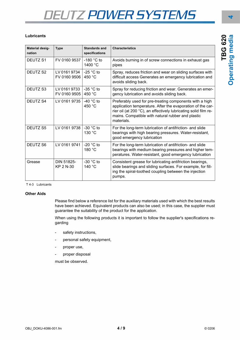
OBJ_DOKU-4086-001.fm 4 / 9 © 0206
4T
BG
62
0O
pe
rati
ng
me
diaLubricants
T 4-3 Lubricants
Other Aids
Please find below a reference list for the auxiliary materials used with which the best resultshave been achieved. Equivalent products can also be used; in this case, the supplier mustguarantee the suitability of the product for the application.
When using the following products it is important to follow the supplier's specifications re-garding
- safety instructions,
- personal safety equipment,
- proper use,
- proper disposal
must be observed.
Material desig-
nation
Type Standards and
specifications
Characteristics
DEUTZ S1 FV 0160 9537 -180 °C to 1400 °C
Avoids burning in of screw connections in exhaust gas pipes
DEUTZ S2 LV 0161 9734 FV 0160 9506
-25 °C to 450 °C
Spray, reduces friction and wear on sliding surfaces with difficult access Generates an emergency lubrication and avoids sliding back.
DEUTZ S3 LV 0161 9733 FV 0160 9505
-35 °C to 450 °C
Spray for reducing friction and wear. Generates an emer-gency lubrication and avoids sliding back.
DEUTZ S4 LV 0161 9735 -40 °C to 450 °C
Preferably used for pre-treating components with a high application temperature. After the evaporation of the car-rier oil (at 200 °C), an effectively lubricating solid film re-mains. Compatible with natural rubber and plastic materials.
DEUTZ S5 LV 0161 9738 -30 °C to 130 °C
For the long-term lubrication of antifriction- and slide bearings with high bearing pressures. Water-resistant, good emergency lubrication
DEUTZ S6 LV 0161 9741 -20 °C to 180 °C
For the long-term lubrication of antifriction- and slide bearings with medium bearing pressures and higher tem-peratures. Water-resistant, good emergency lubrication
Grease DIN 51825- KP 2 N-30
-30 °C to 140 °C
Consistent grease for lubricating antifriction bearings, slide bearings and sliding surfaces. For example, for fill-ing the spiral-toothed coupling between the injection pumps.

OBJ_DOKU-4086-001.fm 4 / 10 © 0206
Op
era
tin
g m
ed
iaT
BG
62
0
Product group Application Product name Supplier
Cleaning agent for engine components P3 Cold cleaner (liquid) Henkel KGAA 40191 Düsseldorf
Vecom B 24 B (liquid) Vecom GmbH 21107 Hamburg
Carbon remover or Ameroid ACC-9 (liquid)
Drew Ameroid Deut-schland GmbH 21107 Hamburg
for engine cooling system P3 T 288 (powder)
P3 Standard (powder)
Henkel KGAA 40191 Düsseldorf
Vecom BA-S (powder)
Vecom BA-30 (liquid)
Vecom GmbH 21107 Hamburg
SAF-Acid (powder)
HDE-777 (liquid)
Drew Ameroid Deut-schland GmbH 21107 Hamburg
for charge air cooler (water side) and raw water circuit
P3 - T1166
P3 - croni
(neutraliser)
Henkel KGAA 40191 Düsseldorf
SAF-Acid (only water softener)
Concentration: 5 %
Temperature: 55 °C - 75 °C
Drew Ameroid Deut-schland GmbH 21107 Hamburg
Porodox
Concentration: 2 % - 10 %Tempera-ture: 20 °C - 60 °CTreatment time: max. 16 hours
Collardi GmbH 50825 Köln
for charge air cooler (air side) ACC 9 Drew Ameroid Deut-schland GmbH 21107 Hamburg
Vecom B 85 Vecom GmbH 21107 Hamburg
P3T-5308 Henkel KGAA 40191 Düsseldorf
for tank plants Vecom B 24 B (liquid)
Vecom B 14 (liquid)
Vecom GmbH 21107 Hamburg
Tank cleaner No. 4 (liquid) Drew Ameroid Deut-schland GmbH 21107 Hamburg
to remove preservatives Eskapon S 255 Haug-Chemie GmbH
74889 Sinsheim
Thinners and removers of wax-like preservants
Reponal B150 Fuchs Europe GmbH,
68169 Mannheim

OBJ_DOKU-4086-001.fm 4 / 11 © 0206
4T
BG
62
0O
pe
rati
ng
me
dia
T 4-4 Other aids
Preservants Preserving oil for preserving the lube oil system and as a 15% additive for the distillate fuel for fuel systems
Run-in oil SAE30W-30
BP-MEK 30
BP
Hamburg
for preserving the coolant sys-tem
Puriton 3956
ODACON Z
Kuhbier
Chemie GmbH,
58566 Kierspe
Reicon Chemie,
04103 Leipzig
for preserving bare external surfaces and parts (wax-like)
Gerserol Super Deutsche Castrol,
76829 Landau
Protective grease for controller linkage and joints
Renolit MP2 Fuchs Europe, 68169 Mannheim
for rubber parts fine talcum, white Silbermann GmbH & Co.KG
86456 Gablingen
Water treatment agent
Hardness determination for cooling water
Aquamerk Art. No. 11129
DEUTZ ordering no. 1215 8292
E. Merck KGAA 64293 Darmstadt
Cooling water hardening Vecom CN (powder) Vecom GmbH 21107 Hamburg
Cooling water softening Trisodiumphosphate (powder) Benckiser GmbH, 67001 Ludwigshafen
Product group Application Product name Supplier

OBJ_DOKU-4086-001.fm 4 / 12 © 0206
Op
era
tin
g m
ed
iaT
BG
62
0

OBJ_DOKU-4087-001.fm 5 / 1 © 0206
5T
BG
62
0M
ain
ten
an
ce
E20
E30
E40
E50
E60
E70

OBJ_DOKU-4087-001.fm 5 / 2 © 0206
Ma
inte
na
nc
eT
BG
62
0

OBJ_DOKU-4087-001.fm 5 / 3 © 0206
5T
BG
62
0M
ain
ten
an
ceMaintenance
Continuous supervision
The normal care of your engine comprises a daily visual inspection by technically skilledpersons. The appropriate activities are listed in job card B 0-1-5.
Maintenance schedule
General
The maintenance schedule lists the measures for maintaining the nominal condition andthus the operational reliability of the engine and the appropriate maintenance intervals. Themaintenance work procedures are described in the specified job cards (AK).
The intervals prescribed in the maintenance schedule are maximum values and as-sume that installation, purpose and operating conditions comply with specifications. Itmust be ensured that all operating media such as combustion gas, lube oil and coolantare of the prescribed quality. You will find information about this in Chapter 4, Operat-ing Media.
This maintenance schedule only applies for the engine itself and the parts attached tothe engine. System parts must be serviced at the intervals and according to the instruc-tions specified by the manufacturer. You will find the appropriate information in the en-closed manufacturer documents (marked ”MD” in the maintenance schedule).
The work described must be performed by technically skilled persons or authorisedspecialists. The competencies are listed in the table of Deutz maintenance and serviceschedules.
Please bear in mind that the following maintenance schedules are Scheduled Mainte-
nance Plans.
It is not possible to make a firm definition of the maintenance intervals for all applications due to the numerous different relationships between ambient conditions, operating mode and quality of fuels.
It may be necessary to shorten the specified maintenance intervals under harsher operating conditions. The scheduled maintenance plan must then be revised completely. Generally the on-site operating conditions are already defined in the planning phase.
Critical operation conditions are for example:
- Contamination of the combustion gases by ingredients which promote wear, e.g. sili-con, sulphur, chlorine, ...
- Frequent cold starts
- Increased dust contamination of the suction intake air
Ask your service partner if in doubt.
In particular it must be ensured that the gas quality meets the minimum requirements in ac-cordance with TR 0199 - 99 - 3017 to avoid malfunctions and/or premature wear of the en-gine.

OBJ_DOKU-4087-001.fm 5 / 4 © 0206
Ma
inte
na
nc
eT
BG
62
0 Selection and structure
Depending on the speed and gas group, the engine is assigned an appropriate mainte-nance schedule.
The maintenance schedule consists of several sections which should be used in parallel.
The maintenance measures independent of operating hours.
The activities to be carried out after reaching the specified time intervals in monthsare listed here.
The maintenance measures dependent on operating hours.
The activities to be carried out after reaching the specified time intervals in oper-ating hours (Deutz maintenance and service schedules) are listed here.
Maintenance measures outside the DEUTZ maintenance and service schedules
The activities for which the time intervals are determined by analysis are listedhere.
The copy forms for proof of maintenance carried out.
Deutz maintenance and service schedules
Maintenance work dependent on operating hours is classified according to Deutz mainte-nance and service schedules. All the work listed must be performed carefully according tothe maintenance schedule determined specifically for the engine.
T 5-1 Deutz maintenance and service schedules
Make sure to observe the due dates for Deutz maintenance and service schedules ac-cording to the number of hours your engine has been in operation.
Arrange the necessary appointment with your responsible service partner in good time.Report any irregularities of your engine when you arrange the appointment.
Sign a service contract with your service partner if necessary. All the due maintenancework including repairs if agreed is then planned and expertly performed by the service
On reaching the specified intervals of time (months or operating hours), the activities spec-ified in the maintenance schedule must be carried out.
Always use the job card (JC) referred to in the maintenance schedule.
Deutz maintenance and service schedules Executed by
E10 each due once after commissioning and af-ter E50, E60 and E70
technically skilled persons
E20 daily check
E30 periodic maintenance (small scope)
E40 periodic maintenance (medium scope)
E50 periodic maintenance (extended scope) authorised specialists
E60 intermediate overhaul
E70 complete overhaul
Please note that DEUTZ maintenance and service schedules may be added or omitted de-pending on the speed and gas group.

OBJ_DOKU-4087-001.fm 5 / 5 © 0206
5T
BG
62
0M
ain
ten
an
cepartner according to the contract. Your service partner will be glad to give you the de-
tails.
Definition of activities in the maintenance schedule
T 5-2 Definition of activities
Gas groups
The maintenance intervals also depend on the quality of the combustion gases.
The combustion gases are divided into two groups according to their wear properties forwhich different scheduled maintenance plans apply, see also Chapter 4, Technical Circular0199 - 99 - 3017.
T 5-3 Gas groups
Adjust Adjust torques, dimensions, pressures etc.; extra work may be necessary to renew parts.
Drain water Drain condensed water for example.
Renew Renew parts, function groups and liquids.
Recondition Material removal within the permitted tolerances to reinstate a nominal condition.
Check Check according to criteria in the job card. If not all criteria are fulfilled, the cause must be found and the nominal condition reinstated.
Clean Cleaning by hand or machine (automatic), renewal of cleaning parts (e.g. air filters) may be necessary.
Visual inspec-
tion
Visual inspection according to criteria in the job card. If not all criteria are fulfilled, the cause must be found and the nominal condition reinstated.
Overhaul Check function groups, rework or renew parts.
Maintain Maintain according to job card. Checking of functions; reworking or renewal of parts may be necessary.
Change Change lube oil for example.
Use the maintenance schedule corresponding to the type of gas used in the system as a basis for the maintenance work.
Gas group 1 Gas group 2 (bio-gases)
Natural gas Sewage gas
Pit gas Landfill gas
Liquid gas - propane, butane, LNG (liq-uid natural gas)
Wood gas
Petroleum gas Other bio-gases
Gases with a hydrogen content of H2 > 30 Vol%, (e.g. coke oven gas)
The worst determined gas quality is essentially binding for defining the maintenance inter-vals. Please consult your service partner.

OBJ_DOKU-4087-001.fm 5 / 6 © 0206
Ma
inte
na
nc
eT
BG
62
0 Silicon content
A 5-1 Dependence: Silicon content-TBO
To guarantee the necessary life cycles, the silicon content of critical gases (gas-group 2,bio-gases) must be determined regularly at least 3x a year in the course of extensive gasanalyses and the maintenance intervals may have to be shortened accordingly.
When using combustion gases with a silicon content > 10 mg/mn3 CH4 the TBOs (TBO =
Time between overhaul) must be reduced in any case because of the strongly abrasive ef-fect of silicon.
10 mg/mn3 CH4 Silizium
100 %
0
TB
O
© 83908-1

5T
BG
62
0M
ain
ten
an
ce
Overview of specific maintenance schedulesThis engine is built exclusively for the purpose intended according to the scope of deliveryas defined by the equipment manufacturer (use for the intended purpose). Depending onits intended purpose the engine is identified by a performance code or an abbreviations forthe gas type which is punched into the rating plate. The rating plate is described in detail inchapter 2.
Maintenance schedule 1
Valid for: Engine type: V12-, V16- and V20-engine
Speed: n = 1,500 rpm (50 Hz applications)
Fuel gas : Gas group 1
Performance code: ICN
Type of application: Current generators
The following activities must be carried out according to the maintenance intervals
Maintenance work independent of operating hours
as required
monthly
after every 4 months
after every 6 months
after every 12 months
after every 24 months
Maintenance work depending on operating hours
E 10 Maintenance once in special cases
E 20 Inspection daily
E 30 Maintenance (small scope) after every 1,500 oh
E 40 Maintenance (medium scope) after every 3,000 oh
E 50 Maintenance (extended scope) after every 12,000 oh
E 60 intermediate overhaul after every 24,000 oh
E 70 complete overhaul after every 48,000 oh
Maintenance work dependent on operating hours outside the DEUTZ maintenance and service
schedule
Lube oil analysis;
according to TR 0199 - 99 - 2105
Initial analysis after 300 op. hrs
All other lube oil changes and analyses are to be agreed between the owner and the lab on the basis of the results of the analysis.
OBJ_DOKU-3934-001.fm 5 / 7 © 0206

Ma
inte
na
nc
eT
BG
62
0
Maintenance schedule 2
Valid for: Engine type: V12-, V16- and V20-engine
Speed: n = 1,500 rpm (50 Hz applications)
Fuel gas : Gas group 2
Performance code: ICN
Type of application: Current generators
The following activities must be carried out according to the maintenance intervals
Maintenance work independent of operating hours
as required
monthly
after every 4 months
after every 6 months
after every 12 months
after every 24 months
Maintenance work depending on operating hours
E 10 Maintenance once in special cases
E 20 Inspection daily
E 30 Maintenance (small scope) after every 1,500 oh
E 40 Maintenance (medium scope) after every 3,000 oh
E 50 Maintenance (extended scope) after every 12,000 oh
E 60 intermediate overhaul after every 24,000 oh
E 70 complete overhaul after every 48,000 oh
Maintenance work dependent on operating hours outside the DEUTZ maintenance and service
schedule
Lube oil analysis;
according to TR 0199 - 99 - 2105
Initial analysis after 100 op. hrs
All other lube oil changes and analyses are to be agreed between the owner and the lab on the basis of the results of the analysis.
OBJ_DOKU-3934-001.fm 5 / 8 © 0206

5T
BG
62
0M
ain
ten
an
ce
Maintenance schedule 3
Valid for: Engine type : V12- and V16- engine
Speed: n = 1,800 rpm (60 Hz applications)
Fuel gas : Gas group 1
Performance code: ICN
Type of application: Current generators
The following activities must be carried out according to the maintenance intervals
Maintenance work independent of operating hours
as required
monthly
after every 4 months
after every 6 months
after every 12 months
after every 24 months
Maintenance work depending on operating hours
E 10 Maintenance once in special cases
E 20 Inspection daily
E 30 Maintenance (small scope) after every 1,000 oh
E 40 Maintenance (medium scope) after every 2,000 oh
E 50 Maintenance (extended scope) after every 10,000 oh
E 60 intermediate overhaul after every 20,000 oh
E 70 complete overhaul after every 40,000 oh
Maintenance work dependent on operating hours outside the DEUTZ maintenance and service
schedule
Lube oil analysis;
according to TR 0199 - 99 - 2105
Initial analysis after 300 op. hrs
All other lube oil changes and analyses are to be agreed between the owner and the lab on the basis of the results of the analysis.
OBJ_DOKU-3934-001.fm 5 / 9 © 0206

Ma
inte
na
nc
eT
BG
62
0
Maintenance schedule 4
Valid for: Engine type : V12- and V16- engine
Speed: n = 1,800 rpm (60 Hz applications)
Fuel gas : Gas group 2
Performance code: ICN
Type of application: Current generators
The following activities must be carried out according to the maintenance intervals
Maintenance work independent of operating hours
as required
monthly
after every 4 months
after every 6 months
after every 12 months
after every 24 months
Maintenance work depending on operating hours
E 10 Maintenance once in special cases
E 20 Inspection daily
E 30 Maintenance (small scope) after every 1,000 oh
E 40 Maintenance (medium scope) after every 2,000 oh
E 50 Maintenance (extended scope) after every 10,000 oh
E 60 intermediate overhaul after every 20,000 oh
E 70 complete overhaul after every 40,000 oh
Maintenance work dependent on operating hours outside the DEUTZ maintenance and service
schedule
Lube oil analysis;
according to TR 0199 - 99 - 2105
Initial analysis after 100 op. hrs
All other lube oil changes and analyses are to be agreed between the owner and the lab on the basis of the results of the analysis.
OBJ_DOKU-3934-001.fm 5 / 10 © 0206

5T
BG
62
0M
ain
ten
an
ce
Maintenance schedule 1Maintenance work independent of operating hours
Valid for: Engine type: V12-, V16- and V20-engine
Speed: n = 1,500 rpm (50 Hz applications)
Fuel gas : Gas group 1
as
re
qu
ired
mo
nth
ly
aft
er
ev
ery
4 m
on
ths
aft
er
ev
ery
6 m
on
ths
aft
er
ev
ery
12
mo
nth
s
aft
er
ev
ery
24
mo
nth
s
Description Job card
x Check suction air intake filter, renew if necessary;according to E50, but earlier if the maintenance indicator is showing "RED"
B 6-3-6
x Maintain crankcase vent;according to E40, but earlier if the maintenance indicator is showing "RED"
B 3-1-9
x Trial run after maintenance work 1) ---
x Run in engine; after maintenance work such as changing bearings, piston, cylinder liner 2)
W 0-1-3
x Clean the engine B 0-3-6
x Trial run3) ---
x Maintaining the battery;according to E30, but monthly if 3) is applicable
B 13-4-1
x Gas analysis ---
x Check percentage of corrosion protection agent or antifreeze in the coolant
B 9-1-1
x x Inspect pressure drop in gas filter MD
x Renew gas filter insert B 7-21-1
x Gas pressure sensor, check set gas pressure MD
x Check gas pressure regulator MD
x Check shutoff valves of the gas control system MD
x Check the entire gas control system for leaks MD
x Lube oil change 4) B 8-1-2
x Renew lube oil filter cartridge 4) B 8-10-4
x Renew the coolant B 9-0-4
1) To be performed by maintenance officers
2) To be performed by authorised experts
3) This activity must be performed when the engine on standby has not been operated for longer than one month. The engine must
be preserved during long periods out of action, e.g. over the winter - see chapter 7.
4) The lube oil must be changed if the maintenance intervals determined in the lube oil analysis are not reached within 12 months.
The lube oil filter cartridge must be used.
OBJ_DOKU-3935-001.fm 5 / 11 © 0206

Ma
inte
na
nc
eT
BG
62
0
Maintenance work depending on operating hoursE10 E20 E30 E40 E50 E60 E70 Description Job card
1x
aft
er
50 o
h
aft
er
ev
ery
24
hrs
(d
aily)
aft
er
ev
ery
1,5
00 o
h
aft
er
ev
ery
3,0
00 o
h
aft
er
ev
ery
12
,000 o
h
aft
er
ev
ery
24
,000 o
h
aft
er
ev
ery
48
,000 o
h
x x x x x x x Visual inspection of the system B 0-1-5
x x x x x x Test and function run TEM
x x x Checking valve clearance B 1-1-1
x x x x x Maintaining battery 1) B 13-4-1
x x x x x Checking speed governor linkage B 5-4-2
x x x x x Maintaining crankcase bleed valve (Racor model) 1) B 3-1-9
x x x Renewing crankcase bleed valve (Mann model) 1) B 3-1-6
x Checking spark plugs, renewing if necessary B 13-5-4
x x x x Renewing spark plugs B 13-5-4
x2) x x x x Renewing lube oil filter cartridge 3) B 8-10-4
x x x x Checking ignition time B 13-5-3
x x x x Auxiliary unit test using the TEM System B 0-1-6
x x x Renewing suction air intake filter, cleaning suction air filter housing
B 6-3-6
x x x Checking engine fastening W 3-7-1
x x x Checking starter pinion and ring gear W 12-6-4
x x x Renewing or overhauling cylinder heads W 1-4-4
x Cleaning combustion chambers ---
x Checking cylinder liners W 3-3-1
x x Renewing cylinder liners W 3-3-2
x Checking and endoscoping intercooler W 6-4-11
x x Cleaning intercooler W 6-4-4
x Checking and cleaning turbocharger 4) MD
x x Renewing or overhauling turbocharger 4) MD
x x Cleaning gas mixer W 7-22-2
x Renewing gas mixer W 7-22-1
x Checking rubber compensators W 12-3-1
x Renewing rubber compensators W 12-3-1
1) For engines with this equipment
2) Only 50 oh as per E50 to E70
3) For other lube oil filter changes, see TC 0199 - 99 - 2105
4) Maintenance intervals, see manufacturer documentation (MD)
OBJ_DOKU-3935-001.fm 5 / 12 © 0206

5T
BG
62
0M
ain
ten
an
ce
T 5-1 Maintenance work depending on operating hours
x x Checking hose pipes, vibration dampers and flexible lines ---
x x Checking engine side fittings and control instruments ---
x x Renew viscosity torsional vibration dampers 1) ---
x Checking crankshaft axial clearance W 2-1-4
x Checking camshaft axial clearance W 4-1-4
x Checking valve tappet W 4-2-1
x Renewing valve tappet W 4-2-1
x Checking con rod liners W 2-3-3
x x Renewing con rod bearings W 2-5-1
x Checking piston W 2-9-7
x Renewing piston W 2-9-3
x Checking piston pin W 2-12-4
x Renewing piston rings W 2-10-1
x x Checking camshaft W 4-5-1
x Renewing camshaft bearing W 4-1-1
x Renewing con rods W 2-3-6
x Renewing drive side crankshaft sealing ring W 2-2-2
x Renewing free side crankshaft sealing ring1) W 2-2-4
x Measuring crankshaft, checking for tears, polishing W 2-1-7
x Checking and cleaning wheel drive and control W 4-4-1
x Renewing main bearing and axial bearing W 2-7-3
x Renewing or overhauling lube oil pump W 8-4-5
x Renewing or overhauling pressure limiting valve ---
x Renewing exhaust gas compensators ---
E10 E20 E30 E40 E50 E60 E70 Description Job card
1x a
fte
r 50 o
h
aft
er
every
24 h
rs (
daily
)
aft
er
every
1,5
00 o
h
aft
er
every
3,0
00 o
h
aft
er
every
12,0
00
oh
aft
er
every
24,0
00
oh
aft
er
every
48,0
00
oh
1) For engines with this equipment
2) Only 50 oh as per E50 to E70
3) For other lube oil filter changes, see TC 0199 - 99 - 2105
4) Maintenance intervals, see manufacturer documentation (MD)
OBJ_DOKU-3935-001.fm 5 / 13 © 0206

Ma
inte
na
nc
eT
BG
62
0
Maintenance work dependent on operating hours outside the DEUTZ maintenance and serviceschedules
T 5-2 Maintenance work outside the DEUTZ maintenance and service schedules
Description Job
card
Lube oil analysis (according to TR 0199 - 99 - 2105)
Initial analysis after 300 op. hrs
All other lube oil changes and analyses are to be agreed between the owner and the lab on the basis of the results of the analysis.
---
We recommend you to record the proper execution of the work in the enclosed mainte-nance tables.
OBJ_DOKU-3935-001.fm 5 / 14 © 0206

5T
BG
62
0M
ain
ten
an
ce
Proof of maintenance performedCopy form for maintenance work independent of operating hours
Date Activity Signature
OBJ_DOKU-3935-001.fm 5 / 15 © 0206

Ma
inte
na
nc
eT
BG
62
0
Table for maintenance work dependent on operating hoursHours Deutz maintenance and serv-
ice schedule
Date Signature
E10 E30 E40 E50 E60 E70
50 1
1.500 1
3.000 1
4.500 2
6.000 2
7.500 3
9.000 3
10.500 4
12.000 1
12.050 2
13.500 5
15.000 4
16.500 6
18.000 5
19.500 7
21.000 6
22.500 8
24.000 1
24.050 3
25.500 9
27.000 7
28.500 10
30.000 8
31.500 11
33.000 9
34.500 12
36.000 2
36.050 4
37.500 13
39.000 10
40.500 14
42.000 11
43.500 15
45.000 12
46.500 16
OBJ_DOKU-3935-001.fm 5 / 16 © 0206

5T
BG
62
0M
ain
ten
an
ce
48.000 1
Number of Deutz maintenance and service schedules up to and includ-ing complete overhaul
Total 4 16 12 2 1 1
Hours Deutz maintenance and serv-
ice schedule
Date Signature
E10 E30 E40 E50 E60 E70
OBJ_DOKU-3935-001.fm 5 / 17 © 0206

Ma
inte
na
nc
eT
BG
62
0
OBJ_DOKU-3935-001.fm 5 / 18 © 0206

5T
BG
62
0M
ain
ten
an
ce
Maintenance schedule 2Maintenance work independent of operating hours
Valid for: Engine type: V12-, V16- and V20-engine
Speed: n = 1,500 rpm (50 Hz applications)
Fuel gas : Gas group 2
as
re
qu
ired
mo
nth
ly
aft
er
ev
ery
4 m
on
ths
aft
er
ev
ery
6 m
on
ths
aft
er
ev
ery
12
mo
nth
s
aft
er
ev
ery
24
mo
nth
s
Description Job card
x Check suction air intake filter, renew if necessary;according to E50, but earlier if the maintenance indicator is showing "RED"
B 6-3-6
x Maintain crankcase vent;according to E40, but earlier if the maintenance indicator is showing "RED"
B 3-1-9
x Trial run after maintenance work 1) ---
x Run in engine; after maintenance work such as changing bearings, piston, cylinder liner 2)
W 0-1-3
x Clean the engine B 0-3-6
x Trial run3) ---
x Maintaining the battery;according to E30, but monthly if 3) is applicable
B 13-4-1
x Gas analysis ---
x Check percentage of corrosion protection agent or antifreeze in the coolant
B 9-1-1
x x Inspect pressure drop in gas filter MD
x Renew gas filter insert B 7-21-1
x Gas pressure sensor, check set gas pressure MD
x Check gas pressure regulator MD
x Check shutoff valves of the gas control system MD
x Check the entire gas control system for leaks MD
x Lube oil change 4) B 8-1-2
x Renew lube oil filter cartridge 4) B 8-10-4
x Renew the coolant B 9-0-4
1) To be performed by maintenance officers
2) To be performed by authorised experts
3) This activity must be performed when the engine on standby has not been operated for longer than one month. The engine must
be preserved during long periods out of action, e.g. over the winter - see chapter 7.
4) The lube oil must be changed if the maintenance intervals determined in the lube oil analysis are not reached within 12 months.
The lube oil filter cartridge must be used.
OBJ_DOKU-3936-001.fm 5 / 19 © 0206

Ma
inte
na
nc
eT
BG
62
0
Maintenance work depending on operating hoursE10 E20 E30 E40 E50 E60 E70 Description Job card
1x
aft
er
50 o
h
aft
er
ev
ery
24
hrs
(d
aily)
aft
er
ev
ery
1,5
00 o
h
aft
er
ev
ery
3,0
00 o
h
aft
er
ev
ery
12
,000 o
h
aft
er
ev
ery
24
,000 o
h
aft
er
ev
ery
48
,000 o
h
x x x x x x x Visual inspection of the system B 0-1-5
x x x x x x Test and function run TEM
x x x Checking valve clearance B 1-1-1
x x x x x Maintaining battery 1) B 13-4-1
x x x x x Checking speed governor linkage B 5-4-2
x x x x x Maintaining crankcase bleed valve (Racor model) 1) B 3-1-9
x x x Renewing crankcase bleed valve (Mann model) 1) B 3-1-6
x Checking spark plugs, renewing if necessary B 13-5-4
x x x x Renewing spark plugs B 13-5-4
x2) x x x x Renewing lube oil filter cartridge 3) B 8-10-4
x x x x Checking ignition time B 13-5-3
x x x x Auxiliary unit test using the TEM System B 0-1-6
x x x Renewing suction air intake filter, cleaning suction air filter housing
B 6-3-6
x x x Checking engine fastening W 3-7-1
x x x Checking starter pinion and ring gear W 12-6-4
x x x Renewing or overhauling cylinder heads W 1-4-4
x Cleaning combustion chambers ---
x Checking cylinder liners W 3-3-1
x x Renewing cylinder liners W 3-3-2
x Checking and endoscoping intercooler W 6-4-11
x x Cleaning intercooler W 6-4-4
x Checking and cleaning turbocharger 4) MD
x x Renewing or overhauling turbocharger 4) MD
x x Cleaning gas mixer W 7-22-2
x Renewing gas mixer W 7-22-1
x Checking rubber compensators W 12-3-1
x Renewing rubber compensators W 12-3-1
1) For engines with this equipment
2) Only 50 oh as per E50 to E70
3) For other lube oil filter changes, see TC 0199 - 99 - 2105
4) Maintenance intervals, see manufacturer documentation (MD)
OBJ_DOKU-3936-001.fm 5 / 20 © 0206

5T
BG
62
0M
ain
ten
an
ce
T 5-1 Maintenance work depending on operating hours
x x Checking hose pipes, vibration dampers and flexible lines ---
x x Checking engine side fittings and control instruments ---
x x Renew viscosity torsional vibration dampers 1) ---
x Checking crankshaft axial clearance W 2-1-4
x Checking camshaft axial clearance W 4-1-4
x Checking valve tappet W 4-2-1
x Renewing valve tappet W 4-2-1
x Checking con rod liners W 2-3-3
x x Renewing con rod bearings W 2-5-1
x Checking piston W 2-9-7
x Renewing piston W 2-9-3
x Checking piston pin W 2-12-4
x Renewing piston rings W 2-10-1
x x Checking camshaft W 4-5-1
x Renewing camshaft bearing W 4-1-1
x Renewing con rods W 2-3-6
x Renewing drive side crankshaft sealing ring W 2-2-2
x Renewing free side crankshaft sealing ring1) W 2-2-4
x Measuring crankshaft, checking for tears, polishing W 2-1-7
x Checking and cleaning wheel drive and control W 4-4-1
x Renewing main bearing and axial bearing W 2-7-3
x Renewing or overhauling lube oil pump W 8-4-5
x Renewing or overhauling pressure limiting valve ---
x Renewing exhaust gas compensators ---
E10 E20 E30 E40 E50 E60 E70 Description Job card
1x a
fte
r 50 o
h
aft
er
every
24 h
rs (
daily
)
aft
er
every
1,5
00 o
h
aft
er
every
3,0
00 o
h
aft
er
every
12,0
00
oh
aft
er
every
24,0
00
oh
aft
er
every
48,0
00
oh
1) For engines with this equipment
2) Only 50 oh as per E50 to E70
3) For other lube oil filter changes, see TC 0199 - 99 - 2105
4) Maintenance intervals, see manufacturer documentation (MD)
OBJ_DOKU-3936-001.fm 5 / 21 © 0206

Ma
inte
na
nc
eT
BG
62
0
Maintenance work dependent on operating hours outside the DEUTZ maintenance and serviceschedules
T 5-2 Maintenance work outside the DEUTZ maintenance and service schedules
Description Job
card
Lube oil analysis (according to TR 0199 - 99 - 2105)
Initial analysis after 100 op. hrs
All other lube oil changes and analyses are to be agreed between the owner and the lab on the basis of the results of the analysis.
---
We recommend you to record the proper execution of the work in the enclosed mainte-nance tables.
OBJ_DOKU-3936-001.fm 5 / 22 © 0206

5T
BG
62
0M
ain
ten
an
ce
Proof of maintenance performedCopy form for maintenance work independent of operating hours
Date Activity Signature
OBJ_DOKU-3936-001.fm 5 / 23 © 0206

Ma
inte
na
nc
eT
BG
62
0
Table for maintenance work dependent on operating hoursHours Deutz maintenance and serv-
ice schedule
Date Signature
E10 E30 E40 E50 E60 E70
50 1
1.500 1
3.000 1
4.500 2
6.000 2
7.500 3
9.000 3
10.500 4
12.000 1
12.050 2
13.500 5
15.000 4
16.500 6
18.000 5
19.500 7
21.000 6
22.500 8
24.000 1
24.050 3
25.500 9
27.000 7
28.500 10
30.000 8
31.500 11
33.000 9
34.500 12
36.000 2
36.050 4
37.500 13
39.000 10
40.500 14
42.000 11
43.500 15
45.000 12
46.500 16
OBJ_DOKU-3936-001.fm 5 / 24 © 0206

5T
BG
62
0M
ain
ten
an
ce
48.000 1
Number of Deutz maintenance and service schedules up to and includ-ing complete overhaul
Total 4 16 12 2 1 1
Hours Deutz maintenance and serv-
ice schedule
Date Signature
E10 E30 E40 E50 E60 E70
OBJ_DOKU-3936-001.fm 5 / 25 © 0206

Ma
inte
na
nc
eT
BG
62
0
OBJ_DOKU-3936-001.fm 5 / 26 © 0206

5T
BG
62
0M
ain
ten
an
ce
Maintenance schedule 3Maintenance work independent of operating hours
Valid for: Engine type : V12- and V16- engine
Speed: n = 1,800 rpm (60 Hz applications)
Fuel gas : Gas group 1
as
re
qu
ired
mo
nth
ly
aft
er
ev
ery
4 m
on
ths
aft
er
ev
ery
6 m
on
ths
aft
er
ev
ery
12
mo
nth
s
aft
er
ev
ery
24
mo
nth
s
Description Job card
x Check suction air intake filter, renew if necessary;according to E50, but earlier if the maintenance indicator is showing "RED"
B 6-3-6
x Maintain crankcase vent;according to E40, but earlier if the maintenance indicator is showing "RED"
B 3-1-9
x Trial run after maintenance work 1) ---
x Run in engine; after maintenance work such as changing bearings, piston, cylinder liner 2)
W 0-1-3
x Clean the engine B 0-3-6
x Trial run3) ---
x Maintaining the battery;according to E30, but monthly if 3) is applicable
B 13-4-1
x Gas analysis ---
x Check percentage of corrosion protection agent or antifreeze in the coolant
B 9-1-1
x x Inspect pressure drop in gas filter MD
x Renew gas filter insert B 7-21-1
x Gas pressure sensor, check set gas pressure MD
x Check gas pressure regulator MD
x Check shutoff valves of the gas control system MD
x Check the entire gas control system for leaks MD
x Lube oil change 4) B 8-1-2
x Renew lube oil filter cartridge 4) B 8-10-4
x Renew the coolant B 9-0-4
1) To be performed by maintenance officers
2) To be performed by authorised experts
3) This activity must be performed when the engine on standby has not been operated for longer than one month. The engine must
be preserved during long periods out of action, e.g. over the winter - see chapter 7.
4) The lube oil must be changed if the maintenance intervals determined in the lube oil analysis are not reached within 12 months.
The lube oil filter cartridge must be used.
OBJ_DOKU-3937-001.fm 5 / 27 © 0206

Ma
inte
na
nc
eT
BG
62
0
Maintenance work depending on operating hoursE10 E20 E30 E40 E50 E60 E70 Description Job card
1x
aft
er
50 o
h
aft
er
ev
ery
24
hrs
(d
aily)
aft
er
ev
ery
1,0
00 o
h
aft
er
ev
ery
2,0
00 o
h
aft
er
ev
ery
10
,000 o
h
aft
er
ev
ery
20
,000 o
h
aft
er
ev
ery
40
,000 o
h
x x x x x x x Visual inspection of the system B 0-1-5
x x x x x x Test and function run TEM
x x x Checking valve clearance B 1-1-1
x x x x x Maintaining battery 1) B 13-4-1
x x x x x Checking speed governor linkage B 5-4-2
x x x x x Maintaining crankcase bleed valve (Racor model) 1) B 3-1-9
x x x Renewing crankcase bleed valve (Mann model) 1) B 3-1-6
x Checking spark plugs, renewing if necessary B 13-5-4
x x x x Renewing spark plugs B 13-5-4
x2) x x x x Renewing lube oil filter cartridge 3) B 8-10-4
x x x x Checking ignition time B 13-5-3
x x x x Auxiliary unit test using the TEM System B 0-1-6
x x x Renewing suction air intake filter, cleaning suction air intake fil-ter housing
B 6-3-6
x x x Checking engine fastening W 3-7-1
x x x Checking starter pinion and ring gear W 12-6-4
x x x Renewing or overhauling cylinder heads W 1-4-4
x Cleaning combustion chambers ---
x Checking cylinder liners W 3-3-1
x x Renewing cylinder liners W 3-3-2
x Checking and endoscoping intercooler W 6-4-11
x x Cleaning intercooler W 6-4-4
x Checking and cleaning turbocharger 4) MD
x x Renewing or overhauling turbocharger 4) MD
x x Cleaning gas mixer W 7-22-2
x Renewing gas mixer W 7-22-1
x Checking rubber compensators W 12-3-1
x Renewing rubber compensators W 12-3-1
1) For engines with this equipment
2) Only 50 oh as per E50 to E70
3) For other lube oil filter changes, see TC 0199 - 99 - 2105
4) Maintenance intervals, see manufacturer documentation (MD)
OBJ_DOKU-3937-001.fm 5 / 28 © 0206

5T
BG
62
0M
ain
ten
an
ce
T 5-1 Maintenance work depending on operating hours
x x Checking hose pipes, vibration dampers and flexible lines ---
x x Checking engine side fittings and control instruments ---
x x Renewing viscosity torsional vibration dampers 1) ---
x Checking crankshaft axial clearance W 2-1-4
x Checking camshaft axial clearance W 4-1-4
x Checking valve tappet W 4-2-1
x Renewing valve tappet W 4-2-1
x Checking con rod liners W 2-3-3
x x Renewing con rod bearings W 2-5-1
x Checking piston W 2-9-7
x Renewing piston W 2-9-3
x Checking piston pin W 2-12-4
x Renewinging piston rings W 2-10-1
x x Checking camshaft W 4-5-1
x Renewing camshaft bearing W 4-1-1
x Renewing con rods W 2-3-6
x Renewing drive side crankshaft sealing ring W 2-2-2
x Renewing free side crankshaft sealing ring1) W 2-2-4
x Measuring crankshaft, checking for tears, polishing W 2-1-7
x Checking and cleaning wheel drive and control W 4-4-1
x Renewing main bearing and axial bearing W 2-7-3
x Renewing or overhauling lube oil pump W 8-4-5
x Renewing or overhauling pressure limiting valve ---
x Renewing exhaust gas compensators ---
E10 E20 E30 E40 E50 E60 E70 Description Job card
1x a
fte
r 50 o
h
aft
er
every
24 h
rs (
daily
)
aft
er
every
1,0
00 o
h
aft
er
every
2,0
00 o
h
aft
er
every
10,0
00
oh
aft
er
every
20,0
00
oh
aft
er
every
40,0
00
oh
1) For engines with this equipment
2) Only 50 oh as per E50 to E70
3) For other lube oil filter changes, see TC 0199 - 99 - 2105
4) Maintenance intervals, see manufacturer documentation (MD)
OBJ_DOKU-3937-001.fm 5 / 29 © 0206

Ma
inte
na
nc
eT
BG
62
0
Maintenance work dependent on operating hours outside the DEUTZ maintenance and serviceschedules
T 5-2 Maintenance work outside the DEUTZ maintenance and service schedules
Description Job
card
Lube oil analysis (according to TR 0199 - 99 - 2105)
Initial analysis after 300 op. hrs
All other lube oil changes and analyses are to be agreed between the owner and the lab on the basis of the results of the analysis.
---
We recommend you to record the proper execution of the work in the enclosed mainte-nance tables.
OBJ_DOKU-3937-001.fm 5 / 30 © 0206

5T
BG
62
0M
ain
ten
an
ce
Proof of maintenance performedCopy form for maintenance work independent of operating hours
Date Activity Signature
OBJ_DOKU-3937-001.fm 5 / 31 © 0206

Ma
inte
na
nc
eT
BG
62
0
Table for maintenance work dependent on operating hoursHours Deutz maintenance and serv-
ice schedule
Date Signature
E10 E30 E40 E50 E60 E70
50 1
1.000 1
2.000 1
3.000 2
4.000 2
5.000 3
6.000 3
7.000 4
8.000 4
9.000 5
10.000 1
10.050 2
11.000 6
12.000 5
13.000 7
14.000 6
15.000 8
16.000 7
17.000 9
18.000 8
19.000 10
20.000 1
20.050 3
21.000 11
22.000 9
23.000 12
24.000 10
25.000 13
26.000 11
27.000 14
28.000 12
29.000 15
30.000 2
30.050 4
31.000 16
OBJ_DOKU-3937-001.fm 5 / 32 © 0206

5T
BG
62
0M
ain
ten
an
ce
32.000 13
33.000 17
34.000 14
35.000 18
36.000 15
37.000 19
38.000 16
39.000 20
40.000 1
Number of Deutz maintenance and service schedules up to and includ-ing complete overhaul
Total 4 20 16 2 1 1
Hours Deutz maintenance and serv-
ice schedule
Date Signature
E10 E30 E40 E50 E60 E70
OBJ_DOKU-3937-001.fm 5 / 33 © 0206

Ma
inte
na
nc
eT
BG
62
0
OBJ_DOKU-3937-001.fm 5 / 34 © 0206

5T
BG
62
0M
ain
ten
an
ce
Maintenance schedule 4Maintenance work independent of operating hours
Valid for: Engine type : V12- and V16- engine
Speed: n = 1,800 rpm (60 Hz applications)
Fuel gas : Gas group 2
as
re
qu
ired
mo
nth
ly
aft
er
ev
ery
4 m
on
ths
aft
er
ev
ery
6 m
on
ths
aft
er
ev
ery
12
mo
nth
s
aft
er
ev
ery
24
mo
nth
s
Description Job card
x Check suction air intake filter, renew if necessary;according to E50, but earlier if the maintenance indicator is showing "RED"
B 6-3-6
x Maintain crankcase vent;according to E40, but earlier if the maintenance indicator is showing "RED"
B 3-1-9
x Trial run after maintenance work 1) ---
x Run in engine; after maintenance work such as changing bearings, piston, cylinder liner 2)
W 0-1-3
x Clean the engine B 0-3-6
x Trial run3) ---
x Maintaining the battery;according to E30, but monthly if 3) is applicable
B 13-4-1
x Gas analysis ---
x Check percentage of corrosion protection agent or antifreeze in the coolant
B 9-1-1
x x Inspect pressure drop in gas filter MD
x Renew gas filter insert B 7-21-1
x Gas pressure sensor, check set gas pressure MD
x Check gas pressure regulator MD
x Check shutoff valves of the gas control system MD
x Check the entire gas control system for leaks MD
x Lube oil change 4) B 8-1-2
x Renew lube oil filter cartridge 4) B 8-10-4
x Renew the coolant B 9-0-4
1) To be performed by maintenance officers
2) To be performed by authorised experts
3) This activity must be performed when the engine on standby has not been operated for longer than one month. The engine must
be preserved during long periods out of action, e.g. over the winter - see chapter 7.
4) The lube oil must be changed if the maintenance intervals determined in the lube oil analysis are not reached within 12 months.
The lube oil filter cartridge must be used.
OBJ_DOKU-3938-001.fm 5 / 35 © 0206

Ma
inte
na
nc
eT
BG
62
0
Maintenance work depending on operating hoursE10 E20 E30 E40 E50 E60 E70 Description Job card
1x
aft
er
50 o
h
aft
er
ev
ery
24
hrs
(d
aily)
aft
er
ev
ery
1,0
00 o
h
aft
er
ev
ery
2,0
00 o
h
aft
er
ev
ery
10
,000 o
h
aft
er
ev
ery
20
,000 o
h
aft
er
ev
ery
40
,000 o
h
x x x x x x x Visual inspection of the system B 0-1-5
x x x x x x Test and function run TEM
x x x Checking valve clearance B 1-1-1
x x x x x Maintaining battery 1) B 13-4-1
x x x x x Checking speed governor linkage B 5-4-2
x x x x x Maintaining crankcase bleed valve (Racor model) 1) B 3-1-9
x x x Renewing crankcase bleed valve (Mann model) 1) B 3-1-6
x Checking spark plugs, renewing if necessary B 13-5-4
x x x x Renewing spark plugs B 13-5-4
x2) x x x x Renewing lube oil filter cartridge 3) B 8-10-4
x x x x Checking ignition time B 13-5-3
x x x x Auxiliary unit test using the TEM System B 0-1-6
x x x Renewing suction air intake filter, cleaning suction air intake fil-ter housing
B 6-3-6
x x x Checking engine fastening W 3-7-1
x x x Checking starter pinion and ring gear W 12-6-4
x x x Renewing or overhauling cylinder heads W 1-4-4
x Cleaning combustion chambers ---
x Checking cylinder liners W 3-3-1
x x Renewing cylinder liners W 3-3-2
x Checking and endoscoping intercooler W 6-4-11
x x Cleaning intercooler W 6-4-4
x Checking and cleaning turbocharger 4) MD
x x Renewing or overhauling turbocharger 4) MD
x x Cleaning gas mixer W 7-22-2
x Renewing gas mixer W 7-22-1
x Checking rubber compensators W 12-3-1
x Renewing rubber compensators W 12-3-1
1) For engines with this equipment
2) Only 50 oh as per E50 to E70
3) For other lube oil filter changes, see TC 0199 - 99 - 2105
4) Maintenance intervals, see manufacturer documentation (MD)
OBJ_DOKU-3938-001.fm 5 / 36 © 0206

5T
BG
62
0M
ain
ten
an
ce
T 5-1 Maintenance work depending on operating hours
x x Checking hose pipes, vibration dampers and flexible lines ---
x x Checking engine side fittings and control instruments ---
x x Renewing viscosity torsional vibration dampers 1) ---
x Checking crankshaft axial clearance W 2-1-4
x Checking camshaft axial clearance W 4-1-4
x Checking valve tappet W 4-2-1
x Renewing valve tappet W 4-2-1
x Checking con rod liners W 2-3-3
x x Renewing con rod bearings W 2-5-1
x Checking piston W 2-9-7
x Renewing piston W 2-9-3
x Checking piston pin W 2-12-4
x Renewinging piston rings W 2-10-1
x x Checking camshaft W 4-5-1
x Renewing camshaft bearing W 4-1-1
x Renewing con rods W 2-3-6
x Renewing drive side crankshaft sealing ring W 2-2-2
x Renewing free side crankshaft sealing ring1) W 2-2-4
x Measuring crankshaft, checking for tears, polishing W 2-1-7
x Checking and cleaning wheel drive and control W 4-4-1
x Renewing main bearing and axial bearing W 2-7-3
x Renewing or overhauling lube oil pump W 8-4-5
x Renewing or overhauling pressure limiting valve ---
x Renewing exhaust gas compensators ---
E10 E20 E30 E40 E50 E60 E70 Description Job card
1x a
fte
r 50 o
h
aft
er
every
24 h
rs (
daily
)
aft
er
every
1,0
00 o
h
aft
er
every
2,0
00 o
h
aft
er
every
10,0
00
oh
aft
er
every
20,0
00
oh
aft
er
every
40,0
00
oh
1) For engines with this equipment
2) Only 50 oh as per E50 to E70
3) For other lube oil filter changes, see TC 0199 - 99 - 2105
4) Maintenance intervals, see manufacturer documentation (MD)
OBJ_DOKU-3938-001.fm 5 / 37 © 0206

Ma
inte
na
nc
eT
BG
62
0
Maintenance work dependent on operating hours outside the DEUTZ maintenance and serviceschedules
T 5-2 Maintenance work outside the DEUTZ maintenance and service schedules
Description Job
card
Lube oil analysis (according to TR 0199 - 99 - 2105)
Initial analysis after 100 op. hrs
All other lube oil changes and analyses are to be agreed between the owner and the lab on the basis of the results of the analysis.
---
We recommend you to record the proper execution of the work in the enclosed mainte-nance tables.
OBJ_DOKU-3938-001.fm 5 / 38 © 0206

5T
BG
62
0M
ain
ten
an
ce
Proof of maintenance performedCopy form for maintenance work independent of operating hours
Date Activity Signature
OBJ_DOKU-3938-001.fm 5 / 39 © 0206

Ma
inte
na
nc
eT
BG
62
0
Table for maintenance work dependent on operating hoursHours Deutz maintenance and serv-
ice schedule
Date Signature
E10 E30 E40 E50 E60 E70
50 1
1.000 1
2.000 1
3.000 2
4.000 2
5.000 3
6.000 3
7.000 4
8.000 4
9.000 5
10.000 1
10.050 2
11.000 6
12.000 5
13.000 7
14.000 6
15.000 8
16.000 7
17.000 9
18.000 8
19.000 10
20.000 1
20.050 3
21.000 11
22.000 9
23.000 12
24.000 10
25.000 13
26.000 11
27.000 14
28.000 12
29.000 15
30.000 2
30.050 4
31.000 16
OBJ_DOKU-3938-001.fm 5 / 40 © 0206

5T
BG
62
0M
ain
ten
an
ce
32.000 13
33.000 17
34.000 14
35.000 18
36.000 15
37.000 19
38.000 16
39.000 20
40.000 1
Number of Deutz maintenance and service schedules up to and includ-ing complete overhaul
Total 4 20 16 2 1 1
Hours Deutz maintenance and serv-
ice schedule
Date Signature
E10 E30 E40 E50 E60 E70
OBJ_DOKU-3938-001.fm 5 / 41 © 0206

Ma
inte
na
nc
eT
BG
62
0
OBJ_DOKU-3938-001.fm 5 / 42 © 0206

OBJ_DOKU-4088-001.fm 5 / 43 © 0206
5T
BG
62
0M
ain
ten
an
ceOperating check log
Keep an operating check log! A copy form is provided on the next page. Please not downall irregularities (warnings, faults) and maintenance work in this log. This means you alwayshave a good idea when maintenance work is due, and you can document all irregularitiesfor our service personnel. If you have connected a printer to your TEM system, print out acopy of the measured values in the event of warnings or faults.
Danger of destruction !
Further operation of the engine in the case of a warning or restarting after a fault
without eliminating the cause can lead to total engine failure.

OBJ_DOKU-4088-001.fm 5 / 44 © 0206
Ma
inte
na
nc
eT
BG
62
0 Operating check log (form for copying)
T 5-1 Operating check log (form for copying)
Do not reset any warning/fault messages before you have ascertained the cause.
Please see the notes in the operating manual.
Enclosures: Engine type: Page:
Date Module Event Signature /
Time Operating
hours
Measure Printer doc. no.

5T
BG
62
0M
ain
ten
an
ce
Tools for competence class 1Order address
The tools can be ordered from your DEUTZ Power Systems Service.
Tools sorted according to order numbers
Name Figure
1 Description / Use
2 Module
3 Competence class
4 Order number / Order from ...
(The illustrations are examples)
Torque wrench
1 Measuring range 0-21 Nm (0-2.1 kpm)
2 00 General
3 (1)
4 1203 0350 / Service Partner
OBJ_DOKU-3939-001.fm 5 / 45 © 0206

Ma
inte
na
nc
eT
BG
62
0
Name Figure
1 Description / Use
2 Module
3 Competence class
4 Order number / Order from ...
(The illustrations are examples)
Tool kit
1 Standard set
2 00 General
3 (1)
4 1212 8419 / Service Partner
comprising: Tool case
Open-end spanner 46
Open-end spanner 36 x 41 DIN 3110
Socket 22 x 12.5 DIN 3124
Socket 24 x 20 DIN 3124
Socket 27 x 20 DIN 3124
Socket 30 x 20 DIN 3124
Socket 32 x 20 DIN 3124
Socket key size 36, extra deep
Socket key, inside size 17
Slider CH 1772/39
Extension CH 1772/38
Extension D 601/602
Adapter A 20 x 12.5 DIN 3123
Torque wrench 0-210 Nm (0-21 kpm)
Extension for torque wrench
Turning bar extension
Ratchet ½”
Ratchet ¾"
Extension for ¾" slider
Right angle screwdriver 5 DIN 911
Right angle screwdriver, gunmetal 5 DIN 911
OBJ_DOKU-3939-001.fm 5 / 46 © 0206

5T
BG
62
0M
ain
ten
an
ce
Right angle screwdriver 6 DIN 911Right angle screwdriver 8 DIN 911
Right angle screwdriver 10 DIN 911
Right angle screwdriver 12 DIN 911
Pin wrench 3/16”
Pliers A 10 DIN 5254
Pliers A 19 DIN 5254
Pliers C 40 DIN 5254
Brush
Handle
Feeler gauge 0.05 - 0.5 mm
Extractor device 401
Pin for loosening the retaining bolts
Ring spanner size 22
Extension for brushes for pipe cooler
Round brush CH 1988/2
Round brush CH 1988/4
Wrench (starter wrench) 27
OBJ_DOKU-3939-001.fm 5 / 47 © 0206

Ma
inte
na
nc
eT
BG
62
0
Name Figure
1 Description / Use
2 Module
3 Competence class
4 Order number / Order from ...
(The illustrations are examples)
Test case for lube oil and coolant
1 Equipment and aids for the lube oil and coolant proper-ties tests
2 00 General
3 (1)
4 1213 0382 / Service Partner
Comprising: 1213 0403 Case (without contents)
For coolant test
1213 0395 Test rods for pH value
1213 0396 Test material for total hardness
1213 0397 Test material for carbonate hardness
1213 0398 Test material for chloride content
1213 0399 Test rod for sulphate content
For lube oil test
1213 0384 Complete set, consisting of:
1213 0385 Instrument for testing water content
1213 0386 Measuring cylinder
1213 0387 Suction measuring instrument
1213 0388 Float vessels (test water content)
1213 0389 Spare gasket
1213 0390 Tweezers
1213 0391 Pipette
1213 0393 Test tube A (check water content)
1213 0394 Test tube B (check water content)
1213 0400 Glass rods for drip sample
1213 0401 Filter paper for drip sample
1213 0402 Instrument for viscosity comparison
OBJ_DOKU-3939-001.fm 5 / 48 © 0206

5T
BG
62
0M
ain
ten
an
ce
Name Figure
1 Description / Use
2 Module
3 Competence class
4 Order number / Order from ...
(The illustrations are examples)
Tool kit
1 Standard set
2 00 General
3 (1)
4 1215 0000 / Service Partner
Comprising: 1215 8074 Tool case
0115 4248 Open end spanner 8 x 10 DIN 3110
0115 4250 Open end spanner 12 x 14 DIN 3110
0115 4251 Open end spanner 13 x 17 DIN 3110
0115 4252 Open end spanner 14 x 15 DIN 3110
0115 4254 Open end spanner 19 x 22 DIN 3110
0115 4255 Open end spanner 24 x 27 DIN 3110
0703 8432 Open end spanner 30 x 32 DIN 3110
0112 4755 Ring spanner 13 x 17 DIN 838
0115 4230 Ring spanner 19 x 22 DIN 838
0115 4231 Ring spanner 24 x 27 DIN 838
0115 4367 Set of feeler gauges 0.2 – 0.45
0710 9764 Socket 10 x 12.5 DIN 3124
0710 9767 Socket 13 x 12.5 DIN 3124
0110 3966 Socket 14 x 12.5 DIN 3124
0110 3967 Socket 17 x 12.5 DIN 3124
0110 3968 Socket 19 x 12.5 DIN 3124
0110 2416 Socket 22 x 12.5 DIN 3124
0115 2905 T-handle A 12.5 DIN 3122
0110 2415 Extension B 12.5 x 250 DIN 3123
0115 4232 Universal joint C 12.5 DIN 3123
0110 3385 Screwdriver A 0.8 x 4.0 DIN 5265
0110 4281 Screwdriver A 1 x 5.5 DIN 5265
OBJ_DOKU-3939-001.fm 5 / 49 © 0206

Ma
inte
na
nc
eT
BG
62
0
Name Figure
1 Description / Use
2 Module
3 Competence class
4 Order number / Order from ...
(The illustrations are examples)
Acid tester
1 For checking the battery fluid density
2 13 Electrical system
3 (1)
4 1215 7944 / Service Partner
Lube oil filter key
1 For loosening the lube oil filter cartridge
2 08 Lube oil system
3 (1)
4 1215 8153 / Service Partner
OBJ_DOKU-3939-001.fm 5 / 50 © 0206

OBJ_DOKU-4089-001.fm 6 / 1 © 0206
6T
BG
62
0T
rou
ble
sh
oo
tin
g
STOP

OBJ_DOKU-4089-001.fm 6 / 2 © 0206
Tro
ub
les
ho
oti
ng
TB
G 6
20

OBJ_DOKU-4089-001.fm 6 / 3 © 0206
6T
BG
62
0T
rou
ble
sh
oo
tin
gTroubleshooting
The following table is a list of faults which may occur during engine operation and their pos-sible causes. It does not claim to be a full list.
The causes of the faults are listed in ascending order of effort required to localise them.
The tables listed below contain measures which may help to eliminate the fault. If the faultpersists even after carrying out the measures, please contact your Service Partner.
Fault table
Fault Page
Engine fails to start 6 / 4
Engine does not reach the specified output or speed 6 / 4
Engine fires irregularly 6 / 4
Engine ”knocks” and runs intermittently. 6 / 5
Engine stops suddenly or is switched off by TEM after a fault 6 / 5
Engine gets too hot or TEM indicates “lack of coolant” 6 / 6
Lube oil pressure too low / TEM ”Lube oil pressure too low” or ”Lube oil level too low”
6 / 6
Coolant in lube oil 6 / 6
Lube oil in coolant 6 / 7

OBJ_DOKU-4089-001.fm 6 / 4 © 0206
Tro
ub
les
ho
oti
ng
TB
G 6
20 Troubleshooting remedies
Engine fails to start
Engine does not reach the specified output or speed
Engine fires irregularly
TEM mes-
sage
Possible cause Remedy
Engine fails to start
Battery flat or defective Check battery, recharge / renew if neces-sary
Starter defective Check starter, renew if necessary
Power supply to unit terminal box interrupt-ed
Check cable harness and repair / renew if necessary
Ignition system defective Check the ignition system
Gas stop valves closed Open gas stop valves
Gas pipe not bled Bleed gas line
TEM mes-
sage
Possible cause Remedy
Gas pressure Gas stop valves not fully open Open the gas stop valves fully / check gas filter and renew if necessary
too little gas Check gas pressure
Air filter soiled Check air filter, renew if necessary
Gas mixer stop
Gas-air mixture defective (too lean / too rich)
Check regulation of the gas mixer
No valve clearance Setting valve clearance
TEM mes-
sage
Possible cause Remedy
Engine misfir-ing 1)
1) The smooth running detector of the TEM system can be used to detect misfiring.
Ignition control unit defective Check ignition control unit, renew if neces-sary
Ignition coils defective Check ignition coils, renew if necessary
Electrode spacing at spark plug too great Check spark plug, adjust / renew if neces-sary
Spark plugs defective Check spark plugs, renew if necessary
Pickup (camshaft or control shaft) gap too great / near limit
Check gap and set if necessary

OBJ_DOKU-4089-001.fm 6 / 5 © 0206
6T
BG
62
0T
rou
ble
sh
oo
tin
gEngine ”knocks” and runs intermittently.
Engine stops suddenly or is switched off by TEM after a fault
TEM mes-
sage
Possible cause Remedy
Engine fails to start
Ignition cable defective Check ignition cable, renew if necessary
Ignition coils defective Check ignition coils, renew if necessary
Pickup (camshaft or control shaft) gap too great / or near limit
Check gap and set if necessary
Gas pipe not bled Bleed gas line
Inlet or outlet valves leaking Check valves, grind if necessary
Oil carbon residue on pistons or outlet valves
Clean components
TEM mes-
sage
Possible cause Remedy
Ignition failed (cable break) Check cable harness and repair / renew if necessary
Ignition control unit defective Check ignition control unit, renew if neces-sary
Pickup (camshaft or control shaft) gap too great / or near limit
Check gap and set if necessary
Gas supply interrupted Check gas pipe
Gas pressure regulator jams Check gas pressure regulator and repair / renew if necessary
Gas mixer stop lean
Gas pressure too high Check gas pressure, correct gas pressure at the gas pressure regulator
Overspeed Speed governor defective Check speed governor, repair if neces-sary 1)
1) only by authorised experts
Fault cooling water pump
Coolant pump defective (pump shaft bro-ken, bearing defective)
Check coolant pump and repair / renew if necessary
Overtempera-ture cooling water
Coolant channels in the engine sludged or blocked by scale
Clean the coolant system
Low cooling water
Too little coolant Check / correct coolant level, find reason for loss of coolant and repair
Coolant pump losing too much coolant Check axial sealing rings of the coolant pump, renew if necessary
Lube oil level too low / over-temperature lube oil
Lube oil level too low Check / correct lube oil level

OBJ_DOKU-4089-001.fm 6 / 6 © 0206
Tro
ub
les
ho
oti
ng
TB
G 6
20 Engine gets too hot or TEM indicates “lack of coolant”
Lube oil pressure too low / TEM ”Lube oil pressure too low” or ”Lube oil level too low”
Coolant in lube oil
TEM mes-
sage
Possible cause Remedy
Fault cooling water pump
Coolant pump defective (pump shaft bro-ken, bearing defective)
Check coolant pump and repair / renew if necessary
Overtempera-ture cooling water
Coolant channels in the engine sludged or blocked by scale
Clean the coolant system
Low cooling water
Too little coolant Check / correct coolant level, find reason for loss of coolant and repair
Coolant pump losing too much coolant Check axial sealing rings of the coolant pump, renew if necessary
Three-way valve secondary heating circuit defective
Check three-way valve secondary heating circuit, renew if necessary
Heat transmission primary to secondary poor
Clean sludged elements of the heat trans-former
TEM mes-
sage
Possible cause Remedy
Lube oil filter soiled
Lube oil filter soiled Replace filter
Lube oil level too low / over-temperature lube oil
Lube oil level too low Check / correct lube oil level
Lube oil pres-sure too low
Manifold to lube oil pump soiled Clean manifold
Lube oil pump heavily worn Check lube oil pump, renew if necessary
Safety valve on the lube oil pump leaking Check safety valve and repair / renew if necessary
Lube oil pressure gauge defective Check lube oil pressure gauge, renew if necessary
Regulating valve defective Check regulating valve, repair if necessary*
Bearing clearance of the crankshaft and con-rod bearings too great (wear)
Check bearing clearances, reposition com-ponents if necessary
TEM mes-
sage
Possible cause Remedy
Cylinder liner seal in crankcase leaking Remove cylinder liner and reseal, analyse lube oil sample

OBJ_DOKU-4089-001.fm 6 / 7 © 0206
6T
BG
62
0T
rou
ble
sh
oo
tin
gLube oil in coolant
TEM mes-
sage
Possible cause Remedy
Lube oil cooler leaking Check lube oil cooler, renew if necessary

OBJ_DOKU-4089-001.fm 6 / 8 © 0206
Tro
ub
les
ho
oti
ng
TB
G 6
20

OBJ_DOKU-4090-001.fm 7 / 1 © 0206
7T
BG
62
0P
res
erv
ati
on

OBJ_DOKU-4090-001.fm 7 / 2 © 0206
Pre
se
rva
tio
nT
BG
62
0

OBJ_DOKU-4090-001.fm 7 / 3 © 0206
7T
BG
62
0P
res
erv
ati
onPreservation
Technical Circular TC 0199-99-2116

OBJ_DOKU-4090-001.fm 7 / 4 © 0206
Pre
se
rva
tio
nT
BG
62
0

8T
BG
62
0T
ec
hn
ica
l d
ata
OBJ_DOKU-3940-001.fm 8 / 1 © 0206

Te
ch
nic
al
da
taT
BG
62
0
OBJ_DOKU-3940-001.fm 8 / 2 © 0206

8T
BG
62
0T
ec
hn
ica
l d
ata
SpecificationsTest and setting values
General
Work procedure Otto four-stroke engine with four-valve technology
Mixture charging Turbocharging with mixture cooling
Liquid-cooled mixture cooler
Cylinder arrangement V-engine with 90° cylinder angle
No. of cylinders 12, 16 and 20
Actuator V12 and V16 engine Heinzmann StG 30 - 01
V20 engine Heinzmann StG 2080 - 01
Combustion gas type V12 and V16 engine Gases of gas group 1 and 2
V20 engine Gases of gas group 1
Efficiency Gas group 1 - 50Hz V12 engine 85,5 %
V16 engine 85,8 %
V20 engine 84,7 %
Gas group 2 - 50Hz V12 engine 87,2 %
V16 engine 87,2 %
V20 engine 84,9 %
Gas group 1 - 60Hz V12 engine 85,7 %
V16 engine 85,8 %
Gas group 2 - 60Hz V12 engine 86,8 %
V16 engine 86,9 %
Speeds at 50 Hz 1500 rpm
at 60 Hz 1800 rpm
Power Gas group 1 - 50Hz V12 engine 1050 kW
V16 engine 1400 kW
V20 engine 2000 kW
Gas group 2 - 50Hz V12 engine 970 kW
V16 engine 1294 kW
V20 engine 1750 kW
Gas group 1 - 60Hz V12 engine 1050 kW
V16 engine 1400 kW
Gas group 2 - 60Hz V12 engine 1050 kW
V16 engine 1400 kW
Bore 170 mm
Stroke 195 mm
OBJ_DOKU-3940-001.fm 8 / 3 © 0206

Te
ch
nic
al
da
taT
BG
62
0
Capacity per cylinder 4.426 dm3Total displacement V12 engine 53.1 dm3
V16 engine 70.8 dm3
V20 engine 88.5 dm3
Ignition se-quence
V12 A1 B2 A5 B4 A3 B1 A6 B5 A2 B3 A4 B6
V16 A1 B2 A6 B5 A8 B7 A3 A7 B6 A4 B8 A2 B3 A5 B1 B4
V20 A1 B7 A2 B5 A4 B3 A6 B1 A8 B2 A10 B4 A9 B6 A7 B8 A5 B10 A3 B9
Dimensions V12 engine Length 4,700 mm
Width 1,800 mm
Height 2,650 mm
V16 engine Length 5,500 mm
Width 1,800 mm
Height 2,650 mm
V20 engine Length 6,300 mm
Width 1,750 mm
Height 2,550 mm
Weights* V12 engine Engine 4,200 kg
Power unit 8,480 kg
V16 engine Engine 5,800 kg
Power unit 10,830 kg
V20 engine Engine 7,800 kg
Power unit 17,580 kg
Cylinder head, complete 45 kg
Cylinder liner 16 kg
Piston, complete 10 kg
Con rod, complete 15 kg
Camshaft V12 engine 44 kg
V16 engine 56 kg
V20 engine 48 kg
Crankshaft with coun-terweights
V12 engine 511 kg
V16 engine 452 kg
V20 engine 611 kg
Main bearing cover 16 kg
Oil pan V12 engine 90 kg
V16 engine 100 kg
V20 engine 340 kg
Flywheel 316 kg
Vibration damper V20 engine 42 kg
OBJ_DOKU-3940-001.fm 8 / 4 © 0206

8T
BG
62
0T
ec
hn
ica
l d
ata
intercooler withoutcoverV12 engine 75 kg
V16 engine 75 kg
V20 engine 113 kg
Lube oil pump, com-plete
V12 engine 37 kg
V16 engine 42 kg
V20 engine 42 kg
* All data are approximate values
Coolant content total V12 engine 139 dm3
V16 engine 179 dm3
V20 engine 262 dm3
Coolant temperatures Engine max. Inlet / outlet 80 / 92 °C
with glycol Inlet / outlet 80 / 92 °C
Intake air temperature min. 20 °C
Design Project-related
Cylinder head
Control times Inlet opens before TDC 12° 45’
(with valve clearance) Inlet closes after BDC 26° 45’
Outlet opens before BDC 49°
Outlet closes after TDC 13°
Valve clearance compensation Valve shaft / valve bridge 0.05 mm
Valve clearance Gas group 1 - 50Hz Inlet 0.3 mm
Outlet 0.7 mm
Gas group 2 - 50Hz Inlet 0.3 mm
Outlet 0.9 mm
Gas group 1 - 60Hz Inlet 0.3 mm
Outlet 0.9 mm
Gas group 2 - 60Hz Inlet 0.3 mm
Outlet 1.1 mm
OBJ_DOKU-3940-001.fm 8 / 5 © 0206

Te
ch
nic
al
da
taT
BG
62
0
Speed controller
Set Altronic frequency generator for camshaft.
Turn engine until pulse screw is visible.
Turn in frequency generator to stop.
Unscrew 0.75 - 1 turn (270°-360°)
Set Jacquet frequency generator for camshaft.
Turn engine until pulse screw is visible.
Turn in frequency generator to stop.
Turn out 2.25 turns (810°)
Turn out further until the mark is facing in running direction
Set Jacquet frequency generator for flywheel.
Turn in frequency generator to stop.
Turn out 1 turn (360°)
Turn out further until the mark is facing in running direction
Actuator Heinzmann Stg 30 - 01
Control output shaft Angle of rotation 42 °
max. torque 28 Nm
Holding torque 14 Nm
Throughput time 170 ms
Power consumption Steady state 1 A
at load change 3-4 A
max. current 4.5 A
limited current 2.5 A
Storage temperature -55 to +110
Ambient temperature Standard -25 to +90
Special version -40 to +90
Air humidity up to 100 %
Type of protection Housing IP 44
Weight 12.3 kg
OBJ_DOKU-3940-001.fm 8 / 6 © 0206

8T
BG
62
0T
ec
hn
ica
l d
ata
Actuator Heinzmann Stg 2080 - 01Control output shaft Angle of rotation 36 °
max. torque 11 Nm
Holding torque 5.5 Nm
Throughput time 60 ms
Power consumption Steady state 1 A
at load change 3-4 A
max. current 4.5 A
limited current 2.5 A
Storage temperature -55 to +110
Ambient temperature Standard -25 to +90
Special version -40 to +90
Air humidity up to 100 %
Type of protection Housing IP 44
Weight 6.6 kg
Fuel system / gas system
Gas pressure of the gas control line* 20 - 100 mbar
* may deviate from the setpoint depending on the system and gas type
Lube oil system
Lube oil content V12 engine 205 dm3
V16 engine 265 dm3
V20 engine 1,080 dm3
Electrical system
Starter (electric) Supply voltage 24 V
Power consumption V12 engine 9 kW
V16 engine 15 kW
V20 engine 18 kW
Starter(compressed air)
Supply pressure min. 16 bar
max. 30 bar
Contents of air bottle 2,000 dm3
Battery Voltage 12 V
Capacity V12 engine 4 x 143 Ah
V16 engine 4 x 215 Ah
V20 engine 6 x 215 Ah
OBJ_DOKU-3940-001.fm 8 / 7 © 0206

Te
ch
nic
al
da
taT
BG
62
0
Battery acid density Charge status Normal Tropical
well charged 1.28 kg/l 1.23 kg/l
semi-charged (re-charge) 1.20 kg/l 1.12 kg/l
discharged (recharge, renew if neces-sary)
1.12 kg/l 1.08 kg/l
Spark plug Electrode gap 0.25 mm
OBJ_DOKU-3940-001.fm 8 / 8 © 0206

8T
BG
62
0T
ec
hn
ica
l d
ata
Tightening specificationsGeneral
Screw connections base frame according to manufacturer's specifications
Engine claw to crankcase M14 x 45/100-12.9 200 Nm
M14 x 140 - 10.9 200 Nm
Engine mounting on engine claw M16 x 90 - 10.9 220 Nm
Engine mounting on crankcase M14 x 40 - 10.9 160 Nm
Nuts / bolts 8.8 10.9 12.9
Standard values according to H 0385-1 M4 2,5 3,5 4.5 Nm
Screw connection class II M5 5,0 7,5 8.5 Nm
M6 8,5 13 15 Nm
M8 20 30 36 Nm
M10 42 60 70 Nm
M12 70 110 120 Nm
M14 110 170 200 Nm
M16 180 260 300 Nm
M18 260 360 420 Nm
M20 360 500 600 Nm
M22 480 700 800 Nm
M24 600 850 1000 Nm
M27 900 1300 1500 Nm
M30 1200 1700 2000 Nm
Vibration dampers on pipes according to manufacturer's specifications
Cylinder head
Valve bridge lock nut M10x1 40 Nm
Lock nut on rocker arm M12x1.5 45 Nm
Cylinder head hood on cylinder head M8x55 / 85 25 Nm
Crankcase
Hatch cover on the crankcase 25 Nm
Fuel system / gas system
Cover for gas filter housing 8 Nm
OBJ_DOKU-3941-001.fm 8 / 9 © 0206

Te
ch
nic
al
da
taT
BG
62
0
Lube oil system
Lube oil filter on console 25 Nm
Pressure limiting valve pre-lube pump Cap nut 70 Nm
Cooling system
Coolant pipes Cup nut Pipe-Ø 6 mm 35 Nm
Pipe-Ø 8 mm 45 Nm
Pipe-Ø 10 mm 60 Nm
Pipe-Ø 12 mm 75 Nm
Hollow screws M10 x 1 18 Nm
M12 x 1.5 29 Nm
M14 x 1.5 39 Nm
M16 x 1.5 49 Nm
Electrical system
Spark plug on cylinder head 52 Nm
OBJ_DOKU-3941-001.fm 8 / 10 © 0206

OBJ_DOKU-4091-001.fm 9 / 1 © 0206
9T
BG
62
0J
ob
ca
rds

OBJ_DOKU-4091-001.fm 9 / 2 © 0206
Jo
b c
ard
sT
BG
62
0
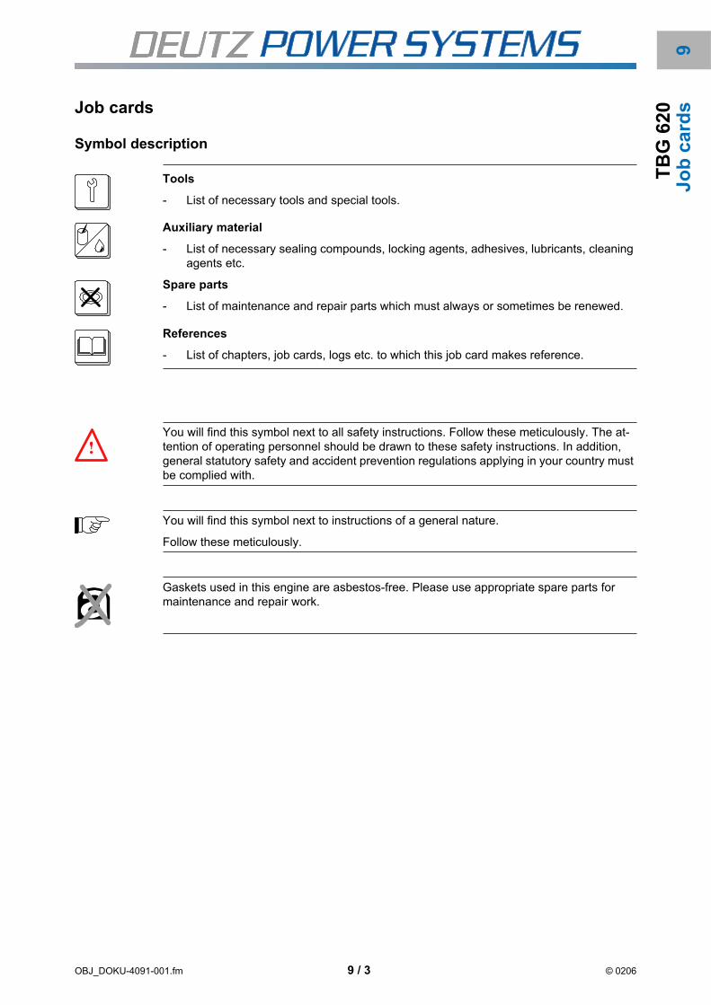
OBJ_DOKU-4091-001.fm 9 / 3 © 0206
9T
BG
62
0J
ob
ca
rdsJob cards
Symbol description
Tools
- List of necessary tools and special tools.
Auxiliary material
- List of necessary sealing compounds, locking agents, adhesives, lubricants, cleaning agents etc.
Spare parts
- List of maintenance and repair parts which must always or sometimes be renewed.
References
- List of chapters, job cards, logs etc. to which this job card makes reference.
You will find this symbol next to all safety instructions. Follow these meticulously. The at-tention of operating personnel should be drawn to these safety instructions. In addition, general statutory safety and accident prevention regulations applying in your country must be complied with.
You will find this symbol next to instructions of a general nature.
Follow these meticulously.
Gaskets used in this engine are asbestos-free. Please use appropriate spare parts for maintenance and repair work.

OBJ_DOKU-4091-001.fm 9 / 4 © 0206
Jo
b c
ard
sT
BG
62
0 Job card list
The job cards are listed in two lists on the following pages.
- According to job card title
- According to job card number

9T
BG
62
0
Auxiliary unit test by means of TEM system (TEM Evolution) B 0-1-6
Changing lube oil B 8-1-2
Checking and adjusting inlet and outlet valve clearance B 1-1-1
Checking percentage of corrosion protection agent or antifreeze in coolant B 9-1-1
Checking the crankcase pressure B 3-1-2
Checking the gas pressure of the gas regulating line B 7-20-1
Checking the speed governor linkage B 5-4-2
Cleaning the engine B 0-3-6
Drain water from and fill air bottle (starter air tank) B 10-7-1
Emptying and filling the cooling system B 9-0-4
Installing, removing and actuating engine turning gear B 4-6-1
Lube oil sampling B 8-1-1
Maintenance crankcase bleeding (Dynapure AS 200 / AS 500 model) B 3-1-9
Maintenance of crankcase vent (Racor) B 3-1-9
Overhaul pressure limiting valve of the pre-lube pump B 8-4-11
Regulations for cutting, grinding, soldering and welding work B 0-0-4
Removing and installing spark plugs, checking ignition cable B 13-5-4
Renewing crankcase bleed valve B 3-1-6
Renewing inspection hole cover gasket B 3-1-4
Renewing lube oil filter cartridge B 8-10-4
Renewing the gas filter insert B 7-21-1
Renewing the suction air intake filter B 6-3-6
Safety regulations for handling components made of elastomers containing fluoride (e.g. Viton)
B 0-0-3
Servicing the battery B 13-4-1
Visual inspection of the system B 0-1-5
OBJ_BUCH-93-001EAL.fm 9 / 5 © TBG 620

TB
G 6
20
B 0-0-3Safety regulations for handling components made of elastomers containing fluoride (e.g. Viton)
B 0-0-4 Regulations for cutting, grinding, soldering and welding work
B 0-1-5 Visual inspection of the system
B 0-1-6 Auxiliary unit test by means of TEM system (TEM Evolution)
B 0-3-6 Cleaning the engine
B 1-1-1 Checking and adjusting inlet and outlet valve clearance
B 3-1-2 Checking the crankcase pressure
B 3-1-4 Renewing inspection hole cover gasket
B 3-1-6 Renewing crankcase bleed valve
B 3-1-9 Maintenance of crankcase vent (Racor)
B 3-1-9 Maintenance crankcase bleeding (Dynapure AS 200 / AS 500 model)
B 4-6-1 Installing, removing and actuating engine turning gear
B 5-4-2 Checking the speed governor linkage
B 6-3-6 Renewing the suction air intake filter
B 7-20-1 Checking the gas pressure of the gas regulating line
B 7-21-1 Renewing the gas filter insert
B 8-1-1 Lube oil sampling
B 8-1-2 Changing lube oil
B 8-4-11 Overhaul pressure limiting valve of the pre-lube pump
B 8-10-4 Renewing lube oil filter cartridge
B 9-0-4 Emptying and filling the cooling system
B 9-1-1 Checking percentage of corrosion protection agent or antifreeze in coolant
B 10-7-1 Drain water from and fill air bottle (starter air tank)
B 13-4-1 Servicing the battery
B 13-5-4 Removing and installing spark plugs, checking ignition cable
OBJ_BUCH-93-001EAL.fm 9 / 6 © TBG 620

TB
G 6
20
OBJ_DOKU-4092-001.fm 1 © 0206
B 0
-0-3Safety regulations for handling components made of elastomers con-
taining fluoride (e.g. Viton)
General information
Gaskets, round sealing rings and moulded parts are manufactured partly from elastomerscontaining fluoride (FPM) to withstand high thermal stress.
At unscheduled temperatures above 315°C (caused for example by an engine fire) the ma-terial decomposes and forms caustic acids. The residue is tacky and black in appearance.
Proceed as follows if high temperatures have caused damage to gaskets or round sealingrings.
Check all gaskets which have suffered from the heat visually.
Wear gloves (neoprene).
Remove and dispose of residual material
- see chapter 1, Disposal regulations
Destroy clothing which has been contaminated by residue of the gaskets.
References
- Chapter 1, Rules for disposal
Touching the residue material with your hands, even after cooling down, may be
damaging to health.

TB
G 6
20
OBJ_DOKU-4092-001.fm 2 © 0206
B 0
-0-3

TB
G 6
20
OBJ_DOKU-4093-001.fm 1 © 0206
B 0
-0-4Regulations for cutting, grinding, soldering and welding work
General information
The contractor of cutting, grinding, soldering and welding work must alert the persons en-listed to do the work to the dangers and ensure that the points listed below are observedand complied with.
Persons entrusted with cutting, grinding, soldering and welding work must be familiar withand observe the valid regulations and specifications, especially the rules for accident pre-vention of the respective national legislations.
The following points must be observed additionally to the specified regulations and specifi-cations.
Electrics / electronics
Disconnect the battery ground and remove and stow away the battery safely if neces-sary.
Pull out the cable set plugs of electrical and electronic components (e.g. TEM switchcabinet, MKS junction box, EMR2-control unit, ignition system, sensors).
Remove electrical and electronic components in the immediate vicinity of the workingarea.
Always connect the ground terminal of the welding gear in the immediate vicinity of thewelding point to avoid vagrant currents. Make sure there is a perfect ground connec-tion, remove varnish in the area of the ground terminal if necessary.
Sparks / danger of fire
Keep all inflammable materials away from the danger area.
Inflammable objects (e.g. cables, compensators) must be covered with non-conduc-tive, non-flammable material or must be removed.
Sensitive surfaces (e.g. air filter) must be covered with non-conductive and non-flam-mable material.
Openings on the engine must be sealed or covered.
Seal off and cover openings to other work areas.
Keep a sufficient number of fire extinguishers close by.
Danger of explosion
Work which could lead to a strong development of heat on gas or fuel pipes and ves-sels may only be carried out when these have been completely emptied and bled or
References
- Accident prevention regulations
The following points apply for work where electrical and electronic components may be at risk due to heat or electrical short circuiting.
Failure to do so can lead to serious damage to the engine electronics.

TB
G 6
20
OBJ_DOKU-4093-001.fm 2 © 0206
B 0
-0-4
flushed.
Shut off gas pipes and fuel pipes.
Health hazard
Air well, suck off fumes and dust particles.
Cordon off the working area during arc welding to protect bystanders against the harm-ful effects of optical radiation.

TB
G 6
20
OBJ_DOKU-4094-001.fm 1 © 0206
B 0
-1-5Visual inspection of the system
General information
The read operating values and liquid levels must be logged with the TEM system.
Daily check
Engine Monitoring System
Check the display data and control lamps on the switching system.
- See the operating manual of the engine monitoring system.
The operating values should be taken from the engine monitoring system and com-pared with the values in the commissioning log.
- If values are out of tolerance, find the cause and eliminate it immediately.
Engine
Check the engine for smooth running and noise.
- If the engine is not running smoothly or abnormal noise can be heard, the causesmust be found and eliminated immediately.
Lube oil circuit
Check the lube oil circuit and all connected components for leaks.
- If leaks are detected, find and eliminate the cause immediately.
Coolant circuits
Check the coolant circuit and all connected components for leaks.
- If leaks are detected, find and eliminate the cause immediately.
Suction air intake system
Check the maintenance indicator of the suction intake air filter.
Tools
- Commercially available tools
References
- B 5-4-2 Checking the speed governor linkage
- B 6-3-6 Renewing the suction air intake filter
- B 7-20-1 Checking the gas pressure of the gas regulating line
- B 7-21-1 Renewing the gas filter insert
- B 13-4-1 Servicing the battery
Danger of burns !
When working on the hot engine.

TB
G 6
20
OBJ_DOKU-4094-001.fm 2 © 0206
B 0
-1-5
- Renew the suction intake air filter if necessary - see job card B 6-3-6.
Gas system
Check the gas pressure of the gas control line - see job card B 7-20-1.
- Renew the gas filter insert if necessary - see job card B 7-21-1.
Check the gas system and all connected components for leaks.
- If leaks are detected, find and eliminate the cause immediately.
Compressed air system
if available - drain water from the air bottle, see job card B 10-7-1.
Check the compressed air system and all connected components for leaks.
- If leaks are detected, find and eliminate the cause immediately.
Starter system
if available - check battery - see job card B 13-4-1.
Check the electrical component and connectors for corrosion and tight fit.
Speed governor
Check the easy action of the speed governor, see job card B 5-4-2.
Exhaust gas system
Check the exhaust gas system and all connected components for firm fit and leaks.
- Defects which are detected must be eliminated immediately.
If the engine is out of operation, the following additional tests can be made.

TB
G 6
20
OBJ_DOKU-4095-001.fm 1 © 0206
B 0
-1-6Auxiliary unit test by means of TEM system (TEM Evolution)
General information
The test mode serves for examining the reaction of the aggregate and individual auxiliaryaggregates to the commands from the control. It is only possible when the engine is at astandstill and the quick stop is not actuated.
An engine start is not possible in test mode.
The number of auxiliary aggregates offered for testing depends on the engine type and theequipment of the system. Therefore only auxiliary aggregates are offered for testing whichhave had their parameters released.
If the test result is okay, this is displayed by a green checkmark. If errors occur in the aux-iliary aggregate tests (displayed by a red cross) or there is a deviation from the specifiedvalues, please contact the DEUTZ Service.
Individual auxiliary aggregates (e.g. starter) can only be activ ated in touch mode for safetyreasons. The auxiliary aggregates only remain switched on for as long as the key ispressed, switching on and off is not possible.
The job can can be used as a copy form.
Conducting the tests
A 1 Mask ”Auxiliary unit control 1”
References
- Operating Manual TEM System
Different test steps of the steps listed below may not be programmed depending on the en-gine variant and equipment.

TB
G 6
20
OBJ_DOKU-4095-001.fm 2 © 0206
B 0
-1-6 Release auxiliary unit test mode
Ignition
Switch on manual mode
»Measured values and operation« (F1 switch off Auto mode)
Switch on test mode in the mask ”Auxiliary aggregates 1” (F9).
F8 switch auxiliary unit on and off
F10 auxiliary unit touch mode: The auxiliary unit is only switched on for as long as the button is pressed.
Test mode ok nok
Switch on ignition (F8)
The ignition runs a self-test and reports the result after 10 seconds
Switch off ignition (F8)
red flash
Ignition is not OK
- Check wiring
- Check supply to ignition
- Check ignition communication
- Repeat test
green tick
Ignition OK
Ignition ok nok

TB
G 6
20
OBJ_DOKU-4095-001.fm 3 © 0206
B 0
-1-6Speed governor
Pre-lubrication pump engine
Switch on speed governor (F8)
The speed governor runs a calibration sequence. To do this it runs from 0 % auf 100 % and back.
The double valve position is indicated in Volts.
Switch off speed governor (F8)
Go to the »Speed governor« mask.
Before the final speed governor test: Check the calibration voltage for 0 % and for 100 % (0 % approx. 1.7 V and 100 % approx. 2.9 V)
Switch on speed governor test mode (F10)
Set nominal position and check on the actuator (20 %, 50 %, 75 % and 100 %)
Switch off speed governor test mode (F10)
Return to the »Auxiliary units 1« mask
Note [V20]
Both actuators are calibrated simultaneously in TBG 620 V20.
Speed governor ok nok
Switch on pre-lubrication pump (F8)
[TBG 620, TBG 616] pre-lubricate for 20 min
[TBG 632] pre-lubricate for 3 min
Check the direction of rotation,
Check oil pressure (1 ... 3 bar)
Leave pre-lubrication pumps switched on
Note [632]
switch off after 3 min in TBG 632
Pre-lubrication pump engine ok nok

TB
G 6
20
OBJ_DOKU-4095-001.fm 4 © 0206
B 0
-1-6 Pre-lubrication pump generator
Starter
The pre-lubrication pump is switched on and off with the menu item »Compartment ventila-tor colder« Feedback also takes place via this menu item.
Switch on pre-lubrication pump (F8)
Check the direction of rotation.
Check oil pressure.
X = Holding pressure Y = Lifting pressure
1 = Pressure set-up for engine start 2 = Start release (approx. 110-120 bar)
3 = Operating pressure (approx. 50-60 bar) 4 = Pressure drop at engine stop
Leave pre-lubrication pump switched on
Pre-lubrication pump generator ok nok
Note prior to starter test:
- Ignition switched off
- Pre-lube pump switched on
Switch on starter briefly (F10)
Check function, speed and oil pressure
In engines with compressed air starter
Set the pre-pressure start air and throttle the starter before actuating it.
Starter ok nok
p
t
© 84540-0
2 3 41
y
x

TB
G 6
20
OBJ_DOKU-4095-001.fm 5 © 0206
B 0
-1-6Pre-heater
Pump engine cooling circuit
Mixture cooling circuit pump
Switch on pre-heater (F8)
Check function
Switch off pre-heater (F8)
There is no feedback in the »Auxiliary units 1« mask.
Bleed the pre-heater first and open all valves
Pre-heater ok nok
Switch on the engine cooling circuit pump (F8)
Check the direction of rotation.
Observe the differential pressure monitor and set if necessary
Check the differential pressure - wait at least 30 seconds
Switch off the engine cooling circuit pump (F8)
red flash (in front of »∆p« symbol)
no differential pressure available
green tick (in front of »∆p« symbol)
differential pressure present
Differential pressure engine cooling circuit ok nok
Switch on the mixture cooling circuit pump (F8)
Check the direction of rotation.
Observe the differential pressure monitor and set if necessary
Check the differential pressure - wait at least 30 seconds
Switch off the mixture cooling circuit pump (F8)
[MCP]
Pump table cooler fan running
red flash (in front of »∆p« symbol)
no differential pressure present
green tick (in front of »∆p« symbol)
differential pressure present
Differential pressure mixture cooling circuit ok nok

TB
G 6
20
OBJ_DOKU-4095-001.fm 6 © 0206
B 0
-1-6 [HC] heating circuit pump
[EC] Emergency cooling circuit pump
Switch on the heating circuit pump (F8)
Check the direction of rotation.
Observe the differential pressure monitor and set if necessary
Check the differential pressure - wait at least 30 seconds
Switch off the heating circuit pump (F8)
red flash (in front of »∆p« symbol)
no differential pressure present
green tick (in front of »∆p« symbol)
differential pressure present
Differential pressure heating circuit ok nok
Switch on the emergency cooling circuit pump (F8)
Check the direction of rotation.
Observe the differential pressure monitor and set if necessary
Check the differential pressure - wait at least 30 seconds
Switch off the emergency cooling circuit (F8)
[ECS]
Pump table cooler fan running
red flash (in front of »∆p« symbol)
no differential pressure present
green tick (in front of »∆p« symbol)
differential pressure present
Differential pressure emergency cooling circuit ok nok
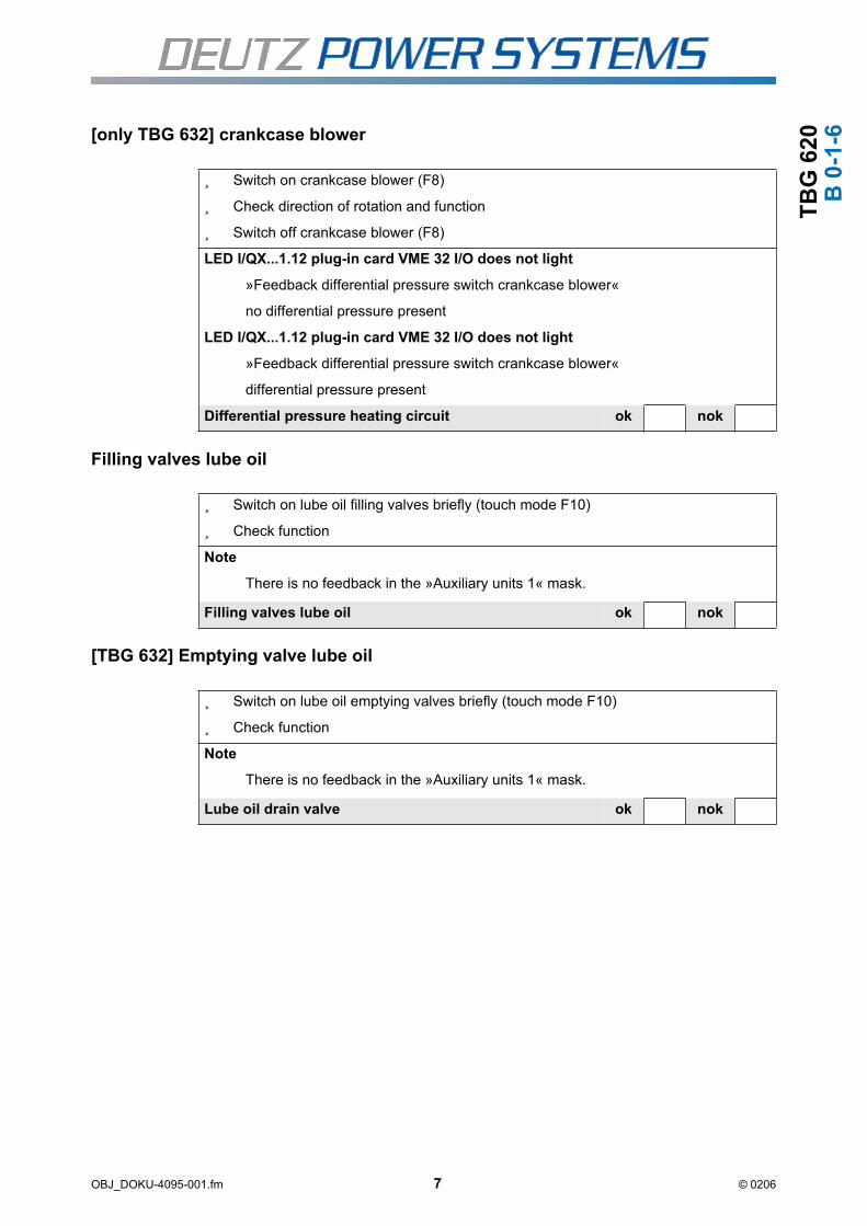
TB
G 6
20
OBJ_DOKU-4095-001.fm 7 © 0206
B 0
-1-6[only TBG 632] crankcase blower
Filling valves lube oil
[TBG 632] Emptying valve lube oil
Switch on crankcase blower (F8)
Check direction of rotation and function
Switch off crankcase blower (F8)
LED I/QX...1.12 plug-in card VME 32 I/O does not light
»Feedback differential pressure switch crankcase blower«
no differential pressure present
LED I/QX...1.12 plug-in card VME 32 I/O does not light
»Feedback differential pressure switch crankcase blower«
differential pressure present
Differential pressure heating circuit ok nok
Switch on lube oil filling valves briefly (touch mode F10)
Check function
Note
There is no feedback in the »Auxiliary units 1« mask.
Filling valves lube oil ok nok
Switch on lube oil emptying valves briefly (touch mode F10)
Check function
Note
There is no feedback in the »Auxiliary units 1« mask.
Lube oil drain valve ok nok
TB
G 6
20
OBJ_DOKU-4095-001.fm 8 © 0206
B 0
-1-6 Gas mixer (A)
Gas mixer (B)
Switch on the rich setting (F8)
If the gas mixer is at the lean stop (indicated by a blue minus sign) the lean stop must disappear after about 50 steps, the number of steps must increase to maxi-mum 3240. Watch the gas mixer to make sure it really does adopt the rich setting
Switch on the rich setting (F8)
Switch on the lean setting (F8)
The number of steps must be reduced until the lean stop is reached (check stop). Watch the gas mixer whether it sets in lean direction.
Switch off the lean setting (F8)
Go to start position (F8)
The gas mixer moves until it has reached the 0 steps position
Repeat the rich and lean settings
Check the number of steps
The same number of steps must be set every time
Go to stop position (F8)
The gas mixer must adjust in lean direction until it has reached the lean stop (F8).
Go to start position (F8)
The stepper motor card then calibrates the momentary position to minus start po-sition and then moves the parameterised number of steps to the start position.
Note
The »rich« stop is marked by a blue (+) symbol
The »lean« stop is marked by a blue (−) symbol
»Intermediate position« is marked by a blue (↔) symbol
Gas mixer (A) ok nok
Gas mixer B is tested in the same way as gas mixer A.
Gas mixer (B) ok nok

TB
G 6
20
OBJ_DOKU-4095-001.fm 9 © 0206
B 0
-1-6[DK] Gas tightness check (A)
Gas valve 1 (A1) and 2 (A2)
[ZG] [DK] Gas tightness check (B)
Switch on gas tightness check (A) (F8)
Check function
Switch off gas tightness check (A) (F8)
green tick (after »Status«) in less than 2 seconds
Tightness check not successful
red flash (in front of »∆p« symbol)
Tightness check not successful
green tick (after »Status«) after 30 seconds
Tightness check successful
Tightness check ok nok
Switch gas valve 1 (A1) on and off (F10)
Check function
Switch gas valve 2 (A2) on and off (F10)
Check function
Gas valve 1 (A1) and 2 (A2) ok nok
Switch on gas tightness check (B) (F8)
Check function
Switch off gas tightness check (B) (F8)
green tick (after »Status«) in less than 2 seconds
Tightness check not successful
red flash (in front of »∆p« symbol)
Tightness check not successful
green tick (after »Status«) after 30 seconds
Tightness check successful
Gas leak inspection ok nok

TB
G 6
20
OBJ_DOKU-4095-001.fm 10 © 0206
B 0
-1-6 Gas valve 1 (B1) and 2 (B2)
[ZG] Gas pressure regulator B
Switch gas valve 1 (B1) on and off (F10)
Check function
Switch gas valve 2 (B2) on and off (F10)
Check function
Gas valve 1 (B1) and 2 (B2) ok nok
Switch on increase gas pressure B (F8).
If the gas pressure regulator is at minus stop (displayed by a blue minus sign), the minus stop must disappear after about 50 steps. The gas pressure regulator then increases the gas pressure until it reaches the plus stop (indicated by a blue plus sign). Watch the gas pressure regulator to make sure it really does set to "higher pressure"
Switch off increase gas pressure B and switch on reduce gas pressure B
The number of steps must be reduced until the minus stop is reached (check stop). Watch the gas pressure regulator whether it sets in minus direction.
Switch off reduce gas pressure B and start position gas pressure regulator. Switch on B.
The gas pressure regulator B moves until it has reached the 0 steps position
Switch on stop position gas pressure regulator B.
The stepper motor card then calibrates the momentary position to minus start po-sition and then moves the parameterised number of steps to the start position.
Note
The »minus« stop is marked by a blue (+) symbol
The »plus« stop is marked by a blue (−) symbol
»Intermediate position« is marked by a blue (↔) symbol
Gas pressure regulator B ok nok
Test regulating valves
The positioning time of the drive should be within the following limits
DN 32 to 80 = 30 to 60 s
DN ≥ 100 = 40 to 80 s
If the valve runtime deviates too greatly, the regulation may become unstable.

TB
G 6
20
OBJ_DOKU-4095-001.fm 11 © 0206
B 0
-1-6Engine cooling water valve
Mixture cooler valve
Switch on the »warmer« setting (F8)
Check the setting direction, stop »warm« (−) must be displayed.
Switch off the »warmer« setting (F8)
Switch on the »colder« setting (F8)
Check the setting direction, stop »cold« (+) must be displayed.
Switch on the »colder« setting (F8)
Note
After both stops have been moved to, the current valve position in % is displayed
Note
The »warm« stop is marked by a blue (+) symbol
The »cold« stop is marked by a blue (−) symbol
»Intermediate position« is marked by a blue (↔) symbol
Engine jacket water valve ok nok
Switch on the »warmer« setting (F8)
Check the setting direction, stop »warm« (−) must be displayed.
Switch off the »warmer« setting (F8)
Switch on the »colder« setting (F8)
Check the setting direction, stop »cold« (+) must be displayed.
Switch on the »colder« setting (F8)
Note
After both stops have been moved to, the current valve position in % is displayed
Note
The »warm« stop is marked by a blue (+) symbol
The »cold« stop is marked by a blue (−) symbol
»Intermediate position« is marked by a blue (↔) symbol
Mixture cooler valve ok nok

TB
G 6
20
OBJ_DOKU-4095-001.fm 12 © 0206
B 0
-1-6 [HC] Heating water
[EC] Emergency cooler
Switch on the »warmer« setting (F8)
Check the setting direction, stop »warm« (−) must be displayed.
Switch off the »warmer« setting (F8)
Switch on the »colder« setting (F8)
Check the setting direction, stop »cold« (+) must be displayed.
Switch on the »colder« setting (F8)
Note
After both stops have been moved to, the current valve position in % is displayed
Note
The »warm« stop is marked by a blue (+) symbol
The »cold« stop is marked by a blue (−) symbol
»Intermediate position« is marked by a blue (↔) symbol
[HC] Heating water ok nok
Switch on the »warmer« setting (F8)
Check the setting direction, stop »warm« (−) must be displayed.
Switch off the »warmer« setting (F8)
Switch on the »colder« setting (F8)
Check the setting direction, stop »cold« (+) must be displayed.
Switch on the »colder« setting (F8)
Note
After both stops have been moved to, the current valve position in % is displayed
Note
The »warm« stop is marked by a blue (+) symbol
The »cold« stop is marked by a blue (−) symbol
»Intermediate position« is marked by a blue (↔) symbol
[EC] Emergency cooler ok nok

TB
G 6
20
OBJ_DOKU-4095-001.fm 13 © 0206
B 0
-1-6[BY] Exhaust bypass valve
[only TBG 632] Charging pressure regulating valve [waste gate]
Compressor bypass
[TBG 632 and KTB] Filling jacket water day tank
Switch on open exhaust bypass valve (F8)
Check setting direction
Switch on open exhaust bypass valve (F8)
The stop must be fed back
Note
The stop is marked by a blue (−) symbol
Exhaust gas bypass valve ok nok
Switch on open charging pressure regulating valve (F8)
Check setting direction
Switch off open charging pressure regulating valve (F8)
The stop must be fed back
Note
The stop is marked by a blue (−) symbol
Charging pressure control valve. ok nok
Switch on open compressor bypass valve (F8)
Check setting direction
Switch off open compressor bypass valve (F8)
The stop must be fed back
Note
The stop is marked by a blue (−) symbol
Compressor bypass ok nok
Switch on filling jacket water day tank (F8)
Check whether the solenoid valve opens and closes.
Switch off filling jacket water day tank (F8)
Filling jacket water day tank ok nok

TB
G 6
20
OBJ_DOKU-4095-001.fm 14 © 0206
B 0
-1-6 [TBG 632 and KTB] Leak test jacket water day tank
[AKR] Anti-knocking governor
Reset emergency off module
Switch on leak test jacket water day tank (F8)
red flash
Leak test unsuccessful - find error.
green tick
Leak test successful
Leak test jacket water day tank ok nok
Switch on anti-knocking governor (F8)
Wait 30 seconds
Switch off anti-knocking governor (F8)
green tick disappears (after 30 seconds)
Anti-knocking governor is not OK
green tick after 30 seconds
Anti-knocking tick is OK
Filling jacket water day tank ok nok
Go to the "Auxiliary units 2" (F6) mask for the following tests
Switch on reset emergency off module (F10)
green LED relay -K136 lights up briefly
»Safety chain« flashes (title bar mask) - emergency off module not reset - trouble-shooting
»Safety chain« is not displayed (title bar mask)
Emergency off module reset
Emergency off module ok nok

TB
G 6
20
OBJ_DOKU-4095-001.fm 15 © 0206
B 0
-1-6Bypass differential pressure monitor
Request circuit breaker
[RL] Switch on compartment ventilator flaps
[RL] Compartment ventilation graduated switching
Switch on bypass differential pressure monitor (F8)
Check function
Switch off bypass differential pressure monitor (F8)
after 30 seconds (green tick in front)
Bypass differential pressure monitor not successful
green tick
Bypass differential pressure monitor successful
Bypass differential pressure monitor ok nok
Switch on request circuit breaker (F8)
Check whether the request is available at the synchronising unit
Switch off request circuit breaker (F8)
Note
The request is only output by the TEM-Evo system if the safety chain is not faulty.
Request circuit breaker ok nok
Switch on compartment ventilator flaps (F8)
Check whether the compartment ventilator flaps open
Switch off compartment ventilator flaps (F8)
compartment ventilator flaps ok nok
Switch on compartment ventilation step 1, 2 (F8)
Check whether the compartment ventilation switches to the selected step
Switch off compartment ventilation step 1, 2 (F8)
Compartment ventilation step 1, 2 ok nok

TB
G 6
20
OBJ_DOKU-4095-001.fm 16 © 0206
B 0
-1-6 [RL] Compartment ventilation frequency controlled
[GKS] Mixture table cooler graduated switching
[GKS] Mixture table cooler frequency controlled
[ECS] Emergency table cooler graduated switching
Switch on the compartment ventilation »warmer« (F8)
Check function
Switch off the compartment ventilation »warmer« (F8)
Switch on the room ventilation »colder« (F8)
Check function
Switch off the room ventilation »colder« (F8)
Room ventilation warmer and colder ok nok
Switch on mixture table cooler step 2, 3 and 4 (F8)
Check whether the fans on the table cooler switch to the selected step
Switch off mixture table cooler step 2, 3 and 4 (F8)
Mixture table cooler step 2, 3 and 4 ok nok
Switch on the mixture table cooler »warmer« (F8)
Check function
Switch off the mixture table cooler »warmer« (F8)
Switch on the mixture table cooler »colder« (F8)
Check function
Switch off the mixture table cooler »colder« (F8)
Mixture table cooler frequency controlled ok nok
Switch on emergency table cooler step 2, 3 and 4 (F8)
Check whether the fans on the table cooler switch to the respective selected step
Switch off emergency table cooler step 2, 3 and 4 (F8)
Emergency table cooler graduated switching ok nok

TB
G 6
20
OBJ_DOKU-4095-001.fm 17 © 0206
B 0
-1-6[ECS] Emergency table cooler frequency controlled
[AVW] Suction intake air pre-heating
[GKNK] Pump mixture emergency cooling circuit
Switch on the emergency table cooler »warmer« (F8)
Check function
Switch off the emergency table cooler »warmer« (F8)
Switch on the emergency table cooler »colder« (F8)
Check function
Switch off the emergency table cooler »colder« (F8)
Emergency table cooler frequency controlled ok nok
Switch on the suction intake air pre-heating »warmer« (F8)
Check function
Switch off the suction intake air pre-heating »warmer« (F8)
Note
The actuating valve for the flow must be set in »open« direction.
Switch on the suction intake air pre-heating »colder« (F8)
Check function
Switch off the suction intake air pre-heating »colder« (F8)
Note
The actuating valve for the flow must be set in »closed« direction.
Note
The »warm« stop is marked by a blue (+) symbol
The »cold« stop is marked by a blue (−) symbol
»Intermediate position« is marked by a blue (↔) symbol
Suction intake air pre-heating ok nok
Switch on the mixture emergency cooling circuit pump (F8)
Check function
Switch off the mixture emergency cooling circuit pump (F8)
Mixture emergency cooling circuit ok nok

TB
G 6
20
OBJ_DOKU-4095-001.fm 18 © 0206
B 0
-1-6 [GKNK frequency controlled] Mixture emergency cooler
Switch on the mixture emergency cooler »warmer« (F8)
Check function
Switch off the mixture emergency cooler »warmer« (F8)
Switch on the mixture emergency cooler »colder« (F8)
Check function
Switch off the mixture emergency cooler »colder« (F8)
Mixture emergency cooler ok nok

TB
G 6
20
OBJ_DOKU-4096-001.fm 1 © 0206
B 0
-3-6Cleaning the engine
General information
Preparation
Switch off the engine and wait for it to cool down.
Select cleaning agents: see chapter 4, Auxiliary materials.
Disconnect the battery.
Remove protective covers.
Remove heat shields from the exhaust pipes.
Seal engine openings (e.g. air inlet) or fit water-tight covers.
Cover electrical and electronic components (e.g. three-phase current generators, start-ers) so that they are water-tight.
Auxiliary material
- Cleaning agent
- Drain plugs, covers
- Compressed air
References
- Chapter 4, Aids
Danger of injury !
Only work with the engine at a standstill.
Secure the engine against starting.
Danger of intoxication !
Provided adequate ventilation !
Suck off fumes, do not inhale !
Risk of injury!
Wear protective glasses and gloves!
If the engine is partially dismantled, housing openings must be sealed or fitted with water-tight covers.

TB
G 6
20
OBJ_DOKU-4096-001.fm 2 © 0206
B 0
-3-6 Cleaning
Spray engine with cleaning agent.
- Observe exposure time according to manufacturer instructions.
Spray or wash down engine with a powerful water jet.
Finishing work
Blow out accumulated water with compressed air.
Remove covers from electrical and electronic components.
Remove covers and seals from engine openings.
Dry and install the exhaust pipe heat shields.
Dry and install the protective covers.
Connect the battery.
High pressure cleaning systems may not be used:
- Sensitive components (e.g. filters, sensors, rubber bushes, sealing rings, cables) could be damaged.
- Joints and bearings coated with lubricant or grease filled.
Repeat if the engine is still not clean enough.
Removed protective covers and heat protection panels must be cleaned separately.
Protective covers and heat protection panels must be dried before replacing. Other-
wise there is a danger of fire due to formation of gas or deflagration inside the hous-
ing covers and panels.

TB
G 6
20
B 1
-1-1
Checking and adjusting inlet and outlet valve clearanceTechnical data
Tools
- Commercially available tools
- Feeler gauge
- Spark-plug wrench
- Torque wrench
Spare parts
- Sealing rings
- poss. shaped gasket for cylinder head cover
References
- B 4-6-1 Installing, removing and actuating engine turning gear
Test and setting values
Valve clearance compensation Valve shaft / valve bridge 0.05 mm
Valve clearance Gas group 1 - 50Hz Inlet 0.3 mm
Outlet 0.7 mm
Gas group 2 - 50Hz Inlet 0.3 mm
Outlet 0.9 mm
Gas group 1 - 60Hz Inlet 0.3 mm
Outlet 0.9 mm
Gas group 2 - 60Hz Inlet 0.3 mm
Outlet 1.1 mm
Tightening specifications
Valve bridge lock nut M10x1 40 Nm
Lock nut on rocker arm M12x1.5 45 Nm
Cylinder head hood on cylinder head M8x55 / 85 25 Nm
OBJ_DOKU-3919-001.fm 1 © 0206

TB
G 6
20
B 1
-1-1
General informationInlet and outlet valves will only form a seal when closed if the specified clearance is avail-able in the valve drive between the camshaft and the valve shaft.
If the valve clearance is too small the valves are only closed briefly or not at all.
This results in a drop in performance for to the subsequent compression loss.
The valve seat and valve head may burn due to overheating. There is also a danger of anengine fire to to flashover in the exhaust or suction intake channel.
If the valve clearance is too great, the valves open later and close earlier.
Because the valves are only fully open briefly, the filling level of the engine drops. Drop inperformance is the result.
This also causes considerable wear in the valve control.
Exact setting and observation of the valve clearance prolongs the life and increases the op-erational reliability of the engine.
A large valve clearance determined in the test is due to wear in the valve drive.
Depending on the difference between the actual value and the reference value, the valveclearance curve of the respective cylinder must be monitored and the cause investigatedimmediately.
The actual values must be noted in the “Valve clearance actual values table“. A copy of thetable is enclosed.
Test and setting sequence.
For the valve setting the inlet and outlet valve of the cylinder to be set must be completelyclosed, i.e. the valve drive must be on the base circle of the cam. This is guaranteed whenthe cylinder firing 360° KW before the cylinder to be set is in valve overlap, i.e. the outletvalve closes whilst the inlet valve opens.
The setting is made according to the order of ignition, starting with cylinder A1. In the figurebelow the ignition order, ignition spacings in degrees of crankshaft and the overlap cylinderassigned to every firing cylinder are specified. To determine the right position of the cylinderto be set the assigned overlap cylinder is observed during slow turning. It must be turneduntil the valves are just overlapping. The whole overlap range of the overlap cylinder is suit-able for the valve setting of the firing cylinder.
The whole valve setting can be made with 2 revolutions of the crankshaft (Step 1 and Step2).
In the schematic engine figure below the position of the firing cylinders and the overlappingcylinders for the first and second crankshaft revolution are shown. The figure only showsthe position, the order is determined by the firing order.
OBJ_DOKU-3919-001.fm 2 © 0206

TB
G 6
20
B 1
-1-1
T 1 Test and setting sequence V12.
12 cylinder engine
Firing angle offset
Ignition TDC A1 B2 A5 B4 A3 B1 A6 B5 A2 B3 A4 B6
Overlap A6 B5 A2 B3 A4 B6 A1 B2 A5 B4 A3 B1
OBJ_DOKU-3919-001.fm 3 © 0206

TB
G 6
20
B 1
-1-1
T 2 Test and setting sequence V16
16 cylinder engine
Firing angle offset
Ignition TDC A1 B2 A6 B5 A8 B7 A3 A7 B6 A4 B8 A2 B3 A5 B1 B4
Overlap B6 A4 B8 A2 B3 A5 B1 B4 A1 B2 A6 B5 A8 B7 A3 A7
OBJ_DOKU-3919-001.fm 4 © 0206

TB
G 6
20
B 1
-1-1
T 3 Test and setting order V20
20 cylinder engine
Firing angle offset
Ig. TDC A1 B7 A2 B5 A4 B3 A6 B1 A8 B2 A10 B4 A9 B6 A7 B8 A5 B10 A3 B9
Overl. A10 B4 A9 B6 A7 B8 A5 B10 A3 B9 A1 B7 A2 B5 A4 B3 A6 B1 A8 B2
Step 1
Step 2
A2 A3 A4 A5 A6A1
B1 B2 B3 B4 B5 B6
A7 A8
B7 B8
A9 A10
B9 B10
A2 A3 A4 A5 A6A1
B1 B2 B3 B4 B5 B6
A7 A8
B7 B8
A9 A10
B9 B10
© 8
45
86
-0
OBJ_DOKU-3919-001.fm 5 © 0206

TB
G 6
20
B 1
-1-1
Remove cylinder head cover.
- Pull off the spark plug connector.
- Unscrew screws and remove the cylinder head cover with gasket.
Install engine turning device, see job card B 4-6-1.
Turn the engine in direction of rotation until cylinder A1 is in the ignition TDC range.
Checking clearance compensation
A 1 Checking clearance compensation
Push feeler gauges between the valve shaft and the valve bridge (arrows).
Press the toggle lever onto the valve bridge with your finger.
- The feeler gauges must be removable with little resistance. The valve clearancecompensation must be set if not.
Only check and set the valve clearance compensation and valve clearance when the en-gine is cold.
Follow the correct test and setting sequence.
OBJ_DOKU-3919-001.fm 6 © 0206
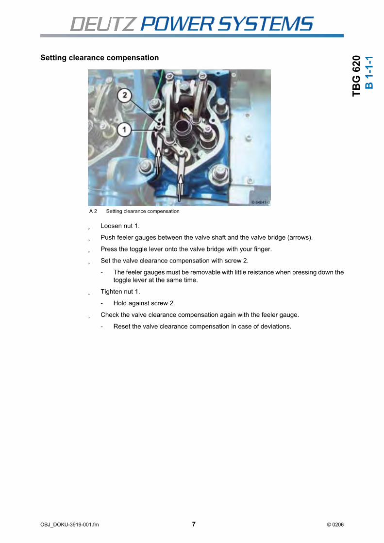
TB
G 6
20
B 1
-1-1
Setting clearance compensationA 2 Setting clearance compensation
Loosen nut 1.
Push feeler gauges between the valve shaft and the valve bridge (arrows).
Press the toggle lever onto the valve bridge with your finger.
Set the valve clearance compensation with screw 2.
- The feeler gauges must be removable with little reistance when pressing down thetoggle lever at the same time.
Tighten nut 1.
- Hold against screw 2.
Check the valve clearance compensation again with the feeler gauge.
- Reset the valve clearance compensation in case of deviations.
OBJ_DOKU-3919-001.fm 7 © 0206

TB
G 6
20
B 1
-1-1
Checking valve clearanceA 3 Checking valve clearance
Push feeler gauge between the valve bridge and the toggle lever (arrow).
- The feeler gauge must be insertable and removable with little resistance. Thevalve clearance must be set if not.
Setting valve clearance
A 4 Valve clearance
Loosen nut 1.
Push feeler gauge between the valve bridge and the toggle lever (arrow).
Set the valve clearance with screw 2.
- The feeler gauge must be insertable and removable with little resistance.
Tighten nut 1.
- Hold against screw 2.
Check the valve clearance again with the feeler gauge.
OBJ_DOKU-3919-001.fm 8 © 0206

TB
G 6
20
B 1
-1-1
- Reset the valve clearance in case of deviations.
Turn the engine in rotation direction until the next cylinder is in overlap.
Repeat the test and setting procedure until the valve clearance is set on all cylinders.
Remove engine turning device, see job card B 4-6-1.
Attach cylinder head cover.
- Check the gasket of the cylinder head hood and renew if necessary.
- Fit the cylinder head covers with gasket and tighten the screws.
- Plug spark plug connector.
OBJ_DOKU-3919-001.fm 9 © 0206

TB
G 6
20
B 1
-1-1
Valve clearance actual values tableThe total adjustment time can be determined by the actual value data.
This can enable predictions to be made about the previous wear in the valve drive.
T 4 Table of actual valve clearance values (over all series)
A1
0 Ou
t
B1
0 Ou
t
A1
0 Ou
t
B1
0 Ou
t
A1
0 Ou
t
B1
0 Ou
t
In
In In
In In
In
A9
Ou
t
B9 O
ut
A9 O
ut
B9 O
ut
A9 O
ut
B9 O
ut
In
In In
In In
In
A8
Ou
t
B8 O
ut
A8 O
ut
B8 O
ut
A8 O
ut
B8 O
ut
In
In In
In In
In
A7
Ou
t
B7 O
ut
A7 O
ut
B7 O
ut
A7 O
ut
B7 O
ut
In
In In
In In
In
A6
Ou
t
B6 O
ut
A6 O
ut
B6 O
ut
A6 O
ut
B6 O
ut
In
In In
In In
In
A5
Ou
t
B5 O
ut
A5 O
ut
B5 O
ut
A5 O
ut
B5 O
ut
In
In In
In In
In
A4
Ou
t
B4 O
ut
A4 O
ut
B4 O
ut
A4 O
ut
B4 O
ut
In
In In
In In
In
A3
Ou
t
B3 O
ut
A3 O
ut
B3 O
ut
A3 O
ut
B3 O
ut
In
In In
In In
In
A2 O
ut
B2 O
ut
A2 O
ut
B2 O
ut
A2 O
ut
B2 O
ut
OH
In In OH
In In OH
In In
A1 O
ut
B1 O
ut
A1 O
ut
B1 O
ut
A1 O
ut
B1 O
ut
In In In In In In
Date
Cy
lin
de
r
Valv
e
Cy
lin
de
r
Valv
e
Date
Cy
lin
de
r
Valv
e
Cy
lin
de
r
Valv
e
Date
Cy
lin
de
r
Valv
e
Cy
lin
de
r
Valv
e
OBJ_DOKU-3919-001.fm 10 © 0206

TB
G 6
20
OBJ_DOKU-4097-001.fm 1 © 0206
B 3
-1-2Checking the crankcase pressure
General information
The crankcase pressure is checked by the TEM system with the engine running.
It depends on the installation site and height of the engine. The appropriate value must betaken from the commissioning log.
If the specified setpoint is not reached, the crankcase bleed valve must be serviced, seejob card B 3-1-9.
References
- B 3-1-6 Renewing crankcase bleed valve
- B 3-1-9 Maintenance of crankcase vent (Racor)

TB
G 6
20
OBJ_DOKU-4097-001.fm 2 © 0206
B 3
-1-2

TB
G 6
20
B 3
-1-4
Renewing inspection hole cover gasketTechnical data
General information
Removing/installing the inspection hole cover
A 1 Inspection hole cover
Remove line 1 if necessary.
Unscrew screws 2.
Remove inspection hole cover 3 with gasket.
Clean the sealing surface.
Mount inspection hole cover 3 with gasket.
Tighten screws 2.
Tools
- Commercially available tools
- Scraper
Spare parts
- Gasket for inspection hole cover
Tightening specifications
Hatch cover on the crankcase 25 Nm
Danger of injury !
Only work with the engine at a standstill.
Secure the engine against starting.
OBJ_DOKU-3924-001.fm 1 © 0206

TB
G 6
20
B 3
-1-4
Mount line 1 if necessary.
OBJ_DOKU-3924-001.fm 2 © 0206

TB
G 6
20
B 3
-1-6
Renewing crankcase bleed valveGeneral information
The number of crankcase bleed valves installed depends on the engine.
The removal and installation example describes one crankcase bleed valve. For multiplecrankcase bleed valves proceed appropriately.
Removing crankcase bleed valve
A 1 Crankcase bleed valve
Loosen hose clips 1 and remove bleed hose 2.
Loosen tightening clamp 3.
Remove crankcase bleed valve 4 from above.
Tools
- Commercially available tools
Spare parts
- Crankcase bleed valve
References
- B 3-1-2 Checking the crankcase pressure
Danger of injury !
Only work with the engine at a standstill.
Secure the engine against starting.
OBJ_DOKU-3925-001.fm 1 © 0206

TB
G 6
20
B 3
-1-6
Installing crankcase bleed valveInsert crankcase bleed valve 4 from above.
Tighten tightening clamp 3.
Push on bleed hose 2 and tighten hose clips 1.
Note installation position of the bleed connection.
After renewing the crankcase bleed valve the crankcase pressure should be checked, see job card B-3-1-2.
OBJ_DOKU-3925-001.fm 2 © 0206

TB
G 6
20
OBJ_DOKU-4098-001.fm 1 © 0206
B 3
-1-9Maintenance of crankcase vent (Racor)
General information
The crankcase vent must be maintained when
- the maintenance intervals have been reached,
- the red indicator button is fully visible in the maintenance indicator.
Dismantling crankcase vent
A 1 Crankcase vent Racor
Open locks 2 and remove the container 4 carefully from the bottom.
- There may be lube oil in the container.
Pull filter element 5 from upper section of filter 3.
Tools
- Commercially available tools
Auxiliary material
- Diesel fuel
Spare parts
- Filter element (with O-seals)
- Base insert, if required
Cleaning the filter elements is not permissible.
Observe the regulations for disposal !
Collect operating materials and dispose of properly according to national regula-
tions.

TB
G 6
20
OBJ_DOKU-4098-001.fm 2 © 0206
B 3
-1-9
Remove base insert 6 from the container 4.
Clean components with diesel fuel, check and renew if necessary.
Assembling crankcase vent
A 2 Filter (cross-sectional diagram)
If present, check oil outlet and non-return valve for free passage.
Check the diaphragm of the non-return valve for damage.
Check all parts of the crankcase vent (e.g. hoses, rubber parts of the connecting anddischarge lines) visually, renew if necessary.
Insert new O-seal 7 in upper section of filter 3.
Insert new filter element 5 with new O-seal 8 in filter top section 3.
Install base insert 6 in container 4.
Wet the new filter element with lube oil.
Position container 4 and close locks 2.
If a base insert is not fitted, this must be retrofitted.
Note installation position.

TB
G 6
20
OBJ_DOKU-4098-001.fm 3 © 0206
B 3
-1-9Check drain hose
A 3 Crankcase vent Racor
Check the condition and laying of the flexible drain hose 9 and correct if necessary.
Resetting the maintenance indicator
Unscrew cap of maintenance indicator 1.
Push in the red indicator button.
Mount and tighten cap.
Instructions for putting (returning) the system into operation
The drain hose must be laid without tension and free from chafing.
Make sure it is far enough away from hot parts.
Depending on the design, back absorption through the oil drainage pipe can be prevented by a return valve, a siphon trap or an oil outlet pipe that ends below the oil level (submerged pipe). Before operating for the first time, the siphon trap must be filled with oil. Where there are separate collectors with submerged pipes, a check must be made to ensure that the pipe is actually below the oil level. If necessary, top up the oil in the collector until there is a sufficient amount.

TB
G 6
20
OBJ_DOKU-4098-001.fm 4 © 0206
B 3
-1-9

TB
G 6
20
B 3
-1-9
Maintenance crankcase bleeding (Dynapure AS 200 / AS 500 model)Technical data
General information
The sucked in air/oil mixture is spun and accelerated by a rotating drum so strongly that themicro-fine oil mist particles form small droplets and are separated from the air in the rotatingfilter drum by the sieving and inertia effect.
The oil recycled in such a way flows back through the outlet in the machine room or oil tank .
Tools
- Commercially available tools
- Special tools available from:
- Umwelt Technik 99 AG, Sunnehof, CH-8493 Saland, Switzerland
- Assembly tool, order no. 909-190500
- Disassembly tool, order no. 909-190501
- Vibration measuring instrument for imbalance check
Spare parts
- Filter insert
- Basic filter
- Filter disk
- Aluminum grille
- Cover seal
- Engine gaskets
Test and setting values
Imbalance of the drum maximum at 50 Hz, 2,810 rpm
Imbalance of the drum maximum at 60 Hz, 3,340 rpm
7.0 mm/s
8.0 mm/s
Danger of injury !
Only work with the engine at a standstill.
Secure the engine against starting.
Risk of injury!
Disconnect the electric motor from the power supply when working on the crankcase
bleeding.
OBJ_DOKU-3926-001.fm 1 © 0206

TB
G 6
20
B 3
-1-9
Remove filter insert and basic filterA 1 AS 500 filter insert and basic filter
Loosen clamping ring 1.
Remove housing cover 2 with gasket 3.
Remove filter insert.
Check basic filter 6 for soiling and renew if necessary.
Install filter insert and basic filter
Insert filter insert 4.
- Pay attention to the mark.
Fit housing cover 2 with gasket 3.
Close clamping ring 1.
Check crankcase bleeding for leaks and perfect functioning.
Danger of imbalance!
Mark the interface of the filter insert 4 in the drum 5
The drum 5 may become imbalanced when the basic filter 6 is changed.
Balancing of the drum is absolutely essential.
OBJ_DOKU-3926-001.fm 2 © 0206

TB
G 6
20
B 3
-1-9
Remove filter disk with aluminum grille.A 2 AS 500 filter disk with aluminum grille
Loosen clamping ring 1.
Remove housing cover 2 with gasket 3.
Unscrew screws 7 and remove turbowheel 8.
Pull drum 5 off the electric motor shaft with the disassembly tool.
Unscrew screws 9 and remove retaining drum 10.
Remove filter disk 11 and aluminum grille 12.
Check wire grille 13, renew if necessary.
Install filter disk with aluminum grille.
Insert wire grille 13, aluminum grille 12, filter disk 11 and retaining drum 10 and tightenscrews 9.
Push drum 5 up to the stop on the electric motor shaft with the assembly tool.
Fit on turbo wheel 8 and tighten screws 7.
Fit housing cover 2 with gasket 3.
Close clamping ring 1.
Check crankcase bleeding for leaks and perfect functioning.
OBJ_DOKU-3926-001.fm 3 © 0206

TB
G 6
20
B 3
-1-9
OBJ_DOKU-3926-001.fm 4 © 0206

TB
G 6
20
B 4
-6-1
Installing, removing and actuating engine turning gearGeneral information
If no engine turning device is available, the engines can be turned with the bar (ordernumber 0216 3939) on the flywheel after removing the protective covers.
Using the engine turning device
Tools
- Commercially available tools
- Engine turning device if necessary
Always turn the engine in the direction of rotation to avoid damage.
Danger of injury !
Only work with the engine at a standstill.
Secure the engine against starting.
The turning device 1 is spring-loaded for safety reasons.
To turn the engine, press in the hexagon with toothed wheel and turn.
OBJ_DOKU-3927-001.fm 1 © 0206

TB
G 6
20
B 4
-6-1
A 1 Installation example engine turning device
A 2 Installation example engine turning device
A 3 Installation example engine turning device
OBJ_DOKU-3927-001.fm 2 © 0206

TB
G 6
20
B 5
-4-2
Checking the speed governor linkageGeneral information
Check speed governor linkage, V12 and V16 engines
A 1 Speed governor linkage
Press the lever 1 to full load stop.
Move the connecting rod 2 in the direction of the arrow and checked the joint heads forclearance.
Tools
- Commercially available tools
Auxiliary material
- Lubricant, see chapter 4, Aids
Danger of injury !
Only work with the engine at a standstill.
Secure the engine against starting.
An even resistance must be felt when pressing, lubricate the joints and repeat the test if necessary.
If the uneven resistance can still be felt, this indicates a defect in the actuator or the throttle valve.
If the joint heads are not free of clearance, they can be renewed.
Please contact your DEUTZ Power Systems Service if this is the case.
OBJ_DOKU-3928-001.fm 1 © 0206

TB
G 6
20
B 5
-4-2
Check speed governor linkage, V20 enginesThe V20 engine is equipped with two actuators the output shafts of which act directly on therotary disk valves.
A 2 Speed governor actuator V20
Turn shaft 3 to full load stop.
An even resistance must be tangible when turning.
If the uneven resistance can still be felt, this indicates a defect in the actuator or the rotary disk valve.
Please contact your DEUTZ Power Systems Service if this is the case.
OBJ_DOKU-3928-001.fm 2 © 0206

TB
G 6
20
B 6
-3-6
Renewing the suction air intake filterGeneral information
Renew the suction air intake filters when
- the maintenance interval has been reached,
- the maintenance indicator on the air filter displays this even after the engine is switchedoff.
Temporary appearance of the display in the maintenance indicator during operation of theengines does not indicate a soiled air filter.
Removing filter insert, V12 and V16 engines
Removing filter insert
A 1 Air filter housing
Unscrew wing nut 1.
Remove cover from the air filter housing.
Tools
- Commercially available tools
Spare parts
- Suction air intake filter
Danger of injury !
Only work with the engine at a standstill.
Secure the engine against starting.
OBJ_DOKU-3929-001.fm 1 © 0206

TB
G 6
20
B 6
-3-6
A 2 Air filter insert
Unscrew nut 2.
Remove suction air intake filter.
Clean the inside of the air filter housing with a cloth.
Fitting filter insert
Insert new suction air intake filter.
Tighten nut 2.
Mount cover on air filter housing.
Tighten wing nut 1.
OBJ_DOKU-3929-001.fm 2 © 0206

TB
G 6
20
B 6
-3-6
Removing and installing the filter insert, V20 enginesRemoving filter insert
A 3 Air filter housing V20
Open catches 3 and lift up cover 4 of the air filter housing.
Remove suction air intake filter 5.
Clean the inside of the air filter housing with a cloth.
Fitting filter insert
Insert new suction air intake filter and push together (arrow).
Close the cover of the air filter housing and lock catches 3.
Note the flow direction of the suction air intake filter.
OBJ_DOKU-3929-001.fm 3 © 0206

TB
G 6
20
B 6
-3-6
OBJ_DOKU-3929-001.fm 4 © 0206

TB
G 6
20
OBJ_DOKU-4099-001.fm 1 © 0206
B 7
-20
-1Checking the gas pressure of the gas regulating line
Technical data
General information
The gas pressure in the gas regulator line can be read from the pressure gauge. This issupplied by the pre-pressure regulator line and depends on the gas type and quality.
Checking the gas pressure in the gas regulator line
A 1 Pressure gauge gas regulating line
Press the button 1 and read the gas pressure.
References
- B 7-21-1 Renewing the gas filter insert
Test and setting values
Gas pressure of the gas control line* 20 - 100 mbar
* may deviate from the setpoint depending on the system and gas type
If the prescribed value is not reached, the gas filter insert must be renewed, see job card B 7-21-1.

TB
G 6
20
OBJ_DOKU-4099-001.fm 2 © 0206
B 7
-20
-1

TB
G 6
20
OBJ_DOKU-4100-001.fm 1 © 0206
B 7
-21
-1Renewing the gas filter insert
Technical data
General information
Removing the gas filter insert
A 1 Gas regulator line
Close the ballcock (arrow) to shut off the gas intake.
Tools
- Commercially available tools
Spare parts
- Gaskets
- Filter insert
References
- B 7-20-1 Checking the gas pressure of the gas regulating line
Tightening specifications
Cover for gas filter housing 8 Nm
Caution, explosion hazard !
The ventilation system should be switched on before carrying out any work on the
gas line.
Smoking and the use of naked flames is prohibited.

TB
G 6
20
OBJ_DOKU-4100-001.fm 2 © 0206
B 7
-21
-1
Loosen nuts 1 and remove the cover from the gas filter housing 2.
A 2 Filter insert/cover
Remove filter insert 3 from cover 4.
Clean cover and gas filter housing.
Installing the gas filter insert
A 3 Filter insert/cover
Renew seal 5.
Mount new filter insert 3 on cover 4.

TB
G 6
20
OBJ_DOKU-4100-001.fm 3 © 0206
B 7
-21
-1
A 4 Cover with filter insert
Place cover with filter insert 6 into gas filter housing.
Turn on nuts and tighten diagonally.
Open ballcock to restore gas supply.
Check the cover and gas filter housing for leaks.
- To do this, spray the cover with leak search spray or soap suds and watch for for-mation of bubbles.
Note the position of the filter insert on the cover (arrow).
Note the position of the filter insert on the gas filter housing (arrows).

TB
G 6
20
OBJ_DOKU-4100-001.fm 4 © 0206
B 7
-21
-1

TB
G 6
20
B 8
-1-1
Lube oil samplingGeneral information
Trouble-free operation and resistance to undue wear depend to a great extent on the lubeoil condition. Checking the lube oil is therefore one of the most important maintenance jobs.
An analysis should be carried out by the lube oil manufacturer because a detailed exami-nation is only possible in the laboratory. If no other possibilities are available, DEUTZ PowerSystems will carry out the analysis for reimbursement of expenses.
The necessary data for lube oil analysis are:
- Lube oil brand and type
- Reading shown on the operating hours counter
- Lube oil consumption since last sample.
The lube oil must be renewed if the result of the analysis is negative.
The lube oil sample must be taken from the lube oil circuit while the engine is running andat operating temperature.
Lube oil tap
A 1 Position of the lube oil tapping valve
Tools
- Commercially available tools
- Lube oil sample container
Auxiliary material
- Lube oil according to operating media specifications, chapter 4, Aids
Risk of scalding !
When working with hot operating materials.
OBJ_DOKU-3930-001.fm 1 © 0206

TB
G 6
20
B 8
-1-1
A 2 Assembly of the tapping valve for the lube oil sampling
Start engine and run up to operating temperature (oil temperature >80°C).
Press coupling piece 2 with hose pipe 3 into the lube oil tap valve 1 until it snaps in.
Drain the required amount of lube oil into the lube oil sample container.
Release the lube oil tap valve 1 and pull off the coupling 2 with hose pipe 3.
Danger of burns !
After snap-in of the coupling, lube oil emerges immediately at about 4 bar and 100°C.
OBJ_DOKU-3930-001.fm 2 © 0206

TB
G 6
20
B 8
-1-2
Changing lube oilGeneral information
The lube oil change is performed in connection with the TEM System.
Depending on the system version, there is an option for "remote oil change" which enablescontrol of two solenoid valves for automatic switching between the pre-lubrication andpumping modes. Oil can then be changed via modem.
The lube oil change should be performed on the warm engine (lube oil temperature at least80°C).
Tools
- Commercially available tools
Spare parts
- Lube oil according to operating media specifications
References
- Chapter 4, Operating media
- Operating Manual TEM System
- Technical Circular TC 0199-99-2105
Danger of injury !
Only work with the engine at a standstill.
Secure the engine against starting.
Risk of scalding !
When working with hot operating materials.
Observe the regulations for disposal !
Collect operating materials and dispose of properly according to national regula-
tions.
OBJ_DOKU-3931-001.fm 1 © 0206

TB
G 6
20
B 8
-1-2
A 1 Dreiwegehahn Vorschmierpumpe
Pump off lube oil
Switch the three-way valve 1 on the pre-lubrication pump so that the used oil can bepumped out.
In the TEM system
- Select the menu item "Service menu"
- Select the "Oil change" menu item.
- Select the "Pump out oil" menu item - (pumping starts and ends after the time pro-grammed in TEM).
Switch the three-way valve 1 on the pre-lubrication pump back to engine mode.
If the oil pan is not empty after the programmed time (pre-lubrication pump switches off), the pumping process must be continued with the "Pump out oil" menu item.
If the oil pan is empty before the programmed time (pre-lubrication pump sucks in air), the pre-lubrication pump can be shut off with the "Oil pan empty" menu item.
The lube oil filter cartridges should always be renewed when changing the lube oil, see job card B 8-10-4.
OBJ_DOKU-3931-001.fm 2 © 0206

TB
G 6
20
B 8
-1-2
Pour in lube oilIn the TEM system
- Select the "Refill" menu item - (fresh oil filling begins).
At the end of fresh oil filling
- Select the "Pre-lubricate" menu item - (pre-lubrication process begins).
The filling process is controlled automatically by the TEM system.
On reaching the filling volume the filling process is ended automatically by the lube oil level switch.
The pre-lube process lasts about 20 minutes, the engine cannot be started beforehand.
OBJ_DOKU-3931-001.fm 3 © 0206

TB
G 6
20
B 8
-1-2
OBJ_DOKU-3931-001.fm 4 © 0206

TB
G 6
20
OBJ_DOKU-4101-001.fm 1 © 0206
B 8
-4-1
1Overhaul pressure limiting valve of the pre-lube pump
Technical data
General information
Dirt particles may collect on the control piston of the pre-lube pump's pressure limitingvalve. The control piston is then no longer fully in contact with the piston seat and leaks.Some of the pumped engine oil is taken off directly due to this leak. The oil pressure re-quired for pre-lurication is then no longer achieved.
Tools
- Commercially available tools
- Torque wrench
- Depth gauge
Spare parts
- Sealing rings (DIN 7603-A 21x26-Cu)
- Poss. control piston
- Poss. compression spring
Tightening specifications
Pressure limiting valve pre-lube pump Cap nut 70 Nm
Danger of injury !
Only work with the engine at a standstill.
Secure the engine against starting.

TB
G 6
20
OBJ_DOKU-4101-001.fm 2 © 0206
B 8
-4-1
1 Overhaul pressure limiting valve of the pre-lube pump
Dismantle the pressure limiting valve
A 1 84923-0 cap nut
Unscrew the cap nut.
A 2 84929-0 Measure setting dimension
Determine dimension X with caliper gauge and note for later installation.
- measured from the top of the setting screw to the lock nut.

TB
G 6
20
OBJ_DOKU-4101-001.fm 3 © 0206
B 8
-4-1
1
A 3 84930-0 Set oil pressure
Loosen lock nut and unscrew setting screw.
A 4 84931-Inside parts
Remove compression spring and control piston.
Clean the seat on the control piston (arrows) and in the housing of the pressure controlvalve.
Assemble pressure limiting valve
Insert control piston and compression spring.
Renew sealing ring and screw in setting screw with lock nut.
Check components (compression spring, control piston) for wear, renew if necessary.

TB
G 6
20
OBJ_DOKU-4101-001.fm 4 © 0206
B 8
-4-1
1
A 5 84929-0 Measure setting dimension
Turn in setting screw to dimension X.
A 6 84930-0 Set oil pressure
Tighten lock nut.
Renew sealing ring and tighten cap nut.
The dimension X determined when removing must be retained otherwise the set oil pres-sure will be changed.
Hold at the setting screw.
After tightening the lock nut, check the dimension X again with the depth measuring appli-ance, loosen the lock nut again if necessary and reset the dimension X.

TB
G 6
20
OBJ_DOKU-4102-001.fm 1 © 0206
B 8
-10
-4Renewing lube oil filter cartridge
Technical data
General information
Tools
- Commercially available tools
- Strip key
Auxiliary material
- Container for waste oil
Spare parts
- Lube oil according to operating media specifications
- Lube oil filter cartridge
References
- Chapter 4, Operating media
- Operation manual TEM System
Lube oil system
Lube oil filter on console 27 Nm
Danger of injury !
Only work with the engine at a standstill.
Secure the engine against starting.
Risk of scalding !
When working with hot operating materials.
Observe the regulations for disposal !
Collect operating materials and dispose of properly according to national regula-
tions.

TB
G 6
20
OBJ_DOKU-4102-001.fm 2 © 0206
B 8
-10
-4 Removing the lube oil filter cartridge
A 1 Remove the lube oil filter
Unscrew and remove the lube oil filter cartridge with commercially available strip key.
- Collect the remaining oil which runs out.
Install the lube oil filter cartridge
A 2 Install the lube oil filter
Clean the seal surface of the filter block.
Wet the gasket of the new lube oil filter cartridge slightly with lube oil.
Fit lube oil filter cartridge to filter block and tighten.
When unscrewing the lube oil cartridge fine plastic chips are produced when the catch is released. These chips do not get into the lube oil system and pose no danger.

TB
G 6
20
OBJ_DOKU-4102-001.fm 3 © 0206
B 8
-10
-4
A 3 Tighten the lube oil filter
Check lube oil filter cartridge for leaks.
- build up oil pressure with pre-lubrication pump to do so.

TB
G 6
20
OBJ_DOKU-4102-001.fm 4 © 0206
B 8
-10
-4

TB
G 6
20
B 9
-0-4
Emptying and filling the cooling systemGeneral information
For various work, e.g. on the cylinder head, crankcase, heat exchanger and pipes, the cool-ant must be partially or totally drained.
If no antifreeze is added, the coolant must be drained totally from the engine and the add-on parts when shutting down the engine for a longer time and in case of frost.
Tools
- Commercially available tools
Auxiliary material
- Collecting vessel for coolant
Spare parts
- Gaskets
References
- Chapter 4, Operating media
- B 9-1-1 Checking percentage of corrosion protection agent or antifreeze in coolant
Danger of burns !
Corrosion protection is not a fire hazard in the hardened state.
Danger of injury !
Only work with the engine at a standstill.
Secure the engine against starting.
Observe the regulations for disposal !
Collect operating materials and dispose of properly according to national regula-
tions.
OBJ_DOKU-3932-001.fm 1 © 0206
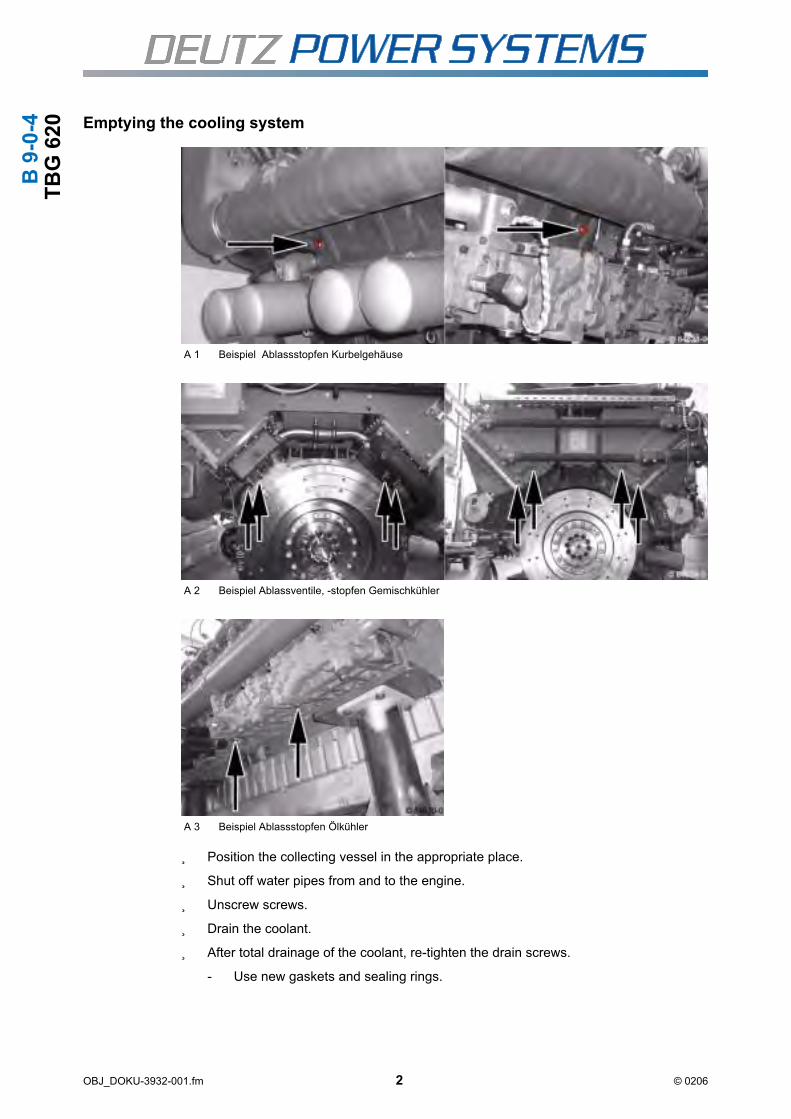
TB
G 6
20
B 9
-0-4
Emptying the cooling systemA 1 Beispiel Ablassstopfen Kurbelgehäuse
A 2 Beispiel Ablassventile, -stopfen Gemischkühler
A 3 Beispiel Ablassstopfen Ölkühler
Position the collecting vessel in the appropriate place.
Shut off water pipes from and to the engine.
Unscrew screws.
Drain the coolant.
After total drainage of the coolant, re-tighten the drain screws.
- Use new gaskets and sealing rings.
OBJ_DOKU-3932-001.fm 2 © 0206

TB
G 6
20
B 9
-0-4
Filling the cooling systemFill the engine cooling system with the prepared coolant.
- The filled cooling system bleeds automatically.
- When refilling, it is necessary to bleed the coolant pipe at the highest point.
- Loosen the hollow screws until the coolant emerges without bubbles.
Open water pipes from and to the engine.
Check pipes, connections and the engine for leaks after filling and repair if necessary.
Check the coolant level again, top up if necessary.
Use the required quality of coolant as described in chapter 4, Operating materials.
Use the right percentage of corrosion protection agent or antifreeze following job card B 9-1-1.
OBJ_DOKU-3932-001.fm 3 © 0206

TB
G 6
20
B 9
-0-4
OBJ_DOKU-3932-001.fm 4 © 0206

TB
G 6
20
OBJ_DOKU-4103-001.fm 1 © 0206
B 9
-1-1Checking percentage of corrosion protection agent or antifreeze in
coolant
General information
Corrosion protection agent is added to the coolant to protect the coolant areas from corro-sion. However, this protection is only given when a certain minimum content of corrosionprotection agent is not exceeded. If there is more corrosion protection agent than necessaryin the coolant, the cooling effect is reduced.
If an antifreeze is added to the coolant, this should also have corrosion protection proper-ties. A corrosion protection agent does not need to be added in this case. The antifreezepercentage must be dosed accordingly for the above mentioned reasons.
If the cooling system needs refilling, the percentage of antifreeze or corrosion protectionagent in the coolant must be measured. Then the coolant should be corrected according tothe following description.
Checking the percentage of corrosion protection agent or antifreeze
Remove the coolant sample from the cooler, compensation tank or draining tap.
Check the percentage additive with the measuring instrument, see TR 0199-99-2091.
Tools
- Commercially available tools
- Measuring instrument (from test case order no. 12158292)
Spare parts
- Corrosion protection agent or antifreeze if necessary
References
- Chapter 4, Operating media
Danger of burns !
Corrosion protection is not a fire hazard in the hardened state.

TB
G 6
20
OBJ_DOKU-4103-001.fm 2 © 0206
B 9
-1-1 Correct the corrosion protection agent and antifreeze percentage
up to low additive percentage:
A = B x (C - D) / 100
- Drain necessary volume of coolant.
- Mix the drained coolant with the volume of additive to be refilled well.
- Fill in mixture.
up to high additive percentage:
A = (1 - B / C) x D
- Drain necessary volume of coolant.
- Fill up cooling system with pure water.
Bleed the cooling system.
A = amount of additionally required additive
B = Total filling volume
C = Setpoint
D = Measured value
A = coolant to be drained
B = Setpoint
C = Measured value
D = Total filling volume
Note water quality - see chapter 4, Operating materials

TB
G 6
20
B 1
0-7
-1
Drain water from and fill air bottle (starter air tank)Open drain valve 1 slowly until water emerges. If no water emerges, close the drainvalve again.
Fill up the air bottle to 30 bar every time before switching off the engine.
A 1 Starter air bottle
Tools
- Commercially available tools
Do not open the drain cock too far because water is displaced if the flow speed is too great and only air escapes. A rising pipe 2 is installed on vertically erected air bottles. The air pressure in the air bottle presses the water through out through the rising pipe into the open.
If no water emerges for several maintenance periods, have the air bottle checked.
1
2
' 80122-1
OBJ_DOKU-3921-001.fm 1 © 0206

TB
G 6
20
B 1
0-7
-1
OBJ_DOKU-3921-001.fm 2 © 0206

TB
G 6
20
OBJ_DOKU-4105-001.fm 1 © 0206
B 1
3-4
-1Servicing the battery
Technical data
General information
Tools
- Commercially available tools
- Acid tester (order no. 12157944)
Auxiliary material
- Distilled water
- Acid protection grease
- Cloth
Test and setting values
Battery acid density Charge status Normal Tropical
well charged 1.28 kg/l 1.23 kg/l
semi-charged (re-charge) 1.20 kg/l 1.12 kg/l
discharged (recharge, renew if neces-sary)
1.12 kg/l 1.08 kg/l
Caution, explosion hazard !
The gases emitted by the battery are explosive.
Avoid sparks and naked flames.
Danger of burn !
Do not allow battery acid to come into contact with skin or clothing.
Wear protective glasses and clothing.
Danger of short-circuit !
Do not rest tools on the battery.
Cover the battery poles.
Danger of injury !
Only work with the engine at a standstill.
Secure the engine against starting.
Keep battery clean and dry.

TB
G 6
20
OBJ_DOKU-4105-001.fm 2 © 0206
B 1
3-4
-1 Check battery and cable connectors
A 1 Battery poles
Remove dirty clamps.
Clean the battery poles and clamps.
Plug on and tighten clamps.
Grease clamps with acid-proof grease.
When reassembling, ensure that clamps make good contact. Tighten clamp boltshand-tight.
Check acid level
A 2 Battery sealing caps
Unscrew and remove sealing caps 1.
Visually check the acid level.
- without control inserts 2: liquid level 10 - 15 mm above top edge of plate.
Make sure the clamps have good contact.
© 24232-5
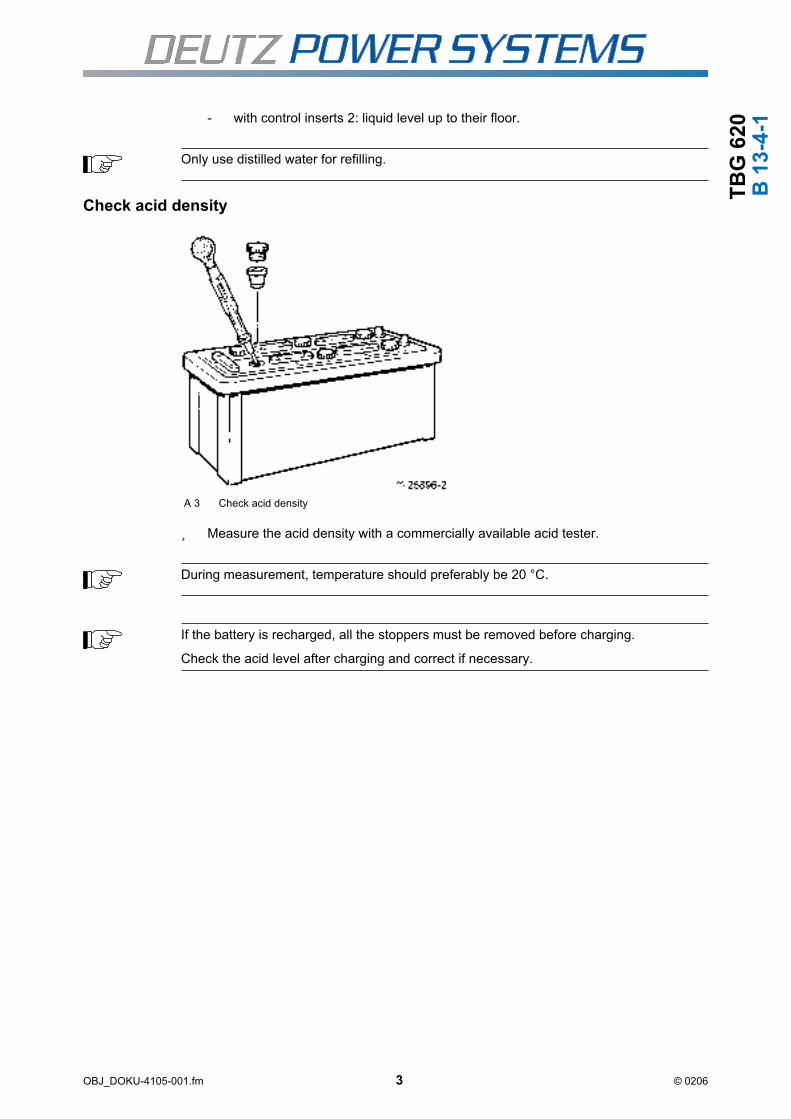
TB
G 6
20
OBJ_DOKU-4105-001.fm 3 © 0206
B 1
3-4
-1
- with control inserts 2: liquid level up to their floor.
Check acid density
A 3 Check acid density
Measure the acid density with a commercially available acid tester.
Only use distilled water for refilling.
During measurement, temperature should preferably be 20 °C.
If the battery is recharged, all the stoppers must be removed before charging.
Check the acid level after charging and correct if necessary.

TB
G 6
20
OBJ_DOKU-4105-001.fm 4 © 0206
B 1
3-4
-1 Correct the acid density
if acid density too low:
A = B x (C - D) / (E - D)
- Suck amount of acid to be refilled from the battery.
- Fill determined amount of battery acid into the battery.
if acid density too high:
A = B x (C - D) / (C - 1)
- Suck amount of water to be refilled from the battery.
- Fill determined amount of water into the battery.
A = Amount of acid to be refilled
B = Cell content
C = Nominal density
D = Acid density in the cell
E = Density of acid to be refilled
A = Amount of water to be refilled
B = Cell content
C = Acid density in the cell
D = Nominal density

TB
G 6
20
B 1
3-5
-4
Removing and installing spark plugs, checking ignition cableTechnical data
General information
If there is an electrode gap of more than 0.25 mm when testing, the spark plug may be ad-justed. As the earth electrodes may only be bent twice, the correction of the electrode gapshould be noted in the operating check log.
Tools
- Commercially available tools
- Spark-plug wrench
- Feeler gauge 0.25 mm
- Torque wrench
Auxiliary material
- Compressed air
- Safety goggles
Spare parts
- Sealing rings for spark plugs
- Spark plugs if necessary
Test and setting values
Spark plug Electrode gap 0.25 mm
Tightening specifications
Spark plug on cylinder head 52 Nm
Danger of injury !
Only work with the engine at a standstill.
Secure the engine against starting.
Mortal danger !
When working on the high voltage ignition system.
OBJ_DOKU-3922-001.fm 1 © 0206

TB
G 6
20
B 1
3-5
-4
A 1 Ignition coil, cable
Removing the spark plug
Pull ignition cable 1 from ignition coil 2.
Pull spark-plug connector 3 off the spark plug.
Check the spark plug shaft for dirt.
Blow out spark plug shaft with compressed air.
Remove spark plug.
The sealing rings of the spark plug protective pipe must be renewed when oil gets into the spark-plug shaft.
Please contact your service partner if coolant gets into the spark-plug shaft.
Particles of dirt can cause injury when cleaning with compressed air.
Wear safety glasses and close-fitting clothing.
OBJ_DOKU-3922-001.fm 2 © 0206

TB
G 6
20
B 1
3-5
-4
Checking and adjusting the spark plugCheck electrode gap with feeler gauge.
- Set the electrode gap by slightly bending the earth electrode to the setpoint if nec-essary.
Checking the ignition cable
Visually inspect the ignition cable for damage and renew if necessary.
Installing the spark plug
Renew the sealing ring of the spark plug.
Insert and tighten spark plug.
Plug the ignition cable to the ignition coil.
If the middle electrode is burnt out or soiled, the spark plug must be renewed.
Cleaning the spark plug is not permissible!
If the spark plug is renewed, the new spark plug must be checked for damage.
The electrode gap must also be checked and set if necessary.
OBJ_DOKU-3922-001.fm 3 © 0206

TB
G 6
20
B 1
3-5
-4
OBJ_DOKU-3922-001.fm 4 © 0206

OBJ_DOKU-4106-001.fm / 1 © 0206
TB
G 6
20
Se
rvic
eService
Sales & Service Index
This Sales & Service Index offers you an overviewof the DEUTZ Power Systems branches in your vi-cinity, including the products for which they are re-sponsible and the range of services provided. Evenwhen no direct product responsibility is mentioned,your local branch will be happy to help you with ex-pert advice. The Index is constantly updated.Please ask your DEUTZ Power Systems servicepartner for the latest edition.
Order no.: 0312 0807 (CD-ROM)
DEPIC
The DEutz Parts Identification for Customers (DE-PIC) offers you spare parts identification individuallyadapted to your systems. DEPIC enables you togenerate an order list almost automatically, makingordering your spare parts more efficient. Order no.:on request (CD-ROM)
Tutorial programs
The degree of availability, reliability and service lifeof equipment and drive assemblies are determinedto a great extent by professional operation and serv-ice by qualified and experienced operators andservice technicians. The DEUTZ AG Power Sys-tems also offers service-related seminars forDEUTZ Power Systems products to the staff of cus-tomers and operators. Apart from the standard sem-inars, held in our Training Centre in Mannheim, it isalso possible to arrange special seminars, either inthe Training Centre or at another location requestedby the customer. Information about the seminar pro-gram will be distributed in a circular. Please askyour DEUTZ Power Systems Service representa-tive.

OBJ_DOKU-4106-001.fm / 2 © 0206
Se
rvic
eT
BG
62
0


© 2004 Page 1 of 6Printed in Germany 0312 1373
DEUTZ AG
Deutz-Mülheimer Straße 147-149
51063 Köln
TR
-Vor
gabe
-mul
ti, 0
2/02
, VS
-TI 1
Engine coolant for DEUTZ medium and large-size engines
This 5th Exchange is issued amongst other things because of a
� Revision of the data on water quality� Introduction of the DEUTZ protective agent for cooling circuit in 20 litre cans� Updating of product recommendations , Enclosures 1 and 2.
Contents
1 General
2 Water quality
3 Protective agents for cooling circuit
3.1 Chemical anticorrosion agent
3.2 Antifreeze agents with corrosion inhibitors
3.3 Corrosion inhibitors
4 Details on cooling circuit
4.1 Monitoring of cooling circuit
4.2 Cleaning of cooling circuit
4.3 Coolant disposal
Enclosures 1 and 2: Product recommendations for cooling circuit protective agents
Enclosure 3: Disposal of DEUTZ cooling systems pretective agent (only in German issue)
Technical Circular
Product:
Date: This Circular supersedes: 0199-99-2091 4th Exchange
of 11.05.2001
Copies to: Adress:
• Service- Partners At Home and Abroad
(subsidiaries, agencies, dealers)
• Service Centers + Xchange Center Germany
• Pocket Book Holders
• Company Departments (02)
• Original equipment manufacturers (OEM)
or end customers
Drawn up by: VS-TIM Phone: +49 (0) 221 822 3687
Fax: +49 (0) 221 822 2752
Note: The part numbers indicated in this document serve technical explanation purposes.
Exclusively the spare parts documentation is binding for the definition of spare parts.
0199 - 99 - 2091 en
5th
Exchange
Medium and large size engines07.01.2004
0080

© 2004 Page 2 of 6
1 General
Coolants of liquid-cooled engines must be treated and monitored since damage may sustained byengine otherwise due to
� corrosion
� cavitation
� freezing
2 Water quality
The correct water quality is important for the preparation of the coolant. If no specifications areprovided by the manufacturer/supplier, clear and clean water must be used within the followinglimit values of analysis:
Limit values of analysis min. max.
pH value at 20°C 6,5 8,5Chloride ion content mg/dm
3- 100
Sulphate ion content mg/dm3
- 100Total hardness *
1°dGH 3 12
*1
Share of carbonate hardness in the overall hardness min. 3°dGH.
For more information on the water quality please consult your local waterworks or use the DEUTZtest kit, Order No. 12130382.
Water treatment is indicated if water qualities differ from the above indicated limit values ofanalysis.
� pH value too lowAdd diluted caustic soda or potash lye and mix.Preparation of small sample mixtures is recommended.
� Total water hardness too high:Mix with softened water * 2
� Total hardness and/or carbonate hardness too lowMix with water of a higher hardness *3
� Chloride and/or sulphate content too highMix with softened water *2
*2 Softened water is distilled water, pH-neutral condensate or water treated by ion exchangers.
*3 Water of a higher hardness is available in most cases in form of potable water (town water).
Use the DEUTZ test kit (order No. 12130382) for a determination, if the limit values of analysis ofthe water to be admixed are unknown.
For safety reasons it is mandatory to carry out another water analysis after water treatment.
Sea water, river water, brackish water or industrial waste water are in no case suitable forthe preparation of the coolant since damage may be sustained by the engine.

© 2004 Page 3 of 6
3 Protective agent for cooling circuit
The coolant is prepared by adding a protective agent to the cooling water as a protection of thecooling circuit. The following additives are commonly used:
� Chemical anticorrosion agent� Antifreeze agent with corrosion inhibitors� Corrosion inhibiting oil
The type of additive can be selected according to the following table:
Chemical Antifreeze agent with Corrosionanticorrosion agent corrosion inhibitors inhibiting oil
Protection good good goodagainst corrosion
Protection satisfactory satisfactory goodagainst cavitation
Protection none up to –45°C according noneagainst freezing to mixing ratio
Maintenance requirement low low *4
very high
Operating reliability good good insufficient
Costs medium very high medium
*4 Only the antifreeze effect is checked normally, to be exchanged every 2 years.
Enclosure 1 lists up some representative products which are recommended by us and which asindicated by the manufacturers/suppliers are suitable for the processing of coolants. Also otherequivalent products of other manufacturer/suppliers may be used as an alternative. Suitability of theprotective agent for the cooling circuit must be warranted/guaranteed by the manufacturer/supplier.No liability is accepted by us.
The various protective agents for the cooling circuit are described below.
3.1 Chemical anticorrosion agent
Chemical anticorrosion agents are compounds which by way of chemical reaction form a protectivefilm on the metal surfaces. Their advantage compared to corrosion inhibiting oils lies in the ease ofapplication and monitoring.
Liquid additives may be admixed directly in the engine, additives in powder form are to be pre-mixed.The manufacturer’s instructions must be adhered to with regard to the concentration of the chemicalanticorrosion agent and subsequent monitoring.
The manufacturer/supplier shall warrant that his additives do not have a detrimental effect on thematerials used in the engine (e.g. seals/gaskets).
Be careful with aluminium components in the cooling circuit. Not all chemical anticorrosion agentsare suitable in such cases; correct dosing is of particular importance since too low a concentrationof the chemical anticorrosion agent will have a damaging effect on the system. Also considered inthe list of recommended products (see Enclosure 1) is the suitability of the anticorrosion agent forengines with aluminium components.
Make sure that aluminium components are property grounded , no additional electric currents maybe induced by these aluminium components via defective insulations (single pole sensors andmonitoring sensors).

© 2004 Page 4 of 6
Chemical anticorrosion agents containing silicates may have a negative effect on the service lifeof the axial-face seals. Such products should only be used for engines which separatelymounted coolant pumps equipped with seals which are resistant to these chemical anticorrosionagents.
Filter systems are available as an alternative, capable of filtering out solid particles from thecooling circuit in addition to providing a protection against corrosion. These filters contain achemical anticorrosion agent in solid form which is gradually dissolved in the cooling water.
Chemical anticorrosion agents and antifreezes as per Section 3.2 are compatible.
Not all chemical anticorrosion agents and antifreeze agents are compatible. Carcinogenicnitrosamines will form when mixing amine based chemical anticorrosion agents withnitrate based antifreeze agents. For compatibility please consult the manufacturer/supplier.Most of the recommended chemical anticorrosion agents may be mixed with the antifreezeagent from DEUTZ (an antifreeze based on ethylene glycol) without incurring any risk.
3.2 Antifreeze agents with corrosion inhibitors
Antifreeze agents are generally used for DEUTZ engines only if ambient temperatures belowzero are likely to occur. The antifreeze agent may be added to the chemical anticorrosion agent(manufacturer/supplier to be contacted for compatibility) or may be added to the water as theonly protective agent against freezing and corrosion. Antifreeze agents based on ethylene glycolare used in general. The anticorrosive substances contained in the antifreeze are agents whichprevent corrosion by forming a protective film on the surface of the components.
Provide for the following concentrations:
Antifreeze agent 10% 15% 20% 25% 30% 35% 40% 45% 50%
Water 90% 85% 80% 75% 70% 65% 60% 55% 50%
Antifreeze effective up to -4°C -7°C -10°C -13°C -18°C -22°C -28°C -35°C -45°C
When the antifreeze agent is used as the only anticorrosion agent (without any chemicalanticorrosion agent) it must be left in the coolant both during winter and summer time; minimumconcentration 35%.
Use of antifreeze reduces the heat transfer coefficient (thermal capacity) of the coolant.Check whether the cooling circuit is laid out accordingly.
Admixture of a corrosion inhibiting oil emulsion is not permissible.
Best results are obtained with the DEUTZ protective agent for cooling circuits as anantifreeze with anticorrosion inhibitors. This ethylene glycol based protective agent for coolingcircuits is matched to the materials used on DEUTZ medium and large size engines and issubject to permanent control and monitoring. This agent is obtainable from the DEUTZorganisation and is supplied in form of
5 litre containers Part No. 0101 1490
20 litre containers Part No. 0101 6416
210 litre barrel Part No. 1221 1500
�
�

© 2004 Page 5 of 6
If the DEUTZ protective agent for the cooling circuit should not be available for important reasonssuch as supply restrictions abroad, other products may be used in exceptional cases. Suchalternative products have been grouped together in product groups and are listed up in Annex1. Products of the same product group may be mixed. Products of different product groups maynot be mixed. The entire cooling circuit must be cleaned thoroughly before a product change.
3.3 Corrosion inhibiting oil
Use of corrosion inhibiting oils is a problem because of the poor stability of the emulsion, theresulting difficulties in monitoring and the potential damage involved.
Corrosion inhibiting oils are emulsive mineral oils with additives which form a thin protective filmon the components of the cooling circuit preventing corrosion and furring.
The emulsion must be prepared in a container outside the engine cooling water circuit addingthe specified amount of corrosion inhibiting oil to the water stirring the mixture thoroughly.Concentration as specified by the manufacturer/supplier.
Loss of coolant to be made up for, excessively low concentrations of corrosion inhibiting oil tobe compensated by adding a highly concentrated emulsion.
Corrosion inhibiting oils must not be used for:
- cooling circuits with connection to a comfort heating system- gas engines
4 Details of the cooling circuit
4.1 Regular checking of the cooling circuit
The cooling circuit must be checked regularly (see current Operating Instructions) whichincludes checking for contamination and checking of the coolant level as well as the concentra-tion of the protective agents of the cooling circuit.
� Chemical anticorrosion agent:Check concentration; suitable tools for testing such as test rods are supplied by themanufacturers/suppliers.
� Antifreeze agent with corrosion inhibitorsCheck antifreeze and anticorrosion effects with antifreeze tester.
� Corrosion inhibiting oilCheck concentration of corrosion inhibiting oil with refractometer, check condition ofemulsion.
Renew coolant always in case of:
� ingress of raw water
� Ingress of lube oil
� pronounced turbidity due to corrosion residues or other suspended matter
� a spent corrosion inhibiting emulsion
� the antifreeze agent to be renewed every 2 years.

4.2 Cleaning of cooling circuit
The cooling circuit must be cleaned if contaminated, corrosion inhibiting oil emulsion is spent or inthe case of lube oil or raw water ingress. The entire coolant must be drained in such as case andthe cooling circuit must be flushed using a suitable detergent. The cooling circuit must also becleaned when changing over to another type of protective agent for the cooling circuit.
Suitable detergents are offered on the market, suitability must be guaranteed by the manufacturer/supplier, however.
4.3 Coolant disposal
The coolant must not be drained into the sewage system. Disposal to be taken care of by a companyspecialised in waste disposal in accordance with the national legal requirements and the instructionsof the manufacturer/supplier.
For disposal of the DEUTZ protective agent for the cooling circuit within the Federal Republicof Germany please refer to Annex 3 (published in German only).
DEUTZ AGService Information Systems
- Sonntag - - Asselborn –
Annexes
�
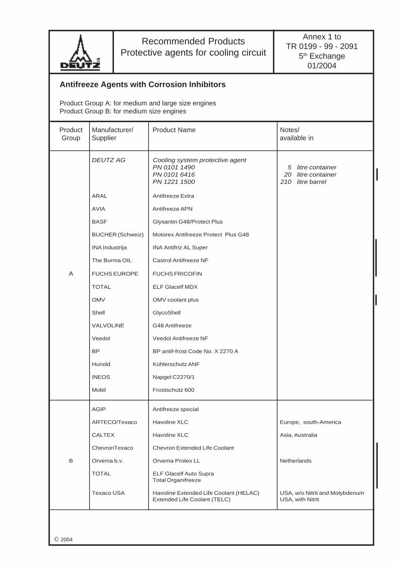
Annex 1 toTR 0199 - 99 - 2091
5th Exchange01/2004
Recommended ProductsProtective agents for cooling circuit
Antifreeze Agents with Corrosion Inhibitors
Product Group A: for medium and large size enginesProduct Group B: for medium size engines
Product Manufacturer/ Product Name Notes/Group Supplier available in
DEUTZ AG Cooling system protective agentPN 0101 1490 5 litre containerPN 0101 6416 20 litre containerPN 1221 1500 210 litre barrel
ARAL Antifreeze Extra
AVIA Antifreeze APN
BASF Glysantin G48/Protect Plus
BUCHER (Schweiz) Motorex Antifreeze Protect Plus G48
INA Industrija INA Antifriz AL Super
The Burma OIL Castrol Antifreeze NF
A FUCHS EUROPE FUCHS FRICOFIN
TOTAL ELF Glacelf MDX
OMV OMV coolant plus
Shell GlycoShell
VALVOLINE G48 Antifreeze
Veedol Veedol Antifreeze NF
BP BP antif-frost Code No. X 2270 A
Hunold Kühlerschutz ANF
INEOS Napgel C2270/1
Mobil Frostschutz 600
AGIP Antifreeze special
ARTECO/Texaco Havoline XLC Europe, south-America
CALTEX Havoline XLC Asia, Australia
ChevronTexaco Chevron Extended Life Coolant
B Orvema b.v. Orvema Protex LL Netherlands
TOTAL ELF Glacelf Auto SupraTotal Organifreeze
Texaco USA Havoline Extended Life Coolant (HELAC) USA, w/o Nitrit and MolybdenumExtended Life Coolant (TELC) USA, with Nitrit
© 2004

Manufacturer/ Product name Diesel engines Notessupplier 234, 616, 2016, 604, 620, 2020
628, 640, 645
DEUTSCHE Castrol CASTROL PRODUCT 481/43 X
Deutsche Shell AG Shell 9156 X
ESSO AG Kutwell 40 X
Mobil Coolant Inhibitor X
Annex 2 toTR 0199 - 99 - 2091
5th Exchange01/2004
Chemical Anticorrosion Agents
Corrosion inhibiting oils – not for gas engines –
Recommended ProductsProtective agents for cooling circuit
Manufacturer/ Product name Diesel engines Gas engines Diesel engines Notessupplier 234, 616, 2016, 234, 616, 628, 640,
604, 620, 2020 604, 620, 2020 645
632, 2032
BEDIA Bedia Liquid BL1 * - X XBedia BS/BT mit BP1 * - X X Filter systemsBedia BL2 X X X
DREW AMEROID DEWT-NC - - X PowderLiquidewt - - XMaxiguard - - X
Fuchs FUCHS ANTICORIT S 2000 A X X X
Houseman Limited Cooltreat 651 * - X X
NALFLEET 9-108 - - X9-111 * - X X9-131 C - - X
REICON ODACON Z X X X
Perry Liquid Perry * - X X(W. Lösing) Perry Filter * - X X Filter systems
Texaco Havoline XLI X X X
Total Total WT Supra X X X
UNITOR ASA Dieselguard NB Pulver - - X not to be mixed withantifreeze agent
ROCOR NB Liquid - - X
Vecom CWT Diesel / QC 2 - - X
* Product contains silicates
© 2004
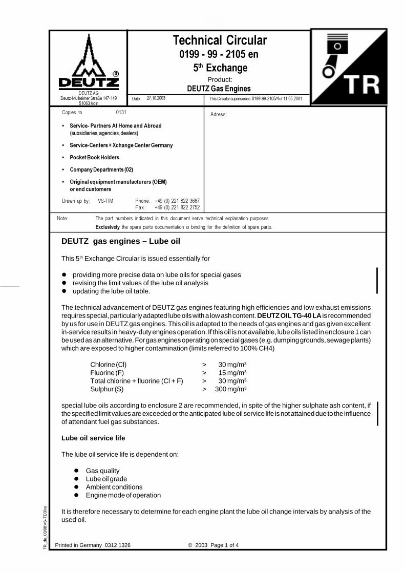
Printed in Germany 0312 1326
TR
_de_
03/9
8 V
S- T
D3/
voTechnical Circular
Product:
Date: This Circular supersedes: 0199-99-2105/4 of 11.05.2001
DEUTZ gas engines – Lube oil
This 5th Exchange Circular is issued essentially for
� providing more precise data on lube oils for special gases� revising the limit values of the lube oil analysis� updating the lube oil table.
The technical advancement of DEUTZ gas engines featuring high efficiencies and low exhaust emissionsrequires special, particularly adapted lube oils with a low ash content. DEUTZ OIL TG-40 LA is recommendedby us for use in DEUTZ gas engines. This oil is adapted to the needs of gas engines and gas given excellentin-service results in heavy-duty engines operation. If this oil is not available, lube oils listed in enclosure 1 canbe used as an alternative. For gas engines operating on special gases (e.g. dumping grounds, sewage plants)which are exposed to higher contamination (limits referred to 100% CH4)
Chlorine (Cl) > 30 mg/m³Fluorine (F) > 15 mg/m³Total chlorine + fluorine (Cl + F) > 30 mg/m³Sulphur (S) > 300 mg/m³
special lube oils according to enclosure 2 are recommended, in spite of the higher sulphate ash content, ifthe specified limit values are exceeded or the anticipated lube oil service life is not attained due to the influenceof attendant fuel gas substances.
Lube oil service life
The lube oil service life is dependent on:
� Gas quality� Lube oil grade� Ambient conditions� Engine mode of operation
It is therefore necessary to determine for each engine plant the lube oil change intervals by analysis of theused oil.
© 2003 Page 1 of 4
DEUTZ AG
Deutz-Mülheimer Straße 147-149
51063 Köln
0199 - 99 - 2105 en
5th
Exchange
DEUTZ Gas Engines
27.10.2003
Note: The part numbers indicated in this document serve technical explanation purposes.
Exclusively the spare parts documentation is binding for the definition of spare parts.
Copies to 0131
• Service- Partners At Home and Abroad
(subsidiaries, agencies, dealers)
• Service-Centers + Xchange Center Germany
• Pocket Book Holders
• Company Departments (02)
• Original equipment manufacturers (OEM)
or end customers
Drawn up by: VS-TIM Phone: +49 (0) 221 822 3687
Fax: +49 (0) 221 822 2752
Adress:

For bio gas, the 1st analysis should be carried out after 100 running hours and for the other types of gas after300 running hours. Further intervals to be observed for analysis and lube oil change should be agreed betweenthe operator and the laboratory on the basis of the following limit values.
Limit values for lube oil analysis RemarksMeasuring method
Viscosity at 100°C min. 12 mm2/sec (cSt) DIN 51 366, ASTM D 445DIN EN ISO 3104
max. increase 3 mm2/sec DIN 51 366max. 18 mm2/sec
Water content max. 0,2% DIN 51777ASTM D 1744
Glycol content max. 500 ppm DIN 51375ASTM D 4291
Total base number TBN > 40% of new oil ISO 3771min. 2,0 mgKOH/g
AN ≤ of simultaneous TBN ASTM 664
SAN 0 mgKOH/g ASTM 664
i pH * ≥ 4,5 DEUTZ
Oxide 5,8 µm 20 A/cm DIN 51 451
Nitr. 6,1 µm 20 A/cm DIN 51 451
Wearing metals: Engine DIN 513911015 616 620 632 ASTM D 51852015 2016 2020 2032
(604B/C)
Aluminium max. mg/kg 20 10 10 5 If two or more wearingmetals exceed the limits
Chromium max. mg/kg 10 5 5 5 of 10 mg/kg, thesubsequent time interval
Copper max. mg/kg 20 25 15 10 for sampling must be
cut in half. If higherIron max. mg/kg 30 30 20 20 values of wear are
confirmed, please
Lead max. mg/kg 20 20 20 10 consult DEUTZ customerservice.
Tin max. mg/kg 10 10 5 5
Silicium max. mg/kg 15 15 15 15 DIN 51391out of dust ** ASTM D 5185
* Biogas
** In the case of engines running on sewage and landfill gas the contamination can also be causedby siloxanes. The elements exposed to wear must be carefully observed.The Si limit value is reached if the proportion of wearing metals increases to max. 300 mg/kg.
© 2003 Page 2 of 4

Not only the limit values but also the course of the recordings of a number of analyses of the oil shouldbe considered in the assessment of the wear components to be sure to detect variations of the enginecondition earliest possible.
You are advised to document the analysis of the oil and produce this evidence for reference, ifnecessary. In the case of abnormal wear within a series of analyses, you are obliged to make availablethe documented analysis to DEUTZ Product Engineering if engines under warranty are involved.
Following a series of three analyses, the analysis can be limited to the oil sample taken during lubeoil change, provided the operating conditions remain the same.
Explanatory notes to the limit values of the lube oil analysis
Abbreviation Term Explanation
TBN Total Base Number Total base number, identifying the alkaline reserve(mgKOH/g) of the oil and characterising the chemical
capacity of neutralization
AN Total Acid Number covers weak and strong acids
SAN Strong Acid Number covers strong acids only, e.g. sulphuric acid
ipH Initial pH-Value Initial pH value
Oxid. 5,8 µm Oxidation covering carbonyl compounds in the IR spectrum (infrared) of 5.8 µm
Nitr. 6,1 µm Nitration Nitrification by ground bacteria, measuredin the IR spectrum (infrared) of 6.1 µm
A/cm Absorption per cm of wavelength in the spectrogram
KOH Potassium hydroxide
Lube oil change
Lube oil to be changed after
� Analysis� Coolant ingress into lube oil� Servicing work on maintenance level E 60 (see Operation Manual)� Repair work exceeding the scope of maintenance level E 50
(see Operation Manual)� at least once a year if engine is run less than 2,000 running hours annually.
New intervals for lube oil change must be fixed in case the mode of operation is changed, followingservice work E60 and/or repair work equivalent to E60.
The lube oil sample is to be taken
- with the engine running by means of the quick coupler directly form the lube oil circuit or
- directly after the engine has came to a standstill form the oil pan.
Fill the cubic centimetres taken as the initial sample back into the engine. Then fill into a clean testbottle.
© 2003 Page 3 of 4

© 2003 Page 4 of 4
Lube oil filter change
Lube oil filter cartridges to be changed
• together with the first lube oil change• thereafter every 1,500 to 3,000 operating hours (see maintenance chart in Operation Manual)• minimum once a year.
If water is analysed in the lube oil or a SAN is measured in the lube oil or servicing work acc. to maintenancelevel E 60 and/or repair work corresponding to E60 in terms of scope has been carried out, also filtercartridges must be changed in the course of the next lube oil change.
DEUTZ AGService Information Systems
- Sonntag - - Asselborn –
Encl. Lube Oil Tables

Manufacturer Type of lube oil Viscosity- Sulphate Total Viscosityclass Base oil ash baseSAE weight number at 40°C at 100°C
per cent (TBN)mgKOH/g
DEUTZ DEUTZ Öl TG-40 LA 40 Mineral 0,43 5,7 156,0 14,5
ARAL AG Degasol LA 40 Mineral 0,48 4,5 137,0 13,7
BP AG Energol IC-DG 40S 40 Mineral 0,48 4,5 137,0 13,7
CEPSA Troncoil Gas 40 Mineral 0,35 4,6 133,8 13,8
Exxon Mobil Pegasus HPC 40 Mineral 0,48 5,5 138,0 14,1Pegasus 1 15W-40 Synthetic 0,48 7,0 132,0 13,6Pegasus 605 40 Mineral 0,50 7,4 119,0 13,0Pegasus 705 40 Mineral 0,49 5,3 122,0 13,1Pegasus 805 40 Mineral 0,50 6,2 130,0 13,5Pegasus 905 40 Mineral 0,50 6,2 115,0 12,7
FUCHS Europe Fuchs Titan GM LA 40 Mineral 0,43 5,7 156,0 14,5
Kuwait Petroleum Q 8 Mahler MA 40 Mineral 0,50 5,5 141,2 13,9
Petro-Canada Sentinel 445 40 Hydro. Tr 0,40 4,7 127,0 13,2
Repsol Extra Gas 40 40 Mineral 0,40 6,0 130,0 13,5
Roloil Mogas / 40 40 Mineral 0,50 5,5 141,2 13,9
Shell Mysella LA 40 Mineral 0,45 5,0 138,0 13,8Mysella XL 40 Mineral 0,50 4,5 131,0 14,1
TOTAL FINA ELF ELF Nateria MHW 40 40 Mineral 0,35 4,6 133,8 13,8ELF Nateria MH 40 40 Mineral 0,45 5,2 139,0 13,9FINA Gasmotorenöl 505 40 Mineral 0,48 5,5 155,0 15,1
TEXACO GEOTEX LA 40 Mineral 0,45 5,5 129,4 13,3GEOTEX PX 40 Mol. conv 0,50 5,4 88,0 13,2
WIPA Chemicals Ecosyn GE 4004 40 Ester 0,40 6,0 155,0 13,7International
Lube oils for gas engines operating with all types of low contaminated gases
Lube Oil TableDEUTZ Gas Engines
Enclosure 1 toTR 0199-99-2105
5th Exchange10 / 2003
© 2003

Manufacturer Type of lube oil Viscosity Sulphate Total base Viscosity
class Base oil ash number at 40 °C at 100 °C
SAE weight (TBN)
per cent mgKOH/g
Caltex Geostar LF 40 40 Mineral 0,99 8,0 138,0 14,0
Kuwait Petroleum Q8 Mahler HA 40 Mineral 0,90 7,9 141,2 14,1
Mobil Pegasus 610 40 Mineral 0,96 9,5 131,0 13,5
Roloil Mogas 40 AC 40 Mineral 0,90 7,9 141,2 14,1
Texaco Geotex LF 40 40 Mineral 0,99 8,0 138,0 14,0
Lube Oil TableDEUTZ Gas Engines
Enclosure 2 toTR 0199-99-2105
5th Exchange10 / 2003
Lube oils for gas engines operating with higher contaminated special gases
© 2003

© 2004 Page 1 of 8Printed in Germany 0312 2429
DEUTZ AGDeutz-Mülheimer Straße 147-149
51063 Köln
TR
-Vo
rga
be
-mu
lti, 0
2/0
2,
VS
-TI
1Technical Circular
Product:
Date: This Circular supersedes:
Copies to: Adress:
• Service- Partners At Home and Abroad
(subsidiaries, agencies, dealers)
• Service Center + Xchange Center Germany
• Pocket Book Holders
• Company Departments (02)
• Original equipment manufacturers (OEM)
or end customers
Drawn up by: VS-TIM Phone: +49 (0) 221 822 3687
Fax: +49 (0) 221 822 2752
Note: The part numbers indicated in this document serve technical explanation purposes.
Exclusively the spare parts documentation is binding for the definition of spare parts.
en0199 - 99 - 2116
1st Exchange
DEUTZ medium and large engines (Diesel and Gas)13.12.2004
TR 0199-99-2116 of 10.01.2000
0080
Engine corrosion protection
This Technical Circular applies for all DEUTZ medium and large engines and for the DEUTZ gas
engine TCG 2015
1 General
2 Corrosion protection for engines which have been in operation
2.1 Interior corrosion protection
2.2 Exterior corrosion protection
2.3 Storage and packaging
3 Subsequent corrosion protection of engines
3.1 Interior corrosion protection
3.2 Exterior corrosion protection
3.3 Storage and packaging
4 Removal of corrosion protection
4.1 Removal of interior corrosion protection
4.2 Removal of exterior corrosion protection
5 Corrosion protection agents / cleaning agents
FV 0160 0062
FV 0160 0073
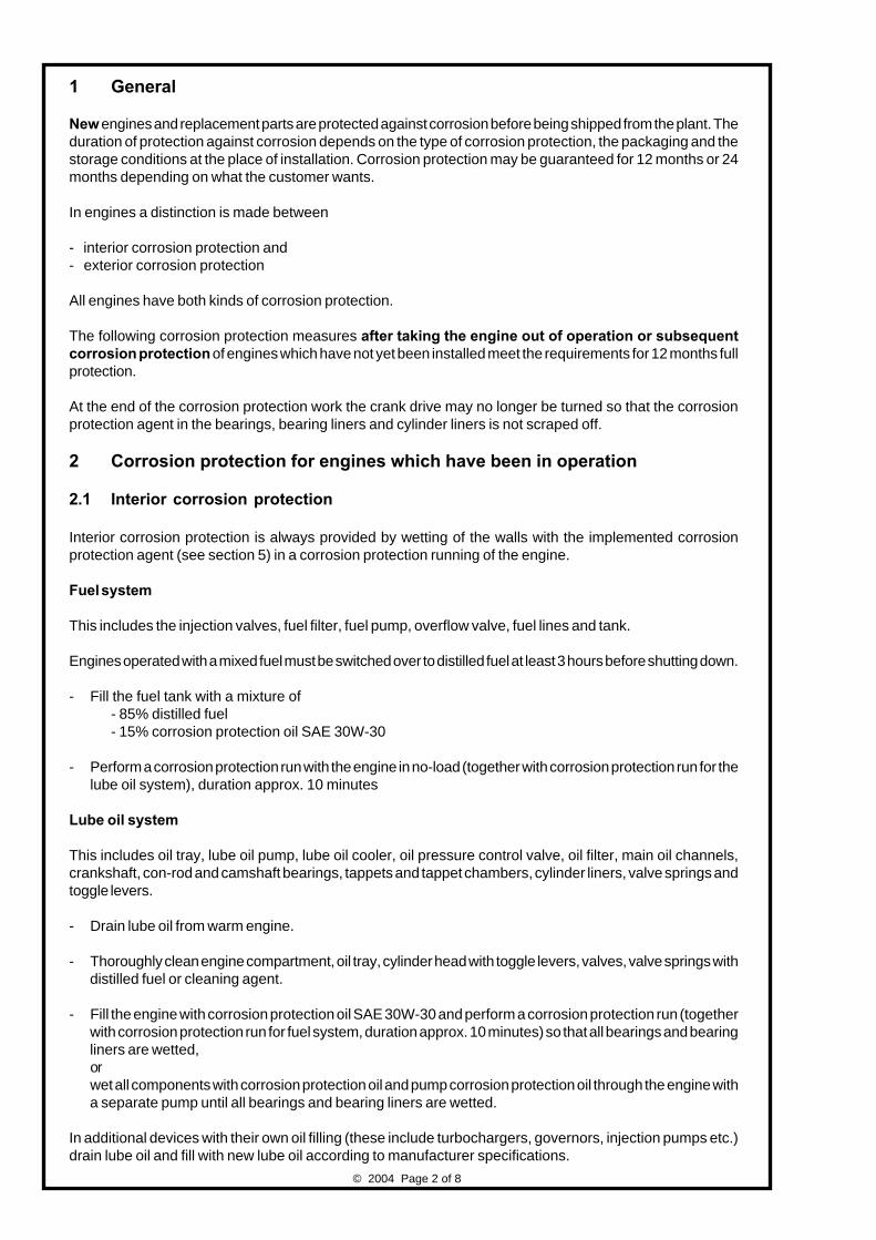
© 2004 Page 2 of 8
1 General
Newengines and replacement parts are protected against corrosion before being shipped from the plant. The
duration of protection against corrosion depends on the type of corrosion protection, the packaging and the
storage conditions at the place of installation. Corrosion protection may be guaranteed for 12 months or 24
months depending on what the customer wants.
In engines a distinction is made between
- interior corrosion protection and
- exterior corrosion protection
All engines have both kinds of corrosion protection.
The following corrosion protection measures after taking the engine out of operation or subsequent
corrosion protection of engines which have not yet been installed meet the requirements for 12 months full
protection.
At the end of the corrosion protection work the crank drive may no longer be turned so that the corrosion
protection agent in the bearings, bearing liners and cylinder liners is not scraped off.
2 Corrosion protection for engines which have been in operation
2.1 Interior corrosion protection
Interior corrosion protection is always provided by wetting of the walls with the implemented corrosion
protection agent (see section 5) in a corrosion protection running of the engine.
Fuel system
This includes the injection valves, fuel filter, fuel pump, overflow valve, fuel lines and tank.
Engines operated with a mixed fuel must be switched over to distilled fuel at least 3 hours before shutting down.
- Fill the fuel tank with a mixture of
- 85% distilled fuel
- 15% corrosion protection oil SAE 30W-30
- Perform a corrosion protection run with the engine in no-load (together with corrosion protection run for the
lube oil system), duration approx. 10 minutes
Lube oil system
This includes oil tray, lube oil pump, lube oil cooler, oil pressure control valve, oil filter, main oil channels,
crankshaft, con-rod and camshaft bearings, tappets and tappet chambers, cylinder liners, valve springs and
toggle levers.
- Drain lube oil from warm engine.
- Thoroughly clean engine compartment, oil tray, cylinder head with toggle levers, valves, valve springs with
distilled fuel or cleaning agent.
- Fill the engine with corrosion protection oil SAE 30W-30 and perform a corrosion protection run (together
with corrosion protection run for fuel system, duration approx. 10 minutes) so that all bearings and bearing
liners are wetted,
or
wet all components with corrosion protection oil and pump corrosion protection oil through the engine with
a separate pump until all bearings and bearing liners are wetted.
In additional devices with their own oil filling (these include turbochargers, governors, injection pumps etc.)
drain lube oil and fill with new lube oil according to manufacturer specifications.

© 2004 Page 3 of 8
Coolant system
If a coolant with corrosion protection properties is poured into the engine, no further action is necessary after
draining the coolant.
If this is not the case, the coolant must be drained and a corrosion protection run performed with a mixture
of corrosion protection agent with corrosion protection properties (see section 5) and fresh water so that a
coating forms on the interior surfaces of the cooling system.
The duration of the corrosion protection run and the concentration of the corrosion protection agent are
specified by the manufacturer of the corrosion protection agent.
Then drain the coolant.
Combustion chamber
The injection valves and spark plugs must be removed at the end of the corrosion protection run. The respective
piston must be set to LT.
The accessible part of the cylinder liner should be coated with corrosion protection oil with a spray lance
through the opening.
Oil drips on the piston are not permissible and must be sucked off if necessary.
Receiver pipe and starter air line
Spray corrosion protection oil 30 W-30 into the receiver pipe and the main starter line.
Oil drips in lines are not permissible and must be sucked off if necessary.
2.2 Exterior corrosion protection
The engine must be cleaned thoroughly with a cleaning agent before exterior corrosion protection. Any signs
of corrosion and damage to the paintwork must be removed. See section 5 for corrosion protection agents
and cleaning agents.
Bare exterior surfaces and parts
All bare surfaces must be coated or sprayed with a corrosion protection agent.
Brush the crankshaft flange with corrosion protection agent and wrap tightly or cover with foil or packing cloth.
Control rods and joints
Coat control rods and joints with protective grease.
Rubber parts
Rub rubber parts with talcum powder.
Rubber parts must not come into contact with oil, grease and paint.
Engine openings
All engine openings must be fitted with air-tight, water-tight covers to delay the liquefication process of the
corrosion protection agents.
Air should be locked out to avoid ventilation of the engine (chimney effect).

© 2004 Page 4 of 8
2.3 Storage and packaging
After being protected against corrosion, the engine must be stored in a dry, ventilated hall or suitably covered.
The cover must be placed loosely over the engine so that the air can circulate around it to prevent
condensation from forming. Use a dessicant if necessary.
3 Subsequent corrosion protection of engines
If the maximum duration of corrosion protection has been reached and the engine is to stay in storage, it must
be subjected to subsequent corrosion protection. The subsequent corrosion protection protects the engine
for another 12 months. Subsequent corrosion protection must be provided accordingly for stored replacement
parts.
Mark the position of the flywheel or crankshaft flange. Deposits may form on the cylinder liner in the area of
the piston rings. For this reason, the pistons must be set to a different position each time corrosion protection
is carried out.
The engine packaging and the covers over the engine openings must be removed.
3.1 Interior corrosion protection
Fuel system
This includes the injection valves, fuel filter, fuel pump, overflow valve, fuel lines and tank.
- Fill the fuel tank with a mixture of
- 85% diesel fuel
- 15% corrosion protection oil SAE 30W-30
- Pump fuel with a separate pump or fuel hand pump until the fuel system is full.
Lube oil system
This includes oil tray, lube oil pump, lube oil cooler, oil pressure control valve, oil filter, main oil channels,
crankshaft, con-rod, camshaft bearings, tappets and tappet chambers, cylinder liners, valve springs and
toggle levers.
- Clean the engine compartment and oil tray with diesel fuel if necessary.
- Spray cleaned compartments with corrosion protection oil SAE 30W-30.
- Pump corrosion protection oil into the lube oil circuit with separate pump or pre-lubrication hand pump.
Turn the engine manually or with electric turning gear so that all bearings and bearing liners are coated.
The engine can also be turned with the starter without starting.
- Remove the cylinder head cover and spray valves, valve springs and toggle levers with corrosion protection
oil SAE 30W-30.
In additional devices with their own oil filling (these include turbochargers, governors, injection pumps etc.)
drain lube oil and fill with new lube oil according to manufacturer specifications.
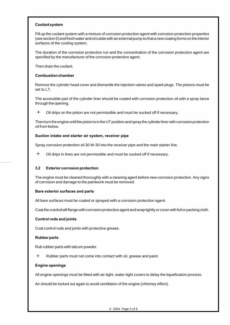
© 2004 Page 5 of 8
Coolant system
Fill up the coolant system with a mixture of corrosion protection agent with corrosion protection properties
(see section 5) and fresh water and circulate with an external pump so that a new coating forms on the interior
surfaces of the cooling system.
The duration of the corrosion protection run and the concentration of the corrosion protection agent are
specified by the manufacturer of the corrosion protection agent.
Then drain the coolant.
Combustion chamber
Remove the cylinder head cover and dismantle the injection valves and spark plugs. The pistons must be
set to LT.
The accessible part of the cylinder liner should be coated with corrosion protection oil with a spray lance
through the opening.
Oil drips on the piston are not permissible and must be sucked off if necessary.
Then turn the engine until the piston is in the UT position and spray the cylinder liner with corrosion protection
oil from below.
Suction intake and starter air system, receiver pipe
Spray corrosion protection oil 30 W-30 into the receiver pipe and the main starter line.
Oil drips in lines are not permissible and must be sucked off if necessary.
3.2 Exterior corrosion protection
The engine must be cleaned thoroughly with a cleaning agent before new corrosion protection. Any signs
of corrosion and damage to the paintwork must be removed.
Bare exterior surfaces and parts
All bare surfaces must be coated or sprayed with a corrosion protection agent.
Coat the crankshaft flange with corrosion protection agent and wrap tightly or cover with foil or packing cloth.
Control rods and joints
Coat control rods and joints with protective grease.
Rubber parts
Rub rubber parts with talcum powder.
Rubber parts must not come into contact with oil, grease and paint.
Engine openings
All engine openings must be fitted with air-tight, water-tight covers to delay the liquefication process.
Air should be locked out again to avoid ventilation of the engine (chimney effect).

© 2004 Page 6 of 8
3.3 Storage and packaging
After being subsequently protected against corrosion, the engine must be stored again in a dry, ventilated
hall or suitably covered. The cover must be placed loosely over the engine so that the air can circulate around
it to prevent condensation from forming. Use a dessicant if necessary.
4 Removal of corrosion protection
The corrosion protection must be removed from the engine before starting. The packaging must be removed
as well as all covers from the sealed openings. Any signs of corrosion and damage to paintwork must be
removed. See section 5 for cleaning agents.
4.1 Removal of interior corrosion protection
Fuel system
- If there is a mixture of diesel fuel/corrosion protection oil in the fuel tank, drain it.
- Fill the fuel tank and fuel system with the proper fuel.
Lube oil system
- If there is corrosion protection oil in the oil tray, drain it or pump it out.
- Fill the engine with the lube oil intended for operation. A purge is not necessary.
- In additional devices with their own oil filling (these include turbochargers, governors, injection pumps etc.)
drain lube oil and fill with new lube oil according to manufacturer specifications.
Coolant system
- If the implemented corrosion protection agent is compatible with the coolant to be used, this can be filled
directly into the coolant system as specified.
- If it is uncertain whether the implemented corrosion protection agent is compatible with the coolant, the
cooling system should be purged with fresh water for about 15 minutes before filling.
4.2 Removal of exterior corrosion protection
- Wash all surfaces and components coated with corrosion protection agent with distilled fuel or a suitable
cleaning agent.
- Wash out grooves of V-belts if necessary.
5 Corrosion protection agents / cleaning agents
Below we list some reference products for the corrosion protection agents or cleaning agents with which the
best results have been achieved. Equivalent products can be used whereby the supplier must guarantee the
suitability of the product for the application.

© 2004 Page 7 of 8
Name Purpose Product name
Supplier
Distilled fuel - Cleaning of engine parts Diesel acc. to DIN EN 590
- Filling the fuel system 85%
distilled fuel
Corrosion protection oil - Protect lube oil system Corrosion protection oil SAE30W-30
- Protect additional devices BP-MEK 30
with own oil filling BP-Deutschland
- 15% to distilled fuel for Hamburg
protecting fuel system
Corrosion protection agent - Protect coolant system Puriton 3956
Kuhbier Chemie GmbH
58566 Kierspe
or
ODACON Z
Reicon Chemie
04103 Leipzig
Corrosion protection agent - Protect bare exterior Gelserol Super
wax-like surfaces and parts Deutsche Castrol
76829 Landau
Protective grease - for control rods and joints Renolit MP2
Fuchs Europe GmbH
68169 Mannheim
Talcum - for rubber parts Talcum fine, white
Silbermann GmbH & Co.KG
86456 Gablingen
Cleaning agent - to remove corrosion protection agent Eskapon S 255
protection agent Haug-Chemie GmbH
74889 Sinsheim
Cleaning agent/ - Thin and remove Renopal B 150
thinner corrosion protection agent Fuchs Europe GmbH
wax-like 68169 Mannheim
DEUTZ AG
Service Information Systems
-Sonntag- -Asselborn-

© 2004 Page 8 of 8
This page intentionelly left blank.
© 2004 Page 1 of 6Printed in Germany
DEUTZ AGDeutz-Mülheimer Straße 147-149
51063 Köln
TR
-Vo
rga
be
-mu
lti, 0
2/0
2,
VS
-TI
1Technical Circular
Product:
Date: This Circular supersedes:
Copies to: Adress:
• Service- Partners At Home and Abroad
(subsidiaries, agencies, dealers)
• Service Centers At Home
• Pocket Book Holders
• Company Departments (02)
• Original equipment manufacturers (OEM)
or end customers
Drawn up by: VS-TI 1 Phone: +49 (0) 621 3 84-88 40
Fax: +49 (0) 621 3 84-88 41
Note: The part numbers indicated in this document serve technical explanation purposes.
Exclusively the spare parts documentation is binding for the definition of spare parts.
en0199 - 99 - 3017
2nd Exchange
DEUTZ01.08.2004 0199-99-3017, 06.09.2002
DEUTZ Gas Engines - Fuel gas
1. General
Fuel gas is the term used to describe gas mixtures of varying composition, calorific value and anti-knock index
which are suitable for use in gas engines.
The knock rating is given by the methane number (MN), where
MN = 100 (antiknock) is defined for methane (CH4) and
MN = 0 (high level of knocking) is defined for hydrogen (H2).
In the case of gases with variable or low methane numbers there is a risk of knocking and hence the risk of
extreme mechanical and thermal stress with possible consequential damage.
The methane number of combustion gas mixtures is influenced by several components. Thereby the main
components are:
- Methane - CH4 - as the most significant component of the standard gas engine combustion gas, particularly
in the case of the diverse natural gases.
- Hydrogen - H2 - which significantly reduces the methane number of the gas mixture. It is mainly present
in combustion gases such as coke oven, blast furnace and low-temperature carbonization gases.
- Higher levels of hydrocarbons - CnH
m with n>1 and m>4 - in other words more hydrocarbons than methane,
which are often very unstable and therefore tend much more to knocking.
- Inert N2 and CO
2 - which do not take an active part in the combustion process, but instead increase the
methane number in a gas mixture, thereby CO2 has three times the effect of N
2.
For the assessment of a gas with respect to its suitability as a combustion gas the attendant materials in the
gas are of great importance. It is true that they have (mostly) no influence on the actual combustion process,
but with respect to the reliable operation of the engine and plant in general these attendant gas materials must
always be taken into account.
These attendant gas materials are released when the gas is generated in sewage treatment works, landfill sites
or biogas plants. They consist of minerals, halogens, metals, heavy metals etc., which form a link with the
hydrocarbons. Depending on the quantity and the damaging effect these attendant gas materials must be
filtered out of the combustion gas in front of the engine. The limiting values of the significant attendant gas
materials, which are known of at present, are listed in Table 2.
0312 1859

© 2004 Page 2 of 6
2. Classification into gas groups
The possible combustion gases are classified into different groups according to their abrasive properties. In
this way the respective maintenance plan in the operation manual can be assigned to the engine.
Engines, which we have supplied, may only be operated with the combustion gas for which they were planned
according to the scope of supply. If you wish to change the combustion gas then please contact DEUTZ first.
Gas group 1 Gas group 2 (bio-gases)
Natural gas sewage gas
Pit gas methane gas
Liquified gas Wood gas
- propane, butane, LNG (liquid natural gas)
Attendant petroleum gas (petroleum gas) other bio-gases
Gases with a hydrogen content, H2 > 30 Vol%,
e.g. coke oven gas
Table 1 Classification into gas groups
3. Minimum properties of combustion gases for gas engines
Please note:
●●●●● The minimum properties for which an engine operation is still possible are given.
However, the max. possible power of the engine is not given in all cases,
●●●●● For the engine-specific requirements of the respectively approved combustion
gases see Table 3.
●●●●● The given minimum properties are only valid for the engine. For plant parts the
respective manufacturer’s documentation should be followed, see also Table 4.
Property Desc. Unit Limit Remark
Calorific value (lower cal. val.) Hu
[kWh/mn
3] ≥ 4Rate of increase H
u[%/min] < 5
CO2/H
uCO
2/H
u[Vol%/kWh/m
n
3] < 10
Sulphur content (total) S [mg/mn
3 CH4] < 2200
or H2S content H
2S [Vol%/m
n
3 CH4] < 0,15 Due to corrosion in the engine
Chlorine content (total) Cl [mg/mn
3 CH4] < 100
Fluorine content (total) F [mg/mn
3 CH4] < 50
Sum of chlorine and fluorine (Cl+F) [mg/mn
3 CH4] < 100
Ammonia NH3
[mg/mn
3 CH4] < 30
Dust content [mg/mn
3 CH4] < 10
Grain size [µm] 3 - 10
Oil gases > C5 < C10 [mg/mn
3 CH4] < 3000 No condensation in gas control
Oil gases > C10 [mg/mn
3 CH4] < 250 system and the suction pipe
Silicon (organic) Si [mg/mn
3 CH4] < 10
Humidity (relative) ϕ [%] < 80 At lowest air temperature
In general no condensation is permitted in the gas control system and the suction pipe
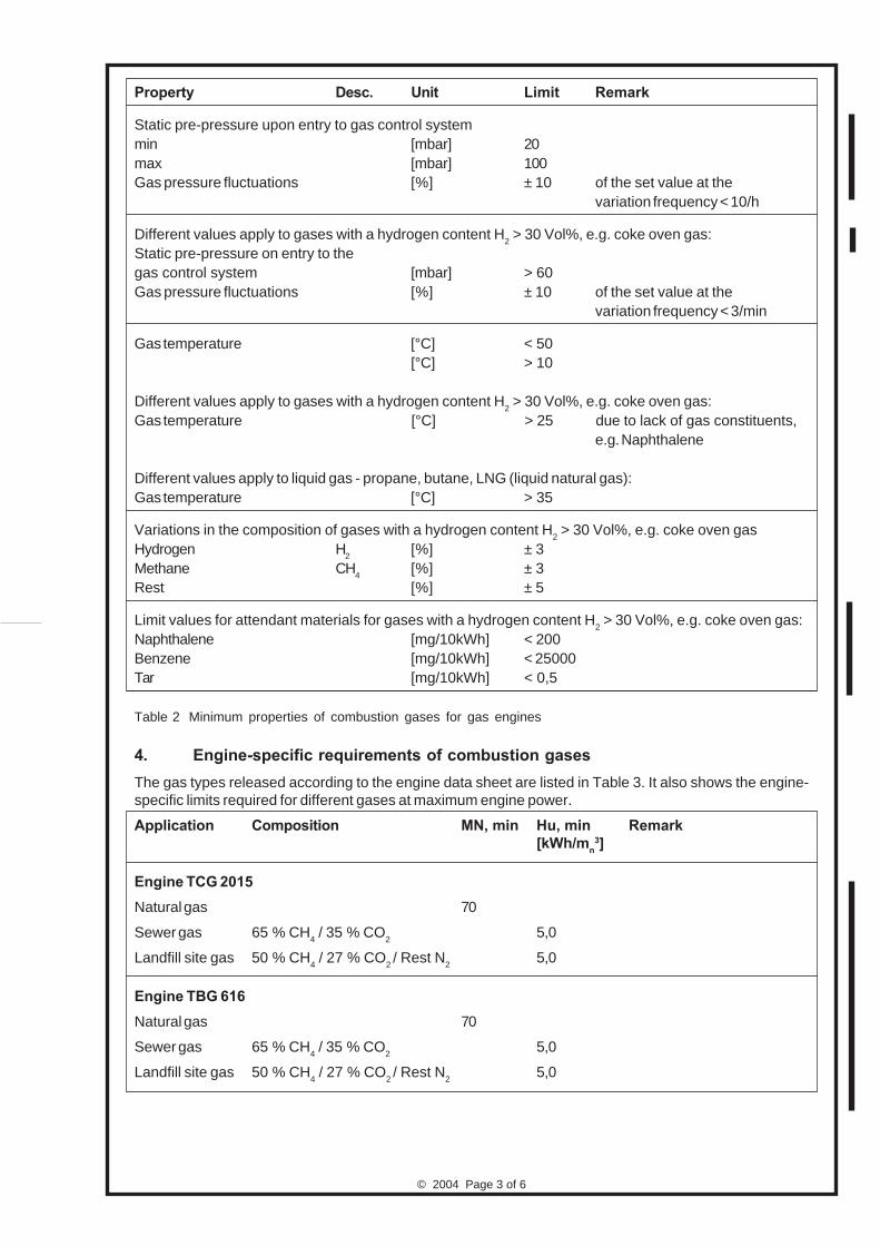
© 2004 Page 3 of 6
Property Desc. Unit Limit Remark
Static pre-pressure upon entry to gas control system
min [mbar] 20
max [mbar] 100
Gas pressure fluctuations [%] ± 10 of the set value at the
variation frequency < 10/h
Different values apply to gases with a hydrogen content H2 > 30 Vol%, e.g. coke oven gas:
Static pre-pressure on entry to the
gas control system [mbar] > 60
Gas pressure fluctuations [%] ± 10 of the set value at the
variation frequency < 3/min
Gas temperature [°C] < 50
[°C] > 10
Different values apply to gases with a hydrogen content H2 > 30 Vol%, e.g. coke oven gas:
Gas temperature [°C] > 25 due to lack of gas constituents,
e.g. Naphthalene
Different values apply to liquid gas - propane, butane, LNG (liquid natural gas):
Gas temperature [°C] > 35
Variations in the composition of gases with a hydrogen content H2 > 30 Vol%, e.g. coke oven gas
Hydrogen H2
[%] ± 3
Methane CH4
[%] ± 3
Rest [%] ± 5
Limit values for attendant materials for gases with a hydrogen content H2 > 30 Vol%, e.g. coke oven gas:
Naphthalene [mg/10kWh] < 200
Benzene [mg/10kWh] < 25000
Tar [mg/10kWh] < 0,5
Table 2 Minimum properties of combustion gases for gas engines
4. Engine-specific requirements of combustion gases
The gas types released according to the engine data sheet are listed in Table 3. It also shows the engine-
specific limits required for different gases at maximum engine power.
Application Composition MN, min Hu, min Remark
[kWh/mn
3]
Engine TCG 2015
Natural gas 70
Sewer gas 65 % CH4 / 35 % CO
25,0
Landfill site gas 50 % CH4 / 27 % CO
2/ Rest N
25,0
Engine TBG 616
Natural gas 70
Sewer gas 65 % CH4 / 35 % CO
25,0
Landfill site gas 50 % CH4 / 27 % CO
2/ Rest N
25,0

© 2004 Page 4 of 6
Application Composition MN, min Hu, min Remark
[kWh/mn
3]
Engine TCG 2016
Natural gas 80
Sewer gas 65 % CH4 / 35 % CO
25,0
Landfill site gas 50 % CH4 / 27 % CO
2/ Rest N
25,0
Engine TBG 620
Natural gas 70
Sewer gas 65 % CH4 / 35 % CO
25,0
Landfill site gas 50 % CH4 / 27 % CO
2/ Rest N
25,0
Engine TCG 2020
Natural gas 80
Sewer gas 65 % CH4 / 35 % CO
25,0
Landfill site gas 50 % CH4 / 27 % CO
2/ Rest N
25,0
Engine TCG 2032
Natural gas 80
Data for special gases and two-gas operation upon request or in the case of engines, which
have already been delivered, according to the supplier documentation.
Table 3 Engine-specific requirements
5. Project-related requirements
● If the required minimum properties of the combustion gas are not met or if it is contaminated with non-
specified components the service life of the engine and its components will be reduced. The scheduled
maintenance times given in the scheduled maintenance plan for the proper specified engine operation
are often substantially fallen short of and hence lose their relevance completely.
● If the planned combustion gas does not meet the minimum properties given here or if the combustion
gas contains additional by-products, which are not specified, and without the actual combustion gas
analysis having been released in writing by DEUTZ, then any guarantee claims against DEUTZ or any
form of liability by DEUTZ will be invalid
● At the time of commissioning, a gas analysis must be submitted (not older than 2 weeks) and the
commissioning report must be attached. After commissioning, a gas analysis is to be carried out 3
times a year and a check made to see if the minimum properties are being complied with. In the event
of a warranty claim, these gas analyses must be presented.
● The respective manufacturer’s documentation should be followed for other plant parts. See also:
- “The design of power plants with gas and diesel engine operation“
(Planning and installation advice)
of DEUTZ AG
- “Project Manual“
of DEUTZ AG
● If catalysers and/or exhaust gas heat exchangers are used the respective manufacturer’s information
should be followed with respect to the permitted gas composition and exhaust gas temperature.
Table 4 Project-related requirements
© 2004 Page 5 of 6
6. Sampling and gas analysis
Sampling and gas analyses are to be carried out according to the relevant standards and guidelines.
We recommend Tedlar bag sampling. This process is calibrated and suitable for determining SI compounds,
chlorine, fluorine, sulphur, chlorinated hydrocarbons/chlorofluorocarbons and aromatic compounds from a
sample. The sample can be used without problems affecting the pressure side of the compressor.
Sampling using the methanol impinger method (washing bottle method) or sampling on activated carbon
(Draeger method) is only possible for Si compounds or, with limitations, also for chlorinated hydrocarbons/
chlorofluorocarbons. Not all Si compounds remain stable and/or conversion processes occur. In addition to
this, the gas volume must be determined exactly, which requires the corresponding equipment on site.
A selection of the analysis parameters is given here:
Analysis parameters Method
Main components DIN 51872-04-A
(O2, CO
2, N
2, CH
4)
Total chlorine, fluorine, sulphur DIN EN 38409 H8 (Wickbold combustion)
using the Wickbold method DIN EN ISO 10304-1 (Ion chromatography)
Total silicon/org. Silicon compounds in appendix VDI 3865, sheet 4
Ammonia VDI 2461, sheet 2, Nessler process
Hydrogen sulphide DIN 51855-4; VDI 3486, Sheet 2
Table 5 Sampling and gas analysis
Si compounds which must also be analyzed with gas chromatography as a minimum requirement:
for landfill sites:
Trimethylsilanol
Hexamethyldisilanol (L2)
Octamethylcyclotetrasilanol (D4)
Decamethylcyclopentasilanol (D5)
for sewage treatment works also:
Hexamethylcyclotrisilanol (D3)
Table 6 Si compounds
7. Examples for the methane number (MN) for selected gases
Biogas MN > 120
Pit gas MN ≅ 105
Methane MN = 100
Natural gas MN = 65 - 95
Propane MN = 33
Butane MN = 10
Hydrogen MN = 0
DEUTZ AG
Service-Technology
- Sonntag - - Boos -

© 2004 Page 6 of 6
This page intentionally left blank.

Medium and Large Size Engines
General Safety Regulations
0297 7857 en
Reprinting and reproduction of any kind, even in form of
excerpts, requires our written approval.

Medium and Large Size Engines
Page 1
General
Safety
Regulations
© 0202
Table of Contents
1 General Safety Regulations
1.1 Selection and qualification of personnel
1.2 Organizational measures
1.3 Intended use
1.4 Symbols used
� Warning signs
� Prohibitive signs
� Order signs
� Notes
� Stickers
2 Safety Regulations for Medium and Large Size Engines
2.1 Transport
2.2 Operation
2.3 Fuels and lubricants
� Diffusion fluids for flaw detection testing
� Various cleansing agents
� Liquid nitrogen
� Fuel (liquid fuel and gas)
� Lubrication oil
� Coolant
� Coolant pre-heating
2.4 Maintenance, inspection and repair
� Electrics / electronics, general
� Battery
2.5 Waste disposal / recycling / waste material
� Waste disposal
� Recycling
� Waste material

Medium and Large Size Engines
Page 2
General
Safety
Regulations
© 0202

Medium and Large Size Engines
Page 3
General
Safety
Regulations
1 General Safety Regulations
This document has been published in various languages. In case of possible uncertainties or interpretative
difficulties the German version is always decisive.
Each country (state) has its own safety regulations. No matter under which work and local
conditions you are working - compliance with all private or public safety regulations of the
respective country (state) and liability association is mandatory.
The safety regulations in this brochure must not be considered as being final for the complete unit
(combustion engine and powered machine), because the assembly and interaction of combustion engine
and powered machine requires further safety relevant measures.
The safety regulations issued by the machine manufacturer must therefore also be observed.
Furthermore, the safety regulations on the respective worksheets in our operating instructions and workshop
manuals must also be complied with.
1.1 Selection and qualification of personnel
Work on or with the combustion engine as well as on the complete machine must only be carried out by
authorized specialists.
A legally specified minimum age must be observed.
Responsibilities for operation, set-up work, maintenance and repair must be clearly determined.
1.2 Organizational measures
The operating instructions must be handed out to the operating personnel. These must be always at hand
at the operating location of the combustion engine, or, if this is not possible, in any other way accessible
for the operating personnel.
With the help of the operating instructions the operating personnel must be instructed in the handling of the
combustion engine, whereby all safety relevant information must be explained in particular. This is especially
valid for persons who work on the machine only occasionally, e.g. for set-up or maintenance work.
In addition to the operating instructions all generally valid legal or country specific regulations for the
avoidance of accidents and the protection of the environment must also be complied with at the operating
location.
Unauthorized changes to the engine can have an adverse effect on safety. The manufacturer will not assume
liability for any damage resulting from this. Manipulations on the injection and governor system may also
affect the performance and exhaust emission characteristics, so that compliance with legal environmental
regulations can no longer be assured.
Only genuine DEUTZ parts may be used.
All notes and warning stickers attached to the engine must be observed and maintained in legible condition.
1.3 Intended use
The combustion engine is solely intended for the contractually determined purpose of use. Any other use
or any use for applications exceeding the intended use is considered as unintended use. The manufacturer
will not assume liability for any damage resulting from this. The user is the sole bearer of any risk.
Observing the operating instructions and compliance with the maintenance instructions is also part of the
intended use.
© 0202

Medium and Large Size Engines
Page 4
General
Safety
Regulations
1.4 Symbols used
The following warning, prohibitive, order signs and notes may be attached with various symbols. These have
the following meaning:
� Warning sign
This symbol is used for all safety regulations the negligence of which will cause danger to
health and life of the persons involved.
Warning of combustible materials
Warning of caustic substances
Warning of dangerous electrical voltage
Warning of harmful or irritating substances
Warning of dangers caused by batteries
Warning of hot surface
� Prohibitive signs
Fire, naked light and smoking prohibited!
� Order signs
Wear eye protection
Wear a hard hat
Wear ear defenders
Wear safety gloves
Wear safety clothes
� Notes
This symbol is used for all notes the negligence of which causes the risk of damage to material,
malfunction and damage to the environment.
© 0202
�

Medium and Large Size Engines
Page 5
General
Safety
Regulations
� Stickers
Stickers are used on the engine to give instructions and to highlight possible special danger
sources which could lead to physical damage.
Damaged or illegible stickers must be replaced immediately.
There are many possible danger sources during operation, set-up, inspection, repair or other work.
Unfortunately it is not possible to fight all these dangers by attaching warning signs. It is therefore of utmost
importance to have the engine operated and serviced by trained personnel concentrated on their work.
Note symbols and warning stickers are in compliance with the technical status at the date of delivery of the
engine.
Due to technical and legal changes the safety regulations for the handling of combustion engines and the
signs to be attached may also change. It is therefore very important to keep an eye on the latest technical
developments.
2 Safety Regulations for Medium and Large Size Engines
2.1 Transport
- Use only transport devices specified by the manufacturer.
- Use only lifting gear recommended by the manufacturer.
- Use only the lifting points specified by the manufacturer.
- Transport the engine only in „as installed“ position.
- For transport lash the engine down only at the points specified by the manufacturer.
- After a transport distance of 50 km check the fastening for tight fit, retighten if necessary.
2.2 Operation
Check before or during commissioning:
- Safety installations for completeness and function!
- Lines, hoses and fittings for leaks!
- Intake and exhaust system for function and compliance with the installation specifications of the engine
manufacturer!
- Run combustion engines only in appropriately ventilated rooms, if necessary use a fume extraction
system. Ensure sufficient ventilation before starting in closed rooms!
- Never bridge the contacts of ignition switches, battery or starter. This can cause severe injury and/or
damage to property.
- Before starting make sure that no persons are in the danger area of the engine!
- Due to the high risk of an explosion engines with compressed air starting system must not be started
with the help of combustible gases and oxygen, even in cases of emergency!
- Start the engine only from the operator’s stand.
- After a starting fault crank the engine without fuel injection!
- Do not perform several cold starts within a short period of time.
© 0202
WARNUNG
Verbrühungsgefahr...
Bei jeder Tätigkeit .............

Medium and Large Size Engines
Page 6
General
Safety
Regulations
- Be extremely careful in the vicinity of rotating, moving and hot parts.
- In the vicinity of the running engine wear ear defenders.
- Please remember that wearing ear defenders will affect the perception of possible warning sounds.
Watch out more intensely for visual alarm signals.
- During operation keep an eye on control lights and gauges.
- In case of deviation from the normal values, e.g. overheating, shut the engine down immediately and
perform trouble shooting. If necessary contact the customer service department. Do not perform any
temporary repairs yourself.
- Inspect the engine at least once every day, even better once per shift, for externally visible deficiencies
and damage! In case of malfunction of the engine have the fault corrected immediately! This applies
particularly for malfunctions which could impair the safety, shut the engine down!
- Make sure the engine does not overshoot after being shut down!
2.3 Fuels and lubricants
� Diffusion fluids for flaw detection tests
- Danger of poisoning when working with trichloroethylene!
- Wear goggles and safety gloves!
- Avoid contact with skin and eyes!
- Ensure sufficient ventilation!
- Extract fumes, do not inhale!
� Various cleansing agents
- Observe the safety instructions of the individual manufacturers.
- Observe the waste disposal regulations, see also para.2.5.
� Liquid nitrogen
- Observe the safety instructions of the manufacturer.
- Wear goggles and safety gloves.
- Risk of perfrigeration.
- Disposal of fluid residues according to the instructions of the manufacturer, see also para. 2.5.
� Fuel (liquid fuel or gas)
- Fuel fumes and gases are harmful, do not inhale.
- Fuel fumes and gases are highly inflammable, do not smoke, do not use open fire, no formation of sparks.
- Do not refuel in closed rooms. However, if this cannot be avoided ensure an adequate supply of fresh air.
- Refuel only with the engine shut down.
- Catch running out fuel. Do not let it seep into the ground!
- Clean the engine from spilled fuel. Risk of combustion on hot engine parts.
© 0202

Medium and Large Size Engines
Page 7
General
Safety
Regulations
- Always keep the tank tightly closed
- Do not lay cleaning cloths soaked in fuel on hot engine parts, risk of ignition.
- Ensure strict cleanliness.
- Do not open any components under pressure, e.g. injection lines or similar.
- When checking the injection jet keep your hands away from the fuel jet.
- Dispose of replaced filter cartridges environmentally.
- Observe the waste disposal regulations, see also para. 2.5.
- Work on injection pumps and on the control linkages between speed governor and injection pump are
only permitted in emergencies and must be checked and, if necessary, readjusted by the DEUTZ
service as soon as possible.
� Lubrication oil
- Oils in engine, transmission or hydraulic system can be under pressure or very hot after operation of the
engine. Before starting work or inspections in such systems the pressure should be relieved by following
the instructions of the manufacturer and safety gloves and goggles should be worn to avoid burning or
scalding.
- Before starting work on oil circuits apply appropriate measures to collect possibly leaking out oil.
- Always ensure strict cleanliness.
- Before disassembling shut down the engine as specified in the operating instructions.
- Laboratory tests revealed that the permanent contact with engine oil will cause cancer.
After work all skin areas in contact with engine oil should be thoroughly cleaned with water and soap.
- Do not lay oily cleaning cloths on hot engine parts, risk of ignition.
- Dispose of oily rags, filters etc. environmentally.
- Wipe up any spilled oil from the floor or any other walk-along areas immediately.
Danger of slipping.
- Make sure that oil does not get in contact with rubber or plastic parts of the engine. Such components
could be destroyed by oil and cause severe material damage or bodily injury during later operation.
- Dispose of any oil dropping down while taking oil samples or oil filter service environmentally together
with the filter cartridge.
- Service the lubrication oil centrifuge only when the engine is stopped.
Dispose of dirt and lubrication oil environmentally.
- Dispose of dirty lubrication oil environmentally.
- Dispose of oily air filter elements environmentally.
- Observe the waste disposal instructions, see para. 2.5.
© 0202

Medium and Large Size Engines
Page 8
General
Safety
Regulations
© 0202
� Coolant
- Wear safety gloves and goggles.
- Let the coolant cool down before opening the cooling system.
- The coolant is under pressure.
- Open the radiator cap slowly, danger of scalding by coolant squirting out or steam.
- Do not touch any engine components or coolant pipes. These are also very hot, danger of burning.
- Coolant additives are partly toxic, therefore avoid contact with skin and eyes, if necessary wash off
immediately.
- Do not drink any coolant, danger of poisoning.
- Dispose of drained off or spilled coolant as specified by the manufacturer, see also para. 2.5.
Do not let it seep into the ground.
� Coolant pre-heating
- Observe the documentation issued by the manufacturer of the coolant pre-heating system.
� With coolant pre-heating system in operation
- Hot coolant, danger of scalding, coolant system is under pressure.
- During pre-heating and engine operation the shut-off valves before and after the pre-heating unit must
always be open, do not close!
- Do not touch any coolant conducting components, danger of burning.
- Before starting maintenance work switch the coolant pre-heating system off and make sure that it is not
started again unintentionally.
Switch of the power supply to the unit.
� With coolant pre-heating system switched off
- The coolant system is under pressure.
- Before opening the coolant system the coolant must have cooled down.
- Close the shut-off valves at the coolant feed and discharge ports only before disassembling.
- During disassembly catch running out coolant, reuse it or dispose of environmentally, see also para 2.5.
2.4 Maintenance, inspection and repair
- Maintenance, inspection and repair work must generally be performed after the engine has been switched
off and cooled down.
- With the engine in operation there is a risk of being injured by rotating and hot parts.
- The maintenance work specified in the operating instructions and in the workshop manual must be
performed as scheduled and completely.
This ensures problem free, secure and environmental operation of the engine.

Medium and Large Size Engines
Page 9
General
Safety
Regulations
- Compliance with all legal and engine specific accident prevention instructions and safety regulations is
mandatory.
- The work described in the operating instructions and in the workshop manual require, among others, the
replacement of parts as well as fuels and lubricants. These replaced parts / fuels and lubricants must
be stored, transported and disposed of as prescribed.
- Secure the engine against unintended starting, if necessary disconnect the battery or close the shut-
off valve on the pressure vessel.
- Attach a warning sign to the operator’s platform, e.g. „Do not start - maintenance work“.
- Have maintenance, inspection and repair work only performed by specially trained personnel.
- Clean engine and area around the engine thoroughly before starting work.
- Allow engine and machine components to cool down before starting work, if necessary wear safety
gloves.
- Perform adjustments only with the engine shut down.
- If certain work is specified to be carried out with the engine running, all related safety regulations must
be strictly followed.
- If the engine is installed in a vehicle, the respective vehicle must be parked on solid ground before starting
work. The vehicle must additionally be secured against rolling.
- All tools needed for work must be clean and in perfect condition. Do not use tools misappropriately and
do not make any temporary tools yourself.
- Use only the specified special tools.
- Use only the prescribed lifting gear and lifting tackle to remove assemblies or components.
- Place removed parts down well secured against tipping over, support if necessary.
- Use only liquid cleansers approved by the manufacturer to clean components or engine and dispose of
these after use as specified by the manufacturer of the cleanser, see also para. 2.5.
- Do not use fuels or other combustible liquids for cleaning.
- Repair and cleaning work on fuel tanks must only be performed by specially trained personnel in
compliance with all special safety regulations applicable for this purpose.
- When working on the fuel or gas system do not use open fire, do not smoke, no formation of sparks.
- Take care when disconnecting fluid conducting lines, the fluid may be hot and under pressure. Therefore
relieve the pressure beforehand and apply preventive measures against scalding.
- Always wear safety gloves when checking for leaks in fluid systems.
Fluid jets penetrating the skin can cause severe bodily injury.
- Route and fasten lines for fluids and electrical system in a professional manner. Length, fittings and
quality of the line must comply with the requirements.
- Before starting welding or torch cutting work disconnect the engine from ground, disconnect possibly
available engine control modules.
© 0202

Medium and Large Size Engines
Page 10
General
Safety
Regulations
- Do not perform any repairs on safety valves. Replace defective parts immediately!
- Before resuming operation make sure that all guards and safety installations, that had probably been
removed, have been reinstalled.
- Make sure that there are no unauthorized persons near the engine when resuming operation.
� Electrics / electronics, general
- Before starting work in the electrics/electronics de-energize the system, pull the ignition switch off.
Compliance with the accident prevention instructions for electrical systems, e.g. VDE-0100/-0101/
-0104/-0105 electrical precautions against dangerous contact voltages - is mandatory.
- Do not touch any current conducting parts!
- Mind the high electric voltage on ignition systems.
- When cleaning with fluids all electrical and electronic components must be tightly covered.
- Return electronic scrap to a specially set up collecting place, see also para. 2.5.
Do not dispose off together with the domestic waste.
� Battery
- When working with or on the battery the following regulations must be observed:
- Always wear protective clothing when working with or on batteries.
Wear at least goggles and safety gloves.
- The battery electrolyte contains acid. Contact with skin, eyes and clothes must be strictly avoided.
However, in case of any contact with skin and clothes neutralize the acid drops immediately with an acid
converter or soap suds and rinse off with lots of water.
- In case of eye contact rinse out immediately with clear water for at least 15 minutes and consult a
physician immediately.
- If acid has been drunk call for medical help immediately.
- Do not lay any tools on the battery (short circuit and danger of explosion).
- Avoid the sparking when handling cables and electrical equipment.
- Avoid short circuits.
- During transport secure batteries against slipping and tipping over, insulate the plus pole.
- When charging batteries open the individual cells, if this is possible, so that the the gases developing
during the charging process can escape.
These gases are harmful and explosive, therefore always ensure sufficient ventilation and avoid sparking
and smoking.
- Do not tip the battery over, acid may seep out of the degassing openings.
- Be extremely careful when connecting and disconnecting the battery charger. Strictly comply with the
operating instructions of the manufacturer of the battery charger.
- Return old and defective batteries to the to the supplier or a specially set up collecting place, see also
para. 2.5.
Do not dispose of together with domestic waste.
© 0202

Medium and Large Size Engines
Page 11
General
Safety
Regulations
2.5 Waste disposal / recycling / waste material
� Waste disposal
Waste disposal includes measures and technical methods for the disposal of residues (e.g. metal, plastic
material, rubber), fuels and lubricants (e.g. lubrication oil, coolant, fuel), other fluids (e.g. cleansing agents,
degreasing agents) as well as waste material (e.g. sealing and screw retention agents, grease, glue).
In this context recycling (reuse) of these residues, fuels and lubricants as well as waste materials has
priority.
Details concerning waste disposal and its monitoring are controlled by regional, national and international
laws and regulations, which must be observed by the operating company in their own responsibility.
It is recommended to file any evidence on the disposal of wastes that require special monitoring.
� Recycling
Recycling is a general term for the material recovery of residues, fuels and lubricants as well as waste
materials.
� Waste materials
Waste materials are all mobile objects the owner wants to or hast to get rid of.
Objects which arise during production or service work, as well as objects the owner no longer has any use
for.
The avoidance of waste material has priority.
Unavoidable wastes should, as far as possible, be recovered materially or energetically.
Waste to be disposed of is waste that cannot be recovered.
© 0202
Medium and Large Size Engines
Page 12
General
Safety
Regulations
© 0202
Notes: