
TaT issue 76 Low Res.pdf - The Automotive Technician
40
Toyota Aurion Faulty a/c servo Audi A3 Terminal symptoms Mazda 6 Hazard switch Nissan Navara D40 Blown fuse Mercedes-Benz C200 Dodgy module Like us on Facebook Repair solutions Join TaT today www.tat.net.au • Cooling systems • Brake and clutch • Diesel servicing • 4WD focus Y o u r D i a g n os t i c P a r t n e r Technician Automotive The Issue 76 2020 WWW.TAT.NET.AU MAXIMUM SAFETY AT YOUR SERVICE, CHOOSE TRW. Premium safety backed by more than 100 years of experience. trwaftermarket.com
-
Upload
khangminh22 -
Category
Documents
-
view
2 -
download
0
Transcript of TaT issue 76 Low Res.pdf - The Automotive Technician

Toyota Aurion Faulty a/c servo
Audi A3 Terminal symptoms
Mazda 6 Hazard switch
Nissan Navara D40 Blown fuse
Mercedes-Benz C200 Dodgy module
Like us on FacebookRepair solutions
Join TaT today www.tat.net.au
• Cooling systems• Brake and clutch• Diesel servicing• 4WD focus
Your Diagnostic Partner
TechnicianAutomotive
The Issue 76 2020
WWW.TAT.NET.AU
MAXIMUM SAFETY AT YOUR SERVICE, CHOOSE TRW.Premium safety backed by more than 100 years of experience.
trwaftermarket.com

2 The Automotive Technician
You’re fiercely independent.Joining us will help you stay that way. We understand that being independent is important to you, just as it is for our Members. We also understand the pressures of running an independent operation. This knowledge helps us provide the tools and support that keep our more than 20,000 Members’ businesses strong. It could help keep yours strong, too.
TM
Join Australasia’s largest automotive [email protected] | capricorn.coop | 1800 327 437

The Automotive Technician 3
PublisherThe Automotive Technician Pty LtdABN 27 121 589 80230 Dale StreetBROOKVALE NSW 2100Ph: 1300 828 000(in Australia)or + 61 2 9907 1332Fax: 1300 828 100All communications to:[email protected]
Editorial boardGeoff MuttonJeff SmitJanene Champion
Technical editorJeff Smit
Sub-editorCameron McGavin
General managerGeoff Mutton
Scan Data directorRod Maher
Technical researchBrendan Sorensen
Technical assistance moderatorScott Thomas
Technical contributorsBrendan SorensenMark RaboneFrank Massey (UK)Clinton Brett (Diesel Help)Jack StepanianSam NazarianJason Smith
Technical assistance teamDeyan BarrieAndrew KolloscheSideth ChivMaurice DonovanGil SherAnthony TyddWayne BroadyJason SmithMarty HosieJack StepanianMark Rabone
Associate team membersGary HomanPeter HindsGraham PattersonAllen ChamberlainSimon Forsey
ColumnistsGeoff Mutton (TaT Biz)
Advertising inquiriesJanene [email protected] 226 77003 5862 3090
Graphic designRussell Jones Graphic Design [email protected] 0411 817 012
PrintingMcPherson’s Printing Group76 Nelson St, Maryborough VIC 3465mcphersonsprinting.com.au
The Automotive Technician Pty Ltd publishes, in print and on its website, technical advice, case studies and items contributed by its members and readers for the purpose of educating technicians and preparing them for a rewarding aftermarket future.
All advices are given in good faith, and are based on actual workshop repairs.No guarantee is given, nor any liability accepted in respect to any published advice.
The Automotive Technician Pty Ltd is not responsible for the accuracy of any information contained in material submitted by contributors or other third parties and published either in print or in digital format online and accepts no liability in relation to such materials or their content.
Newsworthy articles or comments are welcomed, and should be submitted to the technical editor.
All material appearing in The Automotive Technician is copyright.
Reproduction in whole or in part is illegal without prior written consent from the Editorial board.
TaT SD (Scan Data), TaT programs and TaT reviews are exclusive resources to financial members of the TaT network.
All are strictly copyright and must not be published, copied or shared in any manner outside the TaT membership.
All advertisers agree to indemnify the publisher for all damages or liabilities arising from their published or unpublished material.
CONTENTS - The Automotive Technician - Issue 76, 2020
• TaT’s a fact • TaTassist • TaT share • TaT train • Tat Biz • TaT SD (Scan Data)
• TaT programs • TaT reviews • TaT check • TaT find
are all trade names ofThe Automotive Technician Pty Ltd
The Automotive Technician is a member of the Circulations Audit Board.
Audit period 1st April to 30th September 2018. Average net distribution 9795
Affiliated associationsVASA –
[email protected] Society Alliance Supplier
31 Clinton BrettThe hidden extras of a diesel engine
34 Jason SmithVolkswagen Eos with leaking roof
8 Jason SmithPico 4.5 metre USB2 cable
11 Frank MasseyLooking closely at combustion
6 Brendan SorensenGathering the evidence
38 Geoff MuttonWhat’s your forecast profit this financial year?
14 Sam and JackMimicking the operation of an ammeter
THE TAT TEAMYou’re fiercely independent.Joining us will help you stay that way. We understand that being independent is important to you, just as it is for our Members. We also understand the pressures of running an independent operation. This knowledge helps us provide the tools and support that keep our more than 20,000 Members’ businesses strong. It could help keep yours strong, too.
TM
Join Australasia’s largest automotive [email protected] | capricorn.coop | 1800 327 437
28 Mark RaboneUnderstanding the tools we have

4 The Automotive Technician
W ell, 2020 will go down as the most challenging year of my working life
so far and I’m sure many of you are in the same boat.The year started with much of the country on fire, then came the rain and flooding. None of that, however, could prepare us for the current COVID-19 pandemic.We’ve gone from the possibility of a total lockdown and very uncertain times to a partial lockdown where we, as an industry, could still trade – thank goodness for that. I know we all suffered in many different ways and to many different degrees. I hope everyone has come out the other side ready to take on the challenges ahead.
As I am writing this, Victoria is going back into lockdown while the rest of the country is further relaxing restrictions. I hope the outbreak in Melbourne can be contained and doesn’t spread to other parts of the state and country.My experience at the moment – and what I am hearing from others – is that most workshops are busy. That’s good but, rest assured, there will be more challenges ahead.My belief is our customers are now seeing their motor vehicles as more important to them than ever before. From getting the kids to school, getting themselves or a family member to the doctors to shopping or even the family holidays, a safe and reliable
family car is more crucial than ever. So how can we make the most of this situation?Those workshops that have already established a line of communication with their customers – whether via app, SMS or email – are ahead of those who have not. Having direct and fairly instant contact with your customer base is a big first step.The key is to let your customers know you’re open and ready to help, whether it’s for general servicing, repairs, upgrades or even a general safety check before they head off for a weekend away. It all helps to build on the relationship you have with them. If you’re into 4WDs or camping, you need to let your customers know because these are now the go-to holiday options in the absence of overseas travel. Now is the time to build on customer relationships. You need to do this before someone else does and you
can’t just assume the OE dealer networks are going to sit back and do nothing.
What about the medium to long term? What have your thoughts been? Where do you want to be in three to five years? It’s times like we have been through, and are still going through, that can sometimes give us the drive – or necessity – to think ahead.
As the saying goes, if you change nothing, nothing will change. Our industry and customers are changing at an increasing rate but are you changing at the same or greater rate? If you are not, you will be left behind.
The challenge now is to think ahead and try to stay ahead. This is often easier said than done but times like those we are going through can give us the wake-up call that is required. Make the most of this opportunity.
I wish everyone health and happiness.
The TaT SoapboxJeff Smit
June 30, 2020 was another significant date in the life of TaT. Deyan Barrie, a long-time friend and TaT founding director, handed his baton over to Brendan Sorensen.
This change had been in the planning for some time and all parties are very happy with the transition.Deyan has been an essential part of the TaT team from the very beginning and I’m sure he will stay involved and continue to contribute, especially with his fantastic repair solutions.Deyan and I first crossed paths a long time ago. I think he best summed up our friendship in this personal note he sent to all the TaT technical team:Hi guys,As the TaT technical team, I wanted you guys to know the changes in the TaT directors.As of end of June 2020, I have officially passed on my directorship to Brendan Sorenson.I am extremely pleased to inform you gentlemen, especially with this news, as I am confident it will strengthen and grow the TaT brand.It gives me great satisfaction to step down knowing it is in great hands.I have seen Brendan’s passion, knowledge and youthful energy shine through and I
know that all you guys feel the same. It’s a wonderful feeling when you get to my age and see this legacy unfold and grow.A little basic history for those that don’t know.I was talking to Jeff and reminiscing the other day about how our TaT idea started some 20 years ago as a thought bubble on a plane to Surfers Paradise for a meeting with the VASA (Automotive Air Conditioning, Electrical and Cooling Technicians of Australasia) board, and the start of bringing the AAAE (Australian Association of Auto Electricians, which we ran together) with VASA.Our first thoughts on the plane were that we had to push for more training instead of the usual supplier-focused convention. This was how the first Wire & Gas convention was born. A few years later, thanks to the help of a very talented writer and true gentleman called Ken Newton, the wheels started to turn, with a group of us taking on the role of editing the AE & AC magazine. From there, some time in 2006 I believe, a four-director team kicked
off the start of TaT, with Jeff Smit being the powerhouse driving the vision forward.I have a lot of strong feelings for the TaT brand and for all of you guys that are and have been the backbone of the organisation. You have gone so much further and beyond, making it your mission to make TaT – along with the industry we live and breathe – the best that it can be as it evolves to keep up with what is going on around us.I will not be far from my keyboard and will keep on sharing and entering solutions and be part of the TaT team for as long as you will have me.I am excited and extremely pleased that Brendan has taken on this new role and responsibility. My sincere thanks and gratitude for your support and friendship.Warmest regards,Deyan BarrieI think Deyan has summed up our journey with TaT very well. All of us wish him the very best in the future as he continues to run his workshop in Sydney.Thanks Deyan, you’re a big man with an even bigger heart for our industry, TaT and the members within it. You deserve a long, relaxed and healthy retirement. Hope to catch up at a training event or conference as soon as we are allowed to!– Jeff and all the TaT team
Another founding director hands over the baton

The Automotive Technician 5
TRW, a global leader in safety systems for the automotive aftermarket with 100 years of experience behind it, has announced a significant investment in the local market with the expansion of its braking-product offering through ZF Services Australia, effective from August 1, 2020.TRW is a premium ZF brand and leading supplier of OE-quality braking, steering and suspension components for passenger vehicles, light-commercial vehicles, heavy-commercial vehicles and motorcycles.TRW’s local offering covers 2744 brake-related product lines and benefits from the input of 6000 engineers, designers and experts from around the planet. It says this ensures its products are the benchmark of the industry.
Maximum safetyTRW says safety is always at the forefront of its thinking and its rigorous testing gives vehicle manufacturers, aftermarket suppliers, workshops and ultimately consumers the confidence to trust its wide array of products.It says working with premium vehicle manufacturers for more than a century has given it the know-how to produce cutting-edge products that are tailored to ensure efficient installation in the workshop.
Brake-pad leaderTRW says its market-leading advances in brake pads set the brand apart and that the range of products available in Australia provides coverage for the majority of the local car parc.One recent innovation for the ZF brand has been what it claims is the world’s first aftermarket brake pad for electric vehicles.Called ‘Electric Blue’, it has been produced in response to the global move toward hybrid and electric vehicles, which has placed specialist demands on the aftermarket.For more traditional petrol and diesel-powered vehicles, TRW applies COTEC – an advanced silicate made of naturally occurring materials that forms an eco-friendly coating – to the majority of its brake pads.TRW says this innovative coating allows its brake pads to consistently outperform other premium brands during the bedding-in period and improve the friction co-efficient when braking performance is at its lowest, especially when fitted in combination with TRW brake discs.TRW has also developed DTEC, a premium-quality ceramic brake pad claimed to reduce brake-dust exfoliation onto the surface of the wheel rim by up to 45 per cent.
Brake-rotor rangeTRW produces more than 12 million brake discs worldwide every year for both OE fitting and aftermarket purposes, with a range of 559 parts destined for Australia.
The brand’s High Carbon Discs were developed to reduce weight while improving braking
performance and noise, vibration and harshness (NVH) properties via optimal
thermal conductivity.TRW says this technology allows the discs to run cooler for more consistent brake performance, better stability and increased resistance to
distortion and thermal cracking.TRW uses the edge-grinding method for
manufacturing discs and says this ensures they remain balanced for the life of the rotor for
safe, comfortable and vibration-free driving.Each TRW disc has the minimum thickness, part number and a traceable batch code etched into the edge of the rotor for peace of mind.Another signature TRW product is its Black Painted brake discs, which feature a special gloss-black paint coating to provide a protective barrier against corrosion.These discs are packed in moisture-inhibiting VCI paper and do not have to be cleaned with oil or rust preventative prior to fitting, meaning they can be taken straight out of the box and installed, saving time for workshops.TRW also offers a range of cast-iron discs made from GG20 grey cast-iron material, as well as an assortment of discs with integrated bearings, anti-lock braking system (ABS) ring sensors and fixing accessories, all to suit a multitude of replacement applications.
Brake accessories, consumables and beyond!ZF Services Australia will also be offering a range of TRW OE-quality companion products from August 1, including necessities such as brake hoses, brake fluid, brake grease and brake cleaner.For more information contact ZF Aftermarket on 02 9679 5555 or go to www.trwaftermarket.com
ZF expands TRW brake program

6 The Automotive Technician
Last issue (TaT issue 75) I mentioned a common-rail diesel (CRD) with an intermittent problem. After clearly explaining the difference between a service and testing for a fault to the customer, it was time to look into the problem.
The car in question was a 2008 Peugeot 308 with the 2.0-litre CRD engine. The customer complained that it was intermittently idling poorly. Twice in the previous month it had even cut out while slowing down for traffic lights but both times it had started back up straight away and then run fine.Some targeted questioning did not reveal any patterns. As always with intermittent faults, I explained to the customer that our job was to gather evidence. We would need to determine which vehicle systems could cause the fault, then have our test equipment hooked up on the correct system to catch it in the act – anything else would just be guessing, which was not what we are about.With the car left for the day, I started with my generic diagnostic checklist, covering core items such as:
Reading up on the history in our system or in the owner’s manual. A full fault-code scan while I checked the fluid levels. Battery, charging and globes testing, along with a voltage-drop reading from the battery negative to chassis. A visual underbonnet check, not physically disturbing anything. A glance over scan-tool temperature and pressure readings before starting the car, then doing the same at idle and 2000RPM. I also analysed some key common-rail data such as injector-flow correction values.
So far there was nothing out of the ordinary and there were no fault codes. With my fingers crossed, I went for a varied 10-minute test drive with the scan tool recording but, as expected, no fault presented. Key items such as fuel-rail pressure remained steady as a rock at steady loads.Since the fault was described as occuring at idle, I decided to use my remaining tier-one diagnostic block time to let the car do
the work and left it running just outside the door, within earshot and with the scan tool recording.Occasionally when I walked past I would check the RPM, mass air flow (MAF) and fuel-pressure data parameter IDs (PIDs). My scan tool records the mininum and maximum figures so any deviation we didn’t hear would be recorded there.Close to two hours later, I finally heard the fault – a slight surging RPM at idle. I rushed over and, to my dismay, the Peugeot was now idling perfectly. My scan tool’s min/max figures for fuel-rail pressure, however, had some deviation. At some point, the rail pressure had skewed plus 400psi and minus 600psi away from the fairly stable 3800psi I had been seeing at stable idle. I pressed the scan tool’s save button and captured the fault for later review.
A quick scroll back through the scan tool showed PIDs such as accelerator, exhaust-gas recirculation
(EGR) and turbo-vane position remaining stable but RPM, MAF and rail pressure surging a few times before steadying.I now had some diagnostic direction towards a possible fuel-system fault, so I got approval from the customer to continue testing. I advised them that, depending how often the
vehicle decided to fault, I expected I’d need approximately one additional hour of time for
analysis.The Delphi system in this vehicle utilises an inlet-
metering valve (or suction-control valve) on the high-pressure (HP) pump but no other HP control devices such as a fuel-pressure regulating valve on the fuel rail.As with any CRD system, my first test was confirming the low-side fuel supply. I used to rely on some clear generic irrigation hose between the filter and HP pump for systems relying solely on HP pump-suction supply like this one. Nowadays I’ve adapted a clear sight block with a gauge and
am able to read both positive and negative pressure. This allows me to see pressure (positive for in-tank,
pump-fed systems, negative for HP pump-suction fed systems) and flow (no air bubbles). The addition of a tap allows you to deadhead
the in-tank pump to proof-test its ability or create a sealed, suction-based system that should be able
to retain negative pressure (i.e. testing for a leaking fuel-filter O-ring in suction-based systems, pic 1).No air was evident in the low-side fuel system. Access on this model was terrible, with the HP pump tucked so far back I could barely get a fingertip on the inlet metering valve (IMV), let alone access the wiring. I decided to assess the mechanical operation of the HP fuel system using my oscilloscope, accessing the circuits at the ECU.
Gathering the evidence
with Brendan
Sorensen
1
2 3

The Automotive Technician 7
On channel A (blue), I back-probed the IMV control wire. On channel B (red), I back-probed the rail-pressure sensor. For viewing ease I also set up a duty-cycle math channel on channel A (the black channel on the capture) and two measurements to show a numerical display of both channels. At steady idle I had a 69 per cent IMV duty cycle, giving 1.04V rail pressure (pic 2). Raising the RPM saw a drop in duty cycle – a reduction in the positive voltage side of the duty-cycle towers – resulting in higher rail pressure, so by the look of it we had a normally open, power-side driven IMV. In other words, the IMV had a constant ground and applying power to it would reduce its opening, creating less flow and lower rail pressure. If access permitted, it would have been nice to have a current clamp on the IMV, too, but for now – aside from separating the tight wiring loom – this was as much access as I would get.Eventually, as the vehicle idled away in the corner, I heard a brief surge in the idle RPM. I raced over, paused my capture and went back over the data. Zooming in during the fault, over the course of a mere 100 miliseconds, I could see the rail pressure had dropped below 1V with no change in IMV duty cycle. Quickly, with rail pressure around 880 millivolts and a stall event imminent, the ECU responded by dropping the IMV duty cycle to 52 per cent in an attempt to open the IMV further and raise rail pressure (pic 3). Rail pressure rose, the engine did not stall, and this small balancing act of IMV duty and rail-pressure fluctuation could
be seen over the next few hundreds of milliseconds, measuring only in the hundreds of millivolts. My scan tool had no chance of capturing that event, but my scope had succeeded.
Now I had more evidence of a fuel-system issue, so I contacted the customer and explained the IMV was our most likely
suspect at this point and – given its relatively low cost – replacing it and the fuel filter were the next reasonable steps. I fitted a new Delphi IMV and again left the vehicle to run with the scope and scan tool rolling. The new IMV was able to maintain a stable rail pressure of 1.08V at 60 per cent duty cycle.
Had we fixed it? Given the intermittent nature of the fault, that would be a bold call.
When the customer picked the car up, we showed them the print-out evidence supporting the replacement of the IMV. We also showed them the almost rusty appearance of the old IMV mesh (pic 4), advising that we found no evidence of corrosion in the actual fuel
filter but any further issues would require deeper investigation. With faults that are intermittent and have
a brief fault time, it is important to lay all the facts on the table. We are not magicians and, while we can do our best to prove a symptom is corrected, it is important to manage customer expectations and avoid saying, ‘The car is fixed.’Luckily for this little Peugeot, the customer reported the symptoms had not returned after
several weeks of driving.
4
Elite

8 The Automotive Technician
Equipment reviewswith Jason Smith
A lot of workshops are now entering into the world of Pico scopes and the like, which introduces the problem of what set up to use or – to put it another way – how to set up your diagnostic workstation, etc.
As I write this I’m thinking how I could be touching on a sore point with some techs or opening a can of worms for others. Just the thought of setting up a diagnostic workstation can be overwhelming and confusing. How do you run cabling and the like? Where do you mount your Pico? Should you run a boom for the cables? How do I mount the PC or monitor? All of these sometimes confusing thoughts could well be a TaT story in itself.Just remember, you’re the one who has to use it, so do what’s best for you, your type of work and don’t try to reinvent the wheel. Just build something that’s useable for you.Which brings me to the Pico 4.5 metre USB2 cable (part number MI121) – this could solve a lot of problems when deciding how to set up your diagnostic workstation!Most Pico kits are sold with a 3.0 USB cable with a standard length of approximately 1.8m (part number TA155). However, I often need a longer USB cable for certain diagnostic jobs, so a few months ago I purchased the longer 4.5m version (pic 1 and 2).I’ve found it extremely useful and a great addition to my diagnostic workstation. I use it to back-probe signals out of powertrain control modules (PCMs) when they’re mounted under
the dashboard (pic 5 and 6) – you can plug the 4.5m cable into your PC, sit the Pico unit on or inside the vehicle (pic 3 and 4), then use your test leads to back-probe the PCM to obtain signals (pic 5 and 6) and still display waveforms on the screen of your workstation or monitor. It can stop you from needing to disturb the set up of your workstation too much.The list of uses for the Pico 4.5m USB2 cable are endless, so I highly recommend purchasing one.Pico recommends using the standard 3.0 USB cable where possible because a signal can diminish over a certain (i.e. longer) length but I’ve found using the 4.5m cable for most signals is fine.It’s worth mentioning you should only use genuine Pico cables because problems can crop up when using even good-quality, non-genuine cables.The part number for the new cable can vary among suppliers, so please check. Some alternatively list the cable as USB2 or USB 2.0.
Some local suppliers: OPUS IVS (also known as, or better known as Autologic Diagnostics).
Mount Auto Equip Services. CoolDrive.
1
Top Tool –Pico 4.5 metre
USB2 cable2
3
5
4
6

The Automotive Technician 9

10 The Automotive Technician
Scan Barcode
Vehicle Search
Media Library
Hotline
Part Search
CheckPoint
Product Range
About
16:08
40 %VoLTE
Find the right spare parts and technical information fast.• Schaeffler product catalogue and
full TecDoc database featuring all manufacturers
• Product search by part, OE or barcode numbers
• Vehicle and VIN/engine code search • Barcode scanner to check a box in
your workshop• Dual mass flywheel torque tightening
and other values• Media Library with installation videos• Information on Schaeffler products
for transmission, engine and chassis
Download the REPXPERT App for free today.
schaeffler.com.au/aftermarketTechnical info: repxpert.com.au
The anti-lock braking system (ABS) light was illuminated in this 2005 Subaru Outback
petrol, causing it to fail its registration check.
Scanning the vehicle brought up the following codes:
• C0105 – RR wheel-speed sensor.
• C0106 – RL wheel-speed sensor.
Road-tested the vehicle while monitoring the rear wheel-speed sensors and both read lower than the front but still worked.
The customer wanted to replace both sensors.
Replaced the rear tyres to match those on the front and road-tested the vehicle again.
Now only the rear-left (RL) wheel-speed sensor read lower than the rest.
Removed the RL wheel-speed sensor and found the tone wheel was damaged and in the seal.
Removed the hub, thinking the seal might have been slipping and not spinning at wheel speed.
While replacing the rear tyres seemed to fix the right-rear (RR) wheel-speed sensor, the RL hub ultimately needed to be replaced to fix the problem.
Diagnostic time for the job was one hour and repair time was
one hour.Matthew Fish
Jindabyne Auto RepairsJINDABYNE, NSW
Share your solutions
Want to share a repair solution? www.tat.net.au/tat-share
2005 Subaru Outback
ABS light on, rego fail

The Automotive Technician 11
Frank Massey is a leading automotive technical trainer and writer in Lancashire, England. www.autoinform.co.uk
I’m sure none of us could have foreseen just where we would end up today, no more than it is possible to predict where the future will take us. However, I do believe we can have confidence in several probabilities.
The requirement for vehicle repair and servicing will remain and I predict an even more discerning demand from the public for skilful independents to provide that service. It’s inevitable some businesses will cease trading, resulting in a loss of employment for many skilful technicians. The market will find its own natural level and I do not think artificial stimulation will change this. However, this is definitely a pivotal moment when professionally structured, financed and client-focused businesses will take the prime opportunities in our future.As for now, it hurts and hurts a lot, so let’s refocus for a moment on those skills that will be essential. Every day we hear about the importance of testing and the science-led evidence that will result in the quickest possible success. This is the message I and others have applied to vehicle diagnostics for decades. I hope it may now convince other, more skeptical techs how vital it is.As I reflect here on the past, present and future, I’ll focus on combustion problems.
Starting off, we should replace the term misfire with combustion anomaly, which includes a combination of mechanical, ignition and fuel delivery-options as the cause, and these can be and often are intermittent in nature.The past provided many assets that have sadly been dismissed by many today. It could be the obvious visual inspection of the sparking plug or simply listening to the combustion note in the exhaust, where combustion transients can clearly be detected. These were usually associated with fuel quantity, atomisation and flame spread. More on that later.One of the greatest assets was four-gas analysis. This was an acquired art, the bible for all discerning tuners.Has it been stolen? Have we lost it? Where has it gone? It’s still there, you just need to know where to look. It’s hidden, often disguised in the belief that onboard diagnostics will find problems for us. But it would be a mistake to rely entirely on that process, so it’s back to the future, McFly!Why not drill the pre-cat manifold install a rivet nut and hose ferrel? Now you can blow the dust off your four or five-gas analytical skill.
The expression lambda is taken from a mathematical calculation of the four key gases – carbon monoxide (CO), hydrocarbon (HC), carbon dioxide (CO2) and oxygen (O2) [splint calculation].Optimum air/fuel ratio for a given engine design is achieved when CO and O2 balance at around 0.5 per cent (off-load), producing the highest CO2 value at 16-17 per cent. HCs should be exceptionally low at 50-100 parts per million (ppm). These values may subtly change depending on the sophistication of fuel delivery and engine design.Let’s now focus on a phenomenon experienced visually when looking at the spark profile with an oscilloscope. The spark line should display a relatively smooth transition with a slightly negative slope or bow across its entire duration. The spark duration is of paramount importance. It is not dependant on the total energy value (joules) and may vary from two to four milliseconds (ms) dependent on system design. The firing-line voltage (pressure) is determined by the value of resistance in the firing-line circuit. Coil ringing or resonance at the end of the burn time reflects on the integrity of the secondary coil windings. Tom Denton reflected on this recently on a Facebook post – go find it!
The function I’m interested in is the small rise or ‘hump’ after the burn line and just before the coil ringing. From this you could predict the cylinder fuelling. A large hump indicated a lean combustion event, which of course could change with each individual burn. The ultimate way to see this is with a digital phosphor oscilloscope.My thoughts now pass to the injectors, where previous action would have dictated removal and bench-testing. I do accept this is still an option but current thought process is often dictated by time and cost rather than diagnostic expedience. Injector design is, in my opinion, the area where the most advancement has taken place with fuel delivery. The mid 1980s saw around two to four-bar delivery with port injection and single-point manifold injection at one bar but I’m trying desperately to forget about them! Current pressures can reach 700 bar with homogenous and stratified control.Now here is a statement you must not ignore. Bench-testing alone cannot be relied on to determine an injector-performance error, period. Tolerances of two microns dictate that any inappropriate removal technique without the correct tooling will stress the injector, virtually guaranteeing fuel-delivery anomalies. The use of bio-ethanol fuels and foreign object debris (FOD) will also damage the internals, so here we are at the crux of my topic – what are the tools and processes we can use to prove combustion issues?Next month I’ll delve into scoping air mass meter (AMM) output against lambda response, serial-data logging and noise, vibration and harshness (NVH) analysis.Keep well, guys, and remember the automotive support group – it’s there to help you.
FrankMassey
L/H twin scope trace: This image shows both primary and secondary circuits. The profile is normal with a smooth burn line, slightly negative slope and minimal hump prior to coil ringing.
R/H single trace: There is a distinct disruption of the voltage across the plug. I refer to this as a shunt. The main causes are sooty or partial fouled plugs, a cold plug, inappropriate combustion environment (i.e. oil consumption) or an alternative path to ground, depending on spark polarity of course. There is also a more pronounced hump at the end of the spark line.
Looking closely at combustion

12 The Automotive Technician
Top Tool –Rotor Reader Digital Caliper
Equipment reviewswith Jason Smith
L ast year at the Capricorn Trade Show in Melbourne I came across a simple but awesome tool. As soon as I saw it and tried it out, I ordered one on the spot.
Repco’s Rotor Reader Digital Caliper RST230 (pic 1) is marketed as being able to measure disc rotors without the need to remove the wheels from the vehicle (pic 2 and 3). That does work in a lot of cases but in a workshop situation, where vehicles often have the wheels removed anyway, I’ve found it great to get into tight spots between the disc rotor and backing plate (pic 6).As the name suggests, the Rotor Reader is basically a caliper or tool you can use to measure the thickness of disc rotors. Here are some of the advantages of this tool over the normal practice of using vernier calipers:
Larger, easy-to-read screen, which is ideal in low light or tight-space situations.
The jaws are unique in two ways. One has a hook to manoeuvre around the back or inside face of a disc rotor that is small enough to fit outside or in front of any rotor backing plate (in most cases). The inner jaw has a small, strong, circular-shaped magnet to allow the rotor reader to hold itself in position (pic 4, 5, 6 and 7).
The jaws are also spring-loaded to allow one-handed operation when mounting the rotor reader to the disc rotor being measured. No hands are required to position yourself to take the reading (pic 8).
The jaws are small enough to measure the thinnest part of the disc rotor in most cases. Vernier calipers, contrastingly, have longer jaws, so you can get stuck only measuring the thickest part of the disc rotor.
The tool is simple to use, easy to read, accurate and has a range of 0mm to 40.0mm (metric or imperial settings), as well as an auto-off function.Operation is via an SR44 battery (included), which hasn’t needed changing yet in the 10 months I’ve had my unit.Note, it’s recommended to avoid contact with solvents and heat. Also, one of the TaT Tech Team mentioned one of his staff somehow managed to lose the magnet, so – as with all tools – you need to look after it.I think Repco’s Rotor Reader Digital Caliper RST230 is a top tool that’s useful in all workshops.
2
1
5
3
4 8
7
6
The Automotive Technician 13
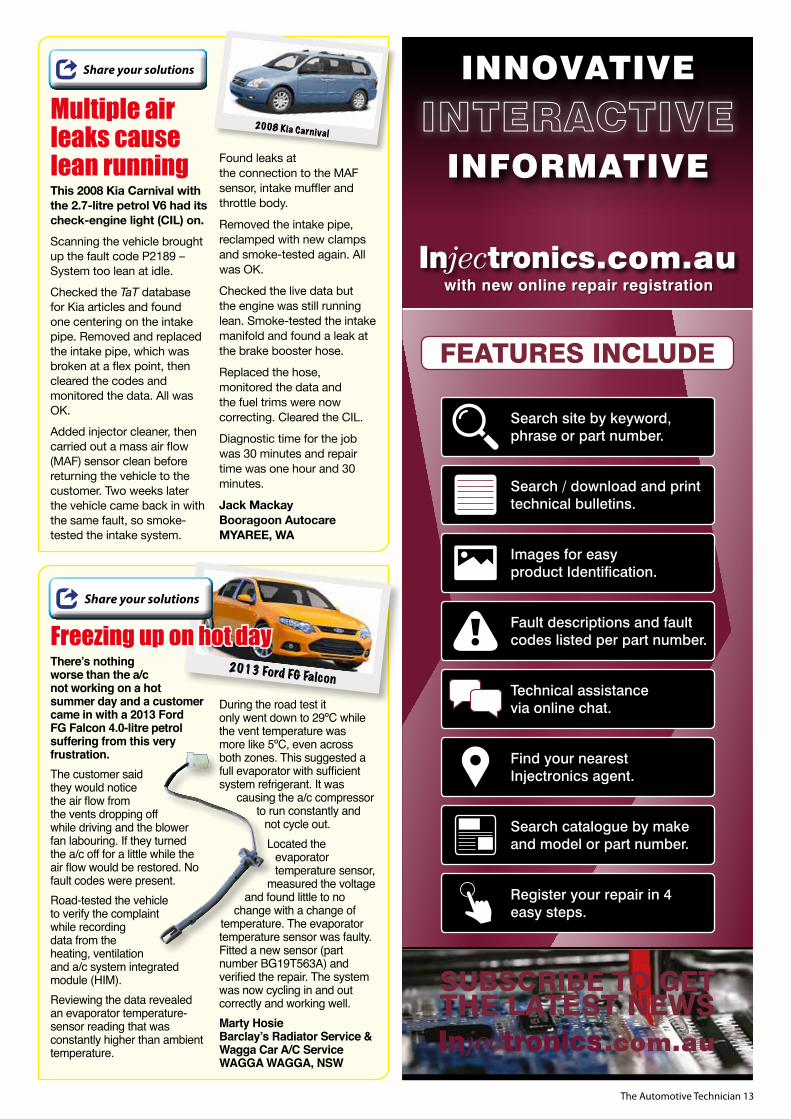
There’s nothing worse than the a/c not working on a hot summer day and a customer came in with a 2013 Ford FG Falcon 4.0-litre petrol suffering from this very frustration.The customer said they would notice the air flow from the vents dropping off while driving and the blower fan labouring. If they turned the a/c off for a little while the air flow would be restored. No fault codes were present.Road-tested the vehicle to verify the complaint while recording data from the heating, ventilation and a/c system integrated module (HIM).Reviewing the data revealed an evaporator temperature-sensor reading that was constantly higher than ambient temperature.
During the road test it only went down to 29ºC while the vent temperature was more like 5ºC, even across both zones. This suggested a full evaporator with sufficient system refrigerant. It was
causing the a/c compressor to run constantly and
not cycle out.Located the
evaporator temperature sensor,
measured the voltage and found little to no
change with a change of temperature. The evaporator temperature sensor was faulty.Fitted a new sensor (part number BG19T563A) and verified the repair. The system was now cycling in and out correctly and working well.Marty HosieBarclay’s Radiator Service & Wagga Car A/C ServiceWAGGA WAGGA, NSW
2013 Ford FG Falcon
Freezing up on hot dayShare your solutions
This 2008 Kia Carnival with the 2.7-litre petrol V6 had its check-engine light (CIL) on. Scanning the vehicle brought up the fault code P2189 – System too lean at idle.Checked the TaT database for Kia articles and found one centering on the intake pipe. Removed and replaced the intake pipe, which was broken at a flex point, then cleared the codes and monitored the data. All was OK.Added injector cleaner, then carried out a mass air flow (MAF) sensor clean before returning the vehicle to the customer. Two weeks later the vehicle came back in with the same fault, so smoke-tested the intake system.
Found leaks at the connection to the MAF sensor, intake muffler and throttle body.
Removed the intake pipe, reclamped with new clamps and smoke-tested again. All was OK.
Checked the live data but the engine was still running lean. Smoke-tested the intake manifold and found a leak at the brake booster hose.
Replaced the hose, monitored the data and the fuel trims were now correcting. Cleared the CIL.
Diagnostic time for the job was 30 minutes and repair time was one hour and 30 minutes.
Jack MackayBooragoon AutocareMYAREE, WA
Multiple air leaks cause lean running
Share your solutions
2008 Kia Carnival

14 The Automotive Technician
When diagnosing a flat battery or, more correctly, the cause of a car battery that keeps going flat, technicians often get a bit lost.
Diagnosticians tend to assess the incorrect (i.e. excessive or inadequate) current draw due to the following possibilities:
Collapsed or faulty battery cell (discharging itself, within itself). Incorrect fitment of aftermarket accessories. Unstable, parasitic controller area network (CAN) bus system (i.e. the system does not go to ‘sleep’). Malfunctioning pulse width modulated (PWM) charging system (i.e. the system fails to deliver the correct amount of charging current).
There can be many other reasons.The process or act of measuring parasitic current draw presents a number of challenges, including:a. The actual methodology of measuring current of a faulty component in an ‘obscure’ physical location’ (pic 1).b. Measuring a current flow without interrupting the circuit.
This can be very difficult, particularly at and around fuse boxes (pic 2).c. Measuring direct current draw (i.e. DC amp draw value) with a digital multimeter often will not display meaningful spurious high-frequency oscillations. This is due to the meter’s limited range of operating bandwidth from DC to typically 150 hertz (Hz) (pic 3).d. Retrospectively speaking, oscilloscopes and or current clamps have much higher operating frequency ranges (DC to 50 megahertz [MHz] and more) that can visually display spurious and base, low level, ground noises (pic 4).The challengeSo the challenge is this – how can we resolve these problems while measuring parasitic current draw from a fuse box without ‘awakening’ or interrupting the communication sleep cycle (pic 5)? If you’re still interested, keep on reading.In this first of this three-part series we will attempt to ‘mimic’ the operation of an ammeter.But before we attempt to address the methodology of fulfilling most of the criteria listed above, let’s examine the meaning of parasitic current draw.What is parasitic current draw?By definition, it is superfluous or ‘unwanted’ current draw that places undue strain on the main battery – a parasite that drains the battery after the ignition is switched off, the key removed and the vehicle locked.However, with today’s ever increasing use of CAN bus systems designed to facilitate inter-communication between ECMs, manufacturers stipulate a ‘pre-defined’ wait period before the system goes to sleep or reaches a low quiescent current draw, typically less than 30 milliamps (mA).Depending on the vehicle’s level of sophistication, this wait period may vary – pending on OEM data – from three to sometimes up to 40 minutes – simulating pseudo-mini-parasitic current draw, controlled and timed.Mandated wait period and technologyBut what if this controlled pseudo-mini-parasitic current draw does not slowly diminish as per the pre-defined wait period? The result is the CAN bus system remains awake.In this circumstance, how do you identify the circuit responsible for keeping the system awake?
Well, one option would be to plug a scan tool in and identify the culprit via DTCs.Case history – Flat battery2005 Volkswagen Golf TFSI, 2.0-litre BLR engineThe vehicle presented to the workshop with symptoms listed above. A newly fitted battery and alternator had been to no avail – the battery was still going flat. Scan tools and CAN busDTCs retreived via a scan tool such as DTC P01305 – Data bus for infotainment can be extremely helpful (pic 6). However, the act or the process of accessing DTCs from a vehicle will naturally keep the CAN bus system awake because the scan tool is requesting data from each and every individual control unit in the system. Hence, by default, the system remains awake, thereby defeating the purpose.So the question still remains, how do you measure current flowing through each and every individual fused circuit without removing a single fuse?Mimicking an ammeterThe act of interrupting the fused circuit will also keep the CAN bus circuit awake. This is why we might be compelled to mimick and/or adopt an alternative technique often used in ammeters (pic 7).Most commercially available ammeters, in contrast with non-contact type ammeters (i.e. loop-around current clamps), are fitted with:
The problem of parasitic current draw, waveforms and flat batteries – Part 1: Mimicking the operation of an ammeter
with Sam Nazarian and Jack Stepanian
14
2
5
3 6

The Automotive Technician 15
Internally calibrated ‘shunt’ resistor (circled white)… … which is calibrated to be a known value of resistance (grey)… … and placed in series so that, as current flows or passes through, the ammeter probes (blue). The same current will also pass through this calibrated shunt resistor (grey)... …which will, in turn, give rise to or develop a voltage drop across the shunt resistor (purple).
This voltage drop is directly proportional to the current flowing though the circuit and then displayed as a value of current (amps) flowing through the circuit. Hence, the current ammeter. How ingenious is that? But how does it relate to above scenario? Let’s expand on it.Reverse-engineering ammeter operationWe will now reverse-engineer the principles of this ingenious current ammeter, which will allow us to measure the daunting parasitic current flowing through a circuit without removing any fuses from the actual circuitry. This is done in the following manner using Ohm’s law.If we assume we have a circuitry consisting of (pic 8):
A supply of 14V (red)... ... across a load of 1.4 ohms (yellow)... ... relative to ground (green)... ... we will then, according to Ohm’s law, have a current flow through the circuit of 10A (blue).
If the circuit is fused (pic 9,) then the same current will also flow through this fuse (purple) because it is in series.For practical purposes, we will now assume that this fuse has a negligible amount of very low resistance, say 0.01 ohms (grey). This will then develop a voltage drop (pic 10) across the resistance of the fuse in the magnitude of 0.01V (purple). That is according to Ohm’s law:
Voltage drop across a resistor = current (A) x resistance value (ohms). V (drop) = 10 X 0.01. V (drop) = 0.1V (or 100mV).
So we can now substitute, diagrammatically speaking, the symbolic fuse (grey) with the actual on-vehicle fuse (pic 11) following the same Ohm’s law stipulations.Final promiseIndeed, by doing so, we have not only mimicked the operation of ammeter but reversed-engineered the principles of its operation to our advantage (pic 12).
We can now measure the voltage drop across the resistance of an on-car fuse – as a true and direct reflection of the current flowing through the circuit – without removing the fuse (pic 11).That fulfills the above-mentioned criteria – we have measured parasitic current draw without awakening or interrupting the sleep cycle of the CAN bus.
In summaryAll materials used in automotive fuses, while infinitesimally small, do have a finite amount of resistance to the current flowing through them and, as a consequence, they will give rise to an infinitesimally small voltage drop, as stipulated by Ohm’s law.This voltage drop is only in millivolts – thousandths of a volt – but it is still a true reflection of current flowing through the fuse.Therefore, measuring the voltage drop across resistive components (i.e. a fuse) can be an extremely useful technique to measure the amount of current passing through the circuit. It can help you discover the fused circuit that is carrying current and flattening the battery.It is worth noting that not all fuse types (i.e. mini, micro, maxi, regular and so on) will have same voltage drop. This is dependent on the type of blade, composition of fusible material and other factors. Charts are available via the internet, however, that allow you to instantly determine the actual value of the voltage drop for a given fuse, for a given fuse type and the amount of current flowing through it.
Next issueIn Part 2 of this series we will further expand on the technique of reverse-engineering the operation of ammeters by utilising your oscilloscope (waveforms) to
‘see’ the parasitic current draw – via the glory of high-frequency oscillations – without awakening or interrupting the sleep cycle of the CAN bus.
Until then, see if you can beat us to it by having a go yourself first. Good luck!
7 10
11
128 9

16 The Automotive Technician
Autocare 2020, Australia’s largest education-led automotive convention and trade show, has been cancelled.
The decision to cancel the event, slated to be held between October 30-31 this year, came after careful consideration of the extraordinary circumstances surrounding the COVID-19 pandemic. ‘Cancelling Autocare 2020 was a difficult decision for all of us, however we believe it was the right decision to make and one we had to make now, for all involved,’ said Australian Automotive Aftermarket Association (AAAA) CEO Stuart Charity. ‘Autocare will return in 2022, with planning now underway. ‘Looking forward, we will now focus our efforts on the upcoming 2021 Australian Auto Aftermarket Expo (AAAExpo), an event that is primed to become our biggest expo yet. We are confident that we can deliver a safe, world-class event for our industry in 2021.’AAAExpo is Australia’s most comprehensive exhibition of vehicle repair and servicing equipment, replacement parts, tools, and accessories. The event hosts leading industry experts, seminars and features more than 350 top Australian and international brands on display.AAAExpo 2021 is scheduled to run at the Melbourne Convention & Exhibition Centre from April 29 to May 1 next year. Don’t miss the opportunity to attendFor more information go to www.autoaftermarketexpo.com.au
Autocare 2020
Going bush or towing?
xedy has a reputation for responding quickly to market trends and emerging opportunities.
Now the leading OEM clutch manufacturer says it has identified a requirement for more 4WD applications and expanded its range of Safari Tuff Heavy Duty Kits to suit.
Ford Ranger/Mazda BT-50 – Safari Tuff FMK-9041STThe new FMK-9041ST clutch kit is engineered for vehicles with modified ECUs and other performance modifications. Exedy says it offers the improved durability and increased torque capacity Safari Tuff clutches are known for.
The FMK-9041 kit is designed to be a direct replacement for the original self-adjusting clutch system in these vehicles.
Holden RG Colorado – Safari Tuff GMK-9005SMFST
The new GMK-9005SMFST clutch kit is designed to meet the demands of serious off-road driving and replace the original dual-mass flywheel system in Holden’s Colorado.The kit includes a single-mass flywheel and has been engineered to provide smooth engagement, optimum durability and enhanced clutch torque capacity.
Mitsubishi Triton – Safari Tuff MBK-8971SMFSTThe new MBK-8971SMFST clutch kit is manufactured as a direct replacement for the Mitsubishi Triton’s original dual-mass flywheel system and purposely designed
for towing heavy loads such as caravans, trailers or boats or any other situations where the transmission of increased torque through the drivetrain is required.The new kit includes a single-mass flywheel and has been engineered for Triton models with the 4N15 turbodiesel engine.Market conditions and continuous changes in the industry call for constant evolution. Exedy says it will keep navigating these challenges by maintaining a strong focus on its core products and expanding its product line-up to service demand for a broader range of vehicles and parts.These new additions to the Exedy Safari Tuff Heavy Duty Clutch Kit range are available now from authorised Exedy distributors.For more information go to www.exedy.com.au/safari-tuff
safari tuff FMK-9041ST
safari tuff GMK-9005SMFST
safari tuff MBK-8971SMFST
Workshop data for professionals
Looking for something different?
Contact [email protected] www.haynespro.com

The Automotive Technician 17
Visit napaparts.com.au or ashdown-ingram.com.au for all branch details.Copyright © 2020 GPC Asia Pacific ABN 97 097 993 283
NAPA Auto Parts is one of the world’s biggest names in aftermarket automotive parts, with a proud history in knowledge, service
and a wide range from reputable brands.
Ashdown-Ingram, Covs, Global Auto Spares and R&E Auto Parts are consolidating to form NAPA Auto Parts, taking over 90 years of specialist
parts knowledge and the local teams you know and trust, and combining it to make the new name of the Australian automotive aftermarket.
THE NEW NAME IN AUTOMOTIVE
AFTERMARKET
Automotive, Mining & Industrial Supplies
Slacks Creek, QLD
The starter motor on this 2010 Volkswagen Multivan 4Motion with the 2.0-litre
twin-turbodiesel TDI engine was not operating and the vehicle’s glow-plug indicator lamp was also flashing.
The problem had initially been intermittent but was now constant.
The vehicle had a history of previous repairs at other workshops, including the owner supplying second-hand parts.
Confirmed the no-start symptom and checked basic items, including the battery and main circuits to the engine.
A full system scan of all related systems brought up a DTC directly related to the fault in the ECM, P0850 00 [175] (VAG code 5604) – Park/neutral switch input circuit open or short to plus.
Checked related input signals with the scan tool connected at the DSG transmission, selector lever and ECU but found no specific parameter related to this input signal.
Researched the fault code, including using OEM data to identify the setting criteria and basic circuit structure.
Eventually found a dedicated park/neutral (P-N) circuit from the DSG mechatronic unit to pins 42 and 62 in the 94-pin ECM connector via a process of elimination.
Dismantled items around the battery to access the ECM in
the front E-box for testing. Confirmed that the P-N signal was not present due to an open circuit in this wire at the DSG 16-pin connector pin 2.
The open circuit was due to a broken wire inside the insulation.
When the ECU received the correct selector position signal, that did not correlate to the DSG P-N signal, resulting in the no-start situation.
Accessed the 16-pin DSG connector and soldered in a new section of wire, which restored the P-N signal at the ECM.
Cleared the fault code, then confirmed all was operating OK. Problem solved.
Diagnostic time for the job was six hours and repair time was three hours.
Scott ThomasSL-TechWARRNAMBOOL, VIC
Share your solutions
2010 Volkswagen Multivan
Broken wire causes a no-start
Want to share a repair solution? www.tat.net.au/tat-share

18 The Automotive Technician
This 2012 Holden Cruze 2.0-litre diesel came in with the customer
complaining of low power when it was first driven.No fault codes were present when it arrived. They had been cleared by another workshop.Road-testing the vehicle showed it had noticeably low power for the first 100m and wouldn’t rev past 2500RPM.Scanning the vehicle again brought up no fault codes, so scoped the mass air flow (MAF) sensor. It was OK but cleaned it anyway.Checked the diesel particulate filter (DPF) data and there had been no regeneration in 65,000km. Added cleaner and forced a regen. That dropped soot content to zero from from 75 per cent.
Changed the fuel filter at the request of the customer – it had never been changed. Monitored the fuel pressure and it was OK.Monitored the actual boost pressure and it was not meeting the desired pressure. Monitored the variable-geometry turbo (VGT) position versus desired and it was also not meeting phsyically.Watched the VGT operation when loading the car and it was sticky. Further inspection showed the rear housing was filled with carbon.Removed and replaced the turbo, then did a relearn on the values. The problem was fixed.Diagnostic time for the job was three hours and repair time was five hours.Norm TempestBooragoon AutocareMYAREE, WA
Share your solutions
2012 Holden Cruze
DPF and turbo issues
STAY CONNECTED TO YOUR CUSTOMERS
WITH YOUR VERY OWN BRANDED BUSINESS APP
• Individually branded & personalised for your business• Designed specifically for the auto repair industry• Receive booking requests through the App• Send marketing & promotional notifications to
customers through the App• Send service & rego reminders through the App• Receive same-day customer satisfaction feedback &
ratings through the App• Wide range of useful features for customers –
including Warning Light Library, Manufacturer Safety Recalls, Fuel Price Check and Refer a Friend
• Unlimited FREE customer downloads from Apple and Android App Stores.
• Convenient monthly subscription by credit card or through your Capricorn Trade Account
Use stand-alone, or fully integrated with ...
For details visit www.serviceprograms.com.au
Question: A customer of ours has a 2010 Audi Q5 and is complaining of a rattling noise from the engine bay while driving. We have experienced the rattling noise during a road test but are struggling to find the cause back in the workshop. Are you aware of any common rattling noises on this model?
Answer: We have had the same problem reported to us by owners of Q5 models with a/c up to 11/15. The rattling noise is due to insufficient clearance between the a/c pipe and engine-coolant expansion tank. Inspect a/c pipe for signs of contact with the engine-coolant expansion tank (pic 1). Fit modified a/c pipe. Ensure suitable clearance between the a/c pipe and engine-coolant expansion tank. Carry out road test to confirm rattling noise has been rectified.To learn more about Autodata’s innovative new online products visit: www.autodata-group.com/au
The Autodocta
Audi Q5: Rattling noise from engine bay while driving
1

The Automotive Technician 19
MERCC02218MERCEDES-BENZ C200 2002Four-cylinder
Repair solutions
Customer complaintThe vehicle, a W203 petrol model, would not start or crank off the key. The transmission selector was in neutral position.
Problem summaryChecked the vehicle over for transmission issues. When it arrived on the tow truck it started but would not move.
Diagnostic sequenceThe vehicle was pushed into the workshop and the selector was put into park. Later the selector would not move out of park and the vehicle would not even crank over. When we scanned the vehicle for codes a a few hours later it started, ran and could be moved back and forwards. This scenario occurred several times throughout the diagnostic process. Extracted the following related codes from the vehicle: • ME-SFI: Motor Electronics Fuel Injection and Ignition System- 2001-002 (2200F-002)
[stored MIL] P200F – Fault is stored in component N15/3 (ETC control module) [P0705].• ESM: Electronic Selector Module- 1856 (P1856) [stored] – Selector lever position detection has failed.• EGS52: Electronic Transmission Control- 2404 (P2404) [stored] – The stop-lamp switch signal sent from the traction system via the CAN bus is implausible. - 2313 (P2313 [stored] – One or more messages from electronic selector lever module control unit (N15/5) are not available on the CAN bus. - 240C (P240C) [stored] – The selector lever position sent from electronic selector module control unit (N15/5) via the CAN bus is implausible.
Fault descriptionThe fault popped up often enough to test and isolate the problem. This led to the module in the gear-selector box. The scan tool and fault codes confirmed the problem.
Disassembled the centre console and removed the gear-selector assembly (pic 1).The complete assembly must be removed and there is a securing clip holding the arm onto the lever (pic 2).To repair and calibrate the gear-selector unit, specialist repairers need it to be completely intact with the outer casing (pic 3).
Fault solutionSent assembly out to be repaired. When it returned, refitted it to the vehicle and put it through an extensive road test. There were no further issues. Checked for codes again after road test and no related ones came back. Problem solved
Note: When refitting the gear-selector unit, make sure the retaining clip is back in securely at the bottom of the selector arm – it can be a bit of a pain to clip in properly (pic 2).
1 3
2 Want to share a repair solution? www.tat.net.au/tat-share

20 The Automotive Technician
Customer complaintThe vehicle, a 2.5-litre diesel model, had stalled numerous times before restarting. Now it wouldn’t start. On its first visit to shop, we found a blown transmission control module (TCM) fuse. Replaced the fuse and the vehicle now started OK. Found the stalling fault was due to the fuel-pump suction valve. Replaced the valve and all was good but one week later the no-crank situation occured again.
Problem summaryThe vehicle was towed into the shop and an initial inspection confirmed the engine wouldn’t crank.The 4WD light was showing on the dash.
Diagnostic sequenceChecked the starter circuit and there was no power going to the starter solenoid when the key was in the ‘start’ position. Discovered the fuse for the TCM had blown again (pic 1).Carried out a visual inspection of the wiring harnesses, fuse panel, relays, etc in the engine bay. Could get the TCM power-supply wire to short to ground while moving the TCM wiring harness, located near the oil cooler next to the starter motor (pic 2).Further inspection showed the conduit was damaged and the wiring exposed (pic 3).Found the yellow wire had rubbed through and was grounding on the edge of the oil-cooler housing (pic 4).
Fault descriptionThe yellow wire to the TCM was shorting to ground and blowing the fuse. This wire also supplies power to the starter circuit.
Fault solutionRepaired the wire, insulated it and re-routed the harness away from the oil cooler (pic 5).
Recommended time Diagnostic time was two hours, taking into account
preparation and research. Repair time was 1.5 hours, taking into account location of
parts and carrying out the repair to a tested outcome.
Tips for TaTTaT thanks Martin Heagney from Rapid Tune Capalaba in Capalaba, Queensland for providing this case study via TaT share.
NISNA07445NISSAN NAVARA D402007Four-cylinder
Repair solutions
To access the entire Repair Solutions database www.tat.net.au/tats-a-fact
1
2
3
4
5

The Automotive Technician 21
TOYAU13619TOYOTA AURION 2013Six-cylinder
Repair solutions
Customer complaintThe internal air-vent controls were not working as requested.
Problem summaryThis vehicle, a Presara model with only 99,400km on the clock, also had a climate-control module issue.That was replaced during the first section of the repair – look for it under TOYAU13623 in the TaT Solution section of the TaT website – before this repair was diagnosed, an estimate given and then carried out. There was no central air-vent flow and air was being pushed everywhere else.
Diagnostic sequenceWe now had a/c operation after the initial repair but we still had no vent control. Checked the system and tested all of the servo motors that work the various vents. Isolated the problem to the driver-side main servo.Had to disassemble a section of dash (pic 1) to gain access to the main, non-working servomotor. It is located on the driver’s side behind the upper section of
the centre dash area. Confirmed we had inputs at the connector plug and even plugged the servo from the left side in to confirm we had movement.
Fault descriptionPlugging the servo in from the left side confirmed the main servo assembly was faulty. Taking lots of images of where items go and how things sit together is highly recommended when performing this repair. Research showed that the complete dash and heater box must come out to access and replace the assembly because everything is in the way. The servo can also only be replaced when the box is on its side due to some linkage arms and gears that must line up.
Fault solutionDegassed the a/c, then disassembled the main cross beam (pic 2) and steering components (pic 3), which is necessary to gain access. Completely disassembled the dash to access and remove the heating, ventilation and a/c (HVAC) system.
Unbolted the HVAC box and removed it from vehicle (pic 4).Ordered a new servo motor from Toyota.Carefully unbolted and removed the old servo-motor assembly (pic 5). This is the assembly lying on its side (pic 6).Carefully mounted and located the new servo assembly (pic 7) so the linkage arms could locate and slot in correctly (pic 8).Refitted the HVAC box, reassembled the dash, then evacuated and recharged the a/c system. It performance-tested OK. Problem solved.
Recommended time Diagnostic time was included in the
previous repair. Repair time was 12 hours, taking into
account location of parts and carrying out the repair to a tested outcome.
Tips for TaTThe part was in stock at local dealer. When the owner went to Toyota they fired off a sum without hesitation, so this might be a common problem.
1
5 6 7 8
3
2
4

22 The Automotive Technician
AUDA314462AUDI A32014Four-cylinder
Repair solutions
Customer complaintThe vehicle, a 1.4-litre turbo-petrol model, was intermittently stalling at the lights. It would usually play up when cold and then be OK for the rest of the drive.
Problem summaryWhen the vehicle played up, it would stop and go into park mode, meaning the start button had to be pressed and transmission put back into gear to get going again. The previous repairer had replaced the cam and crank sensors and had not cleared the fault codes.
Diagnostic sequenceThe following codes were still in the system: • 4514 (P032100) – Ignition/distributor engine speed input circuit range/performance sporadic.• 10203 (P030000) – Random/multiple cylinder misfire detected sporadic.• 10591 (P030100) – Cylinder 1 misfire detected sporadic.• 10594 (P030400) – Cylinder 4 misfire detected sporadic.
There were no other codes in any of the vehicle’s other systems. Carried out the usual basic checks and, during the underbonnet inspection, it all became clear. The battery was the original and you could see major corrosion setting in on the negative terminal (pic 1).
Fault descriptionPrior to touching anything, took the vehicle out on a short road test, making sure all of the big-load systems (interior fan, a/c system, etc) were switched off.Sure enough, the vehicle played up but not as described. While stopped at the lights, the engine stopped. It needed cranking two times and stopped a few seconds later before finally starting and allowing us to drive off. This occurred a couple of times.
Fault solutionRemoved the battery, then scrubbed, cleaned and treated the negative terminal, which is kind of special on this vehicle because it has a current-sensing device hanging off it (pic 2).Fitted a new absorbed glass mat (AGM) stop/start battery. Logged the battery into the system and made sure all of the codes were cleared. Road-tested the vehicle again and there were no further issues. Problem solved.
Recommended time Diagnostic time was one hour, taking
into account preparation and research. Repair time was two hours, taking into
account location of parts and carrying out the repair to a tested outcome.
Tips for TaTThis was a very obvious issue that could be identified visually but it’s not always the case. Always check that the terminals are clean as part of your diagnostic process. Don’t be fooled by a terminal that looks clean on the outside – always inspect both the post and inside of the terminal for a build-up of resistive material.
Customer complaintThe hazard lights on the vehicle, a petrol model, were inoperative.
Problem summaryThe hazard switch was not working but the blinkers were.
Diagnostic sequenceNo fuses were blown.The circuit diagram for the vehicle showed a momentary push circuit to trigger the body-control module.
Tested and isolated the problem to the switch on the dash itself. It was faulty.
Fault descriptionThe hazard switch on this vehicle is part of the centre dash panel and infotainment system (pic 1).Disassembled and removed the centre control panel/audio system head-unit assembly. Tested the circuit to the main connector plug, which is internal of the actual circuit board. The switch is part of the assembly (pic 2).Pulled it out, pulled the modules apart and found corrosion at the back of the hazard-switch circuit board.
It had damaged the copper track and gone open circuit (pic 3).
Fault solutionGot into that section and found it was the earth for the complete board. Repaired the circuit by running another earth circuit over the other side, bypassing the break (pic 4). Reassembled and checked. The hazards now worked off the switch as required. Reassembled the centre console and rechecked operation. Problem solved.
Recommended timeLabour time was four hours, taking
into account research time, location of parts and actual time spent fixing the problem.
MAZM607422MAZDA 62007Four-cylinder
Repair solutions
1
1
2
2
4
3Break
Switch
Break

The Automotive Technician 23
Bosch BatteriesDriven by RELIABILITY
The modern vehicle has an increasing number of electronic components and systems that require electrical power.
Bosch batteries are the power supply that deliver the necessary high performance and safety to meet the demands of today’s modern vehicles, including start-stop vehicles.
Contact your local authorised distributor
www.boschautoparts.com.au
Coverage: SA, VIC, TAS, NT and South NSW & ACT
Phone Number: 08 8260 6111Email: [email protected]
Coverage: WAPhone Number: 08 9417 7033Email: [email protected]
Coverage: QLD and NSWPhone Number: 1300 001 772Email: [email protected]
PV, LCV, SUV & 4WD Marine HCV & Off Highway Deep Cycle/VRLA
00107M A4 TAT Battery Adv 2020 Fin.indd 1 8/7/20 3:09 pm

24 The Automotive Technician
This 2019 Hyundai PD i30 with the 2.0-litre GDI petrol engine came in with the customer complaining of a recurring flat battery.
The battery had gone flat and been replaced by roadside assist. The issue had reoccurred and the battery was replaced again before the vehicle was taken to the local dealership. The dealership had run tests and couldn’t find any faults, so the vehicle was sent back to the owner. The vehicle was returned to the dealership soon after due to another flat battery. We were at the dealership repairing another vehicle and were asked to help continue with diagnosis.Scanned the vehicle with the OEM tool and there were no DTCs. There were some controller area network (CAN) bus DTCs in the history but these were likely caused by previous technicians removing components during diagnosis.The vehicle had a steady current draw of 630 milliamps (mA). Removing fuse 16 (memory fuse 1) from the integrated gateway and power-control module (IGPM) dropped the current draw to 150mA.Sourced schematics and further information.
Share your solutions
2019 Hyundai PD i30
CAN bus not going to sleep

The Automotive Technician 25
In the meantime, the driver’s door connector was readily accessible and unplugging this also dropped the current draw to 150mA. This would dissipate over 20 minutes to approximately 8mA.Fuse 16 at the IGPM also has an internal leak current autocut device (LCAD) that controls the automatic light and photo sensor, as well as the clock ICM relay box (outside mirror folding/unfolding relay).Removing the door trim and unplugging the mirror switch confirmed our suspicions and further testing confirmed that the CAN bus wasn’t shutting down when the switch was set to ‘auto’. It was not clear whether the mirror switch was keeping the LCAD switched on or if there was a fault with the LCAD causing current to flow to the mirror switch.The mirror switch position can be set to always open, which stops the excessive current draw for quick testing purposes or if parts arent readily available.Replaced the electric-mirror switch in driver’s door, which was the cheapest and easiest option, then retested it. All was OK but communicated to the owner that the fault could also be stemming from the IGPM.Diagnostic time was five hours, including the time spent waiting for modules to sleep and retesting to a proven outcome so the vehicle could be safely sent away until the parts arrived. Repair time was one hour.Michael CrossleyDriven Auto ElectricsRINGWOOD, VIC Want to share a repair solution? www.tat.net.au/tat-share

26 The Automotive Technician

The Automotive Technician 27
This 2009 Nissan Navara D40 diesel was suffering from a lack
of power. The customer also said they thought the gearbox wasn’t changing gears correctly.Road-tested the vehicle and it felt like it had no turbo boost. Checked for fault codes and none were present.Checked the manifold absolute pressure (MAP) sensor with a scan tool, which confirmed a lack of boost.Then, when checking the operation of the vacuum-operated wastegate using a Mityvac, noticed the vacuum hose wasn’t tight despite a
piece of the hose remaining on the vacuum-hose fitting on the wastegate – the outer sheath had made it look like it was connected properly.Previous repairs had been done in the area, on the heater hoses. Suspect the vacuum hose might have accidentally been leant on.Cut the hose slightly shorter and resecured, then rechecked operation on the road. All was now OK.Diagnostic time for the job was one hour and repair time was 15 minutes.Wayne BroadyBarrie Auto ElectricsHORNSBY HEIGHTS, NSW
Share your solutions
2009 Nissan Navara D40
Dodgy hose causes no boost
This 2009 Hyundai i30 came in with the customer complaining
of a noise in its 1.6 diesel engine and now it wouldn’t start.The noise described by the customer sounded like a loose torque convertor or flex plate. The noise had since stopped but then the vehicle would not run under 1000RPM and now it would not run at all.Scanned the vehicle for codes and one came up, P0341 – Cam sensor performance.Checked the fuel pressure on the scan tool and it was correct. Obtained information from the Hyundai service site, checked the sensor wiring and voltages, then scoped the crank and cam.
Suspected the timing was out.Checked the cam timing and it was correct, so concentrated on the noise that was no longer present. Knowing the crank/cam was incorrect, removed the engine and found the flex plate had broken as suspected. That had caused the incorrect crank timing.Fitted a new flex plate, then refitted the engine. The car now ran and idled. Diagnostic time for the job was one hour and repair time was 10 hours.Peter HindsBrisbane Mobile MechanicsGREENBANK, QLD
Share your solutions
2009 Hyundai i30Engine noise turns to no-start
Want to share a repair solution? www.tat.net.au/tat-share
NTO
_TAT
_Aug
_072
0
BeltsCompressorsCondensersCoolantEGR CoolersEGR ValvesElectric FansExpansion BottlesFan BladesFan ClutchesFan ResistorsFiltersGlobes
More than just RadiatorsThousands of Quality Cooling & Service Parts
Glow PlugsHeatersHosesIgnition CoilsIntercoolersLightingOil CoolersRadiatorsRefrigerantSpark PlugsWater PumpsWiper Blades
Click into Natrad!
NationwideWarranty
Backed by our
natradtrade.com.au

28 The Automotive Technician
with Mark Rabone
Understanding the tools we have
I’ve seen it many times. A workshop is talked into purchasing a new piece of diagnostic equipment and has the rep train them for an hour or so. The staff in the
workshop use the new scan tool, access the fault codes, replace the part the scan tool has identified and then blame the tool for not fixing the problem.What should you do as soon as you get a new piece of equipment? Well, after doing what always needs to be done first – taking in that new piece of equipment smell – you should read the instructions.Wait... what? I thought real men didn’t read instructions?Well, I’ll let you in on a little secret – real men do read instructions. Not only that, they might read them a second time and again when they are using the equipment. Furthermore, they might even seek extra training or phone a friend to get the best out of the tool.With tools soaking up a large sum of money, it’s vital to get a proper return on your purchase. That means you need to understand the tools you have, so – regardless of diagnostic equipment costing thousands of dollars or only a few – the process should be the same. Find out all the features and capabilities of the tool and think of the additional ways you could use the equipment you have rather than just purchasing equipment that will just sit on a shelf.Some time ago Rod Mayer presented a video on the TaT website dealing with a Piezo Vibration Sensor he had purchased and the benefits of diagnosing with it (go to Databases, then Technical Videos, then Tools & Equipment and Homemade NVH Tool to check it out). Because I’m an electronics hobbyist and a compulsive electronics purchaser – I’m getting help for that, honest – I purchased two of them, thinking I’d get to use them one day. Eventually this ‘one day’ came in the shape of a 2000 Mazda 121 Metro with a 1.3-litre petrol engine.The vehicle owner came in complaining of a noise that occurred and increased with vehicle speed. It became obvious during a road test that the noise was from the front and possibly right side of the vehicle. However, this was also a front-wheel-drive and, as we know with FWDs, final-drive noises can be passed onto the wheel-bearing area due to the driveshaft.I guess we have all tried to diagnose a noise using a screwdriver on the possibly offending part to see if the sound is magnified. This is because noise gets carried along a shaft, making diagnosis more difficult at times.
All normal testing was carried out during the road test, while ensuring all the components were warm to accentuate the fault. This included rocking the steering wheel from side to side to load up each wheel bearing individually.Generally, a faulty wheel bearing creates a ‘wah, wah, wah’ sound while a final-drive noise produces a more consistent, growling sound. This vehicle had a consistent growl that increased with speed and did not vary when the steering was rocked. Easy – it’s in the diff, right?I inspected the transmission oil and found it was very dirty, so recommended replacing the oil, flushing the system and
including an additive. This was carried out with approval of the customer and a week passed by. I told them I hadn’t been able to absolutely pinpoint the noise but felt changing the transmission oil was a step in the right direction because it was so dirty.I asked them to come back to allow me to further diagnose the fault, so while the vehicle was raised in the air, it was driven at 80km/h. At this point a growling could be heard, so I used a screwdriver – as we have for years to try and locate a fault – but couldn’t isolate the area it was coming
from.Enter the Piezo Vibration Sensor. Yes, I know that Pico make an excellent NVH kit and I would love to have one but, being a small workshop, I had to think outside the square with the budget we have.This is such a simple tool but I was amazed by the results. You can see what was found by going to YouTube and searching Which Is It? Wheel Bearing Or Diff Noise? MiracleMAX.There are so many amazing tools out there, from scan tools and thermal cameras to oscilloscopes and all their accessories. The list goes on.You may think up other uses for your diagnostic tools. I have used a coolant-pressure tester to test a differential pressure sensor and also a heat gun to test an exhaust-temperature sensor. I’ve even used my body as a resistance to test control-circuit integrity.
But I guess one of the most important things to you can do is invest in some training, whether it’s for the actual tool or just training in the field. This sharpens your understanding of how things work and how equipment can be used in other ways than it was intended.And don’t forget to do yourself a favour and read the instructions!

The Automotive Technician 29
Schaeffler’s new REPXPERT App is now available in Australia and New Zealand.
The new app has been designed to make it fast and easy to identify the right part for a repair and find all related technical information. Mechanics can enjoy full access to TecDoc and benefit from other solutions such as the barcode scanner or fitting videos for Schaeffler products. The REPXPERT App complements the services available from Schaeffler’s technical portal (www.repxpert.com.au) and is available for iOS and Android devices.App users can access all technical content by scanning the barcode of a Schaeffler product (LuK, INA or FAG) directly, search for a product using the voice command and check set values and tightening torques of dual-mass flywheels (DMFs). They can also call the Schaeffler technical hotline directly.The app’s ‘Vehicle Search’ function is designed to help mechanics find parts for all kinds of vehicles. Once the user has selected the vehicle, they can scroll through products that match the vehicle, sorted either by the Schaeffler brand and its product brands or by category.The ‘Product Search’ function is designed to help mechanics find information via a part number – whether it’s from Schaeffler, an OE manufacturer or other brand – or even by barcode.
Just use a smartphone camera to scan the barcode of any Schaeffler packaging to go to the corresponding product-information sheet.The ‘CheckPoint’ function provides DMF values for repairing clutches that have a dual-mass flywheel. It also provides the tightening torques of the timing-belt rollers and pulleys, along with various values associated with belt maintenance.Schaeffler says it is dedicated to providing practical support to mechanics and the REPXPERT App will keep evolving to offer more benefits in the future.The REPXPERT App is available for free download on the App Store and Google Play. REPXPERT members can use their login details and new subscribers can register via the app. TecDoc search is available only to logged-in users.
For more information go to repxpert.com.au
Schaeffler launches new REPXPERT
App
ENVIROTEK.NET.AU | 1300 584 665
DIESELPOWER BOOST Removes Carbon Build Up Restores Lost Power Improves Fuel Consumption Cleans & Regenerates: DPF, EGR & Intake Manifold
Contact us today.We’re looking for new distributors.

30 The Automotive Technician
EURO TABEURO TAB
All prices are GST, freight and installation exclusive. All pictures are for illustration purpose only. The real products might be different from the pictures. LAUNCH and Powerlift have the right to change the features and prices without notice. Please consult with us for the latest information. All logos, and brands are property of their respective owners and for identification purposes only. Use of these names, logos, and brands does not imply endorsement. Copyright © 2019 Launch Tech Au Pty Ltd. All rights reserved.
New
General Tel:1300 369 788
10”-24” 10”-23”
AUSCAN ADAS
New
PAD 5NewBuilt-in 12/24V and J2534

The Automotive Technician 31
EURO TABEURO TAB
All prices are GST, freight and installation exclusive. All pictures are for illustration purpose only. The real products might be different from the pictures. LAUNCH and Powerlift have the right to change the features and prices without notice. Please consult with us for the latest information. All logos, and brands are property of their respective owners and for identification purposes only. Use of these names, logos, and brands does not imply endorsement. Copyright © 2019 Launch Tech Au Pty Ltd. All rights reserved.
New
General Tel:1300 369 788
10”-24” 10”-23”
AUSCAN ADAS
New
PAD 5NewBuilt-in 12/24V and J2534 by Clinton Brett
The Diesel Service Advisor – The hidden extras of a diesel engine
L ast month we released our first online series, The Diesel Service Advisor. This totally new concept was inspired by a Diesel Help member who attended
our Ultimate course held at their workshop – Ipswich City Mechanical – a couple of years ago.Adele Goodwin, the wife of Brook Goodwin, took it upon herself to attend this training so she would have a better understanding of the diesel system – as one of the workshop’s service advisors, she is confronted by diesel customers daily. Before attending our training, she said to me this to me: ‘The technicians experienced in petrol engines have gained so much from Diesel Help advice, it’s not too hard to work out service advisors must also have knowledge of diesels to confidently advise their customers of correct service recommendations.’I have created the first of several editions of this series targeting front-office and service-advisor staff. Most of the series is based on frequently asked questions (FAQs) I have received over the past few years. Series one was released in early April and includes five parts, each running approximately 17 to 30 minutes, covering a total two hours and 26 subjects:
Part 1: Understanding diesels – correct fuel and filtration. Part 2: Understanding the customer’s diesel symptoms. Part 3: Servicing a diesel-engine intake system. Part 4: The hidden extras of a diesel engine. Part 5: Turbo maintenance.
In this article I will share some of Part 4: The hidden extras of a diesel engine. Some of these extras are often found in the OEM workshop manuals but not enforced due to the workshop being concerned about losing the customer to a cheaper service down the road. That cheaper service might suit owners who only intend to keep a car for two to three years but I’d personally only service a diesel for long-term prosperity. You’ve got to be mindful of the car being sold to an unsuspecting buyer – you would hate to lose a potential client or have another workshop discover these vital service items had been overlooked by your workshop.
Injector-washer replacement
A key feature of the injector-seating washer is it being a compression washer used to seal the combustion chamber, where the piston moves internally, to ensure full engine compression is achieved. The washer’s other key feature is a heat-sink element to protect the injector nozzle from damage. Often washers use a flat mounting position with a bolt and a clamp, which sometimes forces the load to one side, exposing the injector to oxides of nitrogen and creating
increased unwanted heat. This damages the washer’s sealing ability (pic 1).Refer to my article in TaT issue 59 for more information.
What else is being damaged when an injector washer leaks?
The life of an injector is shortened when the washers are not replaced as per the service schedule. We’ve just experienced this common failure yet again, this time on a 2013 Audi Q5 V6 diesel with 131,000km on it, which was unfortunately too late. It was the first time our members had seen this vehicle.
The customer purchased the car second-hand five years ago with 50,000km on the clock. Unbeknown to them, a low-cost repair earlier could have avoided the need for a replacement set of injectors at such low kms.The complaint was loss of power while driving and the vehicle would also stall and not restart. During cranking, the engine appeared to ‘hydraulic’ lock. Among other vital symptoms, we confirmed the injector was sticking open enough to fill the cylinder, which prevented the diesel burning and engine starting. This failure is either caused by the overheating, erosion of the nozzle or the injector nozzle’s retaining-cap nut cracking. Refer to pic 2 and 3 to see the damage to the nozzle.This heat damage has been known to crack the nozzle and
dump excessive fuel into the engine, causing catastrophic failure. Because it is mounted under the rocker cover, carbon leaks past the washer and spreads into oil galleries, blocking them. I recommend carrying out this injector washer-and-bolt replacement every 80,000 to 100,000km.
When to replace fuel injectors
Everything has a life, a life which will eventually come to an end. Just like us humans, feed it rubbish eventually something begins to fail.
1
Failed Audi nozzle.
Audi injectors with leaking washers.
Split cap nut.
2
3

32 The Automotive Technician
Educate your customers to use better-quality diesel fuel. While this is the often the expensive one sold at the green fuel stop, it works out cheaper over the long term.Additives can assist but only prolong inevitable replacement. Too much and/or the wrong additive has proven to have dire results. A temporary fix must be considered carefully when recommending additives for diesels to your customer.When the correct additive and quantity is used, it may provide vital short-term lubrication to assist the injector’s operation for the next couple of thousand kms. The lubrication will help the movement of the internal components damaged by poor-quality fuel or normal wear and tear but it will not prevent final replacement.A diesel injector is constructed from precise metal components with a clearance of 0.002mm between the moving parts, which are mounted in the ever-changing temperature and conditions of the engine.Refer to my article in TaT issue 72 for more information.
Should you prolong replacement to the point where the poor injection quality is damaging the engine?
One sure thing you can do these days for the modern common-rail diesel (CRD) is adjust the injectors – some diagnostic scan tools have a function that allows you to do this.I recently carried out this function using the Delphi DS diagnostic tool (pic 4) on our Ssangyong Actyon ute. Prior to the adjustment, my economy had dropped to around 11L/100km and the engine had also begun to rattle when cold.Two days after performing the simple reset, I made an early start at 6.00am (earlier than my daily adventures since BC) and immediately noticed the rattle had disappeared. After two days and more than 800km of driving, my economy had gone back to where it was originally, about 9.5L/100km.I recommend replacing CRD injectors at approximately 200,000 to 250,000km.
Valve clearance/tappet adjustment
One of the most overlooked major service items on a diesel is valve clearances. Manufacturers and other service-data providers suggest an audible check. That would be great if there was always plenty of clearance and you could distinctively pick the tapping noise over the diesel rattle.Diesel valves most often tend to ride up into the head, causing tight valves with next to no clearance – this is another unfortunate misunderstanding of the difference between a petrol and diesel
engine. A diesel is a thermal-combustion engine. Without a spark plug igniting high octane fuel, it must – within its own construction – physically create the near perfect swirl of air to create clean and long-term reliable combustion. You start interfering with this swirl and the damage will begin to take effect and eventually go past that point of no return.Valves play an important role
in this swirl. Whether or not the intake manifold has a swirl flap, swirl is created to ensure every particle of atomised diesel fuel is swept up within the vortex/cyclone combustion, thereby ensuring clean and complete combustion. Incomplete combustion/unburnt fuel is highly corrosive, as that image of the Audi nozzle shows (pic 3).
When to replace timing chains
A chain is made from steel, so you would expect it to last a long time, but that is not the case these days – I am sure most of you working on modern diesels will have come across a Nissan Navara YD25 with a stretched-chain fault.That one is a bit abnormal but do not rule out other manufacturer’s timing chains failing well before the 200,000km mark.
Many factors can contribute to a failure, including oil quality, which can cause increased wear to chain guides and tensioners. Injector washers leaking have been known to be the initial cause of timing-chain failures due to oil galleries becoming blocked, which results in a lack of lube to the tensioner, causing it to fail. When that happens the chain tension will be lost.I recommend replacing timing chains at 200,000km. When you do replace a timing chain, make sure you also replace any tensioners, guides, idlers, seals and other chains, and especially water pumps if they are being run by the chain.Always make sure you have the correct timing tools when
replacing timing chains. A paint texture is not one of them. Sure, it’s great to highlight any existing marks but do not expect your own marks to work better than the pins or engineered-brackets tool. Only use correct data before quoting the job (pic 5). It is more cost-effective having all the correct tools and instructions before you start.
4
5
Injector adjustment with Delphi DS diagnostic tool.
HaynesPro Direct Evolution.
Proudly supplied by Clinton Brett of Diesel Help Australia.
To purchase one-off, over-the-phone diesel diagnostic assistance for a current job go to www.dieselhelp.com.au/helpmenow and
apply TaT50% to receive a 50 per cent discount.

The Automotive Technician 33
Your name here
Bosch Car Service is a global network of over 10,000 premium expert workshops who partner with Bosch to gain the framework that enables them to work on their business, rather than in it.
Support features include:
National Marketing Professional Branding
Business Coaching Partnerships
Nationwide Warranty Networking
eXtra - Points loyalty program Bosch Support
Energise your workshop with Bosch Car Service
The largest network of independent workshops in the world!
www.boschcarservice.com.au
Visit: www.boschcarservice.com.au
0664 Bosch TAT Magazine A4 Full Page Ad.indd 1 11/5/20 5:09 pm

The Automotive Technician 34
The carVolkswagen Eos (hardtop convertible), 02/2008, BMM 2.0-litre TDI engine, 173,590km on the clock (pic 1).
The complaintWater was leaking into the left side of the passenger compartment whenever it rained.
DiagnosisCommunicated with owner to gather as much information as possible and was told the water seemed to appear on the front passenger-side floor with the car parked on level ground or the nose facing downwards. If the car was parked with the nose facing upwards, the water would appear in the rear passenger-side floor.
The first step was parking car on level ground and using a hose to soak the suspect roof area and surrounds with water.Concentrated on different areas of the roof and found water was not leaking from the roof lining, side windows or seals, etc. However, there was a steady stream of water flowing out of the passenger-side kick-panel trim.Removed the passenger-side kick-panel trim and dash-side mould and again used the hose to soak numerous suspect areas of the roof. There was no leak when the hose was concentrated on the passenger’s side at the front of the roof at the A-pillar, near the join in the convertible roof near the windscreen, but as I moved the hose from the passenger’s side to the centre of the roof, then further to the rear on the
passenger’s side, a stream of water could clearly be seen running from the A-pillar mould to where the kick panel and side trim had been removed. It then ran onto the floor (pic 3).
Checking the front drainsThe next step was checking the front drains. To do this you retract the convertible roof, then take a large syringe filled with water and inject the water into the drains located at the top on both sides of the windscreen (pic 2). The water should exit the vehicle at the bottom of the drainage tubes, which are located behind the front wheels under the sills.On this car the driver’s side was fine but on the passenger’s side the water ran inside the car down the A-pillar mount and
onto the floor, as we discovered with the hose (pic 3). That meant inspecting the drain tube on the passenger’s side. Again, you need the roof retracted to do this. Then you remove both sun visors and the interior-light assembly, which allows you to remove the upper-windscreen trim mould (pic 4), then remove the left-side top A-pillar windscreen mould.Used the syringe again to inject water into the drain (pic 2), which clearly showed the leak was coming from the coupling on the drain tube (pic 5). The coupling and drain tube should be glued together but on this car it appeared the glue or sealant was not present.
Checking the rear drainsTo check the rear drains, the convertible roof must be in position one or half open. To do this, you open the roof from its closed position until the boot lid pivots open from the rear and is in the vertical position. Then you need to immediately release the switch and remove the key from the ignition (pic 7).With the roof in this position, the rear drains can be seen in both rear corners (pic 6 and 7).
Using the syringe to again inject water into the drainage tubes (pic 6), the water should exit at the bottom of the tubes, which are inside the rear guards near the shock absorbers (pic 8). On this car, both rear drains were blocked with dirt at the bottom – rectifying the problem was simply a matter of using a finger to clear the blockage at the bottom of the drainage-tube outlet (pic 9).At this point noticed some water had accumulated in the void on the passenger’s side rear where the roof is stowed. This was caused by the blocked rear drains and most likely part of the cause of the water making its way to the passenger-side floor, as with the leak from the front running to the rear of the car.Contacted the customer with the findings and asked for a decision
Jason Smith
Volkswagen Eos with leaking
roof 1
2
3
4

The Automotive Technician 35
regarding the path of repair. Gave them a price estimate and the go-ahead for the repair was authorised.
RepairRectified the leaking front coupling and hose with sealant. A replacement hose is available and reasonably priced but can be difficult and time-consuming to change because it routes from the bottom of the A-pillar into the dash behind the scuttle plate, then disappears into the subframe behind the front wheel.Rechecked all drains with the water-filled syringe and they were now all OK.Cleaned the roof seals of debris and wiped them down with a clean rag. Closed and leak-tested the roof and no leaks were found. Then refitted all trims.
Contacted the owner the following week and they hadn’t noticed any leaks. They were very happy.
Repair timeApproximately 2.5 hours.
SidenoteAbout a week later I had another Volkswagen Eos come in with a leaking roof. Although this vehicle appeared identical, it was three years newer and a petrol version. There were subtle differences in the locations of the front and rear drains on this vehicle. Once again, I used washer tubing with regulated compressed air to clean the drains and fix the leak.
5 76
8
9

36 The Automotive Technician
T his 2005 Nissan Pathfinder with the VQ40 petrol V6 came into the workshop
on a tow truck with the owner complaining that it was occasionally cutting out.The vehicle had cut out while on its way to the workshop after approximately 40 minutes of driving and was towed in with a cranking/no-start condition.Scanned all control modules for fault codes and one came up in the powertrain control module (PCM), P0335 – Crankshaft position sensor A circuit.Tested the crankshaft positon sensor (CKP) signal output and it was found to be correct. Tested the spark and injector pulse and they were both present, and the vehicle would start on CRC Aerostart.Could hear the fuel pump priming but removing the fuel line at the rail showed there was no pressure or flow. The fuel gauge on the dash indicated the tank was quarter full.Removed the fuel tank and found that the fuel-pump module was not aligned correctly with the location marks. There was evidence that the tank’s sender float had been fouling on the tank wall and the tank was empty even though the gauge was showing quarter full.Fitted a new fuel-pump module and added approximately 10 litres of fuel to the tank. The vehicle started and was returned to the customer. At that time we assumed the P0335 was due to the ECU receiving all signals with a crank/no-start after ‘x’ number of engine revolutions.The next morning, however, the vehicle again would not start, so it was towed back to the workshop. Asked the tow-truck driver if the vehicle was parked on a flat surface. No, it had been parked on a steep driveway, came the answer.Checked the fuel gauge and it was still showing quarter full. Called the customer and asked if they’d added more fuel after picking the car up. They had not.Once the vehicle was off the tow truck and on flat ground, it was able to be started. Left it idling for approximately half an hour and it cut out again. It was also now taking an extended crank before starting.Live data showed no RPM signal for a period of crank time before it finally started. Checked the CKP, ignition coil 1 and injector 1 signals at the ECU. The traces were perfect until the CKP trace dropped out after another half an hour of running in the workshop.
Installed a new CKP and confirmed the repair.Talking to the customer after this work was carried
out, they revealed a previous workshop had fitted a second-hand fuel-pump module, subsequently introducing a second fault that caused the vehicle to run out of fuel. This module may
have been replaced in an attempt to repair the original CKP fault.
Diagnostic time was four hours. Repair time was three hours.Ryan Squires,Laurieton Motors Mechanical,LAURIETON, NSW
2005 Nissan Pathfinder
Crank sensor drops the ball
Want to share a repair solution? www.tat.net.au/tat-share
Share your solutions

The Automotive Technician 37
HIGH PERFORMANCE, LOW DUST & LOW NOISE!Bendix Ultimate+ brake pads provide even greater stopping power utilising an advanced ceramic formulation. The high friction formulation adds advantages including low dust generation, low braking noise and even greater resistance to brake fade at higher temperatures.
Find solutions for every brake job at www.bendix.com.auOr freecall the Bendix Brake Advice Centre on 1800 819 666Bendix is a trademark of Garrett Advancing Motion Inc.
TaT MAGAZINE: Get Australasia’s No.1 technical automotive magazine mailed to you six times per year, plus search over 2000 pages of past editions online.
REPAIR SOLUTIONS: Get access to over 2500 diagnostic repair solutions searchable by vehicle, problem and fault code. Each fortnight we upload 20 new repair solutions.
GOOD SCAN/SCOPE DATA: Get access to over 17,000 good scan tool and scope-data uploads to compare to the bad data you have retrieved from your vehicle.
TECHNICAL ASSISTANCE: Get technical assistance from the TaT tech team and fellow members.
DIAGNOSTIC PROGRAMS: Get access to 20 in-house designed diagnostic calculators and software programs.
FAULT-CODE DATABASE: Get access to an electronically logged database of over 8000 fault-code definitions.
TaT is a unique platform that provides members with practical information and solutions straight from the workshop floor.
Information of the kind you won’t find in a call centre, manual or wiring diagram. Sign up at www.tat.net.au
MEMBERSHIP BENEFITS
Annual Membership
If you like the magazine, you’ll love the website
Like us on Facebook@theautomotivetechnician

38 The Automotive Technician
Ask this question to a CEO of a large corporate and they will answer the question straight
away. Ask it to 10 workshop owners and eight will look at you very oddly. Why is this so? Why do CEOs of large corporates turning over millions know the exact answer while workshop owners have no idea?There are two key reasons. Firstly, CEOs are liable and accountable to shareholders and investors – if they didn’t know the figure, they would be marched out the door. Secondly, they understand they are more likely to achieve a higher profit if they set targets rather than taking on the attitude that what will be will be.If it’s important enough for a multi-million-dollar company to set a profit goals, surely the same applies to a workshop? The attitude that what will be will be is ignorant. Sorry to use such a harsh word but I can’t think of a better one to describe apathy towards setting a profit goal. Not only does a profit goal give you something to work towards, it can be a great reality check that maybe things aren’t going to be as rosy as last year. Surely knowing this upfront is beneficial.A profit and loss budget can be broken down into two distinct sections. First, you need to forecast your revenues, then you need to forecast your expenses. Subtract one from the other and you have a forecast profit or loss for this financial year. Pretty simple
Forecasting revenuesWhen setting a sales target, the easiest thing to do is just look at what you did last year and add some more. This is OK but there is a better way to do it that involves forecasting revenues based on the team you have in place and the output you think you can achieve.
When forecasting sales targets based on the team you need to take the following into consideration:
How many labour hours do you think your technicians can sell taking into consideration their qualification level, other tasks they perform in the workshop and their historical output?
How many weeks on average you think your team will work? There are 52 weeks in a year but you will lose 10 days to public holidays, 20 days to annual leave and five days to sick leave.
What is your average labour rate for the coming financial year? Some workshops have a different rate for trade customers, general repairs and diagnostic work. In this case, just pick what you think the average is.
Forecasting expensesForecasting expenses is relatively easy if you have last year’s numbers at hand. If you don’t know how to access your profit
and loss (P&L) from last year, then get your bookkeeper or accountant to run one for you.Simply work through each expense category and, based on the information you have on hand, forecast what you think it will be this year. If you can’t see any reason why it will be significantly different, just add three per cent. Your biggest two numbers will be rent and wages, so with these take the time to accurately forecast them.Unexpected expenses will pop up every year. To cover this, I suggest creating a miscellaneous category and add an additional five to 10 per cent of your total forecast expenses. This will cover you for one-off items that are impossible to forecast.
Net profit/loss targetIf you subtract your forecast expenses from forecast revenues, you will be left with a forecast profit or loss. If you like the result, you now know what it’s going to take to achieve it. If you don’t like the result, you can review your forecast to see if any changes can be made.It’s now critically important to review your P&L each month to see how you are tracking against your budget.Setting a realistic P&L forecast will take a couple of hours. Trust me when I say these couple of hours have the potential to generate exponentially more money than if you spent those couple of hours fixing cars. Start thinking like a CEO and take the time to set a P&L forecast for your business. It’s only an upside.
Business
For more info visitwww.tatbiz.net.au
TaT Biz is the business-training arm of TaT that specialises in business coaching for automotive workshops. Geoff Mutton specialises in one-on-one business coaching for automotive workshops.
with Geoff Mutton from Tat Biz
ResourcesWhat’s your forecast
profit this financial year?

The Automotive Technician 39

SPEND $30 OR MORE ON CASTROL PRODUCTS USING YOUR REPCO IGNITION MEMBERSHIP TO AUTOMATICALLY
GO INTO THE DRAW! EXCLUSIVE TO AUSTRALIA
PROTECT YOUR ENGINE WITH CASTROL
PROMOTION STARTS 12.01AM (AEST) 31/7/20 & ENDS 11.59PM (AEST) 6/9/20PRIZE DRAW CONDUCTED AS 1 AT CONCLUSION OF PROMOTION.
INSTANT PROTECTION FROM THE MOMENT YOU START.
www.castrol.com.au
EXCLUSIVE TO MEMBERS OF
PLUS WIN 1 of 38 CASTROL KELLY RACING JACKETS
2 x $21KPRIZE PACKS TO BE WON!
KEEP ORIGINAL ITEMISED RECEIPT/S. CAR IS USED FOR ILLUSTRATION PURPOSES.T&Cs: AU residents 18+ only, who are/become Repco Ignition member. Runs 12.01am (AEST) 31/7/20 to 11.59pm (AEST) 6/9/20. To receive auto entry, spend $30 or more in 1 transaction on any Castrol products from participating Repco store (incl. online) & swipe Ignition card or provide member number at time of purchase. Receive 1 entry every $30 spent. Keep original itemised receipt/s. Draw: 11am (AEST) 16/9/20, Lvl 1, 150 Pacific Hwy, North Sydney 2060. 2 major prizes ($21,180ea): LG Complete Home Prize Pack inc TV, Sound Bar, Blu-Ray Player, Audio Mini System, Fridge, Dishwasher, Microwave, Washing Machine, Dryer & Robotic Vacuum Cleaner. 38 minor prizes: Castrol Kelly Racing Jacket ($150ea). Total prize pool $48,060. Max 1 prize type per household (except in SA). See https://www.repco.com.au/en/ on 23/9/20 for major winners. See castrol.com.au/win for full conditions inc. privacy statement. Promoter: Castrol Australia Pty Ltd, ABN 87 008 459 407, 17/717 Bourke St, Docklands 3008. Permits: ACT TP 20/00718, SA T20/613, NSW LTPS/20/43831.