
TANGO 1800 FRAMING - PR LIGHTING LTD.
32
1 TANGO 1800 FRAMING PR-6617 The user manual contains important information about the safe installation and use of a projector. Please read and follow these instructions carefully and keep the manual in a safe place for future reference. PR LIGHTING LTD. http://www.pr-lighting.com
-
Upload
khangminh22 -
Category
Documents
-
view
2 -
download
0
Transcript of TANGO 1800 FRAMING - PR LIGHTING LTD.
1
TANGO 1800 FRAMING
PR-6617
The user manual contains important information about the safe installation and use of a projector. Please read and
follow these instructions carefully and keep the manual in a safe place for future reference.
PR LIGHTING LTD.
http://www.pr-lighting.com
2
INDEX
1. SAFETY AND WARNINGS…………………………………………………………………………………… 3
2. INSTRUCTIONS……………………………………………………………………………………………… 4
3. INSTALLATION……………………………………………………………………………………………… 5
4. SETUP AND CONFIGURATION……………………………………………………………………………… 8
5. OPERATION MENU…………………………………………………………………………………………… 10
6. DMX PROTOCOL……………………………………………………………………………………………… 14
7. ERROR MESSAGES………………………………………………………………………………………… 21
8. TECHNICAL DATA…………………………………………………………………………………………… 21
9. CIRCUIT DIAGRAM AND PCB CONNECTIONS……………………………………………………………… 25
10. COMPONENT ORDER CODES……………………………………………………………………………… 30
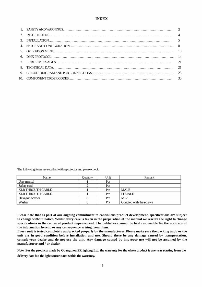
The following items are supplied with a projector and please check:
Name Quantity Unit Remark
User manual 1 Pcs
Safety cord 2 Pcs
XLR THROUTH CABLE 1 Pcs MALE
XLR THROUTH CABLE 1 Pcs FEMALE
Hexagon screws 8 Pcs M12
Washer 8 Pcs Coupled with the screws
Please note that as part of our ongoing commitment to continuous product development, specifications are subject
to change without notice. Whilst every care is taken in the preparation of the manual we reserve the right to change
specifications in the course of product improvement. The publishers cannot be held responsible for the accuracy of
the information herein, or any consequence arising from them.
Every unit is tested completely and packed properly by the manufacturer. Please make sure the packing and / or the
unit are in good condition before installation and use. Should there be any damage caused by transportation,
consult your dealer and do not use the unit. Any damage caused by improper use will not be assumed by the
manufacturer and / or dealer.
Note: For the products made by Guangzhou PR lighting Ltd, the warranty for the whole product is one year starting from the
delivery date but the light source is not within the warranty.
3
1. SAFETY AND WARNINGS
NOTE Before a projector’s installation, power-on, operation and maintenance, please carefully read
the safety information hereinafter!
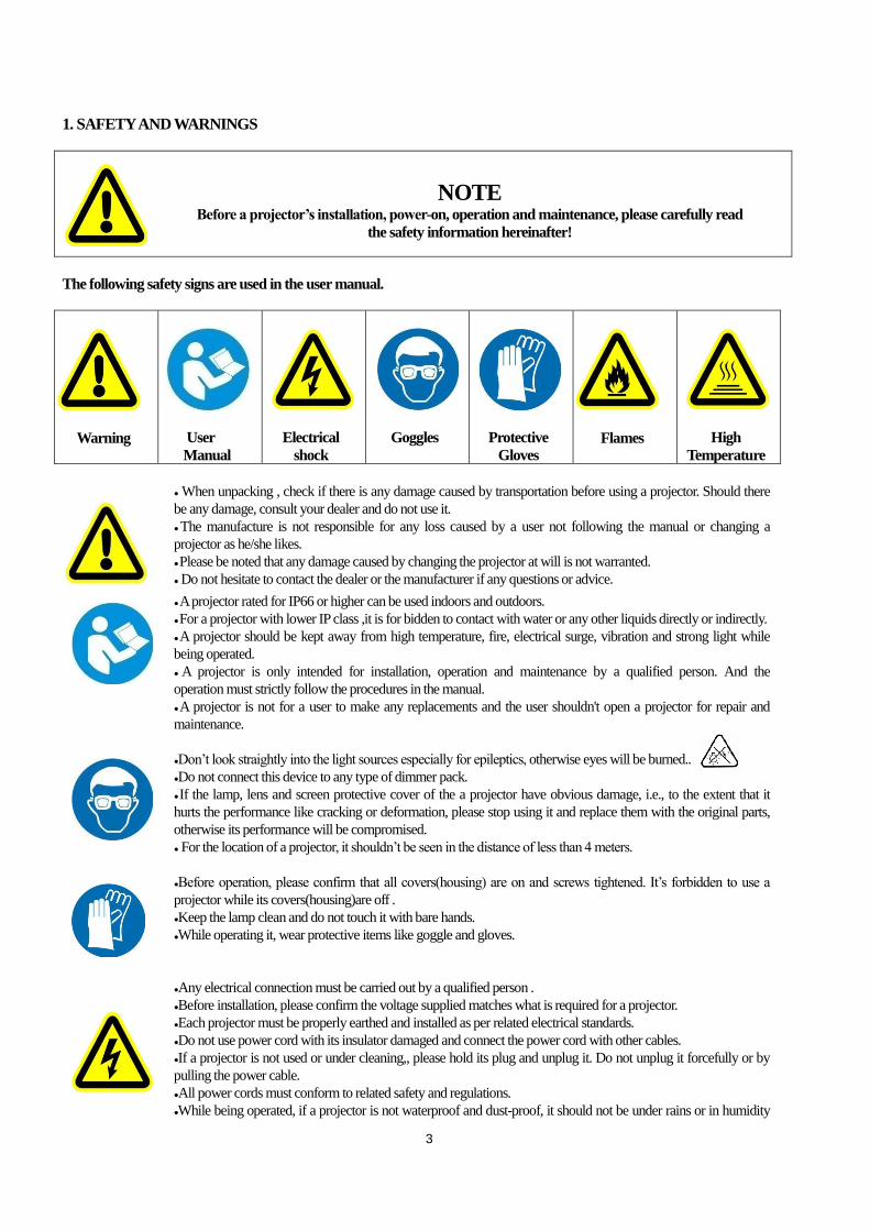
The following safety signs are used in the user manual.
Warning
User
Manual
Electrical
shock
Goggles
Protective
Gloves
Flames
High
Temperature
● When unpacking , check if there is any damage caused by transportation before using a projector. Should there
be any damage, consult your dealer and do not use it.
● The manufacture is not responsible for any loss caused by a user not following the manual or changing a
projector as he/she likes.
● Please be noted that any damage caused by changing the projector at will is not warranted.
● Do not hesitate to contact the dealer or the manufacturer if any questions or advice.
● A projector rated for IP66 or higher can be used indoors and outdoors.
● For a projector with lower IP class ,it is for bidden to contact with water or any other liquids directly or indirectly.
● A projector should be kept away from high temperature, fire, electrical surge, vibration and strong light while
being operated.
● A projector is only intended for installation, operation and maintenance by a qualified person. And the
operation must strictly follow the procedures in the manual.
● A projector is not for a user to make any replacements and the user shouldn't open a projector for repair and
maintenance.
●Don’t look straightly into the light sources especially for epileptics, otherwise eyes will be burned..
●Do not connect this device to any type of dimmer pack.
● If the lamp, lens and screen protective cover of the a projector have obvious damage, i.e., to the extent that it
hurts the performance like cracking or deformation, please stop using it and replace them with the original parts,
otherwise its performance will be compromised.
● For the location of a projector, it shouldn’t be seen in the distance of less than 4 meters.
●Before operation, please confirm that all covers(housing) are on and screws tightened. It’s forbidden to use a
projector while its covers(housing)are off .
●Keep the lamp clean and do not touch it with bare hands.
●While operating it, wear protective items like goggle and gloves.
●Any electrical connection must be carried out by a qualified person .
●Before installation, please confirm the voltage supplied matches what is required for a projector.
●Each projector must be properly earthed and installed as per related electrical standards.
●Do not use power cord with its insulator damaged and connect the power cord with other cables.
●If a projector is not used or under cleaning,, please hold its plug and unplug it. Do not unplug it forcefully or by
pulling the power cable.
●All power cords must conform to related safety and regulations.
●While being operated, if a projector is not waterproof and dust-proof, it should not be under rains or in humidity
4
to avoid being short.
●Do not switch on and off a projector constantly in very short intervals, otherwise its light source’s and other
electrical parts’ life will be shortened .
●There are safety cord holes at the bottom of the base of a projector. In view of safety, please run the safety cord
supplied through the safety cord holes for safety support.
●Before any installation, maintenance and cleaning work, please ensure a projector is disconnected from power
mains.
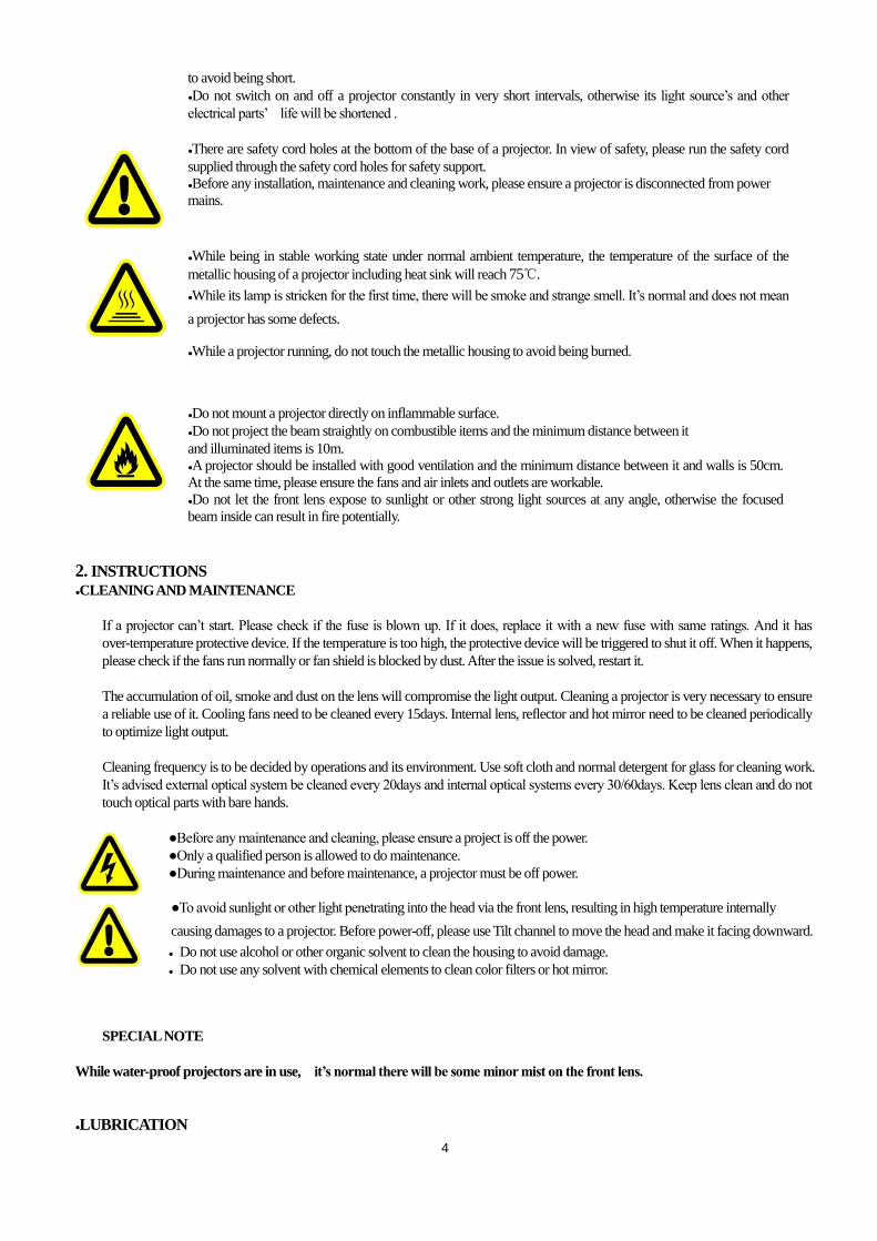
●While being in stable working state under normal ambient temperature, the temperature of the surface of the
metallic housing of a projector including heat sink will reach 75℃.
●While its lamp is stricken for the first time, there will be smoke and strange smell. It’s normal and does not mean
a projector has some defects.
●While a projector running, do not touch the metallic housing to avoid being burned.
●Do not mount a projector directly on inflammable surface.
●Do not project the beam straightly on combustible items and the minimum distance between it
and illuminated items is 10m.
●A projector should be installed with good ventilation and the minimum distance between it and walls is 50cm.
At the same time, please ensure the fans and air inlets and outlets are workable.
●Do not let the front lens expose to sunlight or other strong light sources at any angle, otherwise the focused
beam inside can result in fire potentially.
2. INSTRUCTIONS
●CLEANING AND MAINTENANCE
If a projector can’t start. Please check if the fuse is blown up. If it does, replace it with a new fuse with same ratings. And it has
over-temperature protective device. If the temperature is too high, the protective device will be triggered to shut it off. When it happens,
please check if the fans run normally or fan shield is blocked by dust. After the issue is solved, restart it.
The accumulation of oil, smoke and dust on the lens will compromise the light output. Cleaning a projector is very necessary to ensure
a reliable use of it. Cooling fans need to be cleaned every 15days. Internal lens, reflector and hot mirror need to be cleaned periodically
to optimize light output.
Cleaning frequency is to be decided by operations and its environment. Use soft cloth and normal detergent for glass for cleaning work.
It’s advised external optical system be cleaned every 20days and internal optical systems every 30/60days. Keep lens clean and do not
touch optical parts with bare hands.
●Before any maintenance and cleaning, please ensure a project is off the power.
●Only a qualified person is allowed to do maintenance.
●During maintenance and before maintenance, a projector must be off power.
●To avoid sunlight or other light penetrating into the head via the front lens, resulting in high temperature internally
causing damages to a projector. Before power-off, please use Tilt channel to move the head and make it facing downward.
● Do not use alcohol or other organic solvent to clean the housing to avoid damage.
● Do not use any solvent with chemical elements to clean color filters or hot mirror.
SPECIAL NOTE
While water-proof projectors are in use, it’s normal there will be some minor mist on the front lens.
●LUBRICATION
5
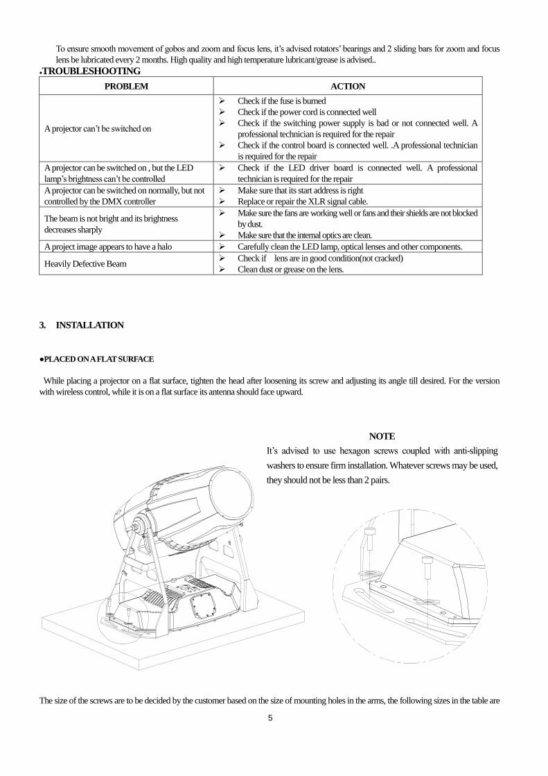
To ensure smooth movement of gobos and zoom and focus lens, it’s advised rotators’ bearings and 2 sliding bars for zoom and focus
lens be lubricated every 2 months. High quality and high temperature lubricant/grease is advised..
●TROUBLESHOOTING
PROBLEM ACTION
A projector can’t be switched on
Check if the fuse is burned
Check if the power cord is connected well
Check if the switching power supply is bad or not connected well. A
professional technician is required for the repair
Check if the control board is connected well. .A professional technician
is required for the repair
A projector can be switched on , but the LED
lamp’s brightness can’t be controlled
Check if the LED driver board is connected well. A professional
technician is required for the repair
A projector can be switched on normally, but not
controlled by the DMX controller
Make sure that its start address is right
Replace or repair the XLR signal cable.
The beam is not bright and its brightness
decreases sharply
Make sure the fans are working well or fans and their shields are not blocked
by dust.
Make sure that the internal optics are clean.
A project image appears to have a halo Carefully clean the LED lamp, optical lenses and other components.
Heavily Defective Beam Check if lens are in good condition(not cracked)
Clean dust or grease on the lens.
3. INSTALLATION
●PLACED ON A FLAT SURFACE
While placing a projector on a flat surface, tighten the head after loosening its screw and adjusting its angle till desired. For the version
with wireless control, while it is on a flat surface its antenna should face upward.
The size of the screws are to be decided by the customer based on the size of mounting holes in the arms, the following sizes in the table are
NOTE
It’s advised to use hexagon screws coupled with anti-slipping
washers to ensure firm installation. Whatever screws may be used,
they should not be less than 2 pairs.

6
only for reference.
● POWER CONNECTION
Connect the power cord as follows:
L (live) =brown
E (earth) =yellow/green
N (neutral) =blue
Before power connection, please ensure the power supplied must match what the nameplate says. It is recommended that each
projector be connected with power separately so that they may be individually switched on and off.
●The earth wire(yellow/green) must be connected to the ground. And electrical connection
must be in accordance with the standards concerned.
●If any questions about the electrical installation, do not continue but consult a qualified
electrician.
●A projector uses naked wires. For wiring please use waterproof junction box with IP
class not lower than IP66. ● THE WIRING OF CONTROL SIGNAL
The colors of signal wires responds to their respective functions:
The shielded 2-core wire between a projector and a controller or between projectors should be not less than 0.5mm in diameter and
NO NAME SIZE QTY REMARKS
1 Hexagon
screws M12 8
2 Washer Coupled with the
screws 8
Blue --- A+
White --- B-
Shied wire ---GND
Wires with different colors inside the XLR cable
and their respective functions
Female Connector Male Connector
7
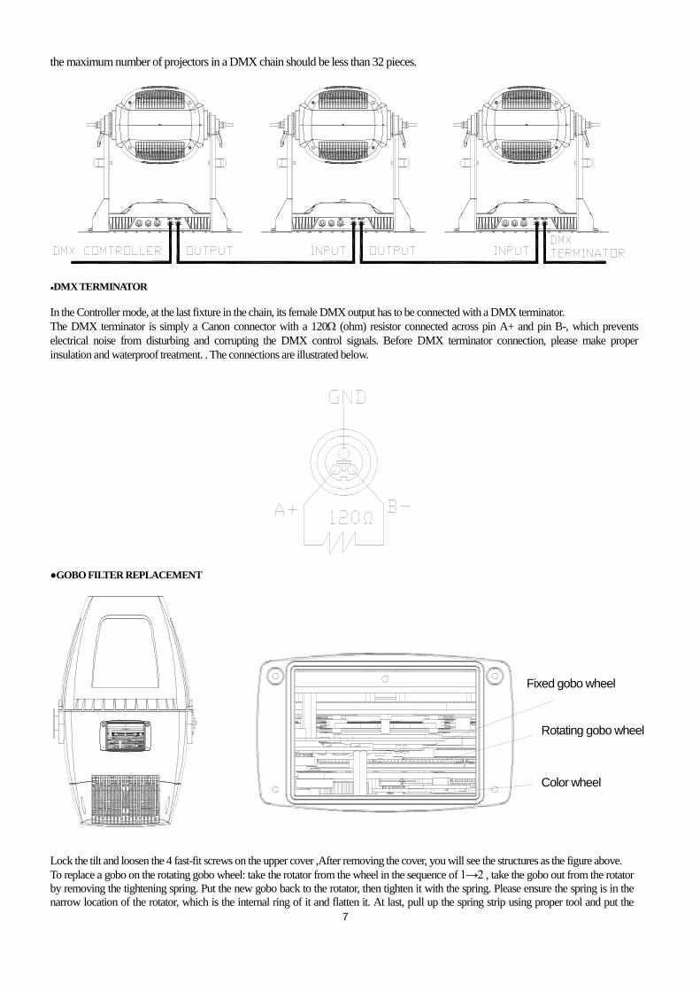
the maximum number of projectors in a DMX chain should be less than 32 pieces.
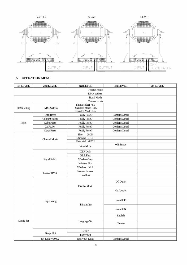
●DMX TERMINATOR
In the Controller mode, at the last fixture in the chain, its female DMX output has to be connected with a DMX terminator.
The DMX terminator is simply a Canon connector with a 120 (ohm) resistor connected across pin A+ and pin B-, which prevents
electrical noise from disturbing and corrupting the DMX control signals. Before DMX terminator connection, please make proper
insulation and waterproof treatment. . The connections are illustrated below.
●GOBO FILTER REPLACEMENT
Lock the tilt and loosen the 4 fast-fit screws on the upper cover ,After removing the cover, you will see the structures as the figure above.
To replace a gobo on the rotating gobo wheel: take the rotator from the wheel in the sequence of 1→2 , take the gobo out from the rotator
by removing the tightening spring. Put the new gobo back to the rotator, then tighten it with the spring. Please ensure the spring is in the
narrow location of the rotator, which is the internal ring of it and flatten it. At last, pull up the spring strip using proper tool and put the
固定图案盘
旋转图案盘
颜色盘
Fixed gobo wheel
Rotating gobo wheel
Color wheel
8
图案片安装 滤色片安装
1 1
22
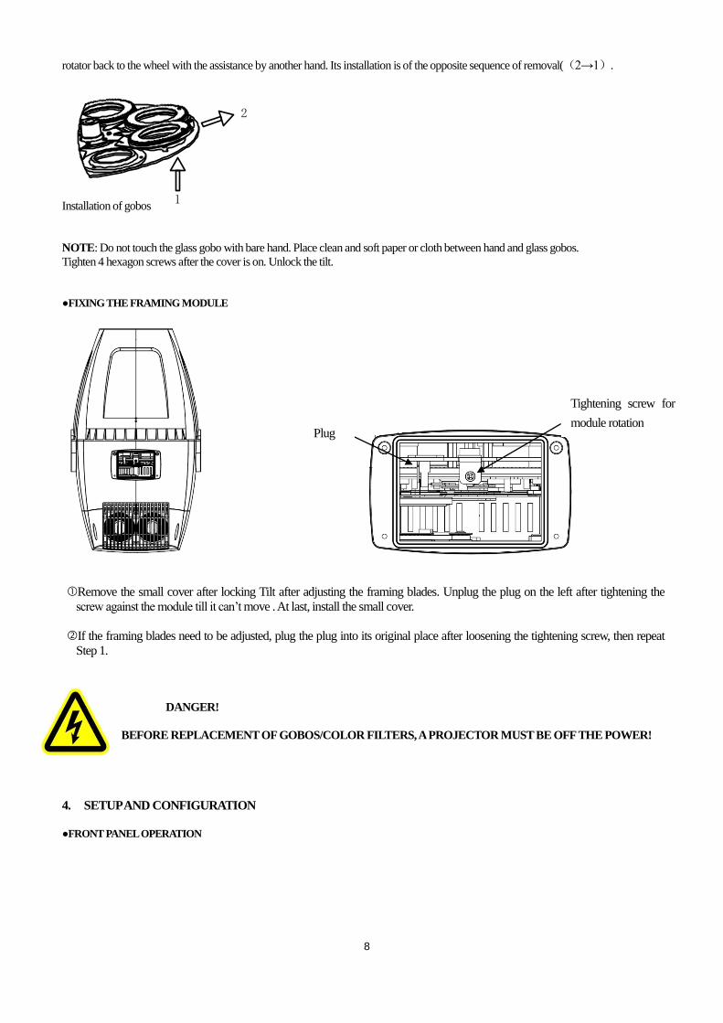
rotator back to the wheel with the assistance by another hand. Its installation is of the opposite sequence of removal((2→1).
Installation of gobos
NOTE: Do not touch the glass gobo with bare hand. Place clean and soft paper or cloth between hand and glass gobos.
Tighten 4 hexagon screws after the cover is on. Unlock the tilt.
●FIXING THE FRAMING MODULE
Remove the small cover after locking Tilt after adjusting the framing blades. Unplug the plug on the left after tightening the
screw against the module till it can’t move . At last, install the small cover.
If the framing blades need to be adjusted, plug the plug into its original place after loosening the tightening screw, then repeat
Step 1.
DANGER!
BEFORE REPLACEMENT OF GOBOS/COLOR FILTERS, A PROJECTOR MUST BE OFF THE POWER!
4. SETUP AND CONFIGURATION
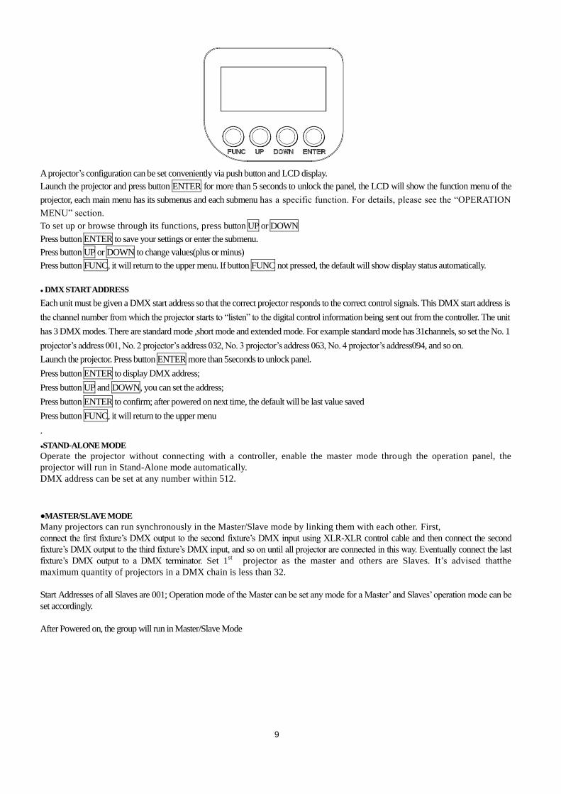
●FRONT PANEL OPERATION
Plug
Tightening screw for
module rotation
9
A projector’s configuration can be set conveniently via push button and LCD display.
Launch the projector and press button ENTER for more than 5 seconds to unlock the panel, the LCD will show the function menu of the
projector, each main menu has its submenus and each submenu has a specific function. For details, please see the “OPERATION
MENU” section.
To set up or browse through its functions, press button UP or DOWN
Press button ENTER to save your settings or enter the submenu.
Press button UP or DOWN to change values(plus or minus)
Press button FUNC, it will return to the upper menu. If button FUNC not pressed, the default will show display status automatically.
● DMX START ADDRESS
Each unit must be given a DMX start address so that the correct projector responds to the correct control signals. This DMX start address is
the channel number from which the projector starts to “listen” to the digital control information being sent out from the controller. The unit
has 3 DMX modes. There are standard mode ,short mode and extended mode. For example standard mode has 31channels, so set the No. 1
projector’s address 001, No. 2 projector’s address 032, No. 3 projector’s address 063, No. 4 projector’s address094, and so on.
Launch the projector. Press button ENTER more than 5seconds to unlock panel.
Press button ENTER to display DMX address;
Press button UP and DOWN, you can set the address;
Press button ENTER to confirm; after powered on next time, the default will be last value saved
Press button FUNC, it will return to the upper menu
.
●STAND-ALONE MODE
Operate the projector without connecting with a controller, enable the master mode through the operation panel, the
projector will run in Stand-Alone mode automatically.
DMX address can be set at any number within 512.
●MASTER/SLAVE MODE
Many projectors can run synchronously in the Master/Slave mode by linking them with each other. First,
connect the first fixture’s DMX output to the second fixture’s DMX input using XLR-XLR control cable and then connect the second
fixture’s DMX output to the third fixture’s DMX input, and so on until all projector are connected in this way. Eventually connect the last
fixture’s DMX output to a DMX terminator. Set 1st projector as the master and others are Slaves. It’s advised thatthe
maximum quantity of projectors in a DMX chain is less than 32.
Start Addresses of all Slaves are 001; Operation mode of the Master can be set any mode for a Master’ and Slaves’ operation mode can be
set accordingly.
After Powered on, the group will run in Master/Slave Mode
10
5. OPERATION MENU
1st LEVEL 2nd LEVEL 3rd LEVEL 4th LEVEL 5th LEVEL
Product model
DMX address
Signal Mode
Channel mode
DMX setting DMX Address
Short Mode:1-485 Standard Mode:1-482
Extended Mode:1-67
Reset
Total Reset Really Reset? Confirm/Cancel
Colour System Really Reset? Confirm/Cancel
Gobo Reset Really Reset? Confirm/Cancel
Zo.Fo. Pr. Really Reset? Confirm/Cancel
Other Reset Really Reset? Confirm/Cancel
Config Set
Channel Mode
Short 28CH
Standard 31CH
Extended 46CH
View Mode 001 Strobe
…
Signal Select
XLR Only
XLR First
Wireless Only
Wireless First
Wireless XLR
Loss of DMX Normal timeout
Hold Last
Disp. Config
Display Mode
Off Delay
On Always
Display Inv
Invert OFF
Invert ON
Language Set
English
Chinese
Temp. Unit Celsius
Fahrenheit
Un-Link WDMX Really Un-Link? Confirm/Cancel
MASTER SLAVE SLAVE

11
Factory Reset Factory Reset Confirm/Cancel
Option Set
Invert Set
Zoom Inv. OFF/ ON
CYM Inv. OFF/ ON
CTO Inv. OFF/ ON
Dimmer Set
Gamma Curve Gamma 2.0/2.2/2.4/2.6
LED Ref. Rate 1200/2400/4800/10000/1200
0/15000/20000/25000Hz
Dimmer Speed Fast/Medium/Slow Speed
Fan Set Standard/Theatre
Blade Detect Detect Disable/ Detect Enable
Information
View DMX
Strobe XXX Dimmer XXX Dimmer F XXX CMY Macro XXX Cyan XXX Yellow XXX Magenta XXX CTO XXX Colour XXX Colour F XXX FGobo XXX RGobo XXX RGobo R XXX RGobo RF XXX Flade 1 A XXX Flade 1 B XXX Flade 2 A XXX Flade 2 B XXX Flade 3 A XXX Flade 3 B XXX Flade 4 A XXX Flade 4 B XXX Flade R XXX Prism XXX Prism R XXX Effect XXX Effect R XXX Frost XXX Focus XXX Zoom XXX
Pow/Sp Fun XXX.
Total Hours XXXXH
Temperature
Display XXX
Driver 1 XXX
Driver 2 XXX
Driver 3 XXX
Driver 4 XXX
Fan board XXX
LED XXX
Software Ver.
Display XXX
Driver 1 XXX
Driver 2 XXX
Driver 3 XXX
Driver 4 XXX
Fan Board XXX
Elect SN Elect SN=
************
RDM Label ANSI E1.20 RDM
TANGO 1800 FRAMING
Fan Status Head Fan XXX×/√
12
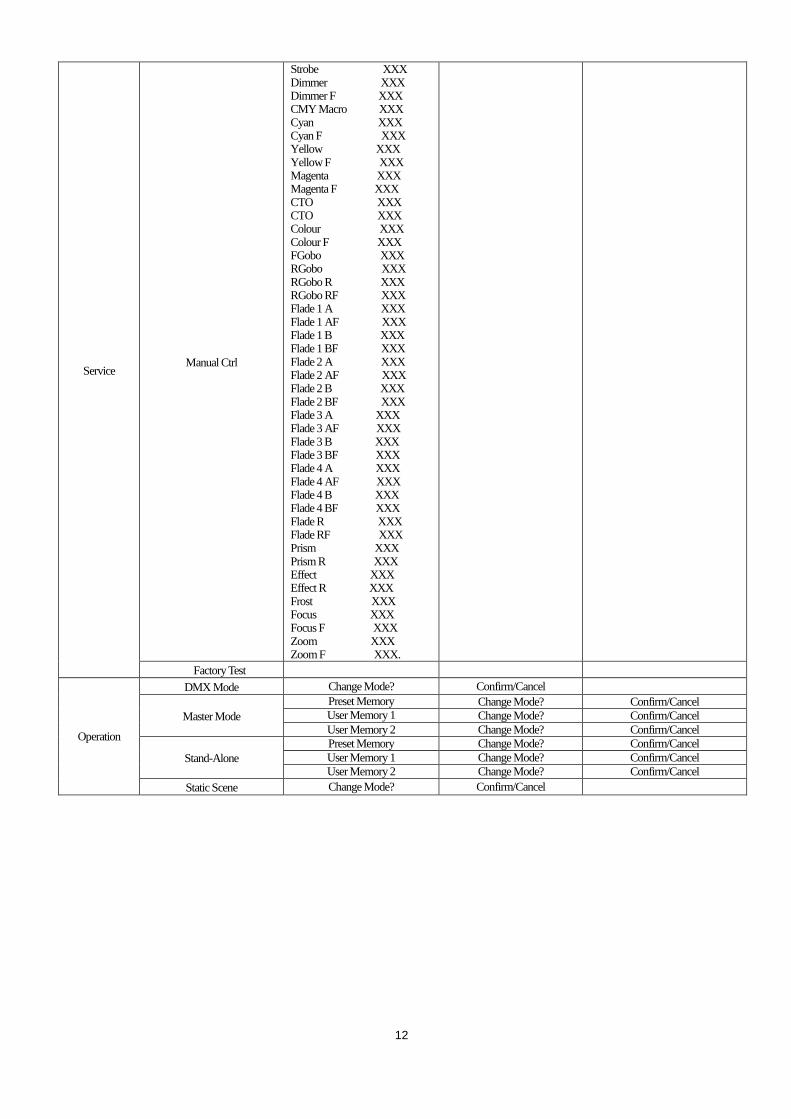
Service Manual Ctrl
Strobe XXX Dimmer XXX Dimmer F XXX CMY Macro XXX Cyan XXX Cyan F XXX Yellow XXX Yellow F XXX Magenta XXX Magenta F XXX CTO XXX CTO XXX Colour XXX Colour F XXX FGobo XXX RGobo XXX RGobo R XXX RGobo RF XXX Flade 1 A XXX Flade 1 AF XXX Flade 1 B XXX Flade 1 BF XXX Flade 2 A XXX Flade 2 AF XXX Flade 2 B XXX Flade 2 BF XXX Flade 3 A XXX Flade 3 AF XXX Flade 3 B XXX Flade 3 BF XXX Flade 4 A XXX Flade 4 AF XXX Flade 4 B XXX Flade 4 BF XXX Flade R XXX Flade RF XXX Prism XXX Prism R XXX Effect XXX Effect R XXX Frost XXX Focus XXX Focus F XXX Zoom XXX Zoom F XXX.
Factory Test
Operation
DMX Mode Change Mode? Confirm/Cancel
Master Mode
Preset Memory Change Mode? Confirm/Cancel User Memory 1 Change Mode? Confirm/Cancel
User Memory 2 Change Mode? Confirm/Cancel
Stand-Alone
Preset Memory Change Mode? Confirm/Cancel
User Memory 1 Change Mode? Confirm/Cancel
User Memory 2 Change Mode? Confirm/Cancel
Static Scene Change Mode? Confirm/Cancel
13
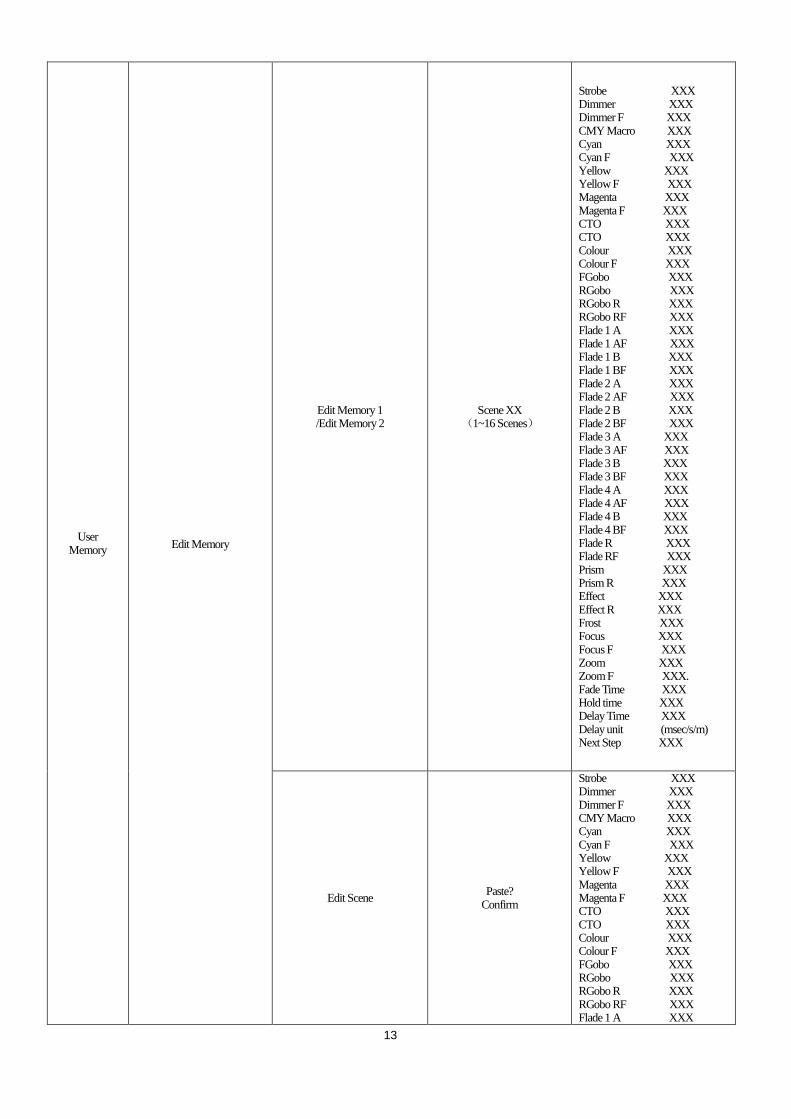
User Memory
Edit Memory
Edit Memory 1 /Edit Memory 2
Scene XX (1~16 Scenes)
Strobe XXX Dimmer XXX Dimmer F XXX CMY Macro XXX Cyan XXX Cyan F XXX Yellow XXX Yellow F XXX Magenta XXX Magenta F XXX CTO XXX CTO XXX Colour XXX Colour F XXX FGobo XXX RGobo XXX RGobo R XXX RGobo RF XXX Flade 1 A XXX Flade 1 AF XXX Flade 1 B XXX Flade 1 BF XXX Flade 2 A XXX Flade 2 AF XXX Flade 2 B XXX Flade 2 BF XXX Flade 3 A XXX Flade 3 AF XXX Flade 3 B XXX Flade 3 BF XXX Flade 4 A XXX Flade 4 AF XXX Flade 4 B XXX Flade 4 BF XXX Flade R XXX Flade RF XXX Prism XXX Prism R XXX Effect XXX Effect R XXX Frost XXX Focus XXX Focus F XXX Zoom XXX Zoom F XXX. Fade Time XXX Hold time XXX Delay Time XXX Delay unit (msec/s/m) Next Step XXX
Edit Scene Paste?
Confirm
Strobe XXX Dimmer XXX Dimmer F XXX CMY Macro XXX Cyan XXX Cyan F XXX Yellow XXX Yellow F XXX Magenta XXX Magenta F XXX CTO XXX CTO XXX Colour XXX Colour F XXX FGobo XXX RGobo XXX RGobo R XXX RGobo RF XXX Flade 1 A XXX
14
Flade 1 AF XXX Flade 1 B XXX Flade 1 BF XXX Flade 2 A XXX Flade 2 AF XXX Flade 2 B XXX Flade 2 BF XXX Flade 3 A XXX Flade 3 AF XXX Flade 3 B XXX Flade 3 BF XXX Flade 4 A XXX Flade 4 AF XXX Flade 4 B XXX Flade 4 BF XXX Flade R XXX Flade RF XXX Prism XXX Prism R XXX Effect XXX Effect R XXX Frost XXX Focus XXX Focus F XXX Zoom XXX Zoom F XXX.
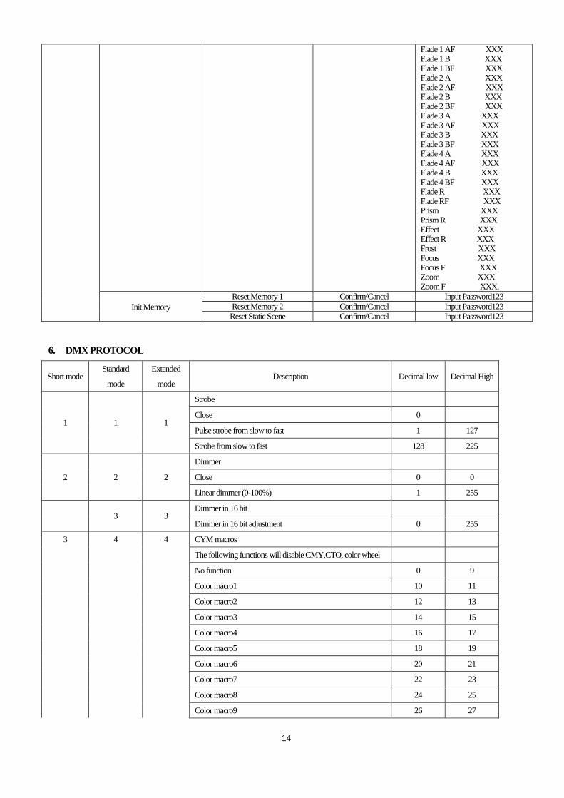
Init Memory
Reset Memory 1 Confirm/Cancel Input Password123
Reset Memory 2 Confirm/Cancel Input Password123
Reset Static Scene Confirm/Cancel Input Password123
6. DMX PROTOCOL
Short mode Standard
mode
Extended
mode Description Decimal low Decimal High
1 1 1
Strobe
Close 0
Pulse strobe from slow to fast 1 127
Strobe from slow to fast 128 225
2 2 2
Dimmer
Close 0 0
Linear dimmer (0-100%) 1 255
3 3 Dimmer in 16 bit
Dimmer in 16 bit adjustment 0 255
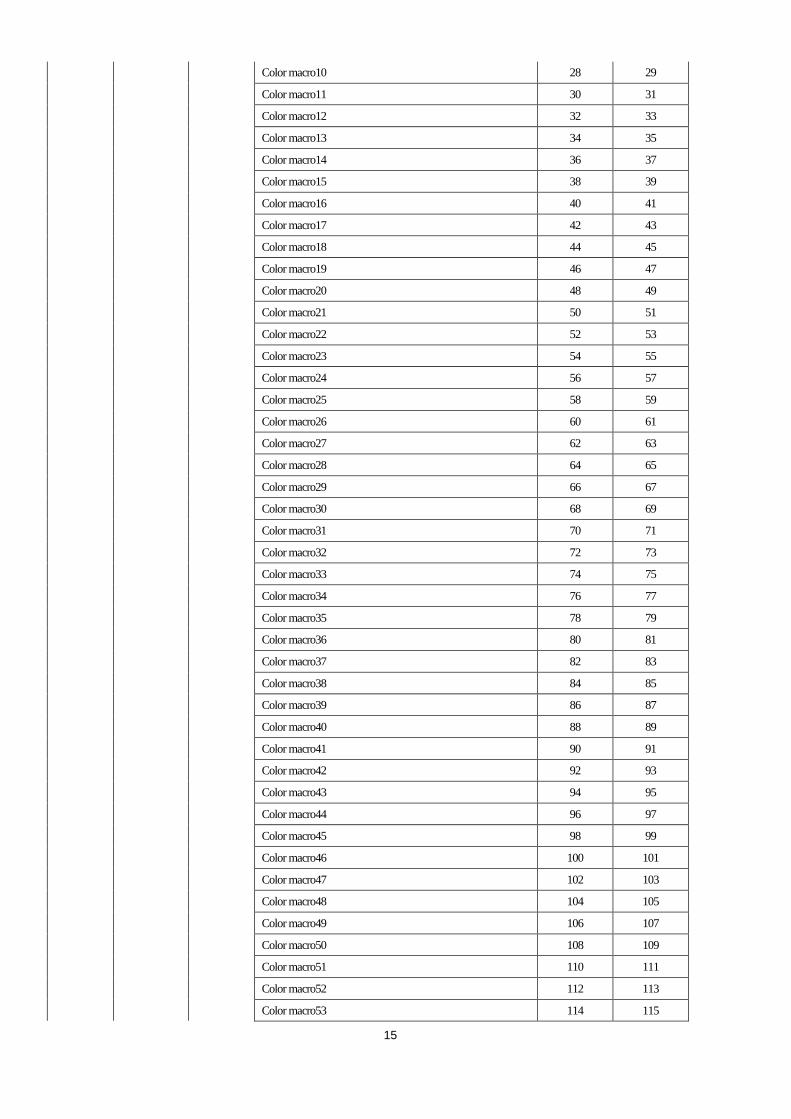
3 4 4 CYM macros
The following functions will disable CMY,CTO, color wheel
No function 0 9
Color macro1 10 11
Color macro2 12 13
Color macro3 14 15
Color macro4 16 17
Color macro5 18 19
Color macro6 20 21
Color macro7 22 23
Color macro8 24 25
Color macro9 26 27
15
Color macro10 28 29
Color macro11 30 31
Color macro12 32 33
Color macro13 34 35
Color macro14 36 37
Color macro15 38 39
Color macro16 40 41
Color macro17 42 43
Color macro18 44 45
Color macro19 46 47
Color macro20 48 49
Color macro21 50 51
Color macro22 52 53
Color macro23 54 55
Color macro24 56 57
Color macro25 58 59
Color macro26 60 61
Color macro27 62 63
Color macro28 64 65
Color macro29 66 67
Color macro30 68 69
Color macro31 70 71
Color macro32 72 73
Color macro33 74 75
Color macro34 76 77
Color macro35 78 79
Color macro36 80 81
Color macro37 82 83
Color macro38 84 85
Color macro39 86 87
Color macro40 88 89
Color macro41 90 91
Color macro42 92 93
Color macro43 94 95
Color macro44 96 97
Color macro45 98 99
Color macro46 100 101
Color macro47 102 103
Color macro48 104 105
Color macro49 106 107
Color macro50 108 109
Color macro51 110 111
Color macro52 112 113
Color macro53 114 115
16
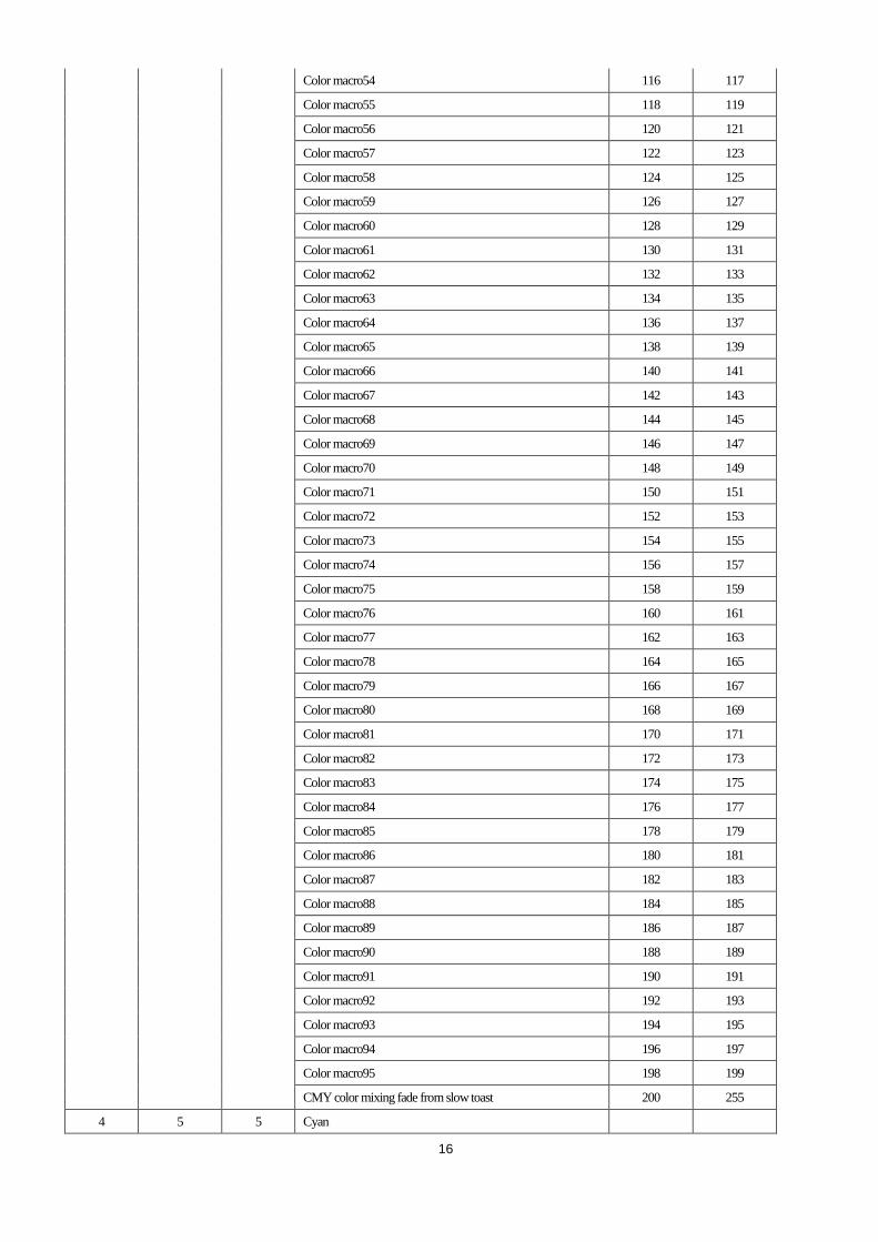
Color macro54 116 117
Color macro55 118 119
Color macro56 120 121
Color macro57 122 123
Color macro58 124 125
Color macro59 126 127
Color macro60 128 129
Color macro61 130 131
Color macro62 132 133
Color macro63 134 135
Color macro64 136 137
Color macro65 138 139
Color macro66 140 141
Color macro67 142 143
Color macro68 144 145
Color macro69 146 147
Color macro70 148 149
Color macro71 150 151
Color macro72 152 153
Color macro73 154 155
Color macro74 156 157
Color macro75 158 159
Color macro76 160 161
Color macro77 162 163
Color macro78 164 165
Color macro79 166 167
Color macro80 168 169
Color macro81 170 171
Color macro82 172 173
Color macro83 174 175
Color macro84 176 177
Color macro85 178 179
Color macro86 180 181
Color macro87 182 183
Color macro88 184 185
Color macro89 186 187
Color macro90 188 189
Color macro91 190 191
Color macro92 192 193
Color macro93 194 195
Color macro94 196 197
Color macro95 198 199
CMY color mixing fade from slow toast 200 255
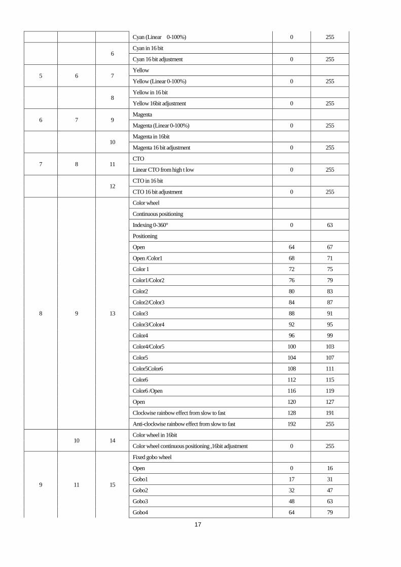
4 5 5 Cyan
17
Cyan (Linear 0-100%) 0 255
6 Cyan in 16 bit
Cyan 16 bit adjustment 0 255
5 6 7 Yellow
Yellow (Linear 0-100%) 0 255
8 Yellow in 16 bit
Yellow 16bit adjustment 0 255
6 7 9 Magenta
Magenta (Linear 0-100%) 0 255
10 Magenta in 16bit
Magenta 16 bit adjustment 0 255
7 8 11 CTO
Linear CTO from high t low 0 255
12 CTO in 16 bit
CTO 16 bit adjustment 0 255
8 9 13
Color wheel
Continuous positioning
Indexing 0-360° 0 63
Positioning
Open 64 67
Open /Color1 68 71
Color 1 72 75
Color1/Color2 76 79
Color2 80 83
Color2/Color3 84 87
Color3 88 91
Color3/Color4 92 95
Color4 96 99
Color4/Color5 100 103
Color5 104 107
Color5Color6 108 111
Color6 112 115
Color6 /Open 116 119
Open 120 127
Clockwise rainbow effect from slow to fast 128 191
Anti-clockwise rainbow effect from slow to fast 192 255
10 14 Color wheel in 16bit
Color wheel continuous positioning ,16bit adjustment 0 255
9 11 15
Fixed gobo wheel
Open 0 16
Gobo1 17 31
Gobo2 32 47
Gobo3 48 63
Gobo4 64 79
18
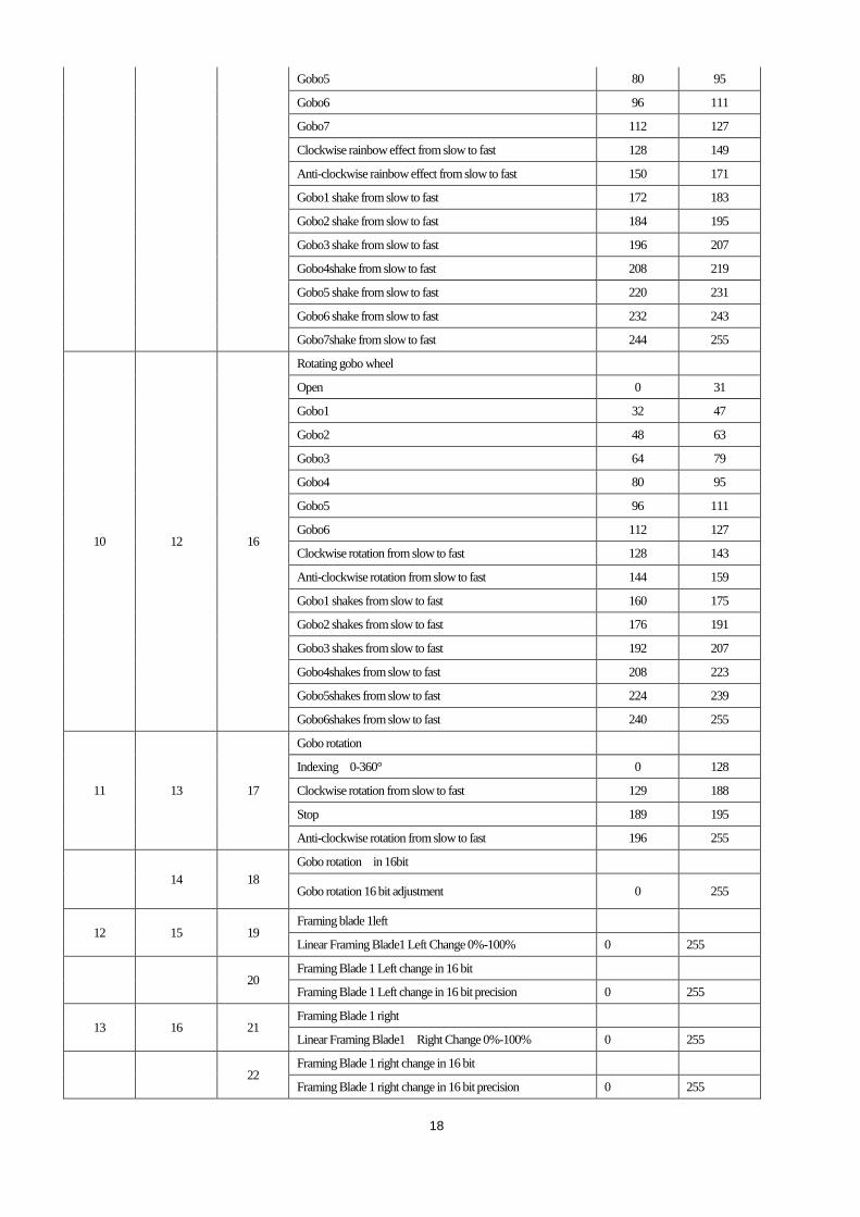
Gobo5 80 95
Gobo6 96 111
Gobo7 112 127
Clockwise rainbow effect from slow to fast 128 149
Anti-clockwise rainbow effect from slow to fast 150 171
Gobo1 shake from slow to fast 172 183
Gobo2 shake from slow to fast 184 195
Gobo3 shake from slow to fast 196 207
Gobo4shake from slow to fast 208 219
Gobo5 shake from slow to fast 220 231
Gobo6 shake from slow to fast 232 243
Gobo7shake from slow to fast 244 255
10 12 16
Rotating gobo wheel
Open 0 31
Gobo1 32 47
Gobo2 48 63
Gobo3 64 79
Gobo4 80 95
Gobo5 96 111
Gobo6 112 127
Clockwise rotation from slow to fast 128 143
Anti-clockwise rotation from slow to fast 144 159
Gobo1 shakes from slow to fast 160 175
Gobo2 shakes from slow to fast 176 191
Gobo3 shakes from slow to fast 192 207
Gobo4shakes from slow to fast 208 223
Gobo5shakes from slow to fast 224 239
Gobo6shakes from slow to fast 240 255
11 13 17
Gobo rotation
Indexing 0-360° 0 128
Clockwise rotation from slow to fast 129 188
Stop 189 195
Anti-clockwise rotation from slow to fast 196 255
14 18
Gobo rotation in 16bit
Gobo rotation 16 bit adjustment 0 255
12 15 19 Framing blade 1left
Linear Framing Blade1 Left Change 0%-100% 0 255
20 Framing Blade 1 Left change in 16 bit
Framing Blade 1 Left change in 16 bit precision 0 255
13 16 21 Framing Blade 1 right
Linear Framing Blade1 Right Change 0%-100% 0 255
22 Framing Blade 1 right change in 16 bit
Framing Blade 1 right change in 16 bit precision 0 255
19
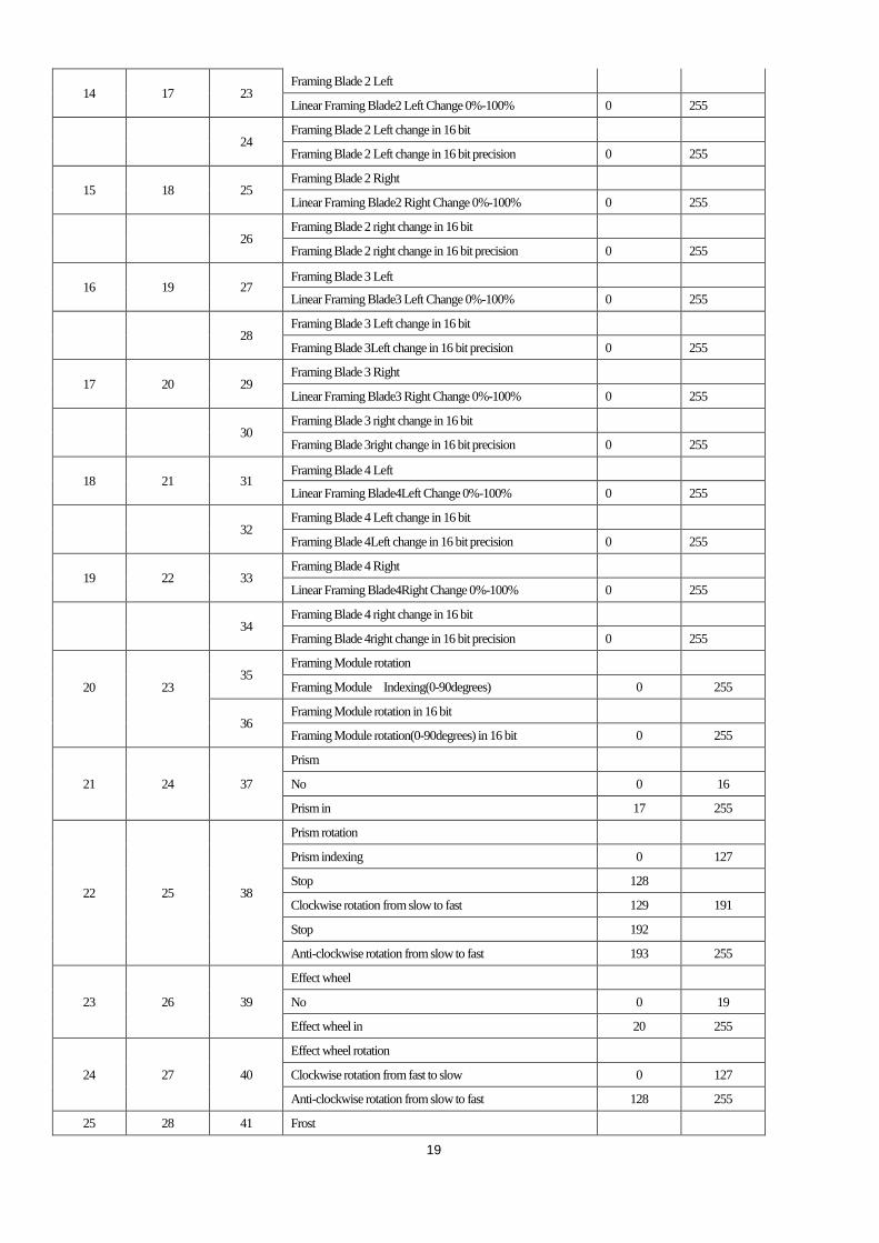
14 17 23 Framing Blade 2 Left
Linear Framing Blade2 Left Change 0%-100% 0 255
24 Framing Blade 2 Left change in 16 bit
Framing Blade 2 Left change in 16 bit precision 0 255
15 18 25 Framing Blade 2 Right
Linear Framing Blade2 Right Change 0%-100% 0 255
26 Framing Blade 2 right change in 16 bit
Framing Blade 2 right change in 16 bit precision 0 255
16 19 27 Framing Blade 3 Left
Linear Framing Blade3 Left Change 0%-100% 0 255
28 Framing Blade 3 Left change in 16 bit
Framing Blade 3Left change in 16 bit precision 0 255
17 20 29 Framing Blade 3 Right
Linear Framing Blade3 Right Change 0%-100% 0 255
30 Framing Blade 3 right change in 16 bit
Framing Blade 3right change in 16 bit precision 0 255
18 21 31 Framing Blade 4 Left
Linear Framing Blade4Left Change 0%-100% 0 255
32 Framing Blade 4 Left change in 16 bit
Framing Blade 4Left change in 16 bit precision 0 255
19 22 33 Framing Blade 4 Right
Linear Framing Blade4Right Change 0%-100% 0 255
34 Framing Blade 4 right change in 16 bit
Framing Blade 4right change in 16 bit precision 0 255
20
23
35 Framing Module rotation
Framing Module Indexing(0-90degrees) 0 255
36 Framing Module rotation in 16 bit
Framing Module rotation(0-90degrees) in 16 bit 0 255
21 24 37
Prism
No 0 16
Prism in 17 255
22 25 38
Prism rotation
Prism indexing 0 127
Stop 128
Clockwise rotation from slow to fast 129 191
Stop 192
Anti-clockwise rotation from slow to fast 193 255
23 26 39
Effect wheel
No 0 19
Effect wheel in 20 255
24 27 40
Effect wheel rotation
Clockwise rotation from fast to slow 0 127
Anti-clockwise rotation from slow to fast 128 255
25 28 41 Frost
20
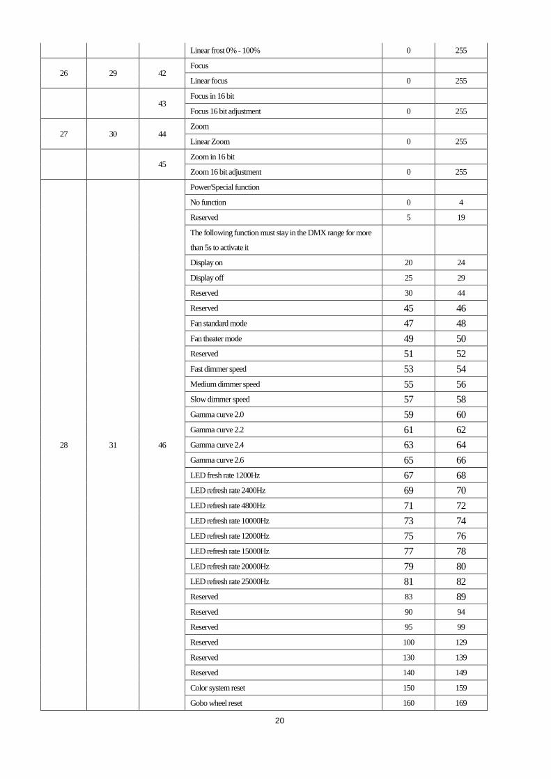
Linear frost 0% - 100% 0 255
26 29 42 Focus
Linear focus 0 255
43 Focus in 16 bit
Focus 16 bit adjustment 0 255
27 30 44 Zoom
Linear Zoom 0 255
45 Zoom in 16 bit
Zoom 16 bit adjustment 0 255
28 31 46
Power/Special function
No function 0 4
Reserved 5 19
The following function must stay in the DMX range for more
than 5s to activate it
Display on 20 24
Display off 25 29
Reserved 30 44
Reserved 45 46
Fan standard mode 47 48
Fan theater mode 49 50
Reserved 51 52
Fast dimmer speed 53 54
Medium dimmer speed 55 56
Slow dimmer speed 57 58
Gamma curve 2.0 59 60
Gamma curve 2.2 61 62
Gamma curve 2.4 63 64
Gamma curve 2.6 65 66
LED fresh rate 1200Hz 67 68
LED refresh rate 2400Hz 69 70
LED refresh rate 4800Hz 71 72
LED refresh rate 10000Hz 73 74
LED refresh rate 12000Hz 75 76
LED refresh rate 15000Hz 77 78
LED refresh rate 20000Hz 79 80
LED refresh rate 25000Hz 81 82
Reserved 83 89
Reserved 90 94
Reserved 95 99
Reserved 100 129
Reserved 130 139
Reserved 140 149
Color system reset 150 159
Gobo wheel reset 160 169

21
Reserved 170 179
Zoom/Focus/Frost/Prism reset 180 189
Other(effect wheel, framing module)reset 190 199
Total reset 200 209
Reserved 210 229
Reserved 240 255
Remarks:
1. Fan errors can result in LED lamp off automatically
2. DMX channel priority: CMY macro is prior to Magenta , Yellow and Cyan flags; Prism is prior to Frost
7. ERROR MESSAGES
The system can detect some errors during the reset, if displayed, press ENTER button to view the error.
The error messages are as follows:
Name Correction
Cyan Check if wiring, positioning parts and motors are normal
Yellow Check if wiring, positioning parts and motors are normal
Magenta Check if wiring, positioning parts and motors are normal
CTO Check if wiring, positioning parts and motors are normal
Color Wheel Check if wiring, positioning parts and motors are normal
Fixed Gobo Wheel Check if wiring, positioning parts and motors are normal
Rot. Gobo Wheel Check if wiring, positioning parts and motors are normal
Rot. Gobo Rotation Check if wiring, positioning parts and motors are normal
Prism Check if wiring, positioning parts and motors are normal
Prism Rotation Check if wiring, positioning parts and motors are normal
Focus Check if wiring, positioning parts and motors are normal
Zoom Check if wiring, positioning parts and motors are normal
Effect wheel Check if wiring, positioning parts and motors are normal
Effect wheel rotation Check if wiring, positioning parts and motors are normal
Driver 1 Check signal wire
Driver 2 Check signal wire
Driver 3 Check signal wire
Driver 4 Check signal wire
Fan Board Check signal wire
Time IC
8. TECHNICAL DATA
ELECTRIC PARAMETERS
Input voltage 100V~240V AC,50/60Hz
Input power 1100W@220V AC
1140W @ 100V AC
Maximum current 12.0 A (100V)
22
Power factor PF>0.9
THE SPECIFICATIONS OF THE LIGHT SOURCE
Power 800W
Color temperature 8000K
Rated life 20000hrs
CRI Ra≥70
Optional high CRI light source Ra ≥95,R9≥90
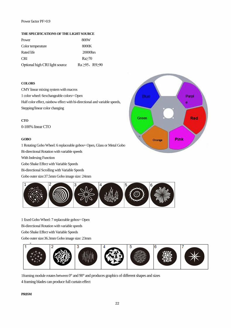
COLORS
CMY linear mixing system with macros
1 color wheel: 6exchangeable colors+ Open
Half color effect, rainbow effect with bi-directional and variable speeds,
Stepping/linear color changing
CTO
0-100% linear CTO
GOBO
1 Rotating Gobo Wheel: 6 replaceable gobos+ Open, Glass or Metal Gobo
Bi-directional Rotation with variable speeds
With Indexing Function
Gobo Shake Effect with Variable Speeds
Bi-directional Scrolling with Variable Speeds
Gobo outer size:37.5mm Gobo image size: 24mm
1 fixed Gobo Wheel: 7 replaceable gobos+ Open
Bi-directional Rotation with variable speeds
Gobo Shake Effect with Variable Speeds
Gobo outer size:36.3mm Gobo image size: 23mm
1framing module rotates between 0° and 90° and produces graphics of different shapes and sizes
4 framing blades can produce full curtain effect
PRISM
4 2 3 1 5 6
23
1pc of 4 facet prism , Bi-directional rotation with variable speeds and indexing function
FROST
1pc frost filter, linear frost effect( 0%-100%)
EFFECT WHEEL
1pc, replaceable, bi-directional rotation with variable speeds
FOCUS
DMX linear Focusing
DIMMER
0-100% Linear adjustment
STROBE
Double shutter blades, 0.3~25 F.P.S
TILT
270°
BEAM ANGLE
linear zoom 6°~ 56°(open)with 16 bit function
CONTROL
DMX512, 5 pin interfaces
RDM control protocol
28channels in short mode,31channels in standard mode and46channels in extended mode
Master/Slave synchronized mode
Stand-alone mode
OTHER FUNCTION
Total hours displayable
English and Chinese menus
Built-in sensor diagnostic system
Software versions displayable
Input signal isolation
Modular Structure for easy maintenance
HOUSING
High temperature ABS+ High tensile cast aluminum , IP66
NET WEIGHT
42Kg
OPERATION TEMPERATURE
24
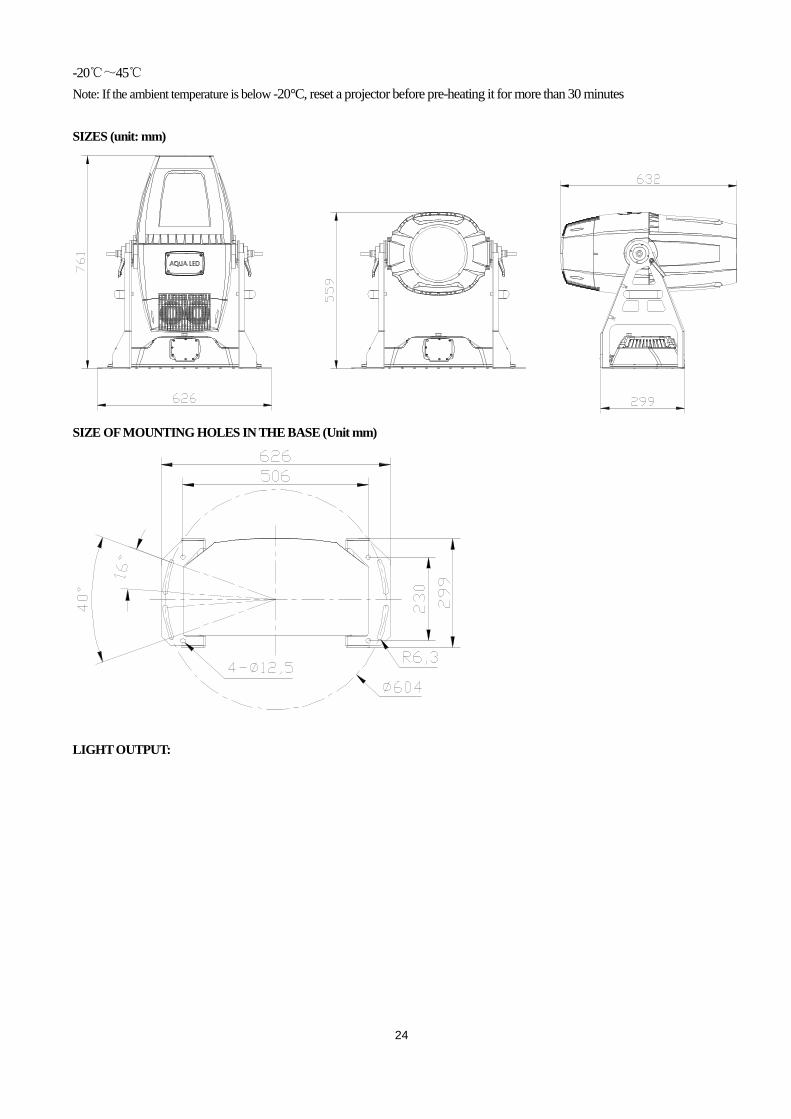
-20℃~45℃
Note: If the ambient temperature is below -20°C, reset a projector before pre-heating it for more than 30 minutes
SIZES (unit: mm)
SIZE OF MOUNTING HOLES IN THE BASE (Unit mm)
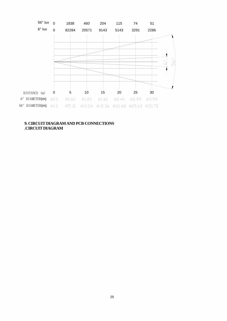
LIGHT OUTPUT:
25
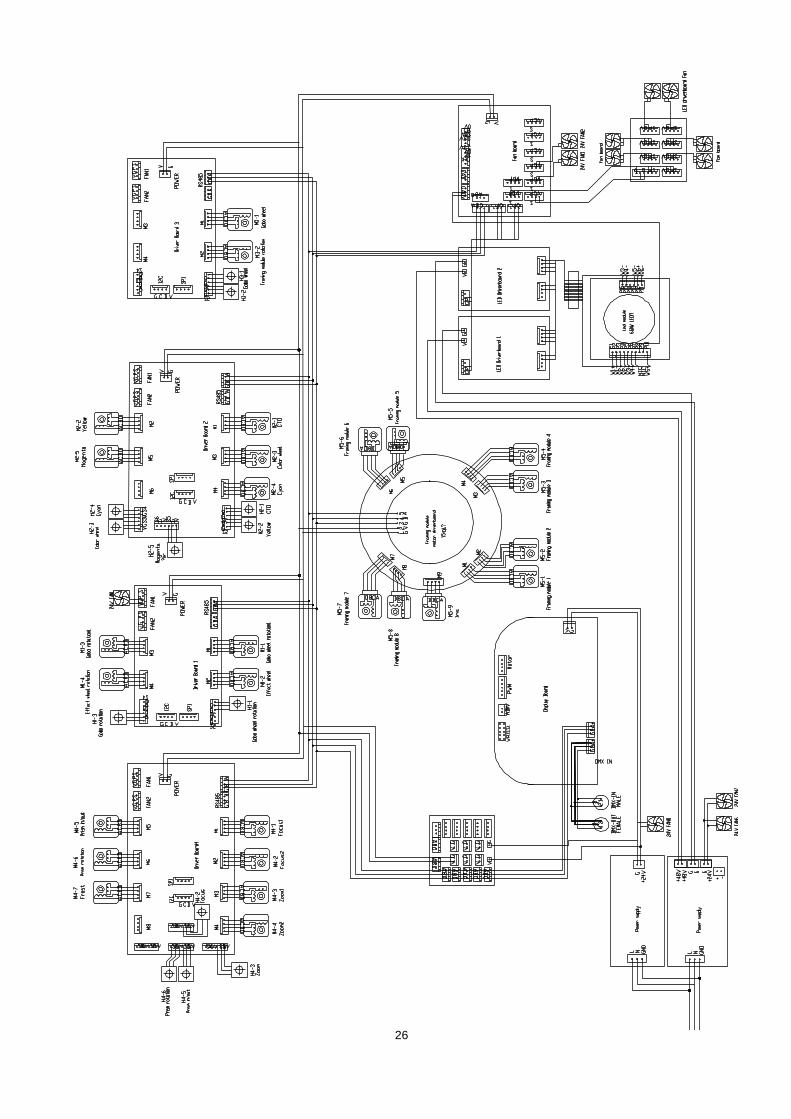
9. CIRCUIT DIAGRAM AND PCB CONNECTIONS .CIRCUIT DIAGRAM
6°DIAMETER(m)
DISTANCE (m) 0 5 10 15 20 25 30
56° lux 1838 460 204 115 74 51
6° lux 82284 20571 9143 5143 3291 22860
0
56°DIAMETER(m)
26
27
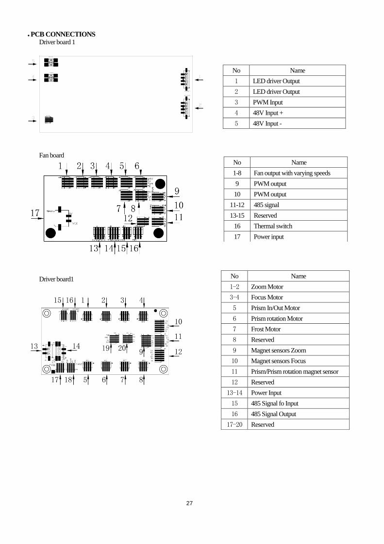
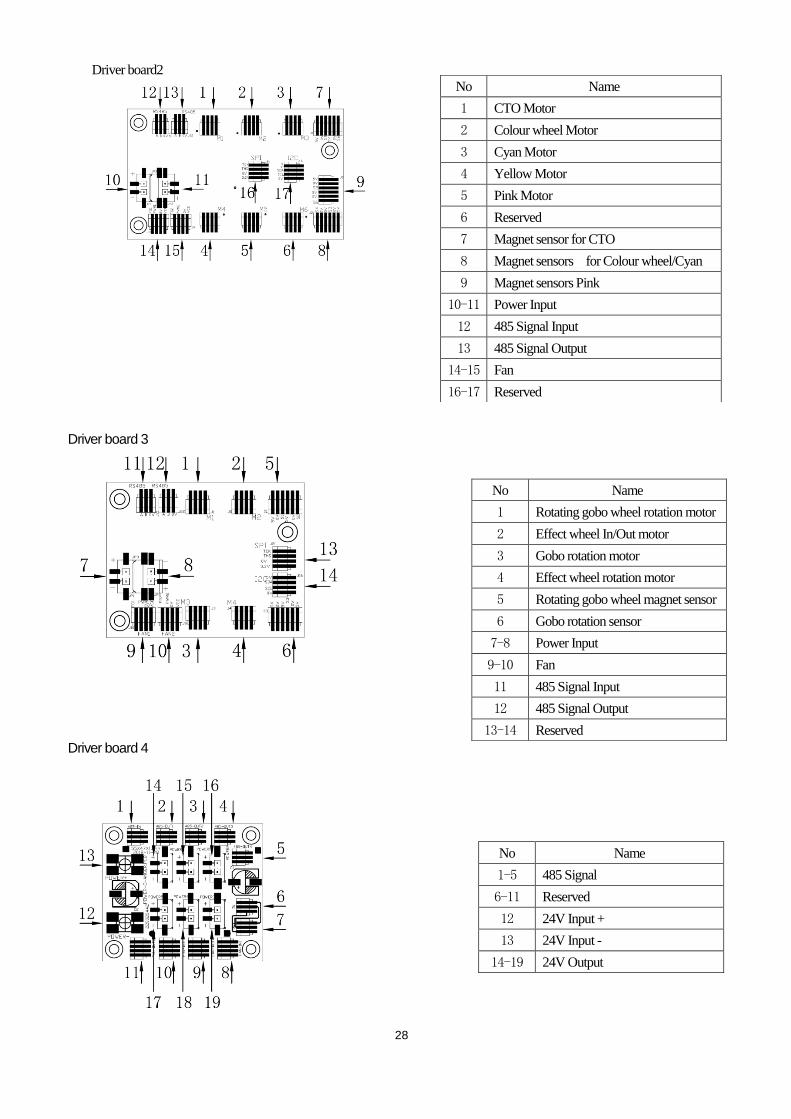
● PCB CONNECTIONS Driver board 1
Fan board
Driver board1
No Name
1 LED driver Output
2 LED driver Output
3 PWM Input
4 48V Input +
5 48V Input -
No Name
1-8 Fan output with varying speeds
9 PWM output
10 PWM output
11-12 485 signal
13-15 Reserved
16 Thermal switch
17 Power input
No Name
1-2 Zoom Motor
3-4 Focus Motor
5 Prism In/Out Motor
6 Prism rotation Motor
7 Frost Motor
8 Reserved
9 Magnet sensors Zoom
10 Magnet sensors Focus
11 Prism/Prism rotation magnet sensor
12 Reserved
13-14 Power Input
15 485 Signal fo Input
16 485 Signal Output
17-20 Reserved
28
Driver board2
Driver board 3
Driver board 4
No Name
1 CTO Motor
2 Colour wheel Motor
3 Cyan Motor
4 Yellow Motor
5 Pink Motor
6 Reserved
7 Magnet sensor for CTO
8 Magnet sensors for Colour wheel/Cyan
9 Magnet sensors Pink
10-11 Power Input
12 485 Signal Input
13 485 Signal Output
14-15 Fan
16-17 Reserved
No Name
1 Rotating gobo wheel rotation motor
2 Effect wheel In/Out motor
3 Gobo rotation motor
4 Effect wheel rotation motor
5 Rotating gobo wheel magnet sensor
6 Gobo rotation sensor
7-8 Power Input
9-10 Fan
11 485 Signal Input
12 485 Signal Output
13-14 Reserved
No Name
1-5 485 Signal
6-11 Reserved
12 24V Input +
13 24V Input -
14-19 24V Output
29
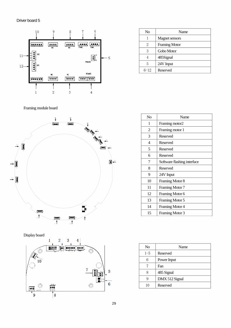
Driver board 5
Framing module board
Display board
No Name
1 Magnet sensors
2 Framing Motor
3 Gobo Motor
4 485Signal
5 24V Input
6-12 Reserved
No Name
1 Framing motor2
2 Framing motor 1
3 Reserved
4 Reserved
5 Reserved
6 Reserved
7 Software flashing interface
8 Reserved
9 24V Input
10 Framing Motor 8
11 Framing Motor 7
12 Framing Motor 6
13 Framing Motor 5
14 Framing Motor 4
15 Framing Motor 3
No Name
1-5 Reserved
6 Power Input
7 Fan
8 485 Signal
9 DMX 512 Signal
10 Reserved
30
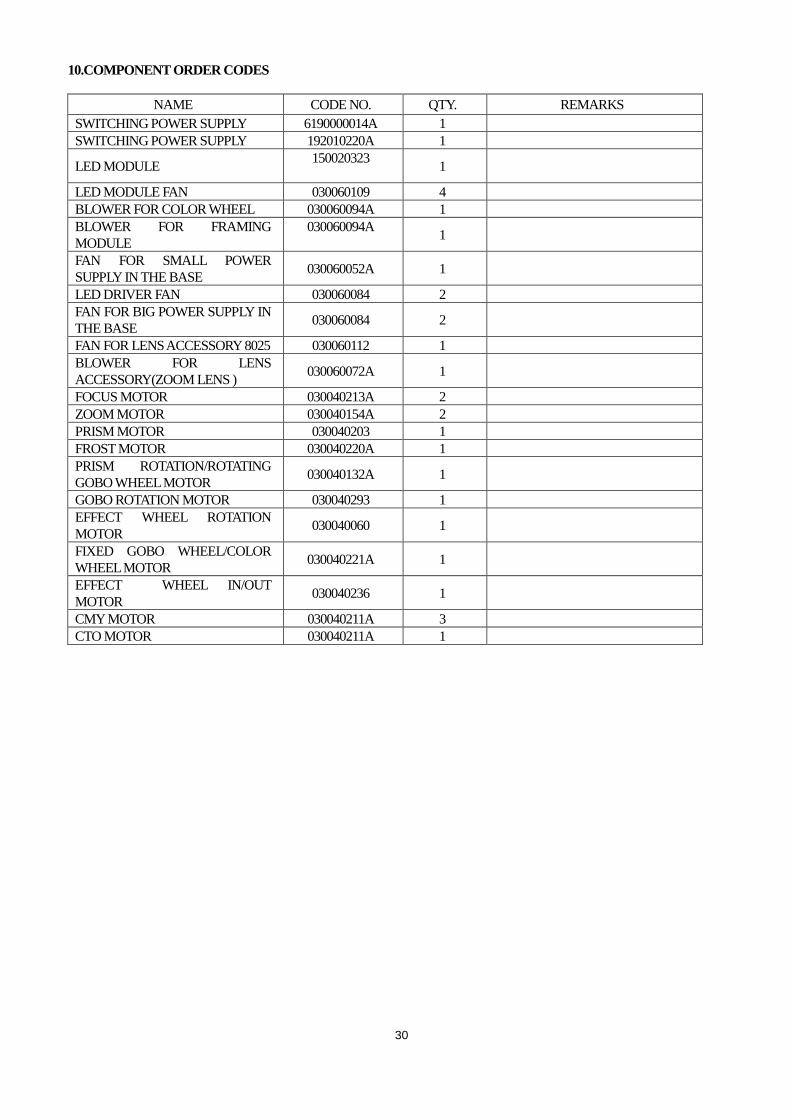
10.COMPONENT ORDER CODES
NAME CODE NO. QTY. REMARKS
SWITCHING POWER SUPPLY 6190000014A 1
SWITCHING POWER SUPPLY 192010220A 1
LED MODULE 150020323
1
LED MODULE FAN 030060109 4
BLOWER FOR COLOR WHEEL 030060094A 1
BLOWER FOR FRAMING
MODULE
030060094A
1
FAN FOR SMALL POWER
SUPPLY IN THE BASE 030060052A 1
LED DRIVER FAN 030060084 2
FAN FOR BIG POWER SUPPLY IN
THE BASE 030060084 2
FAN FOR LENS ACCESSORY 8025 030060112 1
BLOWER FOR LENS
ACCESSORY(ZOOM LENS ) 030060072A 1
FOCUS MOTOR 030040213A 2
ZOOM MOTOR 030040154A 2
PRISM MOTOR 030040203 1
FROST MOTOR 030040220A 1
PRISM ROTATION/ROTATING
GOBO WHEEL MOTOR 030040132A 1
GOBO ROTATION MOTOR 030040293 1
EFFECT WHEEL ROTATION
MOTOR 030040060 1
FIXED GOBO WHEEL/COLOR
WHEEL MOTOR 030040221A 1
EFFECT WHEEL IN/OUT
MOTOR 030040236 1
CMY MOTOR 030040211A 3
CTO MOTOR 030040211A 1

31

32
PR LIGHTING LTD.
1582 Xingye Avenue, Nancun Panyu
Guangzhou, 511442 China
TEL: +86-20-3995 2888
PR lighting will try its best to offer accurate and overall information about a product’s technical data. Any changes won’t be notified if necessary. Patented Products.
Counterfeiting Will be Prosecuted!
P/N: 320021285
Old Version:20210416
New Version:20210511