Tala Constructisn Co.
137
Talcon Tala Constructisn Co. GOMPANY PROFILE ffi@ An ISO SO01:2015 C.rdtrad
-
Upload
khangminh22 -
Category
Documents
-
view
0 -
download
0
Transcript of Tala Constructisn Co.

TalconTala Constructisn Co.
GOMPANY PROFILE
ffi@An ISO SO01:2015 C.rdtrad

OVERWEW
Tala Construction Company (Talcon) is a leading Construction Company, ISO9001:2015 (OMS) & ISO 14001:2015 (EMS) certified, and is the subsidiary ofRAIZ GROUP (RG) which is a well-resourced holding company providingcomplete range of services. RG operates in multiple sectors such as Oil &Gas, Petrochemicals, Industrial Security, Information Technology and variousother industrial sectors.
The group provides a broad portfolio of business and technology solutions tohelp its regional clients improve their business performance. We haveassociations with well-known manufactures and major suppliers worldwide.
Our innovative manage and industry-related regional experience gives us acompetitive advantage and enables us to deliver superior results to our mostdemanding clients.
2

KEY PERSONNEL OF TALCON.
Dr. Saeed Mubarak Al-Dossary
Mr. Saleem Zakharia
Mr. Fouad Taleb
N4r. Willie Duro
Mr. Karim H. Mersal
Mr. Mohammed lbrahim
Mr. Erwin Gariando
Mr. Khaja Samiuddin
Mr. Nizar Koussan
Mr. Ahmed Hatem
lVr. l\ilahmoud Sonbol
Mr. Varghese T.J.
: President of the Group
: General Manager
: Projects Manager
: Project Manager
: Construction Manager
:Technical l\.4anager
: QA/QC Manager
: HSE Manager
: Purchase Manager
: Accounts Manager
:Group Finance Manager
:Administrator.

SUBS'D'AR'ES
Raiz TechnoloSy (RT)Raiz Technology provides solutions and services in the felid InformationTechnology, Industrial Security and Industrial Solutions and Services. Fromsupplying simple technical products to a Lump Sum Turn Key Projects, RTcan do it all.
Petro Tech.Petro Tech is a trading company focused on providing Industrial Valves,OCTG Pipes, and its associated drilling services and supplies. Petro Techcontributes with UIS in providing a wider coverage of market needs in oil andgas industry.
RAIZ Development and Training (RDT)RAIZ Development and Training provides specialized management, technicaland educationaltraining programs. RAIZ Development and Training staffconsists of professionals that possess a very high academic degrees andexperience.
Universal Dynamic Incorporation (UDl)Universal Dynamic Incorporation, based in USA, LA, specializes ininternational trading and business consultation. As an advisor and consultantto RG companies, UDI has shown itself as a reliable and discrete partner.UDI acts as a consolidator and facilitator for all of RG purchasingrequirements.
TALA Tech. Company Limited (TALA Tech)TALA Tech Company Ltd. offers professional services of new technology withhigh standads, commitment of excellence, innovation and client satisfaction inits field of specialization. ltfocuseson providing business solutions in oil &gas, industrial, petrochemical, environmental as well as fabrication in domesticand Gulf region.
4

SUBSIDIARtES (Contd.)
Kaun Tech.Kaun T6ch core value is excellence in energy products, materials leadingsupplies and services. Kaun Tech provides professional project developmentsupported with financial strength, extensive engineering and technicalexpertise and power market knowledge.
Raiz Healthcare (Raiz HG)Raiz Healthcare (Raiz HC) provides transformational medical technologies andservices that are shaping a new age of patient care. lts expertise in medical imagingand information technologies, medical diagnostics, patient monitoring systems,performance improvement, drug discovery, and biopharmaceutical manufacturingtechnologies is helping clinicians around the world re-imagine new ways to predict,diagnose, inform and treat disease, so their patients can live their lives to the fullest.

CONTACTS
Contact Address of HeadquartersSalam Tower, Sixth Floor,
Zaid Bin Al-Khatab Street, Cross 21".P.O. Box - 3045
Al Khobar-31952, Saudi Arabia
Te l :
Fax:
+96613 8813000+96613 889 7650
TaIa A+qn,<l;w. A, Ul
6'h Floor, Salam Tower, Olaya,Zaid Bin AlKhatab Street, Cross 21"t.
P.O. Box - 31325,Al Khobar - 31952.
Tel: +966 13 8890808Mob: +966 569797777Fax: +966 13 8896858
e-mail: [email protected]@yahoo.com
?Talcon
6

HAMANRESOARCES
TOTAL NUMBER OF PERMANENT EMPLOYEE : 770
CLASSIFICATION
ADMINISTRATION : 23ENGINEERS & SUPERWSORS : 44 (26+18)SKILLED WORKERS .. J8.IUNSKILLED WORKERS : 308DMVERS & MECHANICS : 12 (11+01)
7

OTHERRESOARCES
Description Quantity
I Buses 8
2 Cars 46
3 Pick-Ups 1 6
4 Trucks (Dyna) 9
5 Water Tarkers 2
6 Concrete Mixers (2 Baggers) 2
7 Boom Trucks 2
8 Shovel I
9 Bob Cat,4-oader Excavators 2
l 0 JCB Backhoe 2
I I Generators 5
12 Compactors (Pedestrian & Plate) 5
t 3 Welding Machines 2
l 4 Tower Cranes 2
l 5 Forklift with Bucket I
l o Compressors 7
t'7 Construction Hoist I
1 8 Scaffoldings Bulk
1 9 Miscellaneous Tools & EquiDments Bulk

LIST OF ON GOING PROJECTS
S.No Name ofthe proj€ct Contract
Period
Locetion Value (SR)
0n Miuion)
1 . Civil Works for Riyadh
Metro thru Gulf Elite Co.
2017 -2018 Riyadh 15.50
2 . Halliburton Stator
Relining Facility
Workshop
2018 Dammam 3.50
I

LIST OF RECENTLY COMPLETED PROJECTS
S.No Name of the project Contract
Period
Location Value (SR)
(In Million)
1 . SCECO Ghomatah
Substation
2010-2011 Abqaiq 9.20
2. SCECO Al Zuhoor
Substation
201t-2012 Dammam 5 . 1 1
3 . Amiaatit Research &
Development Center
20r0-20t2 DTV-
Dhahran
10 .01
4. Honeyvell Turki Arabia
Ltd (CAC Project)
2011 DTV-
Dhahran
3 0.90
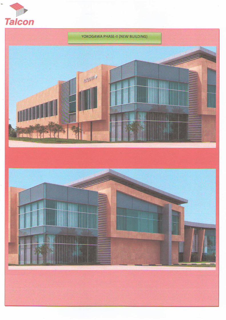
5 . Yokogawa Phase-II (New
Building)
2011.-2012 DTV-
Dhahran
t9.78
6. Civil Works at Culverts
(SATORP) thru GCC.
2012-2013 Jubail 18.00
7. Civil Works at Coke
Storage (SATORP) thru
GCC.
2012-20t3 Jubail 14.00
8 . Halliburton Saihat
Package Dl (Spooling
Area)
2013 Qatif 3.20
9. Hassan Al Husseini Villa 20t2-2013 Al Khobar 5.50
10 . Double Tree Hotel for
Hokair Group
(Renovation)
2013-2014 Al Khobar 3 .50
1 0

LIST OF RECENTLY COMPLETED PROTECTS
S.No Name of the project Contract
Period
Location Value (SR)
(In Million)
l l . GE Oil & Gas Pressure
Control Expansion (Site
Enabling Works)
2014 Dammam 3 . 1 0
12. Hallibufton Saihat
Package D2 (Boots, Coots
& Slick line Buildings)
20t4 Qatif 19.0
1 3 . Mr. Imad Al-Enaizi Villa
(Renovation Work)
20t3-2014 Al Khobar 2.29
14. Halliburton Saihat Phase-4
(SEC & Switch Gear
Room and Storm Water)
2014-20r5 Qatif 4.7 5
1 5 . Mr. Basil Abulhamayel
Villa
2012-2015 Dhahran 6.02
1 6 . GE Oil & Gas Pressure
Control Expansion (Main
Works)
2014-20r5 Dammam 3 3.00
t 7 . Kl.raled Al-Suwaiket Villa
(Concrete Works)
2014-201s Al Khobar 6.5 0
1 8 . 9 Story Commercial
Arcade (Al Mubarak
Investment Co.)
2012-20t5 Al Khobar 69.00
19. CAT Intemational Office
Building (8 Story)
20t2-2016 Al Khobar 2 0.10
1 1

S.No Name ofthe project Contract
Period
Location Value (SR)
(In Million)
20. Galleria Mall (Finishing
Works)
20t4-2016 Jubail 25.02
21 . Ali Al Harbi Building
Concrete Works (15
Story)
2015-2017 Azziziya 16.40
22. Emerson DTV Facility 20t6-2017 DTV.
Dhalmn
57.95
12

LIST OF PROJECTS EXECUTED UNDER CURRENT PROJECT MANAGEMENT TEAM
S.No, Name ofthe Project ContractPeriod
Location Value (SR){ln Mil l lon)
1 Yokoqawa llliddle EasfKSA. Science Park. KFUPM 2D07-2008 Dhahran 20.5(2 Halliburton Al Khurais Fa6ilitv 2007 Ai Khurais 8.7(3 Il,4ohammed Al Subare Viila 2007-2048 Azizivah 8.5C
Faisal Abdul AzizAbdullah AlJamas Buildino 2AA6-2007 Al Khobar 3 .15 AlGosaibi ShoDDinq ViJlaoe Phasel 2005-2006 Al Khobar 20.246 Dr. Jasim M. AlAnsariVilla (Structural Work) 2005 Al Khobar 1.2C7 Atif [,,1. Al-Suwaidi Vil]a 2004-2005 Doha 1.748 Mav Al-Jaber Villa 2003-2005 Al Khobar 6.809 Private Villa 2003-2005 Doha 5.331 0 Rezavat Protective Coalino Co. Lld (Factorv Renovation) 2004 Dammam 0.20t 1 IMadam Bahia Al Gosaibi l\Iosoue 2003-2004 Al Khobar 1 .201 2 SWCC Product Waler Expansion Proiect (CivilWorks) 2403-2004 Jubail 1 . 0 91 3 Hiam Al Rash d Villa 2001-2003 Al Khobar
Saudi Advanced Frberqlass Pipe Industries 2002-2DO3 Dammam 1.5 (1 5 Dr. Jasim l\,4. AlAnsariVilla (Structural Work) 2001 Al Khobar 0.7c
Ahred l\,'1.M. lsmail Residentiai ADt. (Structural WoAl 2000-2002 Al Khobar '1.8C
1 7 Ahmed Al Olavan Villa 2000-2441 Al Khobar 1 . 9 :1 8 Al l\,4utlaq Villa (Structulal Work) 2000 Al Khobar 1 . 0 :'19 Awda AlAhmadiVi l la 1999-2000 Ar Rabiva 2.7C20 Yahva Al Zaid Villa 1999,2000 Ar Rabiva 2.7C21 qsqhar Villa (Extension Work) 2000 Ar Rabiva 0.3022 Al Sahaba l\4osoue 1998-1999 Ras Tanura 10 .5023 AdelAl Ohalv Villa (Structural Work) 1999 Darnrnam 0.8024 qbdullah Al Fozan Showroom 1998 Rakkah 3.5025 ql Falak Staff Accomodatton (Sub-structural) 1 9 9 8 Rakkah 2.5026 Half Moon Bay Beach Resort (Sub-slructural work for
60 resorts) 1 9 9 8 Azizivah 2.0e27 l\Iohammed Bin Jumma Viila (Skeleton Work) 1 9 9 8 Al Khobar 2.Ai2A IMousa Al Mousa Villa (Renovation) 1 9 9 8 Al Khobar 0.7c29 Al Ruoarb Vi l la 1997-1998 Al Khobar 3.0(3 0 Al Hokair Vi la 1997-1999 Al Khobar 2.723 1 lvlohammed Muqhamrs Villa (Renovation) 1997-1999 Doha 1.0c32 Amna Dossarv Vi la 1997 Dammam 3.2C
Samir Al Traiki Vi l la 1 9 9 6 Dammam 2.8C34 Abdul lat i f Abdulhadi Vi l la 1 9 9 6 Al Khobar 2 1 (
Ali Fozan Vil a 1996 Al Khobar 2.5CCommercial Centre Buidino {Suoer llrarke! Farm 10) 1996 Al Khobar 3.4C
37 Corniche Palace 1996-1997 A Khobar 14 .0c38 Dr. Shahab Villa 1 9 9 6 Ai Khobar 4.3C39 Badel Sa eh Al Saleh Villa 1 9 9 6 Al Khobar 2 . t c40 Ahmed Al HlrrnaLd Villa 1996 Al Khobar 6.0c

LIST OF PROJECTS EXECUTED UNDER CURRENT PROJECT MANAGEMENT TEAM
S.No. Name of the Proj€ct ContractPeriod
Locatlon Value (SR){ln Mil l ion)
4 1 FaisalAl Zamrl Commercial Buidl ino t5 Storevl 1 9 9 5 Al Khobar 4.3042 AbdulAziz Al Jaber Commercial Buildino (4 Storey) 1995 Al Khobar 4.5043 AlzamitTwin vi a 19S5 A'u,izlyah 2.30
SARA Showroom 1995 Al Khobaf 1 .5 (45 HRH Prince Sultan Castle (Skeleton) 1995 Al Khobar 1 . 146 Saad Shoufan Villa 1 9 9 5 Al Khobar 3 . 147 Saad AlShaifan Vi l la 1995 Doha 3.5C48 Railwav (Wofkshop) 1995 Dammam 1.5C49 Hazza ComDound 1994 Al Khobar 3.5C50 Khalid Abubshait Villa 1994 Ar Rabiva 2.245 1 Abdul Salam Nlohviddin Villa 1994 Ar Rabiva 2.4452 Yousef Al Rooo Villa 1994 Al Khobar 0.6053 Al Bilad Caialist Factorv 1994 Al Jubai l 2.60
Al Azaz Stores 1994 1 . 5 0SAMBA Dfive-uo 1994 Al Khobar 0.50
56 Jubail Roval Commission (lvlaintenance) 1994 Jubai l 3.5C57 Al Dossarv Villa 1993 Dammam 5.3(58 SAIVIBA - Al Doha Branch (Concrete Slructure) 1993 Al Khobar 1.0c59 ToV Land Extension '1992 Dammam 7.5t60 I l l & M H o u s i n o C o m D o u n d 1991 Al Khobar 18.5C6 1 HRH Prince Mohammed Bin Fahad Mosque 1991-1992 Dammam 4.7C62 Al L4utlaq Furniture Warehouse (Civil Worhs) 1990 Dammam '1.0t
Al Tarnimi SupermaAet Exlension Work 1 9 8 9 Dammam 0.5c64 Al Dabal Co. Residence 1987-1988 Dammam 1.00

**-,
Talcon
" € r
Talcon

SCECO.GHORNATAH SUBSTATION


. :) : ' .


#I,frt"€
71[ =


HALTIBURTON PACXAGE D2 {Boots, Coots & Slick tine Buildings)
- i ' ,
#
. , 8t , ,1
' . , *g
: '
.t1
&


R TD CEXTEN

GALLERIA MAIL

GALLERIA MALI.

cEE


ALI AL HARBI BIJILDING
iffittrffiffirg._{srniEItr
.,. . l l t ,r i f i trmtnn. .,, ;:arutmryEl-
':. ' '.. ' rl. ignl llr tf,' r
: , i f fFdm'E;f,xici6trf,c5tr'ruru EGF'!r- '
# E l ' o f f i
2 1 -
t :i ti t l
, .: .t. t.-tt

Talcon

C ertific ate af Re gistrationCertificate No: l6l f02016621
This is to CertiIJ: tl st the Mnnaget ren, S!'slem of
Tala Construction Company (IAIC0$6th Floor. Salam Tower. Zaid Bin Al'Khatab Street, Cross 2lst,P.O. Box 31325, Al Khobar 31952 - Kingdom ofSaudi Arabia
Has been ossessed and foand t9 fu i1 ucconlunce with the requirements oJ'- standurd detdled balow
ISO 9001:2015This CertiJkate is validfor thefatlowing scope
"Salc snd Purchase of Land & Real f,statc, Retaurant Management andCommemial Markets, Maintmance of f,lcchtml' Meehanical andPetrorhemical Installations, Ceneral Consltuction Contractors"
hrili|ll Rcsistrt(lon DeL
?*I sorl'.illancll otr rr. bcfort
02trd fi'rr.l0l6
02d ()cL t01E
lssue l).ri.
Velid Urtil
l-\f {irtap
Ileririat
.l{ft ON. 2017
0l< Nor. l t l l8
l9 & -12- ?8
0 l
I.jAF' is fidl nnfiber o.f lrrternttbnal Accreditation Fotmn {L4F)I o dfttk t qli.lit), of rt,e cetifc.l,? ple$se :-sit U-y:l,!l'tt!!!fu!l!!
TNYCAccredittd bJ United Accredilation
Fouuilation {flAF}
$bsd5€4m3h.F.Ft, dNE:drls P Lt tur3rctrlEd* ik'-

C erffic ate of Re gistrationCertificate No: l61 10202662 1
This is lo Certify thst lhe En$ronmenl M{ndgement l;istem ot
Tala Construetion Company (TALC0N}6th Floor, Salarn Tower, Zaitl Bin Al-Khalab Street, Cross 2lstP,0" Bor ll3?$, Al Khobrr 31951 - Ki4ilom of$tudi Arabia
Hrs heen osscsserl andfound 1u hY in a3rlrylo.nce with the requirements u!'\tun nr.l d?niled belob'
ISO 14001:2015Thi'- Ccrtilicflte is rdlid for the ftlbwing scope
"Sale and Purchare ofland & Rerl Estate' Restaurant Managenent andComuercial Markets, Maintelan$ of f,lechied, Mechanical andPetrothemical Installrtinns, Ceneral Construction Cofitractors"
tritirl Regis!rntion Dirc
?'" Srn'eillsoce on or h.forc
ffirtrF
01-t Nor'.:016 fesw D.te
o:dort,2lll8 vslidtintil
IAF (;|.('llP
RciBio
ldo {rct t0lt
0lrr Nor.20l8
19& 3!. 28
U I
LIAF i-s fa!! member of Inrernutiot ul A$.edirq{on Forum (IAF)
To check wlittiryl ol thc certifrc le ltle.Be lisit ttt4w,h,wt'o d'tn t
'HdrihErdil if i lqdbsre re i lr4.| lc LiEd^q **d rr ea.$! !**g:BrlidA.! tris rnsm9.r] d r{t C.if isd: lr l Fd s nirrtseu rtb rrd*r s1:€c!
Arcrtdited br Unitcd AccrcdilationFoundation (IL\F)

(,C't
E.J(,
o
oI
GB
N
of
c!c\I
x \\ u -
X > r
( / ? ;
t- a-
; :
- . t j
\u {t
a - =,'ri i:= n.l
t t't- -
d ) E
! ? xx ) <
= -
\ ) a>( , / )
q- 0)
c ) . !
c(ECLEoOEo
t -
+,o5l-+,Qgoo(E
-
t"r-f
I
zoF
ot!E,O- .)o - t rl l oo *ul 1t-
olrFElJlo
zzoUItIJJ
IJJ

cqtngJ.ted the Works underto the Jubaillxpo.t Refinery
irJ.:iqit

P ROVISIONAT ACCEPTANCE CERTIFIEATE
aGritJ tr l|]iciJ,ii-i:;t: 6E Oll & cas - Presture Contrcl, K ngdon lisaudilEbia
?i3!c'l D:ariP:rail:
Dan@e 2d ndusua clly- Klngdomofsalriillzbh
COlllR{CToR: iah ftnslldboi co TEdinq E ccnJa,:dt:. P.0. Box 31352,
Auftobar 31952 lcrld.n otsadiAcUa
coMpl- C^ 8 4I-S tnDJcr'E rtl- u4 rltE Nt u aauplLlt D)
Al1 t1€P wo*r & fxiefiral Works hav6 been compleled.
SlNo. Des{tipton
Snag [el to bs lomple€d by tlre ctnhactor & validtted t 6E, date 4i Jan. 2016 - F$ lnvisiooa' aatepEnta (afrached)
2. To e*end lhe Psjbrmanae 8r.d by to lie aonFachr to ,!ve. {re liabilit perld
3.'Io srbfiit all tB handing over docu.nenb (& bullt Of3wirige, o/L'l nanual!; ]4an anlies' Coniacts list) & b te valid"tedby GE.
4,
5.
a. atu!@artdetfu{dbbi!f GE
!0 f,iovtmbea 2015
12 mo,ilhs IElt ot l{aRlwlYD:Fr-fis 30 N6!dmbet 2t16
AUIIC'IA,$ON fl naSPO{STBLE Mtz #€6EO1&&3 / . w tzt
HCO ('-/&
oa. :',f;A&*Afinadsa! oN TnE stl]Ar' 0,< IALC{JII l./J*)- 1 \ ffi
1+'i+'*_""+.\ ' .1i..*' \ i=,::: : :

t*1'{,:_.:.,. _.:tr
TA:(I}IG OVER, CERTIF:CATE
ntlrtnsahararlrl.t(i!!dh.'s€irdA6bb
to \ ! ,AC oF ' r€ r rydrc . ? r i l6 - , , ; l ; . , - , r ;
A!(r'.t&r31liz {r-,gdn d S:}a n *r3
c{lilrEirar sadJs irtalnar4raH FA\E eF:N CA CltEtt)
,1l Civii, PlB & Ad*rciuraisarts h"* i*,.-"ptd.;.t " "ird,"d;A rri b k;G;ttrr;;;
An lrtr-norisia€!€m coiDlebd, 0tBEnsdEds rglelh be€omplehdo) f!9conmcsr
I :,AF .5 j Or'f! wocxs r+rlaREpR4rnc4 Lv vEt tocO!oJIE qRE AS FO|T C^S
; Slljo. I Dessip on
&rhiie.trd 6rrg Irt b b6 cohpt6bd by hs c.nfrriari€P $ra€ isito ire.anplebd by&]..rontecbr
14 ,t oon$s.bd by li* contrdr!3 d.::hba ty {€ coofuii..
Focns of he ddi! snd potr. ss.leh 6r fi. rFanenr ,olrrim or h. q,;itre; r";;;;l s-;F.
!!]ecRti'irA! oAlEs Asscca€! wi:x rt* &${eo,r:*or.].€.rci|s {on pAFrs }SEor r"*.rs Fo,!o,€
:t'rlev€d 1: Ocr:t1:1
iz t v

TAKIII.G OVES ESRTIF]CATE
@le3BtAa b4e D7 (s !L6 L-tk
#-r.:J:ai a!Si"r;?,.{r!
caxlFAfinR rrl3 C6rE x Cj, ir6r;;r""i,r,,.a. !_ 3l3j?"
- ,qa$nnr3195g rcg6 or Salt r.$ia
cruDrI tc+ s-lIrE -AACItE r{s,upt$a.:I c./'l4EfEA
rdfbr
41 gF *!i{sl6!,
fl.ra P,rils) €!NACIC!].LYYETrcM PL'IEiRE1S'O.LOiI6:
5|l'o. l. [€sojtfrnNdr|ecerral sni! tisl to !e coErleled bv &e .on F*r.r
z n,gP erag lht to be conptetid b} fn coih&br3. Eremll$ag tisl h be coflphFd by t e conU-*lr-
a.1ob€r n1412nonalc
OCoie. 2r1t
12 monD3
odober 2$t
&{|sLFro, /./ }} l . : A . I YAqihoesaF0RtrDo.l
AECOit s(f{: l o zot+sN &€rh3 hcil 'Efy ZL 2 c,lr+ru]}loils:D oN tt€aat* oi t{cct{ 4il.4>. r/6 a4i'+
i "i.i'i r- t, ; F l*t tr{y.:il:! t!,.1
i:rie4.d 13 Od?a14FOi:1--r1A:,-S,DC3t?

ffilAl
Hamdan consutrins office
TAKING OVER CERTIFICATE
Rev . l 0
)a:: f . /arc h 0J, 2014
P.ojrct fit,€
lssrsd byAddres$
Employe:
contractot
Worr.sStuiited a!
GE EWP Enablii.lg Works.
Al Hamdan Consulting OfficeP.O. Box2474Al Khobaf 3J952lctrgdom of S?!di Arabia
GF Oil & 6as.P.O. Box 1258, AI Khobar 31992,Kingdoitl of Saldi A.abia_
Tala Construadioh Co.P.O Box 31325,Al Khobar3t952,Kingdom of Saudi Arabi!_
GE Oil & Gaa Factory,Plot 14,2nd lndustrial City, Street. No.83,Darnmam, Kiagdom of Saudi AIabia.
Projeci no.; 1OO0
Under lbe ter6$ of i]3 above-mentjoned CanAacE we hereby ce.t,fy liat conpl8lion of :!ireeany wo.ts pa.kage enabtisg y,rrits c/w otric€s,. girrr'a troLi";, i"" j,'#p"?iig rno o"r*
cE Oil & 6as Factary ptot :4.Ihis raras achieyed on 25 Sepiembe.2Ol4 and accepted by ilrs ctlent on25 Seriernbef 2014.Outstanding ltems to be complet€d
lisalyore.all works neod to. be dompletsd withinsae the sflached c
Disfribrtlo. C.igln€lto: Copies to:
l7l r",p"ru," r*lJ lOuanljty S!rueyor I r. lconsulrants

TAKING OVER ESR,TIFIE'TE
Ha{jllirn ftergyseryi.$I.c-, PcsOX3?1,nlthjoErR,i9:2 (igccn.rsj ! {:a.,
Hr*:|.r|1 !,rlhat ftf! Kisdon oi !ddi&!bi.
tlNlRAcroFrTatr clGtsddni cc. T6cn9 ! {*g!d.g, p.o 9d 3 i?j2.A!$rta.3J952. (lTaor orgr.iiA65ta
c')\FL-:nS4:.S lolclt r v4i U ,a r. EEE6 Corpt g1Lt ,
All\rcrtg have been compteted b/heconbaclor
ftE PAnTi$l OF rHE !?!&<S WHtCti Ate F{\fiCnLLy yEr Io cor1?|rlr Aiaf€ FoLLogIt:
Destipljon
None
tHE cRflslt DATES Tlt€oc ArE! WIN ]tF TAKNG{VER qF ]]1! i4lixs {Oi pARTs L€REofl ARE A€ rr](tows;
2t/t2,-61 f
i.r4e\r.:! 13 C*20i4 FC-€|itALl!c5!rr2

. '- -':i, . ..'
TAKING OVER CERTIFICATE
I , . .JBURTO\ SAIFAT, pOB0): 4 r f -OBAi ) t . t2Pirap 4 -SLonWee.Sysiem
I !dl.bLnL1. ci.:t, 4rodoF ot Saud, A,aou.: - *j indin iner!/ SqvcA Lrm,kj .dJto.@_ Tala Consttuclion C.mD.n!
,(sA
tE PAri6t 6n.sra&rrc!em^{erj!!
.:015
a{o ora:acrs us!,,1Y- 5r\ 2016
56 14a'!tr 2016
Ar$,qbd- El Xad€r l:lelllburioi ACrslaine B€ll rdibtui Golld 7 ffi+: ) { a j t {
Da\,ld Paine HCO 'dd#--tt# ar o 3 Ldl9
lll,.rlll B upd?ied terminology.:0!i
-1 oba r d (opv o. a o.eeou! vej on o- t' ,_ oocr-e r a."iii";r..r . *..y;Eiiezp"" e.rror se., r>
Ostr!. Nalhar JaSda:lx&proveri T6dnr JeFail REV/ Dsiei A / 3i. JUL i3

1:, . ,:.,. i-". t.,, rr....f,... i . : : l .,
TAKING OVER CERTIFICATE, _
: : ^ . . r_1r " r1e .9 , se ,L .4 l c . . r tB0ru j I . r . ca \ \1 . ! , , . - r r . -o .s . o :
' . : . . : q o a , e * l & r i
liaAioji lr.r:r,tr*lrOo,ri,xir,o*ors,ulir;i-
C^ \A rc Oo _ r r ' d / a : - o i - o ! ( r r , : { . r . 0 B ! I i -
it.{\obar 3Gil &t&n !IsadiAE5t,
cara-4:l,O\ San-r ijs litti&J_E *4?C$ filr€:rr{ toirptFf€ojr
Al rbr"rc halg beel comlLiod by lhe clnbaclor
tl€ paRTis)oF T]{E !10Ri3ll?NtCH ARE piAanoilly.i!:T TO COMFLSF ARe 16 t LLCi!S:
gND. !escriplion' > 44'..mc.4 -^; e,.^*1";:.1 -,- t;2.3. M 0,'",^4L a Jz ,4\S'1idLy'"/ L-4 2t /arl^ti
lHE C*nCAL OATES AaSoC1ATED r!1| 111E TtKlH6O\,rR Oi 1r€}{Car€ (Oi ,1{ts lfi:REa,l arE as Fe-|o!'s:
c5 Apdl 2015
12 runilr
03 ?116
0i 2016
AECOV sf(ftf, 0 , ,v '^l{
fic0 ) (,,-'4)rd--a ,{ 04 2a /€
Ar.llrCasaa|t Ei:liif rF TAtCi at a+ Z.Dl5
ia.! irJAri:43:itcl

^ , ^ - l : l lq+-r..u ur \:Jqql oo lj ,l (1 il d 2. l-JrCULF CONSOLI DATED CONTRACTORS CO.
Ce:tificale of Comple:ion
aac c.nfirms that TAIA CONSiRUCTIOI, CO. (.t-Al"COil! has completed the Works underlj"rl
*i: 6cc-5a4/oyar73 {Con*E t for tbe civit w'*5 _ cutverrs J-5g4i as of 14bNove|nber 2013.
This Certificate of Completion is issued in accordarce w::h Sectio! 7.2, Attaalment 11 of theaoov3 ConJ.act. The issuarce ol this Cenificate ls withogt pr€judic€ to faiiON," anntraorutli€blliiy, if any, pe*atning aothe perfom?n.r of the Works-
6cc wishes to express its appted3tion ro TAaA CONsfRUcTtot{ cO. ffAfCOAl) fo. its services inlhe above projecl, .
Given this 20d dayot Febr!:ry 2014 at JsbatJ, Kingd1)m afSaudlArabia_
HiJSi&r F. A

Sr Ldi I lcctr ic i tv ( o.^ J '
- " - i - : - . i , r e - ' . r . rl . j . l r ' : . 1 ] J . l
,i : it : :' ti r:1 t| a.,..,i,s De, t. _EOj
.- __,! :-_.,j,,_l dJ_iil,;_,- -'.-_r,, -- _,ill ;r_i:
s,.,;t :,:: ;L:.i,:i,;. :j:: - Lrj!:r,":r;rtjt
1 U / t n 0 1 1 G
L- D--.r , ^ ---:----
- r ar,raL ro!!ptet ion 9>+ j l+j)
r l l l 1 /
I Finai Comptsl;;;FEl
: i.t-:t ,Jr-11 -;Az-Zr:hmr
Rzh'a.ar:
: cr---tr:ti
}.l,:l:*J tJLl _+t a:! "-r.,*ltFeJr---1,11 cdit"
l,;;:

, Em
Toriq HoIArchitecls
4 , : a i r r i : i L l i .
F . L I l i
r I r : c r 0 r : : -
on their own fndiit,
9 . 0 . B o r 3 s 6 6A : n t d ! . : . r : : . 9 5 :
S a ! t i A r 6 r l ,rel *!6it 13r!n*$?1t:r+J36 13 [email protected]€.t .eiwww$'ctittd,L..on

€C ?{ARR:$3*:i;::ASggYfsns{-}tx :a li.Fis S:uni.i:t-. rrrr-nrrii I C!
-*]4d llr€€ :crt;n n*d - noridro rr
Knlnffi d galCi AEbi:r <66 {d)9 845 706i
!',&.€ch3Jne(M
o +9iq{oS. 0142685B p6t*[email protected]*

i.'i ,":,,1-" t,., * r..* i:ltj; .ir. j.*t ru
TAKIIUG OVCR CERTIFICATE
i
a
IteFe{:d ?0 Jan!gry, 2!14
irAlr".l6Ll RTo r,1 SAI| tAT, pO BOX 3474, At KH OBAR 31!52
earll.g Blltdi|l!Halibudon, Saihalh, Xlngdom of SaudiArali.
c'}fli,Ac'(*r&cq:*iftn&.ii4rcfti
,rl agreed MEP nas beefi inse ed, ire snrg /ist to be compJeted by main conlacto.
0es.rip:sr Dgsirjpton,1
2. S:cg / i5_ ir. Ae,"r'.d/ r, o? col. p iled Ey Mein car-aclc'
3. S.ae lisi lot l'ledarictl tt te canpkted by llein ciattaetol
rNieo\a.Fn€riiF(!Mp qlBBEr.)rr€xrardie
DATE O. rRACTta,AL aO Ptenoil 2A 01 't+
1? mgnhs
20 01 t 5
12 'r$tnr6
15
l"L\"rtl!*' Har!\ g ! (Tc.1 #S 2\ D1
6ya $*; *&ot4 6/fi{f. z o l *
+etu) s4n"t)H c A %t+Ar'rcRiat ox TU:ItrL\LF 0F ->€C NW€.rL 1:AL cdN O I z,a\1

$Jliij
*
Iii'
ri
- l
i
,a,
{
l i
i'a,
-'1;
t?,aEI:
Ij
. ' l
>f?
3:
{l1.
J Jq:
JI
,9::i:
lI.a
.:
I :
r.:
I'i
1-f
-ii
$
il{
{
4
I,
l:
,9a5'
3
< :
93
"l
{
9l
" j :i':1.
.5:
.l.iJ
4-:
l .J';
:an. :
..Jl
)
,1: :
a l
:::
e
j+I
1 :
?':
iI:
= :

-: lJ
, : - o
rlq
:f
ai
;-q
.ElJ
a?.1
;
?E
!1
, E : J . .
= d - z t , r I i. 4 . - d ) .i < \ - - ' ' 9
i i , < ; . 3 ' i 1, f r i i i * ' . :+ > = ' " - l l l n . :-i ::.1 .J 5 J -
e * S : - ' = ; j ! 3 s " i: - . i m . ( 7 i . r _ 1 ' 9 ! r !. * i l < ' ! ! ? e s
! ' J t s . j , ' { - st ' = i : 4 s B F
- : ' r i . i ' l q Z q ; J -? . - ^ - ) i . : f i i - &d i , q - a 5 , i :€ i ^ a - - o I F - - - -: g s ; ' S' 1 i D a s' E . - 3 $ 3, c F i s l i
.J' ln q
. T R E:
s < >Nr. (\lm l ow ! No
f,, - i!- a'!t !! ii
'b.
- * X l F '! : ' : o- c . t5 z : U 6 io b € = :z . Z s F ' i8 - E ' b e r do * . E , t o
= 6 h . : - r
E F U,E l<.q * 0 . nF e . riiE q, ' io: s , r nr'i r- x
6. i .
A
)
a
i-t
.::r_
, t ' . '. . !
\
,lj
r!
.4)
EU
t i r o JF r o _ Ot \ l F ro - 9 cF : .v- i-i" v . - vo x \ N
€ ( / , ; 9a - " : , 6': /r- Y -c
- - . : : u l
: F i *X . Y + -
- r7r :,1
< U l a
' l g
,-1 €
J T =_ r ' J c t
x l . , , d c' ' ' . . r ]s { , =

:. . rJ .
. 1il
-J
-t
i
t't
- *
:1 ,;
5 . 1 'A . . ' 1
: -
! - +
't-'t
J'- l
3
,\.!3'$,.5-:-".,
\!)a-
\&. q '
: . . 1 .:*{]_-lj$.
? t

illlllllll[[ilillulIHW)W
^
eIi1.1]:*.,:ru#ss
WWHWttffiLWA{;VW\GENERAL AUTHONITY OF ZAKAT &TAX
oAo)cl5:ll9 ollj! epkJl iflAll6ENEML AUTHORITY OF ZA(AT A iAX
nlo..t j l r , i
s'3t*:i,cEilnricA{E
gverilte 6.1t5.r.1J gt"|.ilv, vu as.,.i / .usu ,jL ,J-Jle 65]u a.G.lt &*{Jt J+.ij
ero/.rov. f".r &.i: v..!ro\1to qs.r a5/
p f .!v/ry/fr !.i qA,rtfr ajijr o,' ortj! eG
.r9i:Jl i.9 {l+tl a;Eai.".o r.ir6a eui ri k diy.t'. E.^t 't+! O. a:.s.arJ o.:l{,lJt ojo g;r G5
.fr.1i/.€/r. Ggt$t -o t€r./.A/fo e)r: d.' 6rtsrt oj.o rJssno l9r.x
(gr+l Jr+ti s aJ["r.ri s ,-eJi J|'oa i,o 09J^t*Jl 9 ci*,iltJ')
Gir"U Cse.J g ( r )geJiJt
d,!dliii.d{ld::n9 0l.5!.1
94,111 Sdl
eP9 Jl etr; vs J1,' elhJl e'! i2i*& 'njtl oi^
WWW.gaZt.gov.Sa a,i.alr 6ls" O" \i.a,dJl J$ yl Srkrt oJ.p Jr*1,

Taleon
Quality Assurance Manual
ffi@An |aO S0Ol:2015 Cdtlfi.d
P.O. Box-3 1325, Al Khobar-31952, Kinedon of Saudi Arabia. Phone # 013 8890808. Fax # 013 [email protected] or [email protected]

QUALITY CONTROL PROCEDURES
Table of Contents
I. Forewordil. Quality Contrtil Program for ProjectIII. Project ExecutionIV. QA/QCManagerResponsibilitiesV. QC Engineers ResponsibilitiesVI. OrganizationalChartVII. Quality ProcedureVlIl. Nonconformance'sIX. Corrective ActionX. Quality RecordsXL Quality Assurance Procedure
Pages
4428293l\t
4 l444546
Q0alilyA$urance & Control Procedures

TALA CONSTRUCTION COMPAIIY (Talcon)(an ISO 9001 :201 5 certiJied Company)QUALITY ASSURANCE & CONTROL PROCEDURES
Introduction:
This quality Control Plan is developed to provide an effective system for controllingthe quality of work, products and services in conformance with the contractrequirements on time and free of defects. This Quality Control plan outlines theorganization and policies which have been established to ensure that Procurementand Construction are carried out under controlled conditions, and as per projectspecifications. It requires that all personnel work in accordance with the projectQuality Plan and contract requirements. All contractual activities are planned,controlled and documented in accordance with the standard procedure andrequirements ofthe Quality Plan and contract documents. Records are maintained toprovide evidence ofquality level achieved which enable to cerli! the quality ofthework supplied.
The contents ofthe Project Quality Plan are binding on all projects staff in canyingout their duties, responsibilities, as to ensure effective flow ofinspectron,documentation, implementation of work in the project.
Quilil! Asuancc & Conlrol Pi!cedures IALCON

I . FOREWORD:
Tala Construction Company (Talcon), engaged in Civil, Architectural and BuildingConstruction business entity in the Eastem Province, Al Khobar.
Talcon objective is to provide experience, expeftise, capability and quality servicesin a manner, which fully conform to the Client's contractual and regulatoryrequirements. In order to achieve this objective, it is a company to establish andmaintain an effective and efficient Quality Assurance System planned and developedin conjunction with other management functions. Determination of conformance ofwork to contract and regulatory requirements is made based on objective evidence ofquality.
Talcon brings its rich experience and resources at its disposal into Special buildingsector. Talcon is committed to meeting its client's requirements, has taken uponitself, the implementation ofa quality system complying with intemational standards.The system outlined in this manual meets with the requirements ofthe intemationalstandards.
Qralilt Assurrnue & Co0rroL Ptucdlr.s TAI-l:ON

II. OUALITY CONTROL PROGRAM FOR PROJECT :
This project seeks well-planned and systematic quality contuol program to achieve the requiredquality work and good workrnanship. The quality ofwork and quality control will be flrlly inaccordance with Client / Consultant engineering specifications, the codes and the quality plan.
Talcon will ensure that the prcject manager and the Q.C. Engineer will highlightteam spirit ard quality awareness in various coordination meetings with work force.The Q.C Engineer will ensure coordination between activities of various disciplines.
III. PROJECT EXECUTION
To carry out effective QC program we have divided the Civil/ Structural/Architectwal,Mechanical/Electrical part in to the following main activities.
The Activities subject to quality control, but not limited to be:
1.0 Earthwork
2.0 Reinforced steel, Formwork & Concrcte
3,0 Pre-cast concrcte elements
4.0 Concrete Masonry Units
5.0 Plaster Work
6.0 Hollow metal doors, wooden doors and Overhead doors.
7.0 Aluminum Doors and Windows
8.0 Flooring and Cladding works
9.0 Instal lat ionoff looingceramics
10.0 Installation ofceramics wall tiles
11.0 Thermal and Moisture Protection Painting
12.0 Painting
13.0 In;tallation ofunderground Potable water lines Exterior
14.0 lnstallation Underground Gravity Sewer Lines - Exterior
15.0 Plurnbing installation ofDrainage Pipes - Interior
16.0 Installation of Hot & Cotd water piping System
17 .0 Instal lation of Plumb ing Fiftings and fixtures
18.0 lnstal lat ion ofFire Fighting SysteDr
19.0 Duct Banks & Underground conduits
20.0 Conduits Embedded in Concrete Slabs and Under Floor Service Channel
21.0 Surlace MouDted Conduits
Q0rhly Asurance & Conrolftucedures TALCON

22.0 Conduits in CMU Wall
23.0 Cabling & Wiring
24.0 PanelBoards
25 .0 L igh r ing
BEOUES'T.EOR INSPEC'IION
. Proper coordination ofinspections ofthe works.
. 24 houls advance notification.o Use of approved forms.
An elaborate and methodical approach of execution of above work is given in the followingpages to ensue quality control.
1.0 EARTHWORKS
I.1 DESCRIPTION / SCOPf,
1 Talcon shall perform all operations in connection with the stripping oftopsoil excavation ofsoil and rock material from the work site, placing andcompacting offill materials from work site excavations and / or imported from aborow pit. and grading the site to the required elevations from building externalworks .
Talcon will examine the site, records of exiting utilities and constuctionrecords of test bodngs and the sub-surface exploration reports and soil samplesto detemine all conditions under which work will be pedormed. We wi--fomulate our own conclusions as to the extent of such construction where thereis no record o fex is t ing ur i l i t i es and cons l ruc l lons .
1.2 EXCAVATION:
While excavation activity starts based on approved excavation plan thelbllowilig secluence shall be caried out.
1.2.1. Preserving and rerouting of underground utilities.
1.2.2 Noise and dust control, protection ofpropefy and safety.
a.\rality suranc. & Ccntrol l,rocedurci IAI CON

6
1.2.3 Reuse of excavated mate al if suitable & recommended bv indeDendentIaboratory.
1.2.4 Disposal of swplus excavated suitable mate als: All excavated mate alssuitable for backili shall be used and the suplus shall be removed from the siteas directed by Client representative.
1.2.5 Bracing and shoring: For excavations over 1.20 m deep, the sides ofpitsand trenches shall be sloped back to the natual repose of the soil to avoidcaving. Sides which camot be sloped to natunl rcpose because of adjacentstluctwes or ground condition shall be shored adequately to resist earthmovement and protect workers.
1.2.6 Protection of adjacent building or existing stluctwes: when the excavationis close to and existing structure, Talcon shall avoid any possibility ofundermining or distubing the foundations by placing sheeting bracing andsupports. If, du ng excavation Talcon encounters existing footing or otherobstruction not indicated on the drawings, he shall immediately inform theClient Representative. All construction operation shall then continue inaccordance with subsequent instructions from the Client representative.
1.2.7 Drainage and Dewatering: To ensure proper drainage conditionsthoughout construction Talcon shall provide and maintain devices (includingspares) to intercept remove promptly, and properly dispose of all water enteringthe excavation or tenches. A11 excavation and trenches shall be kept dry untilstructu.es pipes and appufienances to be built are completed.
1,3 STRUCTURAL FILL AND BACKFILL
1.3.1 Backfill around and beneath concrcte foundation shall be in accordance withcontract compaction shall have a minimum of 95 % standard proctor density.
1.3.2 Fill and backfill under structues shall be select fill or coarse aggregate andfine aggrcgate when indicated or specihed for use under stuctures, andcontbrming ro requiremenrs for codrse and fine aggregate .
1.3.3 Fill and backfill rnaterials shall be spaced in layers not exceeding 25 cm inthickress affer compaction of cohesive soils material shall be moistened to within+ / | %%. Unless otherwise specified or indicated each layer shall be compactedto 95% of the maximun dry density or 95olo relative density for cohesion lessmaterial or lvhich ever gives a higher density.
1.3.4 Materials for backfill sha1l not be against or on structues until they haveattained sufficient strength to suppofi the loads (including construction loads) towhich they will be subjected \r'ithout distortion cracking or other damage. Providespecial leak tests if required as soon as practicable after structures are strtctumllyadequate and other necessary work has been done. Start backlilling promptly aftercompletion of tests. Avoid unequal soil pressure by depositing material evenlyarcund stluctr,re.
Qtrxliry A$!rlicc&Conlr.l l,ro.edtrrcr T,\LCON

1.3.5 All bu ed concrete stuctures shall be coated with trvo coats of coal rarepoxy prior to backfilling before coating concrete surfaces must be to well curedand dry.
1.3.6 Talcon shall perform the required. Testing in accordarce with thespecification section.
I.4. FILL
1.4.1 The areas to receive the fill shall be proof rolled with pneumatic tire orvibrating drum rollers and any areas that fail to density or that rut excessively shallbe cut to the depth ofthe loose material and that loose material removed. Groundsurface on which fill is to be placed shall be plowed or otherwise broken uppulverized moistened or aerated as necessaiy thoroughly mixed and compacted tonot less than 95%.
1.4.2 Fill materials shall be placed in successive horizontal lifts or laye$ not toexceed 250 mm in depth after compaction. Each layer before starting the nextshall be leveled and smoothed by means of power driven graders bulldozers orother suitable equipment. Hauling and spreading equipment shall be opented overthe full width ofeach layer. Stones geater than 100 rnm ma\imum size shall bercmoved from the top surface prior to compaction,
1.4.3 Each layer or fill materials shall be moistened to within +/- 1.5% of theoptimum moistu.e content prior to compaction. It is Talcon responsibility todetermine the most efficient equipment to achieve required compaction. All fillsshall be compacted to 70% relative dusty for cohesion less materials or 95% ofthe maximum dry density or cohesive materials or whichever is applicable andgives greater densiry.
1.4.4 Talcon shall drain the surface at all times and poundins ofwater on the fillshall be prevented.
1.4.5 Backfill materials shall be placed and compacted uniformly in such manneras to prevent wedging action or eccent c loading upon or adjacent to thestructures. Slopes bounding or within areas to be backfilled shall be stepped orsenated to prevent sliding of the fil1. During backfrlling operations, equipmentthat will overload the structwe in passing over and compacting this fill shall not beused.
1.4.6 Bonow mate als shall not be brought to work site areas requiringwithout pdor approval of Client representative and conformity withspecifications. Fill material which does not meet the requirementsspecifications shall not be used.
filltheof
1.4.7 Compaction test.
Q LL r \ntr5r !r & Curol l1!.edtr(\ TALCON

A. Talcon shall veriry that the specified degree of compaction has been achievedand shall perform in - place density tests shall be made after compaction of eachlift offill and performed at least one lift thickness below the compacted surface.
2.0 REINFORCED STEEL. CONCRETE AND FORMWORK
2.1 Reinforcins Steel
a. The reinforcing steel & fomwofk will be stdctly as per standards and codes and as per Client /Consultant Engineering specifi cations.
b. Detailed drawings/shop drawings bar bending schedules will be submitted from time totime for Client / Consultant Engineer representatives r€view and approval.
Talcon will recommend its supplier to deliver the reinforcement in the brmdled form, tagged andmarked to the project site, to facilitate sorting transportation or storage.
c. All the reinforcement will be stored above ground and protected against difi, rust, salts andchlo des. Sand blasting will be olherwise it will be cleaned to the satisfaction of Clientrepresentative.
Q.C. will take care ofthe following defects.
a) Bar lengths, depths and bends exceeding specifred fabrication tolerance.b) Bends or kinks not indicate the drawings.c) Bars with reduced cross section.
d. Reinforcing will be secured with accessodes and tie wires to prevent displacement before andduring concreting. Surface clearance dimensions will be maintained as per the specifications.Reinforcement will be checked after fixing and no concrete will not be placed if the bars are notproperly and securely placed with adequate suppofis.
e. Concrete cover blocks required for ensuring the position ofreinforcement will be as small aspossible consistent with their purpose, of a shape acceptable to Client / Consultant. Tying wire willcomply with the dpecification.
f. All the rcinforcement will be clean and free from loose scale, rust, oil, grease or any other matter,prior to concreting Talcon will ensue that the reinforcement is cleaned ofall concrete adheringfiom previous pours.
g. Welded wire fabric will be installed in as long lengths as pmctical. Fabric will be placed on topofreinforcement or on chairs or spacers as indicated.
Qralrv,^$umnc. & Con{ro Pincedures IALCoN

h. Talcon will provide adequate scaffolding boards or similar to ensure that thereinforcement is not displaced by being walked upon during the placing ofthe concrete orotner operatlons.
i. No concrete will be placed until QC representative is satisfied hirnself and a pre-pouringinspection is conducted by Client / Consultant-Engineer reprcsentative.
2,2 Formwork
A detailed drawing/shop drawings will be submitted showing the sequence of supemtructueconcrete placement, location of construction joints and the false work release.
a. All formworks will be so constructed that there will be no loss ofmatedal ftom the concreteand sufficiently mortar tight to prevent loss ofliquid from the surface.
b. Concrete is placed in successive liffs. Care will be taken to ensure that the fomwork is settightly against the concrete of the proceeding lift to prevent the formation of lips and loss ofgrout ard cement slury betwgen the formwork and previously placed concrete.
c. lfdu ng concrete placement, undue settlement bulging or other defects become apparent inthe fomwork, Talcon will cease the placement and take all necessary steps to thesatisfaction of Client Consultant to remedy such defects.
d. The inside suface of the formwork will, except for pemanent formwork or unlessotherwise agreed with Clien Consultant be coated with an approved mate al to preventadhesion ofthe concrete release agent wiil be applied in accordance with the manufactwe'sinstnrctions or reconmendation and will not come into contact with the reinforcement.Formwork will also be wetted with clean water before placing ofconcrete.
e. Forms or sho ng will not be removed until the concrete members have acquired a minimumcompressed strength of 100% of designed compressive strength. Form will be stripped asper the stipulated time and as per the t)?e ofmembers or 28 days compressive strength.
2.3Concrete
2.3,1 BlindingConcretea) Talcon will submit ready mix concrete suppliers design mix for llN/ mm, for lean
concteE.
b) The following test results which are obtained from ready mix concrete supplier, will also
be submitted to ensure quality.
c) Specific gmvity & water absorption combined course and fine agglegate.
d) Sounrlness test ofaggregates.
e) Materials finer than Nor 20 Los angles abrasion on combined aggtegate.
fl Los angles abrasion on 3l4"& 376" aggregate
g) Acid soluble sulfate and chloride on combired aggregate.
Qtrilily Asnmnce & co.l.o Ptucedrra T\I-CON

l 0
Sieve analysis on combined aggregate %", %", 3/8"
Chemical analysis of water.
2.3,2 Reinforced Cemenl Concretea) Ready mix concrete fiom approved batching plant will be used for this work. Contractor
will submit design analysis and calculations for the type of concrete and 4pe of rnixwhigh is going to be used to this project to Client / Consultanl's Engineer rcpresentativefbr his approval & review. Ame can Society for Testing and Materials, Corps ofEngineers Codes and Standards are applicable.
b) Talcon will submit shop drawings and samples of all embedded items, coverings orother accessories, certificates of compliance, independent laboratory test results to Client/ Consultant as and when required.
c) Talcon will coordinate with Client / Consultant's independent testing laboratory toconduct on field tests. The following tests will be conducted.
COMPRESSION TEST SPECIMEN:
d) Five samples of cubes/cylinders will be taken for every 76 M3 or 500 m, of surface areaof each class of concrete placed. Test results of each sample tested after 7, 14 and 28days will be submitted to Client/Consultant.
Core boring test will be conducted by Talcon if the stength test results are below thespecifications requirement or where there is evidence that the quality of concrete isbelow the specifi cations requirement.
Slump test will be performed by the owner's representative.
Once the pre pouring inspection is conducted and satisfied by the inspector, pouring ofconcrete will done as per the standards and specifications. Concrete will be placed inthe foms as close as possible in horizontal layers. Concrete will not be alloweddropping freely more than 1.5 m high. Concrete will be delivered in continuous mannerwithout segregation or loss ofingredients.
Concrete from batching plant will be poured in forms within 30 minutes- Concretetemperature will not exceed 30" C. No water is allowed to add during concerting.
h)
i)
fl
e)
nJ
i) Immediately after placing of concrete each layer will be compacted with goodmechanical vibrators.
j) Concrete will be protected from wind, rain and drying effect of wind, sun and hightemperature as soon as the concrete has hardened sufficiently to avoid its surface beingmaned, it will be covered *ith burlap, damp sand cotton or other approved mate al.Such material will remain on the concrete for seven days and during this time it u,iil bekept thoroughly saturated by spGying at such intervals as may be necessary
Concrete cu ng and protection.
Qrality A$trrdncc & Control Pro..drrcs T A I C O N

A. General: Initial curing shall begin as soon as free moistwe has disappeared from theconqete surface affer placing and finishing. Cu ng shall be continuous for 14 days.Only sweet water shall be used for curing, as per contract specification.
B. Curing Method: Provide moistwe cudng for all concrete by any ofthe
Following methods:
1. Keeping the surface ofthe concrete continuously wet by covering with water.2. Continuous water-fog spray.3. Coveing the concrete suface with the specifred absorptive cover, thoroughly
satwating the cover with water, and keeping the absorptive cover continuously \ret.Place cover so as to provide coverage ofthe concrete surfaces and edges with a 1001nm lap over adjacent absolptive covers.
C. Cwing formed surfaces: Moisture loss forrn surfaces placed against wooden form ormetal foms exposed to heating by the sun shall be minimized by keeping the formscontinually wet until they can be safely removed. After form removal the concretegyll-'e.p:'i99..1911.:Tti'lH 3:,,p::'.f'ji.399Ii . . . . . . . . . . . . . . . . .
3.0 PRE-CAST CONCRETE ELEMENTS
N/Ax:F x ** * * * + + * * + * * * * {<
4.0 INSTALLATION OF CONCR-ET-E MASONRY LNITS
4.0 Concrete blocks are used for constuction. The following submittals will be made beforetaking this work complying the specification & codes ofproject specifications.
a. DetailedDrawings/ShopDrawing'sb. Certificateofconpliance
4.2 Concrete masonry units brought from the approved manufacture will be stored on misedpallet racks and will be protected from weather, soiling and damage.
4.3 QC will take care that all surfaces ofthe block will be flat and rectangular opposite faceswill be parallel.
4.4 AII units $'ill be uniform in size and weight. The bedding surfaces will be right angle tothe face ofblocks.
4.5 Mock-ups for the wall type on site will be prepared for approval from Client/Consultant.
4.6 Before the stafi ofmasomy work, one sample ofmofiar or grout will be taken to see thatthe results r\'il1have specihed mininrum compressive strength.
Qunhlr- Arstr0fce & C.nt.l Proccdurcs TAJ-CON

1 2
4.7 Concrete masoffy units will be flushed-up in water before use and laid in stetcher bondjointer. Half units, bonds beam rmits, open end units, concems, lintels, jamb, sash, headerand other shapes necessary to property complete the work will be provided.
4.8 The average thickness ofall horizontal and vetical mortarjoint will be 10 mm thick andwhere wall face will be plastered will be racked out to from a key. Wall shall be canied outevenly course by cotuse.
4.9 Hodzontal & Vertical reinforcement will be placed as applicable m projecrspecifi cations and standards.
4.10 Concrete masonry units will be placed maximum ofup to six layers. Further work willproceed only with the inspection and satisfaction of Client/Consultants representative.
4.11 Joints will be treated concave for exposed masonry and flush for concealed/coveredmasonry.
4.12 Fixing ofbuilt in / special items to be caried out as the work progress and after closecoordination with other trades.
4.13 SufTicient formwork, scaffolding will be provided to carry out the work for fuitherheights.
4.15 Curing ofconcrete masonry units will be canied out as per contmct specification.
4.16 Talcon will ensure that the hnish walling will not be damaged by subsequentoperations. All newly or partly built walls will be protected with proper shades againstdrying out in the sun's heat.
4.17 Expaasionjoints and control will be provided as per the approved shop drawings.
5.0 PLASTER WORKS
5.1 The follo*ing submittals will be made before taking this wo.k complying with the
specification & codes as per project specifications.
a. Detailed Shop drawings.
b. Sanples ofall plastering accessoies.
c. Mock-up lbr approval.
5.2 Afler cleaning the surface properly. preparing works will be done prior to plaster.
5. i lnstallation ofplaster accessories to the location and indicated / approval t)?es.
Quililr Asurxn.e & (ronltul Procedurs fAt_coN

1 3
5 . 4 Attached accessories securely to plaster bases to hold accesso es in place and align
properly during plastering.
5.5 Affer inspection and approval from Client/Consultants representative Talcon will
proceed for plaster base coat.
5.6 Finish coat will be applied afler 7 days of base coat. Surface of base coat shall be'uifomly
damp when finish coat is applied.
5.7 Plaster will be cured for minimum of 24 hours on intedor and 48 hours on exte or to
assure hydration. Shades will be provided if requircd to protect the moisture.
* * * * * r. * r( * r! * * * ** **
6.0 HOLLOW METAL DOORS. WOODEN DOORS & OVERHEAD DOORS
6.1.1 Shop dnwings, all details, installations instructions, prepared by Client / Consultant'sapproved manufactuer will be submitted to Client / Consultanl's engineer representative forits review & approval.
6.1.2 Hollow metal units *ill be protected fton damage du ng transit, storage andinstallation. Materials will be stored in a dry iocation ofthe ground and in such manner asto prevent detedoration.
6.1.3 Care will be taken to malk finish lloor level, corect opening & door position,concealed items are considered.
6.1.4 Hollow metal door frames will be set at conect locations as shown on approveddrawings in perfect alignment and elevations, plumb level, straight and true.
6.1.4 Anchorage will be extended below fills and finishes. Anchors will be welded to frarnesin fabrication shop. Eight or as per approved drawing selftapping pan head framing screwsper bucket will be fixed to steel studs a1ld left open for inspection.
6.1.5 Hollow metai door leaves will be hanged using the specihed and approved type and noofmetal hinges as sho\in on the dra\\'ings and approved schedules.
6.1.6 Dimensional clearances and tolerance at jambs threshold under cuts, heads, meetingstiles etc are maintained.
6.1.7 Touch up with approved primer to metal doors and frame u'ill be given where patchedputtied or f i l lcd.
Qual l\ Alnmrce & Cf rlr.l l,roc.dtr..\ TAL 'ON

t4
6.1.8 Specified hardware in accordance with item manufactuer's instmction andrecommendations will be installed or fixed.
6.1.9 Item which are not to be painted will be protected with tape. Care to be taken thatpainting does rot inhibit or cause binding ofdoor & frame.
6.2 WOODEN DOORS
6.2.1 Shop drawing showing sizes, elevation of each kind of door, door schedule, detail ofconstuuction, fire ratings, requirements for factory finishing and other useful data shall besubmitted and approved by client / consultant.
6.2.2 Samples of each type of wooden door to be used i.e. tansparent finished doors plasticlaminate faced doors, t<!ak veneer faced doon and shop finished doors shall be submitted andsubject for approval by the client.
6.2.3 Doors which are not conforming to the Specifications shall be rejected.
6.3.4 Proper handling, storage, shall be observed to prevent damages.
6.3.5 Timely installation of doors is required and it shall be coordinated with all relatedconstruction activities.
6.3.6 Install fire rated doors in corresponding fire rated ftames in accordance withSpecifications.
6.3 O!'ERIIEAD DOORS
6.3.1 Manufacturers pre-qualification together with product data, roughing in diagrams,installation and operating instructions, and details shall be submitted and approved by client/ consultant.
6.3.2 Door curtain overhead coiling of interlocking slats designed to withstand requiredwind loading cold rolled galvanized steel sheets and phosphate treated before fabricationend locks shall be riveted and installed altemately to avoid lateral movement.
6.3.3 Provide weather seals at door heads 3mm thick continuous sheet secu.ed to inside ofcutain coil hood and 3mm thick continuous strip secured to exterior side ofthe jarnb.
6.3.4Counter balance barrel shall be hot fomed structural quality carbon steel or seamlesspipe with deflection of not more than 2.5nudm brackets shall be cast iron or cold rolledsteel plate with groove for curtain and steel hoods shall be 0.6mm hot-dip galvanized steelsheet of G90 Zinc coating. Overhead doors shall be ferous metal and galvanized surfaces,rust inhibitive priner sha1l be completed prior to delivery and finishes shall be done on site.
635 Electric door motor type shall be bracket mounted door operator $'ith an electric motorhaving high staftiDg forque, reversible, constant duty, class. A insulated over load
Qnalit\ r\sufrdcc & ConlroL PtucedLres TAI.CON

1 5
protection, sized to more door in either dircction, from any position at not less than 200mm./sec nor more than 30orntsec. motor shall be totally enclosed, non ventilated, fiftedwith plugged drain and control.
7.0 A]-UMINIUM DOORS & WINDOWS
7.1.1 Shop drawing for the fabrication ard installation of aluminum doors and windowsshowing associated component of the work, schedule, elevations at l:20 scale shall besubmitted and apprcved by client / consultant.
7.1.2 Manufacturer's pre-qualification, product sample, prcduct data shall be submitted andapproved by clignt / consultatt.
7.1.3 Aluminum extensions shall be corrosion resistance, and shall match the Specifications.
7.1.4 Aluminum sheets and st ps shall be as recommended by approved manufactuer forstrength, conosior resistance, abrasion resistance, application for required finish and controlofcolor.
7.1.5 Color coating shall be ofcontrolled aluminum alloy and temper suitable for receiving anelectro-sratical l1 applied color coaring.
7.1.6 Shuctural steel accessories shall be as approved bv the consultant.
7.1.7 Provide metal for hardware reinforcements of stainless steel, or steel with a hot dippedgalvanized finish and secue by welding or stainless steel screws.
7.1.8 Metal tamper proof and glazing beads, vinyl insefis and glazing gaskets for securingglass, shall be provided and no fasteners shall be exposed.
7.1.9 Doors and windows shall be installed level and not twisted, assemblies are plumb anddimensional tolerances shall be maintained.
8.0 FLOORING & CLADDING WORKS
8.1.1 Shop drawings showing the set out, dimensions, sections, and other requirements incoordination with floor finishes dra*ing shall be submitted and approved by client /consultant.
8.1.2 Submit specification and other data for each type ofstone work required.
8.1.3Submit sample and mo ar for client / consultant approval
8.1.4 Installation shall be coordinated with all related activities.
Quahrl Assmnce & Corlrollrroccdfes TAI,CO\

1 6
8.1.5 Sub-base shall be clean and free from dirt, dust or any loose particles that makes thesurface uleven.
8.1.6 Do not exceed 2mm thickness slush coat and it must be 15 minutes prior to setting bed.
8.1,73 Pat of sand and I pafi of Pofiland cement shall be used for setting bed. Enough waterto moisten the surface shall be applied and spread and screed to a uniforrn 40mm thickness.
8.1.8 Joint shall not be more than 6mm wide and covered by creamy mix of2 part of sand andPofiland cement.
8.1.9 Pointing mortar shall be cured for 7 days by naintaining moist condition
8.1.10 Do not permit traffic on hodzontal stone suface dwing sefting ofunits for at least 24hows after final pointing ofjoints.
8.1.11 Not less than 6 days after work completion, stone work shall be cleaned.
8.2 CLADDING.
8.2.1. Submit cutting and setting coordinated shop drawings showing sizes, dimensions,sections and prcfiles of stonework units, arrangement and provisions for jointing andinstallation and other necessary details for liffing devises and reception of other work.Indicate location of each stonework unit on setting drawings with number designationcorresponding to number marked on each udt.
8.2.2. Submit specification and other data for each type of stonework required, includingcertification that each type complies with the specified project requirements. Includeinstruction for handling, storage, installation and protection ofeach type.
8.2.3 Talcon shall submit saDrple of each type of stone shall match in color, grade, textueand finish the units to be delivered and installed together with samples of mofiar (andcolor if required) of each type ofstonework required.
8.2.4 Sealant shall be two-part polysulphide applied to joint primed manufactuersrecommended primer. Supply sealant and primer shall be from the same soulce.
8.2.5 Anchor bolts, nuts and washers shall be fabricated from stainless steel or low carbonsteel bolts alld nuts aDd hot dip galvanized.
8.2.6 Fabrication shall be detailed on approved shop drawings and in compliance with therecommendations of the applicable stone association. Provide holes and shrinkages
Qtralr(\ As aDce&C.flrolPioccdures TAL 'ON

1 7
cut or drilled for anchors, as necessary to secure stonework in place. Cut and back-check as required for proper fit and clearance. Shape beds to fit supports
8.2.7 Prior to installation stones shall be cleaned beforc setting by scmbbirrg with fiberbrushes and thoroughly drenched with water and it shall be done by experiencedworkmen of the trade employing skilled stone fitters at the site for necessary fieldcutting as stone is set.
8.2.8 hstallation shallcondition.
be coordinated with all related activities and consider weather
* * * ** ** rt * r* * r, * * * * '*
9.0 INSTALLATION OF FLOOR CERAMIC
9.1 Prior to proceeding a close supewision will be made to make swe thatia. The substrate is stucturally sound and suface are even and free ofclacks.b. Walls are aligned within specified tolennces and with square come$.c. To make / conect any unsatisfactory conditions.d. Requirement ofwater proofing areas are identified.
9.2 Shop drawings, manufacturer's standard color chart, data, cefiificate of compliancealong with the samples of Tiles & Grout will be submitted to Client / Consultant'sEngineer representative for review & approval.
9.3 The floor is thoroughly cleaned to remove grease, oil, loose material or any othersubstances that might interface with proper bond ofprirner and tile adhesive. The concretesubst{ate can be damp but not wet.
9.4 Mortar adhesive will be applied in thin layers evenly in order to obtain a unifomthickness.
9.5 Tiles will be laid in pattem wing fields both directions in each space or on each wallarea will be adjusted to minimize tile cutting. Uniform joint widths will be used. Run ofslope shall be maintained to the outlet direction, to the drains or when client / consultantrequired.
9.6 Tile work will be extended into recesses and under equipment and fixtures in thespaces scheduled to receive.
9.7 Work at obstructions. edges and comers will be neatly tenninated without descriptio[of pattem of joint alignment.
9.8 Care will be taken that the expansion aDd control joints are considered as perdrawings andjoint fillers and sealant are installed. as per recommended by manufacturer.
9.9 Metal edge strip will be installed where indicated, *here there is change of floorfinish and rvhere edge is laised above base flooring to meet the future floor covering.
Qtrahl! Asuiance & c.itol Procldtrres TAJ,CON

1 8
9.10. The tiles will be cleaned with the cleaners recommended by Tiie manufacturer andprotected during and after the work, before the usual inspection.
9.11. Compressive strength and absorTtion level of ceramic and tefiazzo tiles shall beincluded on material submittal's prcduct data.
1O,O INSTAI-LATION OF CERAMIC WALL TILES
10.1 Preparation of submittals/approval of materials will be made before taking up the work.
10.2 The surfaces where the wall finishes are applied will be careflrlly examined and allunsatisfactory conditions will be conected.
10.3 Ceramic floor tiles, removed from its package will be allowed to acclimatize to the area ofinstallation 24 hours before application,
10.4 Center line ofall walls will be marked and ceramic tile ofapproved quality is installed in sucha way that no tiles are left less than halftile.
10.5 Will be placed consecutively in the order they are cut with the approved adhesive vertically totrue line plumb.
10.6 Ceramic floor tiles will be installed with an ultimate substrate bond, smooth, clean, withoutblisters, wrinkle gaps, air pockets, or overlaps. Excessive adhesive is removed and kept cleansurfaces before final installation.
10.7 Materials for grouting could be either pre-blended compound composed ofPofiland cement oradditives fomulated for the type futile installed or latex Po(land cement grout.
* * x * * * * ' F * * + * + * ; ! : l x *
I1.O THERMAL AND MOISTURE PROTECTION
I1.1 Talcon nill appoint a specialist Subcontractor to execute the job of Thermal and
Moistue Protection for each ofthe builcling.
1 1.2 The roof surfaces to the covered rvjll be smooth. hard, dry and free from high spots and
depressions. Roof surfaces will be s$ept clean and free dust, loosened cement scale. oil,
grease, foreign substance and debris.
Qualiry A$uranc. & Corltu| Procadurer TALaON

1 9
11.3 Roof surfaces will be examined for opening holes or services which might allow
asphalt adhesives or sealant to drip or flow though the deck and vertical projections. Such
openings will be hlled or covered before any roofing material is applied.
11.4 The roofing membrane shall be fiber reinforced and loose laid over the intemediate
membrane without stretching. Sheets of the membrane will be positioned to provide a
minimuqn of 100 rrlm edge lap with adjacent sheets. Sheets will be permanently joined at the
over lap which splicing cement and in seam cement as recommended.
11.5 Install membrane ships for reinforcements which are fiber reinforced and have high
elasticity at roof cant strips.
I 1.6 Sheets will be fastened at pe meter of each roof section and parapet wall by means of
rubber fastening strips.
11.7 Parapet flashing will be provided and installed as recommended. The splice between
the flashing and the membrane roof sheets will be sealed with laps slant before flashing
bounded to the vedical sudaces with bonding adhesive.
11.8 Insulation will be installed over the roofing membrane as recommended all insulation
shall be dry when installed. Insulation board shall be laid with joints staggered between
parallel counes.
11.9 Insulation will be tapered around roof drains. Gravel stops, prctective mat and bailast
will also be provided as pafi ofthermal and moistwe protection as recommended,
* * * * * * ** ** * * r( * * *
12.0 PAINTING
12.1 This section coveN painting where indicated on the dlawings, where required and as
specified herein.
12.2 Manufacturer's standaid color chafi, data, submittal for paint coating system, samples
color panels will be submitted for review and approval.
12.3 The following notes will be taken care while painting.
a. Paint dry surfaces only.
b. Paint only under suitable weather (free ofsand and dust)
c. Cover/protect surfaces not regarding paint.
d. Fill dents, cracks, holiow places, open joints and other irregula ties, with a
filler suitable for the purpose and after setting, sand to smooth finish.
Qualll! A$uiance & c.nt.l P.o..d@s 'fAl_coN

20
e. Do not exceed paint manufacturer's recommended coverage per liter.
I Apply paint with cate to a uniform and proper film thickness showing no
runs, holiday's sags crawls or other defects.
g. Apply paint with brush./rollers with a minimum of Brush marks and finish
surfaces in a uniform sheen color ard texture to match approved sample.
h. Allow coats to dry thoroughly before subsequent coats are applied unless
otherwise specifiedTrecommended allow ninimum 24 hous between coat
applications.
i. Prime surfaces not more than 8 hours after cleaning.
12.4 Care to be taken that the dry film thickness for each finish type including prime and
finish coats is not less than the total dry film thickless recommended by the manufacturer.
12.5 Cleaning of all the surfaces not requiring paint will be done ard entire job will kept
clean before the usual inspection.
'&* ' * * ( ' * r ( * , t< \ r r r * ,1** * *
I3.O INSTALLATION OF T'NDERGROUND POTABLE WATER LINES - EXTERIOR
13.1 Talcon will carry ou1 survey with Client/Consultant representative for tie in points
and make aware ofthe existing gate valve. underground utilities and other.
13.2 Installation drawings shall be submitted showing the required invert elevations,
width oftrenches etc. p or to work execution.
13.3 Thorough check up ofthe trenches marking shali be made given due considerations
to the width and depth ofthe excavation required.
13.4 Prior to excavation, a permit will be secured by us from Client/Consultant
represdntative and ensure that the equipment to be used are readily available.
13.5 Pipes and fittings to be used will be examined and ensure that they conform with the
approval.
13.6 Check delivered matedals are stocked properly, area is that stable ground and does
not contain any conosive material, no cracks on intemal lining etc.
13.7 Ensure bedding is neatly done prior to pipe laying and check hydrostatic testing,
submit checking request to Client/ Consultant to witness the test.
13.8 See to it that backlilling/ compaction is done in accordance with the specifications.
L) l , i r 1s rnn . . d . r ' . ( { ru rLhre \ TAI (](]N

2 1
13.9 Flushing / Chlorination shall be checked and witness sampling by the designated
independent testing laboratory representative together with Client/Consultant Engi neer.
1 L l0Submir resulrs ro Client"/ConsLrltan
* * * * * * * * * * * '& l . * * *
14.0 INSTALLATION OF UNDERGROUND GRA\'ITY SEWXR LINES- EXTERIOR.
14.1 Talcon will calay out suNey with Client /Consultant representative for tie in points,
location of manholes, and other underground utilities.
14.2 Installation drawings shall be submitted showing the required elevations, width of
tenches p or to work execution.
14.3 A Thorough check-up ofthe trenches markings shall be made given due considerations
to the width and depth ofthe excavation required.
14.4 Prior to excavation, a permit will be secured by us from Client/Consultant
reprcsentative and ensule that the equipment to be used are readily available.
14.5 Pipes and httings to be used will be examined and ensure that con{brm to the approval.
14.6 Check delivered matedals are stocked properly.
14.7 Ensure bedding is properly done prior pipe laying and check gravity testing, submit
checking request to Client/ Consultant rcprcsentative.
14.8 Brick tiles, warning tapes and leakage test shall be done prior to backfilling. See to it
that backilling is done in accordance with the specifications.
14.9 Flushing, tie in and function shall be checked & witness by Client/Consultant
reprcsentative.
* * * * * * * * * * * * * * * *
15.0 PLUMBING _ INSTALLATION OF DRAINAGE PIPES - INTERIOR
15.1 Setting out of drainage pipe will be checked prior to excavation giving dueconsideration to excavalion giving due considemtion to width and depth oftrenches.
i5.2 Installation drawings shall be submitted showing the required elevations & width oftrenches p or to work execution.15.3 A permit will be secured by us fron Client/Consultant representative pdor toexcavatron.
QtrxlLO A$trr!nce & Conlrol l,ro.cdurcs t / \LcoN

22
15.4 Pipes and fittings to be used shall be examined and ensue they conformed to theapproval.
15.4 Checked delivered materials are stocked properly.
15.6 Bedding is properly done prior to pipe laying and check gravity testing, submitchecking request to Client / Consultant representative.
15.? See to it thar backfi l l ing is done in accordance wirh the specificalions.
15.8 Flushing shall be checked & witness by Client / Consultant representative.
* * + * + * : l * * * * *
I6.0 INSTA]-LATION OF HOT & COLD WATER PIPING SYSYTEM
16.1 Setting out ofpipe routes both under and above ground shall be checked prior to work
executlon.
16.2 Installation &awing shall be submitted and ensurc that approval is on hand.
16.3 Materials to be used shall be examined and ensue that conformed to the approval.
Checked delivered materials a.re stocked properly.
16.5 Check for straightness, slope to the installed piping, ifproperly executed, no rupture if
exposed joints is visible.
16.6 Check hydrostatic testing, submit checking request to Client/ Consultant representative
to witness the test.
16.7 Flushing and chlorination shall be checked by the Client / Consultant to include
sampling by the designated independent testing laboratory representative.
16-8 Support sleeves, seals, expansionjoint shall be performed as per specifications.
16.9 Submit result to Client/ Consultant.
I7.O INSTALLATION OF PLUMBING FITTINGS AND FIXTURES
17.1 Manufacturers product data, sample, set out drawings shall be submitted for
client/consultant approval.
17.2 Ensule that the delivered materials and lixtures confolmed to the codes and staDdards
as per technjcal specifications.
Qdalir! Asuiance & Conr.l f r.c.dtrrcs T, \ ICON

23
17.3 Toilet tissue dispensers shall be recessed-mounted multi roll dispenser, shall be as per
conracl and specifi cations.
17.4 Liquid soap dispensers shall be installed below basin, rigid polyethylene translucent
with 0.47 liter capacity.
17.5 Warm air driers, towel bars, perennial spray, grab bars, and mop and broom holders
shall be as per contact and specificatioru.
17.6 Conduit functiondl test after flushing witnessed by the client / consultant.
* * + * * * + * + + + * * r r * ' r * *
18.0 INSTALLATION OF IIRE FIGHTING SYSTEM
I 8. I Enswe lhal fte installation drawing is on hand,
18.2 All material delivered shall be checked ifthey conformed to the approval.
18.3 Verifu pipe routing and supports to be as approved shop drawing.
18.4 Check pipe alignment and slope on horizoqtal pipes for complete drainage of the
system.
18.5 Flushing and hydrcstatic system shall be checked and witnessed by Client /
Consultant representative.
18.6 Initial testing shall be done by the authorized representative of the supplies of fire
fighting materials.
18.7 Request for the inspection shall be made dudng the time and commissioning to be
performed by the supplier's engineers.** + ** * + * *:t + * * * *
19.0 DUCT BANKS AND UNbERGROUND CONDUITS.
19.1 A suruey shall be catied out as the location ofthe existing manholes along with Client
/ Consultant inspector.
QtralityAsurance & Conrol Procedtrres ,IALCON

24
19.2 Setting out the routing ofthe tenches shall be done as per approved drawings and shall
be checked by us as well with the Client / Consultant inspector.
19.3 Trenching shall be carried out to the required depth either manually or with machine so
a\ lo comply wirh rhe noles of rhe excavarion pennils.
19.4 Polyethylene sheet is used as banier between soil and concrete.
19.5 The approved conduits / fittings cement shall be installed so as to provide a minimum
slope of75 mm (3 inches per 30 m (100 ft)) towards hand-holes and madroles.
19.6 Necessary precautions shall be taken to prevent accumulation of the water inside the
conduits.
19.7 The grounding conduct shall be installed before poudng of concrete.
19.8 The top ofthe dict banks concrete shall be painted with red color.
19.9 Conduits shall be properly spaced by using the approved t)?e of spacers and it shall be
distributed properly to avoid bending ofconduits.
+ * * * * ' & r r * r ( ' & * * * * * *
2O.O CONDUITS EMBEDED IN CONCRETE SLABS AND UNDER FLOOR SERVICE
CILANNEL
20.I Approved shop &awings and approved rnaterials shall be used thought the execution of
work.
20.2 Accurately mark the location ofthe stub outs at walls, equipments etc.
20.3 Care is to be taken that not more than 3 numbers of 90 degree bends are used. 50 mm
diameter and above shall be limited to 2-90 degrees bends.
20.4 Conduits crossing expansionjoints shall be provided with expansion fittings.
20.5 Ensure that the template installation meets the required standard practice and
workmanship.
20.6 Ensure that all conduit runs have been checked for any blockage and clean before
pulling any wire.
20.7 Double check all joints pdor to concrete pou ng.
20.8 Provide caps ro .lub ouls prior lo concrete pouring.
20.9 Floor service channel shall be covered with steel chequered plate. It shall be flushed
with the finish floor levei.
Qurlil) Asnrance & coDtol Ptuccdufts

25
20.10 Cable, cable trucking for all utilities inside the service channel shall be attached
properly to the channel wall. Frorn gridline 15 to 24. conduits are to be laid inside service
channel and from gdd 24 to 32, conduits shall be laid on the cable tray hanged on the
bottom of first floor level.
* * * r ! * r ! * r . x * ' * * * * + *
21.0 SURFACE MOUNTED CONDUITS
21.1 Ensure to follow approved shop drawings and use only approved materials.
21.2 Sruvey the exposed conduit routes where it shall be perpendicular or parallel to walls
and beams. Ensure that the routes are properly coordinated with other disciplines.
21.3 For conduit work proper tools shall be used.
21.4 The supports shall be properly installed and corect type of fittings shall be provided as
required.
21.5 Exposed end shall be plugged till wiring is done. Conduit markers are installed.
21.6 At expansion joints, provide expansion fittings and make sure that it is effectively
bonded to continuous grounding.
21.7 Conduits runs shall be snugly installed on surfaces. Where gaps are unavoidable, use
the conect type ofsupport
22.0 CONDUITS IN CMU WALLS
22.1 In all conc.ete masoffy units (CMU) walls, galvanized rigid steel conduits (RSC) shall
be used.
22.2 Appropriate size ofconduits shall be installed at pre marked locations.
22.3 The walls shall be cut by cutting wheel using grinding machine.
22.5 The appropriate type of tools shall be used for the type of work. and only as to its
purpose ofuse.
22.6 Existing stub outs shall be cleaned and marked. The layout ofconduit distribution shall
be strictly follo$'ed.
22.7 Mounting height ofboxes shall be properly checked and to corect its position.
22.8 The plaster thickless shall be counted when installing the boxes so that the end cover
ofthe electrical device rvill fit correctly. Use extensiol box is necessary.
Qf alily Asurancc & CorltuI i,rocedures TAJ ( ON

26
x:F x:F x * {( * {(:r * * * * r( !k * * ** **
23.0 CABLING AND WIRING
23.1 Inspect the building wires and cables prior to installation. It must have the complete
markings as per the project specifications.
23.2 Merger test and check the continuity of the wires and cables. Refer to the project
specifications for the standard resistance values at certain voltages in checking the
allowed insulations resistances.
23.3 For cable pulling check the manufactues data for the allowed maximum pulling
tensron.
23.4 Put pulling compound in the conduit prior to pulling cables. Pulling compound must
first be submitted for approval before use.
23.5 At circumstances where winch machine will be required to pull the cables, extra
precautions shall be required so that the machine will not exceed the pulling tension.
The machine must first be inspected and approved pior to use.
23.6 A11 feeders and branch circuits shall be color coded. Provide colored shrinkable tubes
at teminals to match the color coding ofthe cables.
23.7 A11 conduits and ducts shall first be cleaned by using blowers with applied pressues
p or to pulling ofcables.
23.8 Cable in pull boxes, manholes, hand holes, cable trays & cable ladders shall be
provided with approved type oftag to identify the destination ofthe cables.
24.0 PANEL BOARDS
24.1 Check the completeness ofthe panel boards and it must comply with the project with
the project specifications, approved shop drawings and submittals.
24.2 Check the bus bars which must be color coded.
24.3 The voltage and curent ratings, short circuit ratings of both main and branch circuit
barkers, the.lug sizes for cable teminations shall be checked.
24.4 Right locations and height shall be vertical and to be marked on the wail.
24.5 The panel board must be fixed squarely on the wall by using a level.
Qtrahtl AsUarcc & (ihlrol Pncedrrcs TALCON

27
25.0 LIGHTING
25.1 Check the lighting fixtures if it complies with the approved specifications and
submittals.
25.2 Check ofany damage and replace it with a new one.
25.3 For lighting fixtures with fallout, check the decibel and it must comply to specified
noise level.
25.4 Upon delivery at site, the lighting fixtures must be placed / stored in a safe place where
it u'jll not be subjected to physical darnage and moistwe.
25.5 The conduits / flexible conduits fromjunction boxes to lighting fixtures shall be
installed as per the standard engineering practice.
25.6 Installation heights, grounding connections, vertical and horizontal alignment shall be
ensured.
25.7 Required testing procedure shall be canied out using calibrated LUX meter.
IV. OA/OC MANAGER'S RESPONSIBILITIES:
1. Implement a Management system that ensures confomance to specified requirements.
2. Perfom a system revie\4 to ensure that the quality system is suitable and effective.
3. To ensure that the quality plan is implemented and the activities meet contactual
requirements, applicable code and standards.
4. To assist in preparation oflnspection and Test plan (ITP) along with record to be used
for major activities on this project.
5. Coordination with all relevant depaftnents in connection with Quality matters.
6. To ensure effectjve Inspection/ Testing caffied out by inspector/techdcians as per latest
approved drau'ing. specifications, submittal. QC plan, etc.
7. To ensure quality records/ document as required by the contmct is maintained.
8. To assist the QC inspectot in order to resolve the quality related by problenr on site.
Qualnv Asur.rce & Controlrtu!.dures TALCON

28
9. To ensure all inspectiod testing required are caried out and approved prior matters are
concemed.
10. Issue nonconformance reports when necessary and to follow up for its agteed disposition
to close out the NCR.
1 1 . To manage quality control sta{f efficiently and effectively wherever quality matter are
conCemed.
12. To coordinate with the consultant in order to resolve quality related problem on site.
13. To assist the QC engineer to prepare daily QC repofi as per requirements.
14. To ensure proper coordination with the testing laboratory to carry out the test repons.
15. To ensure off-site inspection is manag€d properly when required.
16. To ensure proper 6ld effective coordination is developed with the consultant related to
Inspection and Quality Control.
V. OC ENGINEER'S RESPONSIBILITIES:
1. To inspect the work as per specifications, latest approved drawings.
2. To carry out ail inspections, witnessing, monitoring, surveillance etc. as perrequirernents ofinspection and test plan (TIP)
3. To verify the work being implemented on the j ob site conplies with the requirements ofthe latest approved drawings and specifications.
4. To check and verify that the latest approved docume[ts are being used at the work placeon site. All drawings stamped "for construction" are at the work place and must be oflatest versior/revision. Other than "for construction", drawi[gs shall be removed fromthe work place and shall be well identified.
5. To coordinate with the production personnel at all stages ofwork when quality isinvolved.
6. To check with the documents control register the status for all relevant documents andlatest version/revisiol'l such as, shop drawings, as-built, change request, methodstatement. material submittals, procedures etc.
7. To liaise with the consultant when required to cary out inspection and obtain approvalas per request for inspection for an activity.
8. Repoft to the QA/QC Manager when quality related problems are not resolved on site.
9. To ensure safety is practiced on site, any safety hazard noticed shall be repoled to thesaf'ety officer and concerned personnel on site, Initiated to rectify/clear the hazard.
Qua lq $0nnc . & C !n1 ro lP roced$e r I L (oN

29
10. To report immediately any non conformity obserued,hoticed on site to the concernedpersomel for immediate rectificatiolvco1aection. In case rectification/corection is notpossible immediately then a written repoft shall be made to the QA/QC Manager.
11. Write daily briefQC reports highlighting inspecdons canied out, observations,deficiencies, rectification and action taken by the QC Engineer.
12. To check and veriry all materials to be used on the project are approved by theconsultant prior any applications and submit MIR to the consultant.
l l . Conlrol lhe delivery time ofconcrete.
14. Approval ofconcrete delivered to site should be done prior ofcasting.
15. To follow the NCR's issued by the consultant or P.M
VI. ORGANIZATION:
The Quality Assurance /Quality Contol organizational chart shows the titles and reportingrelationship of all QA/QC persorLnel. The QA,/QC Manager is responsible for managing asystem for quality contol, which monitors and verifies the implementation ofthe Drawings,Specifications and Qualiry Plan. The QA/QC Manager reports to the Project Manager(Organization chart). Individual Qc Engineers shall perform inspections as directed by theQA/QC Manager in accordance with the Inspection and Test plans.
All QC personnel have the responsibility and authority to identify and verifr the conpliancewith the drawings and specifications. Where deficiencies are observed, QC personnel shallverbally notify the appropriate production personnel to obtain immediate rectification.
Where immediate rectification is not possible, the QC person shall record it in the inspectionrecord for action at later date. For simple readjustments and rework, this shall be recordedin the inspection request repofi. For significant deficiencies, a system of non confomancereporting shall utilized and lead consr-rltant agreement to conective action as required.
+ Subnit the above mentioned NCR fom for client/consultant review and aooroval.
Qualry $uraf c. & C.nlrol Prouedures TALCON

30
e )IIJ (J
4 zo <z !LII ()
6 Z
tF 1 4z - 1> nR =6 6 tr- i!+a
z iZ C ILlr Lll
tu.l
z
O
a
trLJ,.Iz -o ;Lr :a(.)
Quahty r\ssuatrcc & Con{ro Procedures

3 l
VII. OUALITY PROCEDURE:
This procedure describe the requirements for steps by steps procedure in qualitycontrolling which all checllist will be documented and controlled for proper sequence asrequired by lhe consullan(.
1.I WORK INSPECTION PROCEDURE:
1) QC Engineer for each discipline to check the work and verifiedp or to the inspection of client/consultant.
2) QC Engineer to obtain the approval ftom all discipline engineersprior to ordedng of concrete.
3) Do not place conoete in any part ofthe works until the clien consultant'sapproval is received.
4) QC Engineer should verify the exact concrete to be ordered.
5) QA/QC Plan should mention the authorized person to order theconcrele quanuly
6) The QC Engineer to ensue that fresh concrete is not poued againstcast in place concrete which has been in position for more than 30Minutes unless constructionjoint is formed in accordance with thisspecification.
7) When concrete placing is interupted for any reason and the durationofthe interuption cannot be lbrecast or is likeiy to be prolonged. QCEngineer to take the necessary action to form a constuction joint soas to eliminate as far as possible feather edges and sloping topsurfaces and compact thoroughly the concrete already placed.
8) Verify products incorporated with the works conform to submit dataAnd contract requirements and that necessary materials andEquipment arc readily available.
9) The QAIQC Manager should transmit to client/consultant the followingsteel reinforcement procedures;
a. The Manufacturers mill certificate for ultimate shength,elongation and cold bending together with the chemical analysisofthe steel may be called for by the Engineer for any consign-ment ofreinforcing steel direct from the Manufactuters'.
b. Wlere steel is obtained from an indirect supplier, the Engineer may.equire test in an approved laboratory to prove compliance with theappropriale American Standards.
c. Any reinforcement which does not comply with the Specification will beremoved in'rmediately from site.
Qualn! Asur.nce & Conrol lrror.dtrrcs TAI,CON

32
c.1 Release to pour inspectionc.2 Field Density Test for Backlillingc.3 Concrete Samplingt Curing & Testing procedurec.4 Electrical Inspectionc.5 Mechanical Inspectionc,6 ArchitecturaI InsDection
1.2 Survey Procedure:
1. Pdor to establish a layout for survey, the survey engineer will coordinate to the Q'QCEngineer for the following procedure,
a. To prepare and coordinates points to the building/site and to be submittedto client/consultant for approval.b. The QA,IQC Engineer shall submit the calibration test result for the suNeyEngineer.c. The QA,/QC document contoller will keep record & files for all surveyworks for audit finding repoft puposes.d. AII temporary construction movement establish on site/perimeter will becheck closely for further control ofelevation and coordinates.
Check list
1.1 Checklist will be developed for each major activity requires inspection. This check list isbased on the requirements of specifications, approved drawings, approved materials,checklist for relevant activity, approved method statement and apprcved relevantdocuments. This checklist is pafi ofquality control inspection to verify on the workinspection request each individual requirement as listed on the quality contol inspectionpomon.
The checklist will submit to the consultant for review and approval.
1.2 The Conhactor shall submit to the consultant aNotification for Inspection pdor topouring ofconcrete with the approved mix design and attachment such as sketch, shopdrawing prior to inspection.
1.3 The Document controller (contractor side) shall receive and sign all incomingdocuments or submittal and stamps to secure proper documents control, and any outgoingdocuments, letter, correspondents, notification, inspection checklist, change request shall beforward to the consultant document controller.
1.4 Any revision or shop drawing shall be documented and for\rard to the consultant atransmittal folm for an evaluation and comments.
1.5 Any Material/structure found for deficiency shall issued a non confbrmance rcport orhold point prior for final inspection. And $'ithout any action compliance to the issued NCRwill be issued a comective action report to a person involve to the project.
Qualitr, A$uranc. & ( onlr.l Irrocedtrres TAI-CON
33
1.6 Preparation ofdaily QdQC rcport for any activities on site, including Inspectionchecklist, comments for the consultant, oon conformance, shop drawing etc.
1.7 The Document controller shall prepare and submit a monthly process control sheet asrequired by the consultant and secue every minutes ofmeeting fot intemal documents.
1.8 The QC Engineer shall prepare an lnspection checklist for equipment material receivingrepof, and a photocopy of Material condition on site to be supported by checklist for anycomments aod to be tansmitted to the consultant for evaluation and approval.
1.9 The QA/QC Manager shall provide a list for all personal documents ofQC engineersupported by their duties and responsibilities and a monthly training and evaluationpefomance as stated and required by the consultant.
1.10 Field Density test for Backfrll of Material
1.10.1 The field density test for backfill matedals are controlled by the use ofrequestInspection form. A request for inspection is submitted by the QC engineer to the consultantto inspect the layer ofbackfilling
1.10.2 A field density test is performed according to approved standard, specification by theconsultant. or ASTM D155D in site laboratory.
1.11 Concrete sampling, Cylinder curing and testing Procedue.
1.11.l-This prccedwes describes the quality requirements and required actions for takingconcrete samples, curing or concrete cylinderc and the procedures for testing concrete.
1.11.2-The QC Engineer will request a Notification (inspection checklist) to the consultant,is supplied to the laboratory, checklist will indicate time, date, package and structue ofthepour.
1.11.3-When the conqete arives at the site, the following tests are performed.
a. Slump test according to ASTM Cl43b. Temperatwe check ofconcrete
1.1 1.4-lfthe test are within the acceptance crite.ia for the Design mix ofThe concrete, the concrete will be acceptable to be poured.
1.1 1.5-During the concrete pour, cylinder samples will be taken accordingto ASTM C31.C 192,C172.
a. One(l) sample of8 cylinders will be taken for each 75m3 ofconcreteor as otherwise agreed with the consultant.
b. Columns require one (1) set ofthee cylinders from each concrete mii.
1.11.6-Each sampJe *ill be labeled by an identification label on the surface ofthe cylinder.
QuaiiN A$unncc & Conlrol Pft,cdures TAI -CON

34
1.11.7-The cylinder samples will be moved to the Laboratory and removedfrom the mold and id€ntified by witing on the cylinder.
1 . 1 I . 8-The sample will be placed in a curing tank and cured in accordancewilh ASTM C3l/Cl I M.
1 . 1 I .9-Cylinder samples will be tested in accordance with requirements ofASTM 39 to the following schedule.
a. 7 days after concreting (3 cylinders)b. 28 days after concreting (3cylinders)c. 3 days after concreting (2 cylinders)
These are usually for the slabs for removal ofprops in slabs.1.1 1.10- Results of compressive tests are to be recorded in the Laboratory log. Theresults from the Laboralory log will be provided to the QA,/QC Manager.
1.11.1I Hot weather collcretirg
a) Use ofsliced, flaked or crushed ice to reduce temperatueof mixing water. A11 ice shall be melted before adding toconcrere.
b) Shading of aggregat€sc) Moistening ofaggregates with potable water.d) Cooling offormwork and reinforcemente) Using cement \rr'ith a temperatwe of less than 77"c.t) Use ofwhite or light reflective paints on mixer drums and
water stomge tariks.g) Shading ofthe mixing area.
INDEPENDENT LABORATORY
Independent Testing Laboratory will perform all the related tests concem to Talcon.
. LIST OF TESTS TO BE CONDUCTED AT SITE
L Moisture Contents
2. Sieve Analysis
3. Atterberg Limit
4. Field density test by Nuclear Method
5. Concrete slump and temperature test.
Qnaliry Assurance & Conrrol Procedures TALCON

3 5
6. Compressive strength of concrete cylinder/cube
7. Casting of concrete cylinder/cube
8. Absorption and specific Crar iry
9. Method finer then # 200
10. Clay lumps and friable parlicles
LIST OF OUIPMENT PROVIDE ON SITE
l. Soil festing Equipment s
- Set ofASTM Sieves: 71/2", %", #4,#10,#20,#40,#60,#100,#200- Atterberg Limit apparatus- Moisture cans and Drying pans- Laboratory Oven- Balances Centro gram, Triple beam, Solution balance- Bucket for sample collection
2. Concretetestirg/SamplingEquipment's:
- Slump cone, rod, base plate, scoop *ith thermometer- Set ofConcrete Cylinder molds (l8nos.)- Compression Machine for Crushing ofConc. Cylinder- Melting po1 with base plate (Client provide the capping compound for
cylinder capping)
3. CPN Nuclear Gauge for compaction test
THE OFF SITE TESTS WHICH WILL BE PERFORMED BY TIIEINDEPENDENT LABORATORY
A. Soil
1 Sieve Analysis2. Atterberg Limit3. Modified Proctor (M.D.D.)4. M:rx. & Min. relative density5. Califomia bearing ration (3 points soaked)6. Field Density test by Sand cone method7. Field Density test by Nuclear method8. Consolidation9. Direct shear
Qualitl A$urahce & Conrol l,rocedurcs TALCON

36
B. Concrete + Mortar
1. Slump and Temperature & casting ofCylinder/Cubes2. Compressive Strength ofHollow Blocks (Gross)3. Compressive Strenglh ofHollow Blocks (Net)4. Compressive Strength of Kerb Stone including cuni-ng5. Compressive Strength ofcement Terrazzo Tiles Flexural Strength6. Compressive Strength ofConc. Cylinder with Capping7. Compressive Strength ofconqete Cube8. Concrete Mix Design (excluding Quality Contol)9. Mortax Mix design for Plaste ng (excluding Quality Control)10 Concrete coring including visual classification and testing
C. Aqgreqates
1. Sieve Analysis2. Malerial Finer than Sieve # 2003. Clay Lumps and Friable Particles4. Los Angeles Abrasions5, Specific Gravity and Water Absorption6. Soundness ofAggregate (by MgSO4) 5 cycles7. Flakiness and ElongatJon8. Sand equivalent9. Dry Rodded Unit Weight
D. Cement
1. Fineness of Cement by Sieve # 2002. Consistency & Time ofSetting
E. Asnhalt
1. Marshal stability/flor'/ (each set of3)2. Loss ofstability (each set of3)3. Extraction and gradation ofAsphalt Conoete mix4. Theoretical Specific Gmvity5. Thickness and density ofAsphalt core (including coring)
F. Chemical Analvsis
L Sulfate, Chloride, pH2. Water Soluble Salt3. Organic impurities4. Potential Alkali Reactivity
Quality A$urance & Conlrol Procedures IALCON

3',7
5. Tlpe of Cement6. Cement content7. Chemical test ofwater for Concrete Purpose
G, Steel testins
l. Tensile strength of steel bars (min 3 bars test)2. Elongation of Steel bars (min. 3 bals test)3. Bend test (min. 3 bars test)4. Carbon test (min, 3 baxs test) time requircd two weeks
* * * * *+* * * * ++++* * ' r * * *
Electrical Inspection:
1.1 Purpose
This procedure describes the rcquircments of inspection of electricalEquipment
1.2 Types o nspeclion.
To vedry that electrical itens are being located, assembled, or connected incornpliance with the lalest "Approved for Constuction" drawings, Manufacturer'sinstructioN, and procedures.
1.3 Inslallation Inspection:
Checks should be performed to verify that elechical items have been correctlyinstalled and will function properly so that the initial starting of items ard pre-operational testing can proceed with a minimum amount of problems and delays.
1.4 Final Inspection:
Following the installation ofelectrical items, the checkitg inspection andTesting activities should be performed to vedfy that the completed systemsaie in conformance with specihed requirements.
This is a hnal verification that the requirements defined by drawing, specificationand other contact documents are reflected in the completed installation/ it is alsotime to vedfy that field modifications and other changes made and controlled duringinstallation activities have been incorporated in the As built documents.
Item Activities
Request Process:
QualiN a$dr:nre & C onrol l,nedure\
Responsibility reference
TAt,CON

3 8
A. TECHINICAL INFORMATION
1 The Technical Group will supply QA./QC with TechnicalApproved constuction drawings.
2 The Project Engineer determines one ofthe typesofinspection. 1. in Progress, 2. Installation3. Final
3. The Site Electrical Engineer fills out theNotification part ofthe form and attachesSupplemental inspection and test sheetsTo the WIR.
4. Send WIR package to QC. Site Engineer
5. The package should contain or referenceall applicable drawings. Specification referencesIncludidg desc ptive interface drawings andor seNice drawings.
6. Talcon QC rcviews the QC WIR, for com-pleteness and provides his siglature on theform.
7. Talcon QC then submits the package to theConsultant clerk.
8. The Consultants providgs signatue: date,time ofnotification received ftom Talcon QC.The retums the package to Talcon. QC.
WORK IN PROGRESS:
9. Talcon QC will inspect the work areas and WORKIN PROGRESS by doing the following generalActivities.Verify that electrical items are located, installed,Assembled or connected in compliance with the latestApproved for construction. Drawings.
Inspection performed should include as appropdate, butNot limited to the following:
a. Item identificationb. Location and orientation ofcomponentsc. Level and alignmentd. Clearances and tolerancese. l ighrness oIconneclion and fasteningsi Physical integrity
Qualily Asnmnce & Conirol Proccdurs TAI CON

3 9
g. Cleamessh. Adequacy ofprotective measues to assue that the
Item was not damaged du ng installation.i. Adequacy ofhouse keeping, barriers, and protective
Equipments to assure that the items will not be damagedOr contaminated as a result ofadjacent constructionActivities.
Note:Ifa large complicated system is to be inspected,
QC Engineer to spot check bolting and other repetitive stepsOf installation. If the sample indicates corect installationAccept the whole.
INSTALLATION INSPECTION:
Installation checks shail be performed to verify the electricalItems have been corectly installed and will flmction prope.ly.
These activities shall include as approp ate, but not limitedTo the following:
a) Verification ofinstallation corectness and the abilityto function.
b) Rotation ofp me move$ is conect.c) Electrical circuits control, and relay settings arc corect.d) Phasing ofelectrical buses are corect.e) Instrumentation is calibrated and in service as required.1) Item is correctly valued and isolatedg) Proper communications are established for controlh) Tags are issued, where appropriated, for isolatiolvcontroli) Limit switches, interlocks and stops are properly adjusted.
And set.
FINAL INSPECTIONTalcon QC Checks and inspection should be performed to verifyThe operational readiness and completeness ofcomponentsAnd systems, these systems should be identified, tagged andReleased for operational testing.
lhese checks and inspection should be perlormed lo verif lThe fo11ou'ing;
a) Equipment and material have not sustained extemalPhysical damage.
b) The installation has been made in accordance with theSpecifi ed requirements.
c) All noncontbn'ning items have been satisfactory dis-positioned.d) Internal and external restrictions and obstruction to
Flow any full travel have been renroved,e) Supports and restraints are properly installed.
Qualily \suran.c & CorLml Irrocedures I]\LCO\

40
1) Interfacing connections with adjacent systemCompatible.
g) Original materials and componert identificationHave been preserved with provisions for trace-Ability throughout the installed systems.
h) Safety feature such as interlocks, cable separationGuards, working devices, and lockouts have beenInstalled.
i) Snag lists preparation and conective measures areCompleted, operational check and final sign off.
RECORD.
Code TITLE Filing Indexing Retention LocationNo. System Method Period
I QC WIR Loose WIR No. Until end QA/QCsheet Project File
2 Supplemental test/ file w/ WIRNo. Until end QA/QCInspection sheet QC wir Project Fi
VIII. NON CONFORMANCES:
1.1 Purpose:
This procedure describes the Management ofnonconforming conditions. Theprocedure provides for identifications, docume[tations, dispositions and rectificationofthe disposition and closure ofa Nolconforming condition.
1.2 Scope:
A Non conforming condition is based on a deviation ftom the acceptability ofcontact specifications, drawings, procedures or accepted standards. A nonconformance can be a material item, a process item and/or hardware item.
1.3 A NCR (Non Conformance Report) shall be initiated when a project personnel' observes a non conforming condition during:
a) The Inspection processb) Observations during monitoring the work process.c) Direct notifications from Inspectors, consultants.d) Audit and surveillances.
1.4 When a Non conforming condition is identified during an inspection or test theQC Engineer or Test engineer shall fill out the NCR fo1m.
Qtr.h(l AsuraDce & Coilrol Procedues

4 l
1.5 When a Non conformance is identified fiom QA, Technical, Construction, andConsultant, the person who has made the nonconformance obseNation willrepot the non confoming condition
1.6 The Q'QC Manager will have the infomation typed on a NCR form based onthe data supplied from the observer.
1.7 The QA/QC Engineer or QA./QC Manager shall record the following issuance ofNCR form,
. Package No.
. Location
. Issued dateo DrwgNo./Specifrcationreference,. Description ofNon conformanceo Issued by
1.8 The QC Engineer or the QA/QC Manager will give the draft ofNCR to theDocument controller for tlping and the assigDment ofa NCRNumber ftom theNCR tracking 1og.
1.9 The Document Controller will obtain the QC Engineers the NCR autho.s and/orQATQC Manager's signatories, as applicable.
1 . 1 0 The QA/QC Manager will evaluate the NCR to detemine if anynonconformance is a potential condition that requires a codective action repofi toquality. Ifthere is a need to issue a corrective action report (CAR), The QA/QCManager shall proceed as required by procedure.
1.1 I Internal Document:
The Document controller shall receive and stamp all incomingcorespondents, letter, shop dra*ing, Non conformance and duly examine briefly thecorespondent's tlpe ofNumbering system to be record and file in the recordchecklist on individual file rack and provide an individual copy offile index onevery record.
1.12 Disposition:
The assigned tecl, nical Engineer will evaluate the NCR to detemine whether one ora combination ofthe following can apply:
a. Accepted as is !
Ifthe actual condition meets the design requirements (the statement must statewhy it meeis the design reqlrirements from a Engineering stand point. This shouldbe based on Engineering facts. calculations not opinion).
Oualir\ r\srmr.c & Cortrol Pro!eduEs 1 l .CO\

c. Repair
Provide a repair procedure that will bring the non conforming condition to thedesign
requirements and to be sent to the prcper authority or consultant forevaluationand
apprcval.
d. Rework
Provide a procedure how to rework the installation to bring it to designrequircmenls.
Provide a procedure how to remove the non confomance from the project.
f. Scrap
Provide instuctions how to sqap the non conforming materials.
1 . 1 3 Provide the name of the responsible person of the group assigned to take actionlbr
conecting the non confomance.
1.14The Technical Engineer will send the copy ofthe disposition NCR to QA/QC.
1 . I 5The QA/QC will evaluate the disposition to detemine whether the action is^^nnlara rn.l .^ra^r
1.l6The QA/QC Manager will provide an infomation copy to the Consultant thatgives
the Technical recommendations to the contractor's engineering.
l.l TConstruction shall then schedule this work to make the corection and conJirmthe
name of a responsible person. They will state when they expect the work to becompleted via a copy of the NCR.
1.18when the constuuction work is completed, the construction shall send a copy ofthe
NCR to QA,IQC.
1.19 VERIFICATION:
a. The QC Engineer shall verify that the work has been completed inaccordance with the NCR disposition procedure.
b. Upon written notification on a NCR copy from the QC Engineer,
Qualily Assurance & Conlrol ProceduEs

QA,/QC Engineer, the QA/QC Manager shall close out the NCR.
1.20 TRACKING OF NCR.
The QA/QC Manager shall initiate and maintain a NCR tacking logto facilitate monitoring and closing out nonconformance in a timelymannel,
i.u r rroNtnly nrponr,
The QA/QC Manager shall submit a monthly report to the owner, theConsultant, Project director and Project Manager that includes a listing of allNCR issued and closed in that month along with a short summary ofeachNonconfomance, stating the natue of and the corrective action taken toConect each nonconfomance.
A statistical analysis will be pedormed to determine a trend on repeating typesofnon conformance's. This will provide infomation for a tend report to bepresented monthly.
IX. CORRECTIVE ACTION REPORT:
1.1 PURPOSE;
This procedure provides the method to implement corective and preventlveaction for items that are contrary to the Quality Assurance requirements.
1.2SCOPE;
Conective action encompasses:
a. Effective handling ofcustomer complaints and reports ofthe productnonconformities.
b. Investigation ofthe cause ofnonconformities relating to a product, process, andquality system and the recording ofthe results ofthe investigations.
c. Detemination of the cofiective action needed to eliminate the cause ofnoncon formities.
d. The application of controls to ensue that the corective action is taken and iselfective.
e. Steps taken to prevent the same type ofnonconformities from happening in thefuture.
1.3GENER{L STATEMENTS:
a. Any activity that is contrary to the requirements ofthe Quality AssuranceProgram will be recorded on a Conective action Repoft(CAR)
b. There three (3) areas in the project that will contribute to issuance ofa CorrecrlveAction Report. (see scope)
QuahI Astrrance & C.irolProoedu.es TAt_(ON

+4
c. Those non conformities that are based on a very se ous condition identified by anonconJonnance report (car), which is based on process non conformance's andproduct prcblems ftom purchased material. (Responsibility QA./QC\4A\ACfR)
d. The QA/QC Manager will review the Co{ective action and preventive actionstatements given by the responsible individual.
e. QA,/QC Manager will send a copy ofthe CAR signifying acceptance ofofcorective action and permission to implement corective action.
t The QA,/QC will request QA./QC Depafiment personnel to provide a follow upevaluation.
g. If the folldw up evaluation is approved, the QA,/QC Manager will close out theCAR.
h. The Q'QC Document controller will maintain a file by CAR Number andrcvision.
X. QUALITY RECORDS:
This procedure describes the quality asswance (QA) requirements for Collection,storage and retrieval ofquality records generated by the owner/consultant and theirSubcontnctor's and vendors/suppliers, as applicable.
l.lRecord Collection:
a. Quality records generated by the Construction, Subcontractors, andvendors/suppliers are maintained by Quality records.
b. The record holders shall ensue that the records are acceptable using thefollowing criteria.
. Record shall be legible and ofreproducible quality.r Records shall be legibly identified with data as descdbed in the
Procedures.. Records shall be submitted on durable paper or equivalent
material such as film when there fie negatives.
c. For records sucb as computer tapes, diskettes or CD's whereRequirements of2 do not apply, the record submitter shall ensure that t herecords are properly identified and verified.
1.2RECORD FILING AND STORA.GE:
a. Records should be filed and stored satisfactory in accordance with the fileindex established by Uniform file index."
b. Records should firmly attach in binders or in folders or envelopes andprotected from moisture, excessive heat or pressure.
Qualiry AsuraDce & Contrcl l,rocedures

45
c. Records place in storage shall be stored according to inshuctions given ineach procedure Records later superseded; made obsolete or withdrawnshall be maintained unchanged in the filing system.
XI, QUALITY ASSURANCE PROCEDURE:
This procedure describes the controls and quality requirements for the preparation, approval,and contol ofthe Document distribution list and for the preparation and distribution oftheUniform file index. The procedure controls distribution and indexing as well as revisionsthereto.
Preparation and Approvall
1,1 The Project Manager or Designee shall consult with the Technical Manager, QA/QCManager, Project Engineers and others, as needed and shall prepare the DocumentDistribution List, and reflect distribution requirements indicated by quality procedwesasswance program.
1.2 The QA/QC Manager shall review the Document Distdbution List for adequacy whensatisfred he shall sign and date the list as approver and shall transmit it to the TechnicalManager.
1.3 The DDL shall then be distributed in accordance with the persons responsible fordistribution of listed documents shall be indicated in approp ate quality procedures.
2,0Process control sheetl
2.1 The QA/QC Manager shall ensure that all incoming ard outgoing checklist,nonconformance, change request etc. shall be in a standard file index record log to secureproper document control.
2.2The Inspection request records are developed specifically for the work in hand at thesame time as the Inspection checklist and can include verification and comments boxes etc.they always make specific reference to the area ofwork inspected and to thedrawings/specifications to which the inspection was pefomed.
Inspection checklist and completed forrns are quality recotds ofthe works and are numberedand filled in accordance *ith the asreed index.
3.0 DRA.WING CONTROL:
3.l.Upon receipt ofan approved drawing, the Technical Manager or Designee shall updatefie Master drawing list with the current infomation, and shall arrange for distribution ofthedrawing in accordance with the document distribution list.
Q! alil! Asnmnce & Corbol Pni!cdurc\ rAt aoN

3.2when an unapproved drawing is received, the Technical Manager or designeeshall inform the submitter ofthe unacceptable status. The Technical Manager orDesignee shall not process the drawing until approval has been received.
3.3. Approval &awings received ftom outside source shall be dist buted forcommerts using comments hansmittal fom, and comments shall be resolved beforethe drawings are issued for construction.
3.4Comments shall be requested from the Consultant using Transmittal folm.
3.5. The list for submitted drawings shall be checked for accuracy and completeness.The Project engineer or designee shall indicate this verification by dated signature.
3.6The Technical Manager or Designee shall resolve consultant comments.
3.7Only construction issue
i(***********nodline follows* * r( 't * 't !t * * * **
Qurlity Assurancc & Control Procedures TALCON

{ * rtffi* mte s/ trsg is trsti* yeCertifitaie No: l6t 10201662 |
This is to Certifr* ,hat thc M.tttdgemtlrrr S.}1tldl'r .r/
Tah Construction Company ffAtC0N)6tft Floor, Salam Tower, Zairl Bin .,|l-Khatrb Street, Crosr 2lstP.O. Bor 31325, Al Khobar 3195? - of Sardi Arabia
Ikrs heen ussrssed nnd fountl t9 hg iy uttonlsnte with the requiremuts ofst(nl rd tldailul helow
E Gfl ) ,f if:bfl-i " 'r{}, X q
ff r-:. ' .t . " 'J_Jd r, ; t. l .d' . , 1
This (erti{icatc is t: lidl.tr the.fltllo 'ittg st'op'!
"Salc anrl Purchase ofLand & Real list'atg Restauritnt Managernent lndComrnercial :\{trket,r, }laintenance uf ecn'ir:al. Mechrrnicrl lldPen'nchenic:tl lnitnllatiols. Ceneral Constr*ttion Contrattors"
In i t i { l Rcsi i t rnt i (nr Dt l t
l"'r s'r.!cill:rnce tn or htlbl'r
i t : "1r N!]1.: l i l f , l$rr( thrr
02-!( lcr . !ar l8 \ l r l i r l l nr i l
l,{ F t}ronlrt t$is i i ' r r
3o,r' Orr, ?0l t
t l l ' r N 0 ! . l l i l S
:q .!i -D- :*1 t l
tilF is _flrll ettnber J lnfe!' rrl'li
cltrLk |nlilitt ol" t h.' &:rtil1
art t! &redituti0n: r'r:rir ].t'l_.::r,j _
l , f f t I '
4 A (
ectorvt Ltd.
IDF
i:r ii
( t.4 F)r n
i l
l \itrfr'\il
Manld)ertilicat
' , t j t f l i

Talcon
Health & Safety Manual
P.O. Box-31325, Al Khobar-31952, Kingdom ofSaudi Arabia" Phone # 013 8890808. Fax# 013 8896868.e-mai1:[email protected] or [email protected]

TALA CONSTRUCTION GOMPANY (Talcon)CONSTRUCTION SAFETY AND LOSS PREVENTION PLAN
HSE MANUAL
Introduction:
Our safety and prevention plan is to clarify the guidelines and procedures which willbe followed during construction. Our objective is to maintain the highest health andsafety for the benefits of the workers, subcontractors, suppliers, client, public andourselves. Our commitment is that every one takes responsibility for working safelyand for the safety of fellow workers. We believe that all safety related incidents arepreventable.
SECTION 1.0
1.1 PURPOSE
The purpose of this manual is to state the Policies and Guidelines to be followed in thedevelopment of specific site Safety Plans and to serve as a guide to execute siteConstruction activities.
1 .2 SCOPE
The Policies, Procedures and Guidelines contained in this manual shall apply to thisConstruction Project executed by Talcon.
The Talcon shall compliment and use in conjunction with the company policies andprocedures of the individual subcontractor's Safety and Loss prevention program.
1 .3 CONSTRUCTION, HEALTH AND SAFETY POLICY STATEMENT.
Talcon is committed to carry out the responsibilit ies and duties in a manner designed toachieve and maintain a high standard of protection for our employees, and those of ourContractors and Clients, the environment, property, equipment and the public in theconducts of our business.
Talcon will continually strive to enhance these standards in all phases of our operations,from the initial planning and design stages through overall Construction and including finalcommissioning turn over, and start-up operations.
The Talcon management, supervision, employees along with our Subcontractors and thejremployees are charged with the responsibility of providing and maintaining the highestdegree of Safety and Health performances and protection of our environment and theSafety of others affected by our work.
It is this commitment to excellence, which motivates the Talcon to be diligent in theplacement of field supervision and selection of Subcontractors. Through our established
l lealth SatetraDd Fnvtonmenl N1 u!l IALCON

programs as well as relevant training and open communication. We nurture theemployee's desire to excel in the areas of Safety and quality of work.
'1 .4 COMPLIANCE WITH SPECIFICATION & DRAWINGS REQUIREMENTS:
Consistent with its commitment, the Talcon through its Project Management Team willensure full compliance with standards and safety requirements as covered in the Projectspecification throughout the duration of project.
All provisions contained in this "Construction Safety and loss Prevention Plan" shall betotally adhered to by Subcontractor work forces in carrying out the necessary execution ofall works required for the Project.
1 ,5 SUMIVARY DESCRIPTION OF THE WORK.
Talcon will ensure that it shall furnish without limitation all facilit ies, tools, raoor,supervision, technical and professional services, material, equipment supplies and articlesand shall perform all operations and incidentals required to totally deliver, install, conductand test facilities described in the Project Specifications including all referenced / specifiedheretn.
A summary description of the major facilit ies to be installed and tested by the Talconincludes but not limited to the Bid Packages of the Client.
,1.6 PRINCIPLES OF SAFETY AND LOSS MANAGEMENT
The Talcon has overall responsibility for Safety and has stated its commitment to healthand Safety programs of Construction.
The Talcon has prime responsibility for Construction Safety for direct hhed andSubcontractor's personnel and will administer an effective Safety Program.
This Safety program is to be maintained throughout the Project and shall meet or exceedthe Employefs Project Safety Standards and regulatory requirements.
Worker's Safety shall be the prime consideration in the construction planning andConstruction execution.
Copies of this 'rconstruction Safety and Loss Prevention Plan" shall be made available tothe Talcon Management team and Subcontractor Management for reference during theProject.
All construction personnel will be advised of Project Safety goal, Safety standards, andProcedures.
Safety consciousness and performance of the Subcontractors will be monitored by theTalcon Safety ln-charge and upgraded as required throughout Construction.
Each employee is responsible for his own Safety of co-workers by following safe workProcedures and by reporting unsafe working conditions to his immediate supervrsor.
ll.alrh. Safelr, {nd lrrnoin.nl Nlanual l]\LCON

sEcTtoN 2.0SAFETY PERSONNEL
2.1 PROJECTMANAGER
Talcon is committed to achieving and sustaining a high standard of Safety performance. ltis our policy to place a high priority on actively promoting and sustaining thecomprehensive Safety and Loss Prevention Plan, so as to provide all persons on site witha safe work environment. Our commitment to Safety at site begins with the ProjectManager who endorses the Statement of policy and is ultimately responsible for theimplementation of the Safety and Loss Prevention Plan at a senior management level.This participation will include periodically reviewing the program's successes and shortfallsand providing an executive communication link between him and other managers onSafety matters .
2.2 PROJECT ENGINEER
The Talcon Project Engineer will provide Project commitment to the Construction Safetyand Loss Prevention Plan. He will participate in Safety reviews and general meetingsj andon regular basis, will interface to review Safety performance.
2.3 SAFETY IN-CHARGE
It is the responsibility of the Project Safety and Loss Prevention Personnel to adviceTalcon l\,4anagement and Subcontractor's management on current codes of Practice andto give guidance as to the interpretation to line management.
l\ronitor Subcontractor's Safety Procedures and update when required. Make regular sitevisits, and prepare reports on site Safety performance, copies to be given to the SiteProject l\ilanager, Construction Manager and Subcontractors. Monitor Personnel AccidentReports, Vehicle and Plant reports, and Property Damage reports etc. Ensure that allincidents / accidents are reported to the Project Manager and Consultant. Investigatepersonnel injuries and other incidents and make recommendations for improvement toprevent recurrence.
The Safety In-charge will compile a monthly Safety Report, which will be included in theMonthly Project Progress Report.
He shall assist in Safety Training, organize in Safety meetings, and regularly attend weeklyJob progress meetings to address and discuss pertinent Safety issues with Projectlvlanager to ensure compliance with their conditions, and to carry out visits.
The Safety In-charge will not be assigned any duties not related to H & S
He shall ensure adequate First Aid coverage, emergency vehicle coverage and securitycoverage as per the Specifications.
l leahh Salcrt an,i EDVlronmentMartrnl

2.4 ORGANIZATION CHART
The organizational chart included at the end of this manual shows the reporting structureof the Safety Organization.
SECTION 3.0
SITE SAFETY ORIENTATION
Worker's orientation for all personnel who wjll be working on the Construction of theProject shall be handled under the direction of the Safety In-Charge who shall monitor thisto ensure compliance and documentation. Orientation is a pre-requisite to working atanyConstruction site. During orientation as far as is practicable he may provide additionalinformation to the employees if required. Safety orientation shall include butnotbe limitedto the following:
3.,I. THE 5 STEP SAFETY PROGRAM
1. Everyone must check theirwork place. ls it Safe?
2. Are the tools and equipment in good repair?
3. Everyone is responsible fortheir own "Safety" and other person may beaffected by their actions.
4. Everyone is responsible fortheir own Safety and other person may beaffected by their actions.
5. Continue to work safely even if supervision is not present.
WARNING TO BE PERFORMED IN RESPECT OF WORK SAFETY(TO BE DISTRIBUTED TO ALL SITE PERSONNEL)
1. Wear your helmet within construction site.
2. Do not work at high altitudes without putting on your safety belt.
3. Do not enter water for swimming purpose within construction sites.
4. Do not walk around under cranes, hoists and scaffolds.
5. Do not get in or get off vehicles in movement.
6. Wear your mask while working with lime.
7. Wear rubber gloves and boots while working with concrete.
8. Wear protective glasses while welding.
l lexh[ Salit! and Fn\tronmenl Nl.nual TAI.CO\

L Do not perform any repairs or maintenance while the machine is underoperaton.
10. Never touch electric panels and cables. Report any failures to machinery in-charge or electric engineers.
11. Do not interfere in any failure of machine; just report it to machinery in-charge.
12. Do not touch at any machines that you are not familiar with.
13. Do not throw any material down.
14. Protect all materials produced for a purpose.
15. Do not abandon your workplace or do not be engaged with any other works.
'16. Do not make available inflammable and explosive materials in dormitories.Do not use gas tubes to cook or to prepare tea or coffee. lt is forbidden andoangerous.
17. Throw garbage into garbage barrels or baskets.
18. Use toilets, lavatories, and showers properly and keep them clean and ingood condition.
19. Report any work accident to construction site In-charge.
3.2 GENERAL RULES
This section presents general rules and regulations that have to be established on thePoect to provide a safe and healthy working environment.
3.2.1 Rules of Conduct
All employees are required to conform to all rules of conduct relating to Safety and Healthon the Project.
All employees shall observe the following prohibitions:
. Indulgence in practicaljokes, horseplay, scuffing, wrestling or fighting is forbidden.
. Destroying or tampering with Safety devices, signs and equipment or willfully andunnecessarily discharging a fire extinguisher is prohibited.
3.2.2 Insubordination
Insubordination in respect to carrying out verbal or written instructions or directives issuedby ihe management or supervisory personnel, shall be sufficient cause for initiatingdisciplinary action.
l lealth Salet! atrd Fnvironnrent NlaDual TALCON

3.2.3 Work Dress Standard
All site employees shall wear clothing suitable for the weather and working conditions.The minimum requirements for site work shall be a short sleeve shirt, long trousers, Safetyhelmet, and protective clothing and equipment issued to him.
Torn clothing, sandals or tennis shoes are prohibited on site work areas.
3.2.4 Specialized Personal Protective Clothing and Equipment
Personal protective clothing and equipment shall be issued to each employee to suit theparticular work task he is required to perform. Every employee is required to use thepersonal protective clothing and equipment issued to him.
3.2.5 Full body Harness
In elevated activities at 6 feet and above where no permanent or temporary work platformwith complete guardrails is provided a Full body Harness will be used. The workerwill beproperly tied off at all times.
3.2.6 Drug Possession and Use
The Possession or use of il legal narcotics or intoxicants is a serious legal offense in SaudiArabia. Proof of possession or use of illegal narcotics or intoxicants shall result inimmediate disciplinary action in accordance with established company Procedures, andthe laws of the Kingdom of Saudi Arabia.
3.2.7 No Smoking Area
Smoking within areas posted with "No Smoking" signs is prohibited.
3.3 Reporting injuri€s, il lness, and property and equipment damage
. All injuries and personal il lness shall be reported to an immediate supervisor toensure that proper and adequate medical attention is obtained and that anyaccident involving personal injury is investigated.
. All accidents that result in injury to any employee of another Contractor or otherPersons, such as private vehicle drivers, passengers, pedestrians or site visitorsshall be immediately reported to a supervisor.
. All accidents that result in damage to any vehicles, plant, equipment or propertyshall be immediately reported to a supervisof.
. Whenever possible damaged vehicles, equipment and other property shall be leftundisturbed at the scene of the accident until the accident investiqation iscompleted.
Any incident / accident must be reported immediately. For initial notification oralinformation is adequate. Completed reports wjth recommendations for action: if any,with designated individual to take action shall be completed within 2 working days of
Heillh. Strltt\ and Err rorh.nl Nlaru.l 1A l .CO\

7
the occurrence. Discussion of incident and recommendations shall be the aoenda forWeekly Toolbox meetings.
Statistic from the Accident / Incident investigation reports shall be included in theMonthly report.
3.4 REPORTING UNSAFE AND HMARDOUS CONDITIONS.
All employees shall immediately report all unsafe acts or conditions and near missincidents that they may observe to their supervisors so that corrective action can be takento prevent the risk of injury or damage.
Situating involving "lmminent Danger" shall be reported to the first supervisor or foremanthe employee can locate.
3.5 DRIVING
All employees who drive motor vehicles on and off the Poject shall be in possession of adriving license valid for the class of vehicle they are driving.
Every driver shall familiarize himself with Saudi Arabian Government Traffic Laws and SiteTraffic Regulations.
All speed limits shall be strictly observed.
"Drive carefully - Speed kills" - Boards will be displayed at site.
3.6 EQUIPMENTOPERATION
All applicable requirements of this Safety l\4anual will be abided by:
Personnel in possession of valid Saudi Arabian Government license and TalconCertificate for specific heavy equipment will only be allowed to operate that particularequipment such as:
. l\y'obile Cranes
. Fork Lifts
. Pay loaders
. Dump Truck, etc.,
A work permit will first be obtained before any mechanical equipment is brought in or usedon sjte a restricted area operating plant,
Pfeventive maintenance will be regularly carried out by competent mechanic(s).
Operator shall check at the start of work shift the oil, fuel, water, hydrauljc levels andgauge of his equipment and ensure that they are properly operating.
ller th Saftt! ard Fnvironment Manual TAJ-CON

Before any repair takes place, the equipment shall be stopped and deactivated so that ifcan not be intentionally started.
Cabs fitted to the equipment will be maintained free of sight obstruction as curtains, suchDrotection. etc.
Where required, a spotter will be provided to assist and direct the operator of mobileequipment during maneuvering, reversing or setting up a work area where nearby facilit ies/ equipment or fall hazards, exists.
Compressors on the Prolect will be properly maintained and regularly inspected by acompetent mechanic. lts relief valves will be in good working condition. Air receivers willbe periodically inspected.
A warning notice "Ear Protection Required" will be installed where compressors arelocated. Affected personn€il will require wearing of such personal protection (earplug).
A routine check by the designated equipment mechanic will be conducted on eachcompressor prior to start up.
lVotorized mechanical equipment will be equipped with at least 20lb dry chemical portablefire extinguisher.
3.7.1 Hazard Management & Job Safety Analysis
Contractors are responsible for the establishment and implementation of the necessarydetailed procedure for Hazard identification and Job Safety Analysis.
Hazard Management
Hazard identification is the first step in the process of accident prevention. When a hazardhas been identified it must be reported to the employee's Supervisor. The employeeshould eliminate or control the hazard immediately if this is within his abilit ies.
Once reported the hazard must be assessed, prioritized and controls put in place to eithercontrol or eliminate the hazard.
The Supervisor shall determine the action required to control oreliminatethe hazard. Thismay require a Job Safety Analysis (JSA) to be conducted and a Safe Work Procedure(SWP) developed if the hazard cannot be eliminated.
3.8 ldentificationHazards
The following table list identification Hazards and Mandatory protective l\4easures.
Any activities involving these hazards are subject to mandatory Job Safety Analysis (JSA).The Table is not intended to be exhaustive and does not exhaustive and does not absolvecontractors of their responsibility for completion of JSA as for hazardous activities notincluded in the table.
ldentification Hazard PotentialConsequences MandatoryProtectiveMeasure
H.aith Satnly dld llnrinnment MantraL T LCON

1. Safety competence ofContractors Supervisory
2. Housekeeping
3. Lighting (particularly ifWorking in shift)
4. Working at Heights
- Injury/Fatality* Damage to equipment
.lnjury / Fatality
-lnjury / Fatality
.lnjury / Fatality
9
*Provide experience and trainedSupervisory staff
"lvlaintain good housekeeping at
All times.lf working in poor light additionallighting to be provided.
* Ensure personnel working above2.4m have fall protective measuresPreparation of JSA
*Ensure correct manual handlingProcedures are understood &followed.-Men & Equipment to be segregatedoo ra r a> Pv-orure
*Ensure adequate barriers areErected around openings andshoring is used.
*Preparation of JSA*working in accordance withconfined space procedure.
5. Manual Handl ing
6. l\ren and EquipmentWork in close proximity
7. Excavation openings
-rnjury
. I nju ryffata lity*Damage to equipment.
.lnjury / Fatality
8. Confined Space .lnjury / Fatality
3.9 SAFETY VALUES
The following safety management values have been adopted for the project:
--\
-1
-1- 1
--)
r---\-1
r - )
Project
SAFETY
VALUES
For all ProjectPersonnel
3.9.1 Responsibilit ies
All inluries are Preventable
Manaqers qet the level of thev demonstrate
working safety is a condition of employment
employee involvement is esseniial
All levels of management are accountable foa managinghealth safety & environmental issues.
All hazards can be identified, assessed and controlled
Training employee to work safety ls essential
llexhh Srtan .id EnvirrnmeDt Vaful TAICON

1 0
In addition to the specific responsibilities outlined in the respective Contract SafetyManagement Plans, each individual on the Project has the following responsibilit ies.
1. Yourresponsibilit ies
2. Personally adopt the project safety Value.
3. perform your duties in a manner, which does not create any situation whereyou can cause an injury to yourself or,
4. Cooperate with others to ensure that they are able to fulfill their ownresponsibilit ies.
5. Observe allthe Project Safety Rules outlined in the Project SafetyManagement Plan.
6. Intervene immediately to correct any unsafe acts you see.
3.10 INCIDENT REPORT
DATE:
T O :
COPY:
FROM:
OUR REF: (lncident Number)Department
NOTIFICATION OF A SERIOUS INCIDENT
PROJECT:
CONTRACTOR:
DATE:
DESCRIPTION OFINCIDENT:
RISK RATING PEOPLE PLANT/EQUIPMENT ENVIRONMENTActual:Potential:
IMIVIEDIATECAUSE:
IMIV]EDIATECORRECTIVE
I leR th. Safel! and Errir.nmqnl Nlanrrl

1 1
ACTION:
SIGNATIJ RE:SAFETY IN-CHARGE
sEcTtoN 4.0
SAFETY ORIENTATION - GENERAL CONDITIONS
4.1 DOCUMENTATION(Personal)
The following documentation shall be carried by employees at all timesl
1 . Country of origin passport if work permit not acquired.'
2. Or SaudiArabian Government Residence Card (lqama)
3. Client ldentification Card (white on the Project and, where applicable)
4. SaudiArabian Government Driving License
5. Company authorization for Driving Vehicles or Equipment.
4.2 EMERGENCYPROCEDURES
It is the responsibility of every employee to familiarize himself with the applicableemergency Procedures that apply to the site. Employees wjll receive instruction from theSite Safety Department and their own supervisor on what action to take in an emergency.Employees will be encouraged to ask questions if they are uncertain, it may eventuallysave their life and possibly the lives of their fellow employees.
4.3 SAFETY MEETINGS AND INFORMATION
4.31 Safety Meetings
Supervisors/ foremen shall hold weekly Safety meetings on site. The objective isforthemto provide Safety information regarding particular work tasks. All employees are requiredto actively participate in these Toolbox Meetings and raise any relevant questions aboutsafety.
These meetings are solely intended for Safety matters and will not be used to discussother work problems or general grievances. Other channels of communication areavailable within established Company Procedure to deal with these matters.
Hcalrh. lalely nnd Lnvirofni. Nlatrual

1 2
4.3.2 Safetylnformation
Safety news bulletin on general items of interest will be posted on site notice boards atregular intervals to provide all employees with typical Safety information.
4.3.3 Safety Topics
A monthly Safety topic will be introduced to each site to draw all employees' attention to aparticular hazard and to reduce or eliminate the number of accidents or occurrencesalising from thistypeof hazard. All employees are required to provide theirfullcooperation to achieve this aim.
4.3.4 First Aid Training
Designate employees shall be given instructions on basic first aid by the site medical staff.
4.3.5 Radiography
All radiation hazards areas shall be clearly identified by barriers, radiation hazard warningsigns and warning devices, including flashing lights and audible alarms.
No unauthorized Derson shall enter a radiation hazard area.
4.3.6 Blasting
All employees shall be informed of the blasting signal sequence.
Before blasting commences, all employees in the blasting area shall be warned of theblast and moved to a safe area.After the blast, no unauthorized employee shall be permitted to return to the blasting areauntil the area is declared safe to enter.
4.8 OFFICE SAFETY
All office employees shall familiarize themselves with all applicable Safety instructions,including emergency evacuation from the buildings.
All fire escapes and access areas in t he office buildings shall be kept clear forobstructions.
Always use the ashtray provided in the areas where smoking is permitted. Never emptyan ashtray into a waste bin without insuring that the contents of the ashtray have beenextinguished.
4.9 BASIC FIRST AID TIPS
ln the event of injury to persons:
l le.llh Salit!and Fnvnonnrent Nlffual TAI,CON

13
. Attend to Breathing
Clear the patient's air passage, and if necessary apply artificial respiration withoutdelay.
. Stop the Bleeding
Apply direct pressure with a clean pad and bandage the wound.
. Treat for Shock
Keep the patient warm, cover him with a blanket and reassure him.
. Do not move the patient.
Unless he is in danger and then only move him with great care.
. Call for a Doctor
4.10 SITE SPECIFIC EMERGENCY PHONE NUMBERS
Emergency Telephone Numbers are: (to be provided for each site)
Site office
o Fire
. Security
. Emergency control
. Head office
. Authorized Hospital
Notes:
IIeallh Safit_v and Envnonment Manual

).4
4.10 GENERAL SAFETY RULES
The following 28 general safety rules are helpful guidance.
'1. Personal Protective Equipment (PPES) such as hard hats, safety glasses and safetyfootwear is mandatory for all personnel at the work site. Ear protection, respirators,face shields and similar personal protection shall be worn when required.
2. Full body harness shall beworn when working in elevated areas over 6 feet, withoutcomplete guardrails.
3. No. activity shalltake place in a restricted area unless a certified work permitreceiver obtains a signed work permit.
4. Employees shall report all occupational injuries, accidents, including nearmissimmediately to their supervisors for appropriate preventive measure.
5. Cameras without prior authorization from Project Manager / Owner is strictlyprohibited anywhere in the plant.
6. Fighting and / or horseplay are prohibited.
7. Running on the job site is prohibited except in life threatening emergencies.
8. Site employees are to report any observed unsafe condition.
9. smoking is permitted only in designated "smoking area"
l0.Sleeping on site is absolutely forbidden.
1 1 . Safety devices / protective guards not to be removed / tampered.
12. Only tools equipment, materials that are free of defect are allowed on project site.
13. Speed limits shall, at all time be observed on or off site.
14. Post job lnspection (End-of-shift-checks) shall be observed by all site personnelbefore leaving the area.
'15. Parking of vehicles is permitted only at the designated parking area (s).
16. Every site employee shall, at all times be familiar with the plant emergencyprocedures and alarms
'17. No electrically operated hand tools will be used unless protected wjth Ground FaultCircuit Interruptef (CGFI).
18. Good housekeeping shall be observed in all work afea.
19. Compressed gas cylinders shall always be secured in an upright position andproperly capped when not in use.
lle{ th Safil_v and Ervnonrnent lvl.nual TALCON

1 5
20.Warning signs / barricades and appropriate notices shall be installed andmaintained where required. They must be removed afterjob completion.
21.Access / lD badges, shall be displayed at work area
22. Riding on the back of the pick-ups is prohibited.
23.Wearing of seat belts must be observed on and off the site.
24. Under no circumstances, will unauthorized personnel operate any equipment.
25. Proper inspection of tools, equipment before and after use, this must includepersonal protective equipment.
26.lsolation / lock out procedures shall be observed when working on or near anyenergized equipment.
27. Supervisors must know the actual number of personnel in his work area at all times.
28.All personnel must lead by example.
SECTION 5,0
5.0 PROGRAM MONITORING & REPORTING
5.1 WEEKLY REPORTING
Safety In-charge will submit the following at weekly Client meeting:
1. Work Injuries
2. Fires
3. Incidents or property damage over SR.10,000.00
4. Motor Vehicle Accidents (MVA'S)
5. Incidents involving damage to owner's equipment or property.
6. Cranes / heavy equipment and man lift accidents.
5.2 WEEKLY INSPECTION REPORT
A weekly subcontractor job site Inspection report will be completed and kept on file at thesite Safety office. Copies of these reports will be made available to Project Manager uponlatter's request.
lleahh Satry and Enrironment M.nurl TALCON

1 6
5,3 INJURY AND DAMAGE REPORTING
In the event of an injury accident, first priority is to be given to obtaining medicalassistance for the injured.
Oral Report
Safety In-charge will ensure that an immediate oral report is made to Project Manager inthe case of:
. All Fatalities, on or off the job, including death by natural causes.
. All injuries and il lnesses requiring medical treatment and /or incurring lost time.
. All damage to property and equipment (i.e. crane / heavy equipment mishaps,scatfold and excavalion collapse, near miss incidents, etc.)
. All damages, in any amount, to owner or third party property and equipment,including underground / overhead util it ies and communications.
. All fires.
He will ensure that a Preliminary report is made as soon as possible, but not later thantwenty-four (24) hours after the oral report.
5.4 RECORDS
The following information will be kept on file at site Safety Office throughout the duration ofthe Project. They will also be readily available for inspection / review by Project Managerand Client's personnel.
. Weekly (Contractor Safety) reports.
. Weekly inspection reports.
. lvlotor vehicle accident report (NIVAS) (if any)
. Toolbox meeting reports and attendance.
5.5 ACCIDENT / TREATMENT REGISTER
Talcon will ensure that all Subcontractors will provide and maintain a hardbound accidenutreatment register at site first aid clinic showing details of all treatment administered by theProject nurse.
SECTION 6.0
6.0 EMERGENCY RESPONSE PROGRAM
It is the policy of Talcon to ensure injured employees receive prompt and proper first aidtreatment for all injuries and to provide transportation to medical facilit ies for furthertreatment when reouired.
l lealth Satd\ and Fnynoiffenl Nlinual I'ALCON

The Talcon will ensure that a Project emergency response is developed covering allcampsites, Construction sites and construction areas. Details of the plans for each areawill be in place prior lo the commencement of construction in that area and will bedeveloped in conjunction with the Project l\ilanager.
The plan will detail specific responses to the following occurrences:
. Major fire
. Scaffolding collapse
. Serious injuries resulting from an accident.
. Electrical shock
. Fatalities
6.1 CONTINGENCY PLAN
In the event of a fire, scaffolding collapse in the work area or from nearby facilitiesaffecting work area, the following immediate actions shall be taken:
The immediate witness, upon observing the scaffolding collapse, fire, etc. shall
1. Alert other employees in the effected vicinity of the emergency.2. Notify Site personnel whichever is most practical, in report the emergency the
following item must be clearly identified:
Exact location of the caller:
Extent and exact location of observed leak, fire, scaffolding collapses.
Name and badge number of the caller.
3. Notify Talcon Project Engineer or designated in his absence.
The Talcon Project Engineer upon learning the emergency, shall:
lmmediately contact Project Manager, who in turn shall notify all concerned site / Projectauthorities, asses the overall situation site and direct further action if necessary.
6.2 SITE DEVELOPIV]ENT MONITORING / COORDINATION
The Project Engineer and Safety Officer shall keep in touch with the Project Manager untilsuch time emergency shall under control and site normal condition resumed. Anydevelopment from lhe incident require further action e.g. total pull out from the site as maybe necessary / will be taken / relayed to site employees accordingly.
SECTION 7.0
7.0 PERSONAL PROTECTIVE EQUIPMENT
It will be ensure that the following personal protective equipment (PPE) are provided toand worn bv all personnel at work sites:
ilea lh Safelv.nd Enrno.nent Nlrn0al

1 8
7.1 HARD HATS, SAFETY SHOES AND SAFEry GLASSES
In allwork areas where necessary:
7.2 HEARING PROTECTION
When conducting highly noisy operation such as; air hose cleaning, concrete breaking /cutting / chipping, etc. or when performing activities in areas identified to be "Hiqh NoiseAreas" or close to high noise producing equipment such as compressors, etc. Hearingprotection will be worn.
7.3 FACE SHIELDS: To be used when conducting any or the following activities:
. Grinding / torch cutiing.
. Concrete chipping
. Pressure testing (when directly involved in monitoring test pressures), and similarother activities posing face injury hazards.
7.4 GLOVES
In all activities requiring hand protection from sharp / rough objects include but not limitedto: cable pulling, hand digging, rigging, / l ift ing operations, piping works, etc. cloveshowever, will not be used in situations where the individual is exposed to "pinch points" orworking close to moving machines / objects as they can be caught and trap the handbefore it can be withdrawn from the gloves.
7.5 WELDING (LEATHER) GLOVES
For welders on site:
. Leather gloves will be worn during welding / cutting operation.
. No one will be allowed to work without a shirt, short sleeves are the ritinimumstandard.
. Long cuff leather or insulated gloves shall be worn by persons handing hotmaterials.
7.6 FULL BODY HARNESS
Proper Safety harness be used and worn by all working at heights greater than 6 feetabove grade where it is impracticalto provide adequate work platforms with system ofguard's rails (proper scaffold).
Note: lf not properly adjusted the worker will have a false sense of security.
Heahh Satcr)_ and Enrlronment Nlantrxl

l 9
. Tie off points:
Must be able to support the forces created during a fall:
Ensure the tie-off point is waist level or higher. lf noting near to tie-off to a static linemay have to be installed. Never select an anchor point below the waist.
7.7 DISPOSABLECOVERALL
For personnel engaged in painting, cleaning, and similar activities.
7.8 DISPOSABLE DUST MASKS
For all personnel exposed to respiratory hazards such as: dust or similar air contaminants.
7.9 CHEMICALCARTRIDGERESPIRATORS
Where required, in activities such as mists from paints, welding fumes, organic vapor,minute fiber, etc. exit or possible. Before using cartridge type respirators worker trainingand fit testing is required.
7.10 CHIN STRAP
For all personnel engaged in elevated works where hard hats may fall, or in extreme windconditions.
7.11 GENERAL
All relevant requirements on proper use and selection of personal protective equipment(PPEs) should be in compliance with Safety Manual.
It shall be made clear to all personnel for the correct use and care of personnel protectiveequipment. This is normally done at time of orientation and at the training sessions forspecific PPE.
SECTION 8.0
8,0 FIRE PROTECTION
Fire prevention will be given utmost priority by Talcon on the project. This requires carefulplanning and execution especially those activities that afe to be carried out withinoperating plant facilit ies.
8.1 PRIOR TO MOBILIZATION
. The followino considerations must be established:
i lealtb Salilr and Enviro0menrMatrual I C t C O N

20
. Severity and nature offire risk.
. Plant safety requirements.
. Training of Personnel.
. Anticipated volume of hot works.
. Location of activities.
. Quantity of engine / power driven equipment including vehicles
. Quantity and size of storages yards or buildings.
. Quantity and size of flammable storage.
During the mobilization stage or site preparation, fire-extinguishing equipment shall beavailable.
8.2 TEMPORARY SITE FACILITY
The facility shall be laid-out and constructed such that, the following factors are taken intoaccounl:
. Stationary equipment i.e. generators, power distribution panel are obstruction freeand apart from flammable / combustible materials.
. Aisles and access ways are adequate and continuous.
. Designated area for hot work operation such as welding, cutting, grinding, etc. areisolated form flammable or combustible materials such as paints, solvents,acetylene or work area that may create or increase potential risk to fire such ascarpenrry snops.
. Orderly arrangement ofequipment, materials and portal buildings to preventcongestion of activities and traffic.
As soon as the temporary site facility is completed, fire extinguishing equipment shall beinstalled without delay at strategic location.
8.3 CONSTRUCTION WORK
Hot work shall not be conducted in the Dresence of or close to flammable or combustiblematerials.
Wind protection for welding shall be fire proof.
A fire watch shall be designated wherever a hot work is performed. His responsibilit iesinclude wetting of floor and surrounding area. Stop hot work if deemed necessary andensure that the crew is in total compliance with the plant fire Safety requirement.
Helllh. Srfel! and Ln! fonDrcrtMnntral TAL' ON

At least one 20 lbs. ABC dry chemical fire extinguisher shall be provided for every hot workbeing performed.
A posfinspection shall be conducted by the concerned crew and responsible supervisor atthe affected vicinity after every hot work, and or at the end shift.
8.4 SMOKING
Smoking policy shall be stringently enforced. Smoking shall be allowed in designatedsmoking areas approved. Smoking in ofiice is not allowed.
8.5 FLAMMABLE / COMBUSTIBLE MATERIALS
Storage of paints, thinners, solvents and other flammable substances will be located atleast 15 meter away from the nearest building or storage area. No other materials shall bestored in the combustible storage area.
Paint storage will be provided with warning sign "Danger, Flammable Area, No Smoking /Open Flame".
Under no circumstances, will hot work be allowed within 50 feet of the flammable storage.
At least two (2) 20 lbs. (ABC) fire extinguishers shall be provided and maintained at everyflammable / combustible materials storaoe.
8.6 REPORTING A FIRE
Every fire will be reported
4.7 CAUTION TO BE OBSERVED
Each employee shall comply with the following fire prevention, detection and controlrequrrements.
. Do not smoke in "No Smoking" areas.
. Practice good housekeeping at all times and place rubbish in the containersprovided for that purpose.
. Do not tamper with fire extinguishers, fire hoses or any other equipment intended todetect and extinguish fires.
. Promptly report all damaged fault or empty fire extinguishers to your supervisor sothat repairs or replacement can be made as soon possible.
. Remember the fire alarm location and signals. Familiarize yourself with fireprocedure where to go and what to do in case of fife when the alarm is sounded.
Other types of fire extinguisher include:
Ilealrh Safel! and Filtonnrent \,i nr l ^LcoN

. Carbon Dioxide (CO2) extinguisher. These are suitable for use on electrical firesand also fires involving flammable liquid. This type of extinguisher can be placed inkitchens and computer rooms.
WARNING: The user should take care when using this type of equipment. TheCO2 appliance has a horn shape nozzle through which the gas is discharged during
It is essential that the user hold the horn by the handle and not the horn itself as thiscould result in the user receiving frostbite to him while the gas is being discharged.
* Foam or water, fire extinguishers, shall never be used on electrical fires because ofthe danger of electrocution to the user.
Foam extinguishers are suitable for use on fires involving wood, paper rubbish,cloth and flammable liquid such as gasoline, diesel oil, and paints and also grease.
Each subcontractor will be responsible to ensure workers are trained in proper use offire extinguishers
sEcTroN 9.0
9.0 FIRST AID FACILITIES
Talcon will monitor, ensure, provide and maintain adequate first aid facilit ies at theProject site in compliance with Saudi Government Law.
9.1 REQUIREMENTS
The Site First Aid facility will be maintained in a sanitary condition at all times.
A first aid Treatment register will be provided and maintained as follows by thedesignated qualified nurse.
. Name ahd location of hospital to which the injured who requires hospital treatmentis to be sent
. The telephone number of the approved area doctor.
. Emergency telephone number to be called for assistance.
9.2 MEDICAL EVACUATION PROCEDURE
Talcon will ensure that each dedicated emergency vehicle is, at all times in propercondition, manned by a licensed driver and readily available to transport seriously il l orinjured site personnel io the nearest health care facility or Designated clinic / hospital.
lleahh Satcr!andErrlronnrentMxrtrrl TAI CON

23
All drivers on the Project will be made aware of the location of the nearest health carefacility or hospital where ill or injured personnel are to be taken. A sketch of trafficroutes where necessary, including emergency telephone numbers will be provided tothe driver.
. The witness or immediate companion of the injured shall immediate call forassistance. Send someone to call for an ambulance. lf known start first aid.
. lf the injured is ambulatory, assist him to the site first aid clinic for first aid treatment.Otherwise, immediately transport him to the site clinic. In case of fall injury orsuspected broken bones / dislocated joints, do not attempt to move the injuredexcept when absolutely necessary to prevent further injuries. Leave this to thequalified first aid or nurse.
sEcTtoN 10.01.0 EXCAVATIONS
For all excavation work to be performed on the Project, Talcon ensure compliance withConstruction Safety (excavation, trenching and shoring).
The following factors will be considered in order to begin excavation work with minimumrisk to men, plant and equipment, which will also enable the work to proceed withoutinterruDtion:
. Size and ouroose ofthe excavation.
. Nature of the ground including the proximity of land fil ls areas.
. Stability of adjacent structures.
. Position of underground obstruction such as pipes, electric cables and other util it iesthrough "As Built" plans / drawings and electronic located devices.
. Sources of soil vibration (machinery, traffic, etc.).
. Adjacent roads and footpaths.
. Method of excavation (hand digging only unless pre-arranged with and permitted bythe Project lvlanager.
It will be ensured that access and egress form an excavation is adequate and provided atintervals not exceeding 25 feet. Ladders will be placed and secured so that they make anangle of approximately 75 degrees with the ground.
Clearance of spoil pile will be maintained at least 2 feet (0.6 meter) from all sides, toprovide safe footing at the edge and prevent falling into the excavation.
llealth Satiry.nd Fnvir.nment Nlatrual

Warning enclosure / barricades and appropriate traffic sign (i.e., "Detour", ,,RoadClosed", etc. will be provided and properly maintained. Road blinkers will beadequately provided at nighttime.
Machine digging, where permitted, will be provided with a watchman / equipment spotter todirect the activity and monitor the area as the work progresses.
In all cases, pilot trenching will be observed to determine presence of undergroundfacilities before totally excavating the area.
Note:
The marking of construction sites and the safe and efficient diversion and control of trafficmust be properly planned and executed. To ensure this:
. Warning devices must be put in place for as long as needed. They must bepromptly removed when work is completed.
. Activities which produce dust shall be kept to a minimum.
. Permanent road signs shall be replaced before the roadway is returned to service.
. Excavation in sidewalks or areas of expected pedestrian traffic shall be providedWith closed-planked walkways or bridges 0.9 meters (3 feet) wide and equippedWith guardrails.
1.1 EXCAVATION & TRENCHES
Where employees are working in a trench '1.2 meter or more in depth, one or more laddersshall be placed in the trench to provide both routine emergency exist from the area of workin the trench.
Excavations and trenches 1.5 meters or more in depth, shall shored or sloped in anapproved manner if manual work is to be done in the trench or excavation.
No material shall be stofed closer than 1 meter from the edge of a trench orexcavation.
Excavations and trenches shall be inspected by a competent person daily or before use. lfthere is evidence of slides or a cave-in then all work in the exposed area shall stop until allthe necessary precautions have been taken for the protection of the employees. Extraprecautions shall be taken to ensure excavations and trenches are safe to enter after arainfall.
No excavating or trenching shall be permitted without first obtaining written permissionfrom site management. This is to prevent damage to existing buried power, water, telecomand other lines.
Heallh. Sal!!v.nd Etrvir..ncnr Mdnual TAJ CON

2,)
,1.2 FORMWORKS
The following minimum requirements will be ensured during the form works operation ofConstruction.
Formworks supports shall conform to the Contract Requirements.
The timber or metal to be used will be of suitable material quality and of adequatestrength. Formwork will be designed, erected, supported and braced by competent crew,and will be maintained so that it will safely support all vertical and lateral that may beimposed upon it during the pouring of concrete.
2.O LADDERS
As a minimum requirement Talcon will ensure through each subcontractor that thefollowing safety measures are observed.
Each ladder shall be examined.
Those with split or broken side rails, missing, broken, loose, decayed or damaged rungs orwith faults shall not be used.
Rungs shall be properly secured into side rails, Cleats shall be inset by one-half inch, orfilter blocks used on the side rails between the cleats. Cleats shall be evenlv sDaced 12 in.from toD to toD.
Thesiderailsof aladdershall be equally supported on afirm level surface. No other itemshall be used as a means of support e.g. boxes blocks, barriers, etc. The area at the basemust be kept clear.
Both sides' rails shall be evenly supported at the upper resting-place. Side rails shall betied off to prevent movement.
Where there is danger of a ladder being struck by moving equipment / Vehicles a watchperson shall be in attendance or the area must be properly secured with barricades etc.
Ladder landing platforms shall be provided every I meters and shall be fitted withguardrails and toe boards.
Where an extension ladder is used the minimum overlap shall be four rungs. Lashing ofladders together is prohibited.
One person must only use single rung ladders at a time. When the ladder is in use, theuser must face the ladder for ascending or descending.
l\4en descending or ascending ladders shall not carry tools and of equipment in theirhands. Tools can be carried in their pockets attached to their belts or hoisted using handl rne.
Whenever possible, ladder should be set an angle of 75 degrees. (One - to four ratio).
IJcalth. Safetr ard !0vn nmeDl NlaDual

26
Ladders will reach at least 1 meter above the landing and be secured top and bottom.
Only approved ladders shall be used on the Project.
Niletal ladder shall not be used in proximity to electrically energized lines or equipment.
When a ladder is no longer in use it shall be untied, removed to storage or at least laiddown in safe place.
2.O SCAFFOLDINGS
All works that cannot be performed safely from a ladder shall be done from scaffoldplatforms.
Scaffolds shall be constructed substantially to carry loads imposed on them to provide safework platform.
The Talcon shall monitor and ensure that all subcontractors comply with SafetyRequirements for Scaffoldings.
As minimum requirements the following precautionary measures on the erection, use andremoval of scaffoldings will be observed.
Only competent and well-trained scaffolding personnel will be allowed to erect anddismantle scaffoldings.
Scaffoldings will be inspected by a scaffold or scaffolding foreman prior to use.
All scaffolds shall have the following basic components / requirements.
. Stable and level ground
. Base plates.
. Guard rails (top ra:l & mid rail) and toe boards on all sides (for scaffold of 6 feet andhigher.)
r Closed and secured decking.
. Plumb standards.
. 6 - 12 inches wood plank overhang, planks shall be examined before use to ensurethat they are not damaged or warped. Damaged/warped planksto be scrapped.
. Load bearing couplers for ledger-standard and transom-standard connections.
. Adequate access ladders.
Ilealth. snfct! add Environmel]l NlaDral TALCON

27
. Access ladders extended at least 36 inches above the work deck. insDected andwithout defect.
. Sway braces (cross braces.)
. Heavy duty casters fitted with brakes cannot be release accidentally will be securelyfixed to the base as a standard on all rolling scaffolds.
. Outriggers and ties where required
. Board bearers / intermediate transoms
Always use the proper scaffolds access system or tied of ladder provided for the purpose.
No loose tools or materials.shall be left on scaffold work platforms. They shall be securedor places in secured containers if required for further use. Clear access for employees onscaffold work platforms shall be maintained at all times.
No materials shall be dropped from scaffolds.
Under no circumstances will a mobile scaffold will be moved with persons on the platform.
Defective scaffolding materials will be removed from the site.
3.0 PLANKS.
Planks shall be of rough timber and graded as scaffold planks without defects (2" x 9"), 5centimeters (2 inches) thick by 23 centimeters (9 inches) wide, and shall conform to thefollowing specifications.
. All planking shall be Scaffold Grade standard requirements.
. On the face ofthe plank, the ends shall not be split up more than 30.5 centimeters(1 foot), without fixed banding or the end bolted through.
. On the face ofthe plank, not more than third the width in any one place shall beknot wood.
. On the edge of the plank, the grain shall not cross from face to face within adistance bf less than 30.5 centimeters (1 foot)
. From end to end, the plank must not be twisted by more than 1 .3 centimeters (1/2inch. )
Planks shall not be painted or treated in any way that would conceal defect.
Planks, which are split, decayed or warped, shall not be used, but the parts affected maybe cut off to produce shorter planks with the ends banded or bolted through.
Heallh Sal.ti ard Environnre.t i\laou!l TALCON
28
Planks should be stacked on a suitable foundation. Where the heightofa Stack exceeds20 planks, measures should be taken to tie or bond succeeding layers.
Planks should not be stood on an end unattended.
Scaffold planks shall not be used for concrete forms, shoring for trenches, or as sills forscaffoldings. Planks shall be inspected for defects, including decay, prior to each use.
Where ever suspended scaffold is to be installed, doubly secured drop standard above theprimary (load bearing) connection on the suspended standard is required.
4.0 WELDING AND CUTTING SAFETY
The Talcon will ensure that each worker will be in full compliance with all welding andcutting operation within the operating plan, restricted area, pipeline right of way etc.
5.1 SAFETY MEASURES
Include but not Iimited to the following:
Only qualified / competent welders will be allowed to perform welding works of the Project.
. Before starting to cut or weld, the work area shall be inspected to insure that sparksor molten metalwill not fall on combustible materials.
. No welding shall be carried out in hazardous area without obtaining permission formauthorized Dersonnel at site.
. Ensure that suitable fire-extinguishers are available in the work area.
. Suitable protective clothing including eye protection with the correct lenses, shall beworn.
. All cutting and welding equipment shall be maintained in a safe operating condition.
. All welding and cutting hoses, cables, shall be kept clear of walkways andstarrways.
. No weldlng or cutting shall be carried out on barrels, tanks, piping or other systemswhich may have contained either combustible or unknown producis without firstobtaining approval form competent personnel.
. Only hoses of suitable type and condition areto be used. All unions, hoses,torches, valves are to be checked before work begins.
. Those who are exposed to chipping slag or other weld-cleaning activity shall weareye protection (i.e. face shield)
. When Arc welding is carried out near other workmen, they shall be protected fromthe arc rays by non-combustible screens or eye protection.
H.ahh Salil! and Enyitunmerl N,laDUd

29
. Where required fire blanket shall be provided, especially at elevated location to fullycontain sparks / slag.
. Spark igniters shall be used to light torches, Matches will not be used: Torcheswill be used only for the purpose they were made and not to light cigarettes andother materials.
. A special valve wrench will be used to operate the acetylene cylinder valve.
. Oxygen and acetylene cylinders shall be painted green and yellow respectively.
5.2 CYLINDERS
Talcon will ensure full compliance with specification in using, handling, storing andtransporting oxygen, acetylene, argon and similar compressed gas cylinder which are tobe used on the Project.
Talcon will monitor and ensure all Subcontractors observe the following requirements asminimum, in handling, using, storing and transporting compressed gas cylinder.
. Oxygen and acetylene gas cylinders unless as a working unitwill be storedseparately at least 20 feet 6.6 meter apart.
. Empty and full cylinders will be stored separately. Empty cylinders will be plainlyidentified or marked "empty" as to avoid confusion.
. Warning notices such as; "Danger No Smoking" will be posted and maintained in allcompressed (oxy-acetylene) gas cylinders' storage areas.
. All compressed gas cylinders will be secured upright at all times and properlycapped when not in use.
. Under no circumstances will cylinders be located or stored near sources of heatsuch as; generators, welding machines, compressors, oven or near welding /cutting operation or near flammable / combustible materials such as gasoline,^ . in t . ^ ra .ea At^
. Flammable / combustible substances shall not be stored less than 50 feet form anvvy l r ruEr - rv roge c r ea .
. Compressed gas cylinder storage areas will be located in an open / well-ventilatedarea with sun protection.
6.1 General Safety in Paint Application
All personnel involved with the application of paint to surfaces should wear theappropriate personal protective equipment for the work being carried out at agiven location. For some paintjobs personal protective equipment may have to
llerhr Safet! and En!lfonnrcnl Mantral IALCON

30
to exceed the requirements specified due to the nature of the work beingperformed. Some examples of these jobs are above ground and water operations,use of sDecial Daints etc.
All pressurized equipment should be handled carefully. Operators and theirassistant should know how to operate and de-energize the equipment inaccordance to manufacturer's recommendations.
No spray gun should be pointed at anyone or part of the user's body.The spray painting operation should be conducted from the upwind side of theobject being coated, wherever practicable.
Before using airless spray equipment, all guards recommended by themanufacturers shall be in place and the system shall be in good order and correctlygrounded to prevent static build-up.
Prompt professional medical aid shall be available to any person receivingpaint Injuries.
The area around spray painting activity should be enclosed by hardboard fenceOr equivalent to protect outside personnel form paint over spray.
Added Personal Protective Equipment such as coveralls, goggles, respirator etc.shall be used when working on surface painting or handling paint coating materials.
Palnts and solvents shall be mixed in adequately well-ventilated area.
Paint mixing areas shall be define "NO SIVOKING AREA'
Solvents paint or coating materials shall be sheltered from exposure to extremesummer heat, and stored in a well-ventilated area.
Fire extinguisher must be readily available.
5.0 CRANE AND RIGGING EQUIPMENT
Only competent crane operators with valid heavy equipment license will be allowed tooperate cranes on the Project. No unauthorized persons are allowed on a crane at anytime.
Only a qualified operator will operate the specific equipment as per crane operatorcertificate.
All cranes will havea periodic inspections / certification. A crane without a validinspection sticker will not be allowed on the Project.
7.1 CRANE AND LIFTING OPERATIONS
Only certified riggers and holders of a valid riggels card will perform rigging operation onthe Project.
Hcallh. Saletr and lnrnonnr.nl ManuaL TAI .CON

Only qualified, Foreman / supervisors and crane operators shall check and complete thecritical lift checklist prior to a critical lift.
Only authorized personnelwill be allowed to be involved in lifting operations. Craneoperators shall only take signals from a properly trained signalman, except in emergency.
No employee shall be permitted to ride the crane hood or the load.
No employee shall be allowed under a suspended load.
Accessible areas within the swing radius of the crane shall be barricaded where there isany risk of employees being crushed by the crane counterweight.
7.2 RIGGING EQUIPMENT
Talcon will monitor and erisure compliance with all applicable requirements on usage,handling and maintenance of dgging equipment on the Project.
Talcon will ensure the following requirements.
. No slings and lifting gear without plainly marked safe working load (SWL) will beused. Any sling or lifting equipment without this requirement will be disposed of orremoved from site.
. All slings, shackles, come-a-longs, chain falls, and similar lifting equipment shall beaccompanied with load test certificates from the manufacturer upon delivery on site.
. Only wire rope slings with steel ferrules will be allowed on site. No aluminum ferruleslings will be used.
. Sling shall be stored in a dry location and protected from direct sunlight. Beforestorage, wire rope slings shall be cleaned, lightly lubricated and lnspected.
Hooks being used either be fitted with safety catch or be of the design that the sling cannotbe displaced. Hooks will be visually inspected at regular intervals for cracks andspreading a thorough examination is required each year. S.W.L. (Safe Working Load) is tobe marked on each hook
Correct pin must be used for each shackles, rebar, bolts etc. shall never be used asreolacement for shackle oins.
All slings and lifting gears must be clearly marked with the safe working Load (SWL) foreach item. Tags must clearly show identiflcation, number, date of service, etc.
7.3 FLAT BELT SLINGS,
These are made from man made fibers, wire rope. Strength lies in the width of theirbearings surfaces, point loading sharp edges; ad non-vertical l ift ing must be avoided.Sling is to be inspected before each use.
Health Satd! aDd Fnvnonnr.nt l\ldrLal TALCON

J Z
7.4 LIFTING / RIGGING PRACTICES
The following poor lifting / rigging practices will not be allowed.
. Shortening chains or slings by knotting
. To join two chains by nut and bolt.
. To use ordinary bolts for shackle pins.
. To use equipment not bearing means of identiflcation.
. To lift loads greaterthan the safe working load ofthe equipment.
. To use lifting tackle. not covered by current test certificate.
6.0 SAFETY RULES FOR WORKS OF ERECTION
1 . Erection work requires a specialty and balance. Therefore, workers withoutSufficient experience and specialty and workers who are afraid of high altitudeshould not be employed in erection works.
2. Erection workers who feel un-well should be given a medical check form by theproject manager for consultation.
3. Erection workers must use the following protective material:
> Safety shoes W/front steel> Helmets.> Safety belts, (or material belts to be used for safety belts)> Glasses) Face shields> Gloves> Other oersonal Drotective materials
5. Erection workers should never wear flabby and drooping clothes. Specialworkdress or overalls should be put on in such works.
Trousers legs should not be large and torn and they should be inserted into socks,if necessary. Jackets should be buttoned. Jackets sleeves should not be long.Wrist watches and rings should not be put on.
6. Erection worker will go up to the working place after they take their personalprotective materials with them and they place necessary tools into their materialbelts. Thus, no materials should be thrown from up to down and vice versa.
7. Any materials should not be put on erection scaffolds or on beams. For instancea screwdriver, a pliers or nut fall down may cause someone to be killed.
Hcallh. Sallly.nd LnvnoDnie Nlatrtral TALCON

J J
8. Erection elements or materials should be lifted up or taken down by a hoist or pulleysystem. Theywill never be lifted up ortaken down byhand. Any workers will notstand or sit on materials being lifted up or taken down.
9. Any workers will not stand under or around materials being lifted up or taken down.
10. Any energy transmission lines, water pipe etc. that would be risky will not beavajlable within the area of lifting up or taking down.
11. Erection will be made according to plan and any parts or elements should not beleft undetermined.
12. Any materials to cause to slide, such as plaster, mud, new painting, grease, fruitPeels etc. should not be found during mounting.
13. No one will work under erection areas when working is continued on upper side,because of Dossible falls.
14. lt is forbidden and dangerous to walk on steel beams, bars or angle bards formingthe frame.
15. In case of mobile platforms are used in erection work, when the work ends on theplatform, workers on the platform first should get down, then the platform should bepulled to the required place and then workers should go up on the platform.
16. During mounting, one should sit on the beam taking it between legs and legs shouldDe crosseo.
17. At places with a slide or fall danger, first the safety belt should be fastened to a safeplace end then working should be started. lfthe rope ofthe safety belt is not longenough, additional hemp rope will be added.
19. lf there is a slide or fall risk d u dng tightening nuts or bolts first fasten the safetybelt to a safe place, use one hand to work and use the other hand to secureyourself
20. Tools to be used for erection will be maintained in good condition. Hammers withloose handles, worm wrenches or broken screwdriver will not be used.
21. During taking up erection materials to erection place by a hoist, a rope will beconnected to the load from one end of the rope will be left down to control the loadnot to hit anything, by an experienced worker, by pulling or freeing the rope.
22. Cables of electric equipment to be used for erection should be in perfect conditionwithout any joints and bruises.
23. Electric equipment to be used for erection should be checked before operation.Breakdowns should be removed.
24. Unrelated persons should never enter into erection areas.
Herhh. Safet\ ard Eivnonnlenl Nlanral TAI,CON

25.
26.
27.
It should never be smoked in erection places where smoking is prohibited.
Warning signs in erection areas must be obeyed.
Erection should be avoided in windy and rainy weather, especially at hiEth altitudes.
OPERATORS SAFETY INSTRUCTION FOR WORKS BY TIRE LOADERS ANDDOZERS
l. Use your equipment properly. Use safety shoes, glasses, work clothes, reflectors,belts earplugs, mask, work gloves etc. When necessary. No not wear large clotheswith large sleeves, ties, scarf's, rings and wristwatches when working with movingDart.
2. Control and insure all parts of the machine to be operative (fences, protections,windshields, warning devices, mirrors, safety belts, headlights, tope and signallights, horns etc.)
3. Make available first - aid kits and fire extinguishers in your vehicle. Get informationhow to use them.
4. Learn how to use safety and warning signals of your machine from the manual.Learn what to do in case of high temperature and low oil pressure.
5. Get informed on the land and working condition where you willwork. l\4ake a draftplant mentally. Determine whether you need any assistants. Take weatherconditions into consideration. Get informed on warning signs and signals used inworK piace.
6. Control your machine before operating. Control oil and fuel leakage, loose belts,breakdown, worn parts. Inform any deficiencies and failures to related personnel.Have them moved.
7. Do notsmokewhile refueling. Stop engine. Do not leave the machine downhill oruphillwhile refueling. Insure it to be level all the time while refueling.
L Control air in tires. Replace defective tires.
9. Control mirrors when you get on the machine. Adjust them. Clean glasses. Providea full view. Control windshields wiDers.
10.Warn employees working around before operation. Control personnelworking orstaying around the machine.
11. Do not get on the machine with greasy hands and slippery shoes and do not startthe machjne. Adjust your seat properly. Wear seat safety belt before operation.
l2.Control levers should disengage before operation. Otherwise sudden movementsoccur. Control and insure all levers one by one to be functional. Give a warningbefore starting operation and control all indicators.
9.0
Hcallh. Srfe(! drd lr!ironnlrnl Mantral

J )
13.Obey instruction while using inflammable substances such as either to start enginein cold weather. Do not use excessive ether. Do not smoke. ln case of usingjumper for starting, pay attention to any electric arcs. Do not touch joints to themachine. Use a jumper without a joint if possible. You may cause a fire due toshort circuit.
14. Control brakes and gears in order, afler sitting on operator seat and starting andwarning the engine. Conduct a speed control. Control l ights, bulb, horns and otherwarning and safety signals.
l5.Control buckets, blades and similar equipment in a open area by rotation on acircular way. Do not try a defective machine. Inform related foreman right away.
16.Do not allow anyone to stay in with you. Do not allow anyone to mount on machineand bucket. Does not use bucket as an elevator?
17. Do not pas the load over employees or truck. Pay attention to signalmen whiledriving backwards. Insure reverse gear lig ht or signal to be operating.
'lS.Arrange your speed properly in crowded areas, on rough terrain or on hill. Drivetowards peak or foot of hills while operating on slopes.
l9.Letloadervehiclepassyou. Obey traffic rules and signs. Do not forget traffic rules.
20.Avoid crossing railways, pavement edges, trunks and similar handicaps. lf crossingis necessary, speed down and try pass around.
21.Do not approach pitand canal edges; theymaycollapse orfall over. Your machinemay turnover or may slide downhill.
22. Keep your machine level while loading. Keep loaded near the ground. Do notblack your view. Take wind on your backside while discharging the load into trucks.Otherwise dust may prevent your view.
23. Backside of the bucket may go up under overload. Donotpanic. Discharge load.
24. Do not hit the machine while discharging load into trucks or silos. Do not approachvery much. Arrange distance properly.
25. Drive downhill at a smooth gear. Do not engage the gear with idle.
26.Take another person with you in risky area. Make him observe trees or rocks,which might fall from slope. Make him help and warn you.
27. Do not forget minimum approach distances when you approach energytransmissions lines. Conduct carefully excavations over underground cables.
28. Do not tow defective machines by ropes. Use towing iron or load your machine ona vehicle to carry it. In case towing bya rope, insure anyone nottostayaround therope.
l1eal1h. Saleiy aDd Fnrnonn.rt Mrnua TALCON

3 6
29.Do not leave your machines unaftended under operation. Stop engine if necessary.Disengage gear. Take bucket or blade down. Pull hand brake. Pick up the key.
30, Do not use alcohol or drugs. OtheMise do not operate machine.
31. Do not use the machine as a ram or hammer to take out trees or concrete cotumns.You may cause damage to you machine.
Try always to keep your yyorking area level. Do not allow to skid of tires.
32. Park your machine at a smooth place, on a strong floor, or at a designated place.
Do not get off vehicle unless it fully stops. Turn your face to the veh icle and catchby two hands while descending from vehicle through stairs.
33. Read the manual oi the vehicle all the time. A careful operation isthe greatestSafety provider.
SECTION 11.0
11.0 INSTRUCTIONS FOR STRUGGLE AGAINST DUST
1 . Together with general ventilation, water curtains, vacuum and remote controlsystem will be establish in dusty work places to prevent dust form spreading out intoenvironmental air with proper respiration system. Dusty works will be done inclosed systems or will be separated from other works. Dust rate in work place airwill not exceed determined values.
2. Working floorin dusty works, according to work specialty and technical possibilit ies,will be kept wet and wet methods will be used in drill works to prevent emergingdust.
3. Personal protective materials and dust mask will be given to employees working industy works, according to work and dust specialty.
4. Employees working in dusty works will take showers at the end of shift and will noteat and not to go to bed without taking shower.
5. Labor to be employed in dusty works will be examined generally, their chest X-rayswill taken during their first start to work. lf any deficiencies are found in theirrespiration and circulation systems and any skin il lnesses are encountered, they willnot be accepted to work.
6. l\,4edical examination of employees working in dusty places will be performedperiodically and chest X-rays will be taken in every six months those who haverespiration and circulation problem and skin diseases will leave from dusty work andbe taken under medical control and treatment.
l l e . l lh .Sat tv .nd F t rvnonrnen lN i in ra l IAL 'ON

eer*ltus& N$; 16I l02llX{6?l
??,is is ts t{rw tt c, th* Efiyir',','''€nt &l nags.ntent Ststen' ef.
Crn$rx*lion &mpxny {TA{,e09
o:"1xi;- ?iii6.. o?"rora *tr$
TNVCe4trdffiiifl
$lrxt, lros ?irf.,ol$all* ANlia
wllll lkt reqdremezts 0f:
Ltd..\tfreditrd hr { ritesl Acrredi{ tior
Frtundalior {L,lF}


![Sunset Seed & Plant Co. (Sherwood Hall Nursery Co.) : [catalog]](https://static.fdokumen.com/doc/165x107/63266583e491bcb36c0ac5ab/sunset-seed-plant-co-sherwood-hall-nursery-co-catalog.jpg)