C.E. Niehoff & Co.
7
R Page 1 TG104 C811 Alternator Troubleshooting Guide C.E. Niehoff & Co. HAZARD DEFINITIONS The following terms are used to bring attention to presence of hazards or to important information concerning product life: CAUTION Indicates presence of hazards that will or can cause minor personal injury or damage to equipment. NOTICE Indicates special instructions on installation, operation or maintenance that are important but not related to personal injury hazards. BATTERY CONDITIONS NOTICE These conditions may be observed during cold-start voltage tests until temperatures of electrical system components stabilize. The time it takes to reach optimum voltage and amps will vary with engine speed, load, and ambient temperature. Maintenance/Low Maintenance Lead-Acid Battery • Immediately after engine starts, system volts are lower than regulator setpoint and amp output is medium. • After alternator energizes, voltage will increase by several tenths. Amps will increase gradually to medium-to-high lev- els. • 3–5 minutes into charge cycle, system voltage increase and amps decrease. • 5–10 minutes into charge cycle, system volts increase to, or near, regulator setpoint and amps decrease to a minimum. • Low maintenance battery has same characteristics as main- tenance battery, but has slightly longer recharge time. Maintenance-free Lead-Acid Battery Maintenance-free batteries share similar characteristics to Maintenance/Low Maintenance batteries but may require slightly higher charge voltage. Deep-cycle/Marine Maintenance-free Battery Charge acceptance of these batteries may display characteris- tics similar to maintenance-free batteries and may charge fast- er due to generally lower capacity relative to size. AGM (Absorbed Glass Mat) Maintenance-free Battery These dry-cell batteries respond better than standard mainte- nance-free batteries. If battery state of charge (SOC) drops to 75% or less, batteries should be recharged to 95% or higher separately from engine charging system to avoid damaging charging system components and to provide best overall per- formance. Charge acceptance of these batteries may display characteristics similar to maintenance batteries, but may require higher charge voltage and will draw significant current (>100 amps) when under 50% SOC. TESTING GUIDELINES Professional service technicians rely on the following guidelines when testing electrical components. Voltage testing: • Set meter to proper scale and type (AC or DC). • Be sure the meter leads touch source area only. Prevent short circuit damage to test leads or source by not allowing meter leads to touch other pins or exposed wires in test area. • Be sure to use CEN tools designed especially for trouble- shooting CEN alternators when available. Resistance (ohm) testing: • Set meter to proper scale. • Be sure to zero the meter scale or identify the meter bur- den by touching meter leads together. Meter burden must be subtracted from final reading obtained. • Be sure the meter leads touch source area only. Prevent altering the reading by not allowing fingers or body parts to touch meter leads or source during reading. • Be sure reading is taken when source is at 70ºF. Readings taken at higher temperatures will increase the reading. Conversely, readings taken at lower temperatures will de- crease the reading. • Be sure to test directly at the source. Testing through ex- tended harnesses or cable extensions may increase the reading. Diode testing: Diodes allow current to flow in one direction only. Typical voltage drop in forward bias can range from 0.1-0.85V. Meter should read OL in reverse bias. Check your meter user manual for meter-specific testing guidelines. Voltage drop testing: • Measure voltage between B+ on alternator or source and B- (ground) on alternator or source. Record obtained reading. Move to batteries or other source and measure again between B+ and B- terminals on battery or other source. Difference between the two readings represents voltage lost within the circuit due to but not limited to inad- equate cable gage or faulty connections. • Voltage drop measurements must be taken with all electri- cal loads or source operating. Dynamic/Live testing: When connecting power and ground to a component to test operation/function out of circuit: • Be sure to connect jumper leads directly and securely to source contacts of the component being tested. • Be sure to make any connection to power and ground at the power supply or battery source terminals. Do not make connections at component source terminals, which may create an arc and damage component source terminals. CONTENTS Section A: Description and Operation.............................. 2 Section B: Basic Troubleshooting .................................... 5 Section C: Advanced Troubleshooting ............................ 6 Lithium Battery Lithium batteries have unique charging characteristics that differ from lead acid. These batteries require charging sys- tems configured specifically for lithium battery chemistries. Contact CEN for more information on lithium battery charg- ing systems and components.
-
Upload
khangminh22 -
Category
Documents
-
view
1 -
download
0
Transcript of C.E. Niehoff & Co.

R
Page 1TG104
C811 Alternator Troubleshooting Guide C.E. Niehoff & Co.
HAZARD DEFINITIONS The following terms are used to bring attention to presence of hazards or to important information concerning product life:
CAUTION Indicates presence of hazards that will or can cause minor personal injury or
damage to equipment.
NOTICE Indicates special instructions on installation, operation or maintenance that are important
but not related to personal injury hazards.
BATTERY CONDITIONS
NOTICE These conditions may be observed during cold-start voltage tests until temperatures of
electrical system components stabilize. The time it takes to reach optimum voltage and amps will vary with engine speed, load, and ambient temperature.
Maintenance/Low Maintenance Lead-Acid Battery• Immediately after engine starts, system volts are lower than
regulator setpoint and amp output is medium.• After alternator energizes, voltage will increase by several
tenths. Amps will increase gradually to medium-to-high lev-els.
• 3–5 minutes into charge cycle, system voltage increase and amps decrease.
• 5–10 minutes into charge cycle, system volts increase to, or near, regulator setpoint and amps decrease to a minimum.
• Low maintenance battery has same characteristics as main-tenance battery, but has slightly longer recharge time.
Maintenance-free Lead-Acid BatteryMaintenance-free batteries share similar characteristics to Maintenance/Low Maintenance batteries but may require slightly higher charge voltage.Deep-cycle/Marine Maintenance-free BatteryCharge acceptance of these batteries may display characteris-tics similar to maintenance-free batteries and may charge fast-er due to generally lower capacity relative to size. AGM (Absorbed Glass Mat) Maintenance-free BatteryThese dry-cell batteries respond better than standard mainte-nance-free batteries. If battery state of charge (SOC) drops to 75% or less, batteries should be recharged to 95% or higher separately from engine charging system to avoid damaging charging system components and to provide best overall per-formance. Charge acceptance of these batteries may display characteristics similar to maintenance batteries, but may require higherchargevoltageandwilldrawsignificantcurrent(>100amps) when under 50% SOC.
TESTING GUIDELINESProfessional service technicians rely on the following guidelines when testing electrical components.
Voltage testing: • Set meter to proper scale and type (AC or DC).• Be sure the meter leads touch source area only.
Prevent short circuit damage to test leads or source by not allowing meter leads to touch other pins or exposed wires in test area.
• Be sure to use CEN tools designed especially for trouble-shooting CEN alternators when available.
Resistance (ohm) testing: • Set meter to proper scale.• Be sure to zero the meter scale or identify the meter bur-
den by touching meter leads together. Meter burden must besubtractedfromfinalreadingobtained.
• Be sure the meter leads touch source area only. Preventalteringthereadingbynotallowingfingersorbody parts to touch meter leads or source during reading.
• Be sure reading is taken when source is at 70ºF. Readings taken at higher temperatures will increase the reading. Conversely, readings taken at lower temperatures will de-crease the reading.
• Be sure to test directly at the source. Testing through ex-tended harnesses or cable extensions may increase the reading.
Diode testing: Diodesallowcurrenttoflowinonedirectiononly.Typicalvoltage drop in forward bias can range from 0.1-0.85V. Meter should read OL in reverse bias. Check your meter usermanualformeter-specifictestingguidelines.Voltage drop testing: • Measure voltage between B+ on alternator or source
and B- (ground) on alternator or source. Record obtained reading. Move to batteries or other source and measure again between B+ and B- terminals on battery or other source. Difference between the two readings represents voltage lost within the circuit due to but not limited to inad-equate cable gage or faulty connections.
• Voltage drop measurements must be taken with all electri-cal loads or source operating.
Dynamic/Live testing: When connecting power and ground to a component to test operation/function out of circuit:• Be sure to connect jumper leads directly and securely to
source contacts of the component being tested. • Be sure to make any connection to power and ground
at the power supply or battery source terminals. Do not make connections at component source terminals, which may create an arc and damage component source terminals.
CONTENTSSection A: Description and Operation ..............................2 Section B: Basic Troubleshooting ....................................5Section C: Advanced Troubleshooting ............................6
Lithium BatteryLithium batteries have unique charging characteristics that differ from lead acid. These batteries require charging sys-temsconfiguredspecificallyforlithiumbatterychemistries.Contact CEN for more information on lithium battery charg-ing systems and components.

R
Page 2 TG104
Section A: Description and Operation
Figure 3: C811 Alternator with Regulator Wiring Diagram
(See alternator specific characteristics drawing for notes and detailed descriptions)
C811 Alternator Description and Operation
C811 is a negative ground, hinge mount alternator ratedat28V/525A.C811isinternallyrectified,andallwindings and current-conducting components are non-moving, so there are no brushes or slip rings to wear out.
Voltage regulator is activated when regulator IGN ter-minal receives an ignition/energize signal from the vehicle, usually via oil pressure switch or multiplex sys-tem (see page 3 for regulator features). The regulator monitorsalternatorshaftrotationandprovidesfieldcurrent only when it detects the alternator shaft rotating at a suitable speed.
After the regulator detects shaft rotation, it gradually appliesfieldcurrent,preventinganabruptmechanicalload on accessory drive system. Soft start may take up to 20 seconds after rotation and energize signals are sensed.
Refer to Figure 1 for alternator terminal locations . Refer to Figure 2 for alternator-to-regulator harness pin designations.
Figure 1: C811 Alternator Terminals
Figure 2: Alternator-to-Regulator Harness Pin Designations
Voltage regulator
B+ Terminal
B‒Terminal
A = Temp SenseB = Not UsedC = B-D = B+E = PhaseF = F+
(SMART REGULATOR ONLY)
REGULATOR

R
Page 3TG104
Section A: Description and Operation (cont)
Voltage RegulatorDescription and Operation
CEN voltage regulators can be mounted directly on alternator housing or remotely with compatible extension harness1. Regulator features include:
• IGN terminal (required): Vehicle must supply battery voltage to IGN terminal to energize charging system.
• D+ output (optional): D+ circuit supplies DC battery voltage for use with charge indicator light or multiplex charge warning input.
• Phase output (optional): Phase terminal/pin taps AC voltage from alternator phase for use with relay or tachometer. Out-put is typically half of the output voltage at a frequency ratio of 10:1 of alternator speed.
• Adjustable voltage set points (See Table 1 below).
• Over-voltagecutout(OVCO):Regulatorshutsofffieldswitching circuit if it senses 32 volts or higher for 3 seconds or longer.
CEN Smart Regulator features also include:
• J1939 communication via 10 pin connector.
• Temperature compensation (optional): When used with com-patible CEN remote harness or sensor2, regulator will opti-mize voltage setting based on battery chemistry and com-partment temperature (See Table 1 below).
• Remote voltage compensation (optional): When used with compatible CEN remote harness or sensor2, regulator will boost voltage to batteries up to one volt over set point as nec-essary to compensate for resistive output cable losses.
• Parallel operation (optional): Alternator can be used in tan-dem with another compatible CEN alternator and will sync output when interconnected by A9-4045 harness or similar2.
• Charging system status LED indicator (see Table 2 on page 4). Figure 4: CEN Voltage Regulator Features
Alternator-to-regulator harness connector
J1939/temp/voltage harness connector
(Smart Regulator only)
IGN Terminal
D+ Terminal
P Terminal
Status LED
Voltage Select Switch
Table 1: Regulator Voltage Switch Settings
Position Conventional Regulator Set Point orSmart Series with Sensor/Harness Not Connected
Battery profile for Smart Series Regulators with Sen-sor/Harness or Connected (Battery Select)2,3
1 27.5 V Maintenance (D category)2 28.0 V Maintenance-free (Group 31)3 28.5 V AGM4 29.0 V Flat
1. Contact CEN for regulator extension harness options.2. Contact CEN for sensor/harness options

R
Page 4 TG104
Section A: Description and Operation (cont)
Regulator Status LED
Table 2: Regulator LED IndicationsLED COLOR ALTERNATOR / REGULATOR STATUS REQUIRED ACTION
GREEN (Solid)
Alternator and regulator operating normally.
No action required.
GREEN(Flashing)
Surge suppression circuit disabled; alterna-tor still charging battery.
No action required.
AMBER (Solid)
Voltage is below 25.0 V If voltage is at or below regulator setpoint, allow charg-ing system to operate for several minutes to normalize operating temperature. If charge voltage does not in-crease within 10 minutes, go to Chart 1 on page 6.
AMBER(Flashing)
No rotation detected. Power down and restart alternator. If LED remains flashingamber, perform troubleshootingprocedureson page 6.
RED(Solid)
Fieldcoiloutofspecification. Power down and restart alternator. If LED remains solid red, perform troubleshooting procedures on page 6.
RED(Flashing)
OVCO condition detected. Power down and restart alternator. If LED remains flashingred,refertoOVCOtroubleshootingprocedureon page 5.
NOTE: LED off = No power/output.
Figure 5: Regulator Status LED Location
Temperature/Voltage Sense/J1939 Harness Troubleshooting (if equipped on vehicle)To verify temperature sense function of temperature/voltage sense harness: Apply a warm air source (such as a hair dryer, not to heat above 120°F) to battery negative terminal of harness. B+ battery voltage should decrease as temperature increases. If voltage does not decrease: Check for a resistance reading of 5-15K Ohms across pin H in 10-pin connector on T-VS/J1939 harness and ground with meter in K Ohm scale.
Then check for battery voltage across pin J on temperature/voltage sense harness and ground with meter in VDC scale.Ifoneorbothreadingsfail,verifyproperterminalconnectionsonB+andB−terminalleadsfromT-VS/J1939 harness. If both terminal connections are good, entire harness is defective and should be replaced.

R
Page 5TG104
Basic Troubleshooting1. Inspect charging system components for damage.
Check connections at B– cable, B+ cable, and regulator harness. Check regulator terminal wiring from regulator to vehicle components. Repair or replace any damaged component before electrical troubleshooting.
2. Inspect vehicle battery connections. Connections must be clean and tight.
3. Inspect belt for wear and condition.
Preliminary Check-outCheck symptoms in Table 3 below and correct if necessary.
Required Tools and Equipment
Identification RecordEnter the following information in the spaces provided foridentificationrecords.
Alternator model number:
Regulator model number:
Voltage setpoints listed on regulator:
TABLE 3: Preliminary Charging System Check-OutCONDITION: CHECK FOR:
Low Voltage Output
Low battery state of charge. Load on system exceeds rated out-put of alternator.Faulty wiring or poor ground path.Faulty alternator or regulator.Wrong pulley installed.Wrong regulator installed.
High Voltage Output
Faulty regulator.Faulty alternator.
No Voltage Output
No energize signal at IGN terminal on regulator.Faulty alternator B+ terminal connection.Faulty alternator or regulator.
• Digital Multimeter (DMM)• Ammeter (digital, inductive)• Jumper wires
4. Determine battery type, voltage, and state of charge. Batteries must be all the same type. If batteries are discharged, recharge or replace batteries. Electrical system cannot be properly tested unless batteries are charged 95% or higher. See page 1 for details.
5. Connect meters to alternator:• Connect DMM red lead to alternator B+
terminal.• Connect DMM black lead to alternator B–
terminal.• Clamp inductive ammeter onto alternator B+
cable.6. Operate vehicle and observe charge voltage.
Charge voltage should increase and charge amps should decrease. Battery is considered fully charged when charge voltage is at regulator set point and charge amps remain at lowest value for 10 minutes.
If voltage is at or below regulator set point, allow charging system to operate for several minutes to normalize operating temperature. If charge voltage does not increase within 10 minutes, go to Chart 1 on page 6.
CAUTION If voltage exceeds 32 V, shut down system immediately. Damage to
electrical system may occur if charging system is al-lowed to operate above 32 V for more than 3 sec-onds.
Check for OVCO Condition• Shut down vehicle and restart engine. If alternator
functions normally after restart, a no output condition was normal response of voltage regulator to high voltage condition.
• Inspect vehicle electrical system, including loose battery cables. If battery disconnects from system, it could cause high voltage condition in electrical system, causing OVCO circuit to trip.
• If you have reset alternator once, and electrical system returns to normal charge voltage condition, there may have been a one time, high voltage spike, causing OVCO circuit to trip.
• If OVCO circuit repeats cutout a second time in short succession and shuts off alternator, follow troubleshooting procedures in chart 2 on page 7.
Section B: Basic Troubleshooting

R
Page 6 TG104
Section C: Advanced Troubleshooting
Yes
Stop engine. Disconnect harness from alternator to regulator. If available, plug CEN A10-114 test tool into alternator only. Otherwise test directly through alter-nator-to-regulator harness pins. See Figure 6 below.
Chart 1: No Alternator Output – Test Charging Circuit• TEST MEASUREMENTS ARE TAKEN ON HARNESS PLUG AT ALTERNATOR. TAKING MEASUREMENTS FROM AN
EXTENDED HARNESS PLUG MAY AFFECT RESULTS. • FOR REMOTE-MOUNTED REGULATOR, CHECK CONDITION OF HARNESS FUSES BEFORE TROUBLESHOOTING.• BEFORE STARTING DIAGNOSTIC SEQUENCE, VERIFY THE FOLLOWING AND REPAIR/REPLACE IF NOT TO SPEC:
− BATTERIES FOR STATE-OF-CHARGE (25.0-28.0 V), CONDITION, AND SECURE CONNECTIONS. − MASTER BATTERY SWITCH FOR FUNCTION. − J1939 INTERCONNECT HARNESS FOR FUNCTION IF USED IN PARALLEL-OPERATION SYSTEM.
CAUTION MAKE SURE METER PROBES DO NOT TOUCH OTHER PINS AND CAUSE AN ARC THAT MAY DAMAGE PINS AND HARNESS WIRING.
MASTER BATTERY SWITCH ON, KEY ON, ENGINE ON: Test for battery voltage at B+ terminal on alternator to ground, then at IGN terminal on regulator to ground. Does battery voltage exist at each location?
Yes No
MASTER BATTERY SWITCH ON, KEY ON, ENGINE OFF: Alternator/regulatormustpassofallfivetests.1. Battery voltage test: Set DMM to DC Voltage test. Connect DMM red lead to pin D. Connect DMM black lead
to pin C. Battery voltage should exist.2. Field coil resistance test: Set DMM on Ohms test. Field resistance between pins F and C should measure
nominal1.0-1.5±0.2Ω.Fieldcoilisdefectiveifreadingislessthan0.5Ωorgreaterthan3Ω.3. Field coil isolation test: Set DMM on Ohms test. Resistance between pins F and D should measure OL.4. Phase supply test: Set DMM to Diode test. Connect DMM black lead to pin E. Connect red lead to
alternator B+ terminal. DMM should read OL in this direction. Reverse leads. DMM should read diode voltage dropinthisdirection.RepeatforpinEandB‒terminal.TestsshouldreadOLinonedirectionanddiodevoltage drop in the other direction.
5. Temperature sensor test: Set DMM to Ohms test. Resistance between pin A and alternator B- terminal should measurebetween60kΩand130kΩatroomtemperature.
Alternator is faulty.Regulator is faulty.
Stop engine. Repair vehicle wiring as necessary. Run engine and re-test charging circuit. Is charging sys-tem performing properly?
System is operative.
No Yes
No
A = Temp SenseB = Not UsedC = B-D = B+E = PhaseF = F+
Figure 6: Alternator-to-Regulator Harness Pin Designation and Inline Harness Test Tool
A
B C D E
F
R
Page 7TG104
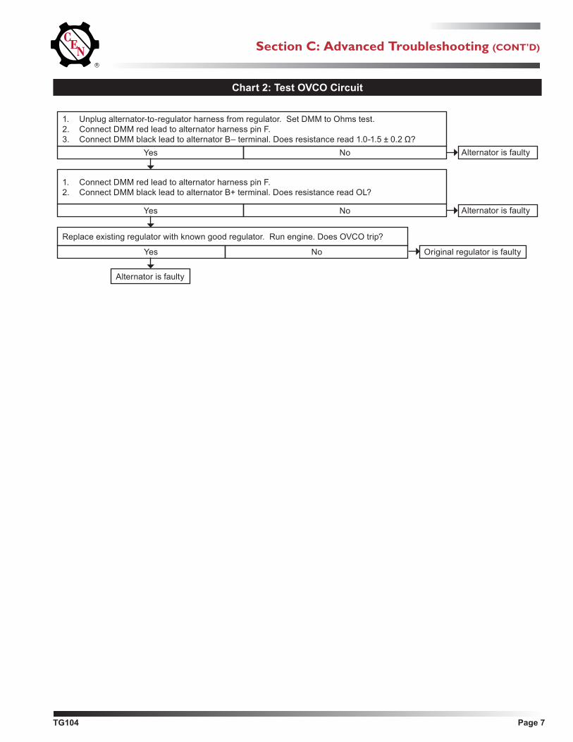
Chart 2: Test OVCO Circuit
Yes No
1. Unplug alternator-to-regulator harness from regulator. Set DMM to Ohms test.2. Connect DMM red lead to alternator harness pin F.3. ConnectDMMblackleadtoalternatorB‒terminal.Doesresistanceread1.0-1.5±0.2Ω?
Yes No
1. Connect DMM red lead to alternator harness pin F.2. Connect DMM black lead to alternator B+ terminal. Does resistance read OL?
Yes No
Replace existing regulator with known good regulator. Run engine. Does OVCO trip?
Alternator is faulty
Alternator is faulty
Alternator is faulty
Original regulator is faulty
Section C: Advanced Troubleshooting (CONT'D)