Table of Contents - Pipeline and Hazardous Materials Safety ...
404
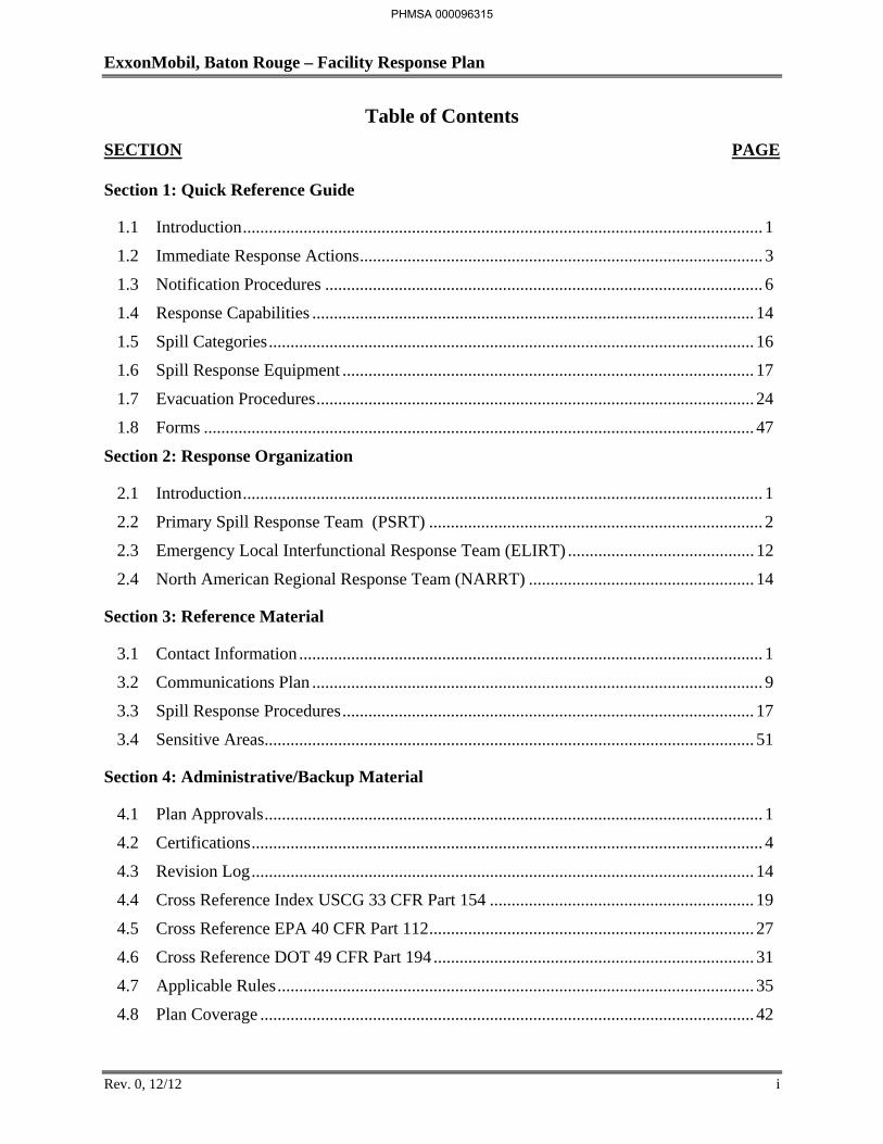
ExxonMobil, Baton Rouge – Facility Response Plan Rev. 0, 12/12 i Table of Contents SECTION PAGE Section 1: Quick Reference Guide 1.1 Introduction ........................................................................................................................ 1 1.2 Immediate Response Actions............................................................................................. 3 1.3 Notification Procedures ..................................................................................................... 6 1.4 Response Capabilities ...................................................................................................... 14 1.5 Spill Categories ................................................................................................................ 16 1.6 Spill Response Equipment ............................................................................................... 17 1.7 Evacuation Procedures ..................................................................................................... 24 1.8 Forms ............................................................................................................................... 47 Section 2: Response Organization 2.1 Introduction ........................................................................................................................ 1 2.2 Primary Spill Response Team (PSRT) ............................................................................. 2 2.3 Emergency Local Interfunctional Response Team (ELIRT) ........................................... 12 2.4 North American Regional Response Team (NARRT) .................................................... 14 Section 3: Reference Material 3.1 Contact Information ........................................................................................................... 1 3.2 Communications Plan ........................................................................................................ 9 3.3 Spill Response Procedures ............................................................................................... 17 3.4 Sensitive Areas................................................................................................................. 51 Section 4: Administrative/Backup Material 4.1 Plan Approvals ................................................................................................................... 1 4.2 Certifications ...................................................................................................................... 4 4.3 Revision Log .................................................................................................................... 14 4.4 Cross Reference Index USCG 33 CFR Part 154 ............................................................. 19 4.5 Cross Reference EPA 40 CFR Part 112........................................................................... 27 4.6 Cross Reference DOT 49 CFR Part 194 .......................................................................... 31 4.7 Applicable Rules .............................................................................................................. 35 4.8 Plan Coverage .................................................................................................................. 42 PHMSA 000096315
-
Upload
khangminh22 -
Category
Documents
-
view
1 -
download
0
Transcript of Table of Contents - Pipeline and Hazardous Materials Safety ...
ExxonMobil, Baton Rouge – Facility Response Plan
Rev. 0, 12/12 i
Table of Contents
SECTION PAGE
Section 1: Quick Reference Guide
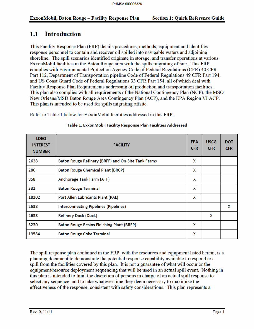
1.1 Introduction ........................................................................................................................ 1
1.2 Immediate Response Actions ............................................................................................. 3
1.3 Notification Procedures ..................................................................................................... 6
1.4 Response Capabilities ...................................................................................................... 14
1.5 Spill Categories ................................................................................................................ 16
1.6 Spill Response Equipment ............................................................................................... 17
1.7 Evacuation Procedures ..................................................................................................... 24
1.8 Forms ............................................................................................................................... 47
Section 2: Response Organization
2.1 Introduction ........................................................................................................................ 1
2.2 Primary Spill Response Team (PSRT) ............................................................................. 2
2.3 Emergency Local Interfunctional Response Team (ELIRT) ........................................... 12
2.4 North American Regional Response Team (NARRT) .................................................... 14
Section 3: Reference Material
3.1 Contact Information ........................................................................................................... 1
3.2 Communications Plan ........................................................................................................ 9
3.3 Spill Response Procedures ............................................................................................... 17
3.4 Sensitive Areas ................................................................................................................. 51
Section 4: Administrative/Backup Material
4.1 Plan Approvals ................................................................................................................... 1
4.2 Certifications ...................................................................................................................... 4
4.3 Revision Log .................................................................................................................... 14
4.4 Cross Reference Index USCG 33 CFR Part 154 ............................................................. 19
4.5 Cross Reference EPA 40 CFR Part 112 ........................................................................... 27
4.6 Cross Reference DOT 49 CFR Part 194 .......................................................................... 31
4.7 Applicable Rules .............................................................................................................. 35
4.8 Plan Coverage .................................................................................................................. 42
PHMSA 000096315
ExxonMobil, Baton Rouge – Facility Response Plan
Rev. 0, 12/12 ii
SECTION PAGE
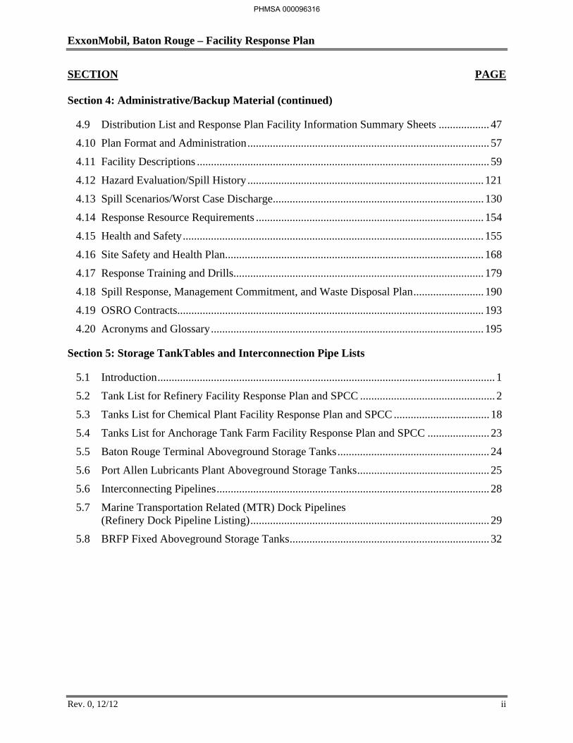
Section 4: Administrative/Backup Material (continued)
4.9 Distribution List and Response Plan Facility Information Summary Sheets .................. 47
4.10 Plan Format and Administration ...................................................................................... 57
4.11 Facility Descriptions ........................................................................................................ 59
4.12 Hazard Evaluation/Spill History .................................................................................... 121
4.13 Spill Scenarios/Worst Case Discharge ........................................................................... 130
4.14 Response Resource Requirements ................................................................................. 154
4.15 Health and Safety ........................................................................................................... 155
4.16 Site Safety and Health Plan............................................................................................ 168
4.17 Response Training and Drills......................................................................................... 179
4.18 Spill Response, Management Commitment, and Waste Disposal Plan ......................... 190
4.19 OSRO Contracts............................................................................................................. 193
4.20 Acronyms and Glossary ................................................................................................. 195
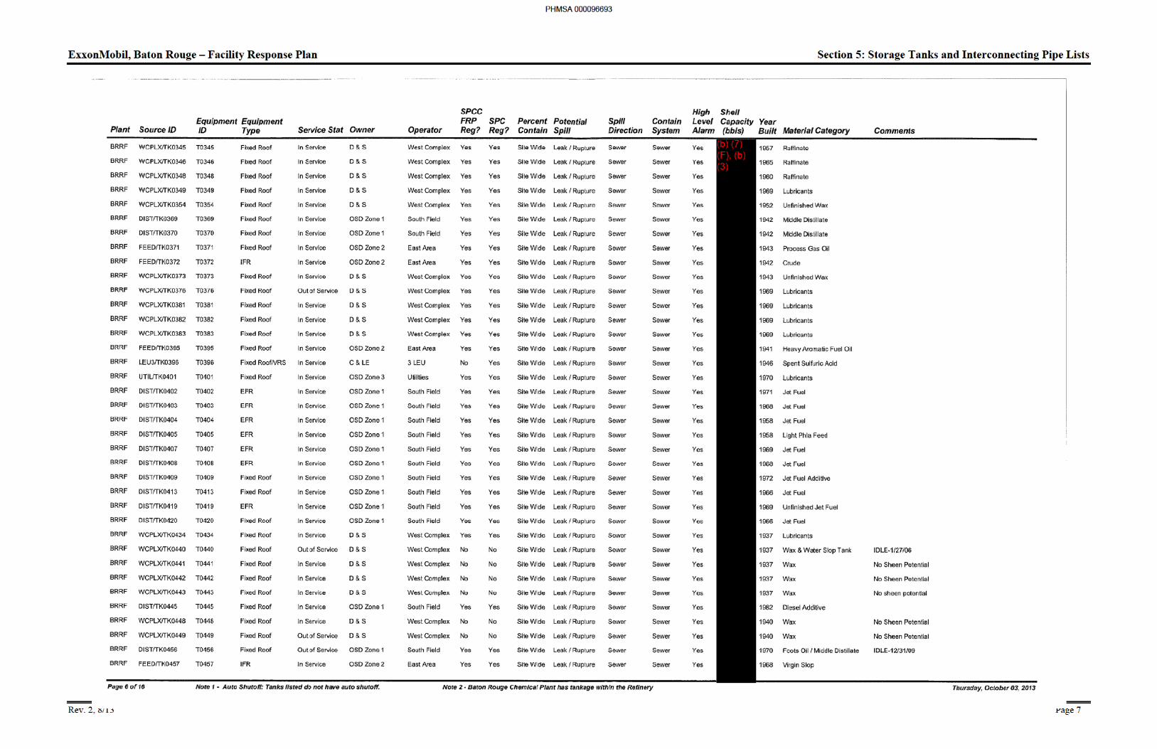
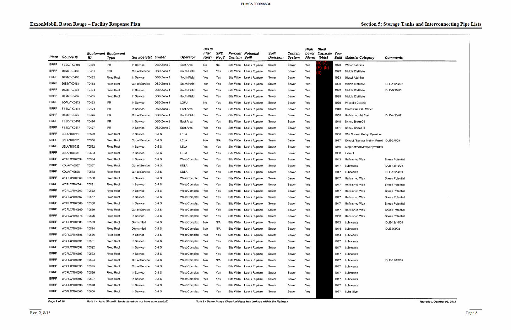
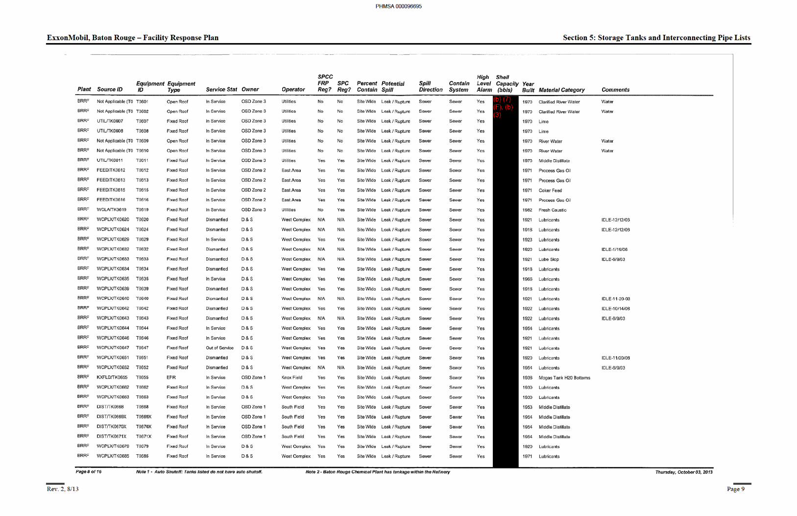
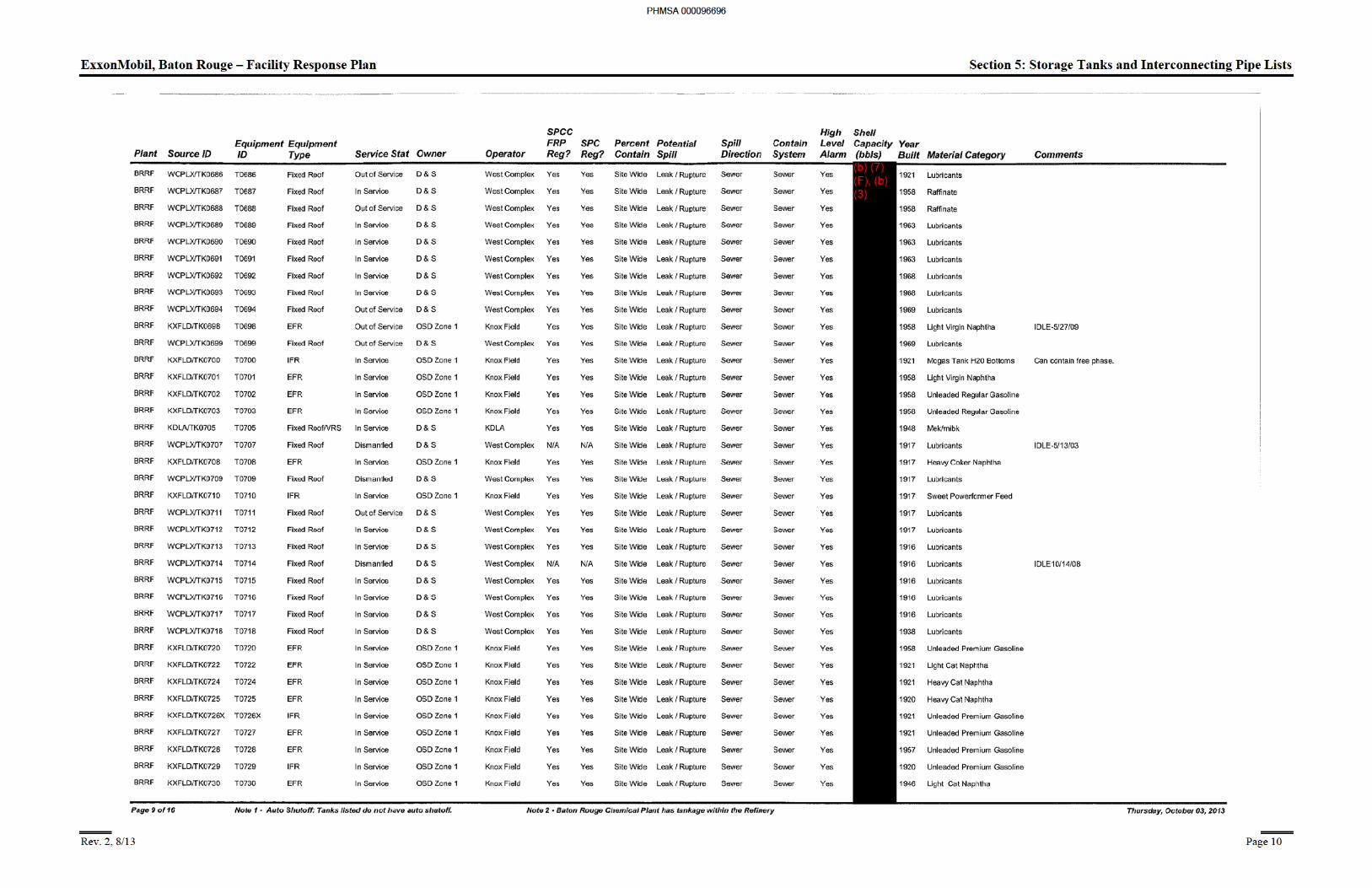
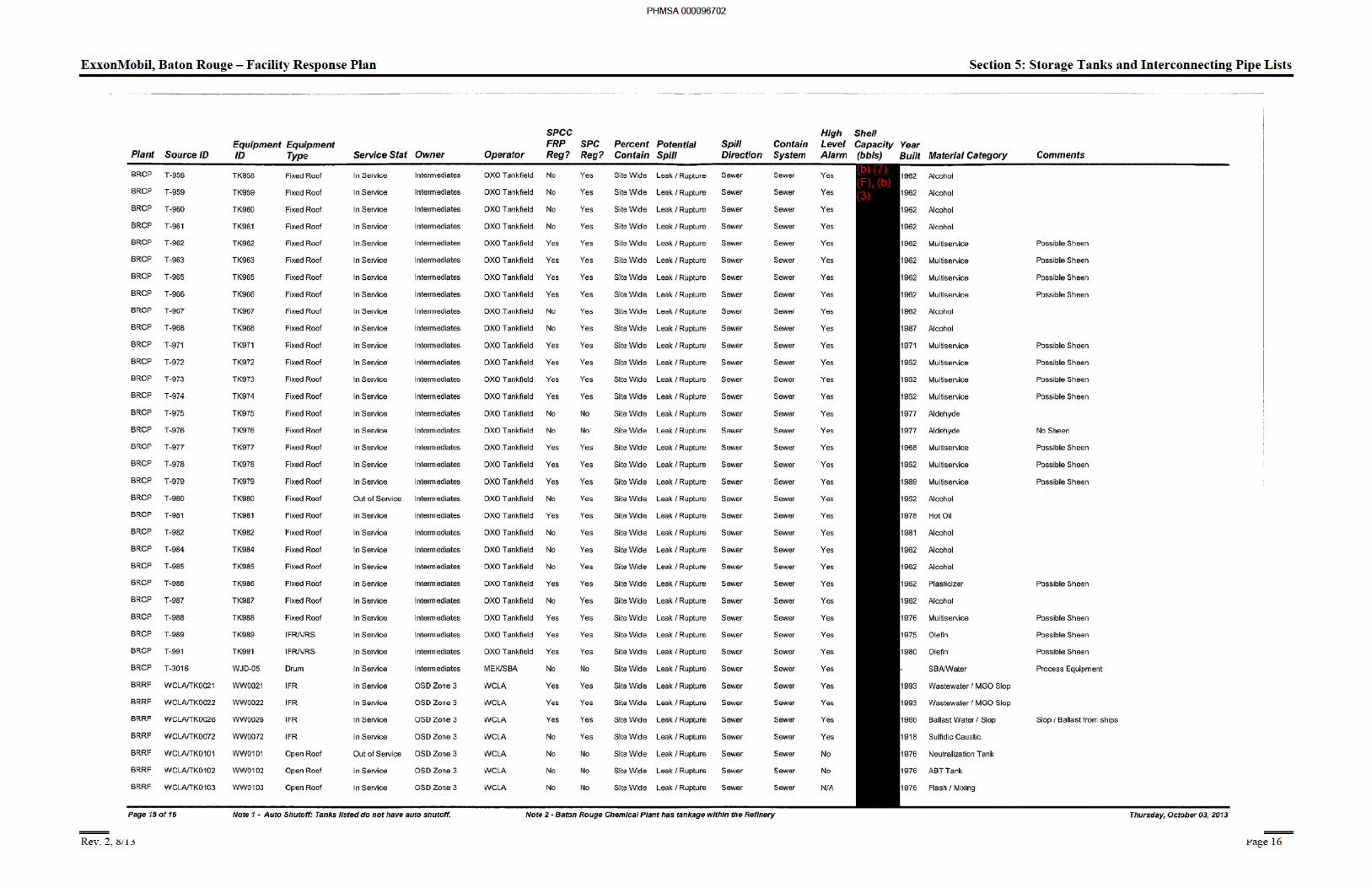
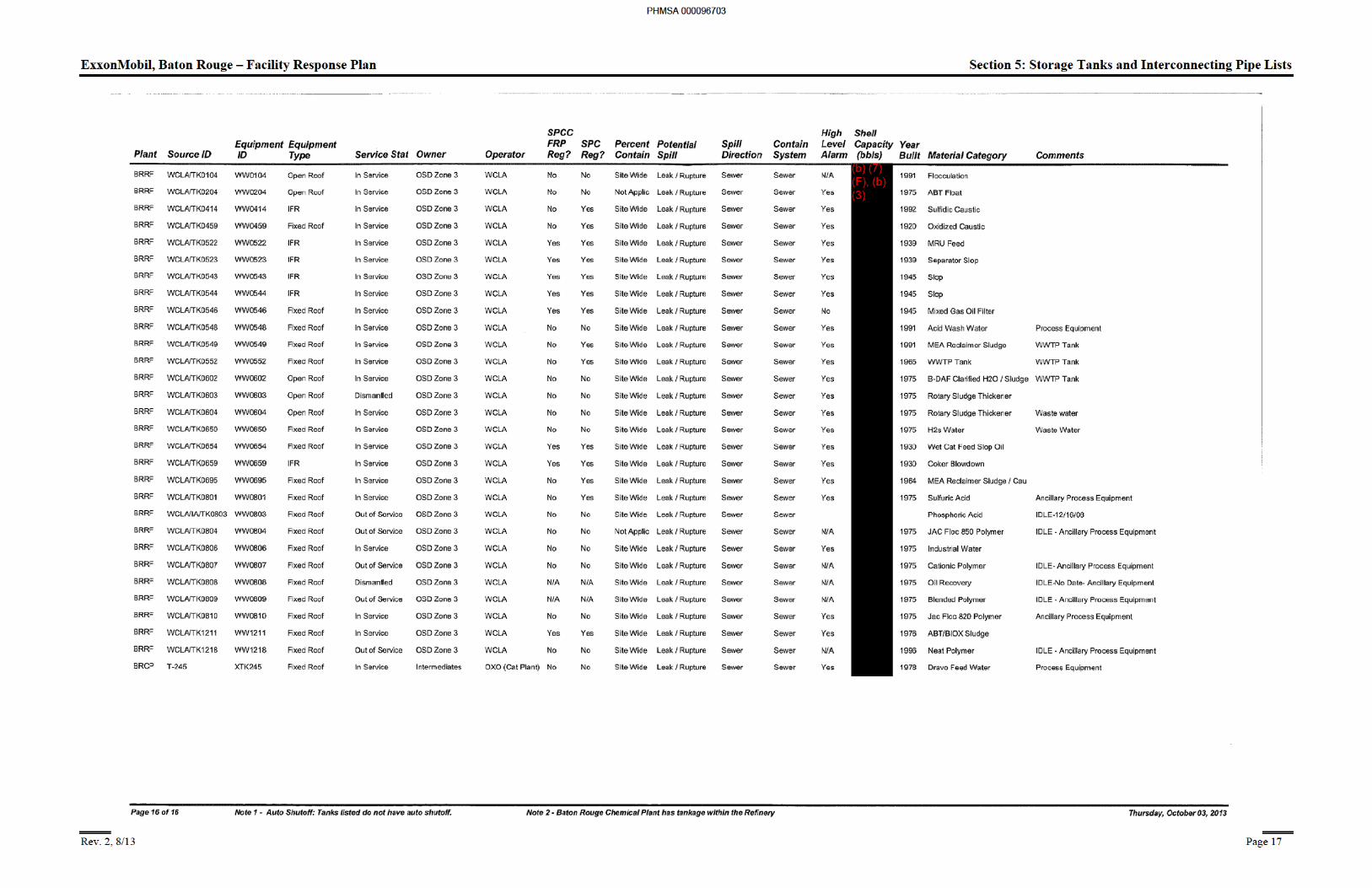
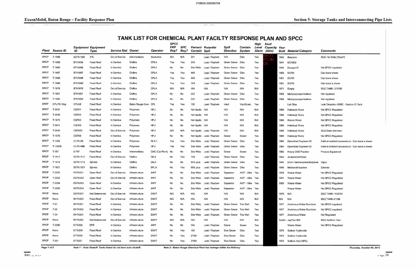
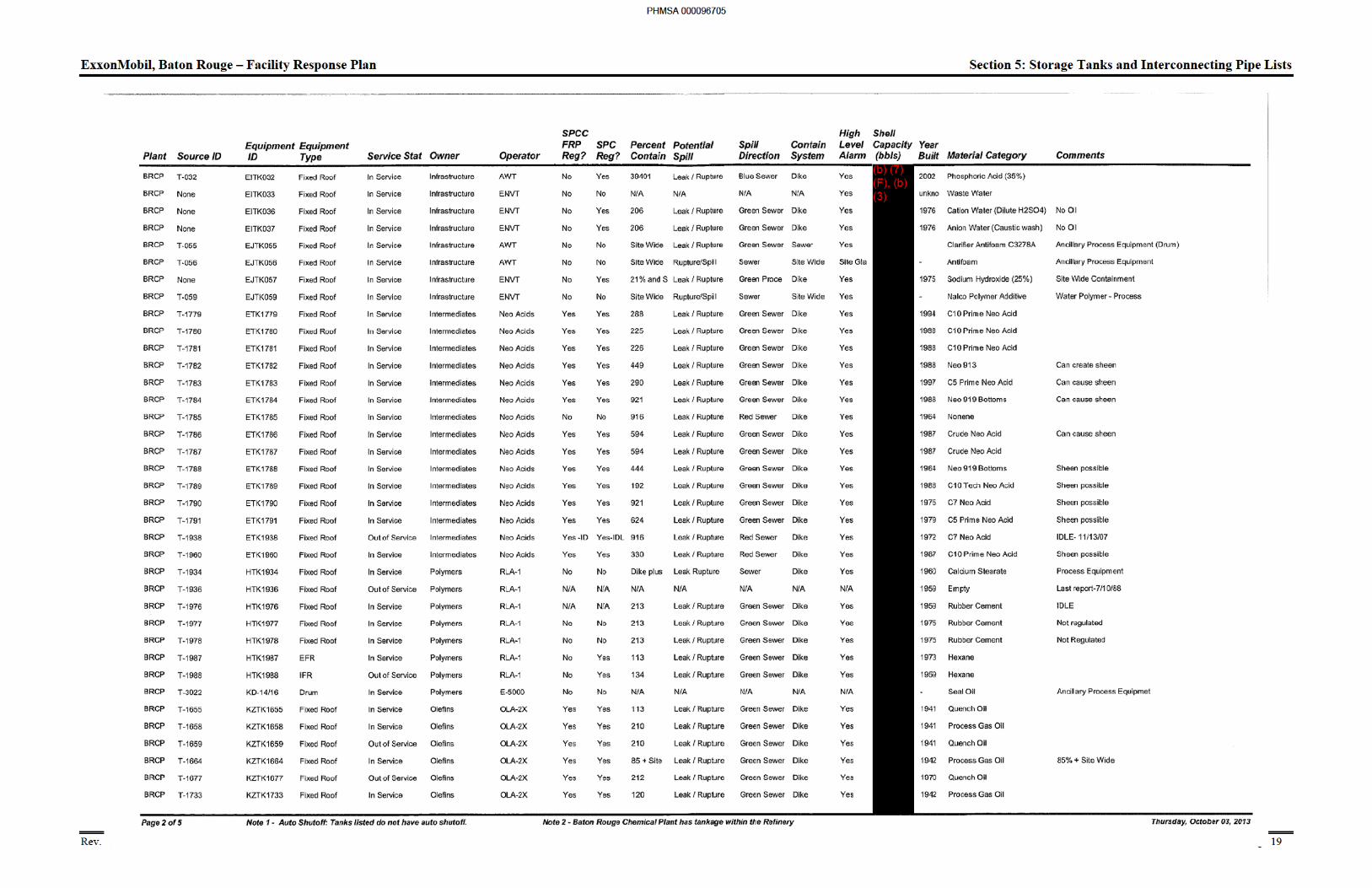
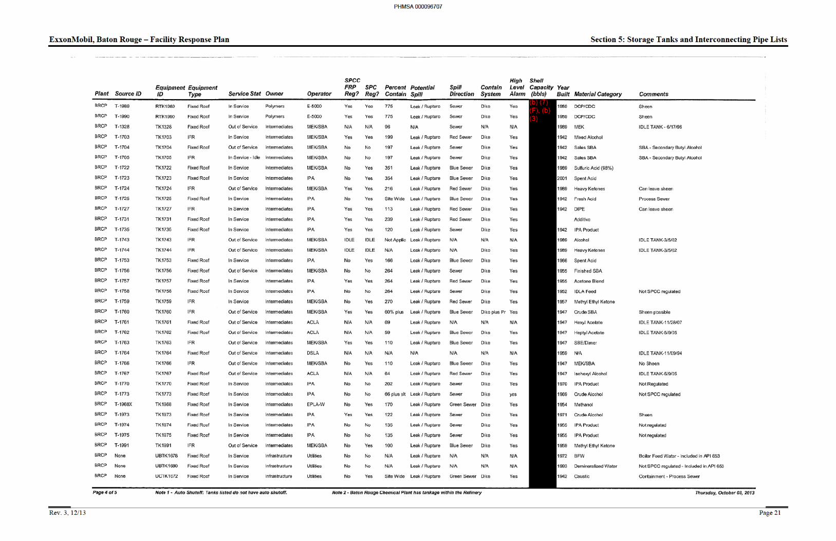
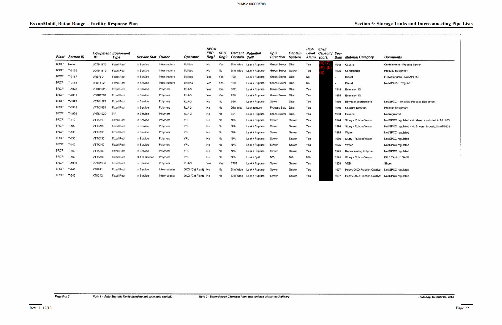
Section 5: Storage TankTables and Interconnection Pipe Lists
5.1 Introduction ........................................................................................................................ 1
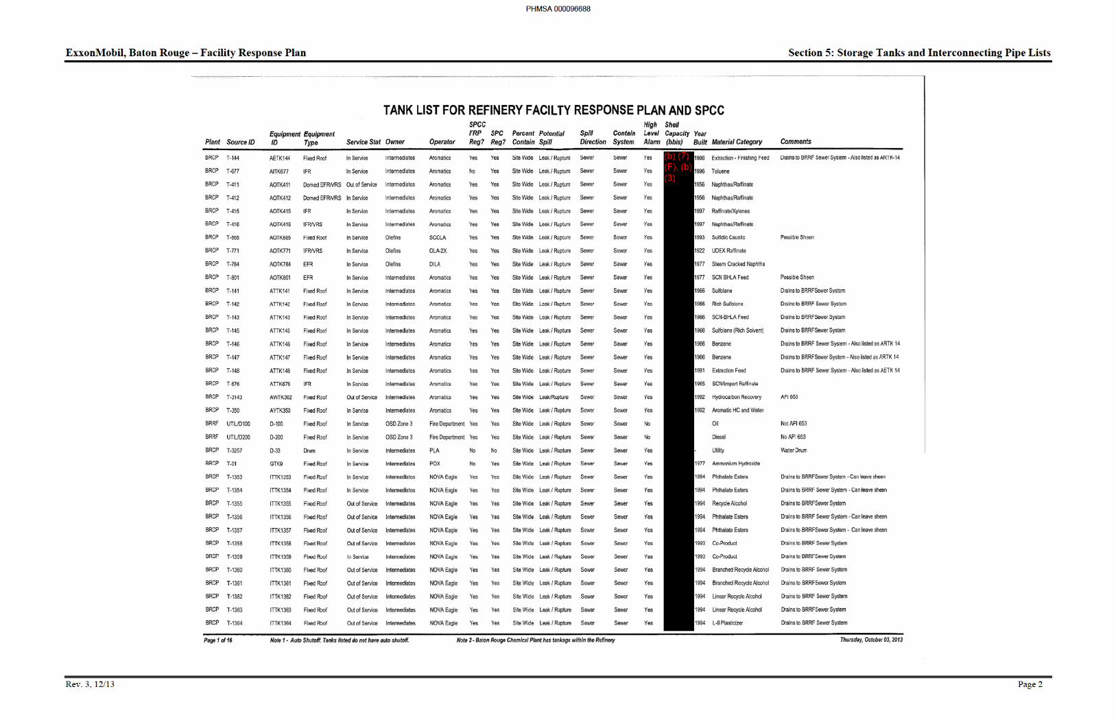
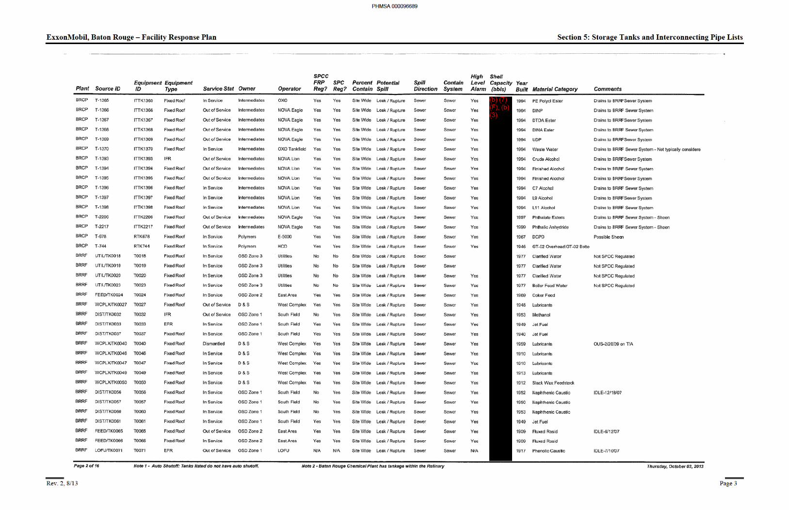
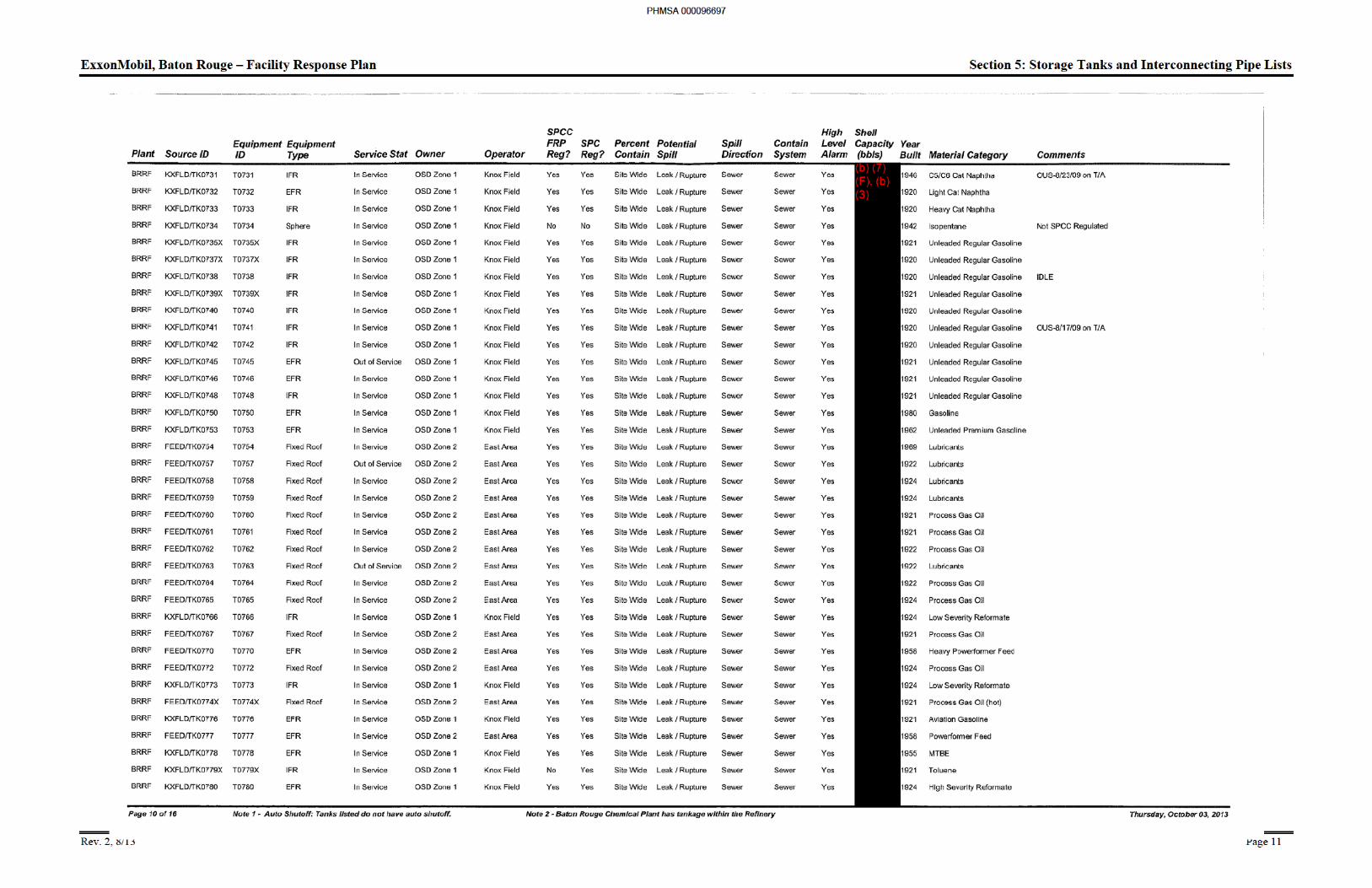
5.2 Tank List for Refinery Facility Response Plan and SPCC ................................................ 2
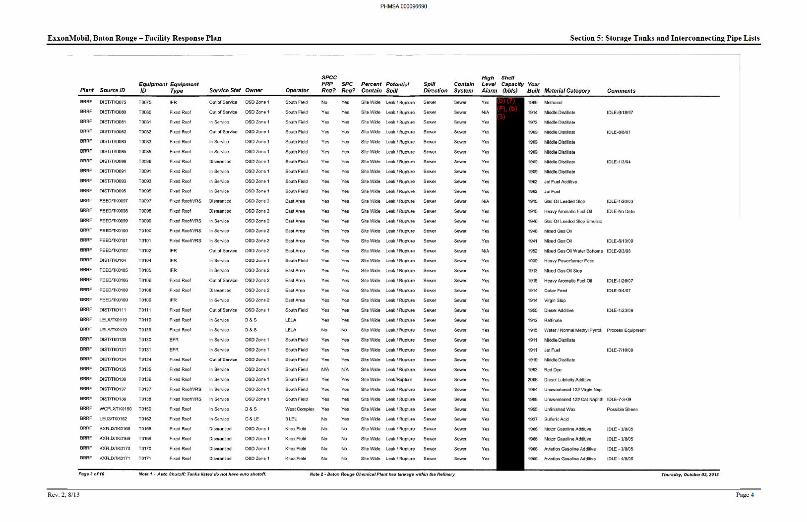
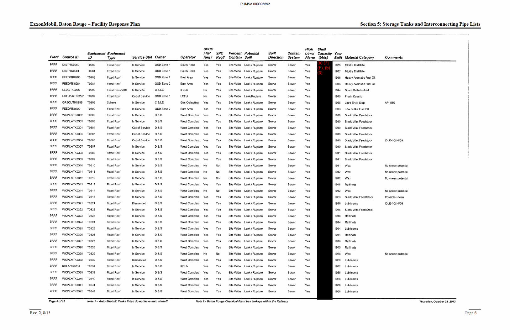
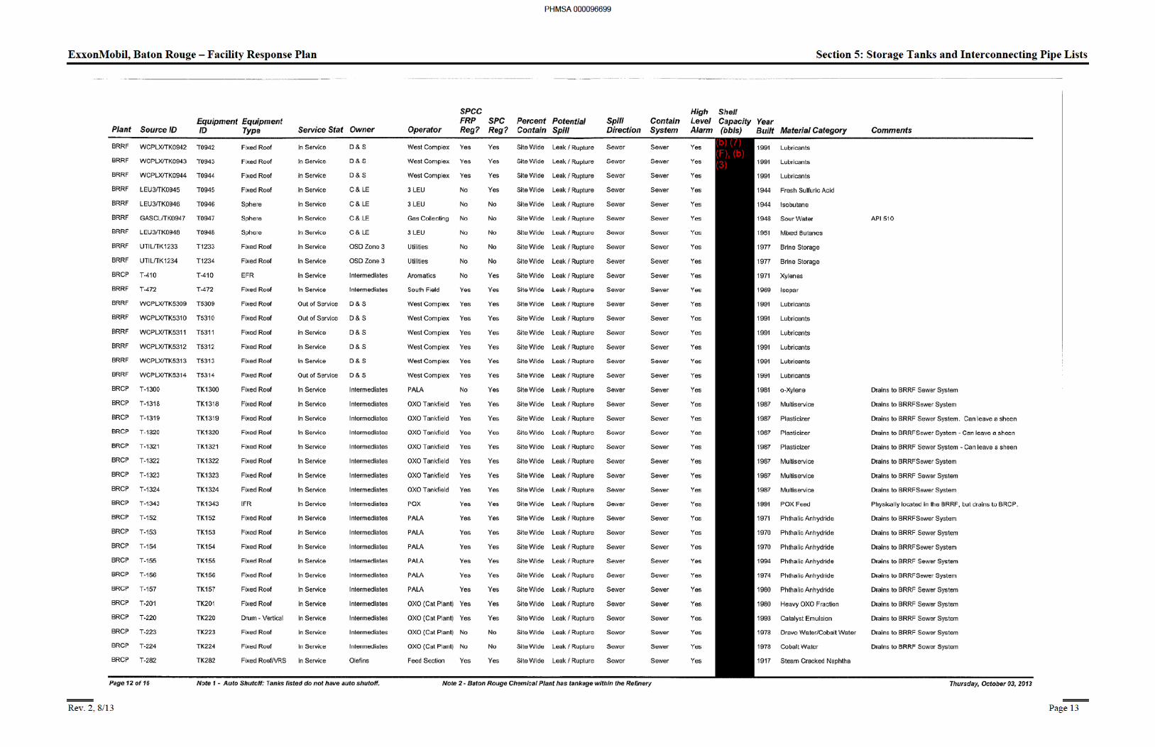
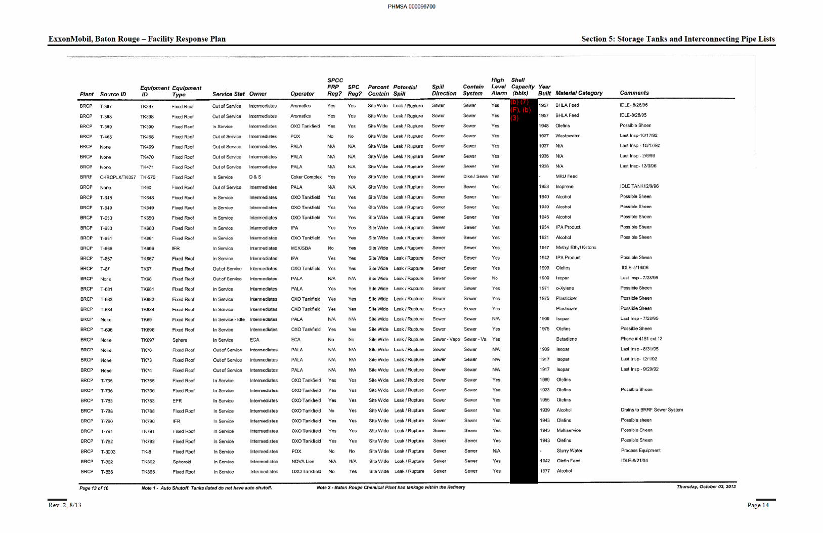
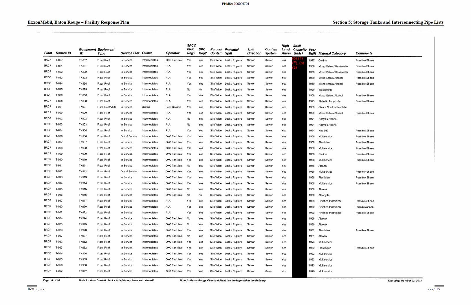
5.3 Tanks List for Chemical Plant Facility Response Plan and SPCC .................................. 18
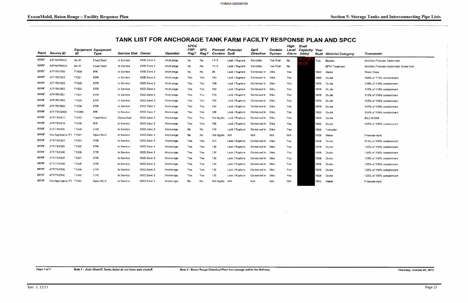
5.4 Tanks List for Anchorage Tank Farm Facility Response Plan and SPCC ...................... 23
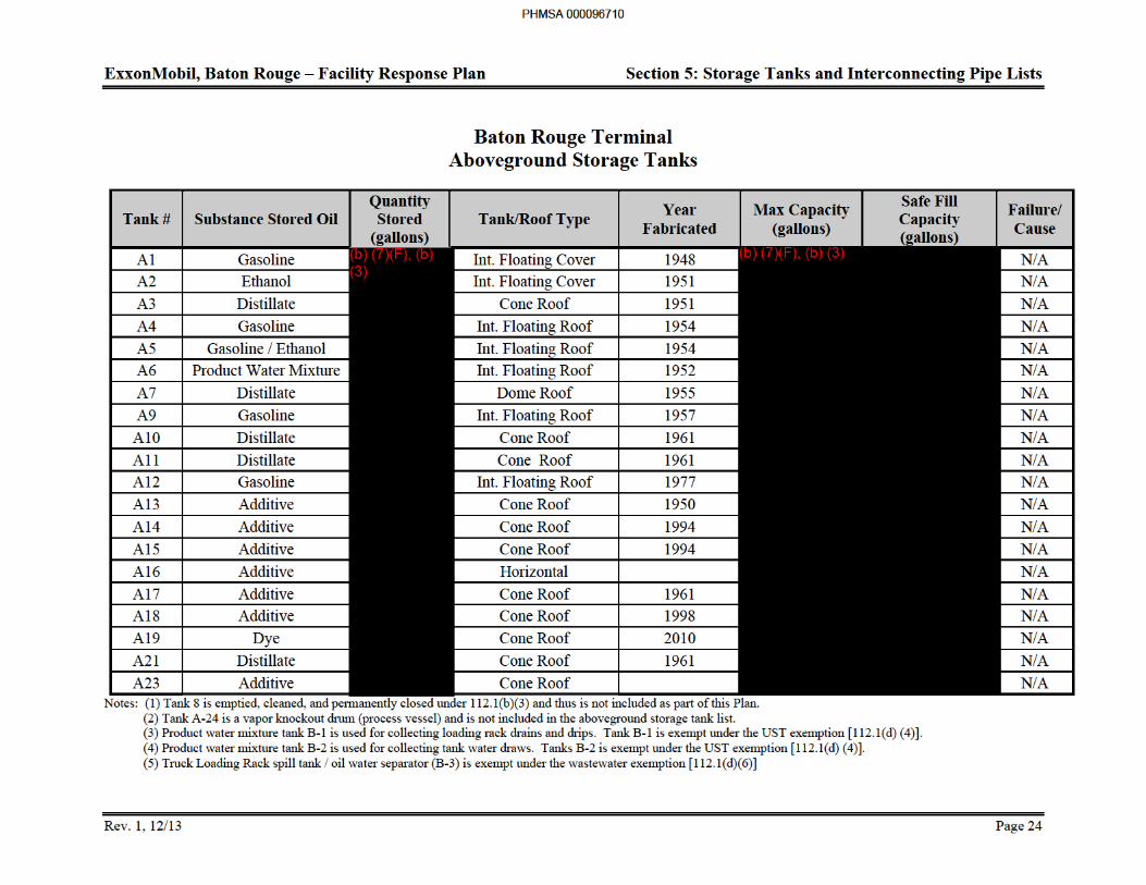
5.5 Baton Rouge Terminal Aboveground Storage Tanks ...................................................... 24
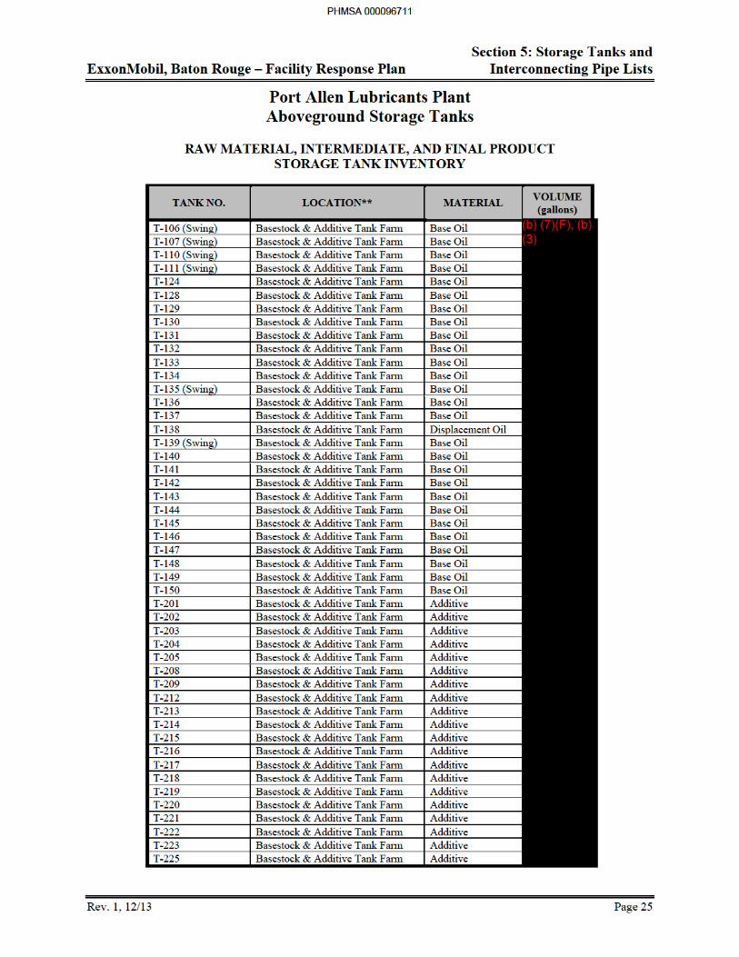
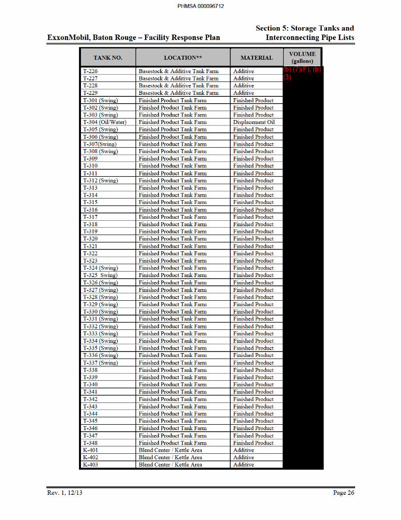
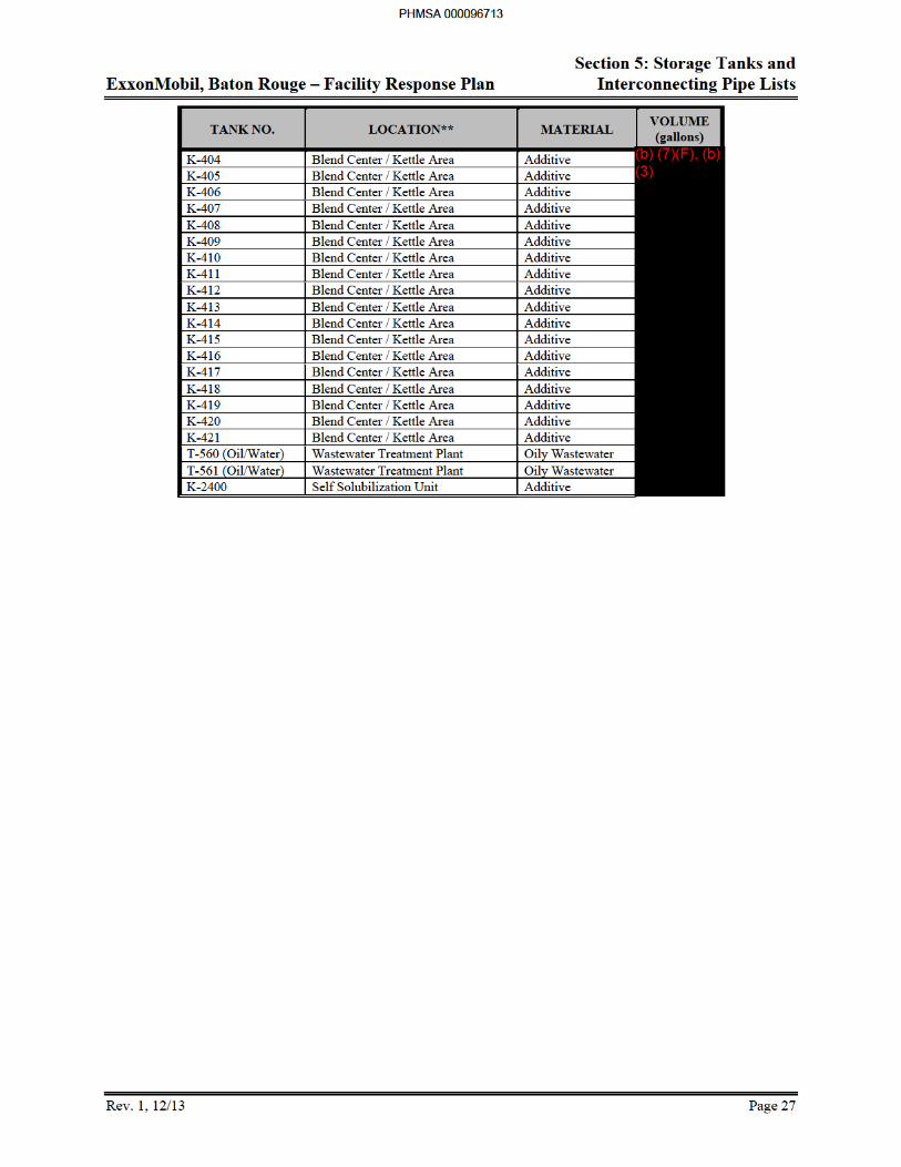
5.6 Port Allen Lubricants Plant Aboveground Storage Tanks ............................................... 25
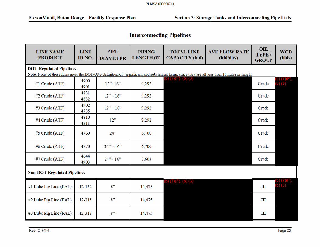
5.6 Interconnecting Pipelines ................................................................................................. 28
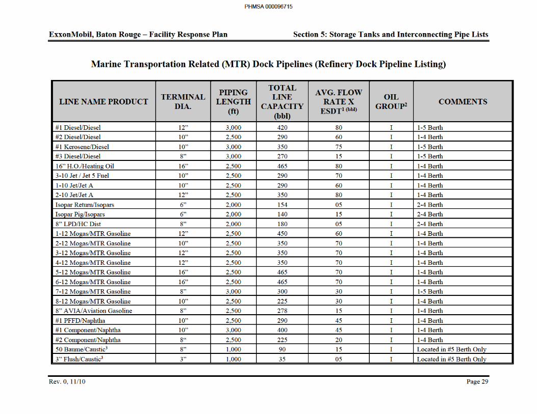
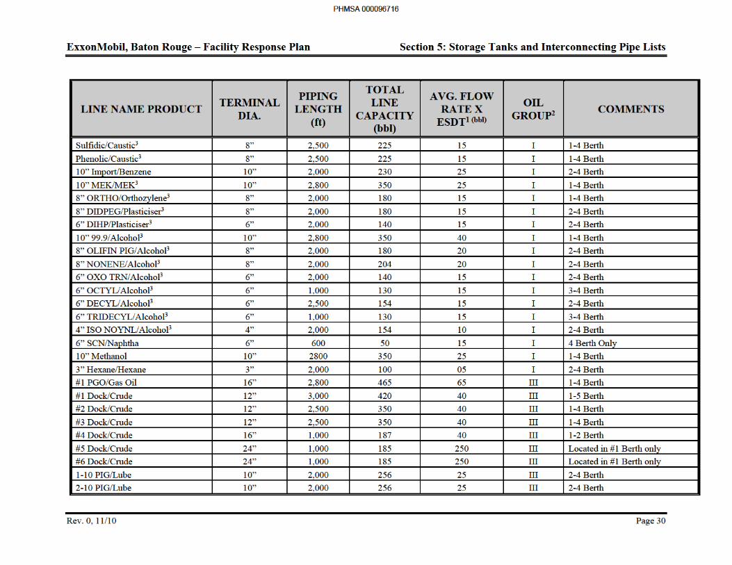
5.7 Marine Transportation Related (MTR) Dock Pipelines (Refinery Dock Pipeline Listing) ..................................................................................... 29
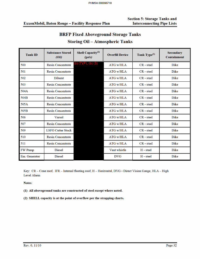
5.8 BRFP Fixed Aboveground Storage Tanks ....................................................................... 32
PHMSA 000096316
ExxonMobil, Baton Rouge – Facility Response Plan
Rev. 0, 12/12 iii
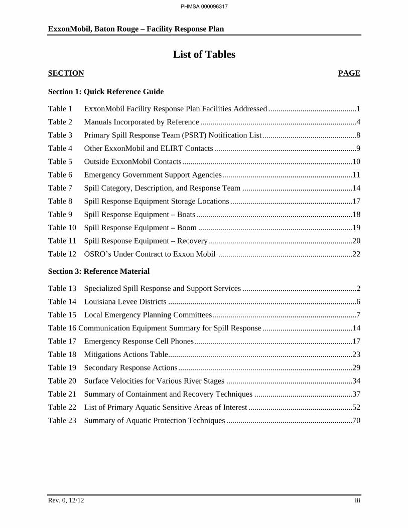
List of Tables
SECTION PAGE
Section 1: Quick Reference Guide
Table 1 ExxonMobil Facility Response Plan Facilities Addressed ............................................1
Table 2 Manuals Incorporated by Reference ..............................................................................4
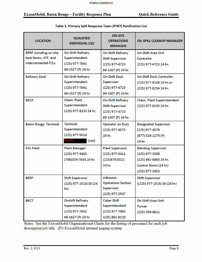
Table 3 Primary Spill Response Team (PSRT) Notification List ...............................................8
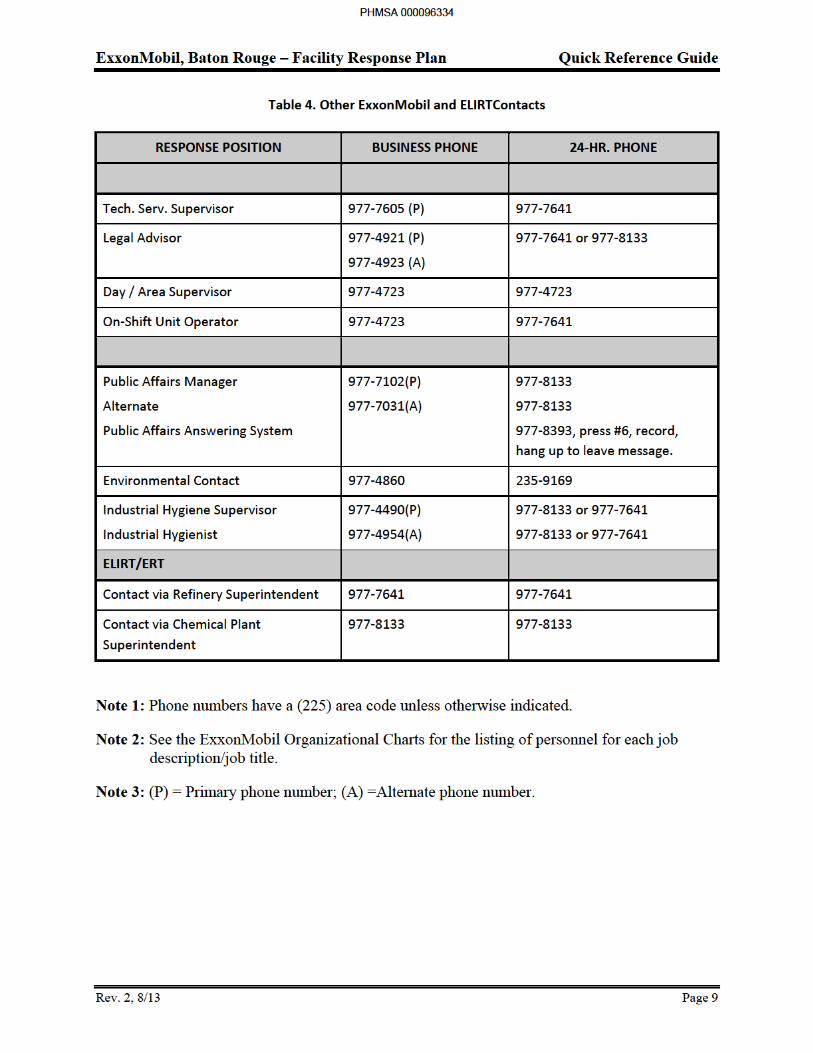
Table 4 Other ExxonMobil and ELIRT Contacts .......................................................................9
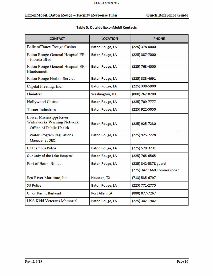
Table 5 Outside ExxonMobil Contacts .....................................................................................10
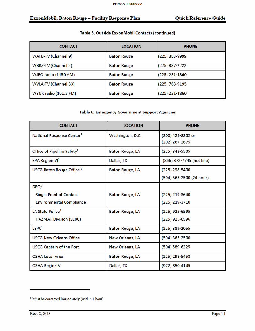
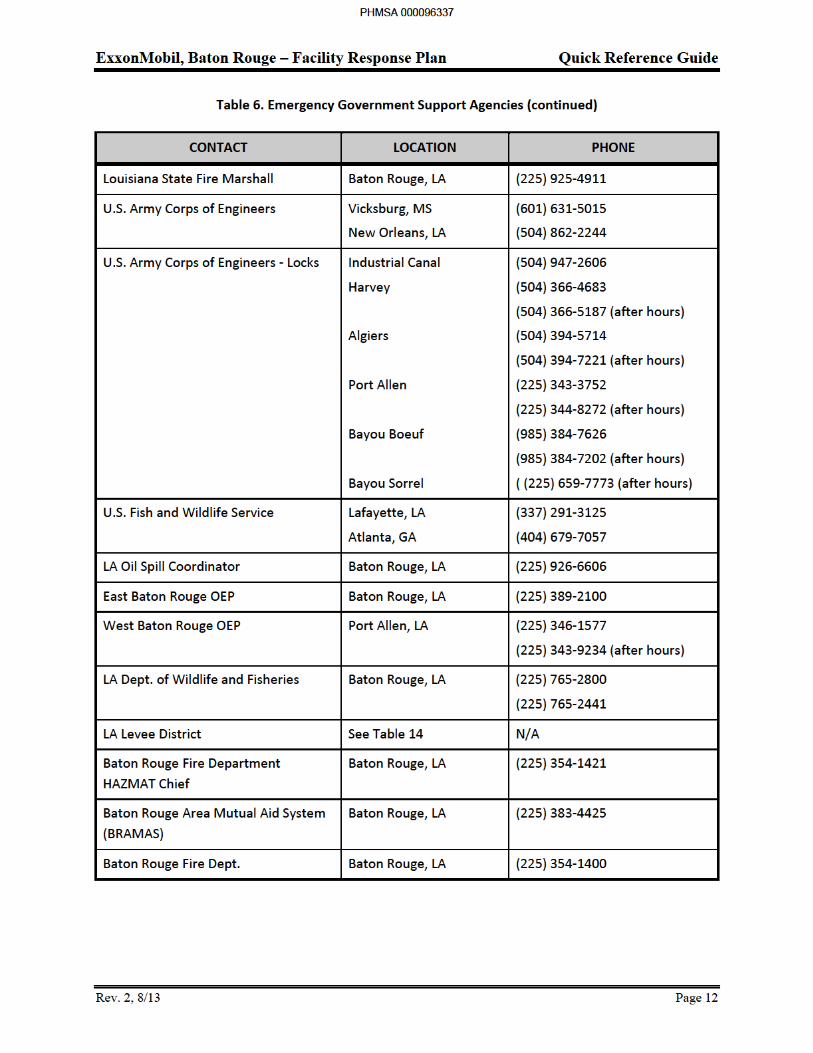
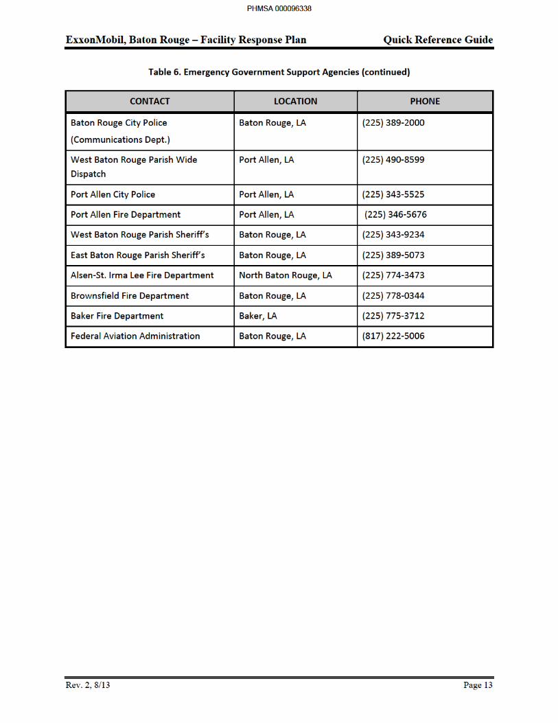
Table 6 Emergency Government Support Agencies .................................................................11
Table 7 Spill Category, Description, and Response Team .......................................................14
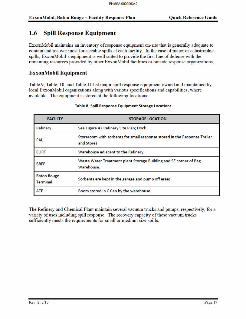
Table 8 Spill Response Equipment Storage Locations .............................................................17
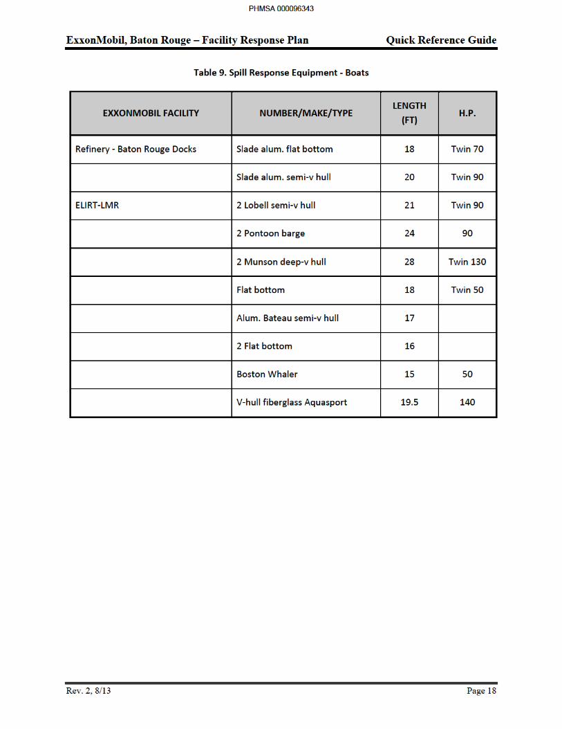
Table 9 Spill Response Equipment – Boats ..............................................................................18
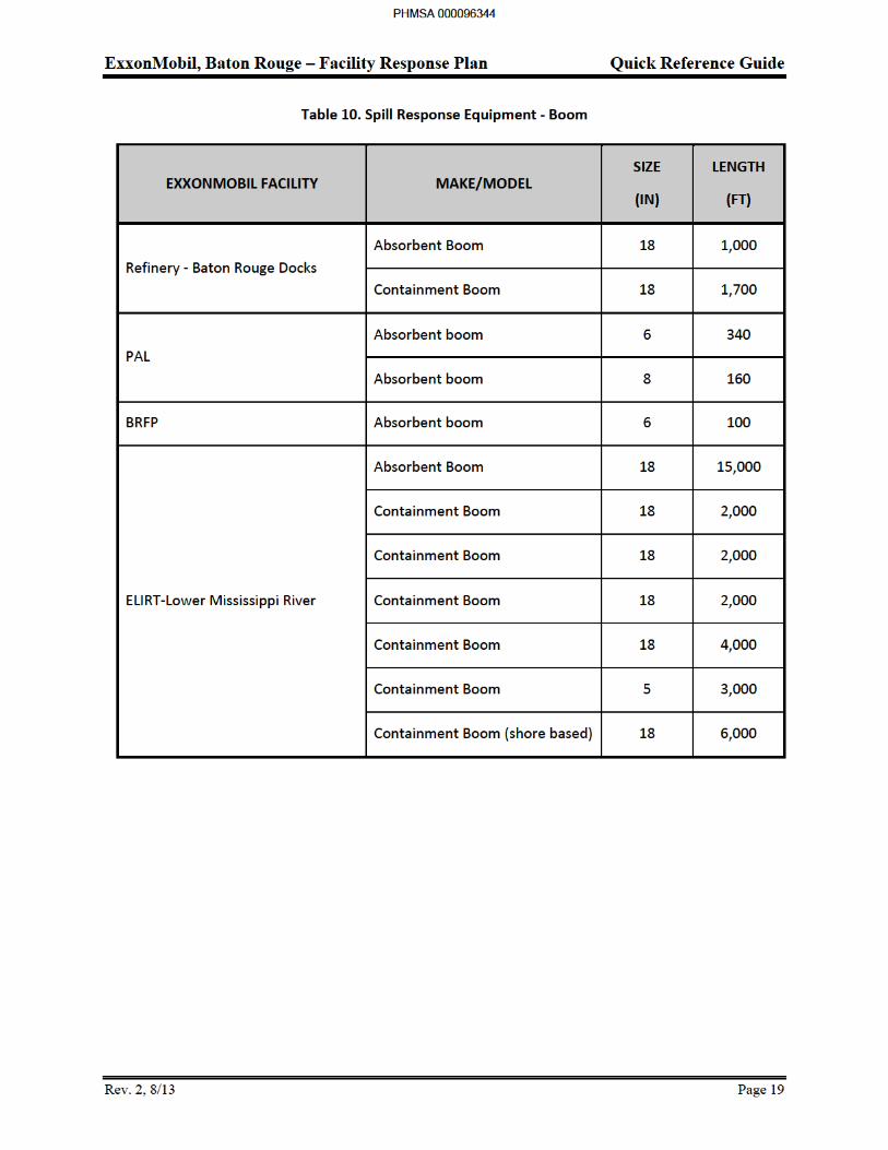
Table 10 Spill Response Equipment – Boom .............................................................................19
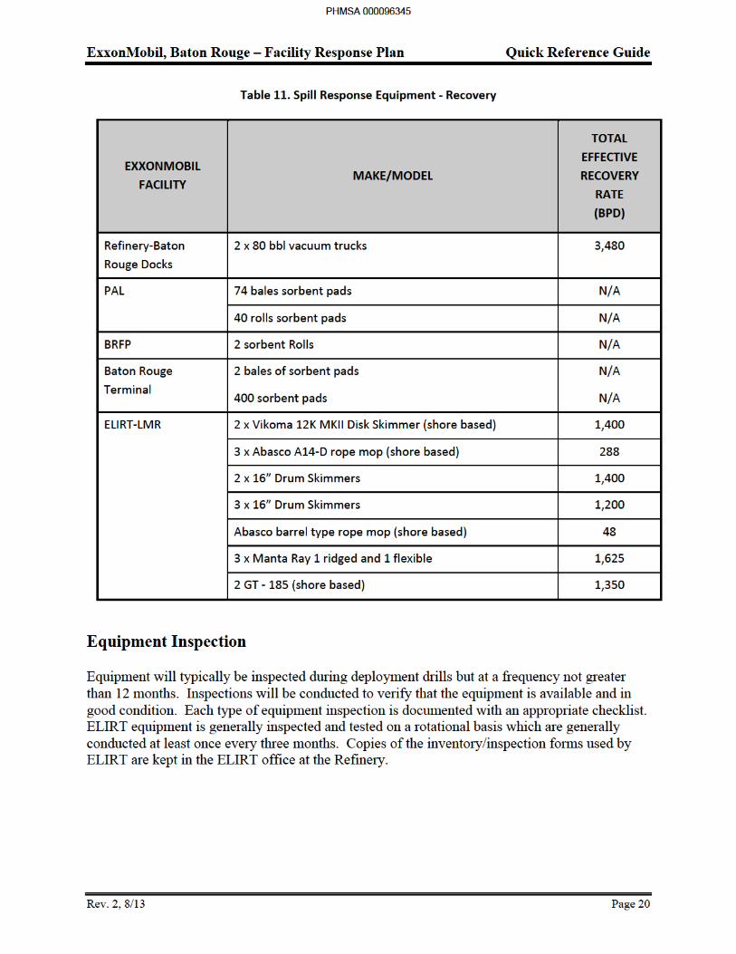
Table 11 Spill Response Equipment – Recovery ........................................................................20
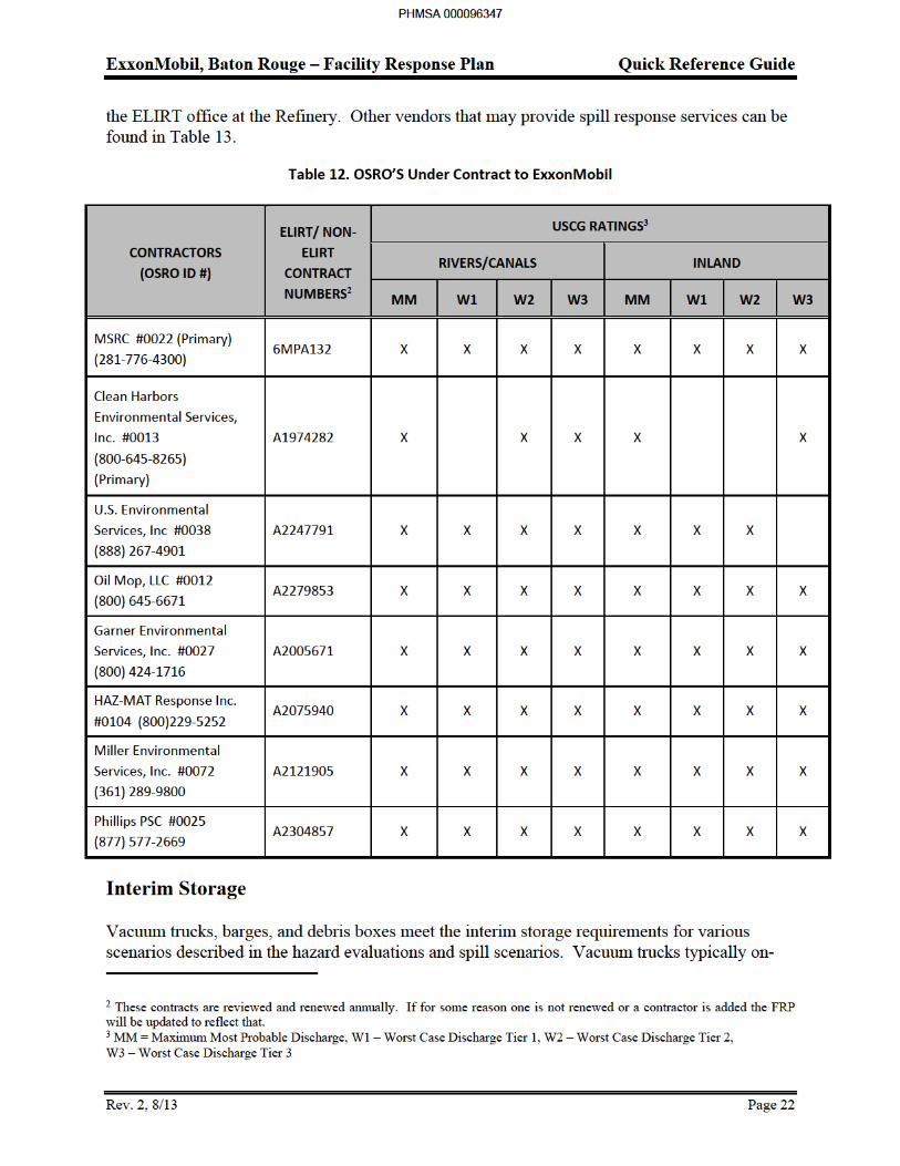
Table 12 OSRO’s Under Contract to Exxon Mobil ...................................................................22
Section 3: Reference Material
Table 13 Specialized Spill Response and Support Services .........................................................2
Table 14 Louisiana Levee Districts ..............................................................................................6
Table 15 Local Emergency Planning Committees ........................................................................7
Table 16 Communication Equipment Summary for Spill Response .............................................14
Table 17 Emergency Response Cell Phones ...............................................................................17
Table 18 Mitigations Actions Table ............................................................................................23
Table 19 Secondary Response Actions .......................................................................................29
Table 20 Surface Velocities for Various River Stages ...............................................................34
Table 21 Summary of Containment and Recovery Techniques .................................................37
Table 22 List of Primary Aquatic Sensitive Areas of Interest ....................................................52
Table 23 Summary of Aquatic Protection Techniques ...............................................................70
PHMSA 000096317
ExxonMobil, Baton Rouge – Facility Response Plan
Rev. 0, 12/12 iv
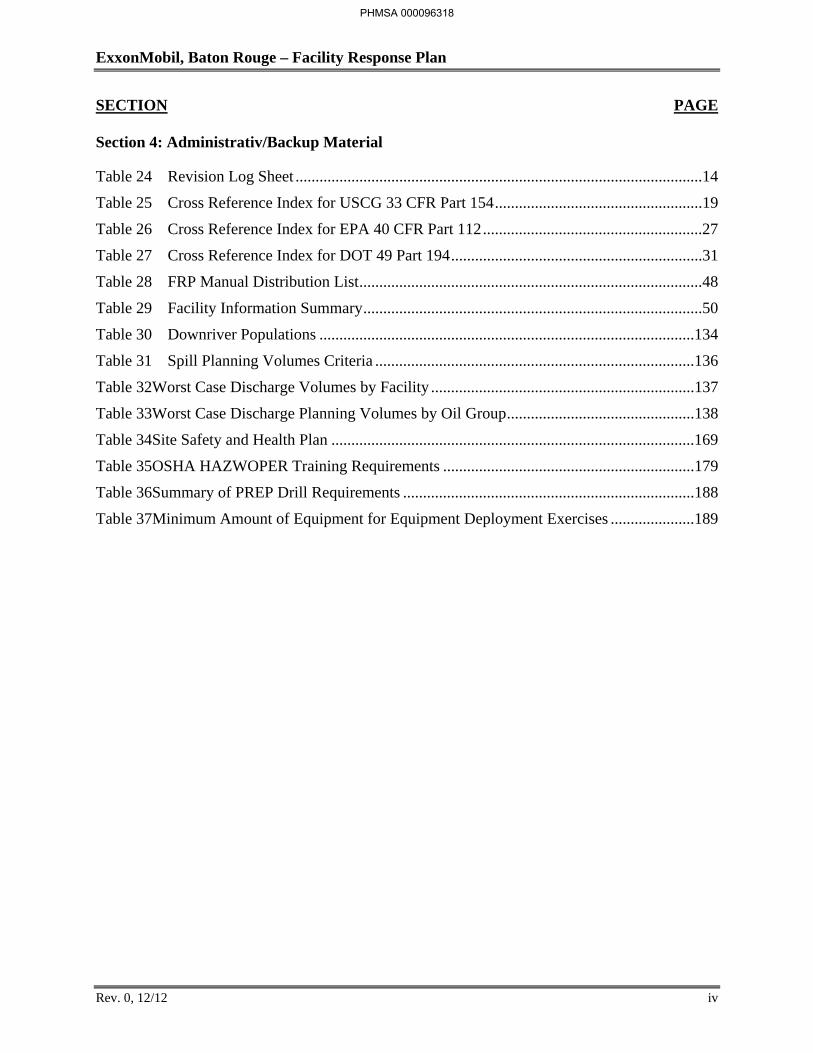
SECTION PAGE
Section 4: Administrativ/Backup Material
Table 24 Revision Log Sheet ......................................................................................................14
Table 25 Cross Reference Index for USCG 33 CFR Part 154 ....................................................19
Table 26 Cross Reference Index for EPA 40 CFR Part 112 .......................................................27
Table 27 Cross Reference Index for DOT 49 Part 194 ...............................................................31
Table 28 FRP Manual Distribution List ......................................................................................48
Table 29 Facility Information Summary .....................................................................................50
Table 30 Downriver Populations ..............................................................................................134
Table 31 Spill Planning Volumes Criteria ................................................................................136
Table 32Worst Case Discharge Volumes by Facility ..................................................................137
Table 33Worst Case Discharge Planning Volumes by Oil Group ...............................................138
Table 34Site Safety and Health Plan ...........................................................................................169
Table 35OSHA HAZWOPER Training Requirements ...............................................................179
Table 36Summary of PREP Drill Requirements .........................................................................188
Table 37Minimum Amount of Equipment for Equipment Deployment Exercises .....................189
PHMSA 000096318
ExxonMobil, Baton Rouge – Facility Response Plan
Rev. 0, 12/12 v
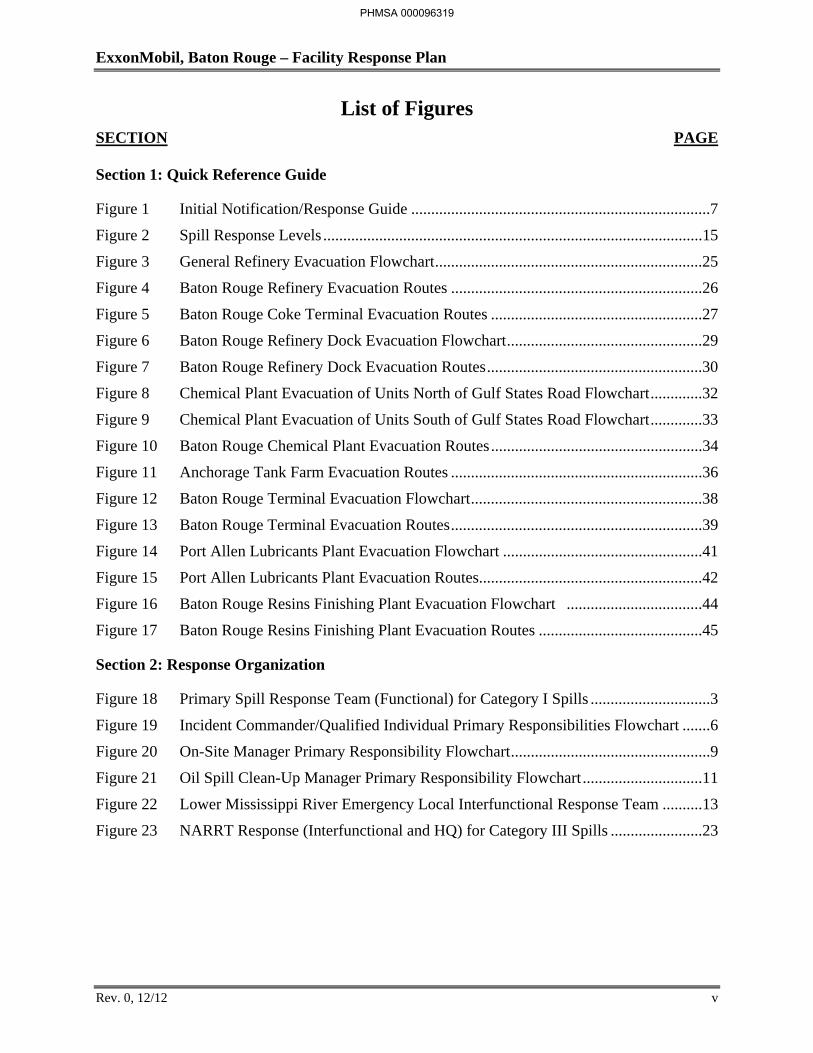
List of Figures SECTION PAGE
Section 1: Quick Reference Guide
Figure 1 Initial Notification/Response Guide ...........................................................................7
Figure 2 Spill Response Levels ...............................................................................................15
Figure 3 General Refinery Evacuation Flowchart ...................................................................25
Figure 4 Baton Rouge Refinery Evacuation Routes ...............................................................26
Figure 5 Baton Rouge Coke Terminal Evacuation Routes .....................................................27
Figure 6 Baton Rouge Refinery Dock Evacuation Flowchart .................................................29
Figure 7 Baton Rouge Refinery Dock Evacuation Routes ......................................................30
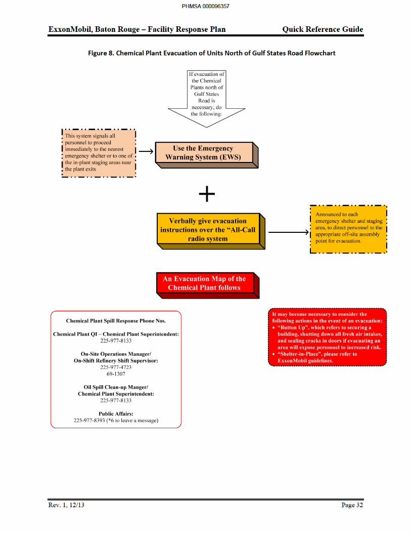
Figure 8 Chemical Plant Evacuation of Units North of Gulf States Road Flowchart .............32
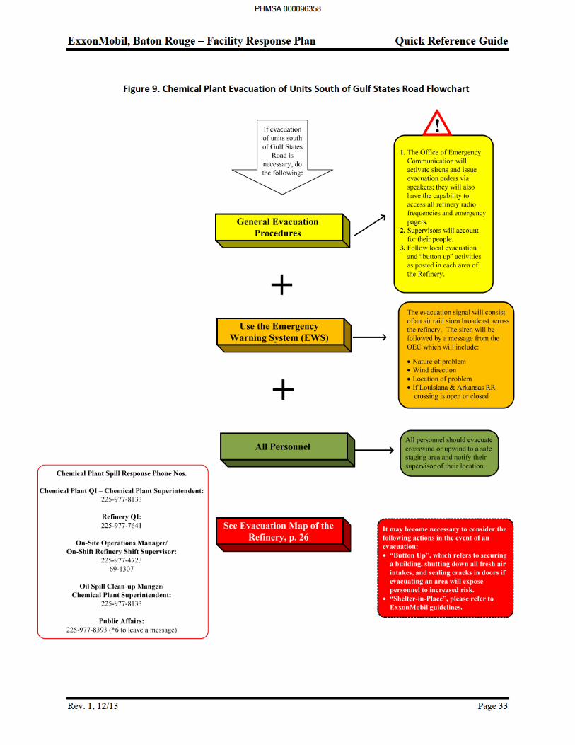
Figure 9 Chemical Plant Evacuation of Units South of Gulf States Road Flowchart .............33
Figure 10 Baton Rouge Chemical Plant Evacuation Routes .....................................................34
Figure 11 Anchorage Tank Farm Evacuation Routes ...............................................................36
Figure 12 Baton Rouge Terminal Evacuation Flowchart ..........................................................38
Figure 13 Baton Rouge Terminal Evacuation Routes ...............................................................39
Figure 14 Port Allen Lubricants Plant Evacuation Flowchart ..................................................41
Figure 15 Port Allen Lubricants Plant Evacuation Routes........................................................42
Figure 16 Baton Rouge Resins Finishing Plant Evacuation Flowchart ..................................44
Figure 17 Baton Rouge Resins Finishing Plant Evacuation Routes .........................................45
Section 2: Response Organization
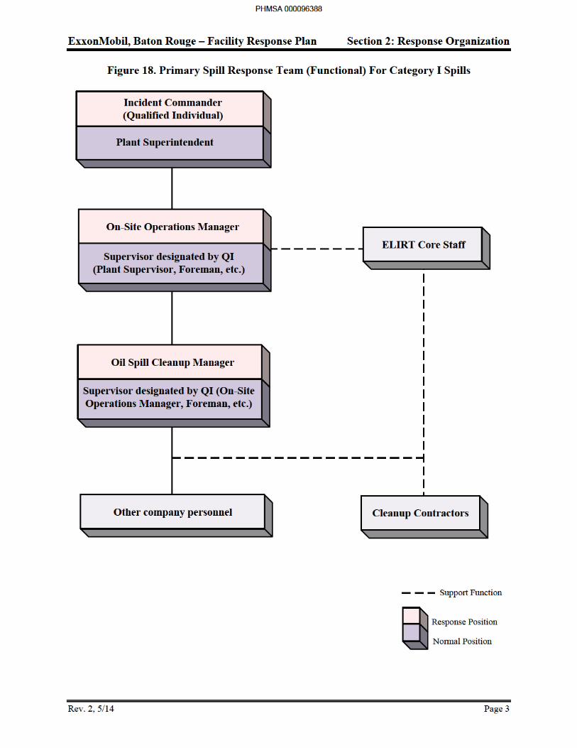
Figure 18 Primary Spill Response Team (Functional) for Category I Spills ..............................3
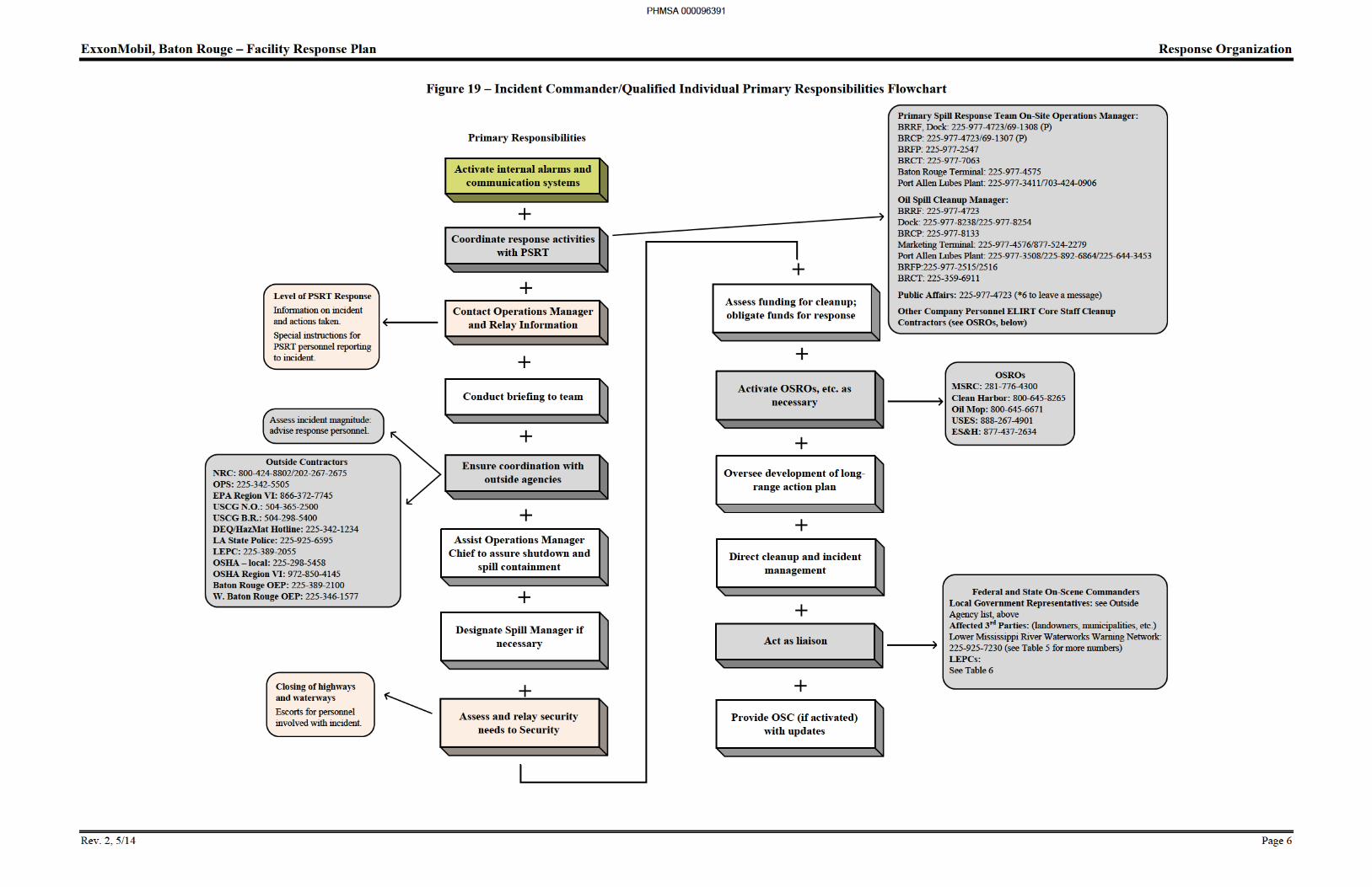
Figure 19 Incident Commander/Qualified Individual Primary Responsibilities Flowchart .......6
Figure 20 On-Site Manager Primary Responsibility Flowchart ..................................................9
Figure 21 Oil Spill Clean-Up Manager Primary Responsibility Flowchart ..............................11
Figure 22 Lower Mississippi River Emergency Local Interfunctional Response Team ..........13
Figure 23 NARRT Response (Interfunctional and HQ) for Category III Spills .......................23
PHMSA 000096319
ExxonMobil, Baton Rouge – Facility Response Plan
Rev. 0, 12/12 vi
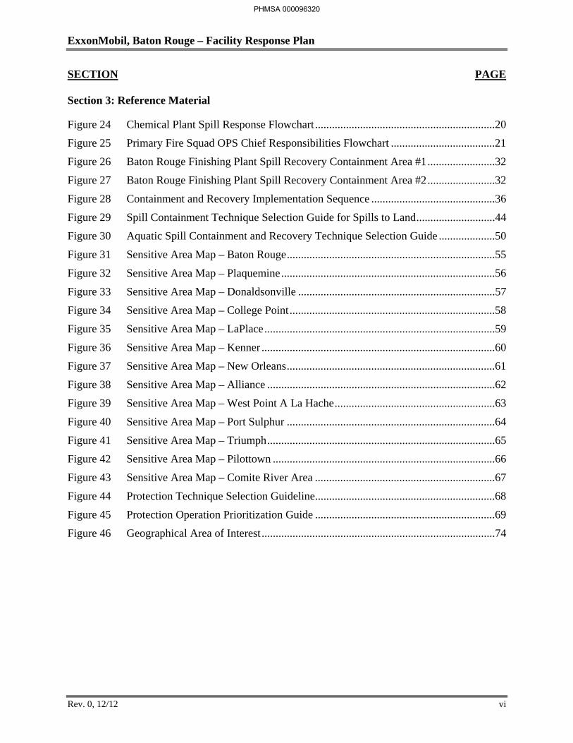
SECTION PAGE
Section 3: Reference Material
Figure 24 Chemical Plant Spill Response Flowchart ................................................................20
Figure 25 Primary Fire Squad OPS Chief Responsibilities Flowchart .....................................21
Figure 26 Baton Rouge Finishing Plant Spill Recovery Containment Area #1 ........................32
Figure 27 Baton Rouge Finishing Plant Spill Recovery Containment Area #2 ........................32
Figure 28 Containment and Recovery Implementation Sequence ............................................36
Figure 29 Spill Containment Technique Selection Guide for Spills to Land ............................44
Figure 30 Aquatic Spill Containment and Recovery Technique Selection Guide ....................50
Figure 31 Sensitive Area Map – Baton Rouge ..........................................................................55
Figure 32 Sensitive Area Map – Plaquemine ............................................................................56
Figure 33 Sensitive Area Map – Donaldsonville ......................................................................57
Figure 34 Sensitive Area Map – College Point .........................................................................58
Figure 35 Sensitive Area Map – LaPlace ..................................................................................59
Figure 36 Sensitive Area Map – Kenner ...................................................................................60
Figure 37 Sensitive Area Map – New Orleans ..........................................................................61
Figure 38 Sensitive Area Map – Alliance .................................................................................62
Figure 39 Sensitive Area Map – West Point A La Hache .........................................................63
Figure 40 Sensitive Area Map – Port Sulphur ..........................................................................64
Figure 41 Sensitive Area Map – Triumph .................................................................................65
Figure 42 Sensitive Area Map – Pilottown ...............................................................................66
Figure 43 Sensitive Area Map – Comite River Area ................................................................67
Figure 44 Protection Technique Selection Guideline ................................................................68
Figure 45 Protection Operation Prioritization Guide ................................................................69
Figure 46 Geographical Area of Interest ...................................................................................74
PHMSA 000096320
ExxonMobil, Baton Rouge – Facility Response Plan
Rev. 0, 12/12 vii
SECTION PAGE
Section 4: Administrativ/Backup Material
Figure 47 Refinery Site Plan .....................................................................................................43
Figure 48 Refinery Drainage Diagram ......................................................................................75
Figure 49 Baton Rouge Coke Terminal Plot Plan .....................................................................76
Figure 50 Chemical Plant Oil Storage Locations ......................................................................77
Figure 51 Chemical Plant Facility Site/Drainage Diagram .......................................................88
Figure 52 Thomas Yard .............................................................................................................89
Figure 53 Anchorage Tank Farm Facility Site/Drainage Diagram ...........................................96
Figure 54 Baton Rouge Terminal Facility Site/Drainage Plan ..................................................99
Figure 55 Port Allen Lubricants Plant Facility Site/drainage Plan .........................................104
Figure 56 Interconnecting Pipelines Site Plan ........................................................................106
Figure 57 No. 1 Berth Safety Equipment ................................................................................110
Figure 58 No. 2 Berth Safety Equipment ................................................................................111
Figure 59 No. 3 Berth Safety Equipment ................................................................................112
Figure 60 No. 4 Berth Safety Equipment ................................................................................113
Figure 61 No. 5 Berth Safety Equipment ................................................................................114
Figure 62 U.S. Coast Guard Boundary Map ...........................................................................115
Figure 63 Baton Rouge Finishing Plant Storm Water Drainage Map .....................................120
PHMSA 000096321

ExxonMobil, Baton Rouge – Facility Response Plan
Rev. 0, 12/12 viii
Frequently Asked Questions How would you respond to a Worst Case Discharge?
Section 4.13 Spill Scenarios / Worst Case Discharge Which way would a spill drain?
Section 4.11 Facility Description Each area describes and map shows drain direction. Where would you find a Small or Average Most Probable Most Probable Spill Scenario?
Section 4.13 Spill Scenarios / Worst Case Discharge
Do you have an OSRO contract? Section 4.19 OSRO/MSRC Contract
Who should be notified immediately in case of a spill?
Section 1.2 Notification Procedures Table 3 Primary Spill Response Team Notification List Table 4 Other ExxonMobil and ELIRT Contacts Table 5 Outside ExxonMobil Contacts Table 6 Emergency Government Support Agencies
What are on-site equipment and boom capabilities?
Section 1.6 Spill Response Equipment Table 8 Spill Response Equipment Storage Locations Table 9 Spill Response Equipment – Boats Table 10 Spill Response Equipment – Boom Table 11 Spill Response Equipment – Recovery
How would you initially contact your oil spill response coordinator?
Section 1.3 Notification Procedures How do you access a spill area?
Section 4.11 Facility Description for both Mississippi River and Intercoastal Canal access
How would you notify required agencies in a timely manner?
Section 1.3 Notification Procedures Table 6 Emergency Government Support Agencies
How would you document a spill?
Section 1.8 Forms Where can evacuation routes be found?
Section 1.7 Evacuation Procedures
PHMSA 000096322
ExxonMobil, Baton Rouge – Facility Response Plan
Rev. 0, 12/12 ix
Frequently Asked Questions (continued) Where can the equipment inspection requirements be found?
Section 1.6 Spill Response Equipment near end of section Section 4.11 Facility Description Section 4.17 Response Training and Drills to check emergency equipment
Where is the automatic shutoff or overfill protection at the tank car / tank truck rack discussed?
Section 4.11 Facility Description
What are 5 immediate response actions of a QI? Section 2.2 Primary Spill Response Team, Incident Commander (Qualified Individual) Position Description
Where is the FRP located?
Section 4.9 Distribution List and Response Plan Facility Information Summary Sheets Table 28 FRP Manual Distribution List
Has the FRP been shared with your Local Emergency Planning Committee?
Section 4.9 Distribution List and Response Plan Facility Information Summary Sheets Table 28 FRP Manual Distribution List
Is your Emergency Response Action Plan easily accessible?
Contained within Sections 1, 3, and 4 of the FRP Does the QI have unlimited spending authority to mitigate a spill?
Section 2.2 Primary Spill Response Team Where will the Command Center be located? Alternate Command Center?
Section 3.2 Communications Plan How many gallons are stored at the facility?
Section 4.9 Distribution List and Response Plan Facility Information Summary Table 29 Facility Information Summary
Is any part of the facility transportation related?
(falls under DOT and USCG regulations also) Section 4.4 Cross Reference Index USCG 33 CFR Part 154 Section 4.6 Cross Reference Index DOT 49 CFR Part 194
Do you have a valid LPDES permit?
Section 4.11 Facility Description Are outfalls permitted?
Section 4.11 Facility Description
PHMSA 000096323
ExxonMobil, Baton Rouge – Facility Response Plan
Rev. 0, 12/12 x
Frequently Asked Questions (continued) Do sites follow API 653?
Section 4.11 Facility Description See SPCC for further site soil discussion for each facility
How is the QI notified in case of a spill? After normal working hours?
Section 1.3 Notification Processes Table 3 Primary Spill Response Team Notification List
Who should be notified in the event of a spill?
Section 1.4 Response Capabilities Table 7 Sill Category, Description, and Response Team
How are plant personnel notified of an incident? Section 1.7 Evacuation Procedures
How is the community notified of an incident?
Section 1.7 Evacuation Procedures, last page of section Do you have a high probability of fire and explosion?
Section 4.13 Scenarios / Worst Case Discharge Table 33 Planning Volumes by Oil Group
Is there a contract or communication with local fire departments? Section 1.3 Notification Procedures Table 6 Emergency Government Support Agencies
If there were a catastrophic oil spill, where would it go? Section 4.11 Facility Descriptions Section 4.13 Spill Scenarios / Worst Case Discharge
What are your immediate response actions to a 50 barrel spill?
Section 4.13 Scenarios / Worst Case Discharge What are your immediate response actions to a Worst Case Discharge?
Section 4.13 Scenarios / Worst Case Discharge
What training is required to be a QI? Section 4.17 Response Training and Drills
What are the emergency response duties of a QI?
Section 2.2 Primary Spill Response Team How does the NIMS-ICS (National Incident Management System/Incident Command System) function?
Section 2.1 Response Organization Introduction
PHMSA 000096324
ExxonMobil, Baton Rouge – Facility Response Plan
Rev. 0, 12/12 xi
Frequently Asked Questions (continued) Can you explain the Unified Command structure?
Section 2.1 Response Organization Introduction
Do you follow the PREP program (Preparedness for Response Exercise Program)? Section 4.17 Response Training and Drills Table 36 Summary of PREP Drill Requirements
How often are personnel trained using response equipment? Section 4.17 Response Training and Drills
Describe the facility’s emergency shutdown procedures. Section 4.11 Facility Descriptions
What spill response equipment does your facility have? Section 1.6 Spill Response Equipment Table 8 Spill Response Equipment Storage Locations Table 9 Spill Response Equipment – Boats Table 10 Spill Response Equipment – Boom Table 11 Spill Response Equipment – Recovery
How often is equipment inspected?
Section 1.6 Spill Response Equipment near end of section Section 4.11 Facility Description Section 4.17 Response Training and Drills to check emergency equipment
What provisions are made to temporarily store recovered product?
Section 1.6 Spill Response Equipment, end of section What is the response time for your OSRO?
Section 1.6 Spill Response Equipment How many OSRO personnel are available for initial response?
Section 1.6 Spill Response Equipment What are the classifications of your OSRO’s?
Section 1.6 Spill Response Equipment Table 12 OSRO’s Under Contract to ExxonMobil
Does your facility rely on it’s on equipment tor small spills? Medium Spills? Worst Case Scenario’s?
Section 1.6 Spill Response Equipment Table 8 Spill Response Equipment Storage Locations Table 9 Spill Response Equipment – Boats Table 10 Spill Response Equipment – Boom Table 11 Spill Response Equipment – Recovery
PHMSA 000096325
ExxonMobil, Baton Rouge – Facility Response Plan Section 1: Quick Reference Guide
Rev. 0, 11/11 Page 2
planning standard but is not and should not be regarded as a performance guarantee. Response operations in any spill event will be tailored to meet the actual circumstances of such event.
This FRP provides guidance for responding to spills of all sizes of spills from minor operational spills, small spills, medium spills, and worst case spills as well as longer term spill responses as defined in Section 1. Three response organizations developed to address various sizes and severities of spills are described in Section 2 – Response Organization.
The facility descriptions in Section 4 – Administrative Material/Back-Up of this FRP identify primary components and equipment (e.g., storage tanks, pipelines) within each facility. The facilities also include ancillary components such as transformers that contain smaller quantities of oil. Although these ancillary components are not specifically listed in the facility descriptions, responses to discharges of oil from any of these components shall be conducted in accordance with this FRP.
Responsibility for initial response in various facilities is as follows:
ExxonMobil Baton Rouge Refinery Complex, Port Allen Lubricants Plant, and the Chemical Plant – Originating department or operating group will coordinate the spill
ExxonMobil Operating Vessels at the Refinery – The refinery will coordinate the spill.
ExxonMobil Chemical owned and operated tanks in the Refinery –ExxonMobil Chemical will coordinate the spill.
ExxonMobil Owned Oil from Non-Owned Vessels – The vessel operator will coordinate the spill. If the operator does not respond, ExxonMobil will initiate containment and cleanup actions but the vessel operator will repay costs.
Interconnecting Pipelines – The Refinery will coordinate the spill.
Chemical Plant Spill to Monte Sano Bayou – Refinery Dock Personnel will coordinate the spill.
PHMSA 000096327
ExxonMobil, Baton Rouge – Facility Response Plan Section 1: Quick Reference Guide
Rev. 0, 11/11 Page 3
1.2 Immediate Response Actions
This section addresses the initial actions to be taken after a spill event. Many of the recommended notification and response actions will occur simultaneously and do not follow precisely the order listed. Checklists provide assistance to ensure key response factors are considered and appropriate actions are implemented. This section includes the following items:
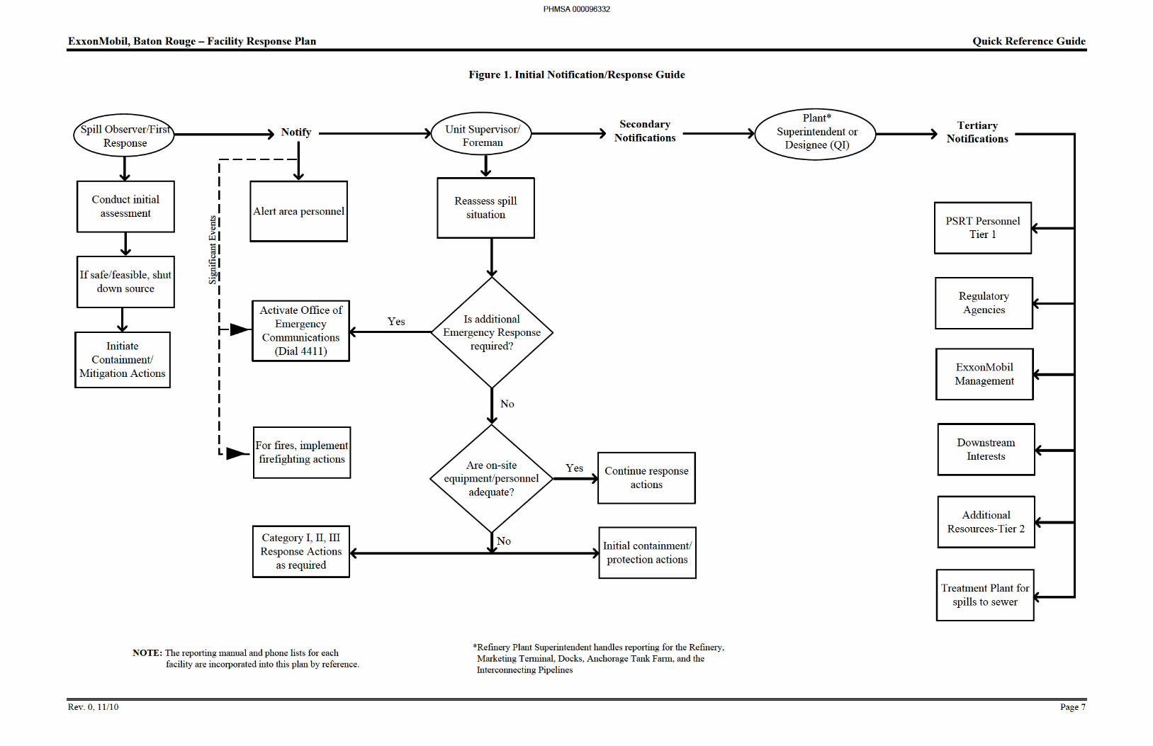
Initial Response Notification/Response Guide Flowchart (Figure 1)
Preliminary Site Assessment and Procedures.
Summary Notification Phone Lists.
Evacuation Procedures and Maps.
Each of the facilities incorporated into this plan have detailed, written procedures for spill notifications to Federal, State, and Local authorities, mutual aid networks, and warning networks. The site specific procedures include appropriate spill reporting forms which are kept up to date and are distributed as needed throughout the organization. Each employee of the facility has access to the ExxonMobil On-Line Phone Directory. These procedures and directories listed in Table 2 are referenced but are not duplicated or reproduced in this FRP.
PHMSA 000096328
ExxonMobil, Baton Rouge – Facility Response Plan Section 1: Quick Reference Guide
Rev. 0, 11/11 Page 4
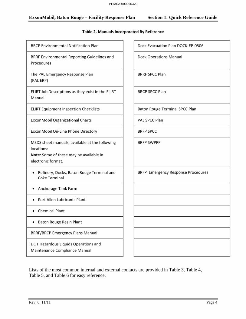
Table 2. Manuals Incorporated By Reference
BRCP Environmental Notification Plan Dock Evacuation Plan DOCK-EP-0506
BRRF Environmental Reporting Guidelines and Procedures
Dock Operations Manual
The PAL Emergency Response Plan (PAL ERP)
BRRF SPCC Plan
ELIRT Job Descriptions as they exist in the ELIRT Manual
BRCP SPCC Plan
ELIRT Equipment Inspection Checklists Baton Rouge Terminal SPCC Plan
ExxonMobil Organizational Charts PAL SPCC Plan
ExxonMobil On-Line Phone Directory BRFP SPCC
MSDS sheet manuals, available at the following locations: Note: Some of these may be available in electronic format.
BRFP SWPPP
Refinery, Docks, Baton Rouge Terminal and Coke Terminal
BRFP Emergency Response Procedures
Anchorage Tank Farm
Port Allen Lubricants Plant
Chemical Plant
Baton Rouge Resin Plant
BRRF/BRCP Emergency Plans Manual
DOT Hazardous Liquids Operations and Maintenance Compliance Manual
Lists of the most common internal and external contacts are provided in Table 3, Table 4, Table 5, and Table 6 for easy reference.
PHMSA 000096329
ExxonMobil, Baton Rouge – Facility Response Plan Section 1: Quick Reference Guide
Rev. 0, 11/11 Page 5
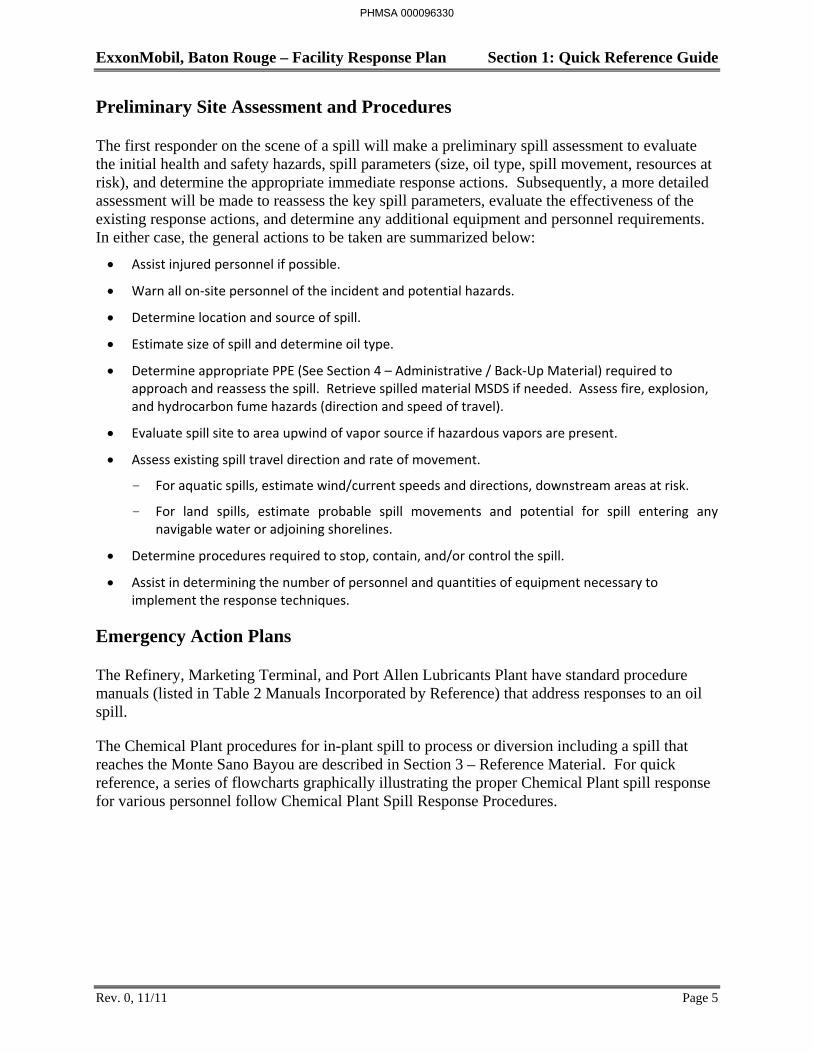
Preliminary Site Assessment and Procedures
The first responder on the scene of a spill will make a preliminary spill assessment to evaluate the initial health and safety hazards, spill parameters (size, oil type, spill movement, resources at risk), and determine the appropriate immediate response actions. Subsequently, a more detailed assessment will be made to reassess the key spill parameters, evaluate the effectiveness of the existing response actions, and determine any additional equipment and personnel requirements. In either case, the general actions to be taken are summarized below:
Assist injured personnel if possible.
Warn all on-site personnel of the incident and potential hazards.
Determine location and source of spill.
Estimate size of spill and determine oil type.
Determine appropriate PPE (See Section 4 – Administrative / Back-Up Material) required to approach and reassess the spill. Retrieve spilled material MSDS if needed. Assess fire, explosion, and hydrocarbon fume hazards (direction and speed of travel).
Evaluate spill site to area upwind of vapor source if hazardous vapors are present.
Assess existing spill travel direction and rate of movement.
- For aquatic spills, estimate wind/current speeds and directions, downstream areas at risk.
- For land spills, estimate probable spill movements and potential for spill entering any navigable water or adjoining shorelines.
Determine procedures required to stop, contain, and/or control the spill.
Assist in determining the number of personnel and quantities of equipment necessary to implement the response techniques.
Emergency Action Plans
The Refinery, Marketing Terminal, and Port Allen Lubricants Plant have standard procedure manuals (listed in Table 2 Manuals Incorporated by Reference) that address responses to an oil spill.
The Chemical Plant procedures for in-plant spill to process or diversion including a spill that reaches the Monte Sano Bayou are described in Section 3 – Reference Material. For quick reference, a series of flowcharts graphically illustrating the proper Chemical Plant spill response for various personnel follow Chemical Plant Spill Response Procedures.
PHMSA 000096330
ExxonMobil, Baton Rouge – Facility Response Plan Section 1: Quick Reference Guide
Rev. 0, 11/11 Page 6
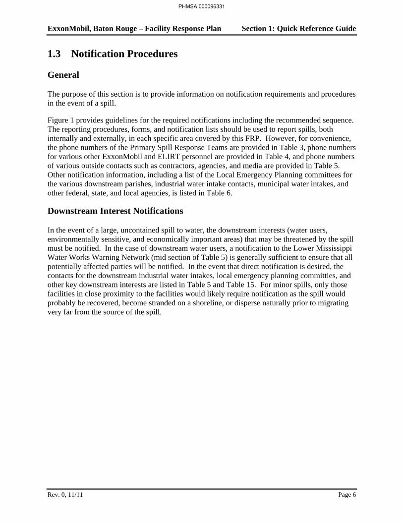
1.3 Notification Procedures
General
The purpose of this section is to provide information on notification requirements and procedures in the event of a spill.
Figure 1 provides guidelines for the required notifications including the recommended sequence. The reporting procedures, forms, and notification lists should be used to report spills, both internally and externally, in each specific area covered by this FRP. However, for convenience, the phone numbers of the Primary Spill Response Teams are provided in Table 3, phone numbers for various other ExxonMobil and ELIRT personnel are provided in Table 4, and phone numbers of various outside contacts such as contractors, agencies, and media are provided in Table 5. Other notification information, including a list of the Local Emergency Planning committees for the various downstream parishes, industrial water intake contacts, municipal water intakes, and other federal, state, and local agencies, is listed in Table 6.
Downstream Interest Notifications
In the event of a large, uncontained spill to water, the downstream interests (water users, environmentally sensitive, and economically important areas) that may be threatened by the spill must be notified. In the case of downstream water users, a notification to the Lower Mississippi Water Works Warning Network (mid section of Table 5) is generally sufficient to ensure that all potentially affected parties will be notified. In the event that direct notification is desired, the contacts for the downstream industrial water intakes, local emergency planning committies, and other key downstream interests are listed in Table 5 and Table 15. For minor spills, only those facilities in close proximity to the facilities would likely require notification as the spill would probably be recovered, become stranded on a shoreline, or disperse naturally prior to migrating very far from the source of the spill.
PHMSA 000096331

ExxonMobil, Baton Rouge – Facility Response Plan Quick Reference Guide
Rev. 2, 8/13 Page 15
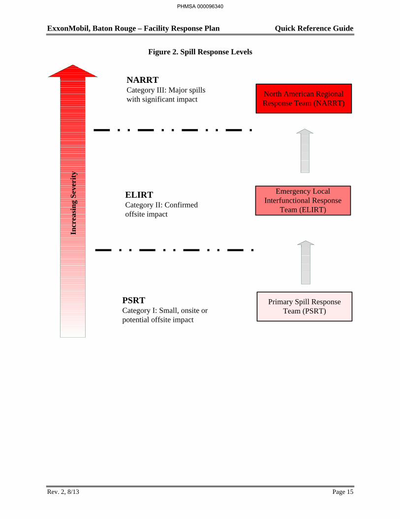
Figure 2. Spill Response Levels
Incr
easi
ng
Sev
erit
yNARRTCategory III: Major spills with significant impact
ELIRTCategory II: Confirmed offsite impact
PSRTCategory I: Small, onsite or potential offsite impact
North American Regional Response Team (NARRT)
Emergency Local Interfunctional Response
Team (ELIRT)
Primary Spill Response Team (PSRT)
PHMSA 000096340
ExxonMobil, Baton Rouge – Facility Response Plan Quick Reference Guide
Rev. 2, 8/13 Page 16
1.5 Spill Categories
The three levels of spill categories are detailed below. Examples of each type of spill can be found in Section 4 – Administrative Material / Back-Up.
Category I or Primary Response (local)
A small spill either confined to the dock or near the source within the complex, a limited aquatic spill with the potential to impact other’s property downstream or a terrestrial spill that is impacting other people’s property. These spills generally require no additional response beyond the capabilities of the facility and/or spilling function. The responders will typically include the following resources:
Unit or Area personnel (Primary Spill Response Team/ELIRT Strike Team) and equipment Other plant personnel On-site or local response contractors ELIRT Coordinator and Core Staff Support
Category II (regional)
A large spill with impact to others’ property and that requires response beyond the capability of the facility and spilling function. The responders may include the following regional resources.
LMR ELIRT/STRCC Activation On-site equipment and personnel (Primary Spill Response Team) On-site and local response contractors Regional equipment and selected regional spill contractors. See list of OSRO’s in Table12.
Category III (national)
A very large spill with significant impact to others’ property and that requires a response which is beyond the capability of ExxonMobil’s regional resources. The responders will likely include equipment and trained personnel from a specific geographic area or region and may require the combined resources from other regions or specialized or technical services.
ELIRT/NARRT activation, response operation may be subject to governmental direction On-site equipment and personnel (Primary Spill Response Team) On-site and local response contractors Local and regional spill response contractors. See list of OSRO’s in Table 12. Other potential vendors as necessary. See Table 13.
See Section 2 – Response Organization for more detailed information regarding the various spill response teams.
PHMSA 000096341
ExxonMobil, Baton Rouge – Facility Response Plan Quick Reference Guide
Rev. 2, 8/13 Page 21
ExxonMobil Spill Response Personnel
Spill response personnel consist mainly of ExxonMobil and on-site contractor personnel.
The primary ExxonMobil Refinery spill response personnel consist of 10-20 personnel from:
Refinery shift workers
Dock contract shift workers
Baton Rouge Terminal shift workers
In addition, the on-site contractor for the Refinery can provide 10-20 spill response personnel within 1-2 hours on a 24-hour basis. All spill response personnel have been trained in spill response.
The ExxonMobil Chemical Plant spill response personnel consist of:
Chemical Plant Superintendent
3-5 Environmental Operations personnel
Dock Contract Personnel along with boom and spill boats.
7-8 personnel from the Refinery
In addition, the on-site contractor for the Chemical Plant can provide 5-10 spill response personnel within 1-2 hours on a 24-hour basis.
The PSRT can respond immediately to spills during normal business hours. Because the members live within close proximity to the facility, they can generally respond within 1-2 hours of notification during off hours.
ELIRT can provide 20 personnel within 1 hour, 50 within 2 hours, and up to 130 within 24 hours.
PAL and BRFP maintain their own primary response system. However, the BRRF/BRCP and ELIRT organizations will be activated as necessary.
Response Contractors
While the on-site contractor for the Refinery and the Chemical Plant is not a USCG-rated OSRO, they provide emergency response personnel under a contract with the Refinery and the Chemical plant.
While the on-site contractor for the Coke Terminal is not a USCG-rated OSRO, they provide emergency response personnel under a contract with the Coke Terminal.
ExxonMobil maintains contracts with several local OSRO’s as listed in Table 12. Table 12 also gives these contractor’s latest USCG response ratings for the rivers/canals and inland operating areas. Initial pages of the Letters of Procurement verifying these contracts can be found in Section 4 – Administrative Material/Back-Up. Complete contract information can be found in
PHMSA 000096346
ExxonMobil, Baton Rouge – Facility Response Plan Quick Reference Guide
Rev. 2, 8/13 Page 24
1.7 Evacuation Procedures
The following subsections describe procedures to follow in the event of an evacuation from the Refinery, Baton Rouge Coke Terminal, Refinery Dock, Chemical Plant, Anchorage Tank Farm, Baton Rouge Terminal, Port Allen Lubricants, Baton Rouge Resins Finishing Plant, and neighboring communities. Evacuation Routes are also provided for each of the ExxonMobil facilities.
Refinery Evacuation Procedures
The refinery has been divided into four geographic sectors with each sector having predefined emergency routes marked with distinctively colored signs leading to predefined offsite staging areas. Each sector is equipped with a powerful and distinct sounding siren and loud speaker. The Office of Emergency Communication (OEC) has the capability to activate the sirens and issue evacuation orders via the speakers. The Refinery Superintendent and/or OEC have the capability to access all refinery radio frequencies and emergency pagers.
Although all personnel are trained in evacuation procedures, each supervisor is responsible for accounting for his personnel during an emergency. Each building or function within the Refinery has procedures for evacuation and “button up” activities which are available to all personnel.
For emergencies requiring evacuation all personnel (employees and contractors) must follow the unit’s specific evacuation plan.
If an incident necessitates a general evacuation of the Refinery, the signal will consist of an air raid type siren broadcast across the Refinery. A message from the OEC will follow the siren which will include:
Nature of the problem
Wind direction
Location of the problem
Whether the Louisiana and Arkansas Railroad Company crossing is open or closed
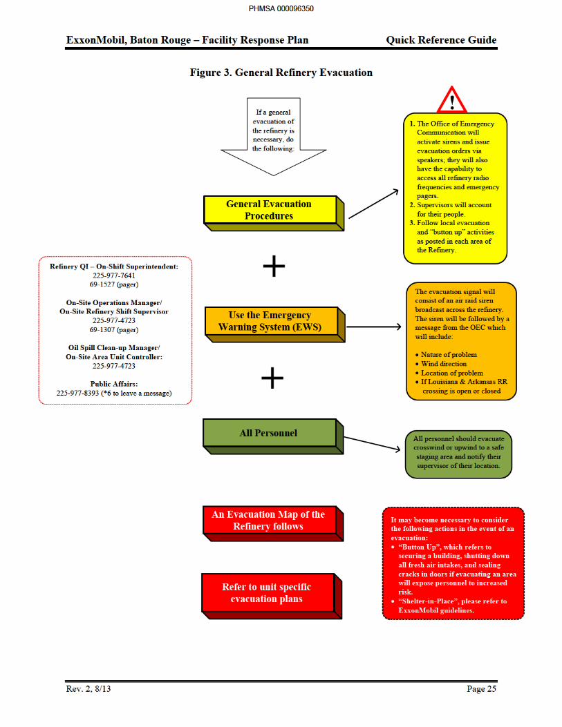
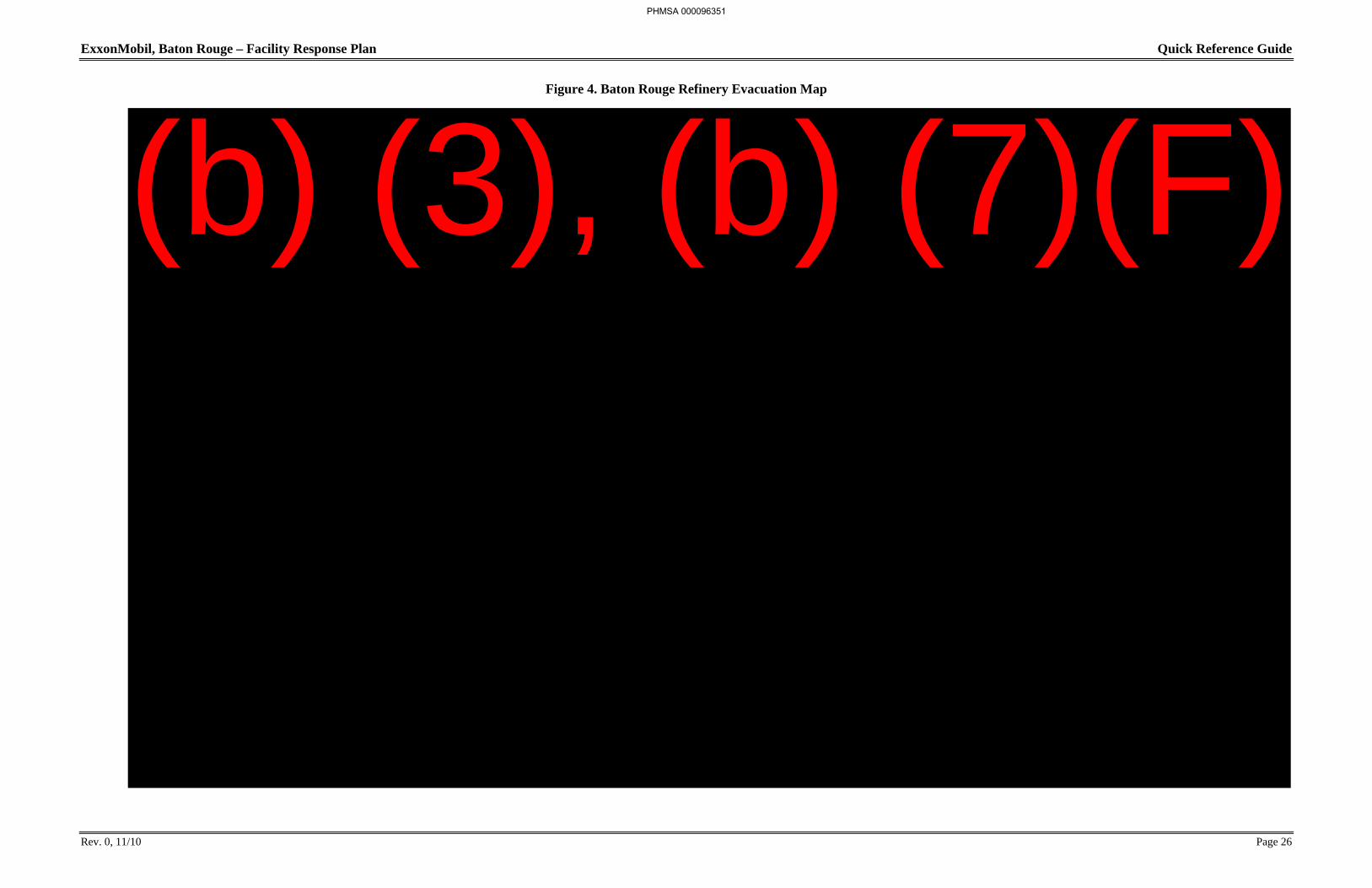
Upon hearing the siren and emergency message, all personnel should evacuate crosswind or upwind to a safe staging area and notify their supervisor of their location. Figure 4 shows various predesignated staging areas and emergency shelters around the Refinery. Figure 3 flowchart details the steps in a general Refinery evacuation.
PHMSA 000096349
ExxonMobil, Baton Rouge – Facility Response Plan Quick Reference Guide
Rev. 0, 11/10 Page 26
Figure 4. Baton Rouge Refinery Evacuation Map
PHMSA 000096351
(b) (3), (b) (7)(F)
ExxonMobil, Baton Rouge – Facility Response Plan Quick Reference Guide
Rev. 0, 11/10 Page 27
Coke Terminal Evacuation Procedures
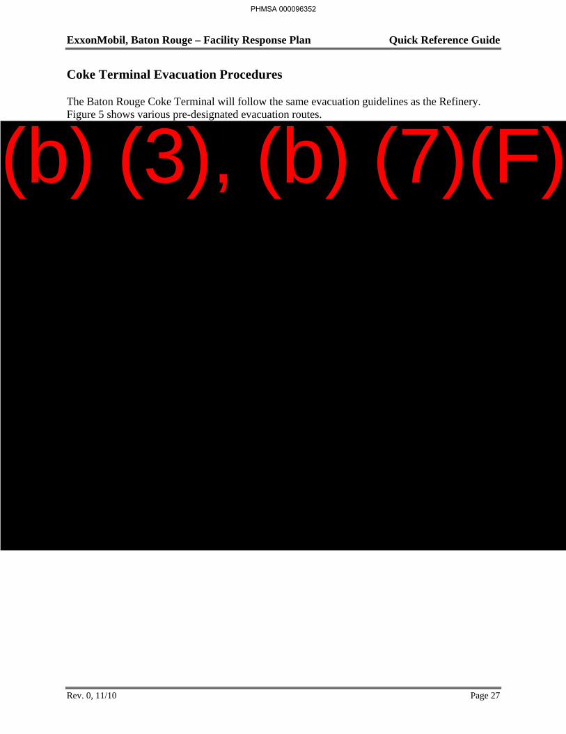
The Baton Rouge Coke Terminal will follow the same evacuation guidelines as the Refinery. Figure 5 shows various pre-designated evacuation routes.
PHMSA 000096352
(b) (3), (b) (7)(F)
ExxonMobil, Baton Rouge – Facility Response Plan Quick Reference Guide
Rev. 0, 11/10 Page 28
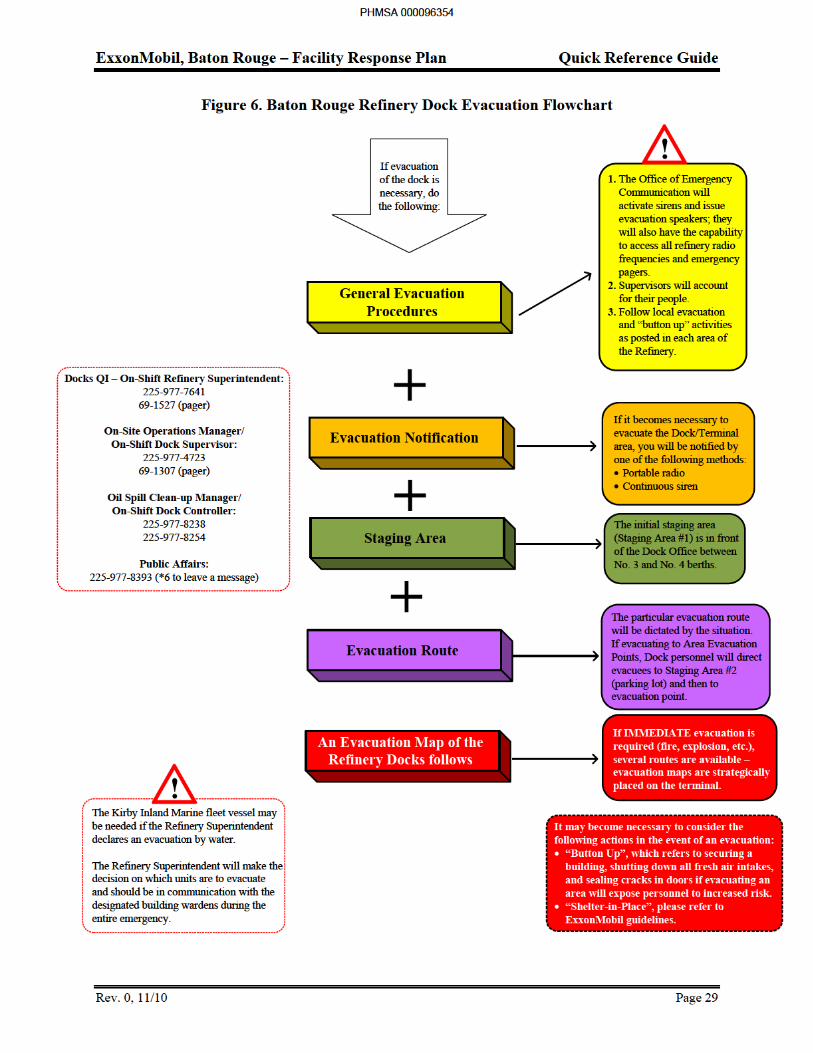
Refinery Dock Evacuation Procedures
The Refinery has been divided into four geographic sectors with each sector having predefined emergency routes leading to predefined offsite staging areas. Each sector is equipped with a distinct sounding siren and loud speaker. The Docks are located in Area Four of the Refinery evacuation grid along with EULA and all property west of the Illinois Central Gulf (ICG) Railroad.
If necessary to evacuate the Dock/Terminal area, personnel will be notified by portable radio or by continuous siren. The situation will determine the particular evacuation route.
1. Initial staging area, Staging Area #1 is located in front of the Dock Office between No. 3 and No. 4 berths.
2. If evacuation is to Area Evacuation Points, Dock personnel will evacuate to Staging Area #2 (parking lot) then to evacuation point.
3. If immediate evacuation of the Dock is required for events such as fire or explosion, several evacuation maps with emergency egress routes are posted for easy access.
If the Refinery Superintendent declares an evacuation by water, the Kirby Inland Marine fleet vessel may be needed. Kirby Inland Marine has made a fleet tug available for use as an evacuation boat and will hold up to 50 people. Kirby Inland Marine will advise in advance if the normally assigned fleet vessel is not available. An alternate vessel will be identified
The Refinery Superintendent will make the decision as to which units are to evacuate and should be in communication with the designated building wardens during the entire emergency.
Figure 6 flowchart details the procedure for a Dock evacuation while Figure 7 provides the Refinery Dock evacuation map.
PHMSA 000096353
ExxonMobil, Baton Rouge – Facility Response Plan Quick Reference Guide
Rev. 1, 12/13 Page 31
Chemical Plant Evacuation Procedures
PHMSA 000096356
(b) (3), (b) (7)(F)
ExxonMobil, Baton Rouge – Facility Response Plan Quick Reference Guide
Rev. 0, 11/10 Page 35
Anchorage Tank Farm Evacuation Procedures
For emergencies within the Anchorage tank farm, the Process Operator will notify all ExxonMobil and contract personnel by radio or direct contact. The Process Operator will then provide instructions as to the proper evacuation route. Figure 11 shows the evacuation routes.
PHMSA 000096360

ExxonMobil, Baton Rouge – Facility Response Plan Quick Reference Guide
Rev. 0, 11/11 Page 37
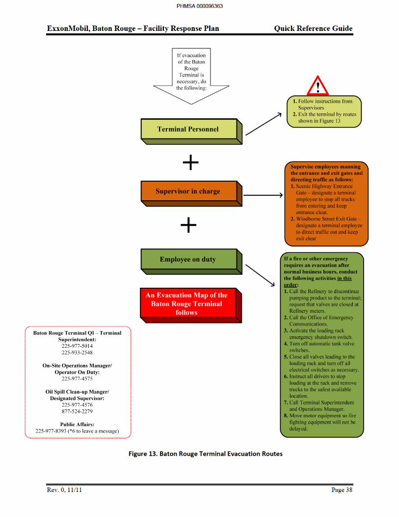
Figure 12. Baton Rouge Terminal Evacuation Flowchart
PHMSA 000096362
(b) (3), (b) (7)(F)
ExxonMobil, Baton Rouge – Facility Response Plan Quick Reference Guide
Rev. 0, 11/11 Page 39
PHMSA 000096364
(b) (3), (b) (7)(F)
ExxonMobil, Baton Rouge – Facility Response Plan Quick Reference Guide
Rev. 0, 11/11 Page 40
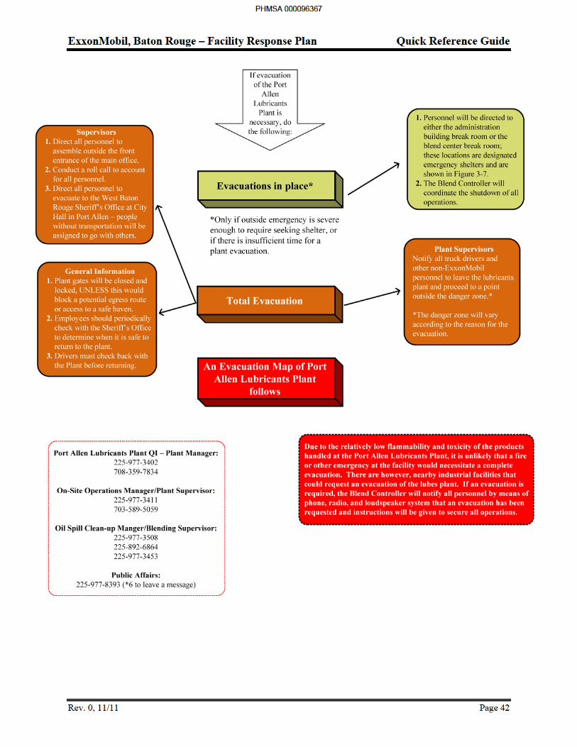
Port Allen Lubricants Plant Procedures
Due to the relatively low flammability and toxicity of the products handled at the Port Allen Lubricants Plant, it is unlikely that a fire or other emergency at the facility would necessitate a complete evacuation. There are, however, nearby industrial facilities that could request an evacuation of the Lubricants Plant. If an evacuation is required, the Blend Controller will notify all personnel by means of phone, radio, and loud speaker system that an evacuation has been requested and that instructions will be given to secure all operations.
In some situations, the outside emergency may only be severe enough to require seeking shelter rather than making a complete evacuation. Other situations may be such that there is insufficient time to carry out a plant evacuation. In either of these situations, all personnel on site will be directed to either the administration building break room or the blend center break room. These two locations are designated as emergency shelters shown on Figure 15.
If it is necessary to evacuate the PAL site, the Plant Supervisors will notify all truck drivers and personnel on site to leave the Lubricants Plant and proceed to a point outside the danger zone which will vary according to the reason for the evacuation. The supervisors should also direct all personnel to assemble outside the front entrance of the main office, conduct a roll call to account for all personnel, and direct all personnel to evacuate to the Port Allen Community Center on North Jefferson Street in Port Allen. People without transportation will be assigned to go with others.
The plant gates should be closed and locked unless this would block a potential egress route or access to an emergency shelter. The employees should periodically check with the Sheriff’s Office to determine when it is safe to return to the plant. Drivers must also check back with the plant before returning.
PHMSA 000096365

ExxonMobil, Baton Rouge – Facility Response Plan Quick Reference Guide
Rev. 0, 11/11 Page 41
Figure 14. Port Allen Lubricants Plant Evacuation Flowchart
PHMSA 000096366
ExxonMobil, Baton Rouge – Facility Response Plan Quick Reference Guide
Figure 15. Port Allen Lubricants Plant Evacuation Routes
PHMSA 000096368
(b) (7)(F), (b) (3)
ExxonMobil, Baton Rouge – Facility Response Plan Quick Reference Guide
Rev. 0, 11/10 Page 44
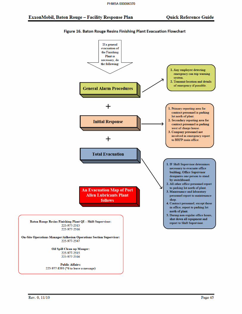
Baton Rouge Resins Finishing Plant Evacuation Procedures
Any employee detecting a fire in the Finishing Plant should go to the nearest alarm station and trip the warning system. If a radio is available, transmit the location and details of the emergency. Upon hearing the alarm, personnel in outlying offices will report as follows:
If the Shift Supervisor determines it necessary to evacuate the office building, the Office Supervisor may consider designating one person to remain in building to stand by the switchboard.
All other office personnel report to the parking lot north of the plant where the Office Supervisor will obtain a head count.
Maintenance personnel, company and contract, and laboratory personnel report to the maintenance shop and stand by.
Contract personnel except those working in the main off ice will report to the parking lot north of the plant where the Contract Supervisor will obtain a head count and report to the liaison or Shift Supervisor.
If an emergency occurs during non-regular work hours, the Packaging Crew Operator and Finishing Operator will shut down all equipment in their respective areas and all in-plant personnel are to report to the Shift Supervisor for further instructions.
PHMSA 000096369
(b) (3), (b) (7)(F)

ExxonMobil, Baton Rouge – Facility Response Plan Quick Reference Guide
Figure 17. Baton Rouge Finishing Plant Evacuation Routes
PHMSA 000096371
(b) (7)(F), (b) (3)
ExxonMobil, Baton Rouge – Facility Response Plan Quick Reference Guide
Rev. 0, 11/11 Page 47
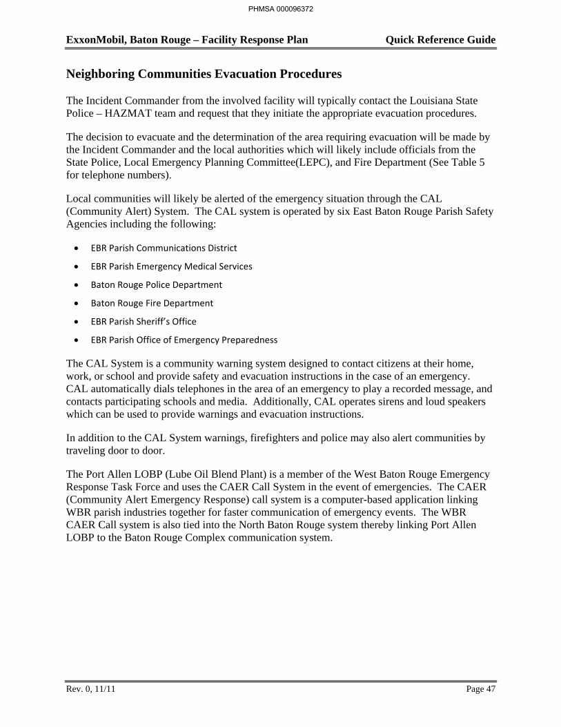
Neighboring Communities Evacuation Procedures
The Incident Commander from the involved facility will typically contact the Louisiana State Police – HAZMAT team and request that they initiate the appropriate evacuation procedures.
The decision to evacuate and the determination of the area requiring evacuation will be made by the Incident Commander and the local authorities which will likely include officials from the State Police, Local Emergency Planning Committee(LEPC), and Fire Department (See Table 5 for telephone numbers).
Local communities will likely be alerted of the emergency situation through the CAL (Community Alert) System. The CAL system is operated by six East Baton Rouge Parish Safety Agencies including the following:
EBR Parish Communications District
EBR Parish Emergency Medical Services
Baton Rouge Police Department
Baton Rouge Fire Department
EBR Parish Sheriff’s Office
EBR Parish Office of Emergency Preparedness
The CAL System is a community warning system designed to contact citizens at their home, work, or school and provide safety and evacuation instructions in the case of an emergency. CAL automatically dials telephones in the area of an emergency to play a recorded message, and contacts participating schools and media. Additionally, CAL operates sirens and loud speakers which can be used to provide warnings and evacuation instructions.
In addition to the CAL System warnings, firefighters and police may also alert communities by traveling door to door.
The Port Allen LOBP (Lube Oil Blend Plant) is a member of the West Baton Rouge Emergency Response Task Force and uses the CAER Call System in the event of emergencies. The CAER (Community Alert Emergency Response) call system is a computer-based application linking WBR parish industries together for faster communication of emergency events. The WBR CAER Call system is also tied into the North Baton Rouge system thereby linking Port Allen LOBP to the Baton Rouge Complex communication system.
PHMSA 000096372
ExxonMobil, Baton Rouge – Facility Response Plan Quick Reference Guide
Rev. 0, 11/11 Page 48
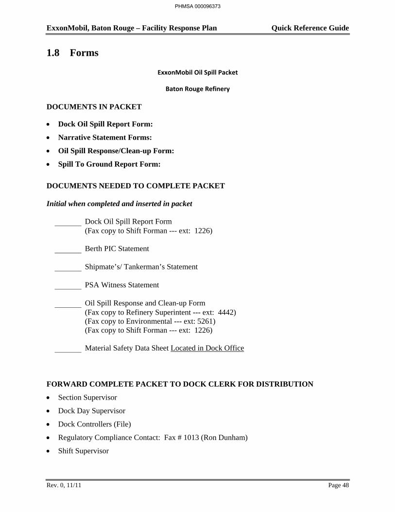
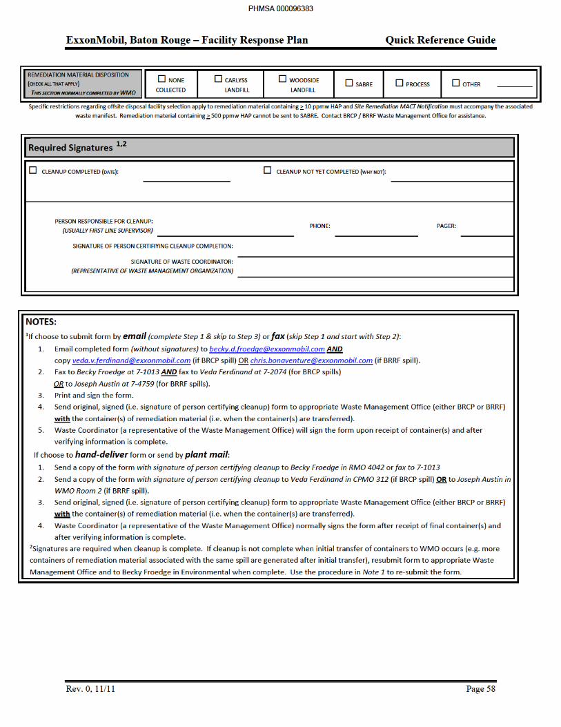
1.8 Forms
ExxonMobil Oil Spill Packet
Baton Rouge Refinery
DOCUMENTS IN PACKET
Dock Oil Spill Report Form:
Narrative Statement Forms:
Oil Spill Response/Clean-up Form:
Spill To Ground Report Form:
DOCUMENTS NEEDED TO COMPLETE PACKET Initial when completed and inserted in packet
Dock Oil Spill Report Form (Fax copy to Shift Forman --- ext: 1226) Berth PIC Statement Shipmate’s/ Tankerman’s Statement PSA Witness Statement Oil Spill Response and Clean-up Form (Fax copy to Refinery Superintent --- ext: 4442) (Fax copy to Environmental --- ext: 5261) (Fax copy to Shift Forman --- ext: 1226) Material Safety Data Sheet Located in Dock Office
FORWARD COMPLETE PACKET TO DOCK CLERK FOR DISTRIBUTION
Section Supervisor
Dock Day Supervisor
Dock Controllers (File)
Regulatory Compliance Contact: Fax # 1013 (Ron Dunham)
Shift Supervisor
PHMSA 000096373
ExxonMobil, Baton Rouge – Facility Response Plan Quick Reference Guide
Rev. 0, 11/11 Page 49
PHMSA 000096374
ExxonMobil, Baton Rouge – Facility Response Plan Quick Reference Guide
Rev. 0, 11/11 Page 50
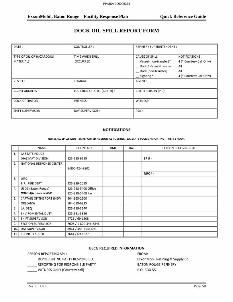
DOCK OIL SPILL REPORT FORM
DATE : CONTROLLER :
REFINERY SUPERINTENDENT :
TYPE OF OIL OR HAZARDOUS MATERIALS :
TIME WHEN SPILL OCCURRED:
CAUSE OF SPILL NOTIFICATIONS __ Vessel (non-transfer)* 4 (* Courtesy Call Only) __ Dock / Vessel (transfer) All __ Dock (non-transfer) All __ Sighting * 4 (* Courtesy Call Only)
VESSEL : TUGBOAT : AGENT :
AGENT ADDRESS : LOCATION OF SPILL (BERTH) : BERTH PERSON (PIC):
DOCK OPERATOR :
WITNESS : WITNESS:
SHIFT SUPERVISOR : DAY SUPERVISOR : PSA :
NOTIFICATIONS
NOTE: ALL SPILLS MUST BE REPORTED AS SOON AS POSSIBLE. LA. STATE POLICE REPORTING TIME < 1 HOUR.
NAME PHONE NO TIME DATE PERSON RECEIVING CALL
1. LA STATE POLICE (HAZ MAT DIVISION)
225-925-6595
SP # -
2. NATIONAL RESPONSE CENTER 1-800-424-8802
NRC # - 3. LEPC
B.R. FIRE DEPT 225-389-2055
4. USCG (Baton Rouge) NOTE: After hours call #5
225-298-5400 Office 225-298-5408 Fax
5. CAPTAIN OF THE PORT (NEW ORLEANS)
504-365-2200 504-589-6225
6. LA. DEQ 225-219-3640 7. ENVIROMENTAL DUTY 225-931-3886 8. SHIFT SUPERVISOR 4723 / 69-1308 9. SECTION SUPERVISOR 7605 / 1-800-346-8846 10. DAY SUPERVISOR 8961 / 445-3134 DIG. 11. REFINERY SUPER 7641 / 69-1527
USCG REQUIRED INFORMATION PERSON REPORTING SPILL FROM: _____ REPRESENTING PARTY RESPONSIBLE ExxonMobil Refining & Supply Co. _____ REPORTING FOR RESPONSIBLE PARTY BATON ROUGE REFINERY _____ WITNESS ONLY (Courtesy call) P.O. BOX 551
PHMSA 000096375
ExxonMobil, Baton Rouge – Facility Response Plan Quick Reference Guide
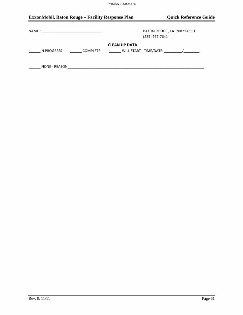
Rev. 0, 11/11 Page 51
NAME : ______________________________ BATON ROUGE , LA. 70821-0551 (225) 977-7641
CLEAN UP DATA ______IN PROGRESS ______ COMPLETE ______ WILL START - TIME/DATE: _________/________
______ NONE - REASON_____________________________________________________________________
PHMSA 000096376
ExxonMobil, Baton Rouge – Facility Response Plan Quick Reference Guide
Rev. 0, 11/11 Page 52
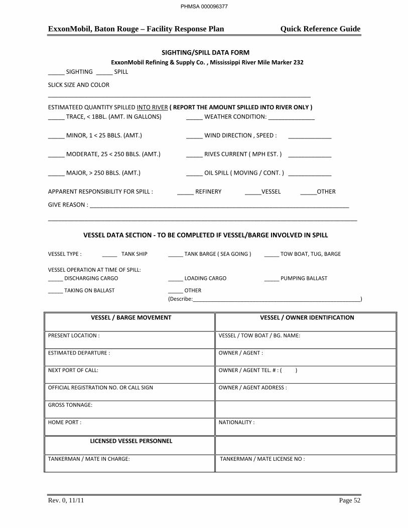
SIGHTING/SPILL DATA FORM ExxonMobil Refining & Supply Co. , Mississippi River Mile Marker 232
_____ SIGHTING _____ SPILL
SLICK SIZE AND COLOR _______________________________________________________________________________
ESTIMATEED QUANTITY SPILLED INTO RIVER ( REPORT THE AMOUNT SPILLED INTO RIVER ONLY ) _____ TRACE, < 1BBL. (AMT. IN GALLONS) _____ WEATHER CONDITION: ______________ _____ MINOR, 1 < 25 BBLS. (AMT.) _____ WIND DIRECTION , SPEED : _____________ _____ MODERATE, 25 < 250 BBLS. (AMT.) _____ RIVES CURRENT ( MPH EST. ) _____________ _____ MAJOR, > 250 BBLS. (AMT.) _____ OIL SPILL ( MOVING / CONT. ) _____________ APPARENT RESPONSIBILITY FOR SPILL : _____ REFINERY _____VESSEL _____OTHER
GIVE REASON : ______________________________________________________________________________
_____________________________________________________________________________________________
VESSEL DATA SECTION - TO BE COMPLETED IF VESSEL/BARGE INVOLVED IN SPILL
VESSEL TYPE : _____ TANK SHIP _____ TANK BARGE ( SEA GOING ) _____ TOW BOAT, TUG, BARGE VESSEL OPERATION AT TIME OF SPILL: _____ DISCHARGING CARGO _____ LOADING CARGO _____ PUMPING BALLAST
_____ TAKING ON BALLAST _____ OTHER (Describe:________________________________________________________)
VESSEL / BARGE MOVEMENT
VESSEL / OWNER IDENTIFICATION
PRESENT LOCATION : VESSEL / TOW BOAT / BG. NAME:
ESTIMATED DEPARTURE :
OWNER / AGENT :
NEXT PORT OF CALL:
OWNER / AGENT TEL. # : ( )
OFFICIAL REGISTRATION NO. OR CALL SIGN
OWNER / AGENT ADDRESS :
GROSS TONNAGE:
HOME PORT :
NATIONALITY :
LICENSED VESSEL PERSONNEL
TANKERMAN / MATE IN CHARGE:
TANKERMAN / MATE LICENSE NO :
PHMSA 000096377
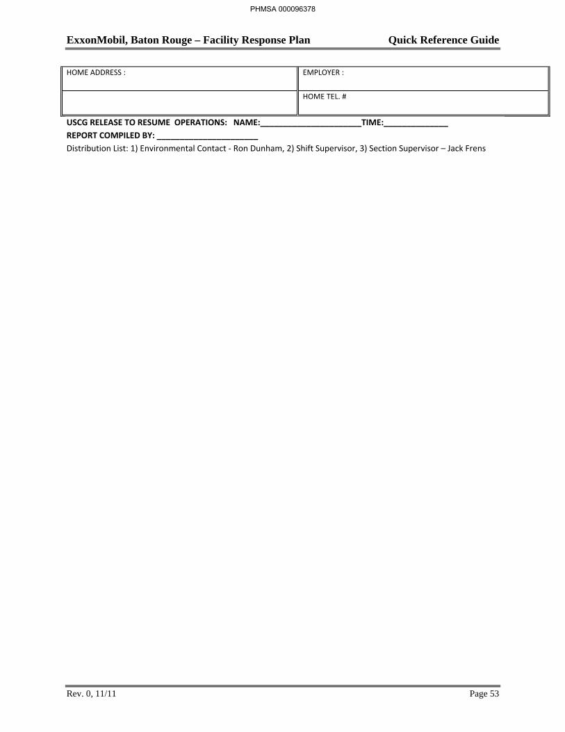
ExxonMobil, Baton Rouge – Facility Response Plan Quick Reference Guide
Rev. 0, 11/11 Page 53
HOME ADDRESS :
EMPLOYER :
HOME TEL. #
USCG RELEASE TO RESUME OPERATIONS: NAME:______________________TIME:______________ REPORT COMPILED BY: ______________________ Distribution List: 1) Environmental Contact - Ron Dunham, 2) Shift Supervisor, 3) Section Supervisor – Jack Frens
PHMSA 000096378
ExxonMobil, Baton Rouge – Facility Response Plan Quick Reference Guide
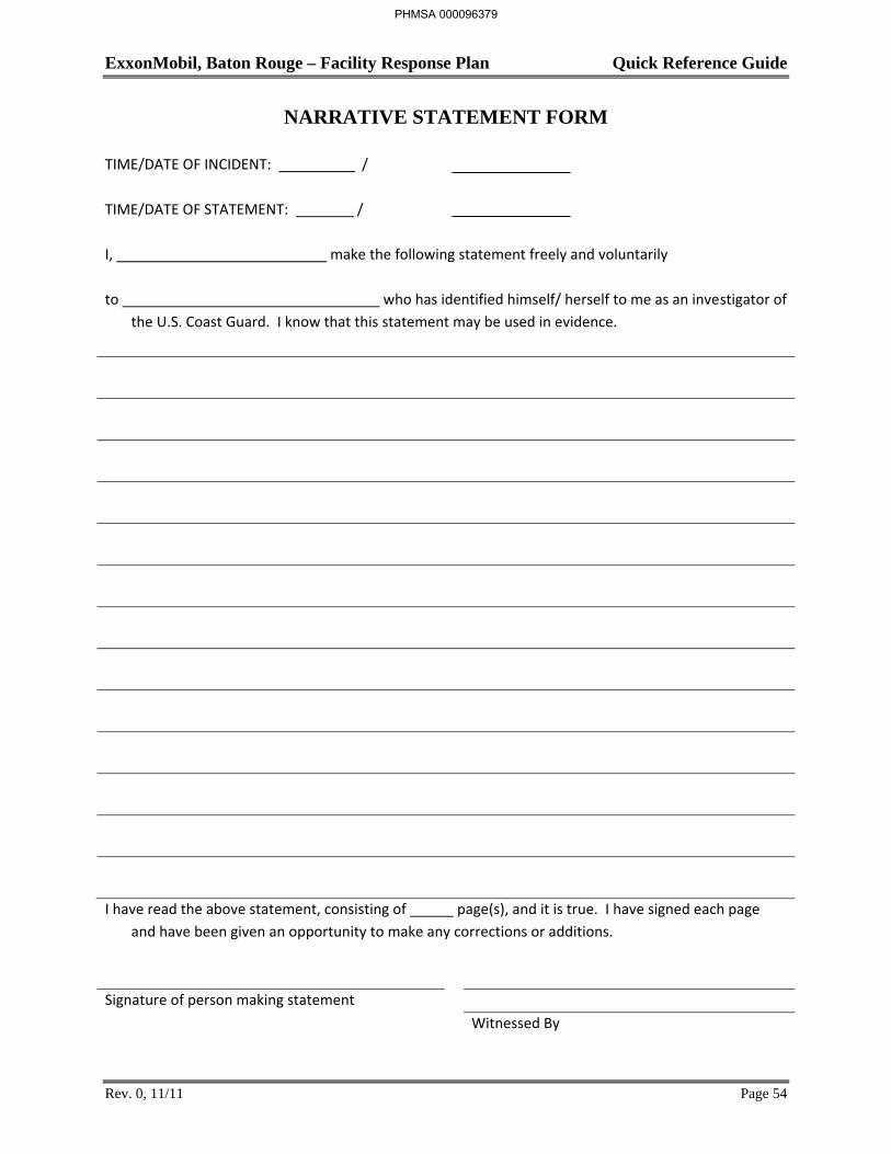
Rev. 0, 11/11 Page 54
NARRATIVE STATEMENT FORM
TIME/DATE OF INCIDENT: / TIME/DATE OF STATEMENT: /
I, make the following statement freely and voluntarily to who has identified himself/ herself to me as an investigator of
the U.S. Coast Guard. I know that this statement may be used in evidence. I have read the above statement, consisting of page(s), and it is true. I have signed each page
and have been given an opportunity to make any corrections or additions. Signature of person making statement Witnessed By
PHMSA 000096379

ExxonMobil, Baton Rouge – Facility Response Plan Quick Reference Guide
Rev. 0, 11/11 Page 55
Address and job title of person making statement:
PHMSA 000096380
ExxonMobil, Baton Rouge – Facility Response Plan Quick Reference Guide
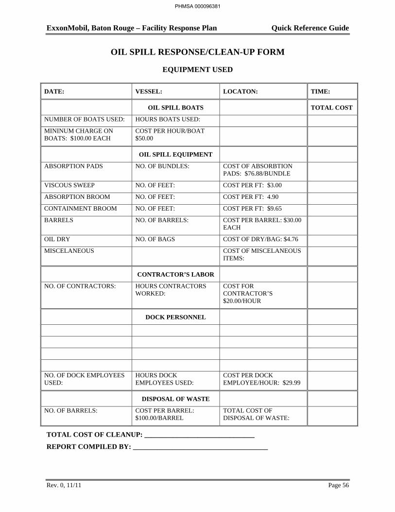
Rev. 0, 11/11 Page 56
OIL SPILL RESPONSE/CLEAN-UP FORM
EQUIPMENT USED
DATE: VESSEL: LOCATON: TIME:
OIL SPILL BOATS TOTAL COST
NUMBER OF BOATS USED: HOURS BOATS USED:
MININUM CHARGE ON BOATS: $100.00 EACH
COST PER HOUR/BOAT $50.00
OIL SPILL EQUIPMENT
ABSORPTION PADS NO. OF BUNDLES: COST OF ABSORBTION PADS: $76.88/BUNDLE
VISCOUS SWEEP NO. OF FEET: COST PER FT: $3.00
ABSORPTION BROOM NO. OF FEET: COST PER FT: 4.90
CONTAINMENT BROOM NO. OF FEET: COST PER FT: $9.65
BARRELS NO. OF BARRELS: COST PER BARREL: $30.00 EACH
OIL DRY NO. OF BAGS COST OF DRY/BAG: $4.76
MISCELANEOUS COST OF MISCELANEOUS ITEMS:
CONTRACTOR’S LABOR
NO. OF CONTRACTORS: HOURS CONTRACTORS WORKED:
COST FOR CONTRACTOR’S $20.00/HOUR
DOCK PERSONNEL
NO. OF DOCK EMPLOYEES USED:
HOURS DOCK EMPLOYEES USED:
COST PER DOCK EMPLOYEE/HOUR: $29.99
DISPOSAL OF WASTE
NO. OF BARRELS: COST PER BARREL: $100.00/BARREL
TOTAL COST OF DISPOSAL OF WASTE:
TOTAL COST OF CLEANUP: _______________________________
REPORT COMPILED BY: ______________________________________
PHMSA 000096381
ExxonMobil, Baton Rouge – Facility Response Plan Section 1: Quick Reference Guide
TABLE OF CONTENTS
SECTION PAGE
Rev. 0, 11/10 i
Section 1: Quick Reference Guide
1.1 Introduction ........................................................................................................................ 1
1.2 Immediate Response Actions ............................................................................................. 3
Preliminary Site Assessment and Procedures ................................................................. 5 Emergency Action Plans ................................................................................................. 5
1.3 Notification Procedures ..................................................................................................... 6
General ............................................................................................................................ 6 Downstream Interest Notifications ................................................................................. 6
1.4 Response Capabilities ...................................................................................................... 14
Response Organization Structure ................................................................................. 14 Response Team Progression ......................................................................................... 14
1.5 Spill Categories ................................................................................................................ 16
Category I or Primary Response (local) ....................................................................... 16 Category II (regional) ................................................................................................... 16 Category III (national) .................................................................................................. 16
1.6 Spill Response Equipment ............................................................................................... 17
ExxonMobil Equipment ................................................................................................ 17 Equipment Inspection ................................................................................................... 20 ExxonMobil Spill Response Personnel ........................................................................ 21 Response Contractors ................................................................................................... 21 Interim Storage ............................................................................................................. 22
1.7 Evacuation Procedures ..................................................................................................... 24
Refinery Evacuation Procedures ................................................................................... 24 Coke Terminal Evacuation Procedures ........................................................................ 27 Refinery Dock Evacuation Procedures ......................................................................... 28 Chemical Plant Evacuation Procedures ........................................................................ 31 Anchorage Tank Farm Evacuation Procedures ............................................................ 35 Baton Rouge Terminal Evacuation Procedures ............................................................ 37 Port Allen Lubricants Plant Procedures ........................................................................ 40 Baton Rouge Resins Finishing Plant Evacuation Procedures ....................................... 43 Neighboring Communities Evacuation Procedures ...................................................... 46
PHMSA 000096384
ExxonMobil, Baton Rouge – Facility Response Plan Section 1: Quick Reference Guide
TABLE OF CONTENTS
SECTION PAGE
Rev. 0, 11/10 ii
1.8 Forms ............................................................................................................................... 47
Dock Oil Spill Report Form ......................................................................................... 48 Narrative Statement Form ............................................................................................. 50 Oil Spill Response/Clean-Up Form .............................................................................. 51 Spill Followup Report ................................................................................................... 52
PHMSA 000096385
ExxonMobil, Baton Rouge – Facility Response Plan Section 2: Response Organization
Rev. 0, 5/12 Page 1
2.1 Introduction
ExxonMobil uses the National Incident Management System Incident Command System (NIMS-ICS) approach to crisis management. The National Incident Management System of structured, standardized, organizational framework used nationwide to respond to emergencies utilizes the Incident Command System. The use of the NIMS-ICS as well as the Unified Command System promotes collaboration between ExxonMobil, oversight regulatory agencies, and other public organizations impacted by a crisis event. The response organization described in this FRP using the NIMS-ICS approach adapts well to any size incident.
PHMSA 000096386
ExxonMobil, Baton Rouge – Facility Response Plan Section 2: Response Organization
Rev. 2, 5/14 Page 2
2.2 Primary Spill Response Team (PSRT)
The PSRT responds to Category I spills. This team is on site 24 hours a day and can provide immediate response as necessary, usually within 30 minutes of a spill. Additionally, contractors working in both the Refinery and Chemical Plant can respond during normal working hours and are on call during off hours.
The PSRT provides supervisory levels available to create a command structure to accommodate the emergency incident. The nature of the incident will determine the scale and complexity of the response organization at the scene. For example, smaller contained spills may only require the activation of the Operations branch whereas larger spills may require activation of the entire team as well as the core group from the ELIRT. Additionally, for smaller spills, one person may be responsible for two or more positions whereas larger spills may require multiple personnel to effectively fill a single position.
Descriptions of each PSRT position, the primary responsibilities, and pre-emergency planning activities follow in this section along with an organizational representation in Fi ure 18.
PHMSA 000096387
(b) (

ExxonMobil, Baton Rouge – Facility Response Plan Section 2: Response Organization
Rev. 2, 5/14 Page 4
Incident Commander (Qualified Individual) Position Description
The Qualified Individual (QI) is a 24 hour contact familiar with implementation of this FRP, and trained in his/her responsibilities. Table 3, Primary Spill Response Team Notification List located in Section 1, lists these individuals and their contact numbers. The QI is responsible for implementing response plans, directing response operations, and resolving internal conflicts that arise during response operations either directly or through the use of qualified designees.
The QI will vary depending on the location as shown below. This initial QI or their designee may be superseded by higher management personnel based on the size and extent of a spill event so that the QI remains authorized to obligate sufficient funds for spill response. The Federal On-Scene Commander (FOSC), along with other local agencies, will be advised in advance of any additional management support or QI change. However, at no time shall the authorization for or expenditure of funds in excess of the liability limits allowed by the Oil Pollution Act of 1990 be regarded as a waiver of any rights that ExxonMobil may have in claiming such liability limit or defenses under federal law.
The Qualified Individuals for the Refinery, Chemical Plant and Marketing Terminal are their respective superintendents, who are available 24 hours a day. The QI for the Port Allen Lubricant Plant is the plant manager during working hours and the Refinery Superintendent after hours. The home numbers and addresses for each designated individual have not been provided since a QI is available 24 hours a day for each site. The names of each person holding the position listed below can be obtained from ExxonMobil Organizational Charts which are kept up to date, widely distributed to all employees, and are incorporated herein by reference. The current phone numbers for each person holding the position listed below can be obtained by all employees from the ExxonMobil On-line Phone Directory.
Primary Responsibilities
The QIs have full authority to implement this response plan and initiate the following activities as necessary. A flowchart listing these primary responsibilities is included in this section.
Activate internal alarms and/or communication systems to alert facility personnel and notify response team members.
Ensure that shutdown and containment of spill is immediately initiated.
Take actions to endure the safety of all personnel.
Notify and coordinate internal response and rescue activities with the PSRT.
Access interaction of spilled material with water and/or other substances stored at facility and notify response personnel appropriately.
Assess possible hazards to human health and to the environment.
Activate IH as necessary.
Contact Site Management and relay following information:
Determine level of PSRT response and initial assessment needs.
Maintain information on incident and actions taken.
Provide special instruction for PSRT personnel reporting to incident.
PHMSA 000096389

ExxonMobil, Baton Rouge – Facility Response Plan Section 2: Response Organization
Rev. 2, 5/14 Page 5
Conduct initial implementation briefing to team members.
Ensure notification of, and coordinate activity with, outside agencies, USCG/NRC, LDEQ HAZMAT, LDNR, EPA, OSHA, etc. and participate as member of joint Incident Command.
Identify the character, exact source, amount and extent of the release required for notifications.
Designate Spill Manager if necessary.
Access and implement removal and containment actions.
Assist Operations Manager Chief to ensure shutdown and containment of spill.
Assess on-site security needs and relay to Security.
- Closing of highways/waterways.
- Escorts for personnel involved with incident.
- Alcohol and drug testing/search of personnel going to site.
Assess company funding to initiate cleanup.
Obligate funds to carry out all necessary or directed spill response activities.
Activate response contractors as necessary.
Oversee development of long-range action plan.
Direct cleanup activities.
Implement and direct overall incident management.
Act as liaison with federal and state On-Scene Coordinators, local government representatives, and affected third parties (Major landowner, municipalities, etc.).
Provide On-Scene Commander, if activated, with regular updates for media and public officials.
Ensure protection of safety at the response site.
Pre-Emergency Planning:
Review and approve pre-emergency planning activities.
Ensure appropriate and trained personnel are assigned to PSRT.
Establish appropriate emergency resource authorization guidelines for non-ELIRT situations.
Keep appraised of and develop mutual assistance agreements as appropriate.
Ensure field personnel are aware of PSRT information needs.
Ensure activation procedures for outside resources are developed and available.
Immediate Supervisor
In Category II and III Spills, the Incident Commander heads the spill management team, but coordinates his actions with the unified command.
PHMSA 000096390
ExxonMobil, Baton Rouge – Facility Response Plan Response Organization
Rev. 2, 5/14 Page 7
On-Site Operations Manager Position Description
The On-Site Operations Manager is responsible for developing response plans, activating response personnel, directing response operations, resolving internal conflicts that arise during response operations, and for reporting the progress and plans of the response operations to the Incident Commander. Table 3, Primary Spill Response Team Notification List gives the job title and contact number for the On-Site Operations Manager for each location.
On-Site Operations Manager Primary Responsibilities:
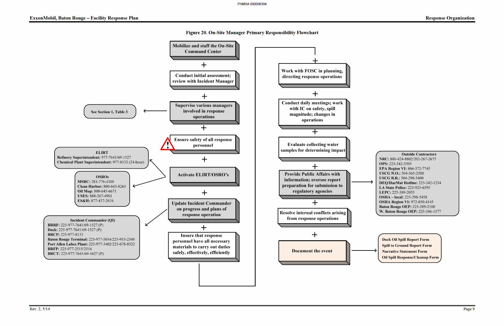
The On-Site Operations Managers have full authority to implement this Facility Response Plan and initiate the following activities as necessary. Figure 20 lists these responsibilities.
Mobilize and staff the On-Site command Center.
Conduct initial assessment of incident. Formulate and review incident action/mobilization plans with Incident Manager.
Supervise the Oil Spill Clean-Up Containment Manager/Spill Response Supervisor, Safety/Health Manager, and the Planning/Technical Manager.
Ensure that the safety of response personnel is accorded the highest priority in all aspects and phases of response operations.
Activate the necessary ELIRT, OSRO’s, and industry resources to implement response.
Update Incident Commander on the progress and plans of the response operation on a timely basis.
Ensure that response personnel have the equipment, materials, and supplies necessary to carry out their duties in a safe, effective, and efficient fashion.
Oversee the development of daily and programmatic incident action plans.
Work with the Federal On-Scene Commander in both planning and direction of response operations.
Conduct daily briefing and debriefing meetings.
Work with the Incident Commander on matters concerning safety, spill magnitude, and changes or developments in each operation that may affect the other.
Evaluate collecting water samples upstream and downstream of the spill to determine the impact of the event.
Provide the Public Affairs Advisor with accurate and timely information on the status of response operations.
Oversee the preparation of all reports, plans, and other materials for submission to regulatory agencies.
Document the event.
PHMSA 000096392
ExxonMobil, Baton Rouge – Facility Response Plan Response Organization
Rev. 2, 5/14 Page 8
On-Site Operations Manager Pre-Emergency Planning:
Keep abreast of ELIRT capability and assist in improving ELIRT response capabilities as required.
Develop PSRT initial briefing agenda.
Provide PSRT periodic updates on status of pre-emergency planning activities and other items of interest.
Provide PSRT briefing on lessons learned from recent spills and drills.
On-Site Operations Manager Immediate Supervisor;
The On-Site Operations Manager reports to the Incident Commander.
PHMSA 000096393
ExxonMobil, Baton Rouge – Facility Response Plan Response Organization
Rev. 2, 5/14 Page 10
Oil Spill Clean-Up Manager Position Description
The Oil Spill Clean-Up Manager is responsible for the management and coordination of all containment, recovery, burning, shoreline protections, shoreline clean-up, and waste disposal activities that occur during response operations. Table 3, Primary Spill Response Team Notification List gives the job title and contact number for the Oil Spill Clean-Up Manager for each location.
Oil Spill Clean-Up Manager Primary Responsibilities:
The Oil Spill Clean-Up Managers have full authority to implement this FRP and initiate the following activities as necessary. Figure 21 lists these responsibilities.
Work closely with Planning/Technical group to determine appropriate response strategy.
Ensure personnel safety the highest priority throughout the conduct of the spill response operations.
Supervise the Containment/Recovery Supervisors and Primary Response Team.
Mobilize fast response equipment.
Mobilize Field Supervisors and activate operations staff as required.
Direct deployment of response equipment and supervise on-water, near-shore, and shoreline response.
Provide information on operations status and make recommendations to the On-Site Operations Manager.
Serve as the field contact person for government agencies.
Provide support for public affairs activities including serving as a spokesperson and assisting in the preparation or review of information for release to external customers.
Ensure adequate records are kept during a spill response operation.
Oil Spill Clean-Up Manager Pre-Emergency Planning:
Oversee pre-emergency planning activities of operations staff.
Maintain staffing plan and ensure training needs are met.
Develop reporting tools to keep On-Site Operations Manager and Incident Commander informed during a response.
Keep informed of ELIRT and ICI/MSRC capabilities, available industry assistance and maintain list of contacts.
Oil Spill Clean-Up Manager Immediate Supervisor”
The Oil Spill Clean-Up Manager reports to the On-Site Operations Manager.
PHMSA 000096395
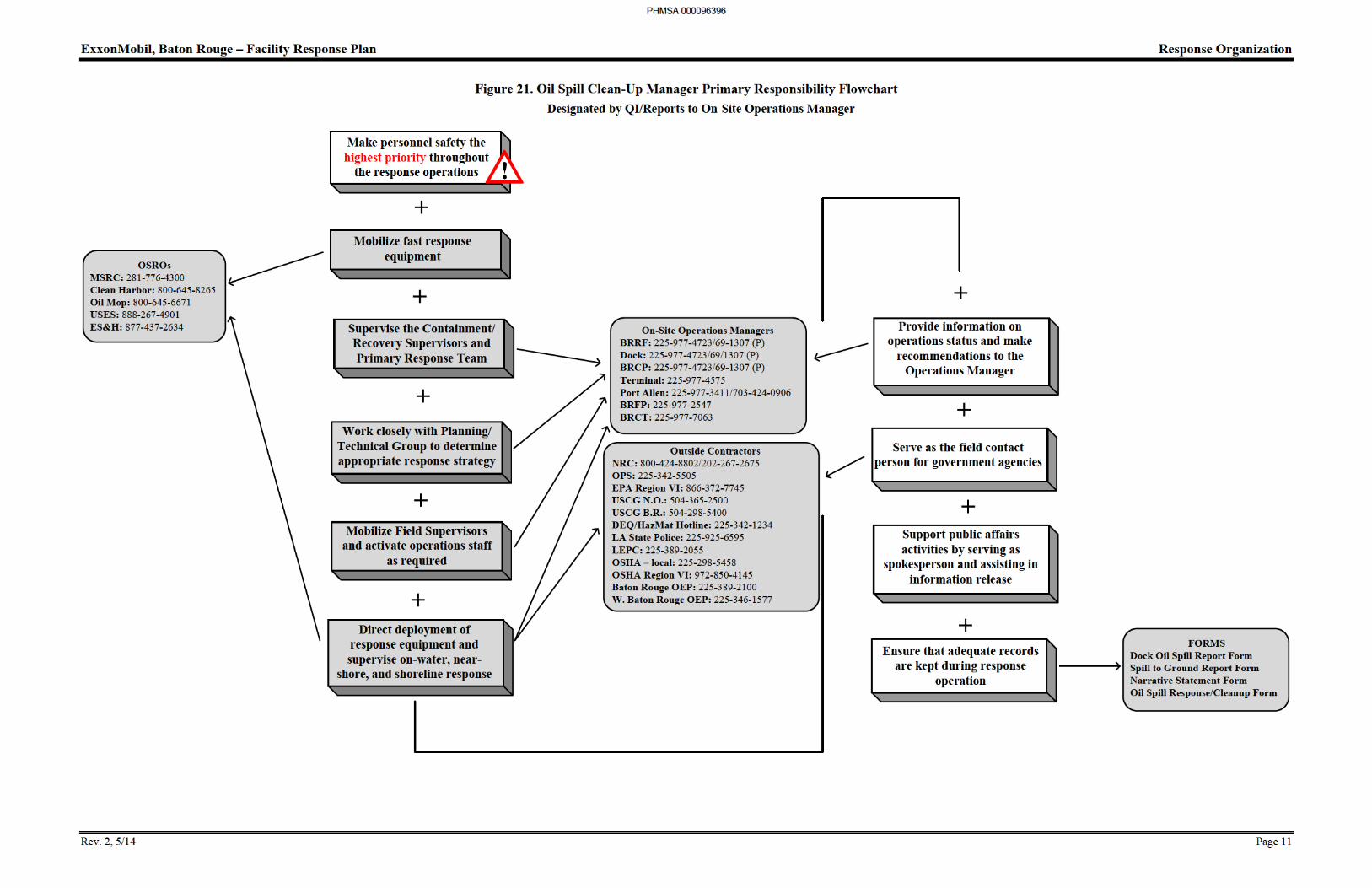
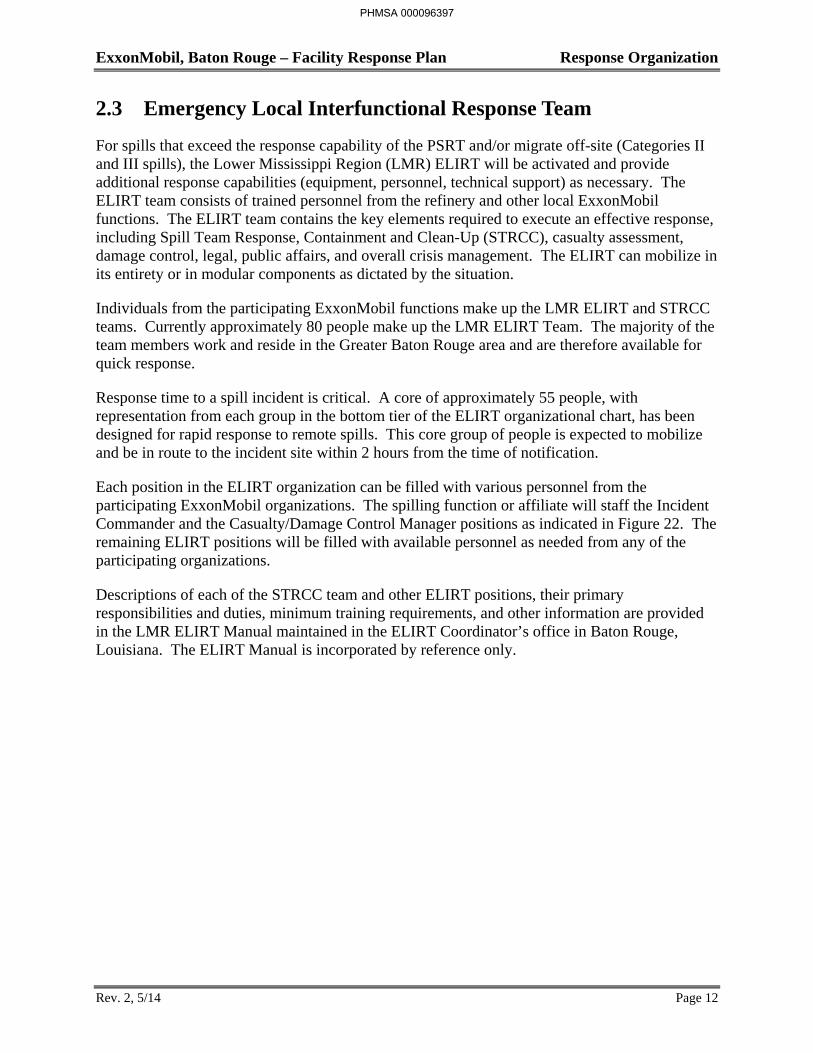
ExxonMobil, Baton Rouge – Facility Response Plan Response Organization
Rev. 2, 5/14 Page 12
2.3 Emergency Local Interfunctional Response Team
For spills that exceed the response capability of the PSRT and/or migrate off-site (Categories II and III spills), the Lower Mississippi Region (LMR) ELIRT will be activated and provide additional response capabilities (equipment, personnel, technical support) as necessary. The ELIRT team consists of trained personnel from the refinery and other local ExxonMobil functions. The ELIRT team contains the key elements required to execute an effective response, including Spill Team Response, Containment and Clean-Up (STRCC), casualty assessment, damage control, legal, public affairs, and overall crisis management. The ELIRT can mobilize in its entirety or in modular components as dictated by the situation.
Individuals from the participating ExxonMobil functions make up the LMR ELIRT and STRCC teams. Currently approximately 80 people make up the LMR ELIRT Team. The majority of the team members work and reside in the Greater Baton Rouge area and are therefore available for quick response.
Response time to a spill incident is critical. A core of approximately 55 people, with representation from each group in the bottom tier of the ELIRT organizational chart, has been designed for rapid response to remote spills. This core group of people is expected to mobilize and be in route to the incident site within 2 hours from the time of notification.
Each position in the ELIRT organization can be filled with various personnel from the participating ExxonMobil organizations. The spilling function or affiliate will staff the Incident Commander and the Casualty/Damage Control Manager positions as indicated in Figure 22. The remaining ELIRT positions will be filled with available personnel as needed from any of the participating organizations.
Descriptions of each of the STRCC team and other ELIRT positions, their primary responsibilities and duties, minimum training requirements, and other information are provided in the LMR ELIRT Manual maintained in the ELIRT Coordinator’s office in Baton Rouge, Louisiana. The ELIRT Manual is incorporated by reference only.
PHMSA 000096397
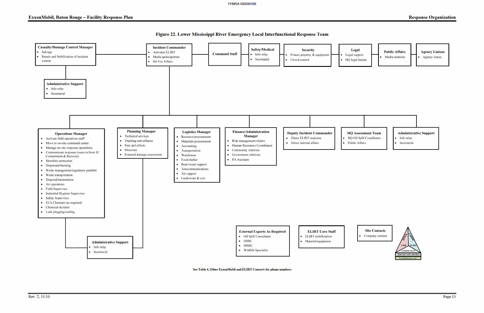
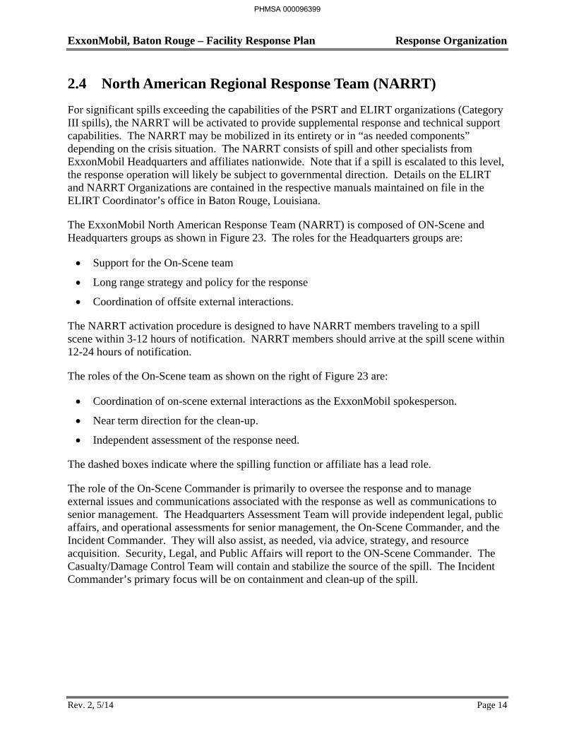
ExxonMobil, Baton Rouge – Facility Response Plan Response Organization
Rev. 2, 5/14 Page 14
2.4 North American Regional Response Team (NARRT)
For significant spills exceeding the capabilities of the PSRT and ELIRT organizations (Category III spills), the NARRT will be activated to provide supplemental response and technical support capabilities. The NARRT may be mobilized in its entirety or in “as needed components” depending on the crisis situation. The NARRT consists of spill and other specialists from ExxonMobil Headquarters and affiliates nationwide. Note that if a spill is escalated to this level, the response operation will likely be subject to governmental direction. Details on the ELIRT and NARRT Organizations are contained in the respective manuals maintained on file in the ELIRT Coordinator’s office in Baton Rouge, Louisiana.
The ExxonMobil North American Response Team (NARRT) is composed of ON-Scene and Headquarters groups as shown in Figure 23. The roles for the Headquarters groups are:
Support for the On-Scene team
Long range strategy and policy for the response
Coordination of offsite external interactions.
The NARRT activation procedure is designed to have NARRT members traveling to a spill scene within 3-12 hours of notification. NARRT members should arrive at the spill scene within 12-24 hours of notification.
The roles of the On-Scene team as shown on the right of Figure 23 are:
Coordination of on-scene external interactions as the ExxonMobil spokesperson.
Near term direction for the clean-up.
Independent assessment of the response need.
The dashed boxes indicate where the spilling function or affiliate has a lead role.
The role of the On-Scene Commander is primarily to oversee the response and to manage external issues and communications associated with the response as well as communications to senior management. The Headquarters Assessment Team will provide independent legal, public affairs, and operational assessments for senior management, the On-Scene Commander, and the Incident Commander. They will also assist, as needed, via advice, strategy, and resource acquisition. Security, Legal, and Public Affairs will report to the ON-Scene Commander. The Casualty/Damage Control Team will contain and stabilize the source of the spill. The Incident Commander’s primary focus will be on containment and clean-up of the spill.
PHMSA 000096399
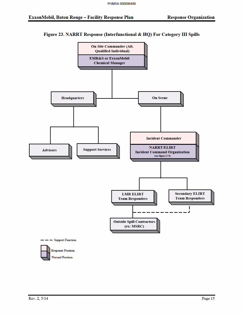

ExxonMobil, Baton Rouge – Facility Response Plan Section 2: Response Organization
TABLE OF CONTENTS
SECTION PAGE
Rev. 0, 11/10 i
Section 2: Response Organization
2.1 Introduction ........................................................................................................................ 1
2.2 Primary Spill Response Team (PSRT) ............................................................................. 2
Incident Commander (Qualified Individual) Position Description ................................ 4 On-Site Operations Manager Position Description ........................................................ 7 Oil Spill Clean-Up Manager Position Description ....................................................... 10
2.3 Emergency Local Interfunctional Response Team (ELIRT) ........................................... 12
2.4 North American Regional Response Team (NARRT) .................................................... 14
PHMSA 000096401
ExxonMobil, Baton Rouge – Facility Response Plan Section 3: Reference Material
TABLE OF CONTENTS
SECTION PAGE
Rev. 0, 11/10 i
Section 3: Reference Material
3.1 Contact Information ........................................................................................................... 1
3.2 Communications Plan ........................................................................................................ 9
Introduction ..................................................................................................................... 9 Emergency Communication Systems ........................................................................... 10 Response Management, Operations, and Logistics Communications .......................... 11 Communications Practices ............................................................................................ 13
3.3 Spill Response Procedures ............................................................................................... 17
Chemical Plant Spill Response Procedure .................................................................... 17 Mitigation/Source Control Measures ............................................................................ 22 Specific Equipment/Spill Type ..................................................................................... 23 Secondary Response Actions ........................................................................................ 29 Group V Petroleum Oils Responses ............................................................................. 33 Spill Assessment ........................................................................................................... 33 Climatic and Hydrographic Conditions ........................................................................ 34 Spill Surveillance .......................................................................................................... 35 Containment and Recovery ........................................................................................... 35 Terrestrial Spills ............................................................................................................ 42 Aquatic Spills ................................................................................................................ 45
3.4 Sensitive Areas ................................................................................................................. 51
Identification ................................................................................................................. 51 Protection ...................................................................................................................... 68 Prioritization of Sensitive Areas for Protection ............................................................ 72 Protection Technique Selection .................................................................................... 75
PHMSA 000096402
ExxonMobil, Baton Rouge – Facility Response Plan Section 3: Reference Material
Rev. 0, 11/10 Page 1
3.1 Contact Information
Overview
The tables on the following pages contain contact information for various support agencies and local officials. These tables include:
Specialized Spill Response and Support Services
Louisiana Levee Districts
Local Emergency Planning Committees
PHMSA 000096403
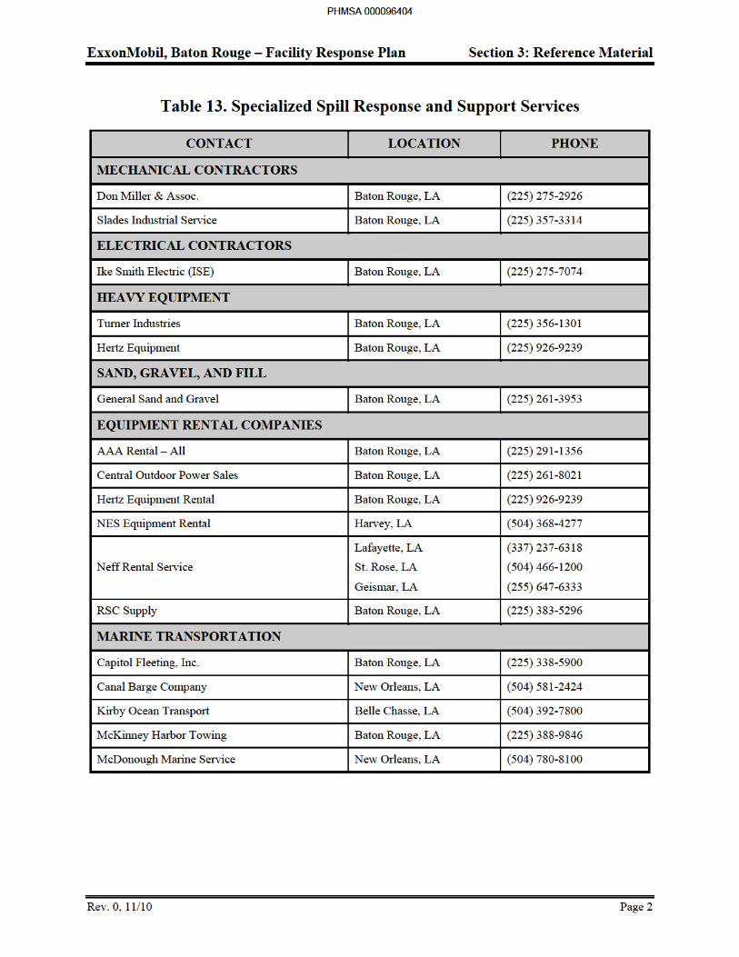
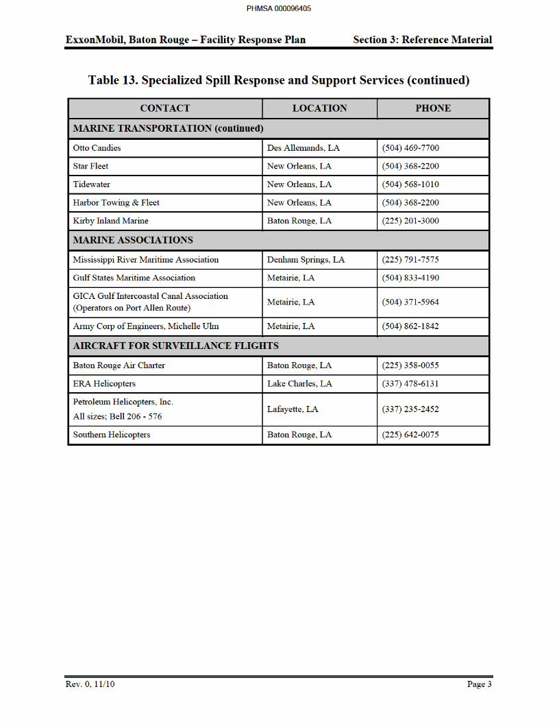
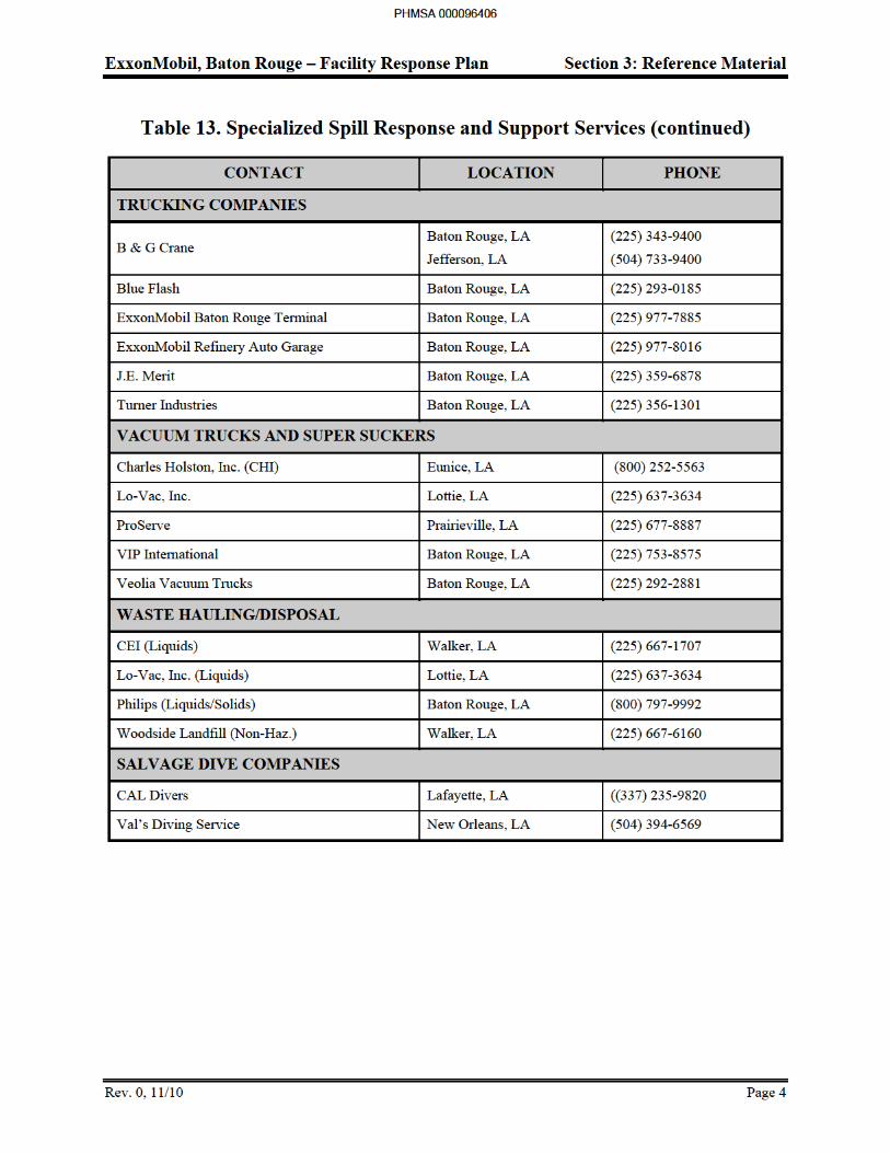
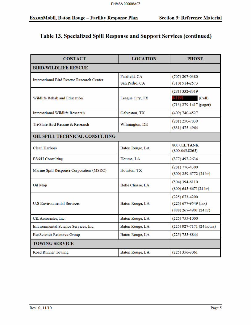
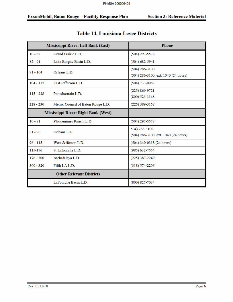
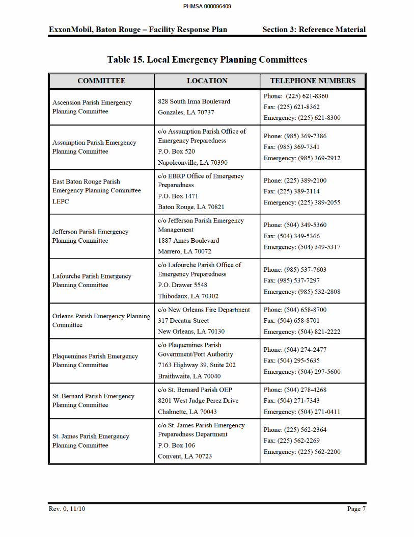
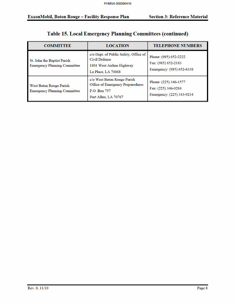
ExxonMobil, Baton Rouge – Facility Response Plan Section 3: Reference Material
Rev. 0, 12/12 Page 9
3.2 Communications Plan
Introduction
This chapter provides general information on communications during a small or large spill. The following topics are discussed:
Emergency Communication Systems
Response Management Communications
Response Operations Communications
Logistics Communications
Communications Practices
Table 16 provides general information on the amount and type of available communication equipment. Table 16 and Table 17 provide communication channels, phone numbers, and fax lines.
Day-to Day operations utilizes complex radios. Individuals should turn these alphanumeric radios to the proper channel in an emergency. Channels exist for ELIRT, EMT, Fire (the designated emergency channel for central communication), Rescue, Security, and Industrial Hygiene.
PHMSA 000096411
ExxonMobil, Baton Rouge – Facility Response Plan Section 3: Reference Material
Rev. 0, 12/12 Page 10
Emergency Communication Systems
Minor Spills
For minor spills, facility direct point-to-point communications using two or more UHF portable radios will be used. All response communications will be conducted on Channel 1 in the Refinery, and Environmental Operations in the Chemical Plant.
Larger Spills
In the unlikely event of a major spill, the Emergency Command Center will be established in the Refinery EMC (3rd floor) and/or the BRCP war room unless the spill circumstances require an alternate location. In certain situations, the Emergency Command Center may establish a remote command center near the downstream area with the greatest level of activity. In this case, ExxonMobil communications van will establish the temporary communications at the remote command center.
An advanced communications system may be required to establish an effective communications network. Communication equipment available for response activities consist of the following:
UHF hand-held radios
UHF mobile radios
UHF base stations
Scanners
Cellular phones
Facsimile machines
VHF marine base stations
VHF marine hand-held radios
VHF marine mobile radios
VHF air to ground hand-held
VHF air to ground base stations
Table 16 provides a more detailed listing of available equipment located at the Refinery and the local LMR ELIRT office. Additional equipment can be obtained if necessary. The ExxonMobil corporate office maintains an inventory of portable communications equipment specifically designed for use in an oil spill or other emergency incident.
PHMSA 000096412
ExxonMobil, Baton Rouge – Facility Response Plan Section 3: Reference Material
Rev. 0, 12/12 Page 11
Response Management, Operations, and Logistics Communications
Because of the heavy volume of radio traffic associated with a moderate to large spill response operation, one or more net control base stations and digital scanning receivers may be used. Assigning specific frequencies or phone lines to particular operations can increase the effectiveness of a communications system. Separate frequencies are often assigned to management, response operations, and logistical support.
Spill response related communications will primarily utilize the dedicated ELIRT radio channel on the complex wide radio system. Typically, activities involving response operations, logistics, and management will use this channel for radio communications.
A number of phone lines, facsimile lines and fax machines will be dedicated to response activities. Key phone and facsimile numbers will be made available on a need-to-know basis to avoid overwhelming the communication systems.
Response Management Communications
For larger spills involving extensive communication needs, one channel may be assigned for the exclusive use of response management functions. When multiple channels are used, a portable scanning receiver
may be installed at the Command Center to enable the Incident Commander and other management personnel to monitor conversations on the key response channels. Only the operating frequencies of all the parties involved in the spill are entered into the scanner to avoid scanning other refinery operations. The scanner cycles these frequencies every few seconds until one of the parties comes on the air. It then locks onto that frequency until the transmission is complete. This provides an excellent tool for anticipating operational and/or logistical problems before they develop. Scanners obtained from outside vendors may be used to document the progress of a major spill by automatically recording all radio traffic.
Response Operations Communications
Point-to-point communications in the field will be conducted with hand-held and mobile radios. Portable radios will be used by the various response team supervisors and other key response personnel, contractor supervisor, agency representatives, aircraft pilots, etc. In some cases, radios may also be issued to the state or federal On-Scene Coordinator such that personnel can communicate directly with response managers. Hand-held radios can be used for communication within close proximity (20 mile radius). Most hand-held radios are four channel models; however, some are equipped with six channels. The mobile units fitted to spill response vehicles are six channel models. A list of various UHF radio and VHF marine channels, and their frequencies are listed in Table 16. One or more portable repeaters may be used if a large area is affected. Cellular phones may also be used particularly for field supervisors where clear, concise person-to-person communication is needed. Communication in the Chemical Plant will occur on the Environmental Talk Group of the 800 mHz system.
The Emergency Response organization has Iridium satellite phones on site. The phones are active but not in-service. When a situation arises that requires satellite phone usage, the phones will be placed in service.
PHMSA 000096413
ExxonMobil, Baton Rouge – Facility Response Plan Section 3: Reference Material
Rev. 0, 12/12 Page 12
Logistics Communications
As with Operations communications, Logistics communications will be conducted on Channel #1 for small spills but may require dedicating a separate channel in the event of a large spill. In this case, one of the channels that operate off of the refinery repeaters or a portable repeater may be dedicated to Logistics. This will maximize the operating range such that Logistics personnel can be contacted while in the field, in town picking up supplies, or within the refinery/chemical plant.
PHMSA 000096414
ExxonMobil, Baton Rouge – Facility Response Plan Section 3: Reference Material
Rev. 2, 5/14 Page 13
Communications Practices
Good communications practices will be the responsibility of the Planning/Technical group or designee and Telecommunications Advisor. For small spills, the Operations Supervisor will be responsible for ensuring the response personnel follow proper communications practices.
For larger spills, a quiet atmosphere with clear connections to the Command Center will be a major consideration in locating the Communications Center. Once the Communications Center is established, the Planning/Technical group may participate in any scheduled planning meeting to determine communication requirements for the next day's operation. This should allow sufficient lead time to assemble any additional equipment that may be needed.
In any spill event, responders, managers, regulatory agency phone numbers (including cell) and radio frequencies, are continuously updated and distributed to the response team. The Incident Commander is responsible for distribution.
PHMSA 000096415
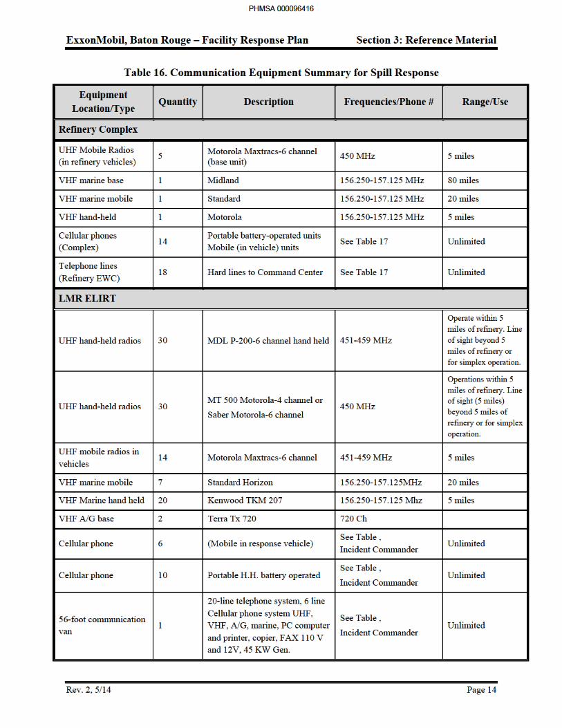
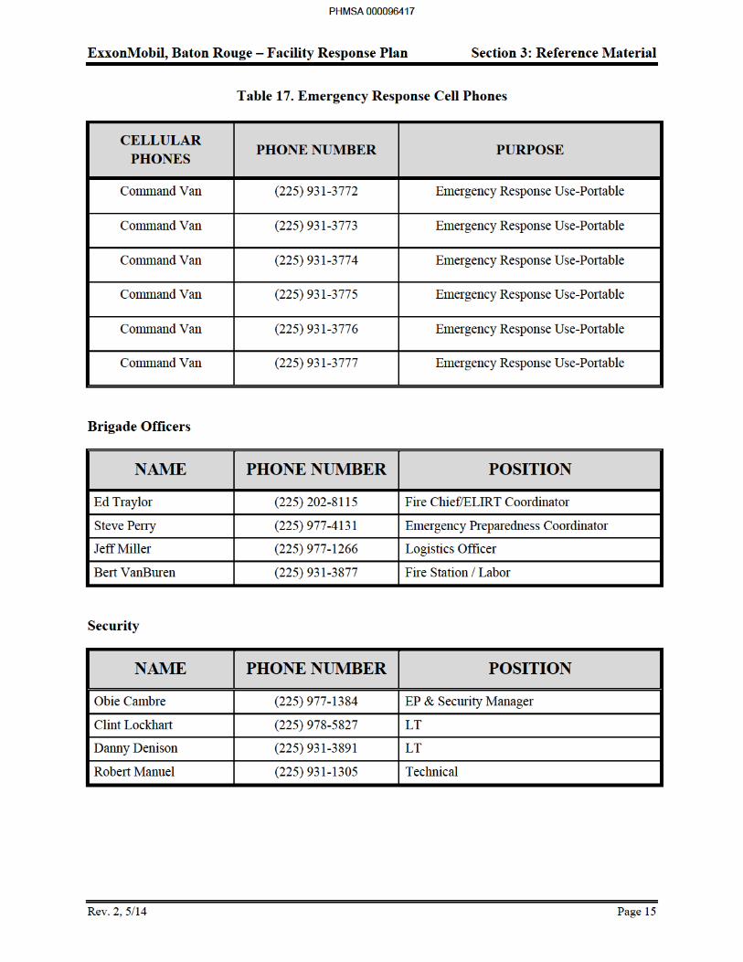
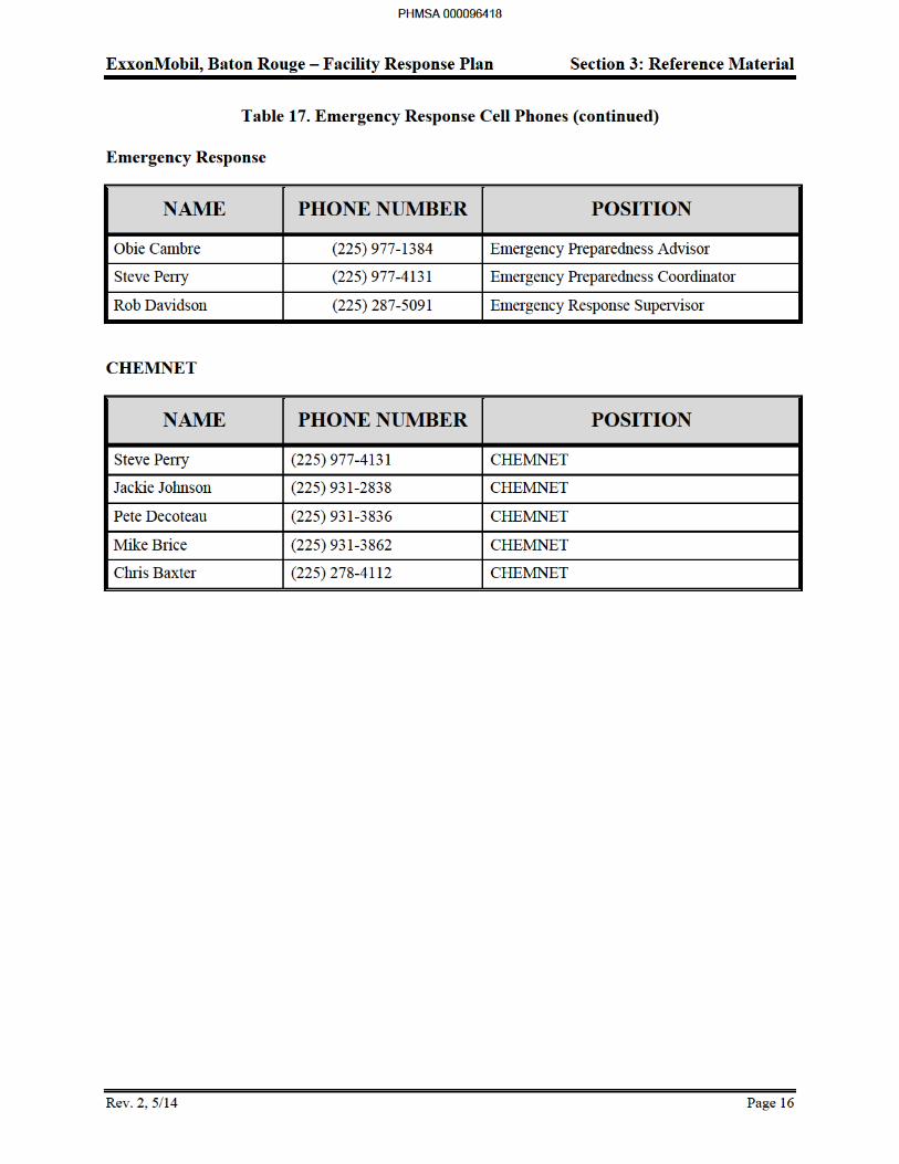
ExxonMobil, Baton Rouge – Facility Response Plan Section 3: Reference Material
Rev. 0, 11/10 Page 17
3.3 Spill Response Procedures
Chemical Plant Spill Response Procedure
Spill Observer, First Response
1. Report spill to affected Unit Supervisor and, if familiar with equipment, take action to stop, control, and/or contain oil spillage.
2. Report spill to Chemical Plant Superintendent immediately giving location, size, source (if known), and safety impact.
Chemical Plant Superintendant
1. Assume role of Incident Commander/Qualified Individual.
2. Manage the overall response for the spill incident.
3. Notify Infrastructure Supervisor and Primary Fire Squad OPS Chief to report spill site.
4. Notify agencies and management. These include:
US Coast Guard
Environmental Duty Person
State Police
National Response Center
5. Verify that the unit has taken action to contain and control the spill. This includes:
Cover sewer grate
Stop influent flow from spill
Other actions as appropriate.
6. Review the spill site with the Infrastructure Supervisor to develop clean-up plan and ensure plan is adequate.
Infrastructure Supervisor
1. Immediately report to spill site when notified.
2. If the spill threatens the Monte Sano Bayou, report directly to the Bayou and evaluate possible containment sites.
3. Evaluate the spill.
4. Communicate with the Chemical Plant Superintendent regarding the status of the spill and plans to contain/control.
5. If the spill is internal to a process operating area or zone shop, consult with the Shift Team Leader of the area to determine:
Material spilled
PHMSA 000096419
ExxonMobil, Baton Rouge – Facility Response Plan Section 3: Reference Material
Rev. 0, 11/10 Page 18
Quantity spilled
Surface area impacted by the spill
Sewers contaminated or threatened by the spill
6. If the spill reached Monte Sano Bayou, direct sampling of the Bayou at the following locations:
Within the spill
Upstream of the plant at or near the Scenic Highway bridge
Downstream of the spill
7. Direct sample personnel to:
a. Place samples in wide mouth jars.
b. Label with date, time, and location of sample.
8. Transport samples to Chemical Plant Laboratory.
Volunteer Fire Squad Team 6 OPS Chief
1. Assume the role of Operations Supervisor for all spills in the Chemical Plant that affect the Monte Sano Bayou.
2. If the spill has reached Monte Sano Bayou, determine, in conjunction with the Chemical Plant Superintendent, whether employing Docks personnel to deploy boom between the Monte Sano Bayou and the Mississippi River would be beneficial. Use the following questions to determine boom needs:
a. Is the Bayou moving toward the river?
b. Is the spill significant enough to pose a threat to the river?
c. Is oil non-water soluble?
3. If boom is to be deployed, notify Docks personnel to deploy boom if available.
a. Deploy boom only during daylight hours.
b. If Docks personnel are NOT available (I.E tying up a ship), call ELIRT to supply personnel for booming operation.
4. Request an MSDS for the spilled material from Industrial Hygiene.
5. Determine PPE requirements.
6. Request OEC to notify the Canadian National Illinois Central (CNIC) and Kansas City Southern (KCS) railroads.
7. Request Security to open the appropriate perimeter gates.
PHMSA 000096420
ExxonMobil, Baton Rouge – Facility Response Plan Section 3: Reference Material
Rev. 0, 11/10 Page 19
8. Direct clean up/recovery of spilled material. Spills exceeding the capability of the on-site response team, or which require on-site supervision for an extended period of time should be referred to ELIRT or an appropriate OSRO for containment and clean-up.
9. After spill cleanup is complete, review spill site with the Chemical Plant Superintendent to ensure the site has been adequately cleaned.
10. Ensure decontamination of both personnel and equipment used in support of the spill.
11. In conjunction with the Chemical Plant Superintendent, declare the spill incident over.
12. Complete Spill Response Checklist (Attachment 1 of BRCP-EP-0641) and prepare a short narrative of the event. This narrative should include:
a. Names of personnel who responded
b. Identity of equipment employed
c. Chronology of mitigation and clean up efforts
13. Send a copy of the completed Spill Response Checklist to Environmental Section.
Refer to the following figures for Chemical Plant Spills:
PHMSA 000096421
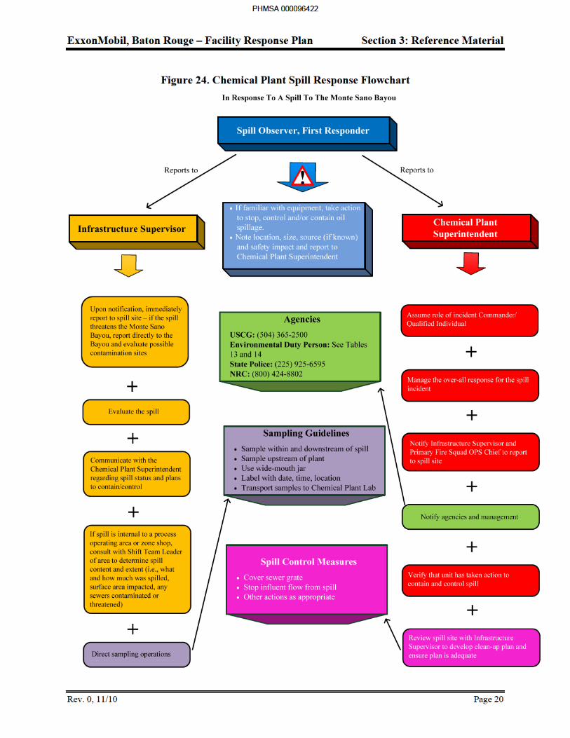
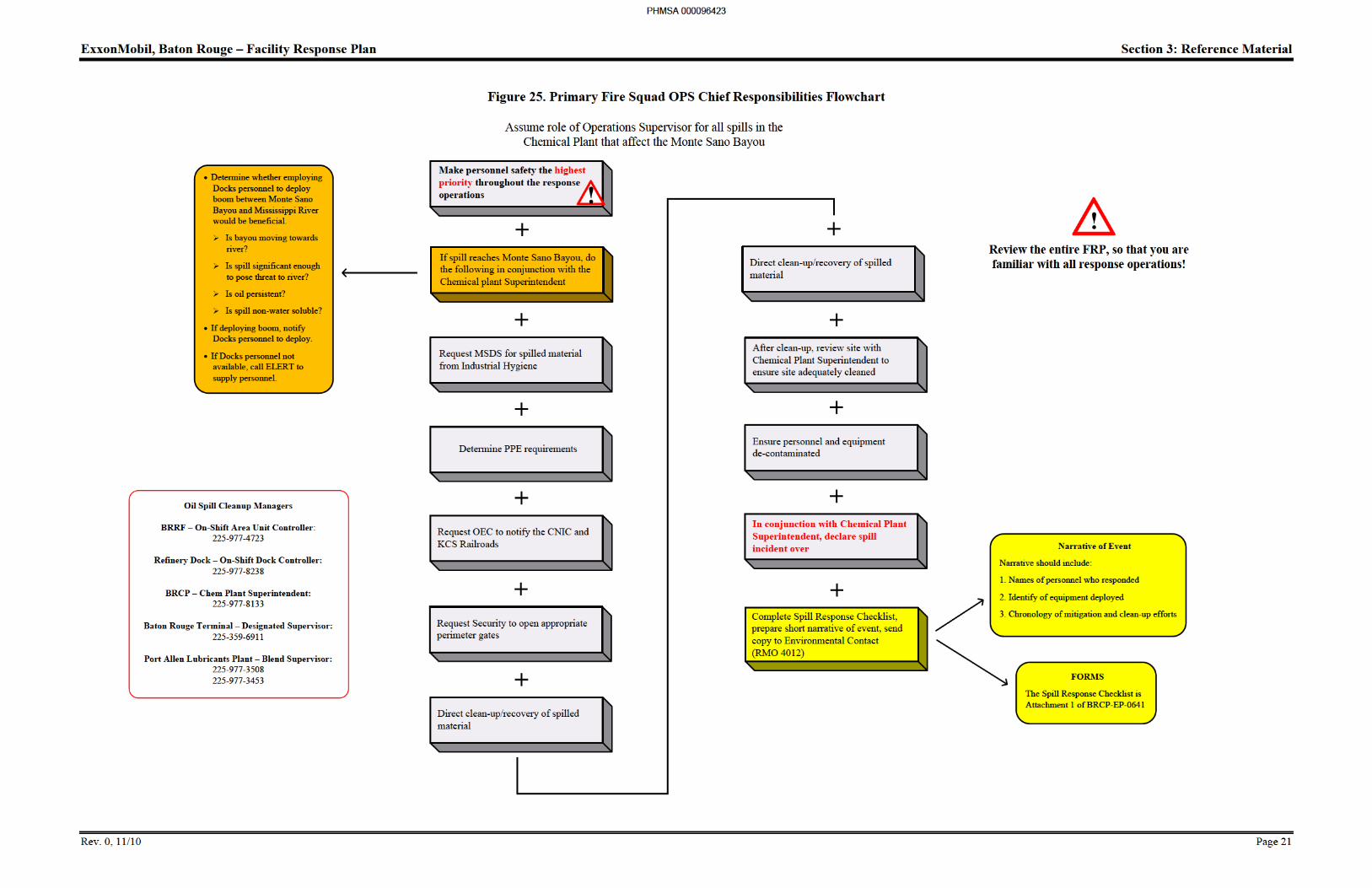
ExxonMobil, Baton Rouge – Facility Response Plan Section 3: Reference Material
Rev. 0, 11/10 Page 22
Mitigation/Source Control Measures
In the event of a spill, several immediate response actions should be taken to control the spill at the source and mitigate the potential consequences. These actions include measures to ensure human health and safety, control the spill, and protect the local environment.
Immediate response procedures have been identified for various types of spills as follows:
General spills
Spills associated with different types of equipment (tanks, pipelines, transfer equipment)
Different types of spills (tank overfills, failures, piping leaks)
Spills at specific locations at the refinery (dock or tank farms)
Whenever possible contain and recover spilled material in the immediate area in which the spill occurred. For extremely volatile materials such as gasoline, make efforts to disperse the material and/or vapors due to the imminent danger of ignition.
Additional response actions or strategies to be considered and implemented by trained personnel only in the event of a spill are described below:
For most spills or leaks, contain release by closing valves to shut off the source, opening valves to bypass the leak, and/or using dikes or berms.
For fire or explosion hazard, use water fog to disperse vapors or foam to blanket vapors.
For large spills, contain release by digging ditches or constructing berms to divert the flow to a suitable retaining area.
For some smaller and/or volatile product spills, flush the spilled material into the sewer system (must first receive authorization from the QI or Operations Manager and also alert the Environmental Utilities, Louisiana (EULA) for BRRF and wastewater treatment plant operator for BRCP).
For heavy products, spills may be left to solidify to facilitate subsequent recovery and disposal. For flammable products, recovery actions should only be taken with the fire brigade standing by and while using non-sparking and explosion proof mechanical devices.
For spills that do not present a fire hazard, use local contractors for cleanup.
For large spills that enter the sewer system, alert the EULA for BRRF and the Advanced Wastewater Treatment (AWT) plant operator for BRCP.
PHMSA 000096424
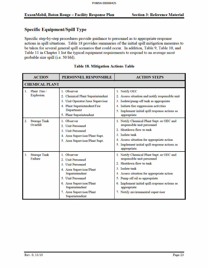
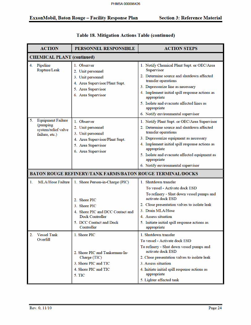
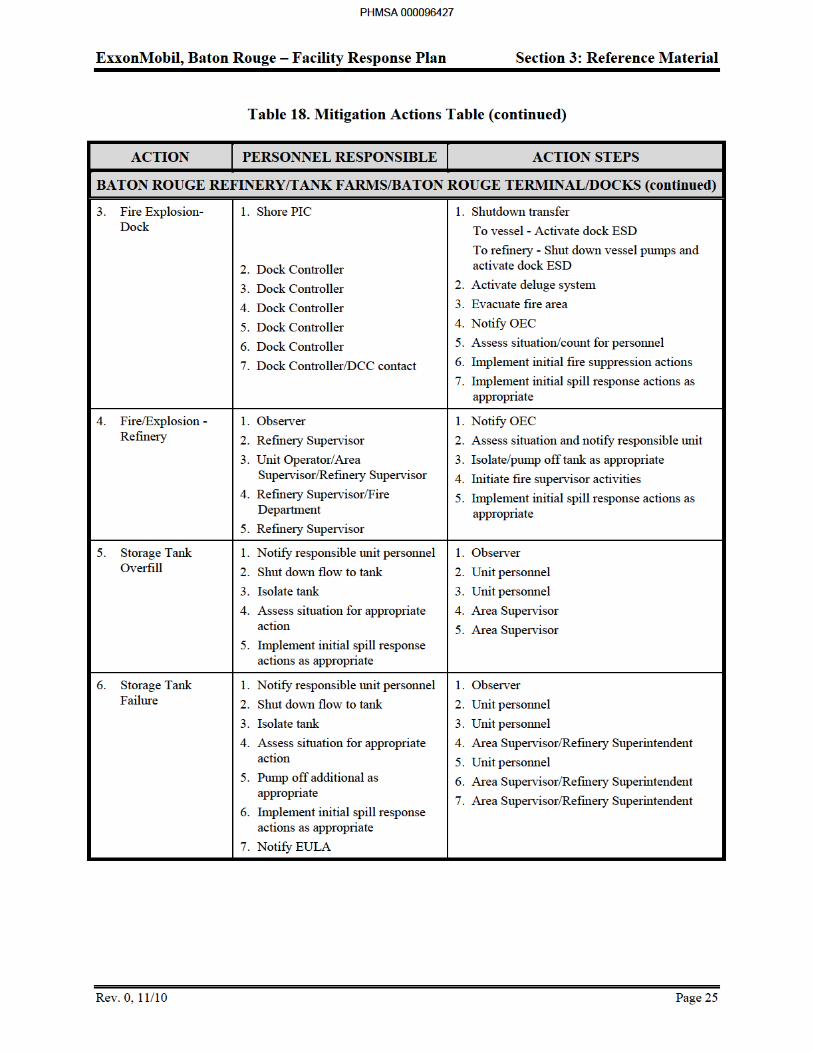
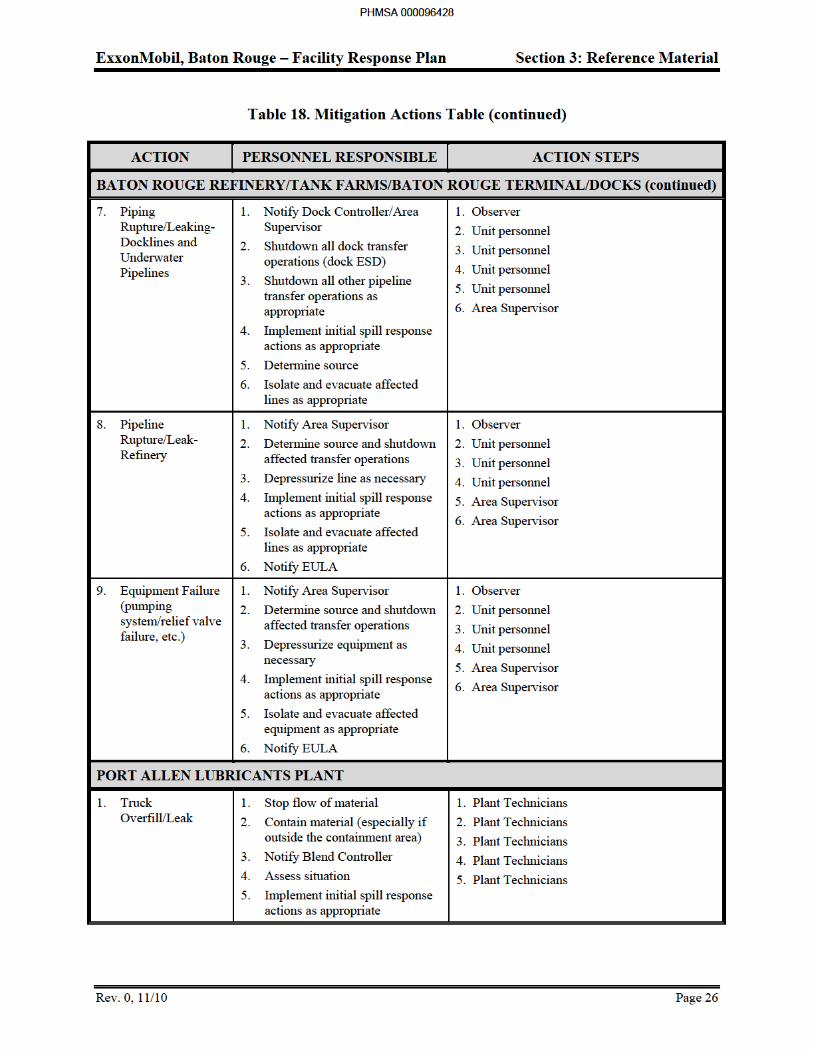
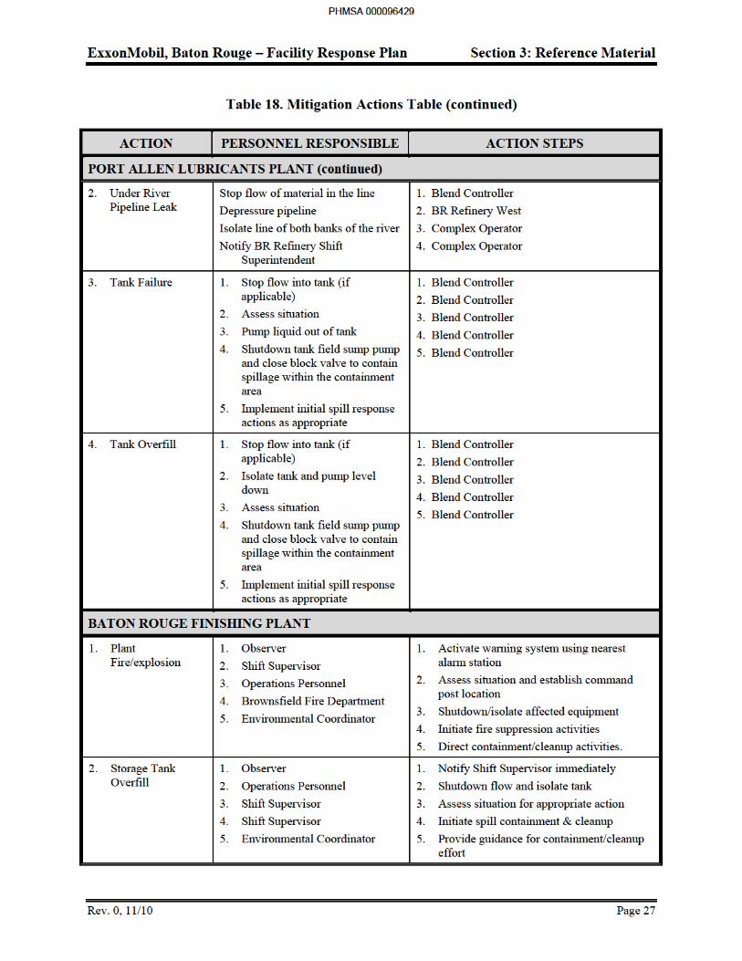
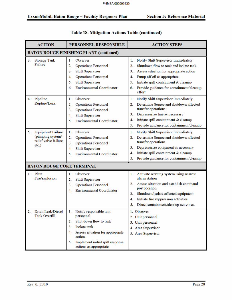
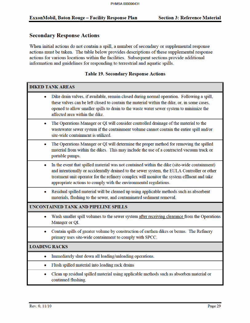
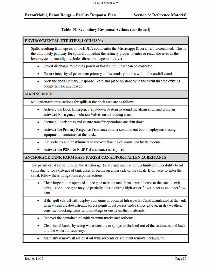
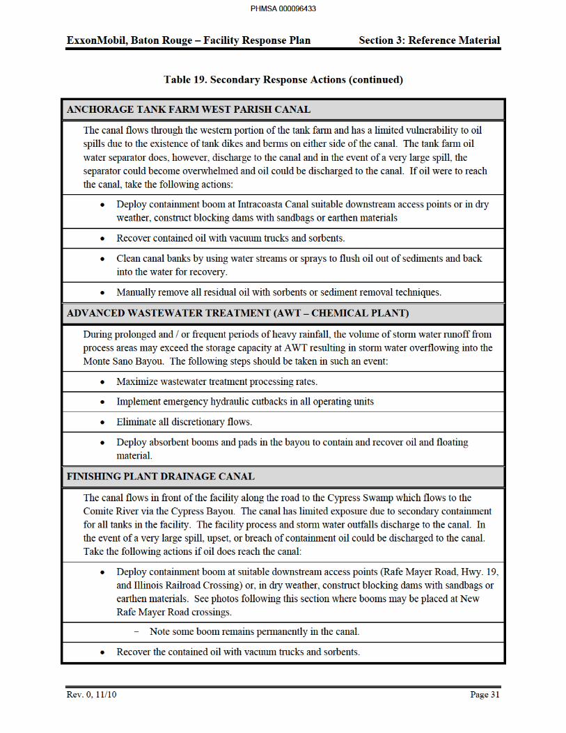
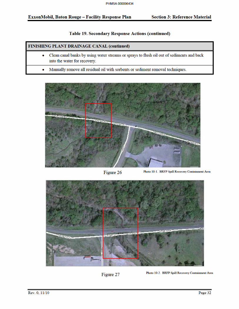
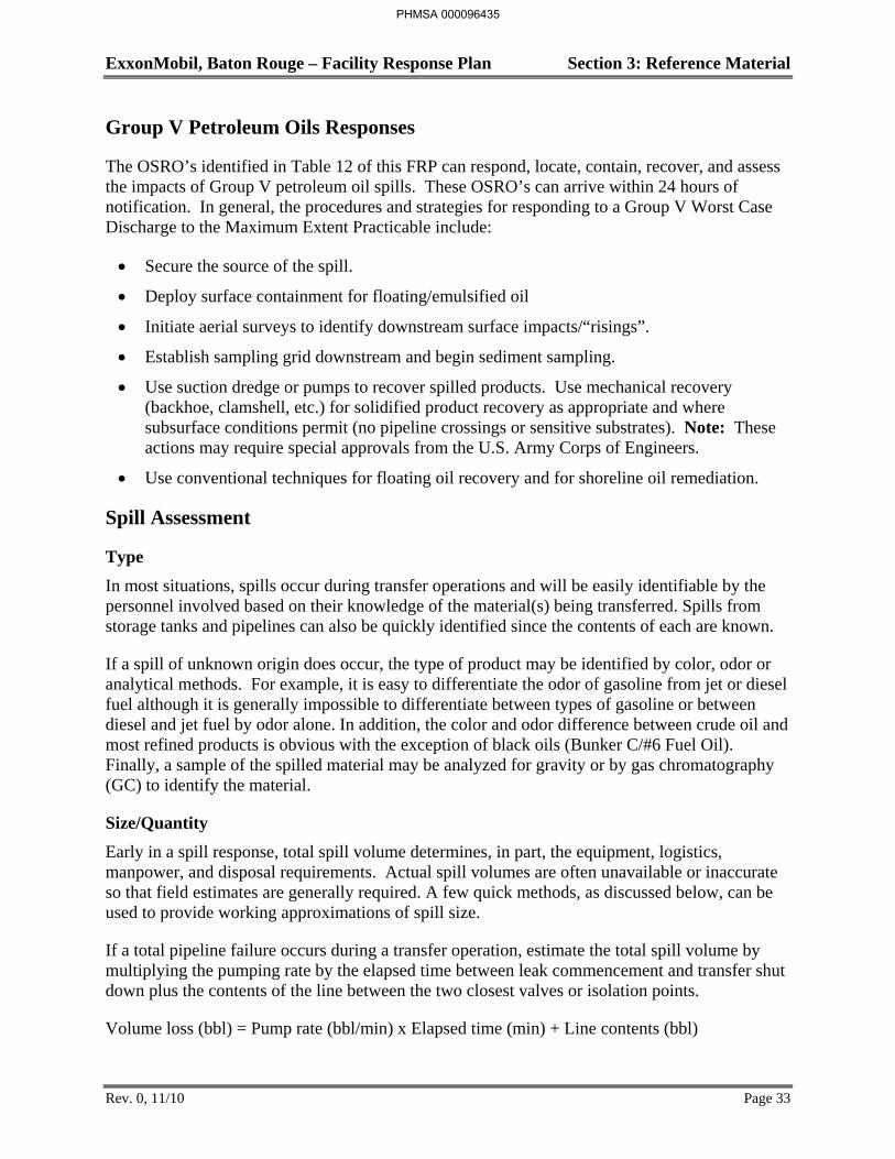
ExxonMobil, Baton Rouge – Facility Response Plan Section 3: Reference Material
Rev. 0, 11/10 Page 33
Group V Petroleum Oils Responses
The OSRO’s identified in Table 12 of this FRP can respond, locate, contain, recover, and assess the impacts of Group V petroleum oil spills. These OSRO’s can arrive within 24 hours of notification. In general, the procedures and strategies for responding to a Group V Worst Case Discharge to the Maximum Extent Practicable include:
Secure the source of the spill.
Deploy surface containment for floating/emulsified oil
Initiate aerial surveys to identify downstream surface impacts/“risings”.
Establish sampling grid downstream and begin sediment sampling.
Use suction dredge or pumps to recover spilled products. Use mechanical recovery (backhoe, clamshell, etc.) for solidified product recovery as appropriate and where subsurface conditions permit (no pipeline crossings or sensitive substrates). Note: These actions may require special approvals from the U.S. Army Corps of Engineers.
Use conventional techniques for floating oil recovery and for shoreline oil remediation.
Spill Assessment
Type
In most situations, spills occur during transfer operations and will be easily identifiable by the personnel involved based on their knowledge of the material(s) being transferred. Spills from storage tanks and pipelines can also be quickly identified since the contents of each are known.
If a spill of unknown origin does occur, the type of product may be identified by color, odor or analytical methods. For example, it is easy to differentiate the odor of gasoline from jet or diesel fuel although it is generally impossible to differentiate between types of gasoline or between diesel and jet fuel by odor alone. In addition, the color and odor difference between crude oil and most refined products is obvious with the exception of black oils (Bunker C/#6 Fuel Oil). Finally, a sample of the spilled material may be analyzed for gravity or by gas chromatography (GC) to identify the material.
Size/Quantity
Early in a spill response, total spill volume determines, in part, the equipment, logistics, manpower, and disposal requirements. Actual spill volumes are often unavailable or inaccurate so that field estimates are generally required. A few quick methods, as discussed below, can be used to provide working approximations of spill size.
If a total pipeline failure occurs during a transfer operation, estimate the total spill volume by multiplying the pumping rate by the elapsed time between leak commencement and transfer shut down plus the contents of the line between the two closest valves or isolation points.
Volume loss (bbl) = Pump rate (bbl/min) x Elapsed time (min) + Line contents (bbl)
PHMSA 000096435
ExxonMobil, Baton Rouge – Facility Response Plan Section 3: Reference Material
Rev. 0, 11/10 Page 35
Spill Surveillance
Begin surveillance of large aquatic spills as soon as possible after discovery of a spill to enable the Incident Manager and other response personnel to track movements and develop and maintain an effective response plan. Spill trajectory estimates are also a critical component of response planning and implementation particularly with respect to the protection of sensitive areas.
Spill surveillance is best accomplished through the use of helicopters or small planes. Helicopters are preferred due to their superior visibility and maneuverability. If fixed-wing planes are to be used, the wing-over types provide significantly better visibility. Document all significant observations both in writing and with photographs and/or video equipment. Photocopy the sensitive area maps provided (Figures 31 - 43) and use as base maps to record aerial observations unless other maps (topographic maps or nautical charts) are available.
Reduced visibility conditions such as dense fog or low cloud cover require other methods of surveillance. If the spill does not involve gasoline or other highly flammable products, boats may be used to patrol the area and document the location and movements of the spill. Vehicles may also be used to observe the water from various vantage points although reduced visibility will also tend to limit the effectiveness of this method.
Containment and Recovery
Containment and recovery refers to the techniques or methods employed to contain and recover floating material or material flowing overland. Recovery of terrestrial spills is addressed in Table 21, Summary of Containment and Recovery Techniques. Containment is most effective when conducted near the source of the spill where the material has not spread over a large area and the contained material is of sufficient thickness to allow effective recovery and/or cleanup. The feasibility of effectively implementing containment and recovery techniques is generally dependent on the size of the spill, available logistical resources, implementation time, and environmental conditions or nature of the terrain in the spill area. A containment and recovery operation implementation guide is shown in Figure 28.
Aquatic spill containment is accomplished primarily through the use of spill containment booms and damming techniques. Skimmers are usually the most efficient means of recovery although pumps, vacuum systems, and sorbents can also be effective. For terrestrial spills, sorbent booms or materials, trenches and earthen berms, or other physical barriers are most often used to contain material migrating on the ground surface. Recovery of free material from the ground surface is best achieved by using pumps, vacuum trucks, and/or sorbents as discussed. The terrestrial containment and aquatic containment and recovery techniques applicable to the Baton Rouge Refinery Complex and the Baton Rouge Chemical Plant area are summarized in Table 21. Some techniques are applicable to both terrestrial and aquatic containment and, consequently, have been listed twice.
PHMSA 000096437
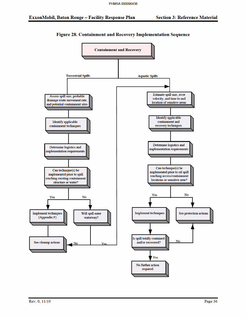
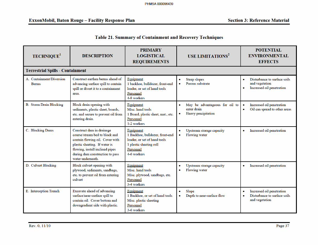
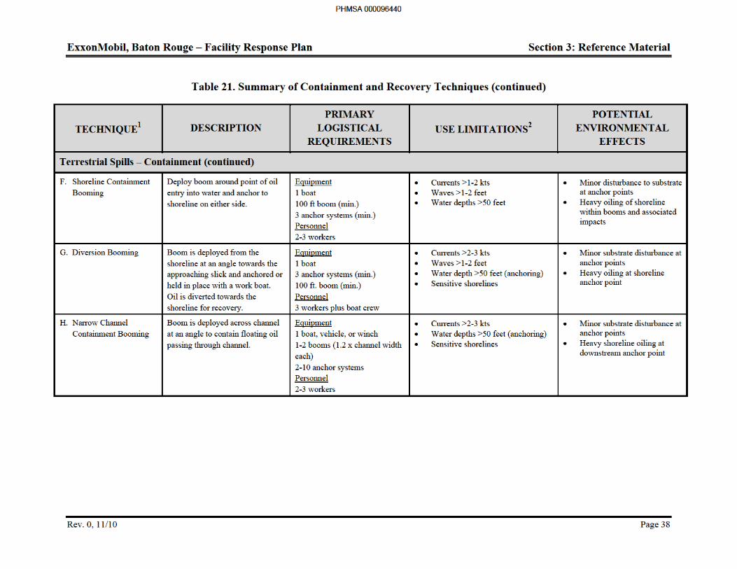
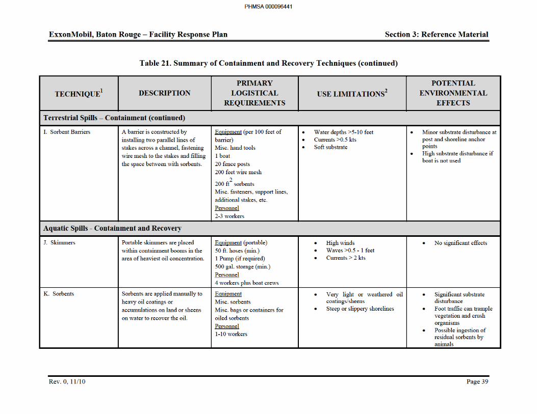
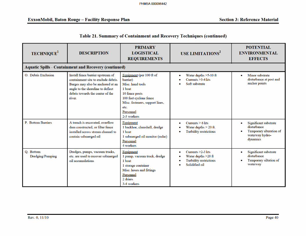
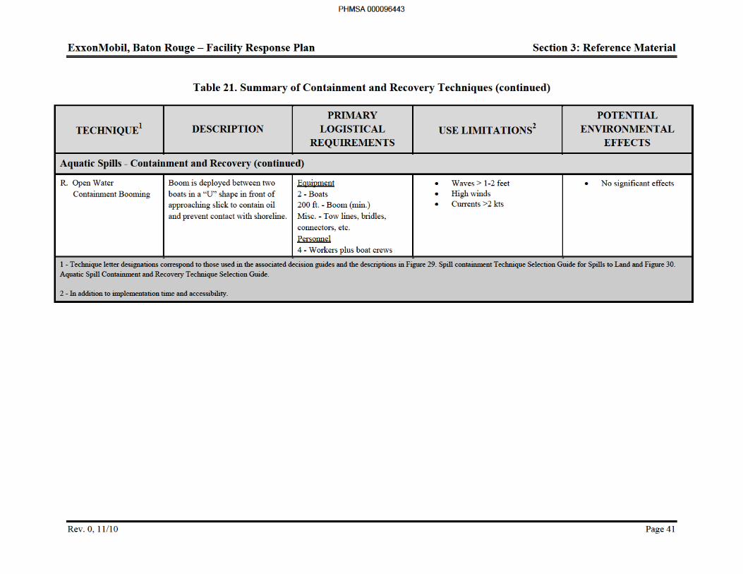
ExxonMobil, Baton Rouge – Facility Response Plan Section 3: Reference Material
Rev. 0, 11/10 Page 42
Terrestrial Spills
Containment dikes, curbs, or some form of secondary containment system surround all storage tanks and the truck and rail car loading/unloading areas. A sewer or runoff collection system services the diked storage tank areas and most of the complex facilities in general. These containment systems are designed for the collection and containment of surface runoff including spills and the diversion of such runoff to the Wastewater Treatment Unit at the Chemical Plant or EULA unit at the Refinery or some form of oil/water separation or treatment system at the outlying facilities.
ExxonMobil design standards require that tanks be located at least 100 feet from property lines if spillage from those tanks could endanger adjacent property. Berms have also been constructed in areas near property lines to provide further safeguards against offsite migration. For spills within the refinery proper, a levee on the western boundary protects the Mississippi River from the runoff of spills and oily rainwater. For spills at the Chemical Plant, controlled drainage systems that divert runoff from process areas to process wastewater sewers protect the Monte Sano Bayou from the runoff of spills and oil rainwater. These measures and others minimize the potential for an uncontained terrestrial spill to occur within the complex boundaries or to migrates offsite.
In general, containment and recovery of terrestrial spills is usually best achieved by using sorbent booms/materials, earthen containment berm, trenches, or physical barriers within a natural or manmade drainage course. This method is generally preferable as the oil is already partially contained and concentrated. The presence of existing drainage courses or containment structures is often critical to the effective containment of large terrestrial spills as most containment techniques for flat surfaces do not provide a significant amount of storage capacity.
In the case of minor spills, it is often preferable to direct a spill towards the nearest process sewer inlet to facilitate spill containment and recovery. Approval from the Operations or Incident Managers and Environmental Shift Supervisors is needed for this containment and recovery technique at all facilities. For all spills that are directed to, or naturally enter the sewer system, the EULA operator for BRRF and/or the BRCP Wastewater Treatment Plant operator should be alerted to the situation immediately so that the appropriate actions can be taken to handle the incoming oil. In this situation, the FRP will be activated to contain any release should a spill occur.
Technique Selection
The primary factors influencing terrestrial containment and recovery are as follows:
Size - Most containment techniques provide limited storage capacity.
Slope - Berms and barriers are generally less effective on steeper slopes and accessibility may be limited.
Surface texture - Rough surfaces with natural ridges and depressions enhance containment and should be taken advantage of whenever possible.
PHMSA 000096444
ExxonMobil, Baton Rouge – Facility Response Plan Section 3: Reference Material
Rev. 0, 11/10 Page 43
Substrate permeability - Highly permeable sediments will allow rapid penetration of oil into the substrate thus complicating containment and recovery.
Existing drainage courses - Oil is more easily contained and recovered if it is flowing within, or can be diverted to, existing natural or manmade drainage structures.
Storm water runoff - Runoff generally requires the containment of larger quantities of liquids and complicates oil recovery.
A selection guide for spill containment and recovery techniques for spills to land is given in Figure 29. If alternative response strategies such as in-situ burning or dispersants are needed, Federal and State permission will be obtained as provided for in the applicable ACP Procedures for obtaining an expedited decision on use of dispersants.
PHMSA 000096445
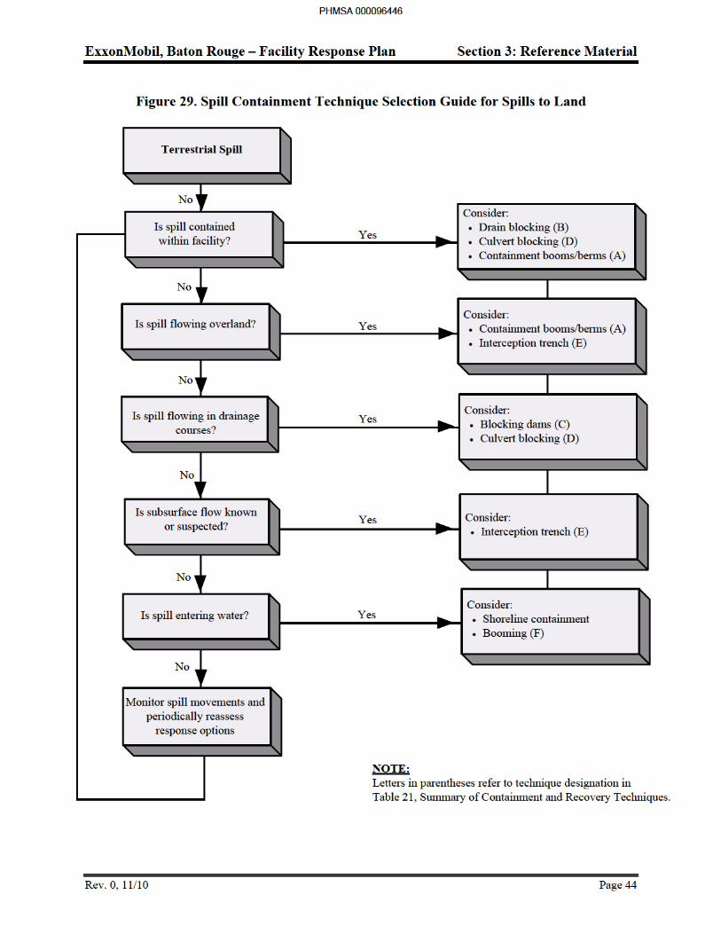
ExxonMobil, Baton Rouge – Facility Response Plan Section 3: Reference Material
Rev. 0, 11/10 Page 45
Aquatic Spills
Effective containment and recovery of aquatic spills depends, in part, on the spill circumstances, how quickly the techniques can be implemented, and the prevailing environmental conditions. Regardless of the size of the spill, containment is most effective if conducted at or near the source before the spill migrates a significant distance downstream. The larger the area covered by the spill, the more equipment and manpower will be required. Containment at or near the source is also often associated with thicker layers of oil within the containment booms which, in turn, increases the efficiency of most skimmers. Away from the source, the oil will spread to very thin layers or sheen making recovery difficult, even with sorbents. The prevailing environmental conditions can affect containment and recovery both in terms of effectiveness and deployment of equipment. The relatively high prevailing currents along the Mississippi River will generally complicate booming operations in most areas along the main portion of the river. In high currents and/or winds, equipment deployment is difficult and often times unsafe. Wind and currents can add significant tension on containment booms making it difficult to deploy and anchor the booms in place or connect sections of boom together in the water. Strong currents can cause entrainment of oil in the water stream flowing beneath the boom, resulting in ineffective containment or boom failure. Shallow water can cause the boom to "lay down," which also allows oil to pass underneath.
The primary aquatic spill concerns are releases to the following:
BRRF
Mississippi River - Refinery Dock/Callahan’s Bayou
BRCP
Monte Sano Bayou - Baton Rouge Chemical Plant
Mississippi River - Baton Rouge Chemical Plant
BRFP
Ash Slough – Baton Rouge Finishing Plant
Cypress Bayou - Baton Rouge Finishing Plant
Comite River - Baton Rouge Finishing Plant
ATF and PAL
Parish Canal – Anchorage Tank Farm and Port Allen Lubes
Intracoastal Waterway - Anchorage Tank Farm and Port Allen Lubes
BRCT
Mississippi River – Baton Rouge Coke Terminal
Mississippi River Containment Strategies
The Baton Rouge Refinery dock is approximately 0.5 mile in length and can service a number of tankers and/or barges simultaneously. Therefore, containment of spills at the dock could be complicated by the presence of other vessels.
PHMSA 000096447
ExxonMobil, Baton Rouge – Facility Response Plan Section 3: Reference Material
Rev. 0, 11/10 Page 46
Approximately 1,700 feet of 18-inch oil spill containment boom is stored at various locations at or near the dock. Response boats are also stationed at the dock to implement deployment of containment booms. Although booms may not effectively contain oil in strong currents, they are valuable in diverting oil to lower current areas where it can be contained and recovered.
The general spill containment strategies that should be used during vessel transfer operations at the dock are described below. These practices are general and are not intended to replace the judgment of the Incident or Operations Manager. During very low river stages or when oil is trapped between two barges, it may be desirable to use a boom to contain the oil rather than divert it.
For spills at the outside berths - Deploy the boom to divert the oil toward the dock by securing one end of the boom to the outside of a moored vessel and securing the other end to the dock downstream of the vessel. The intent is to divert oil along the boom and towards the dock rather than contain the oil within the boom.
For spills under the dock - Deploy the boom in a containment ("U") configuration by securing one end to the outside of the dock and the other end to the inside. Because the dock serves to slow the currents significantly, booming in this manner under the dock can be an effective means of spill containment and should be followed immediately by recovery with sorbents or skimmers.
For spills on the inside of the dock - Deploy the boom at an angle to divert oil toward the bank along the east bank by securing one end of the boom to the inside of the dock or a moored vessel and the other end to a point on the bank a considerable distance downstream. Once the oil reaches the calm area, it can be contained using another boom and then recovered with sorbents or skimmers.
For spills on the dock - Take appropriate action to prevent oil from reaching the river. Wash light to moderate oils down the deck drains and into the catch basins. Heavy oil may plug the drains and should be excluded from these areas and contained and recovered with sorbents.
For spills on the deck of a barge or vessel - Take appropriate action to prevent oil from reaching the river including plugging deck scuppers and placing sorbent materials on and around the spilled oil.
For spills from the BRCP - Large spills from the chemical plant that escape containment in the Monte Sano Bayou could enter the Mississippi River and affect downstream areas.
If a spill was large and/or escaped containment, the following strategies could be employed to contain and recover the floating oil at downstream locations:
Conduct a trajectory analysis to estimate initial spill movements and probable location(s) for shoreline contact.
Deploy diversion booms (Technique G) at estimated shoreline contact points. Barges may also be anchored at an angle into the current to divert oil to the shoreline.
Use bridge abutments, piers, and/or anchored barges whenever possible to anchor boom in place.
PHMSA 000096448
ExxonMobil, Baton Rouge – Facility Response Plan Section 3: Reference Material
Rev. 0, 11/10 Page 47
Divert oil into inlets, coves, and areas behind spits or piers extending into the water where back eddies will tend to temporarily trap oil and currents are low enough for containment booming (Technique G).
Divert oil into side channels or sloughs to facilitate containment (Technique G) if currents are not excessive and area is not environmentally sensitive.
Establish diversion booming sites on the outside shorelines of river bends where oil will naturally concentrate.
Recover heavy oils with dip nets and sorbents.
Contain Group V oils (sinkers) with fishing nets, silt curtains, or wire mesh screen anchored to the bottom downstream of the spill (Technique P).
In the unlikely event that a spill reaches the lower portions of the Mississippi River where the river is generally wider and currents are moderated at times by tidal influences, containment, and/or recovery may be accomplished using open water containment booming procedures as described in Technique G in Table 21, Summary of Containment and Recovery Techniques.
Monte Sano Bayou Containment Strategies
The Monte Sano Bayou is a small waterway that drains the local area to the north of the BRCP and discharges to the Mississippi River approximately one mile to the west of the chemical plant. The bayou runs along the base of a cut in the otherwise flat terrain at the north end of the chemical plant and resembles a small stream until it approaches the river where it widens into a bayou or slough before reaching the river. Spills that escape containment on the north side of the BRCP could enter the bayou and migrate towards the Mississippi River.
The general strategies for containing oil spills to the Monte Sano Bayou include the following:
Notify BRCP QI; which in turn activates Dock Personnel to respond.
Depending on river levels, deploy containment booms at the closest access point to the source of the spill and several other secondary locations between the source and the river.
Construct blocking dams (underflow or overflow), time permitting, to contain the oil along the narrower portions of the bayou.
Construct sorbent barriers along the bayou if water depths preclude containment boom deployment and dam construction is not feasible.
If the water flow in the bayou is high and/or containment actions cannot be implemented upstream, containment booms should be deployed in the wider and lower current portion of the bayou near its confluence with the Mississippi River. Booms should be deployed at an angle to the current with the downstream end on the south side of the bayou which is more accessible than the northern side and generally has less shoreline vegetation that could become oiled. Booms may also be deployed in a "U" configuration at the head of the slough near the river to contain the oil as it flows into the slough. Vacuum trucks and/or portable skimmers and storage tanks can be positioned along the south shore of the bayou to recover the oil from the booms and transport it back to the chemical plant for interim storage prior to recycling or disposal.
PHMSA 000096449
ExxonMobil, Baton Rouge – Facility Response Plan Section 3: Reference Material
Rev. 0, 11/10 Page 48
Comite River Containment Strategies
For spills from the BRFP - Large spills from the BRFP plant that escape containment in the Cypress Bayou could enter the Comite River and affect downstream areas.
If a spill was large and/or escaped containment at the facility, the following strategies could be employed to contain and recover the floating oil at downstream locations:
Conduct a trajectory analysis to estimate initial spill movements and probable location(s) for shoreline contact.
Deploy diversion booms at estimated shoreline contact points.
Use bridge abutments, piers, and/or anchored barges whenever possible to anchor boom in place.
Divert oil into inlets, coves, and areas behind spits or piers extending into the water where back eddies will tend to temporarily trap oil and currents are low enough for containment booming (Technique G).
Divert oil into side channels or sloughs to facilitate containment (Technique G) if currents are not excessive and area is not environmentally sensitive.
Establish diversion booming sites on the outside shorelines of river bends where oil will naturally concentrate.
Recover heavy oils with dip nets and sorbents.
Contain Group V oils (sinkers) with fishing nets, silt curtains, or wire mesh screen anchored to the bottom downstream of the spill (Technique P).
In the unlikely event that a spill reaches the lower portions of the Comite River where the river is generally wider and currents are moderated at times by tidal influences, containment, and/or recovery may be accomplished using open water containment booming procedures as described in Technique G in Table 21, Summary of Containment and Recovery Techniques.
Technique Selection: Selection of an appropriate aquatic containment and recovery technique depends on a number of factors including:
Current speed - Surface currents greater than 1 mph can cause boom failure or entrainment of oil beneath the boom, where booms are placed at right angles to the current. When angled into or away from the current, booms can generally tolerate currents up to 2 to 3 mph before failure occurs.
Water depth - Depths greater than 50 feet can complicate boom anchor placement, whereas depths less than 2 feet can preclude effective boom use. Depths less than 5 to 10 feet can also preclude the use of larger boats for logistical purposes.
Channel width - Widths greater than 200 to 300 feet will generally preclude using booms to completely contain oil floating in the waterway, particularly if strong currents are present.
PHMSA 000096450
ExxonMobil, Baton Rouge – Facility Response Plan Section 3: Reference Material
Rev. 0, 11/10 Page 49
Slick thickness - Recovery effectiveness with pumps/vacuum systems and skimmers decreases as slick thickness decline, becoming relatively ineffective for very thin slicks or sheens.
Shoreline access - Obstacles (rocks, debris, man-made structures, etc.) in the water or steep or densely vegetated shorelines could restrict access and present safety and operational problems.
Anchor points - Soft bottom substrates can complicate boom anchor placement.
Safety - High currents and winds, large obstacles, and other dangerous conditions could present safety hazards and preclude certain techniques.
Based on the above factors, a containment and recovery technique selection guide has been prepared and is shown in Figure 30. If alternative response strategies such as in-stu burning or dispersants are needed, Federal and State permission will be obtained as provided for in the applicable ACP.
PHMSA 000096451
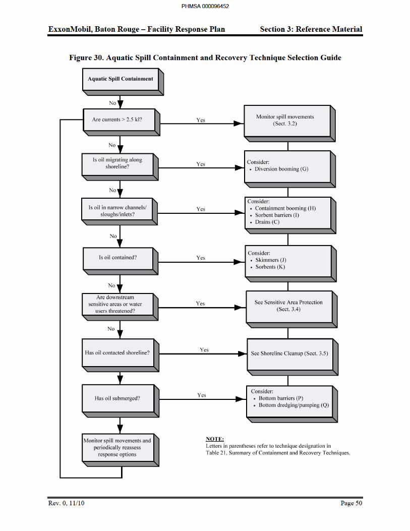
ExxonMobil, Baton Rouge – Facility Response Plan Section 3: Reference Material
Rev. 0, 11/10 Page 51
3.4 Sensitive Areas
Identification
In most spill situations, time does not allow research of the locations and nature of downstream sensitive areas. Therefore, Table 22 provides a summary of the primary aquatic sensitive areas of interest that may be impacted by a spill. Figure 31 through Figure 43 provide detailed maps of these sensitive areas. Table 22 identifies locations and descriptions, relative sensitivities, recommended protection measures, and other information on each identified sensitive area. A relative sensitivity rating has been given to each of the sensitive areas. These ratings are based on their tolerance to oil spills and the general perceived intrinsic value of the resource. The Comments column in Table 22 describes the primary sensitivity concern for each site. All areas within the planning distance calculated in Section 4 and required by regulation are shown in Figure 31 and Figure 32. The other maps, Figure 33 through Figure 43 are included herein for ease of reference only.
EPA Region VI Inland Area Contingency Plan, Annex F for Louisiana, lists the following endangered species for East and West Baton Rouge Parishes, the location of the facilities covered by this plan: Louisiana black bear, red cockaded woodpecker, ivory-billed woodpecker, bald eagle, Florida panther, Eskimo curlew, and Bachman’s warbler.
The key sensitivities along the Mississippi are the numerous municipal and industrial water intakes situated along the majority of the downstream area. The municipal intakes have a greater sensitivity as, unlike most industrial intakes, they cannot tolerate the presence of even minute amounts of free or dissolved oil. Most intakes are, however, situated well below the water surface and during higher river stages, may not be as vulnerable to oil spills as during lower river stage conditions. Other sensitivities include occasional commercial/sport fishing areas, a least tern breeding area, and the Delta National Wildlife Area at the Head of Passes. Due to their greater sensitivity, only the municipal water intakes are addressed in the Table 22.
PHMSA 000096453
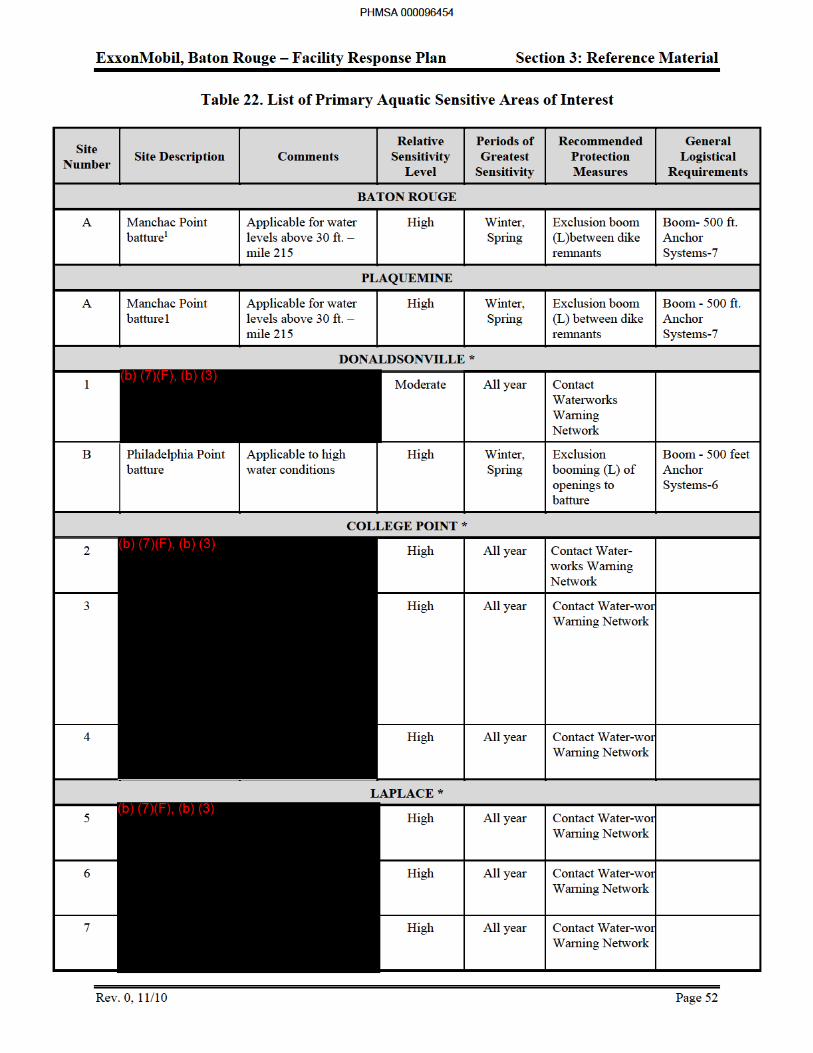
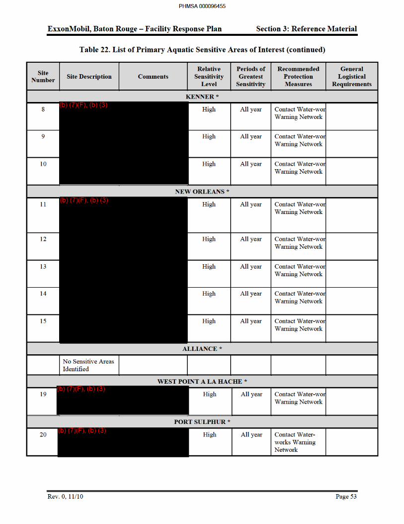
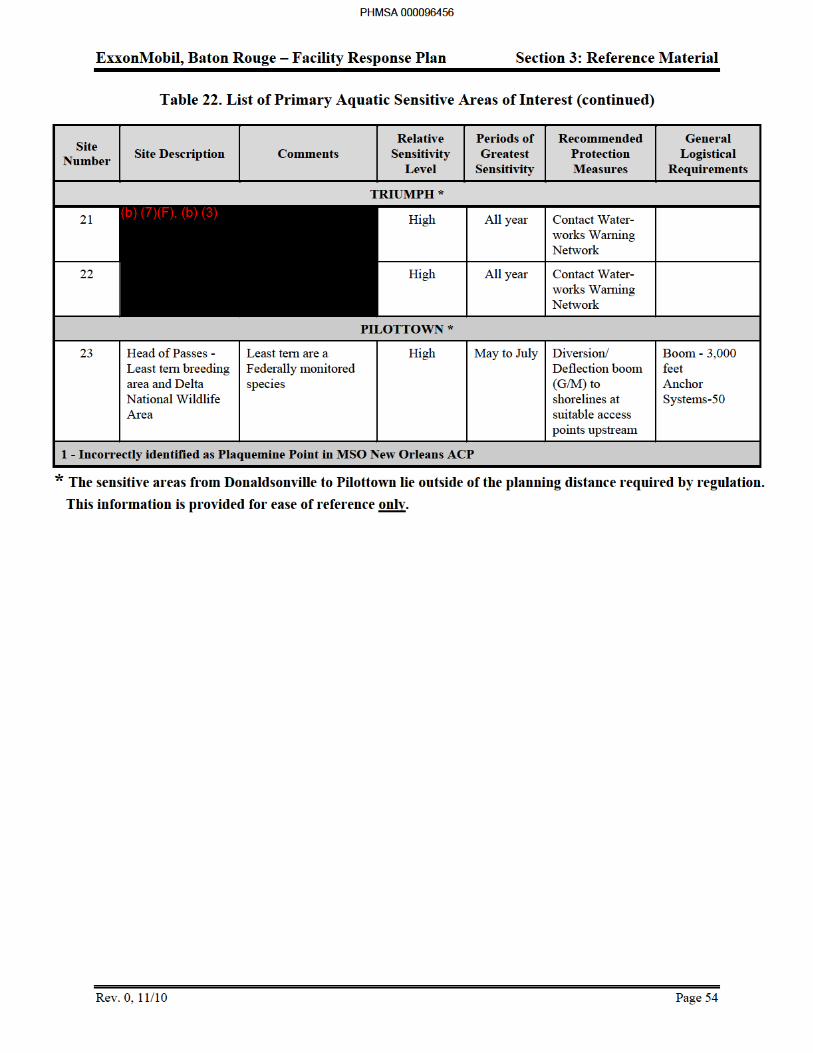
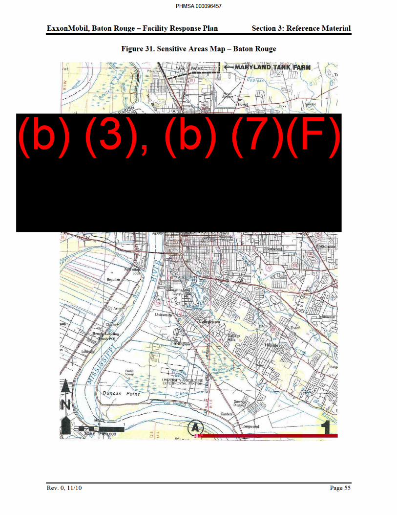
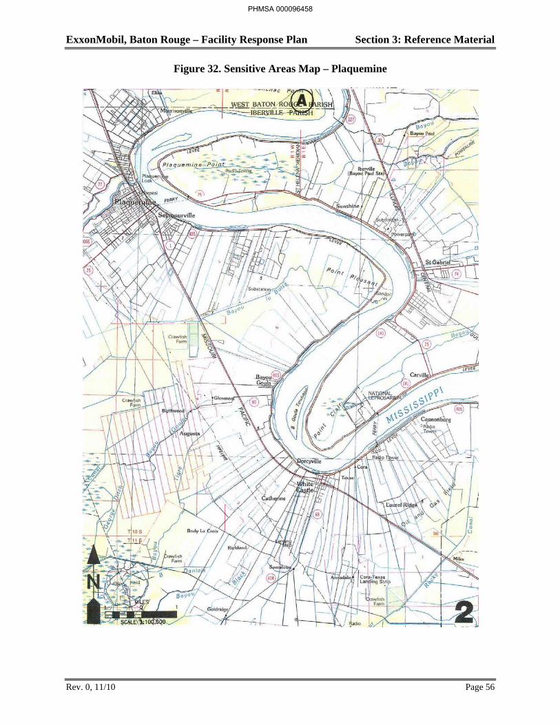
ExxonMobil, Baton Rouge – Facility Response Plan Section 3: Reference Material
Rev. 0, 11/10 Page 56
Figure 32. Sensitive Areas Map – Plaquemine
PHMSA 000096458
ExxonMobil, Baton Rouge – Facility Response Plan Section 3: Reference Material
Rev. 0, 11/10 Page 57
Figure 33. Sensitive Areas Map – Donaldsonville
PHMSA 000096459
(b) (3), (b) (7)(F)
ExxonMobil, Baton Rouge – Facility Response Plan Section 3: Reference Material
Rev. 0, 11/10 Page 58
Figure 34. Sensitive Areas Map – College Point
PHMSA 000096460
(b) (3), (b) (7)(F)
ExxonMobil, Baton Rouge – Facility Response Plan Section 3: Reference Material
Rev. 0, 11/10 Page 59
Figure 35. Sensitive Areas Map – Laplace
PHMSA 000096461
(b) (3), (b) (7)(F)

ExxonMobil, Baton Rouge – Facility Response Plan Section 3: Reference Material
Figure 37. Sensitive Areas Map – New Orleans
PHMSA 000096463
(b) (7)(F), (b) (3)

ExxonMobil, Baton Rouge – Facility Response Plan Section 3: Reference Material
Figure 38. Sensitive Areas Map – Alliance
PHMSA 000096464
(b) (7)(F), (b) (3)

ExxonMobil, Baton Rouge – Facility Response Plan Section 3: Reference Material
Figure 39. Sensitive Areas Map – West Point A La Hache
PHMSA 000096465
(b) (7)(F), (b) (3)

ExxonMobil, Baton Rouge – Facility Response Plan Section 3: Reference Material
Figure 40. Sensitive Areas Map – Port Sulphur
PHMSA 000096466
(b) (7)(F), (b) (3)

ExxonMobil, Baton Rouge – Facility Response Plan Section 3: Reference Material
Figure 41. Sensitive Areas Map – Triumph
PHMSA 000096467
(b) (7)(F), (b) (3)
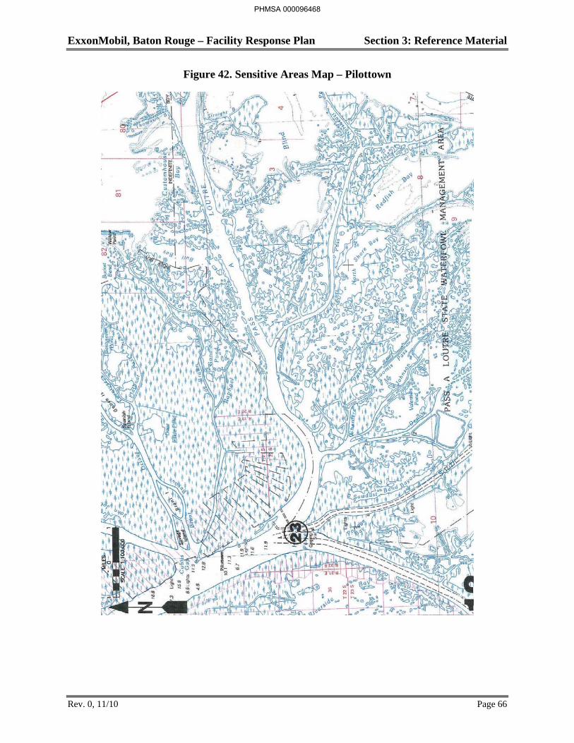
ExxonMobil, Baton Rouge – Facility Response Plan Section 3: Reference Material
Rev. 0, 11/10 Page 66
Figure 42. Sensitive Areas Map – Pilottown
PHMSA 000096468
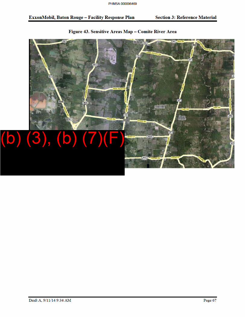
ExxonMobil, Baton Rouge – Facility Response Plan Section 3: Reference Material
Draft A, 9/11/14 9:34 AM Page 68
Protection
In the event of a spill to the Mississippi River, Comite River or Intercoastal Canal, it may be necessary to protect downstream sensitive areas if it appears that local containment and recovery efforts will not be sufficient to control the entire spill. Terrestrial spills are not considered in this section as no terrestrial sensitivities have been identified in the vicinity of the ExxonMobil Complex.
Protection refers to the implementation of techniques or methods to prevent oil from making contact with a shoreline or aquatic area that is determined to be sensitive for environmental, economic, cultural, or human use reasons. Implementation of sensitive area protection techniques must consider a number of factors, several of which are included in Figure 44, Protection Technique Selection Guide. These are further explained in Table 23, Summary of Aquatic Protection Techniques.
Due to the Mississippi River shorelines consisting primarily of man-made levees, there are few environmentally sensitive areas located downstream of the Refinery complex and the Chemical Plant. The exception to this is the area just north of Head of Passes where there is no levee system and a spill reaching this area could migrate into the marsh areas bordering the river. It is, however, unlikely that a significant amount of oil would remain on the water by the time a spill reached this area due to the containment and recovery measures that would be taken by ExxonMobil following a spill and the natural dissipation (evaporation, dispersion, degradation, flocculation, etc.) and stranding along the shoreline that will take place.
The shorelines along the Comite River and Intercoastal Canal do not have a protective man-made levee system. ExxonMobil will take containment and recovery measures to prevent a significant amount of oil from migrating into the areas along these shorelines.
Selected containment and recovery techniques listed in Table 21 (e.g., diversion and narrow channel containment booming and sorbent barriers) can also be used for protection purposes. The common protection techniques are summarized in Table 21
PHMSA 000096470
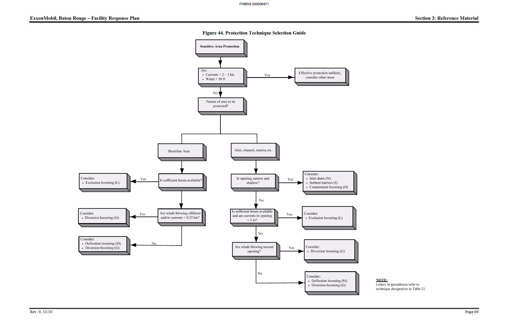
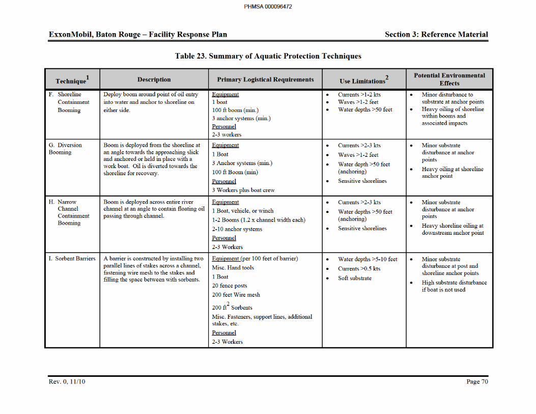
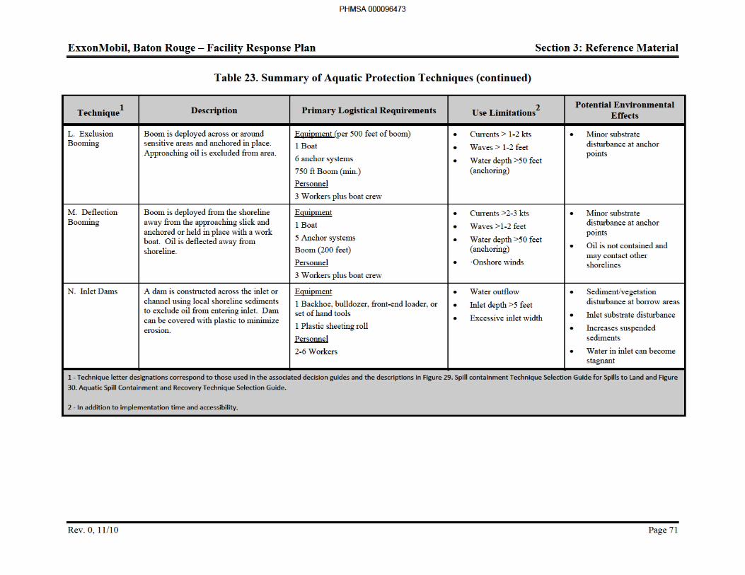
ExxonMobil, Baton Rouge – Facility Response Plan Section 3: Reference Material
Rev. 0, 11/10 Page 72
Prioritization of Sensitive Areas for Protection
It is seldom possible to protect large sections of shoreline following a major spill. Limitations of time, manpower, equipment, water currents, and weather conditions will often restrict the number of areas that can be protected. Therefore, if more than one sensitive area is threatened, the setting of protection priorities becomes an important element of a rapid and effective response.
The need to protect a particular sensitive area or section of shoreline is directly related to the following:
Presence of an environmental, cultural, human use, and/or economical sensitive feature.
Potential degree of oil impact.
Relative level of sensitivity (see Section Identification of Sensitive Areas).
Potential oil residence time.
Feasibility of effectively implementing a protection technique prior to oil contacting the shoreline.
Figure 45 illustrates how these variables can be combined into a general decision guide for selecting relative protection priorities. Explanations of how each variable influences prioritization are provided below.
Sensitive Features
In addition to the sensitive areas identified in Identification of Sensitive Areas Section, other shorelines may possess certain features that are also considered sensitive. These features, listed in order of relative sensitivity, typically include the presence of the following:
Light to moderate bird or waterfowl use areas.
Small marsh or wetland areas.
Residential or commercial waterfront areas.
Recreation or high public use areas.
Boat launching ramps.
Other similar areas.
Potential Degree of Impact
The potential for oil to make contact with a section of shoreline can be estimated using the information included in the Spill Assessment section. The amount of oil that reaches a shoreline depends in part on the quantity spilled and the cohesiveness of the slick. If the quantity spilled is large, the slick does not break into patches or streamers, and it is headed directly at a section of shoreline, the potential degree of impact would be high. Conversely, if the slick has dispersed into patches, the potential degree of impact could be low. The potential is best determined by trajectory estimates followed by aerial reconnaissance.
PHMSA 000096474
ExxonMobil, Baton Rouge – Facility Response Plan Section 3: Reference Material
Rev. 0, 11/10 Page 73
Potential Residence Time
The potential oil residence time is primarily dependent on the:
Degree of impact.
Type of shoreline sediments.
Level of exposure to the elements.
In general, higher degrees of impact, coarser, well sorted sediments, and lower levels of exposure to wind, waves, currents, and natural flushing will increase the residence time of the oil on the shoreline. The sediment type can have the greatest effect on residence time as coarser grain sediments usually permit the oil to penetrate deeper into the shoreline but also allow for greater natural flushing and degradation. Finer grained sediments typically inhibit penetration but if oil does become incorporated into the sediments, residence time will increase.
Lower levels of exposure, such as in protected backwater areas or narrow sloughs, will increase the residence time due to the decreased natural flushing action by wind and vessel-generated waves and currents.
Technique Effectiveness
The probable effectiveness or success of protecting a particular area would be evaluated at the time of a spill and is primarily dependent on:
Current and wind conditions.
Availability of the required equipment, manpower, and logistics.
Accessibility of shoreline.
Time available to implement the technique prior to shoreline contact.
Typically, the probable effectiveness would decrease if high winds and currents were present, only limited manpower, equipment, and logistical support were available, the shoreline was relatively inaccessible, and little time was available prior to shoreline contact.
In this case, protection efforts should focus on other areas with a higher probability of success.
PHMSA 000096475
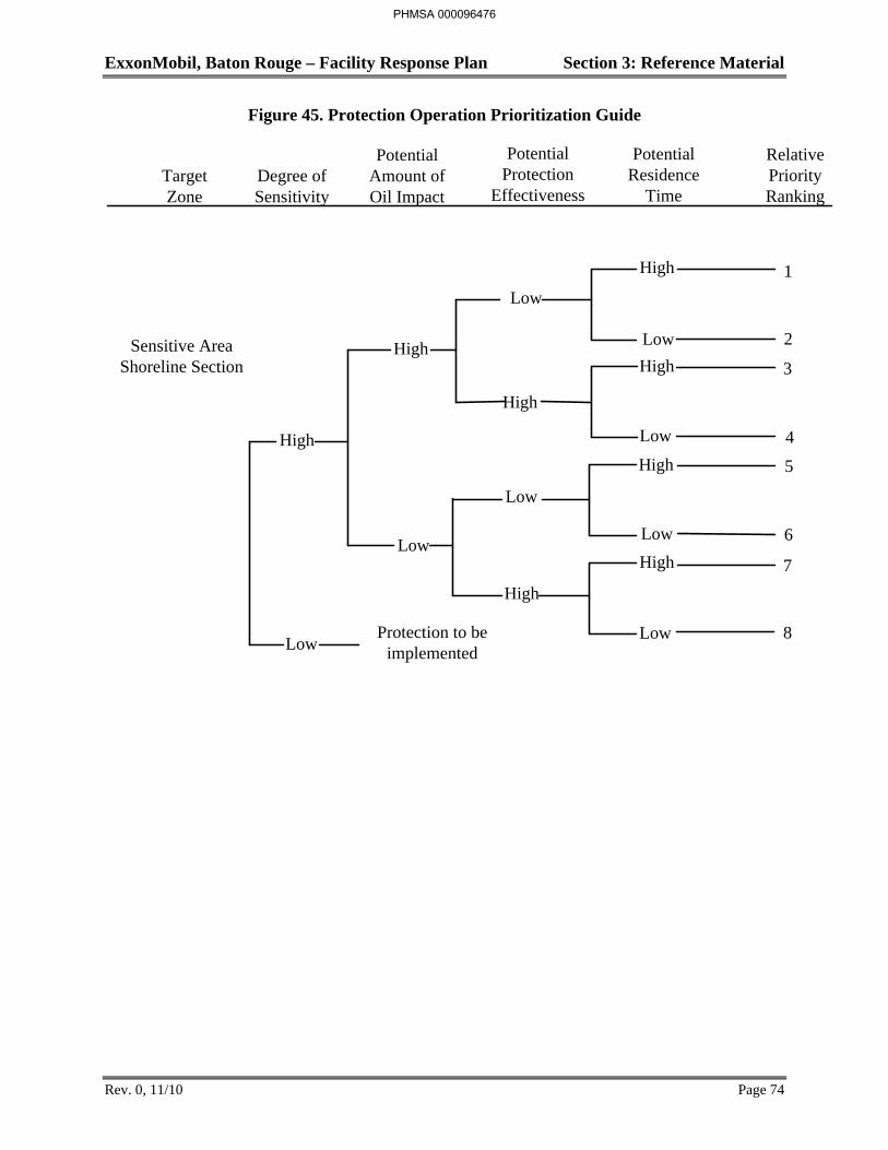
ExxonMobil, Baton Rouge – Facility Response Plan Section 3: Reference Material
Rev. 0, 11/10 Page 74
Figure 45. Protection Operation Prioritization Guide
Target Zone
Degree of Sensitivity
Potential Amount of Oil Impact
Potential Protection
Effectiveness
Potential Residence
Time
Relative Priority Ranking
High
Low
High
Low
High
High
Low
Low
1
2
3
4
5
6
7
8
High
Low
High
Low
High
Low
High
LowProtection to be
implemented
Sensitive Area Shoreline Section
PHMSA 000096476
ExxonMobil, Baton Rouge – Facility Response Plan Section 3: Reference Material
Rev. 0, 11/10 Page 75
Protection Technique Selection
Selection of an appropriate protection technique depends on a variety of factors including:
Current speed - Surface currents greater than 1 knot can cause boom failure or entrainment of oil beneath the boom, where booms are placed at right angles to the current. Booms angled into or away from the direction of flow can generally tolerate currents up to 2 to 3 kt before failure occurs.
Water depth - Depths more than 50 feet can complicate boom anchor placement, whereas depths less than 2 feet can preclude effective boom use.
Shoreline access - Obstacles (rocks, debris, man-made structures, etc.) in the water or steep or densely vegetated shorelines could limit access and present safety and operational problems.
Anchor points - Soft bottom substrates can complicate boom anchor placement.
Safety - High currents, winds, large obstacles, and other dangerous conditions could present safety hazards and preclude certain techniques.
PHMSA 000096477
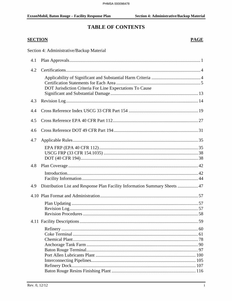
ExxonMobil, Baton Rouge – Facility Response Plan Section 4: Administrative/Backup Material
TABLE OF CONTENTS
SECTION PAGE
Rev. 0, 12/12 i
Section 4: Administrative/Backup Material
4.1 Plan Approvals ................................................................................................................... 1
4.2 Certifications ...................................................................................................................... 4
Applicability of Significant and Substantial Harm Criteria ........................................... 4 Certification Statements for Each Area .......................................................................... 5 DOT Jurisdiction Criteria For Line Expectations To Cause Significant and Substantial Damage ............................................................................. 13
4.3 Revision Log .................................................................................................................... 14
4.4 Cross Reference Index USCG 33 CFR Part 154 ............................................................. 19
4.5 Cross Reference EPA 40 CFR Part 112 ........................................................................... 27
4.6 Cross Reference DOT 49 CFR Part 194 .......................................................................... 31
4.7 Applicable Rules .............................................................................................................. 35
EPA FRP (EPA 40 CFR 112) ....................................................................................... 35 USCG FRP (33 CFR 154.1035) ................................................................................... 38 DOT (40 CFR 194) ....................................................................................................... 38
4.8 Plan Coverage .................................................................................................................. 42
Introduction ................................................................................................................... 42 Facility Information ...................................................................................................... 44
4.9 Distribution List and Response Plan Facility Information Summary Sheets .................. 47
4.10 Plan Format and Administration ...................................................................................... 57
Plan Updating ............................................................................................................... 57 Revision Log ................................................................................................................. 57 Revision Procedures ..................................................................................................... 58
4.11 Facility Descriptions ........................................................................................................ 59
Refinery ........................................................................................................................ 60 Coke Terminal .............................................................................................................. 61 Chemical Plant .............................................................................................................. 78 Anchorage Tank Farm .................................................................................................. 90 Baton Rouge Terminal .................................................................................................. 97 Port Allen Lubricants Plant ........................................................................................ 100 Interconnecting Pipelines ............................................................................................ 105 Refinery Dock ............................................................................................................. 107 Baton Rouge Resins Finishing Plant .......................................................................... 116
PHMSA 000096478
ExxonMobil, Baton Rouge – Facility Response Plan Section 4: Administrative/Backup Material
TABLE OF CONTENTS
SECTION PAGE
Rev. 0, 12/12 ii
4.12 Hazard Evaluation/Spill History .................................................................................... 121
Hazard Evaluation ...................................................................................................... 121 Spill History ................................................................................................................ 128
4.13 Spill Scenarios/Worst Case Discharge ........................................................................... 130
Planning Distance ....................................................................................................... 130 Local Receptors .......................................................................................................... 133 Downstream Human Populations ............................................................................... 134 Spill Scenarios ............................................................................................................ 135 Scenario Descriptions (Average Most Probable/Small Spills) ................................... 140 Medium Spill .............................................................................................................. 143 Worst Case Discharge ................................................................................................. 147
4.14 Response Resource Requirements ................................................................................. 154
4.15 Health and Safety ........................................................................................................... 155
Introduction ................................................................................................................. 155 Responding To Injuries ............................................................................................... 156 Specific Safety Hazards/Guidelines ........................................................................... 157 Health and Safety Plan ................................................................................................ 166 Site Specific Procedures ............................................................................................. 167
4.16 Site Safety and Health Plan............................................................................................ 168
4.17 Response Training and Drills......................................................................................... 179
Training ....................................................................................................................... 179 Drills ........................................................................................................................... 185 Documentation of Training and Drills ........................................................................ 187
4.18 Spill Response, Management Commitment, and Waste Disposal Plan ......................... 190
Spill Response ............................................................................................................ 190 Management Commitment ......................................................................................... 190 Waste Disposal Plan ................................................................................................... 191 Oil Spill Prevention .................................................................................................... 192
4.19 OSRO Contracts............................................................................................................. 193
4.20 Acronyms and Glossary ................................................................................................. 195
Acronyms .................................................................................................................... 195 Glossary ...................................................................................................................... 199
PHMSA 000096479
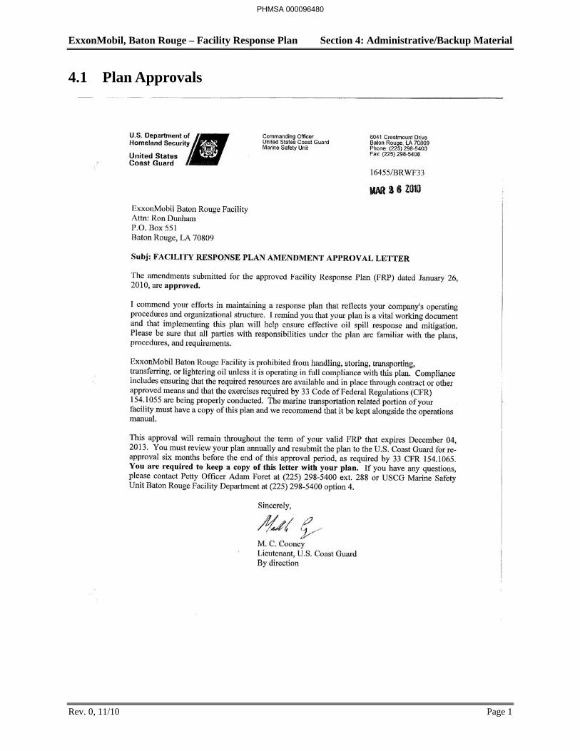
ExxonMobil, Baton Rouge – Facility Response Plan Section 4: Administrative/Backup Material
Rev. 0, 11/10 Page 1
4.1 Plan Approvals
PHMSA 000096480
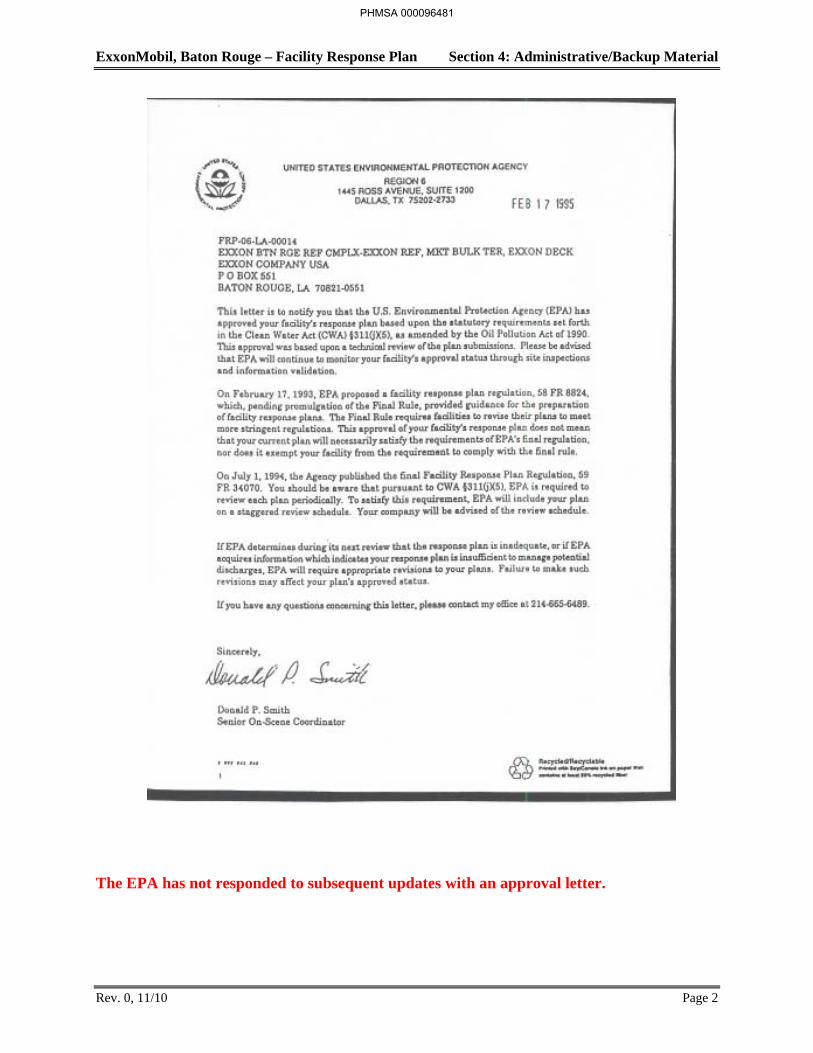
ExxonMobil, Baton Rouge – Facility Response Plan Section 4: Administrative/Backup Material
Rev. 0, 11/10 Page 2
The EPA has not responded to subsequent updates with an approval letter.
PHMSA 000096481
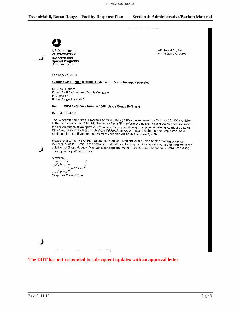
ExxonMobil, Baton Rouge – Facility Response Plan Section 4: Administrative/Backup Material
Rev. 0, 11/10 Page 3
The DOT has not responded to subsequent updates with an approval letter.
PHMSA 000096482
ExxonMobil, Baton Rouge – Facility Response Plan Section 4: Administrative/Backup Material
Rev. 0, 11/10 Page 57
4.10 Plan Format and Administration
This plan was originally developed in 1992 following the guidelines and general format included in the U.S. Coast Guard Navigation and Vessel Inspection Circular No. 7-92 and USCG 33 CFR Part 154 due to the absence of EPA regulations at that time. Minor changes were made to the suggested format in those documents to enhance plan functionality and access to key response information as well as to provide additional response information not specifically required by the above regulations and guidelines. The plan was re-written in 1996-1997 to incorporate the “Facility Response Plan” Guidance. Cross-references to the Facility Response Plan Regulations are included in this chapter.
The plan was then re-done again in 2004 to remove the SPCC Requirements.
Plan Updating
The ExxonMobil Refinery Emergency Preparedness Coordinator is responsible for reviewing, updating, and distributing this FRP. The plan will be reviewed and updated in accordance with all applicable regulations [33 CFR 154.1065(a), 40 CFR 112.(g), 49 CFR 194.121]. The plan will be reviewed by responsible personnel in its entirety (with each person reviewing their sections) every 5 years. Any changes will be replaced in the controlled manuals and sent to the regulatory agencies by the Refinery Emergency Preparedness Coordinator or his designee. In the interim, if a user of the plan determines there is an operational change that requires significant update to the plan (i.e. extension of pipeline, addition/deletion of facilities, change in QI, change in OSRO, etc) he will contact the Emergency Preparedness Coordinator who will revise the plan within 30 days. In addition, the plan will be revised as needed to incorporate post-drill and post-incident evaluation results. These revisions are to be sent to each person that has a controlled copy of the plan and to the regulatory agencies.
The Refinery Incident Manager or his designee will review the National Oil and Hazardous Substance Contingency Plan (NCP) and applicable Area Contingency Plans (ACPs) annually and make revisions to this plan as necessary to ensure consistency.
Revision Log
The FRP, which contains USCG, EPA, and DOT requirements, was completed May 1, 1997. The original FRP was approved on December 15, 1997 (See Section 4 Approvals). Any revision after that date has been entered on the Revision Log Sheet (See Table 24).
Plan revision or amendments will be numbered sequentially. The revised section, page number, and purpose of the revision (code or text) will also be entered on the log sheet.
PHMSA 000096483
ExxonMobil, Baton Rouge – Facility Response Plan Section 4: Administrative/Backup Material
Rev. 0, 11/10 Page 58
Revision Procedures
All pages in the plan have the preparation date shown in the footer to identify when the information was last revised. Any changes to the text or figures should also include a revision date in the footer. Copies of all revised pages must be distributed immediately to each person on the plan distribution list to ensure all copies of the FRP are current. Pen and ink changes may be made to the plan for minor revisions only such as a phone numbers or minor increases or decreases in response equipment quantities. In this case, a transmittal letter is all that is required explaining the change and instructing the plan holders to enter it into their copies.
In addition, if the revision is a complete redistribution of the entire manual, the certification sheets located in Figure 4.3 must be signed by the appropriate manager and placed in each manual.
PHMSA 000096484
ExxonMobil, Baton Rouge – Facility Response Plan Section 4: Administrative/Backup Material
Rev. 0, 11/10 Page 59
4.11 Facility Descriptions
This section provides information specific to the following ExxonMobil facilities:
Refinery
Coke Terminal
Chemical Plant
Anchorage Tank Farm
Baton Rouge Terminal
Port Allen Lubricants Plant
Interconnecting Pipelines
Refinery Dock
Resins Finishing Plant
Information is provided in the following areas as required for each facility by 40 CFR 112.20(h) (EPA-FRP), 33 CFR 154.1035 (USCG-FRP), and 49 CFR 194 (DOT-FRP).
Facility Description
Tank car/truck loading/unloading
Drainage and Spill Containment
Spill Detection and/or Prevention
Storage and Diversionary Structures
Piping
Transfer Operations
Inspections/Records
Security
Fire Control
These facility descriptions identify all primary components and equipment (e.g., storage tanks, pipelines, etc.) within each facility. The facilities also include ancillary components, such as transformers, that contain smaller quantities of oil. Although these ancillary components are not specifically listed in the facility descriptions, responses to discharges of oil from any of these components shall be conducted in accordance with this plan.
PHMSA 000096485
ExxonMobil, Baton Rouge – Facility Response Plan Section 4: Administrative/Backup Material
Rev. 0, 11/10 Page 60
Refinery
Facility Description
The Refinery is located on the east bank of the Mississippi River at river mile 232. It is located in the industrial complex northwest of Baton Rouge at 4045 Scenic Highway in East Baton Rouge Parish. The Refinery is bounded by industrial property on the north, commercial and residential properties on the south and east, and the Mississippi River on the west. The Mississippi River is the nearest receiving body of water.
The Refinery began operations in November of 1909 and began the storage of oil between April and November of that year. Today, the refinery covers about 1,000 acres (excluding the remote tank fields) of level land and employs approximately 2,100 people in a 24-hour a day operation. The Refinery is a thoroughly integrated complex with a crude run of 515,000 barrels per calendar day. The major refinery processes include distillation, catalytic cracking, hydrocracking, reforming, coking, alkylation, polymerization, dewaxing, deasphalting, hydrofining, treating, and blending. Approximately 500 petroleum products and grades of products are produced by the various refining processes and range from propane to residual fuel, asphalt, and coke.
Refinery facilities include more than thirty major process units including tankage, loading facilities, docks, river water clarifiers, office buildings and laboratories. In addition, ExxonMobil Chemical Company has ten process units (Plasticizers, Oxo, Aromatics, PALA, POX, Eagle, Lion, Cat Plant, Poly, and LOLA) as well as storage tanks located within the Refinery which are listed in the tank database maintained by the Environmental Department. Environmental control facilities include a 10,000-gpm wastewater treatment plant, two 5 million-gallon wastewater containment tanks, two storm water basins, a sulfur recovery and tail gas cleanup unit, a catalytic cracking regenerator flue gas scrubber, a marine vapor recovery unit, and a benzene recovery unit. A site plan of the Refinery is provided in Figure 47.
PHMSA 000096486
ExxonMobil, Baton Rouge – Facility Response Plan Section 4: Administrative/Backup Material
Rev. 1, 5/14 Page 61
Coke Terminal
ExxonMobil Corporation operates the Baton Rouge Coke Terminal (BRCT) located in Baton Rouge, Louisiana in East Baton Rouge Parish. A Facility Plot Plan is provided as Figure 49.
Petroleum coke comes into the BRCT by railcar from the ExxonMobil refinery. These railcars are moved into a covered area and emptied though the bottom into a concrete-lined underground pit. A conveyor at the bottom of the pit moves the coke to the enclosed crusher where oversize pieces are crushed. From the crusher, the main conveyor takes the coke to the barge to be loaded or, when a barge is not available, to a storage pad to be held in storage piles. When a barge becomes available, a front-end loader moves the coke from the storage piles to a hopper. The hopper feeds a conveyor that transfers the coke to the main conveyor where it is transferred to the barge.
Coke is removed from the process equipment at the refinery using water. The facility does not maintain any stationary combustion sources; all motors are electric. The only combustion sources onsite are mobile vehicles (i.e. a diesel backhoe, a front-end loader, and two railcar moving vehicles). To fuel the mobile vehicles, the BRCT maintains a 600-gallon diesel storage tank.
Thomas Yard
Thomas Yard is the southern railroad spur and is adjacent to the refinery. The area is managed by the Baton Rouge Chemical Plant. Thomas Yard is used for the storage of materials for delivery to and from the facility. Empty cars may also be stored at the site. Up to a maximum of 30 rail cars may be stored with the largest car being approximately 33,000 gallons.
Materials stored in the cars are various chemicals from the Chemical Plant. A list of those possible materials can be found in the BRCP SPCC Plan. All cars are inspected by the railroad company prior to entering the Yard.
Emergency response is provided by the facility. Initial emergency notifications will be made to the Chemical Superintendent. Small leaks (valves) they will be handled by Petroleum Services Corporation. Larger spills will be handled by the ChemNet organization and/or BRRF Emergency Response.
During the course of a day there is normal daily activity within the site that would observe any leaking cars, however this is not documented formally. A formal written inspection is performed during normal working days.
PHMSA 000096487
ExxonMobil, Baton Rouge – Facility Response Plan Section 4: Administrative/Backup Material
Rev. 1, 5/14 Page 62
SABRE
The Baton Rouge Refinery’s Beneficial Reuse Program consists of an asphalt paving materials manufacturing operation. The operation uses non-hazardous petroleum contaminated soils and concrete rubble from the seven ExxonMobil facilities in close geographical proximity to the Refinery to produce asphaltic paving materials under a program called SABRE (Soils-to-Asphalt-Beneficial Reuse at Exxon). ExxonMobil recycles non-hazardous soils into asphaltic paving products as a preferred environmental alternative to landfill disposal.
Raw materials are collected during construction projects at the seven facilities and the SABRE recycle product is re-used as roadbase or fill at these same facilities. The SABRE equipment is located and operated at a designated site within the Refinery on a recycling pad designed and constructed to specifications contained within the existing Beneficial Reuse Plan.
SABRE is located on the river on the very SW part of the facility. The area has two tanks: 1) 5500 gallon 3% asphalt emulsion and 2) 500 gallon diesel tank. The SABRE area is regularly visited and is inspected per SPCC. Each tank has greater than 110% containment.
Tank Car/Truck Loading/Unloading
The Refinery has ten tank car and tank truck loading racks which handle liquid hydrocarbon: PALA, Lube, Wax, Oxo, NOVA, TEL, Cetane, Additives, Propane, Sulfur and Light Ends. Tank cars and tank trucks are loaded. Some of the racks can service both types of vehicles. The equipment used and procedures followed at the racks meet the requirements established by the Department of Transportation. Large warning signs are used at some racks to prevent vehicle departure before the complete disconnection of transfer lines. Other racks require that ignition keys be retained by the operator to prevent premature vehicle departure before the complete disconnection of transfer lines. Tank cars are loaded during "X" shift but are not removed until "Y" shift. This practice greatly reduces the chance of cars being moved while connected to loading lines. Drains and outlets of cars and trucks are checked before loading is begun. Where necessary, adjustments and repairs are made to prevent the leaking of oil in transit.
External covers are provided for several of the loading/unloading facilities to segregate the loading rack catch basins from storm water use. These are discussed in more detail in the SPCC Plan.
Drainage and Spill Containment
The majority of the Refinery is fairly level, well-drained and not located in a flood area. A spill which spreads out should follow normal drainage patterns (Figure 48) to sewer catch basins which can generally be sealed using covers.
Spills that occur in most of the tank field areas and the loading racks will likely occur inside diked areas in tank fields. If a significant spill occurs and remains undetected, it will eventually flow to the catch basins inside the dikes which are connected to the Refinery sewer system. Once the spill is discovered, the catch basin may be sealed, providing complete containment
PHMSA 000096488
ExxonMobil, Baton Rouge – Facility Response Plan Section 4: Administrative/Backup Material
Rev. 1, 5/14 Page 63
within the dike. The spilled material will then be recovered by vacuum truck and the affected area cleaned up.
Spills occurring at process units will generally reach catch basins more quickly than in tank fields because these areas are paved. They have considerably more employee traffic than the tank fields which usually leads to rapid identification of spills or discharges of oil. After a spill has occurred at a unit, the catch basins will be sealed as appropriate. In addition to being paved, process units usually have curbs or toewalls around the equipment which limit spill spreading. Further containment can be achieved through the use of temporary berms. Once contained, the spilled material will be recovered by vacuum trucks and the affected areas cleaned up.
Areas around pipebands have a somewhat smaller spill potential. Spills in these areas would be contained by sealing catch basins and using temporary berms. However, areas adjacent to paved streets under pipebands are generally not paved and may be very irregular. Vacuum trucks would be used for initial recovery followed by washing of the unit. Depending on the degree of irregularity, significant manual labor may be required in the use of sorbents, mops, and other equipment.
The Refinery maintains a fleet of contractor vacuum trucks, with at least one driver on call 24 hours a day. In a normal day, several trucks can be diverted to a spill. Portable sump pumps can be used with the trucks to expedite recovery operations. Water streams can be used for washing the area and collecting the remaining oil. Disposable sorbents (kept in plant inventory) can be used for the final cleanup.
There are five below ground sewer systems in the refinery. Centrifugal pumps were installed upstream of the API separators in 1994 to route normal sewer flow to the wastewater containment tanks. Any spilled oil that makes its way to these centrifugal pumps will also be routed to these same tanks up to the capacity of the pumps. The separators (main bays) in the refinery no longer meet the definition of API separators since they no longer function for primary waste water treatment. However, for the purposes of describing the refinery sewer system, the term API separator(s) may be used since the bays still exist. Recovered oil from the waste water containment tanks is then sent to specific tankage assigned to the Refinery slop system. If additional volume is then required, the slop tanks can be pumped at a rate of 500 barrels per hour to make room for additional slops.
Every attempt will be made to pump the spilled material to the wastewater containment tanks from the sewer systems. Any spilled material that cannot be handled by these centrifugal pumps will be diverted to the 24 million-gallon Rain Basin-1 or, as an absolute last resort, diverted to the 15 million-gallon Rain Basin-2. Diversion to the rain basins is a last resort response. Any spilled oil that reaches the rain basins can be collected with vacuum trucks or surface oil skimmers. RB1 and RB2 are the only spill containment surface impoundments.
Spill Detection and/or Prevention
The Refinery is designed for the quick detection and prevention of problems. Written procedures cover all aspects of the operation of process units. Operational procedures and practices, including the flushing and draining of sample lines to collection pails or pump-out systems, are followed to prevent or minimize spills and discharges to the Refinery sewer system.
PHMSA 000096489
ExxonMobil, Baton Rouge – Facility Response Plan Section 4: Administrative/Backup Material
Rev. 1, 5/14 Page 64
Set procedures are also followed for tank and equipment cleaning. When a piece of equipment is disconnected, catch pans are utilized to contain any residual oil which may drain from the equipment or the line. Minimum displacement valves and recycle lines which do not require displacement of sample line oil, have been installed in many locations throughout the Refinery.
All critical and most non-critical instruments are monitored from control houses or centers. Some equipment items, such as furnaces, automatically shut down when certain set values are exceeded. Control valves are set to fail in the safe position should instrument air pressure be lost. Unit equipment is protected by safety valves.
A spill to the sewer system would be detected promptly by Refinery personnel or detection systems. Effluent quality is closely monitored through the on-line analysis and the regular collection and analysis of composite and grab samples.
Wastewater treatment operating personnel make frequent observations of the wastewater treatment facilities as part of their normal duties to ensure that its operation is acceptable and that no undetected upsets have occurred. The full-time wastewater treatment operator visually inspects the mainline sewers several times each shift. The continuing surveillance provided by the controller, the operators, the assistant operators, the wastewater treatment personnel and other employees is a key element is early spill detection.
The Pollution Control Group is responsible for monitoring and auditing the Upstream Sewer Surveillance Program. Their main responsibilities include unit inspections, troubleshooting, and monitoring effluents. This team routinely checks sewers and process units for spills, leaks, and other conditions which can lead to discharges or spills. When upsets or unusual conditions are detected anywhere in the wastewater system, this group tracks back through the various sewer systems to find the source of the problem. Based on their findings, appropriate corrective action is taken.
Roughly twenty percent of the Refinery storage tanks have internal steam heating coils for maintaining minimum temperatures of certain materials. Much of the steam condensate in the Refinery is recovered and reused. Condensate which is not recovered goes to the Refinery sewer. Leakage of oil into a heating coil poses no pollution problem since the condensate is handled and treated in the same manner as other waters routinely produced in Refinery operations. If a problem is suspected, the coil can easily be pressure tested to confirm the existence of a leak, and corrective action can be taken as appropriate.
Refinery bulk storage tanks, spheres and spheroids are equipped with level measuring instruments. Varecs are used almost exclusively. All gauges have local readouts, and the vast majority of those gauges are wired to operations control centers. All gauges are checked for operation and accuracy periodically by operations personnel. This procedure is incorporated into the shift operating orders. All problems are logged in an effort to identify any gauges with recurring malfunctions. High level pump cutoffs are not used. However, high level alarms are used on all spheres, spheroids, and on tanks in critical service. The alarms trigger annunciators which are constantly manned operating posts. In addition, frequent attention is given to tank instrumentation by operations personnel. An advanced real-time computer monitoring system provides hourly computer printouts of tank levels.
PHMSA 000096490
ExxonMobil, Baton Rouge – Facility Response Plan Section 4: Administrative/Backup Material
Rev. 1, 5/14 Page 65
Several major steps have been taken to protect against tank overfilling. Every area control center and several operator buildings have monitors from the advanced computer system for monitoring tank levels. The computer can display up to 20 tanks simultaneously, including their current level, emergency levels, target level, and direction of movement (filling or emptying). During the installation of this monitoring system, each level gauge was overhauled and new wire was used to connect each tank to the control center. Also, alarms were installed to signal initial movement in a tank. This alarm signals the operator to verify that the correct tank is being filled or emptied. Alarms are also provided to detect drastic changes in tank levels which may be caused by a hung level gauge suddenly freeing or other indication of mechanical trouble or leak. These alarms help ensure that the level measurement equipment is kept in reliable working condition. In addition to the advanced monitoring system, independent high level alarms are installed on approximately 150 tanks containing low flash materials.
Operators of DOT pipelines follow procedure P-195.402(d) in the DOT Pipeline Operations and Maintenance Manual to detect and respond to abnormal operations in order to prevent a substantial threat of a worse case discharge resulting from an abnormal operation. These abnormal operations include: unintended valve closure or pipeline shutdown, increase or decrease in pressure or flow rate outside normal operating limits, loss of communication and operation of a safety device.
Storage and Diversionary Structures
Bulk storage is approximately , excluding the remote tank fields. Normal daily throughput is 515,000 barrels per day. The storage tank areas within the refinery are divided into several fields depending on location and product stored. These tank farms or fields include the:
Knox Field (gasoline)
Zone I Area (distillate)
Zone II East Area (miscellaneous products)
East Area (miscellaneous products)
Specialties (lube oils)
The facility has approximately 450 atmospheric bulk storage tanks and 12 spheres, spheroids and hemispheroids under pressure. New tanks are constructed in accordance with applicable API codes. Storage vessels designed for a pressure of 15 psia or greater are built to applicable ASME codes. Vessel designs consider maximum and operating temperatures and pressures, compatibility of stored material, and construction materials. All tankage is carbon steel constructed with special grades or alloys used when required. The older tanks in the Refinery are predominantly of riveted construction, while tanks erected since the early 1930's have all been welded. Only approved contractors are used for tank construction. All phases of the construction are closely monitored and inspected by ExxonMobil personnel. Welds receive X-ray examination as the tank is being built. All welders and welding procedures must receive approval and certification. In addition to the tank itself, careful consideration is given to the foundation with complete excavation and backfilling when necessary.
PHMSA 000096491
(b) (3), (b) (7)(F)
ExxonMobil, Baton Rouge – Facility Response Plan Section 4: Administrative/Backup Material
Rev. 1, 5/14 Page 66
There are Tanks in the Refinery that are not diked but do not pose significant pollution or safety problems. The materials stored are viscous and will normally not travel very far or very rapidly if leaked or spilled. Although secondary containment does not exist in the form of dikes, a spill can be contained in the Refinery sewer and oil/water separation facility. Any spill in this area would also be noticed quickly because of the location. Due to the natural grade of the area, a spill could not leave Refinery property.
The Refinery does not have any buried or partially buried bulk hydrocarbon/oil storage tanks. All bulk storage is aboveground (see Section 5). However, three small underground tanks do exist that do store hydrocarbons. These UST's are operated consistent with UST regulations to prevent leaks and spills. It is not expected that buried or partially buried tanks will be used in the future.
Tanks are periodically removed from service for cleaning and maintenance. The frequency of this work varies with the past history of a tank and the service in which it is being used. Much of the time maintenance is of a preventive nature; tanks are taken out of service on schedules. Typically, a maintenance supervisor has specific responsibility for offsite tankage. Tanks are painted for protection against corrosion and weathering. The bottoms of some tanks are cathodically protected. These systems are also included in maintenance work lists. Leaks and other problems which occur are corrected.
When bulk storage tanks are idle for an extended period of time, unused nozzles (those without connected piping) are blanked off on all tanks without regard to the tank's state of service. Normally, tanks can be drained only through their suction lines.
Mobile or portable storage tanks are typically not used by the Refinery. All bulk storage is permanent, fixed-position tankage. However, contractors working within the Refinery frequently do use portable storage tanks for fueling or storage purposes. These tanks may contain as much as 500-1,000 gallons of gasoline or diesel fuel. The location of these tanks must be approved by a Refinery construction supervisor. Consideration is given to the potential safety and pollution risks associated with the location. The potential for pollution is very low since these tanks should be placed in acceptable locations. I f a spill should occur, the substance could be contained at the site or drain to the Refinery sewer system.
Inspections/Records
The field-erected aboveground storage tanks will be inspected and non-destructive integrity tested in accordance with API Standard 653. The Facility will conduct external and internal inspections for the aboveground storage tanks as follows:
Routine In-Service Inspection (API 653, Section 6.3.1) – Visual inspections are performed by facility personnel at an interval not to exceed one month. A site-specific inspection task (Tank Walk-Around Task) has been developed for the Refinery. This task documents when the visual inspection was performed, who performed it, and if any problems were found. This is tracked in the ExxonMobil Tiger System. The Marketing Terminal and BRFP information is retained via paper.
PHMSA 000096492
ExxonMobil, Baton Rouge – Facility Response Plan Section 4: Administrative/Backup Material
Rev. 1, 5/14 Page 67
External In-Service Inspection (API 653, Section 6.3.2) – Visual external inspections are performed by or under that direction of an API 653 Authorized Inspector at least every five years.
Internal Inspections (API 653, Section 6.4) – All tanks are given an internal inspection by or under the direction of an API 653 Authorized Inspector at the intervals defined by API 653, Section 6.4.2 or 6.4.3.
The basic approach for inspection procedures and record keeping is guided by the ExxonMobil’s inspection guidelines. Thorough records are maintained in the plant’s file system. These records include construction specifications, ultrasonic thickness measurements and subsequent inspections and repairs. The schedule of tank inspections is retained with the refinery's business teams. The schedule is maintained as usual and customary business records and shall be made available upon request. A regular schedule of inspections is set based on general service conditions and performance history. Any inspection not made on schedule will be properly recorded in an equipment plan and will be highlighted to management via routine stewardship activities.
Shop-fabricated bulk storage tanks are mounted on leak prevention barriers (e.g., concrete) or are elevated where all product-retaining surfaces are visible (i.e., the container has no contact with the ground) to ensure any leaks are immediately detected. These tanks are visually inspected at an interval not to exceed one month. The visual-only inspection shall assess the containers' exterior surfaces checking for leaks, shell distortions, signs of corrosion, paint coating deterioration, and malfunctioning of appurtenances. Facility personnel knowledgeable of facility operations, the container and the characteristics of the product stored shall conduct this inspection. If deterioration, corrosion, or a leak is found, corrective action will be taken as indicated by the magnitude of the condition. . The routine in-service visual inspections are documented using Tiger checklist.
The portable bulk storage containers (drums, totes, etc.) in dedicated container storage areas (Satellite Accumulation Areas, Garage, Transportation Building, Shop, Warehouse, etc. except for Container Storage Area), are inspected as part of the operator’s normal rounds because these containers are under constant surveillance by facility personnel. The routine in-service visual inspections are documented by exception (e.g., noted on a Job Ticket). If deterioration, corrosion, or a leak is found, corrective action will be taken as indicated by the magnitude of the condition.
The container storage areas are inspected at an interval not to exceed monthly. The routine in-service inspections are documented by geographic operating areas instead of by individual containers. The visual-only inspection shall assess the containers' exterior surfaces checking for leaks, shell distortions, signs of corrosion, paint coating deterioration, and malfunctioning of appurtenances. Facility personnel knowledgeable of facility operations, the container and the characteristics of the product stored shall conduct this inspection. If deterioration, corrosion, or a leak is found, corrective action will be taken as indicated by the magnitude of the condition. The routine in-service (Tiger Task) visual inspections are documented by area using the checklist.
The BRRF also regularly maintains 28-30 satellite accumulation areas throughout the site. These areas are regularly inspected and volumes are small. At least once per month, all containers are
PHMSA 000096493
ExxonMobil, Baton Rouge – Facility Response Plan Section 4: Administrative/Backup Material
Rev. 1, 5/14 Page 68
formally inspected for leaks at satellite accumulation areas and in the less than 90-day storage areas (e.g. 55-gallon drums, roll-off boxes, and any other oil containers in the designated area). Confirmation is obtained to whether the containers are in good general condition. Documentation of the inspection is with a paper or electronic signature. Established procedures for reporting leaks or other areas of concern (RCRA requirements for accumulation/storage of hazardous waste) is by submitting proper work requests.
API 650 tanks that are out of service (idle)1 but not permanently closed2 shall be deferred from the tank integrity testing and inspection program if the tank does not contain any residual oil. The tank shall be integrity tested prior to placing the tank back into service, if the testing schedule has expired.
Tanks that are in-service (idle) shall continue to be inspected under the tank integrity testing program if the tank contains any residual oil. In service (idle) tanks are tanks that are currently not in operation, contains sludge and oil in the tank, and associated piping may/may not be connected to the tank.
API Standard 653 (Section 5, Third Edition, 2001 or equivalent section from most recent edition) is used for brittle fracture evaluation for all API 650 field-erected aboveground tanks that undergo a repair, alteration, reconstruction, or a change in service.
Working tanks that have automatic gauging systems are checked once per quarter against automatic read-out to ensure accuracy. Any discrepancies are checked by the Mechanical Department and repaired as required. Information on the level gauges is maintained in Operation's files.
Any alarm failure must be fixed prior to receipt, or if not, alternate safety procedures requiring management approval must be employed. Inspection information on the alarm testing is maintained in the operation's files.
Integrity and leak testing will be conducted at the time of installation, modification, construction, relocation, or replacement of buried piping to be put into oil service. As a minimum, the initial testing will only be conducted on the specific piece or length of piping that is newly installed, modified, relocated or replaced. Such testing will follow ASME B31.3, Section 345 for new installations, or API 570, Section 8.2.6 for existing buried piping modifications, relocations or replacements.
Integrity and leak testing records will be maintained for purposes of documenting piping design and repair activities. Record retention is for a minimum of 5 years per ASME B31.3, Section 346. SPCC required records will be kept at the facility.
1 Out-of-service tanks are tanks not in use, cleaned and either likely to be back in use. Associated piping is disconnected from the tank and blanked off and all valves are closed and locked. 2 Permanently closed means any container or facility for which: (1) All liquid and sludge has been removed from each container and connecting line; and (2) All connecting lines and piping have been disconnected from the container and blanked off, all valves (except for ventilation valves) have been closed and locked and conspicuous signs have been posted on each container stating that it is a permanently closed container and noting the date of closure.
PHMSA 000096494
ExxonMobil, Baton Rouge – Facility Response Plan Section 4: Administrative/Backup Material
Rev. 1, 5/14 Page 69
If a section of buried line in oil service is exposed either unintentionally or exposed due to a non-related construction or maintenance activity, the exposed piping will be examined for deterioration by facility personnel knowledgeable of facility operations, the piping, and the characteristics of the product transferred. The external examination will include a visual inspection the external surface of the piping and or coating for leaks, pipe deformations or dents, deteriorated or damaged coating, and paint/coating concerns beyond light surface rust and minor paint chipping.
If a section of buried line is exposed specifically for inspection, maintenance or repair, the exposed piping will be examined for deterioration by or under the direction of an API authorized inspector. The external examination (adapted from API 570 Section 9 “Inspection of Buried Piping", Section 9.1.6(c) will include a visual inspection of the external condition of the piping. If the coating is deteriorated or damaged, it should be removed in that area to visually examine the condition of the underlying metal.
If deteriorated coating, corrosion, or a leak is found, corrective action will be taken as indicated by the magnitude of the condition. Repairs/alterations will follow API 570 Section 9.3 "Repairs to Buried Piping Systems", where applicable.
Inspection documentation is not provided for either unintentional or intentional exposure of piping unless deteriorated coatings or corrosion are found and corrective action is taken. The Facility will maintain permanent and progressive records documenting deteriorated coatings or corrosion damage findings and corrective action. ExxonMobil Americas Refining Inspection Manual provides a checklist for documentation of exposed piping. SPCC required records will be kept at the Facility.
The scope of aboveground piping inspections is limited to piping in oil service that is outside the unit battery limit, including inter-unit piping. Inside battery limit (IBL) piping is excluded from the SPCC inspection requirements because the IBL piping is associated with manufacturing equipment (e.g., process vessels) and is also regulated under OSHA 29 CFR Part 1910.119, Process Safety Management of Highly Hazardous Chemicals.
Routine observations of aboveground piping, valves and appurtenances will be performed for piping as required in the LDAR program. Visual observations will be periodically conducted (e.g., daily to monthly depending on service and location) by the plant operators as part of their normal rounds to check for leaks and obvious corrosion. If piping deterioration, corrosion, or leaks are found, additional examination and corrective action will be taken as indicated by the magnitude of the condition. The external in-service, visual observations will be documented by exception. Documentation (e.g., work orders, operator logs, etc.) will be noted where deteriorated coatings, corrosion, or leaks are found and corrective action is required.
The plant also has an inspection program designed to monitor piping integrity. External in-service inspections will be performed at intervals based on the API 570 piping classifications. The external in-service inspection program shall follow API 570, Section 5.4.3 and Appendix D. The inspection shall be performed at intervals in accordance with API 570, Section 6.4. The inspection shall include a visual observation of the pipe's exterior surface checking for leaks, damage, distortions, corrosion, and paint coating deterioration. The inspection shall also assess
PHMSA 000096495
ExxonMobil, Baton Rouge – Facility Response Plan Section 4: Administrative/Backup Material
the general condition of items, such as flange joints, expansion joints, valve glands and bodies, general alignment and supports, and locking of valves. The external in-service visual observation will be documented using the procedures described in the Global Inspection Practices. The visual external inspection shall be performed by or under the direction of an API Authorized Inspector. The schedule of piping inspections is retained in the refinery’s inspection data management system. The schedule shall be maintained as usual and customary business records and shall be made available upon request.
Any repairs or alterations will be done in accordance with API 570 Section 8, "Repairs, Alterations, and Rerating of the Piping Systems, where applicable.
Records will be maintained for purposes of piping inspection and repair history. The facility will retain permanent and progressive records documenting inspection results, any deteriorated coatings, corrosion findings and leaks, and corrective action taken. SPCC required records will be kept at the facility.
A leak inspection of the Refinery pipe bands are conducted weekly and documented with a signature. This is done in addition to normal process rounds.
LPDES permits LA 0005584 (BRRF) and LA 0005683 (ATF) require weekly and monthly monitoring requirements for key pollutants discharged in the Refinery’s effluent. The monitoring results are documented in Discharge Monitoring Reports (DMRs) submitted to the State each month following the end of each reporting period.
Plant personnel conduct formal (Tiger Task) monthly visual inspections of the facility to check the following: piping, equipment and tanks for leakage; soils for staining and discoloring; and accumulations of storm water in the diked areas (more frequent informal walk-around observations are conducted but are not documented.)
Process unit equipment receives regular inspection and maintenance. ExxonMobil inspectors are assigned to specific process units. All equipment is considered for inspection during unit turnarounds. The degree of inspection will vary with the equipment’s history and service. A visual inspection in the field may suffice, or an extensive examination in the mechanical shop may be required. Suspect equipment is kept under close surveillance and critical properties are monitored. Some equipment can be bypassed and removed from service for more extensive inspection while unit operations continue.
The Coke Terminal, Saber and Thomas Yard are not included in the Tiger Task inspections for SPCC. These areas conduct their own monthly inspections.
Security
PHMSA 000096496
(b) (7)(F), (b) (3)

ExxonMobil, Baton Rouge – Facility Response Plan Section 4: Administrative/Backup Material
PHMSA 000096497
(b) (7)(F), (b) (3)
ExxonMobil, Baton Rouge – Facility Response Plan Section 4: Administrative/Backup Material
Figure 47. Refinery-Site Plan
PHMSA 000096498
(b) (7)(F), (b) (3)

ExxonMobil, Baton Rouge – Facility Response Plan Section 4: Administrative/Backup Material
PHMSA 000096499
(b) (7)(F), (b) (3)

ExxonMobil, Baton Rouge – Facility Response Plan Section 4: Administrative/Backup Material
PHMSA 000096500
(b) (7)(F), (b) (3)
ExxonMobil, Baton Rouge – Facility Response Plan Section 4: Administrative/Backup Material
Figure 48. Refinery-Drainage Diagram
PHMSA 000096501
(b) (7)(F), (b) (3)
ExxonMobil, Baton Rouge – Facility Response Plan Section 4: Administrative/Backup Material
Figure 49. Baton Rouge Coke Terminal Plot Plan
PHMSA 000096502
(b) (7)(F), (b) (3)
ExxonMobil, Baton Rouge – Facility Response Plan Section 4: Administrative/Backup Material
Rev. 0, 11/10 Page 78
Chemical Plant
The Chemical Plant is located approximately one mile east of the Mississippi River at river mile 232 north of the City of Baton Rouge and parish of East Baton Rouge. It is situated in an industrial area of Baton Rouge. The plant is bounded on the north by the Monte Sano Bayou, on the east by Scenic Highway, on the south by Gulf States Utilities Road and ExxonMobil Baton Rouge Refinery, and on the west by the Louisiana and Arkansas Railroad. Some Chemical Plant operations and storage tanks are physically located within the boundaries of the ExxonMobil Baton Rouge Refinery immediately to the south of the Chemical Plant.
The Chemical Plant is an onshore petrochemical manufacturing plant that began operation and oil storage in April 1941. The plant processes petrochemical distillates and light hydrocarbon gases into a wide variety of petrochemical products including ethylene, propylene, butadiene, benzene, methyl ethyl ketone, alcohols, plasticizers, acetates, synthetic elastomers, and others. The Chemical Plant also includes a full scale laboratory (CPLab) for supporting the manufacturing facilities and a Chemical Technology Development Laboratory (CTDL) for evaluating new product and process technology developments and providing manufacturing support.
A listing of tanks is maintained by the Environmental Department and can also be found in this plan in Section 5
A map of the Chemical Plant showing facility and oil storage tank locations is provided in Figure 50. The nearest receiving water for the Chemical Plant is the Monte Sano Bayou which borders the plant to the north and flows to the Mississippi River. The Mississippi River borders the Refinery on the west side and is the nearest receiving water for the tanks within the refinery.
Thomas Yard
Thomas Yard is a railroad spur south, but adjacent to the Baton Rouge Refinery (See Figure 52). The area is managed by the Baton Rouge Chemical Plant. Thomas Yard is used for the storage of materials for delivery to and from the facility. Empty cars may also be stored at the site. Up to a maximum of 30 rail cars may be stored with the largest car being approx 33,000 gallons.
Materials stored in the cars are various chemicals from the Chemical Plant. A list of those materials can be found in the SPCC plan. All cars are inspected by the railroad company prior to entering the yard.
Emergency response is provided by the facility. Initial emergency notifications will be made to the Chemical Superintendent, which is the QI. Small leaks (valves), will be handled by Petroleum Services Corporation. Larger spills would be handled by the ChemNet organization and/or ELIRT.
During the course of a day there are personnel within the site that could observe any leaking cars. These leaks would not be formally documented.
PHMSA 000096503

ExxonMobil, Baton Rouge – Facility Response Plan Section 4: Administrative/Backup Material
Rev. 0, 11/10 Page 79
Tank Car/Truck Loading/Unloading
There are specific areas at the Chemical Plant where various products are loaded and unloaded from tank trucks and rail cars. The tank truck and rail car loading areas are equipped with containment systems that will hold the maximum capacity of any single compartment of a tank truck or railcar loaded or unloaded at the plant.
Drainage from loading racks is designed so that spills flow into the process sewers. The spill would then flow to the oil/water separator and to the plant’s advanced wastewater treatment (AWT) facility. The process water sewer system is designed to handle spills of oil and other materials handled onsite. It is constructed of concrete and other oil-resistant materials. The detention capacity of the oil/water separator in this system can easily hold the largest expected spill from the loading racks. In addition, there is significant detention volume in the sewer lines and other waste water treatment facilities.
Loading/unloading procedures meet the minimum requirements and regulations of the Department of Transportation. A written checklist procedure is followed for loading operations. For tank trucks, the wheels are chocked, the hand brake is set, and the keys are removed from the ignition. The driver and all personnel are required to get out of the truck during the loading but to stay within 25 feet of the operation. For tank cars, warning signs are placed at least 30 feet ahead of the cars, wheels are chocked, and the hand brake is set. After loading is completed, transfer lines are disconnected from both tank cars and tank trucks and they are carefully inspected before safeguards are removed. An interlocked warning light, a physical barrier system, or warning signs are provided in loading/unloading areas to prevent vehicular departure before transfer lines are disconnected. Before departure, drains and outlets on tank trucks and tank cars are checked for leakage. These are further covered in the SPCC Plan.
Drainage and Spill Containment
A drainage plan of the Chemical Plant is shown in Figure 51.
The Baton Rouge Chemical Plant has a wastewater treatment plant that removes better than 95 percent of the organic contaminants from the process wastewater. In order to achieve this high efficiency, it was necessary to minimize the hydraulic loading on the treatment plant. This is accomplished by draining rainfall runoff from normally clean areas of the plant to a non-process sewer system which flows directly to the Monte Sano Bayou. This system includes the Avenue “J” and Avenue “E” Storm Sewers and the Avenue “C” and Avenue “H” Diversion Sewers.
The Chemical Plant’s secondary containment and surface drainage control systems are designed to collect, contain, and/or treat all process wastewater, storm water run-off from process areas, and spills that may occur within the Chemical Plant. Spills and storm water run-off from chemical plant storage tanks within the adjacent Refinery are handled by their secondary containment and drainage control systems. The remainder of this section applies to drainage and containment from the Chemical Plant (North of GSU Road), and any Chemical Plant facilities and storage tanks located in the Refinery are addressed in the Refinery “Drainage and Spill Containment” Section.
PHMSA 000096504
ExxonMobil, Baton Rouge – Facility Response Plan Section 4: Administrative/Backup Material
Rev. 0, 11/10 Page 80
All oil storage tanks, process areas, and tank truck and rail car loading/unloading areas within the Chemical Plant have some form of secondary containment, either containment dikes, curbs, or nearby process sewer inlets.
Most of the large storage tanks located in the Chemical Plant are diked. Drain lines from diked areas to the process or non-process sewer systems have gate valves which are kept closed. The contents of the diked areas are inspected before being drained to the sewers. Manual pumps are used if liquid stored in a diked area which normally drains to a non-process sewer must be directed to the process sewer system for treatment.
All surface drainage from process or loading areas is directed by curbs to a process water sewer system. This system is designed for the collection and containment of surface runoff from these areas, which includes spills, and the diversion of such runoff to the oil/water separator and AWT.
Drainage from non-process areas such as roads and roofs flow to one of the following:
1. Two diversion sewers (Ave "C" and "H") which flow directly to Monte Sano Bayou.
2. Two storm sewers (Ave. "J" and "E") which, during dry weather, flow to the oil/water separator with a detention capacity of 116,000 gal. (2,760 bbl.), but which are diverted to the bayou during rain storms.
3. The bayou in areas covered by the Storm water Pollution Prevention Plan.
The non-process sewer outfalls that typically have flow are monitored for pH and TOD to allow for early detection of problems and implementation of countermeasures. Intermittent non-process sewer outfalls are monitored once per week when water is present in the system and being discharged to the bayou.
In dry weather, spill control valves in the Ave. "J" sewer and the MBLA/TFLA area are used to direct water flow to the process water sewer system. Valve status is set and logged in the Environmental Unit diversion sewer log, every Monday or as weather conditions change. The Avenue “E” Storm sewer has a sump preceding its outfall which pumps flows under 600 gpm to the oil/water separator. Pumps have been installed in key locations in the Avenue “C” Diversion Sewer to capture dry weather contamination, if any exists, and transfer it to the process sewer. These sewer systems will drain directly to the bayou via their outfalls during a significant rainfall.
Toe walls and curbs direct flow to process sewers in undiked areas where oil spills may occur. An oil/water separator collects drainage from the process sewers and recovers the insoluble material. Following the separator, the water goes to AWT where soluble materials are biologically treated.
The procedure for supervising the drainage of rainwater from secondary containment into a storm drain or an open watercourse is covered in the Baton Rouge Chemical Plant Document Management System, Wastewater Management Standard No. 109. Valves are installed in the sewer lines from the diked areas and can be opened only after authorization from the Infrastructure Operations Shift Foreman. Operating unit personnel must inspect and obtain a sample from each diked area, take it to the Chemical Plant Lab for TOD and pH analyses, and
PHMSA 000096505
ExxonMobil, Baton Rouge – Facility Response Plan Section 4: Administrative/Backup Material
Rev. 0, 11/10 Page 81
report the results to the ICC Shift Foreman. The foreman will authorize drainage to a non-process sewer if laboratory results are within the permit limits. After the diked area is drained, the drain valve must be re-blocked and its status must be reported to the Infrastructure Shift Foreman as being closed. If the lab results are not acceptable for draining to the non-process sewer, the ICC Shift Foreman will specify an alternate disposition such as manual pumping to the process sewer system.
Spill Detection and/or Prevention
ExxonMobil Chemical has implemented several systems to provide for the rapid detection of spills from storage tanks and other areas within the facility. These systems involve both the use of automated equipment and standard procedures for detecting actual and potential spills from the storage tanks and non-process areas of the Chemical Plant. Each of these systems is described below.
Most storage tanks are provided with a minimum of one automatic level gauging instrument which is readable locally at the base of the tank and, in some cases, is monitored remotely from a central control station. Tanks that are remotely monitored are typically equipped with an independent high level alarm which is set to allow personnel sufficient time to stop flow without exceeding the safe fill level of the tank. Similar high level alarms are also provided on each atmospheric storage tank that handles material with a flash point of 100°F or lower. The alarms are located so they are audible to personnel controlling the filling of the tank. Automatic high level cutoffs are also fitted to pumps used to transfer oil into selected tanks.
In addition to the level gauges described above, each tank is equipped with provisions for manual gauging. Manual gauging is conducted periodically for inventory control purposes and to calibrate the local and/or remote gauging equipment. The high level alarms are usually triggered manually on a periodic basis to ensure they are functioning properly.
Another form of discharge detection is the monitoring of the process and non-process sewer outfalls. The treated effluent from AWT (outfall 001) and the Avenue "C" and "H" diversion sewer outfalls are continuously monitored for TOD, pH and flow. Outfall No. 001 is also monitored for oil and grease daily. Ave. "J" and "E" storm sewer outfalls have intermittent flow and are monitored for total oxygen demand (TOD) and pH once per week during periods of discharge. In addition, frequent visual inspections of the outfalls are conducted to check for the presence of oil or unusual conditions.
Storage and Diversionary Structures
The Chemical Plant utilizes numerous bulk storage tanks for the storage of process materials and intermediate and finished products (see Section 5). Most of the large storage tanks at the Chemical Plant are surrounded by dikes to provide secondary containment in the event of a tank failure or overflow. Many of the smaller tanks are located in process unit areas which drain to the process sewers and oil/water separator; therefore, they are not equipped with containment dikes. There is no uncontrolled drainage from the diked or process areas within the Chemical Plant boundaries into open waterways.
PHMSA 000096506
ExxonMobil, Baton Rouge – Facility Response Plan Section 4: Administrative/Backup Material
Rev. 0, 11/10 Page 82
Atmospheric tank design is consistent with API Code 650. Pressure vessel design is consistent with ASME Standards. Construction materials are suitable for the oils stored within the vessels and tanks. Fail-safe engineering features for this equipment include: high level alarms, high level pump cutoffs, computer controls, radio communication, and other controls where appropriate.
Dikes are constructed according to ExxonMobil Engineering Basic Practices 9-1-1 and 9-3-1. Construction materials are normally earth or concrete. Most dikes have volumes adequate to hold the contents of the largest single tank plus at least a six-inch rainfall.
Inspections/Records
The field erected aboveground storage tanks will be inspected and non-destructive integrity tested in accordance with API Standard 653, Section 6. The facility will conduct external and internal inspections for the aboveground storage tanks as follows:
Routine In-service Inspection (6.3.1) - Visual inspections are performed by facility personnel at an interval not to exceed one month. A site-specific inspection task (Tank Walk-Around Task) has been developed for the Plant. This task documents when the visual inspection was performed, who performed it, and if any problems were found. This is tracked in the ExxonMobil Electronic Task Book.
External In-Service Inspection (6.3.2) - Visual external inspections are performed by or under that direction of an API 653 Authorized Inspector at least every five years.
Internal Inspections (6.4) - All tanks are given an internal inspection by or under the direction of an API 653 Authorized Inspector at the intervals defined by API 653, Section 6.4.2 or 6.4.3.
The basic approach for inspection procedures and record keeping is guided by the ExxonMobil’s inspection guidelines. Thorough records are maintained in the plant’s file system. These records include construction specifications, ultrasonic thickness measurements and subsequent inspections and repairs. The schedule of tank inspections is retained with the Inspection Department. The schedule shall be maintained as usual and customary business records and shall be made available upon request. A regular schedule of inspections is set based on general service conditions and performance history. Any inspection not made on schedule will be properly recorded in an equipment plan and will be highlighted to management via routine stewardship activities.
Shop-fabricated bulk storage tanks are mounted on leak prevention barriers (e.g., concrete) or are elevated where all product-retaining surfaces are visible (i.e., the container has no contact with the ground) to ensure any leaks are immediately detected. These tanks are visually inspected at an interval not to exceed one month. The visual-only inspection shall assess the containers' exterior surfaces checking for leaks, shell distortions, signs of corrosion, paint coating deterioration, and malfunctioning of appurtenances. Facility personnel knowledgeable of facility operations, the container and the characteristics of the product stored shall conduct this inspection. If deterioration, corrosion, or a leak is found, corrective action will be taken as
PHMSA 000096507
ExxonMobil, Baton Rouge – Facility Response Plan Section 4: Administrative/Backup Material
Rev. 0, 11/10 Page 83
indicated by the magnitude of the condition. The routine in-service visual inspections are documented using the Electronic Task Book.
The portable bulk storage containers (drums, totes, etc.) in dedicated container storage areas are inspected as part of the operator’s normal rounds because these containers are under constant surveillance by facility personnel. The routine in-service visual inspections are documented by exception (e.g., noted on a Work Ticket). If deterioration, corrosion, or a leak is found, corrective action will be taken as indicated by the magnitude of the condition.
The container storage areas are inspected at an interval not to exceed monthly. The routine in-service inspections are documented by geographic operating areas instead of by individual containers. The visual-only inspection shall assess the containers' exterior surfaces checking for leaks, shell distortions, signs of corrosion, paint coating deterioration, and malfunctioning of appurtenances. Facility personnel knowledgeable of facility operations, the container and the characteristics of the product stored shall conduct this inspection. If deterioration, corrosion, or a leak is found, corrective action will be taken as indicated by the magnitude of the condition.
The BRCP also regularly maintains satellite accumulation areas throughout the site. These areas are regularly inspected and volumes are small. At least once per month, all containers are formally inspected for leaks at satellite accumulation areas and in the less than 90-day storage areas (i.e., 55 gallon drums, roll-off boxes, and any other oil containers in the designated area). Confirmation is obtained to whether the containers are in good general condition. Documentation of the inspection is with a paper or electronic signature. Established procedures for reporting leaks or other areas of concern (RCRA requirements for accumulation/storage of hazardous waste) is by submitting proper work requests.
API 650 tanks that are out of service (idle)1 but not permanently closed2 shall be deferred from the tank integrity testing and inspection program if the tank does not contain any residual oil. The tank shall be integrity tested prior to placing the tank back into service, if the testing schedule has expired.
Tanks that are temporarily idle shall continue to be inspected under the tank integrity testing program if the tank contains any residual oil. In service (idle) tanks are tanks that are currently not in operation, contains sludge and oil in the tank, and associated piping may/may not be connected to the tank.
API Standard 653 Section 5 is used for brittle fracture evaluation for all API 650 field-erected aboveground tanks that undergo a repair, alteration, reconstruction, or a change in service.
1 Out of service tanks are tanks not in use, cleaned and likely to be back in use. Associated piping is disconnected from the tank and blanked off and all valves are closed and locked. 2 Permanently closed means any container or facility for which: (1) All liquid and sludge has been removed from each container and connecting line; and (2) All connecting lines and piping have been disconnected from the container and blanked off, all valves (except for ventilation valves) have been closed and locked, and conspicuous signs have been posted on each container stating that it is a permanently closed container and noting the date of closure.
PHMSA 000096508
ExxonMobil, Baton Rouge – Facility Response Plan Section 4: Administrative/Backup Material
Rev. 0, 11/10 Page 84
Working tanks that have automatic gauging systems are checked once per quarter to ensure accuracy. Any discrepancies are checked by the Mechanical Department and repaired as required.
Any alarm failure must be fixed prior to receipt, or if not, alternate safety procedures requiring management approval must be employed. Inspection information on the alarm testing is maintained in the operation's files.
Integrity and leak testing will be conducted at the time of installation, modification, construction, relocation, or replacement of buried piping to be put into oil service. As a minimum, the initial testing will only be conducted on the specific piece or length of piping that is newly installed, modified, relocated or replaced. Such testing will follow ASME B31.3, Section 345 for new installations, or API 570, Section 8.2.6 "Pressure Testing of Piping Systems" Addendum 3 for existing buried piping modifications, relocations or replacements.
Integrity and leak testing records will be maintained for purposes of documenting piping design and repair activities. Record retention is for a minimum of 5 years per ASME B31.3, Section 346. SPCC required records will be kept at the facility.
If a section of buried line in oil service is exposed either unintentionally or exposed due to a non-related construction or maintenance activity, the exposed piping will be examined for deterioration by facility personnel knowledgeable of facility operations, the piping, and the characteristics of the product transferred. The external examination will include a visual inspection the external surface of the piping and or coating for leaks, pipe deformations or dents, deteriorated or damaged coating, and paint/coating concerns beyond light surface rust and minor paint chipping.
If a section of buried line is exposed specifically for inspection, maintenance or repair, the exposed piping will be examined for deterioration by or under the direction of an API authorized inspector. The external examination (adapted from API 570 Section 9 “Inspection of Buried Piping", Section 9.1.6(c) Excavation, will include a visual inspection of the external condition of the piping. If the coating is deteriorated or damaged, it should be removed in that area to visually examine the condition of the underlying metal.
If deteriorated coating, corrosion, or a leak is found, corrective action will be taken as indicated by the magnitude of the condition. Repairs/alterations will follow API 570 Section 9.3 "Repairs to Buried Piping Systems", where applicable.
Inspection documentation is not provided for either unintentional or intentional exposure of piping unless deteriorated coatings or corrosion are found and corrective action is taken. The facility will maintain permanent and progressive records documenting deteriorated coatings or corrosion damage findings and corrective action. ExxonMobil Americas Refining Inspection Manual provides a checklist for documentation of exposed piping. SPCC required records will be kept at the facility.
The scope of aboveground piping inspections is limited to piping in oil service that is outside the unit battery limit, including inter-unit piping. Inside battery limit (IBL) piping is excluded from the SPCC inspection requirements because the IBL piping is associated with manufacturing
PHMSA 000096509

ExxonMobil, Baton Rouge – Facility Response Plan Section 4: Administrative/Backup Material
Rev. 0, 11/10 Page 85
equipment (e.g., process vessels) and is also regulated under OSHA 29 CFR Part 1910.119, Process Safety Management of Highly Hazardous Chemicals.
Routine observations of aboveground piping, valves and appurtenances will be performed for piping as required in the LDAR program. Visual observations will be periodically conducted (e.g., daily to monthly depending on service and location) by the plant operators as part of their normal rounds to check for leaks and obvious corrosion. If piping deterioration, corrosion, or leaks are found, additional examination and corrective action will be taken as indicated by the magnitude of the condition. The external in-service, visual observations will be documented by exception. Documentation (e.g., work orders, operator logs, etc.) will be noted where deteriorated coatings, corrosion, or leaks are found and corrective action is required.
The plant also has an inspection program designed to monitor piping integrity. External in-service inspections will be performed at intervals based on the API 570 piping classifications. The external in-service inspection program shall follow API 570, Section 5.4.3 and Appendix D. The inspection shall be performed at intervals in accordance with API 570, Section 6.4. The inspection shall include a visual observation of the pipe's exterior surface checking for leaks, damage, distortions, corrosion, and paint coating deterioration. The inspection shall also assess the general condition of items, such as flange joints, expansion joints, valve glands and bodies, general alignment and supports, and locking of valves. The external in-service visual observation will be documented using the procedures described in the Global Inspection Practices. The visual external inspection shall be performed by or under the direction of an API Authorized Inspector. The schedule of piping inspections is retained in the Plant’s inspection data management system. The schedule shall be maintained as usual and customary business records and shall be made available upon request.
Any repairs or alterations will be done in accordance with API 570 Section 8, "Repairs, Alterations, and Rerating of the Piping Systems, where applicable.
Records will be maintained for purposes of piping inspection and repair history. The facility will retain permanent and progressive records documenting inspection results, any deteriorated coatings, corrosion findings and leaks, and corrective action taken. SPCC required records will be kept at the facility.
A leak inspection of the Plant pipe bands are conducted as part of normal process rounds. Inspections required internally by the Electronic Task Book (SPCC) capture pipebands.
The plant follows Wastewater Management Standard No. 102: Tank Firewall Drainage when draining rainwater detained within tank firewalls to the sewer system.
LPDES permit LA 0005401 requires weekly and monthly monitoring requirements for key pollutants discharged in the Plant’s effluent. The monitoring results are documented in Discharge Monitoring Reports (DMRs) submitted to the state each month following the end of each reporting period.
The LPDES Storm Water (LAR05N087) requires the maintenance of a Storm Water Pollution Prevention Plan (SWPPP) for compliance. The SWPPP documents the management practices and storm water pollution prevention measures that are in place or will be implemented at the
PHMSA 000096510

ExxonMobil, Baton Rouge – Facility Response Plan Section 4: Administrative/Backup Material
facility in order to prevent or minimize the contamination of storm water discharges by potential pollutant sources at the site. The SWPPP also contains the monitoring and reporting requirements for the storm water outfalls
Plant personnel conduct formal (Electronic Task Book) monthly visual inspections of the facility to check for leaks, piping, equipment, tanks (More frequent informal walk-around observations are conducted but are not documented.).
Process unit equipment receives regular inspection and maintenance. ExxonMobil inspectors are assigned to specific process units. All equipment is considered for inspection during unit turnarounds. The degree of inspection will vary with the equipment’s history and service. A visual inspection in the field may suffice, or an extensive examination in the mechanical shop may be required. Suspect equipment is kept under close surveillance and critical properties are monitored. Some equipment can be bypassed and removed from service for more extensive inspection while unit operations continue.
Security
PHMSA 000096511
(b) (7)(F), (b) (3)
ExxonMobil, Baton Rouge – Facility Response Plan Section 4: Administrative/Backup Material
Rev. 0, 11/10 Page 87
Figure 50. Chemical Plant Oil Storage Locations
REFER TO INSERT FOLDER
PHMSA 000096512
ExxonMobil, Baton Rouge – Facility Response Plan Section 4: Administrative/Backup Material
Figure 51. Chemical Plant Facility Site/Drainage Diagram
PHMSA 000096513
(b) (7)(F), (b) (3)
ExxonMobil, Baton Rouge – Facility Response Plan Section 4: Administrative/Backup Material
Figure 52. Thomas Yard
PHMSA 000096514
(b) (7)(F), (b) (3)
ExxonMobil, Baton Rouge – Facility Response Plan Section 4: Administrative/Backup Material
Rev. 0, 5/12 Page 90
Anchorage Tank Farm
Facility Description
The Anchorage Tank Farm is located 1 mile north of Port Allen, west of Louisiana Highway 1 in the parish of West Baton Rouge. This site is approximately 1 mile west and across the Mississippi River from the Refinery. The tank field is bounded by residential and industrial property on the east, by wooded land on the west, and by sugar cane fields on the north and south. A canal that leads to the Intercoastal Waterway passes through the tank farm along its western boundary.
Construction of the Anchorage Tank Farm was started in 1926. Operations began in November, 1926. Today, the remote tank field covers about 150 acres of land and is manned 24 hours a day. Twenty tanks provide over 4 million barrels of crude oil storage capacity. Additional facilities include piping stations, an ExxonMobil pipeline terminal, and eight transfer lines to the Refinery. The facility does not include tank car/truck loading/unloading racks. Drainage from the tank farm flows to the parish canal, which leads to the Intercoastal Waterway, which leads into the Mississippi River. The eight transfer lines run under the Mississippi River. The tank farm layout including tank locations is shown in Figure 53.
Tank 1440 at the Anchorage Tank Farm serves as a breakout tank for ExxonMobil Pipeline’s DOT lines that make deliveries to the tank farm.
This is a riveted/welded tank that was reconstructed in 1953.
Drainage and Spill Containment
The Anchorage Tank Farm drainage plan is shown in Figure 53. This facility has no underground conveyances except where culverts pass under roads. Each tank in the tank farm is individually diked. Dikes are of earthen construction with capacities > 110% of the tank volume. All diked areas are drained by an interconnected system of natural hydraulic flow ditches. Drainage from all diked areas is restricted by block valves which allow containment of the oil in the event of a spill. The diked area drainage valves are operated in the closed position. The valves are only opened after the water contained in the diked area has passed a visual inspection. Any material not contained at the immediate vicinity of the spill will eventually flow into one of the drainage ditches. The spilled material can then be removed from the ditch by vacuum truck or sump pump. Water flow and drainage can be observed at all points in the system.
The system of ditches converges upon and discharges into an oil/water separator. The small amount of oil which is not picked up at the site of the spill or in the drainage ditch will be recovered in the separator. The separator is not of API design, but functions in an equivalent manner. The separator, which is located in a non-flood area, provides holdup time, thereby reducing the velocity of water and allowing free oil to rise to the surface where it is removed by skimming. A slop tank receives the oil recovered from the separator. Skimming pump suction is located on the upstream side of the outlet baffles. If the permanent skimming facilities are inadequate, the separator is accessible to vacuum trucks which are available in case of an emergency. If additional slop recovery volume is required, the slop tank can be pumped to the
PHMSA 000096515
(b) (7)(F), (b) (3)

ExxonMobil, Baton Rouge – Facility Response Plan Section 4: Administrative/Backup Material
Rev. 0, 5/12 Page 91
Refinery. Spare steam-driven skimming pumps are maintained in the Refinery and are available as temporary replacements or as supplements. The steam-driven pumps can also be powered by compressed air. A loss of electrical power would not affect wastewater operations due to the availability of these spare pumps.
The separator discharges through a concrete flume into the westernmost parish canal near the south boundary of the Tank Farm. These two canals merge one mile downstream and then run 1-2 miles to the Intercoastal Waterway. Two miles further downstream the Waterway joins the Mississippi River.
Normal water flow from the Tank Farm is very small. The major flow handled by the separator is rainwater runoff. The drainage ditch and separator receive most water flow within the Tank Farm. A small amount of storm water from the open areas drains to either of the two parish drainage canals. These canals originate north of the Tank Farm and carry parish runoff through the area. Equipment is on hand for retention and recovery operations in the parish canals should some oil be released. The eight pipelines to the Refinery run at grade to the Mississippi River where they go underground.
The eastern parish canal has a very limited vulnerability to spilled oil. Drainage of areas where Refinery pipelines pass in the Tank Farm or north of the Tank Farm could enter the canal. A large motor-operated sluice gate has been installed in this canal just as it passes through a culvert to leave the Tank Farm on the south. This sluice gate is within 300 feet of the control house and can be quickly operated if oil were to enter the canal. The gate can block the canal's flow entirely or can function as an underflow baffle to allow storm water to pass while retaining oil. Vacuum trucks and sorbents can be used for complete recovery of all oil. Complete recovery is essential since there are no additional permanent containment facilities downstream. The western canal has no sluice gate installation since the probability of oil entry into it is very low.
It is very unlikely that any spilled material would avoid containment and pass through the entire system to be discharged from the Tank Farm. Should that event occur, access to the spill is available through the intercoastal canal. Oil spill boom is on hand for deployment in either ditch before the oil leaves the Tank Farm. The boom could also be used at downstream locations or at points after the parish canals have merged. During dry weather, sand bags could be used as another effective means of containment. In this case, vacuum trucks would be used for recovery of the oil. Substantial manual labor would be used for final cleanup to ensure no oil residue would be left to be swept out with the next rain. Sorbents would be used extensively in all stages of cleanup.
Spill Detection and/or Prevention
Operation of the separator is among the responsibilities of the Tank Farm Operator. The operator periodically checks the separator and ditches for upset conditions and operates the skimming pumps. The facilities are reliable and effective in keeping oil from being discharged from the Tank Farm. The system presents almost no opportunity for human errors that could result in the discharge of oil. The system is simple with minimal mechanical action involved.
Many precautions are taken to help prevent spills in the Anchorage Tank Farm. When equipment is out of service for extended periods of time, certain precautions are taken to prevent
PHMSA 000096516
ExxonMobil, Baton Rouge – Facility Response Plan Section 4: Administrative/Backup Material
Rev. 0, 5/12 Page 92
accidental usage of the equipment. Loading and unloading connections of idle pipelines are blank flanged or capped. Bulk storage tanks are rarely allowed to become idle. Unused nozzles (those without connected piping) are blanked off on all tanks without regard to the tank's state of service. Normally, tanks can be drained only through their suction lines. Starter controls on all pumps are located in areas restricted to employees and other authorized personnel only. Such limited access provides protection against the improper use of pumps. In addition, idle pumps are electrically blocked out to minimize the opportunity for operator error. Equipment determined to be permanently idle is removed and sent to a designated storage yard within the Refinery.
None of the tanks are equipped with internal steam heating coils or any other type of heating elements. Bulk storage tanks are equipped with level measuring instruments. Varec gauges are used exclusively. Warnings are provided to the operator by an advanced real-time computer monitoring system and hourly computer printouts of changes in tank levels. The computer system indicates stop levels, high levels, and independent high levels for all tanks. The operator will act accordingly when one of the alarms is activated. The alarms trigger annunciators at constantly manned operating posts. All gauge problems are logged in an effort to identify any gauges with recurring malfunctions. High-level pump cutoffs are not used. In addition to the attention given to tank instrumentation by operations personnel, the Maintenance Department has approximately ten technicians which maintain tank field instruments.
Maintenance of facilities plays an important part in spill prevention. The Maintenance Department has a supervisor responsible for offsite equipment and tankage. Much of the maintenance is performed routinely and is designed to be preventive in nature. The Maintenance Department has all the equipment and facilities necessary to effectively work most jobs.
Normal dry weather flow originates from storage tank water draws. In order to prevent the inadvertent release of oil to the drainage ditches during the water draw operation, all water bottoms are collected via a closed system in a common draw-off tank. Oil is returned to the system and water is pumped to the Refinery via one of seven transfer lines.
Spills most commonly occur inside diked areas. Lines draining these areas are equipped with valves to contain spills within the dike. The spill can then be recovered by vacuum truck.
Storage and Diversionary Structures
Anchorage Tank Farm has 20 atmospheric bulk storage tanks presently in crude service and two firewater tanks. Tanks are constructed in accordance with applicable national codes. Maximum and operating temperatures and pressures, compatibility of stored material, and construction materials are considered in vessel design. All tanks are carbon steel constructed with special grades or alloys used when required. The older tanks are predominantly of riveted construction while tanks erected since the early 1930's have all been welded. Tanks are constructed by approved contractors only. All phases of construction are closely monitored and inspected by Refinery personnel. Welds receive X-ray examination as the tank is being built. All welders and welding procedures must receive approval and certification before being used. In addition to the tank itself, careful consideration is given to the foundation. Complete excavation and backfilling is performed when necessary.
PHMSA 000096517
ExxonMobil, Baton Rouge – Facility Response Plan Section 4: Administrative/Backup Material
Rev. 0, 5/12 Page 93
The Tank Farm does not have any buried or partially buried oil storage tanks. All bulk oil storage is above ground. It is not expected that buried or partially buried tanks will be used in the future.
Tanks are periodically removed from service for cleaning and maintenance. The frequency of this work varies with the past history of a tank and the service in which it is being used. Much maintenance is of a preventive nature, and tanks are therefore taken out of service on schedules which are conducive to this effort. A maintenance supervisor has the specific responsibility for tankage.
Several small storage tanks are used in the tank field. One storage tank is located immediately west of the control room and is used to hold gasoline for the operator's truck. 55 gallon drums are maintained in this area. Another 320-gallon diesel tank is located north of the separator. It is used for fueling the skimming pump. Should a spill escape containment, the oil would flow into one of the tank farm's drainage ditches and on to the separator. Contractors occasionally working within the tank farm also use portable storage tanks for fueling purposes. These tanks might contain as much as 500 gallons of gasoline or diesel fuel. The location of these tanks must be approved by a Refinery construction supervisor. Consideration is given to the potential safety and pollution risks associated with the location. The potential for pollution is very low since these tanks should be placed in acceptable locations which will drain to the ditch system should a spill occur.
Transfer Operations
Oil movements in the Tank Farm are under the control of the Operating Services Department. That department has total responsibility for the operation of the Tank Farm and the transfers that takes place within it. The Tank Farm is primarily a local operation with backup control available from a large control center in the Refinery. Continuous communication is maintained between the center and personnel in the field.
Written procedures cover all aspects of operation of the Tank Farm. Startup, shutdown, and emergency situations are emphasized. Tank filling operations are conducted so as to minimize the potential for overfilling and other mishaps. The operator can monitor tank level via an advanced real-time computer monitoring system. The operator is in continuous, direct radio communication with other departmental personnel performing transfers. Pumping does not begin until it is verified that valves are properly set and that the system is prepared for the transfer. Instantaneous tank level readings can be obtained for all tanks. During transfer operations, remote readouts are periodically taken in an effort to spot any problems that may exist. Each observation is entered on a gauging sheet and a reconciliation (based on the expected pumping rate and tank height differential) is performed.
Emergencies and problems are quickly detected. Control valves are set to fail in the safe position should actuating media pressure be lost. Equipment is protected by safety valves which discharge to closed systems when problems result in increased operating pressures (except for thermal expansion safety valves, which discharge to the atmosphere).
PHMSA 000096518
ExxonMobil, Baton Rouge – Facility Response Plan Section 4: Administrative/Backup Material
Rev. 0, 5/12 Page 94
Inspections/Records
The inspection of bulk storage tanks, pipelines, and associated equipment is a continuous activity. The scheduling of inspections is based on the equipment's use, age, and the presence of corrosion or special coatings.
Periodic inspections are made by qualified members of the Refinery's Inspection Group. Records are kept in accordance with applicable regulations and are available for review by the Inspections Section. One full-time inspector is assigned to oversee tankage. Other inspectors can be utilized for special welding problems and for expertise on protective coatings. Informal inspections are typically performed on the tanks once a month by operating personnel.
Above ground piping, flanges, valves, supports, and metal surfaces are inspected periodically. Wall thicknesses are measured by X-ray techniques or other non-destructive techniques. All sensing devices are tested on a regular basis.
Usually tanks are thoroughly inspected whenever they are removed from service for physical cleaning or mechanical work. Tanks are frequently visually inspected by operating personnel for deterioration and leaks. Inspections are performed taking into consideration the size, complexity, and condition of the facilities. Past history and type of service are important in determining frequency of inspection. Tanks are hydrotested when the integrity of shells or bottoms is suspect. Inspections utilize visual and other nondestructive techniques. When corrosion is indicated, shell thicknesses are measured. Tank foundations are also examined to the fullest extent possible when inspections are made. Extensive safety audits of specific areas in the Refinery are conducted annually. Inspections of equipment and facilities are carried out in accordance with established procedures. National codes and API Practices are used as guidance for inspection of Refinery equipment. Extensive inspection files are maintained on all identifiable equipment such as tanks, drums, pumps and exchangers. Only the inspector assigned to the unit or area can make entries or changes to the file on that unit or area.
In addition to the Refinery inspectors, external specialists are available with expertise in areas such as welding quality, insulation, and protective coatings. Expertise recognized by the oil industry is also readily available from other locations within the company.
Pumps used in the Tank Farm are built in compliance with codes regulating their construction. As they are being built, the pumps are subjected to frequent inspection by outside inspectors. Their inspection reports are made a part of the file maintained by the Refinery on major equipment. The inspectors will not certify equipment for shipment until all tests have been passed and requirements met.
Buried lines are not regularly exposed and inspected unless they are considered critical or are suspected to be leaking. When excavation does expose underground lines, they are inspected and repaired if necessary. New piping is painted with a zinc rich primer for corrosion resistance.
Some lines are inspected regularly, but most piping is examined on a less routine basis. Conditions requiring investigation may be discovered by the casual observations of workers in the various piping areas.
PHMSA 000096519

ExxonMobil, Baton Rouge – Facility Response Plan Section 4: Administrative/Backup Material
Unit operators make several rounds per day and are on the alert for potential pollution and spill conditions. The Operators visually evaluate the influent and effluent of the Tank Farm oil/water separator. Any sighted oil is backtracked to its source. Visible oil leaks on equipment are corrected when discovered or reported to the Maintenance Group for repair or replacement of the defective equipment.
Security
PHMSA 000096520
(b) (7)(F), (b) (3)
ExxonMobil, Baton Rouge – Facility Response Plan Section 4: Administrative/Backup Material
Rev. 0, 11/10 Page 97
Baton Rouge Terminal
The Baton Rouge Bulk Terminal is located on a 6.2 acre tract adjacent to and designed with the same standards such as valve, tank, and pipeline design as the Refinery. The terminal layout is provided in Figure 54.
The facility was originally built in 1938. Continual upgrades and capital improvements have been made within the facility since that time. The facility receives, handles, stores, and distributes bulk petroleum products. The terminal receives motor gasoline, diesel fuel and aviation fuels through dedicated pipelines from the Baton Rouge Refinery and stores the products in tanks before loading into tank trucks for delivery to local retail outlets and other customers. Product is delivered and/or received into the plant's storage tanks by pipeline directly from the adjacent refinery. Deliveries are made from the terminal by outside haulers with capacities ranging from 600 to 10,200 gallons. Deliveries of ethanol are made by truck.
Truck Loading/Unloading
The Baton Rouge terminal does have loading racks. Tank trucks are loaded, with some of the racks being equipped to service both types of vehicles. The equipment used and procedures followed at the racks meet the requirements established by the Department of Transportation.
Drainage and Spill Containment
If a spill were to occur, the contents could be contained within the diked area surrounding the tanks. The topography is generally flat, with the drainage in a westerly direction. The entire facility (excluding the tank farm area) has been graded to drain both north and south as well as to the west. All surface drainage drains into surface inlets or catch basins inside the fenced area. An interconnecting system of drainage carries runoff from the Refinery and Baton Rouge Terminal to one sewer system which services both areas. Any remaining material not contained in the catch basins would follow normal drainage patterns to the Refinery sewer system. A site drainage diagram is provided in Figure 54.
Spill Detection and/or Prevention
All bulk storage tanks at the Baton Rouge Terminal tanks are all equipped with high level alarms. These instruments signal in a control room. For more information, see the “Spill Detection and/or Prevention” Section of the Refinery.
Storage and Diversionary Structures
There are nineteen bulk storage tanks at the Baton Rouge Terminal (see Section 5). All of these tanks are enclosed by a single dike. There are three underground tanks: a slop tank, an oil/water separator, and an off-spec product tank. The volume contained within the diked area is more than sufficient to contain the entire contents of the largest tank. (For information on tank construction and design, see the “Storage and Diversionary Structures” Section of the Refinery.
Piping
This is covered in the Terminal SPCC Plan.
PHMSA 000096522
ExxonMobil, Baton Rouge – Facility Response Plan Section 4: Administrative/Backup Material
Rev. 0, 11/10 Page 98
Inspections/Records
Inspections are conducted with the same frequency and using the same procedures as inspections in the Refinery. For additional inspection information and recordkeeping procedures, see the “Inspections/Records” Section of the Refinery.
Security
See the “Security” Section of the Refinery.
PHMSA 000096523
ExxonMobil, Baton Rouge – Facility Response Plan Section 4: Administrative/Backup Material
Rev. 0, 5/12 Page 100
Port Allen Lubricants Plant
Facility Description
The Port Allen Lubricants Plant (PAL) is located on approximately 50 acres of land, 2 miles north of the town of Port Allen. It is located across the Mississippi River from the Refinery on Highway 1 at the south end of Lobdell Railway overpass at the intersection of Vicknair Street. The plant is outside the western levee of the Mississippi River, 232 miles above the Head of Passes.
Oil storage at the PAL plant began in July 1990. The current operations at the lubricants plant include; blending, packaging, bulk receipt and shipment, and package shipment of lubricants and petroleum specialties. Most of the base stocks are received from the Baton Rouge Refinery through three 8-inch pipelines under the Mississippi River. Most additives are received via tank car on a railroad spur to the property. The property includes more than 250,000 square feet of buildings. Bulk base stocks and finished products are shipped from four tank truck loading racks and one rail car loading rack. All tankage and loading facilities are within concrete containment facilities.
Water from the containment areas is treated in an on-site water treatment facility that operates under a Louisiana Pollutant Discharge Elimination System (LPDES) permit number LA0085821. All rainwater run-off (even that which has not had any contact with oil) is discharged through an outfall weir that is also regulated by the LPDES permit. The layout of the Port Allen Lubricants Plant is shown in Figure 55.
Tank Car/Truck Loading/Unloading
Rail car loading operations are conducted automatically to avoid the potential for overfilling and spills. Each car is spotted at the loading rack and inspected prior to connecting the loading arms. The desired amount by weight is entered into the computer and the transfer is activated by facility personnel. Once the predesignated quantity has been transferred, the system automatically shuts down including closure of the loading arm valve and shut down of the transfer pump. Stop signs (“Stop – Tank Car Connected”) are placed at least 25 feet from the tank car.
Emergency shutdown switches are located at each transfer rack position and in the control room. Activation of the emergency shutdown system shuts down all transfer pumps and closes automatic valves in the supply lines to each transfer rack. Scully overfill protection will also shutdown pumps and close automatic valves to prevent railcar overfill.
Spill containment for the loading rack consists of a sump located underneath the scale. Any spills or drips collected in the sump are pumped to the displacement oil tank (Tank 304).
The three rail car unloading areas are lined with plastic drip pans. These pans drain to sumps located underneath the unloading areas. Spills or drips collected in the sump are pumped to the displacement oil tank.
PHMSA 000096525
ExxonMobil, Baton Rouge – Facility Response Plan Section 4: Administrative/Backup Material
Rev. 0, 5/12 Page 101
Tank truck loading operations are conducted in a manner similar to the rail cars except that plant personnel are present at the loading rack at all times during the transfer.
Drainage and Spill Containment
The facility drainage diagram is given in Figure 55.
In the Tank Farm at the Port Allen Lubricants Plant, all product tankage has a complete dike system constructed to appropriate standards and designed for effective containment. Dike walls and floors are sufficiently impervious for containment; there are no open drains, sewers, or other connections that would allow uncontrolled discharge of material. The tank farm floors are constructed of concrete and sloped to a catch basin.
All tank transfer areas are curbed. Spills are contained, absorbed, or allowed to flow from the area to a sump, as at the tank car transfer area, then pumped to the displacement oil tank (Tank 304).
In the plant yard, all product tankage has a complete dike system for containment of product, and there are no open drains, sewers, or other connections that could discharge spilled product. In the event of a spill at a transfer rack, the activation of the emergency shutdown system cuts off all loading pumps as well as closing automatic valves in the product supply lines to each loading rack. Drains are located at each rack to collect any spilled material. The drains are connected to a sump that pumps liquid to the displacement oil tank. Packaged material spilled in the yard will be contained by sorbent material and diking if necessary.
Spill Detection and/or Prevention
All tanks on the tank farms are equipped with ground-level gauges and a high-level alarm system to facilitate monitoring. The transfer lines are continuously monitored through instrumentation and routine visual inspections. Continuous visual inspections are performed by plant technicians for pipeline, flange, valve, or other leaks, and appropriate repairs are made, or shutdown occurs.
The piping is cathodically protected and is pressure tested for leak detection before each use. Any problems that may occur with these pipes from the east bank manifold to the PAL Plant are handled by PAL. Pipelines within the facility are inspected weekly by the Operations Superintendent or his designee for proper maintenance. Any leak, discharge, or system failure is immediately reported. Spills are contained by plant personnel. All personnel are instructed on the importance of immediate reporting of a leak or other failure that may result in the discharge of material.
At truck and rail tank car loading locations there are emergency shutdown switches at each transfer rack position and in the control room. Activation of the emergency shutdown system stops all loading pumps and closes automatic valves in the material supply lines to and from each transfer rack.
Scully overfill protection devices are also located at each loading rack and will shutdown pumps and close automatic valves to prevent overfill of tank trucks.
PHMSA 000096526
ExxonMobil, Baton Rouge – Facility Response Plan Section 4: Administrative/Backup Material
Storage and Diversionary Structures
The PAL Plant includes 121 above ground tanks for the storage of lube oil base stocks, additives and finished products. All tanks are equipped with level gauges that are monitored periodically each day and more frequently during product receipts from the pipelines. These tanks are located in Section 5 of the FRP.
Transfer Operations
For receipts of product from the pipelines, the receiving tanks are gauged to assure sufficient capacity is available to accept the quantities to be delivered. Plant personnel will monitor the receipt of product using the tank gauges and are in constant radio communication with the Blend Center (main control station).
Under River Piping
All pipelines located aboveground are welded steel and placed on pipe racks. These lines should present no serious leakage or rupture exposure but are spot inspected annually for metal deterioration.
The welded steel underground sections of line are double wrapped and coated. All steam lines are insulated. Ample provision is made for thermal expansion and contraction.
The three oil transfer pipelines from the ExxonMobil Refinery, Baton Rouge are maintained by ExxonMobil PAL beginning at the manifold on the east bank of the Mississippi River. The piping is cathodically protected and is pressure tested for leak detection before each use. Any problems that may occur with these pipes from the east bank manifold to the PAL plant are handled by ExxonMobil PAL.
Inspections/Records
Pipelines and equipment are inspected in accordance with applicable regulations. At the tank farms, inspections are performed by plant technicians for pipeline, flange, valve or other leaks, and appropriate repairs are made or shutdown will occur. An annual system inspection is made by ExxonMobil Refining and Supply Company’s safety and environmental specialist.
Pipelines with the facility are inspected weekly by the Operations Superintendent or his designee for proper maintenance. Any leak, discharge, or system failure is immediately reported. Spills are contained by plant personnel. An annual inspection is made by ExxonMobil Refining and Supply Company’s safety and environmental specialist.
Security
PHMSA 000096527
(b) (7)(F), (b) (3)
ExxonMobil, Baton Rouge – Facility Response Plan Section 4: Administrative/Backup Material
Rev. 0, 5/12 Page 103
PHMSA 000096528
(b) (3), (b) (7)(F)
ExxonMobil, Baton Rouge – Facility Response Plan Section 4: Administrative/Backup Material
Figure 55. Port Allen Lube Plant Facility Site/Drainage Plan
PHMSA 000096529
(b) (7)(F), (b) (3)
ExxonMobil, Baton Rouge – Facility Response Plan Section 4: Administrative/Backup Material
Rev. 0, 11/10 Page 105
Interconnecting Pipelines
The interconnecting pipelines at the ExxonMobil Baton Rouge Complex, which are regulated by the Department of Transportation’s Office of Pipeline Safety (DOT/OPS) OPA rules include the lines to the Anchorage Tank Farm and the Port Allen Lubricants Plant. See Figure 56 for Interconnecting Pipelines Site Plan. Pipeline sizes, lengths, normal contents, capacities, and other information used to calculate the worst-case discharges are provided in Section 5.
There is only one response zone, which contains all the interconnecting pipelines. It is in the state of Louisiana, and covers the parishes of East Baton Rouge, West Baton Rouge, Iberville, Ascension, St. James, St. John the Baptist, St. Charles, Jefferson, Orleans, and Plaquemines.
The worst-case discharge for the interconnecting pipelines is much smaller than the worst-case discharge for other facilities contained in this response plan. In fact, none of the interconnecting pipelines are large enough to pose a “significant and substantial harm” under the DOT/OPS OPA rules, since they are all less than 10 miles in length. Thus, the majority of this plan is dedicated to other non-pipeline spill scenarios.
PHMSA 000096530

ExxonMobil, Baton Rouge – Facility Response Plan Section 4: Administrative/Backup Material
Figure 56. Interconnecting Pipelines Site Plan
PHMSA 000096531
(b) (7)(F), (b) (3)
ExxonMobil, Baton Rouge – Facility Response Plan Section 4: Administrative/Backup Material
Rev. 0, 5/12 Page 107
Refinery Dock
Facility Description
The Refinery dock is located on the Mississippi River along the west side of the Refinery. The dock is a steel and concrete structure, 3,000 feet long, and approximately 50 feet wide. The dock operates 24 hours a day, 7 days a week. The docks are served by various pipelines that connect to the Refinery’s tankage. The marine transportation-related portion of the facility ends at the first valve inside secondary containment for the Refinery. See Section 5 for a list of marine transportation related dock pipelines and Figure 62 shows the boundary for the USCG facilities.
There are five transfer points on the dock called berths. The dock runs parallel to the Mississippi River and all five berths are approachable from the outside (river side) of the dock. Berths 1, 2, and 3 can also be approached from the inside (shore side) making eight docking areas in total. The Berths 1 through 4 on the outside are capable of handling ships or barges whereas Berth 5 on the outside and Berths 1, 2, and 3 on the inside are suitable for barges only. Berths 1 and 5 have limited loading line ability while Berths 2, 3, and 4 are considered full service areas. A description of each berth is provided below, and a layout of the dock is shown in Figure 57 through Figure 61.
Berth 1 - This berth is 1,000 feet long and is the southernmost and newest berth. Transfers can be made from either the shore or river side of this berth. Ships can dock on the river side only. There are four clusters of loading lines servicing the river side, four clusters servicing the shore side, and one set of four loading arms that service only the river side of the berth. There are two smaller loading arms located on the south end of the dock that service only the shore side of this berth. (See Figure 57)
Berth 2 - This berth is 500 feet long. Transfers can be made from either the shore or river side of the berth. Ships can dock on the river side only. Three clusters of loading lines service the river side, three clusters service the shore side, and one set of five loading arms service only the river side of the berth. (See Figure 58)
Berth 3 - This berth is 500 feet long. Transfers can be made from either the shore or river side of the berth. Ships can dock on the river side only. Three clusters of loading lines services the river side of the berth and three loading arms service the shore side. (See Figure 59)
Berth 4 - This berth is 510 feet long. Only the river side of the berth is used. Both ships and barges can be handled here. There are two clusters of loading lines and one set of five loading arms that service the berth. (See Figure 60)
Berth 5 - This berth is 490 feet long. Only the river side of the berth is used. It is serviced by five loading arms but can only accommodate barges. (See Figure 61)
The Berths typically accommodate ships that are 820 feet up to 90,000 deadweight tons (76 thousand dead weight tons (KDWT)) fully loaded. Larger ships can be handled on a one-time basis with special consideration from the Dock Supervisor or Section Supervisor in advance of its arrival. The number of ships and barges that can be handled simultaneously depends on the size of the vessels and the type of products they transfer.
PHMSA 000096532
ExxonMobil, Baton Rouge – Facility Response Plan Section 4: Administrative/Backup Material
Rev. 0, 5/12 Page 108
Other major components of the refinery dock include the pipe risers, valve clusters and loading arms which are described below.
Riser and Valve Clusters - Dock pipe lines lie on four levels of pipe supports under the Dock deck. Risers from each line extend through the Dock deck to facilitate hose connections. These risers are in groups called clusters. There are four clusters in Berth 1, three in Berth 2, three in Berth 3, and two in Berth 4. Berth 5 has loading arms only. All risers are fitted with quarter turn valves to which the cargo hoses are connected during transfer.
Loading Arms - There are 25 hydraulically operated steel loading arms currently being used on the Dock.
These arms have selected lines available to them for loading and discharging products. Berth 2 has five hydraulically operated arms as does Berth 4. Berth 5 has five hydraulically operated loading arms; two of which are used for Resid/Coker Feed service and one arm dedicated to receiving caustic only. The other three arms are for mixed products.
Fire Control
The Refinery Dock is equipped with sprinkler and foam application systems to aid in the response to, and control of, fires at the dock. The sprinkler system is actually situated below the dock and is intended to cool the dock structure and associated pipelines as a means of preventing collapse or rupture from the intense heat that can accompany large petroleum fires. The system consists of 17 sprinkler headers which are supplied from a main firewater line that runs the length of the dock. The headers can be activated individually from a control panel adjacent to the dock office.
The application of fire retardant foam at the dock is facilitated by two application systems: the new foam system and the old foam system. The new system consists of:
One 1,600 - gallon bladder tank
One 8-inch line
Two foam risers
One short foam monitor
18 monitors elevated to 38 feet above the dock
PHMSA 000096533
(b) (3), (b) (7)(F)
ExxonMobil, Baton Rouge – Facility Response Plan Section 4: Administrative/Backup Material
Rev. 0, 5/12 Page 109
This system provides the capability of producing foam without waiting for the refinery firefighting equipment to arrive as with the old system. The system can be manifolded remotely or manually into the Old Foam System, the discharge of the P-12 firewater pump, or the dock firewater lines. The system can be used to apply deluge water to the dock area and moored ships as well as applying foam. The system is activated by manually opening the valves at the base of the desired monitors. Foam is added to the water streams by pushing the “Foam” button on the control panel in the dock office.
The Old Foam System is not automated and cannot produce foam without the use of a foam truck which is available from Refinery Fire Department. It can, however, be manifolded into the New Foam System by operating selected valves. The system consists of:
One 8-inch line
Several hose risers along the east edge of the dock
Hose storage cabinets for each riser with 4 lengths of hose and 2 to 3 nozzles
One manifold for connecting foam truck
Spills from the refinery or docks may be accessed from the public boat launch under the Mississippi River Bridge. Other private access points are available with permission.
Abnormal operating procedures for these pipelines are addressed in ExxonMobil’s DOT Hazardous Liquids Operations and Maintenance Compliance Manual.
PHMSA 000096534
ExxonMobil, Baton Rouge – Facility Response Plan Section 4: Administrative/Backup Material
Figure 62. U.S. Coast Guard Boundary Map
PHMSA 000096540
(b) (7)(F), (b) (3)
ExxonMobil, Baton Rouge – Facility Response Plan Section 4: Administrative/Backup Material
Rev. 2, 5/14 Page 116
Baton Rouge Resins Finishing Plant
Facility Description
ExxonMobil Chemical Company Baton Rouge Resins Finishing Plant (BRFP) is located on approximately 63 acres, in Section 56 and 57 of Township 6S, Range 1W in East Baton Rouge Parish. The plant property is bordered on the west by U.S. Highway 61 and on the north, east, and south property by Kansas City Southern Railroad Company. The facility was constructed in 1968 to function much as it does today.
ExxonMobil BRFP is a manufacturer of non-aromatic and aromatic petroleum hydrocarbon resins, the manufacture of which is included in SIC Code 2821. The resin polymerization is done off-site at the ExxonMobil Baton Rouge Chemical Plant (BRCP), and two types of dilute hydrocarbon resin solutions (hydrogenated resin and catalytic resin) are received via pipeline from this off-site facility. The hydrogenated resin is dissolved in a varsol diluent, and the catalytic resin dissolved in a diluent made up of unreacted feedstock. The resin solution is pumped to storage tanks, prior to stripping the diluent. From the storage tanks, the resin solutions are routed to either the hydrogenated or catalytic resin steam stripping units at ExxonMobil BRFP where the resins are recovered and are sent on to be packaged. Both diluents are separated from contact water and sent back to off-site ExxonMobil facilities for reuse. Additional hydrocarbons are recovered from process contact water by additional steps of separation and steam stripping. These recovered hydrocarbons are returned to the process. The molten resins are solidified and packaged into bags or boxes. Molten resin is loaded into tank cars, tank trucks, and drums. Resin/oil solutions/fill are produced via mixing facilities and loaded onto tank cars. The resin is sold primarily as a tackifier in adhesive blends. A site plan of BRFP is provided in Figure 63.
Tank Car/Truck Loading/Unloading
BRFP has seven tank car loading racks, which handle liquid hydrocarbon. Tank cars are loaded and unloaded. The equipment used and procedures followed at the racks meet the requirements established by the Department of Transportation. Large warning signs are used at the racks to prevent vehicle departure before the complete disconnection of transfer lines. Tank cars are loaded and unloaded on both "X" shift and "Y" shift. Drains and outlets of cars and trucks are checked before loading is begun. Where necessary, adjustments and repairs are made to prevent the leaking of oil in transit. A dedicated employee observes all loading/unloading operations.
External covers are provided for the loading/unloading facilities to segregate the loading rack catch basins from storm water use. These are further covered in the SPCC Plan.
Drainage and Spill Containment
A drainage plan of the BRFP is shown in Figure 63.
Drainage from undiked areas having a high potential of a spill is confined by curbs and flows to a sump. It is then pumped to treatment facilities where floating and dissolved hydrocarbons are removed. From there, the water is pumped to a series of ponds.
PHMSA 000096541
ExxonMobil, Baton Rouge – Facility Response Plan Section 4: Administrative/Backup Material
Rev. 2, 5/14 Page 117
All oil storage tanks, process areas, and tank truck and rail car loading/unloading areas within BRFP have some form of secondary containment, either containment dikes, curbs, or nearby process sewer inlets. Drain lines from diked areas to process sewer or the storm water sewer have gate valves that are kept closed. The contents of the diked areas are inspected prior to being drained to the sewers. Manual pumps are used if liquid stored in a diked area which normally drains to a storm water sewer must be directed to the process sewer system for treatment.
There are three process ponds or surface impoundments at the BRFP. Water gravity flows via underflow weirs from the primary pond to the secondary pond and then to the Firewater pond before it is discharged at Outfall 001 (i.e. natural hydraulic flow). Oil, which makes it to the ponds, is manually skimmed. Drainage from uncurbed areas must pass through at least one and up to two underflow weirs before leaving the plant. All ponds and weirs are checked routinely and skimmed of any oil as needed. These three impoundments can be used to contain spills.
Absorbent materials, placed along the storm water ditches and ponds further help to block any small oil spills from traveling further downstream to the plant outfall. A pick-up weir pump just upstream of Outfall 001 and 002 discharge can be used to divert dike drainage water and/or smaller spills in ditches to the secondary pond. The pick-up weir itself has a large gate that can be shutoff in the event of a larger spill. Effluent water from the wastewater treatment plant is also pumped into the secondary pond. The third pond, besides being a firewater reservoir, adds more treatment residence time to the surface impoundment system. Water exiting the firewater pond combines with a treated sanitary effluent stream prior to discharging at Outfall 001.
Spill Detection and/or Prevention
BRFP has written procedures that cover all aspects of the operation of process units. Operational procedures and practices are followed to prevent or minimize spills and discharges to the BRFP sewer system. Set procedures are also followed for tank and equipment cleaning.
All critical and most non-critical instruments are monitored from control centers. Control valves are set to fail in the safe position should instrument air pressure be lost. Unit equipment is protected by safety valves.
A spill to the sewer system would be detected promptly by BRFP personnel or detection systems. Effluent quality is closely monitored through the on-line analysis and the regular collection and analysis of composite and grab samples.
Wastewater treatment operating personnel make frequent observations of the wastewater treatment facilities as part of their normal duties to ensure that its operation is acceptable and that no undetected upsets have occurred. The environmental operator visually inspects the process sewers, ponds, and storm water ditches several times each shift. The continuing surveillance provided by the shift team leader, the operators, the environmental operator and other employees is a key element is early spill detection.
BRFP bulk storage tanks are equipped with level measuring instruments. All gauges have local readouts, and the vast majority is wired to the operations control center. All gauges are checked
PHMSA 000096542
ExxonMobil, Baton Rouge – Facility Response Plan Section 4: Administrative/Backup Material
Rev. 2, 5/14 Page 118
for operation and accuracy periodically by operations personnel. Major bulk storage tanks are equipped with high level and local level manometers. In addition, frequent attention is given to tank instrumentation by operations personnel. A real-time computer monitoring system provides hourly computer printouts of tank levels. Alarms are provided to detect drastic changes in tank levels, which may be caused by a hung level gauge suddenly freeing or other indication of mechanical trouble or leak. These alarms help ensure that the level measurement equipment is kept in reliable working condition.
Operators of DOT pipelines follow procedure P-195.402(d) in the DOT Pipeline Operations and Maintenance Manual to detect and respond to abnormal operations in order to prevent a substantial threat of a worse case discharge resulting from an abnormal operation. These abnormal operations include: unintended valve closure or pipeline shutdown, increase or decrease in pressure or flow rate outside normal operating limits, loss of communication and operation of a safety device.
Storage and Diversionary Structures
Bulk storage is approximately 4.9 million gallons of a variety of oil products. Section 5 provides a listing of the aboveground tanks in the BRFP. All hydrocarbon storage tanks are made of material compatible with the materials stored and conditions of storage. Major bulk storage tanks are equipped with high level alarms and local manometers. All hydrocarbon storage tank levels are daily and the majority of tanks can be monitored via TDC. Dikes to provide secondary containment in the event of tank failure or overflow surround the feed storage tanks containing liquid hydrocarbons. Dikes are constructed of earth and/or concrete. Earthen dikes are covered with shells/rocks to help prevent erosion. Process surge tank (TK-100) and process vessels are located in process areas that drain to the process sewers. There is no uncontrolled drainage from the diked or process areas into open waterways.
There are Tanks in the BRFP that are not diked but do not pose significant pollution or safety problems. The materials stored are viscous and will normally not travel very far or very rapidly if leaked or spilled. Any spill in this area would also be noticed quickly because of the location. Due to the natural grade of the area, a spill could not leave BRFP property.
Tanks are periodically removed from service for cleaning and maintenance. The frequency of this work varies with the past history of a tank and the service in which it is being used. Much of the time maintenance is of a preventive nature; tanks are taken out of service on schedules. Tanks are painted for protection against corrosion and weathering.
Portable 55-gallon diesel drums are stored in plastic receptacles that provide full secondary containment and shield the drums from rainfall.
For liquid hydrocarbon spills that reach the storm water ditches; the Shift Supervisor will determine if the material could migrate off-site through the facilities storm water outfall. If necessary, the storm water weir gates will be closed to assist in the containment of the spill.
PHMSA 000096543

ExxonMobil, Baton Rouge – Facility Response Plan Section 4: Administrative/Backup Material
Rev. 2, 5/14 Page 119
Inspections/Records
Pipelines and equipment are inspected in accordance with applicable regulations. Operating, maintenance, and supervisory personnel perform inspections of tanks. These checks are visual and made on a routine basis, since the plant is operated continuously. The plant inspector who maintains procedures and records does mechanical integrity testing.
Plant personnel are charged with looking for spills and other problems in conjunction with their normal routines. These frequent observations facilitate early recognition of any occurrence, which may result in spilled oil.
All wastewater and storm water handling facilities are the responsibility of the shift team leader, environmental operator, and unit operators. The facilities are checked regularly each shift for upset conditions, mechanical problems, operation of skimming equipment, and instrument malfunctions. If such problems occur, fully trained maintenance personnel are available to correct them.
Records of the inspection and draining of dikes are kept in the Shift Supervisor's office. Time of dike valve opening and when the valve was locked and closed are recorded. Routine inspection of plant ditch system is described in detail in facility procedures. Railcar inspections are conducted per facility procedures.
PHMSA 000096544
(b) (3), (b) (7)(F)
ExxonMobil, Baton Rouge – Facility Response Plan Section 4: Administrative/Backup Material
Rev. 2, 8/13 Page 121
4.12 Hazard Evaluation/Spill History
Hazard Evaluation
Refinery and Baton Rouge Terminal
Total average throughput of petroleum products at the Refinery is approximately 500,000 bbl of oil per calendar day. Included in that volume is approximately 23,800 barrels per day; handled by the Baton Rouge Terminal. However, it is not expected that any of the oil would be discharged into the surrounding environment from the facility.
The EULA receives the wastewaters generated at the refinery and Baton Rouge terminal as well as the oily ballast water from vessels at the dock. The EULA provides treatment of those wastewater streams for contaminant removal, and discharges the treated effluent to the Mississippi River.
Tanks
The potential for spills is greatest in those areas where feedstocks and products are handled and stored. Tank overfilling, rupture, or leaks and boilovers present a potential for spills in tank areas. With present day construction standards and techniques, new tankage has an extremely low probability of failure. An ongoing tank inspection, maintenance, and replacement program minimizes the potential for rupture in older, existing tanks.
Tank leaks, primarily in bottoms, can occur. Such leaks typically result in an aboveground accumulation of five barrels or less of oil. Any leaked aboveground oil would be contained. Tank bottom leaks are typically not a problem in terms of potential free phase oil being discharged from the facility.
Tank spillage may result from a boilover. This generally results when water enters a tank containing heated materials, such as coker feed. The rapid expansion and vaporization of the water cause the tank contents to boil over. The amount of oil involved in this spill would be less than the amount expected from an overfill. Heated materials tend to be more viscous, which would limit the area of contamination and rate of flow.
Overfilling is another source of potential spills. The potential for this type of spill is minimal because warnings are provided to the operator by an advanced real-time computer monitoring system and hourly computer printouts of changes in tank levels. The majority of the tanks are located in the four major on-site tank fields (Knox, South, East Area-North, and East Area-South). Drainage from the undiked and diked areas flows into one of the Refinery sewer systems.
The ExxonMobil Baton Rouge Terminal drains into the Refinery sewer system. One acre of the Baton Rouge Terminal is utilized for bulk storage. This area contains tanks of various sizes with all being enclosed by a single dike. The largest potential spill would most likely be the result of overfilling a tank and would not be expected to exceed 500 barrels. This spill would be completely contained by the dike.
PHMSA 000096546
ExxonMobil, Baton Rouge – Facility Response Plan Section 4: Administrative/Backup Material
Rev. 2, 8/13 Page 122
Pipelines
Pipeline and other transfers pose a slight spill hazard. A significant portion of lube oils produced at the refinery are transferred by pipeline to the Port Allen Lubricants Plant for blending and packaging or storage for bulk shipments. Gasoline, diesel, and aviation fuel are also piped to the ExxonMobil Baton Rouge Terminal for storage and distribution, and a small portion of the petroleum products are shipped from the refinery in tank trucks and rail cars.
Pipeline ruptures and leaks in industry do occur on occasion and can result in spills of up to a few hundred barrels of oil, depending on the remoteness of the area and how soon the rupture or leak is detected. Hydrocarbon pipelines are primarily of welded construction. This practice increases the integrity of the lines and lessens the chance for rupture as well as minimizes the use of gaskets. If a spill should occur, the material will be contained by way of booms or barriers, followed by the use of portable oil recovery equipment or sorbents to recover the oil. Should an ExxonMobil Complex spill occur, all the recovered oil and water will be handled by the Refinery. Any free oil will be reprocessed, the water will be treated by the Refinery's wastewater treatment plant, and any contaminated materials will be appropriately handled.
Process Units
Process units have many different pieces of equipment, all of which could be subject, although remotely, to failure. Spills caused by blown seals and gaskets, human errors, and rare pipeline leaks are typically very small. Human errors are possible such as operating the wrong valve or failure to install blinds properly. Again, these spills are typically small.
A vessel failure would probably be brought about by an increase in operating pressure. Vessel failure is rare partially because all pressured equipment and systems are protected by rupture disks or pressure relief valves which limit the pressures to which equipment is subjected.
Other equipment such as pumps and exchangers may malfunction or fail but such events occur infrequently.
The highest probability for an equipment-related spill exists with blown pump seals and gaskets. These types of failures are detected immediately by operating personnel; therefore, the resulting spill would be minimal. These types of discharges would rarely be a real threat to the environment due to the centralized location of process units and the drainage of all units and surrounding areas into the Refinery sewer system and containment tanks or API separators. In addition, most of the process unit areas are built upon concrete which facilitates containment and recovery.
Spilled material which could not be recovered onsite would then flow into the Refinery's sewer where recovery would be made, with the exception of a few ExxonMobil Chemical units. The surface drainage from these units is contained in a separate system and pumped to the Chemical Plant for treatment in their wastewater treatment unit. Affected areas cleaned, with waste materials sent for disposal at a properly permitted disposal facility.
PHMSA 000096547
ExxonMobil, Baton Rouge – Facility Response Plan Section 4: Administrative/Backup Material
Rev. 2, 8/13 Page 123
Tank Trucks
Tank truck transfers occur frequently at the Baton Rouge Terminal. These transfers present a higher spill potential. The quantities involved are, however, fairly small and the transfers are conducted within secondary containment systems that drain to the Refinery sewers. Therefore, the potential for spills to escape containment and migrate offsite is low. Equipment failures and tank truck overfills can occur at these transfer facilities and typically result in spills less than 1 to 2 bbl.
The spill hazard at the loading racks is minimized by the installation of a variety of safety equipment and the strict adherence to established procedures. The equipment used and procedures followed at the loading racks meet the requirements established by the Department of Transportation. Large warning signs at some racks are used to prevent vehicle departure before the transfer lines have been completely disconnected. Other racks require that ignition keys be retained by the operator to prevent premature vehicle departure.
Maintenance
Maintenance and repairs of pumps, valves, piping, tanks, and other oil storage and transfer equipment occur frequently at the complex. These activities can present a minor spill hazard, although a variety of procedures have been implemented to prevent their occurrence and to minimize the size of the spill. Maintenance or repair tickets are issued for each piece of equipment and specific procedures must be followed for performing the associated activities which include actions to prevent spills from occurring. General work permits are also assigned to personnel performing activities other than those which are part of normal operations and hot work permits are issued for activities involving equipment that could act as an ignition source. Due to the large variability in the type of maintenance and repair activities and the equipment involved, it is not practical to estimate the volume of oil that could be released from these operations.
Coke Terminal
Rail car and fuel truck spills are the largest spill potentials at the Coke Terminal. These transfers occur at locations to minimize the potential for spills to migrate offsite. The fueling operation is always attended so fuel can be immediately stopped should an incident occur.
Chemical Plant
Total throughput at the Chemical Plant is approximately 27,000,000 lbs of material daily. Only a portion of this material is classified as oil. A significant percentage of the materials are gases and non-petroleum chemicals. The day-to-day operations involve receipt of feedstocks, a portion of which are classified as oil, from the Refinery via pipeline, into storage at various locations within the Chemical Plant and adjacent Refinery. In some cases, intermediate materials are manufactured at the units and placed in temporary storage prior to transfer back to process units for the production of the finished materials. The finished materials are again placed in storage prior to shipment by pipeline, tanker, barge, rail car, tank truck, and cargo truck to various manufacturing facilities worldwide.
PHMSA 000096548
ExxonMobil, Baton Rouge – Facility Response Plan Section 4: Administrative/Backup Material
Rev. 2, 8/13 Page 124
Because the Chemical Plant does not have a marine transfer facility, all barge and ship shipments are handled by the ExxonMobil Refinery at its dock. Much of the products produced at the Chemical Plant are shipped via cargo truck and rail car.
Tank overfill, rupture, leakage and maintenance of storage tanks, process units, transfers, loading operations, and wastewater tanks have been identified as potential major types of equipment failure that may result in a spill. Quantities of tanks range from 1 to 82K bbls, process units, 1 to 5K bbls, loading operations, 1 to 400 bbls, and wastewater tanks, 1 to 5.5M bbls. The amount varies for transfer operations. Many preventative measures have been taken to minimize the potential of spills (see Section 4). If a spill came from an oil storage tank, the spill would flow into dikes or process sewers. If a spill came from process units, or loading operations, the spill would flow into process sewers. A major spill could make it to a storm sewer. However, procedures are in place to mitigate these spills. If the spill came from transfer operations or in-transit tank cars or trucks, the spill would flow to process or non-process sewers. Spills from wastewater tanks would flow to process sewers or runoff to Monte Sano Bayou. Secondary containment is provided for storage tanks, process units, loading operations, and depending on location, for transfer operations, in-transit tank cars and trucks, and wastewater tanks.
For information on how the spills would be contained and remediated, see Section 4, “Chemical Plant” section.
Anchorage Tank Farm
Daily activities are limited to the storage and transfer of crude oil and the general maintenance of the tank farm. Spills may result from overfilling, human errors, equipment failure, and rare pipeline ruptures.
Overfilling, although extremely rare, poses the greatest potential cause of a large spill in the Tank Farm. The maximum spillage could be about 1,000 barrels. Drainage from tank field roads and other non-diked areas is into the ditch system. Gasket and seal failures have the highest probability of causing an equipment-related spill. Such failures are detected fairly rapidly by the operator or other employees working in the area. Hydrocarbon pipelines are primarily of welded construction. This practice increases the integrity of the lines and lessens the chance for rupture as well as minimizing the use of gaskets.
Maintenance and repairs of pumps, valves, piping, tanks, and other oil storage and transfer equipment occur periodically at the complex. These activities can present a minor spill hazard, although a variety of procedures have been implemented to prevent their occurrence and to minimize the size of the spill. Maintenance or repair tickets are issued for each piece of equipment and specific procedures must be followed for performing the associated activities which include actions to prevent spills from occurring. General work permits are also assigned to personnel performing activities other than those which are part of normal operations and hot work permits are issued for activities involving equipment that could act as an ignition source. Due to the large variability in the type of maintenance and repair activities and the equipment involved, it is not practical to estimate the volume of oil that could be released from these operations.
PHMSA 000096549
ExxonMobil, Baton Rouge – Facility Response Plan Section 4: Administrative/Backup Material
Rev. 2, 8/13 Page 125
Human errors may also result in a spill. These errors can include operating the wrong valves or the failure to install blinds properly. They may cause up to several hundred barrels of oil to be spilled. Human errors are minimized through operations procedures and practices and unit personnel are highly trained.
Continuing and thorough equipment inspection and the timely performance of maintenance will also minimize the risk of a spill from equipment failures and other causes.
With present day construction standards and techniques, new tankage has an extremely low probability of failure. However, tank leaks, primarily in bottoms, do occasionally occur. Such leaks typically result in an aboveground accumulation of five barrels or less of oil due to construction techniques and underlying soil conditions. These leaks will typically be detected along the circumference of the tank base before the quantity leaked is significant. Any leaked aboveground oil would be contained within the dike. Tank level changes are monitored using an advanced real-time computer system, which would likely lead to identification of a large tank bottom leak when levels change unexpectedly. An ongoing tank maintenance and replacement program minimizes the potential for rupture in older, existing tanks.
Spills resulting from the overfilling, tank leaks, and other causes would not likely be discharged from the Tank Farm. All tanks are contained in diked areas with >100% containment. Drainage from the diked areas flow in the same direction as the runoff into the ditch system.
Pipeline ruptures do occur on occasion and can result in spills in the range of a few hundred barrels of oil, depending on the remoteness of the area and how soon the rupture is detected. Any spilled oil from a pipeline rupture will find its way into the drainage ditch system.
In addition to the individual tank diked areas, the Tank Farm is surrounded with a one-foot high earthen berm at its perimeter. This berm has been installed to contain and direct storm water and spills into the drainage system and to the oil/water separators.
Port Allen Lubricants Plant
The Port Allen Lubricants Plant handles approximately 7,000-9,000 bbl of lube oils per day. Rail cars and tank truck transfers occur frequently. These transfers present a relatively high spill potential. The quantities involved are, however, fairly small and the transfers are conducted within secondary containment systems that drain to the lube plant sewers or process sewers. Therefore, the potential for spills to escape containment and migrate offsite is low. Equipment failures and tank truck overfills can occur at these transfer facilities and typically result in spills less than 1 to 2 bbl.
The spill hazard at the loading racks is minimized by the installation of a variety of safety equipment and the strict adherence to established procedures. The equipment used and procedures followed at the loading racks meet the requirements established by the Department of Transportation. Large warning signs at some racks are used to prevent vehicle departure before the transfer lines have been completely disconnected. Other racks require that ignition keys be retained by the operator to prevent premature vehicle departure.
PHMSA 000096550
ExxonMobil, Baton Rouge – Facility Response Plan Section 4: Administrative/Backup Material
Rev. 2, 8/13 Page 126
Maintenance and repairs of pumps, valves, piping, tanks, and other oil storage and transfer equipment occur periodically at the complex. These activities can present a minor spill hazard, although a variety of procedures have been implemented to prevent their occurrence and to minimize the size of the spill. Maintenance or repair tickets are issued for each piece of equipment and specific procedures must be followed for performing the associated activities which include actions to prevent spills from occurring. General work permits are also assigned to personnel performing activities other than those which are part of normal operations and hot work permits are issued for activities involving equipment that could act as an ignition source. Due to the large variability in the type of maintenance and repair activities and the equipment involved, it is not practical to estimate the volume of oil that could be released from these operations.
Interconnecting Pipelines
The primary pipeline transfer hazards are related to the pipelines that cross the Mississippi River between the refinery and the Anchorage Tank Farm and Port Allen Lubricants Plant and the Anchorage Tank Farm. Although the pipeline crossings are well marked, there is always the potential for a ship to drag anchor across a line or for damage to the lines to result from flooding. These lines are buried deeply in bundles which have external casing. External damage has not been a problem with these line bundles.
Docks
Crudes, intermediates, and products are loaded to or unloaded from barges and ships at the docks. The potential exists for gaskets to fail, hoses to rupture, and barge compartments to be overfilled or leak. These transfer operations occur through the use of loading arms or cargo hoses which are connected to manifolds on the vessels. To minimize the potential for gasket failure, new gaskets are used every time a flange is opened during each loading operation and hoses are pressure tested periodically to ensure strength. Compartment overfills are usually caused by human error. Personnel training is used to minimize the frequency of errors. The training includes periodic review of procedures to ensure proper loading operations. When barge compartment leaks are detected, the compartment is quickly emptied concurrent with the initiation of oil containment and recovery.
The Refinery Dock Operations Manual describes in detail the procedures taken to prevent and abate dock-related oil spills. Copies of this manual are kept at the Dock Control House. The dock platform is equipped with a containment system such that spills will flow into the system and be pumped to the refinery wastewater treatment system. This minimizes the potential for minor spills to reach the river. A major equipment failure or hose rupture during a transfer operation may, however, result in oil being discharged to the river.
ExxonMobil and vessel personnel follow strict procedures developed by the U.S. Coast Guard and ExxonMobil to minimize the chances of a spill occurring. These procedures include reviewing a pre-transfer checklist and procedures, providing continual communication between vessel and dock personnel, performing volume balance checks, and surveillance activities during transfers to rapidly detect potential problems or spills. Gaskets are checked during each loading operation and hoses are pressure tested according to USCG requirements to ensure adequate
PHMSA 000096551
ExxonMobil, Baton Rouge – Facility Response Plan Section 4: Administrative/Backup Material
Rev. 2, 8/13 Page 127
strength. Dock personnel also receive ongoing training which includes periodic reviews of proper transfer operation and spill prevention procedures.
Maintenance and repairs of pumps, valves, piping, tanks, and other oil storage and transfer equipment occur periodically at the complex. These activities can present a minor spill hazard, although a variety of procedures have been implemented to prevent their occurrence and to minimize the size of the spill. Maintenance or repair tickets are issued for each piece of equipment and specific procedures must be followed for performing the associated activities which include actions to prevent spills from occurring. General work permits are also assigned to personnel performing activities other than those which are part of normal operations and hot work permits are issued for activities involving equipment that could act as an ignition source. Due to the large variability in the type of maintenance and repair activities and the equipment involved, it is not practical to estimate the volume of oil that could be released from these operations.
Baton Rouge Resin Finishing Plant
Total throughput at the BRFP is approximately 500,000 lbs. of dilute hydrocarbon resin daily. All of the feedstock received is classified as oil. The day-to-day operations involve receipt of dilute hydrocarbon, from the Chemical plant via pipeline, into feed storage tanks. The diluents, once stripped from the resin are placed in temporary storage prior to transfer back to the Chemical Plant and/or Refinery for reprocessing/reuse. The finished resin materials are placed in storage prior to shipment by rail car, tank truck, and cargo truck to various manufacturing facilities worldwide.
BRFP does not have a marine transfer facility. The products manufactured at the BRFP are shipped via cargo truck, tank truck, and rail car.
Tank overfill, rupture, leakage and maintenance of storage tanks, process units, transfers, loading operations, and wastewater tanks have been identified as potential major types of equipment failure that may result in a spill. Quantities of tanks range from 1 to 12.6 Kbbls, process units, 1 to 200 bbls, loading operations, 1 to 500 bbls, and wastewater tanks 1 to 3.8 Kbbls. The amount varies for transfer operations. Many preventative measures have been taken to minimize the potential of spills (see Section 4). If a spill came from an oil storage tank, the spill would flow into dikes or process sewers. If a spill came from process units, the spill would flow into process sewers. Spills occurring during loading operations would be contained in catch basins. A major spill could make it to a storm sewer. However, procedures are in place to mitigate these spills. If the spill came from transfer operations, the spill would flow to process or non-process sewers. Spills from wastewater tanks would flow into dikes or process sewers. Secondary containment is provided for storage tanks, process units, loading operations, and depending on location, for transfer operations, and wastewater tanks.
For information on how the spills are contained and remediated, see Section 4, “Baton Rouge Resin Finishing Plant” section.
PHMSA 000096552

ExxonMobil, Baton Rouge – Facility Response Plan Section 4: Administrative/Backup Material
Rev. 2, 8/13 Page 128
Spill History
Refinery and Anchorage Tank Farm (ATF) (2000-2010)2
Due to excessive rain fall, small sheens have occurred from storm water outfall 003 which is an exceedance of NPDES Permit (LA 0005584). These sheens are not related to any known spill event. The permit exceedance is reported to the appropriate regulatory agencies, and if warranted, containment and recovery is conducted. Documentation of these events is available upon request.
No off-site spills to navigable waters have occurred from the Refinery or ATF in the past 10 years.
Dock (2000-2012)
On September 5, 2012, a 5.0 barrel crude oil spill occurred to the Mississippi River from the BRRF dock. Quantity was based on the 2.4 barrel sheen. Cause was due to improper transfer system alignment. Upon discovery, operations were immediately discontinued and the Emergency Response Team was activated. Actions taken to prevent a recurrence include refresher training and an evaluation for the use of additional level instrumentation to provide potential early detection. Consistent with the information reported to the USCG, a theoretical maximum potential spill volume of 43 barrels was calculated using theoretical oil spill calculations.
Other dock spills have been much less significant in the past 10 years. Documentation of these spills is, however, available from the Environmental Section at the refinery upon request.
Port Allen Lubricants Plant (2000-2010)
No reportable spills to navigable waters have occurred at the Port Allen Lubricants Plant since the facility began operation in 1990.
Chemical Plant (2000-2010)
Records of the reportable oil spills that have occurred at the BRCP over the last 10 years are contained in the following pages. Only spills associated with LPDES events are listed. As shown, the majority of the spills are very small and all involve discharges to the Monte Sano Bayou which is the navigable waterway adjacent to the Chemical Plant. The information provided includes the date, volume, and cause of each spill as well as a brief description of the corrective actions taken and the plans considered or measures implemented for preventing a recurrence of the incident.
The following list represents spills which have occurred from the Chemical Plant into Monte Sano Bayou navigable water.
1. Date 6/7/01
a. Volume: Approximately 1437 Gals
b. Cause: Exceptionally heavy rainfall resulted in an overflow of AWT tank EGTK-01, which contained storm water and untreated waste water, into the Monte Sano Bayou.
PHMSA 000096553
ExxonMobil, Baton Rouge – Facility Response Plan Section 4: Administrative/Backup Material
Rev. 2, 8/13 Page 129
c. Corrective action taken: The waste water treatment processing rate was maximized and emergency cutback plans were implemented across BRCP. These cutback plans eliminate discretionary waste water flows and reduce production rates in some areas.
d. Plans for preventing recurrence: The project to increase rainwater storage capacity was completed in late 2000, and the new storage tanks were utilized during the 6/7/01 storm event. A review of waste treatment plant operations during the event did not identify any areas for improvement. There are no plans to further increase rainwater storage capacity at this time. However, we are in the process of reviewing and optimizing the BRCP emergency cutback plan.
2. Date 6/11/2001
a. Volume: Approximately 2440 gals. of stormwater.
b. Based on oil and grease results < 1 gal. of oil. On June 11, 2001, the Waste Water Treatment Plant (WWT) began draining stormwater retention tanks EGTK-03 and EGTK-04. These tanks were full of storm water from the heavy rainfall event that occurred on June 7, 2001. During the draining process, the drain water backed up into the EGTK-03 and EGTK-04 toewall’s catch basin and overflowed to Monte Sano Bayou. There were no reportable quantity exceedances associated with this event.
c. Corrective action taken: Draining was stopped as soon as the overflow was detected.
d. Plans for preventing recurrence: Draining procedures will be modified to isolate the catch basin prior to draining stormwater tanks EGTK-03 and EGTK-04.
3. Date 8/10/2008
a. Volume: Approximately 15.9 bbl of 20 wt% isopropanol/80wt% water solution into Monte Sano Bayou.
b. Cause: On August 10, 2008 a high Total Organic Carbon (TOC) reading was detected from an analyzer at Outfall 003 to Monte Sano Bayou. A leak was discovered on a 2” carbon steel pipe inside an idled tank’s diked containment wall at the Isopropyl Alcohol Unit. The material was leaking onto the soil and into a sewer drain. A total of 206.5 barrels of material leaked into the containment wall.
c. Corrective action taken: The sewer line was blocked containing all but 15.9 barrels of material which went to Monte Sano Bayou.
d. Plans for preventing recurrence: Repaired leak in pipe.
Baton Rouge Terminal (2000-2010)
No reportable spills to navigable waters are known to have occurred at the Baton Rouge Terminal.
Baton Rouge Finishing Plant (2000-2010)
No reportable spills to navigable waters are known to have occurred at the Baton Rouge Finishing Plant.
Interconnecting Pipelines (2000-2010)
No reportable spills to navigable waters are known to have occurred from Interconnecting Pipelines.
PHMSA 000096554
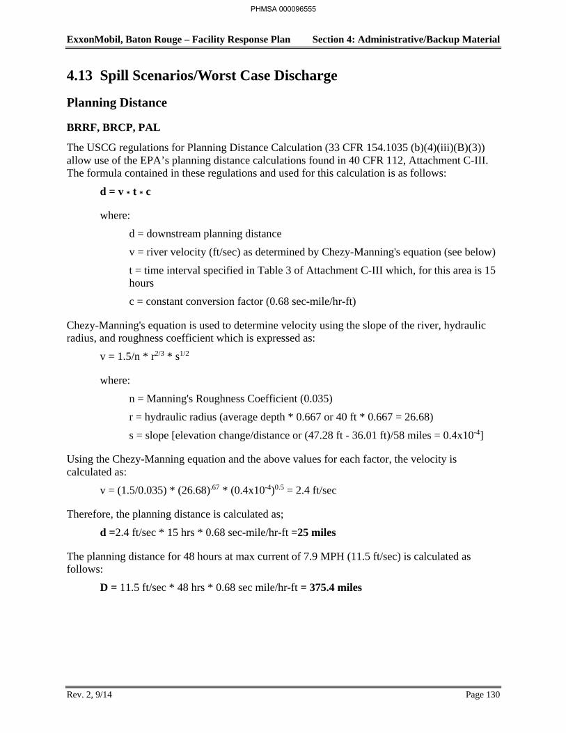
ExxonMobil, Baton Rouge – Facility Response Plan Section 4: Administrative/Backup Material
Rev. 2, 9/14 Page 130
4.13 Spill Scenarios/Worst Case Discharge
Planning Distance
BRRF, BRCP, PAL
The USCG regulations for Planning Distance Calculation (33 CFR 154.1035 (b)(4)(iii)(B)(3)) allow use of the EPA’s planning distance calculations found in 40 CFR 112, Attachment C-III. The formula contained in these regulations and used for this calculation is as follows:
d = v * t * c
where:
d = downstream planning distance
v = river velocity (ft/sec) as determined by Chezy-Manning's equation (see below)
t = time interval specified in Table 3 of Attachment C-III which, for this area is 15 hours
c = constant conversion factor (0.68 sec-mile/hr-ft)
Chezy-Manning's equation is used to determine velocity using the slope of the river, hydraulic radius, and roughness coefficient which is expressed as:
v = 1.5/n * r2/3 * s1/2
where:
n = Manning's Roughness Coefficient (0.035)
r = hydraulic radius (average depth * 0.667 or 40 ft * 0.667 = 26.68)
s = slope [elevation change/distance or (47.28 ft - 36.01 ft)/58 miles = 0.4x10⁻⁴]
Using the Chezy-Manning equation and the above values for each factor, the velocity is calculated as:
v = (1.5/0.035) * (26.68).67 * (0.4x10-4)0.5 = 2.4 ft/sec
Therefore, the planning distance is calculated as;
d =2.4 ft/sec * 15 hrs * 0.68 sec-mile/hr-ft =25 miles
The planning distance for 48 hours at max current of 7.9 MPH (11.5 ft/sec) is calculated as follows:
D = 11.5 ft/sec * 48 hrs * 0.68 sec mile/hr-ft = 375.4 miles
PHMSA 000096555
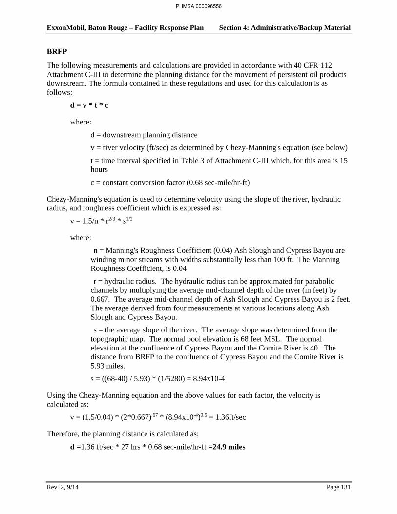
ExxonMobil, Baton Rouge – Facility Response Plan Section 4: Administrative/Backup Material
Rev. 2, 9/14 Page 131
BRFP
The following measurements and calculations are provided in accordance with 40 CFR 112 Attachment C-III to determine the planning distance for the movement of persistent oil products downstream. The formula contained in these regulations and used for this calculation is as follows:
d = v * t * c
where:
d = downstream planning distance
v = river velocity (ft/sec) as determined by Chezy-Manning's equation (see below)
t = time interval specified in Table 3 of Attachment C-III which, for this area is 15 hours
c = constant conversion factor (0.68 sec-mile/hr-ft)
Chezy-Manning's equation is used to determine velocity using the slope of the river, hydraulic radius, and roughness coefficient which is expressed as:
v = 1.5/n * r2/3 * s1/2
where:
n = Manning's Roughness Coefficient (0.04) Ash Slough and Cypress Bayou are winding minor streams with widths substantially less than 100 ft. The Manning Roughness Coefficient, is 0.04
r = hydraulic radius. The hydraulic radius can be approximated for parabolic channels by multiplying the average mid-channel depth of the river (in feet) by 0.667. The average mid-channel depth of Ash Slough and Cypress Bayou is 2 feet. The average derived from four measurements at various locations along Ash Slough and Cypress Bayou.
s = the average slope of the river. The average slope was determined from the topographic map. The normal pool elevation is 68 feet MSL. The normal elevation at the confluence of Cypress Bayou and the Comite River is 40. The distance from BRFP to the confluence of Cypress Bayou and the Comite River is 5.93 miles.
s = ((68-40) / 5.93) * (1/5280) = 8.94x10⁻⁴
Using the Chezy-Manning equation and the above values for each factor, the velocity is calculated as:
v = (1.5/0.04) * (2*0.667).67 * (8.94x10-4)0.5 = 1.36ft/sec
Therefore, the planning distance is calculated as;
d =1.36 ft/sec * 27 hrs * 0.68 sec-mile/hr-ft =24.9 miles
PHMSA 000096556
ExxonMobil, Baton Rouge – Facility Response Plan Section 4: Administrative/Backup Material
Rev. 2, 9/14 Page 132
Note that this is a worse case distance. Prior to getting to the Comite River, the material must flow 5.93 miles though the bayou. During this time, every attempt will be made to stop the oil before it enters the river.
PHMSA 000096557
ExxonMobil, Baton Rouge – Facility Response Plan Section 4: Administrative/Backup Material
Rev. 2, 9/14 Page 133
Local Receptors
The potential effects of a terrestrial spill on land-based sensitivities such as schools, medical facilities, residential areas and businesses, would be non-existent or minimal as it is very unlikely that a spill of significant size would escape containment and migrate a considerable distance off the various Refinery and Chemical Plant property. The Refinery, Baton Rouge Terminal and Chemical Plant are located in an industrial area which precludes the presence of the majority of the above receptors except that there are some residences a few hundred yards to the east of the Refinery, Terminal and Chemical Plant. Even if a spill were to escape containment on that side of the facilities, the oil would likely flow onto Scenic Highway and into the storm drain inlets along the highway and would not reach any of the residences.
The Anchorage Tank Farm and Port Allen Lubricants Plant are situated on the west side of the Mississippi River and within an area that is characterized as light industrial and somewhat rural. There are a few commercial facilities and sporadic residences in the general vicinity of the two facilities but most of the area is open space. Spills that may escape containment would likely enter drainages that would discharge into the local parish canal that, in turn, discharges to the Intracoastal Waterway. No local sensitive receptors have been located in the vicinity of these two facilities.
The only sensitive receptor in the vicinity of the Chemical Plant is the Monte Sano Bayou to the north as the ExxonMobil Baton Rouge Refinery borders the Chemical Plant to the south and other industrial facilities are situated to the west. The bayou has been classified by the Louisiana Department of Environmental Quality as a designated man-made water body from Highway 61, upstream of the Chemical Plant, to the Mississippi River for the purposes of water quality standards. Environmental sensitivities are minimal.
In the event a large spill reaches the Mississippi River from the refinery, there are a number of receptors that could be impacted including waterfront facilities, municipal and industrial water intakes, and waterborne commerce. A large spill would likely require a temporary closure of the river to commerce due to the potential for a fire, particularly for non-persistent oils, as well as the shutting down of the various downstream water intakes. There are very few environmental sensitivities along the river that could be impacted by an oil spill. Water intakes and environmental sensitivities along the downstream portions of the Mississippi River are addressed in Section 3.
PHMSA 000096558
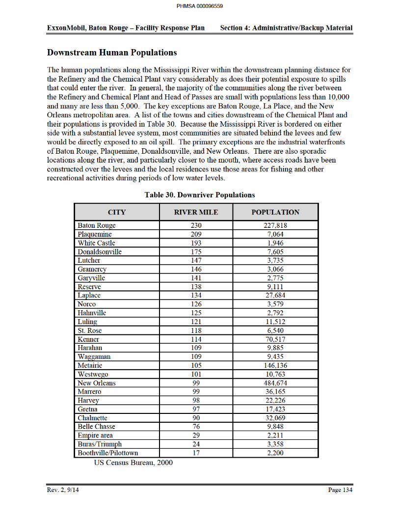

ExxonMobil, Baton Rouge – Facility Response Plan Section 4: Administrative/Backup Material
Rev. 2, 9/14 Page 135
Spill Scenarios
The small, medium, and worst case discharge (WCD) volumes for each category of oil, and scenarios that may result in the worst case planning volume are described below and listed in Table 31.
Scenario Volumes
The worst case discharges (Table 32) and planning volumes (Table 31) were calculated separately for each facility, the dock, and the interconnecting pipelines between the Refinery and the Anchorage Tank Farm.
Receiving Waters
The likely receiving waters for worst case discharges from the Anchorage Tank Farm and Port Allen Lubricants Plant are the parish canal and eventually the Intracoastal Waterway and are classified as river/canal waterways and for the chemical plant is the Monte Sano Bayou, which is also classified as a river/canal waterway. The receiving waters for worst case discharges from the Refinery (including Chemical Plant tanks within the Refinery), and Baton Rouge terminal are local drainage courses and the Mississippi River which is classified as an inland water.
Methods of calculation/assumptions:
Tank Assumptions (EPA Regulated):
• All tanks are individually diked or separated by valves and operate as individual storage systems or utilize sitewide containment as detailed in appropriate SPCC plan.
• Secondary containment is provided for at least 110 percent of the contents of each tank either through the secondary containment dike/fire wall or tertiary systems (process sewers) if the secondary systems are insufficient.
Dock Assumptions (USCG Regulated):
• Vessel ramming incident occurs at Berth 4 where the largest concentration of pipelines is located and all lines are severed by the incident.
• Approximately 25 percent of the lines are in service at the time of the incident which is based on berthing space limitations at the dock and historical data.
• Chemical (non-oil) and water lines that pass through Berth 4 were excluded from the calculations.
• Detection and shut down time is 1 minute based on the use of the Emergency Shut Down system at the dock.
• Pumping losses prior to shut down and drain down after shut down are based on 25 percent of the lines severed being in service.
PHMSA 000096560

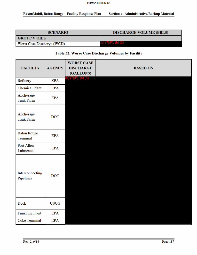
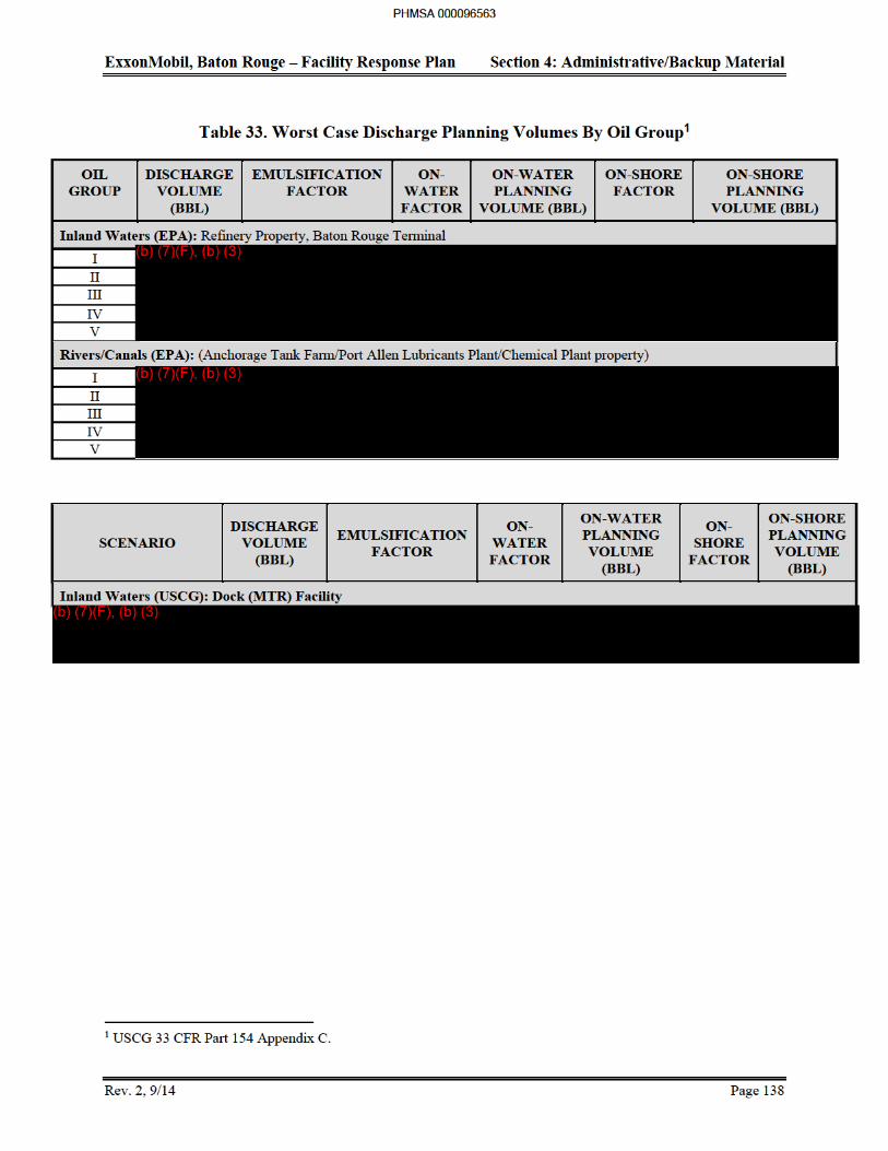
ExxonMobil, Baton Rouge – Facility Response Plan Section 4: Administrative/Backup Material
Rev. 2, 9/14 Page 140
Scenario Descriptions (Average Most Probable/Small Spills)
Aquatic Spill
Refinery
This scenario involves a 50 bbl (1,200 gallon) gas oil spill from the refinery dock when one of the loading hoses experiences a gasket failure at the barge manifold during a loading operation at one of the inside berths. The result is oil spraying from the leak up into the air and falling both onto the barge and into the Mississippi River. The oil on the barge is contained by plugging the scuppers along the edge of the deck thus reducing the amount of oil reaching the water to approximately 50 bbl reach the water. The Dock Controller is immediately aware of the incident and terminates the transfer operation. He then activates the primary response personnel at the dock and contacts the Refinery Superintendent to advise him of the situation. The response personnel are directed to begin deploying boom immediately downstream of the berth in a diversionary mode to direct the oil to the shoreline for recovery. Secondary booms are deployed slightly downstream of the primary booms to contain oil that may escape under the primary boom. The Refinery Superintendent initiates notification of the regulatory agencies and responds to the dock to assess the situation. The booms deployed by the dock personnel have contained the majority of the oil although a few patches of sheen have escaped containment and are migrating down river. The Refinery Superintendent has assumed the role of Incident Commander and dispatches a crew of response personnel in a boat to pursue the sheens and attempt recovery with sorbents. The oil that is contained within the booms has been diverted to the shoreline where recovery has been initiated using one of the on-site contractor's vacuum trucks. The recovered oil is then taken to the refinery for processing through the Mixed Gas Oil recovery system.
Chemical Plant
This scenario involves a 2,100-gallon distillate spill from a tanker truck within the Chemical Plant. The tank truck experiences a tire blowout while rounding a corner after leaving the loading racks and rolls over resulting in a partial valve failure on one of the tank compartments. The spilled distillate flows to a nearby non-process sewer inlet which normally handles storm water runoff and discharges to the Monte Sano Bayou. Due to the potential fire hazard and concern for injuries, the initial response focuses on removing the driver from the vehicle. Blanketing the spill with foam, and actions to prevent the distillate from reaching the bayou are not immediately initiated. The initial response is implemented by the facility fire department and medical personnel.
Once the fire hazard is mitigated and the driver is attended to, the Chemical Plant Superintendent dispatches the Environmental Shift Supervisor to inspect the Monte Sano Bayou for oil. The supervisor reports back that oil has entered the bayou and estimates the quantity at approximately 2,100 gallons. The Chemical Plant Superintendent immediately assumes the role of Incident Commander, activates the PSRT, and initiates the internal and external notification procedures.
The PSRT responds to the bayou with the chemical plant's containment boom and places it across the bayou at accessible downstream locations. Sorbent booms are also deployed across the bayou to help contain the oil and begin recovery. Several vacuum trucks provided by a local
PHMSA 000096565
ExxonMobil, Baton Rouge – Facility Response Plan Section 4: Administrative/Backup Material
Rev. 2, 9/14 Page 141
contractor and Chemical Plant pumps are dispatched to the bayou to recover the contained oil. The recovered material is taken to the refinery for processing through the Mixed Gas Oil recovery system.
Following recovery of most of the oil, the oiled shorelines are flushed with water to wash the oil back into the bayou for recovery. The resulting oil and remaining sheens are recovered using the pumps and sorbent pads. In consultation with state and federal officials, the response is terminated and options for removing residual oil are explored.
Terrestrial Spill
Refinery
This scenario involves a valve seal failure at a distillate storage tank within the refinery which occurs at night and goes undetected for several hours resulting in a spill of 50 bbl (1,200 gallons). The oil drains to a low spot at the corner of the fire wall. The plant personnel working in that area notice the spill and place sorbent booms on the ground around the spill to limit spreading. They notify the Plant Superintendent of the incident. The superintendent activates the PSRT and selected contractor response personnel and instructs them to mobilize to the involved tank. An on-site contractor vacuum truck is also dispatched to the site of the spill. Personnel are instructed to secure the leaking valve or transfer the contents of the leaking tank into available tankage. The response personnel use the vacuum truck to remove the pooled oil and transport it to the EULA treatment plant and discharge it to one of the recovered oil tanks for reprocessing. Sorbent materials are used to recover the remaining free oil and the oiled sediments are removed for on-site or off-site treatment.
Chemical Plant
This scenario involves a valve seal failure at a gas oil storage tank which occurs at night and goes undetected for several hours resulting in a spill of 2,100 gallons. The oil drains to a sump at the corner of the containment dike. The Chemical Plant personnel working in that area ensure that the dike valve is closed, place sorbent booms on the ground around the spill to limit spreading, and notify the Chemical Plant Superintendent of the incident. The superintendent activates the PSRT Spill Response Supervisor (Contractor Foreman) and the contractor response personnel. A local contractor is notified and dispatches a vacuum truck to the facility. The on-site response contractors and vacuum truck remove the pooled oil from the sump area and transport it to the plant's wet naphtha return system. This system is used to transfer oils recovered from various chemical plant processes to the adjacent refinery for reprocessing. Sorbent materials are used to recover the remaining free oil and the oiled sediments in the sump are removed for off-site disposal.
The which contains gas oil and has been identified as resulting in the largest worst case discharge planning volume. The chemical plant owns and operates a larger tank (Tank 784), but it is located within the adjacent ExxonMobil Baton Rouge Refinery and contains steam-cracked distillate. This distillate is classified as non-persistent oil and consequently, will evaporate relatively rapidly and result in a smaller planning volume and amount of oil that will require recovery. Response to non-persistent oils is not
PHMSA 000096566
(b) (3), (b) (7)(F)
ExxonMobil, Baton Rouge – Facility Response Plan Section 4: Administrative/Backup Material
Rev. 2, 9/14 Page 142
always recommended due to the potential fire and health hazards which further substantiate the use of Tank 1664 for this scenario.
Port Allen Lube Oil Blending Plant (PAL)
For this scenario it is assumed that a rail car being loaded with finished product and after reaching the set-point stop weight on the scale, the operator calls for the line pig to be launched to clear residual product. As the pig travels to the rail car air bypasses the pig in the pipeline. As the pig nears the rail car, approximately 5 gallons of air-entrained oil sprays from the line and lands on the top and sides of the railcar. The Blend Supervisor is first advised and then plant management. The spill is properly cleaned up and an investigation initiated to determine cause and remedial action.
Finishing Plant
This scenario involves a valve seal failure at a resin concentrate storage tank which occurs at night and goes undetected for several hours resulting in a spill of 50 bbl (2100 gallons). The oil drains to a low spot at the corner of the fire wall. The plant personnel working in that area notice the spill and place sorbent booms on the ground around the spill to limit spreading. They notify the Plant Shift Supervisor of the incident. The Shift Supervisor activates the PSRT and selected contractor response personnel and instructs them to mobilize to the involved tank. A contract vacuum truck is notified / dispatched to the site of the spill. Personnel are instructed to secure the leaking valve or transfer the contents of the leaking tank into available tankage. The response personnel use the vacuum truck to remove the pooled oil and return to tankage.
Marketing Terminal
This scenario involves a pinhole leak on a line within the terminal which occurs at night and goes undetected for several hours resulting in a spill of 10 bbl (420 gallons). The oil drains to a low spot at the corner of the fire wall. The plant personnel working in that area notice the spill and place sorbent booms on the ground around the spill to limit spreading. They notify the Plant Superintendent of the incident. The superintendent activates the PSRT and selected contractor response personnel and instructs them to mobilize to isolate the line. An on-site contractor vacuum truck is also dispatched to the site of the spill. The response personnel use the vacuum truck to remove the pooled oil and transport it to the EULA treatment plant and discharge it to one of the recovered oil tanks for reprocessing. Sorbent materials are used to recover the remaining free oil and the oiled sediments are removed for on-site or off-site treatment.
Interconnecting Pipe
This scenario involves a pinhole leak on a line which occurs at night and goes undetected for several hours resulting in a spill of 10 bbl (420 gallons). The oil drains to a low spot at the corner of the fire wall. The plant personnel working in that area notice the spill and place sorbent booms on the ground around the spill to limit spreading. They notify the Plant Shift Supervisor of the incident. The Shift Supervisor activates the PSRT and selected contractor response personnel and instructs them to mobilize to the area of the spill. A contract vacuum truck is notified / dispatched to the site of the spill. Personnel are instructed to secure the leaking line. The response personnel use the vacuum truck to remove the pooled oil and transport it to the EULA treatment plant and discharge it to one of the recovered oil tanks for reprocessing.
PHMSA 000096567
ExxonMobil, Baton Rouge – Facility Response Plan Section 4: Administrative/Backup Material
Rev. 2, 9/14 Page 143
Medium Spill
Refinery
For this scenario, it is assumed that the manifold on a tanker experiences a complete failure at the unloading arm connection during the transfer of crude oil to the refinery. Although the Dock Coordinator is immediately aware of the situation and notifies the tanker captain, the oil continues to flow for a few minutes while the tanker's pumps are being shut down. Some of the oil is sprayed onto the dock but most is discharged directly into the Mississippi River. Although the spill is the responsibility of the tanker, the ExxonMobil refinery initiates the response for this scenario.
The dock controller assesses the situation for any potential health and safety hazards and the extent of the spill. No hazards are identified and the controller estimates that 857 to 1,200 bbl (36,000 to 50,400 gallons) have been discharged to the river. The controller immediately notifies the Refinery Superintendent and activates the dock Primary Response Team. The Refinery Superintendent assumes the position of Incident Commander (IC), notifies refinery management and regulatory agency personnel. The ExxonMobil ELIRT is activated contract Oil Spill Response Organizations (OSRO) are called. The (IC) responds to the dock and takes control of the response activities from the dock controller.
The dock PSRT begins deploying a 500 ft. length of boom stored at the dock in a diversionary mode from the end of the dock to direct oil to the shoreline for subsequent recovery.
Additional 500 ft lengths of boom available in the dock area are deployed in a diversionary mode farther downstream to contain oil that migrated past the dock before the initial boom had been deployed. The ExxonMobil ELIRT and OSRO contract responders deploy additional diversion booms to contain oil along the river bank. Additional booms and boats are mobilized to various downstream locations to deploy supplemental diversion booms.
On-site contractor vacuum trucks and contract skimming equipment (Refinery skimming equipment could also be used) are deployed to the various booming sites to begin recovery of the oil. The IC arranges for aircraft over flights of the river to determine the extent of the spill and the effectiveness of the response operations. A westerly wind has kept the oil near the east bank of the river enabling the booming operations to contain most of the oil. Patches of oil and sheen have, however, migrated towards the center of the river and continue to move downstream. The IC mobilizes response boats to recover as much of the patches of oil as possible with sorbents and small lengths of booms deployed between the two response boats in a catenary configuration.
The recovered oil and water is transported back to the refinery and discharged into the Mixed Gas Oil system for processing. Oil that is stranded on the shorelines is flushed back into the river for containment and recovery using the existing diversion booms. Most of the floating sheens and oil patches are recovered by response vessels and the residual stranded oil is recovered with sorbent materials. The response operation is terminated after all sheens are removed from the water and the federal and state authorities have given their concurrence.
PHMSA 000096568
ExxonMobil, Baton Rouge – Facility Response Plan Section 4: Administrative/Backup Material
Rev. 2, 9/14 Page 144
Chemical Plant
For this scenario, it is assumed that heavy equipment operating adjacent to a gas oil storage tank accidentally backs into the tank and punctures the shell. Oil begins to spill from the tank and accumulates in the sump area near the containment dike drain valve. T he workers check to see that the drain valve is closed and notify the Chemical Plant Shift Superintendent. The superintendent directs the workers to begin transferring oil from the damaged tank into other tanks with available storage capacity. He also activates the PSRT Operations Chief (OSD Shift Supervisor), Spill Response Supervisor (Contractor Foreman), and the contractor response personnel. A local contractor is notified and dispatches a vacuum truck to the facility.
The Chemical Plant Superintendent dispatches the Infrastructure Supervisor to inspect the Monte Sano Bayou to ensure that oil has not entered the non-process sewer and reached the bayou. The supervisor reports back that the containment dike drain valve has apparently failed as oil has entered the bayou and estimates the quantity at approximately 36,000 gallons. The superintendent immediately assumes the role of Incident Commander and activates the ExxonMobil ELIRT. He also initiates the internal and external notification process.
The refinery Dock PSRT is directed to deploy the boom across the mouth of the bayou to ensure no oil reaches the river. Due to the size of the spill, the Chemical Plant Superintendent directs the ELIRT Core Staff and a local response contractor (OSRO’s) to provide additional vacuum trucks, portable skimmers, and response personnel.
The recovered oil and water is transported back to the chemical plant and the oil is decanted into the wet naphtha recovery system for reprocessing by the refinery. The oily water is discharged to the chemical plant's advanced wastewater treatment (AWT) system for supplemental oil/water separation and treatment. Oil that is stranded on the shorelines is flushed back into the bayou for recovery. Residual floating and stranded oil is recovered with sorbent materials and the response operation terminated after all sheens are removed from the water and the federal and state authorities have given their concurrence.
Port Allen Lube Oil Blending Plant (PAL)
For this scenario it is assumed that the Plant Control System (PCS) is inoperative because of a power spike that disables the main PCS computer. Plant Operations continue in manual mode. A tank truck is filling on the North Loading Rack with product (Delvac 1300 Super) from Tank 342. As loading proceeds Tank 313 in the North Tank Farm begins to overflow, going undetected for another 25 minutes thus allowing 5000 gallons of product to spill on to the Tank Farm concrete containment. PCS is inoperative so activation of emergency shutdown systems is not an option. The Blend Controller is advised to de-energize the Tank 342 loading pump and dispatch emergency response personnel. Although the contained area is sufficiently impervious to prevent migration to surrounding soil and allows for drainage to sumps that feed the waste-water treatment systems (WWTS), management elects for dispatch a vacuum truck to recover the oil and transport it offsite so as not to overwhelm the WWTS. A subsequent investigation reveals that the Tank 313 isolation valve at the loading rack manifold does not seat properly, which allowed product to bypass it.
PHMSA 000096569
ExxonMobil, Baton Rouge – Facility Response Plan Section 4: Administrative/Backup Material
Rev. 2, 9/14 Page 145
Resins Finishing Plant
For this scenario, it is assumed that heavy equipment operating adjacent to a varsol storage tank accidentally backs into the tank and punctures the shell. Varsol begins to spill from the tank and accumulates in the sump area near the containment dike drain valve. The workers check to see that the drain valve is closed and notify the Finishing Plant Shift Supervisor. The Supervisor directs the workers to begin transferring varsol from the damaged tank into other tanks with available storage capacity.
The Resin Plant Shift Supervisor dispatches the Environmental Operator to inspect the storm-water ditch/outfall 002 to ensure that varsol has not escaped containment. The Environmental Operator reports back that the containment dike drain valve has apparently failed as varsol has entered the stormwater ditch and the pick-up weir pump has pumped it to the pond system allowing varsol through Outfall 001. The Operator proceeds down the drainage canal and finds front end of varsol near the plant property line. Due to the amount of varsol in ditch and pond system he estimates a spill of 20,000 gals. The Shift Supervisor immediately assumes the role of Incident Commander and initiates the internal and external notification process.
Company /contract response personnel are directed to deploy boom across the canal to ensure no varsol reaches Ash Slough. Due to the size of the spill, the Finishing Plant Supervisor activates the ELIRT Core Staff and a local response contractor (OSRO’s) to provide additional vacuum trucks, portable skimmers, and response personnel.
The recovered varsol and water is transported back to the finishing plant and is decanted into the plant’s recovery system for reprocessing/treatment. Varsol that is stranded on the shorelines is flushed back into the canal for recovery. Residual fating and stranded varsol is recovered with sorbent materials and the response operation terminated after all sheens are removed from the water and the federal and state authorities have given their concurrence.
Marketing Terminal
This scenario involves a flange leak on a line within the terminal which occurs at night and goes undetected for several hours resulting in a spill of 1,500 bbl. The oil drains to a low spot at the corner of the fire wall. The plant personnel working in that area notice the spill and place sorbent booms on the ground around the spill to limit spreading. They notify the Plant Superintendent of the incident. The superintendent activates the PSRT and selected contractor response personnel and instructs them to mobilize to isolate the line. An on-site contractor vacuum truck is also dispatched to the site of the spill. The response personnel use the vacuum truck to remove the pooled oil and transport it to the EULA treatment plant and discharge it to one of the recovered oil tanks for reprocessing. Sorbent materials are used to recover the remaining free oil and the oiled sediments are removed for on-site or off-site treatment.
Interconnecting Pipe
This scenario involves a flange leak on a line which occurs at night and goes undetected for several hours resulting in a spill of 1,500 bbl. The oil drains to a low spot at the corner of the fire wall. The plant personnel working in that area notice the spill and place sorbent booms on the ground around the spill to limit spreading. They notify the Plant Shift Supervisor of the incident.
PHMSA 000096570

ExxonMobil, Baton Rouge – Facility Response Plan Section 4: Administrative/Backup Material
Rev. 2, 9/14 Page 146
The Shift Supervisor activates the PSRT and selected contractor response personnel and instructs them to mobilize to the area of the spill. A contract vacuum truck is notified / dispatched to the site of the spill. Personnel are instructed to secure the leaking line. The response personnel use the vacuum truck to remove the pooled oil and transport it to the EULA treatment plant and discharge it to one of the recovered oil tanks for reprocessing.
PHMSA 000096571
ExxonMobil, Baton Rouge – Facility Response Plan Section 4: Administrative/Backup Material
Rev. 2, 9/14 Page 147
Worst Case Discharge
Anchorage Tank Farm
This scenario involves Tank 1504 at the Anchorage Tank Farm which contains crude oil and has been identified as resulting in the worst case discharge. For this scenario, it is assumed that heavy rains have been falling in the Baton Rouge area for three consecutive days and the waste treatment facility is overwhelmed. The spill occurs when a crane working within the dike wall on a pipeline project tops over. The crane strikes the production line to the tank resulting in loss of the entire contents of the tank.
Workers at the tank farm observe the incident and immediately contact the Refinery Superintendent and respond to the leaking tank. The workers proceed with caution using PPE as appropriate due to the potential fire and hydrocarbon vapor/H2S hazard. The workers determine that there is an explosion hazard and evacuate the tank farm. Before leaving, they attempt to close the sluice gate on the Parish Canal to contain the oil within the tank farm but are only partially successful.
The Refinery Superintendent assumes the position of Incident Commander and activates ELIRT. The Incident Commander then initiates the internal and external (regulatory) notification process including notification of West Baton Rouge Parish OEP. Several spill contractors are activated to respond to the spill. Because the OSRO is located in Port Allen and close to the East Parish Canal, they are the first responders on-site. Due to the relatively high currents in the canal much of the oil has already migrated past their location and continues towards the Intracoastal Waterway. The OSRO begins deploying a series of containment booms across the canal to contain as much of the remaining oil as possible.
The Incident Commander and ELIRT core staffs respond to the Anchorage Tank Farm and survey the length of the East Parish Canal to conduct a more detailed assessment of the situation. It is difficult to obtain an accurate assessment but the tank farm workers report that the entire contents of Tank 1504 or approximately of crude have been released to the East Parish Canal. Industrial Hygiene is on site to monitor for H2S and advise accordingly
The ELIRT personnel begin to arrive and the Incident Commander directs them to begin deploying additional containment booms along the Parish Canal both upstream and downstream of the OSRO locations. Oil is continuing to flow down the canal and because of the high flow conditions in the canal and the large volume of oil, the OSRO booming operations have only been partially effective. The initial boom deployment operations were also delayed due to the rain and darkness, allowing a significant amount of oil to reach the Intracoastal Waterway.
As additional contractors and ELIRT equipment arrives, the Incident Commander directs their deployment in the Intracoastal Waterway. The oil has covered the width of the waterway and has spread a significant distance in either direction. Containment booms are deployed across the waterway at suitable access points ahead of the advancing slick. Exclusion booms are placed in front of waterfront facilities wherever possible as a protection measure.
The Incident Commander notifies NARRT along with the U.S. Coast Guard MSO Baton Rouge and MSO New Orleans that a large quantity of oil has entered the Intracoastal Waterway and that
PHMSA 000096572
(b) (7)(F), (b) (3)
(b) (7)(F), (b) (3)
ExxonMobil, Baton Rouge – Facility Response Plan Section 4: Administrative/Backup Material
Rev. 2, 9/14 Page 148
the waterway should be closed to all vessel traffic. The Port Allen Locks at the confluence of the waterway and Mississippi River are contacted and requested to shut down to all vessel traffic except response vessels in an effort to exclude oil from reaching the Mississippi River. The Waterworks Warning Network is also contacted to alert downstream water users of the potential for oil to enter the river.
The ELIRT mobile command center is set up in Port Allen near the waterway. As representatives from the state agencies, U.S. Coast Guard, and U.S. Environmental Protection Agency begin to arrive, they are directed to the command center where they meet with the ExxonMobil response personnel. It is decided to establish a unified command system. An overall response strategy is developed jointly between ExxonMobil and the various agency representatives.
As early as possible, aerial reconnaissance is conducted by ExxonMobil to assess the situation. The oil has migrated a considerable distance in either direction along the Intracoastal Waterway but the containment operations have proven to be effective. Some oil has escaped under the booms and is still moving to the west along the waterway. Regular over flights continue throughout the day and more containment booming and shoreline protection operations are implemented along the waterway.
Skimmers and portable tanks and/or vacuum trucks available from response organizations are positioned along the shoreline at the various containment booming locations on both the Intracoastal Waterway and Parish Canal. Other vacuum or tank trucks are brought in to shuttle recovered oil and water back to the refinery. It is discharged into the Mixed Gas Oil recovery system for processing.
Containment and recovery operations continue over the next few days until all of the oil is recovered from the waterway and Parish Canal. Oil stranded on the shorelines is flushed back into the water and recovered with skimmers or sorbents. Some sediment along the affected shorelines was heavily oiled and required removal and disposal at commercial disposal sites. Response operations are terminated after several days with concurrence from the state and federal agencies and a long-term monitoring and restoration program is developed.
Refinery Complex
This scenario involves Tank 300 which contains fuel oil and has been identified as resulting in the worst case discharge. For this scenario, it is assumed that heavy rains have been falling in the Baton Rouge area for three consecutive days and the waste treatment facility is overwhelmed. The spill occurs when a crane working within the dike wall on a pipeline project tops over. The crane strikes the production line to the tank resulting in loss of the entire contents of the tank. Because of the working containment capabilities within the refinery, 25% of the tank’s total capacity is contained before reaching waterways. Therefore, the actual WCD is reduced to
Workers at the tank farm observe the incident and immediately contact the Refinery Superintendent and respond to the tank to assess the situation. The workers proceed with caution due to the potential fire and hydrocarbon vapor. The workers determine that there is an explosion hazard and evacuate the area.
PHMSA 000096573
(b) (7)(F), (b) (3)
(b) (7)(F), (b) (3)
ExxonMobil, Baton Rouge – Facility Response Plan Section 4: Administrative/Backup Material
Rev. 2, 9/14 Page 149
The Refinery Superintendent assumes the position of Incident Commander and activates ELIRT. The PSRT are the first responders on-site. The Incident Commander initiates the internal and external (regulatory) notification process and activates several spill contractors to respond to the spill. The sewer system and containment ponds are mostly full of water from the previous days’ rainfall event. OSRO’s are called due to the possibility that the oil may not be able to be contained on site.
The Incident Commander and ELIRT core staffs respond to Tank 300 area for a more detailed assessment of the situation. It is difficult to obtain an accurate assessment but the tank farm workers report that the entire contents of Tank 300 have been released but only 75% of the material makes its way off the refinery property; 25% of the oil is contained in the sewer system.
The ELIRT personnel begin to arrive and the Incident Commander directs them to deploy containment boom from the dock in a diversionary mode to divert oil moving downstream to the shoreline for recovery, referring to ELIRT’s “first day” plan. The initial boom deployment operations are delayed due to the darkness, allowing a significant amount of oil to reach the Mississippi River.
As additional contractors and ELIRT equipment arrives, the Incident Commander directs their deployment in the Mississippi River staging area. Exclusion booms are placed in front of waterfront facilities wherever possible as a protection measure.
The Incident Commander notifies the U.S. Coast Guard MSO Baton Rouge and MSO New Orleans that a large quantity of oil has entered the Mississippi River and that the river is closed to all vessel traffic. The Port Allen Locks at the Mississippi River are contacted and requested to shut down to all vessel traffic except response vessels. The Waterworks Warning Network is also contacted to alert downstream water users of the potential for oil to enter the river.
The ELIRT mobile command center is set up at the Refinery near the river. As representatives from the state agencies, U.S. Coast Guard, and U.S. Environmental Protection Agency begin to arrive they are directed to the command center where they meet with the ExxonMobil response personnel. It is decided to establish a unified command system. An overall response strategy is developed jointly between ExxonMobil and the various agency representatives.
As soon as possible, aerial reconnaissance is conducted by ExxonMobil to assess the situation. The oil has migrated a considerable distance downstream along the Mississippi River but the booming operations have proven to be effective. Some oil is still moving downriver. Regular over flights continue throughout the day and more containment booming operations and shoreline protection operations are implemented along the river.
Skimmers and portable tanks and/or vacuum trucks available from response organizations are positioned along the shoreline at the various containment booming locations. Other vacuum or tank trucks are brought in to shuttle recovered oil and water back to the refinery.
Containment and recovery operations continue over the next several days until all of the oil is recovered from the river. Oil stranded on the shorelines is recovered with skimmers or sorbents. Some sediment along the affected shorelines was heavily oiled and required removal and
PHMSA 000096574
(b) (7)(F), (b) (3)
ExxonMobil, Baton Rouge – Facility Response Plan Section 4: Administrative/Backup Material
Rev. 2, 9/14 Page 150
disposal at commercial disposal sites. Response operations are terminated after several days with concurrence from the state and federal agencies and a long-term monitoring and restoration program is developed.
Chemical Plant
This spill is caused by the overfilling of Tank 1664 following an alarm system malfunction. The overfilling places a high structural load on the tank causing it to fail. The heavy rains have weakened the dike system and the sudden spill from the tank further weakens the dike and causes it to fail. This allows the oil to enter a nearby inlet to the non-process sewer system where it flows to the outfall and into the Monte Sano Bayou.
Workers passing by the tank area notice the incident and immediately contact the operations personnel to terminate pumping and notify the Chemical Plant Superintendent who, in turn, assumes the position of Incident Commander. The superintendent responds to the Monte Sano Bayou to conduct a preliminary assessment and finds a large quantity of oil covering the bayou and migrating towards the Mississippi River. Due to the continued pumping for a short time following the tank failure, the spill volume exceeds the maximum tank capacity and is estimated at The Incident Commander then initiates the internal and external notification process and requests activation of the ELIRT.
The Incident Commander directs ELIRT to deploy booms from the docks along the bayou to contain as much oil as possible. Due to the darkness, rain, and high water levels in the bayou, booming is complicated and delayed somewhat, allowing oil to reach the Mississippi River. The ELIRT has responded with equipment stored at the ExxonMobil Baton Rouge Refinery. The Dock PSRT begins to deploy boom across the mouth of the bayou. ExxonMobil ELIRT is instructed to deploy containment boom from the dock in a diversionary mode to divert oil moving downstream to the shoreline for recovery.
The Incident Commander, in conjunction with the ELIRT Incident Manager, begins contacting ExxonMobil's various response contractors, and request that they respond to the spill. Because of the high currents in the Mississippi River, containment and diversion booming is not effective except in backwater eddy areas or areas along the shoreline where currents are lower. Contractor equipment and personnel are dispatched downstream to deploy exclusion booms around municipal water intakes.
The Incident Commander notifies the U.S. Coast Guard MSD Baton Rouge and MSO New Orleans that a large quantity of oil has entered the river and that the river should be closed to all vessel traffic. The Waterworks Warning Network is also contacted to alert downstream water users of the situation. The response contractors and ELIRT are directed to mobilize to downstream river access points where currents are known to be lower to deploy diversion booms and initiate recovery operations.
At first light, aerial reconnaissance is conducted by ELIRT to assess the situation. The oil has migrated a considerable distance downstream and the shoreline containment and recovery operations have proven to be effective at their selected locations. The turbulent waters of the Mississippi River appear to have dispersed much of the oil and the high sediment loadings may
PHMSA 000096575
(b) (7)(F), (b) (3)
ExxonMobil, Baton Rouge – Facility Response Plan Section 4: Administrative/Backup Material
Rev. 2, 9/14 Page 151
have reduced the buoyancy of some of the oil causing it to submerge, as there is little oil remaining on the water.
Regular over fights continue throughout the day and more diversion booming and intake protection operations are implemented downstream as contractor resources continue to arrive on-site. Oil recovered from the shoreline containment operations along the Mississippi River and the Monte Sano Bayou is shuttled back to the chemical plant in contractor vacuum and tank trucks. The recovered oil and water is either placed in the wet naphtha recovery system for reprocessing at the ExxonMobil refinery or into the holding tanks at the chemical plant's AWT facility for gravity separation, recovery of the separated oil, and subsequent treatment of the water by the AWT.
Containment and recovery operations continue over the next few days until all of the oil is recovered from the river and bayou. Oil stranded on the shorelines is flushed back into the water and contained by diversion booms placed just downstream and recovered with skimmers or sorbents. Some shoreline areas within the bayou were heavily oiled and required sediment removal and disposal at off-site facilities. In consultation with state and federal officials, containment and recovery operations are terminated and options for continued surveillance and cleanup of oiled shorelines are explored.
Port Allen Lube Oil Blending Plant (PAL)
For this scenario it is assumed that heavy rains have been falling in the BR area for three consecutive days and the WWTS at the Port Allen LOBP is overwhelmed and inoperative forcing operations to use the concrete contained areas of the Tank Farms to temporarily store rainwater. The diked area is approximately 75% full. During normal operations the plant is taking 5000 bbl receipt of base stock from BRR. Approximately 15 minutes before the estimated receipt finish the Operator on duty reports Tank 148 is overflowing. The Blend Controller (BC) immediately calls the Refinery Base Oil Group but is unable to reach anyone. The BC activates the emergency shutdown systems and oil flow stops but line pressure starts to decline. The Base Oil group contacts the BC to find out why the shutdown was initiated and informs the BC the Refinery pumps are still running; which the BC directs be de-energized. At this point the BC receives a call from Enterprise Resources notifying that oil is spraying from the pipeline manifold located approximately 200 yards east of PAL. The Blend Supervisor and Operations Manager proceed to the manifold and identify the leaking flange as the Base Stock line that was in service filling Tank 148. Emergency notifications are made and remediation contractors dispatched to the manifold area. Back at Tank 148 personnel attempting to contain the overflow oil with booms notice that oil is seeping from under the surface of the water and, upon further investigation, notice a crack in the tank shell at the corner weld. The BC is notified, who then informs Plant Management. Operating personnel are directed to vacate the area around Tank 148 and as they do so one operator notes the east side of Tank 148’s shell is bulging substantially. Shortly thereafter, Tank 148’s shell ruptures, releasing its entire contents (~8,800 bbls) into the tank farm, which overflows the containment and allows an estimated 2000 bbls to reach the already swollen drainage ditches. The oil flows along the water surface to the weir in the SW corner of the plant where it overwhelms the control device and flows off the plant property through the ditches flowing through ATF then connect to the East Parish canal, which drains into the Intracoastal waterway.
PHMSA 000096576
ExxonMobil, Baton Rouge – Facility Response Plan Section 4: Administrative/Backup Material
Rev. 2, 9/14 Page 152
Plant Management notifies PSRT and ELIRT personnel to advise them and request their assistance. ATF personnel are also notified. The PAL Plant Manager assumes the role of Incident Commander and notifies OSRO, the U.S. Coast Guard MSO Baton Rouge and MSO New Orleans that a large quantity of oil has reached the East Parish Canal and is flowing toward the Inter-coastal Waterway. Several spill contractors are also notified to deploy to the site.
Because the OSRO is located in Port Allen they are the first responders and begin to deploy a series of containment booms to mitigate the flow of additional oil into the waterways. PSRT and ELIRT personnel arrive approximately 1 hour after they are notified and deploy up and down the length of the East Parish Canal to further assess the situation. After their investigation the Incident Commander directs them to deploy additional booms upstream and downstream along the canal. Spill contractors arrive and begin oil recovery operations using vacuum trucks, skimmers, portable tanks, sorbent pads and booms. Approximately 6 hours later the spill is determined to be fully contained and has not reached the Inter-coastal Waterway.
Recovery and cleanup operations continue for several more days until all oil is recovered from the waterways. Response operations are terminated with concurrence from state and federal agencies, and a long-term restoration program is developed.
Resins Finishing Plant
This spill is caused by the overfilling of Tank 506 following an alarm system malfunction. The overfilling places a high structural load on the tank causing it to fail. The heavy rains have weakened the dike system and the sudden spill from the tank further weakens the dike and causes it to fail. This allows the varsol to enter the stormwater drainage system where it flows through outfall 002 and into the Ash Slough.
Operations personnel passing by the tank area notice the incident and immediately contact the Finishing Plant Shift Supervisor. The Shift Supervisor immediately orders Operations Personnel to stop feed to the Hydrogenated Stripping Unit thus stopping flow varsol to TK-506. The Shift Supervisor assumes the responsibility of Incident Commander and responds to the Cypress Bayou Bridge on Rafe Mayer Road to conduct a preliminary assessment and finds varsol covering the bayou and migrating downstream. He then proceeds to the Cypress Bayou Bridge at Thomas Road and discovers that varsol has not reached this location. Due to the continued pumping for a short time following the tank failure, the spill volume exceeds the maximum tank capacity and is estimated at The Incident Commander then initiates the internal and external notification process and requests activation of the ELIRT. All roads in the area are closed except for emergency vehicles.
The Incident Commander Response Personnel to deploy booms at suitable access points along Cypress Bayou and in conjunction with the ELIRT Incident Manager begins contacting ExxonMobil's various response contractors, and request that they respond to the spill. At first light, aerial reconnaissance is conducted by ELIRT to assess the situation and regular over flights continue throughout the day. Varsol recovered from the containment operations along Ash Slough and Cypress Bayou is shuttled back to the Finishing Plant in contractor vacuum and tank trucks. The recovered varsol and water is transported back to the finishing plant and is decanted into the plants recovery system for reprocessing/treatment.
PHMSA 000096577
(b) (7)(F), (b) (3)
(b) (7)(F), (b) (3)
ExxonMobil, Baton Rouge – Facility Response Plan Section 4: Administrative/Backup Material
Rev. 2, 9/14 Page 153
Containment and recovery operations continue over the next few days until all of the varsol is recovered from the Ash Slough and Cypress Bayou. Varsol stranded on the shorelines is flushed back into the water and contained by diversion booms placed just downstream and recovered with skimmers or sorbents. Some shoreline areas within the bayou were heavily impacted and required sediment removal and disposal at off-site facilities. In consultation with state and federal officials, containment and recovery operations are terminated and options for continued surveillance and cleanup of oiled shorelines are explored.
Baton Rouge Marketing Terminal
A description of the worst case scenario has not been included since the volume of the largest tank is significantly less than the Refinery’s largest tank (Tank 300) and the spill would migrate along the same flow path.
Baton Rouge Coke Terminal
The worst case scenario for the Baton Rouge Coke terminal is a 660 gallon diesel tank and is within much greater than 100% containment. In the event of an usual spill occurrence, the spill would not be expected to reach a navigable waterway.
Dock Area
The worst case scenario for the dock area is loss of containment of the longest crude line within the dock area. During work activities a hole is punched on the underside of in the 16" diesel heating oil line underneath the dock. The line contains 621 bbls or 26,082 gallons oil. The ESD is hit but the contents of the line do go to the river. For USCG planning purposes, claim 25% (6,520 gallons) of the material is lost to the river. The response scenario is identical to that of the Refinery.
PHMSA 000096578
ExxonMobil, Baton Rouge – Facility Response Plan Section 4: Administrative/Backup Material
Rev. 0, 11/10 Page 154
4.14 Response Resource Requirements
The planning volumes are summarized in Table 31 with calculations following.
The resources available under contract to ExxonMobil significantly exceed the federal requirements for all scenarios.
The planning volumes calculated all exceed the applicable response equipment maximums and/or capacity described in the EPA and USCG regulations. As described in Section 1 ExxonMobil has in excess of 18,000 feet of boom and 11,500 bpd of recovery capacity available on their private local inventories, as well as 14 motorized boats for use in spill response. Most of this equipment can be deployed within 6 hours, with 1,700 feet of boom and 2 boats being ready for instant deployment at the docks. This easily satisfies the equipment requirements for AMP/small and MMP/medium discharges.
ExxonMobil also has contracts with several OSRO’s, as described in Section 1. The USCG ratings for these OSRO’s indicate that 3 of these local OSRO’s are rated A, B, C, D, and E capable for both rivers/canals and Inland response areas, another 2 are rated D and E capable in both operating areas, and another one is rated D and E capable for rivers/canals. This satisfies the requirement to have contracts up to the maximum capacity for each WCD Tier, and to identify additional equipment up to 2 times the tier maximum capacity if needed (it is needed in this case). Each of these OSRO’s also maintains equipment outside the New Orleans MSO area, which can be called upon if needed.
Sensitive area protection would require approximately 4,000 feet of boom, as shown in Section 3. This quantity can be provided by any of the 5 OSRO’s contracted within the New Orleans MSO area. These OSRO’s can also provide any manpower and equipment necessary for shoreline cleanup of a WCD spill to the maximum extent practicable.
Any substantial threat of a worse case discharge on a DOT Pipeline shall also follow Procedure P-195.402(d) in the Operations and Maintenance Manual.
PHMSA 000096579
ExxonMobil, Baton Rouge – Facility Response Plan Section 4: Administrative/Backup Material
Rev. 0, 11/10 Page 155
4.15 Health and Safety
Introduction
This section discusses the most common causes of accidents and injuries and identifies appropriate preventive measures to ensure a safe working environment and attitude.
Buddy System
• Communication is critical in working groups. Response personnel should always stay in visual contact with their team. Use of the team approach and/or buddy system assures emergency assistance is always available.
General
• Make safety your first step in every job. This includes proper use of personal protective equipment, hazard recognition, watching your buddy, injury reporting, keeping shorelines and work areas free of debris, proper decontamination, and all other elements of this program.
• Do not operate equipment unless you have been trained in its use.
• If you are a supervisor, you have a responsibility to protect the people working for you.
By following the procedures outlined in this program, you should be able to protect yourself and your fellow workers from hazards and to perform your work in a safe and healthy manner.
PHMSA 000096580
ExxonMobil, Baton Rouge – Facility Response Plan Section 4: Administrative/Backup Material
Rev. 0, 11/10 Page 156
Responding To Injuries
In reporting injuries, these guidelines must be followed:
• Reporting
- All occupational injuries, illnesses or accidents must be immediately reported to the supervisor.
- The supervisor has responsibility to investigate all accidents/illnesses to make sure corrective action is taken and to provide proper documentation.
• First Aid Response
- All work crews have a first aid kit on site which is to be used for minor cuts and scrapes.
- If any questions arise as to the seriousness of a problem, consult your supervisor.
- Insect bites can cause infection - seek medical attention if required.
• On-Site Treatment
- Persons trained to provide emergency first aid, including CPR, are available to each work group.
- They will treat minor injuries and illnesses and make a determination if more advanced treatment is required.
PHMSA 000096581
ExxonMobil, Baton Rouge – Facility Response Plan Section 4: Administrative/Backup Material
Rev. 0, 11/10 Page 157
Specific Safety Hazards/Guidelines
Aviation Safety
Aircraft present many potential hazards to both passengers and ground personnel. Exxon's aviation program addresses many of these safety concerns. The following points highlight aviation safety:
• All air traffic will comply with FAA regulations and ExxonMobil command directives.
• No one will board or exit any aircraft unless directed by the pilot; the aircraft and its passengers are under the control of the pilot.
• When traveling in helicopters or amphibious aircraft, approved flotation must be worn.
• Seat belts are required to be worn at all times.
• When entering or exiting a helicopter, walk straight to it from the front side; never from the rear. The invisible tail rotor can cause severe injuries.
• When entering or exiting aircraft, approach from the side or rear under direction of the pilot or other designated personnel.
• When entering helicopters, watch foot placement in order to protect the emergency pop-out flotation pontoons. Stepping on the pontoons may puncture them and reduce the effectiveness of these emergency devices.
Boat/Water Safety
Boat usage has many risks to the employees working from them. Fueling, pulling loads, poor sea conditions, lack of communications, inadequate boat or motor for sea conditions, and improper safety gear all create additional hazards to personnel.
Water operation will be governed by these minimum requirements:
• All boats will comply with Coast Guard regulations for their size/class and carry safety gear.
• Operators of skiffs and other self-propelled vessels used to transport personnel on the water will be properly trained, and meet all USCG requirements.
• Radio equipment on all boats and vessels shall be in good working order and compatible with ExxonMobil communication networks.
• All boats used to transport personnel will be outfitted with the necessary navigation equipment to assure safe transportation.
• Boats without proper lighting will not travel at night or in a fog.
PHMSA 000096582
ExxonMobil, Baton Rouge – Facility Response Plan Section 4: Administrative/Backup Material
Rev. 0, 11/10 Page 158
• Rules of the Road as described in USCG water safety will be the operating criteria for operations of skiffs, Zodiacs and other small work boats. Supervisors are responsible for assuring that all small boat operators are trained and understand these rules.
• When personnel are: going from boat to another vessel; boat to shore; or working where there is a danger of falling into the water, they will wear USCG approved PFD's. Your supervisor will inform you of the type of PFD required for the work you will be conducting.
• Handle anchors and anchor ropes carefully. A common accident is catching the hand between boat sides and anchor rope.
• Extreme care is needed when beaching the boat due to strong underwater currents and underwater obstructions.
• To assure safe boat operations, personnel will be instructed not to:
- Stand up or move around in small boats while they are underway.
- Overload the boat or distribute loads unevenly.
- Decelerate suddenly, allowing the stern wake to overtake and swamp the boat by washing over the transom.
• In handling gasoline for small outboard motors:
- Always fuel boat in good light. Fill all portable tanks on the dock, not while in the boat.
- When boat is tied up at a fueling dock:
Do not smoke, light matches or lighters, or operate electric switches.
Stop engines, motors, fans, and anything else that may cause a spark.
- Secure all fires. Remember pilot lights on gas stoves and refrigerators.
• Before you start to fuel:
- Check the mooring of your boat and get everybody out of the boat.
- Close ports, windows, doors, and hatches (keep fumes and vapors off the boat).
- Check your tanks, filler pipes, tank vents, and flame screens.
- Check to see how much fuel the tank will take.
• During fueling:
- Keep the nozzle of the hose in contact with the can opening to prevent static sparks.
- Guard against spillage. If fuel spills, wipe it up immediately.
- Do not let vapor get below the deck.
PHMSA 000096583
ExxonMobil, Baton Rouge – Facility Response Plan Section 4: Administrative/Backup Material
Rev. 0, 11/10 Page 159
• After fueling:
- Replace caps or fill openings.
- Open up the boat completely and ventilate.
- Air out the boat for five minutes.
- Give low spots (engine bilges, tank spaces) the sniff. If you smell gasoline vapor, look for spillage and leakage.
- Wipe up all spills.
• Fueling is an important operation. You, as skipper, should do it yourself.
• Marine vessels often have unique configurations which require special attention to minimize injuries. Ladders and stairways are narrower and are steeper angles that one normally encounters. Also there are often lower ceilings and protruding pipes which need special attention. Added to these are the high probability of a wet surface. To prevent injury, you must stay aware of your surroundings, reduce loads that you carry and do not move rapidly.
Chemical Exposure
The chemical nature and hazards of each petroleum product handled at the ExxonMobil Baton Rouge complex are provided in the MSDS sheets that are available electronically at BRRF and personnel needing them have access. Updates to these sheets are provided to the local MSU on computer disk. The actual hazards posed to spill response personnel will vary with the type of oil and degree of weathering (i.e. evaporation, dissolution, dispersion, biodegradation, and emulsification). Gasoline is generally the most toxic of the oils handled at the plant. The concentrations of gasoline vapors in the breathing zone and the associated health hazards are:
• 160 to 270 ppm - Can cause eye, nose, and throat irritation after several hours of exposure
• 500 to 900 ppm - Can cause the above irritations and dizziness in one hour
• 2,000 ppm - Can produce mild anesthesia in 30 minutes
Vapor monitoring shall be performed using an organic vapor meter or organic vapor analyzer, as often as necessary to ensure field personnel are protected from hazardous vapors and by individuals trained in the use and care of the monitoring equipment. Decisions regarding the need for respiratory protection should be made using vapor concentrations in the breathing zone prior to the initiation of work in a particular area and at periodic intervals throughout the response operation. If hydrocarbon vapor levels are consistently low or non-detectable, vapor monitoring may be discontinued or the frequency reduced. In all emergency situations, monitoring and exposure prevention will adhere to ExxonMobil standards.
Decontamination
Decontamination procedures must be followed to ensure that all oiled protective clothing is removed safely with minimum direct skin contact and adequately cleaned or disposed of. In
PHMSA 000096584
ExxonMobil, Baton Rouge – Facility Response Plan Section 4: Administrative/Backup Material
Rev. 0, 11/10 Page 160
addition, all tools and equipment exposed to oil contact should be cleaned periodically or prior to transporting offsite.
The essence of decontamination procedures is to remove all oil from work clothing, to prevent direct skin contact, and secondary oiling of other garments and clean areas. Exact procedures will vary between locations, activities conducted, and the level of oil contact. Actual procedures will be determined by the Safety/Health Manager. In general, the decontamination policy will be:
• Limited Decontamination - Prior to lunch or other breaks, workers will move to a designated area and remove oily gloves, followed by cleaning hands with waterless hand cleaner. Workers must avoid secondary contamination from oily outer wear during these periods.
• Full Decontamination - At shift's end, workers go to decontamination area where all oily protective clothing will be removed. Re-usable oiled clothing will be segregated by type (i.e., boots, rain gear, hard hats, etc.). Disposable clothing (gloves, Tyveks, booties) will be put in waste containers. Coveralls will be put into laundry baskets and workers will then proceed to a clean area where street clothing will be available.
• Equipment Decontamination - Oiled tools and equipment will be left at the site or stored on boats and cleaned at the end of the cleanup operations or if they become extremely oiled and difficult or dangerous to use. Boats will be cleaned periodically at designated areas by protected personnel.
Fire and Explosion
Until otherwise established, all spills should be considered as potential fire and explosion hazards. All nearby sources of ignition (electrical equipment, automobiles, welding operations, etc.) should be eliminated and the area cordoned off to all non-essential personnel.
Note: Response to large aquatic spills involving gasoline or similar products is not recommended without proper assistance due to extreme fire hazard. Similarly, response to large terrestrial gasoline, diesel, jet fuel and other petroleum product spills is also not recommended without the assistance of the fire department.
Fire and explosion hazards are generally evaluated based on visual observations and combustible gas indicator or explosimeter lower explosive limit (LEL) readings. The LEL is the minimum vapor concentration where flame propagation will occur in the presence of an ignition source. There is also an upper explosive limit (UEL) wherein explosions will not occur due to the excessive vapor concentrations and lack of oxygen. Most combustible gas meters will drop to 0 or below when the UEL is reached.
Guidelines for conducting response operations in the presence of potentially explosive vapors are as follows:
• 0% LEL – Vapor monitoring required to assess the need for respiratory protection.
PHMSA 000096585
ExxonMobil, Baton Rouge – Facility Response Plan Section 4: Administrative/Backup Material
Rev. 0, 11/10 Page 161
• < 10% LEL – Work may only continue with incident command approval and appropriate respiratory protection.
• > 10% LEL – response must be evaluated by the on scene commander, work may only continue with incident approval and approximate respiratory protection.
Accumulated debris, oily waste, trash and other fuels will be present in all operations to add to the fire danger. Strict control and isolation of these fire sources will be exercised to avoid their accumulation in inhabited areas. In addition, the following precautions are taken:
• Care must be taken around hydrocarbons and fuels: gasoline storage and transfer must be per codes and fire extinguisher must be readily available.
• Fuel handlers will be trained in safe handling techniques.
• Fire suppression equipment will be readily available.
• Smoking is not allowed near flammable materials.
• Welding and burning require work permits where hydrocarbon mixtures may exist (i.e. vessels, tanks, etc.). The safety department will issue work permits.
• All fires will be completely extinguished before leaving the work site.
Noise
Harmful noise levels will be prevalent in oil spill activities. Sources of noise include boats, generators, pumps, aircraft, winches, and other commonly used equipment. Impact noise (sharp or explosive inputs of energy) will exist in some of these operations. Noise levels as determined by field surveys and monitoring may require hearing protection.
Hearing protection will be provided to minimize exposures. If noise monitoring and surveys determine a noise hazard exists, those operations will require full time use of hearing protection. Noise will be discussed in a separate section.
Eye Safety
Splashing of liquids (oil, oily materials, salt water, and transfer of liquids), vapors (from the spill, fumes from the equipment), welding, grinding, and other sources may pose risks of eye injury and irritation.
Wind, heat or cold and reflective sunlight dry the eyes and appropriate action must be taken to minimize the effect of eye irritation.
• Suitable eye protection must be worn in all work areas. Safety glasses are a minimum. Boat decks, barge decks, staging areas, etc., are considered work areas.
• For those involved in beach washing/spraying activities, consideration should be given to face shields or goggles. If contact lenses are worn on the work site, goggles are required instead of safety glasses.
PHMSA 000096586
ExxonMobil, Baton Rouge – Facility Response Plan Section 4: Administrative/Backup Material
Rev. 0, 11/10 Page 162
• Proper eye protection is required for welding, grinding, cutting and burning. This includes welding hood, face shield, and colored goggles, respectively. Do not watch welding operations even from a distance unless you have proper eye wear.
• If oil or any other material enters eyes, flush thoroughly with eyewash solution or clean fresh water and have eye examined by medic.
Personal Protective Equipment (PPE)
To ensure the protection of all cleanup workers and other response personnel, PPE will be required for specific response activities or during transit between sites. Certain items of PPE are mandatory and others are optional depending on the potential for oil contact. Actual PPE requirements will be determined by the Incident Commander or Site Safety Officer. The general PPE to be used for activities with potentially elevated levels of exposure (i.e., cleanup and waste handling) are outlined below:
• Face and eye protection
• Hard hats
• Oil resistant gloves
• High top, oil resistant boots
• Steel toe shoes
• Protective outer wear/rain suits, Tyvek suits and/or fire-proof (Nomex) overalls or undergarments
• Personal Flotation (Type III PFDs or better)
• Respiratory protection (if required)
Requirements for negative pressure respirator use:
• The identity and concentration of the containment is known;
• The oxygen content in the air is at least 19.5 percent;
• There is periodic monitoring of the work area;
• The respirator assembly is approved for the specific contaminant and concentration level;
• The type of respirator being used has been successfully fit-tested on the wearer; and
• Total organic vapor concentrations and/or benzene concentrations are evaluated and recommendations made by Industrial Hygiene.
PHMSA 000096587
ExxonMobil, Baton Rouge – Facility Response Plan Section 4: Administrative/Backup Material
Rev. 0, 11/10 Page 163
Pressure Washing
Pressure washing techniques can result in hazards to operators. Any persons operating such equipment must be specifically instructed in safe use of such equipment by their supervisors. Training will include:
• Orientation to the pressure system, relief valves, pressure gauges.
• Special instruction in routine operations and maintenance of equipment.
• Special precautions to be taken in eye, face and skin protection from contacting the pressure wash stream.
• Proper use of all personal protective equipment (eye protection, hard hat, coveralls, boots, gloves, slicker suits, hearing protection, personal flotation devices, face shields, etc.)
• Equipment will not be operated without proper training.
• It is not advisable to wear jewelry, loose clothing or loose long hair around operating equipment.
Slips, Trips, and Falls
Slips, trips, and falls comprise the major physical hazard to personnel. Most activities will be conducted in an environment and on surfaces that are not conducive to walking, namely wet and/or oily surfaces. Many of the walkways, steps and ladders are built for use in the marine environment and do not meet OSHA standards. This, combined with the wet, oily conditions, increases the risk for injury to the back, knees and ankles from slips, trips, and falls. Control measures must be taken by installing anti-slip surfaces, building adequate access ways, installing handrails, warning employees, and other similar steps to eliminate these hazards.
Slips
• Loss of traction is the leading cause of workplace slips.
• Caused by wet surfaces, spills, or weather hazards like ice and snow.
• Footwear with soft, flexible soles that fit well is a must.
• Practice safe walking skills:
- be cautious on wet surfaces; take short steps and keep your center of balance under you; point your feet slightly outward
- be cautious of smooth surfaces
- cleanup floor spills immediately
Trips
• Make sure you can see where you are going.
PHMSA 000096588

ExxonMobil, Baton Rouge – Facility Response Plan Section 4: Administrative/Backup Material
Rev. 0, 11/10 Page 164
• Keep work areas well-lit.
• Keep work area clean; don't clutter aisle, stairs, or foot paths.
• Place equipment so it does not interfere with your walk path areas.
• Extension or power tools can be dangerous tripping hazards.
• Eliminate hazards due to loose footing on stairs, steps, and floors.
• Arrange loading docks, store gangplanks and ramps properly.
Falls
• Leading cause of injury-producing accidents.
• Avoid jumping.
• Repair or replace stairs or handrails that are loose or broken.
• Do not store items on stairs or in aisles.
• Wear good shoes; non-skid soles are a good choice.
• Inspect all ladders for defects before you begin climbing.
• Do not reach from a ladder or stand on the stop step of the ladder.
• Hoist tools or materials up to you after you reach the top of the ladder.
Small Tools and Equipment
Small tools and equipment pose the normal hazards to workers plus a few special concerns given the worksite.
• Use the proper tool for the job.
• Do not take shortcuts.
• Special care will be taken to properly store and handle compressed gas cylinders. They are to be secured at all times to prevent them from falling, rolling, and creating hazardous conditions. Be careful to protect cylinder valves. Oxygen gas cylinders, empty and full, will be stored with proper separation from all sources of fuel (acetylene, greases, oil, motor fuels, etc.) and ignition to reduce fire hazards.
• All electrical equipment (motors, welding machines, transformers, electrical tools, extension cords, etc.) will be properly grounded to reduce or minimize electrical shock hazards. Almost all of this equipment will be used under wet conditions which increase the potential for electrical shock hazards.
PHMSA 000096589
ExxonMobil, Baton Rouge – Facility Response Plan Section 4: Administrative/Backup Material
Rev. 0, 11/10 Page 165
Strains
Strains can also be a major accident cause. Pulling booms, handling oily waste materials, securing boats, handling hoses, and overexertion are examples of sources for strains. Slips, trips, and falls also result in strains. The most common will be back strain, although any muscle group may be affected.
Effective measures to eliminate strains include use of mechanized lifting equipment, employee education, and assuring that sufficient assistance is available to prevent overexertion. To minimize the potential for strained muscles, remember the following:
• Lift with your legs and not your back.
• Don't try to lift too much - get help or use machinery.
• Pulling of anchors or hoses on beaches are common sources of back strains, etc.
PHMSA 000096590
ExxonMobil, Baton Rouge – Facility Response Plan Section 4: Administrative/Backup Material
Rev. 0, 11/10 Page 166
Health and Safety Plan
Federal OSHA regulations (29 CFR 1910.120) require that a Health and Safety Plan be prepared for certain spill response operations that require an "Emergency Response" by offsite personnel. The scope of the HAZWOPER standard does not cover the inevitable release of a hazardous substance that is limited in quantity and poses no emergency or significant threat to the safety and health of employees in the immediate vicinity. This type of release is referred to as an "incidental release" in 29 CFR 1910.120(a)(3).
An incidental release is a release of hazardous substance which does not pose a significant safety or health hazard to employees in the immediate vicinity or to the employee cleaning it up, nor does it have the potential to become an emergency within a short time frame.
Incidental releases are limited in quantity, exposure potential, or toxicity and present minor safety or health hazards to employees in the immediate work area or those assigned to clean them up.
An example of a fill-in-the blank (template) clean-up operations site health and safety plan is included in Section 4.18. This template should be used as the basis for preparing a plan if required.
PHMSA 000096591
ExxonMobil, Baton Rouge – Facility Response Plan Section 4: Administrative/Backup Material
Rev. 0, 11/10 Page 167
Site Specific Procedures
Anyone handling spilled material will wear as a minimum the following protective equipment:
• Gloves for incidental contact with routine hydrocarbons (gasoline, kerosene, etc). These gloves should be neoprene, nitrile, or a mixture. Verify that other gloves are rated (by the manufacturer) to protect against the specific hazard.
• Rain suits or disposal coveralls where clothing contamination is likely to occur. These protective suites should be rated (by the manufacturer) to protect against the specific hazard.
• Any entry into confined spaces will be conducted following entry permit procedures.
• Any vacuum truck usage will be in accordance with Safety Standard 412.
• Anyone who handles spilled material and gets a small amount of spilled material on their skin or clothing will decontaminate at the end of the work period/shift. Areas of gross contamination should be decontaminated immediately.
• Decontamination will include a shower where any significant contamination occurs.
• All re-useable PPE must be decontaminated or discarded upon removal
• Equipment which comes in contact with spilled material will be cleaned before it leaves the site. Where it is not possible to completely clean equipment before it leaves the site, steps will be taken as needed to prevent the spread of spilled material. This equipment will be cleaned as soon as possible.
• All containers of spilled material will be labeled. The label will include the identity of the spilled material and appropriate hazard warnings.
• Anyone handling or likely to come in contact with the spilled material must receive a review of the MSDS for the spilled material. This review must take place prior to the employee handling or contacting the spilled material. MSDS sheets for each facility are kept at the facility and are readily assessable to all employees.
• Log(s) of workers on site must be kept by the workers’ supervisors. The purpose of these logs is to account for everyone on site at all times.
ALL CLEANUP CONTRACTORS MUST HAVE HAZWOPER TRAINING.
PHMSA 000096592
ExxonMobil, Baton Rouge – Facility Response Plan Section 4: Administrative/Backup Material
Rev. 0, 11/10 Page 168
4.16 Site Safety and Health Plan
The Site Safety and Health Plan should be completed by the site safety and health officer at the outset of an emergency response operation involving offsite response personnel. It should be revised and re-distributed as conditions change. The plan will cover all clean-up operations and all employees working on this project, including contractors and sub-contractors.
PHMSA 000096593
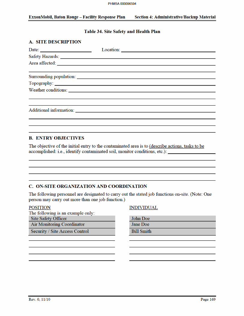
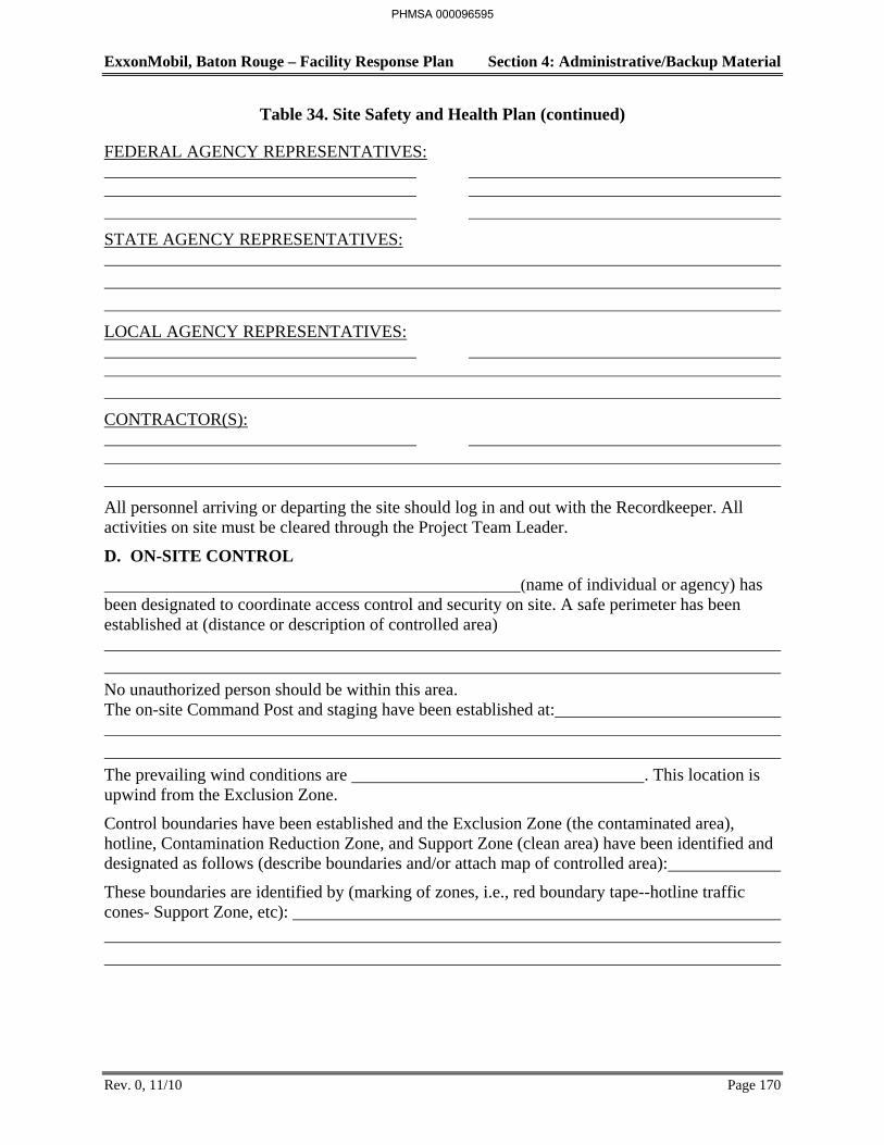
ExxonMobil, Baton Rouge – Facility Response Plan Section 4: Administrative/Backup Material
Rev. 0, 11/10 Page 170
Table 34. Site Safety and Health Plan (continued)
FEDERAL AGENCY REPRESENTATIVES:
STATE AGENCY REPRESENTATIVES:
LOCAL AGENCY REPRESENTATIVES:
CONTRACTOR(S):
All personnel arriving or departing the site should log in and out with the Recordkeeper. All activities on site must be cleared through the Project Team Leader.
D. ON-SITE CONTROL
(name of individual or agency) has been designated to coordinate access control and security on site. A safe perimeter has been established at (distance or description of controlled area)
No unauthorized person should be within this area. The on-site Command Post and staging have been established at:
The prevailing wind conditions are . This location is upwind from the Exclusion Zone.
Control boundaries have been established and the Exclusion Zone (the contaminated area), hotline, Contamination Reduction Zone, and Support Zone (clean area) have been identified and designated as follows (describe boundaries and/or attach map of controlled area):
These boundaries are identified by (marking of zones, i.e., red boundary tape--hotline traffic cones- Support Zone, etc):
PHMSA 000096595

ExxonMobil, Baton Rouge – Facility Response Plan Section 4: Administrative/Backup Material
Rev. 0, 11/10 Page 171
Table 34. Site Safety and Health Plan (continued)
E. HAZARD EVALUATION
The following substance(s) are known or suspected to be on site. The primary hazards of each are identified. Material Safety Data Sheets for the involved substances are available on site.
Substance Involved Concentrations (Chemical Name) (If Known) Primary Hazards
The following additional hazards are expected on site (i.e., slippery ground, uneven terrain, etc.):
Hazardous substance information form(s) for the involved substance(s) have been completed and are attached.
F. PERSONAL PROTECTIVE EQUIPMENT
Based on evaluation of potential hazards, the following levels of personal protection have been designated for the applicable work areas or tasks:
Location Job Function Level of Protection
A B C D Other
A B C D Other
A B C D Other
A B C D Other
A B C D Other
A B C D Other
A B C D Other
A B C D Other
A B C D Other
A B C D Other
A B C D Other
A B C D Other
PHMSA 000096596
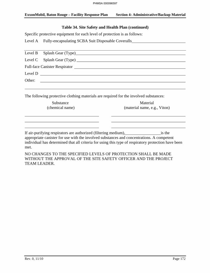
ExxonMobil, Baton Rouge – Facility Response Plan Section 4: Administrative/Backup Material
Rev. 0, 11/10 Page 172
Table 34. Site Safety and Health Plan (continued)
Specific protective equipment for each level of protection is as follows:
Level A Fully-encapsulating SCBA Suit Disposable Coveralls
Level B Splash Gear (Type)
Level C Splash Gear (Type)
Full-face Canister Respirator
Level D
Other:
The following protective clothing materials are required for the involved substances:
Substance Material (chemical name) (material name, e.g., Viton)
If air-purifying respirators are authorized (filtering medium), is the appropriate canister for use with the involved substances and concentrations. A competent individual has determined that all criteria for using this type of respiratory protection have been met.
NO CHANGES TO THE SPECIFIED LEVELS OF PROTECTION SHALL BE MADE WITHOUT THE APPROVAL OF THE SITE SAFETY OFFICER AND THE PROJECT TEAM LEADER.
PHMSA 000096597

ExxonMobil, Baton Rouge – Facility Response Plan Section 4: Administrative/Backup Material
Rev. 0, 11/10 Page 173
Table 34. Site Safety and Health Plan (continued)
G. ON-SITE WORK PLANS
Work party(s) consisting of person(s) will perform the following tasks:
Name Function Project Team Leader Work Party #1
Work Party #2 Rescue Team (required - entries to IDLH environments)
Decontamination Team
The work party(s) were briefed on the contents of this plan at
PHMSA 000096598
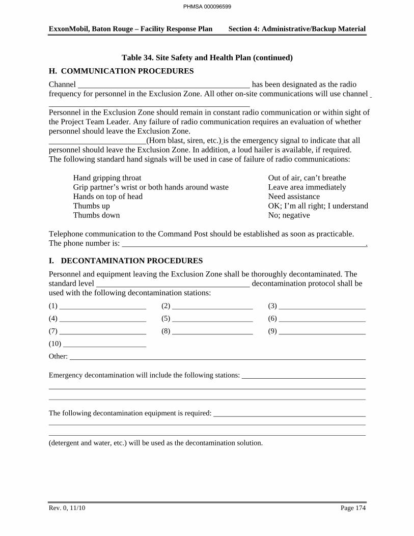
ExxonMobil, Baton Rouge – Facility Response Plan Section 4: Administrative/Backup Material
Rev. 0, 11/10 Page 174
Table 34. Site Safety and Health Plan (continued)
H. COMMUNICATION PROCEDURES
Channel has been designated as the radio frequency for personnel in the Exclusion Zone. All other on-site communications will use channel Personnel in the Exclusion Zone should remain in constant radio communication or within sight of the Project Team Leader. Any failure of radio communication requires an evaluation of whether personnel should leave the Exclusion Zone. (Horn blast, siren, etc.) is the emergency signal to indicate that all personnel should leave the Exclusion Zone. In addition, a loud hailer is available, if required. The following standard hand signals will be used in case of failure of radio communications: Hand gripping throat Out of air, can’t breathe Grip partner’s wrist or both hands around waste Leave area immediately Hands on top of head Need assistance Thumbs up OK; I’m all right; I understand Thumbs down No; negative
Telephone communication to the Command Post should be established as soon as practicable. The phone number is: .
I. DECONTAMINATION PROCEDURES
Personnel and equipment leaving the Exclusion Zone shall be thoroughly decontaminated. The standard level decontamination protocol shall be used with the following decontamination stations:
(1) (2) (3)
(4) (5) (6)
(7) (8) (9)
(10)
Other:
Emergency decontamination will include the following stations:
The following decontamination equipment is required:
(detergent and water, etc.) will be used as the decontamination solution.
PHMSA 000096599
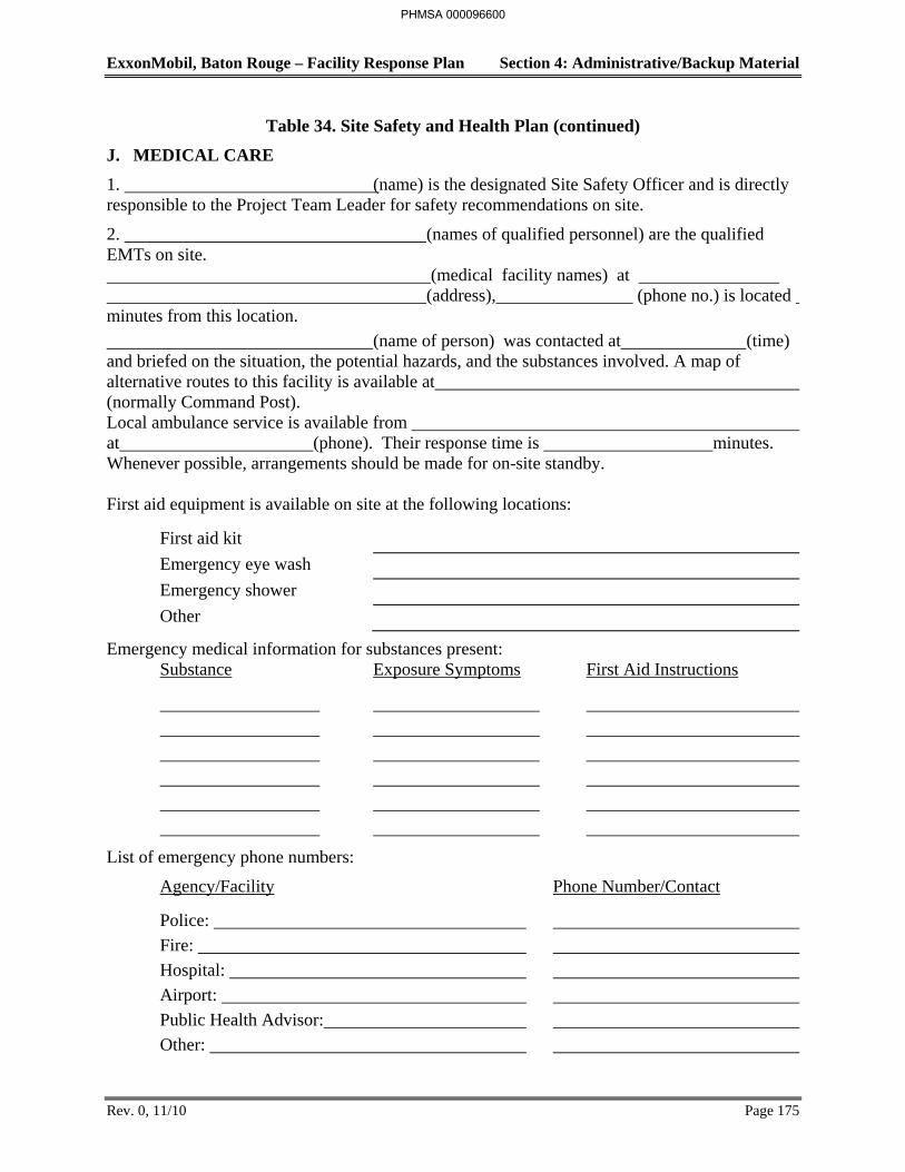
ExxonMobil, Baton Rouge – Facility Response Plan Section 4: Administrative/Backup Material
Rev. 0, 11/10 Page 175
Table 34. Site Safety and Health Plan (continued)
J. MEDICAL CARE
1. (name) is the designated Site Safety Officer and is directly responsible to the Project Team Leader for safety recommendations on site.
2. (names of qualified personnel) are the qualified EMTs on site. (medical facility names) at (address), (phone no.) is located minutes from this location.
(name of person) was contacted at (time) and briefed on the situation, the potential hazards, and the substances involved. A map of alternative routes to this facility is available at (normally Command Post). Local ambulance service is available from at (phone). Their response time is minutes. Whenever possible, arrangements should be made for on-site standby. First aid equipment is available on site at the following locations:
First aid kit
Emergency eye wash
Emergency shower
Other
Emergency medical information for substances present: Substance Exposure Symptoms First Aid Instructions
List of emergency phone numbers:
Agency/Facility Phone Number/Contact
Police:
Fire:
Hospital:
Airport:
Public Health Advisor:
Other:
PHMSA 000096600
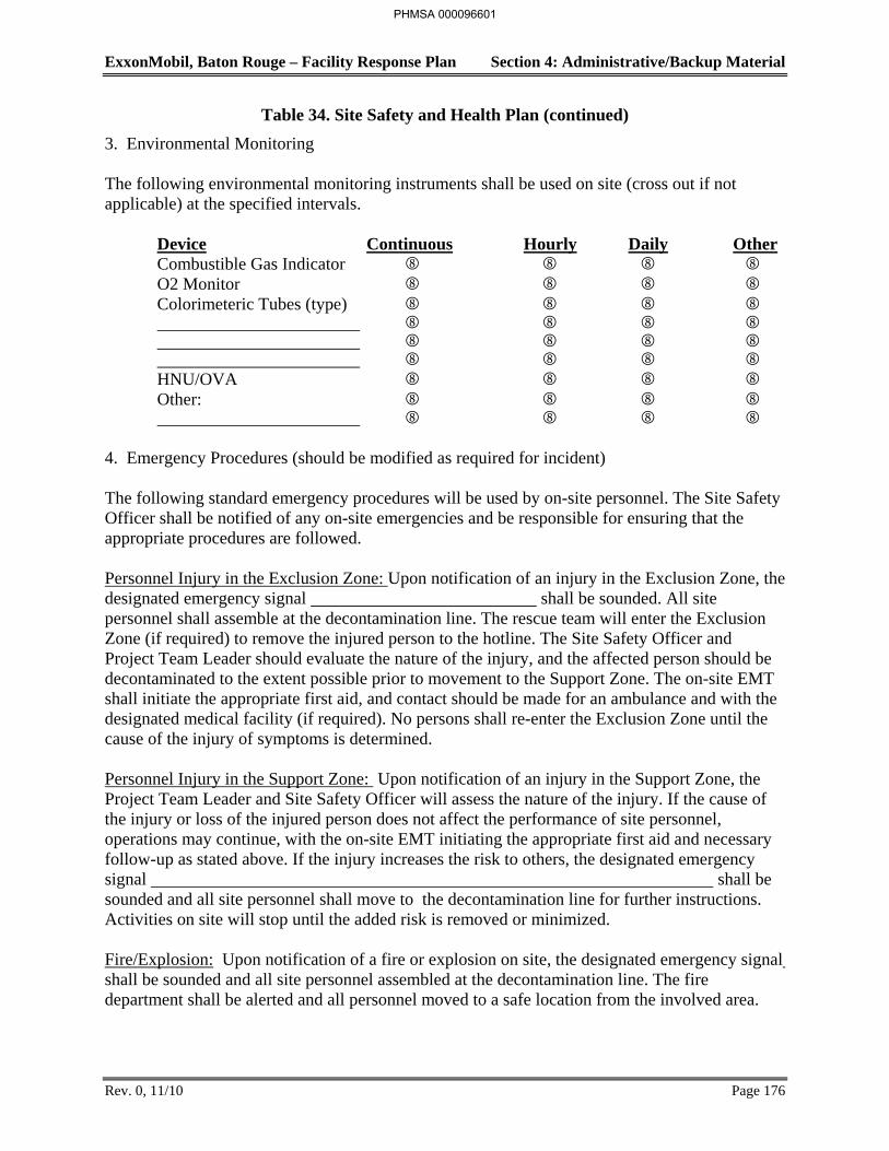
ExxonMobil, Baton Rouge – Facility Response Plan Section 4: Administrative/Backup Material
Rev. 0, 11/10 Page 176
Table 34. Site Safety and Health Plan (continued)
3. Environmental Monitoring
The following environmental monitoring instruments shall be used on site (cross out if not applicable) at the specified intervals.
Device Continuous Hourly Daily Other Combustible Gas Indicator O2 Monitor Colorimeteric Tubes (type) HNU/OVA Other:
4. Emergency Procedures (should be modified as required for incident) The following standard emergency procedures will be used by on-site personnel. The Site Safety Officer shall be notified of any on-site emergencies and be responsible for ensuring that the appropriate procedures are followed. Personnel Injury in the Exclusion Zone: Upon notification of an injury in the Exclusion Zone, the designated emergency signal shall be sounded. All site personnel shall assemble at the decontamination line. The rescue team will enter the Exclusion Zone (if required) to remove the injured person to the hotline. The Site Safety Officer and Project Team Leader should evaluate the nature of the injury, and the affected person should be decontaminated to the extent possible prior to movement to the Support Zone. The on-site EMT shall initiate the appropriate first aid, and contact should be made for an ambulance and with the designated medical facility (if required). No persons shall re-enter the Exclusion Zone until the cause of the injury of symptoms is determined. Personnel Injury in the Support Zone: Upon notification of an injury in the Support Zone, the Project Team Leader and Site Safety Officer will assess the nature of the injury. If the cause of the injury or loss of the injured person does not affect the performance of site personnel, operations may continue, with the on-site EMT initiating the appropriate first aid and necessary follow-up as stated above. If the injury increases the risk to others, the designated emergency signal shall be sounded and all site personnel shall move to the decontamination line for further instructions. Activities on site will stop until the added risk is removed or minimized. Fire/Explosion: Upon notification of a fire or explosion on site, the designated emergency signal shall be sounded and all site personnel assembled at the decontamination line. The fire department shall be alerted and all personnel moved to a safe location from the involved area.
PHMSA 000096601
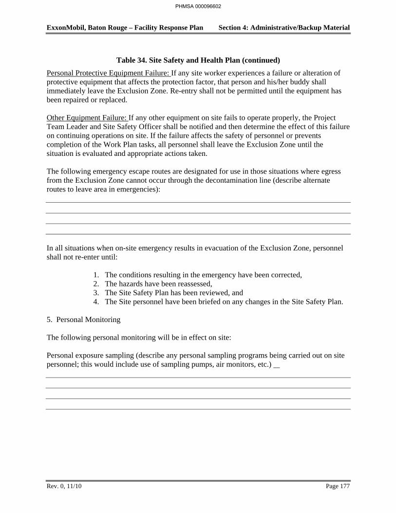
ExxonMobil, Baton Rouge – Facility Response Plan Section 4: Administrative/Backup Material
Rev. 0, 11/10 Page 177
Table 34. Site Safety and Health Plan (continued)
Personal Protective Equipment Failure: If any site worker experiences a failure or alteration of protective equipment that affects the protection factor, that person and his/her buddy shall immediately leave the Exclusion Zone. Re-entry shall not be permitted until the equipment has been repaired or replaced. Other Equipment Failure: If any other equipment on site fails to operate properly, the Project Team Leader and Site Safety Officer shall be notified and then determine the effect of this failure on continuing operations on site. If the failure affects the safety of personnel or prevents completion of the Work Plan tasks, all personnel shall leave the Exclusion Zone until the situation is evaluated and appropriate actions taken. The following emergency escape routes are designated for use in those situations where egress from the Exclusion Zone cannot occur through the decontamination line (describe alternate routes to leave area in emergencies): In all situations when on-site emergency results in evacuation of the Exclusion Zone, personnel shall not re-enter until:
1. The conditions resulting in the emergency have been corrected, 2. The hazards have been reassessed, 3. The Site Safety Plan has been reviewed, and 4. The Site personnel have been briefed on any changes in the Site Safety Plan.
5. Personal Monitoring
The following personal monitoring will be in effect on site:
Personal exposure sampling (describe any personal sampling programs being carried out on site personnel; this would include use of sampling pumps, air monitors, etc.)
PHMSA 000096602
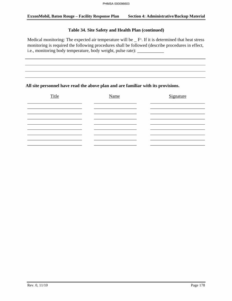
ExxonMobil, Baton Rouge – Facility Response Plan Section 4: Administrative/Backup Material
Rev. 0, 11/10 Page 178
Table 34. Site Safety and Health Plan (continued)
Medical monitoring: The expected air temperature will be F°. If it is determined that heat stress monitoring is required the following procedures shall be followed (describe procedures in effect, i.e., monitoring body temperature, body weight, pulse rate):
All site personnel have read the above plan and are familiar with its provisions.
Title Name Signature
PHMSA 000096603

ExxonMobil, Baton Rouge – Facility Response Plan Section 4: Administrative/Backup Material
Rev. 0, 11/11 Page 180
to date, widely distributed to all employees, and are incorporated herein by reference. The current phone numbers for each person holding the position listed below can be obtained by all employees from the ExxonMobil On-line Phone Directory.
First Responder/Operations
Personnel involved in the day to day operations within a specific unit receive continual instruction and experience in the proper handling and potential hazards associated with the materials that could be spilled in their area. Personnel are involved in protection and containment operations which do not involve contact with the spill (i.e., booming operations prior to arrival of the oil) must have at least 8 hours of HAZOPER training or sufficient experience to demonstrate competency in their spill response duties.
Incident Commander (Qualified Individual)
IC is trained to assume control of an incident. Training includes ExxonMobil’s incident command system, how to implement the facility’s response plan, the associated risks of employees working in chemical protective clothing, decontamination procedures, how to implement the local emergency response plan, and knowledge of the state emergency response plan and of the Federal Regional Response Team.
Other Response Support
Personnel from other aspects of the Emergency Response Team (e.g. Hazmat, fire brigade, medical, etc.) can be made available depending on the spill event.
Other personnel whose skills are needed temporarily to perform immediate emergency support work (such as dump truck drivers and crane operators) are not required to meet the training requirements discussed above. However, these personnel must be briefed on the potential hazards and the duties to be performed at the site before participating in response operations. They must also receive instruction in the use of any safety and personal protective equipment needed and on all other appropriate safety and health precautions.
Company and Other Specialist Support
Experts would provide technical advice or guidance during response to a spill incident. Examples of such specialists might include chemists, biologists, industrial hygienists, physicians, or others with skills useful during a spill response operation. Such persons must receive appropriate training or demonstrate competency in their specialty. There are no specific requirements on training content or hours of training for these persons. However, the training must be sufficient for the individuals to maintain competency in their specific area of expertise. Training and demonstration of competency for skilled support personnel and specialists should be documented.
Initial and Refresher Training Requirements
Refresher training or a demonstration of competency is required annually to maintain qualification as a Responder. A record must be kept of the methodology used to demonstrate competency. Exercises that are well organized, competently conducted, thoughtfully critiqued, and carefully documented will qualify as part of the annual refresher training. Competency can
PHMSA 000096605
ExxonMobil, Baton Rouge – Facility Response Plan Section 4: Administrative/Backup Material
Rev. 0, 11/11 Page 181
be demonstrated through written or oral examinations or through performance during exercises. HAZWOPER rules do not specify content requirements for refresher training sessions.
Chemical Plant Response Training
ExxonMobil Chemical will provide response awareness training to the personnel that provide support functions in a spill response as well as those operations and maintenance personnel that will typically be involved in the initial response to a spill within their normal work area but will not necessarily respond to spills outside their areas. Portions of this training are already included in their standard orientation and ongoing training programs while the remainder will have to be provided through a supplemental training program.
This supplemental training may be provided in a video format wherein personnel will be required to watch the video and sign a certification form documenting that they watched the video and understood the contents. Alternatively, personnel may be issued written materials that they will be required to read and sign a statement of understanding form or be required to attend classroom sessions.
The topics that will generally be covered by these training modules include:
Notification procedures and requirements for internal ExxonMobil Chemical personnel; federal, state, and local agencies, and contracted oil spill removal organizations (OSROs) and the information required for those organizations.
Communications systems used for implementing the above notifications.
Information of the products stored, used, or transferred by the chemical plant, including familiarity with the material safety data sheets, special handling procedures, health and safety hazards, and spill and firefighting procedures.
Facility personnel responsibilities and procedures for use of facility equipment which may be available to mitigate or prevent an oil spill.
Shutting down affected operations and isolating affected equipment.
Procedures to follow in the event of a spill, potential spill, or emergency involving the following equipment or scenarios:
- Tank overfill
- Tank rupture
- Piping or pipeline rupture
- Piping or pipeline leak, both under pressure and not under pressure
- Explosion or fire
- Failure of secondary containment system
Name of Qualified Individual (Chemical Plant Superintendent) and method of contact.
PHMSA 000096606
ExxonMobil, Baton Rouge – Facility Response Plan Section 4: Administrative/Backup Material
Rev. 0, 11/11 Page 182
General responsibilities and authorities of the Qualified Individual and the PSRT.
Drill and exercise program for meeting federal requirements.
Chemical Plant Spill Prevention Training
Routine safety meetings are typically used as the forum for reviewing and discussing spill events and other incidents having oil pollution potential, spill prevention issues, and other safety related topics. All operations and maintenance personnel participate in the routine safety meetings held by their various teams. Different departments within the chemical plant may have different meeting and recordkeeping formats, but the process of meeting to discuss pertinent issues is essentially the same.
In addition to the above training, all operating personnel must complete a rigorous four year apprentice-training program which includes the operation and maintenance of equipment to prevent oil spills. The BRCP Environmental Standards, contained in the BRCP Document Management System, which addresses plant procedures for ensuring compliance with applicable pollution control laws, rules, and regulations, are reviewed during this training and a copy is maintained in all control centers and on computer and is available to all employees.
EPA Required Training
The EPA requires that all facilities that have a FRP develop and implement a facility response training program and a drill/exercise program that satisfy the requirements of this section.
The facility owner or operator shall develop a facility response training program to train those personnel involved in oil spill response activities. It is recommended that the training program be based on the USCG's Training Elements for Oil Spill Response, as applicable to facility operations. An alternative program can also be acceptable subject to approval by the Regional Administrator.
The owner or operator shall be responsible for the proper instruction of facility personnel in the procedures to respond to discharges of oil and in applicable oil spill response laws, rules, and regulations.
Training shall be functional in nature according to job tasks for both supervisory and non-supervisory operational personnel.
Trainers shall develop specific lesson plans on subject areas relevant to facility personnel involved in oil spill response and cleanup.
PHMSA 000096607
ExxonMobil, Baton Rouge – Facility Response Plan Section 4: Administrative/Backup Material
Rev. 0, 11/11 Page 183
The facility owner or operator shall develop a program of facility response drills/exercises, including evaluation procedures. A program that follows the National Preparedness for Response Exercise Program (PREP) will be deemed satisfactory for purposes of this section. An alternative program can also be acceptable subject to approval by the Regional Administrator.
USCG Required Training
A response plan submitted by an owner or operator of an MTR facility must include an exercise program containing both announced and unannounced exercises. The following are the minimum exercise requirements:
Qualified Individual notification exercises (quarterly).
Spill management team tabletop exercises (annually). In a 3-year period, at least one of these exercises must include a worst case discharge scenario.
Equipment deployment exercises:
- Semiannually for facility owned and operated equipment.
- Annually for oil spill removal organization equipment.
Emergency procedure exercises (optional).
Annually, at least one of the exercises listed in §154.1055(a) (2) through (4) must be unannounced. Unannounced means the personnel participating in the exercise must not be advised in advance, of the exact date, time and scenario of the exercise.
The facility owner or operator shall design the exercise program so that all components of the response plan are exercised at least once every 3 years. All of the components do not have to be exercised at one time; they may be exercised over the 3-year period through the required exercises or through an Area exercise.
COTP. The objectives of the unannounced exercises will be to test notifications and equipment deployment for response to the average most probable discharge. After participating in an unannounced exercise directed by a COTP, the owner or operator will not be required to participate in another COTP initiated unannounced exercise for at least 3 years from the date of the exercise.
A facility owner or operator shall participate in Area exercises as directed by the applicable On-Scene Coordinator. The Area exercises will involve equipment deployment to respond to the spill scenario developed by the Exercise Design Team, of which the facility owner or operator will be a member. After participating in an Area exercise, a facility owner or operator will not be required to participate in another Area exercise for at least 6 years.
The facility owner or operator shall ensure that adequate records of all required exercises are maintained at the facility for 3 years. Records shall be made available to the Coast Guard upon request.
PHMSA 000096608
ExxonMobil, Baton Rouge – Facility Response Plan Section 4: Administrative/Backup Material
Rev. 0, 11/11 Page 184
The response plan submitted to meet the requirements of this subpart must specify the planned exercise program. The plan must detail the exercise program, including the types of exercises, frequency, scope, objectives and the scheme for exercising the entire response plan every 3 years.
Compliance with the National Preparedness for Response Exercise Program (PREP) Guidelines will satisfy the facility response plan exercise requirements. Compliance with an alternative program that meets the requirements of paragraph (a) of this section and has been approved under §154.1060 will also satisfy the facility response plan exercise requirements.
DOT Required Training
Each operator shall conduct training to ensure that:
All personnel know:
Their responsibilities under the response plan,
The name and address of, and the procedure for contacting, the operator on a 24-hour basis, and
The name of, and procedures for contacting, the qualified individual on a 24-hour basis.
Reporting personnel know:
The content of the information summary of the response plan,
The toll-free telephone number of the National Response Center, and
The notification process; and
Personnel engaged in response activities know:
The characteristics and hazards of the oil discharged,
The conditions that are likely to worsen emergencies, including the consequences of facility malfunctions or failures, and the appropriate corrective actions,
The steps necessary to control any accidental discharge of oil and to minimize the potential for fire, explosion, toxicity, or environmental damage, and
The proper firefighting procedures and use of equipment, fire suits, and breathing apparatus.
Each operator shall maintain a training record for each individual that has been trained as required by this section. These records must be maintained in the following manner as long as the individual is assigned duties under the response plan:
Records for operator personnel must be maintained at the operator's headquarters; and
Records for personnel engaged in response, other than operator personnel, shall be maintained as determined by the operator.
PHMSA 000096609
ExxonMobil, Baton Rouge – Facility Response Plan Section 4: Administrative/Backup Material
Rev. 0, 11/11 Page 185
Nothing in this section relieves an operator from the responsibility to ensure that all response personnel are trained to meet the Occupational Safety and Health Administration (OSHA) standards for emergency response operations in 29 CFR 1910.120, including volunteers or casual laborers employed during a response who are subject to those standards pursuant to 40 CFR part 311.
Drills
Response Drills
ExxonMobil intends to follow the drill requirements specified in the National Preparedness for Response Exercise Program (PREP) Guidelines, USDOT/USEPA/USDOI. PREP states that completion of the PREP exercises will satisfy all OPA 90 mandated federal oil pollution response exercise requirements.
For this FRP, PREP requires three types of drills: QI notification drills, spill management team (SMT) table top exercises (TTX) and equipment deployment exercises. These are summarized in Table 36. ExxonMobil may elect to exercise individual components of the plan but at various times during a triennial cycle, with each component of the plan being exercised at least once. PREP lists 15 components of the response plan must be exercised over the triennial period. The guidelines, however, state that if the plan does not contain all 15 components, only those that are contained in the plan must be exercised. The 15 components include:
Notification
Staff mobilization
Ability to operate within the response management system
Discharge control
Assessment
Containment
Recovery
Protection
Disposal
Communications
Transportation
Personnel support
Equipment and maintenance support
Procurement
Documentation
PHMSA 000096610
ExxonMobil, Baton Rouge – Facility Response Plan Section 4: Administrative/Backup Material
Rev. 0, 11/11 Page 186
Notification Drills
Quarterly, each facility conducts a QI notification drill. The drill may be announced or unannounced. Actual events may also be used to demonstrate compliance with this requirement. Typically, the drill is initiated by one of the individuals listed in Table 28 by attempting to contact the QI for that particular location via phone or radio. Drill documentation is developed and retained per the retention requirements.
Tabletop Exercises (TTX)
This drill is conducted annually and involves an activity in which key spill response personnel are presented with simulated emergency situations without time constraints. It is usually informal, in a conference room environment, and designed to stimulate constructive discussion by the participants as they attempt to examine and then resolve problems related to the emergency response using this FRP and other emergency and operations plans. The purpose is to resolve questions of coordination and assignment of responsibilities in a non-threatening format and under minimum stress.
As described in Figure 2, the Primary Spill Response Team (PSRT) would respond to small, onsite spills. Each QI staffs the key team management positions (Table 18) resulting in four potentially different PSRTs (one for each part of the complex). The PSRT’s at the Refinery, Chemical Plant, Lubricant Plant and Baton Rouge will conduct Tabletop Exercises annually. All the components of the plan for PSRTs will be exercised during the triennial cycle, but not necessarily during a single exercise. At least one of these drills in a triennial period must be conducted using the Worst Case Discharge Scenario.
In addition to the PSRT, ELIRT may be asked to assist an area in responding to a larger spill. To ensure ELIRT personnel remain knowledge in this FRP, they will participate in the Refinery Table Top Drills and drills in the other areas of the complex when they exercise the Worse Case Discharge.
Even though the FRP describes the North American Regional Response Team (NARRT) for major spills with significant impact (Figure 2), this plan does not contemplate using the NARRT for the response to a Worst Case Discharge at this facility.
Equipment Deployment Drills
PREP requires ExxonMobil to conduct equipment deployment drills twice a year for equipment cited in the FRP and owned/operated by ExxonMobil personnel. PREP specifies a minimum amount of equipment to be deployed during each exercise (Table 37). These drills may be combined with a notification and/or tabletop drill and may be announced or unannounced. The drills will typically involve the dispatch of selected PSRT, and possibly, ELIRT personnel and on-site equipment to a hypothetical spill location and the deployment of boom, skimmers and/or other response equipment.
ExxonMobil requires, through contract, that their OSRO’s conduct equipment deployment drills annually in compliance with the PREP requirements. The OSRO’s are also required to maintain
PHMSA 000096611
ExxonMobil, Baton Rouge – Facility Response Plan Section 4: Administrative/Backup Material
Rev. 0, 11/11 Page 187
documentation of these drills or actual spill incidents which involve equipment deployment and provide that documentation to ExxonMobil upon request.
Full Response Plan Implementation Drills
This drill is conducted at three-year intervals and involves a hypothetical worst case spill situation that requires full implementation of the entire response plan. It is intended to evaluate the operational capability of an emergency management system in an interactive manner over an extended time period. It involves testing a major portion of the basic plan elements in a stressful environment and could involve all PSRT personnel, key ELIRT responders, response contractors, and regulatory agencies. Personnel and equipment will be dispatched to the scene and logistical arrangements made for additional response resources and the handling, storage, and general management of estimated quantities of oily wastes.
Documentation of Training and Drills
ExxonMobil will ensure that the spill response personnel assigned to all levels have received the required training or equivalent experience and are competent in their duties. Training will be documented as required by OSHA. Similarly, participation in any response drills will be documented regarding the type of drill, location, and date. Participation in discharge prevention meetings will also be documented. Training records will be maintained by each site's respective Environmental Section or in the training database for a period of not less than 5 years.
ExxonMobil will document and certify PREP drills conducted and maintain these records for up to 5 years. Drill document records will be equivalent to those suggested in the PREP document.
Details of the initial HAZWOPER training and the procedure used to satisfy the refresher training/competency demonstration requirement must be documented in writing for each employee trained for spill response. This documentation shall include lesson plans covering the material taught and the methods used to demonstrate an employee's competence.
ExxonMobil's response contractors are required, under the conditions of their contract, to provide the appropriate HAZWOPER and spill response training to their personnel. The contractors are required to maintain documentation of this training and make it available to ExxonMobil upon request. ExxonMobil may also conduct spot checks of their documentation during drills or training programs in which the contractors participate.
PHMSA 000096612
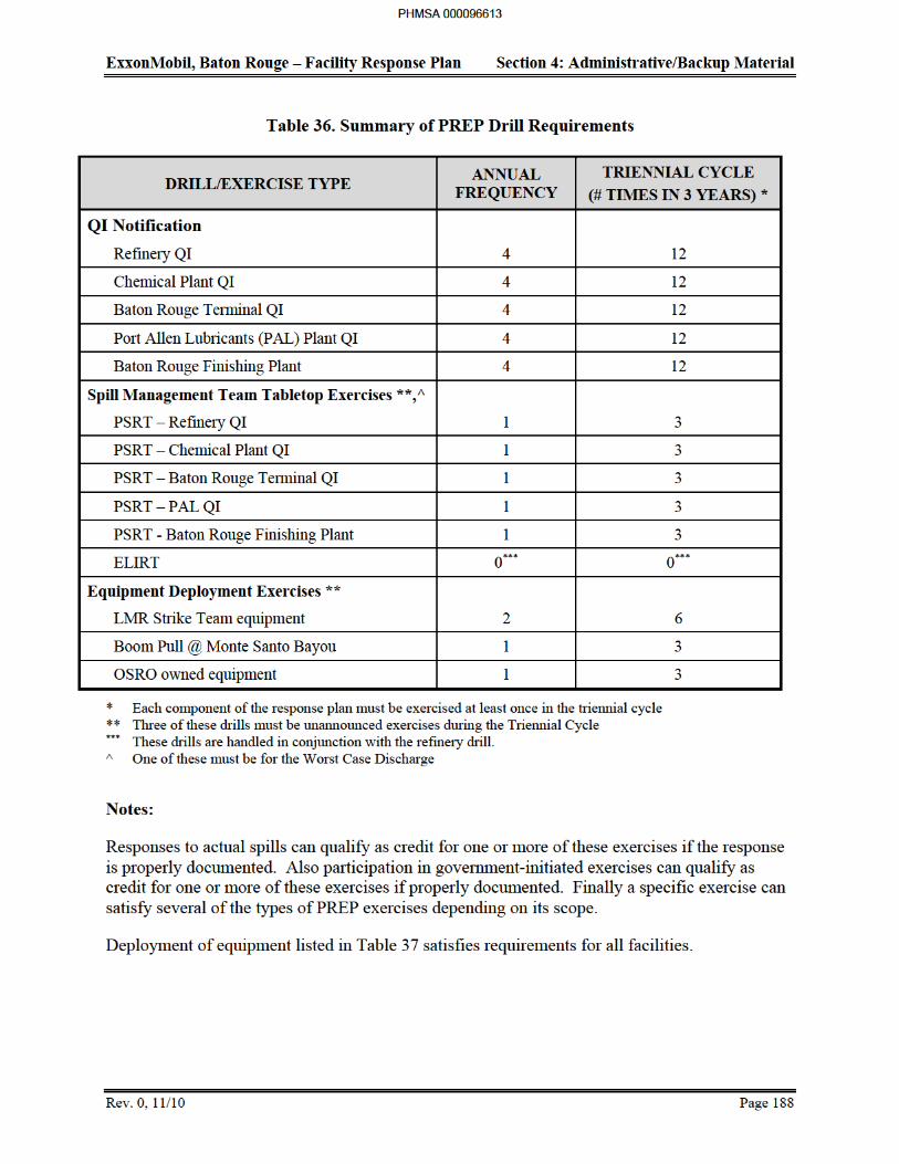
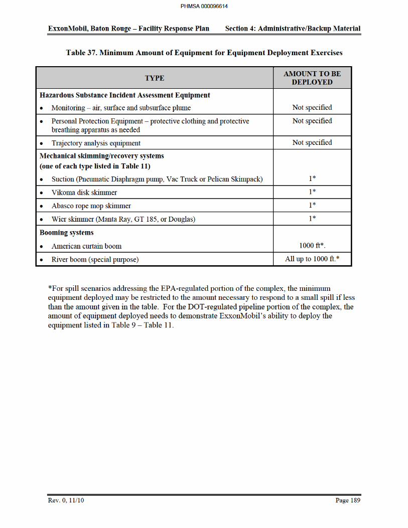
ExxonMobil, Baton Rouge – Facility Response Plan Section 4: Administrative/Backup Material
Rev. 0, 11/10 Page 190
4.18 Spill Response, Management Commitment, and Waste Disposal Plan
Spill Response
An oil spill to the waters of the United States is to be handled on an emergency basis. The containment and cleanup of the spill shall take priority over other activities except when it conflicts with ExxonMobil's requirement to maintain safe operations.
The Refinery Docks Section and/or the Operating Services Department are primarily responsible for responding to ExxonMobil spills to water at the ExxonMobil Baton Rouge Refinery Dock Facility. The Docks Section is also responsible for ensuring that such pollution incidents have been thoroughly investigated for future action. Other ExxonMobil facilities (i.e., ExxonMobil Baton Rouge Refinery proper, Chemical Plant, Coke Terminal, Anchorage Tank Farm, Port Allen Lubricants Plant, and Baton Rouge Baton Rouge Terminal) will respond, investigate and report spill incidents accordingly. In incidents where ExxonMobil is the responsible party, ExxonMobil is bound by the regulations of both the federal and state regulatory agencies.
Management Commitment
ExxonMobil is committed to operations, products, and practices which protect safety, health, and the environment. With the active participation of all employees and through the relentless pursuit of continuous improvement, ExxonMobil is committed to being a leader in safety, health, and environmental protection. ExxonMobil seeks to minimize risks associated with manufacturing, transportation, use, and disposal of their products. ExxonMobil pursues this objective in the design and modification of facilities, processes, products and the management of operations. Risks are anticipated, analyzed, and discussed with those affected and monitored to ensure proper control. ExxonMobil will not conduct any operation or market a product without adequate safeguards.
ExxonMobil seeks a workplace free of occupational injury and illness and an overall performance free of accidents. ExxonMobil believes that accident prevention must be the primary objective, but will also be prepared for emergencies should they occur.
ExxonMobil will continue to expand their knowledge of safety, health, and the effect of their operations on the environment. New knowledge will be promptly applied and shared with employees, customers, the scientific community, government agencies, and other potentially affected parties.
ExxonMobil strives to be a trusted and responsible member of every community in which people live and work. ExxonMobil recognizes that public trust and confidence are earned through performance, open communication, and community involvement.
ExxonMobil will comply with all applicable laws and regulations and other standards as necessary to provide adequate protection. ExxonMobil will also work with others to develop
PHMSA 000096615
ExxonMobil, Baton Rouge – Facility Response Plan Section 4: Administrative/Backup Material
Rev. 0, 11/10 Page 191
responsible laws, regulations, and standards that may be required to further safeguard the community, workplace, and environment.
The ExxonMobil spill response teams are part of the company’s commitment to respond in a quick, caring and competent manner. The information included in this manual is intended to assist response personnel in handling an incident. ExxonMobil intends to ensure that all members of the team are familiar with the facility response plan and participate in regular maintenance training and drills.
ExxonMobil will retain the responsibility of response operations for spills for which it is a responsible party under federal and state law. ExxonMobil will also coordinate and cooperate with the Federal/State On-Scene Coordinator during response activity.
Waste Disposal Plan
ExxonMobil is committed to conserving natural resources and further increasing margins of protection by reducing waste generation and contamination of air, water, and land. Any waste generated during normal operation or as part of spill cleanup will be disposed of in a safe and environmentally sound manner. All costs associated with the cleanup and disposal of waste material will be charged to the operating unit that spilled the material.
Any contaminated material generated at the site will be placed in the proper disposal container and an identification number will be assigned to the waste. Analytical testing and/or engineering judgment will be utilized to determine the appropriate method for disposal. Once the disposal disposition is determined, a manifest will be created for shipping the waste off-site. The net weight of each load will be recorded on the manifest, and all records will be maintained in the waste management offices of the respective facilities.
ExxonMobil has contracts with hundreds of waste disposal facilities. Typically the disposal sites used are the ones closest to where the waste was generated. However, factors such as economics and environmental issues may cause sites to be chosen or not to be chosen. This will also be dependent upon the waste characterization of the material to be disposed. For the Baton Rouge facilities named in this FRP, the Waste Management Office (WMO) located in the Refinery would assume the lead on disposal coordination. The WMO is knowledgeable of sites that ExxonMobil has approved and has contracts with. Based on the situation, the category of spill (2 or 3) and the location of the materials being recovered, the WMO may deter to another ExxonMobil organization for the management of the disposal coordination, but the waste would still be sent to an approved waste disposal site.
Records that will be maintained by ExxonMobil include:
Computerized records for each shipment of waste
Waste manifests
Certification records for the waste at the disposal facility
Analytical data and
Annual waste summary reports
PHMSA 000096616
ExxonMobil, Baton Rouge – Facility Response Plan Section 4: Administrative/Backup Material
Rev. 0, 11/10 Page 192
Oil Spill Prevention
For the Chemical Plant and the Refinery, the respective Environmental coordinators or designees are accountable for oil spill prevention
PHMSA 000096617
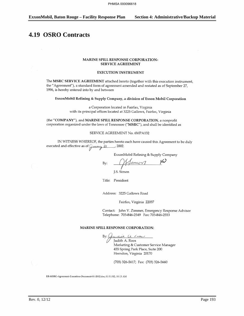
ExxonMobil, Baton Rouge – Facility Response Plan Section 4: Administrative/Backup Material
Rev. 0, 12/12 Page 193
4.19 OSRO Contracts
PHMSA 000096618
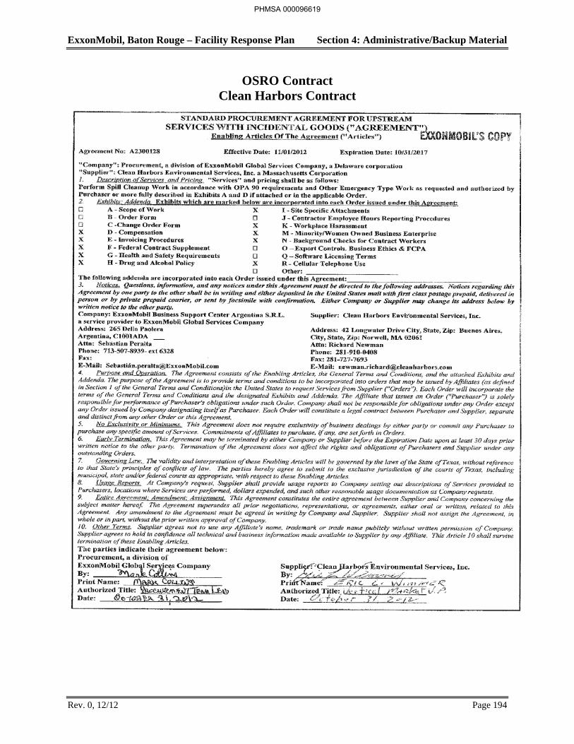
ExxonMobil, Baton Rouge – Facility Response Plan Section 4: Administrative/Backup Material
Rev. 0, 12/12 Page 194
OSRO Contract Clean Harbors Contract
PHMSA 000096619
ExxonMobil, Baton Rouge – Facility Response Plan Section 4: Administrative/Backup Material
Rev. 0, 5/12 Page 4
4.2 Certifications
Applicability of Significant and Substantial Harm Criteria
The pages following describe the EPA Applicability of Substantial Harm Criteria of each area covered by this Facility Response Plan. Certification statements follow each checklist of Applicability of Substantial Harm Criteria for each area covered by the FRP.
PHMSA 000096620
ExxonMobil, Baton Rouge – Facility Response Plan Section 4: Administrative/Backup Material
Rev. 0, 5/12 Page 5
Certification Statements for Each Area
PHMSA 000096621

ExxonMobil, Baton Rouge – Facility Response Plan Section 4: Administrative/Backup Material
Rev. 0, 5/12 Page 6
Baton Rouge Refinery and On-Site Tank Farms
EPA Applicability of Substantial Harm Criteria
Does the facility transfer oil over-water to or from vessels and does the facility have a total oil storage capacity greater than or equal to 42,000 gallons?
Yes X No
Does the facility have a total oil storage capacity greater than or equal to 1 million gallons and, within any storage area, does the facility lack secondary containment that is sufficiently large to contain the capacity of the largest aboveground oil storage tank plus sufficient freeboard to allow for precipitation?
Yes No X
Does the facility have a total oil storage capacity greater than or equal to 1 million gallons and is the facility located at a distance (as calculated using the appropriate formula in 40 CFR 112 Appendix C or a comparable formula) such that a discharge from the facility could cause injury to fish and wildlife and sensitive environments?
Yes X No
Does the facility have a total oil storage capacity greater than or equal to 1 million gallons and is the facility located at a distance (as calculated using the appropriate formula in Appendix C or a comparable formula) such that a discharge from the facility would shut down a public drinking water intake.
Yes X No
Does the facility have a total oil storage capacity greater than or equal to 1 million gallons and has the facility experienced a reportable oil spill in an amount greater than or equal to 10,000 gallons within the last 5 years?
Yes No X
I certify under penalty of law that I have personally examined and am familiar with the information submitted in this document, and that based on my inquiry of those individuals responsible for obtaining information, I believe that the submitted information is true accurate, and complete.
Craig Pike Date
Steve Blume Date
PHMSA 000096622
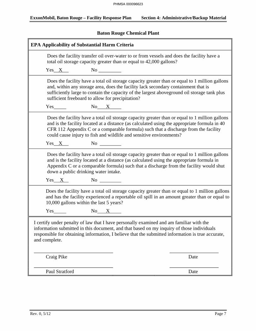
ExxonMobil, Baton Rouge – Facility Response Plan Section 4: Administrative/Backup Material
Rev. 0, 5/12 Page 7
Baton Rouge Chemical Plant
EPA Applicability of Substantial Harm Criteria
Does the facility transfer oil over-water to or from vessels and does the facility have a total oil storage capacity greater than or equal to 42,000 gallons?
Yes X No
Does the facility have a total oil storage capacity greater than or equal to 1 million gallons and, within any storage area, does the facility lack secondary containment that is sufficiently large to contain the capacity of the largest aboveground oil storage tank plus sufficient freeboard to allow for precipitation?
Yes No X
Does the facility have a total oil storage capacity greater than or equal to 1 million gallons and is the facility located at a distance (as calculated using the appropriate formula in 40 CFR 112 Appendix C or a comparable formula) such that a discharge from the facility could cause injury to fish and wildlife and sensitive environments?
Yes X No
Does the facility have a total oil storage capacity greater than or equal to 1 million gallons and is the facility located at a distance (as calculated using the appropriate formula in Appendix C or a comparable formula) such that a discharge from the facility would shut down a public drinking water intake.
Yes X No
Does the facility have a total oil storage capacity greater than or equal to 1 million gallons and has the facility experienced a reportable oil spill in an amount greater than or equal to 10,000 gallons within the last 5 years?
Yes No X
I certify under penalty of law that I have personally examined and am familiar with the information submitted in this document, and that based on my inquiry of those individuals responsible for obtaining information, I believe that the submitted information is true accurate, and complete.
Craig Pike Date
Paul Stratford Date
PHMSA 000096623

ExxonMobil, Baton Rouge – Facility Response Plan Section 4: Administrative/Backup Material
Rev. 0, 5/12 Page 8
Anchorage Tank Farm
EPA Applicability of Substantial Harm Criteria
Does the facility transfer oil over-water to or from vessels and does the facility have a total oil storage capacity greater than or equal to 42,000 gallons?
Yes X No
Does the facility have a total oil storage capacity greater than or equal to 1 million gallons and, within any storage area, does the facility lack secondary containment that is sufficiently large to contain the capacity of the largest aboveground oil storage tank plus sufficient freeboard to allow for precipitation?
Yes No X
Does the facility have a total oil storage capacity greater than or equal to 1 million gallons and is the facility located at a distance (as calculated using the appropriate formula in 40 CFR 112 Appendix C or a comparable formula) such that a discharge from the facility could cause injury to fish and wildlife and sensitive environments?
Yes X No
Does the facility have a total oil storage capacity greater than or equal to 1 million gallons and is the facility located at a distance (as calculated using the appropriate formula in Appendix C or a comparable formula) such that a discharge from the facility would shut down a public drinking water intake.
Yes X No
Does the facility have a total oil storage capacity greater than or equal to 1 million gallons and has the facility experienced a reportable oil spill in an amount greater than or equal to 10,000 gallons within the last 5 years?
Yes No X
I certify under penalty of law that I have personally examined and am familiar with the information submitted in this document, and that based on my inquiry of those individuals responsible for obtaining information, I believe that the submitted information is true accurate, and complete.
Craig Pike Date
Steve Blume Date
PHMSA 000096624
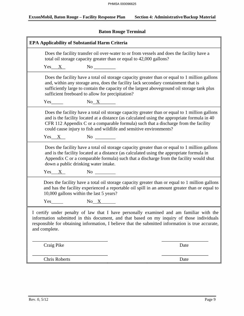
ExxonMobil, Baton Rouge – Facility Response Plan Section 4: Administrative/Backup Material
Rev. 0, 5/12 Page 9
Baton Rouge Terminal
EPA Applicability of Substantial Harm Criteria
Does the facility transfer oil over-water to or from vessels and does the facility have a total oil storage capacity greater than or equal to 42,000 gallons?
Yes X No
Does the facility have a total oil storage capacity greater than or equal to 1 million gallons and, within any storage area, does the facility lack secondary containment that is sufficiently large to contain the capacity of the largest aboveground oil storage tank plus sufficient freeboard to allow for precipitation?
Yes No X
Does the facility have a total oil storage capacity greater than or equal to 1 million gallons and is the facility located at a distance (as calculated using the appropriate formula in 40 CFR 112 Appendix C or a comparable formula) such that a discharge from the facility could cause injury to fish and wildlife and sensitive environments?
Yes X No
Does the facility have a total oil storage capacity greater than or equal to 1 million gallons and is the facility located at a distance (as calculated using the appropriate formula in Appendix C or a comparable formula) such that a discharge from the facility would shut down a public drinking water intake.
Yes X No
Does the facility have a total oil storage capacity greater than or equal to 1 million gallons and has the facility experienced a reportable oil spill in an amount greater than or equal to 10,000 gallons within the last 5 years?
Yes No X
I certify under penalty of law that I have personally examined and am familiar with the information submitted in this document, and that based on my inquiry of those individuals responsible for obtaining information, I believe that the submitted information is true accurate, and complete.
Craig Pike Date
Chris Roberts Date
PHMSA 000096625
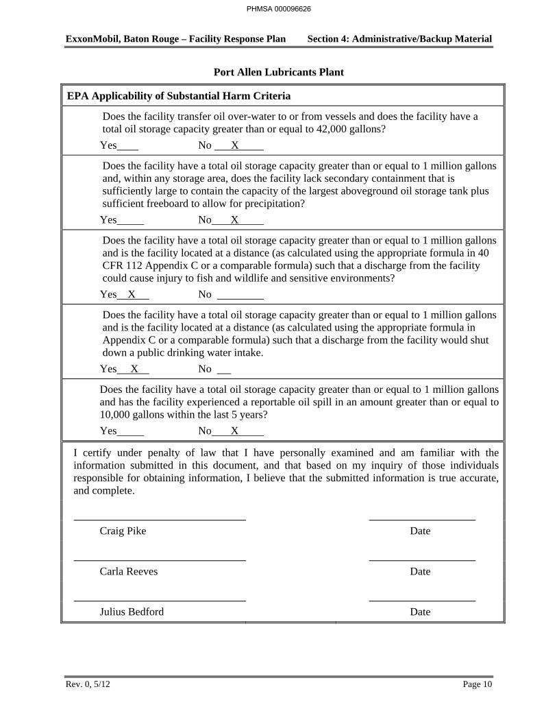
ExxonMobil, Baton Rouge – Facility Response Plan Section 4: Administrative/Backup Material
Rev. 0, 5/12 Page 10
Port Allen Lubricants Plant
EPA Applicability of Substantial Harm Criteria
Does the facility transfer oil over-water to or from vessels and does the facility have a total oil storage capacity greater than or equal to 42,000 gallons?
Yes No X
Does the facility have a total oil storage capacity greater than or equal to 1 million gallons and, within any storage area, does the facility lack secondary containment that is sufficiently large to contain the capacity of the largest aboveground oil storage tank plus sufficient freeboard to allow for precipitation?
Yes No X
Does the facility have a total oil storage capacity greater than or equal to 1 million gallons and is the facility located at a distance (as calculated using the appropriate formula in 40 CFR 112 Appendix C or a comparable formula) such that a discharge from the facility could cause injury to fish and wildlife and sensitive environments?
Yes X No
Does the facility have a total oil storage capacity greater than or equal to 1 million gallons and is the facility located at a distance (as calculated using the appropriate formula in Appendix C or a comparable formula) such that a discharge from the facility would shut down a public drinking water intake.
Yes X No
Does the facility have a total oil storage capacity greater than or equal to 1 million gallons and has the facility experienced a reportable oil spill in an amount greater than or equal to 10,000 gallons within the last 5 years?
Yes No X
I certify under penalty of law that I have personally examined and am familiar with the information submitted in this document, and that based on my inquiry of those individuals responsible for obtaining information, I believe that the submitted information is true accurate, and complete.
Craig Pike Date
Carla Reeves Date
Julius Bedford Date
PHMSA 000096626
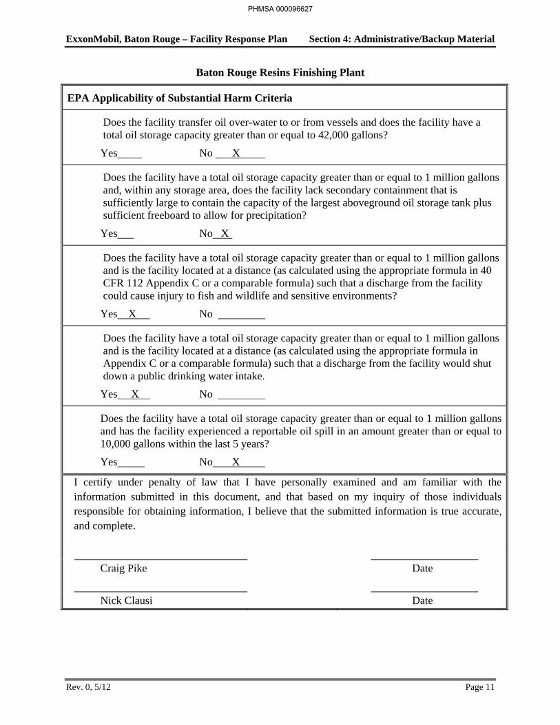
ExxonMobil, Baton Rouge – Facility Response Plan Section 4: Administrative/Backup Material
Rev. 0, 5/12 Page 11
Baton Rouge Resins Finishing Plant
EPA Applicability of Substantial Harm Criteria
Does the facility transfer oil over-water to or from vessels and does the facility have a total oil storage capacity greater than or equal to 42,000 gallons?
Yes No X
Does the facility have a total oil storage capacity greater than or equal to 1 million gallons and, within any storage area, does the facility lack secondary containment that is sufficiently large to contain the capacity of the largest aboveground oil storage tank plus sufficient freeboard to allow for precipitation?
Yes No X
Does the facility have a total oil storage capacity greater than or equal to 1 million gallons and is the facility located at a distance (as calculated using the appropriate formula in 40 CFR 112 Appendix C or a comparable formula) such that a discharge from the facility could cause injury to fish and wildlife and sensitive environments?
Yes X No
Does the facility have a total oil storage capacity greater than or equal to 1 million gallons and is the facility located at a distance (as calculated using the appropriate formula in Appendix C or a comparable formula) such that a discharge from the facility would shut down a public drinking water intake.
Yes X No
Does the facility have a total oil storage capacity greater than or equal to 1 million gallons and has the facility experienced a reportable oil spill in an amount greater than or equal to 10,000 gallons within the last 5 years?
Yes No X
I certify under penalty of law that I have personally examined and am familiar with the information submitted in this document, and that based on my inquiry of those individuals responsible for obtaining information, I believe that the submitted information is true accurate, and complete.
Craig Pike Date
Nick Clausi Date
PHMSA 000096627

ExxonMobil, Baton Rouge – Facility Response Plan Section 4: Administrative/Backup Material
Rev. 0, 5/12 Page 12
Baton Rouge Coke Terminal
EPA Applicability of Substantial Harm Criteria
Does the facility transfer oil over-water to or from vessels and does the facility have a total oil storage capacity greater than or equal to 42,000 gallons?
Yes X No
Does the facility have a total oil storage capacity greater than or equal to 1 million gallons and, within any storage area, does the facility lack secondary containment that is sufficiently large to contain the capacity of the largest aboveground oil storage tank plus sufficient freeboard to allow for precipitation?
Yes No X
Does the facility have a total oil storage capacity greater than or equal to 1 million gallons and is the facility located at a distance (as calculated using the appropriate formula in 40 CFR 112 Appendix C or a comparable formula) such that a discharge from the facility could cause injury to fish and wildlife and sensitive environments?
Yes X No
Does the facility have a total oil storage capacity greater than or equal to 1 million gallons and is the facility located at a distance (as calculated using the appropriate formula in Appendix C or a comparable formula) such that a discharge from the facility would shut down a public drinking water intake.
Yes X No
Does the facility have a total oil storage capacity greater than or equal to 1 million gallons and has the facility experienced a reportable oil spill in an amount greater than or equal to 10,000 gallons within the last 5 years?
Yes No X
I certify under penalty of law that I have personally examined and am familiar with the information submitted in this document, and that based on my inquiry of those individuals responsible for obtaining information, I believe that the submitted information is true accurate, and complete.
Craig Pike Date
Steve Blume Date
PHMSA 000096628

ExxonMobil, Baton Rouge – Facility Response Plan Section 4: Administrative/Backup Material
Rev. 0, 5/12 Page 13
DOT Jurisdiction Criteria For Line Expectations To Cause Significant and Substantial Damage
The facilities in this plan under DOT jurisdiction (See Table 1-1) cannot be expected to cause significant and substantial damage according to 49 CFR 194.103. These lines have outside diameters greater than 6.875 inches; however, they are less than ten miles long. These lines however do not meet the exceptions in 49 CFR 194.101(b) and can be considered to cause substantial harm.
PHMSA 000096629
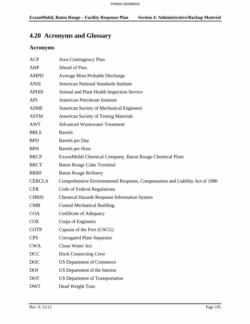
ExxonMobil, Baton Rouge – Facility Response Plan Section 4: Administrative/Backup Material
Rev. 0, 12/12 Page 195
4.20 Acronyms and Glossary
Acronyms
ACP Area Contingency Plan
AHP Ahead of Pass
AMPD Average Most Probable Discharge
ANSI American National Standards Institute
APHIS Animal and Plant Health Inspection Service
API American Petroleum Institute
ASME American Society of Mechanical Engineers
ASTM American Society of Testing Materials
AWT Advanced Wastewater Treatment
BBLS Barrels
BPD Barrels per Day
BPH Barrels per Hour
BRCP ExxonMobil Chemical Company, Baton Rouge Chemical Plant
BRCT Baton Rouge Coke Terminal
BRRF Baton Rouge Refinery
CERCLA Comprehensive Environmental Response, Compensation and Liability Act of 1980
CFR Code of Federal Regulations
CHRIS Chemical Hazards Response Information System
CMB Central Mechanical Building
COA Certificate of Adequacy
COE Corps of Engineers
COTP Captain of the Port (USCG)
CPS Corrugated Plate Separator
CWA Clean Water Act
DCC Dock Connecting Crew
DOC US Department of Commerce
DOI US Department of the Interior
DOT US Department of Transportation
DWT Dead Weight Tons
PHMSA 000096630
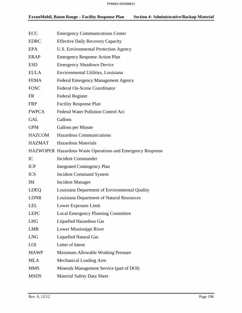
ExxonMobil, Baton Rouge – Facility Response Plan Section 4: Administrative/Backup Material
Rev. 0, 12/12 Page 196
ECC Emergency Communications Center
EDRC Effective Daily Recovery Capacity
EPA U.S. Environmental Protection Agency
ERAP Emergency Response Action Plan
ESD Emergency Shutdown Device
EULA Environmental Utilities, Louisiana
FEMA Federal Emergency Management Agency
FOSC Federal On-Scene Coordinator
FR Federal Register
FRP Facility Response Plan
FWPCA Federal Water Pollution Control Act
GAL Gallons
GPM Gallons per Minute
HAZCOM Hazardous Communications
HAZMAT Hazardous Materials
HAZWOPER Hazardous Waste Operations and Emergency Response
IC Incident Commander
ICP Integrated Contingency Plan
ICS Incident Command System
IM Incident Manager
LDEQ Louisiana Department of Environmental Quality
LDNR Louisiana Department of Natural Resources
LEL Lower Exposure Limit
LEPC Local Emergency Planning Committee
LHG Liquefied Hazardous Gas
LMR Lower Mississippi River
LNG Liquefied Natural Gas
LOI Letter of Intent
MAWP Maximum Allowable Working Pressure
MLA Mechanical Loading Arm
MMS Minerals Management Service (part of DOI)
MSDS Material Safety Data Sheet
PHMSA 000096631
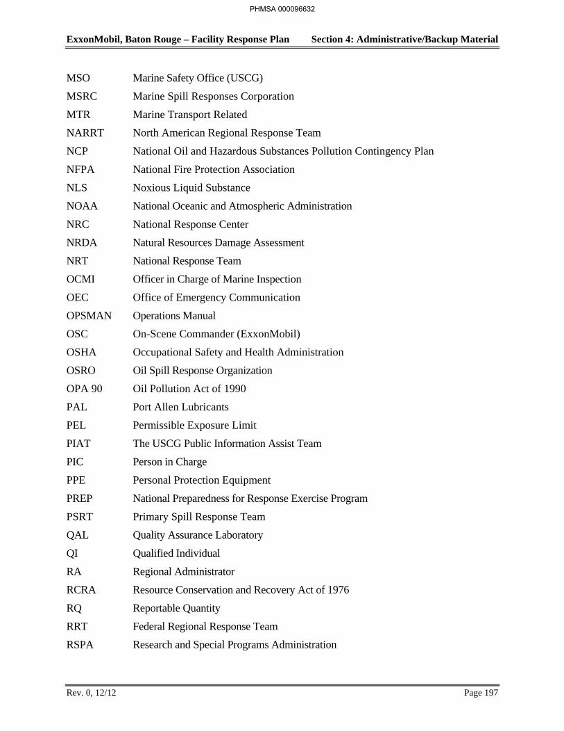
ExxonMobil, Baton Rouge – Facility Response Plan Section 4: Administrative/Backup Material
Rev. 0, 12/12 Page 197
MSO Marine Safety Office (USCG)
MSRC Marine Spill Responses Corporation
MTR Marine Transport Related
NARRT North American Regional Response Team
NCP National Oil and Hazardous Substances Pollution Contingency Plan
NFPA National Fire Protection Association
NLS Noxious Liquid Substance
NOAA National Oceanic and Atmospheric Administration
NRC National Response Center
NRDA Natural Resources Damage Assessment
NRT National Response Team
OCMI Officer in Charge of Marine Inspection
OEC Office of Emergency Communication
OPSMAN Operations Manual
OSC On-Scene Commander (ExxonMobil)
OSHA Occupational Safety and Health Administration
OSRO Oil Spill Response Organization
OPA 90 Oil Pollution Act of 1990
PAL Port Allen Lubricants
PEL Permissible Exposure Limit
PIAT The USCG Public Information Assist Team
PIC Person in Charge
PPE Personal Protection Equipment
PREP National Preparedness for Response Exercise Program
PSRT Primary Spill Response Team
QAL Quality Assurance Laboratory
QI Qualified Individual
RA Regional Administrator
RCRA Resource Conservation and Recovery Act of 1976
RQ Reportable Quantity
RRT Federal Regional Response Team
RSPA Research and Special Programs Administration
PHMSA 000096632
ExxonMobil, Baton Rouge – Facility Response Plan Section 4: Administrative/Backup Material
Rev. 0, 12/12 Page 198
SARA Superfund Amendments and Reauthorization Act
SCBA Self-Contained Breathing Apparatus
SDWA Safe Drinking Water Act of 1986
SERC State Emergency Response Commission
SI Surface Impoundment
SIC Standard Industrial Classification
SOSC State On-Scene Coordinator
SPCC Spill Prevention Control and Countermeasures
SSC Scientific Support Coordinator (NOAA)
STRCC Spill Team Response, Containment, and Cleanup
SUPSALV US Navy Supervisor of Salvage
TCLP Toxicity Characteristic Leaching Procedure
TIC Tankerman in Charge
UEL Upper Exposure Limit
US United States of America
USCG United States Coast Guard
USF&WS US Fish and Wildlife Service (DOI)
WCD Worst Case Discharge
WCLA Water Clarification Louisiana
PHMSA 000096633
ExxonMobil, Baton Rouge – Facility Response Plan Section 4: Administrative/Backup Material
Rev. 0, 12/12 Page 199
Glossary
Adverse Weather –Weather conditions that make it difficult for response equipment and personnel to clean up or remove spilled oil, and that must be considered when identifying response systems and equipment in a response plan for the applicable operating environment. Factors to consider include significant wave height, ice conditions, temperatures, weather-related visibility, and currents within the area in which the systems or equipment is intended to function.
Alteration – Any work on a container involving cutting, burning, welding, or heating operations that changes the physical dimensions or configuration of the container.
Animal Fat – A non-petroleum oil, fat, or grease of animal, fish, or marine mammal origin.
Biological Additives (Bioremediation) - Microbiological cultures, enzymes, or nutrient additives that are deliberately introduced into oil discharge for the specific purpose of encouraging biodegradation to mitigate the effects of the discharge.
Breakout Tank – A container used to relieve surges in an oil pipeline system or to receive and store oil transported by a pipeline for reinjection and continued transportation by pipeline.
Bulk Storage Container – Any container used to store oil. These containers are used for purposes including, but not limited to, the storage of oil prior to use, while being used, or prior to further distribution in commerce. Oil-filled electrical, operating, or manufacturing equipment is not a bulk storage container.
Bunkered Tank – A container constructed or placed in the ground by cutting the earth and re-covering the container in a manner that breaks the surrounding natural grade, or that lies above grade, and is covered with earth, sand, gravel, asphalt, or other material. A bunkered tank is considered an aboveground storage container for purposes of 40 CFR 112.
Burning Agents - Those additives that, through physical or chemical means, improve the combustibility of the materials to which they are applied.
Chemical Agents - Those elements, compounds, or mixtures that coagulate, disperse, dissolve, emulsify, foam, neutralize, precipitate, reduce, solubilize, oxidize, concentrate, congeal, entrap, fix, make the pollutant mass more rigid of viscous, or otherwise facilitate the mitigation of deleterious effects or the removal of the pollutant from the water.
Coastal Waters - Waters of the coastal zone except for the Great Lakes and specified ports and harbors on inland rivers.
Coastal Zone - All United States waters subject to the tide, United States waters of the Great Lakes, specified ports and harbors on inland rivers, waters of the contiguous zone, other waters of the high seas subject to the Federal National Contingency Plan, and the land surface or land substrata, ground waters, and ambient air proximal to those waters. The term coastal zone delineates an area of Federal responsibility for response action. Precise boundaries are determined by EPA/USCG agreements and identified in Federal Regional contingency plans.
PHMSA 000096634
ExxonMobil, Baton Rouge – Facility Response Plan Section 4: Administrative/Backup Material
Rev. 0, 12/12 Page 200
Completely Buried Tank – Any container completely below grade and covered with earth, sand, gravel, asphalt, or other material. Containers in vaults, bunkered tanks, or partially buried tanks are considered aboveground storage containers for purposes of 40 CFR 112.
Complex – A facility possessing a combination of transportation-related and non-transportation-related components that is subject to the jurisdiction of more than one Federal agency under section 311(j) of the CWA.
Contiguous Zone - The zone of the high seas, established by the United States under Article 24 of the Convention on the Territorial Sea and Contiguous Zone, which is contiguous to the territorial sea and which extends nine miles seaward from the outer limit of the territorial sea.
Contract or Other Approved means:
1. A written contractual agreement with an oil spill removal organization that identifies and ensures the availability of the necessary personnel and equipment with in appropriate response times; and/or
2. A written certification by the owner or operator that the necessary personnel and equipment resources, owned or operated by the facility owner or operator, are available to respond to discharge within appropriate response times; and/or
3. Active membership in a local or regional oil spill removal organization that has identified and ensures adequate access through such membership to necessary personnel and equipment to respond to a discharge within appropriate response times in the specified geographic area; and/or
4. Any other specific arrangement approved by the Regional Administrator upon request of the owner or operator.
Discharge - Includes, but is not limited to, spilling, leaking, pumping, pouring, emitting, emptying, or dumping of oil, but excludes discharges in compliance with a permit under section 402 of the CWA; discharges resulting from circumstances identified, reviewed, and made a part of the public record with respect to a permit issued or modified under section 402 of the CWA, and subject to a condition in such permit; or continuous or anticipated intermittent discharges from a point source, identified in a permit or permit application under section 402 of the CWA, that are caused by events occurring within the scope of relevant operating or treatment systems. For purposes of 40 CFR 112, the term discharge shall not include any discharge of oil that is authorized by a permit issued under section 13 of the River and Harbor Act of 1899 (33 U.S.C. 407).
Dispersants - Those chemical agents that emulsify, disperse, or solubilize oil into the water column or promote the surface spreading of oil slicks to facilitate dispersion of the oil into the water column.
Facility - Any mobile or fixed, onshore or offshore building, structure, installation, equipment, pipe or pipeline (including any pipe into a sewer, or publicly owned treatment works), well, put, pond, lagoon, impoundment, ditch, landfill, storage container, motor vehicle, rolling stock, or aircraft, or any site or area, where oil or a hazardous substance has been deposited, stored,
PHMSA 000096635
ExxonMobil, Baton Rouge – Facility Response Plan Section 4: Administrative/Backup Material
Rev. 0, 12/12 Page 201
disposed of, placed, or otherwise come to be located; but does not include any consumer product in consumer use or any vessel.
Federal On-Scene Coordinator (FOSC) - The Federal official predesignated by EPA or the USCG to coordinate and direct Federal responses.
Fish and Wildlife and Sensitive Environments – Areas that may be identified by their legal designation or by evaluations of Area Committees (for planning) or members of the Federal On-Scene Coordinator’s spill response structure (during responses). These areas may include wetlands, National and State parks, critical habitats for endangered or threatened species, wilderness and natural resource area, marine sanctuaries and estuarine reserves, conservation areas, preserves, wildlife areas, wildlife refuges, wild and scenic rivers, recreational area, national forests, Federal and State lands that are research national area, heritage program areas, land trust areas, and historical and archaeological sites and parks. These areas may also include unique habitats such as aquaculture sites and agricultural surface water intakes, bird nesting areas, critical biological resource areas, designated migratory routes, and designated seasonal habitats.
Hazardous Substance - Any substance designated pursuant to Section 311(b)(2)(a) of the CWA; any element, compound, mixture, solution, or substance designated pursuant to Section 102 of CERCLA; any hazardous waste having characteristics identified under or listed pursuant to Section 3001 of the Solid Waste Disposal Act (but not including any waste the regulation of which under the Solid Waste Disposal Act has been suspended by an Act of Congress.); any toxic pollutant listed under Section 307(1) of the CWA; any hazardous air pollutant listed under Section 112 of the Clean Air Act; and any imminently hazardous chemical substance or mixture with respect to which the EPA Administrator has taken action pursuant to Section 7 of the Toxic Substances Control Act. The term does not include petroleum, including crude oil or any fraction thereof, which is not otherwise specifically listed or designated as a hazardous substance in the first sentence of this paragraph, and the term does not include natural gas, natural gas liquids, liquefied natural gas or synthetic gas usable for fuel (or mixtures of natural gas and such synthetic gas).
Injury – A measurable and adverse change, either long-or short-term, in the chemical or physical quality or the viability of a natural resource resulting either directly or indirectly from exposure to a discharge, or exposure to a product of reactions resulting from a discharge.
Inland waters - Waters of the United States in the inland zone, waters of the Great Lakes, and specified ports and harbors on inland rivers.
Maximum Extend Practicable – Within the limitations used to determine oil spill planning resources and response times for on-water recover, shoreline protection, and cleanup for worst case discharges from onshore non-transportation-related facilities in adverse weather. It includes the planned capability to respond to a worst case discharge in adverse weather, as contained in a response plan that meets the requirements in §112.20 or in a specific plan approved by the Regional Administrator.
PHMSA 000096636
ExxonMobil, Baton Rouge – Facility Response Plan Section 4: Administrative/Backup Material
Rev. 0, 12/12 Page 202
Natural resources - Land, fish, wildlife, biota, air, water, ground water, drinking water supplies, and other such resources belonging to, managed by, held in trust by, appertaining to, or otherwise controlled by the United States (including the resources of the exclusive economic zone defined by the Magnuson Fishery Conservation and Management Act of 1976), any state or local government, any foreign government, any Indian tribe, or, if such resources are subject to a trust restriction on alienation, any member of an Indian tribe.
Navigable waters - (NOTE: this definition is currently being re-evaluated by the EPA and Corps of Engineers) - The waters of the United States, including the territorial seas. The term includes:
1. All waters that are currently used, were used in the past, or may be susceptible to use in interstate or foreign commerce, including all waters that are subject to the ebb and flow of the tide;
2. Interstate waters, including interstate wetlands;
3. All other waters such as intrastate lakes, rivers, streams (including intermittent streams), mudflats, sandflats, and wetlands, the use, degradation, or destruction of which would affect or could affect interstate or foreign commerce including any such waters;
a. That could be used by interstate or foreign travelers for recreational or other purposes;
b. From which fish or shellfish are, or could, be taken and sold in interstate or foreign commerce;
c. That are used, or could be used, for industrial purposes by industries in interstate commerce;
4. All impoundments of waters otherwise defined as navigable waters under this section;
5. Tributaries of water identified in paragraphs (a) through (d) of this definition, including adjacent wetlands;
6. The territorial sea; and
7. Wetlands adjacent to waters identified in paragraphs (1) through (6) of this definition; provided, that waste treatment systems (other than cooling ponds meeting the criteria of this paragraph) are not waters of the United States.
Waste treatment systems, including treatment ponds or lagoons designed to meet the requirements of the CWA are not waters of the United States. Navigable waters do not include prior converted cropland. Notwithstanding the determination of an area’s status as prior converted cropland by any other Federal agency, for the purposes of the CWA, the final authority regarding CWA jurisdiction remains with EPA.
Non-Petroleum Oil – Oil of any kind that is not petroleum-based, including but not limited to: Fats, oils, and greases of animal, fish, or marine mammal origin; and vegetable oils, including oils from seeds, nuts, fruits, and kernels.
Offshore facility - As defined by Section 311(a)(11) of the CWA, means any facility of any kind located in, on, or under any of the navigable waters of the United States and any facility of any
PHMSA 000096637
ExxonMobil, Baton Rouge – Facility Response Plan Section 4: Administrative/Backup Material
Rev. 0, 12/12 Page 203
kind which is subject to the jurisdiction of the United States and is located in, on, or under any other waters, other than a vessel or a public vessel.
Oil - As defined by Section 311(a)(1) of the CWA, means oil of any kind or in any form, including, but not limited to: fats, oils, and greases of animal, fish , or marine origin; vegetable oils, including oils from seeds, nuts, fruits or kernels; and other oils and greases including petroleum, fuel oil, sludge, synthetic oils, mineral oils, oil refuse, and oil mixed with wastes other than dredged spoil.
Oil Spill Removal Organization – An entity that provides oil spill response resources, and includes any for-profit or not-for-profit contractor, cooperative, or in-house response resources that have been established in a geographic area to provide required response resources.
Onshore facility - Any facility (including, but not limited to, motor vehicles and rolling stock) of any kind located in, on or under any land or non-navigable waters within the United States; and means any facility (including, but not limited to, motor vehicles and rolling stock) of any kind located in, on, or under any land within the United States other than submerged land.
Owner or Operator – Any person owning or operating an onshore facility or an offshore facility, and in the case of any abandoned offshore facility, the person who owned or operated or maintained the facility immediately prior to such abandonment.
Partially Buried Tank – A storage container that is partially inserted or constructed in the ground, but not entirely below grade, and not completely covered with earth, sand, gravel, asphalt, or other material. A partially buried tank is considered an aboveground storage container for purposes of 40 CFR 112.
Permanently Closed – Any container or facility for which:
1. All liquid and sludge has been removed from each container and connecting line; and
2. All connecting lines and piping have been disconnected from the container and blanked off, all valves (except for ventilation valves) have been closed and locked, and conspicuous signs have been posed on each container stating that it is a permanently closed container and noting the date of closure.
Person – An individual, firm, corporation, association, or partnership.
Petroleum Oil – Petroleum in any form, including but not limited to crude oil, fuel oil, mineral oil, sludge, oil refuse, and refined products.
Production Facility – All structures (including but not limited to wells, platforms, or storage facilities), piping (including but not limited to flowlines or gathering lines), or equipment (including but not limited to work-over equipment, separation equipment, or auxiliary non-transportation-related equipment) used in the production, extraction, recovery, lifting stabilization, separation or treating of oil, or associated storage or measurement, and located in a single geographical oil or gas field operated by a single operator.
PHMSA 000096638
ExxonMobil, Baton Rouge – Facility Response Plan Section 4: Administrative/Backup Material
Rev. 0, 12/12 Page 204
Regional Administrator – The Regional Administrator of the Environmental Protection Agency, in and for the Region in which the facility is located.
Remove or removal - As defined by Section 311(a)(8) of the CWA, refers to removal of oil or hazardous substances from the water and shorelines or the taking of such other actions as may be necessary to minimize or mitigate damage to the public health or welfare or to the environment.
Repair – Any work necessary to maintain or restore a container to a condition suitable for safe operation, other than that necessary for ordinary, day-to-day maintenance to maintain the functional integrity of the container and that does not weaken the container.
Sinking agents - Those additives applied to oil discharges to sink floating pollutants below the water surface; may only be used with explicit FOSC authorization.
Spill Prevention, Control, and Countermeasure Plan; SPCC Plan, or Plan – The document required by §112.3 that details the equipment, workforce, procedures, and steps to prevent, control, and provide adequate countermeasures to a discharge.
Storage Capacity – A container means the shell capacity of the container.
Surface collecting agents - Those chemical agents that form a surface film to control the spreading of oil.
Transportation-Related and Non-Transportation-Related – As applied to an onshore or offshore facility, are defined in the Memorandum of Understanding between the Secretary of Transportation and the Administrator of the Environmental Protection Agency, dated November 24, 1971, (Appendix A of 40 CFR 112).
United States - The states, the District of Columbia, the Commonwealth of Puerto Rico, Commonwealth of the Northern Mariana Islands, Territories of Guam, American Samoa, the United States Virgin Islands, and the Trust Territories of the Pacific Islands including Palau.
Vegetable Oil – A non-petroleum oil or fat of vegetable origin, including but not limited to oils and fats derived from plant seeds, nuts, fruits, and kernels.
Vessel - Any maritime vessel.
Wetlands – Those areas that are inundated or saturated by surface or groundwater at a frequency or duration sufficient to support and that under normal circumstances do support, a prevalence of vegetation typically adapted for life in saturated soil conditions. Wetlands generally include playa lakes, swamps, marshes, bogs, and similar areas such as sloughs, prairie potholes, wet meadows, prairie river overflows, mudflats, and natural ponds.
Worst Case Discharge – For an onshore non-transportation-related facility means the largest foreseeable discharge in adverse weather conditions as determined using the worksheets in Appendix D to 40 CFR 112.
PHMSA 000096639
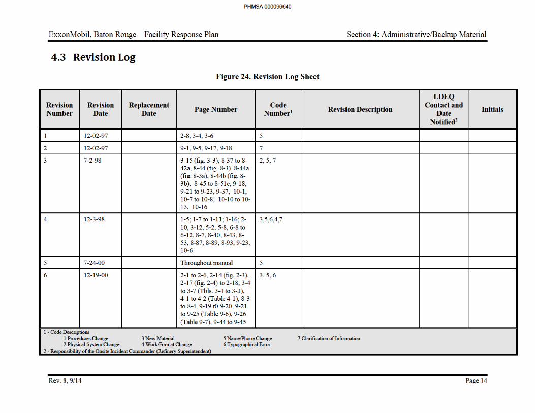

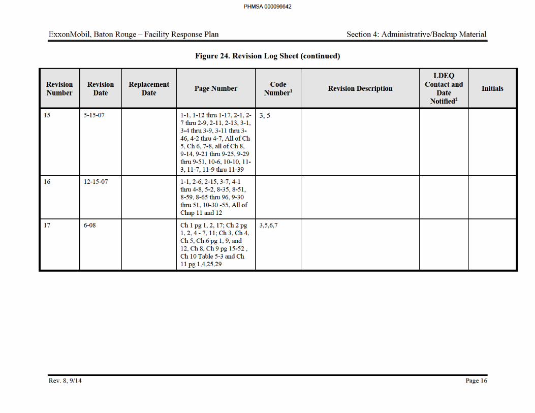
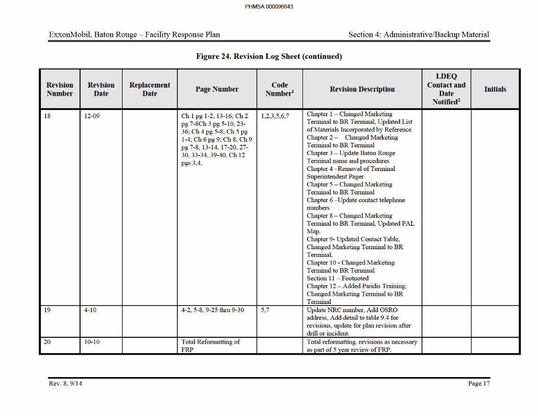
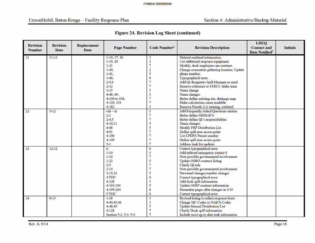
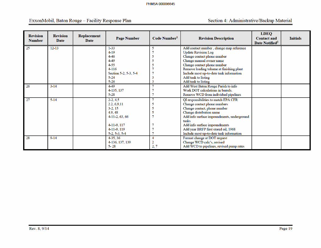
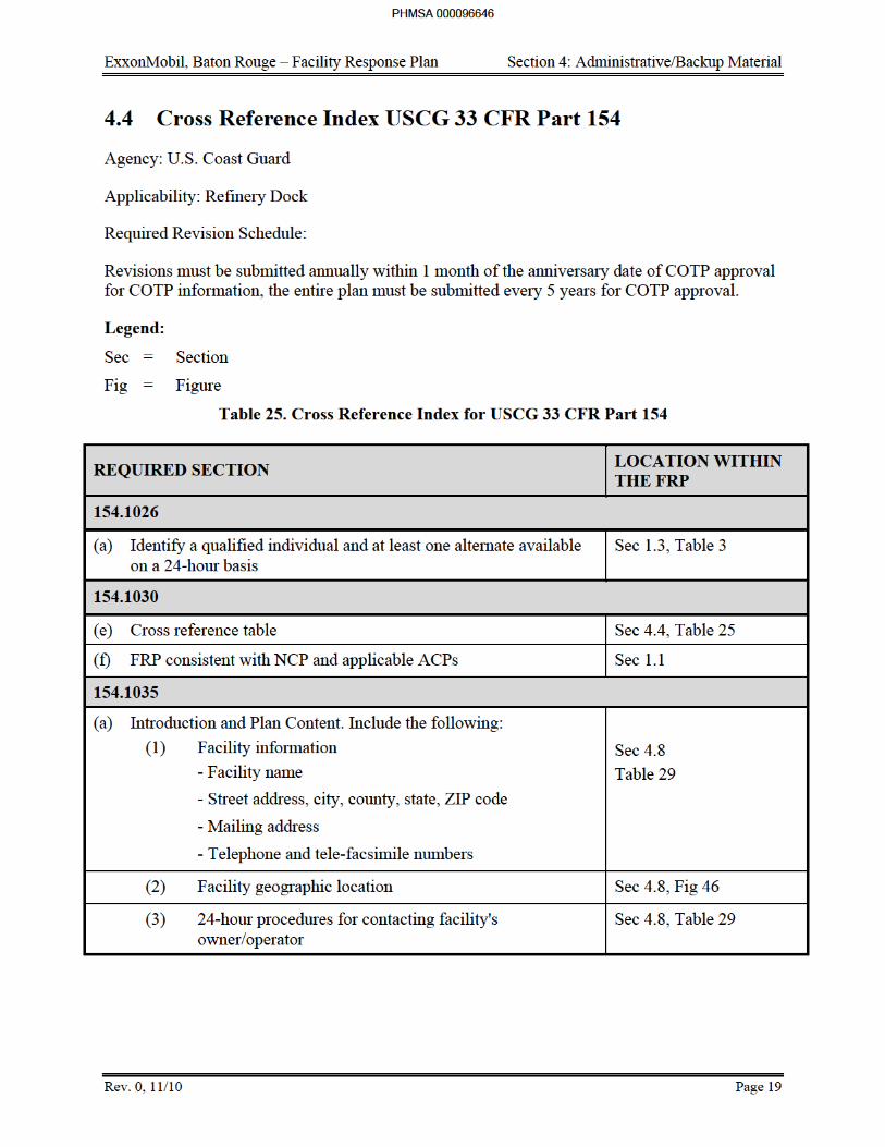
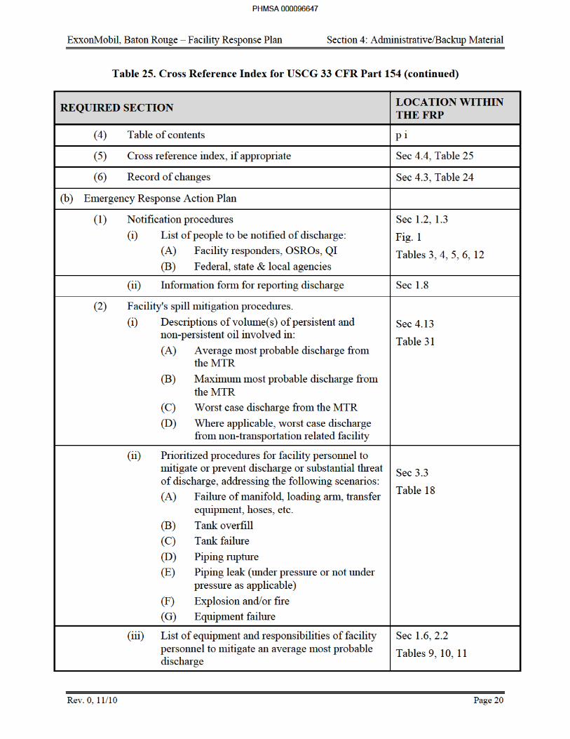
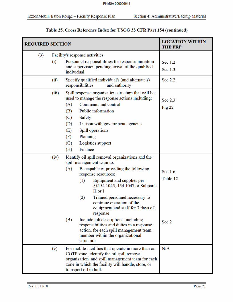
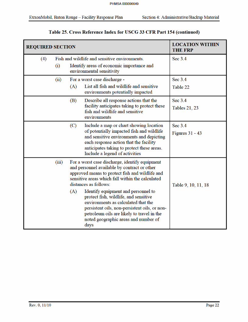
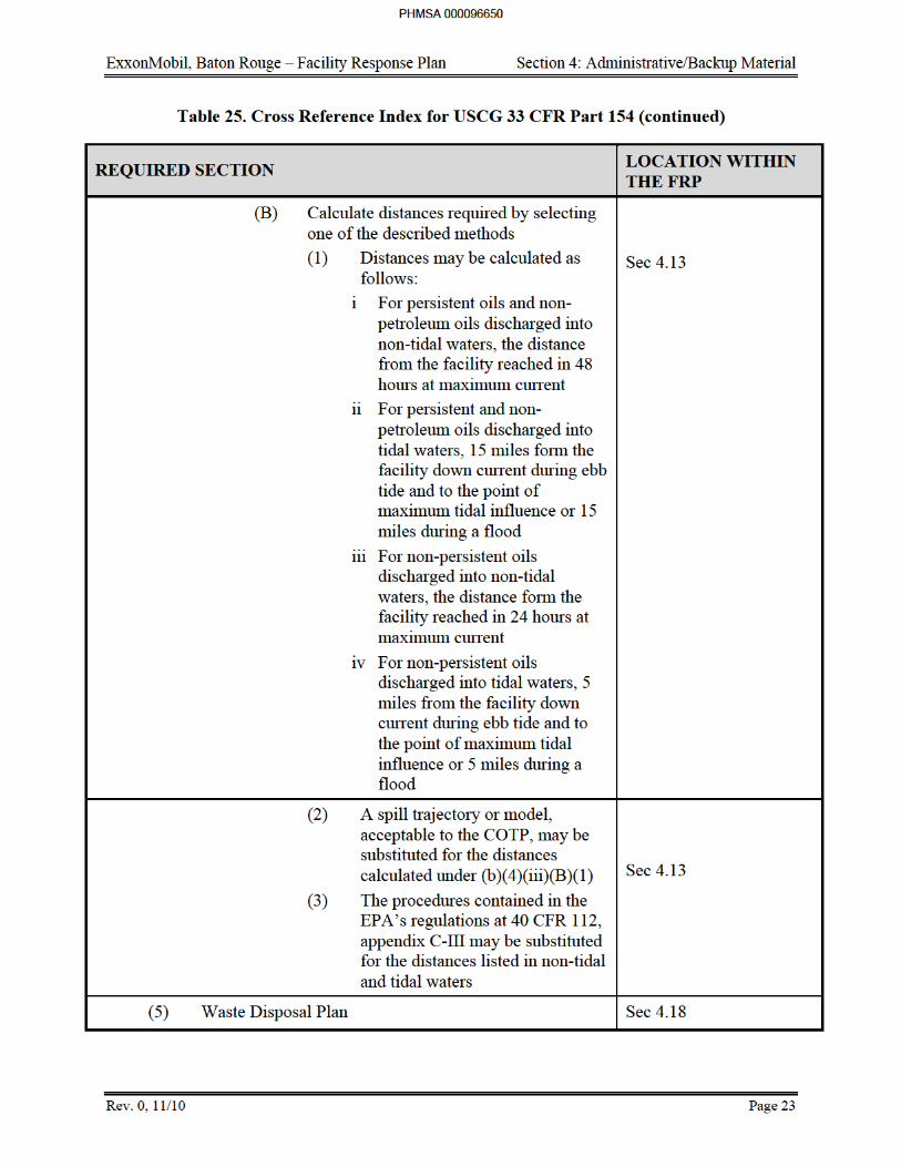
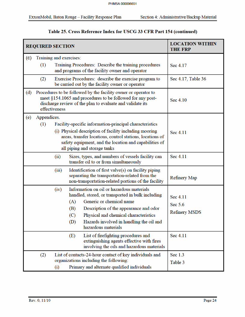
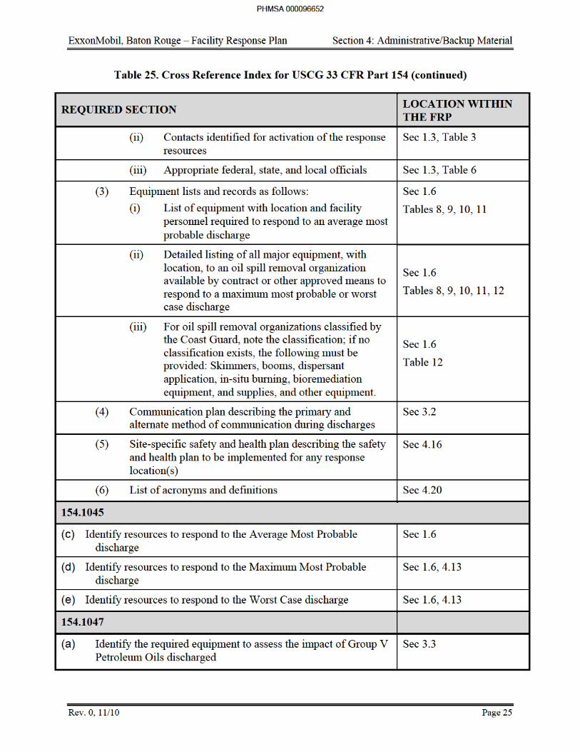


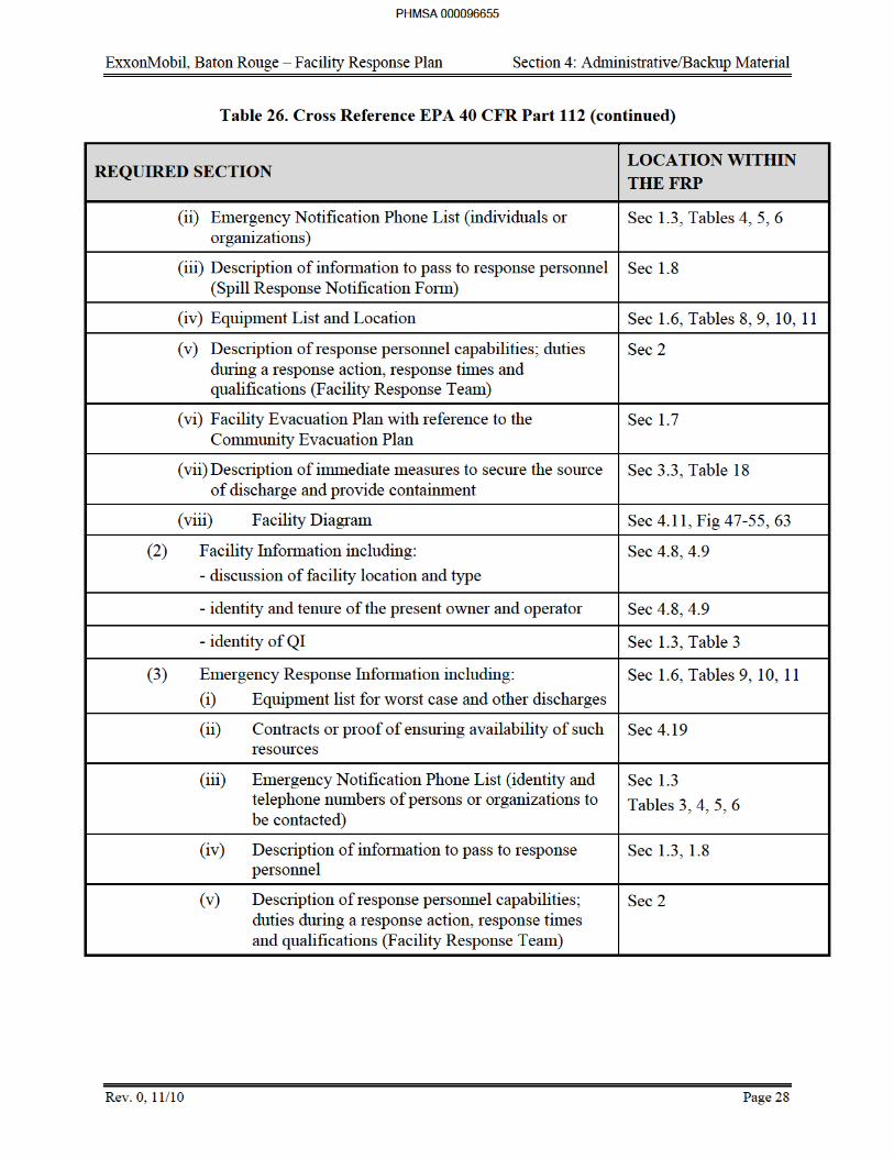
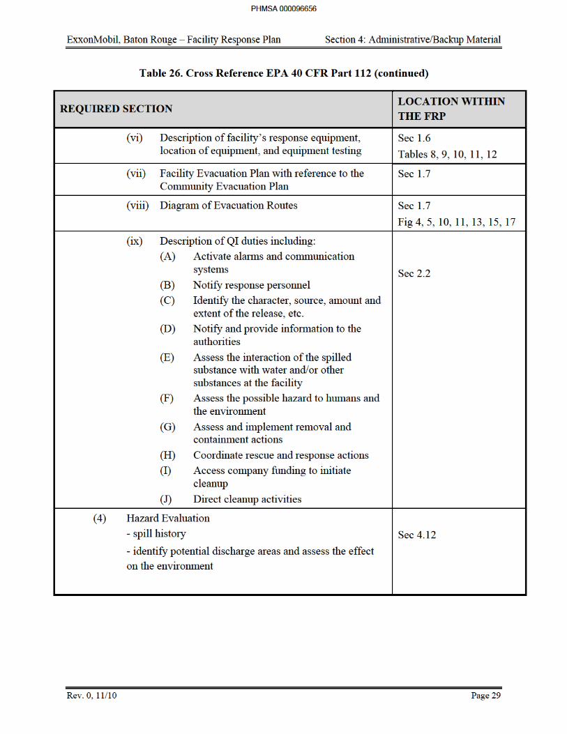
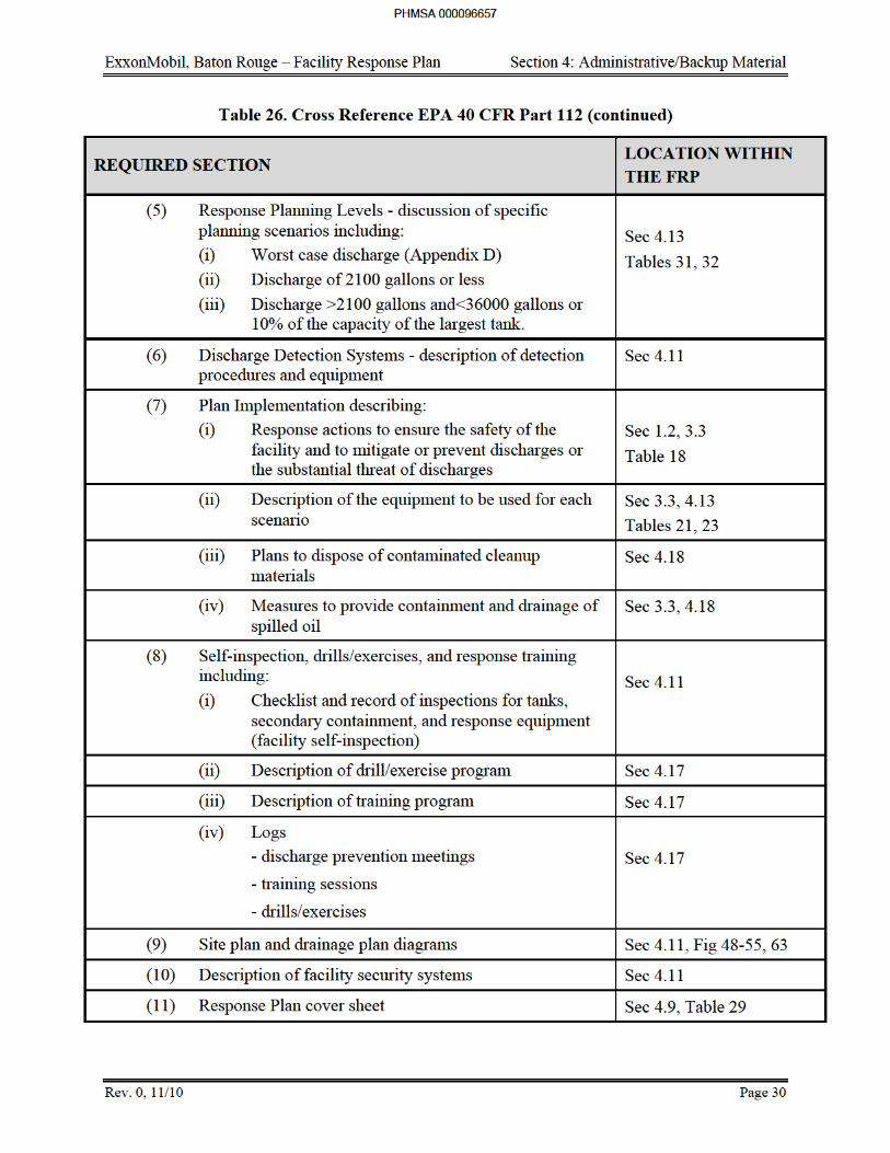
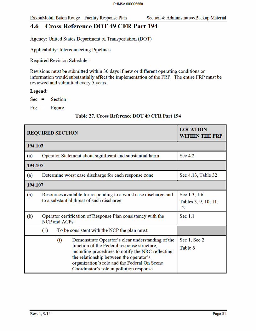
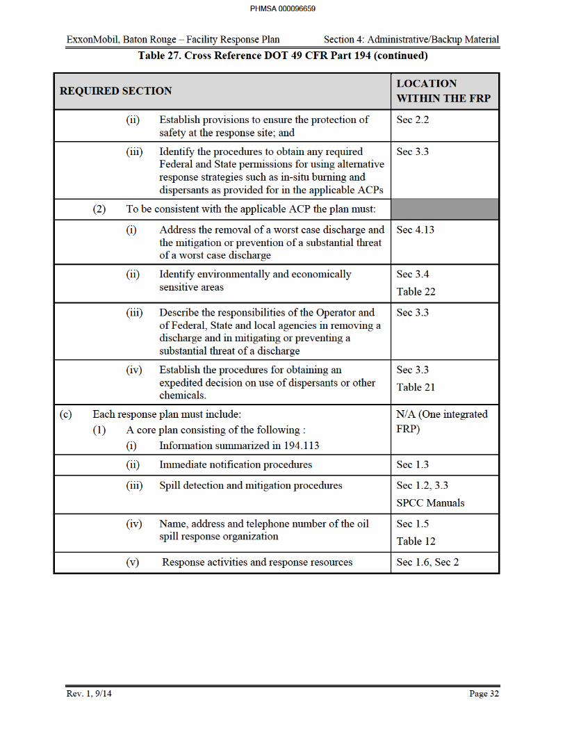
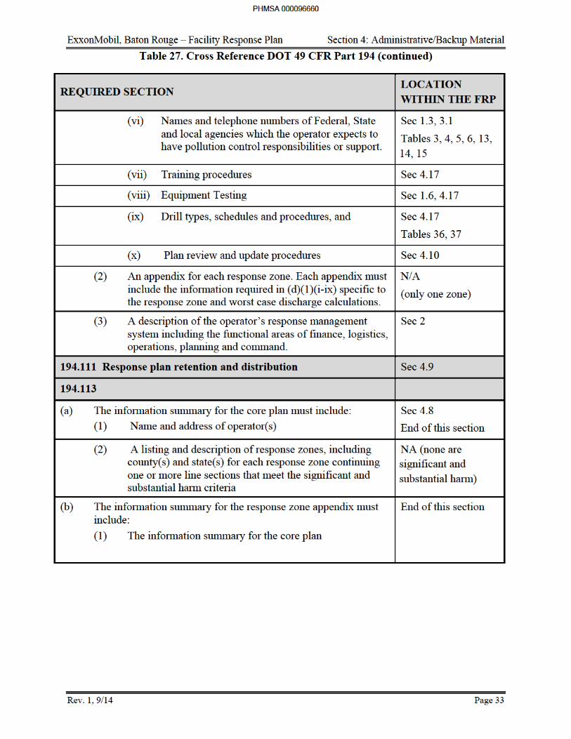
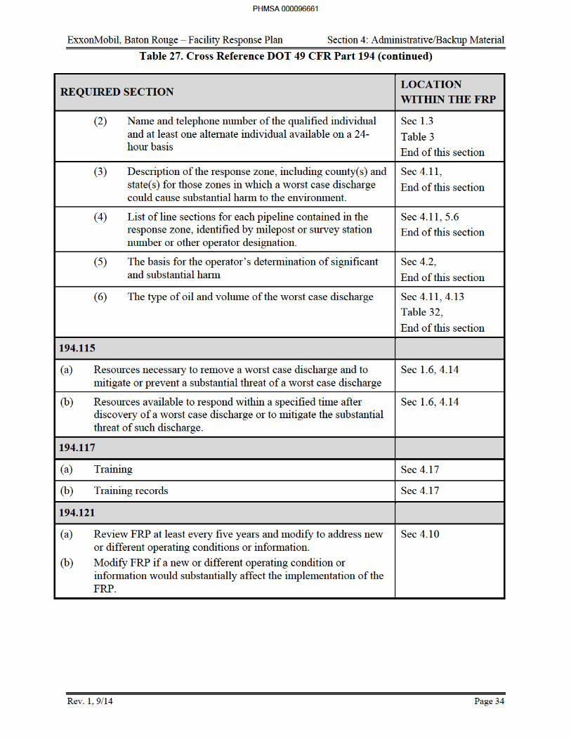
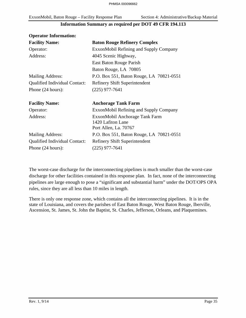
ExxonMobil, Baton Rouge – Facility Response Plan Section 4: Administrative/Backup Material
Rev. 1, 9/14 Page 35
Information Summary as required per DOT 49 CFR 194.113
Operator Information:
Facility Name: Baton Rouge Refinery Complex
Operator: ExxonMobil Refining and Supply Company
Address: 4045 Scenic Highway,
East Baton Rouge Parish
Baton Rouge, LA 70805
Mailing Address: P.O. Box 551, Baton Rouge, LA 70821-0551
Qualified Individual Contact: Refinery Shift Superintendent
Phone (24 hours): (225) 977-7641
Facility Name: Anchorage Tank Farm
Operator: ExxonMobil Refining and Supply Company
Address: ExxonMobil Anchorage Tank Farm 1420 Lafiton Lane Port Allen, La. 70767
Mailing Address: P.O. Box 551, Baton Rouge, LA 70821-0551
Qualified Individual Contact: Refinery Shift Superintendent
Phone (24 hours): (225) 977-7641
The worst-case discharge for the interconnecting pipelines is much smaller than the worst-case discharge for other facilities contained in this response plan. In fact, none of the interconnecting pipelines are large enough to pose a “significant and substantial harm” under the DOT/OPS OPA rules, since they are all less than 10 miles in length.
There is only one response zone, which contains all the interconnecting pipelines. It is in the state of Louisiana, and covers the parishes of East Baton Rouge, West Baton Rouge, Iberville, Ascension, St. James, St. John the Baptist, St. Charles, Jefferson, Orleans, and Plaquemines.
PHMSA 000096662
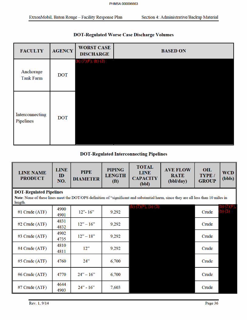
ExxonMobil, Baton Rouge – Facility Response Plan Section 4: Administrative/Backup Material
Rev. 0, 11/10 Page 35
4.7 Applicable Rules
ExxonMobil has reviewed the requirements for Oil Spill Response plans under EPA, DOT and USCG regulations. They have determined that all three of these apply to some portion of the complex. Requirements of these regulations are covered in this FRP. The rules are summarized as follows:
EPA FRP (EPA 40 CFR 112)
Per the Oil Pollution Act of 1990, the owner or operator of a facility that could potentially discharge oil into or on navigable water causing substantial harm (Table 24 contains this determination for each entity included in the manual.) to the environment must prepare and submit a facility response plan to the EPA Region VI office. The facility response plan must include the following:
1. Emergency response action plan. The response plan includes an emergency response action that includes the following information:
a. The identity and telephone number of a qualified individual having full authority, including contracting authority, to implement removal actions;
b. The identity of individuals or organizations to be contacted in the event of a discharge so that immediate communications between the qualified individual and the appropriate Federal officials and the persons providing response personnel and equipment can be ensured;
c. A description of information to pass to response personnel in the event of a reportable discharge;
d. A description of the facility's response equipment and its location;
e. A description of response personnel capabilities, including the duties of persons at the facility during a response action and their response times and qualifications;
f. Plans for evacuation of the facility and a reference to community evacuation plans, as appropriate;
g. A description of immediate measures to secure the source of the discharge, and to provide adequate containment and drainage of discharged oil; and
h. A diagram of the facility.
2. Facility information. The response plan identifies and discusses the location and type of the facility, the identity and tenure of the present owner and operator, and the identity of the qualified individual identified.
3. Information about emergency response. The response plan includes:
a. The identity of private personnel and equipment necessary to remove to the maximum extent practicable a worst case discharge and other discharges of oil and to mitigate or prevent a substantial threat of a worst case discharge;
PHMSA 000096664
ExxonMobil, Baton Rouge – Facility Response Plan Section 4: Administrative/Backup Material
Rev. 0, 11/10 Page 36
b. Evidence of contracts or other approved means for ensuring the availability of such personnel and equipment;
c. The identity and the telephone number of individuals or organizations to be contacted in the event of a discharge so that immediate communications between the qualified individual and the appropriate Federal official and the persons providing response personnel and equipment can be ensured;
d. A description of information to pass to response personnel in the event of a reportable discharge;
e. A description of response personnel capabilities, including the duties of persons at the facility during a response action and their response times and qualifications;
f. A description of the facility's response equipment, the location of the equipment, and equipment testing;
g. Plans for evacuation of the facility and a reference to community evacuation plans, as appropriate;
h. A diagram of evacuation routes; and
i. A description of the duties of the qualified individual identified that include:
i. Activate internal alarms and hazard communication systems to notify all facility personnel;
ii. Notify all response personnel, as needed;
iii. Identify the character, exact source, amount, and extent of the release, as well as the other items needed for notification;
iv. Notify and provide necessary information to the appropriate Federal, State, and local authorities with designated response roles, including the National Response Center, State Emergency Response Commission, and Local Emergency Planning Committee;
v. Assess the interaction of the discharged substance with water and/or other substances stored at the facility and notify response personnel at the scene of that assessment;
vi. Assess the possible hazards to human health and the environment due to the release.;
vii. Assess and implement prompt removal actions to contain and remove the substance released;
viii. Coordinate rescue and response actions as previously arranged with all response personnel;
ix. Use authority to immediately access company funding to initiate cleanup activities; and
x. Direct cleanup activities until properly relieved of this responsibility.
PHMSA 000096665
ExxonMobil, Baton Rouge – Facility Response Plan Section 4: Administrative/Backup Material
Rev. 0, 11/10 Page 37
4. Hazard evaluation. The response plan discusses the facility's known or reasonably identifiable history of discharges reportable under 40 CFR part 110 for the entire life of the facility and identifies areas within the facility where discharges could occur and what the potential effects of the discharges would be on the affected environment.
5. Response planning levels. The response plan includes discussion of specific planning scenarios for:
a. A worst case discharge;
b. A discharge of 2,100 gallons or less, provided that this amount is less than the worst case discharge amount. For complexes, this planning quantity shall be the larger of the amounts calculated for each component of the facility; and
c. A discharge greater than 2,100 gallons and less than or equal to 36,000 gallons or 10 percent of the capacity of the largest tank at the facility, whichever is less, provided that this amount is less than the worst case discharge amount. For complexes, this planning quantity shall be the larger of the amounts calculated for each component of the facility.
6. Discharge detection systems. The response plan describes the procedures and equipment used to detect discharges.
7. Plan implementation. The response plan shall describe:
a. Response actions to be carried out by facility personnel or contracted personnel under the response plan to ensure the safety of the facility and to mitigate or prevent discharges or the substantial threat of such discharges;
b. A description of the equipment to be used for each scenario;
c. Plans to dispose of contaminated cleanup materials; and
d. Measures to provide adequate containment and drainage of discharged oil.
8. Self-inspection, drills/exercises, and response training. The response plan includes:
a. A checklist and record of inspections for tanks, secondary containment, and response equipment;
b. A description of the drill/exercise program to be carried out under the response plan as described in §112.21;
c. A description of the training program to be carried out under the response plan as described in §112.21; and
d. Logs of discharge prevention meetings, training sessions, and drills/exercises. These logs may be maintained as an annex to the response plan.
9. Diagrams. The response plan includes site plan and drainage plan diagrams.
10. Security systems. The response plan includes a description of facility security systems.
11. Response plan cover sheet. The response plan includes a completed response plan cover sheet provided.
PHMSA 000096666
ExxonMobil, Baton Rouge – Facility Response Plan Section 4: Administrative/Backup Material
Rev. 0, 11/10 Page 38
USCG FRP (33 CFR 154.1035)
33 CFR 154.1035 provides specific facility response plan requirements for marine transportation related (MTR) facilities under the jurisdiction of the U.S. Coast Guard that could reasonably be expected to cause significant and substantial harm to the environment. The information contained in the plan must be consistent with the National Contingency Plan and the Area Contingency Plan(s) covering the area in which the facility operates. The facility response plan must include the following:
1. An introduction providing information such as facility name, address and telephone number; directions to the facility; facility location and contact procedures; and a table of contents for the plan.
2. An emergency response action plan including notification procedures; spill mitigation procedures for average most probable discharges, maximum most probable discharges and worst case discharges; response activities and identification of potentially impacted fish and wildlife resources and sensitive areas.
3. Training and exercise procedures.
4. Plan review and update procedures.
5. Appendices including:
a. facility-specific information (plans of the facility, types and number of vessels that the facility can transfer oil to and from simultaneously, information on the oil and hazardous material handled, stored or transported at the facility, etc.),
b. lists of contacts,
c. equipment lists and records,
d. a communications plan,
e. site-specific safety and health plan,
f. list of acronyms and definitions and,
g. if applicable, a geographic-specific appendix for each zone in which a mobile facility operates.
DOT (40 CFR 194)
This regulation outlines the requirements for oil spill response to reduce the environmental impact of oil discharged from onshore oil pipelines that could reasonably be expected to cause substantial harm to the environment by discharging oil into or on any navigable waters of the United States or adjoining shorelines.
This plan is to be submitted along with a statement identifying which line sections in the response zone can be expected to cause significant and substantial harm to the environment in the event of a discharge of oil into or on the navigable waterways or adjacent shoreline. If the operator suspects that a line section in a response zone can cause significant harm, then the entire
PHMSA 000096667

ExxonMobil, Baton Rouge – Facility Response Plan Section 4: Administrative/Backup Material
Rev. 0, 11/10 Page 39
response zone must be treated as if it is expected to cause significant harm. However, the operator does not have to submit separate plans for each line section.
The operator will determine the worst case discharge from the following in barrels for each of its response zones and provide the methodology, including calculations, used to arrive at the volume:
Pipeline’s maximum release in hours, plus the maximum shut-in response time in hours, multiplied by the maximum flow rate expressed in barrels per hour, plus the largest line drainage volume after shutdown of the line sections in the response zone expressed in barrels.
Largest foreseeable discharge for the line section within a response zone, expressed in barrels, based on the maximum historic discharge, adjusted for any subsequent corrective or preventive action taken.
The capacity of the single largest tank or battery of tanks within a single secondary containment system, adjusted for the capacity of the secondary containment system.
The general response plan must meet the following requirements:
Must plan for resources for responding to a worst case discharge and to a substantial threat of such a discharge, Note: The “substantial threat” term is equivalent to abnormal operations outlined in 49 CFR 195.402(d).
Must be written in English and any other language that is understood by personnel that will be responsible for carrying out the plan,
Must be consistent with the National Contingency Plan. In order to do this, the plan must (at a minimum):
Demonstrate an understanding of the function of the Federal response structure, including procedures to notify the National Response Center reflecting the relationship between ExxonMobil’s response organization and the Federal On Scene Coordinator’s role in pollution response;
Establish provisions to ensure the protection of safety at the response site; and,
Identify the procedures to obtain any required Federal and State permissions for using alternative response strategies such as in-situ burning and dispersants as provided for in the applicable ACPs
Must be consistent with each applicable Area Contingency Plan. In order to do this, the plan must (at a minimum):
Address the removal of a worst case discharge and the mitigation or prevention of a substantial threat of a worse case discharge;
Identify environmentally and economically sensitive areas;
PHMSA 000096668
ExxonMobil, Baton Rouge – Facility Response Plan Section 4: Administrative/Backup Material
Rev. 0, 11/10 Page 40
Describe the responsibilities of Federal, State, and local agencies in removing a discharge and in mitigating or preventing a substantial threat of a discharge; and
Establish procedures for obtaining an expedited decision on use of dispersants or other chemicals
Must include:
Information summary,
- Name and address of the operator;
- Names or titles and 24-hour telephone number of the qualified individuals and at least one alternate qualified individual,
- A listing and description of response zones, including counties and states;
Immediate notification procedures,
Spill detection and mitigation procedures,
Name, address and telephone number of Oil Spill Response Organization,
Response activities and resources,
Names and telephone numbers of federal, state and local agencies which the operator expects to have pollution control responsibilities or support,
Training procedures:
- All personnel must know-
Their responsibilities;
Name, address, and procedure for contacting the operator ( 24 hour)
Name and procedures for contacting qualified individuals (24 hour);
- Reporting personnel know
Content of the information summary of the response plan;
Toll-free telephone number of the National Response Center;
Notification Process
- Personnel engaged in response activities know-
Characteristics and hazards of the oil discharged;
Conditions likely to worsen emergencies;
Steps necessary to control any accidental discharge of oil and to minimize the potential for fire, explosion, toxicity, or environmental damage, and
Proper firefighting procedures
PHMSA 000096669
ExxonMobil, Baton Rouge – Facility Response Plan Section 4: Administrative/Backup Material
Rev. 0, 11/10 Page 41
Equipment testing,
Drill types, schedules, and procedures,
Plan review and update procedures,
Appendix for each response zone
- Information summary for core plan;
- Name and telephone number of the qualified individual available on a 24-hour basis;
- Description of the response zone (if the worst case discharge could cause substantial harm to the environment);
- List of line sections
- Basis for the operator’s determination of significant and substantial harm;
- Type of oil and volume of the worst case discharge
A description of the response management system including the functional areas of finance, logistics, operations, planning, and command. This system must use common technology and have a manageable span of control, a clearly defined chain of command, and sufficient trained personnel for each position.
Relevant portions of this plan must be retained at the operator’s headquarters, at relevant pump stations and any other locations from which response activities may be conducted, for example, in field offices, supervisors’ vehicles or spill response trailers. Each qualified individual must be provided with a complete copy of the plan. Refinery superintendents are not issued individual copies, but copies are available in their offices.
Records of training will be maintained for as long as the person has responsibilities under the response plan.
PHMSA 000096670
ExxonMobil, Baton Rouge – Facility Response Plan Section 4: Administrative/Backup Material
Rev. 3, 3/14 Page 42
4.8 Plan Coverage
Introduction
The geographic area covered by this FRP includes the facilities mentioned in Section 1, Table 1, along with Monte Sano Bayou from the ExxonMobil Chemical Plant to the Mississippi River and the Mississippi River from mile marker 233 above Head of Passes south to Head of Passes (river mile marker 0). A map of the geographic area of interest is shown in Figure 46.
Facility-specific information such as facility name, owner, address, etc. for each of the facilities covered by this plan is provided in the list following Figure 46.
PHMSA 000096671
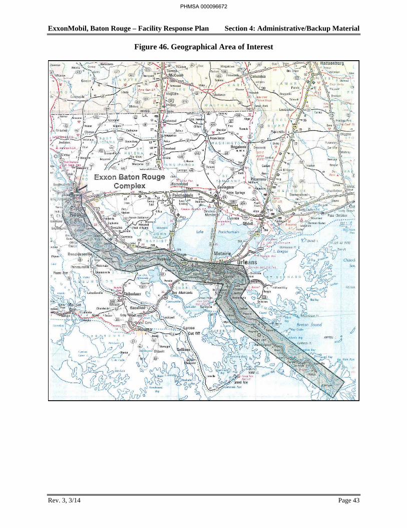
ExxonMobil, Baton Rouge – Facility Response Plan Section 4: Administrative/Backup Material
Rev. 3, 3/14 Page 43
Figure 46. Geographical Area of Interest
PHMSA 000096672
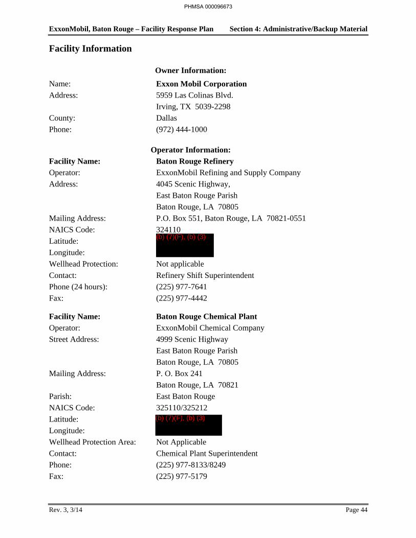
ExxonMobil, Baton Rouge – Facility Response Plan Section 4: Administrative/Backup Material
Rev. 3, 3/14 Page 44
Facility Information
Owner Information:
Name: Exxon Mobil Corporation
Address: 5959 Las Colinas Blvd.
Irving, TX 5039-2298
County: Dallas
Phone: (972) 444-1000
Operator Information:
Facility Name: Baton Rouge Refinery
Operator: ExxonMobil Refining and Supply Company
Address: 4045 Scenic Highway,
East Baton Rouge Parish
Baton Rouge, LA 70805
Mailing Address: P.O. Box 551, Baton Rouge, LA 70821-0551
NAICS Code: 324110
Latitude:
Longitude:
Wellhead Protection: Not applicable
Contact: Refinery Shift Superintendent
Phone (24 hours): (225) 977-7641
Fax: (225) 977-4442
Facility Name: Baton Rouge Chemical Plant
Operator: ExxonMobil Chemical Company
Street Address: 4999 Scenic Highway
East Baton Rouge Parish
Baton Rouge, LA 70805
Mailing Address: P. O. Box 241
Baton Rouge, LA 70821
Parish: East Baton Rouge
NAICS Code: 325110/325212
Latitude:
Longitude:
Wellhead Protection Area: Not Applicable
Contact: Chemical Plant Superintendent
Phone: (225) 977-8133/8249
Fax: (225) 977-5179
PHMSA 000096673
(b) (7)(F), (b) (3)
(b) (7)(F), (b) (3)
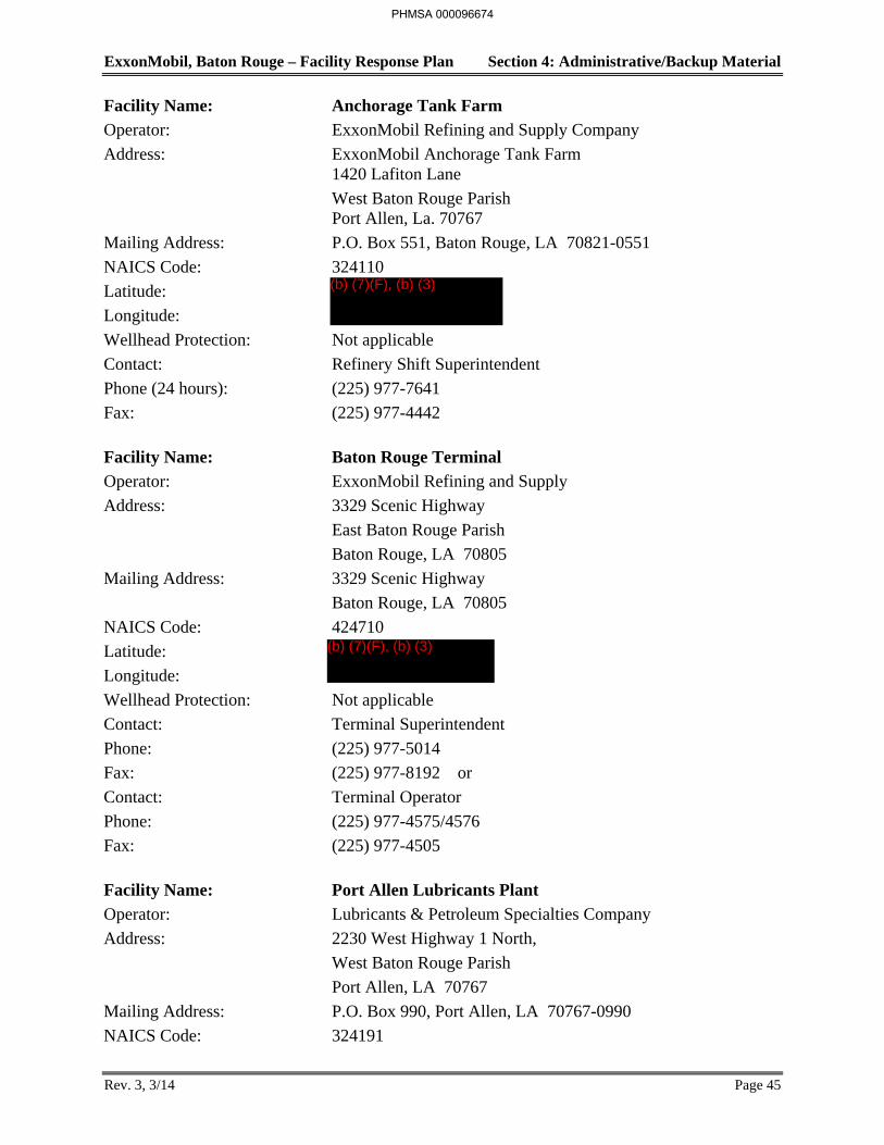
ExxonMobil, Baton Rouge – Facility Response Plan Section 4: Administrative/Backup Material
Rev. 3, 3/14 Page 45
Facility Name: Anchorage Tank Farm
Operator: ExxonMobil Refining and Supply Company
Address: ExxonMobil Anchorage Tank Farm 1420 Lafiton Lane
West Baton Rouge Parish Port Allen, La. 70767
Mailing Address: P.O. Box 551, Baton Rouge, LA 70821-0551
NAICS Code: 324110
Latitude:
Longitude:
Wellhead Protection: Not applicable
Contact: Refinery Shift Superintendent
Phone (24 hours): (225) 977-7641
Fax: (225) 977-4442
Facility Name: Baton Rouge Terminal
Operator: ExxonMobil Refining and Supply
Address: 3329 Scenic Highway
East Baton Rouge Parish
Baton Rouge, LA 70805
Mailing Address: 3329 Scenic Highway
Baton Rouge, LA 70805
NAICS Code: 424710
Latitude:
Longitude:
Wellhead Protection: Not applicable
Contact: Terminal Superintendent
Phone: (225) 977-5014
Fax: (225) 977-8192 or
Contact: Terminal Operator
Phone: (225) 977-4575/4576
Fax: (225) 977-4505
Facility Name: Port Allen Lubricants Plant
Operator: Lubricants & Petroleum Specialties Company
Address: 2230 West Highway 1 North,
West Baton Rouge Parish
Port Allen, LA 70767
Mailing Address: P.O. Box 990, Port Allen, LA 70767-0990
NAICS Code: 324191
PHMSA 000096674
(b) (7)(F), (b) (3)
(b) (7)(F), (b) (3)

ExxonMobil, Baton Rouge – Facility Response Plan Section 4: Administrative/Backup Material
Rev. 3, 3/14 Page 46
Facility Name: Port Allen Lubricants Plant (continued)
Latitude:
Longitude:
Wellhead Protection: Not applicable
Contact: Plant Manager
Phone: (225) 977-3402
Fax: (225) 977-3444
Facility Name: Baton Rouge Resins Finishing Plant (BRFP)
Operator: ExxonMobil Chemical Company
Street Address: 12480 Scenic Highway
East Baton Rouge Parish
Baton Rouge, LA 70807
Mailing Address: 12480 Scenic Highway
Baton Rouge, LA 70807
Parish: East Baton Rouge
NAICS Code: 325211
Latitude:
Longitude:
Wellhead Protection Area: Not Applicable
Contact: Shift Supervisor
Phone: (24 Hours) (225) 977-2516
Fax: (225) 977-2560
Facility Name: Baton Rouge Coke Terminal
Operator: ExxonMobil Refining and Supply Company
Address: End of Gulf States Road at River 233 M.M.
East Baton Rouge Parish
Baton Rouge, LA 70805
Mailing Address: P.O. Box 551, Baton Rouge, LA 70821-0551
NAICS Code: 324110
Latitude:
Longitude:
Wellhead Protection: Not applicable
Contact: Refinery Shift Superintendent
Phone (24 hours): (225) 977-7641
Fax: (225) 977-4442
*All of the facilities represented in this plan have been owned by Exxon Corporation (now Exxon Mobil Corporation) since their inception.
PHMSA 000096675
(b) (7)(F), (b) (3)
(b) (7)(F), (b) (3)
(b) (7)(F), (b) (3)
ExxonMobil, Baton Rouge – Facility Response Plan Section 4: Administrative/Backup Material
Rev. 4, 5/14 Page 47
4.9 Distribution List and Response Plan Facility Information Summary Sheets
A copy of the FRP has been assigned to the key response personnel and regulatory agency personnel. Copies of all revised or updated pages must be distributed to the individuals included on the attached FRP distribution list shown in Table 28. Each plan recipient is expected to review the plan changes.
The Response Plan Facility Information Summary Sheets for the ExxonMobil Baton Rouge Refinery, Chemical Plant, Anchorage Tank Farm, Baton Rouge Terminal, Port Allen Lubricants Plant and Baton Rouge Finishing Plant, and Baton Rouge Coke Terminal are provided in Table 29.
PHMSA 000096676
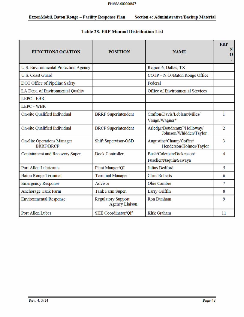
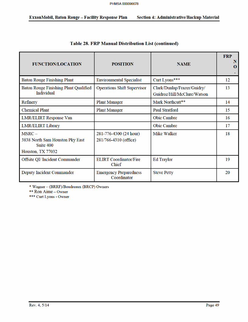
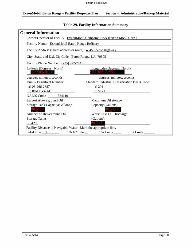
ExxonMobil, Baton Rouge – Facility Response Plan Section 4: Administrative/Backup Material
Rev. 4, 5/14 Page 50
Table 29. Facility Information Summary
General Information Owner/Operator of Facility: ExxonMobil Company, USA (Exxon Mobil Corp.)
Facility Name: ExxonMobil Baton Rouge Refinery
Facility Address (Street address or route): 4045 Scenic Highway
City, State, and U.S. Zip Code: Baton Rouge, LA 70805
Facility Phone Number: (225) 977-7641
Latitude (Degrees: North) Longitude (Degrees: North) degrees, minutes, seconds degrees, minutes, seconds Dun & Bradstreet Number: Standard Industrial Classification (SIC) Code: a) 06-266-2887 a) 2911 b) 00-121-3214 b) 5171 NAICS Code: 324110 Largest Above ground Oil Maximum Oil storage Storage Tank Capacity(Gallons): Capacity (Gallons): Number of aboveground Oil Worst Case Oil Discharge Storage Tanks: (Gallons): 429 Facility Distance to Navigable Water. Mark the appropriate line. 0-1/4 mile: X 1/4-1/2 mile: 1/2-1 mile: >1 mile:
PHMSA 000096679
(b) (7)(F), (b) (3) (b) (7)(F), (b) (3)
(b) (7)(F), (b) (3)
(b) (7)(F), (b) (3)
(b) (7)(F), (b) (3)
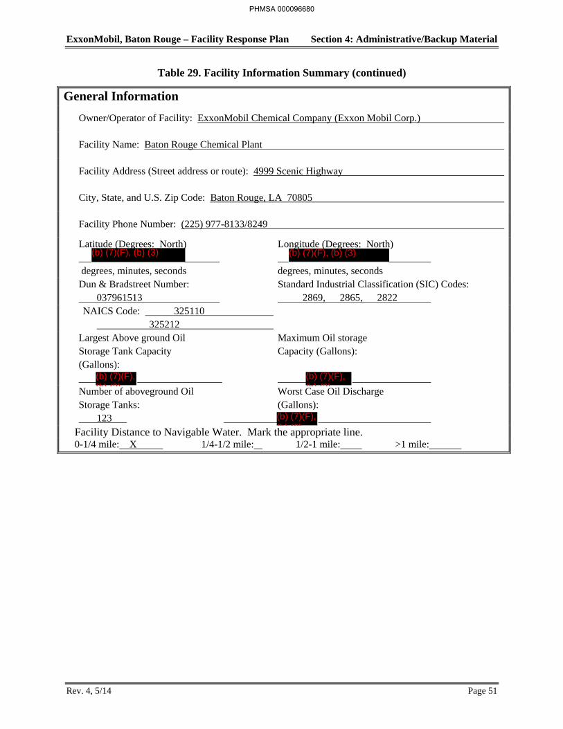
ExxonMobil, Baton Rouge – Facility Response Plan Section 4: Administrative/Backup Material
Rev. 4, 5/14 Page 51
Table 29. Facility Information Summary (continued)
General Information
Owner/Operator of Facility: ExxonMobil Chemical Company (Exxon Mobil Corp.)
Facility Name: Baton Rouge Chemical Plant
Facility Address (Street address or route): 4999 Scenic Highway
City, State, and U.S. Zip Code: Baton Rouge, LA 70805
Facility Phone Number: (225) 977-8133/8249
Latitude (Degrees: North) Longitude (Degrees: North) degrees, minutes, seconds degrees, minutes, seconds Dun & Bradstreet Number: Standard Industrial Classification (SIC) Codes: 037961513 2869, 2865, 2822 NAICS Code: 325110 325212 Largest Above ground Oil Maximum Oil storage Storage Tank Capacity Capacity (Gallons): (Gallons): Number of aboveground Oil Worst Case Oil Discharge Storage Tanks: (Gallons): 123
Facility Distance to Navigable Water. Mark the appropriate line. 0-1/4 mile: X 1/4-1/2 mile: 1/2-1 mile: >1 mile:
PHMSA 000096680
(b) (7)(F), (b) (3) (b) (7)(F), (b) (3)
(b) (7)(F), (b) (3)
(b) (7)(F), (b) (3)
(b) (7)(F), (b) (3)
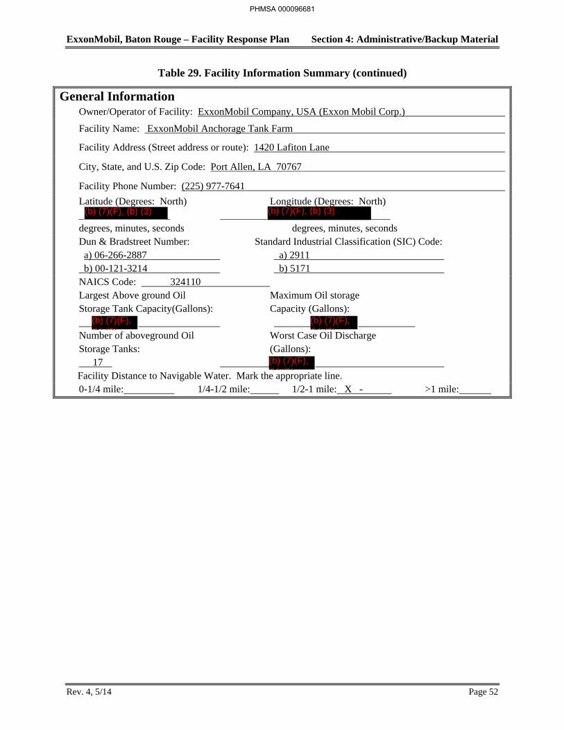
ExxonMobil, Baton Rouge – Facility Response Plan Section 4: Administrative/Backup Material
Rev. 4, 5/14 Page 52
Table 29. Facility Information Summary (continued)
General Information Owner/Operator of Facility: ExxonMobil Company, USA (Exxon Mobil Corp.)
Facility Name: ExxonMobil Anchorage Tank Farm
Facility Address (Street address or route): 1420 Lafiton Lane
City, State, and U.S. Zip Code: Port Allen, LA 70767
Facility Phone Number: (225) 977-7641
Latitude (Degrees: North) Longitude (Degrees: North) degrees, minutes, seconds degrees, minutes, seconds Dun & Bradstreet Number: Standard Industrial Classification (SIC) Code: a) 06-266-2887 a) 2911 b) 00-121-3214 b) 5171 NAICS Code: 324110 Largest Above ground Oil Maximum Oil storage Storage Tank Capacity(Gallons): Capacity (Gallons): Number of aboveground Oil Worst Case Oil Discharge Storage Tanks: (Gallons): 17 Facility Distance to Navigable Water. Mark the appropriate line. 0-1/4 mile: 1/4-1/2 mile: 1/2-1 mile: X - >1 mile:
PHMSA 000096681
(b) (7)(F), (b) (3) (b) (7)(F), (b) (3)
(b) (7)(F), (b) (3)
(b) (7)(F), (b) (3)
(b) (7)(F), (b) (3)

ExxonMobil, Baton Rouge – Facility Response Plan Section 4: Administrative/Backup Material
Rev. 4, 5/14 Page 53
Table 29. Facility Information Summary (continued)
General Information
Owner/Operator of Facility: ExxonMobil Refining and Supply Company (Exxon Mobil Corp.)
Facility Name: ExxonMobil Baton Rouge Terminal Facility Address (Street address or route): 3329 Scenic Highway
City, State, and U.S. Zip Code: Baton Rouge, LA 70805
Facility Phone Number: (225) 977-4575
Latitude (Degrees: North) Longitude (Degrees: North) degrees, minutes, seconds degrees, minutes, seconds Dun & Bradstreet Number: Standard Industrial Classification (SIC)
Code: a) 06-266-2887 b) 00-121-3214 5171 NAICS Code: 424710
Largest Above ground Oil Maximum Oil storage Storage Tank Capacity Capacity (Gallons): (Gallons): Number of aboveground Oil Worst Case Oil Discharge Storage Tanks: (Gallons): 19
Facility Distance to Navigable Water. Mark the appropriate line.
0-1/4 mile: X 1/4-1/2 mile: 1/2-1 mile: >1 mile:
PHMSA 000096682
(b) (7)(F), (b) (3) (b) (7)(F), (b) (3)
(b) (7)(F) (b)
(b) (7)(F), (b) (3)
(b) (7)(F) (b)
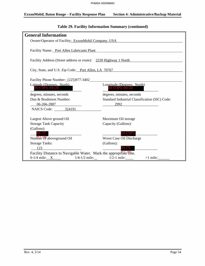
ExxonMobil, Baton Rouge – Facility Response Plan Section 4: Administrative/Backup Material
Rev. 4, 5/14 Page 54
Table 29. Facility Information Summary (continued)
General Information Owner/Operator of Facility: ExxonMobil Company, USA Facility Name: Port Allen Lubricants Plant Facility Address (Street address or route): 2230 Highway 1 North City, State, and U.S. Zip Code: Port Allen, LA 70767 Facility Phone Number: (225)977-3402 Latitude (Degrees: North) Longitude (Degrees: North) degrees, minutes, seconds degrees, minutes, seconds Dun & Bradstreet Number: Standard Industrial Classification (SIC) Code: 06-266-2887 2992 NAICS Code: 324191
Largest Above ground Oil Maximum Oil storage Storage Tank Capacity Capacity (Gallons): (Gallons): Number of aboveground Oil Worst Case Oil Discharge Storage Tanks: (Gallons): 123
Facility Distance to Navigable Water. Mark the appropriate line. 0-1/4 mile: X 1/4-1/2 mile: 1/2-1 mile: >1 mile:
PHMSA 000096683
(b) (7)(F), (b) (3) (b) (7)(F), (b) (3)
(b) (7)(F) (b)
(b) (7)(F), (b) (3)
(b) (7)(F) (b)
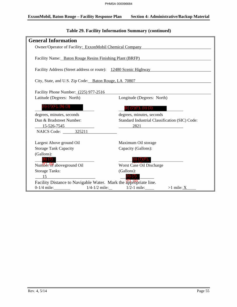
ExxonMobil, Baton Rouge – Facility Response Plan Section 4: Administrative/Backup Material
Rev. 4, 5/14 Page 55
Table 29. Facility Information Summary (continued)
General Information Owner/Operator of Facility: ExxonMobil Chemical Company Facility Name: Baton Rouge Resins Finishing Plant (BRFP) Facility Address (Street address or route): 12480 Scenic Highway City, State, and U.S. Zip Code: Baton Rouge, LA 70807 Facility Phone Number: (225) 977-2516 Latitude (Degrees: North) Longitude (Degrees: North) degrees, minutes, seconds degrees, minutes, seconds Dun & Bradstreet Number: Standard Industrial Classification (SIC) Code: 15-526-7545 2821 NAICS Code: 325211
Largest Above ground Oil Maximum Oil storage Storage Tank Capacity Capacity (Gallons): (Gallons): Number of aboveground Oil Worst Case Oil Discharge Storage Tanks: (Gallons): 15
Facility Distance to Navigable Water. Mark the appropriate line. 0-1/4 mile: 1/4-1/2 mile: 1/2-1 mile: >1 mile: X
PHMSA 000096684
(b) (7)(F), (b) (3) (b) (7)(F), (b) (3)
(b) (7)(F) (b)
(b) (7)(F), (b) (3)
(b) (7)(F) (b)
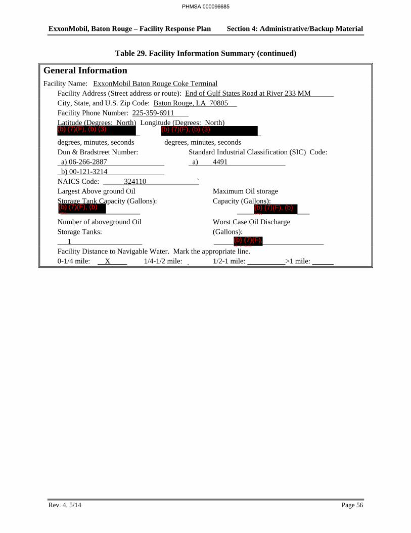
ExxonMobil, Baton Rouge – Facility Response Plan Section 4: Administrative/Backup Material
Rev. 4, 5/14 Page 56
Table 29. Facility Information Summary (continued)
General Information Facility Name: ExxonMobil Baton Rouge Coke Terminal Facility Address (Street address or route): End of Gulf States Road at River 233 MM City, State, and U.S. Zip Code: Baton Rouge, LA 70805 Facility Phone Number: 225-359-6911 Latitude (Degrees: North) Longitude (Degrees: North) degrees, minutes, seconds degrees, minutes, seconds Dun & Bradstreet Number: Standard Industrial Classification (SIC) Code: a) 06-266-2887 a) 4491 b) 00-121-3214 NAICS Code: 324110 ` Largest Above ground Oil Maximum Oil storage Storage Tank Capacity (Gallons): Capacity (Gallons):
Number of aboveground Oil Worst Case Oil Discharge Storage Tanks: (Gallons): 1 Facility Distance to Navigable Water. Mark the appropriate line. 0-1/4 mile: X 1/4-1/2 mile: 1/2-1 mile: >1 mile:
PHMSA 000096685
(b) (7)(F), (b) (3) (b) (7)(F), (b) (3)
(b) (7)(F), (b) (3)
(b) (7)(F), (b) (3)
(b) (7)(F), (b) (3)
Section 5: Storage Tanks and ExxonMobil, Baton Rouge – Facility Response Plan Interconnecting Pipe Lists
TABLE OF CONTENTS
SECTION PAGE
Rev. 0, 12/12 i
Section 5: Storage TankTables and Interconnection Pipe Lists
5.1 Introduction ........................................................................................................................ 1
5.2 Tank List for Refinery Facility Response Plan and SPCC ................................................ 2
5.3 Tanks List for Chemical Plant Facility Response Plan and SPCC .................................. 18
5.4 Tanks List for Anchorage Tank Farm Facility Response Plan and SPCC ...................... 23
5.5 Baton Rouge Terminal Aboveground Storage Tanks ...................................................... 24
5.6 Port Allen Lubricants Plant Aboveground Storage Tanks ............................................... 25
5.6 Interconnecting Pipelines ................................................................................................. 28
5.7 Marine Transportation Related (MTR) Dock Pipelines (Refinery Dock Pipeline Listing) ..................................................................................... 29
5.8 BRFP Fixed Aboveground Storage Tanks ....................................................................... 32
PHMSA 000096686
Section 5: Storage Tanks and ExxonMobil, Baton Rouge – Facility Response Plan Interconnecting Pipe Lists
Rev. 0, 5/12 Page 1
Introduction
Electronic versions of the following tank lists are updated as tank service and operating circumstances change. The electronic version of the tank lists is readily available to facility personnel and operations. All changes to tank operations are controlled through an approved ExxonMobil management of change process
Tank lists for Baton Rouge Refinery, Baton Rouge Chemical Plant, and Anchorage Tank Farm are updated each March and September as part of the required SPCC review. These SPCC tank lists will be inserted into the FRP Manual as the SPCC lists are published. However, the FRP Manual will not be resubmitted to agencies at that time. The remaining tank and piping lists will be reviewed as part of the annual FRP review and updated as needed.
PHMSA 000096687