TABLE OF CONTENTS - Infrastructure BC
223
©Abbotsford Hospital & Cancer Centre Inc. Output Specifications – November 29, 2004 Unauthorized Reproduction Prohibited Section 5-Design & Technical TABLE OF CONTENTS TABLE OF CONTENTS Section 1 Key Site and Building Design Criteria Section 2 Clinical Services Section 3 Non-Clinical Services Section 4 Facility Management Services Section 5 Design and Technical Section 6 IT/Tel Services Section 7 Equipment
-
Upload
khangminh22 -
Category
Documents
-
view
1 -
download
0
Transcript of TABLE OF CONTENTS - Infrastructure BC
©Abbotsford Hospital & Cancer Centre Inc. Output Specifications – November 29, 2004 Unauthorized Reproduction Prohibited Section 5-Design & Technical
TABLE OF CONTENTS
TABLE OF CONTENTS
Section 1 Key Site and Building Design Criteria
Section 2 Clinical Services
Section 3 Non-Clinical Services
Section 4 Facility Management Services
Section 5 Design and Technical
Section 6 IT/Tel Services
Section 7 Equipment

©Abbotsford Hospital & Cancer Centre Inc. Output Specifications – November 29, 2004 Unauthorized Reproduction Prohibited Section 5-Design & Technical
TABLE OF CONTENTS
Purposely left blank for pagination.
Abbotsford Hospital & Cancer Centre
Output Specifications Section 5 – Design and Technical
November 29, 2004

Purposely left blank for pagination
©Abbotsford Hospital & Cancer Centre Inc. Output Specifications – November 29, 2004 Unauthorized Reproduction Prohibited Section 5 – Design and Technical
SECTIONS 5 TABLE OF CONTENTS
1
SECTION 5 TABLE OF CONTENTS
Section 5 Design and Technical Page
5.1 Introduction 1. Summary ............................................................................................................................ 5
5.2 Technical Requirements For Building Systems and Assemblies
1. Site Development 1.1 Municipal Off-Site Services ................................................................................... 7 1.2 On-Site Services .................................................................................................... 9
2. Structural Systems 2.1 General Structural Design Requirements ........................................................... 11
3. Building Envelope 3.1 Exterior Walls and Exterior Wall Systems .......................................................... 15 3.2 Roofs and Roof Systems .................................................................................... 17
4. Interior Building Components 4.1 Internal Walls & Partitions .................................................................................. 19 4.2 Ceilings ............................................................................................................... 20 4.3 Floor Finishes ..................................................................................................... 21
5. Building Systems 5.1 Mechanical Services ........................................................................................... 23 5.2 Electrical Services ............................................................................................... 23
6. List of Referenced Codes and Standards 6.1 FHA Documents and Standards ......................................................................... 25 6.2 Other Codes and Standards ............................................................................... 25 6.3 Appendix 5A – Technical Reference Standards .................................................. 25
5.3 Performance Specifications 1. General Requirements (Division 1)................................................................................... 27
Not included in 5.3; Intentionally left blank. 2. Site Construction (Division 2)
2.1 Basic Requirements ............................................................................................ 29 2.2 Municipal Servicing Works .................................................................................. 29 2.3 Site Works, Site Improvements and Amenities ................................................... 29
3. Concrete (Division 3) 3.1 Basic Requirements ............................................................................................ 33 3.2 Concrete .............................................................................................................. 33
4. Masonry (Division 4) 4.1 Basic Requirements ........................................................................................... 35 4.2 Concrete Unit Masonry ....................................................................................... 35 4.3 Brick Masonry ..................................................................................................... 36 4.4 Stone Masonry .................................................................................................... 37
5. Metals (Division 5) 5.1 Basic Requirements ........................................................................................... 39 5.2 Structural Steel and Steel Joists ......................................................................... 39 5.3 Steel Deck .......................................................................................................... 39 5.4 Load Bearing Steel Studs ................................................................................... 40 5.5 Miscellaneous Metals ......................................................................................... 41
©Abbotsford Hospital & Cancer Centre Inc. Output Specifications – November 29, 2004 Unauthorized Reproduction Prohibited Section 5 – Design and Technical
SECTIONS 5 TABLE OF CONTENTS
2
6. Wood and Plastics (Division 6) 6.1 Basic Requirements ........................................................................................... 43 6.2 Rough Carpentry ................................................................................................ 43 6.3 Finish Carpentry and Architectural Woodwork ................................................... 43
7. Thermal and Moisture Protection (Division 7) 7.1 Basic Requirements ........................................................................................... 45 7.2 Dampproofing ..................................................................................................... 45 7.3 Waterproofing ..................................................................................................... 45 7.4 Not used ............................................................................................................. 46 7.5 Vapour Barriers .................................................................................................. 46 7.6 Air Barriers .......................................................................................................... 47 7.7 Thermal Protection ............................................................................................. 47 7.8 Roofing ............................................................................................................... 48 7.9 Fire and Smoke Protection ................................................................................. 50 7.10 Sealants .............................................................................................................. 50
8. Doors and Windows (Division 8) 8.1 Basic Requirements ........................................................................................... 53 8.2 Hollow Metal Doors and Frames ........................................................................ 55 8.3 Wood Doors ........................................................................................................ 54 8.4 Aluminum Entrances and Storefronts ................................................................. 58 8.5 Specialty Doors .................................................................................................. 59 8.6 Aluminum Curtain Walls ..................................................................................... 62 8.7 Aluminum Windows ............................................................................................ 63 8.8 Skylights ............................................................................................................. 64 8.9 Glass and Glazing .............................................................................................. 64 8.10 Finish Hardware ................................................................................................. 65
9. Finishes (Division 9) 9.1 Basic Requirements ........................................................................................... 67 9.2 Interior Wall Framing .......................................................................................... 67 9.3 Gypsum Board .................................................................................................... 68 9.4 Ceramic Tilework................................................................................................. 70 9.5 Acoustical Ceilings ............................................................................................. 71 9.6 Flooring ............................................................................................................... 72 9.7 Acoustical Treatment .......................................................................................... 75 9.8 Painting and Protective Coatings ....................................................................... 76 9.9 Special Wall Coverings ....................................................................................... 77
10. Manufactured Specialties (Division 10) 10.1 Basic Requirements ........................................................................................... 79 10.2 Tackboards and Whiteboards ............................................................................. 79 10.3 Compartments and Cubicles ............................................................................. 79 10.4 Patient Service Walls .......................................................................................... 81 10.5 Wall Guards and Corner Guards, Handrails, Wall Protection, Door Edge and Door Frame Protection .............................................................. 81 10.6 Elevated Access Flooring ................................................................................... 82 10.7 Building Signage ................................................................................................. 84 10.8 Metal Lockers ..................................................................................................... 85 10.9 Storage Shelving Systems ................................................................................. 85 10.10 Washroom Accessories ...................................................................................... 86 10.11 IV and Privacy Curtain Tracks ............................................................................ 88 10.12 Projection Screens .............................................................................................. 88
©Abbotsford Hospital & Cancer Centre Inc. Output Specifications – November 29, 2004 Unauthorized Reproduction Prohibited Section 5 – Design and Technical
SECTIONS 5 TABLE OF CONTENTS
3
11. Equipment (Division 11) 11.1 Basic Requirements ........................................................................................... 91 11.2 Patient Lifts ......................................................................................................... 91 11.3 Fall Protection and Anchors ............................................................................... 92 11.4 Dock Levelers ..................................................................................................... 92
12. Furnishings (Division 12) 12.1 Basic Requirements ........................................................................................... 93 12.2 Window Coverings .............................................................................................. 93 12.3 Laboratory Casework ......................................................................................... 94
13. Special Construction (Division 13) 13.1 Basic Requirements ........................................................................................... 99 13.2 Radiation Protection ........................................................................................... 99 13.3 Cold Rooms ...................................................................................................... 100
14. Conveying Systems (Division 14) 14.1 Basic Requirements ......................................................................................... 103 14.2 Elevators ........................................................................................................... 103 14.3 Dumbwaiters ..................................................................................................... 106 14.4 Pneumatic Tube System .................................................................................. 106
15. Mechanical (Division 15) 15.1 Basic Requirements ......................................................................................... 109 15.2 Water, Sanitary, Storm and Gas Utilities .......................................................... 110 15.3 Commissioning, Testing and Balancing-Not Used ........................................... 111 15.4 Water Treatment Systems ................................................................................ 111 15.5 Pipe and Pipe Fittings ....................................................................................... 112 15.6 Sound Attenuation and Vibration Isolation ....................................................... 113 15.7 Pipes, Ducts, Equipment and Breeching Insulation ......................................... 114 15.8 Plumbing Systems ............................................................................................ 115 15.9 Medical Gas Systems ....................................................................................... 117 15.10 Fire Protection Systems ................................................................................... 118 15.11 Heating Plant .................................................................................................... 119 15.12 Cooling Plant .................................................................................................... 121 15.13 Steam Plant ...................................................................................................... 122 15.14 Heating, Ventilation and Air Conditioning Systems .......................................... 123 15.15 Specialty Systems ............................................................................................ 129 15.16 Controls ............................................................................................................ 131
16. Electrical (Division 16) 16.1 Basic Requirements ......................................................................................... 137 16.2 Wiring Methods and Materials .......................................................................... 138 16.3 Raceways ......................................................................................................... 139 16.4 Electrical Utilities .............................................................................................. 140 16.5 Emergency Power ............................................................................................ 141 16.6 Transmission and Distribution .......................................................................... 143 16.7 Metering ............................................................................................................ 146 16.8 Grounding and Bonding .................................................................................... 147 16.9 Seismic Requirements For Electrical Systems ................................................. 147 16.10 Power Quality ................................................................................................... 148 16.11 Lighting ............................................................................................................. 149 16.12 Lighting Control ................................................................................................ 153 16.13 Major Medical Equipment ................................................................................. 154 16.14 Energy Management ........................................................................................ 155
©Abbotsford Hospital & Cancer Centre Inc. Output Specifications – November 29, 2004 Unauthorized Reproduction Prohibited Section 5 – Design and Technical
SECTIONS 5 TABLE OF CONTENTS
4
16.15 Mechanical Equipment Connections ................................................................ 156 16.16 Specialty Systems ............................................................................................ 156
17. Technology & Communication Systems (Division 17) 17.1 Basic Requirements ......................................................................................... 159 17.2 Integration with Health Authorities .................................................................... 160 17.3 Fire Alarm ......................................................................................................... 161 17.4 Network Interface ............................................................................................. 163 17.5 Nurse Call ......................................................................................................... 164 17.6 Wireless Staff Communication Systems .......................................................... 166 17.7 Public Address .................................................................................................. 168 17.8 Mechanical Control Systems Interface ............................................................. 170 17.9 Structured Cabling ............................................................................................ 171 17.10 Video Conferencing .......................................................................................... 173 17.11 Code Blue System ............................................................................................ 174 17.12 Wireless Infrastructure ...................................................................................... 175 17.13 Patient Entertainment System .......................................................................... 176 17.14 Patient / Staff Education System ...................................................................... 178 17.15 Doctors Registry ............................................................................................... 179 17.16 Timing Systems ................................................................................................ 179 17.17 Patient Monitoring ............................................................................................. 180 17.18 Central Dictation ............................................................................................... 181 17.19 Intercommunication Systems ........................................................................... 182 17.20 Security (CCTV, Access Control, Intrusion Detection, Panic Duress, Patient
Wandering, Incident Reporting System) ........................................................... 182
Appendix 5A Technical Reference Standards Page
1. Introduction ................................................................................................................................ 5A-1
5.3.3. Concrete (Division 3) ................................................................................................................. 5A-3
5.3.4. Masonry (Division 4) .................................................................................................................. 5A-5
5.3.5. Metals (Division 5) ..................................................................................................................... 5A-7
5.3.6. Wood and Plastics (Division 6) ................................................................................................. 5A-9
5.3.7. Thermal and Moisture Protection (Division 7) ......................................................................... 5A-11
5.3.8. Doors and Windows (Division 8) ............................................................................................. 5A-15
5.3.9. Finishes (Division 9) ................................................................................................................ 5A-21
5.3.10. Manufactured Specialties (Division 10) ................................................................................... 5A-25
5.3.11. Equipment (Division 11) ........................................................................................................... 5A-27
5.3.12. Furnishings (Division 12) ......................................................................................................... 5A-29
5.3.14. Conveying Systems (Division 14) ........................................................................................... 5A-31
5.3.15. Mechanical (Division 15) ......................................................................................................... 5A-33
©Abbotsford Hospital & Cancer Centre Inc. Output Specifications – November 29, 2004 Unauthorized Reproduction Prohibited Section 5 – Design and Technical
5.1 INTRODUCTION
5
1. SUMMARY
1.1 Components of the Output Specifications
Section 5 Design and Technical
Section 5 Design and Technical: Subsection 5.2 Technical Requirements for Building Systems and Assemblies contains technical performance requirements relating to Facility systems and assemblies.
Section 5 Design and Technical: Subsection 5.3 Performance Specifications contains technical performance requirements relating to the components and materials. This subsection is organized into 17 major heading that correspond to the 17 divisions of the Construction Specification Institute specifications format.

©Abbotsford Hospital & Cancer Centre Inc. Output Specifications – November 29, 2004 Unauthorized Reproduction Prohibited Section 5 – Design and Technical
5.1 INTRODUCTION
6
Purposely left blank for pagination.
©Abbotsford Hospital & Cancer Centre Inc. Output Specifications – November 29, 2004 Unauthorized Reproduction Prohibited Section 5 – Design and Technical
5.2 TECHNICAL REQUIREMENTS FOR BUILDING
SYSTEMS AND ASSEMBLIES 1. Site Development
7
1. SITE DEVELOPMENT
1.1 MUNICIPAL OFF-SITE SERVICES
1.1.1. General
1. Design and construct the Municipal off-site services to provide the infrastructure necessary to support the on-site land use.
2. All work shall be designed and constructed to the satisfaction of the authority having jurisdiction (AHJ).
3. All work shall comply with the Abbotsford Subdivision and Development Bylaw 1125-2002 (BL1125-2002) and the Master Municipal Construction Document (MMCD). Refer to the Data Room for these documents.
4. Two agreements between FHA and Abbotsford will be registered as covenants against the title of the property. The agreements are a Design Control Covenant and a Development Agreement. Refer to Output Specifications - Section 1 Key Site and Building Design: Subsection 2.1 Site Conditions for additional information regarding the Design Control Covenant. The Development Agreement lists the general requirements for infrastructure upgrading expected from the developer before the proposed land use is permitted on the property. The Development Agreement contains both Municipal and public utility upgrading requirements. The Development Agreement tries to anticipate all requirements, but makes allowance for the addition or deletion of requirements as may be determined during the detail design process. Points 6. through 10. are provided for overview level information only for Project Co. Project Co is responsible to review and interpret the Design Control Covenant and Development Agreement accordingly.
5. The Project Co, as the developer of the property, will design the proposed works, estimate the value of the works, provide financial security in an acceptable format (usually with an irrevocable letter of credit) for the construction of the works, and enter into a Servicing Agreement with Abbotsford. Construction of the works normally proceeds following the execution of the Servicing Agreement document.
6. Sanitary Sewers
• Abbotsford has determined the minimum sewer diameter. Flow calculations during the design process may show that a larger diameter is required.
• A development on Marshall Road at Horizon Street has designed the downstream 104m of this sewer. The design is for a 375mm pipe at a 0.3% grade. The construction of this section of sewer is expected to precede this project and should be considered as existing for the purpose of this proposal.
©Abbotsford Hospital & Cancer Centre Inc. Output Specifications – November 29, 2004 Unauthorized Reproduction Prohibited Section 5 – Design and Technical
5.2 TECHNICAL REQUIREMENTS FOR BUILDING
SYSTEMS AND ASSEMBLIES 1. Site Development
8
7. Storm Sewers and Drainage
• Marshall Road has existing storm sewers which service this site. Abbotsford has not identified any upgrading requirements other than those related to road drainage.
• Abbotsford requires storm water management on the site to reduce the development storm water runoff.
8. Roadworks
• Land dedications for roadworks will be required for the off-set turnaround on Gladwin Road and for a corner cut at Gladwin Road/Marshall Road.
9. Traffic Signals
• Project Co shall provide a comprehensive traffic study to the satisfaction of Abbotsford which will determine if traffic signals are required.
10. Electrical and Communications Wiring
• Abbotsford requires that the near side overhead hydro system be replaced with an underground system. Hydro is aware of this requirement and has no objections.
• Abbotsford requires that any existing far side overhead hydro services be replaced with underground services. This can be achieved with reverse dip services.
• Abbotsford requires that Telus and Shaw services to the site from the far side overhead system be extended as underground dip services.
©Abbotsford Hospital & Cancer Centre Inc. Output Specifications – November 29, 2004 Unauthorized Reproduction Prohibited Section 5 – Design and Technical
5.2 TECHNICAL REQUIREMENTS FOR BUILDING
SYSTEMS AND ASSEMBLIES 1. Site Development
9
1.2 ON-SITE SERVICES
1.2.1. General
1. On-site services refers to the construction of works within the boundaries of the private property and outside of the building footprint. The on-site services are the private infrastructure required to support the proposed land use. The private infrastructure extends from the terminus of the public infrastructure at the property line to the building(s) and in between buildings, if applicable. The works include in ground components (eg, sewers) and above ground component (eg, roadways).
2. The design of the infrastructure shall consider the capacity for future expansion of the Facility. If, at the time of Project Completion, the infrastructure does not have capacity to accommodate future Facility expansion, Project Co shall show how future Facility expansion can be serviced cost effectively without disruption of the existing Facility and operation.
3. The design shall be supported with a design report including a parking analysis and a parking management report.
4. All on-site services shall meet or exceed the quality requirements for the corresponding off-site Municipal works, except barrier curb to MMCD standard C-4 will be accepted in lieu of the C-5 standard. Any variation in road structure from municipal standards has to be supported by a report from a geotechnical consultant
1.2.2. Sanitary Sewers
1. The sanitary sewer system shall be of a diameter, grade and depth to safely convey all effluent to the Municipal sewer system. The sanitary sewer system includes the pipes, manholes and other required appurtenances to comply with Municipal and Provincial standards.
1.2.3. Storm Sewers and Drainage
1. The storm sewer system shall be of a diameter, grade and depth to safely convey all storm water. The system will include a storm water detention system of a size and control to ensure compliance with Abbotsford BL1125-2002 or its latest revisions. The system shall also include in ground disposal of roof drainage in accordance with BL1125-2002, or disposed of in the on-site pond as agreed to by the City of Abbotsford in the Site Development Plan approval.
2. The system and the site grading must ensure that the building(s) is protected against a 100 year storm event in accordance with BL1125-2002.
1.2.4. Watermains and Appurtenances
1. The watermain system (the main and the appurtenances) shall be capable of providing domestic and fire fighting capacity for the proposed land use.
2. Redundancy shall be provided by constructing a looped system with at least two connection points to the Municipal system.
3. Fire Hydrant(s) will be provided to NFPA 24 and AHJ.
©Abbotsford Hospital & Cancer Centre Inc. Output Specifications – November 29, 2004 Unauthorized Reproduction Prohibited Section 5 – Design and Technical
5.2 TECHNICAL REQUIREMENTS FOR BUILDING
SYSTEMS AND ASSEMBLIES 1. Site Development
10
4. The system shall include backflow preventers to protect the Municipal system and the on-site facilities from contaminants.
1.2.5. Roadworks
1. The on-site roadways shall provide safe passage between parking areas, loading areas, emergency vehicle areas, and drop off areas without requiring the driver to enter the Municipal roadways. On-site vehicle circulation must be based on a traffic and parking analysis prepared by a traffic engineer for the intended land use.
The analysis must address lane width, one or two way traffic flow, separation of different types of vehicle traffic, separation of vehicle and pedestrian traffic.
2. The on-site roadways include the pavement, curb and gutters, sidewalks, walkways, signage, pavement marking, and traffic calming devices.
1.2.6. Streetlights
1. On-site roadway, walkways and parking areas shall be lit during darkness to ensure safe vehicle and pedestrian traffic both in respect to collisions and personal safety.
1.2.7. Electrical and Telecommunications Wiring, Gas Services
1. The on-site work shall include electrical and communications wiring and gas services to support the intended land use.
1.2.8. Parking
Refer to Output Specifications - Section 1 Key Site and Building design Criteria: Subsection 1.2.2.2 Building Accessibility for parking requirements.

©Abbotsford Hospital & Cancer Centre Inc. Output Specifications – November 29, 2004 Unauthorized Reproduction Prohibited Section 5 – Design and Technical
5.2 TECHNICAL REQUIREMENTS FOR BUILDING
SYSTEMS AND ASSEMBLIES 2. Structural Systems
11
2. STRUCTURAL SYSTEMS
2.1 GENERAL STRUCTURAL DESIGN REQUIREMENTS
2.1.1. Basic Requirements
1. Structural design, documentation, and contract administration shall satisfy the requirements of the latest edition of the BC Building Code in effect at the time of building permit application.
2. The building code outlines minimum design loads and general provisions and material specifications and design standards that shall be followed in the design of the building. Where higher standards or design loads are required to ensure appropriate performance for proposed uses, they shall be implemented.
3. The structural Engineer-of-Record shall be a professional engineer registered in the Province of British Columbia.
4. The Association of Professional engineers and Geoscientists of British Columbia Quality Management By-law requires certification from a second professional engineer registered in British Columbia that a concept review satisfying the by-law has been completed prior to Building Permit application.
5. At the time of construction, the structural Engineer-of-Record shall perform field services sufficient to verify that the building has been built substantially in accordance with design documents.
6. At the time of construction, testing agencies shall be retained to verify and document that the materials and construction methods used are in accordance with the BC Building Code and its referenced standards.
2.1.2. Design Loads
1. Floors shall be designed for dead and live loads according to their use and occupancy but the live load for the ground floor is to be not less than 4.8 kPa and for the upper floors not less than 3.6 kPa. Library areas shall be designed for a live load of 7.2 kPa. The structure shall be designed to accommodate concentrated loads from fixtures, equipment and machinery, whether floor, wall, or ceiling mounted., including ceiling-mounted patient lifting devices.
The building code states that offices in the basement and the ‘First Story’ must be designed for 4.8 kPa. ‘First Story’ is defined by the building code in Clause 1.1.3.2 as being “The uppermost story having its uppermost floor level not more than 2m above grade”. The intent of the building code and the Output Specifications is those levels that are accessible from grade should be designed for 4.8 kPa to account for heavier use and to account for heavier loads including the accessing of operating rooms with equipment. The use of 3.6 kPa for nursing floors and offices that are not directly accessible from grade is in accordance with the intent of the building Code and design guidelines provided requirements for concentrated loads and heavy loads for areas such as libraries are addressed.
©Abbotsford Hospital & Cancer Centre Inc. Output Specifications – November 29, 2004 Unauthorized Reproduction Prohibited Section 5 – Design and Technical
5.2 TECHNICAL REQUIREMENTS FOR BUILDING
SYSTEMS AND ASSEMBLIES 2. Structural Systems
12
For the avoidance of doubt, floors will be designed for the following loading:
• Level 00 & 01 – 4.8 kPa live load plus 1.0 kPa partition allowance.
• Level 02, 03, 04 – office and patient areas 3.6 kPa live load plus 1 kPa partition allowance., Other areas 4.8 kPa live load plus 1 kPa partition allowance.
• All levels – areas with exceptional loadings requirements such as library, MRI rooms, equipment rooms, etc will be designed for the loading appropriate for the use.
2. Design loads in areas designated for storage items such as film, files, or supplies shall be appropriate to the use.
2.1.3 Flexibility for Future Change
1. Changing technology, development of new equipment and techniques, and changes in tenancy or occupancy of spaces will result in changes to service requirements for the space. New openings for HVAC or holes for plumbing and electrical services may be required at any location in the floor plate. The floor system shall be designed to allow for approximately 350mm x 350mm holes at all column locations on two sides of the column. The floor system shall also be able to accommodate 100mm holes at almost any location in the floor plate. Existing openings and holes may have to be filled. The proposed structural system should be designed to be flexible enough to allow this work to be done with a minimum of expense or disruption to Facility users. For instance, the addition of structural framing members, use of welding or other processes that produce fumes, or demolition techniques that cause noise and vibration shall be minimized by selection of an appropriate structural system.
2.1.4 Deflection Limitations
1. The structure shall be designed to minimize the effects of long-term creep to less than one-half of allowable total deflection for the structural element in question. Total deflection, including the effects of creep and live load, shall be within the limits specified in CSA A23.3-M94 and CSA S16-01.
Designing the structure to meet the deflection limits of CSA A23.3-M94 meets the intent of the Output Specifications for a concrete structure. The total allowable deflection of the members is specified in table 9-2 of CSA A23.3-M94. Floors and roofs not supporting or attached to non-structural elements likely to be damaged by large deformation shall have a maximum immediate deflection under live load of span/360. Roof or floor construction that is attached to non-structural elements likely to be damaged by large deflections shall have a maximum deflection of span/480 where deflection is that part of the total deflection occurring after the installation of non-structural elements and would include creep, deflection occurring after that point and live load deflection. Designs using reinforced concrete that meet the intent of table 9.2 of CSA A23.3-M94 will be deemed to have met the intent of the deflection requirements.
©Abbotsford Hospital & Cancer Centre Inc. Output Specifications – November 29, 2004 Unauthorized Reproduction Prohibited Section 5 – Design and Technical
5.2 TECHNICAL REQUIREMENTS FOR BUILDING
SYSTEMS AND ASSEMBLIES 2. Structural Systems
13
2.1.5 Vibration Limitations
1. Machinery that could be a source of vibration of the structure shall be mounted using vibration isolation techniques. Selected structural systems for floors with uses other than parking shall be designed to have an acceleration limit of .5% g with a damping ratio of .02 when an excitation force of .29 kN is applied.
2. In areas where MRI and other vibration-sensitive equipment will be installed, the structural system shall be designed to provide vibration limitation in accordance with specific manufacturer requirements.
2.1.6 Levelness of Floors
1. Floors shall be designed and finished to tight tolerances for levelness to minimize problems with installation of casework, rail-mounted filing systems, prefabricated partition systems, etc. Floor flatness tolerance shall be in accordance with CSA A23.1-94.
In areas where installation of equipment or casework require critical levelness then tolerances shall be 3mm in 3m. The areas of critical tolerance would include Radiology, MRI areas, laboratories and operating rooms.
Areas other than the above are to achieve the industry standard for institutional and commercial floors as outlined in Table 19 of CSA-A23.1-00. This gives a straight edge value of 8 mm in 3m.

©Abbotsford Hospital & Cancer Centre Inc. Output Specifications – November 29, 2004 Unauthorized Reproduction Prohibited Section 5 – Design and Technical
5.2 TECHNICAL REQUIREMENTS FOR BUILDING
SYSTEMS AND ASSEMBLIES 2. Structural Systems
14
Purposely left blank for pagination.
©Abbotsford Hospital & Cancer Centre Inc. Output Specifications – November 29, 2004 Unauthorized Reproduction Prohibited Section 5 – Design and Technical
5.2 TECHNICAL REQUIREMENTS FOR BUILDING
SYSTEMS AND ASSEMBLIES 3. Building Envelope
15
3. BUILDING ENVELOPE
3.1 EXTERIOR WALLS AND WALL SYSTEMS
3.1.1. Basic Requirements
1. The exterior walls and exterior wall systems:
1.1 Shall comprise the exterior envelope of the building and shall define the internal space.
1.2 May be part of the building structure or independent of the building structure.
3.1.2. Performance Criteria
1. The following criteria and standards shall govern and be integral to the composition of exterior walls.
1.1 Conform to structural Loading requirements of the BC Building Code including:
• Vertical loads superimposed onto the building structure and transmitted by the building structure.
• Horizontal / lateral wind loads.
• Seismic loads due to earthquake motion.
1.2 Conform to the Environmental Separation requirements of the BC Building Code to prevent the penetration of water or water vapour through or into the exterior walls and prevent condensation within the wall composition
• The exterior walls shall be designed and constructed using rain screen or cavity wall construction systems to enable any water which has penetrated to finish layer or skin to exit before entering the wall composition or assembly and into the interior space.
• Prevent water penetration by integrating sills, thresholds, lintels, flashings and flashing systems, sealants, water proof membranes, and other barriers into the construction in conformance with best construction practices appropriate to the climate and geography of the site.
• Prevent air leakage and water vapour transmission through external walls by incorporating air barrier and vapour barrier systems.
• Prevent corrosion or deterioration of building construction and finishing materials.
©Abbotsford Hospital & Cancer Centre Inc. Output Specifications – November 29, 2004 Unauthorized Reproduction Prohibited Section 5 – Design and Technical
5.2 TECHNICAL REQUIREMENTS FOR BUILDING
SYSTEMS AND ASSEMBLIES 3. Building Envelope
16
• Retain the services of a Building Envelope Professional whose credentials as a BEP are recognised by the Architectural Institute of British Columbia or the Association of Professional Engineers and Geoscientists of British Columbia, to advise on the Building Envelope design and construction and to approve, sign and seal details of its composition and construction. A registered professional working in the capacity of BEP shall:
• possess the necessary education, training and experience to properly discharge the responsibilities of this specialty role (shall include successfully completed the BEEP courses available through the AIBC).
• have a thorough understanding of the principles of building science and be fully conversant with recent developments in the theory and practice of building envelope design and construction.
• possess the ability and tenacity to diligently carry out the enhanced field review/quality assurance role of the BEP.
• refer to AIBC Bulletin 34 Building Envelope Services: Appropriate Professional Practice or other applicable documents available through the AIBC or the Association of Professional Engineers and Geoscientists of British Columbia
1.3 Thermal insulation to resist heat transfer through the exterior walls to create interior environmental conditions suitable to the needs of the Facility.
1.4 Resistance to damage from dimensional changes caused by temperature related reactions of building materials.
1.5 Resistance to damage caused by forces generated by differential settlement or other foundation related movement.
1.6 Resistance to the transmission of external airborne sounds detrimental to the needs of the Facility and the delivery of the health care services.
1.7 Light transmission and visibility as required to provide natural light and views to the exterior to create an open atmosphere and a safe and comfortable environment.
1.8 The windows shall be glazed with sealed, double glazed low-E units.
1.9 On the north and south elevations, the windows shall consist of clear float glass exterior lite, an argon filled air space of 13 mm., a low-E coating on the number 3 surface, with a clear float glass interior lite. The shading coefficient of these insulating units shall be maximum 0.76.
1.10 On the east and west elevations, the window glazing shall be similar to the north and south, except that the exterior lite is solar screen Including Azurlite glass. The shading coefficient shall be a minimum of 0.22.
©Abbotsford Hospital & Cancer Centre Inc. Output Specifications – November 29, 2004 Unauthorized Reproduction Prohibited Section 5 – Design and Technical
5.2 TECHNICAL REQUIREMENTS FOR BUILDING
SYSTEMS AND ASSEMBLIES 3. Building Envelope
17
1.11 The exterior walls shall be insulated to R20 and shall have a general U-value of 0.05. The roof areas shall be insulated to R30 and shall have a general U- value of 0.033.
3.2 ROOFS AND ROOF SYSTEMS
3.2.1 Basic Requirements
1. The roofs and roof systems shall:
1.1 Comprise the external and complete horizontal barrier to weather and climate.
3.2.2 Performance Criteria
1. The following criteria and standards shall be integral to the composition of roofs and roof systems.
1.1 Conform to the Environmental Separation requirements of the BC Building Code to prevent the penetration of water or water vapour through or into the roof systems and prevent condensation of water vapour in the roof systems.
• Prevent air leakage and water vapour transmission through and into the roof systems by incorporating air barrier and vapour barrier systems.
• Prevent corrosion or deterioration of building construction and finishing materials.
1.2 Thermal insulation to resist heat transfer through the roof and roof systems to create interior environmental conditions suitable to the needs of the Facility.
1.3 Resistance to damage from dimensional changes caused by temperature related reactions of building materials.
1.4 Light transmission may be required to provide natural light to interior areas not adjacent or accessible to exterior walls.
1.5 Design and install to withstand local wind uplift in accordance with BC Building Code and conform to CAN/ULC S126-M86 for Class ‘C’ roof covering.
1.6 Conform to the latest guarantee and standards of the Roofing Contractors Association of British Columbia Guarantee Corp (RGC) as published in the RGC Roofing Practices Manual and include required Inspections by the RCABC.
1.7 The integrity of the roof membrane shall be maintained at all roof penetrations.
©Abbotsford Hospital & Cancer Centre Inc. Output Specifications – November 29, 2004 Unauthorized Reproduction Prohibited Section 5 – Design and Technical
5.2 TECHNICAL REQUIREMENTS FOR BUILDING
SYSTEMS AND ASSEMBLIES 3. Building Envelope
18
Page left blank for pagination.
©Abbotsford Hospital & Cancer Centre Inc. Output Specifications – November 29, 2004 Unauthorized Reproduction Prohibited Section 5 – Design and Technical
5.2 TECHNICAL REQUIREMENTS FOR BUILDING
SYSTEMS AND ASSEMBLIES 4. Interior Building Components
19
4. INTERIOR BUILDING COMPONENTS
4.1 INTERNAL WALLS AND PARTITIONS
4.1.1. Basic Requirements
1. The interior walls and partition systems shall:
1.1 Define the interior spaces of the building and may be part of the building structure or independent of the building structure.
1.2 Define the functions and activities inherent with the use and occupancy of the interior spaces.
1.3 Provide acoustic separations as required for the specific functions to be carried out in the spaces affected.
1.4 Provide separations required for fire safety and protection as defined in 4.1.2 Performance Criteria and in 5.3 Performance Specifications.
4.1.2. Performance Criteria
1. The following criteria and standards shall govern and be integral to the composition of internal walls and partitions.
1.1 Fire and smoke separation and fire resistance ratings shall conform to the requirements of the BC Building Code.
1.2 Seismic resistance capabilities shall conform to the requirements of the BC Building Code and CSA S832-01 Guidelines For Seismic Risk reduction of Operational and Function.
1.3 Acoustic performance of internal walls and partitions shall be to the values in Table 1.2.5.4 (Refer to Output Specifications - Section 1 Key Site and Building Design Criteria: Subsection 1.2.5.4 Acoustics).
2. Design and select interior walls and partitions, partition systems and interior finishes to comply with the following criteria as may be relevant for the particular or specific functions enclosed:
2.1 Acoustic requirements listed above.
2.2 Cleaning, maintenance and infection control.
2.3 Permanence and durability including impact resistance.
2.4 Flexibility and adaptability of services.
©Abbotsford Hospital & Cancer Centre Inc. Output Specifications – November 29, 2004 Unauthorized Reproduction Prohibited Section 5 – Design and Technical
5.2 TECHNICAL REQUIREMENTS FOR BUILDING
SYSTEMS AND ASSEMBLIES 4. Interior Building Components
20
2.5 Aesthetic and design qualities to provide a healing environment for the benefit of patients, staff and public.
2.6 Flexibility to permit adaptability of the internal spaces, if required to suit future process revisions.
4.2 CEILINGS
4.2.1. Basic Requirements
1. The ceiling systems shall be part of the definition of interior spaces and may be accessible or inaccessible in total or in part.
2. Accessible ceiling systems may provide access to the ceiling spaces throughout the system or at specific and particular locations.
3. Ceiling systems shall comprise a major component of the acoustic or sound attenuation function as required in the spaces in which they are installed.
4. Ceiling systems shall form a component of fire resistance rated separations for areas requiring such separation and shall be as defined in 4.4.2 Performance Criteria and in 5.3 Performance Specifications.
5. Ceiling height shall be 2.7 metres above the finished floor in all areas except for the following:
5.1 Ceiling heights in treatment rooms, inpatient rooms and all clinical rooms shall not be less than 2.7 metres.
5.2 Ceilings in radiographic, operating and delivery rooms, cancer treatment vaults, and other rooms containing ceiling-mounted equipment or ceiling-mounted surgical light fixtures shall be of sufficient height to accommodate the equipment or fixtures and their normal movement. Consider 3.0 metres as a typical ceiling height in these areas.
5.3 Ceiling heights in corridors, storage rooms and toilet rooms shall be not less than 2.4 metres. Ceiling heights in small, normally unoccupied spaces such as storage closets may be reduced.
5.4 Suspended tracks, rails and pipes located in the traffic path for patients in beds and/or on stretchers, including those in inpatient service areas, shall not be less than 2.2 metres above the finished floor.
5.5 Boiler rooms shall have ceiling clearances as required to suit final layout..
©Abbotsford Hospital & Cancer Centre Inc. Output Specifications – November 29, 2004 Unauthorized Reproduction Prohibited Section 5 – Design and Technical
5.2 TECHNICAL REQUIREMENTS FOR BUILDING
SYSTEMS AND ASSEMBLIES 4. Interior Building Components
21
4.2.2. Performance Criteria
1. The following criteria and standards shall govern and be integral to the composition of ceilings.
1.1 Fire and smoke separation and fire resistance ratings shall conform to the requirements of the BC Building Code.
1.2 Seismic resistance capabilities shall conform to the requirements of the BC Building Code.
1.3 Acoustic performance shall be to the values of Table 1.2.5.4 (a) Sound Transmission Limitations.
2. Design and select ceiling systems and ceiling finishes to comply with the following criteria as may be relevant to the particular or specific functions of the space.
2.1 Criteria and standards listed in 4.2.2.1.above.
2.2 Cleaning, maintenance and infection control.
2.3 Flexibility and access to the spaces above.
2.4 Compatibility with Mechanical, Plumbing, Electrical, Communications services and fixtures.
2.5 Compatibility with ceiling attached equipment or systems such as patient lifts, curtain track, IV tracks and TV monitors.
2.4 Aesthetic and design qualities to provide a healing environment for the patients, staff and public.
4.3 FLOOR FINISHES
4.3.1. Basic Requirements
1. The floor and floor systems shall be a component of the definition of interior space and shall be finished to be complementary and integral to the functional and aesthetic requirements of the interior space.
2. Floor finishes shall be selected to suit types and concentration of pedestrian and / or vehicular/wheel traffic to be anticipated.
3. Flooring designs and patterns shall comprise a major component of the “way finding” system of the Facility.
©Abbotsford Hospital & Cancer Centre Inc. Output Specifications – November 29, 2004 Unauthorized Reproduction Prohibited Section 5 – Design and Technical
5.2 TECHNICAL REQUIREMENTS FOR BUILDING
SYSTEMS AND ASSEMBLIES 4. Interior Building Components
22
4.3.2. Performance Criteria
1. The following criteria and standards shall govern and be integral to the selection of floor finishes.
1.1 Cleaning, maintenance and infection control including the frequency and quality of joints and also including ease of replacement if and when required.
1.2 Imperviousness to concentrations of moisture anticipated to be existing on the floors and duration of that moisture.
1.3 Permanence and durability and resistance to concentrated service traffic both pedestrian and wheel vehicular.
1.4 Aesthetic and design qualities to provide a healing environment for the benefit of patients, staff and public.
1.5 Patterns and textures compatible with the requirements for pedestrian safety including the exiting and other relevant requirements of the BC Building Code.
©Abbotsford Hospital & Cancer Centre Inc. Output Specifications – November 29, 2004 Unauthorized Reproduction Prohibited Section 5 – Design and Technical
5.2 TECHNICAL REQUIREMENTS FOR BUILDING
SYSTEMS AND ASSEMBLIES 5. Building Systems
23
5. BUILDING SYSTEMS
5.1 MECHANICAL SERVICES
5.1.1. Basic requirements
1. The mechanical systems for the Facility shall be designed, built and operated to provide a healing, safe and comfortable environment for the patients, families and workers.
2. Mechanical systems shall be flexible and adaptable for future expansion and technological changes.
3. Mechanical systems shall be highly energy efficient and shall be chosen to minimize impact on the natural and physical environment.
4. Mechanical systems shall be designed and constructed to provide operational reliability for the Facility.
5.1.2 Performance Criteria
1. The mechanical systems shall conform to BC Building Code, applicable CSA Standards, ASHRAE Standards, NFPA Standards, and Municipal by-laws and shall meet the requirements of the Authorities having Jurisdiction.
2. Mechanical systems shall be complete, fully tested, commissioned and operational prior to occupancy.
3. Mechanical systems shall be operated and maintained to maximize energy efficiency, indoor air quality and occupant comfort.
4. Provide adequate redundancy and standby capacity to ensure continuous operation of all critical areas in the Facility as defined in 5.3.15.
5.2 ELECTRICAL SERVICES
5.2.1. Basic Requirements
1. The Facility is to promote a healing environment. The electrical systems and lighting system are to be provided to assist with this principal.
2. All electrical systems shall function to assist the programs provided in the hospital in a reliable cost effective manner.
3. Electrical systems shall be provided and installed that offer a true life cycle value to the Health Co while still providing the quality normally used in a permanent health care facilities.
©Abbotsford Hospital & Cancer Centre Inc. Output Specifications – November 29, 2004 Unauthorized Reproduction Prohibited Section 5 – Design and Technical
5.2 TECHNICAL REQUIREMENTS FOR BUILDING
SYSTEMS AND ASSEMBLIES 5. Building Systems
24
4. Electrical systems shall be installed to promote energy efficiency and LEED principals where applicable.
5. Communications systems shall be integrated where this integration provides an efficiency advantage, operational advantage, and cost advantage.
5.5.2. Performance Criteria
1. The electrical installation shall conform to the BC Building Code, the Canadian Electrical Code, CSA Standards and NFPA 70 and NFPA 99 Standards, latest applicable edition.
©Abbotsford Hospital & Cancer Centre Inc. Output Specifications – November 29, 2004 Unauthorized Reproduction Prohibited Section 5 – Design and Technical
5.2 TECHNICAL REQUIREMENTS FOR BUILDING
SYSTEMS AND ASSEMBLIES 6. List of Reference Codes and Standards
25
6. REFERENCED CODES AND STANDARDS
6.1 FHA DOCUMENTS AND STANDARDS
FHA and BCCA documents and standards will be available in the Data Room, or as indicated in the Project Agreement.
6.2 OTHER CODES AND STANDARDS
The design of the AHCC Facility shall be in accordance with the current version of the BC Building Code, as well as all codes and standards referenced in the Output Specifications. It is Project Co’s responsibility to use all Applicable Standards consistent with best practice for design and construction of a hospital in British Columbia even if they are not listed in the Output Specifications. Where compliance with a specific code or standard is required in the text of the Output Specifications, and Project Co chooses to make reference in their documentation to codes or standards from jurisdictions outside Canada, Project Co shall demonstrate compliance to the Canadian code or standard to the satisfaction of Health Co.
6.3 APPENDIX 5A – TECHNICAL REFERENCE STANDARDS
Project Co shall comply with the requirements of the BC Building Code and all Applicable Standards including, but not limited to, those standards in Appendix 5A – Technical Reference Standards.
Appendix 5A – Technical Reference Standards is not intended to be a complete list of all Applicable Standards. Project Co is responsible for identifying and complying with all Applicable Standards regardless of whether they appear in the Technical Reference Standards or not.

©Abbotsford Hospital & Cancer Centre Inc. Output Specifications – November 29, 2004 Unauthorized Reproduction Prohibited Section 5 – Design and Technical
5.2 TECHNICAL REQUIREMENTS FOR BUILDING
SYSTEMS AND ASSEMBLIES 6. List of Reference Codes and Standards
26
Page left blank for pagination.
©Abbotsford Hospital & Cancer Centre Inc. Output Specifications – November 29, 2004 Unauthorized Reproduction Prohibited Section 5 – Design and Technical
5.3 PERFOMANCE SPECIFICATIONS 1. General Requirements (Division 1)
27
1. GENERAL REQUIREMENTS (DIVISION 1)
Note: This section not used.
End of General Requirements

©Abbotsford Hospital & Cancer Centre Inc. Output Specifications – November 29, 2004 Unauthorized Reproduction Prohibited Section 5 – Design and Technical
5.3 PERFOMANCE SPECIFICATIONS 1. General Requirements (Division 1)
28
Page left blank for pagination.
©Abbotsford Hospital & Cancer Centre Inc. Output Specifications – November 29, 2004 Unauthorized Reproduction Prohibited Section 5 – Design and Technical
5.3 PERFORMANCE SPECIFICATIONS 2. Site Construction (Division 2)
29
2. SITE CONSTRUCTION (DIVISION 2)
2.1 BASIC REQUIREMENTS
2.1.1. The works must service the building(s) and the expected land use with a reliable infrastructure.
2.1.2. The infrastructure must be maintainable without disrupting the effective operation of the hospital and the related land uses.
2.2 MUNICIPAL SERVICING WORKS
Refer to 5.2.1.1 Municipal Off-Site Services
2.3 SITE WORKS, SITE IMPROVEMENTS AND AMENITIES
2.3.1. Overriding Principles.
1. Site Works
1.1 Excavate and backfill as necessary to provide levels and elevations for foundations, service trenching, drainage, site contours and other required earthworks.
2. Site Improvements and Amenities
2.1 Provide landscaping, including planting and paving as may be required by Municipal by-laws and regulations.
2.2 Planting shall be provided to create scale, natural ambience, visual screening, acoustic screening and space definition.
2.3. Pavements may include asphalt pavement, unit masonry pavers, pervious pavement, permeable interlocking paving stones, concrete and other hard wearing surfaces and shall be provided for:
• Pedestrian routes and accesses.
• Vehicular routes, accesses and parking.
©Abbotsford Hospital & Cancer Centre Inc. Output Specifications – November 29, 2004 Unauthorized Reproduction Prohibited Section 5 – Design and Technical
5.3 PERFORMANCE SPECIFICATIONS 2. Site Construction (Division 2)
30
2.3.2. Quality Requirements
1. Project Co shall comply with all Applicable Standards including, but not limited to, the BC Building Code and those standards in Appendix 5A Technical Reference Standards. Refer to Output Specifications Section 5 – Design and Technical: Subsection 5.2.6.2. Other Codes and Standards for information regarding Appendix 5A Technical Reference Standards.
2. Site Works
2.1 Excavation, Backfill and Compaction.
• Backfill under streets and sidewalks shall conform to Municipal standards.
• Streets, sidewalks and curbs that are required to be cut and restored during construction, or damaged during construction shall be repaired to local Municipal standards.
2.2 Other Standards:
• Workers Compensation Board Industrial Health and Safety Regulations.
3. Site Improvements and Amenities
3.1 Planting materials and workmanship shall conform to the following standards.
• Canadian Nursery Trades Association (CNTA)
• British Columbia Nursery Trades Association (BCNTA).
• British Columbia Landscape Standard (BCLA).
2.2 Pavements
• Asphalt paving shall conform to MMCD or an equivalent standard. The following will be applied:
75 mm asphalt in truck and high traffic areas. 50 mm thick asphalt in parking areas. delivery truck route shall be similar to a collector road, i.e.
minimum of 100 mm of asphalt 100 mm of 19 mm of crushed base gravel 190 mm minimum of 100 mm minus pitrun sub-base gravel.
• Asphalt paving shall be in compliance with a Geotechnical report.
• Concrete paving shall conform to MMCD.
• Unit concrete paving shall conform to MMCD and shall meet or exceed ASTM C936 Standard Specifications for Solid Concrete Interlocking Paving Units. Bedding sand shall conform to ASTM C33 or CAN/CSA-A231.1.

©Abbotsford Hospital & Cancer Centre Inc. Output Specifications – November 29, 2004 Unauthorized Reproduction Prohibited Section 5 – Design and Technical
5.3 PERFORMANCE SPECIFICATIONS 2. Site Construction (Division 2)
31
2.3.3. Performance Requirements
1. Site Improvements and Amenities
1.1 Planting and landscaping shall conform to requirements of British Columbia Landscape Standard (BCLA) and shall be designed, located and configured as determined by Project Co in consultation with the Health Co.
1.2 Protection of existing trees which are determined to be retained, shall be provided as required to BCLA standard without minimum.
1.3 Pedestrian pavements and walkways shall be smooth, nonslip and without impediments and shall be of material and installation which is securely founded.
1.4 Vehicular traffic pavements shall be in compliance with the Geotechnical report and be capable of normal hospital vehicle loads and movement.
1.5 Pavements for loading areas and other areas where heavy loads, which would not be carried by asphalt paving without damage, are anticipated, shall be reinforced concrete.
End of Site Construction

©Abbotsford Hospital & Cancer Centre Inc. Output Specifications – November 29, 2004 Unauthorized Reproduction Prohibited Section 5 – Design and Technical
5.3 PERFORMANCE SPECIFICATIONS 2. Site Construction (Division 2)
32
Page left blank for pagination.
©Abbotsford Hospital & Cancer Centre Inc. Output Specifications – November 29, 2004 Unauthorized Reproduction Prohibited Section 5 – Design and Technical
5.3 PERFORMANCE SPECIFICATIONS 3. Concrete (Division 3)
33
3. CONCRETE (DIVISION 3)
3.1 BASIC REQUIREMENTS
3.1.1. Reinforced concrete construction, both cast-in-place and precast, that meets or exceeds current Canadian standards and practice as set out in this division, may be considered for building elements and systems, where appropriate.
3.2 CONCRETE
3.2.1. Overriding Principles
1. Supply and place cast in place or precast concrete of appropriate properties for the intended use in accordance with the requirements of the following specifications.
3.2.2 Quality Requirements
1. Project Co shall comply with all Applicable Standards including, but not limited to, the BC Building Code and those standards in Appendix 5A Technical Reference Standards. Refer to Output Specifications Section 5 – Design and Technical: Subsection 5.2.6.2. Other Codes and Standards for information regarding Appendix 5A Technical Reference Standards.
2. Inspection and testing of cast in place concrete and concrete materials shall be carried out by a testing laboratory in accordance with CAN/CSA A23.1-94. Non-destructive Methods for Testing Concrete shall comply with CAN/CSA A23.2-94.
3. Inspection and testing of precast concrete materials and workmanship shall be carried out by the precast concrete contractor as part of its quality control program in accordance with CAN/CSA-A23.2-94. Maintain plant records and a quality control program as required by CSA A251.
3.2.3 Performance Requirements
1. All concrete formwork shall comply with CAN/CSA S269.1, S269.3, Worker’s Compensation Board of British Columbia regulations and the B.C. Building Code. Construct forms to produce finished concrete conforming to shape, dimensions, locations, and levels indicated within the following tolerances. Tolerances shall not be cumulative.
The intent is in areas where installation of equipment or casework could be a problem shall be 3mm in 3m. The areas of critical tolerance would include Radiology, MRI areas, laboratories and operating rooms.
Areas other than the above are to achieve the industry standard for institutional and commercial floors as outlined in Table 19 of CSA-A23.1-00. This gives a straight edge value of 8 mm in 3m.

©Abbotsford Hospital & Cancer Centre Inc. Output Specifications – November 29, 2004 Unauthorized Reproduction Prohibited Section 5 – Design and Technical
5.3 PERFORMANCE SPECIFICATIONS 3. Concrete (Division 3)
34
All areas of exposed public architectural concrete, except the interior of stairwells, shall also meet the following criteria for dimensional deviations:
(a) Deviation from vertical line - 6mm in 3000mm, 9mm in 6000mm, and 18mm in 12000mm or more.
(b) Deviation from flat surface, for walls and floors - 3mm in 3000mm. (c) Deviation from horizontal - 6mm in 3000mm. (d) Deviation of linear building lines from established position in plans and related
position of columns, walls, and partitions plus or minus 6mm. (e) Deviation in cross sectional dimensions of columns or beams, or in thickness of
slabs and wall plus or minus 6mm.
2. Concrete reinforcing work shall comply with CAN/CSA A23.1-94 and the American Concrete Institute (ACI) Manual of Engineering and Placing Drawings for Reinforced Concrete Structures.
3. Cast in place concrete work shall comply with CAN/CSA-A23.1-94, CAN/CSA A23.2-94, and CSA S413-94. Minimize honeycombing or patching in exposed architectural concrete.
4. Design of cast in place concrete for radiation shielding shall conform to B.C.C.A. Design Criteria for Radiation Therapy Vaults.
End of Concrete
©Abbotsford Hospital & Cancer Centre Inc. Output Specifications – November 29, 2004 Unauthorized Reproduction Prohibited Section 5 – Design and Technical
5.3 PERFORMANCE SPECIFICATIONS 4. Masonry (Division 4)
35
4. MASONRY (DIVISION 4)
4.1 BASIC REQUIREMENTS
4.1.1. Masonry construction may be considered for exterior walls and walls systems where permanence of finishes both visually and functionally, and ease of maintenance are primary considerations in the exterior fabric of the Facility.
4.1.2. Masonry construction may be considered for interior walls and wall systems when priorities include, permanence and maintenance, sound transmission control, fire resistance and separation requirements and security.
4.2 CONCRETE UNIT MASONRY
4.2.1. Overriding Principles
1. Concrete unit masonry may be considered for both independent exterior walls and in exterior wall systems as back up to other finish materials or systems.
2. Concrete unit masonry for interior applications may be considered as an integrally finished material, as a base for applied finish and as backing to other finish systems.
2.1 Painted or unpainted concrete unit masonry shall not be considered an acceptable exposed finish in clinical areas.
4.2.2. Quality Requirements
1. Project Co shall comply with all Applicable Standards including, but not limited to, the BC Building Code and those standards in Appendix 5A Technical Reference Standards. Refer to Output Specifications Section 5 – Design and Technical: Subsection 5.2.6.2. Other Codes and Standards for information regarding Appendix 5A Technical Reference Standards.
2. Concrete unit masonry practices and work standards shall comply with Canadian Masonry Contractors Association (CMCA) Masonry Practices Manual, and with CSA-S304.1 and CSA-A371.
3. Design of reinforced concrete block masonry shall be by a professional engineer registered in British Columbia.
4.2.3. Performance Requirements
1. Materials, workmanship and application procedures shall comply with standards and references listed in Quality Requirements above.
2. Exposed exterior concrete unit masonry shall have an applied finish to prevent moisture ingress.
©Abbotsford Hospital & Cancer Centre Inc. Output Specifications – November 29, 2004 Unauthorized Reproduction Prohibited Section 5 – Design and Technical
5.3 PERFORMANCE SPECIFICATIONS 4. Masonry (Division 4)
36
4.3 BRICK MASONRY
4.3.1. Overriding Principles
1. Brick masonry may be considered as a finish veneer to concrete, concrete masonry or metal framing exterior wall systems. The exterior wall systems in such applications shall be a rain screen or cavity wall system.
2. Brick masonry in interior applications shall have integral finish and construction compatible to the maintenance and infection control requirements of Health Co.
3. Brick masonry may be either piece constructed on site or pre-constructed panels constructed on site or off site and erected on site.
4.3.2. Quality Requirements
1. Project Co shall comply with all Applicable Standards including, but not limited to, the BC Building Code and those standards in Appendix 5A Technical Reference Standards. Refer to Output Specifications Section 5 – Design and Technical: Subsection 5.2.6.2. Other Codes and Standards for information regarding Appendix 5A Technical Reference Standards.
2. Brick veneer practices and work standards shall comply with Canadian Masonry Contractors Association (CMCA) Masonry Practices Manual and with CSA-S304.1 and CSA-A371.
3. Design of brick veneer anchorage shall be by a professional engineer registered in British Columbia.
4.3.3. Performance Requirements
1. Materials, workmanship and application procedures shall comply with standards and references listed in Quality Requirements above.
2. Brick veneer anchorage shall be designed and installed to accommodate the vertical and horizontal deflections of the building.
3. Water repellent coating shall be applied to exterior brick veneer. Coating shall be a clear, colourless, penetrating, non-yellowing, silane-siloxane or silane type with not less than 8% solids.
©Abbotsford Hospital & Cancer Centre Inc. Output Specifications – November 29, 2004 Unauthorized Reproduction Prohibited Section 5 – Design and Technical
5.3 PERFORMANCE SPECIFICATIONS 4. Masonry (Division 4)
37
4.4 STONE MASONRY
4.4.1. Overriding Principles.
1. Stone masonry may be considered as a finish veneer to concrete walls or concrete masonry walls. Exterior wall systems in such applications shall be a rain screen or cavity wall system.
4.4.2. Quality Requirements.
1. Project Co shall comply with all Applicable Standards including, but not limited to, the BC Building Code and those standards in Appendix 5A Technical Reference Standards. Refer to Output Specifications Section 5 – Design and Technical: Subsection 5.2.6.2. Other Codes and Standards for information regarding Appendix 5A Technical Reference Standards.
2. Stone veneer practices and work standards shall comply with Canadian Masonry Contractors Association (CMCA) Masonry Practices Manual and with CSA-S304.1 and CSA-A371.
2. Design of stone veneer anchorage shall be by a professional engineer registered in British Columbia.
4.4.3. Performance Requirements.
1. Materials, workmanship and application procedures shall comply with standards and references listed in Quality Requirements above.
2. Stone veneer anchorage shall be designed and installed to accommodate the vertical and horizontal deflections of the building.
3. Stone shall be sound, hard, durable, well seasoned and of uniform strength, colour and texture, free of quarry sap, flaws, seams, sand holes, iron pyrites or other mineral or organize defects.
4. Water repellent coating shall be applied to exterior stone veneer. Coating shall be clear, colourless, penetrating, non-yellowing, silane-siloxane or silane type with not less than 8% solids.
End of Masonry

©Abbotsford Hospital & Cancer Centre Inc. Output Specifications – November 29, 2004 Unauthorized Reproduction Prohibited Section 5 – Design and Technical
5.3 PERFORMANCE SPECIFICATIONS 4. Masonry (Division 4)
38
Page left blank for pagination.
©Abbotsford Hospital & Cancer Centre Inc. Output Specifications – November 29, 2004 Unauthorized Reproduction Prohibited Section 5 – Design and Technical
5.3 PERFORMANCE SPECIFICATIONS 5. Metals (Division 5)
39
5. METALS (DIVISION 5)
5.1 BASIC REQUIREMENTS
5.1.1. Metal products specified in this Division shall be manufactured for the specific purposes intended and shall be fabricated and installed in strict accordance with the standards of materials and construction set out.
5.2 STRUCTURAL STEEL AND STEEL JOISTS
5.2.1. Overriding Principles
1. Structural steel and/or steel joists may be considered as a viable structural system or components of a structural system and shall conform to the standards of material and construction specified below.
5.2.2. Quality Requirements
1. Project Co shall comply with all Applicable Standards including, but not limited to, the BC Building Code and those standards in Appendix 5A Technical Reference Standards. Refer to Output Specifications Section 5 – Design and Technical: Subsection 5.2.6.2. Other Codes and Standards for information regarding Appendix 5A Technical Reference Standards.
2. Companies shall be certified under Division 1 or 2.1 of CSA W47.1 for fusion welding of steel structures and/or CSA W55.3 for resistance welding of structural components.
3; Inspection and testing of materials and workmanship shall be carried out by an approved testing laboratory. Use testing procedures as specified in CAN3 S16-01 to verify soundness of representative shop and field welds.
5.2.3. Performance Requirements
1. Conform to the requirements of the BC Building Code.
5.3 STEEL DECK
5.3.1. Overriding Principles
1. Steel deck may form an integral part of the horizontal load bearing structural system of floors and/or roofs and shall conform to the standards of materials and construction specified.
©Abbotsford Hospital & Cancer Centre Inc. Output Specifications – November 29, 2004 Unauthorized Reproduction Prohibited Section 5 – Design and Technical
5.3 PERFORMANCE SPECIFICATIONS 5. Metals (Division 5)
40
5.3.2. Quality Requirements
1. Project Co shall comply with all Applicable Standards including, but not limited to, the BC Building Code and those standards in Appendix 5A Technical Reference Standards. Refer to Output Specifications Section 5 – Design and Technical: Subsection 5.2.6.2. Other Codes and Standards for information regarding Appendix 5A Technical Reference Standards.
2. Fabricator and erector shall be certified in accordance with CSA W47.1-M92.
3. Inspection and testing of materials and workmanship shall be carried out by an approved testing laboratory.
5.3.3. Performance Requirements
1. Deflection under live load only shall not exceed 1/240th of span for roofs and 1/360th of span for floors, except that when plastered gypsum board ceilings are hung directly from decking, live load deflection shall not exceed 1/360th of span.
5.4 LOAD BEARING STEEL STUDS
5.4.1. Overriding Principles
1. Load bearing steel studs may be considered as a component of the exterior wall systems to support exterior wall finishes and form an integral part of the building envelope.
2. Load bearing steel studs may be part of the building structure or may be independent of the principle building structural system.
3. Load bearing steel studs shall conform to the standards of materials and construction specified.
5.4.2. Quality Requirements
1. Project Co shall comply with all Applicable Standards including, but not limited to, the BC Building Code and those standards in Appendix 5A Technical Reference Standards. Refer to Output Specifications Section 5 – Design and Technical: Subsection 5.2.6.2. Other Codes and Standards for information regarding Appendix 5A Technical Reference Standards.
2. Manufacturer shall be certified in accordance with CSSBI Standard 30M and CSA-A660
3. Fabricator and erector shall be experienced in the type of work undertaken.
4. Retain a professional engineer registered in British Columbia to design the system, prepare sealed shop drawings and perform field reviews.
5. Conform to the Association of Wall and Ceiling Contractor's Specification Standards Manual (AWCC).
©Abbotsford Hospital & Cancer Centre Inc. Output Specifications – November 29, 2004 Unauthorized Reproduction Prohibited Section 5 – Design and Technical
5.3 PERFORMANCE SPECIFICATIONS 5. Metals (Division 5)
41
6. Conform to the requirements of the BC Building Code.
5.4.3. Performance Requirements
1. Limit maximum deflection under specified wind loads to L/720 for walls supporting masonry and L/360 for all other walls.
2. Design components to accommodate erection tolerances of the structure.
3. Design wind bearing stud end connections to accommodate floor/roof deflections and to ensure that studs are not loaded axially.
4. Design steel studs to take into account the anchorage of other materials being supported including but not limited to: sub-girts supporting metal cladding and composite panels, soffit finishes and the provision of lateral support at window heads.
5.5 MISCELLANEOUS METALS
5.5.1. Overriding Principles
1. Miscellaneous metal products shall be designed and fabricated to suit the specific and particular purposes intended.
5.5.2. Quality Requirements
1. Project Co shall comply with all Applicable Standards including, but not limited to, the BC Building Code and those standards in Appendix 5A Technical Reference Standards. Refer to Output Specifications Section 5 – Design and Technical: Subsection 5.2.6.2. Other Codes and Standards for information regarding Appendix 5A Technical Reference Standards.
2. Welding work shall conform to CSA-W59 and shall only be performed by organizations and operators qualified under CSA-47.1.
3. Miscellaneous metal shall conform to CAN/CSA-S16-01 for design of steel, framing details, unit stresses and workmanship, and to BC Building Code for seismic restraint.
4. Design of handrails, balustrades and guardrails shall conform to BC Building Code to withstand lateral loads for guardrails.
5. Primers and paints of miscellaneous metals shall conform to Master Painters Institute (MPI) Architectural Specification Standards Manual.
5.5.3. Performance Requirements
1. Materials and workmanship for miscellaneous metals shall conform to reference standards listed in Quality Requirements above.
End of Metals

©Abbotsford Hospital & Cancer Centre Inc. Output Specifications – November 29, 2004 Unauthorized Reproduction Prohibited Section 5 – Design and Technical
5.3 PERFORMANCE SPECIFICATIONS 5. Metals (Division 5)
42
Page left blank for pagination.
©Abbotsford Hospital & Cancer Centre Inc. Output Specifications – November 29, 2004 Unauthorized Reproduction Prohibited Section 5 – Design and Technical
5.3 PERFORMANCE SPECIFICATIONS 6. Wood and Plastics (Division 6)
43
6. WOOD AND PLASTICS (DIVISION 6)
6.1 BASIC REQUIREMENTS
6.1.1. Wood products and procedures required in the construction process and as integral components of the fabric of the building shall conform to the requirements set out in this division.
6.1.2. Products, fabrications and assemblies requiring wood or plastic parts, surfaces or finishes shall be to the quality and standards of materials and construction as set out in this Division.
6.2 ROUGH CARPENTRY
6.2.1. Overriding Principles
1. Rough carpentry work including but not limited to, wood blocking, backing and fasteners, wood preservatives, wood fire retardency treatment, forming, bracing, scaffolding shall be provided as required to facilitate the construction of the Facility.
6.2.2. Quality Requirements
1. Project Co shall comply with all Applicable Standards including, but not limited to, the BC Building Code and those standards in Appendix 5A Technical Reference Standards. Refer to Output Specifications Section 5 – Design and Technical: Subsection 5.2.6.2. Other Codes and Standards for information regarding Appendix 5A Technical Reference Standards.
6.2.3. Performance Requirements
1. Wood products and procedures used in the construction process and as part of the structural fabric of the building shall conform to the requirements of the BC Building Code and the standards listed above.
6.3 FINISH CARPENTRY AND ARCHITECTURAL WOODWORK
6.3.1. Overriding Principles
1. Provide finish carpentry and architectural woodwork as required for wood products exposed to view in finished interior and exterior installations, including cabinets, casework, frames, panelling, trim, installation of doors and hardware, and other wood related products and applications.
2. Provide plastic laminate surfacing and/or solid polymer fabricated surfacing as may be required to create surfaces which require, antiseptic or clean characteristics, special or regular maintenance and cleaning or as required to resist the caustic action of particular chemicals or agents.
©Abbotsford Hospital & Cancer Centre Inc. Output Specifications – November 29, 2004 Unauthorized Reproduction Prohibited Section 5 – Design and Technical
5.3 PERFORMANCE SPECIFICATIONS 6. Wood and Plastics (Division 6)
44
3. Provide acrylic plastic products as may be required for wall cladding, casework finishing, trims, ornamental elements, or other applications to complete the quality of interior finish suitable for the use of patients and staff.
6.3.2. Quality Requirements
1. Project Co shall comply with all Applicable Standards including, but not limited to, the BC Building Code and those standards in Appendix 5A Technical Reference Standards. Refer to Output Specifications Section 5 – Design and Technical: Subsection 5.2.6.2. Other Codes and Standards for information regarding Appendix 5A Technical Reference Standards.
2. Design, fabrication, materials and workmanship shall conform to Architectural Woodwork Manufacturer’s Association of Canada (AWMAC) Quality Standards Manual (latest edition) for minimum “Custom Grade”.
3. Installation methods and locations for finish hardware shall conform to Door and Hardware Institute (DHI) standards.
4. Adhesives shall be non-toxic, non-solvent glue to comply with AWMAC Quality Standards Manual. Adhesive shall meet requirements of Canadian ‘Eco-Logo’ program or equivalent, and shall have a Total Volatile Organic Carbon (TVOC) emissive content of 20gr/litre.
6.3.3. Performance Requirements
1. Finish carpentry and architectural woodwork including cabinet work and millwork but excluding laboratory casework, which shall be included in Division 12, shall conform to the Quality Requirements indicated above.
End of Wood and Plastics

©Abbotsford Hospital & Cancer Centre Inc. Output Specifications – November 29, 2004 Unauthorized Reproduction Prohibited Section 5 – Design and Technical
5.3 PERFORMANCE SPECIFICATIONS 7. Thermal and Moisture Protection (Division 7)
45
7. THERMAL AND MOISTURE PROTECTION (DIVISION 7)
7.1 BASIC REQUIREMENTS
7.1.1. Provide construction assemblies to prevent the ingress of moisture or water vapour into the building and building fabric from the exterior and the passage of air through the building envelope from the interior spaces to the exterior or from the exterior to the interior spaces.
7.1.2. Create comfortable, liveable interior environments by providing insulation and protection to resist the transfer of heat through the exterior walls and roofs.
7.1.3. Provide resistance to the propagation and spread of fire through the exterior walls and through those interior walls designated as fire resistance rated separations.
7.2 DAMPPROOFING
7.2.1. Overriding Principles
1. Prevent moisture ingress through foundation walls below grade.
7.2.2 Quality Requirements
1. Project Co shall comply with all Applicable Standards including, but not limited to, the BC Building Code and those standards in Appendix 5A Technical Reference Standards. Refer to Output Specifications Section 5 – Design and Technical: Subsection 5.2.6.2. Other Codes and Standards for information regarding Appendix 5A Technical Reference Standards.
7.2.3. Performance Requirements
1. Ensure sufficient coverage of foundation wall surfaces to repel moisture and prevent transmission through or ingress into the foundation walls.
2. Dampproofing shall prevent the penetration of moisture through foundation walls not subject to hydrostatic pressure.
7.3 WATERPROOFING
7.3.1 Overriding Principles
1. Waterproofing (Subgrade)
1.1 Prevent moisture ingress to occupied spaces below grade, as determined by the occupancy of the spaces enclosed, the level and extent of moisture present and as appropriate to geotechnical conditions.

©Abbotsford Hospital & Cancer Centre Inc. Output Specifications – November 29, 2004 Unauthorized Reproduction Prohibited Section 5 – Design and Technical
5.3 PERFORMANCE SPECIFICATIONS 7. Thermal and Moisture Protection (Division 7)
46
2. Waterproofing membranes on suspended horizontal or vertical concrete surfaces.
2.1 Provide sheet membrane waterproofing over suspended slabs and decks and associated walls over habitable spaces where water collection is anticipated, to prevent water ingress and damage caused by such water ingress.
3. Waterproofing Membranes in Building Envelope
3.1 Provide waterproof membranes in exterior walls as part of the building envelope integral with the rain screen or cavity wall assemblies.
7.3.2. Quality Requirements
1. Project Co shall comply with all Applicable Standards including, but not limited to, the BC Building Code and those standards in Appendix 5A Technical Reference Standards. Refer to Output Specifications Section 5 – Design and Technical: Subsection 5.2.6.2. Other Codes and Standards for information regarding Appendix 5A Technical Reference Standards.
7.3.3. Performance Requirements
1. Waterproofing materials shall conform to the standards and references listed in Quality Requirements above.
7.4 THIS SECTION NOT APPLICABLE.
7.5 VAPOUR BARRIERS
7.5.1. Overriding Principles
1. Provide a continuous membrane vapour barrier to prevent water vapour transmission into the exterior wall assembly and the resultant condensation of the moisture in the wall assembly.
2. Provide a continuous membrane vapour barrier in the roofing assembly. Refer to 7.8 Roofing.
3. Provide continuous membrane vapour barrier under concrete slabs on grade within the building perimeter to prevent water and water vapour transmission through the slab.
7.5.2. Quality Requirements
1. Project Co shall comply with all Applicable Standards including, but not limited to, the BC Building Code and those standards in Appendix 5A Technical Reference Standards. Refer to Output Specifications Section 5 – Design and Technical: Subsection 5.2.6.2. Other Codes and Standards for information regarding Appendix 5A Technical Reference Standards.
©Abbotsford Hospital & Cancer Centre Inc. Output Specifications – November 29, 2004 Unauthorized Reproduction Prohibited Section 5 – Design and Technical
5.3 PERFORMANCE SPECIFICATIONS 7. Thermal and Moisture Protection (Division 7)
47
7.5.3. Performance Requirements
1. Vapour barrier materials shall conform to standards and references listed in Quality Requirements above.
7.6 AIR BARRIERS
7.6.1. Overriding Principles
1. In order to maintain a consistent and comfortable interior environment and to allow for efficient and viable environmental systems, provide a continuous membrane air barrier to prevent the ingress and egress of air through the building envelope.
7.6.2. Quality Requirements
1. Project Co shall comply with all Applicable Standards including, but not limited to, the BC Building Code and those standards in Appendix 5A Technical Reference Standards. Refer to Output Specifications Section 5 – Design and Technical: Subsection 5.2.6.2. Other Codes and Standards for information regarding Appendix 5A Technical Reference Standards.
2. Air barrier assemblies shall be designed to limit air exfiltration and infiltration through materials of the assembly, joints in the assembly, joints in components of the wall assembly, and junctions with other building elements including the roof.
3. The air barrier system shall be based on “rainscreen” principles.
7.6.3. Performance Requirements
1. Air barrier materials shall conform to the standards and references listed in Quality Requirements above.
2. The air barrier shall prevent air leakage caused by static air pressure across the wall and roof assembly including interruptions to the integrity of wall and roof systems such as junctions with dissimilar constructions to the standards as listed above.
7.7 THERMAL PROTECTION
7.7.1. Overriding Principles
1. Provide thermal insulation as part of the building envelope to prevent the transfer of heat both from the interior to the exterior and from the exterior to the interior dependent on seasonal conditions.
2. Thermal protection materials shall be of a type and quality which will provide consistent environmental quality to the spaces enclosed.
©Abbotsford Hospital & Cancer Centre Inc. Output Specifications – November 29, 2004 Unauthorized Reproduction Prohibited Section 5 – Design and Technical
5.3 PERFORMANCE SPECIFICATIONS 7. Thermal and Moisture Protection (Division 7)
48
7.7.2. Quality Requirements
1. Project Co shall comply with all Applicable Standards including, but not limited to, the BC Building Code and those standards in Appendix 5A Technical Reference Standards. Refer to Output Specifications Section 5 – Design and Technical: Subsection 5.2.6.2. Other Codes and Standards for information regarding Appendix 5A Technical Reference Standards.
2. Thermal RSI values shall comply with requirements of the BC Building Code Compliance Method using ASHRAE STD 90.1.
3. Foamed plastic insulation shall be CFC and HCFC FREE and in compliance with Province of British Columbia Ozone Depleting Substances Regulations.
7.7.3. Performance Requirements
1. Thermal insulation shall provide thermal values and fire resistance characteristics in conformance with the requirements of the BC Building Code, and shall conform to the standards and references listed in Quality Requirements above.
2 Minimum insulation values shall be R20 for exterior walls and R30 for roof areas.
3. Minimum U-Values shall be 0.05 for exterior walls and 0.033 for roof areas.
7.8 ROOFING
7.8.1. Overriding Principles
1. Provide a complete horizontal barrier to weather and climate comprising one of the following construction systems as applicable to the installation required.
1.1 Built up bituminous or non bituminous exposed or protected roofing systems in conformance with the standards and requirements listed below.
1.2 Other roofing systems including, sheet metal, shingles, roof tiles or other in conformance with the standards and requirements listed below.
2. Roofing systems shall include:
2.1 Flashings and sheet metal.
2.2 Thermal insulation.
2.3 Roofing specialties and accessories required to provide a complete finished roofing system.
2.4 Interior access systems to roof areas.
2.5 Protection of the roof system from pedestrian traffic and solar radiation in accordance with clause 7.8.2.2.
©Abbotsford Hospital & Cancer Centre Inc. Output Specifications – November 29, 2004 Unauthorized Reproduction Prohibited Section 5 – Design and Technical
5.3 PERFORMANCE SPECIFICATIONS 7. Thermal and Moisture Protection (Division 7)
49
2.6 Roof drainage including overflow scuppers in conformance with Applicable Standards and regulations.
7.8.2. Quality Requirements
1. Project Co shall comply with all Applicable Standards including, but not limited to, the BC Building Code and those standards in Appendix 5A Technical Reference Standards. Refer to Output Specifications Section 5 – Design and Technical: Subsection 5.2.6.2. Other Codes and Standards for information regarding Appendix 5A Technical Reference Standards.
2. Conform to the latest Guarantee and Standards of the Roofing Contractors Association of British Columbia Guarantee Corp (RGC) as published in the RGC Roofing Practices Manual including required inspections by the RCABC.
2.1 Acceptable materials for each roof category shall be as listed in the RGC “Acceptable Materials List” of the RGC Roofing Practices Manual including:
• Flexible membrane – SBS Modified (2 ply system).
• Flexible membrane – Elastomeric or Thermoplastic (single ply system).
3. Roofing quality shall be equal to that required by the Roofing Contractors Association of BC (RGC) five (5) year guarantee.
4. Foamed plastic insulation shall be CFC and HCFC free and in compliance with Province of British Columbia Ozone Depleting Substances Regulations.
7.8.3. Performance Requirements
1. Prevent air leakage and water vapour transmission through and into the roof systems by incorporating air barrier and vapour barrier systems and by providing flashing and barriers to the ingress of water.
2. Provide thermal insulation to resist heat transfer through the roof and roof assembly to create interior environments suitable to the needs of the Health Co.
3. Roof insulation shall conform to the standards and references listed in Quality Requirements above.
4. Sheet metal flashings shall be designed to divert water away from membrane flashing termination, usually onto the roof. The metal flashing shall protect the membrane from deterioration due to the elements and from mechanical damage. The roofing membrane shall be continuous under the metal.
5. Metal roofing systems, if used, shall provide clear internal paths of drainage in order to drain any trapped moisture to the exterior, discharging moisture in a manner avoiding staining of architectural finishes, collecting in puddles, formation of icicles and dripping on pedestrians. Assemblies shall be weatherproof and prevent infiltration of water into the system.

©Abbotsford Hospital & Cancer Centre Inc. Output Specifications – November 29, 2004 Unauthorized Reproduction Prohibited Section 5 – Design and Technical
5.3 PERFORMANCE SPECIFICATIONS 7. Thermal and Moisture Protection (Division 7)
50
7.9 FIRE AND SMOKE PROTECTION
7.9.1. Overriding Principles
1. Provide protection from the spread of fire and smoke by integrating barriers into the vertical and horizontal space separations and by application to exposed structural and non structural building elements susceptible to fire and subsequent damage.
2. Provide protection to penetrations of vertical and horizontal fire resistance rated separations.
7.9.2. Quality Requirements
1. Project Co shall comply with all Applicable Standards including, but not limited to, the BC Building Code and those standards in Appendix 5A Technical Reference Standards. Refer to Output Specifications Section 5 – Design and Technical: Subsection 5.2.6.2. Other Codes and Standards for information regarding Appendix 5A Technical Reference Standards.
7.9.3. Performance Requirements
1. Fire-stopping and smoke seals shall conform to the standards and references listed in Quality Assurance above.
1.1 Fire-stopping and smoke seal systems shall be asbestos-free materials and systems capable of maintaining an effective barrier against flame, smoke and gases.
2. Spray-applied fire proofing shall conform to the standards and references listed in Quality Assurance above.
2.1 Cementitious fireproofing shall be a completely asbestos-free material, mill mixed plaster cementitious setting type, which after setting shall not be affected by water, moisture or condensation.
7.10 SEALANTS
7.10.1. Overriding Principles
1. Apply sealant materials
1.1 To create effective seals to the building envelope systems or around openings in the building envelope systems as required to prevent water ingress.
1.2 To seal around and over cavities in or behind surface elements to allow effective infection control.
1.3 To seal joints between dissimilar or similar materials to allow a smooth or even transitions.
©Abbotsford Hospital & Cancer Centre Inc. Output Specifications – November 29, 2004 Unauthorized Reproduction Prohibited Section 5 – Design and Technical
5.3 PERFORMANCE SPECIFICATIONS 7. Thermal and Moisture Protection (Division 7)
51
1.4 To seal expansion or controls joints in the building envelope systems or structural systems to allow movement due to:
• Dimensional changes caused by thermal movement.
• Forces generated by differential settlements or other foundation related movement.
• Horizontal or vertical forces generated by wind or other environmental or climatic conditions.
• Seismic loads due to earthquake motion.
• Normally superimposed building loads.
7.10.2. Quality Requirements
1. Project Co shall comply with all Applicable Standards including, but not limited to, the BC Building Code and those standards in Appendix 5A Technical Reference Standards. Refer to Output Specifications Section 5 – Design and Technical: Subsection 5.2.6.2. Other Codes and Standards for information regarding Appendix 5A Technical Reference Standards.
7.10.3. Performance Requirements
1. Exterior sealants shall completely and continuously fill joints between dissimilar and/or between similar materials.
2. Interior sealant (at frames) shall completely fill joints between dissimilar materials and shall be one component, acrylic emulsion type.
3. Silicone caulking to washroom plumbing fixtures shall be impervious to water, mildew-resistant silicone.
5. Sealants for the application at expansion and control joints in concrete floors requiring self-leveling properties shall be polysulphide multi-component sealants for horizontal surfaces.
6. Sealants for exterior vertical expansion and control joints in masonry or wall cladding shall be non-sag sealant.

©Abbotsford Hospital & Cancer Centre Inc. Output Specifications – November 29, 2004 Unauthorized Reproduction Prohibited Section 5 – Design and Technical
5.3 PERFORMANCE SPECIFICATIONS 7. Thermal and Moisture Protection (Division 7)
52
Page left blank for pagination.
©Abbotsford Hospital & Cancer Centre Inc. Output Specifications – November 29, 2004 Unauthorized Reproduction Prohibited Section 5 – Design and Technical
5.3 PERFORMANCE SPECIFICATIONS 8. Doors and Windows (Division 8)
53
8. DOORS AND WINDOWS (DIVISION 8)
8.1 BASIC REQUIREMENTS
8.1.1. Spaces or rooms requiring acoustic or visual privacy, security, special HVAC requirements, fire resistance rated separations or other accessible closures shall receive appropriately sized, fabricated and installed doors suited for the intended function.
8.1.2. Rooms requiring daylight, views and/or natural ventilation shall receive appropriately sized and configured and adequately constructed windows.
8.1.3. Consideration shall be given to providing “borrowed light” through interior windows for occupied rooms which do not have exterior windows. The intent is to borrow light from areas that have windows and consequently to create a more comfortable and less a closed-in atmosphere.
8.1.4. Size Requirements for Doors.
1. Doors shall be sized in accordance with the requirements of the BC Building Code and the following Schedule of minimum door sizes.
1.1 Doors through which stretchers, carts, or large mobile equipment pass on a regular basis shall have a minimum width of 1200 mm. to allow ease and speed of movement. The maximum width of single doors shall be 1200 mm.
1.2 Provide double doors into rooms where large pieces of equipment will be moved in or out during the lifetime of the Building and where such equipment will not pass through 1200 mm. single doors.
1.3 Door openings must accommodate movement of Equipment Listed in Section 7. Equipment.
1.4 Provide double doors in corridors and into major rooms to ease access where patients in beds or stretchers will be attended to or accompanied by a large number of medical staff.
1.5 Generally doors to patient areas other than those referred to in 4.1.1 above and including doors to water closets and change room cubicles shall have a minimum width of 950 mm.
1.6 No single door shall be less than 750 mm wide and shall be of a width to facilitate movement without obstruction.
1.7 No door or door leaf shall be less than 2150 mm high unless specifically required for access to services or other purposes where height is restricted.
8.1.5. Acoustic Requirements for doors.
1. Doors shall comply with the requirements of the BC Building Code.
2. Doors shall have an STC rating appropriate for the STC rating of the wall or partition in which the door is located. A standard solid slab door provides a nominal STC rating of 20, and would be appropriate for wall ratings as per Table 1.2.5.4.
©Abbotsford Hospital & Cancer Centre Inc. Output Specifications – November 29, 2004 Unauthorized Reproduction Prohibited Section 5 – Design and Technical
5.3 PERFORMANCE SPECIFICATIONS 8. Doors and Windows (Division 8)
54
8.1.6. Except for rooms requiring a positive or negative pressurization, in-patient room doors shall have hardware that allows the doors to stay in an open position and further allows casual observance of the patients by the nursing staff.
8.1.7. Doors into major departments or between major departments or activity areas through which cart, stretcher, or bed traffic is anticipated on a routine basis, shall be automatically activated by electronic device or by manual push button, located to allow emergency access without the necessity to stop movement. All other doors through which cart, stretcher, or bed traffic is anticipated on a routine basis or through which frequent patient or staff traffic is routine, shall be capable of being held in an open position by the use of appropriate hardware or shall be automatically activated, as the BC Building Code will allow and as determined by Project Co in consultation with the Health Co.
8.1.8. Door sizes and designs shall be applied consistently to rooms of similar use, location and configuration.
8.1.9. Doors shall not swing into corridors in a manner that may obstruct traffic flow or reduce the corridor width, except doors to spaces such as small closets which are used infrequently and are not subject to occupancy.
8.1.10. Doors may swing into single patient rooms provided they conform to the accessibility requirements of the BC Building Code and allow for ease of patient use, both on their own and assisted by staff. Such doors shall be equipped with appropriate hardware to allow the door to be opened out of the room during an emergency situation.
8.1.11. Doors shall have appropriate hinges, edge protection and face protection to minimize damage and resultant disruptive maintenance to the doors.
8.1.12. Doors and frames shall have a suitable finish which prevents dirt and finger print accumulation, and is easily cleanable.
8.1.13. Doors, frames and windows within a fire separation shall have appropriate ratings and be equipped with hardware in accordance with BC Building Code requirements. Doors, frames and hardware that are required to have a Fire Resistance Ratings shall be designed to function together and bear the appropriate labels for the rating required.
8.1.14. The extent of glazing in a door, or the size and quantity of sidelights, shall be consistent and balanced between the degree of observation required and the privacy requirements of the occupants of the room. Where possible and appropriate the preference is to provide glazing in an adjacent sidelight as opposed to within the door itself.
8.1.15. Glazing in doors and sidelights shall allow patient observation and safety of operation of the spaces they serve. Blinds or window coverings suitable and appropriate for the level of privacy intended and required shall be provided.
8.1.16. Interior door frames shall be fully welded, pressed steel, except those in non-clinical and low impact areas where other frame materials may be used as appropriate for the function. Doors and door frames shall have the capability to withstand the varying and high levels of humidity and impact that occur typically within a hospital and in specific rooms within the hospital and maintain the inherent aesthetic and functional capacities. Frames and anchors for doors and sidelights and interior and exterior windows for special areas such as Mental Health/Psychiatry and Emergency shall be designed to withstand the heavy degree of impact anticipated and shall
©Abbotsford Hospital & Cancer Centre Inc. Output Specifications – November 29, 2004 Unauthorized Reproduction Prohibited Section 5 – Design and Technical
5.3 PERFORMANCE SPECIFICATIONS 8. Doors and Windows (Division 8)
55
maintain their aesthetic and functional capacities. Glazing within such components shall be non-breakable.
8.1.17. Exterior door frames shall be fully welded, pressed steel, insulated and thermally broken.
8.1.18. In areas such as Mental Health/Psychiatry, Emergency triage, security, Pharmacy Services and Laboratory Medicine entrances where security is considered paramount, appropriate location, configuration, materials, construction and detailing is required to ensure safety and security.
8.1.19. Interior windows and sidelights shall be constructed of tempered glass except where wire glass is required by the BC Building Code.
8.1.20. Co-ordinate heights of glazing with adjacent wall protection, handrails, and other required accessories to achieve functional and aesthetic coordination.
8.2 HOLLOW METAL DOORS AND FRAMES
8.2.1. Overriding Principles
1. Metal doors of suitable size, construction, hardware and finish, shall be provided where functionally and aesthetically appropriate for Health Co and the Facility.
2. Metal doors shall be mounted in metal frames conforming to the standards described herein.
8.2.2. Quality Requirements
1. Project Co shall comply with all Applicable Standards including, but not limited to, the BC Building Code and those standards in Appendix 5A Technical Reference Standards. Refer to Output Specifications Section 5 – Design and Technical: Subsection 5.2.6.2. Other Codes and Standards for information regarding Appendix 5A Technical Reference Standards.
2. Materials and manufacture of metal doors and frames shall conform to the requirements of the Canadian Steel Door and Frame Manufacturer’s Association (CSDFMA) .
3. Fire resistance rated doors and frames shall conform to CAN4-S104M and CAN4-S105M and shall be fabricated and tested in accordance with ULC or Warnock Hersey requirements and have the appropriate ULC or Warnock Hersey fire resistance labels attached.
4. The installed door and frame assembly including the finish hardware and finish hardware installation shall conform to NFPA No. 80 Standard for fire protection ratings as applicable.

©Abbotsford Hospital & Cancer Centre Inc. Output Specifications – November 29, 2004 Unauthorized Reproduction Prohibited Section 5 – Design and Technical
5.3 PERFORMANCE SPECIFICATIONS 8. Doors and Windows (Division 8)
56
8.2.3. Performance Requirements
1. Interior metal doors shall be:
1.1 In conformance with the requirements and standards set out in 8.2.2 Quality Requirements and the documents listed therein.
1.2 Fabricated complete with cut outs and reinforcing and drilled and tapped to receive the appropriate finish hardware required.
1.3 Flush faced construction with edge seam to meet the aesthetic, functional and maintenance performance requirements established by Project Co in consultation with Health Co.
1.4 Surfaces prepared to receive finishes as required. Specific door surfaces shall be prepared to resist corrosion from vapours which may exist in specific rooms.
2. Exterior Metal Doors shall be:
2.1 Heavy duty, welded construction, in conformance with the requirements set out in 8.2.2 Quality Requirements and the documents listed therein.
2.2 Fabricated complete with cut outs and reinforcing and drilled and tapped to receive the appropriate finish hardware required.
2.3 Flush faced construction to meet the aesthetic, functional and maintenance performance requirements established Project Co in consultation with Health Co and the weather and climatic conditions of the project site.
2.4 Surfaces prepared to resist corrosion from exposure to weather and to receive appropriate finishes.
3. Pressed Metal Frames shall be:
3.1 Fully welded construction in conformance with the requirements set out in 8.2.2 Quality Requirements and the documents listed therein.
3.2 Complete with anchors to each jamb to suit wall type to receive the frame.
3.3 Fabricated complete with cut outs and reinforcing and drilled and tapped to receive the appropriate finish hardware required.
3.4 Exterior door frames to be shall be thermally broken to prevent heat loss and condensation.
3.5 Surface preparation to suit the doors for which the frames are installed.
©Abbotsford Hospital & Cancer Centre Inc. Output Specifications – November 29, 2004 Unauthorized Reproduction Prohibited Section 5 – Design and Technical
5.3 PERFORMANCE SPECIFICATIONS 8. Doors and Windows (Division 8)
57
4. Door Glazing
4.1 Provide door glazing in the sizes and configurations required where functionally and aesthetically appropriate for Health Co, as stated in 8.1 Overriding Principles and as may be required by the BC Building Code and other governing regulations.
4.2 Exterior glazing to be sealed units in thermally broken frames to prevent heat loss.
8.3 WOOD DOORS
8.3.1. Overriding Principles
1 Wood doors of suitable size, construction, hardware and finish shall be provided where functionally and aesthetically appropriate for the Health Co.
2. Wood doors shall be constructed, finished and installed so as to minimise the requirement for maintenance and the resulting disruption to hospital operations.
8.3.2. Quality Requirements
1. Project Co shall comply with all Applicable Standards including, but not limited to, the BC Building Code and those standards in Appendix 5A Technical Reference Standards. Refer to Output Specifications Section 5 – Design and Technical: Subsection 5.2.6.2. Other Codes and Standards for information regarding Appendix 5A Technical Reference Standards.
2. Wood doors shall conform to the Custom Grade Standards as set out in the Quality Standards for Architectural Woodwork (current edition) published by the Architectural Woodwork Manufacturer’s Association of Canada (AWMAC) and as specifically noted in 8.3.3 Performance Requirements.
2. Doors requiring fire resistance ratings shall be fabricated and tested in accordance with ULC or Warnock Hersey requirements and have the appropriate ULC or Warnock Hersey fire resistance labels attached.
3. Finish hardware and finish hardware installation shall meet requirements of NFPA No.80 Standard for Fire Doors and Windows, where applicable.
8.3.3. Performance Requirements
1. Wood doors shall be flush Custom Grade quality, solid particleboard core or a similar quality to meet the aesthetic, functional and maintenance performance needs established by the Project Co in consultation with the Health Co.
2. Finish hardware shall be fastened to solid wood backing except where hardware is designed to be through-bolted. Finish hardware shall be installed securely and to resist loosening over time.
©Abbotsford Hospital & Cancer Centre Inc. Output Specifications – November 29, 2004 Unauthorized Reproduction Prohibited Section 5 – Design and Technical
5.3 PERFORMANCE SPECIFICATIONS 8. Doors and Windows (Division 8)
58
3. Stiles, rails and face shall be glued to the core with Type II water resistant adhesive to minimize de-lamination or disassembly as a result of moisture ingress.
4. Face veneer to be B Grade hardwood veneer with AWMAC No. 3 edge and with transparent finish or appropriate finish surface to suit the intended use.
5. Wood veneer faced doors shall not be used in critical care areas for reasons of cleanability and infection control unless suitably finished to mitigate concerns.
6. Provide door sizes in accordance with 8.1.4.
7. Fire resistance rated doors shall conform to the AWMAC Quality Standards as referred to in 8.3.2 and to fabrication, testing and labelling requirements as referred to in 8.3.2.
7.1 Fire resistance rated doors to be constructed with a homogeneous incombustible mineral core and AWMAC Quality Standards Option 5 blocking.
8. Doors used in locations requiring radiation protection:
8.1 Shall be lead lined doors in conformance with the AWMAC Quality Standards as referred to in 8.3.2 and labelled with lead thickness.
8.2 Shall conform to Federal and Provincial radiation authority requirements.
9. Doors requiring acoustic STC ratings shall conform to the AWMAC Quality Standards as referred to in 8.3 and labelled with the STC rating of the door.
8.4 ALUMINUM ENTRANCES AND STOREFRONT
8.4.1 Overriding Principles
1. Aluminum entrances and storefront framing may form part of the exterior envelope of the building(s) for entrances and ground floor single storey installations as appropriate to provide vision from and natural light into the interior spaces as the functional program may require.
2. Aluminum storefront framing and doors may be used to provide glazed interior partitions as appropriate to comply with the spatial configuration requirements of the functional program.
3. Aluminum doors shall be used within aluminum entrances and storefront.
8.4.2 Quality Requirements.
1. Project Co shall comply with all Applicable Standards including, but not limited to, the BC Building Code and those standards in Appendix 5A Technical Reference Standards. Refer to Output Specifications Section 5 – Design and Technical: Subsection 5.2.6.2. Other Codes and Standards for information regarding Appendix 5A Technical Reference Standards.

©Abbotsford Hospital & Cancer Centre Inc. Output Specifications – November 29, 2004 Unauthorized Reproduction Prohibited Section 5 – Design and Technical
5.3 PERFORMANCE SPECIFICATIONS 8. Doors and Windows (Division 8)
59
2. Exterior aluminum entrances and storefront shall conform to the requirements of 5.2.3 Building Envelope, 3.1 Exterior Walls and Wall Systems.
3. Exterior aluminum entrances and storefront shall be designed by a professional engineer registered in British Columbia.
8.4.3. Performance Requirements.
1. Aluminum entrance and storefront framing shall be thermally broken, flush glazed, aluminum sections, to accept insulating glass units.
2. Thermally broken aluminum entrance and storefront framing shall incorporate drained and vented system with a complete air and vapour seal, allowing any moisture entering the framing to drain to the exterior and also allow air into the pressuring chamber.
3. Aluminum swing entrance doors shall be heavy duty commercial or institutional grade and may be automatically operated, motion detector controlled.
4. Aluminum finish for exposed aluminum surfaces shall be applied in the manufacturing process and shall be permanent and resistant to corrosion caused by exposure to weather and climate.
8.5 SPECIALTY DOORS
8.5.1. Overriding Principles
1. Specialty doors of suitable size and construction shall be provided to openings requiring closures which cannot be accommodated by 8.2 Wood Door, 8.3 Metal Doors and Frames or 8.4 Aluminum Entrances and Storefront.
2. Specialty doors shall be complete with integral frames, custom manufactured frames or purpose made frames to suit the installation and with finish hardware functionally appropriate for the operation required.
8.5.2. Quality Requirements.
1. Project Co shall comply with all Applicable Standards including, but not limited to, the BC Building Code and those standards in Appendix 5A Technical Reference Standards. Refer to Output Specifications Section 5 – Design and Technical: Subsection 5.2.6.2. Other Codes and Standards for information regarding Appendix 5A Technical Reference Standards.
2. Fire rated overhead rolling doors and counters shall have been tested in accordance with ULC or Warnock Hersey requirements and have the appropriate ULC or Warnock Hersey fire resistance labels attached.

©Abbotsford Hospital & Cancer Centre Inc. Output Specifications – November 29, 2004 Unauthorized Reproduction Prohibited Section 5 – Design and Technical
5.3 PERFORMANCE SPECIFICATIONS 8. Doors and Windows (Division 8)
60
8.5.3. Overhead Rolling Service Doors
1. Performance Requirements
1.1 Restrain lateral movement of the door curtain slats. Windlocks shall be provided as required by door size or special windload requirements.
1.2 Curtain slats shall be interlocking flat slats complete with bottom bar and contact type bottom astragal.
1.3 Manual operation shall be provided with inside lift handle and locking bar or chain hoist. Motor operation may be provided on doors requiring constant usage. Chain operation shall be by means of reduction gears and galvanized hand chain.
1.4 Fire doors shall conform to testing and labelling requirements as referred to in 8.5.2.
1.5 For fire doors, automatic closing device shall be operated by fire door release device connected to fire alarm system.
8.5.4. Overhead Rolling Grilles
1. Performance Requirements
1.1 Overhead rolling grilles curtains shall be fabricated with metal components assembled to allow visual access to areas being secured.
1.2 Grille guides be complete with aluminum or steel guides fabricated to withstand vertical and lateral loads, counterbalance by helical torsion springs and sound deadened.
1.3 Grilles shall be manually operated by means of lift handles or by chain and gear. or may require motor operation, to be determined by Project Co in consultation with Health Co.
8.5.5. Overhead Rolling Counter Shutters
1. Performance Requirements
1.1 Shutter curtains shall be fabricated with extruded aluminum, galvanized steel or stainless steel interlocking flat slats, complete with guides of similar materials. Fire rated shutters shall conform to testing and labelling requirements as referred to in 8.5.2.
1.2 Shutters shall have manual operation and locking capability.
©Abbotsford Hospital & Cancer Centre Inc. Output Specifications – November 29, 2004 Unauthorized Reproduction Prohibited Section 5 – Design and Technical
5.3 PERFORMANCE SPECIFICATIONS 8. Doors and Windows (Division 8)
61
8.5.6. ICU/CCU Sliding Doors and Panels
1. Performance Requirements
1.1 Interior manually operated ICU/CCU glazed aluminum sliding door systems shall be located where clinical requirements dictate or to locations determined by Project Co in consultation with Health Co and shall include combination slide active leaf, breakaway sidelight, header housing, door carrier and track.
1.2 Doors and tracks materials and assembly shall ensure smooth manual operation and prevent door derailment.
1.3 The systems to have a swing-type door(s) attached to the slide door carrier(s) by means of top pivot bar and bottom pin guide, and contain a breakaway release latch for holding the door in the closed position during normal operation. Swing out sidelights shall allow the active sliding door to swing at 900 from any position in the sliding mode.
1.4 Glass shall safety type capable of withstanding impact of manually wheeled vehicles at emergency situations.
8.5.7. Interior Aluminum Sliding Doors and Sidelights
1. Performance Requirements
1.1 Interior sliding doors and sidelights shall have recessed mounted track with sliding and fixed panel(s), and suitable for single glazing with 6 mm clear fully tempered float glass.
1.2 Door opening width shall conform to the requirements listed in 8.1.4.
8.5.8. Automatic Doors
1. Performance Requirements
1.1 Automatic door systems shall be ULC listed.
1.2 Automatic sliding doors shall be installed at main, emergency and cancer department entrances and shall conform to the following performance requirements:
• Accommodate medium to heavy pedestrian traffic and up to the following weights for active leaf doors: 100 kg for locations as designated bi-part, 200 kg for single slide.
• Sliding door operator, including the motion and presence detection system, shall be capable of operating within the temperature ranges existing at the Facility site. The motion and presence detection system shall be unaffected by ambient light or ultrasonic principles.
©Abbotsford Hospital & Cancer Centre Inc. Output Specifications – November 29, 2004 Unauthorized Reproduction Prohibited Section 5 – Design and Technical
5.3 PERFORMANCE SPECIFICATIONS 8. Doors and Windows (Division 8)
62
• Energy saving device shall be provided to reduce conditioned air loss.
• Full breakaway or fixed sidelight system shall be provided as required by code.
1.3 Automatic swing doors shall be used for interior and exterior locations as designated and shall conform to following performance requirements:
• Automatic door equipment shall accommodate medium to heavy pedestrian traffic and up to 98 kg weight of doors.
• Door operator for exterior locations shall be capable of operating within temperature ranges existing at the Facility site.
• Directional motion sensor control device, if used, shall be unaffected by ambient light or ultrasonic frequencies.
• All IN-swing doors, which are required exits, shall be equipped with an emergency breakaway switch which internally cuts power to the operator. No external power switch will be allowed.
8.6 ALUMINUM CURTAIN WALLS
8.6.1. Overriding Principles
1. Aluminum curtain walls may form part of the exterior envelope of the building(s) for single storey or continuous multi-storey installations to provide vision from and natural light into the interior spaces and to provide conformance to environmental, climatic and weather criteria as the functional program may require.
8.6.2. Quality Requirements.
1. Project Co shall comply with all Applicable Standards including, but not limited to, the BC Building Code and those standards in Appendix 5A Technical Reference Standards. Refer to Output Specifications Section 5 – Design and Technical: Subsection 5.2.6.2. Other Codes and Standards for information regarding Appendix 5A Technical Reference Standards.
2. Aluminum curtain walls shall conform to the requirements of 5.2.3 Building Envelope, 3.1 Exterior Walls and Wall Systems.
3. Aluminum curtain walls shall be designed and engineered by a professional engineer registered in British Columbia.
©Abbotsford Hospital & Cancer Centre Inc. Output Specifications – November 29, 2004 Unauthorized Reproduction Prohibited Section 5 – Design and Technical
5.3 PERFORMANCE SPECIFICATIONS 8. Doors and Windows (Division 8)
63
8.6.3. Performance Requirements.
1. Air infiltration and water leakage shall conform to the requirements of tests and standards as listed in 2. Quality Requirements.
2. Curtain wall framing shall incorporate a drained and vented system with a complete air and vapour seal, allowing any water entering the framing/system and the glazing detail cavities to drain to the exterior and also allow air into the pressuring chamber.
3. The design of the curtain wall framing shall incorporate a thermal-break system.
4. Curtain wall system shall be designed to accommodate the estimated structural long and short term movements of the building and lateral interstorey drift under local seismic conditions.
5. Aluminum finish for exposed aluminum surfaces shall be applied in the manufacturing process and shall be permanent and resistant to corrosion resulting from exposure to weather and climate.
8.7 ALUMINUM WINDOWS
8.7.1. Overriding Principles
1. Exterior glazing by windows shall be provided as part of the exterior envelope where vision from and natural light into interior spaces is required and where not provided by aluminum curtain wall or aluminum storefront.
8.7.2. Quality Requirements.
1. Project Co shall comply with all Applicable Standards including, but not limited to, the BC Building Code and those standards in Appendix 5A Technical Reference Standards. Refer to Output Specifications Section 5 – Design and Technical: Subsection 5.2.6.2. Other Codes and Standards for information regarding Appendix 5A Technical Reference Standards.
2. Exterior glazing shall conform to the requirements of BC Building Code and to 5.2.3 Building Envelope, 3.1 Exterior Walls and Wall Systems.
3. Aluminum windows shall be designed and engineered by a professional engineer registered in British Columbia.
8.7.3. Performance Requirements.
1. Air infiltration and water leakage for fixed and ventilator windows shall conform to the requirements of tests and standards as listed in 2. Quality Requirements.
2. Aluminum finish for exposed aluminum surfaces shall be applied in the manufacturing process and shall be permanent and resistant to corrosion resulting from exposure to weather and climate

©Abbotsford Hospital & Cancer Centre Inc. Output Specifications – November 29, 2004 Unauthorized Reproduction Prohibited Section 5 – Design and Technical
5.3 PERFORMANCE SPECIFICATIONS 8. Doors and Windows (Division 8)
64
8.8 SKYLIGHTS
8.8.1. Overriding Principles
1. Roof or skylight glazing may be provided where natural light is required in interior spaces to augment or complement interior ambient lighting.
8.8.2. Quality Requirements.
1. Project Co shall comply with all Applicable Standards including, but not limited to, the BC Building Code and those standards in Appendix 5A Technical Reference Standards. Refer to Output Specifications Section 5 – Design and Technical: Subsection 5.2.6.2. Other Codes and Standards for information regarding Appendix 5A Technical Reference Standards.
2. Roof or skylight glazing shall conform to the requirements of 5.2.3 Building Envelope, 3.2 Roofs and Roof Systems.
3. Aluminum skylights shall be designed and engineered by a professional engineer registered in British Columbia.
4. Aluminum alloy used for sheet material or extrusions shall contain a minimum percentage of recycled material in accordance with LEED requirements where applicable.
8.8.3. Performance Requirements.
1. Aluminum finish for exposed aluminum surfaces shall be applied in the manufacturing process and shall be permanent and resistant to corrosion resulting from exposure to weather and climate
8.9 GLASS AND GLAZING
8.9.1. Overriding Principles
1. Exterior and/or interior glass and glazing may be provided as integral components of the exterior building envelope, interior partitions and screens, exterior and interior doors, handrail balustrades, skylights and decorative and ornamental glazing.
8.9.2. Quality Requirements.
1. Project Co shall comply with all Applicable Standards including, but not limited to, the BC Building Code and those standards in Appendix 5A Technical Reference Standards. Refer to Output Specifications Section 5 – Design and Technical: Subsection 5.2.6.2. Other Codes and Standards for information regarding Appendix 5A Technical Reference Standards.

©Abbotsford Hospital & Cancer Centre Inc. Output Specifications – November 29, 2004 Unauthorized Reproduction Prohibited Section 5 – Design and Technical
5.3 PERFORMANCE SPECIFICATIONS 8. Doors and Windows (Division 8)
65
2. Materials and workmanship shall conform to Glazing Contractors Association of B.C. (GCA) Glazing Systems Specifications Manual and Insulating Glass Manufacturers Association of Canada (IGMAC) Guidelines.
3. Glass and glazing work also to conform to good glazing practice as described in the IGMAC “Glazing Recommendations for Sealed Insulating glass Units”, IGMAC “Sloped Glazing Guidelines”, and the GANA “Glazing Manual”.
4. Glass in curtain walls, windows and skylights shall be designed by a professional engineer registered in British Columbia.
8.9.3. Performance Requirements.
1. Conform to the requirements of the tests and standards listed in 2.Quality Requirements.
2. Laminated safety glass shall be used in single glazed skylights, or as the inboard light of a double glazed skylight.
3. For glazing in special areas such as Mental Health refer to 8.1.16.
4. Mirrors
4.1 Full wall mirror: Mirrors shall be Type 1A in accordance with CAN/CGSB-12.5. Full wall unframed mirrors shall be 6 mm thick minimum float glass backed with electrolytically applied copper plating. All edges shall be ground smooth and polished.
4.2 Wall mounted posture mirror: Mirrors shall be framed type; one piece, stainless steel channel frame with a No. 1 quality, 6 mm thick float glass mirror backed with electrolytically applied copper plating. Back to be galvanized steel.
8.10 FINISH HARDWARE
8.10.1. Overriding Principles
1. Provide finish hardware as required to enable doors to function as required:
1.1 For the passage of patients, staff and services as and where appropriate.
1.2 For the safety and security of the Occupants.
1.3 In conformance with fire safety requirements as set out in the BC Building Code and associated and relevant codes and regulations.
1.4 With due consideration given to the maintenance and service requirements of Health Co.
©Abbotsford Hospital & Cancer Centre Inc. Output Specifications – November 29, 2004 Unauthorized Reproduction Prohibited Section 5 – Design and Technical
5.3 PERFORMANCE SPECIFICATIONS 8. Doors and Windows (Division 8)
66
8.10.2. Quality Requirements.
1. Project Co shall comply with all Applicable Standards including, but not limited to, the BC Building Code and those standards in Appendix 5A Technical Reference Standards. Refer to Output Specifications Section 5 – Design and Technical: Subsection 5.2.6.2. Other Codes and Standards for information regarding Appendix 5A Technical Reference Standards.
2. Finish hardware supplier shall be an established contract builders hardware firm who shall have in its employ one or more AHC (Architectural Hardware Consultant) who are members in good standing of the DHI (Door and Hardware Institute) and who will be responsible for the complete hardware contract.
3. Hardware finish shall be selected to provide maximum longevity and preservation of the finish.
4. Finish hardware, where applicable, shall be ULC listed for fire rating for all functions up to 2-hour doors.
5. The installed door and frame assembly including the finish hardware and finish hardware installation shall conform to NFPA No. 80 Standard for fire protection ratings as applicable.
8.10.3. Performance Requirements.
1. Finish hardware shall be heavy duty commercial quality hardware. Locksets and latchsets shall be fully mortised type and lever handles shall be solid material.
2. Finish hardware is special areas such as Mental Health shall be suitable for the uses and purposes unique to those areas.

©Abbotsford Hospital & Cancer Centre Inc. Output Specifications – November 29, 2004 Unauthorized Reproduction Prohibited Section 5 – Design and Technical
5.3 PERFORMANCE SPECIFICATIONS 9. Finishes (Division 9)
67
9. FINISHES (DIVISION 9)
9.1 BASIC REQUIREMENTS
9.1.1. Interior wall, floor and ceiling finishes and assemblies to support finishes shall be suitable for the requirements of the Facility as established by the Project Co in consultation with the Health Co.
1. Finishes shall be selected to allow ease of cleaning and maintenance. The degree and frequency of cleaning and maintenance shall be deciding factors in the selection of finishes in particular areas.
2. Finishes and systems of installation in areas where water is anticipated to be present due to cleaning or as a product of procedures and process shall be such as to allow water to collect and exist without causing damage to the finish or substrate.
3. Areas where wear due to pedestrian or wheeled traffic is a anticipated and is a concern shall have finish materials which can withstand damage and can be replaced in sections with relative ease if damage occurs.
4. Infection control shall be a priority factor in the selection of finishes for all patient care areas.
5. Acoustic characteristics of finish materials shall be a priority consideration in those areas identified as requiring sound attenuation and or sound transmission control.
6. Appearance characteristics creating and promoting a natural healing environment, including non-glare producing finishes and colours that will reduce artificial lighting requirements shall be encouraged and incorporated.
9.2 INTERIOR WALL FRAMING
9.2.1. Overriding Principles.
1. Interior wall framing shall be standard steel studs assembled to support wall finishes, ceiling finishes, furring and enclosures, mechanical services, electrical services, medical gas services and wall and ceiling attachments as may be required in a fully functioning Facility.
9.2.2. Quality Requirements
1. Project Co shall comply with all Applicable Standards including, but not limited to, the BC Building Code and those standards in Appendix 5A Technical Reference Standards. Refer to Output Specifications Section 5 – Design and Technical: Subsection 5.2.6.2. Other Codes and Standards for information regarding Appendix 5A Technical Reference Standards.
2. Materials and workmanship for steel studs and furring and gypsum board ceiling suspension systems shall conform to Association of Wall and Ceiling Contractors of B.C.
©Abbotsford Hospital & Cancer Centre Inc. Output Specifications – November 29, 2004 Unauthorized Reproduction Prohibited Section 5 – Design and Technical
5.3 PERFORMANCE SPECIFICATIONS 9. Finishes (Division 9)
68
(AWCC) Wall & Ceiling Specification Standards Manual (latest edition), Section 9.7 – Interior Steel Studs and Furring.
3. Ceiling suspension systems for gypsum board ceiling shall conform to AWCC Specification Standards Manual, Section 9.7, Item 5. Maximum spans for steel studs used as ceiling joists shall conform to Table 9.7/7 in the Standards Manual.
9.2.3. Performance Requirements
1. Prefabricated steel studs for interior partitions and furring shall be non-load bearing steel studs with no axial load other than self-weight and the weight of attached finishes and with lateral loads of interior pressure differences and seismic loads as defined by BC Building Code.
2. Steel stud framing construction shall accommodate electrical, plumbing and other services in the partition cavity. Reinforce steel stud framing and provide backing as required to support fixtures, wall cabinets and other such items requiring wall fixing.
3. In the design of steel studs for interior walls and partitions, due consideration shall be given to differences in air pressure on opposite sides of the wall or partition which may result from:
3.1 Pressure differences between the windward and leeward sides of a building.
3.2 Stack effects due to a difference in air temperature between the exterior and interior of the building, and
3.3 Air pressurization by the mechanical services of the building.
3.4 These interior pressure differences are lateral pressures and in determining the maximum allowable stud heights, under specific deflection limits, a lateral pressure of 240 Pa shall be assumed as an average pressure.
4. Design of steel stud partitions and suspended bulkheads shall be by a professional engineer registered in British Columbia and shall conform to BC Building Code for seismic restraint. The seismic design shall make provisions for the weight of the steel stud / gypsum wallboard partitions, suspended bulkheads and any equipment attached to the partition system.
9.3 GYPSUM BOARD
9.3.1. Overriding Principles
1. Gypsum board manufactured and installed to the required standards may be an integral component in interior wall, ceiling and related finish assemblies and as backing to exterior finishes on metal framing assemblies.
©Abbotsford Hospital & Cancer Centre Inc. Output Specifications – November 29, 2004 Unauthorized Reproduction Prohibited Section 5 – Design and Technical
5.3 PERFORMANCE SPECIFICATIONS 9. Finishes (Division 9)
69
1.1 Interior finish applications may include the following:
• Exposed wall or ceiling materials finished by painting or coating or by application of wall or ceiling covering materials.
• Impact resistant wall finish materials.
• Sheathing materials used as backing for finishes in “wet” areas.
• Finish or backing materials used singly or in combination in fire resistance rated assemblies including walls, ceilings, shafts and enclosures.
1.2 Exterior sheathing board may be used as backing for exterior finishes or cladding assemblies and shall be resistant to deterioration due to contact with moisture.
9.3.2. Quality Requirements
1. Project Co shall comply with all Applicable Standards including, but not limited to, the BC Building Code and those standards in Appendix 5A Technical Reference Standards. Refer to Output Specifications Section 5 – Design and Technical: Subsection 5.2.6.2. Other Codes and Standards for information regarding Appendix 5A Technical Reference Standards.
2. Materials and workmanship for gypsum board and accessories shall conform to he Association of Wall and Ceiling Contractors of B.C. (AWCC) Wall & Ceiling Specification Standards Manual (latest edition), Section 9.6.
9.3.3. Performance Requirements
1. Glass mat water-resistant gypsum backing panels (tile backer board) shall be used behind ceramic wall tile in showers or other wet areas.
2. Reinforced cementitious board or cementitious backer unit (CBU) may be used as an alternative to glass mat water-resistant gypsum backing panels.
3. Abuse-resistant gypsum board shall be provided where required for increased resistance to abrasion, indentation and penetration for interior walls and ceilings.
4. Glass mat surfaced gypsum sheathing board shall be used wherever exterior gypsum sheathing is required at exterior walls.
5. Gypsum board wall and ceiling assemblies to provide fire resistance ratings shall be designed in accordance with the BC Building Code and shall be ULC or Warnock Hersey listed.
6. Where fire resistance rated gypsum wallboard assemblies are required, they shall be constructed to applicable ULC or WHI listings.
©Abbotsford Hospital & Cancer Centre Inc. Output Specifications – November 29, 2004 Unauthorized Reproduction Prohibited Section 5 – Design and Technical
5.3 PERFORMANCE SPECIFICATIONS 9. Finishes (Division 9)
70
7. Airborne sound insulation shall be provided for gypsum board/steel stud assembly to close off air leaks and flanking paths by which noise can go around the assembly. Assemblies shall be airtight. Recessed wall fixtures such as cabinets or electrical, telephone and television outlets, which perforate the gypsum board surface shall not be located back-to-back. In addition, any opening for fixtures shall be carefully cut to proper size and piping penetrations shall be appropriately sealed..Conduit/duct/piping penetrations will be sealed with tape and fill at the plenum barrier. The entire perimeter of a sound insulating assembly shall be made airtight to prevent sound flanking, An acoustic caulking compound or acoustical sealant as recommended by the acoustic consultant shall be used to seal between the assembly and all dissimilar surfaces (including at window mullions) in accordance with the recommendations of the Acoustic Consultant.
7.1 Refer to required Sound Transmission Limitations in Table 1.2.5.4(a) in 1.2.5.4 Acoustics.
9.4 CERAMIC TILEWORK
9.4.1. Overriding Principles.
1. Manufactured unit ceramic tile work may be installed for interior and exterior vertical or horizontal applications as follows:
1.1 Floors or walls or portions of floors or walls where a water resistant impervious finish is required to avoid water damage and to facilitate cleaning and maintenance.
1.2 Floor areas upon which water will collect and channelling of collected water to drainage is required.
1.3 Floors or walls or portions of floors or walls where resistance to low impact damage is required.
1.4 Floor or wall areas requiring permanent colour fast surface finishes.
1.5 An area of floors where particular patterns or symbols are deemed to be desirable for aesthetic, symbolic or identification purposes.
1.6 Finish for exterior pedestrian areas requiring low maintenance and permanent finish.
9.4.2. Quality Requirements.
1. Project Co shall comply with all Applicable Standards including, but not limited to, the BC Building Code and those standards in Appendix 5A Technical Reference Standards. Refer to Output Specifications Section 5 – Design and Technical: Subsection 5.2.6.2. Other Codes and Standards for information regarding Appendix 5A Technical Reference Standards.
2. Materials and workmanship for ceramic tilework shall conform to Terrazzo Tile and Marble Association of Canada (TTMAC) Specification Guide 09300 Tile Installation Manual (latest edition).
©Abbotsford Hospital & Cancer Centre Inc. Output Specifications – November 29, 2004 Unauthorized Reproduction Prohibited Section 5 – Design and Technical
5.3 PERFORMANCE SPECIFICATIONS 9. Finishes (Division 9)
71
9.4.3. Performance Requirements
1. Ceramic tile shall meet the following performance standards as applicable:
1.1 Static Coefficient of Friction: Floor tile installed on wet and exterior surfaces shall have the following values as determined by testing identical products per ASTM C1028.
• Level Surfaces: Not less than 0.50 for wet and dry conditions.
• Step Treads: Not less than 0.60 for wet and dry conditions.
• Ramp Surfaces: Not less than 0.60 for wet and dry conditions.
1.2 Exterior tiles shall be frost resistant and shall have a moisture absorption rating of 3.0% or less.
1.3 Control joints and expansion joints shall be provided in conformance with the recommendations of the TTMAC Tile Installation Manual.
1.4 Waterproof membrane shall be provided under ceramic floor tile in showers and other wet areas in accordance with BC Building Code or local authority having jurisdiction. These membranes may be trowel applied, built-up membranes, liquid applied or sheet applied materials.
1.5 Crack isolation membranes shall be provided where necessary to resists crack transmission from the substrate due to lateral movement. Crack isolation membranes shall be designed for use in thin-set applications of tile over a cracked substrate. Materials used shall be elastomeric sheets or trowel applied materials suitable for subsequent bonding of ceramic tile.
1.6 Ceramic tile shall be set and grouted with epoxy setting and grouting materials.
9.5 ACOUSTICAL CEILINGS
9.5.1. Overriding Principles
1. General interior sound levels shall be controlled to facilitate a comfortable and healing environment for patients and a safe working environment for Facility staff. Sound attenuation may be provided in part by the use of ceiling materials that have been certified to provide such control.
2. Acoustic ceiling tiles in a suspension system shall be installed where applicable to provide the levels of sound attenuation for particular applications as may be required.
3. Ceiling tiles in a suspension system shall provide accessibility to the ceiling spaces where regular or particular access is required to mechanical, electrical or other service systems.
©Abbotsford Hospital & Cancer Centre Inc. Output Specifications – November 29, 2004 Unauthorized Reproduction Prohibited Section 5 – Design and Technical
5.3 PERFORMANCE SPECIFICATIONS 9. Finishes (Division 9)
72
4. Special surface treated ceiling tiles may be installed where maintenance and cleanability is a priority requirement as well as the accessibility and acoustic requirements.
4.1 These surface treatments may included:
• Mylar faced tile.
• Metal faced tile.
9.5.2. Quality Requirements
1. Project Co shall comply with all Applicable Standards including, but not limited to, the BC Building Code and those standards in Appendix 5A Technical Reference Standards. Refer to Output Specifications Section 5 – Design and Technical: Subsection 5.2.6.2. Other Codes and Standards for information regarding Appendix 5A Technical Reference Standards.
9.5.3. Performance Requirements
1. Suspension systems for acoustic tile shall be designed by a professional engineer registered in British Columbia to conform to seismic restraint requirements of ASTM E580 Standard Practice for Application of Ceiling Suspension Systems for Acoustical Tile and Lay-In Panels in Areas Requiring Moderate Seismic Restraint.
2. Components for ceiling suspension system shall be “intermediate” system manufactured to meet ASTM C635 Suspension Systems for Acoustical Tile and Lay-In Ceilings, and shall be formed from commercial quality zinc coated cold rolled steel, and to meet specifications for seismic restraint.
3. Temperature and humidity affect acoustical panel and tile dimensional and planar stability. Standard acoustical panels and tiles designed for installation within the normal occupancy condition range of 150 C to 290 C and maximum 70% RH. When the service use temperature and RH are expected to exceed these ranges, consider the use of acoustical units specifically designed for these applications.
4. In any area where lay-in ceiling panels frequently need to be removed for plenum access, tiles shall be provided with surface scratch resistance.
5. Ceilings installed in laboratories, clean rooms and food preparation areas shall capable of being cleaned without undue wear on the tile.
9.6 FLOORING
9.6.1. Overriding Requirements.
1. Flooring finishes shall be provided as required to comply with the functional and aesthetic parameters of Health Co as follows:
1.1 The selection process for flooring materials shall include considerations of cleaning and maintenance, pedestrian and rolling traffic, acoustics, infection control and aesthetics.

©Abbotsford Hospital & Cancer Centre Inc. Output Specifications – November 29, 2004 Unauthorized Reproduction Prohibited Section 5 – Design and Technical
5.3 PERFORMANCE SPECIFICATIONS 9. Finishes (Division 9)
73
1.2 Flooring in areas where water is expected to collect as a result of the functions and processes inherent in the use of the area shall be water resistant and slip resistant and shall prevent water or moisture transmission to the substrate. Termination of the flooring at the walls in the form of “flash coves” may be required in these areas.
1.3 Flooring over which wheeled or service vehicle traffic is anticipated and where wear and damage may result shall be heavy duty materials suitable for that purpose.
1.4 Flooring in areas subject to moisture and heat over extended periods of time such as Sterile Processing Services areas shall be permanent heavy duty integral materials such as seamless epoxy quartz flooring.
1.5 Flooring in patient areas and staff areas where cart or stretcher traffic is expected or where cleaning on a regular or emergency basis is necessary shall be resilient sheet materials with a minimum of seams and joints and the product and installation shall be of a quality suitable for that purpose.
1.6 Flooring in sterile medical and procedure areas such as operating rooms shall be impervious, readily cleanable materials with a minimum of seams and joints with complimentary or matching wall cladding and flash cove materials.
1.7 Flooring in public washrooms, staff washrooms, patient washrooms shall be impervious to water and have a slip resistant finish.
1.8 Resilient tile products shall be considered as flooring in service corridors and service areas.
1.9 Finish materials on stair treads and risers in stairs or stairwells used by the public or patient care staff shall be of resilient materials purpose manufactured.
1.10 Carpet finishes shall be considered in patient and staff areas where relaxation and comfort are primary considerations. These would include patient/public lounges, staff lounges, staff offices and areas of similar function.
1.11 Carpet finishes shall be considered as flooring at public corridors or rooms where acoustic attenuation is a priority consideration and where cleanability is a secondary consideration.
9.6.2. Quality Requirements.
1. Project Co shall comply with all Applicable Standards including, but not limited to, the BC Building Code and those standards in Appendix 5A Technical Reference Standards. Refer to Output Specifications Section 5 – Design and Technical: Subsection 5.2.6.2. Other Codes and Standards for information regarding Appendix 5A Technical Reference Standards.
2. Materials and workmanship for resilient flooring and carpeting shall conform to the National Floor Covering Association (NFCA) Specification Standards Manual.
9.6.3. Performance Requirements
©Abbotsford Hospital & Cancer Centre Inc. Output Specifications – November 29, 2004 Unauthorized Reproduction Prohibited Section 5 – Design and Technical
5.3 PERFORMANCE SPECIFICATIONS 9. Finishes (Division 9)
74
1. Resilient Flooring
1.1 Slip resistant sheet vinyl shall have Static Coefficient of Friction of 0.6 on level surfaces and 0.8 on ramps. Exposed surface shall provide anti-bacterial activity against gram-positive and gram-negative micro-organisms. All seams shall be welded.
1.2 Linoleum sheet flooring shall be a homogenous sheet linoleum of primarily natural materials, consisting of linseed oil, wood flour and resin binders mixed and calendared onto a natural jute backing. All seams shall be welded.
1.3 Rubber flooring tile shall be formulated with 100% virgin elastomers, reinforcing agents, soil-resisting agents and migrating waxes compounded to afford the end user benefits of long durability, excellent cleaning characteristics and exceptional slip retardance. Stud designs shall have chamfered edges with a sharply defined edge at the top, for higher slip resistance, easier cleaning and superior maintenance and low vibration design to minimize vibration and noise.
1.4 Visually impaired tactile warning strips and stair nosings shall be provided to conform to BC Building Code handicapped requirements.
1.5 Adhesive for resilient flooring shall be non-solvent, non-toxic, odourless adhesive which when installed shall meet or exceed EPA Standards for acceptable VOC concentration and emission rates.
2. Carpets
2.1 Carpeting shall be certified under CCI/CRI Indoor Air Quality Program and shall have CRI/IAQ Label and number certifying carpet has passed VOC emission rate of less than 0.6 mg/m2/h4.
2.2 Carpet shall maintain static generation at less than 3.5 KV at 210C and 20% RH throughout the life of the product.
2.3 Adhesive for carpet shall be non-solvent, non-toxic, odourless adhesive which when installed shall meet or exceed EPA Standards for acceptable VOC concentration and emission rate.
3. Seamless Quartz Epoxy Flooring
3.1 Seamless epoxy flooring shall be 100% solids, zero VOC, solvent free system comprised of a two-component epoxy primer, a two-component epoxy resin and curing agent, coloured quartz aggregate broadcast into both primer and undercoat and a high performance UV resistant two-component, clear epoxy sealer. Bases shall be integral cove bases.
©Abbotsford Hospital & Cancer Centre Inc. Output Specifications – November 29, 2004 Unauthorized Reproduction Prohibited Section 5 – Design and Technical
5.3 PERFORMANCE SPECIFICATIONS 9. Finishes (Division 9)
75
9.7 ACOUSTIC TREATMENT
9.7.1. Overriding Principles.
1. Acoustic treatment shall be provided where sound attenuation, soundproofing or other sound control measures are necessary to create a healing environment for patients and a safe and comfortable environment for staff.
2. Sound control shall include:
2.1 Attenuation of sound within public, patient and staff environments.
2.2 Sound isolation between the exterior and interior spaces.
2.3 Sound isolation between interior spaces within the Facility at both horizontal and vertical separations.
2.4 Sound and vibration isolation of building services noises and sound isolation of building services rooms.
9.7.2. Quality Requirements
1. Project Co shall comply with all Applicable Standards including, but not limited to, the BC Building Code and those standards in Appendix 5A Technical Reference Standards. Refer to Output Specifications Section 5 – Design and Technical: Subsection 5.2.6.2. Other Codes and Standards for information regarding Appendix 5A Technical Reference Standards.
2. Refer to Sound Transmission Limitations in Table 1.2.5.4(a) in 1.2.5.4 Acoustics.
9.7.3. Performance Requirements
1. Partition and ceiling construction shall provide approximately the same degree of sound control through each assembly. When partition is used for sound isolation, the sound control construction shall extend from slab to slab.
2. As a general principle, optimum sound isolation requires that the integrity of gypsum board partitions and ceilings (mass) never be violated by cutting out for vents or grilles or by recessing cabinets, light fixtures, etc.
3. Where penetrations are necessary, placing them back to back and next to each other shall be minimized. Electrical boxes shall be staggered, preferably at least one stud space. Mineral fibre insulation should be used to seal joints around all cutouts, such as electrical, TV and telephone outlets, plumbing escutcheons, recessed cabinets and bathtubs.
4. Constructions such as ducts, rigid conduits or corridors, which act as speaking tubes to transmit sound from one area to another shall be minimized. Common supply and return ducts shall have sound attenuation liners at the diffuser and/or grill to maintain assemblies STC. Conduit shall be sealed.
5. To isolate structure-borne vibrations and sound, vibrating equipment shall have resilient mountings to minimize sound transfer to structural materials. Ducts, pipes and conduits shall have resilient, non-rigid boots or flexible couplings where they leave vibrating

©Abbotsford Hospital & Cancer Centre Inc. Output Specifications – November 29, 2004 Unauthorized Reproduction Prohibited Section 5 – Design and Technical
5.3 PERFORMANCE SPECIFICATIONS 9. Finishes (Division 9)
76
equipment; and they should be isolated from structure with resilient gasketing and sealant where they pass through walls, floors or other building surfaces.
9.8 PAINTING AND PROTECTIVE COATINGS
9.8.1. Overriding Principles
1. All exterior and interior finish materials shall have surface finishes either as manufactured and integral to the finish material or as applied to the surface of the finish material by paint or special coating.
2. Exterior paints and painting shall be of a quality to protect the substrate materials from the conditions of weather and climate existing at the site and environs of the Health Co.
3. Exterior masonry materials such as brick and concrete block shall be treated with water repellent coatings to prevent water ingress into or through the material.
4. In patient, staff and public interior areas, indoor air quality shall be a priority and paints and paint materials shall have a minimum volatile organic compound level.
5. Interior paint materials shall be of a quality to withstand regular or repeated cleaning if and as the function of the area dictates.
6. Exterior and interior materials subject to corrosion from exposure to moisture or other corrosive agent and where painting is deemed to be insufficient protection shall receive a special protective coating. Such materials include exterior and interior structural and miscellaneous steel and galvanized steel.
9.8.2. Quality Requirements
1. Project Co shall comply with all Applicable Standards including, but not limited to, the BC Building Code and those standards in Appendix 5A Technical Reference Standards. Refer to Output Specifications Section 5 – Design and Technical: Subsection 5.2.6.2. Other Codes and Standards for information regarding Appendix 5A Technical Reference Standards.
2. Materials and workmanship shall conform to the Master Painters Institute (MPI) Architectural Painting Specification Manual (latest edition).
9.8.3. Performance Requirements
1. All paint materials shall also have been rated under Environmental Notation System (ENS) with acceptable VOC ranges as listed in the MPI Approved Product List under “E” ranges.
2. All materials used shall be lead and mercury free.
3. Where required, use only materials having a minimum MPI “Environmentally Friendly” E2 rating based on VOC (EPA Method 24) content levels.
4. Where indoor air quality (odour) is an issue, use only MPI listed materials having a minimum E2 rating.
©Abbotsford Hospital & Cancer Centre Inc. Output Specifications – November 29, 2004 Unauthorized Reproduction Prohibited Section 5 – Design and Technical
5.3 PERFORMANCE SPECIFICATIONS 9. Finishes (Division 9)
77
5. Seamless epoxy wall coatings shall be a two component, high solids, Zero or low VOC, solvent free, epoxy glaze wall coating which shall be seamless, abrasion and chemical resistant, and UV resistant. Coating shall have been tested in accordance with ASTM D1308 – Standard Test Method for Effect of Household Chemicals on Clear and Pigmented Organic Finishes.
9.9 SPECIAL WALL COVERINGS
9.9.1. Overriding Principles
1. Interior walls may require wall coverings to satisfy aesthetic or appearance considerations beyond the application of paint. These considerations may add to the creation of healing environment in patient areas, in the creation of comfortable working environment in staff work areas and safe and inviting environment in public areas.
2. Wall coverings are not recommended in areas which may have excessive moisture present or those areas requiring high and frequent maintenance.
9.9.2. Quality Requirements
1. Project Co shall comply with all Applicable Standards including, but not limited to, the BC Building Code and those standards in Appendix 5A Technical Reference Standards. Refer to Output Specifications Section 5 – Design and Technical: Subsection 5.2.6.2. Other Codes and Standards for information regarding Appendix 5A Technical Reference Standards.
2. Materials and workmanship shall conform to the Master Painters Institute (MPI) Architectural Painting Specification Manual (latest edition).
3. Sealers and adhesives shall be non-toxic, water based type and shall meet requirements of Canadian “Eco Logo” program or equivalent. TVOC emissive content shall not be more than 20 grams per litre.
9.9.3. Performance Requirements.
1. Refer to 1. Overriding Principles and 2. Quality Requirements above.

©Abbotsford Hospital & Cancer Centre Inc. Output Specifications – November 29, 2004 Unauthorized Reproduction Prohibited Section 5 – Design and Technical
5.3 PERFORMANCE SPECIFICATIONS 9. Finishes (Division 9)
78
Page left blank for pagination.
©Abbotsford Hospital & Cancer Centre Inc. Output Specifications – November 29, 2004 Unauthorized Reproduction Prohibited Section 5 – Design and Technical
5.3 PERFORMANCE SPECIFICATIONS 10. Manufactured Specialties (Division 10)
79
10. MANUFACTURED SPECIALTIES (DIVISION 10)
10.1 BASIC REQUIREMENTS
10.1.1. Specialty products specified in this Division shall be manufactured for the specific purposes intended and shall be installed and/or applied in strict accordance with the manufacturer’s directions.
10.2 TACKBOARDS AND WHITEBOARDS
10.2.1. Overriding Principles.
1. Writing and pinup surfaces shall be provided in staff and patient areas for display, communications, notices, and other information transfer purposes.
2. Tackboard surfaces shall be of a type and quality to allow pin penetration of the surface materials while allowing reasonable resistance to deterioration.
3. Whiteboard surfaces shall be of a type to allow use of felt type writing instruments and allow erasing and cleaning with minimum effort.
10.2.2. Quality Requirements
1. Project Co shall comply with all Applicable Standards including, but not limited to, the BC Building Code and those standards in Appendix 5A Technical Reference Standards. Refer to Output Specifications Section 5 – Design and Technical: Subsection 5.2.6.2. Other Codes and Standards for information regarding Appendix 5A Technical Reference Standards.
10.2.3. Performance Requirements
1. Tackboards and whiteboards shall be complete with manufactured frames and accessory trays as and where required.
2. Whiteboard writing surface shall be porcelain ceramic on steel surface with maximum contrast and glare control and reflectivity, and shall be scratch and abrasion resistant.
3. Lamination adhesive used for tackboards and whiteboards shall be non-toxic water based adhesive.
10.3 COMPARTMENTS AND CUBICLES
10.3.1. Overriding Principles.
1. Compartments and cubicle shall include toilet partitions, change cubicle and shower partitions and other compartments and cubicles requiring privacy and security.
©Abbotsford Hospital & Cancer Centre Inc. Output Specifications – November 29, 2004 Unauthorized Reproduction Prohibited Section 5 – Design and Technical
5.3 PERFORMANCE SPECIFICATIONS 10. Manufactured Specialties (Division 10)
80
2. Compartments and cubicles shall be comprised of pre-manufactured purpose made partitions to provide privacy.
3. Conform to the handicap accessible requirements of the BC Building Code.
4. Exposed surfaces shall be permanent, water resistant, corrosion proof and readily cleaned and maintained.
5. Partitions and standards shall be self-supporting either secure to the floor or secured to the ceiling structure and resistant to lateral loading and impact.
6. Compartment/cubicle doors, where used, shall be of material matching the partitions and shall be complete with permanent, purpose made hardware. Doors and hardware shall provide privacy and security and shall be handicap accessible where required.
7. Curtain track and curtain may be used in lieu of door where and as appropriate.
8. Change Compartments shall be complete with a mirror, size and location to be determined by Project Co in consultation with Health Co.
10.3.2. Quality Requirements
1. Project Co shall comply with all Applicable Standards including, but not limited to, the BC Building Code and those standards in Appendix 5A Technical Reference Standards. Refer to Output Specifications Section 5 – Design and Technical: Subsection 5.2.6.2. Other Codes and Standards for information regarding Appendix 5A Technical Reference Standards.
2. Toilet Partitions
1.1 Sheet metal where used for toilet partitions shall be galvannealed steel conforming to ASTM A653 with minimum ZF001 (A01) zinc coating. Finish for steel surfaces shall be polyester baked enamel.
1.2 Stainless steel used for partitions shall be Type 304 conforming to ASTM A240 with No. 4 finish.
1.3 Plastic laminate used for partitions shall be Grade 10/HGS GP50 scuff resistant high pressure laminate, conforming to NEMA LD-3.
1.4 Fiber reinforced plastic (fibreglass) shall be moisture resistant.
1.5 Particleboard core for partitions shall conform to CAN3-0188.1 Industrial Grade “R”.
3. Change Cubicle Partitions
2.1 Where not adjacent to showers, partitions shall conform to quality assurance requirements specified for toilet partitions
©Abbotsford Hospital & Cancer Centre Inc. Output Specifications – November 29, 2004 Unauthorized Reproduction Prohibited Section 5 – Design and Technical
5.3 PERFORMANCE SPECIFICATIONS 10. Manufactured Specialties (Division 10)
81
4. Shower Partitions
3.1 Partitions for showers shall be solid phenolic laminated thick stock, factory laminated with decorative finish both faces of core and conforming to CAN3-A172 or NEMA LD3.
10.3.3. Performance Requirements
1. Refer to Overriding Principles and Quality Requirements.
10.4 PATIENT SERVICE WALLS
Refer to Section 7 Equipment for Patient Service Walls
10.5 WALL GUARDS AND CORNER GUARDS, HANDRAILS, WALL PROTECTION, DOOR EDGE AND DOOR FRAME PROTECTION.
10.5.1. Overriding Principles
1. Wall and corner guards:
1.1 Provide protection to walls and exposed wall corners at inpatient areas, ORs and other areas as may be required, from damage due to impact from stretcher and other wheeled vehicle traffic.
1.2 Provide protection to walls and exposed wall corners at service areas from damage due to impact from service vehicles.
1.3 Select wall guards and corner guards of materials appropriate to the amount and degree of impact anticipated in the areas noted above.
1.4 Wall guards and corner guards used for the above purposes shall be secured to reinforcing and backing in the walls sufficient to withstand expected impact loads.
2. Handrails:
2.1 Provide handrails in corridors and other ambulatory patient areas for patients requiring support.
3. Wall Protection:
3.1 Apply sheet wall protection to wall areas where impact damage is anticipated over a larger area of wall than will be protected by bumper guards.
3.2 Apply sheet wall protection to faces of doors where impact damage is anticipated. Sheet wall protection on doors may complement the installation of door edge and frame protection noted in 1.4 Door Edge and Door Frame Protection.
©Abbotsford Hospital & Cancer Centre Inc. Output Specifications – November 29, 2004 Unauthorized Reproduction Prohibited Section 5 – Design and Technical
5.3 PERFORMANCE SPECIFICATIONS 10. Manufactured Specialties (Division 10)
82
4. Door Edge and Door Frame Protection:
4.1 Protect door edges and door frames in inpatient areas from damage caused by impact by stretcher movement and regular movement of other wheeled vehicles.
4.2 Protect door edges and door frames in service areas from damage caused by impact by regular and non regular miscellaneous service vehicles.
10.5.2. Quality Requirements
1. Project Co shall comply with all Applicable Standards including, but not limited to, the BC Building Code and those standards in Appendix 5A Technical Reference Standards. Refer to Output Specifications Section 5 – Design and Technical: Subsection 5.2.6.2. Other Codes and Standards for information regarding Appendix 5A Technical Reference Standards.
2. If vinyl acrylic is used for bumper guards, crash rails, handrails and corner guards, it shall be high impact resistant extrusion conforming to ASTM D4226 and with anti-microbial additive. Vinyl acrylic extrusions shall be chemical and stain resistant in accordance with ASTM D1308.
3. Wall protection shall be high impact stain resistant vinyl acrylic conforming to ASTM D4226 with anti-microbial additives. Wall protection vinyl acrylic shall be chemical and stain resistant in accordance with ASTM D1308.
10.5.3. Performance Requirements.
1. Refer to Overriding Principles and Quality Requirements.
2. Vinyl acrylic wall protection handrails and corner guard products shall be stain resistant to pen marks, paint and graffiti, and shall withstand commercial cleaners without fading or staining. These products shall also contain anti-microbial additives to retard mildew and bacterial growth.
10.6 ELEVATED ACCESS FLOORING
10.6.1. Overriding Principles.
1. Elevated access flooring may be considered where:
1. Access through the floor may be required to electronic and data cabling, outlets, junctions, etc., in areas where such services are required in heavy concentration and must be regularly serviced, added to or altered.
2. Where flexibility of access points is required over a floor area or portion of a floor area rather than a focussed single access or distributed single access points into a sub-floor space.
©Abbotsford Hospital & Cancer Centre Inc. Output Specifications – November 29, 2004 Unauthorized Reproduction Prohibited Section 5 – Design and Technical
5.3 PERFORMANCE SPECIFICATIONS 10. Manufactured Specialties (Division 10)
83
10.6.2. Quality Requirements.
1. Project Co shall comply with all Applicable Standards including, but not limited to, the BC Building Code and those standards in Appendix 5A Technical Reference Standards. Refer to Output Specifications Section 5 – Design and Technical: Subsection 5.2.6.2. Other Codes and Standards for information regarding Appendix 5A Technical Reference Standards.
2. Access floor system shall be designed by a professional engineer registered in British Columbia and shall be installed to meet seismic restraint requirements of BC Building Code.
3. Panel-to-understructure (metal to metal) connections shall provide less than 10 ohms resistance without grounding clips.
4. Test methods for concentrated, ultimate, rolling, overturning moment, and axial loads shall be in accordance with the “Recommended Test Procedures for Access Floors” as published by the Ceilings and Interiors Systems Construction Association (CISCA).
5. The electrical resistance of the access floor system shall be tested in accordance with NFPA 99.
10.6.3. Performance Requirements.
1. The access floor system shall consist of an assembly of modular square floor panels laid out on a grid system supported by and secured to appropriate understructure. Panels shall be supported by adjustable pedestal assemblies which positively locate, engage, and secure panels, and which accommodate horizontal grid members only as required. All components of the access floor system shall be of steel construction, except for panel-cementitious core.
2. Panels shall be easily removable by one person with standard tools and a lifting device and shall be interchangeable except where cut-out for special conditions. Cable cut-out panels shall be interchangeable with solid panels.
3. The completed surface of floor system shall provide a continuous smooth floor surface and under-floor space to accommodate electrical, communication, computer service lines and mechanical ducting and may serve various areas as air supply or return plenums. The area below the raised access floor system may be a pressurized area.
4. The understructure system shall consist of all metal pedestal base and head assemblies fabricated with manufacturer’s standard corrosive resistant finishes.
5. Panels shall be square, of welded steel components with an enclosed galvanized steel bottom pan formed in a flat or uniform pattern of square or round pockets. The unitized panels shall be internally filled with a lightweight concrete fill to improve sound characteristics and to provide performance value.
6. Panels may be surfaced with resilient floor tiles or carpet tiles, where required.
©Abbotsford Hospital & Cancer Centre Inc. Output Specifications – November 29, 2004 Unauthorized Reproduction Prohibited Section 5 – Design and Technical
5.3 PERFORMANCE SPECIFICATIONS 10. Manufactured Specialties (Division 10)
84
7. Loading Requirements:
7.1 Pedestals, when secured to subfloor, shall be capable of supporting a minimum axial load without deformation.
7.2 Panels shall support a minimum concentrated load of 566 kg on a 25 mm square point anywhere on the panel, with a deflection not to exceed 2.5 mm.
7.3 Panels shall support a rolling load of 453 kg on a 75 mm x 20.6 mm wheel at 10 passes, and 800 lbs on a 150 mm x 38 mm wheel at 10,000 passes.
7.4 Ultimate load shall be 1721 kg.
10.7 BUILDING SIGNAGE
10.7.1. Overriding Principles
1. Exterior and interior building signage shall provide identification, information and assist in way finding and orientation.
2. Building signage shall be highly visible, clear, concise and well differentiated from surrounding information, notices, advertising etc.
3. Materials, colours, letter fonts, sizes, and other aesthetic and functional considerations shall conform to the overall “way finding” design and implementation.
4. Existing signage requirements and Health Co standards shall be considered and incorporated.
5. International symbols shall be used where and as applicable.
6. Required signage such as “exit signs” and “warning signs” shall conform to the BC Building Code and all other relevant codes and regulations.
10.7.2. Quality Requirements.
1. Project Co shall comply with all Applicable Standards including, but not limited to, the BC Building Code and those standards in Appendix 5A Technical Reference Standards. Refer to Output Specifications Section 5 – Design and Technical: Subsection 5.2.6.2. Other Codes and Standards for information regarding Appendix 5A Technical Reference Standards.
10.7.3. Performance Requirements.
1. Refer to Overriding Principles and Quality Requirements.
©Abbotsford Hospital & Cancer Centre Inc. Output Specifications – November 29, 2004 Unauthorized Reproduction Prohibited Section 5 – Design and Technical
5.3 PERFORMANCE SPECIFICATIONS 10. Manufactured Specialties (Division 10)
85
10.8 METAL LOCKERS
10.8.1. Overriding Principles.
1. Individual storage facilities shall be provided for securing the personal effects of Facility staff in designated staff areas and patients in appropriate secure areas accessible to patients.
2. Such storage facilities may be metal lockers and metal locker systems of sizes, numbers and groupings as appropriate for the numbers and functions as determined by Project Co in consultation with Health Co.
10.8.2. Quality Requirements
1. Project Co shall comply with all Applicable Standards including, but not limited to, the BC Building Code and those standards in Appendix 5A Technical Reference Standards. Refer to Output Specifications Section 5 – Design and Technical: Subsection 5.2.6.2. Other Codes and Standards for information regarding Appendix 5A Technical Reference Standards.
2. Sheet metal where used for metal lockers shall be galvannealed steel conforming to ASTM A653 with ZF001 (A01) zinc coating.
3. Finish for steel surfaces shall be polyester baked enamel.
10.8.3. Performance Requirements.
1. Staff lockers shall be single, double or multiple tier metal lockers as determined by Project Co in consultation with Health Co, complete with handlebox and pull with provision for locking with padlock, number plates, and coat hooks.
2. Patient lockers shall be single, double or multiple tier metal lockers as determined by Project Co in consultation with Health Co. Such patient lockers shall be coin and key locking operation.
3. Ventilation shall be provided on the locker front at top and bottom of lockers.
10.9 STORAGE SHELVING SYSTEMS
10.9.1. Overriding Principles
1. Facilities for materials storage shall be provided in designated storage areas.
2. These storage systems or facilities may be provided by adjustable shelving systems specifically manufactured for such storage purposes.
©Abbotsford Hospital & Cancer Centre Inc. Output Specifications – November 29, 2004 Unauthorized Reproduction Prohibited Section 5 – Design and Technical
5.3 PERFORMANCE SPECIFICATIONS 10. Manufactured Specialties (Division 10)
86
10.9.2. Quality Requirements
1. Project Co shall comply with all Applicable Standards including, but not limited to, the BC Building Code and those standards in Appendix 5A Technical Reference Standards. Refer to Output Specifications Section 5 – Design and Technical: Subsection 5.2.6.2. Other Codes and Standards for information regarding Appendix 5A Technical Reference Standards.
10.9.3. Performance Requirements.
1. Materials storage system for bulk materials may be fabricated from plywood or steel slotted angle industrial shelving.
2. Materials storage system for clean storage shall be fabricated from plastic laminate faced plywood.
3. Mobile storage systems for files shall be high density system designed to make maximum use of available space by eliminating need for access aisle for each run of shelving. Mobile storage system may be motorized.
10.10 WASHROOM ACCESSORIES
10.10.1. Overriding Principles.
1. Accessories as required for washroom functions shall be provided to public, patient, and staff washrooms. Type, size, number of accessories shall be determined from the numbers and categories of users.
2. Washroom accessories conforming to the Health Co requirements. Standard products shall include but are not limited to the following:
2.1 Staff and Public Washrooms
• Soap dispensers
• Toilet paper dispensers.
• Sanitary napkin dispenser
• Sanitary napkin disposals
• Paper towel dispensers
• Paper towel disposals
• Mirrors
• Handicap grab bars.
• Coat hooks
©Abbotsford Hospital & Cancer Centre Inc. Output Specifications – November 29, 2004 Unauthorized Reproduction Prohibited Section 5 – Design and Technical
5.3 PERFORMANCE SPECIFICATIONS 10. Manufactured Specialties (Division 10)
87
2.2 Patient Washrooms
• Soap dispensers
• Toilet paper dispensers
• Handicap grab bars
• Paper towel dispensers and receptacles
• Mirror
• Coat hook
2.3 Shower rooms or showers in washrooms shall be provided with:
• Shower curtain track or rod as appropriate.
• Handicap grab bars.
• Fold down shower seat.
3. Washroom Accessories and installation shall conform to the BC Building Code “Building Requirements for Persons with Disabilities”.
4. Washroom accessories with appropriate safety features shall be selected for Mental Health/Psychiatry and other areas where there is increased risk of patient injury.
10.10.2. Quality Requirements
1. Project Co shall comply with all Applicable Standards including, but not limited to, the BC Building Code and those standards in Appendix 5A Technical Reference Standards. Refer to Output Specifications Section 5 – Design and Technical: Subsection 5.2.6.2. Other Codes and Standards for information regarding Appendix 5A Technical Reference Standards.
10.10.3. Performance Requirements.
1. Accessories shall be best grade, entirely free from imperfections in manufacture and finish.
2. The washroom accessory and installation shall allow cleaning and maintenance of the accessory and the walls surrounding.
3. Fixings shall be concealed type for security and to discourage tampering.
©Abbotsford Hospital & Cancer Centre Inc. Output Specifications – November 29, 2004 Unauthorized Reproduction Prohibited Section 5 – Design and Technical
5.3 PERFORMANCE SPECIFICATIONS 10. Manufactured Specialties (Division 10)
88
10.11 IV AND PRIVACY CURTAIN TRACKS
10.11.1. Overriding Principles
1. Patient bed locations shall have the capability to provide visual privacy for the patient when and as required. Such capability may be provided by curtains suspended from ceiling mounted curtain tracks.
2. Patient bed locations shall have the capability, if the patient or medical procedures requires, to provide ceiling mounted intravenous apparatus.
10.11.2. Quality Requirements
1. Project Co shall comply with all Applicable Standards including, but not limited to, the BC Building Code and those standards in Appendix 5A Technical Reference Standards. Refer to Output Specifications Section 5 – Design and Technical: Subsection 5.2.6.2. Other Codes and Standards for information regarding Appendix 5A Technical Reference Standards.
10.11.3. Performance Requirements.
1. Cubicle tracks shall be extruded, anodized aluminum, entirely enclosed, except for slot in bottom.
2. Cubicle carriers shall be composed of a non-binding, abrasion-resistant, nylon block supported from self-lubricating bearings by two nylon wheels and contain a free-moving plated swivel-hook assembly. One end of each track shall be fitted with a removable end stop to permit simple carrier replacement. Splicing clamps shall be of anodized aluminum. Curves shall be factory-curved.
1. IV tracks shall be extruded aluminum, anodized finish and entirely enclosed except for slot in bottom. IV carriers shall consist of plated steel block supported from four nonconductive nylon ball-bearing wheels and equipped with 180 degree twist lock with nylon washer.
10.12 PROJECTION SCREENS
10.12.1. Overriding Principles
1. Screens to be fully recessed heavy duty type for electrical operation
10.12.2. Quality Requirements
1. Project Co shall comply with all Applicable Standards including, but not limited to, the BC Building Code and those standards in Appendix 5A Technical Reference Standards. Refer to Output Specifications Section 5 – Design and Technical: Subsection 5.2.6.2. Other Codes and Standards for information regarding Appendix 5A Technical Reference Standards.

©Abbotsford Hospital & Cancer Centre Inc. Output Specifications – November 29, 2004 Unauthorized Reproduction Prohibited Section 5 – Design and Technical
5.3 PERFORMANCE SPECIFICATIONS 10. Manufactured Specialties (Division 10)
89
2. Screen to be listed by Underwriter’s Laboratories and CSA
10.12.3. Performance Requirements
1. Motor to be quick reversal type especially designed for the purpose, to be ball bearing and oiled for life, with automatic thermal overload cutout and integral interlocking gears with preset but adjustable limit switches to automatically stop screen fabric in the up and down positions. Stop action to be positive to prevent coasting. Roller to be mounted on two heavy-duty brackets equipped with self-aligning bearings.
2. Screen surfaces to be flame retardant and mildew resistant. Case to be wood with double top for rigidity and strength.
3. Motor compartment to be metal lined. Case to be finished with a primer coat ready to accept final finish. Heavy metal brackets shall be supplied for mounting screen to ceiling or wall. Screen to be complete with three position control switch in box with cover plate.
End of Manufactured Specialties

©Abbotsford Hospital & Cancer Centre Inc. Output Specifications – November 29, 2004 Unauthorized Reproduction Prohibited Section 5 – Design and Technical
5.3 PERFORMANCE SPECIFICATIONS 10. Manufactured Specialties (Division 10)
90
Page left blank for pagination.
.
©Abbotsford Hospital & Cancer Centre Inc. Output Specifications – November 29, 2004 Unauthorized Reproduction Prohibited Section 5 – Design and Technical
5.3 PERFORMANCE SPECIFICATIONS 11. Equipment (Division 11)
91
11. EQUIPMENT (DIVISION 11)
11.1 BASIC REQUIREMENTS
11.1.1. Equipment specified in this Subsection shall be manufactured for the specific purposes intended and shall be installed or applied in strict accordance with the manufacturer’s directions.
11.2 PATIENT LIFTS
11.2.1. Overriding Principles.
1. Ceiling mounted patient lift systems shall provide mechanical assistance to staff in the movement of patients in prone or sedentary positions.
2. Locations shall include but not be limited to, patient bed locations, bath/tub rooms, treatment rooms, operating rooms, physiotherapy rooms and other rooms or areas as required by the specific and particular requirements of the Health Co.
11.2.2. Quality Requirements
1. Project Co shall comply with all Applicable Standards including, but not limited to, the BC Building Code and those standards in Appendix 5A Technical Reference Standards. Refer to Output Specifications Section 5 – Design and Technical: Subsection 5.2.6.2. Other Codes and Standards for information regarding Appendix 5A Technical Reference Standards.
2. All work to be done in accordance with the requirements of the Canadian Electrical Code (CEC), Canadian Standards Association (CSA) and all governing local and Provincial regulations.
11.2.3. Performance Requirements
1. Ensure that the lift or lift system has the capability to access all parts of the patient station or area in which it is located.
2. Loading requirements shall be determined by the Project Co in consultation with Health Co.
3. The patient lift system shall be electrically operated. Specific mounting levels of the electric motors shall be determined by Project Co in consultation with Health Co.
©Abbotsford Hospital & Cancer Centre Inc. Output Specifications – November 29, 2004 Unauthorized Reproduction Prohibited Section 5 – Design and Technical
5.3 PERFORMANCE SPECIFICATIONS 11. Equipment (Division 11)
92
11.3 FALL PROTECTION AND ANCHORS
11.3.1. Overriding Principles
1. System to be provided to be a safety tie-back and life line anchors and horizontal life line system and associated equipment for safe building maintenance operations.
11.3.2. Quality Requirements
1. Project Co shall comply with all Applicable Standards including, but not limited to, the BC Building Code and those standards in Appendix 5A Technical Reference Standards. Refer to Output Specifications Section 5 – Design and Technical: Subsection 5.2.6.2. Other Codes and Standards for information regarding Appendix 5A Technical Reference Standards.
2. Fall protection system shall be designed and engineered by a professional engineer registered in British Columbia.
11.3.3. Performance Requirements
1. Fall protection system shall be designed and engineered to protect workers from free falling a vertical distance greater than 1200 mm. (Province of British Columbia Industrial Health and Safety Regulations., pursuant to WCB of BC).
2. Fall protection system shall include all hardware and lanyards attached to the horizontal lifeline system complete with body harness.
11.4 DOCK LEVELLERS
11.4.1. Overriding Principles
1. Provide as and if necessary for the efficient and labour saving operation of receiving and loading facilities.
11.4.2. Quality Requirements
1. Project Co shall comply with all Applicable Standards including, but not limited to, the BC Building Code and those standards in Appendix 5A Technical Reference Standards. Refer to Output Specifications Section 5 – Design and Technical: Subsection 5.2.6.2. Other Codes and Standards for information regarding Appendix 5A Technical Reference Standards.
2. Dock levellers shall have all safety devices required the Workers Compensation Board of B.C.
11.4.3. Performance Requirements
1. Conform to the requirements of 11.4.1 and 11.4.2 above.

©Abbotsford Hospital & Cancer Centre Inc. Output Specifications – November 29, 2004 Unauthorized Reproduction Prohibited Section 5 – Design and Technical
5.3 PERFORMANCE SPECIFICATIONS 12. Furnishings (Division 12)
93
12. FURNISHINGS (DIVISION 12)
12.1 BASIC REQUIREMENTS
12.1.1. Provide furnishings included herein as may be appropriate and required for the facilities, locations and conditions specifically so determined by Project Co in consultation with Health Co.
12.2 WINDOW COVERINGS
12.2.1. Overriding Principles.
1. Provide window coverings to exterior windows in patient rooms and other rooms requiring window coverings as established by the Project Co in consultation with Health Co.
2. Window coverings shall allow control of exterior light entering the room during daylight hours and provide privacy during daylight and non-daylight hours.
3. Window coverings may be required to provide black out functions and if so required, materials, tracks, seals and operation shall be appropriate to this purpose.
4. Window coverings shall be designed and manufactured using materials and mechanisms which would minimise cleaning and maintenance operations and maximize infection control.
12.2.2. Quality Requirements
1. Project Co shall comply with all Applicable Standards including, but not limited to, the BC Building Code and those standards in Appendix 5A Technical Reference Standards. Refer to Output Specifications Section 5 – Design and Technical: Subsection 5.2.6.2. Other Codes and Standards for information regarding Appendix 5A Technical Reference Standards.
12.2.3. Performance Requirements
1. Window Shade Systems
1.2 Shading fabric shall be PVC or vinyl coated polyester or fibreglass yarn. Fabric shall be waterproof, washable, rot proof, flame resistant, fungal and bacteria resistant, colourfast to light and shall control heat gain and provide external visibility and reduction of glare.
2. Venetian Blinds
2.1 Venetian blinds shall be hand operated, horizontal louver blinds with spring tempered aluminum alloy slats with baked enamel finish.
©Abbotsford Hospital & Cancer Centre Inc. Output Specifications – November 29, 2004 Unauthorized Reproduction Prohibited Section 5 – Design and Technical
5.3 PERFORMANCE SPECIFICATIONS 12. Furnishings (Division 12)
94
2.2 Blinds shall have high tenacity woven polyester fibre lift cords, electro-galvanized coated head channel and bottom rail, and cord lock.
3. Vertical Blinds
3.1 Venetian blinds shall be mono-control single cord vertical blind system to provide rotating and traversing action. Vanes to be aluminum alloy with baked enamel finish, or fabric. Fabric shall be waterproof, washable, Vertical blinds shall be mono-control single cord vertical blind system rot proof, flame resistant, colour fast to light, and fungal and bacteria resistant.
4. Venetian Type Between Glass Blinds
4.1 Provide between-glass blinds in the OR suite, ICU and other appropriate locations as determined by consultation between Health Co and Project Co.
4.2 The blind shall consist of slats uniformly spaced and 100% interlaced between cross-ladders on at least one tape. The attachment directly to the of the suspension members from the window opening to the blind shall be tapes with no special end rails required.
4.3 There shall be no openings in the glazing plane.
4.4 The slats shall be tempered aluminum alloy.
4.5 The operator shall be a specially constructed permanent magnet capable of moving the blind assembly from a closed position in one direction to a closed position in the opposite direction.
12.3 LABORATORY CASEWORK
12.3.1. Overriding Principles.
1. Design and manufacture casework for laboratories, treatment rooms, patient care areas, medical and surgical procedures areas, workstations staff work areas and other related areas for the specific and particular functions to be performed by the casework.
2. Casework shall be modular and consistent throughout the Facility for the functions to be performed by the casework.
3. Casework materials and fabrication shall be wood and/or metal selected to minimise cleaning and maintenance operations and maximise infection control capabilities.
©Abbotsford Hospital & Cancer Centre Inc. Output Specifications – November 29, 2004 Unauthorized Reproduction Prohibited Section 5 – Design and Technical
5.3 PERFORMANCE SPECIFICATIONS 12. Furnishings (Division 12)
95
12.3.2. Quality Requirements
1. Project Co shall comply with all Applicable Standards including, but not limited to, the BC Building Code and those standards in Appendix 5A Technical Reference Standards. Refer to Output Specifications Section 5 – Design and Technical: Subsection 5.2.6.2. Other Codes and Standards for information regarding Appendix 5A Technical Reference Standards.
2. Wood cabinet work materials and workmanship for laboratory casework shall conform to the Quality Standards of the Architectural Woodwork Manufacturers Association of Canada (AWMAC), for Custom Grade, as a minimum standard and to reference standards.
3. Adhesives shall be non-toxic, non-solvent glue to comply with AWMAC Quality Standards Manual. Adhesive shall meet requirements of Canadian ‘Eco-Logo’ program or equivalent and shall have a Total Volatile Organic Carbon (TVOC) emissive content of 20 gr/litre.
4. Casework anchorage shall be designed and installed to conform to seismic restraint requirements of BC Building Code.
5. Steel for cabinet construction for laboratory casework shall be levelled prime quality furniture grade cold rolled steel.
6. Casework shall conform to the BC Building Code “Building Requirements for Persons with Disabilities”.
12.3.3. Performance Requirements
1. Cabinets
1.1 Cabinet parts and sub-assemblies (doors, drawers, tracks and back panels) shall be interchangeable in the field without requiring special tools. Doors and drawers shall be interchangeable with like size cabinets. Cabinets shall be constructed so that a standard height drawer can be removed and two 1/2 height drawers installed in its place. Likewise, a cupboard door or doors can be removed and replaced by a like sized combination of drawers, or vice versa. This interchangeability shall permit rearrangement in the field of all components in addition to being able to relocate the entire cabinet, should changing needs dictate a revision in the storage facility layout of base cabinets.
2. Wood Laboratory Casework
2.1 Materials for wood casework shall conform to reference standards listed in Quality Requirements above. Cabinetwork and framing system shall be construction of prime grade selected materials to conform to AWMAC Custom Grade; Flush Overlay Cabinet construction.
©Abbotsford Hospital & Cancer Centre Inc. Output Specifications – November 29, 2004 Unauthorized Reproduction Prohibited Section 5 – Design and Technical
5.3 PERFORMANCE SPECIFICATIONS 12. Furnishings (Division 12)
96
2.2 Cabinets and cases shall be fabricated as self-contained modules and in accordance with the best practices of the wood laboratory furniture industry. Exterior and interior surfaces shall be finished to allow for relocation without the need of additional finishing.
2.3 Units shall be of concealed fasteners, or glued and screwed construction, making each unit rigid and self-supporting for use interchangeably in an assembly or for single unit use.
2.4 Plastic laminate countertops and splashbacks shall be self-edge type, finished on all exposed surfaces with GP Laboratory Grade plastic laminate, with no metal trim and shall be permanently fixed in place.
2.5 Natural finish for exposed surfaces shall be a polymerizing two-component catalytic conversion varnish system specially formulated for chemical reagent resistance. The individual components shall be chemically compatible to assure perfect adhesion and a top quality, durable finish.
3. Steel Laboratory Casework
3.1 Materials for steel laboratory casework shall conform to reference standards listed in Quality Requirements above.
3.2 Cabinet carcasses shall be constructed with integrally formed front and back stiles. Stiles to be formed to receive flush fitted doors and drawers and inner channel posts. Top and bottom rails set back. Intermediate rails, where necessary, shall be channel shaped and set behind and concealed by the drawer fronts and doors.
3.3 Box channel inner posts shall be slotted to receive adjustable shelf hardware and mechanically fitted to cabinet stiles. Front inner posts shall be removable. Removable backs shall be fitted to all base cupboard units. Backs to be removable without tools. Drawer units shall be without backs.
3.4 Shelves shall be supplied in cupboard units except sink units. Shelves shall be adjustable with boxed edge construction. Each base cabinet shall have recessed base equipped with levelling devices at each corner.
3.5 Solid hinged doors shall be double panel construction and sound deadened with compressed fibrous material. The front panel shall be channel formed on four sides to receive flush fitted, mechanically connected inner panel. Hinge positions reinforced shall be with heavy duty concealed tapping plates. Drawer bodies shall be one piece construction with the top edge flanged and hemmed. Bodies welded to the inner drawer front. Drawer fronts shall be double pan construction sound deadened with compressed fibrous material.
3.6 Steel surfaces for laboratory cabinets shall receive a coating integrally bound to metal surfaces to produce a high resistance to corrosion, marring and scratching, capable of withstanding normal handling, connection procedures during installation and maintenance, cleaning and handling under laboratory use. Coating shall be a chemical resistant polyester baking enamel with chemical and abrasion resistance.
©Abbotsford Hospital & Cancer Centre Inc. Output Specifications – November 29, 2004 Unauthorized Reproduction Prohibited Section 5 – Design and Technical
5.3 PERFORMANCE SPECIFICATIONS 12. Furnishings (Division 12)
97
4. Stainless Steel Casework
4.1 Casework shall be fabricated form Type 316, No. 4 finish stainless steel.
4.2 Stainless steel work shall conform to best practice and fabrication techniques. Corners shall be welded, ground, polished and crevice-free. Joints and welds shall be polished to a uniform No. 4 satin finish. No filler or solders shall be used. Straight lengths shall be one piece with all seams, including field joints, welded.
4.3 Tops shall be sound-deadened and reinforced with waterproof plywood core, bonded to tops with waterproof contact cement. Underside of top (plywood core) shall be sealed with a waterproof finish. The front edges of the tops shall be marine edge. Splashback shall be formed as an integral part of the tops and shall be radiused construction where the splashback occurs in the top. All splashbacks shall be bonded to a plywood core, bonded the same as specified for the tops. Countertops, splashbacks, and front aprons shall be fabricated out of one piece of stainless steel. Counter and sink assemblies shall be welded into single units without seams or joints. Splashbacks, tops and sinks shall be drilled to receive plumbing and electrical fittings.
4.4 Integral sinks shall be of all-welded rounded corners, seamless construction with all traces of welding removed. Stainless steel sinks shall be welded integrally into tops without seams or joints. Tops for sinks and adjacent drain boards shall be sloped to sinks. Sinks shall be complete with drain outlets with removable stainless steel strainer.
5. Leg Frame Laboratory Casework System
5.1 The leg frame system shall provide complete independent rigid support for all overhead shelving, undercounter suspended cabinets, service cover panels, countertops, sinks and fittings including all mechanical and electrical line work, as necessary to make the assembly operational.
5.2 The concept shall permit the addition, relocation or removal of suspended base cabinets, the removal of the entire leg frame module including base cabinet and countertop, leaving intact the separate service strip with all its service fittings, service lines and cover panels as a finished operational component. The countertop height shall be adjustable, where necessary, without the addition of framing components.
5.3 The framing modules shall be based on basic standard cabinet modules.
5.4 Steel frame shall comprise vertical wall channels, and independent self-contained pipe chase and leg sets which will allow for the removal and/or interchange of work surfaces, and suspended under-counter mounted cabinets and upper shelving.
©Abbotsford Hospital & Cancer Centre Inc. Output Specifications – November 29, 2004 Unauthorized Reproduction Prohibited Section 5 – Design and Technical
5.3 PERFORMANCE SPECIFICATIONS 12. Furnishings (Division 12)
98
5.5 System shall be fabricated from prime quality furniture grade cold rolled steel. All components to be formed to create a rigid interlocking structure. All services to be fully accessible through removable cover panels, no special assembly tools are required. Bench legs come in two styles, fixed height or fully adjustable. All legs to have leveller bolt. Suspended cabinets to be interchangeable and can be easily moved form workstation to workstation. Adjustable leg frame modules shall be capable of adjusting countertop heights in 25 mm. increments from 750 mm. height to 1100 mm. height.
5.6 Finish for steel surfaces to be as specified under 3.3.6 above.
6. Miscellaneous Accessories
6.1 Laboratory casework may include but is not limited to the following accessory items as applicable:
• Countertops and splashbacks
• Service fittings.
• Drying racks.
• Pegboards.
• Acid storage cabinets.
• Solvent storage cabinets.
• Glassware drying cabinets.
• Framed sliding glass doors.
• Sliding glass doors.
• Open storage units.
• Emergency eye wash.
• Emergency shower head.
• Safety shower station.
• Bin cabinets.
• File drawer cabinets.
• Mobile cabinets.
©Abbotsford Hospital & Cancer Centre Inc. Output Specifications – November 29, 2004 Unauthorized Reproduction Prohibited Section 5 – Design and Technical
5.3 PERFORMANCE SPECIFICATIONS 13. Special Construction (Division 13)
99
13. SPECIAL CONSTRUCTION (DIVISION 13)
13.1 BASIC REQUIREMENTS
13.1.1. Provide special constructions as may be appropriate and required for the conditions as outlined below.
13.2 RADIATION PROTECTION
13.2.1. Overriding Principles
1. Provide radiation shielding in walls, doors, windows as required to protect staff and patients from x-ray and nuclear radiation emitted from equipment in radiography, mammography, tomography, angiography and nuclear medicine facilities and radioactive material storage rooms and other rooms as appropriate and inclusive in the radiation protection shield. Floors and ceilings may be required to be included in the radiation protection shield if direction of radiation is deemed to be in vertical or angled directions.
2. Radiation protection shall be provided by the incorporation of lead sheet of appropriate weight and thickness into the walls and doors assemblies and leaded glass manufactured for radiation shielding purposes into the windows assemblies.
3. Provide radiation shielding around radiation therapy vaults.
4. Provide radiation shielding around three operating rooms (OR #3, #7, #8) and the Cysto Room in General Daycare.
5. All radiation shielding shall be 0.9 mm lead to 2.1 m above floor level.
13.2.2. Quality Requirements
1. Project Co shall comply with all Applicable Standards including, but not limited to, the BC Building Code and those standards in Appendix 5A Technical Reference Standards. Refer to Output Specifications Section 5 – Design and Technical: Subsection 5.2.6.2. Other Codes and Standards for information regarding Appendix 5A Technical Reference Standards.
2. Sheet lead shall conform to ASTM B749 Standard Specification for Lead and Lead Alloy Strip, Sheet and Plate and shall meet or exceed Federal Specification QQL-201F Grade C.
3. Lead shielding products shall be manufactured in accordance with National Council on Radiation Protection and Measurement (NCRP) applicable reports.
4. Lead-lined gypsum board shall conform to ASTM C36 or CAN/CSA-A82.27, Type X.
5. Lead glass shall meet or exceed Federal Specification DD-G-451.
©Abbotsford Hospital & Cancer Centre Inc. Output Specifications – November 29, 2004 Unauthorized Reproduction Prohibited Section 5 – Design and Technical
5.3 PERFORMANCE SPECIFICATIONS 13. Special Construction (Division 13)
100
6. Cassette transfer cabinets shall meet or exceed MIL-C-3673 (DM) Radiation shielded.
7. Radiation shielded doors shall meet or exceed ANSI/NWMA Industry Standard for wood doors and NCRP Report #49.
8. Radiation shielding around radiation therapy vaults shall conform to the requirements as outlined in the BC Cancer Agency “Design Criteria for High Energy Radiation Therapy Vaults”. Appropriately shielded doors shall be included in the design of the radiation therapy vault.
13.2.3. Performance Requirements
1. Radiation shielding for radiography, mammography, tomography, angiography and nuclear medicine facilities, radioactive material storage rooms and other areas requiring lead sheet shielding shall have:
1.1 Radiation shielded doors shall be fabricated using single layer of sheet lead in centre of the door with wood core laminated on each side of lead. Cores to be bonded using poured lead dowels at edges.
1.2 Radiation shielded door frames shall be lead lined pressed steel door frames.
1.3 Lead glass or lead louvers in radiation shielded doors shall be equivalent to sheet lead in doors.
1.4 Lead laminated gypsum wallboard shall consist of a single unpierced sheet of lead laminated to the wallboard.
1.5 Sheet lead applied directly to partition steel studs shall be installed to provide a continuous and complete protective shield.
2. Radiation shielding barriers, mobile or fixed, modular and transparent barriers shall be provided to protect medical personnel by providing a full body shield. Units shall have distortion free lead-plastic windows.
3. Radiation shielding for radiation therapy vaults shall conform to the requirements of 2.7 above complete with the licensing requirements of the Canadian Nuclear Safety Commission (CNSC).
13.3 COLD ROOMS
13.3.1. Overriding Principles
1. Short term or long term refrigerated storage for medical supplies, chemicals, food stuffs and other goods and materials shall be accommodated in engineered and manufactured insulated “walk-in” rooms.
©Abbotsford Hospital & Cancer Centre Inc. Output Specifications – November 29, 2004 Unauthorized Reproduction Prohibited Section 5 – Design and Technical
5.3 PERFORMANCE SPECIFICATIONS 13. Special Construction (Division 13)
101
2. Such rooms shall be sized and the refrigeration level calibrated for the specific and particular goods or materials to be stored.
13.3.2. Quality Requirements
1. Project Co shall comply with all Applicable Standards including, but not limited to, the BC Building Code and those standards in Appendix 5A Technical Reference Standards. Refer to Output Specifications Section 5 – Design and Technical: Subsection 5.2.6.2. Other Codes and Standards for information regarding Appendix 5A Technical Reference Standards.
2. Cold room panel joints, when tested in accordance with ASTM E283 – Air Leakage Rate Testing and ASTM E96 – Water Vapour Permeance Rate Testing, shall have an air leakage rate of 75 Pa OF 0.00m3/h-m2 and a water vapour permeance rate of 0.00 perms.
3. Cold room wall and ceiling panels shall be listed with Underwriters Laboratories of Canada (ULC) in accordance with ULC/ORD-C376-1995 – Fire Growth of Foamed Plastic Insulated Building Panels in a Full-Scale Room Configuration.
13.3.3. Performance Requirements
1. Cold rooms shall provide for positive drainage of condensation occurring within wall construction and water entering at joints, to exterior face of wall in accordance with NRC “Rain Screen Principles”.
2. Design cold room enclosure elements to accommodate, by expansion joints, movement in wall and structural movements without permanent distortion, damage to infills, racking of joints, breakage of seals, water penetration or glass breakage.
3. Completed cold rooms shall have exterior to interior sound attenuation of not less than STC 30.
4. Design, assemble and secure room elements to room frame to ensure stresses in sealants and seals are within sealant manufacturer’s recommended maximum.
5. Design cold room assembly to permit easy replacement of components.
6. Allow for ceiling, piping, conduit and other interior dead loads imposed on cold room.
7. Doors to be manufacturer’s standard complete with pre-wired light switch, door closer, and dial thermometer. Freezer door to be supplied with anti-condensate heater, heated vent and pre-wired sill.
8. Cold room enclosure assembly shall be complete including exterior skin, glass units, access units (doors, etc) inner air/vapour seal membrane, thermal insulation, interior finish, alarms, condensing unit, evaporating coil, compressor and lighting as required for cold room or freezer operation.
9. Cold rooms shall be complete with shelving, bins or other storage facility to suit the specific and particular goods or materials to be stored.

©Abbotsford Hospital & Cancer Centre Inc. Output Specifications – November 29, 2004 Unauthorized Reproduction Prohibited Section 5 – Design and Technical
5.3 PERFORMANCE SPECIFICATIONS 13. Special Construction (Division 13)
102
Page left blank for pagination.
©Abbotsford Hospital & Cancer Centre Inc. Output Specifications – November 29, 2004 Unauthorized Reproduction Prohibited Section 5 – Design and Technical
5.3 PERFORMANCE SPECIFICATIONS 14. Conveying Systems (Division 14)
103
14. CONVEYING SYSTEMS (DIVISION 14)
14.1 BASIC REQUIREMENTS
14.1.1. Means of mechanized vertical transportation shall be provided for the conveyance of persons, materials, equipment, services, wheeled vehicles, beds and other items as required, to areas of the Facility located other than at the ground level.
14.1.2 Computer controlled pneumatic tube materials distribution system .
14.2 ELEVATORS
14.2.1. Overriding Principles
1. Elevators shall be designated to reflect use as:
1.1 Public elevators.
1.2 Service elevators
2. Elevators shall be provided in groups or banks rather than singly to provide sufficient service and decrease wait times at peak or emergency service times.
3. Elevators shall be located in proximity to stairwells to provide alternative means of access from floor to floor.
4. Public elevators shall be designated as such and located in close proximity to the main public access to the Facility and shall be used by visiting public, patients and staff.
5. Service elevators shall be designated service use and shall be in locations separated from public elevators. Service elevators shall be for the use of service personnel, staff and patients.
6. Elevators which are anticipated to be used to transport hospital beds shall have inside dimensions that will accommodate a hospital bed with attendants.
7. Elevators providing access from parking areas may be required and shall be generally separated from the public and service elevators.
8. Access by at least one elevator shall be required to service rooms in basement areas and in penthouse locations.
9. Elevator(s) may be required to be designated for use by the Fire Department in emergency situations.
©Abbotsford Hospital & Cancer Centre Inc. Output Specifications – November 29, 2004 Unauthorized Reproduction Prohibited Section 5 – Design and Technical
5.3 PERFORMANCE SPECIFICATIONS 14. Conveying Systems (Division 14)
104
14.2.2. Quality Requirements
1. Project Co shall comply with all Applicable Standards including, but not limited to, the BC Building Code and those standards in Appendix 5A Technical Reference Standards. Refer to Output Specifications Section 5 – Design and Technical: Subsection 5.2.6.2. Other Codes and Standards for information regarding Appendix 5A Technical Reference Standards.
2. Conform to the requirements of the BC Building Code and the BC Elevating Devices Safety Act and Regulations.
3. Conform to the requirements of the local Municipal and fire dept codes and regulations.
14.2.3. Performance Requirements
1. Elevators shall be provided with:
1.1 Emergency voice communications from the elevator cab to a monitoring station.
1.2 Emergency recall provisions.
1.3 Standby or emergency power requirements.
2. Elevators used for conveyance of clean and soiled materials to and from operating room areas, central sterilisation areas, obstetrics areas and other similar facilities shall have interior finishes suitable for such use.
3. Elevators so designated by the Health Co for cardiac (code blue) control use shall have the capability to function for that emergency purpose only to the exclusion of all other uses.
4. Elevators and vertical transportation shall be provided in accordance with Table 5.3.14.5 Elevators/Vertical Transportation:
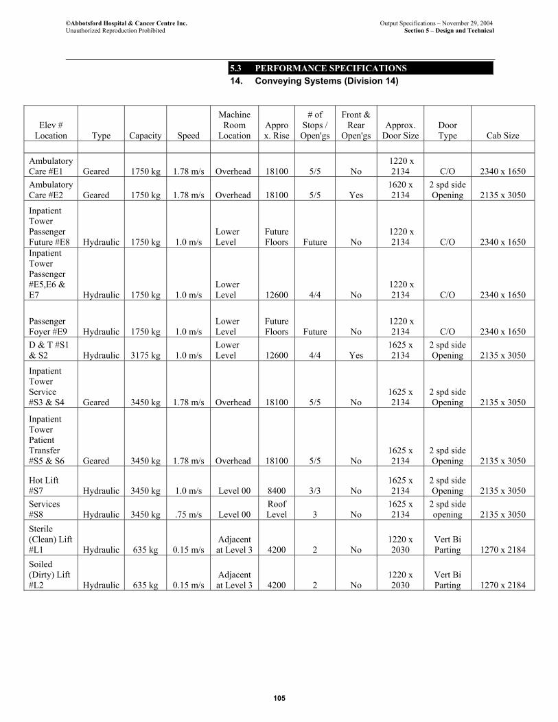
©Abbotsford Hospital & Cancer Centre Inc. Output Specifications – November 29, 2004 Unauthorized Reproduction Prohibited Section 5 – Design and Technical
5.3 PERFORMANCE SPECIFICATIONS 14. Conveying Systems (Division 14)
105
Elev # Location Type Capacity Speed
Machine Room
Location Approx. Rise
# of Stops / Open'gs
Front & Rear
Open'gs Approx.
Door Size Door Type Cab Size
Ambulatory Care #E1 Geared 1750 kg 1.78 m/s Overhead 18100 5/5 No
1220 x 2134 C/O 2340 x 1650
Ambulatory Care #E2 Geared 1750 kg 1.78 m/s Overhead 18100 5/5 Yes
1620 x 2134
2 spd side Opening 2135 x 3050
Inpatient Tower Passenger Future #E8 Hydraulic 1750 kg 1.0 m/s
Lower Level
Future Floors Future No
1220 x 2134 C/O 2340 x 1650
Inpatient Tower Passenger #E5,E6 & E7 Hydraulic 1750 kg 1.0 m/s
Lower Level 12600 4/4 No
1220 x 2134 C/O 2340 x 1650
Passenger Foyer #E9 Hydraulic 1750 kg 1.0 m/s
Lower Level
Future Floors Future No
1220 x 2134 C/O 2340 x 1650
D & T #S1 & S2 Hydraulic 3175 kg 1.0 m/s
Lower Level 12600 4/4 Yes
1625 x 2134
2 spd side Opening 2135 x 3050
Inpatient Tower Service #S3 & S4 Geared 3450 kg 1.78 m/s Overhead 18100 5/5 No
1625 x 2134
2 spd side Opening 2135 x 3050
Inpatient Tower Patient Transfer #S5 & S6 Geared 3450 kg 1.78 m/s Overhead 18100 5/5 No
1625 x 2134
2 spd side Opening 2135 x 3050
Hot Lift #S7 Hydraulic 3450 kg 1.0 m/s Level 00 8400 3/3 No
1625 x 2134
2 spd side Opening 2135 x 3050
Services #S8 Hydraulic 3450 kg .75 m/s Level 00
Roof Level 3 No
1625 x 2134
2 spd side opening 2135 x 3050
Sterile (Clean) Lift #L1 Hydraulic 635 kg 0.15 m/s
Adjacent at Level 3 4200 2 No
1220 x 2030
Vert Bi Parting 1270 x 2184
Soiled (Dirty) Lift #L2 Hydraulic 635 kg 0.15 m/s
Adjacent at Level 3 4200 2 No
1220 x 2030
Vert Bi Parting 1270 x 2184
©Abbotsford Hospital & Cancer Centre Inc. Output Specifications – November 29, 2004 Unauthorized Reproduction Prohibited Section 5 – Design and Technical
5.3 PERFORMANCE SPECIFICATIONS 14. Conveying Systems (Division 14)
106
14.3 DUMBWAITERS
14.3.1. Overriding Principles
1. Vertical conveyance of patient meals and trays may be by dumbwaiters directly from kitchen facilities to patient floors.
14.3.2. Quality Requirements
1. Project Co shall comply with all Applicable Standards including, but not limited to, the BC Building Code and those standards in Appendix 5A Technical Reference Standards. Refer to Output Specifications Section 5 – Design and Technical: Subsection 5.2.6.2. Other Codes and Standards for information regarding Appendix 5A Technical Reference Standards.
2. Conform to the requirements of the BC Elevating Devices Safety Act and Regulations.
3. Conform to the requirements of the local Municipal and Fire Department codes and regulations.
14.3.3. Performance Requirements
1. Dumbwaiter shall be provided in accordance with table 5.3.14.5.
14.4 PNEUMATIC TUBE SYSTEM
14.4.1 Overriding Principles
1. The system shall be a computer controlled pneumatic tube materials distribution system consisting of tubing, stations, transfer units, blower packages, carriers and a control system.
14.4.2 Quality Requirements.
1. Project Co shall comply with all Applicable Standards including, but not limited to, the BC Building Code and those standards in Appendix 5A Technical Reference Standards. Refer to Output Specifications Section 5 – Design and Technical: Subsection 5.2.6.2. Other Codes and Standards for information regarding Appendix 5A Technical Reference Standards.
2. Conform to the requirements of applicable Provincial and local codes and regulations.
©Abbotsford Hospital & Cancer Centre Inc. Output Specifications – November 29, 2004 Unauthorized Reproduction Prohibited Section 5 – Design and Technical
5.3 PERFORMANCE SPECIFICATIONS 14. Conveying Systems (Division 14)
107
14.4.3 Performance Requirements.
1. The system shall be configured of groups of stations (zones) connected together by interzone tubes. Each station shall be connected to the system by a single tube to a transfer unit.
2. Each zone shall contain its own blower and function independently.
3. The dispatching, routing and storage of carriers shall be directed by a system control centre to provide automatic unattended transmission of carriers between two stations.
4. The system shall provide shortest route vacuum pressure travel.
5. Refer to Output Specifications Section 7 Equipment Category F for locations and numbers of stations and zones.
6. The modular design of the system components shall permit changes in the number of stations and/or zones as Health Co requirements change.
End of Conveying Systems

©Abbotsford Hospital & Cancer Centre Inc. Output Specifications – November 29, 2004 Unauthorized Reproduction Prohibited Section 5 – Design and Technical
5.3 PERFORMANCE SPECIFICATIONS 14. Conveying Systems (Division 14)
108
Page left blank for pagination.
©Abbotsford Hospital & Cancer Centre Inc. Output Specifications – November 29, 2004 Unauthorized Reproduction Prohibited Section 5 – Design and Technical
5.3 PERFORMANCE SPECIFICATIONS 15. Mechanical (Division 15)
109
15. MECHANICAL (DIVISION 15)
15.1 BASIC REQUIREMENTS
15.1.1 Overriding Principles
1. Provide fully operational mechanical, HVAC, plumbing, fire protection, speciality systems and medical gas systems of standard and quality that meets or exceeds the latest health care and hospital industry standards and constructed to the Applicable Standards.
2. The HVAC, plumbing, fire protection, speciality systems and medical gas systems shall be designed to provide a healing, comfortable and productive environment for the patients and staff.
3. The mechanical, plumbing, fire protection, speciality systems and medical gas systems shall minimize impact on the natural and physical environment, through energy efficiency, optimization of resource use, and simplification of the systems.
4. For Class I areas and patient rooms, mechanical and plumbing equipment shall be configured and located in such a way that maintenance and repair can be performed without entering these areas.
5. The mechanical, plumbing, fire protection, speciality systems and medical gas systems developed shall provide the most economical approach, on a life cycle cost basis, in terms of capital, operating and maintenance costs.
6. The mechanical, plumbing, fire protection, speciality systems and medical gas systems component selection, system design, and installation shall incorporate the flexibility and adaptability for future expansion without major disruption or alteration to the facilities infrastructure.
7. Mechanical, plumbing, fire protection, speciality systems and medical gas systems shall be planned for future expansion, while deferring the equipment cost until the expansion takes place. Expansion space shall be shown on the developed drawings for the boiler and chiller room for future installation of one hot water boiler, one chiller and associated pumps and equipment. Adequate space shall be provided to install a future cooling tower adjacent to the other cooling towers. Chilled water, heating water and condenser water headers, in the energy plant, shall be increased one pipe size to incorporate future capacity addition, and valved connections shall be provided for connection of future equipment. Easy access shall be provided for moving the new equipment in and out of the mechanical rooms and energy plant with out disruption and major rework.
8. The mechanical, plumbing, fire protection, speciality systems and medical gas systems shall be developed to provide reliability of continual operation. Adequate standby capacity and redundancy shall be included in system design.

©Abbotsford Hospital & Cancer Centre Inc. Output Specifications – November 29, 2004 Unauthorized Reproduction Prohibited Section 5 – Design and Technical
5.3 PERFORMANCE SPECIFICATIONS 15. Mechanical (Division 15)
110
9. All piping, ductwork, plumbing systems and mechanical equipment which is part of the building mechanical systems in all parts of the facility will be seismically restrained to the post disaster standards in accordance with the applicable BC Building Code to prevent injury or hazard to persons and equipment and to retain equipment in a safe position in the event of a seismic disaster.
15.1.2 Quality Requirements
1. Project Co shall comply with all Applicable Standards including, but not limited to, the BC Building Code and those standards in Appendix 5A Technical Reference Standards. Refer to Output Specifications Section 5 – Design and Technical: Subsection 5.2.6.2. Other Codes and Standards for information regarding Appendix 5A Technical Reference Standards.
2. The equipment, material, workmanship, start up, testing and commissioning shall comply with the Provincial codes, Municipal by-laws and regulations and shall meet the requirements of the AHJ.
3. Qualified tradesmen with valid Provincial trade qualification certificates shall perform all work.
4. All material and equipment installed shall be new, full weight and of quality standards suitable for the Facility.
15.1.3 Performance Requirements
1. Equipment shall be installed for ease of access for maintenance, and ability to remove from the building without major equipment dismantling or cutting and patching of the building components.
2. Provide access doors for maintenance and adjustment, while minimizing functional intrusion, for all mechanical, HVAC, plumbing, fire protection, speciality systems and medical gas system components.
3. Identify and colour code all equipment, piping and ducts complete with directional flow arrows.
4. Shafts, services, and mechanical rooms shall be located and sized such that they do not impact future expansion.
15.2 WATER, SANITARY, STORM AND GAS UTILITIES
15.2.1. Overriding Principles
1. Provide water, sanitary, storm and gas utilities as required and sized to suit the consumption and discharge needs of the Facility.
15.2.2. Quality Requirements
©Abbotsford Hospital & Cancer Centre Inc. Output Specifications – November 29, 2004 Unauthorized Reproduction Prohibited Section 5 – Design and Technical
5.3 PERFORMANCE SPECIFICATIONS 15. Mechanical (Division 15)
111
1. Project Co shall comply with all Applicable Standards including, but not limited to, the BC Building Code and those standards in Appendix 5A Technical Reference Standards. Refer to Output Specifications Section 5 – Design and Technical: Subsection 5.2.6.2. Refer Other Codes and Standards for information regarding Appendix 5A Technical Reference Standards.
2. All material shall be in accordance with the BC Plumbing Code and Canadian Standards Association (CSA).
15.2.3. Performance Requirements
1. All internal utilities shall be co-ordinated with the civil engineering specifications for external utilities.
2. All services shall be co-ordinated with geotechnical conditions.
3. All sub-surface storm water drainage shall be provided in accordance with the geotechnical conditions.
4. Provide backflow preventor assembly on the water service in accordance with BC Plumbing Code and Municipal regulations.
5. New gas service shall be complete with gas meter and regulators.
15.3 COMMISSIONING, TESTING AND BALANCING
This section not used.
15.4 WATER TREATMENT SYSTEMS
15.4.1 Overriding Principles
1. Water, glycol and other fluids used within mechanical systems shall be treated to prevent corrosion, algae growth, build up of deposits, disease, bacteria and shall prolong the equipment life.
15.4.2. Quality Requirements
1. Project Co shall comply with all Applicable Standards including, but not limited to, the BC Building Code and those standards in Appendix 5A Technical Reference Standards. Refer to Output Specifications Section 5 – Design and Technical: Subsection 5.2.6.2. Other Codes and Standards for information regarding Appendix 5A Technical Reference Standards.
2. Domestic water systems shall be to AWWA standards. Water quality will be as provided by the Fraser Valley Regional District. No further treatment is required on site with the exception of special care areas such as renal dialysis and adjacent
©Abbotsford Hospital & Cancer Centre Inc. Output Specifications – November 29, 2004 Unauthorized Reproduction Prohibited Section 5 – Design and Technical
5.3 PERFORMANCE SPECIFICATIONS 15. Mechanical (Division 15)
112
special care areas, which will be treated through a reverse osmosis water treatment system prior to downstream use.
3. Chemicals used in treating the mechanical systems shall be environmentally friendly, shall meet all applicable environmental regulations and shall not pose a health hazard.
4. MSDS for all chemicals used shall be made available to the Facility.
5. System cleaning degreasing, testing and treatment work shall be performed by an agency specializing in this type of work.
15.4.3 Performance Requirements
1. Provide for cleaning, degreasing and chemical treatment of hot water heating, glycol, chilled water, condenser water, steam and condensate, air washer and cooling tower systems.
2. Provide for flushing and disinfection of domestic water systems.
3. Provide solution pumps, chemical mixing/storage tanks, chemical pot feeders, impulse water meters, test kits and other equipment necessary for initial cleaning, degreasing and chemical treatment and for ongoing testing and treatment of the systems.
15.5 PIPE AND PIPE FITTINGS
15.5.1 Overriding Principles
1. All piping and fitting quality for the mechanical, HVAC, plumbing, fire protection, speciality systems and medical gas systems shall be of institutional quality and appropriate for use in a modern Hospital and Cancer Centre.
15.5.2. Quality Requirements
1. Project Co shall comply with all Applicable Standards including, but not limited to, the BC Building Code and those standards in Appendix 5A Technical Reference Standards. Refer to Output Specifications Section 5 – Design and Technical: Subsection 5.2.6.2. Other Codes and Standards for information regarding Appendix 5A Technical Reference Standards.
2. Piping and fittings for plumbing systems shall be in accordance with the BC Plumbing code.
3. Piping and fittings for fire protection systems shall be in accordance with the NFPA standards.
4. Footing drainage piping material shall suit geotechnical conditions.
15.5.3. Performance Requirements
©Abbotsford Hospital & Cancer Centre Inc. Output Specifications – November 29, 2004 Unauthorized Reproduction Prohibited Section 5 – Design and Technical
5.3 PERFORMANCE SPECIFICATIONS 15. Mechanical (Division 15)
113
1. All piping shall be supported and anchored to meet the BC Building Code and ASHRAE requirements.
2. All piping shall be sealed where it passes through walls, floors or ceilings to conform to fire resistance rating of the walls, floors or ceilings.
3. All piping and fittings shall be installed to allow for adequate expansion and contraction.
4. All solder shall be lead free.
5. All flux shall be non acidic and water soluble.
6. All piping systems shall be provided with appropriate isolation valves.
7. All acid waste piping shall be installed to manufacturers’ requirements.
8. All footing drainage piping shall be installed to the geotechnical conditions.
9. All buried steel lines and fittings shall be jacketed to prevent corrosion.
10. All piping shall be arranged for ease of operating, accessibility for maintenance, safety and appearance.
15.6 SOUND ATTENUATION AND VIBRATION ISOLATION
15.6.1. Overriding Principles
1. All mechanical, HVAC, plumbing, fire protection, and speciality systems and medical gas systems shall be vibration isolated to prevent noise and vibration through the structure or other components of the Facility.
2. All mechanical, HVAC, plumbing, fire protection, speciality systems and medical gas systems shall comply with acoustic requirements outlined in Output Specifications - Section 1 Key Site and Building Design Criteria: Subsection 1.2.5.4 Acoustics.
15.6.2. Quality Requirements
1. Project Co shall comply with all Applicable Standards including, but not limited to, the BC Building Code and those standards in Appendix 5A Technical Reference Standards. Refer to Output Specifications Section 5 – Design and Technical: Subsection 5.2.6.2. Other Codes and Standards for information regarding Appendix 5A Technical Reference Standards.
2. All isolation and vibration materials and products shall not exceed the average noise criteria curves, as outlined in ASHRAE guides.
3. All isolation and vibration equipment shall be the product of a single manufacturer or shall be interchangeable.
4. All integral isolation and restraint devices shall conform to the BC Building Code requirements.
©Abbotsford Hospital & Cancer Centre Inc. Output Specifications – November 29, 2004 Unauthorized Reproduction Prohibited Section 5 – Design and Technical
5.3 PERFORMANCE SPECIFICATIONS 15. Mechanical (Division 15)
114
5. Duct silencers shall be the products of a manufacturer regularly engaged in the production of silencers.
6. The tabulated airflow and acoustical performance data for silencers shall be in accordance with the applicable ASHRAE, AMCA and ASME test codes.
15.6.3. Performance Requirements
1. Provide vibration isolators for all motor driven mechanical equipment.
2. All piping connections to isolated equipment shall be supported resiliently.
3. Pipe, duct and wiring connections to isolated equipment shall be flexible.
4. Duct silencer selections shall be optimized for noise attenuation and insertion losses.
15.7 PIPES, DUCTS, EQUIPMENT AND BREECHING INSULATION
15.7.1 Overriding Principles
1. All pipes, ducts and fittings shall be insulated to conserve energy, prevent condensation, attenuate noise and prevent accidental burns.
15.7.2 Quality Requirements
1. Project Co shall comply with all Applicable Standards including, but not limited to, the BC Building Code and those standards in Appendix 5A Technical Reference Standards. Refer to Output Specifications Section 5 – Design and Technical: Subsection 5.2.6.2. Other Codes and Standards for information regarding Appendix 5A Technical Reference Standards.
2. All insulation and adhesives shall be in accordance with the current edition of British Columbia Insulation Construction Association (BCICA) quality standards manual for mechanical insulation.
3. Insulation shall be applied to piping in accordance with BCICA Quality Standards Specification 1501.
4. All insulation thickness shall be in accordance with the ASHRAE Standard 90.1, 1999, Energy Standard for Buildings.
5. Insulating materials shall meet or exceed fire and smoke hazard ratings required by BC Building Code.
15.7.3. Performance Requirements
1. Piping conveying cold fluids shall be insulated and vapour sealed to prevent condensation.
2. Piping conveying hot fluids shall be insulated to prevent energy loss.
3. All piping containing water and subject to freezing temperature shall be insulated.
©Abbotsford Hospital & Cancer Centre Inc. Output Specifications – November 29, 2004 Unauthorized Reproduction Prohibited Section 5 – Design and Technical
5.3 PERFORMANCE SPECIFICATIONS 15. Mechanical (Division 15)
115
4. All air plenums and ducts exposed to outdoors shall be insulated to prevent energy loss and moisture condensation.
5. All air conditioning ducts shall be insulated and vapour sealed to prevent energy loss and moisture condensation.
6. All heating ducts shall be insulated to prevent energy loss.
7. All cold tanks and equipment shall be insulated vapour sealed to prevent energy loss and moisture condensation.
8. All hot tanks and equipment shall be insulated to prevent energy loss.
9. All insulated equipment, exposed piping and duct systems, shall be provided with a durable finishing jacket, to prevent damage to insulation for 2 metres above finish floor.
10. Piping insulation shall be continuous when passing through walls and floors.
11. Complete systems shall be insulated including fittings, valves, unions, flanges, and strainers.
12. Back of all radiant ceiling panels shall be insulated, using aluminum foil back insulation to prevent energy loss.
15.8 PLUMBING SYSTEMS
15.8.1 Overriding Principles
1. Provide plumbing fixtures, trim, equipment and plumbing systems as required and appropriate for a hospital and cancer centre facility in British Columbia.
2. All plumbing systems shall be sized and at appropriate pressures to accommodate the requirements of the Facility.
15.8.2 Quality Requirements
1. Project Co shall comply with all Applicable Standards including, but not limited to, the BC Building Code and those standards in Appendix 5A Technical Reference Standards. Refer to Output Specifications Section 5 – Design and Technical: Subsection 5.2.6.2. Other Codes and Standards for information regarding Appendix 5A Technical Reference Standards.
2. All plumbing fixtures, trim, and equipment for the plumbing systems shall comply with the BC Plumbing Code and CSA.
3. All toilets shall be dual flush toilets.
4. Provide emergency plumbing fixtures and trim to suit the requirements of the Workers’ Compensation Act and regulations of British Columbia (WCB).
©Abbotsford Hospital & Cancer Centre Inc. Output Specifications – November 29, 2004 Unauthorized Reproduction Prohibited Section 5 – Design and Technical
5.3 PERFORMANCE SPECIFICATIONS 15. Mechanical (Division 15)
116
5. All plumbing fixture trim shall be in accordance with guidelines outlined in Output Specifications - Section 1 Key Site and Building Design Criteria: Subsection 1.2.4.5 Infection Control.
6. All plumbing fixtures, trim, and equipment for the plumbing systems shall provide acoustic levels appropriate for the space in which they are located.
7. All plumbing fixtures, trim and equipment for the plumbing systems shall be institutional quality.
8. All laboratory plumbing fixtures, sinks and trim subject to acid use shall be acid resistant.
9. All backflow devices shall be provided in accordance with CSA backflow requirements.
10. All storm water, sanitary waste, sanitary vent, and domestic water systems shall be in accordance with the BC Plumbing Code.
11. All cleanouts, water hammer arrestors and trap primers shall be installed as per the BC Plumbing Code.
15.8.3. Performance Requirements
1. All plumbing fixtures, trim and equipment for the plumbing systems shall be installed to manufacturers installation requirements.
2. All plumbing fixtures and trim in mental health rooms shall be of a type that will protect the patients and staff from harm.
3. Provide carrier types to suit the fixtures and fixture usage.
4. Provide backflow protection on all plumbing fixture trim and plumbing system equipment where applicable.
5. Provide mildew and algae resistant sealant between walls, floors, etc. for all applicable plumbing fixtures.
6. All bathtubs and showers shall have slip resistant surfaces.
7. All plumbing fixture p-traps shall be easily removable for servicing and cleaning.
8. All drains shall be suitable for the type of construction to which they are installed.
9. Provide interceptors as required to intercept oil, dirt, grease and neutralizing of acids for waste systems.
10. Provide pressure reducing valves as required to properly regulate pressure of the plumbing systems.
©Abbotsford Hospital & Cancer Centre Inc. Output Specifications – November 29, 2004 Unauthorized Reproduction Prohibited Section 5 – Design and Technical
5.3 PERFORMANCE SPECIFICATIONS 15. Mechanical (Division 15)
117
11. Domestic hot water shall be of adequate temperature to serve the needs of the Facility at not less then 60ºC. Provide mixing valves where temperatures are required to be less then 60ºC at point of use.
12. Domestic hot water shall be protected from contamination as outlined in the American Society of Plumbing Engineer (ASPE) Guidelines for Legionellae control in Health Care Facilities.
13. Provide Plumbing system connections as required to all Facility equipment
14. Provide hose bibbs as required for the Facility
15. Provide domestic water strainers.
15.9 MEDICAL GAS SYSTEM
15.9.1. Overriding Principles
1. Provide medical gas systems as required to the standards and quality appropriate for a modern Hospital and Cancer Centre.
2. Provide medical gas systems and equipment to suit the consumption needs of the Facility.
3. All medical gas outlets shall be of the type and quantity to suit the functions performed in each department of the Facility.
4. Medical gases shall include but not be limited to oxygen, vacuum, nitrous oxide, medical air and nitrogen.
15.9.2. Quality Requirements
1. Project Co shall comply with all Applicable Standards including, but not limited to, the BC Building Code and those standards in Appendix 5A Technical Reference Standards. Refer to Output Specifications Section 5 – Design and Technical: Subsection 5.2.6.2. Other Codes and Standards for information regarding Appendix 5A Technical Reference Standards.
2. All medical gas systems shall be to CSA standard Z-305.1-M 1992 non-flammable medical gas systems code.
3. All material and equipment for the medical gas system shall be to CSA Standards.
4. All on-site storage of medical gases shall be to CSA Standards.
5. All piping, valves and filters shall be factory cleaned and capped or sealed to prevent contamination.
6. All medical gas piping shall be identified in accordance with CSA Standards.
©Abbotsford Hospital & Cancer Centre Inc. Output Specifications – November 29, 2004 Unauthorized Reproduction Prohibited Section 5 – Design and Technical
5.3 PERFORMANCE SPECIFICATIONS 15. Mechanical (Division 15)
118
7. All departments shall be provided with local valve boxes and alarm panels in accordance with CSA Standards.
8. A master medical gas alarm panel shall be provided to monitor all medical gas functions.
9. All Master alarm panels shall be connected to the Building Management System to meet code.
15.9.3. Performance Requirements
1. All medical gas systems shall be certified in accordance with CSA standards by an independent testing agency.
2. All medical gas outlets and piping systems shall be cleaned in accordance with CSA standards.
3. All systems components requiring electrical power shall be on emergency power.
4. All medical gas piping installed behind walls or ceilings, which are not accessible (means in this case behind hard walls or ceilings, not hard to reach places or T-bar ceilings) , shall be spray bomb painted for their entire length as the piping is installed.
5. Medical gas outlets shall be provided to suit CSA and the Facility requirements. Outlets shall be quantified with the Equipment List(s) in Section 7 Equipment.
15.10 FIRE PROTECTION SYSTEMS
15.10.1. Overriding Principles
1. Provide fire protection systems as required to the standards and quality appropriate for a modern hospital and cancer centre.
2. Provide fire protection systems to suit the construction of the Facility.
15.10.2. Quality Requirements
1. Project Co shall comply with all Applicable Standards including, but not limited to, the BC Building Code and those standards in Appendix 5A Technical Reference Standards. Refer to Output Specifications Section 5 – Design and Technical: Subsection 5.2.6.2. Other Codes and Standards for information regarding Appendix 5A Technical Reference Standards.
2. All fire protection systems shall be to the appropriate NFPA standards and the BC Building Code.
3. All fire protection systems shall be hydraulically sized to NFPA standards.
4. All equipment and installation shall be in accordance with manufacturers requirements.
©Abbotsford Hospital & Cancer Centre Inc. Output Specifications – November 29, 2004 Unauthorized Reproduction Prohibited Section 5 – Design and Technical
5.3 PERFORMANCE SPECIFICATIONS 15. Mechanical (Division 15)
119
5. All equipment shall be ULC approved.
6. Qualified contractor licensed and regularly engaged in such installations shall install all fire protection systems and equipment.
7. Provide backflow protection on all fire protection systems in accordance with CSA requirements.
15.10.3. Performance Requirements
1. All fire protection systems documentation shall be approved by AHJ.
2. All sprinkler heads shall have temperature ratings to suit the specific hazard area.
3. Protect all systems from freezing.
4. All valves controlling water flow shall be monitored.
5. All systems components requiring electrical power shall be on emergency power.
6. Protect sprinkler heads from mechanical injury with appropriate guards where necessary.
7. All sprinkler heads in Mental Health/Psychiatry rooms shall be of a type that will protect the patients and staff from harm.
8. Provide pre-action sprinkler systems in Linear Accelerators, CT Simulators, MRI, Server room, Active Medical Records, and 2 CT Rooms within Imaging ..
15.11 HEATING PLANT
15.11.1. Overriding Principles
1. The Facility heating plant shall meet all space and process heating needs under all weather conditions in an energy and cost efficient manner.
2. The heating plant shall be provided with adequate backup capacity and equipment redundancy to ensure continuous Facility operation at all times, with not noticeable reduction in service outcomes. 100% heating capacity redundancy for Class I and 67% redundancy for Class II and Class III areas shall be provided (conceptually via two-500 HP boilers and one-200HP boiler).
15.11.2. Quality Requirements
1. Project Co shall comply with all Applicable Standards including, but not limited to, the BC Building Code and those standards in Appendix 5A Technical Reference Standards. Refer to Output Specifications Section 5 – Design and Technical: Subsection 5.2.6.2. Other Codes and Standards for information regarding Appendix 5A Technical Reference Standards.
©Abbotsford Hospital & Cancer Centre Inc. Output Specifications – November 29, 2004 Unauthorized Reproduction Prohibited Section 5 – Design and Technical
5.3 PERFORMANCE SPECIFICATIONS 15. Mechanical (Division 15)
120
2. The design and installation shall comply with Labour Relations Board of BC regulations. Register and obtain approval for the design of piping system, prior to construction.
3. Equipment shall have CSA approval, and shall meet the applicable sections of the ASME Code.
4. Welding materials, fabrication standards, and labour qualifications shall conform to ANSI/ASME B 31.1, ANSI/ ASME Section IX. and applicable ANSI and ASTM Standards.
15.11.3. Performance Requirements
1. Boilers shall be guaranteed to operate at a minimum efficiency of 85% at all firing rates.
2. Provide adequate expansion compensation for heating piping throughout. Location of anchors and guides, design of expansion compensation loops and selection of expansion compensation devices shall be based upon a thorough review of piping layout, and piping stress analysis.
3. All high points in piping shall be equipped with air removal devices such as air collection chambers and air vents.
4. Equipment and piping shall be installed with adequate service space, access panels and ability to remove equipment from building for servicing or replacement.
5. Isolation valves, unions and bypass piping shall be provided to allow for equipment isolation and removal without unduly affecting the system operation or major drain down.
6. Balancing valves, flow-measuring devices, temperature and pressure sensors shall be provided throughout the system to facilitate system balancing.
7. Pumps shall be selected to operate at the system fluid temperature without vapour binding and cavitation, shall be non overloading in parallel or individual operation, and shall operate within 25% of the mid point of published maximum efficiency curve.
8. Pump construction and installation shall permit complete pump servicing without breaking piping or motor connections.
9. Boilers shall be duel fuel fired with natural gas as the primary fuel and fuel oil as the secondary fuel. Adequate fuel oil storage shall be provided on site to operate the boilers for a minimum of 36 hours, under maximum demand conditions.
©Abbotsford Hospital & Cancer Centre Inc. Output Specifications – November 29, 2004 Unauthorized Reproduction Prohibited Section 5 – Design and Technical
5.3 PERFORMANCE SPECIFICATIONS 15. Mechanical (Division 15)
121
15.12 COOLING PLANT
15.12.1. Overriding Principles
1. The Facility cooling plant shall meet all space and process cooling needs under all weather conditions in an energy and cost efficient manner.
2. The cooling plant shall be provided with adequate back up capacity and equipment redundancy to ensure continuous Facility operation at all times, with no noticeable reduction in service outcomes. 100% cooling capacity redundancy for Class I and 50% redundancy for Class II and Class III areas shall be provided (conceptually via two 900 Ton chillers).
3. Cooling shall be available 24/7 for areas containing specialized high tech equipment.
15.12.2. Quality Requirements
1. Project Co shall comply with all Applicable Standards including, but not limited to, the BC Building Code and those standards in Appendix 5A Technical Reference Standards. Refer to Output Specifications Section 5 – Design and Technical: Subsection 5.2.6.2. Other Codes and Standards for information regarding Appendix 5A Technical Reference Standards.
2. The design and installation shall comply with Provincial Board of Labour Regulations, and CSA B52, Mechanical Refrigeration Code. Register and obtain approval for the design of the piping system prior to construction.
3. Equipment shall have CSA approval and meet applicable sections of the ASME Code.
4. Welding materials, fabrication standards, and labour qualifications shall conform to ANSI/ASME B31.1, ANSI/ASME Section IX and applicable ASNI and ASTM Standards.
5. Chillers shall be rated in accordance with ARI 550-88.
6. Cooling tower performance shall be certified in accordance with CTI Standard STD-201.
7. Cooling tower design, placement and operation shall comply with ASHRAE Guideline 12 – 2000, Minimizing the Risk of Legionellae Associated with Building Water Systems.
15.12.3. Performance Requirements
1. CFC and HCFC based refrigerants shall not be used in the refrigeration equipment.
2. Locate cooling towers to ensure absolutely no potential of cooling tower discharge entering the building through air intakes and other openings in the Facility.
©Abbotsford Hospital & Cancer Centre Inc. Output Specifications – November 29, 2004 Unauthorized Reproduction Prohibited Section 5 – Design and Technical
5.3 PERFORMANCE SPECIFICATIONS 15. Mechanical (Division 15)
122
3. Piping shall be installed in an orderly manner. Slope piping to permit complete drainage of the system.
4. All high points in the closed loop piping shall be equipped with air removal devices, such as air collection chambers and air vents.
5. Equipment and piping shall be installed with adequate service space, access panels and ability to remove equipment from building for servicing or replacement.
6. Isolation valves, unions and bypass piping shall be provided to allow for equipment isolation and removal without unduly affecting the system operation or major drain down.
7. Pumps shall be selected to operate without vapour binding or cavitation, shall be non-overloading in parallel or individual operation, and shall operate within 25% of the mid-point of published maximum efficiency curve.
8. Pump construction and installation shall permit complete pump servicing without breaking piping or motor connections.
15.13 STEAM PLANT
15.13.1. Overriding Principles
1. The Facility steam plant shall meet all steam needs in a safe and energy and cost efficient manner.
2. The steam generation and distribution plant shall be provided with adequate backup capacity and equipment redundancy to ensure continuous Facility operation at all times, with no noticeable reduction in service outcomes. Two steam boilers shall supply steam for the base load. A third steam boiler equal in size to the largest steam boiler shall be provided as a backup boiler. The backup boiler shall be supplied with an easily connectable spool-piece for connection to the steam mains in the event of a failure of either of the duty steam boilers.
15.13.2. Quality Requirements
1. Project Co shall comply with all Applicable Standards including, but not limited to, the BC Building Code and those standards in Appendix 5A Technical Reference Standards. Refer to Output Specifications Section 5 – Design and Technical: Subsection 5.2.6.2. Other Codes and Standards for information regarding Appendix 5A Technical Reference Standards.
2. The design and installation shall comply with Provincial Board of Labour regulations. Register and obtain approval for the design of piping system, prior to construction.
3. Equipment shall have CSA approval, and meet applicable sections of the ASME Code.
©Abbotsford Hospital & Cancer Centre Inc. Output Specifications – November 29, 2004 Unauthorized Reproduction Prohibited Section 5 – Design and Technical
5.3 PERFORMANCE SPECIFICATIONS 15. Mechanical (Division 15)
123
4. Welding materials, fabrication standards and labour qualifications shall conform to ANSI/ASME B31.1 ., ANSI/ASME Section IX, and applicable ANSI and ASTM Standards.
15.13.3. Performance Requirements
1. Piping shall be arranged for ease of operation, accessibility for maintenance, safety considerations and appearance.
2. Boilers shall be guaranteed to operate at a minimum efficiency of 80% at all firing rates.
3. Provide expansion compensation for heating piping throughout. Location of anchors and guides, design of expansion compensation loops and selection of expansion compensation devices shall be based upon a thorough review of piping layout, and piping stress analysis.
4. Equipment and piping shall be installed with adequate service space, access panels and ability to remove equipment from building for servicing or replacement.
5. Isolation valves, unions and bypass piping shall be provided to allow for equipment isolation and removal without unduly affecting the system operation or major drain down.
6. Pumps shall be selected to operate at the system fluid temperature without vapour binding and cavitation, shall be non overloading in parallel or individual operation, and shall operate within 25% of the mid point of published maximum efficiency curve.
7. Pump construction and installation shall permit complete pump servicing without breaking piping or motor connections.
8. Discharge from steam safety valves and vents shall be piped to the outdoors.
9. Boilers shall be dual fuel fired with natural gas as the primary fuel and fuel oil as the standby fuel. Adequate fuel oil storage shall be provided on site to operate the boilers for a minimum of 36 hours, under maximum demand conditions.
15.14 HEATING, VENTILATION AND AIR CONDITIONING SYSTEMS
15.14.1. Overriding Principles
1. Heating, ventilation and air conditioning (HVAC) system shall provide a comfortable internal environment for the patients and staff, and shall meet the required environmental conditions for the equipment.
2. The HVAC system shall maintain appropriate pressure relationships between various areas of the Facility and shall provide necessary air filtration, cleansing and exhaust to control the transmission of infection.
©Abbotsford Hospital & Cancer Centre Inc. Output Specifications – November 29, 2004 Unauthorized Reproduction Prohibited Section 5 – Design and Technical
5.3 PERFORMANCE SPECIFICATIONS 15. Mechanical (Division 15)
124
3. HVAC systems shall be provided with adequate backup capacity and equipment redundancy to ensure continuous Facility operation at all times.
• The Class I areas shall be provided with 100% redundancy. Air handling units shall be provided with sectional heating and cooling coils with manual isolation valves, enabling isolation of the damaged sections of the coils.
• For Class II and Class III areas, two roof top units will be “paired” together. The two-paired units will serve the same area rather than a single larger unit. This arrangement shall provide a certain amount of standby capacity so that in the event of a failure or scheduled serviced shutdown of one unit the other unit will continue to run and provide approximately 70% capacity to the affected area. 100 percent redundancy shall be provided for the Lab areas,
• 100 percent redundancy shall be provided for morgue exhaust.
• Server rooms shall be supplied with 2-duty and 1-standby computer room air conditioning units (Liebert or equal quality) with remote condensers
• Linac area shall be provided with adequate redundancy to maintain at least 12 Air Changes per Hour and maintain the room temperature set point at all times.
4. Energy efficiency shall be key criteria in the selection of the HVAC systems. Where possible, use of natural ventilation shall be considered.
15.14.2. Quality Requirements
1. Project Co shall comply with all Applicable Standards including, but not limited to, the BC Building Code and those standards in Appendix 5A Technical Reference Standards. Refer to Output Specifications Section 5 – Design and Technical: Subsection 5.2.6.2. Refer Other Codes and Standards for information regarding Appendix 5A Technical Reference Standards.
2. The HVAC systems shall conform to BC Building Code, applicable CSA Standards, ASHRAE Standards, SMACNA Standards, Municipal by-laws and shall meet the requirements of the AHJ.
3. HVAC Systems shall meet the requirements of CAN/CSA Z317.2 – 01, Special Requirements for Heating, Ventilation and Air Conditioning Systems in Health Care Facilities.
4. Heating, Cooling and Refrigeration Coil Capacities, Pressure drops, and selection procedures shall be certified in accordance with ARI Standards and bear ARI seal.
5. Fans shall be AMCA Certified, and shall bear AMCA Certified Rating seal.
6. Filter media shall be UL listed.
7. Ductwork shall be fabricated in accordance with SMACNA Duct Manuals and ASHRAE Handbooks.
©Abbotsford Hospital & Cancer Centre Inc. Output Specifications – November 29, 2004 Unauthorized Reproduction Prohibited Section 5 – Design and Technical
5.3 PERFORMANCE SPECIFICATIONS 15. Mechanical (Division 15)
125
8. Ductwork shall meet the requirements of NFPA No. 90A-Air Conditioning and Ventilating Systems; NFPA No. 90B – Standard for the Installation of Warm Air Heating and Air Conditioning Systems; and NFPA No. 96-Standard for the Installation of Equipment for the Removal of Smoke and Grease-Laden Vapours from Commercial Cooking Equipment.
9. Fire and smoke dampers shall be ULC listed.
10. Ethylene oxide exhaust systems shall meet the requirements of CSA Standard Z314.9.
11. The construction quality of the roof top air handling units shall be similar to the units that are used indoors. These units will be factory fabricated (by Haakon, Scott Springfield or equivalent) rather than site fabricated to ensure higher construction standard.
15.14.3. Performance Requirements
1. The HVAC systems shall be designed to the following outdoor conditions.
1.1 Winter:
DB Temperature: -12°C.
1.2 Summer:
DB Temperature: 30°C.
WB Temperature: 20°C.
2. The HVAC Systems shall meet the design requirements as outlined in Table 5.3.15.14, Design Criteria; and in Table 1 HVAC Criteria, in CSA Standard Z317.2-01.
3. The Project Co shall submit an IAQ plan that would outline their strategy(s) for meeting the IAQ requirements.
4. Separate supply, return and/or exhaust shall be provided for Class 1 areas, isolation rooms, and other such highly specialized areas as required.
5. For all Class 1 rooms, (including ortho and one general rm as determined through consultation with Health Co), the air supply shall be at the ceiling and the exhaust at the floor, to ensure a laminar flow air pattern. No recirculation of air shall be permitted. Operating room shall utilize laminar flow ceiling diffusers specifically designed to produce a column of laminar air flow at and around the operating table.
6. All supply air, return air and exhaust air to each space shall be fully ducted. Use of ceiling plenums, air transfer through rooms, corridors, shafts etc. shall not be permitted.
7. Thermal/acoustic insulation on the inside of the air handling units and ducts/plenums shall be enclosed in a double skin construction.
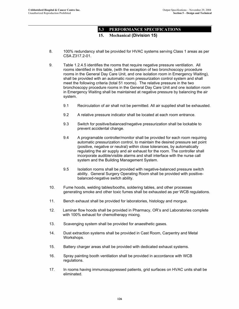
©Abbotsford Hospital & Cancer Centre Inc. Output Specifications – November 29, 2004 Unauthorized Reproduction Prohibited Section 5 – Design and Technical
5.3 PERFORMANCE SPECIFICATIONS 15. Mechanical (Division 15)
126
8. 100% redundancy shall be provided for HVAC systems serving Class 1 areas as per CSA Z317.2-01.
9. Table 1.2.4.5 identifies the rooms that require negative pressure ventilation. All rooms identified in this table, (with the exception of two bronchoscopy procedure rooms in the General Day Care Unit, and one isolation room in Emergency Waiting), shall be provided with an automatic room pressurization control system and shall meet the following criteria (total 51 rooms). The relative pressure in the two bronchoscopy procedure rooms in the General Day Care Unit and one isolation room in Emergency Waiting shall be maintained at negative pressure by balancing the air system.
9.1 Recirculation of air shall not be permitted. All air supplied shall be exhausted.
9.2 A relative pressure indicator shall be located at each room entrance.
9.3 Switch for positive/balanced/negative pressurization shall be lockable to prevent accidental change.
9.4 A programable controller/monitor shall be provided for each room requiring automatic pressurization control, to maintain the desired pressure set point (positive, negative or neutral) within close tolerances, by automatically regulating the air supply and air exhaust for the room. The controller shall incorporate audible/visible alarms and shall interface with the nurse call system and the Building Management System.
9.5 Isolation rooms shall be provided with negative-balanced pressure switch ability. General Surgery Operating Room shall be provided with positive-balanced-negative switch ability.
10. Fume hoods, welding tables/booths, soldering tables, and other processes generating smoke and other toxic fumes shall be exhausted as per WCB regulations.
11. Bench exhaust shall be provided for laboratories, histology and morgue.
12. Laminar flow hoods shall be provided in Pharmacy, OR’s and Laboratories complete with 100% exhaust for chemotherapy mixing.
13. Scavenging system shall be provided for anaesthetic gases.
14. Dust extraction systems shall be provided in Cast Room, Carpentry and Metal Workshops.
15. Battery charger areas shall be provided with dedicated exhaust systems.
16. Spray painting booth ventilation shall be provided in accordance with WCB regulations.
17. In rooms having immunosuppressed patients, grid surfaces on HVAC units shall be eliminated.

©Abbotsford Hospital & Cancer Centre Inc. Output Specifications – November 29, 2004 Unauthorized Reproduction Prohibited Section 5 – Design and Technical
5.3 PERFORMANCE SPECIFICATIONS 15. Mechanical (Division 15)
127
18. Garbage receiving, soiled utility rooms and storage rooms shall be maintained under negative pressure.
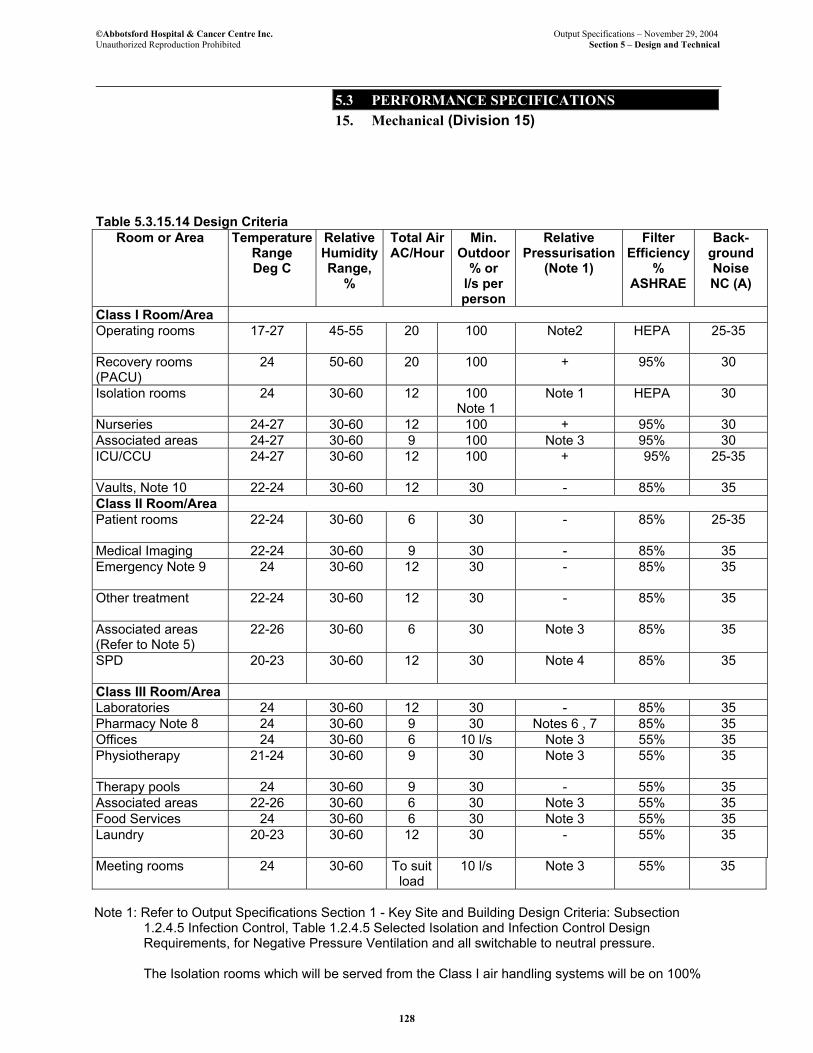
©Abbotsford Hospital & Cancer Centre Inc. Output Specifications – November 29, 2004 Unauthorized Reproduction Prohibited Section 5 – Design and Technical
5.3 PERFORMANCE SPECIFICATIONS 15. Mechanical (Division 15)
128
Table 5.3.15.14 Design Criteria
Room or Area Temperature Range Deg C
Relative HumidityRange,
%
Total Air AC/Hour
Min. Outdoor
% or l/s per person
Relative Pressurisation
(Note 1)
Filter Efficiency
% ASHRAE
Back-ground Noise NC (A)
Class I Room/Area Operating rooms 17-27
45-55 20 100 Note2 HEPA 25-35
Recovery rooms (PACU)
24
50-60 20 100 + 95% 30
Isolation rooms 24
30-60 12 100 Note 1
Note 1 HEPA 30
Nurseries 24-27 30-60 12 100 + 95% 30 Associated areas 24-27 30-60 9 100 Note 3 95% 30 ICU/CCU 24-27 30-60 12 100 + 95% 25-35
Vaults, Note 10 22-24 30-60 12 30 - 85% 35 Class II Room/Area Patient rooms 22-24 30-60 6 30 - 85% 25-35
Medical Imaging 22-24 30-60 9 30 - 85% 35 Emergency Note 9 24
30-60 12 30 -
85% 35
Other treatment
22-24
30-60 12
30 - 85% 35
Associated areas (Refer to Note 5)
22-26 30-60 6 30 Note 3 85% 35
SPD 20-23
30-60 12 30 Note 4 85% 35
Class III Room/Area Laboratories 24 30-60 12 30 - 85% 35 Pharmacy Note 8 24 30-60 9 30 Notes 6 , 7 85% 35 Offices 24 30-60 6 10 l/s Note 3 55% 35 Physiotherapy 21-24
30-60 9 30 Note 3 55% 35
Therapy pools 24 30-60 9 30 - 55% 35 Associated areas 22-26 30-60 6 30 Note 3 55% 35 Food Services 24 30-60 6 30 Note 3 55% 35 Laundry 20-23
30-60 12 30 - 55% 35
Meeting rooms 24 30-60 To suit load
10 l/s Note 3 55% 35
Note 1: Refer to Output Specifications Section 1 - Key Site and Building Design Criteria: Subsection
1.2.4.5 Infection Control, Table 1.2.4.5 Selected Isolation and Infection Control Design Requirements, for Negative Pressure Ventilation and all switchable to neutral pressure.
The Isolation rooms which will be served from the Class I air handling systems will be on 100%
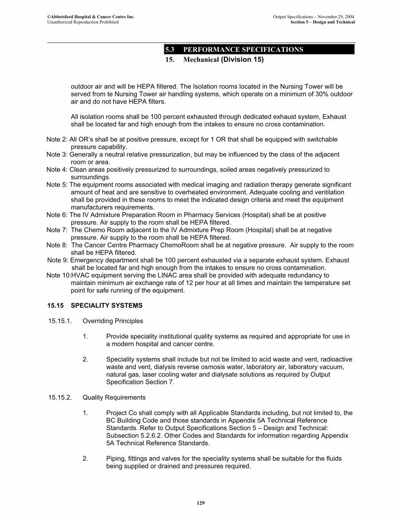
©Abbotsford Hospital & Cancer Centre Inc. Output Specifications – November 29, 2004 Unauthorized Reproduction Prohibited Section 5 – Design and Technical
5.3 PERFORMANCE SPECIFICATIONS 15. Mechanical (Division 15)
129
outdoor air and will be HEPA filtered. The Isolation rooms located in the Nursing Tower will be served from te Nursing Tower air handling systems, which operate on a minimum of 30% outdoor air and do not have HEPA filters. All isolation rooms shall be 100 percent exhausted through dedicated exhaust system, Exhaust shall be located far and high enough from the intakes to ensure no cross contamination.
Note 2: All OR’s shall be at positive pressure, except for 1 OR that shall be equipped with switchable
pressure capability. Note 3: Generally a neutral relative pressurization, but may be influenced by the class of the adjacent
room or area. Note 4: Clean areas positively pressurized to surroundings, soiled areas negatively pressurized to
surroundings. Note 5: The equipment rooms associated with medical imaging and radiation therapy generate significant
amount of heat and are sensitive to overheated environment. Adequate cooling and ventilation shall be provided in these rooms to meet the indicated design criteria and meet the equipment manufacturers requirements.
Note 6: The IV Admixture Preparation Room in Pharmacy Services (Hospital) shall be at positive pressure. Air supply to the room shall be HEPA filtered.
Note 7: The Chemo Room adjacent to the IV Admixture Prep Room (Hospital) shall be at negative pressure. Air supply to the room shall be HEPA filtered.
Note 8: The Cancer Centre Pharmacy ChemoRoom shall be at negative pressure. Air supply to the room shall be HEPA filtered.
Note 9: Emergency department shall be 100 percent exhausted via a separate exhaust system. Exhaust shall be located far and high enough from the intakes to ensure no cross contamination.
Note 10:HVAC equipment serving the LINAC area shall be provided with adequate redundancy to maintain minimum air exchange rate of 12 per hour at all times and maintain the temperature set point for safe running of the equipment.
15.15 SPECIALITY SYSTEMS
15.15.1. Overriding Principles
1. Provide speciality institutional quality systems as required and appropriate for use in a modern hospital and cancer centre.
2. Speciality systems shall include but not be limited to acid waste and vent, radioactive waste and vent, dialysis reverse osmosis water, laboratory air, laboratory vacuum, natural gas, laser cooling water and dialysate solutions as required by Output Specification Section 7.
15.15.2. Quality Requirements
1. Project Co shall comply with all Applicable Standards including, but not limited to, the BC Building Code and those standards in Appendix 5A Technical Reference Standards. Refer to Output Specifications Section 5 – Design and Technical: Subsection 5.2.6.2. Other Codes and Standards for information regarding Appendix 5A Technical Reference Standards.
2. Piping, fittings and valves for the speciality systems shall be suitable for the fluids being supplied or drained and pressures required.
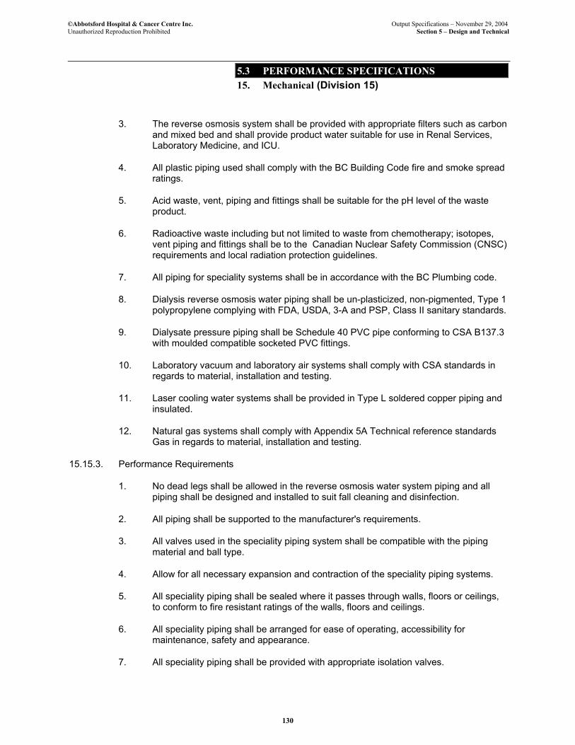
©Abbotsford Hospital & Cancer Centre Inc. Output Specifications – November 29, 2004 Unauthorized Reproduction Prohibited Section 5 – Design and Technical
5.3 PERFORMANCE SPECIFICATIONS 15. Mechanical (Division 15)
130
3. The reverse osmosis system shall be provided with appropriate filters such as carbon and mixed bed and shall provide product water suitable for use in Renal Services, Laboratory Medicine, and ICU.
4. All plastic piping used shall comply with the BC Building Code fire and smoke spread ratings.
5. Acid waste, vent, piping and fittings shall be suitable for the pH level of the waste product.
6. Radioactive waste including but not limited to waste from chemotherapy; isotopes, vent piping and fittings shall be to the Canadian Nuclear Safety Commission (CNSC) requirements and local radiation protection guidelines.
7. All piping for speciality systems shall be in accordance with the BC Plumbing code.
8. Dialysis reverse osmosis water piping shall be un-plasticized, non-pigmented, Type 1 polypropylene complying with FDA, USDA, 3-A and PSP, Class II sanitary standards.
9. Dialysate pressure piping shall be Schedule 40 PVC pipe conforming to CSA B137.3 with moulded compatible socketed PVC fittings.
10. Laboratory vacuum and laboratory air systems shall comply with CSA standards in regards to material, installation and testing.
11. Laser cooling water systems shall be provided in Type L soldered copper piping and insulated.
12. Natural gas systems shall comply with Appendix 5A Technical reference standards Gas in regards to material, installation and testing.
15.15.3. Performance Requirements
1. No dead legs shall be allowed in the reverse osmosis water system piping and all piping shall be designed and installed to suit fall cleaning and disinfection.
2. All piping shall be supported to the manufacturer's requirements.
3. All valves used in the speciality piping system shall be compatible with the piping material and ball type.
4. Allow for all necessary expansion and contraction of the speciality piping systems.
5. All speciality piping shall be sealed where it passes through walls, floors or ceilings, to conform to fire resistant ratings of the walls, floors and ceilings.
6. All speciality piping shall be arranged for ease of operating, accessibility for maintenance, safety and appearance.
7. All speciality piping shall be provided with appropriate isolation valves.
©Abbotsford Hospital & Cancer Centre Inc. Output Specifications – November 29, 2004 Unauthorized Reproduction Prohibited Section 5 – Design and Technical
5.3 PERFORMANCE SPECIFICATIONS 15. Mechanical (Division 15)
131
8. All speciality piping shall be seismically restrained in accordance with ‘SMACNA’ guidelines.
9. Provide redundancy for domestic water make up to serve the dialysis reverse osmosis water system unit and connect all alarm functions to the building management system.
10. Provide speciality system connections as required to all Facility equipment.
15.16 CONTROLS
15.16.1. Overriding Principles
1. The Building Management System (BMS) shall perform the following functions:
1.1. Automatically operate, monitor and manage the building mechanical systems to provide a high level of occupant comfort and maintain a healthy and productive environment without interfering with the clinical and patient treatment requirements.
1.2. Display building related alarms at the Project Co facility management control centre Helpdesk).
1.3 Provide a monitoring system for Health Co including all associated hardware and software. The exact annunciation provided for Health Co shall be determined in consultation with Health Co.
1.4 Meter and trend data related to flow of electrical power, natural gas and domestic water to the Facility.
1.5. Interface with the building electrical and communication systems including security, fire alarm, lighting, UPS and emergency power systems for monitoring, control and alarming.
1.6. Monitor equipment status, temperature, humidity and alarms in clinical areas, freezers, coolers, labs and other medical equipment as identified in Volume 3 Output Specifications, Section 7.
2. The BMS system shall optimize the system performance under all operating conditions to minimize the Facility energy usage.
3. The BMS system configuration shall lend itself to accommodate future technological changes with ease and the architecture of the BMS system shall permit expansion to the full extent of the Health Co IT network that it resides on.
15.16.2. Quality Requirements
1. Project Co shall comply with all Applicable Standards including, but not limited to, the BC Building Code and those standards in Appendix 5A Technical Reference Standards. Refer to Output Specifications Section 5 – Design and Technical:

©Abbotsford Hospital & Cancer Centre Inc. Output Specifications – November 29, 2004 Unauthorized Reproduction Prohibited Section 5 – Design and Technical
5.3 PERFORMANCE SPECIFICATIONS 15. Mechanical (Division 15)
132
Subsection 5.2.6.2. Other Codes and Standards for information regarding Appendix 5A Technical Reference Standards.
2. Control components shall be CSA approved and the installation shall meet the Canadian Electrical Code (CEC), applicable Municipal and Provincial codes and regulations.
3. The control system shall be one complete package from one controls manufacturer and not an integrated system from different manufacturers.
4. The control system shall be supplied by a controls manufacturer who maintains a service force resident in the Province of British Columbia and stocks the spare parts locally.
15.16.3. Performance Requirements
1. Monitoring of HVAC system performance shall be carried out in accordance with Table 2 of CAN/CSA – Z317.2 – M91, Special Requirements for HVAC Systems in Health Care Facilities.
2. The control system shall be a distributed based system with a capability to link into the building network.
3. An additional 20% capacity shall be provided to accommodate future expansion.
4. The control system shall be capable to have Internet access for individual user set points.
5. All BMS alarms shall be displayed at the call centre.
6. The BMS system shall monitor, control and report the following parameters as a minimum. Additional control points, monitoring and alarm functions shall be provided as required, to make the systems fully functional and operational.
6.1. Air Handling Units
• Fan start/stop control and status indication. • Damper control and status. • Pressure drop indication and alarm across all filter banks. • Mix air temperature, supply air temperature, return air temperature and
temperature downstream of each heating and cooling coil within the air handling unit.
• Differential pressure across fans. • Supply and return air volume measurements. • Supply air humidity measurement. • Humidifier control. • Fan speed control. • System failure alarms. • Control valve control and valve position status.

©Abbotsford Hospital & Cancer Centre Inc. Output Specifications – November 29, 2004 Unauthorized Reproduction Prohibited Section 5 – Design and Technical
5.3 PERFORMANCE SPECIFICATIONS 15. Mechanical (Division 15)
133
6.2 Fans
• Fans start/stop control and status indication. • Fan speed control where applicable.
6.3 Pumps
• Pump start/stop control and status indication. • Differential pressure across pumps. • Automatic change over of pumps where applicable. • Pump failure alarm. • Pump speed control, if applicable.
6.4. Boilers
• Boiler enable/disable. • Boiler status. • Automatic boiler sequencing. • Supply/return water temperature. • Boiler alarms. • Gas flow rate. • Flue gas temperature. • Boiler emissions monitoring.
6.5. Chillers
• Chiller enable/disable. • Chiller status. • Chiller water supply/return temperature. • Condenser water supply/return temperature. • Chilled and condensor water flow rates. • Automatic chiller sequencing. • Chiller system alarms. • Compressor motor current. • Compressor capacity control position.
6.6. Cooling Tower
• Cooling tower fan enable/disable. • Fan status. • Sump bleed solenoid status. • Condenser water flow rate. • Condensor water supply/return temperature. • Cooling tower alarms.
6.7. Heating/Cooling Coils
• Supply/return water temperature. • Valve control and valve position status.
©Abbotsford Hospital & Cancer Centre Inc. Output Specifications – November 29, 2004 Unauthorized Reproduction Prohibited Section 5 – Design and Technical
5.3 PERFORMANCE SPECIFICATIONS 15. Mechanical (Division 15)
134
6.8. Heat Exchangers
• Supply/return fluid temperature, both fluids. • Control valve control and valve position status.
6.9. Expansion Tanks
• System pressure • Expansion tank fluid low level alarm • Makeup fluid metering
6.10. Domestic Hot Water System
• Heating hot water supply/return temperature. • Domestic hot water supply temperature. • Domestic hot water recirculation temperature. • Make up water flow rate and metering.
6.11. Medical Gas Systems
• Medical air compressor and medical vacuum pump enable/disable, and status.
• Pressure/vacuum in each receiver. • Medical air supply pressure down stream of refrigerated air dryer. • Refrigerated air dryer enable/disable and fault alarm. • Differential pressure across each air filter and trap. • All Master alarm panels shall be connected to the BMS system and to
meet code. • Manifold pressure for each oxygen, nitrogen and nitrous oxide system.
6.12. Steam/Condensate System
• Boiler enable/disable. • Boiler status. • Steam supply pressure. • Boiler alarms. • Steam pressure upstream and downstream of PRV’s. • Feed water pump start/stop, status and sequencing. • .
6.13 Zone temperature for each thermostatic zone; and humidity sensor for each humidity zone
6.14. CO2 level measurements at multiple locations based on ventilation system configuration.
©Abbotsford Hospital & Cancer Centre Inc. Output Specifications – November 29, 2004 Unauthorized Reproduction Prohibited Section 5 – Design and Technical
5.3 PERFORMANCE SPECIFICATIONS 15. Mechanical (Division 15)
135
6.15. Emergency Generators
• Main fuel storage tank level and fuel temperature. • Day tank fuel level alarm • Fuel transfer pump status. • Emergency generator status. • Transmit all alarms from the emergency generator panel.
6.16. Miscellaneous Points
• Elevator machine rooms temperature and alarm • Electrical rooms temperature and alarm • Communication rooms temperature and alarm • Emergency generator rooms temperature and alarm • UPS rooms temperature and alarm • Mechanical rooms temperature and alarm • Sumps high level alarm • High CO2 level alarms • High space temperature alarms • Operating room, isolation rooms loss of pressurization alarms • Medical equipment alarms
6.17. Electrical Metering
• Refer to Output Specifications Section 5 Design and Technical – Subsection 5.3.16.7 Metering, for minimum metering requirements.
6.18. Natural Gas and Water Metering
• Main natural gas and water supply to the Facility
6.19. Lighting Control
• Refer to Output Specifications Section 5 – Design and Technical: Subsection 5.3.16.12 Lighting Control for lighting control integration requirements with BMS.
6.20. Fire Protection System
• Status of all monitored valves. • Fire pump status. • Smoke evacuation system status and alarms • Fire Alarm System interface with BMS as per Output Specifications,
Section 5 – Design and Technical: Subsection 5.3.17.3 Fire Alarm System.
• Report all fire related alarms to BMS.
End of Mechanical

©Abbotsford Hospital & Cancer Centre Inc. Output Specifications – November 29, 2004 Unauthorized Reproduction Prohibited Section 5 – Design and Technical
5.3 PERFORMANCE SPECIFICATIONS 15. Mechanical (Division 15)
136
Page left blank for pagination.
©Abbotsford Hospital & Cancer Centre Inc. Output Specifications – November 29, 2004 Unauthorized Reproduction Prohibited Section 5 – Design and Technical
5.3 PERFORMANCE SPECIFICATIONS 16. Electrical (Division 16)
137
16. ELECTRICAL (DIVISION 16)
16.1 BASIC REQUIREMENTS
16.1.1. Overriding Principles
1. All electrical systems, materials, and equipment in the Facility shall be of a type and quality intended for use in a permanent health care facility. The electrical systems shall provide redundancy, proper protection, continuity of service and a safe working environment for patients, visitors, and staff.
2. All systems and equipment required for the work of each identified program shall be provided and shall be configured with due regard for the details of delivery of the programs.
3. Understand and incorporate into the design and construction the principal that change will be a constant and inevitable fact within the Facility. All systems shall be constructed so as to facilitate this change while minimizing the cost of change and the amount of interruption to the regular activities of the Facility.
4. Systems and equipment shall be designed and installed in a coordinated fashion. Systems shall work together where advantageous, take advantage of current best available technology and through synergy provide the Facility with reliable electrical systems performance directed to facilitating the various functions of the Facility, now and into the future.
16.1.2. Quality Requirements
1. Project Co shall comply with all Applicable Standards including, but not limited to, the BC Building Code and those standards in Appendix 5A Technical Reference Standards. Refer to Output Specifications Section 5 – Design and Technical: Subsection 5.2.6.2. Other Codes and Standards for information regarding Appendix 5A Technical Reference Standards.
2. All electrical systems, including but not limited to life safety systems, lighting, control systems, power service and distribution, and grounding shall comply in all respects with the Canadian Electrical Code (CEC) latest version and with all other standards, directives statutes and regional and local regulations governing electrical work in general, and work in hospitals, cancer facilities and health care facilities specifically.
3. Provision and installation of electrical systems and equipment shall also comply with Standard CAN/CSA-C22.2 No. 0-M91 (R1997) and CAN/CSA C22.2 Standards specifically identified in Appendix A of Standard C22.1-02 for Health Care Products.
4. All electrical systems shall comply with the B.C. Building Code and all related bulletins and directives as required by the City of Abbotsford.
5. All equipment and materials shall be certified by CSA or ULC or other testing agency approved and accepted by the Government of B.C. Safety Branch and local authorities having jurisdiction, and shall bear the seal of the testing agency in clearly visible locations.
©Abbotsford Hospital & Cancer Centre Inc. Output Specifications – November 29, 2004 Unauthorized Reproduction Prohibited Section 5 – Design and Technical
5.3 PERFORMANCE SPECIFICATIONS 16. Electrical (Division 16)
138
6. Configuration and installation shall comply in all respects to CSA Standards, including but not limited to CSA Z32.99 Electrical Safety and Essential Electrical Systems in Health Care Facilities.
16.1.3. Performance Requirements
1. Every electrical system shall be installed in a fixed and permanent manner, adequately seismically restrained to meet the Facility needs including the areas identified as post-disaster. The installation shall economically occupy available space, leaving space for future additions, and shall be planned to facilitate easy access to other systems and equipment, including but not limited to mechanical equipment, building systems access ways, and architectural building components which may require periodic inspection or maintenance.
2. Redundancy shall be incorporated into systems and equipment such that the failure of a single piece of major equipment or major conductor shall not impair the operation of the Facility nor the clinical or administrative activities.
3. The protection, grounding and/or isolation, insulation and control of all circuits and systems shall be designed and constructed specifically to address the clinical and functional requirements of the locations where they are installed.
16.2 WIRING METHODS AND MATERIALS
16.2.1. Overriding Principles
1. Wiring methods and materials shall result in safe reliable and flexible electrical power, control, communication, data, and life safety systems in the hospital.
2. All wiring shall be neatly and securely installed in such a way that it is protected from damage, is not in conflict with mechanical or architectural components of the building(s) and allows for future changes and additions.
3. Wiring materials and methods shall comply with all applicable codes, regulations and standards.
4. Wiring methods shall accommodate additions removals and relocations within the Facility for the working life of the Facility.
16.2.2. Quality Requirements
1. Project Co shall comply with all Applicable Standards including, but not limited to, the BC Building Code and those standards in Appendix 5A Technical Reference Standards. Refer to Output Specifications Section 5 – Design and Technical: Subsection 5.2.6.2. Other Codes and Standards for information regarding Appendix 5A Technical Reference Standards.

©Abbotsford Hospital & Cancer Centre Inc. Output Specifications – November 29, 2004 Unauthorized Reproduction Prohibited Section 5 – Design and Technical
5.3 PERFORMANCE SPECIFICATIONS 16. Electrical (Division 16)
139
16.2.3. Performance Requirements
1. All conductors and all conducting components of electrical equipment, which form part of the wiring systems in the Facility, shall be of non-alloyed copper unless they are larger than 100A where they may be aluminium.
2. Wiring and wiring support systems shall be concealed from public view unless specific exemption is granted by Health Co.
3. All wiring shall be protected from mechanical damage throughout each wiring system. Entry or accumulation of moisture into any wire, cable, or wire way shall be prevented.
4. Wiring for systems of different voltages and from different sources of supply shall be separated and shall not be run in common systems. Interference between wiring of power supply systems and wiring of data and communication systems shall be prevented by maintaining adequate separation and shielding throughout.
5. Ease of maintenance and continuous service to the clinical operations is considered a benefit such that the wiring systems while being serviced or added to do not cause or require major service disruptions in the building.
6. Conduit fill shall not exceed 40% in any conduit.
7. Fill of back boxes and junction boxes shall not exceed 80% of the maximum fill allowable by code.
8. All conductors and cables shall be clearly labelled at both ends.
9. All pull boxes, junction boxes and conduits shall be identified with purpose-manufactured durable and clearly legible marking to identify the function and voltage of the system.
10. Approved fire stopping shall be installed and maintained at all fire separations and at any other locations required by code or by the local inspection authority.
16.3 RACEWAYS
16.3.1. Overriding Principles
1. For the purpose of this specification, the word “raceway” shall have the same meaning as defined in the Canadian Electrical Code, Section 0.
2. Raceways for wiring and cabling shall be provided to support, protect and organize wiring and cabling systems throughout the Facility.
3. Raceways shall be designed and installed in a way which provides ease of access, capacity for expansion and for change, and which is consistent with the requirements of the equipment and systems that they serve.
©Abbotsford Hospital & Cancer Centre Inc. Output Specifications – November 29, 2004 Unauthorized Reproduction Prohibited Section 5 – Design and Technical
5.3 PERFORMANCE SPECIFICATIONS 16. Electrical (Division 16)
140
16.3.2. Quality Requirements
1. Project Co shall comply with all Applicable Standards including, but not limited to, the BC Building Code and those standards in Appendix 5A Technical Reference Standards. Refer to Output Specifications Section 5 – Design and Technical: Subsection 5.2.6.2. Other Codes and Standards for information regarding Appendix 5A Technical Reference Standards.
16.3.3. Performance Requirements
1. Separate raceways or appropriately barriered raceways shall be provided for cables and conductors of different voltages and or different signal and noise characteristics.
2. Conduits, other than conduits dedicated to a single feeder or branch circuit, shall have minimum 50% spare capacity for installation of future circuits. Cable trays, in-floor tray or duct systems shall have minimum 70% spare capacity for installation of future cables. Wherever multiple raceways are required in a group, such as a duct bank or tray system interconnecting two or more major areas, a minimum of 50% spare empty matching raceways shall be provided.
3. All raceway systems shall be securely fastened and seismically restrained in accordance with requirements of the BC Building Code.
4. Raceways shall be planned to facilitate easy access to other systems and equipment, including but not limited to mechanical equipment, building systems access ways, and architectural building components which may require periodic inspection or maintenance.
5. In general, raceways shall be designed and installed without sharp edges or sharp bends so that cables can be pulled in or laid in and removed without damage to the cables.
6. All metallic raceways shall be continuously grounded with a bonding conductor installed with the raceway.
7. Provide spare raceways/ducts from the main electrical room energy centre to the lower level sub-electrical rooms.
16.4 ELECTRICAL UTILITIES
16.4.1. Overriding Principles
1. The supply of electrical energy from BC Hydro to the Facility shall be designed and installed to provide the highest possible power quality, power security, and economical operation of the facilities.
©Abbotsford Hospital & Cancer Centre Inc. Output Specifications – November 29, 2004 Unauthorized Reproduction Prohibited Section 5 – Design and Technical
5.3 PERFORMANCE SPECIFICATIONS 16. Electrical (Division 16)
141
16.4.2. Quality Requirements
1. Project Co shall comply with all Applicable Standards including, but not limited to, the BC Building Code and those standards in Appendix 5A Technical Reference Standards. Refer to Output Specifications Section 5 – Design and Technical: Subsection 5.2.6.2. Other Codes and Standards for information regarding Appendix 5A Technical Reference Standards.
2. Arrangement of BC Hydro Power Service to the Facility shall comply with IEEE Standard 602-1996, Recommended Practice for Electrical Systems in Health Care Facilities.
16.4.3. Performance Requirements
1. Project Co will provide the work referenced in the Project Agreement, Section 22.1 in connection with the delivery of BC Hydro Works. Two services in conformance with Section 22.1(a)(ii) of the Agreement will be provided to the energy centre within the Facility The switchgear for these incoming services shall be arranged to manually switch over to the alternate supply should the current supply fail for any reason.
2. The capacity of the Utility connections, cable and incoming high voltage switchgear, shall, in the initial installation, allow for the initial connected load requirements. The design shall anticipate the need for future expansion of the energy facility building to accommodate any future growth to the Facility and to the connected load. The cost for such expansion will be borne by that expansion.
3. The design and construction of the Utility connections shall include two incoming breakers, one hot and one standby and provisions for the addition of a future additional connection, (spare ducts only)
4. Vulnerability of the Utility connections shall be reduced by the mechanisms of burial, concrete encasement and location marking and other available means to guard against accidental disruption by on-site or near-site activities.
5. The location of the BC Hydro ducts shall not interfere with any known future expansion of the facility.
16.5 EMERGENCY POWER
16.5.1. Overriding Principles
1. Provide a continuous source of power to all essential areas and systems in the hospital. A reliable, redundant emergency power system available 100% of the time, if BC Hydro fails, is required for the safety of patients and staff.
16.5.2. Quality Requirements
1. Project Co shall comply with all Applicable Standards including, but not limited to, the BC Building Code and those standards in Appendix 5A Technical Reference Standards. Refer to Output Specifications Section 5 – Design and Technical: Subsection 5.2.6.2. Other Codes and Standards for information regarding Appendix 5A Technical Reference Standards.
©Abbotsford Hospital & Cancer Centre Inc. Output Specifications – November 29, 2004 Unauthorized Reproduction Prohibited Section 5 – Design and Technical
5.3 PERFORMANCE SPECIFICATIONS 16. Electrical (Division 16)
142
2. Provision and installation of fuel system shall comply with CSA B139 and ULC CAN4-S601.
3. Generators supplied shall comply with noise bylaws in the City of Abbotsford.
16.5.3. Performance Requirements
1. Generators shall be diesel to ensure continuous source of fuel supply.
2. Fuel supply stored on site in permanent storage shall provide for continuous operation of the Emergency Power System at 80% rated load for a period of at least 72 hours.
3. Generators shall be located so as to permit convenient servicing and monitoring and to prevent unauthorized access.
4. Generators shall be located, vibration isolated, and muffled so that neither sound nor vibration are perceptible in the Hospital or Cancer Centre outside of the rooms containing the generators.
5. Generator sets shall be tested each week for at least ½ hour with actual hospital load.
6. As per the BC Building Code, generators shall provide full-rated loading plus 10% extra capacity on a continuous basis.
7. Redundancy on the source of supply is considered a beneficial feature such that if a generator is out of service and power fails, there is an automatic means to provide continuous power to the load.
8. Ease of maintenance and continuous service to the clinical operations is considered a benefit such that the distribution equipment while being serviced or added to does not constitute major service disruptions in the building.
9. The transfer switches shall allow in phase monitoring allowing seamless transfer between Hydro and the plant. This is not a requirement between the normal and conditional power distributions.
10. If multiple generators are utilized allow for automatic transfer between sources, and both sources can feed each other’s loads.
11. The generators loads and alarms shall be monitored and recorded on a digital system.
12. The generator plant shall provide 65% of the total demand load of the complex.
13. In addition to the building code requirements, the following areas shall be supplied with emergency power as per CSA Z 32-99:
• All patient care spaces: Basic care Intermediate care
©Abbotsford Hospital & Cancer Centre Inc. Output Specifications – November 29, 2004 Unauthorized Reproduction Prohibited Section 5 – Design and Technical
5.3 PERFORMANCE SPECIFICATIONS 16. Electrical (Division 16)
143
Critical care Operating Rooms
• CT Scan • Two imaging suites (One (1) Angio & One (1) Radiography) • CSD • Mechanical systems associated with these areas • Fire alarm system • Emergency communications devices • Main server room • Nursing stations • Sufficient exterior lighting for wayfinding and safety • Security systems • One radiation therapy suite • Emergency Operation Centre (EOC) • Alarmed freezers and coolers as per section 15.16.1.1.5
Where emergency power is needed to meet program requirements or to protect equipment from damage, it shall be provided.
14. Uninterruptible Power Supplies (UPS) shall be provided for all equipment that requires a continuous and uninterrupted source of power. UPS units for single isolated small loads less than 1 kilowatt may be freestanding units, located adjacent to the supplied equipment and rated for the connected load plus at least 20%. Where there are a number of units in a location, all of which require UPS power, the UPS shall be mounted in an electrical room and a separate UPS distribution panel shall be provided with UPS receptacles provided for each of the UPS loads. Loads larger than 1 kilowatt shall be circuited from a UPS distribution panel. UPS units supplying UPS panels shall be rated for the known connected or intended loads, plus 100% spare capacity.
UPS units shall be fed by circuits supported by an emergency generator and shall be rated for a minimum of 15 minutes at full rated load. Where vital functions are connected to a UPS circuit, an audible warning shall sound in the vital function area 5 minutes before the UPS battery supply is exhausted.
UPS units larger than 1500 watts shall have static bypass maintenance switching to permit servicing of the UPS without power interruption. All UPS units shall automatically transfer the load to and from the Normal power supply without any interruption or disturbance of supply to the load.
16.6 TRANSMISSION AND DISTRIBUTION
16.6.1. Overriding Principles
1. Electrical power of the voltage, current, and phase(s) required shall be provided, from the main sources of supply, to each load requiring supply of power, and to convenience and special purpose outlets designed to meet all requirements of building operation and clinical and administrative functions.
2. Transmission and distribution equipment and systems form the backbone of all electrical operation of the Facility. They shall be robust, reliable, easily operated and

©Abbotsford Hospital & Cancer Centre Inc. Output Specifications – November 29, 2004 Unauthorized Reproduction Prohibited Section 5 – Design and Technical
5.3 PERFORMANCE SPECIFICATIONS 16. Electrical (Division 16)
144
maintained and shall be designed with extra capacity to accommodate load growth and equipment additions.
3. The transmission and distribution systems shall provide for “Normal” power and the three categories of “Essential” power identified in CSA Standard Z32-99, vital, delayed vital, and conditional of the building(s) and shall allow for future changes and additions.
16.6.2. Quality Requirements
1. Project Co shall comply with all Applicable Standards including, but not limited to, the BC Building Code and those standards in Appendix 5A Technical Reference Standards. Refer to Output Specifications Section 5 – Design and Technical: Subsection 5.2.6.2. Other Codes and Standards for information regarding Appendix 5A Technical Reference Standards.
2. Transmission and distribution equipment shall be of a “specification grade” and “institutional” or “industrial” quality and not of a “light duty” or “commercial” quality.
16.6.3. Performance Requirements
1. Major electrical equipment, which includes but is not limited to transformers, main distribution centres, transfer switches, motor control centres, and power factor correction equipment shall be grouped together in a configuration that allows for addition or expansion of each type of equipment, logical arrangement in terms of the interconnection, operation and maintenance of the equipment. The two high voltage breakers shall be dolly-mounted and the 600V main distribution shall consist of drawout breakers in DP-1N only.
2. Major electrical equipment shall be located with the intention of minimizing run length of feeders and branch circuits, and shall be located so as to provide a clean, dry, safe, accessible installation protected from unauthorized access
3. All components of transmission and distribution systems shall be selected configured, located, and installed so as to avoid the transmission of noise, vibration or unwanted heat into other parts of the Facility.
4. Protection, and coordination of protection equipment shall be designed and installed so that the initial electrical installation, and future additions and modifications to the installation shall be properly protected and fully coordinated, meaning that in the event of a fault or overload, protective devices will act to isolate only the faulty portion of the system, leaving all other portions of the system fully operational. Protection equipment shall adequately protect against injury to persons and damage to property. The 600V secondary main switchgear shall consist of breakers not fuses. Provide proper interrupting rating on breakers as needed per the design.
5. Where required by system characteristics or operational requirements, special shielding, isolation, grounding, bonding, harmonic filtration or other treatment shall be provided to prevent interference between systems or degradation of performance of an individual system.
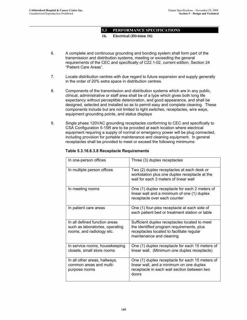
©Abbotsford Hospital & Cancer Centre Inc. Output Specifications – November 29, 2004 Unauthorized Reproduction Prohibited Section 5 – Design and Technical
5.3 PERFORMANCE SPECIFICATIONS 16. Electrical (Division 16)
145
6. A complete and continuous grounding and bonding system shall form part of the transmission and distribution systems, meeting or exceeding the general requirements of the CEC and specifically of C22.1-02, current edition, Section 24 “Patient Care Areas”.
7. Locate distribution centres with due regard to future expansion and supply generally in the order of 20% extra space in distribution centres.
8. Components of the transmission and distribution systems which are in any public, clinical, administrative or staff area shall be of a type which gives both long life expectancy without perceptible deterioration, and good appearance, and shall be designed, selected and installed so as to permit easy and complete cleaning. These components include but are not limited to light switches, receptacles, wire ways, equipment grounding points, and status displays
9. Single phase 120VAC grounding receptacles conforming to CEC and specifically to CSA Configuration 5-15R are to be provided at each location where electrical equipment requiring a supply of normal or emergency power will be plug connected, including provision for portable maintenance and cleaning equipment. In general receptacles shall be provided to meet or exceed the following minimums:
Table 5.3.16.6.3.8 Receptacle Requirements
In one-person offices Three (3) duplex receptacles
In multiple person offices Two (2) duplex receptacles at each desk or workstation plus one duplex receptacle at the wall for each 3 meters of linear wall
In meeting rooms One (1) duplex receptacle for each 2 meters of linear wall and a minimum of one (1) duplex receptacle over each counter
In patient care areas One (1) four-plex receptacle at each side of each patient bed or treatment station or table
In all defined function areas such as laboratories, operating rooms, and radiology etc.
Sufficient duplex receptacles located to meet the identified program requirements, plus receptacles located to facilitate regular maintenance and cleaning
In service rooms, housekeeping closets, small store rooms
One (1) duplex receptacle for each 15 meters of linear wall. (Minimum one duplex receptacle)
In all other areas, hallways, common areas and multi-purpose rooms
One (1) duplex receptacle for each 15 meters of linear wall, and a minimum on one duplex receptacle in each wall section between two doors
©Abbotsford Hospital & Cancer Centre Inc. Output Specifications – November 29, 2004 Unauthorized Reproduction Prohibited Section 5 – Design and Technical
5.3 PERFORMANCE SPECIFICATIONS 16. Electrical (Division 16)
146
Receptacles in patient care areas shall be Hospital Grade. Receptacles in all other areas shall be Specification Grade. Residential Grade receptacles shall not be permitted. All receptacles shall have stainless steel cover plates. Grouped receptacles shall have a single cover plate covering the whole group. Receptacles on normal power circuits shall be white, receptacles on emergency power circuits shall be red, and receptacles on UPS circuits shall be red and identified as UPS circuits using lamacoid or similar labels.
All receptacles shall be permanently marked with lamacoid labels identifying the circuit and panel number.
16.7 METERING
16.7.1. Overriding Principles
1. Digital metering shall be supplied to provide detailed information about power quality and power consumption throughout the Facility.
2. Any metering which is to be used to charge tenants or agencies for their power consumption shall be “revenue certified”.
3. The metering system shall be a networked system, with terminals for maintenance and plant administration, and data transfer to the Facility’s Building Management System.
16.7.2. Quality Requirements
1. Project Co shall comply with all Applicable Standards including, but not limited to, the BC Building Code and those standards in Appendix 5A Technical Reference Standards. Refer to Output Specifications Section 5 – Design and Technical: Subsection 5.2.6.2. Other Codes and Standards for information regarding Appendix 5A Technical Reference Standards.
16.7.3. Performance Requirements
1. The metering system shall provide easily read locally displayed information for all distribution at primary voltage and for each secondary distribution centre..
2. Historical data from the metering system network shall be stored and shall be capable of generating user configurable electronic and printed reports on demand.
3. The metering system shall not be dependant on power from the metered circuit for its operation, and shall be supported by a backup power source or sources, which ensure operation when the metered circuit is de-energized.
4. The metering system shall, at a minimum, provide the following information about each metered circuit: Phase-to-Phase Voltage (all phases), Line-to-Neutral Voltage (all phases), Phase Current (all phases and neutral), KW, KVA, Power Factor, KWH, VAR hours.
5. The meters shall be power quality type able to read harmonics and surges / sags.
©Abbotsford Hospital & Cancer Centre Inc. Output Specifications – November 29, 2004 Unauthorized Reproduction Prohibited Section 5 – Design and Technical
5.3 PERFORMANCE SPECIFICATIONS 16. Electrical (Division 16)
147
6. Electrical consumption meters will be connected to the Building Management System.
16.8 GROUNDING AND BONDING
16.8.1. Overriding Principles
1. In general all electrical equipment and systems in the Facility shall be properly bonded and grounded except for equipment that is specifically intended to be ungrounded. .
2. Grounding and bonding shall provide for safety of personnel and for protection against damage to equipment or property in the case of a fault occurring in any of the equipment or systems.
16.8.2. Quality Requirements
1. Project Co shall comply with all Applicable Standards including, but not limited to, the BC Building Code and those standards in Appendix 5A Technical Reference Standards. Refer to Output Specifications Section 5 – Design and Technical: Subsection 5.2.6.2. Other Codes and Standards for information regarding Appendix 5A Technical Reference Standards.
16.8.3. Performance Requirements
1. All conductors and all conducting components of electrical equipment which form part of the grounding and bonding systems in the Facility shall be of non-alloyed copper and aluminum.
2. Provide solid low resistance grounding and bonding systems in full compliance with the standards and regulations listed above.
3. In addition, provide equipotential grounding systems and equipment for patient care areas in compliance with the codes and regulations listed above. All metal in patient care rooms shall be bonded to the equipotential grounding system
16.9 SEISMIC REQUIREMENTS FOR ELECTRICAL SYSTEMS
16.9.1. Overriding Principles
1. Seismic restraint for all electrical equipment and components of electrical systems which is part of the building electrical systems in all parts of the facility will be seismically restrained to the post disaster standards in accordance with the applicable BC Building Code to prevent injury or hazard to persons and equipment and to retain equipment in a safe position in the event of a seismic disaster..
2. Seismic restraint systems and methods shall be selected to facilitate ease of maintenance and ease of replacement and reconfiguration of electrical equipment and systems and other equipment and building components.
©Abbotsford Hospital & Cancer Centre Inc. Output Specifications – November 29, 2004 Unauthorized Reproduction Prohibited Section 5 – Design and Technical
5.3 PERFORMANCE SPECIFICATIONS 16. Electrical (Division 16)
148
3. Seismic restraint systems and methods shall be selected to coordinate with the building Architecture and finishes. Components of seismic restraints shall, wherever practicable, be concealed from public view. Where concealment is not practicable the systems shall be designed to complement building Architecture and finishes.
16.9.2. Quality Requirements
1. Project Co shall comply with all Applicable Standards including, but not limited to, the BC Building Code and those standards in Appendix 5A Technical Reference Standards. Refer to Output Specifications Section 5 – Design and Technical: Subsection 5.2.6.2. Other Codes and Standards for information regarding Appendix 5A Technical Reference Standards.
2. Seismic restraints shall meet or exceed the requirements of the current edition of the B.C. Building Code. Where the Code identifies specific requirements for Health Care Facilities and/or Post Disaster areas within this building, those requirements shall be met or exceeded.
3. Where possible, seismic restraint design shall follow the recommended practices published in the Seismic Restrain Standards Manual (AIBC) as adopted by the Electrical Contractors Association of BC.
4. Where possible, seismic restraint design shall follow CSA 5832-01 Guidelines for Seismic Risk Reduction of Operational and Functional Components.
16.9.3. Performance Requirements
1. All electrical equipment and components of electrical systems that have the potential to cause injury or damage during or following a seismic event shall be seismically restrained.
2. Seismic restraint systems shall either be designed by a professional engineer registered in British Columbia, or, where an identified pre-designed standard restraint device or system exists for a particular item, that equipment may be used provided that written confirmation of its acceptability for the installation is provided by a professional engineer registered in British Columbia.
16.10 POWER QUALITY
16.10.1. Overriding Principles
1. An overall power quality which assures suitable conditions for operation of all electrical and electronic equipment throughout Facility shall be established and maintained
2. A wide variety of electrical and electronic equipment types will be in use in the Facility. Equipment and systems which assure that electrical equipment and systems will not be harmed or impaired either by external events or conditions, such as lightning and disturbances on the utility service, or by internal events or conditions generated within the Facility by characteristics of systems and equipment are to be provided.
©Abbotsford Hospital & Cancer Centre Inc. Output Specifications – November 29, 2004 Unauthorized Reproduction Prohibited Section 5 – Design and Technical
5.3 PERFORMANCE SPECIFICATIONS 16. Electrical (Division 16)
149
16.10.2. Quality Requirements
1. Project Co shall comply with all Applicable Standards including, but not limited to, the BC Building Code and those standards in Appendix 5A Technical Reference Standards. Refer to Output Specifications Section 5 – Design and Technical: Subsection 5.2.6.2. Other Codes and Standards for information regarding Appendix 5A Technical Reference Standards.
2. Power quality shall meet or exceed the IEEE established standards for power quality, including but not limited to Harmonic Mitigated transformers provided where deemed necessary by Project Co. and the following:
• IEEE Standard 519 - Harmonics
• IEEE Standard 1250 - Voltage Quality
• IEEE Standard 1346 - Recommended Practice for Evaluation Electric Power System Compatibility with Electronic Process Equipment
3. Methods and equipment consistent with IEEE Standard 1159 - Monitoring Electric Power Quality shall be provided by installing 1 built-in power quality meter at the BCH incoming service. All other system testing will be done by a technician using portable test equipment. Filters, TVSS, etc will be provided as required. Power quality meters will be provided at all secondary distribution centres. Project Co to provide transient suppression to panels as required, used to prove that power quality meets or exceeds published standards.
16.10.3 Performance Requirements
1. The facilities are to include equipment specifically designed to control and remove all adverse power quality conditions that could damage or impair function of any of the electrical or electronic equipment, which will be in use in the facilities. Adverse power quality conditions to be addressed include but are not limited to voltage spikes, dips and droops, transients, harmonics, power factor and radio frequency interference.
2. Project Co shall be able to demonstrate to Health Co at any time that there are no potentially harmful power conditions present and that equipment intended to guard against such conditions is in proper working order.
16.11 LIGHTING
16.11.1. Overriding Principles
1. Light of excellent character and quality and in appropriate quantity is to be provided throughout the Abbotsford Hospital and Cancer Centre.
2. Lighting shall be energy efficient.
3. Appropriate lighting shall optimize use of daylight and shall be achieved through a combination of natural light and luminaries and controls as further described in Output Specifications Section 5 – Design and Techncial: Subsection 5.3.16.12 Lighting Control.
©Abbotsford Hospital & Cancer Centre Inc. Output Specifications – November 29, 2004 Unauthorized Reproduction Prohibited Section 5 – Design and Technical
5.3 PERFORMANCE SPECIFICATIONS 16. Electrical (Division 16)
150
4. Exterior and interior lighting shall create a safe and secure environment for patients and staff.
16.11.2. Quality Requirements
1. Project Co shall comply with all Applicable Standards including, but not limited to, the BC Building Code and those standards in Appendix 5A Technical Reference Standards. Refer to Output Specifications Section 5 – Design and Technical: Subsection 5.2.6.2. Other Codes and Standards for information regarding Appendix 5A Technical Reference Standards.
2. Lighting shall comply with all characteristics recommended by the Illuminating Engineering Society of North America (IESNA) CP29 Lighting for Health Care Facilities and CAN/CSA Z317.5 Illumination in Health Care Facilities
3. Lighting shall comply with Workers Compensation Board (WCB) regulations and bulletins.
4. Lighting energy consumption shall comply with ASHRAE Standard 90.1 and shall exceed that standard by as much as possible with a reasonable standard being a 10% reduction range while still meeting program requirements.
16.11.3. Performance Requirements
1. Selection of luminaires and light sources shall meet the stated energy efficiency and quality and quantity requirements, but shall also meet the objective of providing both a comfortable working environment and an environment conducive to healing and recovery. Light levels with contributions only from artificial light need meet the (IESNA) CP29 Lighting for Health Care Facilities and CAN/CSA Z317.5 Illumination in Health Care facilities. Please reference Output Specifications Section 7 - Equipment for additional exam lights.
Table 5.3.16.11.3.1 Light
Requirements
AREA / ACTIVITY Comments Rehabilitation Work areas general Exercise rooms/therapy room Multilevel control Radiation Treatment Rooms Patient treatment Multilevel control Setup Cleanup Imaging Suite Patient treatment Dimmable Setup Multilevel control Cleanup Chemotherapy Treatment Unit Multilevel control Renal Services

©Abbotsford Hospital & Cancer Centre Inc. Output Specifications – November 29, 2004 Unauthorized Reproduction Prohibited Section 5 – Design and Technical
5.3 PERFORMANCE SPECIFICATIONS 16. Electrical (Division 16)
151
General AREA / ACTIVITY Comments Patient care area Multilevel control Emergency Department General Multilevel control Examination / Treatment (fixed) Examination & Treatment Rooms General Multilevel control Exam / treatment May be portable Hand wash locations Surgical Suite Operating room, general Multilevel control Operating table Operating room light Scrub areas Instruments and sterile supply areas Clean up Patient Holding Areas Critical Care Areas General (entire room) Examination (local) fixed Patient Rooms
Observation Patient/Staff control switching
Critical examination May be portable Reading location (reading lamp or overbed fixture)
Patient/Staff control switching
Maternal Child Delivery suite LBRP rooms Special care nursery Nursing Stations General Desk Medication station Pharmacy General Multilevel control

©Abbotsford Hospital & Cancer Centre Inc. Output Specifications – November 29, 2004 Unauthorized Reproduction Prohibited Section 5 – Design and Technical
5.3 PERFORMANCE SPECIFICATIONS 16. Electrical (Division 16)
152
AREA / ACTIVITY Comments Laboratories General Task lighting Morgue Autopsy room Task lighting for table Morgue, general Sterile Processing Services Work areas Processed storage Charting Corridors Day Night Food Services General Dish washing Assembly Food storage Dining room Multilevel control General Areas Stairways Storage rooms Offices Lobbies
Day Building Management Control
Night Waiting areas
Day Building Management Control
Night Storage Locker rooms Maintenance department Wash rooms Utility rooms Housekeeping closet Exterior walkways
Parking areas Control light spill to no more than 5% off site
Main Entrances Other Exterior Entrances
©Abbotsford Hospital & Cancer Centre Inc. Output Specifications – November 29, 2004 Unauthorized Reproduction Prohibited Section 5 – Design and Technical
5.3 PERFORMANCE SPECIFICATIONS 16. Electrical (Division 16)
153
2. Special task lighting designed for the types of procedures conducted shall be provided as per Section 7 for rooms and areas where treatment is provided and rooms and areas where specialized analytical or diagnostic work is carried out.
3. Luminaires in all areas shall be so constructed as to require minimal cleaning and shall permit practical and easy access and disassembly. All lighting components shall be institutional grade.
4. Lighting in areas where computer terminals and similar screens will be used shall be specifically designed to eliminate indirect glare and shall meet or exceed the IES recommended cut off for VDT luminaries.
5. Lighting in technology conference rooms and video conferencing facilities shall maximize viewing of monitors and screens and shall provide suitable illumination of people being viewed. The lighting system shall allow a minimum of 4 preset levels for different types of conferences.
6. Exterior luminaires shall be vandal resistant.
7. Use of battery-operated unit emergency lighting shall be minimized, however battery-operated unit emergency lighting or and acceptable alternative shall be provided as a second level of emergency lighting in the most critical areas.
8. Lighting systems above patients shall be located to minimize glare.
9. Lighting in main lobbies, waiting areas and the main entrances are features of the building and shall be designed of high quality products aesthetically pleasing to the public and staff.
16.12 LIGHTING CONTROL
16.12.1. Overriding Principles
1. Lighting controls shall comprise a significant part both of the energy management of the facilities and of the flexibility required to adjust lighting to suit functions and activities.
2. Lighting control shall permit simple and integrated control of lighting; controls shall be easily operated and conveniently and appropriately located for each area and function.
3. Staff and patients shall have the ability to control the lighting in their environment. All patient rooms shall have staff and patient lighting control. All other rooms shall have staff lighting control.
4. Occupancy sensors and daylight control systems shall be utilized to maintain light levels at appropriate levels based upon the occupancy of the room and the quantity of daylight.
16.12.2. Quality Requirements
©Abbotsford Hospital & Cancer Centre Inc. Output Specifications – November 29, 2004 Unauthorized Reproduction Prohibited Section 5 – Design and Technical
5.3 PERFORMANCE SPECIFICATIONS 16. Electrical (Division 16)
154
1. Project Co shall comply with all Applicable Standards including, but not limited to, the BC Building Code and those standards in Appendix 5A Technical Reference Standards. Refer to Output Specifications Section 5 – Design and Technical: Subsection 5.2.6.2. Other Codes and Standards for information regarding Appendix 5A Technical Reference Standards.
16.12.3. Performance Requirements
1. Where lighting controls are required to be located in areas accessible to the public, they shall be protected from unauthorized operation.
2. All manually operated lighting controls shall be of a type, which can be completely cleaned and disinfected without requiring any disassembly. Manually operated controls shall not be deteriorated or otherwise adversely affected by frequent cleaning and disinfections.
3. Lighting controls in locations where they may be subjected to excessive moisture or to chemicals that might cause deterioration are to be rated specifically for the application.
4. A multitude of lighting control options will be utilized. Lighting control for exterior lighting, common area lighting and lighting in other areas such as offices and conference rooms shall be energy managed with some of these systems connected to the building energy management and HVAC Building Management System (BMS) where appropriate.
5. Lighting in open areas and common areas shall be appropriately zoned and subdivided to permit energy management and appropriate control and variation of light levels.
6. Control of lighting in technology conference rooms and in videoconference facilities shall be integrated with the equipment controls and control stations in the room so as to permit the conference manager to vary the lighting as required for different activities.
16.13 MAJOR MEDICAL EQUIPMENT
16.13.1. Overriding Principles
1. Numerous items of major medical equipment will be supplied and installed by Project Co in the Facility. Provide all electrical requirements for connection, operation and monitoring and control of this major medical equipment.
16.13.2. Quality Requirements
1. Project Co shall comply with all Applicable Standards including, but not limited to, the BC Building Code and those standards in Appendix 5A Technical Reference Standards. Refer to Output Specifications Section 5 – Design and Technical: Subsection 5.2.6.2. Other Codes and Standards for information regarding Appendix 5A Technical Reference Standards.

©Abbotsford Hospital & Cancer Centre Inc. Output Specifications – November 29, 2004 Unauthorized Reproduction Prohibited Section 5 – Design and Technical
5.3 PERFORMANCE SPECIFICATIONS 16. Electrical (Division 16)
155
16.13.3. Performance Requirements
1. Each item of equipment shall be installed and electrically connected for proper and full operation.
2. Electrical characteristics of this equipment, including but not limited to voltage, wattage, phase, demand, inrush, frequency, connection method and control and monitoring requirements shall be confirmed by the designer and provided for.
3. Space, access and ventilation requirements and other operation critical characteristics of this equipment shall be provided for and outlets and connection points shall be located correctly for installation and so as to permit proper and safe isolation for servicing and disconnection for removal or replacement.
4. The major medical equipment which requires emergency power shall be connected to the appropriate emergency power sources and emergency power sources and distribution equipment shall be appropriately sized to supply this equipment with an additional capacity for a minimum of 50% of the initially required capacity to allow for addition of future medical equipment.
16.14 ENERGY MANAGEMENT
16.14.1. Overriding Principles
1. The integrated energy management system shall monitor, record, report on and control energy from all sources which supply energy to the Facility.
2. The Project Co energy management systems and equipment shall be flexible, controllable, and shall form an integral part of the buildings design and construction.
16.14.2. Quality Requirements
1. Project Co shall comply with all Applicable Standards including, but not limited to, the BC Building Code and those standards in Appendix 5A Technical Reference Standards. Refer to Output Specifications Section 5 – Design and Technical: Subsection 5.2.6.2. Other Codes and Standards for information regarding Appendix 5A Technical Reference Standards.
16.14.3. Performance Requirements
1. The energy management system shall be in accordance with the requirements as set out in Section 4, Facilities Management Services Output Specification.
16.15 MECHANICAL EQUIPMENT CONNECTIONS
16.15.1. Overriding Principles
©Abbotsford Hospital & Cancer Centre Inc. Output Specifications – November 29, 2004 Unauthorized Reproduction Prohibited Section 5 – Design and Technical
5.3 PERFORMANCE SPECIFICATIONS 16. Electrical (Division 16)
156
1. Electrical power and control and monitoring connections shall be provided to all mechanical equipment as required for proper operation, protection and maintenance of the equipment. Materials and installation methods shall result in safe reliable and serviceable mechanical equipment and systems in the Facility.
16.15.2. Quality Requirements
1. Project Co shall comply with all Applicable Standards including, but not limited to, the BC Building Code and those standards in Appendix 5A Technical Reference Standards. Refer to Output Specifications Section 5 – Design and Technical: Subsection 5.2.6.2. Other Codes and Standards for information regarding Appendix 5A Technical Reference Standards.
16.15.3. Performance Requirements
1. Cables, connectors, conduit systems, fittings and hardware used to make connection to mechanical equipment shall be of institutional or industrial quality, and shall be so selected and installed as to provide for high levels of reliability, durability and ease of maintenance of the equipment
2. Connections made to motors and/or motor driven equipment or equipment with noticeable levels of vibration shall be of a type specifically designed to accommodate the vibration.
3. Connections to mechanical equipment shall be designed and installed to easily permit removal and replacement of the equipment and shall provide for the eventuality that equipment may be replaced in the future with upgraded and dissimilar equipment types.
4. Motor control centres, main feeders to motor control centres, and mechanical distribution centres shall be sized to accommodate the current mechanical equipment plus 50% spare capacity.
16.16 SPECIALTY SYSTEMS
16.16.1. Overriding Principles
1. Special electrical and technology and communications systems are required in the Facility and form essential parts of the complete Facility. (Refer to 5.3.17 for descriptions of these special systems.) Power supply, specially conditioned power and communication conduits and other electrical operational support equipment shall be supplied and installed in order to provide for all the requirements of permanent installations of these special electrical and electronic systems. .
16.16.2. Quality Requirements
1. Project Co shall comply with all Applicable Standards including, but not limited to, the BC Building Code and those standards in Appendix 5A Technical Reference
©Abbotsford Hospital & Cancer Centre Inc. Output Specifications – November 29, 2004 Unauthorized Reproduction Prohibited Section 5 – Design and Technical
5.3 PERFORMANCE SPECIFICATIONS 16. Electrical (Division 16)
157
Standards. Refer to Output Specifications Section 5 – Design and Technical: Subsection 5.2.6.2. Other Codes and Standards for information regarding Appendix 5A Technical Reference Standards.
16.16.3. Performance Requirements
1. Cables, connectors, conduit systems, fittings and hardware used to make connection to special equipment shall be of institutional or industrial quality, and shall be so selected and installed as to provide for high levels of reliability, durability and ease of maintenance of the equipment.
2. Connections to special equipment shall be designed and installed to easily permit removal and replacement of the equipment and shall provide for the eventuality that equipment may be replaced in the future with upgraded and dissimilar equipment types.
End of Electrical

©Abbotsford Hospital & Cancer Centre Inc. Output Specifications – November 29, 2004 Unauthorized Reproduction Prohibited Section 5 – Design and Technical
5.3 PERFORMANCE SPECIFICATIONS 16. Electrical (Division 16)
158
Page left blank for pagination
©Abbotsford Hospital & Cancer Centre Inc. Output Specifications – November 29, 2004 Unauthorized Reproduction Prohibited Section 5 – Design and Technical
5.3 PERFORMANCE SPECIFICATIONS 17. Technology And Communications Systems
(Division 17)
159
17. TECHNOLOGY AND COMMUNICATIONS SYSTEMS (DIVISION 17)
17.1 BASIC REQUIREMENTS
17.1.1. Overriding Principles
1. Technology and communications systems shall be provided to assist staff, patients and the public with dissemination of all forms of information. Information transfer is an essential part of providing care in a health centre and the timely, accurate delivery of information is one of the essential services of the proponent.
2. All media types will be utilized including but not limited to data, voice, video and paging. The appropriate choice of the media type can better enable the health centre to fulfil its overall role within the community of delivery of preventative as well as interventional health services.
3. Confidentiality, privacy and security of information are the cornerstones to establishing trust between the public and the health centre. Project Co shall take all reasonable precautions when transferring information that it is confidential, delivered to the appropriate party, secure from unauthorized access and stored in a secure environment.
17.1.2. Quality Requirements
1. Project Co shall comply with all Applicable Standards including, but not limited to, the BC Building Code and those standards in Appendix 5A Technical Reference Standards. Refer to Output Specifications Section 5 – Design and Technical: Subsection 5.2.6.2. Other Codes and Standards for information regarding Appendix 5A Technical Reference Standards.
2. The latest technology of April 16, 2004 for transferring, securing, and storing information shall be utilized by the proponent. Health Co expects to receive the most current technology and systems available on the date of installation. However, it is understood that for the purposes of bidding only, Project Co will design and price the latest technology available April 16, 2004. To stay competitive, most suppliers incorporate evolving technology into their products without additional pricing. Therefore Variations would only arise if there was a change of products or standards – for example a change in wiring.
3. The latest Provincial and health authority standards shall be utilized by the proponent to transfer, secure, and store information.
4. All Provincial / Canadian laws pertaining to the transfer, storage of information in relation to medical services shall be followed by the proponent when they are directly or indirectly involved in the transfer or storage of medical information.
5. The Freedom of Information and Protection of Privacy Act (FOIPPA) shall govern dissemination of information.
6. Project shall comply with the Canadian Electrical Code.

©Abbotsford Hospital & Cancer Centre Inc. Output Specifications – November 29, 2004 Unauthorized Reproduction Prohibited Section 5 – Design and Technical
5.3 PERFORMANCE SPECIFICATIONS 17. Technology And Communications Systems
(Division 17)
160
7. Project shall comply with all applicable CSA Standards including but not limited to CSA C22.2, CSA Z32.99.
8. All equipment and materials shall be certified by CSA or ULC or other testing agency approved and accepted by the Safety Engineering Services (SES) and local authorities having jurisdiction, and shall bear the seal of the agency in clearly visible locations.
17.1.3. Performance Requirements
1. Project Co shall comply with all Applicable Standards including, but not limited to, the BC Building Code and those standards in Appendix 5A Technical Reference Standards. Refer to Output Specifications Section 5 – Design and Technical: Subsection 5.2.6.2. Refer Other Codes and Standards for information regarding Appendix 5A Technical Reference Standards.
2. The communications systems shall be proven technology, effectively used in other health facilities (preferably in the Fraser Health Authority or BC Cancer Agency), shall be easy to operate, and easy to maintain. Where needed, these systems shall integrate readily with the other systems in this Facility and with technology provided in other health facilities to allow Provincial wide communications.
3. Project Co shall be trained on the proper use and maintenance of all the systems provided in the Facility and shall be responsible for training / educating all clinical / non-clinical staff and where necessary the public on the proper use of these systems.
4. The systems chosen by the Project Co shall be chosen because they are cost effective, provide efficiencies for staff and patients, perform the necessary tasks sufficiently, are adaptable to change, flexible in implementation and are expandable to accommodate growth.
17.2 INTEGRATION WITH HEALTH AUTHORTIES
17.2.1. Overriding Principles
1. The Fraser Health Authority (FHA) and the BC Cancer Agency (BCCA) have their clinical staff providing comprehensive health services in the Facility. The communications systems and technological systems in the new Facility are to integrate with the existing and new communication systems and technology in the agency and the health authority to enable the efficient, and secure exchange of information between all the various facilities within these entities and the Facility.
2. The electronic health record (all patient information is stored electronically) is the standard both agencies have adopted. The facilities electronic systems are to allow for the transmission, storage, and retrieval of the electronic health record within the Facility and from / to all other FHA / BCCA facilities.
3. The FHA and BCCA have agreements with service providers (such as Telus) to assist in delivering information to and from their sites as well as upgrading and maintaining technology on each site. The Project Co is to become aware of the

©Abbotsford Hospital & Cancer Centre Inc. Output Specifications – November 29, 2004 Unauthorized Reproduction Prohibited Section 5 – Design and Technical
5.3 PERFORMANCE SPECIFICATIONS 17. Technology And Communications Systems
(Division 17)
161
service agreements and ensure that the technology they are providing can integrate with these service providers equipment and utilize the FHA’s and BCCA’s service agreements (extend them to this site) where it is economically advantages to do so.
17.2.2. Quality Requirements
1. Project Co shall comply with all Applicable Standards including, but not limited to, the BC Building Code and those standards in Appendix 5A Technical Reference Standards. Refer to Output Specifications Section 5 – Design and Technical: Subsection 5.2.6.2. Other Codes and Standards for information regarding Appendix 5A Technical Reference Standards.
2. All FHA and BCCA standards in effect at the time of installation of the communications and technology systems shall be observed.
3. All applicable IEEE, CSA, TIA / EIA, and BICSI standards shall be complied with.
4. All technology and communications systems supplied shall be compatible with and operate with the technology and communications systems utilized in the FHA’s and BCCA’s other facilities.
17.2.3. Performance Requirements
1. Project Co to provide technology and communications systems that integrate with the Health Authority’s existing systems and future new systems to allow seamless communications between other health facilities in the region and this Facility.
2. The systems to be integrated include but are not necessarily limited to video conferencing, telephones, all networks, patient entertainment, patient education, access control, CCTV, timing, intrusion detection, and specialized clinical equipment such as picture archiving and communication systems (PACS), cancer treatment systems, electronic registration, and dictation systems.
17.3 FIRE ALARM
17.3.1. Overriding Principles
1. Project Co shall construct a safe and code compliant Facility that includes a fire alarm system. The fire alarm system shall allow the proponent an early warning system in the event of a fire that will communicate the location of the fire.
2. The fire alarm system shall be one part of Project Co’s overall fire plan. A sprinkler system, policy and procedures, staff education, and the city and fire department liaison will compliment the system assisting the proponent in protecting staff and public in case of fire.
3. The fire alarm system shall annunciate on the wireless telephone system and on the building management system notifying selected staff of the alarm event.
©Abbotsford Hospital & Cancer Centre Inc. Output Specifications – November 29, 2004 Unauthorized Reproduction Prohibited Section 5 – Design and Technical
5.3 PERFORMANCE SPECIFICATIONS 17. Technology And Communications Systems
(Division 17)
162
17.3.2. Quality Requirements
1. Project Co shall comply with all Applicable Standards including, but not limited to, the BC Building Code and those standards in Appendix 5A Technical Reference Standards. Refer to Output Specifications Section 5 – Design and Technical: Subsection 5.2.6.2. Other Codes and Standards for information regarding Appendix 5A Technical Reference Standards.
2. The fire alarm system shall be designed and installed to meet the following standards.
2.1 Can / ULC S524 standard for installation of Fire Alarm Systems
2.2 Can / ULC S537 Standard for Verification of Fire Alarm Systems
2.3 Elevator Code CAN3-B44.
3. The system shall be the latest proven technology available at the time of installation.
17.3.3. Performance Requirements
1. Provide a fully addressable, two stage, computer based fire alarm system throughout the new Facility.
2. The fire command centre shall include the main panel, a personal computer with the latest monitoring software and control of all required elevators, mechanical systems and fire fighter phones.
3. Smoke and heat detectors shall be individually field programmable and include multiple elements for earliest detection, individually adjustable for ambient environmental conditions.
4. The sprinkler systems shall connect to the fire alarm system and provide full annunciation of all alarms and trouble conditions.
5. Audible annunciation shall be via a zoned overhead paging system that shall also act as the public address system, shall be accessible via microphone at the command centre and from any Facility phone via a telephone interface. Audible alert levels shall be 10dBA above ambient with minimum of 75dBA.
6. Train staff on operation of system and incorporate fire plan in training to alert staff to policy and procedures in case of fire alarm and safe gathering points in case of evacuation.
7. Visual annunciation shall be via building graphic annunciators, a computer workstation, room annunciators provided at all Care (nursing) stations (excluding care substations) and main control reception areas.
8. All alarms, trouble signals, other information shall be annunciated at the Facility management call centre location to allow project co the ability to manage the system from their main alarm monitoring centre.
©Abbotsford Hospital & Cancer Centre Inc. Output Specifications – November 29, 2004 Unauthorized Reproduction Prohibited Section 5 – Design and Technical
5.3 PERFORMANCE SPECIFICATIONS 17. Technology And Communications Systems
(Division 17)
163
9. Annunciation shall occur at the emergency response centre.
10. The system shall include pre-programmed voice messaging to automatically audibly annunciate the location of the alarm. All devices to be programmed into the message system.
17.4 NETWORK INTERFACE
17.4.1. Overriding Principles
1. Technology and communications systems provided by Project Co that are in a digital format may run on the Facility network and integrate with Health Co applications where they provide an advantage to staff and / or patients.
2. It is the intent of the Health Co that electronic patient information is available at the bedside to assist clinical staff in performing their duties. This information is to be available on portable devices and run over the wired or wireless network. It is the intent that the device display information such as nurses call, code blue, video conferencing, patient / staff education, and patient monitoring where this creates efficiencies for clinical staff. These systems are to integrate with the IT applications and run over the common network platform.
17.4.2. Quality Requirements
1. Project Co shall comply with all Applicable Standards including, but not limited to, the BC Building Code and those standards in Appendix 5A Technical Reference Standards. Refer to Output Specifications Section 5 – Design and Technical: Subsection 5.2.6.2. Other Codes and Standards for information regarding Appendix 5A Technical Reference Standards.
2. The technology and communications system are to be IP compatible and run over a standard Ethernet network.
3. Databases for these systems shall be HL7 compatible with an SQL open system architecture to allow key fields to be read from and written to the health authorities information technology software applications.
17.4.3. Performance Requirements
1. Servers for the technology and communication systems shall be a Microsoft compliant, and shall be from a common manufacturer where possible.
2. The servers shall be the latest technology (Intel Pentium latest model or similar) and shall interface to the Ethernet network via a 100mB network interface card.
©Abbotsford Hospital & Cancer Centre Inc. Output Specifications – November 29, 2004 Unauthorized Reproduction Prohibited Section 5 – Design and Technical
5.3 PERFORMANCE SPECIFICATIONS 17. Technology And Communications Systems
(Division 17)
164
17.5 NURSE CALL
17.5.1. Overriding Principles
1. Project Co shall supply and install nurse call systems in each patient care area in the new Facility. The nurse call system shall be the latest proven technology at the time of construction of the Facility. The nurse call system shall promote efficient operation for Health Co staff.
2. The nurse call system is the primary emergency communication device for patients to contact staff in each patient care or treatment room. It is also the primary communication device for Health Co staff to alert other staff that they need assistance in a patient room. Since it is a life safety system, it must have a reliability factor of greater than 99%.
3. Modern nurse call systems can take any alarm input and annunciate it for staff. Project Co shall design the nurse call system to integrate with other alarm systems to annunciate alarms that clinical staff need such as patient wandering, code red (fire), code white (panic duress), code blue (cardiac arrest), patient monitoring systems and monitoring equipment where it creates efficiencies for staff, creates a common alarm display, and is cost effective.
4. The nurse call system shall be capable of integrating with an annunciator on wireless staff communication devices (PDA’s or phones) for near instant alarm response. The wireless staff communication device shall be extremely simple to operate (no more than 2 buttons to answer a nurse call), be impact resistant and operate seamlessly with the nurse call system allowing two-way voice communication into all patient rooms.
5. The nurse call system shall be capable of future integration with systems such as Meditech and CAIS to allow automatic call up of the patient record on their wireless devices to give the clinical staff easy access to patient information.
6. Advanced nurse call system feature such as information display systems, room tracking systems (i.e. surgery, patient wards), electronic bulletin boards, nurse tracking, patient tracking, and call buttons located on bedside computers or wireless computers shall be examined by Project Co in their design and where efficiencies in process can be realized, these features shall be implemented.
7. The nurse call system shall be of the same manufacturer throughout and connected to the network to allow a server to track calls via nurse call management software. The call management software shall record all calls from all departments, response time and allow trending and report generation. The programming servers and staff communication device allocation server shall also reside on the network and allow any nursing station computer access to monitor status of the system and with the appropriate password implement programming changes.
17.5.2. Quality Requirements
1. Project Co shall comply with all Applicable Standards including, but not limited to, the BC Building Code and those standards in Appendix 5A Technical Reference Standards. Refer to Output Specifications Section 5 – Design and Technical:
©Abbotsford Hospital & Cancer Centre Inc. Output Specifications – November 29, 2004 Unauthorized Reproduction Prohibited Section 5 – Design and Technical
5.3 PERFORMANCE SPECIFICATIONS 17. Technology And Communications Systems
(Division 17)
165
Subsection 5.2.6.2. Other Codes and Standards for information regarding Appendix 5A Technical Reference Standards.
2. The nurse call systems shall be the latest proven product [*DELETION] or better, [*DELETION] or better [*DELETION] or better.
3. Installation shall comply with CSA C22.2 and CSA Z32.99.
4. All systems shall be from a single manufacturer and be the same model number from that manufacturer.
17.5.3. Performance Requirements
1. The nurse call systems shall be supplied and installed in each medical department that contains patient care areas. All nurse call systems shall have two-way voice capabilities as well as tone and light communication.
2. All patient care rooms, treatment rooms, patient dressing cubicles, emergency department, patient treatment areas, and bathrooms where patients may need to call for assistance shall have a patient call cord. The call cord shall be located for ease of access by the patient. A button only system shall be utilized in mental health.
3. All patient care rooms, treatment rooms and other rooms where staff may need to call for assistance shall have a staff emergency button. The button shall be located for ease of access by the staff.
4. All rooms where a nurse call device is installed shall have a multi-call classification dome light (minimum 4-lamps) to annunciate the calls. The dome light shall be located to provide staff the best possible view on the outside of the room where the nurse call stations are located.
5. All patient care rooms and patient bed or chair locations shall have a separate jack input for medical equipment monitoring or patient monitoring (such as bed exit).
6. All calls shall be annunciated at nurse call master stations located at the main nursing desk and / or reception desk. Master stations shall link together to allow shift programming (day/night) annunciation of calls at different nursing stations when and if nursing stations are unmanned. If there is no nursing station in department the nurse calls should annunciate at the reception of that department.
7. Each nurse call station shall be individually programmable to allow multiple call classification and priority levels. At minimum, nurse call alarms shall be normal patient call, staff emergency call, priority patient call, bathroom call, shower call, anaesthetic call, clean room call, porter call and shall be located in the appropriate room types. The call system shall allow for cascading of call to higher priorities if they are not answered, shall have time out call cascading if the calls are not cancelled and shall be able to be displayed on the nurse call master, the wireless phone, and any other type of call display.
8. Prior to programming system Project Co shall meet with Health Co staff to obtain functional programming requirements. Call assignments, wireless staff communication device assignments, priority levels, day night shift mode, call
©Abbotsford Hospital & Cancer Centre Inc. Output Specifications – November 29, 2004 Unauthorized Reproduction Prohibited Section 5 – Design and Technical
5.3 PERFORMANCE SPECIFICATIONS 17. Technology And Communications Systems
(Division 17)
166
annunciation locations, code blue response, other alarm systems response, Meditech interface capabilities, call display requirement, bulletin board requirements are just some of the programming issues. It is intended that the programming be simple but comprehensive.
9. Tone stations shall be provided in each department in sufficient quantities such that the calls can be heard from any location.
.
10. Locate all nurse call field panels in communication rooms as near as possible to the department they serve.
11. If possible, utilize structured Cat 6 cabling for all nurse call system devices.
12. Fault monitoring to be a standard feature of the nurse call system. Alarms such as communication fault, power fail, and CPU fault shall be standard features.
13. Project Co shall be able to have the systems serviced, install additional components or program system within 12 hours of call origin. Parts need to be available on extremely short notice to keep this life safety system operational in the event of an extended component failure.
14. If electronic patient beds with built in nurse call buttons, automatic TV muting, are being provided that allow connection of nurse call to the bed, provide appropriate jack and connect nurse call system into bed.
15. All nurse call systems shall be supplied power from the emergency power system and have at least 1 hour of battery supply.
17.6 WIRELESS STAFF COMMUNICATION SYSTEMS
17.6.1. Overriding Principles
1. Staff to Staff communications is an essential component of achieving optimum healthcare in the Facility. This is accomplished in many ways including conventional telephones, emails, and intercom. A key new strategy for staff to staff communication is wireless telephone and / or wireless personal digital assistants (PDA’s).
2. Both Health Co staff and Project Co staff will need wireless portable communication devices for fast effective two-way voice communication. It is preferred that a common system be utilized throughout the Facility to allow Health Co staff easy access to Project Co staff and vice versa, but Project Co staff may utilize different system such as portable radios if it is not cost effective to provide a common system.
©Abbotsford Hospital & Cancer Centre Inc. Output Specifications – November 29, 2004 Unauthorized Reproduction Prohibited Section 5 – Design and Technical
5.3 PERFORMANCE SPECIFICATIONS 17. Technology And Communications Systems
(Division 17)
167
3. All Health Co staff will not need the wireless staff communication devices. Health Co staff who require portable communication devices are those who will require it for nurse call annunciation, need them for access to portable clinical software applications, those staff who are often on the move and need access to other staff, have no fixed office location such as OR staff and all doctors and nurse managers.
4. The wireless system shall function throughout the entire Facility. The design goal is full coverage throughout the facility. A site survey will be conducted to identify dead spots. A remedy will be recommended to Health Co for acceptance at no additional cost. This may include adding antennas to be installed in sensitive areas such as operation theatres, medical imaging and radiology rooms.
5. The wireless system shall integrate with the nurse call system, the main telephone PABX system, voice mail system, dictation system, and the other data network system. It shall be able to access Meditech and CAIS applications. Each wireless device shall offer the full functionality of a standard hardwired telephone handset.
6. Cost efficiencies need to be found for staff communication systems. Several systems such as telephone, wireless telephone, and intercom have similar functionality. A backup communication system is needed in the Facility in case the telephone PBX fails. Project Co is to promote cost efficiencies by reducing redundancy in functions across systems.
17.6.2. Quality Requirements
1. Project Co shall comply with all Applicable Standards including, but not limited to, the BC Building Code and those standards in Appendix 5A Technical Reference Standards. Refer to Output Specifications Section 5 – Design and Technical: Subsection 5.2.6.2. Other Codes and Standards for information regarding Appendix 5A Technical Reference Standards.
2. The wireless staff communication system shall meet the IEEE 802.11x standards and allow sufficient bandwidth to display clinical data.
3. The wireless staff communication system shall be the latest proven technology from a recognized leader in the industry providing all necessary functionality.
4. The wireless staff communication system shall provide standard telephone features as well as IP addressing and voice over IP.
5. The Wireless signalling is to be at a frequency or amplitude to not interfere with any medical equipment.
6. Wireless data security encryption techniques are to be employed by the system.
17.6.3. Performance Requirements
1. Project Co shall provide a complete wireless staff to staff communication system that will allow staff to place calls from wireless handheld devices and initiate a two-way voice conversation without the need to connect to the telephone PABX.
©Abbotsford Hospital & Cancer Centre Inc. Output Specifications – November 29, 2004 Unauthorized Reproduction Prohibited Section 5 – Design and Technical
5.3 PERFORMANCE SPECIFICATIONS 17. Technology And Communications Systems
(Division 17)
168
2. System to consist of a head end CPU, application server, antennae base stations, line cards, software and wireless handheld devices. Antennae base stations are to be located in concealed areas throughout the Facility to provide full coverage with no dead spots.
3. System is to connect directly to the PABX telephone switch to allow each wireless handheld communication device the same functionality as a wired phone. Project Co to include additional line cards for the PABX to provide the functionality. All wireless handheld devices shall be able to have outside telephone access.
4. System server to include application software for full programming as well as gateway software to integrate with the nurse call system and other alarm systems to annunciate all necessary local alarms on the wireless handset.
5. Wireless handheld devices to automatically log onto system. No manual intervention is required.
6. Project Co shall meet with clinical staff and determine programming requirements such as phone groups, personal profiles, extensions, long distance access, dialing plan, nurse call assignment plan, text messaging, web access, email access, encryption requirements and fully program system.
7. Handheld devices to be battery powered and each one to come with battery and charger. Fully charged battery to last for minimum of 8 hours of talk time. Handheld devices to include full keyboard, an LCD 60 character display, IP address, wireless network card, and soft keys.
8. Locate wireless CPU in main communication room along with applications servers. All antennae base stations to mount concealed in ceilings throughout the Facility. Power for system to come from a small separate uninterruptible power supply providing 24 hours of continuous power. UPS to be fed from emergency power distribution.
9. Wiring for system to be part of category 6 structured cabling plant.
10. The application server shall be the same as the minimum server standard identified in Output Specifications Section 6 – IT/TEL Services: Subsection 6.4 End-Use Devices and shall be connected to the network such that other workstations (on nursing desks) can access this application program.
17.7 PUBLIC ADDRESS
17.7.1. Overriding Principles
1. The Facility requires an overhead paging system allowing selected staff the ability to communicate to other staff, patients, and the public.
©Abbotsford Hospital & Cancer Centre Inc. Output Specifications – November 29, 2004 Unauthorized Reproduction Prohibited Section 5 – Design and Technical
5.3 PERFORMANCE SPECIFICATIONS 17. Technology And Communications Systems
(Division 17)
169
2. This paging system shall form part of the fire alarm system and will utilize the amplifiers, mixers, microphones, and speakers of the fire alarm system. The paging system shall connect to the telephone system allowing any telephone to page in the Facility.
3. In general, the Facility’s communication requirements are to be met without using the overhead paging system. This system shall be utilized only for emergency calls when other communications systems have not worked or when general announcements are needed to communicate with staff or the public.
17.7.2. Quality Requirements
1. Project Co shall comply with all Applicable Standards including, but not limited to, the BC Building Code and those standards in Appendix 5A Technical Reference Standards. Refer to Output Specifications Section 5 – Design and Technical: Subsection 5.2.6.2. Other Codes and Standards for information regarding Appendix 5A Technical Reference Standards.
2. The system shall meet ULC 537 and NFPA standards.
3. During fire alarm signalling, the system shall provide 10 dB above ambient or at minimum 75 dB in all areas of the Facility.
17.7.3. Performance Requirements
1. The public address system shall consist of amplifiers, mixers, speakers, zone paging modules, telephone interface modules, microphones, and other devices as needed to facilitate overhead paging in the Facility.
2. The public address system shall form part of the fire alarm system.
3. The telephone system shall interface to the public address system allowing any wired or wireless telephone access to page in the Facility. The paging system shall be accessible by dialing certain codes into the telephone system to page zones (areas of the Facility) or the entire Facility.
4. The paging system shall be a constant voltage system with speakers placed to cover all areas and provide at minimum 60 dB in all areas of the Facility. Amplifiers to be sized to drive all speakers in each zone plus 20% spare capacity for future growth. The mixers to accommodate all inputs and provide the appropriate signal to the amplifiers and speakers.
5. The system is to be zoned to allow paging into individual departments. It is necessary to drive different inputs into each department, for instance the Ambulatory Care Cancer Centre component may want music inputs (CD player, radio tuner, tape player) for music therapy component. These inputs to be overridden when paging or fire alarm takes place. Each zone to be accessible by telephone to allow department paging or Facility wide paging. A page in one department shall be isolated to that department.
©Abbotsford Hospital & Cancer Centre Inc. Output Specifications – November 29, 2004 Unauthorized Reproduction Prohibited Section 5 – Design and Technical
5.3 PERFORMANCE SPECIFICATIONS 17. Technology And Communications Systems
(Division 17)
170
6. Speakers to be recessed in ceiling whenever possible and come complete with speaker back box. Speakers to be aesthetically pleasing. Speakers in service rooms (mechanical and electrical rooms) where ambient noise level is high shall be sized to provide at least 10 dB more sound pressure than the ambient noise level. Minimum sound pressure level for fire alarm is 75 dB, normal level for music 54 dB, normal level for paging 60 dB.
7. Music source inputs in the Ambulatory Care Centre shall be located at nursing stations to allow clinical staff to activate music.
8. Amplifiers to be distributed such that the failure of one set of amplifiers does not cause the entire system to malfunction. Other sets of amplifiers to operate properly even if one set malfunctions.
9. Telephone access to paging shall be nearly instantaneous (less than 1 second) from the time the telephone dials to the time the message is sent over the speakers.
17.8 MECHANICAL CONTROL SYSTEMS INTERFACE
17.8.1. Overriding Principles
1. Project Co will be providing a fully functional building management system whose primary function will be to control the mechanical systems within the Facility. Another key function of this system is to display building related alarms at the Facility Management Call Centre / Control Centre. The building management shall interface with building electrical and communication systems. Where it is cost effective this system is to be utilized to annunciate security alarms, freezer alarms, lab alarms, medical equipment alarms, UPS, generator, and switchgear alarm, and control the building and site lighting (for energy management reasons) via its software program.
2. The system is to be used for energy management functions as well as energy related data acquisition and trending. The digital meters monitoring the electrical power systems are to be connected to this system.
17.8.2. Quality Requirements
1. Project Co shall comply with all Applicable Standards including, but not limited to, the BC Building Code and those standards in Appendix 5A Technical Reference Standards. Refer to Output Specifications Section 5 – Design and Technical: Subsection 5.2.6.2. Other Codes and Standards for information regarding Appendix 5A Technical Reference Standards.
17.8.3. Performance Requirements
1. Refer to Output Specifications Section 5 – Design and Technical: Subsection 5.3.15.17 Controls for details of Building Management System.
©Abbotsford Hospital & Cancer Centre Inc. Output Specifications – November 29, 2004 Unauthorized Reproduction Prohibited Section 5 – Design and Technical
5.3 PERFORMANCE SPECIFICATIONS 17. Technology And Communications Systems
(Division 17)
171
17.9 STRUCTURED CABLING
17.9.1. Overriding Principles
1. Access to information is a key component of providing quality health care in the new Facility. A cabling infrastructure is required throughout the Facility that allows computers, telephones, video conferencing equipment and other digital End-Use Devices to access the various IT, Telecommunication, and digital video networks.
2. The cabling infrastructure does not differentiate on the type of End-Use Device that connects to it. The cabling infrastructure is to be universal and allow all forms of End-Use Devices access to the different system types.
3. The cabling infrastructure is to be designed by a Registered Certified Data Designer (RCDD) or professional engineer and is to be the latest TIA / EIA solution. The current solution is a category 6 cable infrastructure.
4. All cables are to terminate in communication rooms sized in accordance with the TIA / EIA standard. Maximum cable distance form room outlet to communication room shall be 70 meters.
5. Communication rooms are to serve the floor they are on and are to be placed to maximize the area they serve.
6. Cable types to be unshielded twisted pair and fibre optic multimode and single mode. The bandwidth requirements and distance limitations will determine the type of cable installed.
17.9.2. Quality Requirements
1. Project Co shall comply with all Applicable Standards including, but not limited to, the BC Building Code and those standards in Appendix 5A Technical Reference Standards. Refer to Output Specifications Section 5 – Design and Technical: Subsection 5.2.6.2. Other Codes and Standards for information regarding Appendix 5A Technical Reference Standards.
2. The conduits, pathways, room layouts, and design are to comply with the TIA / EIA-569 Commercial Building Standard for Telecommunications Pathway and Spaces, latest version.
3. The cabling design and installation shall comply with the TIA / EIA – 568B.1, B.2 and B.3 Commercial Building Cabling Standards and Optical Fibre Cabling Standards.
4. Testing of the fibre optic cable shall meet the TIA / EIA 526-7, 14 standards for Optical Power Loss measurement of single mode and multimode fibre cable plant.
5. The management and administration of the cabling plant shall be done in accordance with the TIA / EIA 606 standard – the Administration Standard for the Telecommunications Infrastructure of Commercial Buildings.

©Abbotsford Hospital & Cancer Centre Inc. Output Specifications – November 29, 2004 Unauthorized Reproduction Prohibited Section 5 – Design and Technical
5.3 PERFORMANCE SPECIFICATIONS 17. Technology And Communications Systems
(Division 17)
172
6. The grounding of the conduit pathways and components is to meet the TIA / EIA 607 Standard – Commercial Building Grounding and Bonding Requirements for Telecommunication.
7. The structured cabling component shall be of the same manufacturer and shall be supplied by one of the recognized industry leaders. The system shall be installed by a data contactor who is certified by one of the industry leaders consistent with the manufacturer’s best warranty.
17.9.3. Performance Requirements
1. Project Co is to provide and install a complete category 6 structured cabling solution throughout the Facility. If a category better than category 6 is the latest standard at the time of ordering, it shall be priced and presented to Health Co. to determine if they want to utilize the latest standard.
2. A star wired cabling approach shall be utilized to wire all outlet locations back to communication rooms and all communication rooms back to the main computer room and main telephone room.
3. All rooms that have or are anticipated to have data, phone, video, or other End-Use Devices shall have cable system drops ran back to the communication rooms. It is anticipated that only storage, clean/dirty supply rooms, and some corridors will not have cable system drops.
4. All rooms that have cable system drops shall have at minimum 10% additional drops, all conduit pathways shall have minimum 100% spare capacity, all cable trays shall have at minimum 300% spare capacity and all communication rooms shall have 500% spare capacity (indicating that each communication room must have enough room for 500% more cable drops). All cabling shall be run in conduit and cable tray.
5. All ceiling spaces shall have cable system drops for wireless network access points, information display systems, and other ceiling mounted digital devices.
6. Fibre optic cabling shall be utilized to connect communication rooms to the main computer room and the core network room. Both multimode and single mode fibre shall be provided. Provide at minimum 200% spare fibre strand terminations in each communication room. Fibre optic cabling shall also be provided for rooms requiring video streaming, in digital operating rooms and area where bandwidth requirements necessitate it be used.
7. All cable drops shall be terminated at both ends. The proper flame spread rating shall be provided for the cabling system.
8. Multi-conductor twisted pair telephone style riser cables and multi-standard fibre cables shall be run from the main telephone room to each communication room to connect the telephone switch to the telephone handsets. Provide 100% spare capacity in each communication room.
9. Patch cables for all End-Use Devices shall be provided in sufficient quantity to make each device operational plus 10% spare. Patch cable shall allow complete connection from end to end.
©Abbotsford Hospital & Cancer Centre Inc. Output Specifications – November 29, 2004 Unauthorized Reproduction Prohibited Section 5 – Design and Technical
5.3 PERFORMANCE SPECIFICATIONS 17. Technology And Communications Systems
(Division 17)
173
10. A cable management labelling software and electronic drawing system shall be implemented by Project Co to track and manage the cable plant.
11. Self-registration systems, electronic directional systems and patient education kiosks may be provided in reception areas. Provide floor data outlets and floor power to connect these floor mounted systems as requested.
12. Specialized systems requiring multiple drops shall have sufficient drops at each location to ensure system operation.
13. Provide cable for all public phones, minimum 1 per lobby area per department throughout the Facility.
17.10 VIDEO CONFERENCING
17.10.1. Overriding Principles
1. Audio / Video conferencing has become an integral part of healthcare operation and is increasing in its frequency of use. The conferencing is both simple such as “a conference room in this Facility to conference room in another hospital” and complex such as “digital interactive surgery from an operating room in this Facility to an operating room in another hospital.” Project Co is to provide full video conferencing systems and video conferencing building infrastructure in all rooms requiring audio/video conferencing as identified in the Equipment Schedule.
2. The audio / video conferencing systems shall be designed and configured by audio visual professionals who are experts in the application and use of audio/video conferencing systems.
17.10.2. Quality Requirements
1. Project Co shall comply with all Applicable Standards including, but not limited to, the BC Building Code and those standards in Appendix 5A Technical Reference Standards. Refer to Output Specifications Section 5 – Design and Technical: Subsection 5.2.6.2. Other Codes and Standards for information regarding Appendix 5A Technical Reference Standards.
2. The audio / video conferencing systems shall comply with the latest IP based video conferencing standards or the latest high speed common standard.
3. The H.323 internet video conferencing standard and web broadcasting shall allow computers on the network set up for videoconferencing to broadcast internally or externally over the network.
4. The audio and video clarity within the rooms in the Facility shall be excellent. The location of microphones, video cameras, video monitors, and the design of the lighting systems and sound attenuation in the room shall optimize the performance of the video conferencing system.
©Abbotsford Hospital & Cancer Centre Inc. Output Specifications – November 29, 2004 Unauthorized Reproduction Prohibited Section 5 – Design and Technical
5.3 PERFORMANCE SPECIFICATIONS 17. Technology And Communications Systems
(Division 17)
174
17.10.3. Performance Requirements
1. Video conferencing systems shall be supplied and installed as per the Equipment Schedule. Simple fixed systems shall be provided in conference rooms complete with monitors, cameras, microphones, automatic microphone controllers, amplifiers, speakers, video controllers, remote controls, codecs and network connections.
2. Larger conference rooms are to be configured for a higher end conference system complete with multiple cameras, multiple monitors, multiple microphones, automatic mic selection, a podium connection with a portable podium master system, a touch screen room control and audio / visual control system, video multiplexors, controlled dimmed lighting, spot lighting, ceiling microphone, multiple input sources, recording capability, document feeds, network PC connections, centralized speaker system, a codec, amplifiers, if the room is divided multiple room configuration system and isolation from room to room, audio equalization, echo cancellation and multiple network connection points.
3. The digital operating theatres shall allow audio / video streaming to other facilities. Cameras, camera controllers, LCD displays and video display controllers, PC based control systems, network connections, microphones, speakers, digital audio / video recorders, automated voice response system or wireless tablet control system shall allow the clinical staff the ability to send live pictures of the procedure to other facilities, record the procedures and access PACS, the Electronic Health Record (EHR), and clinical vital sign / patient monitoring systems to demonstrate the results the procedure has had for the patient.
17.11 CODE BLUE SYSTEM
17.11.1. Overriding Principles
1. Code blue or cardiac arrest systems along with a set of policy and procedures enable clinical staff the ability to respond extremely quickly to this urgent medical condition.
2. The code blue call buttons shall form part of the nurse call system, shall annunciate on the nurse call system, shall annunciate at a location designated by Health Co so that they can page the clinical code blue response team, interface to the elevators to automatically home elevators to the appropriate location, automatically display on the wireless handheld devices, and instruct Health Co staff to overhead page the code blue situation.
3. If the nurse call system has failed, the telephone system with a pre-programmed button shall allow clinical staff to call the appropriate Health Co staff so that they may initiate the code blue response team.
17.11.2. Quality Requirements
1. Project Co shall comply with all Applicable Standards including, but not limited to, the BC Building Code and those standards in Appendix 5A Technical Reference Standards. Refer to Output Specifications Section 5 – Design and Technical: Subsection 5.2.6.2. Other Codes and Standards for information regarding Appendix 5A Technical Reference Standards.

©Abbotsford Hospital & Cancer Centre Inc. Output Specifications – November 29, 2004 Unauthorized Reproduction Prohibited Section 5 – Design and Technical
5.3 PERFORMANCE SPECIFICATIONS 17. Technology And Communications Systems
(Division 17)
175
2. Project Co shall meet with clinical staff and set in place Health Co’s response criteria for code blue situations.
3. The code blue buttons as part of the nurse call system shall have the same quality and meet the same standards as the nurse call systems.
17.11.3. Performance Requirements
1. All patient care departments shall have code blue buttons located at the nurse’s station or reception desk to initiate the code blue response.
2. All patient care rooms in ICU and CCU shall have code blue buttons in each room to identify the exact room where the patient needs assistance.
17.12 WIRELESS INFRASTRUCTURE
17.12.1. Overriding Principles
1. Clinical staff and facility staff are constantly on the go in their day to day jobs in a healthcare centre. Access to information via a portable wireless system is becoming increasingly commonplace and promotes faster responses to alarms and increased efficiency and better accuracy for clinical staff. This requirement will continue to increase and may overtake wired solutions in the future.
2. The entire Facility is to be provided with a digital wireless network infrastructure that will allow wireless End-Use Devices access to the Health Co’s network and all its associated applications.
17.12.2. Quality Requirements
1. Project Co shall comply with all Applicable Standards including, but not limited to, the BC Building Code and those standards in Appendix 5A Technical Reference Standards. Refer to Output Specifications Section 5 – Design and Technical: Subsection 5.2.6.2. Other Codes and Standards for information regarding Appendix 5A Technical Reference Standards.
2. The wireless network components shall meet the current IEEE 802.11x standards. The latest standards shall be adopted and the bandwidth of the network shall meet the requirements of the Facility at the time of installation.
3. The wireless products shall use advanced random data encryption protocol to secure the information.
4. The wireless transmitters shall not adversely affect other biomedical equipment.
17.12.3. Performance Requirements
1. Project Co shall provide a complete wireless network throughout the Facility with no dead spots allowing any standard network applications or telephone application to be utilized on the wireless End-Use Devices.
©Abbotsford Hospital & Cancer Centre Inc. Output Specifications – November 29, 2004 Unauthorized Reproduction Prohibited Section 5 – Design and Technical
5.3 PERFORMANCE SPECIFICATIONS 17. Technology And Communications Systems
(Division 17)
176
2. It is anticipated that two separate antennae systems with access points will be needed, one for wireless telephone and one for the wireless data devices but Project Co is encouraged to provide cost effective solutions that may utilize a common access point for both systems.
3. The structured cabling system shall connect the wireless access points to the communication rooms.
4. All access points and wireless components shall be seismically supported.
5. Sufficient bandwidth shall be provided for the wireless system for all current applications in the Facility plus 100% additional capacity.
6. The wireless network shall be fed from a UPS power source and be fed via emergency circuits.
17.13 PATIENT ENTERTAINMENT SYSTEM
17.13.1. Overriding Principles
1. Patients and the public require access to entertainment when required to wait for procedures or while recovering from a procedure. Entertainment is one coping strategy that patients can use to reduce the stress of a Hospital visit or stay.
2. Patient in-room entertainment is not free and service providers often charge a nominal daily fee for access to television and telephone services. Project Co is to provide in-room patient entertainment and in-room telephone service in all in-patient rooms and all other patient locations where it is expected that patients will have long stays such as IV therapy in Ambulatory care, renal, and cancer treatment in ambulatory care. Project Co may charge a fee for this service but the fee shall be similar to the fees charged in the FHA and BCCA.
All TV’s/DVD’s etc. are to connect to the patient entertainment system.
Day patients (hemodialysis, etc.) will not be charged for the use of the patient entertainment system.
A patient entertainment system is to be implemented, which includes TV, film, internet, network integration for patient education, etc. and that the system will be self supported through revenues generated.
The areas requiring access to the patient entertainment system, one for each patient, will include all Patient Bedrooms except the following:
The ten bed ICU unit
Adolescent Psychiatry
Mental Health

©Abbotsford Hospital & Cancer Centre Inc. Output Specifications – November 29, 2004 Unauthorized Reproduction Prohibited Section 5 – Design and Technical
5.3 PERFORMANCE SPECIFICATIONS 17. Technology And Communications Systems
(Division 17)
177
These areas do not require any form of TV in the bedroom.
Project Co. may charge for the use of the Patient Entertainment System in all areas where the Patient Entertainment System is installed.
The Renal Unit must have patient televisions and access to local cable TV and Patient education only and may be provided with the option to “purchase” the enhanced patient entertainment services which may include internet, movies, etc.
3. The type of service is at the discretion of Project Co and either digital systems with file servers, pre-programmed movies, internet access, games, standard TV, satellite TV, and on-demand access or standard analog television systems with cable service may be utilized. The content of the services and service restrictions is at the sole discretion of Health Co.
4. Health Co wants to provide education content for this system and this system shall connect to the network to allow Health Co’s education application servers access to these End-Use Devices.
5. The type of End-Use Device is dependent upon the type of system Project Co utilizes but patients and staff shall be able to change program channels as easy as a standard television via a menu and remote control.
17.13.2. Quality Requirements
1. Project Co shall comply with all Applicable Standards including, but not limited to, the BC Building Code and those standards in Appendix 5A Technical Reference Standards. Refer to Output Specifications Section 5 – Design and Technical: Subsection 5.2.6.2. Other Codes and Standards for information regarding Appendix 5A Technical Reference Standards.
2. The system shall be manufactured by an industry leader and all components shall be of that manufacturer.
3. If the system is networked based, it shall meet the networking standards of this Facility.
4. If the system is NTSC broadband video, it shall meet the CRTC standards and operate in the 8dbmv to 16dbmv range.
17.13.3. Performance Requirements
1. All waiting areas shall be provided with free access to an entertainment display system or TV.
Public area TVs will require access to patient education and local TV channels only. They will not require access to the enhanced entertainment option.
©Abbotsford Hospital & Cancer Centre Inc. Output Specifications – November 29, 2004 Unauthorized Reproduction Prohibited Section 5 – Design and Technical
5.3 PERFORMANCE SPECIFICATIONS 17. Technology And Communications Systems
(Division 17)
178
2. All patient rooms shall have a fixed entertainment device in the room that can be programmed to access the entertainment system if the patient pays the fees. The device shall be easy to view, control, and adjust by the patient.
3. Entertainment application servers, web servers, controllers, shall be provided by Project Co including all software for a complete operating system. Access to digital radio, standard TV, on demand TV, digital TV, games, Internet, and other entertainment services is encouraged. All content will be reviewed by Health Co and where deemed inappropriate restricted.
4. Portable cart based systems with personal computers or TVs and CD / VCR players shall be provided that can connect to this system in each conference room and boardroom.
5. All cabling shall be via the structured cabling system if it is a digital system or a coax cabling system if it is a broadband system.
6. All patient rooms shall have access to a patient telephone via the structured cabling system. Project Co to provide standard telephones to all patients who rent them.
7. The system shall access the network allowing Health Co to display education materials and potentially other clinical applications on the in-room display / computer / TV.
17.14 PATIENT / STAFF EDUCATION SYSTEM
17.14.1. Overriding Principles
1. Preventative medicine is a key element in the overall plan for improved healthcare in the province. Patient education is one step in implementing a preventative medicine program. FHA and BCCA have current education programs and will continue to develop new programs to assist all patients and the public on all elements of health care. These programs consist of hard material such as leaflets and brochures, telephone access to clinical staff who provide healthcare advice and electronic access via web, Internet, or internal network to in-patients, outpatients and the public. Health Co will provide the application services, programs and electronic educational material that will be displayed on the network.
2. Staff education programs will become available on the network that can be accessed via any computer. Rooms with network access like conference rooms will be able to display this information.
3. Health Co will display the education information on the patient entertainment system via the hospital network. Project Co to provide the infrastructure, End-Use Devices and connect to the network.
©Abbotsford Hospital & Cancer Centre Inc. Output Specifications – November 29, 2004 Unauthorized Reproduction Prohibited Section 5 – Design and Technical
5.3 PERFORMANCE SPECIFICATIONS 17. Technology And Communications Systems
(Division 17)
179
17.14.2. Quality Requirements
1. Project Co shall comply with all Applicable Standards including, but not limited to, the BC Building Code and those standards in Appendix 5A Technical Reference Standards. Refer to Output Specifications Section 5 – Design and Technical: Subsection 5.2.6.2. Other Codes and Standards for information regarding Appendix 5A Technical Reference Standards.
2. All Facility network standards referenced in Output Specifications Section 6 – IT/TEL Services: Subsection 6.2 Network Equipment.
17.14.3. Performance Requirements
1. Health Co shall provide the head end components for this system in their server located offsite. Project Co will provide infrastructure and End-Use Devices in all patient rooms as part of patient entertainment system that will allow these applications to be displayed to patients.
2. Project Co to provide electronic patient education kiosks in all waiting areas in each medical department in Ambulatory Care that will consist of a computer with touch screen, network connection and fixed millwork. This system may be wired or wireless.
17.15 DOCTOR’S REGISTRY
17.15.1. Overriding Principles
1. Project Co is not required to provide a formal doctors registry system. If one is provided it shall be an application on the information management system provided by Health Co. This will be accessible on the network from any computer.
17.16 TIMING SYSTEMS
17.16.1. Overriding Principles
1. Accurate time consistent from clock to clock is critical for clinical staff when recording events that concern the patient. It can create difficulties if clocks aren’t synchronized and time of birth, time of death are inaccurate as a result. Project Co shall provide a centralized master clock system that shall synchronize all clocks to matching time, provide automatic correction for daylight savings time and self correct if power fails.
2. Project Co may utilize the network to provide the accurate time to the master time controller.
©Abbotsford Hospital & Cancer Centre Inc. Output Specifications – November 29, 2004 Unauthorized Reproduction Prohibited Section 5 – Design and Technical
5.3 PERFORMANCE SPECIFICATIONS 17. Technology And Communications Systems
(Division 17)
180
17.16.2. Quality Requirements
1. Project Co shall comply with all Applicable Standards including, but not limited to, the BC Building Code and those standards in Appendix 5A Technical Reference Standards. Refer to Output Specifications Section 5 – Design and Technical: Subsection 5.2.6.2. Other Codes and Standards for information regarding Appendix 5A Technical Reference Standards.
2. The master time controllers and all clocks shall be provided by a recognized industry leader and all components shall be of the same manufacturer.
17.16.3. Requirements
1. Clocks shall be provided in all patient care locations such as patient rooms, treatment rooms, procedure rooms, diagnostic rooms, in all OR’s, at all nursing desks, reception desks, in corridors, conference rooms, boardrooms and service rooms. Clocks shall be analogue type, at least 14” diameter with 24-hour numbering.
17.17 PATIENT MONITORING
17.17.1. Overriding Principles
1. All forms of monitoring assist clinical staff with patient care. Modern systems can transmit data over the network and can be recorded to form part of the electronic health record. The patient monitoring systems provided for this Facility shall be connected to the network.
2. All patient care rooms shall be wired to allow a patient monitoring device to be located in the room. The patient monitoring shall be connected via the structured cabling system to the network. Any specialized wiring needed to connect centralized monitors shall be provided to form a complete system.
3. Wireless telemetry monitoring shall be provided in all ICU / CCU areas, cardiac areas, and in the emergency department for monitoring of patients who have mobility.
17.17.2. Quality Requirements
1. Project Co shall comply with all Applicable Standards including, but not limited to, the BC Building Code and those standards in Appendix 5A Technical Reference Standards. Refer to Output Specifications Section 5 – Design and Technical: Subsection 5.2.6.2. Other Codes and Standards for information regarding Appendix 5A Technical Reference Standards.
2. Wiring for these systems shall meet TIA / EIA standards.
3. The patient care monitoring system shall be proven technology provided by one of the industry leaders in the manufacturing of these systems. Preferably these systems shall be one of the standardized systems used in FHA and BCCA.
©Abbotsford Hospital & Cancer Centre Inc. Output Specifications – November 29, 2004 Unauthorized Reproduction Prohibited Section 5 – Design and Technical
5.3 PERFORMANCE SPECIFICATIONS 17. Technology And Communications Systems
(Division 17)
181
4. The Telemetry system shall be of a frequency and power level to eliminate any potential interference from other wireless systems.
17.17.3. Requirements
1. Project Co shall provide all patient monitoring systems including but not limited to fetal monitoring, cardiac monitoring, pulmonary monitoring, vital signs monitoring, and others identified in the Equipment Schedule.
2. All patient monitoring systems shall be monitored at the nursing desk for each medical department and all alarms shall be annunciated on the wireless devices issued by the nursing staff.
3. All patient monitoring systems shall connect to the network to allow the information to be stored as part of the Electronic Health Record.
4. The systems shall include all required components to form a complete system including the data acquisition device, the local monitors, the remote monitors, the file server, all software, firmware, and network interface cards.
17.18 CENTRAL DICTATION
17.18.1. Overriding Principles
1. The central dictation system for this Facility shall form part of the overall centralized system of the FHA. The file server and storage server is located off site in the server farm.
2. All telephones in the new Facility shall be programmed to access the dictation system.
17.18.2. Quality Requirements
1. Project Co shall comply with all Applicable Standards including, but not limited to, the BC Building Code and those standards in Appendix 5A Technical Reference Standards. Refer to Output Specifications Section 5 – Design and Technical: Subsection 5.2.6.2. Other Codes and Standards for information regarding Appendix 5A Technical Reference Standards.
2. Information security and privacy are governed by Canadian laws and shall meet the Freedom of Information and Protection of Privacy Act (FOIPPA).
17.18.3. Performance Requirements
1. All telephones shall allow staff the ability to dictate onto the central FHA / BCCA dictation systems. An access code will be needed to access the dictation system. All dictation stations shall be provided with a full featured phone and connect to the PABX via the structured cabling system.
©Abbotsford Hospital & Cancer Centre Inc. Output Specifications – November 29, 2004 Unauthorized Reproduction Prohibited Section 5 – Design and Technical
5.3 PERFORMANCE SPECIFICATIONS 17. Technology And Communications Systems
(Division 17)
182
2. Additional dictation storage, additional dictation ports for the central FHA / BCCA system and all additional telephone trunks shall be provided by Project Co for the new Facility as directed by Health Co.
17.19 INTERCOMMUNICATION SYSTEM
17.19.1. Overriding Principles
1. Internal communication systems within acute care hospitals are an important part of ensuring clinical staff can deliver and receive timely information. The PABX telephone system shall have intercommunication capabilities. A centralized PABX style intercom is not required because the wireless telephone system shall be the emergency back-up communication system at this Facility.
2. Local Intercom systems are required at locked entrance doors that delivery personnel or the public will need access through.
17.19.2. Quality Requirements
1. Project Co shall comply with all Applicable Standards including, but not limited to, the BC Building Code and those standards in Appendix 5A Technical Reference Standards. Refer to Output Specifications Section 5 – Design and Technical: Subsection 5.2.6.2. Other Codes and Standards for information regarding Appendix 5A Technical Reference Standards.
2. The local intercom systems shall be manufactured by recognized industry leaders in the intercom business.
3. All wiring for the intercom system shall be part of the structured cabling system.
17.19.3. Performance Requirements
1. Project Co shall provide local intercom systems at all locations requiring public or delivery access that may be locked. These systems shall connect to the telephone system to allow the intercom to dial up the telephone at the nearest manned reception area. The telephone system shall be able to remotely unlock the door.
2. A video intercom system shall be provided at all entrance locations needing more security as determined by Project Co security planner.
17.20 SECURITY (CCTV, ACCESS CONTROL, INTRUSION DETECTION, PANIC DURESS PATIENT WANDERING, INCIDENT REPORTING SYSTEM)
17.20.1. Overriding Principles
1. Both the FHA and BCCA have security programs that include policy and procedures, specialized security staff, incident report, staff education and specialized electronic security systems. Project Co shall provide a security program to protect staff,

©Abbotsford Hospital & Cancer Centre Inc. Output Specifications – November 29, 2004 Unauthorized Reproduction Prohibited Section 5 – Design and Technical
5.3 PERFORMANCE SPECIFICATIONS 17. Technology And Communications Systems
(Division 17)
183
patients, and property. As part of this security program, they shall provide a closed circuit television system to record events, an access control system to restrict access to secure areas to authorized staff only, intrusion detection systems to prevent theft, a Facility wide panic duress system (wired and wireless) to protect staff, patient wandering systems to protect the few patients needing this, and an electronic incident reporting system to record events.
2. These systems are the responsibility of the Project Co security management program and are to be designed, provided, and installed by Project Co.
3. It would be beneficial if the access control system allows the use of the existing FHA and BCCA security photo ID access cards in the new Facility. Several staff from both regions will require access to this new Facility.
4. The CCTV system is to allow web based access to all live and recorded images. This will enable Health Co to view the image.
5. Project Co is to meet with Health Co and determine security needs through a comprehensive threat and risk assessment analysis. Programming of photo ID cards, location of all security devices and monitoring requirements to be identified. All alarm annunciation requirements to be identified.
6. All security systems to connect to their own Ethernet network via the structured cabling system and network devices to allow Health Co the opportunity (with permission of Project Co) to review events and monitor the status of these systems from off site locations.
7. Staff education and training is an essential part of any security program. Health Co staff are to be fully trained by Project Co staff on the use, operation, and location of all security devices.
17.20.2. Quality Requirements
1. Project Co shall comply with all Applicable Standards including, but not limited to, the BC Building Code and those standards in Appendix 5A Technical Reference Standards. Refer to Output Specifications Section 5 – Design and Technical: Subsection 5.2.6.2. Other Codes and Standards for information regarding Appendix 5A Technical Reference Standards.
2. All systems to be the latest proven technology supplied by industry leading manufacturers in the security industry.
3. All systems to be interconnected to the fire alarm system where required.
17.20.3. Performance Requirements
1. It is the responsibility of Project Co to design, provide and install, the security systems to meet the objectives of their security programs. Health Co will identify
©Abbotsford Hospital & Cancer Centre Inc. Output Specifications – November 29, 2004 Unauthorized Reproduction Prohibited Section 5 – Design and Technical
5.3 PERFORMANCE SPECIFICATIONS 17. Technology And Communications Systems
(Division 17)
184
their needs as one aspect of the security system requirements. Project Co to meet with Health Co to obtain this information.
2. An access control system is required that is PC based, contains an integral photo identification card system, can lock and unlock doors via time schedule, utilizes proximity field effect technology, has sufficient capacity to handle at minimum 25,000 regional employees down to the field panel level, can grant or restrict access to employees via a programmable classification system, and run over a standard TCP / IP Ethernet network. The system shall utilize a file server and allow multiple workstations to access this file server for control and annunciation purposes. All alarms shall be annunciated at the facility management call centre / alarm management centre location at minimum. Location of access control doors and door alarms to be determined by Project Co but at minimum shall ensure perimeter protection of the Facility, of critical departments, of those departments where the majority of staff do not require access and of those departments that shutdown after regular working hours such as Ambulatory Care. A lock down system is required in the emergency department to allow security staff the ability to lock the doors leading from emergency to the rest of the hospital and from the outside to the emergency department.
3. A CCTV system is required throughout the Facility and in the parking areas to record events. The system shall be a digital CCTV system consisting of digital colour CCTV cameras, colour monitors located as needed, digital PC based video recorder complete with software that controls all parameters of each individual camera, pan tilt zoom functionality, frame by frame recording, pre and post alarm recording, motion detection, sequence switching, multiplexing, adjustable frame speeds, and will record all cameras 24-hours per day, 7 days a week in real time. The system shall have capacity to record all cameras and store those recordings for 30 days at four frames per second minimum. Provide file servers, workstations, and optical storage devices and connect to network. System shall have network and web access for remote monitoring. System shall be of sufficient quality to be used as court evidence in Canada.
4. Intrusion detection systems shall be installed in all areas where protection of physical assets is critical. These systems shall consist of a controller, activation keypads, motion sensors, glass break sensors where necessary, door contacts and any other initiating devices as needed. These alarms shall annunciate via standard telephone lines to the FM central monitoring facility and / or to their choice of central monitoring facility providers.
5. A wired and wireless panic duress system shall be provided for staff in all areas where there is a danger to staff from the patients or public. The system shall be Rf or infrared based, annunciate the location of the alarm at the FM call centre and annunciate a local audible and visual alarm. Five (5) fixed panic alarm poles shall be provided in the parking lots complete with audible siren, strobe light, initiating button, and connection to the security control station. These duress alarms may be located on light poles.
6. A patient wandering system shall be installed in all departments where patients may be at risk of injury if they leave the department unescorted. The system shall consist of wireless transmitters for each required patient that will initiate an alarm at each entry / exit point from the department via programmable receivers. These receivers shall allow staff the ability to override the alarm for authorized outings on a patient by
©Abbotsford Hospital & Cancer Centre Inc. Output Specifications – November 29, 2004 Unauthorized Reproduction Prohibited Section 5 – Design and Technical
5.3 PERFORMANCE SPECIFICATIONS 17. Technology And Communications Systems
(Division 17)
185
patient basis. Annunciation shall be local and be connected to the access control system to be recorded.
7. An electronic incident reporting system shall be provided consisting of a PC and software that Project Co will utilize to record all security incidents at the Facility. The software shall be a standard database system that allows any number of reports to be generated at the request of Project Co or Health Co management.
8. Project Co shall program all systems, maintain all systems and replace systems with latest technology every 10 years.
9. Project Co shall institute a training program that initially trains all staff, trains new staff and refreshes staff training each year on all aspects of the security systems. Coordinate these efforts with Health Co staff.
10. The access control system shall be compatible with the existing FHA / BCCA systems to allow existing FHA / BCCA cards to work on the system at the Facility and allow new cards for the Facility to work on systems in the rest of the FHA / BCCA regions. Project Co to program existing cards in the new facilities system.
End of Technology and Communications Systems

©Abbotsford Hospital & Cancer Centre Inc. Output Specifications – November 29, 2004 Unauthorized Reproduction Prohibited Section 5 – Design and Technical
5.3 PERFORMANCE SPECIFICATIONS 17. Technology And Communications Systems
(Division 17)
186
Page left blank for pagination.

©Abbotsford Hospital & Cancer Centre Inc. Output Specifications – November 29, 2004 Unauthorized Reproduction Prohibited Section 5 – Design and Technical
APPENDIX 5A – TECHNICAL REFERENCE STANDARDS
5A-1
1. INTRODUCTION – TECHNICAL REFERENCE STANDARDS
This document, Appendix 5A - Technical Reference Standards, is not intended to be a complete list of all Applicable Standards. Project Co is responsible for identifying and complying with all Applicable Standards regardless of whether they appear in this document or not.
The section numbering in this document refers back to the subsections in Output Specifications Section 1 – Key Site and Building Design Criteria and Section 5 – Design and Technical where the reference standards apply.

©Abbotsford Hospital & Cancer Centre Inc. Output Specifications – November 29, 2004 Unauthorized Reproduction Prohibited Section 5 – Design and Technical
APPENDIX 5A – TECHNICAL REFERENCE STANDARDS
5A-2
Purposely left blank for pagination
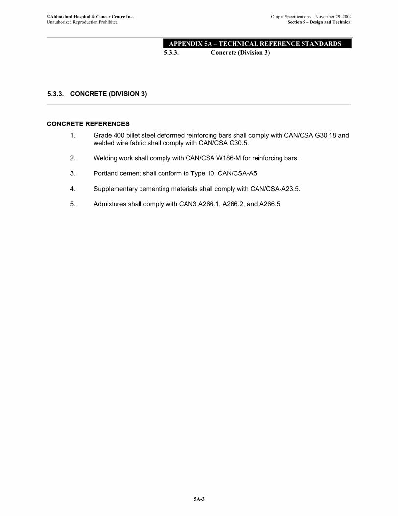
©Abbotsford Hospital & Cancer Centre Inc. Output Specifications – November 29, 2004 Unauthorized Reproduction Prohibited Section 5 – Design and Technical
APPENDIX 5A – TECHNICAL REFERENCE STANDARDS 5.3.3. Concrete (Division 3)
5A-3
5.3.3. CONCRETE (DIVISION 3)
CONCRETE REFERENCES
1. Grade 400 billet steel deformed reinforcing bars shall comply with CAN/CSA G30.18 and welded wire fabric shall comply with CAN/CSA G30.5.
2. Welding work shall comply with CAN/CSA W186-M for reinforcing bars.
3. Portland cement shall conform to Type 10, CAN/CSA-A5.
4. Supplementary cementing materials shall comply with CAN/CSA-A23.5.
5. Admixtures shall comply with CAN3 A266.1, A266.2, and A266.5

©Abbotsford Hospital & Cancer Centre Inc. Output Specifications – November 29, 2004 Unauthorized Reproduction Prohibited Section 5 – Design and Technical
APPENDIX 5A – TECHNICAL REFERENCE STANDARDS 5.3.3. Concrete (Division 3)
5A-4
Purposely left blank for pagination
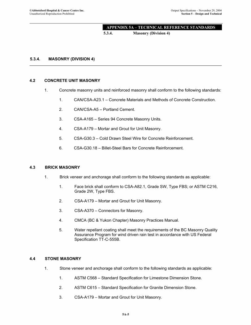
©Abbotsford Hospital & Cancer Centre Inc. Output Specifications – November 29, 2004 Unauthorized Reproduction Prohibited Section 5 – Design and Technical
APPENDIX 5A – TECHNICAL REFERENCE STANDARDS 5.3.4. Masonry (Division 4)
5A-5
5.3.4. MASONRY (DIVISION 4)
4.2 CONCRETE UNIT MASONRY
1. Concrete masonry units and reinforced masonry shall conform to the following standards:
1. CAN/CSA-A23.1 – Concrete Materials and Methods of Concrete Construction.
2. CAN/CSA-A5 – Portland Cement.
3. CSA-A165 – Series 94 Concrete Masonry Units.
4. CSA-A179 – Mortar and Grout for Unit Masonry.
5. CSA-G30.3 – Cold Drawn Steel Wire for Concrete Reinforcement.
6. CSA-G30.18 – Billet-Steel Bars for Concrete Reinforcement.
4.3 BRICK MASONRY
1. Brick veneer and anchorage shall conform to the following standards as applicable:
1. Face brick shall conform to CSA-A82.1, Grade SW, Type FBS; or ASTM C216, Grade 2W, Type FBS.
2. CSA-A179 – Mortar and Grout for Unit Masonry.
3. CSA-A370 – Connectors for Masonry.
4. CMCA (BC & Yukon Chapter) Masonry Practices Manual.
5. Water repellant coating shall meet the requirements of the BC Masonry Quality Assurance Program for wind driven rain test in accordance with US Federal Specification TT-C-555B.
4.4 STONE MASONRY
1. Stone veneer and anchorage shall conform to the following standards as applicable:
1. ASTM C568 – Standard Specification for Limestone Dimension Stone.
2. ASTM C615 – Standard Specification for Granite Dimension Stone.
3. CSA-A179 – Mortar and Grout for Unit Masonry.
©Abbotsford Hospital & Cancer Centre Inc. Output Specifications – November 29, 2004 Unauthorized Reproduction Prohibited Section 5 – Design and Technical
APPENDIX 5A – TECHNICAL REFERENCE STANDARDS 5.3.4. Masonry (Division 4)
5A-6
4. CAN/CSA-A5 – Portland Cement.
5. CSA-A370 – Connectors for Masonry.
6. Water repellant coating shall meet the requirements of the BC Masonry Quality Assurance Program for wind driven rain test in accordance with US Federal Specification TT-C-555B.

©Abbotsford Hospital & Cancer Centre Inc. Output Specifications – November 29, 2004 Unauthorized Reproduction Prohibited Section 5 – Design and Technical
APPENDIX 5A – TECHNICAL REFERENCE STANDARDS 5.3.5. Metals (Division 5)
5A-7
5.3.5. METALS (DIVISION 5)
5.2 STRUCTURAL STEEL AND STEEL JOISTS
1. ASTM A307, Specification for Carbon Steel Bolts and Studs, 60,000 psi tensile strength
2. ASTM A325M, Specification for High-Strength Bolts for Structural Steel Joints.
3. CAN/CSA G40.20-M, General Requirements for Rolled or Welded Structural Quality Steel.
4. Structural steel: CAN3 G40.21,
5. Hot dip galvanizing: CSA G164.
6. Supply, fabricate, and erect structural steel and/or steel joists in accordance with CAN3 S16-01 and CSA W59.
5.3 STEEL DECK
1. Welding and welding materials shall be in accordance with CSA W59.
2. Sheet steel shall conform to CSSBI 101M and shall be galvanized to ASTM A5255 with Z275 zinc coating class for roof deck, and ZF075 zinc coating class for floor deck, Grade A structural quality.
3. Design, fabrication and erection shall be in accordance with CSA S136, CSA S136.1, the Canadian Sheet Steel Building Institute Standards for Steel Roof Deck and Steel Floor Deck and the B.C. Building Code.
5.4 LOAD BEARING STEEL STUDS
1. Conform to CSA W47.1-92, "Certification of Companies for Fusion Welding of Steel Structures".
2. Conform to CSA W59-M1989, "Welded Steel Construction (Metal Arc Welding)".
3. Conform to ANSI/AWS Dl.3, "Structural Welding Code - Sheet Steel".
4. Materials shall conform to CSA-S136"Cold Formed Steel Structural Members".
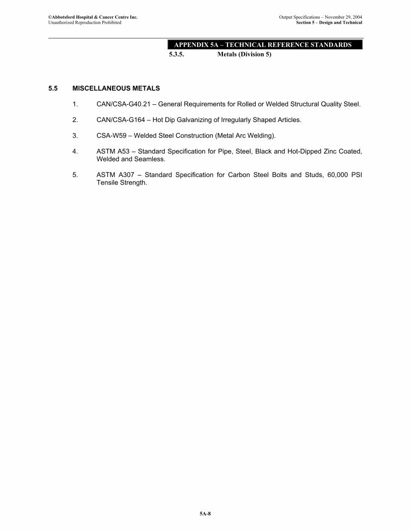
©Abbotsford Hospital & Cancer Centre Inc. Output Specifications – November 29, 2004 Unauthorized Reproduction Prohibited Section 5 – Design and Technical
APPENDIX 5A – TECHNICAL REFERENCE STANDARDS 5.3.5. Metals (Division 5)
5A-8
5.5 MISCELLANEOUS METALS
1. CAN/CSA-G40.21 – General Requirements for Rolled or Welded Structural Quality Steel.
2. CAN/CSA-G164 – Hot Dip Galvanizing of Irregularly Shaped Articles.
3. CSA-W59 – Welded Steel Construction (Metal Arc Welding).
4. ASTM A53 – Standard Specification for Pipe, Steel, Black and Hot-Dipped Zinc Coated, Welded and Seamless.
5. ASTM A307 – Standard Specification for Carbon Steel Bolts and Studs, 60,000 PSI Tensile Strength.
©Abbotsford Hospital & Cancer Centre Inc. Output Specifications – November 29, 2004 Unauthorized Reproduction Prohibited Section 5 – Design and Technical
APPENDIX 5A – TECHNICAL REFERENCE STANDARDS 5.3.6. Wood and Plastics (Division 6)
5A-9
5.3.6. WOOD AND PLASTICS (DIVISION 6)
6.2 ROUGH CARPENTRY
1. Conform to the following Standards.
1. NLGA Standard Grading Rules for Canadian Lumber.
2. CSA-B111 – Wire Nails, Spikes and Staples.
3. CAN/CSA-0141 – Softwood Lumber.
4. CSA-0151 – Canadian Softwood Plywood.
5. CSA-0121 – Douglas Fir Plywood.
6. CSA-080.1 – Preservative Treatment of All Timber Products by Pressure Processes.
7. CSA-080.9 – Preservative Treatment of Plywood by Pressure Processes.
6.3 FINISH CARPENTRY AND ARCHITECTURAL WOODWORK
1. Other Standards:
1. ANSI/NEMA LD3 – High Pressure Decorative Laminates
2. ANSI A208.1 – Particleboard, Mat-Formed Wood
3. ANSI/HPVA-HP-1 – Hardwood and Decorative Plywood
4. ANSI A208.2 – Medium Density Fibreboard
5. CAN3-A172 – High Pressure, Paper Base, Decorative Laminates
6. CAN3-0188.1 – Interior Mat-formed Wood Particleboard
7. CSA-0121 – Douglas Fir Plywood
8. CSA-0151 – Canadian Softwood Plywood
9. CSA-0153 – Poplar Plywood

©Abbotsford Hospital & Cancer Centre Inc. Output Specifications – November 29, 2004 Unauthorized Reproduction Prohibited Section 5 – Design and Technical
APPENDIX 5A – TECHNICAL REFERENCE STANDARDS 5.3.6. Wood and Plastics (Division 6)
5A-10
Purposely left blank for pagination
©Abbotsford Hospital & Cancer Centre Inc. Output Specifications – November 29, 2004 Unauthorized Reproduction Prohibited Section 5 – Design and Technical
APPENDIX 5A – TECHNICAL REFERENCE STANDARDS 5.3.7. Thermal and Moisture Protection (Division 7)
5A-11
5.3.7. THERMAL AND MOISTURE PROTECTION (DIVISION 7)
7.2 DAMPPROOFING
1. Materials and workmanship for dampproofing applied to exterior face of foundation walls below grade shall conform to the following standards, as applicable:
1. Static Type Mineral Colloid Asphalt Emulsion: Conforming to CGSB-37-GP-2.
2. Solvent Base Waterproofing Compound: Conforming to CGSB-37-GP-16. For use at temperatures below 40C.
3. CGSB-37-GP-3 Application of Emulsified Asphalts for Dampproofing and Waterproofing.
4. CGSB-37-GP-36 Application of Filled Cutback Asphalts for Dampproofing and Waterproofing.
7.3 WATERPROOFING
1. Conform to the following Standards:
1. CAN/CGSB-37.50 – Hot Applied Rubberized Asphalt for Roofing and Waterproofing.
2. CAN/CGSB-37.51 – Application of Hot Applied Rubberized Asphalt for Roofing and Waterproofing.
3. CGSB-37-GP-52 – Roofing and Waterproofing Membrane, Sheet Applied Elastomeric.
4. CGSB-37-GP-56 – Membrane, Modified, Bituminous, Prefabricated and Reinforced for Roofing.
5. CAN/CGSB-37.58 – Liquid Applied Moisture Cured Polyurethane Waterproofing membrane.
7.5 VAPOUR BARRIERS
1. Conform to the following Standards:
1. CAN/CGSB-51.34 – Vapour Barrier, Polyethylene Sheet for Use in Building Construction.
©Abbotsford Hospital & Cancer Centre Inc. Output Specifications – November 29, 2004 Unauthorized Reproduction Prohibited Section 5 – Design and Technical
APPENDIX 5A – TECHNICAL REFERENCE STANDARDS 5.3.7. Thermal and Moisture Protection (Division 7)
5A-12
7.6 AIR BARRIERS
1. Conform to the following Standards:
1. ASTM E283 – Standard Test Method for Water Penetration of Exterior Windows, Curtain Walls and Doors Under Specified Pressure Differences Across the Specimen.
2. CGSB-37-GP-56 – Membrane, Modified, Bituminous, Prefabricated and Reinforced for Roofing.
7.7 THERMAL PROTECTION
1. Other Standards:
1. CAN/ULC-S705.1 – Spray Applied Rigid Polyurethane Cellular Plastic Thermal Insulation.
2. CAN/ULC-S102 – Test for Surface Burning Characteristics of Building Materials
3. CAN/CGSB-51.39 – Spray Application of Rigid Polyurethane Cellular Plastic Thermal Insulation for Building Construction.
4. CCMC 12932-R – Air Barrier System.
5. CAN/ULC-701 – Standard for Thermal Insulation, Polystyrene.
6. CAN/ULC-702 – Standard for Thermal Insulation, Mineral Fibre for Buildings.
7. CAN/ULC-704 – Standard for Thermal Insulation Polyurethane and Polyisocyanurate Boards, Faced.
7.8 ROOFING
1. Design and installation of built up roofing to withstand local wind uplift in and conformance to CAN/ULC S126 for Class ‘C’ roof covering.
2. Roof covering materials shall be tested in accordance with CAN/ULC-S107 to achieve a Class C rating.
3. Other Standards:
3.1 CAN/ULC-S102 – Test for Surface Burning Characteristics of Building Materials and Assemblies.
3.2 CAN/ULC-701 – Standard for Thermal Insulation, Polystyrene.
3.3 CAN/ULC-702 – Standard for Thermal Insulation, Mineral Fibre for Buildings.
3.4 CAN/ULC-704 – Standard for Thermal Insulation Polyurethane and Polyisocyanurate Boards, Faced.
©Abbotsford Hospital & Cancer Centre Inc. Output Specifications – November 29, 2004 Unauthorized Reproduction Prohibited Section 5 – Design and Technical
APPENDIX 5A – TECHNICAL REFERENCE STANDARDS 5.3.7. Thermal and Moisture Protection (Division 7)
5A-13
7.9 FIRE AND SMOKE PROTECTION
1. Firestopping and smoke seals shall conform to the following standards:
1.1 ULC-S115 and UL-1470 for:
• Fire (F), hose (H) and temperature (T) ratings.
• Provision and maintainance of fire resistance rating of the adjacent floor, wall or other fire separation assembly.
• Certification by ULC of cUL. Also as listed in ULC List of Equipment and Materials – Firestop Systems and Components or UL Products Certified for Canada (cUL) Directory.
1.2 CAN/ULC-S101 – Fire Endurance Tests of Building Construction and Materials.
1.3 CAN/ULC-S102 – Testing for Surface Burning Characteristics of Building Materials and Assemblies.
1.5 UL-2079 – Tests for Fire Resistance of Building Joint Systems.
1.6 ASTM E84 – Standard Test Method for Surface Burning Characteristics of Building Materials.
1.7 ASTM E814 – Standard Test Method for Through-Penetration Firestopping.
1.8 ULC List of Equipment and Materials – Firestop Systems and Components Directory.
2. Spray applied cementitious fireproofing shall conform to the following standards:
2.1 CAN/ULC-S101 – Standard Methods of Fire Endurance Tests of Building Construction and Materials.
2.2 ULC – List of Equipment and Materials – Fire Resistance Ratings (latest edition).
2.3 WH Certification Listings.
2.4 CAN/ULC-S101 – Standard Methods of Fire Tests of Building Construction and Materials.
2.5 CAN4-S114 – Standard Test Method for Determination of Noncombustibility in Building Materials.
©Abbotsford Hospital & Cancer Centre Inc. Output Specifications – November 29, 2004 Unauthorized Reproduction Prohibited Section 5 – Design and Technical
APPENDIX 5A – TECHNICAL REFERENCE STANDARDS 5.3.7. Thermal and Moisture Protection (Division 7)
5A-14
7.10 SEALANTS
1. Sealant joints shall conform to ASTM C1193 – Standard Guide for Use of Joint Sealants.
2. Structural glazing sealant shall conform to ASTM C920, Type S, NS, Class 25, or CAN/CGSB-19.13.
3. Other Standards:
3.1 CAN2-19.13 – Sealing Compound, One Component Elastomeric, Chemical Curing.
3.2 CAN/CGSB-19.18 – Sealing Compound, One Component, Silicone Based, Solvent Curing.
3.3 CAN2-19.24 – Sealing Compound, Multi-Component, Chemical Curing.
3.4 CAN/CGSB-19.2 – Glazing Compound, Nonhardening, Modified Oil Type 19-GP-5M Sealing Compound, One Component, Acrylic Base, Solvent Curing.
3.5 CAN/CGSB-19.17 – One Component, Acrylic Emulsion Base Sealing Compound.
3.6 CAN/CGSB-19.21 – Sealing and Bedding Compound Acoustical.
3.7 CAN/CGSB-19.22 – Mildew-Resistance Sealing Compound for Tub and Tiles.
3.8 ASTM C920 – Standard Specification for Elastomeric Joint Sealants.
End of Thermal and Moisture Protection
©Abbotsford Hospital & Cancer Centre Inc. Output Specifications – November 29, 2004 Unauthorized Reproduction Prohibited Section 5 – Design and Technical
APPENDIX 5A – TECHNICAL REFERENCE STANDARDS 5.3.8. Doors and Windows (Division 8)
5A-15
5.3.8. DOORS AND WINDOWS (DIVISION 8)
8.2 HOLLOW METAL DOORS AND FRAMES
1. Other Standards:
1.1 Recommended locations for Architectural Hardware as published by the Door and Hardware Institute (DHI)
1.2 Installation of Commercial Steel Doors and Frames as published by the Door and Hardware Institute (DHI).
1.3 ASTM A653/A653M – Standard Specification for Steel Sheet Zinc-Coated (Galvanized) or Zinc-Iron Alloy-Coated (Galvannealed) by the Hot Dip Process.
8.3 WOOD DOORS
1. Other Standards:
1.1 CAN3-0188.1-M Specification for Interior Mat Formed Wood Particleboard.
8.4 ALUMINUM ENTRANCES AND STOREFRONT
1. Design of exterior aluminum entrance and storefront framing shall conform to CAN3-S157.
2. Aluminum extrusions shall be fabricated from Aluminum Association 6063-T5 alloy and temper or ASTM B221.
3. Aluminum sheet shall be Aluminum Association 3003 H14 or ASTM B209 sheet.
4. Other Standards:
4.1 AA (Aluminum Association) Standards.
4.2 ASTM E283 – Standard Test Method for Air Infiltration of Exterior Windows, Curtain Walls and Doors Under Specified Pressure Differences Across the Specimen.
4.3 ASTM E330 – Standard Test Method for Structural Performance of Exterior Windows, Curtain Walls and Doors by Uniform Static Air Pressure Difference.
4.4 ASTM E331 – Standard Test Method for Water Penetration of Exterior Windows, Skylights, Doors and Curtain Walls by Uniform Static Air Pressure Difference.
©Abbotsford Hospital & Cancer Centre Inc. Output Specifications – November 29, 2004 Unauthorized Reproduction Prohibited Section 5 – Design and Technical
APPENDIX 5A – TECHNICAL REFERENCE STANDARDS 5.3.8. Doors and Windows (Division 8)
5A-16
8.5 SPECIALTY DOORS
1. Smoke control doors shall have been tested with UL 1784 - Air Leakage Test for Door Assemblies and shall meet criteria for NFPA 105 – Installation of Smoke Control Door Assemblies.
2. The installed fire door and frame assembly installation shall conform to NFPA No. 80 Standard for fire protection ratings as applicable.
3. Aluminum extrusions shall be fabricated from AA 6063-T5 or T6 aluminum alloy or ASTM B221 aluminum alloy, of proper temper for extruding and fabricating with adequate structural characteristics to meet design and performance criteria, and suitable for required finishing.
4. Aluminum sheet shall be of grade AA 3003 H14 aluminum sheet, or ASTM B209 aluminum sheet suitable for application of required finish and of thickness to provide distortion free surface completely free of oil canning under design loads specified. All sheets to be stretcher levelled and stress relieved.
. Other Standards:
4.1 CAN4-S104M – Standard Method for Fire Tests of Door Assemblies.
4.2 ANSI American National Standards Institute Standards.
4.3 ANSI/BHMA 156.10 – Power Operated Pedestrian Doors.
4.4 ANSI/UL 325 – Door, Drapery, Gate, Louver, and Window Operators and Systems.
8.6 ALUMINUM CURTAIN WALLS
1. Design of aluminum framing members shall conform to CAN3-S157-M83 – Strength Design in Aluminum.
2. Ventilator window units within curtain wall shall conform to the performance levels of CAN/CSA-A440 Windows and as specified under 8.7 Aluminum Windows.
3. Aluminum extrusions shall be fabricated from AA 6063-T5 or T6 aluminum alloy or ASTM B221 aluminum alloy, of proper temper for extruding and fabricating with adequate structural characteristics to meet design and performance criteria, and suitable for required finishing.
4. Aluminum sheet shall be of grade AA 3003 H14 aluminum sheet, or ASTM B209 aluminum sheet suitable for application of required finish and of thickness to provide distortion free surface completely free of oil canning under design loads specified. All sheets to be stretcher levelled and stress relieved.
©Abbotsford Hospital & Cancer Centre Inc. Output Specifications – November 29, 2004 Unauthorized Reproduction Prohibited Section 5 – Design and Technical
APPENDIX 5A – TECHNICAL REFERENCE STANDARDS 5.3.8. Doors and Windows (Division 8)
5A-17
5. Other Standards:
5.1 AA (Aluminum Association Standards.
5.2 AAMA 503 Specifications for Field Testing of Metal Storefront, Curtain Wall and Sloped Glazing Systems.
5.3 ASTM E283 – Standard Test Method for Air Infiltration of Exterior Windows, Curtain Walls and Doors Under Specified Pressure Differences Across the Specimen.
5.4 ASTM E330 – Standard Test Method for Structural Performance of Exterior Windows, Curtain Walls and Doors by Uniform Static Air Pressure Difference.
5.5 ASTM E331 – Standard Test Method for Water Penetration of Exterior Windows, Skylights, Doors and Curtain Walls by Uniform Static Air Pressure Difference.
8.7 ALUMINUM WINDOWS
1. Design of aluminum windows shall conform to CAN3-S157 – Strength Design in Aluminum.
2. Aluminum extrusions shall be fabricated from AA 6063-T5 or T6 aluminum alloy or ASTM B221 aluminum alloy, of proper temper for extruding and fabricating with adequate structural characteristics to meet performance criteria, and suitable for required finishing.
3. Aluminum sheet shall be of grade AA 3003 H14 aluminum sheet, or ASTM B209 aluminum sheet suitable for application of required finish and of thickness to provide distortion free surface completely free of oil canning under design loads specified. All sheets to be stretcher levelled and stress relieved.
4. Other Standards:
4.1 CSA A440 – Windows.
4.2 Other reference standards shall be as listed under 8.6 Aluminum Curtain Wall.

©Abbotsford Hospital & Cancer Centre Inc. Output Specifications – November 29, 2004 Unauthorized Reproduction Prohibited Section 5 – Design and Technical
APPENDIX 5A – TECHNICAL REFERENCE STANDARDS 5.3.8. Doors and Windows (Division 8)
5A-18
8.8 SKYLIGHTS
1. Structural performance of skylights shall be based on CAN3-S157 – Strength Design in Aluminum.
2. Aluminum extrusions shall be fabricated from AA 6063-T5 or T6 aluminum alloy or ASTM B221 aluminum alloy, of proper temper for extruding and fabricating with adequate structural characteristics to meet performance criteria, and suitable for required finishing.
3. Aluminum sheet shall be of grade AA 3003 H14 aluminum sheet, or ASTM B209 aluminum sheet suitable for application of required finish and of thickness to provide distortion free surface completely free of oil canning under design loads specified. All sheets to be stretcher levelled and stress relieved.
8.9 GLASS AND GLAZING
1. Glass shall be designed according to CAN/CGSB-12.20 with glass deflection limited to L/175, to a maximum of 20 mm for any single light of insulating glass.
2. Other Standards:
2.1 CAN/CGSB-12.1 – Tempered or Laminated Safety Glass.
2.2 CAN/CGSB-12.3 – Flat, Clear Float Glass.
2.3 CAN/CGSB-12.4 – Heat Absorbing Glass.
2.4 CAN/CGSB-12.5 – Mirrors, Silvered.
2.5 CAN/CGSB-12.8 – Insulating Glass Units.
2.6 CAN/CGSB-12.9 – Spandrel Glass.
2.7 CAN/CGSB-12.10 – Glass, Heat and Light Reflecting.
2.8 CAN/CGSB-12.11 – Wired Safety Glass.
2.9 CAN/CGSB-12.13 – Glass, Patterned.
2.10 IGMAC “Glazing Recommendations for Sealed Insulating Glass Units”.
2.11 IGMAC “Sloped Glazing Guidelines”.
2.12 GCA Glazing Contractors Association of B.C. Glazing Systems Specifications Manual.
©Abbotsford Hospital & Cancer Centre Inc. Output Specifications – November 29, 2004 Unauthorized Reproduction Prohibited Section 5 – Design and Technical
APPENDIX 5A – TECHNICAL REFERENCE STANDARDS 5.3.8. Doors and Windows (Division 8)
5A-19
8.10 FINISH HARDWARE
1. Other Standards:
1.1 ANSI - American National Standards Institute Standards.
1.2 CAN4-S104M- Standard Method for Fire Tests of Door Assemblies.
1.3 Recommended locations for Architectural Hardware as published by the Door and Hardware Institute (DHI).
1.4 Installation of Commercial Steel Doors and Frames as published by the Door and Hardware Institute (DHI).
End of Doors and Windows
©Abbotsford Hospital & Cancer Centre Inc. Output Specifications – November 29, 2004 Unauthorized Reproduction Prohibited Section 5 – Design and Technical
APPENDIX 5A – TECHNICAL REFERENCE STANDARDS 5.3.8. Doors and Windows (Division 8)
5A-20
Page left blank for pagination
©Abbotsford Hospital & Cancer Centre Inc. Output Specifications – November 29, 2004 Unauthorized Reproduction Prohibited Section 5 – Design and Technical
APPENDIX 5A – TECHNICAL REFERENCE STANDARDS 5.3.9. Finishes (Division 9)
5A-21
5.3.9. FINISHES (DIVISION 9)
9.2 INTERIOR WALL FRAMING
1. Lightweight steel studs and tracks for interior partitions are classified under CAN/CGSB-7.1-98 Lightweight Steel Wall Framing Components as non-load bearing steel studs and shall be manufactured from steel sheet, coil or cut length to conform to ASTM standards listed under CAN/CGSB-7.1-98. For interior application, the steel shall be protected from corrosion by a zinc coating at least meeting the requirements of ASTM A653/A653M.
2. Other Standards:
2.1 CSSB1 – Canadian Sheet Steel Building Institute Standards.
2.2 CSA-S136 – Cold Formed Steel Structural Members.
2.3 BC Building Code
9.3 GYPSUM BOARD
1. Gypsum board shall conform to CAN/CSA-A82.27.
2. Gypsum board application shall conform to CSA-A82-31, or Gypsum Association GA216 specification.
3. Fire rated Type ‘X’ and ‘C’ gypsum board assemblies shall be tested assemblies in accordance with CAN/ULC S101 or ASTM E119, in conjunction with non load bearing steel studs.
4. Other Standards:
4.1 ASTM C36/C36M – Standard Specification for Gypsum Board.
4.2 ASTM C360/C360M – Standard Specification for Water-Resistant Gypsum Backing Board.
4.3 ASTM C1278 – Standard Specification for Fiber Reinforced Gypsum Panel.
4.4 ASTM C1177 – Standard Specification for Glass Mat Water-Resistant Gypsum Backing Panel.
4.5 ASTM C1178 – Standard Specification for Glass Mat Water-Resistant Gypsum Backing Panel.
4.6 ANSI A118.9 – Cementitious Back Units (CBU).
©Abbotsford Hospital & Cancer Centre Inc. Output Specifications – November 29, 2004 Unauthorized Reproduction Prohibited Section 5 – Design and Technical
APPENDIX 5A – TECHNICAL REFERENCE STANDARDS 5.3.9. Finishes (Division 9)
5A-22
9.4 CERAMIC TILEWORK
1. Other Standards:
1.1 CAN/CGSB-25.20-95 – Surface Sealer for Floors.
1.2 CAN/CSGB-75.1 – Moisture Resistance (MR) of glazed and unglazed ceramic tiles, Table 1 Water Absorption, Percentage by Mass.
9.5 ACOUSTICAL CEILINGS
1. Acoustic tile shall be rated Class 25 (Incombustible) under Flame Spread Index Section of Federal Specifications 55-5-118a and have a Class 1 Flame Spread rating according to CAN/ULC-S102 or ASTM E84. tile shall also be listed and labelled by Underwriters Laboratories Inc or ULC, under Hazard Classification for a flame spread of 0-25.
2. Acoustical ceilings shall be installed in accordance with ASTM C636.
3. Fir rate ceiling assemblies (including ceiling panels, suspension system, light fixtures and diffusers and structural components shall be tested assemblies in accordance with CAN/ULC-S101 or ASTM E119.
4. Other Standards
4.1 ASTM C423 – Standard Test Method for Sound Absorption and Sound Absorption Coefficients by the Reverberation Room Method.
4.2 ASTM E90 – Method for Laboratory Measurement of Airborne Sound Transmission Loss of Building Partitions.
4.3 ASTM E1414 – Standard Test Method for Airborne Sound Attenuation Between Rooms Sharing a Common Ceiling Plenum (previously known as ASTM E413).
4.4 CAN/CGSB-92.1 – Sound Absorptive Acoustical Units, Prefabricated.
9.6 FLOORING
1. Carpeting shall meet or exceed all requirements of the CGSB-4-GP-129 Standard for Carpets, Commercial and the Hazardous Products Act.
2. Resilient stair treads and risers shall conform to US Federal Specification RR-T-650d.
3. Other Standards
3.1 ASTM F1066 – Standard Specification for Vinyl Composition Floor tile.
3.2 ASTM F1303 – Standard Specification for Sheet Vinyl Floor Covering.
©Abbotsford Hospital & Cancer Centre Inc. Output Specifications – November 29, 2004 Unauthorized Reproduction Prohibited Section 5 – Design and Technical
APPENDIX 5A – TECHNICAL REFERENCE STANDARDS 5.3.9. Finishes (Division 9)
5A-23
3.3 ASTM F2034 – Standard Specification for Linoleum Sheet Flooring.
3.4 ASTM F1344 – Standard Specification for Rubber Floor Tile.
9.7 ACOUSTIC TREATMENT
1. Conform to the following Standards:
1.1 ASTM C423 – Standard Method for Sound Absorption and Sound Absorption Coefficients by the Reverberation Method.
1.2 ASTM E84 – Test Method for Surface Burning Characteristics of Building Materials.
1.3 ASTM E90 – Test Method for Laboratory Measurement of Airborne Sound Transmission Loss of Building Partitions
1.4 ASTEM E336 – Test Method for Measurement of Airborne Sound Insulation in Buildings.
1.5 CAN/ULC-S101 – Fire Endurance Tests of Building Construction and Materials.
1.6 CAN/ULC-S102 – Test for Surface Burning Characteristics of Building Materials and Assemblies.
End of Finishes

©Abbotsford Hospital & Cancer Centre Inc. Output Specifications – November 29, 2004 Unauthorized Reproduction Prohibited Section 5 – Design and Technical
APPENDIX 5A – TECHNICAL REFERENCE STANDARDS 5.3.9. Finishes (Division 9)
5A-24
Purposely left blank for pagination
©Abbotsford Hospital & Cancer Centre Inc. Output Specifications – November 29, 2004 Unauthorized Reproduction Prohibited Section 5 – Design and Technical
APPENDIX 5A – TECHNICAL REFERENCE STANDARDS 5.3.10. Manufactured Specialties (Division 10)
5A-25
5.3.10. MANUFACTURED SPECIALTIES (DIVISION 10)
10.5 WALL GUARDS AND CORNER GUARDS, HANDRAILS, WALL PROTECTION, DOOR EDGE AND DOOR FRAME PROTECTION.
1. Vinyl acrylic bumper guards, handrails, corner guards and wall protection shall have been tested in accordance with CAN/ULC-S102 or ASTM E84 for Class 1 rating to provide Flame Spread Rating of 25 or less.
10.6 ELEVATED ACCESS FLOORING
1. The floor panels, exclusive of covering, shall have a Flame Spread Rating of 25 or less when tested in accordance with CAN/ULC-S102, and shall be fabricated completely of non-combustible materials
10.10 WASHROOM ACCESSORIES
1. Sheet steel shall be commercial quality to ASTM A653 with ZF001 designation zinc coating.
2. Stainless steel sheet shall conform to ASTM A167, Type 304, No. 4 finish.
3. Stainless steel tubing shall conform to ASTM A269, Type 304 seamless, No. 4 finish.
©Abbotsford Hospital & Cancer Centre Inc. Output Specifications – November 29, 2004 Unauthorized Reproduction Prohibited Section 5 – Design and Technical
APPENDIX 5A – TECHNICAL REFERENCE STANDARDS 5.3.10. Manufactured Specialties (Division 10)
5A-26
Purposely left blank for pagination
End of Specialities
©Abbotsford Hospital & Cancer Centre Inc. Output Specifications – November 29, 2004 Unauthorized Reproduction Prohibited Section 5 – Design and Technical
APPENDIX 5A – TECHNICAL REFERENCE STANDARDS 5.3.11. Equipment (Division 11)
5A-27
5.3.11. EQUIPMENT (DIVISION 11)
11.3 FALL PROTECTION AND ANCHORS
1. Other Standards
1.1 Province of British Columbia I.H.S.R. pursuant to WCB of British Columbia, Fall Protection Regulations, British Columbia Regulation 296/97, effective April 15, 1998.
1.2 CSA-S16-01, CSA-S136, the CISC Code of Standard Practice for Buildings.
1.3 CSA-W59 – Welded Steel Construction (Metal Arc Welding).
1.4 CSA-W47.1 – Certificate of Companies for Fusion Welding of Steel Structures.
1.5 CAN/CSA-Z91 – Safety Code for Window Cleaning Operations.
1.6 CAN/CSA-Z271 - Safety factor for the design of outriggers, cables, anchors.
11.4 DOCK LEVELLERS
1. Dock levellers shall conform to ANSI MH14.1, ANSI Z535.1, and CS 202-56.
End of Equipment

©Abbotsford Hospital & Cancer Centre Inc. Output Specifications – November 29, 2004 Unauthorized Reproduction Prohibited Section 5 – Design and Technical
APPENDIX 5A – TECHNICAL REFERENCE STANDARDS 5.3.11. Equipment (Division 11)
5A-28
Purposely left blank for pagination
©Abbotsford Hospital & Cancer Centre Inc. Output Specifications – November 29, 2004 Unauthorized Reproduction Prohibited Section 5 – Design and Technical
APPENDIX 5A – TECHNICAL REFERENCE STANDARDS 5.3.12. Furnishings (Division 12)
5A-29
5.3.12. FURNISHINGS (DIVISION 12)
12.2 WINDOW COVERINGS
1. Shading fabric for window shade systems shall pass Small Scale Vertical Burn requirements in accordance with CAN/ULC-S109 or NFPA-701.
2. Shading fabric for window shade systems shall have been tested in accordance with ASHRAE Standard 74073 for shading coefficient, for fungal resistance in accordance with ASTM G21, and for bacterial resistance.
12.3 LABORATORY CASEWORK
1. High pressure laminates for horizontal and vertical applications shall conform to ANSI/NEMA LD-3 or CAN3-A172 General Purpose Grade, Postforming Grade, Laboratory Grade and Liner Grade.
2. Medium density fibreboard shall be no added formaldehyde medium density fibreboard conforming to ANSI Standard 208.2 and meeting requirements of ANSI A208.1 concentration 3 PPM at a loading factor of 0.8/m3.
3. Other Standards:
3.1 CAN3-A172 – High Pressure, Paper Base, Decorative Laminates.
3.2 CAN3-0188.1 – Interior Mat-Formed Wood Particleboard.
3.3 CSA-0121 – Douglas Fir Plywood.
End of Furnishings

©Abbotsford Hospital & Cancer Centre Inc. Output Specifications – November 29, 2004 Unauthorized Reproduction Prohibited Section 5 – Design and Technical
APPENDIX 5A – TECHNICAL REFERENCE STANDARDS 5.3.12. Furnishings (Division 12)
5A-30
Purposely left blank for pagination
©Abbotsford Hospital & Cancer Centre Inc. Output Specifications – November 29, 2004 Unauthorized Reproduction Prohibited Section 5 – Design and Technical
APPENDIX 5A – TECHNICAL REFERENCE STANDARDS 5.3.14. Conveying Systems (Division 14)
5A-31
5.3.14. CONVEYING SYSTEMS (DIVISION 14)
14.2 ELEVATORS
1. Conform to the requirements of CAN/CSA-B44 and CSA-C22.1 - Canadian Electrical Code, Part 1, Safety Standards for Electrical Installations.
2. Other Standards.
2.1 CAN4-S104 – Standard Method for Fire Tests of Door Assemblies.
14.3 DUMBWAITERS
1. Conform to the requirements of CAN/CSA-B44 and CSA-C22.1 - Canadian Electrical Code, Part 1, Safety Standards for Electrical Installations.
2. Reference Standards
2.1 CAN4-S104 – Standard Method for Fire Tests of Door Assemblies.
End of Conveying Systems

©Abbotsford Hospital & Cancer Centre Inc. Output Specifications – November 29, 2004 Unauthorized Reproduction Prohibited Section 5 – Design and Technical
APPENDIX 5A – TECHNICAL REFERENCE STANDARDS 5.3.14. Conveying Systems (Division 14)
5A-32
Purposely left blank for pagination
5.3.15. MECHANICAL (DIVISION 15)
15.5 PIPE AND PIPE FITTINGS
1. Piping and fittings for Medical gas systems shall be in accordance with CSA Z-305.1-M 1992 code for non-flammable medical gas system.
2. Piping and fittings for natural gas system shall be in accordance with CAN1-B149, 1-M80 standards.
3. Piping and fittings for oil piping systems shall be in accordance with CSA Standard B139.
4. Copper piping shall conform to ASTM B88 standards.
5. Refrigerant piping shall be to CSAB52 Standard.
6. Steam and Condensate piping systems shall comply with ANSI/ASME B31.1, Power Piping Code for Steam Systems.
7. Heating hot water and chilled water piping systems shall comply with ANSI/ASME B31.1.
15.14 HEATING, VENTILATION AND AIR CONDITIONING SYSTEMS
1. Internal thermal environmental conditions shall meet the requirements of ASHRAE Standard 55-1992 – Thermal Environmental Conditions for Human Occupancy.
2. Ventilation shall meet the requirements of ASHRAE Standard 62-2001-Ventilation for Acceptable Indoor Air Quality, and Health Canada Regulations.
3. Filters shall be tested and rated in accordance with ASHRAE Standard 52.2 – 1999, Method of Testing General Ventilation Air Cleaning Devices for Removal Efficiency by Particle Size.