Table of Contents - Classic Wire & Cable.
36
TECHNICAL RESOURCES Table of Contents Information on this sheet subject to change without notice. Copyright © 2021, Classic Wire & Cable, Inc. 07 MAY 2021 classicwire.com | [email protected] | 800.298.3500 Terms & Conditions Wire & Cable: Handling and Installation Engineering Guide Jacket Material Selection Chart EPR Performance Specifications Thermal Resistivity of Materials Guide for the Installation of ACSR Twisted Pair (TP) Conductor Wire & Cable: Methods of Color Coding & Color Coding Charts Recommended Reel Handling Practices & Recycling/Reel Return Steel Reel Specifications Paralleling Metric Size to AWG Size Copper Conductor Stranding Chart: Class A thru M Allowable Ampacities of Insulated Conductors Wire & Cable: Glossary of Terms
-
Upload
khangminh22 -
Category
Documents
-
view
1 -
download
0
Transcript of Table of Contents - Classic Wire & Cable.
TECHNICAL RESOURCES
Table of Contents
Information on this sheet subject to change without notice. Copyright © 2021, Classic Wire & Cable, Inc. 07 MAY 2021
classicwire.com | [email protected] | 800.298.3500
Terms & Conditions
Wire & Cable: Handling and Installation Engineering Guide
Jacket Material Selection Chart
EPR Performance Specifications
Thermal Resistivity of Materials
Guide for the Installation of ACSR Twisted Pair (TP) Conductor
Wire & Cable: Methods of Color Coding & Color Coding Charts
Recommended Reel Handling Practices & Recycling/Reel Return
Steel Reel Specifications
Paralleling
Metric Size to AWG Size
Copper Conductor Stranding Chart: Class A thru M
Allowable Ampacities of Insulated Conductors
Wire & Cable: Glossary of Terms

TECHNICAL RESOURCES
Terms & Conditions
Information on this sheet subject to change without notice. Copyright © 2021, Classic Wire & Cable, Inc. 07 MAY 2021
classicwire.com | [email protected] | 800.298.3500
PRICEPrices are based on COMEX copper or LME aluminum listed on the quotation. Prices are subject to copper/aluminum adjustment at the time of shipment in the event that COMEX or LME copper exceeds the quoted base in excess of 10%.
CANCELLATIONCancellation after acceptance of an order cannot be made without Seller’s written consent and on such conditions as will indemnify Seller against loss for commitments made and work already complete and/or in process.
SPECIAL ORDERSWhen Special Make Orders are accepted the entire order must be taken. Special Make Orders cannot be cancelled or modified once accepted and cannot be returned.
TOLERANCESNon-Stock & Special Make merchandise is subject to the following tolerances: Total product -0 and Reel lengths +/-10%, or as specified. Exact reel lengths will incur additional charges.
DELIVERYAny shipment schedule is approximate. Seller shall not be liable for any delay in delivery or failure to deliver caused in whole or in part by any reason beyond Seller’s control.
CLAIMSBuyer agrees to inspect merchandise for defects and for conformity, and agrees to check material against shipping papers upon unloading at destination. All claims for shortages or defective merchandise must be made by Buyer in writing within seven (7) days of receipt of shipment.
RETURNSReturn merchandise must be full reels or cartons, undamaged and in the original unopened package. Credit will be given for returned merchandise only for full reels of undamaged wire if still in the original package. No merchandise may be returned without the written authority of Seller and receipt of Seller’s RMA number. No merchandise may be returned after the expiration of sixty (60) days following the date of shipment. Returns may be subject to a Restocking Fee. Non-Stock & Special Make merchandise will not be considered for return and is not subject to the previous stated return conditions.
REFUNDSNo cash refunds. Trade Credit Only. All returns and other proper claims for credit may be applied toward future purchases only or as agreed.
TAXESLiability for all taxes imposed by any government authority with respect to the goods herein ordered shall be assumed and paid by Buyer.
MODIFICATIONSAny modification of these Standard Terms and Conditions shall not be binding on Seller unless signed on behalf of Seller by a representative authorized to do so, regardless of whether Seller has commenced shipping of any merchandise ordered hereunder or whether Seller has accepted payments therefore.
WARRANTYAll merchandise ordered will be supplied in accordance with the description on the face of the order acknowledgment and in accordance with applicable specifications and design standards, and will be substantially free from defects in material and workmanship. The Seller’s liability in respect to any defect in or failure of the merchandise supplied, as well as any loss, injury or damage attributable thereto, is limited to the replacement or repair of defects which, under proper use and handling, have been proven to the Seller’s satisfaction to arise solely from faulty design, materials or workmanship, within a period of one (1) year from the date of shipment from the Seller’s factory. Further, the Seller must be notified in writing of the said defect or failure within a period of one (1) year from the date of shipment. The replacement of such merchandise does not include expenses incurred in the installation or use of the material. No merchandise shall be returned to the Seller’s factory or warehouse for credit or replacement before the Seller has officially advised of this transaction.
WARRANTY LIMITATIONSThis warranty does not cover the repair or replacement of any cable which fails as a result of damage in transit, misuse, neglect, accident, Acts of God, abuse, improper handling, improper storage, excessive stress, faulty or improper or unauthorized installation or repair, negligent maintenance or failure to comply with the written instructions for installation, use or maintenance provided by the Seller.
EXCLUSION OF OTHER WARRANTIESThis warranty is in lieu of all other warranties, express or implied, and all other warranties, including but not limited to the implied warranties of merchantability and fitness for a particular purpose, are expressly disclaimed.
LIMITATION OF LIABILITY AND LIMITATION OF ACTIONSIn no event shall Seller be liable for any indirect, incidental, special, punitive or consequential loss, damage or expense (which shall be deemed to include without limitation: any loss of profit or revenue, loss of goodwill, loss claimed by end-user’s customers, or loss of business opportunity) of any nature or kind, however arising, whether in contract, in tort or otherwise, even if Seller is deemed to be aware of the possibility of such damages. Seller’s maximum liability for any claim, loss or damage shall not exceed the purchase price for the cable subject to a claim under any circumstance, even if end-user has claims or is subject to claims in excess of this limitation. Any legal proceeding related to this warranty must be presented within (1) year after the cause of action arises.
SOLE AND EXCLUSIVE REMEDYThis document sets forth the Seller’s sole and exclusive warranty obligation to the Buyer and the Buyer’s sole and exclusive remedy in the event of defective cable.
CHOICE OF LAWThe laws of the State of Florida, without giving effect to its conflicts of law principles, govern all matters arising out of or relating to these Standard Terms and Conditions and all the transactions it contemplates, including, without limitation, its validity, interpretation, construction, performance and enforcement.
TECHNICAL RESOURCES
Wire & Cable:Handling and Installation Engineering Guide
Information on this sheet subject to change without notice. 1Copyright © 2021, Classic Wire & Cable, Inc. 07 MAY 2021
classicwire.com | [email protected] | 800.298.3500
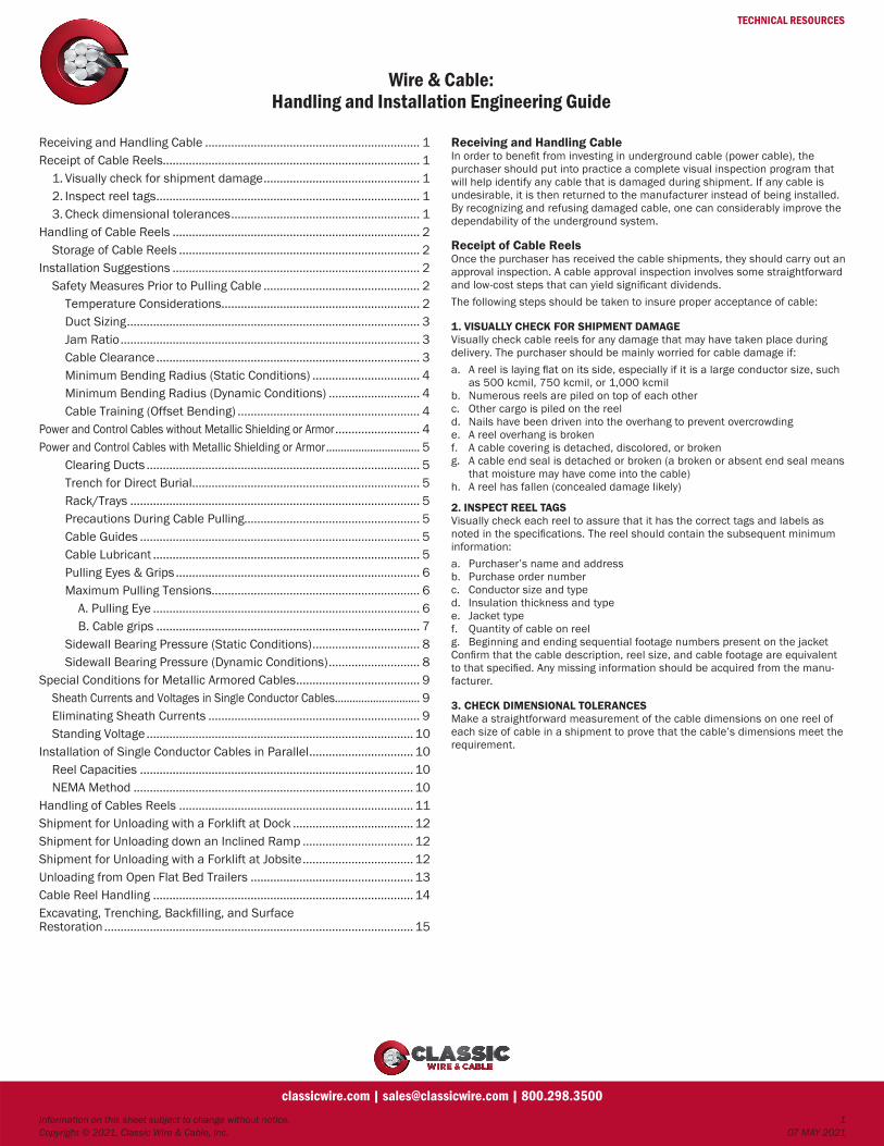
Receiving and Handling Cable .................................................................. 1Receipt of Cable Reels............................................................................... 1 1. Visually check for shipment damage ................................................ 1 2. Inspect reel tags ................................................................................. 1 3. Check dimensional tolerances .......................................................... 1Handling of Cable Reels ............................................................................ 2 Storage of Cable Reels .......................................................................... 2Installation Suggestions ............................................................................ 2 Safety Measures Prior to Pulling Cable ................................................ 2 Temperature Considerations ............................................................. 2 Duct Sizing .......................................................................................... 3 Jam Ratio ............................................................................................ 3 Cable Clearance ................................................................................. 3 Minimum Bending Radius (Static Conditions) ................................. 4 Minimum Bending Radius (Dynamic Conditions) ............................ 4 Cable Training (Offset Bending) ........................................................ 4Power and Control Cables without Metallic Shielding or Armor .......................... 4Power and Control Cables with Metallic Shielding or Armor ................................ 5 Clearing Ducts .................................................................................... 5 Trench for Direct Burial ...................................................................... 5 Rack/Trays ......................................................................................... 5 Precautions During Cable Pulling...................................................... 5 Cable Guides ...................................................................................... 5 Cable Lubricant .................................................................................. 5 Pulling Eyes & Grips ........................................................................... 6 Maximum Pulling Tensions................................................................ 6 A. Pulling Eye .................................................................................. 6 B. Cable grips ................................................................................. 7 Sidewall Bearing Pressure (Static Conditions) ................................. 8 Sidewall Bearing Pressure (Dynamic Conditions) ............................ 8Special Conditions for Metallic Armored Cables ...................................... 9 Sheath Currents and Voltages in Single Conductor Cables ............................. 9 Eliminating Sheath Currents ................................................................. 9 Standing Voltage .................................................................................. 10Installation of Single Conductor Cables in Parallel ................................ 10 Reel Capacities .................................................................................... 10 NEMA Method ...................................................................................... 10Handling of Cables Reels ........................................................................ 11Shipment for Unloading with a Forklift at Dock ..................................... 12Shipment for Unloading down an Inclined Ramp .................................. 12Shipment for Unloading with a Forklift at Jobsite .................................. 12Unloading from Open Flat Bed Trailers .................................................. 13Cable Reel Handling ................................................................................ 14Excavating, Trenching, Backfilling, and Surface Restoration ............................................................................................... 15
Receiving and Handling CableIn order to benefit from investing in underground cable (power cable), the purchaser should put into practice a complete visual inspection program that will help identify any cable that is damaged during shipment. If any cable is undesirable, it is then returned to the manufacturer instead of being installed. By recognizing and refusing damaged cable, one can considerably improve the dependability of the underground system.
Receipt of Cable ReelsOnce the purchaser has received the cable shipments, they should carry out an approval inspection. A cable approval inspection involves some straightforward and low-cost steps that can yield significant dividends. The following steps should be taken to insure proper acceptance of cable:
1. VISUALLY CHECK FOR SHIPMENT DAMAGEVisually check cable reels for any damage that may have taken place during delivery. The purchaser should be mainly worried for cable damage if:a. A reel is laying flat on its side, especially if it is a large conductor size, such
as 500 kcmil, 750 kcmil, or 1,000 kcmilb. Numerous reels are piled on top of each otherc. Other cargo is piled on the reeld. Nails have been driven into the overhang to prevent overcrowdinge. A reel overhang is brokenf. A cable covering is detached, discolored, or brokeng. A cable end seal is detached or broken (a broken or absent end seal means
that moisture may have come into the cable)h. A reel has fallen (concealed damage likely)
2. INSPECT REEL TAGSVisually check each reel to assure that it has the correct tags and labels as noted in the specifications. The reel should contain the subsequent minimum information:a. Purchaser’s name and addressb. Purchase order numberc. Conductor size and typed. Insulation thickness and typee. Jacket typef. Quantity of cable on reelg. Beginning and ending sequential footage numbers present on the jacket Confirm that the cable description, reel size, and cable footage are equivalent to that specified. Any missing information should be acquired from the manu-facturer.
3. CHECK DIMENSIONAL TOLERANCESMake a straightforward measurement of the cable dimensions on one reel of each size of cable in a shipment to prove that the cable’s dimensions meet the requirement.

TECHNICAL RESOURCES
Wire & Cable:Handling and Installation Engineering Guide
Information on this sheet subject to change without notice. 2Copyright © 2021, Classic Wire & Cable, Inc. 07 MAY 2021
classicwire.com | [email protected] | 800.298.3500
Handling of Cable ReelsTo guarantee that material handling equipment does not touch or interfere with cable surfaces or with protective covering on the reel, the utmost care should be taken when moving the cable reels. It is very important that cable reels not be dropped from any height, or be allowed to roll unrestrained. Cable reels should be moved or lifted using the technique depicted at the end of this document.1. For cranes, booms, or other overhead lifting equipment, a sturdy steel arbor
or heavy rod or pipe should be placed in through the reel hubs so that the cable reel can be lifted by slings that make the most of spreader bars. This technique will assure that sling pressure against a reel flange, slanting of the reel, sliding of the sling, and other unstable situation will be reduced.
2. When lifting reels by fork truck type equipment, reels should only be lifted from the sides, and only if the blades of the fork truck are long enough to support both flanges. This way will make sure that the lift pressure is uni-formly dispersed on both flanges and not on the cable itself.
3. Rolling reels containing cables should be kept to a minimum; if rolling is necessary, reels should always be rolled in the direction indicated by the “arrows” on the sides of the reel flanges or in the opposite direction to which the cable is wrapped onto the reel. Rolling the reels this way will avoid the release of the cable wraps, which may lead to problems during installation.
4. It is important that any debris be cleared from the path over which the cable reels are to be rolled since that might damage the cable if the reels were to roll over it. Cable reels should be rolled in the direction of the “Roll This Way” arrow and lowered in a controlled manner. The ramps should be spaced far enough apart so that they are touching the reel flanges at all times.
STORAGE OF CABLE REELSCable reels should not be stored on their sides if at all possible. To prevent deterioration of the reels and moisture seeping into the cables, it is preferable to store cable reels indoors on a hard, dry surface. If cable reels are stored outdoors they must be supported off the ground and protected with a suitable weatherproof material. The reel supports should be at least twice the width of the reel flange, long enough to provide a sufficient load bearing surface (to prevent sinking), and high enough to prevent the reel from sitting in free standing water in case of rain. Reel supports should be placed under each reel flange, and to prevent rolling each reel should be placed between the reel flange and the support at opposite sides of the flange. All cable reels should be stored in such a way so as to allow easy access for lifting and moving, away from construction activities, falling or lying objects, sources of high heat, open flames, chemicals or petroleum products, etc. that may cause damage to the cable. It is also recommended to use fences or any other suitable barriers to protect cables and reels against damage by vehicles or other moving equipment in the storage area.
If the cable is stored on reels for future use after the factory applied end caps are removed, the exposed cable ends MUST be re-sealed using properly applied weatherproof end caps or by taping the ends with a tape designed to prevent moisture. PVC tapes or Duct Tape are not appropriate for preventing moisture. One must secure the loose ends of the cable reels to the reel flange and cannot lie on the ground.Reels and end caps should be inspected from time to time if they will be stored outside for a long period of time. A once a month inspection is suitable at first but one should consider increasing this if storage time is extended since wooden reels tend to deteriorate over time and sealed end caps will lose their usefulness. Rates of deterioration will vary depending on the environment in which the reels are stored. NOTE: If a specific method of shipping is used, such as shipping to a job site, etc., the manufacturer must be notified of these special requirements.
Installation SuggestionsBelow you will find a general guide for the installation of shielded and unshield-ed cables, jacketed cables rated 600 to 35,000 volts in conduit, underground ducts, racks, trays or direct buried.
SAFETY MEASURES PRIOR TO PULLING CABLE TEMPERATURE CONSIDERATIONS AWG would follow and support the guidelines in the IEEE 576 Section 8 Mini-mum installation temperature. MINIMUM INSTALLATION TEMPERATURE When installing cables under cold ambient conditions, various insulations and jacket materials become brittle and cables may be damaged if worked at too low a temperature. Table 7 gives the recommended minimum temperatures for handling and installing cables. It should be noted that these are typical values for standard compound materials; minimum temperatures will vary with special compound designs and requirements as specifications dictate.APPLICATIONSTable 7—Recommended minimum temperature for handling and installing cables
Type of Insulation or Jacket Minimum Temperature for Installation
PVC -10°C
PCP -20°C
CSPE -20°C
CPE -20°C
XLPE -40°C
PE -40°C
EPR -40°C

TECHNICAL RESOURCES
Wire & Cable:Handling and Installation Engineering Guide
Information on this sheet subject to change without notice. 3Copyright © 2021, Classic Wire & Cable, Inc. 07 MAY 2021
classicwire.com | [email protected] | 800.298.3500
DUCT SIZINGSelect duct size in such a way that the difference between the hoop diameter of the cable(s) and the inside diameter of the duct will not be less than ½”. Also check that the cross-sectional area of the cable is not more than the per-centage of the interior cross-sectional area of the conduit, as recommended by the National Electric Code (NEC). In addition, consider using larger ducts or additional pull boxes if long pulls are required.
JAM RATIOJamming might occur in bends if three cables are pulled in parallel in duct. This happens when the cables adjust from a triangular pattern to a cradled pattern as they are pulled in through the bend. This pattern change will force the two outer cables to move farther apart. The cables will also jam if the conduit diam-eter is too small to contain the wider pattern. To prevent this, the jam ratio should be checked. The jam ratio corresponds to the inside diameter of the duct to the cable diameter, such that:
J = D ÷ dWhere: J = Jam ratio D = Inside diameter of duct (in) d = Outside diameter of cable (in)The proper cable configuration can be determined if the above jam ratio is cal-culated. The likely configurations are as follows:
Jam Ratio Cable Configuration
J < 2.4 Triangular
2.4 < J < 2.6 More likely triangular
2.6 < J < 2.8 Either triangular or cradled
2.8 < J < 3.0 More likely cradled
J > 3.0 Cradled
Cable jamming tends to occur between J = 2.8 and J = 3.1. This is true if the sidewall bearing pressure (SWBP) in a bend surpasses the 1,000 lbs/foot.
CABLE CLEARANCEIn order to make sure that the cables can be pulled through the conduit, specif-ically in applications where the National Electric Code (NEC) limits on conduit fill do not apply, one needs to calculate the clearance between the cable(s) and conduit. The recommended calculated clearance should not be less than 0.5 inches. However, a lesser clearance, such as 0.25 inches, may be suitable for primarily straight pulls.In addition, the clearance should contain the pulling eye or cable grip, which is used for the cable pull. The formulas below can be used to calculate the cable clearance for a single cable pull and for a three-cable pull. (Please Note: To allow for differences in cable and duct dimensions and ovality of the duct at bends, the nominal cable diameter “d” has been increased by 5%).a. Single Cable Pull C = D – 1.05 x d
b. Three Cable Pull (triangular pattern)
C = __ – 1.366 (1.05 x d) + ____________ x 1 – [ ____________ ]D2
(D – 1.05 x d)2
1.05 x d(D – 1.05 x d)
2
Where: C = Cable clearance (in) D = Inside diameter of duct (in) d = Outside diameter of cable (in)Please reference the following table in dealing with applications where the National Electric Code (NEC) is compulsory. The table shows the most ordinary scenarios concerning the fill ratio of many cable configurations in various duct sizes.
Conductor Fill Per NECDuct 1 Conductor 2 Conductors 3 Conductors 4 conductorsSizes (53% Fill Ratio) (31% Fill Ratio) (40% Fill Ratio) (40% Fill Ratio)(in) Area Dmax Area Dmax Area Dmax Area Dmax
(in2) (in) (in2) (in) (in2) (in) (in2) (in)
½ 0.16 0.453 0.09 0.245 0.12 0.227 0.12 0.197
¾ 0.28 0.6 0.16 0.324 0.21 0.301 0.21 0.261
1 0.46 0.764 0.27 0.413 0.34 0.383 0.34 0.332
1 ¼ 0.80 1.005 0.47 0.543 0.60 0.504 0.60 0.436
1 ½ 1.08 1.172 0.63 0.634 0.82 0.588 0.82 0.509
2 1.78 1.505 1.04 0.814 1.34 0.755 1.34 0.654
2 ½ 2.54 1.797 1.48 0.972 1.92 0.902 1.92 0.781
3 3.91 2.234 2.26 1.208 2.95 1.12 2.95 0.97
3 ½ 5.25 2.583 3.07 1.397 3.96 1.296 3.96 1.122
4 6.74 2.931 3.94 1.585 5.09 1.47 5.09 1.273
5 10.60 3.674 6.20 1.987 8.00 1.843 8.00 1.596
6 15.31 4.415 8.96 2.388 11.56 2.215 11.56 1.918
Please Note: “dmax(in)” is the maximum single conductor diameter that will comply with the above requirements. “Area (in2)” is the area of the conduc-tor(s). Ground wires have not been considered in the above table. The NEC requires that “Equipment grounding or bonding conductors, where installed, shall be included when calculating conduit or tubing fill. The actual dimen-sions of the equipment grounding or bonding conductor (insulated or bare) shall be used in the calculation.”The below formula can be used when a calculation must be made to comply with the NEC fill ratio requirements:
FR = [NPC x (PCD ÷ 2)2 + NGC x (GCD ÷ 2)2] ÷ (CD ÷ 2)2
Where: FR = Fill Ratio (%) NPC = Number of Phase Conductors with the same diameter PCD = Diameter of Phase Conductor (in) NGC = Number of Ground Conductors with the same diameter GCD = Diameter of Ground Conductor (in) CD = Diameter of Conduit or Duct (in)

TECHNICAL RESOURCES
Wire & Cable:Handling and Installation Engineering Guide
Information on this sheet subject to change without notice. 4Copyright © 2021, Classic Wire & Cable, Inc. 07 MAY 2021
classicwire.com | [email protected] | 800.298.3500
MINIMUM BENDING RADIUS (STATIC CONDITIONS)The following formula can be used to determine the minimum values for the radii to which such cables may be bent for permanent training:
MBR = OD x MWhere: MBR = Minimum radius of bend (in) OD = Outside diameter of cable (in) M = Diameter multiplier (Please see tables on the next page(s))Note: The above calculation applies to STATIC conditions ONLY. Please refer-ence the DYNAMIC conditions section below and the Sidewall Bearing Pres-sure section for the minimum bending radius of cable in motion.
MINIMUM BENDING RADIUS (DYNAMIC CONDITIONS)The following formula can be used to determine the minimum values for the radii to which such cables may be bent while being pulled into an installation and while under tension. This value will largely depend on the tension the cable experiences as it exits the bend. The greater the exiting tension, the greater the minimum-bending radius will be for the cable.
MBR = (Te ÷ SWBP) X 12 (in)Where: MBR = Minimum radius of bend (in) Te = Tension as cable exits the bend (pounds x force) SWBP = Maximum allowable Sidewall Bearing Pressure (pounds x force per foot of bend radius)
CABLE TRAINING (OFFSET BENDING)You may use the following formula to determine the minimum distance neces-sary for permanent cable training (offset bending) in a manhole:
L = S (4 R – S)
Where: L = Minimum distance required (in) S = Offset (in) R = Bending radius to cable centerline (in)
S
L
R
Allow a suitable length of straight cable at both ends of the offset bend.
Power and Control Cables without Metallic Shielding or Armor
Insulation Overall Diameter of CableThickness (in)(mil) 1.000 and Less 1.001 to 2.000 2.001 and Over
Minimum Bending Radius as a Multiple of Cable Diameter
155 and less 4 5 6
156 to 310 5 6 7
310 and over — 7 8
Note 1: The highest applicable multiplier should be used in all cases. The calculated minimum bend radius (applicable multiplier x outside diameter of cable) refers to the inner surface of the bent cable, and not the axis (centerline) of the cable conduit. Note 2: Use the thickest of the insulations of the cables within the assembly and the diameter of the largest single cable within the cable assembly to determine the multiplier. Afterwards, apply that multiplier to the diameter of the overall assembly.Note 3: The minimum values for the radii to which cables may be bent during installation may not apply to conduit bends, sheaves or other curved surfaces around which the cable may be pulled under tension while being installed. Larger radii bends may be required for such conditions. (Please reference “Precautions during Cable Pulling” in the “Sidewall Bearing Pressure” section).

TECHNICAL RESOURCES
Wire & Cable:Handling and Installation Engineering Guide
Information on this sheet subject to change without notice. 5Copyright © 2021, Classic Wire & Cable, Inc. 07 MAY 2021
classicwire.com | [email protected] | 800.298.3500
Power and Control Cables with Metallic Shielding or Armor
Cable TypeMinimum Bending
RadiusMinimum Bending
Radius
For Single ConductorsFor Multiple Conductors†
Interlocked and Polymeric Armor (without shielded conductor) 7 7
Interlocked Armor and Polymeric Armor (with shielded conductor) 12 7
Wired Armored Cable 12 12
Metallic Tape Shielded Cable 12 7
Metallic Fine Wire Shield 12 7
Concentric Neutral Wire Shielded Cable 8 5
Lead Sheath Cable 12 7
LC Shielded Cable 12* 7
† Use the larger of the two minimum bending radii when considering the minimum-bending radius for multiple conductors.*For conductor sizes 1500kcm and larger, the minimum bending radius for LC Shielded cable is 18X the cable diameter.
Note 1: Multiply the diameter of the cable by the factor in the table above to attain the minimum-bending radius. Note 2: These limits may not be appropriate for use with conduit bends, sheaves or other curved surfaces around which the cable may be pulled under tension while being installed due to sidewall bearing pressure limits. The min-imum radius specified refers to the inner radius of the cable bend and not to the axis of the cable.
CLEARING DUCTSUsing a plug that is roughly the same diameter as the inside of the duct does not permit obstructions in the duct since it pulls the plug through the structure. After doing this, use a wire brush to clean and remove foreign matter from the duct. In order to prevent scratch damage to the cable jacket during pulling, it is important to smooth the interior.
TRENCH FOR DIRECT BURIALTo prevent damage to the cable jacket during or after cable installation, the trench should be clean of sharp stone, glass, metal or wood debris. The trench bottom should be evenly covered with a layer of soil or sand that has been screened through a medium-to-fine mesh screen to remove all larger stones or other material. This will assure a smooth, soft-bedding surface for the cable(s). It is a good idea to lay a protective covering on the fill about 6-8 inches above the cable to protect it if working in an urban area or near where a lot of digging occurs. If working under highways or railroad rights-of-way, it is also a good idea to install the cable in a pipe or conduit to give added mechanical protection.
RACK/TRAYSOne should check the entire path that the cable will follow during pulling to make sure that the cable will have a smooth ride, free of all barriers or sharp edges. In checking this, one should consider the position the cable will take on when under tension.
PRECAUTIONS DURING CABLE PULLINGCABLE GUIDESAll guides should be in the form of large diameter, smooth-surfaced, free-turn-ing sheaves or rollers to prevent damage to the cable jacket when guiding the cable from the reel to the duct mouth or trench. Guide tubes or chutes must be smooth, burr-free working surfaces with the largest possible bend radii and be securely anchored if used. Mounting the cable reel in sturdy jacks, leveling the reel shaft and lubricating the reel arbor holes with grease will lead to low cable tension. If breaking the reel needs to happen, it should only be done to prevent reel over-run when the pull is slowed or stopped, or on steep downhill runs where cable weight is enough to overcome cable-duct friction.This information also applies for rack or tray installations. The following points should be noted when making such pulls: 1. Cable support rollers should be spaced close enough so that the cable’s
normal sag, even when under tension, will not result in tray dragging. 2. The cable rollers should be contoured so that the cable will not ride off the
end of the roller or be “pinched” into a sheave contour diameter that is smaller than that of the cable.
3. When rollers or sheaves are used to guide the cable through the bends, it is important that enough of them be used to guide the cable in a smooth curve of the desired radius from tangent point to tangent point. If this is not done, the cable may be “kinked” around the radius of each roller.
The cable may be paid off the reel and laid into the trench as the reel is moved along the length of the trench in cases of direct-burial installations. When this happens, the cable is laid on a bed of soil or sand. If the cable needs to be pulled through the trench, the best way to do so is to support the cable on temporary rollers so that the cable does not drag over the soil or sand bed. If one does not have rollers handy, sacks filled with very fine sand or other fine powdery material may be used as an alternative to support the cable and keep it from dragging on the trench bed during the pulling pro-cess.
CABLE LUBRICANTTo reduce pulling tensions and damage on cables, lubricants may be used in conduit. When using cable or pulling lubricants, one should avoid compounds that may contain oils or greases since they may damage the cable jackets. Also, pulling lubricants that contain micro-spheres or micro-balls should be avoided for medium-voltage cable installations. These kinds of lubricants are meant to be used on low-tension pulls that are not representative of power cable pulls. Most commercially available pulling lubricants can be used with little worry for compatibility. But, one does need to keep in mind that some pulling lubricants react poorly to some cable jacket compounds, which may lead to ruining the cable jacket. It is best to avoid damage to the cable jacket by consulting the cable manufacturer regarding lubricant compatibility with specific jacket com-pounds.

TECHNICAL RESOURCES
Wire & Cable:Handling and Installation Engineering Guide
Information on this sheet subject to change without notice. 6Copyright © 2021, Classic Wire & Cable, Inc. 07 MAY 2021
classicwire.com | [email protected] | 800.298.3500
PULLING EYES & GRIPSPulling eyes attached to the cable conductor(s) are used for large, heavy cable, or for cables where the pulls are very long or contain numerous bends. To use the pulling eye, one must fasten it directly to the conductor(s) on the end of the cable by soldering the copper conductors into a socket-type eye, or by mechan-ically compressing the aluminum conductors into an aluminum eye. Then, a tape seal or heat-shrinkable tube is placed over the eye-cable joint to provide a reliable weather-tight seal for the cable during pulling. For armored cables, the armor needs to be properly secured to the eye to insure the reliability of the cable during pulling. Generally, pulling eyes tend to be installed at the factory; however, they can also be installed in the field.Often times, woven wire pulling grips, generally called “baskets” are used to pull armored cables; they are well suited for pulling smaller size voltage cables, or where the pulls are fairly short. Special measures need to be taken if using “baskets” on Interlock Armored cables to avoid damage to the cable or prob-lems in making the pull. The puling grip may tend to stretch the armor if the grip is not properly secured to the cable. The following method for preparing the cable and attaching the grip is advised:1. Select the grip size that fits the cable diameter or armor best. Determine
the length of the gripping portion of the grip.2. Find two points on the end of the cable. The first is 75% of the grip length
from the end; the second is 100% of the grip length from the end.3. Get rid of the sheath/armor, and also the outer jacket if there, to the first
mark. Do not damage the core of the armor. If need be, secure the armor at the cut point with friction tape before cutting.
4. Apply four, 3-inch long, tight wrappings of friction tape. Place this tape on a) the end of the core, b) on the core to the edge of the sheath/armor, c) on the jacket, or sheath/armor to the edge of same, and d) on jacket, or sheath/armor where the last 3 inches of grip will be.
5. If cable will be exposed to moisture during the pull, seal the cut ends of the conductors with sealing mastic and vinyl tape, or heat-shrinkable cap(s).
6. Place the grip on the cable and secure it tightly by “milking” it from the cable end towards the end of the grip.
7. Clamp the back end of the grip to secure it to the cable with a steel hose clamp, such as the “Band-It” types, or a tough steel wire that is firmly applied.
8. Over the clamp apply a tape wrapping to smooth it and prevent drag during the pull.
CAUTION: The ends of cable pulled this way will not be entirely safe from water. If this is an issue, properly applied pulling eyes should be used.*NOTE: The force applied by pulling a grip may damage or disrupt the under-lying cable, so it is best to cut off the section immediately below the grip as well as the three feet of cable behind the grip before fixing together.
MAXIMUM PULLING TENSIONSTo prevent damage to the cable, pulling tensions for installing electrical cables should be maintained as low as possible. This may be done through proper use of size ducts or conduits, by avoiding long pulls, and avoiding runs that may contain sharp bends or severe changes in elevation. The following maximum allowable pulling tension must not be passed when pulling cable by the method indicated.
A. PULLING EYEThe maximum tension for cables pulled with a pulling eye should not exceed the value calculated using the following formula:
Tmax = CTC x CA x NWhere: Tmax = Maximum pulling tension (lb) CA = Conductor Area (cmil) N = Number of conductors being pulled CTC = Conductor Tension ConstantFor CTC with aluminum compression eyes or blots use: 0.011 — Copper conductor 0.008 — Aluminum Stranded conductor 0.006 — Aluminum Solid conductorFor CTC with filled eyes or bolts use: 0.013 — Copper conductor 0.011 — Aluminum Stranded conductor 0.008 — Aluminum Solid conductorNOTE: When calculating the maximum pulling tension, DO NOT consider the area of neutral or grounding conductors in cable(s). The number of conductors should be reduced by one (1) when calculating the maximum tension for paral-lel cable assemblies. The “N” can equal the number of cables in the assembly, excluding ground wires. This number can also be reduced by one (1) as an extra measure.

TECHNICAL RESOURCES
Wire & Cable:Handling and Installation Engineering Guide
Information on this sheet subject to change without notice. 7Copyright © 2021, Classic Wire & Cable, Inc. 07 MAY 2021
classicwire.com | [email protected] | 800.298.3500
PULLING EYE MAXIMUM PULLING TENSION (LBS)
Size Copper Stranded Aluminum1/C 3-1/C 3-1/C 1/C 3-1/C 3-1/C
Single Parallel Triplex Single Parallel Triplex
8 AWG 181 362 543 132 264 396
7 AWG 229 458 687 166 332 498
6 AWG 288 576 864 209 418 627
5 AWG 363 726 1089 264 528 792
4 AWG 459 918 1377 333 666 999
3 AWG 578 1156 1734 420 840 1260
2 AWG 729 1458 2187 530 1060 1590
1 AWG 920 1840 2760 669 1338 2007
1/0 AWG 1161 2322 3483 844 1688 2532
2/0 AWG 1464 2928 4392 1064 2128 3192
3/0 AWG 1845 3690 5535 1342 2684 4026
4/0 AWG 2327 4654 6981 1692 3384 5076
250 kcmil 2750 5500 8250 2000 4000 6000
300 kcmil 3300 6600 9900 2400 4800 7200
350 kcmil 3850 7700 11550 2800 5600 8400
400 kcmil 4400 8800 13200 3200 6400 9600
450 kcmil 4950 9900 14850 3600 7200 10800
500 kcmil 5500 11000 16000 4000 8000 12000
550 kcmil 6050 12100 18150 4400 8800 13200
600 kcmil 6600 13200 19800 4800 9600 14400
650 kcmil 7150 14300 21450 5200 10400 15600
700 kcmil 7700 15400 23100 5600 11200 16800
750 kcmil 8250 16500 24750 6000 12000 18000
800 kcmil 8800 17600 26400 6400 12800 19200
900 kcmil 9900 19800 29700 7200 14400 21600
1000 kcmil 11000 22000 33000 8000 16000 24000
B. CABLE GRIPSWhen using a cable grip to pull cables, the maximum tension should not exceed the value shown in the following two tables, or the formula used in the table above.
PULLING GRIPS MAXIMUM PULLING TENSION (LBS)
Type of Cable PE, XLPE Insulated EPR InsulatedSingle Multiple Single MultipleCable Cables Cable Cables
Unshielded, with or without Jacket 2000 2000 2000 2000
Concentric Wire URD with Jacket 10000 5000 10000 10000
Concentric Wire URD without Jacket 10000 5000 6000 3000
Taped Shielded with Jacket 10000 5000 10000 10000
Fine Wire Shielded with Jacket 10000 5000 10000 10000
LC Shielded with Jacket 8000 4000 5000 2500
Polymeric Armored Cables (See Note 3) — — 10000 10000
Interlock Armor with PVC Jacket 5000† — 5000† —
Interlock Armor with PE Jacket 5000† — 5000† —
Lead Sheathed Cables See Subsequent Table
† Interlock Armor pulling tension using pulling grips should be limited to the lesser of the value provided above or 50% of value of Tmax calculated using “Pulling Eye” formula.
Note 1: The above tensions correspond to three cables in one grip. The stress on the cable conductor should not exceed 16,000 psi (0.013 lbs/cmil) for annealed copper con-ductors when using a grip. For stranded ¾ and full hard aluminum conductors the stress should not exceed 14,000 psi (0.011 lbs/cmil) and 10,000 psi (0.008 lbs/cmil) for solid ½ to full hard aluminum conductors. The allowable conductor stress should be based on two cables sharing a load for three single conductor cables in parallel and triplexed configurations.
Note 2: The manufacturer of the cable(s) used should be contacted to determine the mechanical limitations of the cable(s).
Note 3: It is recommended that pulling grips be used during installation of Polymeric Armored Cables, due to their higher sidewall bearing pressure capabilities.
PULLING GRIPS MAXIMUM PULLING TENSION (PSI)
Type of Cable PE,
XLPE Insulated EPR Insulated Paper InsulatedSingle Multiple Single Multiple Single MultipleCable Cables Cable Cables Cable Cables
Lead Shielded16000 (Note 4)
16000 (Note 4)
8000 (Note 5)
8000 (Note 5)
1500 (Note 6)
1500 (Note 6)
Note 4: The maximum pulling tension stress limit for pulling grips on lead sheathed cable with XLPE or TR-XLPE insulation is 16,000 psi of lead sheath area for a single cable as well as one grip on three cables (per AEIC CG5-2005).
Note 5: The maximum pulling tension stress limit for pulling grips on lead sheathed cable with EPR insulation is 8,000 psi of lead sheath area for a single cable as well as one grip on three cable (per AEIC CG5-2005).
Note 6: The maximum pulling tension stress limit for pulling grips on lead sheathed cable with Paper insulation is 1,500 psi of lead sheath area for a single cable as well as one grip on three cables (per IPCEA P-41-412-1958).

TECHNICAL RESOURCES
Wire & Cable:Handling and Installation Engineering Guide
Information on this sheet subject to change without notice. 8Copyright © 2021, Classic Wire & Cable, Inc. 07 MAY 2021
classicwire.com | [email protected] | 800.298.3500
SIDEWALL BEARING PRESSURE (STATIC CONDITIONS)The dynamic radial pressure of cable which is pulled around a bend under pulling tension should be kept as low as possible and not exceed the following values listed in the table. To calculate these values use the following formula:
PSW = Te ÷ Br
Where: PSW = Sidewall Bearing Pressure in pounds per foot of bend radius Te = Pulling Tension as cable exits the bend (lbs)* Br = Bend radius, in feet*Note: The maximum pulling tension determined by the above formulas must be observed.
SIDEWALL BEARING PRESSURE (DYNAMIC CONDITIONS)To calculate the minimum bending radii for dynamic conditions, use the follow-ing formula:
MBR = (Te ÷ PSW) x 12Where: MBR = Minimum Bending Radius (in) Te = Pulling Tension as cable exits the bend (lbs)* PSW = Maximum Sidewall Bearing Pressure in pounds per foot of bend radius from following table*Note: The maximum pulling tension determined by the above formulas must be observed.
SIDEWALL BEARING PRESSURE (LBS/FT OF BEND RADIUS)*
Type of Cable PE, XLPE EPRInsulated Insulated
Unshielded, without Jacket 1200 500
Unshielded, with Jacket 1200 1000
Interlock Armor with PVC Jacket Single Conductor & Three Conductor having round core (100% fillers) 800 800
Interlock Armor with PE Jacket Single Conductor & Three Conductor having round core (100% fillers) 1000 1000
Concentric Wire URD, without Jacket 1200† 1000†
Concentric Wire, Encapsulating Jacket 2000 2000
Concentric Wire, with Sleeved Jacket 1500 1500
LC Shielded with Jacket 1500 1500
Taped Shielded with Jacket 1500 1500
Fine Wire Shielded with Jacket 1500 1500
TECK90 Cable, Single Conductor & Three Conductor having round core (100% fillers) 800 800
TECK90 Cable, Three Conductor with minimal or no fillers 350 350
Lead Sheathed (Solid Dielectric) 2000** 2000**
Polymeric Armored Cables Air Bag®
AirGuard®2400 3000
Lead Sheath (PILC) 400
† Value shown corresponds to a single conductor cable pull. Maximum Sidewall Bearing Pressure limits of 750 and 200 lbs. per foot, respectively, are recommended for a three-con-ductor pull.* For a pulling eye/pulling grip, the maximum pulling tension must be observed in addition to the maximum sidewall bearing pressure limit.** These values are based on the cross-sectional area of one lead sheath.
Note 1: It is recommended that the manufacturer of the cable(s) in question be contacted concerning the mechanical limitations of the cable.

TECHNICAL RESOURCES
Wire & Cable:Handling and Installation Engineering Guide
Information on this sheet subject to change without notice. 9Copyright © 2021, Classic Wire & Cable, Inc. 07 MAY 2021
classicwire.com | [email protected] | 800.298.3500
Special Conditions for Metallic Armored Cables
SHEATH CURRENTS AND VOLTAGES IN SINGLE CONDUCTOR CABLESA voltage is induced in the concentrically applied wires of the grounding con-ductor and the armor in a single conductor cable with an interlocking armor.A current will flow in the completed path if the armor and the concentric grounding conductor are bonded or grounded at more than one (1) point. The magnitude of the induced voltage is relative to the magnitude of the current in the phase conductor. The magnitude of the sheath currents is a function of the induced voltage and the sheath impedance. The armor and the grounding conductor can become very hot if the sheath current is large. If this occurs, the conductor insulation will also be subjected to temperatures that may cause electrical failure or reduce the life expectancy of the cable. One will have to derate the cable if sheath currents are large enough to raise the temperature of the insulation above its rated value.In a single conductor cable carrying currents less than 180 amps, sheath cur-rents will not pose a problem since induced voltages and sheath impedances minimize sheath losses. In single conductor cables carrying currents between 180 and 425 amps, sheath currents will not pose a problem if the cables are spaced about one (1) cable diameter apart. When this spacing is done, mutual heating is minimized and the induced voltage is reduced by virtue of field cancellation. In single conductor cables carrying currents larger than 425 amps, it is nor-mally necessary to derate the cables to avoid overheating unless the sheath currents are removed. Armor of magnetic material (such as galvanized steel) should not be used on single conductor cables intended for use in AC circuits.
ELIMINATING SHEATH CURRENTSOne needs to make sure that all paths by which sheath currents circulate are kept open in order to prevent the current from flowing. One should ground and bond cable armors and concentrically applied grounding conductors at the sup-ply end only and afterwards isolated from ground and each other. Isolation may be established when installing cables in individual ducts by using cables with PVC jackets or other insulating materials, or also by mounting cables. No sheath current will flow if the armors and concentrically applied grounding conductors are bonded and grounded at the supply end through a non-ferrous metal panel and mounted on an insulated panel at the load end. For an illus-tration of this, please see the figure down below.a) Cables enter supply end enclosure through metallic non-ferrous panel to
avoid overheating. Cable armors are bonded through panel.b) Cable enters load end enclosure through panel of insulating material. The
insulating material maintains the open circuit of the armors.c) Cable armors and concentrically applied grounding conductors are bond-
ed and grounded at the supply end only. When installed in this way, the armor and concentric grounding conductor do not form a part of the system ground circuit and a separate ground conductor should be installed, follow-ing the proper electrical code.
d) All cable connectors and lock nuts are made of non-magnetic metal (alumi-num or other).

TECHNICAL RESOURCES
Wire & Cable:Handling and Installation Engineering Guide
Information on this sheet subject to change without notice. 10Copyright © 2021, Classic Wire & Cable, Inc. 07 MAY 2021
classicwire.com | [email protected] | 800.298.3500
STANDING VOLTAGEAn induced voltage will exist between ground and both the armor and the concentric grounding conductor throughout the length of the cable when single conductor cables are installed, as shown in the figure below:The magnitude of this voltage is proportional to the phase conductor
current, the cable length and the spacing between the cables. The magni-tude of the “standing voltage” is usually limited to about 25 volts. Please be aware that some Electrical Inspection Authorities limit this voltage to a lower amount.By grounding the armor and the concentric grounding conductor at the midpoint of the cable run, one can limit the standing voltage and also increase the circuit length. If doing this, the cable must go through a junction box at the midpoint of the run and must be connected on each side of the junction box as shown on the supply end of the figure above. In this case, the cables at both the supply and load ends must be con-nected through panels of insulating material to prevent the flow of sheath currents. Nevertheless, when two (2) or more single conductor cables are installed in parallel per phase, grounding at the midpoint is not allowed. For more on installing single conductor armor cables in parallel please see the diagram below, which depicts symmetrical configurations:
Installation of Single Conductor Cables in Parallel
Notes: 1. S = Separation of groups. This equals the width of one group.2. Horizontal and vertical separation between adjacent cables should be
a minimum of one (1) cable diameter to benefit from the ampacity in free air in a ventilated cable tray.
3. Neutral conductors can be located outside of the above groups.
REEL CAPACITIES
NEMA METHODThe formula for calculating footage capacities of reels for round cable is shown below. A 5% factor and 95% traverse utilization have been built into the formula. Cables must be wound evenly to obtain consistency.
* Round off the result to the nearest whole number.
Where: F = Feet of cable on reel A = Flange diameter, in inches B = Drum diameter, in inches C = Inside traverse, in inches D = Cable diameter, in inches X = This variable is defined as the distance between the cable and the outside edge of the reel flange. Clearance is equivalent to 1 inch or 1 cable diameter, whichever is the larger quantity.Note: The NEMA formula does not cover paralleled or triplexed assem-blies. Contact the cable manufacturer for the maximum footages of these assemblies.
F = __ {[B + (____________)* 0.95 x D][ ____________ ]*[f12
A – 2 x X – B1.9 – D
A – 2 x X – B1.9 – D
________ ]*}0.95 x CD
SUPPLYEND
LOADEND
Non-FerrousMetal Panel
Panel ofInsulatingMaterials
Connectors & Locknutsof Non-Ferrous Material
Separate Ground Conductor
Metal Enclosure
Metallic ShieldCut-Off InsideEnclosure Close to Connector

TECHNICAL RESOURCES
Wire & Cable:Handling and Installation Engineering Guide
Information on this sheet subject to change without notice. 11Copyright © 2021, Classic Wire & Cable, Inc. 07 MAY 2021
classicwire.com | [email protected] | 800.298.3500
Handling of Cables Reels
Reels should be lifted with a shaft extending through both flanges. Inspect all reels. Reels laying flat should be refused or received subject to inspection.
YES NO
Reels should be lowered using hydraulic gate, hoise or forklift. LOWER CAREFULLY.
Do NOT allow forks to touch cable or reel wrap.
Load with flanges on edge and chock securely.. Never drop reels from trailer.

TECHNICAL RESOURCES
Wire & Cable:Handling and Installation Engineering Guide
Information on this sheet subject to change without notice. 12Copyright © 2021, Classic Wire & Cable, Inc. 07 MAY 2021
classicwire.com | [email protected] | 800.298.3500
Shipment for unloading with a forklift at dock
Shipment for unloading down an inclined ramp
Shipment for unloading with a forklift at jobsite
TECHNICAL RESOURCES
Wire & Cable:Handling and Installation Engineering Guide
Information on this sheet subject to change without notice. 13Copyright © 2021, Classic Wire & Cable, Inc. 07 MAY 2021
classicwire.com | [email protected] | 800.298.3500
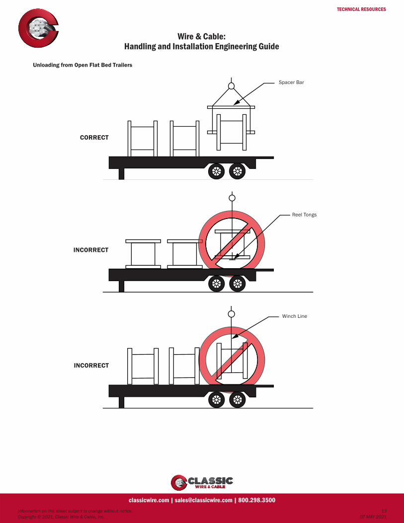
Unloading from Open Flat Bed Trailers
Spacer Bar
Reel Tongs
Winch Line
CORRECT
INCORRECT
INCORRECT

TECHNICAL RESOURCES
Wire & Cable:Handling and Installation Engineering Guide
Information on this sheet subject to change without notice. 14Copyright © 2021, Classic Wire & Cable, Inc. 07 MAY 2021
classicwire.com | [email protected] | 800.298.3500
Cable Reel Handling
Do NOT allow forks to touch cable or reel wrap. Do NOT allow forks to touch cable or reel wrap.
Do NOT allow forks to touch cable or reel wrap.This method OK for Low Voltage Cable only!
Do NOT allow forks to touch cable or reel wrap.
TECHNICAL RESOURCES
Wire & Cable:Handling and Installation Engineering Guide
Information on this sheet subject to change without notice. 15Copyright © 2021, Classic Wire & Cable, Inc. 07 MAY 2021
classicwire.com | [email protected] | 800.298.3500
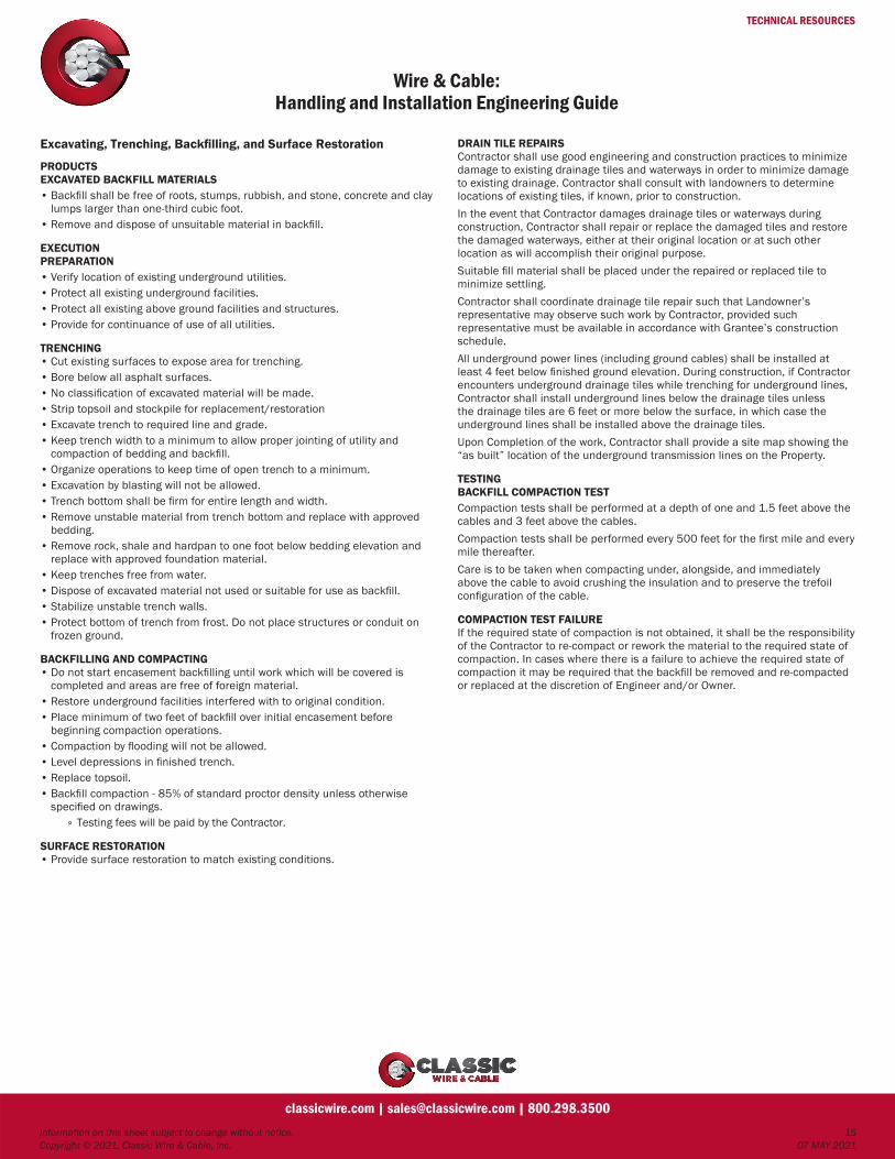
Excavating, Trenching, Backfilling, and Surface Restoration
PRODUCTSEXCAVATED BACKFILL MATERIALS• Backfill shall be free of roots, stumps, rubbish, and stone, concrete and clay
lumps larger than one-third cubic foot.• Remove and dispose of unsuitable material in backfill.
EXECUTIONPREPARATION• Verify location of existing underground utilities.• Protect all existing underground facilities.• Protect all existing above ground facilities and structures.• Provide for continuance of use of all utilities.
TRENCHING• Cut existing surfaces to expose area for trenching.• Bore below all asphalt surfaces.• No classification of excavated material will be made.• Strip topsoil and stockpile for replacement/restoration• Excavate trench to required line and grade.• Keep trench width to a minimum to allow proper jointing of utility and
compaction of bedding and backfill.• Organize operations to keep time of open trench to a minimum.• Excavation by blasting will not be allowed.• Trench bottom shall be firm for entire length and width.• Remove unstable material from trench bottom and replace with approved
bedding.• Remove rock, shale and hardpan to one foot below bedding elevation and
replace with approved foundation material.• Keep trenches free from water.• Dispose of excavated material not used or suitable for use as backfill.• Stabilize unstable trench walls.• Protect bottom of trench from frost. Do not place structures or conduit on
frozen ground.
BACKFILLING AND COMPACTING• Do not start encasement backfilling until work which will be covered is
completed and areas are free of foreign material.• Restore underground facilities interfered with to original condition.• Place minimum of two feet of backfill over initial encasement before
beginning compaction operations.• Compaction by flooding will not be allowed.• Level depressions in finished trench.• Replace topsoil.• Backfill compaction - 85% of standard proctor density unless otherwise
specified on drawings.° Testing fees will be paid by the Contractor.
SURFACE RESTORATION• Provide surface restoration to match existing conditions.
DRAIN TILE REPAIRSContractor shall use good engineering and construction practices to minimize damage to existing drainage tiles and waterways in order to minimize damage to existing drainage. Contractor shall consult with landowners to determine locations of existing tiles, if known, prior to construction.In the event that Contractor damages drainage tiles or waterways during construction, Contractor shall repair or replace the damaged tiles and restore the damaged waterways, either at their original location or at such other location as will accomplish their original purpose.Suitable fill material shall be placed under the repaired or replaced tile to minimize settling.Contractor shall coordinate drainage tile repair such that Landowner’s representative may observe such work by Contractor, provided such representative must be available in accordance with Grantee’s construction schedule.All underground power lines (including ground cables) shall be installed at least 4 feet below finished ground elevation. During construction, if Contractor encounters underground drainage tiles while trenching for underground lines, Contractor shall install underground lines below the drainage tiles unless the drainage tiles are 6 feet or more below the surface, in which case the underground lines shall be installed above the drainage tiles.Upon Completion of the work, Contractor shall provide a site map showing the “as built” location of the underground transmission lines on the Property.
TESTINGBACKFILL COMPACTION TESTCompaction tests shall be performed at a depth of one and 1.5 feet above the cables and 3 feet above the cables.Compaction tests shall be performed every 500 feet for the first mile and every mile thereafter.Care is to be taken when compacting under, alongside, and immediately above the cable to avoid crushing the insulation and to preserve the trefoil configuration of the cable.
COMPACTION TEST FAILUREIf the required state of compaction is not obtained, it shall be the responsibility of the Contractor to re-compact or rework the material to the required state of compaction. In cases where there is a failure to achieve the required state of compaction it may be required that the backfill be removed and re-compacted or replaced at the discretion of Engineer and/or Owner.

TECHNICAL RESOURCES
Jacket Material Selection Chart
Information on this sheet subject to change without notice. Copyright © 2021, Classic Wire & Cable, Inc. 07 MAY 2021
classicwire.com | [email protected] | 800.298.3500
Polyvinyl Chloride (PVC) Polyethylene (PE) Neoprene
Chlorosulphonated Polyethylene (CP) Thermoplastic CP
Mechanical
Abrasion Resistance Good Excellent Good Good Excellent
Tensile Strength Excellent Excellent Excellent Excellent Good
Elongation Good Excellent Excellent Excellent Good
Compression Resistance Good Excellent Excellent Excellent Good
Flexibility Good Fair Excellent Excellent Fair
Environmental
Flame Good Poor Excellent Excellent Good
Fresh Water Good Exceptional Excellent Excellent Excellent
Salt Water Good Exceptional Excellent Excellent Excellent
Motor Oil Good Excellent Good Good Good
Fuel Oil Good Slight swelling above 60°C Good Good Poor above 110°C
Crude Oil Good Slight swelling above 60°C Good Good Poor above 110°C
Creosote Poor Good Fair Fair Good
Gasoline Good Excellent Poor Poor Excellent
Kerosene GoodSlight swelling at
higher temperature Poor PoorSlight swelling at
higher temperature
Isopropyl Alcohol Fair Good Fair Good Good
Wood Alcohol Fair Good Fair Good Good
Grain Alcohol Fair Good Fair Good Good
Sulfuric Acid Excellent Excellent Excellent Excellent Excellent
Nitric Acid Excellent Excellent Excellent Excellent Excellent
Hydrochloric Acid Excellent Excellent Excellent Excellent Excellent
Sodium Hydroxide (Lye) Good Excellent Good Excellent Excellent
Potassium Hydroxide (Potash) Good Excellent Good Excellent Excellent
Calcium Hydroxide (Lime) Good Excellent Poor Fair Excellent
Acetone Poor Excellent Poor Fair Good
Methyl Ethyl Ketone (MEK) Poor Good Poor Fair Good
Ethyl Acetate Poor Good Poor Fair Good
Lacquer Thinner Poor Good Poor Fair Good
Chloroform Poor Good Poor Fair Good
Carbon Tetrachloride Poor Good Poor Fair Good
Methyl Chloride Poor Poor Poor Poor Poor
General
Leaves protective residue after combustion Yes No Yes Yes Yes
Oxygen index (ASTMD-2863) 23-30% 17-18% 31-39% 30-36% 30-34%
Halogen content - % weight 26 0 18 14 18-20
Minimum installation temperature -10°C -40°C -20°C -20°C -40°C
Dimensional stability underheat Fair Fair Excellent Excellent Fair
Maximum operating temperature 75°C 75°C 90°C 90°C 75°CNote: When cables are to be installed in cold weather, they should be kept in heated storage for at least 24 hrs. before installation.
TECHNICAL RESOURCES
EPR Performance Specifications
Information on this sheet subject to change without notice. Copyright © 2021, Classic Wire & Cable, Inc. 07 MAY 2021
classicwire.com | [email protected] | 800.298.3500
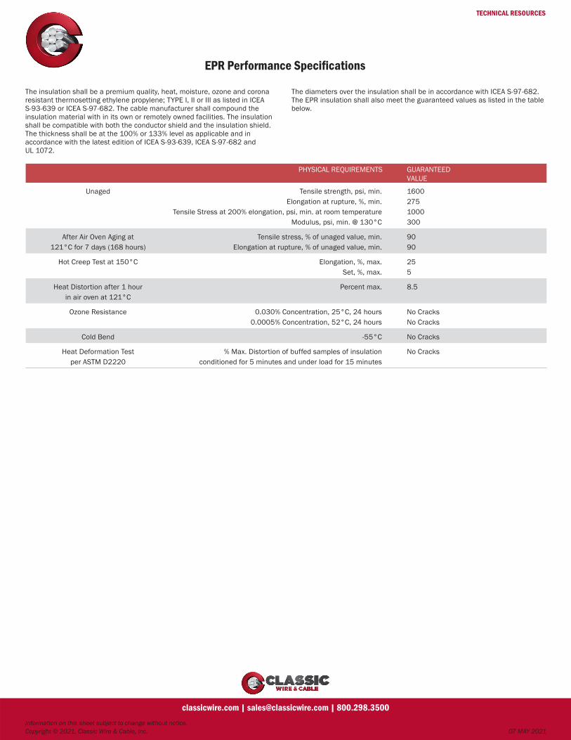
PHYSICAL REQUIREMENTS GUARANTEED VALUE
Unaged Tensile strength, psi, min.Elongation at rupture, %, min.
Tensile Stress at 200% elongation, psi, min. at room temperatureModulus, psi, min. @ 130°C
16002751000300
After Air Oven Aging at121°C for 7 days (168 hours)
Tensile stress, % of unaged value, min.Elongation at rupture, % of unaged value, min.
9090
Hot Creep Test at 150°C Elongation, %, max.Set, %, max.
255
Heat Distortion after 1 hour in air oven at 121°C
Percent max. 8.5
Ozone Resistance 0.030% Concentration, 25°C, 24 hours0.0005% Concentration, 52°C, 24 hours
No CracksNo Cracks
Cold Bend -55°C No Cracks
Heat Deformation Test per ASTM D2220
% Max. Distortion of buffed samples of insulation conditioned for 5 minutes and under load for 15 minutes
No Cracks
The insulation shall be a premium quality, heat, moisture, ozone and corona resistant thermosetting ethylene propylene; TYPE I, II or III as listed in ICEA S-93-639 or ICEA S-97-682. The cable manufacturer shall compound the insulation material with in its own or remotely owned facilities. The insulation shall be compatible with both the conductor shield and the insulation shield. The thickness shall be at the 100% or 133% level as applicable and in accordance with the latest edition of ICEA S-93-639, ICEA S-97-682 and UL 1072.
The diameters over the insulation shall be in accordance with ICEA S-97-682. The EPR insulation shall also meet the guaranteed values as listed in the table below.

TECHNICAL RESOURCES
Thermal Resistivities of Materials
Information on this sheet subject to change without notice. Copyright © 2021, Classic Wire & Cable, Inc. 07 MAY 2021
classicwire.com | [email protected] | 800.298.3500
Material Thermal Resistivity (ρT)
Km/W
Insulating Materials*
Paper insulation in solid type cables 6.0
Paper insulation in oil-filled cables 5.0
Paper insulation in cables with external gas pressure 5.5
Paper insulation in cables with internal gas pressure
A) Pre-impregnated 5.5
B) Mass-impregnated 6.0
PE 3.5
XLPE 3.5
PPL 5.5
Polyvinyl chloride
Up to and including 3kV cables 5.0
Greater than 3kV cables 6.0
EPR
Up to and including 3kV cables 3.5
Greater than 3kV cables 5.0
Butyl rubber 5.0
Rubber 5.0
Protective Coverings
Compounded jute and fibrous materials 6.0
Rubber sandwich protection 6.0
Polychoroprene
PVC
Up to and including 35kV cables 5.0
Greater than 35kV cables 6.0
PVC/Bitumen on corrugated aluminum sheaths 6.0
PE 3.5
Materials for Duct Installations
Concrete 1.0
Fibre 4.8
Earthenware 1.2
PVC 6.0
PE 3.5
*For the purposes of current rating calculations, the semiconducting screening materials are assumed to have the same thermal properties as the adjacent dielectric materials.Where plastic or elastomeric materials are used for protective coverings, the thermal resistivities shall be taken to be the same as those for the insulation grades of the materials given in this table.
TECHNICAL RESOURCES
Guide for the Installation of ACSR Twisted Pair (TP) Conductor
Information on this sheet subject to change without notice. Copyright © 2021, Classic Wire & Cable, Inc. 07 MAY 2021
classicwire.com | [email protected] | 800.298.3500
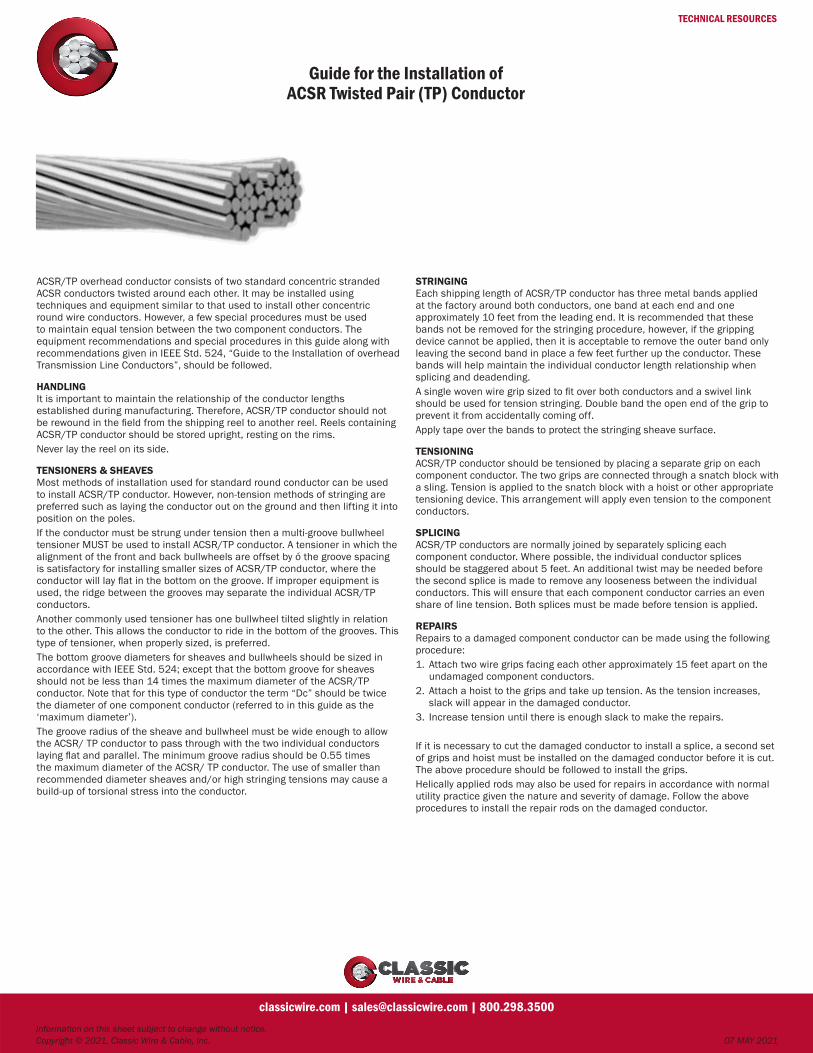
ACSR/TP overhead conductor consists of two standard concentric stranded ACSR conductors twisted around each other. It may be installed using techniques and equipment similar to that used to install other concentric round wire conductors. However, a few special procedures must be used to maintain equal tension between the two component conductors. The equipment recommendations and special procedures in this guide along with recommendations given in IEEE Std. 524, “Guide to the Installation of overhead Transmission Line Conductors”, should be followed.
HANDLINGIt is important to maintain the relationship of the conductor lengths established during manufacturing. Therefore, ACSR/TP conductor should not be rewound in the field from the shipping reel to another reel. Reels containing ACSR/TP conductor should be stored upright, resting on the rims.Never lay the reel on its side.
TENSIONERS & SHEAVESMost methods of installation used for standard round conductor can be used to install ACSR/TP conductor. However, non-tension methods of stringing are preferred such as laying the conductor out on the ground and then lifting it into position on the poles.If the conductor must be strung under tension then a multi-groove bullwheel tensioner MUST be used to install ACSR/TP conductor. A tensioner in which the alignment of the front and back bullwheels are offset by ó the groove spacing is satisfactory for installing smaller sizes of ACSR/TP conductor, where the conductor will lay flat in the bottom on the groove. If improper equipment is used, the ridge between the grooves may separate the individual ACSR/TP conductors.Another commonly used tensioner has one bullwheel tilted slightly in relation to the other. This allows the conductor to ride in the bottom of the grooves. This type of tensioner, when properly sized, is preferred.The bottom groove diameters for sheaves and bullwheels should be sized in accordance with IEEE Std. 524; except that the bottom groove for sheaves should not be less than 14 times the maximum diameter of the ACSR/TP conductor. Note that for this type of conductor the term “Dc” should be twice the diameter of one component conductor (referred to in this guide as the ‘maximum diameter’).The groove radius of the sheave and bullwheel must be wide enough to allow the ACSR/ TP conductor to pass through with the two individual conductors laying flat and parallel. The minimum groove radius should be 0.55 times the maximum diameter of the ACSR/ TP conductor. The use of smaller than recommended diameter sheaves and/or high stringing tensions may cause a build-up of torsional stress into the conductor.
STRINGINGEach shipping length of ACSR/TP conductor has three metal bands applied at the factory around both conductors, one band at each end and one approximately 10 feet from the leading end. It is recommended that these bands not be removed for the stringing procedure, however, if the gripping device cannot be applied, then it is acceptable to remove the outer band only leaving the second band in place a few feet further up the conductor. These bands will help maintain the individual conductor length relationship when splicing and deadending.A single woven wire grip sized to fit over both conductors and a swivel link should be used for tension stringing. Double band the open end of the grip to prevent it from accidentally coming off.Apply tape over the bands to protect the stringing sheave surface.
TENSIONINGACSR/TP conductor should be tensioned by placing a separate grip on each component conductor. The two grips are connected through a snatch block with a sling. Tension is applied to the snatch block with a hoist or other appropriate tensioning device. This arrangement will apply even tension to the component conductors.
SPLICINGACSR/TP conductors are normally joined by separately splicing each component conductor. Where possible, the individual conductor splices should be staggered about 5 feet. An additional twist may be needed before the second splice is made to remove any looseness between the individual conductors. This will ensure that each component conductor carries an even share of line tension. Both splices must be made before tension is applied.
REPAIRSRepairs to a damaged component conductor can be made using the following procedure:1. Attach two wire grips facing each other approximately 15 feet apart on the
undamaged component conductors.2. Attach a hoist to the grips and take up tension. As the tension increases,
slack will appear in the damaged conductor.3. Increase tension until there is enough slack to make the repairs.
If it is necessary to cut the damaged conductor to install a splice, a second set of grips and hoist must be installed on the damaged conductor before it is cut. The above procedure should be followed to install the grips.Helically applied rods may also be used for repairs in accordance with normal utility practice given the nature and severity of damage. Follow the above procedures to install the repair rods on the damaged conductor.

TECHNICAL RESOURCES
Wire & CableMethods of Color Coding
Information on this sheet subject to change without notice. Copyright © 2021, Classic Wire & Cable, Inc. 07 MAY 2021
classicwire.com | [email protected] | 800.298.3500
Color Codes (ICEA Methods)
ICEA/NEMA Method 1
Colored insulation with contrasting ink tracers as required. Six different insulation colors and four different colored ink tracers are used to provide positive identification through 21 conductors. The same identification sequence is repeated for cables containing more than 21 conductors.
ICEA/NEMA Method 2
A neutral colored compound is used with single or double spiral ink tracers as required to provide positive identification through 21 conductors. The identification sequence is repeated for cables containing more than 21 conductors.
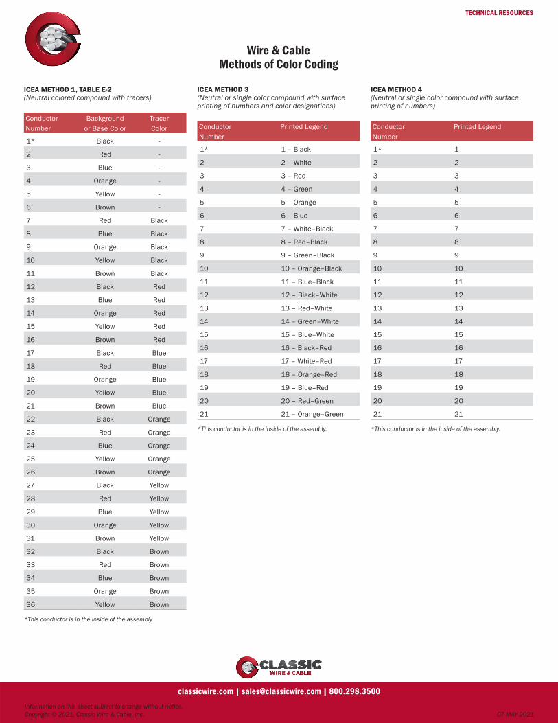
ICEA/NEMA Method 3
A neutral or single colored insulation compound is surface ink printed with both conductor number and color designation to provide positive identification through 21 conductors. The identification sequence is repeated for colors containing more than 21 conductors.
ICEA/NEMA Method 4
A neutral or single colored insulation compound is surface ink printed with conductor number to provide positive conductor identification through 21 conductors. The identification sequence is repeated for cables containing more than 21 conductors.
ICEA/NEMA Method 5
A color coding using braids. Also sometimes specified using colored insulation and contrasting tracers as an extension of Method I to eliminate duplicate conductors. Up to 127 positive conductor coding are available with this method. Usually specified as per: ICEA5-61-402 Table 5-1 or ICEA 5-19-81 Table 5-2.
ICEA/NEMA Method 6
A color coding whereby one conductor in each layer is identified by a braid, tape, ridge, stripe or color.
ICEA/NEMA Paired Color Code
A coding whereby one leg of all pairs is coded white and its mate is coded in accordance with the first 21 conductors of Method 1, omitting white and repeating the sequence as necessary.
Telephone Paired Color Code
Five colors are paired with each of five mate colors to give 25 identified pairs. The color sequences are repeated for more than 25 pairs using colored binder strings for group identification.
Used to identify conductors for point-to-point wiring and for circuit diagrams. Color codes are used to establish a standard for use by different manufacturers.
The first color code used colored tracers in a solid colored braid. Most control cable color codes are adaptations of this method. Later, for ease and convenience, ink printed versions were developed.Telephone requirements established special color codes.
Note: UL and the NEC restrict the use of green and white as colors and stripes. Special color codes are available to meet these requirements. One method is ICEA Method E-2 which is similar to Method 1 and ICEA Method E-4 which is similar to Method 2.

TECHNICAL RESOURCES
Wire & CableMethods of Color Coding
Information on this sheet subject to change without notice. Copyright © 2021, Classic Wire & Cable, Inc. 07 MAY 2021
classicwire.com | [email protected] | 800.298.3500
ICEA METHOD 1, TABLE E-1(Colored compound with tracers)
Conductor Background Tracer Number or Base Color Color
1* Black –
2 White –
3 Red –
4 Green –
5 Orange –
6 Blue –
7 White Black
8 Red Black
9 Green Black
10 Orange Black
11 Blue Black
12 Black White
13 Red White
14 Green White
15 Blue White
16 Black Red
17 White Red
18 Orange Red
19 Blue Red
20 Red Green
21 Orange Green
*This conductor is in the inside of the assembly.
ICEA METHOD 2, TABLE E-1(Neutral colored compound with tracers)
Conductor First SecondNumber Tracer Tracer
Color Color(Wide (Narrow
Tracer) Tracer)
1* Black –
2 White –
3 Red –
4 Green –
5 Orange –
6 Blue –
7 White Black
8 Red Black
9 Green Black
10 Orange Black
11 Blue Black
12 Black White
13 Red White
14 Green White
15 Blue White
16 Black Red
17 White Red
18 Orange Red
19 Blue Red
20 Red Green
21 Orange Green
*This conductor is in the inside of the assembly.
ICEA METHOD 1, TABLE E-2(Colored compound with tracers)
Conductor Background Tracer Number or Base Color Color
1* Black –
2 Red –
3 Blue –
4 Orange –
5 Yellow –
6 Brown –
7 Red Black
8 Blue Black
9 Orange Black
10 Yellow Black
11 Brown Black
12 Black Red
13 Blue Red
14 Orange Red
15 Yellow Red
16 Brown Red
17 Black Blue
18 Red Blue
19 Orange Blue
20 Yellow Blue
21 Brown Blue
22 Black Orange
23 Red Orange
24 Blue Orange
25 Yellow Orange
26 Brown Orange
27 Black Yellow
28 Red Yellow
29 Blue Yellow
30 Orange Yellow
31 Brown Yellow
32 Black Brown
33 Red Brown
34 Blue Brown
35 Orange Brown
36 Yellow Brown
*This conductor is in the inside of the assembly.
TECHNICAL RESOURCES
Wire & CableMethods of Color Coding
Information on this sheet subject to change without notice. Copyright © 2021, Classic Wire & Cable, Inc. 07 MAY 2021
classicwire.com | [email protected] | 800.298.3500
ICEA METHOD 1, TABLE E-2(Neutral colored compound with tracers)
Conductor Background Tracer Number or Base Color Color
1* Black -
2 Red -
3 Blue -
4 Orange -
5 Yellow -
6 Brown -
7 Red Black
8 Blue Black
9 Orange Black
10 Yellow Black
11 Brown Black
12 Black Red
13 Blue Red
14 Orange Red
15 Yellow Red
16 Brown Red
17 Black Blue
18 Red Blue
19 Orange Blue
20 Yellow Blue
21 Brown Blue
22 Black Orange
23 Red Orange
24 Blue Orange
25 Yellow Orange
26 Brown Orange
27 Black Yellow
28 Red Yellow
29 Blue Yellow
30 Orange Yellow
31 Brown Yellow
32 Black Brown
33 Red Brown
34 Blue Brown
35 Orange Brown
36 Yellow Brown
*This conductor is in the inside of the assembly.
ICEA METHOD 3(Neutral or single color compound with surface printing of numbers and color designations)
Conductor Printed LegendNumber
1* 1 – Black
2 2 – White
3 3 – Red
4 4 – Green
5 5 – Orange
6 6 – Blue
7 7 – White–Black
8 8 – Red–Black
9 9 – Green–Black
10 10 – Orange–Black
11 11 – Blue–Black
12 12 – Black–White
13 13 – Red–White
14 14 – Green–White
15 15 – Blue–White
16 16 – Black–Red
17 17 – White–Red
18 18 – Orange–Red
19 19 – Blue–Red
20 20 – Red–Green
21 21 – Orange–Green
*This conductor is in the inside of the assembly.
ICEA METHOD 4(Neutral or single color compound with surface printing of numbers)
Conductor Printed LegendNumber
1* 1
2 2
3 3
4 4
5 5
6 6
7 7
8 8
9 9
10 10
11 11
12 12
13 13
14 14
15 15
16 16
17 17
18 18
19 19
20 20
21 21
*This conductor is in the inside of the assembly.

TECHNICAL RESOURCES
Wire & CableMethods of Color Coding
Information on this sheet subject to change without notice. Copyright © 2021, Classic Wire & Cable, Inc. 07 MAY 2021
classicwire.com | [email protected] | 800.298.3500
ICEA METHOD 5(Colored compounds with tracers)
Cond. Background First SecondNumber or Tracer Tracer Base Color Color Color 1* Black – – 2 White – 3 Red – – 4 Green – – 5 Orange – – 6 Blue – – 7 White Black – 8 Red Black – 9 Green Black – 10 Orange Black – 11 Blue Black – 12 Black White –13 Red White –14 Green White –15 Blue White –16 Black Red –17 White Red –18 Orange Red –19 Blue Red –20 Red Green –21 Orange Green –22 Black White Red23 White Black Red24 Orange Black White25 Blue Black White26 Red Black White27 Orange Black White28 Black Red Green29 White Red Green30 Red Black Green31 Green Black Orange32 Orange Black Green33 Blue White Orange34 Black White Orange35 White Red Orange36 Orange White Blue37 White Red Blue38 Black White Green39 White Black Green40 Red White Green41 Green White Blue42 Orange Red Green43 Blue Red Green
Cond. Background First SecondNumber or Tracer Tracer
Base Color Color Color 44 Black White Blue 45 White Black Blue 46 Red White Blue 47 Green Orange Red 48 Orange Red Blue 49 Blue Red Orange 50 Black Orange Red 51 White Black Orange 52 Red Orange Black 53 Green Red Blue 54 Orange Black Blue 55 Blue Black Orange 56 Black Orange Green57 White Orange Green58 Red Orange Green59 Green Black Blue60 Orange Green Blue61 Blue Green Orange62 Black Red Blue63 White Orange Blue64 Red Black Blue65 Green Orange Blue66 Orange White Red67 Blue White Red68 Black Green Blue69 White Green Blue70 Red Green Blue71 Green White Red72 Orange Red Black73 Blue Red Black74 Black Orange Blue75 Red Orange Blue76 Green Red Black77 Orange White Green78 Blue White Green79 Red White Orange80 Green White Orange81 Blue Black Green82 Orange White –83 Green Red –84 Black Green –85 White Green –86 Blue Green –
Cond. Background First SecondNumber or Tracer Tracer
Base Color Color Color 87 Black Orange – 88 White Orange – 89 Red Orange – 90 Green Orange – 91 Blue Orange – 92 Black Blue – 93 White Blue – 94 Red Blue – 95 Green Blue – 96 Orange Blue – 97 Yellow – – 98 Yellow Black – 99 Yellow White – 100 Yellow Red – 101 Yellow Green – 102 Yellow Orange – 103 Yellow Blue – 104 Black Yellow – 105 White Yellow – 106 Red Yellow – 107 Green Yellow – 108 Orange Yellow – 109 Blue Yellow – 110 Black Yellow Red 111 White Yellow Red 112 Green Yellow Red 113 Orange Yellow Red114 Blue Yellow Red 115 Black Yellow White 116 Red Yellow White 117 Green Yellow White 118 Orange Yellow White 119 Blue Yellow White 120 Black Yellow Green121 White Yellow Green122 Red Yellow Green 123 Orange Yellow Green 124 Blue Yellow Green 125 Black Yellow Blue 126 White Yellow Blue 127 Red Yellow Blue
*This conductor is in the inside of the assembly.
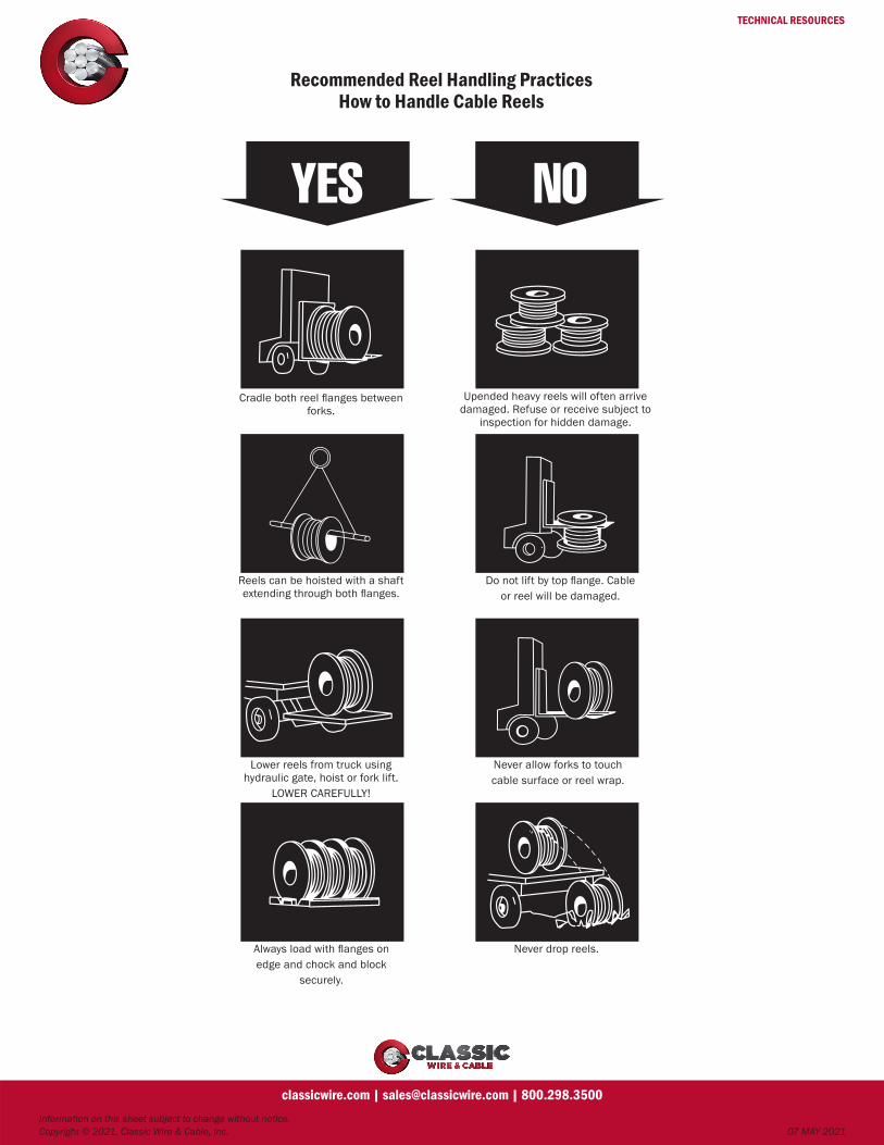
TECHNICAL RESOURCES
Recommended Reel Handling PracticesHow to Handle Cable Reels
Information on this sheet subject to change without notice. Copyright © 2021, Classic Wire & Cable, Inc. 07 MAY 2021
classicwire.com | [email protected] | 800.298.3500
Cradle both reel flanges between forks.
Reels can be hoisted with a shaft extending through both flanges.
Lower reels from truck using hydraulic gate, hoist or fork lift.
LOWER CAREFULLY!
Always load with flanges onedge and chock and block
securely.
Upended heavy reels will often arrive damaged. Refuse or receive subject to
inspection for hidden damage.
Do not lift by top flange. Cableor reel will be damaged.
Never allow forks to touchcable surface or reel wrap.
Never drop reels.

TECHNICAL RESOURCES
Steel Reel Specifications
Information on this sheet subject to change without notice. Copyright © 2021, Classic Wire & Cable, Inc. 07 MAY 2021
classicwire.com | [email protected] | 800.298.3500
THE LAG OPENING SHOULDBE WELL ROUNDED AND
GROUND SMOOTH
LAG OPENING
1” RADIUS
30°
TRAVERSE
FLANGEDIAMETER DRUM
DIAMETER
HEAD SHEET
INNER RING
SHORT CROSS ARMLONG CROSS ARMFLUTES
ARBOR HOLE
Y”
TIRE
DRUM
I-BEAM TIRE FLUTED STEEL REEL—TYPE RMTNOTE — When required, cable test hole in the flange shall not have more than 3 flutes removed to provide this opening. The cable test hole shall be reinforced along the cutout with a metal equal to or greater than that required for use in the drum of the reel. Height of cable test hole to be no greater than onehalf the length.

TECHNICAL RESOURCES
Steel Reel Specifications
Information on this sheet subject to change without notice. Copyright © 2021, Classic Wire & Cable, Inc. 07 MAY 2021
classicwire.com | [email protected] | 800.298.3500
General Purpose Steel Fluted Returnable Reels for Wire and Cables—Class 1Type* –Reel Dimensions– Max. Arbor Max. Tire ––––Cross Arms–––– Drum Inner (Flange) Maximum
Fl Trav Drum Overall Hole Number Size U.S.S. Long Short U.S.S. Ring Head –––Capacity–––Width Diameter Flutes (in) (ga) (in) (in) (ga) Dimensions Sheet (lb) (kg)(in) (in) per Hd (in) U.S.S.
(ga)
RM 42 24 24 33 3.25 24 2x5/16 8 5x2 4x2 12 3-3/4x3/16 16 1,956 887
RM 48 24 24 33 3.25 24 2x5/16 8 5x2 4x2 12 3-3/4x3/16 16 3,072 1,393
RM 54 32 32 41 3.25 30 2x5/16 8 5x2 4x2 12 3-3/4x3/16 16 4,464 2,024
RM 60 32 32 41 3.25 30 2x5/16 8 5x2 4x2 12 3-3/4x3/16 16 6,360 2,884
RM 66 32 36 41 3.25 32 2-1/2x1/2 8 6x2 5x2 12 3-3/4x3/16 16 7,680 3,482
RM 72 36 40 45 3.25 40 2-1/2x1/2 8 6x2 5x2 12 3-3/4x1/4 16 10,260 4,654
RM 72 36 48 45 3.25 40 2-1/2x1/2 8 6x2 5x2 12 3-3/4x1/4 16 7,872 3,570
RM 78 36 48 45 3.25 40 2-1/2x5/8† 8 6x2 5x2 12 3-3/4x1/4 16 10,752 4,876
RMT 84 36 42 45 5.25 40 7.5lb/ft, 3” I-Beam 8 7-7/8x2 6x2 10 4x1/4 16 13,608 6,171
RMT 84 45 42 55 5.25 40 7.5lb/ft, 3” I-Beam 8 7-7/8x2 6x2 10 4x1/4 16 17,004 7,711
RMT 84 45 56 55 5.25 40 7.5lb/ft, 3” I-Beam 8 7-7/8x2 6x2 10 4x1/4 16 11,196 5,050
RMT 90 45 42 55 5.25 40 7.5lb/ft, 3” I-Beam 8 7-7/8x2 6x2 10 4-1/4x1/4 16 21,036 9,540
RMT 90 45 56 55 5.25 40 7.5lb/ft, 3” I-Beam 8 7-7/8x2 6x2 10 4-1/4x1/4 16 15,216 6,900
RMT 90 54 56 64 5.25 40 7.5lb/ft, 3” I-Beam 8 7-7/8x2 6x2 8 4-1/4x1/4 16 18,252 8,277
RMT 96 60 42 71 5.25 40 7.5lb/ft, 3” I-Beam 8 7-7/8x3 6x3 8 4-1/2x5/16 14 26,000 11,719
RMT 98 60 56 71 5.25 40 7.5lb/ft, 3” I-Beam 8 7-7/8x3 6x3 8 4-1/2x5/16 14 26,000 11,719
RMT** 108 74 56 85 5.25 40 7.5lb/ft, 3” I-Beam 8 7-7/8x3 6x3 8 4-1/2x5/16 14 30,000 13,605
* RM—Flat bar tire** Generally used for aluminum wire and cable† Alternate size is 3x1/2 inchRMT—I-Beam TireNOTE—Tie holes, if necessary, shall be in the flat portion of the head sheet. There will be no holes in the flute itself.NOTE—A range of 3 to 3.25-inch and 5 to 5.25-inch arbor hole diameter shall be permitted for existing reels until the year 2005.
WELDING REQUIREMENTS FOR CLASS 1 REELSHead sheet to tire—at all radii of flute-intermittent weldHead sheet to inner ring—at all radii of flute-intermittent weldDrum to inner ring—intermittent weldCross arm to cross arm—continuous weldCross arm to inner ring—continuous weldCross arm to hub—continuous weldBack-up plate to hub and cross arm—continuous weldPort frame—continuous weldAll welds shall reflect good welding practice with proper penetration.
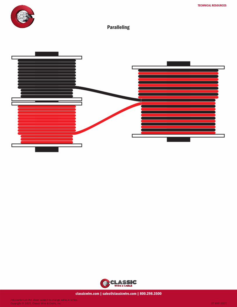
TECHNICAL RESOURCES
Paralleling
Information on this sheet subject to change without notice. Copyright © 2021, Classic Wire & Cable, Inc. 07 MAY 2021
classicwire.com | [email protected] | 800.298.3500

TECHNICAL RESOURCES
Metric IEC Size Compared to AWG or kcmil Size with Equivalent Metric Size
Information on this sheet subject to change without notice. Copyright © 2021, Classic Wire & Cable, Inc. 07 MAY 2021
classicwire.com | [email protected] | 800.298.3500
Area Size Nominal Nominal Number(mm2) AWG or kcmil Overall Overall of Wires
Diameter Diameter(mm) (in)
1010 2000 41.45 1.63 127
1000 41.14 1.62 91
887 1750 38.76 1.53 127
800 36.81 1.45 61
760 1500 35.87 1.41 91
633 1250 32.74 1.29 91
507 1000 29.26 1.15 61
500 29.05 1.14 37
400 25.97 1.02 37
380 750 25.35 0.10 61
304 600 22.68 0.89 61
300 22.46 0.88 37
253.4 500 20.65 0.81 37
240 20.09 0.79 37
203 400 18.49 0.73 37
185 17.64 0.70 37
177 350 17.3 0.68 37
152 300 16 0.63 37
150 15.85 0.62 19
127 250 14.61 0.58 37
120 14.15 0.56 19
107.2 4/0 13.41 0.53 19
95 12.6 0.50 19
85.01 3/0 11.94 0.47 19
70 10.86 0.43 19
67.43 2/0 10.64 0.42 19
53.49 1/0 9.47 0.37 19
50 9.15 0.36 19
Area Size Nominal Nominal Number(mm2) AWG or kcmil Overall Overall of Wires
Diameter Diameter(mm) (in)
42.41 1 8.43 0.33 19
35 7.65 0.30 19
35 7.56 0.30 7
33.62 2 7.42 0.29 7
26.67 3 6.61 0.26 7
25 6.39 0.25 7
21.15 4 5.89 0.23 7
16 5.13 0.20 7
13.3 6 4.67 0.18 7
10 4.05 0.16 7
8.37 8 3.71 0.15 7
6 3.12 0.12 7
5.26 10 2.95 0.12 7
4 2.55 0.10 7
3.31 12 2.34 0.09 7
2.5 2.01 0.08 7
2.08 14 1.85 0.07 7
1.5 1.56 0.06 7
1.31 16 1.47 0.06 7
1 1.29 0.05 7
0.82 18 1.02 0.05 7
0.75 0.98 0.04 7
0.52 20 0.81 0.03 7
0.5 0.8 0.03 7
0.33 22 0.64 0.03 7
0.25 0.56 0.02 7
0.2 24 0.51 0.02 7
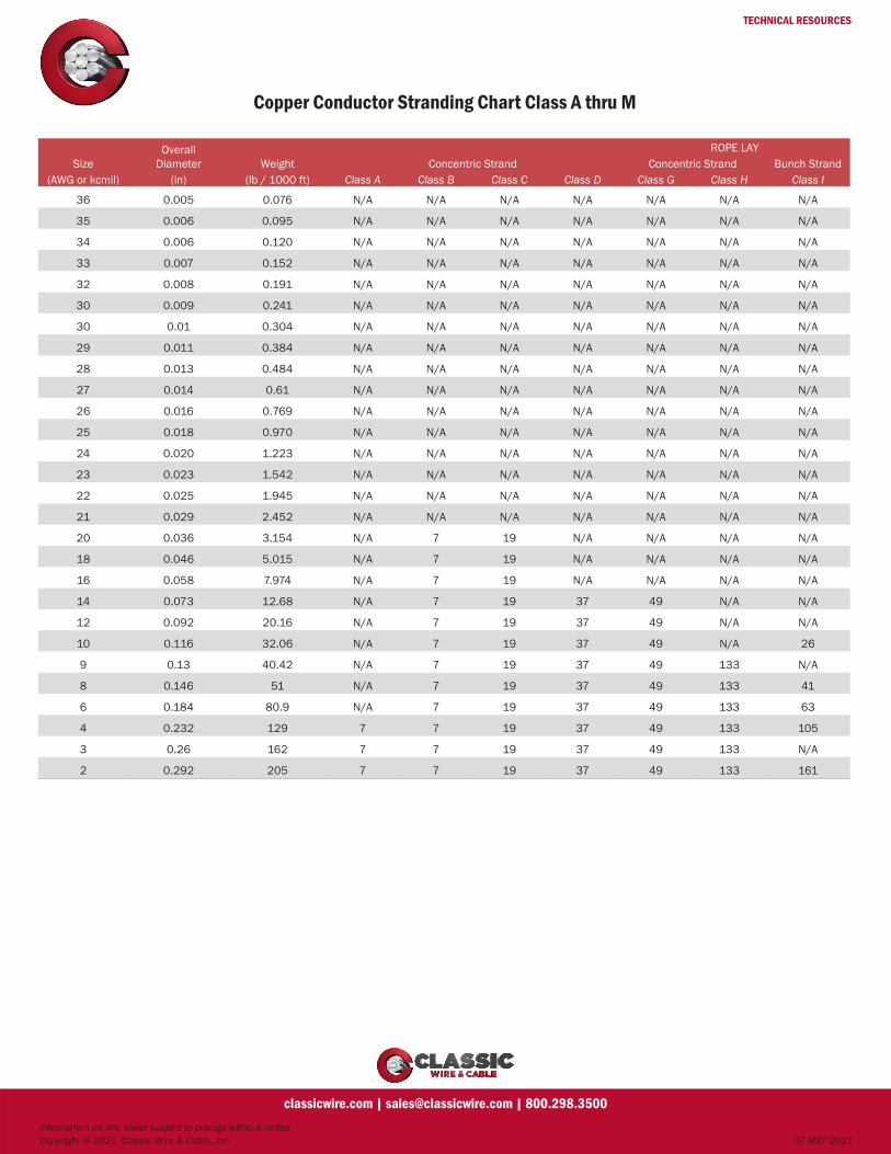
TECHNICAL RESOURCES
Copper Conductor Stranding Chart Class A thru M
Information on this sheet subject to change without notice. Copyright © 2021, Classic Wire & Cable, Inc. 07 MAY 2021
classicwire.com | [email protected] | 800.298.3500
SizeOverall
Diameter Weight Concentric StrandROPE LAY
Concentric Strand Bunch Strand(AWG or kcmil) (in) (lb / 1000 ft) Class A Class B Class C Class D Class G Class H Class I
36 0.005 0.076 N/A N/A N/A N/A N/A N/A N/A
35 0.006 0.095 N/A N/A N/A N/A N/A N/A N/A
34 0.006 0.120 N/A N/A N/A N/A N/A N/A N/A
33 0.007 0.152 N/A N/A N/A N/A N/A N/A N/A
32 0.008 0.191 N/A N/A N/A N/A N/A N/A N/A
30 0.009 0.241 N/A N/A N/A N/A N/A N/A N/A
30 0.01 0.304 N/A N/A N/A N/A N/A N/A N/A
29 0.011 0.384 N/A N/A N/A N/A N/A N/A N/A
28 0.013 0.484 N/A N/A N/A N/A N/A N/A N/A
27 0.014 0.61 N/A N/A N/A N/A N/A N/A N/A
26 0.016 0.769 N/A N/A N/A N/A N/A N/A N/A
25 0.018 0.970 N/A N/A N/A N/A N/A N/A N/A
24 0.020 1.223 N/A N/A N/A N/A N/A N/A N/A
23 0.023 1.542 N/A N/A N/A N/A N/A N/A N/A
22 0.025 1.945 N/A N/A N/A N/A N/A N/A N/A
21 0.029 2.452 N/A N/A N/A N/A N/A N/A N/A
20 0.036 3.154 N/A 7 19 N/A N/A N/A N/A
18 0.046 5.015 N/A 7 19 N/A N/A N/A N/A
16 0.058 7.974 N/A 7 19 N/A N/A N/A N/A
14 0.073 12.68 N/A 7 19 37 49 N/A N/A
12 0.092 20.16 N/A 7 19 37 49 N/A N/A
10 0.116 32.06 N/A 7 19 37 49 N/A 26
9 0.13 40.42 N/A 7 19 37 49 133 N/A
8 0.146 51 N/A 7 19 37 49 133 41
6 0.184 80.9 N/A 7 19 37 49 133 63
4 0.232 129 7 7 19 37 49 133 105
3 0.26 162 7 7 19 37 49 133 N/A
2 0.292 205 7 7 19 37 49 133 161
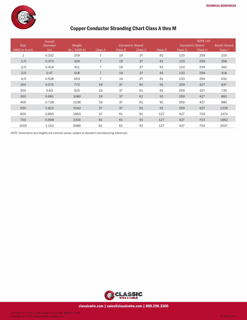
TECHNICAL RESOURCES
Copper Conductor Stranding Chart Class A thru M
Information on this sheet subject to change without notice. Copyright © 2021, Classic Wire & Cable, Inc. 07 MAY 2021
classicwire.com | [email protected] | 800.298.3500
SizeOverall
Diameter Weight Concentric StrandROPE LAY
Concentric Strand Bunch Strand(AWG or kcmil) (in) (lb / 1000 ft) Class A Class B Class C Class D Class G Class H Class I
1 0.332 259 7 19 37 61 133 259 210
1/0 0.373 326 7 19 37 61 133 259 266
2/0 0.419 411 7 19 37 61 133 259 342
3/0 0.47 518 7 19 37 61 133 259 418
4/0 0.528 653 7 19 37 61 133 259 532
250 0.575 772 19 37 61 91 259 427 637
300 0.63 925 19 37 61 91 259 427 735
350 0.681 1080 19 37 61 91 259 427 882
400 0.728 1236 19 37 61 91 259 427 980
500 0.813 1542 37 37 61 91 259 427 1225
600 0.893 1850 37 61 91 127 427 703 1470
750 0.998 2316 61 61 91 127 427 703 1862
1000 1.152 3086 61 61 91 127 427 703 2527
NOTE: Dimensions and weights are nominal values, subject to standard manufacturing tolerances.

TECHNICAL RESOURCES
Allowable Ampacities of Insulated Conductors
Information on this sheet subject to change without notice. Copyright © 2021, Classic Wire & Cable, Inc. 07 MAY 2021
classicwire.com | [email protected] | 800.298.3500
Conductor Size (AWG or kcmil)
60°C (140°F) TW, UF
75°C (167°F) RHW, THHW, THW,
THWN, XHHW, USE, ZW
90°C (194°F) TBS, SA, SIS, FEP, FEPB, MI, RHH, RHW-2, THHN, XHH, XHHW, XHHW-2,
USE-2, ZW
14* - - -
12* 15 20 25
10* 25 30 35
8 35 40 45
6 40 50 55
4 55 65 75
3 65 75 85
2 75 90 100
1 85 100 115
1/0 100 120 135
2/0 115 135 150
3/0 130 155 175
4/0 150 180 205
250 170 205 230
300 195 230 260
350 210 250 280
400 225 270 305
500 260 310 350
600 285 340 385
700 315 375 425
750 320 385 435
800 330 395 445
900 355 425 480
1000 375 445 500
Conductor Size (AWG or kcmil)
60°C (140°F) TW, UF
75°C (167°F) RHW, THHW, THW,
THWN, XHHW, USE, ZW
90°C (194°F) TBS, SA, SIS, FEP, FEPB, MI, RHH, RHW-2, THHN, XHH, XHHW, XHHW-2,
USE-2, ZW
14* 15 20 25
12* 20 25 30
10* 30 35 40
8 40 50 55
6 55 65 75
4 70 85 95
3 85 100 115
2 95 115 130
1 110 130 145
1/0 125 150 170
2/0 145 175 195
3/0 165 200 225
4/0 195 230 260
250 215 255 290
300 240 285 320
350 260 310 350
400 280 335 380
500 320 380 430
600 350 420 475
700 385 460 520
750 400 475 535
800 410 490 555
900 435 520 585
1000 455 545 615
ALLOWABLE AMPACITIES OF INSULATED ALUMINUM OR COPPERCLAD ALUMINUM CONDUCTORS
• Rated Up to and Including 2000 Volts, 60°C through 90°C (140°F through 194°F).
• Not More Than Three Current-Carrying Conductors in Raceway, Cable, or Earth (Directly Buried).
• Based on Ambient Temperature of 30°C (86°F)
ALLOWABLE AMPACITIES OF INSULATED COPPER CONDUCTORS
• Rated Up to and Including 2000 Volts, 60°C through 90°C (140°F through 194°F).
• Not More Than Three Current-Carrying Conductors in Raceway, Cable, or Earth (Directly Buried).
• Based on Ambient Temperature of 30°C (86°F).
* Unless specifically permitted in 240.4(E) through (G), the overcurrent protection shall not exceed 15 amperes for 14 AWG, 20 amperes for 12 AWG, and 30 amperes for 10 AWG copper; or 15 amperes for 12 AWG and 25 amperes for 10 AWG aluminum and copper-clad aluminum after any correction factors for ambient temperature and number of conductors have been applied.See the NEC for conductor ampacities, correction factors, and conditions of use.

TECHNICAL RESOURCES
Wire & CableGlossary of Terms
Information on this sheet subject to change without notice. Copyright © 2021, Classic Wire & Cable, Inc. 07 MAY 2021
classicwire.com | [email protected] | 800.298.3500
AWG
Abbreviation for American Wire Gauge.
Alternating Current
Electric current that continually reverses its direction. Is expressed in cycles per second (hertz or Hz).
Ambient Temperature
The temperature of the medium (gas, liquid or earth) surrounding an object.
American Mustang
A premium grade thermoset cord, UL listed as SOOW or SJOOW, CSA SOOW and SJOOW.
American Wire Gauge (AWG)
A standard system for designating wire diameter. Also referred to as the Brown and Sharpe (B&S) wire gauge.
Ampacity
See Current Carrying Capacity.
Ampere
The unit of current. One ampere is the current flowing through one ohm of resistance at one volt potential.
Anneal
Relief of mechanical stress through application of heat and gradual cooling. Annealing copper renders it soft and less brittle.
Audio Frequency
The range of frequencies audible to the human ear. Usually 20–20,000Hz.
Braid
A fibrous or metallic group of filaments interwoven in cylindrical form to form a covering over one or more wires.
Breakdown Voltage
The voltage at which the insulation between two conductors breaks down.
Bunch Stranding
A group of wires of the same diameter twisted together without a predetermined pattern.
Cabling
The twisting together of two or more insulated conductors to form a cable.
Capacitance
The ability of a dielectric material between conductors to store electricity when a difference of potential exists between the conductors. The unit of measurement is the farad, which is the capacitance value that will store a charge of one coulomb when a one-volt potential difference exists between the conductors. In AC, one farad is the capacitance value that will permit one ampere of current when the voltage across the capacitor changes at a rate of one volt per second.
Circuit (Electric)
The complete path of an electrical current. When the continuity is broken, it is called an open circuit; when continuity is maintained, it is called a closed circuit.
Cold Flow
Permanent deformation of the insulation due to mechanical force or pressure (not due to heat softening).
Color Code
A system for circuit identification through use of solid colors and contrasting tracers.
Compound
An insulating or jacketing material made by mixing two or more ingredients.
Concentricity
In a wire or cable, the measurement of the location of the center of the conductor with respect to the geometric center of the surrounding insulation.
Conductor
An uninsulated wire suitable for carrying electrical current.
Contacts
The parts of the connector that actually carry the electrical current and that touch the equivalent parts in the mating connector.
Continuity Check
A test to determine whether electrical current flows continuously throughout the length of a single wire or individual wires in a cable.
Cord
A flexible insulated wire suitable for carrying electric current.
Corona
Ionization of air surrounding a conductor caused by the influence of high voltage. Causes deterioration of insulation materials.
Crazing
The minute cracks on the surface of plastic materials.
CSA
Abbreviation for Canadian Standards Association, a nonprofit, independent organization that operates a listing service for electrical and electronic materials and equipment. The Canadian counterpart of the Underwriters Laboratories
Current Carrying Capacity
The maximum current an insulated conductor can safely carry without exceeding its insulation and jacket temperature limitations. It is dependent on the installation conditions.
Decibel (db)
A unit that expresses differences of power or voltage level. It is used to express power loss in passive circuits or cables.
Dielectric Strength
The voltage that an insulation can withstand before breakdown occurs. Usually expressed as a voltage gradient (such as volts per mil).
Direct Capacitance
The capacitance measured directly from conductor to conductor through a single insulating layer.
Drain Wire
In a cable, the uninsulated wire laid over the shield component or components and used as a ground connection.
Drawing
In wire manufacture, pulling the metal through a die or series of dies to reduce diameter to a specified size.

TECHNICAL RESOURCES
Wire & CableGlossary of Terms
Information on this sheet subject to change without notice. Copyright © 2021, Classic Wire & Cable, Inc. 07 MAY 2021
classicwire.com | [email protected] | 800.298.3500
Eccentricity
Like concentricity, a measure of the center of a conductor’s location with respect to the circular cross section of the insulation. Expressed as a percentage of displacement of one circle within the other.
Elongation
The fractional increase in length of a material stressed in tension.
EMI
Abbreviation for electromagnetic interference.
Farad
A unit of electrical capacitance.
Filler
1) A material used in multiconductor cables to occupy large interstices formed by the assembled conductors; 2) An inert substance added to a compound to improve properties or decrease cost.
Flame Resistance
The ability of a material to resist the propagation of flame once the heat source is removed.
Flex Life
The measurement of the ability of a conductor or cable to withstand repeated bending.
Frequency
The number of times an alternating current repeats its cycle in one second.
Gauge
A term used to denote the physical size of a wire.
Ground
An electrical term meaning to connect to the earth or other large conducting body to serve as an earth, thus making a complete electrical circuit.
Harness
An arrangement of wires and cables, usually with many breakouts, which have been tied together or pulled into a rubber or plastic sheath, used to interconnect an electric circuit.
Hertz (Hz)
A term replacing cycles per second as an indication of frequency.
Hi-Pot
A test designed to determine the highest voltage that can be applied to a conductor without breaking through the insulation.
Impedance
The total opposition that a circuit offers to the flow of alternating current or any other varying current at a particular frequency. It is a combination of resistance R and reactance X, measured in ohms.
Inductance
The property of a circuit or circuit element that opposes a change in current flow, thus causing current changes to lag behind voltage changes. It is measured in henrys.
Insulation
A material having high resistance to the flow of electric current. Often called a dielectric in radio frequency cable.
Jacket
An outer non-metallic protective covering applied over an insulated wire or cable.
Jumper Cable
A short flat cable interconnecting two wiring boards or devices.
Lay
The length measured along the axis of a wire or cable required for a single strand (in stranded wire) or conductor (in cable) to make one complete turn about the axis of the conductor or cable.
Longitudinal Shield
A tape shield, flat or corrugated, applied longitudinally with the axis of the core being shielded.
Multiconductor
More than one conductor within a single cable complex.
Mylar
A synthetic compound with high dielectric qualities made by DuPont and used extensively in the wire and cable industry in tape form.
NEMA
Abbreviation for National Electrical Manufacturers Association.
Ohm
A unit of electrical resistance.
OSHA
Abbreviation for Occupational Safety and Health Act, specifically the Williams Steiger Law passed in 1970 covering all factors relating to safety in places of employment.
Plasticizer
A chemical agent added to plastics to make them softer and more pliable.
Potting
The sealing of a cable termination or other component with a liquid that cures into an elastomer.
Primary Insulation
The first layer of nonconductive material applied over a conductor, whose prime function is to act as electrical insulation.
Put-Up
Packaging of finished wire or cable by size and length.
PVC
Abbreviation for polyvinyl chloride.
Rated Voltage
The maximum voltage at which an electrical component can operate for extended periods without undue degradation or safety hazard.
REA
Abbreviation for Rural Electrification Administration, which is part of the US Dept. of Agriculture. REA establishes specifications and provides approval for telephone station wire and power cables.
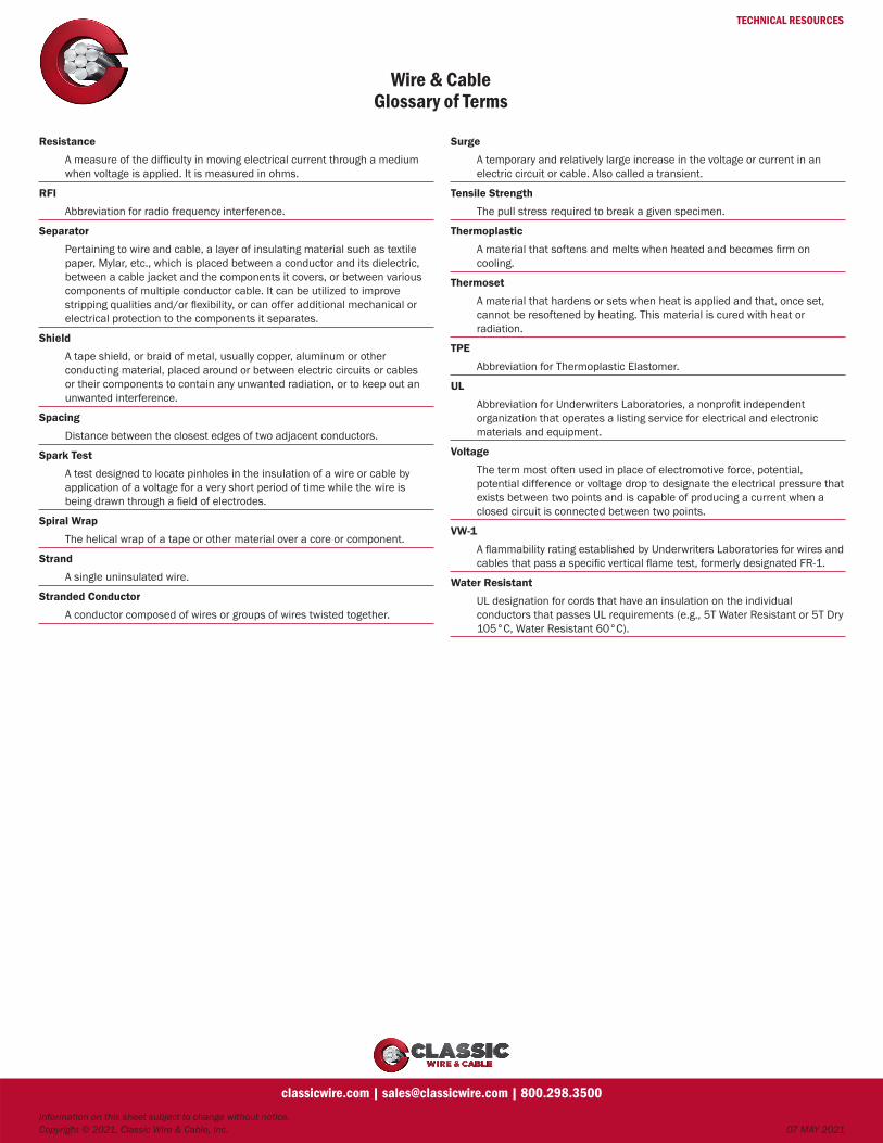
TECHNICAL RESOURCES
Wire & CableGlossary of Terms
Information on this sheet subject to change without notice. Copyright © 2021, Classic Wire & Cable, Inc. 07 MAY 2021
classicwire.com | [email protected] | 800.298.3500
Resistance
A measure of the difficulty in moving electrical current through a medium when voltage is applied. It is measured in ohms.
RFI
Abbreviation for radio frequency interference.
Separator
Pertaining to wire and cable, a layer of insulating material such as textile paper, Mylar, etc., which is placed between a conductor and its dielectric, between a cable jacket and the components it covers, or between various components of multiple conductor cable. It can be utilized to improve stripping qualities and/or flexibility, or can offer additional mechanical or electrical protection to the components it separates.
Shield
A tape shield, or braid of metal, usually copper, aluminum or other conducting material, placed around or between electric circuits or cables or their components to contain any unwanted radiation, or to keep out an unwanted interference.
Spacing
Distance between the closest edges of two adjacent conductors.
Spark Test
A test designed to locate pinholes in the insulation of a wire or cable by application of a voltage for a very short period of time while the wire is being drawn through a field of electrodes.
Spiral Wrap
The helical wrap of a tape or other material over a core or component.
Strand
A single uninsulated wire.
Stranded Conductor
A conductor composed of wires or groups of wires twisted together.
Surge
A temporary and relatively large increase in the voltage or current in an electric circuit or cable. Also called a transient.
Tensile Strength
The pull stress required to break a given specimen.
Thermoplastic
A material that softens and melts when heated and becomes firm on cooling.
Thermoset
A material that hardens or sets when heat is applied and that, once set, cannot be resoftened by heating. This material is cured with heat or radiation.
TPE
Abbreviation for Thermoplastic Elastomer.
UL
Abbreviation for Underwriters Laboratories, a nonprofit independent organization that operates a listing service for electrical and electronic materials and equipment.
Voltage
The term most often used in place of electromotive force, potential, potential difference or voltage drop to designate the electrical pressure that exists between two points and is capable of producing a current when a closed circuit is connected between two points.
VW-1
A flammability rating established by Underwriters Laboratories for wires and cables that pass a specific vertical flame test, formerly designated FR-1.
Water Resistant
UL designation for cords that have an insulation on the individual conductors that passes UL requirements (e.g., 5T Water Resistant or 5T Dry 105°C, Water Resistant 60°C).