Extending Definite Clause Grammar to Handle Flexible Word Order
Upload
khangminh22Category
view
3download
0

The T-Handle and Push Button shifters are timeproven designs for rugged operation in trucks andbuses. They have flexible options available and the T-Handle can be custom assembled by many of ourF.A.S.T. distributors.
SPECIFICATIONS
• Lamp Illumination: 14 volts, orange lens• Switches: ball type, see options for
Neutral and/or Reverse• Travel: 3 inches• Cable Connection: 4 series (1/4-28) or
6 series (5/16-24)• Cable Entry: Push or pull to reverse,
4 hanger positions• “2nd Neutral” type available for
Allison Transmissions
T-Handle and Push Button Shifters
ALLISON AT 540, AT 545, AT 543 55051 55751 56051 R,N,D,3,2,1MT 643, MT 647, MT 644 (MT 640)
MT 653 DR 55052 55752 56052 R,N,2-5,2-4,2,1CLT 650 (MT 650)
MT 654 CR, MT 750 CRD 55053 55753 56053 R,N,1-5,1-4,1-3,1-2,1CLT 654
HT 754 CR 56054 R,N,D,4,3,2,1
V 730 55054 55754 R,N,D,2,1
HT 750 DRD 55055 55755 56055 R,N,2-5,2-4,2-3,2,1CL (B) T 750
HT 740, HT 740FS, HT 740RS 55056 55756 56056 R,N,D,3,2,1
AT542N, AT545N 55934 P-B,R,N,D,D3,D1AT1542N, AT1545N
AT542N, AT545N 55946 P-B,R,N,D,D3,D1AT1542N, AT1545N
MECHANICALUSES CABLE
ELECTRICAL
Transmission Models T-Handle Push Button Shift Inhibitor 2nd Neutral Position StripP-B Shifter
Items listed within yellow field are Basic Part Numbers. Refer to these when ordering a shifter.
See page 6 for Shift Inhibitor and 2nd Neutral P-B Shifters.
B A S I C N U M B E R
2

Ordering the exact shifter that meets your requirements is not difficult. Simply follow the instructions below to create yourown part number. (Example: you are ordering basic part #55051 to fit your Allison transmission #MT 643. You desire thefollowing configuration: Right-hand mount/reverse to front (Chart 1, Option #2); push to reverse/vertical cable hanger(Chart 2, Option #7); 4 Series Cable (Chart 3, Option #4); No Switches (Chart 4, Option #0). Your part number would be 55051-2740.)
1. Match your automatic transmission model to the basic part number. This is your BASIC NUMBER.
2. Refer to Charts 1 through 4 on this page for assembly configuration in order to meet vehicle and system requirements.(Not applicable to Shift Inhibitor and 2nd Neutral P-B Shifter.)
3. Follow the form below and enter the option number desired from each chart in the appropriate order.
BASIC NUMBER OPTION #from chart 1
OPTION #from chart 2
OPTION #from chart 3
OPTION #from chart 4
CONTROL MOUNT/REVERSE POSITION OPTIONS CHART 1
OPTION #1Left-Hand Mount
OPTION #2Right-Hand Mount
OPTION #3Left-Hand Mount
OPTION #4Right-Hand Mount
CABLE SERIES OPTIONS CHART 3
CABLE HANGER BRACKET POSITION OPTIONS
OPTION #1Cable PULLS Transmission
Arm into REVERSE
OPTION #5Cable PUSHES Transmission
Arm into REVERSE
OPTION #3Cable PULLS Transmission
Arm into REVERSE
OPTION #7Cable PUSHES Transmission
Arm into REVERSE
REVERSE TO FRONT - USE WITH CONTROL MOUNT OPTIONS 1 & 2
OPTION #2Cable PUSHES Transmission
Arm into REVERSE
OPTION #6Cable PULLS Transmission
Arm into REVERSE
OPTION #4Cable PUSHES Transmission
Arm into REVERSE
OPTION #8Cable PULLS Transmission
Arm into REVERSE
REVERSE TO REAR - USE WITH CONTROL MOUNT OPTIONS 3 & 4
OPTION #4 OPTION #64 Series 6 Series1/4 - 28 Thread (.25 - 28) 5/16 - 24 Thread (.31 - 24)
ELECTRIC SWITCH OPTIONS CHART 4
OPTION #0 OPTION #1No Switches Reverse Switch
OPTION #2 OPTION #3Neutral Switch Reverse and Neutral Switch
CHART 2
How to Order the Shifter
REV. REV. REV.
REV. REV. REV.
REV.
REV.
Vehicle FrontReverse to Front
Vehicle FrontReverse to Rear
3
EXAMPLE

Transmission Connection Kits
Transmission kits come complete with shift arm, transmission mounting bracket, cable hanger and required hardware. Connection kits are designed to fit any of the five most popular entry positions to the transmission shift arm. Refer to the following drawings to find the cable entry that best fits your vehiclerequirements and shifter control positions (push to reverse, pull to reverse), then assemble the kit to match the installation required. Shown below are configurations that can be made from the Universal Kit. (Universal Kit #59005 includes all parts to assemble any 59004 and 59006 kit configuration.)
.75 (19)
6.506(165.1)
5.886(149.2)
5.156(130.9)
3.256(82.5)
3.75 (95.2) 0.28 (07.1)4.38 (111.1)
2.66 (67.5)
.73 (18.5)
.50 (12.7)
1.106(27.9)
4.386(111.2)
17°6REF
2.606(66.0)
4.40 (111.8)
.32 (8.1)
0.25 (07.1)
3.75 (85.3) (8) HOLES
6.766(171.7) 4.006
(101.8)
1.53 (38.8)
5.13+.036
.00
R .50
4.38
2.19
2.184.38
3.88
7.76
5.25
2.26
.14TYP (4) SLOTS
.25 WIDE X .42 LONG6(4) SLOTS
.30 REF
4.3756REF
12.70±.06
.08
.05
IDENTIFICATION LABLE6(LOCATED INSIDE OF TOWER)
HEIGHT
2.646INSIDE
+.036.00
Accessories
MOUNTING FLANGE59002Made of prefabricated steel with a matte blackepoxy finish. Simplifies a top mount installationand is perfect for vehicle conversions. Kit iscomplete with control mounting hardware. Usewith cable hanger bracket in any position.
MOUNTING WEDGE59009A cast aluminum wedge with a matte blackepoxy finish. Raises the shifter to a 17° anglefrom desired mounting surface. Kit is completewith control mounting hardware. Use withcable hanger bracket in any position except #1 or #2.
MOUNTING TOWER59000 (13")59035 (9")A prefabricated tower with a matte black epoxyfinish. Features access panels on both sides foreasy installation and adjustment. A rubber floorgasket is included with tower. Kit is completewith control mounting hardware. For use withcable hanger positions #3, 4, 7, and 8 ONLY!
SWITCH AND PIN SET KIT50036-1
SWITCH SET50036-2
PIN SET50036-3
FINGER RELEASE KIT59193-1
T-HANDLE KIT59228
PUSH-PULL SHIFT CABLES(Used with Controls and Kits)4 Series: 1/4 - 28 thread, base partnumber: 100-4333 length (recommended)6 Series: 5/16 - 24 thread, base partnumber: 100-6333 length
TRANSMISSION CONNECTION KITS
UNASSEMBLED UNIVERSALKIT OIL PAN MOUNT59004 4 Series59006 6 Series59005 4 and 6 Series
HardwareKits to be assembled in field to fit installation required.
MACHINE PAD MOUNT59369-1 4 Series59369-2 6 Series
Mount to machine pad above the transmission shift arm. They do not mount to oil pan bolts as shown in diagrams above. * HT Series, MT 654 with 4.5" oil pan. For refuse and HD applcations.
CONFIGURATION #1Cable PUSHES Transmission
Arm into REVERSE.Use with Shifter Control Positions
numbers 2, 4, 5, 7.Cable 100-4333-L / 100-6333-L
CONFIGURATION #2Cable PULLS Transmission
Arm into REVERSE.Use with Shifter Control Positions
numbers 1, 3, 6, 8.Cable 100-4333-L / 100-6333-L
CONFIGURATION #3Cable PUSHES Transmission
Arm into REVERSE.Use with Shifter Control Positions
numbers 2, 4, 5, 7.Cable 100-4333-L / 100-6333-L
CONFIGURATION #4Cable PULLS Transmission
Arm into REVERSE.Use with Shifter Control Positions
numbers 1, 3, 6, 8.Cable 100-4333-L / 100-6333-L
CONFIGURATION #5Cable PUSHES Transmission
Arm into REVERSE.Use with Shifter Control Positions
numbers 2, 4, 5, 7.Cable 100-4333-L / 100-6333-L
4

NG Shifter
This product combines the strength and reliability ofthe T-Handle Shifter with the latest in manufacturingtechnologies to produce a high value control system forour customers.
As an added feature, we have incorporated a quick-connect cable mounting system into this control.Utilizing a clamp built into the cable mounting bracket,the assembler needs only a standard 1/4 x 1" bolt andlocknut to attach the cable to the control. This allowsfaster assembly of the cable, while using commonmounting hardware available anywhere.
STANDARD FEATURES:
• Steel chassis and handle assembly• Black E-coat finish on handle and zinc
plating on other metal parts for corrosion protection
• Black textured polymer knob and trim covers
• Four 1/4-20 threaded mounting holes• All detents are positive locking (no ramping between detents)• Requires 4 series, 3" travel cable with
clamp type hub and 1/4-28 rod threads• Maximum 2-1/2" of actual cable travel
produced• Built-in cable clamp requires a 1/4 x 1"
bolt w/locknuts: Kit #NG0016-1• Unthreaded pivot for easy cable hook-up
AVAILABLE CONFIGURATIONS:
• Right- or left-hand mounting• Push or pull to reverse• Top mounting plate available• 14 or 28 VDC illumination, single or dual
(ground included) wire leads• Electrical switches – contact factory• Side push button factory preset at 0 or
45 degrees• Cable bracket angle factory preset at 0, 30,
60, or 90 degrees.• Currently available for Allison AT545,
MT643, MT653DR, MT654CR, HT740, HT750CR, HT750DR, HT754CR
• There are no charts to build a part number with this style control. Consult factory with specifications to receive recommendation and part number.
5

2nd Neutral P-B Shifter Shift Inhibitor
The Shift Inhibitor is designed to prevent costly drivetrain damage due to high RPM shifting.
Automatic transmissions in refuse packers and similarheavy-duty vehicles, especially those involved in frequentstop-and-go PTO operations where engine speeds aboveidle are required, can suffer major abuse from impropershifting. If the driver does not wait until engine RPMsreturn to idle before shifting, high inertial loads can beforced upon the transmission and drivetrain, potentiallyleading to extensive and expensive damage.
The Shift Inhibitor System combats this by delaying theshifting process until the engine has returned to idlespeed. It is a pneumatic-mechanical system and complieswith the Allison® Transmission Watch Notice #65, requiringa neutral to range shift inhibitor system.
SYSTEM COMPONENTS:• Shift inhibitor control• Engine speed sensor*• Speed switch*• Airbrake Tubing*• Push-Pull Cable• Fittings*• Transmission Connection Kit
* These items are not supplied.Use this bulletin to determine the shifter part number, then consult with Sales/Engineering to create the correct system for your application.
1. Select proper BASIC NUMBER box from page 2 of this brochure.
2. Select position from Chart 1 on page 3.
3. Select Cable Series from Chart 3 on page 3.
4. Select Hanger Bracket Position from Chart 2 onpage 3 or Chart 2a right. Note: If using options from chart 2 on page 3, place a “0” prefix with the single digit in box below.
NOTE: These shifters offer 4 positions NOT available with the standard T-handle shifters. They are shown as additional options on this page.
This control is used on Allison's AT transmissions that havea 2nd neutral position beyond reverse and no internal parking pawl mechanism. Movement of the shiftselector from reverse to the “PB” position will shift thetransmission into 2nd neutral and actuate the vehicleSpring Parking Brake system control.
In the mechanical control, brake actuation is accomplishedthrough a push/pull cable. In the electrical control, brakeactuation is accomplished through an electrical switch.
The shift position indicator reads “PB R N D D3 D1”.
SPECIFICATIONS:• Rugged steel construction.• Four 1/4-20 threaded mounting holes.• 14 volt illumination, single wire with
chassis ground.• Uses a 4 series High Performance
transmission shift cable.• Detents are ramped “D1” thru “N” on
upshift and “R” to “N” on downshift.• Mechanical brake actuation cable is 3
series. Cable travel is .74" from “R” to “PB”.• Electrical brake actuation switch has
contacts closed in all positions “D1” thru “R”.Switch contacts open in “PB” position only.Electrical load not to exceed 1 amp induc-tive @ 13 VDC.
BASIC NUMBER OPTION #from chart 1
Control Mount
OPTION #from chart 3Cable Series
OPTION #from chart
2 or 2aHanger Position
MORE CABLE HANGER BRACKETPOSITION OPTIONSX = 36° for shift inhibitor X = 45° for 2nd neutral shifter
OPTION #09Cable PULLS Transmission
Arm into REVERSE
OPTION #11Cable PUSHES Transmission
Arm into REVERSE
OPTION #10Cable PUSHES Transmission
Arm into REVERSE
OPTION #12Cable PULLS Transmission
Arm into REVERSE
CHART 2a
REV. REV.
REV. REV.
6
How to Order the Shift Inhibitor and 2nd Neutral P-B Shifter:
Thesepositions
are availableonly for
Shift Inhibitorand 2ndNeutral
P-B Shifter.

Modulators
The modulator cable control is designed to send theengine throttle rate (on a mechanically governed engine)to the hydraulic control valve in the transmission. It will fit AllisonTM Transmission models AT500, MT600, HT700,V730, CLT650, and CLBT750 series.
SPECIFICATIONS:• Control Cable is polymer lined rated at
300° F (149° C)• 4 inch bend radii minimum• Built-in spring returns to idle• Pull function recommended, but push
also available• Can be locally assembled via F.A.S.T. cable
assembly distributors.
Pull Type Description Transmission2124 Clamp FMX
3-series end (threaded mount)2130 Bulkhead Allison
3-series end2179 Clamp C-6
3-series end2180 Bulkhead C-6
3-series end2182 Bulkhead Hydramatic
4-series end (350/400)2183 Clamp Hydramatic
4-series end (350/400)2220 Bulkhead Allison
4-series end2230 Clamp Allison
4-series end
Push Type Description Transmission2225 Bulkhead Allison
4-series end2235 Clamp Allison
4-series end
Modulator Slip Link Kit (shown at right)
Polymer Link Thread Size For Use withPart No. Modulator Part No.
59049-1 (3 Series) 2124, 2179, 218010-32UNF-2A THD
59049-2 (4 Series) 2220, 2225, 2230, 22352528UNF-2ATHD
The Slip-Link kit includes the necessary hardware for complete installation of the kit to the engine fuel control lever. Kit includes a slotted slip-link, link pin, flatwasher, cotter pin and locknut.To order, see chart below.
+ Link pin attachesengine fuel controllever with slip link.Note: Use “MOO” prefix to part number for metal link.
Specifications subject to change without notice.
Orscheln Products, LLC • 8351 County Road 245 • P.O. Box 68 • Holmesville, Ohio 44633-9771Phone 330-279-3711 • www.orschelnproducts.com • Fax 330-279-3791
Orscheln Europe • Webb Ellis Industrial Park • Unit 15, Wood Street • Rugby, England CV21 2NPPhone +44 (0)1788 561400 • Fax +44 (0)1788 567555 HDT304

Felsted® Engine, Valve, and Pump Controls
4
Assembly Part Number
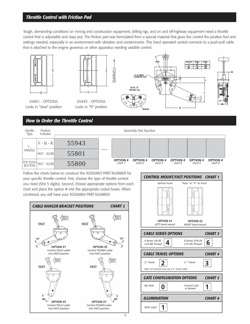
Throttle Control with Friction Pad
How to Order the Throttle Control
Tough, demanding conditions on mining and construction equipment, drilling rigs, and on and off-highway equipment need a throttlecontrol that is adjustable and stays put. The friction pad was formulated from a special material that gives the control the positive feel andsettings needed, especially in an environment with vibration and contaminants. This hand operated control connects to a push-pull cablethat is attached to the engine governor, or other apparatus needing variable control.
OPTION #chart 1
OPTION #chart 2
OPTION #chart 3
OPTION #chart 4
OPTION #chart 5
OPTION #chart 6
F - N - R
FAST - SLOW
FAST - SLOW
T -HANDLE
HandleType
PositionIndicator
TOP PUSHBUTTON
CABLE SERIES OPTIONS CHART 3
4 Series 1/4-28 6 Series 5/16-24(.25-28) Thread (.31-24) Thread
CONTROL MOUNT/FAST POSITIONS CHART 1
CABLE TRAVEL OPTIONS CHART 4
2” Travel 3 “ Travel
Note: All controls must use a 3” Travel Cable.
GATE CONFIGURATION OPTIONS CHART 5
No Gate Control Lockin Detent
ILLUMINATION CHART 6
With Light
55943
55801
55800
CABLE HANGER BRACKET POSITIONS
OPTION #1Control PULLS cableinto FAST position
OPTION #5Control PUSHES cable
into FAST position
OPTION #3Control PULLS cableinto FAST position
OPTION #7Control PUSHES cable
into FAST position
CHART 2
FAST FAST
FAST FAST
OPTION #1LEFT hand mount
OPTION #2RIGHT hand mount
Follow the charts below to construct the ASSEMBLY PART NUMBER foryour specific throttle control. First, choose the type of throttle controlyou need (first 5 digits). Second, choose appropriate options from eachchart and place the option # into the appropriate coded boxes. Whencombined, you will have your ASSEMBLY PART NUMBER.
55801 - OPTIONSLocks in “slow” position
55943 - OPTIONSLocks in “N” position
Vehicle Front “Fast” or “F” to front
FAST
SLOW
FAST
SLOW
FAST
SLOW
FAST
SLOW
4 6
2 3
0 1
1
Cable Hanger Kit 99000-1 = 2” Travel99000-2 = 3” Travel
Includes:Hanger AssemblyFlange Nuts (2)
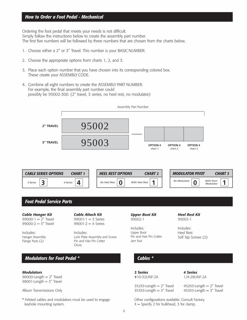
How to Order a Foot Pedal - Mechanical
Foot Pedal Service Parts
Modulators for Foot Pedal * Cables *
Ordering the foot pedal that meets your needs is not difficult.Simply follow the instructions below to create the assembly part number. The first five numbers will be followed by three numbers that are chosen from the charts below.
1. Choose either a 2” or 3” Travel. This number is your BASIC NUMBER.
2. Choose the appropriate options from charts 1, 2, and 3.
3. Place each option number that you have chosen into its corresponding colored box.These create your ASSEMBLY CODE.
4. Combine all eight numbers to create the ASSEMBLY PART NUMBER.For example, the final assembly part number could possibly be 95002-300. (2” travel, 3 series, no heel rest, no modulator)
Other configurations available. Consult Factory.X = Specify 2 for bulkhead, 3 for clamp.
* Felsted cables and modulators must be used to engage keyhole mounting system.
OPTION #chart 1
OPTION #chart 2
OPTION #chart 3
2” TRAVEL
3” TRAVEL
CABLE SERIES OPTIONS CHART 1
3 Series 4 Series
HEEL REST OPTIONS CHART 2
No Heel Rest With Heel Rest
MODULATOR PIVOT CHART 3
No Modulator With PivotModulator
Cable Attach Kit99001-1 = 3 Series99001-2 = 4 Series
Includes:Lock Plate Assembly and ScrewPin and Hair Pin CotterClevis
Upper Boot Kit99002-1
Includes:Upper BootPin and Hair Pin CotterJam Nut
Heel Rest Kit 99003-1
Includes:Heel RestSelf Tap Screws (2)
Modulators98000-Length = 2” Travel98001-Length = 3” Travel
Allison Transmissions Only
3 Series#10-32UNF-2A
352X3-Length = 2” Travel353X3-Length = 3” Travel
4 Series1/4-28UNF-2A
452X3-Length = 2” Travel453X3-Length = 3” Travel
95002
95003
Assembly Part Number
3 4 0 1 0 1
6

RVO Controls
7
The Felsted remote valve operator (RVO) control system per-mits highly efficient remote cable operation of hydraulic spoolvalves. While the control head is in easy reach of the operator,the noise, heat, and inconvenience of high pressure hydrauliclines are removed from the cab area. In addition to economicalinstallation, the Felsted system also allows greater flexibilitywhen planning valve placement.
A remote valve control system consists of a control head, acable, and a valve connection kit. Felsted systems are designedfor ease of installation, operation, and maintenance in a widevariety of equipment in agriculture, construction, off-highwaytrucks, and industrial applications.
Control CablesSee Felsted Cable Catalog for more Information
100-45600 - Length Input end connects to control head, output end connects to universal connection kit.
100-45622 - Length Input end connects to control head, output end is a series 2” travel bulkhead type connection.
100-45623 - Length Input end connects to control head, output end is a 4 series 2” travel clamp type connection
Rods, sleeves stainless steelTemp. rating - 65°F to +225°F.
(Hi-temp avail. to +300°F)Bend Radii 5”
Connection Kits See page 8 of this catalog.
Specifications for Remote Valve Operator
Control Head 55700#, 55709# 90° HandleHandle Plated SteelBoot PVC Dip MoldedHousing Die Cast AluminumKnob Black PhenolicOverall Length 16.4 InchesSpring Action Spring Centered 40°
Forward/RearTravel 1.75 Inches Max.Stackable Create Multiples,
Combinations, Both 55700 and 55709
Cable Servicing When Stacked, Cables Can Be Serviced WithoutComplete Disassembly.
P/N 55700#
P/N 55709#
8
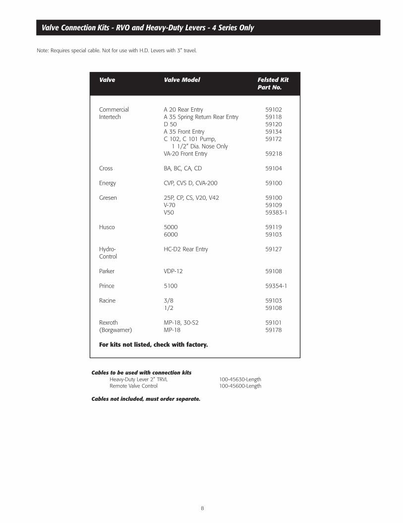
Valve Connection Kits - RVO and Heavy-Duty Levers - 4 Series Only
Valve Valve Model Felsted KitPart No.
Commercial A 20 Rear Entry 59102Intertech A 35 Spring Return Rear Entry 59118
D 50 59120A 35 Front Entry 59134C 102, C 101 Pump, 59172
1 1/2” Dia. Nose OnlyVA-20 Front Entry 59218
Cross BA, BC, CA, CD 59104
Energy CVP, CVS D, CVA-200 59100
Gresen 25P, CP, CS, V20, V42 59100V-70 59109V50 59383-1
Husco 5000 591196000 59103
Hydro- HC-D2 Rear Entry 59127Control
Parker VDP-12 59108
Prince 5100 59354-1
Racine 3/8 591031/2 59108
Rexroth MP-18, 30-S2 59101(Borgwarner) MP-18 59178
For kits not listed, check with factory.
Note: Requires special cable. Not for use with H.D. Levers with 3” travel.
Cables to be used with connection kitsHeavy-Duty Lever 2” TRVL 100-45630-LengthRemote Valve Control 100-45600-Length
Cables not included, must order separate.

Heavy-Duty Levers
How to Order a Standard Non-Push Button Lever
9
Felsted’s Heavy-Duty Levers are built especially for rugged,demanding applications in the construction, farm, and specialtytruck business. In addition to the standard version, a push button version is also available which provides convenientpush button operation and a choice of five gate configurationsto offer a variety of design applications where the lever needsa detent locking mechanism.
The mechanical advantage of both levers is 5:1 with operatingloads from 125 to 400 pounds dependent on cable series andtravel. Superior corrosion resistance is provided by a handsomeblack matte finish Electrocoat Coating for the lever mechanism,which will meet 5% Salt-Spray, 336-500, with zinc plate forfasteners. Other advantages include a lightweight design and a pivot bushing.
OPTION #chart 1
OPTION #chart 2
OPTION #chart 3
Hollow Steel Handle
Solid Steel Handle
KNOB COLOR OPTIONS CHART 1
Black Knob Color
CABLE SERIES OPTIONS CHART 2
4 Series 6 Series
TRAVEL DISTANCE CHART 3
2 Inches 3 Inches
58000
58100
Assembly Part Number
To build an Assembly Part Number, please refer to the optioncharts below, and place the option numbers into the corre-sponding color coded boxes. Please Note: Knob color optiononly exists as black, which is #1.
Floor Cut-Out
1
1
4 6
2 3
StandardNon-Push ButtonHeavy-Duty Lever

Cable Part Travel Cable Input Max.Number Dim. “A” Dim. “B” Series Load Lb.
100-4222-length 5 1/2” 2” 4 150
100-4223-length 5 1/2” 2” 4 150
100-4322-length 7” 3” 4 125
100-4323-length 7” 3” 4 125
100-6222-length 5 1/2” 2” 6 250
100-6223-length 5 1/2” 2” 6 250
100-6322-length 7” 3” 6 210
100-6323-length 7” 3” 6 210
Push Button Heavy-Duty Levers
10
Cables not included. All dimensions in inches.Mounting dimensions same for push button and standard levers.
Recommended Cables for Push Button and Standard Levers:
How to Order a Push Button Heavy-Duty Lever
OPTION #chart 1
OPTION #chart 2
OPTION #chart 3
Push Button Style
GATE CONFIGURATIONS CHART 1 CABLE SERIES OPTIONS CHART 2
4 Series 6 Series
TRAVEL DISTANCE CHART 3
2 Inches 3 Inches
58001
Assembly Part Number
#1
#2
#3
#4
#5
POSITION #1
#1
#2
#3
#4
#5
POSITION #2
#1
#2
#3
#4
#5
POSITION #3
#1
#2
#3
#4
#5POSITION #4
#1
#2
#3
#4
#5
POSITION #5
4 6
2 3
Push ButtonHeavy-Duty Lever
NG Dump Body Control
11
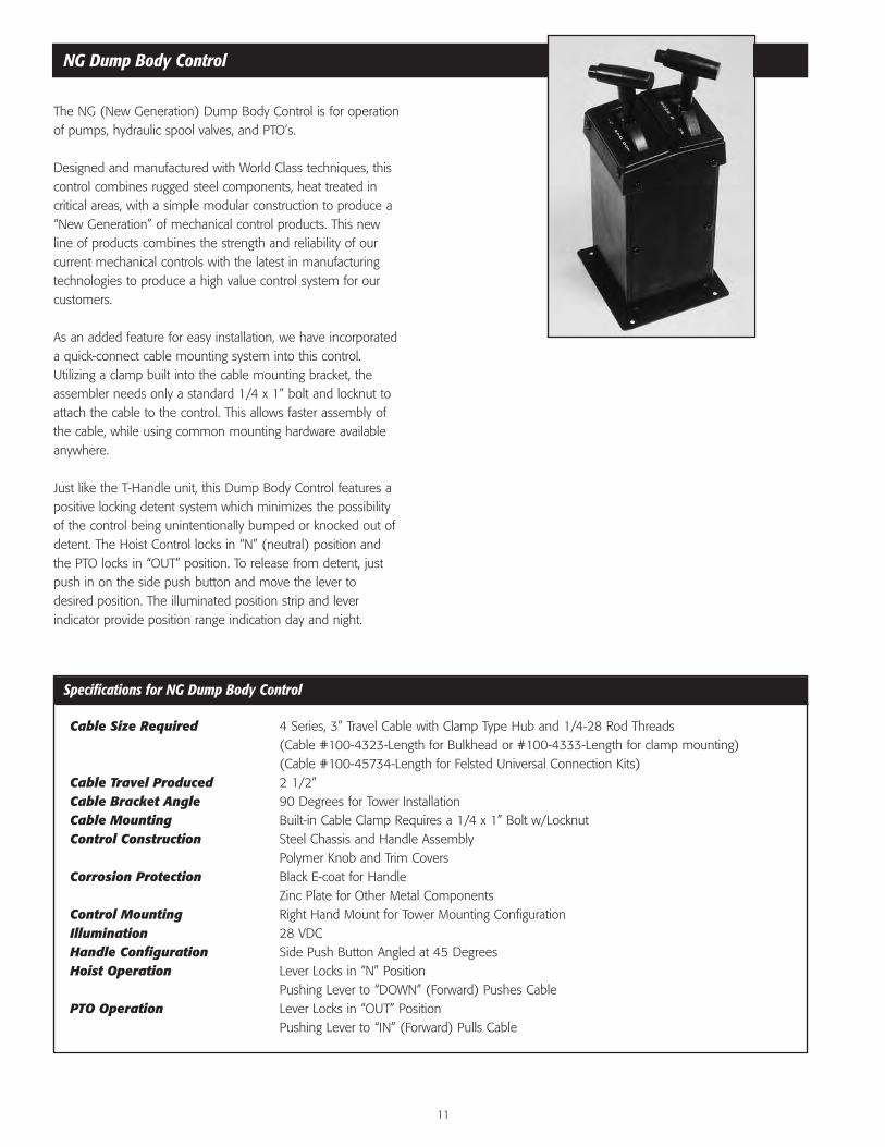
The NG (New Generation) Dump Body Control is for operationof pumps, hydraulic spool valves, and PTO’s.
Designed and manufactured with World Class techniques, thiscontrol combines rugged steel components, heat treated incritical areas, with a simple modular construction to produce a“New Generation” of mechanical control products. This newline of products combines the strength and reliability of ourcurrent mechanical controls with the latest in manufacturingtechnologies to produce a high value control system for ourcustomers.
As an added feature for easy installation, we have incorporateda quick-connect cable mounting system into this control.Utilizing a clamp built into the cable mounting bracket, theassembler needs only a standard 1/4 x 1” bolt and locknut toattach the cable to the control. This allows faster assembly ofthe cable, while using common mounting hardware availableanywhere.
Just like the T-Handle unit, this Dump Body Control features apositive locking detent system which minimizes the possibilityof the control being unintentionally bumped or knocked out ofdetent. The Hoist Control locks in “N” (neutral) position andthe PTO locks in “OUT” position. To release from detent, justpush in on the side push button and move the lever todesired position. The illuminated position strip and lever indicator provide position range indication day and night.
Specifications for NG Dump Body Control
Cable Size Required 4 Series, 3” Travel Cable with Clamp Type Hub and 1/4-28 Rod Threads (Cable #100-4323-Length for Bulkhead or #100-4333-Length for clamp mounting) (Cable #100-45734-Length for Felsted Universal Connection Kits)
Cable Travel Produced 2 1/2”Cable Bracket Angle 90 Degrees for Tower InstallationCable Mounting Built-in Cable Clamp Requires a 1/4 x 1” Bolt w/LocknutControl Construction Steel Chassis and Handle Assembly
Polymer Knob and Trim CoversCorrosion Protection Black E-coat for Handle
Zinc Plate for Other Metal ComponentsControl Mounting Right Hand Mount for Tower Mounting ConfigurationIllumination 28 VDCHandle Configuration Side Push Button Angled at 45 DegreesHoist Operation Lever Locks in “N” Position
Pushing Lever to “DOWN” (Forward) Pushes CablePTO Operation Lever Locks in “OUT” Position
Pushing Lever to “IN” (Forward) Pulls Cable

12
NG Dump Body Control
Part Numbers
Dual ControlsNG0003 NG PTO / Hoist Control
(PTO on left, hoist on right,as shown)
NG0004 NG Hoist / PTO Control(Hoist on left, PTO on right)
Hoist Control Notes
PTO Control Notes
• Lever locks in the “N” position.• Pushing lever to “DOWN” position pushes cable.
• Lever locks in the “OUT” position.• Pushing lever to “1N” position pulls cable.
Single ControlsNG0001 NG Hoist ControlNG0001 NG PTO Control
NG0005-1 Knob Service Kit

T-Handle Dump Body Control Systems
13
Lever Locks in "Out" Position
Lever Locks in "N" Position
6.63" (168.4)
5.94" (150.8) 5.75"
(146.1)
7.50" Square (190.5)
6.50" (165.1)
Position Strip and Indicator Illuminated for Night Operation 12 V. System
5.50" (139.7) Ref. Tower Dim.
Lamp Lead 22 Ga. Blue 12" (304.8) Long
Control Levers Include Hardware for Felsted Type 4 and 6 Series Cables
7.32" (185.9) 6 Series Cable
6.94 (176.3) 4 Series Cable
45° 45°
5°
22.5°
5°
1.5" Travel (38.1)
1.5" Travel (38.1)
6.00" (152.4) Ref. Tower Dim.
18.0" Ref. (457.2)
5.50" (139.7)
7.75" (196.9)
.38" (9.7)
5.50" (139.7)
Mounting Holes
6.74" (171.2)
I N P T O O U T
D O W N N U P
The Felsted T-Handle Dump Body Control is used to controlthe PTO and/or pump for dump body hoists. This control isstandard as a dual unit (PTO and Hoist) or available as a singleunit (PTO or Hoist), or a triple control unit (two Hoists and aPTO). Quad units are also available. Also available with the PTOcontrol as a factory installed option, is a switch for a dash light,or secondary electrical function when PTO is engaged (“IN”position).
These controls feature a positive detent locking system whichpractically eliminates any possibility of the control being unintentionally bumped or knocked out of detent. The HoistControl locks in “N” (neutral) position, and the PTO locks in“out” position. To release from detent, just pull up on “T” liftbelow the knob and move lever to desired position.
The illuminated position strip and lever indicator provide position range identification at night.
Felsted Dump Body Controls are constructed of high qualitymaterials and workmanship incorporating hardened steel partsand a rugged housing. The stand has a tough coating for durability and long life. The control is sealed to keep enginenoise, dirt and fumes from entering the cap. All controls have a maximum 3” standard cable travel and, for ease of installation,come complete with mounting hardware for both 4 & 6 series cables.

T-Handle Dump Body Control Systems
Additional Dump Body Accessories
14
Fits into 59000 Tower
55064 PTO55064-1 PTO w/Switch55065 Hoist
Fits into 59015 Tower
55317 Hoist/Open
Fits into 59015 Tower
55317-2 Hoist/Muncie PTO
Fits into 59015 Tower
55317-3 Hoist/Chelsea PTO
Fits into 59015 Tower
55062 Hoist/PTO55062-1 Hoist/PTO
w/Switch55066 Hoist/Hoist
Fits into 59016 Tower
55067 Hoist/Hoist/PTO55067-1 Hoist/Hoist/PTO
w/Switch
Fits into 59016 Tower
55780-2 Hoist/Hoist/Muncie PTO
Fits into 59016 Tower
55780-3 Hoist/Hoist/Chelsea PTO
Note: All Felsted Hoist Controls lock in “Neutral” Position. All Felsted PTO Controls Lock in “OUT” Position.
Towers
59000 Single59015 Double59016 Triple
Air PTO Kits
(Top Plate and Hardware Only)
Accessories
59002 Single TopMount Flange
59009 Single WedgeMounting Kit(17” Angle Wedge)
Cables
100-4323-Length” Bulkhead/Clamp100-4333-Length” Clamp/Clamp100-6323-Length” Bulkhead/Clamp100-6333-Length” Clamp/Clamp
(See FelstedHP Cable Catalog)
Copyright © 2022 FDOKUMEN