Systems Engineering Process of a CubeSat from the Perspective of Operations
13
Systems Engineering Process of a CubeSat from the Perspective of Operations Bruno Morato Arnaut ITA Graduate Student Brazilian Army Military Engineer [email protected] Diego Dutra Viot INPE Graduate Student [email protected] Lucas Lopes Costa INPE Graduate Student [email protected] Geilson Loureiro Systems Engineering Professor INPE [email protected] Eduardo Escobar Bürger INPE Graduate Student [email protected] Marcelo Franchitto Electronics Engineer DCTA - Brazilian Air Force [email protected] Instituto Tecnológico de Aeronáutica - ITA Departamento de Ciência e Tecnologia Aeroespacial - DCTA Pç Mal Eduardo Gomes, 50 São José dos Campos, SP, Brasil 12.2228-900 Instituto Nacional de Pesquisas Espaciais - INPE Av. dos Astronautas, 1758 São José dos Campos, SP, Brasil 12.227-010 Copyright © 2013 by Arnaut, Bruno; Loureiro, Geilson et al. Published and used by INCOSE with permission. Abstract. This paper presents the application of a systems concurrent engineering approach to university CubeSats development. The university CubeSat, object of this paper, is a joint development between the Brazilian Institute for Space Research (INPE) and the Aeronautics Institute of Technology (ITA). The effort consists in developing a Brazilian CubeSat platform that can be industrialized in Brazil and takes advantage of a Systems Engineering Process approach. This Systems Engineering Process applied on the CubeSat includes mission and life-cycle analysis, requirements engineering, functional analysis, architecture design, and uses an operation life-cycle scenario as an example. The approach is supposed to be applied to every life-cycle process. Thus, System Engineering Process gives a wide range view of the problem, guiding engineers to develop product and organization solutions throughout life-cycle. This approach helps to solve technical and management issues that sometimes are not encompassed with just experienced staff and standard methods. 1. Introduction Fostering aerospace industry is strategic for any country. Governments and universities have had an important role in this process. In Brazil, Aeronautics Institute of Technology (ITA), a federal university dedicated to provide high level education and research in Science and Technology areas, and the Brazilian Institute for Space Research (INPE), under the Ministry of Science and Technology (MCTI) umbrella, have done a great effort to develop
-
Upload
independent -
Category
Documents
-
view
0 -
download
0
Transcript of Systems Engineering Process of a CubeSat from the Perspective of Operations

Systems Engineering Process of a CubeSat from the Perspective of Operations
Bruno Morato Arnaut ITA Graduate Student
Brazilian Army Military Engineer [email protected]
Diego Dutra Viot
INPE Graduate Student [email protected]
Lucas Lopes Costa INPE Graduate Student
Geilson Loureiro Systems Engineering Professor
INPE [email protected]
Eduardo Escobar Bürger INPE Graduate Student
Marcelo Franchitto Electronics Engineer
DCTA - Brazilian Air Force [email protected]
Instituto Tecnológico de Aeronáutica - ITA
Departamento de Ciência e Tecnologia Aeroespacial - DCTA Pç Mal Eduardo Gomes, 50 São José dos Campos, SP, Brasil 12.2228-900
Instituto Nacional de Pesquisas Espaciais - INPE Av. dos Astronautas, 1758 São José dos Campos, SP, Brasil 12.227-010
Copyright © 2013 by Arnaut, Bruno; Loureiro, Geilson et al. Published and used by INCOSE with permission. Abstract. This paper presents the application of a systems concurrent engineering approach to university CubeSats development. The university CubeSat, object of this paper, is a joint development between the Brazilian Institute for Space Research (INPE) and the Aeronautics Institute of Technology (ITA). The effort consists in developing a Brazilian CubeSat platform that can be industrialized in Brazil and takes advantage of a Systems Engineering Process approach. This Systems Engineering Process applied on the CubeSat includes mission and life-cycle analysis, requirements engineering, functional analysis, architecture design, and uses an operation life-cycle scenario as an example. The approach is supposed to be applied to every life-cycle process. Thus, System Engineering Process gives a wide range view of the problem, guiding engineers to develop product and organization solutions throughout life-cycle. This approach helps to solve technical and management issues that sometimes are not encompassed with just experienced staff and standard methods.
1. Introduction
Fostering aerospace industry is strategic for any country. Governments and universities have had an important role in this process. In Brazil, Aeronautics Institute of Technology (ITA), a federal university dedicated to provide high level education and research in Science and Technology areas, and the Brazilian Institute for Space Research (INPE), under the Ministry of Science and Technology (MCTI) umbrella, have done a great effort to develop
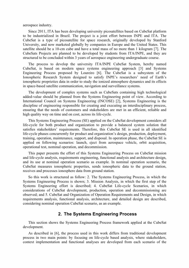
aerospace industry. Since 2011, ITA has been developing university picosatellites based on CubeSat platform
to be industrialized in Brazil. The project is a joint effort between INPE and ITA. The CubeSat is a type of picosatellite for space research, originally developed by Stanford University, and now marketed globally by companies in Europe and the United States. This satellite should be a 10-cm cube and have a total mass of no more than 1 kilogram [7]. The CubeSats Projects are planned to be developed by students from ITA/INPE, and they are structured to be concluded within 3 years of aerospace engineering undergraduate course.
The process to develop the university ITA/INPE CubeSat System, hereby named CubeSat, is based on modern space systems engineering approach [3] and Systems Engineering Process proposed by Loureiro [6]. The CubeSat is a subsystem of the Ionospheric Research System designed to satisfy INPE’s researchers’ need of Earth’s ionospheric proprieties data in order to study the ionized atmosphere dynamics and its effects in space-based satellite communication, navigation and surveillance systems.
The development of complex systems such as CubeSats containing high technological added-value should be planned from the Systems Engineering point of view. According to International Council on Systems Engineering (INCOSE) [2], Systems Engineering is the discipline of engineering responsible for creating and executing an interdisciplinary process, ensuring that the needs of customers and stakeholders are met in an efficient, reliable and high quality way on time and on cost, across its life-cycle.
This Systems Engineering Process (SE) applied on the CubeSat development considers all life-cycle for both product and organization to provide a balanced system solution that satisfies stakeholders’ requirements. Therefore, this CubeSat SE is used in all identified life-cycle phases concurrently for product and organization’s design, production, deployment, training, operation, maintenance, support, and disposal. In operation phase, the CubeSat SE is applied on following scenarios: launch, eject from aerospace vehicle, orbit acquisition, operational test, nominal operation, and decommission.
This paper presents the effort of this Systems Engineering Process on CubeSat mission and life-cycle analysis, requirements engineering, functional analysis and architecture design, and its use at nominal operation scenario as example. In nominal operation scenario, the CubeSat measures ionospheric properties, sends ionospheric data to the ground station, receives and processes ionosphere data from ground station.
So this work is structured as follow: 2. The Systems Engineering Process, in which the Systems Engineering Process is shown; 3. Mission Analysis, in which the first step of the Systems Engineering effort is described; 4. CubeSat Life-cycle Scenarios, in which considerations of CubeSat development, production, operation and decommissioning are observed; and 5. CubeSat and Organization of Operation Requirements and Design, in which requirements analysis, functional analysis, architecture, and detailed design are described, considering nominal operation CubeSat scenario, as an example.
2. The Systems Engineering Process
This section shows the Systems Engineering Process framework applied at the CubeSat development.
As described in [6], the process used in this work differs from traditional development process in two main points: by focusing on life-cycle based analysis, where stakeholders, context implementation and functional analyses are developed from each scenario of the

life-cycle processes; and by being utilized not only in the product development, but both in the organizations and product development concurrently. The Systems Engineering Process explored by this work from Loureiro’s thesis [6] is shown in Figure 1 and will be discussed as follow.
Figure 1. The applied Systems Engineering Process
This SE philosophy explores concurrently the two mirrored and complementary sub-processes: the product and organization’s development using the life-cycle scenarios iteratively derived. Figure 1 shows a vertical flow of activities, but the process overall is developed based in loops and feedbacks aiming to achieve a sufficient maturity to baseline each development phase.
In the two sub-processes (product and organization), three branches are explored. Firstly, the stakeholders relative to the analyzed scenario are identified and their concerns are gathered. Subsequently, techniques are applied for identification of the stakeholder’s real needs, their capabilities and constraints will then be derived in stakeholder’s requirements. In the second branch, the system functional context is analyzed and the system of interest functions are allocated. In the last branch, the preliminary physical architecture is developed and the external interfaces requirements are identified. All three branches are iteratively explored so that requirements of the whole system are derived.
Since the system requirements are defined, functional architectures describing structure and behavior are created for product and organization. From these architectures, some alternatives of implementation are proposed and then analyzed. The result is two specific physical architectures which have its interfaces and flows (energy, information and material) defined. These architectures and its elements are continuously decomposed using this SE until be sufficiently detailed to be implemented in a lower level with a specific engineering method related to the expertise area.
This work practices part of the SE presented in a CubeSat satellite based system. The process development is performed by the authors in academic environment to explore the innovative process. The results of this work are shown in the next sections of this article.
3. Mission Analysis
Mission analysis is the first process of this method, as shown in Figure 1. This process is inserted in the planning stage of the system life-cycle. It intends to capture needs and expectations of primary stakeholders and translate them in the description of a system at the highest level of abstraction that satisfies requirements.
For the purpose of CubeSat development and aligned with presented by Larson [3], the mission analysis has six activities: write down the statement of the need; identify initial stakeholders; derive goals, objectives, measures of effectiveness (MoEs) and qualification strategy; depict the as-is operational scenarios and to-be operational scenarios; list capabilities and constraints; and derive the concept of operations and the system operational architecture.
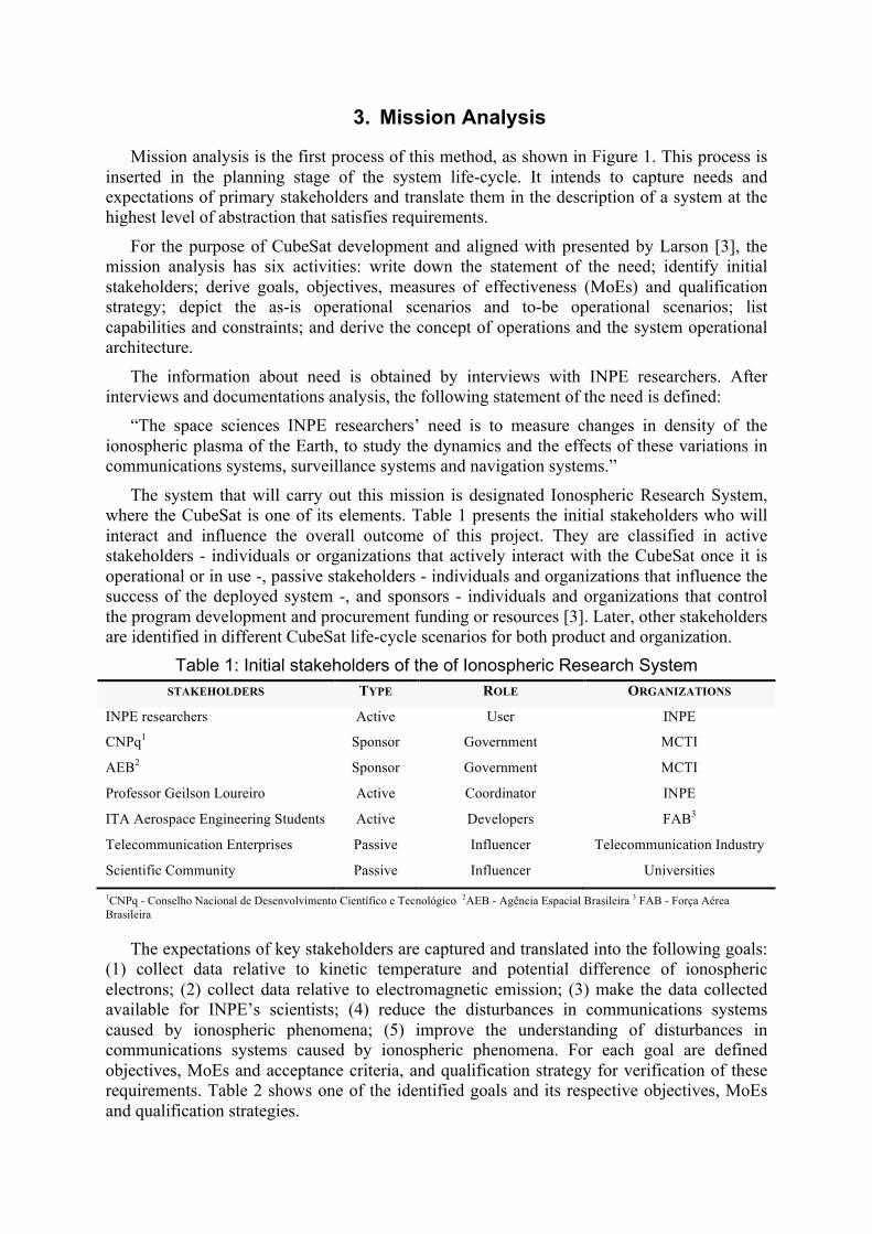
The information about need is obtained by interviews with INPE researchers. After interviews and documentations analysis, the following statement of the need is defined:
“The space sciences INPE researchers’ need is to measure changes in density of the ionospheric plasma of the Earth, to study the dynamics and the effects of these variations in communications systems, surveillance systems and navigation systems.”
The system that will carry out this mission is designated Ionospheric Research System, where the CubeSat is one of its elements. Table 1 presents the initial stakeholders who will interact and influence the overall outcome of this project. They are classified in active stakeholders - individuals or organizations that actively interact with the CubeSat once it is operational or in use -, passive stakeholders - individuals and organizations that influence the success of the deployed system -, and sponsors - individuals and organizations that control the program development and procurement funding or resources [3]. Later, other stakeholders are identified in different CubeSat life-cycle scenarios for both product and organization.
Table 1: Initial stakeholders of the of Ionospheric Research System STAKEHOLDERS TYPE ROLE ORGANIZATIONS
INPE researchers Active User INPE
CNPq1 Sponsor Government MCTI
AEB2 Sponsor Government MCTI
Professor Geilson Loureiro Active Coordinator INPE
ITA Aerospace Engineering Students Active Developers FAB3
Telecommunication Enterprises Passive Influencer Telecommunication Industry
Scientific Community Passive Influencer Universities
1CNPq - Conselho Nacional de Desenvolvimento Científico e Tecnológico 2AEB - Agência Espacial Brasileira 3 FAB - Força Aérea Brasileira
The expectations of key stakeholders are captured and translated into the following goals: (1) collect data relative to kinetic temperature and potential difference of ionospheric electrons; (2) collect data relative to electromagnetic emission; (3) make the data collected available for INPE’s scientists; (4) reduce the disturbances in communications systems caused by ionospheric phenomena; (5) improve the understanding of disturbances in communications systems caused by ionospheric phenomena. For each goal are defined objectives, MoEs and acceptance criteria, and qualification strategy for verification of these requirements. Table 2 shows one of the identified goals and its respective objectives, MoEs and qualification strategies.

Table 2: Goal, objectives, MoEs and Qualification Strategy of the System (example)
Goal Objectives Measures of effectiveness Qualification
strategy MOEs Description
1
Collect the data of temperature kinetic and potential
difference of ionospheric electrons
1.1
Collect the data with frequency not less than 1 sample every 4 hours
Frequency of
measure
-‐Capture every 4 hours 1 -‐ Capture every hour 2
-‐ Measure the data 24h per day 3
Count the number of
samples / time
1.2 Collect the data in altitude between 200 and 2000 km
Altitude of the collect
-‐ Measure in an altitude between 200 to 2000 km 1 -‐ Measure at all altitudes between 200 to 2000 km 3
Periodic checking of the
altitude
1.3 Capture data with reliability not less
than 90 %. Reliability
-‐ Density of electrons with reliability of 90 % 1 -‐ Density of electrons with reliability of 99.9 % 3
-‐ Accelerated life testing data
analysis -‐ Warranty
data for COTS 4
1 Mandatory 2 Desirable 3 Optimum 4 Commercial off-‐the-‐shelf
The next step is to develop the operation concept description (OCD) of the Ionospheric Research System. The OCD describes what operators and users want and how the conceived system and its elements will meet their needs [3]. The OCD is used to validate goals, objectives, MoEs and qualification strategies previous defined, and as a vehicle for provide a common understanding of the Ionospheric Research System among stakeholders associated with a particular intended use. More detail about how developing OCD can be obtained in PPI [8].
The concept of operation of the Ionospheric Research System is described "as-is" and "to-be", as shown in Figure 2. The current operational doctrine and procedures, infrastructure existent, elements of the system for improve performance, skills and competencies of available operators and support are considered to develop the current and envisioned environment.
Figure 2. Operation concept description - “"as-is" and "to-be"
At the last step of mission analysis, the function analysis is developed and the operation architectures (physical architectures) are proposed. Finally, the operation architecture is chosen, detailed and the CubeSat stakeholders requirements are defined. Figure 3 shows System Operational Architecture or Concept of Operations (ConOps) of the Ionospheric Research System which functions are the following: (1) Launch System launches the CubeSat
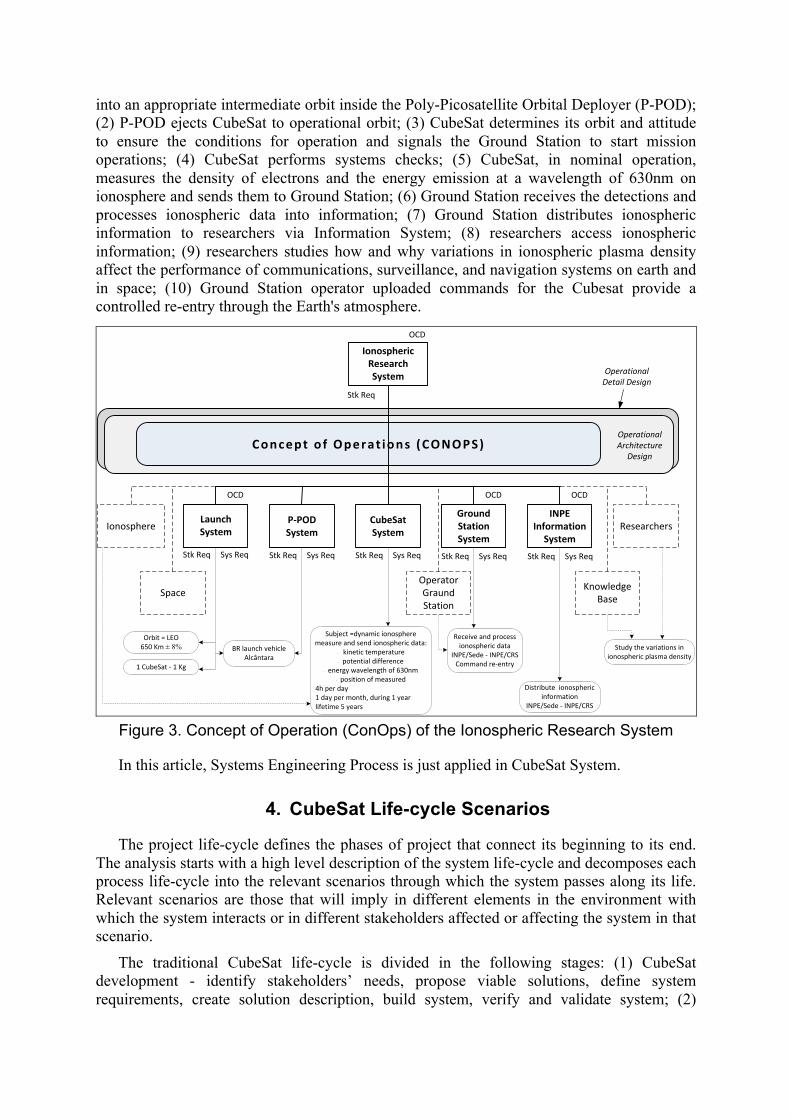
into an appropriate intermediate orbit inside the Poly-Picosatellite Orbital Deployer (P-POD); (2) P-POD ejects CubeSat to operational orbit; (3) CubeSat determines its orbit and attitude to ensure the conditions for operation and signals the Ground Station to start mission operations; (4) CubeSat performs systems checks; (5) CubeSat, in nominal operation, measures the density of electrons and the energy emission at a wavelength of 630nm on ionosphere and sends them to Ground Station; (6) Ground Station receives the detections and processes ionospheric data into information; (7) Ground Station distributes ionospheric information to researchers via Information System; (8) researchers access ionospheric information; (9) researchers studies how and why variations in ionospheric plasma density affect the performance of communications, surveillance, and navigation systems on earth and in space; (10) Ground Station operator uploaded commands for the Cubesat provide a controlled re-entry through the Earth's atmosphere.
Ionospheric Research System
P-‐POD System
Concept of Operat ions (CONOPS)
OCD
Stk Req
Stk Req Sys Req Stk Req Sys Req Stk Req Sys Req
Operational Architecture
Design
Operational Detail Design
CubeSat System
Ground Station System
ResearchersIonosphereLaunch System
Stk Req Sys Req
Knowledge Base
OCD OCD
Stk Req Sys Req
INPE Information System
OCD
Operator Graund Station
Space
Orbit = LEO650 Km ± 8%
1 CubeSat -‐ 1 Kg
BR launch vehicleAlcântara
Subject =dynamic ionospheremeasure and send ionospheric data:
·∙ kinetic temperature ·∙ potential difference
·∙ energy wavelength of 630nm·∙ position of measured
4h per day 1 day per month, during 1 year lifetime 5 years
Receive and process ionospheric data
INPE/Sede -‐ INPE/CRSCommand re-‐entry
Distribute ionospheric information
INPE/Sede -‐ INPE/CRS
Study the variations in ionospheric plasma density
Figure 3. Concept of Operation (ConOps) of the Ionospheric Research System
In this article, Systems Engineering Process is just applied in CubeSat System.
4. CubeSat Life-cycle Scenarios
The project life-cycle defines the phases of project that connect its beginning to its end. The analysis starts with a high level description of the system life-cycle and decomposes each process life-cycle into the relevant scenarios through which the system passes along its life. Relevant scenarios are those that will imply in different elements in the environment with which the system interacts or in different stakeholders affected or affecting the system in that scenario.
The traditional CubeSat life-cycle is divided in the following stages: (1) CubeSat development - identify stakeholders’ needs, propose viable solutions, define system requirements, create solution description, build system, verify and validate system; (2)

CubeSat Manufacturing; (3) CubeSat logistics - storage, handle, transport and launch provision; (4) CubeSat operation - launching, P-POD ejection, orbit acquisition, operational test, nominal operation, and (5) re-entry through the Earth's atmosphere.
The method described in Section 2 is applied for product and organization. For every scenario defined in the life-cycle analysis of a system this should be concurrently performed. In order to exemplify the Systems Engineering Process for a CubeSat using that method, this paper covers only CubeSat nominal operation scenario. In this scenario the CubeSat measures the density of electrons and the energy emission at a wavelength of 630nm on ionosphere, sends them to ground station and receives commands from it.
5. CubeSat and Organization Requirements and Design
From the scenarios decomposed in Section 4, it is chosen nominal operation for driving the Product and Organization’s CubeSat System requirements eliciting and architecture development. This applied Systems Engineering Process (SE) on Cubesat considers all life-cycle for both product and organization to provide a balanced system solution that satisfies stakeholders requirements. Different graphical systems tools are used to support the Systems Engineering Processes.
5.1. Stakeholder Analysis. The life-cycle decomposition in scenarios is the main input for the stakeholder analysis where each sub-process or scenario represents the product during that sub-process. A brainstorming technique starts stakeholder analysis, by asking questions for each scenario considered in this work (e.g. who are the sources of inputs/outputs?).
For each identified stakeholder, using analogy and brainstorming technique, it is asked what are their worries, wishes, desires, goals and needs. The answers are the stakeholder concerns, summarized in Figure 4.
CubeSat
Mission, control and operation Staff
ITU
Scientist
Database operator
Communication systems
GSITA, CRS
GS operator
Data specificityData availability
AccessibilityControllabilityMaintainability
RiskReliability
Accessibility
TraceabilityCommunication
TraceabilityInternal Communication
SuitabilityOrganization of Operation
INPE / AEB Director
Maintenance Team
Scientist
Manager of mission
Operation team Engineer
InteractiveConmunication Quality
Training
Integration TeamEasy to use
Accessibility
Figure 4. Stakeholders concerns for nominal operation scenario
Using the Goal, Question, Metric technique it is gotten from each stakeholder’s concerns: the aspects, metrics and measures of effectiveness (MoEs). For instance, availability and easy to use feature are identified for scientist and operation team concerns from CubeSat product and Organization points of view respectively. The following aspects are analyzed and metrics are defined for availability: reliability – comparison percentage in models comparison; ease of access – time measurement; collection schedule – efficiency percentage (collection / collection plan). Likewise, the following aspects are analyzed and metrics are defined for

easy to use: training – annual training for operators; planning – time work; and manuals – clarity, online procedures.
From the concerns and MoEs, the stakeholders’ needs are derived, and then translated to stakeholders’ requirements.
5.2. Functional Analysis. Functional analysis is part of the eliciting requirements process but from the functional point of view. The first step is to create a context diagram for each decomposed life-cycle scenario, and then identify the elements in the system environment and the flows of energy, material or information between them, as shown in Figure 5.
Figure 5. Functional context diagram in nominal operation scenario
Using the context diagram, the data context diagram and the control context diagram are developed. These diagrams permit to visualize the links between the system and the environment elements and extract the system essential functions.
The following step is to develop circumstances analyses, which are combinations of the possible elements attributes values in the environment, and flows in the system context. To define the system modes, the value or value range for each attribute is combined in different groups, which form the modes, which transit when the circumstances change.
The essential function diagram and the event list mode are developed based on the previous context and modes analysis. The event function diagram shown in Figure 6 represents the basic CubeSat Product and Organization functions that justify its existence.
The essential function diagram is then exploded and other secondary functions are added to the system, sustaining the essential functions. This process is called functional decomposition. Figure 7 and Figure 8 show an example for CubeSat Product and
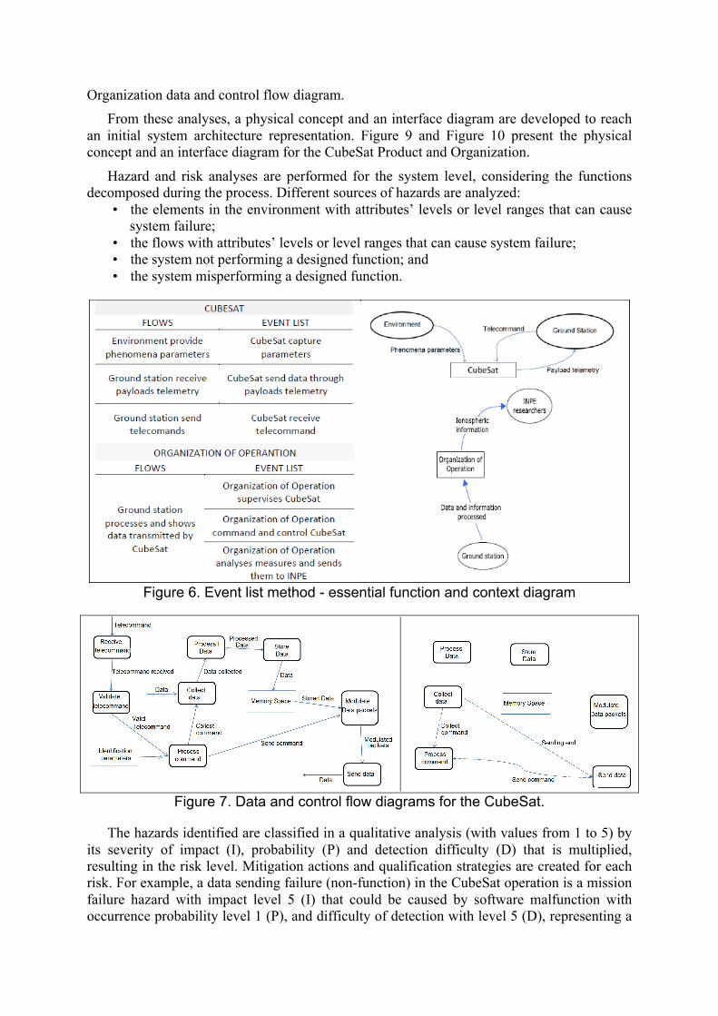
Organization data and control flow diagram. From these analyses, a physical concept and an interface diagram are developed to reach
an initial system architecture representation. Figure 9 and Figure 10 present the physical concept and an interface diagram for the CubeSat Product and Organization.
Hazard and risk analyses are performed for the system level, considering the functions decomposed during the process. Different sources of hazards are analyzed:
• the elements in the environment with attributes’ levels or level ranges that can cause system failure;
• the flows with attributes’ levels or level ranges that can cause system failure; • the system not performing a designed function; and • the system misperforming a designed function.
Figure 6. Event list method - essential function and context diagram
Figure 7. Data and control flow diagrams for the CubeSat.
The hazards identified are classified in a qualitative analysis (with values from 1 to 5) by its severity of impact (I), probability (P) and detection difficulty (D) that is multiplied, resulting in the risk level. Mitigation actions and qualification strategies are created for each risk. For example, a data sending failure (non-function) in the CubeSat operation is a mission failure hazard with impact level 5 (I) that could be caused by software malfunction with occurrence probability level 1 (P), and difficulty of detection with level 5 (D), representing a

25 (IxPxD) risk level. This risk level justifies an improvement in this configuration item to mitigate such risk, then a qualification strategy shall be created. A hazard analysis is also performed for the operation organization. For example, a not executed command altering payload parameter (non-function) by the satellite operator is a negligible hazard with impact level 1 (I) that could be caused by overwork with probability level 3 (P), and difficulty of detection with level 2 (D), representing a level 6 risk. Thus, could be designed a redundancy on the operator responsibility function. The qualification strategy created is verified by inspection.
Behavior analysis is performed through state identification and transition diagram. The states identified for the CubeSat are simple, for example: a payload exposed or not exposed to space environment could be two different states. For the operation organization, the states are identified to start, operate and finish the mission. Figure 11 shows the state transition machine. The functional analysis results are synthesized in the system requirements.
Figure 8. Operation organization data and control flow diagram.
Figure 9. CubeSat architecture (physical / interface diagram)
5.3. Architecture. The CubeSat concept architecture developed for functional analysis is further analyzed, and a system architecture block diagram is created. The functional decomposition can be structured in a functional block diagram and organized with the

partitioning and coupling method. The result is that functions are organized in coupled blocks that can be allocated to architecture block diagram physical components. Figure 12 shows the functions final allocation for the satellite example adopted in this work.
The functions allocated to architecture physical elements imply that the derived system requirements from these functions are assigned to the physical component directly. The requirements allocation sheet can be used in order to have a set of requirements for each physical component, which will be further decomposed in the subsystem level process.
Given the requirements set for each component (subsystem), it is possible to estimate some technology implementation alternatives and further perform a trade-off analysis. The alternatives can be judged following several criteria, such as the typical decision analysis sheet (adopted in this example), Pugh matrix or decision under risk. The analysis based on different criteria is settled for each subsystem (of product and organization), and the criteria decision is based in the team knowledge for each subsystem.
ORGANIZATION OF OPERATION
INPEresearchers
IssuesEngineering Sector
Operation Sector
ManagementSector
R&D Organization
Contract
Logisticorganization
Manuals andprocedures
ManagementSystem
Report
Master Operation Plan,procedures, and standards
Suppliers
Ground StationSystem
Ionosphericdata
Report
Materialsand services
Materialsand services
Ionosphericinformation
Figure 10. Operation organization architecture (physical and interface diagram)
Management System determinesthe end of operations
Management performs proceduresfor the end of operations
Organization ready for operation
Engineering performsstart-up
Problems in operation
Manager initiatesprocedures for maintenance
End of operations
System of Management determines start mission
Figure 11. State transitions machine (product and organization operation)
The analysis results are synthesized in specific physical architectures: architecture flow diagram and architecture interconnect diagram, shown in Figure 12 for product and organization. These diagrams are developed to highlight the interfaces between the subsystems.
A N2 chart is build showing the type of information transferred between the subsystems.

The identified interfaces in the N2 are better defined in an Interface Control Document (ICD), and will generate requirements for specific subsystems.
Applying this process for each subsystem generates missing requirements on system level, and also creates inputs for subsystem requirements which will be developed in detailed design process. 5.4. Detail Design. The detailed design process consists of the subsystem requirements specification. The first activity is to apply the make-it or buy-it method, in which the answers can be: internal development, external development, COTS (Commercial off-the-shelf) or reuse. For the CubeSat example, the following decisions are made to products and organizations elements: external development of Payload (Photometer and Langmuir Probe) and System design; COTS subsystems of telemetry and telecommand (TMTC), and antennas (ANTS - ANT1 and ANT2); internal development of OBC and others organization elements. The last step is to gather a complete set of requirements to subsystems, in order to proceed the implementation. At this point, the Systems Engineering Process of architecture development is complete.
Figure 12. Physical architecture interfaces for product and organization
6. Conclusion
The application of systems concurrent engineering concept to a university CubeSat development shows how product and organization may be concurrently developed. Projects of such class of satellite traditionally do not use such methodology. When Systems Engineering Processes is applied, the projects are usually product and operations focused.
This work presents results that show how to integrate Concurrent Engineering and Systems Engineering in order to achieve a successful Cubesat mission with a life-cycle perspective. The innovative method gives a wide range view of the problem, guiding the engineers throughout product and organization life-cycles, helping to visualize product and organization solutions that sometimes just experienced staff and standard methods do not

encompass. Conclusions given by this paper are that the anticipation of life-cycle process
requirements offers an opportunity to better understand and implement product and organization, covering all stakeholders’ needs. Thus, it may provide better cost schedule management and avoid overrun.
Those interested can write to the authors for obtaining additional information.
References
[1] Fortescue, P., Swinerd, G., Stark, J. 2011. Spacecraft Systems Engineering (4th ed.), J. Wiley & Sons.
[2] Haskins, C., ed. 2011. Systems Engineering Handbook: A Guide for System Life-cycle Processes and Activities. Version 3.1. Revised by K. Forsberg and M. Krueger. San Diego, CA (US): INCOSE.
[3] Larson, W J; Kirkpatrick, D et al, 2009. Applied Space Systems Engineering - Space Technology Series. The McGraw-Hill Companies, Inc. US.
[4] Larson, W J; Wertz, J R, 1992. Space Mission Analysis and Design. Second Edition. Microcosm, Inc. Torrance, California.
[5] Loureiro, G.; Fialho, M; Rabello, A, 2012. “System concurrent engineering of a Star Sensor.” 22nd Annual INCOSE International Symposium, Rome - Italy.
[6] Loureiro, G., 1999. “A Systems Engineering and Concurrent Engineering Framework for the Integrated Development of Complex Products.” PhD Thesis, Loughborough University (Loughborough, Leicestershire, UK).
[7] Nugent, R; Munakata, R et al, 2008. California State Polytechnic University. “The CubeSat: The Picosatellite Standard for Research and Education”. Available in: http://cubesat.org/images/More_Papers/cps2008.pdf.
[8] Project Performance International. “Operational Concept Description” - White paper, PPI - Project Performance International - Systems Engineering. Available in: http://www.ppi-int.com/systems-engineering/free%20resources/PPA-000950-10%20(OCD)%20120530.pdf.
Acknowledgement
The authors would like to thanks Brazilian Army, Brazilian Air Force, CAPES (Brazilian Coordination for Improving Superior Education Personnel) and FUNCATE (Science, Application and Space Technology Foundation) for their support in sponsoring the participation in the 23rd Annual INCOSE International Symposium.