System Design Description for HVAC Systems - emcbc
83
DUF6-X-M-SDD-HVA REV. 5 ISSUING ORGANIZATION: ENGINEERING EFFECTIVE DATE: 2/4/2020 REQUIRED REVIEW DATE: 2/4/2023 PAGE 1 OF 83 HEATING, VENTILATION, AND AIR CONDITIONING SYSTEMS U.S. Department of Energy Portsmouth/Paducah Project Office Portsmouth Site Paducah Site F D U 6 Depleted Uranium Hexafluoride Conversion Project
-
Upload
khangminh22 -
Category
Documents
-
view
2 -
download
0
Transcript of System Design Description for HVAC Systems - emcbc
DUF6-X-M-SDD-HVA REV. 5
ISSUING ORGANIZATION: ENGINEERING EFFECTIVE DATE: 2/4/2020
REQUIRED REVIEW DATE: 2/4/2023 PAGE 1 OF 83
HEATING, VENTILATION, AND AIR CONDITIONING SYSTEMS
U.S. Department of Energy Portsmouth/Paducah Project Office Portsmouth Site Paducah Site
FDU 6Depleted UraniumHexafluorideConversion Project
HEATING, VENTILATION, AND AIR CONDITIONING SYSTEMS
PAGE 2 OF 83 DUF6-X-M-SDD-HVA, REV. 5
APPROVAL PAGE Listed below are personnel responsible for the preparation, review, and approval of this plan. Signatures for each have been provided on DUF6 Form 4320, Document Review & Approval Form.
LEAD PREPARER Rick Spaulding, Portsmouth System Engineer
CONCURRED: Michael Robey, Portsmouth System Engineer
APPROVERS: Greg LeHew, Portsmouth Engineering Manager
Kirk Barlow, Design Authority
Jackie East, Nuclear Safety Manager
Scott Nicholson, Program Director I - ESH&QA
Adam Goldberg, Program Manager II - Chief Process Technical Officer Fred Jackson, Program Director I - Chief Process Technical Officer/Chief Engineer/Deputy Project Manager

HEATING, VENTILATION, AND AIR CONDITIONING SYSTEMS
PAGE 3 OF 83 DUF6-X-M-SDD-HVA, REV. 5
REVISION LOG Revisi
on Effective
Date Description of Change Pages Affected
0 08/30/05 Initial issue. Issued for construction. All
1 11/20/05
Simplified Conversion Building Laboratory HVAC System, HV-011, from variable volume system to constant volume system per DCR-040.
Deleted humidifiers and humidification control from the Office and Laboratory systems of the Conversion Building per DCR-040.
In the conversion Building: Added heat detectors in ductwork upstream of each recirculation HEPA filter bank. Added heat detectors to the clean side plenum of each recirculation HEPA bank. Added heat detectors in HVAC exhaust ductwork upstream of the building exhaust HEPA bank. Added heat detector to the clean side plenum of the building exhaust HEPA bank. All heat detectors are wired to the fire protection system.
Revised Conversion Building HVAC systems for the office and laboratory areas, HV-010 and HV-011, to shut down when signaled by the fire protection system. Duct smoke detectors are wired only to the fire protection system and not wired directly to HV-010, HV-011 and FN-028.
Added redundant HEPA filter, FL-039B, to oxide powder hopper exhaust to allow for uninterrupted process operation during filter changes.
All
2 03/29/07 Revised sequence of operations for conversion building laboratory per DCR 066.
All
HEATING, VENTILATION, AND AIR CONDITIONING SYSTEMS
PAGE 4 OF 83 DUF6-X-M-SDD-HVA, REV. 5
All references to exhaust stack radiation monitoring system revised to consistently be described as a “sampling” system.
Revised KOH HV description to as built.
Deleted references to manual isolation dampers at the exhaust fan discharges.
Revised list and drawing appendices.
Revised process HVAC system outside air dampers to index full open when fire alarm is signaled.
Revised format of SDD.
3 01/31/12 Updates to SDD All
4 11/03/15 3 YR Periodic Review All
5 2/4/2020
3 YR Periodic Review: 1. Removed all references to duct radiation
monitoring 2. Clarified wording related to exhaust stack air
sampling 3. Clarified and corrected wording as needed 4. Replaced references to outdated ASME
N509/510 with ASME AG-1 Removed outdated year specified for DOE-STD-3020
See revision bars
HEATING, VENTILATION, AND AIR CONDITIONING SYSTEMS
PAGE 5 OF 83 DUF6-X-M-SDD-HVA, REV. 5
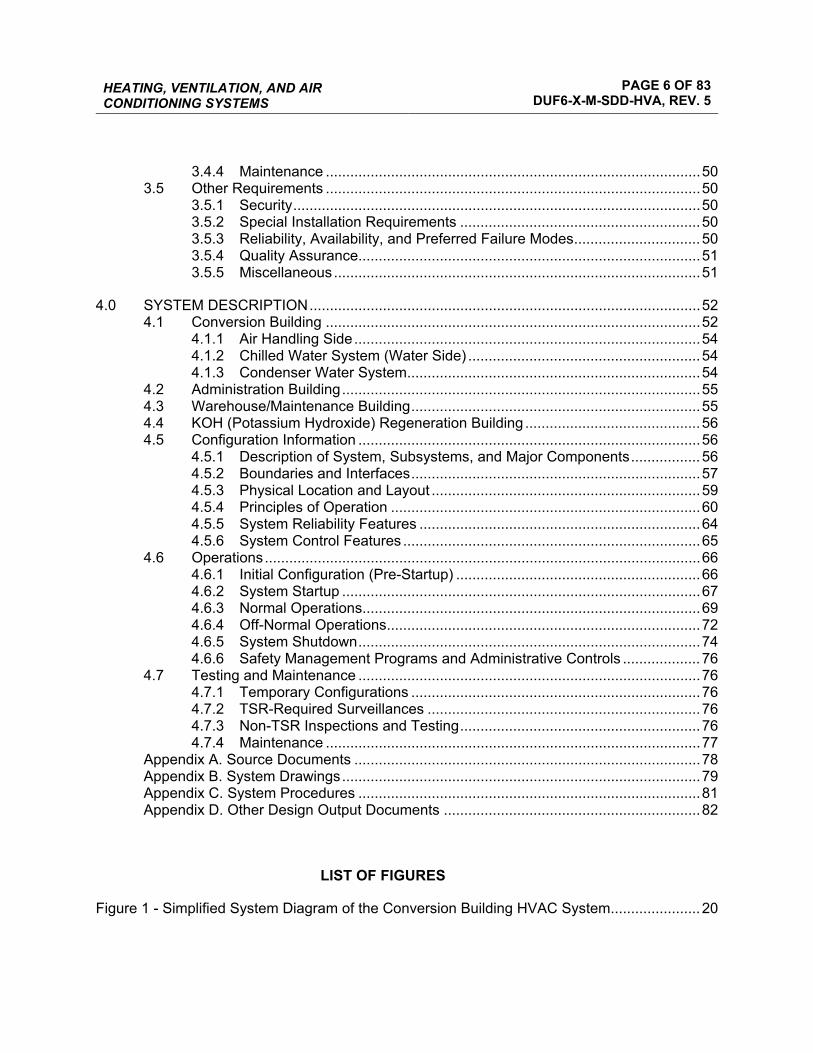
TABLE OF CONTENTS
1.0 INTRODUCTION ............................................................................................................... 7 1.1 System Identification ............................................................................................. 7 1.2 Limitations of this SDD .......................................................................................... 7 1.3 Ownership of this SDD .......................................................................................... 7 1.4 Definitions/Glossary .............................................................................................. 7 1.5 Acronyms .............................................................................................................. 9
2.0 GENERAL OVERVIEW ................................................................................................... 12 2.1 System Functions ................................................................................................ 12
2.1.1 Primary HVAC System Functions ............................................................ 12 2.1.2 Safety Functions ...................................................................................... 12
2.2 System Classification .......................................................................................... 12 2.3 Basic Operational Overview ................................................................................ 13
2.3.1 Conversion Building ................................................................................. 13 2.3.2 Administration Building ............................................................................ 18 2.3.3 Warehouse/Maintenance Building ........................................................... 18 2.3.4 KOH Regeneration Building ..................................................................... 18
3.0 REQUIREMENTS AND BASES ...................................................................................... 20 3.1 General Requirements ........................................................................................ 20
3.1.1 System Functional Requirements ............................................................ 20 3.1.2 Subsystem and Major Components ......................................................... 20 3.1.3 Boundaries and Interfaces ....................................................................... 20 3.1.4 Codes, Standards, and Regulations ........................................................ 21 3.1.5 Operability................................................................................................ 25
3.2 Special Requirements ......................................................................................... 25 3.2.1 Radiation and Other Hazards .................................................................. 25 3.2.2 AS LOW AS REASONABLY ACHIEVABLE (ALARA) ............................. 25 3.2.3 Nuclear Criticality Safety .......................................................................... 25 3.2.4 Industrial Hazards .................................................................................... 25 3.2.5 Operating Environment and Natural Phenomena .................................... 25 3.2.6 Human Interface Requirements ............................................................... 26 3.2.7 Specific Commitments ............................................................................. 26
3.3 Engineering Disciplinary Requirements............................................................... 26 3.3.1 Civil and Structural ................................................................................... 26 3.3.2 Mechanical and Materials ........................................................................ 26 3.3.3 Chemical and Process ............................................................................. 48 3.3.4 Electrical Power ....................................................................................... 48 3.3.5 Instrumentation and Control .................................................................... 49 3.3.6 Computer Hardware and Software .......................................................... 49 3.3.7 Fire Protection ......................................................................................... 49
3.4 Testing And Maintenance Requirements ............................................................ 50 3.4.1 Testability................................................................................................. 50 3.4.2 TSR Required Surveillance ..................................................................... 50 3.4.3 Non-TSR Inspections and Testing ........................................................... 50
HEATING, VENTILATION, AND AIR CONDITIONING SYSTEMS
PAGE 6 OF 83 DUF6-X-M-SDD-HVA, REV. 5
3.4.4 Maintenance ............................................................................................ 50 3.5 Other Requirements ............................................................................................ 50
3.5.1 Security .................................................................................................... 50 3.5.2 Special Installation Requirements ........................................................... 50 3.5.3 Reliability, Availability, and Preferred Failure Modes ............................... 50 3.5.4 Quality Assurance.................................................................................... 51 3.5.5 Miscellaneous .......................................................................................... 51
4.0 SYSTEM DESCRIPTION ................................................................................................ 52 4.1 Conversion Building ............................................................................................ 52
4.1.1 Air Handling Side ..................................................................................... 54 4.1.2 Chilled Water System (Water Side) ......................................................... 54 4.1.3 Condenser Water System ........................................................................ 54
4.2 Administration Building ........................................................................................ 55 4.3 Warehouse/Maintenance Building ....................................................................... 55 4.4 KOH (Potassium Hydroxide) Regeneration Building ........................................... 56 4.5 Configuration Information .................................................................................... 56
4.5.1 Description of System, Subsystems, and Major Components ................. 56 4.5.2 Boundaries and Interfaces ....................................................................... 57 4.5.3 Physical Location and Layout .................................................................. 59 4.5.4 Principles of Operation ............................................................................ 60 4.5.5 System Reliability Features ..................................................................... 64 4.5.6 System Control Features ......................................................................... 65
4.6 Operations ........................................................................................................... 66 4.6.1 Initial Configuration (Pre-Startup) ............................................................ 66 4.6.2 System Startup ........................................................................................ 67 4.6.3 Normal Operations ................................................................................... 69 4.6.4 Off-Normal Operations ............................................................................. 72 4.6.5 System Shutdown .................................................................................... 74 4.6.6 Safety Management Programs and Administrative Controls ................... 76
4.7 Testing and Maintenance .................................................................................... 76 4.7.1 Temporary Configurations ....................................................................... 76 4.7.2 TSR-Required Surveillances ................................................................... 76 4.7.3 Non-TSR Inspections and Testing ........................................................... 76 4.7.4 Maintenance ............................................................................................ 77
Appendix A. Source Documents ..................................................................................... 78 Appendix B. System Drawings ........................................................................................ 79 Appendix C. System Procedures .................................................................................... 81 Appendix D. Other Design Output Documents ............................................................... 82
LIST OF FIGURES
Figure 1 - Simplified System Diagram of the Conversion Building HVAC System...................... 20

HEATING, VENTILATION, AND AIR CONDITIONING SYSTEMS
PAGE 7 OF 83 DUF6-X-M-SDD-HVA, REV. 5
1.0 INTRODUCTION
This System Design Description (SDD) document provides the design description for the Heating, Ventilating, and Air Conditioning (HVAC) Systems that serve the buildings constructed at the Portsmouth, Ohio, facility as part of the Depleted Uranium Hexafluoride (DUF6) Conversion Project.
1.1 SYSTEM IDENTIFICATION
There are four buildings constructed for the project that require an HVAC system: Conversion Building, Administration Building, Warehouse/Maintenance Building, and KOH Building (heating and ventilation only).
1.2 LIMITATIONS OF THIS SDD
This SDD does not cover requirements related to the structure in which the system is housed. These requirements, such as civil and structural requirements, fire suppression requirements, and all requirements related to the Performance Category (PC) of the structure are covered in the Facility Design Description (FDD).
All systems interface with the Plant Main AC Power Supply System (MPS), Instrument Air System (IAS), and Integrated Control System (ICS) at the instruments, controls, equipment, and circuit breakers. The particulars of these interfaces are not described in detail in this SDD.
Information in this SDD pertaining to information contained in the Documented Safety Analyses (DSAs), Technical Safety Requirements (TSRs), and Software Requirements Specification (SRS) documents are based on current approved versions of those documents
1.3 OWNERSHIP OF THIS SDD
The owner of this SDD is the System Engineer. The System Engineer is responsible for making changes to the technical content of the SDD.
1.4 DEFINITIONS/GLOSSARY
Term Definition
Hydrofluoric Acid (HF) Hydrofluoric acid is a severe respiratory irritant, and in solution, causes severe and painful burns of the skin.
Integrated Control System (ICS)
The Integrated Control System is the network of software and hardware components used to monitor and operate the process. ICS consists of the basic process control system (BPCS) and independent safety system (ISS).
HEATING, VENTILATION, AND AIR CONDITIONING SYSTEMS
PAGE 8 OF 83 DUF6-X-M-SDD-HVA, REV. 5
Term Definition
Intelligent Motor Control Center (MCC)
A standard MCC that has individual compartments factory-wired with control system interface modules. These modules will transmit most starter and motor data to the BPCS and allow for connection of external control interlocks.
Operator Workstation (OWS)
An operator interface consisting of a display system and keyboard with a communication link to the ICS. OWS provides the operator interface required for start-up, shutdown and for general plant control and monitoring.
Performance Category (PC)
A classification using a graded approach in which structures, systems, or components in a category are designed to ensure similar levels of protection (i.e., meet the same performance goal and damage consequences) during natural phenomena hazard events.
Production Support A component or system that is not a major contributor to defense in depth and/or worker safety but is a major contributor to facility production as determined from hazard analysis.
Safety Significant A component or system whose preventative or mitigative functions are a major contributor to defense in depth (i.e., prevention of uncontrolled material release) and/or worker safety as determined from hazard analysis (DOE-STD-3009-94).
Standard Operating Procedure (SOP)
A Standard Operating Procedure is a document that identifies the actions and safeguards that must be taken to perform a task.
Technical Safety Requirement (TSR) The limits, controls, and related actions that establish the specific
parameters and requisite actions for the safe operation of a nuclear facility and include, as appropriate for the work and the hazards identified in the documented safety analysis for the facility: Safety limits, operating limits, surveillance requirements, administrative and management controls, use and application provisions, and design features, as well as a bases appendix.
HEATING, VENTILATION, AND AIR CONDITIONING SYSTEMS
PAGE 9 OF 83 DUF6-X-M-SDD-HVA, REV. 5
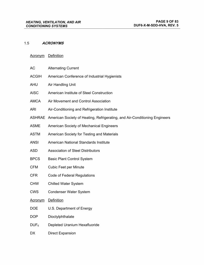
1.5 ACRONYMS
Acronym Definition
AC Alternating Current
ACGIH American Conference of Industrial Hygienists
AHU Air Handling Unit
AISC American Institute of Steel Construction
AMCA Air Movement and Control Association
ARI Air-Conditioning and Refrigeration Institute
ASHRAE American Society of Heating, Refrigerating, and Air-Conditioning Engineers
ASME American Society of Mechanical Engineers
ASTM American Society for Testing and Materials
ANSI American National Standards Institute
ASD Association of Steel Distributors
BPCS Basic Plant Control System
CFM Cubic Feet per Minute
CFR Code of Federal Regulations
CHW Chilled Water System
CWS Condenser Water System
Acronym Definition
DOE U.S. Department of Energy
DOP Dioctylphthalate
DUF6 Depleted Uranium Hexafluoride
DX Direct Expansion
HEATING, VENTILATION, AND AIR CONDITIONING SYSTEMS
PAGE 10 OF 83 DUF6-X-M-SDD-HVA, REV. 5
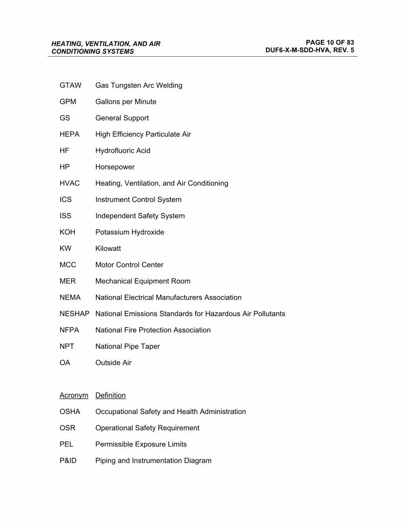
GTAW Gas Tungsten Arc Welding
GPM Gallons per Minute
GS General Support
HEPA High Efficiency Particulate Air
HF Hydrofluoric Acid
HP Horsepower
HVAC Heating, Ventilation, and Air Conditioning
ICS Instrument Control System
ISS Independent Safety System
KOH Potassium Hydroxide
KW Kilowatt
MCC Motor Control Center
MER Mechanical Equipment Room
NEMA National Electrical Manufacturers Association
NESHAP National Emissions Standards for Hazardous Air Pollutants
NFPA National Fire Protection Association
NPT National Pipe Taper
OA Outside Air
Acronym Definition
OSHA Occupational Safety and Health Administration
OSR Operational Safety Requirement
PEL Permissible Exposure Limits
P&ID Piping and Instrumentation Diagram

HEATING, VENTILATION, AND AIR CONDITIONING SYSTEMS
PAGE 11 OF 83 DUF6-X-M-SDD-HVA, REV. 5
PRV Pressure Regulating Valve
SCR Silicon Controlled Rectifier
SDD System Design Description
SMACNA Sheet Metal and Air Conditioning Contractors’ National Association
SMAW Shielded Metal Arc Welding
SNM Security and Special Nuclear Material
SOP Standard Operating Procedure
SQFT Square Foot
TCV Temperature Control Valve
TSR Technical Safety Requirement
UDS Uranium Disposition Services, LLC
UL Underwriters Laboratories, Inc.
VAV Variable Air Volume
WG Water Gauge
WBGT Wet Bulb Globe Temperature
WC Water Column
WRC Welding Research Council
UF6 Uranium Hexafluoride
UO2F2 Uranyl Fluoride

HEATING, VENTILATION, AND AIR CONDITIONING SYSTEMS
PAGE 12 OF 83 DUF6-X-M-SDD-HVA, REV. 5
2.0 GENERAL OVERVIEW
2.1 SYSTEM FUNCTIONS
The HVAC Systems are designed to maintain acceptable conditions of temperature, humidity, filtration, outdoor air supply, pressurization, air movement, and exhaust of the indoor areas of the Conversion, Administration, Warehouse/Maintenance, and Potassium Hydroxide (KOH) Buildings. The HVAC Systems are designed to be in compliance with local building codes and U.S. Department of Energy (DOE) requirements. Specific system safety functions pertain to fire protection, exhaust of hazardous gases, and the exhaust of contaminated air.
2.1.1 Primary HVAC System Functions
The following list of functions is generic for the HVA system and not intended to be equipment specific.
• Provide conditioned air to the respective areas • Provide outside air to the facilities • Provide adequate air filtration of air supplied to buildings and recirculation air throughout
the facilities • Provide adequate air filtration from hazardous gases and contaminated air prior to
exhausting to the atmosphere • Maintain area pressures for contamination control • Provide exhaust for process systems
2.1.2 Provide exhaust for process systems Safety Functions
None.
2.2 SYSTEM CLASSIFICATION
This system is classified as General Support Nonconfigured (GSN). There are no Technical Safety Requirements (TSR’s) associated with the HVA system.
The Administration and Warehouse/Maintenance Buildings have HVAC systems for office, storage, and industrial workroom area occupancy classifications. There are also office areas of the Conversion Building that are similar to the Administration and Warehouse/Maintenance Buildings, which have standard HVAC systems for office, storage, and industrial workroom area occupancy classifications. The KOH Building is a metal building that requires heating and ventilation only.

HEATING, VENTILATION, AND AIR CONDITIONING SYSTEMS
PAGE 13 OF 83 DUF6-X-M-SDD-HVA, REV. 5
2.3 BASIC OPERATIONAL OVERVIEW
2.3.1 Conversion Building
2.3.1.1 General
Each of the areas and rooms of the Conversion Building is designed for one of the following purposes: Process, Building Support Systems (equipment Rooms), and offices. The process areas take up to approximately 85% of the space in the building.
The HVAC systems for the process areas are designed to suit the specific processes taking place in those areas. There are eight designated process areas where there is the potential for DUF6 or uranium oxide contamination. These areas are:
• Cylinder Transfer Room
• Cylinder Evacuation Room
• Vaporization Room
• Conversion Area
• Powder Transfer Room
• Cylinder Fill Area
• Cylinder Preparation/Hot Shop
• Decontamination Room and Monitor Area
The air conditioning systems for these areas shall either be a “once-through” type, where the air supplied to the space is exhausted directly from the building; or a “recirculation” type, where a percentage of the supply air is recirculated through high efficiency particulate air (HEPA) filters, mixed with outside air, conditioned by cooling coils and or heating elements, and re-introduced to the process space.
The one area where all of the air supplied to the space is exhausted is the Powder Transfer Room.
Recirculation is used for large volume closed process spaces with a low potential for contamination. These spaces are:
• Cylinder Transfer Room
• Cylinder Evacuation Room
• Vaporization Room
HEATING, VENTILATION, AND AIR CONDITIONING SYSTEMS
PAGE 14 OF 83 DUF6-X-M-SDD-HVA, REV. 5
• Conversion Area
• Cylinder Fill Area
• Cylinder Preparation/Hot Shop
There are certain areas within some of the spaces listed above that are designated as “Hot Spots,” where there is an intermittent potential for a small amount of DUF6 or uranium oxide contamination to occur. These “Hot Spots” are provided with snorkels or hoods that are connected to the building exhaust system, thus preventing the potentially contaminated air from being recirculated. As an added precaution, the air pulled from the “Hot Spots” passes through a HEPA filter assembly located in the process space before traveling on to the building exhaust HEPA filters.
This is the primary engineered design feature used to avoid accumulation of powder and other contaminates in the large HVAC ducts. In each case where this technique is implemented, the hood or other potentially contaminated area is vented to a room (local) HEPA filter bank, then the vent duct is routed directly to the exhaust filter bank (no recirculation). This is done for two reasons; first to avoid buildup of contaminated material in the duct between the hood and the main HEPA bank and second to avoid gross contamination of the main HEPA bank.
The following systems include HEPA filters in the process room and vent directly to the main HEPA bank:
• CYL Evacuation Room Snorkel • CYL Evacuation Room • CYL Transfer Room Snorkels • Vaporization Room Snorkels • CSS Snorkel & Process Vent • CON Bed Load Hood • CON Powder Transfer Room • CON Transfer station Hoods • CON By-Pass Blowers • CON Cooler Blower Vent • CMS Vent Hood • OPH Load Out Hood • OPH Vacuum Transfer Blowers • Evaporator Vent (Evaporator Removed/Vent Abandoned In Place) • Hot Shop area

HEATING, VENTILATION, AND AIR CONDITIONING SYSTEMS
PAGE 15 OF 83 DUF6-X-M-SDD-HVA, REV. 5
All of the process areas where there is a potential for DUF6 or uranium oxide contamination to occur are designed to maintain a negative room pressure relative to the outside and all other clean areas of the building. The basis of this design is to pull more exhaust air from the process spaces than outside air is pumped in. This causes the room “to go negative” and pull clean infiltration air from outside and inside the building. The room pressure relative to outside is continually monitored in the ICS. The ICS maintains negative room pressure by modulating a damper in the exhaust duct leaving the room. The VAP area may lose negative pressure for minimal periods due to both air lock doors being opened simultaneously during cylinder transfer.
Process and equipment rooms, where there is not a potential for DUF6 or uranium oxide contamination, are ventilated using outside air.
The office area of the Conversion Building consists of two stories. The ground floor houses a few offices, operator toilet, shower, and locker facilities, and a laboratory. The second story houses additional office space and the Central Control Room. Two different air handling units (AHUs) are used to serve the office and laboratory spaces. The office AHU utilizes a return duct network and economizer to provide thermal and energy efficiency. The laboratory AHU is a make-up air unit that provides conditioned air for the space. The laboratory is maintained at a slightly higher pressure than the process areas of the conversion building.
2.3.1.2 Vaporization Area HVAC System (HV-001)
The vaporization area of the Conversion Building consists of the following rooms or areas: Vaporization Room, Cylinder Transfer Area, Cylinder Evacuation Room, and the Decontamination Room and Monitor Area.
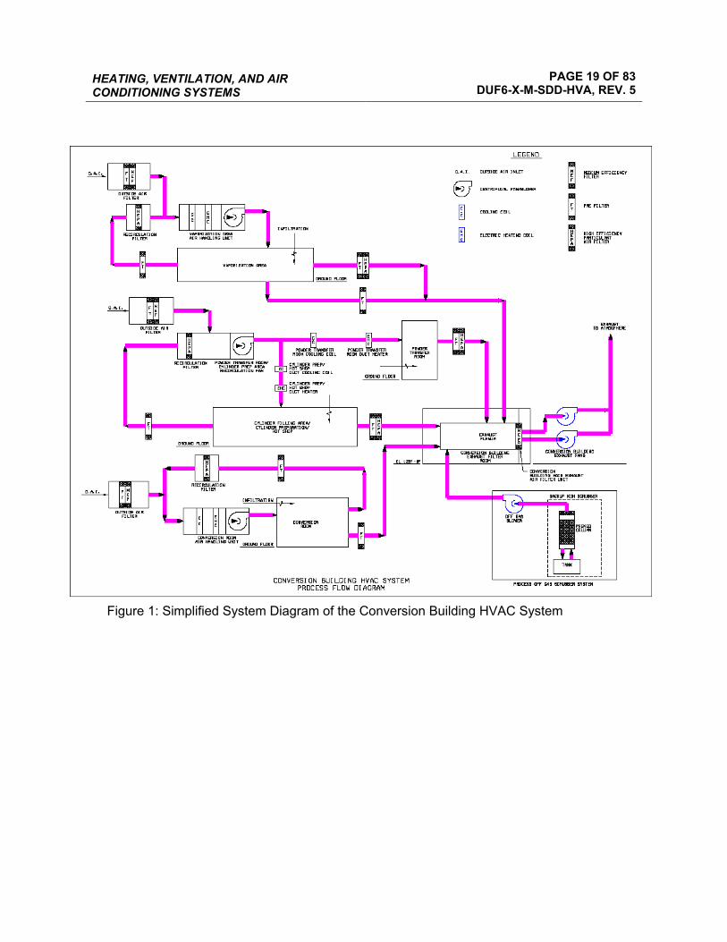
The AHU for this area (HV-001) shall maintain the room temperature between 60oF and 80oF. The system shall provide conditioned air to maintain this temperature year-round. The humidity in the area shall not be controlled. Due to the high process equipment load in this space, HV-001 shall require chilled water year-round. An electric heating coil located in HV-001 provides heat for the process area to maintain a minimum of 60oF. The heating coil will only be required when the process equipment is not in operation and not giving off heat to the space. All recirculated air is passed through a nuclear filtration system HEPA filter bank.
2.3.1.3 HVAC System (FN-053)
FN-053 serves the Cylinder Preparation and Hot Shop Area, the Cylinder Fill Area, the Hot Lab, and the Powder Transfer Room.
There is no AHU for this system. A recirculation fan is used to take clean return air from the Cylinder Preparation/Hot Shop and Cylinder Fill Areas, and mix this air with outside air. This
HEATING, VENTILATION, AND AIR CONDITIONING SYSTEMS
PAGE 16 OF 83 DUF6-X-M-SDD-HVA, REV. 5
mixture is split and supplied to two sets of electric heating and cooling coils. The air must be split due to the large difference in equipment and climatic loads between the two spaces. A high percentage of outside air is required for this system because all of the air supplied to the Powder Transfer Room is exhausted. There are also a few “Hot Spots” in the Hot Shop that require direct exhaust as well. All recirculated air is passed through a nuclear filtration system HEPA filter bank. The heating and cooling coils maintain the room temperature between 60oF and 80oF. The humidity in these areas is not controlled.
2.3.1.4 Conversion Area HVAC System (HV-003)
The Conversion Area consists of the following areas: Lower Conversion Area, Intermediate Conversion Area, and Upper Conversion Area.
The AHU for the Conversion Area (HV-003) shall maintain the area temperature between 60oF and 80oF. The system shall provide conditioned air to maintain this temperature year-round. The humidity in the area shall not be controlled. Due to the high process equipment load in this space, HV-003 shall require chilled water year-round. An electric heating coil located in HV-003 provides heat for the process area to maintain at least 60oF. The heating coil will only be required when the process equipment is not in operation and not giving off heat to the space.
All recirculated air is passed through a nuclear filtration system HEPA filter bank.
2.3.1.5 Building Exhaust System
The Building Exhaust System removes a percentage of air from each of the three process area HVAC systems (HV-001, FN-053, and HV-003). The Building Exhaust System is also directly connected to several process exhaust blowers located throughout the building. All air to be exhausted travels through round, smooth, wall ducts before emptying into the exhaust room plenum. Once in the exhaust room, the air is pulled through a bank of HEPA filters by a tandem of centrifugal fans (FN-051 and FN-052) and exhausted from the building through a steel stack located on the roof of the electrical room outside the Exhaust Fan Room. Each fan provides 100% of the required exhaust capacity. One of the two fans must always be in operation, with the second in stand-by mode. The fans are provided with variable speed drives to enable constant negative plenum pressure by varying the exhaust rate should conditions in the process areas change (due to, for example, an increase in filter pressure drop, or failure of an AHU supply fan). The speed drive will maintain the negative static pressure in the exhaust system just upstream of the final filter bank. The exhaust air is monitored for radiation.
2.3.1.6 Office Area HVAC System (HV-010)
The office area is served by AHU HV-010. The AHU is provided with a return fan, economizer section, filter section, cooling coil, electric heating coil, and supply fan. The HVAC supply system utilizes variable air volume (VAV) boxes and room thermostats to provide cooling in the summer and tempered ventilated air in the winter. Electric reheat coils provided with each VAV

HEATING, VENTILATION, AND AIR CONDITIONING SYSTEMS
PAGE 17 OF 83 DUF6-X-M-SDD-HVA, REV. 5
are used to provide heat in those rooms with transmission loads from the roof, outside walls, and windows.
A plenum return is used to bring return air back to the AHU. Air from the toilets, showers, lockers, janitor’s closets, and storage rooms are exhausted from the building by two exhaust fans. The exhaust system is designed to have one exhaust fan for each level of the office area.
2.3.1.7 Office Laboratory Area HVAC System (HV-011)
The Office Laboratory area is served by AHU HV-011 and exhaust fan FN-028. The AHU is provided with a filter section, cooling coil, electric heating coil, and supply fan. The heating coil in the AHU is not used. Heat for the laboratory is provided by a duct heater located in the supply ductwork. The AHU provides a constant flow of air to the Laboratory, recirculating 67% of the supply air while exhausting 33% through a fume hood exhaust fan.
2.3.1.8 Ventilation for Hazardous Equipment Rooms
The Scrubber Room is a process area in the Conversion Building where there is not a potential for DUF6 or uranium oxide contamination, but are classified as hazardous areas. This room is provided with HF gas detection systems. A ventilation system is provided with three supply fans and three exhaust fans sized to supply outside air to the space when needed. Two AC units area used to keep the Scrubber Room cool. A small capacity wall fan, running continuously, supplies outside air to space year round to comply with minimum code ventilation requirements.
The Condenser Room is a process areas in the Conversion Building where there is not a potential for DUF6 or uranium oxide contamination, but are classified as hazardous areas. This room is provided with HF gas detection systems. A ventilation system is provided with three supply fans and three exhaust fans to supply outside air to the space. Normally only an exhaust fan is to maintain a slightly negative pressure in the conning denser room. A small capacity wall fan, running continuously, supplies outside air to space year round to comply with minimum code ventilation requirements. .
2.3.1.9 Ventilation Systems for Non-Hazardous Equipment Rooms
The Conversion Building contains an electrical equipment room, two mechanical equipment rooms, and two sprinkler rooms, which house the building systems services equipment.
The Electrical Equipment Room is provided with two unit heaters and two cooling coils to maintain the room temperature. A small supply fan is used to provide minimal air changes for ventilation.

HEATING, VENTILATION, AND AIR CONDITIONING SYSTEMS
PAGE 18 OF 83 DUF6-X-M-SDD-HVA, REV. 5
The large mechanical equipment room (MER), adjacent to the electrical equipment room, houses the electric chillers, chilled water pumps, air compressors, and a hydraulic pump set. The ventilation system is provided with three supply fans and three exhaust fans. A small capacity wall fan, running continuously, supplies outside air to space year round to comply with minimum code ventilation requirements.
The small MER in the office area adjacent to the laboratory houses the hot water heater for the showers and toilets. This room is provided with heating and ventilation by HV-010.
The sprinkler rooms are not ventilated. Unit heaters are provided to maintain space temperature above 55oF.
2.3.2 Administration Building
The Administration Building is a two-story structure with offices and a computer server room. Each level of the building is provided with a heat pump. The server room system is designed with a pair of redundant heat pumps. The heat pumps are all roof-mounted and provided with filter section, direct expansion coil section with a packaged refrigeration cycle, condenser fans, air supply fan, down flow economizer, and power exhaust. Unit operation is integrated with VAV terminal boxes. Electric baseboard heaters are used to provide heat in those rooms with transmission loads from the roof, outside walls, and windows.
Plenum returns are used to bring return air back to the office space heat pumps; whereas the server room return system is ducted. Air from the toilets, showers, lockers, janitor’s closets, and storage rooms is exhausted from the building by two exhaust fans. The exhaust system is designed to have one exhaust fan for each level of office area.
2.3.3 Warehouse/Maintenance Building
The Warehouse/Maintenance Building is a one-story building consisting of a warehouse storage area, a maintenance workshop area, and an office area. The warehouse and maintenance areas are heated and ventilated. The office area is provided with HVAC by a roof-mounted, packaged heat pump, with supplemental heat provided by electric baseboard heaters.
2.3.4 KOH Regeneration Building
The KOH Building is a one-story metal building used to house the KOH regeneration process equipment. The building is heated and ventilated only. The building is provided with roof exhaust ventilators and outside air louvers. Outside ventilation air is drawn through motorized dampers at the wall louvers and is exhausted through the roof ventilators. Heating for the building during cold weather conditions is provided via local electric unit heaters.
HEATING, VENTILATION, AND AIR CONDITIONING SYSTEMS
PAGE 19 OF 83 DUF6-X-M-SDD-HVA, REV. 5
Figure 1: Simplified System Diagram of the Conversion Building HVAC System
HEATING, VENTILATION, AND AIR CONDITIONING SYSTEMS
PAGE 20 OF 83 DUF6-X-M-SDD-HVA, REV. 5
3.0 REQUIREMENTS AND BASES
3.1 GENERAL REQUIREMENTS
3.1.1 System Functional Requirements
3.1.1.1 Requirement: The HVAC Systems shall be designed to maintain acceptable conditions of temperature, humidity, filtration, outdoor air supply, pressurization, air movement, and exhaust of contaminated air as applicable.
Basis: The HVAC Systems shall provide an environment within the various buildings suitable for personnel and/or equipment operations.
3.1.2 Subsystem and Major Components
3.1.2.1 Requirement: The HVAC Systems described in Section 2 require a chiller plant. The chiller plant designed to serve the building’s HVAC System consists of three 50% capacity chillers, one dual cell cooling tower, three 50% capacity chilled water pumps, three 50% condenser water pumps, and batch water treatment equipment for the condenser and chilled water systems.
3.1.3 Boundaries and Interfaces
3.1.3.1 Conversion Building
The building exhaust fans (FN-051 and FN-052) are connected to the stand-by power generator systems in order to continue to provide building exhaust upon loss of power. The AHUs for the Conversion Building are not connected to the stand-by power system.
The HVAC Systems are provided with duct-mounted smoke detectors in the supply ductwork to signal the Fire Protection System to shut down their respective AHU supply fans when triggered. The AHU supply fans and the building exhaust fans are provided with variable speed drives that will vary or reduce air flow depending on the upset or alarm condition.
Fire dampers shall be provided at the fire-rated walls between fire zones except where fire damper closure would interfere with safe process operation. The dampers shall be the fusible link type. There shall be no fire dampers in the process ductwork. Fire dampers will be used in the Conversion Building office area and laboratory systems, HV-010 and HV-011.
3.1.3.2 Warehouse/Maintenance and Administration Buildings
The HVAC Systems for the Warehouse/Maintenance and Administration Buildings shall be provided with duct-mounted smoke detectors and fire dampers in the supply ductwork to shut down the supply and exhaust fans and signal the fire alarm system as required by code.
HEATING, VENTILATION, AND AIR CONDITIONING SYSTEMS
PAGE 21 OF 83 DUF6-X-M-SDD-HVA, REV. 5
3.1.4 Codes, Standards, and Regulations
The editions of the Codes and Standards shall be those in effect on August 2002, unless otherwise indicated.
3.1.4.1 American Institute of Steel Construction (AISC)
• AISC Manual of Steel Construction
Basis: This requirement gives the allowable stresses for structural steel members and is utilized to properly select the structural members used throughout the system.
3.1.4.2 American National Standards Institute (ANSI)
• ANSI C50.41, Polyphase Induction Motors For Power Generating Stations
Basis: ANSI C50.41 is an industry consensus standard and provides operational requirements for motors.
3.1.4.3 Air Movement and Control Association (AMCA)
• AMCA 210, Laboratory Methods of Testing Fans for Aerodynamic Performance Rating
• AMCA 211, Certified Ratings Program – Air Performance
• AMCA 300, Reverberant Room Method for Sound Testing of Fans
• AMCA 301, Methods for Calculating Fan Sound Ratings from Laboratory Test Data
• AMCA 500, Test Methods for Louvers, Dampers, and Shutters
Basis: Compliance with AMCA standards is stated in ASME AG-1-2003, Code on Nuclear Air and Gas
Treatment and DOE Handbook, Nuclear Air Cleaning Handbook (DOE HDBK-1169-2003).
3.1.4.4 Air Conditioning and Refrigeration Institute (ARI)
• ARI 410, Forced-Circulation Air-Cooling and Air-Heating Coils
• ARI 430, Standard for Central Station Air Handling Units
• ARI 550/590, Performance Rating of Water Chilling Packages Using the Vapor Compression Cycle
• ARI 640, Commercial and Industrial Humidifiers
• ARI 850, Commercial and Industrial Air Filter Equipment
Basis: Compliance with ARI standards is stated in ASME AG-1-2003, Code on Nuclear Air and Gas Treatment and DOE Handbook (HDBK)-1169-2003, Nuclear Air Cleaning Handbook.
HEATING, VENTILATION, AND AIR CONDITIONING SYSTEMS
PAGE 22 OF 83 DUF6-X-M-SDD-HVA, REV. 5
3.1.4.5 American Society of Heating, Refrigerating and Air-Conditioning Engineers (ASHRAE)
• ASHRAE Handbook - Fundamentals, 2001
• ASHRAE 15, Safety Standard for Refrigeration Systems
• ASHRAE 52, Methods of Testing Air Cleaning Devices Used in General Ventilation for Removing Particulate Matter
• ASHRAE 24, Methods of Testing for Rating Liquid Coolers
Basis: Compliance with ASHRAE standards is stated in ASME AG-1-2003 Code on Nuclear Air and Gas Treatment and DOE HDBK-1169-2003, Nuclear Air Cleaning Handbook.
3.1.4.6 American Society of Mechanical Engineers (ASME)
• ASME B31.3, Process Piping
• ASME B31.5, Refrigeration Piping
• ASME B31.9, Building Services Piping
• ASME, Boiler and Pressure Vessel Code, Section VIII
• ASME AG-1-2003, Code on Nuclear Air and Gas Treatment
Basis: Compliance with the above ASME standards is stated in DUF6-SRD-PORTS, Portsmouth
Systems Requirement Document.
3.1.4.7 American Society for Testing and Materials (ASTM)
• ASTM E 84-99, Standard Test Method for Surface Burning Characteristics of Building Materials
Basis: The use of non-combustible and self-extinguishing materials reduces the possibility of a fire and the risk of fire damage to adjacent buildings and equipment.
3.1.4.8 Code of Federal Regulations (CFR)
• CFR 10, Energy, Part 835, Occupational Radiation Protection
• CFR 40, Protection of Environment
• PART 60, Standards of Performance for New Stationary Sources
• PART 61, National Emission Standards for Hazardous Air Pollutants Basis: Compliance with the CFR standards above is stated in DUF6-UDS-SRD-PORTS, Portsmouth Systems Requirement Document.
HEATING, VENTILATION, AND AIR CONDITIONING SYSTEMS
PAGE 23 OF 83 DUF6-X-M-SDD-HVA, REV. 5
3.1.4.9 U.S. Department of Energy (DOE)
• DOE-Standard (STD)-3020, Specification for HEPA Filters Used by DOE Contractors
• DOE Order (O) 440.1A, Worker Protection Management for DOE Federal and Contractor Employees
• DOE Guide (G) 420.1-1, Nonreactor Nuclear Safety Design Criteria and Explosive Safety Criteria Guide for use with DOE O 420.1, Facility Safety
• DOE O 420.1A, Facility Safety
• DOE G 440.1-5, Fire Safety Program Implementation Guide for use with DOE Orders 420.1 and 440.1
• DOE HDBK-1169-2003, DOE Handbook: Nuclear Air Cleaning Handbook
• DOE STD 1066-99, DOE Fire Protection Design Criteria
Basis: Compliance with the DOE standards above is stated in DUF6-SRD-PORTS, Portsmouth Systems Requirement Document.
3.1.4.10 National Electrical Manufacturers Association (NEMA)
• NEMA MG 1, Motor and Generators
Basis: NEMA Standard MG 1, an industry consensus standard, provides operational requirements for motors.
3.1.4.11 National Fire Protection Association (NFPA)
NFPA 70
NFPA 90A
3.1.4.12 Occupational Safety and Health Administration (OSHA)
• OSHA 1910.95, Occupational Noise Exposure
Basis: This requirement is stated in DUF6-SRD-PORTS, Portsmouth Systems Requirement
Document.
3.1.4.13 Ohio State Codes
• Ohio Building Code
• Ohio Mechanical Code
• International Building Code
HEATING, VENTILATION, AND AIR CONDITIONING SYSTEMS
PAGE 24 OF 83 DUF6-X-M-SDD-HVA, REV. 5
Basis: This requirement is stated in DUF6-SRD-PORTS, Portsmouth Systems Requirement
Document.
3.1.4.14 Sheet Metal and Air Conditioning Contractors’ National Association (SMACNA)
• High Pressure Duct Construction Standards
• HVAC Duct Construction Standards – Metal and Flexible
• HVAC Duct Leakage Test Manual
• HVAC Systems – Testing, Adjusting, and Balancing
• Duct Design
Basis: Compliance with SMACNA standards is stated in ASME AG-1-2003 Code on Nuclear Air and
Gas Treatment and DOE HDBK-1169-2003, Nuclear Air Cleaning Handbook.
3.1.4.15 Underwriters Laboratories, Inc. (UL)
• UL 555, Fire Dampers
• UL 555S, Smoke Dampers
• UL 586, High-Efficiency, Particulate, Air Filter Units
• UL 900, Air Filter Units
• UL 1995, Heating and Cooling Equipment
• UL 1996, Standard for Electric Duct Heaters
• UL Class 1, Flammable Gases, Vapors or Liquids
Basis: Compliance with UL standards is a requirement stated in DUF6-SRD-PORTS, Portsmouth
Systems Requirement Document.
3.1.4.16 Welding Research Council (WRC)
• WRC Bulletin 107, Local Stresses in Spherical & Cylindrical Shells due to External Loadings
• WRC Bulletin 297, Local Stresses in Cylindrical Shells Due to External Loadings on Nozzles
Basis: The WRC standards listed above are industry consensus standards.

HEATING, VENTILATION, AND AIR CONDITIONING SYSTEMS
PAGE 25 OF 83 DUF6-X-M-SDD-HVA, REV. 5
3.1.5 Operability
The Conversion Building Process Exhaust System (FN-051 and FN-052) is required to be operable subject to Operational Safety Requirement (OSR). The Conversion Building Process Exhaust System is designed to monitor the exhaust air for radioactive particulate contamination. The HVAC systems serving process areas of the building are also interlocked with the facility radiation detection system.
Refer to Section 3.1.3, “Boundaries and Interfaces,” for a description of interface requirements with the Fire Protection System.
3.2 SPECIAL REQUIREMENTS
3.2.1 Radiation and Other Hazards
There are no radiation or other hazards associated with the HVAC System.
3.2.2 AS LOW AS REASONABLY ACHIEVABLE (ALARA)
An engineering study has been developed to evaluate radiation exposure at the DUF6 facilities. DUF6-G-Q-STU-002, ALARA Study – Radiation Exposure Evaluation, determined that the maximum dose to any facility worker would be less than 1 roentgen equivalent man (rem)/year (yr), which is lower than the DOE administrative control limit of 2 rem/yr. DUF6-UDS-PLN-007, Radiation Protection Program, is in place for controlling personnel exposure from external sources of radiation to levels below 1 rem/yr and as far below this average as reasonably achievable. The highest anticipated radiation exposures are associated with cylinder operations.
3.2.3 Nuclear Criticality Safety
Nuclear Criticality Safety requirements are not identified since Safety Management Program (SMP) Descriptions for DUF6 Conversion Project (DUF6-U-SMP-005) has certified that the nuclear criticality accident is not credible.
3.2.4 Industrial Hazards
There are no industrial hazards associated with the HVAC system.
3.2.5 Operating Environment and Natural Phenomena
For site-specific Natural Phenomena hazards (NPH) mitigation, refer to DUF6-X-G-NPH-001 for Portsmouth, OH.

HEATING, VENTILATION, AND AIR CONDITIONING SYSTEMS
PAGE 26 OF 83 DUF6-X-M-SDD-HVA, REV. 5
3.2.6 Human Interface Requirements
As filters degrade, the HVAC system will have to be manually balanced in order to ensure proper operation. Filters, when clogged or scheduled for replacement, will be manually replaced.
3.2.7 Specific Commitments
3.2.7.1 Requirement: HVAC System Design Air Flow Requirements. Airflow movements shall ensure that area cross-contamination does not occur. Directional airflows shall be maintainable from the clean areas into the process areas.
Basis: Maintaining airflow from clean to dirty areas is one means to achieve confinement, which is required per DOE G 420.1-1.
3.2.7.2 Requirement: HVAC System Design Air Flow Requirements. Airflow control shall be designed for modulation and make-up air.
Basis: Control of airflow is required to maintain building negative pressure and confinement.
3.2.7.3 Requirement: HVAC System Design Air Flow Requirements. The building and ventilation system design shall include provisions for maintaining negative pressure to prevent release of unmonitored and/or contaminated air to the atmosphere or to clean areas. Basis: Compliance with DOE G 420.1-1.
3.3 ENGINEERING DISCIPLINARY REQUIREMENTS
3.3.1 Civil and Structural
3.3.1.1 Seismic Requirements: All equipment, piping, and ductwork and seismic restraints shall be installed in accordance with the Ohio Building Code and Ohio Mechanical Code.
3.3.2 Mechanical and Materials
3.3.2.1 Requirement: HVAC-Cooling Towers. Cooling towers shall be fabricated from non-combustible materials. Fill shall be non-combustible or shall be self-extinguishing for fire resistance with a flame spread rating of 5 or less in accordance with ASTM E 84-99.
Basis: The use of non-combustible and self-extinguishing materials reduces the possibility of a fire and the risk of fire damage to adjacent buildings and equipment.
HEATING, VENTILATION, AND AIR CONDITIONING SYSTEMS
PAGE 27 OF 83 DUF6-X-M-SDD-HVA, REV. 5
3.3.2.2 Requirement: HVAC - Conversion Building. In areas where there is potential for DUF6
or uranium oxide contamination, the air conditioning system shall be either a “once through” type, or “recirculation” type maintaining a slightly negative pressure relative to outdoors. Air may be cooled and re-circulated within a single room or area as required for temperature control provided it does not result in air movement from potentially contaminated areas into clean areas. The VAP area may lose negative pressure for minimal periods due to both air lock doors being opened simultaneously during cylinder transfer.
Basis: The use of a “once through” ventilation system prevents potentially contaminated air from being supplied to clean areas. Maintaining the building at a negative pressure provides confinement. Local re-circulation provides a means of efficient temperature control without compromising design features that limit the potential for the spread of contamination and provides energy efficiency superior to a “once through” design.
3.3.2.3 Requirement: HVAC - Administration Building and Warehouse/Maintenance Building. Rooftop packaged heat pump units, with supplemental heat provided by electric baseboard heaters, shall be utilized to provide conditioned air to the different areas of the building. Air from locker and toilet areas shall be exhausted to the atmosphere through roof-mounted exhaust fans.
Basis: Good engineering practice. Exhaust of air from lockers and toilets is required per the building code.
3.3.2.4 Requirement: HVAC - General Ventilation. Ventilation of the Warehouse/Maintenance Building shall be provided by means of roof-mounted exhaust fans and wall-mounted air intake louvers.
Basis: General engineering practice for buildings of this type and usage.
3.3.2.5 Requirement: HVAC - Fan and Louver Control. Fans and louvers may be thermostatically controlled.
Basis: Thermostatic control limits ventilation to only those times when cooling is required and prevents freezing during the winter.
3.3.2.6 Requirement: HVAC - Heating and Air Conditioning. The office, toilet, and locker areas shall be air conditioned by rooftop AHUs or packaged heat pump units, with supplemental heat provided by electric baseboard heaters.
Basis: General engineering practice for rooms/areas of this type and usage.
3.3.2.7 Requirements: HVAC - Locker Areas. Air from locker and toilet areas shall be exhausted to the atmosphere through roof-mounted exhaust fans.
Basis: Exhaust to atmosphere is required for compliance with the building code.

HEATING, VENTILATION, AND AIR CONDITIONING SYSTEMS
PAGE 28 OF 83 DUF6-X-M-SDD-HVA, REV. 5
3.3.2.8 Requirement: HVAC - Equipment, Storage, and Maintenance Areas - Heating. Heat will be provided by means of electric unit heaters.
Basis: Electric unit heaters are an inexpensive means of providing general area heating.
3.3.2.9 Requirement: HVAC - Outdoor Design Conditions. Design outdoor temperatures shall be based on Tables 1A and 1B, Chapter 27, Climatic Design Information, of the 2001 ASHRAE Handbook – Fundamentals. The design values shall be:
• Heating dry bulb (99%): 10º Fahrenheit (F)
• Cooling dry bulb/wet bulb (0.4%): 92ºF / 74ºF Evap wet bulb (0.4%): 77ºF
Basis: ASHRAE recommends the site-specific design data for proper sizing of the HVAC Systems.
3.3.2.10 Requirement: HVAC - Indoor Design Conditions. Indoor design conditions shall be as follows:
Summer
• General air-conditioned spaces shall be at a maximum temperature of 78ºF.
• The Conversion Building process areas shall have a temperature of approximately 80ºF, with approximately 85ºF for the upper elevation in the Conversion Room.
• The ventilated spaces shall have a maximum temperature of 104ºF.
Winter
• General air-conditioned spaces shall be designed for 72ºF dry bulb.
• The Conversion Building process areas shall have a minimum temperature of 60ºF and maximum temperature of 80oF.
• The ventilated spaces shall have a minimum temperature of 55ºF.
Basis: Indoor design temperatures were selected based on personnel and equipment requirements. Maximum temperature of 104ºF is based on the electrical equipment design temperature of 40ºC (104ºF). Minimum temperature of 55ºF is based on freeze protection and worker comfort.
3.3.2.11 Requirement: HVAC - Indoor Design Conditions - Humidity Control. There shall be approximately 40% relative humidity in the office areas of the Administration and Warehouse Maintenance Buildings. Humidity is uncontrolled in process and equipment areas and the office area of the Conversion Building.
Basis: Humidity control is provided in office areas for worker comfort.
HEATING, VENTILATION, AND AIR CONDITIONING SYSTEMS
PAGE 29 OF 83 DUF6-X-M-SDD-HVA, REV. 5
3.3.2.12 Requirement: HVAC - Indoor Design Conditions - Air-Conditioned Office Area. Outdoor ventilation air shall be provided as required by the Ohio Mechanical Code for air-conditioned office areas.
Basis: Compliance with the building and mechanical code.
3.3.2.13 Requirement: HVAC - Indoor Design Conditions - Exhaust. Exhaust requirements for air-conditioned office areas shall be provided on the basis of the greatest amount determined from the following pertinent criteria:
• Toilets: 75 cfm per water closet or urinal
• Locker Rooms: 0.5 cfm/sq ft or 1 1/2 air changes per hour whichever is greater
• Shower Areas: 0.5 cfm/sq ft or 6 air changes per hour whichever is greater
• Labs: Fume Hood manufacturer's data and applicable codes and standards
Basis: Compliance with the building and mechanical code and good engineering practice.
3.3.2.14 Requirement: HVAC - Indoor Design Conditions - Ventilated Areas. For ventilated areas, the quantity of supply and exhaust air shall be based on limiting the space temperatures to the design limits or for airborne contamination control, whichever is greater.
Basis: The greater ventilation flow ensures that both the temperature and air change requirements are met.
3.3.2.15 Requirement: HVAC - Indoor Design Conditions - Noise Contribution. Noise contribution from HVAC equipment to the air-conditioned office spaces shall be limited to the NC35 curve shown in the ASHRAE Handbook - Fundamentals. All other HVAC noise contribution shall comply with Occupational Safety and Health Administration (OSHA) Standard 1910.95 for 8 hours per day occupancy.
Basis: Limiting the noise in office spaces is a good engineering practice. Limiting noise to OSHA limits is required for worker safety.
3.3.2.16 Requirement: HVAC - General Requirements. All HVAC Systems and components shall be designed in accordance with the specific codes and standards referenced in this document.
Basis: Design to recognized codes and standards is a requirement to ensure the quality and function of the systems and equipment.

HEATING, VENTILATION, AND AIR CONDITIONING SYSTEMS
PAGE 30 OF 83 DUF6-X-M-SDD-HVA, REV. 5
3.3.2.17 Requirement: HVAC - General Requirements. All equipment shall be arranged to allow removal without disassembling ductwork. If this is not possible, the ductwork shall be sectioned such that small sections of ductwork can be removed.
Basis: Allows easier maintenance and repair and reduces maintenance effort and costs.
3.3.2.18 Requirement: HVAC - General Requirements. All floor-mounted equipment shall be installed on 4” minimum concrete pads or steel platforms.
Basis: Enhances general housekeeping and prevents possible water damage if water is on the floor.
3.3.2.19 Requirement: HVAC - General Requirements. Sufficient space shall be provided to allow for removal of coils, fans, filters, etc., from ductwork and equipment. Where components may be radioactive, space shall be provided for appropriate radiological safeguards.
Basis: Allow easier maintenance and repair and reduce maintenance effort and costs.
3.3.2.20 Requirement: HVAC - General Requirements. Where possible, pull spaces shall be shared between equipment and components.
Basis: Shared pull spaces reduce overall room/building volume and therefore building costs.
3.3.2.21 Requirement: HVAC - General Requirements. Access doors shall be provided in ductwork on the upstream and/or downstream sides of each component or piece of equipment requiring maintenance.
Basis: Provide access to duct-mounted equipment for maintenance, inspection, and repair.
3.3.2.22 Requirement: HVAC - General Requirements. Access doors shall be sized to the maximum size required for its particular function with consideration given to the duct size and shall maintain the design pressure and leakage requirements of the ductwork. Access doors shall have minimum dimensions of 12 inches wide x 12 inches high.
Basis: Good engineering practice.
3.3.2.23 Requirement: HVAC - General Requirements. Drain connections shall be provided where required. All clean wastewater, such as condensate from cooling coils serving non-radiological areas, shall be piped to clean water drains.
Basis: Drain connections allow piping to be easily drained for maintenance and repair. Clean wastewater does not need special handling or treatment.
HEATING, VENTILATION, AND AIR CONDITIONING SYSTEMS
PAGE 31 OF 83 DUF6-X-M-SDD-HVA, REV. 5
3.3.2.24 Requirement: HVAC - General Requirements. The requirements for outdoor ventilation air for building occupants and air change rates for toilet, locker, and shower areas shall be in accordance with the Ohio Mechanical Code.
Basis: Compliance with the applicable building code.
3.3.2.25 Requirement: HVAC Air Handling Units Requirements. Air handling units shall be industrial type rugged construction, factory assembled, and skid-mounted in a one-piece packaged unit.
Basis: Good engineering practice. A one-piece packaged unit results in easier installation and less site work.
3.3.2.26 Requirement: HVAC Air Handling Units Requirements. Air handling unit (AHU) casings shall be galvanized steel and insulated and coated per the requirements of NFPA 90A.
Basis: Good engineering practice. Compliance with NFPA 90A reduces the fire hazard of the AHUs.
3.3.2.27 Requirement: HVAC Air Handling Units Requirements. Structural support steel shall be provided to support filters, coils, fans, bearings, motors, and other components to withstand the specific operating requirements of the units.
Basis: Steel supports are utilized for structural integrity and to eliminate the use of combustible materials.
3.3.2.28 Requirement: HVAC Air Handling Units Requirements. Access doors shall be provided on AHUs that are quickly and easily opened or removable for inspection or access to internal components.
Basis: Enhance system maintenance and repair.
3.3.2.29 Requirement: HVAC Air Handling Units Requirements. The housing design for air handling units shall be standardized with the same side removal capability and shall allow for adequate and safe removal and replacement of filters, coils, and fans.
Basis: Enhance system maintenance and repair.
3.3.2.30 Requirement: HVAC Air Handling Units Requirements. Where space permits, piping connections to coil headers shall be located on the opposite side of the coil pull space to minimize the amount of work necessary for coil removal.
Basis: Enhance system maintenance and repair.

HEATING, VENTILATION, AND AIR CONDITIONING SYSTEMS
PAGE 32 OF 83 DUF6-X-M-SDD-HVA, REV. 5
3.3.2.31 Requirement: HVAC Air Handling Units Requirements. All fans shall be internally isolated from the air handling unit casing by means of spring isolators and flexible connections.
Basis: Isolation reduces system vibration and noise.
3.3.2.32 Requirement: HVAC Air Handling Units Requirements. Air handling units shall be designed to the requirements of ARI 430.
Basis: Good engineering practice using an industry accepted standard.
3.3.2.33 Requirement: HVAC Water Chillers Requirements. Chillers shall be designed and rated in accordance with ARI 590.
Basis: Design to recognized industry codes and standards ensures the quality, function, and performance of the equipment.
3.3.2.34 Requirement: HVAC Water Chillers Requirements. Condensers and evaporators shall be designed in accordance with the requirements of ASME Section VIII and ANSI/ASHRAE 15.
Basis: Design to recognized industry codes and standards ensures the quality, function, and performance of the equipment.
3.3.2.35 Requirement: HVAC Water Chillers Requirements. Redundancy shall be provided by using three 50% capacity chillers.
Basis: Redundancy is provided to enhance system availability, thereby increasing overall process system operation availability.
3.3.2.36 Requirement: HVAC Water Chillers Requirements. Chillers shall utilize a propylene glycol / water fluid as the heat transfer medium.
Basis: Propylene glycol is used because it is non-toxic. The mixture is used to prevent freezing in piping and coils that could be exposed to outdoor freezing conditions.
3.3.2.37 Requirement: HVAC Filter Units Requirements. Filter units shall be factory-assembled and skid-mounted in a one-piece package unit to the maximum extent practical.
Basis: This approach reduces the amount of site work required for filter unit installation.
3.3.2.38 Requirement: HVAC Filter Units Requirements: The installed capacity of the filter unit shall be no greater than the limiting installed capacity of any bank of components contained in the filter unit.
Basis: The airflow capability of the filter unit is limited by the airflow capability of the most restrictive component in the unit.

HEATING, VENTILATION, AND AIR CONDITIONING SYSTEMS
PAGE 33 OF 83 DUF6-X-M-SDD-HVA, REV. 5
3.3.2.39 Requirement: HVAC HEPA Nuclear Filter Units Requirements. Nuclear filter units and their associated components shall be designed, constructed, and tested to meet the requirements of ASME AG-1 and the in-place testing requirements of ASME AG-1.
Basis: Compliance with industry accepted standards for nuclear filtration units.
3.3.2.40 Requirement: HVAC HEPA Nuclear Filter Units Requirements. Maximum nuclear filter bank flow rate will be approximately 30,000 (cfm). Systems with flow rates greater than 30,000 (cfm) will be segmented into two or more smaller subsystems.
Basis: Recommended practice, DOE HDBK-1169-2003, Nuclear Air Cleaning Handbook.
3.3.2.41 Requirement: HVAC HEPA Nuclear Filter Units Requirements. Heat detectors will be installed in the ductwork upstream of the nuclear filter units and in the filter units downstream of the HEPA filters.
Basis: Requirement of DOE STD 1066-99, DOE Fire Protection Design Criteria.
3.3.2.42 Requirement: HVAC Air Filters Requirements: Air filters shall be selected based on their operating characteristics, including efficiency, airflow resistance, and dust holding capacity. The following types of filters shall be selected:
• Low efficiency filters – minimum 25% efficiency based on ASHRAE Standard 52 dust spot test.
• Medium efficiency filters – minimum 65-80% efficiency based on ASHRAE Standard 52 duct spot test.
• HEPA filters – minimum 99.97% efficiency for 0.3-micron particles.
Basis: Accepted industry practice and compliance with DOE-STD-3020.
3.3.2.43 Requirement: HVAC Air Filters Requirements. All filters shall be replaceable, cartridge type, and of standard manufactured modules with nominal dimensions of 24 inches wide x 24 inches high.
Basis: Standardization of filters reduces facility replacement filter inventory.
3.3.2.44 Requirement: HVAC Air Filters Requirements. All filters shall be moisture resistant.
Basis: Moisture resistance extends the operating life of the filter and helps to prevent organic growth in the filter.
3.3.2.45 Requirement: HVAC Air Filters Requirements. In general, the maximum face velocity of air filters shall not exceed 500 fpm.
Basis: Good engineering practice.
HEATING, VENTILATION, AND AIR CONDITIONING SYSTEMS
PAGE 34 OF 83 DUF6-X-M-SDD-HVA, REV. 5
3.3.2.46 Requirement: HVAC Air Filters Requirements. Low and medium efficiency filters shall be designed in accordance with ARI 850, constructed to UL 900 criteria, and shall carry a UL Class 1 label.
Basis: Design to recognized industry codes and standards ensures the quality, function, and performance of the equipment. Class 1 filters, when clean, do not contribute fuel when attacked by flame and emit only negligible amounts of smoke.
3.3.2.47 Requirement: HVAC Air Filters Requirements. Filters shall be provided upstream of cooling coils for all air handling units to protect the coils from coarse particles and to maintain coil design thermal efficiency.
Basis: Protection of coils from coarse particles and maintaining coil design efficiency are good engineering practices and reduce operating costs.
3.3.2.48 Requirement: HVAC Air Filters Requirements. Pre-filters shall be provided upstream of HEPA filters to protect the HEPA filters from coarse particles and to extend their service life.
Basis: Good engineering practice to increase the time between HEPA filter replacements and therefore reduce costs.
3.3.2.49 Requirement: HVAC Air Filters Requirements. HEPA filters shall be constructed to UL 586 criteria, carry a UL Class 1 label, have characteristics per ASME AG-1, Section FC, and be procured to DOE-STD-3020.
Basis: Compliance with DOE design requirements. Class 1 filters, when clean, do not contribute fuel when attacked by flame and emit only negligible amounts of smoke.
3.3.2.50 Requirement: HVAC Air Filters Requirements. HEPA filters shall be provided as required in systems to remove radioactive particulate airborne contaminants and to control radioactivity release to the environment.
Basis: Compliance with DOE G 420.1-1 to provide confinement.
3.3.2.51 Requirement: HVAC Air Filters Requirements. Air filters shall be selected based on their operating characteristics, including efficiency, airflow resistance, and dust-holding capacity.
Basis: Good engineering practice.
3.3.2.52 Requirement: HVAC Heating Coils Requirements. Heating coils shall be provided to temper air in order to control the thermal environment in the areas being served by the HVAC Systems.
Basis: Compliance with the indoor design temperature requirements.
HEATING, VENTILATION, AND AIR CONDITIONING SYSTEMS
PAGE 35 OF 83 DUF6-X-M-SDD-HVA, REV. 5
3.3.2.53 Requirement: HVAC Heating Coils Requirements. Where heating coils are installed in air handling units for office spaces, they shall be located downstream of the filter and upstream of the cooling coil.
Basis: Locating heating coils downstream of the filters keeps the coils cleaner, thereby enhancing coil performance and reducing maintenance. Locating heating coils upstream of the cooling coils prevents water carryover from the cooling coils from damaging or dirtying the heating coil.
3.3.2.54 Requirement: HVAC Heating Coils Requirements. Where heating coils are installed in air handling units for process spaces, they shall be located downstream of both the filter and the cooling coil.
Basis: Locating heating coils downstream of the filters keeps the coils cleaner, which enhances coil performance and reduces maintenance. Locating heating coils downstream of the cooling coils allows the heating coils to provide reheat to the cooled air.
3.3.2.55 Requirement: HVAC Heating Coils Requirements. Electric heating coils shall be designed with sufficient and uniform airflow across the coil in order to prevent overheating and nuisance tripping of the thermal cutouts.
Basis: Uniform and sufficient airflow prevents electric heating coils from overheating and prevents nuisance tripping of the thermal cutouts.
3.3.2.56 Requirement: HVAC Heating Coils Requirements. Electric heating coils shall be fin-tubular type and wired for Silicon Controlled Rectifier (SCR) controlled heating.
Basis: Fin-tubular coils are more rugged and less susceptible to physical damage than open coils.
3.3.2.57 Requirement: HVAC Heating Coils Requirements. Electric heating coils shall be designed to meet the requirements of UL 1995, UL 1996, and NFPA 70.
Basis: Compliance to industry-recognized codes provides assurance of coil performance and safety.
3.3.2.58 Requirement: HVAC Cooling Coils Requirements. Cooling coils shall be provided to cool air in order to control the thermal environment in the areas served by the HVAC Systems.
Basis: The use of cooling coils allows lower building temperatures to be maintained and reduces the amount of outside air required for “once through” ventilation systems.
3.3.2.59 Requirement: HVAC Cooling Coils Requirements. The cooling coils shall be installed in air handling units or unit coolers in the vertical position (perpendicular to airflow) to minimize condensation carryover.
Basis: Condensation carryover can contribute to AHU/duct corrosion or water damage, especially if excessive carryover occurs.
HEATING, VENTILATION, AND AIR CONDITIONING SYSTEMS
PAGE 36 OF 83 DUF6-X-M-SDD-HVA, REV. 5
3.3.2.60 Requirement: HVAC Cooling Coils Requirements. An insulated, stainless steel drain pan and drain connection shall be provided below each individual cooling coil to collect water condensation from each coil.
Basis: Stainless steel drain pans provide good corrosion resistance. Insulated pans prevent condensation on the sides and underside of the drain pan.
3.3.2.61 Requirement: HVAC Cooling Coils Requirements. In administrative areas, the cooling coils shall be located downstream of the heating coil in air handling units or downstream of the filter in unit coolers.
Basis: Locating the cooling coil downstream prevents the possibility of water carryover to the heating coils and filters.
3.3.2.62 Requirement: HVAC Cooling Coils Requirements. In process areas, the cooling coil shall be located upstream of the heating coil in air handling units or downstream of the filter in unit coolers.
Basis: Locating the cooling coil upstream of the heating coil allows the electric coil to be used for re-heating the conditioned air. This feature is beneficial when large amounts of outside air must be cooled and dehumidified.
3.3.2.63 Requirement: HVAC Cooling Coils Requirements. The coils shall be located upstream of the supply fan.
Basis: Upstream coils provide better airflow distribution across the cooling coils.
3.3.2.64 Requirement: HVAC Cooling Coils Requirements. Cooling coils shall be sized for face velocities of 500 fpm and shall not exceed 550 fpm.
Basis: Velocities in this range provide good heat transfer and limit water carryover.
3.3.2.65 Requirement: HVAC Cooling Coils Requirements. Tube water velocity shall not exceed 7.5 feet per second (fps) nor be less than 1.5 fps at full-flow conditions.
Basis: Tube velocities in this range provide reasonable coil performance.
3.3.2.66 Requirement: HVAC Cooling Coils Requirements. The coils shall be designed to withstand a minimum working pressure of 150 pounds per square inch gage (psig) at 200ºF and they shall be leak tested to 300 psig air pressure under water.
Basis: Ensures that the coil will maintain its integrity during all system operating modes.
3.3.2.67 Requirement: HVAC Cooling Coils Requirements. The coil certified rating shall be in accordance with ARI 410.
Basis: ARI 410 is an accepted industry standard. Compliance with this standard provides reasonable assurance that the coil will meet the performance requirements.
HEATING, VENTILATION, AND AIR CONDITIONING SYSTEMS
PAGE 37 OF 83 DUF6-X-M-SDD-HVA, REV. 5
3.3.2.68 Requirement: HVAC Fans Requirements. Fans shall be the direct-driven type. Belt-driven fans should only be used when direct-driven fans are not available at the design rating or unless special circumstances dictate their usage.
Basis: Direct-driven fans eliminate fan problems with belts and belt drives and belt/drive maintenance.
3.3.2.69 Requirement: HVAC Fans Requirements. All fans shall be statically and dynamically balanced.
Basis: Balancing reduces vibration and noise.
3.3.2.70 Requirement: HVAC Fans Requirements. Fans shall be UL listed and bear the UL seal. When available, fans should have an AMCA certified ratings seal.
Basis: Listing and certified ratings provide assurance that the fans meet a recognized level of quality. Certified ratings also provide assurance that the fans will meet their design requirements; however, AMCA certified ratings seals may not be available for all fans.
3.3.2.71 Requirement: HVAC Fans Requirements. Fan performance shall be rated in accordance with AMCA 211 or performance tested in accordance with AMCA 210.
Basis: AMCA rating and testing provide assurance that the fans will meet their design performance requirements.
3.3.2.72 Requirement: HVAC Fans Requirements. The fan sound power rating shall be rated in accordance with AMCA 301 or tested in accordance with AMCA 300.
Basis: AMCA rating and testing provide assurance that the fans will meet their design performance requirements.
3.3.2.73 Requirement: HVAC Fans Requirements. Fans shall be designed with high efficiency wheels to produce non-overloading horsepower characteristics.
Basis: Non-overloading wheel design prevents fan failure due to circuit breaker trip.
3.3.2.74 Requirement: HVAC Fans Requirements. Fans bearings shall be of the split case type.
Basis: Split bearings easier to maintain and replace.
3.3.2.75 Requirement: HVAC Electric Unit Heaters Requirements. Unit heaters shall be provided in areas where spot heating is required and shall be factory assembled. The unit heaters shall be designed for horizontal or vertical discharge, as required, with a built-in fan, steel cabinet, and individually adjustable discharge louvers.
Basis: Unit heaters are an inexpensive means of providing localized heating. Procuring heaters that are factory assembled with accessories reduces installation cost.
HEATING, VENTILATION, AND AIR CONDITIONING SYSTEMS
PAGE 38 OF 83 DUF6-X-M-SDD-HVA, REV. 5
3.3.2.76 Requirement: HVAC Electric Unit Heaters Requirements. All unit heaters shall be UL listed and designed in accordance with NFPA 70.
Basis: Compliance to industry-recognized codes provides assurance of coil performance and safety.
3.3.2.77 Requirement: HVAC Ductwork Material Requirements. In general, all duct material shall be galvanized steel. Alternate materials such as stainless steel, copper, aluminum, or black iron may be used for special applications or field conditions. Non-metallic flexible ductwork shall only be used in office-type applications. Flexible ductwork used for connections to process equipment and hoods shall be steel and no longer than 18 inches.
Basis: Galvanized steel is typical for industrial ductwork systems and is more economical than other metal ducts. Non-metal ducts should not be used for areas that could become contaminated.
3.3.2.78 Requirement: HVAC Ductwork Material Requirements. All ducts shall be designed to SMACNA standards and NFPA 90A, and ASME AG-1, where applicable.
Basis: SMACNA standards are industry-accepted duct design standards. Compliance with NFPA 90A contributes to overall fire safety. Design of ducts to AG-1 is required for ducts that are part of nuclear air-cleaning systems.
3.3.2.79 Requirement: HVAC Ductwork Material Requirements. In general, supply ductwork should be rectangular and exhaust ducts for potentially contaminated areas shall be round or flat oval. Duct configurations shall be selected with the following preference:
• High velocity and Low velocity – Square duct, Rectangular duct, Round duct, Flat Oval duct.
• High velocity is defined as a movement of air of 2,000 fpm or above. Low velocity is defined as a movement of air below 2,000 fpm.
Basis: These are general industry standard duct configurations and usages. Round/oval ducts are used for exhaust ducts that are potentially contaminated because they have more uniform airflow profiles, resulting in less potential for ducts trapping contaminants.
3.3.2.80 Requirement: HVAC Ductwork Material Requirements. Ductwork shall be designed to resist corrosive contaminants if present.
Basis: Duct material shall be selected to be compatible with the air/gas being conducted.

HEATING, VENTILATION, AND AIR CONDITIONING SYSTEMS
PAGE 39 OF 83 DUF6-X-M-SDD-HVA, REV. 5
3.3.2.81 Requirement: HVAC Ductwork Material Requirements. Ductwork that handles air exhausted from shower rooms, dishwashing areas, or other areas causing condensation on the duct interior shall be of aluminum construction, have welded joints and seams, and have drainage at low points.
Basis: Aluminum ductwork is more resistant than steel duct to moisture that may be contained in the exhaust air.
3.3.2.82 Requirement: HVAC Ductwork Material Requirements. Ductwork that handles air exhausted and recirculated air from process areas, shall have welded joints and seams. Vanstone joints shall not be used.
Basis: Welded duct and joints provide superior leakage characteristics.
3.3.2.83 Requirement: HVAC Ductwork Leakage. General duct systems shall be designed for a total system duct leak rate of less than or equal to 5 percent of the total system design airflow rate.
Basis: Amount of duct leakage is limited to control system airflows.
3.3.2.84 Requirement: HVAC Ductwork Leakage. Nuclear filter unit duct systems shall be designed for a total system duct leak rate in accordance with ASME N509.
Basis: Compliance with ASME N509 for the design of ductwork for nuclear filtration systems.
3.3.2.85 Requirement: HVAC Ductwork Security. Where ducts pass through security barriers, appropriate measures shall be taken to maintain the integrity of the security barrier.
Basis: Duct openings in security barriers should not allow the barrier to be breached.
3.3.2.86 Requirement: HVAC Duct Sizing – General HVAC Usage Requirements. Ductwork shall be sized by the “Equal Friction Method.”
Basis: This method is one of the acceptable design methods discussed in the ASHRAE Handbook - Fundamentals.
3.3.2.87 Requirement: HVAC Duct Sizing – General HVAC Usage Requirements. Main ducts shall be sized for approximately 0.1 inches water gauge (WG) per 100 feet pressure drop according to the available space, with losses up to 0.2 inches WG per 100 feet for specific design requirements, and a velocity not to exceed 2,600 fpm.
Basis: These are typical design values for the “Equal Friction Method.”

HEATING, VENTILATION, AND AIR CONDITIONING SYSTEMS
PAGE 40 OF 83 DUF6-X-M-SDD-HVA, REV. 5
3.3.2.88 Requirement: HVAC Duct Sizing – General HVAC Usage Requirements. Branch ducts shall be sized not to exceed 0.1 inches WG per 100 feet pressure drop, or a velocity of 1,800 fpm. Ductwork serving up to three outlets shall be considered branch ducts.
Basis: These are typical design values for the “Equal Friction Method.”
3.3.2.89 Requirement: HVAC Duct Sizing – General HVAC Usage Requirements. Exhaust ducts that may carry radioactive particulate matter shall be round with a minimum velocity of 2,500 fpm and a maximum velocity of 4,000 fpm.
Basis: High duct velocities maintain particulates entrained in the air stream, preventing them from “plating out” on the duct wall.
3.3.2.90 Requirement: HVAC Duct Sizing – General HVAC Usage Requirements. Ductwork serving office or administrative areas shall be sized not to exceed 0.08 inches WG per 100 feet pressure drop or a velocity of 1,600 fpm.
Basis: These are typical design values for the “Equal Friction Method.”
3.3.2.91 Requirement: HVAC Ductwork Fittings. Fittings shall be designed in accordance with SMACNA and ASHRAE requirements.
Basis: Fittings designed to recognized codes and standards ensure the quality and function of the items.
3.3.2.92 Requirement: HVAC Duct Insulation and Lining Requirements. An insulation thickness of 1½ inches shall be used on all supply ductwork as a guideline to reserve space in duct routing. Final duct insulation thickness shall be determined by the designer.
Basis: Supply duct insulation thickness is typically 1½ inches or less. Using the upper limit of 1½ inches for duct routing is conservative and allows routing to occur early in the design.
3.3.2.93 Requirement: HVAC Duct Insulation and Lining Requirements. Where required, ducts shall be lined with acoustical lining for the purpose of sound attenuation. The length of lining shall depend on the air velocity in the duct and the amount of attenuation required. The designer shall be responsible for determining where the lining shall be placed and what quantity of ductwork shall be lined. Overall, duct size shall be increased wherever duct lining is used so that the net inside dimensions of the duct are unchanged.
Basis: Acoustical duct lining is provided to meet the duct noise criteria.
HEATING, VENTILATION, AND AIR CONDITIONING SYSTEMS
PAGE 41 OF 83 DUF6-X-M-SDD-HVA, REV. 5
3.3.2.94 Requirement: HVAC Duct Insulation and Lining Requirements. All insulation and lining shall be in accordance with NFPA 90A.
Basis: NFPA 90A provides criteria for insulation flame spread and fuel contribution during burning.
3.3.2.95 Requirement: HVAC Duct Supports Requirements. Duct shall be supported from concrete walls, ceilings, floors, columns, beams, etc., depending on their location.
Basis: Support of ductwork from structural elements results in a ductwork system that is firmly supported and subject to less noise and vibration.
3.3.2.96 Requirement: HVAC Duct Supports Requirements. Ductwork that requires seismic support shall be supported in two planes and preferably routed in the corners of buildings so that economical seismic supports can be designed.
Basis: Good engineering practice.
3.3.2.97 Requirement: HVAC Flexible Connections Requirements. All fans shall have flexible connections on the intake and discharge sides to reduce the transmission of vibration.
Basis: Isolation of the fan from the ductwork reduces the vibration and noise that can be transmitted along the ductwork.
3.3.2.98 Requirement: HVAC Dampers Requirements. All dampers shall be heavy-duty construction, low leakage type, and designed for the same differential pressures as the duct section in which they are located.
Basis: Dampers designed to these criteria will typically maintain their design configuration, not crack or bend, and will not be damaged by duct pressure when closed, thereby stopping the airflow as required.
3.3.2.99 Requirement: HVAC Dampers Requirements. All dampers shall meet the ratings and testing requirements specified in AMCA 500.
Basis: AMCA 500 is an accepted industry standard. Compliance with this standard provides reasonable assurance of damper performance.
3.3.2.100 Requirement: HVAC Dampers Requirements. Parallel blade dampers shall be used for open or closed airflow applications.
Basis: Parallel blade dampers have less airflow resistance at full open than opposed blade dampers.
3.3.2.101 Requirement: HVAC Dampers Requirements. Opposed blade dampers shall be used for volume control of airflow.
Basis: Opposed blade dampers provide better airflow control than parallel blade dampers for this application.
HEATING, VENTILATION, AND AIR CONDITIONING SYSTEMS
PAGE 42 OF 83 DUF6-X-M-SDD-HVA, REV. 5
3.3.2.102 Requirement: HVAC Dampers Requirements. Where flow control or pressure control dampers are required, they shall be provided in straight runs of ducts with a minimum straight distance of three times the largest duct dimension both upstream and downstream of the dampers wherever possible.
Basis: Locating control dampers in straight duct runs provides a more uniform air distribution across the damper, allowing better damper control.
3.3.2.103 Requirement: HVAC Dampers Requirements. Volume dampers shall be provided on all branch ducts for air balancing. Operators shall be oriented and positioned for accessibility and maintainability.
Basis: Good engineering practice that permits good system balancing.
3.3.2.104 Requirement: HVAC Fire Dampers Requirements. Fire dampers shall be provided in all ducts passing through firewalls, floors, or other types of fire barriers.
Exceptions: Fire dampers do not need to be provided in fire barriers allowed by the building code. Fire dampers may also be deleted from systems due to specific system design concerns such as building pressure control, contamination control, etc., provided that a sufficient level of fire separation is still maintained across the fire barrier.
Basis: The use of fire dampers maintains the fire rating of the fire barrier.
3.3.2.105 Requirement: HVAC Fire Dampers Requirements. The fire damper shall have at least the same fire rating as the barrier being penetrated, and shall be designed with sleeves for installation in the fire barrier.
Basis: A fire damper with the same rating as the barrier maintains the rating of the fire barrier. Dampers with sleeves make field installation easier.
3.3.2.106 Requirement: HVAC Fire Dampers Requirements. Fire dampers shall be designed in accordance with UL 555 and bear a UL label.
Basis: Design to UL 555 is required by NFPA 90A. The UL label provides proof of compliance with the UL standard.
3.3.2.107 Requirement: HVAC Fire Dampers Requirements. Where motor operators are required for fire dampers, they shall be located with respect to function and operation, and shall be in accordance with UL 555S.
Basis: Motor location can affect damper operation and availability. Design to UL 555S is required by NFPA 90A.
HEATING, VENTILATION, AND AIR CONDITIONING SYSTEMS
PAGE 43 OF 83 DUF6-X-M-SDD-HVA, REV. 5
3.3.2.108 Requirement: HVAC Fire Dampers Requirements. Access doors shall be provided for all fire dampers, with particular attention given to the location of all fusible links to ensure ease of maintenance and inspection.
Basis: Access doors are required in order to replace fusible links.
3.3.2.109 Requirement: HVAC Fire Dampers Requirements. Fire dampers shall be seismically qualified, where required.
Basis: Seismic qualification will insure damper integrity and proper damper functioning after a seismic event.
3.3.2.110 Requirement: HVAC Louvers Requirements. All air intake and exhaust louvers shall be steel, weatherproof type, having a minimum 50 percent free area, with fixed horizontal, 45 degree blades and a removable bird screen.
Basis: Weatherproof blades help prevent water carryover during rain. A 50% free area maintains a reasonable louver size and pressure loss across the louver. Bird screens prevent birds, debris, etc., from entering the AHU or building.
3.3.2.111 Requirement: HVAC Louvers Requirements. Provision shall be made for drainage of all entrained water in the louver.
Basis: Water that is not drained from the louver will cascade down the blades and become entrained in the airflow, causing water carryover.
3.3.2.112 Requirement: HVAC Louvers Requirements. Louvers shall be designed in accordance with AMCA 500.
Basis: Compliance with an industry-recognized standard for louver design and performance provides assurance of louver quality.
3.3.2.113 Requirement: HVAC Louvers Requirements. Outside air intake louvers shall be sized based on a velocity not to exceed 700 fpm over the free area.
Basis: Limiting the velocity on air intake louvers results in lower pressure loss across the louver and less water carryover in the air stream.
3.3.2.114 Requirement: HVAC Louvers Requirements. Exhaust louvers shall be sized based on a velocity not to exceed 1,000 fpm over the free area.
Basis: Limiting the velocity results in a lower pressure drop and noise level across exhaust louvers.
3.3.2.115 Requirement: HVAC Piping Requirements. Piping inside the Conversion Building shall be in accordance with ASME B31.3, Process Piping.
Basis: Compliance with this industry-accepted standard provides a level of quality for the design and installation of the system piping.

HEATING, VENTILATION, AND AIR CONDITIONING SYSTEMS
PAGE 44 OF 83 DUF6-X-M-SDD-HVA, REV. 5
3.3.2.116 Requirement: HVAC Piping Requirements. Piping outside of the Conversion Building shall be in accordance with ASME B31.3 or ASME B31.9, Building Services Piping.
Basis: Compliance with either of these industry-accepted standards provides a level of quality for the design and installation of the system piping.
3.3.2.117 Requirement: HVAC Piping Requirements. Piping in potentially contaminated areas of the Conversion Building shall be welded carbon steel.
Basis: Welded steel piping provides assurance that the piping will not leak in potentially contaminated areas, thereby preventing contaminated liquid.
3.3.2.118 Requirement: HVAC Piping Requirements. Maximum fluid (glycol/water) velocity shall be 12 fps.
Basis: Limiting flow velocity limits pipe friction losses and pipe erosion.
3.3.2.119 Requirement: HVAC Piping Requirements. Refrigerant system piping shall be designed in accordance with the requirements of ASME B31.5, Refrigeration Piping, and ANSI/ASHRAE 15.
Basis: Compliance with industry-accepted standards provides a level of quality for the design and installation of the system piping.
3.3.2.120 Requirement: ES&H Requirements - Air Emissions Requirements. Sufficient space for monitoring equipment and maintenance access shall be provided.
Basis: 40 CFR 61, Subpart H, National Emission Standards for Hazardous Air Pollutants (NESHAP).
3.3.2.121 Requirement: ES&H Requirements - Air Emissions Requirements. Sampling ports adequate for test methods shall be provided such that there is no cyclonic flow and volumetric flow rates and emission rates can be accurately determined.
Basis: Maintain sample accuracy. 40 CFR 60, Standards of Performance for New Stationary Sources.
3.3.2.122 Requirement: ES&H Requirements - Air Emissions Requirements. Sampling port locations shall be at least 8-stack or duct-diameters downstream and 2 diameters upstream of any flow disturbance unless adequate sampling accuracy can be demonstrated using shorter distances.
Basis: These locations provide more uniform airflow and therefore better sample accuracy. 40 CFR 60, Standards of Performance for New Stationary Sources.

HEATING, VENTILATION, AND AIR CONDITIONING SYSTEMS
PAGE 45 OF 83 DUF6-X-M-SDD-HVA, REV. 5
3.3.2.123 Requirement: ES&H Requirements - Air Emissions Requirements. Sampling platforms and utilities for sampling and testing equipment shall be provided where required.
Basis: Enhance the ability to perform sampling and maintenance activities. 40 CFR 60, Standards of Performance for New Stationary Sources.
3.3.2.124 Requirement: ES&H Requirements - Air Emissions Requirements. Radioactive partirculate contamination monitoring system shall continuously sample the air in the exhaust stack. The system shall consist of a stack probe connected by tubing to a manifold stack containing a sampling paper holder.
Basis: Required by 10 CFR 835, Occupational Radiation Protection.
3.3.2.125 Requirement: ES&H Requirements - Air Emissions Requirements. Lightning protection shall be provided for those portions of the effluent monitoring systems located outside on a stack or vent.
Basis: The equipment shall be protected from damage due to environmental factors.
3.3.2.126 Requirement: ES&H Requirements - Safety and Health Requirements. To the maximum extent practicable, the atmospheric work environment in all worker occupied or potentially occupied areas shall comply with OSHA’s Permissible Exposure Limits (PELs), or the American Conference of Governmental Industrial Hygienists’ (ACGIH) “Threshold Limit Values for Chemical Substances and Physical Agents and Biological Exposure Indices,” or the manufacturer’s recommended exposure limits, whichever is more protective of worker health and safety.
Basis: DOE Order 440.1A, Worker Protection Management.
3.3.2.127 Requirement: ES&H Requirements - Safety and Health Requirements. The design, to the maximum extent practicable, should maintain habitable work areas at Wet Bulb Globe Temperatures (WBGTs) below 30o Centigrade (C) for light work, 28o C for moderate work, and 26.5o C for heavy work activities performed in permeable clothing, and at a minimum of 16o C if work is to be performed with the bare hands for more than 10 or 20 minutes.
Basis: DOE Order 440.1A, Worker Protection Management, and ASHRAE Standard 24, Thermal Environmental Conditions for Human Occupancy.
3.3.2.128 Requirement: Piping Criteria - Stress Analysis and Support Requirements. Piping shall be routed and supported in such a manner that the stresses due to the imposed loads are below the ASME B31.3 code allowable limits and the forces and moments on connected equipment are below the manufacturers’ acceptable values.
Basis: Designing to this criteria reduces the possibility of pipe failure and damage to connected equipment due to overstressing of piping system components.
HEATING, VENTILATION, AND AIR CONDITIONING SYSTEMS
PAGE 46 OF 83 DUF6-X-M-SDD-HVA, REV. 5
3.3.2.129 Requirement: Piping Criteria - Stress Analysis and Support Requirements. Pipe supports shall be designed in accordance with the requirements of Section 321 of the ASME B31.3 code and the requirements of the American Institute of Steel Construction (AISC) - Manual of Steel Construction Association of Steel Distributors (ASD), Ninth Edition.
Basis: These requirements have been established to ensure that piping supports are properly designed. Correct design of the piping supports is necessary in order to prevent excessive piping, equipment, and support stresses, leakage at piping and equipment joints, excessive piping sag or distortion, and other unwanted conditions in the system.
3.3.2.130 Requirement: Piping Criteria - Stress Analysis and Support Requirements. Piping and pipe support code compliance shall be demonstrated by one of the following methods:
• Method A - Comprehensive analytical methods that include the use of piping analysis computer software to calculate stresses and support loads and demonstrate compliance with code requirements.
• Method B - Chart methods that include the derivation of pipe support spans and guidelines for locating restraints such that the stresses do not exceed the code allowable values
Method A shall be used primarily for all piping with an operating temperature equal to or greater than 300ºF and/or subject to pressure transient loads. Method B shall be used for all other piping. It is expected that the majority of piping systems will be qualified by Method B.
Specific runs of pipe within the scope of Method B may be analyzed by Method A as an acceptable alternative when more accurate values of pipe responses (such as nozzle loads, pipe stresses, or support loads) are required.
Basis: These two methods are accepted industry practices for determining piping and pipe support code compliance. Compliance with the codes is necessary to ensure that the system is properly designed and to reduce the possibility of piping and/or support failure and/or equipment damage.
3.3.2.131 Requirement: Piping Criteria - Stress Analysis and Support Requirements. The pipe support arrangement shall be based on the approach of maximizing the use of a limited number of pre-qualified Unistrut standard support types.
Basis: This requirement simplifies the design of the support system by reducing the number of non-standard supports used in the design.
3.3.2.132 Requirement: Piping Criteria - Stress Analysis and Support Requirements. The use of snubbers shall be avoided whenever possible.
Basis: Snubbers have a high failure rate and have a tendency to leak. Therefore, piping systems without snubbers require less maintenance.
HEATING, VENTILATION, AND AIR CONDITIONING SYSTEMS
PAGE 47 OF 83 DUF6-X-M-SDD-HVA, REV. 5
3.3.2.133 Requirement: Piping Criteria - Stress Analysis and Support Requirements. The structural elements that constitute the entire pipe support assembly, including pipe attachments and supplementary steel, shall be verified for strength and code compliance for the load combinations and acceptance stress criteria specified by the governing codes.
Basis: The entire support assembly must be properly designed and analyzed in order to prevent failure of the structure and/or damage to the connected piping system and equipment.
3.3.2.134 Requirement: Piping Criteria - Stress Analysis and Support Requirements. Pipe support loads shall also be checked to ensure that they are not excessive with respect to stress guidelines for local pipe stresses at the interface of piping and supports.
Basis: In order to prevent failure of the pipe at the support locations, the support loads must not cause the local stresses of the pipe to exceed the allowables.
3.3.2.135 Requirement: Piping Criteria - Welding Requirements. Permissible use of flanges for "all welded systems" shall be restricted to connections to equipment and/or to permit maintenance under special conditions.
Basis: Some pieces of system equipment may have to be procured with flanged connections. Flanges shall be kept to a minimum in order to eliminate the potential for leakage at connection points.
3.3.2.136 Requirement: Piping Criteria - Welding Requirements. The following welding end preparation and welding shall be used: For piping 2-1/2” and larger, root pass and first pass to be gas tungsten arc welding (GTAW), balance of weld to be shielded metal arc welding (SMAW).
Backing rings are not permitted. Open root welding shall be used where the Contractor can demonstrate qualified procedures and personnel. For all 2" and under piping, socket welding shall be used.
Basis: These requirements are industry standard practices and are specified in order to maintain control over the welding methods used in joining metallic pipe.
3.3.2.137 Requirement: Pressure Vessel Analysis Requirements. Pressure vessels’ structural integrity and operability shall be assured by strict implementation of ASME Boiler and Pressure Vessel Code, Section VIII, Division 1 and Division 2 (alternative rules for vessel qualification).
Basis: These codes are used to properly design the pressure vessels within the system. Following these codes ensures that an acceptable and safe design is developed.

HEATING, VENTILATION, AND AIR CONDITIONING SYSTEMS
PAGE 48 OF 83 DUF6-X-M-SDD-HVA, REV. 5
3.3.2.138 Requirement: Pressure Vessel Analysis Requirements. The qualification based on the Division 1 shall also require use of the Welding Research Council (WRC) Bulletin 107 and Bulletin 297 – “Local Stresses in Spherical and Cylindrical Shells due to External Loading.”
Basis: This requirement is used to properly design the pressure vessel nozzles and attachments within the system. This requirement ensures that an acceptable and safe design is developed.
3.3.2.139 Requirement: Pressure Vessel Analysis Requirements. In case of need, due to complexity of geometry and/or loading, application of the Division 2 may be utilized (use of the Finite Element Method, qualifying the vessel discontinuity based on the stresses at the point). The vessel structural integrity shall be demonstrated by meeting all allowable stress limits for all load combinations provided by the ASME Code.
Basis: This requirement is used to properly design the pressure vessels within the system. This requirement ensures that an acceptable and safe design is developed.
3.3.2.140 Requirement: Pressure Vessel Analysis Requirements. Where applicable, design rules of the AISC-Manual of Steel Construction (ASD), Ninth Edition, shall be implemented for the various vessel- supporting components.
Basis: This code is used to properly design the steel supports for the pressure vessels. Following this code ensures that an acceptable and safe design is developed.
3.3.3 Chemical and Process
Not applicable.
3.3.4 Electrical Power
3.3.4.1 Requirement: Main Alternating Current (AC) Power Supply AC Motors. All AC motors shall be suitable for full-voltage starting. In general, they shall be designed to accelerate their connected loads with a minimum 80 percent voltage at the motor terminals. Other engineering approved reduced voltage motor starting methods shall be used if the degree of inrush current is excessive.
Motors for the loads requiring successive starts shall be rated for multiple start duty cycle.
Motors will be rated for inverter duty in those applications where variable speed control is employed.
Basis: National Electrical Manufacturers Association (NEMA) Standard MG 1, an industry consensus standard, provides operational requirements for motors.
HEATING, VENTILATION, AND AIR CONDITIONING SYSTEMS
PAGE 49 OF 83 DUF6-X-M-SDD-HVA, REV. 5
3.3.4.2 Requirement: Motor Ratings. Motors from 200 horsepower (hp or HP) to 300hp shall be rated 460 Volt (V), 60 Hertz (Hz), 3 phase, and shall be powered from 480Vac switchgear.
Motors 1/2hp to 150hp shall be rated 460V, 60Hz, 3 phase, and generally shall be powered from 480Vac motor control centers (MCCs).
Basis: Standard engineering practice.
3.3.4.3 Requirement: Main AC Power Supply AC Motors. All AC motor operators for the motor operated valves shall be rated at 460Vac, 60Hz, 3 phase, and be powered from the motor control centers. Motors less than 1/2hp shall be rated 120V, 60Hz, one phase.
Basis: Consensus industry standard equipment ratings.
3.3.4.4 Requirement: Motor Wiring Methods. Flexible conduit connections shall be utilized between conduit and motor terminal boxes to reduce the transmission of vibration.
Basis: Standard engineering practice.
3.3.4.5 Requirement: Motors. All motors shall be rated, built, tested, and applied in accordance with ANSI C50.41 and NEMA Standard MG 1.
Low voltage motors shall be designed for Class B temperature rise and shall be provided with Class F or better insulation.
Basis: ANSI and NEMA provide consensus industry standards. Insulation is in accordance with standard engineering practice.
3.3.5 Instrumentation and Control
Conversion Building process area HVAC systems shall be controlled by the Integrated Control System (ICS). The Office and general occupancy area, laboratory, mechanical equipment room and electrical equipment room HVAC systems shall be controlled using local controls.
See the Integrated Control System SDD, DUF6-G-J-SDD-ICS.
3.3.6 Computer Hardware and Software
Not applicable.
3.3.7 Fire Protection
Fire protection features and requirements have been addressed as part of the requirements for the specific HVAC systems and equipment.

HEATING, VENTILATION, AND AIR CONDITIONING SYSTEMS
PAGE 50 OF 83 DUF6-X-M-SDD-HVA, REV. 5
3.4 TESTING AND MAINTENANCE REQUIREMENTS
3.4.1 Testability
The HVAC air systems are designed to include dampers and test ports to allow the airflow to be measured and balanced to the set points indicated on the system Piping and Instrumentation Diagrams (P&IDs). The same dampers and test ports are used to facilitate dioctyl phthalate (DOP) testing of the HEPA filters.
The hydronic systems are provided with balancing valves at the pump discharges and in the branch returns to allow the fluid flow to be measured and adjusted to the base points indicated on the P&IDs.
3.4.2 TSR Required Surveillance
Not applicable.
3.4.3 Non-TSR Inspections and Testing
Not applicable.
3.4.4 Maintenance
Prescribed equipment in this system is subject to periodic maintenance through a preventative maintenance program. The equipment subject to the program is maintained and tested based manufacturer recommendations, engineering, and operational experience.
3.5 OTHER REQUIREMENTS
3.5.1 Security
There are no special security requirements for the HVAC systems. The HVAC systems are within the boundary of the DUF6 Conversion Facility. Security requirements applicable to the HVAC system are described in the Facility Design Descriptions ( DUF6-FDD-PORT).
There are no Security and Special Nuclear Material (SNM) protection requirements for the HVAC systems.
3.5.2 Special Installation Requirements
Not applicable.
3.5.3 Reliability, Availability, and Preferred Failure Modes
A Reliability, Availability and Maintainability (RAM) report has been prepared based on operating Dry Conversion Facilities in Richland, Washington and Lingen, Germany. The DUF6 Conversion Facilities are based on the same technology as these Dry Conversion Facilities, and lessons

HEATING, VENTILATION, AND AIR CONDITIONING SYSTEMS
PAGE 51 OF 83 DUF6-X-M-SDD-HVA, REV. 5
learned from installation, operation, and maintenance of these facilities has been incorporated into the design of the HVAC System. The RAM analysis is documented in DUF6- G-M-STU-006.
3.5.4 Quality Assurance
The system was designed using the Project Quality Assurance Plan (DUF6- UDS-PLN-003) that is based upon 10 CFR 830 Nuclear Safety Management, Subpart A Quality Assurance Requirements, 830.122 Quality Assurance criteria and DOE Order 414.1A, Quality Assurance.
3.5.5 Miscellaneous
There are no unique requirements developed that do not fit into the categories above.

HEATING, VENTILATION, AND AIR CONDITIONING SYSTEMS
PAGE 52 OF 83 DUF6-X-M-SDD-HVA, REV. 5
4.0 SYSTEM DESCRIPTION
4.1 CONVERSION BUILDING
The HVAC Systems for the Conversion Building are designed to provide an environment within the various rooms and areas suitable for personnel and/or equipment operations with design consideration given to maintaining acceptable conditions of temperature, humidity, filtration of recirculated air, minimum outdoor fresh air supply, and filtered exhaust of potentially contaminated air.
The Conversion Building HVAC Supply Air System consists of various air handling units, fans, fan coil units, electric resistance duct heaters, electric unit heaters, high efficiency particulate air (HEPA) filters, and exhaust fans. Cooling of the areas within the building is provided by a chilled water system, which provides chilled water distribution to the cooling coils located in the air handling units, system ductwork, and fan coil units. Heating is provided by electric heaters located in the air handling units and system ductwork. Supplemental heat is provided by electric heaters and localized electric unit heaters.
The Conversion Building process area HVAC systems HV-001, FN-053, and HV-003 are each provided with recirculation air subsystems. The recirculation systems consist of a configuration of local filtration units located in the process area ducted in parallel to a common HEPA filtration room. The local filtration units are commercially standard, steel pre-filter housings holding low efficiency pre-filters. The face or inlet sides of the housings are either grilles open to the space or plenums with inlet ductwork from one or more locations in the room. After passing through the HEPA filters, the recirculation air is mixed with a minimum of 20% outside air before entering into the air handling unit, where it is conditioned and supplied to the process space. Each system is provided with an outside air inlet filter module. The modules are provided with low and medium efficiency filter banks and a control damper. The damper is used to modulate the amount of outside air introduced to the inlet side of the supply fan. The outside air must be modulated and balanced with the system exhaust damper so as to maintain a negative pressure in the process area space. HV-001 and HV-003 are provided with (in the direction of air flow) a mixing plenum, chilled water coil, electric resistance heating coil, and a centrifugal fan, all enclosed in a double-insulated, galvanized steel casing enclosure.
The exhaust air system for the Conversion Building process areas consists of localized exhaust air filter modules containing either pre-filters, or both pre-filters and HEPA filters, ducted in parallel to a main exhaust air plenum, where a large bank of HEPA filters perform final filtration before exhaust fans send the air up a stack that exits to atmosphere 12 feet above the roof line.
The exhaust system provides a “once through” air supply system for the Powder Transfer Room and other areas designated by the DUF6 process as “Hot Spots” in the Vaporization Room, Cylinder Evacuation Room, and Cylinder Preparation/Filling Area. The exhaust system also removes a percentage of air from each of the three process area HVAC systems (HV-001, FN-053, and HV-003) in order to maintain a balance with the outside air introduced to the systems by the respective AHUs or recirculation fans and to maintain a space pressure that is normally negative relative to atmosphere.
HEATING, VENTILATION, AND AIR CONDITIONING SYSTEMS
PAGE 53 OF 83 DUF6-X-M-SDD-HVA, REV. 5
All air exhausted from the Conversion Building passes through a minimum of one pre-filter bank and the main HEPA bank located in the Exhaust Filter Room before being exhausted up the stack. “Hot Spots” are provided with filter modules that house both pre-filtration and HEPA filtration before allowing passage of the air to the exhaust room plenum. All air to be exhausted travels through round, smooth wall ducts before emptying into the exhaust room plenum. The exhaust air is continuously sampled and monitored for radioactive particulate contamination.
Areas such as the Condenser Room, HF Scrubber Room, and Mechanical Equipment Rooms are provided with ventilation fans to maintain minimum ventilation requirements in winter and room temperature below 104oF in summer. Electric unit heaters maintain room temperature above 55oF in winter.
The scrubber room is provided with ventilation fans to maintain minimum ventilation requirements in winter. Two air handling units are located in the scrubber room to provide cooling for worker comfort and reduction in condensation on piping and equipment. Electric unit heaters maintain room temperature above 55F in winter.
The Electrical Equipment Room is provided with localized fan coil units for room cooling and electric unit heaters for heating. In order to provide equal temperature throughout the room, distribution ductwork is provided for each fan coil unit. The fan coil units consist of a filter section, chilled water coil section, and a centrifugal fan.
The Conversion Building Office HVAC air handling unit (HV-010) provides conditioned air to the Central Control Room and office area. The AHU is provided with, a return fan, economizer section, filter section, cooling coil, electric heating coil and supply fan. Variable speed drives are provided with the unit to modulate the return and supply fans to control system airflow and pressure based on the demand set by VAV boxes located in the system ductwork. Exhaust fans provide exhaust air from the shower and toilet facilities. Humidity is uncontrolled.
The Office Laboratory area is served by AHU HV-011 and exhaust fan FN-028. The AHU is provided with a filter section, cooling coil, electric heating coil, and supply fan. The heating coil in the AHU is not used. Heat for the laboratory is provided by a duct heater located in the supply ductwork. The AHU provides a constant flow of air to the Laboratory, recirculating 67% of the supply air, while exhausting 33% through a fume head exhaust fan.
The Conversion Building chilled water system consists of three 50% capacity centrifugal chillers, three 50% capacity chilled water distribution pumps, an expansion tank, air extractor tank, and cooling coils located in the various air handling units and fan coil units. Cooling water for the chiller condensers is provided from an open circulating water system with a prefabricated galvanized two cell cooling tower, distribution piping, and three 50% capacity condenser circulating water pumps. The packaged cooling towers are provided with a control system to modulate the operation of two-speed fans in order to control leaving water temperature.
The Conversion Building HVAC Systems include the following major pieces of equipment (all tag numbers are suffixed with GSN).
HEATING, VENTILATION, AND AIR CONDITIONING SYSTEMS
PAGE 54 OF 83 DUF6-X-M-SDD-HVA, REV. 5
4.1.1 Air Handling Side
• Vaporization Area System HV-001: Air Handling Unit (Tag number: X-0-HVA-HV-001), Recirculation HEPA Filter Bank (Tag number: X-0-HVA-FL-011), Outside Air Inlet Filter Unit (Tag number: X-0-HVA-FL-051), Cylinder Evacuation Room Duct Heater (Tag number: X-0-HVA-HE-002)
• Powder Transfer Room/Cylinder Preparation Area System FN-053: Recirculation Fan (Tag number: X-0-HVA-FN-053), Recirculation HEPA Filter Bank (Tag number: X-0-HVA-FL-012), Outside Air Inlet Filter Unit (Tag number: X-0-HVA- FL-052), Powder Transfer Room Cooling Coil and Heating Coil (Tag numbers: X-0-HVA-CC-001 and X-0-HVA-HE-006), Cylinder Preparation Area Cooling Coil and Heating Coil (Tag numbers: X-0-HVA-CC-002 and X-0-HVA-HE-008)
• Conversion Area System HV-003: Air Handling Unit (Tag number: X-0-HVA-HV-003), Recirculation HEPA Filter Banks (Tag numbers: X-0-HVA-FL-013 and -014), Outside Air Inlet Filter Unit (Tag number: X-0-HVA-FL-053)
• Office Area System HV-010: Air Handling Unit (Tag number: X-0-HVA-HV-010), Toilet Exhaust Fans (Tag numbers: X-0-HVA-FN-006 and -007)
• Office Laboratory System HV-011: Air Handling Unit (Tag number: X-0-HVA-HV-011), Duct Heater (Tag number: X-0-HVA-HE-013), Fume Hood Exhaust Fan (Tag number: X-0-HVA-FN-028)
• Building Exhaust System: Building Exhaust Fans (Tag numbers: X-0-HVA-FN-051 and -052), Building Exhaust Filter Bank (Tag number: X-0-HVA-FL-001), Conversion Building Exhaust Stack (Tag number: X-0-HVA-DT-001)
• Scrubber Room System: Air Handling Units (Tag numbers: X-0-HVA-AHU-001 and X-0-HVA-AHU-002)
4.1.2 Chilled Water System (Water Side)
• Centrifugal Chillers (Tag numbers: X-0-CHW-CH-001, -002, and -003)
• Chilled Water Pumps (Tag numbers: X-0-CHW-PP-001, -002, and -003)
• Expansion Tank (Tag number: X-0-CHW-TK-002)
• Air Separator (Tag number: X-0-CHW-TK-001)
• Glycol / Chilled Water Make-up Skid (Tag number: X-0-CHW-SK-001)
4.1.3 Condenser Water System
• Cooling Tower (Tag number: X-0-CWS-CT-001)
• Condenser Water Pumps (Tag numbers: X-0-CWS-PP-001, -002, and -003)
• Tower Cleaning Skid (Tag number: X-0-CWS-SK-001)
HEATING, VENTILATION, AND AIR CONDITIONING SYSTEMS
PAGE 55 OF 83 DUF6-X-M-SDD-HVA, REV. 5
4.2 ADMINISTRATION BUILDING
The Administration Building is provided with two packaged heat pump units; one for rooms/areas on the first floor, another for rooms/areas on the second floor. Two separate toilet exhaust fans are also provided. A pair of redundant packaged heat pump units provides HVAC for the Computer Server Room. All the systems are designed to provide conditioned air to all areas.
The Administration Building HVAC System consists of the following major equipment (all tag numbers are suffixed with General Service Nonconfigured (GSN)):
• 1st Floor Office Area Packaged Heat Pump Unit (Tag number: X-0-HVA-HA-001)
• 2nd Floor Office Area Packaged Heat Pump Unit (Tag number: X-0-HVA-HA-002)
• 2nd Floor Server Room Packaged Heat Pump Units (Tag numbers: X-0-HVA-HA-003 and -004)
• 1st Floor Toilet Exhaust Fan (Tag number: X-0-HVA-FN-001)
• 2nd Floor Toilet Exhaust Fan (Tag number: X-0-HVA-FN-002).
Each packaged heat pump unit is provided with an electric resistance heating coil and a direct expansion (DX) coil with refrigeration circuit. Supplemental heat is provided via electric baseboard and/or convection heaters located in the respective rooms, where required.
4.3 WAREHOUSE/MAINTENANCE BUILDING
The HVAC System for the Warehouse/Maintenance Building consists of a packaged heat pump for the office areas, a through the wall packaged heat pump for the Receiving Office and roof ventilators for ventilation and electric unit heaters for heating of the maintenance shop/warehouse area. The office heat pump unit contains a filter section, electric resistance heating coil, and a DX coil, together with a packaged refrigeration cycle. The unit is designed to maintain acceptable ambient temperatures within the office areas. Supplemental heat is provided by local electric baseboard or cabinet electric heaters.
The Warehouse/Maintenance Building HVAC System consists of the following major equipment (all tag numbers are suffixed with GSN):
• Office Area Heat Pump Unit (Tag number: X-0-HVA-HA-005)
• Receiving Office Heat Pump Unit (Tag number: X-0-HVA-HA-006)
• Toilet Exhaust Fan (Tag number: X-0-HVA-FN-020)
• Exhaust Fans (Roof Ventilators) (Tag numbers: X-0-HVA-FN-013, -014, -016, and -017)
• Electric Unit Heaters (Tag numbers: X-0-HVA-UH-001, -002, -003, -004, 007, -008, -009, and -010)
HEATING, VENTILATION, AND AIR CONDITIONING SYSTEMS
PAGE 56 OF 83 DUF6-X-M-SDD-HVA, REV. 5
4.4 KOH (POTASSIUM HYDROXIDE) REGENERATION BUILDING
The KOH Regeneration Building is provided with roof exhaust ventilators and outside air louvers. Outside ventilation air is drawn through dampers at the louvers and is exhausted through the roof ventilators. Two roof ventilators and motorized wall louvers are provided. Heating for the building during cold weather conditions is provided via six local electric unit heaters.
The KOH Building Heating and Ventilating System consists of the following major equipment (all tag numbers are suffixed with GSN):
• Exhaust Fans (Roof Ventilators) (Tag numbers: X-0-HVA-FN-008, and -009)
• Electric Unit Heaters (Tag numbers: X-0-HVA-UH-011, -012, -013, -014, 043, and -044)
4.5 CONFIGURATION INFORMATION
4.5.1 Description of System, Subsystems, and Major Components
4.5.1.1 Conversion Building
The HVAC Process Flow Diagram for the Conversion Building is shown on Drawings D-X-1300- HVA-0062-01, -02, -03, and -04 - M (total of four sheets).
The P&IDs for the Conversion Building HVAC Systems are as follows:
• Process Areas HVAC System, Drawing Numbers D-X-1300-HVA-0159-01, -02, -03, -04, -05, -06, -07, -08, and -09 - M (total of 9 sheets)
• Office Area HVAC System, Drawing Numbers D-X-1300-HVA-0160-01and -02 - M (total of 2 sheets)
• Miscellaneous Areas HVAC System, Drawing Numbers D-X-1300-HVA-0165-01, -02, -03, and -04 - M (total of 4 sheets)
• Chilled and Condenser Water Systems, Drawing Numbers D-X-1300-CHW-0164-01, -02, -03, -04, -05 and -06 - M (total of 6 sheets)
The P&IDs show all equipment, piping, ductwork, controls, specialties, and valves that are provided to meet the requirements of the HVAC Systems. Equipment sizes for the major pieces of equipment are not shown on the P&IDs, but are contained in the Mechanical Equipment List and Contract Specifications.
4.5.1.2 Administration Building
The HVAC P&ID for the Administration Building is shown on Drawings D-X-1100-HVA-0161-01, -02, and -03 - M.
The P&ID depicts all equipment, ductwork, and controls that are provided to meet the requirements of the HVAC System. Equipment sizing not shown on the P&ID (e.g., kilowatt (KW)

HEATING, VENTILATION, AND AIR CONDITIONING SYSTEMS
PAGE 57 OF 83 DUF6-X-M-SDD-HVA, REV. 5
load and/or motor HP) is contained on the drawing schedules, Mechanical Equipment List, and Contract Specifications.
4.5.1.3 Warehouse/Maintenance Building
The HVAC P&ID for the Warehouse/Maintenance Building is shown on Drawings D-X-1700- HVA-0162-01 and -02 - M.
The P&ID depicts all equipment, ductwork, and controls that are provided to meet the requirements of the HVAC System. Equipment sizing not shown on the P&ID (e.g., KW load and/or motor HP) will be documented in the Contractor documents and drawings.
4.5.1.4 KOH Regeneration Building
The HVAC P&ID for the KOH Regeneration Building is shown on Drawing D-X-1320-HVA-0163- M.
The P&ID depicts all fans, louvers, dampers, electric unit heaters, and controls that are provided to meet the temperature requirements for the building. Equipment sizing not shown on the P&ID, e.g., KW load and/or motor HP, will be documented in the Contractor documents and drawings.
4.5.2 Boundaries and Interfaces
4.5.2.1 Conversion Building
The Conversion Building HVAC and associated Chilled Water/Condenser Water Systems consist of all equipment, piping, tanks, ductwork, heaters, valves, specialty items, and controls as shown on the system piping and instrumentation diagrams.
The Conversion Building HVAC Systems interface with the following plant systems:
• Instrument Air System - Provides air supply to pneumatic control valves, dampers, etc.
• Potable Water System - None
• Service Water System - Provides makeup water for the Chilled Water and for the chiller condenser water cooling tower
• Wastewater System - Receives cooling tower blowdown and provides drainage for the Chiller Condenser Water subsystem. Also receives condensate drains from the air handling unit/fan coil unit drain pans.
• Plant Electrical System - Provides electric power to all motors, heaters, and other electrically powered components
• Plant Instrumentation and Controls System - Provides controls for all systems
• Fire Detection and Alarm System - Ductwork smoke and heat detectors sends an alarm to the building fire alarm panel
HEATING, VENTILATION, AND AIR CONDITIONING SYSTEMS
PAGE 58 OF 83 DUF6-X-M-SDD-HVA, REV. 5
The boundaries between the Conversion Building HVAC Systems and the interfacing systems are as follows:
• Instrument Air System - Instrument root valve and/or regulator located on the chilled water control valve and HVAC dampers
• Potable Water System - None
• Service Water - National Pipe Thread Taper (NPT) make-up water connections located on each cooling tower cell; flanged connectors at the Pressure Regulating Valve (PRV) station for the expansion tanks
• Wastewater System - Flanged connection downstream of cooling tower blowdown flow element; drain connections at all coils, equipment, etc.
• Plant Electrical System - Wiring terminations for power feeds at MCCs and switchgear
• Plant Instrumentation and Controls System - Wiring terminations at local control panels, instruments, and the ICS
• Fire Detection and Alarm System - Wiring from the fan MCC to the fire alarm and detection panel
4.5.2.2 Administration Building
The Administration Building HVAC System interfaces with the following plant systems:
• Potable Water System - Provides water supply for humidifiers
• Plant Electrical System - Power is run to the heat pumps, exhaust fans, and baseboard heaters from the building miscellaneous MCCs and power panels
• Fire Detection and Alarm System - Ductwork smoke detectors send an alarm to the local building fire alarm panel
4.5.2.3 Warehouse/Maintenance Building
The Warehouse/Maintenance Building HVAC System interfaces with the following plant systems:
• Potable Water System - Provides water supply for humidifiers
• Plant Electrical System - Power is run to the heat pumps, exhaust fans, and baseboard heaters from the building miscellaneous MCCs and power panels
• Fire Detection and Alarm System - Ductwork smoke detectors send an alarm to the local building fire alarm panel
4.5.2.4 KOH Regeneration Building
The KOH Regeneration Building HVAC System interfaces with the following plant systems:

HEATING, VENTILATION, AND AIR CONDITIONING SYSTEMS
PAGE 59 OF 83 DUF6-X-M-SDD-HVA, REV. 5
• Plant Electrical System - Power is run to the exhaust fans and electric unit heaters from the MCCs and power panels
• Fire Detection and Alarm System - Area fire detectors trip the ventilation fans in the building
4.5.3 Physical Location and Layout
4.5.3.1 Conversion Building
All air handling units are located on the roof of the Conversion Building with the exception of the electrical fan coil units, which are located inside the Electrical Equipment Room. Air distribution ductwork is run from the air handlers through the roof to supply air to the various rooms and/or areas. Individual electric unit heaters are located in the respective rooms they serve.
The recirculation HEPA filter banks for HV-001 and FN-053 are located in concrete penthouse rooms on the roof of the Conversion Building. The recirculation HEPA filter banks for HV-003 are located in concrete chambers in the Exhaust Filter Room. System shutdown is required in order to perform filter replacement.
Recirculation fan FN-053 is located on the clean side of the HEPA filter bank chamber on the Conversion Building roof.
The outside air inlet filter units for each system are located as close as possible to the inlet side of FN-053 and AHUs HV-001 and -003. The filter units for HV-001 and FN-053 are located on the roof. The filter unit for HV-003 is in a clean access area in the Exhaust Filter Room above the recirculation HEPA filter chambers for HV-003.
Local pre-filter and/or HEPA filter banks are provided in the exhaust ductwork for the room they serve. The main exhaust filtration unit and exhaust fans are located on elevation 120’-0” in the northwest corner of the Conversion Building. All exhaust ductwork from the process areas is run to the Exhaust Filter Room. All exhaust air will pass through the main exhaust filter bank consisting of a 99.97% efficient HEPA filter. Downstream of the HEPA filter bank are two 100% capacity centrifugal fans. Ductwork from each fan is run directly to the exhaust stack, which is located at the northwest corner of the building.
The three HVAC chillers, three chilled water pumps, expansion tank, and air extractor are all located in the first floor Mechanical Equipment Room, which is situated at the northwest corner of the Conversion Building. The HVAC chiller cooling tower and condensate water pumps are located outdoors, northwest of the Conversion Building.
4.5.3.2 Administration Building
Heat Pump Units, HA-001, HA-002, HA-003, and HA-004, and Toilet Exhaust Fans, FN-001 and FN-002, are located on the roof of the building. Individual electric baseboard heaters are located in the respective room they serve.
HEATING, VENTILATION, AND AIR CONDITIONING SYSTEMS
PAGE 60 OF 83 DUF6-X-M-SDD-HVA, REV. 5
4.5.3.3 Warehouse/Maintenance Building
Toilet Exhaust Fan FN-020, and Ventilation Exhaust Fans FN-013, FN-014, FN-016, and FN-017 are all located on the roof of the building.
Electric unit heaters for the warehouse and maintenance shop areas are local to their area.
4.5.3.4 KOH Regeneration Building
Ventilation Exhaust Fans FN-008 and FN-009 are located on the roof of the building. Stationary louvers with operable dampers are located on the wall and are designed to provide an architectural fit to the building siding.
Electric unit heaters are located in the areas they serve.
4.5.4 Principles of Operation
4.5.4.1 Conversion Building Process Areas
The principals of operation for the Conversion Building process HVAC systems (HV-001, FN-053 and HV-003) are similar. All three areas are maintained at a pressure negative relative to outside. The vaporization area is normally maintained at the greatest negative pressure. The Conversion and Hot Shop areas will at all times be maintained at a pressure slightly positive relative to the Vaporization area. Negative pressure is maintained using differential pressure control. Exhaust flow will be trimmed by the area differential pressure controller. A closed loop flow control is used to modulate the supply fan variable speed drive and outside air damper to maintain fixed supply and outside air flow rates.
Temperature elements are mounted in the supply duct to sense supply air temperature. Temperature sensors in the areas are used to sense the space temperature. The temperature controller uses the area temperature to determine the supply air temperature setpoint. The controller then modulates the chilled water valve and electric heater based on the difference between the actual and setpoint duct temperatures. Flow transmitters measure supply and outside airflows, and provide feedback to the controller to modulate the supply fan variable frequency drive and outside air dampers to maintain the design supply airflow and the ratio of outside air to recirculation air specified for each system (20% outside air (OA) for HV-001 and HV-003, 73% OA for FN-053).
4.5.4.2 Conversion Building Process Area Exhaust System
The HVAC Building Exhaust uses differential pressure control and duct static control to maintain negative pressure in the process space. The HVAC Building Exhaust System continually draws air from the process areas at a rate higher than the rate at which outside air is introduced to the spaces. The exhaust fan drive speed is regulated to maintain a negative pressure set point in the exhaust plenum. Two 100% capacity exhaust fans are provided. Either fan may be selected to run. When one fan is selected to run the remaining fan shall operate in stand-by mode. Stand-by/Run selection may be made with HVA on line. A short loss of pressure control in the negative areas will occur.
HEATING, VENTILATION, AND AIR CONDITIONING SYSTEMS
PAGE 61 OF 83 DUF6-X-M-SDD-HVA, REV. 5
System Features and Functions: A pressure transmitter provides transmission of the pressure in the exhaust air plenum. A stack sampler consisting of tubing, sampler paper holder, flow meter and a central vacuum system are used to monitor for radioactive particulate contamination. Flow ports are provided in the ductwork entering the exhaust plenum and the ductwork to the exhaust fan inlets to facilitate testing and balancing. A flow element in the stack measures exhaust airflow.
4.5.4.3 Conversion Building Equipment Rooms
The HVAC mechanical equipment room and the Scrubber and Condenser equipment rooms ventilation systems are provided with an arrangement of three supply fans and three exhaust fans sized to supply outside air to the space at a slightly higher rate than the exhaust so as to keep the space at a positive pressure. Maintaining a positive pressure prevents air from entering the clean space from the more tightly controlled process areas. The fans are belt driven so the speed of the supply fans can be specified to be faster than the exhaust fans. This assures a positive pressure in the room during operation. A small capacity wall fan, running continuously, supplies outside air to space year round to comply with minimum code ventilation requirements. The ventilation fans sequence on and off one set at a time to maintain room temperature below 104oF. The ventilation fans are supplied with a factory wired and assembled motorized damper with a limit switch and disconnect switch. The wiring is such that the fan motor will not operate unless the limit switch proves the damper open. Damper actuator will be a spring type to close on loss of power. Electric unit heaters provide heat to maintain a minimum temperature of 55oF.
The Scrubber room also contains two air handling units. These units provide cooling only to aid in cooling the room for worker comfort and to reduce condensation on equipment and piping.
The Scrubber and Condenser equipment rooms are classified as hazardous areas and are provided with HF gas detection systems. When in alarm, all the ventilation fans will shut down and an audio/visual alarm will be sounded in the Control Room. The HVAC Mechanical Room and Scrubber Room are provided with refrigerant monitoring systems. When a refrigerant leak is detected, the one set of ventilation fans (supply and exhaust) will operate to evacuate the space. The HVAC mechanical room and Scrubber rooms are classified as “unoccupied”. The Mechanical Code only requires a continuous ventilation of 0.5 cfm/sqft when the room is occupied. Therefore, only a minimum code requirement of 0.05 cfm/sqft is enforced for these spaces.
The Electrical Equipment Room is maintained between 55 and 80oF. Unit heaters are provided to maintain the temperature above 55oF. A small supply fan is used to provide a minimum number of air changes for ventilation. Two cooling coils, HV-006 & HV-007, are used to maintain the room temperature at or below 80oF. Each fan coil unit is sized to allow individual operation and maintain room temperature below 104oF under upset conditions. A single three-way control valve is used to serve both fan coil units. Under normal operation, chilled water flows evenly to both units arranged in parallel. When one unit is brought off line and isolated, all the chilled water from the control valve will flow to the one operational fan coil unit. This allows the room to be maintained at a maximum of 104oF until the isolated unit can be brought back into service.
There is a small Mechanical Equipment Room (MER) in the office area adjacent to the laboratory used to house the hot water heater for the showers and toilets. An elevator equipment room is also located in this area. The rooms are provided with ventilation from HV-010 to maintain room temperature below 104oF for the MER and 85oF for the Elevator Equipment Room. Dampers in a
HEATING, VENTILATION, AND AIR CONDITIONING SYSTEMS
PAGE 62 OF 83 DUF6-X-M-SDD-HVA, REV. 5
supply duct from HV-010 opened to bring cool air into the rooms when the temperature in the room rises to within 10oF of setpoint. A relief vent and back draft damper allow the hot air to leave the room. A unit heater is installed in the MER to provide maintain room temperature above 55oF. The Elevator Equipment Room is an interior room and does not require a unit heater.
The sprinkler rooms are not mechanically ventilated. Unit heaters are provided to maintain space temperature above 55oF.
4.5.4.4 Conversion Building Office Area HVAC Systems
The two HVAC systems serving the office areas of the Conversion Building (HV-010 and HV-011) are provided with control systems that operate independently of the ICS system.
Air handler HV-010 provides conditioned air to the office and locker room areas of the building. The AHU control system modulates the temperature of the supply air based on feedback from temperature sensors in the office spaces and return ductwork. The office spaces are divided into zones that use VAV boxes and local thermostats to regulate the amount of supply air introduced into each zone to maintain temperature setpoint. Each VAV box is provided with a damper and temperature controller which modulates damper position based on feedback from the local thermostat. As the dampers change position, the supply air system pressure rises and falls. The fluctuation in system pressure is measured by the control system which in turn modulates the speed of the supply fan to maintain the pressure setpoint. The principal is the same for both cooling and heating with the exception that supplemental heating for each zone is provided in the form of an electric heating coil installed in each VAV. HV-010 is also provided with an economizer system which modulates the amount of outside air introduced to the AHU based on outside temperature and enthalpy. HV-010 and the control system are designed and balanced such that the minimum amount of outside air is greater than the amount of air exhausted by the toilet fans. This maintains the office spaces at a positive pressure relative to outside and the adjacent process areas of the Conversion Building.
The Office Laboratory area is served by AHU HV-011 and exhaust fan FN-028. The AHU is provided with a filter section, cooling coil, electric heating coil, and supply fan. The heating coil in the AHU is not used. Heat for the laboratory is provided by a duct heater located in the supply ductwork. The AHU provides a constant flow of air to the laboratory, recirculating 67% of the supply air, while exhausting 33% through a fume hood exhaust fan. The AHU fan runs continuously. The pressure in the laboratory is to be negative relative to atmosphere within a range of 0 to –0.04” Water Column (WC). The control system uses pressure elements and a differential pressure transducer to provide the feedback required to modulate a motorized control damper in the supply ductwork to maintain the room relative pressure within the required range.
The AHU will shut down when an alarm signal from the fire protection system when activated. A smoke detector is installed in the supply duct to signal the fire protection system when smoke is detected in the ductwork.
4.5.4.5 Conversion Building HVAC Chilled Water Plant
The Conversion Building Chilled Water Plant is designed to provide chilled water for the HVAC system air handling units and cooling coils.

HEATING, VENTILATION, AND AIR CONDITIONING SYSTEMS
PAGE 63 OF 83 DUF6-X-M-SDD-HVA, REV. 5
The main purpose of the chilled water plant is to provide cooling for the process areas of the building. The process equipment in the vaporization and conversion areas of the building expel enough heat into the building space so that one chiller operation is required year-round. One chiller is required for operation in winter, while outside air loads require two chillers to be in operation during the summer and warmer months.
The Conversion Building chilled water system consists of three 50% capacity centrifugal chillers, three 50% capacity chilled water distribution pumps, an expansion tank, air extractor tank, and cooling coils located in the various air handling units and fan coil units. Cooling water for the chiller condensers is provided from an open circulating water system with a prefabricated galvanized two cell cooling tower, distribution piping, and three 50% capacity condenser circulating water pumps.
The chilled water temperature difference across the evaporator and condenser shall be 12oF (54oF entering and 42oF leaving) and 10oF (85oF entering and 95oF leaving) respectively.
The chilled water system utilizes a direct return constant flow, two pipe principal. The direct return principal allows the chilled water system to function at a constant flow and system pressure with either one or two chillers and pumps operating.
The three chillers and the three chilled water pumps are arranged in parallel. The capacity (Gallons per Minute [GPM]) of a single pump is equal to the evaporator capacity of each chiller. A common header sized for two pump flow connects the pumps to the chillers. The chiller outlets combine to form a supply header. The header runs the lengths of the MER. Branches come off of the supply header to feed each of the AHU coils. Branches from the coils return the chilled water to the MER to form a return header to the suction side of the pump arrangement. Because all the distribution loops to the coils are in parallel, balancing valves are used to maintain the same pressure drop in each loop. Three-way temperature valves control each coil maintain a constant flow and pressure drop in each loop.
Chillers utilize a 40% propylene glycol/water fluid as the heat transfer medium. Propylene glycol is used because it is non-toxic. The mixture is used to prevent freezing in piping and coils that could be exposed to outdoor freezing conditions. Make-up system consisting of a pump, mixing tank, pressure regulating valve and controls are used to introduce 40% propylene glycol / water fluid to the system automatically when system pressure drops below setpoint.
The packaged cooling tower is provided with a control panel to modulate the operation of the two speed fan motors in order to maintain a maximum leaving water temperature of 85oF. A float-operated valve located in the water basin of each tower is used to introduce make-up water when the basin water level falls below setpoint. A packaged tower cleaning skid consisting of a circulating pump, strainer, blowdown valve and controls are used to continually wash the bottom of each water basin.
The tower is provided with an electric emersion heater to provide freeze protection in winter operation. The outdoor piping and pumps are also provided with insulation and electric freeze protection.

HEATING, VENTILATION, AND AIR CONDITIONING SYSTEMS
PAGE 64 OF 83 DUF6-X-M-SDD-HVA, REV. 5
4.5.5 System Reliability Features
4.5.5.1 Conversion Building
There are two 100% capacity exhaust fans provided in the Conversion Building. In addition, the fans are powered from the stand by diesel generator.
Three 50% capacity HVAC chillers and three 50% capacity chilled water pumps are provided in the HVAC Chilled Water System. The cooling water system for the chillers employs three 50% capacity condenser circulating water pumps and one two cell cooling tower. Each cell is rated for 50% of the design heat rejection load. Based on the above, sufficient redundancy/reliability has been provided for in the HVAC Chilled Water System.
The exhaust air from the process areas in the Conversion Building is provided with filtration at two different points in the system; locally in the exhaust ductwork, and in the main exhaust filtration unit on elevation 120’-0”. Local HEPA and pre-filters are provided in the exhaust air ductwork from the Powder Transfer Room area, the Cylinder Evacuation Room, and the Cylinder Preparation/Hot Shop area. Low efficiency filters are provided in the exhaust air ductwork from the vaporization and conversion areas.
4.5.5.2 Administration Building
A pair of redundant packaged heat pump units provides HVAC for the Computer Server Room. Redundancy has not been provided in the remaining areas of the Administration Building.
The heat pump units and toilet exhaust fans are commercially built units.
4.5.5.3 Warehouse/Maintenance Building
Redundancy has not been provided for in the HVAC System of the Warehouse/Maintenance Building. All units are commercially built type units. Two 50% capacity ventilation fans are provided for both the warehouse and maintenance shop area. Therefore, if one fan fails, ventilation air at a reduced flow rate will still be available for the area. Electric unit heaters are sized to handle design basis outdoor winter temperature conditions. Failure of any one electric unit heater will not compromise heating of the area.
4.5.5.4 KOH Regeneration Building
Redundancy has not been provided for in the HVAC System of the KOH Regeneration Building. All equipment is of the commercially built type. Two 50% capacity ventilation fans are provided; therefore, if one fan fails, ventilation air at a reduced flow rate will still be available for the building. Electric unit heaters are sized to handle design basis outdoor winter temperature conditions. Failure of any one electric unit heater will not compromise heating of the building.
HEATING, VENTILATION, AND AIR CONDITIONING SYSTEMS
PAGE 65 OF 83 DUF6-X-M-SDD-HVA, REV. 5
4.5.6 System Control Features
4.5.6.1 Conversion Building
The Vaporization, Conversion, Powder Transfer, and Cylinder Preparation areas are all equipped with ICS pressure and temperature controls. Pressure controls shall ensure that the pressure in these areas remains negative to atmosphere and to other adjacent areas. Pressure controls shall also ensure that the Vaporization area is maintained slightly more negative than the Conversion, Powder Transfer, and Cylinder Preparation areas. This will prevent the migration of potential airborne contaminants to adjacent areas. Temperature control will modulate the chilled water to the cooling coils and electric heaters will operate as required to maintain area temperatures between 60oF and 80oF.
Flow elements are used to measure the supply, outside air and exhaust airflows to and from each process area. A flow element in the exhaust stack is used to read the total exhaust rate for the building process HVAC systems. The ICS uses the readings from the outside air and supply airflow elements for a closed loop control of the each process area outside air and supply air airflow rates.
Temperature sensors shall be installed in the air supply to each area. These will be monitored by the ICS and alarmed when outside the normal expected ranges.
A smoke detector shall be installed in the supply duct of each air supply system. Heat detectors shall be installed in the ductwork upstream of each recirculation HEPA filter bank and in the plenums downstream of each recirculation HEPA bank. The detectors will be wired to the fire protection system. Upon detection of smoke or heat, the fire protection system will signal the ICS to stop the air supply fan and close the associated outside air make-up damper.
Main exhaust fans (FN-051 and FN-052) are each provided with variable speed drives. Fan speed will be adjusted by the ICS as required to maintain a constant negative pressure in the exhaust plenum. This will be the lowest pressure within the HVAC system.
Upon loss of power, the main exhaust fans will be powered by the stand-by diesel generator. The air supply fans will stop, resulting in a decrease in airflow to the exhaust system. The plenum pressure control will automatically respond by reducing exhaust fan speed as required to maintain the building areas at a negative pressure.
Temperature control for the Conversion Building Office area is maintained by a local temperature controller located in the Central Control Room. The controller will modulate the air handler’s chilled water Temperature Control Valve (TCV) and electric heater controls to maintain room temperature between 72oF and 78oF. Humidity is uncontrolled. Office area air handling unit HV-010 is provided with a duct-mounted temperature sensor to shut down the fan on low temperature. A signal from the fire protection system will trip the AHU when the smoke detector in the supply duct or any area fire detectors are triggered. Supplemental heat in the office areas will be provided by VAV boxes that have electric reheat coils and local thermostats.
A local temperature controller maintains temperature control for the Conversion Building Laboratory. The controller will modulate the air handling unit’s chilled water TCV and electric heater controls to maintain room temperature between 72oF and 78oF. Humidity is uncontrolled.

HEATING, VENTILATION, AND AIR CONDITIONING SYSTEMS
PAGE 66 OF 83 DUF6-X-M-SDD-HVA, REV. 5
Laboratory air handling unit HV-011 is provided with a duct-mounted temperature sensor to shut down the fan on low temperature. A signal from the fire protection system will trip the AHU when the smoke detector in the supply duct or any area fire detectors are triggered.
The Laboratory AHU and exhaust fan, FN-028, are constant speed units and run continuously. A motorized damper in the supply ductwork is used to maintain the balance between the supply and exhaust flow rates.
4.5.6.2 Administration Building
Each Administration Building heat pump unit will be controlled by a packaged control system furnished by the heat pump vendor. Variable air volume boxes will be provided to different room combinations in order to maintain closer temperature control. Electric baseboard heaters are provided to provide additional room heat, where required. Each local baseboard heater is supplied with a built-in thermostat.
4.5.6.3 Warehouse/Maintenance Building
The heat pump units located for the Warehouse/Maintenance Building are provided with a controller furnished by the heat pump vendor.
Room thermostats are provided in both the Warehouse and Maintenance Shop area and will cycle the ventilation fans on and off to maintain room temperature conditions. Whenever a ventilation roof exhaust fan is started, its associated motorized outside air damper opens. Electric unit heaters will cycle to maintain area temperatures (minimum 55oF) as required. Each electric unit heater has a built-in thermostat.
4.5.6.4 KOH Regeneration Building
Space thermostats are provided to cycle the ventilation fans on and off to maintain building temperature conditions. Whenever a ventilation roof exhaust fan is started, all the outside air dampers at the stationary louvers open.
Electric unit heaters will cycle to maintain area temperatures (minimum 55oF) as required. Each electric unit heater has a built-in thermostat.
4.6 OPERATIONS
4.6.1 Initial Configuration (Pre-Startup)
4.6.1.1 Balancing of Conversion Building Process Air Systems
The systems shall be balanced to provide the airflows indicated on the design drawings. Balancing dampers are provided at the outlet of each recirculation and exhaust filter housing. The supply fans are provided with variable speed drives that will also be used to balance the system airflows. Once a system has been balanced, the positions of the balancing dampers shall be recorded, marked and locked in place. The position of the dampers should only be changed from their set points if isolation of a local filtration unit is required for maintenance service or testing.
HEATING, VENTILATION, AND AIR CONDITIONING SYSTEMS
PAGE 67 OF 83 DUF6-X-M-SDD-HVA, REV. 5
Very little modulation of the exhaust fan speed and automated exhaust dampers is expected once the systems are up and running. Normal modulation would only occur as the pressure drop across the air-filters rise.
4.6.2 System Startup
4.6.2.1 Conversion Building Process Area HVAC Systems
1. HVA is normally started or stopped by an automatic sequenced control function. The startup sequencer will control HVA fans, automatic dampers, pressure, and flow controllers under ICS control during system start-up as needed. All setpoints, ramp rates, starting values, and final values for these loops are controlled by the startup sequencer.
Pre-start Requirements:
1. The HVA system equipment must be lined up per procedure and all local controls be placed into remote (ICS).
2. Duty/Stand-by exhaust fan order is selected on the exhaust graphic screen. The sequencer starts the duty exhaust fan. Duty/Stand-by order may be changed at any time except during sequencer operation. Exhaust fan duty/stand-by order may be changed when the HVA system is running, but will result in a temporary loss of building vacuum.
Start Up Automatic Sequencer:
1. The HVA system is normally started and stopped using the startup sequencer. Individual HVA components may be controlled as needed.
2. Equipment and control loops are not “locked” to the sequencer while the sequencer is operating. Operator control of all devices and loops is possible. The sequencer continues with automatic start up of the remaining control loops.
3. Each control loop’s setpoint ramping start point, ramp rate is settable. Ramping may be stopped or altered by setting loop to internal setpoint and entering a new setpoint as required.
4. Immediately after initiation, the automatic sequencer sets all ICS controlled devices to the initial conditions needed for HVA start up. Outside air control loops are placed in auto at specified setpoints. All building pressure control dampers are placed in manual at predetermined positions to facilitate uniform exhausting of air and pressure decrease in the conversion building sections.
5. Duty fan exhaust damper is then commanded open. Upon receiving confirmation that the damper is not closed, the duty exhaust fan is started. Plenum pressure control is placed in automatic and the pressure setpoint ramp is started. Building pressure control loops are placed in auto at specified setpoints.
6. HV-001 (Vaporization), FN-053 (Powder Transfer/Hot Shop/Cylinder Preparation), and HV-003 (Conversion) fans are started after the associated building section’s vacuum increases, indicating sufficient exhaust flow is present to allow pressure control. Pressure control loops are placed in auto and setpoint ramping is started.

HEATING, VENTILATION, AND AIR CONDITIONING SYSTEMS
PAGE 68 OF 83 DUF6-X-M-SDD-HVA, REV. 5
7. Immediately after all recirculation fans are started the auto sequencer operation is ended and the “Sequence Operating” light will extinguish. Ramping continues under the separate control of each control loop until the final setpoint is reached.
4.6.2.2 Conversion Building Process Area Exhaust System
Pre-start Requirements:
1. Fan inlet automated damper indexes to the full open position.
Start Sequence:
1. Start selected fan. The fan speed drive is programmed for a slow start.
2. Initiate starting sequence for process area HVAC system supply fans.
3. Ramp up of exhaust fan speed will occur automatically as the supply fans for all systems (HV-001, FN-053 and HV-003) are brought up to their operating setpoints. While the fans are ramping up the following must be maintained:
• The process spaces are able to maintain negative pressure set points
• The exhaust air plenum is maintained at a negative pressure
4.6.2.3 Conversion Building HVAC Chilled Water Plant
Start-up Sequence:
1. Through ICS, one chilled water pump, one condenser water pump and one chiller are selected to be “Primary” and enabled for operation. A second chiller and set of circulating pumps are selected to be “Stand-by.”
2. Through the ICS, open the automated chilled water and condenser valves for the primary chiller and start the primary condenser and chilled water pumps.
3. When a pressure differential is measured across the chilled water, the condenser water the ICS will prompt the enabled chiller to start.
4. The chiller control panel will now begin automatic start-up of the chiller.
5. The system is now up and running with one chiller and set of circulating pumps in operation.
Start-up of “Stand-by” Chiller
1. Through the ICS, open the automated chilled water and condenser valves for the stand-by chiller. A low-pressure condition will be sensed by the ICS that will initiate the starting of the stand-by condenser and chilled water pumps.
2. When a pressure differential is measured across the chilled water the condenser water the ICS will prompt the enabled chiller to start.
3. The stand-by chiller control panel will now begin automatic start-up of the chiller.
HEATING, VENTILATION, AND AIR CONDITIONING SYSTEMS
PAGE 69 OF 83 DUF6-X-M-SDD-HVA, REV. 5
4.6.3 Normal Operations
4.6.3.1 Conversion Building Process Area HVAC Systems
Normal Operation:
During normal operations, the supply systems (HV-001, HV-003, and FN-053) will be controlled automatically through ICS to maintain outside air flow and supply air flow.
1. The closed loop flow control system monitors supply and outside airflow rates and adjusts supply fan speed and the outside air damper to maintain fixed supply and outside airflows.
2. The exhaust damper controller modulates the exhaust damper to maintain pressure setpoint. The Vaporization room is .02” WC more negative than the adjacent Powder Transfer and Conversion areas.
3. When the process is in operation, cooling will be required year-round to maintain space temperature at 80oF.
4. When the process is off and the outside air temperature is below 60oF, heating will be required to maintain room temperature at 60oF.
4.6.3.2 Conversion Building Process Area Exhaust System
Normal Operation:
During normal operations, the exhaust systems (FN-051, FN-052 and associated motorized dampers) will be controlled automatically through ICS to maintain the prescribed exhaust plenum and area differential pressures.
1. Only one exhaust fan is in operation at a time.
2. Through ICS, the exhaust plenum pressure is monitored and the exhaust fan speed is modulated to maintain negative pressure set point in the exhaust air plenum.
3. The area differential pressures are monitored and the associated exhaust damper for the individual areas is modulated to maintain the area negative pressure set point.
4.6.3.3 Conversion Building Equipment Room Ventilation Systems (Condenser, Scrubber and HVAC MER)
Normal Operation:
1. A small wall-mounted supply fan (450 cfm) serves to provide continuous ventilation.
2. The control room operator shall select lead, second and third order of fan operation.
3. A room temperature sensor is used to sequence the “ON” depending on room temperature.

HEATING, VENTILATION, AND AIR CONDITIONING SYSTEMS
PAGE 70 OF 83 DUF6-X-M-SDD-HVA, REV. 5
4. The associated fans will cycle on and off based on the pre-determined temperature set-points and the duty/standby configuration.
5. Electric unit heaters are used to provide heat should the temperature in the room fall below 55oF.
6. The Scrubber room also contains two air handling units.
4.6.3.4 Conversion Building Office Area HVAC System (HV-010)
Normal Operation:
1. When the system starts the supply and return fans shall operate continuously. The outside air damper will open to the minimum outside air setpoint.
2. The AHU controls will provide supply air at either the winter or summer setpoint (65oF or 55oF respectively).
3. The VAV boxes shall provide reheat and modulate the airflow into the space to satisfy the set points of local thermostats (72oF winter, 78oF summer).
4. The supply and return fan Variable Frequency Drive (VFD) will modulate airflow based on the demand (back pressure) set by the VAV boxes to maintain system pressure set point.
5. When the outside air temperature is below the leaving air setpoint, the return and outside air dampers will modulate to maintain the leaving air setpoint. The electric heating coil will be energized to raise the leaving air temperature to the setpoint when required.
6. Mechanical Room and Elevator Room Ventilation: The Mechanical and Elevator Rooms are provided with supply and relief ductwork. The supply duct to each room is provided with a motorized damper. A temperature sensor in the each of the rooms provides a signal to the HVAC-CP to open and close the respective supply fan dampers to maintain room temperature.
• Mechanical Room 55oF min, 104oF max.
• Elevator Room 55oF min, 95oF max.
4.6.3.5 Conversion Building Office Area Laboratory HVAC System (HV-011)
Normal Operation:
1. When the system starts, the outside air damper will open. The supply fan and exhaust fans shall start and operate continuously.
2. The independent HV-011 controls will modulate the control damper, chilled water control valve and duct mounted electric heating coil HE-013 to satisfy room temperature and pressure relative to atmosphere between -.04” and 0” WC.
3. Exhaust from the room is provided through the fume hood.

HEATING, VENTILATION, AND AIR CONDITIONING SYSTEMS
PAGE 71 OF 83 DUF6-X-M-SDD-HVA, REV. 5
4.6.3.6 Conversion Building Electrical Equipment Room HVAC System
Normal Operation:
1. A local control panel provides automatic and manual control of the fan coil units, HV-006 & HV-007, to maintain room temperature below 80oF.
2. An independent supply fan operates continually to satisfy a minimum outside air rate of 450 cfm.
3. Unit heaters with built in thermostats are used to maintain room temperature above 55oF should the room require heat when the room cooling load is not present.
4.6.3.7 Conversion Building HVAC Chilled Water Plant
Normal Operation
1. The ICS monitors the exiting supply temperature in the header downstream of the chillers. If the supply temperature drops below setpoint (42oF), the stand-by chiller will be started if it is not already in operation. If two chillers are already in operation and low exit temperature is sensed then an audio/visual alarm shall be sounded in the control room.
2. The ICS monitors the pressure drop across each chilled and condenser water pump. If no pressure differential is sensed across the “Primary Pump” then the “Stand-by Pump” will start automatically. If the “Stand-by Pump” is already in operation then the third pump shall start automatically.
Winter Operation:
1. Only one chiller is required to satisfy the winter cooling load. In winter operation, one of the cooling tower cells may be isolated, drained, and winterized. If only one tower will be available, the ICS will only allow the operation of one chiller at a time.
4.6.3.8 Chilled Water Make-Up Water System
1. The chilled water make-up water system will pump 40% propylene glycol/water fluid from a 55 gallon mixing tank into the suction header if system pressure drops below setpoint. A bladder expansion tank connected to the chilled water suction header is used to pressurize the system to 32 psig (5 psig over the static pressure in the suction header). A self contained pressure regulating valve on the make-up line is set to open when the system pressure drops to 29 psig and close when pressure rises to 35 psig. When the valve opens a pressure switch on, the Make-up Water Skid will trip on low-pressure condition and start the make-up pump. The pump will shut down on high pressure after the PRV closes. A low level switch in the tank will shut down the pump upon sensing a low level condition.
HEATING, VENTILATION, AND AIR CONDITIONING SYSTEMS
PAGE 72 OF 83 DUF6-X-M-SDD-HVA, REV. 5
4.6.4 Off-Normal Operations
4.6.4.1 Conversion Building Process Area HVAC Systems:
Responses to Abnormal Conditions:
1. Fire Alarm: Fire alarm mode shall be the same for detection by the duct smoke and heat detectors as for detection by sensors in the space. When signaled by the fire protection system, the ICS will automatically stop the supply air fan and index the OA damper to the full open position. Area pressure controller continues to modulate the exhaust damper to maintain room negative setpoint.
2. Supply Air Fan Failure: Sound Audio/Visual Alarm in the control room. Supply air system is not running. Area exhaust system is drawing only in-leakage and leakage of outside air through the supply fan. This will result in a reduction of the amount of air exhausted from the space. The exhaust fan control system shall automatically adjust to reduction in air being exhausted from the room. Room pressure in the Vaporization area is maintained to be more negative relative to outside and the adjacent Powder Transfer and Conversion areas.
3. Main Exhaust Fan (FN-051, 052) Failure: Automatically stop supply air fans. Sound Audio/Visual Alarm in the control room. Supply air systems are not running. Systems will require re-starting after main exhaust system operation is re- established.
4. Outside Air Damper Fails Closed: Automatically stop supply air fan. Audio/Visual Alarm is sounded in control room. Area exhaust system is drawing only in-leakage from the surrounding spaces and outside. This will result in a reduction of the amount of air exhausted from the space. The exhaust fan control system shall adjust to reduction in air being exhausted from the room. Exhaust airflow is dampened to maintain process area negative pressure relationships.
4.6.4.2 Conversion Building Process Area Exhaust System
Responses to Abnormal Conditions:
1. Radiation Detected in Exhaust Air Stack: Exhaust system remains in operation to maintain negative pressure in process areas until a controlled shutdown of the DUF6 Conversion process can be implemented to investigate and correct the issue.
2. Fire Alarm: Exhaust fan continues to operate under normal operation. If supply fans shut down, the exhaust fan speed will adjust to maintain building negative pressure.
3. Supply Air Fan Failure
a. If one of the HVAC system supply fans stops working, the exhaust fan speed shall modulate to a lower capacity such that negative pressure is maintained at its setpoint in the exhaust air plenum and the negative pressure setpoints in the process spaces are maintained as described under normal operation.
HEATING, VENTILATION, AND AIR CONDITIONING SYSTEMS
PAGE 73 OF 83 DUF6-X-M-SDD-HVA, REV. 5
b. Should all three supply fans lose power at once, the exhaust fan speed shall ramp down to maintain negative pressure setpoints in the process spaces and the exhaust air plenum.
4. Main Exhaust Fan (FN-051, 052) or Exhaust Inlet Damper Failure
a. Due to the exhaust fan loss, the process area supply fans will shut down.
b. Stand-by exhaust fan inlet damper proves open.
c. Stand-by fan and process area supply fans initiate start-up.
4.6.4.3 Conversion Building Equipment Room Ventilation Systems (Condenser, Scrubber and HVAC MER)
Exhaust Mode: (Scrubber and HVAC MER)
1. The lead exhaust and supply fans will operate upon receiving a signal from the refrigerant leak detection system. The fans will remain on until manually reset.
HF Detection Alarm: (Condenser and Scrubber Rooms)
1. All fan supply and exhaust fans shall shut down. Spring return actuators will close fan dampers. The ventilation fan will also shut down.
Fire Alarm Mode: (All)
1. The fans will shut down through the ICS system if fire is detected in the room.
4.6.4.4 Conversion Building Office Area HVAC System (HV-010)
Fire Alarm Mode:
1. The AHU will shut down when an alarm signal from the fire protection system is activated. A smoke detector is installed in the supply duct to signal the fire protection system when smoke is detected in the ductwork.
4.6.4.5 Conversion Building Office Area Laboratory HVAC System (HV-011)
Fire Alarm Mode:
1. The AHU will shut down when an alarm signal from the fire protection system is activated. A smoke detector is installed in the supply duct to signal the fire protection system when smoke is detected in the ductwork.
4.6.4.6 Conversion Building Electrical Equipment Room HVAC System
HEATING, VENTILATION, AND AIR CONDITIONING SYSTEMS
PAGE 74 OF 83 DUF6-X-M-SDD-HVA, REV. 5
Fire Alarm Mode:
1. The fan coil units shall shut down when an alarm signal is received from the fire protection system. Smoke detectors are installed in the supply duct of each fan coil unit to provide a signal to the fire protection system.
2. The ventilation supply fan will be shut down in alarm mode.
Fan Coil Unit Failure:
1. An audiovisual alarm will sound in the electrical room when the local control panel senses a fan coil unit failure (high supply air temperature). The Alarm will require operations personnel to investigate and isolate the fan coil unit that is not operating thus diverting additional chilled water to the operating coil to maintain room temperature below 104oF until the condition can be corrected.
4.6.5 System Shutdown
4.6.5.1 Conversion Building
Shutdown of all Conversion Building process HVAC systems will consist of controlled ramp down of the exhaust and supply fans using the ICS and the respective variable speed drives for each fan motor. Shut down of individual supply fans can also be performed by a controlled ramp down by the ICS through the variable speed drive. The negative relative pressure control parameters are to be maintained during all controlled shutdowns by the ICS.
Full or partial shutdown of the process HVAC systems will be required to perform HEPA filter replacement.
4.6.5.2 Conversion Building Main Exhaust HEPA Filter Change
The entire Conversion Building, DUF6 Process, and Process HVAC systems must be shut down in order to replace the Main Exhaust HEPA Filters. Once the entire process has been shut down, the building exhaust plenum may be isolated and the plenum entered for filter change.
4.6.5.3 Recirculation HEPA Filter Change
Shut down supply fan. Modulate OA damper to the full open position. Close isolation dampers at each of the recirculation pre-filter units. Recirculation back draft damper closes automatically. Space is maintained at negative pressure by exhaust system. HEPA is isolated. Chamber may be entered for filter change.
4.6.5.4 Recirculation Pre-Filter Change
Change of recirculation air pre-filters can be performed without shutting down the HVAC system. The recirculation filtration system in each area is provided with multiple pre-filtration units. Each air pre-filtration unit is provided with an isolation damper. When one isolation damper is closed, recirculation air continues to be pulled through the remaining units by the system supply fan. The

HEATING, VENTILATION, AND AIR CONDITIONING SYSTEMS
PAGE 75 OF 83 DUF6-X-M-SDD-HVA, REV. 5
exhaust air damper will modulate to maintain room negative until the unit is brought back in service.
4.6.5.5 Vaporization Room Exhaust HEPA Change
Service to the Vaporization Room exhaust HEPA filters can be performed without shutting down the HVAC system. The room exhaust system is provided with three exhaust filtration units, two with HEPA filters and a third with just pre-filters. Each air filtration unit is provided with an isolation damper. When one isolation damper is closed, exhaust air continues to be pulled through the remaining two units by the system building exhaust fan. The exhaust air damper will modulate to maintain room negative until the unit is brought back in service.
4.6.5.6 Cylinder Preparation / Hot Shop Exhaust Pre Filter Change
Change of exhaust air pre filters can be performed without shutting down the HVAC system.
The room exhaust filtration system is provided with three individual exhaust filter units. Each unit is provided with an isolation damper. When one isolation damper is closed, exhaust air continues to be pulled through the remaining units by the building exhaust system. The exhaust air damper will modulate to maintain room negative until the unit is brought back in service.
4.6.5.7 Cylinder Preparation / Hot Shop Exhaust HEPA Filter Change
Service to the exhaust HEPA filter (FL-038) cannot be performed without interrupting the DUF6 process. The process airflows to FL-038 are continuous and interrupting the flow to the filter for a filter change will disrupt the process. If service is required, a planned shutdown of the process will be required. Because FL-038 is a local filter upstream of the building exhaust system, HEPA bank it is not imperative that the HEPA filter be replaced immediately if a rupture is detected.
Service to the Welding Hood exhaust HEPA filter (FL-037) can be performed without interrupting the DUF6 process and normal operation of the HVAC system. When service is required, the filter is isolated from the building exhaust by a motorized damper downstream of the hood blower. The Cylinder Prep / Hot Shop exhaust damper will modulate to accept more air and maintain negative pressure in the space as required.
4.6.5.8 Oxide Powder Hopper Exhaust HEPA Filter Change
Service to the Oxide Powder Hopper exhaust HEPA filters (FL-039A and FL-039B) can be performed without interrupting the DUF6 process and normal operation of the HVAC system. The filters are redundant and when service is required one filter housing may be isolated from the Oxide Powder Hopper Blowers without impact on process or HVAC systems.
4.6.5.9 Powder Transfer Room Exhaust HEPA Change
Service to the exhaust HEPA filters (FL-026) cannot be performed without interrupting the DUF6 process and normal operation of the HVAC system. The motorized exhaust control damper is located downstream of FL-026. When FL-026 is isolated for filter replacement, the HVAC system will lose the means to automatically control room negative pressure in the Powder Transfer Room.
HEATING, VENTILATION, AND AIR CONDITIONING SYSTEMS
PAGE 76 OF 83 DUF6-X-M-SDD-HVA, REV. 5
If service is required, a planned shutdown of the process will be required. Because FL-026 is a local filter upstream of the building exhaust system HEPA bank, it is not imperative that the HEPA filter be replaced immediately if a rupture is detected.
Service to Powder Transfer exhaust HEPA filters FL-025, FL-027 and FL-028 can be performed without shutting down the HVAC system. These units tie into the building exhaust system downstream of the motorized exhaust control damper and can be isolated and serviced one unit at a time. This is possible because as each filter isolation damper is closed, exhaust air continues to be pulled through the remaining units and the exhaust air damper will modulate open to maintain room negative.
4.6.5.10 Conversion Room Exhaust Pre-Filter Change
Service to the Conversion Room exhaust pre-filters can be performed without shutting down the HVAC system. The room exhaust system is provided with two exhaust filtration units. Each air filtration unit is provided with an isolation damper. When one isolation damper is closed, exhaust air continues to be pulled through the remaining two units by the system building exhaust fan. The exhaust air damper will modulate to maintain room negative until the unit is brought back in service.
4.6.6 Safety Management Programs and Administrative Controls
Not applicable.
4.7 TESTING AND MAINTENANCE
4.7.1 Temporary Configurations
Temporary modification and configurations are non-routine and not predictable, the procedures and acceptance criteria for temporary configuration changes are unique. As such, they will be handled on an individual basis with sufficient detail described in the design change documentation.
4.7.2 TSR-Required Surveillances
Not applicable.
4.7.3 Non-TSR Inspections and Testing
Inspection, testing and requirements for specific instruments will be performed using the pertinent approved SOPs .
Conversion Building nuclear exhaust and recirculation HEPA filter units; FL-001, FL-011, FL-012, FL-013 and FL-014 shall be tested in accordance with AMSE AG-1.
HEATING, VENTILATION, AND AIR CONDITIONING SYSTEMS
PAGE 77 OF 83 DUF6-X-M-SDD-HVA, REV. 5
4.7.4 Maintenance
Preventive maintenance tasks will be performed on various equipment to ensure reliability and operability. The tasks and frequencies will be based on code requirements, vendor recommendations, engineering and operational experiences. The tasks and frequencies are subject to change based on additional operational experience. Typical periodic maintenance for the HVA, CHW, and CWS Systems may include but is not limited to the following:
• Annual and 3 years calibration of instruments • Quarterly cleaning of strainers • Annual Pump Inspections • Monthly inspection of cooling tower • Annual inspection of backdraft dampers • Monthly and quarterly filter inspections • Monthly, quarterly, and semi-annual bearing lubrication • Semi-annual and annual inspection of fans • Semi-annual motor operated damper inspection • Annual cooling coil inspections and cleaning • Annual heater/heater coil inspections and cleaning • Annual louver inspections • Semi-annual smoke and heat detector inspections • Annual smoke and heat detector testing • Annual VAV box inspections • Bi-annual inspection of fire dampers • Monthly, quarterly, and annual chiller inspections • Annual and 3 years relief valve inspection/testing
HEATING, VENTILATION, AND AIR CONDITIONING SYSTEMS
PAGE 78 OF 83 DUF6-X-M-SDD-HVA, REV. 5
APPENDIX A. SOURCE DOCUMENTS
DUF6-SRD-PORT Portsmouth System Requirements Document
DUF6-X-G-NPH-001 Design Requirements for Natural Phenomena Hazards Mitigation, Portsmouth DUF6 Conversion Facility
DUF6-PLN-007 Radiation Protection Program
DUF6-X-TSR-002 Technical Safety Requirements for the DUF6 Conversion Facility, Piketon, Ohio
DUF6-X-DSA-001 Portsmouth DUF6 Conversion Facility Documented Safety Analysis, Piketon, Ohio
DUF6-X-SRS-002 Portsmouth BPCS Software Requirements Specification (SRS)
HEATING, VENTILATION, AND AIR CONDITIONING SYSTEMS
PAGE 79 OF 83 DUF6-X-M-SDD-HVA, REV. 5
APPENDIX B. SYSTEM DRAWINGS
D-X-1300-HVA-0062-01-M HVAC System – Conversion Building P&ID, Sheet 1 of 4
D-X-1300-HVA-0062-02-M HVAC System – Conversion Building P&ID, Sheet 2 of 4
D-X-1300-HVA-0062-03-M HVAC System – Conversion Building P&ID, Sheet 3 of 4
D-X-1300-HVA-0062-04-M HVAC System – Conversion Building P&ID, Sheet 4 of 4
D-X-1300-HVA-0159-01-M HVAC System – Conversion Building Process P&ID, Sheet 1 of 9
D-X-1300-HVA-0159-02-M HVAC System – Conversion Building Process P&ID, Sheet 2 of 9
D-X-1300-HVA-0159-03-M HVAC System – Conversion Building Process P&ID, Sheet 3 of 9
D-X-1300-HVA-0159-04-M HVAC System – Conversion Building Process P&ID, Sheet 4 of 9
D-X-1300-HVA-0159-05-M HVAC System – Conversion Building Process P&ID, Sheet 5 of 9
D-X-1300-HVA-0159-06-M HVAC System – Conversion Building Process P&ID, Sheet 6 of 9
D-X-1300-HVA-0159-07-M HVAC System – Conversion Building Process P&ID, Sheet 7 of 9
D-X-1300-HVA-0159-08-M HVAC System – Conversion Building Process P&ID, Sheet 8 of 9
D-X-1300-HVA-0159-09-M HVAC System – Conversion Building Process P&ID, Sheet 9 of 9
D-X-1300-HVA-0160-01-M HVAC System – Conversion Building Office Area P&ID, Sheet 1 of 2
D-X-1300-HVA-0160-02-M HVAC System – Conversion Building Office Area P&ID, Sheet 2 of 2
D-X-1100-HVA-0161-01-M HVAC System – Administration Building P&ID, Sheet 1 of 3
D-X-1100-HVA-0161-02-M HVAC System – Administration Building P&ID, Sheet 2 of 3
D-X-1100-HVA-0161-03-M HVAC System – Administration Building P&ID, Sheet 3 of 3
D-X-1700-HVA-0162-01-M HVAC System – Warehouse / Office Area P&ID
D-X-1700-HVA-0162-02-M HVAC System – Warehouse / Maintenance Shop P&ID
D-X-1320-HVA-0163-01-M HVAC System – KOH Regeneration Building P&ID
D-X-1300-CHW-0164-01-M HVAC System – HVAC Conversion Building Chilled and Condenser Water System P&ID, Sheet 1 of 6
D-X-1300-CHW-0164-02-M HVAC System – HVAC Conversion Building Chilled and Condenser Water System P&ID, Sheet 2 of 6
D-X-1300-CHW-0164-03-M HVAC System – HVAC Conversion Building Chilled and Condenser Water System P&ID, Sheet 3 of 6

HEATING, VENTILATION, AND AIR CONDITIONING SYSTEMS
PAGE 80 OF 83 DUF6-X-M-SDD-HVA, REV. 5
D-X-1300-CHW-0164-04-M HVAC System – HVAC Conversion Building Chilled and Condenser Water System P&ID, Sheet 4 of 6
D-X-1300-CHW-0164-05-M HVAC System – HVAC Conversion Building Chilled and Condenser Water System P&ID, Sheet 5 of 6
D-X-1300-CHW-0164-06-M HVAC System – HVAC Conversion Building Chilled and Condenser Water System P&ID, Sheet 6 of 6
D-X-1300-HVA-0165-01-M HVAC System – Conversion Building Miscellaneous Area HVAC System P&ID, Sheet 1 of 4
D-X-1300-HVA-0165-02-M HVAC System – Conversion Building Miscellaneous Area HVAC System P&ID, Sheet 2 of 4
D-X-1300-HVA-0165-03-M HVAC System – Conversion Building Miscellaneous Area HVAC System P&ID, Sheet 3 of 4
D-X-1300-HVA-0165-04-M HVAC System – Conversion Building Miscellaneous Area HVAC System P&ID, Sheet 4 of 4

HEATING, VENTILATION, AND AIR CONDITIONING SYSTEMS
PAGE 81 OF 83 DUF6-X-M-SDD-HVA, REV. 5
APPENDIX C. SYSTEM PROCEDURES
DUF6-X-OPS-0500 HVAC Operation DUF6-X-OPS-0518 Operation of the HVAC Chilled Water and
Condenser Water Systems DUF6-X-OPS-0623 Heating, Ventilation and Air Conditioning (HVA)
Alarm Response DUF6-X-OPS-0624 HVAC Chiller condenser Cooling Water (CWS) &
Chilled Water (CHW) Alarm Response
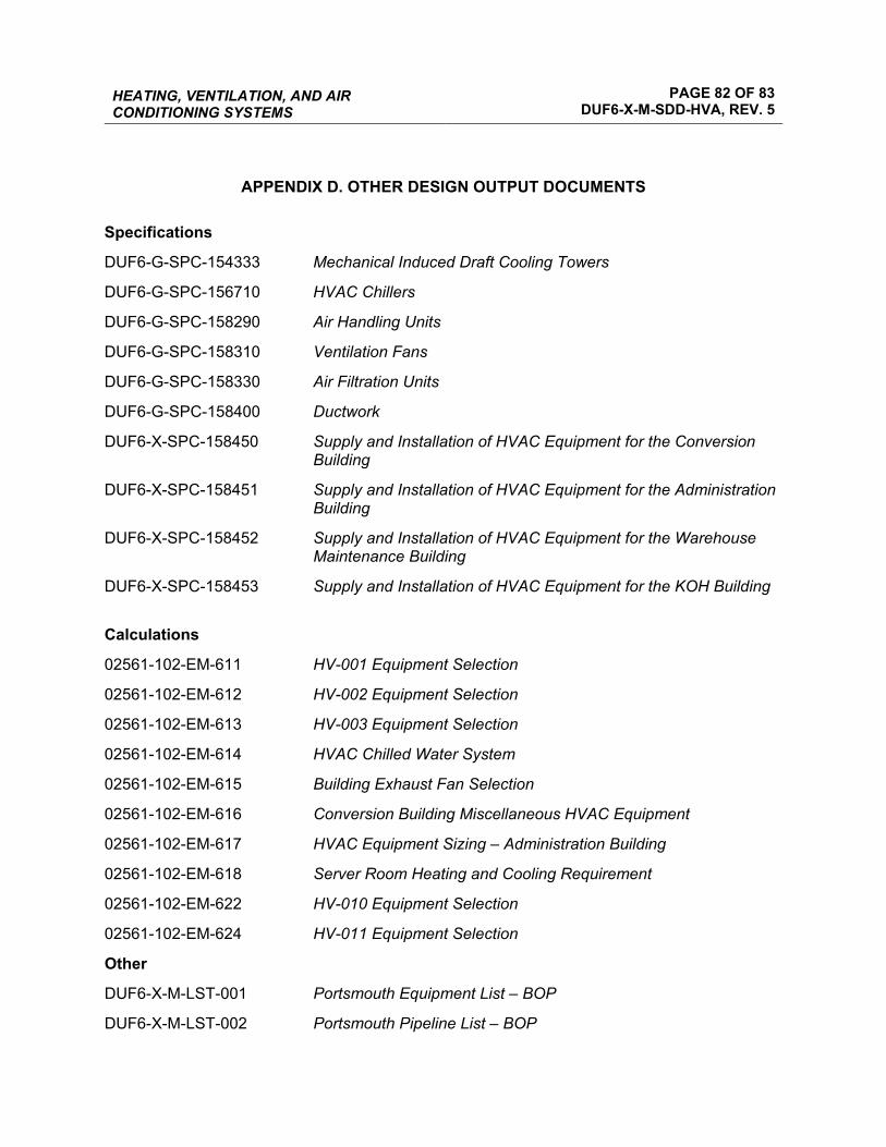
HEATING, VENTILATION, AND AIR CONDITIONING SYSTEMS
PAGE 82 OF 83 DUF6-X-M-SDD-HVA, REV. 5
APPENDIX D. OTHER DESIGN OUTPUT DOCUMENTS Specifications
DUF6-G-SPC-154333 Mechanical Induced Draft Cooling Towers
DUF6-G-SPC-156710 HVAC Chillers
DUF6-G-SPC-158290 Air Handling Units
DUF6-G-SPC-158310 Ventilation Fans
DUF6-G-SPC-158330 Air Filtration Units
DUF6-G-SPC-158400 Ductwork
DUF6-X-SPC-158450 Supply and Installation of HVAC Equipment for the Conversion Building
DUF6-X-SPC-158451 Supply and Installation of HVAC Equipment for the Administration Building
DUF6-X-SPC-158452 Supply and Installation of HVAC Equipment for the Warehouse Maintenance Building
DUF6-X-SPC-158453 Supply and Installation of HVAC Equipment for the KOH Building
Calculations
02561-102-EM-611 HV-001 Equipment Selection
02561-102-EM-612 HV-002 Equipment Selection
02561-102-EM-613 HV-003 Equipment Selection
02561-102-EM-614 HVAC Chilled Water System
02561-102-EM-615 Building Exhaust Fan Selection
02561-102-EM-616 Conversion Building Miscellaneous HVAC Equipment
02561-102-EM-617 HVAC Equipment Sizing – Administration Building
02561-102-EM-618 Server Room Heating and Cooling Requirement
02561-102-EM-622 HV-010 Equipment Selection
02561-102-EM-624 HV-011 Equipment Selection
Other
DUF6-X-M-LST-001 Portsmouth Equipment List – BOP
DUF6-X-M-LST-002 Portsmouth Pipeline List – BOP
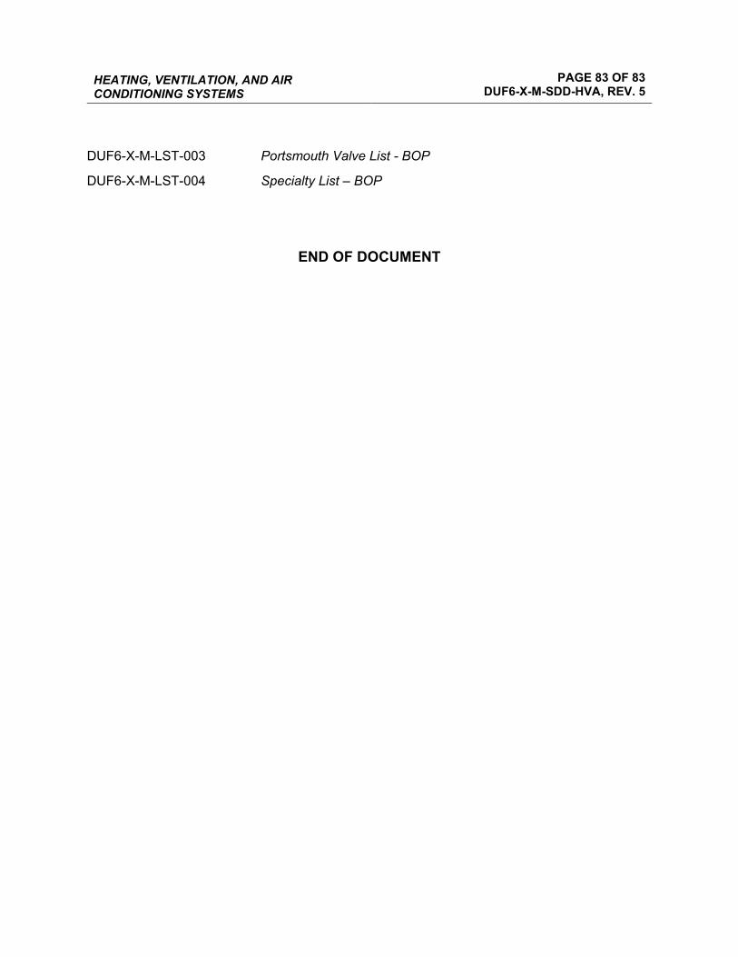
HEATING, VENTILATION, AND AIR CONDITIONING SYSTEMS
PAGE 83 OF 83 DUF6-X-M-SDD-HVA, REV. 5
DUF6-X-M-LST-003 Portsmouth Valve List - BOP
DUF6-X-M-LST-004 Specialty List – BOP
END OF DOCUMENT