Codesign of an impulse generator and miniaturized antennas for IR-UWB

E
Tarek Ben Ismail and Ahmed Amine Jerraya National Polytechnical Institute of Grenoble
m Growing design complexity
and an urgent need for early
prototypes have become
limitations in electronic
systems design. A mature
codesign offers advantages to
overcome this challenge.
Computer
odesign is a joint development of hardware and software compo- nents to obtain a complete system design. The codesign field is C actually not that new, but the joint specification, design, and syn-
thesis of mixed hardware/software systems is a recent development issue. The fields of specification, design, and synthesis of mixed hardwarehoft- ware systems are becoming increasingly more popular.1.2 The renewed interest in codesign is driven by increasing design complexity and the need for early prototypes to validate the specification and provide the customer with feedback during the design p r o c e s ~ . ~ - ~
Codesign is an important step in rapid system prototyping (RSP). Figure 1 shows a typical RSP design The design starts with a sys- tem specification that may be nonexecutable and produces an executable specification, which may be in an existing language such as Specification and Description Language (SDL),S Statemate,s or Communicating Sequential Processes (CSP) .6 At this stage, the specification contains inter- acting modules. The next step is codesign, which includes several design decisions and refinement steps. Codesign aims to produce an abstract architecture of communicating processors that implements the initial specification.
The main steps needed to transform a system-level specification into a mixed hardware/software specification are system partitioning, com- munication synthesis, and architecture generation. The output of archi- tecture generation is a heterogeneous architecture containing hardware and software modules. This step includes virtual prototyping and archi- tecture mapping (prototyping). Virtual prototyping produces a system model that can be simulated. Architecture mapping produces an archi- tecture that implements (or emulates) the initial specification.
TAXONOMY OF CODESIGN Several current projects (SpecSyn at Irvine? Codes (concurrent design
environment) at S i e m e n ~ , ~ the Thomas approach at Carnegie Mellon University,6 the Gupta and DeMicheli approach at Stanford,l Ptolemy at Berkeley,2 Rapid prototyping of Application-Specific Signal Processors
and so on) are trying to integrate hardware and software in the same design process. Three main concepts describe the state of the art:
1. the input specification (one thread or multithread), 2. target architecture (monoprocessor or multiprocessor), and 3. synthesis steps performed by the codesign system.
Figure 2 summarizes the combination of these concepts. The input description may be a single control thread such as a C program, aVHDL, or a multicontrol thread containing communicating subsystems such as an
0018-9162/95/$4.00 0 1995 IEEE
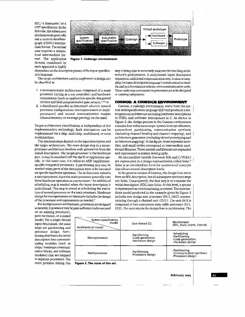
SDL,5 a Statemate,5 or a CSP specification. In the first case, the subsequent synthesis tools generally use a control-dataflow- graph (CDFG) interme- diate format. The second case requires a system- level intermediate for-
System-specification I \ Architectural model I I Onethread (C)
mat. The application Figure 1. Codesign environment.
Multithread (SDL, State charts, Esterel)
domain considered by each approach is highly dependent on the descriptive power of the input-specifica- tion language.
The target architecture used to implement a design can be classified as
Monoprocessor
1. a monoprocessor architecture composed of a main processor (acting as a top controller) and hardware components (such as application-specific integrated circuits and field-programmable gate arrays),l, 5.6 or
2. a distributed parallel architecture2 wherein several processor configurations (monoprocessors or multi- processors) and several communication models (shared memory or message passing) can be used.
-Scheduling -Partitioning -Partitioning
-Code generation -Code generation -Hardware design -Hardware design
Target architecture classification is independent of the implementation technology. Both alternatives can be implemented via a chip, multichip, multiboard, or even multimachine.
The synthesis steps depend on the input description and the target architecture. The main design step in a mono- processor architecture involves code generation from the initial description. The target processor is the hardware part. It may be standard (off the shelf) or application spe- cific. In this latter case, it is called an ASIP (application- specific integrated processor). A partitioning step may be needed when parts of the description have to be executed on specific hardware operators. The architecture remains a monoprocessor, since the main processor generally uses these hardware operators as coprocessors.1 An additional scheduling step is needed when the input description is multithread. This step is aimed at scheduling the execu- tion of several processes on the main processor. Hardware design for monoprocessor architectures includes the design of the processor and coprocessors as needed.7
For multiprocessor architectures, processors are designed separately. Aprocessor may be pure software (code executed on an existing processor), pure hardware, or a mixed model. For a single-thread input description, the main steps are partitioning and processor design. Parti- tioning distributes the initial description into communi- cating modules (such as chips: hardware communi- cation blocks, and software modules) that are mapped in separate processors. The main problem during this
step is being able to accurately estimate the resulting archi- tecture’s performance. A multithread input description requires an additional communication step. It aims at map- ping the input description language’s communication mod- els and synchronization scheme onto communication units. These units may correspond to processors yet to be designed or existing subsystems.
COSMOS: A CODESIGN ENVIRONMENT Cosmos, a codesign environment, starts from the sys-
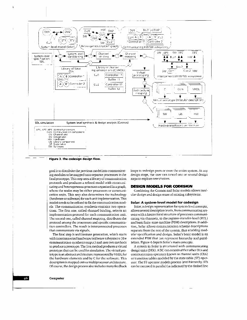
tem-level specification language SDL8 and produces a het- erogeneous architecture including hardware descriptions in VHDL and software descriptions in C. As shown in Figure 3, the design process in the Cosmos environment contains four refinement steps: system-level specification, system-level partitioning, communication synthesis (including channel binding and channel mapping), and architecture generation (including virtual prototyping and architecture mapping). In the figure, boxes represent activ- ities, and small circles correspond to intermediate mod- els and libraries. These models and libraries are expanded and represented as system-level graphs.
All intermediate models (between SDL and C/VHDL) are represented in a design representation called S01ar.~ Solar is an intermediate form for system-level concepts that allows several description levels.
In the present version of Cosmos, the design flow starts from an SDL description, but all subsequent synthesis steps use Solar. Consequently, the first step is to translate the initial description (SDL) into Solar. At this level, a system is represented as communicating processes. The interme- diate model produced in the example given by Figure 3 includes two design unit processes (DU1, DU2) commu- nicating through a channel unit (CU1). The unit DU2 is composed of two concurrent state-table processes (ST1, ST2). The next step in the design flow is partitioning. The
-Partitioning -Communication synthesis -Processors design
-Partitioning -Processors design Multi processor
Figure 2. The state of the art. I
Library of channel * I I Bus2- mplementations (C,VHDL)
i 81 (3 Control le r 1 CU1 i Controller 11 I
' Buffer 1 1 ' cuz 'controller 121
- z G r
H b X
t 4 L
T s w ) C o m l ~ o m 2 HW ,I Virtual -.
~ prototyping Interconnected HWiSW rubsystems ' - 141 , 1 14- , , mapping ~
U p Virtual prototype (Modular description) Y L
SDL simulation System-level synthesis & design analysis (Cosmos) 7 V f Hardwareisoftware architecture ,
CU Channel unit DU Design unit
HW Hardware Lib Library component ST State table
SW Software
1 Figure 3. The codesign design flow.
I- -
goal is to distribute the previous model into communicat- ing modules to be mapped onto separate processors in the final prototype. This step uses a library of communication protocols and produces a refined model with communi- cating and heterogeneous processes organized in a graph, where the nodes may be either processors or communi- cation units. This step also determines the technology (hardware or software) for each unit implementation. This model needs to be refined to fix the communication mod- els. The communication synthesis contains two opera- tions. The first one, called channel binding, selects an implementation protocol for each communication unit. The second one, called channel mapping, distributes the protocol among the processors and specific communica- tion controllers. The result is interconnected processes that communicate via signals.
The final step is architecture generation, which starts with interconnected hardware/software subsystems (the communication-synthesis output) and uses two methods to produce aprototype. The first method produces avirtual prototype that can be used for simulation. The virtual pro- totype is an abstract architecture represented byVHDL for the hardware elements and by C for the software. This description is mapped onto a multiprocessor architecture. Of course, the design process also includes many feedback
Computer
loops to redesign parts or even the entire system. At any design stage, the user can cancel one or several design steps to explore new choices.
DESIGN MODELS FOR CODESIGN
ular design and design reuse of existing subsystems. Combining the Cosmos and Solar models allows mod-
Solar: A system-level model for codesign Solar, a design representation for system-level concepts,
allows several description levels, from communicating sys- tems with a hierarchical structure of processes communi- cating via channels, to the register-transfer-level (RTL) and basic finite-state-machine (FSM) descriptions. In addi- tion, Solar allows communication scheme descriptions separate from the rest of the system, thus enabling mod- ular specification and design. Solar's basic model is an extended FSM that can represent hierarchy and paral- lelism. Figure 4 depicts Solar's main concepts.
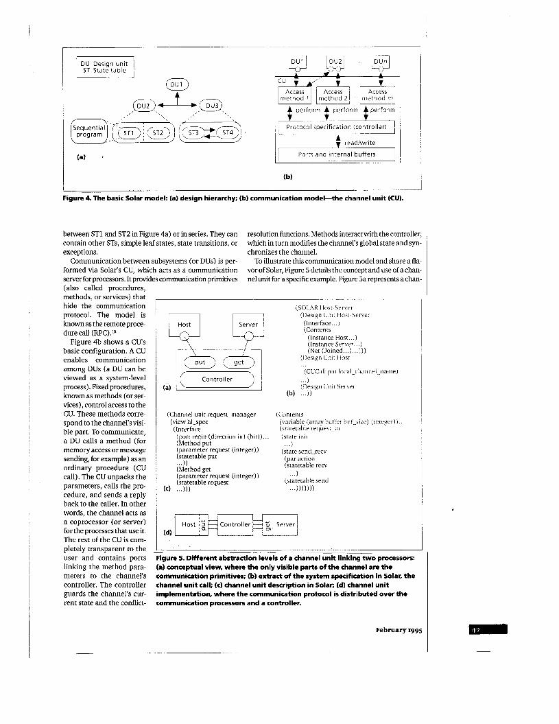
A system in Solar is structured with communicating design units (DUs). A DU can contain either other DUs and communication operators known as channel units (CUs) or transition tables modeled by the state table (ST) oper- ator. The ST operator models process-level hierarchy. STs can be executed in parallel (as indicated by the dashed line
5 Access
method m
(a)
Protocol specification (controller) : Ports and internal buffers
readiwrite
... ) (Design Unit Server
Controller I
(b)
___ Figure 4. The basic Solar model: (a) design hierarchy; (b) communication model-the channel unit (CU).
between ST1 and ST2 in Figure 4a) or in series. They can contain other STs, simple leaf states, state transitions, or exceptions. chronizes the channel.
Communication between subsystems (or DUs) is per- formed via Solar's CU, which acts as a communication server for processors. It provides communication primitives
resolution functions. Methods interact with the controller, which in turn modifies the channel's global state and syn-
To illustrate this communication model and share a fla- vor of Solar, Figure 5 details the concept and use of a chan- nel unit for a specific example. Figure Sa represents a chan-
(also called procedures, methods, or services) that hide the communication protocol. The model is known as the remote proce- dure call (RPC>.lo
Figure 4b shows a CU's basic configuration. A CU enables communication among DUs (a DU can be viewed as a system-level process). Fixed procedures, known as methods (or ser- vices), control access to the CU. These methods corre- spond to the channel's visi- ble part. To communicate, a DU calls a method (for memory access or message sending, for example) as an ordinary procedure (CU call). The CU unpacks the parameters, calls the pro- cedure, and sends a reply back to the caller. In other words, the channel acts as a coprocessor (or server) for the processes that use it. The rest of the CU is com- pletely transparent to the user and contains ports linking the method para- meters to the channel's controller. The controller guards the channel's cur- rent state and the conflict-
(SOLAR Host-Server (Design Unit Host-Server
Server (Interface . . . ) (Contents
(Instance Host ... ) (Instance Server.. .) (Net (Joined.. .) . . .I))
(Design Unit Host ... (CUCall pur local-channel-name)
(Channel unit request-manager (Contents (view hl-spec (variable (array butfcr huf-siLe) (inregeri 1
(state init (Interface (sratetable request-in (port reqin (direction in) (bit)) ... (Method put . . .) (parameter request (integer)) (state send-recv (ye tab le put (par action ... I ) (statetable recv (Method get
(statetable request (statetable send (parameter request (integer)) . . .)
(c) ... 1)) ... )))))I)
(d)
- ~~ ~~
igure 5. Different abstraction levels of a channel unit linking two processors: (a) conceptual view, where the only visible parts of the channel are the communication primitives; (b) extract of the system specification in Solar, the channel unit call; (c) channel unit description in Solar; (d) channel unit implementation, where the communication protocol is distributed over the communication processors and a controller.
February 1995

ASIC Corn
FPGA HW PLD
Application specific integrated circuit Communication component Field-programmable gate array Hardware Programmable logic device
pProc Microprocessor SW Software
co m m u n i ca t i on\ '4'' controller i
/, I Hardware ' ASIC ' I
Hardware part Software part
(a)
\
-
e,+- + ,
f I FPGA
[VHardware )
Figure 6. Architectural models: (a) general model for flexible architectural platform; (b) example of an architecture supported by Cosmos.
~ _ _ ~
ne1 linking two processes (host and server). Figure 5b briefly outlines Solar's description of this system. The first DU, Host-Server, is a structural view of the system. The two constituent DUs, Host and Server, are instantiated. And a netlist of the connections between these two DUs is given. This netlist contains the name-mapping informa- tion for the channel thatjoins the two DUs. The other units represent the functionality of the three constituent ele- ments (the DUs, themselves, maybe structural). Ttyo DUs model the host and server processes.
This description is inde- pendent of the communica- tion protocol. The onlyinfor- mation that is necessary to communicating DUs is the factthatwecanexecute two METHODS methods named get and put. With Solar, we may have several protocols executing ARE VISIBLE. the same methods. The channel binding allocates CUs to execute these methods. Figure 5c extracts a Solar description of a CU. This description contains an interface and contents. The interface describes the CU controller's ports; the methods describe the protocol involving these ports. In this case, the channel can be accessed through two methods, put and get. This description may correspond to the abstraction of one or several existing communication units. The Solar model allows hiding of the channel's imple- mentation details. During the early stage of the design process, only methods executed by a given channel are vis- ible. The implementation of the channel is needed onlydur- ing the channel-mapping step. This step replaces the abstract channels by an implementation. The channel-mapping step yields interconnected modules. The caller process expands the communication modules to control data exchange with the communication controller (see Figure 5d).
URING THE D EARLY STAGE OF THE DESIGN PROCESS, ONLY
EXECUTED BY A GIVEN CHANNEL
Computer
During the synthesis process, Cosmos uses an external library of CUs. ACU fits either a standard protocol or a cus- tomized protocol described by the user. During partition- ing and communication synthesis, Cosmos uses an abstract model of the channel. The architecture generation step requires an implementation of the channel. This imple- mentation may come from an early synthesis step with Cosmos or another design method; it may also correspond to an existing architecture. This model not onlylets the user describe several communication schemes but also separates the communication from the rest of the design, thereby allowing reuse of existing communication schemes.
Hardwarelsoftware architectural model Cosmos uses a modular, flexible architectural model.
Figure 6a shows the general model, which includes three kinds of components: software, hardware, and commu- nication components. This model serves as a platform onto which a mixed hardware/software system is mapped.
Communication modules come from a CU library and fit existing communication models, which may be as simple as a handshake or as complex as a layered network. For example, a communication controller may correspond to an existing interface circuit, an application-specific inte- grated circuit (ASIC), or microcode executing on a dedi- cated microprocessor.
The proposed architectural model is general enough to represent a large class of existing hardware/software plat- forms and allows different implementations of mixed hardware/software systems. A typical architecture con- tains hardware, software, and communication modules, linked with buses. Figure 6b exemplifies a typical archi- tecture supported by Cosmos.
DESIGN STEPS FOR CODESIGN Cosmos starts with a multithread description and pro-
duces a multiprocessor architecture. The necessary main steps are system specification, system partitioning, com-
munication synthesis, and architecture generation.
Design model generation
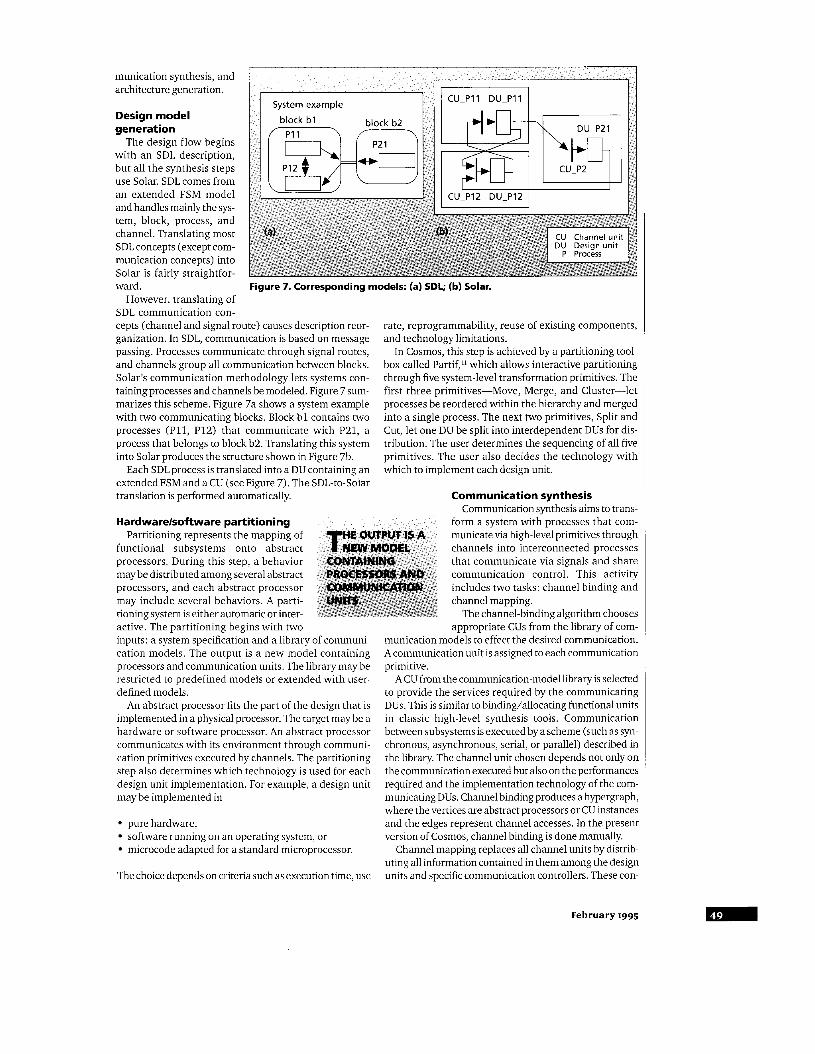
The design flow begins with an SDL description, but all the synthesis steps use Solar. SDL comes from an extended FSM model and handles mainly the sys- tem, block, process, and channel. Translating most SDL concepts (except com- munication concepts) into Solar is fairly straightfor- ward.
However, translating of SDL communication con- cepts (channel and signal route) causes description reor- ganization. In SDL, communication is based on message passing. Processes communicate through signal routes, and channels group all communication between blocks. Solar’s communication methodology lets systems con- tainingprocesses and channels be modeled. Figure 7 sum- marizes this scheme. Figure 7a shows a system example with two communicating blocks. Block b l contains two processes (P11, P12) that communicate with P21, a process that belongs to block b2. Translating this system into Solar produces the structure shown in Figure 7b.
Each SDL process is translated into a DU containing an extended FSM and a CU (see Figure 7). The SDL-to-Solar translation is performed automatically.
rate, reprogrammability, reuse of existing components, and technology limitations.
In Cosmos, this step is achieved by a partitioning tool- box called Partif,ll which allows interactive partitioning through five system-level transformation primitives. The first three primitives-Move, Merge, and Cluster-let processes be reordered within the hierarchy and merged into a single process. The next two primitives, Split and Cut, let one DU be split into interdependent DUs for dis- tribution. The user determines the sequencing of all five primitives. The user also decides the technology with which to implement each design unit.
Hardwarelsoftware partitioning Partitioning represents the mapping of
functional subsystems onto abstract processors. During this step, a behavior may be distributed among several abstract processors, and each abstract processor may include several behaviors. A parti- tioning system is either automatic or inter- active. The partitioning begins with two inputs: a system specification and a library of communi- cation models. The output is a new model containing processors and communication units. The library may be restricted to predefined models or extended with user- defined models.
An abstract processor fits the part of the design that is implemented in a physical processor. The target may be a hardware or software processor. An abstract processor communicates with its environment through communi- cation primitives executed by channels. The partitioning step also determines which technology is used for each design unit implementation. For example, a design unit may be implemented in
pure hardware, software running on an operating system, or microcode adapted for a standard microprocessor.
The choice depends on criteria such as execution time, use
Communication synthesis Communication synthesis aims to trans-
form a system with processes that com- municate via high-level primitives through channels into interconnected processes that communicate via signals and share communication control. This activity includes two tasks: channel binding and channel mapping.
The channel-binding algorithm chooses appropriate CUs fromthelibrary of com- ~
munication models to effect the desired communication. A communication unit is assigned to each communication primitive.
A CU from the communication-model library is selected to provide the services required by the communicating DUs. This is similar to binding/allocating functional units in classic high-level synthesis tools. Communication between subsystems is executed by a scheme (such as syn- chronous, asynchronous, serial, or parallel) described in the library. The channel unit chosen depends not only on the communication executed but also on the performances required and the implementation technology of the com- municating DUs. Channel binding produces a hypergraph, where the vertices are abstract processors or CU instances and the edges represent channel accesses. In the present version of Cosmos, channel binding is done manually.
Channel mapping replaces all channel units by distrib- uting all information contained in them among the design units and specific communication controllers. These con-
February 1995
Storage Acquisition and
conversion subsystem
A/Dt)i Acquisition L , Disk
(b)
HW (VHDL) HW (VHDL)
(4
Hardware part (development board) 4 Software part
1 ..~...................... .....~. ~ . ~ ~ ~ . . ~
I - P C AT extension bus
A/D Analog/digital converter CU Channel unit
DMA Direct memory access HW Hardware
Mux Multiplexer RTSl Real-time system interface SW Software
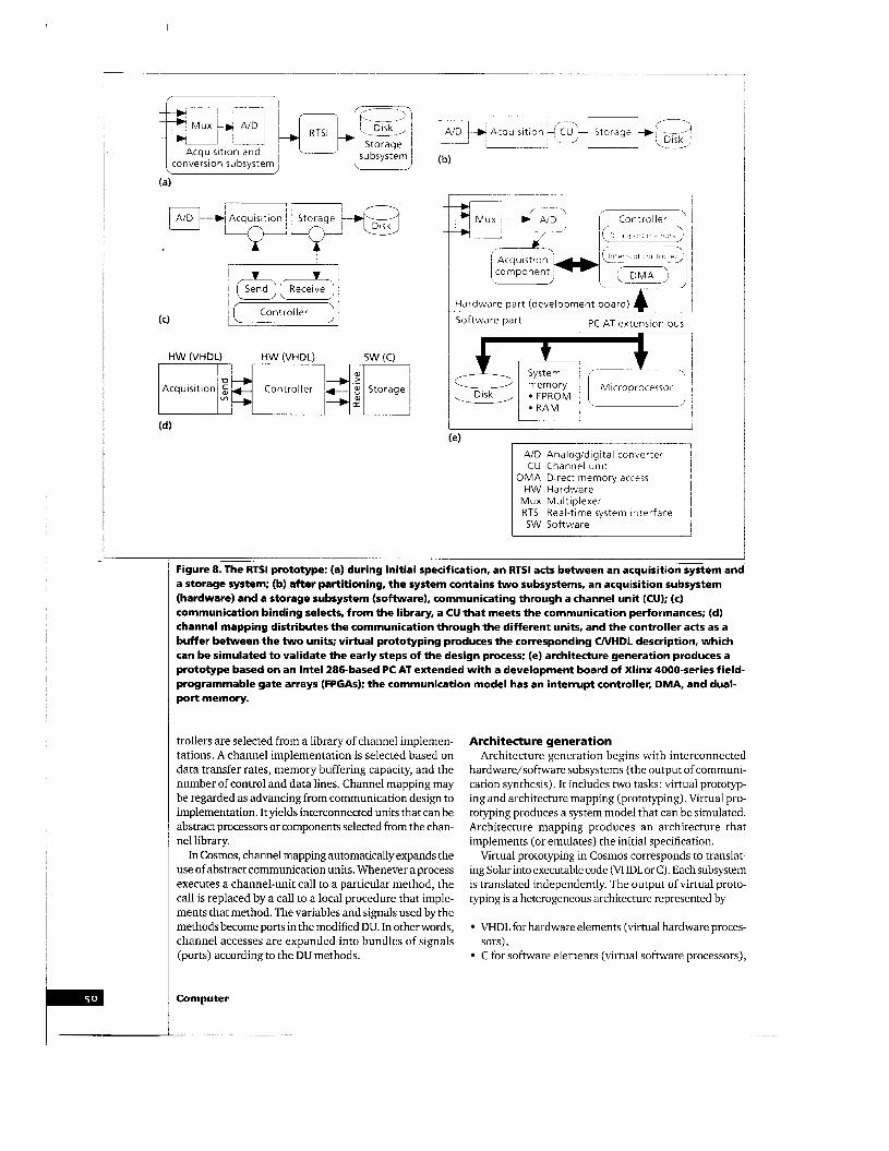
Figure 8. The RTSl prototype: (a) during initial specification, an RTSl actsbetween an acquisitionsystem and a storage system; (b) after partitioning, the system contains t w o subsystems, an acquisition subsystem (hardware) and a storage subsystem (software), communicating through a channel unit (CU); (c) communication binding selects, from the library, a CU that meets the communication performances; (d) channel mapping distributes the communication through the different units, and the controller acts as a buffer between the t w o units; virtual prototyping produces the corresponding UVHDL description, which can be simulated t o validate the early steps of the design process; (e) architecture generation produces a prototype based on an Intel 286-based PC AT extended with a development board of Xlinx 4000-series field- programmable gate arrays (FPGAs); the communication model has an interrupt controller, DMA, and dual- port memory.
trollers are selected from a library of channel implemen- tations. A channel implementation is selected based on data transfer rates, memory buffering capacity, and the number of control and data lines. Channel mapping may be regarded as advancing from communication design to implementation. It yields interconnected units that can be abstract processors or components selected from the chan- nel library.
In Cosmos, channel mapping automatically expands the use of abstract communication units. Whenever a process executes a channel-unit call to a particular method, the call is replaced by a call to a local procedure that imple- ments that method. The variables and signals used by the methods become ports in the modified DU. In other words, channel accesses are expanded into bundles of signals (ports) according to the DU methods.
Computer
Architecture generat ion Architecture generation begins with interconnected
hardware/software subsystems (the output of communi- cation synthesis). It includes two tasks: virtual prototyp- ing and architecture mapping (prototyping). Virtual pro- totyping produces a system model that can be simulated. Architecture mapping produces an architecture that implements (or emulates) the initial specification.
Virtual prototyping in Cosmos corresponds to translat- ing Solar into executable code (VHDL or C) . Each subsystem is translated independently. The output of virtual proto- typing is a heterogeneous architecture represented by
VHDL for hardware elements (virtual hardware proces-
C for software elements (virtual software processors), sors),

and
components). VHDL or C for communication controllers (library
Architecture mapping can be achieved via standard code generators for software parts and synthesis tools for hardware parts. Code generators transform software parts into assembly-language code, and hardware synthesis tools translate hardware parts into ASICs or virtual hard- ware processors (emulators). The result is an architecture containing software, hardware, and communication com- ponents. In Cosmos, standard compilers transform C into assembly language code for software parts, and synthesis tools translate VHDL into hardware.
EVALUATION AND FUTURE DlRECelON Here we discuss a codesign case using Cosmos method-
ology to present the status of the Cosmos environment and outline future directions.
A codesign example Figure 8 illustrates the overall codesign process for a
real-time system interface (RTSI) between sensor-pro- ducing digital signals and a storage disk. As explained above, the codesign process includes several steps and intermediate models. The input to Cosmos is an SDL description of this system, while the output is a mixed C/VHDL description that can be mapped onto a target architecture to produce a prototype. The different steps and models corresponding to this example follow.
DESIGN MODEL GENERATION. The initial system is spec- ified in SDL as a behavioral description acting between an acquisition unit and a storage unit (see Figure Sa). This system synchronizes the signals' arrival from acquisition parts and acceptance by the storage unit. These signals should be grouped into blocks before storage.
HARDwARE/SOFTWARE PARTITIONING. Starting with the initial specification, the system is first decomposed into an acquisition subsystem (hardware) and a storage sub- system (software), which communicate through a chan- nel unit (Figure 8b). This step is performed interactively through primitives applied under user control.
COMMUNICATION SYNTHESIS. The role of this task is to select a communication protocol. The final parameters (memory size and blocking factors) of the communica- tion units may be fixed later. This task links communica- tion primitives to the units that execute them. Communication protocol selection is performed during the communication-binding step (Figure Sc), which selects a CU from the library that can execute the different communication primitives.
ARCHITECTURE GENERATION. Virtual prototyping translates the resulting Solar into a C/VHDL description (Figure 8d). In this case, the communication unit is described in VHDL. This description models an existing scheme containing an interrupt controller, direct memory access (DMA), and dual-port memory. The virtual proto- type can be simulated to validate the early steps of the
design process and check functional properties. The final step produces a prototype architecture (Figure 8e). This prototype is based on an Intel 286-based PC AT, extended with a development board of Xilinx 4000-series field-pro- grammable gate arrays (FPGAs). During this step, the VHDL acquisition-unit description is mapped onto an FPGA, and the C description corresponding to the storage unit is compiled for the 286.
WE HAVE PRESENTED THE COSMOS ENVIRONMENT and methodology for codesign. The codesign methodol- ogy has already been proven through several designs. The most important design is a large robot application with adaptive control of a robot arm having three fingers. This application controls an 18-engine system and includes both hardware and software.
The Solar environment has already been well tested. The partitioning tool has been developed.Il In the present version of this tool, the design process is interactive: The designer makes most decisions; the system provides only primitives for automatic transformation of Solar descrip- tions. The designer also sequences these primitives. Our goal is to let the user do the intelligent work (such as decid- ing which part is in software and which is in hardware) and let the system perform the fastidious and error-prone tasks.
The kev issue is the use of an abstract, general com- munication model. The separation between com- munication and computa- tion (hardware and soft- ware) allows the reuse of existing communication
UR GOAL IS TO LET THE c[uM R Do THE INTELLIGENT WlOlJIK AND LET THE SYSTEM $SRFORM THE FASTIDIOUS UIJt, ERROR-PRONE TASKS.
models. Each communica- tion unit can be specified at different levels of abstraction (for instance, functional-abstracted as a black box link- ing interconnected subsystems-and implementation views). The benefits from using external channel libraries at different levels of abstraction are as follows:
1. This scheme improves design reuse. For example, we can design a subsystem and put it in the channel library for reuse in building larger designs. A com- munication subsystem can also correspond to a design produced by external tools.
2. A channel library offers several different communi- cation mechanisms to help the designer select the appropriate communication protocol for an applica- tion. For instance, synchronous or asynchronous protocols and blocking or nonblocking message exchanges can be used.
3. The different modules can be upgraded and rede- signed independently, and this modularity allows great flexibility for maintaining and updating large designs.
4. Since no restrictions are imposed to the communica- tion models, this codesign process can be applied to many applications.
We have only discussed the design steps of a full codesign
February 1995
methodology. Of course, several other key issues are still needed for complete design flow, including the following:
Validation and verification of the initial specification. This is a classical problem for system design. Several tools exist for the validation and verification of SDL, such as descriptions.8 But most of these tools act only at the functional level. Much work is still needed to handle real-time aspects. Validation of different design models per the initial spec- ification. This validation is required (even when the tools are bug-free) to check design decisions against the environment’s (real-time) constraints. Evaluation tools and models. As mentioned, a crucial step in deciding the implementation of different mod- ules is ensuring that the resulting solution respects the real-time constraints. Only limited work has been done in this area.’* Automatic algorithms for partitioning and communi- cation synthesis. These are needed for fast and vast exploration of the design space. The efficiency of such techniques depends on the objective function used. This brings us again to the previous point: the need for good estimation methods. I
Acknowledgments The authors thank all the members of the System Level
Synthesis Group for their help in different parts of this pro- ject. In particular, we thank Mohamed Abid and Adel Changuel for their work on architecture modeling, Carlos Valderrama for his assistance in virtual prototyping, Kevin O’Brien for his contribution in communication synthesis, and Mohamed Romdhani for his workon SDL and the sys- tem-level specification. This work has been generously supported by France Telecom (Grenoble, France) under Convention CNET No. 933B, Aerospatiale (Toulouse, France), Ministry of Defense DRET/DGA (France), SGS Thomson (Grenoble, France), and Bell Northern Research (Canada).
References 1. R. Gupta and G. De Micheli, “Hardware-Software Cosynthe-
sis for Digital Systems,” IEEEDesign and Test ofcomputers, Vol. 10, No. 3, Sept. 1993, pp. 29-41.
2. A. Kalavade and E.A. Lee, “A Hardware-Software Codesign Methodology for DSP Applications,” IEEEDesign and Test of Computers, Vol. 10, No. 3, Sept. 1993, pp. 16-28.
3. M.A. Richards, “The Rapid Prototyping of Application-Spe- cific Signal Processors (RASSP) Program: Overview and Sta- tus,”Proc. Int’l Workshop Rapid System Prototyping, IEEE CS Press, Los Alamitos, Calif., Order No. 5885,1994, pp. 1-6.
4. D. Gajski, F. Vahid, and S. Narayan, “A System-Design Methodology: Executable-Specification Refinement,” Proc. European Design and Test Conf. 1994, IEEE CS Press, Los Alamitos, Calif., Order No. 5410,1994, pp. 458-463.
5. K. Buchenrieder, A. Sedlmeier, and C.Veith, “HW/SW Code- sign with PRAMS Using Codes,” Proc. IFIP Conf. Hardware Description Languages, Elsevier Science, Amsterdam, The Netherlands, 1993, pp. 55-68.
6. D.E. Thomas, J.K. Adams, and H. Schmitt, “A Model and Methodology for Hardware-Software Codesign,” IEEEDesign and Test of Computers, Vol. 10, No. 3, Sept. 1993, pp. 6-15.
7. G. Goossens et al., “Design of Heterogeneous ICs for Mobile and Personal Communication Systems,”Proc. IEEErnt’l Con) Computer-Aided Design, IEEE CS Press, Los Alamitos, Calif., Order No. 6415,1994, pp. 524-531.
8. R. Saracco and P.A.J. Tilanus, “CCI’IT SDL: An Overview of the Language and its Applications,” Computer Networks & ISDN Systems, Special Issue on CCITT SDL, Vol 13, No. 2,
9. A.A. Jerraya and K. OBrien, “Solar: An Intermediate Format for System-Level Modeling and Synthesis,” in J. Rozenblit and K. Buchenrieder, eds., Computer-Aided Software/Hard- ware Engineering, IEEE Press, Piscataway, N.J., 1994.
10. G.R. Andrews, Concurrent Programming: Principles andPrac- tice, 1991, BenjamidCummings, Redwood City, Calif., 1991,
11. T. Ben Ismail, K. OBrien, and A.A. Jerraya, “Interactive Sys- tem-Level Partitioning with Partif,” Proc. European Design and Test of Computers 1994, IEEE CS Press, Los Alamitos, Calif., Order No. 5410,1994, pp. 464-468.
12. D. Herman, J. Henkel, and R. Ernst, “An Approach to the Adaptation of Estimated Cost Parameters in the Cosyma Sys- tem,” Proc. Third Int’l Workshop Hardware/software Code- sign, IEEE CS Press, Los Alamitos, Calif., Order No. 6315,
1987, pp. 65-74.
pp. 484-494.
1994, pp. 100-107.
TarekBen IsmailiscompletingaPhDdegree incomputer engineering at the National Polytechnical Institute of Greno- ble, France. His research interests include system-level spec- ification, codesign, and synthesis of mixed hardware/ software systems. He received an engineering degreefrom the University of Tunis, Tunisia, in 1991, and an MS degree in computer engineeringfrom the University of Grenoble, France, in 1992. He is the author of several papers on sys- tem-level synthesis and is a member of the French Network in computer systems and machine architecture.
Ahmed Amine Jerraya is head of the System-Level Syn- thesis Group within TIWCNRS-INPG-UJF (Techniques of Informatics and Microelectronics/Centre National de la Recherche Scienti,fique/Universite Joseph Fourier). He has held afull research position with the CNRS in France since 1986. He has been involved in several CADprojects, such as the Lucieproject in the early 1980s and more recently the high-level synthesis system Amical. He is the technical pro- gram and organization chair of the Eighth International Symposium on System Synthesis (1995). Jerraya received an engineering degreefrom the University of Tunis, Tunisia, in 1980, and a Docteur Ingenieur degree in 1983 and Doc- teur d’Etat degree in 1989, both from the University of Greno- ble, France.
Readers can contact the authors at TIWINPG Laboratorx System-Level Synthesis Group, 46 AV. Fi l ix Mallet, 38031 Grenoble Cidex, France; e-mail tarek.ismail@ imag.fr.
Computer
Copyright © 2022 FDOKUMEN