CHARGED DILATONIC BLACK HOLES: STRING FRAME VERSUS EINSTEIN FRAME
Upload
khangminh22Category
view
0download
0
Synchronous Reference Frame with Finite Impulse Response Filter for Operation of Single-phase Shunt Active Power Filter
Zhen Ye Tham1, Yap Hoon1,*, and Mohd Amran Mohd Radzi2
1School of Computer Science and Engineering, Faculty of Innovation and Technology, Taylor’s University, Subang Jaya 47500, Selangor, Malaysia. 2Department of Electrical and Electronic Engineering, Faculty of Engineering, Universiti Putra Malaysia, 43400 UPM Serdang, Selangor, Malaysia.
Abstract. Power Quality (PQ) has been recognized as one of the main issues in electricity supply worldwide after the invention of nonlinear load. In 2017, PQ problem leads to significant economic losses in the Pan European region. Therefore, Active Power Filter has been developed during the past two decades to improve the harmonic compensation, reactive power, and voltage balance. In this research, the evaluation of the Synchronous Reference Frame (SRF) method is done under nonlinear load condition. The objective of this research is to modify the harmonic extraction algorithm based on SRF concepts for the application of single-phase shunt active power filter (SAPF) in harmonics mitigation and evaluate the performance of it. The performance of the SAPF that used SRF is evaluated and verified using MATLAB/Simulink. Besides that, the proposed SRF will be benchmarked with several existing techniques. The results are verified using MATLAB/Simulink with the aid of Powergui in the SimPower System block. Powergui has a built in Fast Fourier Transform (FFT) analysis tool that could perform harmonic analysis. With the aid of this tool, the Total Harmonic Distortion (THD) value can be viewed in the block. This research does achieve the THD value of the power system keeps under the limit set by IEEE standard 519.
1 Introduction Power Quality (PQ) has been recognized as one of the main issues in electricity supply worldwide after the invention of nonlinear load. In this paper focuses more on one of the PQ disturbances, harmonics distortions, it happens when additional frequency components present in the mains voltage or current, which are integral multiples of the mains frequency. Harmonic distortions are mainly caused by the use of nonlinear loads [1]. Nonlinear loads are basically referring to vast majority of loads with power electronic devices, draw current in a non-sinusoidal manner. The PQ problem leads to significant economic losses, Poman and his team have estimated the total expenses for overvoltage and transient phenomena in
* Corresponding author: [email protected]
© The Authors, published by EDP Sciences. This is an open access article distributed under the terms of the Creative Commons Attribution License 4.0 (http://creativecommons.org/licenses/by/4.0/).
MATEC Web of Conferences 335, 02004 (2021) https://doi.org/10.1051/matecconf/20213350200414th EURECA 2020

Pan European region with the range from €120,000 to €180,000 (RM 640,000 to RM 960,000) in 2007 [2]. Besides that, harmonics may cause interference and inefficiencies in power systems and equipment and reduce the lifespan of the equipment.
Active Power Filter (APF) have been developed during the past two decades to improve the harmonic compensation, reactive power, and voltage balance [3]. Among various types of active power filter, shunt active power filter (SAPF) is most commonly used to tackle the harmonics distortion as proven by Hirofumi Akagi in his literature [4].
A typical control system of SAPF consists of several algorithms, harmonic extraction algorithm, synchronization algorithm, DC-link capacitor voltage regulation algorithm, and current control algorithm. All these control algorithms are linked up and formed a closed loop system. Phase locked loop (PLL) is one of the control systems in the synchronization algorithm which provides the output phase angle that matches the input phase angle. In the PLL control system, Proportional Integral (PI) controller and Filter is the main control system that researchers main focus on. Zhao and his team have conducted a research on using different model on the Synchronous Reference Frame with different filters, his design model is used as a benchmarking model in this paper [5].
Therefore, in this paper a comparison of different filter will be applied to improve on the benchmarked model published by Zhao on his LPF in his SRF control system. Butterworth is always the first choice in designing the lowpass filter, but Butterworth method performance only improves when filter order increases which result in used of larger number of storage elements required. Hence, least square method is used to approximate the ideal frequency response [6]. The implementation of finite impulse response filter is to replace the infinite impulse response filter used in the benchmarked model and this proposed method is verified using MATLAB-Simulink.
2 Methodology In this section, the method to conduct this research and obtain results will be discussed in detail. The simulation model will be built in MATLAB-Simulink R2016b, all the control algorithms involved are developed using SimPower System blocks.
2.1 Circuit configuration of shunt active power filter (SAPF)
The proposed single-phase SAPF is connected at the point of coupling (PCC) between the supply voltage and nonlinear load, as shown in Figure 1. The nonlinear load consists of a full bridge rectifier feeding two inductive loads. The operation of SAPF can be easily explained using Kirchhoff’s current law (KCL) at PCC shown in (1), where the source current is the same as the load current after summing with the compensating current provided from the control system. iS(t) = iL(t) + iC(t) (1)
Where iS is the source current, iL is the load current and iC is the compensated current.
2.2 Control strategy
Control strategies for generating compensation current or voltage can be classified into two type, continuous time-domain control and discrete-time or frequency-domain control. Synchronous reference frame (SRF) is one of the techniques falls under the time-domain
2
MATEC Web of Conferences 335, 02004 (2021) https://doi.org/10.1051/matecconf/20213350200414th EURECA 2020
Pan European region with the range from €120,000 to €180,000 (RM 640,000 to RM 960,000) in 2007 [2]. Besides that, harmonics may cause interference and inefficiencies in power systems and equipment and reduce the lifespan of the equipment.
Active Power Filter (APF) have been developed during the past two decades to improve the harmonic compensation, reactive power, and voltage balance [3]. Among various types of active power filter, shunt active power filter (SAPF) is most commonly used to tackle the harmonics distortion as proven by Hirofumi Akagi in his literature [4].
A typical control system of SAPF consists of several algorithms, harmonic extraction algorithm, synchronization algorithm, DC-link capacitor voltage regulation algorithm, and current control algorithm. All these control algorithms are linked up and formed a closed loop system. Phase locked loop (PLL) is one of the control systems in the synchronization algorithm which provides the output phase angle that matches the input phase angle. In the PLL control system, Proportional Integral (PI) controller and Filter is the main control system that researchers main focus on. Zhao and his team have conducted a research on using different model on the Synchronous Reference Frame with different filters, his design model is used as a benchmarking model in this paper [5].
Therefore, in this paper a comparison of different filter will be applied to improve on the benchmarked model published by Zhao on his LPF in his SRF control system. Butterworth is always the first choice in designing the lowpass filter, but Butterworth method performance only improves when filter order increases which result in used of larger number of storage elements required. Hence, least square method is used to approximate the ideal frequency response [6]. The implementation of finite impulse response filter is to replace the infinite impulse response filter used in the benchmarked model and this proposed method is verified using MATLAB-Simulink.
2 Methodology In this section, the method to conduct this research and obtain results will be discussed in detail. The simulation model will be built in MATLAB-Simulink R2016b, all the control algorithms involved are developed using SimPower System blocks.
2.1 Circuit configuration of shunt active power filter (SAPF)
The proposed single-phase SAPF is connected at the point of coupling (PCC) between the supply voltage and nonlinear load, as shown in Figure 1. The nonlinear load consists of a full bridge rectifier feeding two inductive loads. The operation of SAPF can be easily explained using Kirchhoff’s current law (KCL) at PCC shown in (1), where the source current is the same as the load current after summing with the compensating current provided from the control system. iS(t) = iL(t) + iC(t) (1)
Where iS is the source current, iL is the load current and iC is the compensated current.
2.2 Control strategy
Control strategies for generating compensation current or voltage can be classified into two type, continuous time-domain control and discrete-time or frequency-domain control. Synchronous reference frame (SRF) is one of the techniques falls under the time-domain
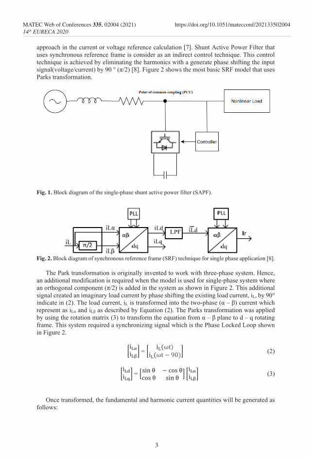
approach in the current or voltage reference calculation [7]. Shunt Active Power Filter that uses synchronous reference frame is consider as an indirect control technique. This control technique is achieved by eliminating the harmonics with a generate phase shifting the input signal(voltage/current) by 90 ° (π/2) [8]. Figure 2 shows the most basic SRF model that uses Parks transformation.
Fig. 1. Block diagram of the single-phase shunt active power filter (SAPF).
Fig. 2. Block diagram of synchronous reference frame (SRF) technique for single phase application [8].
The Park transformation is originally invented to work with three-phase system. Hence,
an additional modification is required when the model is used for single-phase system where an orthogonal component (π/2) is added in the system as shown in Figure 2. This additional signal created an imaginary load current by phase shifting the existing load current, iL, by 90° indicate in (2). The load current, iL is transformed into the two-phase (α – β) current which represent as iLα and iLβ as described by Equation (2). The Parks transformation was applied by using the rotation matrix (3) to transform the equation from α – β plane to d – q rotating frame. This system required a synchronizing signal which is the Phase Locked Loop shown in Figure 2.
�iLαiLβ� = � iL(ωt)
iL(ωt − 90)� (2)
�iLdiLq� = �sin θ − cos θ
cos θ sin θ � �iLαiLβ� (3)
Once transformed, the fundamental and harmonic current quantities will be generated as
follows:
3
MATEC Web of Conferences 335, 02004 (2021) https://doi.org/10.1051/matecconf/20213350200414th EURECA 2020

�iLdiLq� = �
ıLd���� + ıLd�ıLq���� + ıLq�
� (4)
where ıLd���� and ıLd� are the fundamental and harmonic components of the measured load
current in d-axis. Same relation hold for measured load current in q-axis. In the context of harmonic extraction, only fundamental magnitude is required to be extracted from the d-axis by using a LPF, meanwhile the components in q-axis can be neglected as shown in Figure 2.
Once the required fundamental component is extracted from the measured load current, the algorithm will then compute the desired reference current signal by using an inverse rotating frame which transform the extracted fundamental component back to stationary frame as represented in Equation (5).
�iLαiLβ� = �sin θ − cos θ
cos θ sin θ �−1�ıLd����0 � (5)
Since the β component is neglected, hence the fundamental load current can be obtained
as: ir = iα_ref = ıLd���� × sinθ (6)
Note that the fundamental load current is the desired reference current signal, 𝑖𝑖𝑖𝑖α_ref and it can be obtained simply by multiplying ıLd���� with the original sine function obtained from PLL as summarized in Equation (6). The extracted reference current is utilized to guide the generation of switching pulses for the SAPF.
2.3 Selection of filter
From Figure 2 and Equation (5) shows that filter is holding an important role where it will affect the result of the system, when selecting the filtering order and the cutoff frequency when designing the filter. High filtering order and low cutoff frequency does improve the attenuation of harmonics, but it has a drawback on the response time of the system which result in allowing the system to operate in nonlinear load condition until it reaches steady state. The filter use in the following section are Butterworth Infinite Impulse Response (IIR) and Least-squares Finite Impulse Response (FIR) filters.
Hemachandran and his team have design a single-phase SAPF with PI controller in his research, from his research they have tabulate the THD table for current harmonic mitigation shown in Table 1 [9].
Table 1. THD table for current harmonic mitigation [9].
Fundamental harmonic % of THD before mitigation 62.45%
% of THD after mitigation 6.68%
H3 56.58 0.98 H5 16.81 1.75 H7 15.28 0.40 H9 7.84 0.83
H11 7.22 0.57 H13 4.38 0.27
From his findings, higher fundamental harmonic order contributes to a lower value of the THD. Hence, the lower third and fifth filtering order will be selected for both the HPF and LPF in the simulation. LPF is used as it is widely applied in the SAPF model due to its
4
MATEC Web of Conferences 335, 02004 (2021) https://doi.org/10.1051/matecconf/20213350200414th EURECA 2020
�iLdiLq� = �
ıLd���� + ıLd�ıLq���� + ıLq�
� (4)
where ıLd���� and ıLd� are the fundamental and harmonic components of the measured load
current in d-axis. Same relation hold for measured load current in q-axis. In the context of harmonic extraction, only fundamental magnitude is required to be extracted from the d-axis by using a LPF, meanwhile the components in q-axis can be neglected as shown in Figure 2.
Once the required fundamental component is extracted from the measured load current, the algorithm will then compute the desired reference current signal by using an inverse rotating frame which transform the extracted fundamental component back to stationary frame as represented in Equation (5).
�iLαiLβ� = �sin θ − cos θ
cos θ sin θ �−1�ıLd����0 � (5)
Since the β component is neglected, hence the fundamental load current can be obtained
as: ir = iα_ref = ıLd���� × sinθ (6)
Note that the fundamental load current is the desired reference current signal, 𝑖𝑖𝑖𝑖α_ref and it can be obtained simply by multiplying ıLd���� with the original sine function obtained from PLL as summarized in Equation (6). The extracted reference current is utilized to guide the generation of switching pulses for the SAPF.
2.3 Selection of filter
From Figure 2 and Equation (5) shows that filter is holding an important role where it will affect the result of the system, when selecting the filtering order and the cutoff frequency when designing the filter. High filtering order and low cutoff frequency does improve the attenuation of harmonics, but it has a drawback on the response time of the system which result in allowing the system to operate in nonlinear load condition until it reaches steady state. The filter use in the following section are Butterworth Infinite Impulse Response (IIR) and Least-squares Finite Impulse Response (FIR) filters.
Hemachandran and his team have design a single-phase SAPF with PI controller in his research, from his research they have tabulate the THD table for current harmonic mitigation shown in Table 1 [9].
Table 1. THD table for current harmonic mitigation [9].
Fundamental harmonic % of THD before mitigation 62.45%
% of THD after mitigation 6.68%
H3 56.58 0.98 H5 16.81 1.75 H7 15.28 0.40 H9 7.84 0.83
H11 7.22 0.57 H13 4.38 0.27
From his findings, higher fundamental harmonic order contributes to a lower value of the THD. Hence, the lower third and fifth filtering order will be selected for both the HPF and LPF in the simulation. LPF is used as it is widely applied in the SAPF model due to its
simplicity as well as the building cost of it. Meanwhile, HPF is slightly more expensive than LPF, due to the finding from Hemachandran and teams the higher the order it has a lower THD value. Hence comparison of LPF and HPF is performed in the simulation.
3 Simulation Results This section presents the results and justification to verify the work. The simulation parameters stated in Table 2 are applied in this work.
Table 2. Simulation Parameters Simulation Parameter Value
Peak amplitude Vm 325 V Supply frequency f 50 Hz
Source impedance Rs Ls 1 mΩ, 1mH Line impedance Rr Lr 1 mΩ, 3mH Inductive load 1 L1 15 Ω, 5mH Inductive load 2 L2 45 Ω, 15mH
DC voltage Vdc 500 V Capacitance Cdc 4.7mF
Sampling time Ts 1/150000
3.1 Simulation results before installing SAPF
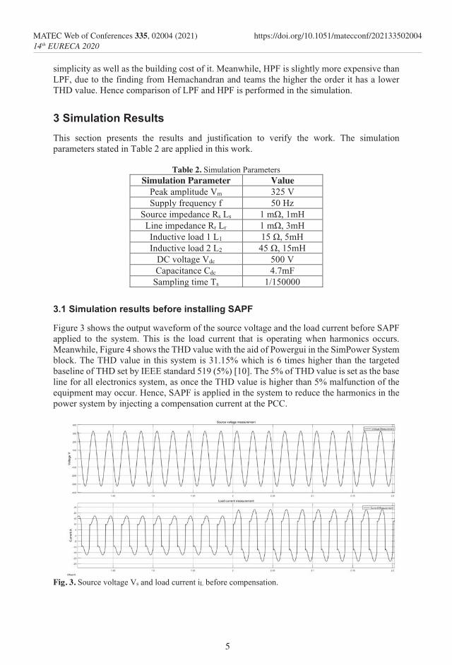
Figure 3 shows the output waveform of the source voltage and the load current before SAPF applied to the system. This is the load current that is operating when harmonics occurs. Meanwhile, Figure 4 shows the THD value with the aid of Powergui in the SimPower System block. The THD value in this system is 31.15% which is 6 times higher than the targeted baseline of THD set by IEEE standard 519 (5%) [10]. The 5% of THD value is set as the base line for all electronics system, as once the THD value is higher than 5% malfunction of the equipment may occur. Hence, SAPF is applied in the system to reduce the harmonics in the power system by injecting a compensation current at the PCC.
Fig. 3. Source voltage Vs and load current iL before compensation.
5
MATEC Web of Conferences 335, 02004 (2021) https://doi.org/10.1051/matecconf/20213350200414th EURECA 2020
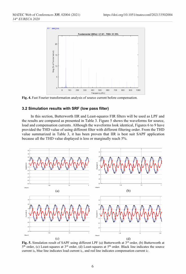
Fig. 4. Fast Fourier transformation analysis of source current before compensation.
3.2 Simulation results with SRF (low pass filter)
In this section, Butterworth IIR and Least-squares FIR filters will be used as LPF and the results are compared as presented in Table 3. Figure 5 shows the waveforms for source, load and compensation currents. Although the waveforms look identical, Figures 6 to 9 have provided the THD value of using different filter with different filtering order. From the THD value summarized in Table 3, it has been proven that IIR is best suit SAPF application because all the THD value displayed is less or marginally reach 5%.
(a)
(b)
(c)
(d)
Fig. 5. Simulation result of SAPF using different LPF (a) Butterworth at 3rd order, (b) Butterworth at 5th order, (c) Least-squares at 3rd order, (d) Least-squares at 5th order. Black line indicates the source current iS, blue line indicates load current iL, and red line indicates compensation current iC.
6
MATEC Web of Conferences 335, 02004 (2021) https://doi.org/10.1051/matecconf/20213350200414th EURECA 2020

Fig. 4. Fast Fourier transformation analysis of source current before compensation.
3.2 Simulation results with SRF (low pass filter)
In this section, Butterworth IIR and Least-squares FIR filters will be used as LPF and the results are compared as presented in Table 3. Figure 5 shows the waveforms for source, load and compensation currents. Although the waveforms look identical, Figures 6 to 9 have provided the THD value of using different filter with different filtering order. From the THD value summarized in Table 3, it has been proven that IIR is best suit SAPF application because all the THD value displayed is less or marginally reach 5%.
(a)
(b)
(c)
(d)
Fig. 5. Simulation result of SAPF using different LPF (a) Butterworth at 3rd order, (b) Butterworth at 5th order, (c) Least-squares at 3rd order, (d) Least-squares at 5th order. Black line indicates the source current iS, blue line indicates load current iL, and red line indicates compensation current iC.
Fig. 6. Fast Fourier transformation analysis Butterworth LPF at 3rd order.
Fig. 7. Fast Fourier transformation analysis Butterworth LPF at 5th order.
Fig. 8. Fast Fourier transformation analysis Least-Squares LPF at 3rd order.
By comparing both IIR and FIR, both the filters at different filtering order are capable to
perform the harmonics extraction process. It is clear that IIR at 3rd order are marginally passing the THD value set at 5% which will damage the system in a long run. Meanwhile, FIR have a more stable result as shown in Table 3 where both orders achieve a better result compare to IIR.
7
MATEC Web of Conferences 335, 02004 (2021) https://doi.org/10.1051/matecconf/20213350200414th EURECA 2020

Fig. 9. Fast Fourier transformation analysis Least-Squares LPF at 5th order.
Table 3. Tabulation of THD values between IIR and FIR based LPF.
SAPF THD of load current (%)
THD of source current with 3rd
filtering order (%)
THD of source current with 5th
filtering order (%) Without SAPF 31.15 31.15 31.15
SAPF with SRF(IIR)
31.15 5.07 4.31
SAPF with SRF(FIR)
31.15 3.59 3.59
3.3 Simulation results with SRF (high pass filter)
In this section, Butterworth IIR and Least-squares FIR filters will be used as HPF and the results obtained are compared as presented in Table 4. Figure 10 shows the waveforms for source, load and compensation currents. From the graph, it clearly shows that Butterworth in HPF is not suitable for SAPF model since the THD value is more than 5%. On the other hand, Least-square in HPF are still capable in using for this system. Figures 11 to 14 present the THD value resulted from different filter at different filtering order.
Table 4. Tabulation of THD values between IIR and FIR based HPF.
SAPF THD of load current (%)
THD of source current with 3rd
filtering order (%)
THD of source current with 5th
filtering order (%) Without SAPF 31.15 31.15 31.15
SAPF with SRF(IIR)
31.15 8.22 8.70
SAPF with SRF(FIR)
31.15 3.59 3.60
By comparing both LPF and HPF, it is clear that filters at different filtering order are able
to perform harmonics extraction except for Butterworth in HPF. As mentioned, Butterworth LPF is a more preferred model used by other researchers. Due to the limitation of IIR filter, FIR filter is chosen and used in this research. The findings presented in Tables 3 and 4 show that FIR is comparatively better than IIR. Additionally, FIR filter is suitable to function as LPF and HPF and with different filtering orders.
8
MATEC Web of Conferences 335, 02004 (2021) https://doi.org/10.1051/matecconf/20213350200414th EURECA 2020
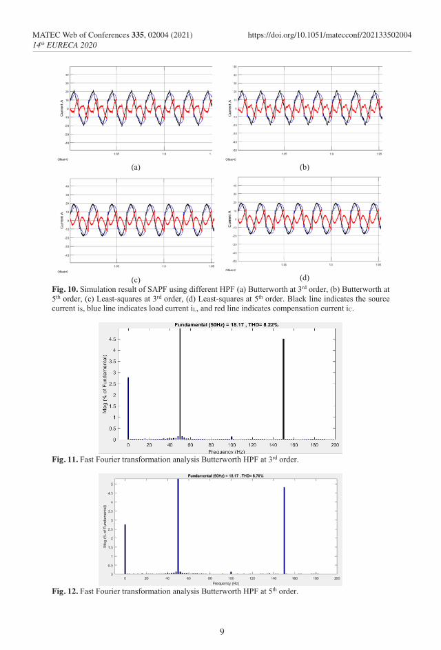
Fig. 9. Fast Fourier transformation analysis Least-Squares LPF at 5th order.
Table 3. Tabulation of THD values between IIR and FIR based LPF.
SAPF THD of load current (%)
THD of source current with 3rd
filtering order (%)
THD of source current with 5th
filtering order (%) Without SAPF 31.15 31.15 31.15
SAPF with SRF(IIR)
31.15 5.07 4.31
SAPF with SRF(FIR)
31.15 3.59 3.59
3.3 Simulation results with SRF (high pass filter)
In this section, Butterworth IIR and Least-squares FIR filters will be used as HPF and the results obtained are compared as presented in Table 4. Figure 10 shows the waveforms for source, load and compensation currents. From the graph, it clearly shows that Butterworth in HPF is not suitable for SAPF model since the THD value is more than 5%. On the other hand, Least-square in HPF are still capable in using for this system. Figures 11 to 14 present the THD value resulted from different filter at different filtering order.
Table 4. Tabulation of THD values between IIR and FIR based HPF.
SAPF THD of load current (%)
THD of source current with 3rd
filtering order (%)
THD of source current with 5th
filtering order (%) Without SAPF 31.15 31.15 31.15
SAPF with SRF(IIR)
31.15 8.22 8.70
SAPF with SRF(FIR)
31.15 3.59 3.60
By comparing both LPF and HPF, it is clear that filters at different filtering order are able
to perform harmonics extraction except for Butterworth in HPF. As mentioned, Butterworth LPF is a more preferred model used by other researchers. Due to the limitation of IIR filter, FIR filter is chosen and used in this research. The findings presented in Tables 3 and 4 show that FIR is comparatively better than IIR. Additionally, FIR filter is suitable to function as LPF and HPF and with different filtering orders.
(a)
(b)
(c)
(d)
Fig. 10. Simulation result of SAPF using different HPF (a) Butterworth at 3rd order, (b) Butterworth at 5th order, (c) Least-squares at 3rd order, (d) Least-squares at 5th order. Black line indicates the source current iS, blue line indicates load current iL, and red line indicates compensation current iC.
Fig. 11. Fast Fourier transformation analysis Butterworth HPF at 3rd order.
Fig. 12. Fast Fourier transformation analysis Butterworth HPF at 5th order.
9
MATEC Web of Conferences 335, 02004 (2021) https://doi.org/10.1051/matecconf/20213350200414th EURECA 2020

Fig. 13. Fast Fourier transformation analysis Least-Squares HPF at 3rd order.
Fig. 14. Fast Fourier transformation analysis Least-Squares HPF at 5th order.
4 Conclusion The application of Least-squares FIR filter in the control structure of SRF technique is presented in this research. From the findings, SRF with Least-squares FIR filter is proven to be more effective in extracting the desired harmonic contents and the THD value achieved is lower than SRF with Butterworth IIR filter. Hence, the proposed SRF with Least-squares FIR filter (either as LPF or HPF) can serve as a better alternative in managing the operation of APF to perform mitigation of harmonics.
References 1. Y. Hoon, M.A.M. Radzi, M.K. Hassan, N.F. Mailah, 5th IET Int. Conf. Clean Energy
Technol. 1 (2018).
2. R. Targosz, J. Manson, 9th Int. Conf. Elect. Power Quality Util. 1 (2007).
3. A.S. Al-Ogaili, A. Ramasamy, Y. Hoon, R. Verayiah, M. Marsadek, T. Juhana, N.A. Rahmat. Int. J. Electr. Comput. Eng. 10, 5609 (2020).
4. H. Akagi, Proc. IEEE, 93, 2128 (2005).
5. H. Zhao, L. Zhang, J. Liu, C. Zhang, Electron. 9, 729 (2020).
6. M.A.S. Masoum, E.F. Fuchs, Power Quality in Power Systems and Electrical Machines, 779 (2015).
7. X. Wang, X. Guo, F. Wang, 2009 Asia-Pacif. Power Energy Eng. Conf. 1 (2009).
10
MATEC Web of Conferences 335, 02004 (2021) https://doi.org/10.1051/matecconf/20213350200414th EURECA 2020

Fig. 13. Fast Fourier transformation analysis Least-Squares HPF at 3rd order.
Fig. 14. Fast Fourier transformation analysis Least-Squares HPF at 5th order.
4 Conclusion The application of Least-squares FIR filter in the control structure of SRF technique is presented in this research. From the findings, SRF with Least-squares FIR filter is proven to be more effective in extracting the desired harmonic contents and the THD value achieved is lower than SRF with Butterworth IIR filter. Hence, the proposed SRF with Least-squares FIR filter (either as LPF or HPF) can serve as a better alternative in managing the operation of APF to perform mitigation of harmonics.
References 1. Y. Hoon, M.A.M. Radzi, M.K. Hassan, N.F. Mailah, 5th IET Int. Conf. Clean Energy
Technol. 1 (2018).
2. R. Targosz, J. Manson, 9th Int. Conf. Elect. Power Quality Util. 1 (2007).
3. A.S. Al-Ogaili, A. Ramasamy, Y. Hoon, R. Verayiah, M. Marsadek, T. Juhana, N.A. Rahmat. Int. J. Electr. Comput. Eng. 10, 5609 (2020).
4. H. Akagi, Proc. IEEE, 93, 2128 (2005).
5. H. Zhao, L. Zhang, J. Liu, C. Zhang, Electron. 9, 729 (2020).
6. M.A.S. Masoum, E.F. Fuchs, Power Quality in Power Systems and Electrical Machines, 779 (2015).
7. X. Wang, X. Guo, F. Wang, 2009 Asia-Pacif. Power Energy Eng. Conf. 1 (2009).
8. M. Anzari, R. Chandran, R. ArunKumar, Adv. Electron. Electr. Eng., 3, 81 (2013).
9. K. Hemachandran, D.J. Rabi, S.S. Darly. 8th Int. Conf. Cir. Sys. Sign. 1 (2015).
10. Institute of Electrical and Electronics Engineers (IEEE). “IEEE recommended practice and requirement for harmonic control in electric power systems,” IEEE Std 519-2014 (Revision of IEEE Std 519-1992), 1 (2014).
11
MATEC Web of Conferences 335, 02004 (2021) https://doi.org/10.1051/matecconf/20213350200414th EURECA 2020
Copyright © 2022 FDOKUMEN