Synapse-_Issue 1.00.D
68
Synapse 2XG100 Dual channel 3Gb/s, HD and SD up/down/cross converter and synchronizer with optional audio shuffler Version 1.00 | November 2021 INSTALLATION AND OPERATION MANUAL
-
Upload
khangminh22 -
Category
Documents
-
view
0 -
download
0
Transcript of Synapse-_Issue 1.00.D

Synapse2XG100Dual channel 3Gb/s, HD and SD up/down/crossconverter and synchronizer with optional audioshufflerVersion 1.00 | November 2021
INSTALLATION AND OPERATION MANUAL


DisclaimerThis manual and the information contained herein are the sole property of EVS Broadcast Equipment SAand/or its affiliates (EVS) and are provided “as is” without any expressed or implied warranties, including,but not limited to, the implied warranties of merchantability and fitness for a particular purpose. Inparticular, EVS makes no warranty regarding the use or the consequences of use of this manual and theinformation contained herein. Furthermore, EVS may not be held liable for any direct or indirect,incidental, punitive or consequential loss, damage, cost or expense of any kind whatsoever andhowsoever resulting from the normal or abnormal use of this manual and the information containedherein, even if advised of the possibility of such loss, damage, cost or expense.
While every effort has been made to ensure that the information contained in this manual is accurate,up-to-date and reliable, EVS cannot be held liable for inaccuracies or errors that may appear in thispublication. The information in this manual is furnished for informational purpose and use only andsubject to change without notice.
This manual cancels and replaces any previous versions thereof.
CopyrightCopyright © 2003-2021 EVS Broadcast Equipment SA. All rights reserved.
This manual may not be reproduced, transcribed, stored (in a database or a retrieval system), translatedinto any language, computer language, transmitted in any form or by any means – electronically,mechanically, printed, photocopied, optically, manually or otherwise – in whole or in part without theprior written consent of EVS.
TrademarksAll product and brand names are registered trademarks and trademarks of EVS or of their respectiveowners.
Improvement RequestsYour comments will help us improve the quality of the user documentation. Please send improvementrequests, or report any error or inaccuracy on this user manual by e-mail to [email protected].
Regional ContactsYou will find the full list of addresses and phone numbers on the following webpage:https://evs.com/contact/offices.
User Manuals on EVSWebsiteThe latest version of the user manual, if any, and other user manuals on EVS products can be found atthe EVS download center, on the following webpage: https://download-area.evs.com.
INSTALLATION AND OPERATION MANUAL
Synapse 2XG100 | Disclaimer | i

General InformationALWAYS disconnect your entire system from the AC mains before cleaning any component. The productframe (SFR18, SFR08 or SFR04) must be terminated with three-conductor AC mains power cord thatincludes an earth ground connection. To prevent shock hazard, all three connections must always beused.
NEVER use flammable or combustible chemicals for cleaning components.
NEVER operate this product if any cover is removed.
NEVER wet the inside of this product with any liquid.
NEVER pour or spill liquids directly onto this unit.
NEVER block airflow through ventilation slots.
NEVER bypass any fuse.
NEVER replace any fuse with a value or type other than those specified.
NEVER attempt to repair this product. If a problem occurs, contact your local EVS distributor.
NEVER expose this product to extremely high or low temperatures.
NEVER operate this product in an explosive atmosphere.
To reduce the risk of fire or electrical shock, do not expose this appliance to rain or moisture.
This product complies with the requirements of the product family standards for audio, video, audio-visual entertainment lighting control apparatus for professional use as mentioned below.
EN60950 SafetyEN55103-1: 1996 EmissionEN55103-2: 1996 Immunity
This device complies with Part 15 of the FCC Rules. Operation is subjectto the following two conditions:
1. This device may cause harmful interference, and
2. This device must accept any interference received,including interference that may cause undesired operation.
Tested to comply withFCC StandardsFOR HOME OR OFFICEUSE
ii | November 2021 | Issue 1.00.D

ContentsDisclaimer i
General Information ii
Contents iii
What's New? v
1. Introduction 1
2. Unpacking and Placement 2
3. Quick Start 3
4. The 2XG100-110 Card 6
5. Settings Menu 12
5.1. System Settings 12
5.2. Up-Conv 19
5.3. Down-Conv 21
5.4. Cross-Conv 24
5.5. Transparent 26
5.6. Inserter 29
5.7. Video-Proc 32
5.8. Audio Proc Amp 33
5.9. Embedder 34
5.10. GPI Mode 36
5.11. Network 37
6. Status Menu 38
6.1. System Status 38
6.2. Net Status 41
7. Events Menu 42
INSTALLATION AND OPERATION MANUAL
Synapse 2XG100 | Contents | iii

8. LED Indication 44
9. Block Schematic 45
10. Connector Panels 46
Appendices 48
Appendix 1: GPIs Explained 48
Appendix 2: Card Dip Switches for BHX and Fiber Configurations 56
GNU Public License 58
ICONOGRAPHY
Note Tip Warning
iv | November 2021 | Issue 1.00.D

What's New?
In the Installation and Operation Manual the icon has been added on the left margin to highlightinformation on updated features.
The changes linked to new features in version 1.00 of 2XG100/110 are listed below.
SMPTE ST 352 Payload Identifier
• See section "Inserter" on page 29.
INSTALLATION AND OPERATION MANUAL
Synapse 2XG100 | What's New? | v


1. IntroductionSynapse is a modular system designed for the broadcast industry. High density, intuitive operation andhigh-quality processing are key features of this system. Synapse offers a full range of converters andprocessing modules. Please visit the EVS website at www.evs.com to obtain the latest information onour new products and updates.
Local Control Panel
The local control panel gives access to all adjustable parameters and provides status information for anyof the cards in the Synapse frame, including the Synapse rack controller. The local control panel is alsoused to back-up and restore card settings. Please refer to the RRC18, RRC10, RRC04, RRS18 and RRS04manuals for a detailed description of the local control panel, the way to set up remote control over IP andfor frame-related settings and status information.
Remote Control Capabilities
The remote-control options are explained in the rack controller (RRC18 / RRC10 / RRC04 / RRS18 /RRS04) manual. The method for connecting to a computer using Ethernet is described in the RRC/RRSmanual.
Cortex software will increase system flexibility of one or more Synapse frames.
Although it is not required to use Cortex with a Synapse frame, you are strongly advised to use a remotepersonal computer or laptop PC with Cortex installed, as this increases the ease of use andunderstanding of the modules.
INSTALLATION AND OPERATION MANUAL
Synapse 2XG100 | 1. Introduction | 1

2. Unpacking and PlacementUnpacking
The EVS Synapse card must be unpacked in an anti-static environment. Care must be taken NOT totouch components on the card – always handle the card carefully by the edges. The card must be storedand shipped in anti-static packaging. Ensuring that these precautions are followed will preventpremature failure of components mounted on the board.
Placing the Card
The Synapse card can be placed vertically in an SFR18 frame or horizontally in an SFR04 and SFR08frame. Locate the two guide slots to be used, slide in the mounted circuit board, and push it firmly tolocate the connectors.
Correct insertion of the card is essential, as a card that is not located properly may show valid indicators,but will not function correctly.
On power up, all LEDs will light up for a few seconds. This is the time it takes to initialize thecard.
Please refer to "Appendix 2: Card Dip Switches for BHX and Fiber Configurations" on page 56before connecting any back panel.
2 | November 2021 | Issue 1.00.D

3. Quick StartPowering Up
On powering up the Synapse frame, the card set will use basic data and default initialization settings. AllLEDs will light up during this process. After initialization, several LEDs will remain lit – the exact numberand configuration is dependent upon the number of inputs connected and the status of the inputs.
Changing Settings and Parameters
The front panel controls or Cortex can be used to change the settings. An overview of the settings canbe found in later chapters of this manual. Please refer to "Graphical User Interface" on page 1 and"Events Menu" on page 42.
Front Panel Control
Front Panel Display and Cursor
Settings are displayed and changed as follows:
Use the cursor ‘arrows’ on the front panel to select the menu and parameter to be displayed and/orchanged.
Move forward through the menu structure.
Go back through the menu structure.
Move up within a menu, or increase the value of a parameter.
Move down through a menu or decrease the value of a parameter.
When editing parameters, pressing ► twice will reset the value to its default setting.
INSTALLATION AND OPERATION MANUAL
Synapse 2XG100 | 3. Quick Start | 3

How to Change Parameters Using the Front Panel Control
With the display as shown below:
Pressing selects the SFS10 in frame slot 01.
The display changes to indicate that the SFS10 has been selected. In this example the Settings menuitem is indicated.
Pressing the selects the menu item shown, in this example Settings.
(Pressing or will change to a different menu, e.g. Status, Events).
The display changes to indicate that the SFS10 Settings menu item SDI-Format has been selected andshows that its current setting is Auto.
Pressing the selects the Settings item shown, in this example SDI-Format.
(Pressing or will change to a different setting, e.g. Mode, H-Delay).
The display changes to indicate that the SFS10 Edit Setting menu item SDI-Format has been selected.
To edit the setting of the menu item, press or .
All menu items can be monitored and/or changed in this way. Changing a setting has an immediateeffect.
4 | November 2021 | Issue 1.00.D

EVS Cortex Software
Cortex can be used to change the settings of Synapse modules from a PC, either locally or remotely. Thesoftware enables communication based on TCP/IP between the Setup PC and Synapseframes/modules.
Each Synapse frame is addressed through its rack controller’s unique IP address, giving access to eachmodule, its menus and adjustment items. Cortex has access to data contained within the Synapsemodule and displays it on a GUI. The software has an intuitive structure following that of the module thatit is controlling.
For operation of Cortex, please refer to the Cortex help files.
Menu Structure Example
Slot Module Item Parameter Setting
S02 Identity
S01 SFS10 Settings Standard dig Auto
S00 RRC18 Status Mode 625
Events Ref-Input 525
H-Delay
Further information about Front Panel Control and Cortex can be obtained from the ERC, ERS,RRC and RRS operational manuals and the Cortex help files.
INSTALLATION AND OPERATION MANUAL
Synapse 2XG100 | 3. Quick Start | 5

4. The 2XG100-110 CardIntroduction
The 2XG100-110 is a dual-channel, high-quality up converter. The optimized scaling and filter algorithmsensure crisp broadcast ready pictures from a native SD or HD source, by use of a 64 tap FIR filters. Thecard allows you to simulcast 2 HD or 3Gb/s signals from 2 native HD, SD or 1 CVBS and an SDinfrastructure. The embedded audio is carried over to the HD or 3Gb/s domain. The appropriate aspectratio can be applied by control of VI, WSS and GPI inputs by use of 8 presets per output that can storethe aspect ratio conversions.
Beside a high quality up converter, the 2XG110 is also a very powerful cross-input audio shuffler andproc-amp. With the 110 model, you can de-embed 2x 8 channels out of any of the 16 embedded audiochannels of both HD/SD inputs and shuffle these channels. This means you can combine embeddedaudio channels from input 1 and embedded audio channels from input 2 in your 3Gb/s, HD, SD outputs.The embedded audio is carried over to the HD or 3Gb/s domain.
The 2XG100-110 is compatible with 270Mb/s, 1.5Gb/s and 3Gb/s for full 1080p/50 or 1080p/59.94 use.
Features• 3 inputs: 2 SDI and 1 composite.
• Configurable output function
◦ Straight (1=1, 2=2)
◦ Crossed (2=1, 1=2)
◦ A only
◦ B only
• Low latency conversion process (as low as 1 field in controlled timing environment)
• Compatible with the following input formats (auto selecting):
◦ 1080i/59.94 ◦ 720p/59.94◦ 1080i/50 ◦ 720p/50◦ 1080p/59.94 ◦ 720p/30◦ 1080p/50 ◦ 720p/25◦ 1080p/30 ◦ 720p/23.98◦ 1080p/25 ◦ SD525◦ 1080p/23.98 ◦ SD625
• Output standards (only one standard can be chosen for both outputs simultaneously):
◦ 1080p/59.94 ◦ 720p/59.94◦ 1080p/50 ◦ 720p/50◦ 1080i/59.94 ◦ 720p/23.98
6 | November 2021 | Issue 1.00.D

◦ 1080i/50 ◦ SD525◦ 1080p/23.98 ◦ SD625◦ 1080psf/23.98
• Two individual conversion paths. The inputs can be different standards SD or HD and unlocked tothe single output format.
• Frame sync with output phase control in Frames, Lines and pixels with respect to reference. Delaysettings are stored per output format for a constant latency operation.
◦ 30 Frames delay offset (per channel)
◦ 1080i/59.94 ◦ 1080p/23.98◦ 1080i/50 ◦ 1080p/59.94◦ 1080p/50 ◦ 1080psf/23.98
◦ 60 Frames delay offset (per channel)
◦ 720p/59.94 ◦ 720p/23.98◦ 720p/50
◦ 125 Frames delay offset (per channel)
◦ SD525 ◦ SD625
• All ARC modes contain:
◦ Anamorphic
◦ Center Cut
◦ V-Zoom
◦ LBox-16:9
◦ LBox-14:9
◦ PBox-4:3
◦ PBox-14:9
◦ Variable H and V (50-200%)
• Free individual programmable presets banks for:
◦ Up converter ARC A and B 16-presets each
◦ Down converter ARC A and B 16-presets each
◦ Cross converter ARC A and B 16-presets each
◦ Transparent ARC A and B 16-presets each
◦ VI insertion A and B 16-presets each
• 5 GPI inputs assignable to different preset banks
◦ Input selection
◦ Output mode
◦ Up conversion aspect ratio for channel A and B
INSTALLATION AND OPERATION MANUAL
Synapse 2XG100 | 4. The 2XG100-110 Card | 7

◦ Down conversion aspect ratio for channel A and B
◦ Cross conversion aspect ratio for channel A and B
◦ Transparent aspect ratio (equal in-output) for channel A and B
◦ Insertion of VI, WSS, AFD (S2016) for channel A and B
◦ Audio shuffling, gain and phase (160 only)
• ARC triggers by VI, WSS, WSSext and S2016 (AFD)
• Individual color corrector for video paths A and B
• Transparent for 16 channels of embedded audio
• Embedded domain cross-input audio shuffling, gain and phase control (2XG110 only)
• Embedding and de-embedding through Synapse bus
• Video proc-amp (Y and C control)
• Color corrector (RGB and total gain, RGB and total black)
• Hue control for NTSC inputs
• Full control and status monitoring through the front panel of the SFR04/SFR08/SFR18 frame and theEthernet port (ACP).
8 | November 2021 | Issue 1.00.D

Conversion Capabilities
INSTALLATION AND OPERATION MANUAL
Synapse 2XG100 | 4. The 2XG100-110 Card | 9

Applications2XG100-2XG110:
• Truck input synchronizer converter
• Infrastructure up/down/cross conversion
• Up-conversion with side-fill/curtain input
2XG110 only:
• Combining embedded audio channels of 2 inputs into 1 (see below).
10 | November 2021 | Issue 1.00.D

Block Schematic
Important Notice about Closed CaptionsHistorically, closed captions were transmitted in NTSC line 21 in accordance with EIA-608. This allowstwo caption data bytes per field to be transmitted. With the introduction of HD and DTV, a new ClosedCaption specification was introduced: EIA-708. This allows more data to be sent per field, for extendedlanguage, color support, PMT and EIT and timecode data.
The new DTV caption format cannot be translated back to EIA-608. However the EIA-708 may includeEIA-608 data as "NTSC closed captions" for compatibility with old decoders.
This card only de-embeds the NTSC closed captions, not the DTV closed captions. It will not functionwith a DTV-only 708 closed-caption source.
INSTALLATION AND OPERATION MANUAL
Synapse 2XG100 | 4. The 2XG100-110 Card | 11

5. Settings Menu
IntroductionThe Settings menu displays the current state of each 2XG100/110 setting and allows you to change oradjust it.
Settings can be changed using the front panel of the Synapse frame (SFR18, SFR08 or SFR04) or withCortex. The SCP08 control can also be used. Please refer to "Quick Start" on page 3 for information onthe Synapse front panel control and Cortex.
All items preceded with a # sign are part of the presets.
5.1. System SettingsSetting Description
IO-Ctrl This card has separate presets for the input and output settings underthe ‘SYSTEM SETTINGS’ header. With this item you select how the IOpresets are controlled: manually (Manual), via GPI-triggers (GPI-A, GPI-Bor GPI-C) or by the input format on input 1 (SDI1-format) or input 2 (SDI2-Format). By default it is set to Manual.
The input formats are mapped to the preset as follows:
Preset Format Preset Format
1 1080i60 9 720p30
2 1080i50 10 720p25
3 1080p30 11 720p24
4 1080p25 12 SD525
5 1080p24 13 SD625
7 720p60 14 1080p50
8 720p50 15 1080p60
IO_Prst_Act With this item you can manually change the currently active IO settings.Can be any preset between 1 and 16. By default it is set to 1. All menusettings that are preceded by the # prefix under the ‘SYSTEM SETTINGS’header are part of the preset.
12 | November 2021 | Issue 1.00.D

IO_Prst_Edit Here you can select which of the 16 selectable IO settings presets youwant to edit. Changing this will not change the active preset, unless thecurrently active preset is the one you are going to edit. All menu settingsthat are preceded by the # prefix under the ‘SYSTEM SETTINGS’ headerare part of the preset.
#Inp_SelA With this item you can select which input you want to use for Channel A.
Can be SDI-1 (SDI input 1), SDI-2 (SDI input 2) or Analog (CVBS in). Youcan also choose a Zoneplate or Colorbar as input. Can also be set to Offto switch off Channel A entirely. The default for this setting is SDI-1.
#Inp_SelB With this item you can select which input you want to use for Channel B.Can be SDI-1 (SDI input 1), SDI-2 (SDI input 2) or Analog (CVBS in).
You can also choose a Zoneplate or Colorbar as input. Can also be set toOff to switch off channel B entirely. The default for this setting is SDI-2.
#CVBS-Frmt With this item you can set the format of the CVBS input. Possible formatsto select here are (default is Auto):
• PAL-M
• PAL-N
• NTSC-M
• NTSC-4.43
• NTSC-J
• SECAM
• PAL-60
• PAL-BGHID
• Auto (automatic detection and selection between NTSC-J and PAL-BGHID)
#Out-Ctrl This setting controls the output format of the card. When set to Manual,the output format corresponds to the Out-Frmt setting. When set toAuto, the output format follows the input format. Possible settings are:
• Manual (default)
• Auto
INSTALLATION AND OPERATION MANUAL
Synapse 2XG100 | 5. Settings Menu | 13

#Out-Frmt With Out-Frmt you can set what the output should be of channel A aswell as channel B. Possible settings are:
• 1080i60 (default) • 1080i50• 1080p60 • 1080p50 • 1080p30• 1080p25 • 1080p24 • 1080p24sf• 720p60 • 720p50 • 720p30• 720p25 • 720p24• SD525 • SD625
#IO-Map With this setting you can configure the output as Level A (default) orLevel B (according to SMPTE S425) when the output format is 1080p50or 1080p60.
#Out-Mode With this setting you choose which input should be on which output.There are 4 available modes:
• Straight (default): Channel A to outputs A1-A2, Channel B to outputsB1-B2
• Crossed: Channel A to outputs B1-B2, Channel B to outputs A1-A2
• SUM: All outputs contain a mix (sum) of Channel A and Channel B
• A Only: Channel A to all outputs
• B Only: Channel B to all outputs
When in ‘A only’ or ‘B only’ modes, you can process 16 channels of audio for the outputs.When in mixed modes, you can process only 8 channels of audio per input.
Also when in ‘A only’ all the settings that involve video channel B are discarded and when in‘B only’ all channel A settings are discarded.
#F_delay F-Delay sets the number of delayed Frames. The available range is from0 to 250 fields (dependent on the I/O). Default is 0F. The preset masterfor this is Out-Frmt, hence the # prefix.
#V_delay V-Delay setting allows adjustment of the vertical phase of the outputsignal with respect to the selected reference input.
The V-Delay setting gives a delay in addition to the reference timing. Forexample: if the V-Delay is set to 10 TV HD lines, the output signal will bedelayed by reference timing + 10 TV HD lines. The signal is delayed(advanced) with respect to the phase of the reference signal. Theavailable range is from 0 to a maximum of 1125 lines (dependent on I/Oformat). The default setting is 0ln. The preset master for this is Out-Frmt,hence the # prefix.
14 | November 2021 | Issue 1.00.D

#H_delay The H-Delay setting allows adjustment of the Horizontal phase of theoutput signal with respect to the selected reference input.
The H-Delay setting gives a delay in addition to the reference timing. Forexample: if the H-Delay is set to 10 pixels, the output signal will bedelayed by reference timing + 10 pixels. The signal is delayed (advanced)with respect to the phase of the reference signal. The available range isfrom 0 to a maximum of 5124 pixels (dependent on I/O format). Thedefault setting is 0px. The preset master for this is Out-Frmt, hence the #prefix.
#Freeze_A Freeze enables the capture of one Video Frame. The settings for Freezeare On or Off. The default is Off.
#Freeze_B Freeze_B enables the capture of one Video frame on the B channel. Thesettings for Freeze are On or Off. The default is Off.
INSTALLATION AND OPERATION MANUAL
Synapse 2XG100 | 5. Settings Menu | 15

#LowPassFilt_A Here you can set the horizontal and vertical video low-pass filter forchannel A. These are the possible settings:
• Off: the normal broadband filters will be used when the card isconverting. A 64 taps brick wall type horizontal filter:
• H_only: a less steep filter with no aliasing Y and soft for C for lessringing effects:
• V_only: vertical filters will be active which “soften” the image andprevents “ring”-effects in down converted content.
• H_And_V: same horizontal filter as described under H_Only will beactive, together with the vertical filters described under V_only.
16 | November 2021 | Issue 1.00.D

• H2_Only: less steep filter with aliasing and soft for C for less ringing,more sharpness but with aliasing:
• H2_And_V: same horizontal filter as described under H2_Only will beactive, together with the vertical filters described under V_only.
This only works when down-converting.
When the card is in Transparent mode, the filters will be entirely bypassed.
#LowPassFilt_B This sets the horizontal and vertical low-pass filter for channel B. Pleaserefer to #LowPassFilt_A for an explanation of the possible settings.
Pos-Prst_Act Selects the active preset to control the positions #H-Pos-A, #V-Pos-A,#H-Pos_B and #V-Pos-B. Here you can select which of the 8 selectablepositioning settings presets you want to activate. Default setting is 1.
Pos-Prst_Edit Edit preset control for the position controls #H-Pos-A, #V-Pos-A, #H-Pos_B and #V-Pos-B. Here you can select which of the 8 selectablepositioning settings presets you want to edit. Default setting is 1.
#H-Pos-A Controls the horizontal positioning offset in pixels for channel A. Onlyworks correctly when zooming in, for instance when down-convertingusing Center-Cut aspect ratio conversion.
#V-Pos-A Controls the vertical positioning offset in pixels for channel A. Only workscorrectly when zooming in, for instance when down-converting usingCenter-Cut aspect ratio conversion.
#H-Pos-B Controls the horizontal positioning offset in pixels for channel B. Onlyworks correctly when zooming in, for instance when down-convertingusing Center-Cut aspect ratio conversion.
#V-Pos-B Controls the vertical positioning offset in pixels for channel B. Only workscorrectly when zooming in, for instance when down-converting usingCenter-Cut aspect ratio conversion.
INSTALLATION AND OPERATION MANUAL
Synapse 2XG100 | 5. Settings Menu | 17

Delay-Status It is possible to display (in the IODelayA and IODelayB) the processingtime of the card in the Status menu. This setting allows you to switch thisfunction On or Off (default).
Lock-Mode Lock-Mode determines whether the card is locked to its input input 1), tothe reference (Ref1 or Ref2) or freerun (not locked). Can also be set toRefAuto. By default it is set to Ref1.
When set to RefAuto the card chooses ref1 as its source. Whenever ref1fails, it will switch to ref 2 (only for SFR08 and SFR18 frames and onlywhen ref2 offers the same ref format as ref 1). When ref 1 is back upagain, it will only automatically switch back to ref 1 when ref 2 fails.
Ref-Type Sets the type of incoming reference. Can be either Bi-Level (default) orTri- Level.
PrstEditView With this setting set to Follow Active, the edit preset settings (e.g. UP_Prst_editA and UP_Prst_editB) will follow the active preset when theactive preset is changed. This is to avoid confusion when changing theactive preset. Set to Independent, the edit preset will not automaticallyfollow active preset changes. By default set to Follow Active.
PatternSpeed Sets the speed of the test-pattern (see settings Inp_SelA and Inp_SelB)animation between 0 (still) and 15 (fast). Default is 1.
SD-AR-Det This card can switch between presets on the changes of the aspectratio. Aspect ratio information can be taken out of the VI (video index),WSS (widescreen signaling) or WSS-extended (extended form ofwidescreen signaling). With this setting you can select which of theabove protocols should be used to detect aspect ratio changes. Bydefault it is set to VI.
NoWSS/VI_prstA With this setting you can set to which preset the card should jumpchannel A, when no WSS or VI information is found. Can be any presetbetween 1 and 16 or Hold (holds current active preset). By default it is setto Hold.
NoWSS/VI_prstB With this setting you can set to which preset the card should jumpchannel B, when no WSS or VI information is found. Can be any presetbetween 1 and 16 or Hold (holds current active preset). By default it is setto Hold.
18 | November 2021 | Issue 1.00.D

Input_Loss_A Input_loss_A determines what the output of outputs A is in case of lostinput:
• Freeze: a capture of the last good field or frame.
• Colorbar: a color bar
• Zoneplate: a zone plate
• Black: a black output.
• Grey: a gray output.
• Green: a green output.
Input_Loss_B Input_loss_B determines what the output of output B is in case of lostinput. Same values as Input_Loss_A are possible.
5.2. Up-ConvSetting Description
Up_CtrlA With this item you select how the presets for Channel A in up converter mode arecontrolled: manually (Manual), via GPI-triggers (GPI, GPI-A, GPI-B or GPI-C), orvia changes of the SD (SD-AR) or HD (S2016) aspect ratio. By default it is set toManual.
Up_Prst_ActA With this item you can manually change the currently active preset of channel Ain up converter mode. Can be any preset between 1 and 16. By default it is set to1. All menu settings that are preceded with an '#Up' prefix are part of the preset.
UP_Prst_EditA Here you can select which of the 16 selectable presets you want to edit forChannel A in up converter mode. Changing this will not change the active preset,unless the currently active preset is the same you are going to edit. All menusettings that are preceded with an '#Up' prefix are part of the preset.
INSTALLATION AND OPERATION MANUAL
Synapse 2XG100 | 5. Settings Menu | 19

#Up_ArcA With this item you set the Aspect Ratio of the output of channel A in up convertermode. Can be Anamorphic, V-Zoom, PBox-4:3, PBox-14:9 or Variable (customset AR, set by H-scale and V-scale settings). The following table showsexamples of the possible aspect ratios when the input source is 4:3.
Setting Result on 16:19 screens:
Anamorphic
V-Zoom
PBox-4:3
PBox-14:9
Variable Dependent on Up H-scale andUp V-scale settings.
Anam-702 Anamorphic scaling based on702 active pixels, instead of 720pixels
#Up_H-ScaleA The horizontal scaling of the TV picture of channel A in up converter mode is setusing #Up_H-scaleA. #Up_H-scaleA can be set within the range of 50% to 200%of the input signal (only used when #Up_ArcA is set to variable). Default value is100%.
#Up_V-ScaleA Sets the vertical scaling of the TV picture of channel A in up converter mode. Canbe set within the range of 50% to 200% of the input signal (only used when #Up_ArcA is set to variable). Default value is 100%.
#Up_H-EnhA With this item you can set the horizontal picture enhancement of channel A in upconverter mode between 0 and 100%. By default set to 0%.
#Up_ColorConvA ColorConvA optimizes the color conversion for Channel A in up converter mode.As the color coding of HD (709) and SD(601) are different, it is necessary toconvert these when Channel A is up-converting. The best result is generatedwhen the up-converter is active and the 601to709 setting is selected. It is alsopossible to switch the filter off. The default setting isOff.
20 | November 2021 | Issue 1.00.D

Up_CtrlB With this item you select how the presets for Channel B are controlled in upconverter mode: Manually (manual), via GPI-triggers (GPI, GPI-A, GPI-B, GPI-C)or via changes of the SD Aspect Ratio (SD-AR). By default it is set to Manual.
Up_Prst_ActB With this item you can manually change the currently active preset of channel Bin up converter mode. Can be any preset between 1 and 16. By default it is set to1. All menu settings that are preceded with an '#Up' prefix are part of the preset.
Up_Prst_EditB Here you can select which of the 16 selectable presets you want to edit forChannel B in up converter mode. Changing this will not change the active preset,unless the currently active preset is the same you are going to edit. All menusettings that are preceded with an '#Up' prefix are part of the preset.
#Up_ArcB With this item you set the Aspect Ratio of the output of channel B in up convertermode. Can be Anamorphic, V-Zoom, PBox-4:3, PBox-14:9. Anam-702 or Variable(custom set AR, set by H-scale and V-scale settings). The table in setting #Up_ArcA shows examples of the possible aspect ratios when the input source is 4:3.
#Up_H-ScaleB The horizontal scaling of the TV picture of channel B in up converter mode is setusing #Up_H-scaleB. #Up_H-scaleB can be set within the range of 50% to 200%of the input signal (only used when #Up_ArcB is set to variable). Default value is100%.
#Up_V-ScaleB Sets the vertical scaling of the TV picture of channel B in up converter mode. Canbe set within the range of 50% to 200% of the input signal (only used when #Up_ArcB is set to variable). Default value is 100%.
#Up_H-EnhB With this item you can set the horizontal picture enhancement of channel B in upconverter mode between 0 and 100%. By default set to 0%.
#Up_ColorConvB ColorConvB optimizes the color conversion in up converter mode. As the colorcoding of HD (709) and SD (601) are different, it is necessary to convert thesewhen Channel B is up-converting. The best result is generated when the up-converter is active and the 601to709 setting is selected. It is also possible toswitch the filter off. The default setting is 601to709.
5.3. Down-ConvSetting Description
Dn_CtrlA With this item you select how the presets for Channel A are controlled in down-converter mode: manually (Manual), via GPI-triggers (GPI, GPI-A, GPI-B or GPI-C)or via changes of the HD Aspect Ratio (S2016). By default it is set toManual.
Dn_Prst_ActA With this item you can manually change the currently active preset of channel Ain down-converter mode. Can be any preset between 1 and 16. By default it isset to 1. All menu settings that are preceded with a '#Dn' prefix are part of thepreset.
INSTALLATION AND OPERATION MANUAL
Synapse 2XG100 | 5. Settings Menu | 21

Dn_Prst_EditA Here you can select which of the 16 selectable presets you want to edit forChannel A in down-converter mode. Changing this will not change the activepreset, unless the currently active preset is the same you are going to edit. Allmenu settings that are preceded with a '#Dn' prefix are part of the preset.
#Dn_ArcA With this item you set the Aspect Ratio of the output of channel A in downconverter mode. Can be Anamorphic (default), CenterCut, LBox-16:9, LBox-14:9or Variable (custom set AR, set by H-scale and V-scale settings). The followingtable shows examples of the possible aspect ratios when the input source is16:9.
Setting Result on 4:3 screens:
Anamorphic
CenterCut
LBox-16:19
LBox-14:19
Variable Dependent on Dn H-scale and Dn V-scale settings.
Anam-702 Anamorphic scaling based on 702 activepixels, instead of 720 pixels
#Dn_H-ScaleA The horizontal scaling of the TV picture of channel A in down converter mode isset using #Dn_H-scaleA. #Dn_H-scaleA can be set within the range of 50% to200% of the input signal (only used when #Dn_ArcA is set to variable). Defaultvalue is 100%.
22 | November 2021 | Issue 1.00.D

#Dn_V-ScaleA Sets the vertical scaling of the TV picture of channel A in down converter mode.Can be set within the range of 50% to 200% of the input signal (only used when#Dn_ArcA is set to variable). Default value is 100%.
#Dn_H-EnhA With this item you can set the horizontal picture enhancement of channel A indown converter mode between 0 and 100%. By default set to 0%.
#Dn_ColorConvA ColorConvA optimizes the color conversion of channel A in down convertermode. As the color coding of HD (709) and SD (601) are different, it is necessaryto convert these when Channel A is up-converting. The best result is generatedwhen the up-converter is active and the 709to601 setting is selected. It is alsopossible to switch the filter off. The default setting is 709to601.
Dn_CtrlB With this item you select how the presets for Channel B are controlled in downconverter mode: Manually (manual), via GPI-triggers (GPI, GPI-A, GPI-B or GPI-C)or via changes of the HD Aspect Ratio (S2016). By default it is set to Manual.
Dn_Prst_ActB With this item you can manually change the currently active preset of channel Bin down converter mode. Can be any preset between 1 and 16. By default it is setto 1. All menu settings that are preceded with a ‘#Dn‘-prefix are part of thepreset.
Dn_Prst_EditB Here you can select which of the 16 selectable presets you want to edit forChannel B in down converter mode. Changing this will not change the activepreset, unless the currently active preset is the same you are going to edit. Allmenu settings that are preceded with a '#Dn' prefix are part of the preset.
#Dn_ArcB With this item you set the Aspect Ratio of the output of channel B in downconverter mode. Can be Anamorphic, CenterCut, LBox-16:9, LBox-14:9, Anam-702 or Variable (custom set AR, set by H-scale and V-scale settings). The tablein #Dn_ArcA shows examples of the possible aspect ratios when the inputsource is 16:9.
#Dn_H-ScaleB The horizontal scaling of the TV picture of channel B in down converter mode isset using #Dn_H-scaleB. #Dn_H-scaleB can be set within the range of 50% to200% of the input signal (only used when #Dn_ArcA is set to variable). Defaultvalue is 100%.
#Dn_V-ScaleB Sets the vertical scaling of the TV picture of channel B in down converter mode.Can be set within the range of 50% to 200% of the input signal (only used when#Dn_ArcB is set to variable). Default value is 100%.
#Dn_H-EnhB With this item you can set the horizontal picture enhancement of channel B indown converter mode between 0 and 100%. By default set to 0%.
#Dn_ColorConvB ColorConvB optimizes the color conversion of channel B in down convertermode. As the color coding of HD (709) and SD (601) are different, it is necessaryto convert these when Channel B is up-converting. The best result is generatedwhen the up-converter is active and the 709to601 setting is selected. It is alsopossible to switch the filter off. The default setting is Off.
INSTALLATION AND OPERATION MANUAL
Synapse 2XG100 | 5. Settings Menu | 23
5.4. Cross-ConvSetting Description
Cr_CtrlA With this item you select how the presets for Channel A are controlled in crossconverter mode: manually (Manual), via GPI-triggers (GPI-A, GPI-B or GPI-C) or viachanges of the HD Aspect Ratio (S2016). By default it is set to Manual.
Cr_Prst_ActA With this item you can manually change the currently active preset of channel A incross converter mode. Can be any preset between 1 and 16. By default it is set to1. All menu settings that are preceded with a ‘#Cr‘-prefix are part of the preset.
Cr_Prst_EditA Here you can select which of the 16 selectable presets you want to edit forChannel A in cross converter mode. Changing this will not change the activepreset, unless the currently active preset is the same you are going to edit. Allmenu settings that are preceded with a ‘#Cr‘-prefix are part of the preset.
24 | November 2021 | Issue 1.00.D

#Cr_ArcA With this item you set the Aspect Ratio of the output of channel A in crossconverter mode. Can be Anamorphic, V-Zoom, CenterCut, LBox-16:9, LBox-14:9,PBox-4:3, PBox-14:9 or Variable (custom set AR, set by H-scale and V-scalesettings). The following table shows the possible aspect ratios.
Setting Result:
Anamorphic With 16:9 sourceon 4:3 screens
CenterCut With 16:9 sourceon 4:3 screens
V-Zoom With 4:3 sourceon 6:9 screens
LBox-16:9 With 16:9 sourceon 4:3 screens
LBox-14:9 With 16:9 sourceon 4:3 screens
PBox-4:3 With 4:3 sourceon 16:9 screens
PBox-14:9 With 4:3 sourceon 16:9 screens
Variable Dependent on Cr H-scale and Cr V-scalesettings.
INSTALLATION AND OPERATION MANUAL
Synapse 2XG100 | 5. Settings Menu | 25

#Cr_H-ScaleA The horizontal scaling of the TV picture of channel A in cross converter mode isset using #Cr_H-scaleA. #Cr_H-scaleA can be set within the range of 50% to 200%of the input signal (only used when #Cr_ArcA is set to variable). Default value is100%.
#Cr_V-ScaleA Sets the vertical scaling of the TV picture of channel A in cross converter mode.Can be set within the range of 50% to 200% of the input signal (only used when#Up_ArcA is set to variable). Default value is 100%.
#Cr_H-EnhA With this item you can set the horizontal picture enhancement of channel A incross converter mode between 0 and 100%. By default set to 0%.
Cr_CtrlB With this item you select how the presets for Channel B are controlled in crossconverter mode: Manually (manual), via GPI-triggers (GPI, GPI-A, GPI-B or GPI-C),the SD aspect ratio (SD-AR) or via changes of the HD Aspect Ratio (S2016). Bydefault it is set to Manual.
Cr_Prst_ActB With this item you can manually change the currently active preset of channel B incross converter mode. Can be any preset between 1 and 16. By default it is set to1. All menu settings that are preceded with a ‘#Cr‘-prefix are part of the preset.
Cr_Prst_EditB Here you can select which of the 16 selectable presets you want to edit forChannel B in cross converter mode. Changing this will not change the activepreset, unless the currently active preset is the same you are going to edit. Allmenu settings that are preceded with a ‘#Cr‘-prefix are part of the preset.
#Cr_ArcB With this item you set the Aspect Ratio of the output of channel B in crossconverter mode. Can be Anamorphic, V-Zoom, CenterCut, LBox-16:9, LBox-14:9,PBox-4:3, PBox-14:9 or Variable (custom set AR, set by H-scale and V-scalesettings). The table under #Cr_ArcA shows examples of the possible aspect ratios.
#Cr_H-ScaleB The horizontal scaling of the TV picture of channel B in cross converter mode isset using #Cr_H-scaleB. #Cr_H-scaleB can be set within the range of 50% to 200%of the input signal (only used when #Cr_ArcB is set to variable). Default value is100%.
#Cr_V-ScaleB Sets the vertical scaling of the TV picture of channel B in cross converter mode.Can be set within the range of 50% to 200% of the input signal (only used when#Up_ArcB is set to variable). Default value is 100%.
#Cr_H-EnhB With this item you can set the horizontal picture enhancement of channel B incross converter mode between 0 and 100%. By default set to 0%.
5.5. TransparentIn Transparent mode (no conversion), the card is not transparent for horizontal and verticalblanking, except for audio.
26 | November 2021 | Issue 1.00.D

Setting Description
Tr_CtrlA With this item you select how the presets for Channel A are controlled inTransparent mode: manually (Manual), via GPI-triggers (GPI-A, GPI-B or GPI-C) orvia changes of the HD or SD aspect ratios (S2016 or SD_AR). By default it is set toManual.
Tr_Prst_ActA With this item you can manually change the currently active preset of channel Ain Transparent mode. Can be any preset between 1 and 16. By default it is set to1. All menu settings that are preceded by the #Tr prefix are part of the preset.
Tr_Prst_EditA Here you can select which of the 16 selectable presets you want to edit forChannel A in Transparent mode. Changing this will not change the active preset,unless the currently active preset is the same as the one you are going to edit. Allmenu settings that are preceded by the #Tr prefix are part of the preset.
#Tr_ArcA With this item you set the Aspect Ratio of the output of channel A in Transparentmode. Can be Anamorphic (default) or Variable (custom set AR, set by H-scaleand V-scale settings). The following table shows examples of the possible aspectratios.
Setting Result
Anamorphic With 16:9 source on4:3 screens
Variable Dependent on Tr H-scale and Tr V-scalesettings.
#Tr_H-ScaleA The horizontal scaling of the TV picture of channel A in Transparent mode is setusing #Tr_H-scaleA. #Tr_H-scaleA can be set within the range of 50% to 200% ofthe input signal (only used when #Tr_ArcA is set to variable). Default value is100%.
#Tr_V-ScaleA Sets the vertical scaling of the TV picture of channel A in Transparent mode. Canbe set within the range of 50% to 200% of the input signal (only used when #Up_ArcA is set to variable). Default value is 100%.
#Tr_H-EnhA With this item you can set the horizontal picture enhancement of channel A inTransparent mode between 0 and 100%. By default set to 0%.
Tr_CtrlB With this item you select how the presets for Channel B are controlled inTransparent mode: Manually (manual), via GPI-triggers (GPI, GPI-A, GPI-B or GPI-C) or via changes of the HD Aspect Ratio (S2016). By default it is set to Manual.
Tr_Prst_ActB With this item you can manually change the currently active preset of channel Bin Transparent mode. Can be any preset between 1 and 16. By default it is set to1. All menu settings that are preceded with a ‘#Tr‘-prefix are part of the preset.
INSTALLATION AND OPERATION MANUAL
Synapse 2XG100 | 5. Settings Menu | 27

Tr_Prst_EditB Here you can select which of the 16 selectable presets you want to edit forChannel B in Transparent mode. Changing this will not change the active preset,unless the currently active preset is the same you are going to edit. All menusettings that are preceded with a ‘#Tr‘-prefix are part of the preset.
#Tr_ArcB With this item you set the Aspect Ratio of the output of channel B in Transparentmode. Can be Anamorphic, V-Zoom, PBox-4:3, PBox-14:9 or Variable (customset AR, set by H-scale and V-scale settings). The table under #Tr_ArcA showsexamples of the possible aspect ratios.
#Tr_H-ScaleB The horizontal scaling of the TV picture of channel B in Transparent mode is setusing #Tr_H-scaleB. #Tr_H-scaleB can be set within the range of 50% to 200% ofthe input signal (only used when #Tr_ArcB is set to variable). Default value is100%.
#Tr_V-ScaleB Sets the vertical scaling of the TV picture of channel B in Transparent mode. Canbe set within the range of 50% to 200% of the input signal (only used when #Up_ArcB is set to variable). Default value is 100%.
#Tr_H-EnhB With this item you can set the horizontal picture enhancement of channel B inTransparent mode between 0 and 100%. By default set to 0%.
28 | November 2021 | Issue 1.00.D

5.6. InserterThis card can insert several data values in the VBI of the outputs. With the following settings you canchoose what you want to insert.
SMPTE ST 352 Payload Identifier
The SMPTE ST 352 Video Payload Identifier, also known as VPID, is transported within the ancillary dataof an SDI stream. The ancillary packet is placed in the HANC space. This packet contains 4 bytes ofdata.
There are two versions of the standard. The first was published in 2011 and the second in 2013. Therevision can be seen within the 4 bytes.
When the 2XG100 is not processing the incoming VPID packets, they will be passed transparently. Whenit generates the packets, the 2XG100 will output VPID packets using the 2013 standard.
Setting Description
S352_Insert S352_Insert enables the Video Payload Identifier insertion in the HANCspace. It enables the user to insert or passthrough (On) the S352 Dynamicrange and colorspace payload. When this menu item is set to On (default), itwill generate a SMPTE ST352-2013 packet and overwrite the existing one(for both Luminance and Chrominance).When it is set to Off, it will pass thepacket to the output as-is (only on Luminance).In HD 1080i for ATC-LTCtransparency, the user may switch it Off to pass the ATC-LTC HANCpacket on line 10.
Output-Matrix This setting will only work if S352_Insert is set to On. It enables you to setthe colorspace in REC709 (default) or REC2020. When set to either REC709or REC2020, the S352 data is included in the s352 packet. (This does notchange anything in the picture.)
HDR_Curve_Out The dynamic range is the range of information between the lightest anddarkest part of an image, also known as an image’s luminosity. This settingenables you to set the dynamic range in standard dynamic range SDR(default), HLG, PQ or SLOG3. With all of these settings, the S352 data isincluded in the S352 packet. (This does not change anything in thepicture.)
Bit_Depth_Out Bit depth is the range of bits being used. This setting enables you to set thebit depth to Narrow (8bits) or Full (10bits). When set to either Narrow(default) or Full, it includes this data in the S352 packet. (This does notchange anything in the picture.)
S2016-Line With this setting you select a line in the VBI to where the AFD (SMPTE 2016)data should be written. Lines 0 till 31 are selectable. By default it is set toline 17.
INSTALLATION AND OPERATION MANUAL
Synapse 2XG100 | 5. Settings Menu | 29

Timecode_ins Here you can set if the timecode on the inputs should be copied to theoutputs (On), or to copy the timecode from input 1 to input 2 (Copy 1 => 2),or to copy the timecode from input 2 to input 1 (Copy 2 => 1). You can alsoturn Off timecode insertion.
Default is On.
VITC_Ln_In With this setting you can select what line of the input you want to copy theVITC data from (only when input is SD). Can be any line between line 7 andline 22. Default is line 19.
VITC_Ln_Ctrl Here you can choose whether you want to select the line, to where youwant to copy the timecode data to, manually (manual) or use theinformation in the ATC_DBB package to select the lines (ATC_DBB packagecontains information about the line duplication as well). Default is Manual.
VITC_Ln_625 When VITC_Ln_Ctrl is set to Manual, with this setting you can select a linebetween 7 and 22 when the output is SD625. Default is line 19.
VITC_Ln_525 When VITC_Ln_Ctrl is set to Manual, with this setting you can select a linebetween 7 and 22 when the output is SD525. Default is line 10.
VITC_Ln_Dup When set to On, the VITC line is duplicated to the above selected line + 2lines.
ATC_Dem_Sel ATC source de-embed selection. Previously, the first ATC found in a fieldwould be transcoded to the output. Now, the user can select whether tode-embed LTC_Ln10, VITC_Ln9 or the (default) First ATC found.
ATC_Emb_Sel ATC_Emb_Sel: ATC destination embed selection. Previously, timecode wastranscoded into VITC. Now the user can select whether to transcode toVITC_Ln9 (default) or LTC_Ln10.
Ins_CtrlA With this item you select how the inserter presets are controlled: Manually(manual), via GPI-triggers (GPI-A, GPI-B or GPI-C), via changes of the SDaspect ratio (SD_AR) or the HD aspect ratio (S2016). Can be set to Follow,in which case this setting will automatically follow the active preset. Defaultis Manual.
Ins_Prst_ActA With this item you can manually change the currently active preset ofChannel A when in transparent mode. Can be any preset between 1 and 16.By default it is set to 1. All menu settings that are preceded with a ‘#Ins’-prefix are part of the preset.
Ins_Prst_EditA Here you can select which of the 16 selectable presets you want to editwhen in a transparent mode. Changing this will not change the activepreset, unless the currently active preset is the same you are going to edit.All menu settings that are preceded with a ‘#Ins’-prefix are part of thepreset.
#VI-InsertA You can turn VI insertion on or off for Channel A. Default is Off.
30 | November 2021 | Issue 1.00.D
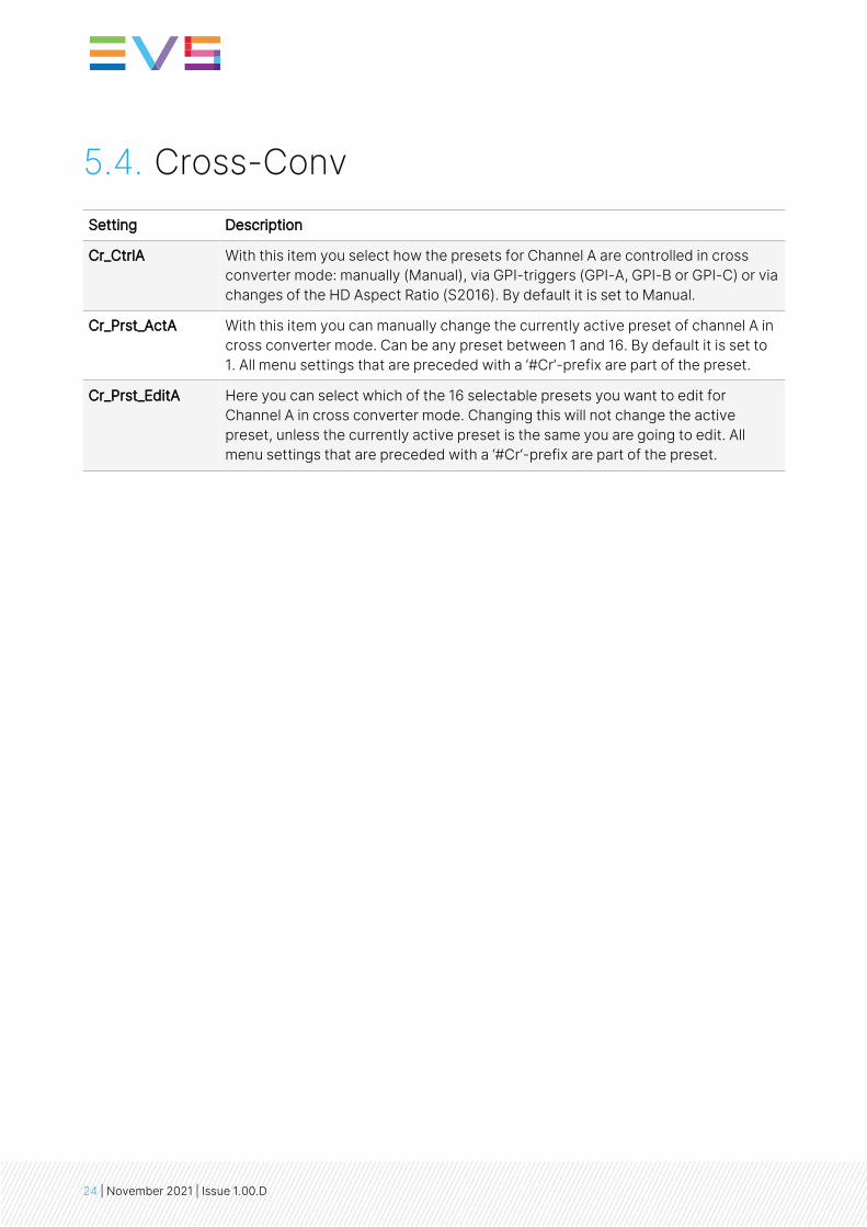
#VI-DataA With the #VI-InsertA setting set to On, you can select VI values with thissetting, which you want to be inserted. possible are all VI values from 4:3_0through 4:3_7 and the settings from 16:9_0 through 16:9_7. Default is 4:3_0.
#WSS-InsertA You can choose which type of WSS data you want to insert with thissetting, or switch WSS insertion entirely off (default value). You can set it toStandard or Extended.
With the #WSS-InsertA setting set to Extended, you can select WSS extended values fromthe #VI-DataA setting, which you want to be inserted. Possible VI settings are 4:3_0 through4:3_7 and the settings 16:9_0 through 16:9_7. Default is 4:3_0.
#WSS-StndA With the #WSS-InsertA setting set to Standard, you can select WSSstandard values with this setting, which you want to be inserted. possibleare all WSS values from 1_vid through 8_vid and the settings from 1_flmthrough 8_flm. Default is 1_vid.
#WSS-ExtndA With the #VI-InsertA setting set to Extended, you can select VI values withthis setting, which you want to be inserted. Possible WSS values are 4:3_0through 4:3_7 and the settings 16:9_0 through 16:9_7. Default is 4:3_0.
#S2016-InsertA You can turn S2016 (AFD) insertion on or off for Channel A. Default is Off.
#S2016-DataA With the #S2016-InsertA setting set to on, you can select AFD values withthis setting, which you want to be inserted. possible are all AFD values fromAFD0 through AFD15.
Ins_CtrlB With this item you select how the inserter presets for Channel A arecontrolled: Manually (manual), via GPI-triggers (GPI), via changes of the HDAspect Ratio (VI, WSS, WSS-ext or S2016 (AFD)). Default is Manual.
Ins_Prst_ActB With this item you can manually change the currently active preset ofChannel B when in transparent mode. Can be any preset between 1 and 16.By default it is set to 1. All menu settings that are preceded with a #Ins-prefix are part of the preset.
Ins_Prst_EditB Here you can select which of the 16 selectable presets you want to edit forChannel B when in a transparent mode. Changing this will not change theactive preset, unless the currently active preset is the same you are goingto edit. All menu settings that are preceded with a #Ins-prefix are part ofthe preset.
#VI-InsertB You can turn VI insertion on or off for channel B. Default is Off.
#VI-DataB With the #VI-InsertB setting set to on, you can select VI values with thissetting, which you want to be inserted in Channel B. All VI values arepossible from 4:3_0 through 4:3_7 and the settings from 16:9_0 through16:9_7. Default is 4:3_0.
#WSS-InsertB You can choose which type of WSS data you want to insert in Channel Bwith this setting, or switch WSS insertion entirely off (default value). Youcan set it to Standard or Extended.
INSTALLATION AND OPERATION MANUAL
Synapse 2XG100 | 5. Settings Menu | 31
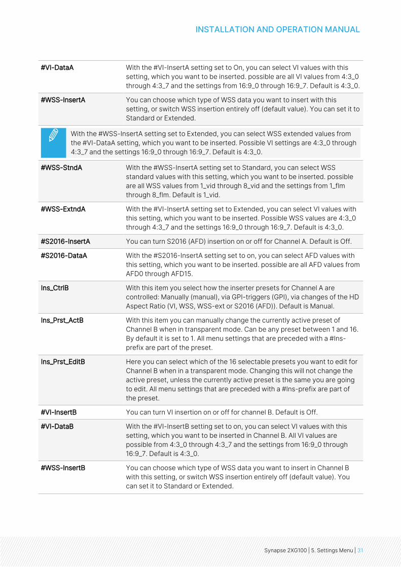
With the #WSS-InsertB setting set to Extended, you can select WSS extended values fromthe #VI-DataB setting, which you want to be inserted in Channel B. All VI settings between4:3_0 and 4:3_7 are possible and the settings between 16:9_0 and 16:9_7. Default is 4:3_0.
#WSS-StndB With the #WSS-InsertB setting set to Standard, you can select WSSstandard values with this setting, which you want to be inserted in ChannelB. possible are all WSS values from 1_vid through 8_vid and the settingsfrom 1_flm through 8_flm. Default is 1_vid.
#WSS-ExtndB With the #VI-InsertB setting set to on, you can select VI values with thissetting, which you want to be inserted in Channel B. possible are all WSSvalues between 4:3_0 and 4:3_7 and the settings between 16:9_0 and 16:9_7. Default is 4:3_0.
#S2016-InsertB You can turn S2016 (AFD) insertion on or off for Channel B. Default is Off.
#S2016-DataB With the #S2016-InsertB setting set to on, you can select AFD values withthis setting, which you want to be inserted in Channel B. possible are allAFD values from AFD0 through AFD15.
5.7. Video-ProcSetting Description
Y_Gain Y-Gain controls the Yellow gain. The control range is between 0% and 200%. Thedefault setting is 100%.
C_Gain C-Gain controls the Cyan gain. The control range is between 50% and 150%. Thedefault setting is 100%.
GainA With this setting you control the overall gain of the video between 50 and 150%.Default is 100%.
R-GainA R-GainA controls the Red gain. The control range is between 50% and 150%. Thedefault setting is 100%.
G-GainA G-GainA controls the Green gain. The control range is between 50% and 150%. Thedefault setting is 100%.
B-GainA B-GainA controls the Blue gain. The control range is between 50% and 150%. Thedefault setting is 100%.
GainB With this setting you control the overall gain of the video of channel B between 50 and150%. Default is 100%.
R-GainB R-GainB controls the Red gain of channel B. The control range is between 50% and150%. The default setting is 100%.
G-GainB G-GainB controls the Green gain of channel B. The control range is between 50% and150%. The default setting is 100%.
32 | November 2021 | Issue 1.00.D

B-GainB B-GainB controls the Blue gain of channel B The control range is between 50% and150%. The default setting is 100%.
BlackA BlackA controls the total R-G-B Black gain. The range is between –128bit and 127bit.The default setting is 0bit.
R-BlackA R-BlackA controls the Red-Black. The control range is between –128bits and 127 bitsin steps of 1 bit. The default setting is 0 bit.
G-BlackA G-BlackA controls the Green-Black. The control range is between –128bits and 127bits in steps of 1 bit. The default setting is 0 bit.
B-BlackA B-BlackA controls the Blue-Black. The control range is between –128bits and 127 bitsin steps of 1 bit. The default setting is 0 bit.
BlackB BlackB controls the total R-G-B Black gain of channel B. The control range is between–128bit and 127bit. The default setting is 0bit.
R-BlackB R-BlackB controls the Red-Black of channel B. The control range is between –128bitsand 127 bits in steps of 1 bit The default setting is 0 bit.
G-BlackB G-BlackB controls the Green-Black of channel B. The control range is between –128bits and 127 bits in steps of 1 bit The default setting is 0 bit.
B-BlackB B-BlackB controls the Blue-Black of channel B. The control range is between –128bitsand 127 bits in steps of 1 bit The default setting is 0 bit.
CVBS-Hue This item adjusts the HUE of the CVBS input. Can be set between -90 and +90degrees. Default is 0 degrees.
5.8. Audio Proc AmpSetting Description
Audio-Bus-IO This setting can change the Audio bus order from the normal 1234 (=default) to1324. The 1324 order is used to route the 1st group of audio from the 2nd inputto the 2nd channel of a slave card (like the DIO48).
Audio_Ctrl With this setting you select how the audio presets should be controlled. Can beeither Manually (Manual), via GPI-triggers (GPI, GPI-A, GPI-B or GPI-C), via theSD aspect ratio (SD-AR) or via the HD aspect ratio (S2016).
Audio_Prst_Act With this item you can manually change the currently active audio preset. Canbe any preset between 1 and 16. By default it is set to 1. All menu settings thatare preceded by the #Emb prefix are part of the preset.
Audio_Prst_Edit Here you can select which of the 16 selectable audio presets you want to edit.Changing this will not change the active preset, unless you have selected toedit the currently active preset. All menu settings that are preceded by the#Emb prefix are part of the preset.
INSTALLATION AND OPERATION MANUAL
Synapse 2XG100 | 5. Settings Menu | 33

#Audio-Dly-sInp1
(2XG110 only)
With this item you can delay all audio on input 1 between -10000ms and10000ms with 0.01ms increments, allowing for precise control (2 sampleaccuracy in practice). Default is 0ms. This item is part of the audio presets. Thisaudio delay is calculated on top of the tracked video delay.
#Audio-Dly-sInp2
(2XG110 only)
With this item you can delay all audio on input 2 between -10000ms and10000ms with 0.01ms increments, allowing for precise control (2 sampleaccuracy in practice). Default is 0ms. This item is part of the audio presets. Thisaudio delay is calculated on top of the tracked video delay.
5.9. EmbedderSetting Description
#EmbA_Grp With this setting you select into which audio group (= 4 audio channels) of theoutputs you want to embed the first 4 forwarded audio channels coming fromthe de-embedders/add-on bus. Can be group1, group2, group3 or group4.You can also choose to not use these 4 audio channels for anything by settingthis item to off. By default it is set to Group1.
#EmbA1_Inp ~#EmbA4_Inp
With these settings you can select where the corresponding audio channels(channel A1 till channel A4) of the outputs are coming from. In this card youcan choose to get the audio from the de-embedder of SDI input 1 (Demb-SDI1)or SDI input 2 (Demb-SDI2), the embedder of the active input (Demb-Input,dependent on the current active input), from the ADD-ON bus groups, or tomute the corresponding channel (set to off). Defaults here are Off.
With this card, the ADD-ON bus can only be used to either embed audio or de-embed audio.When one of the EmbXx_Inp settings is set to embed from the ADD-ON bus, no audio will bede-embedded towards the bus anymore, not for any of the channels.
#EmbA1_Inp_Ch ~#EmbA4_Inp_Ch
(2XG110 only)
With these settings you can select which Channel of the selected input shouldbe embedded to the corresponding output channel. Can be any channelbetween Ch_1 through Ch_16. Defaults for A1 through A4 are respectively Ch_1through Ch_4.
#EmbB_Grp With this setting you select into which audio group (= 4 audio channels) of theoutputs you want to embed the second 4 forwarded audio channels comingfrom the de-embedders/add-on bus. Can be group1, group2, group3 orgroup4. You can also choose to not use these 4 audio channels for anythingby setting this item to off. By default it is set to Group2.
34 | November 2021 | Issue 1.00.D

#EmbB1_Inp ~#EmbB4_Inp
With these settings you can select where the corresponding audio channels(channel B1 till channel B4) of the outputs are coming from. In this card youcan choose to get the audio from the de-embedder of SDI input 1 (Demb-SDI1)or SDI input 2 (Demb-SDI2), the embedder of the active input (Demb-Input,dependant on the current active input), from the ADD-ON bus groups, orto mute the corresponding channel (set to off). Defaults here are Off.
Note: With this card the ADD-ON bus can only be used to either embed audioor de-embed audio. When one of the EmbXx_Inp settings is set to embed fromthe ADD-ON bus, no audio will be de-embedded towards the bus anymore,not for any of the channels.
#EmbB1_Inp_Ch ~#EmbB4_Inp_Ch
(2XG110 only)
With these settings you can select which Channel of the selected input shouldbe embedded to the corresponding output channel. Can be any channelbetween Ch_1 and Ch_16. Defaults for B1 till B4 are respectively Ch_5 till Ch_8.
#EmbC_Grp With this setting you select in to which audio group (= 4 audio channels) of theoutputs you want to embed the third group of 4 forwarded audio channelscoming from the de-embedders/add-on bus. Can be group1, group2, group3or group4. You can also choose to not use these 4 audio channels for anythingby setting this item to off. By default it is set to Group2.
#EmbC1_Inp ~#EmbC4_Inp
With these settings you can select where the corresponding audio channels ofthe outputs are coming from. In this card you can choose to get the audio fromthe de-embedder of SDI input 1 (Demb-SDI1) or SDI input 2 (Demb-SDI2), theembedder of the active input (Demb-Input, dependent on the current activeinput), from the ADD-ON bus groups, or to mute the corresponding channel(set to off). Defaults here are Off.
Note: With this card the ADD-ON bus can only be used to either embed audioor de-embed audio. When one of the EmbXx_Inp settings is set to embed fromthe ADD-ON bus, no audio will be de-embedded towards the bus anymore,not for any of the channels.
#EmbC1_Inp_Ch ~#EmbC4_Inp_Ch
(2XG110 only)
With these settings you can select which Channel of the selected input shouldbe embedded to the corresponding output channel. Can be any channelbetween Ch_1 and Ch_16. Defaults for C1 till C4 are respectively Ch_9 till Ch_12.
#EmbD_Grp With this setting you select in to which audio group (= 4 audio channels) of theoutputs you want to embed the last 4 forwarded audio channels coming fromthe de-embedders/add-on bus. Can be group1, group2, group3 or group4.You can also choose to not use these 4 audio channels for anything by settingthis item to off. By default it is set to Group2.
INSTALLATION AND OPERATION MANUAL
Synapse 2XG100 | 5. Settings Menu | 35

#EmbD1_Inp ~#EmbD4_Inp
With these settings you can select where the corresponding audio channels ofoutputs B are coming from. In this card you can choose to get the audio fromthe de-embedder of SDI input 1 (Demb-SDI1) or SDI input 2 (Demb-SDI2), theembedder of the active input (Demb-Input, dependent on the current activeinput), from the ADD-ON bus groups, or to mute the corresponding channel(set to off). Defaults here are Off.
Note: With this card the ADD-ON bus can only be used to either embed audioor de-embed audio. When one of the EmbXx_Inp settings is set to embed fromthe ADD-ON bus, no audio will be de-embedded towards the bus anymore,not for any of the channels.
#EmbD1_Inp_Ch ~#EmbD4_Inp_Ch
(2XG110 only)
With these settings you can select which Channel of the selected input shouldbe embedded to the corresponding output channel. Can be any channelbetween Ch_1 and Ch_16. Defaults for C1 till C4 are respectively Ch_13 till Ch_16.
#EmbA1_Gain ~#EmbD4_Gain
(2XG110 only)
Adjusts the gain for the corresponding audio channel between -60 and 12dB.Everything below -999 dB means the audio will be muted.
#EmbA1_Phase ~#EmbD4_Phase
(2XG110 only)
Adjusts the audio phase of the corresponding to 0 deg or 180 deg.
5.10. GPI ModeSetting Description
Contact_1 ~Contact_5
In this card it is possible to make the 5 available GPI triggers part of a GPI poolthat can control the various functions in the card separately (all Xx_Ctrl items ofthe menu). With these items you can select which pool the corresponding GPI ispart of. You can also choose to not use the corresponding GPI at all by setting itto Off. Possible settings are:
• GPI A: part of GPI-A pool, triggered once Take A is closed.
• GPI B: part of GPI-B pool, triggered once Take B is closed.
• GPI C: part of GPI-C pool, triggered once Take C is closed.
Please refer to "GPIs Explained" for a more elaborate explanation of the GPIsettings.
36 | November 2021 | Issue 1.00.D

GPI_A-Mode ~
GPI_C-Mode
Selects the mode for the corresponding GPI pool. Possible settings are:
• Prio: Each contact triggers another value, so values are one- hot encoded.
• Prio_latched: This mode functions like Prio Mode, but the card latches thevalue. Each contact triggers another value, so values are one-hot encoded.Use this mode when using pushbuttons.
• Binary: Values are coded in a binary fashion, with code “00000” coding for astarting value of 1, as can be seen in the GPI status items.
Please refer to "GPIs Explained" for a more elaborate explanation of the GPIsettings.
GPI_A-Take ~
GPI_C-Take
Selects a take contact for the corresponding GPI pool. Possible settings are:
• Off: No take contact is defined, and values on the GPI contact are takeninstantly.
• Contact_1 ~ Contact_5: The selected contact is used as a Take command forthe corresponding pool. Closing the selected contact results in the cardlatching the value provided on the selected contacts for that pool.
Please refer to "Appendix 1: GPIs Explained" on page 48 for a more elaborateexplanation of the GPI settings.
GPI-DebounceTime This setting allows you to specify the permitted delay for valid signals on all GPIs(general purpose inputs). Values can be from 1ms through 40ms. default is10ms.
5.11. NetworkSetting Description
IP_Conf0 With this setting you can either let the card obtain an IP address automatically viaDHCP, or assign an IP address manually.
By default this is set to DHCP.
mGW0 With IP_Conf0 set to manual, this setting lets you set a Standard Gateway.Default is set to 0.0.0.0.
mIP0 When IP_Conf0 is set to manual, you can enter the preferred IP address here. Bydefault it is set to 0.0.0.0
NetwPrefix0 Here you can set the specific network prefix if required.
mNM0 With IP_Conf0 set to manual, with this setting you can set a Netmask. Default is0.0.0.0
INSTALLATION AND OPERATION MANUAL
Synapse 2XG100 | 5. Settings Menu | 37

6. Status MenuIntroduction
The Status menu provides information about the current status of each item listed below.
6.1. System StatusItem Description
sInp1 This status item indicates the presence and format of a valid signal in input 1.This is displayed as:
• 1080p60 • 720p60 • 1080i60• 1080p50 • 720p50 • 1080i50• 1080p30 • 720p30 • 1035i60• 1080p25 • 720p25 • SD625• 1080p24 • 720p24 • SD525
• NA
sInp1_VI Displays the detected VI value found in input 1. This is displayed as follows:
• 4:3_0 • 16:9_0• 4:3_1 • 16:9_1• 4:3_2 • 16:9_2• 4:3_3 • 16:9_3• 4:3_4 • 16:9_4• 4:3_5 • 16:9_5• 4:3_6 • 16:9_6• 4:3_7 • 16:9_7• NA (no VI detected)
38 | November 2021 | Issue 1.00.D

sInp1_WSS-Stnd This status item displays the detected standard WSS value of input 1. This isdisplayed as follows:
• 1_vid • 1_flm• 2_vid • 2_flm• 3_vid • 3_flm• 4_vid • 4_flm• 5_vid • 5_flm• 6_vid • 6_flm• 7_vid • 7_flm• 8_vid • 8_flm• NA (no standard WSS detected)
sInp1_WSS-Extd This item displays the detected extended WSS value of input 1. This isdisplayed as follows:
• 4:3_0 • 16:9_0• 4:3_1 • 16:9_1• 4:3_2 • 16:9_2• 4:3_3 • 16:9_3• 4:3_4 • 16:9_4• 4:3_5 • 16:9_5• 4:3_6 • 16:9_6• 4:3_7 • 16:9_7• NA (no WSS extended detected)
sInp1_s2016 This item displays the detected SMPTE 2016 (AFD) values of input 1. This isdisplayed as follows:
• AFD0 • AFD8• AFD1 • AFD9• AFD2 • AFD10• AFD3 • AFD11• AFD4 • AFD12• AFD5 • AFD13• AFD6 • AFD14• AFD7 • AFD15• NA (no S2016 detected)
sInp1_CRC_EDH This item indicates CRC and EDH errors on input 1. Can be:
• OK • Error• NA
sInp1_Map This indicates the mapping of the 3Gb/s input 1 when the input format is1080p50 or 1080p60. Can be Level A or Level B. When the input format is not3Gb/s, this item indicates NA.
INSTALLATION AND OPERATION MANUAL
Synapse 2XG100 | 6. Status Menu | 39

sInp2 This status item indicates the presence and format of a valid signal in input2. This is displayed as listed under sInp1.
sInp2_VI Displays the detected VI value found in input 2. This is displayed as listedunder sInp1_VI.
sInp2_WSS-Stnd Displays the detected WSS-standard value found in input 2. This isdisplayed as listed under sInp1_WSS-Stnd.
sInp2_WSS-Extnd Displays the detected WSS-extended value found in input 2. This isdisplayed as listed under sInp1_WSS-ext.
sInp2_s2016 Displays the detected S2016 value found in input 2. This is displayed aslisted under sInp1_s2016.
sInp2_CRC_EDH This item indicates CRC and EDH errors on input 2. Can be:
• OK
• Error
• NA
sInp2-Map Displays the mapping of the 3Gb/s input, if the format is 1080p50 or1080p60 on input 2. Can be Level A or Level B. NA is indicated if the input isnot 3Gb/s.
sInp3_WSS-Stnd Displays the detected WSS-standard value found in input3 (CVBS input).This is displayed as listed under sInp1_WSS-Stnd.
sInp3_WSS-Extnd Displays the detected WSS-extended value found in input3 (CVBS input).This is displayed as listed under sInp1_WSS-ext.
sInpCVBS This status item indicates the detected input format on the CVBS input. Thisis displayed as one of the following values:
• NTSC-J • PAL-BGHID• NTSC-M • PAL-N• NTSC-4.43 • PAL-M• SECAM • PAL-60• SECAM-525 • NA (no input detected)
IODelayA Displays the total delay in ms of outputs A1 and A2. Can be a value between0ms and 15000 ms.
IODelayB Displays the total delay in ms of outputs B1 and B2. can be a value between0ms and 15000ms.
FunctionA Displays the current function outputs A1 and A2. For the card it can only beTrans, TestPattern or NA.
FunctionB Displays the current function outputs B1 and B2. For the card it can only beTrans, TestPattern or NA.
Ref Displays whether a correct reference is found (Present) or not (NA).
40 | November 2021 | Issue 1.00.D

Contact-Status Displays the currently closed GPI contacts. This is displayed as for instance10100 when contacts 1 and 3 are closed and for instance 01110 whencontacts 2, 3 and 4 are closed.
GPI_A Displays the current value of GPI pool A.
GPI_B Displays the current value of GPI pool B.
GPI_C Displays the current value of GPI pool C.
SDI1DemFrmt01/02 ~
SDI1DemFrmt15/16
These status items indicate the detected audio format of each audio pair inthe de-embedder of SDI input 1. Can be one of the following formats:
• NA (default) • PCM• Null • AC-3• TimeStmp • SMPTE-KLV• MPEG-1 • MPEG-2• Dolby E • Caption data• UserDef • Rsvd• Enh AC-3
SDI2DemFrmt01/02 ~
SDI2DemFrmt15/16
These status items indicate the detected audio format of each audio pair inthe de-embedder of SDI input 2. Can be one of the following formats:
• NA (default) • PCM• Null • AC-3• TimeStmp • SMPTE-KLV• MPEG-1 • MPEG-2• Dolby E • Caption data• UserDef • Rsvd• Enh AC-3
6.2. Net StatusSetting Description
IP_Addr0 This item displays the status of the IP address. It can be manual, DHCP asking(default), DHCP Leased or DHCP Infin.
MAC0 This item displays the MAC address of the card.
IP0 This item displays the current IP address of the card.
NM0 This item displays the current Netmask of the card.
GW0 This item displays the current Standard Gateway of the card.
INSTALLATION AND OPERATION MANUAL
Synapse 2XG100 | 6. Status Menu | 41

7. Events MenuIntroduction
An event is a special message that is generated on the card asynchronously. This means that it is not theresponse to a request to the card, but a spontaneous message.
What is the Goal of an Event?
The goal of events is to inform the environment about a changing condition on the card. A message maybe broadcast to mark the change in status. The message is volatile and cannot be retrieved from thesystem after it has been broadcast. There are several means by which the message can be filtered.
The events reported by the 2XG100-110 card are as follows:
Menu Item Description
Announcements Announcements is not an event. This item is only used for switching theannouncement of status changes on/off. 0=off, other =on
Input_A Input_A can be selected between 0 .. 255. 0= no event, 1..255 is the priority setting.
Input_B Input_B can be selected between 0 .. 255. 0= no event, 1..255 is the priority setting.
Ref-Status Reference can be selected between 0 .. 255. 0= no event, 1..255 is the prioritysetting.
Active_Out_A Active output A can be selected between 0 .. 255. 0= no event, 1..255 is the prioritysetting.
Active_Out_B Active output B can be selected between 0 .. 255. 0= no event, 1..255 is the prioritysetting.
What Information is Available in an Event?
The message consists of the following items:
• A message string to show what has happened in text, for example: “INP_LOSS”, “REF_LOSS”, “INP_RETURN”.
• A tag that also shows what happens, but with a predefined number: e.g. 1 (= loss of input), 2 (= lossof reference), 129(= 1+128 = return of input). For a list of these predefined tags, please see the tablebelow.
• A priority that marks the importance of an event. This value is defined by the user and can have anyvalue between 1 and 255, or 0 when disabled.
• A slot number of the source of this event.
42 | November 2021 | Issue 1.00.D

Message String
The message string is defined in the card and is therefore fixed. It may be used in controlling softwarelike Synapse Set-up to show the event.
Tags
The tag is also defined in the card. The tag has a fixed meaning. When controlling or monitoring softwareshould make decisions based on events, it is easier to use the tag instead of interpreting a string. Thefirst implementation is the tag-controlled switch in the GPI16.
In cases where the event marks a change to fault status (e.g. 1 for Loss of Input), the complement ismarked by the tag increased by 128 (80hex) (e.g. 129 (81hex) for Return of Input).
The tags defined for the 2XG100-110 card are:
Event Menu Item Tag Description
Announcements 01hex=Announcementson
81hex=Announcementsoff
Announcement of report andcontrol values
Input_A 01hex=INP_A_LOSS 81hex=INP_A_RETURN Input A lost or returned
Input_B 41hex=INP_B_LOSS c1hex= INP_B_RETURN Input B lost or returned
Ref-Status 02hex=REF_LOSS 82hex=REF_RETURN Reference lost or returned
Active_Out_A 19hex=IN_B->OUT_A 99hex= IN_A->OUT_A Input B or input A on outputs A
Active_Out_B 1ahex= IN_A->OUT_B 9ahex=IN_B->OUT_B Input A or input B on outputs B
Priority
The priority is a user-defined value. The higher the priority of the alarm, the higher this value will be.Setting the priority to Zero disables the announcement of this alarm. Alarms with priorities equal to orhigher than the Error Threshold setting of the RRC will cause the error LED on the Synapse rack frontpanel to light up.
Card Address
Together with the message string or the tag, the slot number or address of the card is relevant to beable to assign the event to a certain card.
INSTALLATION AND OPERATION MANUAL
Synapse 2XG100 | 7. Events Menu | 43

8. LED IndicationIndicator Description
Error LED The error LED indicates an error if the internal logic of the card is not configuredcorrectly or has a hardware failure.
Input_A LED This LED indicates the presence of a valid SDI video signal on input A.
Input_B LED This LED indicates the presence of a valid SDI video signal on input B.
ANC Data LED Indicates the presence of embedded audio within the input signal.
Reference LED Indicates the presence of a valid reference signal on the selected reference inputconnector (ref-1 or ref-2).
Data Error LED This LED indicates a CRC error.
Connection LED This LED lights up after the card has initialized. The LED lights up for 0.5 secondsevery time a connection is made to the card.
44 | November 2021 | Issue 1.00.D

9. Block Schematic
INSTALLATION AND OPERATION MANUAL
Synapse 2XG100 | 9. Block Schematic | 45

10. Connector PanelsThe 2XG100-110 can be used with the BPH17 or the BHX17b and their relay bypass equivalents.
The following diagrams show the pinout of the backpanels in combination with the card.
BPH17 BHX17b
HD/SD SDI INPUT 1
HD/SD-SDI INPUT 2
HD/SD-SDI PROCESSED OUTPUT A1
HD/SD-SDI PROCESSED OUTPUT A2
GPI INPUT/OUTPUT
HD/SD-SDI PROCESSED OUTPUT B1
HD/SD-SDI PROCESSED OUTPUT B2
CVBS INPUT
For fiber connectivity, see www.evs.com
Unused inputs and outputs must be terminated with the correct impedance.
Please refer to "Card Dip Switches for BHX and Fiber Configurations" in the Appendices beforeconnecting any backpanel.
46 | November 2021 | Issue 1.00.D

GPI Pinning
Pin Function1 GPI in 12 GPI in 23 GPI in 34 GPI in 45 GPI in 56 GPI out 17 GPI out 28 Ground
INSTALLATION AND OPERATION MANUAL
Synapse 2XG100 | 10. Connector Panels | 47

Appendices
Appendix 1: GPIs Explained
Introduction
This appendix describes the functionality of the GPIs that are generally used within Synapse-basedproducts.
General Functionality
The physical contacts of a General Purpose Interface can be assigned by the user. In our cards theGeneral Purpose Interface contacts (GPI contacts) will be named as General Purpose Input (GPI) orGeneral Purpose Output (GPO). The GPI inputs and outputs are assignable to different preset banks.These preset banks (GPI pools) can be used to switch multiple settings at once.
Some examples of these functions are:
• Input selection
• Output mode
• Up conversion aspect ratio for channel A and B
• Down conversion aspect ratio for channel A and B
• Cross conversion aspect ratio for channel A and B
• Transparent aspect ratio (equal in-output) for channel A and B
• Insertion of VI, WSS, AFD (S2016) for channel A and B
• Audio shuffling, gain and phase.
Contact Assignment
The physical contacts can be assigned as input or output. In the menu of a card, these will be calledContact_N depending on the amount of contacts available. Contacts could be inputs, outputs or bi-directional I/O. The Contact_N menu item will be used to assign this specific contact to input or outputpools. The choices are Off, GPI_A, GPI_B, GPI_C, etc. to GPI_N, GPO_A, GPO_B, GPO_C, etc. to GPO_N,depending on the amount of contacts and pools.
48 | November 2021 | Issue 1.00.D

Pools
A GPI/GPO pool is a place where contacts are collected to form an output trigger.
Take
The GPI contacts not only can be used as GPI contact but also can be assigned as Take contact. Themenu item is called GPI_n-Take. Where n is the amount of GPI pools in the product. Every pool can onlyhave one Take contact. There will be no restrictions in assigning the contact to a GPI pool and Takefunction at the same time. The values will be 1 to x. When assigning a take pin to a pool set to Prio_Latched mode, the pool will behave the same as when set to Prio mode with a take pin assigned. This isbecause the take pin overrules the latched functionality of the Prio_Latched mode.
Pool Mode: GPI
Every GPI pool can be set up to process the input contacts in three ways. This setting is called GPI_n-Mode and can be set into priority (Prio), priority latched (Prio_Latched) and Binary mode. N is defined asa character in the range from A-Z depending on the number of pools. The default output value of a poolis always 0. This translates to preset 1 in EVS products.
In priority mode, the contact which has the highest priority defines the pool value. Priority is defined asranging from the least significant bit (low priority) to the most significant bit (high priority). This isessentially a one-hot coding of preset values.
If a pool has three contacts connected and all inputs are high, the output value of the pool will be 3.Another example is when three contacts are connected to a pool with the first and third contact are lowand the second contact is high the output value is 1.
Input 1 Input 2 Input 3 Pool Value Preset no.
0 0 0 1 1
1 0 0 1 1
X 1 0 2 2
X X 1 3 3
Table 1. Pool value in prio and prio_latched mode
INSTALLATION AND OPERATION MANUAL
Synapse 2XG100 | Appendix 1: GPIs Explained | 49

In binary mode, the contacts are interpreted as a binary value of concatenated contacts available in apool. e.g. assigning two contacts to a GPI pool translates to the following output values.
Input 1 Input 2 Pool Value Preset no.
0 0 1 1
0 1 2 2
1 0 3 3
1 1 4 4
Table 2. Pool value in binary mode
Pool Mode: GPO
Every GPO pool can be set up to process the input values in two ways.
This setting is called GPO_n-Mode and can be set into Priority (Prio) or Binary mode. N is defined as acharacter in the range from A-Z depending on the number of pools. The default output value of a pool isalways 0.
In priority mode, the value is translated to one-shot encoding on the output contacts. See the tablebelow:
Preset nr Output 1 Output 2 Output 3 Pool Value
1 1 0 0 1
2 0 1 0 2
3 0 0 1 3
Table 3. Pool value in priority mode
50 | November 2021 | Issue 1.00.D

In binary mode, the input value is exposed on the output contacts as a binary value.
Preset nr Output 1 Output 2 Pool Value
1 0 0 1
2 0 1 2
3 1 0 3
4 1 1 4
Table 4. Pool value in binary mode
GPO_n-Source is the setting with which a function is assigned to a GPO pool. e.g. When the outputformat needs to be reflected on the output contacts, this setting may be set to something like Output_Format. The contents of the enumeration are product specific.
Statuses: Contact Direction
This status Contact-Dir shows the direction of the physical contacts. The value will be presented as aconcatenated string containing one character per pin: I for Input, O for output and _ for unassignedcontacts.
Statuses: Contact Status
Contact-Status shows the current logical value of the physical contacts, formatted as a concatenatedstring containing one character per pin: 1 for asserted, 0 for non-asserted and _ for unassigned.
Statuses: GPI Status
GPI_n is an integer which reflects the value of the pool.
Statuses: GPO Status
GPO_n is an integer which reflects the value of the pool.
INSTALLATION AND OPERATION MANUAL
Synapse 2XG100 | Appendix 1: GPIs Explained | 51

Example 1: Two Pools in Binary Mode
To control the up converter presets using Pool A (Up_CtrlA set to GPI-A) and the output mode settingusing Pool B (Out-mode-Ctrl set to GPI-B), with both pools working in priority mode, the GPIs have to beset up as follows:
• Set GPI_A-Mode to Prio
• Set Contact_1 to GPI_A
• Set Contact_2 to GPI_A
• Set Contact_3 to GPI_A
• Set Contact_4 to GPI_A
• Set GPI_B-Mode to Prio
• Set Contact_5 to GPI_B
Pool A now consists of GPI 1, GPI 2, GPI 3 and GPI 4 in priority mode, controlling the Up converter preset.Pool B consists only of GPI 5 (also in priority mode), controlling the Output mode setting.
Pool A now works as follows:
Contact_1
Status
Contact_2
Status
Contact_3
Status
Contact_4
Status
GPI_A
Value
0 0 0 0 Up-conv Preset 1
1 0 0 0 Up-conv Preset 1
0 1 0 0 Up-conv Preset 2
0 0 1 0 Up-conv Preset 3
0 0 0 1 Up-conv Preset 4
0 1 1 0 Up-conv Preset 3 (becausehighest takes priority)
1 1 1 1 Up-conv Preset 4 (becausehighest takes priority)
Table 5. Pool value in priority mode
Pool B now works as follows:
Contact 5 Status GPI_BValue
0 A out only
1 B out only
Table 6. Pool value in priority mode
52 | November 2021 | Issue 1.00.D

Example 2: One Pool in Binary Mode and One in Priority Mode
Let’s say we would like to control the GXG up-converter presets using Pool A (Up_CtrlA set to GPI-A) inbinary mode and the audio presets using Pool B (Audio_Ctrl set to GPI-B) in priority mode. We could dothe following:
• Set GPI_A-Mode to binary
• Set Contact_1 to GPI_A
• Set Contact_2 to GPI_A
• Set GPI_A-Take to Contact_3
• Set GPI_B-Mode to Prio
• Set Contact_4 to GPI_B
• Set Contact_5 to GPI_B
Pool A now consists of GPI 1, GPI 2 and GPI 3 (as take), in a binary mode, controlling the Up converterpreset. Pool B now consists of GPI 4 and GPI 5 in a priority mode, controlling the audio presets.
Pool A now works as follows:
Contact 1 Status Contact 2 Status Preset Value (when Contact_3 (take) is closed)
0 0 Up-converter Preset 1
1 0 Up-converter Preset 2
0 1 Up-converter Preset 3
1 1 Up-converter Preset 4
Table 7. Pool value in binary mode
Pool B now works as follows:
Contact 4 Status Contact 5 Status Preset Value
0 0 Audio Preset 1
1 0 Audio Preset 1
0 1 Audio Preset 2
1 1 Audio Preset 2 (because highest takes priority)
Table 8. Pool value in priority mode
INSTALLATION AND OPERATION MANUAL
Synapse 2XG100 | Appendix 1: GPIs Explained | 53

Example 3: Two Pools in Priority Mode
Let’s say we would like to control the up-converter presets using Pool A (Up_CtrlA set to GPI-A) inpriority mode and the audio presets using Pool B (Audio_Ctrl set to GPI-B) in priority mode. We could dothe following:
• Set GPI_A-Mode to Prio
• Set Contact_1 to GPI_A
• Set Contact_2 to GPI_A
• Set GPI_B-Mode to Prio
• Set Contact_3 to GPI_B
• Set Contact_4 to GPI_B
Pool A now consists of GPI 1 and GPI 2 in a priority mode, controlling the Up converter preset. Pool B nowconsists of GPI 3 and GPI 4 in priority mode, controlling the audio presets.
54 | November 2021 | Issue 1.00.D

Pool A now works as follows:
Contact 1 Status Contact 2 Status Preset Value
0 0 Up-converter Preset 1
1 0 Up-converter Preset 1
0 1 Up-converter Preset 2
1 1 Up-converter Preset 2 (because highest takes priority)
Table 9. Pool value in priority mode
Pool B now works as follows:
Contact 3 Status Contact 4 Status Preset Value
0 0 Audio Preset 1
1 0 Audio Preset 1
0 1 Audio Preset 2
1 1 Audio Preset 2 (because highest takes priority)
Table 10. Pool value in priority mode
INSTALLATION AND OPERATION MANUAL
Synapse 2XG100 | Appendix 1: GPIs Explained | 55

Appendix 2: Card Dip Switches for BHX andFiber ConfigurationsThere are dip switches on the circuit board of the card itself. With these dip switches you can changethe power voltages that is put on the backpanel. By default the switches are set to off, putting no poweron the backpanel. The picture below displays where the switch is positioned on the card.
When using a ‘normal’ BPH17 (passive) backpanel with this card, the dip switch on the carditself must be switchedOFF.
Using BPH17 with Fiber I/O
When using a BPH17 backpanel with fiber I/O, you must first set the top-side dip switch on the synapseboard toON. This will pass 30 volt to the backpanel. If this is not done, the relays won’t work at all.
Using BHX17b
When using the backpanel with a bypass relay (BHX17b), you must first set the bottom-side dip switchon the card toON. This will pass 5 volts to the backpanel. If this is not done, the relays won’t work at all.
On the BHX17b itself, there are also 2 dip switches (see picture below). The bottom dip switch is notconnected. With the top switch you can choose the Bypass function. There are 2 possible functionindications “on” (printed on the dip switch itself) and “off”:
56 | November 2021 | Issue 1.00.D

“Direct Backpanel Switchover” dip switch set to ON:
Will make the BHX backpanel switch over to the processed signal as soon as it detects the trigger signalfrom the connected Synapse card. This setting will minimize the bypass time and ensures fast recoveryof processed signals.
TheON setting is recommended if the BHX backpanel is used in combination with Synapse cards:
• which have a short initialization time, or
• which have a delayed trigger-signal onboard.
“Direct Backpanel Switchover” dipswitch set to OFF (default):
Will make the BHX backpanel switch after about 15 seconds from the moment the BHX backpaneldetects the trigger signal from the connected Synapse card. This setting will allow more time forcomplex synapse cards to finish initialization and stabilize proper signal processing before thebackpanel switches over to the processed signal.
TheOFF setting is recommended if the BHX-backpanel is used in combination with Synapse cards:
• which are more complex and thus need a longer initialization time and do NOT have a delayed triggersignal onboard.
In case of power failure or when the Synapse board is extracted from the frame, the bypass isimmediately active.
INSTALLATION AND OPERATION MANUAL
Synapse 2XG100 | Appendix 2: Card Dip Switches for BHX and Fiber Configurations | 57

GNU Public License
Open-Source Software
This product contains open-source software licensed under the GNU Public License (GPL). A copy ofthe GNU Public License can be obtained from https://www.gnu.org/licenses/old-licenses/gpl-2.0.html.Under this license, you are eligible to receive a copy of the source code of this software, including anychanges.
EVS Broadcast Equipment SA shall provide the source code on request either through physicaldistribution or electronic communication. For physical distribution you may be charged a fee that coversdistribution costs. This offer is valid up to three years after date of purchase. Please direct your requestto the support department of EVS Broadcast Equipment SA.
EVS Broadcast Equipment SA supports open-source software by participating in the development ofopen-source projects or submitting improvements to these projects. For more information, please visithttps://mi-sftp.evs.com.
58 | November 2021 | Issue 1.00.D