Surface designing of carbon fabric polymer composites with nano and micron sized PTFE particles
8
Surface designing of carbon fabric polymer composites with nano and micron sized PTFE particles Mohit Sharma • Jayashree Bijwe Received: 16 January 2012 / Accepted: 21 February 2012 / Published online: 13 March 2012 Ó Springer Science+Business Media, LLC 2012 Abstract The new technique to tailor carbon fabric- polyethersulphone (CF-PES) composite surface with polytetrafluoroethylene (PTFE) nano particles; to improve wear performance has been reported. Cold remote nitrogen oxygen plasma (CRNOP) treatment was employed to alter the CF surface to promote fiber/matrix adhesion and fur- ther; inter laminar shear strength and wear performance of the composites. The atomic force microscopy and high resolution transmission microscopy; studies confirms the topographical modification on the fiber surface due to CRNOP treatment. The dipper ridges and perforations introduced on the fiber surface were analyzed with field emission scanning electron microscopy. The PTFE parti- cles film formation on the worn composite surface was supportively analyzed by Raman spectroscopy and energy dispersive X-ray techniques. The topographical smooth- ening and rolling effect during the wearing of surface designed composites with PTFE nano particles; endorse to enhance its sliding wear properties and life. Introduction Polymers form very important class of engineering tribo- materials, especially for dry bearings or gears applications [1, 2]. However, polymers are mostly used in composite form with the reinforcements such as fibers/fabrics of carbon, glass, Aramid etc., and solid lubricants (SLs) such as PTFE, graphite etc., in right amount and combinations. SLs have very low surface energy, which enhance the tri- bological performance of a composite at the cost of strength. Tribology is a science of surfaces and hence it is wise to tailor the surface with various fillers rather than incorporating these in the bulk and sacrificing the impor- tant strength properties of an engineering component apart from increasing the cost. However, efforts in this direction are numbered [3]. A series of composites using commin- gled fibers of carbon and Polyetheretherketone (PEEK) was developed with designing the surfaces with various SLs (micron sized) such as PTFE, graphite, MoS 2 and copper powder either in isolation or in combination in different proportions in top layers. It was reported that the tribo- performance got enhanced significantly without apprecia- ble loss in strength of a composite [3]. Use of nano scale fillers especially nano-SLs in the polymer composites has become very attractive solution for enhancing friction and wear performance as compared to micron or sub-micron sized fillers. A lot is reported on the nano-composites for tribological exploitation; however, no literature is available on inclusion of nanoparticles (NPs) or SLs for surface tailoring which could be very wise solution for engineering of the composite surfaces [4–6]. While designing the advanced composites, carbon fiber reinforcement is most preferred because of its excellent performance to cost ratio. The only limitation of its inert- ness towards matrix is overcome by surface treatment with Electronic supplementary material The online version of this article (doi:10.1007/s10853-012-6367-5) contains supplementary material, which is available to authorized users. M. Sharma J. Bijwe (&) Industrial Tribology Machine Dynamics and Maintenance Engineering Centre (ITMMEC), Indian Institute of Technology Delhi, Hauz Khas, New Delhi 110016, India e-mail: [email protected] M. Sharma Leibniz-Institut fu ¨r Polymerforschung Dresden e.V., Hohe Strasse 6, 01069 Dresden, Germany 123 J Mater Sci (2012) 47:4928–4935 DOI 10.1007/s10853-012-6367-5
-
Upload
independent -
Category
Documents
-
view
0 -
download
0
Transcript of Surface designing of carbon fabric polymer composites with nano and micron sized PTFE particles
Surface designing of carbon fabric polymer composites with nanoand micron sized PTFE particles
Mohit Sharma • Jayashree Bijwe
Received: 16 January 2012 / Accepted: 21 February 2012 / Published online: 13 March 2012
� Springer Science+Business Media, LLC 2012
Abstract The new technique to tailor carbon fabric-
polyethersulphone (CF-PES) composite surface with
polytetrafluoroethylene (PTFE) nano particles; to improve
wear performance has been reported. Cold remote nitrogen
oxygen plasma (CRNOP) treatment was employed to alter
the CF surface to promote fiber/matrix adhesion and fur-
ther; inter laminar shear strength and wear performance of
the composites. The atomic force microscopy and high
resolution transmission microscopy; studies confirms the
topographical modification on the fiber surface due to
CRNOP treatment. The dipper ridges and perforations
introduced on the fiber surface were analyzed with field
emission scanning electron microscopy. The PTFE parti-
cles film formation on the worn composite surface was
supportively analyzed by Raman spectroscopy and energy
dispersive X-ray techniques. The topographical smooth-
ening and rolling effect during the wearing of surface
designed composites with PTFE nano particles; endorse to
enhance its sliding wear properties and life.
Introduction
Polymers form very important class of engineering tribo-
materials, especially for dry bearings or gears applications
[1, 2]. However, polymers are mostly used in composite
form with the reinforcements such as fibers/fabrics of
carbon, glass, Aramid etc., and solid lubricants (SLs) such
as PTFE, graphite etc., in right amount and combinations.
SLs have very low surface energy, which enhance the tri-
bological performance of a composite at the cost of
strength. Tribology is a science of surfaces and hence it is
wise to tailor the surface with various fillers rather than
incorporating these in the bulk and sacrificing the impor-
tant strength properties of an engineering component apart
from increasing the cost. However, efforts in this direction
are numbered [3]. A series of composites using commin-
gled fibers of carbon and Polyetheretherketone (PEEK) was
developed with designing the surfaces with various SLs
(micron sized) such as PTFE, graphite, MoS2 and copper
powder either in isolation or in combination in different
proportions in top layers. It was reported that the tribo-
performance got enhanced significantly without apprecia-
ble loss in strength of a composite [3].
Use of nano scale fillers especially nano-SLs in the
polymer composites has become very attractive solution
for enhancing friction and wear performance as compared
to micron or sub-micron sized fillers. A lot is reported on
the nano-composites for tribological exploitation; however,
no literature is available on inclusion of nanoparticles
(NPs) or SLs for surface tailoring which could be very wise
solution for engineering of the composite surfaces [4–6].
While designing the advanced composites, carbon fiber
reinforcement is most preferred because of its excellent
performance to cost ratio. The only limitation of its inert-
ness towards matrix is overcome by surface treatment with
Electronic supplementary material The online version of thisarticle (doi:10.1007/s10853-012-6367-5) contains supplementarymaterial, which is available to authorized users.
M. Sharma � J. Bijwe (&)
Industrial Tribology Machine Dynamics and Maintenance
Engineering Centre (ITMMEC), Indian Institute of Technology
Delhi, Hauz Khas, New Delhi 110016, India
e-mail: [email protected]
M. Sharma
Leibniz-Institut fur Polymerforschung Dresden e.V., Hohe
Strasse 6, 01069 Dresden, Germany
123
J Mater Sci (2012) 47:4928–4935
DOI 10.1007/s10853-012-6367-5
various methods [7, 8]. Cold remote nitrogen oxygen
plasma (CRNOP) is a very recent technique [9, 10] and has
been explored by the group recently for CF [11, 12].
However, changes in the CF on nano-scale due to such
treatment were not reported in details and hence presented
in this research paper.
In this work, the concept of surface engineering of a
composite with PTFE of varying sizes (from nano to micro
scale) is explored by developing a series of composites
with CF (untreated and CRNOP treated) and polyether-
sulphone (PES). In depth investigations are reported on the
induced distortions in the CF due to treatment along with
the mechanical and tribological performance of surface
engineered CRNOP treated composites.
Experimental
Materials
The carbon fabric (CF) was procured from Fibre Glast
Development Corp. USA. PES polymer Veradel 3600P
was supplied by Solvay Advanced Polymers, India in
powder form. PTFE powders of three sizes (50–80 nm,
150–200 nm and 450–500 nm) were supplied by Shanghai
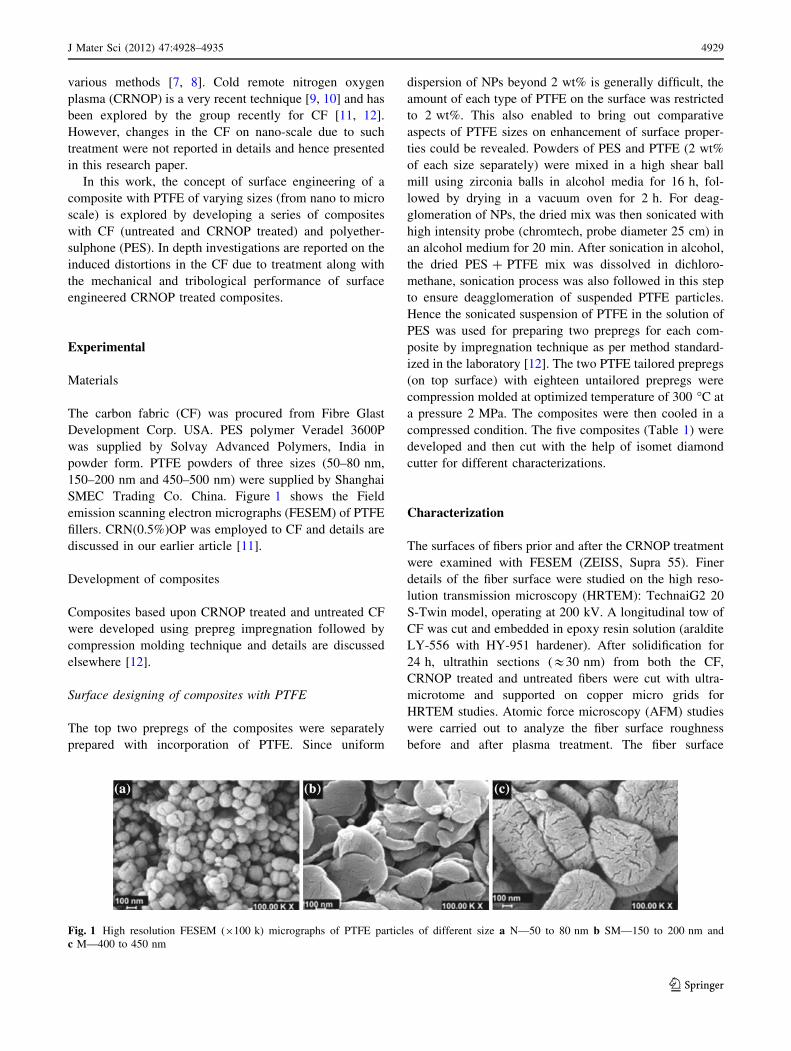
SMEC Trading Co. China. Figure 1 shows the Field
emission scanning electron micrographs (FESEM) of PTFE
fillers. CRN(0.5%)OP was employed to CF and details are
discussed in our earlier article [11].
Development of composites
Composites based upon CRNOP treated and untreated CF
were developed using prepreg impregnation followed by
compression molding technique and details are discussed
elsewhere [12].
Surface designing of composites with PTFE
The top two prepregs of the composites were separately
prepared with incorporation of PTFE. Since uniform
dispersion of NPs beyond 2 wt% is generally difficult, the
amount of each type of PTFE on the surface was restricted
to 2 wt%. This also enabled to bring out comparative
aspects of PTFE sizes on enhancement of surface proper-
ties could be revealed. Powders of PES and PTFE (2 wt%
of each size separately) were mixed in a high shear ball
mill using zirconia balls in alcohol media for 16 h, fol-
lowed by drying in a vacuum oven for 2 h. For deag-
glomeration of NPs, the dried mix was then sonicated with
high intensity probe (chromtech, probe diameter 25 cm) in
an alcohol medium for 20 min. After sonication in alcohol,
the dried PES ? PTFE mix was dissolved in dichloro-
methane, sonication process was also followed in this step
to ensure deagglomeration of suspended PTFE particles.
Hence the sonicated suspension of PTFE in the solution of
PES was used for preparing two prepregs for each com-
posite by impregnation technique as per method standard-
ized in the laboratory [12]. The two PTFE tailored prepregs
(on top surface) with eighteen untailored prepregs were
compression molded at optimized temperature of 300 �C at
a pressure 2 MPa. The composites were then cooled in a
compressed condition. The five composites (Table 1) were
developed and then cut with the help of isomet diamond
cutter for different characterizations.
Characterization
The surfaces of fibers prior and after the CRNOP treatment
were examined with FESEM (ZEISS, Supra 55). Finer
details of the fiber surface were studied on the high reso-
lution transmission microscopy (HRTEM): TechnaiG2 20
S-Twin model, operating at 200 kV. A longitudinal tow of
CF was cut and embedded in epoxy resin solution (araldite
LY-556 with HY-951 hardener). After solidification for
24 h, ultrathin sections (&30 nm) from both the CF,
CRNOP treated and untreated fibers were cut with ultra-
microtome and supported on copper micro grids for
HRTEM studies. Atomic force microscopy (AFM) studies
were carried out to analyze the fiber surface roughness
before and after plasma treatment. The fiber surface
Fig. 1 High resolution FESEM (9100 k) micrographs of PTFE particles of different size a N—50 to 80 nm b SM—150 to 200 nm and
c M—400 to 450 nm
J Mater Sci (2012) 47:4928–4935 4929
123
roughness was analyzed over a 2 lm 9 2 lm area. Studies
were done on Nanonics MultiView scanning probe
microscope, with transparent glass cantilever OptoProbe
(tip diameter \ 10 nm).
X-ray diffraction studies in bulk and thin film diffraction
geometry were done with Glancing angle X-ray diffraction
(GAXRD); Phillips X’Pert, PRO-PW 3040. SEM (ZEISS,
EVO-MA10) was used to study worn surfaces of com-
posites. Renishaw inVia Raman spectrometer with 514 nm
He–Ne laser and 785 nm near infrared laser excitation
wavelength was used to record the spectra of fibers, poly-
mers and composites. Theoretical void content in com-
posites was calculated using ASTM 2734 and were in the
range of 0.5% which confirms the void free composites.
Wear studies
Sliding wear studies were carried out on UMT-3MT
Tribometer supplied by CETR, USA; in a pin-on-disc
configuration discussed elsewhere [12]. The composite pin
(10 mm 9 10 mm 9 4 mm) was slid against a mild steel
disc (Ra * 0.2 lm) at a constant speed of 1 m/s and 1 sq.
cm nominal contact area. The coefficient of friction (l) as a
function of time during sliding was recorded with the help
of viewer software. The specific wear rate (K0) was cal-
culated using the equation:
K0 ¼W
qLdm3N�1m�1 ð1Þ
where W is the weight loss in kg, q the density of pin in
kg/m3, L the load in N and d the sliding distance in
meters. The experiment was repeated for three times and
the average of two closest values of weight loss was used
for specific wear rate calculations.
Results and discussion
The plasma treatment has beneficially improved the phys-
ical and mechanical properties of CF-PES composites
[12]. The interlaminar shear strength (ILSS) values of
composites increased up to 27% due to the CRNOP treat-
ment which indicates the enhanced fiber matrix adhesion.
Micrographs (FESEM) in Fig. 1a, b and c show the size
and shape of three types of PTFE particles used for surface
designing of composites. Nanometer range (50–80 nm)
particles are highly spherical, while submicron (200–250
nm) and micron (400–450 nm) sized are sub rounded and
sub angular, respectively. Figure 2a and b shows the FE-
SEM images of treated and untreated fibers, treatment
increased perforations and roughness on the fiber surface.
As compared to crenulations on the untreated fiber surface,
the deeper and narrower ridges at nanoscale can be easily
visible on the treated fiber surface (Fig. 2b). Figure 3
shows HRTEM images of longitudinal thin section for
untreated (Fig. 3a) and CRNOP treated (Fig. 3b) fibers.
Both types of fibers have inter-planar spacing of 0.34 nm;
typically observed for (210) planes of PAN-based CF and
high purity carbon and graphite materials [13–15]. The
micrographs show the orientation of small graphite crys-
tallites for untreated and treated CF. Coexistence of crys-
talline and amorphous phases was observed, which is
accordance to the literature [16, 17]. Warner et al. [18]
suggested that the structure of PAN fibers is constitutive of
ordered and amorphous domains with the length of the
ordered regions ranging from 80 to 100 A, roughly twice
that of the disordered regions. During the process of fiber
manufacturing the uneven distribution of stresses during
the drawing step is the reason for existence of both the
phases [16]. The distorted graphitic plane can be seen in
the case of treated CF (Fig. 3b) which supports the results
from the MRS studies as reported in our earlier article, [11]
in which ID/IG ratio increased in the case of treated CF due
to treatment. The planes are more smother and regular in
the case of untreated CF (Fig. 3a). Distortion indicates the
pitting on the fiber (as seen in FESEM studies Fig. 2)
which eventually is responsible for improving its adhesion
with the matrix.
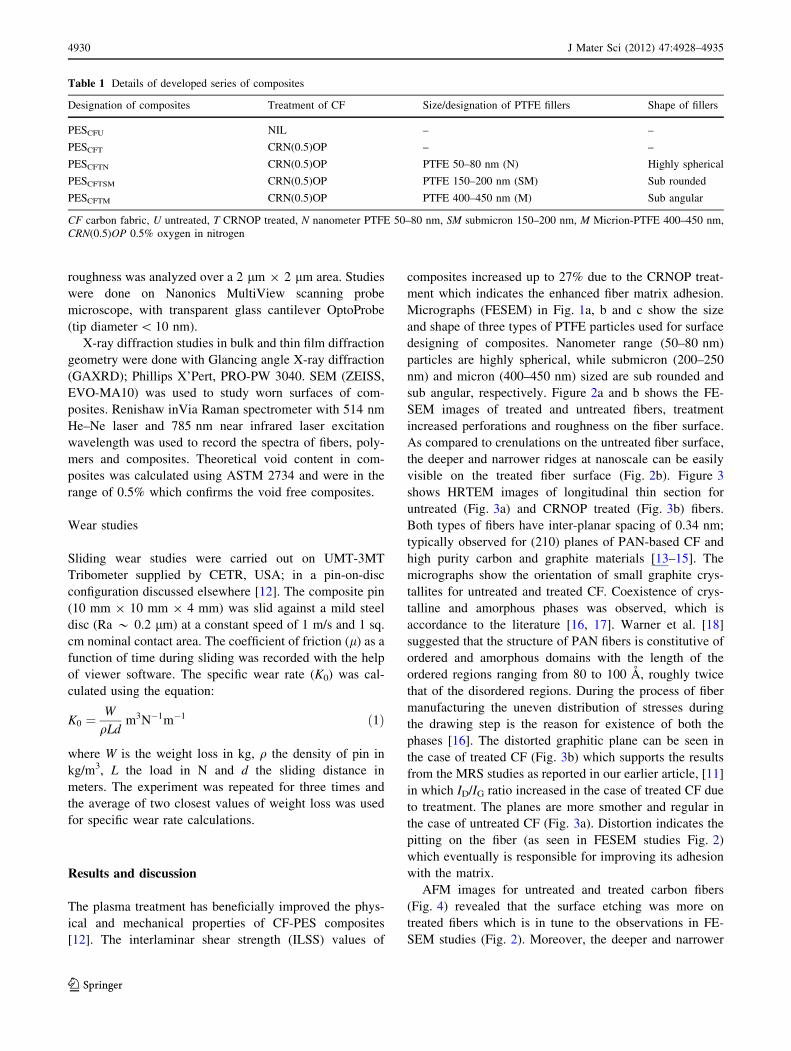
AFM images for untreated and treated carbon fibers
(Fig. 4) revealed that the surface etching was more on
treated fibers which is in tune to the observations in FE-
SEM studies (Fig. 2). Moreover, the deeper and narrower
Table 1 Details of developed series of composites
Designation of composites Treatment of CF Size/designation of PTFE fillers Shape of fillers
PESCFU NIL – –
PESCFT CRN(0.5)OP – –
PESCFTN CRN(0.5)OP PTFE 50–80 nm (N) Highly spherical
PESCFTSM CRN(0.5)OP PTFE 150–200 nm (SM) Sub rounded
PESCFTM CRN(0.5)OP PTFE 400–450 nm (M) Sub angular
CF carbon fabric, U untreated, T CRNOP treated, N nanometer PTFE 50–80 nm, SM submicron 150–200 nm, M Micrion-PTFE 400–450 nm,
CRN(0.5)OP 0.5% oxygen in nitrogen
4930 J Mater Sci (2012) 47:4928–4935
123

ridges were observed from both the studies, which are in
accordance to the literature [19]. The fine striations on the
untreated fiber surface were due to the spinning of the fiber
precursor [20]. The average surface roughness (Ra) values
for untreated and treated fibers were 38.4 nm and 66.3 nm,
respectively, which confirmed the increase in surface area
and alteration in the morphology. The increase in surface
roughness of treated carbon fibers is beneficial for
enhancing its reactivity towards matrix, since rougher fiber
topography would lead to a higher degree of mechanical
interlocking between the fiber and matrix [21].
The diffraction peak for carbon fibers (untreated and
CRNOP treated) at 2h = 26.3�, 44.2�, 54.5� and 77.4� can
be assigned to (002), (100), (004) and (110) planes,
respectively (JCPDS-76-0152) in Fig. 5a, which appeared
for PAN-based CF and well coherent to the literature [22].
The (002) diffraction profiles for both treated and
untreated fibers are much narrower than the other peaks.
Less prominently with the effect of CRNOP treatment, the
main peak shifted from 26.3� to 26.5� with little broad-
ening in size. In our earlier work ATR-FTIR studies
revealed the presence of oxygenated polar functional
groups was confirmed on treated fibers [11]. The inclusion
of O-atom on the treated fibers surface, (which is bigger
than the C- atom) leads to the enhancement in lattice
parameter and slight peak shifting as seen in Fig. 5a.
Figure 5b shows the diffraction peak for PES micron
powder; PTFE powder (N—50 to 80 nm, table 1) and ball
milled PES and PTFE mix. (100) peak for crystalline nano
PTFE is sharp as compared to its mixture with PES; micro
PTFE and PES (M ? PES) and amorphous PES. All
above characterization results confirmed the changes on
the fiber surface in nano-scale, due to CRNOP treatment,
which is further responsible for enhanced fiber-matrix
adhesion and improved performance properties of the
composites.
Figure 6 shows the comparative tribo-performance (land K0) for composites confirming that the inclusion of
PTFE fillers on the surface of composites affected the
sliding wear performance positively. The l values for
composites were in the range (0.07–0.25) while K0 varied
from 1.25 to 2.2 9 10-15 m3/Nm. The limiting load value
Fig. 2 High resolution FESEM (9150 k) micrographs of a carbon fibers a before treatment and b after CRNO(0.5)P treatment (Color figure
online)
Fig. 3 HRTEM images of carbon fibers a untreated and b treated fibers
J Mater Sci (2012) 47:4928–4935 4931
123
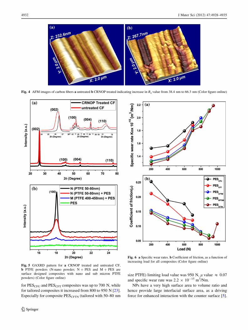
for PESCFU and PESCFT composites was up to 700 N, while
for tailored composites it increased from 800 to 950 N [23].
Especially for composite PESCFTN (tailored with 50–80 nm
size PTFE) limiting load value was 950 N, l value & 0.07
and specific wear rate was 2.2 9 10-15 m3/Nm.
NPs have a very high surface area to volume ratio and
hence provide large interfacial surface area, as a driving
force for enhanced interaction with the counter surface [5].
Fig. 4 AFM images of carbon fibers a untreated b CRNOP treated indicating increase in Ra value from 38.4 nm to 66.3 nm (Color figure online)
Fig. 5 GAXRD pattern for a CRNOP treated and untreated CF,
b PTFE powders (N-nano powder; N ? PES and M ? PES are
surface designed composites with nano and sub micron PTFE
powders) (Color figure online)
Fig. 6 a Specific wear rates. b Coefficient of friction, as a function of
increasing load for all composites (Color figure online)
4932 J Mater Sci (2012) 47:4928–4935
123
Spherical NPs provide high interfacial area between the
fillers and matrix also. This leads to a better bonding
between the two phases and hence better properties [24,
25]. PTFE, a high molecular weight fluorocarbon com-
pound demonstrates mitigated London dispersive forces
due to highly electronegative F- atoms. In PTFE molecule,
C–F forms non reactive and instantaneous polarized multi
poles, with the increases in surface contact, the polariz-
ability increases due to the dispersed electron clouds hence
closer interaction between different molecules. At larger
scale, the long chains of PTFE orient on the counter face
during sliding creating a fine coherent transfer film. The
transfer film creates a low shear-strength interface with the
bulk PTFE material [26]. Hence the interaction is between
PTFE film and the PTFE containing composite leading to
least possible adhesion and hence very low l.
The film transferring ability depends on operating con-
ditions and the size and amount of PTFE particles. Its
application in nanosize however, is not reported in the
literature. It was anticipated that nano-size PTFE would
lead to the highest interaction with the counterface and
hence would lead to the lowest l and wear. Topographical
smoothening and a rolling effect due to the inclusion of
nano-fillers at the surface is the reason for improved fric-
tion and wear performance of PESCFTN composite. During
the wear process, NPs are removed from the surface of a
matrix and can act as third body element in the contacting
regions. The rolling effect of the NPs, especially at the
edge of exposed fibers, reduce the shear stress in the con-
tact region and hence the l. This leads to the smoothening
of topography of a composite surface. It also protects the
fibers adhered to the matrix and results in increased fiber
thinning before final removal of fibers from the matrix [27].
The rolling effect is also observed in the case of micro
particulate inclusions, for which the small particles tends to
tumble through the contact region and larger particles
plough through it. There is a critical size of particle gov-
erning the transition from rolling to ploughing. To achieve
the rolling, the ratio of maximum particle dimension to the
minimum gap of contacting bodies must be exceeding the
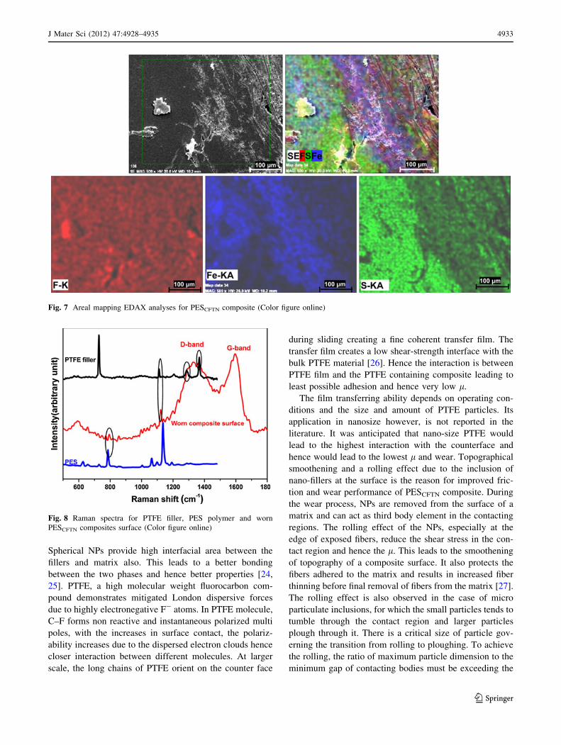
Fig. 7 Areal mapping EDAX analyses for PESCFTN composite (Color figure online)
Fig. 8 Raman spectra for PTFE filler, PES polymer and worn
PESCFTN composites surface (Color figure online)
J Mater Sci (2012) 47:4928–4935 4933
123
critical value which depends on the particle size. The hard
micro sized particles and fillers abrade the counterface.
This prevents the formation of a beneficial protective
transfer film and increase the counter face roughness and
hence the l of the composite [28]. The NPs have potential
to reduce abrasion that leads to these cascading events. NPs
(\100 nm) are of the same size as the counterface asperi-
ties and polish the highest asperities and promote the
development of transfer films. The transfer films shield the
composite from direct asperity contact and damage [5].
These mechanisms as reported in the literature are
responsible for beneficial influence of NPs on the tribo-
performance in the present case.
Figure 7 shows the areal mapping EDAX analyses for
worn PESCFTN composites which confirm the uniform
distribution of Fluorine on the surface (Red color). Blue
color shows back-transferred Fe on the composite surface
from the counter face. Existence of sulfur can be visible
from green color mapping which confirms the PES matrix
phase. MRS studies for CF in our earlier work supports the
HRTEM results in Fig. 2 by indicating the increased ID/IG
ratio; hence induced distortion (reduced crystallinity) with
plasma treatment to CF [11]. To confirm the inclusion of
PTFE filler at the worn composite surface, MRS studies for
worn composites and polymers were carried out. Figure 8
shows comparison among Raman spectra for pristine nano
PTFE powder, PES powder and worn CF-PES composite
surface tailored with nano PTFF filler. For PES, main peak
of symmetric C–O–C stretching at 1154 cm-1 matches
with the spectra for composite, also the deformation peak
at 791 cm-1 [29] can be visible in the spectra. The main
PTFE peaks at 1216 and 1300 cm-1 can be traced from the
spectra of composites. An additional signal from PTFE
spectra at 1118 cm-1 matches with the spectra of
composites.
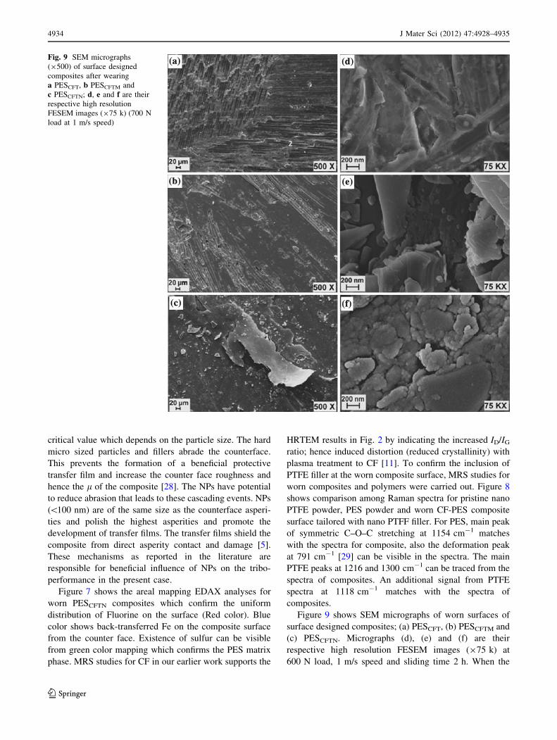
Figure 9 shows SEM micrographs of worn surfaces of
surface designed composites; (a) PESCFT, (b) PESCFTM and
(c) PESCFTN. Micrographs (d), (e) and (f) are their
respective high resolution FESEM images (975 k) at
600 N load, 1 m/s speed and sliding time 2 h. When the
Fig. 9 SEM micrographs
(9500) of surface designed
composites after wearing
a PESCFT, b PESCFTM and
c PESCFTN; d, e and f are their
respective high resolution
FESEM images (975 k) (700 N
load at 1 m/s speed)
4934 J Mater Sci (2012) 47:4928–4935
123

topography of composites with and without PTFE is
compared, it can be clearly seen that PTFE has smoothened
the surface and spread over the fibers and matrix. Nano-
PTFE has spread over in such a way that it has formed a
thin and coherent film on the surface (marked as 1 in
Fig. 9c) which was responsible for its lowest l. The
elongated and uplifted film during shearing in the middle of
the micrograph indicates how thin (\0.1 lm) and coherent
the film was. The nano-fillers (Fig. 9f) and micro fillers
(Fig. 9e) are clearly visible with high resolution FESEM
images of worn composites surfaces. Increased fiber dam-
age and easy peeling off of fibers leading to breakage
(Fig. 9a) is responsible for high wear of untailored
composite.
Conclusions
The concept of CRNOP treatment and surface designing
with micron, sub-micron and nano sized PTFE proved
beneficial for achieving high wear resistance, low friction
and high life span of a composite containing CF and
Polyethersulphone. The treatment to the fibers led to
changes in the surface roughness (as evident from AFM
studies), deep crenulations and pitting (as evident from
FESEM studies), distortion in graphitic structure (as evi-
dent from HRTEM studies). All these led to better fiber-
matrix adhesion and hence stronger composite. The idea of
surface engineering of a composite with SLs (rather than
incorporating in the bulk) to safeguard the composite from
an un-intentional reduction in the strength properties and
increase in the cost proved successful. The nano-PTFE
proved most beneficial followed by sub-micron sized PTFE
and then micron sized PTFE. Based on SEM and FESEM
analyses it was concluded that the enhanced fiber-matrix
adhesion led to the reduction in the severity of wear-events
such as wear breakage, fiber peeling off from the matrix,
fiber pulverization etc. Instead, wear thinning was promi-
nently observed and was concluded to be responsible for
less wear of treated fabric composites.
Acknowledgements Authors are grateful to the Council of Scien-
tific and Industrial Research (CSIR), New Delhi, India for funding the
work reported in this paper. Authors are also grateful to Prof. Brigitte
Mutel from University of Lille, France for extending facility of
plasma treatment to the fabric.
References
1. Soutis C (2005) Mater Sci Eng A 412:171
2. Lancaster JK (1986) In: Friedrich K (ed) Friction and wear of
polymer composites. Elsevier, Amsterdam, p 363
3. Bijwe J, Hufenbach W, Kunze K, Langkamp A (2008) In:
Friedrich K, Schlarb AK (eds) Tribology of polymeric nano-
composites. Elsevier, Amsterdam, p 483
4. Zhang Z, Friedrich K (2005) In: Friedrich K, Fakirov S, Zhang Z
(eds) Polymer composites: from nano to macro scale. Springer,
New York, p 169
5. Burris DL, Boesl B, Bourne GR, Sawyer WG (2007) Macromol
Mater Eng 292:387
6. Zhang ZZ, Sua FH, Wang K, Jiang W, Mena XH, Liu WM
(2005) Mater Sci Eng A 404:251
7. Cao H, Huang Y, Zhang Z, Sun J (2005) Compos Sci Technol
65:1655
8. Lee WH, Lee JG, Reucroft PJ (2001) Appl Surf Sci 171:136
9. Mutel B, Bigan M, Vezin H (2004) Appl Surf Sci 239:25
10. Vivien C, Wartelle C, Mutel B, Grimblot J (2002) Surf Interface
Anal 34:575
11. Tiwari S, Sharma M, Panier S, Mutel B, Mitschang P, Bijwe J
(2011) J Mater Sci 46:964 10.1007/s10853-010-4847-z
12. Sharma M, Bijwe J (2012) Wear 274–275:388
13. Tressaud A, Chambon M, Gupta V, Flandrois S, Bahl OP (1995)
Carbon 33:1339
14. Sharma SP, Lakkad SC (2009) Surf Coat Technol 203:1329
15. Gaskell DR (1981) Introduction to the thermodynamics of
materials. McGraw-Hill, New York
16. Bai YJ, Wang CG, Lun N, Wang YX, Yu MJ, Zhu B (2006)
Carbon 44:1773
17. Hai XS, Ying ZF, Huan LS, Dong-mei H, Qing-yun C (2010) J
Cent South Univ Technol 17:703
18. Warner SB, Uhlmann DR, Peebles LH (1975) J Mater Sci 10:758.
doi:10.1007/BF01163070
19. Sarraf H, Skarpova L, Louda P (2007) J Achiev Mater Manuf Eng
25:24
20. Zhang X, Huang Y, Wang T (2006) Appl Surf Sci 253:2885
21. Paredes JI, Alonso AM, Tasco JMD (2000) J Mater Chem
10:1585
22. Dobiasova L, Stary V, Glogar P, Valvoda V (1999) Carbon
37:421
23. Sharma M, Bijwe J (2011) Wear 271:2919
24. Friedrich K, Zhang Z, Schlarb AK (2005) Comp Sci Technol
65:2329
25. Kocsis JK, Zhang Z (2005) In: Michler GH, Calleja JFB (eds)
Mechanical properties of polymers based on nanostructure and
morphology. Taylor & Francis, New York
26. Schadler LS, Brinson LC, Sawyer WG (2007) J of Miner Metals
and Maters Society 59:53
27. Chang L, Zhang Z, Ye L, Friedrich K (2008) In: Friedrich K,
Schlarb AK (eds) Tribology of polymeric nanocomposites.
Elsevier BV, Amsterdam, p 35
28. Bahadur S (2000) Wear 245:92
29. Choi YB, Park OO (2008) J Appl Polym Sci 109:736
J Mater Sci (2012) 47:4928–4935 4935
123