
Supporting UML-based development of embedded systems by formal techniques
25
Softw Syst Model DOI 10.1007/s10270-006-0043-7 SPECIAL SECTION PAPER Supporting UML-based development of embedded systems by formal techniques Jozef Hooman · Hillel Kugler · Iulian Ober · Anjelika Votintseva · Yuri Yushtein Received: 20 December 2005 / Revised: 2 October 2006 / Accepted: 9 October 2006 © Springer-Verlag 2007 Abstract We describe an approach to support UML- based development of embedded systems by formal techniques. A subset of UML is extended with timing annotations and given a formal semantics. UML models are translated, via XMI, to the input format of formal tools, to allow timed and non-timed model checking and interactive theorem proving. Moreover, the Play-Engine Communicated by Dr. Susanne Graf. This work has been supported by EU-project IST 33522 – OMEGA “Correct Development of Real-Time Embedded Systems in UML”. For more information, see http://www-omega.imag.fr/. During this project, the second author was at the Weizmann Institute of Science, the third author at VERIMAG, the fourth author at OFFIS, and the fifth author at NLR. J. Hooman(B ) Embedded Systems Institute, Eindhoven, The Netherlands e-mail: [email protected] J. Hooman Radboud University, Nijmegen, The Netherlands H. Kugler New York University, New York, NY,USA e-mail: [email protected] I. Ober Toulouse-II University, Toulouse, France e-mail: [email protected] A. Votintseva CT SE 1 Siemens AG, Munich, Germany e-mail: [email protected] Y. Yushtein CIMSOLUTIONSB.V., Vianen, The Netherlands e-mail: [email protected] tool is used to execute and analyze requirements by means of live sequence charts. We apply the approach to a part of an industrial case study, the MARS system, and report about the experiences, results and conclusions. Keywords Formal methods · UML · Embedded systems · Real-time 1 Introduction We report about our results and experiences on com- bining a number of formal techniques with UML-based development. This work has been carried out in the con- text of the EU project OMEGA (Correct Development of Real-Time Embedded systems in UML). A general aim of this project is to improve the quality of software for embedded systems by the use of formal techniques. Embedded systems typically have an intensive real- time interaction with their environment. Although UML [3] has not been designed originally for such systems, one can observe an increasing use of object-oriented tech- niques and UML in this domain. There exists a num- ber of specialized methods [43, 11], a UML profile for Schedulability, Performance and Time [35] and several dedicated CASE tools (e.g., Artisan’s Real-time Stu- dio, Rhapsody of I-Logix, Rational Rose RealTime, and Telelogic TAU). Embedded applications typically have strong require- ments on the correctness of the software. This, however, is not easy to achieve, since these applications are typi- cally highly innovative, have intricate assumptions about the behavior of their environment, and are developed quite incrementally. Hence, it is important to detect errors as soon as possible during the development pro- cess. In this paper, we address the use of formal methods
Transcript of Supporting UML-based development of embedded systems by formal techniques
Softw Syst ModelDOI 10.1007/s10270-006-0043-7
SPECIAL SECTION PAPER
Supporting UML-based development of embedded systemsby formal techniques
Jozef Hooman · Hillel Kugler · Iulian Ober ·Anjelika Votintseva · Yuri Yushtein
Received: 20 December 2005 / Revised: 2 October 2006 / Accepted: 9 October 2006© Springer-Verlag 2007
Abstract We describe an approach to support UML-based development of embedded systems by formaltechniques. A subset of UML is extended with timingannotations and given a formal semantics. UML modelsare translated, via XMI, to the input format of formaltools, to allow timed and non-timed model checking andinteractive theorem proving. Moreover, the Play-Engine
Communicated by Dr. Susanne Graf.
This work has been supported by EU-project IST 33522 –OMEGA “Correct Development of Real-Time EmbeddedSystems in UML”. For more information, seehttp://www-omega.imag.fr/. During this project, the secondauthor was at the Weizmann Institute of Science, the third authorat VERIMAG, the fourth author at OFFIS, and the fifth authorat NLR.
J. Hooman(B)Embedded Systems Institute,Eindhoven, The Netherlandse-mail: [email protected]
J. HoomanRadboud University,Nijmegen, The Netherlands
H. KuglerNew York University, New York, NY, USAe-mail: [email protected]
I. OberToulouse-II University, Toulouse, Francee-mail: [email protected]
A. VotintsevaCT SE 1 Siemens AG, Munich, Germanye-mail: [email protected]
Y. YushteinCIMSOLUTIONS B.V., Vianen, The Netherlandse-mail: [email protected]
tool is used to execute and analyze requirements bymeans of live sequence charts. We apply the approach toa part of an industrial case study, the MARS system, andreport about the experiences, results and conclusions.
Keywords Formalmethods · UML · Embedded systems · Real-time
1 Introduction
We report about our results and experiences on com-bining a number of formal techniques with UML-baseddevelopment. This work has been carried out in the con-text of the EU project OMEGA (Correct Developmentof Real-Time Embedded systems in UML). A generalaim of this project is to improve the quality of softwarefor embedded systems by the use of formal techniques.
Embedded systems typically have an intensive real-time interaction with their environment. Although UML[3] has not been designed originally for such systems, onecan observe an increasing use of object-oriented tech-niques and UML in this domain. There exists a num-ber of specialized methods [43,11], a UML profile forSchedulability, Performance and Time [35] and severaldedicated CASE tools (e.g., Artisan’s Real-time Stu-dio, Rhapsody of I-Logix, Rational Rose RealTime, andTelelogic TAU).
Embedded applications typically have strong require-ments on the correctness of the software. This, however,is not easy to achieve, since these applications are typi-cally highly innovative, have intricate assumptions aboutthe behavior of their environment, and are developedquite incrementally. Hence, it is important to detecterrors as soon as possible during the development pro-cess. In this paper, we address the use of formal methods
J. Hooman et al.
to improve the quality of UML-based development ofembedded systems.
There exists already a number of formal techniquesthat have been applied to UML [41,30]. Earlyapproaches to formal verification based on model check-ing UML models actually only consider singlesub-languages of UML, like statecharts [29,26], and theyeffectively verify only a single object in isolation. ThevUML tool [38] provides a predefined set of checks ofinvariants, e.g., absence of deadlocks, queue overflows,and unreachability of invalid states. The specificationlanguage of [44] is the temporal logic of the underlyingmodel checker, hence far from the level of UML. Thework on model checking of xUML [46] is closest to theUVE approach described in this paper. A rich set ofUML language concepts and features, like parallelism,inheritance, object creation/destruction, etc. are sup-ported by the xUML approach. But it only deals withclosed systems without taking a non-deterministic envi-ronment into account. Moreover, the used requirementspecification language is restricted to a set of temporalpatterns and has no graphical representation.
Related to the IFx tool considered in this paper formodel checking real-time properties is the translation oftimed UML state machines [24] to Uppaal [28]. Relevantis also the work in the context of the Fujaba real-timetool suite for UML-based development on the integra-tion of Uppaal [7]. To support interactive verificationof untimed UML models, a development environmenthas been developed [45], based on the theorem proverPVS [36]. A proposal for a general framework to inte-grate tools for UML and formal methods can be foundin [32].
However, most techniques are not coupled to CASEtools and are based on a very small subset of UML.Often, it is difficult to express timing properties con-veniently and at a sufficient level of abstraction, andassumptions about the environment can usually beexpressed only by including the environment explic-itly in the model, leading to a closed system. In theOMEGA project we investigated how this situation canbe improved. We mention a few important points of theOMEGA approach: a tight integration of formal tech-niques in the development process, a sufficiently largesubset of UML which allows convenient modeling ofembedded systems, and the combination of techniques.
To be able to integrate formal techniques, we haveestablished a coupling with commercial UML-basedCASE tools by translating the standard XMI repre-sentation of a UML model into the format of formaltools, such as model checkers and theorem provers. Inthis way, the formal tools can be applied to a UMLmodel that has been edited by means of any commercial
UML-based CASE tool which is able to generate XMI.Although XMI is the XML standard for UML, unfor-tunately, most current UML tools use slightly differentversions of XMI. In OMEGA we have concentrated onthe XMI versions of Rational Rose and Rhapsody ofI-Logix. The latter has been used for all experimentsdescribed in this paper.
To obtain a coherent set of tools, without havingto deal immediately with the full UML language, wehave defined a convenient subset of UML, called theOMEGA kernel language, which is close to the coreUML language described in [13]. Basically, this consistsof class diagrams for specifying the structure of the sys-tem, including structural relationships like generaliza-tion, association, and composition, and state machines todescribe the behavior of classes. Objects may communi-cate by means of (asynchronous) signals and operations.
The language has been extended with suitable prim-itives to express real-time behavior. Timing extensionshave been proposed, called the OMEGA real-time pro-file for UML, based on the profile for Schedulability,Time and Performance. Details can be found in [12].The sequence diagrams of UML have been replaced byLSCs [8] which are more expressive [25] and also havebeen extended with primitives to express timing [19].LSCs can be captured by the user by means of a sepa-rate tool, the Play-Engine. Note that our work on UMLwas mainly based on UML 1.4, since that was the stan-dard during most of our project. Because we concentrateon the core modeling capability of UML, the differenceswith UML 2.0 [34] are not very relevant.
Clearly the coherence of this tool set also requires acommon semantic model. Within OMEGA, this led toextensive discussions and decisions on semantic varia-tion points and unclear issues in the definition of UML.Our starting point was an operational semantics [10,9]which was especially inspired by the execution mecha-nism of Rhapsody. Whereas many formal methodsrequire flat state machines, this semantics also includeshierarchy and orthogonality which is convenient formodeling. This semantic model, based on labeled tran-sition systems, turned out to be convenient for the inte-gration of the commercial tool and model checking.
We reformulated the semantics to make it more suit-able for interactive theorem proving. For instance, weabstracted from the pending request table for operationcalls in [9] and used explicit synchronization betweencaller and callee. Moreover, the semantics has beendefined in an incremental way, starting from a basicnon-timed semantics. This has been extended with acontinuous notion of time in an orthogonal way. Sim-ilarly, threads of control have been added in a modularway. More details can be found in [23], which clarifies a
Supporting UML-based development of embedded systems by formal techniques
number of semantic questions and decisions, e.g., con-cerning the passing of control and the dispatching ofsignal events.
Another relevant aspect of the OMEGA approach isthe combination of various formal techniques, to obtainflexible support with e.g., various specification styles,different visualizations, the possibility to deal with bothclosed and open systems—with assumptions about theenvironment, and both automated checks and userguided verification, depending on the properties to beverified. By experimenting with various tools on indus-trial examples, the aim is to derive guidelines about whenand how to use the formal techniques. In particular, weconsider the support of UML-based development by thefollowing four formal techniques:
– Live Sequence Charts (LSCs), to capture specifica-tions, using the Play-Engine tool
– Model checking of functional properties by meansof the UVE tool
– Timed model checking, using the IFx tool– Interactive verification supported by the PVS theo-
rem prover
More details about these techniques will be given inSect. 3.
The main aim of this paper is to describe the appli-cation of the formal techniques to UML models of anindustrial case study, which has been provided by one ofthe industrial partners of the OMEGA project. We pres-ent the results of applying the first versions of the devel-oped tools to the original model, leading to an interme-diate conclusion about what had to be improved. Nextthe application has been remodeled and we put moreemphasis on the combined application of the improvedtools.
In general, the emphasis of this paper is on globalresults, experiences with the case studies, and generalconclusions. Hence, we will neither expose all featuresof the techniques used, nor show the full functionalityof all tools. During the case study we have often usedpreliminary versions of the tools, and the experimentsillustrate tool development within the OMEGA project.Moreover, note that the aim is not to compare the tools,which would also be difficult because they have differentgoals and are rather complementary. Instead, the focusis on the synergy of the approaches and the possibilitiesto exploit the combination of the tools.
The rest of this paper is structured as follows. In Sec-tion 2 we introduce the industrial case study, the UMLmodel of a part of it, and the properties to be verified forthis part. Section 3 contains a brief introduction to thefour formal techniques used, illustrated by their applica-
tion to the UML model of the case study. Next, in Sect. 4we redesign the considered part of the case study, tofacilitate compositional techniques and abstraction, andapply the OMEGA techniques to this new model. Anevaluation of the specification and verification experi-ments is presented in Sect. 5. Finally, concluding remarkscan be found in Sect. 6.
2 The MARS system
We describe a selected part of the MARS system(Medium Altitude Reconnaissance System) from theNLR.1 This system has been used as a common real-timeembedded application within the OMEGA project.
The system controls the operation of a reconnais-sance photo camera in an aircraft; ground survey pho-tographs are taken by the camera during the flight. Toobtain high-resolution images, the MARS system coun-teracts the image quality degradation caused by the for-ward motion of the aircraft by creating a compensationmotion of the film during the film exposure, based onthe current aircraft altitude, ground speed, etc. The sys-tem also performs health monitoring and alarm process-ing functions. The Reconnaissance Control Unit (RCU)is responsible for the three major categories of tasks:camera and film exposure control, film annotation, andsystem health monitoring and alarm processing.
In order to perform the camera and film-exposurecontrol functions the RCU acquires the current altitudeand velocity data from the avionics data bus of the air-craft. Based on these values it computes the film FrameRate to be used and the value for the Forward MotionCompensation (FMC) signal. The computed values aresent to the trigger and exposure module via a seriallink. To perform the film annotation functions, the RCUacquires the current navigation data (latitude, longitudeand heading) as well as the time-of-day value from theavionics data bus of the aircraft. It formats the data andsends it to the annotation module via the serial link.Upon completion of each frame exposure, the camerahalts the film and issues an annotation request to theannotation module. Upon reception of this request theannotation module provides the current annotation datato the camera to annotate the current frame. The anno-tation cycle must be completed before the next frameexposure begins.
The navigation and altitude data messages are pro-vided by the corresponding subsystems of the aircraft.These data sources are independent and not synchro-
1 National Aerospace Laboratory, the Netherlands, http://www.nlr.nl.
J. Hooman et al.
nized; they provide data with a period P of 25 ms and ajitter J of ± 5 ms (i.e. data may arrive up to 5 ms earlieror later). Data messages may occasionally be lost due totransmission errors.
The system has hard timing constraints, such asrequirements on the age of data used for exposure con-trol, on the data acquisition and on processing timein order to accommodate the data rate of the avionicsdata bus. The system is mission-critical as it is used formedium altitude reconnaissance missions over poten-tially hostile territories. Corrupted mission results willinvolve unnecessary additional risks to both the air-craft and the pilot in repeated attempts to execute themission.
2.1 UML model of part of the MARS system
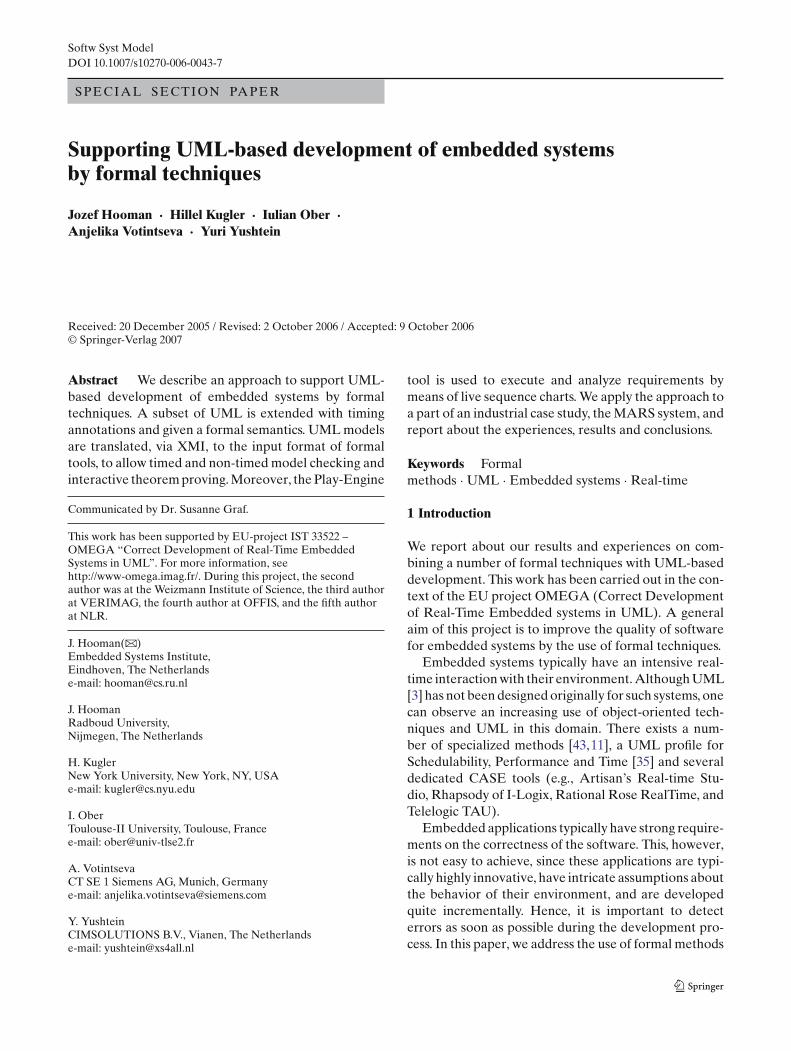
Here we present only a small part of the complete sys-tem, namely the data bus manager which is part of thedata acquisition subsystem of the MARS system; theclass diagram is given in Fig. 1. For simplicity, we oftenrefer to the DatabusManager as the MARS system. Thefocus is on the classes ControllerMonitor and Message-Receiver in an environment represented by the classesDatabusController, altDataSource, and navDataSource.The last two actors represent the data sources for alti-tude and navigation data. The main class is the Mes-sageReceiver which processes the incoming data. Thecontroller monitor periodically calls an operation of thebus controller to obtain its status. In case of an error the
monitor will send the evControllerError signal to themessage receiver. The monitor sends the evControlle-rOK signal to the receiver if the bus controller indicatesthat the error situation is resolved.
For each class the behavior of its objects is definedby means of a state machine and methods (programtext) for its so-called primitive operations. Non-primi-tive operations of a class are defined by means of its statemachine (this is not used in the MARS case study).
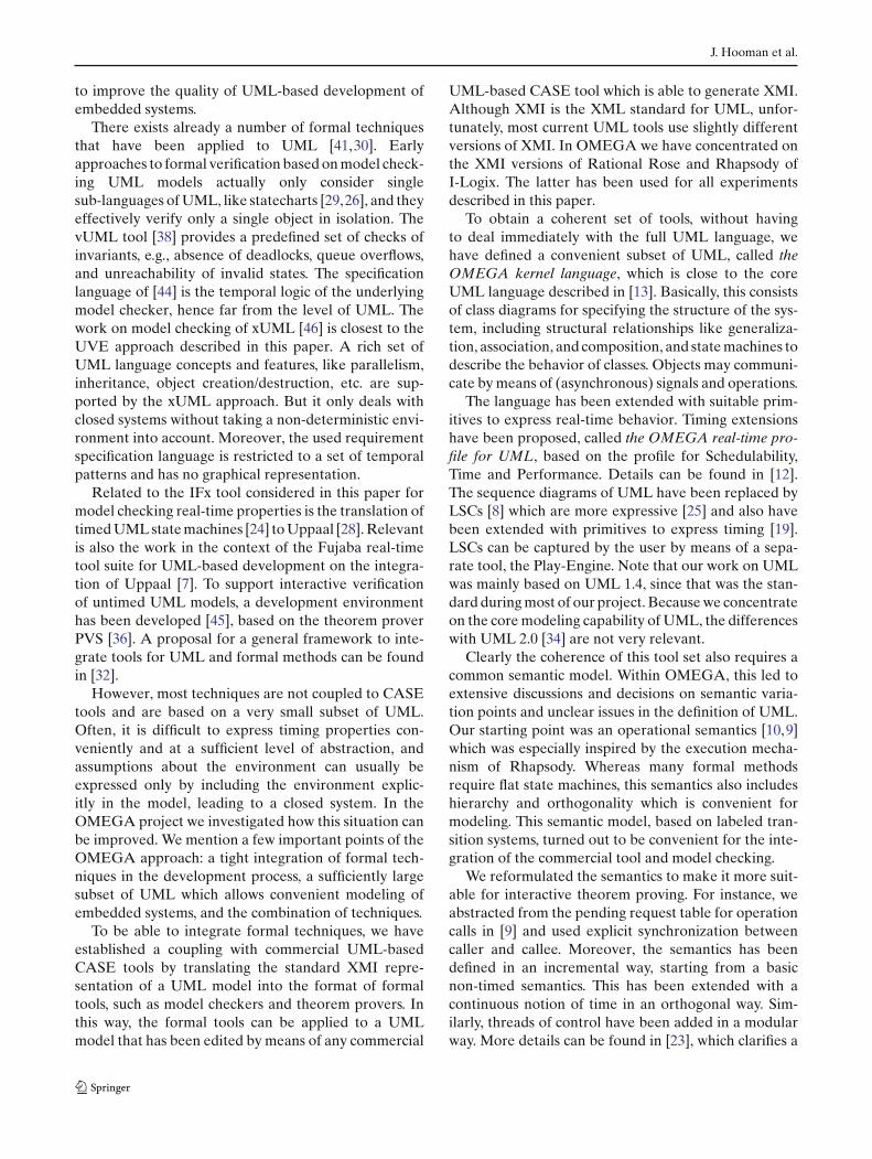
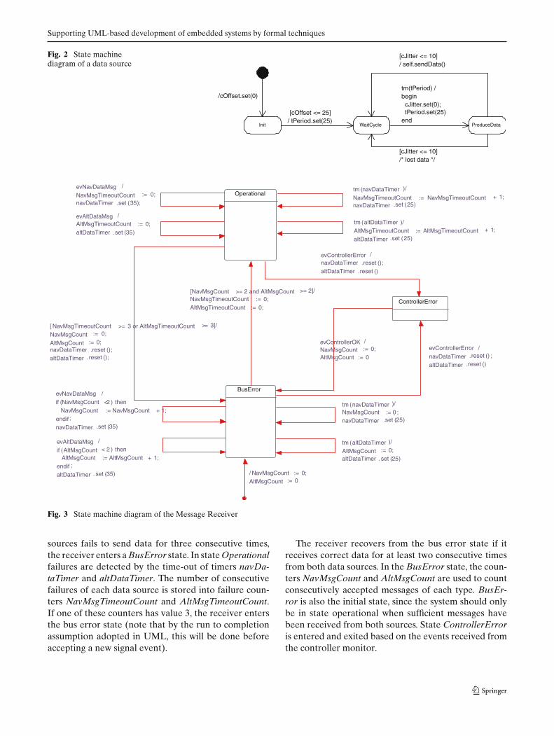
The state machine of the class DataSource, is depictedin Fig. 2. It expresses that, non-deterministically, eitherdata is sent, represented by primitive operation send-Data, or no data is transmitted. The primitive operationsendData is overridden by the subclasses altDataSourceand navDataSource to generate events evAltDataMsgand evNavDataMsg, respectively. This state machineuses interval conditions on clocks to model the non-determinism introduced by the starting time and by jit-ter. All transitions here are interpreted as delayableaccording to the terminology of timed automata withurgency [4], meaning that once they are enabled, theywill be taken before their time guard becomes false(unless they are disabled by some other discrete tran-sition). Together with usual non-Zenoness assumption,this guarantees in this example that the computationcannot get stalled in any state.
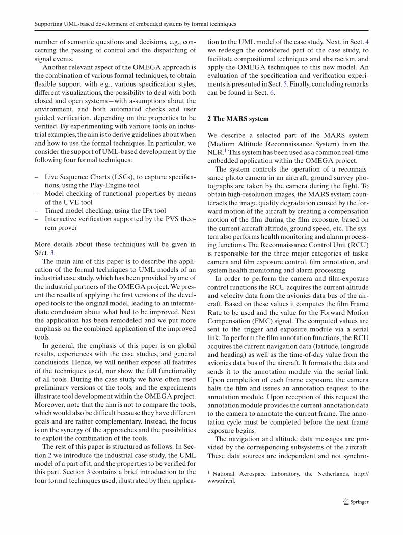
The behavior of the MessageReceiver is modeled bythe state machine diagram depicted in Fig. 3. The speci-fication of the system expresses that a few failures fromthe data sources can be tolerated, but if one of the
Fig. 1 Class diagram of thedata bus manager DatabusManager
MessageReceiver
- altDataTimer: Timer- navDataTimer: Timer- AltMsgCount: int- NavMsgCount: int- AltMsgTimeoutCount: int- NavMsgTimeoutCount: int
+ «signal» evAltDataMsg() : void+ «signal» evNavDataMsg() : void+ «signal» evControllerError() : void+ «signal» evControllerOK() : void
ControllerMonitor
- currentStatus: int- previousStatus: int
DataSource
- cOffset: Clock- tPeriod: Timer- cJitter: Clock
altDataSource navDataSource
DatabusController
- status: int
+ controllerStatus() : int
DatabusManager
MessageReceiver
- altDataTimer: Timer- navDataTimer: Timer- AltMsgCount: int- NavMsgCount: int- AltMsgTimeoutCount: int- NavMsgTimeoutCount: int
+ «signal» evAltDataMsg() : void+ «signal» evNavDataMsg() : void+ «signal» evControllerError() : void+ «signal» evControllerOK() : void
ControllerMonitor
- currentStatus: int- previousStatus: int
DataSource
- cOffset: Clock- tPeriod: Timer- cJitter: Clock
altDataSource navDataSource
DatabusController
- status: int
+ controllerStatus() : int
Supporting UML-based development of embedded systems by formal techniques
Fig. 2 State machinediagram of a data source
Init
/cOffset.set(0)
WaitCycle ProduceData
[cOffset <= 25]/ tPeriod.set(25)
tm(tPeriod) /begin cJitter.set(0); tPeriod.set(25)end
[cJitter <= 10]/ self.sendData()
[cJitter <= 10]/* lost data */
ControllerError
BusError
evControllerOK /NavMsgCount := 0;AltMsgCount := 0
evControllerError /navDataTimer .reset () ;
altDataTimer .reset ()
/ NavMsgCount := 0;AltMsgCount := 0
tm (altDataTimer )/
AltMsgCount := 0;altDataTimer . set (25)
evAltDataMsg /
if (AltMsgCount < 2 ) then AltMsgCount := AltMsgCount + 1; endif ;
altDataTimer . set (35)
tm (navDataTimer )/NavMsgCount := 0 ;navDataTimer .set (25)
evNavDataMsg /if (NavMsgCount <2 ) then NavMsgCount := NavMsgCount + 1;endif ;
navDataTimer .set (35)
Operational
[NavMsgCount >= 2 and AltMsgCount >= 2]/NavMsgTimeoutCount := 0;AltMsgTimeoutCount := 0;
evControllerError /navDataTimer .reset ();altDataTimer .reset ()
[ NavMsgTimeoutCount >= 3 or AltMsgTimeoutCount >= 3]/
NavMsgCount := 0;
AltMsgCount := 0;navDataTimer .reset ();altDataTimer . reset ();
evNavDataMsg /
NavMsgTimeoutCount := 0;navDataTimer .set (35);
evAltDataMsg /AltMsgTimeoutCount := 0;altDataTimer . set (35)
tm (navDataTimer )/
NavMsgTimeoutCount := NavMsgTimeoutCount + 1;navDataTimer .set (25)
tm (altDataTimer )/AltMsgTimeoutCount := AltMsgTimeoutCount + 1;
altDataTimer .set (25)
Fig. 3 State machine diagram of the Message Receiver
sources fails to send data for three consecutive times,the receiver enters a BusError state. In state Operationalfailures are detected by the time-out of timers navDa-taTimer and altDataTimer. The number of consecutivefailures of each data source is stored into failure coun-ters NavMsgTimeoutCount and AltMsgTimeoutCount.If one of these counters has value 3, the receiver entersthe bus error state (note that by the run to completionassumption adopted in UML, this will be done beforeaccepting a new signal event).
The receiver recovers from the bus error state if itreceives correct data for at least two consecutive timesfrom both data sources. In the BusError state, the coun-ters NavMsgCount and AltMsgCount are used to countconsecutively accepted messages of each type. BusEr-ror is also the initial state, since the system should onlybe in state operational when sufficient messages havebeen received from both sources. State ControllerErroris entered and exited based on the events received fromthe controller monitor.
J. Hooman et al.
Similarly, the behavior of the ControllerMonitor hasbeen modeled by means of state machines. Details arenot shown here, since the main focus is on the detectionof failures of the data sources and the response to thesefailures.
2.2 Properties of the MARS system
During our verification experiments, we concentratedon the following two properties of the MARS system:
1. Timely detection of a Databus Controller error,leading to the ControllerError state of the MessageReceiver, and proper recovery, i.e. returning to stateBusError if the Controller is OK again.
2. Timely detection of an error in the databus, basedon data message arrival monitoring, leading to stateBusError, and proper recovery.
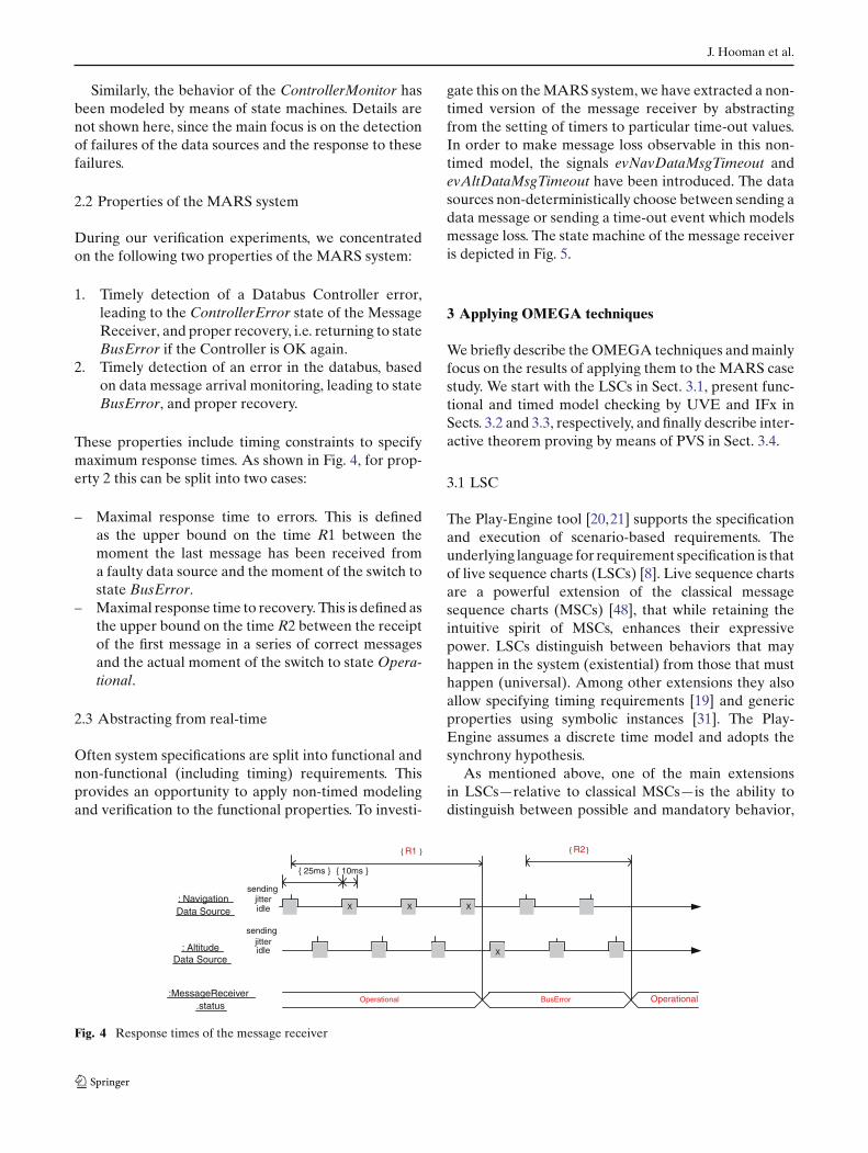
These properties include timing constraints to specifymaximum response times. As shown in Fig. 4, for prop-erty 2 this can be split into two cases:
– Maximal response time to errors. This is definedas the upper bound on the time R1 between themoment the last message has been received froma faulty data source and the moment of the switch tostate BusError.
– Maximal response time to recovery. This is defined asthe upper bound on the time R2 between the receiptof the first message in a series of correct messagesand the actual moment of the switch to state Opera-tional.
2.3 Abstracting from real-time
Often system specifications are split into functional andnon-functional (including timing) requirements. Thisprovides an opportunity to apply non-timed modelingand verification to the functional properties. To investi-
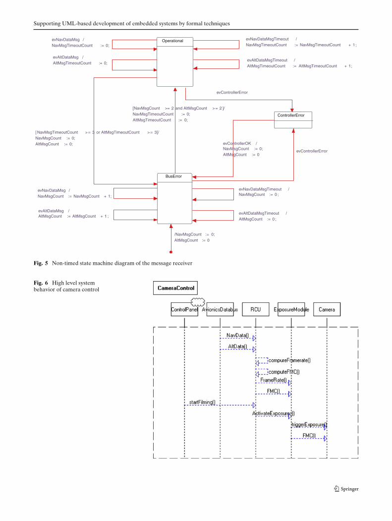
gate this on the MARS system, we have extracted a non-timed version of the message receiver by abstractingfrom the setting of timers to particular time-out values.In order to make message loss observable in this non-timed model, the signals evNavDataMsgTimeout andevAltDataMsgTimeout have been introduced. The datasources non-deterministically choose between sending adata message or sending a time-out event which modelsmessage loss. The state machine of the message receiveris depicted in Fig. 5.
3 Applying OMEGA techniques
We briefly describe the OMEGA techniques and mainlyfocus on the results of applying them to the MARS casestudy. We start with the LSCs in Sect. 3.1, present func-tional and timed model checking by UVE and IFx inSects. 3.2 and 3.3, respectively, and finally describe inter-active theorem proving by means of PVS in Sect. 3.4.
3.1 LSC
The Play-Engine tool [20,21] supports the specificationand execution of scenario-based requirements. Theunderlying language for requirement specification is thatof live sequence charts (LSCs) [8]. Live sequence chartsare a powerful extension of the classical messagesequence charts (MSCs) [48], that while retaining theintuitive spirit of MSCs, enhances their expressivepower. LSCs distinguish between behaviors that mayhappen in the system (existential) from those that musthappen (universal). Among other extensions they alsoallow specifying timing requirements [19] and genericproperties using symbolic instances [31]. The Play-Engine assumes a discrete time model and adopts thesynchrony hypothesis.
As mentioned above, one of the main extensionsin LSCs—relative to classical MSCs—is the ability todistinguish between possible and mandatory behavior,
: NavigationData Source
: AltitudeData Source
X
Operational BusError Operational
{ 25ms } { 10ms }
{ R1 } { R2 }
idle
sending
idle
sending
:MessageReceiver.status
jitter
jitterX X
X
Fig. 4 Response times of the message receiver
Supporting UML-based development of embedded systems by formal techniques
ControllerError
BusError
/NavMsgCount := 0;AltMsgCount := 0
evControllerOK /NavMsgCount := 0;AltMsgCount := 0
evControllerError
evAltDataMsgTimeout /AltMsgCount := 0 ;
evAltDataMsg /AltMsgCount := AltMsgCount + 1 ;
evNavDataMsgTimeout /NavMsgCount := 0 ;
evNavDataMsg /NavMsgCount := NavMsgCount + 1;
Operational
[NavMsgCount >= 2 and AltMsgCount >= 2 ]/NavMsgTimeoutCount := 0;AltMsgTimeoutCount := 0;
evControllerError
[ NavMsgTimeoutCount >= 3 or AltMsgTimeoutCount >= 3]/NavMsgCount := 0;AltMsgCount := 0;
evNavDataMsg /NavMsgTimeoutCount := 0;
evAltDataMsg /AltMsgTimeoutCount := 0;
evNavDataMsgTimeout /NavMsgTimeoutCount := NavMsgTimeoutCount + 1 ;
evAltDataMsgTimeout /AltMsgTimeoutCount := AltMsgTimeoutCount + 1;
Fig. 5 Non-timed state machine diagram of the message receiver
Fig. 6 High level systembehavior of camera control
J. Hooman et al.
using two types of charts. An existential chart describes apossible scenario in the system. Figure 6 depicts an exis-tential chart, as denoted by the dashed border, whichrepresents a high level system behavior of the cameracontrol. The vertical instances correspond to the partic-ipating objects—AvionicsDatabus, RCU, Exposu-reModule, Camera and the external object Control-Panel. Time progresses from top to bottom, thus theorder of the events in this chart is NavData, AltDa-ta, ComputeFramerate, ComputeFMC, FrameRate,FMC, StartFilming, ActivateExposures, trig-gerExposure and FMC. In general, a scenario definesa partial order on the events appearing in the chart,where events on the same object line occur according tothe visual order from top to bottom, and any given mes-sage can be received only after being sent. Since Fig. 6 isan existential chart, it specifies that there exists at leastone run of the system which exhibits the sequence ofevents described above.
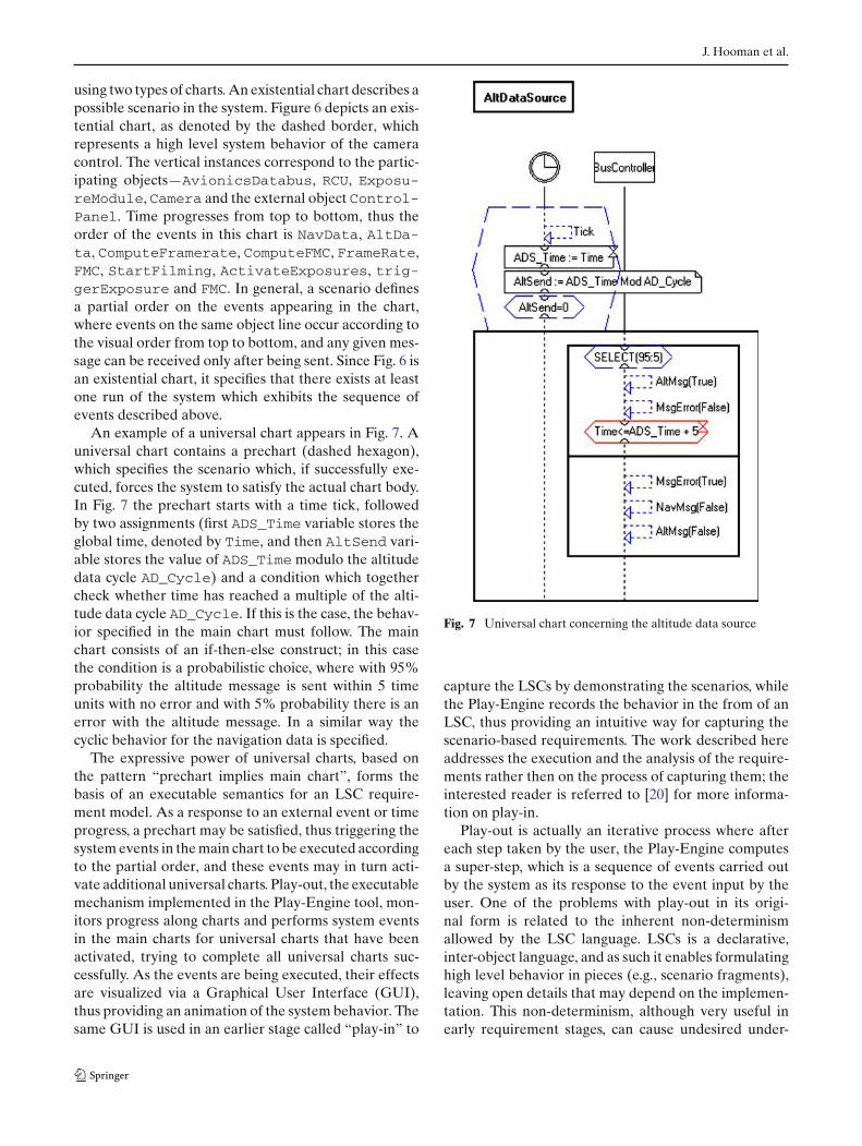
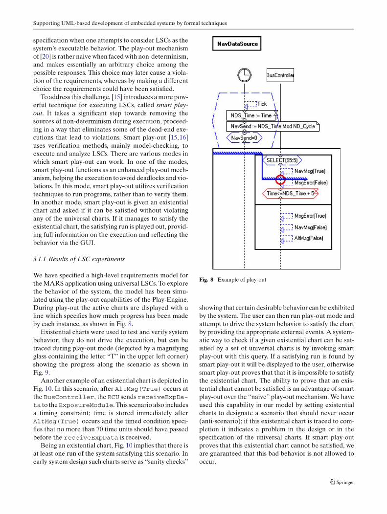
An example of a universal chart appears in Fig. 7. Auniversal chart contains a prechart (dashed hexagon),which specifies the scenario which, if successfully exe-cuted, forces the system to satisfy the actual chart body.In Fig. 7 the prechart starts with a time tick, followedby two assignments (first ADS_Time variable stores theglobal time, denoted by Time, and then AltSend vari-able stores the value of ADS_Time modulo the altitudedata cycle AD_Cycle) and a condition which togethercheck whether time has reached a multiple of the alti-tude data cycle AD_Cycle. If this is the case, the behav-ior specified in the main chart must follow. The mainchart consists of an if-then-else construct; in this casethe condition is a probabilistic choice, where with 95%probability the altitude message is sent within 5 timeunits with no error and with 5% probability there is anerror with the altitude message. In a similar way thecyclic behavior for the navigation data is specified.
The expressive power of universal charts, based onthe pattern “prechart implies main chart”, forms thebasis of an executable semantics for an LSC require-ment model. As a response to an external event or timeprogress, a prechart may be satisfied, thus triggering thesystem events in the main chart to be executed accordingto the partial order, and these events may in turn acti-vate additional universal charts. Play-out, the executablemechanism implemented in the Play-Engine tool, mon-itors progress along charts and performs system eventsin the main charts for universal charts that have beenactivated, trying to complete all universal charts suc-cessfully. As the events are being executed, their effectsare visualized via a Graphical User Interface (GUI),thus providing an animation of the system behavior. Thesame GUI is used in an earlier stage called “play-in” to
Fig. 7 Universal chart concerning the altitude data source
capture the LSCs by demonstrating the scenarios, whilethe Play-Engine records the behavior in the from of anLSC, thus providing an intuitive way for capturing thescenario-based requirements. The work described hereaddresses the execution and the analysis of the require-ments rather then on the process of capturing them; theinterested reader is referred to [20] for more informa-tion on play-in.
Play-out is actually an iterative process where aftereach step taken by the user, the Play-Engine computesa super-step, which is a sequence of events carried outby the system as its response to the event input by theuser. One of the problems with play-out in its origi-nal form is related to the inherent non-determinismallowed by the LSC language. LSCs is a declarative,inter-object language, and as such it enables formulatinghigh level behavior in pieces (e.g., scenario fragments),leaving open details that may depend on the implemen-tation. This non-determinism, although very useful inearly requirement stages, can cause undesired under-
Supporting UML-based development of embedded systems by formal techniques
specification when one attempts to consider LSCs as thesystem’s executable behavior. The play-out mechanismof [20] is rather naive when faced with non-determinism,and makes essentially an arbitrary choice among thepossible responses. This choice may later cause a viola-tion of the requirements, whereas by making a differentchoice the requirements could have been satisfied.
To address this challenge, [15] introduces a more pow-erful technique for executing LSCs, called smart play-out. It takes a significant step towards removing thesources of non-determinism during execution, proceed-ing in a way that eliminates some of the dead-end exe-cutions that lead to violations. Smart play-out [15,16]uses verification methods, mainly model-checking, toexecute and analyze LSCs. There are various modes inwhich smart play-out can work. In one of the modes,smart play-out functions as an enhanced play-out mech-anism, helping the execution to avoid deadlocks and vio-lations. In this mode, smart play-out utilizes verificationtechniques to run programs, rather than to verify them.In another mode, smart play-out is given an existentialchart and asked if it can be satisfied without violatingany of the universal charts. If it manages to satisfy theexistential chart, the satisfying run is played out, provid-ing full information on the execution and reflecting thebehavior via the GUI.
3.1.1 Results of LSC experiments
We have specified a high-level requirements model forthe MARS application using universal LSCs. To explorethe behavior of the system, the model has been simu-lated using the play-out capabilities of the Play-Engine.During play-out the active charts are displayed with aline which specifies how much progress has been madeby each instance, as shown in Fig. 8.
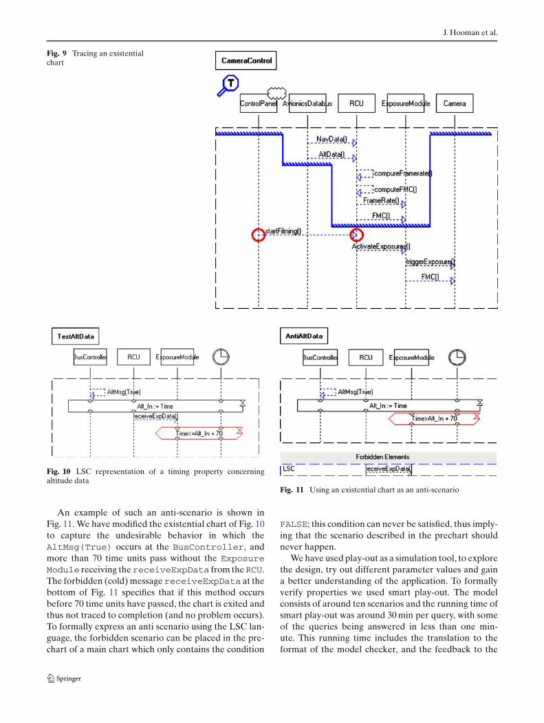
Existential charts were used to test and verify systembehavior; they do not drive the execution, but can betraced during play-out mode (depicted by a magnifyingglass containing the letter “T” in the upper left corner)showing the progress along the scenario as shown inFig. 9.
Another example of an existential chart is depicted inFig. 10. In this scenario, after AltMsg(True) occurs atthe BusController, the RCU sends receiveExpDa-ta to theExposureModule. This scenario also includesa timing constraint; time is stored immediately afterAltMsg(True) occurs and the timed condition speci-fies that no more than 70 time units should have passedbefore the receiveExpData is received.
Being an existential chart, Fig. 10 implies that there isat least one run of the system satisfying this scenario. Inearly system design such charts serve as “sanity checks”
Fig. 8 Example of play-out
showing that certain desirable behavior can be exhibitedby the system. The user can then run play-out mode andattempt to drive the system behavior to satisfy the chartby providing the appropriate external events. A system-atic way to check if a given existential chart can be sat-isfied by a set of universal charts is by invoking smartplay-out with this query. If a satisfying run is found bysmart play-out it will be displayed to the user, otherwisesmart play-out proves that that it is impossible to satisfythe existential chart. The ability to prove that an exis-tential chart cannot be satisfied is an advantage of smartplay-out over the “naive” play-out mechanism. We haveused this capability in our model by setting existentialcharts to designate a scenario that should never occur(anti-scenario); if this existential chart is traced to com-pletion it indicates a problem in the design or in thespecification of the universal charts. If smart play-outproves that this existential chart cannot be satisfied, weare guaranteed that this bad behavior is not allowed tooccur.
J. Hooman et al.
Fig. 9 Tracing an existentialchart
Fig. 10 LSC representation of a timing property concerningaltitude data
An example of such an anti-scenario is shown inFig. 11. We have modified the existential chart of Fig. 10to capture the undesirable behavior in which theAltMsg(True) occurs at the BusController, andmore than 70 time units pass without the ExposureModule receiving thereceiveExpData from theRCU.The forbidden (cold) message receiveExpData at thebottom of Fig. 11 specifies that if this method occursbefore 70 time units have passed, the chart is exited andthus not traced to completion (and no problem occurs).To formally express an anti scenario using the LSC lan-guage, the forbidden scenario can be placed in the pre-chart of a main chart which only contains the condition
Fig. 11 Using an existential chart as an anti-scenario
FALSE; this condition can never be satisfied, thus imply-ing that the scenario described in the prechart shouldnever happen.
We have used play-out as a simulation tool, to explorethe design, try out different parameter values and gaina better understanding of the application. To formallyverify properties we used smart play-out. The modelconsists of around ten scenarios and the running time ofsmart play-out was around 30 min per query, with someof the queries being answered in less than one min-ute. This running time includes the translation to theformat of the model checker, and the feedback to the
Supporting UML-based development of embedded systems by formal techniques
Play-Engine in case a satisfying run was found. Apply-ing smart play-out to larger models remains a majorchallenge due to the performance of the underlyingmodel checkers. The initial experience with smart play-out allowed the verification of some functional proper-ties, but also pointed out several problems in the tool,that will be discussed in Sects. 4.4 and 5.1.
3.2 UVE
The model-checking tool UVE [42] supports boundedand exhaustive verification of open systems with a non-deterministic environment. A discrete time semantics [9]has been implemented, where only the order betweenthe observable entities is considered. A discrete timestep corresponds to the execution of a transition in astate machine or the removal of an event from an eventqueue. Each action is considered instantaneous. Execu-tion duration is counted in terms of the number of stepsand this is used to bound the depth of the model explo-ration and to specify points of time during executionwhere conditions should be evaluated.
To formalize requirement specifications one can usethe built-in temporal logic patterns, based on CTL(Computation Tree Logic) formulas, or the LSC for-malism of the tool. Both notations use a discrete-timequantification in terms of steps which makes it possibleto express bounded properties such as “if P then even-tually Q within X steps”. The UVE tool can be used tocheck whether a certain UML model satisfies its speci-fied functionality. Functional requirements that can bechecked with UVE can be distinguished into universalproperties, which should hold for all system runs, andexistential properties, which require at least one run asa witness of the property.
UVE supports a subset of the LSCs from Sect. 3.1.This subset does not contain real-time constraints /con-ditions, but instead has additional possibilities to puta bound on the number of steps for which a propertyshould hold (and thus on the depth of model explora-tion). UVE also distinguishes between assumption andcommitment LSCs, which are just different roles of theproperties specifications within the verification process.This is important to restrict the non-deterministic envi-ronment of open systems.
UVE is based on backward state space explorationover bounded values of natural numbers. The problemof scalability, typical for model-checking approaches,depends not only on the size of the model, but to a largeextent also on the complexity of the property verified,the concurrency level in the model, and the amount ofnon-determinism of the environment.
An execution trace is represented in the form of anexistential LSC, showing the order of communicationevents between objects, and a so-called Symbolic Tim-ing Diagram (STD), which shows for observable execu-tion steps the changes of variables, states, event queues,etc. These STDs are similar to the timing diagrams thathave been added to UML 2.0. In UVE, STDs are onlyused to visualize verification results, making it easier tosearch for the source of an error. Whereas LSCs visu-alize the interaction between objects, STDs are conve-nient to show the internal computations of objects whichis often the focus of UVE-based verifications.
3.2.1 UVE experiments on MARS
UVE has been used to verify a number of propertiesof a non-timed version of the MARS system, using thestate diagram of the Message Receiver from Fig. 5. Theproperties mentioned in Sect. 2.2 have been expressedas bounded response properties where timing has beenreplaced by steps. The correct number of steps for whicha property holds has been obtained by a series ofverification experiments, involving counter-exampleanalysis and fine-tuning the specified step counts by suc-cessive approximations. On the average between fiveand ten experiments were needed per specified propertydepending on the complexity of the generated counterexample.
When a universal property does not hold or an exis-tential property holds, the UVE tool generates an errorpath or a witness path, respectively. The result of a ver-ification consists of a summarizing text and a generatedpath (when available), represented as an STD or anLSC.
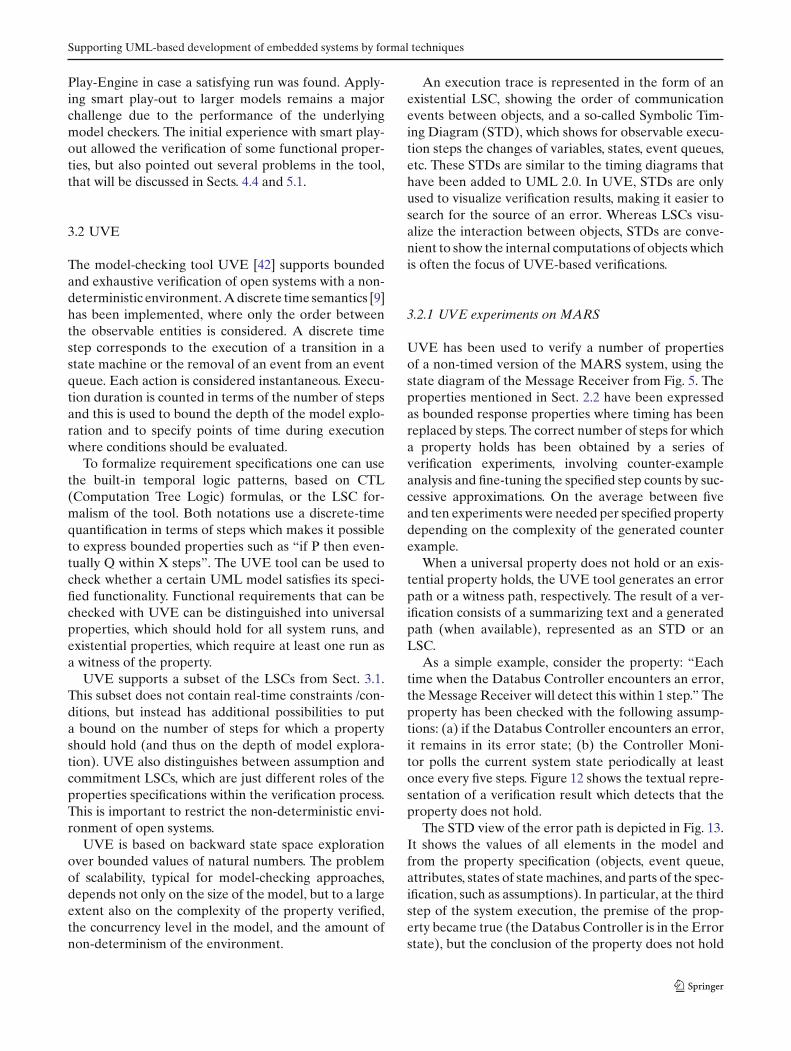
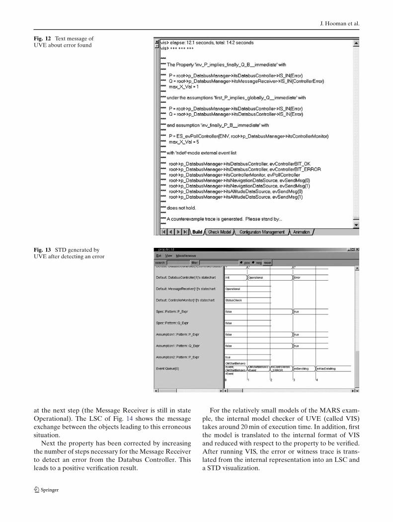
As a simple example, consider the property: “Eachtime when the Databus Controller encounters an error,the Message Receiver will detect this within 1 step.” Theproperty has been checked with the following assump-tions: (a) if the Databus Controller encounters an error,it remains in its error state; (b) the Controller Moni-tor polls the current system state periodically at leastonce every five steps. Figure 12 shows the textual repre-sentation of a verification result which detects that theproperty does not hold.
The STD view of the error path is depicted in Fig. 13.It shows the values of all elements in the model andfrom the property specification (objects, event queue,attributes, states of state machines, and parts of the spec-ification, such as assumptions). In particular, at the thirdstep of the system execution, the premise of the prop-erty became true (the Databus Controller is in the Errorstate), but the conclusion of the property does not hold
J. Hooman et al.
Fig. 12 Text message ofUVE about error found
Fig. 13 STD generated byUVE after detecting an error
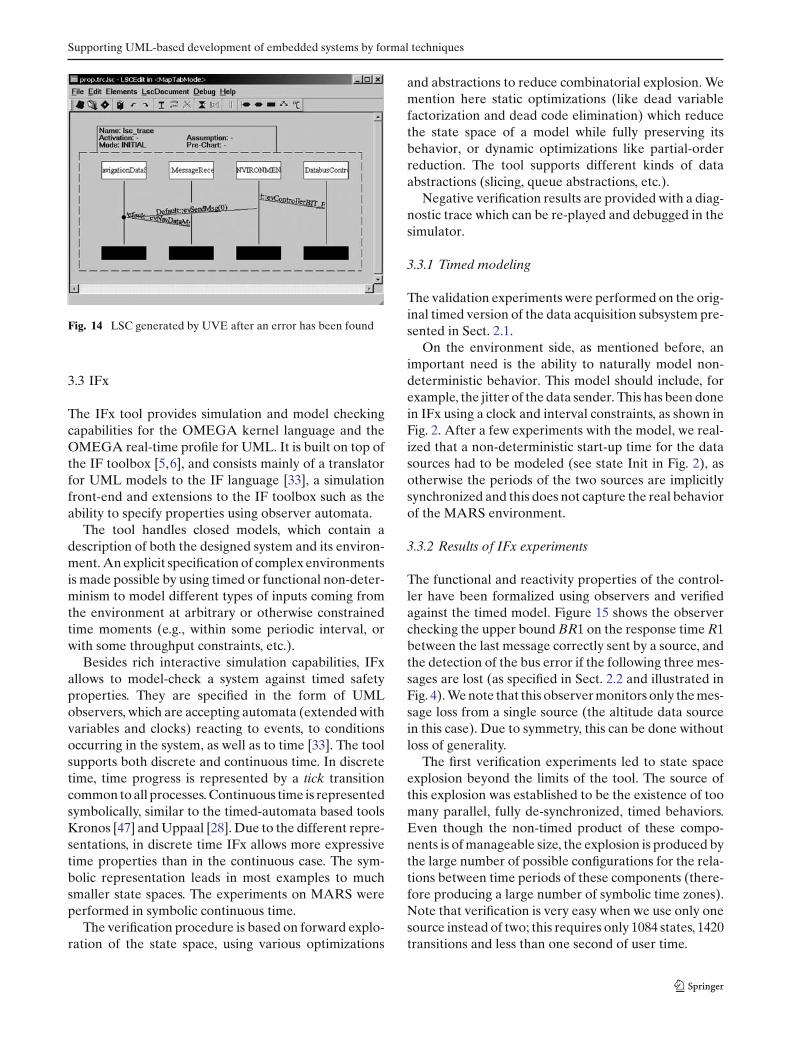
at the next step (the Message Receiver is still in stateOperational). The LSC of Fig. 14 shows the messageexchange between the objects leading to this erroneoussituation.
Next the property has been corrected by increasingthe number of steps necessary for the Message Receiverto detect an error from the Databus Controller. Thisleads to a positive verification result.
For the relatively small models of the MARS exam-ple, the internal model checker of UVE (called VIS)takes around 20 min of execution time. In addition, firstthe model is translated to the internal format of VISand reduced with respect to the property to be verified.After running VIS, the error or witness trace is trans-lated from the internal representation into an LSC anda STD visualization.
Supporting UML-based development of embedded systems by formal techniques
Fig. 14 LSC generated by UVE after an error has been found
3.3 IFx
The IFx tool provides simulation and model checkingcapabilities for the OMEGA kernel language and theOMEGA real-time profile for UML. It is built on top ofthe IF toolbox [5,6], and consists mainly of a translatorfor UML models to the IF language [33], a simulationfront-end and extensions to the IF toolbox such as theability to specify properties using observer automata.
The tool handles closed models, which contain adescription of both the designed system and its environ-ment. An explicit specification of complex environmentsis made possible by using timed or functional non-deter-minism to model different types of inputs coming fromthe environment at arbitrary or otherwise constrainedtime moments (e.g., within some periodic interval, orwith some throughput constraints, etc.).
Besides rich interactive simulation capabilities, IFxallows to model-check a system against timed safetyproperties. They are specified in the form of UMLobservers, which are accepting automata (extended withvariables and clocks) reacting to events, to conditionsoccurring in the system, as well as to time [33]. The toolsupports both discrete and continuous time. In discretetime, time progress is represented by a tick transitioncommon to all processes. Continuous time is representedsymbolically, similar to the timed-automata based toolsKronos [47] and Uppaal [28]. Due to the different repre-sentations, in discrete time IFx allows more expressivetime properties than in the continuous case. The sym-bolic representation leads in most examples to muchsmaller state spaces. The experiments on MARS wereperformed in symbolic continuous time.
The verification procedure is based on forward explo-ration of the state space, using various optimizations
and abstractions to reduce combinatorial explosion. Wemention here static optimizations (like dead variablefactorization and dead code elimination) which reducethe state space of a model while fully preserving itsbehavior, or dynamic optimizations like partial-orderreduction. The tool supports different kinds of dataabstractions (slicing, queue abstractions, etc.).
Negative verification results are provided with a diag-nostic trace which can be re-played and debugged in thesimulator.
3.3.1 Timed modeling
The validation experiments were performed on the orig-inal timed version of the data acquisition subsystem pre-sented in Sect. 2.1.
On the environment side, as mentioned before, animportant need is the ability to naturally model non-deterministic behavior. This model should include, forexample, the jitter of the data sender. This has been donein IFx using a clock and interval constraints, as shown inFig. 2. After a few experiments with the model, we real-ized that a non-deterministic start-up time for the datasources had to be modeled (see state Init in Fig. 2), asotherwise the periods of the two sources are implicitlysynchronized and this does not capture the real behaviorof the MARS environment.
3.3.2 Results of IFx experiments
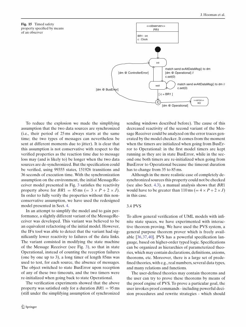
The functional and reactivity properties of the control-ler have been formalized using observers and verifiedagainst the timed model. Figure 15 shows the observerchecking the upper bound BR1 on the response time R1between the last message correctly sent by a source, andthe detection of the bus error if the following three mes-sages are lost (as specified in Sect. 2.2 and illustrated inFig. 4). We note that this observer monitors only the mes-sage loss from a single source (the altitude data sourcein this case). Due to symmetry, this can be done withoutloss of generality.
The first verification experiments led to state spaceexplosion beyond the limits of the tool. The source ofthis explosion was established to be the existence of toomany parallel, fully de-synchronized, timed behaviors.Even though the non-timed product of these compo-nents is of manageable size, the explosion is produced bythe large number of possible configurations for the rela-tions between time periods of these components (there-fore producing a large number of symbolic time zones).Note that verification is very easy when we use only onesource instead of two; this requires only 1084 states, 1420transitions and less than one second of user time.
J. Hooman et al.
Fig. 15 Timed safetyproperty specified by meansof an observer
init
wait
match send evAltDataMsg() to dm[dm @ Operational] //c.set(0)
match send evAltDataMsg() to dm //c.set(0)
C
[dm @ ControllerError]
[dm @ BusError]
[ c = BR1 ]
<<error>>KO
[dm @ Operational]
<<observer>>PR1
BR1 : intc : Clock
To reduce the explosion we made the simplifyingassumption that the two data sources are synchronized(i.e., their period of 25 ms always starts at the sametime; the two types of messages can nevertheless besent at different moments due to jitter). It is clear thatthis assumption is not conservative with respect to theverified properties as the reaction time due to messageloss may (and is likely to) be longer when the two datasources are de-synchronized. But the specification couldbe verified, using 99355 states, 151926 transitions and36 seconds of execution time. With the synchronizationassumption on the environment, the initial MessageRe-ceiver model presented in Fig. 3 satisfies the reactivityproperty above for BR1 = 85 ms (= 3 × P + 2 × J).In order to fully verify the properties without this non-conservative assumption, we have used the redesignedmodel presented in Sect. 4.
In an attempt to simplify the model and to gain per-formance, a slightly different variant of the MessageRe-ceiver was developed. This variant was believed to bean equivalent refactoring of the initial model. However,the IFx tool was able to detect that the variant had sig-nificantly lower reactivity to failures of the data links.The variant consisted in modifying the state machineof the Message Receiver (see Fig. 3), so that in stateOperational, instead of counting the reception failures(one by one up to 3), a long timer of length 85ms wasused to test, for each source, the absence of messages.The object switched to state BusError upon receptionof any of these two timeouts, and the two timers werere-initialized when going back to state Operational.
The verification experiments showed that the aboveproperty was satisfied only for a duration BR1 = 95 ms(still under the simplifying assumption of synchronized
sending windows described before). The cause of thisdecreased reactivity of the second variant of the Mes-sage Receiver could be analyzed on the error traces gen-erated by the model checker. It comes from the momentwhen the timers are initialized when going from BusEr-ror to Operational: in the first model timers are keptrunning as they are in state BusError, while in the sec-ond one both timers are re-initialized when going fromBusError to Operational because the timeout durationhas to change from 35 to 85 ms.
Although in the more realistic case of completely de-synchronized sources this property could not be checked(see also Sect. 4.3), a manual analysis shows that BR1would have to be greater than 110 ms (= 4 × P + 2 × J)in this case.
3.4 PVS
To allow general verification of UML models with infi-nite state spaces, we have experimented with interac-tive theorem proving. We have used the PVS system, ageneral purpose theorem prover which is freely avail-able [36,37,40]. PVS has a powerful specification lan-guage, based on higher-order typed logic. Specificationscan be organized as hierarchies of parameterized theo-ries, which may contain declarations, definitions, axioms,theorems, etc. Moreover, there is a large set of prede-fined theories, with e.g., real numbers, several data types,and many relations and functions.
The user-defined theories may contain theorems andthe user can try to prove these theorems by means ofthe proof engine of PVS. To prove a particular goal, theuser invokes proof commands - including powerful deci-sion procedures and rewrite strategies - which should
Supporting UML-based development of embedded systems by formal techniques
simplify the goal until it can be proved automatically byPVS.
To be able to use the PVS system for the verificationof UML models, we have represented the semantics ofthe OMEGA kernel model in PVS [23]. The general ideais that an execution of the UML model is representedby a run (i.e., an execution trace) which is a sequence ofthe form c0 → c1 → c2 → c3 → · · · where the ci areconfigurations, representing a snapshot of the systemduring execution and each pair of successive configura-tions represents a step of a state machine of one of theobjects or a time step. Time steps model the global pro-gress of time, similar to timed automata (see, e.g., [28]),using the real numbers of PVS to obtain a continuousnotion of time.
The semantics has been defined in a few PVS theorieswhich are parameterized by the syntax of a UML model,including class names, transitions of state machines,methods, etc. These theories form the core of the tech-niques used to verify UML models by means of PVS.The user can model a system in the OMEGA kernellanguage using a commercial UML-based CASE tool.The XMI output of the tool, representing the model inXML, is first preprocessed to remove a large amountof XMI information and to get a concise representation.Next it is transformed into a representation of the syntaxof the model in PVS [27].
Properties of the system under development mightbe specified in OCL and can then also be transformedinto the PVS specification language. In the experimentsdescribed here, however, we have specified the proper-ties directly in PVS because the industrial users werenot acquainted with OCL and they did not have toolsupport for it.
To verify that the UML model satisfies a certain prop-erty, a PVS theory is created which imports the PVS rep-resentation of the UML semantics, parameterized by thesyntax of the concrete model. It also defines the prop-erties, expressed as predicates over runs of the model.Next the user can use the proof environment of PVS totry to prove the properties in an interactive way.
The focus of the PVS experiments with the MARSsystem was on the verification of general properties thatare beyond the scope of model checkers. This concernsproperties that express relations between parametersfor system characteristics such as period, jitter, time-outvalues, the number of allowed retries, and the numberof messages needed for recovery. Other work addressessystems where the number of objects is unbounded [1].
In the next two subsections we first present ourverification experiments with the non-timed model ofMARS, and next describe the attempts to verify thetimed model.
3.4.1 Non-timed model
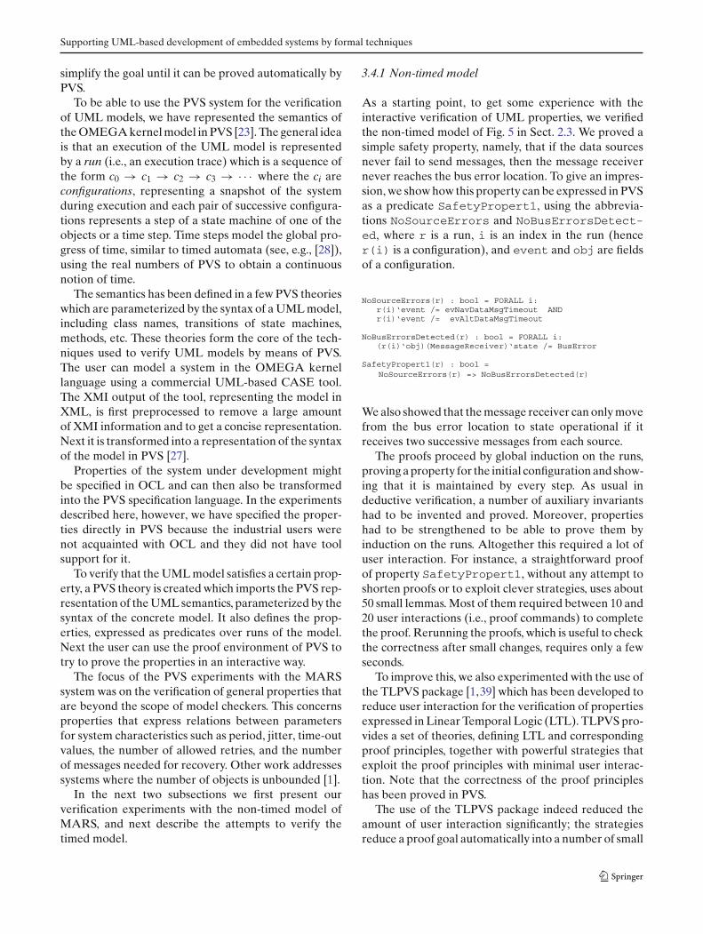
As a starting point, to get some experience with theinteractive verification of UML properties, we verifiedthe non-timed model of Fig. 5 in Sect. 2.3. We proved asimple safety property, namely, that if the data sourcesnever fail to send messages, then the message receivernever reaches the bus error location. To give an impres-sion, we show how this property can be expressed in PVSas a predicate SafetyPropert1, using the abbrevia-tions NoSourceErrors and NoBusErrorsDetect-ed, where r is a run, i is an index in the run (hencer(i) is a configuration), and event and obj are fieldsof a configuration.
We also showed that the message receiver can only movefrom the bus error location to state operational if itreceives two successive messages from each source.
The proofs proceed by global induction on the runs,proving a property for the initial configuration and show-ing that it is maintained by every step. As usual indeductive verification, a number of auxiliary invariantshad to be invented and proved. Moreover, propertieshad to be strengthened to be able to prove them byinduction on the runs. Altogether this required a lot ofuser interaction. For instance, a straightforward proofof property SafetyPropert1, without any attempt toshorten proofs or to exploit clever strategies, uses about50 small lemmas. Most of them required between 10 and20 user interactions (i.e., proof commands) to completethe proof. Rerunning the proofs, which is useful to checkthe correctness after small changes, requires only a fewseconds.
To improve this, we also experimented with the use ofthe TLPVS package [1,39] which has been developed toreduce user interaction for the verification of propertiesexpressed in Linear Temporal Logic (LTL). TLPVS pro-vides a set of theories, defining LTL and correspondingproof principles, together with powerful strategies thatexploit the proof principles with minimal user interac-tion. Note that the correctness of the proof principleshas been proved in PVS.
The use of the TLPVS package indeed reduced theamount of user interaction significantly; the strategiesreduce a proof goal automatically into a number of small
J. Hooman et al.
cases, which often can be discharged by a fixed sequenceof commands. For property SafetyPropert1, theproof could be reduced to 3 lemmas which togetherrequired around 120 interactions (including calls torather complex strategies). Note, however, that theinsight obtained by the earlier proof has been used;for instance, all required auxiliary properties have beencombined into a single lemma.
3.4.2 Adding time
Our main interest was a general verification of the timedcase, using parameters for the timing values. We useTout to represent the time-out value for message loss,and parameters PN and PA for the maximal processingtime of navigation and altitude messages, respectively.Moreover, we use parameters N and K for the numberof allowed data losses and the number of consecutivemessages needed for recovery, respectively, to general-ize the two properties mentioned in Sect. 2.2:
1. The receiver shall move to the bus error location ifand only if one of data sources misses N consecutivemessages
2. The receiver shall recover from a bus error if andonly if both data sources send K consecutive mes-sages
In the original MARS system, we have N = 3 andK = 2. We started the verification experiments witha simple case where N = 1, K = 1, and using a longtime-out Tout (as shown in Sect. 3.3.2 this is less opti-mal than a sequence of small time-outs). We managedto prove a safety property, but this required about 50auxiliary lemmas in PVS and a lot of user interactionand ingenuity. Positive was the identification of requiredrelations between the parameters, such as 4 × J < P,max(PN, PA) < P − 4 × J, and N × P + 2 × J < Tout <
(N + 1) × P − 2 × J. Observe that this implies, forinstance, that jitter J should be relatively small com-pared to period P and it also gives an upper bound onthe processing times PN and PA.
4 OMEGA techniques applied to a redesign of MARS
Evaluating the verification of the MARS system, itbecame clear that for complex examples compositional-ity and abstraction are essential to improve scalability.To be able to experiment with these techniques in theMARS system, we re-model this system. In addition tofacilitating formal techniques, the new model is moremodular and flexible, since it can be easily instantiated
for an arbitrary number of data sources. Instead of usinginternal states to represent errors, we make them exter-nally visible by sending error and operational signals. Toshow the essential part, we omit the controller error andfocus on detecting and recovering from bus errors.
The basic idea is that we replace the original mes-sage receiver, which deals with two data sources, by thecomposition of three objects: two instances of a sim-pler message receiver MR which deals with a single datasource, and an error logic object EL. Each MR objectreceives data from a particular source and sends an errsignal to EL if a number of consecutive data items ismissing. When MR observes a recovery of the databusby receiving a number of successive data items, it sendsan ok signal to EL.
The error logic object EL collects the ok and err sig-nals; when the system is operating correctly then a singleerr signal leads to an error signal. After sending error,object EL sends signal operational if it is informed thatboth MR objects are correct, that is, if for both objectsit has received an ok signal after every err signal.
Finally, we proposed a refinement of each MR objectinto two objects:
– A receiver R which receives data items and containstime-outs to detect the absence of data.
– A monitor M which gets information from receiver Rabout the absence or presence of data, counts theseevents, and generates the err and ok signals whenneeded.
Note that M is non-timed, containing only computa-tions, whereas component R just detects the presence orabsence of messages during specified time periods.
In the next subsections we apply the OMEGA tech-niques to this redesign of MARS. In Sect. 4.1 we provethe correctness of the high-level decomposition of thedesign using PVS. Sections 4.2 and 4.3 contain the appli-cation of functional and timed model checking, respec-tively. The use of LSCs is shown in Sect. 4.4.
4.1 PVS
For the redesign of MARS, the focus of interactive veri-fication by means of PVS is on high-level verificationon the level of components. The aim is to show thecorrectness of the design at this level, reasoning withthe specifications of components without knowing theirimplementation. Hence we consider in this section onlytwo constructs: parallel composition and hiding of inter-nal events. To obtain a compositional framework forreasoning about components, we have changed the PVSframework in a number of aspects:
Supporting UML-based development of embedded systems by formal techniques
– The semantics has been reformulated to obtain adenotational (i.e. compositional) semantics for par-allel composition and hiding. The semantics has beenformulated in terms of traces, which are an abstrac-tion of the runs in the basic OMEGA semantics.Since we are dealing with high-level decompositions,we abstract from all internal details such as internalobjects and the values of their attributes. We onlyrecord the current time of the configurations and theexternal events which cause configuration changes.
– To express properties of (part of) a system, we uselogical formulae that define a set of traces. To be ableto formalize intermediate stages during thetop-down design of a system, we have defined aframework where specifications and programmingconstructs can be mixed freely. Refinement corre-sponds to trace inclusion. This is inspired by similarwork on non-timed systems and related to work ontimed systems [22].
– Compositional proof rules for parallel compositionand hiding have been formulated and proven tobe sound in PVS. The rule for parallel composi-tion expresses that the composition of two compo-nents satisfies the conjunction of the specificationsof these components, provided their specificationsonly depend on the interface of the correspondingcomponent.
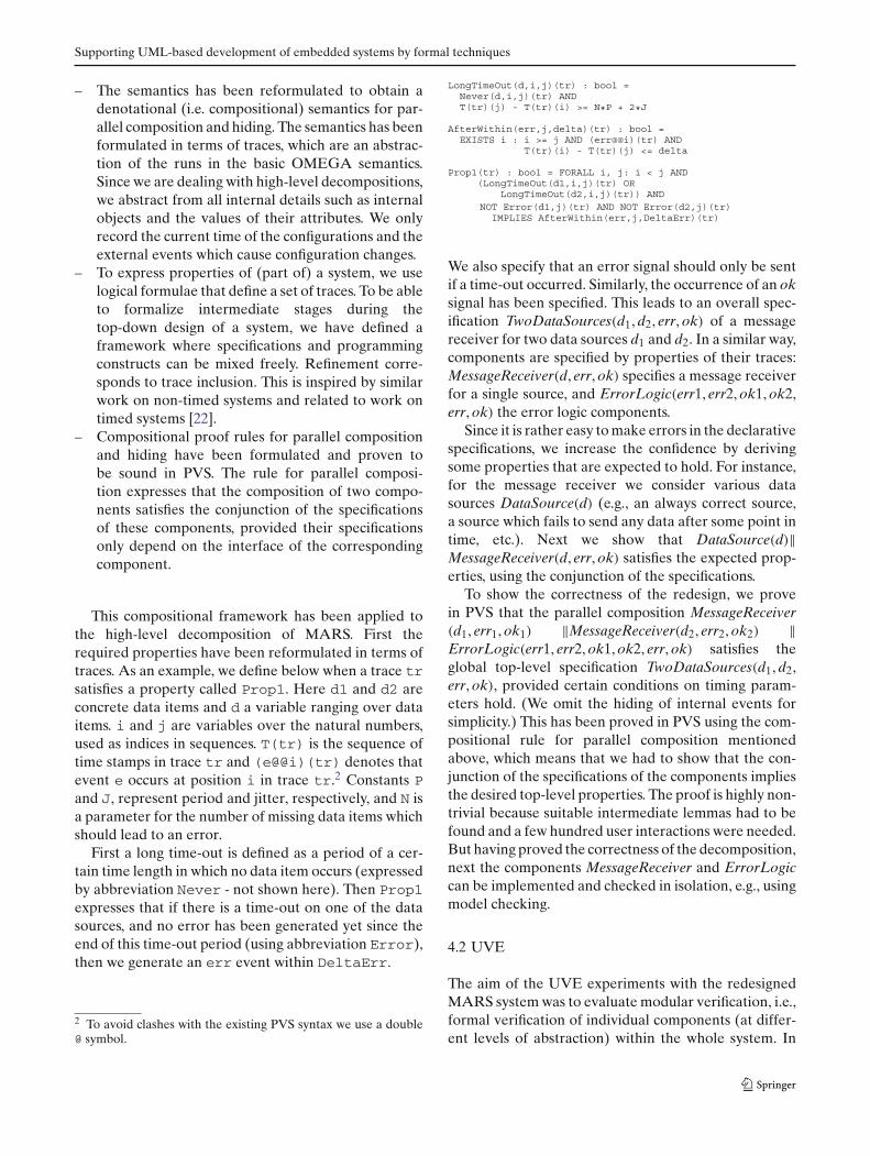
This compositional framework has been applied tothe high-level decomposition of MARS. First therequired properties have been reformulated in terms oftraces. As an example, we define below when a trace trsatisfies a property called Prop1. Here d1 and d2 areconcrete data items and d a variable ranging over dataitems. i and j are variables over the natural numbers,used as indices in sequences. T(tr) is the sequence oftime stamps in trace tr and (e@@i)(tr) denotes thatevent e occurs at position i in trace tr.2 Constants Pand J, represent period and jitter, respectively, and N isa parameter for the number of missing data items whichshould lead to an error.
First a long time-out is defined as a period of a cer-tain time length in which no data item occurs (expressedby abbreviation Never - not shown here). Then Prop1expresses that if there is a time-out on one of the datasources, and no error has been generated yet since theend of this time-out period (using abbreviation Error),then we generate an err event within DeltaErr.
2 To avoid clashes with the existing PVS syntax we use a double@ symbol.
We also specify that an error signal should only be sentif a time-out occurred. Similarly, the occurrence of an oksignal has been specified. This leads to an overall spec-ification TwoDataSources(d1, d2, err, ok) of a messagereceiver for two data sources d1 and d2. In a similar way,components are specified by properties of their traces:MessageReceiver(d, err, ok) specifies a message receiverfor a single source, and ErrorLogic(err1, err2, ok1, ok2,err, ok) the error logic components.
Since it is rather easy to make errors in the declarativespecifications, we increase the confidence by derivingsome properties that are expected to hold. For instance,for the message receiver we consider various datasources DataSource(d) (e.g., an always correct source,a source which fails to send any data after some point intime, etc.). Next we show that DataSource(d)‖MessageReceiver(d, err, ok) satisfies the expected prop-erties, using the conjunction of the specifications.
To show the correctness of the redesign, we provein PVS that the parallel composition MessageReceiver(d1, err1, ok1) ‖MessageReceiver(d2, err2, ok2) ‖ErrorLogic(err1, err2, ok1, ok2, err, ok) satisfies theglobal top-level specification TwoDataSources(d1, d2,err, ok), provided certain conditions on timing param-eters hold. (We omit the hiding of internal events forsimplicity.) This has been proved in PVS using the com-positional rule for parallel composition mentionedabove, which means that we had to show that the con-junction of the specifications of the components impliesthe desired top-level properties. The proof is highly non-trivial because suitable intermediate lemmas had to befound and a few hundred user interactions were needed.But having proved the correctness of the decomposition,next the components MessageReceiver and ErrorLogiccan be implemented and checked in isolation, e.g., usingmodel checking.
4.2 UVE
The aim of the UVE experiments with the redesignedMARS system was to evaluate modular verification, i.e.,formal verification of individual components (at differ-ent levels of abstraction) within the whole system. In
J. Hooman et al.
the UVE context, a component is an object of the rootclass together with all its children related to it via com-position and aggregation associations. The behavior of acomponent must be fully specified with state machinesand methods.
In the redesigned MARS system, the componentsMR (message receiver) and EL (error logic) have beenconsidered separately, as well as the smaller subcompo-nent M and a larger subsystem containing a single datasource, one MR object, and an EL object. The compo-nents were verified relative to assumptions about inputfrom the environment. For instance, for the subsystemR||M, the non-timed component M has been verifiedwith respect to a specification (with an over-approxima-tion) of the timed part R.
Different kinds of property specifications were ver-ified for the chosen system parts (propositional andtemporal formulas, LSCs), making assumptions on theinputs (order of events, attribute values), and observingthe responses of the component under verification.
Due to restrictions in the tool (e.g., there is no possi-bility to define or automatically detect component inter-faces for outgoing events, and the targets of all eventsmust be specified explicitly in the model), some fur-ther remodeling has been performed to enable compo-sitional reasoning. This has been done using standardelements of UML 2.0 like ports and connections, butexpressed in UML 1.4 since UVE was primary basedon this version of UML. The whole remodeling in UVEtook a few hours of an experienced designer. It wasmore difficult (a few days of experimentation) to findsuitable properties for the parts and the proper assump-tions about the inputs to the ports.
The general observation concerning the redesign isthat the decomposed model became larger due to addi-tional communication mechanisms (handling communi-cation abstraction, dealing with explicit targets of theoutput events). This increases the verification time ofthe entire system, but makes it possible to verify partsquickly and in a more general context. Analysis resultsfor a larger model can then be obtained out of the prop-erties of its parts and the connection structure betweenthese parts. Without such decomposition, verificationoften took too long and sometimes had to be aborted,especially for models with a lot of concurrency, i.e. withmultiple active objects. Observe, however, that the com-positional approach requires more specialized modelingeffort from designers.
4.3 IFx
The introduction of the compositional model hasallowed to push forward the analysis with IFx. As men-
tioned before, the original model could not be verifiedin case of completely de-synchronized data sources.
The compositional model allows the construction ofa simple abstraction for one of the Data Sources: its cor-responding MR sends out non-deterministically eitherok or err, at unspecified moments. The specification ofproperties has to be adapted accordingly. For example,the property “if there is no message from one of the DataSources for more than T time units, then the Message-Receiver is in state BusError at the end of this interval”(introduced in Sect. 3.3) becomes “if there is no mes-sage from the concrete Data Source for more than Ttime units, then the MessageReceiver is in state BusEr-ror at the end of this interval”. Using the symmetry ofthe two Data Sources, this property implies the originalone.
The use of this abstraction brought the state space to amanageable size and allowed the verification of all prop-erties, while effectively over-approximating the generalcase of de-synchronized Data Sources. The verificationtook 155166 states, 263368 transitions and 1 min and 21 sof execution time.
The experiments pointed out a problem with the pro-posed redesign: the fact that an MR object does not sendthe err signal is not sufficient for recovery. For instance,if the MR misses a single data item, then this does notlead to err, but a global recovery does not allow anymiss; it requires that all data must have been received.There are several solutions to this: either weaken theinitial specification, or adapt the design by adding forexample a miss signal, or use parameterized signals torepresent the presence of the last N messages (insteadof the simple ok and err messages).
4.4 LSC
The Play-Engine has been applied to the redesign of theMARS system in three phases: model construction, ver-ification, and synthesis. The first phase involved mostlyconstructing an LSC model using play-in and simula-tion using play-out. We have modified our original LSCmodel and then used play-out to simulate the behav-ior for various types of data sources, including modelswhere both sources never fail, where only one of thesources may fail, and where a source that fails neverrecovers and does not send any data. We have alsochanged the probability for failure in the original modeland used play-out to see the effect on the behavior.In the second phase, we have applied smart play-outto formally verify properties of the LSC model. Afterextending smart play-out to support time and forbiddenelements [16], we managed to verify timed properties ofthe model.
Supporting UML-based development of embedded systems by formal techniques
Fig. 16 Synthesized state machine for the non-timed part of themessage receiver
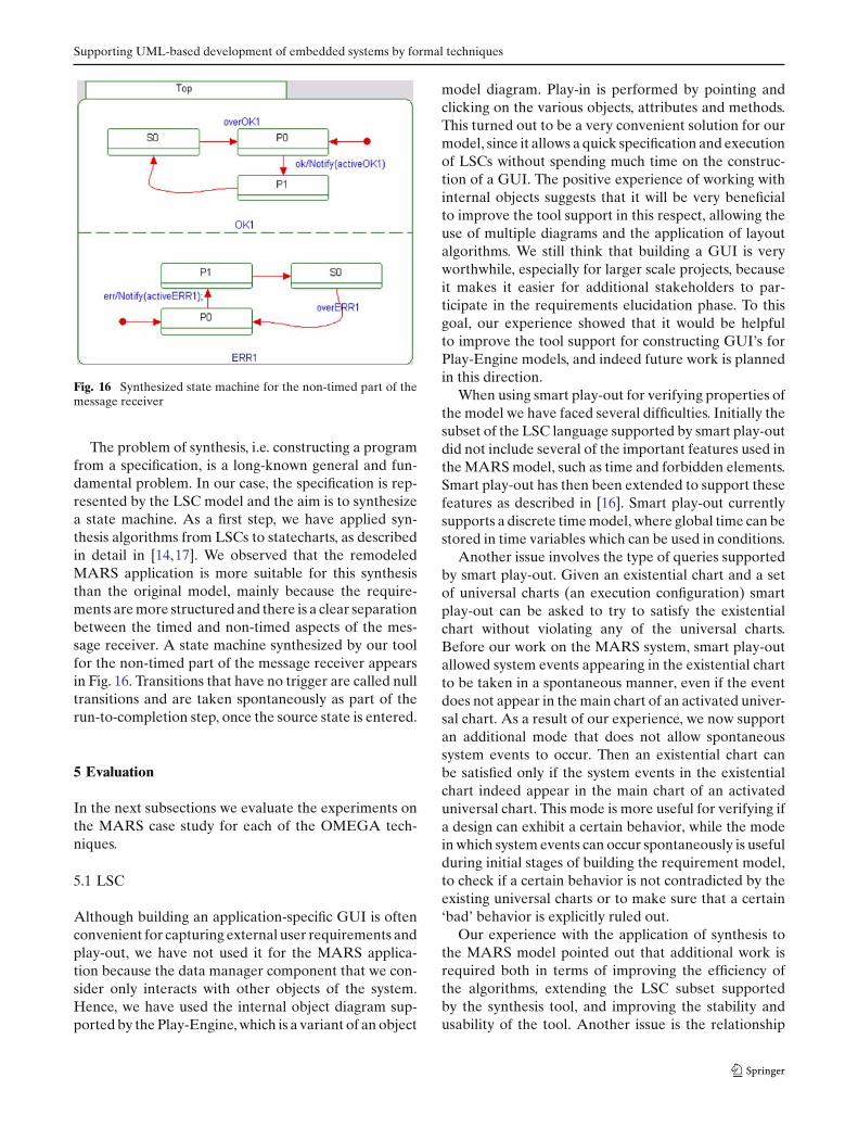
The problem of synthesis, i.e. constructing a programfrom a specification, is a long-known general and fun-damental problem. In our case, the specification is rep-resented by the LSC model and the aim is to synthesizea state machine. As a first step, we have applied syn-thesis algorithms from LSCs to statecharts, as describedin detail in [14,17]. We observed that the remodeledMARS application is more suitable for this synthesisthan the original model, mainly because the require-ments are more structured and there is a clear separationbetween the timed and non-timed aspects of the mes-sage receiver. A state machine synthesized by our toolfor the non-timed part of the message receiver appearsin Fig. 16. Transitions that have no trigger are called nulltransitions and are taken spontaneously as part of therun-to-completion step, once the source state is entered.
5 Evaluation
In the next subsections we evaluate the experiments onthe MARS case study for each of the OMEGA tech-niques.
5.1 LSC
Although building an application-specific GUI is oftenconvenient for capturing external user requirements andplay-out, we have not used it for the MARS applica-tion because the data manager component that we con-sider only interacts with other objects of the system.Hence, we have used the internal object diagram sup-ported by the Play-Engine, which is a variant of an object
model diagram. Play-in is performed by pointing andclicking on the various objects, attributes and methods.This turned out to be a very convenient solution for ourmodel, since it allows a quick specification and executionof LSCs without spending much time on the construc-tion of a GUI. The positive experience of working withinternal objects suggests that it will be very beneficialto improve the tool support in this respect, allowing theuse of multiple diagrams and the application of layoutalgorithms. We still think that building a GUI is veryworthwhile, especially for larger scale projects, becauseit makes it easier for additional stakeholders to par-ticipate in the requirements elucidation phase. To thisgoal, our experience showed that it would be helpfulto improve the tool support for constructing GUI’s forPlay-Engine models, and indeed future work is plannedin this direction.
When using smart play-out for verifying properties ofthe model we have faced several difficulties. Initially thesubset of the LSC language supported by smart play-outdid not include several of the important features used inthe MARS model, such as time and forbidden elements.Smart play-out has then been extended to support thesefeatures as described in [16]. Smart play-out currentlysupports a discrete time model, where global time can bestored in time variables which can be used in conditions.
Another issue involves the type of queries supportedby smart play-out. Given an existential chart and a setof universal charts (an execution configuration) smartplay-out can be asked to try to satisfy the existentialchart without violating any of the universal charts.Before our work on the MARS system, smart play-outallowed system events appearing in the existential chartto be taken in a spontaneous manner, even if the eventdoes not appear in the main chart of an activated univer-sal chart. As a result of our experience, we now supportan additional mode that does not allow spontaneoussystem events to occur. Then an existential chart canbe satisfied only if the system events in the existentialchart indeed appear in the main chart of an activateduniversal chart. This mode is more useful for verifying ifa design can exhibit a certain behavior, while the modein which system events can occur spontaneously is usefulduring initial stages of building the requirement model,to check if a certain behavior is not contradicted by theexisting universal charts or to make sure that a certain‘bad’ behavior is explicitly ruled out.
Our experience with the application of synthesis tothe MARS model pointed out that additional work isrequired both in terms of improving the efficiency ofthe algorithms, extending the LSC subset supportedby the synthesis tool, and improving the stability andusability of the tool. Another issue is the relationship
J. Hooman et al.
between manually designed state machines and auto-matically synthesized ones. Although the synthesizedmodel is guaranteed to be correct with respect to thegiven requirements, a manual design may have otheradvantages in terms of efficiency and the ability of thedesigner to understand and modify the model if neces-sary. Having said that, tool support for synthesizing evena relatively small model from LSCs into state machinesand run it in a powerful UML tool like Rhapsody, opensup exciting development opportunities which we plan tocontinue exploring.
Additional information on using LSCs and the Play-Engine for other case studies in OMEGA appearsin [18].
5.2 UVE
The UVE tool is intended to be used during the develop-ment of individual components, allowing the verificationof executable models at different levels of abstraction.It has been found useful for estimating the relative dis-crete timing of the different entities in the model and forgaining insight into the step interleaving of model com-ponents as part of the total model behavior. The majorproblem of the application of UVE to a UML model, asobserved during the experiments on MARS, is the sig-nificant decrease in performance while verifying morecomplex properties.
The complexity of the model-checking task dependson many parameters: the size of the model (the num-ber of objects and links between them), the levels ofnon-determinism (e.g., due to multiple active objects,concurrency in state machines, and a non-determinis-tic environment), the complicated arithmetic (includingloops, dynamic branching, etc.), the complexity of thetemporal property under verification (e.g., long execu-tion paths specified by different events and conditions,or many assumptions on the environment).
The experiments showed that it is difficult for the userto assess the verification complexity and to set the rele-vant parameters to reduce this complexity. For instance,it is difficult to find reasonable assumptions (both onthe environment and on the system parts outside theverification scope) to reduce external non-determinism.The same holds for finding the correct step boundariesin properties.
To be able to verify components with UVE, a well-structured model is needed, e.g., communicationbetween components must be asynchronous by means ofsignals. We strongly recommend to separate concurrentthreads of control into different components, becauseverification of a component with multiple threads oftenmeets complexity problems, not yet resolved in the tool.
The design of each component should be incremental.A system containing a small number of components canonly be verified at a quite high level of abstraction. Aftersubcomponents have been refined with detailed imple-mentations (and with specified connectors to their envi-ronments), they can be verified individually against theproperties used as assumptions for the higher level ofabstraction.
The most effective use of the tool is for verificationof high-level models, or partial models of the criticalparts only. The tool may provide effective feedback toearly functional design decisions taken. Being alreadyintegrated with the industrially used Rhapsody tool, theUVE tool is potentially suitable for industrial accep-tance. The learning curve for an effective use of the toolis quite steep; reasonable levels may be achieved withinfew weeks. On the other hand, the tool performanceand the ability to deal with larger models and complexproperty specifications is highly dependable on the avail-able hardware resources and can easily reach the currentplatform limits.
5.3 IFx
Like many explicit model-checking tools, IFx is quiteeffective for the verification of the functional aspects ofreactive, concurrent systems. However, the experimentsshowed that the domain in which the tool becomes par-ticularly interesting is the validation of timing conditions- where it can help in finding subtle errors like the reac-tivity degradation discussed in Sect. 3.3.2.
The tool is based on timed automata-theoretic meth-ods and implements state of the art optimization andreduction techniques. However, timed verification isnotoriously difficult and resource intensive, and thus theIFx tool is best used for solving isolated, hard timingproblems in a UML design.
The ability to specify bounded or unbounded timenon-determinism was found very useful for modelingrealistic system environments, like the two Data Sourcesor the bus controller failures. However, bounded timenon-determinism is the foremost cause of state spaceexplosion. A rule of thumb is that the tool can handleup to about eight non-deterministic cyclic behaviors inparallel (if the different time-bounds are in the sameorder of magnitude).
Relaxation of timing conditions was found to be asimple and efficient abstraction technique: removing thebounds on a non-deterministic element provides an easyto specify over-approximation of its behavior—mean-ing that the resulting specification defines a superset ofthe executions of the initial one. This transformationis conservative for the satisfaction of safety properties
Supporting UML-based development of embedded systems by formal techniques
(including timed ones): if the resulting model satisfies aproperty, the initial one will too.
Applying this form of abstraction may drasticallyimprove the analysis performance, as the state spaceof the resulting model is much smaller; due to the useof a symbolic representation of time, many, previouslydistinct, states are represented by the same symbolicstate. The downside is that it can introduce false negativeresults. In the MARS example we have used this formof abstraction; when verifying properties concerning thedetection of Data Sources failures, we have removedthe bounds on the ControllerMonitor polling period,making the polling completely non-deterministic. Thisallowed a proof of the properties, while reducing thestate space by at least two orders of magnitude (a pre-cise number cannot be produced, since the analysis ofthe system without this abstraction did not terminate).
The experiments with IFx show that, generally, spec-ification of properties using observers is intuitive andverification may be performed by a non-specialist aftera relatively short learning period. This form of specifi-cation is limited to timed safety properties; it would bepossible to interpret observers as Büchi automata forexpressing liveness properties, but this leads to complexand error-prone specifications. For liveness propertieswe therefore recommend a temporal logic style of spec-ification (e.g., using the µ-calculus evaluator of IF).
Some methodological guidelines for writing observ-ers and for using the toolbox have been developed as aside result of the teamwork within OMEGA. The ver-ification experiments also suggested several new usefulfeatures for the tool, like informal actions and inter-observer communication. Informal actions can be usedas observation conditions, without affecting the behav-ior of the original model. Inter-observer communicationallows a more intuitive and less complicated specifica-tion of complex properties, compared to the use of asingle observer.
While currently exhibiting a more academic, non-industrial way of use, the IFx tool proves to be veryeffective in providing early feedback to the design deci-sions and their effect on timing matters. The tool hassignificant added value in cases of timing non-determin-ism of the system environment. The fact that the toolis, in principle, usable in combination with any com-mercial UML tool capable of exporting XMI, facilitatesits potential introduction into the industrial softwaredevelopment process. The learning curve for the effec-tive tool use can be characterized as medium, with arough estimation of 4 to 5 weeks. This is mainly dueto the involvement of internal tool information in userinteraction, which obscures the UML-level overview.Moreover, the error messages are mostly at the level of
the underlying IF tool and not at the level of the UMLmodel. While acknowledging the named issues, the IFxtool has a potential of effective and beneficial use in theindustrial environment.
5.4 PVS
In the PVS-based verification experiments, we firstshowed that it is possible to prove general properties ofthe non-timed version of MARS. In contrast to model-checking techniques, there are no limitations on finite-ness of the UML model or the properties to be verified.The first attempts required quite some user interaction,which could be improved by the use of the TLPVS pack-age. Still, expert knowledge and good skills in the use ofthe tool are required for the application of such interac-tive theorem provers.
The PVS-based verification experiments on MARSrevealed that global, non-compositional verification ofa timed version of the original model is difficult. Ingeneral, interactive verification of UML models is verycomplex because we have to deal with a number of fea-tures simultaneously, such as timing, synchronous oper-ation calls, asynchronous signals, threads of control, andhierarchical state machines. Hence, modularization ofsemantic definitions is important to allow the use of theminimal semantics for the features needed in a partic-ular case study. For instance, if there are no asynchro-nous signals, then the complexity of manipulating eventqueues can be removed.
The compositional verification of the redesignedMARS example shows that PVS is more suitable forthe correctness proof of high-level decompositions, toobtain relatively small components that are suitablefor model checking. Observe that the compositionalapproach requires substantial additional effort to obtainappropriate specifications for the components. More-over, finding suitable specifications is difficult and itis easy to make mistakes in declarative specifications.Hence, it is advisable to start with finite-state high-levelmodels of the components and to simulate and to model-check them as much as possible. Interactive verificationshould be applied only when sufficient confidence hasbeen obtained. Finally, it is good to realize that inter-active verification is quite time consuming and requiresdetailed knowledge of the tool.
6 Concluding remarks
We have used the MARS case study to experiment withvarious forms of formal support for UML-based devel-opment. This includes requirements capturing by LSCs,
J. Hooman et al.
timed and non-timed model checking, using IFx andUVE, and interactive verification by means of PVS.
Clearly, scalability is an important problem for alltechniques. In the MARS example, small models leadto state explosion problems for model checkers, e.g.,due to the asynchronous data sources. Moreover, thelarge number of features in UML (such as synchronousand asynchronous communication, threads of control,and hierarchical state machines) creates an additionallayer of complexity, since the semantics of all these fea-tures has to be included in the tools. This makes, forinstance, non-compositional verification of small exam-ples in PVS already very complex and user intensive.
The work on the redesign of the MARS system showsthat a clean modular design allows compositional PVS-based reasoning and improves the abstraction possibili-ties for model checkers. A high-level decomposition ofthe system into a set of components that communicateby asynchronous message passing (similar to the ROOMapproach [43]) increases the size of the models that canbe verified by a fruitful combination of tools, togetherwith compositionality and abstraction.
To exploit the combination, we propose to use LSCsto capture high-level requirements and to specify thebehavior of internal objects. Next, the correctness ofhigh-level decompositions can be proved by theoremproving in PVS. Since it is usually difficult to find suit-able specifications for components, it is important to pre-cede the time consuming interactive verification task byexperiments with the model-checking tools to simulateand to check finite instances of the decomposition. Bymodeling the behavior of components by abstract statemachines, more insight can be obtained which will makeit more easy to formulate suitable declarative compo-nent specifications. In this way, the efficiency of interac-tive theorem proving can be improved.
After proving the correctness of a decomposition bymeans of PVS, one may repeat the process to furtherdecompose a component or, when relatively small com-ponents have been obtained, to prove the correctness ofa detailed component design with respect to the high-level specification. This last step can again be done bymeans of a combination of formal techniques, usingUVE for the non-timed, finite part, IFx for the finitetimed part and PVS for the infinite aspects. An interest-ing topic, which requires further research, is the possi-bility to synthesize a state machine automatically froman LSC specification.
In general, we observed that the effectiveness of for-mal verification techniques, can be increased by design-ing well-structured models and applying verificationalready at the abstract levels, using assumptions aboutthe non-implemented parts of the model, in addition to
assumptions on the environment. Compositional veri-fication can decrease the complexity of system analy-sis by wiring properties of small components togetherand deriving global requirements without analysis ofthe individual implementations. But this requires addi-tional efforts concerning model (re)design and mightintroduce overhead to obtain a suitable abstraction ofthe communication between components. Hence, it cre-ates an additional burden for industrial developmentprocess, and one has to investigate whether this is bene-ficial. In the MARS example, the redesign had positiveside-effects on the re-usability, flexibility (e.g., for chang-ing the error logic) and extendability (e.g., to more datasources) of the system.
We have used many different specification formal-isms, such as LSCs, temporal logic patterns, proposi-tional logic, higher-order logic, and observer statemachines. As expected, industrial users within theOMEGA project usually prefer the visual - more oper-ational - descriptions, such as LSCs and observer statemachines, to the declarative logic formulations. Forinstance, OCL has not been used because the limitedamount of tool support for this notation in our projectand the required learning time.
A disadvantage of the broad spectrum of specificationlanguages is that specifications had to be reformulatedmanually when moving from one technique to the other.This was especially inconvenient during later stages ofthe OMEGA project, when there was more emphasison the combinations of tools. Automatic translationsbetween specification formalisms is very well conceiv-able, but out of the scope of the OMEGA project anda topic of future research. Besides an improved cou-pling at the syntactic level, e.g., using XML, also moreresearch is needed to establish a coherence of the seman-tics. The current implementations of the semantics of theOMEGA kernel language have not been validated in asystematic way, but within the OMEGA project researchhas been started to include a description of this seman-tics in XML format, using the so-called Rule MarkupLanguage (RML) [2].
Acknowledgments Our thanks goes to all OMEGA partners formany extensive discussions about the formal techniques presentedhere and their application to UML models of industrial case stud-ies. The reviewers are gratefully acknowledged for many usefulcomments and valuable suggestions.
References
1. Arons, T., Hooman, J., Kugler, H., Pnueli, A., van der Zwaag,M.: Deductive verification of UML models in TLPVS. In:Proc. UML 2004, pp. 335–349. LNCS, vol. 3273. Springer,Heidelberg (2004)
Supporting UML-based development of embedded systems by formal techniques
2. de Boer, F.S., Bonsangue, M.M., Jacob, J., Stam, A., van derTorre, L.W.N.: Enterprise architecture analysis with XML. In:HICSS (2005)
3. Booch, G., Rumbaugh, J., Jacobson, I.: The Unified ModelingLanguage User Guide. Addison Wesley (1999)
4. Bornot, S., Sifakis, J.: Relating time progress and deadlines inhybrid systems. In: International Workshop HART, pp. 286–300. LNCS, vol. 1201. Springer, Heidelberg (1997)
5. Bozga, M., Graf, S., Mounier, L.: IF-2.0: A validation envi-ronment for component-based real-time systems. In: Conf.on Computer Aided Verification (CAV), pp. 343–348. LNCS,vol. 2404. Springer, Heidelberg (2002)
6. Bozga, M., Graf, S., Ober, I., Ober, I., Sifakis, J.: The IF toolset.In: School on Formal Methods for the Design of Computer,Communication and Software Systems: Real Time, pp. 237–267. LNCS, vol. 3185. Springer, Heidelberg (2004)
7. Burmester, S., Giese, H., Schäfer, W.: Model-drivenarchitecture for hard real-time systems: From platform inde-pendent models to code. In: Model Driven Architecture -Foundations and Applications, First European Conference(ECMDA-FA), pp. 25–40. LNCS, vol. 3748, Springer, Heidel-berg (2005)
8. Damm, W., Harel, D.: LSCs: Breathing life into messagesequence charts. Formal Methods System Des. 19(1), 45–80 (2001)
9. Damm, W., Josko, B., Pnueli, A., Votintseva, A.: A discrete-time UML semantics for concurrency and communica-tion in safety-critical applications. Sci. Comput. Program.55(1–3), 81–115 (2005)
10. Damm, W., Josko, B., Votintseva, A., Pnueli, A.: A for-mal semantics for a UML kernel language. Available viahttp://www-omega.imag.fr/ Part I of IST/33522/WP1.1/D1.1.2,Omega Deliverable (2003)
11. Douglass, B.: Real-time design patterns: robust scalable archi-tecture for real-time systems. Object Technology. Addison-Wesley (2003)
12. Graf, S., Ober, I., Ober, I.: A real-time profile in UML. Int.J. Softw. Tools Technol. Transf. (STTT) 8(4), 113–127 (2006)
13. Harel, D., Gery, E.: Executable object modeling with state-charts. IEEE Comput. 31–42 (1997)
14. Harel, D., Kugler, H.: Synthesizing state-based object sys-tems from LSC specifications. Int. J. Foundations Comput.Sci. (IJFCS) 13(1), 5–51 (2002)
15. Harel, D., Kugler, H., Marelly, R., Pnueli, A.: Smart play-outof behavioral requirements. In: Conf. on Formal Methods inComputer-Aided Design (FMCAD), pp. 378–398. LNCS, vol.2517. Springer, Heidelberg (2002)
16. Harel, D., Kugler, H., Pnueli, A.: Smart play-out extended:Time and forbidden elements. In: Conf. on Quality Software(QSIC), pp. 2–10. IEEE Computer Society Press (2004)
17. Harel, D., Kugler, H., Pnueli, A.: Synthesis revisited: Gener-ating statechart models from scenarios-based requirements.In: Formal Methods in Software and System Modeling, pp.309–324. LNCS, vol. 3393. Springer, Heidelberg (2005)
18. Harel, D., Kugler, H., Weiss, G.: Some methodological obser-vations resulting from experience using LSCs and the play-in/play-out approach. In: Scenarios: Models, Algorithms andTools, pp. 26–42. LNCS, vol. 3466. Springer, Heidelberg(2005)
19. Harel, D., Marelly, R.: Playing with time: On the specificationand execution of time-enriched LSCs. In: Symp. on Modeling,Analysis and Simulation of Computer and Telecommunica-tion Systems (MASCOTS), pp. 193–202 (2002)
20. Harel, D., Marelly, R.: Come, Let’s Play: Scenario-Based Pro-gramming Using LSCs and the Play-Engine. Springer, Hei-delberg (2003)
21. Harel, D., Marelly, R.: Specifying and executing behavioralrequirements: the play in/play-out approach. Softw. SystemModel. (SoSyM) 2(2), 82–107 (2003)
22. Hooman, J.: Compositional verification of real-time appli-cations. In: Compositionality—The Significant Difference(COMPOS), pp. 276–300. LNCS, vol. 1536. Springer, Hei-delberg (1998)
23. Hooman, J., van der Zwaag, M.: A semantics of communicat-ing reactive objects with timing. Int. J. Softw. Tools Technol.Transf. (STTT) 8(4), 97–112 (2006)
24. Knapp, A., Merz, S., Rauh, C.: Model checking timed UMLstate machines and collaborations. In: Symp. on Formal Tech-niques in Real-Time and Fault-Tolerant Systems (FTRTFT),pp. 395–414. LNCS, vol. 2469. Springer, Heidelberg (2002)
25. Kugler, H., Harel, D., Pnueli, A., Lu, Y., Bontemps, Y.: Tem-poral logic for scenario-based specifications. In: Conf. onTools and Algorithms for the Construction and Analysis ofSystems (TACAS), pp. 445–460. LNCS, vol. 3440. Springer,Heidelberg (2005)
26. Kwon, G.: Rewrite rules and operational semantics for modelchecking UML statecharts. In: UML 2000, pp. 528–540.LNCS, vol. 1939. Springer, Heidelberg (2000)
27. Kyas, M., Fecher, H., de Boer, F., Jacob, J., Hooman, J., van derZwaag, M., Arons, T., Kugler, H.: Formalizing UML modelsand OCL constraints in PVS. In: Semantic Foundations ofEngineering Design Languages (SFEDL), vol. 115, pp. 39–47.Electronic Notes in Theoretical Computer Science (ENTCS)(2005)
28. Larsen, K., Petterson, P., Yi, W.: UPPAAL: Status & devel-opments. In: Conf. on Computer Aided Verification (CAV),pp. 456–459. LNCS, vol. 1254. Springer, Heidelberg (1997)
29. Latella, D., Majzik, I., Massink, M.: Automatic verification ofa behavioural subset of UML statechart diagrams using theSPIN model-checker. Formal Aspects Comput. 11(6), 637–664 (1999)
30. Lavazza, L., Quaroni, G., Venturelli, M.: Combining UMLand formal notations for modelling real-time systems. In:European Software Engineering Conference, pp. 196–206.ACM SIGSOFT (2001)
31. Marelly, R., Harel, D., Kugler, H.: Multiple instances andsymbolic variables in executable sequence charts. In: Conf.on Object-Oriented Programming, Systems, Languages andApplications (OOPSLA), pp. 83–100 (2002)
32. Mota, E., Clarke, E.M., Groce, A., Oliveira, W., Falcão, M.,Kanda, J.: VeriAgent: an approach to integrating UML andformal verification tools. Electron. Notes Theor. Comput. Sci.(ENTCS) 95, 111–129 (2004)
33. Ober, I., Graf, S., Ober, I.: Validating timed UML modelsby simulation and verification. Int. Journal on Soft. ToolsTechnol. Transf. (STTT) 8(4), 128–145 (2006)
34. OMG: UML 2.0 Superstructure. http://www.omg.org/cgi-bin/doc?formal/05-07-04 (2005)
35. OMG: UML Profile for Schedulability, Performance,and Time, v1.1. Available from http://www.omg.org/cgi-bin/doc?formal/2005-01-02 (2005)
36. Owre, S., Rushby, J., Shankar, N.: PVS: A prototype verifi-cation system. In: Conference on Automated Deduction, pp.748–752. Lecture Notes in Artificial Intelligence, vol. 607.Springer, Heidelberg (1992)
37. Owre, S., Rushby, J., Shankar, N., von Henke, F.: Formal ver-ification for fault-tolerant architectures: Prolegomena to thedesign of PVS. IEEE Trans. Softw. Eng. 21(2), 107–125 (1995)
38. Paltor, I.P., Lilius, J.: Formalising UML state machinesfor model-checking. In: UML’99: The Unified ModelingLanguage—Beyond the Standard, pp. 430–445. LNCS, vol.1723. Springer, Heidelberg (1999)
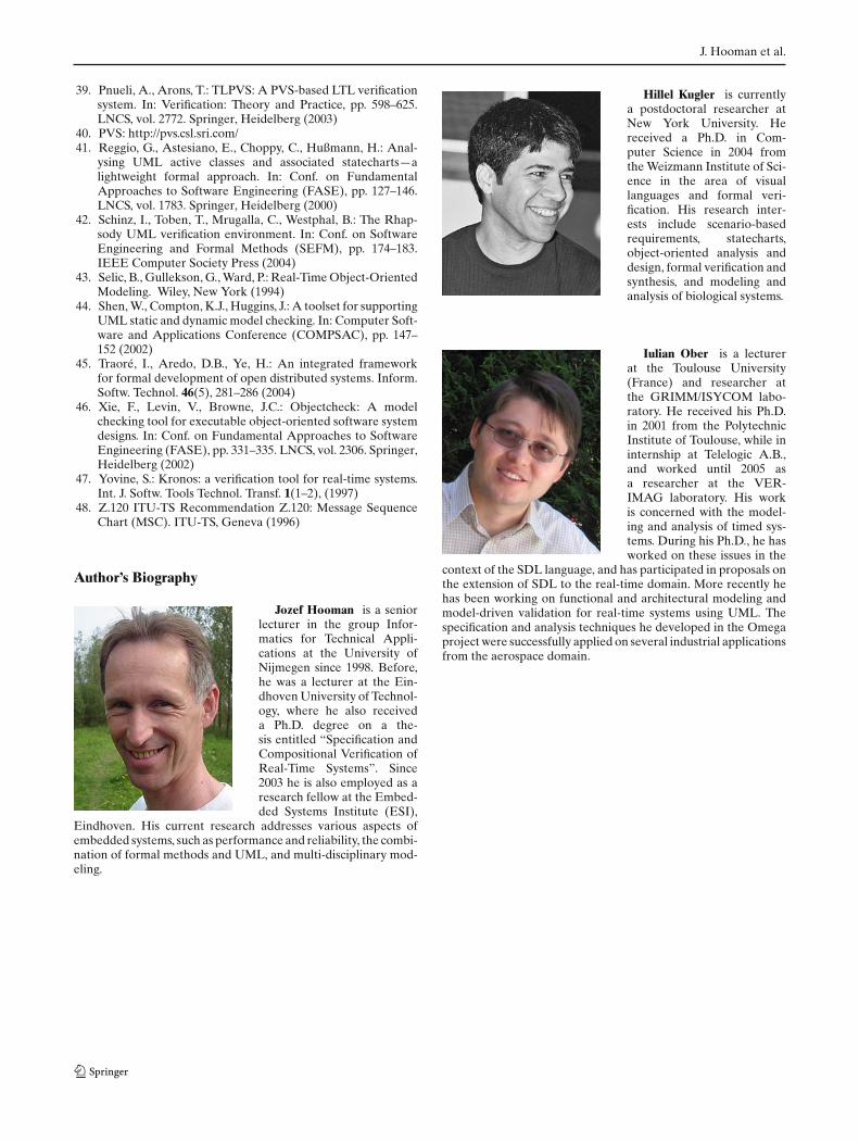
J. Hooman et al.
39. Pnueli, A., Arons, T.: TLPVS: A PVS-based LTL verificationsystem. In: Verification: Theory and Practice, pp. 598–625.LNCS, vol. 2772. Springer, Heidelberg (2003)
40. PVS: http://pvs.csl.sri.com/41. Reggio, G., Astesiano, E., Choppy, C., Hußmann, H.: Anal-
ysing UML active classes and associated statecharts—alightweight formal approach. In: Conf. on FundamentalApproaches to Software Engineering (FASE), pp. 127–146.LNCS, vol. 1783. Springer, Heidelberg (2000)
42. Schinz, I., Toben, T., Mrugalla, C., Westphal, B.: The Rhap-sody UML verification environment. In: Conf. on SoftwareEngineering and Formal Methods (SEFM), pp. 174–183.IEEE Computer Society Press (2004)
43. Selic, B., Gullekson, G., Ward, P.: Real-Time Object-OrientedModeling. Wiley, New York (1994)
44. Shen, W., Compton, K.J., Huggins, J.: A toolset for supportingUML static and dynamic model checking. In: Computer Soft-ware and Applications Conference (COMPSAC), pp. 147–152 (2002)
45. Traoré, I., Aredo, D.B., Ye, H.: An integrated frameworkfor formal development of open distributed systems. Inform.Softw. Technol. 46(5), 281–286 (2004)
46. Xie, F., Levin, V., Browne, J.C.: Objectcheck: A modelchecking tool for executable object-oriented software systemdesigns. In: Conf. on Fundamental Approaches to SoftwareEngineering (FASE), pp. 331–335. LNCS, vol. 2306. Springer,Heidelberg (2002)
47. Yovine, S.: Kronos: a verification tool for real-time systems.Int. J. Softw. Tools Technol. Transf. 1(1–2), (1997)
48. Z.120 ITU-TS Recommendation Z.120: Message SequenceChart (MSC). ITU-TS, Geneva (1996)
Author’s Biography
Jozef Hooman is a seniorlecturer in the group Infor-matics for Technical Appli-cations at the University ofNijmegen since 1998. Before,he was a lecturer at the Ein-dhoven University of Technol-ogy, where he also receiveda Ph.D. degree on a the-sis entitled “Specification andCompositional Verification ofReal-Time Systems”. Since2003 he is also employed as aresearch fellow at the Embed-ded Systems Institute (ESI),
Eindhoven. His current research addresses various aspects ofembedded systems, such as performance and reliability, the combi-nation of formal methods and UML, and multi-disciplinary mod-eling.
Hillel Kugler is currentlya postdoctoral researcher atNew York University. Hereceived a Ph.D. in Com-puter Science in 2004 fromthe Weizmann Institute of Sci-ence in the area of visuallanguages and formal veri-fication. His research inter-ests include scenario-basedrequirements, statecharts,object-oriented analysis anddesign, formal verification andsynthesis, and modeling andanalysis of biological systems.
Iulian Ober is a lecturerat the Toulouse University(France) and researcher atthe GRIMM/ISYCOM labo-ratory. He received his Ph.D.in 2001 from the PolytechnicInstitute of Toulouse, while ininternship at Telelogic A.B.,and worked until 2005 asa researcher at the VER-IMAG laboratory. His workis concerned with the model-ing and analysis of timed sys-tems. During his Ph.D., he hasworked on these issues in the
context of the SDL language, and has participated in proposals onthe extension of SDL to the real-time domain. More recently hehas been working on functional and architectural modeling andmodel-driven validation for real-time systems using UML. Thespecification and analysis techniques he developed in the Omegaproject were successfully applied on several industrial applicationsfrom the aerospace domain.
Supporting UML-based development of embedded systems by formal techniques
Anjelika Votintseva workedas a scientific researcher atOFFIS till September 2005.She received a Ph.D. in 1997at the Institute of InformaticsSystems in Novosibirsk (Rus-sia) in the field of formalmethods for the models ofconcurrent and distributedcomputations. Further researchand teaching topics are UMLsemantics and formal verifi-cation, temporal logic specifi-cations, compositional design,and development methodol-
ogy. Currently, she is working at Siemens AG, CT SE (Corpo-rate Technology, Software Engineering) as a consultant for UMLdesign and requirements engineering.
Yuri Yushtein worked asa senior software systems ana-lyst at the National Aero-space Laboratory NLR (TheNetherlands) till July 2004.He received an M.Sc. degreein Radio Communication andBroadcasting Engineering in1988 at the Odessa Electro-technical Institute of Commu-nication, with a specializationin Space Communication. Hehas been involved in the devel-opment of the fault-tolerant,mission-critical, and safety-
critical real-time embedded software systems for aerospace andtelecommunication. His interests include UML for critical real-time systems and formal verification and validation during thedevelopment process of such systems. Currently he is employedat CIMSOLUTIONS B.V. as a senior technical specialist and con-sultant on industrial software.