Supported Sensor Devices - emDeveloper - EM Microelectronic
13
AppNote 004 Copyright 2014, EM Microelectronic-Marin SA ApplicationNote004_Supported_Sensor_Devices, Version 1.7, 22-May-14 1 www.emmicroelectronic.com Application Note 4 Title: Supported Sensor Devices Product Family: EM7180 Part Number: EM7180 Keywords: Sensor Drivers, Sensor Boards Date: March 7 th , 2014 _ Document History Doc Version Firmware Release Author Date Description 1.0 1.1 EM – Milos Becvar January 15 th , 2014 Initial Release 1.1 1.1 EM – Milos Becvar January 20 th , 2014 LSM9DS0 gyro driver is the LSM330 Gyro driver 1.2 1.1 EM – Milos Becvar January 27 th , 2014 LSM9DS0 name corrected 1.3 1.2 EM – Evan Lojewski February 21 st , 2014 Merge AK8975 and AK8963 driver 1.4 1.3 EM – Evan Lojewski February 27 th , 2014 Add TMP112 driver. Update driver table to contain driver type and SDK version it first appears in. 1.5 1.3 EM – Milos Becvar March 7 th , 2014 Added PNI M&M Boards, added GS0 + sensor configurations 1.6 1.2 EM – Milos Becvar April 1 st , 2014 Corrected PNI Yellow M&M GPIO pin for Mag 1.7 1.4 EM – Milos Becvar May 21 st , 2014 AK09911 device added Table of Contents Title: Supported Sensor Devices ............................................................................................................................................ 1 Document History ...................................................................................................................................................................... 1 Table of Contents ....................................................................................................................................................................... 1 References .................................................................................................................................................................................. 1 1 Introduction ............................................................................................................................................................................ 2 2 Supported Sensor Devices ...................................................................................................................................................... 2 3. Sensor Board Specific Settings .................................................................................................................................................. 3 3.1 EM Sensor Fusion Platform ................................................................................................................................................. 3 3.2 PNI DevKit Boards .............................................................................................................................................................. 4 3.3 PNI M&M Boards ................................................................................................................................................................ 9 No table of figures entries found. Table 1: Supported Sensor Devices and Associated Drivers.......................................................................................................... 2 Table 2: Supported Sensor Boards ................................................................................................................................................. 2 Table 3: Sensor Fusion Platform Settings ...................................................................................................................................... 3 Table 4: PNI DevKit GS1 Board Settings ...................................................................................................................................... 4 Table 5: PNI DevKit GS3 Board Settings ...................................................................................................................................... 5 Table 6: PNI DevKit GS0 + AK8963 + BMI055 Settings ............................................................................................................. 6 Table 7: PNI DevKit GS0 + BMM150 + BMI055 Settings ........................................................................................................... 7 Table 8: PNI Blue M&M Board Settings ....................................................................................................................................... 9 Table 9: PNI Green M&M Board Settings ................................................................................................................................... 10 Table 10: PNI Orange M&M Board Settings ............................................................................................................................... 11 Table 11: PNI Red M&M Board Settings .................................................................................................................................... 12 Table 12: PNI Yellow M&M Board Settings ............................................................................................................................... 13 References [1] EM7180 Datasheet [2] EM Sensor Fusion Platform Datasheet EM MICROELECTRONIC - MARIN SA
-
Upload
khangminh22 -
Category
Documents
-
view
4 -
download
0
Transcript of Supported Sensor Devices - emDeveloper - EM Microelectronic

AppNote 004
Copyright 2014, EM Microelectronic-Marin SA ApplicationNote004_Supported_Sensor_Devices, Version 1.7, 22-May-14
1 www.emmicroelectronic.com
Application Note 4
Title: Supported Sensor Devices
Product Family: EM7180
Part Number: EM7180
Keywords: Sensor Drivers, Sensor Boards
Date: March 7th
, 2014
_
Document History Doc Version Firmware Release Author Date Description
1.0 1.1 EM – Milos Becvar January 15th
, 2014 Initial Release
1.1 1.1 EM – Milos Becvar January 20th
, 2014 LSM9DS0 gyro driver is the LSM330 Gyro driver
1.2 1.1 EM – Milos Becvar January 27th
, 2014 LSM9DS0 name corrected
1.3 1.2 EM – Evan Lojewski February 21st, 2014 Merge AK8975 and AK8963
driver
1.4 1.3 EM – Evan Lojewski February 27th
, 2014 Add TMP112 driver. Update driver table to contain driver type and SDK version it first appears in.
1.5 1.3 EM – Milos Becvar March 7th
, 2014 Added PNI M&M Boards, added GS0 + sensor configurations
1.6 1.2 EM – Milos Becvar April 1st
, 2014 Corrected PNI Yellow M&M GPIO pin for Mag
1.7 1.4 EM – Milos Becvar May 21st , 2014 AK09911 device added
Table of Contents Title: Supported Sensor Devices ............................................................................................................................................ 1
Document History ...................................................................................................................................................................... 1 Table of Contents ....................................................................................................................................................................... 1 References .................................................................................................................................................................................. 1
1 Introduction ............................................................................................................................................................................ 2 2 Supported Sensor Devices ...................................................................................................................................................... 2 3. Sensor Board Specific Settings .................................................................................................................................................. 3
3.1 EM Sensor Fusion Platform ................................................................................................................................................. 3 3.2 PNI DevKit Boards .............................................................................................................................................................. 4 3.3 PNI M&M Boards ................................................................................................................................................................ 9
No table of figures entries found. Table 1: Supported Sensor Devices and Associated Drivers .......................................................................................................... 2 Table 2: Supported Sensor Boards ................................................................................................................................................. 2 Table 3: Sensor Fusion Platform Settings ...................................................................................................................................... 3 Table 4: PNI DevKit GS1 Board Settings ...................................................................................................................................... 4 Table 5: PNI DevKit GS3 Board Settings ...................................................................................................................................... 5 Table 6: PNI DevKit GS0 + AK8963 + BMI055 Settings ............................................................................................................. 6 Table 7: PNI DevKit GS0 + BMM150 + BMI055 Settings ........................................................................................................... 7 Table 8: PNI Blue M&M Board Settings ....................................................................................................................................... 9 Table 9: PNI Green M&M Board Settings ................................................................................................................................... 10 Table 10: PNI Orange M&M Board Settings ............................................................................................................................... 11 Table 11: PNI Red M&M Board Settings .................................................................................................................................... 12 Table 12: PNI Yellow M&M Board Settings ............................................................................................................................... 13
References [1] EM7180 Datasheet
[2] EM Sensor Fusion Platform Datasheet
EM MICROELECTRONIC - MARIN SA
AppNote 004
Copyright 2014, EM Microelectronic-Marin SA ApplicationNote004_Supported_Sensor_Devices, Version 1.7, 22-May-14
2 www.emmicroelectronic.com
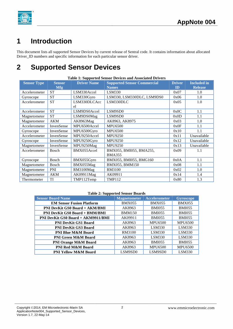
1 Introduction
This document lists all supported Sensor Devices by current release of Sentral code. It contains information about allocated
Driver_ID numbers and specific information for each particular sensor driver.
2 Supported Sensor Devices
Table 1: Supported Sensor Devices and Associated Drivers
Sensor Type Sensor
Mfg
Driver Name Supported Sensor Commercial
Names
Driver
ID
Included in
Release
Accelerometer ST LSM330Accel LSM330 0x07 1.0
Gyroscope ST LSM330Gyro LSM330, LSM330DLC, LSM9DS0 0x06 1.0
Accelerometer ST LSM330DLCAcc
el
LSM330DLC 0x05 1.0
Accelerometer ST LSM9DS0Accel LSM9SD0 0x0C 1.1
Magnetometer ST LSM9DS0Mag LSM9SD0 0x0D 1.1
Magnetometer AKM AK8963Mag AK8963, AK8975 0x03 1.0
Accelerometer InvenSense MPU6500Accel MPU6500 0x0F 1.1
Gyroscope InvenSense MPU6500Gyro MPU6500 0x10 1.1
Accelerometer InvenSense MPU9250Accel MPU9250 0x11 Unavailable
Gyroscope InvenSense MPU9250Gyro MPU9250 0x12 Unavailable
Magnetometer InvenSense MPU9250Mag MPU9250 0x13 Unavailable
Accelerometer Bosch BMX055Accel BMX055, BMI055, BMA255,
BMA355
0x09 1.1
Gyroscope Bosch BMX055Gyro BMX055, BMI055, BMG160 0x0A 1.1
Magnetometer Bosch BMX055Mag BMX055, BMM150 0x08 1.1
Magnetometer PNI RM3100Mag RM3100 0x02 1.0
Magnetometer AKM AK09911Mag AK09911 0x14 1.4
Thermometer TI TMP112Temp TMP112 0x80 1.3
Table 2: Supported Sensor Boards
Sensor Board Name Magnetometer Accelerometer Gyroscope
EM Sensor Fusion Platform BMX055 BMX055 BMX055
PNI DevKit GS0 Board + AKM/BMI AK8963 BMI055 BMI055
PNI DevKit GS0 Board + BMM/BMI BMM150 BMI055 BMI055
PNI DevKit GS0 Board + AKM9911/BMI AK09911 BMI055 BMI055
PNI DevKit GS1 Board AK8963 MPU6500 MPU6500
PNI DevKit GS3 Board AK8963 LSM330 LSM330
PNI Blue M&M Board RM3100 LSM330 LSM330
PNI Green M&M Board AK8963 LSM330 LSM330
PNI Orange M&M Board AK8963 BMI055 BMI055
PNI Red M&M Board AK8963 MPU6500 MPU6500
PNI Yellow M&M Board LSM9SD0 LSM9SD0 LSM330

AppNote 004
Copyright 2014, EM Microelectronic-Marin SA ApplicationNote004_Supported_Sensor_Devices, Version 1.7, 22-May-14
3 www.emmicroelectronic.com
3. Sensor Board Specific Settings
3.1 EM Sensor Fusion Platform
EM Sensor Fusion platform (SFP) [2] is a castellated module containing Sentral, Bosch BMX055 9-DOF sensor and
EEPROM.
Table 3: Sensor Fusion Platform Settings
Parameter Value
Magnetometer BMX055
GPIO pin 4 I2C Address 16
Calibration Matrix 0 -1 0
-1 0 0
0 0 -1
Calibration Offsets 0 0 0
Accelerometer BMX055
GPIO pin 2 I2C Address 24
Calibration Matrix -1 0 0
0 1 0
0 0 1
Calibration Offsets 0 0 0
Gyroscope BMX055
GPIO pin 0 I2C Address 104
Calibration Matrix 1 0 0
0 -1 0
0 0 -1
Calibration Offsets 0 0 0
Upload Speed 400 Kbit/s
Host IRQ pin 6
GPIO pull settings 6 5 4 3 2 1 0
Def Def Def Def Def Def Def

AppNote 004
Copyright 2014, EM Microelectronic-Marin SA ApplicationNote004_Supported_Sensor_Devices, Version 1.7, 22-May-14
4 www.emmicroelectronic.com
3.2 PNI DevKit Boards
GS1 Board is GEN7 compatible board containing Sentral, AK8963and MPU6500. It is compatible with PNI DevKit.
Table 4: PNI DevKit GS1 Board Settings
Parameter Value
Magnetometer AK8963
GPIO pin 0 I2C Address 12
Calibration Matrix -1 0 0
0 1 0
0 0 -1
Calibration Offsets 0 0 0
Accelerometer MPU6500
GPIO pin 1 I2C Address 104
Calibration Matrix 0 -1 0
-1 0 0
0 0 1
Calibration Offsets 0 0 0
Gyroscope MPU6500
GPIO pin 1 I2C Address 104
Calibration Matrix 0 1 0
1 0 0
0 0 -1
Calibration Offsets 0 0 0
Upload Speed 400 Kbit/s
Host IRQ pin 6
GPIO pull settings
6 5 4 3 2 1 0
Def Def Def Def Def Def Def
AppNote 004
Copyright 2014, EM Microelectronic-Marin SA ApplicationNote004_Supported_Sensor_Devices, Version 1.7, 22-May-14
5 www.emmicroelectronic.com
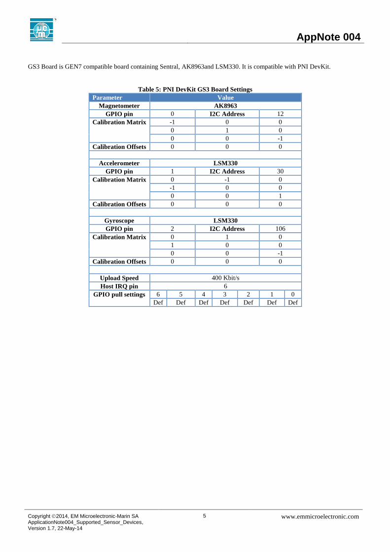
GS3 Board is GEN7 compatible board containing Sentral, AK8963and LSM330. It is compatible with PNI DevKit.
Table 5: PNI DevKit GS3 Board Settings
Parameter Value
Magnetometer AK8963
GPIO pin 0 I2C Address 12
Calibration Matrix -1 0 0
0 1 0
0 0 -1
Calibration Offsets 0 0 0
Accelerometer LSM330
GPIO pin 1 I2C Address 30
Calibration Matrix 0 -1 0
-1 0 0
0 0 1
Calibration Offsets 0 0 0
Gyroscope LSM330
GPIO pin 2 I2C Address 106
Calibration Matrix 0 1 0
1 0 0
0 0 -1
Calibration Offsets 0 0 0
Upload Speed 400 Kbit/s
Host IRQ pin 6
GPIO pull settings
6 5 4 3 2 1 0
Def Def Def Def Def Def Def

AppNote 004
Copyright 2014, EM Microelectronic-Marin SA ApplicationNote004_Supported_Sensor_Devices, Version 1.7, 22-May-14
6 www.emmicroelectronic.com
GS0 Board is GEN7 compatible board containing just Sentral motion processor. Additional connectors on the devkit can be
populated by GEN7 compatible boards containing sensor devices – AK8963 magnetometer, BMI055 Accelerometer/Gyro and
BMM150 magnetometer.
Table 6: PNI DevKit GS0 + AK8963 + BMI055 Settings
Parameter Value
Magnetometer AK8963
GPIO pin 0 I2C Address 12
Calibration Matrix 0 -1 0
-1 0 0
0 0 -1
Calibration Offsets 0 0 0
Accelerometer BMI055
GPIO pin 1 I2C Address 25
Calibration Matrix 0 -1 0
-1 0 0
0 0 1
Calibration Offsets 0 0 0
Gyroscope BMI055
GPIO pin 2 I2C Address 105
Calibration Matrix 0 1 0
1 0 0
0 0 -1
Calibration Offsets 0 0 0
Upload Speed 400 Kbit/s
Host IRQ pin 6
GPIO pull settings
6 5 4 3 2 1 0
Def Def Def Def Def Def Def

AppNote 004
Copyright 2014, EM Microelectronic-Marin SA ApplicationNote004_Supported_Sensor_Devices, Version 1.7, 22-May-14
7 www.emmicroelectronic.com
Table 7: PNI DevKit GS0 + BMM150 + BMI055 Settings
Parameter Value
Magnetometer BMM150
GPIO pin 0 I2C Address 19
Calibration Matrix 0 1 0
-1 0 0
0 0 1
Calibration Offsets 0 0 0
Accelerometer BMI055
GPIO pin 1 I2C Address 25
Calibration Matrix 0 -1 0
-1 0 0
0 0 1
Calibration Offsets 0 0 0
Gyroscope BMI055
GPIO pin 2 I2C Address 105
Calibration Matrix 0 1 0
1 0 0
0 0 -1
Calibration Offsets 0 0 0
Upload Speed 400 Kbit/s
Host IRQ pin 6
GPIO pull settings
6 5 4 3 2 1 0
Def Def Def Def Def Def Def

AppNote 004
Copyright 2014, EM Microelectronic-Marin SA ApplicationNote004_Supported_Sensor_Devices, Version 1.7, 22-May-14
8 www.emmicroelectronic.com
Table 8: PNI DevKit GS0 + AK09911 + BMI055 Settings
Parameter Value
Magnetometer AK09911
GPIO pin 0 I2C Address 12
Calibration Matrix 0 -1 0
-1 0 0
0 0 -1
Calibration Offsets 0 0 0
Accelerometer BMI055
GPIO pin 1 I2C Address 25
Calibration Matrix 0 -1 0
-1 0 0
0 0 1
Calibration Offsets 0 0 0
Gyroscope BMI055
GPIO pin 2 I2C Address 105
Calibration Matrix 0 1 0
1 0 0
0 0 -1
Calibration Offsets 0 0 0
Upload Speed 400 Kbit/s
Host IRQ pin 6
GPIO pull settings
6 5 4 3 2 1 0
Def Def Def Def Def Def Def
Note: Although AKM09911 sensor does not have an interrupt wire, GPIO pin is reserved for obtaining timestamps.

AppNote 004
Copyright 2014, EM Microelectronic-Marin SA ApplicationNote004_Supported_Sensor_Devices, Version 1.7, 22-May-14
9 www.emmicroelectronic.com
3.3 PNI M&M Boards
Table 9: PNI Blue M&M Board Settings
Parameter Value
Magnetometer RM3100
GPIO pin 0 I2C Address 32
Calibration Matrix 1 0 0
0 1 0
0 0 1
Calibration Offsets 0 0 0
Accelerometer LSM330
GPIO pin 1 I2C Address 30
Calibration Matrix -1 0 0
0 1 0
0 0 1
Calibration Offsets 0 0 0
Gyroscope LSM330
GPIO pin 2 I2C Address 106
Calibration Matrix 1 0 0
0 -1 0
0 0 -1
Calibration Offsets 0 0 0
Upload Speed 400 Kbit/s
Host IRQ pin 6
GPIO pull settings
6 5 4 3 2 1 0
Def Def Def Def Def Def Def

AppNote 004
Copyright 2014, EM Microelectronic-Marin SA ApplicationNote004_Supported_Sensor_Devices, Version 1.7, 22-May-14
10 www.emmicroelectronic.com
Table 10: PNI Green M&M Board Settings
Parameter Value
Magnetometer AK8963
GPIO pin 0 I2C Address 12
Calibration Matrix -1 0 0
0 1 0
0 0 -1
Calibration Offsets 0 0 0
Accelerometer LSM330
GPIO pin 1 I2C Address 30
Calibration Matrix 0 -1 0
-1 0 0
0 0 1
Calibration Offsets 0 0 0
Gyroscope LSM330
GPIO pin 2 I2C Address 106
Calibration Matrix 0 1 0
1 0 0
0 0 -1
Calibration Offsets 0 0 0
Upload Speed 400 Kbit/s
Host IRQ pin 6
GPIO pull settings
6 5 4 3 2 1 0
Def Def Def Def Def Def Def

AppNote 004
Copyright 2014, EM Microelectronic-Marin SA ApplicationNote004_Supported_Sensor_Devices, Version 1.7, 22-May-14
11 www.emmicroelectronic.com
Table 11: PNI Orange M&M Board Settings
Parameter Value
Magnetometer AK8963
GPIO pin 0 I2C Address 12
Calibration Matrix -1 0 0
0 1 0
0 0 -1
Calibration Offsets 0 0 0
Accelerometer BMI055
GPIO pin 1 I2C Address 24
Calibration Matrix -1 0 0
0 1 0
0 0 1
Calibration Offsets 0 0 0
Gyroscope BMI055
GPIO pin 2 I2C Address 104
Calibration Matrix 1 0 0
0 -1 0
0 0 -1
Calibration Offsets 0 0 0
Upload Speed 400 Kbit/s
Host IRQ pin 6
GPIO pull settings
6 5 4 3 2 1 0
Def Def Def Def Def Def Def

AppNote 004
Copyright 2014, EM Microelectronic-Marin SA ApplicationNote004_Supported_Sensor_Devices, Version 1.7, 22-May-14
12 www.emmicroelectronic.com
Table 12: PNI Red M&M Board Settings
Parameter Value
Magnetometer AK8963
GPIO pin 0 I2C Address 12
Calibration Matrix -1 0 0
0 1 0
0 0 -1
Calibration Offsets 0 0 0
Accelerometer MPU6500
GPIO pin 1 I2C Address 104
Calibration Matrix 0 -1 0
-1 0 0
0 0 1
Calibration Offsets 0 0 0
Gyroscope MPU6500
GPIO pin 1 I2C Address 104
Calibration Matrix 0 1 0
1 0 0
0 0 -1
Calibration Offsets 0 0 0
Upload Speed 400 Kbit/s
Host IRQ pin 6
GPIO pull settings
6 5 4 3 2 1 0
Def Def Def Def Def Def Def

AppNote 004
Copyright 2014, EM Microelectronic-Marin SA ApplicationNote004_Supported_Sensor_Devices, Version 1.7, 22-May-14
13 www.emmicroelectronic.com
Table 13: PNI Yellow M&M Board Settings
Parameter Value
Magnetometer LSM9SD0
GPIO pin 0 I2C Address 30
Calibration Matrix 1 0 0
0 -1 0
0 0 1
Calibration Offsets 0 0 0
Accelerometer LSM9SD0
GPIO pin 1 I2C Address 30
Calibration Matrix -1 0 0
0 1 0
0 0 1
Calibration Offsets 0 0 0
Gyroscope LSM9SD0
GPIO pin 2 I2C Address 106
Calibration Matrix 1 0 0
0 -1 0
0 0 -1
Calibration Offsets 0 0 0
Upload Speed 400 Kbit/s
Host IRQ pin 6
GPIO pull settings
6 5 4 3 2 1 0
Def Def Def Def Def Def Def
EM Microelectronic-Marin SA (“EM”) makes no warranties for the use of EM products, other than those expressly contained in EM's applicable General Terms of Sale, located at http://www.emmicroelectronic.com. EM assumes no responsibility for any errors which may have crept into this document, reserves the right to change devices or specifications detailed herein at any time without notice, and does not make any commitment to update the information contained herein. No licenses to patents or other intellectual property rights of EM are granted in connection with the sale of EM products, neither expressly nor implicitly. In respect of the intended use of EM products by customer, customer is solely responsible for observing existing patents and other intellectual property rights of third parties and for obtaining, as the case may be, the necessary licenses. Important note: The use of EM products as components in medical devices and/or medical applications, including but not limited to, safety and life supporting systems, where malfunction of such EM products might result in damage to and/or injury or death of persons is expressly prohibited, as EM products are neither destined nor qualified for use as components in such medical devices and/or medical applications. The prohibited use of EM products in such medical devices and/or medical applications is exclusively at the risk of the customer.