Superior Essex
269
TECHNICAL SUPPORT CUSTOMER SERVICE COPPER FIBER COMPOSITES COMMUNICATIONS WIRE & CABLE 110110101001110001100100010101110100 110110100101011101010011100011001000 010011100011001011011011110100000101 PERFORMANCE 11011010100111000110010 0010101110100 QUALITY Quick Links Search Engine Table of Contents Part Number Index About Superior Essex Premises Copper Miscellaneous Copper Wire Central Office Copper RDUP/RUS OSP Copper Bell OSP Copper OSP Copper Wire Canadian OSP Copper OSP Composite Premises Fiber OSP Fiber Cable Fiber Types Optical Fiber Selection Chart Fiber Color Codes & Conversions Fire Resistance Ratings UTP Categories Tech Tip OSP Color Code Charts Packaging OSP Packaging Glossary Standard Warranty PerformaLink ® Warranty Program Campus Warranty Program NEW Products Updated: September, 2008
-
Upload
khangminh22 -
Category
Documents
-
view
0 -
download
0
Transcript of Superior Essex

TECHNICAL SUPPORT
CU
ST
OM
ER
SE
RV
ICE
COPPERFIBER
COMPOSITESCOMMUNICATIONS WIRE & CABLE
110110101001110001100100010101110100
110110100101011101010011100011001000
010011100011001011011011110100000101
PERFORMANCE
11011010100111000110010 0010101110100
QU
ALIT
Y
Quick Links
Search Engine
Table of Contents
Part Number Index
About Super ior Essex
Premises Copper
Miscel laneous Copper Wire
Centra l Of f ice Copper
RDUP/RUS OSP Copper
Bel l OSP Copper
OSP Copper Wire
Canadian OSP Copper
OSP Composi te
Premises F iber
OSP F iber Cable
F iber Types
Opt ical F iber Select ion Chart
F iber Color Codes & Conversions
F i re Resistance Rat ings
UTP Categor ies Tech Tip
OSP Color Code Charts
Packaging
OSP Packaging
Glossary
Standard Warranty
PerformaLink® Warranty Program
Campus Warranty Program
NEW Products
Updated: September, 2008

SUPERIORESSEX.COM
0100101011101010011100011001000
PERFORMANCE
QU
ALI
TY
Combining Value and Performance Like No One ElseWith a heritage of more than 50 years as a telecommunica-tions cable manufacturer, Superior Essex has grown to become the most trusted name in wire and cable in North America. Our portfolio of copper and fiber cable for both outside
plant and premises applications is the broadest in theindustry and provides assurance of the highest quality and performance available.
Outside Plant Wire and Cable
Superior Essex has been a long-time leader in the OSP cable market. With over 4000 different copper and fiber cable and wire designs to choose from, our products serve virtually every application demanded for outside plant installations. Our strong market position was built from an endless pursuit of perfection in our products and in our service. It’s a difference that has kept customers loyal for decades and has earned Superior Essex customer quality awards year after year.
Premises Cables
Superior Essex believes that its premises wire and cable products should provide a total user experience that is unequaled in the industry. That is why we tend to offer more useful features, better performance, higher quality and bet-ter overall value than our competition. For example, in many of our boxed premises products, you will find our unique QuickCount® marking system; hailed by customers as a major time and money saver as it counts down the remaining cable from 1000 to zero feet. You’ll also find color-coded labels to let you know from a distance what color the jacket is inside the box. Many other subtle advantages make Superior Essex premises products the preferred choice.

TECHNICAL SUPPORT
CU
ST
OM
ER
SE
RV
ICE
Defining Quality
Superior Essex has TL 9000 and ISO 9001:2001 certification in every Communications production facility, assuring a level of quality and consistency of the company’s products and service. But there is much more to this commitment. Beyond quality assurance of our products is our dedication to bring value added elements and superior customer service to our products. At Superior Essex quality is simple – providing the customer what is expected every time.
Consistency Matters
Any cable manufacturer can design a high-per-formance cable, but very few have the ability or inclination to ensure that every cable produced is high-performance. Superior Essex does. Any manufacturer can claim to have high quality, but very few actually deliver on that promise every time. Superior Essex does.
Flexibility
This cable and wire catalog is extensive, but we also receive requests for products with special requirements. Our technical team regularly quotes and manufactures custom designs for customers around the world. See what we can do for you.
Product Performance
When it comes to product performance, Superior Essex has engineered some of the highest perfor-mance copper and fiber optic cable products avail-able anywhere.
In independent tests, Superior Essex Category 5e and Category 6 cables regularly surpass the per-formance of competitors who claim performance to be their sole distinction. This same attention to engineering excellence is also extended to our fiber cable products and to our lower-bandwidth voice and data cables.
1101101010010110001100100010101110100
110110100101

TA
BLE O
F C
ON
TEN
TS
� Toll Free 800.551.8948 — Fax 770.657.6807www.superioressex.com
Table Of Contents
PREMISES COPPER
10Gain® Category 6A CMR/CMP�� �� �� �� �� �� �� �� �� �� �� �� �� �� �� �� �� �� �� �� �� �� �� �� 8
Category 6A STP Cable CMR/CMP �� �� �� �� �� �� �� �� �� �� �� �� �� �� �� �� �� �� �� �� �� 10
NextGain® Category 6eX CMR/CMP���� �� �� �� �� �� �� �� �� �� �� �� �� �� �� �� �� �� �� �� 12
DataGain® Category 6+ CMR/CMP�� �� �� �� �� �� �� �� �� �� �� �� �� �� �� �� �� �� �� �� �� �� 14
Category 6 CMR/CMP�� �� �� �� �� �� �� �� �� �� �� �� �� �� �� �� �� �� �� �� �� �� �� �� �� �� �� �� �� �� �� �� 16
Cobra Category 5e+ CMR/CMP �� �� �� �� �� �� �� �� �� �� �� �� �� �� �� �� �� �� �� �� �� �� �� �� 18
Category 5e+ ScTP CMR/CMP �� �� �� �� �� �� �� �� �� �� �� �� �� �� �� �� �� �� �� �� �� �� �� �� �� 20
Marathon LAN® Category 5e CMR/CMP �� �� �� �� �� �� �� �� �� �� �� �� �� �� �� �� �� 22
Category 5e CMR/CMX – Outdoor�� �� �� �� �� �� �� �� �� �� �� �� �� �� �� �� �� �� �� �� �� �� 24
Category 5e CM�� �� �� �� �� �� �� �� �� �� �� �� �� �� �� �� �� �� �� �� �� �� �� �� �� �� �� �� �� �� �� �� �� �� �� �� �� 26
6 Pair Category 5e CMR �� �� �� �� �� �� �� �� �� �� �� �� �� �� �� �� �� �� �� �� �� �� �� �� �� �� �� �� �� �� 28
25-Pair Category 5e Power Sum – CMR/CMP�� �� �� �� �� �� �� �� �� �� �� �� �� 29
Bundled UTP Cable Category 6�� �� �� �� �� �� �� �� �� �� �� �� �� �� �� �� �� �� �� �� �� �� �� �� 30
Bundled UTP Cable Category 5e�� �� �� �� �� �� �� �� �� �� �� �� �� �� �� �� �� �� �� �� �� �� �� 32
Residential Broadband Series 6 Quad Shield Coax/ Category 6/Fiber�� �� �� �� �� �� �� �� �� �� �� �� �� �� �� �� �� �� �� �� �� �� �� �� �� �� �� �� �� �� �� �� �� �� �� ��34
Residential Broadband Series 6 Quad Shield Coax/ Category 5e/Fiber�� �� �� �� �� �� �� �� �� �� �� �� �� �� �� �� �� �� �� �� �� �� �� �� �� �� �� �� �� �� �� �� �� �� ��36
Coax Series 6 Quad Shield CM/CMR�� �� �� �� �� �� �� �� �� �� �� �� �� �� �� �� �� �� �� �� 38
Coax Series 6 60% Shield CM �� �� �� �� �� �� �� �� �� �� �� �� �� �� �� �� �� �� �� �� �� �� �� �� �� 40
Coax Series 6 Tri-Shield 70% CM/CMR�� �� �� �� �� �� �� �� �� �� �� �� �� �� �� �� �� �� 41
OSP Broadband Category 6�� �� �� �� �� �� �� �� �� �� �� �� �� �� �� �� �� �� �� �� �� �� �� �� �� �� �� 42
OSP Broadband Category 5e�� �� �� �� �� �� �� �� �� �� �� �� �� �� �� �� �� �� �� �� �� �� �� �� �� �� 44
MEGAPIC™ OSP Broadband Backbone Category 5 �� �� �� �� �� �� �� �� 46
Category 3 CMR/CMP (2-Pair – 400-Pair)�� �� �� �� �� �� �� �� �� �� �� �� �� �� �� �� ��48
AR Series Riser Cable – ARAM/ARMM�� �� �� �� �� �� �� �� �� �� �� �� �� �� �� �� �� �� 50
Category 3 Station Wire CMR/CMX Outdoor�� �� �� �� �� �� �� �� �� �� �� �� �� 52
MISCELLANEOUS COPPER WIRE
Cross-Connect Category 5 Wire (XWC)�� �� �� �� �� �� �� �� �� �� �� �� �� �� �� �� �� �� 56
Bridle Wire�� �� �� �� �� �� �� �� �� �� �� �� �� �� �� �� �� �� �� �� �� �� �� �� �� �� �� �� �� �� �� �� �� �� �� �� �� �� �� �� �� 56
Temporary Drop Wire (TDW) �� �� �� �� �� �� �� �� �� �� �� �� �� �� �� �� �� �� �� �� �� �� �� �� �� �� 57
E-Block Wire �� �� �� �� �� �� �� �� �� �� �� �� �� �� �� �� �� �� �� �� �� �� �� �� �� �� �� �� �� �� �� �� �� �� �� �� �� �� �� 58
Ground Wire (Bare or Jacketed)�� �� �� �� �� �� �� �� �� �� �� �� �� �� �� �� �� �� �� �� �� �� �� ��59
Air Pipe�� �� �� �� �� �� �� �� �� �� �� �� �� �� �� �� �� �� �� �� �� �� �� �� �� �� �� �� �� �� �� �� �� �� �� �� �� �� �� �� �� �� �� �� 60
Indoor/Outdoor Cross-Connect Wire (XCW)�� �� �� �� �� �� �� �� �� �� �� �� �� �� 61
CENTRAL OFFICE COPPER
ABAM (600B) & ABMM Series Central Office Cable �� �� �� �� �� �� �� 64
1249C Series Central Office Cable�� �� �� �� �� �� �� �� �� �� �� �� �� �� �� �� �� �� �� �� �� �� 66
1161A Series Central Office Cable�� �� �� �� �� �� �� �� �� �� �� �� �� �� �� �� �� �� �� �� �� �� 68
600C Series Central Office Cable�� �� �� �� �� �� �� �� �� �� �� �� �� �� �� �� �� �� �� �� �� �� �� 70
Switchboard 100 Central Office Cable���� �� �� �� �� �� �� �� �� �� �� �� �� �� �� �� �� �� 72
Switchboard 100 Ohm Central Office Cable �� �� �� �� �� �� �� �� �� �� �� �� �� 74
200A/800A series (Canadian Color Code) �� �� �� �� �� �� �� �� �� �� �� �� �� �� �� 74
T100 Series Central Office Cable�� �� �� �� �� �� �� �� �� �� �� �� �� �� �� �� �� �� �� �� �� �� �� 75
Switchboard 85 and Shielded Switchboard 85 Cable�� �� �� �� �� �� 76
Tight Twist Distribution Frame Wire (DFW) �� �� �� �� �� �� �� �� �� �� �� �� �� �� 77
Heavy Duty Distribution Frame Wire (HD-DFW)�� �� �� �� �� �� �� �� �� �� ��78
Distribution Frame Wire (DFW)���� �� �� �� �� �� �� �� �� �� �� �� �� �� �� �� �� �� �� �� �� �� �� �� 79
RDUP/RUS OSP COPPER CABLE
SEALPIC® �� �� �� �� �� �� �� �� �� �� �� �� �� �� �� �� �� �� �� �� �� �� �� �� �� �� �� �� �� �� �� �� �� �� �� �� �� �� �� �� �� �� 82
SEALPIC®–84���� �� �� �� �� �� �� �� �� �� �� �� �� �� �� �� �� �� �� �� �� �� �� �� �� �� �� �� �� �� �� �� �� �� �� �� �� �� �� 84
SEALPIC®–FSF-84�� �� �� �� �� �� �� �� �� �� �� �� �� �� �� �� �� �� �� �� �� �� �� �� �� �� �� �� �� �� �� �� �� �� �� �� 86
SEALPIC®–FSF (RDUP PE-89) �� �� �� �� �� �� �� �� �� �� �� �� �� �� �� �� �� �� �� �� �� �� �� �� �� �� 88
CASPIC®–FSF (RDUP PE-89)�� �� �� �� �� �� �� �� �� �� �� �� �� �� �� �� �� �� �� �� �� �� �� �� �� �� �� 94
SEALPIC®–F (RDUP PE-39) �� �� �� �� �� �� �� �� �� �� �� �� �� �� �� �� �� �� �� �� �� �� �� �� �� �� �� �� 96
CUPIC®–F (RDUP PE-39) �� �� �� �� �� �� �� �� �� �� �� �� �� �� �� �� �� �� �� �� �� �� �� �� �� �� �� �� �� �� 98
GOPIC®
–F (RDUP PE-39)�� �� �� �� �� �� �� �� �� �� �� �� �� �� �� �� �� �� �� �� �� �� �� �� �� �� �� �� �� 100
CASPIC®–F (RDUP PE-39) �� �� �� �� �� �� �� �� �� �� �� �� �� �� �� �� �� �� �� �� �� �� �� �� �� �� �� �� 102
BELL OSP COPPER
ALPETH BHBA/BHAA/BKMA/BKTA �� �� �� �� �� �� �� �� �� �� �� �� �� �� �� �� �� �� �� �� ��106
PASP BHBH/BHAH/BKMH/BKTH �� �� �� �� �� �� �� �� �� �� �� �� �� �� �� �� �� �� �� �� �� �� ��108
Self-Support BHBS/BHAS/BKMS/BKTS�� �� �� �� �� �� �� �� �� �� �� �� �� �� �� �� �� ��110
Reinforced Self-Support BHBP/BHAP/BKMP/BKTP�� �� �� �� �� �� �� �� ��112
Bonded STALPETH DCAZ/DCMZ/DCTZ �� �� �� �� �� �� �� �� �� �� �� �� �� �� �� �� ��114
STEAMPETH DKMN/DKTN�� �� �� �� �� �� �� �� �� �� �� �� �� �� �� �� �� �� �� �� �� �� �� �� �� �� ��116
Power Station High Potential Filled ASP (CMAW) �� �� �� �� �� �� �� ��117
Filled ALPETH ANBA/ANAA/ANMA/ANTA �� �� �� �� �� �� �� �� �� �� �� �� �� �� ��118
Filled ASP ANBW/ANAW/ANMW/ANTW�� �� �� �� �� �� �� �� �� �� �� �� �� �� �� �� ��120
T-SCREEN® Filled ASP KNAW/KNMW �� �� �� �� �� �� �� �� �� �� �� �� �� �� �� �� �� ��122
OSP COPPER WIRE
C-Rural Wire�� �� �� �� �� �� �� �� �� �� �� �� �� �� �� �� �� �� �� �� �� �� �� �� �� �� �� �� �� �� �� �� �� �� �� �� �� �� �� 126
IMRDW�� �� �� �� �� �� �� �� �� �� �� �� �� �� �� �� �� �� �� �� �� �� �� �� �� �� �� �� �� �� �� �� �� �� �� �� �� �� �� �� �� �� �� 128
IMRDWS�� �� �� �� �� �� �� �� �� �� �� �� �� �� �� �� �� �� �� �� �� �� �� �� �� �� �� �� �� �� �� �� �� �� �� �� �� �� �� �� �� �� 130
ADP NMS�� �� �� �� �� �� �� �� �� �� �� �� �� �� �� �� �� �� �� �� �� �� �� �� �� �� �� �� �� �� �� �� �� �� �� �� �� �� �� �� �� 133
ADP NMS (6x24) Compact Design���� �� �� �� �� �� �� �� �� �� �� �� �� �� �� �� �� �� �� �� 134
ADP-S�� �� �� �� �� �� �� �� �� �� �� �� �� �� �� �� �� �� �� �� �� �� �� �� �� �� �� �� �� �� �� �� �� �� �� �� �� �� �� �� �� �� �� �� 135
Integrated Messenger Wire IM/F, IM/H & IM/G���� �� �� �� �� �� �� �� �� �� �� 136
BSW A/BSW G�� �� �� �� �� �� �� �� �� �� �� �� �� �� �� �� �� �� �� �� �� �� �� �� �� �� �� �� �� �� �� �� �� �� �� �� �� 138
BDW A �� �� �� �� �� �� �� �� �� �� �� �� �� �� �� �� �� �� �� �� �� �� �� �� �� �� �� �� �� �� �� �� �� �� �� �� �� �� �� �� �� �� �� 140
BDW G �� �� �� �� �� �� �� �� �� �� �� �� �� �� �� �� �� �� �� �� �� �� �� �� �� �� �� �� �� �� �� �� �� �� �� �� �� �� �� �� �� �� �� 141
BW CF�� �� �� �� �� �� �� �� �� �� �� �� �� �� �� �� �� �� �� �� �� �� �� �� �� �� �� �� �� �� �� �� �� �� �� �� �� �� �� �� �� �� �� �� 142
BW GDJ �� �� �� �� �� �� �� �� �� �� �� �� �� �� �� �� �� �� �� �� �� �� �� �� �� �� �� �� �� �� �� �� �� �� �� �� �� �� �� �� �� �� 144
CANADIAN OSP COPPER
CELFIL BJBB/BJAB/BJMB/BJTB �� �� �� �� �� �� �� �� �� �� �� �� �� �� �� �� �� �� �� �� �� �� ��148
ALPETH BHBB/BHAB/BKMB/BKTB �� �� �� �� �� �� �� �� �� �� �� �� �� �� �� �� �� �� �� �� ��150
SEALPAP BHBF, BHAF, BKMF, BKTF �� �� �� �� �� �� �� �� �� �� �� �� �� �� �� �� �� �� �� ��152
Canadian Self Support BHBS-BC/BHAS-BC/BKMS-BC �� �� �� �� �� ��154
Table Of Contents

TA
BLE O
F C
ON
TEN
TS
Toll Free 800.551.8948 — Fax 770.657.6807www.superioressex.com �
Table Of Contents
ADP-X-NMS�� �� �� �� �� �� �� �� �� �� �� �� �� �� �� �� �� �� �� �� �� �� �� �� �� �� �� �� �� �� �� �� �� �� �� �� �� �� �� 156
ADW Aerial Drop Wire�� �� �� �� �� �� �� �� �� �� �� �� �� �� �� �� �� �� �� �� �� �� �� �� �� �� �� �� �� ��157
Integrated Messenger Wire IM/F, IM/H & IM/G���� �� �� �� �� �� �� �� �� �� �� 158
ADP NMS (with QuickCount® in meters)�� �� �� �� �� �� �� �� �� �� �� �� �� �� �� �� ��159
BCBD Buried Distribution Wire�� �� �� �� �� �� �� �� �� �� �� �� �� �� �� �� �� �� �� �� �� �� �� ��160
OSP COMPOSITE
Series 71 W Composite Drop Web Design �� �� �� �� �� �� �� �� �� �� �� �� �� �� ��164
Series 71 OJ Composite Drop Overjacket Design�� �� �� �� �� �� �� �� �� ��165
Series 5V Composite OSP Web �� �� �� �� �� �� �� �� �� �� �� �� �� �� �� �� �� �� �� �� �� �� ��166
Series 70 OJ Composite OSP Overjacket �� �� �� �� �� �� �� �� �� �� �� �� �� �� �� ��167
Series 5F Category 5e Composite Drop���� �� �� �� �� �� �� �� �� �� �� �� �� �� �� �� ��168
Series L Composite Round CF �� �� �� �� �� �� �� �� �� �� �� �� �� �� �� �� �� �� �� �� �� �� �� ��169
BroadGain®-CX Copper/Coax Composite Web Design �� �� �� �� �� �� ��171
PREMISES FIBER
Simplex, Duplex and Quad Fiber Optic Interconnect Cable OFNR/OFNP �� �� �� �� �� �� �� �� �� �� �� �� �� �� �� �� �� �� �� �� �� �� �� �� �� �� �� �� �� �� �� �� �� �� �� �� �� ��174
Single Unit Premises Distribution Fiber Optic Cables OFNR/OFNP �� �� �� �� �� �� �� �� �� �� �� �� �� �� �� �� �� �� �� �� �� �� �� �� �� �� �� �� �� �� �� �� �� �� �� �� �� ��176
Multi-Unit Premises Distribution Fiber Optic Cables OFNR/OFNP �� �� �� �� �� �� �� �� �� �� �� �� �� �� �� �� �� �� �� �� �� �� �� �� �� �� �� �� �� �� �� �� �� �� �� �� �� ��178
Fiber Reel-in-a-Box with QuickCount® Marking System�� �� �� �� 180
Indoor/Outdoor Tight Buffer Fiber Optic Cables OFNR/OFNP �� �� �� �� �� �� �� �� �� �� �� �� �� �� �� �� �� �� �� �� �� �� �� �� �� �� �� �� �� �� �� �� �� �� �� �� �� ��182
Water-Blocked/Sunlight Resistant Indoor/Outdoor Tight Buffer Fiber Optic Cables – Riser Rated OFNR�� �� �� �� �� �� �� �� ��184
Hybrid Fiber Optic Cables OFNR/OFNP�� �� �� �� �� �� �� �� �� �� �� �� �� �� �� �� ��186
Interlocked Armor Fiber Optic Cables OFCR/OFCP�� �� �� �� �� �� �� ��188
OSP FIBER CABLE
Loose Tube Single Jacket All-Dielectric Cables Series 11�� �� ��192
Loose Tube Double Jacket Non-Armor Cables Series 1G�� �� ��193
Loose Tube Single Jacket Single Armor Cables Series 12�� ��194
Loose Tube Double Jacket Single Armor Cables Series1A����195
Loose Tube Double Jacket Double Armor Cables Series 1D��196
Loose Tube Triple Jacket Double Armor Cables Series 1C�� ��197
Loose Tube Single Jacket Cables Self Support Series 11M�� 198
Loose Tube Double Jacket Self Support Series 1GM�� �� �� �� �� ��199
Loose Tube Single Jacket Single Armor Self Sup Series12 ��200
Loose Tube Double Jacket Single Armor Self Support
Series1AM �� �� �� �� �� �� �� �� �� �� �� �� �� �� �� �� �� �� �� �� �� �� �� �� �� �� �� �� �� �� �� �� �� �� �� �� �� �� ��201
Single Loose Tube All-Dielectric Cables Series 51 �� �� �� �� �� �� �� ��202
Single Loose Tube Single Armor Cables Series 52�� �� �� �� �� �� �� ��203
Single Flex Tube All-Dielectric Cables Series F1�� �� �� �� �� �� �� �� �� ��204
Single Flex Tube Single Armor Series F2 �� �� �� �� �� �� �� �� �� �� �� �� �� �� ��205
Loose Tube Indoor/Outdoor Riser – OFNR Series 13�� �� �� �� �� �� ��206
Single Loose Tube Indoor/Outdoor Riser – OFNR Series 53 �� ��207
Series 1H – Heavy Duty Loose Tube OFNR Cables �� �� �� �� �� �� �� 208
ADP FTTP (Fiber-To-The-Premises) Series 57 �� �� �� �� �� �� �� �� �� �� �� ��209
UG FTTP Cables Series 513�� �� �� �� �� �� �� �� �� �� �� �� �� �� �� �� �� �� �� �� �� �� �� �� �� ��210
Buried FTTP Cables Series 523 �� �� �� �� �� �� �� �� �� �� �� �� �� �� �� �� �� �� �� �� �� �� ��211
Buried FTTP Composite Series 72�� �� �� �� �� �� �� �� �� �� �� �� �� �� �� �� �� �� �� �� ��212
Toneable Drop FTTP Series 571Q���� �� �� �� �� �� �� �� �� �� �� �� �� �� �� �� �� �� �� �� ��214
Universal Drop FTTP Series 570Q �� �� �� �� �� �� �� �� �� �� �� �� �� �� �� �� �� �� �� �� ��215
Universal FTTP OFNR�� �� �� �� �� �� �� �� �� �� �� �� �� �� �� �� �� �� �� �� �� �� �� �� �� �� �� �� �� �� �� 216
Toneable FTTP OFCR���� �� �� �� �� �� �� �� �� �� �� �� �� �� �� �� �� �� �� �� �� �� �� �� �� �� �� �� �� �� �� 217
Figure 8 FTTP Cables Series 573Q�� �� �� �� �� �� �� �� �� �� �� �� �� �� �� �� �� �� �� �� ��218
Stranded Tube Ribbon Armored Cables Series S2 �� �� �� �� �� �� �� ��219
Single Tube Ribbon Non Armored Cables Series R1���� �� �� �� �� ��220
Single Tube Ribbon Armored Cables Series R2���� �� �� �� �� �� �� �� �� ��221
TECHNICAL INFORMATION
Part Number Index �� �� �� �� �� �� �� �� �� �� �� �� �� �� �� �� �� �� �� �� �� �� �� �� �� �� �� �� �� �� �� �� �� 224
Fiber Types�� �� �� �� �� �� �� �� �� �� �� �� �� �� �� �� �� �� �� �� �� �� �� �� �� �� �� �� �� �� �� �� �� �� �� �� �� �� �� �� 229
Optical Fiber Selection Chart�� �� �� �� �� �� �� �� �� �� �� �� �� �� �� �� �� �� �� �� �� �� �� �� �� 230
Optical Fiber Color Codes and Conversion Table���� �� �� �� �� �� �� �� 231
Copper Wire & Cable NEC Fire Resistance Ratings�� �� �� �� �� �� �� 232
UTP Categories TECH TIP�� �� �� �� �� �� �� �� �� �� �� �� �� �� �� �� �� �� �� �� �� �� �� �� �� �� �� �� 233
OSP Color Code Charts�� �� �� �� �� �� �� �� �� �� �� �� �� �� �� �� �� �� �� �� �� �� �� �� �� �� �� �� �� �� 234
Packaging �� �� �� �� �� �� �� �� �� �� �� �� �� �� �� �� �� �� �� �� �� �� �� �� �� �� �� �� �� �� �� �� �� �� �� �� �� �� �� �� 236
OSP Packaging �� �� �� �� �� �� �� �� �� �� �� �� �� �� �� �� �� �� �� �� �� �� �� �� �� �� �� �� �� �� �� �� �� �� �� �� 238
Glossary �� �� �� �� �� �� �� �� �� �� �� �� �� �� �� �� �� �� �� �� �� �� �� �� �� �� �� �� �� �� �� �� �� �� �� �� �� �� �� �� �� 242
Standard Warranty, Terms and Conditions�� �� �� �� �� �� �� �� �� �� �� �� �� �� 246
PerformaLink ®
Warranty Program�� �� �� �� �� �� �� �� �� �� �� �� �� �� �� �� �� �� �� �� �� 248
PerformaLink® Registration Form���� �� �� �� �� �� �� �� �� �� �� �� �� �� �� �� �� �� �� �� �� 249
Campus Warranty Program �� �� �� �� �� �� �� �� �� �� �� �� �� �� �� �� �� �� �� �� �� �� �� �� �� �� 250
New Products
Buried FTTP Cables Steel Armor Series 523 �� �� �� �� �� �� �� �� �� �� �� �� �� �� 255
Category 5e CMR/CMX – Outdoor Sunlight Resistant�� �� �� �� �� 256
DataGain® Category 6+ Limited Combustible Cable �� �� �� �� �� �� 258
Cobra Category 5e+ Limited Combustible Cable�� �� �� �� �� �� �� �� �� 260
25-Pair Category 5e Shielded CMR ���� �� �� �� �� �� �� �� �� �� �� �� �� �� �� �� �� �� �� 262
Non-Jacketed Tight Twist Cable Core�� �� �� �� �� �� �� �� �� �� �� �� �� �� �� �� �� �� 263
Dri-Lite™ Non-Armored Ribbon Series R1D���� �� �� �� �� �� �� �� �� �� �� �� �� �� 264
Dri-Lite™ Armored Ribbon Series R2D�� �� �� �� �� �� �� �� �� �� �� �� �� �� �� �� �� �� �� 265
Loose Tube 12 AWG Composite Series 1N���� �� �� �� �� �� �� �� �� �� �� �� �� �� 268
BW-NS Buried Wire Non-Shielded �� �� �� �� �� �� �� �� �� �� �� �� �� �� �� �� �� �� �� �� 269
Superior Essex makes every effort to ensure the accuracy of the information contained in this catalogue at the time of publication. Specifications, packaging and part numbers detailed within are subject to change. For the most up to date information, please contact Superior Essex at 770.657.6000 or visit www.superioressex.com.
© 2007 Superior Essex, Inc.

6 Toll Free 800.551.8948 — Fax 770.657.6807www.superioressex.com

Toll Free 800.551.8948 — Fax 770.657.6807www.superioressex.com 7
PR
EM
ISES
CO
PP
ER
PREMISES COPPER
PREMISES COPPER
Table of Contents
10Gain® Category 6A CMR/CMP. . . . . . . . . . . . . . . . . . . . . . . . . . . . . . . . . . . . . . . . . . . 8
Category 6A STP Cable CMR/CMP . . . . . . . . . . . . . . . . . . . . . . . . . . . . . . . . . . . . . . . . 10
NextGain® Category 6eX CMR/CMP . . . . . . . . . . . . . . . . . . . . . . . . . . . . . . . . . . . . . . . 12
DataGain® Category 6+ CMR/CMP . . . . . . . . . . . . . . . . . . . . . . . . . . . . . . . . . . . . . . . . 14
Category 6 CMR/CMP. . . . . . . . . . . . . . . . . . . . . . . . . . . . . . . . . . . . . . . . . . . . . . . . . . . 16
Cobra Category 5e+ CMR/CMP . . . . . . . . . . . . . . . . . . . . . . . . . . . . . . . . . . . . . . . . . . . 18
Category 5e+ ScTP CMR/CMP. . . . . . . . . . . . . . . . . . . . . . . . . . . . . . . . . . . . . . . . . . . . 20
Marathon LAN® Category 5e CMR/CMP . . . . . . . . . . . . . . . . . . . . . . . . . . . . . . . . . . . . 22
Category 5e CMR/CMX – Outdoor . . . . . . . . . . . . . . . . . . . . . . . . . . . . . . . . . . . . . . . . 24
Category 5e CM . . . . . . . . . . . . . . . . . . . . . . . . . . . . . . . . . . . . . . . . . . . . . . . . . . . . . . . 26
6 Pair Category 5e CMR. . . . . . . . . . . . . . . . . . . . . . . . . . . . . . . . . . . . . . . . . . . . . . . . . 28
25-Pair Category 5e Power Sum – CMR/CMP . . . . . . . . . . . . . . . . . . . . . . . . . . . . . . . 29
Bundled UTP Cable Category 6. . . . . . . . . . . . . . . . . . . . . . . . . . . . . . . . . . . . . . . . . . . 30
Bundled UTP Cable Category 5e. . . . . . . . . . . . . . . . . . . . . . . . . . . . . . . . . . . . . . . . . . 32
Residential Broadband Series 6 Quad Shield Coax/Category 6/Fiber . . . . . . . . . . . . . .34
Residential Broadband Series 6 Quad Shield Coax/Category 5e/Fiber . . . . . . . . . . . . .36
Coax Series 6 Quad Shield CM/CMR . . . . . . . . . . . . . . . . . . . . . . . . . . . . . . . . . . . . . . 38
Coax Series 6 60% Shield CM . . . . . . . . . . . . . . . . . . . . . . . . . . . . . . . . . . . . . . . . . . . . 40
Coax Series 6 Tri-Shield 70% CM/CMR . . . . . . . . . . . . . . . . . . . . . . . . . . . . . . . . . . . . 41
OSP Broadband Category 6. . . . . . . . . . . . . . . . . . . . . . . . . . . . . . . . . . . . . . . . . . . . . . 42
OSP Broadband Category 5e. . . . . . . . . . . . . . . . . . . . . . . . . . . . . . . . . . . . . . . . . . . . . 44
MEGAPIC™ OSP Broadband Backbone Category 5 . . . . . . . . . . . . . . . . . . . . . . . . . . . 46
Category 3 CMR/CMP (2-Pair – 400-Pair) . . . . . . . . . . . . . . . . . . . . . . . . . . . . . . . . . .48
AR Series Riser Cable – ARAM/ARMM. . . . . . . . . . . . . . . . . . . . . . . . . . . . . . . . . . . . . 50
Category 3 Station Wire CMR/CMX Outdoor. . . . . . . . . . . . . . . . . . . . . . . . . . . . . . . . 52
Category 5e CMR/CMX – Outdoor Sunlight Resistant . . . . . . . . . . . . . . . . . . . . . . . . . 256
DataGain® Category 6+ Limited Combustible Cable . . . . . . . . . . . . . . . . . . . . . . . . . 258
Cobra Category 5e+ Limited Combustible Cable . . . . . . . . . . . . . . . . . . . . . . . . . . . 260

� Toll Free 800.551.8948 — Fax 770.657.6807www.superioressex.com
PR
EM
ISES
CO
PP
ER
Standards Compliance:UL 444, UL Listed CMP (NFPA 262), UL Listed CMR (UL 1666), ISO/IEC 11�01, ANSI/TIA 56�-B.2-10, ANSI/ICEA S-90-661-2002, RoHS 2002/95/EC Compliant.
10Gain® Category 6A CMR/CMP
Product Description
10Gain Augmented Category 6 (CAT 6A) cable brings UTP performance to a new level. This cable meets the internal and alien cross-talk performance requirements of TIA/EIA 568-B.2-10 and ISO/IEC 11801 Edition 2.1 as tested in a 6 around 1 configuration. With guaranteed performance out to 500 MHz and independently verified and monitored by UL, 10Gain CAT 6A cable demonstrates superior capability for 10 Gigabit Ethernet and all other bandwidth intensive and legacy applications.
Features Benefits
• UL Verified CAT 6A • Exceptional PS-ACR, PSANEXT and PSAACRF (PSAELFEXT) performance
• QuickCount® marking system • Color coded box labels• ColorTip™ Circuit Identification System
• Assures consistent, worry-free performance• Performance assurance for 10 Gigabit Ethernet and multiple
high-bandwidth applications
• Eliminates guess work of footage on reel• Easily identifiable jacket colors• Easily identifiable conductor mates even in low light environments
Applications • 10GBASE-T and legacy applications 10BASE-T through 1000BASE-T Ethernet• ATM and Token Ring• Backward compatible to legacy protocols and applications
Part Numbers and Physical CharacteristicsPart # Pair Count AWG (mm) Jacket Color Nom. Dia.
inches (mm)Approx. Weight lbs/kft (kg/km)
Package
CMR 6A-272-2A 4 22 (0.63) Blue 0.35 (8.9) 50 (75) 1000' Reel
6A-272-3A 4 22 (0.63) Gray 0.35 (8.9) 50 (75) 1000' Reel
6A-272-4A 4 22 (0.63) White 0.35 (8.9) 50 (75) 1000' Reel
6A-272-5A 4 22 (0.63) Green 0.35 (8.9) 50 (75) 1000' Reel
6A-272-6A 4 22 (0.63) Yellow 0.35 (8.9) 50 (75) 1000' Reel
6A-272-7A 4 22 (0.63) Purple 0.35 (8.9) 50 (75) 1000' Reel
6A-272-9A 4 22 (0.63) Red 0.35 (8.9) 50 (75) 1000' Reel
CMP 6A-272-2B 4 22 (0.63) Blue 0.32 (8.1) 48 (72) 1000' Reel
6A-272-3B 4 22 (0.63) Gray 0.32 (8.1) 48 (72) 1000' Reel
6A-272-4B 4 22 (0.63) White 0.32 (8.1) 48 (72) 1000' Reel
6A-272-5B 4 22 (0.63) Green 0.32 (8.1) 48 (72) 1000' Reel
6A-272-6B 4 22 (0.63) Yellow 0.32 (8.1) 48 (72) 1000' Reel
6A-272-7B 4 22 (0.63) Purple 0.32 (8.1) 48 (72) 1000' Reel
6A-272-9B 4 22 (0.63) Red 0.32 (8.1) 48 (72) 1000' Reel

Toll Free 800.551.8948 — Fax 770.657.6807www.superioressex.com 9
PR
EM
ISES
CO
PP
ER
10Gain Category 6A CMR/CMP
Product Description CMR• Conductor: 22 AWG (0.63 mm) Solid Annealed Bare Copper • Insulation: Thermoplastic • Web Separator • Jacket: Flame Retardant PVC (Polyvinyl Chloride)
Product Description CMP• Conductor: 22 AWG (0.63 mm) Solid Annealed Bare Copper • Insulation: FEP • Web Separator • Jacket: Flame Retardant, Low Smoke PVC (Polyvinyl Chloride)
ElectricalFrequency
MHzAttenuation (dB/100m) @ 20°C
MaximumNEXT (dB/100m)
MinimumACR (dB/100m)
MinimumPS-NEXT (dB/100m)
Minimum
TIA 568-B.2-10
Superior Essex TIA 568-B.2-10
Superior Essex TIA 568-B.2-10
Superior Essex TIA 568-B.2-10
Superior Essex
Specified Guaran-teed
Typical Specified Guaran-teed
Typical Calculated Guaran-teed
Typical Specified Guaran-teed
Typical
1 2.1 2.0 1.7 74.3 75.3 92.4 72.3 74.3 90.7 72.3 74.3 90.3
4 3.8 3.6 3.4 65.3 66.3 82.2 61.5 63.5 78.9 63.3 65.3 80.5
8 5.3 5.1 4.7 60.8 61.8 78.0 55.4 57.4 73.3 58.8 60.8 76.4
10 5.9 5.7 5.3 59.3 60.3 76.5 53.4 55.4 71.2 57.3 59.3 74.8
16 7.5 7.2 6.7 56.2 57.2 73.8 48.8 50.8 67.2 54.2 56.2 72.0
20 8.4 8.1 7.6 54.8 55.8 71.1 46.4 48.4 63.6 52.8 54.8 69.7
25 9.4 9.1 8.5 53.3 54.3 68.9 44.0 46.0 60.5 51.3 53.3 67.4
31.25 10.5 10.2 9.5 51.9 52.9 68.3 41.4 43.4 58.9 49.9 51.9 67.0
62.5 15.0 14.5 13.6 47.4 48.4 64.3 32.4 34.4 50.8 45.4 47.4 62.3
100 19.1 18.5 17.4 44.3 45.3 61.2 25.2 27.2 44.0 42.3 44.3 59.2
155 24.1 23.4 21.9 41.4 42.4 57.3 17.4 19.4 35.7 39.4 41.4 55.9
200 27.6 26.8 25.1 39.8 40.8 57.1 12.2 14.2 32.4 37.8 39.8 54.9
250 31.1 30.2 28.2 38.3 39.3 55.9 7.3 9.3 27.6 36.3 38.3 53.3
300 34.3 33.3 31.1 37.1 38.1 53.7 2.9 4.9 22.8 35.1 37.1 51.5
350 37.2 36.3 33.8 36.1 37.1 52.7 19.1 34.1 36.1 50.1
400 40.1 39.0 36.3 35.3 37.3 52.4 15.3 33.3 36.3 49.3
450 42.7 41.6 38.7 34.5 36.5 50.2 11.6 32.5 35.5 47.8
500 45.3 44.1 41.0 33.8 35.8 48.7 7.7 31.8 34.8 46.2
550 43.2 45.6 2.3 43.7
600 45.3 44.0 -1.2 42.2
650 47.5 42.0 -5.3 40.2
Frequency MHz
PS-ACR (dB/100m) Minimum
Return Loss (dB/100m) Minimum
ELFEXT (ACRF) (dB/100m) Minimum
PS-ELFEXT (PSACRF) (dB/100m) Minimum
TIA 568-B.2-10
Superior Essex TIA 568-B.2-10
Superior Essex TIA 568-B.2-10
Superior Essex TIA 568-B.2-10
Superior Essex
Calculated Guaran-teed
Typical Specified Guaran-teed
Typical Specified Guaran-teed
Typical Specified Guaran-teed
Typical
1 70.2 72.2 88.7 20.0 20.0 27.3 67.8 71.8 83.6 64.8 68.8 81.2
4 59.5 61.5 77.2 23.0 23.0 33.1 55.8 59.8 72.0 52.8 56.8 69.6
8 53.4 55.4 71.7 24.5 24.5 35.3 49.7 53.7 66.2 46.7 50.7 63.7
10 51.4 53.4 69.6 25.0 25.0 36.0 47.8 51.8 64.4 44.8 48.8 61.8
16 46.8 48.8 65.4 25.0 25.0 36.5 43.7 47.7 60.3 40.7 44.7 57.8
20 44.4 46.4 62.2 25.0 25.0 38.4 41.8 45.8 58.4 38.8 42.8 56.0
25 42.0 44.0 59.1 24.3 24.3 37.6 39.8 43.8 56.3 36.8 40.8 54.1
31.25 39.4 41.4 57.6 23.6 23.6 37.8 37.9 41.9 54.3 34.9 38.9 52.1
62.5 30.4 32.4 49.0 21.5 21.5 36.6 31.9 35.9 48.3 28.9 32.9 46.1
100 23.2 25.2 42.2 20.1 20.1 33.5 27.8 31.8 44.5 24.8 28.8 42.3
155 15.4 17.4 34.4 18.8 18.8 33.0 24.0 28.0 40.6 21.0 25.0 38.5
200 10.2 12.2 30.3 18.0 18.0 30.7 21.8 25.8 38.4 18.8 22.8 36.2
250 5.3 7.3 25.4 17.3 17.3 30.3 19.8 23.8 35.0 16.8 20.8 33.4
300 0.9 2.9 20.9 16.8 16.8 26.9 18.3 22.3 33.8 15.3 19.3 31.6
350 16.9 16.3 16.3 27.0 16.9 21.9 32.5 13.9 18.9 30.4
400 13.5 15.9 15.9 26.9 15.8 18.8 31.8 12.8 16.8 29.8
450 9.7 15.5 15.5 26.0 14.7 18.7 30.8 11.7 16.7 28.8
500 5.8 15.2 15.2 24.8 13.8 16.8 29.8 10.8 14.8 28.1
550 1.0 24.2 28.8 26.9
600 -2.5 22.7 28.6 26.4
650 -6.3 19.6 27.2 25.3
Nominal Impedance (Ohms) Delay Skew (ns/100m) Maximum Typical
Velocity of Propagation (%)
Plenum Riser
DC Resistance (Ohms/100m)
MaximumTypical
Resistance Unbalance (%)
MaximumTypical
Transverse Conversion Loss (dB) @ 500 MHZ
Minimum
100 45 27 68 65 9.38 7.0 4.0 1.0 23.0

10 Toll Free 800.551.8948 — Fax 770.657.6807www.superioressex.com
PR
EM
ISES
CO
PP
ER
Category 6A STP Cable CMR/CMP
Product DescriptionSuperior Essex offers Shielded Twisted Pair (STP) Category 6A cables in both plenum and riser versions. The cable has guaranteed performance out to 600 MHz and meets all applicable TIA 568-B.2-1 requirements. In addition, the cable meets or exceeds TIA/EIA 568-B.2-10 Draft Specification for Augmented Category 6 (CAT 6A) cables required for 10GBASE-T applications. The cable consists of four (4) balanced 23 AWG copper pairs. Each pair is wrapped with a mylar-backed aluminum foil with the drain wire in the center of all four pairs. The wrapped pairs are then jacketed with a flexible PVC jacket appropriate for either plenum or riser applications.
Features Benefits• Individually foil shielded pairs
• Exceeds Draft Specification TIA/EIA-568-B.2-10 for Augmented Cat 6 (Cat 6A)Cable Performance
• Exceeds both TIA 568-B.2-1 and ISO/IEC 11801 for Category 6• Riser and plenum rated designs
• Protects against EMI/RFI and provides exceptional NEXT, PSNEXT, ELFEXT,and Electrical Performance performance
• Meets 10GBASE-T Application Requirements for both Insertion Loss and Return Loss and Exceeds Requirements for Alien and Internal Crosstalk Performance
• Assures compliance for all current networking applications• UL 1666 and NFPA 262 (UL 910) fire rating options
help to reduce additional expensive materialsrequired to meet building safety codes.
Applications
• 10GBASE-T and legacy applications 10BASE-T through 1000BASE-T Ethernet• ATM and Token Ring
Part Numbers and Physical CharacteristicsPart # Listing Pair Count Nom. Dia.
inches (mm)Approx. Weightlbs/kft (kg/km)
Package
6S-220-XA Riser 4 0.31 (7.9) 40 (60) 1,000 Reel
6S-220-XB Plenum 4 0.29 (7.4) 46 (69) 1,000 Reel
Jacket Color Cross-Reference Table Cable ConstructionReplace "X" with Color Configuration: 4 copper pairs each surrounded by
Aluminum/Mylar foil with center drain wire and jacket
2 Blue Conductor: 23 AWG Solid Copper
3 Gray Insulation Material: Riser – PE; Plenum – FEP
4 White Insulation Colors: Pair 1 – White/Blue; Pair 2 – White/Orange; Pair 3 – White/Green;Pair 4 – White/Brown
5 Green Drain Wire: Tinned Copper
6 Yellow Jacket Material: Plenum – Plenum Grade Low Smoke PVC;Riser – Riser Grade PVC
9 Red Jacket Color: Blue, Gray, White, Yellow, Orange, Green, Red
D Orange Fire Listings: Plenum – NFPA 262 UL CMP; FT6Riser – UL 1666, UL CMR, c(UL) FT-4
(U/FTP)

Toll Free 800.551.8948 — Fax 770.657.6807www.superioressex.com 11
PR
EM
ISES
CO
PP
ER
Category 6A STP Cable CMR/CMP
Input Impedance (Ohms) Delay Skew (ns/100m) Guaranteed Maximum
Velocity of Propagation (%) Nominal
DC Resistance (Ohms/100m)Maximum
Resistance Unbalance (%)Maximum
100+/-15 @ 1-100MHz 100+/-22 @ 100-300MHz100+/-32 @ 350-600MHz
25 Plenum - 77 ; Riser - 74 9.38 3%
Standards Compliance: UL 444, UL Listed CMP (NFPA 262), UL Listed CMR (UL 1666), ISO/IEC 11801, ANSI/TIA 568-B.2-10, RoHS Compliant.
ElectricalFrequency
MHzAttenuation (dB/100m) @ 20°C
MaximumNEXT (dB/100m)
MinimumACR (dB/100m)
MinimumPS-NEXT (dB/100m)
Minimum
TIA568-B.2-10
Superior Essex TIA568-B.2-10
Superior Essex TIA568-B.2-10
Superior Essex TIA568-B.2-10
Superior Essex
Specified Guaran-teed
Typical Specified Guaran-teed
Typical Calculated Guaran-teed
Typical Specified Guaran-teed
Typical
1 2.1 2.1 2.1 74.2 74.2 74.2 72.2 72.2 72.2 72.2 72.2 72.2
4 3.8 3.8 3.7 65.2 65.2 74.2 61.4 61.4 70.5 63.2 63.2 72.2
8 5.3 5.3 5.2 60.7 60.7 74.2 55.4 55.4 69.0 58.7 58.7 72.2
10 5.9 5.9 5.8 59.2 59.2 74.2 53.3 53.3 68.4 57.2 57.2 72.2
16 7.4 7.4 7.4 56.2 56.2 74.2 48.7 48.7 66.8 54.2 54.2 71.2
20 8.3 8.3 8.2 54.7 54.7 72.7 46.4 46.4 64.4 52.7 52.7 69.7
25 9.3 9.3 9.2 53.3 53.3 71.3 43.9 43.9 62.0 51.3 51.3 68.3
31.25 10.5 10.5 10.4 51.8 51.8 69.8 41.3 41.3 59.4 49.8 49.8 66.8
62.5 14.9 14.9 14.8 47.3 47.3 65.3 32.3 32.3 50.5 45.3 45.3 62.3
100 19.1 19.1 18.9 44.2 44.2 62.2 25.1 25.1 43.3 42.2 42.2 59.2
200 27.5 27.5 27.3 39.7 39.7 57.7 12.2 12.2 30.4 37.7 37.7 54.7
250 31.1 31.1 30.7 38.3 38.3 56.3 7.2 7.2 25.5 36.3 36.3 53.3
300 34.2 34.2 33.9 37.1 37.1 55.1 2.8 2.8 21.2 35.1 35.1 52.1
350 37.2 37.2 36.8 36.1 36.1 54.1 -1.1 -1.1 17.2 34.1 34.1 51.1
400 40.1 40.1 39.6 35.2 35.2 53.2 -4.7 -4.7 13.6 33.2 33.2 50.2
500 45.2 45.2 44.8 33.8 33.8 51.8 -11.4 -11.4 7.0 31.8 31.8 48.8
600 50.1 49.5 32.6 50.6 -17.4 1.1 30.6 47.6
FrequencyMHz
PS-ACR (dB/100m) Minimum
Return Loss (dB/100m) Minimum
ELFEXT (ACRF) (dB/100m) Minimum
PS-ELFEXT (PSACRF) (dB/100m) Minimum
TIA568-B.2-10
Superior Essex TIA568-B.2-10
Superior Essex TIA568-B.2-10
Superior Essex TIA568-B.2-10
Superior Essex
Calculated Guaran-teed
Typical Specified Guaran-teed
Typical Specified Guaran-teed
Typical Specified Guaran-teed
Typical
1 70.2 70.2 70.2 20.0 20.0 20.6 67.7 67.7 73.7 64.7 64.7 70.7
4 59.4 59.4 68.5 23.0 23.0 23.7 55.7 55.7 61.7 52.7 52.7 58.7
8 53.4 53.4 67.0 24.5 24.5 25.3 49.7 49.7 55.7 46.7 46.7 52.7
10 51.3 51.3 66.4 25.0 25.0 25.8 47.7 47.7 53.7 44.7 44.7 50.7
16 46.7 46.7 63.8 25.0 25.0 25.8 43.7 43.7 49.7 40.7 40.7 46.7
20 44.4 44.4 61.4 25.0 25.0 25.8 41.7 41.7 47.7 38.7 38.7 44.7
25 41.9 41.9 59.0 24.3 24.3 25.1 39.8 39.8 45.8 36.8 36.8 42.8
31.25 39.3 39.3 56.4 23.6 23.6 24.3 37.8 37.8 43.8 34.8 34.8 40.8
62.5 30.3 30.3 47.5 21.5 21.5 22.2 31.8 31.8 37.8 28.8 28.8 34.8
100 23.1 23.1 40.3 20.1 20.1 20.7 27.8 27.8 33.7 24.8 24.8 30.8
200 10.2 10.2 27.4 18.0 18.0 18.5 21.7 21.7 27.7 18.7 18.7 24.7
250 5.2 5.2 22.5 17.3 17.3 17.8 19.8 19.8 25.8 16.8 16.8 22.8
300 0.8 0.8 18.2 16.8 16.8 17.3 18.2 18.2 24.2 15.2 15.2 21.2
350 -3.1 -3.1 14.2 16.3 16.3 16.8 16.9 16.9 22.9 13.9 13.9 19.9
400 -6.7 -6.7 10.6 15.9 15.9 16.4 15.7 15.7 21.7 12.7 12.7 18.7
500 -13.4 -13.4 4.0 15.2 15.7 13.8 13.8 19.8 10.8 10.8 16.8
600 -19.4 -1.9 15.1 12.2 18.2 9.2 15.2

12 Toll Free 800.551.8948 — Fax 770.657.6807www.superioressex.com
PR
EM
ISES
CO
PP
ER
NextGain® Category 6eX CMR/CMP
Product Description
NextGain Category 6eX cable brings UTP performance to a new level. Guaranteed for 6 dB of margin (headroom) over base requirements of Category 6 NEXT standards, this cable maximizes bandwidth for today’s leading edge applications and those of the future. With positive ACR verified beyond 300 MHz, NextGain CAT 6eX cable demonstrates superior capability for ATM, Gigabit Ethernet and other bandwidth intensive applications.
Features Benefits
• Guaranteed NEXT of 6 dB greater than Category 6 requirements• Guaranteed ACR of 30 dB at 100 MHz and 11.7 dB at 250 MHz
• Exceptional PS NEXT, PS ELFEXT, ACR and PS ACR performance over and above Category 6 requirements
• QuickCount® marking system• Color coded box labels• Warranted with numerous connectivity manufacturers• ColorTip™ Circuit Identification System
• “Future-proofing” the cable installation• Performance assurance for multiple high-bandwidth applications
(e.g., Fast Ethernet, ATM, Gigabit Ethernet)• Reduces BER, improving network efficiency
• Eliminates guess work of footage in box or reel• Easily identifiable jacket colors• Offers flexibility in selection of connectivity solutions• Easily identifiable conductor mates even in low light environments
Applications • 10BASE-T through 1000BASE-T Ethernet, ATM and Token Ring • Supports legacy protocols and applications
Part Numbers and Physical CharacteristicsPart # Pair Count AWG (mm) Jacket Color Nom. Dia.
inches (mm)Approx. Weight lbs/kft (kg/km)
Package
CMR 54-246-2A 4 23 (0.57) Blue 0.23 (5.8) 24 (36) 1000' Reel-in-a-Box
54-246-3A 4 23 (0.57) Gray 0.23 (5.8) 24 (36) 1000' Reel-in-a-Box
54-246-4A 4 23 (0.57) White 0.23 (5.8) 24 (36) 1000' Reel-in-a-Box
54-246-6A 4 23 (0.57) Yellow 0.23 (5.8) 24 (36) 1000' Reel-in-a-Box
54-246-5A 4 23 (0.57) Green 0.23 (5.8) 24 (36) 1000' Reel-in-a-Box
54-246-7A 4 23 (0.57) Purple 0.23 (5.8) 24 (36) 1000' Reel-in-a-Box
54-246-9A 4 23 (0.57) Red 0.23 (5.8) 24 (36) 1000' Reel-in-a-Box
54-272-2A 4 23 (0.57) Blue 0.23 (5.8) 24 (36) 1000' Reel
54-272-3A 4 23 (0.57) Gray 0.23 (5.8) 24 (36) 1000' Reel
54-272-4A 4 23 (0.57) White 0.23 (5.8) 24 (36) 1000' Reel
54-272-6A 4 23 (0.57) Yellow 0.23 (5.8) 24 (36) 1000' Reel
54-272-5A 4 23 (0.57) Green 0.23 (5.8) 24 (36) 1000' Reel
54-272-7A 4 23 (0.57) Purple 0.23 (5.8) 24 (36) 1000' Reel
54-272-9A 4 23 (0.57) Red 0.23 (5.8) 24 (36) 1000' Reel
CMP 54-246-2B 4 23 (0.57) Blue 0.23 (5.8) 27 (40) 1000' Reel-in-a-Box
54-246-3B 4 23 (0.57) Gray 0.23 (5.8) 27 (40) 1000' Reel-in-a-Box
54-246-4B 4 23 (0.57) White 0.23 (5.8) 27 (40) 1000' Reel-in-a-Box
54-246-6B 4 23 (0.57) Yellow 0.23 (5.8) 27 (40) 1000' Reel-in-a-Box
54-246-5B 4 23 (0.57) Green 0.23 (5.8) 27 (40) 1000' Reel-in-a-Box
54-246-7B 4 23 (0.57) Purple 0.23 (5.8) 27 (40) 1000' Reel-in-a-Box
54-246-9B 4 23 (0.57) Red 0.23 (5.8) 27 (40) 1000' Reel-in-a-Box
54-246-FB 4 23 (0.57) teal 0.23 (5.8) 27 (40) 1000' Reel-in-a-Box
54-272-2B 4 23 (0.57) Blue 0.23 (5.8) 27 (40) 1000' Reel
54-272-3B 4 23 (0.57) Gray 0.23 (5.8) 27 (40) 1000' Reel
54-272-4B 4 23 (0.57) White 0.23 (5.8) 27 (40) 1000' Reel
54-272-6B 4 23 (0.57) Yellow 0.23 (5.8) 27 (40) 1000' Reel
54-272-5B 4 23 (0.57) Green 0.23 (5.8) 27 (40) 1000' Reel
54-272-7B 4 23 (0.57) Purple 0.23 (5.8) 27 (40) 1000' Reel
54-272-9B 4 23 (0.57) Red 0.23 (5.8) 27 (40) 1000' Reel

Toll Free 800.551.8948 — Fax 770.657.6807www.superioressex.com 13
PR
EM
ISES
CO
PP
ER
NextGain Category 6eX CMR/CMP
Product Description CMR• Conductor: 23 AWG (0.57 mm) Solid Annealed Bare Copper • Insulation: Thermoplastic • Web Separator • Jacket: Flame Retardant PVC (Polyvinyl Chloride)
Product Description CMP• Conductor: 23 AWG (0.57 mm) Solid Annealed Bare Copper • Insulation: FEP • Web Separator • Jacket: Flame Retardant, Low Smoke PVC (Polyvinyl Chloride)
ElectricalFrequency
MHzAttenuation (dB/100m) @ 20°C
MaximumNEXT (dB/100m)
MinimumACR (dB/100m)
MinimumPS-NEXT (dB/100m)
Minimum
TIA 568-B.2-1 Superior Essex TIA 568-B.2-1 Superior Essex TIA 568-B.2-1 Superior Essex TIA 568-B.2-1 Superior Essex
Specified Guaran-teed
Typical Specified Guaran-teed
Typical Calculated Guaran-teed
Typical Specified Guaran-teed
Typical
1 2.0 2.0 1.7 74.3 80.3 92.7 72.3 78.3 90.9 72.3 78.3 90.4
4 3.8 3.8 3.4 65.3 71.3 83.5 61.5 67.5 80.1 63.3 69.3 81.4
10 6.0 5.9 5.4 59.3 65.3 76.9 53.3 59.3 71.6 57.3 63.3 74.9
16 7.6 7.5 6.9 56.3 62.3 74.2 48.6 54.7 67.3 54.3 60.3 72.0
20 8.5 8.4 7.7 54.8 60.8 72.7 46.3 52.3 64.9 52.8 58.8 70.6
25 9.5 9.4 8.7 53.3 59.3 71.2 43.8 49.8 62.5 51.3 57.3 69.1
31.25 10.7 10.6 9.8 51.9 57.9 69.1 41.2 47.2 59.3 49.9 54.9 67.2
62.5 15.4 15.3 14.1 47.4 53.4 64.6 32.0 37.9 50.6 45.4 51.4 62.6
100 19.8 19.7 18.1 44.3 50.3 62.4 24.5 30.4 44.3 42.3 48.3 60.3
200 29.0 28.8 26.3 39.8 45.8 57.1 10.8 16.6 30.9 37.8 43.8 55.0
250 32.8 32.6 29.8 38.3 44.3 56.0 5.5 11.7 26.0 36.3 42.3 53.8
300 36.2 33.0 40.2 54.5 4.6 21.5 38.2 52.3
350 39.5 35.9 39.2 53.1 17.1 37.2 50.8
400 43.2 38.5 38.3 50.9 12.2 36.3 48.6
450 46.3 41.3 37.5 48.3 7.0 35.5 46.3
500 49.2 44.0 36.8 48.80 4.9 34.8 46.8
550 51.4 46.6 36.2 48.1 1.6 34.2 46.0
650 54.2 51.1 35.1 45.0 33.5 43.1
Frequency MHz
PS-ACR (dB/100m)Minimum
Return Loss (dB/100m)Minimum
ELFEXT (ACRF) (dB/100m)Minimum
PS-ELFEXT (PSACRF) (dB/100m)Minimum
TIA 568-B.2-1 Superior Essex TIA 568-B.2-1 Superior Essex TIA 568-B.2-1 Superior Essex TIA 568-B.2-1 Superior Essex
Calculated Guaran-teed
Typical Specified Guaran-teed
Typical Specified Guaran-teed
Typical Specified Guaran-teed
Typical
1 70.3 76.3 88.7 20.0 20.0 26.8 67.8 73.8 84.7 64.8 70.8 82.8
4 59.5 65.5 78.1 23.0 23.6 31.2 55.7 61.7 72.8 52.7 58.7 71.0
10 51.3 57.3 69.6 25.0 26.0 33.2 47.8 53.8 65.1 44.8 50.8 63.1
16 46.6 52.7 65.2 25.0 26.0 32.8 43.7 49.7 61.2 40.7 46.7 59.2
20 44.3 50.3 63.0 25.0 26.0 33.0 41.7 47.7 59.3 38.7 44.7 57.3
25 41.8 47.8 60.5 24.3 25.5 34.6 39.8 45.8 57.4 36.8 42.8 55.4
31.25 39.2 45.2 57.6 23.6 25.0 34.6 37.9 43.9 55.6 34.9 40.9 53.5
62.5 30.0 35.9 48.7 21.5 23.5 34.0 31.8 37.8 49.8 28.8 34.8 47.7
100 22.5 28.4 42.4 20.1 22.5 33.0 27.8 33.8 46.0 24.8 30.8 43.7
200 8.8 14.6 29.0 18.0 21.0 30.6 21.7 27.7 40.1 18.7 24.7 37.8
250 3.5 9.3 24.3 17.3 20.5 29.8 19.8 25.8 38.1 16.8 22.8 35.8
300 1.5 19.8 20.1 28.7 24.2 36.3 21.2 34.0
350 -2.8 15.3 19.8 27.3 22.9 35.0 19.9 32.7
400 -7.4 10.6 16.2 26.7 21.7 33.6 18.7 31.1
450 -11.3 5.5 15.5 25.8 20.5 32.4 17.1 30.1
500 -14.9 3.3 15.2 24.7 19.3 30.9 16.1 28.6
550 -17.7 0.0 14.9 23.1 18.1 29.5 15.4 27.2
650 -21.2 14.6 18.4 16.9 26.2 14.2 24.0
Input Impedance (Ohms) Delay Skew (ns/100m) Guaranteed Maximum Typical
Velocity of Propagation (%) Nominal
DC Resistance (Ohms/100m) Maximum Typical
Resistance Unbalance (%) Maximum Typical
100+/-15 @ 1-100MHz 100+/-22 @ 100-250MHz100+/-32 @ 250-650MHz
CMR
CMP
25 18 69 9.38 7.0 3.0 0.5
25 18 72 9.38 7.0 3.0 0.5
Standards Compliance:UL 444, UL Listed CMP (NFPA 262), UL Listed CMR (UL 1666), ISO/IEC 11801, ANSI/TIA/EIA 568-B.2-1, Verified to Category 6, RoHS 2002/95/EC Compliant.

14 Toll Free 800.551.8948 — Fax 770.657.6807www.superioressex.com
PR
EM
ISES
CO
PP
ER
DataGain® Category 6+ CMR/CMP
Product DescriptionDataGain cable provides the best value in Category 6 cables on the market today. The innovative design, which utilizes a flexible center rod filler, yields exceptionalperformance that exceeds TIA/EIA Category 6 specifications. DataGain easily surpasses the performance of other cost-competitive Category 6 cables.
Features• Guaranteed NEXT, PS NEXT, ELFEXT, PS ELFEXT, ACR, PS ACR,
and RL values greater than Category 6 requirements• Guaranteed ACR of 27.6 dB at 100 MHz and 8.7 dB at 250 MHz• QuickCount® marking system• Color coded box labels• Round Design with flexible center rod filler• Warranted with numerous connectivity manufacturers• ColorTip™ Circuit Identification System• BrakeBox™ payout control system
Benefits• Greater assurance of exceptional overall channel performance
at a great value• “Future-proofs” the cable installation• Eliminates guess work of footage in box or reel• Easily identifiable jacket colors• Reduces installation time• Offers flexibility in selection of connectivity solutions• Easily identifiable conductor mates even in low light environments• Adjustable tension control on reel prevents overspin and entangling of cable.
Applications • 10BASE-T through 1000BASE-T Ethernet, ATM and Token Ring
Part Numbers and Physical CharacteristicsPart # Pair Count AWG (mm) Jacket Color Nom. Dia.
inches (mm)Approx. Weight lbs/kft (kg/km)
Package
CMR 66-246-2A 4 23 (0.57) Blue 0.22 (5.5) 23 (35) 1000' BrakeBox*
66-246-3A 4 23 (0.57) Gray 0.22 (5.5) 23 (35) 1000' BrakeBox*
66-246-4A 4 23 (0.57) White 0.22 (5.5) 23 (35) 1000' BrakeBox*
66-246-6A 4 23 (0.57) Yellow 0.22 (5.5) 23 (35) 1000' BrakeBox*
66-246-5A 4 23 (0.57) Green 0.22 (5.5) 23 (35) 1000' BrakeBox*
66-246-7A 4 23 (0.57) Purple 0.22 (5.5) 23 (35) 1000' BrakeBox*
66-246-DA 4 23 (0.57) Orange 0.22 (5.5) 23 (35) 1000' BrakeBox*
66-272-2A 4 23 (0.57) Blue 0.22 (5.5) 23 (35) 1000’ Reel
66-272-3A 4 23 (0.57) Gray 0.22 (5.5) 23 (35) 1000’ Reel
66-272-4A 4 23 (0.57) White 0.22 (5.5) 23 (35) 1000’ Reel
66-272-6A 4 23 (0.57) Yellow 0.22 (5.5) 23 (35) 1000’ Reel
66-272-5A 4 23 (0.57) Green 0.22 (5.5) 23 (35) 1000’ Reel
66-272-7A 4 23 (0.57) Purple 0.22 (5.5) 23 (35) 1000’ Reel
66-240-2A 4 23 (0.57) Blue 0.22 (5.5) 23 (35) 1000' POP™ Box
66-240-3A 4 23 (0.57) Gray 0.22 (5.5) 23 (35) 1000' POP™ Box
66-240-4A 4 23 (0.57) White 0.22 (5.5) 23 (35) 1000' POP™ Box
66-240-5A 4 23 (0.57) Green 0.22 (5.5) 23 (35) 1000' POP™ Box
66-240-6A 4 23 (0.57) Yellow 0.22 (5.5) 23 (35) 1000' POP™ Box
66-240-7A 4 23 (0.57) Purple 0.22 (5.5) 23 (35) 1000' POP™ Box
66-240-DA 4 23 (0.57) Orange 0.22 (5.5) 23 (35) 1000' POP™ Box
CMP 66-246-2B 4 23 (0.57) Blue 0.22 (5.5) 24 (36) 1000' BrakeBox*
66-246-3B 4 23 (0.57) Gray 0.22 (5.5) 24 (36) 1000' BrakeBox*
66-246-4B 4 23 (0.57) White 0.22 (5.5) 24 (36) 1000' BrakeBox*
66-246-6B 4 23 (0.57) Yellow 0.22 (5.5) 24 (36) 1000' BrakeBox*
66-246-5B 4 23 (0.57) Green 0.22 (5.5) 24 (36) 1000' BrakeBox*
66-246-7B 4 23 (0.57) Purple 0.22 (5.5) 24 (36) 1000' BrakeBox*
66-246-DB 4 23 (0.57) Orange 0.22 (5.5) 24 (36) 1000' BrakeBox*
66-272-2B 4 23 (0.57) Blue 0.22 (5.5) 24 (36) 1000’ Reel
66-272-3B 4 23 (0.57) Gray 0.22 (5.5) 24 (36) 1000’ Reel
66-272-4B 4 23 (0.57) White 0.22 (5.5) 24 (36) 1000’ Reel
66-272-6B 4 23 (0.57) Yellow 0.22 (5.5) 24 (36) 1000’ Reel
66-272-5B 4 23 (0.57) Green 0.22 (5.5) 24 (36) 1000’ Reel
66-272-7B 4 23 (0.57) Purple 0.22 (5.5) 24 (36) 1000’ Reel
66-240-2B 4 23 (0.57) Blue 0.22 (5.5) 24 (36) 1000' POP™ Box
66-240-3B 4 23 (0.57) Gray 0.22 (5.5) 24 (36) 1000' POP™ Box
66-240-4B 4 23 (0.57) White 0.22 (5.5) 24 (36) 1000' POP™ Box
66-240-5B 4 23 (0.57) Green 0.22 (5.5) 24 (36) 1000' POP™ Box
66-240-6B 4 23 (0.57) Yellow 0.22 (5.5) 24 (36) 1000' POP™ Box
66-240-7B 4 23 (0.57) Purple 0.22 (5.5) 24 (36) 1000' POP™ Box
66-240-DB 4 23 (0.57) Orange 0.22 (5.5) 24 (36) 1000' POP™ Box
Other colors available: Red, Pink* Reel-in-a-box with Dual Brake System, see page 236 for details.

Toll Free 800.551.8948 — Fax 770.657.6807www.superioressex.com 15
PR
EM
ISES
CO
PP
ER
DataGain Category 6+ CMR/CMP
Product Description CMR• Conductor: 23 AWG (0.57 mm) Solid Annealed Bare Copper • Insulation: Thermoplastic • Flexible Rod Filler • Jacket: Flame Retardant PVC (Polyvinyl Chloride)
Product Description CMP• Conductor: 23 AWG (0.57 mm) Solid Annealed Bare Copper • Insulation: FEP • Flexible Rod Filler • Jacket: Flame Retardant, Low Smoke PVC (Polyvinyl Chloride)
ElectricalFrequency
MHzAttenuation (dB/100m) @ 20°C
MaximumNEXT (dB/100m)
MinimumACR (dB/100m)
MinimumPS-NEXT (dB/100m)
Minimum
TIA 568-B.2-1 Superior Essex TIA 568-B.2-1 Superior Essex TIA 568-B.2-1 Superior Essex TIA 568-B.2-1 Superior Essex
Specified Guaran-teed
Typical Specified Guaran-teed
Typical Calculated Guaran-teed
Typical Specified Guaran-teed
Typical
1 2.0 2.0 1.7 74.3 77.3 87.6 72.3 75.3 85.9 72.3 75.3 85.2
4 3.8 3.8 3.4 65.3 68.3 77.9 61.5 64.5 74.5 63.3 66.3 75.6
10 6.0 5.9 5.4 59.3 62.3 71.4 53.3 56.4 66.0 57.3 60.3 69.1
16 7.6 7.5 6.9 56.3 59.2 68.4 48.6 51.7 61.5 54.2 57.2 66.1
20 8.5 8.4 7.8 54.8 57.8 67.1 46.3 49.4 59.4 52.8 55.8 64.8
25 9.5 9.4 8.7 53.3 56.3 65.4 43.8 46.9 56.7 51.3 54.3 63.1
31.25 10.7 10.6 9.8 51.9 54.9 64.2 41.2 44.3 54.3 49.9 52.9 61.8
62.5 15.4 15.3 14.1 47.4 50.4 59.5 32.0 35.1 45.4 45.4 48.4 57.3
100 19.8 19.7 18.1 44.3 47.3 56.7 24.5 27.6 38.5 42.3 45.3 54.3
200 29.0 28.8 26.4 39.8 42.8 51.5 10.8 14.0 25.3 37.8 40.8 49.3
250 32.8 32.6 29.8 38.3 41.3 50.5 5.5 8.7 20.5 36.3 39.3 47.8
300 36.2 33.0 37.1 48.2 0.7 15.2 35.1 45.7
400 42.7 38.9 35.3 45.2 6.2 33.3 42.6
500 44.2 42.4 40.0
550 47.2 41.0 39.1
Frequency MHz
PS-ACR (dB/100m)Minimum
Return Loss (dB/100m)Minimum
ELFEXT (dB/100m)Minimum
PS-ELFEXT (dB/100m)Minimum
TIA 568-B.2-1 Superior Essex TIA 568-B.2-1 Superior Essex TIA 568-B.2-1 Superior Essex TIA 568-B.2-1 Superior Essex
Calculated Guaran-teed
Typical Specified Guaran-teed
Typical Calculated Guaran-teed
Typical Specified Guaran-teed
Typical
1 70.3 73.3 83.6 20.0 20.2 27.5 67.8 70.7 80.6 64.8 68.3 78.6
4 59.5 62.5 72.3 23.0 23.2 32.8 55.8 58.7 68.7 52.8 56.3 66.8
10 51.3 54.5 63.7 25.0 25.5 35.1 47.8 50.7 60.9 44.8 48.3 58.9
16 46.6 49.7 59.3 25.0 25.5 35.2 43.7 46.6 56.9 40.7 44.2 54.9
20 44.3 47.4 57.2 25.0 25.5 34.9 41.8 44.7 55.0 38.8 42.3 52.9
25 41.8 44.9 54.5 24.3 24.8 35.0 39.8 42.7 53.2 36.8 40.3 51.0
31.25 39.2 42.3 52.2 23.6 24.1 34.7 37.9 40.8 51.3 34.9 38.4 49.1
62.5 30.0 33.1 43.3 21.5 22.0 32.2 31.9 34.8 45.5 28.9 32.4 43.2
100 22.5 25.6 36.5 20.1 20.6 31.2 27.8 30.7 41.6 24.8 28.3 39.3
200 8.8 12.0 23.2 18.0 18.5 29.2 21.8 24.7 35.7 18.8 22.3 33.4
250 3.5 6.7 18.4 17.3 17.8 29.1 19.8 22.7 33.7 16.8 20.3 31.4
300 13.1 16.8 27.4 18.3 32.0 15.3 29.7
400 4.2 15.9 26.0 15.8 29.2 12.8 26.8
500 24.5 26.2 23.9
550 23.6 24.6 22.5
Input Impedance (Ohms) Delay Skew (ns/100m) Guaranteed Maximum Typical
Velocity of Propagation (%) Nominal
DC Resistance (Ohms/100m) Maximum Typical
Resistance Unbalance (%) Maximum Typical
100+/-15 @ 1-100MHz 100+/-22 @ 100-250MHz100+/-32 @ 250-550MHz
CMR
CMP
25 16 68 9.38 7.0 3.0 0.5
25 20 71 9.38 7.0 3.0 0.5
Standards Compliance:UL 444, UL Listed CMP (NFPA 262), UL Listed CMR (UL 1666), ISO/IEC 11801, ANSI/TIA/EIA 568-B.2-1, UL Verified to Category 6, RoHS Compliant.

16 Toll Free 800.551.8948 — Fax 770.657.6807www.superioressex.com
PR
EM
ISES
CO
PP
ER
Category 6 CMR/CMP
Product DescriptionSuperior Essex Series 77 product line provides exceptional value for jobs which require standards compliance Category 6 cable at a cost-effective price.
Features Benefits• Meets TIA/EIA 568-B.2-1 specification• QuickCount® marking system• Color coded box labels• ColorTip™ Circuit Identification System• BrakeBox™ payout control system
• Provides cost effective solution• Eliminates guess work of footage remaining in box or reel• Easily identifiable jacket colors• Easily identifiable conductor mates even in low light environments• Adjustable tension control on reel prevents overspin and tangling of cable.
Applications• 10BASE-T through 1000BASE-T Ethernet, ATM and Token Ring
Part Numbers and Physical CharacteristicsPart # Pair Count AWG (mm) Jacket Color Nom. Dia.
inches (mm)Approx. Weight lbs/kft (kg/km)
Package
CMR 77-246-2A 4 23 (0.57) Blue 0.22 (5.5) 23 (35) 1000' BrakeBox*
77-246-3A 4 23 (0.57) Gray 0.22 (5.5) 23 (35) 1000' BrakeBox*
77-246-4A 4 23 (0.57) White 0.22 (5.5) 23 (35) 1000' BrakeBox*
77-246-6A 4 23 (0.57) Yellow 0.22 (5.5) 23 (35) 1000' BrakeBox*
77-246-5A 4 23 (0.57) Green 0.22 (5.5) 23 (35) 1000' BrakeBox*
77-246-EA 4 23 (0.57) Black 0.22 (5.5) 23 (35) 1000' BrakeBox*
77-272-2A 4 23 (0.57) Blue 0.22 (5.5) 23 (35) 1000’ Reel
77-272-3A 4 23 (0.57) Gray 0.22 (5.5) 23 (35) 1000’ Reel
77-272-4A 4 23 (0.57) White 0.22 (5.5) 23 (35) 1000’ Reel
77-272-6A 4 23 (0.57) Yellow 0.22 (5.5) 23 (35) 1000’ Reel
77-272-5A 4 23 (0.57) Green 0.22 (5.5) 23 (35) 1000’ Reel
77-240-2A 4 23 (0.57) Blue 0.22 (5.5) 23 (35) 1000’ POP™ Box
77-240-3A 4 23 (0.57) Gray 0.22 (5.5) 23 (35) 1000’ POP™ Box
77-240-4A 4 23 (0.57) White 0.22 (5.5) 23 (35) 1000’ POP™ Box
77-240-5A 4 23 (0.57) Green 0.22 (5.5) 23 (35) 1000’ POP™ Box
77-240-6A 4 23 (0.57) Yellow 0.22 (5.5) 23 (35) 1000’ POP™ Box
CMP 77-246-2B 4 23 (0.57) Blue 0.21 (5.4) 24 (36) 1000' BrakeBox*
77-246-3B 4 23 (0.57) Gray 0.21 (5.4) 24 (36) 1000' BrakeBox*
77-246-4B 4 23 (0.57) White 0.21 (5.4) 24 (36) 1000' BrakeBox*
77-246-6B 4 23 (0.57) Yellow 0.21 (5.4) 24 (36) 1000' BrakeBox*
77-246-5B 4 23 (0.57) Green 0.21 (5.4) 24 (36) 1000' BrakeBox*
77-246-EB 4 23 (0.57) Black 0.21 (5.4) 24 (36) 1000' BrakeBox*
77-272-2B 4 23 (0.57) Blue 0.21 (5.4) 24 (36) 1000’ Reel
77-272-3B 4 23 (0.57) Gray 0.21 (5.4) 24 (36) 1000’ Reel
77-272-4B 4 23 (0.57) White 0.21 (5.4) 24 (36) 1000’ Reel
77-272-6B 4 23 (0.57) Yellow 0.21 (5.4) 24 (36) 1000’ Reel
77-272-5B 4 23 (0.57) Green 0.21 (5.4) 24 (36) 1000’ Reel
77-240-2B 4 23 (0.57) Blue 0.21 (5.4) 24 (36) 1000’ POP™ Box
77-240-3B 4 23 (0.57) Gray 0.21 (5.4) 24 (36) 1000’ POP™ Box
77-240-4B 4 23 (0.57) White 0.21 (5.4) 24 (36) 1000’ POP™ Box
77-240-5B 4 23 (0.57) Green 0.21 (5.4) 24 (36) 1000’ POP™ Box
77-240-6B 4 23 (0.57) Yellow 0.21 (5.4) 24 (36) 1000’ POP™ Box
* Reel-in-a-box with Dual Brake System, see page 236 for details.

Toll Free 800.551.8948 — Fax 770.657.6807www.superioressex.com 17
PR
EM
ISES
CO
PP
ER
Category 6 CMR/CMP
Product Description CMR• Conductor: 23 AWG (0.57 mm) Solid Annealed Bare Copper • Insulation: Thermoplastic • Flexible Rod Filler • Jacket: Flame Retardant PVC (Polyvinyl Chloride)
Product Description CMP• Conductor: 23 AWG (0.57 mm) Solid Annealed Bare Copper • Insulation: Thermoplastic • Jacket: Flame Retardant, Low Smoke PVC (Polyvinyl Chloride)
ElectricalFrequency MHz Attenuation (dB/100m) @ 20°C
MaximumNEXT (dB/100m)
MinimumACR (dB/100m)
MinimumPS-NEXT (dB/100m)
Minimum
TIA 568-B.2-1 Superior Essex TIA 568-B.2-1 Superior Essex TIA 568-B.2-1 Superior Essex TIA 568-B.2-1 Superior Essex
Specified Typical Specified Typical Calculated Typical Specified Typical
1 2.0 1.9 74.3 85.1 72.3 83.2 72.3 83.9
4 3.8 3.5 65.3 75.4 61.5 71.9 63.3 74.3
10 6.0 5.6 59.3 68.9 53.3 63.3 57.3 67.8
16 7.6 7.1 56.2 65.9 48.6 58.8 54.2 64.8
20 8.5 8.0 54.8 64.6 46.3 56.6 52.8 63.4
25 9.5 9.0 53.3 62.6 43.8 53.6 51.3 61.7
31.25 10.7 10.1 51.9 61.7 41.2 51.6 49.9 60.4
62.5 15.4 14.5 47.4 57.1 32.0 42.6 45.4 55.8
100 19.8 18.6 44.3 54.1 24.5 35.5 42.3 52.8
200 29.0 27.2 39.8 48.8 10.8 21.6 37.8 47.7
250 32.8 30.7 38.3 47.7 5.5 17.0 36.3 46.2
Frequency MHz PS-ACR (dB/100m) Minimum
Return Loss (dB/100m) Minimum
ELFEXT (dB/100m) Minimum
PS-ELFEXT (dB/100m) Minimum
TIA 568-B.2-1 Superior Essex TIA 568-B.2-1 Superior Essex TIA 568-B.2-1 Superior Essex TIA 568-B.2-1 Superior Essex
Calculated Typical Specified Typical Specified Typical Specified Typical
1 70.3 82.0 20.0 23.8 67.8 74.2 64.8 71.7
4 59.5 70.8 23.0 27.9 55.8 62.3 52.8 59.8
10 51.3 62.2 25.0 30.1 47.8 54.4 44.8 51.8
16 46.6 57.7 25.0 30.1 43.7 5.03 40.7 47.8
20 44.3 55.4 25.0 30.0 41.8 48.4 38.8 45.9
25 41.8 52.7 24.3 29.7 39.8 46.5 36.8 43.9
31.25 39.2 50.3 23.6 29.2 37.9 44.6 34.9 42.0
62.5 30.0 41.3 21.5 26.9 31.9 38.7 28.9 36.0
100 22.5 34.2 20.1 25.7 27.8 34.7 24.8 32.1
200 8.8 20.5 18.0 23.6 21.8 28.8 18.8 26.0
250 3.5 15.5 17.3 23.2 19.8 26.7 16.8 24.1
Input Impedance (Ohms) Delay Skew (ns/100m) Guaranteed Maximum Typical
Velocity of Propagation (%) Nominal
DC Resistance (Ohms/100m) Maximum Typical
Resistance Unbalance (%) Maximum Typical
100+/-15 @ 1-100MHz
100+/-22 @ 100-250MHz
CMR
CMP
45 25 68 9.38 7.0 3.0 0.5
45 25 71 9.38 7.0 3.0 0.5
Standards Compliance:UL 444, UL Listed CMP (NFPA 262), UL Listed CMR (UL 1666), ISO/IEC 11801, ANSI/TIA/EIA 568-B.2-1, UL Verified to Category 6, RoHS Compliant.

18 Toll Free 800.551.8948 — Fax 770.657.6807www.superioressex.com
PR
EM
ISES
CO
PP
ER
Cobra Category 5e+ CMR/CMP
Product DescriptionCobra Category 5e+ cable is the performance leader in its class. With enough headroom to greatly exceed TIA/EIA 568-B.2 specifications, Cobra cable is ideal for installations that require true “future proofing” in channel performance. By design, Cobra cables are manufactured to the highest quality standards, design requirements and materials which ensure that every box provides significant margin over TIA/EIA 568-B.2 specifications for NEXT, Power Sum NEXTand Attenuation. Outstanding guaranteed and typical performance sets Cobra far apart from common CAT 5e cables.
Features Benefits
• Guaranteed NEXT of 3 dB greater than TIA/EIA 568-B.2 specification across frequency range
• Guaranteed ACR of 19.5 dB at 100MHz• Exceptional PS NEXT, PS ELFEXT and PS ACR over Category 5e • “WideMouth” POP® Box design
• ColorTip™ circuit identification• QuickCount® marking system• Color coded box labels
• Greater assurance of exceptional overall channel performance
• Performance assurance for multiple high-bandwidth applications • Reduces BER, improving network efficiency• Reduces tension on wire to ensure proper electrical performance
after installation• Easily identifiable conductor mates even in low light environments• Eliminates guess work of footage in box or reel• Easily identifiable jacket colors
Applications • 10BASE-T through 1000BASE-T Ethernet, ATM and Token Ring
Part Numbers and Physical CharacteristicsPart # Pair Count AWG (mm) Jacket Color Nom. Dia.
inches (mm)Approx. Weight lbs/kft (kg/km)
Package
CMR 52-200-25 4 24 (0.5) Blue 0.20 (5.1) 21 (31) 1000' Reel-in-a-Box
52-200-35 4 24 (0.5) Gray 0.20 (5.1) 21 (31) 1000' Reel-in-a-Box
52-200-45 4 24 (0.5) White 0.20 (5.1) 21 (31) 1000' Reel-in-a-Box
52-200-65 4 24 (0.5) Yellow 0.20 (5.1) 21 (31) 1000' Reel-in-a-Box
52-200-55 4 24 (0.5) Green 0.20 (5.1) 21 (31) 1000' Reel-in-a-Box
52-240-25 4 24 (0.5) Blue 0.20 (5.1) 21 (31) 1000’ POP Box
52-240-35 4 24 (0.5) Gray 0.20 (5.1) 21 (31) 1000’ POP Box
52-240-45 4 24 (0.5) White 0.20 (5.1) 21 (31) 1000’ POP Box
52-240-65 4 24 (0.5) Yellow 0.20 (5.1) 21 (31) 1000’ POP Box
52-240-55 4 24 (0.5) Green 0.20 (5.1) 21 (31) 1000’ POP Box
52-240-75 4 24 (0.5) Purple 0.20 (5.1) 21 (31) 1000’ POP Box
52-240-95 4 24 (0.5) Red 0.20 (5.1) 21 (31) 1000’ POP Box
52-240-D5 4 24 (0.5) Orange 0.20 (5.1) 21 (31) 1000’ POP Box
52-240-E5 4 24 (0.5) black 0.20 (5.1) 21 (31) 1000’ POP Box
CMP 52-200-28 4 24 (0.5) Blue 0.21 (5.3) 23 (34) 1000' Reel-in-a-Box
52-200-38 4 24 (0.5) Gray 0.21 (5.3) 23 (34) 1000' Reel-in-a-Box
52-200-48 4 24 (0.5) White 0.21 (5.3) 23 (34) 1000' Reel-in-a-Box
52-200-68 4 24 (0.5) Yellow 0.21 (5.3) 23 (34) 1000' Reel-in-a-Box
52-200-58 4 24 (0.5) Green 0.21 (5.3) 23 (34) 1000' Reel-in-a-Box
52-241-28 4 24 (0.5) Blue 0.21 (5.3) 23 (34) 1000’ POP Box
52-241-38 4 24 (0.5) Gray 0.21 (5.3) 23 (34) 1000’ POP Box
52-241-48 4 24 (0.5) White 0.21 (5.3) 23 (34) 1000’ POP Box
52-241-68 4 24 (0.5) Yellow 0.21 (5.3) 23 (34) 1000’ POP Box
52-241-58 4 24 (0.5) Green 0.21 (5.3) 23 (34) 1000’ POP Box
52-241-78 4 24 (0.5) Purple 0.21 (5.3) 23 (34) 1000’ POP Box
52-241-98 4 24 (0.5) Red 0.21 (5.3) 23 (34) 1000’ POP Box
52-241-D8 4 24 (0.5) Orange 0.21 (5.3) 23 (34) 1000’ POP Box
52-241-E8 4 24 (0.5) black 0.21 (5.3) 23 (34) 1000’ POP Box

Toll Free 800.551.8948 — Fax 770.657.6807www.superioressex.com 19
PR
EM
ISES
CO
PP
ER
Cobra Category 5e+ CMR/CMP
Product Description CMR• Conductor: 24 AWG (0.5 mm) Solid Annealed Bare Copper • Insulation: Thermoplastic • Jacket: Flame Retardant PVC (Polyvinyl Chloride)
Product Description CMP• Conductor: 24 AWG (0.5 mm) Solid Annealed Bare Copper • Insulation: Thermoplastic • Jacket: Flame Retardant, Low Smoke PVC (Polyvinyl Chloride)
ElectricalFrequency
MHzAttenuation (dB/100m) @ 20°C
MaximumNEXT (dB/100m)
MinimumACR (dB/100m)
MinimumPS-NEXT (dB/100m)
Minimum
TIA 568-B.2 Superior Essex TIA 568-B.2 Superior Essex TIA 568-B.2 Superior Essex TIA 568-B.2 Superior Essex
Specified Guaran-teed
Typical Specified Guaran-teed
Typical Calculated Guaran-teed
Typical Specified Guaran-teed
Typical
1 2.0 2.0 1.8 65.3 68.3 79.4 63.3 65.9 77.7 62.3 66.3 77.2
4 4.1 4.0 3.6 56.3 59.3 69.9 52.2 54.9 66.4 53.3 57.3 67.4
8 5.8 5.7 5.1 51.8 54.8 65.1 46.0 48.8 60.0 48.8 52.8 62.7
10 6.5 6.4 5.8 50.3 53.3 63.6 43.8 46.7 57.9 47.3 51.3 61.2
16 8.2 8.2 7.4 47.3 50.3 60.4 39.1 41.9 53.1 44.3 48.3 58.0
20 9.3 9.2 8.2 45.8 48.8 59.0 36.5 39.5 50.9 42.8 46.8 56.6
25 10.4 10.3 9.3 44.3 47.3 57.5 33.9 37.0 48.3 41.3 45.3 55.1
31.25 11.7 11.6 10.5 42.9 45.9 56.0 31.2 34.3 45.7 39.9 43.9 53.5
62.5 17.0 16.8 14.9 38.4 41.4 51.7 21.4 24.7 36.8 35.4 39.4 49.2
100 22.0 21.7 19.2 35.3 38.3 48.5 13.3 19.5 29.5 32.3 36.3 46.0
155 27.8 24.2 35.5 45.7 9.3 21.6 33.5 43.1
200 32.1 27.8 29.8 43.6 3.5 16.0 27.8 41.0
250 36.5 31.4 28.3 42.0 10.7 26.3 39.4
300 40.5 34.7 27.2 40.4 5.9 25.2 37.7
350 44.4 37.8 26.2 39.3 1.7 24.2 36.8
FrequencyMHz
PS-ACR (dB/100m) Minimum
Return Loss (dB/100m) Minimum
ELFEXT (dB/100m) Minimum
PS-ELFEXT (dB/100m) Minimum
TIA 568-B.2 Superior Essex TIA 568-B.2 Superior Essex TIA 568-B.2 Superior Essex TIA 568-B.2 Superior Essex
Calculated Guaran-teed
Typical Specified Guaran-teed
Typical Specified Guaran-teed
Typical Specified Guaran-teed
Typical
1 60.3 64.4 75.4 20.0 20.0 28.5 63.8 63.8 72.6 60.8 60.8 70.6
4 49.2 53.4 64.0 23.0 23.0 35.6 51.7 51.7 60.7 48.7 48.7 59.0
8 43.0 47.3 57.7 24.5 24.5 35.7 45.7 45.7 54.8 42.7 42.7 53.1
10 40.8 45.2 55.6 25.0 25.0 35.9 43.8 43.8 52.9 40.8 40.8 51.1
16 36.1 40.4 50.8 25.0 25.0 35.2 39.7 39.7 48.9 36.7 36.7 47.1
20 33.5 38.0 48.6 25.0 25.0 34.9 37.7 37.7 47.0 34.7 34.7 45.2
25 30.9 35.5 46.0 24.3 24.3 35.2 35.8 35.8 45.1 32.8 32.8 43.3
31.25 28.2 32.8 43.4 23.6 23.6 34.8 33.9 33.9 43.2 30.9 30.9 41.3
62.5 18.4 23.2 34.6 21.5 21.5 31.8 27.8 27.8 37.2 24.8 24.8 35.2
100 10.3 18.0 27.3 20.1 20.1 30.1 23.8 23.8 33.2 20.0 20.8 31.1
155 6.8 19.4 18.8 28.4 19.9 29.3 16.9 27.2
200 1.0 13.9 18.0 27.3 11.7 27.1 10.7 25.0
250 8.6 17.3 26.1 9.8 25.1 8.8 23.1
300 3.8 16.8 25.1 8.2 23.7 7.2 21.5
350 16.3 24.0 6.9 22.5 5.9 20.3
Input Impedance (Ohms) Delay Skew (ns/100m) Guaranteed Maximum Typical
Velocity of Propagation (%) Nominal
DC Resistance (Ohms/100m)Maximum Typical
Resistance Unbalance (%)Maximum Typical
100+/-15 @ 1-100MHz
100+/-22 @ 100-350MHz
CMR
CMP
25 12 70 9.4 9.0 5.0 0.5
25 14 73 9.4 9.0 5.0 0.5
Standards Compliance:UL 444, UL Listed CMP (NFPA 262), UL Listed CMR (UL 1666), ISO/IEC 11801, ANSI/TIA/EIA 568-B.2, ANSI/ICEA S-90-661-2002, UL Verified to Category 5e,RoHS Compliant.

20 Toll Free 800.551.8948 — Fax 770.657.6807www.superioressex.com
PR
EM
ISES
CO
PP
ER
Category 5e+ ScTP CMR/CMP
Product DescriptionSuperior Essex offers Screen Twisted Pair (ScTP) Category 5e+ cables in both plenum and riser versions. The cable has guaranteed performance out to 350MHz and meets all applicable TIA 568-B.2 requirements. The cable consists of four (4) balanced 24 AWG copper pairs. The core is wrapped with an aluminum foil tape and has a tin coated drain wire. The tape wrapped core is jacketed with the appropriate flexible PVC jacket for plenum or riser applications.
Features Benefits
• Aluminum foil tape covers all four pairs• Exceeds both TIA-568-B.2 and ISO/IEC 11801 for Category 5e cable performance• Riser and plenum rated designs
• Protects against EMI/RFI and provides greater security• Assures compliance for all current networking applications (up to 1000 BASE-T)• Suitable for all commercial building installations
Applications• Exceeds TIA 568-B.2 and ISO/IEC 11801 Requirements for
Cat 5e ScTP with Guaranteed Performance to 350 MHz• ATM and Token Ring Configurations• 10BASE-T through 1000BASE-T Ethernet• Applications Requiring Secure Networks or Protection from EMI/RFI
Part Numbers and Physical CharacteristicsPart # Rating Pair Count AWG (mm) Nom. Dia.
inches (mm)Approx. Weight lbs/kft (kg/km)
Package
5F-220-X5 Riser 4 24 (0.5) 0.25 (6.4) 32 (48) 1000' Reel
5F-220-X8 Plenum 4 24 (0.5) 0.23 (5.8) 33 (49) 1000' Reel
Jacket Color Cross-Reference Table Cable ConstructionReplace "X" with Color Configuration: 4-pair copper core surrounded by aluminum foil tape
with drain wire and jacket
2 Blue Conductor: 24 AWG Solid Copper
3 Gray Insulation Material: Riser - Riser Rated ThermoplasticPlenum - Plenum Rated Thermoplastic
4 White Insulation Colors: Pair 1 - White/Blue, Blue Pair 2 - White/Orange, Orange Pair 3 - White/Green, GreenPair 4 - White/Brown, Brown
5 Green Shield: Aluminum foil tape
6 Yellow Drain Wire: 24 AWG 7/32 Tinned Copper
9 Red Jacket Material: Riser - Riser Grade PVCPlenum - Plenum Grade Low Smoke PVC
D Orange Compliance: TIA 568-B.2 and ISO/IEC 11801
Fire Listings: Riser - UL 1666, UL CMR, c(UL) CMR-FT-4Plenum - NFPA 262 (UL910) UL CMP; c(UL) CMP-FT6
(F/UTP)

Toll Free 800.551.8948 — Fax 770.657.6807www.superioressex.com 21
PR
EM
ISES
CO
PP
ER
Category 5e+ ScTP CMR/CMP
Impedance Delay Skew (Ohms) (ns/100m)
Maximum Guaranteed
Velocity of Propagation (%) Nominal
DC Resistance (Ohms/100m)Maximum Typical
DCR Unbalance (%) Maximum
Capacitance Unbalance (pF/100m (1 pF/ft)
Maximum
100+/-15 @ 1-100MHz 100+/-15 @ 101-200MHz100+/-15 @ 201-350MHz
45 Riser - 69Plenum - 72
9.38 7.00 5 330
Standards Compliance: UL 444, UL Listed CMP (NFPA 262), UL Listed CMR (UL 1666), ISO/IEC 11801, ANSI/TIA/EIA 568-B.2, ANSI/ICEA S-90-661-2002, CAT 5e Verified.
ElectricalFrequency
MHzAttenuation (dB/100m) @ 20°C
MaximumNEXT (dB/100m)
MinimumACR (dB/100m)
MinimumPS-NEXT (dB/100m)
Minimum
TIA 568-B.2 Superior Essex TIA 568-B.2 Superior Essex TIA 568-B.2 Superior Essex TIA 568-B.2 Superior Essex
Specified Guaran-teed
Typical Specified Guaran-teed
Typical Calculated Guaran-teed
Typical Specified Guaran-teed
Typical
1 2.5 2.5 2.0 65.3 68.3 79.5 62.8 66.3 77.6 62.3 66.3 78.0
4 4.3 4.3 3.6 56.3 59.3 69.7 52.0 55.2 66.2 53.3 57.3 68.5
8 5.9 5.9 5.1 51.8 54.8 61.7 45.8 49.0 56.7 48.8 52.8 60.9
10 6.6 6.6 5.7 50.3 53.3 61.0 43.7 46.8 55.5 47.3 51.3 60.0
16 8.4 8.4 7.3 47.2 50.2 57.4 38.9 42.1 50.3 44.2 48.2 56.4
20 9.4 9.4 8.2 45.8 48.8 57.3 36.4 39.5 49.4 42.8 46.8 55.8
25 10.5 10.5 9.1 44.3 47.3 55.7 33.8 36.9 46.8 41.3 45.3 54.1
31.25 11.8 11.8 10.2 42.9 45.9 55.9 31.1 34.2 45.8 39.9 43.9 54.3
62.5 17.1 17.1 14.4 38.4 41.4 51.1 21.3 24.4 36.9 35.4 39.4 49.4
100 22.0 22.0 18.3 35.3 38.3 43.7 13.3 16.3 26.0 32.3 36.3 42.7
155 28.1 22.8 35.4 40.7 7.4 18.8 33.4 38.4
200 32.5 26.2 33.8 35.4 1.4 10.0 31.8 34.8
250 36.9 29.9 32.3 37.0 - 8.0 30.3 33.2
300 41.0 32.7 31.1 37.7 - 5.9 29.1 31.8
350 44.9 35.3 30.1 36.3 - 2.1 28.1 30.0
FrequencyMHz
PS-ACR (dB/100m) Minimum
Return Loss (dB/100m) Minimum
ELFEXT (dB/100m) Minimum
PS-ELFEXT (dB/100m) Minimum
TIA 568-B.2 Superior Essex TIA 568-B.2 Superior Essex TIA 568-B.2 Superior Essex TIA 568-B.2 Superior Essex
Calculated Guaran-teed
Typical Specified Guaran-teed
Typical Specified Guaran-teed
Typical Specified Guaran-teed
Typical
1 59.8 64.3 76.1 20.0 20.0 26.5 63.8 63.8 79.7 60.8 60.8 78.1
4 49.0 53.2 65.0 23.0 23.0 32.6 51.8 51.8 67.3 48.8 48.8 66.2
8 42.8 47.0 56.0 24.5 24.5 34.3 45.7 45.7 61.2 42.7 42.7 60.2
10 40.7 44.8 54.5 25.0 25.0 35.7 43.8 43.8 59.7 40.8 40.8 58.2
16 35.9 40.1 49.4 25.0 25.0 34.7 39.7 39.7 55.7 36.7 36.7 54.4
20 33.4 37.5 47.9 25.0 25.0 37.3 37.8 37.8 53.4 34.8 34.8 52.2
25 30.8 34.9 45.3 24.3 24.3 35.2 35.8 35.8 51.5 32.8 32.8 50.0
31.25 28.1 32.2 44.4 23.6 23.6 32.8 33.9 33.9 49.6 30.9 30.9 48.4
62.5 18.3 22.4 35.4 21.5 21.5 29.7 27.9 27.9 42.7 24.9 24.9 42.1
100 10.3 14.3 25.0 20.1 20.1 27.0 23.8 23.8 39.2 20.8 20.8 38.5
155 5.4 17.2 18.8 23.5 20.0 35.6 17.0 34.8
200 - 9.5 18.0 22.0 17.8 32.7 14.8 31.8
250 - 7.1 17.3 19.3 15.8 31.0 12.8 30.0
300 - 4.9 16.8 18.6 14.3 29.6 11.3 28.5
350 - 1.0 16.3 17.1 12.9 28.9 9.9 27.7

22 Toll Free 800.551.8948 — Fax 770.657.6807www.superioressex.com
PR
EM
ISES
CO
PP
ER
Marathon LAN® Category 5e CMR/CMP
Product Description
Marathon LAN Category 5e cable offers an exceptional value for jobs which require standards compliance at a cost-effective price. While Marathon LAN cable meets all of the TIA/EIA 568-B.2 specifications, it also offers other features that make it easier to use, save on installation time and expense and ensure product quality during the installation. From the QuickCount® feature, which marks the exact cable remaining in the box, to the WideMouth payout design, which reduces ten-sion on the wire as it is pulled during installation, Marathon LAN cable provides more overall value than any other Category 5e product available today.
Features Benefits
• Meets TIA/EIA 568-B specification • “WideMouth” POP® Box design
• QuickCount® marking system• Color coded labels• ColorTip™ circuit identification system
• Provides cost- effective solution• Reduces tension on wire to ensure proper electrical performance
after installation• Eliminates guesswork of footage in box and reduces scrap• Reduces time with inventory management• Easily identifiable conductor mates, even in low light environment
Applications
• 10BASE-T through 1000BASE-T Ethernet, ATM and Token Ring
Part Numbers and Physical CharacteristicsPart # Pair Count AWG (mm) Jacket Color Nom. Dia.
inches (mm)Approx. Weight lbs/kft (kg/km)
Package
CMR 51-243-25 4 24 (0.5) Blue 0.20 (5.1) 19 (28) 1000' Reel-in-a-Box
51-243-35 4 24 (0.5) Gray 0.20 (5.1) 19 (28) 1000' Reel-in-a-Box
51-243-45 4 24 (0.5) White 0.20 (5.1) 19 (28) 1000' Reel-in-a-Box
51-243-55 4 24 (0.5) Green 0.20 (5.1) 19 (28) 1000' Reel-in-a-Box
51-243-65 4 24 (0.5) Yellow 0.20 (5.1) 19 (28) 1000' Reel-in-a-Box
51-243-75 4 24 (0.5) Purple 0.20 (5.1) 19 (28) 1000' Reel-in-a-Box
51-243-95 4 24 (0.5) Red 0.20 (5.1) 19 (28) 1000' Reel-in-a-Box
51-240-25 4 24 (0.5) Blue 0.20 (5.1) 19 (28) 1000’ POP Box
51-240-35 4 24 (0.5) Gray 0.20 (5.1) 19 (28) 1000’ POP Box
51-240-45 4 24 (0.5) White 0.20 (5.1) 19 (28) 1000’ POP Box
51-240-55 4 24 (0.5) Green 0.20 (5.1) 19 (28) 1000’ POP Box
51-240-65 4 24 (0.5) Yellow 0.20 (5.1) 19 (28) 1000’ POP Box
51-240-75 4 24 (0.5) Purple 0.20 (5.1) 19 (28) 1000’ POP Box
51-240-95 4 24 (0.5) Red 0.20 (5.1) 19 (28) 1000’ POP Box
51-240-D5 4 24 (0.5) Orange 0.20 (5.1) 19 (28) 1000’ POP Box
51-240-E5 4 24 (0.5) Black 0.20 (5.1) 19 (28) 1000’ POP Box
CMP 51-243-28 4 24 (0.5) Blue 0.21 (5.3) 23 (34) 1000' Reel-in-a-Box
51-243-38 4 24 (0.5) Gray 0.21 (5.3) 23 (34) 1000' Reel-in-a-Box
51-243-48 4 24 (0.5) White 0.21 (5.3) 23 (34) 1000' Reel-in-a-Box
51-243-58 4 24 (0.5) Green 0.21 (5.3) 23 (34) 1000' Reel-in-a-Box
51-243-68 4 24 (0.5) Yellow 0.21 (5.3) 23 (34) 1000' Reel-in-a-Box
51-243-78 4 24 (0.5) Purple 0.21 (5.3) 23 (34) 1000' Reel-in-a-Box
51-243-98 4 24 (0.5) Red 0.21 (5.3) 23 (34) 1000' Reel-in-a-Box
51-241-28 4 24 (0.5) Blue 0.21 (5.3) 23 (34) 1000’ POP Box
51-241-38 4 24 (0.5) Gray 0.21 (5.3) 23 (34) 1000’ POP Box
51-241-48 4 24 (0.5) White 0.21 (5.3) 23 (34) 1000’ POP Box
51-241-58 4 24 (0.5) Green 0.21 (5.3) 23 (34) 1000’ POP Box
51-241-68 4 24 (0.5) Yellow 0.21 (5.3) 23 (34) 1000’ POP Box
51-241-78 4 24 (0.5) Purple 0.21 (5.3) 23 (34) 1000’ POP Box
51-241-98 4 24 (0.5) Red 0.21 (5.3) 23 (34) 1000’ POP Box
51-241-C8 4 24 (0.5) Orange 0.21 (5.3) 23 (34) 1000’ POP Box
51-241-D8 4 24 (0.5 Pink 0.21 (5.3) 23 (34) 1000’ POP Box
51-241-E8 4 24 (0.5) Black 0.21 (5.3) 23 (34) 1000’ POP Box
Note: For additional colors and packages, please contact your Superior Essex sales professional.

Toll Free 800.551.8948 — Fax 770.657.6807www.superioressex.com 23
PR
EM
ISES
CO
PP
ER
Marathon LAN Category 5e CMR/CMP
Product Description CMR• Conductor: 24 AWG (0.5 mm) Solid Annealed Bare Copper • Insulation: Thermoplastic • Jacket: Flame Retardant PVC (Polyvinyl Chloride)
Product Description CMP• Conductor: 24 AWG (0.5 mm) Solid Annealed Bare Copper • Insulation: Thermoplastic • Jacket: Flame Retardant, Low Smoke PVC (Polyvinyl Chloride)
ElectricalFrequency MHz Attenuation (dB/100m) @ 20°C
MaximumNEXT (dB/100m)
MinimumACR (dB/100m)
MinimumPS-NEXT (dB/100m)
Minimum
TIA 568-B.2 Superior Essex TIA 568-B.2 Superior Essex TIA 568-B.2 Superior Essex TIA 568-B.2 Superior Essex
Specified Typical SpecifiedMaximum
Typical Calculated Typical Specified Typical
1 2.0 2.0 65.3 78.6 63.3 76.7 62.3 76.2
4 4.1 3.9 56.3 68.6 52.2 64.8 53.3 66.2
8 5.8 5.5 51.8 63.8 46.0 58.4 48.8 61.4
10 6.5 6.2 50.3 62.4 43.8 56.3 47.3 60.0
16 8.2 7.8 47.3 59.3 39.1 51.5 44.3 56.8
20 9.3 8.8 45.8 57.8 36.5 49.0 42.8 55.4
25 10.4 9.8 44.3 56.3 33.9 46.4 41.3 53.8
31.25 11.7 11.1 42.9 54.7 31.2 43.8 39.9 52.3
62.5 17.0 15.8 38.4 50.6 21.4 34.7 35.4 48.0
100 22.0 20.2 35.3 47.3 13.3 27.2 32.3 44.8
155 25.5 44.8 19.2 42.0
200 29.3 43.4 13.8 40.5
250 33.3 41.4 8.4 39.0
300 36.9 40.6 3.9 38.1
350 39.9 39.0 36.6
Frequency MHz PS-ACR (dB/100m) Minimum
Return Loss (dB/100m) Minimum
ELFEXT (dB/100m) Minimum
PS-ELFEXT (dB/100m) Minimum
TIA 568-B.2 Superior Essex TIA 568-B.2 Superior Essex TIA 568-B.2 Superior Essex TIA 568-B.2 Superior Essex
Calculated Typical Specified Typical Specified Typical Specified Typical
1 60.3 74.3 20.0 28.6 63.8 72.3 60.8 70.7
4 49.2 62.4 23.0 34.8 51.7 60.5 48.7 58.9
8 43.0 56.0 24.5 33.9 45.7 54.6 42.7 53.0
10 40.8 53.9 25.0 34.4 43.8 52.7 40.8 51.1
16 36.1 49.1 25.0 34.7 39.7 48.7 36.7 47.1
20 33.5 46.7 25.0 34.9 37.7 46.8 34.7 45.2
25 30.9 44.2 24.3 33.7 35.8 44.9 32.8 43.3
31.25 28.2 41.5 23.6 32.8 33.9 43.0 30.9 41.3
62.5 18.4 32.5 21.5 29.5 27.8 37.1 24.8 35.3
100 10.3 25.0 20.1 27.5 23.8 33.0 20.8 31.2
155 17.0 24.8 29.1 27.4
200 11.7 23.0 26.8 25.1
250 6.2 21.4 24.8 23.1
300 1.7 20.2 23.3 21.6
350 19.2 22.1 20.3
Input Impedance (Ohms) Delay Skew (ns/100m) Guaranteed Maximum Typical
Velocity of Propagation (%) Nominal
DC Resistance (Ohms/100m)Maximum Typical
Resistance Unbalance (%)Maximum Typical
100+/-15 @ 1-100MHz 100+/-22 @ 100-200MHz100+/-32 @ 200-350MHz
CMR
CMP
45 11 71 9.38 9.00 5.0 0.7
45 12 74 9.38 9.00 5.0 0.8
Standards Compliance: UL 444, UL Listed CMP (NFPA 262), UL Listed CMR (UL 1666), ISO/IEC 11801, ANSI/TIA/EIA 568-B.2, ANSI/ICEA S-90-661-2002 , UL Verified to Category 5e,RoHS Compliant.

24 Toll Free 800.551.8948 — Fax 770.657.6807www.superioressex.com
PR
EM
ISES
CO
PP
ER
Category 5e CMR/CMX – Outdoor
Product DescriptionSuperior Essex Category 5e CMR/CMX - Outdoor cable is designed for residential indoor/outdoor LAN applications. Category 5e compliance ensures this cable will support 1000BASE-T Gigabit Ethernet. This cable easily surpasses the Grade 2 requirements specified in the TIA/EIA 570-B Residential Telecommunications Standard. The Category 5e CMR/CMX-Outdoor cable is resistant to cracking after long-term UV exposure, making it ideal for installation runs that require the cable to be exposed to the elements. This cable has been tested and is listed as compliant to the 300 hour weatherometer test and -20°C cold bend test.
Features Benefits
• Tough, weather resistant PVC jacket
• Combined Indoor/Outdoor Rating• Meets TIA/EIA 568-B.2 Specification
• QuickCount® marking system• ColorTip™ circuit identification system
• Increases life of cable by providing low temperature handlingand sunlight resistance; cable jacket resists cracking over time
• Reduces inventory by eliminating multiple cable types• Category 5e compliance supports GigaBit Ethernet
for LAN applications• Eliminates guesswork of footage in box and reduces scrap• Easily identifiable conductor mates, even in low light environment
Applications
• 10BASE-T through 1000BASE-T Ethernet, ATM and Token Ring
Part Numbers and Physical CharacteristicsPart # Pair Count AWG (mm) Jacket Color Nom. Dia.
inches (mm)Approx. Weight lbs/kft (kg/km)
Package
51-240-11 4 24 (0.5) Beige 0.22 (5.6) 22 (33) 1000’ POP® Box
51-240-21 4 24 (0.5) Blue 0.22 (5.6) 22 (33) 1000’ POP Box
51-240-31 4 24 (0.5) Gray 0.22 (5.6) 22 (33) 1000’ POP Box

Toll Free 800.551.8948 — Fax 770.657.6807www.superioressex.com 25
PR
EM
ISES
CO
PP
ER
Category 5e CMR/CMX – Outdoor
Physical Description• Conductor: 24 AWG (0.5 mm) Solid Annealed Bare Copper • Insulation: Polyolefin • Jacket: Tough, Flame Retardant, Weather and Abrasion Resistant PVC (Polyvinyl Chloride)
ElectricalFrequency MHz Attenuation (dB/100m) @ 20°C
MaximumNEXT (dB/100m)
MinimumACR (dB/100m)
MinimumPS-NEXT (dB/100m)
Minimum
TIA 568-B.2 Superior Essex TIA 568-B.2 Superior Essex TIA 568-B.2 Superior Essex TIA 568-B.2 Superior Essex
Specified Typical Specified Typical Calculated Typical Specified Typical
1 2.0 1.8 65.3 77.7 63.3 75.9 62.3 75.2
4 4.1 3.7 56.3 68.7 52.2 64.9 53.3 66.0
8 5.8 5.4 51.8 61.3 46.0 55.8 48.8 58.7
10 6.5 6.0 50.3 60.7 43.8 54.5 47.3 58.3
16 8.2 7.7 47.3 56.1 39.1 48.3 44.3 53.7
20 9.3 8.6 45.8 55.3 36.5 46.5 42.8 52.9
25 10.4 9.6 44.3 53.8 33.9 44.0 41.3 51.4
31.25 11.7 10.8 42.9 52.7 31.2 41.6 39.9 50.0
62.5 17.0 15.5 38.4 48.0 21.4 32.2 35.4 45.5
100 22.0 19.8 35.3 44.5 13.3 24.2 32.3 42.2
Frequency MHz PS-ACR (dB/100m) Minimum
Return Loss (dB/100m) Minimum
ELFEXT (ACRF) (dB/100m) Minimum
PS-ELFEXT (PSACRF) (dB/100m) Minimum
TIA 568-B.2 Superior Essex TIA 568-B.2 Superior Essex TIA 568-B.2 Superior Essex TIA 568-B.2 Superior Essex
Calculated Typical Specified Typical Specified Typical Specified Typical
1 60.3 73.3 20.0 40.1 63.8 69.2 60.8 68.5
4 49.2 62.2 23.0 40.1 51.7 57.7 48.7 57.0
8 43.0 53.2 24.5 39.8 45.7 51.6 42.7 49.5
10 40.8 52.2 25.0 37.3 43.8 49.0 40.8 48.2
16 36.1 46.0 25.0 36.7 39.7 45.6 36.7 43.8
20 33.5 44.2 25.0 36.0 37.7 43.6 34.7 42.8
25 30.9 41.7 24.3 34.5 35.8 42.0 32.8 40.7
31.25 28.2 39.0 23.6 32.6 33.9 40.1 30.9 39.3
62.5 18.4 29.9 21.5 31.6 27.8 34.7 24.8 33.5
100 10.3 22.1 20.1 31.7 23.8 30.4 20.8 29.4
Input Impedance (Ohms) Delay Skew (ns/100m) Guaranteed Maximum Typical
Velocity of Propagation (%) Nominal
DC Resistance (Ohms/100m)Maximum Typical
Resistance Unbalance (%)Maximum Typical
100+/-15 @ 1-100MHz 45 21 69 9.38 9.00 5.0 0.7
Standards Compliance:UL 444, UL 1581, ANSI/TIA/EIA 568-B.2, ANSI/TIA/EIA 570-B Residential Telecommunications Cabling Standard, ANSI/ICEA S-90-661-2002, Listed as CMX (Outdoor) & UL 1666 (CMR).
26 Toll Free 800.551.8948 — Fax 770.657.6807www.superioressex.com
PR
EM
ISES
CO
PP
ER
Category 5e CM
Product DescriptionSuperior Essex Category 5e CM cable is designed for residential LAN applications. Category 5e compliance ensures this cable will support 1000BASE-T Gigabit Ethernet. This cable easily surpasses the Grade 2 requirements specified in the TIA/EIA 570-B Residential Telecommunications Standard.
Features Benefits
• Meets TIA/EIA 568-B.2 Specification
• QuickCount® marking system• ColorTip™ circuit identification system
• Category 5e compliance supports GigaBit Ethernetfor LAN applications
• Eliminates guesswork of footage in box and reduces scrap• Easily identifiable conductor mates, even in low light environment
Applications
• 10BASE-T through 1000BASE-T Ethernet, ATM and Token Ring
Part Numbers and Physical CharacteristicsPart # Pair Count AWG (mm) Jacket Color Nom. Dia.
inches (mm)Approx. Weight lbs/kft (kg/km)
Package
51-240-3G 4 24 (0.5) Gray 0.19 (4.8) 17 (25) 1000’ POP® Box
51-240-2G 4 24 (0.5) Blue 0.19 (4.8) 17 (25) 1000’ POP Box
51-240-4G 4 24 (0.5) White 0.19 (4.8) 17 (25) 1000’ POP Box
Toll Free 800.551.8948 — Fax 770.657.6807www.superioressex.com 27
PR
EM
ISES
CO
PP
ER
Category 5e CM
Physical Description• Conductor: 24 AWG (0.5 mm) Solid Annealed Bare Copper • Insulation: Polyolefin • Jacket: Tough, Abrasion Resistant PVC (Polyvinyl Chloride)
ElectricalFrequency MHz Attenuation (dB/100m) @ 20°C
MaximumNEXT (dB/100m)
MinimumACR (dB/100m)
MinimumPS-NEXT (dB/100m)
Minimum
TIA 568-B.2 Superior Essex TIA 568-B.2 Superior Essex TIA 568-B.2 Superior Essex TIA 568-B.2 Superior Essex
Specified Typical Specified Typical Calculated Typical Specified Typical
1 2.0 1.8 65.3 77.7 63.3 75.9 62.3 75.2
4 4.1 3.7 56.3 68.7 52.2 64.9 53.3 66.0
8 5.8 5.4 51.8 61.3 46.0 55.8 48.8 58.7
10 6.5 6.0 50.3 60.7 43.8 54.5 47.3 58.3
16 8.2 7.7 47.3 56.1 39.1 48.3 44.3 53.7
20 9.3 8.6 45.8 55.3 36.5 46.5 42.8 52.9
25 10.4 9.6 44.3 53.8 33.9 44.0 41.3 51.4
31.25 11.7 10.8 42.9 52.7 31.2 41.6 39.9 50.0
62.5 17.0 15.5 38.4 48.0 21.4 32.2 35.4 45.5
100 22.0 19.8 35.3 44.5 13.3 24.2 32.3 42.2
Frequency MHz PS-ACR (dB/100m) Minimum
Return Loss (dB/100m) Minimum
ELFEXT (dB/100m) Minimum
PS-ELFEXT (dB/100m) Minimum
TIA 568-B.2 Superior Essex TIA 568-B.2 Superior Essex TIA 568-B.2 Superior Essex TIA 568-B.2 Superior Essex
Calculated Typical Specified Typical Specified Typical Specified Typical
1 60.3 73.3 20.0 40.1 63.8 69.2 60.8 68.5
4 49.2 62.2 23.0 40.1 51.7 57.7 48.7 57.0
8 43.0 53.2 24.5 39.8 45.7 51.6 42.7 49.5
10 40.8 52.2 25.0 37.3 43.8 49.0 40.8 48.2
16 36.1 46.0 25.0 36.7 39.7 45.6 36.7 43.8
20 33.5 44.2 25.0 36.0 37.7 43.6 34.7 42.8
25 30.9 41.7 24.3 34.5 35.8 42.0 32.8 40.7
31.25 28.2 39.0 23.6 32.6 33.9 40.1 30.9 39.3
62.5 18.4 29.9 21.5 31.6 27.8 34.7 24.8 33.5
100 10.3 22.1 20.1 31.7 23.8 30.4 20.8 29.4
Input Impedance (Ohms) Delay Skew (ns/100m) Guaranteed Maximum Typical
Velocity of Propagation (%) Nominal
DC Resistance (Ohms/100m)Maximum Typical
Resistance Unbalance (%)Maximum Typical
100+/-15 @ 1-100MHz 45 21 69 9.38 9.00 5.0 0.7
Standards Compliance:UL 444, ANSI/TIA/EIA 568-B.2, ANSI/TIA/EIA 570-B Residential Telecommunications Cabling Standard, ANSI/ICEA S-90-661-2002, RoHS Compliant.

28 Toll Free 800.551.8948 — Fax 770.657.6807www.superioressex.com
PR
EM
ISES
CO
PP
ER
ElectricalFrequency MHz Attenuation (dB/100m) @ 20°C
MaximumNEXT (dB/100m)
MinimumACR (dB/100m)
MinimumPS-NEXT (dB/100m)
Minimum
TIA 568-B.2 Superior Essex TIA 568-B.2 Superior Essex TIA 568-B.2 Superior Essex TIA 568-B.2 Superior Essex
Specified Typical Specified Typical Calculated Typical Specified Typical
1 2.0 1.8 65.3 77.7 63.3 75.9 62.3 75.2
4 4.1 3.7 56.3 68.7 52.2 64.9 53.3 66.0
8 5.8 5.4 51.8 61.3 46.0 55.8 48.8 58.7
10 6.5 6.0 50.3 60.7 43.8 54.5 47.3 58.3
16 8.2 7.7 47.2 56.1 39.1 48.3 44.3 53.7
20 9.3 8.6 45.8 55.3 36.5 46.5 42.8 52.9
25 10.4 9.6 44.3 53.8 33.9 44.0 41.3 51.4
31.25 11.7 10.8 42.9 52.7 31.2 41.6 39.9 50.0
62.5 17.0 15.5 38.4 48.0 21.4 32.2 35.4 45.5
100 22.0 19.8 35.3 44.5 13.3 24.2 32.3 42.2
Frequency MHz PS-ACR (dB/100m) Minimum
Return Loss (dB/100m) Minimum
ELFEXT (dB/100m) Minimum
PS-ELFEXT (dB/100m) Minimum
TIA 568-B.2 Superior Essex TIA 568-B.2 Superior Essex TIA 568-B.2 Superior Essex TIA 568-B.2 Superior Essex
Calculated Typical Specified Typical Specified Typical Specified Typical
1 60.3 73.3 20.0 40.1 63.8 69.2 60.8 68.5
4 49.2 62.2 23.0 40.1 51.7 57.7 48.7 57.0
8 43.0 53.2 24.5 39.8 45.7 51.6 42.7 49.5
10 40.8 52.2 25.0 37.3 43.8 49.0 40.8 48.2
16 36.1 46.0 25.0 36.7 39.7 45.6 36.7 43.8
20 33.5 44.2 25.0 36.0 37.7 43.6 34.7 42.8
25 30.9 41.7 24.3 34.5 35.8 42.0 32.8 40.7
31.25 28.2 39.0 23.6 32.6 33.9 40.1 30.9 39.3
62.5 18.4 29.9 21.5 31.6 27.8 34.7 24.8 33.5
100 10.3 22.1 20.1 31.7 23.8 30.4 20.8 29.4
Input Impedance (Ohms) Delay Skew (ns100m) Guaranteed Maximum Typical
Velocity of Propagation (%) Nominal
DC Resistance (Ohms/100m)Maximum Typical
Resistance Unbalance (%)Maximum Typical
100+/-15 @ 1-100MHz 45 21 69 9.38 9.0 5.0 0.7
Standards Compliance:UL 444, UL 1666, ANSI/TIA/EIA 568-B.2, ANSI/ICEA S-90-661-2002, Listed as CMR, RoHS Compliant.
6 Pair Category 5e CMR
Product Description
6-pair UTP cable, with Category 5e (TIA/EIA 568-B.2) performance, is the solution to a growing number of special installation needs. More customers are demanding two additional pairs above the standard 4-pair cable for high-bandwidth applications. Two additional pairs provide the flexibility for utility metering and other telemetry needs without the expense of adding a separate cable and without additional space. The Superior Essex 6-pair Category 5e cable delivers the performance expected, while offering the many features and user advantages of all our high performance premises products.
Physical Description
• Conductor: 24 AWG (0.5 mm) Solid Annealed Bare Copper • Insulation: Polyolefin • Round Filler • Jacket: Flame Retardant PVC (Polyvinyl Chloride)
Features Benefits
• Two additional pairs in excess of the standard 4 pair construction
• TIA/EIA 568-B.2 compliance• QuickCount® marking system• Warranted with all leading connectivity manufacturers• ColorTip™ circuit identification system
• Eliminates expense of additional cable when 6 pairs are required, reduces cabling space requirements; speeds installation time
• Any of 6 pairs can be used for CAT 5e applications• Eliminates guesswork of footage on reel and reduces scrap• Offers flexibility in selection of connectivity solutions• Easily identifiable conductor mates, even in low light environment
Applications • 10BASE-T through 1000BASE-T Ethernet, ATM and Token Ring
Part Numbers and Physical CharacteristicsPart # Pair Count AWG (mm) Jacket Color Nom. Dia.
inches (mm)Approx. Weight lbs/kft (kg/km)
Package
51-347-25 6 24 (0.5) Blue 0.26 (6.6) 31 (46) 1000' Reel-in-a-Box

Toll Free 800.551.8948 — Fax 770.657.6807www.superioressex.com 29
PR
EM
ISES
CO
PP
ER
Physical Description CMR • Conductor: 24 AWG (0.5 mm) Solid annealed Bare Copper • Insulation: Polyolefin • Jacket: Flame Retardant PVC (Polyvinyl Chloride) • Cylindrical separator
Physical Description CMP • Conductor: 24 AWG (0.5 mm) Solid Annealed Bare Copper • Insulation: FEP • Jacket: Flame Retardant, Low Smoke PVC (Polyvinyl Chloride) • Cylindrical separator
ElectricalFrequency MHz Attenuation (dB/100m) @ 20°C
MaximumNEXT (dB/100m)
MinimumACR (dB/100m)
MinimumPS-NEXT (dB/100m)
Minimum
TIA 568-B.2 Superior Essex TIA 568-B.2 Superior Essex TIA 568-B.2 Superior Essex TIA 568-B.2 Superior Essex
Specified Typical Specified Typical Calculated Typical Specified Typical
1 2.0 1.8 65.3 77.7 63.3 75.9 62.3 75.2
4 4.1 3.7 56.3 68.7 52.2 64.9 53.3 66.0
8 5.8 5.4 51.8 61.3 46.0 55.8 48.8 58.7
10 6.5 6.0 50.3 60.7 43.8 54.5 47.3 58.3
16 8.2 7.7 47.2 56.1 39.1 48.3 44.3 53.7
20 9.3 8.6 45.8 55.3 36.5 46.5 42.8 52.9
25 10.4 9.6 44.3 53.8 33.9 44.0 41.3 51.4
31.25 11.7 10.8 42.9 52.7 31.2 41.6 39.9 50.0
62.5 17.0 15.5 38.4 48.0 21.4 32.2 35.4 45.5
100 22.0 19.8 35.3 44.5 13.3 24.2 32.3 42.2
Frequency MHz PS-ACR (dB/100m) Minimum
Return Loss (dB/100m) Minimum
ELFEXT (dB/100m) Minimum
PS-ELFEXT (dB/100m) Minimum
TIA 568-B.2 Superior Essex TIA 568-B.2 Superior Essex TIA 568-B.2 Superior Essex TIA 568-B.2 Superior Essex
Calculated Typical Specified Typical Specified Typical Specified Typical
1 60.3 73.3 20.0 40.1 63.8 69.2 60.8 68.5
4 49.2 62.2 23.0 40.1 51.7 57.7 48.7 57.0
8 43.0 53.2 24.5 39.8 45.7 51.6 42.7 49.5
10 40.8 52.2 25.0 37.3 43.8 49.0 40.8 48.2
16 36.1 46.0 25.0 36.7 39.7 45.6 36.7 43.8
20 33.5 44.2 25.0 36.0 37.7 43.6 34.7 42.8
25 30.9 41.7 24.3 34.5 35.8 42.0 32.8 40.7
31.25 28.2 39.0 23.6 32.6 33.9 40.1 30.9 39.3
62.5 18.4 29.9 21.5 31.6 27.8 34.7 24.8 33.5
100 10.3 22.1 20.1 31.7 23.8 30.4 20.8 29.4
Input Impedance (Ohms) Delay Skew (ns/100m) Guaranteed Maximum Typical
Velocity of Propagation (%) Nominal
DC Resistance (Ohms/100m) Maximum Typical
Resistance Unbalance (%) Maximum Typical
100+/-15 @ 1-100MHz CMR 45 21 69 9.38 9.0 5.0 0.7
CMP 45 21 72 9.38 9.0 5.0 0.7
Standards Compliance:UL 444, NFPA 262, UL 1666, ANSI/TIA/EIA 568-B.2, ANSI/ICEA S-90-661-2002, Listed as CMP or CMR, Verified to Category 5e, RoHS Compliant.
25-Pair Category 5e Power Sum – CMR/CMP
Product Description
25-Pair Power Sum Category 5e UTP cables are designed to provide support for both backbone and horizontal applications. These applications include inter-closet backbone links, equipment cabling between cross-connect and hub equipment and zone distribution horizontal cabling between wiring closets and multiple work area transition points. The cable is available in CMP and CMR ratings and is UL verified to meet all requirements of TIA/EIA 568-B.2.
Features Benefits
• Small outside diameter• Vibrant insulation colors• Flexible jacket material
• Handles tight installations• Easier identification of conductors• Ease of use during installation
Applications • 10BASE-T through 1000BASE-T Ethernet, ATM and Token Ring
Part Numbers and Physical CharacteristicsPart # Pair Count AWG (mm) Jacket Color Nom. Dia.
inches (mm)Approx. Weight lbs/kft (kg/km)
Package
CMR 51-478-25 25 24 (0.5) Blue 0.55 (14) 144 (214) 1000’ Reel
51-478-35 25 24 (0.5) Gray 0.55 (14) 144 (214) 1000’ Reel
51-478-45 25 24 (0.5) White 0.55 (14) 144 (214) 1000’ Reel
CMP 51-478-28 25 24 (0.5) Blue 0.48 (12) 114 (170) 1000’ Reel
51-478-38 25 24 (0.5) Gray 0.48 (12) 114 (170) 1000’ Reel
51-478-48 25 24 (0.5) White 0.48 (12) 114 (170) 1000’ Reel

30 Toll Free 800.551.8948 — Fax 770.657.6807www.superioressex.com
PR
EM
ISES
CO
PP
ER
Bundled UTP Cable Category 6
Product Description
Superior Essex Bundled UTP cables reduce the amount of cable pulls in an installation and simplify cable management. These bundled cables consist of multiple Category 6 compliant cables bundled together and bound by contra-helically applied binder yarns. The binder configuration allows for easy breakout and offers greater flexibility compared to an overjacket design. Contrasting jacket colors allow for easy identification.
Features Benefits
• Binding of multiple UTP cables.• Multiple construction options (2 to 7 cable sub-units)• Warranted with numerous connectivity manufacturers• ColorTip™ circuit identification system• Flexible, dual binder yarns, contra-helically applied
• Reduces installation time• Improves cable management • Sizes available for small and large projects• Easily identifiable conductor mates, even in low light environment• Maintains maximum flexibility and allows for easy breakout
Applications
• 10BASE-T through 1000BASE-T Ethernet, ATM and Token Ring
Part Numbers and Physical CharacteristicsPart # Cable Sub-units Jacket Color Nom. Dia.
inches (mm)Approx. Weight lbs/kft (kg/km)
Standard Length ft (m)
Reel DimensionsF x T x D (in)
CMR 56-202-2A 2 BL, GY 0.45 (11) 48 (72) 2500 (762) 30 x 18 x 12
56-202-3A 3 BL, GY, WH 0.49 (12) 72 (108) 2500 (762) 30 x 18 x 12
56-202-4A 4 BL, GY, WH, YL 0.55 (13) 96 (144) 2500 (762) 36 x 18 x 14
56-201-7A 7 BL, GY, WH, YL, GN, RD, PU 0.68 (17) 168 (252) 1000 (305) 30 x 18 x 12
CMP 56-202-2B 2 BL, GY 0.41 (10) 50 (76) 2500 (762) 30 x 18 x 12
56-202-3B 3 BL, GY, WH 0.44 (11) 75 (111) 2500 (762) 30 x 18 x 12
56-202-4B 4 BL, GY, WH, YL 0.49 (12) 100 (148) 2500 (762) 30 x 18 x 12
56-201-7B 7 BL, GY, WH, YL, GN, RD, PU 0.62 (15) 175 (259) 1000 (305) 30 x 18 x 12
For additional colors, please contact your Superior Essex sales professional.

Toll Free 800.551.8948 — Fax 770.657.6807www.superioressex.com 31
PR
EM
ISES
CO
PP
ER
Bundled UTP Cable Category 6
Physical Description CMR• Conductor: 23 AWG (0.57 mm) Solid Annealed Bare Copper • Separator • Insulation: Thermoplastic • Jacket: Flame Retardant PVC (Polyvinyl Chloride)
Physical Description CMP• Conductor: 23 AWG (0.57 mm) Solid Annealed Bare Copper • Separator • Insulation: Thermoplastic • Jacket: Flame Retardant Low smoke PVC (Polyvinyl Chloride)
Electrical Performance of Individual CablesFrequency
MHzAttenuation (dB/100m) @ 20°C
MaximumNEXT (dB/100m)
MinimumACR (dB/100m)
MinimumPS-NEXT (dB/100m)
Minimum
1 2.0 74.3 72.3 72.3
4 3.8 65.3 61.5 63.3
10 6.0 59.3 53.3 57.3
16 7.6 56.2 48.6 54.2
20 8.5 54.8 46.3 52.8
25 9.5 53.3 43.8 51.3
31.25 10.7 51.9 41.2 49.9
62.5 15.4 47.4 32.0 45.4
100 19.8 44.3 24.5 42.3
200 29.0 39.8 10.8 37.8
250 32.8 38.3 5.5 36.3
FrequencyMHz
PS-ACR (dB/100m) Minimum
Return Loss (dB/100m) Minimum
ELFEXT (dB/100m) Minimum
PS-ELFEXT (dB/100m) Minimum
1 70.3 20.0 67.8 64.8
4 59.5 23.0 55.8 52.8
10 51.3 25.0 47.8 44.8
16 46.6 25.0 43.7 40.7
20 44.3 25.0 41.8 38.8
25 41.8 24.3 39.8 36.8
31.25 39.2 23.6 37.9 34.9
62.5 30.0 21.5 31.9 28.9
100 22.5 20.1 27.8 24.8
200 8.8 18.0 21.8 18.8
250 3.5 17.3 19.8 16.8
Input Impedance (Ohms) Delay Skew (ns/100m) Guaranteed Maximum
Velocity of Propagation (%) Nominal
DC Resistance (Ohms/100m)Maximum
Resistance Unbalance (%)Maximum
100+/-15 @ 1-100MHz 100+/-22 @ 100-200MHz100+/-25 @ 200-250MHz
CMR 25 68 9.38 3.0
CMP 25 71 9.38 3.0
Individual Cable Standards Compliance:UL 444, NFPA 262, UL 1666, ANSI/TIA/EIA-568-B.2-1, Listed as CMP or CMR, Category 6, RoHS Compliant.

32 Toll Free 800.551.8948 — Fax 770.657.6807www.superioressex.com
PR
EM
ISES
CO
PP
ER
Bundled UTP Cable Category 5e
Product Description
Superior Essex Bundled UTP cables reduce the amount of cable pulls in an installation and simplify cable management. These bundled cables consistof multiple Category 5e compliant cables bundled together and bound by contra-helically applied binder yarns. The binder configuration allows for easybreak-out and offers greater flexibility compared to a composite overjacket design. Contrasting jacket colors allow easy identification.
Features Benefits
• Binding of multiple UTP cables.• Multiple construction options (2 to 7 cable sub-units)• Warranted with numerous connectivity manufacturers• Flexible wrap binder• ColorTip™ circuit identification system
• Reduces installation time• Improves cable management • Sizes available for small and large projects• Maintains maximum flexibility and allows for easy breakout• Easily identifiable conductor mates even in low light environments
Applications
• 10BASE-T through 1000BASE-T Ethernet, ATM and Token Ring
Part Numbers and Physical CharacteristicsPart # Cable Sub-units Jacket Color Nom. Dia.
inches (mm)Approx.Weight lbs/kft (kg/km)
Standard Length ft (m)
Reel DimensionsF x T x D (in)
CMR 56-202-25 2 BL, GY 0.41 (10) 46 (88) 2500 (762) 30 x 18 x 12
56-202-35 3 BL, GY, WH 0.43 (11) 65 (97) 2500 (762) 30 x 18 x 12
56-202-45 4 BL, GY, WH, YL 0.48 (12) 86 (128) 2500 (762) 36 x 18 x 14
56-201-75 7 BL, GY, WH, YL, GN, RD, PU 0.67 (17) 154 (229) 1000 (305) 30 x 18 x 12
CMP 56-202-28 2 BL, GY 0.41 (10) 46 (68) 2500 (762) 30 x 18 x 12
56-202-38 3 BL, GY, WH 0.44 (11) 69 (103) 2500 (762) 30 x 18 x 12
56-202-48 4 BL, GY, WH, YL 0.50 (13) 92 (137) 2500 (762) 30 x 18 x 12
56-201-78 7 BL, GY, WH, YL, GN, RD, PU 0.62 (16) 160 (238) 1000 (305) 30 x 18 x 12
* For additional colors, please contact your Superior Essex sales professional.* Bundled cables are also available with Category 6 Cables

Toll Free 800.551.8948 — Fax 770.657.6807www.superioressex.com 33
PR
EM
ISES
CO
PP
ER
Bundled UTP Cable Category 5e
Physical Description CMR• Conductor: 24 AWG (0.5 mm) Solid Annealed Bare Copper • Insulation: Thermoplastic • Jacket: Flame Retardant PVC (Polyvinyl Chloride)
Physical Description CMP• Conductor: 24 AWG (0.5 mm) Solid Annealed Bare Copper • Insulation: Thermoplastic • Jacket: Flame Retardant, Low Smoke PVC (Polyvinyl Chloride)
Electrical Performance of Individual CablesFrequency
MHzAttenuation (dB/100m) @ 20°C
MaximumNEXT (dB/100m)
MinimumACR (dB/100m)
MinimumPS-NEXT (dB/100m)
Minimum
1 2.0 65.3 63.3 62.3
4 4.1 56.3 52.2 53.3
8 5.8 51.8 46.0 48.8
10 6.5 50.3 43.8 47.3
16 8.2 47.3 39.1 44.3
20 9.3 45.8 36.5 42.8
25 10.4 44.3 33.9 41.3
31.25 11.7 42.9 31.2 39.9
62.5 17.0 38.4 21.4 35.4
100 22.0 35.3 13.3 32.3
FrequencyMHz
PS-ACR (dB/100m) Minimum
Return Loss (dB/100m) Minimum
ELFEXT (dB/100m) Minimum
PS-ELFEXT (dB/100m) Minimum
1 60.3 20.0 63.8 60.8
4 49.2 23.0 51.7 48.7
8 43.0 24.5 45.7 42.7
10 40.8 25.0 43.8 40.8
16 36.1 25.0 39.7 36.7
20 33.5 25.0 37.7 34.7
25 30.9 24.3 35.8 32.8
31.25 28.2 23.6 33.9 30.9
62.5 18.4 21.5 27.8 24.8
100 10.3 20.1 23.8 20.8
Input Impedance (Ohms) Delay Skew (ns/100m) Guaranteed Maximum Typical
Velocity of Propagation (%) Nominal
DC Resistance (Ohms/100m)Maximum Typical
Resistance Unbalance (%)Maximum Typical
100+/-15 @ 1-100MHz CMR 45 21 69 9.38 9.0 5.0 0.7
CMP 45 21 72 9.38 9.0 5.0 0.8
Individual Cable Standards Compliance:UL 444, UL Listed CMP (NFPA 262), UL Listed CMR (UL 1666), ISO/IEC 11801, ANSI/TIA/EIA 568-B.2, ANSI/ICEA S-90-661-2002, Category 5e, RoHS Compliant.

34 Toll Free 800.551.8948 — Fax 770.657.6807www.superioressex.com
PR
EM
ISES
CO
PP
ER
Residential Broadband Series 6 Quad Shield Coax/Category 6/Fiber
Product DescriptionSuperior Essex offers multiple configurations of Residential Broadband riser-rated (CMR) composite cables to support the three common drop configurations usedin residential structured wiring installations. These composite cables improve installation time and reduce the chance of violating minimum bend radius of the cable. The individual components support many technologies, including extended bandwidth satellite service, 1000BASE-T and 100BASE-TX Ethernet and high-definition TV signals. The use of TIA/EIA 568-B.2-1 compliant Category 6 UTP cables and Series 6 Quad Shield coaxial cables ensures these composite cables are designed to easily surpass the Grade 2 requirements specified in the TIA/EIA 570-B Residential Telecommunications Standard. This product is also available with a 62.5 μm duplex multimode fiber.
Features Benefits
• All-in-one cable design
• Series 6 Quad Shield coaxial cable with typical bandwidth that exceeds 2GHz, CAT 6 4-pair
• Multiple constructions available• TeraGain® multimode fiber (optional)
• Reduces installation time, provides additional protection to the individual cables
• “Future-Proofing” the installation. Supports extended bandwidth satelliteservice and high-definition TV signals
• Customized flexibility for the application• Integrated fiber reduces the need to install separate cables
for in home optical networks
Applications
• 10BASE-T through 1000BASE-T Ethernet • ATM • Token Ring • HDTV • CATV • CCTV • DBS
Part Numbers and Physical CharacteristicsPart # Jacket Color Nom. Dia.
inches (mm)Approx.Weight lbs/kft (kg/km)
Standard Length ft (m)
72-512-01 1 Series 6 Quad x 1 CAT 6 Orange 0.37 x 0.54 (9.27 x 13.59) 70 (104) 1000 (305)
72-621-03 2 Series 6 Quad x 2 CAT 6 Orange 0.62 x 0.54 (15.7 x 13.5) 130 (193) 500 (152)
7A-621-03 2 Series 6 Quad x 2 CAT 6 x 1 Duplex 62.5/125 MMF Orange 0.62 x 0.54 (15.7 x 13.6) 144 (214) 500 (152)PR
EM
ISES
CO
PP
ER
Physical Description CMR• UTP – Conductor: 23 AWG (0.57 mm) Solid Annealed Bare Copper • Tape Separator • Insulation: Thermoplastic • Jacket: Flame Retardant PVC (Polyvinyl Chloride)• Coax – Conductor: 18 AWG Copper Clad Steel • Insulation: Polyethylene • Inner Shield: 2.8-mil aluminum tape • 60% Inner Braid: 34 AWG aluminum outer shield
1.8-mil aluminum tape • 40% Outer Braid: 34 AWG aluminum • Jacket: PVC (Polyvinyl Chloride) • Fiber – 62.5/125 μm Duplex, 5mm Round, 900 μm tight buffered design; orange jacket. • Overall Jacket – PVC (Polyvinyl Chloride)
Optical - Fiber ComponentTeraGain® Multimode
Optical Specifications 62.5/125
Wavelength (nm) 850/1300
Max Attenuation (dB/km) 3.5/1.5
Min Bandwidth (MHz•km) 220/600
Gigabit Ethernet Min Distance (m) 300/550
See complete fiber specifications on page 230.

Toll Free 800.551.8948 — Fax 770.657.6807www.superioressex.com 35
PR
EM
ISES
CO
PP
ER
Electrical - UTP Component (Continued)Frequency
MHz PS-ACR (dB/100m)Calculated Minimum
Return Loss (dB/100m) Specified Minimum
ELFEXT (dB/100m) Specified Minimum
PS-ELFEXT (dB/100m)Specified Minimum
1 70.3 20.0 67.8 64.8
4 59.5 23.0 55.8 52.8
10 51.3 25.0 47.8 44.8
16 46.6 25.0 43.7 40.7
20 44.3 25.0 41.8 38.8
25 41.8 24.3 39.8 36.8
31.25 39.2 23.6 37.9 34.9
62.5 30.0 21.5 31.9 28.9
100 22.5 20.1 27.8 24.8
200 8.8 18.0 21.8 18.8
250 3.5 17.3 19.8 16.8
Input Impedance (Ohms) Delay Skew (ns/100m) Guaranteed Maximum
Velocity of Propagation (%) Nominal
DC Resistance (Ohms/100m)Maximum
Resistance Unbalance (%)Maximum
100+/-15 @ 1-100MHz 100+/-22 @ 100-200MHz100+/-25 @ 200-250MHz
25 68 9.38 5.0
Standards Compliance:UL 444, Listed as CMR (UL 1666), ANSI/TIA/EIA-570-B, TIA/EIA 568-B.2-1, Category 6, Telcordia GR-2881-CORE, RoHS Compliant.
Electrical - UTP ComponentFrequency
MHzAttenuation (dB/100m) @ 20°C
Specified MaximumNEXT (dB/100m)
Specified MinimumACR (dB/100m)
Calculated MinimumPS-NEXT (dB/100m) Specified Minimum
1 2.0 74.3 72.3 72.3
4 3.8 65.3 61.5 63.3
10 6.0 59.3 53.3 57.3
16 7.6 56.2 48.6 54.2
20 8.5 54.8 46.3 52.8
25 9.5 53.3 43.8 51.3
31.25 10.7 51.9 41.2 49.9
62.5 15.4 47.4 32.0 45.4
100 19.8 44.3 24.5 42.3
200 29.0 39.8 10.8 37.8
250 32.8 38.3 5.5 36.3
Residential Broadband Series 6 Quad Shield Coax/Category 6/Fiber
Electrical - Coax ComponentFrequency MHz Attenuation, Guaranteed
Maximum dB/100mAttenuation, Typical
dB/100mSRL, Typical dB
5 2.7 1.6 20
55 5.3 4.8 20
211 10.1 9.0 20
270 11.5 10.3 20
300 12.1 11.0 20
330 12.8 11.7 20
400 14.1 13.1 20
450 15.0 13.6 20
550 16.7 15.3 20
750 19.7 17.1 20
870 21.3 19.7 20
1000 23.0 21.2 20
1200 23.7 18
1450 26.1 18
1800 29.0 18
2200 32.1 18

36 Toll Free 800.551.8948 — Fax 770.657.6807www.superioressex.com
PR
EM
ISES
CO
PP
ER
Residential Broadband Series 6 Quad Shield Coax/Category 5e/Fiber
Product Description
Superior Essex offers multiple configurations of Residential Broadband riser-rated (CMR) composite cables to support the three common drop configurations usedin residential structured wiring installations. These composite cables improve installation time and reduce the chance of violating minimum bend radius of the cable. The individual components support many technologies, including extended bandwidth satellite service, 1000BASE-T and 100BASE-TX Ethernet and high-definition TV signals. The use of TIA/EIA 568-B.2 compliant UTP cables and Series 6 Quad Shield coaxial cables ensures these composite cables are designed to easily surpass the Grade 2 requirements specified in the TIA/EIA 570-B Residential Telecommunications Standard. This product is also available with a 62.5 μm duplex multimode fiber.
Features Benefits
• All-in-one cable design
• Series 6 Quad Shield coaxial cable with typical bandwidth that exceeds 2GHz
• Multiple constructions available• TeraGain® multimode fiber (optional)
• Category 5e, 4-pair
• Reduces installation time provides additional protection to the individual cables
• “Future-Proofing” the installation. Supports extended bandwidth satelliteservice and high-definition TV signals
• Customized flexibility for the application• Integrated fiber reduces the need to install separate cables
for in home optical networks• For high bandwidth applications
Applications • 10BASE-T through 1000BASE-T Ethernet • ATM • Token Ring HDTV, CATV • CCTV • DBS
Part Numbers and Physical CharacteristicsPart # Jacket
ColorNom. Dia.
inches (mm)Approx.Weight lbs/kft (kg/km)
Standard Length ft (m)
72-312-01 1 Series 6 Quad x 1 CAT 5e Orange 0.365 x 0.535 (9.27 x 13.59) 70 (104) 1000 (305)
72-421-03 2 Series 6 Quad x 2 CAT 5e Orange 0.620 x 0.535 (15.75 x 13.59) 130 (193) 500 (152)
7A-421-03 2 Series 6 Quad x 2 CAT 5e x 1 Duplex 62.5/125 MMF
Orange 0.622 x 0.537 (15.79 x 13.64) 144 (214) 500 (152)
Physical Description
• UTP – Conductor: 24 AWG (0.5 mm) Solid Annealed Bare Copper • Insulation: Polyolefin • Jacket: Flame Retardant PVC (Polyvinyl Chloride)• Coax – Conductor: 18 AWG Copper Clad Steel • Insulation: Polyethylene • Inner Shield: 2.8-mil aluminum tape • 60% Inner Braid: 34 AWG aluminum • Outer Shield 1.8-mil aluminum tape • 40% Outer Braid: 34 AWG aluminum • Jacket: PVC (Polyvinyl Chloride) • Fiber – 62.5/125 μm Duplex, 5mm Round, 900 μm tight buffered design; orange jacket. • Overall Jacket – PVC (Polyvinyl Chloride)
Optical - Fiber ComponentTeraGain® Multimode
Optical Specifications 62.5/125
Wavelength (nm) 850/1300
Max Attenuation (dB/km) 3.5/1.5
Min Bandwidth (MHz•km) 220/600
Gigabit Ethernet Min Distance (m) 300/550
See complete fiber specifications on page 230.

Toll Free 800.551.8948 — Fax 770.657.6807www.superioressex.com 37
PR
EM
ISES
CO
PP
ER
Electrical - UTP Component (Continued)Frequency MHz PS-ACR (dB/100m)
Minimum Return Loss (dB/100m)
MinimumELFEXT (dB/100m)
MinimumPS-ELFEXT (dB/100m)
Minimum
TIA 568-B.2 Superior Essex TIA 568-B.2 Superior Essex TIA 568-B.2 Superior Essex TIA 568-B.2 Superior Essex
Calculated Typical Specified Typical Specified Typical Specified Typical
1 60.3 73.3 20.0 40.1 63.8 69.2 60.8 68.5
4 49.2 62.2 23.0 40.1 51.7 57.7 48.7 57.0
8 43.0 53.2 24.5 39.8 45.7 51.6 42.7 49.5
10 40.8 52.2 25.0 37.3 43.8 49.0 40.8 48.2
16 36.1 46.0 25.0 36.7 39.7 45.6 36.7 43.8
20 33.5 44.2 25.0 36.0 37.7 43.6 34.7 42.8
25 30.9 41.7 24.3 34.5 35.8 42.0 32.8 40.7
31.25 28.2 39.0 23.6 32.6 33.9 40.1 30.9 39.3
62.5 18.4 29.9 21.5 31.6 27.8 34.7 24.8 33.5
100 10.3 22.1 20.1 31.7 23.8 30.4 20.8 29.4
Impedance (Ohms) Delay Skew (ns/100m) Guaranteed Maximum
Velocity of Propagation (%) Nominal
DC Resistance (Ohms/100m)Maximum
Resistance Unbalance (%)Maximum
100+/-15 @ 1-100MHz 45 69 9.4 5.0
Standards Compliance:UL 444, Listed as CMR (UL 1666), ANSI/TIA/EIA-570-B Residential Telecommunications Cabling Standard, ANSI/ICEA S-90-661-2002, TIA/EIA 568-B.2, Category 5e,Telcordia GR-2881-CORE, RoHs Complaint.
Electrical - UTP ComponentFrequency MHz Attenuation (dB/100m) @ 20°C
MaximumNEXT (dB/100m)
MinimumACR (dB/100m)
MinimumPS-NEXT (dB/100m)
Minimum
TIA 568-B.2 Superior Essex TIA 568-B.2 Superior Essex TIA 568-B.2 Superior Essex TIA 568-B.2 Superior Essex
Specified Typical Specified Typical Specified Typical Specified Typical
1 2.0 1.8 65.3 77.7 63.3 75.9 62.3 75.2
4 4.1 3.7 56.3 68.7 52.2 64.9 53.3 66.0
8 5.8 5.4 51.8 61.3 46.0 55.8 48.8 58.7
10 6.5 6.0 50.3 60.7 43.8 54.5 47.3 58.3
16 8.2 7.7 47.3 56.1 39.1 48.3 44.3 53.7
20 9.3 8.6 45.8 55.3 36.5 46.5 42.8 52.9
25 10.4 9.6 44.3 53.8 33.9 44.0 41.3 51.4
31.25 11.7 10.8 42.9 52.7 31.2 41.6 39.9 50.0
62.5 17.0 15.5 38.4 48.0 21.4 32.2 35.4 45.5
100 22.0 19.8 35.3 44.5 13.3 24.2 32.3 42.2
Residential Broadband Series 6 Quad Shield Coax/Category 5e/Fiber
Electrical - Coax ComponentFrequency MHz Attenuation, Guaranteed
Maximum dB/100mAttenuation, Typical
dB/100mSRL
Typical dB
5 2.7 1.6 20
55 5.3 4.8 20
211 10.1 9.0 20
270 11.5 10.3 20
300 12.1 11.0 20
330 12.8 11.7 20
400 14.1 13.1 20
450 15.0 13.6 20
550 16.7 15.3 20
750 19.7 17.1 20
870 21.3 19.7 20
1000 23.0 21.2 20
1200 23.7 18
1450 26.1 18
1800 29.0 18
2200 32.1 18

38 Toll Free 800.551.8948 — Fax 770.657.6807www.superioressex.com
PR
EM
ISES
CO
PP
ER
Coax Series 6 Quad Shield CM/CMR/ Aluminum Interlock CMR
Product Description
Superior Essex Series 6 quad shield coaxial cables are designed to support technologies such as extended bandwidth satellite service, high definition TV signals, CATV and two-way cable modems. Superior Essex maintains tight tolerances to cable diameter requirements of leading connector manufacturers. Also available as interlock armored coax.
Features Benefits
• Series 6 Quad Shield Coaxial cable with bandwidth that exceeds 3 GHz
• Tight foamed polyethylene insulating skin bonds around center conductor
• Black and White jacket colors available
• Interlock armored version
• Future-proofing” the installation. Supports extended bandwidth satellite service and high-definition TV signals
• Exhibits better transmission characteristics
• Helps differentiate incoming service versus internal cabling infrastructure
• Provides additional mechanical and fire safety protection
Applications • High Definition Television (HDTV)• Cable Television (CATV)• Extended bandwidth satellite service
• Two-way cable modems• Closed circuit television (CCTV)
Part Numbers and Physical CharacteristicsPart # Color Nom. Dia.
inches (mm)Approx.Weight lbs/kft (kg/km)
Standard Length ft (m)
Package
CM/CATV 78-147-91 White 0.3 (7.6) 30 (45) 1000 (305) Reel
79-147-91 Black 0.3 (7.6) 30 (45) 1000 (305) Reel
78-147-9P White 0.3 (7.6) 30 (45) 1000 (305) POP™ Box
79-147-9P Black 0.3 (7.6) 30 (45) 1000 (305) POP™ Box
CMR/CATVR 78-148-91 White 0.3 (7.6) 32 (48) 1000 (305) Reel
79-148-91 Black 0.3 (7.6) 32 (48) 1000 (305) Reel
Aluminum InterlockArmored
KC-919-45 White 0.53 (13.5) 73 (109) 1000 (305) Reel
CMR (no outer jacket) KC-919-E5 Black 0.53 (13.5) 73 (109) 1000 (305) Reel

Toll Free 800.551.8948 — Fax 770.657.6807www.superioressex.com 39
PR
EM
ISES
CO
PP
ER
Coax Series 6 Quad Shield CM/CMR/Aluminum Interlock CMR
Physical Description • Conductor: 18 AWG Copper Clad Steel + Insulation: Polyethylene + Inner Shield: 2.8-mil aluminum foil + 60% Inner Braid: 34 AWG aluminum
Outer Shield: 1.8-mil aluminum foil + 40% Outer Braid: 34 AWG aluminum + Jacket: PVC (Polyvinyl Chloride)
Electrical Performance Attenuation (dB/100m)
Maximum
Frequency MHz GR-2881, Specification Typical SRL, Typical (dB)
5 2.7 1.6 20
55 5.3 4.8 20
211 10.1 9.0 20
270 11.5 10.3 20
300 12.1 11.0 20
330 12.8 11.7 20
400 14.1 13.1 20
450 15.0 13.6 20
550 16.7 15.3 20
750 19.7 17.1 20
870 21.3 19.7 20
1000 23.0 21.2 20
1200 23.7 18
1450 26.1 18
1800 29.0 18
2200 32.1 18
2600 35.2 15
3000 38.3 15
Typical Electrical Performance Nominal Impedance 75 Ohms
Nominal Velocity of Propagation 85%
Physical Characteristics inches (mm)
Nominal Center Conductor Diameter 0.04 (1.0)
Nominal Diameter Over Shield 0.19 (4.7)
Nominal Diameter Over Jacket 0.30 (7.6)
Nominal Jacket Wall Thickness 0.03 (0.7)
Nominal Diameter over Dielectric 0.18 (4.57)
Standards Compliance:UL 444, Listed as CM (UL 1581) / CMR (UL 1666), RoHS Compliant

40 Toll Free 800.551.8948 — Fax 770.657.6807www.superioressex.com
PR
EM
ISES
CO
PP
ER
Electrical Performance Frequency, MHz Attenuation Maximum
GR-2881, SpecificationSRL Typical (dB)
55 5.2 20
211 10.1 20
270 11.4 20
330 12.7 20
350 14.1 20
450 15.0 20
500 15.8 20
550 16.7 20
600 17.5 20
750 19.6 20
870 21.3 20
1000 22.9 20
1200 15
1450 15
Typical Electrical Performance Nominal Impedance 75 Ohms
Nominal Velocity of Propagation 85%
Physical Characteristics inches (mm)
Nominal Center Conductor Diameter 0.04 (1.02)
Nominal Diameter Over Shield 0.18 (4.57)
Nominal Diameter Over Jacket 0.27 (6.9)
Standards Compliance:UL 444, UL 1655, Listed as CM (UL 1581), RoHS Compliant
Coax Series 6 60% Shield CM
Product Description
Superior Essex Series 6 60% shield coaxial cables are designed to surpass the basic product requirements specified in the TIA/EIA 570-B Residential Telecommunications Standard. This Series 6 coaxial cable will support analog, digital and high-bandwidth technologies. Superior Essex maintains tight tolerances to cable diameter requirements of leading connector manufacturers.
Physical Description
• Conductor: 18 AWG Copper Clad Steel • Insulation: Polyethylene • Inner Shield: 2.8-mil aluminum foil • 60% Inner Braid: 34 AWG aluminum • Jacket: PVC (Polyvinyl Chloride)
Features Benefits
• Series 6 60% Shield Coaxial cable with bandwidth that exceeds 2 GHz
• Tight foamed polyethylene insulating skin bonds around center conductor
• Black and White jacket colors available
• “Future-proofing” the installation.
• Exhibits better transmission characteristics
• Helps differentiate incoming serviceversus internal cabling infrastructure
Applications
• High Definition Television (HDTV)• Cable Television (CATV)• Extended bandwidth satellite service
• Two-way cable modems• Closed Circuit Television (CCTV)
Part Numbers and Physical CharacteristicsPart # AWG Color Nom. Dia.
inches (mm)Approx.Weight lbs/kft (kg/km)
Standard Length ft (m)
Package
78-107-9P 18 White 0.27 (6.9) 32 (14) 1000 (305) 1000' POP® Box
79-107-9P 18 Black 0.27 (6.9) 32 (14) 1000 (305) 1000' POP Box
78-107-91 18 White 0.27 (6.9) 32 (14) 1000 (305) 1000' Reel
79-107-91 18 Black 0.27 (6.9) 32 (14) 1000 (305) 1000' Reel

Toll Free 800.551.8948 — Fax 770.657.6807www.superioressex.com 41
PR
EM
ISES
CO
PP
ER
Coax Series 6 Tri-Shield 70% CM/CMR
Product Description
Superior Essex Series 6 Tri-Shield 70% braided coaxial cables exceed the requirements specified in ANSI/SCTE 74-2003. The shielding consists of an inner aluminum/polyester foil bonded to the insulation, an aluminum 34 AWG braid, and an outer aluminum/polyester foil. This Series 6 Tri-Shield will support such technologies as extended bandwidth satellite service, high definition TV signals, CATV and two-way cable modems.
Features• Series 6 (18 AWG copper clad steel center conductor)• Available in CM (60 degree C rated jacket) or CMR (75 degree rated jacket)• Tri-Shield consists of inner aluminum/polyester foil, aluminum braid, outer aluminum/polyester foil • Bonded inner foil • 100% coverage over the 70% (34 AWG aluminum) braiding. • Available in water resistant Reel-in-a-Box package • UL 444 listed• Outer jacket black (UV rated for exterior use) or White PVC jacket
Part Numbers and Physical CharacteristicsPart # Description Color Rating Std. Length
(ft)Qty. on Pallet Nominal O.D.
inchesWeight (Lbs/Kft)
Package Type
79-117-9R Series 6 Tri-shield Black CM 1000 27 0.278 31 Reel in Box
78-117-9R Series 6 Tri-shield White CM 1000 27 0.278 31 Reel in Box
79-118-9R Series 6 Tri-shield Black CMR 1000 27 0.278 36 Reel in Box
Typical Test Data Dimension
Copper clad steel conductor diameter (inches) .0403
Tri-shield Braid coverage 70%
Tri-shield Foil coverage 100%
Final outside diameter (inches) .277
Typical Electrical PropertiesImpedance 75.4 Ohms
Attenuation @20°C
Frequency MHz Attenuation dB/100 M
55 4.8
211 7.2
250 9.7
270 10.3
330 10.8
350 11.7
450 13.3
500 14.1
550 14.8
600 15.8
750 17.8
870 18.8
1000 20.3
Standards Compliance:UL 444, CM and CMR rated; ANSI/SCTE 74-2003; Appropriate ASTM standards; RoHS Compliant

42 Toll Free 800.551.8948 — Fax 770.657.6807www.superioressex.com
PR
EM
ISES
CO
PP
ER
OSP Broadband Category 6
Product DescriptionBBD6 Is Superior Essex’s Outside Plant unshielded Broadband Category 6 cable. The cable has guaranteed transmission performance out to 250 MHz. The cable consists of a core of four (4) balanced twisted pairs held in place by a cross web separator and surrounded by a filling compound to prevent water ingress. The core is jacketed with a sunlight and abrasion resistant black polyethylene outer jacket. All designs are suitable for buried applications.
Features Benefits
• Fully filled core• Category 6 transmission performance characterized to 650MHz• Black polyethylene outer jacket
BBD6 • Unshielded • Small, robust design for unshielded applications
BBDN6 • Aluminum Tape Shield • Protection against EMI/RFI
BBDG6 • Copper-clad armor shield• Protection against EMI/RFI and provides rodent resistance
• Prevents water ingress that can affect electrical performance• Outside Plant rated cable provides connections for work area and
extension of the LAN• Sunlight and weather resistant
Applications • 10BASE-T through 1000BASE-T Ethernet• ATM and Token Ring
Part Numbers and Physical CharacteristicsName Part # Shield Pair Count AWG (mm) Nom. Dia.
inches (mm)Approx. Weight lbs/kft (kg/km)
Package
BBD6 04-001-68 None 4 23 (0.57) 0.30 (7.6) 36 (58) 1000’ Reel
04-002-68 None 4 23 (0.57) 0.30 (7.6) 36 (58) 2500’ Reel
04-003-68 None 4 23 (0.57) 0.30 (7.6) 36 (58) 5000’ Reel
04-601-68 None 4 23 (0.57) 0.30 (7.6) 36 (58) Cut to Length
BBDN6 04-001-64 Coated Aluminum 4 23 (0.57) 0.37 (9.4) 59 (88) 1000’ Reel
04-002-64 Coated Aluminum 4 23 (0.57) 0.37 (9.4) 59 (88) 2500’ Reel
04-003-64 Coated Aluminum 4 23 (0.57) 0.37 (9.4) 59 (88) 5000’ Reel
04-601-64 Coated Aluminum 4 23 (0.57) 0.37 (9.4) 59 (88) Cut to Length
BBDG6 04-001-65 Copper Clad 4 23 (0.57) 0.38 (9.7) 75 (112) 1000’ Reel
04-002-65 Copper Clad 4 23 (0.57) 0.38 (9.7) 75 (112) 2500’ Reel
04-003-65 Copper Clad 4 23 (0.57) 0.38 (9.7) 75 (112) 5000’ Reel
04-601-65 Copper Clad 4 23 (0.57) 0.38 (9.7) 75 (112) Cut to Length
Physical Description • Conductor/Cable Core: 23 AWG (0.57 mm) Solid Annealed Bare Copper • Insulation: Solid Polyolefin • Core Filling Compound: 80°C ETPR
(extended thermoplastic rubber)
• BBD6: No shield • Black polyethylene outer jacket
• BBDN6: Inner polyethylene jacket • Electrically continuous 0.008 in (0.2 mm) polymer coated smooth aluminum tape, applied with an overlap, black polyethylene outer jacket
• BBDG6: Inner polyethylene jacket • Electrically continuous 0.005 in (0.13 mm) corrugated copper-clad armor, applied with an overlap shield flooded with a flooding compound • Black polyethylene outer jacket

Toll Free 800.551.8948 — Fax 770.657.6807www.superioressex.com 43
PR
EM
ISES
CO
PP
ER
OSP Broadband Category 6
Input Impedance Delay Skew (Ohms) (ns/100m) Maximum Maximum
Velocity of Propagation (%) Nominal
DC Resistance (Ohms/100m) Maximum
DC Resistance Unbalance (%)Maximum
100+/-15 @ 1-100MHz 100+/-22 @ 100-250MHz
45 57 9.38 3
Applicable StandardsANSI/TIA/EIA-B.2-1, ANSI/ICEA/S-86-634, RoHS 2002/95/EC Compliant
Electrical PerformanceFrequency MHz Attenuation (dB/100m) @ 20°C
MaximumNEXT (dB/100m)
MinimumACR (dB/100m)
MinimumPS-NEXT (dB/100m)
Minimum
TIA 568-B.2 Superior Essex TIA 568-B.2 Superior Essex TIA 568-B.2 Superior Essex TIA 568-B.2 Superior Essex
Specified Typical Specified Typical Calculated Typical Specified Typical
1 2.0 1.7 74.3 87.6 72.3 86.2 72.3 84.8
4 3.8 3.3 65.3 79.9 61.5 76.7 63.3 78.0
8 5.3 4.7 60.8 78.0 55.4 73.2 58.8 75.9
10 6.0 5.2 59.3 74.3 53.3 69.2 57.3 72.8
16 7.6 6.7 56.2 70.9 48.7 64.6 54.2 69.2
20 8.5 7.5 54.8 71.1 46.3 62.8 52.8 68.9
25 9.5 8.4 53.3 71.0 43.8 62.8 51.3 69.2
31.25 10.7 9.4 51.9 68.6 41.2 58.5 49.9 66.1
62.5 15.4 13.5 47.4 60.9 32.0 48.1 45.4 60.8
100 19.8 17.2 44.3 61.4 24.5 44.4 42.3 59.9
155 25.2 21.7 41.4 58.0 16.3 38.1 39.4 57.5
200 29.0 24.8 39.8 58.1 10.8 32.3 37.8 55.0
250 32.8 28.0 38.3 56.4 5.5 28.9 36.3 54.2
300 30.8 52.3 22.3 51.6
350 33.6 53.6 20.8 51.9
400 36.1 52.4 16.3 49.9
450 38.4 51.3 13.5 49.1
500 40.6 51.1 11.7 49.0
550 42.9 50.2 9.2 48.4
600 45.1 49.2 4.7 46.6
650 47.7 45.0 -2.0 43.0
Electrical Performance (Continued)Frequency MHz PS-ACR (dB/100m)
Minimum Return Loss (dB/100m)
MinimumELFEXT (dB/100m)
MinimumPS-ELFEXT (dB/100m)
Minimum
TIA 568-B.2 Superior Essex TIA 568-B.2 Superior Essex TIA 568-B.2 Superior Essex TIA 568-B.2 Superior Essex
Calculated Typical Specified Typical Specified Typical Specified Typical
1 70.3 83.2 20.0 27.8 67.8 77.8 64.8 76.2
4 59.5 74.8 23.0 30.3 55.8 66.6 52.8 64.9
8 53.4 71.3 24.5 36.8 49.7 60.7 46.7 59.0
10 51.3 67.7 25.0 30.4 47.8 58.8 44.8 57.1
16 46.7 62.8 25.0 35.0 43.7 55.2 40.7 53.1
20 44.3 61.6 25.0 33.1 41.8 53.4 38.8 51.2
25 41.8 60.9 24.3 29.8 39.8 51.4 36.8 49.2
31.25 39.2 56.7 23.6 34.0 37.9 49.3 34.9 47.2
62.5 30.0 47.6 21.5 33.2 31.9 45.4 28.9 43.3
100 22.5 43.1 20.1 32.3 27.8 43.1 24.8 41.0
155 14.3 36.1 18.8 29.4 24.0 39.9 21.0 38.5
200 8.8 30.5 18.0 26.8 21.8 35.0 18.8 32.9
250 3.5 27.3 17.3 26.0 19.8 33.0 16.8 31.8
300 21.3 24.4 31.9 30.4
350 19.2 23.2 33.2 30.8
400 14.3 22.2 28.8 27.1
450 11,5 21.1 25.5 24.4
500 8.6 20.7 25.6 23.6
550 6.0 18.9 23.2 21.5
600 2.0 18.7 22.3 20.6
650 -3.8 17.6 21.0 19.1

44 Toll Free 800.551.8948 — Fax 770.657.6807www.superioressex.com
PR
EM
ISES
CO
PP
ER
OSP Broadband Category 5e
Product Description�BBD�Category�5e�OSP�cables�are�designed�to�provide�extension�of�the�LAN�beyond�the�premises.�A�variety�of�constructions�are�available�to�suit�multiple��environmental�needs.�All�designs�are�suitable�for�buried�applications.
Features Benefits
•��Category�5e�Transmission�performance�characterized�to�350MHz•��Metallic�shield�tapes��
(Aluminum�for�BBDNE�and�Copper-clad�armor�for�BBDGE)•��Fully�filled�constructions•�UV/Sunlight�resistant�black�jacket
BBDE���•�Unshielded��•�Small,�robust�design�for�unshielded�applications
BBDNE�•�Aluminum�Tape�Shield��•�Protection�against�EMI/RFI
BBDGE�•�Copper-clad�armor�shield•�Protection�against�EMI/RFI�and�provides�rodent�resistance
•��OSP�rated�cable�connections�for�work�area�and�backbone�LAN�•��Provides�additional�protection�against�EMI/RFI�and�rodents.�
•��Prevents�intrusion�of�moisture�that�can�degrade�transmission�quality•��Confidence�that�cable�will�last�even�with�long-term�exposure��
to�direct�sunlight
Applications •��10BASE-T�through�1000BASE-T�Ethernet•�ATM�and�Token�Ring
Part Numbers and Physical CharacteristicsName Part # Pair Count AWG (mm) Nom. Dia.
inches (mm)Approx. Weight lbs/kft (kg/km)
Package
BBDE 04-001-58 4 24 (0.5) 0.25 (6.6) 28 (42) 1000’ Reel
04-002-58 4 24 (0.5) 0.25 (6.6) 28 (42) 2500’ Reel
04-003-58 4 24 (0.5) 0.25 (6.6) 28 (42) 5000’ Reel
04-601-58 4 24 (0.5) 0.25 (6.6) 28 (42) Cut to length
BBDNE 04-001-54 4 24 (0.5) 0.33 (8.4) 48 (71) 1000’ Reel
04-002-54 4 24 (0.5) 0.33 (8.4) 48 (71) 2500’ Reel
04-003-54 4 24 (0.5) 0.33 (8.4) 48 (71) 5000’ Reel
04-601-54 4 24 (0.5) 0.33 (8.4) 48 (71) Cut to length
BBDGE 04-001-55 4 24 (0.5) 0.33 (8.4) 62 (92) 1000’ Reel
04-002-55 4 24 (0.5) 0.33 (8.4) 62 (92) 2500’ Reel
04-003-55 4 24 (0.5) 0.33 (8.4) 62 (92) 5000’ Reel
04-601-55 4 24 (0.5) 0.33 (8.4) 62 (92) Cut to length

Toll Free 800.551.8948 — Fax 770.657.6807www.superioressex.com 45
PR
EM
ISES
CO
PP
ER
OSP Broadband Category 5e
Physical Description •��Conductor/Cable�Core:�24�AWG�(0.5�mm)�Solid�Annealed�Bare�Copper�•�Insulation:�Solid�Polyolefin�•�Core�Filling�Compound:�80°C�ETPR��
(extended�thermoplastic�rubber)
•��BBDE:�No�shield�•�Black�polyethylene�outer�jacket
•��BBDNE:�Inner�polyethylene�jacket�•�Electrically�continuous�0.008�in�(0.2�mm)�polymer�coated�smooth�aluminum�tape,�applied�with�an�overlap�black�polyethylene�outer�jacket
•��BBDGE:�Inner�polyethylene�jacket�•�Electrically�continuous�0.005�in�(0.13�mm)�corrugated�copper-clad�armor,�applied�with�an�overlap�shield�flooded�with�a�flooding�compound�•�Black�polyethylene�outer�jacket
Input Impedance Delay Skew (Ohms) (ns/100m) Maximum Maximum
Velocity of Propagation (%) Nominal
DC Resistance (Ohms/100m) Maximum
100+/-15 @ 1-100MHz 48 62 9.38
Standards Compliance:ANSI/TIA/EIA 568-B.2, ANSI/ICEA/S-86-634, ANSI/ICEA S-90-661-2002, ANSI/ICEA S-99-689-1997, ANSI/ICEA S-99-689-2006, RoHS Compliant.
Electrical PerformanceFrequency�MHz Attenuation�(dB/100m)�@�20°C
�MaximumNEXT�(dB/100m)
�MinimumACR�(dB/100m)
�MinimumPS-NEXT�(dB/100m)
�Minimum
TIA 568-B.2 Superior Essex TIA 568-B.2 Superior Essex TIA 568-B.2 Superior Essex TIA 568-B.2 Superior Essex
Specified Typical Specified Typical Calculated Typical Specified Typical
1 2.0 2.0 65.3 82.7 63.3 80.5 62.3 80.3
4 4.1 3.8 56.3 71.8 52.2 68.0 53.3 69.9
8 5.8 5.3 51.8 66.6 46.0 61.3 48.8 64.7
10 6.5 5.9 50.3 65.6 43.8 59.7 47.3 63.9
16 8.2 7.5 47.3 62.3 39.1 55.0 44.3 60.5
20 9.3 8.4 45.8 60.7 36.5 52.3 42.8 58.8
25 10.4 9.4 44.3 59.0 33.9 49.6 41.3 57.2
31.25 11.7 10.5 42.9 57.3 31.2 46.6 39.9 55.5
62.5 17.0 15.0 38.4 53.7 21.4 38.5 35.4 51.8
100 22.0 19.2 35.3 51.0 13.3 31.8 32.3 49.0
155 24.1 49.2 25.1 46.9
200 27.5 47.6 20.2 45.6
250 30.9 46.0 15.5 43.8
300 34.0 45.5 11.1 42.6
350 36.9 42.6 6.5 40.7
Electrical Performance (Continued)Frequency�MHz PS-ACR�(dB/100m)
�Minimum��Return�Loss�(dB/100m)
�MinimumELFEXT�(dB/100m)
�MinimumPS-ELFEXT�(dB/100m)
�Minimum
TIA 568-B.2 Superior Essex TIA 568-B.2 Superior Essex TIA 568-B.2 Superior Essex TIA 568-B.2 Superior Essex
Calculated Typical Specified Typical Specified Typical Specified Typical
1 60.3 78.4 20.0 28.0 63.8 73.5 60.8 72.1
4 49.2 66.2 23.0 33.5 51.7 61.7 48.7 60.3
8 43.0 59.5 24.5 35.1 45.7 55.8 42.7 54.4
10 40.8 58.1 25.0 35.6 43.8 54.1 40.8 52.6
16 36.1 53.1 25.0 35.6 39.7 49.8 36.7 48.3
20 33.5 50.5 25.0 36.5 37.7 48.0 34.7 46.5
25 30.9 47.9 24.3 35.5 35.8 46.2 32.8 44.6
31.25 28.2 45.2 23.6 34.6 33.9 44.3 30.9 42.7
62.5 18.4 37.0 21.5 30.7 27.8 38.5 24.8 36.9
100 10.3 30.2 20.1 26.3 23.8 34.4 20.8 32.7
155 23.2 23.2 30.5 28.7
200 18.4 21.3 28.1 26.4
250 13.4 19.6 26.4 24.7
300 9.1 18.4 24.6 22.8
350 4.4 17.7 23.5 21.7

46 Toll Free 800.551.8948 — Fax 770.657.6807www.superioressex.com
PR
EM
ISES
CO
PP
ER
MEGAPIC™ OSP Broadband Backbone Category 5
Product DescriptionMEGAPIC Category 5 cables provide an extension of the LAN beyond the premises. These cables are ideal for direct burial, underground and lashed aerial applications.
Features Benefits
• Transmission performance characterized to 100MHz• Metallic shield tapes • Fully filled constructions
• Extends the LAN to the entire campus • Facilitates grounding according to NEC requirements• Helps prevent intrusion of moisture
Applications
• 10BASE-T• ATM and Token Ring
• MEGAPIC-NF: Higher pair count shielded distribution cable for use in aerial, direct burial and duct installations
• MEGAPIC-GF: Higher pair count shielded distribution cable for use in lashed aerial, direct burial and installations in high risk areas where additional
mechanical protection is required.
Part Numbers and Physical CharacteristicsPart # Name Pair Count AWG (mm) Jacket Color Nom. Dia.
inches (mm)Approx. Weight lbs/kft (kg/km)
Package
04-097-31 MEGAPIC -NF 25 24 (0.5) black 0.63 (16) 190 (283) 5000' Reel
04-104-31 MEGAPIC -NF 100 24 (0.5) black 1.20 (30) 631 (941) 1000' Reel
04-097-37 MEGAPIC -GF 25 24 (0.5) black 0.67 (17) 242 (360) 5000' Reel
04-104-37 MEGAPIC -GF 100 24 (0.5) black 1.29 (33) 778 (1158) 1000' Reel

Toll Free 800.551.8948 — Fax 770.657.6807www.superioressex.com 47
PR
EM
ISES
CO
PP
ER
MEGAPIC™ OSP Broadband Backbone Category 5
Physical Description • Conductor: 24 AWG (0.5 mm) Solid Annealed Bare Copper, Insulation: Solid Polyolefin, Filling Compound: 80°C ETPR (extended thermoplastic rubber)
• MEGAPIC-NF: Core Covering: non-hygroscopic dielectric tape, electrically continuous 0.008 in (0.2 mm) polymer coated corrugated aluminum tape,applied with an overlap, the shield interface is flooded, black polyethylene outer jacket.
• MEGAPIC-GF: Core Covering: non-hygroscopic dielectric tape, ASP sheath consisting of an inner electrically continuous 0.008 in (0.2 mm) polymer coatedcorrugated aluminum tape, applied with gap, over which an outer electrically continuous 0.006 in (0.15 mm) polymer coated corrugated steel tapeis applied with an overlap, the interfaces of the tapes are covered with a flooding compound. Black polyethylene outer jacket.
ElectricalFrequency
MHz Attenuation (dB/100m) @ 20°C
Maximum PS-NEXT (dB/100m)
Minimum
1 2.0 62.3
4 4.1 53.3
8 5.8 48.8
10 6.5 47.3
16 8.2 44.2
20 9.3 42.8
25 10.4 41.3
31.25 11.7 39.9
62.5 17.0 35.4
100 22.0 32.3
FrequencyMHz
PS-ACR (dB/100m) Calculated
SLR (dB/100m) Minimum
1 60.3 23.0
4 49.2 23.0
8 43.0 23.0
10 40.8 23.0
16 36.0 23.0
20 33.5 23.0
25 30.9 22.0
31.25 28.2 21.1
62.5 18.4 18.0
100 10.3 16.0
Input Impedance Delay Skew (Ohms) (ns/100m)
Maximum Guaranteed
Velocity of Propagation (%) Nominal
DC Resistance (Ohms/100m)Maximum
100+/-15 @ 1-100MHz 48 62 9.38
Standards Compliance:TIA/EIA 568-B.2, ANSI/ICEA/S-86-634, RoHS Compliant.

48 Toll Free 800.551.8948 — Fax 770.657.6807www.superioressex.com
PR
EM
ISES
CO
PP
ER
Category 3 CMR/CMP (2-Pair – 400-Pair)
Product DescriptionThe ideal choice for LAN transmission with specified bandwidth up to 16 MHz. These cables are used for voice and data communications and can handleapplication bandwidths up to 16 MHz. Other uses for these cables include indoor use on customer premises for the interconnection of telephone key systems, PBX and intercom systems. Product is offered for both Plenum (CMP) and Riser (CMR) applications.
Features Benefits
• CMR and CMP constructions use extremely flexible, FR-PVC jacket
• Jacket color options
• Bandmarked insulated conductors
• Easier and less time-consuming installations,no kinking of outer jacket
• Improves backbone sub-system identification,reduces labor and mistakes
• Reduces termination time and improves circuit identification
Applications
• 4 Mbps Token Ring™ (IEEE 802.5)• Analog Voice
• 10 Mbps 10 BASE-T Ethernet (IEEE 802.3)• Telecommunications Closet Wiring
Physical Description CMR• Conductor: 24 AWG (0.5 mm) Solid Annealed Bare Copper • Insulation: Polyolefin or PVC (Polyvinyl Chloride) • Jacket: Flame Retardant PVC (Polyvinyl Chloride)
Physical Description CMP• Conductor: 24 AWG (0.5 mm) Solid Annealed Bare Copper • Insulation: Low Smoke FR-PVC (Polyvinyl Chloride) • Jacket: Low Smoke FR-PVC (Polyvinyl Chloride)
Electrical CMR/CMP – Horizontal 2-4 PairFrequency
MHzAttenuation (dB/100m) @ 20°C
Maximum GuaranteedNEXT (dB/100m)
Minimum GuaranteedSRL (dB/100m)
Guaranteed Minimum
0.772 2.2 43 12
1 2.6 41 12
4 5.6 32 12
8 8.5 28 12
10 9.7 26 12
16 13.1 23 10
Electrical CMR/CMP – Category 3 Backbone 6 Pair and LargerFrequency
MHzAttenuation (dB/100m) @ 20°C
Maximum GuaranteedPS-NEXT (dB/100m)
Minimum GuaranteedSRL (dB/100m)
Guaranteed Minimum
0.772 2.2 43 12
1 2.6 41 12
4 5.6 32 12
8 8.5 28 12
10 9.7 26 12
16 13.1 23 10
Characteristic Impedance Delay Skew (Ohms) (ns/100m)
Maximum
DC Resistance (Ohms/100m)Maximum
Resistance Unbalance (%) Maximum
100+/-15 45 9.38 5

Toll Free 800.551.8948 — Fax 770.657.6807www.superioressex.com 49
PR
EM
ISES
CO
PP
ER
Category 3 CMR/CMP (2-Pair – 400-Pair)
Standards Compliance:UL 444, UL Listed CMP (NFPA 262), UL Listed CMR (UL 1666), ANSI/TIA/EIA 568-B.2, Category 3, RoHS Compliant.
Part Numbers and Physical CharacteristicsPart # Pair Count AWG (mm) Jacket Color Nom. Dia.
inches (mm)Approx. Weight lbs/kft (kg/km)
Package
CMR 18-042-13 2 24 (0.5) beige 0.12 (3.0) 8.7 (12) 1000’ POP® Box
18-042-33 2 24 (0.5) Gray 0.12 (3.0) 8.7 (12) 1000’ POP Box
18-141-13 3 24 (0.5) beige 0.14 (3.6) 12 (18) 1000’ POP Box
18-141-33 3 24 (0.5) Gray 0.14 (3.6) 12 (18) 1000’ POP Box
18-241-13 4 24 (0.5) beige 0.16 (4.1) 16 (24) 1000’ POP Box
18-241-23 4 24 (0.5) Blue 0.16 (4.1) 16 (24) 1000’ POP Box
18-241-33 4 24 (0.5) Gray 0.16 (4.1) 16 (24) 1000’ POP Box
18-241-43 4 24 (0.5) White 0.16 (4.1) 16 (24) 1000’ POP Box
18-341-13 6 24 (0.5) beige 0.18 (4.6) 22 (33) 1000’ POP Box
18-341-33 6 24 (0.5) Gray 0.18 (4.6) 22 (33) 1000’ POP Box
18-872-13 12 24 (0.5) beige 0.27 (6.9) 47 (70) 1000’ Reel
18-872-33 12 24 (0.5) Gray 0.27 (6.9) 47 (70) 1000’ Reel
18-475-13 25 24 (0.5) beige 0.38 (9.7) 92 (137) 1000’ Reel
18-499-13 25 24 (0.5) beige 0.38 (9.7) 92 (137) Cut to length
18-475-33 25 24 (0.5) Gray 0.38 (9.7) 92 (137) 1000’ Reel
18-499-33 25 24 (0.5) Gray 0.38 (9.7) 92 (137) Cut to length
18-579-13 50 24 (0.5) beige 0.56 (14) 187 (278) 1000’ Reel
18-599-13 50 24 (0.5) beige 0.56 (14) 187 (278) Cut to length
18-579-33 50 24 (0.5) Gray 0.56 (14) 187 (278) 1000’ Reel
18-599-33 50 24 (0.5) Gray 0.56 (14) 187 (278) Cut to length
18-789-13 100 24 (0.5) beige 0.74 (19) 361 (537) Cut to Length
18-789-33 100 24 (0.5) Gray 0.74 (19) 361 (537) Cut to Length
18-D99-33 150 24 (0.5) Gray 0.92 (23) 541 (805) Cut to length
18-A99-33 200 24 (0.5) Gray 1.05 (27) 711 (1058) Cut to length
18-B99-33 300 24 (0.5) Gray 1.27 (32) 1049 (1561) Cut to length
18-C99-33 400 24 (0.5) Gray 1.47 (37) 1403 (2088) Cut to length
CMP 18-041-36 2 24 (0.5) Gray 0.13 (3.3) 10 (15) 1000’ POP Box
18-141-36 3 24 (0.5) Gray 0.15 (3.8) 14 (21) 1000’ POP Box
18-241-26 4 24 (0.5) Blue 0.17 (4.3) 18 (27) 1000’ POP Box
18-241-36 4 24 (0.5) Gray 0.17 (4.3) 18 (27) 1000’ POP Box
18-241-46 4 24 (0.5) White 0.17 (4.3) 18 (27) 1000’ POP Box
18-241-56 4 24 (0.5) Green 0.17 (4.3) 18 (27) 1000’ POP Box
18-341-36 6 24 (0.5) Gray 0.20 (5.1) 26 (39) 1000’ POP Box
18-341-46 6 24 (0.5) White 0.20 (5.1) 26 (39) 1000’ POP Box
18-872-46 12 24 (0.5) White 0.29 (7.4) 54 (80) 1000’ Reel
18-475-36 25 24 (0.5) Gray 0.42 (11.0) 113 (168) 1000’ Reel
18-499-36 25 24 (0.5) Gray 0.42 (11.0) 113 (168) Cut to length
18-475-46 25 24 (0.5) White 0.42 (11.0) 113 (168) 1000’ Reel
18-499-46 25 24 (0.5) White 0.42 (11.0) 113 (168) Cut to length
18-579-36 50 24 (0.5) Gray 0.59 (15.0) 224 (333) 1000’ Reel
18-599-36 50 24 (0.5) Gray 0.59 (15.0) 224 (333) Cut to length
18-799-36 100 24 (0.5) Gray 0.82 (21.0) 437 (650) Cut to Length
18-A99-36 200 24 (0.5) Gray 1.15 (29.0) 852 (1268) Cut to length
18-B99-36 300 24 (0.5) Gray 1.39 (35.0) 1236 (1839) Cut to length
18-C99-36 400 24 (0.5) Gray 1.62 (41.1) 1681 (2504) Cut to length

50 Toll Free 800.551.8948 — Fax 770.657.6807www.superioressex.com
PR
EM
ISES
CO
PP
ER
AR Series Riser Cable – ARAM/ARMM
Product Description
�The�AR�series�riser�cables�are�intended�for�vertical�and�horizontal�distribution�in�commercial�buildings�and�meet�Category�3�electrical�specifications.�This�includes�all�applications�except�those�in�plenums.�These�cables�have�a�fire-retardant�PVC�jacket�and�have�been�listed�as�CMR�rated�in�accordance�with�the�National�Electrical�Code.�AR�cables�are�color�coded�to�match�standard�outside�plant�cable�designs.�The�cable�consists�of�solid�soft�bare�copper�insulated�with�foam�polyethylene�and�a�skin�of�PVC.�Cores�through�900�pair�are�color�coded�to�match�the�standard�PIC�color�code.�Cables�1200�pair�and�larger�have�a�“Mirror�Image”�color�code.�Spare�pairs�are�offered�in�cables�of�1200�pair�and�larger.�An�ALVYN�sheath�is�applied�overall.�The�ALVYN�sheath�consists�of�a�8-mil�aluminum�tape�applied�longitudinally�and�bonded�to�a�Gray�PVC�outer�jacket.�
Applications •�Riser�shafts�without�using�conduits•�4�Mbps�Token�Ring™
•�Analog�Voice•�10�BASE-T�Ethernet
Part Numbers and Physical Characteristics
Part # Pair Count AWG (mm) Jacket ColorNom. Dia.
inches (mm)Approx. Weight lbs/kft (kg/km) Package
ARAM 02-062-03 25 22 (0.6) Gray 0.61 (16) 205 (305) Cut to Length
02-065-03 50 22 (0.6) Gray 0.78 (20) 350 (521) Cut to Length
02-069-03 100 22 (0.6) Gray 1.05 (27) 648 (964) Cut to Length
02-073-03 200 22 (0.6) Gray 1.41 (36) 1183 (1761) Cut to Length
02-075-03 300 22 (0.6) Gray 1.68 (43) 1704 (2536) Cut to Length
02-077-03 400 22 (0.6) Gray 1.93 (49) 2189 (3258) Cut to Length
02-081-03 600 22 (0.6) Gray 2.31 (59) 3207 (4773) Cut to Length
ARMM 02-097-03 25 24 (0.5) Gray 0.52 (13) 149 (222) Cut to Length
02-100-03 50 24 (0.5) Gray 0.65 (17) 245 (365) Cut to Length
02-104-03 100 24 (0.5) Gray 0.84 (21) 424 (631) Cut to Length
02-106-03 150 24 (0.5) Gray 1.03 (26) 624 (929) Cut to Length
02-108-03 200 24 (0.5) Gray 1.15 (29) 796 (1185) Cut to Length
02-110-03 300 24 (0.5) Gray 1.37 (35) 1137 (1692) Cut to Length
02-112-03 400 24 (0.5) Gray 1.53 (39) 1418 (2110) Cut to Length
02-116-03 600 24 (0.5) Gray 1.87 (48) 2121 (3157) Cut to Length
02-118-03 900 24 (0.5) Gray 2.22 (56) 3080 (4584) Cut to Length
02-120-03 1200 24 (0.5) Gray 2.52 (64) 4036 (6006) Cut to Length
02-121-03 1500 24 (0.5) Gray 2.82 (72) 5046 (7510) Cut to Length
02-124-03 1800 24 (0.5) Gray 3.07 (78) 5995 (8922) Cut to Length
02-125-03 2100 24 (0.5) Gray 3.33 (85) 6952 (10346) Cut to Length
02-126-03 2400 24 (0.5) Gray 3.55 (90) 7852 (11709) Cut to Length

Toll Free 800.551.8948 — Fax 770.657.6807www.superioressex.com 51
PR
EM
ISES
CO
PP
ER
AR Series Riser Cable – ARAM/ARMM
Physical Description•�Conductor:�22�or�24�AWG�(0.64�mm,�0.5�mm)�Solid�Annealed�Bare�Copper�•�Insulation:�Foam-Skin�Polyolefin,�PVC�(Polyvinyl�Chloride)•�Shield:�Corrugated�8�mil�Aluminum�Tape•�Jacket:�Tough,�Flame�Retardant,�weather�and�abrasion�resistant�PVC�(Polyvinyl�Chloride)
ANSI/TIA/EIA 568-B.2 Electrical PerformanceFrequency�
MHzAttenuation�(dB/100m)�@�20°C
�MaximumPS-NEXT�(dB/100m)
�MinimumSRL�(dB/100m)
Minimum
0.772 2.2 43 12
1 2.6 41 12
4 5.6 32 12
8 8.5 28 12
10 9.7 26 12
16 13.1 23 10
TELCORDIA GR-111 Electrical Performance (Standard Riser Cable)
Frequency�MHz
PS-ELFEXT-Mean�(dB/kft)Minimum
PS-ELFEXT-Worst�Pair�(dB/kft)Minimum
PS�NEXT-Mean�(dB/kft)Minimum
PS�NEXT-Worst�Pair�(dB/kft)Minimum
0.15 63 57 58 53
0.772 49 43 47 42�
1.6 43 37 43 38�
3.15 37 31 38 33�
6.3 31 25 34 29�
Standards Compliance:UL 444, UL Listed CMR (UL 1666), TIA 568-B.2 Category 3, Telcordia GR-111, RoHS Compliant.
Mutual Capacitance, nF/mile (nF/km)
Average 83 ± 4, (52 ± 2)
Max Individual 92 (57)
Capacitance Unbalance, pF/kft (pF/km)Maximum RMS 25 (45)
Maximum Individual 80 (145)
Insulation Resistance, Gigohm-mile (Gigohm-km)Minimum Individual 1.0 (1.6)
High Voltage Test, DC VoltageConductor to Conductor 1500
Conductor to Shield 5000
DC Conductor Resistance @ 20°C, Ohms/mile (Ohms/km)Maximum Individual (22 AWG) 91.0 (56.5)
Maximum Individual (24 AWG) 144.0 (89.5)
Attenuation @ 20°C, dB/kft (dB/km) @ 772 kHzMaximum Worst Pair (22 AWG) 5.1 (16.7)
Maximum Worst Pair (24 AWG) 6.3 (20.7)
Characteristic Impedance Delay Skew (Ohms) (ns/100m) Guaranteed Maximum
Nominal Velocity of Propagation (%)
Resistance Unbalance (%) Maximum Average
100+/-15 45 60 5

52 Toll Free 800.551.8948 — Fax 770.657.6807www.superioressex.com
PR
EM
ISES
CO
PP
ER
Category 3 Station Wire CMR/CMX Outdoor
Product DescriptionStation Wire Category 3 CMR/CMX Outdoor Wires are small, light-weight, twisted pair cables designed for use in protected outdoor locations, indoor areas or combined. Two levels of Outdoor Protection are available CMR/CMX Outdoor and Extreme CMR/CMX Outdoor. The Extreme Series meets the -40°C anvil test.
Physical Description
• Conductor: 22 or 24 AWG (0.64 mm or 0.5 mm) Solid Annealed Bare Copper• Insulation: Polyolefin • Jacket: Tough, Flame Retardant, weather and abrasion resistant PVC (Polyvinyl Chloride)• CMR/CMX Outdoor• Extreme CMR/CMX Outdoor
Part Numbers and Physical CharacteristicsCMR/CMX Outdoor
Part # Pair Count AWG (mm) Jacket Color Nom. Dia. inches (mm)
Approx. Weight lbs/kft (kg/km)
Package
CMR 12-202-37 2 22 (0.64) Beige 0.16 (4.1) 16 (24) 1000’ POP™ Box
12-203-37 3 22 (0.64) Beige 0.18 (4.6) 21 (31) 1000’ POP™ Box
12-204-37 4 22 (0.64) Beige 0.19 (4.8) 26 (39) 1000’ POP™ Box
12-214-37 4 22 (0.64) Gray 0.19 (4.8) 26 (39) 1000' POP™ Box
12-402-37 2 24 (0.50) Beige 0.18 (4.6) 13 (19) 1000’ POP™ Box
12-403-37 3 24 (0.50) Beige 0.18 (4.6) 16 (24) 1000’ POP™ Box
12-404-37 4 24 (0.50) Beige 0.21 (5.3) 21 (31) 1000’ POP™ Box
The above products use the following color code: Blue/White, Orange/White, Green/White, Brown/White, tubed jacket design.
12-212-32 2 22 (0.64) Beige 0.16 (4.1) 16 (24) 1000’ POP™ Box
12-213-32 3 22 (0.64) Beige 0.18 (4.6) 21 (31) 1000’ POP™ Box
12-206-32 4 22 (0.64) Beige 0.19 (4.8) 26 (39) 500' POP™ Box
12-412-32 2 24 (0.50) Beige 0.18 (4.6) 13 (19) 1000’ POP™ Box
12-413-32 3 24 (0.50) Beige 0.18 (4.6) 16 (24) 1000’ POP™ Box
12-414-32 4 24 (0.50) Beige 0.21 (5.3) 21 (31) 1000’ POP™ Box
The above products use the following color code: Red/Green, Yellow/black, Blue/White, Orange/Brown, tubed jacket design
Extreme CMR/CMX Outdoor
11-002-89 2 22 (0.64) Gray 0.17 (4.3) 19 (28) 125' Coil Pack
11-002-88 2 22 (0.64) Ivory 0.17 (4.3) 19 (28) 125' Coil Pack
11-002-87 2 22 (0.64) Ivory 0.17 (4.3) 19 (28) 1000’ POP™ Box
11-003-12 2 24 (0.50) Ivory 0.15 (3.8) 12 (18) 1000’ POP™ Box
11-003-13 2 24 (0.50) Gray 0.15 (3.8) 12 (18) 1000’ POP™ Box
12-303-62 6 24 (0.50) Gray 0.20 (5.1) 25 (37) 1000’ POP™ Box
12-325-62 6 24 (0.50) Ivory 0.20 (5.1) 25 (37) 1000' Reel
12-805-62 12 24 (0.50) Gray 0.29 (7.4) 53 (79) 1000' Reel
12-825-62 12 24 (0.50) Ivory 0.29 (7.4) 53 (79) 1000' Reel
The above products use the following color code: Blue/White, Orange/White, 2 pair 22 AWG is jacket pressure extruded design, 6/12 pair 24 AWG is a tube jacket design
12-414-52 3 22 (0.64) Beige 0.22 (5.6) 24 (36) 1000’ POP™ Box
12-415-52 2 24 (0.50) Beige 0.17 (4.3) 11 (16) 1000’ POP™ Box
12-416-52 3 24 (0.50) Beige 0.17 (4.3) 16 (24) 1000’ POP™ Box
12-417-52 4 24 (0.50) Beige 0.20 (5.1) 20 (30) 1000’ POP™ Box
The above products use the following color code: Red/Green, Yellow/black, Blue/White, Orange/Brown, tubed jacket design.
Standards Compliance:CMR/CMX Outdoor UL 444, ANSI/ICEA-S-100-685,1997 TIA/EIA 568-B.2, Category 3, Extreme CMR/CMX Outdoor Includes ICEA -40°C Anvil Test. RoHS 2002/95/EC Compliant

PR
EM
ISES
CO
PP
ER
ColorTip = Easy Tip/Ring Pairing
Band marking = Difficult Tip/Ring Pairing
ColorTip™
Tip Conductor Identification
Positive Identification of conductors in premises cable now lives up to its name! The system of
marking a conductor with the color of its mate has been upgraded by Superior Essex. The ColorTip
system tints the entire conductor, instead of the industry practice of indistinct, inked-on, widely spaced
band marks. Band marks only appear every inch or more, suffer from poor color quality, and can be
rubbed off during installation. In contrast, ColorTip is an integral part of the insulating layer. 100% of
the conductor is easily identified. Truly an industry best practice, ColorTip conductors offer the ulti-
mate in ease of determining tip and ring mates, saving time during installation and test certifica-
tion, and insuring correct terminations each and every time. ColorTip is another notable improvement
in premises cables from Superior Essex.
• ColorTip circumferentially colors 100% of the conductor
• ColorTip is integral part of insulating layer
• ColorTip reduces termination time and errors
• ColorTip has easily distinguishable colors
• ColorTip is environmentally friendly
• Easily identifiable conductor mates
• Permanent; won’t rub or wear off
• Saves installation time and money
• Eliminates doubt between all conductors,primarily orange and brown
• Eliminates hazardous disposal of ink materialat cabling plants
PRODUCT BULLETINUTP
FEATURES BENEFITS
Toll Free 800.551.8948 — Fax 770.657.6807www.superioressex.com 53

54 Toll Free 800.551.8948 — Fax 770.657.6807www.superioressex.com
PR
EM
ISES
CO
PP
ER

55
MIS
CELLA
NEO
US
CO
PP
ER
Toll Free 800.551.8948 — Fax 770.657.6807www.superioressex.com
PR
EM
ISES
CO
PP
ER
PR
EM
ISES
CO
PP
ER
MISCELLANEOUS COPPER WIRE
Table of Contents
Cross-Connect Category 5 Wire (XWC). . . . . . . . . . . . . . . . . . . . . . . . . . . . . . . . . . . . . 56
Bridle Wire . . . . . . . . . . . . . . . . . . . . . . . . . . . . . . . . . . . . . . . . . . . . . . . . . . . . . . . . . . . 56
Temporary Drop Wire (TDW) . . . . . . . . . . . . . . . . . . . . . . . . . . . . . . . . . . . . . . . . . . . . . 57
E-Block Wire . . . . . . . . . . . . . . . . . . . . . . . . . . . . . . . . . . . . . . . . . . . . . . . . . . . . . . . . . . 58
Ground Wire (Bare or Jacketed) . . . . . . . . . . . . . . . . . . . . . . . . . . . . . . . . . . . . . . . . .59
Air Pipe . . . . . . . . . . . . . . . . . . . . . . . . . . . . . . . . . . . . . . . . . . . . . . . . . . . . . . . . . . . . . . 60
Indoor/Outdoor Cross-Connect Wire (XCW). . . . . . . . . . . . . . . . . . . . . . . . . . . . . . . . . 61
Non-Jacketed Tight Twist Cable Core. . . . . . . . . . . . . . . . . . . . . . . . . . . . . . . . . . . . . 263

56
MIS
CELLA
NEO
US
CO
PP
ER
Toll Free 800.551.8948 — Fax 770.657.6807www.superioressex.com
Cross-Connect Category 5 Wire (XWC)
Product DescriptionCross-Connect Cat 5 Wire is designed with a tighter twist to support higher data speedsCross-Connect Cat 5 Wire is intended for connections in cross connect cabinets
Physical Description
• CONDUCTORS: Solid bare copper conductors in 24 AWG (0.5 mm) • INSULATION: Flame Retardant PVC. Each insulated conductor is identified by a solid insulation color.
Part Numbers and Physical CharacteristicsPart # Pair Count AWG Wire Color Nom. Dia.
inches (mm)Approx. Weight lbs/kft (kg/km)
Package
02-011-23 1 24 W/BL 0.08 (2.0) 5 (7) 1000' Spool
02-010-23 1 24 W/G 0.08 (2.0) 5 (7) 1000' Spool
02-031-23 1 24 Y/R 0.08 (2.0) 5 (7) 1000' Spool
02-032-23 1 24 V/BL 0.08 (2.0) 5 (7) 1000' Spool
02-111-23 1 24 W/BL 0.08 (2.0) 5 (7) 6000’ Spool
02-131-23 1 24 Y/R 0.08 (2.0) 5 (7) 6000’ Spool
02-050-23 1 24 W/O 0.08 (2.0) 5 (7) 1000' Spool
02-006-23 1 24 W/R 0.08(2.0) 5 (7) 1000' Spool
02-020-23 2 24 W/BL, W/O 0.12 (3.0) 5 (7) 1000' Spool
02-021-23 2 24 R/BL, R/O 0.12 (3.0) 5 (7) 1000' Spool
02-022-23 2 24 W/O, W/G 0.12 (3.0) 5 (7) 1000' Spool
02-024-23 2 24 V/BL, V/O 0.12 (3.0) 5 (7) 1000' Spool
Bridle Wire
Product DescriptionBridle Wire is used to extend the telephone circuit from aerial distribution cable terminals to building entrance protectors or network interfaceunits on subscriber premises. This wire has a black PVC jacket with a ripcord for easy access to conductors
Physical Description
• CONDUCTORS: Solid annealed bare copper 22 AWG• INSULATION: Color coded, solid, polyolefin tip conductors are striped with mating
color for positive identification.• JACKET: A black, PVC jacket provides a tough flexible protective covering that withstands exposure to sunlight and stresses encountered in standard installations.
Part Numbers and Physical CharacteristicsPart # Pair Count Nom.Dia inches
(mm)Approx. Weight lbs/kft (kg/km)
Package
12-262-01 2 0.23 (5.7) 600 (183) 600' POP® Box
12-642-01 6 0.31 (7.9) 450(137) 450' Coil
12-842-01 12 0.38 (9.6) 250 (76) 250' Coil
Standards Compliance: UL 444, listed as CM, RoHS Compliant
Standards Compliance: TR-NWT-00122, as applicable, RoHS Compliant

57
MIS
CELLA
NEO
US
CO
PP
ER
Toll Free 800.551.8948 — Fax 770.657.6807www.superioressex.com
Temporary Drop Wire (TDW)
Product DescriptionSafety orange colored Temporary non-shielded Drop Wire intended to temporarily extend or replace service
Physical Description • CONDUCTOR: Solid annealed bare copper 22 or 24 AWG• INSULATION: Polyolefin• JACKET: Bright Orange Color PVC
PR
EM
ISES
CO
PP
ER
Part Numbers and Physical CharacteristicsPart # Pair Count AWG Wire Color Nom. Dia.
inches (mm)Approx. Weight lbs/kft (kg/km)
Package
12-311-36 2 22 R/G - BK/Y 0.14 (3.6) 13 (19) 1000’ POP® Box
12-322-36 1 24 R/G 0.13 (3.3) 7 (10) 2000’ POP Box
Standards Compliance: RoHS Compliant

58
MIS
CELLA
NEO
US
CO
PP
ER
Toll Free 800.551.8948 — Fax 770.657.6807www.superioressex.com
E-Block Wire
Product Description• E-Block Wire is used for “ring wiring” of buildings and is also used as a fusible link for aerial distribution. E-Block Wire is available in twisted pair and quad forms.
It consists of copper clad steel conductors. Each conductor is dual insulated with a color coded inner layer of PVC and a black outer layer of PVC.
Physical Description
• CONDUCTORS: Copper covered steel in 20 AWG (0.13mm)• DUAL INSULATION: Color-coded inner layer of PVC and a black outer layer of PVC
Part Numbers and Physical CharacteristicsPart # Style Nom. Dia.
inches (mm)Approx. Weight lbs/kft (kg/km)
Standard Lengthft (m)
Package
12-140-03 Pair 0.20 (5.1) 14 (20) 400 (122) Coil
12-220-03 Quad 0.24 (6.1) 32 (47) 250 (76) Coil
Standards Compliance: TR-TSY-000127, UL 83, VW1, RoHS Compliant

59
MIS
CELLA
NEO
US
CO
PP
ER
Toll Free 800.551.8948 — Fax 770.657.6807www.superioressex.com
Ground Wire (Bare or Jacketed)
Product Description
Ground Wire is used specifically to ground electrical devices and to maintain shield continuity at cable splices
Physical Description
• CONDUCTOR: Solid Annealed Bare Copper 6 AWG (4.1 mm), 10 AWG (2.6 mm), 12 AWG (2.0 mm) • INSULATION: Weather-resistant PVC (Polyvinyl Chloride) as applicable
Part Numbers and Physical CharacteristicsPart # AWG Jacket Color Nom. Dia.
inches (mm)Approx. Weight lbs/kft (kg/km)
Package
12-001-04 6 Black 0.22 (5.6) 91 (135) 500 ft Spool
12-101-04 6 Gray 0.22 (5.6) 91 (135) 200 ft Boxed Coil
12-102-04 6 Gray 0.22 (5.6) 91 (135) 200 ft Coil
12-105-04 6 Gray 0.22 (5.6) 91 (135) 500 ft Coil
12-106-04 6 Gray 0.22 (5.6) 91 (135) 500 ft Box Coil
12-107-04 6 Gray 0.22 (5.6) 91 (135) 600 ft Coil
12-104-04 6 Gray 0.22 (5.6) 91 (135) 4000 ft Reel
12-018-04 6 Green 0.22 (5.6) 91 (135) 500 ft Reel
12-905-04 6 Bare 0.16 (4.1) 79 (118) 600 ft Plastic Spool
12-901-04 6 Bare 0.16 (4.1) 79 (118) 200 ft Boxed Coil
12-902-04 6 Bare 0.16 (4.1) 79 (118) 2500 ft Plywood Spool
12-903-04 6 Bare 0.16 (4.1) 79 (118) 300 ft Plastic Spool
12-904-04 6 Bare 0.16 (4.1) 79 (118) 4000 ft Reel
12-907-04 6 Bare 0.16 (4.1) 79 (118) 500 ft Coil
12-111-04 10 Gray 0.14 (3.6) 37 (55) 200 ft Boxed Coil
12-112-04 10 Gray 0.14 (3.6) 37 (55) 500 ft Boxed Coil
12-011-04 10 Black 0.14 (3.6) 37 (55) 500 ft Plastic Spool
12-015-04 10 Green 0.14 (3.6) 37 (55) 500 ft Plastic Spool
12-121-04 12 Gray 0.12 (3.0) 25 (37) 200 ft Boxed Coil
12-122-04 12 Gray 0.12 (3.0) 25 (37) 300 ft Boxed Coil
12-123-04 12 Gray 0.12 (3.0) 25 (37) 500 ft Plywood Spool
Standards Compliance: RoHS Compliant, UL Listed.

60
MIS
CELLA
NEO
US
CO
PP
ER
Toll Free 800.551.8948 — Fax 770.657.6807www.superioressex.com
Air Pipe
Product DescriptionAir Pipe is used for supplying air pressure to underground pressurized cable systems. Air pressure is distributed off the air pipe at regular intervals and applied to pressurized cables to supplement and boost air pressure along the cable route. It is normally placed in ducts. The laminated aluminum and polyethylene construction assures water vapor will not penetrate to the pipe interior.
Physical Description
• SHIELD: 4 mil aluminum tape is formed longitudinally with bonded overlap.• JACKET: Black Medium Density Polyethylene jacket is extruded over
and laminated to the aluminum shield.• PRESSURIZATION: Air Pipe is factory pressurized and shipped with
a positive dry air pressure.
Part Numbers and Physical CharacteristicsPart # Nom. O.D
inches (mm)Nom. I.D
inches (mm)Approx. Weight lbs/kft (kg/km)
Standard Length ft (m)
Package
85-019-25 0.71 (18) 0.59 (15) 56 (83) 6500 (1980) Reel
85-018-25 0.71 (18) 0.59 (15) 56 (83) 6500 (1980) Reel

61
MIS
CELLA
NEO
US
CO
PP
ER
Toll Free 800.551.8948 — Fax 770.657.6807www.superioressex.com
Indoor/Outdoor Cross-Connect Wire (XCW)
Product DescriptionIndoor/Outdoor Cross-Connect Wire is intended for cross-connecting points in building entrance enclosures at subscriber’s premises and/or in OSP enclosures.
Physical Description
• Solid bare copper conductors in 24 AWG (0.5mm) that have an individual nominal 0.036 inch O.D. or 22 AWG (0.64mm) that have an individual nominal O.D of 0.0355 inch with semi-rigid polyvinyl chloride (PVC).
• Each insulated conductor is identified by a combination of solid insulation color, except as noted.
Part Numbers and Physical CharacteristicsPart # Pair Count AWG
inches (mm)Wire Color Nom. Dia.
inches (mm)Approx. Weight lbs/kft (kg/km)
Package Spool ft (m)
02-111-13 1 22 (0.64) W/BL 0.07 (1.8) 4 (9) 1000 (305)
02-102-13 1 22 (0.64) Y/BL 0.07 (1.8) 4 (9) 1000 (305)
02-E02-13 1 22 (0.64) Y/BL 0.07 (1.8) 4 (9) 3000 (915)
02-113-13 1 22 (0.64) W/R 0.07 (1.8) 4 (9) 1000 (305)
02-114-13 1 22 (0.64) W/BK 0.07 (1.8) 4 (9) 1000 (305)
02-513-13* 1 22 (0.64) W/R 0.07 (1.8) 4 (9) 1000 (305)
02-514-13* 1 22 (0.64) W/BK 0.07 (1.8) 4 (9) 1000 (305)
02-120-13 2 22 (0.64) W/BL, W/O 0.11 (2.8) 9 (20) 1000 (305)
03-h12-13 1 22 (0.64) W/V 0.07 (1.8) 3 (7) 400 (122)
02-706-13* 1 24 (0.50) W/R 0.07 (1.8) 3 (7) 1000 (305)
02-001-13 1 24 (0.50) W/BL 0.07 (1.8) 3 (7) 1000 (305)
02-050-13 1 24 (0.50) W/O 0.07 (1.8) 3 (7) 1000 (305)
02-006-13 1 24 (0.50) W/R 0.07 (1.8) 3 (7) 1000 (305)
02-D06-13 1 24 (0.50) W/R 0.07 (1.8) 3 (7) 600 (183)
02-053-13 1 24 (0.50) R/BL 0.07 (1.8) 3 (7) 1000 (305)
02-004-13 1 24 (0.50) R/G 0.07 (1.8) 3 (7) 1000 (305)
02-005-13 1 24 (0.50) R/S 0.07 (1.8) 3 (7) 1000 (305)
02-054-13 1 24 (0.50) R/BK 0.07 (1.8) 3 (7) 1000 (305)
02-702-13* 1 24 (0.50) R/BK 0.07 (1.8) 3 (7) 1000 (305)
02-002-13 1 24 (0.50) Y/BL 0.07 (1.8) 3 (7) 1000 (305)
02-409-13 1 24 (0.50) BL/BK 0.07 (1.8) 3 (7) 3000 (915)
02-401-13 1 24 (0.50) W/BL 0.07 (1.8) 3 (7) 3000 (915)
02-450-13 1 24 (0.50) W/O 0.07 (1.8) 3 (7) 3000 (915)
02-051-13 1 24 (0.50) W/G 0.07 (1.8) 3 (7) 1000 (305)
02-052-13 1 24 (0.50) W/BK 0.07 (1.8) 3 (7) 1000 (305)
02-006-13 1 24 (0.50) W/R 0.07 (1.8) 3 (7) 1000 (305)
02-D02-13 1 24 (0.50) Y/BL 0.07 (1.8) 3 (7) 1000 (305)
11-001-02 1 24 (0.50) W/BL 0.07 (1.8) 3 (7) 1000 (305)
11-001-03 1 24 (0.50) W/G 0.07 (1.8) 3 (7) 2000 (610)
02-222-13 2 24 (0.50) W/BL, W/O 0.10 (2.5) 6 (13) 1000 (305)
02-221-13 2 24 (0.50) R/BL, R/O 0.10 (2.5) 6 (13) 1000 (305)
02-224-13 2 24 (0.50) Y/BL, Y/O 0.10 (2.5) 6 (13) 1000 (305)
02-223-13 2 24 (0.50) W/O W/G 0.10 (2.5) 6 (13) 1000 (305)
02-032-13 3 24 (0.50) W/BL, W/O, W/G 0.12 (3.0) 9 (20) 1000 (305)
02-D30-13 3 24 (0.50) W/BL, W/O, W/G 0.12 (3.0) 9 (20) 600 (183)
02-041-13 4 24 (0.50) W/BL, W/O, W/G, W/BR
0.15 (3.8) 13 (29) 1000 (305)
* Solid Color – Not Bandmarked
Standards Compliance: UL 444, listed as CM. RoHS Compliant

62 Toll Free 800.551.8948 — Fax 770.657.6807www.superioressex.com

63
CE
NTR
AL O
FFIC
E C
OP
PER
Toll Free 800.551.8948 — Fax 770.657.6807www.superioressex.com
PR
EM
ISES
CO
PP
ER
CENTRAL OFFICE COPPER
Table of Contents
ABAM (600B) & ABMM Series Central Office Cable . . . . . . . . . . . . . . . . . . . . . . . . . . 64
1249C Series Central Office Cable . . . . . . . . . . . . . . . . . . . . . . . . . . . . . . . . . . . . . . . . 66
1161A Series Central Office Cable . . . . . . . . . . . . . . . . . . . . . . . . . . . . . . . . . . . . . . . . 68
600C Series Central Office Cable . . . . . . . . . . . . . . . . . . . . . . . . . . . . . . . . . . . . . . . . . 70
Switchboard 100 Central Office Cable . . . . . . . . . . . . . . . . . . . . . . . . . . . . . . . . . . . . . 72
Switchboard 100 Ohm Central Office Cable . . . . . . . . . . . . . . . . . . . . . . . . . . . . . . . 74
200A/800A series (Canadian Color Code). . . . . . . . . . . . . . . . . . . . . . . . . . . . . . . . . . . 74
T100 Series Central Office Cable. . . . . . . . . . . . . . . . . . . . . . . . . . . . . . . . . . . . . . . . . . 75
Switchboard 85 and Shielded Switchboard 85 Cable. . . . . . . . . . . . . . . . . . . . . . . . . 76
Tight Twist Distribution Frame Wire (DFW) . . . . . . . . . . . . . . . . . . . . . . . . . . . . . . . . . 77
Heavy Duty – Distribution Frame Wire (HD-DFW) . . . . . . . . . . . . . . . . . . . . . . . . . . .78
Distribution Frame Wire (DFW) . . . . . . . . . . . . . . . . . . . . . . . . . . . . . . . . . . . . . . . . . . . 79
25-Pair Category 5e Shielded CMR. . . . . . . . . . . . . . . . . . . . . . . . . . . . . . . . . . . . . . . 262

64
CEN
TR
AL O
FFIC
E C
OP
PE
R
Toll Free 800.551.8948 — Fax 770.657.6807www.superioressex.com
ABAM (600B) & ABMM Series Central Office Cable
Product DescriptionThe ABAM (600B), ABMM cable series is designed for use between switching and transmission equipment in central offices for distances up to 650 ft.The ABAM (600B) cable series offers low attenuation by using 22 AWG conductors. Both ABAM (600B) and ABMM series (24 AWG) are manufacturedwith a dark Gray smooth PVC jacket and a 0.008 inch corrugated aluminum shield for additional EMI reduction.
Features Benefits
• 22 and 24 AWG tinned copper conductors
• 100 Ohm nominal Impedance• 0.008 inch corrugated aluminum shield• CMR listed• Category 3 compliant• Bandmarked conductors• Rip Cord
• Low attenuation, enabling longer run length; Tinned copperconductors minimize change in wire-wrap joint resistance
• Impedance mismatch with outside plant cables is minimized• Higher EMI isolation over foil shields; great mechanical strength• Suitable for horizontal and vertical installations• Suitable for network applications• Easy identification of conductor ring mates• Added ease of jacket removal
Applications• T1/DS1• T1C/DS1C• DS2• 4 Mbps Token Ring™ (IEEE 802.5)• 10Mbps 10 BASE-T Ethernet (IEEE 802.3)
Part Numbers and Physical CharacteristicsPart # Product
CodePair
CountAWG Nom. OD
inches (mm)Approx. Weight lbs/kft (kg/km)
Standard Length ft (m)
Package
ABAM 55-399-25 606B 6 22 0.42 (11) 87 (129) 10000 (3050) Reel
55-499-25 607B 12 22 0.50 (13) 131 (195) 7000 (2135) Reel
55-599-25 608B 16 22 0.55 (14) 159 (237) 7000 (2135) Reel
55-799-25 609B 25 22 0.66 (17) 227 (338) 5000 (1525) Reel
55-899-25 616B 28 22 0.68 (17) 247 (368) 7500 (2285) Reel
55-999-25 613B 30 22 0.70 (18) 260 (387) 5000 (1525) Reel
55-A99-25 615B 32 22 0.72 (18) 273 (406) 5000 (1525) Reel
55-B99-25 610B 50 22 0.85 (22) 386 (574) 7500 (2285) Reel
55-C99-25 618B 56 22 0.88 (22) 423 (630) 3000 (915) Reel
55-D99-25 612B 75 22 1.03 (26) 565 (841) 3000 (915) Reel
55-E99-25 611B 100 22 1.15 (29) 715 (1064) 7500 (2285) Reel
ABMM 55-799-24 25 24 0.57 (15) 163 (243) 10000 (3050) Reel
55-B99-24 50 24 0.74 (19) 280 (417) 10000 (3050) Reel
55-E99-24 100 24 1.00 (25) 509 (758) 10000 (3050) Reel
55-V99-24 600 24 2.10 (53) 2389 (3555) 1000 (305) Reel
55-W99-24 900 24 2.52 (64) 3469 (5163) 1000 (305) Reel

65
CE
NTR
AL O
FFIC
E C
OP
PER
Toll Free 800.551.8948 — Fax 770.657.6807www.superioressex.com
ABAM (600B) & ABMM Series Central Office Cable
Physical Description
• The ABAM (600B) & ABMM Series products consist of 22 or 24 AWG tinned copper insulated with a polyolefin. • A corrugated 8 mil aluminum shield is bonded to the outer PVC jacket.
Electrical Performance
FrequencyMHz
Attenuation (dB/100m) @ 20°C Maximum Guaranteed
PS NEXT (dB/100m)Minimum Guaranteed
Min SRL (dB/100m)
0.772 2.2 43 12
1 2.6 41 12
4 5.6 32 12
8 8.5 27 12
10 9.7 26 12
16 13.1 23 10
Standards Compliance:Telcordia GR-137 (select sections) and GR-111; ANSI/TIA/EIA 568-B.2, Category 3; UL 444 CMR, RoHS Compliant
Characteristic Impedance Delay Skew (Ohms) (ns/100m)
Maximum
DC Resistance (Ohms/100m)Maximum
Risistance Unbalance (%) Maximum
100+/-15 45 9.38 5%

CEN
TR
AL O
FFIC
E C
OP
PE
R
66 Toll Free 800.551.8948 — Fax 770.657.6807www.superioressex.com
1249C Series Central Office Cable
Product DescriptionThe 1249C Cable Series is designed for use between switching and transmission equipment in central offices for distances up to 450 ft. With short twist lays, 1249C Cable Series offers superior crosstalk performance over standard telephone cable. It is manufactured with a dual foil shield for additional EMI reduction and is double jacketed for protection of the twisted pairs. The 1249C cable series meets or exceeds all applicable requirements of Telcordia GR-137 specifications.
Features Benefits
• 26 AWG tinned copper conductors
• Solid Polyolefin insulation• 100 Ohm nominal impedance• Short pair lays/tight twists• Dual Aluminum foil shields• Tinned copper drain wire• CMR listed• Rip Cord• Solid Color Insulation
• Small diameter and light weight result in smaller cable bundles and easier handling; Tinned copper conductors minimize change in wire-wrap joint resistance
• Greater crush resistance and improved transmission characteristics• Impedance mismatch with outside plant cables is minimized• Improved crosstalk performance and pair identification• Higher EMI isolation over a single foil shield• Easier termination and superior grounding• Suitable for horizontal and riser installations• Added ease of jacket removal• Easy identification of conductor ring mates
Applications • T1/DS1• T1C/DS1C• DS2
Part Numbers and Physical CharacteristicsPart # Pair Count AWG Nom. OD
inches (mm)Approx. Weight lbs/kft (kg/km)
Standard Length ft (m)
Package
55-299-20 4 26 0.25 (6.4) 29 (43) 10,000 (3,048) Reel
55-399-20 6 26 0.28 (7.1) 36 (54) 10,000 (3,048) Reel
55-499-20 12 26 0.35 (8.9) 55 (82) 7,000 (2,133) Reel
55-599-20 16 26 0.39 (9.9) 70 (104) 7,000 (2,133) Reel
55-699-20 20 26 0.42 (11) 81 (121) 5,000 (1,524) Reel
55-799-20 25 26 0.45 (11) 94 (140) 5,000 (1,524) Reel
55-899-20 28 26 0.44 (11) 100 (149) 5,000 (1,524) Reel
55-999-20 30 26 0.49 (12) 112 (167) 4,000 (1,219) Reel
55-A99-20 32 26 0.50 (13) 117 (174) 4,000 (1,219) Reel
55-B99-20 50 26 0.60 (15) 171 (254) 3,000 (914) Reel
55-E99-20 100 26 0.76 (20) 294 (438) 3,000 (914) Reel
PSNEXT
MEAN WORST PAIR
Frequency Minimum Typical Minimum Typical
MHz dB dB dB dB
0.15 68 78 63 73
0.772 57 67 52 62
1.6 53 61 48 57
3.15 48 58 43 53
6.3 44 53 39 48

CEN
TR
AL O
FFIC
E C
OP
PER
Toll Free 800.551.8948 — Fax 770.657.6807www.superioressex.com 67
1249C Series Central Office Cable
Physical Description
• The 1249C Cable Series products consist of 26 AWG tinned copper conductors, insulated and twisted with tight lays. • The pairs are stranded together and an inner jacket of PVC is extruded over the core. • A dual foil shields are then applied with the aluminum foils facing together. • A tinned copper drain wire is placed between the shields. • An outer PVC jacket is applied.
Electrical PerformancePSELFEXT
MEAN WORST PAIR
Frequency Minimum Typical Minimum Typical
MHz dB/1000 ft dB/100 m dB/1000 ft dB/100 m dB/1000 ft dB/100 m dB/1000 ft dB/100 m
0.15 68 73 75 80 62 67 69 74
0.772 54 59 62 67 48 53 56 61
1.6 47 52 56 61 42 47 50 55
3.15 42 47 50 55 36 41 44 49
6.3 36 41 43 48 30 35 37 42
PSNEXT
MEAN WORST PAIR
Frequency Minimum Typical Minimum Typical
MHz dB dB dB dB
0.15 68 78 63 73
0.772 57 67 52 62
1.6 53 61 48 57
3.15 48 58 43 53
6.3 44 53 39 48
ATTENUATION@ 68°F (@ 20°C)
Bit Rate Frequency Maximum Average Typical
Mb/s MHz dB/1000 ft dB/100 m dB/1000 ft dB/100m
1.544 0.772 6.8 2.2 6.4 2.1
Conductor Size Conductor DC Resistance @ 20°CMax Individual
Mutual CapacitanceNominal
CharacteristicImpedance @ 1MHz
AWG mm Ohms/kft Ohms/km pF/ft pF/m Ohms
26 0.4 44.2 145 16 52 100 ± 15
Standards Compliance:Telcordia GR-137-CORE; Telcordia GR-499-CORE (Pulse shape compliance at 450 ft.); TIA/EIA 464-B, UL 444 CMR, RoHS 2002/95/EC Compliant

CEN
TR
AL O
FFIC
E C
OP
PE
R
68 Toll Free 800.551.8948 — Fax 770.657.6807www.superioressex.com
PSNEXT
MEAN WORST PAIR
Frequency Minimum Typical Minimum Typical
MHz dB dB dB dB
0.15 68 81 61 74
0.772 57 68 50 62
1.6 53 62 46 57
3.15 48 58 41 53
6.3 44 54 37 48
1161A Series Category 3 Central Office Cable
Product DescriptionThe 1161A Cable Series is designed for use between switching and transmission equipment in central offices, spanning distances up to 565 ft. With short twist lays, 1161A Cable Series offers superior crosstalk performance over standard telephone cable. It is manufactured with a foil shield for EMI reduction. The 1161A cable series meets or exceeds all applicable requirements of Telcordia GR-137 specifications.
Features Benefits
• 24 AWG tinned copper conductors
• Solid Color Polyolefin insulation• 100 Ohm nominal Impedance• Short pair lays/tight twists• Aluminum foil shield• Tinned copper drain wire• CMR listed• 75° C temperature rating• Rip Cord
• Smaller overall diameter results in smaller bundles of cables and improved flex-ibility (compared with 600 series cables);
• Tinned copper conductors minimize change in wire-wrap joint resistance• Greater crush resistance and improved transmission characteristics• Impedance mismatch with outside plant cables is minimized• Improved crosstalk performance and pair identification• EMI isolation• Easier termination and superior grounding• Suitable for horizontal and riser installations• Wider operating temperature range• Added ease of jacket removal
Applications • T1/DS1• T1C/DS1C• DS2
Part Numbers and Physical CharacteristicsPart # Pair
CountAWG Nom. OD
inches (mm)Approx. Weight lbs/kft (kg/km)
Standard Length ft (m)
Package
55-299-21 4 24 0.26 (6.6) 28 (42) 10,000 (3,048) Reel
55-399-21 6 24 0.27 (6.9) 35 (52) 10,000 (3,048) Reel
55-499-21 12 24 0.35 (8.9) 58 (86) 7,000 (2,133) Reel
55-599-21 16 24 0.41 (10) 78 (116) 7,000 (2,133) Reel
55-699-21 20 24 0.44 (11) 93 (139) 20,000 (6096) Reel
55-799-21* 25 24 0.48 (12) 112 (167) 5,000 (1,524) Reel
55-899-21 28 24 0.51 (13) 124 (185) 5,000 (1,524) Reel
55-999-21 30 24 0.53 (14) 136 (202) 5,000 (1,524) Reel
55-A99-21 32 24 0.55 (14) 144 (214) 4,000 (1,219) Reel
55-B99-21 50 24 0.66 (17) 211 (314) 3,000 (914) Reel
55-E99-21 100 24 0.89 (23) 390 (580) 1,000 (305) Reel

CEN
TR
AL O
FFIC
E C
OP
PER
Toll Free 800.551.8948 — Fax 770.657.6807www.superioressex.com 69
1161A Series Central Office Cable
Physical Description
• The 1161A Series products consist of 24 AWG tinned copper insulated and twisted with tight lays. • The pairs are stranded together to form a core. • A single foil shield tape and a tinned copper drain wire are then applied. • A Gray outer PVC jacket is applied.
Electrical PerformancePSELFEXT
MEAN WORST PAIR
Frequency Minimum Typical Minimum Typical
MHz dB/1000 ft dB/100 m dB/1000 ft dB/100 m dB/1000 ft dB/100 m dB/1000 ft dB/100 m
0.15 68 73 81 96 60 65 75 80
0.772 54 59 69 74 46 51 63 68
1.6 47 52 63 68 40 45 57 62
3.15 42 47 57 62 34 39 51 56
6.3 36 41 50 55 28 33 44 49
PSNEXT
MEAN WORST PAIR
Frequency Minimum Typical Minimum Typical
MHz dB dB dB dB
0.15 68 81 61 74
0.772 57 68 50 62
1.6 53 62 46 57
3.15 48 58 41 53
6.3 44 54 37 48
ATTENUATION@ 68°F (@ 20°C)
Bit Rate Frequency Maximum Average Typical
Mb/s MHz dB/1000 ft dB/100 m dB/1000 ft dB/100m
1.544 0.772 6.0 2.0 5.4 1.8
Conductor Size Conductor DC Resistance @ 20°CMax Individual
Mutual CapacitanceNominal
CharacteristicImpedance @ 1MHz
AWG mm Ohms/kft Ohms/km pF/ft pF/m Ohms
24 0.5 28.6 93.8 16 52 100 ± 15
Standards Compliance:Telcordia GR-137-CORE; Telcordia GR-499-CORE (Pulse shape compliance at 565 ft.); TIA/EIA 464-B, UL 444 CMR, RoHS 2002/95/EC Compliant: CAT3 TIA 568-B.2*

CEN
TR
AL O
FFIC
E C
OP
PE
R
70 Toll Free 800.551.8948 — Fax 770.657.6807www.superioressex.com
PSNEXT
MEAN WORST PAIR
Frequency Minimum Typical Minimum Typical
MHz dB dB dB dB
0.15 58 66 53 60
0.772 47 53 42 48
1.6 43 47 38 43
3.15 38 42 33 37
6.3 34 38 29 32
600C Series Central Office Cable
Product DescriptionThe 600C Cable Series is designed for use between switching and transmission equipment in central offices for distances up to 650 ft. This cable series offers the lowest attenuation of all Central Office Cable products by using 22 AWG conductors. It is manufactured with a dual foil shield for additional EMI reduction. The 600C cable series meets or exceeds all applicable requirements of Telcordia GR-137 specifications.
Features Benefits• 22 AWG tinned copper conductors
• Solid Polyolefin insulation
• 100 Ohm nominal Impedance• Dual Aluminum foil shield
• Tinned copper drain wire• CMR listed• Rip Cord• Bandmarked
• Low attenuation, enabling longer run length; Tinned copper conductors minimize change in wire-wrap joint resistance
• Greater crush resistance and improved transmission characteristics; smaller cable over dual insulated type
• Impedance mismatch with outside plant cables is minimized• Higher EMI isolation over a single foil shield; Smaller cable
diameter than 600B Series cables• Easier termination and superior grounding• Suitable for horizontal and riser installations• Added ease of jacket removal• Easy identification of conductor ring mates
Applications
• T1/DS1• T1C/DS1C• DS2
Part Numbers and Physical CharacteristicsPart # Product Code Pair
CountAWG Nom. OD
inches (mm)Approx. Weight lbs/kft (kg/km)
Standard Length ft (m)
Package
55-299-38 605C 4 22 0.28 (7.0) 39 (58) 10,000 (3,048) Reel
55-399-38 606C 6 22 0.32 (8.1) 50 (75) 10,000 (3,048) Reel
55-499-38 607C 12 22 0.41 (10) 85 (125) 7,000 (2,133) Reel
55-599-38 608C 16 22 0.47 (12) 115 (170) 7,000 (2,133) Reel
55-699-38 617C 20 22 0.50 (13) 135 (200) 5,000 (1,524) Reel
55-799-38 609C 25 22 0.55 (14) 165 (245) 5,000 (1,524) Reel
55-899-38 616C 28 22 0.58 (15) 180 (270) 5,000 (1,524) Reel
55-999-38 613C 30 22 0.60 (15) 195 (290) 5,000 (1,524) Reel
55-A99-38 615C 32 22 0.61 (16) 205 (305) 5,000 (1,524) Reel
55-B99-38 610C 50 22 0.74 (19) 310 (460) 3,000 (914) Reel
55-C99-38 618C 56 22 0.78 (20) 345 (515) 3,000 (914) Reel

CEN
TR
AL O
FFIC
E C
OP
PER
Toll Free 800.551.8948 — Fax 770.657.6807www.superioressex.com 71
600C Series Central Office Cable
Physical Description
• The 600C Series products consist of 22 AWG tinned copper insulated and twisted. • The pairs are stranded together. • A dual shield foil tape is then applied with the aluminum foils facing together. • A tinned copper drain wire is placed between the shields. • An outer PVC jacket is applied.
PSNEXT
MEAN WORST PAIR
Frequency Minimum Typical Minimum Typical
MHz dB dB dB dB
0.15 58 66 53 60
0.772 47 53 42 48
1.6 43 47 38 43
3.15 38 42 33 37
6.3 34 38 29 32
ATTENUATION@ 68°F (@ 20°C)
Bit Rate Frequency Maximum Average Typical
Mb/s MHz dB/1000 ft dB/100 m dB/1000 ft dB/100m
1.544 0.772 4.6 1.5 4.0 1.3
Conductor Size Conductor DC Resistance @ 20°CMax Individual
Mutual CapacitanceNominal
CharacteristicImpedance @ 1MHz
AWG mm Ohms/kft Ohms/km pF/ft pF/m Ohms
22 0.64 18 59.1 16 52 100 ± 15
Standards Compliance: Telcordia GR-137-CORE; GR-499-CORE (Pulse shape compliance at 650 ft.); TIA/EIA 464-B DS1; UL 444 CMR, RoHS 2002/95/EC Compliant
72
CEN
TR
AL O
FFIC
E C
OP
PE
R
Toll Free 800.551.8948 — Fax 770.657.6807www.superioressex.com
Switchboard 100 Central Office Cable
Product DescriptionSwitchboard 100 is designed for indoor use in central office exchanges, or in premises telephone rooms. It is used for interconnection of distribution frames and digital switching and transmission equipment systems. Switchboard 100 provides 100-ohm characteristic impedance. The product line consists of 24 and 26 AWG tinned insulated copper wires that are twisted into pairs. The pairs are stranded together utilizing a standard color code scheme. The outer jacket is PVC.
Features Benefits• 100 ohm nominal Impedance• Tinned copper conductors• CMR listed• Rip Cord• Bandmarked
• Impedance mismatch with outside plant cables is minimized• Minimize change in wire-wrap joint resistance• Suitable for horizontal and riser installations• Added ease of jacket removal• Easy identification of conductor ring mates
Applications• T1/DS1• T1C/DS1C• DS2• 4 Mbps Token Ring™ (IEEE 802.5)• 10Mbps 10 BASE-T Ethernet (IEEE 802.3)
Part Numbers and Physical CharacteristicsPart # Product Code Pair
CountAWG Nom. OD
inches (mm)Approx. Weight lbs/kft (kg/km)
Standard Length ft (m)
Package
55-041-23 TIW 2/24 2 24 0.15 (4) 10 (15) 1,000 (305) POP® Box
55-141-23 TIW 3/24 3 24 0.17 (4) 15 (22) 1,000 (305) POP Box
55-241-23 TIW 4/24 or 286A
4 24 0.19 (5) 18 (27) 1,000 (305) POP Box
55-341-23 TIW 6/24 or 252A
6 24 0.22 (6) 25 (37) 1,000 (305) POP Box
55-F31-23 294A 8 24 0.24 (7) 35 (52) 1,000 (305) Reel
55-G99-23 TIW 10/24 or 253A
10 24 0.25 (7) 40 (60) 7,000 (2133) Reel
55-499-23 TIW 12/24 or 265A
12 24 0.28 (7) 50 (75) 7,000 (2133) Reel
55-599-23 TIW 16/24 16 24 0.32 (8) 65 (97) 7,000 (2133) Reel
55-699-23 255A 20 24 0.35 (9) 80 (119) 5,000 (1524) Reel
55-N99-23 266A 24 24 0.38 (10) 95 (141) 5,000 (1524) Reel
55-799-23 TIW 25/24 25 24 0.39 (10) 95 (141) 5,000 (1524 Reel
55-899-23 TIW 28/24 28 24 0.41 (10) 110 (164) 5,000 (1524) Reel
55-A99-23 TIW 32/24 32 24 0.43 (11) 120 (179) 5,000 (1524) Reel
55-P99-23 269A 36 24 0.46 (12) 135 (201) 5,000 (1524) Reel
55-Q99-23 257A 40 24 0.48 (12) 150 (223) 5,000 (1524) Reel
55-B99-23 TIW 50/24 or 270A
50 24 0.53 (13) 185 (276) 3,000 (914) Reel
11-003-55* 50 24 0.53 (13) 185 (276) 3,000 (914) Reel
55-S99-23 267A 72 24 0.65 (17) 275 (410) 3,000 (914) Reel
55-D99-23 TIW 75/24 75 24 0.67 (17) 285 (425) 2,000 (609) Reel
55-E99-23 TIW 100/24 or 262A
100 24 0.77 (20) 375 (559) 1,000 (305) Reel
11-003-47* 100 24 0.77 (20) 375 (559) 1,000 (305) Reel
55-U99-23 287A 120 24 0.83 (21) 445 (663) 1,000 (305) Reel
55-M99-23 TIW 125/24 125 24 0.85 22) 465 (693) 1,000 (305) Reel
* 25 pair unit design

73
CE
NTR
AL O
FFIC
E C
OP
PER
Toll Free 800.551.8948 — Fax 770.657.6807www.superioressex.com
Switchboard 100 Central Office Cable
Physical Description
• Switchboard 100 products consist of 24 and 26 AWG tinned copper insulated with PVC and twisted into pairs.• The pairs are stranded together and an outer PVC jacket is applied.
Conductor Size Conductor DC Resistance @ 20°CMax Individual
Mutual CapacitanceNominal
CharacteristicImpedance @ 1MHz
Attenuation Nominal @ 0.772 MHz
@ 68°F (@ 20°C)
AWG mm Ohms/kft Ohms/km pF/ft pF/m Ohms dB/kft dB/km
24 0.5 28.6 93.8 20 66 100 ± 15 6.3 20
26 0.4 44.2 145 20 66 100 ± 15 7.8 25
Standards Compliance:Telcordia GR-137-CORE (select sections) ; UL 444 CMR, RoHS Compliant
Part Numbers and Physical Characteristics (cont.)Part # Product Code Pair
CountAWG Nom. OD
inches (mm)Approx. Weight lbs/kft (kg/km)
Standard Length ft (m)
Package
55-299-26 812A 4 26 0.16 (4) 15 (22) 5,000 (1524) Reel
55-399-26 816A 6 26 0.18 (5) 20 (30) 5,000 (1524) Reel
55-F99-26 811A 8 26 0.20 (5) 25 (37) 5,000 (1524) Reel
55-G99-26 820A 10 26 0.21 (6) 30 (45) 5,000 (1524) Reel
55-599-26 807A 16 26 0.26 (7) 45 (67) 5,000 (1524) Reel
55-699-26 800A 20 26 0.29 (7) 55 (82) 5,000 (1524) Reel
55-799-26 824A 25 26 0.32 (8) 70 (104) 5,000 (1524) Reel
55-A99-26 808A 32 26 0.36 (9) 85 (127) 5,000 (1524) Reel
55-Q99-26 803A 40 26 0.40 (10) 105 (157) 5,000 (1524) Reel
55-P99-26 822A 48 26 0.43 (11) 120 (179) 5,000 (1524) Reel
55-B99-26 813A 50 26 0.44 (11) 125 (186) 5,000 (1524) Reel
55-R99-26 809A 64 26 0.49 (12) 160 (239) 5,000 (1524) Reel
55-K99-26 823A 96 26 0.62 (16) 250 (373) 5,000 (1524) Reel
55-E99-26 806A 100 26 0.63 (16) 260 (388) 5,000 (1524) Reel
55-H99-26 810A 128 26 0.71 (18) 325 (485) 5,000 (1524) Reel
55-L99-26 814A 144 26 0.75 (19) 365 (544) 5,000 (1524) Reel
Note: Standard USA Color Code Scheme

74
CEN
TR
AL O
FFIC
E C
OP
PE
R
Toll Free 800.551.8948 — Fax 770.657.6807www.superioressex.com
Switchboard 100 Ohm Central Office Cable200A/800A series (Canadian Color Code)
Product Description200A and 800A series Central Office cables are designed for indoor use in central offices, or in premise telephone rooms and are utilized between a distribution frame and digital switching/transmission equipment. This series offers 24 and 26 AWG tinned copper at 100-Ohm characteristic impedance levels. Used primarily in Canada, this color code and lay-up scheme has distinctively colored insulation in combination with single dots and double dots or dashes of colored ink. Each wire within a unit is readily distinguishable from all other wires within the same unit. Cables may contain pairs or a combination of pairs and singles. The pairs and singles are assembled together to form a core. The core may consist of either a single unit or pairs and singles. Some cables contain "spare pairs". The core is covered by a Gray PVC jacket. 200A and 800A series cables meet or exceed all applicable requirements of Telcordia GR-137.
Features Benefits
• 24 and 26 AWG tinned copper conductors
• Solid PVC insulation• 100 Ohm Nominal impedance• Standard Pair Lays• CMR listed• Non-Shielded design
• Small diameter and light weight result in smaller cable bundlesand easier handling; Tinned copper conductors minimize changein wire-wrap joint resistance
• Greater crush resistance and improved transmission characteristics• Impedance mismatch with outside plant cables is minimized• Improved crosstalk performance and pair identification• Suitable for horizontal and riser installations
Applications
• T1/DS1• T1C/DS1C
Part Numbers and Physical CharacteristicsPart # Product Code AWG No. of Pairs Nom. OD
inches (mm)Approx. Weight lbs/kft (kg/km)
Standard Length ft (m)
Package
55-399-46 252A 24 6 0.26 (6.6) 34 (51) 3000 (915) Reel
55-699-46 255A 24 20 0.38 (9.7) 87 (129) 3000 (915) Reel
55-E99-46 262A 24 101.5 0.86 (22) 410 (610) 400 (120) Reel
55-G99-46 253A 24 10 0.33 (8.5) 52 (77) 3000 (915) Reel
55-N99-46 266A 24 24 0.45 (11) 105 (156) 1200 (365) Reel
55-P99-46 269A 24 36 0.47 (12) 145 (216) 1000 (305) Reel
55-599-47 807A 26 17 0.29 (7.4) 53 (79) 3000 (915) Reel
55-A99-47 808A 26 33 0.39 (9.9) 95 (141) 2000 (610) Reel
55-E12-47 850A 26 100 0.65 (16.4) 265 (395) 2000 (610) Reel
55-R99-47 809A 26 66 0.53 (14) 176 (262) 1325 (405) Reel
55-H99-47 810A 26 132 0.67 (17) 330 (491) 700 (215) Reel
55-Y99-47 821A 26 52 0.48 (12) 142 (211) 1100 (335) Reel
55-N99-47 824A 26 25 0.35 (8.9) 75 (112) 2400 (730) Reel
55-E99-47 806A 26 103 0.65 (16.4) 265 (394) 1000 (305) Reel
Note: Standard Canadian Color Scheme
Conductor Size Conductor DC Resistance @ 20°CMax Individual
Mutual CapacitanceNominal
CharacteristicImpedance @ 1MHz
Attenuation Nominal @ 0.772 MHz
@ 68°F (@ 20°C)
AWG Ohms/kft Ohms/km pF/ft pF/m Ohms dB/kft dB/km
24 28.6 93.8 20 66 100 ± 15 6.8 22.3
26 46.9 153.9 20 66 100 ± 15 7.4 24.3
Standards Compliance: Telcordia GR-137-CORE (select sections) ; UL 444; CMR, RoHS Compliant

75
CE
NTR
AL O
FFIC
E C
OP
PER
Toll Free 800.551.8948 — Fax 770.657.6807www.superioressex.com
T100 Series Central Office Cable
Product DescriptionThe T100 Cable Series is designed for use between switching and transmission equipment in central offices for distances up to 450 ft. It is manufactured with a longitudinal aluminum-polyester foil shield with aluminum facing the jacket for additional EMI reduction. The pairs are stranded together utilizing distinctive colored insulation in combination with markings of colored ink. The outer jacket is a Gray flame retardant PVC. T100 Cable meets or exceeds all applicable requirements of Telcordia GR-137 specifications.
Features Benefits
• 24 AWG tinned copper conductors
• CMR Listed• Solid PVC insulation• 100 Ohm nominal impedance• Standard pair lays• Longitudinal aluminum-polyester foil shield with aluminum
facing the jacket• 24 AWG Tinned copper drain wire• Ripcord under jacket• Bandmarked
• Small diameter and light weight result in smaller cable bundlesand easier handling; Tinned copper conductors minimize changein wire-wrap joint resistance
• Greater crush resistance and improved transmission characteristics• Impedance mismatch with outside plant cables is minimized• Improved crosstalk performance and pair identification• EMI isolation• Easier termination and superior grounding
• Easy entry• Easy pair identification
Applications
• T1/DS1• T1C/DS1C
Part Numbers and Physical CharacteristicsPart # Product Code AWG No. of Pairs Nom. OD
inches (mm)Approx. Weight lbs/kft (kg/km)
Standard Length ft (m)
Package
55-399-43 T106 24 6 0.29 (7.3) 37 (55) 6644 (2025) Reel
55-F99-43 T108 24 8 0.31 (7.9) 45 (67) 5578 (1700) Reel
55-499-43 T112 24 12 0.35 (8.8) 59 (88) 6644 (2025) Reel
55-599-43 T116 24 16 0.38 (9.6) 77 (115) 6644 (2025) Reel
55-699-43 T120 24 20 0.41 (10) 91 (135) 5315 (1620) Reel
55-799-43 T125 24 25 0.45 (11) 111 (165) 5315 (1620) Reel
55-899-43 T128 24 28 0.46 (11) 120 (179) 5000 (1524) Reel
55-999-43 T130 24 30 0.47 (11) 129 (192) 4429 (1350) Reel
55-A99-43 T132 24 32 0.49 (12) 135 (201) 3937 (1200) Reel
Conductor Size Conductor DC Resistance @ 20°CMax Individual
Mutual CapacitanceNominal
CharacteristicImpedance @ 1MHz
Attenuation Nominal @ 0.772 MHz
@ 68°F (@ 20°C)
AWG mm Ohms/kft Ohms/km pF/ft pF/m Ohms dB/kft dB/km
24 0.5 28.6 93.8 20 66 100 ± 15 7.2 23.6
Standards Compliance:Telcordia GR-137-CORE (select sections); UL 444; CMR (pulse shape compliance at 450 ft), RoHS Compliant

76
CEN
TR
AL O
FFIC
E C
OP
PE
R
Toll Free 800.551.8948 — Fax 770.657.6807www.superioressex.com
Switchboard 85 and Shielded Switchboard 85 Cable
Product DescriptionSwitchboard Cables are designed for indoor use in central exchanges, the interconnection of distribution frames and for switching and transmission equipment systems. Available in both shielded and unshielded designs.
Physical Description• Conductor 24 AWG (0.5 mm) solid tinned copper • Insulation: PVC • Shield (if applicable): Aluminum/Polyester • Jacket: PVC - Gray
Shielded Switchboard (SSWBD)Features Benefits• Aluminum foil shield• Tinned copper drain wire• Tinned copper conductors• CMR listed• Rip Cord• Bandmarked
Unshielded Switchboard (SWBD) Features
• Tinned copper conductors• CMR listed• Rip Cord• Bandmarked
• EMI isolation• Easier termination and superior grounding• Minimize change in wire-wrap joint resistance• Suitable for horizontal and riser installations• Added ease of jacket removal• Easy identification of conductor ring mates
Benefits
• Minimize change in wire-wrap joint resistance• Suitable for horizontal and riser installations• Added ease of jacket removal• Easy identification of conductor ring mates
Part Numbers and Physical CharacteristicsPart # Pair Count AWG Jacket Color Nom. OD
inches (mm)Approx. Weight lbs/kft (kg/km)
Standard Length ft (m)
Package
SSWBD 02-201-61 25 24 Gray 0.38 (9.7) 95 (140) 1,000 (305) Reel
02-097-61 25 24 Gray 0.38 (9.7) 95 (140) 5,000 (1524) Reel
02-203-61 25 24 grey 0.38 (9.7) 95 (140) 2,000 (610) Reel
02-098-61 32 24 Gray 0.41 (10) 120 (180) 5000 (1524) Reel
02-100-61 50 24 Gray 0.48 (12) 170 (255) 5,000 (1524) Reel
02-104-61 100 24 Gray 0.64 (16) 320 (475) 5,000 (1524) Reel
SWBD 02-840-10 6 24 Gray 0.18 (4.6) 20 (30) 1,000 (305) Reel
02-810-10 6 24 Gray 0.18 (4.6) 20 (30) 5,000 (1524) Reel
02-841-10 12 24 Gray 0.24 (6.1) 40 (60) 1,000 (305) Reel
02-811-10 12 24 Gray 0.24 (6.1) 40 (60) 5,000 (1524) Reel
02-431-10 25 24 Gray 0.31 (7.9) 80 (120) 1,000 (305) Reel
02-815-10 25 24 Gray 0.31 (7.9) 80 (120) 5,000 (1524) Reel
02-832-10 32 24 Gray 0.35 (8.9) 100 (150) 5,000 (1524) Reel
02-813-10 50 24 Gray 0.44 (11) 155 (230) 5,000 (1524) Reel
02-820-10 100 24 Gray 0.60 (15) 300 (445) 5,000 (1524) Reel
Standards Compliance:UL 444, Listed as CMR, RoHS Compliant
Conductor Size Conductor DC Resistance @ 20°CMax Individual
Mutual CapacitanceNominal
CharacteristicImpedance @ 1MHz
Attenuation Nominal @ 1 MHz
@ 68°F (@ 20°C)
AWG mm Ohms/kft Ohms/km pF/ft pF/m Ohms dB/kft dB/km
SSWBD 24 0.5 28.6 93.8 20 66 85 ± 15 11 36
SWBD 24 0.5 28.6 93.8 20 66 85 ± 15 11 36

77
CE
NTR
AL O
FFIC
E C
OP
PER
Toll Free 800.551.8948 — Fax 770.657.6807www.superioressex.com
Standards Compliance: UL 444, Listed as CM, Applicable GR-136 Core requirement for high stress applications. RoHS Compliant
Tight Twist Distribution Frame Wire (DFW)
Product DescriptionTight Twist Distribution Frame Wire is necessary for the deployment of both xDSL and HI-CAP (T-1/HDSL) circuits within the distribution frames of central offices.This higher capacity frame wire is manufactured with a tight twist in order to minimize the impacts of electromagnetic interferences within this indoor environment. The Tight Twist Distribution Frame Wire is available in both 22 and 24 gauge sizes with a heavy duty “Tuff” flame retardant PVC insulation. Heavy duty in this application means a higher level of abrasion resistance, higher cut through and a higher temperature rating. Collectively these features qualify this Tight Twist Distribution Frame Wire to replace the cross-link PVC material from years past. The 22 gauge product is intended for use on main distribution frames (conventional type), while the 24 gauge is intended for use on COSMIC (Modular) distributing frames. The product is available on spools and coils. Coils are normally selectedwhen the GMP terminal reel dispenser or similar device is used for paying out wire.
Features
• 22 or 24 solid tinned annealed copper • Flame Retardant PVC insulation• Robust “Tuff” heavy duty high temperature insulation• Twisting sufficient to meet xDSL requirements• Standard lengths continuous without splices• Available in coil and spool packages
Applications
• XDSL• HI-CAP• T-1/HDSL
Part Numbers and Physical CharacteristicsPart # # of conductors AWG (mm) Color Nom. Dia
inches (mm)Standard Length
ft (m)Package
12-212-T5 2 22 (0.64) White/Green 0.08 (2.0) 3000 (915) Spool
12-213-T5 2 24 (0.50) Violet/Red 0.07 (1.8) 3000 (915) Spool
12-214-T5 2 24 (0.50) Violet/Red 0.07 (1.8) 1000 (305) Spool

78
CEN
TR
AL O
FFIC
E C
OP
PE
R
Toll Free 800.551.8948 — Fax 770.657.6807www.superioressex.com
Heavy Duty – Distribution Frame Wire (HD-DFW)
Product DescriptionHeavy Duty Distribution Frame Wire consists of 22 AWG tinned copper conductors, with a heavy duty abrasion resistant, flame retardant PVC insulation. HD-DFW is available in 2, 3 and 4 conductors and is used for making an interconnection between the incoming cable (tip termination) terminals and the equipment on the main distribution frame in the central office. HD-DFW is suitable for use with either a solderless wrap or soldered terminals.
Physical Description
• Solid tinned copper conductors in 22 AWG (0.64 mm) are insulatedwith polyvinyl chloride (PVC).
• Each insulated conductor is identified by a solid insulation color.• Insulated conductors are twisted into pairs.
Applications
• DSL, Voice, T-1
Part Numbers and Physical CharacteristicsPart # # of Conductors AWG (mm) Wire Color Nom. Dia.
inches (mm)Approx. Weight lbs/kft (kg/km)
Package
12-201-15 2 22 (0.64) W/BL 0.08 (2.0) 5 (7) 914 (m) Parallel Cone
12-205-15 2 22 (0.64) W/O 0.08 (2.0) 5 (7) 914 (m) Parallel Cone
12-206-15 2 22 (0.64) W/R 0.08 (2.0) 5 (7) 914 (m) Parallel Cone
12-207-15 2 22 (0.64) Y/BK 0.08 (2.0) 5 (7) 914 (m) Parallel Cone
12-203-15 2 22 (0.64) BL/W 0.08 (2.0) 5 (7) 1000 (m) Parallel Cone
12-210-15 2 22 (0.64) BK/O 0.08 (2.0) 5 (7) 914 (m) Parallel Cone
12-204-15 2 22 (0.64) W/G 0.08 (2.0) 5 (7) 914 (m) Parallel Cone
12-208-15 2 22 (0.64) Y/G 0.08 (2.0) 5 (7) 914 (m) Parallel Cone
12-202-15 2 22 (0.64) W/BL 0.08 (2.0) 5 (7) 175 (m) Parallel Cone
12-211-15 2 22 (0.64) O/BL 0.08 (2.0) 5 (7) 914 (m) Parallel Cone
12-209-15 2 22 (0.64) Y/O 0.08 (2.0) 5 (7) 914 (m) Parallel Cone
12-216-15 2 22 (0.64) BK/GR 0.08 (2.0) 5 (7) 914 (m) Parallel Cone
12-301-15 3 22 (0.64) W/BL/R 0.12 (3.0) 7 (10) 665 (m) Parallel Cone
12-401-15 4 22 (0.64) W/BL/R/G 0.12 (3.0) 9 (13) 457 (m) Parallel Cone
12-402-15 4 22 (0.64) Y/BL/R/G 0.12 (3.0) 9 (13) 457 (m) Parallel Cone
12-403-15 4 22 (0.64) Y/BL/R/G 0.12 (3.0) 9 (13) 100 (m) Parallel Cone
Standards Compliance: UL 444, listed as CM, GR-136-CORE (Heavy Duty Use), Applicable GR-136 Core requirements for high stress applications.RoHS Compliant

79
CEN
TR
AL O
FFIC
E
Toll Free 800.551.8948 — Fax 770.657.6807www.superioressex.com
Distribution Frame Wire (DFW)
Product Description• Distribution Frame Wire is designed for cross-connection of equipment in telephone switch
and equipment rooms requiring point-to-point hook ups.
Physical Description
• Solid tinned copper conductors in 22 AWG (0.64 mm) or 24 AWG (0.5 mm) are insulated with semi-rigid polyvinyl chloride (PVC).• Each insulated conductor is identified by a solid insulation color.
Part Numbers and Physical CharacteristicsPart # # of Conductors AWG Wire Color Nom. Dia.
inches (mm)Approx. Weight lbs/kft (kg/km)
Package
12-001-11 1 22 R 0.04 (1.0) 2 (3) 750m Spool
12-002-11 1 22 W 0.04 (1.0) 2 (3) 750m Spool
12-003-11 1 22 G 0.04 (1.0) 2 (3) 750m Spool
12-004-11 1 22 BK 0.04 (1.0) 2 (3) 750m Spool
12-303-13 1 22 G 0.04 (1.0) 2 (3) 1000m Spool
12-001-12 2 22 R/G 0.08 (2.0) 5 (7) 500m Spool
12-003-12 2 22 BL/W 0.08 (2.0) 5 (7) 500m Spool
12-004-12 2 22 BR/BL 0.08 (2.0) 5 (7) 500m Spool
12-005-12 2 22 BK/W 0.08 (2.0) 5 (7) 500m Spool
12-001-13 2 22 R/W 0.08 (2.0) 5 (7) 305m Spool
12-003-13 2 22 BL/W 0.08 (2.0) 5 (7) 1000' Spool
12-005-13 2 22 BK/W 0.08 (2.0) 5 (7) 1000' Spool
12-203-13 2 22 BL/W 0.08 (2.0) 5 (7) 1000' Spool
12-406-13 2 22 Y/V 0.08 (2.0) 5 (7) 3000' Spool
12-101-13 2 24 R/W 0.08 (2.0) 4 (6) 1000’ Spool
12-102-13 2 24 R/Y 0.08 (2.0) 4 (6) 1000’ Spool
12-103-13 2 24 W/BL 0.08 (2.0) 4 (6) 1000’ Spool
12-104-13 2 24 V/BL 0.08 (2.0) 4 (6) 305m Spool
12-105-13 2 24 BK/W 0.08 (2.0) 4 (6) 1000’ Spool
12-106-13 2 24 R/W 0.08 (2.0) 4 (6) 6000' Spool
12-107-13 2 24 BK/W 0.08 (2.0) 4 (6) 6000' Spool
12-108-13 2 24 W/BL 0.08 (2.0) 4 (6) 6000’ Spool
12-109-13 2 24 Y/BL 0.08 (2.0) 4 (6) 6000’ Spool
12-326-11 1 22 BR 0.04 (1.0) 2 (3) 3000' Spool
12-311-13 2 22 R/G 0.08 (2.0) 5 (7) 3000' Spool
12-313-13 2 22 BL/W 0.08 (2.0) 5 (7) 3000' Spool
12-305-13 2 22 BK/W 0.08 (2.0) 5 (7) 1000m Tapered Cone
12-031-12 4 22 BL/W R/G 0.12 (3.0) 9 (13) 1640' Tapered Cone
12-032-13 4 22 BK/W BK/W 0.12 (3.0) 9 (13) 1640' Tapered Cone
12-033-13 4 22 Y/BL O/BR 0.12 (3.0) 9 (13) 1640' Tapered Cone
12-034-13 5 22 Y/BL O/BR G 0.17 (4.3) 13 (20) 500m Tapered Cone
12-035-13 5 22 BK/W BK/W G 0.17 (4.3) 13 (20) 500m Tapered Cone
12-304-13 2 22 BR/BL 0.08 (2.0) 5 (7) 1000m Tapered Cone
Standards Compliance: UL 444, listed as CM, GR 136 CORE (Normal Use), RoHS Compliant

80 Toll Free 800.551.8948 — Fax 770.657.6807www.superioressex.com

RD
UP
OS
P C
OP
PER
CA
BLE
Toll Free 800.551.8948 — Fax 770.657.6807www.superioressex.com 81
RDUP/RUS OSP COPPER CABLE
Table of Contents
SEALPIC® �� �� �� �� �� �� �� �� �� �� �� �� �� �� �� �� �� �� �� �� �� �� �� �� �� �� �� �� �� �� �� �� �� �� �� �� �� �� �� �� �� �� �� �� �� �� �� �� �� �� �� �� �� �� �� �� �� �� �� �� �� 82
SEALPIC®–84��� �� �� �� �� �� �� �� �� �� �� �� �� �� �� �� �� �� �� �� �� �� �� �� �� �� �� �� �� �� �� �� �� �� �� �� �� �� �� �� �� �� �� �� �� �� �� �� �� �� �� �� �� �� �� �� �� �� 84
SEALPIC®–FSF-84� �� �� �� �� �� �� �� �� �� �� �� �� �� �� �� �� �� �� �� �� �� �� �� �� �� �� �� �� �� �� �� �� �� �� �� �� �� �� �� �� �� �� �� �� �� �� �� �� �� �� �� �� �� �� 86
SEALPIC®–FSF (RDUP PE-89) �� �� �� �� �� �� �� �� �� �� �� �� �� �� �� �� �� �� �� �� �� �� �� �� �� �� �� �� �� �� �� �� �� �� �� �� �� �� �� �� �� �� �� �� �� 88
CASPIC®–FSF (RDUP PE-89)�� �� �� �� �� �� �� �� �� �� �� �� �� �� �� �� �� �� �� �� �� �� �� �� �� �� �� �� �� �� �� �� �� �� �� �� �� �� �� �� �� �� �� �� �� �� 94
SEALPIC®–F (RDUP PE-39) �� �� �� �� �� �� �� �� �� �� �� �� �� �� �� �� �� �� �� �� �� �� �� �� �� �� �� �� �� �� �� �� �� �� �� �� �� �� �� �� �� �� �� �� �� �� �� 96
CUPIC®–F (RDUP PE-39) �� �� �� �� �� �� �� �� �� �� �� �� �� �� �� �� �� �� �� �� �� �� �� �� �� �� �� �� �� �� �� �� �� �� �� �� �� �� �� �� �� �� �� �� �� �� �� �� �� 98
GOPIC®
–F (RDUP PE-39)� �� �� �� �� �� �� �� �� �� �� �� �� �� �� �� �� �� �� �� �� �� �� �� �� �� �� �� �� �� �� �� �� �� �� �� �� �� �� �� �� �� �� �� �� �� �� �� 100
CASPIC®–F (RDUP PE-39) �� �� �� �� �� �� �� �� �� �� �� �� �� �� �� �� �� �� �� �� �� �� �� �� �� �� �� �� �� �� �� �� �� �� �� �� �� �� �� �� �� �� �� �� �� �� �� 102

RD
UP
OS
P C
OP
PER
CA
BLE
82 Toll Free 800.551.8948 — Fax 770.657.6807www.superioressex.com
SEALPIC®
Product DescriptionSEALPIC cables are designed primarily for aerial use. In this application, the cable must be attached to a support strand. If the cable is to be placed in a duct, the cable must be pressurized.
Physical Description
• CONDUCTORS: Solid annealed copper in 19, 22 and 24 AWG.• INSULATION: Conductors are insulated with solid polyolefin, color coded
in accordance with industry standards.• TWISTED PAIRS: Individual insulated conductors are twisted into pairs with
varying lay lengths to minimize crosstalk and specific color combinations to provide pair identification.
• CORE ASSEMBLY: Cables of 25 pairs or less are assembled into a cylindrical core. Cables larger than 25 pairs are assembled into units, which are then used to assemble the core. Units are individually identifiable by color coded unit binders.
• CORE WRAP: A non-hygroscopic, dielectric tape is applied over the core assembly to provide protection for the core.
• SHIELDING: A corrugated, copolymer coated, 8-mil aluminum tape is applied longitudinally with an overlap.
• JACKET: A black, linear low-density polyethylene jacket is applied overall. The jacket provides a tough protective covering designed to withstand exposure to direct sunlight, atmospheric temperature changes and stresses expected in standard installations.
• JACKET MARKINGS: Information such as manufacturer’s identification, pair count, AWG, product identification, sequential footage and a telephone handset is printed at 2 ft. intervals on the cable jacket.
Electrical SpecificationsAverage Mutual Capacitance at 1000 Hz
Total Number of Pairs nF/mile nF/km
12 or less 83 ± 7 52 ± 4
Over 12 83 ± 4 52 ± 2
Conductor Size Minimum Insulation Resistance68° F (20° C)
Max Average Attenuation 772 kHz
@ 68°F (20° C)
DC Resistance UnbalanceMaximum %
Dielectric Strength DC Potential – Volts
AWG mm gigohm-mile
gigohm-km
dB/kft dB/km km Avg. Individual Pair Cdr. to Cdr. Cdr. to Grnd.
19 0.90 1.0 1.6 3.3 10.9 28.0 1.5 5.0 5,000 10,000
22 0.64 1.0 1.6 4.6 15.3 56.5 1.5 5.0 4,000 10,000
24 0.50 1.0 1.6 5.7 19.4 89.5 1.5 5.0 3,000 10,000
Minimum Near End Crosstalk (NEXT) at
150 kHz 772 kHz Capacitance Unbalance Pair to Pair @ 1 kHz
Maximum Individual
Maximum RMS
P.S.WUNEXT mean (dB) 58 47 Pairs pF/kft pF/km pF/kft pF/km
P.S.WUNEXT worst pair (dB) 53 42 12 or less 80 145 - -
Minimum Far End Crosstalk at 150 kHz more than 12 80 145 25 45
Conductor size (AWG) 19 22 24
P.S. ELFEXT mean (dB/kft) 65 63 63
P.S. ELFEXT worst pair (dB/kft) 59 57 57
Minimum Far End Crosstalk at 772 kHz
Capacitance Unbalance Pair to Ground @ 1 kHz
Maximum Individual
Maximum Avg
Conductor size (AWG) 19 22 24 Pairs pF/kft pF/km pF/kft pF/km
P.S. ELFEXT mean (dB/kft) 51 49 49 12 or less 800 2625 - -
P.S. ELFEXT worst pair (dB/kft) 45 43 43 more than 12 800 2625 175 574
*For cables of 12 pairs or less, the maximum average attenuation may be increased by 10% over the values shown.

RD
UP
OS
P C
OP
PER
CA
BLE
Toll Free 800.551.8948 — Fax 770.657.6807www.superioressex.com 83
SEALPIC
Part Numbers and Physical CharacteristicsPart # Pair
CountNom. OD
inches (mm)Approx. Weight lbs/kft (kg/km)
Standard Length ft (m)
Approx. Shipping Weight lbs (kg)
Reel SizeFxTxD (in)
19 AWG 01-026-40 6 0.48 (12) 105 (155) 5000 (1524) 635 (285) 44 x 18 x 20
(0.90 mm) 01-028-40 12 0.57 (15) 170 (255) 5000 (1524) 1015 (460) 46 x 25 x 20
01-031-40 25 0.76 (19) 310 (460) 5000 (1524) 1755 (795) 52 x 25 x 20
01-034-40 50 1.00 (25) 575 (855) 5000 (1524) 3165 (1435) 62 x 30 x 24
01-038-40 100 1.34 (34) 1075 (1600) 5000 (1524) 6075 (2755) 78 x 40 x 39
22 AWG 01-057-40 6 0.39 (9.9) 65 (95) 5000 (1524) 390 (175) 36 x 18 x 14
(0.64 mm) 01-059-40 12 0.46 (12) 100 (150) 5000 (1524) 610 (275) 44 x 18 x 20
01-062-40 25 0.60 (15) 180 (270) 5000 (1524) 1065 (485) 46 x 25 x 20
01-065-40 50 0.77 (20) 315 (470) 5000 (1524) 1780 (805) 52 x 25 x 20
01-069-40 100 1.02 (26) 580 (865) 5000 (1524) 3190 (1445) 62 x 30 x 24
01-073-40 200 1.38 (35) 1095 (1630) 5000 (1524) 6175 (2800) 78 x 40 x 39
01-075-40 300 1.66 (42) 1605 (2390) 2500 (762) 4625 (2100) 72 x 35 x 36
01-077-40 400 1.89 (48) 2115 (3150) 2500 (762) 5985 (2715) 78 x 40 x 39
01-081-40 600 2.28 (58) 3125 (4650) 1250 (381) 4520 (2050) 72 x 35 x 36
01-083-40 900 2.76 (70) 4635 (6900) 1250 (381) 6590 (2990) 84 x 40 x 42
01-085-40 1200 3.15 (80) 6125 (9115) 1000 (305) 6920 (3140) 84 x 40 x 42
24 AWG 01-092-40 6 0.35 (8.9) 50 (75) 5000 (1524) 295 (135) 30 x 18 x 12
(0.50 mm) 01-094-40 12 0.41 (10) 75 (110) 5000 (1524) 440 (200) 36 x 18 x 14
01-097-40 25 0.51 (13) 125 (185) 5000 (1524) 735 (330) 44 x 18 x 20
01-100-40 50 0.64 (16) 215 (320) 5000 (1524) 1240 (560) 46 x 25 x 20
01-104-40 100 0.83 (21) 385 (575) 5000 (1524) 2170 (985) 58 x 25 x 20
01-108-40 200 1.12 (28) 715 (1065) 5000 (1524) 4190 (1900) 72 x 35 x 36
01-110-40 300 1.33 (34) 1040 (1550) 5000 (1524) 5900 (2675) 78 x 40 x 39
01-112-40 400 1.52 (39) 1360 (2025) 2500 (762) 4015 (1820) 72 x 35 x 36
01-116-40 600 1.82 (46) 2005 (2985) 2500 (762) 5710 (2590) 78 x 40 x 39
01-118-40 900 2.19 (56) 2960 (4405) 1250 (381) 4315 (1955) 72 x 35 x 36
01-120-40 1200 2.49 (63) 3895 (5795) 1250 (381) 5570 (2525) 78 x 40 x 39
01-121-40 1500 2.79 (71) 4845 (7210) 1250 (381) 6855 (3110) 84 x 40 x 42
01-124-40 1800 3.04 (77) 5785 (8610) 1000 (305) 6485 (2940) 78 x 40 x 39
01-125-40 2100 3.31 (84) 6735 (10025) 1000 (305) 7530 (3415) 84 x 40 x 42
01-126-40 2400 3.49 (89) 7650 (11385) 750 (229) 6915 (3135) 96 x 40 x 48
Standards Compliance:ANSI/ICEA S-85-625-2002; Formerly manufactured to RDUP Specification PE-22 (PE-22 was deactivated by RDUP and is superseded by ANSI/ICEA specifications), RoHS complaint.

RD
UP
OS
P C
OP
PER
CA
BLE
84 Toll Free 800.551.8948 — Fax 770.657.6807www.superioressex.com
SEALPIC®–84
Product DescriptionSEALPIC-84 cables are designed for aerial installations. The core and support member (messenger) lay parallel to each other forming a cross-sectional “figure 8”. The messenger is an integral part of the cable sheath, yet readily available for gripping, pulling and tensioning. Installation is fast and easy using standard methods and hardware.
Physical Description
• CONDUCTORS: Solid annealed copper in 19, 22 and 24 AWG• INSULATION: Conductors are insulated with solid polyolefin, color coded
in accordance with industry standards.• TWISTED PAIRS: Individual insulated conductors are twisted into pairs with
varying lay lengths to minimize crosstalk and specific color combinations to provide pair identification.
• CORE ASSEMBLY: Cables of 25 pairs or less are assembled into a cylindrical core. Cables larger than 25 pairs are assembled into units, which are then used to assemble the core. Units are individually identifiable by color coded unit binders.
• CORE WRAP: A non-hygroscopic, dielectric tape is applied over the core assembly to provide thermal protection for the core.
• SHIELDING: A corrugated, copolymer coated, 8-mil aluminum tape is applied longitudinally with an overlap.
• SUPPORT MEMBER: A 1/4 inch, 7-strand Extra High Strength (EHS) galvanized steel messenger serves as the support member and is an integral part of the sheath. The messenger is flooded to inhibit corrosion.
• JACKET: A black, linear low-density polyethylene jacket is applied overall. The jacket provides a tough protective covering designed to withstand exposure to direct sunlight, atmospheric temperature changes and stresses expected in standard installations.
• JACKET MARKINGS: Information such as manufacturer’s identification, pair count, AWG, product identification, sequential footage and a telephone handset is printed at 2 ft. intervals on the cable jacket.
Electrical SpecificationsAverage Mutual Capacitance at 1000 Hz
Total Number of Pairs nF/mile nF/km
12 or less 83 ± 7 52 ± 4
Over 12 83 ± 4 52 ± 2
Conductor Size Minimum Insulation Resistance68° F (20° C)
Max Average Attenuation 772kHz
@ 68°F (20° C)
Resistance UnbalanceMaximum %
Dielectric Strength DC Potential – Volts
AWG mm gigohm-mile
gigohm-km
dB/kft dB/km km Avg. Individual Pair Cdr. to Cdr. Cdr. to Grnd.
19 0.90 1.0 1.6 3.3 10.9 28.0 1.5 5.0 5,000 10,000
22 0.64 1.0 1.6 4.6 15.3 56.5 1.5 5.0 4,000 10,000
24 0.50 1.0 1.6 5.7 19.4 89.5 1.5 5.0 3,000 10,000
Minimum Near End Crosstalk (NEXT) at
150 kHz 772 kHz Capacitance Unbalance Pair to Pair @ 1 kHz
Maximum Individual
Maximum RMS
P.S.WUNEXT mean (dB) 58 47 Pairs pF/kft pF/km pF/kft pF/km
P.S.WUNEXT worst pair (dB) 53 42 12 or less 80 145 - -
Minimum Far End Crosstalk at 150 kHz more than 12 80 145 25 45
Conductor size (AWG) 19 22 24
P.S. ELFEXT mean (dB/kft) 65 63 63
P.S. ELFEXT worst pair (dB/kft) 59 57 57
Minimum Far End Crosstalk at 772 kHz
Capacitance Unbalance Pair to Ground @ 1 kHz
Maximum Individual
Maximum Avg
Conductor size (AWG) 19 22 24 Pairs pF/kft pF/km pF/kft pF/km
P.S. ELFEXT mean (dB/kft) 51 49 49 12 or less 800 2625 - -
P.S. ELFEXT worst pair (dB/kft) 45 43 43 more than 12 800 2625 175 574
*For cables of 12 pairs or less, the maximum average attenuation may be increased by 10% over the values shown.

RD
UP
OS
P C
OP
PER
CA
BLE
Toll Free 800.551.8948 — Fax 770.657.6807www.superioressex.com 85
SEALPIC–84
Part Numbers and Physical CharacteristicsPart # Pair
CountNom. OD (Cable Only)
inches (mm)Nom. O.D.
inches (mm)Approx. Weight lbs/kft (kg/km)
Standard Length ft (m)
Approx. Shipping Weight lbs (kg)
Reel SizeFxTxD (in)
19 AWG 01-026-38 6 0.47 (12) 0.96 (24) 240 (355) 5000 (1530) 1850 (839) 72 x 36 x 36
(0.90 mm) 01-028-38 12 0.56 (14) 1.05 (27) 305 (455) 5000 (1530) 1795 (814) 58 x 25 x 20
01-031-38 25 0.74 (19) 1.24 (31) 445 (660) 5000 (1530) 2975 (1349) 78 x 40 x 39
01-034-38 50 1.01 (26) 1.48 (38) 715 (1065) 5000 (1530) 4395 (1993) 84 x 40 x 42
01-038-38 100 1.36 (35) 1.82 (46) 1235 (1840) 2500 (760) 3685 (1671) 72 x 36 x 36
22 AWG 01-057-38 6 0.38 (9.7) 0.87 (22) 200 (300) 5000 (1530) 1270 (576) 58 x 25 x 20
(0.64 mm) 01-059-38 12 0.45 (11) 0.94 (24) 235 (350) 5000 (1530) 1515 (687) 62 x 30 x 24
01-062-38 25 0.59 (15) 1.08 (27) 315 (470) 5000 (1530) 2225 (1009) 72 x 36 x 36
01-065-38 50 0.75 (19) 1.25 (32) 450 (670) 5000 (1530) 3000 (1361) 78 x 40 x 39
01-069-38 100 1.03 (26) 1.50 (38) 725 (1080) 2500 (760) 2100 (952) 62 x 30 x 24
01-073-38 200 1.40 (36) 1.86 (47) 1255 (1870) 2500 (760) 3725 (1689) 72 x 36 x 36
24 AWG 01-092-38 6 0.34 (8.6) 0.83 (21) 185 (275) 5000 (1530) 1115 (506) 46 x 25 x 20
(0.50 mm) 01-094-38 12 0.40 (10) 0.89 (23) 210 (315) 5000 (1530) 1280 (580) 52 x 25 x 20
01-097-38 25 0.50 (13) 0.99 (25) 260 (385) 5000 (1530) 1595 (723) 58 x 25 x 20
01-100-38 50 0.63 (16) 1.12 (28) 350 (520) 5000 (1530) 2065 (937) 62 x 30 x 24
01-104-38 100 0.81 (21) 1.31 (33) 515 (765) 5000 (1530) 3275 (1485) 72 x 36 x 36
01-108-38 200 1.14 (29) 1.60 (41) 875 (1300) 2500 (760) 2440 (1107) 62 x 30 x 24
01-110-38 300 1.36 (35) 1.81 (46) 1200 (1785) 2500 (760) 3585 (1626) 72 x 36 x 36
Standards Compliance:ANSI/ICEA S-85-625-2002; Formerly manufactured to RDUP Specification PE-38, PE-38 was deactivated by RDUP in 1993 and is superseded by the ANSI/ICEA specifications, RoHS compliant
Sag and Tension guidelines for these products are available online:http://www.spsx.com/communicationscable.aspx?id=1710&ekmensel=c580fa7b_10_108_1710_1/techinfo/sag-tension.htm

RD
UP
OS
P C
OP
PER
CA
BLE
86 Toll Free 800.551.8948 — Fax 770.657.6807www.superioressex.com
SEALPIC®–FSF-84
Product Description SEALPIC-FSF-84 cables are designed for aerial applications where a filled cable design is preferred. The core and support member (messenger) lay parallel to each other forming a cross-sectional “figure 8”. The messenger is an integral part of the cable sheath, yet readily available for gripping, pulling and tensioning. Installation is fast and easy using standard methods and hardware.
Physical Description
• CONDUCTORS: Solid annealed bare copper in 19, 22 and 24 AWG.• INSULATION: Conductors are dual insulated with an inner layer of foamed,
natural polyolefin covered by an outer layer of solid, colored polyolefin. The conductor insulation is color coded in accordance with industry standards.
• TWISTED PAIRS: Individual insulated conductors are twisted into pairs with varying lay lengths to minimize crosstalk and specific color combinations to provide pair identification.
• CORE ASSEMBLY: Cables of 25 pairs and less are assembled into a cylindrical core. Cables larger than 25 pairs are assembled into units, which are then used to assemble the core. Units are individually identifiable by color coded binders.
• FILLING COMPOUND: The core assembly is filled with an 80°C ETPR compound, completely filling the interstices between the pairs and under the core wrap.
• CORE WRAP: A non-hygroscopic, dielectric tape is applied over the core assembly to provide thermal protection for the core.
• SHIELDING: A corrugated, copolymer coated, 8-mil aluminum tape is applied longitudinally with an overlap. The shield interfaces are flooded.
• SUPPORT MEMBER: A 1/4 inch, 7-strand Extra High Strength (EHS) galvanized steel messenger serves as the support member and is an integral part of the sheath. The messenger is flooded to inhibit corrosion.
• JACKET: A black, linear low-density polyethylene jacket is applied overall. The jacket provides a tough protective covering designed to withstand exposure to direct sunlight, atmospheric temperature changes and stresses expected in standard installations.
• JACKET MARKINGS: Information including the manufacturer’s identification, pair count, AWG, product identification, sequential footage and a telephone handset is printed at 2 ft intervals on the cable jacket.
Electrical SpecificationsAverage Mutual Capacitance at 1000 Hz
Total Number of Pairs nF/mile nF/km
12 or less 83 ± 7 52 ± 4
Over 12 83 ± 4 52 ± 2
Conductor Size Minimum Insulation Resistance68° F (20° C)
Max Average Attenuation 772kHz
@ 68°F (20° C)
Max ConductorResistance
@ 68°F (20° C)Ohms/sheath
Resistance UnbalanceMaximum %
Dielectric Strength DC Potential – Volts
AWG mm gigohm-mile
gigohm-km
dB/kft dB/km mile km Avg. Individual Pair Cdr. to Cdr. Cdr. to Grnd.
19 0.90 1.0 1.6 3.2 10.5 45.0 28.0 1.5 5.0 4,500 10,000
22 0.64 1.0 1.6 4.5 14.8 91.0 56.6 1.5 5.0 3,600 10,000
24 0.50 1.0 1.6 5.6 18.4 144.0 89.5 1.5 5.0 3,000 10,000
Minimum Near End Crosstalk (NEXT) at
150 kHz 772 kHz Capacitance Unbalance Pair to Pair @ 1 kHz
Maximum Individual
Maximum RMS
P.S.WUNEXT mean (dB) 58 47 Pairs pF/kft pF/km pF/kft pF/km
P.S.WUNEXT worst pair (dB) 53 42 12 or less 80 145 - -
Minimum Far End Crosstalk at 150 kHz more than 12 80 145 25 45
Conductor size (AWG) 19 22 24
P.S. ELFEXT mean (dB/kft) 65 63 63
P.S. ELFEXT worst pair (dB/kft) 59 57 57
Minimum Far End Crosstalk at 772 kHz
Capacitance Unbalance Pair to Ground @ 1 kHz
Maximum Individual
Maximum Avg
Conductor size (AWG) 19 22 24 Pairs pF/kft pF/km pF/kft pF/km
P.S. ELFEXT mean (dB/kft) 51 49 49 12 or less 800 2625 - -
P.S. ELFEXT worst pair (dB/kft) 45 43 43 more than 12 800 2625 175 574
*For cables of 12 pairs or less, the maximum average attenuation may be increased by 10% over the values shown.

RD
UP
OS
P C
OP
PER
CA
BLE
Toll Free 800.551.8948 — Fax 770.657.6807www.superioressex.com 87
SEALPIC–FSF-84
Part Numbers and Physical CharacteristicsPart # Pair
CountNom. OD (Cable Only)
inches (mm)Nom. O.D.
inches (mm)Approx. Weight lbs/kft (kg/km)
Standard Length ft (m)
Approx. Shipping Weight lbs (kg)
Reel SizeFxTxD (in)
19 AWG 09-034-05 50 1.04 (26) 1.51 (38) 800 (1190) 2500 (760) 2270 (1030) 60 x 30 x 30
(0.90 mm)
22 AWG 09-057-05 6 0.37 (9.4) 0.84 (22) 205 (305) 5000 (1530) 1255 (569) 52 x 25 x 20
(0.64 mm) 09-059-05 12 0.46 (12) 0.93 (24) 250 (370) 5000 (1530) 1513 (687) 52 x 25 x 20
09-062-05 25 0.59 (15) 1.06 (27) 330 (490) 5000 (1530) 1945 (882) 58 x 25 x 20
09-065-05 50 0.75 (19) 1.22 (31) 485 (720) 5000 (1530) 2765 (1254) 62 x 30 x 24
24 AWG 09-092-05 6 0.34 (8.6) 0.83 (21) 185 (275) 5000 (1530) 1115 (506) 46 x 25 x 20
(0.50 mm) 09-094-05 12 0.40 (10) 0.89 (23) 210 (315) 5000 (1530) 1280 (580) 52 x 25 x 20
09-097-05 25 0.50 (13) 0.99 (25) 260 (385) 5000 (1530) 1595 (723) 58 x 25 x 20
09-100-05 50 0.63 (16) 1.12 (28) 350 (520) 5000 (1530) 2065 (937) 62 x 30 x 24
09-104-05 100 0.81 (21) 1.31 (33) 515 (765) 5000 (1530) 3275 (1485) 72 x 36 x 36
09-108-05 200 1.14 (29) 1.60 (41) 875 (1300) 2500 (760) 2440 (1107) 62 x 30 x 24
09-110-05 300 1.36 (35) 1.81 (46) 1200 (1785) 2500 (760) 3585 (1626) 72 x 36 x 36
Standards Compliance: SEALPIC®-FSF-84 cables meet the physical and electrical requirements of RDUP specification 7 CFR 1755.890 (PE-89), latest issue except that the figure-8 sheath shall meet the requirements of ANSI/ICEA S-85-625-2002, Option A, RoHS compliant
Sag and Tension guidelines for these products are available online:http://www.spsx.com/communicationscable.aspx?id=1710&ekmensel=c580fa7b_10_108_1710_1/techinfo/sag-tension.htm

RD
UP
OS
P C
OP
PER
CA
BLE
88 Toll Free 800.551.8948 — Fax 770.657.6807www.superioressex.com
SEALPIC®–FSF (RDUP PE-89)
Product DescriptionSEALPIC-FSF cables are designed for direct burial or duct applications where protection from moisture is required and aluminum shielding is desired. SEALPIC-FSF may be used aerially, but must be attached to a support strand.
Physical Description
• CONDUCTORS: Solid annealed copper in 19, 22, 24 and 26 AWG.• INSULATION: Conductors are dual insulated with an inner layer of foamed,
natural polyolefin covered by an outer layer of solid, colored polyolefin. The conductor insulation is color coded in accordance with industry standards.
• TWISTED PAIRS: Individual insulated conductors are twisted into pairs with varying lay lengths to minimize crosstalk and specific color combinations to provide pair identification.
• CORE ASSEMBLY: Cables of 25 pairs or less are assembled into a cylindrical core. Cables larger than 25 pairs are assembled into units, which are then used to assemble the core. Units are individually identifiable by color coded unit binders.
• FILLING COMPOUND: The core assembly is filled with an 80°C ETPR compound, completely filling the interstices between the pairs and under the core wrap.
• CORE WRAP: A non-hygroscopic, dielectric tape is applied over the core assembly to provide thermal protection for the core.
• SHIELDING: A corrugated, copolymer coated, 8-mil aluminum tape is applied longitudinally with an overlap. The shield interfaces are flooded.
• JACKET: A black, linear low-density polyethylene jacket is applied overall. The jacket provides a tough protective covering designed to withstand exposure to direct sunlight, atmospheric temperature changes and stresses expected in standard installations.
• JACKET MARKINGS: Information such as manufacturer’s identification, pair count, AWG, product identification, sequential footage and a telephone handset is printed at 2 ft. intervals on the cable jacket.
Electrical SpecificationsAverage Mutual Capacitance at 1000 Hz
Total Number of Pairs nF/mile nF/km
12 or less 83 ± 7 52 ± 4
Over 12 83 ± 4 52 ± 2
Conductor Size Minimum Insulation Resistance68° F (20° C)
Max Average Attenuation 772kHz
@ 68°F (20° C)
Max ConductorResistance
@ 68°F (20° C)Ohms/sheath
Resistance UnbalanceMaximum %
Dielectric Strength DC Potential – Volts
AWG mm gigohm-mile
gigohm-km
dB/kft dB/km mile km Avg. Individual Pair Cdr. to Cdr. Cdr. to Grnd.
19 0.90 1.0 1.6 3.2 10.5 45.0 28.0 1.5 5.0 4,500 10,000
22 0.64 1.0 1.6 4.5 14.8 91.0 56.6 1.5 5.0 3,600 10,000
24 0.50 1.0 1.6 5.6 18.4 144.0 89.5 1.5 5.0 3,000 10,000
26 0.40 1.0 1.6 7.0 23.3 232.0 144.0 1.5 5.0 2,400 10,000
Minimum Near End Crosstalk (NEXT) at
150 kHz 772 kHz Capacitance Unbalance Pair to Pair @ 1 kHz
Maximum Individual
Maximum RMS
P.S.WUNEXT mean (dB) 58 47 Pairs pF/kft pF/km pF/kft pF/km
P.S.WUNEXT worst pair (dB) 53 42 12 or less 80 145 - -
Minimum Far End Crosstalk at 150 kHz more than 12 80 145 25 45
Conductor size (AWG) 19 22 24 26
P.S. ELFEXT mean (dB/kft) 65 63 63 61
P.S. ELFEXT worst pair (dB/kft) 59 57 57 57
Minimum Far End Crosstalk at 772 kHz
Capacitance Unbalance Pair to Ground @ 1 kHz
Maximum Individual
Maximum Avg
Conductor size (AWG) 19 22 24 26 Pairs pF/kft pF/km pF/kft pF/km
P.S. ELFEXT mean (dB/kft) 51 49 49 47 12 or less 800 2625 - -
P.S. ELFEXT worst pair (dB/kft) 45 43 43 43 more than 12 800 2625 175 574
*For cables of 12 pairs or less, the maximum average attenuation may be increased by 10% over the values shown.
RD
UP
OS
P C
OP
PER
CA
BLE
Toll Free 800.551.8948 — Fax 770.657.6807www.superioressex.com 89
SEALPIC–FSF (RDUP PE-89)
Part Numbers and Physical CharacteristicsPart # Pair
CountNom. O.D.
inches (mm)Approx. Weight lbs/kft (kg/km)
Standard Length ft (m)
Approx. Shipping Weight lbs (kg)
Reel SizeFxTxD (in)
19 AWG 09-026-02 6 0.49 (12) 120 (180) 5000 (1524) 710 (320) 44 x 18 x 20
(0.90 mm) 09-028-02 12 0.59 (15) 190 (285) 5000 (1524) 1115 (505) 46 x 25 x 20
09-031-02 25 0.78 (20) 355 (530) 5000 (1524) 1980 (895) 52 x 25 x 20
09-034-02 50 1.03 (26) 655 (975) 5000 (1524) 3565 (1615) 62 x 30 x 24
09-038-02 100 1.37 (35) 1225 (1825) 2500 (762) 3430 (1555) 65 x 30 x 32
22 AWG 09-057-02 6 0.39 (9.9) 70 (105) 5000 (1524) 415 (190) 36 x 18 x 14
(0.64 mm) 09-059-02 12 0.47 (12) 115 (170) 5000 (1524) 685 (310) 44 x 18 x 20
09-062-02 25 0.60 (15) 200 (300) 5000 (1524) 1165 (530) 46 x 25 x 20
09-065-02 50 0.77 (20) 350 (520) 5000 (1524) 1955 (885) 52 x 25 x 20
09-069-02 100 1.02 (26) 650 (965) 5000 (1524) 3540 (1605) 62 x 30 x 24
09-073-02 200 1.38 (35) 1225 (1825) 2500 (762) 3350 (1520) 62 x 30 x 24
09-075-02 300 1.65 (42) 1800 (2680) 1250 (381) 2495 (1130) 58 x 25 x 20
09-077-02 400 1.88 (48) 2365 (3520) 1250 (381) 3245 (1470) 62 x 30 x 24
09-081-02 600 2.28 (58) 3505 (5215) 1250 (381) 4995 (2265) 72 x 35 x 36
09-083-02 900 2.76 (70) 5195 (7730) 1250 (381) 7290 (3305) 84 x 40 x 42
09-085-02 1200 3.14 (80) 6845 (10185) 1250 (381) 9730 (4415) 96 x 40 x 48
09-087-02 1500 3.51 (89) 8520 (12680) 1000 (305) 9695 (4400) 96 x 40 x 48
24 AWG 09-092-02 6 0.36 (9.1) 55 (80) 5000 (1524) 320 (145) 36 x 18 x 14
(0.50 mm) 09-094-02 12 0.42 (11) 85 (125) 5000 (1524) 490 (220) 36 x 18 x 14
09-097-02 25 0.52 (13) 140 (210) 5000 (1524) 810 (365) 44 x 18 x 20
09-100-02 50 0.66 (17) 240 (355) 5000 (1524) 1365 (620) 46 x 25 x 20
09-104-02 100 0.85 (22) 430 (640) 5000 (1524) 2395 (1085) 58 x 25 x 20
09-108-02 200 1.14 (29) 810 (1205) 5000 (1524) 4665 (2115) 72 x 35 x 36
09-110-02 300 1.37 (35) 1180 (1755) 2500 (762) 3320 (1505) 65 x 30 x 32
09-112-02 400 1.55 (39) 1545 (2300) 2500 (762) 4475 (2030) 72 x 35 x 36
09-116-02 600 1.88 (48) 2285 (3400) 1250 (381) 3145 (1425) 62 x 30 x 24
09-118-02 900 2.25 (57) 3350 (4985) 1250 (381) 4800 (2180) 72 x 35 x 36
09-120-02 1200 2.57 (65) 4420 (6580) 1250 (381) 6225 (2825) 78 x 40 x 39
09-121-02 1500 2.86 (73) 5490 (8170) 1000 (305) 6190 (2805) 78 x 40 x 39
09-124-02 1800 3.12 (79) 6560 (9765) 1000 (305) 7355 (3335) 84 x 40 x 42
09-125-02 2100 3.40 (86) 7690 (11445) 1000 (305) 8865 (4020) 96 x 40 x 48
09-126-02 2400 3.59 (91) 8695 (12940) 1000 (305) 9870 (4475) 96 x 40 x 48
26 AWG 09-132-02 25 0.44 (11) 100 (150) 5000 (1524) 565 (255) 36 x 18 x 14
(0.40 mm) 09-135-02 50 0.55 (14) 165 (245) 5000 (1524) 990 (450) 46 x 25 x 20
09-139-02 100 0.71 (18) 290 (430) 5000 (1524) 1655 (750) 52 x 25 x 20
09-143-02 200 0.94 (24) 535 (795) 5000 (1524) 2965 (1345) 62 x 30 x 24
09-145-02 300 1.09 (28) 755 (1125) 5000 (1524) 4390 (1990) 72 x 35 x 36
09-147-02 400 1.25 (32) 995 (1480) 2500 (762) 2735 (1240) 58 x 25 x 20
09-151-02 600 1.49 (38) 1455 (2165) 2500 (762) 4250 (1930) 72 x 35 x 36
09-153-02 900 1.78 (45) 2120 (3155) 1250 (381) 3020 (1370) 65 x 30 x 32
09-155-02 1200 2.03 (52) 2785 (4145) 1250 (381) 4095 (1860) 72 x 35 x 36
09-156-02 1500 2.28 (58) 3480 (5180) 1250 (381) 4965 (2250) 72 x 35 x 36
09-157-02 1800 2.48 (63) 4150 (6175) 1250 (381) 5885 (2670) 78 x 40 x 39
09-159-02 2400 2.86 (73) 5515 (8210) 1250 (381) 8070 (3660) 96 x 40 x 48
09-164-02 3600 3.45 (88) 8165 (12150) 1000 (305) 9340 (4235) 96 x 40 x 48
Standards Compliance:ANSI/ICEA S-84-608-2002; RDUP 7 CFR 1755.890 (PE-89), RoHS compliant

90

91
There are Those who wanTTo insTallThe besT cable
And those who hAve toWhen even the slightest delay can mean the difference between disaster and success, there’sno room for compromising on data cable. That’swhy more network designers choose Superior Essex for critical environments. Our data cable products are engineered to outperform the industry standard on every level – for customers whose networksare anything but standard.
For detailed performance information and real-life case studies, visit www.spsx.com/comm/performance
SE Perfrmc_ad_CI_M.indd 1 6/25/07 8:15:03 AM

92
FORGET PLAN BInstall our Premises Fiber Cables and Get it Right the First TimeYour reputation is only as good as your last installation.
That’s why the only worry-free performance choice for premises fiber applications includes cable solutions from Superior Essex.We offer an extensive portfolio of configurations, same-day availability for virtually every application, on-time delivery for custom orders, expert technical advice and unparalleled warranty options.Get it right the first time with Superior Essex.
View our broad portfolio of premises fiber cables and installations at:www.spsx.com/comm/PlanB.aspx
Y O U R C O M M U N I C AT I O N S E X P E R T S

93
NO SURPRISESUnless You Count Exceeding Your Expectations for Premises Fiber Cable
No Surprises” means getting worry-free cable
performance now and 20 years from now.
It’s more than getting what you ask for;
it’s getting what you want.
We know that you expect more than great products.
You expect on-time delivery, dedication to service, expert
advice, and unquestionable dependability; and we’re
committed to this end.
With Superior Essex tight buffer, loose tube, and ribbon
fiber cables, you can trust there won’t be any surprises.
View our broad portfolio of premises
fiber cables and installations at:
www.spsx.com/fiber1.aspx
Y O U R C O M M U N I C AT I O N S E X P E R T S
“

RD
UP
OS
P C
OP
PER
CA
BLE
94 Toll Free 800.551.8948 — Fax 770.657.6807www.superioressex.com
CASPIC®–FSF (RDUP PE-89)
Product DescriptionCASPIC-FSF cables are designed for direct burial or duct applications where protection from moisture is required. CASPIC-FSF cables are recommended for use in high-risk areas where additional mechanical or rodent protection is required. CASPIC-FSF may be used aerially, but must be attached to a support strand.
Physical Description
• CONDUCTORS: Solid annealed copper in 19, 22 and 24 AWG.• INSULATION: Conductors are dual insulated with an inner layer of foamed,
natural polyolefin covered by an outer layer of solid, colored polyolefin. The conductor insulation is color coded in accordance with industry standard.
• TWISTED PAIRS: Individual insulated conductors are twisted into pairs with varying lay lengths to minimize crosstalk and specific color combinations to provide pair identification.
• CORE ASSEMBLY: Cables of 25 pairs or less are assembled into a cylindrical core. Cables larger than 25 pairs are assembled into units, which are then used to assemble the core. Units are individually identifiable by color coded unit binders.
• FILLING COMPOUND: The core assembly is filled with an 80°C ETPR compound, completely filling the interstices between the pairs and under the core wrap.
• CORE WRAP: A non-hygroscopic, dielectric tape is applied over the core assembly to provide thermal protection for the core.
• SHIELDING: The dual shielding system consists of two metal tapes. • Inner: A corrugated, copolymer coated, 8-mil aluminum tape is applied directly over the core wrap. The aluminum tape does not butt or overlap at any point along the length of the cable. • Outer: A corrugated, copolymer coated, 6-mil steel tape is applied directly over the aluminum and overlaps. The shield interfaces are flooded.• JACKET: A black, linear low-density polyethylene jacket is applied overall. The
jacket provides a tough protective covering designed to withstand exposure to direct sunlight, atmospheric temperature changes and stresses expected in standard installations.
• JACKET MARKINGS: Information, such as manufacturer's identification, pair count, AWG, product identification, sequential footage and a telephone handset is printed at 2 ft. intervals on the cable jacket.
Electrical SpecificationsAverage Mutual Capacitance at 1000 Hz
Total Number of Pairs nF/mile nF/km
12 or less 83 ± 7 52 ± 4
Over 12 83 ± 4 52 ± 2
Conductor Size Minimum Insulation Resistance68° F (20° C)
Max Average Attenuation 772kHz
@ 68°F (20° C)
Resistance UnbalanceMaximum %
Dielectric Strength DC Potential – Volts
AWG mm gigohm-mile
gigohm-km
dB/kft dB/km km Avg. Individual Pair Cdr. to Cdr. Cdr. to Grnd.
19 0.90 1.0 1.6 3.2 10.5 28.0 1.5 5.0 4,500 10,000
22 0.64 1.0 1.6 4.5 14.8 56.6 1.5 5.0 3,600 10,000
24 0.50 1.0 1.6 5.6 18.4 89.5 1.5 5.0 3,000 10,000
Minimum Near End Crosstalk (NEXT) at
150 kHz 772 kHz Capacitance Unbalance Pair to Pair @ 1 kHz
Maximum Individual
Maximum RMS
P.S.WUNEXT mean (dB) 58 47 Pairs pF/kft pF/km pF/kft pF/km
P.S.WUNEXT worst pair (dB) 53 42 12 or less 80 145 - -
Minimum Far End Crosstalk at 150 kHz more than 12 80 145 25 45
Conductor size (AWG) 19 22 24
P.S. ELFEXT mean (dB/kft) 65 63 63
P.S. ELFEXT worst pair (dB/kft) 59 57 57
Minimum Far End Crosstalk at 772 kHz
Capacitance Unbalance Pair to Ground @ 1 kHz
Maximum Individual
Maximum Avg
Conductor size (AWG) 19 22 24 Pairs pF/kft pF/km pF/kft pF/km
P.S. ELFEXT mean (dB/kft) 51 49 49 12 or less 800 2625 - -
P.S. ELFEXT worst pair (dB/kft) 45 43 43 more than 12 800 2625 175 574
*For cables of 12 pairs or less, the maximum average attenuation may be increased by 10% over the values shown.

RD
UP
OS
P C
OP
PER
CA
BLE
Toll Free 800.551.8948 — Fax 770.657.6807www.superioressex.com 95
CASPIC–FSF (RDUP PE-89)
Part Numbers and Physical CharacteristicsPart # Pair
CountNom. Overall O.D.
inches (mm)Approx. Weight lbs/kft (kg/km)
Standard Length ft (m)
Approx. Shipping Weight lbs (kg)
Reel SizeFxTxD (in)
19 AWG 09-026-92 6 0.52 (13) 155 (230) 5000 (1524) 885 (400) 44 x 18 x 20
(0.90 mm) 09-028-92 12 0.62 (16) 235 (350) 5000 (1524) 1340 (610) 46 x 25 x 20
09-031-92 25 0.81 (21) 415 (620) 5000 (1524) 2320 (1050) 58 x 25 x 20
09-034-92 50 1.07 (27) 740 (1100) 5000 (1524) 4315 (1955) 72 x 35 x 36
09-038-92 100 1.41 (36) 1345 (2000) 5000 (1524) 7425 (3370) 78 x 40 x 39
22 AWG 09-057-92 6 0.42 (11) 95 (140) 5000 (1524) 540 (245) 36 x 18 x 14
(0.64 mm) 09-059-92 12 0.50 (13) 150 (225) 5000 (1524) 860 (390) 44 x 18 x 20
09-062-92 25 0.63 (16) 245 (365) 5000 (1524) 1390 (630) 46 x 25 x 20
09-065-92 50 0.80 (20) 410 (610) 5000 (1524) 2295 (1040) 58 x 25 x 20
09-069-92 100 1.05 (27) 730 (1085) 5000 (1524) 4265 (1935) 72 x 35 x 36
09-073-92 200 1.42 (36) 1345 (2000) 2500 (762) 3650 (1655) 62 x 30 x 24
09-075-92 300 1.70 (43) 1945 (2895) 1250 (381) 2720 (1235) 62 x 30 x 24
09-077-92 400 1.92 (49) 2535 (3775) 1250 (381) 3455 (1570) 62 x 30 x 24
09-081-92 600 2.32 (59) 3710 (5520) 1250 (381) 5250 (2380) 72 x 35 x 36
09-083-92 900 2.81 (71) 5455 (8120) 1250 (381) 7615 (3455) 84 x 40 x 42
09-085-92 1200 3.19 (81) 7140 (10625) 1250 (381) 10100 (4580) 96 x 40 x 48
24 AWG 09-092-92 6 0.39 (9.9) 80 (120) 5000 (1524) 465 (210) 36 x 18 x 14
(0.50 mm) 09-094-92 12 0.45 (11) 110 (165) 5000 (1524) 615 (280) 36 x 18 x 14
09-097-92 25 0.55 (14) 180 (270) 5000 (1524) 1065 (485) 46 x 25 x 20
09-100-92 50 0.69 (18) 290 (430) 5000 (1524) 1615 (735) 46 x 25 x 20
09-104-92 100 0.88 (22) 500 (745) 5000 (1524) 2745 (1245) 58 x 25 x 20
09-108-92 200 1.18 (30) 905 (1345) 2500 (762) 2510 (1135) 58 x 25 x 20
09-110-92 300 1.41 (36) 1300 (1935) 2500 (762) 3540 (1605) 62 x 30 x 24
09-112-92 400 1.59 (40) 1680 (2500) 2500 (762) 4815 (2185) 72 x 35 x 36
09-116-92 600 1.92 (49) 2450 (3645) 1250 (381) 3350 (1520) 62 x 30 x 24
09-118-92 900 2.29 (58) 3555 (5290) 1250 (381) 5060 (2295) 72 x 35 x 36
09-120-92 1200 2.62 (67) 4660 (6935) 1250 (381) 6525 (2960) 78 x 40 x 39
09-121-92 1500 2.91 (74) 5755 (8565) 1000 (305) 6455 (2930) 78 x 40 x 39
09-124-92 1800 3.17 (81) 6855 (10200) 1000 (305) 7650 (3470) 84 x 40 x 42
09-125-92 2100 3.45 (88) 8015 (11930) 1000 (305) 9190 (4170) 96 x 40 x 48
09-126-92 2400 3.64 (93) 9035 (13445) 750 (229) 7950 (3605) 96 x 40 x 48
Standards Compliance:ANSI/ICEA S-84-608-2002; RDUP 7 CFR 1755.890 (PE-89), RoHS compliant

RD
UP
OS
P C
OP
PER
CA
BLE
96 Toll Free 800.551.8948 — Fax 770.657.6807www.superioressex.com
SEALPIC®–F (RDUP PE-39)
Product DescriptionSEALPIC-F cables are designed for direct burial or duct applications where protection from moisture is required and aluminum shielding is desired. SEALPIC-F may be used aerially, but must be attached to a support strand.
Physical Description
• CONDUCTORS: Solid annealed copper in 19, 22 and 24 AWG.• INSULATION: Conductors are insulated with solid polyolefin, color coded
in accordance with industry standards.• TWISTED PAIRS: Individual insulated conductors are twisted into pairs with
varying lay lengths to minimize crosstalk and specific color combinations to provide pair identification.
• CORE ASSEMBLY: Cables of 25 pairs or less are assembled into a cylindrical core. Cables larger than 25 pairs are assembled into units, which are then used to assemble the core. Units are individually identifiable by color coded unit binders.
• FILLING COMPOUND: The core assembly is filled with an 80°C ETPR compound, completely filling the interstices between the pairs and under the core wrap.
• CORE WRAP: A non-hygroscopic, dielectric tape is applied over the core assembly to provide thermal protection for the core.
• SHIELDING: A corrugated, copolymer coated, 8-mil aluminum tape is applied longitudinally with an overlap. The shield interfaces are flooded.
• JACKET: A black, linear low-density polyethylene jacket is applied overall. The jacket provides a tough protective covering designed to withstand exposure to direct sunlight, atmospheric temperature changes and stresses expected in standard installations.
• JACKET MARKINGS: Information, such as manufacturer's identification, pair count, AWG, product identification, sequential footage and a telephone handset is printed at 2 ft. intervals on the cable jacket.
Electrical SpecificationsAverage Mutual Capacitance at 1000 Hz
Total Number of Pairs nF/mile nF/km
12 or less 83 ± 7 52 ± 4
Over 12 83 ± 4 52 ± 2
Conductor Size Minimum Insulation Resistance68° F (20° C)
Max Average Attenuation 772kHz
@ 68°F (20° C)
Resistance UnbalanceMaximum %
Dielectric Strength DC Potential – Volts
AWG mm gigohm-mile
gigohm-km
dB/kft dB/km km Avg. Individual Pair Cdr. to Cdr. Cdr. to Grnd.
19 0.90 1.0 1.6 2.8 9.2 28.0 1.5 5.0 7,000 15,000
22 0.64 1.0 1.6 4.0 13.1 56.6 1.5 5.0 5,000 15,000
24 0.50 1.0 1.6 5.0 16.4 89.5 1.5 5.0 4,000 15,000
Minimum Near End Crosstalk (NEXT) at
150 kHz 772 kHz Capacitance Unbalance Pair to Pair @ 1 kHz
Maximum Individual
Maximum RMS
P.S.WUNEXT mean (dB) 58 47 Pairs pF/kft pF/km pF/kft pF/km
P.S.WUNEXT worst pair (dB) 53 42 12 or less 80 145 - -
Minimum Far End Crosstalk at 150 kHz more than 12 80 145 25 45
Conductor size (AWG) 19 22 24
P.S. ELFEXT mean (dB/kft) 65 63 63
P.S. ELFEXT worst pair (dB/kft) 59 57 57
Minimum Far End Crosstalk at 772 kHz
Capacitance Unbalance Pair to Ground @ 1 kHz
Maximum Individual
Maximum Avg
Conductor size (AWG) 19 22 24 Pairs pF/kft pF/km pF/kft pF/km
P.S. ELFEXT mean (dB/kft) 51 49 49 12 or less 800 2625 - -
P.S. ELFEXT worst pair (dB/kft) 45 43 43 more than 12 800 2625 175 574
*For cables of 12 pairs or less, the maximum average attenuation may be increased by 10% over the values shown.

RD
UP
OS
P C
OP
PER
CA
BLE
Toll Free 800.551.8948 — Fax 770.657.6807www.superioressex.com 97
SEALPIC–F (RDUP PE-39)
Part Numbers and Physical CharacteristicsPart # Pair
CountNom. O.D.
inches (mm)Approx. Weight lbs/kft (kg/km)
Standard Length ft (m)
Approx. Shipping Weight lbs (kg)
Reel SizeFxTxD (in)
19 AWG 04-026-21 6 0.54 (14) 140 (210) 5000 (1524) 810 (365) 44 x 18 x 20
(0.90 mm) 04-028-21 12 0.69 (18) 235 (350) 5000 (1524) 1340 (610) 46 x 25 x 20
04-031-21 25 0.92 (23) 440 (655) 5000 (1524) 2570 (1165) 65 x 30 x 32
04-034-21 50 1.22 (31) 810 (1205) 5000 (1524) 4750 (2155) 78 x 40 x 39
04-038-21 100 1.69 (43) 1565 (2330) 2500 (762) 4525 (2055) 72 x 35 x 36
22 AWG 04-057-21 6 0.43 (11) 85 (125) 5000 (1524) 490 (220) 36 x 18 x 14
(0.64 mm) 04-059-21 12 0.53 (14) 135 (200) 5000 (1524) 785 (355) 44 x 18 x 20
04-062-21 25 0.68 (17) 240 (355) 5000 (1524) 1365 (620) 46 x 25 x 20
04-065-21 50 0.89 (23) 425 (630) 5000 (1524) 2370 (1075) 58 x 25 x 20
04-069-21 100 1.19 (30) 780 (1160) 5000 (1524) 4515 (2050) 72 x 35 x 36
04-073-21 200 1.63 (41) 1500 (2230) 2500 (762) 4365 (1980) 72 x 35 x 36
04-075-21 300 1.96 (50) 2205 (3280) 2500 (762) 6210 (2820) 78 x 40 x 39
04-077-21 400 2.23 (57) 2890 (4300) 1250 (381) 4225 (1915) 72 x 35 x 36
04-081-21 600 2.72 (69) 4295 (6390) 1250 (381) 6165 (2795) 84 x 40 x 42
04-083-21 900 3.30 (84) 6380 (9495) 1250 (381) 7975 (3615) 96 x 40 x 48
24 AWG 04-092-21 6 0.38 (9.7) 60 (90) 5000 (1524) 365 (165) 36 x 18 x 14
(0.50 mm) 04-094-21 12 0.46 (12) 95 (140) 5000 (1524) 585 (265) 44 x 18 x 20
04-097-21 25 0.58 (15) 165 (245) 5000 (1524) 990 (450) 46 x 25 x 20
04-100-21 50 0.74 (19) 285 (425) 5000 (1524) 1630 (740) 52 x 25 x 20
04-104-21 100 0.98 (25) 520 (775) 5000 (1524) 2970 (1345) 65 x 30 x 32
04-108-21 200 1.32 (34) 975 (1450) 5000 (1524) 5575 (2530) 78 x 40 x 39
04-110-21 300 1.58 (40) 1420 (2115) 2500 (762) 4165 (1890) 72 x 35 x 36
04-112-21 400 1.79 (46) 1850 (2755) 2500 (762) 5325 (2415) 78 x 40 x 39
04-116-21 600 2.18 (55) 2745 (4085) 1250 (381) 4045 (1835) 72 x 35 x 36
04-118-21 900 2.63 (67) 4050 (6025) 1250 (381) 5760 (2615) 78 x 40 x 39
04-120-21 1200 3.00 (76) 5325 (7925) 1000 (305) 6025 (2730) 78 x 40 x 39
04-121-21 1500 3.35 (85) 6625 (9860) 1000 (305) 7800 (3540) 96 x 40 x 48
04-124-21 1800 3.63 (92) 7870 (11710) 1000 (305) 9045 (4105) 96 x 40 x 48
Standards Compliance:ANSI/ICEA S-84-608-2002; RDUP 7 CFR 1755.390 (PE-39), RoHS compliant

RD
UP
OS
P C
OP
PER
CA
BLE
98 Toll Free 800.551.8948 — Fax 770.657.6807www.superioressex.com
CUPIC®–F (RDUP PE-39)
Product DescriptionCUPIC-F cables are designed for use in duct or direct burial applications where protection from moisture is required and copper shielding is desired. CUPIC-F may be used aerially, but must be attached to a support strand.
Physical Description• CONDUCTORS: Solid annealed copper in 19, 22 and 24 AWG.• INSULATION: Conductors are insulated with solid polyolefin, color coded
in accordance with industry standards.• TWISTED PAIRS: Individual insulated conductors are twisted into pairs with
varying lay lengths to minimize crosstalk and specific color combinations to provide pair identification.
• CORE ASSEMBLY: Cables of 25 pairs or less are assembled into a cylindrical core. Cables larger than 25 pairs are assembled into units, which are then used to assemble the core. Units are individually identifiable by color coded unit binders.
• FILLING COMPOUND: The core assembly is filled with an 80°C ETPR compound, completely filling the interstices between the pair and under the core wrap.
• CORE WRAP: A non-hygroscopic, dielectric tape is applied over the core assembly to provide thermal protection for the core.
• SHIELDING: A corrugated, 5-mil copper tape is applied longitudinally with an overlap. The shield interfaces are flooded.
• JACKET: A black, linear low-density polyethylene jacket is applied overall. The jacket provides a tough protective covering designed to withstand exposure to direct sunlight, atmospheric temperature changes and stresses expected in standard installations.
• JACKET MARKINGS: Information, such as manufacturer's identification, pair count, AWG, product identification, sequential footage and a telephone handset is printed at 2 ft. intervals on the cable jacket.
Electrical SpecificationsAverage Mutual Capacitance at 1000 Hz
Total Number of Pairs nF/mile nF/km
12 or less 83 ± 7 52 ± 4
Over 12 83 ± 4 52 ± 2
Conductor Size Minimum Insulation Resistance68° F (20° C)
Max Average Attenuation 772kHz
@ 68°F (20° C)
Max ConductorResistance
@ 68°F (20° C)Ohms/sheath
Resistance UnbalanceMaximum %
Dielectric Strength DC Potential – Volts
AWG mm gigohm-mile
gigohm-km
dB/kft dB/km mile km Avg. Individual Pair Cdr. to Cdr. Cdr. to Grnd.
19 0.90 1.0 1.6 2.8 9.2 45.0 28.0 1.5 5.0 7,000 15,000
22 0.64 1.0 1.6 4.0 13.1 91.0 56.6 1.5 5.0 5,000 15,000
24 0.50 1.0 1.6 5.0 16.4 144.0 89.5 1.5 5.0 4,000 15,000
Minimum Near End Crosstalk (NEXT) at
150 kHz 772 kHz Capacitance Unbalance Pair to Pair @ 1 kHz
Maximum Individual
Maximum RMS
P.S.WUNEXT mean (dB) 58 47 Pairs pF/kft pF/km pF/kft pF/km
P.S.WUNEXT worst pair (dB) 53 42 12 or less 80 145 - -
Minimum Far End Crosstalk at 150 kHz more than 12 80 145 25 45
Conductor size (AWG) 19 22 24
P.S. ELFEXT mean (dB/kft) 65 63 63
P.S. ELFEXT worst pair (dB/kft) 59 57 57
Minimum Far End Crosstalk at 772 kHz
Capacitance Unbalance Pair to Ground @ 1 kHz
Maximum Individual
Maximum Avg
Conductor size (AWG) 19 22 24 Pairs pF/kft pF/km pF/kft pF/km
P.S. ELFEXT mean (dB/kft) 51 49 49 12 or less 800 2625 - -
P.S. ELFEXT worst pair (dB/kft) 45 43 43 more than 12 800 2625 175 574
*For cables of 12 pairs or less, the maximum average attenuation may be increased by 10% over the values shown.

RD
UP
OS
P C
OP
PER
CA
BLE
Toll Free 800.551.8948 — Fax 770.657.6807www.superioressex.com 99
CUPIC–F (RDUP PE-39)
Part Numbers and Physical CharacteristicsPart # Pair
CountNom. O.D.
inches (mm)Approx. Weight lbs/kft (kg/km)
Standard Length ft (m)
Approx. Shipping Weight lbs (kg)
Reel SizeFxTxD (in)
19 AWG 04-026-04 6 0.54 (14) 150 (225) 5000 (1524) 860 (390) 44 x 18 x 20
(0.90 mm) 04-028-04 12 0.69 (18) 255 (380) 5000 (1524) 1440 (655) 46 x 25 x 20
04-031-04 25 0.92 (23) 470 (700) 5000 (1524) 2720 (1235) 65 x 30 x 32
04-034-04 50 1.22 (31) 845 (1260) 5000 (1524) 4925 (2235) 78 x 40 x 39
04-038-04 100 1.69 (43) 1620 (2410) 2500 (762) 4750 (2155) 78 x 40 x 39
22 AWG 04-057-04 6 0.43 (11) 95 (140) 5000 (1524) 540 (245) 36 x 18 x 14
(0.64 mm) 04-059-04 12 0.53 (14) 145 (215) 5000 (1524) 835 (380) 44 x 18 x 20
04-062-04 25 0.68 (17) 255 (380) 5000 (1524) 1440 (655) 46 x 25 x 20
04-065-04 50 0.89 (23) 450 (670) 5000 (1524) 2495 (1130) 58 x 25 x 20
04-069-04 100 1.19 (30) 815 (1215) 5000 (1524) 4690 (2125) 72 x 35 x 36
04-073-04 200 1.63 (41) 1550 (2305) 2500 (762) 4490 (2035) 72 x 35 x 36
04-075-04 300 1.97 (50) 2270 (3380) 2500 (762) 6375 (2890) 78 x 40 x 39
04-077-04 400 2.23 (57) 2960 (4405) 1250 (381) 4315 (1955) 72 x 35 x 36
04-081-04 600 2.72 (69) 4385 (6525) 1250 (381) 6280 (2850) 84 x 40 x 42
04-083-04 900 3.30 (84) 6490 (9660) 1250 (381) 9290 (4215) 96 x 40 x 48
24 AWG 04-092-04 6 0.38 (9.7) 70 (105) 5000 (1524) 415 (190) 36 x 18 x 14
(0.50 mm) 04-094-04 12 0.46 (12) 110 (165) 5000 (1524) 660 (300) 44 x 18 x 20
04-097-04 25 0.58 (15) 180 (270) 5000 (1524) 1065 (485) 46 x 25 x 20
04-100-04 50 0.74 (19) 305 (455) 5000 (1524) 1730 (785) 52 x 25 x 20
04-104-04 100 0.98 (25) 550 (820) 5000 (1524) 3120 (1415) 65 x 30 x 32
04-108-04 200 1.32 (34) 1015 (1510) 5000 (1524) 5775 (2620) 78 x 40 x 39
04-110-04 300 1.59 (40) 1470 (2190) 2500 (762) 4290 (1945) 72 x 35 x 36
04-112-04 400 1.79 (46) 1905 (2835) 2500 (762) 5460 (2475) 78 x 40 x 39
04-116-04 600 2.18 (55) 2815 (4190) 1250 (381) 4135 (1875) 72 x 35 x 36
04-118-04 900 2.63 (67) 4135 (6155) 1250 (381) 5870 (2660) 78 x 40 x 39
04-120-04 1200 3.00 (76) 5420 (8065) 1000 (305) 6120 (2775) 78 x 40 x 39
04-121-04 1500 3.35 (85) 6730 (10015) 1000 (305) 7905 (3585) 96 x 40 x 48
04-124-04 1800 3.63 (92) 7990 (11890) 1000 (305) 9165 (4155) 96 x 40 x 48
Standards Compliance:ANSI/ICEA S-84-608-2002; RDUP 7 CFR 1755.390 (PE-39), RoHS compliant

RD
UP
OS
P C
OP
PER
CA
BLE
100 Toll Free 800.551.8948 — Fax 770.657.6807www.superioressex.com
GOPIC® –F (RDUP PE-39)
Product DescriptionGOPIC-F cables are designed for use in duct or direct burial applications where protection from moisture is required. GOPIC-F may be used aerially, but must be attached to a support strand. GOPIC-F cables are recommended for use in high-risk areas where additional mechanical or rodent protection is required.
Physical Description• CONDUCTORS: Solid annealed copper in 19, 22 and 24 AWG.• INSULATION: Conductors are insulated with solid polyolefin, color coded
in accordance with industry standards.• TWISTED PAIRS: Individual insulated conductors are twisted into pairs with
varying lay lengths to minimize crosstalk and specific color combinations to provide pair identification.
• CORE ASSEMBLY: Cables of 25 pairs or less are assembled into a cylindrical core. Cables larger than 25 pairs are assembled into units, which are then used to assemble the core. Units are individually identifiable by color coded unit binders.
• FILLING COMPOUND: The core assembly is filled with an 80°C ETPR compound, completely filling the interstices between the pairs and under the core wrap.
• CORE WRAP: A non-hygroscopic, dielectric tape is applied over the core assembly to provide thermal protection for the core.
• SHIELDING: A corrugated, gopher resistant, copper alloy or copper clad steel tape is applied longitudinally with an overlap. The shield interfaces are flooded.
• JACKET: A black, linear low-density polyethylene jacket is applied overall. The jacket provides a tough protective covering designed to withstand exposure to direct sunlight, atmospheric temperature changes and stresses expected in standard installations.
• JACKET MARKINGS: Information, such as manufacturer's identification, pair count, AWG, product identification, sequential footage and a telephone handset is printed at 2 ft. intervals on the cable jacket.
Electrical SpecificationsAverage Mutual Capacitance at 1000 Hz
Total Number of Pairs nF/mile nF/km
12 or less 83 ± 7 52 ± 4
Over 12 83 ± 4 52 ± 2
Conductor Size Minimum Insulation Resistance68° F (20° C)
Max Average Attenuation 772kHz
@ 68°F (20° C)
Max ConductorResistance
@ 68°F (20° C)Ohms/sheath
Resistance UnbalanceMaximum %
Dielectric Strength DC Potential – Volts
AWG mm gigohm-mile
gigohm-km
dB/kft dB/km mile km Avg. Individual Pair Cdr. to Cdr. Cdr. to Grnd.
19 0.90 1.0 1.6 2.8 9.2 45.0 28.0 1.5 5.0 7,000 15,000
22 0.64 1.0 1.6 4.0 13.1 91.0 56.6 1.5 5.0 5,000 15,000
24 0.50 1.0 1.6 5.0 16.4 144.0 89.5 1.5 5.0 4,000 15,000
Minimum Near End Crosstalk (NEXT) at
150 kHz 772 kHz Capacitance Unbalance Pair to Pair @ 1 kHz
Maximum Individual
Maximum RMS
P.S.WUNEXT mean (dB) 58 47 Pairs pF/kft pF/km pF/kft pF/km
P.S.WUNEXT worst pair (dB) 53 42 12 or less 80 145 - -
Minimum Far End Crosstalk at 150 kHz more than 12 80 145 25 45
Conductor size (AWG) 19 22 24
P.S. ELFEXT mean (dB/kft) 65 63 63
P.S. ELFEXT worst pair (dB/kft) 59 57 57
Minimum Far End Crosstalk at 772 kHz
Capacitance Unbalance Pair to Ground @ 1 kHz
Maximum Individual
Maximum Avg
Conductor size (AWG) 19 22 24 Pairs pF/kft pF/km pF/kft pF/km
P.S. ELFEXT mean (dB/kft) 51 49 49 12 or less 800 2625 - -
P.S. ELFEXT worst pair (dB/kft) 45 43 43 more than 12 800 2625 175 574
*For cables of 12 pairs or less, the maximum average attenuation may be increased by 10% over the values shown.

RD
UP
OS
P C
OP
PER
CA
BLE
Toll Free 800.551.8948 — Fax 770.657.6807www.superioressex.com 101
GOPIC–F (RDUP PE-39)
Part Numbers and Physical CharacteristicsPart # Pair
CountNom. O.D.
inches (mm)Approx. Weight lbs/kft (kg/km)
Standard Length ft (m)
Approx. Shipping Weight lbs (kg)
Reel SizeFxTxD (in)
19 AWG 04-026-27 6 0.54 (14) 155 (230) 5000 (1524) 885 (400) 44 x 18 x 20
(0.90 mm) 04-028-27 12 0.69 (18) 255 (380) 5000 (1524) 1440 (655) 46 x 25 x 20
04-031-27 25 0.92 (23) 470 (700) 5000 (1524) 2720 (1235) 65 x 30 x 32
04-034-27 50 1.22 (31) 850 (1265) 5000 (1524) 4950 (2245) 78 x 40 x 39
04-038-27 100 1.69 (43) 1620 (2410) 2500 (762) 4665 (2115) 72 x 35 x 36
22 AWG 04-057-27 6 0.43 (11) 95 (140) 5000 (1524) 540 (245) 36 x 18 x 14
(0.64 mm) 04-059-27 12 0.53 (14) 150 (225) 5000 (1524) 860 (390) 44 x 18 x 20
04-062-27 25 0.68 (17) 260 (385) 5000 (1524) 1465 (665) 46 x 25 x 20
04-065-27 50 0.89 (23) 450 (670) 5000 (1524) 2495 (1130) 58 x 25 x 20
04-069-27 100 1.19 (30) 820 (1220) 5000 (1524) 4715 (2140) 72 x 35 x 36
04-073-27 200 1.63 (41) 1555 (2315) 2500 (762) 4500 (2040) 72 x 35 x 36
04-075-27 300 1.96 (50) 2275 (3385) 2500 (762) 6385 (2895) 78 x 40 x 39
04-077-27 400 2.23 (57) 2965 (4415) 1250 (381) 4320 (1960) 72 x 35 x 36
04-081-27 600 2.72 (69) 4395 (6540) 1250 (381) 6290 (2855) 84 x 40 x 42
04-083-27 900 3.30 (84) 6505 (9680) 1250 (381) 8130 (3690) 96 x 40 x 48
24 AWG 04-092-27 6 0.38 (9.7) 70 (105) 5000 (1524) 415 (190) 36 x 18 x 14
(0.50 mm) 04-094-27 12 0.46 (12) 110 (165) 5000 (1524) 660 (300) 44 x 18 x 20
04-097-27 25 0.58 (15) 180 (270) 5000 (1524) 1065 (485) 46 x 25 x 20
04-100-27 50 0.74 (19) 310 (460) 5000 (1524) 1755 (795) 52 x 25 x 20
04-104-27 100 0.98 (25) 550 (820) 5000 (1524) 3120 (1415) 65 x 30 x 32
04-108-27 200 1.32 (34) 1020 (1520) 5000 (1524) 5800 (2630) 78 x 40 x 39
04-110-27 300 1.58 (40) 1475 (2195) 2500 (762) 4300 (1950) 72 x 35 x 36
04-112-27 400 1.79 (46) 1910 (2845) 2500 (762) 5475 (2485) 78 x 40 x 39
04-116-27 600 2.18 (55) 2825 (4205) 1250 (381) 4145 (1880) 72 x 35 x 36
04-118-27 900 2.63 (67) 4145 (6170) 1250 (381) 5880 (2665) 78 x 40 x 39
04-120-27 1200 3.00 (76) 5435 (8090) 1000 (305) 6135 (2780) 78 x 40 x 39
04-121-27 1500 3.35 (85) 6745 (10040) 1000 (305) 7920 (3590) 96 x 40 x 48
04-124-27 1800 3.63 (92) 8005 (11915) 1000 (305) 9180 (4165) 96 x 40 x 48
Standards Compliance:ANSI/ICEA S-84-608-2002; RDUP 7 CFR 1755.390 (PE-39), RoHS compliant

RD
UP
OS
P C
OP
PER
CA
BLE
102 Toll Free 800.551.8948 — Fax 770.657.6807www.superioressex.com
CASPIC®–F (RDUP PE-39)
Product DescriptionCASPIC-F cables are designed for use in duct or direct burial applications where protection from moisture is required. CASPIC-F may be used aerially, but must be attached to a support strand. CASPIC-F cables are recommended for use in high-risk areas where additional mechanical or rodent protection is required.
Physical Description• CONDUCTORS: Solid annealed copper in 19, 22 and 24 AWG.• INSULATION: Conductors are insulated with solid polyolefin, color coded
in accordance with industry standards.• TWISTED PAIRS: Individual insulated conductors are twisted into pairs with
varying lay lengths to minimize crosstalk and specific color combinations to provide pair identification.
• CORE ASSEMBLY: Cables of 25 pairs or less are assembled into a cylindrical core. Cables larger than 25 pairs are assembled into units, which are then used to assemble the core. Units are individually identifiable by color coded unit binders.
• FILLING COMPOUND: The core assembly is filled with an 80°C ETPR compound, completely filling the interstices between the pairs and under the core wrap.
• CORE WRAP: A non-hygroscopic, dielectric tape is applied over the core assembly to provide thermal protection for the core.
• SHIELDING: The dual shielding system consists of two metal tapes. • Inner: A corrugated, copolymer coated, 8-mil aluminum tape is applied directly over the core wrap. The aluminum tape does not butt or overlap at any point along the length of the cable. • Outer: A corrugated, copolymer coated, 6-mil steel tape is applied directly over the aluminum and overlaps. The shield interfaces are flooded.• JACKET: A black, linear low-density polyethylene jacket is applied overall. The
jacket provides a tough protective covering designed to withstand exposure to direct sunlight, atmospheric temperature changes and stresses expected in standard installations.
• JACKET MARKINGS: Information, such as manufacturer’s identification, pair count, AWG, product identification, sequential footage and a telephone handset is printed at 2 ft. intervals on the cable jacket.
Electrical SpecificationsAverage Mutual Capacitance at 1000 Hz
Total Number of Pairs nF/mile nF/km
12 or less 83 ± 7 52 ± 4
Over 12 83 ± 4 52 ± 2
Conductor Size Minimum Insulation Resistance68° F (20° C)
Max Average Attenuation 772kHz
@ 68°F (20° C)
Resistance UnbalanceMaximum %
Dielectric Strength DC Potential – Volts
AWG mm gigohm-mile
gigohm-km
dB/kft dB/km km Avg. Individual Pair Cdr. to Cdr. Cdr. to Grnd.
19 0.90 1.0 1.6 2.8 9.2 28.0 1.5 5.0 7,000 15,000
22 0.64 1.0 1.6 4.0 13.1 56.6 1.5 5.0 5,000 15,000
24 0.50 1.0 1.6 5.0 16.4 89.5 1.5 5.0 4,000 15,000
Minimum Near End Crosstalk (NEXT) at
150 kHz 772 kHz Capacitance Unbalance Pair to Pair @ 1 kHz
Maximum Individual
Maximum RMS
P.S.WUNEXT mean (dB) 58 47 Pairs pF/kft pF/km pF/kft pF/km
P.S.WUNEXT worst pair (dB) 53 42 12 or less 80 145 - -
Minimum Far End Crosstalk at 150 kHz more than 12 80 145 25 45
Conductor size (AWG) 19 22 24
P.S. ELFEXT mean (dB/kft) 65 63 63
P.S. ELFEXT worst pair (dB/kft) 59 57 57
Minimum Far End Crosstalk at 772 kHz
Capacitance Unbalance Pair to Ground @ 1 kHz
Maximum Individual
Maximum Avg
Conductor size (AWG) 19 22 24 Pairs pF/kft pF/km pF/kft pF/km
P.S. ELFEXT mean (dB/kft) 51 49 49 12 or less 800 2625 - -
P.S. ELFEXT worst pair (dB/kft) 45 43 43 more than 12 800 2625 175 574
*For cables of 12 pairs or less, the maximum average attenuation may be increased by 10% over the values shown.

RD
UP
OS
P C
OP
PER
CA
BLE
Toll Free 800.551.8948 — Fax 770.657.6807www.superioressex.com 103
CASPIC–F (RDUP PE-39)
Part Numbers and Physical CharacteristicsPart # Pair
CountNom. Overall O.D.
inches (mm)Approx. Weight lbs/kft (kg/km)
Standard Length ft (m)
Approx. Shipping Weight lbs (kg)
Reel SizeFxTxD (in)
19 AWG 04-026-94 6 0.57 (15) 175 (260) 5000 (1524) 1040 (470) 46 x 25 x 20
(0.90 mm) 04-028-94 12 0.72 (18) 285 (425) 5000 (1524) 1630 (740) 52 x 25 x 20
04-031-94 25 0.95 (24) 515 (765) 5000 (1524) 2865 (1300) 62 x 30 x 24
04-034-94 50 1.26 (32) 915 (1360) 5000 (1524) 5275 (2390) 78 x 40 x 39
04-038-94 100 1.73 (44) 1715 (2550) 2500 (762) 4985 (2260) 78 x 40 x 39
22 AWG 04-057-94 6 0.46 (12) 110 (165) 5000 (1524) 660 (300) 44 x 18 x 20
(0.64 mm) 04-059-94 12 0.56 (14) 170 (255) 5000 (1524) 1015 (460) 46 x 25 x 20
04-062-94 25 0.71 (18) 290 (430) 5000 (1524) 1655 (750) 52 x 25 x 20
04-065-94 50 0.93 (24) 495 (735) 5000 (1524) 2845 (1290) 65 x 30 x 32
04-069-94 100 1.22 (31) 880 (1310) 5000 (1524) 5100 (2315) 78 x 40 x 39
04-073-94 200 1.67 (42) 1645 (2450) 2500 (762) 4725 (2145) 72 x 35 x 36
24 AWG 04-092-94 6 0.41 (10) 90 (135) 5000 (1524) 515 (235) 36 x 18 x 14
(0.50 mm) 04-094-94 12 0.49 (12) 130 (195) 5000 (1524) 760 (345) 44 x 18 x 20
04-097-94 25 0.61 (16) 205 (305) 5000 (1524) 1190 (540) 46 x 25 x 20
04-100-94 50 0.77 (20) 340 (505) 5000 (1524) 1905 (865) 52 x 25 x 20
04-104-94 100 1.01 (26) 600 (895) 5000 (1524) 3290 (1490) 62 x 30 x 24
04-108-94 200 1.36 (35) 1090 (1620) 5000 (1524) 6150 (2790) 78 x 40 x 39
04-110-94 300 1.63 (41) 1560 (2320) 2500 (762) 4515 (2050) 72 x 35 x 36
04-112-94 400 1.84 (47) 2015 (3000) 2500 (762) 5735 (2600) 78 x 40 x 39
04-116-94 600 2.22 (56) 2945 (4385) 1250 (381) 4295 (1950) 72 x 35 x 36
04-118-94 900 2.68 (68) 4300 (6400) 1250 (381) 6170 (2800) 84 x 40 x 42
Standards Compliance:ANSI/ICEA S-84-608-2002; RDUP 7 CFR 1755.390 (PE-39), RoHS compliant

104 Toll Free 800.551.8948 — Fax 770.657.6807www.superioressex.com
PR
EM
ISES
CO
PP
ER

105
BE
LL O
SP
CO
PP
ER
CA
BLE
Toll Free 800.551.8948 — Fax 770.657.6807www.superioressex.com
PR
EM
ISES
CO
PP
ER
PR
EM
ISES
CO
PP
ER
BELL OSP COPPER
BELL OSP COPPER CABLE
Table of Contents
ALPETH BHBA/BHAA/BKMA/BKTA. . . . . . . . . . . . . . . . . . . . . . . . . . . . . . . . . . . . . . .106
PASP BHBH/BHAH/BKMH/BKTH . . . . . . . . . . . . . . . . . . . . . . . . . . . . . . . . . . . . . . . . .108
Self-Support BHBS/BHAS/BKMS/BKTS . . . . . . . . . . . . . . . . . . . . . . . . . . . . . . . . . . .110
Reinforced Self-Support BHBP/BHAP/BKMP/BKTP . . . . . . . . . . . . . . . . . . . . . . . . . .112
Bonded STALPETH DCAZ/DCMZ/DCTZ . . . . . . . . . . . . . . . . . . . . . . . . . . . . . . . . . . .114
STEAMPETH DKMN/DKTN . . . . . . . . . . . . . . . . . . . . . . . . . . . . . . . . . . . . . . . . . . . .116
Power Station High Potential Filled ASP (CMAW) . . . . . . . . . . . . . . . . . . . . . . . . . .117
Filled ALPETH ANBA/ANAA/ANMA/ANTA . . . . . . . . . . . . . . . . . . . . . . . . . . . . . . . . .118
Filled ASP ANBW/ANAW/ANMW/ANTW . . . . . . . . . . . . . . . . . . . . . . . . . . . . . . . . . .120
T-SCREEN® Filled ASP KNAW/KNMW . . . . . . . . . . . . . . . . . . . . . . . . . . . . . . . . . . . .122

106
BELL O
SP
CO
PP
ER
CA
BLE
Toll Free 800.551.8948 — Fax 770.657.6807www.superioressex.com
ALPETH BHBA/BHAA/BKMA/BKTA
Product DescriptionALPETH cable is a solid insulated, single jacketed aircore design intended for aerial installations. In this application, the cable must be attachedto a support strand (messenger). ALPETH cable is not recommended for any buried or duct application, with or without air pressure.
Physical Description
• CONDUCTORS: Solid annealed copper in 19, 22, 24 and 26 AWG.• INSULATION: Conductors are insulated with solid polyolefin in distinctive colors
to facilitate pair identification.• CORE ASSEMBLY: Individual conductor dimensions are tightly controlled to limit
resistance unbalance of the paired conductors. Pair twist lays and the relative placement of the pairs are designed to minimize crosstalk and meet capaci-tance unbalance requirements. In cables having 25 pairs or less, the pairs are combined into a cylindrical core. In cables of 50 pairs and more, multiples of 25 pair groups are assembled to form the final cable core. Each group is identified by color coded non-hygroscopic binders. For 1200 pair and larger, the color code is a Mirror Image design.
• CORE WRAP: A complete covering of non-hygroscopic dielectric material protects the core and helps provide core-to-shield dielectric strength.
• SHIELD: A corrugated bare 8-mil aluminum tape is applied longitudinally over the core wrap. Bare aluminum is used to assure good electrical contact with non-piercing bonding clamps.
• OUTER JACKET: A black polyethylene provides a tough, flexible, protective covering that withstands exposure to sunlight, atmospheric temperatures and stresses expected in standard installations.
• JACKET MARKINGS: Information such as manufacturer’s identification, pair count, AWG, product identification, sequential footage and a telephone handset is printed at 2 ft. intervals on the cable jacket.
• OPTIONS: If extra mechanical protection is desired, an additionalouter steel armor and polyethylene jacket (UM) can be requested.
Electrical SpecificationsAverage Mutual Capacitance at 1000 Hz
Total Number of Pairs nF/mile nF/km
Over 12 83 ± 4 52 ± 2
Conductor Size Minimum Insulation Resistance68° F (20° C)
Max Average Attenuation 772kHz
@ 68°F (20° C)
Max ConductorResistance
@ 68°F (20° C)Ohms/sheath
Resistance UnbalanceMaximum %
Dielectric StrengthDC Potential – Volts
AWG mm gigohm-mile
gigohm-km
dB/kft dB/km mile km Avg. Individual Pair Cdr. to Cdr. Cdr. to Grnd.
19 0.90 1.0 1.6 3.3 10.9 45.0 28.0 1.5 5 5,000 10,000
22 0.64 1.0 1.6 4.6 15.3 91.0 56.5 1.5 5 4,000 10,000
24 0.50 1.0 1.6 5.7 19.4 144.0 89.5 1.5 5 3,000 10,000
26 0.40 1.0 1.6 7.2 23.6 232.0 144.2 1.5 5 2,400 10,000
Minimum Near End Crosstalk (NEXT) at
150 kHz 772 kHz Capacitance Unbalance Pair to Pair @ 1 kHz
MaximumIndividual
Maximum RMS
P.S.WUNEXT mean (dB) 58 47 Pairs pF/kft pF/km pF/kft pF/km
P.S.WUNEXT worst pair (dB) 53 42 more than 12 80 145 25 45
Minimum Far End Crosstalk at 150 kHz
Conductor size (AWG) 19 22 24 26
P.S. ELFEXT mean (dB/kft) 65 63 63 61
P.S. ELFEXT worst pair (dB/kft) 59 57 57 57
Minimum Far End Crosstalk at 772 kHz
Capacitance Unbalance Pair to Ground @ 1 kHz
MaximumIndividual
Maximum Avg
Conductor size (AWG) 19 22 24 26 Pairs pF/kft pF/km pF/kft pF/km
P.S. ELFEXT mean (dB/kft) 51 49 49 47 more than 12 800 2625 175 574
P.S. ELFEXT worst pair (dB/kft) 45 43 43 43

107
BE
LL O
SP
CO
PP
ER
CA
BLE
Toll Free 800.551.8948 — Fax 770.657.6807www.superioressex.com
ALPETH BHBA/BHAA/BKMA/BKTA
Part Numbers and Physical CharacteristicsPart # Pair Count Nom. O.D.
inches (mm)Approx. Weight lbs/kft (kg/km)
Standard Length ft (m)
Approx. Shipping Weight lbs (kg)
Reel Size
BHBA - 19 AWG 20-031-42 25 0.76 (19) 310 (460) 10000 (3048) 3895 (1765) 420
(0.90 mm) 20-034-42 50 1.00 (25) 570 (850) 10000 (3048) 6495 (2945) 420
20-038-42 100 1.34 (34) 1070 (1590) 5000 (1524) 6145 (2785) 420
20-042-42 200 1.85 (47) 2075 (3090) 2500 (762) 5985 (2715) 420
20-044-42 300 2.23 (57) 3065 (4560) 2000 (610) 6925 (3140) 420
20-046-42 400 2.73 (69) 4172 (6215) 1260 (384) 5997 (2723) 420
BHAA - 22 AWG 20-062-42 25 0.60 (15) 180 (270) 15000 (4572) 3495 (1585) 420
(0.64 mm) 20-065-42 50 0.77 (20) 315 (470) 15000 (4572) 5520 (2505) 420
20-069-42 100 1.02 (26) 580 (865) 10000 (3048) 6595 (2990) 420
20-073-42 200 1.38 (35) 1090 (1620) 5000 (1524) 6245 (2835) 420
20-075-42 300 1.66 (42) 1600 (2380) 3300 (1006) 6075 (2755) 420
20-077-42 400 1.89 (48) 2110 (3140) 2500 (762) 6070 (2755) 420
20-081-42 600 2.28 (58) 3115 (4635) 2000 (610) 7025 (3185) 420
20-083-42 900 2.76 (70) 4625 (6885) 1100 (335) 5885 (2670) 420
BKMA - 24 AWG 20-097-42 25 0.51 (13) 125 (185) 20000 (6096) 3295 (1495) 420
(0.50 mm) 20-100-42 50 0.64 (16) 215 (320) 20000 (6096) 5095 (2310) 420
20-104-42 100 0.83 (21) 380 (565) 13300 (4054) 5850 (2655) 420
20-108-42 200 1.12 (28) 710 (1055) 8000 (2438) 6475 (2935) 420
20-110-42 300 1.33 (34) 1035 (1540) 5700 (1737) 6695 (3035) 420
20-112-42 400 1.52 (39) 1355 (2015) 4400 (1341) 6755 (3065) 420
20-116-42 600 1.82 (46) 1995 (2970) 3100 (945) 6980 (3165) 420
20-118-42 900 2.19 (56) 2950 (4390) 2200 (671) 7285 (3305) 420
20-120-42 1200 2.50 (64) 3905 (5810) 1600 (488) 7045 (3195) 420
20-121-42 1500 2.79 (71) 4860 (7235) 1250 (381) 6870 (3115) 420
20-124-42 1800 3.05 (78) 5810 (8645) 1140 (347) 7420 (3365) 420
BKTA - 26 AWG 20-132-42 25 0.44 (11) 90 (135) 20000 (6096) 2595 (1175) 420
(0.40 mm) 20-135-42 50 0.55 (14) 150 (225) 20000 (6096) 3795 (1720) 420
20-139-42 100 0.70 (18) 260 (385) 20000 (6096) 5995 (2720) 420
20-143-42 200 0.93 (24) 470 (700) 10000 (3048) 5495 (2495) 420
20-145-42 300 1.07 (27) 675 (1005) 8000 (2438) 6195 (2810) 420
20-147-42 400 1.23 (31) 875 (1300) 6600 (2012) 6570 (2980) 420
20-151-42 600 1.47 (37) 1290 (1920) 5000 (1524) 7245 (3285) 420
20-153-42 900 1.75 (45) 1890 (2815) 3300 (1006) 7030 (3190) 420
20-155-42 1200 2.00 (51) 2495 (3715) 2200 (671) 6285 (2850) 420
20-156-42 1500 2.25 (57) 3100 (4615) 2000 (610) 6995 (3175) 420
20-157-42 1800 2.45 (62) 3695 (5500) 1600 (488) 6705 (3040) 420
20-158-42 2100 2.65 (67) 4305 (6405) 1140 (347) 5705 (2585) 420
20-159-42 2400 2.86 (73) 4988 (7430) 1000 (305) 5770 (2620) 420
20-161-42 2700 2.97 (75) 5495 (8180) 1050 (320) 6565 (2980) 420
20-162-42 3000 3.13 (80) 6090 (9065) 800 (244) 5665 (2570) 420
Standards Compliance:Telcordia GR-421-CORE; ANSI/ICEA S-85-625-2002, RoHS compliant

108
BELL O
SP
CO
PP
ER
CA
BLE
Toll Free 800.551.8948 — Fax 770.657.6807www.superioressex.com
PASP BHBH/BHAH/BKMH/BKTH
Product DescriptionPASP cable is a solid-insulated, double-jacketed, armored aircore design intended for use in outside cable plant where a greater risk of physical damage exists.The inner jacket provides protection to the cable core in the event of severe damage to the outer protective sheath.
Physical Description
• CONDUCTORS: Solid annealed copper in 19, 22, 24 and 26 AWG.• INSULATION: Conductors are insulated with solid polyolefin in distinctive colors
to facilitate pair identification.• CORE ASSEMBLY: Individual conductor dimensions are tightly controlled to limit
resistance unbalance of the paired conductors. Pair twist lays and the rela-tive placement of the pairs are designed to minimize crosstalk and meet the capacitance unbalance limits. In cables having 25 pairs or less, the pairs are combined into a cylindrical core. In cables of 50 pairs and more, multiples of 25 pair groups are assembled to form the final cable core. Each group is identified by color coded non-hygroscopic binders. For 1200 pair and larger, the color code is a Mirror Image design.
• CORE WRAP: A complete covering of a non-hygroscopic dielectric material protects the core and helps provide core-to-shield dielectric strength.
• INNER JACKET: A polyethylene inner jacket provides additional protection against mechanical damage and helps prevent the ingress of moisture.
• SHIELD: A corrugated bare 8-mil aluminum tape is applied longitudinally over the inner jacket. Bare aluminum is used to assure good electricalcontact with non-piercing bonding clamps.
• ARMOR: A corrugated, copolymer coated, 6-mil steel tape is applied over the aluminum shield to help protect the core from mechanical damage. The armor is bonded to the outer jacket to reduce the possibility of tape buckling during installation, ingress of water to the aluminum shield and of water along the cable between the armor and outer jacket.
• OUTER JACKET: A black polyethylene provides a tough, flexible, protective covering that withstands exposure to sunlight, atmospheric temperatures, ground chemicals and stresses expected in standard installations.
• JACKET MARKINGS: Information such as manufacturer’s identification, pair count AWG, product identification, sequential footage and a telephone handset is printed at 2 ft. intervals on the cable jacket.
Electrical SpecificationsAverage Mutual Capacitance at 1000 Hz
Total Number of Pairs nF/mile nF/km
Over 12 83 + 4 52 ± 2
Conductor Size Minimum Insulation Resistance68° F (20° C)
Max Average Attenuation 772kHz
@ 68°F (20° C)
Max ConductorResistance
@ 68°F (20° C)Ohms/sheath
Resistance UnbalanceMaximum %
Dielectric StrengthDC Potential – Volts
AWG mm gigohm-mile
gigohm-km
dB/kft dB/km mile km Avg. Individual Pair Cdr. to Cdr. Cdr. to Grnd.
19 0.90 1.0 1.6 3.3 10.8 45 28.0 1.5 5.0 5,000 20,000
22 0.64 1.0 1.6 4.7 15.4 91 56.5 1.5 5.0 4,000 20,000
24 0.50 1.0 1.6 5.9 19.4 144 89.5 1.5 5.0 3,000 20,000
26 0.40 1.0 1.6 7.4 24.3 232 144.2 1.5 5.0 2,400 20,000
Minimum Near End Crosstalk (NEXT) at
150 kHz 772 kHz Capacitance Unbalance Pair to Pair @ 1 kHz
MaximumIndividual
Maximum RMS
P.S.WUNEXT mean (dB) 58 47 Pairs pF/kft pF/km pF/kft pF/km
P.S.WUNEXT worst pair (dB) 53 42 more than 12 80 145 25 45
Minimum Far End Crosstalk at 150 kHz
Conductor size (AWG) 19 22 24 26
P.S. ELFEXT mean (dB/kft) 65 63 63 61
P.S. ELFEXT worst pair (dB/kft) 59 57 57 57
Minimum Far End Crosstalk at 772 kHz
Capacitance Unbalance Pair to Ground @ 1 kHz
MaximumIndividual
Maximum Avg
Conductor size (AWG) 19 22 24 26 Pairs pF/kft pF/km pF/kft pF/km
P.S. ELFEXT mean (dB/kft) 51 49 49 47 more than 12 800 2625 175 574
P.S. ELFEXT worst pair (dB/kft) 45 43 43 43

109
BE
LL O
SP
CO
PP
ER
CA
BLE
Toll Free 800.551.8948 — Fax 770.657.6807www.superioressex.com
PASP BHBH/BHAH/BKMH/BKTH
Part Numbers and Physical CharacteristicsPart # Pair Count Nom. O.D.
inches (mm)Approx. Weight lbs/kft (kg/km)
Standard Length ft (m)
Approx. Shipping Weight lbs (kg)
Reel Size
BHBH - 19 AWG 20-031-05 25 0.89 (23) 415 (620) 10000 (3048) 4945 (2245) 420
(0.90 mm) 20-034-05 50 1.13 (29) 705 (1050) 5000 (1524) 4320 (1960) 420
20-038-05 100 1.50 (38) 1280 (1905) 3300 (1006) 5020 (2275) 420
20-042-05 200 2.20 (56) 2424 (3611) 2000 (610) 5630 (2556) 420
20-044-05 300 2.43 (62) 3460 (5150) 1250 (381) 5120 (2320) 420
BHAH - 22 AWG 20-062-05 25 0.72 (18) 260 (385) 15000 (4572) 4695 (2130) 420
(0.64 mm) 20-065-05 50 0.90 (23) 425 (630) 10000 (3048) 5045 (2290) 420
20-069-05 100 1.15 (29) 715 (1065) 7500 (2286) 6160 (2795) 420
20-073-05 200 1.54 (39) 1300 (1935) 3750 (1143) 5670 (2570) 420
20-075-05 300 1.83 (47) 1865 (2775) 3300 (1006) 6950 (3150) 420
20-077-05 400 2.05 (52) 2405 (3580) 2000 (610) 5605 (2540) 420
20-081-05 600 2.48 (63) 3515 (5230) 1250 (381) 5190 (2355) 420
20-083-05 900 2.96 (75) 5110 (7605) 1100 (335) 6415 (2910) 420
20-085-05 1200 3.37 (86) 6601 (9833) 800 (200) 5865 (2663) 420
BKMH - 24 AWG 20-097-05 25 0.63 (16) 195 (290) 20000 (6096) 4695 (2130) 420
(0.50 mm) 20-100-05 50 0.76 (19) 300 (445) 13300 (4054) 4785 (2170) 420
20-104-05 100 0.97 (25) 500 (745) 10000 (3048) 5795 (2630) 420
20-108-05 200 1.24 (32) 860 (1280) 6600 (2012) 6470 (2935) 420
20-110-05 300 1.49 (38) 1240 (1845) 4400 (1341) 6250 (2835) 420
20-112-05 400 1.68 (43) 1595 (2375) 3300 (1006) 6060 (2750) 420
20-116-05 600 1.99 (51) 2290 (3410) 2500 (762) 6520 (2955) 420
20-118-05 900 2.38 (61) 3335 (4965) 1600 (488) 6130 (2780) 420
20-120-05 1200 2.72 (69) 4355 (6480) 1100 (335) 5585 (2535) 420
20-121-05 1500 2.99 (76) 5350 (7960) 1100 (335) 6680 (3030) 420
20-124-05 1800 3.25 (83) 6340 (9435) 800 (244) 5865 (2660) 420
20-125-05 2100 3.58 (91) 7329 (10917) 750 (229) 6279 (2851) 420
BKTH - 26 AWG 20-132-05 25 0.56 (14) 150 (225) 20000 (6096) 3795 (1720) 420
(0.40 mm) 20-135-05 50 0.67 (17) 220 (325) 20000 (6096) 5195 (2355) 420
20-139-05 100 0.82 (21) 350 (520) 13300 (4054) 5450 (2470) 420
20-143-05 200 1.06 (27) 600 (895) 8000 (2438) 5595 (2540) 420
20-145-05 300 1.20 (31) 820 (1220) 6600 (2012) 6205 (2815) 420
20-147-05 400 1.40 (36) 1075 (1600) 5000 (1524) 6170 (2800) 420
20-151-05 600 1.64 (42) 1520 (2260) 3300 (1006) 5810 (2635) 420
20-153-05 900 1.93 (49) 2175 (3235) 2600 (792) 6450 (2925) 420
20-155-05 1200 2.20 (56) 2845 (4235) 2200 (671) 7055 (3200) 420
20-156-05 1500 2.45 (62) 3490 (5195) 1600 (488) 6380 (2895) 420
20-157-05 1800 2.66 (68) 4135 (6155) 1300 (396) 6170 (2800) 420
20-158-05 2100 2.85 (72) 4770 (7100) 1140 (347) 6235 (2825) 420
20-159-05 2400 3.05 (80) 5465 (8141) 1100 (335) 7012 (3183) 420
20-161-05 2700 3.18 (81) 6015 (8950) 1140 (347) 7650 (3470) 420
Standards Compliance:Telcordia GR-421-CORE; ANSI/ICEA S-85-625-2002, RoHS compliant

110
BELL O
SP
CO
PP
ER
CA
BLE
Toll Free 800.551.8948 — Fax 770.657.6807www.superioressex.com
Self-Support BHBS/BHAS/BKMS/BKTS
Product DescriptionSELF-SUPPORT cable is a solid insulated, single jacketed aircore design with a built-in support member intended specifically for aerial applications. The undulated, shielded core is laid parallel to a flooded steel support member and jacketed in an integral extrusion to form a “figure-8” configuration. The supporting member is an integral part of the cable sheath yet readily available for gripping, pulling and tensioning. Installation is fast and easy using standard methods and hardware.
Physical Description
• CONDUCTORS: Solid annealed copper in 19, 22, 24 and 26 AWG.• INSULATION: Conductors are insulated with solid polyolefin in distinctive
colors to facilitate pair identification.• CORE ASSEMBLY: Individual conductor dimensions are tightly controlled to limit
resistance unbalance of the paired conductors. Pair twist lays and the relative placement of the pairs are designed to minimize crosstalk and meet thecapacitance unbalance limits. In cables of 25 pairs, the pairs are combined into a cylindrical core. In cables of 50 pairs and more, multiples of 25 pair groups are assembled to form the final cable core. Each group is identified by color coded non-hygroscopic binders. To eliminate strain on the conductors, the core assembly is undulated to provide sufficient slack during installation.
• CORE WRAP: A complete covering of non-hygroscopic dielectric materialprotects the core and helps provide core-to-shield dielectric strength.
• SHIELD: A corrugated, 8-mil aluminum tape is applied longitudinally over the core wrap.
• SUPPORT MEMBER: A 1/4 inch, 7-strand Extra High-Strength (EHS) galvanized steel member, fully flooded for corrosion protection, serves as thesupport member and is an integral part of the sheath.
• OUTER JACKET: A black polyethylene provides a tough, flexible, protective covering that withstands exposure to sunlight, atmospheric temperatures and stresses expected in standard installations.
• JACKET MARKINGS: Information such as manufacturer’s identification, pair count AWG and product identification, sequential footage and a telephone handset is printed at 2 ft. intervals on the cable jacket.
Electrical SpecificationsAverage Mutual Capacitance at 1000 Hz
Total Number of Pairs nF/mile nF/km
12 or less 83 ± 7 52 ± 4
Over 12 83 + 4, - 5 52 + 2, -3
Conductor Size Minimum Insulation Resistance68° F (20° C)
Max Average Attenuation 772kHz
@ 68°F (20° C)
Max ConductorResistance
@ 68°F (20° C)Ohms/sheath
Resistance UnbalanceMaximum %
Dielectric StrengthDC Potential – Volts
AWG mm gigohm-mile
gigohm-km
dB/kft dB/km mile km Avg. Individual Pair Cdr. to Cdr. Cdr. to Grnd.
19 0.90 1.0 1.6 3.3 10.8 45 28.0 1.5 5.0 5,000 10,000
22 0.64 1.0 1.6 4.7 15.4 91 56.5 1.5 5.0 4,000 10,000
24 0.50 1.0 1.6 5.9 19.4 144 89.5 1.5 5.0 3,000 10,000
26 0.40 1.0 1.6 7.4 24.3 232 144.2 1.5 5.0 2,400 10,000
Minimum Near End Crosstalk (NEXT) at
150 kHz 772 kHz Capacitance Unbalance Pair to Pair @ 1 kHz
MaximumIndividual
Maximum RMS
P.S.WUNEXT mean (dB) 58 47 Pairs pF/kft pF/km pF/kft pF/km
P.S.WUNEXT worst pair (dB) 53 42 12 or less 80 145 - -
Minimum Far End Crosstalk at 150 kHz more than 12 80 145 25 45
Conductor size (AWG) 19 22 24 26
P.S. ELFEXT mean (dB/kft) 65 63 63 61
P.S. ELFEXT worst pair (dB/kft) 59 57 57 57
Minimum Far End Crosstalk at 772 kHz
Capacitance Unbalance Pair to Ground @ 1 kHz
MaximumIndividual
Maximum Avg
Conductor size (AWG) 19 22 24 26 Pairs pF/kft pF/km pF/kft pF/km
P.S. ELFEXT mean (dB/kft) 51 49 49 47 12 or less 800 2625 - -
P.S. ELFEXT worst pair (dB/kft) 45 43 43 43 more than 12 800 2625 175 574
*For cables of 12 pairs or less, the maximum average attenuation may be increased by 10% over the values shown.

111
BE
LL O
SP
CO
PP
ER
CA
BLE
Toll Free 800.551.8948 — Fax 770.657.6807www.superioressex.com
Self-Support BHBS/BHAS/BKMS/BKTS
Part Numbers and Physical CharacteristicsPart # Pair
CountNom. Cable Only O.D.
inches (mm)Nom. O.D.
inches (mm)Approx. Weight lbs/kft (kg/km)
StandardLengthft (m)
Approx. Shipping Weight lbs (kg)
Reel Size
BHBS - 19 AWG 20-026-43 6 0.48 (12) 0.95 (24) 283 (422) 10000 (3050) 3612 (1640) 420
(0.90 mm) 20-031-43 25 0.92 (23) 1.38 (35) 465 (690) 5000 (1530) 3237 (1470) 420
20-034-43 50 1.09 (28) 1.55 (39) 710 (1055) 5000 (1530) 4295 (1948) 420
BHAS - 22 AWG 20-062-43 25 0.58 (15) 1.05 (27) 310 (461) 10000 (3050) 3895 (1766) 420
(0.64 mm) 20-065-43 50 0.74 (19) 1.20 (31) 445 (662) 7500 (2290) 4135 (1875) 420
20-069-43 100 1.00 (25) 1.47 (37) 705 (1049) 6000 (1830) 5025 (2279) 420
BKMS - 24 AWG 20-097-43 25 0.49 (12) 0.96 (24) 260 (387) 13300 (4055) 4255 (1930) 420
(0.50 mm) 20-100-43 50 0.62 (16) 1.09 (28) 345 (513) 13300 (4055) 5385 (2442) 420
20-104-43 100 0.80 (20) 1.27 (32) 515 (766) 8000 (2440) 4915 (2229) 420
20-108-43 200 1.09 (28) 1.56 (40) 840 (1250) 5000 (1530) 4995 (2265) 420
BKTS - 26 AWG 20-132-43 25 0.45 (11) 0.92 (23) 256 (381) 20000 (6100) 5905 (2681) 420
(0.40 mm) 20-135-43 50 0.52 (13) 0.97 (25) 280 (417) 13300 (4055) 4520 (2050) 420
20-139-43 100 0.67 (17) 1.14 (29) 390 (580) 10000 (3050) 4695 (2129) 420
20-143-43 200 0.93 (24) 1.40 (36) 647 (964) 8000 (2440) 5958 (2705) 420
20-145-43 300 1.25 (32) 1.72 (44) 853 (1271) 5000 (1530) 5047 (2291) 420
Standards Compliance:Telcordia GR-421-CORE; ANSI/ICEA S-85-625-2002, RoHS compliant
Sag and Tension guidelines for these products are available online:http://www.spsx.com/communicationscable.aspx?id=1710&ekmensel=c580fa7b_10_108_1710_1/techinfo/sag-tension.htm

112
BELL O
SP
CO
PP
ER
CA
BLE
Toll Free 800.551.8948 — Fax 770.657.6807www.superioressex.com
Reinforced Self-Support BHBP/BHAP/BKMP/BKTP
Product DescriptionREINFORCED SELF-SUPPORT cable is a solid insulated, double-jacketed, armored, self-supporting aircore design intended for aerial installations where hazards from squirrel attack, tree limb abrasion or lightning exist. The undulated, shielded, jacketed core is covered with a flooded steel armor, laid parallel to a flooded steel support member and jacketed in an integral extrusion to form a “figure-8” configuration. The steel strand member is readily available for gripping, pulling and tensioning using standard methods and hardware.
Physical Description
• CONDUCTORS: Solid annealed copper in 19, 22, 24 and 26 AWG.• INSULATION: Conductors are insulated with solid polyolefin in distinctive colors
to facilitate pair identification.• CORE ASSEMBLY: Individual conductor dimensions are tightly controlled to
limit resistance unbalance of the paired conductors. Pair twist lays and the relative placement of the pairs are designed to minimize crosstalk and meet capacitance unbalance limits. In 25 pair cables, the pairs are combined into a cylindrical core. In cables of 50 pairs and more, multiples of 25 pair groups are assembled to form the final cable core. Each group is identified by color coded non-hygroscopic binders. To eliminate strain on the conductors, the core assembly is undulated to provide sufficient slack during installation.
• CORE WRAP: A complete covering of a non-hygroscopic dielectric material protects the core and helps provide core-to-shield dielectric strength.
• SHIELD & INNER JACKET: A corrugated, 8-mil aluminum tape is appliedlongitudinally over the core wrap. A polyethylene inner jacket helps protect the core and shield against mechanical damage and ingress of moisture.
• ARMOR: A corrugated bare 6-mil steel tape is applied longitudinally overthe inner jacket. The inner and outer surfaces of the steel are flooded.
• SUPPORT MEMBER: A 1/4 inch, 7-strand Extra High-Strength (EHS)galvanized steel member, fully flooded for corrosion protection, servesas the support member and is an integral part of the sheath.
• OUTER JACKET: A black polyethylene provides a tough, flexible, protective covering that withstands exposure to sunlight, atmospheric temperatures and stresses expected in standard installations.
• JACKET MARKINGS: Information such as manufacturer’s identification, pair count AWG, product identification, sequential footage and a telephone handset is printed at 2 ft. intervals on the cable jacket.
Electrical SpecificationsAverage Mutual Capacitance at 1000 Hz
Total Number of Pairs nF/mile nF/km
12 or less 83 ± 7 52 ± 4
Over 12 83 + 4 - 5 52 ± 2
Conductor Size Minimum Insulation Resistance68° F (20° C)
Max Average Attenuation 772kHz
@ 68°F (20° C)
Max ConductorResistance
@ 68°F (20° C)Ohms/sheath
Resistance UnbalanceMaximum %
Dielectric StrengthDC Potential – Volts
AWG mm gigohm-mile
gigohm-km
dB/kft dB/km mile km Avg. Individual Pair Cdr. to Cdr. Cdr. to Grnd.
19 0.90 1.0 1.6 3.3 10.8 45 28.0 1.5 5.0 5,000 10,000
22 0.64 1.0 1.6 4.7 15.4 91 56.5 1.5 5.0 4,000 10,000
24 0.50 1.0 1.6 5.9 19.4 144 89.5 1.5 5.0 3,000 10,000
26 0.40 1.0 1.6 7.4 24.3 232 144.2 1.5 5.0 2,400 10,000
Minimum Near End Crosstalk (NEXT) at
150 kHz 772 kHz Capacitance Unbalance Pair to Pair @ 1 kHz
MaximumIndividual
Maximum RMS
P.S.WUNEXT mean (dB) 58 47 Pairs pF/kft pF/km pF/kft pF/km
P.S.WUNEXT worst pair (dB) 53 42 12 or less 80 145 - -
Minimum Far End Crosstalk at 150 kHz more than 12 80 145 25 45
Conductor size (AWG) 19 22 24 26
P.S. ELFEXT mean (dB/kft) 65 63 63 61
P.S. ELFEXT worst pair (dB/kft) 59 57 57 57
Minimum Far End Crosstalk at 772 kHz
Capacitance Unbalance Pair to Ground @ 1 kHz
MaximumIndividual
Maximum Avg
Conductor size (AWG) 19 22 24 26 Pairs pF/kft pF/km pF/kft pF/km
P.S. ELFEXT mean (dB/kft) 51 49 49 47 12 or less 800 2625 - -
P.S. ELFEXT worst pair (dB/kft) 45 43 43 43 more than 12 800 2625 175 574
*For cables of 12 pairs or less, the maximum average attenuation may be increased by 10% over the values shown.

113
BE
LL O
SP
CO
PP
ER
CA
BLE
Toll Free 800.551.8948 — Fax 770.657.6807www.superioressex.com
Reinforced Self-Support BHBP/BHAP/BKMP/BKTP
Part Numbers and Physical CharacteristicsPart # Pair
CountNom. Cable Only O.D.
inches (mm)Nom. Overall O.D.
inches (mm)Approx. Weight lbs/kft (kg/km)
StandardLength ft (m)
Approx. Shipping Weight lbs (kg)
Reel Size
BHBP - 19 AWG 20-026-20 6 0.83 (21) 1.31 (33) 377 (562) 10000 (3050) 4552 (2067) 420
(0.90 mm) 20-031-20 25 1.18 (30) 1.66 (42) 631 (940) 5000 (1530) 3937 (1787) 420
20-034-20 50 1.39 (35) 1.87 (47) 953 (1420) 3300 (1010) 3927 (1783) 420
BHAP - 22 AWG 20-062-20 25 0.87 (22) 1.33 (34) 455 (675) 10000 (3050) 4200 (1905) 420
(0.64 mm) 20-065-20 50 1.05 (27) 1.51 (38) 625 (930) 7500 (2290) 4465 (2025) 420
20-069-20 100 1.30 (33) 1.76 (45) 940 (1400) 5000 (1530) 4475 (2029) 420
BKMP - 24 AWG 20-097-20 25 0.83 (21) 1.29 (33) 400 (595) 10000 (3050) 4345 (1971) 420
(0.50 mm) 20-100-20 50 0.94 (24) 1.40 (36) 510 (760) 10000 (3050) 5445 (2469) 420
20-104-20 100 1.13 (29) 1.59 (40) 715 (1065) 5000 (1530) 4145 (1880) 420
20-108-20 200 1.42 (36) 1.88 (48) 1120 (1665) 4000 (1220) 4995 (2265) 420
BKTP - 26 AWG 20-132-20 25 0.69 (18) 1.15 (29) 335 (500) 13300 (4060) 4850 (2200) 420
(0.40 mm) 20-135-20 50 0.80 (20) 1.26 (32) 410 (610) 10000 (3050) 4645 (2107) 420
20-139-20 100 0.97 (25) 1.43 (36) 560 (835) 8000 (2440) 4955 (2247) 420
20-143-20 200 1.21 (31) 1.67 (42) 810 (1205) 5000 (1530) 4670 (2118) 420
20-145-20 300 1.35 (34) 1.81 (46) 1045 (1555) 3300 (1010) 4110 (1864) 420
Standards Compliance:Telcordia GR-421-CORE; ANSI/ICEA S-85-625-2002, RoHS compliant
Sag and Tension guidelines for these products are available online:http://www.spsx.com/communicationscable.aspx?id=1710&ekmensel=c580fa7b_10_108_1710_1/techinfo/sag-tension.htm

114
BELL O
SP
CO
PP
ER
CA
BLE
Toll Free 800.551.8948 — Fax 770.657.6807www.superioressex.com
Bonded STALPETH DCAZ/DCMZ/DCTZ
Product DescriptionBonded STALPETH cable is a foam-skin insulated, single jacketed, armored aircore design intended for use in ducts to provide more efficient duct utilization than standard PIC designs.
Physical Description
• CONDUCTORS: Solid annealed copper in 22, 24 and 26 AWG.• INSULATION: Conductors are dual insulated with an inner layer of foamed,
natural polyolefin covered by an outer layer of solid, colored polyolefin. The conductor insulation is color coded in accordance with industry standard.
• CORE ASSEMBLY: Individual conductor dimensions are tightly controlled to limit resistance unbalance of the paired conductors. Pair twist lays and the relative placement of the pairs are designed to minimize crosstalk and meet the capacitance unbalance requirements. In cables of 50 pairs and more, multiples of 25 pair groups are assembled to form the final cable core. Each group is identified by color coded non-hygroscopic binders. For 1200 pair and larger, the color code is mirror image design.
• CORE WRAP: A complete covering of a non-hygroscopic dielectric material protects the core and helps provide core-to-shield dielectric strength.
• SHIELD: A corrugated bare 8-mil aluminum tape is applied longitudinally over the core wrap. Bare aluminum is used to assure good electricalcontact with non-piercing bonding clamps.
• ARMOR: A corrugated, copolymer coated, 6-mil steel tape is applied over the aluminum shield to help protect the core from mechanical damage. The armor is bonded to the outer jacket to reduce the possibility of tape buckling during installation, ingress of water to the aluminum shield and of water along the cable between the armor and outer jacket.
• OUTER JACKET: A black polyethylene provides a tough, flexible, protective covering that withstands exposure to sunlight, atmospheric temperatures, ground chemicals and stresses expected in standard installations.
• JACKET MARKINGS: Information such as manufacturer’s identification,pair count AWG, product identification and a telephone handset is printedat 2 ft. intervals on the cable jacket. Sequential footage markings are printed at alternate 2 ft. intervals.
Electrical SpecificationsAverage Mutual Capacitance at 1000 Hz
Total Number of Pairs nF/mile nF/km
All Pairs 83 + 4 52 ± 2
Conductor Size Minimum Insulation Resistance68° F (20° C)
Max Average Attenuation 772kHz
@ 68°F (20° C)
Max ConductorResistance
@ 68°F (20° C)Ohms/sheath
Resistance UnbalanceMaximum %
Dielectric StrengthDC Potential – Volts
AWG mm gigohm-mile
gigohm-km
dB/kft dB/km mile km Avg. Individual Pair Cdr. to Cdr. Cdr. to Grnd.
22 0.64 1.0 1.6 5.0 16.4 91 56.5 1.5 5.0 1,400 5,000
24 0.50 1.0 1.6 6.3 20.7 144 89.5 1.5 5.0 1,200 5,000
26 0.40 1.0 1.6 7.9 25.9 232 144.2 1.5 5.0 1,000 5,000
Minimum Near End Crosstalk (NEXT) at
150 kHz 772 kHz Capacitance Unbalance Pair to Pair @ 1 kHz
MaximumIndividual
Maximum RMS
P.S.WUNEXT mean (dB) 58 47 Pairs pF/kft pF/km pF/kft pF/km
P.S.WUNEXT worst pair (dB) 53 42 All Pairs 80 145 25 45
Minimum Far End Crosstalk at 150 kHz
Conductor size (AWG) 22 24 26
P.S. ELFEXT mean (dB/kft) 63 63 61
P.S. ELFEXT worst pair (dB/kft) 57 57 57
Minimum Far End Crosstalk at 772 kHz
Capacitance Unbalance Pair to Ground @ 1 kHz
MaximumIndividual
Maximum Avg
Conductor size (AWG) 22 24 26 Pairs pF/kft pF/km pF/kft pF/km
P.S. ELFEXT mean (dB/kft) 49 49 47 All Pairs 800 2625 175 574
P.S. ELFEXT worst pair (dB/kft) 43 43 43

115
BE
LL O
SP
CO
PP
ER
CA
BLE
Toll Free 800.551.8948 — Fax 770.657.6807www.superioressex.com
Bonded STALPETH DCAZ/DCMZ/DCTZ
Part Numbers and Physical CharacteristicsPart # Pair Count Nom. O.D.
inches (mm)Approx. Weight lbs/kft (kg/km)
Standard Length ft (m)
Approx. Shipping Weight lbs (kg)
Reel Size
DCAZ - 22 AWG 19-081-01 603 2.08 (53) 2990 (4450) 2200 (671) 7375 (3345) 420
(0.64 mm) 19-083-01 900 2.49 (63) 4375 (6510) 1600 (488) 7795 (3535) 420
19-085-01 1200 2.85 (72) 5770 (8585) 1200 (366) 7720 (3500) 420
DCMZ - 24 AWG 19-116-01 600 1.70 (43) 1960 (2915) 3900 (1189) 8440 (3830) 420
(0.50 mm) 19-118-01 900 2.02 (51) 2860 (4255) 2616 (797) 8275 (3755) 420
19-120-01 1200 2.30 (58) 3755 (5590) 2000 (610) 8305 (3765) 420
19-121-01 1500 2.57 (65) 4660 (6935) 1600 (488) 8250 (3745) 420
19-124-01 1800 2.81 (71) 5545 (8250) 1250 (381) 7725 (3505) 420
19-125-01 2100 3.04 (77) 6440 (9585) 1150 (351) 8200 (3720) 420
19-126-01 2400 3.22 (82) 7320 (10895) 876 (267) 7205 (3270) 420
DCTZ - 26 AWG 19-151-01 600 1.38 (35) 1285 (1910) 5700 (1737) 8120 (3685) 420
(0.40 mm) 19-153-01 900 1.62 (41) 1850 (2755) 3900 (1189) 8010 (3635) 420
19-155-01 1200 1.84 (47) 2420 (3600) 3200 (975) 8540 (3875) 420
19-156-01 1500 2.08 (53) 2995 (4455) 2500 (762) 8285 (3755) 420
19-157-01 1800 2.26 (57) 3560 (5300) 2080 (634) 8200 (3720) 420
19-158-01 2100 2.41 (61) 4115 (6125) 1250 (381) 5940 (2695) 420
19-159-01 2400 2.58 (66) 4685 (6970) 1600 (488) 8290 (3760) 420
19-161-01 2700 2.71 (69) 5240 (7800) 1250 (381) 7345 (3330) 420
19-162-01 3000 2.86 (73) 5800 (8630) 1200 (366) 7755 (3520) 420
19-164-01 3600 3.03 (77) 6885 (10245) 1150 (351) 8715 (3950) 420
19-167-01 4200 3.26 (83) 7995 (11900) 900 (274) 7990 (3625) 420
Standards Compliance:Telcordia GR-421-CORE; ANSI/ICEA S-85-625-2002, RoHS compliant

116
BELL O
SP
CO
PP
ER
CA
BLE
Toll Free 800.551.8948 — Fax 770.657.6807www.superioressex.com
STEAMPETH DKMN/DKTN
Product DescriptionSTEAMPETH cable is a solid insulated, single jacketed, armored aircore design intended for use in underground systems where a high incidence of damage could occur if steam enters the duct. The cable is designed for application in high temperature environments up to 230° F.
Physical Description
• CONDUCTORS: Solid annealed copper in 24 and 26 AWG.• INSULATION: Each conductor has a solid polypropylene insulation
to provide the higher temperature rating. Standard color codes are used for pair identification.
• CORE ASSEMBLY: Individual conductor dimensions are tightly controlled to limit resistance unbalance of the paired conductors. Pair twist lays and the relative placement of the pairs are designed to minimize crosstalk and meet the capacitance unbalance requirements. Multiples of 25 pair groups are assembled to form the final cable core. Each group is identified by color coded non-hygroscopic binders. For 1200 pair and larger, mirror image color coding is used.
• CORE WRAP: A complete covering of a non-hygroscopic dielectric material protects the core and help provide core-to-shield dielectric strength.
• SHIELD: A corrugated bare 8-mil aluminum tape is applied longitudinally over the core wrap. Bare aluminum is used to assure good electrical contact with non-piercing bonding clamps.
• ARMOR: A corrugated, copolymer coated, 6-mil steel tape is applied over the aluminum shield to help protect the core from mechanical damage. The armor is bonded to the outer jacket to reduce the possibility of tape buckling during installation, ingress of water to the aluminum shield and seepage of water along the cable between the armor and outer jacket.
• OUTER JACKET: A black, medium density polyethylene provides a tough, flexible, protective covering that withstands exposure to sunlight, above-normal temperatures, ground chemicals and stresses expected during installation.
• JACKET MARKINGS: Information such as manufacturer’s identification, pair count AWG, product identification, a telephone handset and sequential footage markings are printed at 2 foot intervals.
Electrical SpecificationsAverage Mutual Capacitance at 1000 Hz
Total Number of Pairs nF/mile nF/km
All Pairs 83 + 4 52 ± 2
Conductor Size Minimum Insulation Resistance68° F (20° C)
Max Average Attenuation 772kHz
@ 68°F (20° C)
Max Conductor Resistance @ 68°F (20° C)
Ohms/sheath
Resistance UnbalanceMaximum %
Dielectric StrengthDC Potential – Volts
AWG mm gigohm-mile
gigohm-km
dB/kft dB/km mile km Avg. IndividualPair
Cdr. to Cdr. Cdr. to Grnd.
24 0.50 1.0 1.6 5.9 19.4 144 89.5 1.5 5.0 3,000 10,000
26 0.40 1.0 1.6 7.4 24.3 232 144.2 1.5 5.0 2,400 10,000
Minimum Near End Crosstalk (NEXT) at
150 kHz 772 kHz Capacitance Unbalance Pair to Pair @ 1 kHz
MaximumIndividual
Maximum RMS
P.S.WUNEXT mean (dB) 58 47 pF/kft pF/km pF/kft pF/km
P.S.WUNEXT worst pair (dB) 53 42 All Pairs 80 145 25 45
Minimum Far End Crosstalk at 150 kHz Capacitance Unbalance Pair to Ground @ 1 kHz
MaximumIndividual
Maximum Avg
Conductor size (AWG) 24 26 pF/kft pF/km pF/kft pF/km
P.S. ELFEXT mean (dB/kft) 63 61 All Pairs 800 2625 175 574
P.S. ELFEXT worst pair (dB/kft) 57 57
Minimum Far End Crosstalk at 772 kHz
Conductor size (AWG) 24 26
P.S. ELFEXT mean (dB/kft) 49 47
P.S. ELFEXT worst pair (dB/kft) 43 43
Part Numbers and Physical CharacteristicsPart # Pair Count Nom. O.D.
inches (mm)Approx. Weight lbs/kft (kg/km)
Standard Length ft (m)
Approx. Shipping Weight lbs (kg)
Reel Size
DKMN - 24 AWG 27-116-19 600 1.87 (48) 2135 (3175) 3200 (975) 7625 (3460) 420
(0.50 mm) 27-118-19 900 2.23 (57) 3110 (4630) 2100 (640) 7325 (3325) 420
27-120-19 1200 2.55 (65) 4100 (6100) 1600 (488) 7355 (3335) 420
27-124-19 1800 3.10 (79) 6035 (8980) 1150 (351) 7735 (3510) 420
DKTN - 26 AWG 27-145-19 300 1.11 (28) 750 (1115) 8600 (2621) 7245 (3285) 420
(0.40 mm) 27-151-19 600 1.51 (38) 1395 (2075) 4800 (1463) 7490 (3400) 420
27-153-19 900 1.79 (46) 2015 (3000) 3300 (1006) 7445 (3375) 420
27-155-19 1200 2.04 (52) 2635 (3920) 2120 (646) 6380 (2895) 420
27-157-19 1800 2.50 (64) 3885 (5780) 1650 (503) 7205 (3270) 420
27-159-19 2400 2.87 (73) 5110 (7605) 1250 (381) 7185 (3260) 420
27-162-19 3000 3.18 (81) 6325 (9415) 1150 (351) 8070 (3660) 420
27-164-19 3600 3.36 (85) 7495 (11155) 850 (259) 7165 (3250) 420

117
BE
LL O
SP
CO
PP
ER
CA
BLE
Toll Free 800.551.8948 — Fax 770.657.6807www.superioressex.com
Power Station High Potential Filled ASP (CMAW)
Product DescriptionHigh Potential Filled ASP cable with solid insulation is a single jacketed, filled, armored design intended for applications associated with power substations. The cable provide exceptional durability and resistance to moisture. The finished cable meets all standard electrical requirements plus a 20 kv high voltage test between the conductors and the shield.
Physical Description
• CONDUCTORS: Solid annealed bare copper in 22 AWG. • INSULATION: Each conductor has an insulation of color coded solid polyolefin,
Standard color codes are used for pair identification.• CORE ASSEMBLY: Individual conductor dimensions are tightly controlled to limit
resistance unbalance of the paired conductors. Pair twist lays and therelative placement of the pairs are designed to minimize crosstalk and meet the capacitance unbalance requirements. In 25 pair cables, the pairs are combined into a cylindrical core. In cables having 50 pair and more, multiples of 25 pair groups are assembled to form the final cable core. Each group is identified by color-coded non-hygroscopic binders. The entire core assembly is completely filled with 80°C ETPR compound, filling the air space between the insulated conductors.
• CORE WRAP: A non hygroscopic core wrap protects the core and provides improved mechanical and electrical characteristics.
• SHIELD and ARMOR: A corrugated bare 8 mil aluminum tape covered by a corrugated bare 6-mil steel tape is applied longitudinally over the core wrap. The inner and outer surfaces of the aluminum shield and steel armor are flooded with an adhesive compound lo provide a moisture barrier and to inhibit corrosion.
• OUTER JACKET: A black polyethylene provides a tough, flexible protective covering that withstands exposure to sunlight, atmospheric temperatures, ground chemicals and stresses expected on standard installations.• JACKET MARKINGS: Information such as manufacturer’s ID, Pair count, AWG,
product ID and telephone handset is printed every two feet. Sequential footage marking is printed at two feet intervals.
Conductor Size Minimum Insulation Resistance68° F (20° C)
Max Average Attenuation 772kHz
@ 68°F (20° C)772 kHz
Max ConductorResistance
@ 68°F Ohms/sheath
Resistance UnbalanceMaximum %
Dielectric StrengthDC Potential – Volts
Minimum
AWG mm gigohm-mile
gigohm-km
dB/kft dB/km mile km Avg. Individual Pair Cdr. to Cdr. Cdr. to Grnd.
22 0.64 1.0 1.6 4.0 13.1 91 56.5 1.5 5.0 5,000 20,000
Far End Crosstalk (dB/kft) 150 kHz 772 kHz Capacitance Unbalance Pair to Pair @ 1 kHz
MaximumIndividual
Maximum RMS
P.S.ELFEXT mean 63 49 Pairs pF/kft pF/km pF/kft pF/km
P.S.ELFEXT worst pair 57 43 All Pairs 80 145 25 45
Near End Crosstalk (dB) Capacitance Unbalance Pair to Ground @ 1 kHz
MaximumIndividual
Maximum Avg
P.S.WUNEXT mean 58 47 Pairs pF/kft pF/km pF/kft pF/km
P.S.WUNEXT worst pair 53 42 All Pairs 800 2625 175 574
Part Numbers and Physical CharacteristicsPart # Pair size Nom. O.D.
inches (mm)Approx. Weight lbs/kft (kg/km)
Standard Length ft (m)
Approx. Shipping Weight lbs (kg)
Reel SizeFxTxD (in)
CMAW - 22 AWG 21-062-48 25 0.71 (18) 285 (425) 10000 (3048) 3645 (1655) 420
(0.64 mm) 21-065-48 50 0.93 (24) 495 (735) 10000 (3048) 5745 (2605) 420
21-069-48 100 1.22 (31) 875 (1300) 5000 (1524) 5170 (2345) 420
21-073-48 200 1.76 (45) 1758 (2619) 2500 (760) 5190(2360) 420
21-075-48 300 2.11 (54) 2529 (3767) 2500 (760) 7115(3235) 420
21-077-48 400 2.40 (61) 3293 (4906) 1250 (380) 4910(2230) 420
21-081-48 600 2.88 (73) 4803 (7155) 1250 (380) 6800(3090) 420
Standards ComplianceTelcordia GR-421-CORE; ANSI/ICEA S-84-608-2002, RoHS compliant
Electrical SpecificationsAverage Mutual Capacitance at 1000 Hz
Total Number of Pairs nF/mile nF/km
All Pairs 83 + 4 52 ± 2

118
BELL O
SP
CO
PP
ER
CA
BLE
Toll Free 800.551.8948 — Fax 770.657.6807www.superioressex.com
Filled ALPETH ANBA/ANAA/ANMA/ANTA
Product DescriptionFilled ALPETH cable with foam skin insulation is a single jacketed filled design intended for direct burial application. An ETPR compound completely coats each insulated conductor and fills the air space between conductors. The shielding and jacketing combined with the filling and flooding compounds throughout the cable provide exceptional durability and resistance to moisture.
Physical Description
• CONDUCTORS: Solid annealed copper in 19, 22, 24 and 26 AWG.• INSULATION: Conductors are dual insulated with an inner layer of foamed,
natural polyolefin covered by an outer layer of solid, colored polyolefin. The conductor insulation is color coded in accordance with industry standard.
• CORE ASSEMBLY: Individual conductor dimensions are tightly controlled to limit resistance unbalance of the paired conductors. Pair twist lays and the relative placement of the pairs are designed to minimize crosstalk and meet the capacitance unbalance requirements. In 25 pair cables, the pairs are combined into a cylindrical core. In cables of 50 pairs and more, multiples of 25 pair groups are assembled to form the final cable core. Each group is identified by color coded non-hygroscopic binders. The entire core assembly is completely filled with an 80°C ETPR compound, filling the air space between the insulated conductors. For 1200 pair and larger, the color code is a mirror image design.
• CORE WRAP: A non-hygroscopic core wrap protects the core and provides improved mechanical and electrical characteristics.
• SHIELD: A corrugated bare 8-mil aluminum tape is applied longitudinally over the core wrap. The inner and outer surfaces of the aluminum shield are flooded.
• OUTER JACKET: A black, polyethylene provides a tough, flexible protective covering that withstands exposure to sunlight, atmospheric temperatures, ground chemicals and stresses expected in standard installations.
• JACKET MARKINGS: Information such as manufacturer’s identification, pair count AWG, product identification, sequential footage and a telephone handset is printed at 2 ft. intervals on the cable jacket.
Electrical SpecificationsAverage Mutual Capacitance at 1000 Hz
Total Number of Pairs nF/mile nF/km
Over 12 83 ± 4 52 ± 2
Conductor Size Minimum Insulation Resistance68° F (20° C)
Max Average Attenuation 772kHz
@ 68°F (20° C)
Max ConductorResistance
@ 68°F (20° C)Ohms/sheath
Resistance UnbalanceMaximum %
Dielectric StrengthDC Potential – Volts
Minimum
AWG mm gigohm-mile
gigohm-km
dB/kft dB/km mile km Avg. Individual Pair Cdr. to Cdr. Cdr. to Grnd.
19 0.90 1.0 1.6 3.2 10.5 45 28.0 1.5 5.0 4,500 10,000
22 0.64 1.0 1.6 4.5 14.8 91 56.5 1.5 5.0 3,600 10,000
24 0.50 1.0 1.6 5.6 18.4 144 89.5 1.5 5.0 3,000 10,000
26 0.40 1.0 1.6 7.0 23.0 232 144.2 1.5 5.0 2,400 10,000
Minimum Near End Crosstalk (NEXT) at
150 kHz 772 kHz Capacitance Unbalance Pair to Pair @ 1 kHz
MaximumIndividual
Maximum RMS
P.S.WUNEXT mean (dB) 58 47 Pairs pF/kft pF/km pF/kft pF/km
P.S.WUNEXT worst pair (dB) 53 42 All Pairs 80 145 25 45
Minimum Far End Crosstalk at 150 kHz
Conductor size (AWG) 19 22 24 26
P.S. ELFEXT mean (dB/kft) 65 63 63 61
P.S. ELFEXT worst pair (dB/kft) 59 57 57 57
Minimum Far End Crosstalk at 772 kHz
Capacitance Unbalance Pair to Ground @ 1 kHz
MaximumIndividual
Maximum Avg
Conductor size (AWG) 19 22 24 26 Pairs pF/kft pF/km pF/kft pF/km
P.S. ELFEXT mean (dB/kft) 51 49 49 47 All Pairs 800 2625 175 574
P.S. ELFEXT worst pair (dB/kft) 45 43 43 43

119
BE
LL O
SP
CO
PP
ER
CA
BLE
Toll Free 800.551.8948 — Fax 770.657.6807www.superioressex.com
Filled ALPETH ANBA/ANAA/ANMA/ANTA
Part Numbers and Physical CharacteristicsPart # Pair Count Nom. O.D.
inches (mm)Approx. Weight lbs/kft (kg/km)
Standard Length ft (m)
Approx. Shipping Weight lbs (kg)
Reel Size
ANBA - 19 AWG 09-031-77 25 0.78 (20) 355 (530) 10000 (3048) 4345 (1970) 420
(0.90 mm) 09-034-77 50 1.03 (26) 655 (975) 5000 (1524) 4070 (1845) 420
09-038-77 100 1.37 (35) 1225 (1825) 3300 (1006) 4840 (2195) 420
09-042-77 200 1.92 (49) 2405 (3580) 2000 (610) 5605 (2540) 420
09-044-77 300 2.30 (58) 3535 (5260) 1650 (503) 6630 (3005) 420
ANAA - 22 AWG 09-062-77 25 0.60 (15) 200 (300) 15000 (4572) 3795 (1720) 420
(0.64 mm) 09-065-77 50 0.77 (20) 350 (520) 15000 (4572) 6045 (2740) 420
09-069-77 100 1.02 (26) 645 (960) 7500 (2286) 5635 (2555) 420
09-073-77 200 1.38 (35) 1225 (1825) 5000 (1524) 6920 (3140) 420
09-075-77 300 1.65 (42) 1800 (2680) 3300 (1006) 6735 (3055) 420
09-077-77 400 1.88 (48) 2365 (3520) 2500 (762) 6710 (3045) 420
09-081-77 600 2.28 (58) 3500 (5210) 1650 (503) 6570 (2980) 420
09-083-77 900 2.76 (70) 5190 (7725) 1000 (305) 5985 (2715) 420
09-085-77 1200 3.15 (80) 6870 (10225) 834 (254) 6525 (2960) 420
ANMA - 24 AWG 09-097-77 25 0.52 (13) 140 (210) 20000 (6096) 3595 (1630) 420
(0.50 mm) 09-100-77 50 0.66 (17) 240 (355) 20000 (6096) 5595 (2540) 420
09-104-77 100 0.85 (22) 430 (640) 10000 (3048) 5095 (2310) 420
09-108-77 200 1.14 (29) 810 (1205) 5000 (1524) 4845 (2200) 420
09-110-77 300 1.37 (35) 1180 (1755) 5000 (1524) 6695 (3035) 420
09-112-77 400 1.55 (39) 1545 (2300) 4000 (1219) 6975 (3165) 420
09-116-77 600 1.88 (48) 2285 (3400) 2500 (762) 6510 (2950) 420
09-118-77 900 2.25 (57) 3345 (4980) 1650 (503) 6315 (2865) 420
09-120-77 1200 2.58 (66) 4430 (6595) 1250 (381) 6335 (2870) 420
09-121-77 1500 2.87 (73) 5510 (8200) 1000 (305) 6305 (2860) 420
09-124-77 1800 3.13 (80) 6590 (9805) 840 (256) 6330 (2870) 420
09-125-77 2100 3.40 (86) 7725 (11495) 750 (229) 6590 (2990) 420
ANTA - 26 AWG 09-132-77 25 0.44 (11) 100 (150) 20000 (6096) 2795 (1270) 420
(0.40 mm) 09-135-77 50 0.55 (14) 165 (245) 20000 (6096) 4095 (1855) 420
09-139-77 100 0.71 (18) 290 (430) 15000 (4572) 5145 (2335) 420
09-143-77 200 0.94 (24) 535 (795) 10000 (3048) 6145 (2785) 420
09-145-77 300 1.09 (28) 755 (1125) 6000 (1829) 5325 (2415) 420
09-147-77 400 1.25 (32) 995 (1480) 5000 (1524) 5770 (2615) 420
09-151-77 600 1.49 (38) 1450 (2160) 3300 (1006) 5580 (2530) 420
09-153-77 900 1.78 (45) 2120 (3155) 2500 (762) 6095 (2765) 420
09-155-77 1200 2.03 (52) 2790 (4150) 2000 (610) 6375 (2890) 420
09-156-77 1500 2.28 (58) 3490 (5195) 1300 (396) 5330 (2420) 420
09-157-77 1800 2.49 (63) 4165 (6200) 1250 (381) 6000 (2720) 420
09-158-77 2100 2.69 (68) 4870 (7250) 1200 (366) 6640 (3010) 420
09-159-77 2400 2.86 (73) 5535 (8235) 1000 (305) 6330 (2870) 420
Standards Compliance:Telcordia GR-421-CORE; ANSI/ICEA S-84-608-2002, RoHS compliant

120
BELL O
SP
CO
PP
ER
CA
BLE
Toll Free 800.551.8948 — Fax 770.657.6807www.superioressex.com
Filled ASP ANBW/ANAW/ANMW/ANTW
Product DescriptionFILLED ASP cable with foam-skin insulation is a single jacketed, armored, filled design intended for direct burial applications in high risk areas. An ETPR compound completely coats each insulated conductor and fills the air space between conductors. The shielding, armoring and jacketing combined with the filling and flooding compounds throughout the cable, provide exceptional durability and resistance to moisture.
Physical Description
• CONDUCTORS: Solid annealed copper in 19, 22, 24 and 26 AWG.• INSULATION: Conductors are dual insulated with an inner layer of foamed,
natural polyolefin covered by an outer layer of solid, colored polyolefin. The conductor insulation is color coded in accordance with industry standard.
• CORE ASSEMBLY: Individual conductor dimensions are tightly controlled to limit resistance unbalance of the paired conductors. Pair twist lays and the relative placement of the pairs are designed to minimize crosstalk and meet the capacitance unbalance requirements. In 25 pair cables, the pairs are combined into a cylindrical core. In cables having 50 pairs and more, multiples of 25 pair groups are assembled to form the final cable core. Each group is identified by color coded non-hygroscopic binders. The entire core assembly is completely filled with an 80°C ETPR compound, filling the air space between the insulated conductors. For 1200 pair and larger, the color code is a mirror image design.
• CORE WRAP: A non-hygroscopic core wrap protects the core and provides improved mechanical and electrical characteristics.
• SHIELD AND ARMOR: A corrugated bare 8-mil aluminum tape covered by a corrugated bare 6-mil steel tape is applied longitudinally over the core wrap. The inner and outer surfaces of the aluminum shield and steel tape areflooded with an adhesive compound to provide a moisture barrier and to inhibit corrosion.
• OUTER JACKET: A black, polyethylene provides a tough, flexible protective covering that withstands exposure to sunlight, atmospheric temperatures, ground chemicals and stresses expected in standard installations.
• JACKET MARKINGS: Information such as manufacturer’s identification, pair count, AWG, product identification, sequential footage and a telephone handset is printed at 2 ft. intervals on the cable jacket.
Conductor Size Minimum Insulation Resistance68° F (20° C)
Max Average Attenuation 772kHz*
@ 68°F (20° C)
Max ConductorResistance
@ 68°F (20° C)Ohms/sheath
Resistance UnbalanceMaximum %
Dielectric StrengthDC Potential – Volts
Minimum
AWG mm gigohm-mile
gigohm-km
dB/kft dB/km mile km Avg. Individual Pair Cdr. to Cdr. Cdr. to Grnd.
19 0.90 1.0 1.6 3.2 10.5 45 28.0 1.5 5.0 4,500 10,000
22 0.64 1.0 1.6 4.5 14.8 91 56.5 1.5 5.0 3,600 10,000
24 0.50 1.0 1.6 5.6 18.4 144 89.5 1.5 5.0 3,000 10,000
26 0.40 1.0 1.6 7.0 23.0 232 144.2 1.5 5.0 2,400 10,000
Minimum Near End Crosstalk (NEXT) at
150 kHz 772 kHz Capacitance Unbalance Pair to Pair @ 1 kHz
MaximumIndividual
Maximum RMS
P.S.WUNEXT mean (dB) 58 47 Pairs pF/kft pF/km pF/kft pF/km
P.S.WUNEXT worst pair (dB) 53 42 more than 12 80 145 25 45
Minimum Far End Crosstalk at 150 kHz
Conductor size (AWG) 19 22 24 26
P.S. ELFEXT mean (dB/kft) 65 63 63 61
P.S. ELFEXT worst pair (dB/kft) 59 57 57 57
Minimum Far End Crosstalk at 772 kHz
Capacitance Unbalance Pair to Ground @ 1 kHz
MaximumIndividual
Maximum Avg
Conductor size (AWG) 19 22 24 26 Pairs pF/kft pF/km pF/kft pF/km
P.S. ELFEXT mean (dB/kft) 51 49 49 47 more than 12 800 2625 175 574
P.S. ELFEXT worst pair (dB/kft) 45 43 43 43
Electrical SpecificationsAverage Mutual Capacitance at 1000 Hz
Total Number of Pairs nF/mile nF/km
Over 12 83 + 4 52 ± 2

121
BE
LL O
SP
CO
PP
ER
CA
BLE
Toll Free 800.551.8948 — Fax 770.657.6807www.superioressex.com
Filled ASP ANBW/ANAW/ANMW/ANTW
Part Numbers and Physical CharacteristicsPart # Pair size Nom. O.D.
inches (mm)Approx. Weight lbs/kft (kg/km)
Standard Length ft (m)
Approx. Shipping Weight lbs (kg)
Reel Size
ANBW - 19 AWG 22-031-83 25 0.81 (21) 410 (610) 10000 (3048) 4895 (2220) 420
(0.90 mm) 22-034-83 50 1.07 (27) 735 (1095) 5000 (1524) 4470 (2030) 420
22-038-83 100 1.41 (36) 1340 (1995) 5000 (1524) 7495 (3400) 420
22-042-83 200 1.96 (50) 2570 (3825) 2000 (610) 5935 (2690) 420
22-044-83 300 2.35 (60) 3740 (5565) 1650 (503) 6965 (3160) 420
ANAW - 22 AWG 22-062-83 25 0.63 (16) 240 (355) 18000 (5486) 5115 (2320) 420
(0.64 mm) 22-065-83 50 0.80 (20) 405 (605) 15000 (4572) 6870 (3115) 420
22-069-83 100 1.05 (27) 730 (1085) 7500 (2286) 6270 (2845) 420
22-073-83 200 1.42 (36) 1340 (1995) 5000 (1524) 7495 (3400) 420
22-075-83 300 1.69 (43) 1940 (2885) 3300 (1006) 7195 (3265) 420
22-077-83 400 1.92 (49) 2530 (3765) 2500 (762) 7120 (3230) 420
22-081-83 600 2.32 (59) 3705 (5515) 1650 (503) 6910 (3135) 420
22-083-83 900 2.81 (71) 5445 (8105) 1100 (335) 6785 (3075) 420
22-085-83 1200 3.20 (81) 7160 (10655) 834 (254) 6765 (3070) 420
ANMW - 24 AWG 22-097-83 25 0.55 (14) 175 (260) 20000 (6096) 4295 (1950) 420
(0.50 mm) 22-100-83 50 0.69 (18) 290 (430) 20000 (6096) 6595 (2990) 420
22-104-83 100 0.88 (22) 500 (745) 13300 (4054) 7445 (3375) 420
22-108-83 200 1.18 (30) 900 (1340) 6600 (2012) 6735 (3055) 420
22-110-83 300 1.41 (36) 1295 (1925) 5000 (1524) 7270 (3300) 420
22-112-83 400 1.59 (40) 1680 (2500) 4000 (1219) 7515 (3410) 420
22-116-83 600 1.92 (49) 2445 (3640) 2500 (762) 6910 (3135) 420
22-118-83 900 2.29 (58) 3545 (5275) 2000 (610) 7885 (3575) 420
22-120-83 1200 2.63 (67) 4670 (6950) 1250 (381) 6635 (3010) 420
22-121-83 1500 2.92 (74) 5775 (8595) 1000 (305) 6570 (2980) 420
22-124-83 1800 3.18 (81) 6880 (10240) 950 (290) 7330 (3325) 420
22-125-83 2100 3.45 (88) 8045 (11975) 940 (287) 8960 (4065) 487
ANTW - 26 AWG 22-132-83 25 0.47 (12) 130 (195) 20000 (6096) 3395 (1540) 420
(0.40 mm) 22-135-83 50 0.58 (15) 205 (305) 20000 (6096) 4895 (2220) 420
22-139-83 100 0.74 (19) 340 (505) 15000 (4572) 5895 (2675) 420
22-143-83 200 0.98 (25) 610 (910) 10000 (3048) 6895 (3130) 420
22-145-83 300 1.13 (29) 840 (1250) 6000 (1829) 5835 (2645) 420
22-147-83 400 1.29 (33) 1100 (1635) 6000 (1829) 7395 (3355) 420
22-151-83 600 1.53 (39) 1580 (2350) 4000 (1219) 7115 (3225) 420
22-153-83 900 1.83 (47) 2275 (3385) 2500 (762) 6485 (2940) 420
22-155-83 1200 2.07 (53) 2965 (4415) 2000 (610) 6725 (3050) 420
22-156-83 1500 2.33 (59) 3695 (5500) 1600 (488) 6705 (3040) 420
22-157-83 1800 2.54 (65) 4400 (6550) 1250 (381) 6295 (2855) 420
22-158-83 2100 2.74 (70) 5120 (7620) 1200 (366) 6940 (3150) 420
22-159-83 2400 2.91 (74) 5805 (8640) 1000 (305) 6600 (2995) 420
22-161-83 2700 3.08 (78) 6485 (9650) 740 (226) 5595 (2535) 420
22-162-83 3000 3.24 (82) 7185 (10695) 750 (229) 6185 (2805) 420
Standards ComplianceTelcordia GR-421-CORE; ANSI/ICEA S-84-608-2002, RoHS compliant

122
BELL O
SP
CO
PP
ER
CA
BLE
Toll Free 800.551.8948 — Fax 770.657.6807www.superioressex.com
T-SCREEN® Filled ASP KNAW/KNMW
Product DescriptionT-Screen filled ASP cable with foam skin insulation is a single jacketed, armored, filled design intended for direct burial applications in high risk areas. An ETPR compound completely coats each insulated conductor and fills the air space between conductors. An internal separator screen is included that provides two core compartments for use in T1C PCM applications. The shielding, armor and jacketing combined with the filling and flooding compounds throughout the cable, provides exceptional durability and resistance to moisture.
Physical Description
• CONDUCTORS: Solid annealed copper in 22 and 24 AWG.• INSULATION: Conductors are dual insulated with an inner layer of foamed,
natural polyolefin covered by an outer coating of solid, colored polyolefin. The conductor insulation is color coded in accordance with industry standard.
• CORE ASSEMBLY: Twisted pairs are assembled and equally placed on either side of the T-Screen dividing the core into two electrically isolated compartments.
• CORE WRAP: A non-hygroscopic core wrap protects the core and provides improved mechanical and electrical characteristics.
• SCREEN: A coated 4-mil aluminum tape is applied to separate the cable into two halves.
• SHIELD AND ARMOR: A corrugated bare 8-mil aluminum tape covered by a corrugated bare 6-mil steel tape is applied longitudinally over the core wrap. The inner and outer surfaces of the aluminum shield and steel tape are flooded.
• OUTER JACKET: A black polyethylene provides a tough, flexible protective covering that withstands exposure to sunlight,atmospheric temperatures, ground chemicals and stresses expected in standard installations.
• JACKET MARKINGS: Information, such as manufacturer's identification,pair count, AWG, product identification, sequential footage and a telephone handset is printed at 2 ft. intervals on the cable jacket.
Electrical SpecificationsAverage Mutual Capacitance at 1000 Hz
nF/mile nF/km
All Pairs 83 ± 4 52 ± 2
Conductor Size Minimum Insulation Resistance68° F (20° C)
Max Average Attenuation 772kHz
@ 68°F (20° C)
Max ConductorResistance
@ 68°F (20° C)Ohms/sheath
Resistance UnbalanceMaximum %
Dielectric StrengthDC Potential – Volts
AWG mm gigohm-mile
gigohm-km
dB/kft dB/km mile km Avg. Individual Pair Cdr. to Cdr. Cdr. to Grnd.
22 0.64 1.0 1.6 4.5 14.8 91 56.5 1.5 5.0 3,600 10,000
24 0.50 1.0 1.6 5.6 18.4 144 89.5 1.5 5.0 3,000 10,000
Minimum Near End Crosstalk (NEXT) at
150 kHz 772 kHz 1600 kHz Capacitance Unbalance Pair to Pair @ 1 kHz
Maximum Individual
Maximum RMS
P.S.WUNEXT mean (dB) 58 47 - pF/kft pF/km pF/kft pF/km
P.S.WUNEXT worst pair (dB) 53 42 - All Pairs 80 145 25 45
P.S.NEXT between
Compartments (dB)
- - 78
Minimum Far End Crosstalk at 150 kHz
Conductor size (AWG) 22 24 Capacitance Unbalance Pair to Ground @ 1 kHz
MaximumIndividual
Maximum Avg
P.S. ELFEXT mean (dB/kft) 63 63 pF/kft pF/km pF/kft pF/km
P.S. ELFEXT worst pair (dB/kft) 57 57 All Pairs 800 2625 175 574
Minimum Far End Crosstalk at 772 kHz
Conductor size (AWG) 22 24
P.S. ELFEXT mean (dB/kft) 49 49
P.S. ELFEXT worst pair (dB/kft) 43 43

123
BE
LL O
SP
CO
PP
ER
CA
BLE
Toll Free 800.551.8948 — Fax 770.657.6807www.superioressex.com
T-SCREEN KNAW/KNMW
Part Numbers and Physical CharacteristicsPart # Pair
CountNom. O.D.
inches (mm)Approx. Weight lbs/kft (kg/km)
Standard Length ft (m)
Approx. Shipping Weight lbs (kg)
Reel Size
KNAW - 22 AWG 24-417-83 28 0.69 (18) 280 (415) 10000 (3048) 3595 (1630) 420
(0.64 mm) 24-440-83 54 0.95 (24) 510 (760) 10000 (3048) 5895 (2675) 420
24-456-83 106 1.10 (28) 785 (1170) 7500 (2286) 6685 (3030) 420
24-472-83 158 1.29 (33) 1105 (1645) 5000 (1524) 6320 (2865) 420
24-493-83 210 1.46 (37) 1420 (2115) 4280 (1305) 6875 (3115) 420
24-526-83 314 1.70 (43) 2005 (2985) 2500 (762) 5810 (2635) 420
24-564-83 418 1.98 (50) 2675 (3980) 2500 (762) 7485 (3395) 420
24-586-83 616 2.40 (61) 3875 (5765) 1650 (503) 7190 (3260) 420
KNMW - 24 AWG 24-618-83 28 0.63 (16) 220 (325) 10000 (3048) 2995 (1360) 420
(0.50 mm) 24-642-83 54 0.79 (20) 350 (520) 10000 (3048) 4295 (1950) 420
24-657-83 106 0.92 (23) 540 (805) 5000 (1524) 3495 (1585) 420
24-692-83 210 1.21 (31) 955 (1420) 5000 (1524) 5570 (2525) 420
T-SCREEN Aircore DesignKHAH - 22 AWG 24-440-05 54 0.98 (25) 475 (705) 7500 (2286) 4360 (1975) 420
(0.64 mm) 24-456-05 106 1.20 (31) 780 (1160) 5000 (1524) 4695 (2130) 420
24-472-05 158 1.44 (37) 1095 (1630) 4250 (1295) 5450 (2470) 420
24-493-05 210 1.60 (41) 1395 (2075) 3300 (1006) 5400 (2450) 420
24-564-05 418 2.12 (54) 2550 (3795) 2000 (610) 5895 (2675) 420
24-586-05 616 2.54 (65) 3660 (5445) 1250 (381) 5370 (2435) 420
* Electrical specifications may differ from those shown.
Standards Compliance:Telcordia GR-421-CORE; ANSI/ICEA S-84-608-2002, RoHS compliant

124 Toll Free 800.551.8948 — Fax 770.657.6807www.superioressex.com

OS
P C
OP
PER
WIR
E
Toll Free 800.551.8948 — Fax 770.657.6807www.superioressex.com 125
OSP COPPER WIRE
OSP COPPER WIRE
Table of Contents
C-Rural Wire�� �� �� �� �� �� �� �� �� �� �� �� �� �� �� �� �� �� �� �� �� �� �� �� �� �� �� �� �� �� �� �� �� �� �� �� �� �� �� �� �� �� �� �� �� �� �� �� �� �� �� �� �� �� �� �� �� �� 126
IMRDW�� �� �� �� �� �� �� �� �� �� �� �� �� �� �� �� �� �� �� �� �� �� �� �� �� �� �� �� �� �� �� �� �� �� �� �� �� �� �� �� �� �� �� �� �� �� �� �� �� �� �� �� �� �� �� �� �� �� �� �� �� �� 128
IMRDWS�� �� �� �� �� �� �� �� �� �� �� �� �� �� �� �� �� �� �� �� �� �� �� �� �� �� �� �� �� �� �� �� �� �� �� �� �� �� �� �� �� �� �� �� �� �� �� �� �� �� �� �� �� �� �� �� �� �� �� �� �� 130
ADP NMS�� �� �� �� �� �� �� �� �� �� �� �� �� �� �� �� �� �� �� �� �� �� �� �� �� �� �� �� �� �� �� �� �� �� �� �� �� �� �� �� �� �� �� �� �� �� �� �� �� �� �� �� �� �� �� �� �� �� �� �� 133
ADP NMS (6x24) Compact Design���� �� �� �� �� �� �� �� �� �� �� �� �� �� �� �� �� �� �� �� �� �� �� �� �� �� �� �� �� �� �� �� �� �� �� �� �� �� �� 134
ADP-S�� �� �� �� �� �� �� �� �� �� �� �� �� �� �� �� �� �� �� �� �� �� �� �� �� �� �� �� �� �� �� �� �� �� �� �� �� �� �� �� �� �� �� �� �� �� �� �� �� �� �� �� �� �� �� �� �� �� �� �� �� �� �� 135
Integrated Messenger Wire IM/F, IM/H & IM/G�� �� �� �� �� �� �� �� �� �� �� �� �� �� �� �� �� �� �� �� �� �� �� �� �� �� �� �� �� �� 136
Universal Service Wire - Dry Filled (USW-DF)�� �� �� �� �� �� �� �� �� �� �� �� �� �� �� �� �� �� �� �� �� �� �� �� �� �� �� �� �� �� 137
BDW A �� �� �� �� �� �� �� �� �� �� �� �� �� �� �� �� �� �� �� �� �� �� �� �� �� �� �� �� �� �� �� �� �� �� �� �� �� �� �� �� �� �� �� �� �� �� �� �� �� �� �� �� �� �� �� �� �� �� �� �� �� �� 140
BDW B/BDW G�� �� �� �� �� �� �� �� �� �� �� �� �� �� �� �� �� �� �� �� �� �� �� �� �� �� �� �� �� �� �� �� �� �� �� �� �� �� �� �� �� �� �� �� �� �� �� �� �� �� �� �� �� �� �� �� 141
BW CF/BRF�� �� �� �� �� �� �� �� �� �� �� �� �� �� �� �� �� �� �� �� �� �� �� �� �� �� �� �� �� �� �� �� �� �� �� �� �� �� �� �� �� �� �� �� �� �� �� �� �� �� �� �� �� �� �� �� �� �� �� 142
BW GDJ �� �� �� �� �� �� �� �� �� �� �� �� �� �� �� �� �� �� �� �� �� �� �� �� �� �� �� �� �� �� �� �� �� �� �� �� �� �� �� �� �� �� �� �� �� �� �� �� �� �� �� �� �� �� �� �� �� �� �� �� �� 144

OS
P C
OP
PER
WIR
E
126 Toll Free 800.551.8948 — Fax 770.657.6807www.superioressex.com
C-Rural Wire
Product DescriptionC-Rural Wire is quickly and easily installed, utilizing standard hardware and installation procedures for single circuit aerial distribution rural networks.
Physical Description
• CONDUCTORS: 14 AWG solid 30% conductivity copper-covered steel.• INSULATION: Black polyolefin compound extruded over the two conductors in parallel to form an integrated oval configuration.
A raised rigid tracer on one edge of the jacket provides conductor polarity identification.
Part Numbers and Physical CharacteristicsPart # Minor Dimension
inches (mm)Major Dimension
inches (mm)Approx. Weight lbs/kft (kg/km)
Standard Length ft (m)
Package
10-026-06 0.15 (3.8) 0.28 (7.1) 36 (54) 1000 (305) Coil
10-016-06 0.15 (3.8) 0.28 (7.1) 36 (54) 5500 (1676) Wooden Reel
10-096-06 0.15 (3.8) 0.28 (7.1) 36 (54) 19000 (5791) Steel Reel
Standards Compliance: Telcordia TA-TSY-000125, RoHS compliant

127
There are Those who wanTTo insTallThe besT cable
And those who hAve toWhen even the slightest delay can mean the difference between disaster and success, there’sno room for compromising on data cable. That’swhy more network designers choose Superior Essex for critical environments. Our data cable products are engineered to outperform the industry standard on every level – for customers whose networksare anything but standard.
For detailed performance information and real-life case studies, visit www.spsx.com/comm/performance
SE Perfrmc_ad_CI_M.indd 1 6/25/07 8:15:03 AM

OS
P C
OP
PER
WIR
E
128 Toll Free 800.551.8948 — Fax 770.657.6807www.superioressex.com
IMRDW
Product DescriptionMulti-pair, self-supporting IMRDW wire is used for subscriber lines in exchange plant; single-pair is often used for lateral runs from aerial plant. In both single and multi-pair types, the wire core is laid parallel to a solid steel support wire and jacketed in an integral extrusion to form a “figure-8” configuration utilizing a 0.109 inch solid, extra-high strength steel support member. The IM construction permits fast, economical installation and facilitates removal and re-use of wire.
Physical Description
• CONDUCTORS: Solid annealed bare copper in 19, 22 and 24 AWG.• INSULATION: Each conductor is insulated with solid polyolefin
in distinctive colors. Standard color codes are used for pair identification.
• CORE ASSEMBLY: Individual conductors are carefully twisted into pairs in a manner designed to minimize resistance unbalance. In multi-pair constructions, pair twist lays are varied to minimize crosstalk and meet capacitance unbalance requirements. Twisted pairs are formed into a firm, round core.
• CORE COVERING: The core assembly is completely enclosed by a non-hygroscopic, dielectric wrap.
• OUTER JACKET: A black polyethylene provides a tough, flexible protective covering that withstands exposure to sunlight, atmospheric temperatures and stresses encountered in standard installations.
• SUPPORT WIRE: A single 0.109" solid, extra-high strength steel, is jacketed in an integral extrusion with the core.
Electrical SpecificationsAverage Mutual Capacitance at 1000 Hz
Total Number of Pairs nF/mile nF/km
Maximum Individual 94 58
12 or less 83 ± 7 52 ± 4
Over 12 83 ± 4 52 ± 2
Conductor Size Minimum Insulation Resistance
68° F
Maximum Average At-tenuation
@ 68°F and 772 kHz
Conductor DCResistance @ 68°F
Maximum Individual
Resistance UnbalanceMaximum %
Dielectric Strength Minimum Volts DC
AWG mm megohm-kft
megohm-km
dB/kft dB/km ohms/mile
ohms/km Individual Pair
19 0.90 5000 1600 3.6 11.8 45.0 28.0 5.0 7,200
22 0.64 5000 1600 5.1 16.7 91.0 56.4 5.0 7,200
24 0.50 5000 1600 6.5 21.3 144.0 89.5 5.0 7,200
Crosstalk Loss dB/kft dB/km Capacitance Unbalance @ 1000 Hz
pF/kft
Min. FEXT @ 150 kHz 63 58 Maximum Pair to Pair 80
Min. NEXT @ 772 kHz 44dB / 1000 ft ( 305m) Maximum Pair to Ground 800

OS
P C
OP
PER
WIR
E
Toll Free 800.551.8948 — Fax 770.657.6807www.superioressex.com 129
IMRDW
Part Numbers and Physical CharacteristicsPart # Pair Count Dimensions
Minorinches (mm)
DimensionsMajor
inches (mm
Approx. Weight lbs/kft (kg/km)
Standard Length ft (m)
Package
19 AWG (0.90 mm) 10-001-15 1 0.2 (5.1) 0.48 (12.2) 60 (90) 5000 (1525) Reel
10-002-15 2 0.25 (6.4) 0.53 (13.5) 70 (105) 5000 (1525) Reel
10-003-15 3 0.3 (7.6) 0.59 (15.0) 85 (125) 5000 (1525) Reel
10-006-15 6 0.39 (9.9) 0.68 (17.2) 120 (180) 5000 (1525) Reel
10-012-15 12 0.48 (12.2) 0.77 (19.5) 180 (270) 5000 (1525) Reel
22 AWG (0.64 mm) 10-002-17 2 0.2 (5.1) 0.48 (12.2) 60 (90) 5000 (1525) Reel
10-003-17 3 0.23 (5.8) 0.51 (12.9) 65 (95) 5000 (1525) Reel
10-004-17 4 0.24 (6.0) 0.52 (13.2) 70 (104) 5000 (1525) Reel
10-006-17 6 0.29 (7.5) 0.58 (14.8) 85 (125) 5000 (1525) Reel
10-012-17 12 0.36 (9.2) 0.65 (16.5) 115 (170) 5000 (1525) Reel
10-018-17 18 0.43 (11) 0.72 (18.3) 150 (225) 5000 (1525) Reel
24 AWG (0.50 mm) 10-006-19 6 0.25 (6.4) 0.54 (13.7) 70 (105) 5000 (1525) Reel
10-012-19 12 0.32 (8.2) 0.61 (15.4) 95 (140) 5000 (1525) Reel
Standards Compliance:RDUP PE-27 & PE-28 deactivated by RDUP, ICEA S-89-648 as applicable, RoHS Compliant
Sag and Tension guidelines for these products are available online:http://www.spsx.com/communicationscable.aspx?id=1710&ekmensel=c580fa7b_10_108_1710_1/techinfo/sag-tension.htm

OS
P C
OP
PER
WIR
E
130 Toll Free 800.551.8948 — Fax 770.657.6807www.superioressex.com
IMRDWS
Product DescriptionIMRDWS is an aerial wire designed for use in extending communications service (voice, data, and/or video) to a subscriber premises from the distribution point. This product has additional capabilities over the standard IMRDW product because it contains a shielding screen. The conductors are wrapped within a metallic aluminum shield to insulate them from interference and thus provide high quality digital transmission. In addition, a drain wire runs longitudinally the length of the wire to drain off Electromagnetic Interference (EMI) and Radio Frequency Interference (RFI). Without shielding and a drain wire, noise can be introduced into circuits from high voltage AC power lines, machinery with motors, x-ray systems, and TV sets and AM radio stations. Shielding also lessens the chance that DSL or other high frequency transmission protocols will interfere with other signals on adjacent cables.
Physical Description
• CONDUCTORS: Solid annealed bare copper in 22 AWG.• COPPER INSULATION: Each conductor is insulated with a solid colored
polyolefin or high-density polyethylene material in distinctive colors.• CORE ASSEMBLY: Individual conductors are carefully twisted into pairs to
minimize resistance unbalance and cross-talk.• SHIELDING SCREEN AND DRAIN WIRE: An 8-mil aluminum shield with a drain
wire provides high quality digital transmission medium for XDSL technologies and when properly grounded, removes spectrum interferences.
• OUTER JACKET: A black, polyethylene provides a tough, flexible protective covering that withstands exposure to sunlight, atmospheric temperatures and stresses encountered in standard installations.
• RIPCORD: A ripcord is placed parallel to the core to facilitate jacket removal.• SUPPORT WIRE: A “Figure 8” configuration utilizing a 0.109”, solid, extra high
strength, steel support wire.
Electrical SpecificationsAverage Mutual Capacitance at 1000 Hz
All Pairs nF/mile nF/km
Maximum Individual 94 58
Wire Average 83 ± 7 52 ± 4
Conductor Size Minimum Insulation Resistance
68° F
Maximum Average Attenuation
@ 68°F and 772 kHz
Conductor DCResistance @ 68°F
Maximum Indi-vidual
Resistance UnbalanceMaximum %
Dielectric Strength Minimum Volts
DC
AWG mm megohm-kft
megohm-km
dB/kft dB/km ohms/mile
ohms/km
Individual Pair Cdr. to Cdr. Cdr. to Shield
22 0.64 5000 1600 5.1 16.7 91.0 56.4 5.0 7,200 3,600
Crosstalk Loss dB/kft dB/km Capacitance Unbalance @ 1000 Hz
pF/kft pF/km
Min. FEXT @ 150 kHz 63 58 Maximum Individual Pair to Pair
80 145
Min. NEXT @ 722 kHz 44 dB/1000 ft (305m) Maximum Individual Pair to Ground
800 2,625
Part Numbers and Physical CharacteristicsPart # Pair Count Dimensions Approx. Weight
lbs/kft (kg/km)Standard Length
ft (m)Package
Minorin(mm)
Major in(mm)
10-061-29 6 0.6 (15.3) 0.32 (8.1) 95 (142) 2133 (650) Reel
Standards Compliance:ICEA S-89-648 as applicable, RoHS Compliant

131
NO SURPRISESUnless You Count Exceeding Your Expectations for Premises Fiber Cable
No Surprises” means getting worry-free cable
performance now and 20 years from now.
It’s more than getting what you ask for;
it’s getting what you want.
We know that you expect more than great products.
You expect on-time delivery, dedication to service, expert
advice, and unquestionable dependability; and we’re
committed to this end.
With Superior Essex tight buffer, loose tube, and ribbon
fiber cables, you can trust there won’t be any surprises.
View our broad portfolio of premises
fiber cables and installations at:
www.spsx.com/fiber1.aspx
Y O U R C O M M U N I C AT I O N S E X P E R T S
“

132
ADP NMS
Product Description
ADP NMS is a PVC-jacketed aerial service wire offered in two, three, five or six pair. It is designed for use in extending telephone service to subscriber premises from the distribution cable or cable terminal. Major features include small size and light weight coupled with abrasion resistant jacket. Standard hardware and installation procedures are directly applicable to this product.
Physical Description
• CONDUCTORS: Solid annealed copper in 22 AWG.• INSULATION: Each conductor is insulated with solid polyolefin in distinctive
colors. The insulation of the tip conductor is marked with a stripe of the mating ring insulation color to reduce the possibility of splitting pairs during installation.
• CORE ASSEMBLY: Individual conductors are carefully twisted into pairs in a manner designed to minimize resistance unbalance.
• STRENGTH MEMBERS: Non-metallic or fiberglass strength members are placed in the jacket parallel to the core assembly, to provide the necessary longitudinal strength.
• RIPCORD: A ripcord is placed parallel to the core to facilitate jacket removal.• JACKET: A black, weather resistant, polyvinyl chloride jacket is extruded over
the strength members and ripcord to protect the core from mechanical damage, degradation by sunlight and ingress of moisture. The jacket bonds to the strength members to provide the required strength characteristics.
FORGET PLAN BInstall our Premises Fiber Cables and Get it Right the First TimeYour reputation is only as good as your last installation.
That’s why the only worry-free performance choice for premises fiber applications includes cable solutions from Superior Essex.We offer an extensive portfolio of configurations, same-day availability for virtually every application, on-time delivery for custom orders, expert technical advice and unparalleled warranty options.Get it right the first time with Superior Essex.
View our broad portfolio of premises fiber cables and installations at:www.spsx.com/comm/PlanB.aspx
Y O U R C O M M U N I C AT I O N S E X P E R T S

OS
P C
OP
PER
WIR
E
Toll Free 800.551.8948 — Fax 770.657.6807www.superioressex.com 133
ADP NMS
Product Description
ADP NMS is a PVC-jacketed aerial service wire offered in two, three, five or six pair. It is designed for use in extending telephone service to subscriber premises from the distribution cable or cable terminal. Major features include small size and light weight coupled with abrasion resistant jacket. Standard hardware and installation procedures are directly applicable to this product.
Physical Description
• CONDUCTORS: Solid annealed copper in 22 AWG.• INSULATION: Each conductor is insulated with solid polyolefin in distinctive
colors. The insulation of the tip conductor is marked with a stripe of the mating ring insulation color to reduce the possibility of splitting pairs during installation.
• CORE ASSEMBLY: Individual conductors are carefully twisted into pairs in a manner designed to minimize resistance unbalance.
• STRENGTH MEMBERS: Non-metallic or fiberglass strength members are placed in the jacket parallel to the core assembly, to provide the necessary longitudinal strength.
• RIPCORD: A ripcord is placed parallel to the core to facilitate jacket removal.• JACKET: A black, weather resistant, polyvinyl chloride jacket is extruded over
the strength members and ripcord to protect the core from mechanical damage, degradation by sunlight and ingress of moisture. The jacket bonds to the strength members to provide the required strength characteristics.
Electrical SpecificationsAverage Mutual Capacitance at 1000 Hz
All Pairs nF/mile nF/km
Maximum Individual 94 58
Wire Average 83 ± 7 52 ± 4
Conductor Size Insulation ResistanceMinimum
Attenuation - Max Average @ 68°F and 772 kHz
Conductor DCResistance @ 68°F
Maximum Individual
Resistance Unbalance
Maximum %
Dielectric Strength Volts DC
AWG mm megohm-mile megohm-km dB/kft dB/km ohms/mile ohms/km Individual Pair 5 secs, no breakdown
22 0.64 5000 1600 5.1 16.7 91.0 56.0 5.0 7,200
Crosstalk Loss dB/kft dB/km Capacitance Unbalance @ 1000 Hz, Pair to Pair
pF/kft pF/km
FEXT @ 150 kHz; Minimum Individual
63 58 Maximum Individual Pair 80 145
NEXT @ 722 kHz; Minimum Individual
48 dB / 1000 ft (305m)
Standards Compliance:Telecordia GR-1069-CORE; RDUP PE 7; ANSI/ICEA S-89-648-2000; UL Listed, Subject 523; RoHS Compliant
Part Numbers and Physical CharacteristicsPart # Pair Count Minor Dimension
inches (mm)Major Dimension
inches (mm)Approx. Weight lbs/kft (kg/km)
Standard Length ft (m)
Package
12-004-08 2 0.18 (4.8) 0.36 (9.1) 35 (50) 750 (230) POP™ Box
12-010-08 2 0.18 (4.8) 0.36 (9.1) 35 (50) 1000 (305) Coil
12-023-08 2 0.18 (4.8) 0.36 (9.1) 35 (50) 5000 (1524) Reel
12-019-08 3 0.21 (5.3) 0.39 (9.9) 40 (60) 600 (183) POP™ Box
12-022-08 3 0.21 (5.3) 0.39 (9.9) 40 (60) 750 (228) Coil
12-519-08 5 0.27 (7) 0.48 (12) 68 (101) 400 (122) POP™ Box
12-024-08 5 0.27 (7) 0.48 (12) 68 (101) 2500 (763) Reel
12-025-08 5 0.27 (7) 0.48 (12) 68 (101) 1000 (305) Reel
12-026-08 5 0.27 (7) 0.48 (12) 68 (101) 700 (213) IPL Coil
12-006-08 6 0.27 (7) 0.48 (12) 70 (105) 400 (122) Coil
12-007-08 6 0.27 (7) 0.48 (12) 70 (105) 2500 (763) Reel
12-008-08 6 0.27 (7) 0.48 (12) 70 (105) 3500 (1068) Reel
12-009-08 6 0.27 (7) 0.48 (12) 70 (105) 1000 (305) Reel
Sag and Tension guidelines for these products are available online:http://www.spsx.com/communicationscable.aspx?id=1710&ekmensel=c580fa7b_10_108_1710_1/techinfo/sag-tension.htm

OS
P C
OP
PER
WIR
E
134 Toll Free 800.551.8948 — Fax 770.657.6807www.superioressex.com
ADP NMS (6x24) Compact Design
Product Description
The ADP NMS 6x24 Compact Design features a black abrasion resistant PVC-jacket and is used to extend telephone service to subscriber premises from the distribution cable or cable terminal. The product features four fiberglass yarns that provide all the longitudinal strength necessary. Simple access procedures allow for quick and easy installation with the small standard off the shelf industry hardware. This product offers six pairs in the size and shape of the traditional three pair product.
Physical Description
• CONDUCTORS: Solid annealed copper in 24 AWG.• INSULATION: Each conductor is insulated with solid polyolefin in distinctive
colors. The insulation of the tip conductor is marked with a stripe of the mating ring insulation color to reduce the possibility of splitting pairs during installation.
• CORE ASSEMBLY: Individual conductors are carefully twisted into pairs in a manner designed to minimize resistance unbalance.
• STRENGTH MEMBERS: Non-metallic or fiberglass strength members are placed in the jacket parallel to the core assembly, to provide the necessary longitudinal strength.
• RIPCORD: A ripcord is placed parallel to the core to facilitate jacket removal.• JACKET: A black, weather resistant, polyvinyl chloride jacket is extruded over
the strength members and ripcord to protect the core from mechanical damage. The jacket bonds to the fiber glass strength members to provide the required strength characteristics.
ADP-S
Product Description
ADP-S is a PVC-jacketed, aerial service wire designed for use in extending communications service (voice, data and or video) to a subscriber premises from the distribution cable terminal. This product has additional capabilities over the standard ADP NMS product because it contains a shielding screen. The core is wrapped within a metallic foil to provide shielding from interference and thus provide high quality digital transmission. In addition, a drain wire runs longitudinally the length of the wire to drain off Electromagnetic Interference (EMI) and Radio Frequency Interference (RFI). Without shielding and a drain wire, noise can be introduced into circuits from high voltage AC power lines, machinery with motors, x-ray systems, TV sets and AM radio stations. Shielding also lessens the chance that DSL or other high frequency transmission protocols will interfere with other signals on adjacent cables.
Physical Description
• CONDUCTORS: Solid annealed copper in 22 AWG.• INSULATION: Each conductor is insulated with solid polyolefin in distinctive
colors. The insulation of the tip conductor is marked with a stripe of the mating ring insulation color to reduce the possibility of splitting pairs during installation.
• CORE ASSEMBLY: Individual conductors are carefully twisted into pairs in a manner designed to minimize resistance unbalance.
• SHIELDING SCREEN AND DRAIN WIRE: A 0.002 inch metallic foil shield with a drain wire provides high quality digital transmission medium for XDSL technologies and when properly grounded, removes spectrum interferences.
• RIPCORD: A ripcord is placed parallel to the core to facilitate jacket removal.• STRENGTH MEMBERS: Non-metallic or fiberglass strength members are placed in the jacket parallel to the core assembly, to provide the necessary longitudinal strength.• JACKET: A black, weather resistant, polyvinyl chloride jacket is extruded over
the yarns and ripcord to protect the core from mechanical damage, degradation by sunlight and ingress of moisture. The jacket bonds to the fiberglass strength members to provide the required strength characteristics.
Electrical SpecificationsMutual Capacitance at 1000 Hz
All Pairs nF/mile nF/km
Maximum Individual 94 58
Wire Average 83 ± 7 52 ± 4
Conductor Size InsulationResistance Minimum
Attenuation - Max Average@68°F and @ 772 kHz
Conductor DC Resistance @ 68°FMax Individual
Resistance Unbalance Maximum %
AWG mm megohm-mile megohm-km dB/kft dB/km ohms/mile ohms/km Individual Pair
24 0.50 1000 1600 5.8 19.0 144.0 89.5 5.0
Crosstalk Loss dB/kft dB/km Capacitance Unbalance @ 1000 Hz, Pair to Pair
pF/kft pF/km
FEXT @ 150 kHz; Minimum Individual
63 58 Maximum Individual Pair 80 145
NEXT @ 722 kHz; Minimum Individual
44 dB / 1000 ft (305m)
Standards Compliance:Telcordia, TR-TSY-000121; ANSI/ICEA S-89-648-2000; UL Listed, Subject 523; RoHS Compliant
Part Numbers and Physical CharacteristicsPart # Pair Count Minor Dimension
inches (mm)Major Dimension
inches (mm)Approx. Weight lbs/kft (kg/km)
Standard Package ft (m)
Package
12-801-08 6 0.21 (5.3) 0.38 (9.7) 50 (74) 600 (183) POP™ Box
12-802-08 6 0.21 (5.3) 0.38 (9.7) 50 (74) 1000 (305) Reel
Sag and Tension guidelines for these products are available online:http://www.spsx.com/communicationscable.aspx?id=1710&ekmensel=c580fa7b_10_108_1710_1/techinfo/sag-tension.htm

OS
P C
OP
PER
WIR
E
Toll Free 800.551.8948 — Fax 770.657.6807www.superioressex.com 135
ADP-S
Product Description
ADP-S is a PVC-jacketed, aerial service wire designed for use in extending communications service (voice, data and or video) to a subscriber premises from the distribution cable terminal. This product has additional capabilities over the standard ADP NMS product because it contains a shielding screen. The core is wrapped within a metallic foil to provide shielding from interference and thus provide high quality digital transmission. In addition, a drain wire runs longitudinally the length of the wire to drain off Electromagnetic Interference (EMI) and Radio Frequency Interference (RFI). Without shielding and a drain wire, noise can be introduced into circuits from high voltage AC power lines, machinery with motors, x-ray systems, TV sets and AM radio stations. Shielding also lessens the chance that DSL or other high frequency transmission protocols will interfere with other signals on adjacent cables.
Physical Description
• CONDUCTORS: Solid annealed copper in 22 AWG.• INSULATION: Each conductor is insulated with solid polyolefin in distinctive
colors. The insulation of the tip conductor is marked with a stripe of the mating ring insulation color to reduce the possibility of splitting pairs during installation.
• CORE ASSEMBLY: Individual conductors are carefully twisted into pairs in a manner designed to minimize resistance unbalance.
• SHIELDING SCREEN AND DRAIN WIRE: A 0.002 inch metallic foil shield with a drain wire provides high quality digital transmission medium for XDSL technologies and when properly grounded, removes spectrum interferences.
• RIPCORD: A ripcord is placed parallel to the core to facilitate jacket removal.• STRENGTH MEMBERS: Non-metallic or fiberglass strength members are placed in the jacket parallel to the core assembly, to provide the necessary longitudinal strength.• JACKET: A black, weather resistant, polyvinyl chloride jacket is extruded over
the yarns and ripcord to protect the core from mechanical damage, degradation by sunlight and ingress of moisture. The jacket bonds to the fiberglass strength members to provide the required strength characteristics.
Electrical SpecificationsAverage Mutual Capacitance at 1000 Hz
All Pairs nF/mile nF/km
Maximum Individual 94 58
Wire Average 83 ± 7 52 ± 4
Conductor Size Insulation ResistanceMinimum
Attenuation - Max Average @ 68°F 772 kHz
Conductor DCResistance @ 68°F
Maximum Individual
Resistance Unbalance
Maximum %
Dielectric Strength Volts DC
AWG mm megohm-mile megohm-km dB/kft dB/km ohms/mile ohms/km Individual Pair % 5 secs, no breakdown
22 0.64 1000 1600 5.1 16.7 91.0 56.0 5.0 7,200
Crosstalk Loss dB/kft dB/km Capacitance Unbalance @ 1000 Hz, Pair to Pair
pF/kft pF/km
FEXT @ 150 kHz; Minimum Individual 63 58 Maximum Individual Pair 80 145
NEXT @ 722 kHz; Minimum Individual 44 dB / 1000 ft (305m)
Standards Compliance:Telecordia GR-1069-CORE; RDUP PE 7; ANSI/ICEA S-89-648-2000; UL Listed; RoHS Compliant
Part Numbers and Physical CharacteristicsPart # Pair Count Minor Dimension
inches (mm)Major Dimension
inches (mm)Approx. Weight lbs/kft (kg/km)
Standard Length ft (m)
Package
12-301-07 3 0.25 (6.3) 0.43 (10) 55 (82) 1000 (305) Reel
12-302-07 3 0.25 (6.3) 0.43 (10) 55 (82) 400 (122) POP™ Box
12-303-07 3 0.25 (6.3) 0.43 (10) 55 (82) 750 (229) Reel
12-501-07 5 0.28 (7.1) 0.49 (12) 78 (116) 1000 (305) Reel
Sag and Tension guidelines for these products are available online:http://www.spsx.com/communicationscable.aspx?id=1710&ekmensel=c580fa7b_10_108_1710_1/techinfo/sag-tension.htm

OS
P C
OP
PER
WIR
E
136 Toll Free 800.551.8948 — Fax 770.657.6807www.superioressex.com
Integrated Messenger Wire IM/F, IM/H & IM/G
Product Description
IM/F IM/H and IM/G aerial service wire in 2, 3, 6 and 12 pair is self supporting. The conductors are laid parallel to an (F) 0.083 inch, (H) 0.109 inch, or (G) 0.095 inch solid extra-strength steel support wire. Both the conductors and support wire are jacketed in an integral “figure-8” configuration. This product permits fast, economical installation from aerial distribution cable terminals to building entrance protectors or network interface units on the subscriber's premises. The fully color coded core expedites splicing and terminating procedures.
Physical Description
• CONDUCTORS: Solid annealed copper in 19 and 22 AWG.• INSULATION: Each conductor is insulated with solid polyolefin in distinctive
colors. Standard color codes are used for pair identification with compounds chosen for electrical balance and permanency.
• CORE ASSEMBLY: Individual conductor dimensions are tightly controlled to limit resistance unbalance of the twisted pairs. In multi-pair constructions, pair twist lays are varied to minimize crosstalk and meet capacitance limits. Twisted pairs are formed into a firm, round core.
• OUTER JACKET: A black, fire retardant, polyvinyl chloride jacket provides a tough flexible protective covering that withstands exposure to sunlight, atmospheric temperatures and stresses encountered in standard installations. The steel support wire is jacketed in an integral extrusion with the core.
Standards Compliance: Telcordia TR-NWT-000122; ANSI/ICEA S-89-648-2002; UL Listed, RoHS Compliant
Part Numbers and Physical CharacteristicsPart # Support
SizePair Count Dimensions Approx. Weight
lbs/kft (kg/km)Standard Length
ft (m)Package
Minor inches (mm)
Major inches (mm)
19 AWG (0.90 mm) 10-921-38 IM/G 0.095 2 0.27 (6.8) 0.51 (12.9) 73 (109) 656 (200) Coil
10-923-38 IM/G 0.095 2 0.27 (6.8) 0.51 (12.9) 73 (109) 4921 (1500) Reel
22 AWG (0.64 mm) 10-002-34 IM/F 0.083 2 0.22 (5.7) 0.46 (11.7) 55 (82) 600 (183) Coil
10-102-34 IM/F 0.083 2 0.22 (5.7) 0.46 (11.7) 55 (82) 5000 (1525) Reel
10-503-34 IM/F 0.083 3 0.24 (6.2) 0.48 (12.3) 72 (107) 1000 (305) Coil
10-106-34 IM/F 0.083 6 0.30 (7.6) 0.53 (13.6) 80 (119) 3500 (1067) Reel
10-206-34 IM/F 0.083 6 0.30 (7.6) 0.53 (13.6) 80 (119) 1000 (305) Reel
10-306-34 IM/F 0.083 6 0.30 (7.6) 0.53 (13.6) 80 (119) 400 (122) Coil
10-261-38 IM/G 0.095 6 0.30 (7.6) 0.55 (13.9) 80 (119) 492 (150) Coil
10-262-38 IM/G 0.095 6 0.30 (7.6) 0.55 (13.9) 80 (119) 2461 (750) Reel
10-265-38 IM/G 0.095 6 0.30 (7.6) 0.55 (13.9) 80 (119) 5000 (1562) Reel
10-281-38 IM/G 0.095 12 0.38 (7.6) 0.65 (16.6) 114 (170) 410 (125) Coil
10-284-38 IM/G 0.095 12 0.38 (7.6) 0.65 (16.6) 114 (170) 2460 (750) Reel
10-285-38 IM/G 0.095 12 0.38 (7.6) 0.65 (16.6) 114 (170) 8202 (2500) Reel
10-102-35 IM/H 0.109 12 0.38 (7.6) 0.66 (16.7) 130 (193) 1000 (305) Reel
10-012-35 IM/H 0.109 12 0.38 (7.6) 0.66 (16.7) 130 (193) 250 (76) Coil
10-212-35 IM/H 0.109 12 0.38 (7.6) 0.66 (16.7) 130 (193) 5000 (1525) Reel
Contact Superior Essex for additional configurations and AWG sizes.
Electrical SpecificationsAverage Mutual Capacitance at 1000 Hz
All Pairs nF/mile nF/km
Maximum Individual 94 58
Wire Average 83 ± 7 52 ± 4
Conductor Size Insulation ResistanceMinimum
Attenuation - Max Average @ 68°F and 772 kHz
Conductor DCResistance @ 68°F
Maximum Individual
Resistance Unbalance
Maximum %
Dielectric Strength Minimum Volts
DC
AWG mm megohm-kft megohm-km dB/kft dB/km ohms/mile ohms/km Individual Pair 5 secs, no breakdown
19 0.9 5,000 1,600 3.6 11.8 45 28.0 5.0
22 0.64 5,000 1,600 5.1 16.7 91 56.0 5.0 7,200
Crosstalk Loss dB/kft dB/km Capacitance Unbalance @ 1000 Hz pF/kft pF/km
FEXT @ 150 kHz; Minimum Individual 63 58 Individual Maximum Pair to Pair 80 145
NEXT @ 722 kHz; Minimum Individual 44 dB / 1000 ft (305 m) Individual Maximum Pair to Ground 800 2,625
BW-NS Buried Wire Non-Shielded
Product Description
BW-NS is a buried service wire designed for direct burial applications. It is available in 2-pair and 5-pair sizes along with several package options. This round shaped dry filled product has a ripcord and tough black outdoor PVC jacket. The wire can be used for distribution circuits and service entrance wires, and installed with a conventional backyard drop plowed.
Physical Description
• CONDUCTORS: Solid annealed copper in 22 AWG• INSULATION: Each conductor is insulated with a High Density Polyethylene
compound in distinctive colors. The insulation of the tip conductor is marked with the color stripe of its mated ring conductor to reduce the possibility of splitting pairs during installation.
• CORE ASSEMBLY: Individual conductors are carefully twisted into pairs in a manner designed to minimize resistance unbalance. Twist patterns are similar to those used on larger outside plant cables.
• RIPCORD: A ripcord is placed parallel to the core to facilitate jacket removal.• FILLING COMPOUND: Super absorbent water-blocking compound stops and
blocks any moisture movement around the conductors. This is dry core technology.• JACKET: A black weather resistant, polyvinyl chloride jacket is extruded around
the conductors an ripcord and results in a round shaped product. This robust PVC jacketing material protects the core from mechanical damage, degradation by sunlight and ingress of moisture. The jacket is printed on the surface with standard information.

137
www.NextLANsystems.com
next Time, nextLAn.
The new nexTLAn® 10Gc Breakthrough performance, exactly where you need itTo engineer NextLAN 10GC, we used the ultimate test lab: Reality. We focused our design efforts on making a system that will provide peak performance in a real-world environment where interference is uncontrolled and the cabling system needs to run at 10G speeds without error – 100% of the time.
The result? The first UTP cabling system that fully complies with the latest draft ANSI/TIA standard for 10 Gigabit Ethernet cabling requirements and includes a 4dB margin guarantee for Power Sum ACR.
OTher cAbLing sysTems Are fine if yOu wOrk in A TesT LAb. LeViTOn AnD suPeriOr esseX mADe sure ThAT neXTLAn 10gc PerfOrms Like A DreAm in reAL Life – yOurs.
real worldTeST laB

138
There are Those who wanTTo insTallThe besT cable
And those who hAve toWhen even the slightest delay can mean the difference between disaster and success, there’sno room for compromising on data cable. That’swhy more network designers choose Superior Essex for critical environments. Our data cable products are engineered to outperform the industry standard on every level – for customers whose networksare anything but standard.
For detailed performance information and real-life case studies, visit www.spsx.com/comm/performance
SE Perfrmc_ad_CI_M.indd 1 6/25/07 8:15:03 AM

139

OS
P C
OP
PER
WIR
E
140 Toll Free 800.551.8948 — Fax 770.657.6807www.superioressex.com
BDW A
Product DescriptionBDW A is a filled, double-jacketed buried wire intended for direct burial applications. Applications include distribution circuits and service entrance wires. BDW A is designed to withstand installation stresses. BDW A is filled with an ETPR compound, which completely coats each insulated conductor and fills the air space between conductors. BDW A is recommended for non-gopher areas.
Physical Description
• CONDUCTORS: Solid annealed copper in 19, 22 and 24 AWG.• INSULATION: Each conductor is insulated with solid polyolefin in distinctive
colors. The insulation of the tip conductor is marked with a stripe of the mating ring insulation color to reduce the possibility of splitting pairs during installation.
• CORE ASSEMBLY: Individual conductor dimensions are tightly controlled to limit resistance unbalance of twisted pairs. Pair twist lays are varied to minimize crosstalk and meet capacitance unbalance limits.
• FILLING COMPOUND: The wire core is completely filled with an 80°C ETPR compound, filling the air spaces between insulated conductors.
• INNER JACKET: A polyethylene inner jacket provides additional mechanical and moisture protection.
• SHIELD: BDW A - A smooth, copolymer-coated, 8-mil aluminum tape is applied longitudinally over the inner jacket and is bonded to the outer jacket. The space under the tape is flooded to eliminate all air space.
• OUTER JACKET: A black, linear low-density polyethylene provides a tough, flexible, protective covering that withstands exposure to sunlight, atmospheric temperatures, ground chemicals and stresses expected in standard installations.
Electrical SpecificationsMutual Capacitance at 1000 Hz
All Pairs nF/mile nF/km
Maximum Individual 94 58
Wire Average 83 ± 7 52 ± 4
Conductor Size Minimum Insulation Resistance
68° F
Conductor DCResistance @ 68°F
Maximum Individual
Attenuation @ 68°F and 772 kHz
Maximum Average
Resistance UnbalanceMaximum %
Dielectric Strength DC Potential – Volts
Minimum
AWG mm megohm-mile
megohm-km
ohms/mile
ohms/km dB/kft dB/km Individual Pair Cdr. to Cdr. Cdr. to Shld
19 0.90 1000 1600 45.0 28.0 3.1 10.2 5.0 7,000 20,000
22 0.64 1000 1600 91.0 56.4 4.4 14.4 5.0 5,000 20,000
24 0.50 1000 1600 144.0 89.5 5.5 18.0 5.0 4,000 20,000
Crosstalk Loss dB/kft dB/km Capacitance Unbalance @ 1000 Hz, pF/kft pF/km
Min. FEXT @ 150 kHz 63 58 Maximum Individual Pair to Pair 80 145
Min. NEXT @ 772 kHz 44 dB / 1000 ft (305m) Maximum Individual Pair to Ground
800 2,625
Part Numbers and Physical CharacteristicsPart # Pair Count Nominal O.D.
inches (mm)Approx. Weight lbs/kft (kg/km)
Standard Length ft (m)
Package
BDW A 04-023-85 2 0.38 (9.7) 65 (97) 5000 (1525) Reel
19 AWG (0.90 mm) 04-025-85 3 0.42 (11) 85 (125) 5000 (1525) Reel
22 AWG (0.64 mm) 04-052-84 2 0.32 (8.1) 45 (65) 1000 (305) Reel
04-053-84 2 0.32 (8.1) 45 (65) 2500 (763) Reel
04-055-84 2 0.32 (8.1) 45 (65) 5000 (1525) Reel
04-056-84 3 0.33 (8.4) 50 (75) 1000 (305) Reel
04-062-84 3 0.33 (8.4) 50 (75) 2500 (763) Reel
04-058-84 3 0.33 (8.4) 50 (75) 5000 (1525) Reel
04-061-85 6 0.41 (10) 80 (120) 1000 (305) Reel
04-058-85 6 0.41 (10) 80 (120) 2500 (763) Reel
04-057-85 6 0.41 (10) 80 (120) 5000 (1525) Reel
24 AWG (0.50 mm) 04-098-85 2 0.27 (6.9) 30 (45) 5000 (1525) Reel
04-101-85 3 0.29 (7.4) 40 (60) 5000 (1525) Reel
04-097-85 6 0.35 (8.9) 55 (80) 5000 (1525) Reel
Standards Compliance:ANSI/ICEA S-86-634-2004, RoHS Compliant
BDW G
Product Description
BDW B and BDW G are filled, double-jacketed buried wires intended for direct burial applications. Applications include distribution circuits and service entrance wires. All types are designed to withstand installation stresses. They are filled with an ETPR compound, which completely coats each insulated conductor and fills the air space between conductors. BDW B is recommended for non-gopher areas. BDW G provides protection from rodents or harsh environments.
Physical Description
• CONDUCTORS: Solid annealed copper in 19, 22 and 24 AWG.• INSULATION: Each conductor is insulated with solid polyolefin in distinctive
colors. The insulation of the tip conductor is marked with a stripe of the mating ring insulation color to reduce the possibility of splitting pairs during installation.
• CORE ASSEMBLY: Individual conductor dimensions are tightly controlled to limit resistance unbalance of twisted pairs. Pair twist lays are varied to minimize crosstalk and meet capacitance unbalance limits.
• INNER JACKET: A linear low-density polyethylene inner jacket provides additional mechanical and moisture protection.
• FILLING COMPOUND: The wire core is completely filled with an 80°C ETPR compound, filling the air spaces between insulated conductors.
• SHIELD: BDW G - A corrugated, 5-mil gopher resistant armor, which provides excellent mechanical protection, is applied longitudinally over the inner jacket. The armor is flooded.
• OUTER JACKET: A black polyethylene outer jacket provides a tough, flexible, protective covering that withstands exposure to sunlight, atmospheric temperatures, ground chemicals and stresses expected in standard installations.

OS
P C
OP
PER
WIR
E
Toll Free 800.551.8948 — Fax 770.657.6807www.superioressex.com 141
Standards Compliance:RDUP 7 CFR 1755.860 * (PE-86), ANSI/ICEA S-86-634-2004, RoHS Compliant
BDW G
Product Description
BDW B and BDW G are filled, double-jacketed buried wires intended for direct burial applications. Applications include distribution circuits and service entrance wires. All types are designed to withstand installation stresses. They are filled with an ETPR compound, which completely coats each insulated conductor and fills the air space between conductors. BDW B is recommended for non-gopher areas. BDW G provides protection from rodents or harsh environments.
Physical Description
• CONDUCTORS: Solid annealed copper in 19, 22 and 24 AWG.• INSULATION: Each conductor is insulated with solid polyolefin in distinctive
colors. The insulation of the tip conductor is marked with a stripe of the mating ring insulation color to reduce the possibility of splitting pairs during installation.
• CORE ASSEMBLY: Individual conductor dimensions are tightly controlled to limit resistance unbalance of twisted pairs. Pair twist lays are varied to minimize crosstalk and meet capacitance unbalance limits.
• INNER JACKET: A linear low-density polyethylene inner jacket provides additional mechanical and moisture protection.
• FILLING COMPOUND: The wire core is completely filled with an 80°C ETPR compound, filling the air spaces between insulated conductors.
• SHIELD: BDW G - A corrugated, 5-mil gopher resistant armor, which provides excellent mechanical protection, is applied longitudinally over the inner jacket. The armor is flooded.
• OUTER JACKET: A black polyethylene outer jacket provides a tough, flexible, protective covering that withstands exposure to sunlight, atmospheric temperatures, ground chemicals and stresses expected in standard installations.
Electrical Specifications
For BDW B and BDW G Electrical Specifications please refer to BDW A on page140.
Part Numbers and Physical CharacteristicsPart # Pair Count Nominal O.D.
inches (mm)Approx. Weight lbs/kft (kg/km)
Standard Length ft (m)
Package
BDW G 04-022-16 2* 0.37 (9.4) 70 (105) 5000 (1525) Reel
19 AWG (0.90 mm) 04-025-16 3* 0.41 (10) 90 (135) 5000 (1525) Reel
22 AWG (0.64 mm) 04-052-17 2 0.32 (8.1) 55 (80) 1000 (305) Reel
04-053-17 2 0.32 (8.1) 55 (80) 2500 (763) Reel
04-055-17 2 0.32 (8.1) 55 (80) 5000 (1525) Reel
04-056-17 3 0.33 (8.4) 60 (90) 1000 (305) Reel
04-057-17 3 0.33 (8.4) 60 (90) 2500 (763) Reel
04-058-17 3 0.33 (8.4) 60 (90) 5000 (1525) Reel
04-067-16 6* 0.40 (10) 90 (135) 1000 (305) Reel
04-062-16 6* 0.40 (10) 90 (135) 2500 (763) Reel
04-058-16 6* 0.40 (10) 90 (135) 5000 (1525) Reel
24 AWG (0.50 mm) 04-094-16 2 0.27 (6.9) 40 (60) 5000 (1525) Reel
04-091-16 3 0.29 (7.4) 45 (65) 5000 (1525) Reel

OS
P C
OP
PER
WIR
E
142 Toll Free 800.551.8948 — Fax 770.657.6807www.superioressex.com
BW CF
Product DescriptionBW CF/BRF is designed for direct burial applications and is available in 2, 3, 5 and 6 pair sizes. It is filled with an ETPR compound which is chemically and electrically compatible with all other materials in the wire. The compound completely coats each insulated conductor and fills the air space between conductors. BW CF/BRF can be used for distribution circuits and service entrance wires.
Physical Description
• CONDUCTORS: Solid annealed copper in 22 AWG and 19 AWG.• INSULATION: Each conductor is insulated with solid polyolefin in distinctive
colors. The insulation of the tip conductor is marked with a stripe of the mating ring insulation color to reduce the possibility of splitting pairs during installation.
• CORE ASSEMBLY: Individual conductor dimensions are tightly controlled to limit resistance unbalance of the twisted pairs. Pair twist lays are varied to minimize crosstalk and meet capacitance unbalance limits.
• CORE COVERING: A non-hygroscopic core wrap protects the core and provides improved mechanical and electrical characteristics.
• FILLING COMPOUND: The wire core is completely filled with an 80°C ETPR compound, filling the air spaces between insulated conductors.
• SHIELD: A corrugated 4-mil copper clad steel or bronze tape is longitudinally applied over the core wrap. The outer surface of the shield is flooded with an adhesive compound to provide a moisture barrier and to inhibit corrosion.
• RIPCORD: A ripcord is applied over the shield and beneath the jacket to facilitate jacket removal.
• JACKET: A black, weather-resistant polyvinyl chloride jacket is extruded over the shield and ripcord to protect the core from minor mechanical damage, degradation by sunlight and ingress of moisture and water.
Electrical SpecificationsMutual Capacitance at 1000 Hz
All Pairs nF/mile nF/km
Maximum Individual 94 58
Wire Average 83 ± 7 52 ± 4
Conductor Size Minimum Insulation Resistance
68° F
Conductor DCResistance @ 68°F
Maximum Indi-vidual
Attenuation @ 772 kHz
Maximum Average
Resistance UnbalanceMaximum %
Dielectric Strength DC Potential – Volts
Minimum
AWG mm megohm-mile
megohm-km
ohms/mile
ohms/km dB/kft dB/km Individual Pair Cdr. to Cdr. Cdr. to Shld
22 0.64 1000 1600 91.0 56.4 4.4 14.4 5.0 5,000 15,000
Crosstalk Loss dB/kft dB/km Capacitance Unbalance @ 1000 Hz
pF/kft pF/km
Min. FEXT @ 150 kHz 63 58 Maximum Individual Pair to Pair
80 145
Min. NEXT @ 772 kHz 44 dB / 1000 ft (305m) Maximum Individual Pair to Ground
800 2,625

OS
P C
OP
PER
WIR
E
Toll Free 800.551.8948 — Fax 770.657.6807www.superioressex.com 143
BW CF
Part Numbers and Physical CharacteristicsPart # Pair Count Nominal O.D.
inches (mm)Approx. Weight lbs/kft (kg/km)
Standard Length ft (m)
Package
22 AWG (0.64 mm) 25-063-80 2 0.27 (6.9) 43 (64) 250 (76) Coil
25-069-80 2 0.27 (6.9) 43 (64) 1300 (396) Spool
25-078-80 2 0.27 (6.9) 43 (64) 8250 (2514) Reel
25-062-80 2 0.27 (6.9) 43 (64) 700 (214) Coil
25-061-80 2 0.27 (6.9) 43 (64) 1500 (458) Reel
25-064-80 2 0.27 (6.9) 43 (64) 3000 (915) Reel
25-351-80 3 0.30 (7.6) 53 (79) 500 (153) Coil
25-360-80 3 0.30 (7.6) 53 (79) 1200 (366) Reel
25-353-80 3 0.30 (7.6) 53 (79) 3000 (915) Reel
25-358-80 3 0.30 (7.6) 53 (79) 5000 (1525) Reel
25-530-80 5 0.33 (8.4) 67 (100) 300 (92) Reel
25-154-80 5 0.33 (8.4) 67 (100) 500 (153) Coil
25-527-80 5 0.33 (8.4) 67 (100) 900 (274) Spool
25-549-80 5 0.33 (8.4) 67 (100) 5500 (1676) Reel
25-525-80 5 0.33 (8.4) 67 (100) 925 (282) Reel
25-526-80 5 0.33 (8.4) 67 (100) 1200 (366) Reel
25-565-80 5 0.33 (8.4) 67 (100) 2500 (763) Reel
25-667-85 6 0.37 (9.4) 81 (121) 600 (183) Coil
25-680-85 6 0.37 (9.4) 81 (121) 700 (214) Spool
25-685-85 6 0.37 (9.4) 81 (121) 1200 (366) Reel
25-654-85 6 0.37 (9.4) 81 (121) 2500 (762) Reel
25-682-85 6 0.37 (9.4) 81 (121) 4000 (1219) Reel
25-681-80 6 0.37 (9.4) 81 (121) 800 (244) Reel
25-658-80 6 0.37 (9.4) 81 (121) 5000 (1525) Reel
25-684-80 6 0.37 (9.4) 81 (121) 12000 (3660) Reel
19 AWG (0.90 mm) 25-722-80 2 0.32 (8.1) 62 (92) 1600 (488) Reel
25-759-80 2 0.32 (8.1) 62 (92) 5000 (1525) Reel
Standards Compliance:Telcordia TR-NWT-000124; ANSI/ICEA S-86-634-2004, RoHS Compliant

OS
P C
OP
PER
WIR
E
144 Toll Free 800.551.8948 — Fax 770.657.6807www.superioressex.com
BW GDJ
Product Description BW GDJ, available in 2, 3, 5 and 6 pair sizes, is intended for direct burial applications and is well suited to withstand installation stresses. It is filled with an ETPR compound, which is chemically and electrically compatible with all other materials in the wire. The compound completely coats each insulated conductor and fills the air space between conductors. BW GDJ effectively combats attacks by rodents. It can be used for distribution circuits and service entrance wires.
Physical Description
• CONDUCTORS: Solid annealed copper in 19 and 22 AWG.• INSULATION: Each conductor is insulated with solid polyolefin distinctive
colors. The insulation of the tip conductor is marked with a stripe of the mating ring insulation color to reduce the possibility of splitting pairs during installation.
• CORE ASSEMBLY: Conductors are twisted into pairs in a manner designed to minimize resistance unbalance. Pair twist lays are varied to minimize crosstalk.
• FILLING COMPOUND: The core is completely filled with an 80°C ETPR compound, filling the spaces between conductors.
• INNER JACKET: A polyethylene inner jacket provides additional mechanical and moisture protection. The outer surface of the inner jacket is flooded.
• ARMOR: A corrugated 5-mil gopher resistant armor is applied longitudinally over the inner jacket. The inner and outer surface of the armor is flooded to prevent water flow between the shield and outer jacket.
• RIPCORD: A ripcord is applied beneath the inner jacket to facilitate jacket removal. A second ripcord can also be applied under the outer jacket.
• JACKET: A black, polyvinyl chloride jacket is extruded over the armor to protect the core from minor mechanical damage, degradation by sunlight and the ingress of moisture.
Electrical SpecificationsMutual Capacitance at 1000 Hz
All Pairs nF/mile nF/km
Maximum Individual 94 58
Wire Average 83 ± 7 52 ± 4
Conductor Size Minimum Insulation Resistance
@ 68° F
Conductor DCResistance @ 68°F
Maximum Individual
Attenuation @ 68°F and 772 kHz
Maximum Average
Resistance UnbalanceMaximum %
Dielectric Strength DC Potential – Volts
Minimum
AWG mm megohm-mile
megohm-km
ohms/mile
ohms/km dB/kft dB/km Individual Pair Cdr. to Cdr. Cdr. to Shld
19 0.90 1000 1600 45.0 28.0 3.1 10.1 5.0 7,000 20,000
22 0.64 1000 1600 91.0 56.4 4.4 14.4 5.0 5,000 20,000
Crosstalk Loss dB/kft dB/km Capacitance Unbalance @ 1000 Hz
pF/kft pF/km
Min. FEXT @ 150 kHz 63 58 Maximum Individual Pair to Pair
80 145
Min. NEXT @ 772 kHz 44 dB/ 1000 ft (305 m) Maximum Individual Pair to Ground
800 2,625

OS
P C
OP
PER
WIR
E
Toll Free 800.551.8948 — Fax 770.657.6807www.superioressex.com 145
BW GDJ
Part Numbers and Physical CharacteristicsPart # Pair Count Nominal O.D.
inches (mm)Approx. Weight lbs/kft (kg/km)
Standard Length ft (m)
Package
19 AWG (0.90 mm) 25-020-79 2 0.37 (9.4) 80 (119) 900 (275) Reel
25-021-79 2 0.37 (9.4) 80 (119) 7000 (2135) Reel
22 AWG (0.64 mm) 25-063-79 2 0.37 (9.4) 80 (119) 600 (183) Coil
25-064-79 2 0.37 (9.4) 80 (119) 5000 (1525) Reel
25-351-79 3 0.33 (8.4) 70 (104) 500 (153) Coil
25-355-79 3 0.41 (10) 100 (149) 600 (183) Reel
25-360-79 3 0.33 (8.4) 70 (104) 1200 (366) Reel
25-354-79 3 0.33 (8.4) 70 (104) 3000 (915) Reel
25-361-79 3 0.33 (8.4) 70 (104) 8000 (2440) Reel
25-552-79 5 0.38 (9.0) 90 (134) 500 (153) Coil
25-555-79 5 0.38 (9.0) 90 (134) 1000 (305) Reel
25-547-79 5 0.38 (9.0) 90 (134) 2000 (610) Reel
25-553-79 5 0.38 (9.0) 90 (134) 5000 (1525) Reel
25-681-79 6 0.40 (10.0) 100 (149) 800 (244) Reel
25-654-79 6 0.40 (10.0) 100 (149) 350 (107) Coil
25-662-79 6 0.40 (10.0) 100 (149) 1000 (305) Reel
25-663-79 6 0.40 (10.0) 100 (149) 2000 (610) Reel
25-653-79 6 0.40 (10.0) 100 (149) 3000 (915) Reel
25-658-79 6 0.40 (10.0) 100 (149) 5000 (1525) Reel
25-662-79 6 0.40 (10.0) 100 (149) 1000 (305) Reel
Standards Compliance:Telcordia TR-NWT-000124; ANSI/ICEA S-86-634-2004, RoHS Compliant
T-SCREEN OSP COPPER

146 Toll Free 800.551.8948 — Fax 770.657.6807www.superioressex.com

147
CA
NA
DIA
N O
SP
CO
PP
ER
Toll Free 800.551.8948 — Fax 770.657.6807www.superioressex.com
CANADIAN OSP COPPER
CANADIAN OSP COPPER
Table of Contents
CELFIL BJBB/BJAB/BJMB/BJTB . . . . . . . . . . . . . . . . . . . . . . . . . . . . . . . . . . . . . . . . .148
ALPETH BHBB/BHAB/BKMB/BKTB . . . . . . . . . . . . . . . . . . . . . . . . . . . . . . . . . . . . . . .150
SEALPAP BHBF, BHAF, BKMF, BKTF . . . . . . . . . . . . . . . . . . . . . . . . . . . . . . . . . . . . . .152
Canadian Self Support BHBS-BC/BHAS-BC/BKMS-BC . . . . . . . . . . . . . . . . . . . . . . . .154
ADP-X-NMS. . . . . . . . . . . . . . . . . . . . . . . . . . . . . . . . . . . . . . . . . . . . . . . . . . . . . . . . . . 156
ADW Aerial Drop Wire. . . . . . . . . . . . . . . . . . . . . . . . . . . . . . . . . . . . . . . . . . . . . . . .157
Integrated Messenger Wire IM/F, IM/H & IM/G . . . . . . . . . . . . . . . . . . . . . . . . . . . . . 158
ADP NMS (with QuickCount® in meters) . . . . . . . . . . . . . . . . . . . . . . . . . . . . . . . . . .159
BCBD Buried Distribution Wire . . . . . . . . . . . . . . . . . . . . . . . . . . . . . . . . . . . . . . . . .160

148
CA
NA
DIA
N O
SP
CO
PP
ER
Toll Free 800.551.8948 — Fax 770.657.6807www.superioressex.com
CELFIL BJBB/BJAB/BJMB/BJTB
Product DescriptionSuperior Essex CELFIL cable with foam skin insulation is a single jacketed design for use in duct or direct burial installations.
Physical Description
• CONDUCTORS: Solid annealed copper in 19, 22, 24 and 26 AWG.• INSULATION: Individual conductors are insulated with a dual-extruded
cellular inner layer and a color coded solid polyolefin skin. • TWISTED PAIRS: Insulated conductors are twisted to form pairs with varying
lays to minimize crosstalk and meet capacitance unbalance limitations.• CABLE ASSEMBLY: Cables of 25 pairs and less are assembled in concentric
layers to form a cylindrical core. Cables having 50 pairs and more are assembled from concentrically formed units with 25 pairs per unit. These may be stranded into 50 pair or 100 pair groups, which are then cabled to form the complete cylindrical core assembly. For 1200 pair and larger, the color code is a Mirror Image design.
• MOISTURE RESISTANCE: A moisture-resistant PEPJ compound is applied to the cable core which completely coats each insulated conductor and fills the interstices between pairs and units.
• CORE COVERING: A non-hygroscopic core wrap is applied over theassembled core which furnishes mechanical as well as high dielectricprotection between shielding and individual conductors.
• FLOODING COMPOUND: A flooding compound is applied to fill all the voids under the shield.
• SHIELD: An electrically continuous 8-mil flat aluminum shielding tape, with a polyolefin film fused and chemically bonded to both sides, is applied longitudinally over the core and bonded to the outer jacket.
• RIPCORD: A ripcord is placed parallel to the core to facilitate jacket removal.• JACKET: Black medium-density polyethylene provides a tough, flexible
protective covering that withstands exposure to sunlight, atmospheric temperatures, ground chemicals and stresses expected in standard installations.
• IDENTIFICATION AND LENGTH MARKING: Manufacturer’s identification, date of jacketing, gauge, pair count, sequential length and cable type are marked on the jacket at one meter intervals.
Electrical SpecificationsAverage Mutual Capacitance at 1000 Hz
Total Number of Pairs nF/mile nF/km
12 or less 83 ± 7 52 ± 4
Over 12 83 ± 4 52 ± 2
Conductor Size Minimum Insulation Resistance
68° F
Nom. Attenuation@ 68°F (20° C)
1 kHz
Max ConductorResistance
@ 68°FOhms/sheath
Resistance UnbalanceMaximum %
Dielectric StrengthDC Potential – Volts
Minimum
AWG mm gigohm-mile
gigohm-km
dB/kft dB/km kft km Avg. Individual Pair Cdr. to Cdr. Cdr. to Shld.
19 0.90 1.0 1.6 0.24 0.8 8.5 28.0 1.5 5.0 4,500 10,000
22 0.64 1.0 1.6 0.33 1.1 17.3 56.6 1.5 5.0 3,600 10,000
24 0.50 1.0 1.6 0.43 1.4 26.1 85.5 1.5 5.0 3,000 10,000
26 0.40 1.0 1.6 0.55 1.8 44.0 144.2 1.5 5.0 2,400 10,000
Capacitance Unbalance Pair to Pair @ 1 kHz
MaximumIndividual
Maximum RMS
Pairs pF/kft pF/km pF/kft pF/km
12 or less 140 254 - -
more than 12 140 254 25 45
Capacitance Unbalance Pair to Ground @ 1 kHz
MaximumIndividual
Maximum Avg
Pairs pF/kft pF/km pF/kft pF/km
12 or less 800 2625 - -
more than 12 800 2625 175 574
Minimum Near End Crosstalk (NEXT) at
150 kHz 772 kHz
P.S.WUNEXT mean (dB) 58 47
P.S.WUNEXT worst pair (dB) 53 42
Minimum Far End Crosstalk at 150 kHz
Conductor size (AWG) 19 22 24 26
P.S. ELFEXT mean (dB/kft) 65 63 63 61
P.S. ELFEXT worst pair (dB/kft) 59 57 57 57
Minimum Far End Crosstalk at 772 kHz
Conductor size (AWG) 19 22 24 26
P.S. ELFEXT mean (dB/kft) 51 49 49 47
P.S. ELFEXT worst pair (dB/kft) 45 43 43 43
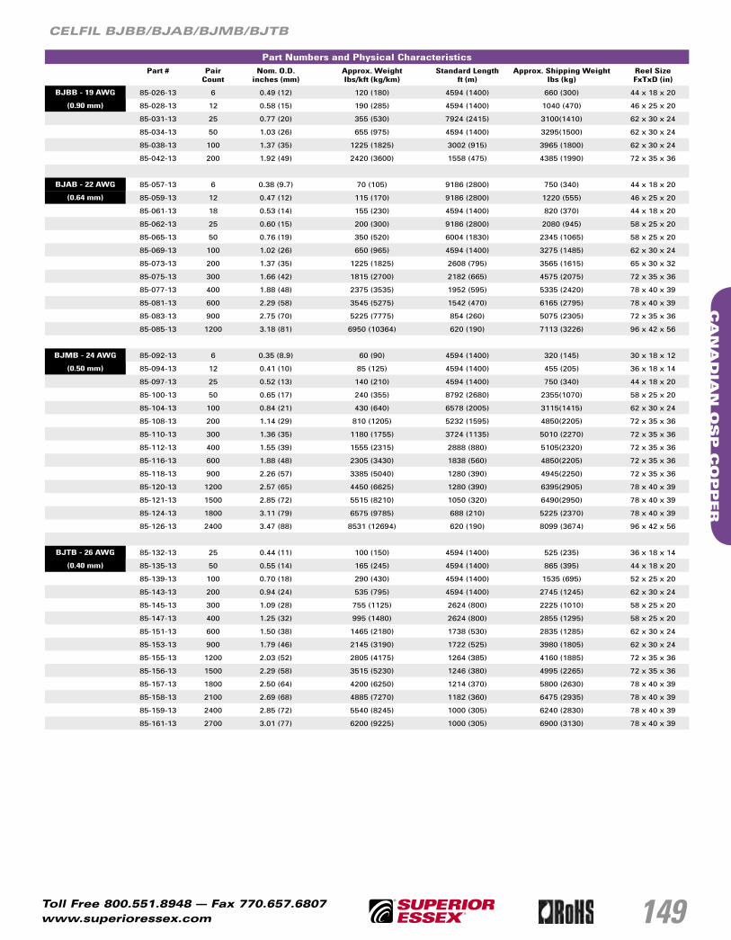
149
CA
NA
DIA
N O
SP
CO
PP
ER
Toll Free 800.551.8948 — Fax 770.657.6807www.superioressex.com
CELFIL BJBB/BJAB/BJMB/BJTB
Part Numbers and Physical CharacteristicsPart # Pair
CountNom. O.D.
inches (mm)Approx. Weight lbs/kft (kg/km)
Standard Length ft (m)
Approx. Shipping Weight lbs (kg)
Reel SizeFxTxD (in)
BJBB - 19 AWG 85-026-13 6 0.49 (12) 120 (180) 4594 (1400) 660 (300) 44 x 18 x 20
(0.90 mm) 85-028-13 12 0.58 (15) 190 (285) 4594 (1400) 1040 (470) 46 x 25 x 20
85-031-13 25 0.77 (20) 355 (530) 7924 (2415) 3100(1410) 62 x 30 x 24
85-034-13 50 1.03 (26) 655 (975) 4594 (1400) 3295(1500) 62 x 30 x 24
85-038-13 100 1.37 (35) 1225 (1825) 3002 (915) 3965 (1800) 62 x 30 x 24
85-042-13 200 1.92 (49) 2420 (3600) 1558 (475) 4385 (1990) 72 x 35 x 36
BJAB - 22 AWG 85-057-13 6 0.38 (9.7) 70 (105) 9186 (2800) 750 (340) 44 x 18 x 20
(0.64 mm) 85-059-13 12 0.47 (12) 115 (170) 9186 (2800) 1220 (555) 46 x 25 x 20
85-061-13 18 0.53 (14) 155 (230) 4594 (1400) 820 (370) 44 x 18 x 20
85-062-13 25 0.60 (15) 200 (300) 9186 (2800) 2080 (945) 58 x 25 x 20
85-065-13 50 0.76 (19) 350 (520) 6004 (1830) 2345 (1065) 58 x 25 x 20
85-069-13 100 1.02 (26) 650 (965) 4594 (1400) 3275 (1485) 62 x 30 x 24
85-073-13 200 1.37 (35) 1225 (1825) 2608 (795) 3565 (1615) 65 x 30 x 32
85-075-13 300 1.66 (42) 1815 (2700) 2182 (665) 4575 (2075) 72 x 35 x 36
85-077-13 400 1.88 (48) 2375 (3535) 1952 (595) 5335 (2420) 78 x 40 x 39
85-081-13 600 2.29 (58) 3545 (5275) 1542 (470) 6165 (2795) 78 x 40 x 39
85-083-13 900 2.75 (70) 5225 (7775) 854 (260) 5075 (2305) 72 x 35 x 36
85-085-13 1200 3.18 (81) 6950 (10364) 620 (190) 7113 (3226) 96 x 42 x 56
BJMB - 24 AWG 85-092-13 6 0.35 (8.9) 60 (90) 4594 (1400) 320 (145) 30 x 18 x 12
(0.50 mm) 85-094-13 12 0.41 (10) 85 (125) 4594 (1400) 455 (205) 36 x 18 x 14
85-097-13 25 0.52 (13) 140 (210) 4594 (1400) 750 (340) 44 x 18 x 20
85-100-13 50 0.65 (17) 240 (355) 8792 (2680) 2355(1070) 58 x 25 x 20
85-104-13 100 0.84 (21) 430 (640) 6578 (2005) 3115(1415) 62 x 30 x 24
85-108-13 200 1.14 (29) 810 (1205) 5232 (1595) 4850(2205) 72 x 35 x 36
85-110-13 300 1.36 (35) 1180 (1755) 3724 (1135) 5010 (2270) 72 x 35 x 36
85-112-13 400 1.55 (39) 1555 (2315) 2888 (880) 5105(2320) 72 x 35 x 36
85-116-13 600 1.88 (48) 2305 (3430) 1838 (560) 4850(2205) 72 x 35 x 36
85-118-13 900 2.26 (57) 3385 (5040) 1280 (390) 4945(2250) 72 x 35 x 36
85-120-13 1200 2.57 (65) 4450 (6625) 1280 (390) 6395(2905) 78 x 40 x 39
85-121-13 1500 2.85 (72) 5515 (8210) 1050 (320) 6490(2950) 78 x 40 x 39
85-124-13 1800 3.11 (79) 6575 (9785) 688 (210) 5225 (2370) 78 x 40 x 39
85-126-13 2400 3.47 (88) 8531 (12694) 620 (190) 8099 (3674) 96 x 42 x 56
BJTB - 26 AWG 85-132-13 25 0.44 (11) 100 (150) 4594 (1400) 525 (235) 36 x 18 x 14
(0.40 mm) 85-135-13 50 0.55 (14) 165 (245) 4594 (1400) 865 (395) 44 x 18 x 20
85-139-13 100 0.70 (18) 290 (430) 4594 (1400) 1535 (695) 52 x 25 x 20
85-143-13 200 0.94 (24) 535 (795) 4594 (1400) 2745 (1245) 62 x 30 x 24
85-145-13 300 1.09 (28) 755 (1125) 2624 (800) 2225 (1010) 58 x 25 x 20
85-147-13 400 1.25 (32) 995 (1480) 2624 (800) 2855 (1295) 58 x 25 x 20
85-151-13 600 1.50 (38) 1465 (2180) 1738 (530) 2835 (1285) 62 x 30 x 24
85-153-13 900 1.79 (46) 2145 (3190) 1722 (525) 3980 (1805) 62 x 30 x 24
85-155-13 1200 2.03 (52) 2805 (4175) 1264 (385) 4160 (1885) 72 x 35 x 36
85-156-13 1500 2.29 (58) 3515 (5230) 1246 (380) 4995 (2265) 72 x 35 x 36
85-157-13 1800 2.50 (64) 4200 (6250) 1214 (370) 5800 (2630) 78 x 40 x 39
85-158-13 2100 2.69 (68) 4885 (7270) 1182 (360) 6475 (2935) 78 x 40 x 39
85-159-13 2400 2.85 (72) 5540 (8245) 1000 (305) 6240 (2830) 78 x 40 x 39
85-161-13 2700 3.01 (77) 6200 (9225) 1000 (305) 6900 (3130) 78 x 40 x 39

150
CA
NA
DIA
N O
SP
CO
PP
ER
Toll Free 800.551.8948 — Fax 770.657.6807www.superioressex.com
ALPETH BHBB/BHAB/BKMB/BKTB
Product DescriptionSuperior Essex ALPETH cables are designed primarily for aerial use. In this application, the cable must be attachedto a support strand (messenger). If the cable is to be placed in a duct, the cable must be pressurized.
Physical Description
• CONDUCTORS: Solid bare annealed copper in 19, 22, 24 and 26 AWG. • INSULATION: Individual conductors are insulated with color coded
solid polyolefin.• TWISTED PAIRS: Insulated conductors are twisted to form pairs with varying
lays to minimize crosstalk and meet capacitance unbalance limitations.• CABLE ASSEMBLY: Cables of 25 pairs and less are assembled in concentric
layers to form a cylindrical core. Cables having more than 25 pairs and more are assembled from concentrically formed units with not more than 25 pair per unit, which may be stranded into 50 pair or 100 pair groups, which are cabled to form the complete cylindrical core assembly. For 1200 pair and larger, the color code is a Mirror Image design.
• CORE COVERING: A non-hygroscopic core wrap is applied over theassembled core which furnishes mechanical as well as high dielectricprotection between shielding and individual conductors.
• SHIELD: An electrically continuous 8-mil flat aluminum shielding tape witha polyolefin film fused and chemically bonded to both sides, is applied longitudinally over the core and bonded to the outer jacket.
• JACKET: Black medium-density polyethylene provides a tough, flexible protective covering that withstands exposure to sunlight, atmospheric temperatures, ground chemicals and stresses expected in standard installations.
• IDENTIFICATION AND LENGTH MARKING: Manufacturer’s identification, date of jacketing, gauge, pair count, sequential length and cable type surface marked on jacket at one meter intervals. Sequentially numbered length markings are located at one meter intervals.
Electrical SpecificationsAverage Mutual Capacitance at 1000 Hz
Total Number of Pairs nF/mile nF/km
12 or less 83 ± 7 52 ± 4
Over 12 83 ± 4 52 ± 2
Conductor Size Minimum Insulation Resistance
68° F
Nom. Attenuation@ 68°F (20° C)
1 kHz
Max ConductorResistance
@ 68°FOhms/sheath
Resistance UnbalanceMaximum %
Dielectric StrengthDC Potential – Volts
Minimum
AWG mm gigohm-mile
gigohm-km
dB/kft dB/km kft km Avg. Individual Pair Cdr. to Cdr. Cdr. to Shld.
19 0.90 1.0 1.6 0.24 0.8 8.5 28.0 1.5 5.0 4,500 10,000
22 0.64 1.0 1.6 0.33 1.1 17.3 56.6 1.5 5.0 3,600 10,000
24 0.50 1.0 1.6 0.43 1.4 26.1 85.5 1.5 5.0 3,000 10,000
26 0.40 1.0 1.6 0.55 1.8 44.0 144.2 1.5 5.0 2,400 10,000
Capacitance Unbalance Pair to Pair @ 1 kHz
MaximumIndividual
Maximum RMS
Pairs pF/kft pF/km pF/kft pF/km
12 or less 140 254 - -
more than 12 140 254 25 45
Capacitance Unbalance Pair to Ground @ 1 kHz
Maximum Individual
Maximum Avg
Pairs pF/kft pF/km pF/kft pF/km
12 or less 800 2625 - -
more than 12 800 2625 175 574
Minimum Near End Crosstalk (NEXT) at
150 kHz 772 kHz
P.S.WUNEXT mean (dB) 58 47
P.S.WUNEXT worst pair (dB) 53 42
Minimum Far End Crosstalk at 150 kHz
Conductor size (AWG) 19 22 24 26
P.S. ELFEXT mean (dB/kft) 65 63 63 61
P.S. ELFEXT worst pair (dB/kft) 59 57 57 57
Minimum Far End Crosstalk at 772 kHz
Conductor size (AWG) 19 22 24 26
P.S. ELFEXT mean (dB/kft) 51 49 49 47
P.S. ELFEXT worst pair (dB/kft) 45 43 43 43

151
CA
NA
DIA
N O
SP
CO
PP
ER
Toll Free 800.551.8948 — Fax 770.657.6807www.superioressex.com
ALPETH BHBB/BHAB/BKMB/BKTB
Part Numbers and Physical CharacteristicsPart # Pair
CountNom. O.D.
inches (mm)Approx. Weight lbs/kft (kg/km)
Standard Length ft (m)
Approx. Shipping Weight lbs (kg)
Reel SizeFxTxD (in)
BHBB - 19 AWG 85-026-01 6 0.47 (12) 105 (155) 4594 (1400) 590 (270) 44 x 18 x 20
(0.90 mm) 85-028-01 12 0.56 (14) 170 (255) 4594 (1400) 945 (430) 46 x 25 x 20
85-031-01 25 0.74 (19) 310 (460) 4594 (1400) 1625 (740) 52 x 25 x 20
85-034-01 50 0.98 (25) 565 (840) 4594 (1400) 2965 (1345) 65 x 30 x 32
85-038-01 100 1.31 (33) 1060 (1580) 3002 (915) 3470 (1575) 62 x 30 x 24
85-042-01 200 1.84 (47) 2075 (3090) 1492 (455) 3385 (1535) 62 x 30 x 24
85-044-01 300 2.25 (57) 3098 (4609) 1000 (305) 4810 (2182) 78 x 36 x 48
85-046-01 400 2.35 (66) 4096 (6095) 710 (215) 4600 (2086) 78 x 36 x 48
BHAB - 22 AWG 85-057-01 6 0.38 (9.7) 65 (95) 4594 (1400) 345 (155) 30 x 18 x 12
(0.64 mm) 85-059-01 12 0.45 (11) 100 (150) 4594 (1400) 525 (235) 36 x 18 x 14
85-062-01 25 0.59 (15) 180 (270) 5724 (1745) 1195 (540) 46 x 25 x 20
85-065-01 50 0.75 (19) 310 (460) 5724 (1745) 2020 (915) 58 x 25 x 20
85-069-01 100 1.00 (25) 570 (850) 4594 (1400) 2905 (1320) 62 x 30 x 24
85-073-01 200 1.35 (34) 1080 (1605) 3412 (1040) 4300 (1950) 72 x 35 x 36
85-075-01 300 1.64 (42) 1595 (2375) 2182 (665) 4095 (1855) 72 x 35 x 36
85-077-01 400 1.86 (47) 2105 (3135) 2132 (650) 5100 (2315) 72 x 35 x 36
85-081-01 600 2.27 (58) 3135 (4665) 1410 (430) 5035 (2285) 72 x 35 x 36
85-083-01 900 2.74 (70) 4640 (6905) 688 (210) 3805 (1725) 72 x 35 x 36
BKMB - 24 AWG 85-092-01 6 0.34 (8.6) 50 (75) 4594 (1400) 275 (125) 30 x 18 x 12
(0.50 mm) 85-094-01 12 0.40 (10) 75 (110) 4594 (1400) 410 (185) 36 x 18 x 14
85-097-01 25 0.50 (13) 125 (185) 4594 (1400) 680 (310) 44 x 18 x 20
85-100-01 50 0.63 (16) 215 (320) 4594 (1400) 1155 (525) 46 x 25 x 20
85-104-01 100 0.81 (21) 380 (565) 4594 (1400) 1950 (885) 52 x 25 x 20
85-108-01 200 1.09 (28) 705 (1050) 4594 (1400) 3605 (1635) 65 x 30 x 32
85-110-01 300 1.30 (33) 1025 (1525) 1838 (560) 2085 (945) 52 x 25 x 20
85-112-01 400 1.50 (38) 1355 (2015) 1492 (455) 2265 (1030) 58 x 25 x 20
85-116-01 600 1.81 (46) 2010 (2990) 1264 (385) 2830 (1285) 62 x 30 x 24
85-118-01 900 2.17 (55) 2970 (4420) 1182 (360) 4125 (1870) 72 x 35 x 36
85-120-01 1200 2.49 (63) 3915 (5825) 952 (290) 4340 (1970) 72 x 35 x 36
BKTB - 26 AWG 85-132-01 25 0.43 (11) 90 (135) 4594 (1400) 475 (215) 36 x 18 x 14
(0.40 mm) 85-135-01 50 0.53 (14) 150 (225) 4822 (1470) 830 (375) 44 x 18 x 20
85-139-01 100 0.68 (17) 255 (380) 4594 (1400) 1335 (605) 46 x 25 x 20
85-143-01 200 0.91 (23) 465 (690) 4594 (1400) 2380 (1080) 58 x 25 x 20
85-145-01 300 1.05 (27) 665 (990) 2624 (800) 1950 (885) 52 x 25 x 20
85-147-01 400 1.21 (31) 870 (1295) 2624 (800) 2530 (1145) 58 x 25 x 20
85-151-01 600 1.45 (37) 1290 (1920) 2394 (730) 3455 (1570) 65 x 30 x 32
85-153-01 900 1.74 (44) 1900 (2830) 1526 (465) 3270(1485) 65 x 30 x 32
85-155-01 1200 1.98 (50) 2495 (3715) 1460 (445) 4255 (1930) 72 x 35 x 36
85-156-01 1500 2.23 (57) 3105 (4620) 1000 (305) 3720 (1685) 72 x 35 x 36
85-157-01 1800 2.43 (62) 3705 (5515) 1312 (400) 5560 (2520) 78 x 40 x 39

152
CA
NA
DIA
N O
SP
CO
PP
ER
Toll Free 800.551.8948 — Fax 770.657.6807www.superioressex.com
SEALPAP BHBF, BHAF, BKMF, BKTF
Product DescriptionDouble jacketed aircore cable commonly called "SEALPAP" is a solid-insulated design intended for use in outside plant where a greater risk of physical damage exists. The inner jacket provides protection to the cable core in the event of severe damage to the outer protective sheath.
Physical Description
• CONDUCTORS: Solid annealed bare copper in 19, 22, 24 and 26 AWG. • INSULATION: Conductors are insulated with solid polyolefin in distinctive colors
to facilitate pair identification.• CORE ASSEMBLY: Individual conductor dimensions are tightly controlled
to limit resistance unbalance of the paired conductors. Pair twist lays and the relative placement of the pairs are designed to minimize crosstalk and meet the capacitance unbalance limits. In cables having 25 pairs or less, the pairs are combined into a cylindrical core. In cables of 50 pairs and more, multiples of 25 pair groups are assembled to form the final cable core. Each group is identified by color coded non-hygroscopic binders. For 1200 pair and larger, the color code is a Mirror Image design.
• CORE WRAP: A complete covering of a non-hygroscopic dielectric material protects the core and helps provide core-to-shield dielectric strength.
• INNER JACKET: A polyethylene inner jacket provides additional protection against mechanical damage and helps prevent the ingress ofmoisture. Ripcords are placed between the core wrap and the inner jacket and between the inner jacket and shield.
• SHIELD: A smooth 8-mil two-side coated aluminum tape is applied longitudinally over the inner jacket.
• JACKET: A black, medium-density polyethylene provides a tough, flexible,protective covering that withstands exposure to sunlight, atmospheric temperatures, and stresses expected in standard installations. The overall outer jacket is bonded to the aluminum shield for additional moisture resistance.
• JACKET MARKINGS: Information such as manufacturer’s identification, plant location, date of jacketing, pair count, AWG, product identification, sequential length markings in meters and a telephone handset.
Electrical SpecificationsAverage Mutual Capacitance at 1000 Hz
nF/mile nF/km
All Pairs 83 ± 4 52 ± 2
Conductor Size Minimum Insulation Resistance68° F (20° C)
Max Average Attenuation 772kHz
@ 68°F (20° C)
Max ConductorResistance
@ 68°F (20° C)Ohms/sheath
Resistance UnbalanceMaximum %
Dielectric StrengthDC Potential – Volts
AWG mm gigohm-mile
gigohm-km
dB/kft dB/km mile km Avg. Individual Pair Cdr. to Cdr. Cdr. to Grnd.
19 0.90 1.0 1.6 3.3 10.9 45.0 28.0 1.5 5.0 5,000 20,000
22 0.64 1.0 1.6 4.6 15.3 91.0 56.6 1.5 5.0 4,000 20,000
24 0.50 1.0 1.6 5.7 19.4 144.0 89.5 1.5 5.0 3,000 20,000
26 0.40 1.0 1.6 7.2 23.6 232.0 144.2 1.5 5.0 2,400 20,000
Minimum Near End Crosstalk (NEXT) at
150 kHz 772 kHz Capacitance Unbalance Pair to Pair @ 1 kHz
MaximumIndividual
Maximum RMS
P.S.WUNEXT mean (dB) 58 47 Pairs pF/kft pF/km pF/kft pF/km
P.S.WUNEXT worst pair (dB) 53 42 12 or less 80 145 - -
Minimum Far End Crosstalk at 150 kHz more than 12 80 145 25 45
Conductor size (AWG) 19 22 24 26
P.S. ELFEXT mean (dB/kft) 65 63 63 61
P.S. ELFEXT worst pair (dB/kft) 59 57 57 57
Minimum Far End Crosstalk at 772 kHz
Capacitance Unbalance Pair to Ground @ 1 kHz
MaximumIndividual
Maximum Avg
Conductor size (AWG) 19 22 24 26 Pairs pF/kft pF/km pF/kft pF/km
P.S. ELFEXT mean (dB/kft) 51 49 49 47 12 or less 800 2625 - -
P.S. ELFEXT worst pair (dB/kft) 45 43 43 43 more than 12 800 2625 175 574

153
CA
NA
DIA
N O
SP
CO
PP
ER
Toll Free 800.551.8948 — Fax 770.657.6807www.superioressex.com
SEALPAP BHBF, BHAF, BKMF, BKTF
Part Numbers and Physical CharacteristicsPart # Pair
CountNom. O.D.
inches (mm)Approx. Weight lbs/kft (kg/km)
Standard Length ft (m)
Approx. Shipping Weight lbs (kg)
Reel Size
BHBF - 19 AWG 85-031-41 25 0.84 (21) 355 (530) 9006 (2745) 3990 (1810) 420
(0.90 mm) 85-034-41 50 1.07 (27) 625 (930) 4512 (1375) 3615 (1640) 420
85-038-41 100 1.43 (36) 1170 (1740) 2986 (910) 4290 (1945) 420
85-042-41 200 1.96 (50) 2230 (3320) 2230 (680) 5770 (2615) 420
BHAF - 22 AWG 85-062-41 25 0.68 (17) 215 (320) 5724 (1745) 2025 (920) 420
(0.64 mm) 85-065-41 50 0.85 (22) 360 (535) 5724 (1745) 2855 (1295) 420
85-069-41 100 1.09 (28) 635 (945) 4282 (1305) 3515 (1595) 420
85-073-41 200 1.47 (37) 1190 (1770) 3412 (1040) 4855 (2200) 420
85-077-41 400 1.99 (51) 2260 (3365) 2132 (650) 5615 (2545) 420
85-081-41 600 2.42 (62) 3370 (5015) 1410 (430) 5545 (2515) 420
BKMF - 24 AWG 85-097-41 25 0.62 (16) 169 (251) 6000 (1830) 1013 (460) 420
(0.50 mm) 85-100-41 50 0.72 (18) 255 (380) 6316 (1925) 2405 (1090) 420
85-104-41 100 0.91 (23) 430 (640) 6004 (1830) 3375 (1530) 420
85-108-41 200 1.18 (30) 770 (1145) 2116 (645) 2425 (1100) 420
85-110-41 300 1.43 (36) 1130 (1680) 2280 (695) 3370 (1530) 420
85-112-41 400 1.62 (41) 1475 (2195) 2280 (695) 4160 (1885) 420
85-116-41 600 1.94 (49) 2160 (3215) 1312 (400) 3630 (1645) 420
85-118-41 900 2.33 (59) 3190 (4745) 1050 (320) 4145 (1880) 420
85-120-41 1200 2.64 (67) 4165 (6200) 1312 (400) 6260 (2840) 420
BKTF - 26 AWG 85-135-41 50 0.63 (16) 185 (275) 4822 (1470) 1685 (765) 420
(0.40 mm) 85-139-41 100 0.77 (20) 300 (445) 4822 (1470) 2240 (1015) 420
85-143-41 200 1.00 (25) 525 (780) 4822 (1470) 3325(1510) 420
85-147-41 400 1.33 (34) 970 (1445) 2394 (730) 3115 (1415) 420
85-151-41 600 1.58 (40) 1410 (2100) 2394 (730) 4170 (1890) 420
85-153-41 900 1.87 (48) 2045 (3045) 1510 (460) 3885 (1760) 420
85-155-41 1200 2.13 (54) 2695 (4010) 1526 (465) 4910 (2225) 420
Standards Compliance:Telcordia GR-421-CORE; ANSI/ICEA S-85-625-2002, RoHS Compliant

154
CA
NA
DIA
N O
SP
CO
PP
ER
Toll Free 800.551.8948 — Fax 770.657.6807www.superioressex.com
Canadian Self Support BHBS-BC/BHAS-BC/BKMS-BC
Product DescriptionSelf support cable is a plastic insulated, single jacketed aircore design with a built-in support member intended specially for aerial applications. The core and support member (messenger) lay parallel to each other forming a cross-sectional “figure 8”. The messenger is an integral part of the cable sheath,yet readily available for gripping, pulling and tensioning. Installation is fast and easy using standard methods and hardware.
Physical Description
• CONDUCTORS: Solid annealed bare copper in 19, 22 and 24 AWG. • INSULATION: Individual conductors are insulated with color coded
solid polyolefin.• TWISTED PAIRS: Individual insulated conductors are twisted into pairs with
varying lay lengths to minimize crosstalk and specific color combinations to provide pair identification.
• CORE ASSEMBLY: Cables of 25 pairs and less are assembled into a cylindrical core. Cables larger than 25 pairs are assembled into units, which are then used to assemble the core. Units are individually identifiable by color coded binders.
• CORE WRAP: A non-hygroscopic, dielectric tape is applied over the core assembly to provide thermal protection for the core.
• SHIELDING: A corrugated, copolymer coated, 8-mil aluminum tape is applied longitudinally with an overlap. The shield interfaces are flooded with an adhesive compound to provide a moisture barrier and inhibit corrosion.
• SUPPORT MEMBER: A 1/4 inch, 7-strand Extra High Strength (EHS)galvanized steel messenger serves as the support member and is an integral part of the sheath. The messenger is flooded to inhibit corrosion.
• JACKET: A black, polyethylene jacket is applied overall. The jacket provides a tough protective covering designed to withstand exposure to direct sunlight, atmospheric temperature changes and stresses expected in standard installations.
• JACKET MARKINGS: Information including the manufacturer’s identification, date of jacketing, pair count, AWG and meter sequentials at 1 meter intervals.
Electrical SpecificationsAverage Mutual Capacitance at 1000 Hz
Total Number of Pairs nF/mile nF/km
12 or less 83 ± 7 52 ± 4
Over 12 83 ± 4 52 ± 2
Conductor Size Minimum Insulation Resistance68° F (20° C)
Max Average Attenuation
@ 68°F (20° C)772 kHz
Max ConductorResistance
@ 68°F Ohms/sheath
Resistance UnbalanceMaximum %
Dielectric StrengthDC Potential – Volts
Minimum
AWG mm gigohm-mile
gigohm-km
dB/kft dB/km mile km Avg. Individual Pair Cdr. to Cdr. Cdr. to Grnd.
19 0.90 1.0 1.6 3.3 10.8 45.0 28.0 1.5 5.0 4,500 10,000
22 0.64 1.0 1.6 4.6 15.3 91.0 56.6 1.5 5.0 3,600 10,000
24 0.50 1.0 1.6 5.7 19.4 144.0 89.5 1.5 5.0 3,000 10,000
Minimum Near End Crosstalk (NEXT) at
150 kHz 772 kHz Capacitance Unbalance Pair to Pair @ 1 kHz
MaximumIndividual
Maximum RMS
P.S.WUNEXT mean (dB) 58 47 Pairs pF/kft pF/km pF/kft pF/km
P.S.WUNEXT worst pair (dB) 53 42 12 or less 80 145 - -
Minimum Far End Crosstalk at 150 kHz more than 12 80 145 25 45
Conductor size (AWG) 19 22 24
P.S. ELFEXT mean (dB/kft) 65 63 63
P.S. ELFEXT worst pair (dB/kft) 59 57 57
Minimum Far End Crosstalk at 772 kHz
Capacitance Unbalance Pair to Ground @ 1 kHz
MaximumIndividual
Maximum Avg
Conductor size (AWG) 19 22 24 Pairs pF/kft pF/km pF/kft pF/km
P.S. ELFEXT mean (dB/kft) 51 49 49 12 or less 800 2625 - -
P.S. ELFEXT worst pair (dB/kft) 45 43 43 more than 12 800 2625 175 574

155
CA
NA
DIA
N O
SP
CO
PP
ER
Toll Free 800.551.8948 — Fax 770.657.6807www.superioressex.com
Canadian Self Support BHBS-BC/BHAS-BC/BKMS-BC
Part Numbers and Physical CharacteristicsPart # Pair
CountMinor
Dimensionsinches (mm)
MajorDimensionsinches (mm)
Approx. Weight lbs/kft (kg/km)
Standard Length ft (m)
Approx.Shipping Weight
lbs (kg)
Reel Size
BHBS-BC - 19 AWG 07-021-51 6 0.48 (12) 0.96 (24) 240 (355) 10006 (3050) 1023 (1526) 420
(0.90 mm) 07-021-52 25 0.60 (15) 1.07 (27) 440 (655) 5019 (1530) 2990(4459) 420
07-021-53 50 0.98 (25) 1.45 (34) 710 (1055) 5019 (1530) 4345 (6480) 420
BHAS-BC - 22 AWG 07-021-54 25 0.58 (15) 1.05 (27) 325 (485) 10006 (3050) 1109 (1654) 420
(0.64 mm) 07-021-55 50 0.74 (19) 1.20 (31) 460 (685) 7513 (2290) 4238 (6320) 420
07-021-56 100 1.00 (25) 1.47 (37) 720 (1070) 6004 (1830) 5105 (7613) 420
BKMS-BC - 24 AWG 07-021-57 50 0.62 (16) 1.09 (28) 385 (573) 13303 (4055) 5904 (8805) 420
(0.50 mm) 07-021-58 100 0.80 (22) 1.27 (32) 575 (856) 8005 (2440) 5305 (8031) 420
07-021-59 200 1.09 (28) 1.56 (40) 1013 (1508) 5020 (1530) 5867 (8750) 420
Standards ComplianceTelecordia GR-421-CORE; ANSI/ICEA S-85-625-1996, RoHS Compliant

156
CA
NA
DIA
N O
SP
CO
PP
ER
Toll Free 800.551.8948 — Fax 770.657.6807www.superioressex.com
ADP-X-NMS
Product DescriptionADP-X-NMS Wire is a PVC-jacketed aerial service wire designed for eXtreme outdoor environments. The ADP-X-NMS wire is designed for heavy loadingconditions which are identified as locations that have a very high potential for extreme icing and very high winds. ADP-X-NMS is offered with the Superior Essex QuickCount® feature in meters. Offered in a two pair size, this aerial service wire is designed for use in extending telephone service to subscriber premises from the distribution cable or cable terminal. Standard hardware and installation procedures are directly applicable to this product.
Physical Description
• CONDUCTORS: Solid annealed copper in 22 AWG.• INSULATION: Each conductor is insulated with solid polyolefin in Blue/White,
Orange/White distinctive colors. The insulation of the tip conductor is marked with a stripe of the mating ring insulation color to reduce the possibility of splitting pairs during installation.
• CORE ASSEMBLY: Individual conductors are carefully twisted into pairs in a manner designed to minimize resistance unbalance.
• STRENGTH MEMBERS: Fiberglass strength members are placed in the jacket parallel to the core assembly to provide the necessary longitudinal strength.
• RIPCORD: A ripcord is placed parallel to the core to facilitate jacket removal.• JACKET: A black, weather resistant, polyvinyl chloride jacket is extruded over
the yarns and ripcord to protect the core from mechanical damage, degradation by sunlight and ingress of moisture. The jacket bonds to the fiberglass strength members to provide the required strength characteristics.
Part Numbers and Physical CharacteristicsPart # Pair Count Minor Dimensions
inches (mm)Major Dimensions
inches (mm)Approx. Weightlbs/kft (kg/km)
Standard Length ft (m)
Package
11-003-16 2 0.18 (4.6) 0.36 (9.1) 36 (54) 492 (150) ReelSaver™ Coil
11-003-15 2 0.18 (4.6) 0.36 (9.1) 36 (54) 984 (300) Coil
Electrical SpecificationsAverage Mutual Capacitance at 1000 Hz
nF/mile nF/km
Maximum Individual 94 58
Wire Average 83 ± 7 52 ± 4
Conductor Size Insulation ResistanceMinimum
Attenuation - Max Average @ 68°F and 772 kHz
Conductor DCResistance @ 68°F
Maximum Individual
Resistance Unbalance
Maximum %
Dielectric StrengthVolts DC
AWG mm megohm-mile megohm-km dB/kft dB/km ohms/mile ohms/km Individual Pair 5 secs, no breakdown
22 0.64 1,000 1,600 5.1 16.7 91.0 56.0 5.0 7,200
Crosstalk Loss dB/kft dB/km Capacitance Unbalance @ 1000 Hz,Pair to Pair
pF/kft pF/km
FEXT @ 150 kHz; Minimum Individual 63 58 Maximum Individual Pair 80 145
NEXT @ 722 kHz; Minimum Individual 48 dB / 1000 ft (305 m)
Standards Compliance:Telcordia GR-1069-CORE; Meets the Extra Strength Objective 04-61; RDUP PE-7; ANSI/ICEA S-89-648-2000; UL Listed, RoHS Compliant

157
CA
NA
DIA
N O
SP
CO
PP
ER
Toll Free 800.551.8948 — Fax 770.657.6807www.superioressex.com
ADW Aerial Drop Wire
Product Description
Superior Essex ADW is a PVC jacketed two or four pair aerial service wire designed for use in extending telephone service to subscriber premises from the distribution cable or cable terminal. Major features include small size and light weight coupled with abrasion resistant jacket. Standard hardware and installations procedures are directly applicable to this product.
Physical Description
• CONDUCTORS: Solid bare annealed copper in 22 AWG (0.64 mm).• INSULATION: Individual conductors are insulated with solid polyolefin
in distinctive colors. The two-pair color code is Blue/White and Orange/Red. The four-pair color code is Blue/White, Orange/Red, Black/Green and Yellow/Brown.
• CORE ASSEMBLY: Individual conductors are carefully twisted into pairsin a manner designed to minimize resistance unbalance.
• STRENGTH MEMBERS: Fiberglass strength members are placedin the jacket parallel to the core assembly to provide the necessary longitudinal strength.
• RIPCORD: A jacket ripcord is placed parallel to the core to facilitatejacket removal.
• JACKET: A sky Blue grey weather-resistant PVC jacket is extruded over the strength members to protect the core from mechanical damage, degradation by sunlight and the ingress of moisture. The jacket bonds to the fiberglass strength members to provide the required strength characteristics.
Part Numbers and Physical CharacteristicsPart # Pair Count Nominal O.D.
inches (mm)Approx. Weight lbs/kft (kg/km)
Standard Length ft (m)
Package
12-022-09 2 0.24 (6.1) 30 (45) 1476 (450) Coil
12-021-09 2 0.24 (6.1) 30 (45) 656 (200) POP®star Box
12-023-09 2 0.24 (6.1) 30 (45) 5000 (1525) Reel
12-041-09 4 0.33 (8.4) 55 (80) 820 (250) Coil
12-042-09 4 0.33 (8.4) 55 (80) 3937(1200) Reel
12-043-09 4 0.33 (8.4) 55 (80) 328 (100) POP Box
Electrical SpecificationsAverage Mutual Capacitance at 1000 Hz
nF/mile nF/km
All Pairs 113 70
Conductor Size Insulation Resistance@ 60°F
Capacitance Unbalance @ 1000Hz Pair to Pair
Maximum
Max Conductor DCResistance @ 20°F
Max. Individual
ResistanceUnbalanceMaximum
Dielectric StrengthDC Potential - Volts
Minimum
AWG mm megohm-mile megohm-km pF/kft pF/km ohms/kft ohms/km Individual Pair % Cdr. to Cdr.
Cdr. to H2O
22 0.64 380 610 140 254 16.8 56.6 5.0 4000 5000

CA
NA
DIA
N O
SP
CO
PP
ER
158 Toll Free 800.551.8948 — Fax 770.657.6807www.superioressex.com
ADP NMS (with QuickCount® in meters)
Product Description
�ADP�NMS�is�a�PVC-jacketed�aerial�service�wire�offered�with�the�Superior�Essex�QuickCount®�in�meters�feature.�Available�in�a�two�and�six�pair�size.�ADP�NMS�printed�in�meters�is�designed�for�use�in�extending�telephone�service�to�subscriber�premises�from�the�distribution�cable�or�cable�terminal.�Major�features�include�small�size�and�light�weight�coupled�with�abrasion�resistant�jacket.�Standard�hardware�and�installation�procedures�are�directly�applicable�to�this�product.
Physical Description
•�CONDUCTORS:�Solid�annealed�copper�in�22�AWG.•��INSULATION:�Each�conductor�is�insulated�with�solid�polyolefin.�The�insulation�
of�the�tip�conductor�is�marked�with�a�stripe�of�the�mating�ring�insulation�color�to�reduce�the�possibility�of�splitting�pairs�during�installation.
•��CORE�ASSEMBLY:�Individual�conductors�are�carefully�twisted�into�pairs��in�a�manner�designed�to�minimize�resistance�unbalance.
•��STRENGTH�MEMBERS:�Fiberglass�yarns�are�placed�parallel�to�the�core�to��provide�the�necessary�longitudinal�strength.
•��RIPCORD:�A�ripcord�is�placed�parallel�to�the�core�to�facilitate�jacket�removal.•��JACKET:�A�black,�weather�resistant,�polyvinyl�chloride�jacket�is�extruded�over�
the�yarns�and�ripcord�to�protect�the�core�from�mechanical�damage,�degradation�by�sunlight�and�ingress�of�moisture.�The�jacket�bonds�to�the�fiberglass�strength�members�to�provide�the�required�strength�characteristics.
Integrated Messenger Wire IM/F, IM/H & IM/G
Product Description
IM/F�IM/H�and�IM/G�aerial�service�wire�in�2,�3,�6�and�12�pair�is�self�supporting.�The�conductors�are�laid�parallel�to�an�(F)�0.083�inch,�(H)�0.109�inch,�or�(G)�0.095�inch�solid�extra-strength�steel�support�wire.�Both�the�conductors�and�support�wire�are�jacketed�in�an�integral�“figure-8”�configuration.�This�product�permits�fast,�economical�installation�from�aerial�distribution�cable�terminals�to�building�entrance�protectors�or�network�interface�units�on�the�subscriber’s�premises.�The�fully�color�coded�core�expedites�splicing�and�terminating�procedures.
Physical Description
•��CONDUCTORS:�Solid�annealed�copper�in�19�and�22�AWG.•��INSULATION:�Each�conductor�is�insulated�with�solid�polyolefin�in�distinctive�
colors.�Standard�color�codes�are�used�for�pair�identification�with�compounds�chosen�for�electrical�balance�and�permanency.�
•��CORE�ASSEMBLY:�Individual�conductor�dimensions�are�tightly�controlled�to�limit�resistance�unbalance�of�the�twisted�pairs.�In�multi-pair�constructions,�pair�twist�lays�are�varied�to�minimize�crosstalk�and�meet�capacitance�limits.�Twisted�pairs�are�formed�into�a�firm,�round�core.
•��OUTER�JACKET:�A�black,�fire�retardant,�polyvinyl�chloride�jacket�provides�a�tough�flexible�protective�covering�that�withstands�exposure�to�sunlight,�atmospheric�temperatures�and�stresses�encountered�in�standard��installations.�The�steel�support�wire�is�jacketed�in�an�integral�extrusion��with�the�core.
Standards Compliance: Telcordia TR-NWT-000122; ANSI/ICEA S-89-648-2002; UL Listed, RoHS Compliant
Part Numbers and Physical CharacteristicsPart # Support
SizePair Count Dimensions Approx. Weight
lbs/kft (kg/km)Standard Length
ft (m)Package
Minor inches (mm)
Major inches (mm)
19 AWG (0.90 mm) 10-921-38 IM/G 0.095 2 0.27 (6.8) 0.51 (12.9) 73 (109) 656 (200) Coil
10-923-38 IM/G 0.095 2 0.27 (6.8) 0.51 (12.9) 73 (109) 4921 (1500) Reel
22 AWG (0.64 mm) 10-002-34 IM/F 0.083 2 0.22 (5.7) 0.46 (11.7) 55 (82) 600 (183) Coil
10-102-34 IM/F 0.083 2 0.22 (5.7) 0.46 (11.7) 55 (82) 5000 (1525) Reel
10-503-34 IM/F 0.083 3 0.24 (6.2) 0.48 (12.3) 72 (107) 1000 (305) Coil
10-106-34 IM/F 0.083 6 0.30 (7.6) 0.53 (13.6) 80 (119) 3500 (1067) Reel
10-206-34 IM/F 0.083 6 0.30 (7.6) 0.53 (13.6) 80 (119) 1000 (305) Reel
10-306-34 IM/F 0.083 6 0.30 (7.6) 0.53 (13.6) 80 (119) 400 (122) Coil
10-261-38 IM/G 0.095 6 0.30 (7.6) 0.55 (13.9) 80 (119) 492 (150) Coil
10-262-38 IM/G 0.095 6 0.30 (7.6) 0.55 (13.9) 80 (119) 2461 (750) Reel
10-265-38 IM/G 0.095 6 0.30 (7.6) 0.55 (13.9) 80 (119) 5000 (1562) Reel
10-281-38 IM/G 0.095 12 0.38 (7.6) 0.65 (16.6) 114 (170) 410 (125) Coil
10-284-38 IM/G 0.095 12 0.38 (7.6) 0.65 (16.6) 114 (170) 2460 (750) Reel
10-285-38 IM/G 0.095 12 0.38 (7.6) 0.65 (16.6) 114 (170) 8202 (2500) Reel
10-102-35 IM/H 0.109 12 0.38 (7.6) 0.66 (16.7) 130 (193) 1000 (305) Reel
10-012-35 IM/H 0.109 12 0.38 (7.6) 0.66 (16.7) 130 (193) 250 (76) Coil
10-212-35 IM/H 0.109 12 0.38 (7.6) 0.66 (16.7) 130 (193) 5000 (1525) Reel
Contact Superior Essex for additional configurations and AWG sizes.
Electrical SpecificationsAverage Mutual Capacitance at 1000 Hz
All Pairs nF/mile nF/km
Maximum Individual 94 58
Wire Average 83 ± 7 52 ± 4
Conductor Size Insulation ResistanceMinimum
Attenuation - Max Average @ 68°F and 772 kHz
Conductor DCResistance @ 68°F
Maximum Individual
Resistance Unbalance
Maximum %
Dielectric Strength Minimum Volts
DC
AWG mm megohm-kft megohm-km dB/kft dB/km ohms/mile ohms/km Individual Pair 5 secs, no breakdown
19 0.9 5,000 1,600 3.6 11.8 45 28.0 5.0
22 0.64 5,000 1,600 5.1 16.7 91 56.0 5.0 7,200
Crosstalk Loss dB/kft dB/km Capacitance Unbalance @ 1000 Hz pF/kft pF/km
FEXT @ 150 kHz; Minimum Individual 63 58 Individual Maximum Pair to Pair 80 145
NEXT @ 722 kHz; Minimum Individual 44 dB / 1000 ft (305 m) Individual Maximum Pair to Ground 800 2,625

159
CA
NA
DIA
N O
SP
CO
PP
ER
Toll Free 800.551.8948 — Fax 770.657.6807www.superioressex.com
ADP NMS (with QuickCount® in meters)
Product Description
ADP NMS is a PVC-jacketed aerial service wire offered with the Superior Essex QuickCount® in meters feature. Available in a two and six pair size.ADP NMS printed in meters is designed for use in extending telephone service to subscriber premises from the distribution cable or cable terminal.Major features include small size and light weight coupled with abrasion resistant jacket. Standard hardware and installation procedures are directlyapplicable to this product.
Physical Description
• CONDUCTORS: Solid annealed copper in 22 AWG.• INSULATION: Each conductor is insulated with solid polyolefin. The insulation
of the tip conductor is marked with a stripe of the mating ring insulation color to reduce the possibility of splitting pairs during installation.
• CORE ASSEMBLY: Individual conductors are carefully twisted into pairs in a manner designed to minimize resistance unbalance.
• STRENGTH MEMBERS: Fiberglass yarns are placed parallel to the core to provide the necessary longitudinal strength.
• RIPCORD: A ripcord is placed parallel to the core to facilitate jacket removal.• JACKET: A black, weather resistant, polyvinyl chloride jacket is extruded over
the yarns and ripcord to protect the core from mechanical damage, degradation by sunlight and ingress of moisture. The jacket bonds to the fiberglass strength members to provide the required strength characteristics.
Part Numbers and Physical CharacteristicsPart # Pair Count Minor Dimensions
inches (mm)Major Dimensions
inches (mm)Approx. Weight lbs/kft (kg/km)
Standard Length (m)
Package
12-015-08 2 0.18 (4.8) 0.36 (9.1) 35 (50) 150 ReelSaver™ Coil
12-014-08 2 0.18 (4.8) 0.36 (9.1) 35 (50) 228 POP® Box
12-013-08 2 0.18 (4.8) 0.36 (9.1) 35 (50) 300 Coil
11-003-66 6 0.27 (7) 0.48 (12) 70 (105) 305 Reel
11-003-65 6 0.27 (7) 0.48 (12) 70 (105) 122 Coil
Electrical SpecificationsAverage Mutual Capacitance at 1000 Hz
nF/mile nF/km
Maximum Individual 94 58
Wire Average 83 ± 7 52 ± 4
Conductor Size Insulation ResistanceMinimum
Attenuation - Max Average @ 68°F and 772 kHz
Conductor DCResistance @ 68°F
Maximum Individual
ResistanceUnbalanceMaximum
Dielectric StrengthVolts DC
AWG mm megohm-mile megohm-km dB/kft dB/km ohms/mile ohms/km Individual Pair % 5 secs, no breakdown
22 0.64 1,000 1,600 5.1 16.7 91.0 56.0 5.0 7,200
Crosstalk Loss dB/kft dB/km Capacitance Unbalance @ 1000 Hz, Pair to Pair
pF/kft pF/km
FEXT @ 150 kHz; Minimum Individual 63 58 Maximum Individual Pair 80 145
NEXT @ 722 kHz; Minimum Individual 48 dB / 1000 ft (305 m)
Standards Compliance:Telecordia GR-1069-CORE;RDUP PE-7; ANSI/ICEA S-89-648-2000; UL Listed, RoHS Compliant

160
CA
NA
DIA
N O
SP
CO
PP
ER
Toll Free 800.551.8948 — Fax 770.657.6807www.superioressex.com
BCBD Buried Distribution Wire
Product DescriptionSuperior Essex BCBD wire with foam skin insulation is a single jacketed design for use in subscriber distribution.
Physical Description
• CONDUCTORS: Solid annealed copper in 22 AWG.• INSULATION: Individual conductors are insulated with a dual-extruded
cellular inner layer and a color coded solid outer layer of polyolefin.• TWISTED PAIRS: Insulated conductors are twisted to form pairs with varying
lays to minimize crosstalk and meet capacitance unbalance limitations.• MOISTURE RESISTANCE: A moisture-resistant PEPJ compound is applied to the
wire core which completely coats each insulated conductor and fills the interstices between pairs.
• CORE COVERING: A non-hygroscopic core wrap is applied over theassembled core which furnishes mechanical as well as high dielectricprotection between shielding and individual conductors.
• FLOODING COMPOUND: A flooding compound is applied to fill all the voids under the shield.
• SHIELD: An electrically-continuous 8-mil flat aluminum shielding tape, with a polyolefin film fused and chemically bonded to both sides, is applied longitudinally over the core and bonded to the outer jacket.
• JACKET: Black medium-density polyethylene provides a tough, flexible protec-tive covering that withstands exposure to sunlight, atmospheric temperatures, ground chemicals and stresses expected in standard installations.
Part Numbers and Physical CharacteristicsPart # Pair Count Nominal O.D.
inches (mm)Approx. Weight lbs/kft (kg/km)
Standard Length ft (m)
Package
85-235-06 4 0.30 (7.6) 45 (65) 1640 (500) Reel
85-233-06 4 0.30 (7.6) 45 (65) 4590 (1400) Reel
85-234-06 4 0.30 (7.6) 45 (65) 656 (200) Coil
Electrical SpecificationsAverage Mutual Capacitance at 1000 Hz
nF/mile nF/km
All Pairs 83 ± 7 51.6 ± 4
Conductor Size Minimum Insulation Resistance @ 60°F
Max Average Attenuation @ 68°F
150 kHz
Max Conductor Resistance @ 68°F
Ohms/sheath
ResistanceUnbalanceMaximum
Dielectric StrengthDC Potential - Volts
Minimum
AWG mm gigohm-mile gigohm-km dB/kft dB/km kft km Individual Pair % Cdr. to Cdr. Cdr. to Gnd.
22 0.64 1.0 1.6 0.33 1.1 17.3 56.6 5.0 3,600 10,000
Capacitance Unbalance Pair to Pair Capacitance Unbalance Pair to Ground
Pairs Maximum Individual pF/kft pF/km
Pairs Maximum Individual pF/kft pF/km
4 140 254 4 800 2625

161
www.NextLANsystems.com
next Time, nextLAn.
The new nexTLAn® 10Gc Breakthrough performance, exactly where you need itTo engineer NextLAN 10GC, we used the ultimate test lab: Reality. We focused our design efforts on making a system that will provide peak performance in a real-world environment where interference is uncontrolled and the cabling system needs to run at 10G speeds without error – 100% of the time.
The result? The first UTP cabling system that fully complies with the latest draft ANSI/TIA standard for 10 Gigabit Ethernet cabling requirements and includes a 4dB margin guarantee for Power Sum ACR.
OTher cAbLing sysTems Are fine if yOu wOrk in A TesT LAb. LeViTOn AnD suPeriOr esseX mADe sure ThAT neXTLAn 10gc PerfOrms Like A DreAm in reAL Life – yOurs.
real worldTeST laB

162 Toll Free 800.551.8948 — Fax 770.657.6807www.superioressex.com

163
OS
P C
OM
PO
SIT
E
Toll Free 800.551.8948 — Fax 770.657.6807www.superioressex.com
OSP COMPOSITE
OSP COMPOSITE
Table of Contents
Series 71 W Composite Drop Web Design . . . . . . . . . . . . . . . . . . . . . . . . . . . . . . . . .164
Series 71 OJ Composite Drop Overjacket Design. . . . . . . . . . . . . . . . . . . . . . . . . . . .165
Series 5V Composite OSP Web . . . . . . . . . . . . . . . . . . . . . . . . . . . . . . . . . . . . . . . .166
Series 70 OJ Composite OSP Overjacket . . . . . . . . . . . . . . . . . . . . . . . . . . . . . . . . .167
Series 5F Category 5e Composite Drop . . . . . . . . . . . . . . . . . . . . . . . . . . . . . . . . . . .168
Series L Composite Round CF . . . . . . . . . . . . . . . . . . . . . . . . . . . . . . . . . . . . . . . . . .169
BroadGain®-CX Copper/Coax Composite Web Design . . . . . . . . . . . . . . . . . . . . . . . .171

164
OS
P C
OM
PO
SIT
E
Toll Free 800.551.8948 — Fax 770.657.6807www.superioressex.com
Series 71 W Composite Drop Web Design
Product DescriptionSeries 71 W composite drop cables combine fiber and copper technologies in a web design. The composite design provides a cost benefit compared to installing
separate fiber and copper cables. The independent fiber and copper cables are combined in a single jacket design utilizing a web separator. This lightweight design is easy to access since the cables are easily separated at the web. In addition, each independent cable also contains a ripcord.
Physical Description
The construction of this product combines an BSW OSP copper wire and a Series 513 fiber optic cable. These independent cables are simultaneously jacketed in a medium density polyethylene outer jacket with a ripcord included for ease of use. The cables are joined by a web that can be split to direct the cables to separate locations.
Copper cable: BSW cable with solid insulation is a single-jacketed, armored, filled design intended for direct bury applications. A corrugated 4 mil bronze shield is applied over the core wrap. An ETPR compound provides water blocking protection. Electrical specifications can be found in the copper section for BSW wires.
Fiber Optic Cable: Series 513 is a single central tube cable. The central tube contains the optical fibers, the tube is surrounded by the flexible yarns which provide the tensile strength. Dry super absorbent polymers provide the water blocking protection.
Features Benefits Applications
• Independent fiber and copper cables combined in a web design
• Combined transport technologies in one cable• Optical / Electrical Technology
• Reduces cost of cable and labor
• Cost-effective installation• Ideal for multiple projects, voice, video, data and powering.
• Network Power and FTTP
Part Numbers and Physical CharacteristicsPart # Fiber Type Fiber Count Pair Count x AWG Standard Reel Length
71-024-12 RWP SMF 2 2 X 19 8,000 ft
71-202-12 RWP SMF 2 5 X 19 8,000 ft
71-055-12 RWP SMF 2 2 X 22 8,000 ft
71-402-12 RWP SMF 2 5 X 22 8,000 ft
Standards Compliance:Copper and Fiber Cables meet applicable Telcordia, RDUP and ICEA specifications. Facilities are registered to ISO 9001: 2000 & TL 9000, RoHS compliant
Environmental SpecificationsOperation/Storage -40°C to + 70°C
Installation -20°C to + 70°C
Optical Specifications Single mode Conventional Single mode RWP Single mode TeraFlexWavelength (nm) 1310/1550 1310/1383/1550 1310/1383/1550
Max Attenuation (dB/km) .40/.30 .40/.40/.30 .40/.40/.30
Typical Attenuation (dB/km) .35/.22 .35/.35/.22 .35/.35/.22

165
OS
P C
OM
PO
SIT
E
Toll Free 800.551.8948 — Fax 770.657.6807www.superioressex.com
Series 71 OJ Composite Drop Overjacket Design
Product DescriptionSeries 71 OJ composite drop cables combine fiber and copper technologies in an overjacket design. The composite design provides a cost benefit compared to installing separate fiber and copper cables.
Physical Description
This design allows great flexibility regarding the independent cables used in the overall construction. These independent cables are encased in a outer jacket of low density polyethylene with an ripcord included for ease of use.
Copper cable: BSW cable with solid insulation is a single-jacketed, armored, filled design intended for direct bury applications. A corrugated 4 mil bronze shield is applied over the core wrap. An ETPR compound provides water blocking protection. Electrical specifications can be found in the copper section for BSW wires.
Fiber Optic Cable: Series 513 is a single central tube cable. The central tube contains the optical fibers, the tube is surrounded by the flexible yarns which provide the tensile strength. Dry super absorbent polymers provide the water blocking protection.
Features Benefits Applications
• Independent fiber and copper cables combined in a overjacket design
• Combined transport technologies in one cable• Overjacket• Various combinations available
• Lightweight, flexible construction
• Cost-effective installation• Easy separation of technologies• Ideal for multiple projects
• Network Power and FTTP
Part Numbers and Physical CharacteristicsPart # Fiber Type Fiber Count Pair Count x AWG Standard Reel Length
71-055-02 RWP SMF 2 2 X 22 8,000 ft
71-402-02 RWP SMF 2 5 X 22 8,000 ft
71-057-14 RWP SMF 4 6 X 22 8,000 ft
Standards Compliance:Copper and Fiber Cables meet applicable Telcordia, RDUP and ICEA specifications. Facilities are registered to ISO 9001: 2000 & TL 9000, RoHS compliant
Environmental SpecificationsOperation/Storage -40°C to + 70°C
Installation -20°C to + 70°C
Optical Specifications Single mode Conventional Single mode RWP Single mode TeraFlexWavelength (nm) 1310/1550 1310/1383/1550 1310/1383/1550
Max Attenuation (dB/km) .40/.30 .40/.40/.30 .40/.40/.30
Typical Attenuation (dB/km) .35/.22 .35/.35/.22 .35/.35/.22

166
OS
P C
OM
PO
SIT
E
Toll Free 800.551.8948 — Fax 770.657.6807www.superioressex.com
Series 5V Composite OSP Web
Product DescriptionSeries 5V cables are designed for outside plant broadband applications. These cables combine copper and fiber optic technologies into one composite cable and are suitable for voice, video and data communications. The copper cable offers the option of providing network power to eliminate the cost of local powering. The wide range of copper and fiber counts make this cable ideal for most projects.
Physical Description
The construction of this product combines an ANAW OSP copper cable and a Series 51 fiber optic cable. These independent cables are simultaneously jacketed in a medium density polyethylene outer jacket with a ripcord included for ease of entry. The web connects the cables and can be easily split to direct the cables to different locations. Copper Cable: ASP cable with foam skin insulation is a single-jacketed, armored, filled design intended for direct bury applications. An ETPR compound provides water blocking protection. Electrical specifications can be found in the copper section for ANAW cables. Fiber Optic Cable: Series 51 is a single central tube cable. The central tube contains the optical fibers, the tube is surrounded by the flexible yarns which provide the tensile strength. Dry super absorbent polymers provide the water blocking protection. The outer jacket is Medium Density Polyethylene. A ripcord is provided for ease of entry.
Features Benefits Applications
• Independent fiber and copper cables under one jacket
• Web• Optical/Electrical Technology• Web Design• PFM™ gel
• Reduces labor cost
• Easy separation to different locations• Ideal for Voice, Video and Data• Lower cost• Non-sticky gel reduces installation time
and labor cost cost
• Direct bury, conduit, lashed aerial
Part Numbers and Physical CharacteristicsPart # Count Nominal Component O.D.
inches mm Approx. Weight lbs/kft (kg/km)
Standard Qty (ft)
cpr fbr cpr(fbr) cpr(fbr)
5V0063061 6 6 0.45 (0.37) 11 (9) 176 (262) 14,800
5V0063121 12 6 0.56 (0.37) 14 (9) 234 (348) 14,800
5V0123121 12 12 0.56 (0.37) 14 (9) 234 (348) 14,800
5V0183181 18 18 0.61 (0.37) 15 (9) 285 (425) 14,800
5V0123251 25 12 0.72 (0.37) 18 (9) 355 (528) 12,700
5V0243251 25 24 0.72 (0.37) 18 (9) 355 (528) 12,700
* Part numbers shown include RWP Single mode fiber
Standards Compliance:Copper and Fiber Cables meet applicable Telcordia Specifications (GR-421-Core, GR 20 Core). Facilities are registered to ISO 9001: 2000 & TL 9000
Environmental SpecificationsOperation/Storage -40°C to + 70°C
Installation -20°C to + 70°C
Optical Specifications Single mode Conventional Single mode RWP Single mode TeraFlexWavelength (nm) 1310/1550 1310/1383/1550 1310/1383/1550
Max Attenuation (dB/km) .40/.30 .40/.40/.30 .40/.40/.30
Typical Attenuation (dB/km) .35/.22 .35/.35/.22 .35/.35/.22

167
OS
P C
OM
PO
SIT
E
Toll Free 800.551.8948 — Fax 770.657.6807www.superioressex.com
Standards Compliance:Copper and Fiber Cables meet applicable Telcordia Specifications (GR-421-Core, GR 20 Core). Facilities are registered to ISO 9001: 2000 & TL 9000
Series 70 OJ Composite OSP Overjacket
Product Description
Series 70 OJ cables are designed for outside plant broadband applications. These cables combine copper and fiber optic technologies into one composite cable and are suitable for voice video and data communications. The copper cable offers the option of providing network power to eliminate the cost of local powering. The wide range of copper and fiber counts make this cable ideal for most projects.
Physical Description
The construction of this product combines an ANAW OSP copper cable and a Series 51 fiber optic cable. These independent cables are encased in a linear low density polyethylene outer jacket with a ripcord included for ease of use. Copper Cable: ASP cable with foam skin insulation is a single-jacketed, armored, filled design intended for direct bury applications. An ETPR compound provides water blocking protection. The outer jacket is a LLDPE jacket. Electrical specifications can be found in the copper section for ANAW cables. Fiber Optic Cable: Series 51 is a single central tube cable. The central tube contains the optical fibers, the tube is surrounded by the flexible yarns which provide the tensile strength. Dry super absorbent polymers provide the water blocking protection. The outer jacket is Medium Density Polyethylene. A ripcord is provided for ease of entry.
Features Benefits Applications
• Independent fiber and copper cables under one jacket• Overjacket• Optical/Electrical Technology• PFM™ gel
• Reduces labor cost
• Easy separation to different locations• Ideal for Voice, Video and Data• Non-sticky gel reduces installation and labor cost
• Direct bury, conduit, lashed aerial
Part Numbers and Physical CharacteristicsPart # Count Nominal Component O.D.
inches mm Approximate Cable Weight
lbs/kft (kg/km)Standard Qty
(ft)
cpr fbr cpr(fbr) cpr(fbr)
70-425-18 36 18 0.76 (0.37) 19 (9) 442.8 (658) 11,100
70-425-36 36 36 0.76 (0.37) 19 (9) 442.8 (658) 11,100
70-065-24 50 24 0.88 (0.37) 22 (9) 545.6 (811) 8,900
70-065-48 50 48 0.88 (0.37) 22 (9) 545.6 (811) 8,900
70-067-36 75 36 1.00 (0.37) 25 (9) 724.14 (1077) 6000
70-067-72 75 72 1.00 (0.51) 25 (13) 734.2 (1092) 6000
70-069-48 100 48 1.15 (0.37) 29 (9) 895.2 (1331) 6000
70-069-72 100 72 1.15 (0.51) 29 (13) 923.9 (1374) 6000
70-071-72 150 72 1.34 (0.51) 34 (13) 1260.0 (1874) 3000
70-071-96 150 96 1.34 (0.51) 34 (13) 1260.0 (1874) 3000
70-073-96 200 96 1.50 (0.51) 38 (13) 1615.0 (2403) 2500
* Part numbers shown include RWP Single mode fiber
Environmental SpecificationsOperation/Storage -40°C to + 70°C
Installation -20°C to + 70°C
Optical Specifications Single mode Conventional Single mode RWP Single mode TeraFlexWavelength (nm) 1310/1550 1310/1383/1550 1310/1383/1550
Max Attenuation (dB/km) .40/.30 .40/.40/.30 .40/.40/.30
Typical Attenuation (dB/km) .35/.22 .35/.35/.22 .35/.35/.22

168
OS
P C
OM
PO
SIT
E
Toll Free 800.551.8948 — Fax 770.657.6807www.superioressex.com
Series 5F Category 5e Composite Drop
Product Description Series 5F combines the broadband performance of Category 5e with the unlimited capacity of optical fiber. A BBDNE Category 5e OSP cable and a Series 513 fiber optic cable are overjacketed into one cable in order to offer flexibility and ease of installation.
Physical Description
FIBER COMPONENTS COPPER COMPONENTS
• FIBER: One to twelve fibers• RUGGED LOOSE TUBE: Optical fibers placed inside a single gel filled loose tube.• STRENGTH MEMBERS: Water-blocking flexible dielectric strength members are
helically applied over the core.• JACKET: A black, weather resistant jacket is applied to protect the core from
mechanical damage, degradation by sunlight and ingress of moisture.• WATER-BLOCKING: Super absorbent powder.
• PAIRS: 4x24 AWG• CONSTRUCTION: Inner Polyethylene jacket, Polymer coated smooth aluminum tape, Black Polyethylene jacket. • WATER-BLOCKING: PEPJ
Features Benefits
• Fiber & Cat 5e• Over jacket design• Single unit construction• 1-12 fibers• PFM Gel
• Offers the maximum bandwidth for FTT Premise, Business, etc.• Ease of use• Lower installation costs• High capacity• Non-sticky gel reduces installation time and labor cost
Applications• Drop Cables• Broadband Network• Fiber-to-the-Premises
Part Numbers and Physical Characteristics
Part # Fiber Count Nominal O.D. inches (mm)
Appox. Weight lbs/kft (kg/km)
Bend Radius inches (mm)
Max Tensile Load Standard Qty.ft (m)
Installlbs (N)
Long Termlbs (N)
11-003-30* 4 0.63 (16) x 0.43 (10.9) 100 (148.8) 5.5 (139.7) 300 (136) 100 (45) 5000 (1524)
*Part numbers shown include RWP Single mode fiber
Environmental SpecificationsOperation / Storage -40°C to +70°C
Installation -10°C to +70°C
Optical Specifications Single mode Conventional Single mode RWP Single mode TeraFlex
Wavelength (nm) 1310/1550 1310/1383/1550 1310/1383/1550
Max. Attenuation (dB/km) .40/.30 .40/.40/.30 .40/.40/.30
Typical Attenuation (dB/km) .35/.22 .35/.35/.22 .35/.35/.22
Standards Compliance:Copper and fiber cables meet applicable Telcordia TIA 568-B.2. Facilities are registered to ISO 9001: 2000 & TL 9000, ANSI/ICEA S-90-661-2002 , RoHS Compliant.

169
OS
P C
OM
PO
SIT
E
Toll Free 800.551.8948 — Fax 770.657.6807www.superioressex.com
Series L Composite Round CF
Product Description
Series L cables combine the attributes of fiber optic and copper technologies in a single cable. Designed for OSP applications, these cables improvenetwork flexibility by addressing the need to transmit electrical power while providing virtually unlimited bandwidth to the subscriber. Labor savings are alsorealized making this product ideal for various projects.
Features Benefits
• Fiber tubes and copper pairs in one jacket• Wide range of copper and fiber counts• Single mode, multimode and hybrid designs• Copper conductors or twisted pairs• Various Cable Designs
• Reduced material cost and significant installation savings• Sizes available for large and small projects• Multiple network applications• Capable of voice transmission, cable location and site powering• Multiple Applications
Standards Compliance:Copper and fiber cables meet applicable Telcordia and RDUP specifications. Facilities are registered to ISO 9001: 2000 & TL 9000, RoHS Compliant
Electrical SpecificationsConductor Size Conductor DC Resistance @ 68°F Max
IndividualResistance Unbalance Maximum Dielectric Strength DC Potential - Volts
Minimum
AWG mm ohms/mile ohms/km Individual Pair % Cdr. to Cdr.
19 0.90 45.0 28.0 5.0 7,000
22 0.64 91.0 56.6 5.0 5,000
24 0.50 144.0 89.5 5.0 4,000
Maximum Voltage Maximum Amperage/Conductor150 VDC 1.0 A
Note• Special cable lengths are available upon request.• Please contact your Superior Essex sales professional with your application requirements.
Optical Specifications Single mode Conventional Single mode RWP Single mode TeraFlexWavelength (nm) 1310/1550 1310/1383/1550 1310/1383/1550
Max. Attenuation (dB/km) .40/.30 .40/.40/.30 .40/.40/.30
Typical Attenuation (dB/km) .35/.22 .35/.35/.22 .35/.35/.22
Part Numbers and Physical Characteristics
Part # Description Copper Pairs Fibers Nominal O.D. inches (mm)
Appox. Weight lbs/kft (kg/km)
Max Tensile Load
Installlbs (N)
Long Termlbs (N)
12024D01Q LTSJSA D/F 6 24 0.60 (16.05) 156 (232) 600 (2700) 200 (890)
12024D02Q LTSJSA F/M 2 24 0.50 (12.20) 108 (161) 600 (2700) 200 (890)
11024C01Q LTSJ D/F 1 24 0.40 (10.85) 58 (86) 600 (2700) 200 (890)
11024D01Q LTSJ F/M 2 24 0.40 (11.05) 69 (103) 600 (2700) 200 (890)
*Part numbers shown include RWP Single mode fiber

170
BroadGain®-CX Copper/Coax Composite Web Design
Product Description
�BroadGain®-CX�buried�drop�wires�combine�copper�and�coaxial�cable�technologies�within�a�single-jacket�design�using�a�web�separator.�This�design�allows�for�easy�separation�of�the�copper�conductors�from�the�coaxial�cable�and�makes�it�lighter�and�more�flexible�than�double-jacket�designs.�While�the�Series�11�Quad�shielded�coaxial�drop�provides�support�for�many�broadband�applications,�the�copper�pairs�provide�flexibility�for�several�transmission�paths�of�voice,�telemetry�and�data.�The�tough,�black�PVC�outer�jacket,�filled�interior�and�shielded�design�make�BroadGain-CX�suitable�for�any�OSP�installation.
Physical Description
•��BURIED�WIRE�CONDUCTORS:�Solid�annealed�copper�in�22�AWG.•��INSULATION:�Each�conductor�is�insulated�with�solid�polyolefin�in�distinctive�
colors.�The�insulation�of�the�tip�conductor�is�marked�with�a�stripe�of�the��mating�ring�insulation�color�to�reduce�the�possibility�of�splitting�pairs��during�installation.
•��CORE�ASSEMBLY:�Pair�twist�lays�are�varied�to�minimize�crosstalk�and�meet�capacitance�unbalance�limits.�The�wire�is�completely�filled�with�an�80°C�ETPR�compound,�filling�the�air�spaces�between�insulated�conductors.
•��CORE�COVERING:�A�non-hygroscopic�core�wrap�protects�the�core�and�provides�improved�mechanical�and�electrical�characteristics.�The�outer�surface�of�the�core�wrap�is�flooded.
•��SHIELD:�A�corrugated�4-mil�Copper�clad�steel�tape�is�longitudinally�applied�over�the�core�wrap.�The�outer�surface�of�the�shield�is�flooded�to�prevent�water��penetration�between�the�shield�and�jacket.�
•��SERIES�11�QUAD�(COAX�TECHNOLOGY)�CONDUCTORS:�14�AWG�0.06�inch�(1.63�mm)�copper�covered�steel�center�conductor.
•��INSULATION:�Foamed�polyethylene�insulation.•��SHIELD:�Quad�shield�which�consists�of�four�layers:�bonded�foil,�60%�braid,�foil�
and�40%�braid.•��OUTER�JACKET:�PVC�material�is�provided�around�both�components�with�
a�web�separator�that�facilitates�separating�of�the�independent�elements.
There are Those who wanTTo insTallThe besT cable
And those who hAve toWhen even the slightest delay can mean the difference between disaster and success, there’sno room for compromising on data cable. That’swhy more network designers choose Superior Essex for critical environments. Our data cable products are engineered to outperform the industry standard on every level – for customers whose networksare anything but standard.
For detailed performance information and real-life case studies, visit www.spsx.com/comm/performance
SE Perfrmc_ad_CI_M.indd 1 6/25/07 8:15:03 AM

171
OS
P C
OM
PO
SIT
E
Toll Free 800.551.8948 — Fax 770.657.6807www.superioressex.com
BroadGain®-CX Copper/Coax Composite Web Design
Product Description
BroadGain®-CX buried drop wires combine copper and coaxial cable technologies within a single-jacket design using a web separator. This design allows for easy separation of the copper conductors from the coaxial cable and makes it lighter and more flexible than double-jacket designs. While the Series 11 Quad shielded coaxial drop provides support for many broadband applications, the copper pairs provide flexibility for several transmission paths of voice, telemetry and data.The tough, black PVC outer jacket, filled interior and shielded design make BroadGain-CX suitable for any OSP installation.
Physical Description
• BURIED WIRE CONDUCTORS: Solid annealed copper in 22 AWG.• INSULATION: Each conductor is insulated with solid polyolefin in distinctive
colors. The insulation of the tip conductor is marked with a stripe of the mating ring insulation color to reduce the possibility of splitting pairs during installation.
• CORE ASSEMBLY: Pair twist lays are varied to minimize crosstalk and meet capacitance unbalance limits. The wire is completely filled with an 80°C ETPR compound, filling the air spaces between insulated conductors.
• CORE COVERING: A non-hygroscopic core wrap protects the core andprovides improved mechanical and electrical characteristics. The outersurface of the core wrap is flooded.
• SHIELD: A corrugated 4-mil Copper clad steel tape is longitudinally applied over the core wrap. The outer surface of the shield is flooded to prevent water penetration between the shield and jacket.
• SERIES 11 QUAD (COAX TECHNOLOGY) CONDUCTORS: 14 AWG0.06 inch (1.63 mm) copper covered steel center conductor.
• INSULATION: Foamed polyethylene insulation.• SHIELD: Quad shield which consists of four layers: bonded foil, 60% braid, foil
and 40% braid.• OUTER JACKET: PVC material is provided around both components with
a web separator that facilitates separating of the independent elements.
Part Numbers and Physical CharacteristicsPart # Description Approx. Weight
lbs/kft (kg/km)Standard Length
ft (m)Package
89-324-21 5 x 22 BW BWCF/11Quad 123 (230) 1000 (305) Reel
89-324-01 2 x 22 BW BWCF/11Quad 99 (147) 1000 (305) Reel
Electrical SpecificationsCopper Pairs Mutual Capacitance at 1000 Hz
All Pairs nF/mile nF/km
Maximum Individual 94 58
Wire Average 83 ± 7 52 ± 4
Conductor Size Insulation ResistanceMinimum
Attenuation - Max Average @ 772 kHz
Conductor DCResistance @ 68°F
Maximum Individual
ResistanceUnbalanceMaximum
Dielectric StrengthVolts DC
AWG mm megohm-mile megohm-km dB/kft dB/km ohms/mile ohms/km Individual Pair % Cdr. to Cdr. Cdr. to Gnd.
22 0.64 1,000 1,600 91.0 56.4 4.4 14.4 5.0 5,000 15,000
Crosstalk Loss dB/kft dB/km Capacitance Unbalance @ 1000 Hz, Pair to Pair
pF/kft pF/km
FEXT @ 150 kHz; Minimum Individual 63 58 Pair to Pair, Maximum 80 145
NEXT @ 722 kHz; Minimum Individual 48 dB
Series 11 Quad Shielded Coax
Nominal Cable Diameter 0.4 inches (10mm)
Nominal Impedance 75 Ohms
Nominal Velocity of Propagation 85%
Standards Compliance:Telcordia TR-NWT-000124; ANSI/ICEA S-86-634-2004; Telcordia GR-1398-CORE and SCTE IPS-SP-001, as applicable, RoHS compliant

172 Toll Free 800.551.8948 — Fax 770.657.6807www.superioressex.com

173
PR
EM
ISES
FIB
ER
Toll Free 800.551.8948 — Fax 770.657.6807www.superioressex.com
PREMISES FIBER
Table of Contents
Simplex, Duplex and Quad Fiber Optic Interconnect Cable OFNR/OFNP . . . . . . . .174
Single Unit Premises Distribution Fiber Optic Cables OFNR/OFNP . . . . . . . . . . . . .176
Multi-Unit Premises Distribution Fiber Optic Cables OFNR/OFNP . . . . . . . . . . . . . .178
Fiber Reel-in-a-Box with QuickCount® Marking System . . . . . . . . . . . . . . . . . . . . . . . 180
Indoor/Outdoor Tight Buffer Fiber Optic Cables OFNR/OFNP . . . . . . . . . . . . . . . . .182
Water-Blocked/Sunlight Resistant Indoor/Outdoor
Tight Buffer Fiber Optic Cables – Riser Rated OFNR . . . . . . . . . . . . . . . . . . . . . . . . . .184
Hybrid Fiber Optic Cables OFNR/OFNP. . . . . . . . . . . . . . . . . . . . . . . . . . . . . . . . . . .186
Interlocked Armor Fiber Optic Cables OFCR/OFCP. . . . . . . . . . . . . . . . . . . . . . . . . .188

Simplex, Duplex and Quad Fiber OpticInterconnect Cable OFNR/OFNP
Product Description
Simplex, duplex and quad cables are typically used for patch cords and intra-building installations. Superior Essex designed these cables for environments where small size, flexible construction and flame resistance are required, and are available in both riser and plenum versions. Higher performance optical fibers are offered as standard; including RWP for Single mode, 220/600 62.5 μm multimode and 10G/150 laser optimized 50 μm multimode.
Physical Description
• The design consists of flexible tight buffer material extruded over the fiber to a diameter of 900 μm for use with standard connectors. Dielectric yarnsare applied for additional strength and a flame resistant outer jacket covers the strength members. Appropriate materials are used to achieve an OFNR (riser)or OFNP (plenum) rating.
• Standard 2.9 mm and small form factor 2 mm diameters are available for simplex and duplex designs.
Jacket Colors
• RWP Single mode – Yellow• TeraGain 62.5/125 μm and 500/500 50/125 μm multimode – Orange• TeraGain 10G/150, 10G/300 and 10G/550 – Aqua
Applications
• Cross-connects and patch applications• Communication closets to wall outlets• Drop ceiling applications (plenum)• Fiber to the work area
Part Numbers and Physical CharacteristicsPart # Fiber Type Configuration Fiber
CountNom. Diameter
inches (mm)Nom. Weight
lbs/kft (kg/km)Max Tensile Loading Min Bend Radius
Install lbs (N)
Long Term lbs (N)
Installinches(mm)
Long Term inches(mm)
OFNR 330013101 RWP SMF Round 1 0.11 (2.9) 4 (6) 100 (440) 30 (132) 2.0 (50) 1.2 (30)
A30013101 RWP SMF Round 1 0.08 (2.0) 4 (6) 100 (440) 30 (132) 2.0 (50) 1.2 (30)
B30023101 RWP SMF Zip 2 0.11 x 0.24(2.9 x 6.2)
8 (12) 100 (440) 30 (132) 2.0 (50) 1.2 (30)
C30023101 RWP SMF Zip 2 0.08 x 0.17(2.0 x 4.2)
8 (12) 100 (440) 30 (132) 2.0 (50) 1.2 (30)
330023101 RWP SMF Round 2 0.20 (5.0) 14 (21) 150 (660) 45 (200) 3.1 (80) 2.0 (50)
330043101 RWP SMF Round 4 0.20 (5.0) 15 (22) 150 (660) 45 (200) 3.1 (80) 2.0 (50)
OFNP 340013101 RWP SMF Round 1 0.11 (2.9) 5 (7) 100 (440) 30 (132) 2.0 (50) 1.2 (30)
A40013101 RWP SMF Round 1 0.08 (2.0) 5 (7) 100 (440) 30 (132) 2.0 (50) 1.2 (30)
B40023101 RWP SMF Zip 2 0.11 x 0.24(2.9 x 6.2)
10 (14) 100 (440) 30 (132) 2.0 (50) 1.2 (30)
C40023101 RWP SMF Zip 2 0.08 x 0.17(2.0 x 4.2)
10 (14) 100 (440) 30 (132) 2.0 (50) 1.2 (30)
340023101 RWP SMF Round 2 0.20 (5.0) 16 (24) 100 (440) 30 (132) 3.1 (80) 2.0 (50)
340043101 RWP SMF Round 4 0.20 (5.0) 18 (26) 100 (440) 30 (132) 3.1 (80) 2.0 (50)
OFNR 330016G01 62.5/125 MM Round 1 0.11 (2.9) 4 (6) 100 (440) 30 (132) 2.0 (50) 1.2 (30)
A30016G01 62.5/125 MM Round 1 0.08 (2.0) 4 (6) 100 (440) 30 (132) 2.0 (50) 1.2 (30)
B30026G01 62.5/125 MM Zip 2 0.11 x 0.24 (2.9 x 6.2)
8 (12) 100 (440) 30 (132) 2.0 (50) 1.2 (30)
C30026G01 62.5/125 MM Zip 2 0.08 x 0.17 (2.0 x 4.2)
8 (12) 100 (440) 30 (132) 2.0 (50) 1.2 (30)
330026G01 62.5/125 MM Round 2 0.20 (5.0) 14 (21) 150 (660) 45 (200) 3.1 (80) 2.0 (50)
330046G01 62.5/125 MM Round 4 0.20 (5.0) 15 (22) 150 (660) 45 (200) 3.1 (80) 2.0 (50)
OFNP 340016G01 62.5/125 MM Round 1 0.11 (2.9) 5 (7) 100 (440) 30 (132) 2.0 (50) 1.2 (30)
A40016G01 62.5/125 MM Round 1 0.08 (2.0) 5 (7) 100 (440) 30 (132) 2.0 (50) 1.2 (30)
B40026G01 62.5/125 MM Zip 2 0.11 x 0.24 (2.9 x 6.2)
10 (14) 100 (440) 30 (132) 2.0 (50) 1.2 (30)
C40026G01 62.5/125 MM Zip 2 0.08 x 0.17 (2.0 x 4.2)
10 (14) 100 (440) 30 (132) 2.0 (50) 1.2 (30)
340026G01 62.5/125 MM Round 2 0.20 (5.0) 16 (24) 100 (440) 30 (132) 3.1 (80) 2.0 (50)
340046G01 62.5/125 MM Round 4 0.20 (5.0) 18 (26) 100 (440) 30 (132) 3.1 (80) 2.0 (50)
Environmental Specifications Plenum RiserOperation -40°C to + 75°C -40°C to + 75°C
Storage/Shipping -40°C to + 75°C -40°C to + 75°C
Installation -20°C to + 65°C -20°C to + 65°C
174
PR
EM
ISES
FIB
ER
Toll Free 800.551.8948 — Fax 770.657.6807www.superioressex.com

175
PR
EM
ISES
FIB
ER
Toll Free 800.551.8948 — Fax 770.657.6807www.superioressex.com
Simplex, Duplex and Quad Fiber Optic Interconnect Cable OFNR/OFNP
Standards Compliance:Listed as OFNR (UL 1666), Listed as OFNP (NFPA 262), Designed in accordance with Telcordia GR-409-CORE, ANSI/TIA/EIA 568-B.3, RoHS Compliant.
Part Numbers and Physical CharacteristicsPart # Fiber Type Configurations Fiber
CountNom. Diameter
inches (mm)Nom. Weight
lbs/kft (kg/km)Max Tensile Loading Min Bend Radius
Install lbs (N)
Long Term lbs (N)
Installinches(mm)
Long Term inches(mm)
OFNR 33001AG01 10G/150 Round 1 0.11 (2.9) 4 (6) 100 (440) 30 (132) 2.0 (50) 1.2 (30)
A3001AG01 10G/150 Round 1 0.08 (2.0) 4 (6) 100 (440) 30 (132) 2.0 (50) 1.2 (30)
B3002AG01 10G/150 Zip 2 0.11 x 0.24 (2.9 x 6.2) 8 (12) 100 (440) 30 (132) 2.0 (50) 1.2 (30)
C3002AG01 10G/150 Zip 2 0.08 x 0.17 (2.0 x 4.2) 8 (12) 100 (440) 30 (132) 2.0 (50) 1.2 (30)
33002AG01 10G/150 Round 2 0.20 (5.0) 14 (21) 150 (660) 45 (200) 3.1 (80) 2.0 (50)
33004AG01 10G/150 Round 4 0.20 (5.0) 15 (22) 150 (660) 45 (200) 3.1 (80) 2.0 (50)
OFNP 34001AG01 10G/150 Round 1 0.11 (2.9) 5 (7) 100 (440) 30 (132) 2.0 (50) 1.2 (30)
A4001AG01 10G/150 Round 1 0.08 (2.0) 5 (7) 100 (440) 30 (132) 2.0 (50) 1.2 (30)
B4002AG01 10G/150 Zip 2 0.11 x 0.24 (2.9 x 6.2) 10 (14) 100 (440) 30 (132) 2.0 (50) 1.2 (30)
C4002AG01 10G/150 Zip 2 0.08 x 0.17 (2.0 x 4.2) 10 (14) 100 (440) 30 (132) 2.0 (50) 1.2 (30)
34002AG01 10G/150 Round 2 0.20 (5.0) 16 (24) 100 (440) 30 (132) 3.1 (80) 2.0 (50)
34004AG01 10G/150 Round 4 0.20 (5.0) 18 (26) 100 (440) 30 (132) 3.1 (80) 2.0 (50)
OFNR 33001BG01 10G/300 Round 1 0.11 (2.9) 4 (6) 100 (440) 30 (132) 2.0 (50) 1.2 (30)
A3001BG01 10G/300 Round 1 0.08 (2.0) 4 (6) 100 (440) 30 (132) 2.0 (50) 1.2 (30)
B3002BG01 10G/300 Zip 2 0.11 x 0.24 (2.9 x 6.2) 8 (12) 100 (440) 30 (132) 2.0 (50) 1.2 (30)
C3002BG01 10G/300 Zip 2 0.08 x 0.17 (2.0 x 4.2) 8 (12) 100 (440) 30 (132) 2.0 (50) 1.2 (30)
33002BG01 10G/300 Round 2 0.20 (5.0) 14 (21) 150 (660) 45 (200) 3.1 (80) 2.0 (50)
33004BG01 10G/300 Round 4 0.20 (5.0) 15 (22) 150 (660) 45 (200) 3.1 (80) 2.0 (50)
OFNP 34001BG01 10G/300 Round 1 0.11 (2.9) 5 (7) 100 (440) 30 (132) 2.0 (50) 1.2 (30)
A4001BG01 10G/300 Round 1 0.08 (2.0) 5 (7) 100 (440) 30 (132) 2.0 (50) 1.2 (30)
B4002BG01 10G/300 Zip 2 0.11 x 0.24 (2.9 x 6.2) 10 (14) 100 (440) 30 (132) 2.0 (50) 1.2 (30)
C4002BG01 10G/300 Zip 2 0.08 x 0.17 (2.0 x 4.2) 10 (14) 100 (440) 30 (132) 2.0 (50) 1.2 (30)
34002BG01 10G/300 Round 2 0.20 (5.0) 16 (24) 100 (440) 30 (132) 3.1 (80) 2.0 (50)
34004BG01 10G/300 Round 4 0.20 (5.0) 18 (26) 100 (440) 30 (132) 3.1 (80) 2.0 (50)
* To select a part number for a fiber type not listed, please see our fiber selection pages starting on page 230

176
PR
EM
ISES
FIB
ER
Toll Free 800.551.8948 — Fax 770.657.6807www.superioressex.com
Single Unit Premises Distribution Fiber Optic Cables OFNR/OFNP
Product DescriptionThese Superior Essex premises distribution fiber optic cables are constructed using a single unit – single jacket RoHS compliant design with fiber counts from 6 through 24. Standard fibers for these cables include Reduced Water Peak (RWP) Single mode, TeraGain® 220/600 62.5 μm multimode and TeraGain® 10G/150 – laser optimized 50 μm multimode fiber. All fibers exceed industry requirements.
Physical Description• The design consists of flexible 900 μm tight buffered industry standard 250 μm fibers (900/250/125 μm) and are suitable for use with standard
connectors, like the SC, ST, and FC, and small-form-factor connectors like the LC. Dielectric aramid yarns are applied for strength while maintaining flexibility. The 18- and 24-fiber cable designs have a flexible glass reinforced central strength element for added durability and performance. For fibers 18 through 24, the 900 μm tight buffered fibers are Bandmarked making them easily distinguishable from fibers 1 through 12. A durable, flame resistant outer jacket is applied over the cable core using appropriate OFNR or OFNP rated materials. All materials used in the construction of these cables are RoHS compliant.
Jacket Colors• RWP Single mode – Yellow• Teragain 62.5/125 μm and 500/500 50/125 μm multimode – Orange• TeraGain 10G/150, 10G/300 and 10G/550 – Aqua
Applications• Intrabuilding backbones• Interbuilding backbone (in conduit)• Conduit pathways• Service entrance to communication closets• "Behind-the-shelf" connections
Part Numbers and Physical CharacteristicsPart # Fiber Type Fiber
CountNom. Diameter
inches (mm)Nom. Weight
lbs/kft (kg/km)Max Tensile Loading Min Bend Radius
Installlbs (N)
Long Term lbs (N)
Installinches (mm)
Long Term inches (mm)
OFNR 430063101 RWP SMF 6 0.20 (5.0) 16 (24) 150 (660) 45 (200) 3.1 (80) 2.0 (50)
430083101 RWP SMF 8 0.24 (6.0) 20 (30) 150 (660) 45 (200) 3.5 (90) 2.4 (60)
430123101 RWP SMF 12 0.26 (6.5) 24 (36) 150 (660) 45 (200) 3.9 (100) 2.8 (70)
430183K01 RWP SMF 18 0.28 (7.1) 32 (48) 300 (1320) 90 (396) 8.4 (213) 5.2 (133)
430243K01 RWP SMF 24 0.335 (8.5) 41 (61) 300 (1320) 90 (396) 8.7 (220) 5.4 (137)
OFNP 440063101 RWP SMF 6 0.20 (5.0) 19 (29) 100 (440) 30 (132) 3.1 (80) 2.0 (50)
440083101 RWP SMF 8 0.24 (6.0) 24 (36) 100 (440) 30 (132) 3.5 (90) 2.4 (60)
440123101 RWP SMF 12 0.26 (6.5) 28 (42) 100 (440) 30 (132) 3.9 (100) 2.8 (70)
440183K01 RWP SMF 18 0.262 (6.7) 29 (43) 809 (3600) 150 (660) 45 (198) 4.9 (124)
440243K01 RWP SMF 24 0.285 (7.2) 35 (53) 674 (3000) 150 (660) 45 (198) 5.2 (131)
OFNR 430066G01 62.5/125 MM 6 0.20 (5.0) 16 (24) 150 (660) 45 (200) 3.1 (80) 2.0 (50)
430086G01 62.5/125 MM 8 0.24 (6.0) 20 (30) 150 (660) 45 (200) 3.5 (90) 2.4 (60)
430126G01 62.5/125 MM 12 0.26 (6.5) 24 (36) 150 (660) 45 (200) 3.9 (100) 2.8 (70)
430186K01 62.5/125 MM 18 0.28 (7.1) 32 (48) 300 (1320) 90 (396) 8.4 (213) 5.2 (133)
430246K01 62.5/125 MM 24 0.335 (8.5) 41 (61) 300 (1320) 90 (396) 8.7 (220) 5.4 (137)
Environmental Specifications Plenum RiserOperation -20°C to + 75°C -40°C to + 75°C
Storage/Shipping -40°C to + 75°C -40°C to + 75°C
Installation -20°C to + 65°C -20°C to + 65°C

177
PR
EM
ISES
FIB
ER
Toll Free 800.551.8948 — Fax 770.657.6807www.superioressex.com
Single Unit Premises Distribution Fiber Optic Cables OFNR/OFNP
Standards Compliance: Listed as OFNR (UL 1666), Listed as OFNP (NFPA 262), Designed in accordance with Telcordia GR-409-CORE, ANSI/TIA/EIA 568-B.3, RoHS Compliant.
Part Numbers and Physical Characteristics (cont.)Part # Fiber Type Fiber
CountNom. Diameter
inches (mm)Nom. Weight
lbs/kft (kg/km)Max Tensile Loading Min Bend Radius
Installlbs (N)
Long Term lbs (N)
Installinches (mm)
Long Term inches (mm)
OFNP 440066G01 62.5/125 MM 6 0.20 (5.0) 19 (29) 100 (440) 30 (132) 3.1 (80) 2.0 (50)
440086G01 62.5/125 MM 8 0.24 (6.0) 24 (36) 100 (440) 30 (132) 3.5 (90) 2.4 (60)
440126G01 62.5/125 MM 12 0.26 (6.5) 28 (42) 100 (440) 30 (132) 3.9 (100) 2.8 (70)
440186K01 62.5/125 MM 18 0.262 (6.7) 29 (43) 150 (660) 45 (198) 7.8 (198) 4.9 (124)
440246K01 62.5/125 MM 24 0.285 (7.2) 35 (53) 150 (660) 45 (198) 8.3 (210) 5.2 (131)
OFNR 43006AG01 10G/150 6 0.20 (5.0) 16 (24) 150 (660) 45 (200) 3.1 (80) 2.0 (50)
43008AG01 10G/150 8 0.24 (6.0) 20 (30) 150 (660) 45 (200) 3.5 (90) 2.4 (60)
43012AG01 10G/150 12 0.26 (6.5) 24 (36) 150 (660) 45 (200) 3.9 (100) 2.8 (70)
43018AK01 10G/150 18 0.28 (7.1) 32 (48) 300 (1320) 90 (396) 8.4 (213) 5.2 (133)
43024AK01 10G/150 24 0.335 (8.5) 41 (61) 300 (1320) 90 (396) 8.7 (220) 5.4 (137)
OFNP 44006AG01 10G/150 6 0.20 (5.0) 19 (29) 100 (440) 30 (132) 3.1 (80) 2.0 (50)
44008AG01 10G/150 8 0.24 (6.0) 24 (36) 100 (440) 30 (132) 3.5 (90) 2.4 (60)
44012AG01 10G/150 12 0.26 (6.5) 28 (42) 100 (440) 30 (132) 3.9 (100) 2.8 (70)
44018AK01 10G/150 18 0.262 (6.7) 29 (43) 150 (660) 45 (198) 7.8 (198) 4.9 (124)
44024AK01 10G/150 24 0.285 (7.2) 35 (53) 150 (660) 45 (198) 8.3 (210) 5.2 (131)
OFNR 43006BG01 10G/300 6 0.20 (5.0) 16 (24) 150 (660) 45 (200) 3.1 (80) 2.0 (50)
43008BG01 10G/300 8 0.24 (6.0) 20 (30) 150 (660) 45 (200) 3.5 (90) 2.4 (60)
43012BG01 10G/300 12 0.26 (6.5) 24 (36) 150 (660) 45 (200) 3.9 (100) 2.8 (70)
43018BK01 10G/300 18 0.28 (7.1) 32 (48) 300 (1320) 90 (396) 8.4 (213) 5.2 (133)
43024BK01 10G/300 24 0.335 (8.5) 41 (61) 300 (1320) 90 (396) 8.7 (220) 5.4 (137)
OFNP 44006BG01 10G/300 6 0.20 (5.0) 19 (29) 100 (440) 30 (132) 3.1 (80) 2.0 (50)
44008BG01 10G/300 8 0.24 (6.0) 24 (36) 100 (440) 30 (132) 3.5 (90) 2.4 (60)
44012BG01 10G/300 12 0.26 (6.5) 28 (42) 100 (440) 30 (132) 3.9 (100) 2.8 (70)
44018BK01 10G/300 18 0.262 (6.7) 29 (43) 150 (660) 45 (198) 7.8 (198) 4.9 (124)
44024BK01 10G/300 24 0.285 (7.2) 35 (53) 150 (660) 45 (198) 8.3 (210) 5.2 (131)
* To select a part number for a fiber type not listed, please see our fiber selection pages starting on page 230

PR
EM
ISES
FIB
ER
178 Toll Free 800.551.8948 — Fax 770.657.6807www.superioressex.com
Multi-Unit Premises Distribution Fiber Optic Cables OFNR/OFNP
Product DescriptionThese Superior Essex premises distribution fiber optic cables are constructed using 6 or 12-fiber subunits stranded around a central strength member in a RoHS compliant design for fiber counts from 18 through 72 for plenum and 18 through 144 for riser. Standard fibers for these cables include Reduced Water Peak (RWP) Single mode, TeraGain 220/600 62.5 µm multimode and TeraGain® 10G/150 – laser optimized 50 µm multimode fiber. All fibers exceed industry requirements.
Physical Description
The design consists of flexible 900 µm tight buffered industry standard 250 µm fibers (900/250/125 µm) and are suitable for use with standard connectors, like the SC, ST, and FC, and small-form-factor connectors like the LC. Subunits are constructed using dielectric aramid yarns for strength while maintaining flexibility and are jacketed using the color appropriate to the type of fiber in the cable. 6-fiber subunits are used for cable fiber counts from 18 through 36, while 12-fiber subunits are used for cable fiber counts from 48 through 144. The subunits are then Reverse-Oscillating-Lay (ROL) stranded around a flexible high-strength glass reinforced rod which provides exceptional resistance to dimensional changes due to temperature. A durable, flame resistant outer jacket is applied over the cable core using appropriate OFNR or OFNP rated materials. All materials used in the construction of these cables are RoHS compliant.
Jacket Colors
• RWP Single mode – Yellow • Teragain 62.5/125 µm and 500/500 50/125 µm multimode – Orange • TeraGain 10G/150, 10G/300 and 10G/550 – Aqua
Applications
• Intrabuilding backbones• Interbuilding backbone (in conduit)• Conduit pathways• Service entrance to communication closets• "Behind-the-shelf" connections
Part Numbers and Physical CharacteristicsPart # Fiber Type Fiber
CountNom. Diameter
inches (mm)Nom. Weight
lbs/kft (kg/km)Max Tensile Loading Min Bend Radius
Install lbs (N)
Long Term lbs (N)
Install inches (mm)
Long Term inches (mm)
OFNR 430183101 RWP SMF 18 0.53 (13.3) 87 (130) 300 (1320) 90 (396) 8.4 (213) 5.2 (133)
430243101 RWP SMF 24 0.54 (13.7) 94 (140) 300 (1320) 90 (396) 8.7 (220) 5.4 (137)
430363101 RWP SMF 36 0.63 (15.9) 128 (190) 300 (1320) 90 (396) 10.0 (254) 6.3 (159)
430483101 RWP SMF 48 0.63 (15.9) 121 (180) 300 (1320) 90 (396) 10.0 (254) 6.3 (159)
430603101 RWP SMF 60 0.69 (17.6) 148 (220) 300 (1320) 90 (396) 11.1 (282) 6.9 (176)
430723101 RWP SMF 72 0.76 (19.3) 185 (275) 600 (2700) 90 (396) 12.2 (309) 7.6 (193)
430963101 RWP SMF 96 0.89 (22.5) 269 (400) 600 (2700) 90 (396) 14.2 (360) 8.9 (225)
431443101 RWP SMF 144 0.98 (25.0) 276 (410) 600 (2700) 90 (396) 15.7 (400) 9.8 (250))
OFNP 440183101 RWP SMF 18 0.49 (12.4) 84 (125) 300 (1320) 90 (396) 7.8 (198) 4.9 (124)
440243101 RWP SMF 24 0.52 (13.1) 104 (155) 300 (1320) 90 (396) 8.3 (210) 5.2 (131)
440363101 RWP SMF 36 0.61 (15.5) 148 (220) 300 (1320) 90 (396) 9.8 (248) 6.1 (155)
440483101 RWP SMF 48 0.62 (15.8) 141 (210) 300 (1320) 90 (396) 10.0 (253) 6.2 (158)
440603101 RWP SMF 60 0.68 (17.2) 171 (255) 300 (1320) 90 (396) 10.8 (275) 6.8 (172)
440723101 RWP SMF 72 0.74 (18.9) 212 (315) 600 (2700) 90 (396) 11.9 (302) 7.4 (189)
OFNR 430186G01 62.5/125 MM 18 0.53 (13.3) 87 (130) 300 (1320) 90 (396) 8.4 (213) 5.2 (133)
430246G01 62.5/125 MM 24 0.54 (13.7) 94 (140) 300 (1320) 90 (396) 8.7 (220) 5.4 (137)
430366G01 62.5/125 MM 36 0.63 (15.9) 128 (190) 300 (1320) 90 (396) 10.0 (254) 6.3 (159)
430486G01 62.5/125 MM 48 0.63 (15.9) 121 (180) 300 (1320) 90 (396) 10.0 (254) 6.3 (159)
430606G01 62.5/125 MM 60 0.69 (17.6) 148 (220) 300 (1320) 90 (396) 11.1 (282) 6.9 (176)
430726G01 62.5/125 MM 72 0.76 (19.3) 185 (275) 600 (2700) 90 (396) 12.2 (309) 7.6 (193)
430966G01 62.5/125 MM 96 0.89 (22.5) 269 (400) 600 (2700) 90 (396) 14.2 (360) 8.9 (225)
431446G01 62.5/125 MM 144 0.98 (25.0) 276 (410) 600 (2700) 90 (396) 15.7 (400) 9.8 (250)
Environmental Specifications Plenum RiserOperation -20°C to + 75°C -40°C to + 75°C
Storage/Shipping -40°C to + 75°C -40°C to + 75°C
Installation -20°C to + 65°C -20°C to + 65°C

PR
EM
ISES
FIB
ER
Toll Free 800.551.8948 — Fax 770.657.6807www.superioressex.com 179
Multi-Unit Premises Distribution Fiber Optic Cables OFNR/OFNP
Standards Compliance: Listed as OFNR (UL 1666), Listed as OFNP (NFPA 262), ICEA S-83-596-2001, Telcordia GR-409-CORE, ANSI/TIA/EIA 568-B.3, RoHS compliant
Part Numbers and Physical Characteristics (cont.)Part # Fiber Type Fiber
CountNom. Diameter
inches (mm)Nom. Weight
lbs/kft (kg/km)Max Tensile Loading Min Bend Radius
Install lbs (N)
Long Term lbs (N)
Install inches (mm)
Long Term inches (mm)
OFNP 440186G01 62.5/125 MM 18 0.49 (12.4) 84 (125) 300 (1320) 90 (396) 7.8 (198) 4.9 (124)
440246G01 62.5/125 MM 24 0.52 (13.1) 104 (155) 300 (1320) 90 (396) 8.3 (210) 5.2 (131)
440366G01 62.5/125 MM 36 0.61 (15.5) 148 (220) 300 (1320) 90 (396) 9.8 (248) 6.1 (155)
440486G01 62.5/125 MM 48 0.62 (15.8) 141 (210) 300 (1320) 90 (396) 10.0 (253) 6.2 (158)
440606G01 62.5/125 MM 60 0.68 (17.2) 171 (255) 300 (1320) 90 (396) 10.8 (275) 6.8 (172)
440726G01 62.5/125 MM 72 0.74 (18.9) 212 (315) 600 (2700) 90 (396) 11.9 (302) 7.4 (189)
OFNR 43018AG01 10G/150 18 0.53 (13.3) 87 (130) 300 (1320) 90 (396) 8.4 (213) 5.2 (133)
43024AG01 10G/150 24 0.54 (13.7) 94 (140) 300 (1320) 90 (396) 8.7 (220) 5.4 (137)
43036AG01 10G/150 36 0.63 (15.9) 128 (190) 300 (1320) 90 (396) 10.0 (254) 6.3 (159)
43048AG01 10G/150 48 0.63 (15.9) 121 (180) 300 (1320) 90 (396) 10.0 (254) 6.3 (159)
43060AG01 10G/150 60 0.69 (17.6) 148 (220) 300 (1320) 90 (396) 11.1 (282) 6.9 (176)
43072AG01 10G/150 72 0.76 (19.3) 185 (275) 600 (2700) 90 (396) 12.2 (309) 7.6 (193)
43096AG01 10G/150 96 0.89 (22.5) 269 (400) 600 (2700) 90 (396) 14.2 (360) 8.9 (225)
43144AG01 10G/150 144 0.98 (25.0) 276 (410) 600 (2700) 90 (396) 15.7 (400) 9.8 (250)
OFNP 44018AG01 10G/150 18 0.49 (12.4) 84 (125) 300 (1320) 90 (396) 7.8 (198) 4.9 (124)
44024AG01 10G/150 24 0.52 (13.1) 104 (155) 300 (1320) 90 (396) 8.3 (210) 5.2 (131)
44036AG01 10G/150 36 0.61 (15.5) 148 (220) 300 (1320) 90 (396) 9.8 (248) 6.1 (155)
44048AG01 10G/150 48 0.62 (15.8) 141 (210) 300 (1320) 90 (396) 10.0 (253) 6.2 (158)
44060AG01 10G/150 60 0.68 (17.2) 171 (255) 300 (1320) 90 (396) 10.8 (275) 6.8 (172)
44072AG01 10G/150 72 0.74 (18.9) 212 (315) 600 (2700) 90 (396) 11.9 (302) 7.4 (189)
OFNR 43018BG01 10G/300 18 0.53 (13.3) 87 (130) 300 (1320) 90 (396) 8.4 (213) 5.2 (133)
43024BG01 10G/300 24 0.54 (13.7) 94 (140) 300 (1320) 90 (396) 8.7 (220) 5.4 (137)
43036BG01 10G/300 36 0.63 (15.9) 128 (190) 300 (1320) 90 (396) 10.0 (254) 6.3 (159)
43048BG01 10G/300 48 0.63 (15.9) 121 (180) 300 (1320) 90 (396) 10.0 (254) 6.3 (159)
43060BG01 10G/300 60 0.69 (17.6) 148 (220) 300 (1320) 90 (396) 11.1 (282) 6.9 (176)
43072BG01 10G/300 72 0.76 (19.3) 185 (275) 600 (2700) 90 (396) 12.2 (309) 7.6 (193)
43096BG01 10G/300 96 0.89 (22.5) 269 (400) 600 (2700) 90 (396) 14.2 (360) 8.9 (225)
43144BG01 10G/300 144 0.98 (25.0) 276 (410) 600 (2700) 90 (396) 15.7 (400) 9.8 (250)
OFNP 44018BG01 10G/300 18 0.49 (12.4) 84 (125) 300 (1320) 90 (396) 7.8 (198) 4.9 (124)
44024BG01 10G/300 24 0.52 (13.1) 104 (155) 300 (1320) 90 (396) 8.3 (210) 5.2 (131)
44036BG01 10G/300 36 0.61 (15.5) 148 (220) 300 (1320) 90 (396) 9.8 (248) 6.1 (155)
44048BG01 10G/300 48 0.62 (15.8) 141 (210) 300 (1320) 90 (396) 10.0 (253) 6.2 (158)
44060BG01 10G/300 60 0.68 (17.2) 171 (255) 300 (1320) 90 (396) 10.8 (275) 6.8 (172)
44072BG01 10G/300 72 0.74 (18.9) 212 (315) 600 (2700) 90 (396) 11.9 (302) 7.4 (189)
OFNR 43018FG01 10G/550 18 0.53 (13.3) 87 (130) 300 (1320) 90 (396) 8.4 (213) 5.2 (133)
43024FG01 10G/550 24 0.54 (13.7) 94 (140) 300 (1320) 90 (396) 8.7 (220) 5.4 (137)
43036FG01 10G/550 36 0.63 (15.9) 128 (190) 300 (1320) 90 (396) 10.0 (254) 6.3 (159)
43048FG01 10G/550 48 0.63 (15.9) 121 (180) 300 (1320) 90 (396) 10.0 (254) 6.3 (159)
43060FG01 10G/550 60 0.69 (17.6) 148 (220) 300 (1320) 90 (396) 11.1 (282) 6.9 (176)
43072FG01 10G/550 72 0.76 (19.3) 185 (275) 600 (2700) 90 (396) 12.2 (309) 7.6 (193)
43096FG01 10G/550 96 0.89 (22.5) 269 (400) 600 (2700) 90 (396) 14.2 (360) 8.9 (225)
43144FG01 10G/550 144 0.98 (25.0) 276 (410) 600 (2700) 90 (396) 15.7 (400) 9.8 (250)
OFNP 44018FG01 10/550 18 0.49 (12.4) 84 (125) 300 (1320) 90 (396) 7.8 (198) 4.9 (124)
44024FG01 10/550 24 0.52 (13.1) 104 (155) 300 (1320) 90 (396) 8.3 (210) 5.2 (131)
44036FG01 10/550 36 0.61 (15.5) 148 (220) 300 (1320) 90 (396) 9.8 (248) 6.1 (155)
44048FG01 10/550 48 0.62 (15.8) 141 (210) 300 (1320) 90 (396) 10.0 (253) 6.2 (158)
44060FG01 10/550 60 0.68 (17.2) 171 (255) 300 (1320) 90 (396) 10.8 (275) 6.8 (172)
44072FG01 10/550 72 0.74 (18.9) 212 (315) 600 (2700) 90 (396) 11.9 (302) 7.4 (189)
* To select a part number for a fiber type not listed, please see our fiber selection pages starting on page 230

180
PR
EM
ISES
FIB
ER
Toll Free 800.551.8948 — Fax 770.657.6807www.superioressex.com
Environmental Specifications Plenum RiserOperation -40°C to + 75°C -40°C to + 75°C
Storage/Shipping -40°C to + 75°C -40°C to + 75°C
Installation -20°C to + 65°C -20°C to + 65°C
Product Description
Superior Essex is the first manufacturer to offer a premises fiber cable product family that is packaged as aReel-in-a-box and includes the innovative QuickCount® footage marking system. The Reel-in-a-Box packaging of fiber cable is a true advantage for installers who are pulling fiber cable in multiple locations. The Reel-in-a-Box package not only stacks and travels better, it also protects the fiber cable better than an open reel. The QuickCount® feature provides footage marking on the cable jacket counting down from 1000ft. This feature has been widely valued in Superior Essex copper cable products for its ability to save time and material by providing an immediate, exact view of unused cable length.The Superior Essex QuickCount®, Reel-in-a-Box product is available for riser and plenum, multimode and Single mode fiber cables in Duplex, Quad, 6-fiber and 12 fiber constructions.
Physical Description
The design consists of flexible tight buffer material extruded over the fiber to a diameter of 900 μm for use withstandard connectors. Dielectric yarns are applied for additional strength and a flame resistant outer jacket covers the strength members. Appropriate materials are used to achieve an OFNR (riser) or OFNP (plenum) rating
Fiber Reel-in-a-Box with QuickCount® Marking System
Features Benefits• QuickCount® countdown footage markings• Reel-in-a-Box packaging
• Heavy-Duty package design• 1000’ packages• Multimode and Single mode
• Allows installer an immediate, exact view of unused cable• Saves time by eliminating payoff stands and provides the ability
to quickly place the reel and begin pulling• Protects the fiber cable more than open reels; avoids damage to material• Reduces cable waste due to left over short lengths• Allows flexibility of using Reel-in-a-Box for virtually all optical fiber cable
networking applications
Applications
• Cross-connects and patch applications• Closet to closet backbone connections• Plenum and riser pathways • Fiber to the work area

181
PR
EM
ISES
FIB
ER
Toll Free 800.551.8948 — Fax 770.657.6807www.superioressex.com
Fiber Reel-in-a-Box with QuickCount ® Marking System
Standards Compliance: Listed as OFNR (UL 1666), Listed as OFNP (NFPA 262), Designed in accordance with Telcordia GR-409-CORE, ANSI/TIA/EIA 568-B.3, RoHS Compliant.
Part Numbers and Physical CharacteristicsPart # Fiber Type Fiber
CountNom. Diameter
inches (mm)Put-up
(ft)Nom. Weight
lbs/kft (kg/km)Max Tensile Loading Min Bend Radius
Install lbs (N)
Long Term lbs (N)
Install inches
(mm)
Long Term inches(mm)
OFNR 33002AGBB 10G/150 2 0.20 (5.0) 1,000 14 (21) 150 (660) 45 (200) 3.1 (80) 2.0 (50)
330026GBB 62.5/125 MM 2 0.20 (5.0) 1,000 14 (21) 150 (660) 45 (200) 3.1 (80) 2.0 (50)
W3002AGBB 10G/150 2 0.20 (5.0) 1,000 14 (21) 150 (660) 45 (200) 3.1 (80) 2.0 (50)
W30026GBB 62.5/125 MM 2 0.20 (5.0) 1,000 14 (21) 150 (660) 45 (200) 3.1 (80) 2.0 (50)
33004AGBB 10G/150 4 0.20 (5.0) 1,000 15 (22) 150 (660) 45 (200) 3.1 (80) 2.0 (50)
330046GBB 62.5/125 MM 4 0.20 (5.0) 1,000 15 (22) 150 (660) 45 (200) 3.1 (80) 2.0 (50)
W3004AGBB 10G/150 4 0.20 (5.0) 1,000 15 (22) 150 (660) 45 (200) 3.1 (80) 2.0 (50)
W30046GBB 62.5/125 MM 4 0.20 (5.0) 1,000 15 (22) 150 (660) 45 (200) 3.1 (80) 2.0 (50)
43006AGBB 10G/150 6 0.20 (5.0) 1,000 16 (24) 150 (660) 45 (200) 3.1 (80) 2.0 (50)
430066GBB 62.5/125 MM 6 0.20 (5.0) 1,000 16 (24) 150 (660) 45 (200) 3.1 (80) 2.0 (50)
W3006AGBB 10G/150 6 0.20 (5.0) 1,000 16 (24) 169 (750) 84 (375) 3.5 (90) 2.4 (60)
W30066GBB 62.5/125 MM 6 0.20 (5.0) 1,000 16 (24) 169 (750) 84 (375) 3.5 (90) 2.4 (60)
43012AGBB 10G/150 12 0.26 (6.5) 1,000 24 (36) 150 (660) 45 (200) 3.9 (100) 2.8 (70)
430126GBB 62.5/125 MM 12 0.26 (6.5) 1,000 24 (36) 150 (660) 45 (200) 3.9 (100) 2.8 (70)
W3012AGBB 10G/150 12 0.26 (6.5) 1,000 24 (36) 225 (1000) 112 (500) 3.9 (100) 2.8 (70)
W30126GBB 62.5/125 MM 12 0.26 (6.5) 1,000 24 (36) 225 (1000) 112 (500) 3.9 (100) 2.8 (70)
OFNP 34002AGBB 10G/150 2 0.20 (5.0) 1,000 16 (24) 100 (440) 30 (132) 3.1 (80) 2.0 (50)
340026GBB 62.5/125 MM 2 0.20 (5.0) 1,000 16 (24) 100 (440) 30 (132) 3.1 (80) 2.0 (50)
34004AGBB 10G/150 4 0.20 (5.0) 1,000 18 (26) 100 (400) 30 (132) 3.1 (80) 2.0 (50)
340046GBB 62.5/125 MM 4 0.20 (5.0) 1,000 18 (26) 100 (400) 30 (132) 3.1 (80) 2.0 (50)
24004AGBB 10G/150 4 0.20 (5.0) 1,000 18 (26) 100 (400) 30 (132) 3.1 (80) 2.0 (50)
240046GBB 62.5/125 MM 4 0.20 (5.0) 1,000 18 (26) 100 (400) 30 (132) 3.1 (80) 2.0 (50)
44006AGBB 10G/150 6 0.20 (5.0) 1,000 19 (29) 100 (400) 30 (132) 3.1 (80) 2.0 (50)
440066GBB 62.5/125 MM 6 0.20 (5.0) 1,000 19 (29) 100 (400) 30 (132) 3.1 (80) 2.0 (50)
24006AGBB 10G/150 6 0.20 (5.0) 1,000 19 (29) 169 (750) 84 (375) 3.1 (80) 2.0 (50)
240066GBB 62.5/125 MM 6 0.20 (5.0) 1,000 19 (29) 169 (750) 84 (375) 3.1 (80) 2.0 (50)
44012AGBB 10G/150 12 0.26 (6.5) 1,000 28 (42) 100 (400) 30 (132) 3.1 (80) 2.0 (50)
440126GBB 62.5/125 MM 12 0.26 (6.5) 1,000 28 (42) 100 (400) 30 (132) 3.1 (80) 2.0 (50)
24012AGBB 10G/150 12 0.26 (6.5) 1,000 28 (42) 225 (1000) 112 (500) 3.9 (100) 2.8 (70)
240126GBB 62.5/125 MM 12 0.26 (6.5) 1,000 28 (42) 225 (1000) 112 (500) 3.9 (100) 2.8 (70)
For complete optical fiber specifications, see page 230.
Part # Positions 1 & 2: Cable TypeW3 = Waterblocking Indoor/Outdoor OFNR24 = Indoor/Outdoor OFNP33/34 = Interconnect43/44 = Distribution
Part # Positions 3, 4, 5: # of Fibers002 through 012
Part # Position 6: Fiber Types
3 = Single mode RWP5 = TeraGain 50 μm6 = TeraGain 62.5 μm
A = TeraGain 50 μm 10G/150B = TeraGain 50 μm 10G/300
Jacket colors:Orange = Multimode 62.5 μmYellow = Single modeAqua = TeraGain 10G 50 μm

182
PR
EM
ISES
FIB
ER
Toll Free 800.551.8948 — Fax 770.657.6807www.superioressex.com
Indoor/Outdoor Tight Buffer Fiber Optic Cables OFNR/OFNP
Product Description
Superior Essex indoor/outdoor tight buffer riser and plenum fiber optic cables are ideally suited for installations that require partial or complete routing of pathways outside the building. These cables can be installed in conduits, inner-ducts and steam tunnels, as well as within building riser and plenum locations.The tight buffer feature of these indoor/outdoor cables eliminates the need for breakout kits and or other special termination equipment associated with loosetube OSP cables. The outer jacket is comprised of a rugged UL listed sunlight resistant polymer that allows for the cable to be exposed to direct sunlight withoutthe concern of material degradation and greatly reduces moisture migration. All fiber types are available, including 50/125 μm, 62.5/125 μm and Single mode.
Physical Description
• The design consists of flexible tight buffer material extruded over the fiber to a diameter of 900 μm for use with standard connectors. Dielectric yarns are applied for additional strength and a flame resistant outer jacket covers the strength members. Appropriate materials are used to achieve an OFNR (riser) or OFNP (plenum) rating.
Features Benefits
• Tested and Qualified to GR-409• Exceeds TIA/EIA 568-B.3 optical performance
• 900 μm tight buffered fibers• Black, UL listed Sunlight Resistant outer jacket
• OFNR and OFNP water resistant, Indoor/Outdoor design
• All – dielectric• Jacket Ripcord
• Assurance that cable investment will last• Future-proof fiber performance for current and future
networking applications• Connect directly to mechanical connectors• Can be placed in open path ways without the need
for additional cable protection and costs• Eliminates the need to purchase separate cables for riser
or plenum Indoor and Outdoor applications• No additional grounding materials need to be purchased• Saves time in cable preparation
Applications
• Intrabuilding backbones• Interbuilding backbone (in conduit)• Conduit pathways• Service entrance to communication closets
Part Numbers and Physical CharacteristicsPart # Fiber Type Fiber Count Nom. Diameter
inches (mm)Nom. Weight
lbs/kft (kg/km)Max Tensile Loading Min Bend Radius Vertical
Rise
Installlbs (N)
Long Term lbs (N)
Installinches (mm)
Long Term inches (mm)
ft (m)
OFNR Indoor/Outdoor
230023101 RWP SMF 2 0.20 (5.0) 14 (21) 150 (660) 45 (200) 3.1 (80) 2.0 (50) 98 (31)
230043101 RWP SMF 4 0.20 (5.0) 15 (22) 150 (660) 45 (200) 3.1 (80) 2.0 (50) 108 (33)
230063101 RWP SMF 6 0.20 (5.0) 16 (24) 150 (660) 45 (200) 3.1 (80) 2.0 (50) 121 (37)
230083101 RWP SMF 8 0.24 (6.0) 20 (30) 150 (660) 45 (200) 3.5 (90) 2.4 (60) 154 (47)
230123101 RWP SMF 12 0.26 (6.5) 24 (36) 150 (660) 45 (200) 3.9 (100) 2.8 (70) 180 (55)
230183101 RWP SMF 18 0.54 (13.7) 94 (140) 300 (1320) 90 (396) 8.7 (220) 5.4 (137) 702 (214)
230243101 RWP SMF 24 0.52 (13.3) 87 (130) 300 (1320) 90 (396) 8.4 (213) 5.2 (133) 856 (261)
230363101 RWP SMF 36 0.63 (15.9) 128 (190) 300 (1320) 90 (396) 10.0 (254) 6.3 (159) 1096 (334)
230483101 RWP SMF 48 0.63 (15.9) 121 (180) 300 (1320) 90 (396) 10.0 (254) 6.3 (159) 1096 (334)
230603101 RWP SMF 60 0.69 (17.6) 148 (220) 300 (1320) 90 (396) 11.1 (282) 6.9 (176) 1096 (334)
230723101 RWP SMF 72 0.76 (19.3) 185 (275) 600 (2700) 90 (396) 12.2 (309) 7.6 (193) 1096 (334)
230963101 RWP SMF 96 0.89 (22.5) 269 (400) 600 (2700) 90 (396) 14.2 (360) 8.9 (225) 1096 (334)
231443101 RWP SMF 144 0.98 (25.0) 276 (410) 600 (2700) 90 (396) 15.7 (400) 9.8 (250) 1096 (334)
OFNP Indoor/Outdoor
240023101 RWP SMF 2 0.20 (5.0) 16 (24) 150 (660) 45 (200) 3.1 (80) 2.0 (50) 98 (31)
240043101 RWP SMF 4 0.20 (5.0) 18 (26) 150 (660) 45 (200) 3.1 (80) 2.0 (50) 108 (33)
240063101 RWP SMF 6 0.20 (5.0) 19 (29) 150 (660) 45 (200) 3.1 (80) 2.0 (50) 121 (37)
240083101 RWP SMF 8 0.24 (6.0) 24 (36) 150 (660) 45 (200) 3.5 (90) 2.4 (60) 154 (47)
240123101 RWP SMF 12 0.26 (6.5) 28 (42) 150 (660) 45 (200) 3.9 (100) 2.8 (70) 180 (55)
240183101 RWP SMF 18 0.49 (12.4) 84 (125) 300 (1320) 90 (396) 7.8 (198) 4.9 (124) 702 (214)
240243101 RWP SMF 24 0.52 (13.1) 104 (155) 300 (1320) 90 (396) 8.3 (210) 5.2 (131) 856 (261)
240363101 RWP SMF 36 0.61 (15.5) 148 (220) 300 (1320) 90 (396) 9.8 (248) 6.1 (155) 1096 (334)
240483101 RWP SMF 48 0.62 (15.8) 141 (210) 300 (1320) 90 (396) 10.0 (253) 6.2 (158) 1096 (334)
240603101 RWP SMF 60 0.68 (17.2) 171 (255) 300 (1320) 90 (396) 10.8 (275) 6.8 (172) 1096 (334)
240723101 RWP SMF 72 0.74 (18.9) 212 (315) 600 (2700) 90 (396) 11.9 (302) 7.4 (189) 1096 (334)
Environmental Specifications Plenum RiserOperation -40°C to + 75°C -40°C to + 75°C
Storage/Shipping -40°C to + 75°C -40°C to + 75°C
Installation -20°C to + 65°C -20°C to + 65°C
Crush 10N/mm 10N/mm
Impact 6 N-m 6 N-m

183
PR
EM
ISES
FIB
ER
Toll Free 800.551.8948 — Fax 770.657.6807www.superioressex.com
Indoor/Outdoor Tight Buffer Fiber Optic Cables OFNR/OFNP
Standards Compliance: Listed as OFNR (UL 1666) , Listed as OFNP (NFPA 262), Designed and tested in accordance with Telcordia GR-409-CORE, GR-2961-CORE, ISO/IEC 11801,ANSI/TIA/EIA 568-B.3
Part Numbers and Physical Characteristics (cont.)Part # Fiber Type Fiber Count Nom. Diameter
inches (mm)Nom. Weight
lbs/kft (kg/km)Max Tensile Loading Min Bend Radius Vertical
Rise
Install lbs (N)
Long Term lbs (N)
Install inches
(mm)
Long Term inches (mm)
ft (m)
OFNR Indoor/Outdoor
230026G01 62.5/125 MM 2 0.20 (5.0) 14 (21) 150 (660) 45 (200) 3.1 (80) 2.0 (50) 98 (31)
230046G01 62.5/125 MM 4 0.20 (5.0) 15 (22) 150 (660) 45 (200) 3.1 (80) 2.0 (50) 108 (33)
230066G01 62.5/125 MM 6 0.20 (5.0) 16 (24) 150 (660) 45 (200) 3.1 (80) 2.0 (50) 121 (37)
230086G01 62.5/125 MM 8 0.24 (6.0) 20 (30) 150 (660) 45 (200) 3.5 (90) 2.4 (60) 154 (47)
230126G01 62.5/125 MM 12 0.26 (6.5) 24 (36) 150 (660) 45 (200) 3.9 (100) 2.8 (70) 180 (55)
230186G01 62.5/125 MM 18 0.54 (13.7) 94 (140) 300 (1320) 90 (396) 8.7 (220) 5.4 (137) 702 (214)
230246G01 62.5/125 MM 24 0.52 (13.3) 87 (130) 300 (1320) 90 (396) 8.4 (213) 5.2 (133) 856 (261)
230366G01 62.5/125 MM 36 0.63 (15.9) 128 (190) 300 (1320) 90 (396) 10.0 (254) 6.3 (159) 1096 (334)
230486G01 62.5/125 MM 48 0.63 (15.9) 121 (180) 300 (1320) 90 (396) 10.0 (254) 6.3 (159) 1096 (334)
230606G01 62.5/125 MM 60 0.69 (17.6) 148 (220) 300 (1320) 90 (396) 11.1 (282) 6.9 (176) 1096 (334)
230726G01 62.5/125 MM 72 0.76 (19.3) 185 (275) 600 (2700) 90 (396) 12.2 (309) 7.6 (193) 1096 (334)
230966G01 62.5/125 MM 96 0.89 (22.5) 269 (400) 600 (2700) 90 (396) 14.2 (360) 8.9 (225) 1096 (334)
231446G01 62.5/125 MM 144 0.98 (25.0) 276 (410) 600 (2700) 90 (396) 15.7 (400) 9.8 (250) 1096 (334)
OFNP Indoor/Outdoor
240026G01 62.5/125 MM 2 0.20 (5.0) 16 (24) 150 (660) 45 (200) 3.1 (80) 2.0 (50) 98 (31)
240046G01 62.5/125 MM 4 0.20 (5.0) 18 (26) 150 (660) 45 (200) 3.1 (80) 2.0 (50) 108 (33)
240066G01 62.5/125 MM 6 0.20 (5.0) 19 (29) 150 (660) 45 (200) 3.1 (80) 2.0 (50) 121 (37)
240086G01 62.5/125 MM 8 0.24 (6.0) 24 (36) 150 (660) 45 (200) 3.5 (90) 2.4 (60) 154 (47)
240126G01 62.5/125 MM 12 0.26 (6.5) 28 (42) 150 (660) 45 (200) 3.9 (100) 2.8 (70) 180 (55)
240186G01 62.5/125 MM 18 0.49 (12.4) 84 (125) 300 (1320) 90 (396) 7.8 (198) 4.9 (124) 702 (214)
240246G01 62.5/125 MM 24 0.52 (13.1) 104 (155) 300 (1320) 90 (396) 8.3 (210) 5.2 (131) 856 (261)
240366G01 62.5/125 MM 36 0.61 (15.5) 148 (220) 300 (1320) 90 (396) 9.8 (248) 6.1 (155) 1096 (334)
240486G01 62.5/125 MM 48 0.62 (15.8) 141 (210) 300 (1320) 90 (396) 10.0 (253) 6.2 (158) 1096 (334)
240606G01 62.5/125 MM 60 0.68 (17.2) 171 (255) 300 (1320) 90 (396) 10.8 (275) 6.8 (172) 1096 (334)
240726G01 62.5/125 MM 72 0.74 (18.9) 212 (315) 600 (2700) 90 (396) 11.9 (302) 7.4 (189) 1096 (334)
OFNR Indoor/Outdoor
23002BG01 10G/300 2 0.20 (5.0) 14 (21) 150 (660) 45 (200) 3.1 (80) 2.0 (50) 98 (31)
23004BG01 10G/300 4 0.20 (5.0) 15 (22) 150 (660) 45 (200) 3.1 (80) 2.0 (50) 108 (33)
23006BG01 10G/300 6 0.20 (5.0) 16 (24) 150 (660) 45 (200) 3.1 (80) 2.0 (50) 121 (37)
23008BG01 10G/300 8 0.24 (6.0) 20 (30) 150 (660) 45 (200) 3.5 (90) 2.4 (60) 154 (47)
23012BG01 10G/300 12 0.26 (6.5) 24 (36) 150 (660) 45 (200) 3.9 (100) 2.8 (70) 180 (55)
23018BG01 10G/300 18 0.54 (13.7) 94 (140) 300 (1320) 90 (396) 8.7 (220) 5.4 (137) 702 (214)
23024BG01 10G/300 24 0.52 (13.3) 87 (130) 300 (1320) 90 (396) 8.4 (213) 5.2 (133) 856 (261)
23036BG01 10G/300 36 0.63 (15.9) 128 (190) 300 (1320) 90 (396) 10.0 (254) 6.3 (159) 1096 (334)
23048BG01 10G/300 48 0.63 (15.9) 121 (180) 300 (1320) 90 (396) 10.0 (254) 6.3 (159) 1096 (334)
23060BG01 10G/300 60 0.69 (17.6) 148 (220) 300 (1320) 90 (396) 11.1 (282) 6.9 (176) 1096 (334)
23072BG01 10G/300 72 0.76 (19.3) 185 (275) 600 (2700) 90 (396) 12.2 (309) 7.6 (193) 1096 (334)
23096BG01 10G/300 96 0.89 (22.5) 269 (400) 600 (2700) 90 (396) 14.2 (360) 8.9 (225) 1096 (334)
23144BG01 10G/300 144 0.98 (25.0) 276 (410) 600 (2700) 90 (396) 15.7 (400) 9.8 (250) 1096 (334)
OFNP Indoor/Outdoor
24002BG01 10G/300 2 0.20 (5.0) 16 (24) 150 (660) 45 (200) 3.1 (80) 2.0 (50) 98 (31)
24004BG01 10G/300 4 0.20 (5.0) 18 (26) 150 (660) 45 (200) 3.1 (80) 2.0 (50) 108 (33)
24006BG01 10G/300 6 0.20 (5.0) 19 (29) 150 (660) 45 (200) 3.1 (80) 2.0 (50) 121 (37)
24008BG01 10G/300 8 0.24 (6.0) 24 (36) 150 (660) 45 (200) 3.5 (90) 2.4 (60) 154 (47)
24012BG01 10G/300 12 0.26 (6.5) 28 (42) 150 (660) 45 (200) 3.9 (100) 2.8 (70) 180 (55)
24018BG01 10G/300 18 0.49 (12.4) 84 (125) 300 (1320) 90 (396) 7.8 (198) 4.9 (124) 702 (214)
24024BG01 10G/300 24 0.52 (13.1) 104 (155) 300 (1320) 90 (396) 8.3 (210) 5.2 (131) 856 (261)
24036BG01 10G/300 36 0.61 (15.5) 148 (220) 300 (1320) 90 (396) 9.8 (248) 6.1 (155) 1096 (334)
24048BG01 10G/300 48 0.62 (15.8) 141 (210) 300 (1320) 90 (396) 10.0 (253) 6.2 (158) 1096 (334)
24060BG01 10G/300 60 0.68 (17.2) 171 (255) 300 (1320) 90 (396) 10.8 (275) 6.8 (172) 1096 (334)
24072BG01 10G/300 72 0.74 (18.9) 212 (315) 600 (2700) 90 (396) 11.9 (302) 7.4 (189) 1096 (334)
* To select a part number for a fiber type not listed, please see our fiber selection pages starting on page 230

184
PR
EM
ISES
FIB
ER
Toll Free 800.551.8948 — Fax 770.657.6807www.superioressex.com
Water-Blocked/Sunlight Resistant Indoor/Outdoor Tight Buffer Fiber Optic Cables – Riser Rated OFNR
Product Description
Superior Essex water-blocked (dry technology), sunlight resistant indoor/outdoor tight buffer riser rated cable line offers the system designer the ultimate inpremises fiber optic cable utility. These cables can be installed in open spaces, trays, conduits, inner-ducts, trenches, steam tunnels and building riser locations. These cables incorporate the latest in dry-water blocking technology. This system of water blocking eliminates the need to clean off the traditional gel-based water-blocking compounds found in loose-tube cables. In addition, breakout kits and or other special termination equipment associated with loose tube OSP cables are not required. The outer jacket is comprised of a rugged UL listed sunlight resistant polymer that allows for the cable to be exposed to long-term direct sunlight without the concern of material degradation. All fiber types are available, including 50/125 μm, 62.5/125 μm and Single mode.
Physical Description• Single-unit Design (2 – 12 Fibers): the design consists of flexible tight buffer material extruded over the fiber to a diameter of 900 μm. Multiple 900 μm, color coded
fibers are combined with aramid and water-blocking elements to obtain proper strength and water-blocking characteristics. The core construction is then covered with flame, chemical and sunlight resistance black outer jacket.
• Multiple-unit Design (18 – 144 fibers): the design consists of multi-fiber dry water-blocked sub-units. For 18 through 36 fiber designs, six-fiber sub-units are grouped together to form the cable core. For 48 through 144 fiber constructions, 12 fiber sub-units are used. For all multiunit constructions, the core is comprised of the water-blocked sub-units cabled together with additional strength members and dry water-blocking elements. The core construction is then covered with flame, chemical and sunlight resistance black outer jacket.
Features Benefits• Tested and Qualified to GR-409 and GR-2961
• Exceeds TIA/EIA 568-B.3 optical performance
• Dry-block design meets Telcordia GR-20 water block requirements
• 900 μm tight-buffered fibers• Black, UL listed Sunlight Resistant and outer jacket
• UL/NEC Listed OFNR/FT4
• All – dielectric
• Assurance that cable investment is maintained over the lifeof the system
• Future-proof fiber performance for current and futuremulti-gigabit applications
• Cable integrity maintained even if damage occursto protective layers
• Direct connectorization without additional hardware• Confidence that cable will last even with long-term exposure
to direct sunlight• Eliminates the need to purchase separate cables for OSP
and indoor/riser applications• No additional grounding materials need to be purchased• Saves time in cable preparation
Applications• Intra/Inter-building Backbones• Trench/Conduit/Duct/Tray pathways• Dry or wet locations
Environmental Specifications Plenum RiserOperation -40°C to + 75°C -40°C to + 75°C
Storage/Shipping -40°C to + 75°C -40°C to + 75°C
Installation -20°C to + 65°C -20°C to + 65°C
Crush 10N/mm 10N/mm
Impact 6 N-m 6 N-m

185
PR
EM
ISES
FIB
ER
Toll Free 800.551.8948 — Fax 770.657.6807www.superioressex.com
Water-Blocked/Sunlight Resistant Indoor/Outdoor Tight Buffer Fiber Optic Cables – Riser Rated OFNR
Standards Compliance UL Listed Sunlight Resistant, Listed as OFNR (UL 1666), Designed and tested in accordance with Telcordia GR-409-CORE, GR-20-CORE, GR-2961-CORE, ISO/IEC 11801, ANSI/TIA/EIA 568-B.3, RoHS Compliant.
Part Numbers and Physical CharacteristicsPart # Fiber
CountNom. Diameter
inches (mm)Nom. Weight
lbs/kft (kg/km)Max Tensile Loading Min Bend Radius Vertical Rise
Install lbs (N)
Long Term lbs (N)
Installinches (mm)
Long Term inches (mm)
ft (m)
Reduced Water Peak Single mode Fiber
W30023101 2 0.20 (5.0) 14 (21) 150 (660) 45 (200) 3.1 (80) 2.0 (50) 98 (31)
W30043101 4 0.20 (5.0) 15 (22) 150 (660) 45 (200) 3.1 (80) 2.0 (50) 108 (33)
W30063101 6 0.20 (5.0) 16 (24) 150 (660) 45 (200) 3.1 (80) 2.0 (50) 121 (37)
W30083101 8 0.24 (6.0) 20 (30) 150 (660) 45 (200) 3.5 (90) 2.4 (60) 154 (47)
W30123101 12 0.26 (6.5) 24 (36) 150 (660) 45 (200) 3.9 (100) 2.8 (70) 180 (55)
W30183101 18 0.54 (13.7) 94 (140) 300 (1320) 90 (396) 8.7 (220) 5.4 (137) 702 (214)
W30243101 24 0.52 (13.3) 87 (130) 300 (1320) 90 (396) 8.4 (213) 5.2 (133) 856 (261)
W30363101 36 0.63 (15.9) 128 (190) 300 (1320) 90 (396) 10.0 (254) 6.3 (159) 1096 (334)
W30483101 48 0.63 (15.9) 121 (180) 300 (1320) 90 (396) 10.0 (254) 6.3 (159) 1096 (334)
W30723101 72 0.76 (19.3) 185 (275) 600 (2700) 90 (396) 12.2 (309) 7.6 (193) 1096 (334)
W30963101 96 0.89 (22.5) 269 (400) 600 (2700) 90 (396) 14.2 (360) 8.9 (225) 1096 (334)
W31443101 144 0.98 (25.0) 276 (410) 600 (2700) 90 (396) 15.7 (400) 9.8 (250) 1096 (334)
TeraGain® 62.5/125 μm (220/600 Mhz-km) MMF
W30026G01 2 0.20 (5.0) 14 (21) 150 (660) 45 (200) 3.1 (80) 2.0 (50) 98 (31)
W30046G01 4 0.20 (5.0) 15 (22) 150 (660) 45 (200) 3.1 (80) 2.0 (50) 108 (33)
W30066G01 6 0.20 (5.0) 16 (24) 150 (660) 45 (200) 3.1 (80) 2.0 (50) 121 (37)
W30086G01 8 0.24 (6.0) 20 (30) 150 (660) 45 (200) 3.5 (90) 2.4 (60) 154 (47)
W30126G01 12 0.26 (6.5) 24 (36) 150 (660) 45 (200) 3.9 (100) 2.8 (70) 180 (55)
W30186G01 18 0.54 (13.7) 94 (140) 300 (1320) 90 (396) 8.7 (220) 5.4 (137) 702 (214)
W30246G01 24 0.52 (13.3) 87 (130) 300 (1320) 90 (396) 8.4 (213) 5.2 (133) 856 (261)
W30366G01 36 0.63 (15.9) 128 (190) 300 (1320) 90 (396) 10.0 (254) 6.3 (159) 1096 (334)
W30486G01 48 0.63 (15.9) 121 (180) 300 (1320) 90 (396) 10.0 (254) 6.3 (159) 1096 (334)
W30726G01 72 0.76 (19.3) 185 (275) 600 (2700) 90 (396) 12.2 (309) 7.6 (193) 1096 (334)
W30966G01 96 0.89 (22.5) 269 (400) 600 (2700) 90 (396) 14.2 (360) 8.9 (225) 1096 (334)
W31446G01 144 0.98 (25.0) 276 (410) 600 (2700) 90 (396) 15.7 (400) 9.8 (250) 1096 (334)
TeraGain® 50/125 μm (700/500 Mhz-km) MMF
W3002AG01 2 0.20 (5.0) 14 (21) 150 (660) 45 (200) 3.1 (80) 2.0 (50) 98 (31)
W3004AG01 4 0.20 (5.0) 15 (22) 150 (660) 45 (200) 3.1 (80) 2.0 (50) 108 (33)
W3006AG01 6 0.20 (5.0) 16 (24) 150 (660) 45 (200) 3.1 (80) 2.0 (50) 121 (37)
W3008AG01 8 0.24 (6.0) 20 (30) 150 (660) 45 (200) 3.5 (90) 2.4 (60) 154 (47)
W3012AG01 12 0.26 (6.5) 24 (36) 150 (660) 45 (200) 3.9 (100) 2.8 (70) 180 (55)
W3018AG01 18 0.54 (13.7) 94 (140) 300 (1320) 90 (396) 8.7 (220) 5.4 (137) 702 (214)
W3024AG01 24 0.52 (13.3) 87 (130) 300 (1320) 90 (396) 8.4 (213) 5.2 (133) 856 (261)
W3036AG01 36 0.63 (15.9) 128 (190) 300 (1320) 90 (396) 10.0 (254) 6.3 (159) 1096 (334)
W3048AG01 48 0.63 (15.9) 121 (180) 300 (1320) 90 (396) 10.0 (254) 6.3 (159) 1096 (334)
W3072AG01 72 0.76 (19.3) 185 (275) 600 (2700) 90 (396) 12.2 (309) 7.6 (193) 1096 (334)
W3096AG01 96 0.89 (22.5) 269 (400) 600 (2700) 90 (396) 14.2 (360) 8.9 (225) 1096 (334)
W3144AG01 144 0.98 (25.0) 276 (410) 600 (2700) 90 (396) 15.7 (400) 9.8 (250) 1096 (334)
TeraGain® 50/125 μm (1500/500 Mhz-km) MMF
W3002BG01 2 0.20 (5.0) 14 (21) 150 (660) 45 (200) 3.1 (80) 2.0 (50) 98 (31)
W3004BG01 4 0.20 (5.0) 15 (22) 150 (660) 45 (200) 3.1 (80) 2.0 (50) 108 (33)
W3006BG01 6 0.20 (5.0) 16 (24) 150 (660) 45 (200) 3.1 (80) 2.0 (50) 121 (37)
W3008BG01 8 0.24 (6.0) 20 (30) 150 (660) 45 (200) 3.5 (90) 2.4 (60) 154 (47)
W3012BG01 12 0.26 (6.5) 24 (36) 150 (660) 45 (200) 3.9 (100) 2.8 (70) 180 (55)
W3018BG01 18 0.54 (13.7) 94 (140) 300 (1320) 90 (396) 8.7 (220) 5.4 (137) 702 (214)
W3024BG01 24 0.52 (13.3) 87 (130) 300 (1320) 90 (396) 8.4 (213) 5.2 (133) 856 (261)
W3036BG01 36 0.63 (15.9) 128 (190) 300 (1320) 90 (396) 10.0 (254) 6.3 (159) 1096 (334)
W3048BG01 48 0.63 (15.9) 121 (180) 300 (1320) 90 (396) 10.0 (254) 6.3 (159) 1096 (334)
W3072BG01 72 0.76 (19.3) 185 (275) 600 (2700) 90 (396) 12.2 (309) 7.6 (193) 1096 (334)
W3096BG01 96 0.89 (22.5) 269 (400) 600 (2700) 90 (396) 14.2 (360) 8.9 (225) 1096 (334)
W3144BG01 144 0.98 (25.0) 276 (410) 600 (2700) 90 (396) 15.7 (400) 9.8 (250) 1096 (334)
* To select a part number for a fiber type not listed, please see our fiber selection pages starting on page 230

186
PR
EM
ISES
FIB
ER
Toll Free 800.551.8948 — Fax 770.657.6807www.superioressex.com
Hybrid Fiber Optic Cables OFNR/OFNP
Product Description
Superior Essex offers a broad line of products including multimode and Single mode fibers within the same fiber optic cable. The use of hybrid fiber designs have proven useful to network systems designers because it offers the flexibility to run diverse applications upgrades without the need to install new cables. Superior Essex hybrid fiber optic cables are available in stranded tight buffer premises distribution cables, as well as all other loose tube cable product designs. Hybrid cables are used for standard campus networking applications and can be manufactured with a wide variety of fiber type combinations. They will save the designer and the customer significant costs over the lifetime of the physical cable plant.
Physical Description• The tight buffer design consists of flexible tight buffer material extruded over the fiber to a diameter of 900 μm for use with standard connectors. Dielectric yarns
are applied for additional strength and a flame resistant outer jacket covers the strength members. Appropriate materials are used to achieve an OFNR (riser)or OFNP (plenum) rating.
• The rugged loose tube design features optical fibers placed inside PFM™ gel filled buffer tubes. The core is constructed by stranding the buffer tubes around a central member using a reverse oscillated lay. The core is wrapped with flexible strength members covered with a water blocking tape, then encased with a black fire resistant jacket. Ripcords are included for ease of entry.
• Hybrid cables are offered in most loose tube designs.
• Single mode fibers are assigned first in the color and/or sub-unit scheme. Multimode fibers are assigned remaining colors and/or sub-units.
Features Benefits• GR-409, GR-20 and GR-2961 Qualified Designs• TeraGain Multimode and Single mode under one jacket
• Compliant with TIA/EIA-568-B.3• Armored, Riser and Plenum designs
• Design options include: armored, Indoor/Outdoor, Tight Buffered riser and plenum, and loosetube.
• Most cost-effective cables for the varied applications• Eliminates the need for additional pathway space for different
cable types• Assures applications compliance for all current networking applications• UL Flame rating options help to reduce additional expensive
materials to meet building safety codes• Cost savings because Inter-building runs can be done without
the need for conduits or inner-ducts
Applications• Intrabuilding backbones• Interbuilding backbone (in conduit)• Conduit pathways• Service entrance to communication closets
Environmental Specifications Tight Buffer Loose TubeOperation -40°C to + 75°C -50°C to + 70°C
Storage/Shipping -40°C to + 75°C -40°C to + 70°C
Installation -20°C to + 65°C -10°C to + 65°C

187
PR
EM
ISES
FIB
ER
Toll Free 800.551.8948 — Fax 770.657.6807www.superioressex.com
Hybrid Fiber Optic Cables OFNR/OFNP
***Standards ComplianceTelcordia GR-20-CORE; Facilities are registered to ISO 9001: 2000 & TL 9000
Part Numbers and Physical CharacteristicsPart # Fiber Count Nom. Diameter
inches (mm)Nom. Weight
lbs/kft (kg/km)Max Tensile Loading Min Bend Radius
RWP SMF 62.5/125* Install lbs (N)
Long Term lbs (N)
Install inches (mm)
Long Term inches (mm)
Premise Distribution Riser **
43012HGA1 6 6 0.26 (6.0) 24 (36) 150 ( 660) 45 (200) 3.9 (100) 2.8 (70)
43018HGA1 6 12 0.54 (13.7) 94 (140) 300 (1320) 90 (396) 8.7 (220) 5.4 (137)
43024HGA1 12 12 0.52 (13.4) 87 ( 130) 300 (1320) 90 (396) 8.7 (220) 5.4 (137)
43024HGB1 6 18 0.52 (13.4) 87 (130) 300 (1320) 90 (396) 8.7 (220) 5.4 (137)
43048HGB1 24 24 0.63 (15.9) 121 (180) 300 (1320) 90 (396) 10.0 (254) 6.3 (159)
43072HGC1 36 36 0.76 (19.3) 185 (275) 600 (2700) 90 (396) 12.2 (309) 7.6 (193)
Premise Distribution Plenum **
44012HGA1 6 6 0.26 (6.5) 28 (42) 100 (440) 30 (132) 3.9 (100) 2.8 (70)
44018HGA1 6 12 0.49 (12.4) 84 (125 320 (1320) 90 (396) 7.8 (198) 4.9 (124)
44024HGA1 12 12 0.52 (13.4) 104 (155) 320 (1320) 90 (396) 8.7 (220) 5.4 (137)
44024HGD1 6 18 0.52 (13.4) 104 (155) 320 (1320) 90 (396) 8.7 (220) 5.4 (137)
44048HGC1 24 24 0.62 (15.8) 171 (255) 300 (1320) 90 (396) 10.0 (254) 6.3 (159)
44072HGC1 36 36 0.76 (19.3) 185 (275) 600 (2700) 90 (396) 12.2 (309) 7.6 (193)
Indoor/Outdoor Tight Buffer Riser **
23012HGB1 6 6 0.26 (6.0) 24 (36) 150 ( 660) 45 (200) 3.9 (100) 2.8 (70)
23018HGA1 6 12 0.54 (13.7) 94 (140) 300 (1320) 90 (396) 8.7 (220) 5.4 (137)
23024HGC1 12 12 0.52 (13.4) 87 ( 130) 300 (1320) 90 (396) 8.7 (220) 5.4 (137)
23024HGA1 6 18 0.52 (13.4) 87 (130) 300 (1320) 90 (396) 8.7 (220) 5.4 (137)
23048HGC1 24 24 0.63 (15.9) 121 (180) 300 (1320) 90 (396) 10.0 (254) 6.3 (159)
23072HGC1 36 36 0.76 (19.3) 185 (275) 600 (2700) 90 (396) 12.2 (309) 7.6 (193)
Indoor/Outdoor Multiple Loose Tube Riser ***
13012H1A1 6 6 0.51 (13.2) 102 (152) 600 (2700) 200 (890) 10.2 (264) 5.1 (132)
13018HTA1 6 12 0.51 (13.2) 102 (152) 600 (2700) 200 (890) 10.2 (264) 5.1 (132)
13024HTA1 12 12 0.51 (13.2) 104 (154) 600 (2700) 200 (890) 10.2 (264) 5.1 (132)
13024HTB1 6 18 0.51 (13.2) 105 (156) 600 (2700) 200 (890) 10.2 (264) 5.1 (132)
13048H1A1 24 24 0.51 (13.2) 107 (159) 600 (2700) 200 (890) 10.2 (264) 5.1 (132)
13072H1C1 36 36 0.56 (14.2) 127 (188) 600 (2700) 200 (890) 11.2 (284) 5.6 (142)
* TeraGain® 62.5/125Many more fiber combinations and cable types are available.Contact your sales representative for more information.Refer to page 230 for detailed Fiber Specifications.
**Standards ComplianceListed as OFNR (UL 1666), Listed as OFNP (NFPA 262), Designed and tested in accordance with Telcordia GR-409-CORE, GR-20-CORE, GR-2961-CORE, ISO/IEC 11801,ANSI/TIA/EIA 568-B.3

188
PR
EM
ISES
FIB
ER
Toll Free 800.551.8948 — Fax 770.657.6807www.superioressex.com
Interlocked Armor Fiber Optic Cables OFCR/OFCP
Product DescriptionInterlocked Armor Fiber Optic Cables provide for an extremely well protected cable package ideally suited for harsh environments. The armor is available in steelor aluminum and comes with either an OFCR (Riser) or OFCP (Plenum) rating. This product design offers the system designer a product that can be installedin high traffic areas where added mechanical protection and security are required. The flexible interlocked armored cable design is also popular for retrofitapplications and eliminates the need to install rigid conduit while still meeting building code guidelines. The complete line of Superior Essex Fiber Opticcables is available with interlocking armor.
Physical Description• The standard product offering uses the 33-series, 34 series, 43-series and 44-series products as the core cables. The heavy duty outer armor is a flexible
interlocking aluminum tape helically applied over the inner cable. Further protection is provided by an outer flame retardant jacket.
Features Benefits• Thick, Flexible metallic armor
• Flame retardant, UL listed designs• Full line of Superior Essex cables available
• Reduce incidences of circuit disruption due to rodentsor mechanically abusive applications
• Eliminates the need for multiple cables for installation• Customized designs reduces cable inventory requirements
Applications• Intrabuilding backbones• Interbuilding backbone (in conduit)• Conduit pathways, trays, risers, plenums• Service entrance to communication closets
Environmental Specifications Plenum RiserOperation -40°C to + 75°C -40°C to + 75°C
Storage/Shipping -40°C to + 75°C -40°C to + 75°C
Installation -20°C to + 65°C -20°C to + 65°C
Part Numbers and Physical CharacteristicsPart # Fiber Type Fiber Count UL Rating Nom. Diameter
inches (mm)Approx. Weight lbs/kft (kg/km)
Max Tensile Loading Min Bend Radius
Install lbs (N)
Long Term lbs (N)
Install inches (mm)
Long Term inches (mm)
Riser Rated, Aluminum Interlocked Armor, FR-PVC Jacket
L30023301 RWP SMF 2 OFCR 0.57 (14.0) 226 (337) 450 (2025) 330 (1350) 6.8 (172) 5.7 (145)
L30043301 RWP SMF 4 OFCR 0.57 (14.0) 226 (337) 450 (2025) 330 (1350) 6.8 (172) 5.7 (145)
L30063401 RWP SMF 6 OFCR 0.57 (14.0) 226 (337) 450 (2025) 330 (1350) 6.8 (172) 5.7 (145)
L30123401 RWP SMF 12 OFCR 0.62 (15.8) 253 (377) 450 (2025) 330 (1350) 7.4 (188) 6.2 (157)
L30183K1Q RWP SMF 18 OFCR 0.624 (15.8) 136 (202) 450 (2025) 330 (1350) 12.5 (31.7) 9.4 (23.8)
L30243K1Q RWP SMF 24 OFCR 0.740 (18.8) 169 (252) 450 (2025) 330 (1350) 14.8 (37.6) 11.1 (28.2)
L30363401 RWP SMF 36 OFCR 0.97 (24.6) 429 (639) 450 (2025) 330 (1350) 11.6 (295) 9.7 (246)
L30483401 RWP SMF 48 OFCR 0.97 (24.6) 429 (639) 450 (2025) 330 (1350) 11.6 (295) 9.7 (246)
L30723401 RWP SMF 72 OFCR 1.12 (28.4) 508 (757) 450 (2025) 330 (1350) 13.4 (340) 11.2 (284)
L30963401 RWP SMF 96 OFCR 1.22 (31.0) 560 (835) 450 (2025) 330 (1350) 14.6 (370) 12.2 (309)
L31443401 RWP SMF 144 OFCR 1.32 (33.5) 612 (912) 450 (2025) 330 (1350) 15.8 (401) 13.2 (335)
Plenum Rated, Aluminum Interlocked Armor, FR-PVC Jacket
L40023301 RWP SMF 2 OFCP 0.57 (14.0) 226 (337) 450 (2025) 330 (1350) 6.8 (172) 5.7 (145)
L40043301 RWP SMF 4 OFCP 0.57 (14.0) 226 (337) 450 (2025) 330 (1350) 6.8 (172) 5.7 (145)
L40063401 RWP SMF 6 OFCP 0.57 (14.0) 226 (337) 450 (2025) 330 (1350) 6.8 (172) 5.7 (145)
L40123401 RWP SMF 12 OFCP 0.62 (15.7) 253 (377) 450 (2025) 330 (1350) 7.4 (188) 6.2 (157)
L40183K1Q RWP SMF 18 OFCP 0.58 (14.8) 105 (156) 450 (2025) 330 (1350) 11.7 (29.7) 8.8 (22.3)
L40243K1Q RWP SMF 24 OFCP 0.58 (14.8) 111 (165) 450 (2025) 330 (1350) 11.7 (29.7) 8.8 (22.3)
L40363401 RWP SMF 36 OFCP 0.97 (24.6) 429 (639) 450 (2025) 330 (1350) 11.6 (295) 9.7 (246)
L40483401 RWP SMF 48 OFCP 0.97 (24.6) 429 (639) 450 (2025) 330 (1350) 11.6 (295) 9.7 (246)
L40723401 RWP SMF 72 OFCP 1.07 (27.2) 482 (720) 450 (2025) 330 (1350) 12.8 (325) 10.7 (271)

189
PR
EM
ISES
FIB
ER
Toll Free 800.551.8948 — Fax 770.657.6807www.superioressex.com
Interlocked Armor Fiber Optic Cables OFCR/OFCP
Standards Compliance: Listed as OFCR (UL 1666), Listed as OFCP (NFPA 262), Designed in accordance with Telcordia GR-409-CORE, ANSI/TIA/EIA 568-B.3
Part Numbers and Physical Characteristics (cont.)Part # Fiber Type Fiber Count UL Rating Nom. Diameter
inches (mm)Nom. Weight
lbs/kft (kg/km)Max Tensile Loading Min Bend Radius
Install lbs (N)
Long Term lbs (N)
Install inches (mm)
Long Term inches (mm)
Riser Rated, Aluminum Interlocked Armor, FR-PVC Jacket
L30026301 62.5/125 MM 2 OFCR 0.570 (14.0) 226 (337) 450 (2025) 330 (1350) 6.8 (172) 5.7 (145)
L30046301 62.5/125 MM 4 OFCR 0.570 (14.0) 226 (337) 450 (2025) 330 (1350) 6.8 (172) 5.7 (145)
L30066401 62.5/125 MM 6 OFCR 0.570 (14.0) 226 (337) 450 (2025) 330 (1350) 6.8 (172) 5.7 (145)
L30126401 62.5/125 MM 12 OFCR 0.620 (15.8) 253 (377) 450 (2025) 330 (1350) 7.4 (188) 6.2 (157)
L30186K1Q 62.5/125 MM 18 OFCR 0.624 (15.8) 136 (202) 450 (2025) 330 (1350) 12.5 (31.7) 9.4 (23.8)
L30246K1Q 62.5/125 MM 24 OFCR 0.740 (18.8) 169 (252) 450 (2025) 330 (1350) 14.8 (37.6) 11.1 (28.2)
L30366401 62.5/125 MM 36 OFCR 0.970 (24.6) 429 (639) 450 (2025) 330 (1350) 11.6 (295) 9.7 (246)
L30486401 62.5/125 MM 48 OFCR 0.970 (24.6) 429 (639) 450 (2025) 330 (1350) 11.6 (295) 9.7 (246)
L30726401 62.5/125 MM 72 OFCR 1.120 (28.4) 508 (757) 450 (2025) 330 (1350) 13.4 (340) 11.2 (284)
L30966401 62.5/125 MM 96 OFCR 1.220 (31.0) 560 (835) 450 (2025) 330 (1350) 14.6 (370) 12.2 (309)
L31446401 62.5/125 MM 144 OFCR 1.320 (33.5) 612 (912) 450 (2025) 330 (1350) 15.8 (401) 13.2 (335)
Plenum Rated, Aluminum Interlocked Armor, FR-PVC Jacket
L40026301 62.5/125 MM 2 OFCP 0.570 (14.0) 226 (337) 450 (2025) 330 (1350) 6.8 (172) 5.7 (145)
L40046301 62.5/125 MM 4 OFCP 0.570 (14.0) 226 (337) 450 (2025) 330 (1350) 6.8 (172) 5.7 (145)
L40066401 62.5/125 MM 6 OFCP 0.570 (14.0) 226 (337) 450 (2025) 330 (1350) 6.8 (172) 5.7 (145)
L40126401 62.5/125 MM 12 OFCP 0.620 (15.7) 253 (377) 450 (2025) 330 (1350) 7.4 (188) 6.2 (157)
L40186K1Q 62.5/125 MM 18 OFCP 0.58 (14.8) 105 (156) 450 (2025) 330 (1350) 11.7 (29.7) 8.8 (22.3)
L40246K1Q 62.5/125 MM 24 OFCP 0.58 (14.8) 111 (165) 450 (2025) 330 (1350) 11.7 (29.7) 8.8 (22.3)
L40366401 62.5/125 MM 36 OFCP 0.970 (24.6) 429 (639) 450 (2025) 330 (1350) 11.6 (295) 9.7 (246)
L40486401 62.5/125 MM 48 OFCP 0.970 (24.6) 429 (639) 450 (2025) 330 (1350) 11.6 (295) 9.7 (246)
L40726401 62.5/125 MM 72 OFCP 1.070 (27.2) 482 (720) 450 (2025) 330 (1350) 12.8 (325) 10.7 (271)
Riser Rated, Aluminum Interlocked Armor, FR-PVC Jacket
L3002B301 10G/300 2 OFCR 0.570 (14.0) 226 (337) 450 (2025) 330 (1350) 6.8 (172) 5.7 (145)
L3004B301 10G/300 4 OFCR 0.570 (14.0) 226 (337) 450 (2025) 330 (1350) 6.8 (172) 5.7 (145)
L3006B401 10G/300 6 OFCR 0.570 (14.0) 226 (337) 450 (2025) 330 (1350) 6.8 (172) 5.7 (145)
L3012B401 10G/300 12 OFCR 0.620 (15.8) 253 (377) 450 (2025) 330 (1350) 7.4 (188) 6.2 (157)
L3018BK1Q 10G/300 18 OFCR 0.624 (15.8) 136 (202) 450 (2025) 330 (1350) 12.5 (31.7) 9.4 (23.8)
L3024BK1Q 10G/300 24 OFCR 0.740 (18.8) 169 (252) 450 (2025) 330 (1350) 14.8 (37.6) 11.1 (28.2)
L3036B401 10G/300 36 OFCR 0.970 (24.6) 429 (639) 450 (2025) 330 (1350) 11.6 (295) 9.7 (246)
L3048B401 10G/300 48 OFCR 0.970 (24.6) 429 (639) 450 (2025) 330 (1350) 11.6 (295) 9.7 (246)
L3072B401 10G/300 72 OFCR 1.120 (28.4) 508 (757) 450 (2025) 330 (1350) 13.4 (340) 11.2 (284)
L3096B401 10G/300 96 OFCR 1.220 (31.0) 560 (835) 450 (2025) 330 (1350) 14.6 (370) 12.2 (309)
L3144B401 10G/300 144 OFCR 1.320 (33.5) 612 (912) 450 (2025) 330 (1350) 15.8 (401) 13.2 (335)
Plenum Rated, Aluminum Interlocked Armor, FR-PVC Jacket
L4002B301 10G/300 2 OFCP 0.570 (14.0) 226 (337) 450 (2025) 330 (1350) 6.8 (172) 5.7 (145)
L4004B301 10G/300 4 OFCP 0.570 (14.0) 226 (337) 450 (2025) 330 (1350) 6.8 (172) 5.7 (145)
L4006B401 10G/300 6 OFCP 0.570 (14.0) 226 (337) 450 (2025) 330 (1350) 6.8 (172) 5.7 (145)
L4012B401 10G/300 12 OFCP 0.620 (15.7) 253 (377) 450 (2025) 330 (1350) 7.4 (188) 6.2 (157)
L4018BK1Q 10G/300 18 OFCP 0.58 (14.8) 105 (156) 450 (2025) 330 (1350) 11.7 (29.7) 8.8 (22.3)
L4024BK1Q 10G/300 24 OFCP 0.58 (14.8) 111 (165) 450 (2025) 330 (1350) 11.7 (29.7) 8.8 (22.3)
L4036B401 10G/300 36 OFCP 0.970 (24.6) 429 (639) 450 (2025) 330 (1350) 11.6 (295) 9.7 (246)
L4048B401 10G/300 48 OFCP 0.970 (24.6) 429 (639) 450 (2025) 330 (1350) 11.6 (295) 9.7 (246)
L4072B401 10G/300 72 OFCP 1.070 (27.2) 482 (720) 450 (2025) 330 (1350) 12.8 (325) 10.7 (271)
To select a part number for a fiber type not listed, please see our fiber selection pages starting on page 230Standard outer jacket color for MM fiber is orange. Steel armoring is also available.

190 Toll Free 800.551.8948 — Fax 770.657.6807www.superioressex.com

OS
P F
IBER
Toll Free 800.551.8948 — Fax 770.657.6807www.superioressex.com 191
OSP FIBER CABLE
Table of Contents
Loose Tube Single Jacket All-Dielectric Cables Series 11�� �� �� �� �� �� �� �� �� �� �� �� �� �� �� �� �� �� �� �� ��192
Loose Tube Double Jacket Non-Armor Cables Series 1G�� �� �� �� �� �� �� �� �� �� �� �� �� �� �� �� �� �� �� �� ��193
Loose Tube Single Jacket Single Armor Cables Series 12�� �� �� �� �� �� �� �� �� �� �� �� �� �� �� �� �� �� �� ��194
Loose Tube Double Jacket Single Armor Cables Series 1A �� �� �� �� �� �� �� �� �� �� �� �� �� �� �� �� �� �� ��195
Loose Tube Double Jacket Double Armor Cables Series 1D���� �� �� �� �� �� �� �� �� �� �� �� �� �� �� �� �� ��196
Loose Tube Triple Jacket Double Armor Cables Series 1C�� �� �� �� �� �� �� �� �� �� �� �� �� �� �� �� �� �� �� ��197
Loose Tube Single Jacket Cables Self Support Series 11M �� �� �� �� �� �� �� �� �� �� �� �� �� �� �� �� �� �� ��198
Loose Tube Double Jacket Self Support Series 1GM�� �� �� �� �� �� �� �� �� �� �� �� �� �� �� �� �� �� �� �� �� �� �� ��199
Loose Tube Single Jacket Single Armor Self Support Series 12M�� �� �� �� �� �� �� �� �� �� �� �� �� �� 200
Loose Tube Double Jacket Single Armor Self Support Series 1AM �� �� �� �� �� �� �� �� �� �� �� �� �� ��201
Single Loose Tube All-Dielectric Cables Series 51 �� �� �� �� �� �� �� �� �� �� �� �� �� �� �� �� �� �� �� �� �� �� �� �� �� ��202
Single Loose Tube Single Armor Cables Series 52�� �� �� �� �� �� �� �� �� �� �� �� �� �� �� �� �� �� �� �� �� �� �� �� �� ��203
Single Flex Tube All-Dielectric Cables Series F1�� �� �� �� �� �� �� �� �� �� �� �� �� �� �� �� �� �� �� �� �� �� �� �� �� �� �� ��204
Single Flex Tube Single Armor Series F2 �� �� �� �� �� �� �� �� �� �� �� �� �� �� �� �� �� �� �� �� �� �� �� �� �� �� �� �� �� �� �� �� ��205
Loose Tube Indoor/Outdoor Riser – OFNR Series 13�� �� �� �� �� �� �� �� �� �� �� �� �� �� �� �� �� �� �� �� �� �� �� �� ��206
Single Loose Tube Indoor/Outdoor Riser – OFNR Series 53 �� �� �� �� �� �� �� �� �� �� �� �� �� �� �� �� �� �� �� ��207
Series 1H – Heavy Duty Loose Tube OFNR Cables �� �� �� �� �� �� �� �� �� �� �� �� �� �� �� �� �� �� �� �� �� �� �� �� �� �� 208
ADP FTTP (Fiber-To-The-Premises) Series 57 �� �� �� �� �� �� �� �� �� �� �� �� �� �� �� �� �� �� �� �� �� �� �� �� �� �� �� �� �� ��209
UG FTTP Cables Series 513�� �� �� �� �� �� �� �� �� �� �� �� �� �� �� �� �� �� �� �� �� �� �� �� �� �� �� �� �� �� �� �� �� �� �� �� �� �� �� �� �� �� �� ��210
Buried FTTP Cables Series 523 �� �� �� �� �� �� �� �� �� �� �� �� �� �� �� �� �� �� �� �� �� �� �� �� �� �� �� �� �� �� �� �� �� �� �� �� �� �� �� �� ��211
Buried FTTP Composite Series 72�� �� �� �� �� �� �� �� �� �� �� �� �� �� �� �� �� �� �� �� �� �� �� �� �� �� �� �� �� �� �� �� �� �� �� �� �� �� ��212
Toneable Drop FTTP Series 571Q���� �� �� �� �� �� �� �� �� �� �� �� �� �� �� �� �� �� �� �� �� �� �� �� �� �� �� �� �� �� �� �� �� �� �� �� �� �� ��214
Universal Drop FTTP Series 570Q �� �� �� �� �� �� �� �� �� �� �� �� �� �� �� �� �� �� �� �� �� �� �� �� �� �� �� �� �� �� �� �� �� �� �� �� �� �� ��215
Universal FTTP OFNR�� �� �� �� �� �� �� �� �� �� �� �� �� �� �� �� �� �� �� �� �� �� �� �� �� �� �� �� �� �� �� �� �� �� �� �� �� �� �� �� �� �� �� �� �� �� �� �� �� �� 216
Toneable FTTP OFCR���� �� �� �� �� �� �� �� �� �� �� �� �� �� �� �� �� �� �� �� �� �� �� �� �� �� �� �� �� �� �� �� �� �� �� �� �� �� �� �� �� �� �� �� �� �� �� �� �� �� 217
Figure 8 FTTP Cables Series 573Q�� �� �� �� �� �� �� �� �� �� �� �� �� �� �� �� �� �� �� �� �� �� �� �� �� �� �� �� �� �� �� �� �� �� �� �� �� �� ��218
Stranded Tube Ribbon Armored Cables Series S2 �� �� �� �� �� �� �� �� �� �� �� �� �� �� �� �� �� �� �� �� �� �� �� �� �� ��219
Single Tube Ribbon Non Armored Cables Series R1���� �� �� �� �� �� �� �� �� �� �� �� �� �� �� �� �� �� �� �� �� �� �� ��220
Single Tube Ribbon Armored Cables Series R2���� �� �� �� �� �� �� �� �� �� �� �� �� �� �� �� �� �� �� �� �� �� �� �� �� �� �� ��221
Buried FTTP Cables Steel Armor Series 523 �� �� �� �� �� �� �� �� �� �� �� �� �� �� �� �� �� �� �� �� �� �� �� �� �� �� �� ��255
Dri-Lite™ Non-Armored Ribbon Series R1D���� �� �� �� �� �� �� �� �� �� �� �� �� �� �� �� �� �� �� �� �� �� �� �� �� �� �� �� �� �� �� �� �� 264
Dri-Lite™ Armored Ribbon Series R2D�� �� �� �� �� �� �� �� �� �� �� �� �� �� �� �� �� �� �� �� �� �� �� �� �� �� �� �� �� �� �� �� �� �� �� �� �� �� 265

192
OS
P F
IBER
Toll Free 800.551.8948 — Fax 770.657.6807www.superioressex.com
Loose Tube Single Jacket All-Dielectric CablesSeries 11
Product DescriptionLoose tube cables are the product of choice as the backbone in outside plant environments. Loose tube all-dielectric cables are designed for use in underground ducts and lashed aerial applications. The loose tube design offers reliable transmission performance over a broad temperature range.
Physical DescriptionThe rugged loose tube design features optical fibers placed inside PFM™ gel filled buffer tubes. The core is constructed by stranding the buffer tubes arounda central member using a reverse oscillated lay. The core is wrapped with flexible strength members covered with a water blocking tape, then encased witha black polyethylene jacket. Ripcords are included for ease of entry.
Features Benefits• Available with up to 288 fibers• Single mode, Multimode, RWP SMF, NZDS and hybrid• Central strength members available in metallic or dielectric
• Dry (SAP) core standard• Standard tube size for all fiber counts• Improved operating temperature range• PFM™ gel
• High fiber density• Multiple network applications• Metallic option offers ease of location, dielectric
design eliminates grounding issues• Reduces cable prep and installation time• Reduces the number of tools required.• Allows use in colder environments.• Non sticky gel allows for easier and faster cleanup
Applications• Underground Duct, Lashed Aerial • Trunk, Distribution and Feeder Cable• Local Loop, Metro and Long-Haul• Broadband Network
Standards Compliance: Telcordia GR-20-CORE, RDUP Designation MLT
Part Numbers and Physical CharacteristicsPart #* Fiber Count Nom. Diameter
inches (mm)Approx. Weight lbs/kft (kg/km)
Max Tensile Loading Min Bend Radius
Install lbs (N) Long Term lbs (N) Install inches (mm)
Long Term inches (mm)
110063101 6 0.40 (11.1) 55 (82) 600 (2700) 200 (890) 9.2 (236) 4.6 (118)
110123T01 12 0.40 (11.1) 55 (82) 600 (2700) 200 (890) 9.2 (236) 4.6 (118)
110243T01 24 0.40 (11.1) 55 (82) 600 (2700) 200 (890) 9.2 (236) 4.6 (118)
110363T01 36 0.40 (11.1) 55 (82) 600 (2700) 200 (890) 9.2 (236) 4.6 (118)
110483101 48 0.40 (11.1) 55 (82) 600 (2700) 200 (890) 9.2 (236) 4.6 (118)
110723101 72 0.48 (12.2) 67 (100) 600 (2700) 200 (890) 10 (256) 5 (128)
110963101 96 0.55 (13.9) 87 (130) 600 (2700) 200 (890) 11.6 (294) 5.8 (147)
111443101 144 0.70 (17.5) 142 (211) 600 (2700) 200 (890) 14.8 (376) 7.4 (188)
112163101 216 0.72 (18.3) 145 (216) 600 (2700) 200 (890) 14.8 (376) 7.4 (188)
112883101 288 0.80 (20.5) 183 (272) 600 (2700) 200 (890) 17.2 (436) 8.6 (218)
To select a part number for a fiber type not listed, please see our fiber selection pages starting on page 230*All part #’s shown above utilize RWP SMFFor complete optical fiber specifications, see page 230.
Environmental SpecificationsOperation/Storage -40°C to + 70°C
Installation -30°C to + 75°C

193
OS
P F
IBER
Toll Free 800.551.8948 — Fax 770.657.6807www.superioressex.com
Loose Tube Double Jacket Non-Armor Cables Series 1G
Product Description
Loose tube cables are the product of choice as the backbone in outside plant environments and double jacket cables offer additional mechanical protection. Loose Tube Double Jacket all-dielectric cables are designed for use in direct burial, underground ducts and lashed aerial applications. The loose tube design offers reliable transmission performance over a broad temperature range.
Physical DescriptionThe rugged loose tube design features optical fibers placed inside PFM™ gel filled buffer tubes. The core is constructed by stranding the buffer tubes around a cen-tral member using a reverse oscillated lay. The core is then wrapped with flexible strength members covered with a water blocking tape, then encased with a black polyethylene inner jacket. Water-blocking yarns and a black polyethylene outer jacket are applied. Ripcords are located under each jacket.
Features Benefits• Available with up to 288 fibers• Single mode, Multimode, RWP SMF, NZDS and hybrid• Central strength members available in metallic or dielectric
• Dry (SAP) core standard• Standard tube for all fiber counts. • Improved operating temperature range • PFM™ gel
• High fiber density• Multiple network applications• Metallic option offers ease of location, dielectric design eliminates
grounding issues• Reduces cable prep and installation time• Reduces the number of tools required.• Allows use in colder environments.• Non sticky gel allows for easier and faster cleanup
Applications• Direct Buried, Underground Duct, Lashed Aerial• Trunk, Distribution and Feeder Cables• Local Loop, metro and long-haul• Broadband Network
Environmental SpecificationsOperation/Storage -40°C to + 70°C
Installation -30°C to + 75°C
Standards Compliance: Telcordia GR-20-CORE, RDUP Designation MLT, RoHS compliant
Part Numbers and Physical CharacteristicsPart #* Fiber Count Nom. Diameter
inches (mm)Approx. Weight lbs/kft (kg/km)
Max Tensile Loading Min Bend Radius
Install lbs (N) Long Term lbs (N) Install inches (mm)
Long Term inches (mm)
1G0063101 6 0.50 (13.4) 86 (127) 600 (2700) 200 (890) 11.3 (286) 5.6 (143)
1G0123T01 12 0.50 (13.4) 86 (127) 600 (2700) 200 (890) 11.3 (286) 5.6 (143)
1G0243T01 24 0.50 (13.4) 86 (127) 600 (2700) 200 (890) 11.3 (286) 5.6 (143)
1G0363T01 36 0.50 (13.4) 86 (127) 600 (2700) 200 (890) 11.3 (286) 5.6 (143)
1G0483101 48 0.50 (13.4) 86 (127) 600 (2700) 200 (890) 11.3 (286) 5.6 (143)
1G0723101 72 0.61 (15.5) 115 (171) 600 (2700) 200 (890) 12.2 (310) 6.1 (155)
1G0963101 96 0.69 (17.6) 147 (218) 600 (2700) 200 (890) 13.9 (352) 6.9 (176)
1G1443101 144 0.85 (21.5) 219 (326) 600 (2700) 200 (890) 16.9 (430) 8.5 (215)
1G2163101 216 0.85 (21.5) 216 (321) 600 (2700) 200 (890) 16.9 (430) 8.5 (215)
1G2883101 288 0.98 (24.8) 283 (421) 600 (2700) 200 (890) 19.5 (496) 9.8 (248)
To select a part number for a fiber type not listed, please see our fiber selection pages starting on page 230*All part #’s shown above utilize RWP SMFFor complete optical fiber specifications, see page 230.

194
OS
P F
IBER
Toll Free 800.551.8948 — Fax 770.657.6807www.superioressex.com
Loose Tube Single Jacket Single Armor Cables Series 12
Product DescriptionLoose tube cables are the product of choice as the backbone in outside plant applications. Loose tube armored cables are designed for improved mechanicaland rodent protection in direct bury applications. The loose tube design offers reliable transmission performance over a broad temperature range.
Physical DescriptionThe rugged loose tube design features optical fibers placed inside PFM™ gel filled buffer tubes. The core is constructed by stranding the buffer tubes arounda central member using a reverse oscillated lay. The core is wrapped with flexible strength members covered with a water blocking tape, a corrugated steelarmor is applied and then encased with a black polyethylene jacket. Ripcords are included for ease of entry.
Features Benefits• Available with up to 288 fibers• Single mode, Multimode, RWP SMF, NZDS and hybrid• Central strength members available in metallic or dielectric
• Dry (SAP) core standard• Standard tube for all fiber counts• Improved operating temperature range• Corrugated steel armor• PFM™ gel
• High fiber density• Multiple network applications• Metallic option offers ease of location, dielectric
design eliminates grounding issues• Reduces cable prep and installation time• Reduces the number of tools required.• Allows use in colder environments. • Improved compressive strength and rodent protection• Non-sticky gel allows for easier and faster cleanup
Applications• Direct Bury, Underground Duct, Lashed Aerial• Trunk, Distribution and Feeder Cables• Local Loop, Metro and Long-Haul• Broadband Network
Standards Compliance: Telcordia GR-20-CORE; RDUP Designation - MLT, RoHS compliant
Part Numbers and Physical CharacteristicsPart #* Fiber Count Nom. Diameter
inches (mm)Approx. Weight lbs/kft (kg/km)
Max Tensile Loading Min Bend Radius
Install lbs (N) Long Term lbs (N) Install inches (mm)
Long Term inches (mm)
120063101 6 0.50 (12.2) 93 (139) 600 (2700) 200 (890) 10.4 (262) 5.2 (131)
120123T01 12 0.50 (12.2) 93 (139) 600 (2700) 200 (890) 10.4 (262) 5.2 (131)
120243T01 24 0.50 (12.2) 93 (139) 600 (2700) 200 (890) 10.4 (262) 5.2 (131)
120363T01 36 0.50 (12.2) 93 (139) 600 (2700) 200 (890) 10.4 (262) 5.2 (131)
120483101 48 0.50 (12.2) 93 (139) 600 (2700) 200 (890) 10.4 (262) 5.2 (131)
120723101 72 0.53 (13.3) 108 (161) 600 (2700) 200 (890) 11.2 (282) 6.1 (155)
120963101 96 0.60 (16.1) 152 (225) 600 (2700) 200 (890) 13.6 (352) 6.9 (176)
121443101 144 0.78 (19.7) 220 (328) 600 (2700) 200 (890) 16.8 (426) 8.5 (215)
122163101 216 0.81 (20.5) 228 (339) 600 (2700) 200 (890) 16.8 (426) 8.5 (215)
122883101 288 0.90 (22.7) 274 (408) 600 (2700) 200 (890) 19.0 (484) 9.8 (248)
To select a part number for a fiber type not listed, please see our fiber selection pages starting on page 230*All part #’s shown above utilize RWP SMFFor complete optical fiber specifications, see page 230.
Environmental SpecificationsOperation/Storage -40°C to + 70°C
Installation -30°C to + 75°C

195
OS
P F
IBER
Toll Free 800.551.8948 — Fax 770.657.6807www.superioressex.com
Loose Tube Double Jacket Single Armor CablesSeries 1A
Product DescriptionLoose tube cables are the product of choice as the backbone in outside plant applications. Loose tube armored cables are designed for improved mechanical and rodent protection in direct bury applications and double jacket cables offer additional mechanical protection. The loose tube design offers reliable transmissionperformance over a broad temperature range.
Physical DescriptionThe rugged loose tube design features optical fibers placed inside PFM™ gel filled buffer tubes. The core is constructed by stranding the buffer tubes arounda central member using a reverse oscillated lay. The core is wrapped with flexible strength members covered with a water blocking tape then encasedwith a black polyethylene inner jacket. Water-blocking yarns and a corrugated steel armor are applied and a black polyethylene outer jacket completesthe cable construction. Ripcords are located under each jacket.
Features Benefits• Available with up to 288 fibers• Single mode, Multimode, RWP SMF, NZDS and hybrid• Central strength members available in metallic or dielectric
• Dry (SAP) core standard• Standard tube size for all fiber counts. • Improved operating temperature range • Corrugated steel armor• PFM™ gel
• High fiber density• Multiple network applications• Metallic option offers ease of location, dielectric
design eliminates grounding issues• Reduces cable prep and installation time• Reduces the number of tools required.• Allows use in colder environments.• Improved compressive strength and rodent protection• Non-sticky gel allows for easier and faster cleanup
Applications• Direct Buried• Trunk, Distribution and Feeder Cables • Local Loop, Metro and Long-Haul• Broadband Network
Environmental SpecificationsOperation/Storage -40°C to + 70°C
Installation -30°C to + 75°C
Standards Compliance: Telcordia GR-20-CORE; RDUP Designation - MLT, RoHS compliant
Part Numbers and Physical CharacteristicsPart #* Fiber Count Nom. Diameter
inches (mm)Approx. Weight lbs/kft (kg/km)
Max Tensile Loading Min Bend Radius
Install lbs (N) Long Term lbs (N) Install inches (mm)
Long Term inches (mm)
1A0063101 6 0.60 (15.5) 145 (217) 600 (2700) 200 (890) 13.0 (330) 6.5 (165)
1A0123T01 12 0.60 (15.5) 145 (217) 600 (2700) 200 (890) 13.0 (330) 6.5 (165)
1A0243T01 24 0.60 (15.5) 145 (217) 600 (2700) 200 (890) 13.0 (330) 6.5 (165)
1A0363T01 36 0.60 (15.5) 145 (217) 600 (2700) 200 (890) 13.0 (330) 6.5 (165)
1A0483101 48 0.60 (15.5) 145 (217) 600 (2700) 200 (890) 13.0 (330) 6.5 (165)
1A0723101 72 0.66 (16.7) 164 (245) 600 (2700) 200 (890) 14.0 (354) 7.0 (177)
1A0963101 96 0.73 (18.4) 196 (291) 600 (2700) 200 (890) 15.4 (392) 7.7 (196)
1A1443101 144 0.90 (22) 274 (408) 600 (2700) 200 (890) 18.2 (460) 9.1 (230)
1A2163101 216 0.90 (22) 267 (397) 600 (2700) 200 (890) 18.2 (460) 9.1 (230)
1A2883101 288 1.00 (25) 334 (497) 600 (2700) 200 (890) 20.4 (520) 10.2 (260)
To select a part number for a fiber type not listed, please see our fiber selection pages starting on page 230*All part #’s shown above utilize RWP SMFFor complete optical fiber specifications, see page 230.

196
OS
P F
IBER
Toll Free 800.551.8948 — Fax 770.657.6807www.superioressex.com
Loose Tube Double Jacket Double Armor Cables Series 1D
Product DescriptionLoose tube cables are the product of choice as the backbone in outside plant applications. Loose tube armored cables are designed for improved mechanicaland rodent protection in direct bury applications, double jacket cables offer additional mechanical protection. The loose tube design offers reliable transmission performance over a broad temperature range.
Physical DescriptionThe rugged loose tube design features optical fibers placed inside PFM™ gel filled buffer tubes. The buffer tubes are reverse oscillated lay stranded arounda central member. The core is wrapped with flexible strength members covered with a water blocking tape, a corrugated steel armor is applied and then encased with a black polyethylene inner jacket. Water-blocking yarns, a corrugated steel armor and a black polyethylene outer jacket complete the cable construction. Ripcords are located under each jacket.
Features Benefits• Available with up to 288 fibers• Single mode, Multimode, RWP SMF, NZDS and hybrid design• Central strength members available in metallic or dielectric
• Dry (SAP) core standard• Standard tube size for all fiber counts. • Improved operating temperature range • Corrugated steel armor• PFM™ gel
• High fiber density• Multiple network applications• Metallic substances offer easy location, dielectric substances
eliminate grounding or bonding problems• Reduces cable prep and installation time• Reduces the number of tools required.• Allows use in colder environments.• Improved compressive strength and rodent protection• Non-sticky gel allows for easier and faster cleanup
Applications• Direct Buried• Trunk, Distribution and Feeder Cables• Local Loop, Metro and Long-Haul• Broadband Network
Standards Compliance: Telcordia GR-20-CORE; RDUP Designation - MLT, RoHS compliant
Part Numbers and Physical CharacteristicsPart #* Fiber Count Nom. Diameter
inches (mm)Approx. Weight lbs/kft (kg/km)
Max Tensile Loading Min Bend Radius
Install lbs (N) Long Term lbs (N) Install inches (mm)
Long Term inches (mm)
1D0063101 6 0.70 (17.5) 207 (308) 600 (2700) 200 (890) 14.6 (370) 7.3 (185)
1D0123T01 12 0.70 (17.5) 207 (308) 600 (2700) 200 (890) 14.6 (370) 7.3 (185)
1D0243T01 24 0.70 (17.5) 207 (308) 600 (2700) 200 (890) 14.6 (370) 7.3 (185)
1D0363T01 36 0.70 (17.5) 207 (308) 600 (2700) 200 (890) 14.6 (370) 7.3 (185)
1D0483101 48 0.70 (17.5) 207 (308) 600 (2700) 200 (890) 14.6 (370) 7.3 (185)
1D0723101 72 0.78 (19.7) 253 (376) 600 (2700) 200 (890) 15.6 (394) 7.8 (197)
1D0963101 96 0.82 (21.6) 298 (443) 600 (2700) 200 (890) 16.4 (432) 8.2 (216)
1D1443101 144 0.90 (23.9) 362 (538) 600 (2700) 200 (890) 20.2 (512) 10.1 (256)
1D2163101 216 1.01 (25.6) 403 (600) 600 (2700) 200 (890) 20.2 (512) 10.1 (256)
1D2883101 288 1.11 (28.6) 516 (768) 600 (2700) 200 (890) 22.2 (572) 11.1 (286)
To select a part number for a fiber type not listed, please see our fiber selection pages starting on page 230*All part #’s shown above utilize RWP SMFFor complete optical fiber specifications, see page 230.
Environmental SpecificationsOperation/Storage -40°C to + 70°C
Installation -30°C to + 75°C

197
OS
P F
IBER
Toll Free 800.551.8948 — Fax 770.657.6807www.superioressex.com
Loose Tube Triple Jacket Double Armor Cables Series 1C
Product Description
Loose tube cables are the product of choice as the backbone in outside plant applications. Loose tube armored cables are designedfor direct bury applications and triple jacket double armor cables offer additional mechanical protection. The loose tube design offersreliable transmission performance over a broad temperature range.
Physical DescriptionThe rugged loose tube design features optical fibers placed inside PFM™ gel filled buffer tubes. The buffer tubes are reverse oscillated lay stranded arounda dielectric central member. The core is helically wrapped with water-blocking strength members and then encased with a black polyethylene inner jacket.A corrugated steel armor is applied and a second black polyethylene jacket surrounds the cable core. Another corrugated steel armor is applied and a thirdblack polyethylene outer jacket completes the cable construction. Ripcords and water-blocking yarns are located under each jacket.
Features Benefits• Available with up to 288 fibers• Single mode, Multimode, RWP SMF, NZDS and hybrid• Central strength members available in metallic or dielectric
• Dry (SAP) core standard• Standard tube size for all fiber counts. • Improved operating temperature range • Corrugated steel armor• PFM™ gel
• High fiber density• Multiple network applications• Metallic option offers ease of location, dielectric
design eliminates grounding issues• Reduces cable prep and installation time• Reduces the number of tools required.• Allows use in colder environments.• Improved compressive strength and rodent protection• Non-sticky gel allows for easier and faster cleanup
Applications• Direct Buried, Underground Duct, Lashed Aerial• Trunk, Distribution and Feeder Cables • Local Loop• Broadband Network
Environmental SpecificationsOperation/Storage -40°C to + 70°C
Installation -30°C to + 75°C
Standards Compliance: Telcordia GR-20-CORE; RDUP Designation - MLT, RoHS compliant
Part Numbers and Physical CharacteristicsPart #* Fiber Count Nom. Diameter
inches (mm)Approx. Weight lbs/kft (kg/km)
Max Tensile Loading Min Bend Radius
Install lbs (N) Long Term lbs (N) Install inches (mm)
Long Term inches (mm)
1C0063101 6 0.80 (20.3) 265 (394) 600 (2700) 200 (890) 16.4 (418) 8.2 (209)
1C0123T01 12 0.80 (20.3) 265 (394) 600 (2700) 200 (890) 16.4 (418) 8.2 (209)
1C0243T01 24 0.80 (20.3) 265 (394) 600 (2700) 200 (890) 16.4 (418) 8.2 (209)
1C0363T01 36 0.80 (20.3) 265 (394) 600 (2700) 200 (890) 16.4 (418) 8.2 (209)
1C0483101 48 0.80 (20.3) 265 (394) 600 (2700) 200 (890) 16.4 (418) 8.2 (209)
1C0723101 72 0.87 (22.1) 265 (394) 600 (2700) 200 (890) 17.6 (446) 8.8 (223)
1C0963101 96 0.94 (23.8) 285 (424) 600 (2700) 200 (890) 19.0 (484) 9.5 (242)
1C1443101 144 1.08 (27.4) 328 (488) 600 (2700) 200 (890) 22.0 (558) 11.0 (279)
1C2163101 216 1.08 (27.4) 330 (490) 600 (2700) 200 (890) 22.0 (558) 11.0 (279)
1C2883101 288 1.19 (30.4) 364 (542) 600 (2700) 200 (890) 24.2 (614) 12.1 (307)
To select a part number for a fiber type not listed, please see our fiber selection pages starting on page 230*All part #’s shown above utilize RWP SMF

198
OS
P F
IBER
Toll Free 800.551.8948 — Fax 770.657.6807www.superioressex.com
Loose Tube Single Jacket Cables Self Support Series 11M
Product DescriptionLoose tube cables are the product of choice as the backbone in outside plant applications. Loose tube self support cables are designed for use in aerial applications as an alternative to lashing. These cables reduce installation time and costs. Superior Essex offers self support cables for spans up to 700 feet. The loose tube design offers reliable transmission performance over a broad temperature range.
Physical DescriptionThe rugged loose tube design features optical fibers placed inside PFM™ gel filled buffer tubes. The core is constructed by stranding the buffer tubes arounda central member using a reverse oscillated lay. The core is wrapped with flexible strength members, a water blocking tape then encased with a blackpolyethylene jacket with integrated EHS steel messenger. Ripcords are included for ease of entry.
Features Benefits• Available with up to 120 fibers• Single mode, Multimode, RWP SMF, NZDS and hybrid• Central strength members available in metallic or dielectric
• Dry (SAP) core standard• Standard tube size for all fiber counts. • Improved operating temperature range • Conforms to Standard Pole attachment hardware• PFM™ gel
• High fiber density• Multiple network applications• Metallic option offers ease of location, dielectric
design eliminates grounding issues• Reduces cable prep and installation time• Reduces the number of tools required.• Allows use in colder environments.• Standard Installation Practices.• Non-sticky gel allows for easier and faster clean up
Applications• Aerial Self Support• Trunk, Distribution and Feeder Cables• Local Loop• Broadband Network
Environmental SpecificationsOperation/Storage -40°C to + 70°C
Installation -30°C to + 75°C
Standards Compliance: Telcordia GR-20-CORE; RDUP Designation - MLT-8, RoHS compliant
Part Numbers and Physical CharacteristicsPart #* Fiber Count Minor Dimension
inches (mm)Major Dimension
inches (mm)Nom. Weight
lbs/kft (kg/km)Max Tensile Loading Min Bend Radius
Install lbs (N)
Long Term lbs (N)
Install inches (mm)
Long Term inches (mm)
1100631M1 6 0.40 (11) 0.80 (20) 209 (311) 600 (2700) 200 (890) 9.2 (236) 4.6 (118)
110123TM1 12 0.40 (11) 0.80 (20) 209 (311) 600 (2700) 200 (890) 9.2 (236) 4.6 (118)
110243TM1 24 0.40 (11) 0.80 (20) 209 (311) 600 (2700) 200 (890) 9.2 (236) 4.6 (118)
110363TM1 36 0.40 (11) 0.80 (20) 209 (311) 600 (2700) 200 (890) 9.2 (236) 4.6 (118)
1104831M1 48 0.40 (11) 0.80 (20) 209 (311) 600 (2700) 200 (890) 9.2 (236) 4.6 (118)
1107231M1 72 0.48 (12) 0.94 (24) 226 (336) 600 (2700) 200 (890) 10.0 (256) 5.0 (128)
1109631M1 96 0.55 (13) 1.01 (26) 250 (372) 600 (2700) 200 (890) 11.6 (294) 5.8 (147)
1112031M1 120 0.60 (15) 1.06 (27) 279 (415) 600 (2700) 200 (890) 13.4 (338) 6.7 (169)
To select a part number for a fiber type not listed, please see our fiber selection pages starting on page 230*All part #’s shown above utilize RWP SMFFor complete optical fiber specifications, see page 230.

199
OS
P F
IBER
Toll Free 800.551.8948 — Fax 770.657.6807www.superioressex.com
Loose Tube Double Jacket Self Support Series 1GM
Product DescriptionLoose tube cables are the product of choice as the backbone in outside plant applications. Loose tube self support cables are designed for use in aerial applications as an alternative to lashing, and double jacket cables offer additional mechanical protection. These cables reduce installation time and costs. Superior Essex offers self support cables for spans up to 700 feet. The loose tube design offers reliable transmission performance over a broad temperature range.
Physical DescriptionThe rugged loose tube design features optical fibers placed inside PFM™ gel filled buffer tubes. The buffer tubes are reverse oscillated lay stranded around a central member. The core is helically wrapped with water-blocking strength members and then encased with a black polyethylene inner jacket. A water blocking tapeis applied and a black polyethylene outer jacket with integrated EHS steel messenger completes the cable construction. Ripcords are located under each jacket.
Features Benefits• Available with up to 288 fibers• Single mode, Multimode, RWP SMF, NZDS and hybrid• Central strength members available in metallic or dielectric
• Dry (SAP) core standard• Improved operating temperature range • Conforms to Standard Pole attachment hardware• PFM™ gel
• High fiber density• Multiple network applications• Metallic substances offer easy location, dielectric substances
eliminate grounding or bonding problems• Reduces cable prep and installation time• Allows use in colder environments.• Standard Installation Practices.• Non sticky gel allows for easier and faster clean up
Applications• Aerial Self Support• Broadband Network• Local Loop• Trunk, Distribution and Feeder Cables
Environmental SpecificationsOperation/Storage -40°C to + 70°C
Installation -30°C to + 75°C
Standards Compliance:Telcordia GR-20-CORE; RDUP Designation - MLT-8, RoHS compliant
Part Numbers and Physical CharacteristicsPart #* Fiber Count Minor Dimension
inches (mm)Major Dimension
inches (mm)Nom. Weight
lbs/kft (kg/km)Max Tensile Loading Min Bend Radius
Install lbs (N) Long Term lbs (N)
Install inches (mm)
Long Term inches (mm)
1G00631M1 6 0.50 (13) 0.96 (24) 236 (352) 600 (2700) 200 (890) 11 (286) 5.6 (143)
1G0123TM1 12 0.50 (13) 0.96 (24) 236 (352) 600 (2700) 200 (890) 11 (286) 5.6 (143)
1G0243TM1 24 0.50 (13) 0.96 (24) 237 (353) 600 (2700) 200 (890) 11 (286) 5.6 (143)
1G0363TM1 36 0.50 (13) 0.96 (24) 238 (355) 600 (2700) 200 (890) 11 (286) 5.6 (143)
1G04831M1 48 0.50 (13) 0.96 (24) 240 (357) 600 (2700) 200 (890) 11 (286) 5.6 (143)
1G07231M1 72 0.61 (15) 1.07 (27) 256 (381) 600 (2700) 200 (890) 12 (310) 6.1 (155)
1G09631M1 96 0.69 (17) 1.15 (29) 288 (428) 600 (2700) 200 (890) 13 (352) 6.9 (176)
1G12031M1 120 0.76 (19) 1.22 (31) 320 (476) 600 (2700) 200 (890) 15 (388) 7.6 (194)
To select a part number for a fiber type not listed, please see our fiber selection pages starting on page 230*All part #’s shown above utilize RWP SMFFor complete optical fiber specifications, see page 230.

200
OS
P F
IBER
Toll Free 800.551.8948 — Fax 770.657.6807www.superioressex.com
Loose Tube Single Jacket Single Armor Self Support Series 12M
Product DescriptionLoose tube cables are the product of choice as the backbone in outside plant applications. Loose tube self support cables are designed for use in aerial applications as an alternative to lashing. These cables reduce installation time and costs. Superior Essex offers self support cables for spans up to 700 feet. The loose tube design offers reliable transmission performance over a broad temperature range.
Physical DescriptionThe rugged loose tube design features optical fibers placed inside PFM™ gel filled buffer tubes.The core is constructed by stranding the buffer tubes around a central member using a reverse oscillated lay. The core is wrapped with flexible strength members covered with a water blocking tape, a corrugated steel armor is applied and then encased with a black polyethylene jacket with integrated EHS steel messenger. Ripcords are included for ease of entry.
Features Benefits• Available with up to 120 fibers• Single mode, Multimode, RWP SMF, NZDS and hybrid• Central strength members available in metallic or dielectric
• Dry (SAP) core standard• Improved operating temperature range • Corrugated steel armor• Conforms to standard pole attachment hardware• PFM™ gel
• High fiber density• Multiple network applications• Metallic option offers ease of location, dielectric
design eliminates grounding issues• Reduces cable prep and installation time• Allows use in colder environments.• Improved compressive strength and rodent protection• Standard installation practices.• Non sticky gel allows for easier and faster clean up
Applications• Aerial Self Support • Trunk, Distribution and Feeder Cables • Local Loop, Metro and Long-Haul • Broadband Network
Environmental SpecificationsOperation/Storage -40°C to + 70°C
Installation -30°C to + 75°C
Standards Compliance:Telcordia GR-20-CORE; RDUP Designation - MLT-8, RoHS compliant
Part Numbers and Physical CharacteristicsPart #* Fiber Count Minor Dimension
inches (mm)Major Dimension
inches (mm)Nom. Weight
lbs/kft (kg/km)Max Tensile Loading Min Bend Radius
Install lbs (N)
Long Term lbs (N)
Installinches (mm)
Long Term inches (mm)
1200631M1 6 0.50 (12.2) 0.98 (24) 249 (371) 600 (2700) 200 (890) 10.4 (262) 5.2 (131)
120123TM1 12 0.50 (12.2) 0.98 (24) 249 (371) 600 (2700) 200 (890) 10.4 (262) 5.2 (131)
120243TM1 24 0.50 (12.2) 0.98 (24) 249 (371) 600 (2700) 200 (890) 10.4 (262) 5.2 (131)
120363TM1 36 0.50 (12.2) 0.98 (24) 249 (371) 600 (2700) 200 (890) 10.4 (262) 5.2 (131)
1204831M1 48 0.50 (12.2) 0.98 (24) 249 (371) 600 (2700) 200 (890) 10.4 (262) 5.2 (131)
1207231M1 72 0.53 (13.3) 1.02 (25) 268 (399) 600 (2700) 200 (890) 11.2 (282) 5.6 (141)
1209631M1 96 0.60 (16.1) 1.14 (29) 304 (452) 600 (2700) 200 (890) 13.6 (327) 6.8 (164)
1212031M1 120 0.70 (17.8) 1.22 (31) 344 (512) 600 (2700) 200 (890) 15.2 (372) 7.6 (186)
To select a part number for a fiber type not listed, please see our fiber selection pages starting on page 230*All part #’s shown above utilize RWP SMFFor complete optical fiber specifications, see page 230.

201
OS
P F
IBER
Toll Free 800.551.8948 — Fax 770.657.6807www.superioressex.com
Loose Tube Double Jacket Single Armor Self SupportSeries 1AM
Product DescriptionLoose tube cables are the product of choice as the backbone in outside plant applications. Loose tube self support cables are designed for use in aerial applications as an alternative to lashing, and double jacket cables offer additional mechanical protection. These cables reduce installation time and costs. Superior Essex offers self support cables for spans up to 700 feet. The loose tube design offers reliable transmission performance over a broad temperature range.
Physical DescriptionThe rugged loose tube design features optical fibers placed inside PFM™ gel filled buffer tubes. The core is constructed by stranding the buffer tubes around a central mem-ber using a reverse oscillated lay. The core is wrapped with flexible strength members covered with a water blocking tape then encased with a black polyethylene jacket inner jacket. Water-blocking yarns and a corrugated steel armor are applied and a black polyethylene outer jacket with integrated EHS steel messengercompletes the cable construction. Ripcords are located under each jacket.
Features Benefits• Available with up to 288 fibers• Single mode, Multimode, RWP SMF, NZDS and hybrid• Central strength members available in metallic or dielectric
• Dry (SAP) core standard• Improved operating temperature range • Corrugated steel armor• Conforms to standard pole attachment hardware• PFM™ gel
• High fiber density• Multiple network applications• Metallic option offers ease of location, dielectric
design eliminates grounding issues• Reduces cable prep and installation time• Allows use in colder environments.• Improved compressive strength and rodent protection• Standard installation practices.• Non sticky gel allows for easier and faster clean up
Applications• Aerial Self Support • Trunk, Distribution and Feeder Cables• Local Loop, Metro and Long-Haul • Broadband Network
Environmental SpecificationsOperation/Storage -40°C to + 70°C
Installation -30°C to + 75°C
Standards Compliance:Telcordia GR-20-CORE; RDUP Designation - MLT-8, RoHS compliant
Part Numbers and Physical CharacteristicsPart #* Fiber Count Minor Dimension
inches (mm)Major Dimension
inches (mm)Nom. Weight
lbs/kft (kg/km)Max Tensile Loading Min Bend Radius
Install lbs (N)
Long Term lbs (N)
Installinches (mm)
Long Term inches (mm)
1A00631M1 6 0.60 (15.5) 1.06 (27) 290 (432) 600 (2700) 200 (890) 13 (312) 6.5 (156)
1A0123TM1 12 0.60 (15.5) 1.06 (27) 290 (432) 600 (2700) 200 (890) 13 (312) 6.5 (156)
1A0243TM1 24 0.60 (15.5) 1.06 (27) 290 (432) 600 (2700) 200 (890) 13 (312) 6.5 (156)
1A0363TM1 36 0.60 (15.5) 1.06 (27) 290 (432) 600 (2700) 200 (890) 13 (312) 6.5 (156)
1A04831M1 48 0.60 (15.5) 1.06 (27) 290 (432) 600 (2700) 200 (890) 13 (312) 6.5 (156)
1A07231M1 72 0.66 (16.7) 1.12 (28) 315 (469) 600 (2700) 200 (890) 14 (337) 7.0 (169)
1A09631M1 96 0.73 (18.4) 1.19 (30) 352 (524) 600 (2700) 200 (890) 15 (372) 7.7 (186)
1A12031M1 120 0.80 (20.3) 1.26 (32) 390 (580) 600 (2700) 200 (890) 17 (402) 8.3 (201)
To select a part number for a fiber type not listed, please see our fiber selection pages starting on page 230*All part #’s shown above utilize RWP SMFFor complete optical fiber specifications, see page 230.

202
OS
P F
IBER
Toll Free 800.551.8948 — Fax 770.657.6807www.superioressex.com
Single Loose Tube All-Dielectric Cables Series 51
Product DescriptionLoose tube cables are the product of choice as the backbone in outside plant applications. Single Loose tube cables offer a low cost alternativeto traditional stranded loose tube cables. The loose tube design offers reliable transmission performance over a broad temperature range.
Physical DescriptionThe rugged single loose tube design features optical fibers placed inside a single PFM™ gel filled tube. The core tube includes up to 8 fiber bundles,each containing up to 12 fibers bound within a color coded binder. The core tube is then helically wrapped with water-blocking strength members,then encased with a black polyethylene jacket. Ripcords are included to provide ease of access to the cable core.
Features Benefits• Available with up to 96 fibers• Single mode, Multimode, RWP SMF and NZDS • Dielectric outer strength members • Dry (SAP) core standard• Highly flexible• Small cable diameter• Fewer cable components• PFM™ gel
• High fiber density• Multiple network applications• Eliminates grounding or bonding problems• Reduces cable prep and installation time• Easy handling• Installation of more fibers in less space• Reduced cost• Non sticky gel allows for easier and faster clean up
Applications• Underground Duct, Lashed Aerial • Trunk, Distribution and Feeder Cable• Local Loop, Metro and Long-Haul• Broadband Network
Standards Compliance: Telcordia GR-20-CORE; RDUP Designation - SLT, RoHS compliant
Part Numbers and Physical CharacteristicsPart #* Fiber Count Nom. Diameter
inches (mm)Approx. Weight lbs/kft (kg/km)
Max Tensile Loading Min Bend Radius
Install lbs (N) Long Term lbs (N) Install inches (mm)
Long Term inches (mm)
510063101 6 0.30 (7.9) 39 (58) 600 (2700) 200 (890) 6.2 (158) 3.1 (79)
510123101 12 0.30 (7.9) 39 (58) 600 (2700) 200 (890) 6.2 (158) 3.1 (79)
510243101 24 0.39 (9.80) 56 (83) 600 (2700) 200 (890) 7.8 (196) 3.9 (98)
510363101 36 0.39 (9.80) 56 (83) 600 (2700) 200 (890) 7.8 (196) 3.9 (98)
510483101 48 0.39 (9.80) 56 (83) 600 (2700) 200 (890) 7.8 (196) 3.9 (98)
510723101 72 0.50 (11.6) 78 (116) 600 (2700) 200 (890) 9.2 (232) 4.6 (116)
510963101 96 0.50 (11.6) 78 (116) 600 (2700) 200 (890) 9.2 (232) 4.6 (116)
To select a part number for a fiber type not listed, please see our fiber selection pages starting on page 230*All part #’s shown above utilize RWP SMFFor complete optical fiber specifications, see page 230.
Environmental SpecificationsOperation/Storage -40°C to + 70°C
Installation -30°C to + 75°C

203
OS
P F
IBER
Toll Free 800.551.8948 — Fax 770.657.6807www.superioressex.com
Single Loose Tube Single Armor Cables Series 52
Product DescriptionLoose tube cables are the product of choice as the backbone in outside plant applications. Single Loose tube cables offer a low cost alternative to traditional stranded loose tube cables. Armored cables are designed for improved mechanical and rodent protection in direct bury applications. The loose tube design offers reliable transmission performance over a broad temperature range.
Physical DescriptionThe rugged single loose tube design features optical fibers placed inside a single PFM™ gel filled tube. The core tube includes up to 8 fiber bundles,each containing up to 12 fibers bound with a color coded binder. The core is wrapped with flexible strength members covered with a water blockingtape, a corrugated steel armor is applied and then encased with a black polyethylene jacket. Ripcords are included for ease of entry.
Features Benefits• Available with up to 96 fibers• Single mode, Multimode, RWP SMF and NZDS• Dielectric outer strength members• Dry (SAP) core standard• Highly flexible• Small cable diameter• Fewer cable components• Corrugated Armor• PFM™ gel
• High fiber density• Multiple network applications• Eliminates grounding or bonding problems• Reduces cable prep and installation time• Easy handling• Installation of more fibers in less space• Reduced cost• Improved compressive strength and rodent protection• Non sticky gel allows for easier and faster clean up
Applications• Direct bury• Trunk, Distribution and Feeder Cables• Local Loop, Metro and Long-Haul• Broadband Network
Environmental SpecificationsOperation/Storage -40°C to + 70°C
Installation -30°C to + 75°C
Standards Compliance: Telcordia GR-20-CORE; RDUP Designation - SLT, RoHS compliant
Part Numbers and Physical CharacteristicsPart #* Fiber Count Nom. Diameter
inches (mm)Approx. Weight lbs/kft (kg/km)
Max Tensile Loading Min Bend Radius
Install lbs (N) Long Term lbs (N) Install inches (mm)
Long Term inches (mm)
520063101 6 0.40 (9.1) 62 (92) 600(2700) 200 (890) 7.0 (180) 3.5 (90)
520123101 12 0.40 (9.1) 62 (92) 600 (2700) 200 (890) 7.0 (180) 3.5 (90)
520243101 24 0.44 (10.95) 83 (124) 600 (2700) 200 (890) 8.6 (218) 4.3 (109)
520363101 36 0.44 (10.95) 83 (124) 600 (2700) 200 (890) 8.6 (218) 4.3 (109)
520483101 48 0.44 (10.95) 83 (124) 600 (2700) 200 (890) 8.6 (218) 4.3 (109)
520723101 72 0.51 (12.75) 111 (165) 600 (2700) 200 (890) 10.0 (256) 5.0 (128)
520963101 96 0.51 (12.75) 111 (165) 600 (2700) 200 (890) 10.0 (256) 5.0 (128)
To select a part number for a fiber type not listed, please see our fiber selection pages starting on page 230*All part #’s shown above utilize RWP SMFFor complete optical fiber specifications, see page 230.

204
OS
P F
IBER
Toll Free 800.551.8948 — Fax 770.657.6807www.superioressex.com
Single Flex Tube All-Dielectric Cables Series F1
Product DescriptionLoose tube cables are the product of choice as the backbone in outside plant applications. Single Loose tube cables offer a low cost alternative to traditional stranded loose tube cables. The highly flexible single tube reduces installation problems. The loose tube design offers reliable transmission performance over a broad temperature range.
Physical DescriptionThe single flex tube design features optical fibers placed inside a single PFM™ gel filled tube. The core tube includes up to 8 fiber bundles, each containingup to 12 fibers bound with a color coded binder. The core is wrapped with water blocking tape and then encased with a black polyethylene jacket containing rigid strength rods. Ripcords are included for ease of entry.
Features Benefits• Available with up to 96 fibers• Single mode, Multimode, RWP SMF and NZDS• Dielectric outer strength members• Dry (SAP) core standard• Highly flexible tube• Small cable diameter• Fewer cable components• PFM™ gel
• High fiber density• Multiple network applications• Eliminates grounding or bonding problems• Reduces cable prep and installation time• Easy handling• Installation of more fibers in less space• Reduced cost• Non sticky gel allows for easier and faster clean up
Applications• Underground Duct, Lashed Aerial • Trunk, Distribution and Feeder Cable• Local Loop, Metro and Long-Haul• Broadband Network
Environmental SpecificationsOperation/Storage -40°C to + 70°C
Installation -30°C to + 75°C
Standards Compliance: Products are qualified by Telcordia to Bellcore GR-20-CORE; RDUP Designation - SLT; Facilities are registered to ISO 9001: 2000 & TL 9000, RoHS compliant
Part Numbers and Physical CharacteristicsPart #* Fiber Count Nom. Diameter
inches (mm)Approx. Weight lbs/kft (kg/km)
Max Tensile Loading Min Bend Radius
Installlbs (N)
Long Term lbs (N)
Installinches (mm)
Long Term inches (mm)
F10063601 6 0.50 (11) 69 (102) 600 (2700) 200 (890) 9.1 (230) 4.5 (115)
F10123601 12 0.50 (11) 69 (102) 600 (2700) 200 (890) 9.1 (230) 4.5 (115)
F10243101 24 0.50 (11) 69 (102) 600 (2700) 200 (890) 9.1 (230) 4.5 (115)
F10363101 36 0.50 (11) 69 (102) 600 (2700) 200 (890) 9.1 (230) 4.5 (115)
F10483101 48 0.50 (11) 69 (102) 600 (2700) 200 (890) 9.1 (230) 4.5 (115)
F10723101 72 0.54 (14) 93 (139) 600 (2700) 200 (890) 10.6 (270) 5.3 (135)
F10963101 96 0.54 (14) 93 (139) 600 (2700) 200 (890) 10.6 (270) 5.3 (135)
To select a part number for a fiber type not listed, please see our fiber selection pages starting on page 230*All part #’s shown above utilize RWP SMFFor complete optical fiber specifications, see page 230.

205
OS
P F
IBER
Toll Free 800.551.8948 — Fax 770.657.6807www.superioressex.com
Single Flex Tube Single Armor Series F2
Product DescriptionSingle Loose tube cables offer a low cost alternative to traditional stranded loose tube cables and armoring provides additional protection for certainenvironments. The highly flexible single tube reduces installation problems. The loose tube design offers reliable transmission performance overa broad temperature range.
Physical DescriptionThe single flex tube design features optical fibers placed inside a single PFM™ gel filled tube. The core tube includes up to 8 fiber bundles, each containingup to 12 fibers bound with a color coded binder. The core is wrapped with flexible strength members covered with a water blocking tape, a corrugatedsteel armor is applied and then encased with a black polyethylene jacket containing rigid steel rods. Ripcords are included for ease of entry.
Features Benefits• Available with up to 96 fibers• Single mode, Multimode, RWP SMF and NZDS• Metallic outer strength members• Dry (SAP) core standard• Highly flexible tube• Small cable diameter• Fewer cable components• Corrugated Armor• PFM™ gel
• High fiber density• Multiple network applications• Offers ease of location• Reduces cable prep and installation time• Easy handling• Installation of more fibers in less space• Reduced cost• Improved compressive strength and rodent protection• Non sticky gel allows for easier and faster clean up
Applications• Underground Duct, Lashed Aerial• Trunk, Distribution and Feeder Cables• Local Loop, Metro and Long-Haul• Broadband Network
Environmental SpecificationsOperation/Storage -40°C to + 70°C
Installation -30°C to + 75°C
Standards Compliance: Products are qualified by Telcordia to Bellcore GR-20-CORE; Accepted by RDUP to RDUP 7 CFR 1755.900 (PE 90): RDUP Designation - SLT; Certified to ICEA S-87-640-1999; Facilities are registered to ISO 9001: 2000 & TL 9000, RoHS compliant
Part Numbers and Physical CharacteristicsPart #* Fiber Count Nom. Diameter
inches (mm)Approx. Weight lbs/kft (kg/km)
Max Tensile Loading Min Bend Radius
Installlbs (N)
Long Term lbs (N)
Installinches (mm)
Long Term inches (mm)
F200636S1 6 0.51 (13) 117 (174) 600 (2700) 200 (890) 10.1 (257) 5.1 (129)
F201236S1 12 0.51 (13) 117 (174) 600 (2700) 200 (890) 10.1 (257) 5.1 (129)
F202431S1 24 0.51 (13) 117 (174) 600 (2700) 200 (890) 10.1 (257) 5.1 (129)
F203631S1 36 0.51 (13) 117 (174) 600 (2700) 200 (890) 10.1 (257) 5.1 (129)
F204831S1 48 0.51 (13) 117 (174) 600 (2700) 200 (890) 10.1 (257) 5.1 (129)
F207231S1 72 0.60 (15) 137 (203) 600 (2700) 200 (890) 11.7 (298) 5.9 (149)
F209631S1 96 0.60 (15) 137 (203) 600 (2700) 200 (890) 11.7 (298) 5.9 (149)
To select a part number for a fiber type not listed, please see our fiber selection pages starting on page 230*All part #’s shown above utilize RWP SMFFor complete optical fiber specifications, see page 230.

206
OS
P F
IBER
Toll Free 800.551.8948 — Fax 770.657.6807www.superioressex.com
Loose Tube Indoor/Outdoor Riser – OFNR Series 13
Product DescriptionThe Superior Essex loose tube riser cables are ideal for campus environments, private networks and local area networks. These dual purpose cables save money and installation time by allowing a direct transition from indoor to outdoor applications with a single cable. Because these cables are fully water blocked with dry elements, stripping and termination is much faster. These cables comply with the standards for both outside plant and indoor riser applications. Loose tube riser cables are available up to 216 fibers. The loose tube design offers reliable transmission performance over a broad temperature range.
Physical DescriptionThe rugged loose tube design features optical fibers placed inside PFM™ gel filled buffer tubes. The core is constructed by stranding the buffer tubes around a central member using a reverse oscillated lay. The core is wrapped with flexible strength members covered with a water blocking tape, then encased with a black fire resistant jacket. Ripcords are included for ease of entry.
Features Benefits• Available with up to 216 fibers• Single mode, Multimode, RWP SMF, NZDS and hybrid fiber• Dielectric center and outer strength members• Dry (SAP) core standard• Standard tube size for all fiber counts• Transitions from indoor to outdoor to indoor with no termination• PFM™ gel• RoHS Compliant
• High fiber density• Multiple network applications• Eliminates grounding or bonding problems• Reduces cable prep and installation time• Reduces the number of tools required.• Reduces labor cost• Non sticky gel allows for easier and faster clean up• No lead or heavy metal
Applications• UL Listed Sunlight Resistant Indoor/Outdoor• Lashed aerial, duct or riser• Inter-building connection• Campus Environments
Environmental SpecificationsOperation/Storage -40°C to + 70°C
Installation -10°C to + 65°C
Standards ComplianceProducts are qualified by Telcordia GR-20-CORE; Listed as OFNR (UL 1666) ; Facilities are registered to ISO 9001: 2000 & TL 9000, RoHS compliant
Part Numbers and Physical CharacteristicsPart #* Fiber Count Nom. Diameter
inches (mm)Nom. Weight
lbs/kft (kg/km)Max Tensile Loading Min Bend Radius
Install lbs (N)
Long Term lbs (N)
Installinches (mm)
Long Term inches (mm)
130066G01 6 0.50 (12) 93 (138) 600 (2700) 200 (890) 10.2 (264) 5.1 (132)
130126G01 12 0.50 (12) 93 (138) 600 (2700) 200 (890) 10.2 (264) 5.1 (132)
130246G01 24 0.50 (12) 93 (138) 600 (2700) 200 (890) 10.2 (264) 5.1 (132)
130366G01 36 0.50 (12) 93 (138) 600 (2700) 200 (890) 10.2 (264) 5.1 (132)
130486G01 48 0.50 (12) 93 (138) 600 (2700) 200 (890) 10.2 (264) 5.1 (132)
130726G01 72 0.53 (13) 109 (163) 600 (2700) 200 (890) 11.2 (284) 5.6 (142)
130966G01 96 0.60 (15) 139 (206) 600 (2700) 200 (890) 12.8 (324) 6.4 (162)
131446G01 144 0.70 (17) 199 (297) 600 (2700) 200 (890) 16.0 (404) 8.0 (202)
132166G01 216 0.80 (20) 215 (320) 600 (2700) 200 (890) 16.0 (404) 8.0 (202)
To select a part number for a fiber type not listed, please see our fiber selection pages starting on page 230*All part #’s shown above utilize TeraGain 62.5 μm MM fiberFor complete optical fiber specifications, see page 230.

207
OS
P F
IBER
Toll Free 800.551.8948 — Fax 770.657.6807www.superioressex.com
Single Loose Tube Indoor/Outdoor Riser – OFNR Series 53
Product Description
The loose tube OFNR cables are ideal for campus environments, private networks and local area networks. These dual purpose cables save money and installation time by allowing a direct transition from indoor to outdoor applications with a single cable. Loose tube cables are the product of choice as the backbone in outside plant applications. Single Loose tube cables offer a low cost alternative to traditional stranded loose tube cables. The loose tube design offers reliable transmission performance over a broad temperature range.
Physical DescriptionThe rugged single loose tube design features optical fibers placed inside a single PFM™ gel filled tube. The core tube includes up to 8 fiber bundles, each containingup to 12 fibers bound with a color coded binder. The core tube is then helically wrapped with water-blocking strength members, then encased with a black fire resistant jacket. Ripcords are included to provide ease of access to the cable core.
Features Benefits• Available with up to 96 fibers• Single mode, Multimode, RWP SMF and NZDS• Dielectric outer strength members• Dry (SAP) core standard• Highly flexible• Small cable diameter• Fewer cable components• Transitions from indoor to outdoor to indoor with no termination• PFM™ gel• RoHS Compliant
• High fiber density• Multiple network applications• Eliminates grounding or bonding problems• Reduces cable prep and installation time• Easy handling• Installation of more fibers in less space• Reduced cost• Reduces labor cost• Non-sticky gel allows for easier and faster clean up• No lead or heavy metal
Applications• UL Listed Sunlight Resistant Indoor/Outdoor• Lashed aerial, duct or riser• Inter-building connection• Campus Environments
Environmental SpecificationsOperation/Storage -40°C to + 70°C
Installation -10°C to + 65°C
Standards Compliance:Products are qualified by Telcordia GR-20-CORE; Listed as OFNR (UL 1666) ; Facilities are registered to ISO 9001: 2000 & TL 9000, RoHS compliant
Part Numbers and Physical CharacteristicsPart #* Fiber Count Nom. O.D.
inches (mm)Nom. Weight
lbs/kft (kg/km)Max Tensile Loading Min Bend Radius
Install lbs (N)
Long Term lbs (N)
Install inches (mm)
Long Term inches (mm)
530066G01 6 0.30 (7) 39 (57) 600 (2700) 200 (890) 5.9 (150) 3.0 (75)
530126G01 12 0.30 (7) 39 (57) 600 (2700) 200 (890) 5.9 (150) 3.0 (75)
530246G01 24 0.40 (10) 57 (85) 600 (2700) 200 (890) 7.4 (188) 3.7 (94)
530366G01 36 0.40 (10) 57 (85) 600 (2700) 200 (890) 7.4 (188) 3.7 (94)
530486G01 48 0.40 (10) 57 (85) 600 (2700) 200 (890) 7.4 (188) 3.7 (94)
530726G01 72 0.50 (13) 106 (157) 600 (2700) 200 (890) 10.0 (254) 5.0 (127)
530966G01 96 0.50 (13) 106 (157) 600 (2700) 200 (890) 10.0 (254) 5.0 (127)
To select a part number for a fiber type not listed, please see our fiber selection pages starting on page 230*All part #’s shown above utilize TeraGain 62.5 μm MM fiberFor complete optical fiber specifications, see page 230.

208
OS
P F
IBER
Toll Free 800.551.8948 — Fax 770.657.6807www.superioressex.com
Series 1H – Heavy Duty Loose Tube OFNR Cables
Product DescriptionThe Superior Essex heavy duty loose tube OFNR cables are ideally suited for harsh environment applications including mining, steel mills, refineries, lumber mills and many other situations requiring a rugged cable construction. These cables have been specifically designed to have greater tensile, crush and impact ratings. With a dual layer of flexible strength members and double-layer of rugged flame retardant and sunlight resistant jacket, this cable design possesses design features ideal for environmentally demanding applications.
Physical Description• The heavy duty loose tube design features optical fibers placed inside PFM™ gel filled buffer tubes. The core is constructed by stranding the buffer tubes around
a central member using reverse oscillated lay. The core is wrapped with flexible strength members and covered by a water blocking tape, then encased in a black fire resistant jacket. A second layer of flexible strength members is applied and then encased in a black fire and sunlight resistant jacket. Ripcords are applied under each jacket.
Features Benefits• Single mode, Multimode, RWP SMF and hybrid• UL Listed, Sunlight Resistant• Transitions from Indoor to Outdoor• Heavy Duty Design• PFM™ gel
• Multiple Network Applications• Longer Cable Life• Reduces Labor Costs• Allows for Harsh Environment Application• Non sticky gel allows for easier and faster clean up
Applications
• IEEE Networks from 10 MBPS to 10 GBPS• Long vertical runs• Cable trays• Outdoor/indoor pathways
Environmental SpecificationsOperation/Storage -40°C to + 70°C
Installation -10°C to + 65°C
Mechanical SpecificationsInstallation Max. Load 600 lbs (4400 N)
Long Term Load 200 lbs (1320 N)
Crush 260 lbs/in (450 N/cm)
Standards ComplianceProducts are qualified by Telcordia GR-20-CORE; Listed as OFNR (UL 1666) ; Facilities are registered to ISO 9001: 2000 & TL 9000, RoHS compliant
Part Numbers and Physical CharacteristicsPart #* Fiber Count Cable Diameter
inches (mm)Nom. Cable Weight
lbs/kft (kg/km)Impact
n*mMin Bend Radius Vertical Rise
ft (m)
Install inches (mm)
Long Term inches (mm)
1H0066G01 6 0.50 (13) 119 (176) 4.41 11 (28) 8 (21) 2,200 (671)
1H0126G01 12 0.50 (13) 119 (176) 4.41 11 (28) 8 (21) 2,200 (671)
1H0246G01 24 0.50 (13) 119 (176) 4.41 11 (28) 8 (21) 2,200 (671)
1H0366G01 36 0.50 (13) 119 (176) 4.41 11 (28) 8 (21) 2,200 (671)
1H0486G01 48 0.50 (13) 119 (176) 4.41 11 (28) 8 (21) 2,200 (671)
1H0726G01 72 0.60 (15) 163 (243) 5.15 11 (28) 8 (21) 1,840 (560)
1H0966G01 96 0.68 (17) 206 (307) 5.88 14 (35) 10 (26) 1,450 (443)
1H1446G01 144 0.84 (21) 268 (399) 6.62 17 (43) 13 (32) 1,050 (320)
1H2166G01 216 0.84 (21) 285 (425) 6.62 17 (43) 13 (32) 1,050 (320)
To select a part number for a fiber type not listed, please see our fiber selection pages starting on page 230*All part #’s shown above utilize TeraGain 62.5 μm MM fiberFor complete optical fiber specifications, see page 230.

209
OS
P F
IBER
Toll Free 800.551.8948 — Fax 770.657.6807www.superioressex.com
ADP FTTP (Fiber-To-The-Premises) Series 57
Product DescriptionADP FTTP (Aerial Drop) is an aerial solution for Fiber-To-The-Premises. ADP FTTP adds a standard fiber component to a proven self support aerial drop product offering combinations up to 12 fibers and 2-22 AWG twisted pairs. This option offers the flexibility of twisted pair copper for communications or power with the future proofing capabilities of optical fiber. It is completely water-blocked using dry technology to reduce weight and increase user friendliness. ADP FTTP uses standard off the shelf self support hardware and well-known industry accepted installation practices. The combination of off the shelf hardware, standard installationpractices and reliable cable components assure you of both the lowest installed cost and the highest performance reliability of any Fiber-To-The-Premises product on the market today.
Physical Description• FIBER: One to twelve optical fibers.• RUGGED LOOSE TUBE: Optical fibers placed inside PFM™ gel filled
buffer tube.• COPPER CONDUCTORS: Solid annealed copper in 22 AWG.• COPPER INSULATION: Each conductor is insulated with solid
polyolefin in distinctive colors. The insulation of the tip conductor is marked with a stripe of the mating ring insulation color to reduce the possibility of splitting pairs during installation.
• COPPER MAXIMUM AMPERAGE: 1.0 A• COPPER MAXIMUM VOLTAGE: 150 VDC
• STRENGTH MEMBERS: Four fiberglass yarns are placed parallelto the core assembly, two on either side, to provide the necessary longitudinal strength.
• RIPCORD: A ripcord is placed parallel to the core to facilitate jacket removal.• JACKET: A black, weather resistant polyvinyl chloride jacket is extruded over the yarns and
rip-cord to protect the core from mechanical damage, degradation by sunlight and ingress of moisture. The jacket bonds to the fiberglass strength members to provide the required strength characteristics.
Features Benefits
• ADP-NMS design• Rectangular Shape• Flexible Strength Members• Composite Fiber/Copper Design• Conforms to Standard Pole attachment hardware• Dry Waterblock (Core)• PFM™ gel
• Proven Design• Off the shelf hardware• All Dielectric Self Support• Powering and Communications• Standard Installation Practices• Craft Friendly• Non-sticky gel allows for easier and faster clean up
Applications
• Aerial Self Support• Broadband Network• Local Loop • Fiber-to-the-Premises
Environmental SpecificationsOperation/Storage -40°C to + 70°C
Installation -10°C to + 65°C
Standards ComplianceProducts are qualified by Telcordia GR-20-CORE; UL Listed; Facilities are registered to ISO 9001: 2000 & TL 9000, RoHS compliant
Part Numbers and Physical CharacteristicsPart #* Copper Pair Count Fiber Count Minor Dimension
inches (mm)Major Dimension
inches (mm)Standard Package Approx. Weight
lbs/kft (kg/km)
570013101 0 1 0.27 (7) 0.48 (12.3) 1,000 ft Reel 84 (38)
570013121 2 1 0.27 (7) 0.48 (12.3) 1,000 ft Reel 84 (38)
570023101 0 2 0.27 (7) 0.48 (12.3) 1,000 ft Reel 84 (38)
570023121 2 2 0.27 (7) 0.48 (12.3) 1,000 ft Reel 84 (38)
570043101 0 4 0.27 (7) 0.48 (12.3) 1,000 ft Reel 84 (38)
570063101 0 6 0.27 (7) 0.48 (12.3) 1,000 ft Reel 84 (38)
570123101 0 12 0.27 (7) 0.48 (12.3) 1,000 ft Reel 84 (38)
To select a part number for a fiber type not listed, please see our fiber selection pages starting on page 230*All part #’s shown above utilize RWP SMFFor complete optical fiber specifications, see page 230.
Electrical SpecificationsConductor DC Resistance @ 68°F Max Individual Resistance Unbalance Maximum Dielectric Strength DC Potential Volts Min.
Conductor ohms/mile ohms/km Individual Pair % Cdr. to Cdr.
22 AWG (0.64 mm) 91.0 56.4 5.0 7,200

210
OS
P F
IBER
Toll Free 800.551.8948 — Fax 770.657.6807www.superioressex.com
UG FTTP Cables Series 513
Product DescriptionUG FTTP all-dielectric cables are designed for outside plant applications, specifically as a drop cable. The reduced diameter maximizes duct spaceand offers the lowest installed cost. The loose tube design offers reliable transmission performance over a broad temperature range.
Physical DescriptionThe rugged single loose tube design features optical fibers placed inside a single PFM™ gel filled tube. The core tube contains up to 12 fibers. The core tubeis then helically wrapped with water-blocking strength members and encased with a black polyethylene jacket. Ripcords are included to provide easeof access to the cable core.
Features Benefits• Available with up to 12 fibers• Single mode, Multimode, RWP SMF• Dielectric outer strength members• Highly flexible• Small cable diameter• Dual ripcords• Dry (SAP) core design• PFM™ gel
• High fiber density• Multiple network applications• Eliminates grounding or bonding problems• Easy handling• Installation of more fibers in less space, reduced cost• Ripcords allow easy fiber access• Reduces cable prep and installation time• Non-sticky gel allows for easier and faster clean up
Applications• Drop Cables• Broadband Network• Local Loop• Fiber to the Premises
Environmental SpecificationsOperation/Storage -40°C to + 70°C
Installation -30°C to + 75°C
Standards ComplianceProducts are qualified by Telcordia GR-20-CORE; Facilities are registered to ISO 9001: 2000 & TL 9000, RoHS compliant
Part Numbers and Physical CharacteristicsPart #* Fiber Count Nom. Diameter
inches (mm)Nom. Weight
lbs/kft (kg/km)Max Tensile Loading Min Bend Radius
Installlbs (N)
Long Termlbs (N)
Installinches (mm)
Long Term inches (mm)
510023301 2 0.28 (7.0) 32 (42) 300 (1335) 100 (445) 5.5 (140) 2.8 (70)
510043301 4 0.28 (7.0) 32 (42) 300 (1335) 100 (445) 5.5 (140) 2.8 (70)
510063301 6 0.28 (7.0) 32 (42) 300 (1335) 100 (445) 5.5 (140) 2.8 (70)
510083301 8 0.32 (7.9) 38 (56) 300 (1335) 100 (445) 5.5 (140) 2.8 (70)
510123301 12 0.32 (7.9) 38 (56) 300 (1335) 100 (445) 5.5 (140) 2.8 (70)
To select a part number for a fiber type not listed, please see our fiber selection pages starting on page 230*All part #’s shown above utilize RWP SMFFor complete optical fiber specifications, see page 230.

211
OS
P F
IBER
Toll Free 800.551.8948 — Fax 770.657.6807www.superioressex.com
Buried FTTP Cables Series 523
Product DescriptionBuried FTTP cables are designed for outside plant applications, specifically as a drop cable. The reduced diameter maximizes duct space and offers additional armoring protection. The loose tube design offers reliable transmission performance over a broad temperature range.
Physical DescriptionThe rugged single loose tube design features optical fibers placed inside a single PFM™ gel filled tube. The core tube contains up to 12 fibers. The core tube is then helically wrapped with water-blocking strength members. A corrugated aluminum armor is applied and encased with a black polyethylene jacket.
Features Benefits• Corrugated Aluminum Armor• Single mode, Multimode, RWP SMF• Dielectric outer strength members• Highly flexible• Small cable diameter• Color coded fibers• Dual ripcords• Dry (SAP) core design• PFM™ gel
• Additional compressive strength and rodent protection.• Multiple network applications• Eliminates grounding or bonding problems• Easy handling• Installation of more fibers in less space, reduced cost• Easy identification during installation• Ripcords allow easy fiber access• Reduces cable prep and installation time• Non sticky gel allows for easier and faster clean up
Applications• Drop Cables• Broadband Network• Local Loop• Fiber-to-the-Premises
Environmental SpecificationsOperation/Storage -40°C to + 70°C
Installation -30°C to + 75°C
Standards ComplianceProducts are qualified by Telcordia GR-20-CORE; Facilities are registered to ISO 9001: 2000 & TL 9000, RoHS compliant
Part Numbers and Physical CharacteristicsPart #* Fiber Count Nom. Diameter
inches (mm)Nom. Weight
lbs/kft (kg/km)Max Tensile Loading Min Bend Radius
Installlbs (N)
Long Term lbs (N)
Install inches (mm)
Long Term inches (mm)
520023301 2 0.33 (8.4) 42 (62) 300 (1335) 100 (445) 6.4 (163) 3.2 (82)
520043301 4 0.33 (8.4) 42 (62) 300 (1335) 100 (445) 6.4 (163) 3.2 (82)
520063301 6 0.33 (8.4) 42 (62) 300 (1335) 100 (445) 6.4 (163) 3.2 (82)
520083301 8 0.40 (9.0) 62 (92) 300 (1335) 100 (445) 6.4 (163) 3.2 (82)
520123301 12 0.40 (9.0) 62 (92) 300 (1335) 100 (445) 6.4 (163) 3.2 (82)
To select a part number for a fiber type not listed, please see our fiber selection pages starting on page 230*All part #’s shown above utilize RWP SMFFor complete optical fiber specifications, see page 230.

212
OS
P F
IBER
Toll Free 800.551.8948 — Fax 770.657.6807www.superioressex.com
Buried FTTP Composite Series 72
Product DescriptionBuried FTTP Composite is a underground solution for Fiber-To-The-Premises. Buried FTTP Composite offers a standard fiber component with twisted copper pairsin combinations up to 12 fibers and 6-22 AWG twisted pairs. This option offers the flexibility of twisted pair copper for communications or power with the future proofing capabilities of optical fiber. The core is completely water-blocked using dry technology to reduce weight and increase user friendliness, the gel filled tube utilizes our non-sticky PFM™ gel.
Physical Description• FIBER: One to twelve optical fibers.• RUGGED LOOSE TUBE: Optical fibers placed
inside gel filled buffer tube.• COPPER CONDUCTORS: 1-6 pairs of solid
annealed copper in 22 AWG.
• COPPER INSULATION: Each conductor is insulated with solidpolyolefin in distinctive colors. The insulation of the tip conductor is marked with a stripe of the mating ring insulation color to reduce the possibility of splitting pairs during installation.
• COPPER MAXIMUM AMPERAGE: 1.0 A• COPPER MAXIMUM VOLTAGE: 150 VDC• Corrugated Aluminum Shield
Features Benefits Applications
• Composite Fiber/Copper design• Round Shape• Aluminum shield• Dry Waterblock (core)• PFM gel
• Multiple Network applications• Conforms to Standard Practices and Hardware• Improved Flexibility• Reduced weight and increased craft friendliness• Non-sticky gel allows for easier and faster clean up
• Fiber To The Premises• Broadband Network• Buried, Underground
Standards ComplianceProducts are qualified by Telcordia GR-20-CORE; Facilities are registered to ISO 9001: 2000 & TL 9000, RoHS compliant
Part Numbers and Physical CharacteristicsPart #* Copper Pair Count Fiber Count Nominal O.D.
inches (mm)Nominal Weight lbs/kft (kg/km)
Standard Package
720023321 2 2 0.40 (10) 61 (91) Reel
720043321 2 4 0.40 (10) 61 (91) Reel
720063321 2 6 0.40 (10) 61 (91) Reel
720023361 6 2 0.40 (10) 81 (120) Reel
720043361 6 4 0.40 (10) 81 (120) Reel
720063361 6 6 0.40 (10) 81 (120) Reel
720123361 6 12 0.40 (10) 81 (120) Reel
To select a part number for a fiber type not listed, please see our fiber selection pages starting on page 230; *All part #’s shown above utilize RWP SMF
Electrical SpecificationsConductor DC Resistance @ 68°F Max Individual Resistance Unbalance Maximum Dielectric Strength DC Potential Volts Min.
Conductor ohms/mile ohms/km Individual Pair % Cdr. to Cdr.
22 AWG (0.64 mm) 91.0 56.4 5.0 7,200
Environmental SpecificationsOperation/Storage -40°C to + 70°C
Installation -10°C to + 65°C
Single mode Conventional Single mode RWP Single mode TeraFlex
Wavelength (nm) 1310/1550 1310/1383/1550 1310/1383/1550
Max Attenuation (dB/km) 0.40/0.30 0.40/0.40/0.30 0.40/0.40/0.30
Typical Attenuation (dB/km) 0.35/0.22 0.35/0.35/0.22 0.35/0.35/0.22

• QuickCount countdown footage markings
• Reel-in-a-Box Packaging
• Heavy-duty package design
• 1,100 and 2,200 feet length package
• Superior Essex TeraGain™, TeraGain™ XTand single mode
Fiber Reel-in-a-Boxwith the QuickCount® marking system
• Allows installer an immediate, exact view of unused cable
• Saves time by eliminating payoff stands and provides the ability to quickly place the reel and begin pulling
• Protects the fiber cable more than open reels;avoids damage to material
• Up to 2X the length of typical UTP packages which helps eliminate cable waste due to leftover short lengths
• Allows flexibility of using Reel-in-a-Box for virtuallyall optical fiber cable networking applications
PRODUCT BULLETINPREMISES FIBER PRODUCTS
FEATURES BENEFITS
Superior Essex is the first manufacturer to offer a
premises fiber cable product family that is pack-
aged as a Reel-in-a-Box and includes the innovative
QuickCount footage marking system. The Reel-in-a-
Box packaging of fiber cable is a true advantage for
installers who are pulling fiber cable in multiple loca-
tions. The Reel-in-a-Box package not only stacks and
travels better, it also protects the fiber cable better
than an open reel. The QuickCount feature provides
footage marking on the cable jacket counting down
from 1,100 or 2,200 feet depending on packaging.
This feature
has been
widely valued in
Superior Essex copper
cable products for its ability to save time and material
by providing an immediate, exact view of unused
cable length. The Superior Essex QuickCount,
Reel-in-a-Box product is available for riser and
plenum, TeraGain™ and TeraGain™ XT multi-mode
and single mode fiber cables in duplex, quad and
6-fiber constructions.
213Toll Free 800.551.8948 — Fax 770.657.6807www.superioressex.com

214
OS
P F
IBER
Toll Free 800.551.8948 — Fax 770.657.6807www.superioressex.com
Part Numbers and Physical CharacteristicsPart #* Fibers Nominal O.D.
mmWeightlbs/kft
Bend RadiusInches (mm)
Tensile LoadShort term / Long term
lbs
Standard Qty. Feet
57002311Q 2-RWP TONE MDPE FTTP SLT D/F 2 8.1 x 4.9 23 3.15 (76) 300/90 2500
57002312Q 2-RWP TONE PVC FTTP SLT D/F 2 8.1 x 4.9 23 3.15 (76) 300/90 2500
5700231AQ 2-RWP TONE PVC FTTP SLT D/F 2 8.1 x 4.9 23 3.15 (76) 300/90 1000
5700231CQ 2-RWP TONE PVC FTTP D/F 1K RB 2 8.1 x 4.9 23 3.15 (76) 300/90 1000
5700231BQ 2-RWP TONE MDPE FTTP D/F 1K RB 2 8.1 x 4.9 23 3.15 (76) 300/90 1000
57004311Q 4-RWP TONE MDPE FTTP SLT D/F 4 8.1 x 4.9 23 3.15 (76) 300/90 2500
57004312Q 4-RWP TONE PVC FTTP SLT D/F 4 8.1 x 4.9 23 3.15 (76) 300/90 2500
5700431CQ 4-RWP TONE PVC FTTP D/F 1K RB 4 8.1 x 4.9 23 3.15 (76) 300/90 1000
5700431BQ 4-RWP TONE MDPE FTTP D/F 1K RB 4 8.1 x 4.9 23 3.15 (76) 300/90 1000
57006311Q 6-RWP TONE MDPE FTTP SLT D/F 6 8.1 x 4.9 23 3.15 (76) 300/90 2500
57006312Q 6-RWP TONE PVC FTTP SLT D/F 6 8.1 x 4.9 23 3.15 (76) 300/90 2500
5700631CQ 6-RWP TONE PVC FTTP D/F 1K RB 6 8.1 x 4.9 23 3.15 (76) 300/90 1000
5700631BQ 6-RWP TONE MDPE FTTP D/F 1K RB 6 8.1 x 4.9 23 3.15 (76) 300/90 1000
57012311Q 12-RWP TONE MDPE FTTP SLT D/F 12 8.1 x 4.9 23 3.15 (76) 300/90 2500
57012312Q 12-RWP TONE PVC FTTP SLT D/F 12 8.1 x 4.9 23 3.15 (76) 300/90 2500
5701231CQ 12-RWP TONE PVC FTTP D/F 1K RB 12 8.1 x 4.9 23 3.15 (76) 300/90 1000
5701231BQ 12-RWP TONE MDPE FTTP D/F 1K RB 12 8.1 x 4.9 23 3.15 (76) 300/90 1000
*Above part numbers utilize RWP SMFTo select a part number for a fiber type not listed, please see our fiber selection pages starting on page 230
Toneable Drop FTTP Series 571Q
Product Description
Toneable Drop FTTP offers the most flexible solution for Fiber-to-the-Premises applications. The toneable unit allows for easy location after installation. The small profile reduces cost and increases both ease of use and access to small conduits. This product is the low cost solution to the network's last 100 meters. The durable design incorporates two dielectric rigid rods for tensile and crush protection, bracketing a single enhanced loose tube containing up to twelve optical fibers and PFM™ gel. This is a water-blocked design, using a “dry” water absorbing thread to prevent the migration of moisture. A black, weather resistant jacket of PVC or MDPE completes the cable construction.
Physical Description
• FIBER: One to twelve fibers• STRENGTH MEMBERS: Water-blocking dielectric strength members are placed parallel to the single loose tube, one on each side, to provide the necessary longitudinal strength.
• RUGGED LOOSE TUBE: Optical fibers placed inside a single gel filled loose tube.• JACKET: A black, weather resistant jacket is applied to protect the core from mechanical damage, degradation by sunlight and ingress of moisture.• 24 AWG COPPER WIRE: Is encased in the jacket to offer ease of location.
Features Benefits Applications
• 1-12 Fiber
• Universal design• Toneable Element• PFM™ gel• Dielectric Rods• Dry Waterblock• Polyethylene or PVC jacket
• Offers the maximum bandwidth for FTT Premises, Business, etc.
• Aerial or direct bury• Ease of location• Non-sticky gel reduces installation time and labor cost• Excellent crush resistance• Craft friendly, less weight• Improved flexibility
• Drop Cables• Broadband Network• Local Loop• Fiber-to-the-Premises
Packaging Options
Tonable FTTP drop is offered as a bulk reel wih a standard length of 2500ft or in a Reel-in-a-box. The Reel-in-a-box is a weather resistant package containing 1000ft and weighs only 35lbs. "QuickCount" print is standardonly on 1,000ft reel box, this feature reduces scrap by identifyingthe length of cable remaining in the package.
Standard LengthStandard Shipping Reel Size
Standard Shipping Reel WeightTotal Shipping Weight
2500’30 x 18 x 1463 lbs121 lbs
1000’14 x 10 x 67 lbs35 lbs
Environmental SpecificationsOperation/Storage -40°C to + 70°C
Installation -10°C to + 70°C
Optical SpecificationsSingle mode RWP Single mode TeraFlex
Wavelength (nm) 1310/1550 1310/1383/1550 1310/1383/1550
Max Attenuation (dB/km) .40/.30 .40/.40/.30 .40/.40/.30
Typical Attenuation (dB/km) .35/.20 .35/.32/.2 .35/.33/.20
Part Number Designation 9 3 K
Standards Compliance:Telcordia GR-20-CORE; Facilities are registered to ISO 9001: 2000 & TL 9000, RoHS compliant

215
OS
P F
IBER
Toll Free 800.551.8948 — Fax 770.657.6807www.superioressex.com
Universal Drop FTTP Series 570Q
Product Description
Universal Drop FTTP offers the most flexible solution for Fiber-to-the-Premises applications. This all dielectric cable requires no grounding or bonding. The small profile reduces cost and increases both ease of use and access to small conduits. This durable design incorporates two dielectric rigid rods for tensile and crush protection, bracketing a single enhanced loose tube containing up to twelve optical fibers and PFM™ gel. This is a water-blocked design, using a “dry” waterabsorbing thread to prevent the migration of moisture. A black, weather resistant jacket completes the cable construction.
Physical Description
• FIBER: One to twelve fibers• STRENGTH MEMBERS: Water-blocking dielectric strength members are placed
parallel to the single loose tube, one on each side, to provide the necessarylongitudinal strength.
• RUGGED LOOSE TUBE: Optical fibers placed inside a single gel filled loose tube.• JACKET: A black, weather resistant jacket is applied to protect the core from
mechanical damage, degradation by sunlight and ingress of moisture.
Features Benefits Applications
• 1-12 Fiber
• Universal design• Dielectric• PFM™ gel• Dielectric Rods• Dry Waterblock• Polyethylene or PVC jacket
• Offers the maximum bandwidth for FTT Premises, Business, etc.
• Aerial or direct bury• Eliminates bonding and grounding• Non-sticky gel reduces installation time and labor cost• Excellent crush resistance• Craft friendly, less weight• Improved flexibility
• Drop Cables• Broadband Network• Local Loop• Fiber-to-the-Premises
Packaging Options
Universal FTTP drop is offered as a bulk reel wih a standard length of 2500ft or in a Reel-in-a-box. The Reel-in-a-box is a weather resistant package containing 1000ft and weighs only 35lbs. "QuickCount" print is standard only on 1,000 ft reel box, this feature reduces scrap by identifying the length of cable remaining in the package.
Standard LengthStandard Shipping Reel Size
Standard Shipping Reel WeightTotal shipping weight
2500’30 x 18 x 1463 lbs121 lbs
1000’14 x 10 x 67 lbs35 lbs
Environmental SpecificationsOperation/Storage -40°C to + 70°C
Installation -10°C to + 70°C
Optical SpecificationsSingle mode RWP Single mode TeraFlex
Wavelength (nm) 1310/1550 1310/1383/1550 1310/1383/1550
Max Attenuation (dB/km) .40/.30 .40/.40/.30 .40/.40/.30
Typical Attenuation (dB/km) .35/.20 .35/.32/.20 .35/.33/.20
Part Number Designation 9 3 K
Part Numbers and Physical CharacteristicsPart #* Fibers Nominal O.D.
mmWeightlbs/kft
Bend RadiusInches (mm)
Tensile LoadShort term / Long term
lbs
Standard Qty. Feet
57002301Q 2-RWP UNIV MDPE FTTP SLT D/F 2 8.1 x 4.9 23 3.15 (76) 300/90 2500
57002302Q 2-RWP UNIV PVC FTTP SLT D/F 2 8.1 x 4.9 23 3.15 (76) 300/90 2500
5700230AQ 2-RWP UNIV PVC FTTP SLT D/F 2 8.1 x 4.9 23 3.15 (76) 300/90 1000
5700230CQ 2-RWP UNIV PVC FTTP D/F 1K RB 2 8.1 x 4.9 23 3.15 (76) 300/90 1000
57002302Q 2-RWP UNIV MDPE FTTP D/F 1K RB 2 8.1 x 4.9 23 3.15 (76) 300/90 1000
57004301Q 4-RWP UNIV MDPE FTTP SLT D/F 4 8.1 x 4.9 23 3.15 (76) 300/90 2500
57004302Q 4-RWP UNIV PVC FTTP SLT D/F 4 8.1 x 4.9 23 3.15 (76) 300/90 2500
5700430CQ 4-RWP UNIV PVC FTTP D/F 1K RB 4 8.1 x 4.9 23 3.15 (76) 300/90 1000
57004302Q 4-RWP UNIV MDPE FTTP D/F 1K RB 4 8.1 x 4.9 23 3.15 (76) 300/90 1000
57006301Q 6-RWP UNIV MDPE FTTP SLT D/F 6 8.1 x 4.9 23 3.15 (76) 300/90 2500
57006302Q 6-RWP UNIV PVC FTTP SLT D/F 6 8.1 x 4.9 23 3.15 (76) 300/90 2500
5700630CQ 6-RWP UNIV PVC FTTP D/F 1K RB 6 8.1 x 4.9 23 3.15 (76) 300/90 1000
57006302Q 6-RWP UNIV MDPE FTTP D/F 1K RB 6 8.1 x 4.9 23 3.15 (76) 300/90 1000
57012301Q 12-RWP UNIV MDPE FTTP SLT D/F 12 8.1 x 4.9 23 3.15 (76) 300/90 2500
57012302Q 12-RWP UNIV PVC FTTP SLT D/F 12 8.1 x 4.9 23 3.15 (76) 300/90 2500
5701230CQ 12-RWP UNIV PVC FTTP D/F 1K RB 12 8.1 x 4.9 23 3.15 (76) 300/90 1000
*Above part numbers utilize RWP SMFTo select a part number for a fiber type not listed, please see our fiber selection pages starting on page 230
Standards Compliance:Telcordia GR-20-CORE; Facilities are registered to ISO 9001: 2000 & TL 9000, RoHS compliant

216
OS
P F
IBER
Toll Free 800.551.8948 — Fax 770.657.6807www.superioressex.com
Universal FTTP OFNR
Product Description
Universal FTTP OFNR offers the most complete solution for the fiber to the premises application. This compact cable is RoHS complaint and OFNR rated making this cable universal in application. The cable is designed for use in duct, aerial, direct bury and riser environments. The product is RoHS compliant meaning no heavy metals. The single tube contains PFM™ gel which provides ease of clean up. The OFNR rating allows use of the cable inside buildings removing the need for termination. This product is standard with TeraFlex™ optical fiber which complies with ITU G.652D and provides increased bend performance.
Physical DescriptionThis loose tube cable contains from 1 to 12 optical fibers in a single PFM™ gel filled tube. The tube is bracketed by 2 rigid GRP rods with water blocking capabilities. A black weather resistant outer jacket of PVC protects the core.
Features Benefits Applications
• 1-12 Fiber• Universal design• TeraFlex Fiber• PFM™ gel• OFNR rating• Reel-in-a-Box Package
• GR-20• RoHS Compliant
• Offers the maximum bandwidth for FTT Premise Business, etc.• Aerial - direct bury - Conduit - Indoor Riser• G.652D compliant bend insensitive• Non-sticky gel reduces installation time and labor cost• Indoor/Outdoor use• QuickCount® countdown footage marking feature
reduces scrap; east to carry and store• Industry accepted standard• No lead or heavy metals
• Drop Cables• Broadband Network• Local Loop• Fiber-to-the-Premises
Standards
• GR-20-CORE
Environmental SpecificationsOperation/Storage -40°C to + 70°C
Installation -10°C to + 70°C
Optical SpecificationsSingle mode Conventional Single mode RWP Single mode TeraFlex
Wavelength (nm) 1310/1550 1310/1383/1550 1310/1383/1550
Max Attenuation (dB/km) .40/.30 .40/.40/.30 .40/.40/.30
Typical Attenuation (dB/km) .35/.20 .35/.35/.20 .35/.35/.20
Part Number Designation 9 3 K
Part Numbers and Physical CharacteristicsPart # Description Fibers Nominal O.D.
inWeightlbs/kft
Cable Bend Radius
Inches (mm)
Tube Bend Radius
Inches (mm)
Tensile LoadShort term / Long term
lbs
Standard Qty.Feet
57002K04Q 2-TeraFlex™ UNIV OFNR SLT D/F 2 0.319 x 0.193 23 3.19 (81) 1.06 (27) 300/90 2,500
57002K0DQ 2-TeraFlex™ UNIV OFNR SLT D/F 1KRB 2 0.319 x 0.193 23 3.19 (81) 1.06 (27) 300/90 1,000
57002304Q 2-RWP UNIV OFNR SLT D/F 2 0.319 x 0.193 23 3.19 (81) 1.06 (27) 300/90 2,500
5700230DQ 2-RWP UNIV OFNR SLT D/F 1KRB 2 0.319 x 0.193 23 3.19 (81) 1.06 (27) 300/90 1,000
57004K04Q 4-TeraFlex™ UNIV OFNR SLT D/F 4 0.319 x 0.193 23 3.19 (81) 1.06 (27) 300/90 2,500
57004K0DQ 4-TeraFlex™ UNIV OFNR SLT D/F 1KRB 4 0.319 x 0.193 23 3.19 (81) 1.06 (27) 300/90 1,000
57004304Q 4-RWP UNIV OFNR SLT D/F 4 0.319 x 0.193 23 3.19 (81) 1.06 (27) 300/90 2,500
5700430DQ 4-RWP UNIV OFNR SLT D/F 1KRB 4 0.319 x 0.193 23 3.19 (81) 1.06 (27) 300/90 1,000
57012K04Q 12-TeraFlex™ UNIV OFNR SLT D/F 12 0.319 x 0.193 23 3.19 (81) 1.06 (27) 300/90 2,500
57012K0DQ 12-TeraFlex™ UNIV OFNR SLT D/F 1KRB 12 0.319 x 0.193 23 3.19 (81) 1.06 (27) 300/90 1,000
57012304Q 12-RWP UNIV OFNR SLT D/F 12 0.319 x 0.193 23 3.19 (81) 1.06 (27) 300/90 2,500
5701230DQ 12-RWP UNIV OFNR SLT D/F 1KRB 12 0.319 x 0.193 23 3.19 (81) 1.06 (27) 300/90 1,000
Toneable FTTP OFCR
Product Description
Toneable FTTP OFCR offers the most complete solution for the fiber to the premises application. This compact cable is RoHS complaint and OFCR rated making this cable universal in application. The cable is designed for use in duct, aerial, direct bury and riser environments. Cable location is made simple with the toneable cop-per wire. The product is RoHS compliant meaning no heavy metals. The single tube contains PFM™ gel which provides ease of clean up. The OFCR rating allows use of the cable inside buildings removing the need for termination. This product is standard with TeraFlex™ optical fiber which complies with ITU G.652D and pro-vides increased bend performance.
Physical Description
This loose tube cable contains from 1 to 12 optical fibers in a single PFM™ gel filled tube. The tube is bracketed by 2 rigid GRP rods with water blocking capabilities. A black weather resistant outer jacket of PVC contains the toneable element and protects the core.
Features Benefits Applications
• 1-12 Fiber• Universal design• TeraFlex Fiber• PFM™ gel • OFNR rating• Reel-in-a-Box Package
• GR-20• RoHS Compliant• Toneable element
• Offers the maximum bandwidth for FTT Premise Business, etc.• Aerial - direct bury - Conduit - Indoor Riser• G.652D compliant band insensitive• Non-sticky gel reduces installation time and labor cost• Indoor/Outdoor use• QuickCount® countdown footage marking feature
reduces scrap; east to carry and store• Industry accepted standard• No lead or heavy metals• Ease of location
• Drop Cables• Broadband Network• Local Loop• Fiber-to-the-Premises
Standards
• GR-20-CORE
Standards Compliance:Products are qualified by Telcordia GR-20-CORE; Facilities are registered to ISO 9001: 2000 & TL 9000, RoHS compliant

217
OS
P F
IBER
Toll Free 800.551.8948 — Fax 770.657.6807www.superioressex.com
Toneable FTTP OFCR
Product Description
Toneable FTTP OFCR offers the most complete solution for the fiber to the premises application. This compact cable is RoHS complaint and OFCR rated making this cable universal in application. The cable is designed for use in duct, aerial, direct bury and riser environments. Cable location is made simple with the toneable cop-per wire. The product is RoHS compliant meaning no heavy metals. The single tube contains PFM™ gel which provides ease of clean up. The OFCR rating allows use of the cable inside buildings removing the need for termination. This product is standard with TeraFlex™ optical fiber which complies with ITU G.652D and pro-vides increased bend performance.
Physical Description
This loose tube cable contains from 1 to 12 optical fibers in a single PFM™ gel filled tube. The tube is bracketed by 2 rigid GRP rods with water blocking capabilities. A black weather resistant outer jacket of PVC contains the toneable element and protects the core.
Features Benefits Applications
• 1-12 Fiber• Universal design• TeraFlex Fiber• PFM™ gel • OFNR rating• Reel-in-a-Box Package
• GR-20• RoHS Compliant• Toneable element
• Offers the maximum bandwidth for FTT Premise Business, etc.• Aerial - direct bury - Conduit - Indoor Riser• G.652D compliant band insensitive• Non-sticky gel reduces installation time and labor cost• Indoor/Outdoor use• QuickCount® countdown footage marking feature
reduces scrap; east to carry and store• Industry accepted standard• No lead or heavy metals• Ease of location
• Drop Cables• Broadband Network• Local Loop• Fiber-to-the-Premises
Standards• GR-20-CORE
Environmental SpecificationsOperation/Storage -40°C to + 70°C
Installation -10°C to + 70°C
Optical SpecificationsSingle mode Conventional Single mode RWP Single mode TeraFlex
Wavelength (nm) 1310/1550 1310/1383/1550 1310/1383/1550
Max Attenuation (dB/km) .40/.30 .40/.40/.30 .40/.40/.30
Typical Attenuation (dB/km) .35/.20 .35/.35/.20 .35/.35/.20
Part Number Designation 9 3 K
Part Numbers and Physical Characteristics
Part # Description Fibers Nominal O.D.in
Weightlbs/kft
Cable Bend Radius
Inches (mm)
Tube Bend Radius
Inches (mm)
Tensile LoadShort term / Long term
lbs
Standard Qty.Feet
57002K14Q 2-SMB TONE OFCR SLT D/F 2 0.319 x 0.193 23 3.19 (81) 1.06 (27) 300/90 2,500
57002K1DQ 2-SMB TONE OFCR SLT D/F 1KRB 2 0.319 x 0.193 23 3.19 (81) 1.06 (27) 300/90 1,000
57002314Q 2-RWP TONE OFCR SLT D/F 2 0.319 x 0.193 23 3.19 (81) 1.06 (27) 300/90 2,500
5700231DQ 2-RWP TONE OFCR SLT D/F 1KRB 2 0.319 x 0.193 23 3.19 (81) 1.06 (27) 300/90 1,000
57004K14Q 4-SMB TONE OFCR SLT D/F 4 0.319 x 0.193 23 3.19 (81) 1.06 (27) 300/90 2,500
57004K1DQ 4-SMB TONE OFCR SLT D/F 1KRB 4 0.319 x 0.193 23 3.19 (81) 1.06 (27) 300/90 1,000
57004314Q 4-RWP TONE OFCR SLT D/F 4 0.319 x 0.193 23 3.19 (81) 1.06 (27) 300/90 2,500
5700431DQ 4-RWP TONE OFCR SLT D/F 1KRB 4 0.319 x 0.193 23 3.19 (81) 1.06 (27) 300/90 1,000
57012K14Q 12-SMB TONE OFCR SLT D/F 12 0.319 x 0.193 23 3.19 (81) 1.06 (27) 300/90 2,500
57012K1DQ 12-SMB TONE OFCR SLT D/F 1KRB 12 0.319 x 0.193 23 3.19 (81) 1.06 (27) 300/90 1,000
57012314Q 12-RWP TONE OFCR SLT D/F 12 0.319 x 0.193 23 3.19 (81) 1.06 (27) 300/90 2,500
5701231DQ 12-RWP TONE OFCR SLT D/F 1KRB 12 0.319 x 0.193 23 3.19 (81) 1.06 (27) 300/90 1,000
Standards Compliance:Products are qualified by Telcordia GR-20-CORE; Facilities are registered to ISO 9001: 2000 & TL 9000, RoHS compliant

218
OS
P F
IBER
Toll Free 800.551.8948 — Fax 770.657.6807www.superioressex.com
Figure 8 FTTP Cables Series 573Q
Product DescriptionFigure 8 FTTP offers an aerial solution for Fiber-to-the-Premises applications. This small profile aerial cable incorporates an 2.1mm solid steel strand supporting a single enhanced loose tube containing up to twelve optical fibers and PFM gel. The small profile reduces cost and problems associated with wind or ice load. This is a water-blocked design, using a “dry” water absorbing thread to prevent the migration of moisture. A black, weather resistant jacket of PVC completes the cable construction.
Physical Description• FIBER: 1-12 fibers• RUGGED LOOSE TUBE: Optical fibers placed inside a single gel filled loose tube• STRENGTH MEMBERS: 2.1mm solid steel strand• JACKET: A black, PVC weather resistant jacket is applied to protect the core from mechanical damage, degradation by sunlight and ingress of moisture
Features Benefits Standards
• 1-12 Fibers
• PFM Gel
• Dry Waterblock• PVC jacket
• Offers the maximum bandwidth for FTT Premise, Business, etc.• Non-sticky gel reduces installation time and labor cost• Craft friendly, less weight• Improved flexibility
• GR-20-CORE
Applications
• Drop Cables• Broadband Network• Local Loop• Fiber-to-the-Premises
Environmental SpecificationsOperation/Storage -40°C to + 70°C
Installation -10°C to + 60°C
Part Numbers and Physical CharacteristicsPart #* Fiber Count Nom. Diameter
inches (mm)Major Dimension
inches (mm)Nom. Weight
lbs/kft (kg/km)Max Tensile Loading Min Bend Radius
Installlbs (N)
Long Term lbs (N)
Installinches (mm)
Long Term inches (mm)
57001323Q 1 0.18 (4.5) 0.33 (8.5) 38 (57) 300 (1334) 90 (400) 4.4 (110) 2.2 (55)
57002323Q 2 0.18 (4.5) 0.33 (8.5) 38 (57) 300 (1334) 90 (400) 4.4 (110) 2.2 (55)
57004323Q 4 0.18 (4.5) 0.33 (8.5) 38 (57) 300 (1334) 90 (400) 4.4 (110) 2.2 (55)
57006323Q 6 0.18 (4.5) 0.33 (8.5) 38 (57) 300 (1334) 90 (400) 4.4 (110) 2.2 (55)
57008323Q 8 0.18 (4.5) 0.33 (8.5) 38 (57) 300 (1334) 90 (400) 4.4 (110) 2.2 (55)
57012323Q 12 0.18 (4.5) 0.33 (8.5) 38 (57) 300 (1334) 90 (400) 4.4 (110) 2.2 (55)
To select a part number for a fiber type not listed, please see our fiber selection pages starting on page 230*All part #’s shown above utilize RWP SMFFor complete optical fiber specifications, see page 230.
Standards Compliance:Products are qualified by Telcordia GR-20-CORE; Facilities are registered to ISO 9001: 2000 & TL 9000, RoHS compliant

219
OS
P F
IBER
Toll Free 800.551.8948 — Fax 770.657.6807www.superioressex.com
Stranded Tube Ribbon Armored Cables Series S2
Product DescriptionSuperior Essex Stranded Tube Armored Ribbon Cable is designed for outside plant applications specifically direct bury installations. Our industry leading optical fiber ribbons are manufactured with high dimensional precision and low planarity which equates to low losses during mass fusion splicing.
Physical DescriptionThe stranded tube design features optical fibers ribbons placed inside gel filled tubes. Each tube contains up to twelve discretely identified, 12 fiber ribbons for maxi-mum design load capacity of 1008 fibers. The core is helically wrapped with water-blocking strength members. A corrugated steel armor is applied over the stranded core. Rigid steel rods encased in a polyethylene outer jacket completes the construction
Features Benefits
• Available with up to 1008 fibers• Single mode, RWP SMF• Multiple stranded tubes• Corrugated steel armor• Ribbonized fiber
• High fiber density• Multiple network applications• Individual tube access• Compressive strength, rodent protection and ease of location• Saves labor cost by offering mass fusion splicing
Applications
• Direct Bury• Broadband Network• Local Loop• Trunk, Distribution and Feeder Cables
Environmental SpecificationsOperation -40°C to + 70°C
Installation -30°C to + 60°C
Storage/Shipping -40°C to + 75°C
Standards ComplianceTelcordia GR-20-CORE, RDUP PE90, RoHS compliant
Part Numbers and Physical CharacteristicsPart #* Fiber Count Nom. Diameter
inches (mm)Nom. Weight
lbs/kft (kg/km)Max Tensile Loading Min Bend Radius
Installlbs (N)
Long Term lbs (N)
Install inches (mm)
Long Term inches (mm)
S23603101 360 1.25 (31.8) 490 (730) 600 (2700) 180 (800) 25 (636) 12.5 (318)
S24323101 432 1.25 (31.8) 490 (730) 600 (2700) 180 (800) 25 (636) 12.5 (318)
S25763101 576 1.25 (31.8) 490 (730) 600 (2700) 180 (800) 25 (636) 12.5 (318)
S28643101 864 1.25 (31.8) 490 (730) 600 (2700) 180 (800) 25 (636) 12.5 (318)
S2A083101 1008 1.25 (31.8) 490 (730) 600 (2700) 180 (800) 25 (636) 12.5 (318)
To select a part number for a fiber type not listed, please see our fiber selection pages starting on page 230*All part #’s shown above utilize RWP SMFFor complete optical fiber specifications, see page 230.

220
OS
P F
IBER
Toll Free 800.551.8948 — Fax 770.657.6807www.superioressex.com
Single Tube Ribbon Non Armored Cables Series R1
Product DescriptionSingle Tube Ribbon cable is designed for outside plant applications, specifically lashed aerial and underground duct installations. Superior Essex's industry leading optical ribbons are manufactured with high dimensional precision and low planarity, which equates to low losses during mass fusion spicing.
Physical DescriptionThe Single Tube Ribbon Cable features optical ribbons inside a single PFM™ gel filled tube. The core tube includes up to eighteen 12 or 24 fiber ribbons. Each 12 fiber ribbon unit is discretely indentified and captured in an easy peel matrix for ease of ribbon breakout and management. The core tube is wrapped with a water-block-ing tape. Longitudinal strength elements are applied over the core tube and encased within a black polyethylene jacket.
Features Benefits
• Available with up to 432 fibers• Single mode, NZDS, or RWP SMF• Dielectric strength members• Highly flexible tube• Ribbonized fiber• Meets or exceeds Bellcore and RDUP specifications• PFM™ gel
• High fiber density• Multiple network applications• Dielectric design eliminates grounding issues• Easy handling and easy tube access• Saves labor cost by offering mass fusion splicing• Industry approved• Non-sticky gel allows for easier and faster clean up, compared to grease-based gel's.
Applications• Lashed Aerial , Underground Duct• Broadband Network• Local Loop• Trunk, Distribution and Feeder Cables
Standards ComplianceTelcordia GR-20-CORE; RDUP PE 90, RDUP Designation - SLT-D-R, RoHS compliant.
Environmental SpecificationsOperation -40°C to + 70°C
Installation -30°C to + 60°C
Storage/Shipping -40°C to + 75°C
Part Numbers and Physical CharacteristicsPart #* Fiber Count Nom. Diameter
inches (mm)Nom. Weight
lbs/kft (kg/km)Max Tensile Loading Min Bend Radius
Install lbs (N)
Long Term lbs (N)
Installinches (mm)
Long Term inches (mm)
R10123101 12 0.40 (11) 76 (113) 600 (2700) 180 (800) 9.1 (230) 4.5 (115)
R10483101 48 0.40 (11) 76 (113) 600 (2700) 180 (800) 9.1 (230) 4.5 (115)
R10723101 72 0.50 (13) 101 (149) 600 (2700) 180 (800) 10.6 (270) 5.3 (135)
R10963101 96 0.50 (13) 101 (149) 600 (2700) 180 (800) 10.6 (270) 5.3 (135)
R11443101 144 0.60 (15) 123 (182) 600 (2700) 180 (800) 10.6 (270) 5.3 (135)
R11923101 192 0.67 (17) 140 (209) 600 (2700) 180 (800) 13.4 (340) 6.7 (170)
R12163101 216 0.67 (17) 140 (209) 600 (2700) 180 (800) 13.4 (340) 6.7 (170)
R12883101 288 0.78 (20) 185 (275) 600 (2700) 180 (800) 15.6 (400) 7.8 (200)
R13603101 360 0.78 (20) 185 (275) 600 (2700) 180 (800) 15.6 (400) 7.8 (200)
R14323101 432 0.78 (20) 185 (275) 600 (2700) 180 (800) 15.6 (400) 7.8 (200)
To select a part number for a fiber type not listed, please see our fiber selection pages starting on page 230*All part #’s shown above utilize RWP SMFFor complete optical fiber specifications, see page 230.

221
OS
P F
IBER
Toll Free 800.551.8948 — Fax 770.657.6807www.superioressex.com
Single Tube Ribbon Armored Cables Series R2
Product DescriptionSingle Tube Armored Ribbon cable is designed for outside plant applications, specifically lashed aerial and underground duct installations. Superior Essex's industry leading optical ribbons are manufactured with high dimensional precision and low planarity, which equates to low losses during mass fusion spicing.
Physical DescriptionThe Single Tube Armored Ribbon Cable features optical ribbons inside a single PFM™ gel filled tube. The core tube includes up to eighteen 12 or 24 fiber ribbons. Each 12 fiber ribbon unit is discretely indentified and captured in an easy peel matrix for ease of ribbon breakout and management. The core tube is wrapped with a water-blocking tape. A corrugated steel armor and longitudinal strength elements are applied over the core tube and encased within a black polyethylene jacket.
Features Benefits
• Available with up to 432 fibers• Single mode, NZDS, or RWP SMF• Metallic outer strength members• Highly flexible tube• Corrugated steel armor• Ribbonized fiber• Meets or exceeds Bellcore and RDUP specifications• PFM gel
• High fiber density• Multiple network applications• Metallic design offers easy location• Easy handling and easy tube access• Compressive strength, rodent protection and ease of location• Saves labor cost by offering mass fusion splicing• Industry approved• Non-sticky gel allows for easier and faster clean up, compared to grease-based gel's
Applications• Direct Bury• Broadband Network• Local Loop• Trunk, Distribution and Feeder Cables
Standards ComplianceTelcordia GR-20-CORE; RDUP PE 90, RDUP Designation - SLT-D-R, RoHS compliant.
Part Numbers and Physical CharacteristicsPart #* Fiber Count Nom. Diameter
inches (mm)Nom. Weight
lbs/kft (kg/km)Max Tensile Loading Min Bend Radius
Install lbs (N)
Long Term lbs (N)
Installinches (mm)
Long Term inches (mm)
R200631S1 6 0.50 (13) 118 (175) 600 (2700) 180 (800) 10.1 (257) 5.1 (129)
R201231S1 12 0.50 (13) 118 (175) 600 (2700) 180 (800) 10.1 (257) 5.1 (129)
R202431S1 24 0.50 (13) 118 (175) 600 (2700) 180 (800) 10.1 (257) 5.1 (129)
R203631S1 36 0.50 (13) 118 (175) 600 (2700) 180 (800) 10.1 (257) 5.1 (129)
R204831S1 48 0.50 (13) 118 (175) 600 (2700) 180 (800) 10.1 (257) 5.1 (129)
R207231S1 72 0.60 (15) 137 (204) 600 (2700) 180 (800) 11.7 (298) 5.9 (149)
R209631S1 96 0.60 (15) 137 (204) 600 (2700) 180 (800) 11.7 (298) 5.9 (149)
R214431S1 144 0.60 (15) 146 (217) 600 (2700) 180 (800) 11.7 (298) 5.9 (149)
R21923151 192 0.67 (17) 187 (278) 600 (2700) 180 (800) 13.4 (340) 6.7 (170)
R22163151 216 0.67 (17) 187 (278) 600 (2700) 180 (800) 13.4 (340)) 6.7 (170)
R22883151 288 0.84 (21) 261 (388) 600 (2700) 180 (800) 16.8 (420) 8.4 (210)
R23603151 360 0.84 (21) 261 (388) 600 (2700) 180 (800) 16.8 (420) 8.4 (210)
R24323151 432 0.84 (21) 261 (388) 600 (2700) 180 (800) 16.8 (420) 8.4 (210)
To select a part number for a fiber type not listed, please see our fiber selection pages starting on page 230*All part #’s shown above utilize RWP SMFFor complete optical fiber specifications, see page 230.
Environmental SpecificationsOperation -40°C to + 70°C
Installation -30°C to + 60°C
Storage/Shipping -40°C to + 75°C

222 Toll Free 800.551.8948 — Fax 770.657.6807www.superioressex.com

223
TEC
H. IN
FO
Toll Free 800.551.8948 — Fax 770.657.6807www.superioressex.com
TECHNICAL INFORMATION
Table of Contents
Part Number Index . . . . . . . . . . . . . . . . . . . . . . . . . . . . . . . . . . . . . . . . . . . . . . . . . . . . 224
Fiber Types . . . . . . . . . . . . . . . . . . . . . . . . . . . . . . . . . . . . . . . . . . . . . . . . . . . . . . . . . . 229
Optical Fiber Selection Chart. . . . . . . . . . . . . . . . . . . . . . . . . . . . . . . . . . . . . . . . . . . . 230
Optical Fiber Color Codes and Conversion Table . . . . . . . . . . . . . . . . . . . . . . . . . . . 231
Copper Wire & Cable NEC Fire Resistance Ratings . . . . . . . . . . . . . . . . . . . . . . . . . 232
UTP Categories TECH TIP . . . . . . . . . . . . . . . . . . . . . . . . . . . . . . . . . . . . . . . . . . . . . . 233
OSP Color Code Charts . . . . . . . . . . . . . . . . . . . . . . . . . . . . . . . . . . . . . . . . . . . . . . . . 234
Packaging . . . . . . . . . . . . . . . . . . . . . . . . . . . . . . . . . . . . . . . . . . . . . . . . . . . . . . . . . . . 236
OSP Packaging . . . . . . . . . . . . . . . . . . . . . . . . . . . . . . . . . . . . . . . . . . . . . . . . . . . . . . . 238
Glossary . . . . . . . . . . . . . . . . . . . . . . . . . . . . . . . . . . . . . . . . . . . . . . . . . . . . . . . . . . . . 242
Standard Warranty, Terms and Conditions . . . . . . . . . . . . . . . . . . . . . . . . . . . . . . . . 246
PerformaLink®
Warranty Program. . . . . . . . . . . . . . . . . . . . . . . . . . . . . . . . . . . . . . . . 248
PerformaLink® Registration Form . . . . . . . . . . . . . . . . . . . . . . . . . . . . . . . . . . . . . . . . 249
Campus Warranty Program. . . . . . . . . . . . . . . . . . . . . . . . . . . . . . . . . . . . . . . . . . . . . 250

224
PA
RT N
UM
BER
IN
DEX
Toll Free 800.551.8948 — Fax 770.657.6807www.superioressex.com
01-026-38 8501-026-40 8301-028-38 8501-028-40 8301-031-38 8501-031-40 8301-034-38 8501-034-40 8301-038-38 8501-038-40 8301-057-38 8501-057-40 8301-059-38 8501-059-40 8301-062-38 8501-062-40 8301-065-38 8501-065-40 8301-069-38 8501-069-40 8301-073-38 8501-073-40 8301-075-40 8301-077-40 8301-081-40 8301-083-40 8301-085-40 8301-092-38 8501-092-40 8301-094-38 8501-094-40 8301-097-38 8501-097-40 8301-100-38 8501-100-40 8301-104-38 8501-104-40 8301-108-38 8501-108-40 8301-110-38 8501-110-40 8301-112-40 8301-116-40 8301-118-40 8301-120-40 8301-121-40 8301-124-40 8301-125-40 8301-126-40 8301-132-38 8501-132-40 8301-135-38 8501-135-40 8301-139-38 8501-139-40 8301-143-38 8501-143-40 8301-145-38 8501-145-40 8301-147-38 8501-147-40 8301-151-40 8301-153-40 8301-155-40 8301-156-40 8301-157-40 8302-001-13 6102-002-13 6102-004-13 6102-005-13 6102-006-13 6102-006-13 6102-006-23 5602-010-23 5602-011-23 5602-020-23 5602-021-23 5602-022-23 5602-024-23 5602-031-23 5602-032-13 6102-032-23 5602-041-13 6102-050-13 6102-050-23 5602-051-13 6102-052-13 6102-053-13 6102-054-13 6102-062-03 5002-065-03 5002-069-03 5002-073-03 5002-075-03 5002-077-03 5002-081-03 5002-097-03 5002-097-61 7602-098-61 7602-100-03 5002-100-61 7602-102-13 6102-104-03 5002-104-61 7602-106-03 5002-108-03 5002-110-03 50
02-111-13 6102-111-23 5602-112-03 5002-113-13 6102-114-13 6102-116-03 5002-118-03 5002-120-03 5002-120-13 6102-121-03 5002-124-03 5002-125-03 5002-131-23 5602-201-61 7602-203-61 7602-221-13 6102-222-13 6102-223-13 6102-224-13 6102-401-13 6102-409-13 6102-431-10 7602-450-13 6102-513-13* 6102-514-13* 6102-702-13* 6102-706-13* 6102-810-10 7602-811-10 7602-813-10 7602-815-10 7602-820-10 7602-832-10 7602-840-10 7602-841-10 7602-D02-13 6102-D06-13 6102-D30-13 6102-E02-13 6103-h12-13 6104-001-54 4404-001-55 4404-001-58 4404-001-64 4204-001-65 4204-001-68 4204-002-54 4404-002-55 4404-002-58 4404-002-64 4204-002-65 4204-002-68 4204-003-54 4404-003-55 4404-003-58 4404-003-64 4204-003-65 4204-003-68 4204-022-16 14104-023-85 14004-025-16 14104-025-85 14004-026-04 9904-026-21 9704-026-27 10104-026-94 10304-028-04 9904-028-21 9704-028-27 10104-028-94 10304-030-23 13904-031-04 9904-031-21 9704-031-27 10104-031-94 10304-034-04 9904-034-21 9704-034-27 10104-034-94 10304-038-04 9904-038-21 9704-038-27 10104-038-94 10304-051-23 13904-052-15 13904-052-17 14104-052-23 13904-052-84 14004-052-98 14104-053-15 13904-053-17 14104-053-23 13904-053-84 14004-053-98 14104-055-15 13904-055-17 14104-055-84 14004-055-98 14104-056-15 13904-056-17 14104-056-84 14004-056-98 14104-057-04 9904-057-15 13904-057-17 14104-057-21 97
04-057-23 13904-057-27 10104-057-85 14004-057-94 10304-057-98 14104-058-16 14104-058-17 14104-058-84 14004-058-85 14004-058-98 14104-059-04 9904-059-21 9704-059-23 13904-059-27 10104-059-94 10304-060-23 13904-061-23 13904-061-85 14004-062-04 9904-062-16 14104-062-21 9704-062-27 10104-062-84 14004-062-94 10304-065-04 9904-065-21 9704-065-27 10104-065-94 10304-067-16 14104-069-04 9904-069-21 9704-069-27 10104-069-94 10304-073-04 9904-073-21 9704-073-27 10104-073-94 10304-075-04 9904-075-21 9704-075-27 10104-075-94 10304-077-04 9904-077-21 9704-077-27 10104-077-94 10304-081-04 9904-081-21 9704-081-27 10104-081-94 10304-083-04 9904-083-21 9704-083-27 10104-083-94 10304-091-16 14104-092-04 9904-092-21 9704-092-27 10104-092-94 10304-094-04 9904-094-16 14104-094-21 9704-094-27 10104-094-94 10304-097-04 9904-097-21 9704-097-27 10104-097-31 4604-097-37 4604-097-85 14004-097-94 10304-098-85 14004-100-04 9904-100-21 9704-100-27 10104-100-94 10304-101-85 14004-104-04 9904-104-21 9704-104-27 10104-104-31 4604-104-37 4604-104-94 10304-108-04 9904-108-21 9704-108-27 10104-108-94 10304-110-04 9904-110-21 9704-110-27 10104-110-94 10304-112-04 9904-112-21 9704-112-27 10104-112-94 10304-116-04 9904-116-21 9704-116-27 10104-116-94 10304-118-04 9904-118-21 9704-118-27 10104-118-94 10304-120-04 9904-120-21 9704-120-27 10104-120-94 10304-121-04 9904-121-21 97
04-121-27 10104-121-94 10304-124-04 9904-124-21 9704-124-27 10104-128-21 9704-129-21 9704-129-94 10304-132-21 9704-132-94 10304-135-21 9704-135-94 10304-139-21 9704-139-94 10304-143-21 9704-143-94 10304-145-21 9704-145-94 10304-147-21 9704-147-94 10304-151-21 9704-151-94 10304-153-21 9704-153-94 10304-155-21 9704-155-94 10304-156-21 9704-156-94 10304-157-21 9704-157-94 10304-158-21 9704-158-94 10304-159-21 9704-159-94 10304-161-94 10304-162-21 9704-163-21 9704-601-54 4404-601-55 4404-601-58 4404-601-64 4204-601-65 4204-601-68 4207-021-51 15507-021-52 15507-021-53 15507-021-54 15507-021-55 15507-021-56 15507-021-57 15507-021-58 15507-021-59 15509-026-02 8909-026-04 9109-026-27 9309-026-92 9509-028-02 8909-028-04 9109-028-27 9309-028-92 9509-031-02 8909-031-04 9109-031-27 9309-031-77 11909-031-92 9509-034-02 8909-034-04 9109-034-05 8709-034-27 9309-034-77 11909-034-92 9509-038-02 8909-038-04 9109-038-27 9309-038-77 11909-038-92 9509-042-77 11909-044-77 11909-057-02 8909-057-04 9109-057-05 8709-057-27 9309-057-92 9509-059-02 8909-059-04 9109-059-05 8709-059-27 9309-059-92 9509-062-02 8909-062-04 9109-062-05 8709-062-27 9309-062-77 11909-062-92 9509-065-02 8909-065-04 9109-065-05 8709-065-27 9309-065-77 11909-065-92 9509-069-02 8909-069-04 9109-069-27 9309-069-77 11909-069-92 9509-073-02 8909-073-04 9109-073-27 93
09-073-77 11909-073-92 9509-075-02 8909-075-04 9109-075-27 9309-075-77 11909-075-92 9509-077-02 8909-077-04 9109-077-27 9309-077-77 11909-077-92 9509-081-02 8909-081-04 9109-081-27 9309-081-77 11909-081-92 9509-083-02 8909-083-04 9109-083-27 9309-083-77 11909-083-92 9509-085-02 8909-085-04 9109-085-27 9309-085-77 11909-085-92 9509-087-02 8909-092-02 8909-092-04 9109-092-05 8709-092-27 9309-092-92 9509-094-02 8909-094-04 9109-094-05 8709-094-27 9309-094-92 9509-097-02 8909-097-04 9109-097-05 8709-097-27 9309-097-77 11909-097-92 9509-100-02 8909-100-04 9109-100-05 8709-100-27 9309-100-77 11909-100-92 9509-104-02 8909-104-04 9109-104-05 8709-104-27 9309-104-77 11909-104-92 9509-108-02 8909-108-04 9109-108-05 8709-108-27 9309-108-77 11909-108-92 9509-110-02 8909-110-04 9109-110-05 8709-110-27 9309-110-77 11909-110-92 9509-112-02 8909-112-04 9109-112-27 9309-112-77 11909-112-92 9509-116-02 8909-116-04 9109-116-27 9309-116-77 11909-116-92 9509-118-02 8909-118-04 9109-118-27 9309-118-77 11909-118-92 9509-120-02 8909-120-04 9109-120-27 9309-120-77 11909-120-92 9509-121-02 8909-121-04 9109-121-27 9309-121-77 11909-121-92 9509-124-02 8909-124-04 9109-124-27 9309-124-77 11909-124-92 9509-125-02 8909-125-04 9109-125-27 9309-125-77 11909-125-92 9509-126-02 8909-126-04 9109-126-27 9309-126-92 9509-132-02 8909-132-77 119
09-132-92 9509-135-02 8909-135-77 11909-135-92 9509-139-02 8909-139-77 11909-139-92 9509-143-02 8909-143-77 11909-143-92 9509-145-02 8909-145-77 11909-145-92 9509-147-02 8909-147-77 11909-147-92 9509-151-02 8909-151-77 11909-151-92 9509-153-02 8909-153-77 11909-153-92 9509-155-02 8909-155-77 11909-155-92 9509-156-02 8909-156-77 11909-156-92 9509-157-02 8909-157-77 11909-157-92 9509-158-77 11909-158-92 9509-159-02 8909-159-77 11909-159-92 9509-162-92 9509-164-02 8910-001-15 12910-002-15 12910-002-17 12910-002-34 13610-002-34 15810-003-15 12910-003-17 12910-004-15 12910-004-17 12910-006-15 12910-006-17 12910-006-19 12910-006-34 13610-006-34 15810-012-15 12910-012-17 12910-012-19 12910-012-35 13610-012-35 15810-016-06 12610-018-17 12910-026-06 12610-061-29 13010-096-06 12610-102-34 13610-102-34 15810-102-35 13610-102-35 15810-106-34 13610-106-34 15810-206-34 13610-206-34 15810-212-35 13610-212-35 15810-261-38 13610-261-38 15810-262-38 13610-262-38 15810-265-38 13610-265-38 15810-281-38 13610-281-38 15810-284-38 13610-284-38 15810-285-38 13610-285-38 15810-306-34 13610-306-34 15810-503-34 13610-503-34 15810-506-34 13610-506-34 15810-921-38 13610-921-38 15810-923-38 13610-923-38 15811-001-02 6111-001-03 6111-002-87 5211-002-88 5211-002-89 5211-003-12 5211-003-13 5211-003-15 15611-003-16 15611-003-30* 16811-003-45 26311-003-46 26311-003-47* 7211-003-53 263
Part Number Page Part Number Page Part Number Page Part Number Page Part Number Page Part Number Page
Part Number Index

225
PA
RT N
UM
BER
IND
EX
Toll Free 800.551.8948 — Fax 770.657.6807www.superioressex.com
11-003-55* 72110063101 1921100631M1 198110123T01 192110123TM1 198110243T01 192110243TM1 19811024C01Q 16911024D01Q 169110363T01 192110363TM1 198110483101 1921104831M1 198110723101 1921107231M1 198110963101 1921109631M1 1981112031M1 198111443101 192112163101 192112883101 19212-001-04 5912-001-11 7912-001-12 7912-001-13 7912-002-11 7912-003-11 7912-003-12 7912-003-13 7912-004-08 13312-004-11 7912-004-12 7912-005-12 7912-005-13 7912-006-08 13312-007-08 13312-008-08 13312-009-08 13312-010-08 13312-011-04 5912-013-08 15912-014-08 15912-015-04 5912-015-08 15912-018-04 5912-019-08 13312-021-09 15712-022-08 13312-022-09 15712-023-08 13312-023-09 15712-031-12 7912-032-13 7912-033-13 7912-034-13 7912-035-13 7912-041-09 15712-042-09 15712-043-09 15712-101-04 5912-101-13 7912-102-04 5912-102-13 7912-103-13 7912-104-02 12712-104-04 5912-104-13 7912-105-02 12712-105-04 5912-105-13 7912-106-04 5912-106-13 7912-107-04 5912-107-13 7912-108-13 7912-109-13 7912-111-04 5912-112-04 5912-119-02 12712-120-02 12712-121-04 5912-122-04 5912-123-04 5912-127-02 12712-132-02 12712-140-03 5812-141-02 13212-142-02 13212-201-15 7812-202-15 7812-202-37 5212-203-13 7912-203-15 7812-203-37 5212-204-15 7812-204-37 5212-205-15 7812-206-15 7812-206-32 5212-207-15 7812-208-15 7812-209-15 7812-210-15 7812-211-15 7812-212-32 5212-212-T5 77
12-213-32 5212-213-T5 7712-214-37 5212-214-T5 7712-216-15 7812-220-03 5812-262-01 5612-301-07 13512-301-15 7812-302-06 13712-302-07 13512-303-07 13512-303-13 7912-303-62 5212-304-13 7912-305-13 7912-311-13 7912-311-36 5712-313-13 7912-314-06 13712-319-06 13712-322-36 5712-325-62 5212-326-11 7912-357-06 13712-358-06 13712-401-15 7812-402-15 7812-402-37 5212-403-15 7812-403-37 5212-404-37 5212-406-13 7912-412-32 5212-413-32 5212-414-32 5212-414-52 5212-415-52 5212-416-52 5212-417-52 5212-501-07 13512-606-06 13712-608-06 13712-610-06 13712-619-06 13712-642-01 5612-657-06 13712-801-08 13412-802-08 13412-803-08 13412-805-62 5212-825-62 5212-842-01 5612-901-04 5912-902-04 5912-903-04 5912-904-04 5912-905-04 5912-907-04 59120063101 1941200631M1 200120123T01 194120123TM1 200120243T01 194120243TM1 20012024D01Q 16912024D02Q 169120363T01 194120363TM1 200120483101 1941204831M1 200120723101 1941207231M1 200120963101 1941209631M1 2001212031M1 200121443101 194122163101 194122883101 194130066G01 206130126G01 20613012H1A1 18713018HTA1 187130246G01 20613024HTA1 18713024HTB1 187130366G01 206130486G01 20613048H1A1 187130726G01 20613072H1C1 187130966G01 206131446G01 206132166G01 20618-042-13 4918-042-33 4918-141-13 4918-141-33 4918-241-13 4918-241-23 4918-241-33 4918-241-43 4918-341-13 4918-341-33 4918-475-13 4918-475-33 49
18-499-13 4918-499-33 4918-579-13 4918-579-33 4918-599-13 4918-599-33 4918-789-13 4918-789-33 4918-872-13 4918-872-33 4918-A99-33 4918-B99-33 4918-C99-33 4918-D99-33 4919-081-01 11519-083-01 11519-085-01 11519-116-01 11519-118-01 11519-120-01 11519-121-01 11519-124-01 11519-125-01 11519-126-01 11519-151-01 11519-153-01 11519-155-01 11519-156-01 11519-157-01 11519-158-01 11519-159-01 11519-161-01 11519-162-01 11519-164-01 11519-167-01 1151A0063101 1951A00631M1 2011A0123T01 1951A0123TM1 2011A0243T01 1951A0243TM1 2011A0363T01 1951A0363TM1 2011A0483101 1951A04831M1 2011A0723101 1951A07231M1 2011A0963101 1951A09631M1 2011A12031M1 2011A1443101 1951A2163101 1951A2883101 1951C0063101 1971C0123T01 1971C0243T01 1971C0363T01 1971C0483101 1971C0723101 1971C0963101 1971C1443101 1971C2163101 1971C2883101 1971D0063101 1961D0123T01 1961D0243T01 1961D0363T01 1961D0483101 1961D0723101 1961D0963101 1961D1443101 1961D2163101 1961D2883101 1961G0063101 1931G00631M1 1991G0123T01 1931G0123TM1 1991G0243T01 1931G0243TM1 1991G0363T01 1931G0363TM1 1991G0483101 1931G04831M1 1991G0723101 1931G07231M1 1991G0963101 1931G09631M1 1991G12031M1 1991G1443101 1931G2163101 1931G2883101 1931H0066G01 2081H0126G01 2081H0246G01 2081H0366G01 2081H0486G01 2081H0726G01 2081H0966G01 2081H1446G01 2081H2166G01 20820-026-20 11320-026-43 11120-031-05 10920-031-20 11320-031-42 10720-031-43 11120-034-05 10920-034-20 113
20-034-42 10720-034-43 11120-038-05 10920-038-42 10720-042-05 10920-042-42 10720-044-05 10920-044-42 10720-046-42 10720-062-05 10920-062-20 11320-062-42 10720-062-43 11120-065-05 10920-065-20 11320-065-42 10720-065-43 11120-069-05 10920-069-20 11320-069-42 10720-069-43 11120-073-05 10920-073-42 10720-075-05 10920-075-42 10720-077-05 10920-077-42 10720-081-05 10920-081-42 10720-083-05 10920-083-42 10720-085-05 10920-097-05 10920-097-20 11320-097-42 10720-097-43 11120-100-05 10920-100-20 11320-100-42 10720-100-43 11120-104-05 10920-104-20 11320-104-42 10720-104-43 11120-108-05 10920-108-20 11320-108-42 10720-108-43 11120-110-05 10920-110-42 10720-112-05 10920-112-42 10720-116-05 10920-116-42 10720-118-05 10920-118-42 10720-120-05 10920-120-42 10720-121-05 10920-121-42 10720-124-05 10920-124-42 10720-125-05 10920-132-05 10920-132-20 11320-132-42 10720-132-43 11120-135-05 10920-135-20 11320-135-42 10720-135-43 11120-139-05 10920-139-20 11320-139-42 10720-139-43 11120-143-05 10920-143-20 11320-143-42 10720-143-43 11120-145-05 10920-145-20 11320-145-42 10720-145-43 11120-147-05 10920-147-42 10720-151-05 10920-151-42 10720-153-05 10920-153-42 10720-155-05 10920-155-42 10720-156-05 10920-156-42 10720-157-05 10920-157-42 10720-158-05 10920-158-42 10720-159-05 10920-159-42 10720-161-05 10920-161-42 10720-162-42 10721-062-48 11721-065-48 11721-069-48 11721-073-48 11721-075-48 11721-077-48 11721-081-48 117
230023101 182230026G01 18323002BG01 183230043101 182230046G01 18323004BG01 183230063101 182230066G01 18323006BG01 183230083101 182230086G01 18323008BG01 183230123101 182230126G01 18323012BG01 18323012HGB1 187230183101 182230186G01 18323018BG01 18323018HGA1 187230243101 182230246G01 18323024BG01 18323024HGA1 18723024HGC1 187230363101 182230366G01 18323036BG01 183230483101 182230486G01 18323048BG01 18323048HGC1 187230603101 182230606G01 18323060BG01 183230723101 182230726G01 18323072BG01 18323072HGC1 187230963101 182230966G01 18323096BG01 183231443101 182231446G01 18323144BG01 18324-417-83 12324-440-05 12324-440-83 12324-456-05 12324-456-83 12324-472-05 12324-472-83 12324-493-05 12324-493-83 12324-526-83 12324-564-05 12324-564-83 12324-586-05 12324-586-83 12324-618-83 12324-642-83 12324-657-83 12324-692-83 123240023101 182240026G01 18324002BG01 183240043101 182240046G01 183240046GBB 18124004AGBB 18124004BG01 183240063101 182240066G01 183240066GBB 18124006AGBB 18124006BG01 183240083101 182240086G01 18324008BG01 183240123101 182240126G01 183240126GBB 18124012AGBB 18124012BG01 183240183101 182240186G01 18324018BG01 183240243101 182240246G01 18324024BG01 183240363101 182240366G01 18324036BG01 183240483101 182240486G01 18324048BG01 183240603101 182240606G01 18324060BG01 183240723101 182240726G01 18324072BG01 18325-020-79 14525-021-79 14525-022-79 14525-023-79 14525-053-79 14525-061-80 14325-062-80 143
25-064-80 14325-076-80 14325-154-80 14325-351-79 14525-351-80 14325-353-80 14325-354-79 14525-358-79 14525-358-80 14325-360-79 14525-360-80 14325-361-79 14525-451-79 14525-453-79 14525-458-79 14525-460-79 14525-461-79 14525-525-80 14325-526-80 14325-530-80 14325-547-79 14525-551-80 14325-552-79 14525-553-79 14525-555-79 14525-555-80 14325-557-79 14525-558-79 14525-565-80 14325-653-79 14525-658-79 14525-658-80 14325-681-79 14525-681-80 14325-684-80 14325-753-79 14525-758-79 14525-781-79 14527-116-19 11627-118-19 11627-120-19 11627-124-19 11627-145-19 11627-151-19 11627-153-19 11627-155-19 11627-157-19 11627-159-19 11627-162-19 11627-164-19 116330013101 174330016G01 17433001AG01 17533001BG01 175330023101 174330026G01 174330026GBB 18133002AG01 17533002AGBB 18133002BG01 175330043101 174330046G01 174330046GBB 18133004AG01 17533004AGBB 18133004BG01 175340013101 174340016G01 17434001AG01 17534001BG01 175340023101 174340026G01 174340026GBB 18134002AG01 17534002AGBB 18134002BG01 175340043101 174340046G01 174340046GBB 18134004AG01 17534004AGBB 18134004BG01 175430063101 176430066G01 176430066GBB 18143006AG01 17743006AGBB 18143006BG01 177430083101 176430086G01 17643008AG01 17743008BG01 177430123101 176430126G01 176430126GBB 18143012AG01 17743012AGBB 18143012BG01 17743012HGA1 187430183101 178430183K01 176430186G01 178430186K01 17643018AG01 17943018AK01 17743018BG01 17943018BK01 17743018HGA1 187430243101 178
Part Number Page Part Number Page Part Number Page Part Number Page Part Number Page Part Number Page

226
PA
RT N
UM
BER
IN
DEX
Toll Free 800.551.8948 — Fax 770.657.6807www.superioressex.com
430243K01 176430246G01 178430246K01 17643024AG01 17943024AK01 17743024BG01 17943024BK01 17743024HGA1 18743024HGB1 187430363101 178430366G01 17843036AG01 17943036BG01 179430483101 178430486G01 17843048AG01 17943048BG01 17943048HGB1 187430603101 178430606G01 17843060AG01 17943060BG01 179430723101 178430726G01 17843072AG01 17943072BG01 17943072HGC1 187430963101 178430966G01 17843096AG01 17943096BG01 179431443101 178431446G01 17843144AG01 17943144BG01 179440063101 176440066G01 177440066GBB 18144006AG01 17744006AGBB 18144006BG01 177440083101 176440086G01 17744008AG01 17744008BG01 177440123101 176440126G01 177440126GBB 18144012AG01 17744012AGBB 18144012BG01 17744012HGA1 187440183101 178440183K01 176440186G01 179440186K01 17744018AG01 17944018AK01 17744018BG01 17944018BK01 17744018HGA1 187440243101 178440243K01 176440246G01 179440246K01 17744024AG01 17944024AK01 17744024BG01 17944024BK01 17744024HGA1 18744024HGD1 187440363101 178440366G01 17944036AG01 17944036BG01 179440483101 178440486G01 17944048AG01 17944048BG01 17944048HGC1 187440603101 178440606G01 17944060AG01 17944060BG01 179440723101 178440726G01 17944072AG01 17944072BG01 17944072HGC1 18751-240-11 2451-240-21 2451-240-25 2251-240-2G 2651-240-31 2451-240-35 2251-240-3G 2651-240-45 2251-240-4G 2651-240-55 2251-240-65 2251-240-75 2251-240-95 2251-240-D5 2251-240-E1 25651-240-E5 2251-241-28 2251-241-38 2251-241-48 22
51-241-58 2251-241-68 2251-241-78 2251-241-98 2251-241-C8 2251-241-D8 2251-241-E8 2251-243-25 2251-243-28 2251-243-35 2251-243-38 2251-243-45 2251-243-48 2251-243-55 2251-243-58 2251-243-65 2251-243-68 2251-243-75 2251-243-78 2251-243-95 2251-243-98 2251-347-25 2851-478-25 2951-478-35 2951-478-48 29510023301 210510043301 210510063101 202510063301 210510083301 210510123101 202510123301 210510243101 202510363101 202510483101 202510723101 202510963101 20252-200-25 1852-200-28 1852-200-35 1852-200-38 1852-200-45 1852-200-48 1852-200-55 1852-200-58 1852-200-65 1852-200-68 1852-240-25 1852-240-35 1852-240-45 1852-240-55 1852-240-65 1852-240-75 1852-240-95 1852-240-D5 1852-240-E5 1852-241-28 1852-241-38 1852-241-48 1852-241-58 1852-241-68 1852-241-78 1852-241-98 1852-241-D8 1852-241-E8 1852-243-2D 26052-243-4D 260520023301 211520023S01 255520043301 211520043S01 255520063101 203520063301 211520063S01 255520083301 211520083S01 255520123101 203520123301 211520123S01 255520243101 203520363101 203520483101 203520723101 203520963101 203530066G01 207530126G01 207530246G01 207530366G01 207530486G01 207530726G01 207530966G01 20754-246-2A 1254-246-2B 1254-246-3A 1254-246-3B 1254-246-4A 1254-246-4B 1254-246-5A 1254-246-5B 1254-246-6A 1254-246-6B 1254-246-7A 1254-246-7B 1254-246-9A 1254-246-9B 1254-246-FB 12
54-272-2A 1254-272-2B 1254-272-3A 1254-272-3B 1254-272-4A 1254-272-4B 1254-272-5A 1254-272-5B 1254-272-6A 1254-272-6B 1254-272-7A 1254-272-7B 1254-272-9A 1254-272-9B 1255-041-23 7255-141-23 7255-241-23 7255-299-20 6655-299-21 6855-299-38 7055-341-23 7255-399-20 6655-399-21 6855-399-25 6455-399-38 7055-399-43 7555-399-46 7455-499-20 6655-499-21 6855-499-23 7255-499-25 6455-499-38 7055-499-43 7555-599-20 6655-599-21 6855-599-23 7255-599-25 6455-599-38 7055-599-43 7555-599-47 7455-699-20 6655-699-21 6855-699-23 7255-699-38 7055-699-43 7555-699-46 7455-799-19 26255-799-20 6655-799-21 6855-799-23 7255-799-24 6455-799-25 6455-799-38 7055-799-43 7555-899-20 6655-899-21 6855-899-23 7255-899-25 6455-899-38 7055-899-43 7555-999-20 6655-999-21 6855-999-25 6455-999-38 7055-999-43 7555-A99-20 6655-A99-21 6855-A99-23 7255-A99-25 6455-A99-38 7055-A99-43 7555-A99-47 7455-B99-20 6655-B99-21 6855-B99-23 7255-B99-24 6455-B99-25 6455-B99-38 7055-C99-25 6455-C99-38 7055-D99-23 7255-D99-25 6455-E12-47 7455-E99-20 6655-E99-21 6855-E99-23 7255-E99-24 6455-E99-25 6455-E99-46 7455-E99-47 7455-F31-23 7255-F99-43 7555-G99-23 7255-G99-46 7455-H99-47 7455-M99-23 7255-N99-23 7255-N99-46 7455-N99-47 7455-P99-23 7255-P99-46 7455-Q99-23 7255-R99-47 7455-S99-23 7255-U99-23 7255-V99-24 6455-W99-24 6455-Y99-47 7456-201-75 32
56-201-78 3256-201-7A 3056-201-7B 3056-202-25 3256-202-28 3256-202-2A 3056-202-2B 3056-202-35 3256-202-38 3256-202-3A 3056-202-3B 3056-202-45 3256-202-48 3256-202-4A 3056-202-4B 30570013101 209570013121 20957001323Q 21857002301Q 21557002302Q 21557002302Q 21557002304Q 2165700230AQ 2155700230CQ 2155700230DQ 216570023101 209570023121 20957002314Q 2175700231BQ 2145700231CQ 2145700231DQ 21757002323Q 21857002K04Q 21657002K0DQ 21657002K14Q 21757002K1DQ 21757004301Q 21557004302Q 21557004302Q 21557004304Q 2165700430CQ 2155700430DQ 216570043101 20957004314Q 2175700431BQ 2145700431CQ 2145700431DQ 21757004323Q 21857004K04Q 21657004K0DQ 21657004K14Q 21757004K1DQ 21757006301Q 21557006302Q 21557006302Q 2155700630CQ 215570063101 2095700631BQ 2145700631CQ 21457006323Q 21857008323Q 21857012301Q 21557012302Q 21557012304Q 2165701230CQ 2155701230DQ 216570123101 20957012314Q 2175701231BQ 2145701231CQ 2145701231DQ 21757012323Q 21857012K04Q 21657012K0DQ 21657012K14Q 21757012K1DQ 2175F-220-X5 205F-220-X8 205V0063061 1665V0063121 1665V0123121 1665V0123251 1665V0183181 1665V0243251 16666-240-2A 1466-240-2B 1466-240-3A 1466-240-3B 1466-240-4A 1466-240-4B 1466-240-5A 1466-240-5B 1466-240-6A 1466-240-6B 1466-240-7A 1466-240-7B 1466-246-2A 1466-246-2B 1466-246-2D 25866-246-3A 1466-246-3B 1466-246-4A 1466-246-4B 1466-246-4D 25866-246-5A 1466-246-5B 1466-246-6A 14
66-246-6B 1466-246-7A 1466-246-7B 1466-272-2A 1466-272-2B 1466-272-2D 25866-272-3A 1466-272-3B 1466-272-4A 1466-272-4B 1466-272-4D 25866-272-5A 1466-272-5B 1466-272-6A 1466-272-6B 1466-272-7A 1466-272-7B 146A-272-2A 86A-272-2B 86A-272-3A 86A-272-3B 86A-272-4A 86A-272-4B 86A-272-5A 86A-272-5B 86A-272-6A 86A-272-6B 86A-272-7A 86A-272-7B 86A-272-9A 86A-272-9B 86S-220-XA 106S-220-XB 1070-065-24 16770-065-48 16770-067-36 16770-067-72 16770-069-48 16770-069-72 16770-071-72 16770-071-96 16770-073-96 16770-425-18 16770-425-36 16771-024-12 16471-055-02 16571-055-12 16471-057-14 16571-202-12 16471-402-02 16571-402-12 16472-312-01 3672-421-03 3672-512-01 3472-621-03 34720023321 212720023361 212720043321 212720043361 212720063321 212720063361 212720123361 21277-240-2A 1677-240-2B 1677-240-3A 1677-240-3B 1677-240-4A 1677-240-4B 1677-240-5A 1677-240-5B 1677-240-6A 1677-240-6B 1677-246-2A 1677-246-2B 1677-246-3A 1677-246-3B 1677-246-4A 1677-246-4B 1677-246-5A 1677-246-5B 1677-246-6A 1677-246-6B 1677-272-2A 1677-272-2B 1677-272-3A 1677-272-3B 1677-272-4A 1677-272-4B 1677-272-5A 1677-272-5B 1677-272-6A 1677-272-6B 1678-107-91 4078-107-9P 4078-117-9R 4178-147-91 3878-147-9P 3878-148-91 3879-107-91 4079-107-9P 4079-117-9R 4179-118-9R 4179-147-91 3879-147-9P 3879-148-91 38
7A-421-03 367A-621-03 3485-018-25 6085-019-25 6085-026-01 15185-026-13 14985-028-01 15185-028-13 14985-031-01 15185-031-13 14985-031-41 15385-034-01 15185-034-13 14985-034-41 15385-038-01 15185-038-13 14985-038-41 15385-042-01 15185-042-13 14985-042-41 15385-044-01 15185-046-01 15185-057-01 15185-057-13 14985-059-01 15185-059-13 14985-061-13 14985-062-01 15185-062-13 14985-062-41 15385-065-01 15185-065-13 14985-065-41 15385-069-01 15185-069-13 14985-069-41 15385-073-01 15185-073-13 14985-073-41 15385-075-01 15185-075-13 14985-077-01 15185-077-13 14985-077-41 15385-081-01 15185-081-13 14985-081-41 15385-083-01 15185-083-13 14985-085-13 14985-092-01 15185-092-13 14985-094-01 15185-094-13 14985-097-01 15185-097-13 14985-097-41 15385-100-01 15185-100-13 14985-100-41 15385-104-01 15185-104-13 14985-104-41 15385-108-01 15185-108-13 14985-108-41 15385-110-01 15185-110-13 14985-110-41 15385-112-01 15185-112-13 14985-112-41 15385-116-01 15185-116-13 14985-116-41 15385-118-01 15185-118-13 14985-118-41 15385-120-01 15185-120-13 14985-120-41 15385-121-13 14985-124-13 14985-126-13 14985-132-01 15185-132-13 14985-135-01 15185-135-13 14985-135-41 15385-139-01 15185-139-13 14985-139-41 15385-143-01 15185-143-13 14985-143-41 15385-145-01 15185-145-13 14985-147-01 15185-147-13 14985-147-41 15385-151-01 15185-151-13 14985-151-41 15385-153-01 15185-153-13 14985-153-41 15385-155-01 15185-155-13 14985-155-41 153
Part Number Page Part Number Page Part Number Page Part Number Page Part Number Page Part Number Page
Part Number Index

227
PA
RT N
UM
BER
IND
EX
Toll Free 800.551.8948 — Fax 770.657.6807www.superioressex.com
85-156-01 15185-156-13 14985-157-01 15185-157-13 14985-158-13 14985-159-13 14985-161-13 14985-233-06 16085-234-06 16085-235-06 16089-324-01 17189-324-21 171A30013101 174A30016G01 174A3001AG01 175A3001BG01 175A40013101 174A40016G01 174A4001AG01 175A4001BG01 175B30023101 174B30026G01 174B3002AG01 175B3002BG01 175B40023101 174B40026G01 174B4002AG01 175B4002BG01 175C30023101 174C30026G01 174C3002AG01 175C3002BG01 175C40023101 174C40026G01 174C4002AG01 175C4002BG01 175F10063601 204F10123601 204F10243101 204F10363101 204F10483101 204F10723101 204F10963101 204F200636S1 205F201236S1 205F202431S1 205F203631S1 205F204831S1 205F207231S1 205F209631S1 205L30023301 188L30026301 189L3002B301 189L30043301 188L30046301 189L3004B301 189L30063401 188L30066401 189L3006B401 189L30123401 188L30126401 189L3012B401 189L30183K1Q 188L30186K1Q 189L3018BK1Q 189L30243K1Q 188L30246K1Q 189L3024BK1Q 189L30363401 188L30366401 189L3036B401 189L30483401 188L30486401 189L3048B401 189L30723401 188L30726401 189L3072B401 189L30963401 188L30966401 189L3096B401 189L31443401 188L31446401 189L3144B401 189L40023301 188L40026301 189L4002B301 189L40043301 188L40046301 189L4004B301 189L40063401 188L40066401 189L4006B401 189L40123401 188L40126401 189L4012B401 189L40183K1Q 188L40186K1Q 189L4018BK1Q 189L40243K1Q 188L40246K1Q 189L4024BK1Q 189L40363401 188L40366401 189L4036B401 189L40483401 188L40486401 189L4048B401 189L40723401 188L40726401 189
L4072B401 189R10123101 220R10483101 220R10723101 220R10963101 220R11443101 220R11923101 220R12163101 220R12883101 220R13603101 220R14323101 220R200631S1 221R201231S1 221R202431S1 221R203631S1 221R204831S1 221R207231S1 221R209631S1 221R214431S1 221R21923151 221R22163151 221R22883151 221R23603151 221R24323151 221S23603101 219S24323101 219S25763101 219S28643101 219S2A083101 219W30023101 185W30026G01 185W30026GBB 181W3002AG01 185W3002AGBB 181W3002BG01 185W30043101 185W30046G01 185W30046GBB 181W3004AG01 185W3004AGBB 181W3004BG01 185W30063101 185W30066G01 185W30066GBB 181W3006AG01 185W3006AGBB 181W3006BG01 185W30083101 185W30086G01 185W3008AG01 185W3008BG01 185W30123101 185W30126G01 185W30126GBB 181W3012AG01 185W3012AGBB 181W3012BG01 185W30183101 185W30186G01 185W3018AG01 185W3018BG01 185W30243101 185W30246G01 185W3024AG01 185W3024BG01 185W30363101 185W30366G01 185W3036AG01 185W3036BG01 185W30483101 185W30486G01 185W3048AG01 185W3048BG01 185W30723101 185W30726G01 185W3072AG01 185W3072BG01 185W30963101 185W30966G01 185W3096AG01 185W3096BG01 185W31443101 185W31446G01 185W3144AG01 185W3144BG01 185
Part Number Page Part Number Page Part Number Page Part Number Page Part Number Page Part Number Page

228
Fiber Types
www.NextLANsystems.com
next Time, nextLAn.
The new nexTLAn® 10Gc Breakthrough performance, exactly where you need itTo engineer NextLAN 10GC, we used the ultimate test lab: Reality. We focused our design efforts on making a system that will provide peak performance in a real-world environment where interference is uncontrolled and the cabling system needs to run at 10G speeds without error – 100% of the time.
The result? The first UTP cabling system that fully complies with the latest draft ANSI/TIA standard for 10 Gigabit Ethernet cabling requirements and includes a 4dB margin guarantee for Power Sum ACR.
OTher cAbLing sysTems Are fine if yOu wOrk in A TesT LAb. LeViTOn AnD suPeriOr esseX mADe sure ThAT neXTLAn 10gc PerfOrms Like A DreAm in reAL Life – yOurs.
real worldTeST laB

229
FIB
ER
TY
PES
Toll Free 800.551.8948 — Fax 770.657.6807www.superioressex.com
Fiber Types
Multimode Optical Fiber
Multimode fibers are identified by the physical size of the core as
measured in microns (μm) and the applications for which they are typically
used. Multimode fibers, the most common types having 62.5/125 μm and 50/125
μm core/cladding dimensions, are used for data communications links with
the local area network (LAN). The term multimode refers to the way the light
travels down the fiber. For each pulse of light launched into the fiber by light source
(transceiver), the light signal energy travels within the fiber core along multiple
paths, or modes. It is this method of light propagation that limits the bandwidth and
distances that can be supported by multimode fibers. Multimode fibers are used in
short distance LAN applications usually less than two kilometers (6560 feet) between
connections. Typical network applications include building-to-building and commu-
nications closet-to-closet backbones, intelligent highway systems and fiber-to-the-
desk. Multimode is the fiber of choice for these short distance applications cables
because of the large core size, which allows for inexpensive connectivity, greater
durability and the use of low-cost light sources.
Typically, a light emitting diode (LED), operating at a nominal wavelength of 850 nm,
is used as the light source for multimode fiber optic cable applications. The use of
LED-based transceivers, multimode cables and inexpensive multimode connector
systems have provided network designers with a relatively low-cost, high-band-
width technology for campus-like networks. Recent technology breakthroughs
in fiber optic transceiver technology have led to a new light source that extends
the distance and increases the signal carrying capacity of multimode fibers. This
next-generation light source uses a vertical cavity surface emitting laser, or VCSEL
(pronounced “vicsel”).
The use of VCSEL transceivers, when compared to traditional LED-based
transmission systems, allows for greater distances for traditional applica-
tions such as 100 Mbps and for higher bandwidth applications such as gigabit
(1 Gbps) Ethernet. The VCSEL source transmits light through the center
region of the fiber core. This has created the requirement for laser-optimized
multimode fiber. One of the most popular emerging applications for VCSEL-
based LAN application is 10 GBPS Ethernet. By using laser-optimized fibers,
network engineers can improve transmission performance over greater
distances.
TeraGain® fibers are available in 62.5/125 μm and 50/125 μm fiber types. These fibers
have been designed to provide greater data rate and distance support compared to
other manufacturers’ optical fiber cables. In particular, the bandwidths of TeraGain
optical fibers are greater than the standard multimode fibers offered by other manu-
facturers and exceed the requirements specified in TIA 568. TeraGain optical fibers
can be used with either LED or laser (VCSEL) transmission equipment. Refer to the
table on page 230 for specific performance information.
TeraGain 10G are 50/125 multimode fibers specifically optimized for 850
nm lasers (or VCSELS) that are the heart of the new 10 GB Ethernet sys-
tems specified in TIA 568. These fibers exceed industry specifications
for both bandwidth and for differential modal dispersion. TeraGain 10G fibers
support 10 GB Ethernet applications in three ranges, 150, 300 meters and 550 meters.
These ranges allow engineers to cost effectively design the right fiber for their
application requirements. Refer to the table on page 230 for specific performance
information.
Single mode Optical Fiber
Single mode fiber is used primarily for intermediate and long distance
outside plant applications that have distances between connections of up to 75
Km (46.6 miles). It is the exceptional information carrying capacity and low-loss
properties of this fiber that make it ideal for these demanding applications.
The core, or light-carrying region of the fiber, is approximately 8.3 μm in
diameter. This narrows the transmission pathway allowing for only a sin-
gle path, or mode, for each pulse of light traveling down the core of the
fiber. The light transmission technology is laser-based for all Single mode
communications applications. By combining the extremely high bandwidth
properties of Single mode fiber with high precision laser-based transceivers,
equipment and network systems designers can create networks capable of
sending simultaneous voice and data transmission well beyond 10 Gbps over
many miles.
Superior Essex offers many types of Single mode fibers for communications
applications. Based on the application, Superior Essex can recommend the fol-
lowing Single mode fiber types.
Standard Single mode fiber offered by Superior Essex is an excellent choice for
patch cords, LAN, wide area network (WAN) and metropolitan area networks
(MAN). This fiber has operating wavelengths centered at 1310 nm and 1550 nm.
Refer to the table on page 230 for performance information.
Reduced Water Peak Single mode fiber, which has been modified to offer low
attenuation at 1383nm, is becoming the most commonly recommended fiber for
all types of network applications. Standard optical fiber displays an attenuation
increase at or about 1383nm. This wavelength is known as the water peak region
and is where light is strongly absorbed by water, causing high attenuation or
signal loss. Specifically, hydroxyl ions, which make up half of a water molecule,
are always present at some level within the glass core and cause increased
attenuation over this wavelength region. Superior Essex Reduced Water Peak
Single mode fiber reduces this effect and is therefore not only an excellent
choice for traditional applications, but also for more advanced systems such
as coarse wavelength division multiplexing (CWDM) and dense wavelength
division multiplexing (DWDM) technologies. Refer to the table on page 230 for
performance information.
Non-Zero Dispersion Shifted (NZDS) fiber is used for very high data rates over
very long distances (> 30 KM). Because of core/cladding modifications, this
fiber is more expensive than standard Single mode. The advantage of NZDS is
that it allows for longer distances between repeaters and therefore lowers the
overall system cost for long distance networks. Refer to the table on page 230
for performance information.
TeraFlex™ bend insensitive fiber is a reduced water peak Single mode fiber that
complies with ITU G.652 D. The bend sensitivity of this fiber has been improved
so that it can be coiled into a 20 mm diameter loop with 0.5 dB incurred loss
@ 1625 nm and 0.2 dB incurred loss @ 1550 nm - five times better bending
performance than leading RWP fibers. TeraFlex offers excellent Polarized
Mode Dispersion (PMD) of 0.1 ps/ km per individual fiber. TeraFlex is an ideal
choice for FTTP applications where small enclosures are normal and space is
at a premium.

FIB
ER
SELEC
TIO
NS
230 Toll Free 800.551.8948 — Fax 770.657.6807www.superioressex.com
Optical Fiber Selection Chart
DescriptionConventional Single mode
Reduced Water Peak Single mode
ZeroWater Peak Single mode
TeraFlex Reduced
Water Peak Single mode
NZDS Single mode
TeraGain®62.5/125
Standard
TeraGain® 50/125
Standard
TeraGain® 50/125
10G-150
TeraGain® 50/125
10G-300
TeraGain® 50/125
10G-550
Part # Designator 9 3 2 K 8 6 5 A B F
Max Attenuation (dB/km) @850/1300
Premise N/A N/A N/A N/A N/A 3.5/1.5 3.5/1.5 3.5/1.5 3.5/1.5 3.5/1.5
OSP N/A N/A N/A N/A N/A 3.5/1.0 3.5/1.5 3.5/1.5 3.5/1.5 3.5/1.5
Max Attenuation (dB/km) @1310/1383/1550
Premise 0.7/NA/0.7 0.7/0.7/0.7 0.7/0.7/0.7 0.7/0.7/0.7 N/A N/A N/A N/A N/A N/A
OSP 0.4/NA/0.3 0.4/0.4/0.3 0.4/0.4/0.3 0.4/0.4/0.3 NA/NA/.25 N/A N/A N/A N/A N/A
Typical Attenuation (dB/km) @850/1300
Premise N/A N/A N/A N/A N/A 3.0/1.0 3.0/1.0 3.0/1.0 3.0/1.0 3.0/1.0
OSP N/A N/A N/A N/A N/A 3.0/1.0 3.0/1.0 3.0/1.0 3.0/1.0 3.0/1.0
Typical Attenuation (dB/km) @1310/1383/1550
Premise 0.7/NA/0.7 0.7/0.7/0.7 0.7/0.7/0.7 0.7/0.7/0.7 -/-/0.7 N/A N/A N/A N/A N/A
OSP 0.34/NA/0.2 0.34/0.33/0.22 0.34/0.33/0.22 0.34/0.33/0.22 (-/-/0.3) N/A N/A N/A N/A N/A
Maximum Individual FiberPolarization Mode
Dispersion≤0.2 ps/√km ≤0.2 ps/√km ≤0.2 ps/√km ≤0.1 ps/√km ≤0.1 ps/√km N/A N/A N/A N/A N/A
Cable Cutoff Wavelength ≤1260 nm ≤1260 nm ≤1260 nm ≤1260 nm N/A N/A N/A N/A N/A N/A
Zero Dispersion Wavelength 1300-1324 1302-1324 1302-1324 1302-1322 N/A N/A N/A N/A N/A N/A
Mode Field Diameter 1310 8.8 to 9.6 µm 8.8 to 9.6 µm 8.8 to 9.6 µm 8.8 to 9.6 µm N/A N/A N/A N/A N/A N/A
Mode Field Diameter 1550 9.5 to 11.5 µm
9.9 to 10.9 µm
9.9 to 10.9 µm
9.9 to 10.9 µm
7.8 to 10.0 µm N/A N/A N/A N/A N/A
Proof test 100 KPSI 100 KPSI 100 KPSI 100 KPSI 100 KPSI 100 KPSI 100 KPSI 100 KPSI 100 KPSI 100 KPSI
Max Attenuation 1490 N/A ≤0.25 dB per km
≤0.25 dB per km
≤0.25 dB per km
≤0.30 dB per km N/A N/A N/A N/A N/A
Max Attenuation 1625 N/A ≤0.25 dB per km
≤0.25 dB per km
≤0.25 dB per km
≤0.25 dB per km N/A N/A N/A N/A N/A
MacroBending Attenuation increase 1310nm
100 Turns, 50mm Mandrel ≤0.05 dB ≤0.05 dB ≤0.05 dB ≤0.01 dB ≤0.05 dB N/A N/A N/A N/A N/A
Maximum Dispersion Slope
0.092 ps/nm²-km
0.092 ps/nm²-km
0.092 ps/nm²-km
0.092 ps/nm²-km N/A N/A N/A N/A N/A N/A
Cladding Diameter 125.0 ±1.2 µm
125.0 ±0.9 µm
125.0 ±0.9 µm
125.0 ±0.7 µm
125.0 ±0.7 µm
125.0 ±1.5 µm
125.0 ±1.5 µm
125.0 ±1.0 µm
125.0 ±1.0 µm
125.0 ±1.0 µm
Core/Clad Concentricity Error ≤0.6 µm ≤0.5 µm ≤0.5 µm ≤0.5 µm ≤0.5 µm ≤1.5 µm ≤1.5 µm ≤1.5 µm ≤1.5 µm ≤1.5 µm
Cladding Non-circularity ≤1% ≤1% ≤1% ≤1% ≤0.7% ≤1.5% ≤1.5% ≤1.5% ≤1.5% ≤1.5%
Coating/Cladding Concentricity Error ≤ 12 µm ≤ 12 µm ≤ 12 µm ≤ 12 µm ≤ 12 µm ≤ 10 µm ≤ 10 µm ≤ 10 µm ≤ 10 µm ≤ 10 µm
Min Bandwidth (MHz-Km)
Overfilled Launch 850/1300 N/A N/A N/A N/A N/A 220/600 500/500 700/500 1500/500 3500/500
Laser EMB 850/1300 N/A N/A N/A N/A N/A -/- -/- 950/500 2000/500 4700/500
Guaranteed Supportable Distances
10 MBPS Ethernet 850/1300 N/A N/A N/A N/A N/A 1250/- 1250/- 1250/- 1250/- 1250/-
100 MBPS Ethernet 850/1300 N/A N/A N/A N/A N/A 300/2000 300/2000 300/2000 300/2000 300/2000
1 GBPS Ethernet 850/1300 N/A N/A N/A N/A N/A 300/550 300/1000 750/600 970/600 1040/600
10 GBPS Ethernet Premise 850/1300 N/A N/A N/A N/A N/A 35/300 82/300 150/300 300/300 550/300
10 GBPS Ethernet OSP 10km-40km 10km-40km 10km-40km 10km-40km >40km N/A N/A N/A N/A N/A
ISO/IEC OS1 - OS1 - - OM1 OM2 OM2 OM3 OM3
Standards
Telcordia GR-20-CORE GR-20-CORE GR-20-CORE GR-20-CORE GR-20-CORE GR-20-CORE GR-20-CORE GR-20-CORE GR-20-CORE GR-20-CORE
ITU-T G.652.b G.652.D G.652.D G.652.D G.655 G.651 G.651 G.651 G.651 G.651
TIA 492CAAA 492CAAB 492CAAB 492CAAB N/A 492AAAA-A 492AAAB 492AAAB 492AAAC-A 492AAAC-A
IEC 60793 60793-2-50 60793-2-50 Type B.1.3 60793-2-50 - 60793-2-10
Type A1b60793-2-10 Type A1a.1
60793-2-10 Type A1a.1
60793-2-10 Type A1a.2
60793-2-10 Type A1a.2
ANSI/ICEA S-87-640 S-87-640 S-87-640 S-87-640 S-87-640 S-87-640 S-87-640 S-87-640 S-87-640 S-87-640
Cable OptionsFlooding Compound/Markings Part Number Designator (last digit in part #)
• Standard : Dry (SAP) Block / Marked in Feet 1
• Options : Dry (SAP) Block / Marked in Meters 2
Flooding Compound / Marked in Feet 3
Flooding Compound / Marked in Meters 4
Central Members / Strength Members
• Standard : Dielectric / Dielectric
• Options : Standard loose tube cables are available with a steel center member
Single tube cables are available with steel strength members embedded in the outer jacket
Other Cable Options Include :
• Special Protection Jacket
• Rodent & Fuel Protection
• Nylon Outer Jacket
Superior Essex can add an additional jacket to most fiber optic cables to provide better protection against rodents and petroleum products.Contact your Superior Essex sales representative for further information.

231
FIB
ER
INFO
RM
ATIO
N
Toll Free 800.551.8948 — Fax 770.657.6807www.superioressex.com
Optical Fiber Color Codes and Conversion Table
Convert To Multiply by μm mils 0.03937
mm in 0.03937
cm in 0.3937
m ft 3.2808
km ft 3280.8
km mi 0.62137
kg lbs 2.2046
kg/km lbs/1000 ft 0.67197
N lbs f 0.22481
N–m ft–lbs 0.73756
N/cm lbs/in 0.57101
kPa PSI 0.14504
°C °F 1.8 x °C + 32
°F °C (°F-32)/1.8
ANSI/TIA/EIA-598-B Standard Fiber Color Code• 1 Blue
• 2 Orange
• 3 Green
• 4 Brown
• 5 Slate
• 6 White
• 7 Red
• 8 Black
• 9 Yellow
• 10 Violet
• 11 Rose
• 12 Aqua
• 13 fibers and higher, the color code is repeated, Black stripe or dash is added, according to the ANSI/TIA/EIA-598-B
specifications
Fiber Jacket Colors• Outside Plant Cables Black
• Indoor/Outdoor Cables Black
• Laser-Optimized 50 μm Premises Cables Aqua
• Multimode Premises Cables Orange
• Single mode Premises Cables Yellow
• Hybrid Premises Cables Orange
• 1 Extruded color stripe is available
Standard stripe colors:• Orange • Green • Yellow • Blue
(Other colors available upon request)
• Custom jacket colors available

232
TEC
H T
IP
Toll Free 800.551.8948 — Fax 770.657.6807www.superioressex.com
Copper Wire & Cable NEC Fire Resistance Ratings
Article 800 of the National Electrical Code (NEC), also known as NFPA 70, covers requirements for low-voltage communications cables. The NEC requires that cables used in premises, both commercial and residential, be “listed for the purpose” by a Nationally Recognized Test Laboratory (NRTL, pronounced “nurtle”). Other coun-tries have similar requirements. UL (Underwriters Laboratories Inc.) is the most recognized listing agency in the US. UL 444 is the overall specification used to identify the requirements for listed communications cables.
Many of the fire resistance test procedures called out in UL 444 are written by UL. However, other laboratories, such as ITS (Intertek Testing Services) and CSA (Canadian Standards Association), can also provide listing com-pliance to the NEC.
Five levels of fire resistance are specified. These are outlined below, from most stringent to least. The ratings are hierarchical, i.e., from a fire resistance standpoint, a higher rating can be substituted for any lower rating, but not vice versa.
NEC Designation Common Term Test Comments
CMP CommunicationsPlenum
NFPA 262 Cable must have resistance to flame spread and reduced smoke generating properties. These cables are approved for place-ment in air handling ducts and chambers (plenums) without the use of fireproof conduit. The purpose of the rating is to lessen the transmission of fire and visible smoke to unaffected parts of the building. Toxic or corrosive elements of the smoke are not measured.
CMR CommunicationsRiser
UL 1666 Cable must not transmit flame from one floor to another when placed vertically in a building shaft (riser).
CMG CommunicationsGeneral use
CSA C22.2No. 0.3-M
(Vertical Tray)
Cable may not transmit flame for more than 4 ft, 11 in. It shall not penetrate floors or ceilings, i.e., may only be used within a single floor. This designation was added as a part of the harmonization efforts between US and Canadian standards.
CM CommunicationsGeneral Purpose
UL 1581(Vertical Tray)
Cable may not transmit flame for more than 4 ft, 11 in. It shall not penetrate floors or ceilings, i.e., may only be used within a single floor.
CMX CommunicationsLimited Purpose
UL 1581 VW-1(Vertical Wire)
Cable meets the least stringent flame spread requirements of all ratings. For residential use, but can only be installed in one and two-family (duplex) housing units. Often rated with optional UL requirements for outdoor use1.
1 These “outdoor” requirements are limited to some cold temperature properties and UV resistance. They do not qualify a cable to be substituted for an Outside Plant cable. For example, they have no protection against the intrusion of water, which can destroy a cable’s transmission properties and physically degrade a cable as well. The purpose of the “outdoor” rating is to ensure the cable can withstand outdoor exposure in the short run between the Network Interface Unit and the point of entry into the interior of the home.

233
TEC
H T
IP
Toll Free 800.551.8948 — Fax 770.657.6807www.superioressex.com
UTP Categories TECH TIP
In response to growing demand for data applications, premises cable performance has evolved such that several categories of transmission performance for Unshielded Twisted Pair (UTP) cables have been developed. These categories are detailed below.
Although some categories are no longer common, all are provided for historical purposes. The categories are hierarchical, i.e., a higher category can be substituted for any lower category, but not vice versa.
Category MaximumBandwidth
Common Applications Specifications Comments
6A 500 MHz 10 GB Ethernet ANSI/TIA-568-B.2-10 Designed for reduced alien crosstalk
6 250 MHz 1000 Mbps Gigabit Ethernet TIA/EIA-568-B.2-1-2002 Doubles the bandwidth of CAT 5e and vastly improves signal-to-noise margins.
5e 100 MHz 1000 Mbps Gigabit EthernetTIA/EIA-568-B.2-2001ANSI/ICEA S-90-661
Characterized by tightly twisted pairs to reduce crosstalk loss.
5 100 MHz
1000 Mbps Gigabit Ethernet100 Mbps Fast Ethernet
100 Mbps TPDDI622 Mbps ATM
TIA/EIA-568-B.2-2001ANSI/ICEA S-90-661
No longer recognized as an appropriate mediumfor commercial networking installations(replaced by CAT 5e or higher).
4 20 MHz10 Mbps Ethernet
16 Mbps Token Ring(IEEE 802.5)
TIA/EIA-568-A (CAT 4) No longer used.
3 16 MHz
100 Mbps Fast Ethernet(IEEE 802.3)
Analog VoiceTelecom Closet Wiring
TIA/EIA-568-B(Category 3)
ANSI/ICEA S-90-661
Minimum allowed by the FCC for horizontal cable in commercial and residential voice and data applications. Market trend is to abandon CAT 3in favor of installing CAT 5e or higher for bothdata and voice.

234
OS
P C
OLO
R C
OD
ES
Toll Free 800.551.8948 — Fax 770.657.6807www.superioressex.com
OSP Color Code Charts
Pair Identification Colors
• For pairs numbering 1 through 25, the pair identification colors are outlined below. In cable constructions containing more than 25 pairs,the colors are repeated as necessary. Color coded binders are used to identify 25 pair groups of color coded pairs.
Identification of Groups of Pairs
• For cables through 600 pairs, 25 pair groups are identified by their binder colors in the same sequence as the pair identification is accomplished. Group 1 has White-Blue binders, Group 2 has White-Orange binders, etc. In this manner, each pair is uniquely identified. In cables having25 pairs or less, binders are normally not used. However, if specified, the binders will be Group 1, White-Blue. For cables of 100-pairs or less,the use of the White binder is optional.
Pair Number Tip Color Ring Color Pair Number Tip Color Ring Color
1 White Blue 16 Yellow Blue
2 White Orange 17 Yellow Orange3 White Green 18 Yellow Green4 White Brown 19 Yellow Brown5 White Slate 20 Yellow Slate6 Red Blue 21 Violet Blue7 Red Orange 22 Violet Orange8 Red Green 23 Violet Green9 Red Brown 24 Violet Brown
10 Red Slate 25 Violet Slate11 Black Blue12 Black Orange13 Black Green14 Black Brown15 Black Slate
Group Number Group Pair Counts Color of Binders Group Number Group Pair Counts Color of Binders
1 1-25 White-Blue W-BL 16 376-400 Yellow-Blue Y-BL
2 26-50 White-Orange W-O 17 401-425 Yellow-Orange Y-O3 51-75 White-Green W-G 18 426-450 Yellow-Green Y-G4 76-100 White Brown W-BR 19 451-475 Yellow-Brown Y-BR5 100-125 White-Slate W-S 20 476-500 Yellow-Slate Y-S6 126-150 Red-Blue R-BL 21 501-525 Violet-Blue V-BL7 151-175 Red-Orange R-O 22 526-550 Violet-Orange V-O8 176-200 Red-Green R-G 23 551-575 Violet-Green V-G9 201-225 Red-Brown R-BR 24 576-600 Violet-Brown V-BR
10 226-250 Red-Slate R-S11 251-275 Black-Blue BK-BL12 276-300 Black-Orange BK-O13 301-325 Black-Green BK-G14 326-350 Black-Brown BK-BR15 351-375 Black-Slate BK-S

235
OS
P C
OLO
R C
OD
ES
Toll Free 800.551.8948 — Fax 770.657.6807www.superioressex.com
OSP Color Code Charts
Super-units Binder Identification Colors
• It is desirable for manufacturing purposes to combine four 25 pair groups into “super units” when cables have 900 pairs or more.
Pair Number Group Number Binder Color
1-600 1-24 White W
601-1200 25-48 Red R1201-1800 49-72 Black BK1801-2400 73-96 Yellow Y2401-3000 97-120 Violet V3001-3600 121-144 Blue BL3601-4200 145-168 Orange O

Packaging Packaging
BrakeBox™ Dual Brake System
This package is dual purpose. In this design the cable is placed onto a plastic spool which is placed into a box. The brake allows for back-tension and over-spin control. The spool may be taken from the box for installation or may be left in the box where the cable pays out through a slotted opening.
POP® Box
In this package, the cable is coiled into a box. The product pays out through a tube opening in the box. This design does not allow for the cable to be removed as a unit from the box.
Reel-in-a-Box
This package is dual purpose. In this design the cable is placed onto a plastic spool which is placed into a box. The spool may be taken from the box for installation or may be left in the box where the cable pays out through a slotted opening.
Knock-out Box
Cable coiled and fastened within a box. Knock out boxes can be identified by a perforated “knock-out” which is removed, allowing access to the cable.
236
PA
CK
AG
ING
Toll Free 800.551.8948 — Fax 770.657.6807www.superioressex.com

Packaging
Steel Reel
Long lengths of cable are placed onto Steel Reels. An advantage of this reel is that it is environmentally-friendly and recycled for years of service.
Wood/Plywood Reel
Reels may be made of plywood or wood. Superior Essex wooden reels can be reused an average of five times before retirement (see website for further details).
Spool
The cable or wire is wound onto a spool. The spool is placed inside a box for protection during shipment. Spools are smaller than wood or steel reels.
Coils
Coils refer to lengths of cable that have been wrapped into a shape (usually a circle) and fastened with multiple ties.
Multiple coils may be placed inside a box for shipping or shipped without being boxed onto a pallet, and then secured by stretch-wrap. Coils are always fastened with ties.
Coils can be custom configured to fit a customer's unique cable and wire feeding systems.
237
PA
CK
AG
ING
Toll Free 800.551.8948 — Fax 770.657.6807www.superioressex.com

238
OS
P P
AC
KA
GIN
G
Toll Free 800.551.8948 — Fax 770.657.6807www.superioressex.com
OSP Packaging Steel Reel Capacities (Feet)
Reel Number 413 414 415 416 417 419 420 487
(F) Flange 48 50 56 66 78 78 83 96
(T) Traverse 18 25.4 25.4 25.4 25.4 30 39.8 44.5
(D) Drum 30 30 30 36 42 42 42 42
Reel Weight (lbs) 216 250 282 360 566 610 782 1400
Cable Nominal O.D. (in)0.40 7288 12535 18169 25756 38265
0.45 5701 9374 14342 19931 29604 35013
0.50 4814 8006 11878 16777 24441 28911
0.55 3706 6312 9807 13382 20099 23778 37297
0.60 3109 5382 8043 11178 16402 19408 30984
0.65 2598 4581 6528 9897 13961 16523 26766
0.70 2442 3885 5691 8196 11831 14003 23064 38432
0.75 2035 3276 4953 7293 10594 12541 19792 33928
0.80 1677 3109 4297 6388 9490 11236 17889 29885
0.85 1594 2607 3711 5625 7934 9395 15223 26239
0.90 1297 2160 3553 4938 7070 8373 13718 22938
0.95 1239 2066 3056 4317 6286 7446 12349 21040
1.00 1187 1982 2940 4152 6049 7167 11098 19295
1.05 949 1622 2512 3617 5373 6366 9951 16682
1.10 912 1561 2425 3129 4753 5633 8897 15234
1.15 878 1251 2052 3024 4184 4959 8619 13891
1.20 683 1208 1987 2597 4051 4803 7687 12642
1.25 660 1167 1660 2517 3549 4208 6826 12314
1.30 638 1130 1611 2442 3445 4085 6636 11191
1.35 617 881 1565 2078 2998 3556 5866 10142
1.40 598 854 1287 2020 2916 3460 5715 9162
1.45 447 830 1252 1697 2840 3369 5022 8955
1.50 434 807 1220 1652 2452 2910 4901 8063
1.55 421 785 1189 1610 2392 2838 4276 7893
1.60 410 765 956 1571 2335 2771 4178 7079
1.65 399 571 933 1298 1995 2368 4086 6938
1.70 389 557 912 1268 1950 2315 3534 6192
1.75 379 543 892 1239 1907 2265 3460 6076
1.80 264 530 872 1212 1608 1910 3390 5391
1.85 258 518 680 1187 1574 1870 3324 5295
1.90 252 507 665 958 1542 1832 2844 5203
1.95 246 496 652 939 1511 1796 2790 4586
2.00 240 485 639 920 1482 1761 2739 4510
2.05 235 338 626 902 1228 1460 2691 4437
2.10 230 331 615 885 1205 1432 2269 3879
2.15 225 324 604 869 1183 1407 2230 3819
2.20 221 318 593 680 1162 1382 2193 3761
2.30 212 306 433 656 924 1099 2123 3207
2.35 130 300 425 644 908 1081 1758 3161
2.40 128 295 418 634 893 1063 1731 3117
2.45 125 289 411 623 879 1046 1705 3075
2.50 123 285 405 613 865 1030 1679 3035
2.55 * * * 604 852 1014 1655 2594
2.60 * * * 595 839 999 1632 2560
2.65 * * * 443 826 984 1319 2528
2.70 * * * 437 647 771 1300 2497
2.75 * * * 430 638 760 1282 2466
2.80 * * * 424 628 749 1265 2076
2.85 * * * 418 619 738 1248 2051
2.90 * * * 412 611 728 1232 2027
2.95 * * * 406 602 718 1217 2004
3.00 * * * 400 594 709 1202 1981
3.05 * * * * 587 700 1187 1959
3.10 * * * * 579 691 927 1938
3.15 * * * * 572 682 916 1600
3.20 * * * * 565 674 905 1582
3.25 * * * * 421 503 894 1565
3.35 * * * * 416 497 884 1549
3.30 * * * * 411 491 874 1533
3.40 * * * * 406 485 864 1518
3.45 * * * * 401 479 855 1503
3.50 * * * * 396 473 846 1489
*Drum diameter is less than 12 times cable diameter (minimum bend radius). This chart applies to round cable only. Chart shows maximum calculated capacity. Actual available cable lengths may be less than capacity. Capacity is based on two inch clearance

239
OS
P P
AC
KA
GIN
G
Toll Free 800.551.8948 — Fax 770.657.6807www.superioressex.com
OSP Packaging Wood Reel Capacities (Feet)
Reel Number
(F) Flange 30 36 44 46 52 58 62 65 72 78 84 96
(T) Traverse 18 18 18 25 25 25 30 30 36 40 40 40
(D) Drum 12 14 20 20 20 20 24 32 36 39 42 48
Reel Weight (lbs) 46 64 108 165 203 245 288 368 614 699 797 1175
Cable Nominal O.D. (in)0.40 3723 5844 8738 13498 19316 25088 33422 32580
0.45 2908 4757 6802 10654 15170 19545 26054 25720 37698
0.50 2472 3848 5576 8838 12337 16303 21714 21006 31148
0.55 1883 3078 4541 7297 9930 12887 17191 17033 25619 32856 39025
0.60 1580 2664 3658 5975 8378 11105 14804 14431 20898 28333 32542
0.65 1317 2078 3177 4834 7023 9535 12710 12174 17794 23225 28199 36623
0.70 1254 1774 2754 4218 6269 8142 10858 10202 15077 20946 24383 32041
0.75 1038 1698 2379 3670 5183 6902 9214 9087 13514 17895 21007 27978
0.80 847** 1445 2046 3181 4598 6221 8299 8090 12116 15185 18003 24353
0.85 814** 1218 1748 2743 4069 5601 7469 7193 10118 13652 16277 21102
0.90 654** 1174** 1679 2639 3589 4653 6220 6381 9018 12263 14713 19217
0.95 630** 980** 1425 2264 3151 4153 5554 5645 8020 10999 13289 17499
1.00 609** 948** 1374 2187 3053 4034 5383 4974 7733 9845 11985 15925
1.05 * 781** 1155 1861 2670 3593 4797 4361 6866 8787 10789 13583
1.10 * 758** 1118 1804 2318 3186 4258 4219 6071 7816 9689 13145
1.15 * 612** 927 1519 2255 2810 3761 3682 5342 7573 8674 11911
1.20 * * 899 1476 1944 2743 3664 3571 5181 6715 7736 10769
1.25 * * 873 1225 1895 2406 3219 3096 4534 6523 7515 9708
1.30 * * 712 1193 1618 2352 3143 3010 4408 5759 6679 8723
1.35 * * 693** 1162** 1580** 2049** 2743 2588 3832 5052 6502 8492
1.40 * * 675** 948** 1545** 2007** 2683 2520 3732 4921 5751 7606
1.45 * * 537** 925** 1304** 1733** 2323 2458 3640 4799 5609 7419
1.50 * * 524** 904** 1276** 1699** 2274 2091 3138 4182 4932 6618
1.55 * * 511** 884** 1250** 1453** 1950 2041 3064 4085 4818 6465
1.60 * * 500** 703** 1039** 1426** 1911 1995 2995 3528 4205 5737
1.65 * * 489** 688** 1019** 1400** 1875** 1674 2554 3450 4113 5612
1.70 * * * * * * 1841** 1638 2499 3376 4026 4949
1.75 * * * * * * 1559** 1603 2447 3307 3483 4846
1.80 * * * * * * 1531** 1571 2058 2825 3412 4750
1.85 * * * * * * 1505** 1295 2017 2770 3345 4157
1.90 * * * * * * 1255** 1269 1978 2717 3282 4078
1.95 * * * * * * 1235** 1245 1941 2289 2808 4003
2.00 * * * * * * 1215** 1222 1906 2246 2757 3931
2.05 * * * * * * * 1201 1574 2206 2708 3410
2.10 * * * * * * * 966 1546 2168 2661 3350
2.15 * * * * * * * 949** 1520 2131 2245 3294
2.20 * * * * * * * 933** 1494 1763 2207 3240
2.25 * * * * * * * 917** 1470 1734 2171 2778
2.30 * * * * * * * 902** 1185 1706 2137 2734
2.35 * * * * * * * 888** 1166 1679 2104 2692
2.40 * * * * * * * 875** 1148 1653 1742 2651
2.45 * * * * * * * 680** 1130** 1629 1716 2241
2.50 * * * * * * * 670** 1114** 1605 1690 2207
2.55 * * * * * * * 660** 1097** 1295 1666 2176
2.60 * * * * * * * 650** 1082** 1277 1642 2145
2.65 * * * * * * * 641** 1067** 1259** 1619 2115
2.70 * * * * * * * * 832** 1241** 1598 2087
2.75 * * * * * * * * 820** 1224** 1291 2059
2.80 * * * * * * * * 809** 1208** 1273 1708
2.85 * * * * * * * * 798** 1193** 1257** 1685
2.90 * * * * * * * * 788** 1178** 1240** 1664
2.95 * * * * * * * * 777** 919** 1225** 1643
3.00 * * * * * * * * 768** 907** 1210** 1623
3.05 * * * * * * * * * 896** 1195** 1603
3.10 * * * * * * * * * 885** 1181** 1584
3.15 * * * * * * * * * 874** 1167** 1282
3.20 * * * * * * * * * 864** 911** 1267
3.25 * * * * * * * * * 854** 900** 1252**
3.30 * * * * * * * * * * 890** 1238**
3.35 * * * * * * * * * * 880** 1224**
3.40 * * * * * * * * * * 870** 1210**
3.45 * * * * * * * * * * 860** 1197**
3.50 * * * * * * * * * * 851** 1184**
3.55 * * * * * * * * * * * 1172**
3.60 * * * * * * * * * * * 1160**
3.65 * * * * * * * * * * * 1148**
3.70 * * * * * * * * * * * 898**
3.75 * * * * * * * * * * * 888**
3.80 * * * * * * * * * * * 879**
3.85 * * * * * * * * * * * 871**
3.90 * * * * * * * * * * * 862**
3.95 * * * * * * * * * * * 854**
4.00 * * * * * * * * * * * 846**
*Drum diameter is less than12 times cable diameter(minimum bend radius).
**Drum diameter is less than 15times cable diameter (recom-mended bend radius). This chart applies to round cable only.Chart shows maximum calcu-lated capacity. Actual available cable lengths may be less than capacity. Capacity is based on two inch clearance.

240
OS
P P
AC
KA
GIN
G
Toll Free 800.551.8948 — Fax 770.657.6807www.superioressex.com
OSP Packaging

241

242
GLO
SS
AR
Y
Toll Free 800.551.8948 — Fax 770.657.6807www.superioressex.com
Glossary
Copper Glossary of Terms
ACR (Attenuation to Crosstalk Ratio): The difference between attenuation and crosstalk, measured in dB, at a given frequency. Important characteristic in networking transmission to assure that signal sent down a twisted pair is stronger at the receiving end of the cable than are any interference signals imposed on that same pair by crosstalk fromadjacent pairs.
ADSL (Asymmetric Digital Subscriber Line): Modems attached to twisted pair copper wiring that transmit from 1.5 Mbps to 9 Mbps downstream (to the subscriber) and from 16 kbps to 800 kbps upstream, depending on line distance.
Amplifier: Any device that intensifies a signal without distorting the shape of the wave.
Analog: A signal that varies continuously (i.e. sound waves). Analog signals have a frequency and bandwidth measured in hertz (Hz).
ANSI: (American National Standards Institute).
Armor: A protective covering of steel wires or tape over the sheath of a telephone cable to prevent damage during its service life.
Asynchronous Transfer Mode (ATM): A high-speed, packet-switching technology used to transmit video, data, voice, etc. via fixed-length cells of 53 bytes.
Attenuation: Loss of signal power between two points. Attenuation is a ratio of input power vs. output power, measured in decibels per unit length, usually dB/km. The received signal is lower in signal power than the transmitted signal.
Backbone: The facility, such as cables and connectors, that connects equipment rooms, telecommunications closets and entrancefacilities. Can be inter-building or intra-building.
Bandwidth: A measure of capacity of communications media. Greater bandwidth allows communication of more information in a given period of time. Bandwidth is generally described either in terms of analog signals in units of Hertz (Hz), which describes the maximum number of cycles per second, or in terms of digital signals in units of bits per second.
BER (Bit-Error Rate): The ratio of incorrectly transmitted bits to correctly transmitted bits.
Binder: A spirally applied colored thread or plastic ribbon used to separate and identify units and groups of cable pairs by means of color coding.
B-ISDN (Broadband Integrated Digital Network): Adigital network with ATM switching operating at data rates in excess of 1.544 or 2.048 Mbps. ATM enables transport and switching of voice, data, image and video over the same infrastructure.
Broadband: An adjective used to describe large-capacity networks that are able to carry several services at the same time, such as data, voice and video.
Byte: Eight bits of digital data.
Cable, Aerial: Cable suspended in the air usually on utility poles. Except for self supporting cables an external messenger strand is used to support the cable.
Cable, Armored: A cable having an outer protection usually in the form of a steel corrugated tape.
Cable, Buried: A cable that is buried directly in the ground without being placed in underground conduit. Generally waterproof type cables are employed.
Cable, Plastic Insulated (PIC): Cable in which the conductors are insulated with plastic. Common insulation is polyethylene and polypropylene. Although a plastic, PVC insulated conductors are not referred to as PIC.
Cable, Waterproof: Cable containing a waterproof filling compound that fills all available space in the core and between core tape and shield and thuspreventing the entrance of water.
Cable, Drop Wire: One or more pairs of insulated wires used to run a subscriber's line from thedistribution terminal at a pole to the protector on the subscriber's premises.
Cable, Figure 8: Cables designed for self supporting aerial installations. The multi-pair core and steelsupport messenger are integrated in a parallel configuration to enable simultaneous installation of cable and messenger.
Capacitance: The ability of a dielectric material between conductors to store electrical energy when a difference of potential exists between the conductors. The unit of measurement is the farad, which is the capacitance value that will store a charge of one coulomb when a one volt potential difference exists between the conductors
Capacitance, Mutual: One of the primary constants of a cable pair which contributes to transmission loss.
Capacitance, Unbalance To Ground: The inequality between the grounded capacitance of a wire and its mate of a pair which causes pickup of energy from external sources, usually power transmission lines
CATV: (Community Antenna Television)
CCTV: (Closed-circuit Television)
Central Office: A building housing the telephone switching apparatus and transmission equipment.
Characteristic Impedance: In a transmission line of infinite length, the ratio of the applied voltage to the resultant current at the point the voltage is applied. Or the impedance which makes a transmission cable seem infinitely long, when connected across the cable’s output terminals.
CLEC (Competitive Local Exchange Carrier):An American term for a telephone company that was created after the Telecommunications Act of 1996 made it legal for companies to compete with the ILECs. Contrast with ILEC.
Closure, Cable: Any of several types of housings that can be used to enclose cable sheath openings necessary for splicing or terminating.
CO (Central Office): A telephone company facility that handles the switching of telephone calls on the public switched telephone network (PSTN) for a small regional area.
Coaxial Capacitance: The capacitance of a single insulated conductor completely surrounded by a dielectric medium.
Conductor: A material that offers low resistanceto the flow of electrical current.
Core Network: Combination of telephone switching offices and transmission plant connecting switching offices together. In the United States, local exchange core networks are linked by several competing inter-exchange networks; in the rest of the world (ROW) the Core Network extends to national boundaries.
Crosstalk: The transmitted signal on one circuit or cable pair causes interference in another circuit or cable pair.
Crosstalk, Far-End: Crosstalk measured by applying the disturbing signal on one pair at the near end and measuring the pick up on the disturbed pair at the far end.
Crosstalk, Near-End: Crosstalk measured by applying and measuring the disturbing signal on two pairs at the same end.
Data Link: The cable, receiver and transmitter that connect two points communicating with digital data.
Decibel (dB): The unit used to describe relative gain or loss of signal power, generally per unit length. Abbreviated dB, the decibel is a ratio of power out vs. power in. Increases or reductions of 3 dB will result in doubling or halving, respectively, the power in a circuit.
Delay Skew: The propagation delay difference between the slowest and fastest cable pair.
Digital: Encoded as a discrete signal in binary ones and zeros.
Digital Signal: A signal that takes on only two values, off or on, typically represented by “0” or “1”. Digital signals require less power but (typically) more bandwidth than analog and copies of digital signals can be made exactly like the original.
DLC (Digital Loop Carrier): A digital transmission system designed for a telephony subscriber’s loop plant. It multiplexes multiple circuits onto very few wires or onto a single fiber pair.
DS1 (Digital Signal 1): Twenty-four voice channels packed into a 193-bit frame and transmitted at1.544 Mbps. The unframed version, or payload,is 192 bits at a rate of 1.536 Mbps.
DS1C: Two T2 frames packed into a higher-level frame transmitted at 3.15 Mbps.
DS2 (Digital Signal 2): Four T1 frames packed intoa higher-level frame transmitted at 6.312 Mbps.

243
GLO
SS
AR
Y
Toll Free 800.551.8948 — Fax 770.657.6807www.superioressex.com
Glossary
Copper Glossary of Terms
DSL (Digital Subscriber Line): Modems on either end of a single twisted pair wire that delivers ISDN Basic Rate Access.
DSLAM (Digital Subscriber Line Access Multiplexer): Specifically, a device which takes a number of ADSL subscriber lines and concentrates these to a single ATM line.
Duct: Conduit for the installation and protectionof cables in congested areas.
EF&I: (Engineer Furnish and Install)
Electromagnetic Coupling: The transfer of energy by means of a varying magnetic field.
ELFEXT (Equal Level Far-end Crosstalk): The ratio of the unwanted crosstalk at the far-end of the disturbed pair, used to quantify the noise seen at a receiver due to a far-end transmitter on another pair. Usually expressed in decibels (dB). Similar to ACR but is measured at the far end of the cable.It is an indication of the quality of the signal sensed by the receiver.
EMI (Electromagnetic Interference): “Noise” generated in copper conductors when electromagnetic fields induce currents. EMI may be caused by other copper cables and is caused by proximity to motors and machinery. The all-dielectric fiber optic cable design makes them immune to EMI.
Equipment Room: A centralized space for telecommunications equipment that serves the occupants of a building. An equipment room is considered distinct from a telecommunicationscloset because of the nature or complexity of the equipment.
Eye, Pulling: A strong metal ring usually installed at the factory, for use in pulling a cable into a duct.
Farad: A unit of capacitance that will store one coulomb of electrical charge when one volt ofelectrical pressure is applied.
FEP (Fluorinated Ethylene-Propylene): A thermoplastic material with good electrical properties insulating
FEXT (Far-End Crosstalk): Refers to crosstalk that is measured at the opposite end of the cable from which it is being disturbed.
F (Frequency): The number of times a periodic action occurs in a unit of time. The number of cycles that an electric current completes in one second, expressed in Hertz.
Flooding: The act of applying a liquid material over a cable or any of its components, usually for the purpose of adhesion, corrosion deterrent, or to fill voids to accomplish a specific purpose.
Frequency, Voice: Although frequencies from32 to 16 kHz are audible to some persons the band normally used for telephone communications is limited to about 3500 Hz. Test frequency mostcommonly used is 1kHz.
Gas Pressurization: A method of preventing water from entering small cracks in cable splices or sheath
and for alerting personnel to larger leaks bykeeping cables under pressure with dry gas.
Gigabit Ethernet: This standard was written by the IEEE 802.3 committee and adopted as a newstandard for Gigabit transmission of LANs.
Group Binder: A binder applied over a numberof units giving group identification.
Headroom: The amount of margin in ACR. A good rule of thumb for adequate cable headroom is 10dB ACR.
Hertz: The unit of frequency, one cycle per second.
Hybrid Cable (Copper): An assembly of two or more cables, of the same or different types or categories, continuously bound with an overall sheath to form a single unit.
Hygroscopic: Readily absorbing and retaining moisture.
IC (Intermediate Cross-Connect): A secondary cross-connect in the backbone cabling used to mechanically terminate and administer backbone cabling between the main cross-connect and horizontal cross-connect.
ILEC (Incumbent Local Exchange Carrier):A local telephone company service consistant with the services provided by a previous carrier. ILECs compete with upstart Competitive Local Exchange Carriers (CLEC).
Laminate: A sheet material made by bonding together two or more layers of the same or different material.
LAN (Local Area Network): A network connecting several nodes within a limited geographic area,usually within a building or campus
Lay: The longitudinal distance that a pair or unit advances in one spiral turn about the cable axis.
LCL (Longitudinal Conversion Loss): Ratio of the common-mode (longitudinal) signal applied to a cable or transmission channel to the resultant differential signal measured at the same end. Used to quantify the longitudinal signal seen at the transmitter due to the differential signals present on the cable or transmission channel which influences the electromagnetic emissions. Usually expressed in decibels (dB).
LCTL (Longitudinal Conversion Transfer Loss): Ratio of the common-mode (longitudinal) signal applied at the near-end of a cable or transmission channel to resultant differential signal measure at the far-end. Used to quantify the undesired differential noise seen at the receiver due to longitudinal noise coupled onto the cable from external sources. Usually expressed in decibels (dB).
LEC (Local Exchange Carrier): Any carrier that has been given permission by the state public utility commission to provide local voice level telecommunications services within a predetermined area.
MB/s (Megabit per second): A million bits per second.
MC (Main Cross-Connect): The centralized portion of the backbone cabling used to mechanically terminate and administer the backbone cabling, providing connectivity between equipment rooms, entrance facilities, horizontal cross-connects and intermediate cross-connects.
nm (Nanometer): One-billionth of a meter;10-9 meter.
ns (Nanosecond): One-billionth of a second;10-9 second.
OEM: Original Equipment Manufacturer
Ohm: The electrical unit of resistance. The valueof resistance through which a potential differenceof one volt will maintain a current of one ampere.
Outside Plant: Usually considered all cable and equipment used outside of the central office and customers’ premises.
Pair: Two wires forming a single circuit, held together by twisting, binding, or a common jacket.
Pedestal: An above ground watertight housing for splicing and terminating buried cables.
Plant, Inside: Usually considered being all cable and equipment inside the central office andcustomer’s premises.
Plenum: A compartment or chamber to which oneor more air ducts are connected and that forms part of the air distribution system (i.e. the space above the drop ceiling).
Plenum Cable: Cable made of fire-retardant materials that generates little smoke. These cables are installed in plenum air ducts, vertical shafts etc.
Polyethylene: A thermoplastic material having excellent electrical properties.
Polyurethane: Broad class of polymers noted for good abrasion and solvent resistance. Can be in solid or cellular form.
Polyvinyl Chloride (PVC): A general purposethermoplastic used for wire and cable insulationand jackets.
POTS (Plain Old Telephone Service): The only name recognized around the world for basic analog telephone service. POTS takes the lowest 4kHz of bandwidth on twisted pair wiring. Any service sharing a line with POTS must either use frequencies above POTS or convert POTS to a digital signal.
POTS splitter: A device that uses filters to separate voice from data signals when they are to be carried on the same phone line, required for several typesof DSL service.

244
GLO
SS
AR
Y
Toll Free 800.551.8948 — Fax 770.657.6807www.superioressex.com
Glossary
Copper / Fiber Glossary of TermsPower Sum: The method of evaluating the performance of a single cable pair taking into account the impact of other cable pairs operating simultaneously.
Propagation Delay: The time loss due to thetransmission medium between when a signal is transmitted and when it is received.
PS-ACR (Power Sum Attenuation to Crosstalk Ratio): Similar to ACR except Power Sum Near-end crosstalk is used in the calculation instead of near-end crosstalk. Used to quantify the noise seen at the receiver due to multiple near-end transmitters relative to the attenuated transmit signal present at the receiver. Usually expressed in decibels (dB).
PS-ELFEXT (Power Sum Equal Level Far-end crosstalk): The mathematical summation of the equal level far-end crosstalk power relative to the attenuated signal of the disturbing pair, coupled into a disturbed pair from all other pairs within a cable or transmission channel. Usually expressed in decibels (dB). Used to quantify the noise seen at the receiver due to multiple far-end transmitters.
PS-NEXT (Power Sum Near End Crosstalk):The measurement of the total crosstalk energy in the cable when more than one cable pair is operating simultaneously. It is determined by measuring the crosstalk of each of the pair combinations in the cable.
PSTN (Public Switched Telephone Network):The worldwide communications network thatcarries phone calls and data.
RBOC (Regional Bell Operating Company): The regional holding companies that resulted from the divestiture of AT&T. The original 22 Bell Telephone companies were combined into seven regionalcompanies in 1984.
Resistance: That property of a conductor, wire or shield that determines the current flow for a given applied voltage. In DC circuits, the opposition a material offers to current flow, measured in Ohms. In AC circuits, resistance is the real component of impedance and may be higher than the value measured at DC.
Return Loss (RL): Also known as echo. Ratio of the reflected power in a cable or transmission channel to the incident power. Effectively expresses therelationship of impedance changes throughout a cable or transmission channel, as a function of frequency, relative to the normal system impedance. Used to quantify the noise seen at a receiver due to reflections (echo) from a near-end transmitter on the same pair when full duplex, bi-directional transmission is employed. Usually expressed in decibels (dB).
Riser: Pathways for indoor cables that pass between floors. It is normally a vertical shaft or space. Also a fire code rating for indoor cable.
Riser cables: Riser cables are intended for use in elevator (vertical) shafts between floors in a building. Also a fire-code rating for indoor cable connectorization.
Router: The central switching device in a packet-switched computer network that directs and controls the flow of data through the network.
RoHS: (The Restriction of Hazardous Substances Directive) RoHS 2002/95/EC was adopted in February 2003 by the European Union. The RoHS took effect on July 1, 2006, but is not a law; it is simply a directive for participating countries, including the European Union (exclusive of the United States and many other countries). This directive restricts the use of six hazardous materials in the manufacture of various types of electronic and electrical equipment. RoHS is often referred to as the "lead-free" directive.
Sag: The downward curvature of an aerial cable or wire due to its weight.
Sheath, Cable: The protective outer covering over the cable core.
Shield: A tape, serve or braid of metal, usuallycopper, aluminum, or other conductive material placed around or between electric circuits or cables or their components, to prevent signal leakage or interference.
Spare Pair: An additional pair in a cable, abovethe guaranteed number, available in case a pair is defective when it leaves the factory.
Splice Case: A metal or plastic housing used around a cable splice to provide a water and gas tight closure.
Structural Return Loss (SRL): Ratio of the reflected power in a cable to the incident power expressed in decibels. Effectively expresses the relationship of impedance changes throughout a cable, as a function of frequency relative to the characteristic impedance of the cable. Important consideration for transmission of Analog video. Used as a figure of merit for consistency of impedance in a cable due to changes in the cable’s construction or structure down a long length.
T-1: Same as DS1.
Telcordia: Formerly Bell Core, a research company once owned by the RBOCs.
TIA: The Telecommunications Industry Association. TIA creates telecommunications standards.
UL: Underwriters Laboratories, Inc.
UTP (Unshielded Twisted Pair): Cable containing one or more pairs of twisted copper without metallic shielding.
Velocity of Propagation: The transmission speed of electrical energy in a length of cable compared to speed in free space. Usually expressed asa percentage.
FIBER GLOSSARY OF TERMS
Absorption: The loss of light energy in an optical fiber, resulting from conversion of optical power into heat and caused primarily by impurities and defects in the glass.
Aerial Cable: Fiber optic cable installed on aerial supporting structures such as poles.
All-dielectric: Non-conducting; made entirely of dielectric (insulating) materials, without any metal conductors.
Aramid Yarn: Strength elements that providetensile strength, support and additional protection of the fiber bundles. Kevlar® is a particular brand of aramid yarn.
Armor: Additional protective covering beneath outer jacket to provide physical protection against severe outdoor environments. Usually made of plastic-coated steel, it may be corrugated for flexibility.
Attenuation: A general term indicating the decrease in power of a signal in transmission as it passes from one point to another. In optical fibers, the power loss results from absorption and scattering and is normally measured in decibels (dB) per kilometer at a specific wavelength.Bandwidth: Measure of the information-carrying capacity of an optical fiber. (This term is often used to specify the normalized bandwidth of a multimode fiber).
Bend Radius: The radius which a fiber or cable can be bent before risking increased attenuation or fiber breaks.
Blown Fiber: A method for installing fiber cable in which the cable is blown through the duct.
Bonding: Electrically connecting the metallic components of cable sheaths together.
Break Out Cable: Multi fiber cables where each fiber is further protected by an additional jacket and strength elements.
Breaking Strength: The amount of force needed to break a fiber.
Broadband: Denotes transmission facilities capable of handling a wide range of frequencies simultaneously, thus permitting multiple channels in data systems, rather than direct modulation.
Buffering: (1) An additional protective material extruded directly over the fiber coating to protect it from the environment and handling (tight-buffered); (2) extruding a tube around the coated fiber to allow isolation of the fiber from stresses in the cable (buffer tubes).
Buffer Tubes: A hard plastic cylindrical tube, with a diameter several times larger than the fiber, covering optical fiber(s) used for protection and isolation.
Cable: An assembly of one or more optical fibers formed into a core and covered with a protective sheath providing mechanical and environmental protection.
Cable Bend Radius: The effective radius resulting when a cable is bent. Often specified as a minimum bend radius that can be applied without causing damage to the cable’s components.
Central Member: The center component in some cable designs. It serves as a strength and anti-buckling element The central member material istypically either steel or glass-reinforced plastic.
Cladding: The material surrounding the core of an optical fiber. The cladding must have a lower index of refraction to keep the light in the core.

245
GLO
SS
AR
Y
Toll Free 800.551.8948 — Fax 770.657.6807www.superioressex.com
Glossary
Fiber Glossary of Terms
Coating: A protective material applied directly over the cladding of the fiber during the draw process to protect the fiber from the environment and handling.
Composite Cable: A cable containing both fiber and copper media per Article 770 of the National Electrical Code (NEC).
Conduit: A pipe or tube that may be buriedor installed within buildings through which cables can be pulled or housed. Synonym for duct.
Core, Cable: The central portion of a cable containing the optical fibers and surrounded by a sheath.
Core, Fiber: The central region of an optical fiber through which light is transmitted. Fiber cores have a higher index of refraction than the claddingin order to contain the light.
Decibel (dB): The unit for measuring the relative strength of light signals (attenuation), normally expressed in dB.
Dielectric Cable: A cable that contains no electrically conducting materials such as metal. Glass fibers are considered dielectric. Dielectric cables are some-times used in areas subject to high lightning or elec-tromagnetic interference.
Distribution Cable: Generally tight buffered fiber cables used for various indoor applications. Distribution cables are usually 6 thru 144 fiber count cables.
Duct: See conduit.
Duplex Cable: A cable containing 2 fibers. Standard configurations are duplex round and duplex zip.
Electromagnetic Interference (EMI): Any electrical interference that causes undesirable interference or failure in electronic equipment. Optical fibers neither emit nor receive EMI.
Fiber: An optical fiber is a thin piece of glass used for transmitting optical signals. An optical fiber consists of three layers: the core, cladding and coating. It is capable of carrying information in the form of light.
Fiber Bend Radius: Radius a fiber can bend before the risk of breakage or increase in attenuation.
Fiber Distributed Data Interface (FDDI):A transmission standard for a fiber optic local area network.
Fiber Optics: Light transmission through optical fibers for communication or signaling.
Grounding: Connecting the metal components of a cable sheath to earth, generally through a ground rod.
Hybrid Cable: A fiber optic cable containing two or more different types of fiber. The most common hybrid includes 62.5/125 μm multimode mixed with Single mode fiber.
Inside Plant: Tight buffered fiber optic cables used for indoor applications.
Interbuilding: Refers to between buildings.
Interconnect: Tight buffer cables such as simplex, duplex and quad cables.
Intrabuilding: Refers to within buildings.
Jacket: A plastic extrusion over a cable. Kevlar®: A strong material used in cable strength members. The name is a trademark of the Dupont Company.
Kilometer (km): One thousand meters, or approxi-mately 3,281 feet, or 0.62 miles. The kilometer is a standard unit of length measurement in fiber optics.
LAN (Local Area Network): See Local Area Network.
Lashing: Attachment of a cable to a support strand by wrapping steel wire helically around them.
Local Area Network (LAN): A geographically limited communications network intended for the local transport of voice, data and video.
Loose Tube Cable: A type of cable construction where the fibers are encased in buffer tubes hav-ing a diameter several times larger than the fiber offering excellent fiber protection and segregation. This design offers excellent protection for outdoor environments.
Macrobending: Visible bends often caused by exceeding suggested bend radius of a cable.
Megahertz (MHz): A unit of frequency that is equal to one million cycles per second.
Microbending: A small fiber bend, invisible to the unaided eye, that results in light displacement and increased loss. They can occur due to coating, cabling, installation and temperature.
Minimum Bend Radius: The amount of bend a fiber (or cable) can withstand before experiencing prob-lems in performance.
Mode: A term used to describe an independent light path through a fiber. Only one mode propagates in a Single mode fiber whereas several modes propagate in a multimode fiber.
Mode Field Diameter (MFD): The diameter of the one mode of light propagating in a Single mode fiber. Since the mode field diameter is larger than the core diameter, it replaces core diameter as the practical parameter in Single mode fiber. Synonym for spot size.
Multifiber Cable: An optical fiber cable that contains two or more fibers.
Multimode Fiber (MM): A type of optical fiber in which light travels in multiple modes. The most com-mon multimode fiber sizes (core/cladding) are 50/125 and 62.5/125.
National Electrical Code (NEC): Defines flammability requirements for cables installed within buildings. (Local codes take precedence but may refer to or require compliance to the NEC.)
Nanometer (nm): A unit of measurementtypically used to express the wavelength of light.
Nonmetallic Cable: See dielectric cable.Optical Fiber: See Fiber.
Plenum: A compartment or chamber to which one or more air ducts are connected and that forms part of the air distribution system (i.e. the space above the drop ceiling).
Polarization Mode Dispersion (PMD): Thebroadening of a light pulse due to the time delay of one of the two pulse components. If significant enough, the result is a bit error.
RoHS: (The Restriction of Hazardous Substances Directive) RoHS 2002/95/EC was adopted in February 2003 by the European Union. The RoHS took effect on July 1, 2006, but is not a law; it is simply a directive for participating countries, including the European Union (exclusive of the United States and many other countries). This directive restricts the use of six hazardous materials in the manufacture of various types of electronic and electrical equipment. RoHS is often referred to as the "lead-free" directive.
Scattering: A property of the fiber that causes light to change direction, contributes to optical attenuation.
Sheath: The protective outer covering of a cable core, including metallic shields and jackets.
Single mode Fiber (SM): An optical fiber in which the signal travels in one mode. The fiber has a small core diameter, typically 8.3 μm.
Spot Size: See mode field diameter.
Stranding: The manufacturing process by which cable components, such as buffer tubes and yarns, are helically assembled around a central member forming a round core.
Strength Member: The part of a fiber optic cable composed of aramid yarns or fiberglass that increase the tensile strength of the cable.
Tensile Strength: The pulling strength or force nec-essary to break a material.
Thermoplastic: A material that softens with heat but returns to its original condition when cooled.
Tight-Buffered Cable: Type of cable construction where the plastic buffer is applied directly over the coating on the fiber to a diameter of 900 μm.
Outside Plant: The portion of a cable network that resides outside of buildings.
PE: Abbreviation used to denote polyethylene.A type of thermoplastic material used for outside plant cable jackets.
Riser cables: Riser cables are intended for use in elevator (vertical) shafts between floors in a building. They are OFNR listed (UL 1666). Also a fire-code rat-ing for indoor cable connectorization.
Wavelength: The distance between two successive points on adjacent waves, usually measured in nano-meters (nm).
Window: A range of wavelengths within which a fiber best operates.

246
WA
RR
AN
TIE
S
Toll Free 800.551.8948 — Fax 770.657.6807www.superioressex.com
Standard Warranty, Terms and Conditions
1. ACCEPTANCE, WAIVER, MODIFICATION, INTERPRETATION AND CONSTRUCTIONOrders which are accepted and contracts that are formed, are accepted or formed at Seller’s offices on the basis of and strictly limited to the Seller’s standard terms and conditions of sale, which Buyer is deemed to consent to as a condition thereto and which shall control over any contrary or additional terms and conditions on any purchase order or other document of Buyer, which additional terms and conditions are hereby objected to and to which Seller shall not be bound. Waiver of any term or condition of sale shall not constitute waiver of any other term or condition or legal remedy of Seller. Any act by Buyer of confirmation of any transaction contemplated hereby, including any order issued in response to a quote of Seller, shall constitute Buyer’s acceptance of Seller’s terms and conditions. No modification of any order or contract shall be binding unless in writing signed by both parties hereto. Orders and contracts shall be interpreted in accordance with and the construction hereof shall be governed by, the laws of the State of Indiana, United States of America. Captions as used herein are for convenience or reference only and shall not be deemed or construed as in any way limiting or extending the meaning of any terms and conditions.2. TITLE, DELIVERY, RISK OF LOSS AND SHIPPINGTitle to and risk of loss of all goods sold hereunder shall pass to Buyer upon their delivery, f.o.b. Seller’s factory (unless a different f.o.b. point is otherwise agreed to and accepted) to any agent of Buyer, including a common carrier or warehouse, as hereinafter provided. Wherever transportation rates and carrier’s liability for damage depend upon the value of the shipment as declared by shipper, Seller will declare such value as will entitle Buyer to have goods shipped at the lowest permissible transportation rates unless otherwise instructed in writing by Buyer. Buyer will furnish written destination instructions for all goods as promptly as possible. Seller shall for the account and at the expense and risk of Buyer arrange for shipment of the goods by a carrier of its own selection to Buyer’s destination. In the absence of destination instructions, Seller may at Buyer’s expense and with notice to Buyer, warehouse the goods in a reasonably suitable manner.Seller shall not be liable for loss or damage attributed to negligence either in selection of the carrier or the warehouse or in agreeing with either of them to contract terms on Buyer’s behalf.All shipments will be at shipper’s option. Customer requested premium cost freight routing, including air freight will be shipped F.O.B. shipping point, freight collect to the customer.The promised shipping date is the Seller’s best estimate and will not operate to bind Seller to ship or make deliveries on the date indicated on quotation or order acknowledgment.3. PRICE AND PAYMENTUnless otherwise specified, all orders or contracts accepted will be invoiced at Seller’s prices in effect on the date of shipment, which Buyer agrees to pay. Unless otherwise specified, payment terms are net 30 days and overdue accounts shall accrue charges at a rate of 1.5% (0.015) per month or the maximum legal rate, whichever is less. Credit and delivery shall be subject to Seller’s approval and Seller reserves the right to alter the terms and fix a limit of credit. Each order or contract shall be treated as a distinct contract but if Buyer shall fail to fulfill the terms of payment, Seller may without prejudice to any other lawful remedy defer further shipments and/or cancel any order or contract. Buyer shall be liable to Seller for all costs and fees, including attorneys’ fees, which Seller may reasonably incur in any actions by Seller taken to collect on any overdue account of Buyer. Unanticipated cost increases created by circumstances such as, but not limitedto, changes in government energy policies, metal premium charges or raw materials price increases are not covered by the price quoted. Any order accepted requiring special manufacturing processes, inspection, specified weight, packaging, test results, certification, etc., is subject to additional charges.4. INSPECTIONIf upon receipt of the goods by Buyer at destination the same shall appear not to conform to this order or contract, Buyer shall within thirty (30) days after receipt thereof notify Seller of such condition and afford Seller a reasonable opportunity to inspect the goods and make any appropriate adjustment or replacement.The remedies afforded Buyer under the paragraph hereof entitled “LIMITED WARRANTIES, REMEDIES AND LIMITATIONS” shall be the exclusive remedies for defective goods whether or not discovered upon inspec-tion by Buyer. Buyer shall not delay payment for the goods pending their inspection.5. LIMITED WARRANTIES, REMEDIES AND LIMITATIONS
a. Defective GoodsSeller warrants to Buyer that at the time of delivery the goods sold hereunder will be free from defects in design, material and manufacture and will conform substantially to Seller’s applicable specifications as stipulated in the order or contract. Seller’s liability and Buyer’s remedy under this warranty are strictly limited to the refund of purchase price, repair or replacement, at Seller’s sole option, of goods or materi-als sold which are returned to Seller and which are shown to Seller’s reasonable satisfaction to have been defective provided that written notice of the defect shall have been given by Buyer to Seller within one year of delivery of such goods by the Seller. Transportation charges to and from Seller’s location for the return of defective goods to Seller and their re-shipment to Buyer and the risk of loss thereof will be borne by Buyer. If services or data are to be furnished hereunder, Seller warrants to Buyer that such services will be performed or such data prepared in a good workmanlike manner. Seller’s liability and Buyer’s remedy under this warranty are limited to the correction of such services or data as are shown to Seller’s reasonable satisfaction to have been defective, provided that written notice of such defective services or data shall have been given by Buyer to Seller within thirty (30) days after the performance of such services or delivery or such data by Seller.
b. TitleSeller warrants to Buyer that it will convey good title to the property sold. Seller’s liability and Buyer’sremedy under this warranty are strictly limited to the removal of any title defect or, at the sole option of the Seller, to the replacement of the goods or parts thereof which are defective in title; provided however, that the rights and remedies of the parties with respect to patent infringement shall be limited to the provisions of subparagraph c. below.
c. Patent InfringementSeller shall conduct, at its own expense, the entire defense of any claim, suit or action alleging that, without further combination, the use or resale by Buyer or any subsequent purchaser or user of the goods delivered hereunder, directly infringes any United States patent, but only on the conditions that, (1) Seller receives prompt written notice of such claim, suit or action, full opportunity and authority to assume the sole defense thereof including settlement and appeals and all information available to Buyer and defendant for such defense, (2) said goods are made according to a specification or design furnished by Seller, or if a process patent is involved, the process performed by the goods is recommended in writing by Seller and (3) the claim, suit or action is brought against Buyer or one expressly indemnified by Buyer. Provided all three of the foregoing conditions have been met, Seller shall, at its own expense, either settle said claim, suit or action or shall pay all damages excluding consequential damages and costs awarded by the court therein and, if the use or resale of such goods is finally enjoined, Seller shall, at Seller’s option, procure for defendant the right to use or resell the goods, replace them with equivalent non-infringing goods, modify them so they become
non-infringing but equivalent, or remove them and refund the purchase price (less a reasonable allowance for use, damage or obsolescence). No indemnity is granted by Seller under the patents of any nation other than that specified above, nor with respect to any of the goods or components thereof manufactured accord-ing to a specification or design of anyone other than Seller. If a claim, suit or action is based on a specification or design furnished by Buyer or on the performance of a process not recommended in writing by Seller, or on the use or sale of the goods delivered hereunder in combination with other goods not delivered to Buyer by Seller, Buyer shall indemnify and save Seller harmless therefrom.
d. Exclusive Warranties and RemediesTHE FOREGOING WARRANTIES ARE EXCLUSIVE AND ARE GIVEN AND ACCEPTED IN LIEUOF (a) ANY AND ALL OTHER WARRANTIES, EXPRESS OR IMPLIED, INCLUDING WITHOUT LIMITATION ANY WARRANTIES OF MERCHANTABILITY OR FITNESS FOR A PARTICULAR PURPOSE OR ARISING OUT OF THE CONDUCT OF THE PARTIES and (b) ANY OBLIGATION, LIABILITY, RIGHT, CLAIM OR REMEDY FOR SELLERS NEGLIGENCE, ACTUAL OR IMPUTED. The remedies of the Buyer for breach of any warranty aris-ing hereby, expressed or implied, or by operation of law, or for breach of any duty of Seller, expressed or implied or arising out of any conduct of the parties, shall be strictly limited to those provided herein to the exclusion of any and all other remedies including, without limitation, claims for incidental or consequential damages. No agreement varying or extending the foregoing warranties, remedies or these limitations will be binding upon Seller unless in writing, signed by a duly authorized executive officer of Seller.6. EXCUSABLE DELAYSBuyer acknowledges that the goods and/or services called for hereunder are to be manufactured or provided by or for Seller to fulfill this order or contract and that the delivery date(s) is (are) based on the assump-tion that there will be no delay due to causes beyond the reasonable control of Seller. Seller shall not be charged with any liability for delay or non-delivery when due to delays of suppliers, acts of God or the public enemy, compliance in good faith with any applicable foreign or domestic governmental regulation or order, whether or not it proves to be invalid, fires, riots, labor disputes, unusually severe weather or any other cause beyond the reasonable control of Seller. To the extent such causes actually retard deliveries on the part of the Seller, the time for performance shall be extended for as many days beyond the date thereof as is required to obtain removal of such causes. This provision shall not, however relieve Seller from using its best efforts to avoid or remove such causes and continue performance with reasonable dispatch whenever such causes are removed.7. TAXESIn addition to the agreed purchase price of the goods and/or services called for hereunder any and all taxes (not including any U.S. income or excess profit taxes attributable to Seller) which may be imposed by any taxing authority, arising from the sale, delivery or use of the goods and/or the furnishing of the services hereunder and for which Seller may be held responsible for collection or payment, either on its own behalf or that of Buyer, shall be paid by Buyer to Seller upon Seller’s demand.8. FINANCIAL RESPONSIBILITY OF BUYERIf before completion of performance of any order or contract by Seller, a receiver or trustee is appointed for any of Buyer’s property, or Buyer be adjudicated or voluntarily becomes a bankrupt under any bank-ruptcy, dissolution or re-organization laws or similar legislation, or if Buyer becomes insolvent or makes an assignment for the benefit of creditors, or an execution be issued pursuant to a judgement rendered against Buyer, or should Buyer be unable or refuse to make payment to Seller in accordance with any of its obligations to Seller, Seller may at its option in any of such events terminate any order or contract by giving to Buyer a written notice of its intention so to do and Seller shall thereupon be relieved of any further obligation to Buyer and Buyer shall reimburse Seller for its termination costs and expenses and a reasonable allowance for profit.9. CANCELLATIONS AND RETURNSOrders may be canceled and goods may be returned for credit, only upon the prior approval of Seller and upon terms protecting Seller from loss. Due to raw material and manufacturing plant scheduling, all orders once placed with and accepted by Seller are non-cancelable thirty (30) days prior to the scheduled ship date. Seller will issue a formal RETURN MATERIAL AUTHORIZATION tag to support all authorized returns. For any credit, this document must denote the Buyer’s order number, Seller’s invoice number, description and quantity of item to be returned and reason for request. Stock items are returnable at invoice price less 20% restocking charge. Freight prepaid to plant of manufacture. Non-stock items and/or special items are not subject to return. All material must be returned to Seller on the original pallets and in the original packaging.10. CHANGESSeller may at its option modify Buyer’s order where necessary by making any of the following changes: (a) substituting the latest or correct part number or part description for the part number or part descrip-tion set forth on the order; (b) substituting Seller’s prices in effect as applicable to the order for the prices set forth in Buyer’s order; (c) substituting an estimated delivery schedule which is reasonable (consider-ing Seller’s stock availability and lead time) for the delivery schedule set forth on the order; (d) correcting any stenographical or typographical error on any document.11. COMPLIANCE WITH FAIR LABOR STANDARDS ACTSeller hereby certifies that all goods sold hereunder which are produced or manufactured in the United States of America are produced in compliance with the Fair Labor Standards Act of 1938, as amended (29 U.S. Code 201-219). All requirements as to the certificate contemplated in the October 26, 1949 amendment to the Fair Labor Standards Act of 1938 shall be considered as satisfied by this certification.12. APPENDICESAny appendix or other terms and conditions of the Seller as may be attached hereto, be on the reverse hereof and/or be identified herewith are hereby incorporated and made a part of these terms and condi-tions. All orders or contracts shall be subject to such additional terms and conditions which shall control over any inconsistency with the terms and conditions stated herein.13. ENTIRE AGREEMENTThe terms and conditions of this order or contract constitute the entire agreement between the parties hereto and shall supersede all previous communications, representations or agreements, either oral or written between the parties hereto with respect to the subject matter hereof.14. CHANGES – PROCESS, MATERIAL AND PRODUCT DESIGNSeller continually develops and uses new processes, materials and product designs in an effort to improve its products, while maintaining conformity to specifications. If your applications of our products rely upon any performance, dimensional or content criteria other than as required by the applicable specifications, you must conduct regular testing or evaluation of those specific products. Seller makes no warranty or representation of any nature that any material shipped conforms to any material of like product descrip-tion as may have previously been delivered to you, except as to the applicable specifications.

247Toll Free 800.551.8948 — Fax 770.657.6807www.superioressex.com
PRODUCT BULLETINPREMISES PRODUCTS
Standard Jacket ColorsPremises Cables
Superior Essex offers an extensive, in-stock, line of jacket color varieties in our Marathon LAN®, Cobra,
DataGain® and NextGain® products lines. These colors are available from stock with no minimum
quantity required. Other colors available upon request with minimum order quantities.
Marathon LAN® Category 5e
CMR cables are available from stock in colors:
CMP cables are available from stock in colors:
Cobra Category 5e+
CMR cables are available from stock in colors:
CMP cables are available from stock in colors:
DataGain® Category 6+
CMR cables are available from stock in colors:
CMP cables are available from stock in colors:
NextGain® Category 6eX
CMR cables are available from stock in colors:
CMP cables are available from stock in colors:

248
WA
RR
AN
TIE
S
Toll Free 800.551.8948 — Fax 770.657.6807www.superioressex.com
Purpose: As further described below, Superior Essex warrants to the customer that premises Category 5e, Category 6, and fiber optic network installations will meet or exceed the standards as defined in the TIA 568 series industry specifications in force at the time of product purchase.
Scope: This warranty covers the permanent link of the network as defined by the TIA/EIA 568-B series, which includes the cable and con-necting hardware. This warranty does not cover other elements of the channel, such as patch cords and workstation cords.
Superior Essex will honor claims on this warranty for a period of twenty-five (25) years. If system performance or material fails to meet the appropriate industry specification, the owner must notify Superior Essex, in writing, within 10 days of defect discovery date. If a warranty claim is determined by Superior Essex in its sole discretion to be valid, Superior Essex will, at its option, replace or repair the defective compo-nents of the permanent link. Superior Essex will reimburse the claimant for necessary and reasonable labor costs, provided prior approval is obtained from Superior Essex. The liability of Superior Essex for the above remedies shall not exceed $500 per each network permanent link or end-user drop.
The electrical and optical performance provided by the combination of the different components of the permanent link will be certified by Superior Essex to meet the industry standard, as defined by the TIA 568 series standard for the “permanent link” in force at time of purchase as long as each condition listed below is met:
1. The connectivity equipment used in the network must be supplied by one or more of the approved suppliers AND each component must be manufactured, tested, and independently verified by UL, ITS/ETL, or any approved independent testing agency to meet the TIA 568 series industry standard in force at the time of purchase. The companies currently recognized as approved connectivity suppliers are:
2. The network system must be designed and installed by “BICSI Certified” or Superior Essex approved designers and installers.
3. Each link in the network must be field tested in accordance with the TIA 568 series industry standard in force at the time of purchase AND the installed network links must have passed all TIA 568 requirements.
4. Appropriate registration form must be properly completed and sub-mitted to Superior Essex within 10 days of installation completion.
5. Copies of all test reports must be submitted along with the registration form to Superior Essex and be kept on file by the registrant to be re-submitted when requested by Superior Essex. Data must be saved in raw data and summary formats and submitted via e-mail or on CD.
6. The following field testers are recognized under the Superior Essex Warranty Programs as acceptable for use to certify installations for warranty coverage.
This warranty will be void unless the system is maintained in accordance with industry standards and no changes are made after warranty issuance and acceptance date, unless Superior Essex grants written consent.
A claim will be reviewed for validity only if all of the following are satisfied:
1.) Reported within ten (10) days of date of defect discovery,
2.) All installation records are provided (original network installation design prints, test results, warranty registration) evidence of original test, including reports showing compliance to all applicable TIA 568 requirements.
3.) Copies of all original receipts for materials and labor from the date of initial installation
4.) Superior Essex has full and open access to inspect and evaluate the installation site.
Superior Essex warrants to Buyer that at the time of delivery the Superior Essex goods sold hereunder will be free from defects in design, material, and manufacture and will conform substantially to the Seller’s applicable specifications as stated herein. Seller’s liability and Buyer’s remedy under this warranty are strictly limited to the repair or replacement specified above.
Administration: Registration forms can be submitted through mail, fax, or on-line through the Superior Essex Internet web site.Test data must be sent electronically. Warranty registration will then be approved or disap-proved with a response sent to the registrant. Mail should be sent to:
PerformaLink® Warranty
Superior Essex
150 Interstate North Parkway SE
Atlanta, GA 30339
Exclusive Warranties and Remedies.
THE FOREGOING WARRANTIES ARE EXCLUSIVE AND ARE GIVEN AND ACCEPTED IN LIEU OF (a) ANY AND ALL OTHER WARRANTIES, EXPRESS OR IMPLIED, INCLUDING WITHOUT LIMITATION ANY WARRANTIES OF MERCHANTABILITY OR FITNESS FOR A PARTICULAR PURPOSE OR ARISING OUT OF THE CONDUCT OR THE PARTIES, AND (b) ANY OBLIGATION, LIABILITY, RIGHT, CLAIM OR REMEDY FOR SELLERS NEGLIGENCE, ACTUAL OR IMPUTED. The remedies of the Buyer for breach of any warranty arising hereby, expressed or implied, or by oper-ation of law, or for breach of any duty of Seller, expressed or implied or arising out of any conduct of the parties, shall be strictly limited to those provided herein to the exclusion of any and all other remedies including, without limitation, claims for incidental or consequential damages. No agreement varying or extending the foregoing warranties, remedies or these limitations will be binding upon Superior Essex unless in writing, signed by a duly authorized executive officer of Superior Essex.
PerformaLink ® Warranty Program
• ADC Telecommunications• AllenTel• AMP• Belden IBDN• Embarq Logistics• Hellermann Tyton
• Krone• Ortronics• Panduit• Siemon • Systimax • Uniprise
Fluke Networks:• DSP-4000 Series• DTX Series• OMNIScanner 2
Ideal Industries:• LANTEK 6, 6a, 7,
7g Series• LT 8000 Series
Agilent:• WireScope 350• WireScope Pro

249
PER
FO
RM
ALIN
K
Toll Free 800.551.8948 — Fax 770.657.6807www.superioressex.com
Warranty Request Date:
End User Information: Installation Contractor Information:
Company Name: Contractor Name
Primary Contact Name: Primary Contact Name:
Street Address: Street Address:
City: State: Zip: City: State: Zip:
Telephone: Fax: Telephone: Fax:
E-Mail Address: E-Mail Address:
Project:
Project Name: Project Manager:
Project Manager Phone Number:
Project Manager E-Mail:
Project Site Address: Is Project Manager RCDD certified: Y / NCertificate Number:
City: State: Zip: List any other certifications:
Project Site Phone Number: Any Remote Site Locations: Y / N If so, list all locations and contact information:
Other Contact Information:
Project Start Date: Project Completion Date:
Terminations
Voice: Data: Video: Other:
Number of Terminations
Connectivity Manufacturer (s)
Connectivity Manufacturer (s) Products Used:
Are all components certified to industry standards: Y / N If so, which standards?
List all network protocol applications:
Is the System Designer BICSI certified? Y / NIf so, provide the designer's certificate number.
Was system tested in accordance with TIA and BICSI standards? Y / N
Did all terminations pass all tests?: Y / N Have test results been submitted to Superior Essex?: Y / N Date Submitted:
List Distributor or reseller of Superior Essex?:
Your signature certifies that the above information is accurate, true and complete
End User Customer Signature: Date: Installation Contractor Signature: Date:
Superior Essex use only
Superior Essex Approval Signature: Date: Version of industry standards in place at time of purchase:
PerformaLink® Registration Form

250
CA
MP
US
WA
RR
AN
TY
Toll Free 800.551.8948 — Fax 770.657.6807www.superioressex.com
Campus Warranty Program
A Total Approachto Campus-Wide Cabling
Today’s communications networks encompass much morethan the inside building data cabling system. In a campussetting, the network extends outside between buildingsand through the telco room. Often the voice network iskept separate from data, yet it is designed and installedsimultaneously with all other network cabling.
Under the Superior Essex Campus Warranty Program,virtually all of the telecommunications cabling needsof a campus project can be met with the comprehensivecoverage of a single warranty solution.
Covering all fiber and copper cabling used throughout
a campus, plus connectivity hardware, the Campus
Warranty Program provides true assurance from
a single source.
OUTSIDE PLANT CABLING
20-Year Extended Manufacturer’s
Warranty on all OSP copper and fiber cables
used within the Campus Project.
STRUCTURED CABLING SYSTEM• 25-year Warranty on cabling and connectivity installed as PerformaLink* System*• Lifetime Warranty on cabling and connectivity installed as NextLAN system*
* Details on the PerformaLink and NextLAN
systems requirements are available
at www.superioressex.com
1. Install your structured cabling system using 100%Superior Essex copper or fiber data cable in combination with a connectivity solution which is included in eitherthe PerformaLink program, the NextLAN* system,or one of the connectivity warranty programsin which Superior Essex participates.
2. Certify your Structured Cabling installation in accordancewith the requirements of PerformaLink or NextLANprograms. Your warranty on inside building structuredcabling will then be provided. You may also choose toobtain your system certification and warranty throughone of the connectivity warranty programs in whichSuperior Essex participates. Complete the registrationform for the warranty of premises voice, telco roomcabling and/or outside plant cabling and submit toSuperior Essex. Your extended manufacturer warranty(or warranties) will then be provided.
How the Campus Warranty Program Works

251
CA
MP
US
WA
RR
AN
TY
Toll Free 800.551.8948 — Fax 770.657.6807www.superioressex.com
Campus Warranty Highlights
Warranty Highlights
• This warranty assures that products within the systemwill be free from defects in material or workmanship andwill meet all published performance specifications for theterm of the warranty.
• In the case of a valid claim this warranty covers repair,replacement or credit of any faulty product, and reasonable cost of labor to remedy the warranty claim.
STRUCTURED CABLING SYSTEM
• PerformaLink structured cabling systems are warrantedfor 25 years. Superior Essex will warrant PerformaLinkcopper or fiber installations to meet or exceed the applicableTIA/EIA-568-B and ISO/IEC 11801 standards wheninstalled by a certified contractor in accordance withindustry standard practices.
• NextLAN cabling systems are warranted for Lifetime ofthe building. The NextLAN warranty covers the permanentlink, channel and inside building backbone as describedin TIA/EIA-568-B (including connectivity). NextLAN willwarrant copper or fiber installations to meet or exceedthe applicable TIA/EIA-568-B and ISO/IEC 11801 standardswhen installed by a certified contractor in accordance withindustry standard practices.
• PerformaLink and NextLAN warranties assure that productswithin the system will support current and futureapplications designed to operate over the StructuredCabling system as defined by TIA/EIA and ISO/IEC at thetime of manufacture.
PREMISES VOICE AND OSP CABLING
• For projects which have utilized 100% Superior Essexcabling for the structured cabling portion of the network(i.e., both horizontal and inside building backbone) andafter proper certification has been obtained, SuperiorEssex will provide a 20-year extended manufacturerwarranty on all grades of additional premises coppercommunications cables installed into the same facilitiesand all grades of Outside Plant copper and fiber communicationscables installed within the same campus as thestructured cabling project.
PREMISES VOICE CABLING
20-Year Extended Manufacturer’s Warranty
on all copper voice-grade premises cables
used within the campus project.

252
CA
MP
US
WA
RR
AN
TY
Toll Free 800.551.8948 — Fax 770.657.6807www.superioressex.com
Campus Warranty Program
Superior Essex Communications Cablesfor Campus Applications*
PREMISES
Copper
• High Performance: Category 5e/5e+ and Category 6/6+• Universal Data/Voice: Category 3 UTP, ARMM, Central Office/Equipment Room
Multimode and Single mode Fiber
• Distribution: OFNR and OFNP (Simplex-144 fibers)• Indoor/Outdoor: OFNR and OFNP• Hybrid designs
OUTSIDE PLANT CABLES
Copper
• Exchange Cable and Service Wire: 2-3600 Pair• Composites: Copper/Fiber, Copper/Coax, Copper/Fiber/Coax, Fiber/Coax
Single mode and Multimode Fiber
• Stranded Loose Tube: 4-288 fibers• Single Tube: 4-96 fibers• Ribbon Cables
* Partial list only. For detailed product information please refer to the
Superior Essex Communications product catalog, or view it online
at www.superioressex.com
A complete set of requirements for obtaining these warranties is
available from Superior Essex salespersons. This is not the actual
warranty document. Sample warranty documents can also be ob-
tained from Superior Essex and include the conditions of the war-
ranties, which are subject to change.
© 2005 Superior Essex Inc.

253
CA
MP
US
WA
RR
AN
TY
Toll Free 800.551.8948 — Fax 770.657.6807www.superioressex.com
Campus Warranty Registration Form
Premises Voice and OSP Cabling
End User Company Name: _______________________________________Warranty Request Date: _________________
Primary Contact Name: __________________________________________________________________________________
Street Address: __________________________________________________________________________________________
City: ____________________________ State: ______ Zip:______________________________________________________
Telephone: ___________________________________ E-Mail Address: __________________________________________
Project Name: ___________________________________________________________________________________________
Project Site Address: ____________________________________________________________________________________
City: ____________________________ State: _____ Zip: _____________________________________________________
Project Site Telephone: _____________________________________________________
Project Start Date: ____________________________ Project Completion Date: _________________________________
Project Manager Name: ____________________________________________________
Project Manager Tel #: ___________ Email Address ________________________________________________________
Installation Contractor Co: _______________________________________________________________________________
Street Address: _________________________________________________________________________________________
City: ____________________________ State: _____ Zip: _____________________________________________________
Primary Contact Name: _____________________________________________________
Telephone: ___________________________________ Email Address: __________________________________________
Is the structured cabling (horizontal and backbone data) 100% Superior Essex products?: Y / N
(*Please provide a copy of the warranty certificate for the structured cabling.)
An extended warranty is requested for which products?: ___________________________________________
_________________________________________________________________________________________________________
_________________________________________________________________________________________________________
How much (in feet) of each product was installed?: ________________________________________________________
_________________________________________________________________________________________________________
_________________________________________________________________________________________________________
_________________________________________________________________________________________________________
Were these components installed to industry Standards?: Y / N
List Distributor(s) where Superior Essex products were purchased: _________________________________________
(*Please enclose copy(ies) of purchase invoices for products eligible for warranty.)
End User Customer Signature: ___________________________________________________________________________
Your signature certifies that the above information is accurate, true and complete:
Installation Contractor Signature: ________________________________________________________________________
Registration Form – Extended Warranty

NEW
PR
OD
UC
TS
254 Toll Free 800.551.8948 — Fax 770.657.6807www.superioressex.com
Buried FTTP Cables Steel Armor Series 523
Product DescriptionBuried FTTP cables are designed for outside plant applications, specifically as a drop cable. The reduced diameter maximizes duct space and offers additional armoring protection. The loose tube design offers reliable transmission performance over a broad temperature range.
Physical DescriptionThe rugged single loose tube design features optical fibers placed inside a single PFM™ gel filled tube. The core tube contains up to 12 fibers. The core tube is then helically wrapped with water-blocking strength members. A corrugated steel armor is applied and encased with a black polyethylene jacket.
Features Benefits• Corrugated Steel Armor• Single mode, Multimode, RWP SMF• Dielectric outer strength members• Highly flexible• Small cable diameter• Color coded fibers• Dry (SAP) core design• PFM™ gel
• Additional compressive strength and rodent protection.• Multiple network applications• Eliminates grounding or bonding problems• Easy handling• Installation of more fibers in less space, reduced cost• Easy identification during installation• Reduces cable prep and installation time• Non sticky gel allows for easier and faster clean up
Applications• Drop Cables• Broadband Network• Local Loop• Fiber-to-the-Premises
New Products
Table of Contents
Buried FTTP Cables Steel Armor Series 523�� �� �� �� �� �� �� �� �� �� �� �� �� �� �� �� �� �� �� �� �� �� �� �� �� �� �� �� �� �� �� �� �� �� 255
Category 5e CMR/CMX – Outdoor Sunlight Resistant�� �� �� �� �� �� �� �� �� �� �� �� �� �� �� �� �� �� �� �� �� �� �� �� 256
Limited Combustible DataGain® Category 6+ . �� �� �� �� �� �� �� �� �� �� �� �� �� �� �� �� �� �� �� �� �� �� �� �� �� �� �� �� �� 258
Limited Combustible Cobra Category 5e+ �� �� �� �� �� �� �� �� �� �� �� �� �� �� �� �� �� �� �� �� �� �� �� �� �� �� �� �� �� �� �� �� �� 260
25-Pair Category 5e Shielded CMR ���� �� �� �� �� �� �� �� �� �� �� �� �� �� �� �� �� �� �� �� �� �� �� �� �� �� �� �� �� �� �� �� �� �� �� �� �� �� 262
Non-jacketed Tight Twist Cable Core���� �� �� �� �� �� �� �� �� �� �� �� �� �� �� �� �� �� �� �� �� �� �� �� �� �� �� �� �� �� �� �� �� �� �� �� �� 263
Dri-Lite™ Non-Armored Ribbon Series R1D���� �� �� �� �� �� �� �� �� �� �� �� �� �� �� �� �� �� �� �� �� �� �� �� �� �� �� �� �� �� �� �� �� 264
Dri-Lite™ Armored Ribbon Series R2D�� �� �� �� �� �� �� �� �� �� �� �� �� �� �� �� �� �� �� �� �� �� �� �� �� �� �� �� �� �� �� �� �� �� �� �� �� �� 265
Loose Tube 12 AWG Composite Series 1N���� �� �� �� �� �� �� �� �� �� �� �� �� �� �� �� �� �� �� �� �� �� �� �� �� �� �� �� �� �� �� �� �� 268
BW-NS Buried Wire Non-Shielded �� �� �� �� �� �� �� �� �� �� �� �� �� �� �� �� �� �� �� �� �� �� �� �� �� �� �� �� �� �� �� �� �� �� �� �� �� �� �� 269

255
OS
P F
IBER
Toll Free 800.551.8948 — Fax 770.657.6807www.superioressex.com
Buried FTTP Cables Steel Armor Series 523
Product DescriptionBuried FTTP cables are designed for outside plant applications, specifically as a drop cable. The reduced diameter maximizes duct space and offers additional armoring protection. The loose tube design offers reliable transmission performance over a broad temperature range.
Physical DescriptionThe rugged single loose tube design features optical fibers placed inside a single PFM™ gel filled tube. The core tube contains up to 12 fibers. The core tube is then helically wrapped with water-blocking strength members. A corrugated steel armor is applied and encased with a black polyethylene jacket.
Features Benefits• Corrugated Steel Armor• Single mode, Multimode, RWP SMF• Dielectric outer strength members• Highly flexible• Small cable diameter• Color coded fibers• Dry (SAP) core design• PFM™ gel
• Additional compressive strength and rodent protection.• Multiple network applications• Eliminates grounding or bonding problems• Easy handling• Installation of more fibers in less space, reduced cost• Easy identification during installation• Reduces cable prep and installation time• Non sticky gel allows for easier and faster clean up
Applications• Drop Cables• Broadband Network• Local Loop• Fiber-to-the-Premises
Environmental SpecificationsOperation/Storage -40°C to + 70°C
Installation -30°C to + 75°C
Standards ComplianceProducts are qualified by Telcordia GR-20-CORE; Facilities are registered to ISO 9001: 2000 & TL 9000, RoHS compliant
Part Numbers and Physical CharacteristicsPart #* Fiber Count Nom. Diameter
inches (mm)Nom. Weight
lbs/kft (kg/km)Max Tensile Loading Min Bend Radius
Installlbs (N)
Long Term lbs (N)
Install inches (mm)
Long Term inches (mm)
520023S01 2 0.36 (9.0) 61 (90) 300 (1335) 100 (445) 6.4 (163) 3.2 (82)
520043S01 4 0.36 (9.0) 61 (90) 300 (1335) 100 (445) 6.4 (163) 3.2 (82)
520063S01 6 0.36 (9.0) 61 (90) 300 (1335) 100 (445) 6.4 (163) 3.2 (82)
520083S01 8 0.36 (9.0) 61 (90) 300 (1335) 100 (445) 6.4 (163) 3.2 (82)
520123S01 12 0.36 (9.0) 61 (90) 300 (1335) 100 (445) 6.4 (163) 3.2 (82)
To select a part number for a fiber type not listed, please see our fiber selection pages starting on page 230*All part #’s shown above utilize RWP SMFFor complete optical fiber specifications, see page 230.

256 Toll Free 800.551.8948 — Fax 770.657.6807www.superioressex.com
PR
EM
ISES
CO
PP
ER
Category 5e CMR/CMX – Outdoor Sunlight Resistant
Product DescriptionSuperior Essex now offers a new 4 pair 24 gauge Category 5e CMR/CMX – Outdoor Sunlight Resistant Premises cable specifically designed for extreme sunlight and temperature applications. The specially formulated black jacket is designed to resist both temperatures down to -20 °C (-4 °F) and up to +60 °C (+140 °F). The level of UV blocking compounds is the same as in traditional Outside Plant cable products with the black color preventing damage from long-term UV sun-light exposure. The combination of temperature and UV tolerance makes this cable ideal for installations that require the cable to be exposed to direct sunlight for long periods of time, such as Ethernet interconnect cable for WiMAX applications or for retrofit cable applications that require exterior runs having long term outdoor exposure between two environmentally protected points.
Superior Essex Cat 5e CMR/CMX – Outdoor Sunlight Resistant Black Premises cable has been tested and listed as UL 444 Sunlight Resistant compliant. This designation requires the cable to resist 720 hours of harsh UV and heat and is more than twice the exposure time of the standard 300 hours required in the CMX Outdoor test. In addition, the CMR listing allows the cable to be used in riser spaces per UL 1666 eliminating the need to transition to fire resistant cables.
Features Benefits• Combines indoor / outdoor applications into one product with the added feature of Sunlight Resistant black color jacket• Exceeds UL 444 • Category 5e performance• QuickCount® marking system• ColorTip™ circuit identification system• Ripcord applied under jacket• Lead free RoHS complaint PVC jacket• CMX Outdoor Listed• CMR UL1666 Listed • UL 444/UL1581 Sunlight Resistant Listed
• Provides cost effective solution
• 720 hour sunlight resistant specification• Meets TIA/EIA 568- B.2 specification• Eliminates guesswork of footage in box and reduces scrap• Easily identifiable conductor mates • Facilitates easy opening• Environmentally-friendly • For Outdoor use • For Indoor use• Increased life in direct, long term sunlight
Applications • 10BASE-T through 1000BASE-T Ethernet, WiMAX
Part Numbers and Physical CharacteristicsPart # Pair Count AWG (mm) Jacket Color Nom. Dia.
inches (mm)Approx. Weight lbs/kft (kg/km)
Package
51-240-E1 4 24 (0.5) Black 0.22 (5.6) 22 (33) 1000’ POP™ Box

Toll Free 800.551.8948 — Fax 770.657.6807www.superioressex.com 257
PR
EM
ISES
CO
PP
ER
Category 5e CMR/CMX – Outdoor Sunlight Resistant, 4 pair 24 AWG, Black
Physical Description• Conductor: 24 AWG (0.5 mm) Solid Annealed Bare Copper • Insulation: Thermoplastic • Jacket: Tough, Flame Retardant, Weather and Abrasion Resistant Riser PVC (Polyvinyl Chloride)
Standards Compliance:UL 444/UL1581 720 Hour UV/Heat exposure test, ANSI/ TIA/EIA-568-B.2, ANSI/ TIA/EIA-570-B, ANSI/ICEA S-90-661-2002, Listed CMX-Outdoor & UL 1666 CMR, RoHS 2002/95/EC Compliant
ElectricalFrequency MHz Attenuation (dB/100m) @ 20°C
MaximumNEXT (dB/100m)
MinimumACR (dB/100m)
MinimumPS-NEXT (dB/100m)
Minimum
TIA 568-B.2 Superior Essex TIA 568-B.2 Superior Essex TIA 568-B.2 Superior Essex TIA 568-B.2 Superior Essex
Specified Typical Specified Typical Calculated Typical Specified Typical
0.772 1.8 1.5 67.0 79.5 65.2 77.9 64.0 76.9
1 2.0 1.8 65.3 77.7 63.3 75.9 62.3 75.2
4 4.1 3.7 56.3 68.7 52.2 64.9 53.3 66.0
8 5.8 5.4 51.8 61.3 46.0 55.8 48.8 58.7
10 6.5 6.0 50.3 60.7 43.8 54.5 47.3 58.3
16 8.2 7.7 47.3 56.1 39.1 48.3 44.3 53.7
20 9.3 8.6 45.8 55.3 36.5 46.5 42.8 52.9
25 10.4 9.6 44.3 53.8 33.9 44.0 41.3 51.4
31.25 11.7 10.8 42.9 52.7 31.2 41.6 39.9 50.0
62.5 17.0 15.5 38.4 48.0 21.4 32.2 35.4 45.5
100 22.0 19.8 35.3 44.5 13.3 24.2 32.3 42.2
Frequency MHz PS-ACR (dB/100m) Minimum
Return Loss (dB/100m) Minimum
ELFEXT (dB/100m) Minimum
PS-ELFEXT (dB/100m) Minimum
TIA 568-B.2 Superior Essex TIA 568-B.2 Superior Essex TIA 568-B.2 Superior Essex TIA 568-B.2 Superior Essex
Calculated Typical Specified Typical Specified Typical Specified Typical
0.772 62.2 75.4 19.4 32.4 66.0 71.1 63.0 70.5
1 60.3 73.3 20.0 40.1 63.8 69.2 60.8 68.5
4 49.2 62.2 23.0 40.1 51.7 57.7 48.7 57.0
8 43.0 53.2 24.5 39.8 45.7 51.6 42.7 49.5
10 40.8 52.2 25.0 37.3 43.8 49.0 40.8 48.2
16 36.1 46.0 25.0 36.7 39.7 45.6 36.7 43.8
20 33.5 44.2 25.0 36.0 37.7 43.6 34.7 42.8
25 30.9 41.7 24.3 34.5 35.8 42.0 32.8 40.7
31.25 28.2 39.0 23.6 32.6 33.9 40.1 30.9 39.3
62.5 18.4 29.9 21.5 31.6 27.8 34.7 24.8 33.5
100 10.3 22.1 20.1 31.7 23.8 30.4 20.8 29.4
Input Impedance (Ohms) Delay Skew (ns/100m) Guaranteed Maximum Typical
Velocity of Propagation (%) Nominal
DC Resistance (Ohms/100m) Maximum Typical
Resistance Unbalance (%) Maximum Typical
100+/-15 @ 1-100MHz 45 21 69 9.38 9.00 5.0 0.7

258 Toll Free 800.551.8948 — Fax 770.657.6807www.superioressex.com
PR
EM
ISES
CO
PP
ER
DataGain® Category 6+ Limited Combustible Cable
Product Description
Limited Combustible DataGain is an enhanced Category 6 cable that has the highest fire safety rating possible for data cables. Limited Combustible DataGain is designed for high-risk applications where the exceptionally low smoke and low fire spread values are required. Employing the latest polymer technology, Limited Combustible DataGain is constructed entirely of chemical, oil, heat, and moisture resistant fluoropolymer; and is ideal for industrial UTP applications where severe environmental stresses would compromise standard PVC plenum or riser cables. In addition, Superior Essex’s new cable printing process insures a more durable print legend on the cable compared with other Limited Combustible Cables.
Features Benefits
• UL Listed: Limited Combustible FHC 25/50• Lower Fuel Load than Plenum PVC• All Fluoropolymer Construction• RoHS Compliant• Exceeds Category Cat 6 Requirements• Durable Cable Print• ColorTip™ Circuit Identification System• BrakeBox™ Payout Control System• QuickCount® Marking System
• Exceptional low smoke and low flame Spread Performance• Higher safety rating for high-risk applications• Resistant to chemical, moisture and heat exposure• No heavy metals; and no toxic components• Insures compatibility with new protocols• Print legend does not rub off cable like other Limited Combustible Cables• Easily identifiable conductor mates even in low light environments• Adjustable tension control on reel prevents overspin and entangling of cable.• Shows remaining feet of cable available
Applications • 10BASE-T through 1000BASE-T Ethernet, ATM and Token Ring • High risk – high liability installations
Part Numbers and Physical CharacteristicsPart # Pair Count AWG (mm) Jacket Color Nom. Dia.
inches (mm)Approx. Weight lbs/kft (kg/km)
Package
66-246-2D 4 23 (0.57) Blue 0.20 (5.1) 24 (36) 1000' BrakeBox
66-246-4D 4 23 (0.57) White 0.20 (5.1) 24 (36) 1000' BrakeBox
66-272-2D 4 23 (0.57) Blue 0.20 (5.1) 24 (36) 1000' Reel
66-272-4D 4 23 (0.57) White 0.20 (5.1) 24 (36) 1000' Reel
Environmental SpecificationsOperation -40°C to + 200°C
Storage/Shipping -40°C to + 200°C
Installation -40°C to + 200°C

Toll Free 800.551.8948 — Fax 770.657.6807www.superioressex.com 259
PR
EM
ISES
CO
PP
ER
DataGain Category 6+ Limited Combustible Cable
Product Description
• Conductor: 23 AWG (0.57 mm) Solid Annealed Bare Copper • Insulation: Thermoplastic Fluoropolymer • Jacket: Thermoplastic Fluoropolymer
ElectricalFrequency
MHzAttenuation (dB/100m) @ 20°C
MaximumNEXT (dB/100m)
MinimumACR (dB/100m)
MinimumPS-NEXT (dB/100m)
Minimum
TIA 568-B.2-1 Superior Essex TIA 568-B.2-1 Superior Essex TIA 568-B.2-1 Superior Essex TIA 568-B.2-1 Superior Essex
Specified Guaran-teed
Typical Specified Guaran-teed
Typical Calculated Guaran-teed
Typical Specified Guaran-teed
Typical
1 2.0 2.0 1.7 74.3 77.3 87.6 72.3 75.3 85.9 72.3 75.3 85.2
4 3.8 3.8 3.4 65.3 68.3 77.9 61.5 64.5 74.5 63.3 66.3 75.6
10 6.0 5.9 5.4 59.3 62.3 71.4 53.3 56.4 66.0 57.3 60.3 69.1
16 7.6 7.5 6.9 56.3 59.2 68.4 48.6 51.7 61.5 54.2 57.2 66.1
20 8.5 8.4 7.8 54.8 57.8 67.1 46.3 49.4 59.4 52.8 55.8 64.8
25 9.5 9.4 8.7 53.3 56.3 65.4 43.8 46.9 56.7 51.3 54.3 63.1
31.25 10.7 10.6 9.8 51.9 54.9 64.2 41.2 44.3 54.3 49.9 52.9 61.8
62.5 15.4 15.3 14.1 47.4 50.4 59.5 32.0 35.1 45.4 45.4 48.4 57.3
100 19.8 19.7 18.1 44.3 47.3 56.7 24.5 27.6 38.5 42.3 45.3 54.3
200 29.0 28.8 26.4 39.8 42.8 51.5 10.8 14.0 25.3 37.8 40.8 49.3
250 32.8 32.6 29.8 38.3 41.3 50.5 5.5 8.7 20.5 36.3 39.3 47.8
300 36.2 33.0 37.1 48.2 0.7 15.2 35.1 45.7
400 42.7 38.9 35.3 45.2 6.2 33.3 42.6
500 44.2 42.4 40.0
550 47.2 41.0 39.1
Frequency MHz
PS-ACR (dB/100m)Minimum
Return Loss (dB/100m)Minimum
ELFEXT (dB/100m)Minimum
PS-ELFEXT (dB/100m)Minimum
TIA 568-B.2-1 Superior Essex TIA 568-B.2-1 Superior Essex TIA 568-B.2-1 Superior Essex TIA 568-B.2-1 Superior Essex
Calculated Guaran-teed
Typical Specified Guaran-teed
Typical Calculated Guaran-teed
Typical Specified Guaran-teed
Typical
1 70.3 73.3 83.6 20.0 20.2 27.5 67.8 70.7 80.6 64.8 68.3 78.6
4 59.5 62.5 72.3 23.0 23.2 32.8 55.8 58.7 68.7 52.8 56.3 66.8
10 51.3 54.5 63.7 25.0 25.5 35.1 47.8 50.7 60.9 44.8 48.3 58.9
16 46.6 49.7 59.3 25.0 25.5 35.2 43.7 46.6 56.9 40.7 44.2 54.9
20 44.3 47.4 57.2 25.0 25.5 34.9 41.8 44.7 55.0 38.8 42.3 52.9
25 41.8 44.9 54.5 24.3 24.8 35.0 39.8 42.7 53.2 36.8 40.3 51.0
31.25 39.2 42.3 52.2 23.6 24.1 34.7 37.9 40.8 51.3 34.9 38.4 49.1
62.5 30.0 33.1 43.3 21.5 22.0 32.2 31.9 34.8 45.5 28.9 32.4 43.2
100 22.5 25.6 36.5 20.1 20.6 31.2 27.8 30.7 41.6 24.8 28.3 39.3
200 8.8 12.0 23.2 18.0 18.5 29.2 21.8 24.7 35.7 18.8 22.3 33.4
250 3.5 6.7 18.4 17.3 17.8 29.1 19.8 22.7 33.7 16.8 20.3 31.4
300 13.1 16.8 27.4 18.3 32.0 15.3 29.7
400 4.2 15.9 26.0 15.8 29.2 12.8 26.8
500 24.5 26.2 23.9
550 23.6 24.6 22.5
Input Impedance (Ohms) Delay Skew (ns/100m) Guaranteed Maximum Typical
Velocity of Propagation (%) Nominal
DC Resistance (Ohms/100m) Maximum Typical
Resistance Unbalance (%) Maximum Typical
100+/-15 @ 1-100MHz 100+/-22 @ 100-250MHz100+/-32 @ 250-550MHz
25 20 71 9.38 7.04 3.0 0.5
Standards Compliance:ANSI/TIA/EIA 568-B.2-1, NFPA 255, 259 and 262 (UL 2424), UL VERIFIED TO CATEGORY 6, RoHS Compliant.

260 Toll Free 800.551.8948 — Fax 770.657.6807www.superioressex.com
PR
EM
ISES
CO
PP
ER
Cobra Category 5e+ Limited Combustible Cable
Product Description
Limited Combustible Cobra is an enhanced Category 5e cable that has the highest fire safety rating possible for data cables. Limited Combustible Cobra is designed for high-risk applications where the exceptionally low smoke and low fire spread values are required. Employing the latest polymer technology, Limited Combustible Cobra is constructed entirely of chemical, oil, heat, and moisture resistant fluoropolymer; and is ideally suited for industrial UTP applications where severe environmental stresses would compromise standard PVC plenum or riser cables. In addition, Superior Essex’s new cable printing process insures a more durable print legend on the cable compared with other Limited Combustible Cables.
Features Benefits
• UL Listed: Limited Combustible FHC 25/50• Lower Fuel Load than Plenum PVC• All Fluoropolymer Construction• RoHS Compliant• Exceeds Category Cat5e Requirements• Durable Cable Print• ColorTip™ Circuit Identification System• BrakeBox™ Payout Control System• QuickCount® Marking System
• Exceptional low smoke and low flame Spread Performance• Higher safety rating for high-risk applications• Resistant to chemical, moisture and heat exposure• No heavy metals; and no toxic components• Insures compatibility with new protocols• Print legend does not rub off cable like other Limited Combustible Cables• Easily identifiable conductor mates even in low light environments• Adjustable tension control on reel prevents overspin and entangling of cable.• Shows remaining feet of cable available
Applications • 10BASE-T through 1000BASE-T Ethernet, ATM and Token Ring • High risk – high liability installations
Part Numbers and Physical CharacteristicsPart # Pair Count AWG (mm) Jacket Color Nom. Dia.
inches (mm)Approx. Weight lbs/kft (kg/km)
Package
52-243-2D 4 24 (0.5) Blue 0.19 (4.8) 23 (34) 1000' BrakeBox
52-243-4D 4 24 (0.5) White 0.19 (4.8) 23 (34) 1000' BrakeBox
Environmental SpecificationsOperation -40°C to + 200°C
Storage/Shipping -40°C to + 200°C
Installation -40°C to + 200°C

Toll Free 800.551.8948 — Fax 770.657.6807www.superioressex.com 261
PR
EM
ISES
CO
PP
ER
Input Impedance (Ohms) Delay Skew (ns/100m) Guaranteed Maximum Typical
Velocity of Propagation (%) Nominal
DC Resistance (Ohms/100m) Maximum Typical
Resistance Unbalance (%) Maximum Typical
100+/-15 @ 1-100MHz 100+/-22 @ 100-350MHz
25 14 73 9.4 9.00 5.0 0.5
Standards Compliance:ANSI/TIA/EIA 568-B.2, ANSI/ICEA S-90-661-2002, NFPA 255, 259 and 262 (UL 2424), UL VERIFIED TO CATEGORY 5e, RoHS Compliant.
Cobra Category 5e+ Limited Combustible Cable
Product Description• Conductor: 24 AWG (0.5 mm) Solid Annealed Bare Copper • Insulation: Thermoplastic Fluoropolymer • Jacket: Thermoplastic Fluoropolymer
ElectricalFrequency
MHzAttenuation (dB/100m) @ 20°C
MaximumNEXT (dB/100m)
MinimumACR (dB/100m)
MinimumPS-NEXT (dB/100m)
Minimum
TIA 568-B.2 Superior Essex TIA 568-B.2 Superior Essex TIA 568-B.2 Superior Essex TIA 568-B.2 Superior Essex
Specified Guaran-teed
Typical Specified Guaran-teed
Typical Calculated Guaran-teed
Typical Specified Guaran-teed
Typical
1 2.0 2.0 1.8 65.3 68.3 79.4 63.3 65.9 77.7 62.3 66.3 77.2
4 4.1 4.0 3.6 56.3 59.3 69.9 52.2 54.9 66.4 53.3 57.3 67.4
8 5.8 5.7 5.1 51.8 54.8 65.1 46.0 48.8 60.0 48.8 52.8 62.7
10 6.5 6.4 5.8 50.3 53.3 63.6 43.8 46.7 57.9 47.3 51.3 61.2
16 8.2 8.2 7.4 47.3 50.3 60.4 39.1 41.9 53.1 44.3 48.3 58.0
20 9.3 9.2 8.2 45.8 48.8 59.0 36.5 39.5 50.9 42.8 46.8 56.6
25 10.4 10.3 9.3 44.3 47.3 57.5 33.9 37.0 48.3 41.3 45.3 55.1
31.25 11.7 11.6 10.5 42.9 45.9 56.0 31.2 34.3 45.7 39.9 43.9 53.5
62.5 17.0 16.8 14.9 38.4 41.4 51.7 21.4 24.7 36.8 35.4 39.4 49.2
100 22.0 21.7 19.2 35.3 38.3 48.5 13.3 19.5 29.5 32.3 36.3 46.0
155 27.8 24.2 35.5 45.7 9.3 21.6 33.5 43.1
200 32.1 27.8 29.8 43.6 3.5 16.0 27.8 41.0
250 36.5 31.4 28.3 42.0 10.7 26.3 39.4
300 40.5 34.7 27.2 40.4 5.9 25.2 37.7
350 44.4 37.8 26.2 39.3 1.7 24.2 36.8
Frequency MHz
PS-ACR (dB/100m) Minimum
Return Loss (dB/100m) Minimum
ELFEXT (dB/100m) Minimum
PS-ELFEXT (dB/100m) Minimum
TIA 568-B.2 Superior Essex TIA 568-B.2 Superior Essex TIA 568-B.2 Superior Essex TIA 568-B.2 Superior Essex
Calculated Guaran-teed
Typical Specified Guaran-teed
Typical Specified Guaran-teed
Typical Specified Guaran-teed
Typical
1 60.3 64.4 75.4 20.0 20.0 28.5 63.8 63.8 72.6 60.8 60.8 70.6
4 49.2 53.4 64.0 23.0 23.0 35.6 51.7 51.7 60.7 48.7 48.7 59.0
8 43.0 47.3 57.7 24.5 24.5 35.7 45.7 45.7 54.8 42.7 42.7 53.1
10 40.8 45.2 55.6 25.0 25.0 35.9 43.8 43.8 52.9 40.8 40.8 51.1
16 36.1 40.4 50.8 25.0 25.0 35.2 39.7 39.7 48.9 36.7 36.7 47.1
20 33.5 38.0 48.6 25.0 25.0 34.9 37.7 37.7 47.0 34.7 34.7 45.2
25 30.9 35.5 46.0 24.3 24.3 35.2 35.8 35.8 45.1 32.8 32.8 43.3
31.25 28.2 32.8 43.4 23.6 23.6 34.8 33.9 33.9 43.2 30.9 30.9 41.3
62.5 18.4 23.2 34.6 21.5 21.5 31.8 27.8 27.8 37.2 24.8 24.8 35.2
100 10.3 18.0 27.3 20.1 20.1 30.1 23.8 23.8 33.2 20.0 20.8 31.1
155 6.8 19.4 18.8 28.4 19.9 29.3 16.9 27.2
200 1.0 13.9 18.0 27.3 11.7 27.1 10.7 25.0
250 8.6 17.3 26.1 9.8 25.1 8.8 23.1
300 3.8 16.8 25.1 8.2 23.7 7.2 21.5
350 16.3 24.0 6.9 22.5 5.9 20.3

262
CEN
TR
AL O
FFIC
E C
OP
PE
R
Toll Free 800.551.8948 — Fax 770.657.6807www.superioressex.com
Non-Jacketed Tight Twist Cable Core
Product DescriptionThis non-jacketed cable core is designed for use on the back side of cross connect and terminal blocks located in a cross connect cabinet adjacent to the RT (remote terminal). Without a jacket this product must always be utilized in a cabinet, enclosure or indoors. These products offer enhanced crosstalk performance in a 100-Ohm design for supporting digital subscriber line (xDSL) technologies and higher IPTV data speeds.
25-Pair Category 5e Shielded CMR
Part Numbers and Physical CharacteristicsPart # Pair Count AWG (mm) Jacket Color Nom. Dia.
inches (mm)Approx. Weight lbs/kft (kg/km)
Package
55-789-19 25 24 (0.5) Gray 0.54 (0.14) 151 (224) 5000' Wood Reel
55-799-19 25 24 (0.5) Blue 0.54 (0.14) 151 (224) 5000' Wood Reel
ElectricalFrequency MHz Attenuation (dB/100m) @ 20°C
MaximumNEXT (dB/100m)
MinimumACR (dB/100m)
MinimumPS-NEXT (dB/100m)
Minimum
TIA 568-B.2 Superior Essex TIA 568-B.2 Superior Essex TIA 568-B.2 Superior Essex TIA 568-B.2 Superior Essex
Specified Typical Specified Typical Calculated Typical Specified Typical
1 2.0 1.8 65.3 77.7 63.3 75.9 62.3 75.2
4 4.1 3.7 56.3 68.7 52.2 64.9 53.3 66.0
8 5.8 5.4 51.8 61.3 46.0 55.8 48.8 58.7
10 6.5 6.0 50.3 60.7 43.8 54.5 47.3 58.3
16 8.2 7.7 47.2 56.1 39.1 48.3 44.3 53.7
20 9.3 8.6 45.8 55.3 36.5 46.5 42.8 52.9
25 10.4 9.6 44.3 53.8 33.9 44.0 41.3 51.4
31.25 11.7 10.8 42.9 52.7 31.2 41.6 39.9 50.0
62.5 17.0 15.5 38.4 48.0 21.4 32.2 35.4 45.5
100 22.0 19.8 35.3 44.5 13.3 24.2 32.3 42.2
Frequency MHz PS-ACR (dB/100m) Minimum
Return Loss (dB/100m) Minimum
ELFEXT (dB/100m) Minimum
PS-ELFEXT (dB/100m) Minimum
TIA 568-B.2 Superior Essex TIA 568-B.2 Superior Essex TIA 568-B.2 Superior Essex TIA 568-B.2 Superior Essex
Calculated Typical Specified Typical Specified Typical Specified Typical
1 60.3 73.3 20.0 40.1 63.8 69.2 60.8 68.5
4 49.2 62.2 23.0 40.1 51.7 57.7 48.7 57.0
8 43.0 53.2 24.5 39.8 45.7 51.6 42.7 49.5
10 40.8 52.2 25.0 37.3 43.8 49.0 40.8 48.2
16 36.1 46.0 25.0 36.7 39.7 45.6 36.7 43.8
20 33.5 44.2 25.0 36.0 37.7 43.6 34.7 42.8
25 30.9 41.7 24.3 34.5 35.8 42.0 32.8 40.7
31.25 28.2 39.0 23.6 32.6 33.9 40.1 30.9 39.3
62.5 18.4 29.9 21.5 31.6 27.8 34.7 24.8 33.5
100 10.3 22.1 20.1 31.7 23.8 30.4 20.8 29.4
Input Impedance (Ohms) Guaranteed
Delay Skew (ns100m) Maximum Typical
Velocity of Propagation (%) Nominal
DC Resistance (Ohms/100m) Maximum Typical
Resistance Unbalance (%) Maximum Typical
100+/-15 @ 1-100MHz 45 21 69 9.38 9.0 5.0 0.7
Standards Compliance:TIA/EIA-568-B.2 Cat 5e, UL 444, CMR, ANSI/ICEA S-90-661-2002, RoHS Compliant.
Product Description
This twenty-five pair, twenty-four gauge category 5e tin copper shielded cable is utilized to connect equipment within a remote terminal cabinet or within a central office. Tight twist lays offer superior crosstalk performance for supporting digital subscriber line (xDSL) technologies and higher IPTV data speeds. Assembled with a cable connector on both ends, this cable and assemblies facilitates quick installation within the cabinet. The cable is manufactured with a blue or gray colored double jacket separated by a single aluminum foil shield for additional EMI reduction and added protection for the twisted pairs.
Physical Description• Conductor: 24 AWG (0.5 mm) Tinned Copper • Insulation: Polyolefin • Round Filler • Shield: Aluminum • Ripcord • Jacket: Flame Retardant PVC (Polyvinyl Chloride)
Features Benefits• Small outside diameter• Vibrant insulation colors• Meets TIA/EIA 568-B specification
• Facilitates routing within a remote terminal• Easier identification of conductors• Provides cost-effective solution
Applications
• Remote terminal connecting cable• Central office cable

263
MIS
CELLA
NEO
US
CO
PP
ER
Toll Free 800.551.8948 — Fax 770.657.6807www.superioressex.com
Non-Jacketed Tight Twist Cable Core
Product DescriptionThis non-jacketed cable core is designed for use on the back side of cross connect and terminal blocks located in a cross connect cabinet adjacent to the RT (remote terminal). Without a jacket this product must always be utilized in a cabinet, enclosure or indoors. These products offer enhanced crosstalk performance in a 100-Ohm design for supporting digital subscriber line (xDSL) technologies and higher IPTV data speeds.
Standards Compliance: RoHS Compliant
Features Applications• 24 AWG solid copper conductors• High Density Polyethylene insulation• Pairing tight twist (category 5 like twists)• Standard telephony solid colors• No outer jacket • Binder strings to hold pairs together
• Terminal block stubs• Cross connect blovk stubs• Other OEM applications
Part Numbers and Physical CharacteristicsPart # Pair Count AWG (mm) Nom. Dia.
inches (mm)Approx. Weight lbs/kft (kg/km)
Standard Lengthft (m)
Package
11-003-53 25 24 (0.5) 0.41 (10) 82 (122) 5000 (1525) Reel
11-003-45 50 24 (0.5) 0.57 (14) 164 (244) 5000 (1525) Reel
11-003-46 100 24 (0.5) 0.82 (21) 328 (488) 5000 (1525) Reel

OS
P F
IBER
264 Toll Free 800.551.8948 — Fax 770.657.6807www.superioressex.com
Dri-Lite™ Non-Armored Ribbon Series R1D
Product DescriptionDri-Lite Single Tube Non Armored Ribbon cable is a totally gel free cable. The cable is designed for outside plant application, specifically lashed aerial and underground duct applications. Superior Essex’s industry leading optical ribbons are manufactured with high dimensional precision and low planarity, which equates to low losses during mass fusion splicing.
Physical Description The Dri-Lite Single Tube Non Armored ribbon cable features optical ribbons inside a gel free tube which contains dry water-blocking elements. The core tube contains up to eighteen 12 or 24 fiber ribbons. Each ribbon unit is discretely identified and captured in an easy peel matrix for ease of ribbon breakout and management. The core tube is wrapped with a water-blocking tape. Longitudinal strength elements are applied over the core tube and encased within a black polyethylene jacket.
Features Benefits• Gel Free water-blocking technology• 12-432 Fibers• RWP, ZWP and SMF fibers• Highly flexible tube• Meets or exceeds Telcordia and RDUP specifications• Small outer diameter• Industry leading planarity
• Reduce preparation time and labor cost• High fiber density• Multiple network applications• Easier handling and reduced loss• Industry approved• Up to 432 fibers in a 1 inch duct• Excellent mass splicing results
Applications• Lashed Aerial • Underground Duct• Broadband Network
Environmental SpecificationsOperation -40°C to + 70°C
Installation -30°C to + 60°C
Storage/Shipping -40°C to + 75°C
Standards Compliance: Products are qualified by Telcordia to Bellcore GR-20-CORE, RDUP PE-90; RDUP Designation - SLT-D-R
Dri-Lite™ Armored Ribbon Series R2D
Product DescriptionDri-Lite Single Tube Armored Ribbon cable is a totally gel free cable. The cable is designed for outside plant application, specifically direct buried, lashed aerial and underground duct applications. Superior Essex’s industry leading optical ribbons are manufactured with high dimensional precision and low planarity, which equates to low losses during mass fusion splicing.
Physical DescriptionThe Dri-Lite Single Tube Armored ribbon cable features optical ribbons inside a gel free tube which contains dry water-blocking elements. The core tube contains up to eighteen 12 or 24 fiber ribbons. Each ribbon unit is discretely identified and captured in an easy peel matrix for ease of ribbon breakout and management. The core tube is wrapped with a water-blocking tape. A corrugated steel armor and longitudinal strength elements are applied over the core tube and encased within a black polyethylene jacket.
Features Benefits• Gel Free water-blocking technology• 12-432 Fibers• RWP, ZWP and SMF fibers• Highly flexible tube• Meets or exceeds Telcordia and RDUP specifications• Small outer diameter• Industry leading planarity
• Reduce preparation time and labor cost• High fiber density• Multiple network applications• Easier handling and reduced loss• Industry approved• Up to 432 fibers in a 1 inch duct• Excellent mass splicing results
Applications• Direct Bury • Lashed Aerial • Underground Duct• Broadband Network
Part Numbers and Physical CharacteristicsPart #* Fiber Count Diameter
inches (mm)Approx. Weight lbs/kft (kg/km)
Max Tensile Loading Min Bend Radius
Install lbs (N)
Long Term lbs (N)
Install inches (mm)
Long Term inches (mm)
R10123D01 12 0.51 (13) 91 (136) 600 (2700) 180 (800) 10.2 (260) 5.1 (130)
R10243D01 24 0.51 (13) 91 (166) 600 (2700) 180 (800) 10.2 (260) 5.1 (130)
R10483D01 48 0.59 (15) 109 (162) 600 (2700) 180 (800) 11.8 (300) 5.9 (150)
R10723D01 72 0.59 (15) 109 (162) 600 (2700) 180 (800) 11.8 (300) 5.9 (150)
R10963D01 96 0.67 (17) 133 (197) 600 (2700) 180 (800) 13.4 (340) 6.7 (170)
R11443D01 144 0.67 (17) 133 (197) 600 (2700) 180 (800) 13.4 (340) 6.7 (170)
R11923D01 192 0.74 (19) 159 (236) 600 (2700) 180 (800) 14.8 (380) 7.4 (190)
R12163D01 216 0.74 (19) 159 (236) 600 (2700) 180 (800) 14.8 (380) 7.4 (190)
R12883D01 288 0.78 (20) 173 (258) 600 (2700) 180 (800) 15.6 (400) 7.8 (200)
R13603D01 360 0.78 (20) 173 (258) 600 (2700) 180 (800) 15.6 (400) 7.8 (200)
R14323D01 432 0.78 (20) 173 (258) 600 (2700) 180 (800) 15.6 (400) 7.8 (200)
Part numbers above contain RWP SMF fiber.To select a part for a fiber type not listed please see the fiber selection guide on pages 230.For complete optical specification please refer to page 230.

OS
P F
IBER
Toll Free 800.551.8948 — Fax 770.657.6807www.superioressex.com 265
Dri-Lite™ Armored Ribbon Series R2D
Product DescriptionDri-Lite Single Tube Armored Ribbon cable is a totally gel free cable. The cable is designed for outside plant application, specifically direct buried, lashed aerial and underground duct applications. Superior Essex’s industry leading optical ribbons are manufactured with high dimensional precision and low planarity, which equates to low losses during mass fusion splicing.
Physical DescriptionThe Dri-Lite Single Tube Armored ribbon cable features optical ribbons inside a gel free tube which contains dry water-blocking elements. The core tube contains up to eighteen 12 or 24 fiber ribbons. Each ribbon unit is discretely identified and captured in an easy peel matrix for ease of ribbon breakout and management. The core tube is wrapped with a water-blocking tape. A corrugated steel armor and longitudinal strength elements are applied over the core tube and encased within a black polyethylene jacket.
Features Benefits• Gel Free water-blocking technology• 12-432 Fibers• RWP, ZWP and SMF fibers• Highly flexible tube• Meets or exceeds Telcordia and RDUP specifications• Small outer diameter• Industry leading planarity
• Reduce preparation time and labor cost• High fiber density• Multiple network applications• Easier handling and reduced loss• Industry approved• Up to 432 fibers in a 1 inch duct• Excellent mass splicing results
Applications• Direct Bury • Lashed Aerial • Underground Duct• Broadband Network
Environmental SpecificationsOperation -40°C to + 70°C
Installation -30°C to + 60°C
Storage/Shipping -40°C to + 75°C
Standards Compliance: Products are qualified by Telcordia to Bellcore GR-20-CORE, RDUP PE-90; RDUP Designation - SLT-D-R
Part Numbers and Physical CharacteristicsPart #* Fiber Count Diameter
inches (mm)Approx. Weight lbs/kft (kg/km)
Max Tensile Loading Min Bend Radius
Install lbs (N)
Long Term lbs (N)
Install inches (mm)
Long Term inches (mm)
R20123DS1 12 0.51 (13) 118 (176) 600 (2700) 180 (800) 10.2 (260) 5.1 (130)
R20243DS1 24 0.51 (13) 118 (176) 600 (2700) 180 (800) 10.2 (260) 5.1 (130)
R20483DS1 48 0.59 (15) 142 (212) 600 (2700) 180 (800) 11.8 (300) 5.9 (150)
R20723DS1 72 0.59 (15) 142 (212) 600 (2700) 180 (800) 11.8 (300) 5.9 (150)
R20963DS1 96 0.66 (17) 171 (254) 600 (2700) 180 (800) 13.2 (340) 6.6 (170)
R21443DS1 144 0.66 (17) 171 (254) 600 (2700) 180 (800) 13.2 (340) 6.6 (170)
R21923DS1 192 0.73 (19) 197 (294) 600 (2700) 180 (800) 14.6 (380) 7.3 (190)
R22163DS1 216 0.73 (19) 197 (294) 600 (2700) 180 (800) 14.6 (380) 7.3 (190)
R22883DS1 288 0.84 (21) 226 (337) 600 (2700) 180 (800) 16.8 (437) 8.4 (219)
R23603DS1 360 0.84 (21) 226 (337) 600 (2700) 180 (800) 16.8 (437) 8.4 (219)
R24323DS1 432 0.84 (21) 226 (337) 600 (2700) 180 (800) 16.8 (437) 8.4 (219)
Part numbers above contain RWP SMF fiber.To select a part for a fiber type not listed please see the fiber selection guide on pages 230.For complete optical specification please refer to page 230.

266
FORGET PLAN BInstall our Premises Fiber Cables and Get it Right the First TimeYour reputation is only as good as your last installation.
That’s why the only worry-free performance choice for premises fiber applications includes cable solutions from Superior Essex.We offer an extensive portfolio of configurations, same-day availability for virtually every application, on-time delivery for custom orders, expert technical advice and unparalleled warranty options.Get it right the first time with Superior Essex.
View our broad portfolio of premises fiber cables and installations at:www.spsx.com/comm/PlanB.aspx
Y O U R C O M M U N I C AT I O N S E X P E R T S

267
NO SURPRISESUnless You Count Exceeding Your Expectations for Premises Fiber Cable
No Surprises” means getting worry-free cable
performance now and 20 years from now.
It’s more than getting what you ask for;
it’s getting what you want.
We know that you expect more than great products.
You expect on-time delivery, dedication to service, expert
advice, and unquestionable dependability; and we’re
committed to this end.
With Superior Essex tight buffer, loose tube, and ribbon
fiber cables, you can trust there won’t be any surprises.
View our broad portfolio of premises
fiber cables and installations at:
www.spsx.com/fiber1.aspx
Y O U R C O M M U N I C AT I O N S E X P E R T S
“

268
OS
P F
IBER
Toll Free 800.551.8948 — Fax 770.657.6807www.superioressex.com
Loose Tube 12 AWG Composite Series 1N
Product DescriptionLoose Tube 12 AWG Composite cable is a stranded, single jacket, non-armored, gel-filled loose tube cable containing a 12AWG conductor which provides long distance tone for location.
Physical DescriptionThis rugged loose tube design features optical fibers contained in PFM gel filled buffer tubes and a 12 AWG conductor for tone-locating. The elements (tubes, con-ductor and fillers) are stranded around a central strength member using a reverse oscillated lay. The core is wrapped with flexible strength members and a water-blocking tape. A black UV resistant polyethylene jacket completes the cable.
Features Benefits• Available with up to 276 Fibers• RWP, ZWP and NZDS Fibers• PFM Gel• Dry SAP Core • Multiple Fiber Vendors• 12 AWG Conductor
• High fiber density• Multiple network applications• Reduced labor and fast clean up• Reduces cable prep time• Meets customer preferences• Meets 10Ohm Standard
Applications• Lashed Aerial• Underground Duct• Broadband Network
Standards Compliance: Telcordia GR-20-CORE
Part Numbers and Physical CharacteristicsPart #* Fiber Count Nom. Diameter
inches (mm)Approx. Weight lbs/kft (kg/km)
Max Tensile Loading Min Bend Radius
Install lbs (N) Long Term lbs (N) Install inches (mm)
Long Term inches (mm)
1N0123T01 12 0.43 (10.8) 76 (113) 600 (2700) 180 (800) 8.6 (216) 4.3 (108)
1N0243T01 24 0.43 (10.8) 76 (113) 600 (2700) 180 (800) 8.6 (216) 4.3 (108)
1N0363T01 36 0.43 (10.8) 76 (113) 600 (2700) 180 (800) 8.6 (216) 4.3 (108)
1N0483101 48 0.43 (10.8) 76 (113) 600 (2700) 180 (800) 8.6 (216) 4.3 (108)
1N0723101 72 0.55 (13.9) 108 (161) 600 (2700) 180 (800) 11.0 (276) 5.5 (138)
1N0963101 96 0.63 (15.7) 128 (191) 600 (2700) 180 (800) 12.6 (316) 6.3 (158)
1N1443101 144 0.72 (18.3) 183 (273) 600 (2700) 180 (800) 14.4 (362) 7.2 (181)
1N2763101 276 0.81 (20.5) 204 (304) 600 (2700) 180 (800) 16.2 (407) 8.1 (203)
Part numbers above contain RWP SMF fiberTo select a part for a fiber type not listed please see the fiber selection guide on pages 230For complete optical fiber specifications, see page 230.
Environmental SpecificationsOperation/Storage -40°C to + 70°C
Installation -30°C to + 60°C

OS
P C
OP
PER
WIR
E
Toll Free 800.551.8948 — Fax 770.657.6807www.superioressex.com 269
Standards Compliance:Applicable Sections of TR-NWT-000124, RoHS Compliant
BW-NS Buried Wire Non-Shielded
Product Description
BW-NS is a buried service wire designed for direct burial applications. It is available in 2-pair and 5-pair sizes along with several package options. This round shaped dry filled product has a ripcord and tough black outdoor PVC jacket. The wire can be used for distribution circuits and service entrance wires, and installed with a conventional backyard drop plowed.
Physical Description
• CONDUCTORS: Solid annealed copper in 22 AWG• INSULATION: Each conductor is insulated with a High Density Polyethylene
compound in distinctive colors. The insulation of the tip conductor is marked with the color stripe of its mated ring conductor to reduce the possibility of splitting pairs during installation.
• CORE ASSEMBLY: Individual conductors are carefully twisted into pairs in a manner designed to minimize resistance unbalance. Twist patterns are similar to those used on larger outside plant cables.
• RIPCORD: A ripcord is placed parallel to the core to facilitate jacket removal.• FILLING COMPOUND: Super absorbent water-blocking compound stops and
blocks any moisture movement around the conductors. This is dry core technology.• JACKET: A black weather resistant, polyvinyl chloride jacket is extruded around
the conductors an ripcord and results in a round shaped product. This robust PVC jacketing material protects the core from mechanical damage, degradation by sunlight and ingress of moisture. The jacket is printed on the surface with standard information.
Electrical SpecificationsMutual Capacitance at 1000 Hz
All Pairs nF/mile nF/km
Maximum Individual 94 58
Wire Average 83 ± 7 52 ± 4
Conductor Size Minimum Insulation Resistance
68° F
Conductor DCResistance @ 68°F
Maximum Indi-vidual
Attenuation @ 772 kHz
Maximum Average
Resistance UnbalanceMaximum %
Dielectric Strength DC Potential – Volts
Minimum
AWG mm megohm-mile
megohm-km
ohms/mile
ohms/km dB/kft dB/km Individual Pair Cdr. to Cdr. Cdr. to Shld
22 0.64 1000 1600 91.0 56.4 4.4 14.4 5.0 5,000 15,000
Crosstalk Loss dB/kft dB/km Capacitance Unbalance @ 1000 Hz
pF/kft pF/km
Min. FEXT @ 150 kHz 63 58 Maximum Individual Pair to Pair
80 145
Min. NEXT @ 772 kHz 44 dB / 1000 ft (305m) Maximum Individual Pair to Ground
800 2,625
Part Numbers and Physical CharacteristicsPart # Pair Count Nominal O.D.
inches (mm)Approx. Weight lbs/kft (kg/km)
Standard Length ft (m)
Package
22 AWG (0.64 mm) 25-262-19 2 0.26 (6.6) 41 (61) 750 (228) POP™ Box
25-263-19 2 0.28 (6.6) 41 (61) 1500 (458) Reel
25-551-19 5 0.32 (8.1) 58 (86) 500 (153) POP™ Box
25-527-19 5 0.32 (8.1) 58 (86) 1000 (305) Reel