SunSet® MTT ACMII
82
SUNRISE TELECOM ® SunSet ® MTT ACMII User’s Manual www.sunrisetelecom.com
-
Upload
khangminh22 -
Category
Documents
-
view
3 -
download
0
Transcript of SunSet® MTT ACMII

1
SUNRISE TELECOM®
SunSet ® MTT ACMIIUser’s Manual
www.sunrisetelecom.com

2 SA946

3
User’s Manual
MAN-22480-001 Rev. D00
SunSet®
MTT ACMII
302 Enzo Drive San Jose, CA 95138
Tel: 1-408-363-8000 Fax: 1-408-363-8313

4 SA946
2010 Sunrise Telecom Incorporated. All rights reserved. Disclaimer: Contents subject to change without notice.
Warning
Using the supplied equipment in a manner not specified by Sunrise Telecom may impair the protection provided by the equipment.
Warning
This is a Class 1 LASER product. Avoid looking directly at the Transmitter source. For added safety, turn off the laser when not in use.
End of Life Recycling and Disposal Information
DO NOT dispose of Waste Electrical and Electronic Equipment (WEEE) as unsorted municipal waste. For proper disposal return the product to Sunrise Telecom. Please contact our local offices or service centers for information on how to arrange the return and recycling of any of our products.
EC Directive on Waste Electrical and Electronic Equipment (WEEE)
The Waste Electrical and Electronic Equipment Directive aims to minimize the impact of the disposal of elec-trical and electronic equipment on the environment. It encourages and sets criteria for the collection, treatment, recycling, recovery, and disposal of waste electrical and electronic equipment.

5
SSMTT ACM II User’s Manual
Table of Contents
1 Initial Setup ...............................................................................................................................................................7
2 Test Set Description .................................................................................................................................................9
2.1 Introduction ....................................................................................................................................92.2 Keypad Functions ........................................................................................................................12
2.2.1 Primary Functions ........................................................................................................122.2.2 Shift Functions .............................................................................................................14
2.3 LEDs ............................................................................................................................................152.4 Connector Panels ........................................................................................................................17
2.4.1 Physical Layer Connector Panel ..................................................................................172.4.2 Module Side Panel .......................................................................................................172.4.3 Top Panel .....................................................................................................................18
2.5 Battery Care and Storage ............................................................................................................192.5.1 Replacing the Battery ..................................................................................................20
3 TDR...........................................................................................................................................................................21
3.1 TDR Setup ...................................................................................................................................213.2 Performing a TDR Measurement .................................................................................................24
3.2.1 Single Mode Measurements ........................................................................................253.2.1.1 Using Auto Search ....................................................................................................273.2.1.2 Finding Multiple Faults ..............................................................................................273.2.1.3 Comparing a Live TDR Trace to Stored TDR Traces .................................................293.2.2 Dual Mode Measurements...........................................................................................303.2.2.1 Dual Trace Split Screen ............................................................................................303.2.2.2 Dual Trace Overlap Screen .......................................................................................303.2.2.3 Dual Trace Difference Screen ...................................................................................303.2.3 Cable Length ...............................................................................................................31
4 RFL ...........................................................................................................................................................................33
4.1 RFL Setup ...................................................................................................................................334.1.1 Single Conductor Setup ...............................................................................................344.1.2 Dual Setup (Separate Pair) ..........................................................................................34
4.2 Fault Location ..............................................................................................................................354.2.1 Cross Fault ..................................................................................................................354.2.2 Battery Cross Fault ......................................................................................................364.2.3 Ground Fault ................................................................................................................364.2.4 Short Fault ...................................................................................................................37
5 DMM .........................................................................................................................................................................39
5.1 DC Voltage ...................................................................................................................................395.2 AC Voltage ...................................................................................................................................405.3 Ohm .............................................................................................................................................405.4 Capacitance .................................................................................................................................415.5 Current .........................................................................................................................................425.6 Utilities-Calibration .......................................................................................................................42
5.6.1 Low Capacitance Calibration .......................................................................................425.6.2 High Ohm Calibration ..................................................................................................42
5.7 DMM Measuring Procedures .......................................................................................................43

6 SA946
6 Line ..........................................................................................................................................................................45
6.1 PSD Background Noise ...............................................................................................................466.1.1 VDSL 30 MHz Results .................................................................................................466.1.2 VF 6000 Hz Results .....................................................................................................476.1.3 ADSL 2.2M Results .....................................................................................................486.1.4 All Other Range Results ..............................................................................................49
6.2 Longitudinal Balance ...................................................................................................................506.3 VF Measurements .......................................................................................................................506.4 Impulse Noise ..............................................................................................................................516.5 Near End Crosstalk-NEXT ...........................................................................................................536.6 Coil Detection ..............................................................................................................................546.7 Frequency Generator ...................................................................................................................556.8 Controller .....................................................................................................................................55
6.8.1 Insertion Loss ..............................................................................................................556.8.1.1 VDSL 30 MHz Insertion Loss (Optional) ...................................................................566.8.1.2 Additional Insertion Loss Tests .................................................................................576.8.2 Signal-to-Noise Test .....................................................................................................586.8.3 Loop Resistance ..........................................................................................................596.8.4 Far End Crosstalk (FEXT) (Optional) ...........................................................................606.8.5 Cable Pair Detect .........................................................................................................606.8.6 TX Cable Pair Tone ......................................................................................................616.8.7 Responder Detection ...................................................................................................61
6.9 Responder ...................................................................................................................................62
7 Auto Test ..................................................................................................................................................................63
7.1 Test Procedure and Results .........................................................................................................63
8 File ...........................................................................................................................................................................67
8.1 Saving a Test ...............................................................................................................................678.2 Viewing a Stored Test ..................................................................................................................678.3 Printing a Stored Test ..................................................................................................................678.4 Deleting a Stored Test .................................................................................................................678.5 Locking and Unlocking a Stored Test ...........................................................................................678.6 Renaming a Stored Test ..............................................................................................................688.7 Transferring Results to a PC ........................................................................................................68
9 System .....................................................................................................................................................................69
9.1 System Configuration ..................................................................................................................699.2 System Tools ...............................................................................................................................70
9.2.1 NV RAM Erase ............................................................................................................709.2.2 Factory Default ............................................................................................................709.2.3 Version Information ......................................................................................................709.2.3.1 Version/Option ..........................................................................................................709.2.3.2 Module Option ..........................................................................................................709.2.3.3 Version List ...............................................................................................................70
9.3 Serial Port Applications ...............................................................................................................719.3.1 Serial Port Configuration..............................................................................................71
Index .............................................................................................................................................................................73

Chapter 1- Initial Setup 7
1 Initial Setup
To unpack and test a new test set:
1. Remove the packing list, test set, and accessories from the shipping container.2. Inspect all parts and immediately report any damage to the carrier and to Sunrise Telecom.3. Verify that all parts specified on the packing list were received.4. Complete the Warranty Registration Card and return it immediately to Sunrise Telecom. Note: Sunrise Telecom must receive the Warranty Registration Card in order to provide software
updates.
5. Ensure that the software cartridge is fully seated in it’s slot as shown in Section 2.4.3.• Theinsidecardcontainsthesoftwareneededtooperatethetestset.Thiscardmaybeupgraded
in the field to provide you with new software options or releases.• Theoutsideslotcanbeusedforextramemorystorage.
6. Plug the AC Battery Charger into an AC wall outlet and connect it to the test set. The charger plugs in at the top of the test set, where it is labeled DC 15V.
• ThetestsetusesaNiMHbattery.UseonlytheSS138Dadaptersuppliedwiththetestset.TheSS138D AC adapter should be used for charging the test set batteries only.
• Chargethetestsetovernightbeforeitsfirstuse.• Foroptimumperformance,thetestsetshouldbeoperatedonbatteriesonly.TheACadapterwill
affect DMM measurement accuracy.
7. Turn the test set on by pressing POWER. Verify that it passes the self test. If the test set does not turn on, charge it for five minutes before operating.
8. Upon powering up, the screen should show several download and calibrate messages, all should say “PASS”. The final message should read “Downloading (type of module) Module PASS”. After this, either a module main menu or test set main menu screen appears.
9. To set the date and time see Section 9.1.

8 SA946

Chapter 2-Test Set Description 9
2 Test Set Description
2.1 IntroductionYou will soon find that the SunSet MTT ACM II (Modular Test Toolkit-Advanced Cable Maintenance) is an indispensable tool for troubleshooting and qualifying access network services.
Figure 1 shows the test set testing from the Central Office, Cross-Box (or B-Box), and NID (Network Interface Device).
T R
T
R
Cross-Box, B-Box
RING 1
TIP 1
MDF
NetworkRING 1
TIP 1
POTS
POTSSplitter
atC.O. DSLAM
SunSet MTT ACM II
NID ATU-R
RING 1
TIP 1SunSet MTT ACM II
SunSet MTT ACM II
Figure 1 DSL Span

10 SA946
Physical Layer TestingTime Domain Reflectometer (TDR); up to 2 lines simultaneously• Locatecablefaults.• Determinedistancetoaopen,short,loadcoil,andbridgetap.Load Coil Detector• Determinepresenceofloadcoils.
Resistance Fault Locator (RFL-optional)• Detectandfindground,crossbatteryandshorts.
Capacitance Meter; with Ring, Tip, and Ground results• Estimatelooplength.• Determinecapacitivecablebalance.
Resistance Meter; with Ring, Tip, and Ground results• Verifyinsulationresistance.• Detectthepresenceofshorts.
DC Volt Meter; with Ring, Tip, and Ground results• VerifyproperPOTSlinepower.• DetectforeignDCvoltage.
AC Volt Meter; with Ring, Tip, and Ground results• DetectForeignACinducedvoltageT/G,R/G,T/R,fromadjacentpowerlines.
DC Current Meter; with Ring to Tip results• VerifyPOTSDCLoopcurrent.
Frequency Response/Attenuation Measurement• DeterminelosscharacteristicsfortheentireVDSL/ADSLband.
PSD Background Noise Measurement• CharacterizespectralcompatibilityinbindergroupfortheentireVDSL/ADSL/VFband.• Measureambientnoise.
Signal-to-Noise• MeasureSignal-to-Noise(SNR)fortheentireVDSL/ADSLband.
Loop Resistance• Estimatelooplength.
NEXT (Near End Crosstalk)/FEXT (Far End Crosstalk)• Measurenearendandfarendcrosstalk.
Cable Pair Detect• Listentoaudibleconfirmationofconnectivity.Usefulwhenrunningdualendedtests.
Longitudinal Balance• Checkswhetherthecablepairhasadequatebalanceforcrosstalkimmunity.
VF Noise Measurement:• MetallicNoisemeasuresthebackgroundnoiseonacablepair.• PowerInfluencemeasuresthenoisefromsourcessuchaspower.• BalanceisderivedfromMetallicNoiseminusPowerInfluence.
Other TestingPlug-in modules allow assembling the test set needed for testing digital subscriber lines or other technologies. The modular platform extends the life of your test equipment investment. Simply add a new module whenever the requirement for a new technology arises. For information on the available modules, contact your sales distributor or visit our web site:
http://www.sunrisetelecom.com/
The rest of this chapter describes the physical features of the test set: the LEDs, keypad functions, and connector panels. The front view of the test set is shown in Figure 2.

Chapter 2-Test Set Description 11
11:50:45
RFL
SunSet MTT ACM II
MODULE
DMM
SIGNAL
FRAME
ERRORS
HOLD
POWER
BATTERY
xTU-C
TDR/RFL
LP 1 SYNC
AIS
BPV/CODE
RESPOND
xTU-R
LINE
LP 2 SYNC
ALARM
PAT SYNC
BIT ERR
Figure 2 Test Set Front View

12 SA946
2.2 Keypad Functions
The keypad has two sets of functions:
Figure 3 Keypad2.2.1 Primary Functions
F1-F4: Select choices listed at the bottom of the screen via the keys labeled F1, F2, F3, and F4. If more than four F-key choices are available, “more” will appear in the F4 position; pressing F4 will display the other available options for F1–F3. See Figure 4 for their relationship to the screen.
MODULE: Displays the main menu of the module installed into the chassis. Use it to access all module functions.
MENU: Displays the chassis main menu, shown to the right and in Figure 5.
The main menu screen displays icons, representing the main func-tions of the test set. To access a particular function, useto move the cursor to the icon representing a function of interest, then press ENTER. The selected function menu is then displayed.
Note: The following convention is used throughout this manual. For example; SYSTEM > SYSTEM CNFG means, use the keypad arrow keys ( ) to move the cursor to the SYSTEM icon and press ENTER, then use to select the SYSTEM CNFG line, and press ENTER.
11:50:45
RFL
F1 F2 F3 F4
Figure 4 Main Menu Screen
The following is a list of functions available under each icon, this is followed by the chassis main menu tree shown in Figure 5.
Digital Multimeter with DCV, ACV, DC mA, CAP, OHM and Utility (Calibration) functions.
Display the main menu of the module installed into the chassis. This can also be accessed by pressing MODULE.
Time Domain Reflectometer
Resistance Fault Locator is an optional feature.
Line can be optioned in two ways.
-
Controller and Responder functions.
Automatic test routines.
Manage, print, and transfer stored files.
others.
RFL

Chapter 2-Test Set Description 13
Digital Multimeter with DCV, ACV, DC mA, CAP, OHM and Utility (Calibration) functions.
Display the main menu of the module installed into the chassis. This can also be accessed by pressing MODULE.
Time Domain Reflectometer
Resistance Fault Locator is an optional feature.
Line can be optioned in two ways.
-
Controller and Responder functions.
Automatic test routines.
Manage, print, and transfer stored files.
others.
RFL
MODULESeparate User’s Manual
MODULE
Chapter 5DMM
5.1 DCV
5.2 ACV
5.3 OHM
5.4 CAP
5.5 mA
5.6 UTIL
Chapter 3TDR
Chapter 4RFL
RFL
MENUMENU
Chapter 9SYSTEM
9.1 SYSTEM CONFIG
9.2 SYSTEM TOOLS
9.2.1 NV RAM ERASE
9.2.2 FACTORY DEFAULT
9.2.3 VERSION INFORMATION
9.2.3.1 VERSION/OPTION
9.2.3.2 MODULE OPTION
9.2.3.3 VERSION LIST
9.3 SERIAL PORT APPS
9.3.1 SERIAL PORT CONFIG
11:50:45
RFL
6.1 PSD BACKGROUND NOISE
6.6 COIL DETECTION
6.5 NEAR END CROSSTALK
6.8 CONTROLLER
6.9 RESPONDER
6.7 FREQUENCY GENERATOR
6.2 LONGITUDINAL BALANCE
6.3 VF MEASUREMENTS
6.4 IMPULSE NOISE
Chapter 6LINE
Chapter 7AUTO TEST
Chapter 8FILE
Figure 5 Main Menu Tree
STATUS: Applicable only to certain modules. See the module User’s Manual for specific details.
VOLUME:Adjustthespeaker’svolumefortalk/listenapplications,likeISDNorVFTIMStesting.
AUTO: Applicable to certain modules. See the module User’s Manual for details.
LIGHT: Manually turn on/off the screen backlight. See Section 9.1 for setting an on time:
HISTORY:ClearanyflashingLEDs.LEDsflashtoindicateanerrororalarmconditionhasoccurred,but is no longer present.
ERR INJ:Applicableonlytocertainmodulefunctions,usedtoinjecterrorsonthetransmitsignal.
CONTRAST:Adjustthecontrastofthedisplay.Repeatuntilthedesirablecontrastlevelhasbeenachieved.
ESC: Move back toward the main menu.
ENTER: Access the highlighted choice.
: Move the cursor in the indicated direction.

14 SA946
2.2.2 Shift Functions
The SHIFT key activates the functions specified by the orange labels. The SHIFT key should always be pressed and released before the orange-label key is pressed. When pressed, a “Shift” indicator is displayed at the top of the screen. Press the key again to remove the indicator, allowing access to the primary white-label functions.
The orange shift keys have the following functions:
0-9: Use to enter numbers during testing. Examples are entering IP addresses during PING testing or entering user test patterns.
A-F: Use to enter hexadecimal values.
PRINT: Use to print the test set screen. Note that in the SERIAL PORT CONFIGURATION screen, PRINT MODE must be set for GRAPHIC.

Chapter 2-Test Set Description 15
2.3 LEDsThe LEDs provide valuable information on:
• Thetestset’scurrenttestmode.• Thestatusofthereceivedsignal.Forexample,whenthetestsetdetectsanalarm,theALARM
LED lights red.• Thestatusofmodemsynchronization.InDSLtesting,asolidgreenLEDforXTU-R(forATU-R
testing) indicates the test set has achieved synchronization with the DSLAM.
Figure 6 shows the Sunset MTT ACM II LED panel.
SunSet MTT ACM II
MODULE
DMM
SIGNAL
FRAME
ERRORS
HOLD
POWER
BATTERY
xTU-C
TDR/RFL
LP 1 SYNC
AIS
BPV/CODE
RESPOND
xTU-R
LINE
LP 2 SYNC
ALARM
PAT SYNC
BIT ERR
Figure 6 LED Panel
The LEDs have the following meanings:
MODULE• Green:Thetestsetisinthemodulemode.• Red:Anerrorinrecognizingmodulehasoccurred.
xTU-CThis LED is active when the test set is emulating an xTU-C.
• Green:ThetestsethassynchronizedwiththexTU-R.• Red:NoconnectionwiththexTU-R.• BlinkingRed:ThetestsetisattemptingtoopenthelinkwiththexTU-R.
xTU-RThis LED is active when the test set is emulating an xTU-R.
• Green:ThetestsethassynchronizedwiththexTU-C.• Red:NoconnectionwiththexTU-C.• BlinkingRed:ThetestsetisattemptingtoopenthelinkwiththexTU-C.
POWER• Green:Thetestsetispoweredon.
DMM• Green:ThetestsetisinDigitalMultimetermode.
TDR/RFL• Green:ThetestsetisinTimeDomainReflectometerorResistanceFaultLocatormode.
LINE• Green:ThetestsetisinLinemeasurementmode.
16 SA946
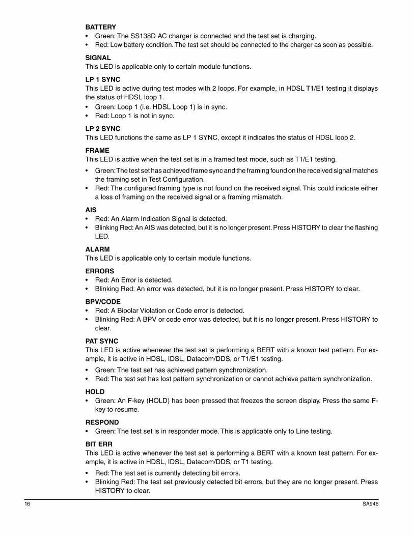
BATTERY• Green:TheSS138DACchargerisconnectedandthetestsetischarging.• Red:Lowbatterycondition.Thetestsetshouldbeconnectedtothechargerassoonaspossible.
SIGNALThis LED is applicable only to certain module functions.
LP 1 SYNCThis LED is active during test modes with 2 loops. For example, in HDSL T1/E1 testing it displays the status of HDSL loop 1.• Green:Loop1(i.e.HDSLLoop1)isinsync.• Red:Loop1isnotinsync.
LP 2 SYNCThis LED functions the same as LP 1 SYNC, except it indicates the status of HDSL loop 2.
FRAMEThis LED is active when the test set is in a framed test mode, such as T1/E1 testing.
• Green:Thetestsethasachievedframesyncandtheframingfoundonthereceivedsignalmatchesthe framing set in Test Configuration.
• Red:Theconfiguredframingtypeisnotfoundonthereceivedsignal.Thiscouldindicateeithera loss of framing on the received signal or a framing mismatch.
AIS• Red:AnAlarmIndicationSignalisdetected.• BlinkingRed:AnAISwasdetected,butitisnolongerpresent.PressHISTORYtocleartheflashing
LED.
ALARMThis LED is applicable only to certain module functions.
ERRORS• Red:AnErrorisdetected.• BlinkingRed:Anerrorwasdetected,butitisnolongerpresent.PressHISTORYtoclear.
BPV/CODE• Red:ABipolarViolationorCodeerrorisdetected.• BlinkingRed:ABPVorcodeerrorwasdetected,butitisnolongerpresent.PressHISTORYto
clear.
PAT SYNCThis LED is active whenever the test set is performing a BERT with a known test pattern. For ex-ample, it is active in HDSL, IDSL, Datacom/DDS, or T1/E1 testing.
• Green:Thetestsethasachievedpatternsynchronization.• Red:Thetestsethaslostpatternsynchronizationorcannotachievepatternsynchronization.
HOLD• Green:AnF-key(HOLD)hasbeenpressedthatfreezesthescreendisplay.PressthesameF-
key to resume.
RESPOND• Green:Thetestsetisinrespondermode.ThisisapplicableonlytoLinetesting.
BIT ERRThis LED is active whenever the test set is performing a BERT with a known test pattern. For ex-ample, it is active in HDSL, IDSL, Datacom/DDS, or T1 testing.
• Red:Thetestsetiscurrentlydetectingbiterrors.• BlinkingRed:Thetestsetpreviouslydetectedbiterrors,buttheyarenolongerpresent.Press
HISTORY to clear.

Chapter 2-Test Set Description 17
2.4 Connector PanelsThe test set has two side panels and one top panel. The left side contains a slot to insert plug-in modules. The right side contains ports for physical layer testing. The top panel of the test set contains a COMM PORT and DC power port.
2.4.1 Physical Layer Connector Panel
The test set’s right side has two sets of TIP/RING ports with a GRND (Ground) port. They use 2 mm test leads.
FOR CONNECTION TO TELECOMCIRCUITS ONLY. CAT1300V , 250V~MAX!
TIP2 RING2 GRND TIP1 RING1
TIP2: Blue
TIP1: Black
RING2: Yellow
RING1: Red
GRND: Green
Figure 7 Right Panel
2.4.2 Module Side PanelThe left side of the test set contains a module slot to insert modules. Upon ordering the test set with module, the module will already be in place. To change modules, use the this procedure:
Caution: Changing modules with the power on will damage the module and or the test set. Always verify that the test set is off before changing modules.
1. Turn the test set off and loosen the two thumb screws on either side of the module. 2. Gently pull the module out from the slot. Place it in its hard case or protective wrapper. 3. Insert the other module. Make sure it is firmly seated. 4. Hand tighten the two thumb screws. Make sure they are secure. 5. Turn on the test set. The screen should show that the test set is downloading the new module
and should read “PASS”.7. Perform an NV RAM ERASE; see Section 9.2.1.
18 SA946
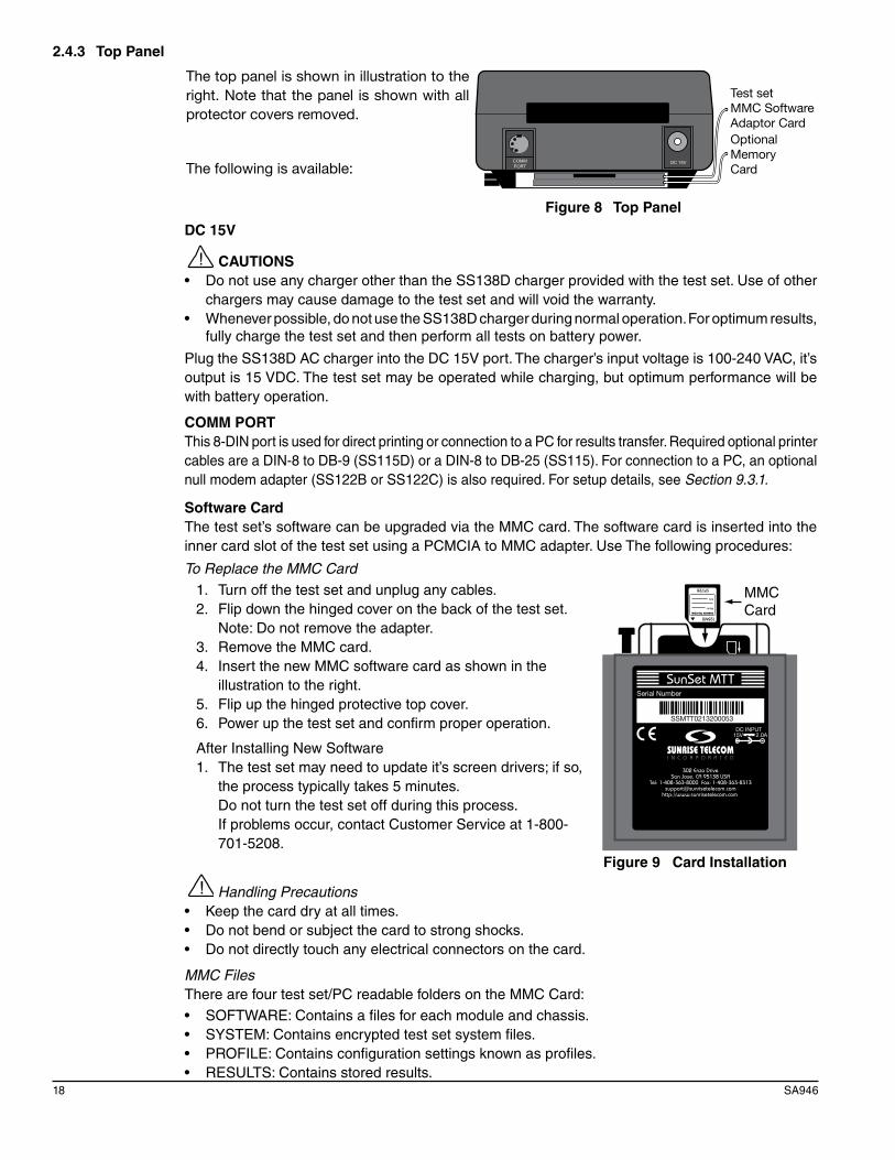
2.4.3 Top Panel
COMMPORT
Test setMMC Software Adaptor CardOptional MemoryCard
DC 15V
The top panel is shown in illustration to the right. Note that the panel is shown with all protector covers removed.
The following is available:
Figure 8 Top Panel
DC 15V
CAUTIONS• DonotuseanychargerotherthantheSS138Dchargerprovidedwiththetestset.Useofother
chargers may cause damage to the test set and will void the warranty.• Wheneverpossible,donotusetheSS138Dchargerduringnormaloperation.Foroptimumresults,
fully charge the test set and then perform all tests on battery power.
Plug the SS138D AC charger into the DC 15V port. The charger’s input voltage is 100-240 VAC, it’s output is 15 VDC. The test set may be operated while charging, but optimum performance will be with battery operation.
COMM PORTThis 8-DIN port is used for direct printing or connection to a PC for results transfer. Required optional printer cables are a DIN-8 to DB-9 (SS115D) or a DIN-8 to DB-25 (SS115). For connection to a PC, an optional null modem adapter (SS122B or SS122C) is also required. For setup details, see Section 9.3.1.
Software Card The test set’s software can be upgraded via the MMC card. The software card is inserted into the inner card slot of the test set using a PCMCIA to MMC adapter. Use The following procedures:
To Replace the MMC Card
MMC Card
1. Turn off the test set and unplug any cables.2. Flip down the hinged cover on the back of the test set. Note: Do not remove the adapter.3. Remove the MMC card.4. Insert the new MMC software card as shown in the
illustration to the right.5. Flip up the hinged protective top cover.6. Power up the test set and confirm proper operation.
After Installing New Software1. The test set may need to update it’s screen drivers; if so,
the process typically takes 5 minutes. Do not turn the test set off during this process. If problems occur, contact Customer Service at 1-800-
701-5208.2. Perform an NV RAM ERASE. See Section 9.2.1. Figure 9 Card Installation
Handling Precautions• Keepthecarddryatalltimes.• Donotbendorsubjectthecardtostrongshocks.• Donotdirectlytouchanyelectricalconnectorsonthecard.
MMC FilesThere are four test set/PC readable folders on the MMC Card:• SOFTWARE:Containsafilesforeachmoduleandchassis.• SYSTEM:Containsencryptedtestsetsystemfiles.• PROFILE:Containsconfigurationsettingsknownasprofiles.• RESULTS:Containsstoredresults.

Chapter 2-Test Set Description 19
2.5 Battery Care and StorageIt is important to observe these basic battery care procedures in order to avoid possible damage to the battery and to maintain it’s performance.
Warnings• Failuretoobservethefollowingproceduresandprecautionscanresultinelectrolyteleaks,heatgeneration,bursting,fire,andseriouspersonalinjury.
• Batteryelectrolyteisastrongcolorlessalkalinesolution,whichisextremelycorrosiveandwillburn skin.- If skin comes in contact with the electrolyte from the battery, thoroughly wash the area imme-
diately with clean water.- If clothing comes in contact with the electrolyte from the battery, discard the clothing.- Ifanyfluidfromthebatterycomesincontactwitheyes,immediatelyflushthoroughlywith
clean water and immediately consult a doctor. The electrolyte can cause permanent loss of eyesight.
• Keepthebatteryoutofreachofchildren.
Cautions• Neverdisposethebatteryinafire.• Neverheatthebattery.• Neverstrikeordropthebattery.• Donotapplywater,orotheroxidizingagentstothebattery.Thiswillcausecorrosionandheat
generation. If the battery becomes rusted, the gas release vent may no longer operate and cause the battery to burst.
• DonotchargethebatteryusinganACadapterorchargernotspecifiedbySunriseTelecom.Chargethe battery only with the Sunrise Telecom charger that came with your test set.- If the battery is not fully charged after the battery charger’s predetermined charging period
has elapsed, stop the charging process. Prolonged charging may cause leakage of battery fluid,heatgeneration,andorbursting.
- Charge the battery within a temperature range of 0°C (+32°F) to +40°C (+104°F).
• Donotusethebatteryifitleaksfluidorchangesshape;otherwiseitmaycauseheatgeneration,bursting, and fire.
• Donotshortcircuitthebatterybyconnectingthepositive(+)andnegative(-)terminalstogetherwith electrically conductive materials, such as lead wires, etc.
• Donotconnectthebatterydirectlytoapowersourceorthecigarettelightersocketinacar.Usea specified cigarette lighter charger from Sunrise Telecom.
• Neverdisassemblethebattery.Doingsomaycauseaninternalorexternalshortcircuit,orresultin exposed material of battery reacting chemically with the air. It may also cause heat generation, bursting, and or fire.
• Nevermodifyorreconstructthebatterypack.Protectivedevicesarebuiltintothebatterypack.Ifdamaged,excessivecurrentflowmaycauselossofcontrolduringchargingordischargingofthebattery,whichcanresultinleakageofbatteryfluid,heatgeneration,bursting,andorfire.
• Thegasreleasevent,whichreleasesinternalgasislocatedinthepositive(+)terminalofthebattery. For this reason, never deform, cover, or obstruct this vent.
• Whenthebatteryoperating timebecomesmuchshorter than its initialoperating timeevenafterrecharged, the battery has reached its end of life and should be replaced with a new one.
Extended Battery Storage• Fullychargethebatterybeforestoring.• Removethebatteryfromthetestset,perSection 2.5.1.• Donotstorebatteryinhightemperatures,suchasdirectsunlight,incarsduringhotweather,
or near any other heat source. This will impair the performance and shorten the operating life of the battery, and may cause battery leakage.

20 SA946
- For maximum battery life, store the battery between -20°C (-4°F) and +30°C (+86°F).
• Duringstoragethebatterywillneedtoberegularlyrecharged.Theintervalrangesfromapproximately30 to 90 days at temperatures between -20°C (-4°F) and +30°C (+86°F). In general, the higher the storage temperature the shorter the recharge cycle. - To recharge, install the battery into the test set and use the supplied Sunrise Telecom battery
charger to recharge the battery.- Charge the battery within a temperature range of 0°C (+32°F) to +40°C (+104°F).
• Afterlong-termstorage,thereisapossibilitythatthebatterywillnotfullyrecharge.Tofullychargeit,charge and discharge the battery for a few times (discharge the battery with the test set).
Note: For optimum test set performance, it is recommended that the test set should only be operated on batteries. AC charger can affect DMM measurement accuracy.
2.5.1 Replacing the Battery
The test set is designed with a field-replaceable 9-cell NiMH battery. A replacement battery (SS140) is available from Sunrise Telecom by contacting customer service at 1-800-701-5208. Follow these steps to replace the battery: 1. Swing the test set support stand out of the way.2. Remove the cover retainer screw and push down on the battery cover on the back panel, in the
direction indicated by the arrow, as shown in Figure 10.3. Unclip the battery, as shown in Figure 10.4. Pull the old SS140 NiMH battery off its Velcro backing, and out of the test set.5. Install the new battery using the reverse of this procedure.
Velcro
Note: Recycle the old battery
Unclip here
Figure 10 Replacing the Battery Pack

Chapter 3-TDR 21
3 TDR
A TDR (Time Domain Reflectometer) operates by sending a pulse of energy down the cable. It then measures any reflections that return to the test set. These reflections are caused by faults that cause impedance changes in the cable. For example, a load coil looks like a large increase in impedance (the high frequency pulses cannot pass through) and can easily be detected by a TDR. Any major change in the twisted pair’s plastic insulation or the cable fill’s material (water in the cable) causes a reflection.
A TDR plays an integral role in testing DSL circuits. It can:
• Locatebridgetaps,indicatingthepresenceofabridgetap,theexactlocation,andthelengthofthe lateral.
• Locateloadcoils,showingthepresenceandexactlocationofloadcoils.• Detectanyothercircuitfaultslikeanopenorshortedcable.
3.1 TDR Setup
DUAL SINGLE START
11:50:45 TIME DOMAIN REFLECTOMETER
MODE : DUAL DISPLAY : SPLIT SEARCH : PAIR 1 Start Search: 0.1 TYPE : PIC GAUGE : 26 AWG VP : 0.66 AVG : 1
UNITS : ENGLISH
RED
R1
BLACK
T1
YELLOW
R2
BLUE
T2
Dual ModeSingle Mode
DUAL SINGLE START
11:50:45 TIME DOMAIN REFLECTOMETER
MODE :SINGLE Start Search: 0.1 TYPE : PIC GAUGE : 26 AWG VP : 0.66 AVG : 1
UNITS : ENGLISH
more more
Length Mode
LENGTH START
11:50:45 TIME DOMAIN REFLECTOMETER
MODE :LENGTH R1 BLACK T1 TYPE : PIC GAUGE : 26 AWG VP : 0.66 AVG : 1
UNITS : ENGLISH
more
RED
R1
BLACK T1
RED
Figure 11 TDR Setup Screens

22 SA946
Configure the following:
MODEOptions: DUAL (F1), SINGLE (F2). LENGTH (more, F1)Select an operating mode:• DUAL:Dualtracemode.AsshowninFigure11DualMode,useR1(Ring1-Red),T1(Tip1-
Black), R2 (Ring 2-Yellow) and T2 (Tip 2-Blue) ports to connect to the circuit.• SINGLE:Singletracemode.AsindicatedinFigure11SingleMode,useR1(Ring1-Red)and
T1 (Tip 1-Black) ports to connect to the circuit.
• LENGTH:Discoverthelengthoftheentirecable;findthelastevent.
DISPLAY (only if MODE: DUAL): Select a display modeOptions: SPLIT (F1), OVERLAP (F2), DIFF (F3)Options: SPLIT, OVERLAP, DIFF• SPLIT:Displaystheresultsofthemeasurementastwoseparatetraces,pair1atthetopofthe
screen, pair 2 at the bottom.• OVERLAP:SimilartoSPLIT,asatraceisdisplayedforeachpair,buttheyareoverlappedon-
screen for easy comparison.• DIFF:Displaysasingletrace,butitisthemathematicaldifferenceoftheresultsofpairs1and2.• See Section 3.2 for examples of these screens.
SEARCH (only if MODE: DUAL): Select a pair to search.Options: PAIR 1 (F1), PAIR 2 (F2)START SEARCH: Set a specific distance away from the tester to begin the auto search at.
Options: 0-20.0 feetUse the +.1 (F1), -.1 (F2), +10 (more, F1) and -10 (more, F2) keys to set the distance.
TYPE: Specify the cable insulation type, a factor in determining VP.Options: PIC (F1), GEL (F2), PVC (more, F1), PAPER (more, F2)• PIC:Polyethylene/airfilled,insulatedcable• GEL:Polyethylene/jellyfilled,insulatedcable• PVC:Polyvinylinsulatedcable• PAPER:Paper/pulpinsulatedcable
GAUGE: Specify the wire gauge, a factor in determining VP.English Options: F1= 24/19/28, F2= 26/22/20Metric Options: F1= .4/.6/.3, F2= .5/.9/.8• Anincorrectsettingmayresultinlessaccuracy.Iftestingacablespanwithmixedgaugevalues,
select the highest gauge value.• TheUNITSsettingdeterminesifthegaugeisexpressedinAWG(English)ormm(Metric).In
North America, thickness is expressed in AWG (American Wire Gauge). A value of 24 AWG refers to wire that is 1/24 inch diameter.
Outside North America, thickness is expressed in millimeters (i.e., 0.4 mm is comparable to 26 AWG; 0.5mm is comparable to 24 AWG).
VP: Set the Velocity of PropagationOptions: from .40 to .99Use F1 and F2 to change the Velocity of Propagation. F4 sets the increment/decrement factor at +/- .01 or +/-.1. This setting calibrates the test set for the particular cable type and is crucial for accurate results.VP indicates the speed of the signal traveling down the cable. It is a ratio of the speed in cable to the speed of light; a value of .65 means the signal travels at 65% the speed of light.
Find the VP in the cable’s specification sheet or from the manufacturer. If it cannot be found, take a representative cable of a known length and measure it with the test set’s TDR. Change the VP setting until the test set provides an accurate distance reading.

Chapter 3-TDR 23
AVG: Determine the number of times the test set sends the pulseOptions: 1-5. The recommended setting is 1.
Use F1 and F2 to determine the number of times the test set sends the pulse. If AVG is set to greater than one, the test set displays an average of all attempts.
UNITS: Select a measurement system.Options: ENGLISH (F1), METRIC (F2)
When finished with configuration, see the next section.

24 SA946
3.2 Performing a TDR MeasurementFollow this procedure for making a TDR measurement:
1. Select TDR. Note that the TDR/RFL LED turns green. See Section 3.1 for configuration details.2. Connect to the cable pair(s) as shown as in Figure 12.
Red
Black
Ring
Tip
Single Mode
SunSet MTT ACM II
Red
Yellow
Blue
Ring 1
Tip 2
Black
Ring 2
Tip 1
Dual Mode
SunSet MTT ACM II
Figure 12 Connecting to the Cable Pair(s)
3. When ready, press START (F3). Refer to Section 3.2.1 for single mode, or Sections 3.2.1 and 3.2.2 for dual mode measurements.

Chapter 3-TDR 25
3.2.1 Single Mode Measurements
After START has been pressed, the waveform is displayed. Use to move the cursor to a dis-playedreflection.
11:50:45
DISTANCE: 1059 FEET
[10 ] [1563 ] MARKER: 0.0 [0:0 ] CURSOR [H:16 ] GAIN [V:1.00 ]
ZOOM_IN ZOOM_OT SEARCH more
Figure 13 Fault Found Screen
Adjusting the Zoom Use ZOOM_IN (F1) and ZOOM_OT (F2) to scan the entire cable span for faults or focus on a par-ticular fault or cable segment. • ZOOM_OTshowsmoreofthecablespan,whileZOOM_INshowsshorterportions.• The“H”(Horizontal)valuereportsthezoomfactor.Itcanrangefrom1-320(1beingtheclosest
range and 320 being the farthest). • Zoomingouttothemaximumvalue(H=320)allowsforviewingtheentirespanlengthtoeasily
locate cable faults. Zooming in allows interpreting potential faults.
The screen shown to the right shows a bridge tap with the zoom out (H=128). The screen shows the whole cable span: from 10 to 12,436 feet. A bridge tap can be made out in the far left of the screen. Press to move the cursor (red line) near the fault; the DISTANCE reading shows it at 701.5 feet.
11:50:45
DISTANCE: 701.5 FEET
[10 ] [12436 ] MARKER: 384.2 [0:0 ] CURSOR [H:128 ] GAIN [V:4.000]
ZOOM_IN ZOOM_OT SEARCH more
Figure 14 Result Zoomed Out Screen
Press ZOOM_IN (F1) to zoom in on the fault. Since the test set zooms in on the cursor’s location, move the cursor to the fault-then press ZOOM_IN (F1). The screen to the right shows the test set at H=64; the bridge tap is now more visible. The screen displays from 10 to 6224 feet.
11:50:45
DISTANCE: 816.7 FEET
[10 ] [6224 ] MARKER: 384.2 [0:0 ] CURSOR [H:64 ] GAIN [V:1.000]
ZOOM_IN ZOOM_OT SEARCH more Figure 15 Zooming in Once

26 SA946
TDR F-keys (shown in Figure 16)ZOOM_IN (F1) and ZOOM_OT(F2):Adjustthescaleofthescreen.ZOOM_OTshowsmoreofthecable span, while ZOOM_IN focuses on shorter portions. Note the “H” (Horizontal) value at bottom right displays the zoom factor.
SEARCH (F3): The Auto Search feature searches for the first fault on the cable pair as described in Section 3.2.1.1.
+OFFSET (more, F1) and -OFFSET (more, F2): Control the vertical position of the trace on the screen. +OFFSET moves the trace up; -OFFSET moves the trace down. The offset value is shown as “O” at the bottom of the screen.
MARKER/CURSOR (F1): Determine the function of . Press CURSOR to move the solid cursor with . Press MARKER to move the dotted marker with .
ALIGN (more, F3): Shift the cursor position (solid line) to the left of the screen. The display is now to the right of the cursor.
HOLD (more, F1): Pause the measurement and activate the HOLD LED. Press again to release the HOLD.
STORE (more, F2): Press to save; see Chapter 8.
PG_LFT (more, F1) and PG_RGT (more, F2): Shift the display 1/2 page to the left or 1/2 page to the right.
In addition to the F-keys:
• Use to move the position of the cursor or Marker.• Use toadjusttheGain(pulsestrength).IncreasingtheGain( ) increases the strength of thereflection.
Lower Display FeaturesBelowthereflection,thereareseveraldisplayitems,asseeninFigure16:
PG_LFT PG_RGT moreSEARCH
+OFFSET -OFFSET moreSEARCH
MARKER ALIGN moreSEARCH
HOLD STORE moreSEARCH
[1500 ] [8715 ] MARKER: 289.7 [0:-2 ] CURSOR [H:128 ] GAIN [V:1.000]
ZOOM_IN ZOOM_OT moreSEARCH
Figure 16 Auto Search Lower Screen Items with F-keys
[1500]: Distance at the left-most start of the screen.
[8715]: Distance at the right-most end of the screen.
MARKER: Distance between the Marker and the cursor. When the cursor is at the beginning of a bridge tap and the marker is at the open end, this value shows the length of the bridge tap.O: Offset value. Offset represents the vertical position of the trace on the screen. This can range from +112 (high on screen) to -112 (low on screen).
H: Zoom (scale) factor. This can range from 1 to 320. 1 shows only a limited portion of the screen in more detail. 320 shows the whole cable span.
V:Gainvalue.Gainadjuststheamplificationofthepulse.Thiscanrangefrom32(highest)to0.13(lowest).

Chapter 3-TDR 27
3.2.1.1 Using Auto SearchUse AUTO SEARCH to search for the first fault on the cable pair. The test set locates the first dip or spike and displays that cable segment.
To use Auto Search:
1. Start a measurement. 2. Press SEARCH (F3) and SEARCHING is displayed until a
fault is found.2. FOUND is displayed along with the fault waveform when a
fault is found.3. The test set also places the cursor (red line) near the fault.
DISTANCE reports the cursor’s location. Use to adjust the cursor’s position.
4. If the test set does not find any faults, NONE is displayed. If this occurs, zoom out and manually search.
11:50:45
DISTANCE: 7949 FEET FOUND
[10 ] [12438 ] MARKER: 0.0 [0:0 ] CURSOR [H:128 ] GAIN [V:1.00 ]
ZOOM_IN ZOOM_OT SEARCH more
Figure 17 Auto Search Screen
3.2.1.2 Finding Multiple Faults
11:50:45
DISTANCE: 1589 FEET
[10 ] [3223 ] MARKER: 412.8 [0:0 ] CURSOR [H:64 ] GAIN [V:4.000]
ZOOM_IN ZOOM_OT SEARCH more
A TDR can see past a bridge tap, cable splice, wet cable, or other impairments. However, it cannot show beyond an open, load coil, or short. For example, if a load coil is detected, it must be removed before continuing with fault detection.The screen to the right shows a bridge tap at 1589 feet. The Cursor (red line) indicates the location (DISTANCE). The Marker (green line) indicates the length of the lateral (MARKER).
Figure 18 Bridge Tap at 1589 ft
Press PG_RGT (more, F2) to look past this length of cable. Pressing PG_RGT one time displays the cable span from 1625 to 4838 feet as shown in the screen to the right.
11:50:45
DISTANCE: 3169 FEET
[1625 ] [4838 ] MARKER: 1544 [0:0 ] CURSOR [H:64 ] GAIN [V:1.000]
PG_LFT PG_RGT SEARCH more
Figure 19 1625 to 4838 ft View
Press PG_RGT again to show 4856 to 8069 feet. A potential fault begins to appear at the right of the screen shown to the right. Press ZOOM_OT (F2) to reveal more of the cable span. Remember that the test set zooms in on the position of the cursor; to focus on a potential fault, move the cursor to that position.
11:50:45
DISTANCE: 6400 FEET
[4856 ] [8069 ] MARKER: 1544 [0:0 ] CURSOR [H:64 ] GAIN [V:1.000]
PG_LFT PG_RGT SEARCH more
Figure 20 4856 to 8069 ft View
28 SA946
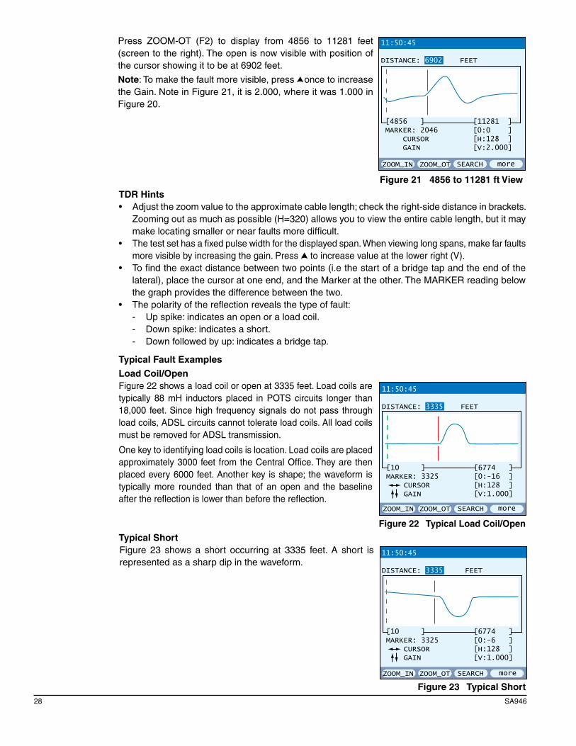
Press ZOOM-OT (F2) to display from 4856 to 11281 feet (screen to the right). The open is now visible with position of the cursor showing it to be at 6902 feet.
Note: To make the fault more visible, press once to increase the Gain. Note in Figure 21, it is 2.000, where it was 1.000 in Figure 20.
ZOOM_IN ZOOM_OT SEARCH more
11:50:45
DISTANCE: 6902 FEET
[4856 ] [11281 ] MARKER: 2046 [0:0 ] CURSOR [H:128 ] GAIN [V:2.000]
Figure 21 4856 to 11281 ft View
TDR Hints• Adjustthezoomvaluetotheapproximatecablelength;checktheright-sidedistanceinbrackets.
Zooming out as much as possible (H=320) allows you to view the entire cable length, but it may make locating smaller or near faults more difficult.
• Thetestsethasafixedpulsewidthforthedisplayedspan.Whenviewinglongspans,makefarfaultsmore visible by increasing the gain. Press to increase value at the lower right (V).
• Tofindtheexactdistancebetweentwopoints(i.ethestartofabridgetapandtheendofthelateral), place the cursor at one end, and the Marker at the other. The MARKER reading below the graph provides the difference between the two.
• Thepolarityofthereflectionrevealsthetypeoffault:- Up spike: indicates an open or a load coil.- Down spike: indicates a short.- Down followed by up: indicates a bridge tap.
Typical Fault Examples
Load Coil/OpenFigure 22 shows a load coil or open at 3335 feet. Load coils are typically 88 mH inductors placed in POTS circuits longer than 18,000 feet. Since high frequency signals do not pass through load coils, ADSL circuits cannot tolerate load coils. All load coils must be removed for ADSL transmission.
One key to identifying load coils is location. Load coils are placed approximately 3000 feet from the Central Office. They are then placed every 6000 feet. Another key is shape; the waveform is typically more rounded than that of an open and the baseline after the reflection is lower than before the reflection.
11:50:45
DISTANCE: 3335 FEET
[10 ] [6774 ] MARKER: 3325 [0:-16 ] CURSOR [H:128 ] GAIN [V:1.000]
ZOOM_IN ZOOM_OT SEARCH more
Figure 22 Typical Load Coil/Open
Typical ShortFigure 23 shows a short occurring at 3335 feet. A short is represented as a sharp dip in the waveform.
11:50:45
DISTANCE: 3335 FEET
[10 ] [6774 ] MARKER: 3325 [0:-6 ] CURSOR [H:128 ] GAIN [V:1.000]
ZOOM_IN ZOOM_OT SEARCH more
Figure 23 Typical Short

Chapter 3-TDR 29
Bridge TapFigure 24 shows a typical bridge tap. It begins at 835 feet and extends for 249 feet (DISTANCE provides the beginning; MARKER provides length). It starts with the steep downward slope; the lateral continues until the sharp upward slope, or bump, which represents the open at the end.
Here are some guidelines for bridge taps in DSL circuits:
After finding and removing a lateral, retest the cable for any other laterals or faults that may have been missed.
11:50:45
DISTANCE: 835.9 FEET
[10 ] [1729 ] MARKER: 249.7 [0:0 ] CURSOR [H:32 ] GAIN [V:1.000]
ZOOM_IN ZOOM_OT SEARCH more
Figure 24 Typical Bridge Tap
3.2.1.3 Comparing a Live TDR Trace to Stored TDR Traces
Once a TDR trace is stored, it can be recalled and compared to a current trace for analysis. Use the following procedure:
1. Store a TDR result; see Section 8.2. Run the TDR measurement. 3. To recall the previously stored result for comparison, press
ESC to reach the main menu and select FILE.3. In the VIEW/STORE/PRINT screen, select the comparison
file and press VIEW (F1). Then press RECALL (F2).4. The TDR display will now be split horizontally in two
sections as shown to the right. The top section displays the stored trace. The bottom section displays the active trace.
5. Values displayed in red correspond to the stored trace in the top section. Values displayed in blue correspond to the active trace in bottom section.
Note: The stored trace is static and does not change. F-key functions apply only to the active trace.
6. To escape from Stored TDR Trace mode, press ESC twice.
11:50:45
DISTANCE: 1059 FEET
[10 10] [1563 1563] MARKER: 3325 [0:0 0 ] CURSOR [H:16 16 ] GAIN [V:1.0 1.0 ]
ZOOM_IN ZOOM_OT SEARCH more
Figure 25 Stored and Live Trace Comparison

30 SA946
3.2.2 Dual Mode MeasurementsUsing this mode, the test set can display the measurements from two lines simultaneously as de-scribed in the following sections.Note: A Dual Trace screen is stored as a split screen. When recalled, the F-keys allow changes to the view, overlap, difference, or back to split.
3.2.2.1 Dual Trace Split ScreenIn Figure 26, PAIR 1 is the top trace; PAIR 2 is the bottom trace. Changing the view or offset, changes the view for both traces. For details on how to use this screen and interpret results from it, see Section 3.2.1.
ZOOM_IN ZOOM_OT SEARCH more
11:50:45
DISTANCE: 1059 FEET SPLIT
[0 ] [1553 ] MARKER:1123.3 [O: 0 ] CURSOR PAIR 1 [H:16 ] GAIN PAIR 2 [V:1.00 ]
Figure 26 Dual Trace Split Screen
3.2.2.2 Dual Trace Overlap ScreenIn Figure 27, the traces are positioned almost on top of each other for easy visual comparison. For details on how to use this screen and how to interpret results from it, see Section 3.2.1.
ZOOM_IN ZOOM_OT SEARCH more
11:50:45
DISTANCE: 1059 FEET OVERLAP
[0 ] [1553 ] MARKER:1123.3 [O: 0 ] CURSOR PAIR 1 [H:16 ] GAIN PAIR 2 [V:1.00 ]
Figure 27 Dual Trace Overlap Screen
3.2.2.3 Dual Trace Difference ScreenIn Figure 28, the mathematical difference of the two traces is displayed. A flat line indicates no difference. For details on how to use this screen and how to interpret results from it, see Section 3.2.1.
ZOOM_IN ZOOM_OT SEARCH more
11:50:45
DISTANCE: 1059 FEET DIFF
[0 ] [1553 ] MARKER:1123.3 [O: 0 ] CURSOR [H:16 ] GAIN [V:1.00 ]
Figure 28 Dual Trace Difference Screen

Chapter 4-RFL 31
3.2.3 Cable Length
Use the LENGTH MODE to find the length of a cable. The search function will find the last open event on the trace.
Once the test has started, you will see a CABLE LENGTH reading of 0.0 FT at the top of the screen.
Press SEARCH (F3) to scan. It takes a few minutes for the test to reach its conclusion.
When the result has returned, the distance will appear. In this sample, the cable length is 1582 feet.
Figure 29 Length Mode Results
11:50:45
CABLE LENGTH: 1582 FEET
[10000 ] [3159 ] MARKER: 3325 [0: 0 ] [H: 16 ] [V: 1.00 ]
PG_LFT PG_RGT SEARCH more

32 SA946

Chapter 4-RFL 33
4 RFL
When the resistance of a T-G or a R-G test is less than the resistance of the copper loop (Solid), use the TDR function to locate the fault. However, when the resistance of a T-G or a R-G test is greater than the resistance of the copper loop, use the optional RFL (Resistance Fault Locator) to locate it.
From the chassis main menu, select RFL and press ENTER. The test set will display the following setup screen. The results are described in the following sections.
RFL
4.1 RFL SetupConfigure the following:
METHOD: Choose the method of measurement.Options: DUAL (F1), SINGLE (F2)
GAUGEUNITS=ENGLISH Options: 24 (F1), 26 (F2), 19 (more, F1), 22 (more, F2), 28 (more, F1), 20 (more, F2), MULTI (more, F1)UNITS=METRIC Options: .4 (F1), .5 (F2), .6 (more, F1), .9 (more, F2), .3 (more, F1), .8 (more, F2), MULTI (more, F1)
displayed:
11:50:45
DUAL SINGLE
RESISTANCE FAULT LOCATOR
METHOD : DUAL GAUGE : MULTI TEMP : 70 °F UNITS : ENGLISH
START
Figure 30 RFL Setup Screen
Use the MULTI-SECTION screen if the cable is made up of sections that are of different gauges, different lengths, or when the distance to the strap is known.
When the cursor is in the GAUGE column, use the F-keys to select the wire gauge for each strand. Use to move the cursor between the 6 strands.
When finished with the gauge selection, press LENGTH (F3), then enter a length from 1 to 10000, using SHIFT and the numeric keypad.
The TOTAL length is reported at the bottom of the LENGTH column. This total is the DTS (Distance To Strap) number that is used to calculate DTF (Distance To Fault) and STF (Strap To Fault) in the result screens.
MULTI-SECTION CABLE
GAUGE LENGTH 1 24 0 2 24 0 3 24 0 4 24 0 5 24 0 6 24 0 TOTAL (DTS) 0
11:50:45
28 20 LENGTH more
Figure 31 Multi-Section Cable Setup Screen
When finished, press ESC to return to the RFL Setup screen shown in Figure 30 and configure the remainder of the setup items:
TEMP: Select the ambient temperature (F or C)Press SHIFT and use the numeric keypad to set the temperature. Out of range entries are re-jected.
Note: The accuracy of the measurement is dependent on the GAUGE and TEMP settings.
UNITS: Select the unit of measurementOptions: ENGLISH (F1)or METRIC (F2).
Whenfinished,pressSTART(F3)tobegin.Anewscreenisdisplayedreflectingthechoicesmadein the setup screen (top left screen of Figures 32 and 33). These screens are described in the fol-lowing subsections:

34 SA946
4.1.1 Single Conductor Setup
24 AWG 70°F HOOK UP STRAP AND TEST LEADS AND PRESS START RED:FAUTED STRAP
BLACK:REF
GREEN:GOOD
11:50:45
START
24 AWG 70°F ERROR: CHECK CONNECTION RED:FAUTED STRAP
BLACK:REF
GREEN:GOOD
11:50:45
START
!
11:50:45
RESTARTSTOREDIST
11:50:45
RESTARTSTOREOHM
OR
84.26
34.32 49.94
3165
1289 1876
24 AWG 70°F DTS
RED Ω STRAP
DTF STF
Ω Ω
BLACK 511.32Ω
GREEN
24 AWG 70°F DTS
RED FT STRAP
DTF STF
FT FT
BLACK 511.32Ω
GREEN
See Section 4.1.2 for screen item definitions.
24 AWG 70°F PLEASE WAIT MEASUREMENT IN PROGRESS RED STRAP
BLACK
GREEN
11:50:45
Figure 32 Single Conductor Screens
4.1.2 Dual Setup (Separate Pair)
OR
24 AWG 70°F ERROR: CHECK CONNECTION RED:FAUTED STRAP
BLACK:REF
GREEN:GOOD
YELLOW:GOOD
11:50:45
START
!
24 AWG 70°F HOOK UP STRAP AND TEST LEADS AND PRESS START RED:FAUTED STRAP
BLACK:REF
GREEN:GOOD
YELLOW:GOOD
11:50:45
START
24 AWG 70°F PLEASE WAIT MEASUREMENT IN PROGRESS RED STRAP
BLACK
GREEN
YELLOW
11:50:45
11:50:45
RESTARTSTOREDIST
11:50:45
RESTARTSTOREOHM
24 AWG 70°F DTS
RED FT STRAP
DTF STF
FT FT
BLACK 511.32Ω
GREEN
YELLOW
3165
1289 1876
24 AWG 70°F DTS
RED Ω STRAP
DTF STF
Ω Ω
BLACK 511.32Ω
GREEN
YELLOW
84.26
34.32 49.94
RFL Start Screen F-key
START (F4): After connecting to the circuit as shown Section 4.2, press START (F4) in the top left screen to begin. As shown in Figures 31 and 32, the screen displays “PLEASE WAIT MEA-SUREMENT IN PROGRESS”. Once the measurement has completed, either an error or a results screen is displayed, with new F-keys.
Figure 33 Dual Conductor Screens
RFL Result Screen F-keysOHM/DIST (F1): If a result is displayed, a distance measurement is displayed for each line of the circuit. Press F1 to display the resistance for each line; press it again to display the distance.STORE (F3): Store the results. See Chapter 8.RESTART (F4): Start another test.

Chapter 4-RFL 35
4.2 Fault LocationThere are four main resistance faults: Cross, Battery Cross, Ground, and Short. They are discussed in the following subsections.
4.2.1 Cross Fault
Tip A
Ring B
Solid Cross Fault
Tip A
Ring B
Non-working Pair 1
Non-working Pair 2
Ring B
Tip A
Tip A
Ring B
Water Cross Fault
Non-working Pair 1
Non-working Pair 2
A Cross Fault is a fault between a non-working pair (pair under test) and another or other non-working pairs. To locate a cross, the pairs must be initially identified. The faults are shown in Figure 34.
Figure 34 Cross Fault Conditions
Figure 35 shows various test set connections for determining which line is at fault, using the single and separate setups.
Green
Red
Black
Good Pair
Tip A
Ring BCross
Strap
Separate Pair Connection
Yellow
Tip A Other non-working pair
Non-working pair under test
Ring B
Green
Black
Yellow
Ring B Good Conductor
Tip A
Ring B Good Conductor
Cross Strap
Separate Pair Connection-Ring B
Red Tip A
Green
Red
Black
Good Conductor
Ring B
Ring BCross
Strap
Single Connection
Tip A
Tip A Other non-working pair
Non-working pairunder test
SunSet MTT ACM II
SunSet MTT ACM II
SunSet MTT ACM II
Figure 35 Cross Fault Test Setups

36 SA946
4.2.2 Battery Cross Fault
Tip A
Ring B
Solid Cross Fault
Tip A
Ring B
Working Pair 1
Non-working Pair 2 (Pair Under Test)
-48 VDC
-46 VDC
Ring B
Tip A
Tip A
Ring B
Resistive Cross Fault Due to Water
Working Pair 1
Non-working Pair 2 (Pair Under Test)
-18 VDC
-7 VDC
A Battery Cross Fault is a fault between a work-ing pair and a non-working pair (pair under test). To locate the fault, there is no need to identify the working pair. The fault locating procedure is the same as locating a ground due to the battery’s internal resistance to ground.
In a Solid Cross Fault, the voltage reading on the pair under test is quite high (the same or very close to the central office battery voltage). In a Non-solid Cross Fault, the voltage reading is considerably lower. Figure 35 shows the faults.
Figure 35 Battery Cross Fault Conditions
Figure 36 shows various test set connections for determining which line is at fault using the single and separate setups.
Green Good ConductorTip A
Strap
Single Connection
Red (-)
Black (+)
Non-working Pair Under TestRing B
Battery CrossRing B
Sheild
48VDC
COBattery
Tip A Unknown Working Pair-
+
Yellow
Green
Red (-)
Black (+)
Good Pair
Ring B
Sheild
Battery Cross
Strap
Separate Pair Connection
Ring B
Tip A
Tip A
Non-working Pair Under Test
18VDC
COBattery
Ring B
Tip A Unknown Working Pair -
+
SunSet MTT ACM II
SunSet MTT ACM II
Figure 36 Battery Cross Fault Setups
4.2.3 Ground Fault
Tip A
Ring B
Shield
Ground Fault by Water
Tip A
Ring B
Shield
Solid Ground Fault
When a fault causes current to flow from any line to ground, it is called a ground fault. The faults are shown in Figure 37.
Figure 37 Ground Fault Conditions

Chapter 5-DMM 37
Green
Red
Black
Ring-Good Conductor
Tip
ShieldGround Fault
Strap
Single Connection
Green
Red
Black
Separate Good Pair
Tip A
ShieldGround Fault
Strap
Separate Pair Connection
Yellow
Ring B
SunSet MTT ACM II
SunSet MTT ACM II
Figure 39 shows various test set connections for determining which line is at fault using single and separate pair setups.
Figure 38 Ground Fault T est Setups
4.2.4 Short Fault
Tip A
Ring BSolid Short Fault
Tip A
Ring BShort Fault by Water
A Short Fault is any condition that causes current to flow between tip and ring conduc-tors. The faults are shown in Figure 39.
Figure 39 Short Fault Conditions
Green
Red
Black
Good Conductor
Tip A
Ring BShort
Strap
Single Connection
Green
Red
Black
Good Pair
Ring B
Tip AShort
Strap
Separate Pair Connection
Yellow
SunSet MTT ACM II
SunSet MTT ACM II
Figure 40 shows various test set connections for determining which line is at fault using the single and separate setups.
Figure 40 Short Fault Test Setups

38 SA946

Chapter 5-DMM 39
5 DMM
Digital Multimeter tests should be used for qualifying or troubleshooting the physical layer. These tests verify required conditions on the line.
Select DMM to display the Digital Multimeter functions, which are:
11:50:45
DIGITAL MULTIMETER
DCV ACV OHM
CAP mA UTIL
The Digital Multimeter menu screen is shown to the right. In it, use to select the desired DMM measurement. Press ENTER to take the measurement.
Sections 5.1-5.5 provide specific requirements and interpre-tations for each of the measurement types. Section 5.6 contains calibration procedures. Section 5.7 provides a sample step-by-step procedure for performing DMM tests.
Note: The STORE (F4 or MORE F3) F-key is available in all DMM result screens. Use it to save a measurement, see Chapter 8.
Figure 41 Digital Multimeter Menu Screen
5.1 DC Voltage
The test set can be used to verify that there is appropriate power on the line. The test set can measure voltage up to 300 VDC.
• For ADSL circuits that support POTS, verify POTS Voltage. POTS, which is offered on the same circuit, requires the following line power:- Tip to Ring: +48 VDC- Ring to Ground: -48 VDC
• For HDSL circuits, verify power at the HDSL remote unit:- HTU-R typically requires 140-225 VDC line power
(unless it is locally powered). TIP_RNG TIP_GND RNG_GND STORE
48.160 v
11:50:45 DC VOLTAGE
RED R1
TIP TO RNG
BLACK RNG TO GND
T1
TIP TO GND
GREEN G
-48.160 v
0.000 v
Figure 42 DC Voltage ScreenFirst, select the type of measurement to be performed:
TIP_RNG (F1) to measure tip to ring.
TIP_GND (F2) to measure tip to ground.
RNG_GND (F3) to measure ring to ground.
Note: All three measurements are displayed simultaneously. However, only the highlighted measure-ment (TIP TO RNG in Figure 42) is a live measurement.
The recommended readings are:
• TIPTORNG:< 3 VDC• RNGTOGND:< 3 VDC• TIPTOGND:< 3 VDC

40 SA946
5.2 AC VoltageAn AC Voltmeter is used for troubleshooting the loop. It can identify an unwanted power influence. The test set can mea-sure up to 250 VAC.
WARNING: AC voltage can kill or cause serious injury.
First, select the type of measurement to be performed:
TIP_RNG (F1) to measure tip to ring.
TIP_GND (F2) to measure tip to ground.
RNG_GND (F3) to measure ring to ground.
Note: All three measurements are displayed simultaneously. However, only the highlighted measurement (TIP TO RNG in the screen to the right) is a live measurement.
TIP_RNG TIP_GND RNG_GND STORE
0.033
0.003
0.014
11:50:45 AC VOLTAGE
RED R1
TIP TO RNG
V BLACK RNG TO GND
T1 V TIP TO GND
V GREEN G
Figure 43 AC Voltage ScreenThe recommended readings are:
• TIPTORNG:< 3 VAC• RNGTOGND:< 25 VAC• TIPTOGND:< 25 VAC
5.3 Ohm
ENTER
This measurement is a prequalification test to verify that the loop meets the proper metallic criteria. Use it to:
• Measure Insulation DC Resistance for T-G/ R-G:- Tip to Ground should be >3.5 MΩ.- Ring to Ground should be >3.5 MΩ. - Check for grounds: If either value is less than 3.5 MΩ,
a ground may exist in the circuit.
• Measure Insulation DC Resistance for T-R:- Tip to Ground should be >3.5 MΩ.- Tip to Ring should be >3.5 MΩ.- Check for shorts: If it is less than 3.5 MΩ, a short may
exist in the circuit.
• Locate a short or ground.The test set can measure from 1Ω to 100 MΩ. The LOW range covers 1Ω to 10 MΩ, HIGH covers 10 MΩ to 100 MΩ. Both ranges operate the same and the following instructions apply to both ranges.
Note: After a power cycle, when entering the HIGH range, the test set will automatically perform a HIGH RESISTANCE CALIBRATION routine. Do not power off the test set during this routine. The measurement will be performed after the routine.
After selecting a measurement and pressing ENTER, select the type of measurement to perform:
11:50:45
OHMMETER SETUP
HIGHRANGE
LEAKAGETEST
TIP_RNG TIP_GND RNG_GND STORE
>10 MΩ
>10 MΩ
>10 MΩ
11:50:45 LOW RANGE RESISTANCE
RED R1
TIP TO RNG
BLACK RNG TO GND
T1
TIP TO GND
GREEN G
Figure 44 Resistance ScreensTIP_RNG (F1) to measure tip to ring.
TIP_GND (F2) to measure tip to ground.
RNG_GND (F3) to measure ring to ground.
Note: All three measurements are displayed simultaneously. However, only the highlighted measure-ment (TIP TO RNG in the bottom screen shown in Figure 44) is a live measurement.

Chapter 6-Line 41
5.4 CapacitanceThe test set can measure from 1 nF to 2 µF. The measure-ment can also be used to estimate loop length (tip-ring).
• This measures the loop to the far end with an open circuit.
• The top left box in the top righ screen provides a distance calculation; it is based on, 83 µF/mile (52 µF/km), conver-sion factor as specified in ANSI T1.601 Annex E.
• This calculation assumes there are no bridge taps pres-ent. It will add any bridge tap lengths to the total distance.
Note: Perform a LOW CAP CALIBRATION, see Section 5.6.1 for the procedure. This must be done at power up.
After any needed calibration, select the type of measurement to perform:
TIP_RNG (F1) to measure tip to ring.
TIP_GND (more, F2) to measure tip to ground.
RNG_GND (more, F3) to measure ring to ground.
Note: All measurements are displayed simultaneously. How-ever, only the highlighted measurement (RNG TO GND in the right screen of Figure 45) is a live measurement.
BALANCE (F2): The test set calculates capacitive balance and is reported in the CAP BALANCE box in the right screen of Figure 45. The recommended figure is >95%.
SETUP (F3): Change the following measurement settings as shown in the bottom screen of Figure 45.
UNITS: Select ENGLISH (F1) or METRIC (F2).
CABLE TYPE: PIC is the only choice.
CAP MUTUAL (ft)/(m): Press SCROLL+ (F1) or SCROLL- (F2) to change, press DEFAULT (F3) to use the test set’s default.
CAP GROUND (ft)/(m): Press SCROLL+ (F1) or SCROLL- (F2) to change, press DEFAULT (F3) to use the test set’s default.
When ready, press START (F4) and return to the top screen of Figure 45.
ENGLISH METRIC START
11:50:45 CAPACITANCE/OPENS SETUP
UNITS : ENGLISH CABLE TYPE : PIC CAP MUTUAL (ft): 83.0 nF/mile CAP MUTUAL (m) : 51.8 nF/km CAP GROUND (ft): 115.0 nF/mile CAP GROUND (m) : 71.5 nF/km
TIP_GND RNG_GND STORE MORE
TIP_RNG BALANCE SETUP MORE
1325 100%
11:50:45 CAPACITANCE/OPENS DISTANCE(FT) CAP BALANCE
RED R1 TIP TO RNG 20.84 nF BLACK RNG TO GND T1 8.151 nF TIP TO GND 8.187 nF GREEN G
Figure 45 Capacitance/Opens Screens

42 SA946
5.5 CurrentThe test set performs a protection check before taking a measurement to protect itself from damage. Because of this, connect the test set to the circuit before selecting this screen. Once the protection test passes, the test set can measure from 0 to 110 DC mA. A sample result is shown in the bottom screen of Figure 46
11:50:45
CURRENT !
Verifying AC Voltage...PASS Verifying DC Voltage...PASS Finding Current...
STORE
4.000
11:50:45
CURRENT RED
R1
TIP TO RNG
mA BLACK
T1
Figure 46 Current Screens
5.6 Utilities-CalibrationThis menu screen contains:
• LOWCAPCALIBRATION• HIGHOHMCALIBRATION
5.6.1 Low Capacitance Calibration
Perform this calibration each time the test set is powered up and a capacitance measurement will be performed.
To perform this calibration:
1. Remove all input cables and charger from the test set. The test set should be operating on batteries for optimal results.
2. Select DMM > UTIL > CALIBRATION > LOW CAP CALIBRATION.3. Follow the on-screen instructions and press ENTER to begin. The procedure takes less than a
minute to perform.
5.6.2 High Ohm Calibration
This procedure is automatically performed each time the test set is powered up, and each time a high range resistance measurement is performed.
To manually perform this calibration:
1. Remove all input cables and charger from the test set. The test set should be operating on batteries for optimal results.
2. Select DMM > UTIL > CALIBRATION > HIGH OHM CALIBRATION.3. Follow the on-screen instructions and press ENTER to begin. The procedure takes less than a
minute to perform.

Chapter 6-Line 43
5.7 DMM Measuring Procedures
Ring
Tip
Note: Ground is not used for current measurements.
Green
Red
Black
Ground
SunSet MTT ACM II
Use this procedure for performing a DMM measurement:1. Select DMM.2. Connect to the circuit using the
RING1/TIP1/ (if needed GRND) ports. • A common method is to use a set of
alligator clip cables as shown in the illustration to the right. Plug the connec-tor cable into the test set ports on the right side. Use alligator clips to clip directly onto the copper pair at the NID, Cross-Box (B-Box), aerial, or other access points.
Figure 47 Connecting with Alligator Clips
3. Press to select a measurement and press ENTER.4. Once in a measurement screen, select a measurement type:• TIP_RNGtomeasuretiptoring.• TIP_GNDtomeasuretiptoground.• RNG_GNDtomeasureringtoground.
Refer to the previous sections to learn the significance and requirements for each of the results.

44 SA946

Chapter 6-Line 45
6 Line
There are two types of Line measurements, single-ended and paired. As shown in Figure 48, single-ended tests require one test set; the test set performs the test and takes the measurement from one end of the cable.
Line measurements can be optioned in two different ways. The standard feature supports the VF6000 Hz and ADSL 2.2 MHz frequency range. The Extended VDSL Range option (SWMTT-ACMp-VDSL) enables support for VDSL spectrums and NEXT/FEXT features. “FEATURE OPTION NOT AVAILABLE” is displayed when optional features are not enabled.
The single-ended tests are:
• PSD BACKGROUND NOISE checks for interfering services or noise.
• LONGITUDINAL BALANCE checks if the cable pair has adequate balance for crosstalk immunity.
• VF MEASUREMENTS provides data on Metallic Noise, Power Influence, and Calculated Balance.
• IMPULSE NOISE checks for any transient noise sources.
• NEAR END CROSSTALK (NEXT) checks for cross-talk between two cable pairs at the near end.
• COIL DETECTION detects load coils in the circuit.• FREQUENCY GENERATOR sends test tones.
Ring
Tip
Green
Red
Black
Ground
SunSet MTT ACM II
Figure 48 Single-ended Test Setup
Single-ended tests are described in Sections 6.1–6.7.
Dual-ended tests require two test sets, one on each end of the cable pair. As shown in Figure 49, there is a Controller, which sends the commands and takes the measurement. The Responder at the far end responds to commands by sending the tone or shorting the far end.
The dual-ended tests are:• INSERTION LOSS measures attenuation
over the chosen frequency range.• SIGNAL TO NOISE measures the signal-to-
noise ratio over the chosen frequency range.• LOOP RESISTANCE determines loop length
by measuring loop resistance with a responder test set at the far end providing a short.
• FAR END CROSSTALK (FEXT) checks for crosstalk between one cable pair at the near end and an adjacent pair at the far end.
• CABLE PAIR DETECT and TX CABLE PAIR TONE check for connectivity.
• RESPONDER DETECTION detects the type of responder is at the far end.
Dual-ended tests are described in Section 6.8.
Ring
Tip
Green
Red
Black
Ground
SunSet MTT ACM II
Green
Red
Black
Ground
SunSet MTT ACM II
Controller
Responder sends tone and shorts far end.
Ring
Tip
Figure 49 Dual-ended Test Setup

46 SA946
6.1 PSD Background NoiseThis PSD (Power Spectral Density) Background Noise test is used to detect interferers from such sources as neighboring digital services or AM radio. It is a single-ended test. The full 30 MHz band, or narrower frequency bands can be tested for background noise.
Use to choose the frequency range for noise mea-surement in the screen to the right.
VDSL 30 MHz: Uses a resolution bandwidth of 34.5 kHz spectrum, covering the VDSL spectrum as well as ADSL2+, ADSL2, ADSL, SHDSL, and other access transmission tech-nologies.
VF 6000 Hz tests at a resolution of 60 Hz.
The other selections test sections of the VDSL spectrum, using a resolution bandwidth of 4.3125 kHz, which allows for a more detailed view of any interferers.
Once a test has been selected, connect to the circuit as shown in Figure 48, and press ENTER. See the following subsections for details on testing and measurement results.
11:50:45
PSD BACKGROUND NOISE
VDSL 30 MHz
VF 6000 Hz ADSL 2.2M 2M to 4M 16M to 18M 4M to 6M 18M to 20M 6M to 8M 20M to 22M 8M to 10M 22M to 24M 10M to 12M 24M to 26M 12M to 14M 26M to 28M 14M to 16M 28M to 30M
Figure 50 PSD Background Noise Setup Screen
6.1.1 VDSL 30 MHz Results
1. Connect the test set to the pair as in Figure 48.2. Select LINE > PSD BACKGROUND NOISE and in the
setup screen, select VDSL 30 MHz. Press ENTER, and the graph view screen on the top right is displayed.
PSD BACKGROUND NOISE Screen F-keysZOOM_OUT/IN (F1): This sets the display scale for the graph screen. The resolution is three tones/pixel with the highest noise value of the three tones plotted on the screen. When zoomed in the full amount, two additional F-keys are available:
|<< (F2) and >>| (F3): Move the screen display to the left or right to display the lower or higher tone frequencies.
dBm or dBm/Hz (F2): Change reference to the noise reading at the bottom of the screen. dBm is a pure power reading with a reference to 1 milliwatt. The dBm/Hz measurement uses a resolution bandwidth of 34.5 kHz for the reading.
TABLE/GRAPH (F3): Display the results as a table or a graph.
STORE (F4 or more, F3): Save the results, see Chapter 8.
In TABLE view, the following F-keys are also available:
PG_DN (F1) and PG_UP (F2): Page through the results table.
Other Screen Features
Cursor line: Use to move the cursor. It’s position reports the frequency on the “X(MHz)” line.
GAIN: Use to increase/decrease the vertical signal gain.
HI and LO: Determine the Y-axis for the graph (automatically scaled).
>>| moreZOOM_OT |<<
STORE moredBm TABLE
ZOOM_IN dBm TABLE STORE
11:50:45
Template:NONE
PSD BACKGROUND NOISE
H- - - - - -L- [0] [30] X(MHz) :4.431 4.416 4.451 Y(dBm/Hz):-152.0 -153.0 -153.6 GAIN HI:-65 LO:-154
STORE moredBm
11:50:45
PSD BACKGROUND NOISE
MHz LEVEL MHz LEVEL MHz LEVEL0.03 -152 0.07 -153 0.10 -1520.14 -151 0.17 -153 0.21 -1520.24 -154 0.28 -153 0.31 -1540.34 -153 0.38 -153 0.41 -1530.45 -153 0.48 -153 0.52 -1530.55 -154 0.59 -153 0.62 -1530.66 -153 0.69 -154 0.72 -1530.76 -152 0.79 -153 0.83 -1520.86 -153 0.90 -153 0.93 -1530.97 -153 1.00 -154 1.03 -152
PG_DN PG_UP GRAPH more
Figure 51 VDSL 30 MHz PSD Background Noise Screens

Chapter 6-Line 47
6.1.2 VF 6000 Hz Results
STORE moredBrn
11:50:45
VF BACKGROUND NOISE
Hz LEVEL Hz LEVEL Hz LEVEL60 -40 120 -50 180 -60240 -70 300 -100 0.21 -100420 -100 480 -100 0.31 -100600 -100 660 -100 0.41 -100780 -100 840 -100 0.52 -100960 -100 1020 -100 0.62 -1001140 -100 1200 -100 0.72 -1001320 -100 1380 -100 0.83 -1001500 -100 1560 -100 0.93 -1001680 -100 1740 -100 1.03 -100
PG_DN PG_UP GRAPH more
1. Connect the test set to the pair as shown in Figure 48.2. Select LINE > PSD BACKGROUND NOISE and in the
setup screen, select VF 6000 Hz. Press ENTER and VF POWER HARMONICS (tip and ring to ground measurement) screen shown at the bottom of Figure 52 will be displayed in 60 Hz steps.
VF BACKGROUND NOISE Screen F-keysdBrn/dBm (F1): Toggles between dBm and dBrn at Y. dBm is a pure power reading with a reference to 1 milliwatt. dBm uses a resolution bandwidth of 60 Hz.
POWER/NOISE (F2): Toggles between the VF POWER HARMONICS screen shown at the bottom of Figure 52 or the VF BACKGROUND NOISE screen shown at the top of Figure 52.
The VF POWER HARMONICS screen displays the power harmonics (tip and ring to ground measurements) in 60 Hz steps with a resolution bandwidth of 60 Hz.
TABLE/GRAPH (F3): Displays the results in a table for VF BACKGROUND NOISE or VF POWER HARMONICS (VF BACKGROUND NOISE is the middle screen in Figure 51a) or a graph view for both.
STORE (F4 or more, F3): Save the results, see Chapter 8.
In TABLE view, the following F-keys are also available:
PG_DN (F1) PG_UP (F2): Page through the results table.
Other Screen FeaturesX (Hz) (frequency) and Y (power level in dBm or dBrn): Displays the frequency and power level of the current cursor location.
Cursor line: Use to move the cursor in 60 Hz incre-ments. X and Y then reflect the new readings.
Gain: Use to increase/decrease the vertical signal gain.
dBrn POWER TABLE STORE
11:50:45
VF BACKGROUND NOISE
-10- - --40- - --70- [0] [6000] X(Hz) :60 Y(dBm) :-40 GAIN
dBrn NOISE TABLE STORE
11:50:45
VF POWER HARMONICS
-10- - --40- - --70- [0] [6000] X(Hz) :60 Y(dBm) :-20 GAIN
Figure 52 VF Measurement Screens

48 SA946
6.1.3 ADSL 2.2M Results
This selection measures the background noise in the 2.2 MHz ADSL/ADSL2/ADSL2+ spectrum, with a resolution bandwidth of 4.3125 kHz.
1. Connect the test set to the pair as in Figure 48.2. Select LINE > PSD BACKGROUND NOISE and in the
setup screen, select ADSL 2.2 M. Press ENTER, and the graph view screen on the top right is displayed.
PSD BACKGROUND NOISE Screen F-keysMASK/CURSOR (F1): When MASK is shown at F1, move the CURSOR by pressing . The CURSOR reports the exact frequency of a disturber at x(MHz).
When CURSOR is shown at F1, use to select a MASK. MASKs are based on crosstalk models defined in various standards based on the number and type of disturber.
The masks described in the Table 1 represent common disturbers associated with DSL circuits. If an increase in the background noise level is observed (Y-value), try scroll-ing through the various templates until a template matches the signal. This helps distinguish the noise source on the circuit.
>>| / |<< (F2): Initially the screen shows 0.004 through 1.121, press >>| to view 1.082 through 2.199. Press |<< to view the previous screen.
TABLE/GRAPH (F3): Display the results as a table or graph.
dBm/dBm/Hz (more, F1): Toggles the noise reading at Y. dBm is a pure power reading with a reference to 1 milliwatt. The dBm/Hz measurement uses a resolution bandwidth of 4.3125 kHz for the reading.
STORE (F3, more F3): Save the results; see Chapter 8.
In TABLE view, the following F-keys are also available:
PG_DN (F1) and PG_UP (F2): View the table of results.
Other Screen Features
Cursor line: Use to move the cursor. Its position reports the frequency on the “X(MHz)” line.
GAIN: Use to increase/decrease the vertical signal gain.
STORE moredBm
MASK >>| TABLE more
11:50:45
Template:NONE
PSD BACKGROUND NOISE
-62- -81- -95--112--126--140--154- [0.013] [1.130] X(MHz) :0.181 Y(dBm/Hz):-135.4 GAIN
STORE moredBm
11:50:45
PSD BACKGROUND NOISE
MHz LEVEL MHz LEVEL MHz LEVEL0.01 -147 0.02 -150 0.02 -1510.03 -152 0.03 -152 0.03 -1520.04 -152 0.04 -153 0.05 -1530.05 -152 0.06 -151 0.06 -1530.06 -153 0.07 -153 0.07 -1520.08 -152 0.08 -153 0.09 -1540.09 -152 0.09 -151 0.10 -1530.10 -155 0.11 -151 0.11 -1530.12 -152 0.12 -155 0.13 -1500.13 -152 0.13 -153 1.14 -153
PG_DN PG_UP GRAPH more
Figure 53 ADSL 2.2M Back-ground Noise Screens

Chapter 6-Line 49
6.1.4 All Other Range Results
These measurements work the same as described in Section 6.1.1.Theyjustcoverdifferentsec-tions of the spectrum and have a resolution bandwidth of 4.3125 kHz.
Interferer Type Description
24-DSL NEXT 24 IDSL services in same binder group
10-HDSL NEXT HDSL services in same binder group
4-T1 ADJ NEXT 4T1servicesinanadjacentbindergroup
24-T1 ADJ NEXT 24T1servicesinanadjacentbindergroup
10-ADSL DN NEXT 10 ADSL downstream services in same binder group
10-ADSL UP NEXT 10 ADSL upstream services in same binder group
T1.601 NEXT ANSI T1.601 Basic Rate ISDN in same binder pair
10-DSL NEXT 10 IDSL services in same binder group
10-ADSL NEXT 10 ADSL services in same binder group
10-T1 ADJ NEXT 10T1servicesinanadjacentbindergroup
INTL AMI 2M International 2.048 Mbps AMI signal (E1)
ETSI BRA ETSI Basic Rate ISDN service
ETSI HDSL ETSI HDSL service
ADSL XTALK, ANSI 7, 13 ADSL cross-talk ANSI loops 7 & 13
ADSL XTALK CSA 4 ADSL cross-talk, CSA loop 4
ADSL XTALK CSA 6 ADSL cross-talk, CSA loop 6
ADSL XTALK CSA 7 ADSL cross-talk, CSA loop 7
DSL NEXT IDSL service in same binder group
HDSL NEXT HDSL service in same binder group
G.DMT EC ADSL UP NEXT G.DMT Echo-cancellation ADSL upstream service in same binder group
G.DMT FDM ADSL UP NEXT G.DMT Frequency division multiplexing ADSL upstream service in same binder group
HDSL2 DN NEXT HDSL2 downstream service in same binder group
HDSL2 UP NEXT HDSL2 upstream service in same binder group
T1 NEXT T1 service in same binder group
EC ADSL DN Echo-cancellation downstream ADSL
G.DMT FDM ADSL DN NEXT G.DMT Frequency division multiplexing ADSL downstream service in same binder group
Table 1 Interferer Type Masks

50 SA946
6.2 Longitudinal BalanceDetermine whether the cable pair has adequate balance for crosstalk immunity. The test set generates a perfectly balanced disturbing tone between the cable pair and ground. The resultant voltage on the cable pair is measured and displayed in units of dB.
To perform the test:
1. Connect the test set to the pair as in Figure 48.2. Select LINE > LONGITUDINAL BALANCE. “WAITING” is
displayed. The measurement appears as shown in the screen to the right. The measurement range is from 0 dB to 70 dB. The measurement value should be as high as possible.
LONGITUDINAL BALANCE Screen F-keySTORE (F4): Save the results; see Section 8.
STORE
11:50:45
LONGITUDINAL BALANCE
> 70 dB
Figure 54 Longitudinal Balance Screen
6.3 VF MeasurementsWhen this measurement is selected, a message screen will appear prompting you to connect TIP1, RING1, and the Ground test leads. Connect the test set, as shown in Figure 48, and press CONTINU (F4).
The measurement uses a FILTER as indicated at the top of the screen. C-MESSAGE filter weighs frequencies between 600 Hz and 3 kHz most heavily. Therefore, it measures noise in the frequency spectrum most noticeable to the human ear. This measurement is called metallic noise.
VF MEASUREMENTS Screen F-keysNOISE (F1): Measure the background noise on a cable pair. To perform this measurement, there must be a quiet termi-nation or open at the end of the cable pair. It is measured in dBrn (decibels relative to noise). dBrn= dBm +90.
PI (F2): Power Influence is noise to ground measurement that measures noise from sources such as induced AC voltage from power utility lines. It is displayed in the POWER INFL. box.
BALANCE (F3): Displays CALC. BALANCE. This is the difference between Power Influence and Metallic Noise.
STORE (F4): Save the results, see Chapter 8.
STORENOISE PI BALANCE
11:50:45
FILTER: C-MESSAGE
VF MEASUREMENTS
RED
R1
NOISE
15.0 dBrn
BLACK
POWER INFL.
T1 75.0 dBrn
GREEN G
CALC. BALANCE 60.0
Figure 55 VF Measurements Screen

Chapter 6-Line 51
6.4 Impulse NoiseDetect impulse noise spikes on the signal and keep a running count of the number of impulse events over time. Impulse noise is defined as a random pulse whose amplitude is much higher than that of background noise.
Use this procedure:
1. Connect the test set to the pair as in Figure 49.2. Select LINE > IMPULSE NOISE, and see the top right
screen.3. Configure the following:
THRESHOLDRange: 50 to 100 dBrrnAdjust the lower threshold value for an impulse noise event. When the test set detects noise above this threshold, the test set records it as an impulse noise event.
Press F4 to use the +/-1 or +/-10 increment values
DELTARange: Fixed at 3 dB
MAX COUNTRange: 1 to 9999This is the maximum number of impulse events that will be counted during a single measurement.
Press F4 to use the +/-1, +/-10, +/-100, or +/-1000 value keys.
DEAD TIMERange: 0.1 ms to 255 msThis refers to the measurement delay after the test set detects the initial impulse. Dead Time begins as soon as the test set detects the initial impulse. The test set resumes measuring events after the dead time has elapsed. This prevents the test set from measuring the same impulse noise spike multiple times.
dBrn dBm START
11:50:45
IMPULSE NOISE COUNT
ET- 00:45:00 HIGH: 66 dBrn
RT- 00:15:00 MID : 63 dBrn
LOW : 60 dBrn
STORE RESTART
HIGH: 0MID : 35LOW : 12
11:50:45
IMPULSE NOISE
THRESHOLD : 75 dBrn DELTA : 3 dB MAX COUNT : 998 DEAD TIME : 125.0 ms TIMER : 60 min UNIT : dBrn
ESC
Figure 56 Impulse Noise Screens
TIMER: Set the duration time of the measurement. Range: 1 to 999, CONTINUAs soon as the measurement is started, the elapsed time starts counting up to this value. When it reaches the timer value, the test stops. Press F4 to use the +/-1, +/-10, +/-100, or CONTINU (for a continuous test).
UNIT: Set the unit of measurement. test.Options: dBrn (F1), dBm (F2)• dBrn:Decibelsabovereferencenoise.• dBm:Purepowerreadingwithareferenceto1milliwatt.
4. When ready, press START (F3) and refer to the following explanation of the items shown in the bottom screen in Figure 56.
The following is reported at the top half of the screen:
ET: Elapsed Time begins counting as soon as START or RESTART is pressed. It continues counting until it reaches the set TIMER value.
RT: Remaining Time is the amount of time left in the test. It shows CONTINU for continuous testing.
HIGH: Noise level for HIGH count. This is equal to MID plus the DELTA count.
MID: Noise level for a MID count. This is equal to the THRESHOLD setting plus the DELTA value.
LOW: Noise level for a LOW count. This is equal to the THRESHOLD setting in the Setup screen.

52 SA946
The following results are shown at the bottom half of the screen:
HIGH: Number of impulse noise spikes detected whose level falls within the HIGH value shown above (above HIGH).
MID: Number of impulse noise spikes detected whose level falls within the MID value shown above (in between MID and HIGH).
LOW: Number of impulse noise spikes detected whose level falls within the LOW value shown above (between LOW and MID).
IMPULSE NOISE Screen F-keysRESTART (F4): Press to restart the measurement and reset all counters to zero.
STORE (F3): Press to save the results; see Chapter 8.

Chapter 6-Line 53
6.5 Near End Crosstalk-NEXT
Measure the crosstalk between one cable pair and an adja-cent cable pair at the same point on the line.
This measurement consists of a single test set transmitting a test signal on one pair and simultaneously measuring the induced crosstalk on an adjacent pair.
The measurement range covers a sweep from 34.5 kHz to 30 MHz in 34.5 kHz steps. Results for test frequency and NEXT level are presented in both graphical and tabular format.
To perform the test:
1. Connect the test cable from the RING1/TIP1 ports to the desired cable pair under test as in Figure 57. Note that these ports measure the amount of induced NEXT.
2. Connect a second test cable from the RING2/TIP2 ports to the desired adjacent cable pair. Note that the test signal is transmitted from these ports.
3. Select LINE > NEAR END CROSSTALK.4. Press ENTER to start the 30 MHz SWEEP test.
NEAR END CROSSTALK Screen F-keys|<< (F1) and >>| (F2): Available only in graph view. Shift the page display 1/2 page to the left, or 1/2 page to the right.
PG_DN (F1) and PG_UP (F2): Available only in the table view. Page through the table of results.
STORE (more, F1 or more, F2): Save the result; see Section 8.
RESTART (more, F2 or more, F3): Restart the test.
STORE moreRESTART
>>| TABLE more
11:50:45
>COMPLETED COMPLETED< NEAR END CROSSTALK
[ 0] [10] Freq. (MHz): 4.485 NEXT (dB) : 71.3
STORE moreRESTART
11:50:45
>COMPLETED COMPLETED< NEAR END CROSSTALK
MHz NEXT MHz NEXT MHz NEXT0.03 85.0 0.07 85.0 0.10 75.00.14 85.0 0.17 85.0 0.21 85.00.24 85.0 0.28 85.0 0.31 85.00.34 85.0 0.38 85.0 0.41 85.00.45 85.0 0.48 85.0 0.52 85.00.55 85.0 0.59 85.0 0.62 85.00.66 85.0 0.69 85.0 0.72 85.00.76 85.0 0.79 85.0 0.83 85.00.86 85.0 0.90 85.0 0.93 85.00.97 85.0 1.00 85.0 1.03 85.0
PG_DN PG_UP GRAPH more
Ring 2
Tip 2
Ring 1
Tip 1
Yellow
Red
Pair
AdjacentPair
SunSet MTT ACM II
|<<
Figure 57 NEXT Connection and Screens

54 SA946
6.6 Coil DetectionThis test is a quick and easy way to check for load coils on a cable. The test cannot locate load coils, (use the TDR function for this) but it will show if any are present.
What is a Load Coil? Over long cable lengths, upper voiceband signals are attenuated due to increased capacitance. Phone companies deal with these long loops by placing load coils at regular intervals. A load coil is an inductor, typically 88 mH. Load coils are placed at regular intervals on cable longer than 18,000 feet. The first appears 3,000 feet from the central office or exchange. Then, load coils are placed every 6,000 feet.
Loaded cable enables transmission between 300 Hz to 3.1 kHz at a higher power level than unloaded cable. However, after 4 kHz, the power level drops below that of an unloaded circuit. The result is that higher frequencies (>4 kHz) are more heavily attenuated with load coils. Therefore, high frequency signals, like ADSL, are severely attenuated by load coils.
Performing a Coil Detection Test
Follow this procedure to perform the Coil Detection test. For accurate results, the load coils on the circuit should comply to standard spacing rules.
1. Connect the test set to the circuit as shown in Figure 48.2. Select LINE > COIL DETECTION.3. The following status messages are displayed at the top
of the screen:
is in the process of taking the measurement. The processing stage takes approximately 30 seconds.
-ment and now displays the results. These results do not
one dip in the graph indicating a coil.
STORE RESTART
11:50:45
>COMPLETED COMPLETED< COIL DETECTION
Possible Coils: 1
Figure 58 Coil Detection Screen
Removing Load CoilsThe Coil Detection test is the fastest method for determining the presence of load coils. If testing proves the presence of load coils, use the TDR function, described in Chapter 3, to determine the exact location of the load coils for removal.
The safest way to ensure that all load coils are removed is to remove the first load coil, then run the test again to check if there are more farther down the cable. Continue this same process: find a load coil, remove it, then check for the presence of another one.
Remember all load coils must be removed for DSL transmission.

Chapter 6-Line 55
6.7 Frequency Generator
Send a tone at a specified frequency and level. At the far end of the circuit, use a tone analyzer to measure the level and frequency.
Set the following to send a tone:
FREQRange: 10 to 20000 kHzAdjust the transmitted tone frequency by pressing SHIFT and using the numeric keypad. Use <-- (F2) and --> (F3) to move the cursor in the indicated direction.
dBmRange: -40 to 0 dBmAdjust the transmit level by pressing SHIFT and using the numeric keypad. Use <-- (F2) and --> (F3) to move the cursor in the indicated direction. Use +/- (F1) to change the sign.
When ready press START (F4). “TRANSMITING...” is displayed, as in Figure 60, when the that the test set is transmitting the tone. When finished transmitting the tone, press ESC.
--> START
11:50:45
FREQUENCY GENERATOR
FREQ : 20000.0 kHz
LEVEL : 0 dBm
TRANSMITING ...
<--
Figure 59 Frequency Generator

56 SA946
6.8 ControllerThe following are available in this menu:• INSERTION LOSS• SIGNALTONOISE• LOOPRESISTANCE• FARENDCROSSTALK• CABLEPAIRDETECT• TXCABLEPAIRTONE• RESPONDER DETECTIONThese are paired tests requiring another test set in responder mode at the far end. This section outlines the controller function for each application. Section 6.9 discusses how to set the test set for responder mode.Note: An ACM II controller is only compatible with another ACM II chassis responder.
6.8.1 Insertion Loss
Insertion loss testing is an excellent prequalification tool. It mea-sures attenuation using two test sets: the Responder test set sends the tones from the far end, while the Controller test set conducts the measurement. It provides loss characteristics up to 30 MHz, applicable to VDSL, ADSL2, ADSL2+ and other access services. Narrower bands can be selected in the screen shown to the right.
After connecting to the circuit, pick a band to test, then press ENTER to start. See the following sections for connection and setup details.
11:50:45
INSERTION LOSS
VDSL 30 MHz SWEEP ADSL 2.2M 2M to 4M 16M to 18M 4M to 6M 18M to 20M 6M to 8M 20M to 22M 8M to 10M 22M to 24M 10M to 12M 24M to 26M 12M to 14M 26M to 28M 14M to 16M 28M to 30M
Figure 60 Insertion Loss Setup Screen

Chapter 6-Line 57
6.8.1.1 VDSL 30 MHz Insertion Loss (Optional)
The VDSL 30 MHz sweep is done at intervals of 34.5 kHz. The 30 MHz range encompasses the VDSL spectrum as well as ADSL, ADSL2, ADSL2+, SHDSL, and most other access transmission technologies. The Responder test set sends the frequency sweep tones; the Controller test set takes the measurement.
Follow these steps to configure the Controller test set:
1. Connect the test set to the circuit as shown in to the left of Figure 62. In this, alligator clips are used to connect to the tip and ring.
2. Select LINE > CONTROLLER > INSERTION LOSS.3. In the INSERTION LOSS setup screen shown in Figure 61,
select VDSL 30 MHz SWEEP, then press ENTER.4. The screens to the right show the test set’s status at the line
under the time. There are four possible states:
and is in the process of sending a tone.
Red
Black
TIP1
Red
Black
TIP1
Controller Responder
SunSet MTT ACM II SunSet MTT ACM II
RESTART moreZOOM TABLE
STORE more
11:53:25
>COMPLETED COMPLETED< INSERTION LOSS
MHz db MHz dB MHz dB0.03 7 0.07 6 0.10 60.14 6 0.17 6 0.21 60.24 7 0.28 7 0.31 80.34 8 0.38 8 0.41 90.45 9 0.48 10 0.52 100.55 10 0.59 11 0.62 110.66 11 0.69 12 0.72 120.76 12 0.79 12 0.83 130.86 13 0.90 13 0.93 140.97 14 1.00 14 1.03 14
PG_DN PG_UP STORE more
RESTART moreGRAPH
moreBRG_TAP
11:53:20
>COMPLETED COMPLETED< INSERTION LOSS
[ 0] [ 10] Freq. (kHz): 4.416LOSS ( dB): 29.9
|<< >>|
Controller Result Screens
Figure 61 Insertion Loss Connection and Result
Screens• COMPLETED:TheResponderhascarriedoutthecommand.• FAILED:TheResponderhasfailedtoreplytothecommand.
5. The result graph screen displays a level versus frequency plot. To find the exact insertion loss for a particular frequency, refer to the results provided below the graph. Use to move the cursor. Check the frequency reading (Freq. MHz) until the cursor has reached the desired frequency. Then refer to the loss reading (Loss dB) for that particular frequency.
INSERTION LOSS Result Screen F-keys<<| (F1) and >>| (F2): Use to move the graph view to the left or right. These views are available; 0 MHz-10 MHz, 10 MHz-20 MHz, and 20 MHz-30 MHz.BRG_TAP (F2): This searches for and reports any bridge taps on the cable pair. See the following subsection; Detecting Bridge Taps with Insertion Loss.STORE (F3): Press to save the results; see Chapter 8.PG_DN (F1) and PG_UP (F2): Scroll through the table.TABLE/GRAPH (more, F2): Displays the results as a table or graph.RESTART (more, F3): Restart the measurement.ZOOM (more, F1): Use to get a close view of a peculiar frequency range. The ZOOM level is indicated by the vertical cursor line and the attached bar at the top of the graph. To use:1. Use a combination of |<< (F1), >>| (F2) and to position the cursor at a frequency of inter-
est.2. Press ZOOM. The test set will conduct an Insertion Loss test for that peculiar range at intervals
of 4.3125 kHz.3. After a few seconds the zoomed in area is displayed. Note that the frequency cursor is available,
but that the bar is not.4. Press ZOOM again to return to the previous display range.

58 SA946
Note: Use ZOOM to look at frequencies listed in Figure 61, instead of having to escape out of the test.
Detecting Bridge Taps with Insertion LossSunrise Telecom has developed a patented technology which enables bridge tap detection using the Insertion Loss measurement. Insertion loss can be advantageous because it allows testing a greater range than a TDR. This method shows the presence of bridge taps and can calculate the approximate length. However, a TDR is still needed to determine the exact location.
1. In the INSERTION LOSS screen, press BRG_TAP (F2).2. The test set looks for any dips in the frequency curve. A typical insertion loss result without any
faults is a linear curve sloping downward. A bridge tap will appear as a subtle dip in the curve. The bridge tap length affects different frequencies.
3. If a bridge tap is found, the test set moves the cursor to the dip. It then reports the length of the bridge tap (BT Ln) in feet. Note that this is not the location of the bridge tap.
4. The test set calculates the length based on the Vp (Velocity of Propagation). The default setting is0.66.IfthespecificVpsettingisknown,usethe+VP(F2)and-VP(F3)toadjustthevalue.The Vp setting will affect the length calculation for the bridge tap. See Chapter 3 for more details on Vp.
5. Insertion loss can detect multiple bridge taps on the cable pair. After it has detected the first bridge tap, press BRG_TAP (F1) again to detect the next tap.
Note: Insertion loss checks for dips in the frequency curve. These dips could be caused by other impairments or cable factors; always verify the presence of a bridge tap with a TDR.
6.8.1.2 Additional Insertion Loss Tests
The other Insertion Loss tests consist of more detailed sweep measurements with 4.3125 kHz spacing.Follow these steps to configure the Controller test set:1. Connect the test set to the span.2. Select LINE > CONTROLLER > INSERTION LOSS.3. Select the desired Insertion Loss test and press ENTER. The tests should be used as follows: ADSL 2.2M: 13 kHz to 2.2 MHz range for ADSL/ADSL2/ADSL2+ The following are optional: 2M to 4M: 2 MHz to 4 MHz range 4M to 6M: 4 MHz to 6 MHz range 6M to 8M: 6 MHz to 8 MHz range 8M to 10M: 8 MHz to 10 MHz range 10M to 12M: 10 MHz to 12 MHz range 12M to 14M: 12 MHz to 14 MHz range 14M to 16M: 14 MHz to 16 MHz range 16M to 18M: 16 MHz to 18 MHz range 18M to 20M: 18 MHz to 20 MHz range 20M to 22M: 20 MHz to 22 MHz range 22M to 24M: 22 MHz to 24 MHz range 24M to 26M: 24 MHz to 26 MHz range 26M to 28M: 26 MHz to 28 MHz range 28M to 30M: 28 MHz to 30 MHz range
4. The results show the frequency tested, this screen works the same as described in Section 6.8.1.1.

Chapter 7-Auto Test 59
6.8.2 Signal-to-Noise Test
11:50:45
>COMPLETED COMPLETED< SIGNAL TO NOISE
MHz LEVEL MHz LEVEL MHz LEVEL0.004 82 0.009 85 0.013 860.017 88 0.022 86 0.026 880.030 89 0.034 88 0.039 890.043 89 0.047 89 0.052 900.056 89 0.060 83 0.065 900.069 89 0.073 81 0.078 890.082 82 0.086 82 0.091 820.095 79 0.099 79 0.104 650.108 82 0.112 82 0.116 820.121 88 0.125 82 0.129 88
PG_DN PG_UP GRAPH more
RESTART moreGRAPHSTORE
VDSL 30 MHz Sweep Screens
moreTABLE
11:50:45
>COMPLETED COMPLETED< SIGNAL TO NOISE
[0.004] [1.251] Freq. (MHz): 0.713 S/N (dB): 88 kbps DOWN : 6240 ANNEX A kbps UP : 800 CAP:100%
RESTART moreSTORE
|<< >>|
ADSL 2 MHz Sweep Screens
11:50:45
>COMPLETED COMPLETED< SIGNAL TO NOISE
MHz dB MHz dB MHz dB0.01 82 0.02 85 0.02 860.03 88 0.03 86 0.03 880.04 89 0.04 88 0.05 890.05 89 0.06 89 0.06 900.06 89 0.07 83 0.07 900.08 89 0.08 81 0.09 890.09 82 0.09 82 0.10 820.10 79 0.11 79 0.11 650.12 82 0.12 82 0.13 820.13 88 0.13 82 0.14 88
PG_DN PG_UP GRAPH more
RESTART moreGRAPHSTORE
CAP_DN moreCAP_UPANNEX-B
RESTART more
STORE moreTABLE
11:50:45
>COMPLETED COMPLETED< SIGNAL TO NOISE
[0.004] [1.251] Freq. (MHz): 0.713 S/N (dB): 88 kbps DOWN : 6240 ANNEX A kbps UP : 800 CAP:100%
>>|
Two frequency ranges are available:
• VDSL 30 MHz Sweep (Optional)• ADSL 2 MHz Sweep
The two sweeps work in a similar manner. 30 MHz Sweep uses 34.5 kHz intervals and 2 MHz Sweep uses 4.3125 kHz intervals. The following description and procedure apply to both, except as noted.
The ADSL 2 MHz test is another paired test. It independently mea-sures the achievable signal-to-noise performance over the full range of carrier frequencies used by DSL modems. These results correlate to the SNR measurements used by ADSL DMT systems to determine bit rates, bit distribution, and transmit power levels. It also can identify carrier frequencies which have low noise margins.
Upon completion of the SNR sweep measurement, predicted ADSL bit rates are reported for downstream and upstream direc-tions, based on either Annex A ADSL over POTS, or Annex B ADSL over ISDN standards.
The Responder test set transmits tones; the Controller test set measures the level of each tone, as well as the background noise, and yields a signal-to-noise ratio.
Follow this procedure for measuring signal-to-noise:
1. Connect the test set to the span as shown in Figure 61.2. Select LINE > CONTROLLER > SIGNAL TO NOISE and press
ENTER to start the test.3. The results are displayed in a signal-to-noise (in dB) versus
frequency plot for the graph view, or as table view, as shown in Figure 61.
SIGNAL TO NOISE Screen F-keys|<< (F1) and >>| (F2): Available only in graph view. They move the screen display to the left or right.
PG_DN (F1) and PG_UP (F2): Available only in table view. Use to page up, or page down through the table of results.
TABLE (F2), GRAPH (F3): Display the results as a table or a graph.
ANNEX-A/ANNEX-B (more, F1): Use these to switch between the two standards for ADSL Bit rate prediction. These are only avail-able for the ADSL 2 MHz Sweep test.
CAP_UP (more, F2) and CAP_DN (more, F2): Use these to adjust the ADSL line capacity. 100% is the default value, adjustment range is 1-100%. This setting is one of the parameters used in calculating the UP/DOWN ADSL rates. These are only available for the ADSL 2 MHz Sweep test.
STORE (F3 or more, F1): Save the results, see Chapter 8.
RESTART (F4 or more, F3): Restart the measurement.
Note: To learn the exact signal-to-noise reading at a particular frequency, refer to the results below the graph. Use to move the cursor to the desired frequency (as read at Freq. kHz). The S/N (dB) shows the exact signal-to-noise ratio for that frequency.
Figure 61 ADSL DMT PSD Signal-to-Noise Result
Screens

60 SA946
6.8.3 Loop Resistance
This measurement provides an estimated loop length. This is a paired test with a test set acting as a responder providing the short at the far end. This test can be used to:
provides the calculation based on ANSI T1.601, Annex G. This conversion factor is based on cable type, AWG (cable width), and temperature.
loop resistance (tip-ring). The following are maximum values with the far end shorted.- HDSL Requirement: 900Ω- ADSL Requirement: 1300Ω
T1 R1T
R
Cross-Box, B-Box
Controller
ResponderApplies Short
Red
RING1
Black
TIP1
RedRING1
BlackTIP1
SunSet MTT ACM II
11:50:45
LOOP RESISTANCE TYPE : TIP_RNG TEMP(F) : 70
0.7584 kΩ
22 AWG : 23409 FT
24 AWG : 14718 FT
26 AWG : 9256 FT
STORE RESTART
SunSet MTT ACM II
Figure 63 Measuring Loop Resistance Setup with Results Screen
Use the following procedure:
1. Connect the test set to the circuit as shown in Figure 63. In this example, alligator clips are used to connect to the tip and ring at a Cross-Box, B-Box.
Note: Use another test set to provide the short at the far end. We recommend waiting 10 seconds before restarting the measurement due communication lag between the two test sets.
2. Select LINE > CONTROLLER > LOOP RESISTANCE. The screen is shown in Figure 63.3. Configure the following two settings for this test:
TYPEDisplays the measurement type: TIP to RING.
TEMP (F)Set to Controller’s surrounding temperature by pressing INC (F1) or DEC (F2).
Note: The far end must be shorted in order to run this test. If it is not, the Controller’s screen will display “OPEN” and will not provide a measurement.
LOOP RESISTANCE Result Screen F-keysSTORE (F3): Press to save the results. See Chapter 8.RESTART (F4): Restart the measurement.

Chapter 7-Auto Test 61
6.8.4 Far End Crosstalk (FEXT) (Optional)
FEXT refers to the crosstalk between one cable pair at the near end and an adjacent cable pair at the far end. This measure-ment requires two test sets, one at each end of the cable pair. A test set can function either as a Controller or Responder. One test set transmits a test signal on one pair at one end. The second test set measures the induced crosstalk on an adjacent pair at the far end.
The measurement range covers a sweep from 34.5 kHz to 30 MHz in steps of 34.5 kHz.
To perform the test:
1. Connect the Controller as shown in Figure 50.2. Connect the Responder placed at the far end of the line as
in Figure 50, and set up the test set as a RESPONDER. Note: After connecting, use CABLE PAIR DETECT and TX
CABLE PAIR TONE testing for audible confirmation of connectivity before performing this test.
3. Once all connections are established, begin testing.
The Controller will control the test as well as present the results. On the Controller, select LINE > CONTROLLER > FAR END CROSSTALK > MHz SWEEP.
The measurement is shown in dB. The value should be as high as possible.
FAR END CROSSTALK Screen F-keys|<< (F1) and >>| (F2): Available only in graph view. Move the screen display to the left or right.
PG_DN (F1) and PG_UP (F2): Available only in table view. Use to page up, or page down through the table of results.
TABLE/GRAPH (F3): Display either a table or a graph.
STORE (more, F1): Save the results, see Section 8.
RESTART (more, F3): Restart the measurement.
STORE moreRESTART
>>| TABLE more
STORE moreRESTART
11:50:45
>COMPLETED COMPLETED< FAR END CROSSTALK
MHz FEXT MHz FEXT MHz FEXT0.03 85.0 0.07 85.0 0.10 75.00.14 85.0 0.17 85.0 0.21 85.00.24 85.0 0.28 85.0 0.31 85.00.34 85.0 0.38 85.0 0.41 85.00.45 85.0 0.48 85.0 0.52 85.00.55 85.0 0.59 85.0 0.62 85.00.66 85.0 0.69 85.0 0.72 85.00.76 85.0 0.79 85.0 0.83 85.00.86 85.0 0.90 85.0 0.93 85.00.97 85.0 1.00 85.0 1.03 85.0
PG_DN PG_UP GRAPH more
|<<
11:50:45
>COMPLETED COMPLETED< FAR END CROSSTALK
[ 0] [ 10] Freq. (MHz): 0.104 FEXT (dB): 75.0
Figure 64 Far End Crosstalk Screens
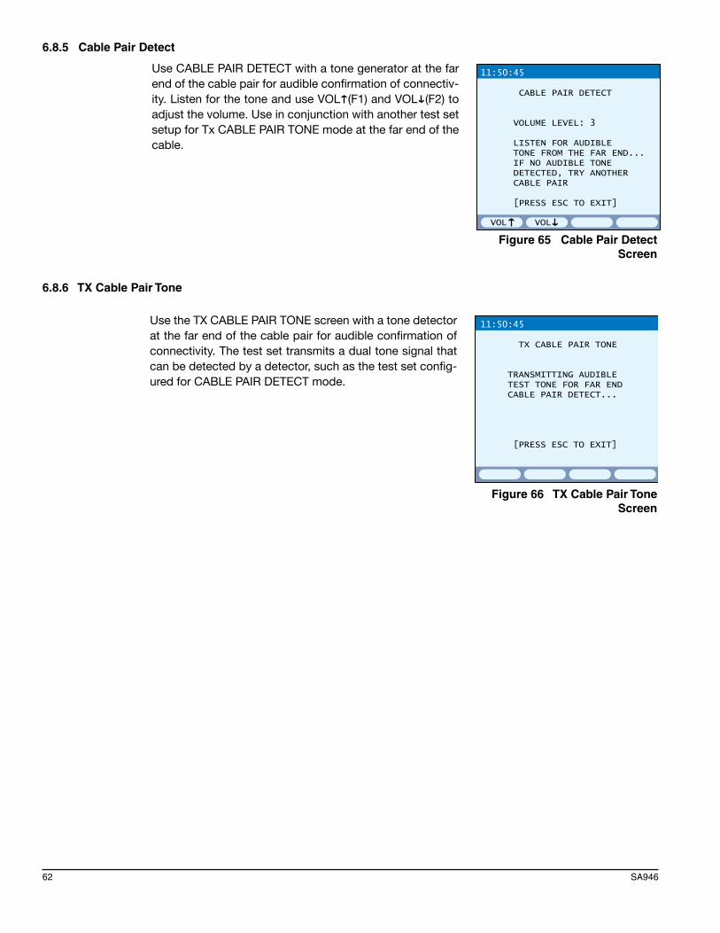
62 SA946
6.8.5 Cable Pair Detect
11:50:45
CABLE PAIR DETECT
VOLUME LEVEL: 3
LISTEN FOR AUDIBLE TONE FROM THE FAR END... IF NO AUDIBLE TONE DETECTED, TRY ANOTHER CABLE PAIR
[PRESS ESC TO EXIT]
VOL VOL
Use with a tone generator at the far end of the cable pair for audible confirmation of connec-tivity. Listen for the tone and use F1 and F2 to adjust the volume. Use in conjunction with another test set setup for Tx CABLE PAIR TONE mode at the far end of the cable.
Use CABLE PAIR DETECT with a tone generator at the far end of the cable pair for audible confirmation of connectiv-ity. Listen for the tone and use VOL (F1) and VOL (F2) to adjust the volume. Use in conjunction with another test set setup for Tx CABLE PAIR TONE mode at the far end of the cable.
11:50:45
CABLE PAIR DETECT
VOLUME LEVEL: 3
LISTEN FOR AUDIBLE TONE FROM THE FAR END... IF NO AUDIBLE TONE DETECTED, TRY ANOTHER CABLE PAIR
[PRESS ESC TO EXIT]
VOL VOL
Figure 65 Cable Pair Detect Screen
6.8.6 TX Cable Pair Tone
11:50:45
TX CABLE PAIR TONE
TRANSMITTING AUDIBLE TEST TONE FOR FAR END CABLE PAIR DETECT...
[PRESS ESC TO EXIT]
Use this feature with a tone detector at the far end of the cable pair for audible confirma-tion of connectivity. The test set transmits a dual tone signal that can be detected by a detector, such as the test set configured for CABLE PAIR DETECT mode.
Use the TX CABLE PAIR TONE screen with a tone detector at the far end of the cable pair for audible confirmation of connectivity. The test set transmits a dual tone signal that can be detected by a detector, such as the test set config-ured for CABLE PAIR DETECT mode.
11:50:45
TX CABLE PAIR TONE
TRANSMITTING AUDIBLE TEST TONE FOR FAR END CABLE PAIR DETECT...
[PRESS ESC TO EXIT]
Figure 66 TX Cable Pair Tone Screen

Chapter 8-File 63
6.8.7 Responder Detection
11:50:45
RESPONDER DETECTION
RESPONDER TYPE: MTT ACM II
[PRESS ESC TO EXIT]
Use this feature to determine the type of responder at the far end. Connect as shown in the procedure associated with Figure 48.
Use the RESPONDER DETECTION screen to determine the type of responder at the far end. Connect as shown in the procedure associated with Figure 48.
11:50:45
RESPONDER DETECTION
RESPONDER TYPE: MTT ACM II
[PRESS ESC TO EXIT]
Figure 67 Responder Detection Screen
6.9 ResponderPaired tests (Insertion Loss, Signal-to-Noise, Loop Resis-tance, and FEXT) require a responder at the far end.
To setup the test set as a Responder:
1. Connect the test set to the span as a responder.2. Select LINE > RESPONDER and the RESPOND LED
turns green.3. The test set will now respond to commands from the
Controller while it is in this screen. Note: Press RESET (F4) to reset the responder.
The following information is displayed:
LINE: Status of the connection with the Controller. LINE displays IDLE (when it’s not receiving anything from the Controller) or CONNECTED (when it’s receiving messages from the Controller).
COMMAND: Type of command received from the Controller. Here, the Controller is running an Insertion Loss test.
STATUS: Responder status. This can be:
• RECEIVED: A command from the controller has been received.• PROCESSING: The test set is in the process of responding to the controller.• COMPLETED: The test set has responded to the controller.
4. When finished testing, press ESC.
11:50:45
LINE MEASUREMENT MODE: RESPONDER
LINE : CONNECTED COMMAND: INSERTION LOSS STATUS : COMPLETED
< Press ESC to Exit >
RESET
Figure 68 Responder Screen

64 SA946
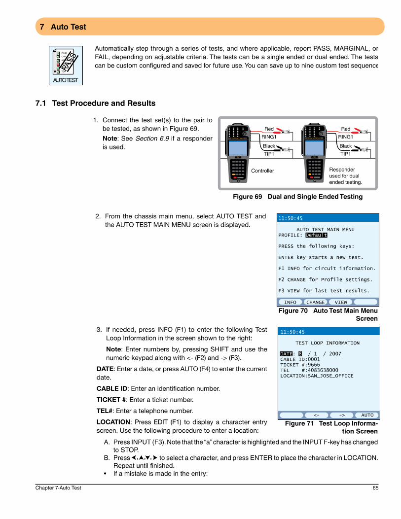
Chapter 7-Auto Test 65
7 Auto Test
Automatically step through a series of tests, and where applicable, report PASS, MARGINAL, or FAIL, depending on adjustable criteria. The tests can be a single ended or dual ended. The tests can be custom configured and saved for future use. You can save up to nine custom test sequences.
7.1 Test Procedure and Results
1. Connect the test set(s) to the pair to be tested, as shown in Figure 69.
Note: See Section 6.9 if a responder is used.
Red
RING1
Black
TIP1
Red
RING1
Black
TIP1
Controller
SunSet MTT ACM II SunSet MTT ACM II
Responder used for dual ended testing.
Figure 69 Dual and Single Ended Testing
2. From the chassis main menu, select AUTO TEST and the AUTO TEST MAIN MENU screen is displayed.
INFO VIEWCHANGE
11:50:45
AUTO TEST MAIN MENUPROFILE: Default
PRESS the following keys:
ENTER key starts a new test.
F1 INFO for circuit information.
F2 CHANGE for Profile settings.
F3 VIEW for last test results.
Figure 70 Auto Test Main Menu Screen
3. If needed, press INFO (F1) to enter the following Test Loop Information in the screen shown to the right:
Note: Enter numbers by, pressing SHIFT and use the numeric keypad along with <- (F2) and -> (F3).
DATE: Enter a date, or press AUTO (F4) to enter the current date.
CABLE ID: Enter an identification number.
TICKET #: Enter a ticket number.
TEL#: Enter a telephone number.
LOCATION: Press EDIT (F1) to display a character entry screen. Use the following procedure to enter a location:
<- AUTO->
11:50:45
TEST LOOP INFORMATION
DATE: 8 / 1 / 2007CABLE ID:0001TICKET #:9666TEL #:4083638000LOCATION:SAN_JOSE_OFFICE
Figure 71 Test Loop Informa-tion Screen
A. Press INPUT (F3). Note that the “a” character is highlighted and the INPUT F-key has changed to STOP.
B. Press to select a character, and press ENTER to place the character in LOCATION. Repeat until finished.
• Ifamistakeismadeintheentry:

66 SA946
I. Press STOP (F3),then move the FILENAME cursor to the incorrect character.II. Press DELETE (F2) to delete the character, or press INSERT (F1) to insert a character.III. Press INPUT (F3) to select a character. Press ENTER to insert the new character to the
left of the cursor.C. Press SAVE (F4) to store the entry and return to the TEST LOOP INFORMATION screen, as
shown in Figure 71.4. When finished, press ESC to return to the AUTO TEST MAIN MENU screen.5. If needed, press CHANGE (F2) to adjust the test profile
settings, found in the screens to the right.
In the screen shown on the top right, PROFILE is selected and there are two F-keys available:
NEW (F1): Create a test profile name via a character entry screen like the one described in Step 3-LOCATION. When finished, press SAVE (F4) to return to the top right screen. Now change the settings in the three screens and press STORE (F3) to save the new profile.
SELECT (F2): Select an existing profile from the AUTO TEST PROFILES selection screen. The Default profile cannot be changed, but any other profile can be renamed or deleted.
The screens shown to the right contain the following settings, that can be ON (F1) or OFF (F2). Change numeric values by using SHIFT and the numeric keypad.
The first group of settings are DUAL ENDED.
DUAL ENDED (require a responder if set to YES) LOOP OHM: NO or YES VDSL LOSS: NO or YES VDSL SNR: NO or YES
INSULATION OHM (single ended testing) TIP_GROUND: NO, YES * If Yes, select from 1000 to 9999Ω. RING_GROUND: NO, Yes
* If YES, select from 1000 to 9999Ω.CAP BALANCE: NO or YES, >/= 95%
DISTANCE (CAP): NO or YESAC VOLTAGE (single ended testing) TIP_RING: NO, or if YES, select from 0 to 99 VAC TIP_GROUND: NO, or if YES, select from 0 to 99 VAC RING_GROUND: NO, or if YES, select from 0 to 99 VAC
DC VOLTAGE (single ended testing) TIP_RING: NO, or if YES, select from 0 to 99 VDC TIP_GROUND: NO, or if YES, select from 0 to 99 VDC RING_GROUND: NO, or if YES, select from 0 to 99 VDC
NEW SELECT
11:50:45
AUTO TEST SETTINGSPROFILE: Default
DUAL ENDED LOOP OHM : N/A Ω NO VDSL LOSS : N/A NO VDSL SNR : N/A NO
INSULATION OHM TIP_RING : > 3500 kΩ YES TIP_GROUND : > 3500 kΩ YES RING_GROUND : > 3500 kΩ YES
NO YES
11:50:45
AUTO TEST SETTINGSPROFILE: Default
CAP BALANCE : >/= 95 % YESDISTANCE (CAP): N/A YESAC VOLTAGE TIP_RING : </= 3 VAC YES TIP_GROUND : </= 25 VAC YES RING_GROUND : </= 25 VAC YESDC VOLTAGE TIP_RING : </= 3 VDC YES TIP_GROUND : </= 3 VDC YES RING_GROUND : </= 3 VDC YES
NO YES
11:50:45
AUTO TEST SETTINGSPROFILE: Default
TDR DISTANCE : N/A NO
CABLE LENGTH : N/A YESVDSL PSD NOISE: N/A YESLOAD COILS : 0 YESLOOP CURRENT : N/A mA NOIMPULSE NOISE : N/A NOLONG BALANCE : 60 dB YESC-MESG NOISE : 20 dBrn YESPOWER INFL : 80 dBrn YES
Figure 72 Auto Test Settings Screens
TDR DISTANCE: NO or YES. Performs a TDR Auto Search.CABLE LENGTH: NO or YES.VDSL PSD NOISE: NO or YES.

Chapter 7-Auto Test 67
LOAD COILS: NO, or if YES, select from 0 to 9.LOOP CURRENT: NO or YES.IMPULSE NOISE: NO or YES.HIGH: This can not be changed.C-MESG NOISE: NO or YES. Default is 20 dBrn YESPOWER INFL: NO or YES. Default is 80 dBrn YES
6. When the screen settings are as desired, press SAVE (F4) and ESC to return to the AUTO TEST MAIN MENU.
7. When ready, press ENTER to display the AUTO TEST screen.
Current Test Indicator
8. Press START (F1) to begin testing. The AUTO TEST screen displays an in progress indicator to the right of “IN PROGRESS” in the screen to the right.
If needed, press STOP (F1) to stop testing.
In Figure 73 there was no response from a responder, so the test skipped to the INSULATION OHM part of the test.
STOP
11:50:45>IN PROGRESS AUTO TESTPROFILE: Default
DUAL ENDED RESPONDER : NO LOOP OHM : N/A Ω VDSL LOSS : N/A N/A VDSL SNR : N/A N/AINSULATION OHM TIP_RING :>10000 kΩ PASS TIP_GROUND : kΩ RING_GROUND : kΩ
Figure 73 Auto Test Progress Screen
9. Once the test is completed, the test results are available as shown in the AUTO TEST result screens. Refer to the listed sections for details on a specific test.
11:50:45> AUTO TESTPROFILE: Default
CAP BALANCE :100 % PASSDISTANCE (CAP):15000 FT N/AAC VOLTAGE TIP_RING :0.0 VAC PASS TIP_GROUND :0.0 VAC PASS RING_GROUND :0.0 VAC PASSDC VOLTAGE TIP_RING :12.0 VDC PASS TIP_GROUND :12.0 VDC PASS RING_GROUND :12.0 VDC PASS
START RETEST STORE
Section 6.3
START RETEST
11:50:45> AUTO TESTPROFILE: Default
LONG BALANCE :0 dB FAILC-MESG NOISE :0 dBrn PASSPOWER INFL :0 dBrn PASS
STORE
Section 3.2.3
START RETEST
11:50:45> AUTO TESTPROFILE: Default
CABLE LENGTH :SEE GRAPH N/A VDSL PSD NOISE :SEE GRAPH N/ALOAD COILS :0 PASSLOOP CURRENT :N/A mAIMPULSE NOISEHIGH :N/AMID :N/ALOW :N/A
STOREGRAPH
Section 6.1
Section 6.8.2
START RETEST STORE
11:50:45
AUTO TESTPROFILE: Default
DUAL ENDED RESPONDER :YES LOOP OHM :100 Ω VDSL LOSS :SEE GRAPH N/A VDSL SNR :SEE GRAPH N/AINSULATION OHM TIP_RING :>10000 kΩ PASS TIP_GROUND :>10000 kΩ PASS RING_GROUND :>10000 kΩ PASS
Section 6.8.1
Figure 74 Auto Test Result Screens

68 SA946
AUTO TEST Result F-keysSTART/STOP (F1): Start and stop testing.
GRAPH (F2): For some tests, a graph is available. See the sections listed in Figure 74 for details.
RETEST (F3): Available after the test is completed; use it to restart the test from a selected line.
STORE (F4): Save the test results; see Chapter 8.

Chapter 8-File 69
8 File
Results can be stored so that they can be viewed or printed at a later time. Each result can be labeled with a filename for easy identification. Store up to 50 individual results, depend-ing on available memory, by using the STORE F-key found in the results screens; see Section 8.1.
Upon selecting FILE, the VIEW/STORE/PRINT screen is displayed. It lists all stored tests.
View/Store/Print F-keysVIEW (F1): View a selected file; see Section 8.2.
PRINT (F3): Print a selected file; see Section 8.3.
RENAME (more, F1): Rename a selected file; see Section 8.6.
UN/LOCK (more, F2): Lock and unlock a selected file; see Section 8.5.
DELETE (more, F3): Delete a selected file, unless locked; see Section 8.4.
RENAME DELETE moreUN/LOCK
11:50:45
VIEW PRINT more
VIEW/STORE/PRINT Free space:82000 kbyte NAME TYPE LOCK
1. 302 ENZO DR SNPSD2. 333W57ST INLS3. MULBERRY-3/11 LPRE4. AUTO0004 AUTO5.6.7.8.9.10.
Figure 75 View/Store/Print Screen
8.1 Saving a Test1. From any screen with a STORE F-key, press the key, and measurements are saved with a generic
file name starting with XXXX0001, continuing with XXXX0002, and so on.
XXXX is the type of saved measurement, i.e., AUTO for auto test, COIL for coil detection, INNS for impulse noise count, BKNS for background noise, etc.
The saved file can be renamed, as described in Section 8.6.
8.2 Viewing a Stored Test1. Select FILE and press ENTER.2. Select the desired file from the VIEW/STORE/PRINT screen using .3. Press VIEW (F1), and the stored result can be viewed.4. Use to scroll through the available screens.5. When finished, press ESC to return to VIEW/STORE/PRINT.
8.3 Printing a Stored Test1. Connect a SunSet printer to the COMM PORT.• Forothertypesofprintersorformoreinformation,seeSection 8.7.2. Select FILE and press ENTER.3. Select the desired file from the VIEW/STORE/PRINT screen using .4. Press PRINT (F3), and the file will begin printing.5. When finished, press ESC to return to VIEW/STORE/PRINT.
8.4 Deleting a Stored Test1. Select FILE and press ENTER.2. Select the desired file from the VIEW/STORE/PRINT screen using .3. Press DELETE (more, F3), and the file is deleted (if the file is unlocked).
8.5 Locking and Unlocking a Stored Test1. Select FILE and press ENTER.2. Select the desired file from the VIEW/STORE/PRINT screen using .3. Press UN/LOCK (more, F2), and the file is locked or unlocked as indicated by the lock icon to
the right of the file name. The lock icon is shown in Figure 75.
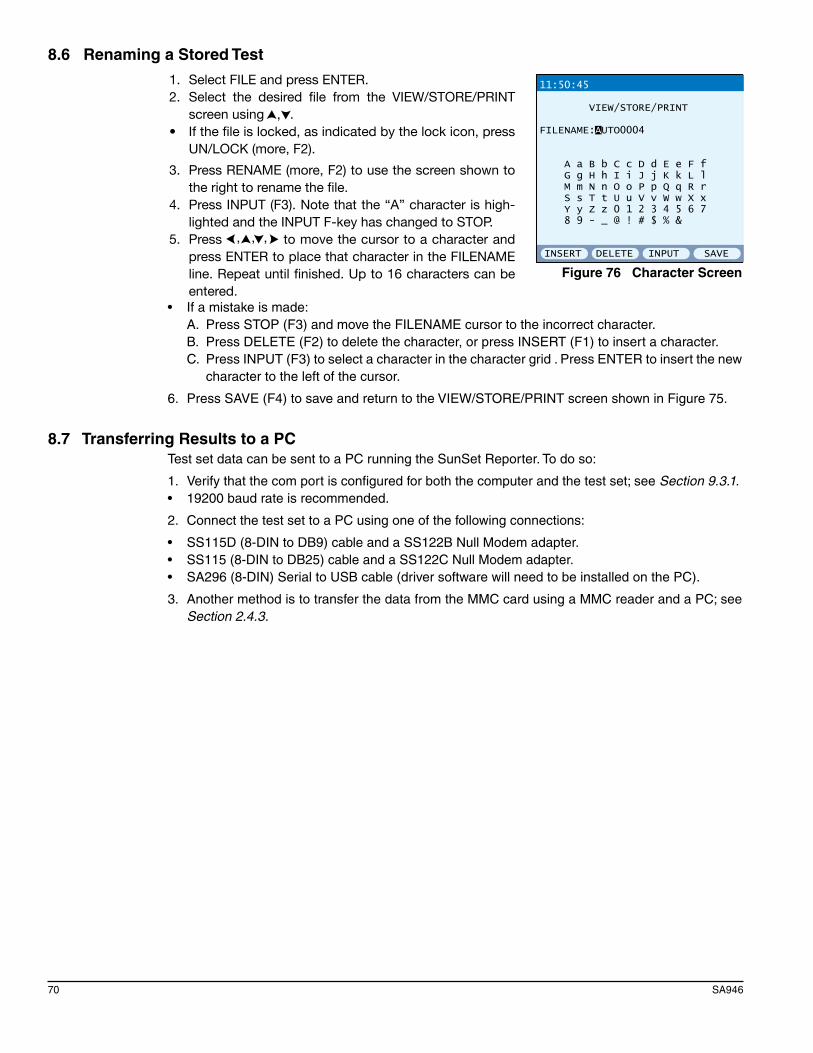
70 SA946
8.6 Renaming a Stored Test
1. Select FILE and press ENTER.2. Select the desired file from the VIEW/STORE/PRINT
screen using .• If the file is locked, as indicated by the lock icon, press
UN/LOCK (more, F2).
3. Press RENAME (more, F2) to use the screen shown to the right to rename the file.
4. Press INPUT (F3). Note that the “A” character is high-lighted and the INPUT F-key has changed to STOP.
5. Press to move the cursor to a character and press ENTER to place that character in the FILENAME line. Repeat until finished. Up to 16 characters can be entered.
INSERT INPUT SAVEDELETE
11:50:45
VIEW/STORE/PRINT
FILENAME:AUTO0004
A a B b C c D d E e F f G g H h I i J j K k L l M m N n O o P p Q q R r S s T t U u V v W w X x Y y Z z 0 1 2 3 4 5 6 7 8 9 - _ @ ! # $ % &
Figure 76 Character Screen
• Ifamistakeismade:A. Press STOP (F3) and move the FILENAME cursor to the incorrect character.B. Press DELETE (F2) to delete the character, or press INSERT (F1) to insert a character.C. Press INPUT (F3) to select a character in the character grid . Press ENTER to insert the new
character to the left of the cursor.
6. Press SAVE (F4) to save and return to the VIEW/STORE/PRINT screen shown in Figure 75.
8.7 Transferring Results to a PCTest set data can be sent to a PC running the SunSet Reporter. To do so:
1. Verify that the com port is configured for both the computer and the test set; see Section 9.3.1.• 19200baudrateisrecommended.
2. Connect the test set to a PC using one of the following connections:
• SS115D(8-DINtoDB9)cableandaSS122BNullModemadapter.• SS115(8-DINtoDB25)cableandaSS122CNullModemadapter.• SA296(8-DIN)SerialtoUSBcable(driversoftwarewillneedtobeinstalledonthePC).
3. Another method is to transfer the data from the MMC card using a MMC reader and a PC; see Section 2.4.3.

Chapter 9-System 71
9 System
This menu screen contains various system settings and functions divided into three groups:
9.1 System Configuration
Use the SYSTEM CONFIGURATION screen to configure the following:
LANGUAGEOptions: ENGLISH (F1), ITALIAN (F2), SPANISH (F3), FRENCH (more, F1), CHINESE (more, F2)Select the language that the test set will display.
UNITOptions: ENGLISH (F1), METRIC (F2)Select the measurement system the test set will use.
BACK LIGHTOptions: 5-60 minutesUse +5 MIN and -5 MIN enter the desired on time duration.
ENGLISH SPANISH moreITALIAN
11:50:45
SYSTEM CONFIGURATION
LANGUAGE : ENGLISH UNIT : ENGLISH BACK LIGHT : 5 MINS AUTO SHUT OFF: 30 MINS
DATE (M/D/Y) : 08/02/2007 TIME (H:M:S) : 11:50:45
Figure 77 System Configuration Screen
AUTO SHUT OFF: Set a time for the test set to shut down.Options: OFF or 2-30 minutesUse +1 MIN and -1 MIN to set the time for the shut down. When this feature is set, the on screen time is displayed against a black background as in Figure 77.
DATE: Set the date.Use to select the month/date/year, along with INC (F1) and DEC (F2) to set the date. When finished, press SET (F3).
TIME: Set the time.Use to select the hour: minute: second, along with INC (F1) and DEC (F2) to set the time. When finished, press SET (F3). Note that the clock can only be set for a 24 hour clock.
72 SA946
9.2 System ToolsThis menu screen contains:
• NVRAMERASE• FACTORYDEFAULT• VERSIONINFORMATION
9.2.1 NV RAM Erase
Use the following procedure to perform NV RAM ERASE:
CAUTION: This will erase all stored information.
1. Select SYSTEM > SYSTEM TOOLS > NV RAM ERASE.2. Press ENTER to start NV RAM ERASE. An “ERASING NV RAM” message will be displayed and
the test set will shut down.• PressESCtoescapefromtheprocedure.
3. After powering up the test set, configure it as required.
9.2.2 Factory Default
Use this procedure to return the test set to it’s original profiles.
1. Select SYSTEM > SYSTEM TOOLS > FACTORY DEFAULT.2. Press ENTER, and the test set resets all settings to their original settings, or press ESC to escape
from the procedure.
9.2.3 Version Information
This menu screen contains:
• VERSION/OPTION• MODULEOPTION• VERSIONLIST
9.2.3.1 Version/Option
View a list of installed software options for the test set and supported modules. Also view basic hardware information such as serial numbers.
If necessary, use PAGE-UP (F1) and PAGE-DN (F2) to view the entire list.
Press PRINT (F3) to print the list.
9.2.3.2 Module Option
This function is currently not supported.
9.2.3.3 Version List
Displays a list of the software versions for the base chassis and supported modules.
If necessary, press “more” (F4) to view the entire list.

Chapter 9-System 73
9.3 Serial Port ApplicationsThis menu screen contains:• SERIAL PORT CNFG• AnyoptionalapplicationsthatusetheCOMMPORT,suchas:
- VT100 EMULATION- TL1 MODE These optional features have their own User’s Manuals.
9.3.1 Serial Port Configuration
In order to print or transfer results to a PC correctly, config-ure the COMM PORT to match the destination printer/PC.
To configure, select SYSTEM > SERIAL PORT APPS > SERIAL PORT CNFG and in the SERIAL PORT CONFIGU-RATION screen, configure the following:
BAUD RATEOptions: 1200 (F1), 2400 (F2), 4800 (F3), 9600 (more, F1), 19200 (more, F2)Select the desired baud rate setting.
• Make sure this setting matches that of the destination printer.
PARITY BITOptions: NO (F1), ODD (F2), EVEN (F3)Parity is a method of checking the accuracy of transmitted or stored data. An extra bit, known as a parity bit, is added to the data as an accuracy check.
• Make sure this setting matches that of the destination printer.
SERIAL PORT CONFIGURATION
BAUD RATE : 19200 PARITY_BIT : NO STOP_BIT : 1_BIT DATA SIZE : 8_BIT CR/LF INSRT : CR PRINT MODE : TEXT PRINT FORMAT: PRINTER
11:50:45
1200 4800 more2400
Figure 78 Serial Port Configura-tion Screen
• InOddParity,thetotalnumberofones(includingtheaddedparitybit)isodd.• InEvenParity,thetotalnumberofones(includingtheaddedparitybit)iseven.• Nonesignifiesnoparitychecking.
STOP BITOptions: 1-BIT (F1), 2-BIT (F2)In asynchronous transmission, the stop bit is the last transmitted character which permits the receiver to come into an idle condition before accepting another character. Make sure this setting matches that of the destination printer.
DATA SIZE: Data Size specifies the number of bits per character. Options: 5_BIT (F1), 6_BIT (F2), 7_BIT (F3), 8_BIT (F4)• Makesurethissettingmatchesthatofthedestinationprinter.
CR/LF INSRTOptions: CR (F1), CR+LF (F2)• CR:Carriagereturn.• CR+LF:Carriage return and line feed. This inserts an extra line space after every line.
PRINT MODE: Choose the print format.Option: TEXT (F1)Text: This mode prints a text-only format. The following Stored Results are printable to a serial printer or a PC terminal program:• BACKGROUNDNOISEPSDTabularResults(F3:PRINT)• NEXTTabularResults(F3:PRINT)• FEXTTabularResults(F3:PRINT)
74 SA946
• INSERTIONLOSSPSDTabularResults(F3:PRINT)• SignaltoBackgroundNoiseTabular Results (F3: PRINT)
PRINT FORMATOptions: PRINTER (F1), VT100 (F2)
• Printer:SupportsSunSetprinters.• VT100:Exportstabularresults(asmentionedinPRINTMODE)inatwocolumnformattoterminal
programs, such as Windows HyperTerminal, for post data processing.

Chapter 10-General Information 75
10 General Information
10.1 Customer ServiceGeneral Sunrise Telecom Customer Service is available from 7:30 AM to 5:30 PM Pacific Standard Time (California, U.S.A.).
Customer Service performs the following functions:
• Answerscustomerquestionsoverthephoneonsuchtopicsasproductoperationandrepair.• Facilitatespromptrepairofmalfunctioningtestsets.• Providesinformationaboutproductupgrades.
A Return Merchandise Authorization (RMA) Number is required before any product may be shipped to Sunrise Telecom for repair. Out-of-warranty repairs require both an RMA and a Purchase Order before the unit is returned. All repairs are warranted for 90 days.
Contact Customer Service at:
Sunrise Telecom Incorporated302 Enzo DriveSan Jose, CA 95138U.S.A.
Tel: 1-800-701-5208Fax: 1-408-363-8313Internet: http://www.sunrisetelecom.come-mail: [email protected]
Or contact one our offices listed in Section 10.2.
MTT Support HotlineIn addition to general customer service, a 24-hour MTT support line is available for dedicated MTT technical support. Our knowledgeable MTT support staff is ready to help with any questions regard-ing MTT testing.
Call: 1-800-701-5208

76 SA946
10.2 OfficesSunrise Telecom offices are located around the world:• America:SUNRISETELECOMINCORPORATED 302 Enzo Drive, San Jose, CA 95138, USA Tel: +1-800-701-5208, +1-408-363-8000, Fax: +1-408-363-8313 Email: [email protected] or [email protected]
• U.S.A. SUNRISE TELECOM ATLANTA
3075 Northwoods Circle, Norcross, GA 30071, USA
Tel: 770-446-6086, Fax: 770-446-6850
• France: SUNRISE TELECOM ZA Courtaboeuf 2 - Immeuble le Ceylan6 Allée de Londres 91140 Villejust, FRANCE Tel: +33 (0) 1 69 93 89 90, Fax: +33 (0) 1 69 93 89 91 Email:[email protected]
• Germany: SUNRISE TELECOM Grabenstrasse 1, 72116 Mssingen, GERMANY Tel: +49 7473 378 2400, Fax: +49 7473 378 2424 Email: [email protected]
• China: SUNRISE TELECOM Room 1503, Tower 3, No. 1, Xizhimenwai Stree.
Xicheng District,Beijing,100044, CHINA Tel: +86-10-5830-2220, Fax: +86-10-5830-2239 Email: [email protected]
• Taiwan:SUNRISETELECOMCompanyLimited 21, Wu Chuan 3rd Road, Wu-Ku Hsiang, Taipei County, 248, Taiwan, R.O.C. Tel: +886-2-5578-0788, Fax: +886-2-2298-2575 Email: [email protected]

Chapter 10-General Information 77
10.3 Express Limited WarrantyT
This Sunrise Telecom product is warranted against defects in materials and workmanship during its warranty period. The warranty period for this product is contained inthe warranty page on http://www.sunrisetelecom.com.
Sunrise Telecom agrees to repair or replace any assembly or compo nent found to bedefective under normal use during this period. The obligation under this warrantyis limited solely to repairing or replacing the product that proves to be defective
within the scope of the warranty when returned to the factory. This warranty doesnot apply under certain conditions, as set forth on the warranty page on http://www.sunrisetelecom.com. Please refer to the website for specific details.
THIS IS A LIMITED WARRANTY AND THE ONLY WARRANTY MADE BY SUNRISE TELECOM. SUNRISE TELECOM MAKES NO OTHER WARRANTY, REPRESENTATION OR CONDITION, EXPRESS OR IMPLIED, AND EXPRESSLY
DISCLAIMS THE IMPLIED WARRANTIES OF MERCHANTABILITY, FITNESS FOR APARTICULAR PURPOSE AND NON-INFRINGEMENT OF THIRD PARTY RIGHTS.
duct is contained inthe warrann http://www.sunrisetelecom.coNON-INFRINGEMENT OF THIRD PARTY RIGH

78 SA946

Index 79
Index
AADSL 2.2M Results; 48Applications
AC Voltage; 40Auto Test; 65Cable Pair Detect; 62Capacitance; 41Coil Detection; 54Current; 42DC Voltage; 39Dual Mode Measurements; 30Far End Crosstalk (FEXT); 61Fault Location; 35Frequency Generator; 55Impulse Noise; 51Insertion Loss; 56Longitudinal Balance; 50Loop Resistance; 60Near End Crosstalk (NEXT); 53Ohm; 40Performing a TDR Measurement; 24PSD Background Noise; 46Responder Detection; 63Signal-to-Noise Test; 59Single Mode Measurements; 25TX Cable Pair Tone; 62VF Measurements; 50
Auto TestDual and Single Ended Testing; 65Main Menu Screen; 65Result Screens; 67Settings Screens; 66Test Loop Information Screen; 65Test Procedure and Results; 65
BBalance; 50Battery
Care and Storage; 19Replacing; 20
Battery Charger; 7Bridge Taps; 58
CCable Length; 31Calibration
High Ohm; 42Low Capacitance; 42
Cautions; 17, 18, 19, 72COMM PORT; 18Connectors; 17Customer Service; 75
DDC 15V; 18Disposal and Recycling; 4DMM; 39
Accuracy; 7DMM (Digital Multimeter)
AC VoltageTIP_RNG, _GNG, RNG_GND, and STORE; 40
Capacitance Opens ScreenTIP_RNG, _GNG, RNG_GND, BALANCE, STORE, SETUP; 41
Capacitance Opens Setup ScreenUNITS and CAP Loop; 41
CurrentSTORE; 42
DC VoltageTIP_RNG, _GNG, RNG_GND, and STORE; 39
Measuring Procedures; 43Ohm
TIP_RNG, _GNG, RNG_GND, and STORE; 40
FFactory Default; 72Far End Crosstalk; 61Figures
01 DSL Span; 902 Test Set Front View; 1103 Keypad; 1204 Main Menu Screen; 1205 Main Menu Tree; 1306 LED Panel; 1507 Right Panel; 1708 Top Panel; 1809 Card Installation; 1810 Replacing the Battery Pack; 2011 TDR Setup Screens; 2112 Connecting to the Cable Pair(s); 2413 Fault Found Screen; 2514 Result Zoomed Out Screen; 2515 Zooming In Once Screen; 2516 Auto Search Lower Screen Items; 2617 Auto Search Screen; 2718 Bridge Tap at 1589 ft; 2719 Page-right, Viewing from 1625 to 4838 ft; 2720 Page-right, Viewing from 4856 to 8069 ft; 2721 Zoom out, Viewing from 4856 to 11281 ft; 2822 Typical Load Coil/Open; 2823 Typical Short; 2824 Typical Bridge Tap; 2925 Stored and Live Trace Comparison; 2926 Dual Trace Split Screen; 3027 Dual Trace Overlap Screen; 3028 Dual Trace Difference Screen; 3029 Length Mode Results; 3129 RFL Setup Screen; 3330 Multi-Section Cable Setup Screen; 3331 Single Conductor Screens; 3432 Dual Conductor Screens; 3433 Cross Fault Conditions; 3534 Cross Fault Test Setups; 3535 Battery Cross Fault Conditions; 3636 Battery Cross Fault Setups; 3637 Ground Fault Conditions; 3638 Ground Fault Test Setups; 3739 Short Fault Conditions; 3740 Short Fault Test Setups; 3741 Digital Multimeter Menu Screen; 3942 DC Voltage Screen; 3943 AC Voltage Screen; 40

80 SA946
44 Resistance Screens; 4045 Capacitance/Opens Screens; 4146 Current Screens; 4247 Connecting with Alligator Clips; 4348 Single-ended Test Setup; 4549 Dual-ended Test Setup; 4550 PSD Background Noise Setup Screen; 4651 VDSL 30 MHz PSD Background Noise Screens; 4652 VF Measurement Screens; 4753 ADSL 2.2M Background Noise Screens; 4854 Longitudinal Balance Screen; 5055 Noise/SNR Screen; 5056 Impulse Noise Screens; 5157 NEXT Connection and Screens; 5358 Coil Detection Screen; 5459 Frequency Generator Screen; 5560 Insertion Loss Setup Screen; 5661 Insertion Loss Connection and Result Screens; 5762 ADSL DMT PSD Signal-to-Noise Result Screens; 5963 Measuring Loop Resistance Setup with Results Screen;
6064 Far End Crosstalk Screens; 6165 Cable Pair Detect Screen; 6266 TX Cable Pair Tone Screen; 6267 Responder Detection Screen; 6368 Responder Screen; 6469 Dual and Single Ended Testing; 6570 Auto Test Main Menu Screen; 6571 Test Loop Information Screen; 6572 Auto Test Settings Screens; 6673 Auto Test Progress Screen; 6774 Auto Test Result Screens; 6775 View/Store/Print Screen; 6976 Character Screen; 7077 System Configuration Screen; 7178 Serial Port Configuration Screen; 73
File; 69Frequency Generator Screen
dBm; 55FREQ;55
Front View; 11
IIcon Description; 13Impulse Noise Screens
DEAD TIME; 51DELTA; 51ET; 51HIGH, MID, and LOW; 51HIGH, MID, and LOW results; 52MAX COUNT; 51RT; 51THRESHOLD; 51TIMER; 51UNIT
dBrn or dBm; 51
Initial Setup; 7Insertion Loss; 56Insertion Loss Test
Single Frequency; 58
KKeypad
0-9; 14A-F; 14AUTO; 13CONTRAST; 13Cursors ( ); 13ENTER; 13ERR INJ; 13ESC; 13F1-F4 (F-keys); 12HISTORY; 13LIGHT; 13MENU; 12MODULE; 12PRINT; 14SHIFT; 14STATUS; 13VOLUME; 13
Keypad Functions; 12
LLEDs; 15
AIS; 16ALARM; 16BATTERY; 16BIT ERR; 16BPV/CODE; 16DMM; 15ERRORS; 16FRAME; 16HOLD; 16LINE; 15LP 1 SYNC; 16LP 2 SYNC; 16MODULE; 15PAT SYNC; 16POWER; 15RESPOND; 16SIGNAL; 16TDR/RFL; 15xTU-C; 15xTU-R; 15
Line MeasurementsCable Pair Detect; 62Coil Detection; 54Dual-ended Test Setup; 45Frequency Generator; 55Impulse Noise Setup
THRESHOLD, DELTA, MAX COUNT, DEAD TIME, TIMER; 51
Loop Resistance TestHDSL and ADSL requirements; 60
Near End Crosstalk-NEXT; 53Responder Detection; 63Single-ended Test Setup; 45TX Cable Pair Tone; 62
Load coils; 54Load Coils
Removing; 54Longitudinal Balance Screen; 50
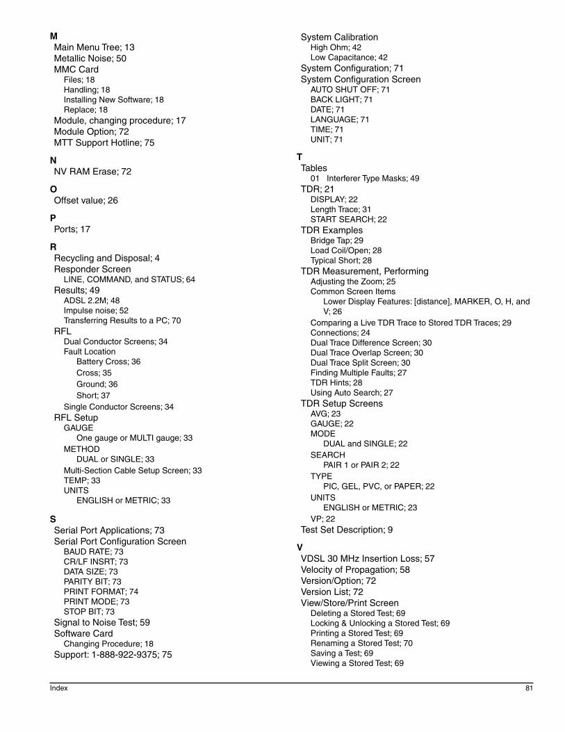
Index 81
MMain Menu Tree; 13Metallic Noise; 50MMC Card
Files; 18Handling; 18Installing New Software; 18Replace; 18
Module, changing procedure; 17Module Option; 72MTT Support Hotline; 75
NNV RAM Erase; 72
OOffset value; 26
PPorts; 17
RRecycling and Disposal; 4Responder Screen
LINE, COMMAND, and STATUS; 64Results; 49
ADSL 2.2M; 48Impulse noise; 52Transferring Results to a PC; 70
RFLDual Conductor Screens; 34Fault Location
Battery Cross; 36Cross; 35Ground; 36Short; 37
Single Conductor Screens; 34RFL Setup
GAUGEOne gauge or MULTI gauge; 33
METHODDUAL or SINGLE; 33
Multi-Section Cable Setup Screen; 33TEMP; 33UNITS
ENGLISH or METRIC; 33
SSerial Port Applications; 73Serial Port Configuration Screen
BAUD RATE; 73CR/LF INSRT; 73DATA SIZE; 73PARITY BIT; 73PRINT FORMAT; 74PRINT MODE; 73STOP BIT; 73
Signal to Noise Test; 59Software Card
Changing Procedure; 18Support: 1-888-922-9375; 75
System CalibrationHigh Ohm; 42Low Capacitance; 42
System Configuration; 71System Configuration Screen
AUTO SHUT OFF; 71BACK LIGHT; 71DATE; 71LANGUAGE; 71TIME; 71UNIT; 71
TTables
01 Interferer Type Masks; 49TDR; 21
DISPLAY; 22Length Trace; 31START SEARCH; 22
TDR ExamplesBridge Tap; 29Load Coil/Open; 28Typical Short; 28
TDR Measurement, PerformingAdjustingtheZoom;25Common Screen Items
Lower Display Features: [distance], MARKER, O, H, and V; 26
Comparing a Live TDR Trace to Stored TDR Traces; 29Connections; 24Dual Trace Difference Screen; 30Dual Trace Overlap Screen; 30Dual Trace Split Screen; 30Finding Multiple Faults; 27TDR Hints; 28Using Auto Search; 27
TDR Setup ScreensAVG; 23GAUGE; 22MODE
DUAL and SINGLE; 22SEARCH
PAIR 1 or PAIR 2; 22TYPE
PIC, GEL, PVC, or PAPER; 22UNITS
ENGLISH or METRIC; 23VP; 22
Test Set Description; 9
VVDSL 30 MHz Insertion Loss; 57Velocity of Propagation; 58Version/Option; 72Version List; 72View/Store/Print Screen
Deleting a Stored Test; 69Locking & Unlocking a Stored Test; 69Printing a Stored Test; 69Renaming a Stored Test; 70Saving a Test; 69Viewing a Stored Test; 69

82 SA946
WWarnings; 19Warranty; 7, 77WEEE; 4