Summary Methods for the Analysis of Physical Properties ...
29
A Catalogue of Crude Oil and Oil Product Properties (1999)---Revised 2022 Summary Methods for the Analysis of Physical Properties, Compositions, Behaviour, and Toxicity of Petroleum Products A Catalogue of Crude Oil and Oil Product Properties (1999)---Revised 2022 Appendix 1 (enclosed): Summary of ESD Analytical Methods
-
Upload
khangminh22 -
Category
Documents
-
view
0 -
download
0
Transcript of Summary Methods for the Analysis of Physical Properties ...
A Catalogue of Crude Oil and Oil Product Properties (1999)---Revised 2022
Summary Methods for the Analysis of Physical Properties, Compositions, Behaviour, and Toxicity of Petroleum Products
A Catalogue of Crude Oil and Oil Product Properties (1999)---Revised 2022
Appendix 1 (enclosed): Summary of ESD Analytical Methods
Summary of Method for Analysis of Oil Properties_________________________________
A Catalogue of Crude Oil and Oil Product Properties (1999)---Revised 2022
2
API Gravity (See Density)
Equations(s) for Predicting Evaporation
Evaporation is a major process that contributes to the weathering of spilled oil. While pure compounds evaporate at constant rates, oils, which are composed of thousands of compounds, do not. Rapid initial loss of the more volatile fractions is followed by progressively slower loss of less volatile components. It is not uncommon for 25% of the total volume of an oil spill to evaporate within one day of the spill (Fingas 79).
Using a simple pan evaporation technique, evaporation rate equations have been developed for many different oils (Fingas 95a). For more details, see Appendix 1.
Sulphur
The sulphur content of a crude oil is important for a number of reasons. Downstream processes such as catalytic cracking and refining will be adversely affected by high sulphur contents. During an oil spill, the sulphur content becomes a health and safety concern for cleanup personnel. In addition, if high sulphur oils are burning, they can produce dangerous levels of sulphur dioxide.
The total sulphur content of oil can be determined by a number of standard techniques. ASTM method D 129 - Standard Test Method for Sulfur in Petroleum Products (General Bomb Method) is applicable to petroleum products of low volatility and containing at least 0.1 mass percent sulphur (ASTM D 129). Sulphur contents from EETD and ESD were determined using a Horiba MESA 200 sulphur and chlorine analyzer, in accordance with ASTM method D 4294 - Standard Test Method for Sulfur in Petroleum Products by Energy-Dispersive X-Ray Fluorescence Spectroscopy. This method is applicable to both volatile and non-volatile petroleum products with sulphur concentrations ranging from 0.05 to 5 mass percent (ASTM D 4294).
Water Content
Some of the oil samples received by ESD contain substantial amounts of water. Because any process that would separate the oil and water would also change the composition of the oil, most properties were determined on the oils as received. Exceptions are noted in the individual data tables. Therefore, for those oils with significant water contents (>5%), many of the properties measured do not represent the properties of the 'dry' oil.
At ESD, water contents were determined by Karl Fischer titration using a Metrohm 701 KF Automatic Titrator. For more details, see Appendix 1.
Flash Point
The flash point of a fuel is the temperature to which the fuel must be heated to produce a vapour/air mixture above the liquid fuel that is ignitable when exposed to an open flame under specified test conditions. In North America, flash point is used as an index of fire hazard. As such, shipping regulations use flash point as a criterion to establish labelling requirements. Flash point is an extremely important factor in relation to the safety of spill cleanup operations. Gasolines and other light fuels can
Summary of Method for Analysis of Oil Properties_________________________________
A Catalogue of Crude Oil and Oil Product Properties (1999)---Revised 2022
3
be ignited under most ambient conditions and therefore pose a serious hazard when spilled. Many freshly spilled crude oils also have low flash points until the lighter components have evaporated or dispersed.
There are several ASTM methods for measuring flash points, using either closed cup or open cup testers. Open cup methods will generally produce results that are higher than those measured with closed testers, and should not be used with volatile substances. The flash points of lubricating oils can be determined by ASTM method D 92/IP 36 - Standard Test Method for Flash and Fire Points by Cleveland Open Cup (ASTM D 92).
For determining the flash points of other oils, methods D 93/IP 34 - Standard Test Methods for Flash Point by Pensky-Martens Closed Tester and D 56 - Standard Test Method for Flash Point by Tag Closed Tester are the most commonly used. The Pensky-Martens tester has an integral stirrer, but no cooling bath. The minimum flashpoint that can be determined by method D93/IP34 is 10°C (ASTM D 93). The Tag closed tester has an integral cooling bath, but no stirring mechanism. Method D 56 is intended for liquids with a viscosity less than 9.5 cSt at 25°C (ASTM D 56).
Many fresh crude oils have flash points below 10°C and/or viscosities above 9.5 cSt at 25 °C. For this reason, at ESD, a SUR BERLIN TAG 2 automatic flash point tester, which has been modified by adding a stirring mechanism, is used to determine flash points. The mechanism operates in a similar fashion to a Pensky-Martens tester, but is of a more efficient design. The stirrer aids in producing more uniform heat transfer to oils that exceed the design viscosity, and in no way interferes with the test mechanism. Flash points measured by this instrument are generally repeatable to ±4 °C. For more details, see Appendix 1.
In the data section, flash points taken from the literature, and determined by open cup methods are designated by a footnote. No designation is provided if the test method was closed cup or not specified.
Flammability Limits in Air
The percent concentration in air (by volume) is given for the lower and upper limits. These values give an indication of relative flammability. The limits are sometimes referred to as 'lower explosive limit' (LEL) and 'upper explosive limit' (UEL).
Ignition Temperature
Sometimes called 'autoignition temperature', this is the minimum temperature at which the material will ignite without a spark or flame being present. The method of measurement is given in ASTM method E 659 - Standard Test Method for Auto-ignition Temperature of Liquid Chemicals (ASTM E 659).
Fire Point
Fire point is the lowest temperature, corrected to one atmosphere pressure (101.3 kPa), at which the application of a test flame to the oil sample surface causes the vapour of the oil to ignite and burn for at least five seconds. For ordinary commercial lubricating oils, the fire point usually runs about 30°Cabove the flash point (Esso 90). The fire points of lubricating oils can be determined by ASTM method D 92/IP 36 - Standard Test Method for Flash and Fire Points by Cleveland Open Cup (ASTM D 92).
Summary of Method for Analysis of Oil Properties_________________________________
A Catalogue of Crude Oil and Oil Product Properties (1999)---Revised 2022
4
Reid Vapour Pressure
Vapour pressure is an important physical property of volatile liquids. It is the pressure that a vapour exerts on its surroundings. Its units are kilopascals, corrected to one atmosphere (101.3 kPa). For volatile petroleum
products, vapour pressure is used as an indirect measure of evaporation rate. Vapour pressure can be measured by a variety of methods, including Reid, dynamic, static, isoteniscopic, vapour pressure balance, and gas saturation. The most commonly used method for crude oils has been the Reid vapour pressure, as determined by ASTM method D 323 - Standard Test Method for Vapor Pressure of Petroleum Products (Reid Method)
(ASTM D 323). This test method determines vapour pressure at 37.8°C (100 °F) of petroleum products and crude oils with an initial boiling point above 0°C (32 °F). It is measured by saturating a known volume of oil in an air chamber of known volume and measuring the equilibrium pressure, which is then corrected to one atmosphere (101.3 kPa).
Hydrogen Sulphide
Unlike other sulphur compounds in crude oils, which tend to accumulate in the distillation residue, hydrogen sulphide is evolved during distillation or other heating processes. During an oil spill, this makes it a safety concern, as hydrogen sulphide is a toxic gas with a time-weighted average (TWA) exposure limit of 10 ppm and a short-term exposure limit (STEL) of 15 ppm (ACGIH 99).
Odour Threshold
This is the lowest concentration in air that most humans can detect by smell. The value cannot be relied on to prevent overexposure because human sensitivity to odours varies over wide limits, some chemicals cannot be smelled at toxic concentrations, odours can be masked by other odours, and some compounds rapidly deaden the sense of smell (CHRIS 91).
Density
Density is defined as the mass per unit volume of a substance. It is most often reported for oils in units of g/mL or g/cm3, and less often in units of kg/m3. Density is temperature-dependent. The table below gives the density of fresh and salt water at various temperatures. Oil will float on water if the density of the oil is less than that of the water. This will be true of all fresh crude oils, and most fuel oils, for both salt and fresh water. Bitumens and certain residual fuel oils may have densities greater than 1.0 g/mL and their buoyancy behaviour will vary depending on the salinity and temperature of the water. The density of spilled oil will also increase with time, as the more volatile (and less dense) components are lost. After considerable evaporation, the density of some crude oils may increase enough for the oils to submerge below the water surface.
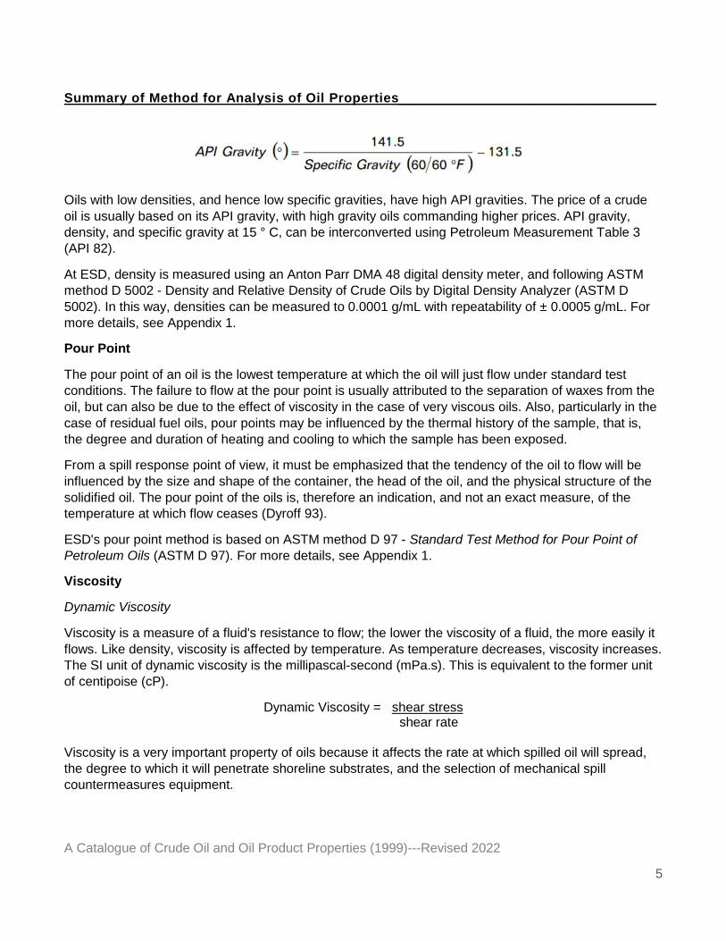
Two density-related properties of oils are often used: specific gravity and American Petroleum Institute (API) gravity. Specific gravity (or relative density) is the ratio, at a specified temperature, of the oil density to the density of pure water. The API gravity scale arbitrarily assigns an API gravity of 10° to pure water. API gravity is calculated as:
Summary of Method for Analysis of Oil Properties_________________________________
A Catalogue of Crude Oil and Oil Product Properties (1999)---Revised 2022
5
Oils with low densities, and hence low specific gravities, have high API gravities. The price of a crude oil is usually based on its API gravity, with high gravity oils commanding higher prices. API gravity, density, and specific gravity at 15 ° C, can be interconverted using Petroleum Measurement Table 3 (API 82).
At ESD, density is measured using an Anton Parr DMA 48 digital density meter, and following ASTM method D 5002 - Density and Relative Density of Crude Oils by Digital Density Analyzer (ASTM D 5002). In this way, densities can be measured to 0.0001 g/mL with repeatability of ± 0.0005 g/mL. For more details, see Appendix 1.
Pour Point
The pour point of an oil is the lowest temperature at which the oil will just flow under standard test conditions. The failure to flow at the pour point is usually attributed to the separation of waxes from the oil, but can also be due to the effect of viscosity in the case of very viscous oils. Also, particularly in the case of residual fuel oils, pour points may be influenced by the thermal history of the sample, that is, the degree and duration of heating and cooling to which the sample has been exposed.
From a spill response point of view, it must be emphasized that the tendency of the oil to flow will be influenced by the size and shape of the container, the head of the oil, and the physical structure of the solidified oil. The pour point of the oils is, therefore an indication, and not an exact measure, of the temperature at which flow ceases (Dyroff 93).
ESD's pour point method is based on ASTM method D 97 - Standard Test Method for Pour Point of Petroleum Oils (ASTM D 97). For more details, see Appendix 1.
Viscosity
Dynamic Viscosity
Viscosity is a measure of a fluid's resistance to flow; the lower the viscosity of a fluid, the more easily it flows. Like density, viscosity is affected by temperature. As temperature decreases, viscosity increases. The SI unit of dynamic viscosity is the millipascal-second (mPa.s). This is equivalent to the former unit of centipoise (cP).
Dynamic Viscosity = shear stress shear rate
Viscosity is a very important property of oils because it affects the rate at which spilled oil will spread, the degree to which it will penetrate shoreline substrates, and the selection of mechanical spill countermeasures equipment.
Summary of Method for Analysis of Oil Properties_________________________________
A Catalogue of Crude Oil and Oil Product Properties (1999)---Revised 2022
6
Viscosity measurements may be absolute or relative (sometimes called 'apparent'). Absolute viscosities are those measured by a standard method, with the results traceable to fundamental units. "Absolute viscosities are distinguished from relative measurements made with instruments that measure viscous drag in a fluid, without known and/or uniform applied shear rates." (Schramm 92). An important benefit of absolute viscometry is that the test results are independent of the particular type or make of viscometer used. Absolute viscosity data can be compared easily between laboratories worldwide.
Modern rotational viscometers are capable of making absolute viscosity measurements for both Newtonian and non-Newtonian fluids at a variety of well controlled, known, and/or uniform shear rates. Unfortunately, no ASTM standard method exists that makes use of these viscometers. Nonetheless, these instruments are in widespread use in many industries.
Prior to 1989, the dynamic viscosity results reported by EETD were measured using a Brookfield LVT viscometer. For non-Newtonian oils, the viscosity measurements were usually performed at shear rates of 1/s and 10/s. Dynamic viscosity data produced by EETD in 1989 or by ESD, were determined using a HAAKE RV20 Rotovisco with the M5 measuring system, and HAAKE RC20 Rheocontroller. The Rheocontroller, which is connected to a personal computer, allows the shear rates to be controlled with great accuracy and precision. A dedicated software package performs automatic dynamic viscosity measurements and outputs the stored data in table and graphical formats. For non-Newtonian oils, measurements are made at multiple shear rates, which are also reported. In general, the viscosity values obtained using this system will be repeatable to ± 5% of the mean. For more details, see Appendix 1.
In the dynamic viscosity data tables, NM indicates that the viscosity was 'not measurable' as it exceeded the measurement range of the instrument.
Kinematic Viscosity
There are several ASTM Standard Methods for measuring the viscosity of oils. Of these, only methods D 445 - Standard Test Method for Kinematic Viscosity of Transparent and Opaque Liquids (the Calculation of Dynamic Viscosity) (ASTM D 445) and D 4486 - Standard Test Method for Kinematic Viscosity of Volatile and Reactive Liquids, will yield absolute viscosity measurements (ASTM D 4486). Both of these methods make use of glass capillary kinematic viscometers and will produce absolute measurements in units of centistokes (cSt) only for oils that exhibit Newtonian flow behaviour (viscosity independent of the rate of shear). Kinematic viscosity can also be calculated from dynamic viscosity and density data determined at the same temperature.
Kinematic Viscosity = dynamic viscosity density
Saybolt Viscosity
Although now obsolete, at one time the petroleum industry relied on measuring kinematic viscosity with the Saybolt viscometer and expressing kinematic viscosity in Saybolt Universal Seconds (SUS) or Saybolt Furol Seconds (SFS). Occasionally, Saybolt viscosities are still reported in the literature. ASTM D 2161 - Standard Practice for Conversion of Kinematic Viscosity to Saybolt Universal Viscosity or to
Summary of Method for Analysis of Oil Properties_________________________________
A Catalogue of Crude Oil and Oil Product Properties (1999)---Revised 2022
7
Saybolt Furol Viscosity establishes the official equations relating SUS and SFS to the SI kinematic viscosity units, mm2/s (ASTM D 2161).
Emulsion Formation
A water-in-oil emulsion is a stable dispersion of small droplets of water in oil. When formed from crude oils spilled at sea, these emulsions can have very different characteristics from their parent crude oils. This has important implications for the fate and behaviour of the oil and its subsequent cleanup. It is desirable, therefore, to determine if an oil is likely to form an emulsion, and if so, whether that emulsion is stable, and what its physical characteristics are.
In 1994, a method was developed for the formation of water-in-oil emulsions using a commercially available apparatus with the same end-over-end type of rotation described by Mackay and Zagorski (Mackay 82a). Studies to optimize the parameters of the test found the water-to-oil ratio, fill volume, and orientation of the vessels to be important (Fingas 94). Analysis of the water content, viscosity, and visco-elastic properties of the emulsion were found to be useful in characterizing the emulsions produced. A stability assessment is also reported, assigning each emulsion to one of four emulsion classes: stable, meso-stable, entrained water, and unstable. A description of each class and corresponding properties is provided in the literature (Fingas 98). See Appendix 1 for more details on the emulsion formation method and the measurement of properties.
Chemical Dispersibility
In some oil spill situations and under appropriate conditions, dispersants may be an effective countermeasure for minimizing the contamination of shorelines, birds, and mammals.
The swirling flask test (SFT) was first developed in the late 1980s by Environment Canada and the U.S. Minerals Management Service with the objective of generating repeatable results for evaluating the effectiveness of chemical dispersants. Dispersibility testing by the SFT method is intended to provide only relative rankings of dispersant-oil combinations under controlled laboratory conditions. It is not intended to quantify the percentage of oil that would disperse on the open water.
The factors affecting dispersion include application rate (dosage), temperature, mixing energy (wave action), chemical composition of the oil, water salinity, and weathering of the oil, including emulsification and evaporation. The test method is designed to focus on the action of the dispersant on the oil. For this reason, the test uses low energy mixing (causing only a 'swirl'), and water column samples are not taken until after a period of settling to allow larger, less stable dispersed droplets to rise to the surface. In the SFT procedure, test parameters are fixed, including pre-mixing the dispersant-oil combination at a controlled ratio to limit variation in application and allow comparison between dispersant/oil combinations. Studies to confirm the optimization of the test parameters are provided in the literature (Fingas 97).
A dynamic system, such as dispersant application to open water, would in general yield higher dispersion values than those generated by the SFT method under similar conditions, as a result of counting large volume oil droplets forced into the water column.
Summary of Method for Analysis of Oil Properties_________________________________
A Catalogue of Crude Oil and Oil Product Properties (1999)---Revised 2022
8
Quantitation of the dispersed oil has been by gas chromatograph with flame ionization detector (GC/FID) since 1995. Prior to 1995, a colourimetric method was employed, using absorbance readings at 340, 370, and 400 nm (Fingas 87). See Appendix 1 for more details on the GC/FID method.
In the chemical dispersibility data tables, a 'visual' notation indicates that a visual assessment of the SFT dispersion was made. That is, if the solvent extract of the sample was colourless, the effectiveness was assigned a zero value, and the test ended. An 'inferred' notation indicates that the oil was not tested, but was assigned a zero effectiveness value on the basis that a less evaporated sample of the same oil was not dispersed.
Hydrocarbon Groups
The behaviour of crude oils at sea is dominated by their chemistry. The main constituents of crude oils can be grouped into several broad classes of compounds: saturates (including waxes), aromatics, resins, and asphaltenes.
Saturates are alkanes with structures of CnH2n+2 (aliphatics) or CnH2n in the case of cyclic saturates (alicyclics). Small saturates (<C18) are the most dispersible components of oils. Large saturates (waxes) can produce anomalous evaporation, dispersion, emulsification, and flow behaviours.
Aromatics are compounds that have at least one benzene ring as part of their chemical structure. The small aromatics (one and two rings) are fairly soluble in water, but also evaporate rapidly from spilled crude oil. Larger aromatics show neither of these behaviours to any extent.
Resins and asphaltenes are similar in many ways. Asphaltenes can be thought of as large resins. Both groups are thought to be composed of condensed aromatic nuclei which may carry alkyl and alicyclic systems containing heteroatoms such as nitrogen, sulphur, and oxygen. Metals such as nickel, vanadium, and iron are also associated with asphaltenes. Both groups do not appreciably evaporate, disperse, or degrade, and both groups stabilize water-in-oil emulsions when they are present in quantities greater than 3% (Fingas 94).
Waxes are predominantly straight-chain saturates with melting points above 20 °C. The preceding definitions may be overly simplistic given the complex chemical composition of petroleum. A greater appreciation of oil chemistry and of how petroleum can be chemically fractionated can be obtained from more detailed texts such as the one by Speight (Speight 91).
Saturate, aromatic, and polar contents can be determined using various techniques such as open column chromatography, high pressure liquid chromatography (HPLC), or thin layer chromatography with flame ionization detection (TLC/FID; also known by the trade name Iatroscan). TLC/FID is usually restricted to determinations on weathered oils, as significant losses of low boiling component are likely with fresh oils. It should be noted that each technique will likely yield different results.
At ESD, hydrocarbon groups in fresh and evaporated crude oils have been determined by using a combination of old and new methods. Asphaltenes are precipitated from n-pentane. To separate saturates, aromatics, and resins, deasphaltened oil (maltenes) is placed on an open silica column, and eluted sequentially with solvents of increasing polarity. Waxes can be precipitated from the maltenes with a mixture of methyl ethyl ketone and dichloromethane at -32 °C. Alternatively, waxes can be
Summary of Method for Analysis of Oil Properties_________________________________
A Catalogue of Crude Oil and Oil Product Properties (1999)---Revised 2022
9
determined by using gas chromatography with flame ionization detection (GC/FID) to analyze the saturate fraction. This method is especially useful with very waxy and/or viscous oils (Jokuty 97) and was used to produce most of the wax data for this catalogue. For more details of both methods, see Appendix 1.
If the oil used has an initial boiling point (IBP) above 250 °C (determined by simulated distillation), a good mass balance can be obtained (>95%). However, most fresh crude oils will have an IBP well below 250 °C, and the loss of light ends during solvent recovery results in a poor mass balance. Fortunately, by making the reasonable assumptions that a) resin and asphaltene contents are not affected by evaporative losses, and b) the aromatic portion of the lost light ends can be equated to the total volatile organic compounds (see Volatile Organic Compounds), it is possible to calculate the distribution of hydrocarbon groups.
Adhesion
It has long been recognized that different oils tend to adhere to surfaces to a greater or lesser degree. A test was developed using a standard surface that gives a semi-quantitative measure of this adhesive property.
For the purposes of this test, oil adhesion is defined as the mass of oil per unit area that will remain on a standard test surface, after 'dipping and draining' for 30 minutes under prescribed conditions. For more details, see Appendix 1. The standard procedure was developed using both fresh and evaporated oils with a wide range of viscosities. Test parameters that were evaluated included temperature, oil viscosity, time, and test-surface area. A recent study has also determined that the relative adhesiveness of different oils is independent of the type of surface material used (Jokuty 96).
Volatile Organic Compounds (VOCs)
Benzene, toluene, ethylbenzene, and xylenes (BTEX), and substituted benzenes are the most common aromatic compounds in petroleum, making up to a few percent of the total mass of some crude oils. They are the most soluble and mobile fraction of crude oil and many petroleum products, and as such, frequently enter soil, sediments, and ground water because of accidental spills, leakage of petroleum fuels from storage tanks and pipelines, and improper oil waste disposal practices. BTEX are hazardous carcinogenic and neurotoxic compounds and are classified as priority pollutants regulated by Environment Canada and the US Environmental Protection Agency.
A rapid, reliable, and effective method for direct determination of BTEX plus C3-substituted benzenes has been developed using gas chromatography with mass spectrometric detection (GC/MS). Details of the method are given in a paper by Wang et al. (Wang 95). In the data tables, 'Total VOCs' is used instead of the more accurate but cumbersome 'Total BTEX plus C3-substituted benzenes'.
Surface Tension and Interfacial Tension
Interfacial tension is the force of attraction between the molecules at the interface of two fluids. At the air/liquid interface, this force is often referred to as surface tension. The SI units for interfacial tension are millinewtons per metre (mN/m). These are equivalent to the former units of dynes per centimetre (dyne/cm). The surface tension of an oil, together with its viscosity, affects the rate at which an oil spill
Summary of Method for Analysis of Oil Properties_________________________________
A Catalogue of Crude Oil and Oil Product Properties (1999)---Revised 2022
10
spreads. Air/oil and oil/water interfacial tensions can be used to calculate a spreading coefficient which gives an indication of the tendency for the oil to spread. It is defined as:
Spreading Coefficient = SWA− SOA−SWO
where SWA is water/air interfacial tension, SOA is oil/air interfacial tension, and SWO is water/oil interfacial tension. Spreading to a thin slick is likely if the spreading coefficient of oil is greater than zero, and the higher the spreading coefficient, the faster the spreading will occur (Twardus 80).
Unlike density and viscosity, which show systematic variations with temperature and degree of evaporation, interfacial tensions of crude oils and oil products show no such correlations. Nor is there any correlation to viscosity (Jokuty 95).
A single ASTM method, D 971 - Standard Test Method for Interfacial Tension of Oil Against Water by the Ring Method (ASTM D 971), is applicable to the measurement of oil/water interfacial tensions. At EETD, measurements were taken using a Fisher Surface Tensiometer Model 21. Prior to 1993, ESD made interfacial and surface tension measurements with a CSC Du Nouy Tensiometer #70545. Since 1993, these measurements have been made using a Kruss Digital Tensiometer K10ST. This instrument uses the Du Nouy principle for measuring interfacial tension, as recommended in the ASTM method. Unlike manually operated ring tensiometers, the maximum deformation of the lamella is detected electronically and occurs before the ring pulls completely through the interface. This results in interfacial tensions that are slightly lower than those measured manually. Repeatability is ± 2% of the mean. For more details, see Appendix 1.
The following abbreviations are used in the surface and interfacial tension tables: NM (not measurable), and DNF (did not flow).
Boiling Point Distribution
In the oil refining industry, boiling range distribution data are used to evaluate new crude oils, to confirm crude quality before purchase, to monitor crude quality during transportation, and to provide information for the optimization of refinery processes. From the point of view of oil analysis for environmental purposes, boiling range distributions provide an indication of volatility and component distribution. In addition, this data can be used as input to some oil spill modelling programs. Boiling range distribution data may also prove to be useful in the development of equations for predicting the evaporative loss.
Traditionally, boiling range distributions have been determined by distillation. However, atmospheric and vacuum distillation techniques have largely been replaced by 'simulated' distillation methods. These methods use low resolution gas chromatography and correlate retention times to hydrocarbon boiling points. ASTM methods D 2887 - Standard Test Method for Boiling Range Distribution of Petroleum Fractions by Gas Chromatography (ASTM D 2887) and D 3710 - Standard Test Method for Boiling Range Distribution of Gasoline and Gasoline Fractions by Gas Chromatography (ASTM D 3710) use external standards composed of n-alkanes ASTM method D 5307 - Standard Test Method for Determination of Boiling Range Distribution of Crude Petroleum by Gas Chromatography is very similar to D 2887, but requires two runs to be made with each sample, one of which uses an internal standard.
Summary of Method for Analysis of Oil Properties_________________________________
A Catalogue of Crude Oil and Oil Product Properties (1999)---Revised 2022
11
The amount of material boiling above 538 °C (reported as residue) is calculated from the differences between the two runs (ASTM D 5307).
At ESD, boiling point distributions are determined by simulated distillation with an AC Analytical Controls SIMDIS analyzer, comprised of a Hewlett Packard 5290 Series II gas chromatograph with an Analytical Controls Programmable Temperature Vaporizer (PTV) injector. The system uses a special high-temperature column and is capable of determining boiling point distributions between 35 °C and 750 °C. For more details, see Appendix 1.
Yield on Crude
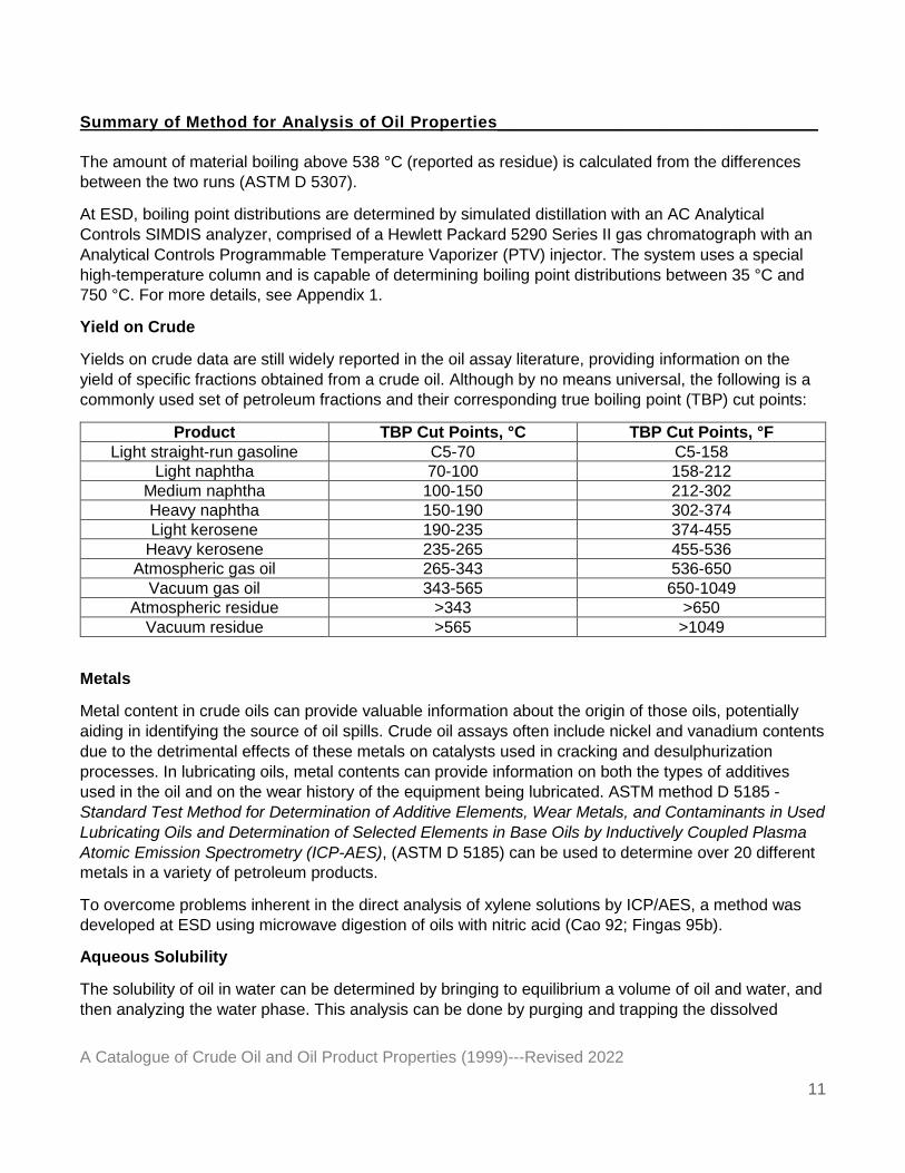
Yields on crude data are still widely reported in the oil assay literature, providing information on the yield of specific fractions obtained from a crude oil. Although by no means universal, the following is a commonly used set of petroleum fractions and their corresponding true boiling point (TBP) cut points:
Product TBP Cut Points, °C TBP Cut Points, °F Light straight-run gasoline C5-70 C5-158
Light naphtha 70-100 158-212 Medium naphtha 100-150 212-302 Heavy naphtha 150-190 302-374 Light kerosene 190-235 374-455
Heavy kerosene 235-265 455-536 Atmospheric gas oil 265-343 536-650
Vacuum gas oil 343-565 650-1049 Atmospheric residue >343 >650
Vacuum residue >565 >1049
Metals
Metal content in crude oils can provide valuable information about the origin of those oils, potentially aiding in identifying the source of oil spills. Crude oil assays often include nickel and vanadium contents due to the detrimental effects of these metals on catalysts used in cracking and desulphurization processes. In lubricating oils, metal contents can provide information on both the types of additives used in the oil and on the wear history of the equipment being lubricated. ASTM method D 5185 - Standard Test Method for Determination of Additive Elements, Wear Metals, and Contaminants in Used Lubricating Oils and Determination of Selected Elements in Base Oils by Inductively Coupled Plasma Atomic Emission Spectrometry (ICP-AES), (ASTM D 5185) can be used to determine over 20 different metals in a variety of petroleum products.
To overcome problems inherent in the direct analysis of xylene solutions by ICP/AES, a method was developed at ESD using microwave digestion of oils with nitric acid (Cao 92; Fingas 95b).
Aqueous Solubility
The solubility of oil in water can be determined by bringing to equilibrium a volume of oil and water, and then analyzing the water phase. This analysis can be done by purging and trapping the dissolved
Summary of Method for Analysis of Oil Properties_________________________________
A Catalogue of Crude Oil and Oil Product Properties (1999)---Revised 2022
12
hydrocarbons or, alternatively, directly analyzing the headspace above the water. Since oil is a complex mixture of components and each component has a different solubility in water, an oil's aqueous solubility is expressed as the cumulative concentration of the individually dissolved components. The composition and concentration of the solubilized mixture will depend upon conditions used during equilibration. The term 'solubility' as applied to oils is being replaced by the technically more precise term 'water-soluble fraction'. The values reported in this catalogue were taken from those studies where an excess of oil was used (oil-to-water volume ratios of at least 1:20) and where the processes of evaporation and oil-in-water emulsification were prevented. Results reported by ESD were obtained as described in Appendix 1.
Toxicity
Toxicity values in this catalogue may be reported as:
LC50: Median lethal concentration is the estimated concentration of a compound that will cause death to 50 percent of the test population in a specified time after exposure. In most instances, LC50 is statistically derived by analysis of mortalities in various test concentrations after a fixed period of exposure.
EC50: Median effective concentration is used when an effect other than death is the observed endpoint. EC50 is the estimated concentration of the compound in water that will have a specific effect on 50 percent of the test population in a specified time after exposure. As with LC50, the EC50 is generally derived statistically.
TLM: Median tolerance limit; a term sometimes used instead of EC50.
Biological Oxygen Demand (BOD)
Also called 'biochemical oxygen demand', this is the standard way of describing how much oxygen, dissolved in water, is consumed by biological oxidation of the chemical during the stated period of time. The unit lb/lb indicates the pounds of oxygen consumed by each pound of chemical during the time stated. When given in percent, the values indicate the pounds of oxygen consumed by each 100 pounds of chemical during the time stated (CHRIS 91).
Threshold Limit Values (TLV)
The following excerpts are taken from ACGIH 99:
Threshold Limit Values refer to airborne concentrations of substances and represent conditions under which it is believed that nearly all workers may be repeatedly exposed day after day without adverse health effects.
Threshold Limit Value – Time-Weighted Average (TLV-TWA)
the time-weighted average concentration for a conventional 8-hour workday and a 40-hour workweek, to which nearly all workers may be repeatedly exposed, day after day, without adverse effect
Summary of Method for Analysis of Oil Properties_________________________________
A Catalogue of Crude Oil and Oil Product Properties (1999)---Revised 2022
13
Threshold Limit Value – Short-Term Exposure Limit (TLV-STEL)
a 15-minute TWA exposure which should not be exceeded at any time during a workday even if the 8-hour TWA is within the TLV-TWA.
Appendix 1-Summary of ESD Analytical Methods__________________________________
A Catalogue of Crude Oil and Oil Product Properties (1999)---Revised 2022
Appendix 1: Summary of ESD methods for the analysis of physical properties, composition, and behavior of petroleum products
The methods listed here are those used by the Emergencies Science Division of Environment Canada (presently referred to as the Emergencies Science and Technology Section (ESTS) of Environment and Climate Change Canada (ECCC)). In some cases, both new and old methods are described, as data from both may be included in the catalogue.
Sample Collection and Storage
The bulk oil container is mechanically mixed prior to obtaining a working sample. Large drums (205-L) are mixed for 24 hours; 20-L cans are mixed for three hours. Working samples are stored in 2-L high-density polyethylene bottles with polypropylene screw closures (Nalgene, Rochester, NY). When not in use, all working samples are stored in a temperature-controlled room at 5 °C. The working sample is shaken for 30 minutes prior to removing an aliquot for testing.
Evaporation (Weathering) of Oils
Prior to 1993, evaporated oils were produced by bubbling air up through a 1-L graduated cylinder filled with oil as per the method developed by Stiver and Mackay (Stiver 83). For oils evaporated by this method, the evaporative loss is expressed as a volume percent. For most light to medium crude oils, this method was used to produce two evaporated oil samples representative of light and moderate degrees of evaporation, respectively.
In 1993, a new method for bulk evaporation was developed. Rotary evaporation of crude oils can produce a greater degree of evaporation in a shorter period of time, allowing the production, for most light to medium crude oils, of three evaporated oil samples representative of light, moderate, and heavy degrees of evaporation. The apparatus used is a Wheaton N10 rotary evaporator with a 10-L flask and an integral water bath. The bath temperature can be controlled to ±0.5 °C. The temperature control
range is 1 °C to 120 °C. The speed of rotation can be continuously varied from 10 to 135 rpm.
a) The water bath is filled with distilled water and brought to 80 °C. Higher temperatures are avoided to ensure that cracking of oil components does not take place. The temperature should remain constant throughout the evaporation process.
b) The oil is removed from storage and shaken for 30 minutes. Two litres of oil is placed into the tared 10-L flask.
c) The flask is placed on the evaporator and run at full speed (135 rpm). An air flow of approximately 13 L/min through the flask is maintained by leaving the vacuum release stopcock open to
atmospheric pressure while a small vacuum pump is running. d) The flask is reweighed every half hour for the first hour, every hour up to eight hours, every two
hours up to 16 hours, every four hours up to 32 hours, and finally at 48 hours. This produces a heavily evaporated oil. For light and medium oils, two more evaporated oils are produced having appropriate intermediate mass losses. For heavy oils, fewer intermediate samples can be produced. All intermediate evaporated oils are produced in the same way as the 48-hour sample, but over a shorter time period, and with only initial and final weight measurements.
Appendix 1-Summary of ESD Analytical Methods__________________________________
A Catalogue of Crude Oil and Oil Product Properties (1999)---Revised 2022
e) If evaporation must be stopped (e.g., scheduled power or water outage, overnight, weekends), the flask must be sealed tightly and refrigerated. When the run is restarted, the flask should be
removed from the cold and allowed to sit at room temperature while the water bath is returned to operating temperature.
Equation(s) for Predicting Evaporation
The evaporation rate of each oil is determined by measuring weight loss over time, using an electronic balance capable of weighing to 0.01 g. The weight is recorded using a system consisting of a computer, data acquisition software, and serial links to the balance. Data are recorded using a sequence with a time multiplier of 1.1 to ensure that approximately equal weight intervals are recorded. Measurements are conducted in the following fashion. A glass petri dish (139 mm i.d.) is tared, then loaded with approximately 20 g of oil. Data acquisition is started and continued until the desired time (varying from a few days for light oils to several days for heavy oils).
Vessels are cleaned with dichloromethane and dried before a new experiment is started. Measurements are conducted in a controlled-temperature chamber at 15 °C. Temperatures are verified with a digital thermometer.
Data are recorded and plotted so that a curve fit can be produced. The weight percent equations are determined without the use of a constant parameter.
Sulphur
Sulphur contents from EETD and ESD were determined using a Horiba MEA 200 sulphur and chlorine analyzer, in accordance with ASTM method D 4294-Standard Test Method for Sulfur in Petroleum Products by Energy-Dispersive X-Ray Fluorescence Spectoscopy (ASTM D 4294).
Water Content
Water contents are determined by Karl Fischer titration, as in ASTM method D 4377- Standard Test Method for Water in Crude Oils by Potentiometric Karl Fischer Titration (ASTM, D 4377) with the following modifications. A Metrohm 701 KF automatic titrator is used, and the sample is dissolved in a pre-titrated 1:1:2 volume mixture of methanol/chloroform/toluene. Samples are run in duplicate, and the mean water content is reported.
Flash Point
A SUR BERLIN TAG 2 automatic flash point tester, which has been modified by adding a stirring mechanism, is used to determine flash points. The mechanism operates in a similar fashion to a Pensky-Martens tester, but is of a more efficient design. The stirrer aids in producing more uniform heat transfer to oils that exceed the design viscosity, and in no way interferes with the test mechanism. The oil is shaken for 30 minutes and then ASTM method D 56 is followed. Samples are run in duplicate and the mean flash point is reported.
Appendix 1-Summary of ESD Analytical Methods__________________________________
A Catalogue of Crude Oil and Oil Product Properties (1999)---Revised 2022
Reid Vapour Pressure
Reid Vapour Pressure data from EETD and ESD are measured in accordance with ASTM method D 323-Standard Test Method for Vapor Pressure of Petroleum Products (Reid Method), (ASTM D 323).
Pour Point
a) If the oil is not fluid at the storage temperature, it is warmed until fluid and then shaken briefly by hand. Otherwise, the oil is removed from cold storage and shaken for 30 minutes.
b) The oil is poured into test jars meeting the specifications of ASTM method D 97.(ASTM D 97) Duplicate samples of each oil are tested.
c) The test jars are fitted with stoppers and ASTM designated thermometers, and warmed in a water bath to 50 °C.
d) The samples are removed from the bath and cooling takes place in the following manner:
i) The samples are allowed to cool to room temperature.
ii) If additional cooling is required, the samples are moved sequentially to a cold room maintained at 5 °C, a freezer at -25 °C, and finally to an acetone/dry ice bath at approximately -65 °C.
e) As the sample is cooling, it is checked periodically to see if the pour point has been reached. These checks are made as per ASTM method D 97, but not necessarily at intervals which are multiples of 3 °C.
f) When the pour point has been reached, 3 °C is added to the temperature recorded from the thermometer, as specified in the ASTM method. This value is reported as the pour point.
Density
Density is measured using an Anton Parr DMA 48 digital density meter, and following ASTM method D 5002 (ASTM D 5002). Samples are run in duplicate and the mean value is reported.
Viscosity
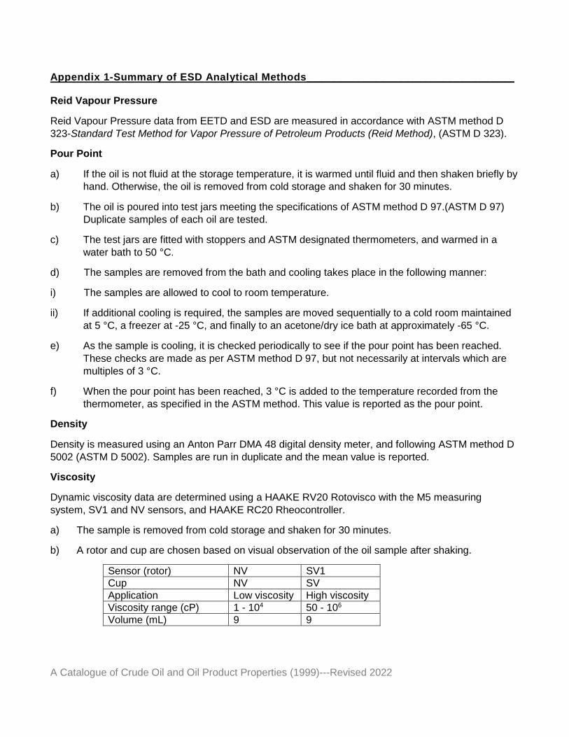
Dynamic viscosity data are determined using a HAAKE RV20 Rotovisco with the M5 measuring system, SV1 and NV sensors, and HAAKE RC20 Rheocontroller.
a) The sample is removed from cold storage and shaken for 30 minutes.
b) A rotor and cup are chosen based on visual observation of the oil sample after shaking.
Sensor (rotor) NV SV1 Cup NV SV Application Low viscosity High viscosity Viscosity range (cP) 1 - 104 50 - 106 Volume (mL) 9 9
Appendix 1-Summary of ESD Analytical Methods__________________________________
A Catalogue of Crude Oil and Oil Product Properties (1999)---Revised 2022
c) Using a 10-mL disposable syringe, an aliquot of oil is obtained. If the oil is too viscous to be pulled into the syringe, it may be sampled by removing the plunger, cutting off the end of the syringe, and plunging the syringe into the oil. The excess oil is wiped off from the outside of the syringe and the sample cup is carefully filled.
d) The sample cup is placed into the holding container. A visual check is made to determine if there is sufficient sample (up to the top of the rotor) or excess sample (over the top of the rotor). The amount of sample is adjusted as necessary.
e) The sample is allowed to equilibrate at the chosen temperature; 15 minutes at 15 °C and 25 °C, or 30 minutes at 0 °C.
f) The measurement parameters are set:
Shear rate: For Newtonian oils, a shear rate is chosen that will most accurately measure the viscosity. In most cases, this will be 100/s for the SV1 rotor and 1000/s for the NV rotor. Non-Newtonian oils are run at 1/s, 10/s, and 100/s whenever possible.
Ramp program: Ramp up, 5 minutes. Hold, 5 minutes. Ramp down, 5 minutes.
g) When the run is complete, the data are printed out along with a plot of viscosity versus shear rate.
h) The rotor and cup are removed and cleaned using sorbents and dichloromethane.
i) Two separate runs are performed for each viscosity measurement, and the mean is reported. For non-Newtonian oils, one measurement is made for each shear rate and the reported value is the viscosity measured at the start of the 5-minute hold during the ramp program.
Emulsion Formation
Water-in-oil emulsions are formed at 15 °C, in 2.2-L fluorinated vessels on an end-over-end rotary mixer at a nominal rotational speed of 50 rpm.
a) 600 mL of salt water (3.3% w/v NaCl) is placed in each mixing vessel.
b) 30 mL of oil is added to each vessel for a 1:20 oil:water ratio.
c) The vessels are sealed and placed in the rotary mixer such that the cap of each mixing vessel follows, rather than leads, the direction of rotation. The rotary mixer is kept in a temperature-controlled cold room at 15 ° C. The vessels and their contents are allowed to stand for approximately 4 hours before rotation begins, then mixed continuously for 12 hours.
d) At the conclusion of the mixing time, the emulsions are collected from the vessels for the measurement of water content, viscosity, and the complex modulus. The emulsions are stored in the cold room at 15° C for one week, then observed for changes in physical appearance. Stability type is assigned based on the observations and data.
Appendix 1-Summary of ESD Analytical Methods__________________________________
A Catalogue of Crude Oil and Oil Product Properties (1999)---Revised 2022
Measurements
Emulsion water content is performed as described previously, by volumetric titration using the Karl-Fischer reaction, with potentiometric end-point determination.
The viscosity at 15 °C is measured on a RV20 Rotovisco with M5 measuring head, RC20 rheocontroller and dedicated software package, using SV1 spindle and SV cup (cylindrical geometry). The shear rate is 1/s.
The complex modulus, also referred to as the 'stiffness' modulus, is a measure of the overall resistance of the material to flow under an applied stress, in units of force per unit area. It combines the viscosity and elasticity components of a visco-elastic material, such as a water-in-oil emulsion, into a single measure by vector addition. Since crude oils generally do not possess significant elasticity, it has been found that dividing the complex modulus of the emulsion by the viscosity of the fresh oil is a useful indicator of the stability of the emulsion, as a ratio greater than 200 generally indicates a stable emulsion. The complex modulus is measured on a RS100 RheoStress rheometer using a 35-mm plate-plate geometry. A stress sweep is performed in the range of 25 to 1,000,000 mPa in the oscillation mode at a frequency of 1 Hz. The resulting complex modulus in the linear portion of the range is reported.
Chemical Dispersibility
The working sample is shaken 30 minutes prior to removing an aliquot for testing. For dispersant testing, an aliquot is removed as needed from the working sample and stored in a 40-mL glass vial with a Teflon-lined cap.
a) Premix sample preparation
Weigh approximately 1.0 mL of oil into a 5-mL amber vial with Teflon-lined cap. Add approximately 100 mg of dispersant into the oil. Add oil until a 1:25.0 ratio of dispersant to oil is achieved (approximately 2.5 mL oil in total). Mix well by shaking manually.
b) Salt-water preparation
Weigh out salt and add lab water to obtain a 3.3% (w/v) solution.
c) Swirling flask preparation
Measure 120 mL of salt water into a 125-mL modified Erlenmeyer flask. Insert the flask into the flask holders on the oscillating table of the shaker. Using a positive displacement pipette, carefully apply 100 µL of pre-mix solution onto the surface of the water by touching the tip of the
pipette to the surface and gently expelling the oil/surfactant mixture.
d) Shaking of swirling flasks
The flask and contents are mechanically mixed on the shaker with the temperature-controlled-chamber at 20 °C. A rotation speed of 150 rpm and a mixing time of 20 minutes is used to agitate the samples followed by a 10-minute settling period.
References___________________________________________________________________
A Catalogue of Crude Oil and Oil Product Properties (1999)---Revised 2022
e) Sample collection
Drain 3 mL of the oil-in-water phase to waste, eliminating any oil from the spout of the flask. Collect a 30 mL aliquot in a graduated cylinder and transfer to a 125-mL separatory funnel. Extract with 3 x 5 mL of a 70:30 volume % dichloromethane: pentane solvent mixture, collected in a 25-mL graduated mixing cylinder and topped up to 15 mL.
f) Sample analysis
Prior to 1994, sample analysis was done using UV/VIS spectroscopy. A semi-micro, UV/VIS cell is filled with a portion of the extract and its absorbance measured at 340 nm, 370 nm, and 400 nm. The absorbance of the samples is compared to a calibration curve derived from the absorbance of a series of prepared oil-in-solvent standards (see below) to produce percent efficiency results.
Since 1994, sample analysis has consisted of gas chromatographic analysis of the resolved petroleum hydrocarbon (RPH) peak area using a flame ionization detector (GC/FID) to
determine the concentration of oil in solvent. A 900.0 µL portion of the 15 mL solvent extract
and a 100.0 µL volume of internal standard (200 ppm 5-ɑ-androstane in hexane) are combined
in a 12 mm x 32 mm crimp-style vial with aluminium/Teflon seals and shaken well. Petroleum hydrocarbon content is quantified by the internal standard method using the total resolved peak area of the chromatogram and the average hydrocarbon response factor determined over the entire analytical range:
RPH = Atotal /AIS x RRF-1 x 20 (mg) x 15 x 120/30/0.9 (1)
Where:
RPH is the resolved petroleum hydrocarbon
Atotal is the total area of the resolved peaks in counts
AIS is the area of the internal standard
RRF is the relative response factor for a series of alkane standards covering the analytical range
g) Calibration standards
A series of 6 oil-in-solvent standards are prepared for evaluating the efficiency of the dispersant for each dispersant/oil combination. The volume of premixed dispersant/oil solution for each standard is selected to represent a percentage efficiency of the dispersed oil, for example, 50 µL
= 50% efficiency (see Step (h) below for method of choosing calibration standard volumes). The dispersant/oil mixture is then accurately measured and applied to the water surface, and treated in the same manner as the samples (see Step (d) above). At this point, the entire volume of water is transferred to a 250-mL separatory funnel and extracted with 3 x 20 mL of a solvent mixture of 70:30 volume % dichloromethane: pentane. All oil is extracted, including the oil slick and oil on the walls of the swirling flask test vessel, using the volume of extraction solvent to rinse the flask of the remaining oil before adding to the separatory funnel. The extracts are combined in a
Summary of Method for Analysis of Oil Properties_________________________________
A Catalogue of Crude Oil and Oil Product Properties (1999)---Revised 2022
20
graduated cylinder and topped up to a total volume of 60 mL. Chromatographic analysis is then performed consistent with the sample analysis (see Step (f) above). A calibration curve of RPH versus % efficiency is produced using a graphics software package. From a comparison of the calibration curve to the RPH content of the samples, the % efficiency is calculated.
RPH = Atotal /AIS x RRF-1 x 20 (mg) x 60 x 120/120/0.9 (2)
Where:
RPH is the resolved petroleum hydrocarbon
Atotal is the total area of the resolved peaks in counts
AIS is the area of the internal standard
RRF is the relative response factor for a series of alkane standards covering the analytical range
h) Selecting the volume range of the calibration standards
The volumes of the six calibration standards are chosen such that the RPH determined for each of the six samples of each dispersant/oil combination falls within the RPH range of the standards. The following guide is used to determine the range of standards for each type of oil being dispersed:
Heavy oil - 10, 15, 20, 25, 30, 35%
Medium oil - 10, 20, 30, 40, 50, 60%
Light oil - 30, 40, 50, 60, 70, 80%
i) Gas chromatograph parameters and sequencing
Petroleum hydrocarbon analysis for C8 through C40 n-alkanes of the dispersed oil-in-water is carried out by high resolution capillary GC/FID under the following conditions:
Column 30 m x 0.25 mm ID HP-5 fused silica column (0.10 mm film thickness) Detector Flame ionization detector Autosampler Hewlett Packard 7673 Inlet Splitless Gases Carrier – helium 1.6 mL/min, nominal Make-up – helium 28.4 mL/min Detector air 400 mL/min Detector hydrogen 30 mL/min Injection volume 1 µL Injector temperature 290 °C Detector temperature 320 °C Temperature program 50 °C for 1 minute, 15 °C/min to 310 °C, hold 5 minutes
Summary of Method for Analysis of Oil Properties_________________________________
A Catalogue of Crude Oil and Oil Product Properties (1999)---Revised 2022
21
Daily calibration Alkane standard mixture of 20 ppm (5-ɑ-androstane, alkane mix, o- terphenyl in hexane) is measured before and after each sample set.
Hydrocarbon Groups
Saturates, Aromatics, Resins, and Asphaltenes
a) 25 mL of n-pentane is added to 2 g of oil, stirred, and allowed to stand for 30 minutes at room temperature. The asphaltenes are then removed by vacuum filtration through a 0.45 µm membrane, and the pentane is recovered by rotary evaporation at 30 °C, leaving the maltenes.
b) 0.4 g to 0.5 g of maltenes is placed on an open glass column (400 mm x 19 mm I.D. x 22 mm O.D., fritted, with stopcock) packed with 30 g silica, topped with 1.5 cm anhydrous sodium sulphate, and saturated with hexane.
c) The sample is eluted with 100 mL hexane and 100 mL of eluant is collected and labeled as 'saturates'.
d) The sample is eluted with 100 mL hexane/benzene (1:1) and 100 mL of eluant is collected and labeled as 'aromatics'.
e) The sample is eluted with 100 mL methanol and 100 mL of eluant is collected and labeled as 'resins'.
f) The sample is eluted with 100 mL dichloromethane and the eluant is collected and labeled as 'resins'.
g) Rotary evaporation is used to recover the bulk of the solvents, followed by nitrogen blow down.
h) Each hydrocarbon group is weighed after solvent recovery is complete. The weights of the two resin fractions are combined.
If the oil used has an initial boiling point (IBP) above 250 °C (determined by simulated distillation), a good mass balance can be obtained (>95%). However, most fresh crude oils will have an IBP well below 250 °C, and the loss of light ends during solvent recovery results in a poor mass balance. Fortunately, by making the reasonable assumptions that a) resin and asphaltene contents are not affected by evaporative losses, and b) the aromatic portion of the lost light ends can be equated to the BTEX plus C3-benzenes content, it is possible to calculate the correct distribution of hydrocarbon groups. Samples are run in duplicate and the mean is reported.
Waxes
Gas Chromatographic Method
The saturate fraction of an oil is obtained as described above and analyzed using the same instrument and operating conditions as described in Boiling Point Distribution below. The resulting chromatogram is integrated first to obtain the total area, and then a second time to obtain the resolved C18+ area. The
Summary of Method for Analysis of Oil Properties_________________________________
A Catalogue of Crude Oil and Oil Product Properties (1999)---Revised 2022
22
ratio of the resolved area to the total area is then used to calculate the wax content of the oil. Additional details of the method, including a sample calculation, can be found in Jokuty 97.
Gravimetric Method
a) Add 50 mL of n-pentane to a 5-mL sample of oil, let stand for 30 minutes, then remove the precipitated asphaltenes by vacuum filtration through a 0.45-µm membrane.
b) Remove the n-pentane by rotary evaporation at 30 °C.
c) Transfer the de-asphaltened oil into a 250-mL Teflon Erlenmeyer flask using 50 mL of a 1:1 volume mixture of dichloromethane (DCM) and methyl ethyl ketone (MEK). The flask is stoppered and swirled for 1/2 hour.
d) Weigh a Buchner funnel to 0.0001 g. Chill the funnel, the Teflon flask, the filtering flask, and a squeeze bottle of DCM/MEK at -30 °C.
e) Before filtering, weigh a Whatman GF/C 5.5-cm glass microfibre filter to 0.0001 g.
f) Working as quickly as possible, set up the chilled filtering apparatus. Turn the vacuum pump on at maximum, and wet the filter with the chilled DCM/MEK solution.
g) Taking extra care to pour the solution into the centre of the filter, filter the oil solution quickly to avoid warming and possible dissolution of the precipitated waxes.
h) Rinse the Teflon flask with chilled DCM/MEK which is then poured onto the filter.
i) Continue aspirating for five minutes, then obtain a final weight.
Samples are run in duplicate and the mean is reported.
Adhesion
This method requires the use of an analytical pan balance capable of weighing to 0.0001 g, and with provision for weighing from below the pan. Some type of draft shield will probably be required to obtain stable readings. Also required is a standard penetrometer needle as described in ASTM method D 5 - Standard Test Method for Penetration of Bituminous Materials (ASTM D 5), adapted for hanging below the balance.
a) The oil sample is allowed to stand at room temperature for 30 minutes.
b) The sample bottle is shaken for 30 minutes using the reciprocating shaker.
c) The balance is prepared for measurement by hanging a penetrometer needle, for which the surface area of the stainless steel section has been calculated, from the balance hook and allowing the weight to stabilize. The weight of the clean needle is recorded.
d) Approximately 80 mL of oil is poured into a 100-mL beaker. The beaker is elevated, using a lab jack, until the top of the stainless steel needle meets the top of the oil. Care must be taken to
Summary of Method for Analysis of Oil Properties_________________________________
A Catalogue of Crude Oil and Oil Product Properties (1999)---Revised 2022
23
avoid having the oil creep up onto the brass section of the needle, as the surface area calculation is based only on the stainless steel portion.
e) The needle is left in the oil for 30 seconds, and then the beaker is lowered, allowing the needle to hang undisturbed.
f) After 30 minutes, the weight of the needle plus oil is recorded.
g) The needle is cleaned with dichloromethane and allowed to dry before the measurement is repeated. A minimum of four measurements are made for each oil. The same beaker of oil can be used for all measurements.
h) The oil adhesion is calculated as the average weight of oil remaining on the needle divided by the needle's surface area.
Volatile Organic Compounds
BTEX plus C3-substituted benzenes are measured by ESD using gas chromatography with mass spectrometric detection (GC/MS). Details of the method are given in Wang 95.
Surface Tension and Interfacial Tension
Prior to 1994, surface and interfacial tensions were measured using a CSC manual DuNouy ring tensiometer in a temperature-controlled room. Since 1994, surface tension and interfacial tension are measured using a Kruss K10ST automatic DuNouy ring tensiometer with a cooling bath. The instrument is operated according to the manufacturer's instructions, with one modification. Ordinary 100-mL Pyrex beakers are used instead of the special sample containers supplied by Kruss. The beakers are prepared for use by rinsing with dichloromethane, followed by soaking and washing with a commercial cleaner (Decon 75), and thorough rinsing with water purified by reverse osmosis. The beakers are then oven-dried at 160 °C, cooled to room temperature, and stored at the desired measurement temperature.
The procedure for making a measurement is essentially that found in ASTM method D 971, but the raising of the platform is done automatically by the instrument, and sample temperature is also maintained automatically. Calculation of the interfacial tension is done as described in the ASTM method (ASTM D 971). Samples are run in duplicate and the mean is reported.
Boiling Point Distribution
This analysis is performed with an AC Analytical Controls SIMDIS analyzer, comprised of a Hewlett Packard 5290 Series II gas chromatograph with an Analytical Controls Programmable Temperature Vaporizer (PTV) injector. The system uses a special high-temperature column which is aluminum-clad, fused silica, 5 m x 0.53 mm diameter, and has 0.09 µm phase thickness. Sub-ambient cooling is provided by liquid nitrogen. Reference oil samples and calibration mixtures are run according to the AC 750 method provided by analytical controls.
Summary of Method for Analysis of Oil Properties_________________________________
A Catalogue of Crude Oil and Oil Product Properties (1999)---Revised 2022
24
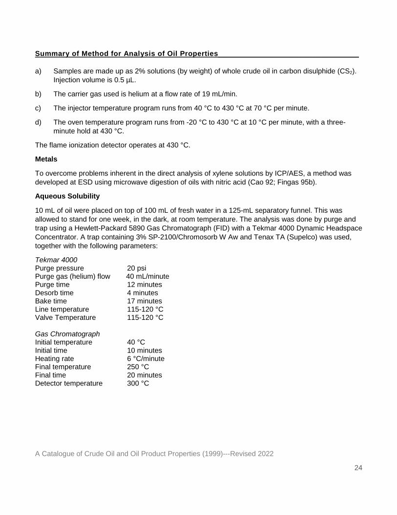
a) Samples are made up as 2% solutions (by weight) of whole crude oil in carbon disulphide (CS2). Injection volume is 0.5 µL.
b) The carrier gas used is helium at a flow rate of 19 mL/min.
c) The injector temperature program runs from 40 °C to 430 °C at 70 °C per minute.
d) The oven temperature program runs from -20 °C to 430 °C at 10 °C per minute, with a three-minute hold at 430 °C.
The flame ionization detector operates at 430 °C.
Metals
To overcome problems inherent in the direct analysis of xylene solutions by ICP/AES, a method was developed at ESD using microwave digestion of oils with nitric acid (Cao 92; Fingas 95b).
Aqueous Solubility
10 mL of oil were placed on top of 100 mL of fresh water in a 125-mL separatory funnel. This was allowed to stand for one week, in the dark, at room temperature. The analysis was done by purge and trap using a Hewlett-Packard 5890 Gas Chromatograph (FID) with a Tekmar 4000 Dynamic Headspace Concentrator. A trap containing 3% SP-2100/Chromosorb W Aw and Tenax TA (Supelco) was used, together with the following parameters:
Tekmar 4000 Purge pressure 20 psi Purge gas (helium) flow 40 mL/minute Purge time 12 minutes Desorb time 4 minutes Bake time 17 minutes Line temperature 115-120 °C Valve Temperature 115-120 °C Gas Chromatograph Initial temperature 40 °C Initial time 10 minutes Heating rate 6 °C/minute Final temperature 250 °C Final time 20 minutes Detector temperature 300 °C
Summary of Method for Analysis of Oil Properties_________________________________
A Catalogue of Crude Oil and Oil Product Properties (1999)---Revised 2022
25
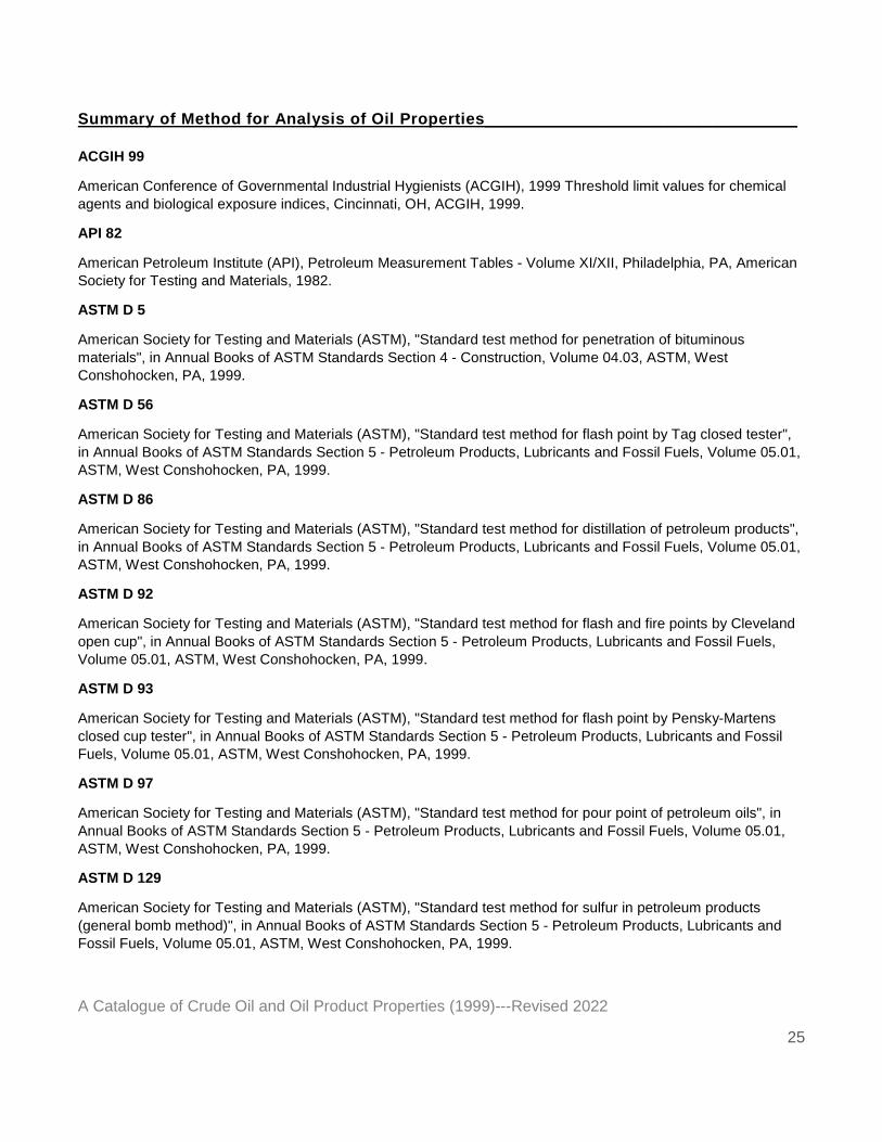
ACGIH 99
American Conference of Governmental Industrial Hygienists (ACGIH), 1999 Threshold limit values for chemical
agents and biological exposure indices, Cincinnati, OH, ACGIH, 1999.
API 82
American Petroleum Institute (API), Petroleum Measurement Tables - Volume XI/XII, Philadelphia, PA, American Society for Testing and Materials, 1982.
ASTM D 5
American Society for Testing and Materials (ASTM), "Standard test method for penetration of bituminous
materials", in Annual Books of ASTM Standards Section 4 - Construction, Volume 04.03, ASTM, West Conshohocken, PA, 1999.
ASTM D 56
American Society for Testing and Materials (ASTM), "Standard test method for flash point by Tag closed tester",
in Annual Books of ASTM Standards Section 5 - Petroleum Products, Lubricants and Fossil Fuels, Volume 05.01, ASTM, West Conshohocken, PA, 1999.
ASTM D 86
American Society for Testing and Materials (ASTM), "Standard test method for distillation of petroleum products",
in Annual Books of ASTM Standards Section 5 - Petroleum Products, Lubricants and Fossil Fuels, Volume 05.01, ASTM, West Conshohocken, PA, 1999.
ASTM D 92
American Society for Testing and Materials (ASTM), "Standard test method for flash and fire points by Cleveland
open cup", in Annual Books of ASTM Standards Section 5 - Petroleum Products, Lubricants and Fossil Fuels, Volume 05.01, ASTM, West Conshohocken, PA, 1999.
ASTM D 93
American Society for Testing and Materials (ASTM), "Standard test method for flash point by Pensky-Martens
closed cup tester", in Annual Books of ASTM Standards Section 5 - Petroleum Products, Lubricants and Fossil Fuels, Volume 05.01, ASTM, West Conshohocken, PA, 1999.
ASTM D 97
American Society for Testing and Materials (ASTM), "Standard test method for pour point of petroleum oils", in
Annual Books of ASTM Standards Section 5 - Petroleum Products, Lubricants and Fossil Fuels, Volume 05.01, ASTM, West Conshohocken, PA, 1999.
ASTM D 129
American Society for Testing and Materials (ASTM), "Standard test method for sulfur in petroleum products
(general bomb method)", in Annual Books of ASTM Standards Section 5 - Petroleum Products, Lubricants and Fossil Fuels, Volume 05.01, ASTM, West Conshohocken, PA, 1999.
References___________________________________________________________________
A Catalogue of Crude Oil and Oil Product Properties (1999)---Revised 2022
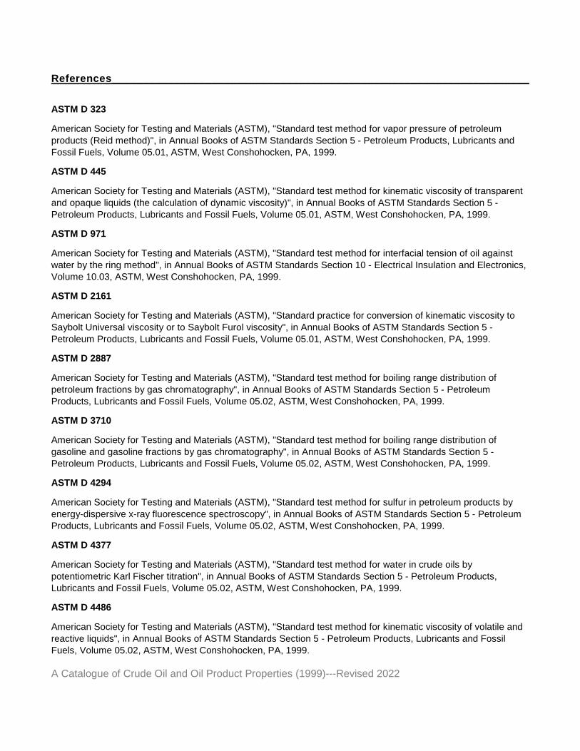
ASTM D 323
American Society for Testing and Materials (ASTM), "Standard test method for vapor pressure of petroleum
products (Reid method)", in Annual Books of ASTM Standards Section 5 - Petroleum Products, Lubricants and Fossil Fuels, Volume 05.01, ASTM, West Conshohocken, PA, 1999.
ASTM D 445
American Society for Testing and Materials (ASTM), "Standard test method for kinematic viscosity of transparent
and opaque liquids (the calculation of dynamic viscosity)", in Annual Books of ASTM Standards Section 5 - Petroleum Products, Lubricants and Fossil Fuels, Volume 05.01, ASTM, West Conshohocken, PA, 1999.
ASTM D 971
American Society for Testing and Materials (ASTM), "Standard test method for interfacial tension of oil against
water by the ring method", in Annual Books of ASTM Standards Section 10 - Electrical Insulation and Electronics, Volume 10.03, ASTM, West Conshohocken, PA, 1999.
ASTM D 2161
American Society for Testing and Materials (ASTM), "Standard practice for conversion of kinematic viscosity to
Saybolt Universal viscosity or to Saybolt Furol viscosity", in Annual Books of ASTM Standards Section 5 - Petroleum Products, Lubricants and Fossil Fuels, Volume 05.01, ASTM, West Conshohocken, PA, 1999.
ASTM D 2887
American Society for Testing and Materials (ASTM), "Standard test method for boiling range distribution of
petroleum fractions by gas chromatography", in Annual Books of ASTM Standards Section 5 - Petroleum Products, Lubricants and Fossil Fuels, Volume 05.02, ASTM, West Conshohocken, PA, 1999.
ASTM D 3710
American Society for Testing and Materials (ASTM), "Standard test method for boiling range distribution of
gasoline and gasoline fractions by gas chromatography", in Annual Books of ASTM Standards Section 5 - Petroleum Products, Lubricants and Fossil Fuels, Volume 05.02, ASTM, West Conshohocken, PA, 1999.
ASTM D 4294
American Society for Testing and Materials (ASTM), "Standard test method for sulfur in petroleum products by
energy-dispersive x-ray fluorescence spectroscopy", in Annual Books of ASTM Standards Section 5 - Petroleum Products, Lubricants and Fossil Fuels, Volume 05.02, ASTM, West Conshohocken, PA, 1999.
ASTM D 4377
American Society for Testing and Materials (ASTM), "Standard test method for water in crude oils by
potentiometric Karl Fischer titration", in Annual Books of ASTM Standards Section 5 - Petroleum Products, Lubricants and Fossil Fuels, Volume 05.02, ASTM, West Conshohocken, PA, 1999.
ASTM D 4486
American Society for Testing and Materials (ASTM), "Standard test method for kinematic viscosity of volatile and
reactive liquids", in Annual Books of ASTM Standards Section 5 - Petroleum Products, Lubricants and Fossil Fuels, Volume 05.02, ASTM, West Conshohocken, PA, 1999.
References___________________________________________________________________
A Catalogue of Crude Oil and Oil Product Properties (1999)---Revised 2022
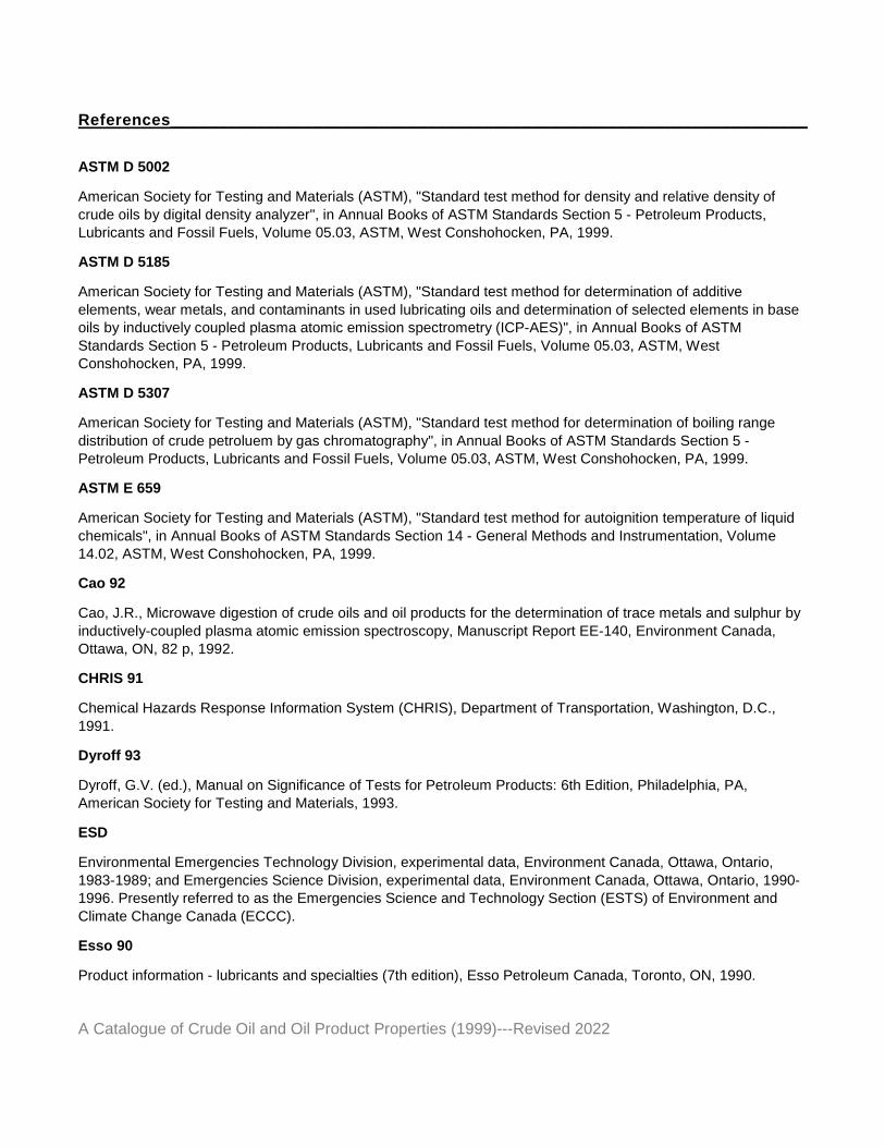
ASTM D 5002
American Society for Testing and Materials (ASTM), "Standard test method for density and relative density of
crude oils by digital density analyzer", in Annual Books of ASTM Standards Section 5 - Petroleum Products, Lubricants and Fossil Fuels, Volume 05.03, ASTM, West Conshohocken, PA, 1999.
ASTM D 5185
American Society for Testing and Materials (ASTM), "Standard test method for determination of additive
elements, wear metals, and contaminants in used lubricating oils and determination of selected elements in base oils by inductively coupled plasma atomic emission spectrometry (ICP-AES)", in Annual Books of ASTM
Standards Section 5 - Petroleum Products, Lubricants and Fossil Fuels, Volume 05.03, ASTM, West Conshohocken, PA, 1999.
ASTM D 5307
American Society for Testing and Materials (ASTM), "Standard test method for determination of boiling range
distribution of crude petroluem by gas chromatography", in Annual Books of ASTM Standards Section 5 - Petroleum Products, Lubricants and Fossil Fuels, Volume 05.03, ASTM, West Conshohocken, PA, 1999.
ASTM E 659
American Society for Testing and Materials (ASTM), "Standard test method for autoignition temperature of liquid
chemicals", in Annual Books of ASTM Standards Section 14 - General Methods and Instrumentation, Volume 14.02, ASTM, West Conshohocken, PA, 1999.
Cao 92
Cao, J.R., Microwave digestion of crude oils and oil products for the determination of trace metals and sulphur by
inductively-coupled plasma atomic emission spectroscopy, Manuscript Report EE-140, Environment Canada, Ottawa, ON, 82 p, 1992.
CHRIS 91
Chemical Hazards Response Information System (CHRIS), Department of Transportation, Washington, D.C.,
1991.
Dyroff 93
Dyroff, G.V. (ed.), Manual on Significance of Tests for Petroleum Products: 6th Edition, Philadelphia, PA, American Society for Testing and Materials, 1993.
ESD
Environmental Emergencies Technology Division, experimental data, Environment Canada, Ottawa, Ontario,
1983-1989; and Emergencies Science Division, experimental data, Environment Canada, Ottawa, Ontario, 1990-1996. Presently referred to as the Emergencies Science and Technology Section (ESTS) of Environment and
Climate Change Canada (ECCC).
Esso 90
Product information - lubricants and specialties (7th edition), Esso Petroleum Canada, Toronto, ON, 1990.
Summary of Method for Analysis of Oil Properties_________________________________
A Catalogue of Crude Oil and Oil Product Properties (1999)---Revised 2022
28
Fingas 79
Fingas, M.F., K.A. Duval, and G.B. Stevenson, The basics of oil spill cleanup, Ottawa, ON, Environment
Canada,1979.
Fingas 87
Fingas, M.F., K.A. Hughes, and M.A. Schweitzer, "Dispersant testing at the Environmental Emergencies Technology Division", in Proceedings of the 10th Arctic and Marine Oil Spill Program Technical Seminar,
Environment Canada, Ottawa, ON, 1987, pp. 343-356.
Fingas 94
Fingas, M., "Chemistry of oil and modelling of spills", Journal of Advances in Marine Technology Conference, 11,1994, pp. 41-63.
Fingas 95a
Fingas, M., "The evaporation of oil spills", in Proceedings of the 18th Arctic and Marine Oil Spill Program
Technical Seminar, Environment Canada, Ottawa, ON, 1995, pp. 43-60.
Fingas 95b
Fingas, M.F., F. Ackerman, P. Lambert, K. Li, Z. Wang, J. Mullin, L. Hannon, D. Wang, A. Steenkamer, R. Hiltabrand, R. Turpin, and P. Campagna, "The Newfoundland Offshore Burn Experiment: further results of
emissions measurement", in Proceedings of the 18th Arctic and Marine Oil Spill Program Technical Seminar, Environment Canada, Ottawa, ON, 1995, pp. 915-995.
Fingas 97
Fingas, M.F., E. Huang, B. Fieldhouse, L. Wang, and J.V. Mullin, "The effect of energy, settling time and shaking
time on the swirling flask dispersant apparatus", in Proceedings of the 20th Arctic and Marine Oil Spill Program Technical Seminar, Environment Canada, Ottawa, ON, 1997, pp. 541-550.
Fingas 98
Fingas, M., B. Fieldhouse, and J. Mullin, "Studies of water-in-oil emulsions: stability and oil properties", in
Proceedings of the 21st Arctic and Marine Oil Spill Program Technical Seminar, Environment Canada, Ottawa, On, 1998, pp. 1-25.
Jokuty 95
Jokuty, P., M. Fingas, S. Whiticar, and B. Fieldhouse, A study of viscosity and interfacial tension of oils and
emulsions, Manuscript Report EE-153, Environment Canada, Ottawa, ON, 50 p, 1995.
Jokuty 96
Jokuty, P., S. Whiticar, K. McRoberts, and J. Mullin, "Oil adhesion testing - recent results", in Proceedings of the 19th Arctic and Marine Oil Spill Program Technical Seminar, Environment Canada, Ottawa, ON, 1996, pp. 9-27.
References___________________________________________________________________
A Catalogue of Crude Oil and Oil Product Properties (1999)---Revised 2022
Jokuty 97
Jokuty, P., S. Whiticar, Z. Wang, M. Landriault, L. Sigouin, and J. Mullin, "A new method for the determination of
wax content of crude oils", in Proceedings of the 20th Arctic and Marine Oil Spill Program Technical Seminar, Environment Canada, Ottawa, ON, 1997, pp. 63-72.
Mackay 82a
Mackay, D. and W. Zagorski, Studies of water-in-oil emulsions, Manuscript Report EE-34, Environment Canada,
Ottawa, ON, 100 p, 1982.
Schramm 92
Schramm, L.L. (ed.), Emulsions. Fundamentals and Applications in the Petroleum Industry, Washington, D.C., American Chemical Society, 1992.
Speight 91
Speight, J.G., The Chemistry and Technology of Petroleum, New York, NY, Marcel Dekker, Inc., 1991.
Stiver 83
Stiver, W. and D. Mackay, Evaporation rate of spills of hydrocarbons and petroleum mixtures, Manuscript
Report EE-49, Environment Canada, Ottawa, ON, 35 p, 1983.
Twardus 80
Twardus, E.M., A study to evaluate the combustibility and other physical and chemical properties of aged oils and emulsions, Manuscript Report EE-5, Environment Canada, Ottawa, On, 1980.
Wang 95
Wang, Z., M. Fingas, M. Landriault, L. Sigouin, and N. Xu, "Identification of alkyl benzenes and direct determination of BTEX and (BTEX + C3-benzenes) in oils by GC/MS", in Proceedings of the 18th Arctic and Marine Oil Spill Program Technical Seminar, Ottawa, ON, Ottawa, ON, 1995, pp. 141-164.