Substitution of lead in free- cutting steels
198
THÈSE Pour obtenir le grade de DOCTEUR DE L’UNIVERSITÉ DE GRENOBLE Spécialité : Matériaux, Mécanique, Génie-civil, Electrochimie Arrêté ministériel : 7 août 2006 Présentée par Aurélien POLLET-VILLARD Thèse dirigée par Muriel VERON préparée au sein du Laboratoire SIMaP dans l'École Doctorale I-MEP2 Substitution of lead in free- cutting steels Thèse soutenue publiquement le 15 mars 2011, devant le jury composé de : Monsieur, Yves, BRECHET Professeur à Grenoble-INP, Président Monsieur, Pedro-José, ARRAZOLA Professeur à l’Université de Mondragon, Rapporteur Monsieur, Konrad, WEGENER Professeur à l’école polytechnique fédérale de Zurich, Rapporteur Madame, Muriel, VERON Professeur à Grenoble-INP, Membre Monsieur, Marc, MANTEL Directeur de la Recherche UGITECH, Membre Monsieur, Hans, ROELOFS Manager R&D SWISS STEEL, Membre Monsieur, Roger, BUSI Ingénieur au CTDEC, Membre
-
Upload
khangminh22 -
Category
Documents
-
view
4 -
download
0
Transcript of Substitution of lead in free- cutting steels

THÈSE
Pour obtenir le grade de
DOCTEUR DE L’UNIVERSITÉ DE GRENOBLE
Spécialité : Matériaux, Mécanique, Génie-civil, Electrochimie
Arrêté ministériel : 7 août 2006
Présentée par
Aurélien POLLET-VILLARD Thèse dirigée par Muriel VERON préparée au sein du Laboratoire SIMaP dans l'École Doctorale I-MEP2
Substitution of lead in free-cutting steels Thèse soutenue publiquement le 15 mars 2011, devant le jury composé de :
Monsieur, Yves, BRECHET Professeur à Grenoble-INP, Président
Monsieur, Pedro-José, ARRAZOLA Professeur à l’Université de Mondragon, Rapporteur
Monsieur, Konrad, WEGENER Professeur à l’école polytechnique fédérale de Zurich, Rapporteur
Madame, Muriel, VERON Professeur à Grenoble-INP, Membre
Monsieur, Marc, MANTEL Directeur de la Recherche UGITECH, Membre
Monsieur, Hans, ROELOFS Manager R&D SWISS STEEL, Membre
Monsieur, Roger, BUSI Ingénieur au CTDEC, Membre


Confidential report
3
Titre : Substitution du plomb dans les aciers de décolletage.
Résumé:
SWISS STEEL, filiale du groupe SCHMOLZ + BICKENBACH, finance des travaux de thèse
menés au Centre de Recherches d’UGITECH, en collaboration avec le laboratoire SIMaP de
Grenoble. Le but de ce programme est de trouver des alternatives au plomb (Pb) dans les aciers bas
carbone de décolletage. Les objectifs sont de conserver le niveau d’usinabilité des aciers de
décolletage au plomb, sans leurs défauts (toxicité, recyclage des aciers au plomb). La production
d’acier au plomb est stratégique pour SWISS STEEL, puisqu’elle représente environ 30% de son
activité. Parmi les différentes alternatives signalées dans la littérature, l’addition d’étain, et la
graphitisation des aciers, sont les concepts les plus intéressants. En effet, il est suggéré que l’étain
présente un comportement similaire à celui du plomb lors de l’usinage. Par ailleurs, Le graphite est
connu pour être un lubrifiant utilisé dans des applications industrielles, ce qui peut améliorer
l’usinabilité. Une caractérisation complète d’aciers industriels au plomb, et sans plomb, en provenance
de SWISS STEEL (11SMn30 et 11SMnPb30), a été menée : analyse chimique, observations
métallographiques et microscopiques (MEB), propriétés mécaniques, etc. Ensuite, nous avons essayé
de comprendre les mécanismes par lesquels le plomb améliore l’usinabilité des aciers de décolletage
aux basses vitesses de coupes (Vc < 100 m/min), grâce à des essais d’usinage spécifiques. Des calculs
thermodynamiques ont été menés sur le procédé de graphitisation, et des analyses d’aciers ont été
déterminées. Ce qui nous a conduits à élaborer des aciers à l’étain et des aciers graphitiques à l’échelle
du laboratoire. La caractérisation de ces coulées de laboratoire, avec la même procédure que celle
utilisée par les aciers industriels, a permis de vérifier la fiabilité de ces concepts, et leur bienfaits sur
l’usinabilité. Des résultats encourageants ont été enregistrés. Pour une étude plus approfondie, il a été
proposé de produire, à l’échelle industrielle, une analyse d’acier particulière, susceptible de remplacer
le plomb dans les aciers de décolletage au plomb.
Mots clefs : Aciers – Plomb – Usinabilité
Title: Substitution of lead in free-cutting steels.
Abstract:
SWISS STEEL, a steel company part of SCHMOLZ + BICKENBACH group, has supported a
PhD program, lead in UGITECH’s Research Center, in collaboration with the SIMaP laboratory of
Grenoble. The aim of this program is to find some alternatives to lead (Pb) in low carbon free-cutting
steels. The objectives are to keep the machinability level of leaded free-cutting grades without their
drawbacks (toxicity, recycling of Pb steels). The production of leaded free-cutting steels is strategic
for SWISS STEEL, since it represents about 30% of its activity. Among the different alternatives
pointed out by the bibliography, tin addition, and graphitisation of steels, were the most interesting
concepts. Indeed, it is suggested that tin presents a similar behaviour to that of lead during machining.
Moreover, graphite is a well known lubricant in industrial applications, which could improve
machinability. A complete characterisation on leaded, and non-leaded, grades form SWISS STEEL
has been carried out (11SMn30 and 11SMnPb30): chemical analysis, metallographic and SEM
observations, mechanical properties, etc. Then we tried to understand, thanks to specific machining
tests, the mechanisms by which lead improves the machinability of free-cutting steel, at low cutting
speed (Vc < 100 m/min). Thermodynamic calculations have been performed to study the graphitisation
process, and conducted to the determination of steels analyses. This lead us to develop tin-added-, and
graphitic steels at the laboratory scale. The characterisation of these laboratory grades, with the same
procedure, than that of industrial steels, allowed to check the reliability of these concepts, and their
benefits on machinability. Promising results have been recorded. For deeper exploration, it has been
proposed to produce, at the industrial scale, a particular steel analysis, which could replace leaded
free-cutting steels.
Key words: Steels – Lead – Machinability

Confidential report
4
Laboratoire universitaire de rattachement : SIMaP
Adresse : 1260, rue de la piscine BP75
38402 Saint Martin d’Hères
Laboratoire industriel d’accueil : Centre de Recherches UGITECH
Adresse : Avenue Paul Girod
73403 UGINE cedex
Partenaire industriel : SWISS STEEL AG
Adresse : Emmenweidstrasse 90
CH-6020 Emmenbrücke, SUISSE

Confidential report
5
Remerciements
Je remercie vivement messieurs, Pedro José ARRAZOLA, professeur à l’université de Mondragon, et
Konrad WEGENER, professeur à l’école polytechnique fédérale de Zurich, d’avoir accepté d’être les
rapporteurs de ce mémoire de thèse. J’adresse aussi mes remerciements à monsieur Yves BRECHET,
professeur à l’université Grenoble-INP, pour avoir présidé ce jury, ainsi qu’à monsieur Roger BUSI,
ingénieur au CTDEC à Cluses, pour avoir accepté de juger ce travail.
Je tiens à remercier tout particulièrement madame Muriel VERON, messieurs Ulrich URLAU et Marc
MANTEL, qui ont dirigé et encadré ce projet. Leurs qualités humaines et professionnelles m’ont permis
d’échanger librement avec eux lors de travaux très enrichissants.
Je souhaite remercier messieurs Hans ROELOFS, Nicolas RENAUDOT, Christian DEVILLE-CAVELLIN et
Nicolas MEYER qui m’ont apporté leur aide, leurs connaissances et leurs compétences, et sans qui, ce
travail ne serait pas ce qu’il est.
Je remercie chaleureusement l’ensemble du personnel du Centre de Recherches UGITECH. Chacun
m’a fait profiter de son expertise afin de mener à bien ce projet. La vision d’un acier oxydable n’a
jamais plombé leur gentillesse et leur bonne humeur. Un grand merci à l’équipe «USINABILITE » :
Philippe MINOLA, Frédéric BONIFASSI, Salvatore CARLINO, Bernadette LABROSSE et Christian
CHAMIOT-CLERC, de m’avoir accueilli pendant trois ans et formé à l’usinage. Je remercie également
toutes les personnes extérieures au CRU et à UGITECH qui ont contribué à la réussite de ce travail.
Je remercie également les membres du SIMaP pour leur accueil et leurs conseils.
Je terminerais en remerciant ma famille et mes amis pour leur soutien au cours de ces trois années.
Mes pensées vont vers mon regretté ami Thomas, qui du haut de sa montagne, est fier de moi.
Confidential report
6
CONTENTS
INTRODUCTION ................................................................................................................................. 9
I. FREE-CUTTING STEELS AND MACHINABILITY ENHANCEMENT ............................... 11
I.1. Brief definition of a steel .............................................................................................................. 11
I.2. Definition of free-cutting steels .................................................................................................... 11
I.3. Steel production at SWISS STEEL ............................................................................................. 15
I.4. Machining processes and machinability ..................................................................................... 16 I.4.1. Introduction to machining process ........................................................................................... 16
I.4.2. Cutting process ......................................................................................................................... 17
I.4.3. Machinability concept .............................................................................................................. 17
I.5. Machinability enhancement, bibliographic survey .................................................................... 19 I.5.1. Sulphide, oxide and lead, typical machinability enhancers ..................................................... 19
I.5.2. Lead substitution by another type of inclusions ....................................................................... 24
I.5.3. Lead suppression and enhancement of sulphides ..................................................................... 37
I.5.4. Conclusion of the bibliographic survey ................................................................................... 43
II. CHARACTERISATION OF INDUSTRIAL FREE-CUTTING STEELS FROM SWISS
STEEL .................................................................................................................................................. 45
II.1. Structural and mechanicals properties ..................................................................................... 45 II.1.1. Chemical analysis ................................................................................................................... 45
II.1.2. Microstructure......................................................................................................................... 45
II.1.3. Inclusions ................................................................................................................................ 45
II.1.4. Mechanicals properties ........................................................................................................... 48
II.2. Machinability of SWISS STEEL free-cutting steels ................................................................ 50 II.2.1. The machines and the processes used during our work .......................................................... 50
II.2.2. Turning operations, experimental procedure and results ........................................................ 54
II.2.3. Drilling operations, experimental procedure .......................................................................... 75
II.3. Conclusion .................................................................................................................................... 76
III. DEVELOPMENT OF ALTERNATIVES TO LEADED FREE-CUTTING STEELS .......... 79
III.1. Substitution of lead by graphite in free-cutting steels ............................................................ 79 III.1.1. Determination of steels composition by thermodynamic calculations .................................. 79
III.2. Substitution of lead by tin in free-cutting steels ...................................................................... 94 III.2.1. Determination of tin added steels compositions .................................................................... 94
III.3. Development of steels at the laboratory scale ......................................................................... 95 III.3.1. Description of the laboratory furnaces .................................................................................. 95
III.3.2. Forging procedure on laboratory steels ............................................................................... 100
III.4. Conclusion ................................................................................................................................ 100

Confidential report
7
IV. CHARACTERISATION OF ALTERNATIVES TO LEADED FREE-CUTTING STEELS
............................................................................................................................................................. 103
IV.1. Conventional free-cutting steels, laboratory casts ................................................................ 103 IV.1.1. Compositions....................................................................................................................... 103
IV.1.2. Microstructure ..................................................................................................................... 103
IV.1.3. Mechanical properties ......................................................................................................... 106
IV.1.4. Machinability ...................................................................................................................... 107
IV.1.5. Conclusion .......................................................................................................................... 108
IV.2. Tin added steels ........................................................................................................................ 111 IV.2.1. Microstructure ..................................................................................................................... 111
IV.2.2. Mechanical properties ......................................................................................................... 114
IV.2.3. Machinability ...................................................................................................................... 116
IV.2.4. Heat treatment for tin segregation ....................................................................................... 117
IV.2.5. Conclusion .......................................................................................................................... 118
IV.3. Graphitic steels ......................................................................................................................... 121 IV.3.1. Initial state ........................................................................................................................... 123
IV.3.2. Graphitic state ..................................................................................................................... 127
IV.3.3. Microstructure depending on graphitisation time ............................................................... 128
IV.3.4. Mechanical properties ......................................................................................................... 134
IV.3.5. Machinability ...................................................................................................................... 135
IV.3.6. Conclusion .......................................................................................................................... 138
V. GLOBAL CONCLUSION AND OUTLOOKS ......................................................................... 139
VI. REFERENCES ............................................................................................................................ 141
VI.1. Bibliographic survey ................................................................................................................ 141
VI.2. Patents research ....................................................................................................................... 145
VII. ANNEXES .................................................................................................................................. 147
VII.1. Annex A: quick-stop measurements, industrial 11SMn30 ................................................. 149
VII.2. Annex B: quick-stop measurements, industrial 11SMnPb30 ............................................. 157
VII.3. Annex C: development of a 11SMn30 grade with lower Mn/S ratio ................................. 165
VII.4. Annex D: CHARPY impact test .............................................................................................. 169
VII.5. Annex E: résumé des travaux de thèse ................................................................................. 171 VII.5.1. Usinage et usinabilité ......................................................................................................... 171
VII.5.2. Les voies d’amélioration de l’usinabilité ........................................................................... 174
VII.5.3. Etude expérimentale de l’effet du plomb sur l’usinabilité ................................................. 176
VII.5.4. Développement d’un acier graphitique .............................................................................. 180
VII.5.5. Développement d’un substitut aux aciers de décolletage au plomb .................................. 190
VII.5.6. Conclusion générale et perspectives .................................................................................. 195

Confidential report
8

Confidential report
9
Introduction
SWISS STEEL, a steel company part of SCHMOLZ + BICKENBACH group, produces leaded
free-cutting steels. It represents about 30% of its activity. Free-cutting steels are used in a broad
variety of applications, mainly in the car industry: axles, shafts, screws, bolts and fittings. This group
of steels results from the requirement to automated machining, i.e. they are easier to machine than
classical steels: higher cutting speed, lower tool wear, better surface finish, better chip breaking and
lower energy consumption of the machines. The economical importance of the machining operations
in the final cost of a steel part (50% of the value of a machined automotive part is due to machining
costs), has driven an important part of metallurgical research in order to improve the steel machining
performance, called machinability.
The most important achievements in the past decades have been obtained using the cheapest routes,
such as increasing the sulphur content and alloying with lead (Pb) the steel destined to be machined. It
is well known that sulphur reacts with manganese to form manganese sulphide inclusions (MnS); these
inclusions soften during the cutting process at medium cutting speed (Vc ≈ 150-300 m/min), where the
temperature is locally higher than 700°C. At these temperatures, MnS inclusions are more malleable
than the steel matrix, and help the chip breaking thanks to a shear localisation around these malleable
sulphides. It allows a better surface finish and avoid chip evacuation difficulties. Moreover, a thin MnS
layer forms at the tool-chip interface, acts as a lubricant and decreases the friction coefficient. It allows
to increase the cutting speed for a given tool life or to increase the tool life for a given cutting speed.
Thus the productivity is increased. Pb acts with equivalent mechanisms than those of MnS inclusions.
But the small nodules of lead (5 µm), dispersed in the matrix, or at the tips of MnS inclusions, present
a very low melting point: 327°C. Thus, their beneficial effect on machinability acts even at low cutting
speed (Vc < 100 m/min). Those two routes have been used for decades, and their cumulative effects
have been the heart of the low carbon free-cutting steels development.
The EU Directive on End of Life Vehicles prohibits the recycling of vehicle components containing
heavy metals, including Pb. There is currently an exemption from the requirements of this directive
for free-cutting steels containing up to 0.35 wt% Pb but it will not last indefinitely. Hence, there is a
considerable interest in the development of alternative machinability enhancers. In order to find some
alternatives to Pb in low carbon free-cutting steels, SWISS STEEL, has supported a PhD program,
lead in UGITECH’s Research Centre, in collaboration with the laboratory SIMaP of Grenoble (the
Materials and Processes Science and Engineering Laboratory). The objectives are to find new
machinability improvement solutions in order to keep the machinability level of leaded free-cutting
grades without Pb and its drawbacks (toxicity, recycling of Pb steels). UGITECH’s Research Centre
has many assets to complete such a project:
Adapted laboratory facilities (melting of laboratory casts, metallurgical characterisations as
varied as X-ray, SEM, TEM, EPMA, and machinability characterisation with three dedicated
machines).
Multiple skills in relevant areas (melting, hot and cold transformation, machining, etc.).
Close relations with SWISS STEEL Research team and academic specialists (Grenoble-INP,
SIMaP laboratory)
The first step of this PhD work will be to make a literature survey in order to identify the possible
machinability enhancers in steels, and to point out possible alternatives to Pb. These alternatives have
to ensure a significant machinability improvement even at low cutting speed (Vc < 100 m/min). In
parallel, the mechanisms by which Pb improves the machinability of free-cutting steels, at low cutting
speed, will be investigated. It is the reason why, a complete characterisation of industrial free-cutting
steels from SWISS STEEL, with and without Pb, will be done (11SMn30 and 11SMnPb30 steels). In
particular the machinability behaviour will be explored thanks to specifically developed procedures:
cutting forces will be recorded, during a turning operation at low cutting speed, and linked to the
influence of the cutting tool coating. Then, the determination of the friction coefficient at the tool-chip
interface, by a dedicated experiment called quick-stop, will be carried out to try to quantify the
lubricant effect of Pb. Finally, the effect of lead on tool wear will be measured by a drilling test with

Confidential report
10
HSS tool. All these results will be taken as references for the futures alternatives prepared first at the
laboratory scale.
Two of these alternatives are tested in the PhD work: tin added grades and graphitic steels. The
chemical compositions of these new grades will be determined in accordance with the bibliographic
survey and thermodynamic calculations made with Thermo-Calc®. In the case of graphitic steels, the
effects of alloying elements, such as Si, Al and Mn, on the graphitisation process should be taken into
account, and predicted. Subsequently, the development of steels at the laboratory scale (25 kg ingots),
and the thermo-mechanical transformation to get final products (hot forging of bars) will be explained
and tested. The characterisation of these laboratory grades, following the same procedure than that of
the references steels, will be carried out. The comparison of the results obtained with the developed
alternatives to those of the references steels, would allow to check their benefits on machinability,
mainly at low cutting speed. Thus, the reliability of these solutions, to replace lead in free-cutting
steels, will be determined.

Confidential report
11
I. Free-cutting steels and machinability enhancement
I.1. Brief definition of a steel
According to European EN 10020 standard, a steel is a material in which iron is the major element.
Its carbon content is generally under 2 wt% (weight percent) and it bears others elements. A few steels
with chromium could present more than 2 wt% of carbon, but this value is the usual limit that
separates steels from cast irons. It has been remarked in literature that this upper limit for carbon
content is delicate to precise. It might be better to consider a metallurgical point of view, during the
solidification of alloys:
The solidification of a cast iron ends by a eutectic reaction, where iron carbide and/or graphite
precipitation occurs.
The solidification of a steel ends by conserving entirely the carbon in solid solution within the
structure, which could be , +, (see figure I.1).
Consequently, a steel is an alloy based on iron, which contains a certain amount of carbon such as at
high temperature, this carbon would be dissolved (no carbide and/or graphite precipitation) during the
completion of solidification (at the solidus temperature). The carbon content limit corresponds to the
solubility limit of carbon in -iron (FCC) at the solidus temperature, and could vary with the alloying
element:
Fe-C — % Climit = 2.11%
Fe-C-Cr17% — % Climit = 0.7%
Fe-C-Si2.4% — % Climit = 1.4%
From the equilibrium states at 20°C, it is useful to distinguish steels that, beside eutectoid phase
(pearlite), contain:
Either proeutectoid ferrite, they are called hypoeutectoids (see figure I.2).
Either proeutectoid cementite, they are called hypereutectoids (see figure I.3).
I.2. Definition of free-cutting steels
Free-cutting steels are used in a broad variety of applications, mainly in the car industry:
crankshafts, connection rods, fitting turn-offs, high pressure fuel injector parts. This group of steels
results from the requirement to automated machining. The EN 10087 standard describes free-cutting
steels as grades that commonly have a minimal sulphur content at least equal to 0.1 wt%. Depending
on the material requirements, free-cutting steels are classified into:
Soft free-cutting steels.
Free-cutting hardening steels.
Free-cutting heat treatable steels.
Grades that answer to this definition are gathered in table I.1.

Confidential report
12
Temperature ( C)
C (weight%)
Cast ironsSteels
Figure I.1: Iron – carbon phases diagram
Reference: G. MURRY, Aciers. Généralités, Techniques de l’Ingénieur, M300, October 1993

Confidential report
13
Figure I.2: Micrographs of an hypoeutectoid steel
Reference: C. BRASSINE, From the course : Connaissance des Matériaux Métalliques, Liège University,
December 2006, page 42, PDF format available on :
http://www.metaux.ulg.ac.be/metaux/uploads/File/coheur/Labo_Phys%20Mat.pdf
x100
x1000
Proeutectoid ferrite
Pearlite
Lamellar aggregate of
ferrite and cementite
= Pearlite
Proeutectoid ferrite

Confidential report
14
x100
x500
Proeutectoid cementite
Pearlite
Pearlite
Figure I.3: Micrographs of an hypereutectoid steel
Reference: C. BRASSINE, From the course : Connaissance des Matériaux Métalliques, Liège University,
December 2006, page 45, PDF format available on :
http://www.metaux.ulg.ac.be/metaux/uploads/File/coheur/Labo_Phys%20Mat.pdf

Confidential report
15
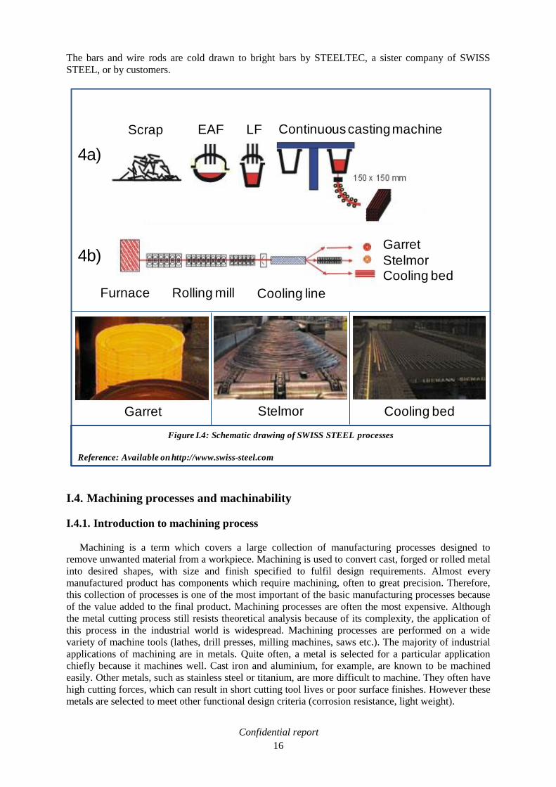
I.3. Steel production at SWISS STEEL
This work is dedicated to long products melted by SWISS STEEL (formerly VON MOOS
STAHL). The production line of the steel shop at SWISS STEEL is shown schematically in figure
I.4a. In the electric arc furnace (EAF), 80 tons of scraps are melted at 1650°C. The melt is
subsequently tapped into the ladle metal furnace (LF) where the secondary metallurgical processes
occur: alloy and micro-alloy of the cast, temperature adjustment. After this, a treatment in the vacuum
machine is carried out for particularly high-quality demanding steel goods. This treatment reduces the
oxygen and nitrogen contents of the steel through powerful rinsing in a vacuum. Finally, the 11 m
long, 150 mm square steel billets are produced by a continuous casting machine. Billets are sent to the
rolling mill facilities that are shown schematically in figure I.4b. They are heated between 1130 and
1230°C in the walking beam furnace and rolled into bars or wire rods (round or hexagonal) through
three product lines:
Stelmor: Ø 5.5 to 22 mm wire.
Garret: Ø 17.6 to 38 mm wire.
Cooling bed: Ø 15.7 to 64 mm bar.
Table I.1: Steel grades, chemical compositions
Reference: EN 10087 standard
The elements not mentioned in this table should not intentionally be added without the customer’s agreement,
except of those that are destined to the steel elaboration. Nevertheless, it is allowed for the producer to add
elements such as : Te, Bi, etc. in order to improve machinability, providing that it has been agreed upon
during tendering and ordering.
(1): If the metallurgical techniques used could guarantee specific oxides formation, it is possible to accept a
Si content between 0.10% and 0.40%.
Confidential report
16
The bars and wire rods are cold drawn to bright bars by STEELTEC, a sister company of SWISS
STEEL, or by customers.
I.4. Machining processes and machinability
I.4.1. Introduction to machining process
Machining is a term which covers a large collection of manufacturing processes designed to
remove unwanted material from a workpiece. Machining is used to convert cast, forged or rolled metal
into desired shapes, with size and finish specified to fulfil design requirements. Almost every
manufactured product has components which require machining, often to great precision. Therefore,
this collection of processes is one of the most important of the basic manufacturing processes because
of the value added to the final product. Machining processes are often the most expensive. Although
the metal cutting process still resists theoretical analysis because of its complexity, the application of
this process in the industrial world is widespread. Machining processes are performed on a wide
variety of machine tools (lathes, drill presses, milling machines, saws etc.). The majority of industrial
applications of machining are in metals. Quite often, a metal is selected for a particular application
chiefly because it machines well. Cast iron and aluminium, for example, are known to be machined
easily. Other metals, such as stainless steel or titanium, are more difficult to machine. They often have
high cutting forces, which can result in short cutting tool lives or poor surface finishes. However these
metals are selected to meet other functional design criteria (corrosion resistance, light weight).
Figure I.4: Schematic drawing of SWISS STEEL processes
Reference: Available on http://www.swiss-steel.com
Continuous casting machine
Garret
StelmorCooling bed
4a)
4b)
Cooling bedStelmorGarret
Cooling lineRolling millFurnace
Scrap EAF LF

Confidential report
17
I.4.2. Cutting process
The machining processes are extremely varied. The present work is focused on cutting processes.
The removal of material is achieved by the mechanical action of a cutting tool. The applied force
induces, at the macroscopic scale, the formation of one, or several, chips.
I.4.2.1. Mechanisms of chip formation
The basic mechanism involved in metal cutting is a localised shear strain on the metal immediately
ahead of the cutting edge of the tool (see figure I.5). The relative motion between the tool and the
workpiece during cutting, compresses the metal near the tool and induces a shear deformation (called
the primary shearing band), which forms the chip. The chip slides (more or less) along the rake face of
the cutting tool, and undergoes an additional deformation (called the secondary shearing band). These
two plastic deformation processes have a mutual dependence:
Prior to its slide on the rake face, the metal is heated and plastically deformed in the primary
shear zone. Therefore, the secondary shear zone is influenced by the preceding phenomena on
the shear plan.
The shear direction modifies the heating, and straining of the chip in the primary shear zone.
However, the deformation and friction processes, which occur in the secondary shear zone,
directly influence the shear direction.
In terms of the metal cutting theory, it means that shear stress and shear direction must be determined
simultaneously.
I.4.3. Machinability concept
Machinability, in the field of this study, is the ability of a material to be shaped by removing chips
thanks to a cutting tool. The economical importance of the machining operations, within the total cost
breakdown of the forming process for steel components, has driven an important part of metallurgical
research in order to improve the steel machining performance. In the automotive industry, the
machinability is an important parameter because more than 50% of the value of a machined
automotive component is due to machining costs [SAN00]. Nevertheless it is important to point out
that it is very difficult to clearly define a concept of machinability in a way that suits everyone. Hence,
in some cases, it is important to improve machinability within the following lines:
General improvement of machining conditions. In order to increase the cutting parameters
(speed, feed rate, depth of cut), it would be necessary to develop steel grades with lower
hardness to reduce cutting forces, and with higher content in low melting point particles, to
improve the lubrication effect at the tool/chip interface.
Reduction of tool costs, not only by the work performed in the tool itself (composition and
geometry), but also reducing the abrasive effect of the metal.
Automation of production processes, and a reduction of manpower effort by a good
reproductivity of results among different heats of same material.
At the UGITECH Research Center, the vision of the machinability is the capacity of a metal to be
machined rapidly (in terms of productivity) by keeping satisfactory tool life, and by avoiding any
machining interruption for chips evacuation. To reach that goal, comparative machinability
measurements are carried out on several grades (tool wear, chip breaking). In any case, this part of the
metallurgical research has been clearly driven by the economical interest, which is why the most
important achievements have been obtained using the cheapest routes, such as increasing the sulphur
content and alloying with lead. Those two routes have been used for decades, and their cumulative

Confidential report
18
effects have been the heart of the low carbon free-cutting steels development. The mechanisms, by
which sulphur and lead act as machinability enhancers, have to be explored, and the other known ways
tested, described thanks to a bibliographic survey.
Figure I.5: Schematic drawing of Chip, workpiece and tool relationship during a cutting process
Workpiece
a
Cutting edge
φ
1
h: feed a : Clearance angle 1: Primary shear zone
Vc: Cutting speed : Rake angle 2: Secondary shear zone
f: Shear angle
h
Tool
Shear planVc
Chip
2

Confidential report
19
I.5. Machinability enhancement, bibliographic survey
I.5.1. Sulphide, oxide and lead, typical machinability enhancers
I.5.1.1. Manganese Sulphide (MnS)
In free-cutting steels, sulphur is added up to 0.30 - 0.35 wt%. During the cutting process, MnS
inclusions are usually more plastic than the steel matrix, deforming preferentially and thus reducing
the total stress involved in chip formation [LER84], [WIS88]. This manifests in reduced chip
thicknesses and cutting temperatures [WIS88], [AKA03], [JIA96]. The presence of this easily sheared
phase also promotes short chipping behaviour [LER84], [WIS88], [TRO98]. The interaction of the
free cutting additive with the tool material is also an important factor. It is claimed that with carbide
tools, a layer of manganese sulphide forms on the rake face: it acts as a lubricant, and as a diffusion
barrier [JIA96], [TRO98]. This reduces the tool-chip contact area, and causes a reduction in chip
thickness, tool forces, and tool temperature. An increase of the chip flow rate for a given tool life is
observed [WIS88], [AKA03], [JIA96], [TRO98]. It is well established that MnS improves
machinability even at low cutting speed (Vc < 100 m/min) [AKA03], [JIA96]. But the optimal
enhancement is reached for medium cutting speed (Vc between 150 and 200 m/min). As the interfacial
temperature approaches 700°C [REY05], ferrite tends to become less plastic than manganese sulphide
and this can be accentuated, if the manganese sulphide inclusion has a high aspect ratio. With an
austenitic stainless steel, if the cutting speed is increased still further, and interfacial temperatures
begin to exceed 850°C, austenite tends to become more plastic than manganese sulphide, any
advantages will be lost. Under these circumstances manganese sulphide becomes ineffective and may
even increase flow strength [WIS88]. At higher cutting speeds (Vc > 200 m/min) using cemented
carbide tools, the seizing phenomenon sets in at the tool-chip interface, resulting in dissolution crater
wear by diffusion mechanism. Sulphide inclusions are not effective in suppressing the dissolution
wear by diffusion mechanism [RAM96]. MnS have also marked adverse effect on other properties of
steels, especially the transverse impact toughness and fracture toughness [JIA96]. The MnS
precipitation could leads to steel decohesion during cold forging. Sulphur also decreases the hot
ductility, the forgeability and the hot rolling behaviour of steels [MAN06]. The manganese sulphides
plasticity allows them to deform along the rolling direction. Thus, the mechanical behaviour in a
perpendicular direction, is altered [MUR93]. Weldability and corrosion resistance are also decreased
[TRO98], [MUR93], [CUN00].
I.5.1.2. Oxides
Generally, free-cutting steel grades process present a deoxidation by aluminium in order to meet
the requirement of the customers in terms of grain size and fatigue resistance. This process leads to the
formation of hard alumina oxide inclusions detrimental to machinability, especially regarding the tool
life of tungsten carbide at high cutting speed [LER84], [MUR93], [CUN00]. One way to improve
machinability is to decrease the abrasive nature of oxides by optimizing the steel refining process to
get oxides with low melting points. For this purpose, a calcium treatment is usually carried out in the
ladle and CaO-Al2O3-SiO2 inclusions are designed [TRO98], [RAM96], [KIR07], [SUB04]. For
example, the glassy anorthite phase on the CaO-Al2O3-SiO2 phase stability diagram is deformable
because of its low viscosity, lower than that of steel [RAM96]. Glassy inclusions are designed to
soften at the tool-chip interface temperature and form a viscous layer, so that the shear is
accommodated within the viscous layer [TRO98], [CUN00], [KIR07], [SUB04]. Therefore, the
viscous layer of glass lubricates the tool-chip interface, thereby preventing the occurrence of
tribological phenomenon of seizing [KIR07]. It also acts as a diffusion barrier [RAM96], [KIR07].
Moreover, the soft inclusions deform preferentially in the shear band, thus reducing the total strain
involved in chip formation. The distance between shear bands is more regular. The presence of this
easily sheared phase also promotes short chipping behaviour (see figure 6) [TRO98], [CUN00].
Deformable glassy oxide inclusions such as CaO-Al2O3-SiO2 engineered in the workpiece, are found to
be an effective means of suppressing dissolution crater wear of carbide tools at high cutting speed
(Vc = 200 m/min) [TRO98], [RAM96]. The wear rates of coated carbide tools are diminished to 20-

Confidential report
20
30% with engineered inclusions compared to standard steels [TRO98], [KIR07]. The cutting speed
could be increased in the same rate without increasing tool wear. The mechanism of machinability of
the oxides is similar to that of sulphides. But these inclusions present a higher softening temperature,
and are really plastic in the 800-1200°C temperature range, or at high strain rate [KIR07]. This
temperature could only be reached at high cutting speed (Vc > 200 m/min); thus machining with
carbide tools is more indicated to obtain the improvement by engineered oxides. If high speed steel
tool are used, the oxides improvement effects will be visible only in particularly hard machining
conditions: drilling with high feed rate for example [TRO98].This explains the major drawback of
engineered oxides: this type of inclusion does not improve machinability at low cutting speed
(Vc < 100 m/min) [ROE08], the temperature reached at the tool-chip interface is not high enough to
soften the inclusions: they are not malleable enough. Finally, it could be noticed that calcium
treatment is favourable to prevent clogging in the submerged entry nozzle, as the liquid calcium
aluminates are non-sticking, unlike solid aluminates [KIR07].
I.5.1.3. Oxide-Sulphide synergy
After a calcium treatment on high sulphur content steels, an interaction involving (Ca,Mn)S
inclusions and CaO-Al2O3-SiO2 inclusions is observed. Oxide inclusions are enveloped by a sulphide
shell. The abrasive behaviour decreases considerably [LER84], [MUR93], [KIR07], [YAS05],
[DAV90]. The synergy of the sulphides and malleable oxides effects leads to an increase of the
productivity of 45% [CUN00].
I.5.1.4. Lead (Pb)
In low carbon free-cutting steels, lead additions, about 0.3 wt%, enhance machinability thanks to:
Better chip breaking [WIS88], [RAM96], [YAG89]
Longer tool life [WIS88], [YAS05], [YAG89]
Better surface finish and dimensional tolerances [WIS88], [REY07], [YAG88]
Figure I.6: Metallographic observation of standard stainless steel chip (a) and inclusion engineered
stainless steel chip (b)
Reference: M. MANTEL, C. VACHEY, Formage à Grande Vitesse, Détermination d’une Loi de
Comportement, Techniques de l’Ingénieur, M3025, March 2006.
6a: 1.4301 standard stainless steel
chip
6b: 1.4301 inclusion engineered stainless
steel chip
Globular oxides Elongated oxides Shear zone

Confidential report
21
Lead is not soluble in solid steel [KUB82], where it is therefore found in the form of small spherical
particles. Good leaded steel should show an ―emulsion‖ of small Pb particles of an average size of 6-7
µm either free or attached to MnS inclusions (at the tip of sulphides, see figure I.7) [YAG89],
[SIM03].
The following mechanisms have been reported to explain how lead improves machinability:
Lubrication is the most widely accepted effect of lead on machinability, since lead reduces the
friction at the tool/chip interface. Here, temperatures are above the melting point of lead and
lead films are formed on the underside of the chip and on the tool surface, being an effective
lubricant [RAM96], [YAG89], [SIM03], [GAR03].
During the cutting process, Pb inclusions (similarly to MnS) are usually more malleable than the
steel matrix, deforming preferentially and thus reducing the total stress involved in chip
formation [WIS88], [YAG89]. This is reflected in the increase of the shear angle, in reduced
chip thicknesses and cutting temperatures [WIS88].
It is suggested that different mechanical properties between the soft additive Pb particles and
the matrix would enhance stress concentration by gap formation and microcracking at the
interface [YAG89], [GAR03]. The improved machinability is suggested to occur by the
reduction in the effective area available to resist to shear stresses in the deformation zone, hence
lowering the cutting forces and power consumption [WIS88], [RAM96], [GAR03].
During hot-ductility tests, some studies discovered that an embrittlement trough in the
temperature range from about 200°C to about 600°C occurs, in which the fracture mode
changes from a relatively ductile mode, to a brittle intergranular mode (see figure I.8) [GAR03],
[BHA84]. The fracture analysis of unleaded 1215 steel indicated that this steel only exhibited
ductile fracture over the entire range of test temperatures. Lead causes this embrittlement by
being present at, and weakening, the ferrite grain boundaries. More precisely, lead lowers the
grain boundary cohesive strength. The energy necessary during cutting decreases, the
machinability is improved.
Figure I.7: SEM observation of Swiss-Steel leaded steel (Hot rolled and drawn bar, diameter: 25mm)
Lead
Manganese sulphide

Confidential report
22
The presence of an easily sheared phase also promotes short chipping behaviour, which is
probably the major advantage as far the machinist is concerned [LER84], [WIS88], [TRO98]. In
the shear band, MnS and MnS-Pb inclusions behave differently (see figure I.9). In the case of
the lead free MnS inclusions, the gaps reweld due to the high compressive stress and the high
temperature. Therefore, the gaps will not remain in the chip. In the case of MnS-Pb inclusions,
the lead prevents the voids from rewelding, thus forming the desired small chips. Thus, Pb
enhances the effectiveness of MnS inclusions by either restricting deformation of MnS or
weakening the inclusion-matrix interface, and stabilises the chip fracture process [WIS88],
[YAG89], [GAR03].
Liquid metal embrittlement (LME) is the loss of ductility due to the presence of low melting
point phases. If a crack is induced in the primary shear zone, the liquid lead flows to the crack
tip reducing the binding energy of the atomic bond. This results in nucleation and propagation
of the crack at a lower stress level. Since for normal cutting speed, the temperature in the
secondary shear zone exceeds the melting point of Pb, it is assumed that LME plays a
significant role in reducing the force in the secondary shear zone, thus enhancing machinability
and chip fracturing in particular [ROE08], [YAG89], [GAR03].
An unstable built-up edge (BUE) may form on the rake face near the tool tip, when machining
under unfavorable cutting conditions (very low cutting speed <50m/min), with high speed tools
in particular [LER84], [ROE08], [YAG88], [YAG89]. This leads to rough machined surfaces
[WIS88], [ROE08], [YAG88]. Lead additions prevent the formation of these unstable BUE
[ROE08]. A least, lead stabilises the BUE height by giving to it a stratified structure that
provides small quantity of steel to be ejected during machining [LER84], [YAG89].BUE are
usually not a problem when machining with carbide tools [BER01], or coated carbide tools
[ROE08].
Figure I.8: Hot ductility behaviour of free-machining 1215 (11SMn30, unleaded) and 12L14
(11SMnPb30, leaded) steels
Reference: C. I. GARCIA, M. J. HUA, M. K. MILLER, A. J. DEARDO, Application of Grain Boundary
Engineering in Lead-Free “Green Steel”, ISIJ International, Vol. 43, 2003, pages 2023-2027.

Confidential report
23
Some authors claimed that lead decreases the tool-chip interface temperature compared to
standard unleaded steels. Thermal finite elements [RAM96] and metallographic observations
method [WIS88], [WRI73], gave similar results: from -70 to -80°C.
Lead is not effective in suppressing the tool dissolution wear at high cutting speed [WIS88],
[RAM96]. Therefore, lead improves the machinability mostly at low cutting speed (Vc < 100m/min).
Some studies showed that tool wear is even higher with leaded steel at high cutting speed
(Vc > 200m/min) [REY05], [REY07]. Moreover, lead is toxic [CAI93], [PIC03] and conducts to
recycling and environmental problems [REY05], [SAN01]:
Special fume cleaning installations should be used in the steel plants together with a restriction
in the manpower exposure to Pb fumes.
The EU Council directive on end-of life vehicles (2000/53/EC) forbids the recycling of vehicle
components containing heavy metals including lead. For the time being, free-cutting steels with
up to 0.35wt% of lead are exempted from this ban but the use of lead will be periodically
reviewed taking account of the scientific and technological progress.
Finally, lead strongly affects hot forgeability, and makes more difficult hot rolling and forging. As
manganese sulphide, the lead inclusion deforms along the rolling direction, the mechanical behaviour
in a perpendicular direction is altered [MUR93].
Within this framework some research results on machinability can be examined to evaluate their
abilities to substitute lead as alloying element to improve machining behaviour.
Figure I.9: Schematic drawing of the behaviour of various types of inclusions during machining
Reference: G. BERNSMANN, M. BLEYMEHL, P. EHL, A. HASSLER, The Making of Free-Cutting Steels with
Additions of Lead, Bismuth, Tellurium, Selenium and Tin, Stahl und Eisen, 121, N°2, 2001, pages 87-91.

Confidential report
24
I.5.2. Lead substitution by another type of inclusions
I.5.2.1. Bismuth (Bi)
Bismuth is close to lead in the periodic table of the chemical elements (ZBi=83). However, its
crystallographic structure is different: rhomboedric (lead: CCF) [NOV04], and its melting temperature
is even lower than lead (271°C). Various studies showed that bismuth is a valid alternative to lead on
technical aspects. Indeed, it provides the same effects on machinability by the same mechanisms
[YAG89], [SIM03], [ROE08], [CHO00], [BER01]. Regarding the machinability enhancement,
authors’ opinions are relatively homogenous. Bismuth improves the machinability as well as lead does
in most cases (see figure I.10) [YAG89], [SIM03], [ROE08], [CHO00], [REY07]. Bismuth at levels
around 0.10-0.15 wt% is an additive that can substitute lead [BER01], [REY07].
However, lead substitution by bismuth has drawbacks:
Ingestion of a big amount of bismuth is really dangerous for health. In the industry field,
bismuth is considered as a toxic heavy metal [HEN03], [LEN08].
Availability of bismuth is too low to substitute lead in free-cutting steels. Worldwide refined
production is about 5200 tons [NRC08] in 2005
(compared to 7 Mtons of lead [MIC07]). Thus,
bismuth is more expensive than lead (8000 USD/ton in 2001 compared to 500 USD/ton)
[SAN01]. And steels producers fear that the replacement of large tonnages of leaded steel by
steel treated with bismuth would lead to an increase in the market price of bismuth [ROE08],
[REY07], [SAN00]. Overall costs (material and production) for those lead-free parts may rise
by an estimated 10 to 20% [SAN00].
The hot workability of bismuth steels is reduced by the occurrence of surface cracks [SIM03],
[ROE08], [BER01], [REY07]. It is claimed that the castability is also deteriorated, but no
arguments are developed in literature [BER01].
Finally, bismuth is not a reliable candidate to substitute lead at an industrial scale.
I.5.2.2. Tin (Sn)
It has been explained in the previous section that lead weakens the ferrite grain boundaries. As tin
is known to segregate at grain boundaries [DEA99], [MAT97], [NAG97], it has been suggested that
tin could replace lead in free-cutting steel. A lead free steel has been developed at the university of
Figure I.10: Production rate and rough form finish of leaded steel alternatives
Reference: P. REYNOLDS, V. BLOCK, I. ESSEL, F. KLOCKE, Alternatives to Lead as a Machinability
Enhancer in Free-Cutting Steels, Steel Research Int.78, N°12, 2007, pages 908-914.

Confidential report
25
Pittsburgh, which essentially is an SAE1215 (11SMn30) containing 0.04-0.08 wt% tin (12T14)
[GAR03], [DEA99]. An appropriate thermal treatment (500°C during 0,4hours x bar diameter in cm)
allows to concentrate tin at the grain boundaries (ten times the bulk tin content). The aim was to
produce a steel grade which would use tin to enhance the machinability, without any adverse
environmental effects attributed to lead. During hot ductility tests, tin added steels exhibit the same
behaviour as leaded steel. An embrittlement trough in the temperature range of about 200°C to about
600°C occurs in which the fracture mode changes from a relatively ductile mode to a brittle
intergranular mode [DEA99] (see figure I.11). The trough is bigger if the heat treatment time is longer.
Some others works presents the same kind of curve in a shifted temperature window: between 700 and
1000°C [NAC88], [SON03]. An embrittlement effect is also suggested to occur.
The machinability should be improved because the specific cutting force decreases. After machining
the steel, it is possible to homogenise the tin in the steel and thus avoid the ductility trough by another
thermal treatment. The machinability results of this new steel are contradictory. For some authors, the
tin added steel does not generally perform better than the 11SMn30 steel (standard unleaded steel)
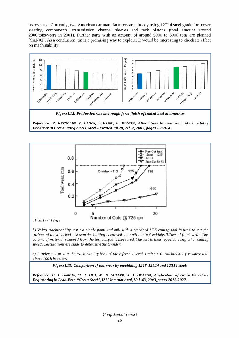
with high speed steel or carbide tools (see figure I.12) [REY07]. For others, studies with high speed
tooling showed good results for milling (see figure I.13), drilling, plunging and cutting-off operations,
but a 30% lower machinability performance in the turning operation, all in comparison to SAE 12L14
(11SMnPb30 leaded steel). Studies on appropriate cutting tools to bring out the full potential of tin
added steel is currently under investigation [BER01]. Neither castability nor rollability problems have
been encountered [BER01], but it’s known that tin impairs the hot rollability [ROE08]. Pittsburgh
University has licensed its 12T14 patent exclusively to the Non-Leaded Free Machining Steel
Consortium, LLC. Members include: The University as the largest shareholder, Curtis Screw Co
Laurel Steel, a division of Harris Steel Group, the MacSteel division of Quantex, Republic
Technologies International (formerly USS/Kobe Steel Co.), Saarstahl Steel, and United Alloys & Steel
Corp. Laurel, Republic and Saarstahl are designated steel producers, with Republic and Saarstahl
using their own hot rolling facilities. Laurel, which is a cold finisher, not a steelmaker, purchases hot
bars from the other consortium producers. It also sub-licensees metal from outside suppliers only for
Figure I.11: Hot ductility behaviour of free-machining 1215 (11SMn30, unleaded) 12L14 (11SMnPb30,
leaded) steels and tin added steels (SN80, HR: Hot Rolled )
Reference: A. DEARDO, Tin-Bearing Free-Machining Steel, Patent WO 99/25891, 27 May 1999.
Confidential report
26
its own use. Currently, two American car manufacturers are already using 12T14 steel grade for power
steering components, transmission channel sleeves and rack pistons (total amount around
2000 tons/years in 2001). Further parts with an amount of around 5000 to 6000 tons are planned
[SAN01]. As a conclusion, tin is a promising way to explore. It would be interesting to check its effect
on machinability.
Figure I.12: Production rate and rough form finish of leaded steel alternatives
Reference: P. REYNOLDS, V. BLOCK, I. ESSEL, F. KLOCKE, Alternatives to Lead as a Machinability
Enhancer in Free-Cutting Steels, Steel Research Int.78, N°12, 2007, pages 908-914.
Figure I.13: Comparison of tool wear by machining 1215, 12L14 and 12T14 steels
Reference: C. I. GARCIA, M. J. HUA, M. K. MILLER, A. J. DEARDO, Application of Grain Boundary
Engineering in Lead-Free “Green Steel”, ISIJ International, Vol. 43, 2003, pages 2023-2027.
a) [Sn] 1 < [Sn] 2
b) Volvo machinability test : a single-point end-mill with a standard HSS cutting tool is used to cut the
surface of a cylindrical test sample. Cutting is carried out until the tool exhibits 0.7mm of flank wear. The
volume of material removed from the test sample is measured. The test is then repeated using other cutting
speed. Calculations are made to determine the C-index.
c) C-index = 100. It is the machinability level of the reference steel. Under 100, machinability is worse and
above 100 it is better.
Confidential report
27
I.5.2.3. Hexagonal Boron Nitride (h-BN)
Boron nitride is a compound with chemical formula BN, consisting of equal numbers of boron and
nitrogen atoms. BN is exists in an amorphous (a-BN) and various crystalline forms. The cubic
(sphalerite structure) variety analogous to diamond is called c-BN. Its hardness is inferior only to
diamond, but its thermal and chemical stability is superior. The rare wurtzite BN modification (w-BN)
may even be harder than the cubic form. The hexagonal form (h-BN) corresponding to graphite (the
graphite structure is described in the next section of this report), is the most stable and softest among
BN polymorphs. It is known as an effective solid lubricant, its lamellar structure provides easy shear
during friction [AYE97]. It is suggested to be a machinability enhancer by JFE steel company since
2004 [TAN07], [SEK04]. Standard steels for machine use (S45C for example) contain about 30 ppm
of nitrogen. If this content is increased up to 175 ppm, and boron added between 50 and 80 ppm,
precipitation of hexagonal boron nitrides is observed. During the heating process the microstructure is
austenic. Boron segregates quickly at the grain boundaries and forms an h–BN precipitate by reacting
with some nitrogen that diffuses to the grain boundaries from the interior of the grains. It also has been
observed that the h-BN could precipitate on MnS inclusions hence being more uniformly dispersed into
ferrite grain.
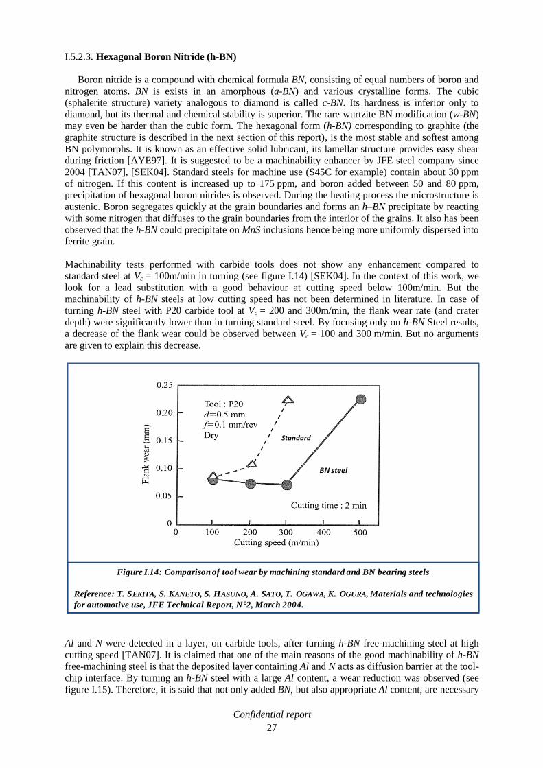
Machinability tests performed with carbide tools does not show any enhancement compared to
standard steel at Vc = 100m/min in turning (see figure I.14) [SEK04]. In the context of this work, we
look for a lead substitution with a good behaviour at cutting speed below 100m/min. But the
machinability of h-BN steels at low cutting speed has not been determined in literature. In case of
turning h-BN steel with P20 carbide tool at Vc = 200 and 300m/min, the flank wear rate (and crater
depth) were significantly lower than in turning standard steel. By focusing only on h-BN Steel results,
a decrease of the flank wear could be observed between Vc = 100 and 300 m/min. But no arguments
are given to explain this decrease.
Al and N were detected in a layer, on carbide tools, after turning h-BN free-machining steel at high
cutting speed [TAN07]. It is claimed that one of the main reasons of the good machinability of h-BN
free-machining steel is that the deposited layer containing Al and N acts as diffusion barrier at the tool-
chip interface. By turning an h-BN steel with a large Al content, a wear reduction was observed (see
figure I.15). Therefore, it is said that not only added BN, but also appropriate Al content, are necessary
Figure I.14: Comparison of tool wear by machining standard and BN bearing steels
Reference: T. SEKITA, S. KANETO, S. HASUNO, A. SATO, T. OGAWA, K. OGURA, Materials and technologies
for automotive use, JFE Technical Report, N 2, March 2004.
BN steel
Standard

Confidential report
28
in the work material. Finally, machining of an h-BN free-machining steel showed slightly lower
cutting temperature, and smaller cutting force in comparison with standard steel [TAN07]. In terms of
size, h-BN precipitates are similar to MnS ones. Therefore, the mechanical properties, fatigue
properties, cold, and hot forgeabilities, and other properties of h-BN free-cutting steel are virtually
equivalent to those of the base steel, before h-BN addition [SEK04].
It could be concluded that h-BN seems to be an effective machinability enhancer at high cutting speed,
but its behaviour at low cutting speed, where the substitution of lead is expected, has not been
explored.
I.5.2.4. Graphite
In industry, graphite is known as a solid lubricant [AYE97]. The graphite structure presents
P63/mmc symmetry [PHI02]. The lattice is hexagonal with 4 atoms per cell: (0, 0, 0), (0, 0, 1/2), (1/3,
2/3, 0) and (2/3, 1/3, 1/2). It could be seen as an ABABA... stacking of (0001) plans in which atoms
are arranged at the tops of regular hexagons (see figure I.16). Each atom has 3 neighbours
(distance = √ ⁄ ) in the basic plan. Half of the atoms of a given plan has neighbours directly
arranged under and above (distance = c/2). For graphite, a = 0.246 nm and c = 0.670 nm at room
temperature. It could be noticed that the h-BN structure, described in the previous section, is similar
(a = 0.250 nm and c = 0.665 nm). The interlayer structure differs, however, from the pattern seen for
graphite, because boron atoms set over and above nitrogen atoms. Another way to describe graphite is
to consider a lamellar hexagonal structure: a stacking of graphene plans. Graphene is a honeycomb
lattice made of carbon atoms. Within a plan, a carbon atom is strongly bound by covalent bonding to
three other atoms (distance = 0.142 nm, angle = 120°). Between two plans, the carbon atoms are
bound by Van der Waals forces. The binding is weak, and cleavage fracture is liable to occur at the
interlayer (see figure I.17). The plans can easily slide on each other, and provide a lubricating effect.
Figure I.15: Relationship between Al content of BN free-machining steel and the flank wear width of
carbide tool P20 in turning (V= 300m/min, ap = 0.5mm, f = 0.1mm/rev, dry)
Reference: R. TANAKA, Y. YAMANE, K. SEKIYA, N. NARUTAKI, T. SHIRAGA, Machinability of BN Free-
Machining Steel in Turning, International Journal of Machine Tools and Manufacture, 47, 2007, pages
1971-1977.

Confidential report
29
The microstructure of medium carbon steels is ferrite and pearlite (composite of ferrite and cementite).
The presence of cementite generally limits the cold working properties. Moreover, the hard cementite
phase (1000-1200 HV) is hard enough to wear high speed steel used for drilling (1000 HV) [KAT96].
By transforming the ferrite + pearlite structure to a ferrite + graphite structure, both machinability and
cold forgeability can be improved. The matrix of a graphitic steel is composed of single ferrite phase,
and the maximum hardness is as low as 120 HV. This practice has not been yet developed for steels
because of the long annealing times required, typically of the order of magnitude of tens or even
hundreds of hours. Graphitisation temperatures are comprised between 650 and 700°C for most of the
Figure I.16: Hexagonal cell of graphite
Reference: J. PHILIBERT, A. VIGNES, Y. BRECHET, P. COMBRADE, Métallurgie – Du Minerai au Matériau,
Ed. Dunod, Paris, 2002, page 304.
Figure I.17: Graphite structure
Reference: S. KATAYAMA, M. TODA, Machinability of Medium Carbon Graphitic Steel, Journal of
Materials Processing Technology, 62, 1996, pages 358-362.

Confidential report
30
authors [EDM05], [IWA04], [IWA02], [MEG96]. It is assumed that the graphitisation process, during
the annealing of carbon steel, consists of two steps: the dissolution of cementite, and the nucleation of
graphite. The approaches to accelerate graphitisation (based upon alloying), can be considered to fall
into two categories: either destabilisation of the cementite phase, or the provision of nucleation sites
for the graphite. The two approaches are generally combined.
I.5.2.4.1. Destabilisation of the cementite phase
This approach is based on the addition of silicon, which reduces the stability of cementite, and
avoids, or reduces, alloying elements such as manganese and chromium which increase cementite
stability [EDM05], [IWA04], [HYO09] (see figure I.18). It has been shown that the graphitisation
could be accelerated, by the addition of silicon and aluminium [KAT96], [EDM05]: the time required
for graphitisation was complete within 2-3 hours. This is the reason why silicon is added in large
quantities, in the developed steels: between 0.6 and 1.8 wt% (see table I.2).
Figure I.18: Effects of chromium and silicon on stability of cementite phase at 700 °C
Reference: T. IWAMOTO, T. MURAKAMI, Bar and Wire Steels for Gears and Valves of Automobiles Eco-
Friendly Free-Cutting Steel Without Lead Addition, JFE Technical Report, n°4, November 2004, pages
74-80.
Table I.2: Chemical compositions of graphitised steels (weight%)
Reference: [KAT96], [EDM05], [IWA04], [IWA02], [MEG96]

Confidential report
31
I.5.2.4.2. Provision of nucleation sites for the graphite
This approach considers additions which will provide a variety of nucleating particles. For
example, non metallic inclusions, such as Al2O3, SiO2 silicates, nitrides, carbides such as h-BN, AlN,
TiN, ZrN, Nb(C,N) and V(C,N), or sulphides, have all been tested as nucleating sites for graphite
[EDM05]. h-BN appeared to be very effective in nucleating graphite [KAT96], [IWA02], [IWA04],
[MEG96], [HYO09]. During the heating process, the microstructure is austenitic. Boron segregates
quickly at the grain boundaries and forms an h-BN precipitate by reacting with some nitrogen, which
diffuses to the grain boundaries, from the interior of the grain. Graphite may preferentially nucleate
where fine precipitates, with nearly the same atomic spacing and arrangement as the (0001) plan of the
graphite, exist. The crystal structure of h-BN is compared with that of graphite in table I.3.
The atomic arrangement and spacing of h-BN are very similar to those of graphite. Therefore, the
graphite particles easily nucleate, and grow epitaxially on the surface of h-BN (see figure I.19).
Table I.3: Crystal structure of h-BN and graphite
Reference: T. MEGA, R. MORIMOTO, M, MORITA, J. I. SHIMOMURA, Auger Electron Spectroscopy of
Boron Nitride in Hot-Rolled Graphitised Steel Sheet, Surface and Interface Analysis, Vol. 24, 1996, pages
375-379.
Figure I.19: Schematic illustration of nucleated graphite and polyhedral BN
Reference: T. IWAMOTO, T. HOSHINO, K. AMANO, J. SHIMOMURA, Graphite Nucleation on Boron Nitride
in 0.53%C Steel, Tetsu-to-Hagané. Vol. 84, 1998, pages 67-72.

Confidential report
32
It also has been observed that h-BN could precipitate on MnS inclusions, hence being more uniformly
dispersed into ferrite grain (see figure I.20) [KAT96]. Therefore graphite which precipitates on the
surface of h-BN, is uniformly dispersed.
It has been studied that the shortest graphitisation time in medium carbon steels, — for a constant
carbon content — was obtained with the smallest graphite particles (see figure I.21) [IWA02].
Graphite particles are small, if they are numerous. If the boron content is increased, and the nitrogen
content is controlled, the number of h-BN nucleation sites increases. Thus, the number of graphite
particles increases in the same proportion. The carbon atoms have a shortest distance of diffusion to
travel, prior to fix on h-BN. Consequently, the time required to complete graphitisation is reduced, if
the number of h-BN nucleation sites increases. With the base steel of this work (11SMn30), and
assuming that enough cementite could transform to graphite, boron would have to be added (20-
40 ppm), and the nitrogen content decreased down to 40 ppm (compared to 80 ppm currently, in
11SMn30 steel) to shorten the graphitisation time.
I.5.2.4.3. Machinability enhancement
Changing hard cementite to graphite makes it possible to soften the steel, and thereby improves
machinability. Machinability is also substantially improved by the lubricating action of the graphite on
the tool surface. The different results showed in literature have been observed in drilling with HSS
tools and in turning with coated carbide tools. Turning tests have been performed at high cutting
speeds (Vc > 200m/min). The tool life is three to seven times better than for other tested steels (see
figure I.22a) [KAT96]. In drilling, for a given tool life, graphitic steel cutting speed is twice better
than for leaded steel (see figure I.22b). These last results show that graphitic steels present an
interesting behaviour at low cutting speed. The cutting forces during machining have been recorded
between those of resulphurised steels and leaded steels. The surface roughness is a few microns higher
that of leaded free-cutting steel, and can be improved by dispersing graphite particles uniformly and
finely [KAT96]. The graphitic steels show an excellent balance of cold forgeability and machinability
in comparison with conventional steels (see figure I.21) [SEK04], [IWA04].
Figure I.20: Micrography of graphite nodule nucleated on h-BN and MnS inclusions (TEM)
Reference: S. KATAYAMA, M. TODA, Machinability of Medium Carbon Graphitic Steel, Journal of
Materials Processing Technology, 62, 1996, pages 358-362.

Confidential report
33
Impro
vem
ent
Improvement
Figure I.21: Influence of boron/nitrogen content on graphitisation time
Reference: T. IWAMOTO, T. OSHINO, A. MATSUZAKI, K. AMANO, Effect of Boron and Nitrogen on
Graphitisation and Hardenability in 0.53%C Steels, ISIJ International, Vol. 42, Supplement, 2002, pages
S77-S81.
tmin

Confidential report
34
Figure I.22: Tool life in turning (a) and in drilling (b) of different steels
Reference: S. KATAYAMA, M. TODA, Machinability of Medium Carbon Graphitic Steel, Journal of
Materials Processing Technology, 62, 1996, pages 358-362.
a) b)
G1-G2: graphitic steels
S55C: standard steel
S: resulphurised steel
PSC: leaded + calcium treated steel
Figure I.23: Balance of machinability and cold forgeability of graphitic and conventional steels
Reference: T. IWAMOTO, T. MURAKAMI, Bar and Wire Steels for Gears and Valves of Automobiles Eco-
Friendly Free-cutting Steel without Lead Addition, JFE Technical Report, n°4, November 2004, pages
74-80.
Confidential report
35
I.5.2.4.4. Reversibility of the process
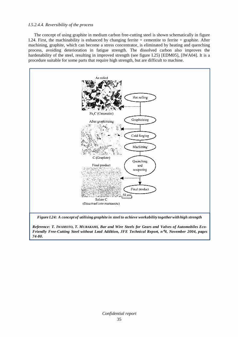
The concept of using graphite in medium carbon free-cutting steel is shown schematically in figure
I.24. First, the machinability is enhanced by changing ferrite + cementite to ferrite + graphite. After
machining, graphite, which can become a stress concentrator, is eliminated by heating and quenching
process, avoiding deterioration in fatigue strength. The dissolved carbon also improves the
hardenability of the steel, resulting in improved strength (see figure I.25) [EDM05], [IWA04]. It is a
procedure suitable for some parts that require high strength, but are difficult to machine.
Figure I.24: A concept of utilising graphite in steel to achieve workability together with high strength
Reference: T. IWAMOTO, T. MURAKAMI, Bar and Wire Steels for Gears and Valves of Automobiles Eco-
Friendly Free-Cutting Steel without Lead Addition, JFE Technical Report, n°4, November 2004, pages
74-80.

Confidential report
36
I.5.2.5. Others types of inclusions
Daido Steel developed in 2002 a ferritic free-cutting stainless steel without lead [OIK02].
Manganese sulphide has a detrimental effect on corrosion resistance, which is a key parameter in
stainless steel. Hence it is suggested to develop other inclusions to enhance machinability. It has been
shown that the addition of proper amounts of titanium, carbon and sulphur in stainless steel result in
the formation of Ti4C2S2 during solidification without the formation of MnS (see table I.4). The Ti4C4S2
inclusions break down into small spheroids during hot working and, unlike MnS, are not elongated in
the working direction. The machinability of the developed alloy is comparable to that of leaded free-
cutting stainless steel.
Like boron nitride and graphite, molybdenum disulphide MoS2 is known as a solid lubricant. In
2008, a sintered stainless steel 316L has been impregnated with 15% MoS2 [RAA08]. The friction
coefficient is diminished by approximately 20-25%. No machinability tests have been lead and
sintering is not a technique appropriate for this study.
Figure I.25: Tool life in turning and fatigue strength obtained with graphitic and conventional steels
Reference: T. IWAMOTO, T. MURAKAMI, Bar and Wire Steels for Gears and Valves of Automobiles Eco-
Friendly Free-Cutting Steel without Lead Addition, JFE Technical Report, n°4, November 2004, pages
74-80.
Table I.4: Chemical compositions of suggested steels with TIC4S2 inclusions (weight%)
Reference: K. OIKAWA et al, A new Pb-Free Machinable Ferritic Stainless Steel, ISIJ International,
Vol.42, N°7, 2002, pages 806-807.

Confidential report
37
I.5.2.6. Conclusion
Among the different ideas discussed in this chapter, graphitic steel seems to be an effective
alternative to lead in free-cutting steel, if the graphitisation process is accelerated. Mainly, only
one Japanese producer, JFE, promote this alternative. More results of machinability at low
cutting speed would be needed to validate this solution. The graphitic steels studied in literature
have more carbon (0.4 to 1% in patent) than the 11SMn30 grade, on which is based this work. It
has not been discussed if the graphitisation of a 0.1% carbon steel would lead to sufficient
machinability enhancement (enough graphite formed). In the case of a 0.5% carbon steel
(common value in literature to form enough graphite), it should be determined if the graphitised
state would present enough mechanical strength for our applications, hence avoiding another
heat treatment to regain a stronger ferrite + pearlite structure.
Tin added steel is presented as a viable alternative, but its machinability behaviour is not totally
understood. Studies on appropriate cutting tools to bring out the full potential of tin added steels
is currently under investigation. If the machinability improvement by tin addition is proven, the
increase of the cost of that kind of steel, after the thermal treatment to segregate tin at the grain
boundaries, has not been precised.
Bismuth added steel is a valid alternative to leaded steels from a technical point of view. It
provides the same improvement of machinability. The availability and the cost of bismuth are
major problems.
h-BN steel shows good results in machinability at high cutting speed. The low speed range has
not been explored, but it is the range where we look for machinability enhancement in low
carbon free-cutting steel. It is difficult to conclude on the efficiency of this alternative in
replacing lead.
I.5.3. Lead suppression and enhancement of sulphides
Manganese sulphide inclusions improve machinability, this aspect has been developed previously.
In order to suppress lead in free-cutting steels, enhancement of sulphides existing in the steel could be
an interesting concept.
I.5.3.1. Increase of sulphur content
Free cutting steels usually contain sulphides of type 1 and 2 (see figure I.26).
Figure I.26: Manganese sulphides in free-cutting steels type 1 (a) and 2 (b) (x300)
Reference: YU.D. YASHIN, S. A. SOLDATKIN, P.YU. CHESNOKOV, High-Machinability Steels, Metallurgist,
Vol. 49, N° 5-6, 2005, pages 236-241.

Confidential report
38
To optimise the machinability of free-cutting steel, coarse, slightly deformed inclusions of the first
type must be the predominant type of inclusion in the steel. An increase in the content of such
inclusions is accompanied by a decrease in the degree of the adhesive interaction between the material
of the workpiece and the material of the tool (see figure I.27), and, thus, a decrease of the tool wear
rate [YAS05]. It has been considered to increase the amount of sulphur from 0.3 to 0.37 wt%
(11SMn37) in an unleaded steel [REY07]. The higher number of sulphide should enhance
machinability more than in conventional 11SMn30. This enhancement would be due to a reduction of
the tool wear rate; assuming that the cutting speed is enough high to cause a tool temperature at the
tool-chip interface that provides malleable MnS. But we think that this enhancement is small at low
cutting speed (Vc < 100m/min) where Pb plays its best role (thanks to a low melting temperature). The
steel shows slightly improved performance compared with the 11SMn30 steel in component
production tests using high speed steel tools, and lubricant. It also showed good chip formation, but it
did not approach the leaded steel (11SMnPb30) in surface finish (see figure I.28) [REY05], [REY07].
Moreover, the hot rollability is more difficult with a bigger amount of sulphur.
Figure I.27: Effect of the content of weakly deformed manganese sulfides on the adhesive interaction
between the workpiece and the tool
Reference: YU.D. YASHIN, S. A. SOLDATKIN, P.YU. CHESNOKOV, High-Machinability Steels, Metallurgist,
Vol. 49, N° 5-6, 2005, pages 236-241.
F and N: The frictional force and the normal pressure on the front surface of the tool
L: Length of the sulphide, B: Thickness of the sulphide
Figure I.28: Production rate and rough form finish of leaded steel alternatives
Reference: P. REYNOLDS, V. BLOCK, I. ESSEL, F. KLOCKE, Alternatives to Lead as a Machinability
Enhancer in Free-Cutting Steels, Steel Research Int.78, N°12, 2007, pages 908-914.

Confidential report
39
I.5.3.2. Morphology of sulphides
In order to lower the plasticity of the sulphides, and to keep them globular during hot rolling and
avoiding perpendicular defects, tellurium, selenium and calcium can added [MUR93].
I.5.3.2.1. Tellurium (Te) and Selenium (Se)
The combination of increased sulphur with tellurium in free-cutting steels gives an improvement of
machinability in surface finish (see figure I.29, a declination of figure I.28). Although this steel does
not approach the performance of the leaded steel in terms of production rate, it shows a better
machinability, than conventional unleaded steel [REY07].
Tellurium forms low melting phases like MnTe and FeTe or PbTe in leaded steels. These phases are
found mainly around the MnS and cause the sulphides to deform less during hot rolling [BER01],
[SIM03], [TRO98], [DAV90]. Hot workability is severely affected. For this reason the addition of
tellurium is usually restricted to below 0.01 wt% [REY07]. The influence of selenium is similar to that
of tellurium, its price being higher. It forms with manganese MnSe compound which is, in solid state,
completely soluble with manganese sulphide. MnSe helps manganese sulphide to stay globular
[TRO98]. To obtain the same effect as with tellurium, selenium has to be added in double quantity. It
does not deteriorate the hot-rolling behaviour as much as tellurium, but its toxicity have prevented a
wide spread use in steels [BER01], [SIM03], [TRO98]. Tellurium and selenium are usually added to
leaded free-cutting steels but are not considered as substitutes. Indeed, no effects on machinability are
expected at low cutting speed.
I.5.3.2.2. Calcium (Ca) and Rare Earth Metals (RE)
Calcium and Rare Earth Metals (RE) have been added in resulphurised free cutting steel to study
their influence on manganese sulphides and machinability (see table I.5) [JIA96].Tests in turning have
been performed with HSS tools at low cutting speed, between 5 and 25m/min. The behaviour of the
sulphide inclusions during machining depends mainly on their deformability, which in turn, depends
on their composition. The greater the deformability, the lower the cutting forces. The deformability of
sulphide inclusions could be presented in this decreasing order: MnS, (Mn,Ca)S, MnS-RE2S3 and
(Mn,Ca)S-RE2S3. Thus, the cutting forces are reduced in the same order: more reduced by MnS
inclusions than by (Mn,Ca)S-RE2S3 inclusions.
Non-deformable inclusions promote unclosed
microvoids in the steel matrix which are helpful for the reduction of the flank wear of the cutting tool.
The tool wear is reduced in the increasing order: MnS, (Mn,Ca)S, MnS-RE2S3 and (MnS,Ca)S-RE2S3
Figure I.29: Production rate and rough form finish of leaded steel alternatives
Reference: P. REYNOLDS, V. BLOCK, I. ESSEL, F. KLOCKE, Alternatives to Lead as a Machinability
Enhancer in Free-Cutting Steels, Steel Research Int.78, N°12, 2007, pages 908-914.

Confidential report
40
(see figure I.30). But the correlation between unclosed microvoids and tool wear is not argued in
literature.
A Japanese patent suggests to add simultaneously calcium and magnesium to sulphur to form
sulphides and soft oxides in order to improve the machinability [IWA07]. It also suggests to decrease
the oxygen content to 20 ppm to avoid the formation of abrasive hard oxides. The flank wear of
carbide tools in turning at Vc = 150 m/min is equivalent to leaded steel. But the behaviour at low
cutting speed is not presented.
Table I.5: Chemical compositions of steels with calcium (Ca) and/or rare earth metals (RE)
addition (weight%)
Reference: L. JIANG, K. CUI, H. HÄNNINEN, Effect of the Composition, Shape Factor and Area Fraction
of Sulphide Inclusions on the Machinability of Re-Sulphurised Free-Machining Steel, Journal of
Materials Processing Technology 58, (1996), pages 160-165.
Figure I.30: Flank wear of HSS tools whilst machining steels with calcium (Ca) and/or rare earth metals
(RE) addition
Reference: L. JIANG, K. CUI, H. HÄNNINEN, Effect of the Composition, Shape Factor and Area Fraction
of Sulphide Inclusions on the Machinability of Re-Sulphurised Free-Machining Steel, Journal of
Materials Processing Technology 58, (1996), pages 160-165.

Confidential report
41
I.5.3.3. Shape factor and size of sulphides
The shape factor (L/B: length L and thickness B) of sulphide has an interesting effect on
machinability. It has been described in the last paragraph, about calcium treated sulphide, that a higher
shape factor (non treated deformable sulphide) is more effective in reducing the cutting force, but less
effective in reducing the flank wear of the tool in turning, compared to more globular sulphide (Ca-
treated sulphide) [DAV90], [JIA96].There are two opposite factors regarding the effect of shape factor
of sulphide inclusions on surface finish [JIA96]:
On the one hand, a greater shape factor of the sulphide inclusions may lead more easily to the
formation of a BUE, impairing surface finish.
On the other hand, however, the microvoids initiated by sulphide inclusions with higher shape
factors may be more easily closed up, improving the surface finish.
The size of the sulphides plays also a role in machinability. It is known that machinability is improved
when the size of sulphide inclusion becomes larger [YAS05]. In 2004, a Japanese team (JFE)
[IWA04] studies the formation of manganese sulphide with high sulphur content and chromium (see
table I.6).These developments suggest to substitute lead for the following reasons:
Because chromium substitutes manganese in sulphide, an increase in the size of sulphide can be
expected. It could be remarked that manganese and chromium atoms exhibit nearly the same
size, so the effect of chromium on sulphide size should be equivalent to that of manganese, and
not superior.
(Cr,Mn)S also improves machinability.
Chromium is not harmful to the environment.
In the studied process, the size of sulphide is increased compared to conventional SAE 12L14 leaded
steel (11SMnPb30, 0.25-0.3% Pb). From our point of view, this increase is more due to the increase of
sulphur content (0.385% compared to 0.34% for 12L14 grade) than to the addition of chromium.
Moreover, the amount of sulphide is larger than in SAE 12L14 leaded steel. It contributes to the
refinement of microstructure by suppressing austenite grain growth during reheating and by
functioning as nuclei for the ferrite transformation. This refinement improves the machinability in the
same manner as increasing the size of sulphide inclusions. The machinability, equal or superior to that
of SAE 12L14, was confirmed with carbide tools at high cutting speed in turning (see figure I.31a),
and with HSS tools at low cutting speed in drilling (see figure I.31b). Similarly, the machined surface
roughness of the developed steel is equal, or smaller, than that of SAE 12L14 at all cutting speed (see
figure I.31c).But the turning at low cutting speed (Vc < 100m/min) was not explored, and it is not
possible to conclude on the effectiveness of the lead substitution in this speed range.
Table I.6: Chemical compositions of SAE 12L14 leaded steel (11SMnPb30) and free-cutting steel with
enhanced sulphide by chromium addition (weight%)
Reference: T. IWAMOTO, T. MURAKAMI, Bar and Wire Steels for Gears and Valves of Automobiles Eco-
Friendly Free-Sutting Steel without Lead Addition, JFE Technical Report, n°4, November 2004, pages
74-80.

Confidential report
42
I.5.3.4. Conclusion
Suppression of lead, and enhancement of sulphides, is claimed to be effective in many cases.
Mainly, the objectives are to keep sulphides globular and to increase their size to improve the
machinability. The performance in machining, compared to leaded steel at low cutting speed
(Vc < 100m/min) is rarely explored. When it is explored, it is generally not better than that of leaded
steel, except for the last example quoted with (Cr,Mn)S inclusions during a drilling operation.
Figure I.31: Machinability of Pb-free steel with (Mn,Cr)S sulphides compared to conventional leaded steel
SAE 12L14 (11SMnPb30)
Reference: T. IWAMOTO, T. MURAKAMI, Bar and Wire Steels for Gears and Valves of Automobiles Eco-
Friendly Free-Sutting Steel without Lead Addition, JFE Technical Report, n°4, November 2004, pages
74-80.
a)
b)
c)

Confidential report
43
I.5.4. Conclusion of the bibliographic survey
During machining, lead strongly improves the machinability at low-cutting speed (Vc < 100m/min):
it lubricates the tool-chip interface, and helps the chip breaking. Several approaches have been studied
during this bibliographic work in order to replace lead in low carbon free-cutting steel. Among them,
some are particularly interesting, based on lead substitution by other types of inclusion:
Titanium carbosulphides, which are often developed in patents, are presented as a promising
alternative in stainless steel. In literature, they have not been developed in carbon steel. Their
efficiency at low cutting speed is not determined, which does not allow to conclude of their
ability to replace lead.
h-BN steels show interesting results in machinability at high cutting speed. But the behaviour at
low cutting speed has not been tested in literature. This idea has not been deeply explored, and it
is not considered it as a possible solution to lead replacement in this study.
Bismuth added steel is a valid alternative to leaded steels from a technical point of view. It
provides the same improvement of machinability. The availability, and the cost, of bismuth are
major problems, and limit its use as a substitute. This study will not go further with this
element.
Other solutions suggest to suppress lead and to enhance the machinability behaviour of the sulphides
existing in the steel:
Manganese sulphides, compared to lead, present the same mechanism of machinability
improvement, but at higher cutting speed. They are not as good as lead at low cutting speed.
Suppression of lead, and enhancement of sulphides is suggested in many cases. Mainly, the
objectives are to keep sulphides globular, and to increase their size, to improve machinability.
The performance in machining at low cutting speed is rarely tested, or generally not better than
that of leaded steel.
Dispersion of sulphide seems to be another way explored in patents, machinability results are
not detailed.
It has been decided not to work more on sulphides enhancement, because of their lack of effect on
machinability at low cutting speed (MnS inclusions are not malleable enough), where lead is
particularly efficient (low melting temperature). MnS should be considered as a second machinability
enhancer in this study, when medium cutting speed (150 < Vc < 300 m/min), or extremely rude
condition are reached (high cutting force).
Thanks to this bibliographic work, two routes for lead replacement have been chosen, graphite and tin:
Tin added steel is presented as a viable alternative, but its machinability behaviour is not totally
understood. Studies on appropriate cutting tools to bring out the full potential of tin added steels
is currently under investigation. If the machinability improvement by tin addition is proven, the
increase of the cost of that kind of steel, after the thermal treatment to segregate tin at the grain
boundaries, has not been precised.
Graphitic steel seems to be an effective alternative to lead in free-cutting steel, if the
graphitisation process is accelerated. More results of machinability at low cutting speed would
be needed to validate this solution. . It has not been discussed if the graphitisation of a 0.1%
carbon steel would lead to sufficient machinability enhancement (enough graphite formed). In
the case of a 0.5% carbon steel (common value in literature to form enough graphite), it should
be determined if the graphitised state would present enough mechanical strength for our

Confidential report
44
applications, hence avoiding another heat treatment to regain a stronger ferrite + pearlite
structure.
It has been assumed that graphite and tin are the most promising ways, and decided to go further in a
theoretical and practical work. Moreover, an innovative way has been explored, based on the
development of graphitic steel. It consists in associating graphite and manganese sulphide particles,
which have a beneficial effect on machinability. Hence, the addition of sulphur and manganese to
medium carbon steel, would allow the formation of MnS, in a ferrite + graphite structure.
Thermodynamic calculations have been carried out in order to determine the best steel analysis. Then,
steels have been melted at the laboratory scale, and a complete characterisation helped to conclude on
the efficiency of these two alternatives.

Confidential report
45
II. Characterisation of industrial free-cutting steels from SWISS STEEL
Prior to develop alternatives to leaded free-cutting steel, the characterisation of industrial grades
from SWISS STEEL was done. SWISS STEEL provided hot rolled bars (Trolling= 1200°C, 64mm
diameter) of a typical free-cutting steel 11SMn30 and its leaded version 11SMnPb30. Structural and
mechanical properties have been studied, and followed by machinability tests in turning and in
drilling. Hence the mechanisms of machinability improvement brought by lead could be determined.
II.1. Structural and mechanicals properties
II.1.1. Chemical analysis
The first experiment made on the two industrial grades was to check their chemical analysis (table
II.1). These free cutting steels content a fairly low carbon (< 0.15 wt% C), are resulphurised
(< 0.33wt% S) and could bear up to 0.35 wt% of lead (EN 10087). A common analysis involving
UGITECH and SWISS STEEL laboratories has been performed on 11SMnPb30 (sample of 25 mm
diameter bar). The slight differences observed on Si and Sn measurements between UGITECH and
SWISS STEEL analysis can be explained by the different calibration of their apparatus.
II.1.2. Microstructure
Both grades show the typical ferrite + pearlite structure of low carbon steels and several manganese
sulphides, MnS (see figure II.1). The normalised ferrite grain size (ASTM E112) is 6-8 /7 in the centre
of the bar and 6-8 /6 at the edge: the grains are slightly finer at the centre. In the case of 11SMnPb30
grade, lead could be observed at the tips of manganese sulphides and rarely isolated. The high atomic
number of Pb allows an easy identification with the scanning electrons microscope (SEM) in back
scattered electrons (BSE) mode (see light areas on figure II.2).
II.1.3. Inclusions
II.1.3.1. Sulphides
As mentioned in the previous chapter, the two steels exhibit several manganese sulphide inclusions.
In both cases, their average size is about 25 µm in length and 6 µm in width (see table II.2).
II.1.3.2. Oxides
The industrials grades provided by SWISS STEEL present glassy oxide inclusions engineered
during steel making (see table II.3 and figure II.3). These inclusions are known to form a viscous layer
at the tool/chip interface during machining of the steel within a high temperature range corresponding
to a high cutting speed range (Vc > 200m/min). The promotion of sliding tribological conditions by in-
situ lubrication at the tool/chip interface decreases the flank wear and suppresses the dissolution crater
wear, which is a key to improve the machinability of steels at moderate and higher cutting speed
[ZHA04].
Table II.1: Chemical compositions of industrial free-cutting steels from SWISS STEEL (weight%)

Confidential report
46
Figure II.1: Microstructures of a: industrial 11SMn30 grade and b: 11SMnPb30 (perpendicular to rolling
direction)
a) b)
Ferrite
Pearlite
MnSFerrite
Pearlite
MnS
a)
Ferrite
PearliteMnS
b)
Ferrite
Pearlite
MnS
Figure II.2: SEM observation (Back Scanning Electron, BSE) of a: 11SMn30 and b11SMnPb30
industrial grades (parallel to rolling direction)
MnS
Oxide
MnS
Oxide
Lead
a) b)

Confidential report
47
Table II.2: Characterisation of manganese sulphide inclusions in industrial 11SMn30 and 11SMnPb30
grades
- Mean values among 5 sulphides
Table II.3: Characterisation of complex oxides in industrial 11SMnPb30 grades
- Mean values among 15 complex oxides
Figure II.3: Composition of complex oxides in industrial 11SMnPb30 grade
- Slice at 15% MnO of the quaternary Al2O3-CaO-SiO2-MnO diagram

Confidential report
48
II.1.4. Mechanicals properties
II.1.4.1. Tensile test and hardness profiles
The stress/strain curve from the tensile test shows a typical behaviour: a yield point followed by a
plateau (figure II.4). In the corresponding strain range, the deformation is entirely localised in Lüders
bands [PHI02]. The microscopic origin of this phenomenon is the strong pinning of dislocations by
carbon atoms. In the elastic domain, the dislocations are strongly pinned and need a high stress to be
released. Once the dislocations are released, the plastic strain starts quickly. As the global strain rate is
imposed, the elastic strain rate decreases, so the stress decreases, which is the origin of the yield point.
The strain continues at a constant load until the Lüders bands totally invade the material. Then the
deformation becomes homogeneous and the stress increases. The bands disappear after the plateau.
The mechanical properties of both grades are similar, but slightly higher in the case of the leaded
11SMnPb30 steel (UTS and HV, see table II.4 and figure II.5).
Table II.4: Tensile test report of 11SMn30 and 11SMnPb30 industrial grades
- Mean values among 3 samples
Figure II.4: Stress/strain curve of 11SMn30 industrial grade with Lüders bands apparition (same
behaviour for industrial 11SMnPb30)
[DIE88]
Strain (%)
Str
ess
(MP
a)

Confidential report
49
II.1.4.2. Hot forging test
The hot forging behaviour of a steel is limited at low temperature (900-1000°C) by a low
deformation capacity and at high temperature (1300-1400°C) by a local fusion phenomenon called
―burning‖. The hot forging behaviour of a leaded free cutting grade has to be determined as a
reference prior to develop any alternatives. The procedure is performed on specimens of 11SMn30 and
11SMnPb30 in the direction of rolling. It includes two stages:
Increasing temperature: Heating of specimens up to a series of temperatures chosen
increasingly higher, followed by a tensile test in order to get the burning temperature.
Decreasing temperature: Simulation of a reheating furnace (in our case: 1250°C) followed by a
tensile test at lower temperatures. It gives back the metal ductility after heating.
The diameter of specimen after necking, is measured and compared to the initial diameter, to
characterise the hot ductility of the steel. The result is shown as the delta diameter in percent
[100 (Øfinal – Øinitial) / Øinitial]. The curves obtained during the test allow to access to the minimal
necking bearable at the final hot rolling temperature (In SWISS STEEL facilities, Tend = 1000°C, see
figure II.6). The more significant result is that lead strongly decreases the ductility of the free-cutting
steel. The ductility curve of grade 11SMnPb30 is shifted to –15% compared to unleaded 11SMn30
steel. During the increasing phase, the ductility did not dramatically dropped till 1400°C. It means that
the burning temperature is higher than 1400°C for both grades. The minimal necking bearable at the
final hot rolling temperature (1000°C) is 35% for leaded grade. This is the reference value that further
developments should not cross (for instance tin added steels). It can be observed that the stress applied
to reach the necking, is equivalent for both grades.
Figure II.5: Industrial grade 11SMn30 and 11SMnPb30 hardness profiles
Uncertainty of measurement = 4%

Confidential report
50
II.2. Machinability of SWISS STEEL free-cutting steels
Lead is well known to increase the machinability of steel: lower cutting forces, better tool life,
better surface finishing etc. A complete characterisation of the industrial grades from SWISS STEEL
has help us to determine how lead acts as a machinability enhancer. Several turning tests have been
carried out: from typical tool wear procedures to specifically developed cutting forces measurements
at low cutting speeds (Vc < 150 m/min). These turning tests have been completed with tool life tests in
drilling.
II.2.1. The machines and the processes used during our work
This study has been carried especially with two machines, a computer numerical controlled lathe
(CNC-lathe, see figure II.7a) and a computer numerically controlled machining centre (CNC-
machining centre, see figure II.7b). Thanks to an ―in-board‖ computer, the moves of the workpiece
and the tool to perform the machining operations at the proper rates through a cycle are automatic. In
the lathe, the workpiece is held in a three-jaw chuck. The tool holders are mounted in a turret. The
lathe has been used for turning operations on 64 mm diameter bars of 500 mm long. Turning is a
machining process for generating external surfaces of revolution, by the action of a cutting tool on a
rotating workpiece (see figure II.8). In the machining center, the workpiece is held in a three-jaw. The
tools used to cut the metal are fixed on the spindle. The machining centre has been used as a drill
press. Drilling is usually the most efficient and economical method of cutting a hole in a solid metal
Figure II.6: Hot forging tests on 11SMn30 and 11SMnPb30 industrial grades
Minimal bearable
necking
Hot rolling Tend

Confidential report
51
(see figure II.9). Moreover, specific piezoelectric sensors fixed on the tool holder (in turning), or on
chuck (in drilling), measure the cutting forces during machining (see figure II.10).
Figure II.7: CNC machines used for machinability characterisations
a) CNC-lathe Ramo RTN 30, turning test
b) CNC-machining centre Alzmetal BAZ 15, drilling test

Confidential report
52
Figure II.8: Turning operation
Workpiece rotation,
Vc (m/min)
Feed movement,
f (mm/rev)Depth of
cut, ap (mm)
Cutting tool
Figure II.9: Drilling operation
Fee
d m
ov
emen
t,
f(m
m/r
ev)
Cutting tool rotation,
Vc (m/min)
Cutting tool
Diameter, ap (mm)

Confidential report
53
Figure II.10: Forces and torque measurements during turning (a) and drilling (b) operations
Fcutting
Fthrust
Ffeed
Fpenetration
Torque
a) Forces measurement in turning
b) Force and torque measurement in drilling

Confidential report
54
II.2.2. Turning operations, experimental procedure and results
As reference tools, a non-coated carbide insert, and two coated carbide inserts have been chosen
(see figure II.11):
ISCAR IC28 CNMG 120408-PP. It is commonly used by SWISS STEEL customers. It is a
cemented carbide tool, designed for carbon steel, but at low cutting speed (Vc < 200 m/min).
ISO codification: P30-P50 and M30-M40.
KENNAMETAL CNMG 120408-MP KC9225, TiN coating. It is a reference insert for
UGITECH laboratory. It is a cemented carbide tool suitable for stainless steel, but it should be
efficient with low carbon free-cutting steel at high cutting speed (Vc > 300 m/min). ISO
codification: M10.
SECO CNMG 120408-MF4 TP2500, Ti(C/N) coating. We chose to use this coated carbide
insert for complementary test. It is indicated for machining carbon steels at high cutting speed
(Vc > 300 m/min). ISO codification: P25.
The characterisation started with typical dry turning tests at high cutting speed (Vc ≥ 150m/min) with
KC9225 coated tools:
Vb 15/0.15 which characterises the tool wear (see figure II.12).
CBD (Chip Breaking Diagram) which allows to study the chip breaking.
Figure II.11: Cemented carbide tools used for turning operations
Rake surface
Flank surface
ISCAR
CNMG 120408-PP
IC28
KENNAMETAL
CNMG 120408-MP
KC9925
SECO
CNMG 120408-MF4
TP2500
Coating / TiN Ti(C,N)

Confidential report
55
The same Vb 15/0.15 procedure has been carried out with IC28 non-coated tools at lower cutting speed
(Vc = 100 m/min). Some phenomena have been studied:
Tool wear and crater wear.
Formation of a built-up edge (BUE).
Identification of elements in the tool deposit.
Then a continuous cutting forces measurement has been achieved during a test which consists in a dry
turning operation, by scanning continuously the cutting speed:
Acceleration from Vc = 20 to 200 m/min for IC28 non-coated tool.
Acceleration from Vc = 20 to 400 m/min for KC9225 coated tool.
The characterisation continued with specific dry turning tests developed in order to focus on low
cutting speeds (10 < Vc < 150 m/min) where Pb play its best role. The studied aspects are:
―Step by step‖ cutting forces measurement depending on cutting speed (from Vc = 10 to
150 m/min) with KC9925 coated and IC28 non coated tool.
BUE formation to have a more clear idea on its effect on machinability and its relation with lead
addition. In this speed range, the formation of a Built-up Edge (BUE) is very important in
relation to various aspects of machinability. It may be either harmful or beneficial, depending
on the conditions.
Complementary test has been performed with TP2500 coated carbide tool:
Continuous cutting forces measurement during a dry turning operation, by scanning
continuously the cutting speed (acceleration from Vc = 10 to 400 m/min)
Finally, a geometrical description of cutting at the tool/chip interface could be determined thanks to
the quick-stop procedure (KC9225 coated tools):
It provided significant results on cutting forces, cutting angles and friction coefficient.
Figure II.12: Tool wear mechanisms
Flank wear
Notch wear
Crater wear
Secondary
notch wear

Confidential report
56
II.2.2.1. Vb 15/0.15
During this experiment, we try to find a the cutting speed in order to reach 0.15 mm of flank wear
in 15 min of effective cutting. The depth of cut and the feed are constant (respectively 1.5 mm and
0.25 mm/rev), and chosen in relation with the cutting tool geometry. With KC9225 coated carbide
tool, the Vb 15/0.15 does not appear as the most appropriate procedure to characterise the machinability of
low carbon free-cutting steel. Their machinability in terms of Vb 15/0.15 could not be determined because
it is too high. Taking into account of the diameter of the bars, Vc = 700 m/min was the highest cutting
speed reachable by our lathe. For that cutting speed, the flank wear is 0.08 mm after 15 min for
11SMn30. For the leaded 11SMnPb30, in the same range of speed, the flank wear reached 0.125 mm
after 15 min (see figure II.13).
As a conclusion, during a turning operation at really high cutting speed (Vc ≥ 500 m/min), it has been
observed that the tool wear is more pronounced in the case of the leaded 11SMnPb30 steel than in the
case of the unleaded 11SMn30 grade. However, it is a small wear regarding the cutting speed
(< 0.15 mm after 15 minutes). Nevertheless, it can be assumed that lead reduces tool life at high
cutting speed. It is the confirmation of results found in literature.
The same procedure has been applied to the IC28 non-coated carbide tool. With that more tough tool
grade, the bearable cutting speed is lower (Vc < 150m/min), and a built-up edge (BUE) appeared on the
tool. The BUE is a piece of stagnant workpiece material stuck to the tool edge, which forms only with
certain machining conditions. It prevented to determine precisely the flank wear and consequently the
Vb 15/0.15 value (see figure II.14).
Figure II.13: Vb 15/0.15 tests on 11SMn30 and 11SMnPb30 grades with coated carbide tool KENNAMETAL
CNMG 120408-MP KC9225
Comments: Machinability too high to determine the Vb 15/0.15 value for both grades.
Tool wear more pronounced with leaded 11SMNPb30 steel.
--- 600 m/min
--- 700 m/min
--- 500 m/min
--- 600 m/min
--- 700 m/min

Confidential report
57
In these conditions, it was interesting to study the morphology of the BUE by observing the tool flank
wear with a SEM, (Vc = 100m/min, see figures II.15, II.16, II.17). First, the BUE made of steel (Fe)
and the bulk material of the carbide tool (WC) have been identified. The flank wear of the tool is
recognisable by its white colour compared to the non-worn grey part (white WC and grey WC, figure
II.15).
Secondly, the notch wear of the tool has been observed (see figure II.16). It was a little bit more
advanced by machining the leaded 11SMnPb30 steel: 0.145 mm after 16 minutes with the leaded
11SMnPb30 against 0.135 mm after 15 minutes with the unleaded 11SMn30. Considering the BUE
morphology, it is massive and uneven in the case of the 11SMn30 but small and regular with
11SMnPb30. As mentioned in literature, lead in free-cutting steels seems to control and reduce the
Figure II.14: BUE formation on non coated ISCAR IC28 CNMG 120408-PP tool after Vb15/0.15 test on
11SMn30 and 11SMnPb30 grades
11SMn30
Vc = 100 m/min
11SMnPb30
Vc = 100 m/min
Figure II.15: SEM observation of the edge of non coated ISCAR IC28 CNMG 120408-PP tool after a
Vb 15/0.15 test on 11SMn30 and 11SMnPb30 grades (BSE detector)
11SMn30
Vc = 100 m/min
11SMnPb30
Vc = 100 m/min

Confidential report
58
BUE size. It has been noticed that the manganese sulphide appeared as a layer on the rake face, but
surprisingly, lead could not be detected.
Then the crater wear has been analysed. It was equivalent for both grades (see figure II.17). An arched
layer of MnS was easily identified, and more stuck pieces of steel have been observed by machining
11SMn30 grade. In the case of machining 11SMnPb30, lead particles could be detected far from the
edge of the tool. Lead might be liquid during the turning operation because of the temperature of the
process, and be sprayed away from the direct tool/chip interface. It can explain why lead was not
detected on the rake face previously. In these conditions (Vc ≥ 100 m/min), It could be assumed that
lead is not enough viscous to provide a lubricant effect. Finally, to access to the tool flank tool wear,
an HCl etching has been performed to remove the BUE. A clean flank wear could be observed (see
figure II.18). In the case of the 11Smn30 grade, the wear criterion is assumed to be reached: 0.145 mm
after 15 minutes. In the case of the 11SMnPb30 grade, and thanks to the measurements gathered at
different cutting speed, the Vb 15/0.15 could be calculated with the Taylor law.
(2.1)
Where t is the effective cutting time to reach 0.15 mm of wear, n and C are constants.
At Vc1 = 200 m/min, t1= 2 min
At Vc2 = 100 m/min, t2 = 21 min
(2.2)
n and C can be determined :
Figure II.16: SEM observation of the notch wear and BUE of non coated ISCAR IC28 CNMG 120408 -PP
tool after a Vb 15/0.15 test on 11SMn30 and 11SMnPb30 grades (SE detector)
11SMn30
Vc = 100 m/min
11SMnPb30
Vc = 100 m/min

Confidential report
59
Hence, the Vb 15/0.15 can be deducted from the formula 2.1, with t = 15 min. The result
is Vb 15/0.15 = 110 m/min. Therefore, with a higher Vb 15/0.15, the leaded 11SMnPb30 steel presents a
better tool life than the unleaded 11SMn30 grade at low cutting speed.
Figure II.17: SEM observation of the crater wear of non coated ISCAR IC28 CNMG 120408 -PP tool after
a Vb 15/0.15 test on 11SMn30 and 11SMnPb30 grades (SE detector)
11SMn30
Vc = 100 m/min
11SMnPb30
Vc = 100 m/min
Figure II.18: Flank wear on non coated ISCAR IC28 CNMG 120408-PP tool after a Vb 15/0.15 test on
11SMn30 and 11SMnPb30 grades (HCl etching)
11SMn30
Vc = 100 m/min, HCl etching
11SMnPb30
Vc = 100 m/min, HCl etching

Confidential report
60
II.2.2.2. Chip breaking diagram (CBD)
The objectives of the CBD test is to determine a domain in terms of depht of cut ap and feed rate f
in which the chips are short enough to be ejected, thus avoiding to scratch the surface of the bar. The
larger the CBD (blue zone, see figures II.19 a and b), the better the grade.The two industrials grades
have been tested with the coated KENNAMETAL CNMG 120408-MP KC9225 tool. A medium
cutting speed has been chosen: 150 m/min. In both case, the chip breaking is excellent for the entire
range of depth of cut (0.5 to 4 mm) and feed (0.1 to 0.4 mm/rev) thanks to the large amount of
sulphide. It has been noticed that the chip breaking is the worst for low depth of cut and low feed,
where the geometry of the tool is not the most appropriate. The addition of lead minimizes this
behaviour. The chips are quite always short with 11SMnPb30 grade. The CBD tests, as the Vb 15/0.15
procedure, is not enough severe to highlight the effect of lead on machinability. The machinability of
free cutting steels is too high for these typical free-machining tests. We decided to develop specific
machining tests at low cutting speeds (Vc < 150 m/min). The mechanisms by which Pb improves the
machinability will be extrapolated from the results of these particular procedures.
II.2.2.3. Dry turning at low cutting speed with non coated carbide tool
Cutting forces measurements at low cutting speed (Vc < 150 m/min) has been achieved in order to
exhibit different cutting behaviour, between the two industrial grades: lead effect and BUE formation.
Non-coated inserts ISCAR IC28 CNMG 120408-PP have been used. The first test consists in a dry
turning operation in Vb 15/0.15 conditions (ap = 1.5 mm and f = 0.25 mm/rev), by scanning continuously
the cutting speed (acceleration of the spindle from Vc = 20 to 200 m/min). The cutting forces have
been continuously recorded (see figure II.20). It should be remarked that the cutting force R exhibited
in the next figures is the global cutting force R = [(Fcutting)2 + (Ffeed)
2 + (Fthrust)
2]
1/2. Then a second test
have been carried out, it differs from the first one by the observation of the cutting forces and the BUE
height for each cutting speed, step by step (from Vc = 10 to 150 m/min, see figure II.21, II.22 and
II.23). Up to Vc = 150 m/min, 11SMnPb30 cutting forces are lower than 11SMn30 cutting forces (see
figure II.20 and II.21). This is the first positive Pb effect (likely lubricant effect). Elsewhere,
11SMnPb30 cutting forces decrease when cutting speed decreases below Vc = 60 m/min. Nevertheless,
when cutting speed decreases, chip strain rate decreases and the chip temperature is limited, which
should increases the cutting forces (well known effect on steels with coated insert). The decrease of
cutting forces while cutting speed decreases below Vc = 60 m/min could not be explained by a lead
effect, since this phenomenon is also observe with 11SMn30 unleaded grade below Vc = 40 m/min.
The explanation is the formation at low cutting speed of a BUE with 11SMn30 and 11SMnPb30
grades, which significantly modify the cutting geometry. These BUE provide a narrower cutting
geometry (rake angle > 0), for lower cutting forces. However, BUE are well known to be instable, to
bring surface flaws on machined parts, and to promote the tear out of insert nose when they are
ejected. Consequently, BUE are avoided during machining although the positive effect on cutting
forces could be interesting. The second lead effect appears, the height of BUE is reduced by the
addition of lead in the steel (see figures II.22 and II.23).

Confidential report
61
Figure II.19 a: CBD tests on 11SMn30 grade with coated carbide tool KENNAMETAL CNMG 120408-
MP KC9225 (Vc = 150 m/min)
f (m
m/r
ev)
ap (mm)
ap (mm)
f (mm/rev)
0.5 1 1.5 2 2.5 3 3.5 4
0.1
0.15
0.2
0.25
0.3
0.35
0.4
11SMn30
Vc = 150 m/min
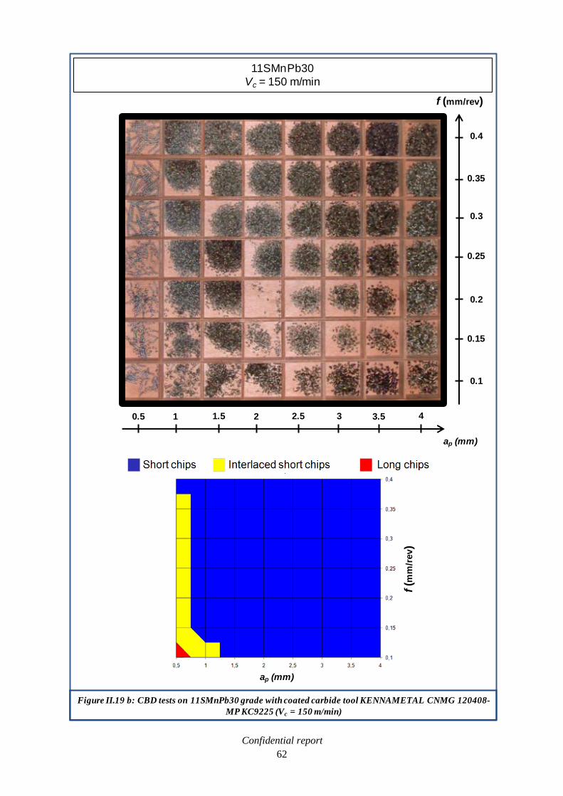
Confidential report
62
Figure II.19 b: CBD tests on 11SMnPb30 grade with coated carbide tool KENNAMETAL CNMG 120408-
MP KC9225 (Vc = 150 m/min)
f (m
m/r
ev)
ap (mm)
11SMnPb30
Vc = 150 m/min
ap (mm)
f (mm/rev)
0.5 1 1.5 2 2.5 3 3.5 4
0.1
0.15
0.2
0.25
0.3
0.35
0.4

Confidential report
63
Figure II.20: Cutting force versus cutting speed during a turning operation with the non-coated ISCAR
IC28 CNMG 120408-PP carbide tool (ap = 1.5mm - f = 0.25mm/rev)
Comments: Lower cutting forces with leaded 11SMnPb30.
BUE formation at really low cutting speed (Vc < 60m/min), lower cutting forces for both
grades.
-Continuous scanning of the cutting speed from Vc = 20 to 200 m/min
-Continuous recording of the cutting forces
Uncertainty of measurement = 3%
Figure II.21: Cutting force versus cutting speed during a turning operation with the non-coated ISCAR
IC28 CNMG 120408-PP carbide tool (ap = 1.5mm - f = 0.25mm/rev)
Comments: Lower cutting forces with leaded 11SMnPb30.
BUE formation at really low cutting speed (Vc < 60 m/min), lower cutting forces for both
grades.
-―Step by step‖ recording of the cutting forces
Uncertainty of measurement = 3%

Confidential report
64
Figure II.22: Formation of a Built-Up Edge (BUE) on non-coated ISCAR IC28 CNMG 120408-PP
carbide tool (ap = 1.5mm - f = 0.25mm/rev)
Comments: Lower BUE with leaded 11SMnPb30 grade.
Figure II.23: BUE size versus cutting speed after turning operation with non-coated ISCAR IC28 CNMG
120408-PP carbide tool (ap = 1.5 mm – f = 0.25 mm/rev)
Comments: Lower BUE with leaded 11SMnPb30 grade.

Confidential report
65
II.2.2.4. Dry turning at low cutting speed with coated carbide tool
The influence of tool coating on BUE formation is an important parameter. The same procedure, as
the tests performed in the last section, has been carried out with a coated carbide tool KENNAMETAL
CNMG 120408-MP KC9225. For the continuous scanning of cutting speeds, the test has been shifted
to Vc = 400 m/min, because the tool hardness allows to explore the high cutting speeds range (see
figure II.24). Then, the ―step by step‖ test recorded the cutting forces between Vc = 10 and 150 m/min
(see figure 25). Up to Vc = 150 m/min, the observation of tools after machining does not show the
presence of a BUE, whatever the cutting speed. But it’s hard to conclude that there is no BUE
formation during machining because if it appeared, maybe it didn’t stick on the tool because of the
coating and disappeared when the test stopped. During the continuous scanning of cutting speeds, it
has been observed that the cutting forces with 11SMn30 present a relative instability between Vc = 30
and 80 m/min. It is maybe due to the formation of a random thin BUE ejected from the tool. The
surface roughnesses of 11SMn30 and 11SMnPb30 are good at low cutting speed (Vc < 150 m/min),
which could tend to prove that there is no BUE under these cutting conditions. This assumption is
confirmed by the evolution of cutting forces with 11SMn30 grade. They are high at low cutting speed
and then decrease when the cutting speed increases (see figure II.24 and II.25). The surface roughness
of 11SMnPb30 is better than the surface roughness of 11SMn30 (or at least equal) whatever the
cutting speed. Therefore, the trough observed on 11SMnPb30 forces curve between Vc = 20 and 60
m/min could not be explained by a BUE. Another explanation is suggested, which considers the
lubricant effect of Pb at low cutting speed. It strongly decreases the cutting forces. Above
Vc = 80 m/min, the temperature at the tool-chip interface is so high that Pb is not viscous enough to
provide a lubricant effect, so the cutting forces increase. It could be remarked how similar are the
cutting forces for both steels when the lead is not efficient anymore at high cutting speeds (from
Vc = 200 m/min to Vc = 400 m/min, see figure II.24).
Figure II.24: Cutting force versus cutting speed during turning operation with coated KENNAMETAL
CNMG 120408-MP KC9225carbide tool (ap = 1.5 mm – f = 0.25 mm/rev)
Comments: Cutting force trough between Vc =20 and 60 m/min with leaded 11SMnPb30 steel.
-Continuous scanning of the cutting speed from Vc = 20 to 400 m/min
-Continuous recording of the cutting forces
Uncertainty of measurement = 3%

Confidential report
66
II.2.2.5. Complementary tests with carbide coated tool
Another coated carbide tool, more indicated in carbon steel (SECO CNMG120408-MF4 TP2500),
has been used to perform a turning test with the 11SMn30 and 11SMnPb30 grades. It has been carried
out by scanning continuously the cutting speed (acceleration of the spindle from Vc = 10 to
400 m/min) and by recording continuously the cutting forces. The results are presented in figure II.26.
In the case of the 11SMnPb30 grade, it has been also chosen to show the different force components
on figure II.27. With the SECO tool, the range of speed, where lead has a positive effect on cutting
forces is wider than that of the KENNAMETAL tool, but do not exceed Vc = 90 m/min. The study of
the different force components, R = [(Fcutting)2 + (Ffeed)
2 + (Fthrust)
2]
1/2 , exhibits that lead acts in the
same manner on each of them, and that the cutting force component Fc is the major contribution to the
global cutting force R. Above Vc = 90 m/min, the curves of the two grades are getting closer and then
confused for higher cutting speeds. This observation tends to confirm that lead is not efficient above
Vc = 100 m/min. It has been observed that the cutting force with 11SMn30 presents a relative
instability between Vc = 30 and 80 m/min (see figure II.26). Previously, the same remark has been
done with the KENNAMETAL coated tool. It is maybe due to the formation of a random thin BUE
ejected from the tool.
Figure II.25: Cutting force versus cutting speed during turning operation with coated KENNAMETAL
CNMG 120408-MP KC9225carbide tool (ap = 1.5 mm – f = 0.25 mm/rev)
Comments: Cutting force trough between Vc = 20 and 60 m/min with leaded 11SMnPb30 steel.
-―Step by step‖ recording of the cutting forces
Uncertainty of measurement = 3%

Confidential report
67
Figure II.26: Cutting force versus cutting speed during turning operation with coated SECO CNMG
120408-MF4 TP2500 carbide tool (ap = 1,5 mm – f = 0,25 mm/rev)
Uncertainty of measurement = 3%
-Continuous scanning of the cutting speed from Vc = 10 to 400 m/min
-Continuous recording of the cutting forces
Figure II.27: Cutting force components versus cutting speed during turning operation with coated SECO
CNMG 120408-MF4 TP2500 carbide tool (ap = 1,5 mm – f = 0,25 mm/rev)
-11SMnPb30 grade
-Continuous scanning of the cutting speed from Vc = 10 to 400 m/min
-Continuous recording of the cutting forces
Uncertainty of measurement = 3%

Confidential report
68
II.2.2.6. Quick-stop test
To verify the assumption that lead acts as a lubricant only at low cutting speed (Vc < 100 m/min),
quick-stop tests have been achieved. This test allows to determinate the friction coefficient at the tool-
chip interface thanks to the Merchant’s model. The aim of the test is quite simple: to remove the
cutting tool during machining and to preserve the chip partially formed. But it hides a real
experimental difficulty. Indeed, the tool should be instantly removed from its position during
machining, in a very short time, to keep the metal being machining. A pyrotechnic device is necessary.
II.2.2.6.1. The Merchant’s model
The first modelling of orthogonal cutting involving cutting forces and chip geometry goes back to
1945. It is due to Merchant [MER45], and considers that the chip formation occurs by a simple shear
along a straight line from the edge at the tool and tilted by a f angle. It is called the primary shear
angle (figure II.28). The resultant force R of the applied stresses by the tool on the bulk material can
be decomposed into: a cutting force Fc (along the cutting speed direction) and a feeding force Ff
(perpendicular to Fc). It is assumed that the normal component to the tool rake surface N and the
tangential component F of – R (module R), which is applied on the tool, are linked to a COULOMB’s
law characterised by a coefficient µ = F/N = tan β, where β is the friction angle.
II.2.2.6.2. Description of the experimental procedure of quick-stop test
The first issue is to achieve a strictly two-dimensional machining operation, to allow the
measurement of angles on micrographs (necessarily flat). In fact, all standard machining operations
are inevitably three-dimensional. In turning, for instance, the tool nose, and its non-negligible corner
radius regarding to the depth of cut, is, combined to the metal flow direction, a tri-dimensional cutting
element. Achieve a strict orthogonal cutting is not possible, because that would means to operate a
sinking procedure, for instance, on an infinite wide. However, local orthogonal machining conditions
can be approximated, playing on the fact that if a symmetry plan exists in the system, phenomena will
be two-dimensional in this plan (symmetric forces equilibrium on both sides of the plan). The most
accurate solution of this problem is described in figure II.29. However, the implementation of this
method assumes that a lathe, which synchronises precisely its rotation speed with the cutting tool
position, is used. But, for tool extraction device volume reasons, studies could not be done on a CNC
machine, only capable of providing this synchronisation. So a second method has been used, although
it admits a small approximation of the local cutting symmetry. Local conditions of orthogonal cutting
can be found by machining a pipe. Indeed, the machining of a pipe is not symmetrical viewed from the
tool. However, for a diameter large enough and a small thickness of the pipe, the deviation from
symmetry is minor, half way of the wall thickness (see figure II.30). A classic lathe has been used to
implement the tool extraction device. Conventional machining speeds are in the order of hundreds
meters per minute. The flow at the surface of the tool is about a few meters per second (For instance,
Vc = 100 m/min = 1.67 m/s). The tool ejection should occur at least at this speed. Moreover, the
distance available for the tool ejection should be very small. Indeed, the chip should be deformed as
few as possible during the transition between the established flow at the rated speed, and the absence
of flow (Vc = 0). The distance that should separate these two conditions must be below the geometric
dimensions of the chip: about tenths of millimetre. A quick calculation shows therefore minimum
acceleration value close to 14000 m/s² (≈ 1400 g). Only a projectile shock could provide this value.
The figure II.31 exhibits the quick-stop test principle.

Confidential report
69
Figure II.28: Merchant’s model
Reference: J.T. Black, Mechanics of chip formation, Metals Hanbook, 9th edition, Vol.16, 1989, pages 7-
12.
Ff
Fc : Cutting force F : Friction force : Cutting angle
Ff : Feeding force N : Normal force β : Friction angle
Fs : Shear force R2 = F2+N2 = Fc2+Ff
2 f : Shear angle
Fn : Perpendicular to Fs Friction coefficient µ = F/N = tan β Vc : Chip velocity
β -
f
β

Confidential report
70
Figure II.29: Orthogonal cutting by a sinking operation on a disc
Reference: C. Deville-Cavellin, UGITECH report, July 2009
Speed
Chip
Tool
Figure II.30: Orthogonal cutting by a facing operation on a pipe
Reference: C. Deville-Cavellin, UGITECH report, July 2009
Speed
Chip
Tool

Confidential report
71
Pipes of industrial grades from SWISS-STEEL (11SMn30 and 11SMnPb30) are machined
(Øext= 60 mm and thickness= 2 mm). Then, the tool is engaged in the material to provide a pseudo-
orthogonal cutting (assuming ―almost verified‖ symmetry conditions). The trigger of a pyrotechnic
apparatus sends a projectile to hit the tool holder. A calibrated pin (made of steel) breaks under the
shock and the tool is ejected. An absorbing system allows to decelerate the tool at the end of the pivot.
Finally, the pipe rotation is ended and the chip formation area retrieved. The formed chip is cut from
the pipe and prepared for microscopic observation (see figure II.32). In parallel, cutting forces
measurements are recorded with a dynamometer installed in the tool holder. The geometrical
description of the chip formation, combined to the forces measurement, allow the determination of
frictional forces, cutting angles and friction coefficient at the tool-chip interface (figure II.33). From
this general description, our experimental procedure has been defined:
Tool: KENNAMETAL CNMG 120408 – MP KC9225, The tool coating allows to assume that
there is no BUE formation during the cutting. The nose radius, which is an important parameter
in the study of the friction at the tool-chip interface, is equal to 7°.
Cutting speed Vc: between 11 and 91m/min to observed the tool chip interface in the speed
range where lead plays its best role.
Feed f: 0.25mm/rev to preserve the consistency with our previous results. The feed is constant
during the entire campaign of measurement.
Projectile
Pin
Tool
Broken Pin
Figure II.31: Quick-stop test principle
Reference: C. Deville-Cavellin, UGITECH report, July 2009

Confidential report
72
Figure II.32: Sampling area
Reference: C. Deville-Cavellin, UGITECH report, July 2009
Fcutting
Ffeed
Figure II.33: Observation of the chip formation and determination of cutting parameters (11SMnPb30
grade – Vc = 29 m/min)
Ff
R
Fc
N
F
Fsβ
f
Fc : Cutting force F : Friction force : Cutting angle
Ff : Feeding force N : Normal force β : Friction angle
Fs : Shear force R2 = F2+N2 = Fc2+Ff
2 f : Shear angle
Friction coefficient µ = F/N = tan β

Confidential report
73
II.2.2.6.3. Results
Cutting forces and shear angle measurements are gathered in table II.5 and presented in figures
II.34 and II.35. The normal and friction forces are extrapolated from the graphical construction (see
Annexes A and B). The friction coefficient at the tool/chip interface is deduced from these results and,
among all the data gathered, it is the most remarkable. In the case of unleaded 11SMn30 steel, the
friction coefficient exhibits a typical behaviour. It decreases when the cutting speed increases (see
figure II.32). It could be explained by the thermal softening of the matrix. When the cutting speed
increases, the temperature at the tool/chip interface also increases, so the matrix becomes more plastic
and the friction coefficient is lower. In consequence, the cutting force decreases when cutting speed
increases. In the case of leaded 11SMnPb30 steel, a particular trough of cutting force between Vc = 20
and 70 m/min has been recorded (see figure II.33). The determination of the friction coefficient at the
tool/chip interface gives crucial clues to explain this phenomenon. In this range of cutting speeds
which is equivalent to a range of temperatures, the lead is viscous and a lubricant effect occurs at the
tool/chip interface. The friction coefficient exhibits a trough between Vc = 20 and 70 m/min, the
cutting force is the lowest. Before Vc = 20 m/min, the lead is hard and does not ensure a lubricant
effect. Above Vc = 70m/min, the lead is not enough viscous and does not facilitate the cutting process.
It should be noticed that, at really low cutting speed, the friction coefficient is higher than 1. It means
that the simple COULOMB’s model is not sufficient to describe the sliding condition at the interface.
Adhesion phenomenon, seizure, ploughing may take place and are not separated from the classic
friction theory. They are strongly influenced by the tool geometry and they increase the F/N ratio. But
for a comparative study between unleaded and leaded steels, the COULOMB’s model gives significant
results on the evolution of the sliding conditions at the tool chip interface.
Table II.5: Quick-stop results on 11SMn30 and 11SMnPb30 grades
/*: For Vc = 18 m/min with 11SMn30 and Vc = 11 m/min with 11SMnPb30, the cutting
conditions were too instable to get a representative chip formation, even after two or three
attempts. These results have been excluded from our exploitation.
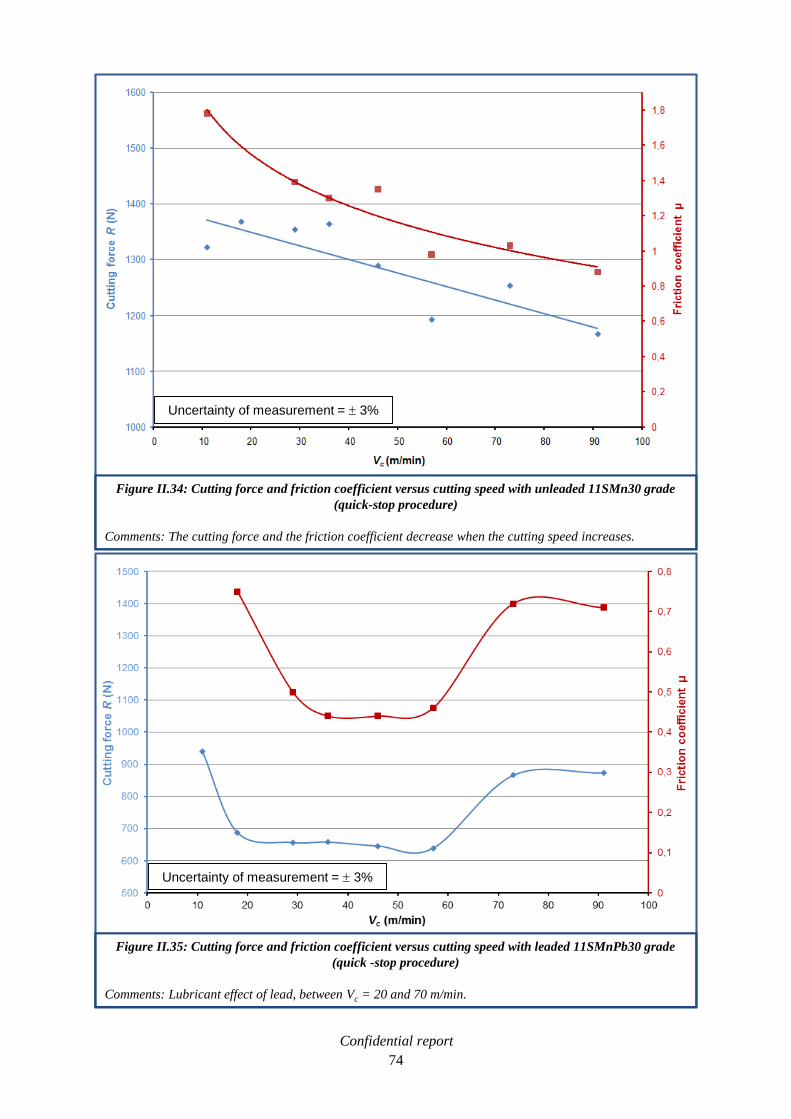
Confidential report
74
Figure II.34: Cutting force and friction coefficient versus cutting speed with unleaded 11SMn30 grade
(quick-stop procedure)
Comments: The cutting force and the friction coefficient decrease when the cutting speed increases.
Uncertainty of measurement = 3%
Figure II.35: Cutting force and friction coefficient versus cutting speed with leaded 11SMnPb30 grade
(quick -stop procedure)
Comments: Lubricant effect of lead, between Vc = 20 and 70 m/min.
Uncertainty of measurement = 3%

Confidential report
75
Moreover, in the particular speed range Vc = 20 - 70 m/min, the shear angle increases in the case of the
leaded 11SMnPb30 grade. At Vc = 46 m/min, the shear angle reaches 36° against 13° in the case of the
unleaded 11SMn30 steel (see figure II.36). This phenomenon contributes to the diminution of cutting
forces.
As a conclusion, quick-stop tests prove the lubricant effect of lead at low cutting speed
(Vc < 100 m/min).
II.2.3. Drilling operations, experimental procedure
To exhibit the effect of lead on machinability, low cutting speeds have to be reached. The drilling
operation allows to machine steel in a wide range of cutting velocity thanks to its particular geometry.
Constantly, the cutting speed varies from 0 m/min at the centre of the drill to the maximum value at
the edge of the tool. So lead should act as a lubricant and tool life enhancer for every hole drilled. In
the entire test campaign, a non-coated 4 mm diameter HSS Tivoly type N 6-5-2 drill (Reference tool at
UGITECH, see figure II.37) has been used under soluble outer lubrication (5%) to fit the speed range
where lead is assuming to have a lubricant effect (Vc < 100 m/min).
II.2.3.1. Tool life test, results
This test consists in the determination of the domain in terms of cutting speed Vc and feed f in
which the lifespans of the drills are long enough. It is called the optimal operating diagram (OOD). In
Figure II.36: Shear angle observation at Vc = 46 m/min with 11SMn30 and 11SMnPb30 grades (quick-
stop procedure)
Comments: Increase of the shear angle by lead addition.
f = 36
11SMn30 11SMnPb30
f = 13
Figure II.37: HSS drilling tool, Tivoly type N 6-5-2, diameter = 4 mm

Confidential report
76
the case of a 4 mm diameter tool, at least 1125 holes of 16 mm depth have to be done to reach 18 m of
drilling, which is the tool life criterion. The larger the OOD (blue zone), the better the grade.The test
has been done on the two industrial grades provided by SWISS STEEL: 11SMn30 and 11SMnPb30.
The OOD is represented in the figure II.38 and the penetration forces in the figure II.39. At high
cutting speed (Vc ≥ 100m/min), the difference is minor between both grades, which could be explained
by the lack of effect of lead at the edge of the tool, where cutting speed is ≥ 100 m/min. But the
improvement of machinability by lead addition is obvious when cutting speed is decreased
(Vc < 100 m/min), Nearly the entire tool fits the speed range where lead has a lubricant effect
(Vc = 0 to 100 m/min). The leaded 11SMnPb30 grade could be drilled at higher cutting speed and feed
than unleaded 11SMn30 steel (see figure II.38). The higher the feed and the speed, the larger the
OOD. The chip flow rate is increased by 116% at feed f = 0.3 mm/rev by lead addition, and by 133%
at feed f = 0.5mm/rev. Similarly to the turning operation, a cutting force decrease (here, penetration
force) has been observed. For instance at f = 0.5 mm/rev and Vc = 15 m/min, the penetration force is
1600 N in 11SMnPb30 instead of 1750 N in 11SMn30 (see figure II.39). As a conclusion, the addition
of lead provides gains in tool life, power consumption and productivity during the drilling operation.
II.3. Conclusion
The two industrials grades provided by SWISS STEEL present only one but major difference:
0.25 wt% of lead. Lead could be observed as small inclusions in an equivalent ferrite + pearlite
structure. It does not have a significant effect on conventional mechanical properties (YS, UTS, etc).
The meaningful effect of lead, as far as mechanical properties are concerned, could be observed on hot
ductility, which is strongly decreased. 11SMn30 and 11SMnPb30 steels show an extremely high
machinability. During the typical test procedures in turning (Vb 15/0.15 and CBD), small differences have
been observed between both. It has been noticed that at high cutting speed (Vc > 600 m/min), with
coated carbide tool, the tool life is decrease by the addition of lead. However, at lower cutting speed
(Vc = 100 m/min) with non-coated tool, the opposite result has been recorded: the tool life is better by
machining leaded steel and built-up edge (BUE) is smaller. During these tests, it is assumed that lead
was liquid at the tool-chip interface thanks to the temperature of the cutting process. Indeed, we
detected lead far away from this interface, and it is assumed that it was not enough viscous to provide
a lubricant effect. Specifics turning tests have been developed by focusing on low cutting speed
(Vc < 150 m/min) where lead plays its best role. With non-coated carbide tool, a global cutting forces
decrease has been observed with leaded steel. Interestingly, a built-up edge (BUE) formed with both
grade, and also lowered cutting forces below Vc = 60 m/min, by modifying cutting geometry. But it
significantly impaired the surface roughness of the bars. We determined that the BUE formation is
more controlled and stabilised with leaded 11SMnPb30 grade. It ensures a better surface finish. With
coated carbide tool, a strong cutting forces decrease has been recorded with leaded 11SMnPb30 steel
between Vc = 20 and 70 m/min. The lubricant effect of lead has been proved thanks to the quick-stop
procedure: Between Vc = 20 and 70 m/min, lead induced the decrease of the friction coefficient at the
tool/chip interface. It is the major explanation of the excellent behaviour of leaded steel at low cutting
speeds. This specific behaviour could be also recorded in drilling. The tool life is increased by the
addition of lead in free cutting steel. The penetration force decreases and the chip flow rate are higher.
Lead provides gains in productivity. Thanks to the complete characterisation of these two grades from
SWISS STEEL, the machinability wished for an alternative to leaded free-cutting steel has been
defined.

Confidential report
77
Figure II.38: Tool life test in drilling with 4mm diameter HSS Tivoly tool on 11SMn30 and 11SMnPb30
grades
Comments: Enhancement of the tool life by lead addition.
Figure II.39: Penetration force (N) of a 4mm diameter HSS Tivoly tool during a tool life test on 11SMn30
and 11SMnPb30 grades
Comments: Decrease of the cutting force by lead addition.

Confidential report
78

Confidential report
79
III. Development of alternatives to leaded free-cutting steels
In this chapter, important theoretical and practical aspects of this PhD work are developed. A
thermodynamic study of graphite nucleation is performed and lead to the determination of five steel
compositions. Thanks to literature and SWISS STEEL expertise, the composition of three tin-added
grades has been determined. These eight steels grades are the alternatives to leaded free-cutting steels
proposed by this study. Then, the melting process of laboratory casts is described and their chemical
analyses are discussed. Finally, the forging procedure, which conducts to the final product, is
explained.
III.1. Substitution of lead by graphite in free-cutting steels
The gain in machinability obtained by graphitic steels has been discussed in the bibliographic
work. It has been chosen to explore this promising way. The aim of the metallurgical work is to
promote the nucleation of graphite, with the carbon that comes from the decomposition of cementite,
during a heat treatment. Thanks to previous works exposed in literature, it has been chosen to fix two
important characteristics for the future developed grades:
Content of carbon = 0.5 wt%.
It is the common analysis in literature (see table I.2 page 30). It should provide a sufficient
amount of graphite phase to ensure a good machinability.
Graphitisation temperature = 700°C.
It is the mean temperature selected in previous attempts in literature [EDM05], [IWA02],
[IWA04], [MEG96]. Moreover, studies on cast irons show that the shortest graphitisation time
has been recorded for a 650-700°C heat treatment [YAM58]. When temperature is lower than
600°C or higher than 700°C, the graphitisation is slower. This point will be developed in a
following chapter.
The crucial objective for the new developments is to decrease as much as possible the time required to
a complete graphitisation. Hence, the study on the effect of alloying elements presented in literature,
such as silicon (Si), aluminium (Al) and manganese (Mn), has to be done.
III.1.1. Determination of steels composition by thermodynamic calculations
Phases of iron-carbon alloys could be described thanks to two diagrams (see figure III.1):
Fe-Fe3C diagram, representing metastable states.
Fe-C diagram, representing stable states.
Fe3C iron carbide, called cementite is metastable, and the true equilibrium is between iron and
graphite. In practice, although graphite occurs extensively in cast irons (2 – 4 wt% C), it is usually
difficult to obtain this equilibrium phase in steels (0.03 – 2 wt% C). Therefore, the metastable
equilibrium between iron and cementite is often considered, because it is relevant to the behaviour of
most steels in practice [HON06]. In the Fe-0.5%C system at 700°C, the metastable state is
ferrite + cementite. If temperature is maintained, the system will naturally tend to a lower energy state
ferrite + graphite (kinetic activates by temperature). This stable state is reached by decomposition of
the cementite, and then by the nucleation and growth of graphite precipitates. Furthermore, it has been
noticed in the bibliographic survey that some graphitiser elements activate the cementite
decomposition (in decreasing order of strength: Si, P, Al, Ni, Cu, Ti, Zr) and impose an evolution in
the Fe-C diagram [DUP08]. Others, called antigraphitiser, stabilise the cementite or analogue mixed
carbides (in decreasing order of strength: Mn, Cr, Mo, S, V, W, B, Se, Te) and conduct to the Fe–Fe3C
phase diagram [DUP08]. Moreover, the presence of nucleation site (nitride, oxide, sulphide) facilitates
the formation of graphite. Thermodynamics calculations based on the bibliographic work have to be
achieved to determine the right amount of alloying elements to get the fastest graphitisation process.

Confidential report
80
The effect of strong graphitiser, such as Si and Al, and antigraphitiser, such as Mn, which are typical
alloying elements in free-cutting steels, will be studied. In that purpose, a thermodynamic simulation
software, Thermo-Calc®, has been used to calculate the driving force for graphite nucleation.
Temperature ( C)
C (weight %)
Cast ironsSteels
Figure III.1: Iron – carbon phases diagram
Reference: G. Murry, Aciers. Généralités, Techniques de l’Ingénieur, M300, October 1993
Solid line: metastable Fe-Fe3C diagram
Dotted line: stable Fe-C diagram

Confidential report
81
III.1.1.1. Presentation of the Thermo-Calc® software
Thermo-Calc® is a software for calculations of multicomponent thermodynamics and phase
diagrams. It is capable of performing many calculations of interest in materials science and
engineering. Applications are:
Phase diagrams (binary, ternary, isothermal, isoplethal, etc.) (up to 5 independent variables).
Thermodynamic properties of pure substances, compounds and solution phases.
Thermodynamic properties of chemical reactions.
Property diagrams (fraction of phases, Gibbs energy, enthalpy, Cp, volume, etc.) (up to 40
components).
Scheil-Gulliver solidification simulations and its extension by considering interstitial back
diffusion in solid phases.
Thermodynamic factors, driving forces.
Metastable equilibria, para-equilibria.
Etc.
Since Thermo-Calc® can handle multicomponent systems, it is possible to investigate how a change in
the content of an alloying element affects the stability of different phases, by calculating a property
diagram or a phase diagram.The Thermo-Calc® calculations are based on thermodynamic databases
created by critical assessments of experimental data. Today there are accurate thermodynamic data
available for many different types of materials such as:
Steels (stainless steels, HSLA steels, high-speed steels, cast irons)
Ni-/NiFe-based superalloys.
Ti-/TiAl-based alloys.
Al-based alloys.
Mg-based alloys.
Zr-based alloys.
Solder alloys (Pb-bearing/-free).
Hard materials, ceramics.
Slags.
Molten salts.
Etc.
The Thermo-Calc® software is divided into several modules for performing different tasks: retrieving
data, performing a calculation or plotting the results. The user interface consists of a command line
interface where commands are typed. All commands can be abbreviated for convenience. There are
also special modules for certain types of calculation such as Scheil-Gulliver simulations of
solidification. Thermo-Calc® has a post processor for producing output from the simulations. Graphs
are plotted with different axis variables. In the following calculations, the S version of Thermo-Calc®
and the TCFE6 database have been used.
III.1.1.2. Thermodynamic of the graphitisation process
The aim of this work is to promote the nucleation of graphite with the carbon that appears from the
decomposition of cementite. A brief reminder of the thermodynamic on classical theory of nucleation
has to be done.
III.1.1.2.1. Classical theory for nucleation
At any temperature above absolute zero, composition and structure fluctuations constantly occur in
alloys as a result of thermal agitation. These fluctuations can lead to the formation of stable nuclei of a
new phase. Thermodynamic variables are used to give an expression for ( ), the variation of Gibbs

Confidential report
82
energy during the nuclei formation. Considering the formation of a nucleus of precipitate in a matrix
a, r being the radius of the nucleus, the change in Gibbs energy of the system is [PHI02]:
( )
(3.1)
Where α is the interface energy per unit area between the two phases (J.m-2
), and is the Gibbs
energy variation per unit volume of embryo, called driving force for nucleation (G – Gα, J.m-3
). Two
cases could be distinguished:
If > 0, ( ) increases continuously with the size r of the fluctuation. Hence the
fluctuation tends to dissolve in a
If < 0, ( )shows two contributions which act in opposition. It decreases with increasing
size only above a critical radius r*(see figure III.2). Hence, fluctuations of size smaller than
r*spontaneously dissolve in the matrix. On the contrary, fluctuations whose size are larger than
r*tend to grow spontaneously to decrease the Gibbs energy of the system.
The critical radius and the activation energy are, assuming a spherical nucleus and neglecting
possible strain effects:
(3.2)
( ) (3.3)
Figure III.2: Gibbs energy variation associated to the formation of a nucleus with a r radius
G
rr*
G*
Interfacial energy (r2)
Volume free energy (r3)
Global nucleus energy G(r)

Confidential report
83
The higher the driving force for nucleation (in absolute value), the lower the critical radius, the
lower the activation energy, the easier the nucleation of precipitate. It shows the need to know . It
has to be considered that this energy has two components:
The chemical component is due to the differences in the crystal structure and composition
of the parent and precipitated phases.
The strain energy component is due to the accommodation of the differences in specifics
volume of the parent and precipitated phases, and the mismatches at the interfaces.
(3.4)
The strain energy term is important for solid state transformation (see [CHR05] for classical
expressions), especially in the case of the graphitisation because the volume change due to this
transformation is high [LES10]. The aim of this work in not to develop a nucleation model, but to
point out the effect of alloying elements on the nucleation of graphite. It is assumed, in first
approximation, that these additions will not change the elastic energy term (in particular the volume
change associated to the transformation), and it will be only considered the chemical component. It
can be write:
(3.5)
Where
id the Gibbs energy per mol of formed at the beginning of the precipitation
(composition of a is still equal to the nominal composition), is the molar volume of ,
assumed constant, which is the case for graphite precipitation. The composition of phase, that
maximises the Gibbs energy change
, is given by the parallel tangent construction [BHA92],
as illustrated in figure III.3.
III.1.1.2.2. Compromise between thermodynamic and diffusion
The number of nuclei (per unit volume) with the critical radius r* is calculated according to the
Boltzmann statistics:
(
) (3.6)
Where n0 is the number of sites per unit volume on which nuclei can form. The nucleation rate is then
derived by considering the frequency with which an atom adds to a critical radius and makes it
stable (I, m-3
.s-1
):
(
) (
) (3.7)
Where A is a number density of available sites on nucleus surface where atoms can be added, is an
attempt frequency, and Gt* is the activation energy for transfer of atoms across the ainterface. The
global activation energy present two terms: thermodynamic ( ) and diffusion ( ). The lower the
activation energy , the higher the nucleation rate. Consequently, the higher the driving force ,
the higher the nucleation rate. It has been mentioned in literature that the higher the under-cooling
(T= Te – T, Te being the equilibrium temperature), the higher the nucleation rate [PHI02]. But, for
temperatures increasingly lower, the diffusion term tends to become increasingly smaller, and leads to
a diminution of the nucleation rate until making it negligible. By increasing the temperature close to
the equilibrium temperature (small T), the critical radius increases, the number of nuclei, and the
nucleation rate are small. The temperature for which graphite appears in a 0.5 wt% C steel has been

Confidential report
84
determined thanks to Thermo-Calc®: Te = 778°C. It means that for temperatures less than 778°C, the
graphite is stable and the graphitisation occurs. In order to maximise the nucleation rate, the
temperature of the graphitisation process should present a sufficient under-cooling compared to the
temperature of graphite formation but it should be not too low to ensure the carbon diffusion (see
figure III.4). 700°C, common values used in literature [EDM05], [IWA04], [IWA02], [MEG96],
seems to reach a compromise between thermodynamic and diffusion. Studies showed that under 600°
and above 700°, the nucleation rate decreases [YAM58]. A 700°C heat treatment will be provided to
the steels developed in this study to decrease as much as possible the graphitisation time.
Figure III.3: An illustration of the construction for finding the driving force for nucleation
Comments : X0 is the nominal composition.
X is the composition of the precipitate that maximises the driving force.
0X X
G (J.mol-1)
X(mol)
Ga
G
mpptG

Confidential report
85
III.1.1.2.3. Development of nucleation sites: heterogeneous nucleation
Homogeneous nucleation, as presented above, very seldom occurs in solid-state transformations.
The presence of defects, with which is associated a given energy, provides sites for preferential
nucleation: inclusions, grains boundaries, dislocations. The gain in energy is obtained on the surfacic
term on formula (3.1). It is considered the formation of a nucleus on the plane surface of the particle
H with the wetting angle (see figure III.5). The Gibbs energy for heterogeneous nucleation is
[TAS06]:
(3.8)
Where Vg is the volume of the graphite nucleus, and A terms are surfaces.
The calculation of the critical radius r* shows that it does not change:
(3.9)
On the other side, the activation energy is decreased (see figure III.6):
( )
( ) ( )
( ) (3.10)
This section exhibits that the acceleration of the nucleation process could be facilitated by the
development of precipitation sites. Hexagonal boron nitride (h-BN), which presents a structure
equivalent to graphite, is the best candidate for an epitaxy of graphite. Boron, and nitrogen additions
will be provided to the steels developed in this study to promote the graphitisation process and
lowering the graphitisation time. Moreover, the addition of aluminium would lead to the formation of
aluminium nitride (AlN) and aluminium oxide (Al2O3), which could act as nucleation site for graphite.
Figure III.4: Nucleation rate variation depending on temperature
Comments: The nucleation rate I is nonzero under a certain temperature T’, smaller than the equilibrium
temperature Te
I (m-3.s-1)
T ( C)eT'T
Thermodynamic
Diffusion Diffusion
Thermodynamic

Confidential report
86
III.1.1.2.4. Calculation on graphitisation process
Before starting, an important practical aspect should be pointed out: Thermo-Calc® is an energy
minimiser without any kinetic considerations. An equilibrium calculation in the Fe-0.5%C system at
700°C, would lead to the stable ferrite + graphite mixture. Nevertheless, the cementite phase should
appear at the initial stale, in order to study its decomposition and the graphite phase formation,
depending on, for instance, Si (graphitiser element) and Mn (antigraphitiser element) additions. In
order to calculate the energy level of a metastable state, it is necessary to change the status of graphite
to ―dormant‖, which means that this phase cannot be present among the possible formed phases. The
influence of Mn and Si additions on the metastable state of the system at 700°C is shown in fig III.7,
and an initial state can be defined at the graphitisation temperature. It could be notice the ferrite former
effect of Si and the austenite former effect of Mn.
Figure III.5: Heterogeneous nucleation model
Young’s relation: Ha = H + a cos
Particle H
nucleus
matrix a
a
HaH
Figure III.6: Difference in energy of activation between homogeneous and heterogeneous nucleation
mechanisms
G
rr*
G*hom
Heterogeneous nucleation
Homogeneous nucleation
G*het
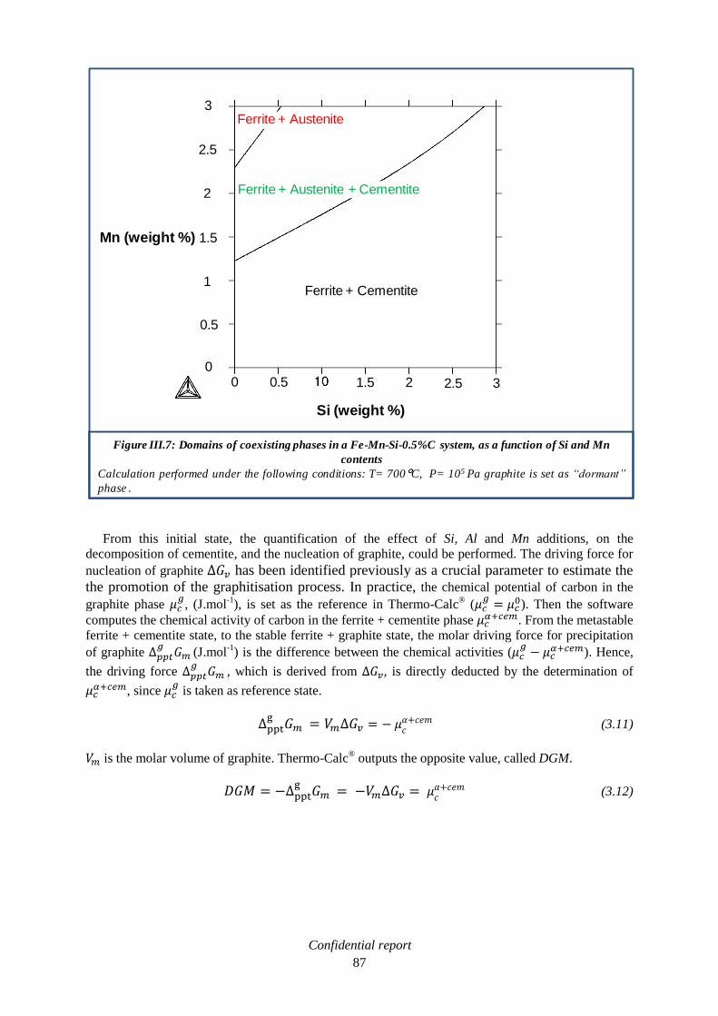
Confidential report
87
From this initial state, the quantification of the effect of Si, Al and Mn additions, on the
decomposition of cementite, and the nucleation of graphite, could be performed. The driving force for
nucleation of graphite has been identified previously as a crucial parameter to estimate the
the promotion of the graphitisation process. In practice, the chemical potential of carbon in the
graphite phase
, (J.mol-1
), is set as the reference in Thermo-Calc® (
). Then the software
computes the chemical activity of carbon in the ferrite + cementite phase . From the metastable
ferrite + cementite state, to the stable ferrite + graphite state, the molar driving force for precipitation
of graphite
(J.mol-1
) is the difference between the chemical activities (
). Hence,
the driving force
, which is derived from , is directly deducted by the determination of
, since
is taken as reference state.
(3.11)
is the molar volume of graphite. Thermo-Calc® outputs the opposite value, called DGM.
(3.12)
Figure III.7: Domains of coexisting phases in a Fe-Mn-Si-0.5%C system, as a function of Si and Mn
contents
Calculation performed under the following conditions: T= 700°C, P= 105 Pa graphite is set as “dormant”
phase .
0.50 1.5 2 2.5 3
0.5
1
1.5
2
2.5
3
Ferrite + Cementite
Ferrite + Austenite + Cementite
Ferrite + Austenite
Si (weight %)
Mn (weight %)
0

Confidential report
88
It could be noticed that for Thermo-Calc®, the nucleation of graphite is effective for a positive value of
the driving force DGM. It is the opposite of the conventional representation which exposes a negative
driving force for an effective nucleation. From the metastable ferrite + cementite state, DGM is a loss
of energy for the system that leads to the stable ferrite + graphite state. Based on the nucleation theory
exposed above, it is assumed that the higher the driving force for graphite nucleation, the easier and
faster the graphitisation process. On the figure III.8, an illustration of the construction for finding
DGM is proposed. Compared to the case described in the previous section on nucleation, the initial
state is the metastable stable ferrite + cementite mixture, which minimises the energy of the system.
The parallel tangent construction is not needed because graphite in a defined compound, there is only
one composition that maximises the driving force. This driving force depends on the addition of
alloying elements such as Si, Al or Mn. If the addition of one of them increases the driving force, the
graphitisation should be accelerated. In the other hand, if the addition of an element leads to the
diminution of the driving force, the graphitisation would be decelerated.
III.1.1.2.5. Effect of alloying elements on graphitisation process
The effect of Si, Al and Mn have been studied on a 0.5 wt% carbon steel at 700°C, which is the
temperature of the graphitisation process. The driving force for nucleation of the graphite phase has
Figure III.8: An illustration of the construction for finding the driving force for nucleation of graphite
DGM
0
cX
cemg XX aa
aa
cemX gX
G (J.mol-1)
X(C, mol)
Ga Gcementite Ggraphite
m
g
pptG
=
DGM(Thermo-calc)
cem
c
a
g
c

Confidential report
89
been calculated depending on the content of one of these alloying elements (see figure III.9). At the
initial state, a 0.5 wt% C carbon at 700°C, the driving force for graphite nucleation is
DGM = 2.3 kJ/mol. This value will be taken as reference. The formation of graphite is known to occur,
but for an extremely long annealing time. If the addition of an element increases the driving force
above 2.3 kJ/mol, it is assumed that this element accelerates the graphitisation. If the addition of an
element decreases the driving force under 2.3 kJ/mol, it is assumed that this element slows down the
graphitisation. On the figure III.7, it could be observed that the addition of Si or Al increases the
driving force above 2.3 kJ/mol. They present a similar behaviour and promote the graphitisation. Mn
addition acts in an opposite way, it decreases the driving force under 2.3 kJ/mol, and makes the
graphitisation harder. These results also highlights that Mn has a stronger effect, as cementite
stabiliser, than Si and Al as graphitisers. It could be remarked that from Mn = 1.23 wt% to 2.33 wt%,
the driving force is constant (DGM = 360 J/mol). In this composition range, the steel presents three
phases: ferrite + austenite + cementite. The degree of freedom is zero and the addition of Mn does not
modify the activity of carbon, hence the driving force. As a conclusion, the promotion of the
graphitisation process could be achieved by the addition of Si, or Al. The graphitisation can be even
more accelerated by the combined addition of Si and Al. The figure III.10 exhibits this effect. It
strongly increases the driving force for graphite nucleation, and should make the graphitisation easier.
However, Si addition should be privileged, because Al has a detrimental effect on hot ductility of steel
[NAC88], and the forging of a steel with large addition of Al, could be problematic. In order not to
stabilise the cementite phase, the addition of Mn should be avoided. Nevertheless, the Mn content is
rarely zero in an industrial steel-shop melting. The study of the combined effect of Si and Mn has to be
studied. Thereby, the simulation of an industrial grade would be more realistic. The figure III.11
shows this effect. A large range of compositions, represented by the surfaces coloured from blue to
green, lead to a detrimental effect on the graphitisation. Indeed, the driving force for graphite
nucleation is under 2.3 kJ/mol in this range. A working zone has been defined to guarantee the
acceleration of the graphitisation (DGM > 2.3 kJ/mol). It contains a compositions range from 0.6 wt%
to 3 wt% Si, corresponding, respectively, to a range from 0 wt% to 2.3 wt% Mn. This working zone,
from the yellow to the red coloured surfaces, is represented by a red dashed line. The entire
compositions of the steels developed in this study, will be selected in this working zone.

Confidential report
90
Figure III.9: Driving force for graphite nucleation in a 0.5 wt% C steel depending on the content of an
alloying element (Si, Al or Mn) at 700°C
Comments: P= 105 Pa and graphite is set as “dormant” phase.
The metastable state from which the driving force is calculated is indicated along the curves.
Si and Al promote the graphitisation. Mn makes the graphitisation harder.
a + + Fe3C
a + Fe3C
a +
a + Fe3C
T = 700 C
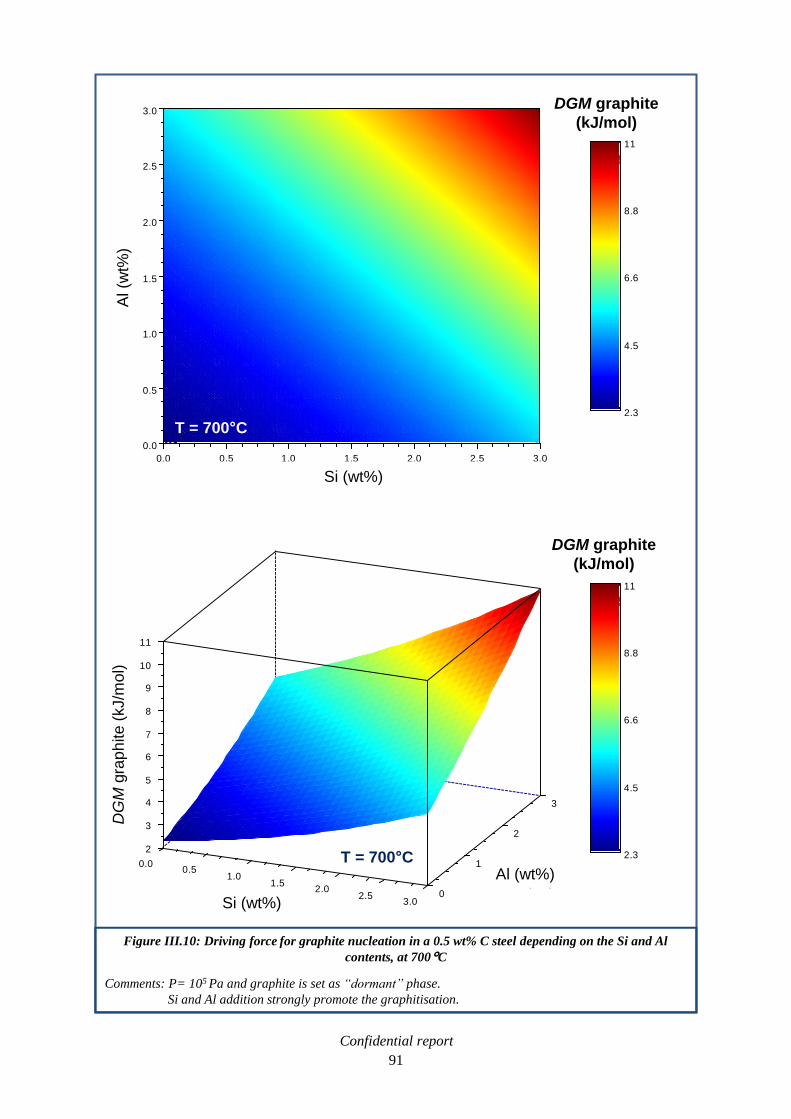
Confidential report
91
Figure III.10: Driving force for graphite nucleation in a 0.5 wt% C steel depending on the Si and Al
contents, at 700°C
Comments: P= 105 Pa and graphite is set as “dormant” phase.
Si and Al addition strongly promote the graphitisation.
0.0 0.5 1.0 1.5 2.0 2.5 3.0
0.0
0.5
1.0
1.5
2.0
2.5
3.0
Si (wt%)
Al (w
t%)
2.3
4.5
6.6
8.8
11
2
3
4
5
6
7
8
9
10
11
Fo
rce
mo
tric
e (
kJ/m
ol)
0
1
2
3
Al (wt%)
0.00.5
1.01.5
2.02.5
3.0Si (wt%)
2.3
4.5
6.6
8.8
11
DGM graphite
(kJ/mol)
Al (wt%)
Si (wt%)
DG
Mgra
ph
ite
(kJ/m
ol)
DGM graphite
(kJ/mol)
Si (wt%)
Al (w
t%)
T = 700 C
T = 700 C

Confidential report
92
Figure III.11: Driving force for graphite nucleation in a 0.5 wt% C steel depending on the Si and Mn
contents, at 700°C
Comments: P= 105 Pa and graphite is set as “dormant” phase.
Si and Mn have opposite effects on the graphitisation.
0.0 0.5 1.0 1.5 2.0 2.5 3.0
0.0
0.5
1.0
1.5
2.0
2.5
3.0
Si (wt%)
Mn
(w
t%)
-1.1
0.5
2.1
3.6
5.2
-2
-1
0
1
2
3
4
5
6
Fo
rce
mo
tric
e (
kJ/m
ol)
0.0
0.5
1.0
1.5
2.0
2.5
3.0
Mn (wt%)
0.0
0.5
1.0
1.5
2.0
2.5
3.0
Si (wt%)
-1.1
0.5
2.1
3.6
5.2
DGM graphite
(kJ/mol)
Si (wt%)
Mn
(wt%
)
DGM graphite
(kJ/mol)
Mn (wt%)Si (wt%)
DG
Mgra
ph
ite
(kJ/m
ol)
T = 700 C
T = 700 C
Working
zone

Confidential report
93
III.1.1.2.6. The chosen compositions
From the theoretical results obtained in the previous sections, it has been decided to develop five
laboratory casts of medium carbon steels, which would endure a graphitisation process. Each
composition (in weight %) will now be described and argued.
Lab G1: 0.5% C – 2% Si – 40 ppm B – 40 ppm N.
DGM (Lab G1, 700°C) = 3.9 kJ/mol.
The high content of silicon provide a higher driving force for the nucleation of graphite
(3.9 kJ/mol) than a theoretical 0.5 wt% C steel at 700°C (i.e. 2.3 kJ/mol). The graphitisation
should be accelerated. Moreover, the nucleation of graphite is facilitated by the formation of h-
BN inclusions, thanks to the addition of boron and nitrogen, in a quantity advised by the
bibliographic survey (see page 32). This heterogeneous nucleation decreases the activation
energy of nucleation, thereby, the graphitisation time should be fast.
Lab G2: 0.5% C – 2% Si – 1% Al – 40 ppm N.
DGM (Lab G2, 700°C) = 5.3 kJ/mol.
This development combines the beneficial effects of silicon and aluminium on the driving
force for the nucleation of graphite. The graphitisation should be even more accelerated than in
the case of Lab G1, because DGM (Lab G2, 700°C) > DGM (Lab G1, 700°C). The addition of
silicon has been privileged to the addition of aluminium, because of the detrimental effect of
aluminium on the hot forging behaviour of steel [NAC88]. The formation of AlN and Al2O3
inclusions, as nucleation site, would facilitate the graphitisation.
Lab G3: 0.5% C – 2% Si – 1% Al – 40 ppm B – 40 ppm N.
DGM (Lab G3, 700°C) = 5.3 kJ/mol.
Lab G3 is a declination of Lab G2, in which heterogeneous nucleation is more developed,
thanks to the addition of boron, and the formation of h-BN nucleation site. The driving force for
the nucleation of graphite is equal to that of Lab G2, because the heterogeneous nucleation does
not influence this value. But, as the activation energy is reduced by heterogeneous nucleation,
the graphitisation should be faster than in the case of Lab G2.
Lab G4: 0.5%C – 2% Si – 0.9% Mn – 0.3% S – 40 ppm B – 40 ppm N.
Free-Mn = 0.39%, DGM (Lab G4, 700°C) = 3.4 kJ/mol.
Lab G4 is the first innovative development of this PhD work. The purpose of this steel is to
combine the beneficial effects of graphite and MnS inclusions on machinability. It could be
considered as a resulphurised version of Lab G1. Indeed, 0.9% Mn and 0.3% S have been added
to the composition of Lab G1. The Mn/S ratio has been determined in another study lead with
SWISS STEEL (see Annex C). The Si and Mn contents place the composition of Lab G4 at the
edge of the working zone that has been defined lately in this study (see page 89). It means that
the driving force for the nucleation of graphite is slightly higher than that of a theoretical
0.5% C steel (2.7 kJ/mol against 2.3 kJ/mol). But in this case, the sulphur added in the steel
consumes a fraction of the manganese to form MnS inclusions. Therefore, only the Mn that did
not react with S (called Free-Mn) would have a detrimental effect on graphitisation. Here, Free-
Mn = 0.39%, which lead to a driving force equal to 3.4 kJ/mol. The positive effect of
heterogeneous nucleation (h-BN inclusions) has to be also considered. As a consequence, the
graphitisation time should be shorter than that of a theoretical 0.5%C steel.

Confidential report
94
Lab G5: 0.5%C – 1.2% Si – 0.6% Mn – 0.2% S – 40 ppm B – 40 ppm N.
Free-Mn = 0.26%, DGM (Lab G5, 700°C) = 2.8 kJ/mol.
This second innovative development follows the same philosophy as Lab G4. But here, it is
tried to reach a compromise between graphitisation time, mechanical properties and
machinability. The silicon amount (1.2%) has been chosen to ensure a decent graphitisation
time and to limit the raise of mechanicals properties (not suitable for machinability) [MUR93].
The amount of manganese (0.6%) is the minimal content that SWISS STEEL steel shop could
handle at an industrial scale. This manganese slows down the graphitisation but forms MnS with
sulphur (0.2%). The Free-Mn content is 0.26%, which added to 1.2% Si, leads to a driving force
at 700°C equal to 2.8 kJ/mol. This value is slightly higher than that of a theoretical 0.5 wt% C
steel at 700°C (DGM = 2.3 kJ/mol), Nevertheless, the graphitisation, helped by the contribution
of nucleation sites (h-BN), should clearly be accelerated. Compared to the other laboratory casts
of this study, the graphitisation time should be the longest.
III.2. Substitution of lead by tin in free-cutting steels
Addition of tin is an alternative to lead in free-cutting steels that emerges from the bibliographic
survey. It is promoted by the University of Pittsburgh, patents and publications claimed its reliability
in replacing lead [DEA99], [GAR03]. It is suggested that a heat treatment provides the segregation of
tin at the grain boundaries, which weakens the steel and improves the machinability. But the
machinability enhancement of tin added steel in not clearly determined [REY07]. It has been decided
to study this alternative and to develop tin added steel to characterise its machinability.
III.2.1. Determination of tin added steels compositions
Initially, it has been considered to perform thermodynamic calculations, thanks to Thermo-Calc®,
in order to study the phases formation and to determine relevant compositions. Unfortunately, the
Thermo-Calc® data base could not take into account the addition of tin in a steel. No calculations
could be achieved. It has been decided to determine the composition of laboratory tin added steels
thanks to the bibliographic survey, and the SWISS STEEL expertise in alloyed steels. In patents and
publications, the tin content is comprised between 0.04 wt% and 0.08 wt% [DEA99], [GAR03],
[REY07]. Empirical compositions rules have been defined at the SWISS STEEL rolling mill to
guarantee the rollability of steel. In the case of tin, here is the formula:
( ) ( ) (3.13)
The Cu content is non zero in laboratory steel ( from 5 to 200 ppm), because of Cu traces present in
the base iron. To guarantee the SWISS STEEL rule, 0.06% Sn has been added to a classic 11SMn30
steel. It is called Lab 11SMn30 + 0.06% Sn. Then, it has been decided to melt a grade with twice more
tin content (0.12% Sn). The SWISS STEEL rule is overtaken, but it allow to study the characteristics
of a steel with more tin than the grade exhibited in patents and publications. The denomination of this
grade is: 11SMn30 + 0.12% Sn. Moreover, the development of a phase in the steel with a lower
melting temperature than Pb could be useful for machinability. The Pb-Sn phase diagram presents an
eutectoid phase that melts at 183°C (38.1wt% Pb, see figure III.11). If tin is added to a classic
11SMnPb30 grade, some eutectoid phase may form. In order to confirm this assumption, 0.06% Sn
has been added to a 11SMnPb30 steel. This hybrid grade is called Lab 11SMnPb30 + 0.06% Sn. If the
presence of Pb-Sn phase is confirmed, the development of steels with the right amount of Pb and Sn to
form the eutectoid phase could be considered. For instance, 0.1 wt% Pb + 0.15 wt% Sn would conduct
to the formation of 0.25 wt% Pb-Sn eutectoid phase, hence, replacing the 0.25 wt% Pb phase of a
classic 11SMnPb30 steel. Then the machinability behaviour would have to be checked. Finally, it
would not be a complete replacement of lead in free-cutting steels, but a promising decrease of the Pb
content.

Confidential report
95
III.3. Development of steels at the laboratory scale
The desired compositions have been described in the past section. Three tin added steels and five
medium carbon steels for graphitisation will be melt. In addition to new developments, the melting of
Lab 11SMn30 and Lab 11SMnPb30 steels at the laboratory scale, has been planned. The purpose of
these grades is to define laboratory references. The new laboratory developments, with different
content of alloying elements, will be compared to theses references.
III.3.1. Description of the laboratory furnaces
The laboratory grades have been melted in two VIM furnaces (vacuum induction melting). The
first furnace could produce 75 kg of metal (see figure III.13), the second, 25 kg (see figure III.13).
Induction heating is the process of heating an electrically conducting object (here: metal) by
electromagnetic induction. Foucault currents are generated within the metal, and resistance leads to
Joule heating. The advantage of the induction furnace is a clean, energy-efficient and well-controllable
melting process. Since no arc, or combustion is used, the temperature of the material is never higher
than required to melt it. This can prevent loss of valuable alloying elements. The induction frequency
is 2,5 kHz and the power is 150 kW. Both furnaces have a sealed chamber in order to work under
vacuum, or controlled atmosphere. Elements addition is achieved by an airlock, and temperature
measurements are done thanks to sacrificial thermocouples. Depending on the elements, the analytical
precision can reach a few ppm. The cast ingots are solidified in square moulds.
III.3.1.1. Course of the melting
First, irons billets, and irons flakes, are placed in the crucible. Different products are added to reach
the final composition, for instance, silicon and sulphur powders. The furnace is heated until everything
is melted (see figure III.15). Then, additions are made, to complete the chemical analysis, thanks to the
airlock of the furnace:
Figure III.12: Pb-Sn phases diagram
Reference: http://upload.wikimedia.org/wikipedia/commons/c/cc/Fasediagram_Pb_Sn.png
Tem
pera
ture
( C
)
Pb (wt%)PbSn

Confidential report
96
Carbon, lead, tin, manganese (metal) and aluminium.
FeMnN2, nitrited ferromanganese, to add manganese and nitrogen.
FeP, ferrophosphorus, to add phosphorus.
FeB, ferroboron, to add boron element.
The amount of each product has been calculated in a software developed in the laboratory. The
contribution of each product, to each element, is taken into account. For instance, the iron content of
FeP addition has been taken into account in the global iron content. The nitrogen content is reached
both by the addition of nitrited ferromanganese, and an addition of nitrogen gas in the chamber during
the melting. When all the elements have been added and the appropriate temperature is reached, the
melt is tapped in a mould (see figure III.16). The ingot is then air-cooled at room temperature (see
figure III.17). It should be noticed that the melting of leaded steels has been performed with all the
security requirements:
Technicians protected with mask, gloves and working clothes, to prevent any contact with Pb.
Working area ventilated and aspiration of eventual Pb fumes.
III.3.1.2. Results of chemicals analyses
Lab 11SMn30 is the only composition which has been produced with the 75 kg furnace, because of
the few elements to add during the melting. Others compositions, with more critical additions (Pb, Sn,
B), have been prepared in the 25 kg furnace. Each composition was cast in three ingots, in order to
obtain 75 kg of available steel. To achieve the chemical analysis, different methods have been used.
The Si, Mn, P, Ni, Cr, Mo, Cu and Sn contents have been measured by X-ray fluorescence
method. The steel sample is exposed to short-wavelength X-rays (high energy), ionisation of
their component atoms may take place. The removal of an electron by this way renders the
electronic structure of the atom unstable, and electrons in higher orbitals "fall" into the lower
orbital to fill the hole left behind. In falling, energy is released in the form of a photon, its
energy is equal to the energy difference of the two orbitals involved. Thus, the steel emits
radiation, which has energy characteristic of the atoms present. For each element, a sensor
measures the intensity of the radiation. The concentration is calculated by applying large
corrections due to interference and matrix effects (calibration curves).
The C and S contents have been determined by an infrared spectroscopy method. The steel
sample is melt in a small induction furnace with the presence of dioxygen gas. CO2 and SO2
gases form and are analysed by infrared absorption. The concentration of C and S are deducted
from this analysis.
The Al, Pb and B contents have been measured by an optical emission spectrometry method
(OES). An electric arc is created between an electrode and the steel sample, heating it to a high
temperature to excite the atoms within it. When they come back to a stable state, the atoms emit
light at characteristic wavelengths that can be dispersed with a lattice and detected. The
intensity of wavelengths gives the concentrations of each element.
The N content has been determined by thermal conductivity technique. The steel sample is
heated to 2000°C by Joule effect in a stream of helium. Nitrides are decomposed and the
nitrogen goes entirely to a gaseous state. This gas passes through a cell and alters the thermal
conductivity: the gap gives back the amount of nitrogen.
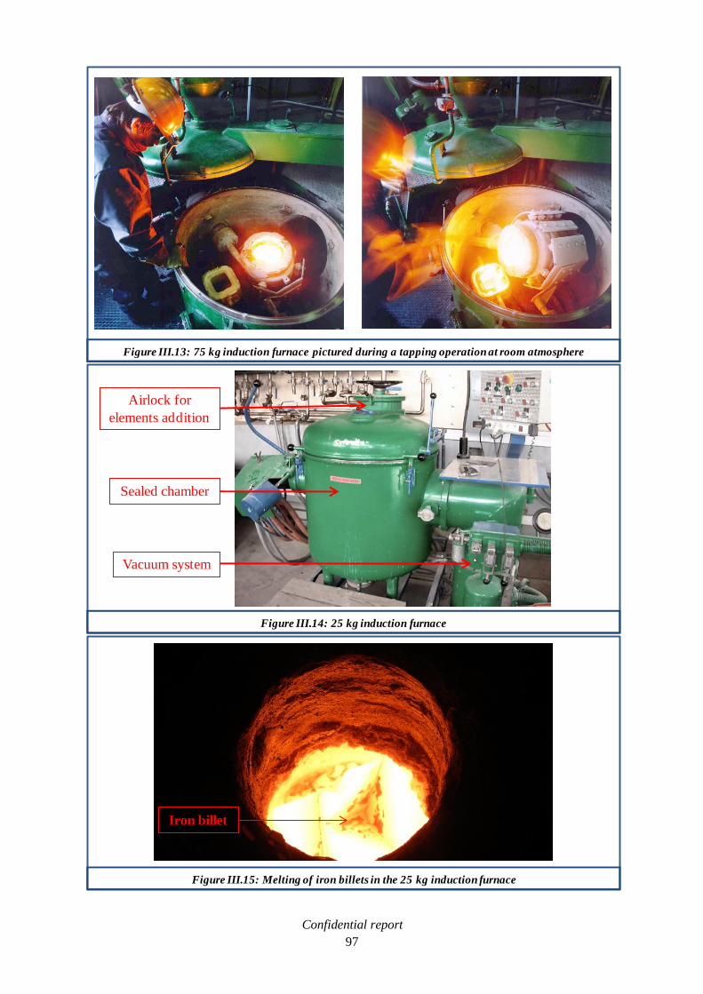
Confidential report
97
Figure III.13: 75 kg induction furnace pictured during a tapping operation at room atmosphere
Figure III.14: 25 kg induction furnace
Sealed chamber
Airlock for
elements addition
Vacuum system
Figure III.15: Melting of iron billets in the 25 kg induction furnace
Iron billet

Confidential report
98
Figure III.16: Tapping of a 25 kg cast in a square mould
Mould
Figure III.17: Air-cooling of a 25 kg ingot
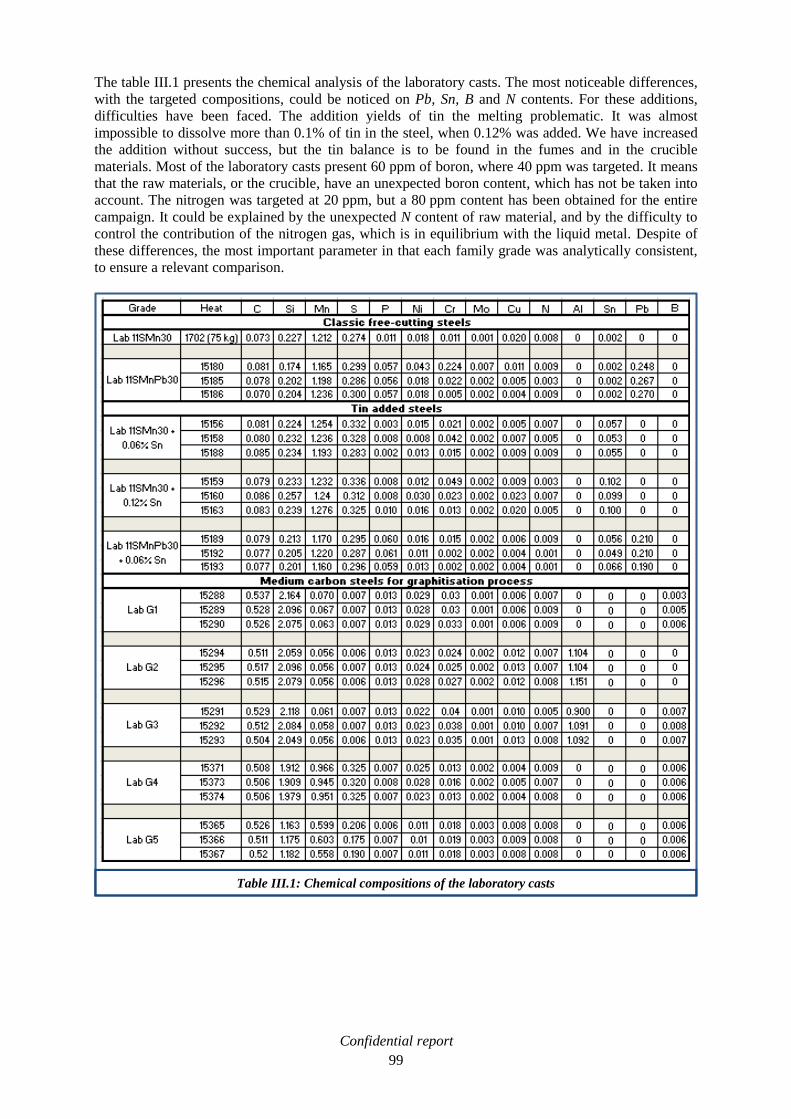
Confidential report
99
The table III.1 presents the chemical analysis of the laboratory casts. The most noticeable differences,
with the targeted compositions, could be noticed on Pb, Sn, B and N contents. For these additions,
difficulties have been faced. The addition yields of tin the melting problematic. It was almost
impossible to dissolve more than 0.1% of tin in the steel, when 0.12% was added. We have increased
the addition without success, but the tin balance is to be found in the fumes and in the crucible
materials. Most of the laboratory casts present 60 ppm of boron, where 40 ppm was targeted. It means
that the raw materials, or the crucible, have an unexpected boron content, which has not be taken into
account. The nitrogen was targeted at 20 ppm, but a 80 ppm content has been obtained for the entire
campaign. It could be explained by the unexpected N content of raw material, and by the difficulty to
control the contribution of the nitrogen gas, which is in equilibrium with the liquid metal. Despite of
these differences, the most important parameter in that each family grade was analytically consistent,
to ensure a relevant comparison.
Table III.1: Chemical compositions of the laboratory casts

Confidential report
100
III.3.2. Forging procedure on laboratory steels
The ingot cannot be used in the as cast state, because of the lack of homogeneity of the structure.
Moreover, to compare the laboratory grades to the industrial steels from SWISS STEEL, the ingots
should endure an equivalent thermo mechanical path. Industrial steels are hot rolled from square
blooms (150 mm x 150 mm) to round bars (Ø = 64 mm), between 1150-1200°C and 950-1000°C. The
section reduction rate is about 7. Laboratory ingots present a pyramidal shape: the section varies from
110 mm x 110 mm to 100 mm x 100 mm. As a consequence, and taking into account that ingots could
only be forged in square shape, a final section of 40 mm x 40 mm would be relevant to get a reduction
rate close to 7. But a significant problem arose: For machining tests, the forged bars will be cut in
50 mm high pieces, which will be held in the machining centre thanks to a three-jaw. But
40 mm x 40 mm is too small for the three-jaw. As a consequence, the ingots have been forged in
50 mm x 50 mm square bars, which mean a section reduction between 4 and 5. The forging procedure
begins by a reheating of the ingot to 1150-1200°C, to simulate the industrial reheating provided on
blooms in the SWISS STEEL rolling mill. Then the ingots are forged thanks to a drop hammer (see
figure III.19 at the end of this chapter). The crucial parameter of the operation is to reach the final
dimensions (i.e. 50 mm x 50 mm) before the temperature reached less than 950°C. Finally, the bars are
air-cooled (see figure III.18). The forging process was successful for all the laboratory casts, except
for Lab G3. A significant part of the steel presented large crack and the forging have not been finished.
This could be explained by the aluminium and boron contents of Lab G3. Indeed, the addition of
aluminium is known to provide an embrittlement effect in this temperature range [NAC88], and the
addition of boron decreases the solidus temperature [OHT88]. Thus, Lab G3 did not endure the
forging process between 1200 and 950°C.
III.4. Conclusion
Thanks to the literature survey and a thermodynamic study, eight compositions of possible
alternatives to leaded free-cutting steels have been determined. Three tin-added grades and five
medium carbon steels for graphitisation process have been suggested. In this last case, thermodynamic
calculations showed that the graphitisation process should be accelerated by the addition of Si and/or
Al to the steel compositions, and decelerated by Mn addition. Among these medium carbon steels, two
innovative compositions which combined graphite and MnS inclusions have been proposed, and
should present promising machinability behaviour. In addition to these new developments, the melting
of Lab 11SMn30 and Lab 11SMnPb30 steels at the laboratory scale, has been planned. The purpose of
these grades is to define laboratory references. The melting in induction furnaces provided 75 kg of
each composition. They have been subsequently forged in square shape bars. The hot transformation
endured by the laboratory ingots tried to simulate as much as possible the thermo mechanical path of
industrial steels from SWISS STEEL. The characterisation of Lab 11SMn30 and Lab 11SMnPb30,
Figure III.18: Air-cooling of a forged bar
≈ 110 cm
≈ 5cm
≈ 5cm

Confidential report
101
with the same procedure than that of industrial grades, will ensure a comparison, as relevant as
possible, to the results obtained with the industrials steels, and finally defined new references. The
alternatives grades developed in this chapter, with different content of alloying elements, will endured
the same characterisation procedure, and will be compared to theses references. Thus, their ability to
replace leaded free-cutting steel will be determined.
Figure III.19: Forging of Lab G5 (heat 15365)
t= 0
T= 1180 C
t= 4 min
T= 975 C
Hammer
t= 1.5 min
T= 1100 C

Confidential report
102
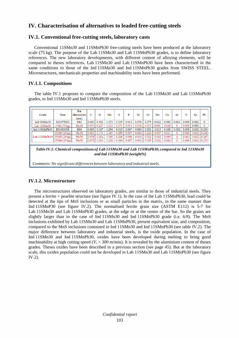
Confidential report
103
IV. Characterisation of alternatives to leaded free-cutting steels
IV.1. Conventional free-cutting steels, laboratory casts
Conventional 11SMn30 and 11SMnPb30 free-cutting steels have been produced at the laboratory
scale (75 kg). The purpose of the Lab 11SMn30 and Lab 11SMnPb30 grades, is to define laboratory
references. The new laboratory developments, with different content of alloying elements, will be
compared to theses references. Lab 11SMn30 and Lab 11SMnPb30 have been characterised in the
same conditions to those of the Ind 11SMn30 and Ind 11SMnPb30 grades from SWISS STEEL.
Microstructures, mechanicals properties and machinability tests have been performed.
IV.1.1. Compositions
The table IV.1 proposes to compare the composition of the Lab 11SMn30 and Lab 11SMnPb30
grades, to Ind 11SMn30 and Ind 11SMnPb30 steels.
IV.1.2. Microstructure
The microstructures observed on laboratory grades, are similar to those of industrial steels. They
present a ferrite + pearlite structure (see figure IV.1). In the case of the Lab 11SMnPb30, lead could be
detected at the tips of MnS inclusions or as small particles in the matrix, in the same manner than
Ind 11SMnP30 (see figure IV.2). The normalised ferrite grain size (ASTM E112) is 5-7 for
Lab 11SMn30 and Lab 11SMnPb30 grades, at the edge or at the centre of the bar. So the grains are
slightly larger than in the case of Ind 11SMn30 and Ind 11SMnPb30 grade (i.e. 6/8). The MnS
inclusions exhibited by Lab 11SMn30 and Lab 11SMnPb30, present equivalent size, and composition,
compared to the MnS inclusions contained in Ind 11SMn30 and Ind 11SMnPb30 (see table IV.2). The
major difference between laboratory and industrial steels, is the oxide population. In the case of
Ind 11SMn30 and Ind 11SMnPb30, oxides have been developed during melting to bring good
machinability at high cutting speed (Vc > 300 m/min). It is revealed by the aluminium content of theses
grades. Theses oxides have been described in a previous section (see page 45). But at the laboratory
scale, this oxides population could not be developed in Lab 11SMn30 and Lab 11SMnPb30 (see figure
IV.2).
Table IV.1: Chemical compositions of Lab 11SMn30 and Lab 11SMnPb30, compared to Ind 11SMn30
and Ind 11SMnPb30 (weight%)
Comments: No significant differences between laboratory and industrial steels.

Confidential report
104
Figure IV.1: Microstructures of Lab 11SMn30 and Lab 11SMnPb30 compared to those of Ind 11SMn30
and Ind 11SMnPb30 (perpendicular to forging/rolling direction)
Comments: No differences between laboratory and industrial steels.
Ind 11SMn30
Ind 11SMnPb30 Lab 11SMnPb30
Lab 11SMn30
MnS
Pearlite
Ferrite
Ferrite
Pearlite
MnS
Pearlite
Ferrite
MnS
Pearlite
Ferrite
MnS

Confidential report
105
MnS
Oxide
Lead
MnS
Oxide
Figure IV.2: SEM observation (BSE) of Lab 11SMn30 and Lab 11SMnPb30 compared to Ind 11SMn30
and Ind 11SMnPb30 (parallel to forging/rolling direction)
Comments: Same inclusions observed, except for the oxides developed in industrial steels.
Ind 11SMn30
Ind 11SMnPb30
Lab 11SMn30
MnS
10 µm N : 1651
Lead
MnS
Lab 11SMnPb30
Detecteur: BSE

Confidential report
106
IV.1.3. Mechanical properties
IV.1.3.1. Tensile test and hardness profile
The thermo mechanical path endured by laboratory and industrial steels is different, respectively
forging and rolling. As a consequence, the mechanical properties of laboratory grades, show slight
differences compared to the results obtained with industrials steels (see table IV.3 and figure IV.3).
Nevertheless, it could be noticed that for Lab 11SMnPb30 and Ind 11SMnPb30, the results follow the
same tendency (equivalent UTS and HV), and are slightly higher than the characteristics of
Ind 11SMn30 (YS, UTS and HV). The hardness gap, between Lab 11SMn30 and Ind 11SMn30, is the
major difference observed (see figure IV.3). It is assumed that the lower carbon content of
Lab 11SMn30 explained this phenomenon.
Table IV.2: Characterisation of manganese sulphide inclusions in Lab 11SMn30 and Lab 11SMnPb30
compared to Ind 11SMn30 and Ind 11SMnPb30
Comments: Equivalent sulphides population between laboratory and industrials steels
- Mean values among 5 sulphides
Table IV.3: Tensile test report of lab11SMn30 and Lab 11SMnPb30, compared to that of Ind 11SMn30
and Ind 11SMnPb30
Comments: Similar mechanical properties between laboratory and industrial steels. YS and UTS are slightly
higher for leaded steel compared to unleaded steel.
- Mean values among 3 samples

Confidential report
107
IV.1.3.2. Hot forging test
The same hot forging test procedure, than the one adopted for the characterisation of industrial
grades, has been executed (see page 49). Once again, the results performed with the laboratory grades
are nearly the same than those observed with industrial steels (see figure IV.4). The addition of lead
strongly decreases the forgeability of free-cutting steel. The needed stress is equivalent in both cases.
IV.1.4. Machinability
The determination of machinability by turning tests has been eliminated because of the square
shape of the bars. Too much material would be lost if it is tried to machine the bar in round shape prior
to carry out turning test. It is the reason why the machinability characterisation has been performed
only in drilling, with the tool life procedure described in page 75. Nevertheless, the limited amount of
laboratory metal does not allow a complete scanning of the optimal operating diagram (OOD) like we
did for industrial grades (see figure IV.5.A). Representative cutting conditions have to be chosen. It
has been decided to work at low feed (f = 0.1 mm/rev), medium feed (f = 0.3 mm/rev) and high feed
(f = 0.5 and 0.65 mm/rev). It has been tried to find the highest cutting speeds that verify the tool life
criterion (more than 1125 holes of 16mm depth, i.e. 18m of cumulative drilling). The machinability
references are the OOD of the Ind 11SMn30 and Ind 11SMnPb30 grades (respectively green and blue
lines on figure IV.5.B). The machinability results of Lab 11SMn30 and Lab 11SMnPb30 grades are
exposed on figure IV.6.A. The superposition of these results on references lines is represented on
figure IV.6.B. Compared to Ind 11SMn30, the same machinability behaviour has been obtained with
the Lab 11SMn30 grade. By superposing laboratory results on industrial OOD reference lines, we
observe that they fit pretty well. The Ind 11SMn30 reference line is relevant to characterise the
machinability of steels developed at the laboratory scale. Lab 11SMnPb30 follows the same tendency
Figure IV.3: Lab 11SMn30 and Lab 11SMnPb30 hardness profiles, compared to those of Ind 11SMn30
and Ind 11SMnPb30.
Comments: Ind 11SMnPb30 and Lab 11SMnPb30 present the same hardness profile, and it is slightly higher
than that of Ind 11SMn30. Lower hardness profile for Lab 11SMn30, due to its lower carbon
content.
Uncertainty of measurement = 4%

Confidential report
108
but, the result obtained at medium feed (f = 0.3 mm/rev), shows a notable gap from the Ind
11SMnPb30 reference line. Indeed, the tool life criterion has been verified at a much higher cutting
speed than the Ind 11SMnPb30 reference line (Vc = 85 m/min compared to 65 m/min). This result has
lead to the definition of a new reference line for that feed, the Lab 11SMnPb30 reference, that has
been add to the Ind 11SMnPb30 reference line. The low amount of laboratory steel cannot highlight a
global machinability improvement with Lab 11SMnPb30 grade.
IV.1.5. Conclusion
The composition, the structure and the mechanical properties of Lab 11SMn30 and
Lab 11SMnPb30, are equivalent to those of Ind 11SMn30 and Ind 11SMnPb30. Its means that, for the
same chemical analysis, a grade developed at the laboratory scale, with a different thermo mechanical
path (i.e. forging instead of rolling), presents the same characteristics than an industrial grade. The
results obtained with Lab 11SMn30 and Lab 11SMnPb30 become the new references for the next
steels developed at the laboratory scale, with different alloying element contents. Nevertheless, the
machinability of theses futures grades will still be compared to the industrial references. Indeed, even
if the machinability behaviour of Lab 11SMn30 is in good accordance with the Ind 11SMn30
reference line, the amount of laboratory steel did not allow to perform a complete machinability
characterisation. It is also applicable for Lab 11SMnPb30. However, Lab 11SMnPb30 exhibited a
higher machinability at medium feed than the Ind 11SMnPb30 reference line. This result has been
Figure IV.4: Hot forging tests on Lab 11SMn30 and Lab 11SMnPb30, compared to those of Ind 11SMn30
and Ind 11SMnPb30
Comments: Similar behaviour observed on laboratory and industrial grades.

Confidential report
109
taking into account, and added to the Ind 11SMnPb30 reference line, in order to guarantee a relevant
comparison with new developed steels.
Figure IV.5: Tool life test in drilling with 4 mm diameter HSS Tivoly tool on Ind 11SMn30
and Ind 11SMnPb30
B
A

Confidential report
110
Figure IV.6: Tool life test in drilling with 4 mm diameter HSS Tivoly tool on Lab 11SMn30 and
Lab 11SMnPb30 (B: superposition of results on industrial reference lines)
Comments: The results obtained with Lab 11SMn30 are in good accordance with the Ind 11SMn30
reference. The machinability of Lab 11SMnPb30 is better, at medium feed, than the
Ind 11SMnPb30 reference. As a consequence, a Lab 11SMnPb30 reference has been defined.
B
A

Confidential report
111
IV.2. Tin added steels
Addition of tin (Sn) to substitute lead (Pb) in free-cutting steels is the first development of this
study. It has been chosen to characterise tin added steels in the same conditions than Lab 11SMn30
and Lab 11SMnPb30 steels, in order to compare them. The different tests have been performed on
steels with two tin levels (0.06 % and 0.12% Sn, see table IV.4) at the initial state and after a heat
treatment that should provide tin concentration at the grain boundaries, and thus, machinability
improvement [DEA99]. Moreover, a hybrid steel (Pb+Sn) has been characterised in order to
investigate the synergic effect of lead and tin and to study the formation of a hypothetic eutectoid
phase.
IV.2.1. Microstructure
As expected, the microstructure of laboratory tin added steel are equivalent to those of
Lab 11SMn30 and Lab 11SMnPb30 grades (see figure IV.7):
Ferrite + pearlite structure
Equivalent grain size
Same manganese sulphides morphology
Tin could not be detected with a scanning electron microscope (see figure IV.8). The solubility limit of
tin in solid ferrite phase is 6.6 wt% (3.2 at%) at 600°C [KUB82]. It is assumed that this solubility
stays quite constant when the temperature decreases to room temperature. Therefore, with 0.06 and
0.12 wt% in the developed tin added steels, it is supposed that tin it is entirely dissolved in the ferritic
matrix. In the case of the hybrid Lab 11SMnPb30 + 0.06% Sn steel, it has been tried to detect the
formation of a Pb-Sn eutectoid phase. Thanks to an electron probe microanalyser (EPMA), a
cartography of lead, tin and sulphur elements, has been carried out (see figure IV.9). Sulphur strongly
appears in MnS inclusions. A sulphur decrease could be noticed, at the interface with the matrix. The
lead is easily detected at the tip of the MnS inclusions or lonely in the matrix. The tin is observed in
each lead inclusion. But the signal is just slightly higher than the signal of the tin dissolved in the
matrix. As the measurement is not quantitative, the presence of a eutectoid phase could not be
confirmed.
Table IV.4: Chemical compositions of laboratory tin added steels (weight%)

Confidential report
112
Figure IV.7: Microstructures of tin added steels compared to those of Lab 11SMn30 and Lab 11SMnPb30
(perpendicular to forging direction)
Comments: Similar microstructures for tin added steel, Lab 11SMn30 and Lab 11SMnPb30
Lab 11SMn30
MnS
Pearlite
Ferrite
Lab 11SMn30 + 0.06% Sn
MnS
Pearlite
Ferrite
Lab 11SMn30 + 0.12% Sn
MnS
Pearlite
Ferrite
Lab 11SMnPb30
MnS
Pearlite
Ferrite
Lab 11SMnPb30 + 0.06% Sn
MnS
Pearlite
Ferrite

Confidential report
113
Figure IV.8: SEM observation (a: SE and b: BSE) of Lab 11SMn30 + 0.12% Sn grade (parallel to forging
direction)
Comments: No tin detected. It is certainly dissolved in the matrix.
MnS MnS
Pearlite Pearlite
Ferrite Ferrite
a: SE detector, topography b: BSE detector, composition
Figure IV.9: EPMA cartography of Lab 11SMnPb30 + 0.06% Sn grade (parallel to forging direction)
Comments: The presence of a Pb-Sn eutectoid phase could not be confirmed.
Sulphur
Lead Tin
0
amount
0
amount
0
amount

Confidential report
114
IV.2.2. Mechanical properties
IV.2.2.1. Tensile test and hardness profile
It could be noticed that steels, with two different tin contents (0.06 and 0.12% Sn), present the same
mechanicals characteristics. It is certainly due to the fact, that, in both cases, tin is entirely dissolved in
the matrix. As a consequence, no significant difference could be done between them.
Lab 11SMn30 + 0.06/0.12% Sn exhibit similar mechanical properties to those of Lab 11SMnPb30 (see
table IV.5). Compared to Lab 11SMn30, the addition of tin, as lead addition, slightly increases the
mechanical properties. The hardness is also higher (see figure IV.10), but it has been discussed that the
hardness of Lab 11SMn30 is maybe too low, certainly because of its carbon content. Compared to Lab
11SMnPb30, Lab 11SMnPb30 + 0.06% Sn exhibits equivalent mechanical properties, with a slightly
higher hardness.
Table IV.5: Tensile test report of tin added steels compared to that of lab 11SMn30 and Lab 11SMnPn30
Comments: No significant difference between tin added grades and Lab 11SMnPb30.
Figure IV.10: Laboratory tin added steels hardness profiles compared to those of lab 11SMn30 and
Lab 11SMnPb30
Comments: Tin addition, as lead addition, conducts to a slight increase of hardness.
Uncertainty of measurement = 4%

Confidential report
115
IV.2.2.2. Hot forging test
In order to characterise the ability of tin added steels to endure the hot rolling transformation, hot
forging tests have been carried out, with the same procedure than the one adopted for the
Lab 11SMn30 and Lab 11SMnPb30 (see page 49). The results recorded with tin added steels are
compared to the values obtained with Lab 11SMn30 and Lab 11SMnPb30 on figure IV.11. It has been
observed that the tin addition, increasingly decreases the hot forging behaviour of free-cutting steels,
when the tin amount increases (dark blue line: 0.06%Sn and green line: 0.12%Sn on figure IV.11).
The combined addition of lead and tin in Lab 11SMnPb30 + 0.06% Sn, conducts to a worse hot
forging behaviour than that of Lab 11SMnPb30 (light blue and red lines on figure IV.11). It can be
also noticed that the needed stress for necking is equivalent whatever the tin or lead content.
Figure IV.11: Hot forging tests on tin added steels compared to those of Lab 11SMn30 and
Lab 11SMnPb30
Comments: Tin addition, as lead addition, strongly decreases the hot forging behaviour of free-cutting
steels.
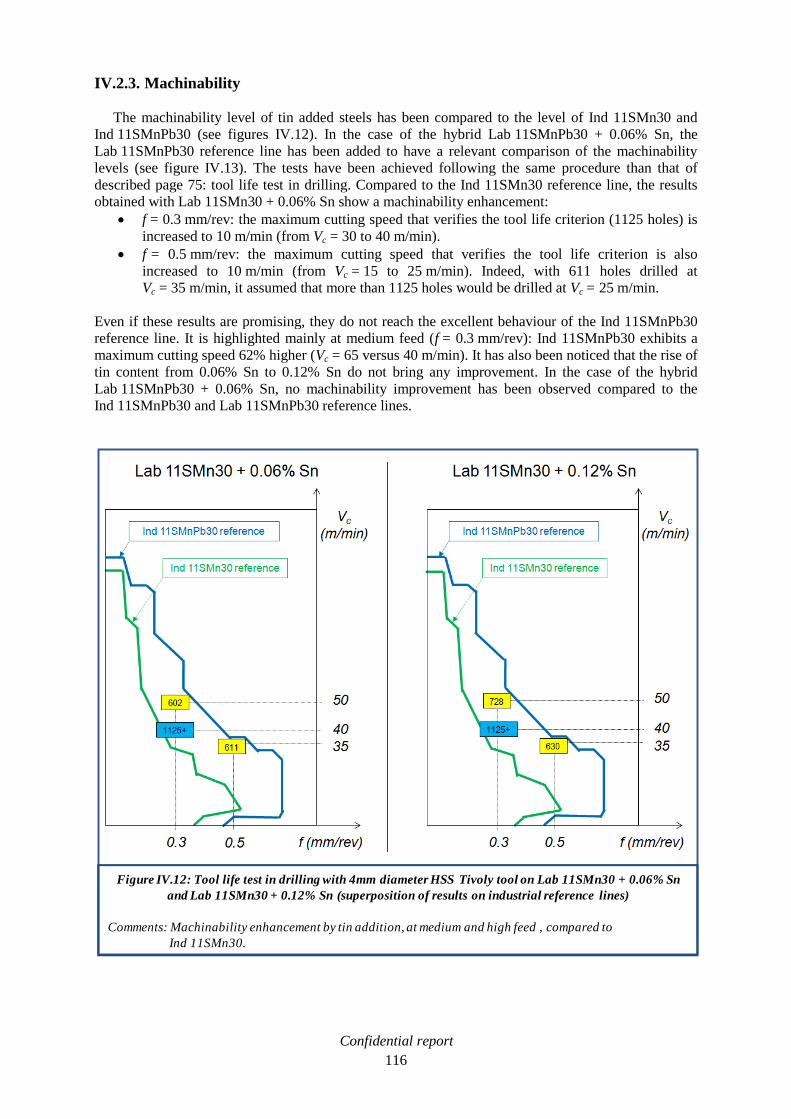
Confidential report
116
IV.2.3. Machinability
The machinability level of tin added steels has been compared to the level of Ind 11SMn30 and
Ind 11SMnPb30 (see figures IV.12). In the case of the hybrid Lab 11SMnPb30 + 0.06% Sn, the
Lab 11SMnPb30 reference line has been added to have a relevant comparison of the machinability
levels (see figure IV.13). The tests have been achieved following the same procedure than that of
described page 75: tool life test in drilling. Compared to the Ind 11SMn30 reference line, the results
obtained with Lab 11SMn30 + 0.06% Sn show a machinability enhancement:
f = 0.3 mm/rev: the maximum cutting speed that verifies the tool life criterion (1125 holes) is
increased to 10 m/min (from Vc = 30 to 40 m/min).
f = 0.5 mm/rev: the maximum cutting speed that verifies the tool life criterion is also
increased to 10 m/min (from Vc = 15 to 25 m/min). Indeed, with 611 holes drilled at
Vc = 35 m/min, it assumed that more than 1125 holes would be drilled at Vc = 25 m/min.
Even if these results are promising, they do not reach the excellent behaviour of the Ind 11SMnPb30
reference line. It is highlighted mainly at medium feed (f = 0.3 mm/rev): Ind 11SMnPb30 exhibits a
maximum cutting speed 62% higher (Vc = 65 versus 40 m/min). It has also been noticed that the rise of
tin content from 0.06% Sn to 0.12% Sn do not bring any improvement. In the case of the hybrid
Lab 11SMnPb30 + 0.06% Sn, no machinability improvement has been observed compared to the
Ind 11SMnPb30 and Lab 11SMnPb30 reference lines.
Figure IV.12: Tool life test in drilling with 4mm diameter HSS Tivoly tool on Lab 11SMn30 + 0.06% Sn
and Lab 11SMn30 + 0.12% Sn (superposition of results on industrial reference lines)
Comments: Machinability enhancement by tin addition, at medium and high feed , compared to
Ind 11SMn30.

Confidential report
117
IV.2.4. Heat treatment for tin segregation
Professor DeArdo claims in its patent that a heat treatment on tin added steels provides the
concentration of tin at the ferrite grain boundaries, which conducts to a machinability enhancement
[DEA99]. It consists to hold the steel in the temperature range from about 425°C to about 575°C for a
sufficient time. Preferably, the holding time is at least about 0.4 hours per centimetre of equivalent
diameter of the steel. For square samples from Lab 11SMn30 + 0.12% Sn (L = 1.5 cm), the equivalent
diameter is:
√
√
Hence, the holding time is:
It has been decided to carry out several holding time at 500°C on samples, from 42 minutes to 7 hours,
and to check whether tin concentrates at the ferrite grain boundaries. Then the entire laboratory cast
have been exposed to the advocated heat treatment. They have been forged in square bars (L = 5 cm),
so The equivalent diameter is:
Figure IV.13: Tool life test in drilling with 4mm diameter HSS Tivoly tool on Lab 11SMnPb30 + 0.06% Sn
(superposition of results on Ind and Lab reference lines)
Comments: No machinability enhancement.

Confidential report
118
And the holding time is:
.
Thus, it has been decided to provide a 500°C heat treatment for 3 hours on tin added steel bars. Finally
the machinability level of these treated grades has been determined.
IV.2.4.1. Microstructure
With a SEM observation, tin has not been detected at the grain boundaries on the samples that
underwent the 500°C heat treatment, even after 7 hours (see figure IV.14). It has been observed
exactly the same result on the entire bars after 3 hours. The heat treatment, claimed to provide tin
concentration at the ferrite grain boundaries, is not efficient, the structure does not evolve because of
the small amount of tin which is still dissolved in the ferritic matrix.
IV.2.4.2. Mechanical properties and machinability
As the heat treatment did not provide tin concentration at the ferrite grain boundaries, no evolution
of the mechanical properties could be observed. The machinability results of tin added steels have
been compared to those of industrial grades in the same manner than the non heat treated steels (see
figure IV.15 and IV.16). The heat treatment did not provide any machinability enhancement because
of its inefficiency to provide a tin concentration at the ferrite grain boundaries, and a weakening of the
steel.
IV.2.5. Conclusion
Lab 11SMn30 + 0.06% Sn and Lab 11SMn30 + 0.12% Sn exhibits higher mechanicals
characteristics to those of Lab 11SMn30 steel (UTS, HV). But the hot forging behaviour is strongly
decreased. A slight machinability enhancement has been observed, but it does not reach the level of
Lab 11SMnPb30. In literature, a heat treatment is claimed to provide a tin concentration at the grain
boundaries and a weakening effect, which conducts to a machinability enhancement. But the tin
content of the developed grades is too small to provide a tin concentration at the grain boundaries. The
Figure IV.14: SEM observation (a: SE, b: BSE) of Lab 11SMn30 + 0.12% Sn, after 7 hours at 500°C
(perpendicular to forging direction)
Comments: No tin concentration at the grain boundaries.
a: SE detector, topography b: BSE detector, composition
MnS
PearlitePearlite
FerriteFerrite
MnS

Confidential report
119
heat treatment was inefficient to improve the machinability of tin added steel. The Lab
11SMnPb30 + 0.06% Sn shows a worse hot forging behaviour than Lab 11SMnPb30, and does not
enhance the machinability, even after a heat treatment. Pb-Sn eutectoid phase, with low melting
temperature that could improve machinability, has not been detected.
Finally, tin as machinability enhancers is not effective enough to pretend to replace lead taking into
account the hot forging degradation for a small quantity of tin, and the slight machinability
enhancement.

Confidential report
120
Figure IV.15: Tool life test in drilling with 4mm diameter HSS Tivoly tool on Lab 11SMn30 + 0.06% Sn
and Lab 11SMn30 + 0.12% Sn, after heat treatment (superposition of results on industrial reference lines)
Comments: No machinability improvement provided by the heat treatment.
Heat treatment (3 hours at 500 C)

Confidential report
121
IV.3. Graphitic steels
In the bibliographic survey, graphite inclusions have been identified as machinability enhancer in
free-cutting steels. It is suggested to develop medium carbon graphitic steels to replace leaded low
carbon free-cutting steel (11SMnPb30). Thanks to literature and thermodynamic calculation, five
grades at 0.5wt% C have been developed (see table IV.6). All of them endured a heat treatment (from
16 to 64 hours at 700°C) in order to transform hard cementite in soft graphite. It is assumed that these
developments would present equivalent mechanical properties to those of Lab 11SMnPb30 grade after
graphitisation process, and that not supplementary treatment would be necessary for final use. A
description of the steels and their purpose can be done:
Lab G1 and Lab G2 should provide short graphitisation because of their high amount of silicon
(2.1 wt%), the high amount of aluminium for Lab G2 (1.1 wt%) and their low amount of manganese
(60ppm). The driving force for graphite nucleation, thermodynamic variables defined in chapter 3, at
700°C is:
DGM (Lab G1, 700°C) = 4.0 kJ/mol
DGM (Lab G2, 700°C) = 5.6 kJ/mol
Both DGM values are higher than that of a theoretical 0.5 wt% C steel at 700°C (DGM = 2.3 kJ/mol),
the graphitisation should be accelerated. Moreover, addition of boron (Lab G1), aluminium (Lab G2)
and nitrogen should promote the formation of nucleation sites for graphite (h-BN and AlN). The
contribution of heterogeneous nucleation could not be calculated with Thermo-Calc®, but the
graphitisation process should be accelerated, thanks to lower activation energy (3.10, page 85).
Figure IV.16: Tool life test in drilling with 4mm diameter HSS Tivoly tool on Lab 11SMnPb30 + 0.06% Sn
after heat treatment (superposition of results on Ind and Lab reference lines)
Comments: No machinability improvement provided by the heat treatment.
Heat
treatment
(3 hours
at 500 C)

Confidential report
122
Lab G3 has been developed in order to maximize the acceleration of the graphitisation process. It
could be defined as an optimised version of Lab G2, by developing the heterogeneous nucleation
thanks to the formation of h-BN inclusions. Lab G3 = Lab G2 + 60 ppm B. unfortunately, this grade
did not endure the forging process (large cracks) and the available amount of steel was not sufficient
for a complete characterisation. The addition of aluminium is known to provide an embrittlement
effect in the hot forging temperature range (1200-1000°C) [NAC88]. Moreover, the addition of boron
decreases the solidus temperature [OHT88], which complicates the hot forging.
Lab G4 is one of the innovations of this study. It proposes to developed graphite and manganese
sulphide inclusions in the same steel. The combined effect of these two machinability enhancers,
should be promising. The base steel of Lab G4 is Lab G1, but in this case, the manganese level is high
(0.9 wt%) and increases the graphitisation time. However, the addition of sulphur (0.3 wt%), allows
the formation of manganese sulphide inclusions. Hence, the manganese content in the matrix, which
does not react with the sulphur, and has a detrimental effect on graphitisation, is reduced to 0.39 wt%
(called Free-Mn). The resulting driving force at 700°c is DGM = 3.4 kJ/mol, which should ensure a
rapid graphitisation.
Lab G5 is the second innovative composition. It is an attempt to reach a compromise between
graphitisation time, mechanical properties and machinability. The silicon amount (1.2 wt%) has been
chosen to ensure a decent graphitisation time and to limit the raise of mechanicals properties (not
suitable for machinability). The amount of manganese (0.6 wt%) is the minimal content that
SWISS STEEL steel shop could handle at an industrial scale. This manganese slows down the
graphitisation but forms manganese sulphides with sulphur (0.2 wt%), which enhance machinability.
The Free-Mn content is 0.26 wt%, which in addition to 1.2 wt% Si, leads to a driving force at 700°C
DGM = 2.8 kJ/mol. This value is higher than that of a theoretical 0.5 wt% C steel at 700°C
(DGM = 2.3 kJ/mol), the graphitisation should be accelerated, helped by the contribution of nucleation
sites (h-BN).But compared to the other laboratory casts of this study, the graphitisation time should be
longer.
Lab G1 to G5 have been characterised at the initial state and after the graphitisation process in the
same manner that all the grades studied in previous chapters. All the results have been compared to the
Lab 11SMnPb30 grade to evaluate the efficiency of lead replacement by graphite.
Table IV.6: Chemical composition s of medium carbon steels for graphitisation process (weight%)

Confidential report
123
IV.3.1. Initial state
IV.3.1.1. Microstructure
Because of the high amount of carbon (0.5 wt%), the microstructures of the five grades exhibits
large pearlitic phases (see figure IV.17). The grain size is slightly smaller than that of
Lab 11SMnPb30 steel (7-9 against 6-8). In the case of Lab G4 and Lab G5, manganese sulphides
inclusions could be observed, and measure, for the larger, 10 µm in length and 5 µm in width.
Figure IV.17: Microstructures at the initial state of medium carbon steels for graphitisation process
(perpendicular to forging direction)
Lab G1 Lab G2
Lab G4 Lab G5
MnS
Pearlite
Ferrite
Pearlite
Ferrite
Pearlite
FerritePearlite
Ferrite
MnS
Lab G3
Pearlite
Ferrite

Confidential report
124
IV.3.1.2. Mechanical properties
IV.3.1.2.1. Tensile test and hardness profile
At the initial state, the medium carbon steels present really much higher mechanical properties than
those of Lab 11SMnPb30 grade (see table IV.7 and figure IV.18). The carbon content and, as a
consequence, the large amount of cementite (contained in pearlite) can easily explain the difference
with low carbon Lab 11SMnPb30 content.
Lab G5 shows lower characteristics than Lab G1 and Lab G4, because of its lower silicon content.
Indeed, silicon strongly increases mechanical properties of steels [MUR93] (see figure IV.19). From
1.2 wt% Si (Lab G5) to 2.1 wt% Si (Lab G1), an increase of ≈ 70 MPa in YS and UTS, and ≈ 20 HV,
could be expected. These theoretical values are in good accordance with the comparison of Lab G1
and Lab G5 characteristics. The global increase is a little bit more pronounced in the case of Lab G4.
Moreover, Lab G2 presents the same Si content than Lab G1 and Lab G4, but it exhibits the highest
characteristics. Therefore, the aluminium addition provided to Lab G2, seems to increase the strength
of medium carbon steels.
Table IV.7: Tensile test report of medium carbon steels for graphitisation compared to those of
Lab 11SMn30 and Lab 11SMnPb30
Comments: The mechanicals properties of medium carbon steels are much higher than those of
Lab 11SMn30 and Lab 11SMnPb30.
- Mean values among 3 samples

Confidential report
125
Figure IV.18: Hardness profiles of medium carbon steels for graphitisation compared to those of
Lab 11SMn30 and Lab 11SMnPb30
Comments: Medium carbon steels present higher hardness profiles than Lab 11SMn30 and Lab11SMnPb30.
Figure IV.19: Effect of steel alloying elements on yield strength (YS), ultimate tensile strength (UTS) and
hardening (HV)
Reference: G. MURRY, Aciers. Généralités, Techniques de l’Ingénieur, M300, October 1993
YS (N/mm2) UTS (N/mm2)
Element content
(weight %)
Element content
(weight %)
Element content
(weight %)
HV
C and N in insertion
Uncertainty of measurement = 4%

Confidential report
126
IV.3.1.2.2. Hot forging test
Hot forging tests have been carried out, with the same procedure than the one adopted for
Lab 11SMn30 and Lab 11SMnPb30 (see page 49). The medium carbon steels have been compared to
the reference with the lowest hot forging behaviour: Lab 11SMnPb30. Between 1000-1200°C (SWISS
STEEL rolling mill temperature range for free-cutting steels), medium carbon steels show a better hot
forging behaviour than that of Lab 11SMnPb30, except for Lab G2 (see figure IV.20). In this case, the
addition of aluminium is known to provide an embrittlement effect in this temperature range
[NAC88]. At higher temperature, medium carbon steels exhibit a burning temperature where hot
forging drops (1250-1300°C). It could be explained by the addition of boron that decreases the solidus
temperature [OHT88]. For T < 1000°C, Lab G1 and Lab G2 present a lower hot forging behaviour
than that of Lab 11SMnPb30, the addition of aluminium could explain this phenomenon for Lab G2
but in the case of Lab G1, this result is not understood. Moreover, Lab G4, exhibits better hot forging
performances than Lab G1. The opposite result was expected, because of the decreasing effect of
sulphur on hot forging. Lab G5 performs better than Lab G4 thanks to its lower amount of sulphur. In
term of stress required to reach the necking of the sample, it is equivalent for each grade, expect for
Lab G2. For this grade, the stress is much higher a low temperature (+75-100 MPa at 900°C) but the
gap decreases when the temperature increases (+20 MPa at 1200°C). This gap can be explained by the
higher mechanical properties of Lab G2.
Figure IV.20: Hot forging tests on medium carbon steels for graphitisation compared to those of
Lab 11SMnPb30
Comments: The hot forging behaviour of medium carbon steels is better than those of Lab 11SMnPb30, in
the hot rolling range 1000-1200°C, except for al added steels (G2 and G3).

Confidential report
127
It should be noticed that the amount of available Lab G3 steel was not sufficient to complete the hot
forging test. The few results obtained show a poor hot forging behaviour, equivalent or lower than that
of Lab 11SMnPb30. The additions of aluminium and boron could explain it.
IV.3.1.3. Machinability
At the initial state, the machinability should be low because of the high mechanical properties of
medium carbon steels. Thus, in order to preserve as much available steel as possible for graphitisation
process, only two drilling conditions have been tested with Lab G1 (see figure IV.21). They have been
performed in the same condition to those described page 75. As expected, the machinability is lower
than that of unleaded Lab 11SMn30, the cutting forces are too high to guarantee a significant tool life.
IV.3.2. Graphitic state
Specimens of each grade have been sampled, in order to determine the time required for a complete
graphitisation at 700°C. Two routes have been studied to achieve this objective:
Observation of microstructure depending on time of heat treatment.
Hardness measurement depending on time of heat treatment.
Once the preferable holding time has been determined for each grade, bars have been graphitised and
then quenched into water to prevent any structure modification during cooling. Mechanicals properties
and machinability have been subsequently explored, and compared to those of Lab 11SMnPb30.
Figure IV.21: Tool life test in drilling with 4mm diameter HSS Tivoly tool on Lab G1(superposition of
results on industrial reference lines)
Comments: The machinability of Lab G1, at the initial state ,is worse than that of Ind 11SMn30.

Confidential report
128
IV.3.3. Microstructure depending on graphitisation time
The evolution of the microstructure during the graphitisation process has been observed for each grade
(see figures IV.22, IV.23, IV.24, IV.25, and IV.26):
Lab G1 presents an advanced decomposition of cementite after 2 hours and the first graphite
nodules (see figure IV.22). After 4 hours, the microstructure consists exclusively in ferrite and
graphite nodules. The growth of graphite on nitride has been observed (see figure IV.27). Even
if the boron element was difficulty identifiable, it is assumed that it is h-BN. The process has
been stopped after 32 hours.
Lab G2 exhibits a fast graphitisation process (see figure IV.23). The decomposition of cementite
and the formation of graphite is observed after an hour. Then the graphite particles grew and
stabilises until the end of the process (16 hours). The effectiveness of aluminium nitrides and
aluminium oxides, as nucleation sites for graphite, has been observed (see figure IV.27).
As expected, Lab G3 shows the fastest graphitisation (see figure IV.24). Formation of graphite
nodules is effective after half an hour, then, they grew and stabilised until the end of the process
(16 hours). The profusion of nucleation site (h-BN, AlN, Al2O3) decreases the graphitisation
time.
Lab G3 shows a similar behaviour to that of Lab G1 but shifted in time because of the free
amount of manganese, that slows down the graphitisation (see figure IV.25). The decomposition
of cementite is well advanced after 8 hours, a stabilisation of the structure is observed after 32
hours. The growth of graphite on manganese sulphides can be observed (see figure IV.27).
Lab G5 is the grade with the longest graphitisation time because of its lower silicon content and
its highest free manganese content (see figure IV.26). The first graphite nodules appeared after
16 hours for a complete graphitisation after 64 hours. Similarly to Lab G5, graphite formation
on manganese sulphides has been noticed.
For the grades with h-BN and/or MnS as nucleation sites (Lab G1, Lab G4 and Lab G5), the graphite
particles measure 5 to 7 µm and the density is about 2000 particles per mm2. In the case of Lab G2 and
Lab G3, which present, in addition to h-BN, or exclusively, AlN and Al2O3 as nucleation sites, the
density of graphite is slower, about 800 particles per mm2, but they are bigger: about 20 µm. This is
the most noticeable difference between the five grades from a microstructural point of view, beside the
presence of MnS inclusions for Lab G4 and Lab G5. The dispersion and the morphology of the
graphite depending on composition are some aspects which could be interesting to explore in futures
works.

Confidential report
129
Fig
ure
IV
.22
: M
icro
stru
ctu
re e
vo
luti
on
of
med
ium
ca
rbo
n s
teel
La
b G
1 d
uri
ng
th
e g
rap
hit
isa
tio
n tre
atm
en
t a
t 7
00
°C
(p
erp
en
dic
ula
r to
fo
rgin
g d
irecti
on
)
2 h
Init
ial
4 h
16
h
Gra
ph
ite
Gra
ph
ite
Gra
ph
ite

Confidential report
130
1 h
4 h
Fig
ure
IV
.23
: M
icro
stru
ctu
re e
vo
luti
on
of
med
ium
ca
rbo
n s
teel
La
b G
2 d
uri
ng
th
e g
rap
hit
isa
tio
n tre
atm
en
t a
t 7
00
°C
(p
erp
en
dic
ula
r to
fo
rgin
g d
irecti
on
)
30
min
Init
ial
Gra
ph
ite
Gra
ph
ite

Confidential report
131
1 h
2 h
Fig
ure
IV
.24
: M
icro
stru
ctu
re e
vo
luti
on
of
med
ium
ca
rbo
n s
teel
La
b G
3 d
uri
ng
th
e g
rap
hit
isa
tio
n tre
atm
en
t a
t 7
00
°C
(p
erp
en
dic
ula
r to
fo
rgin
g d
irecti
on
)
30
min
Init
ial G
rap
hit
e
Gra
ph
ite
Gra
ph
ite

Confidential report
132
8 h
16
h3
2 h
Fig
ure
IV
.25
: M
icro
stru
ctu
re e
vo
luti
on
of
med
ium
ca
rbo
n s
teel
La
b G
4 d
uri
ng
th
e g
rap
hit
isa
tio
n tre
atm
en
t a
t 7
00
°C
(p
erp
en
dic
ula
r to
fo
rgin
g d
irecti
on
)
Init
ial
Gra
ph
ite
Gra
ph
ite
Gra
ph
ite
Mn
S
Mn
SM
nS

Confidential report
133
16
h
32
h6
4 h
Fig
ure
IV
.26
: M
icro
stru
ctu
re e
vo
luti
on
of
med
ium
ca
rbo
n s
teel
La
b G
5 d
uri
ng
th
e g
rap
hit
isa
tio
n tre
atm
en
t a
t 7
00
°C
(p
erp
en
dic
ula
r to
fo
rgin
g d
irecti
on
)
Init
ial
Gra
ph
ite
Mn
S
Gra
ph
ite
Mn
S
Mn
S
Gra
ph
ite
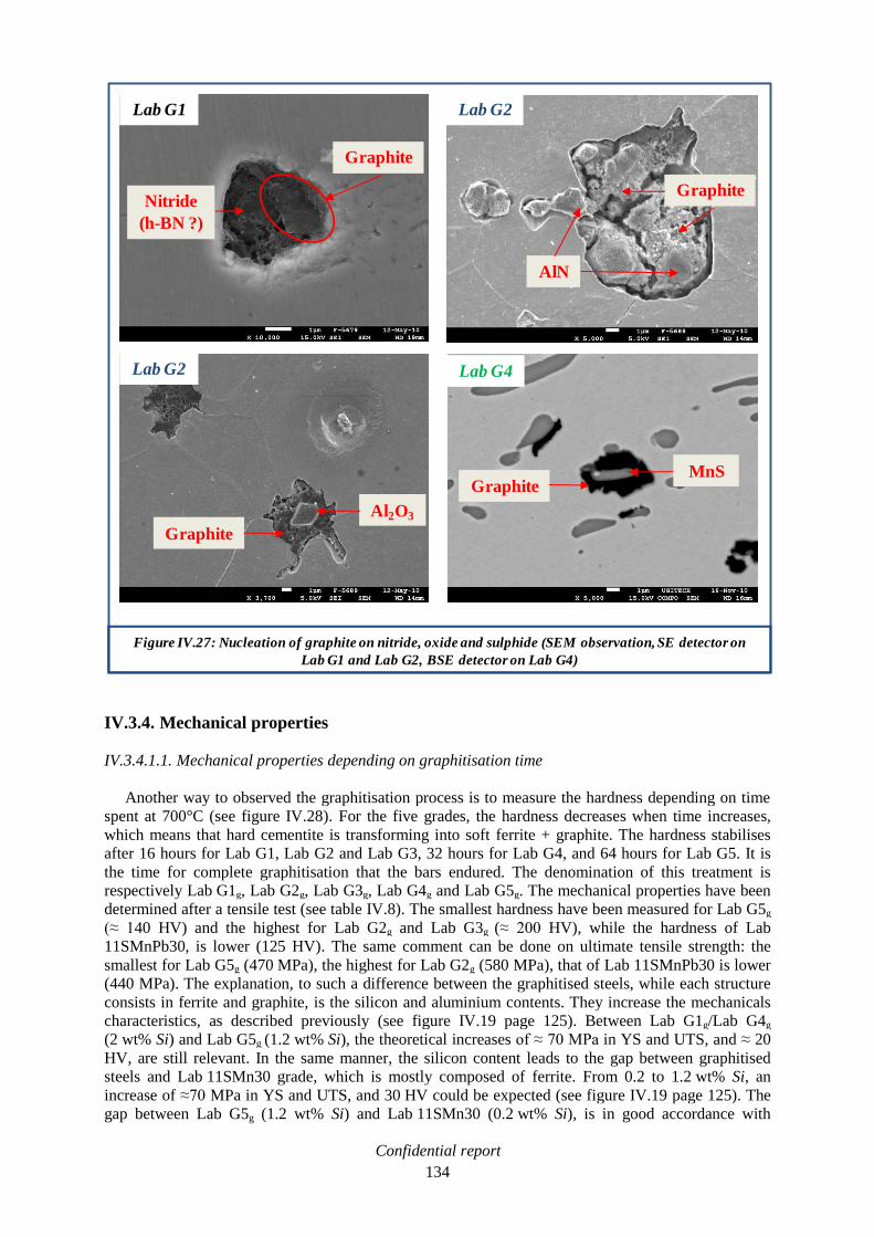
Confidential report
134
IV.3.4. Mechanical properties
IV.3.4.1.1. Mechanical properties depending on graphitisation time
Another way to observed the graphitisation process is to measure the hardness depending on time
spent at 700°C (see figure IV.28). For the five grades, the hardness decreases when time increases,
which means that hard cementite is transforming into soft ferrite + graphite. The hardness stabilises
after 16 hours for Lab G1, Lab G2 and Lab G3, 32 hours for Lab G4, and 64 hours for Lab G5. It is
the time for complete graphitisation that the bars endured. The denomination of this treatment is
respectively Lab G1g, Lab G2g, Lab G3g, Lab G4g and Lab G5g. The mechanical properties have been
determined after a tensile test (see table IV.8). The smallest hardness have been measured for Lab G5g
(≈ 140 HV) and the highest for Lab G2g and Lab G3g (≈ 200 HV), while the hardness of Lab
11SMnPb30, is lower (125 HV). The same comment can be done on ultimate tensile strength: the
smallest for Lab G5g (470 MPa), the highest for Lab G2g (580 MPa), that of Lab 11SMnPb30 is lower
(440 MPa). The explanation, to such a difference between the graphitised steels, while each structure
consists in ferrite and graphite, is the silicon and aluminium contents. They increase the mechanicals
characteristics, as described previously (see figure IV.19 page 125). Between Lab G1g/Lab G4g
(2 wt% Si) and Lab G5g (1.2 wt% Si), the theoretical increases of ≈ 70 MPa in YS and UTS, and ≈ 20
HV, are still relevant. In the same manner, the silicon content leads to the gap between graphitised
steels and Lab 11SMn30 grade, which is mostly composed of ferrite. From 0.2 to 1.2 wt% Si, an
increase of ≈70 MPa in YS and UTS, and 30 HV could be expected (see figure IV.19 page 125). The
gap between Lab G5g (1.2 wt% Si) and Lab 11SMn30 (0.2 wt% Si), is in good accordance with
Figure IV.27: Nucleation of graphite on nitride, oxide and sulphide (SEM observation, SE detector on
Lab G1 and Lab G2, BSE detector on Lab G4)
Nitride
(h-BN ?)
Graphite
AlN
Graphite
Graphite
Al2O3
Lab G1 Lab G2
Lab G2 Lab G4
GraphiteMnS

Confidential report
135
theoretical values. The gap between Lab G5g and Lab 11SMnPb30 is smaller, because it has been
observed that Pb addition conducts to a slight increase of mechanicals properties compared to
Lab 11SMn30.The higher mechanical properties of Lab G2g, compared to Lab G1g and Lab G4g
(2 wt% Si for each), is, once again, assumed to be due to the large addition of aluminium (1.1 wt%).
As a conclusion, the graphitisation process lead to an important decrease of the mechanical properties,
and Lab G5g presents the closest results to Lab 11SMnPb30 grade. Moreover, the graphitisation
provided a significant gain in toughness, at least twice more important than the fracture energy
recorded at the initial state. This study is explained in Annex D.
IV.3.5. Machinability
The machinability test on graphitic steels has been carried out with the same procedure described in
previous chapters (see page 75): tool life test in drilling with an HSS non coated tool (see figure IV.29
at the end of this chapter). The amount of Lab G3g was not sufficient for a machinability
characterisation. Each graphitic steel exhibits a different behaviour:
Lab G1g presents an intermediate behaviour, between Ind 11SMn30 and Ind 11SMnPb30 steels.
It is a promising result taking into account that the mechanical properties of Lab G1g, are higher
than those of Ind 11SMn30 and Ind 11SMnPb30 steels. It proves the effectiveness of graphite
particles to improve the machinability by reducing cutting forces. At f = 0.5 mm/rev and
Vc = 25 m/min, the cutting force is 1750 N with Lab G1g, compared to ≈ 2000 N with
Ind 11SMn30, and 1600 N with Ind 11SMnPb30.
The machinability of Lab G2g is lower than that of Ind 11SMn30 and Ind 11SMnPb30 steels.
The high mechanicals properties of this graphitic grade, lead to high cutting forces, which
conduce to a premature tool wear. At f = 0.5 mm/rev and Vc = 10 m/min, the cutting force is
2500 N with Lab G2g, compared to 1500 N with Ind 11SMnPb30.
Compared to Lab G1g, Lab G4g gains in machinability thanks to the manganese sulphide
inclusions. The tool life is equivalent to that of Lab 11SMnPb30 grade at medium feed
(f = 0.3mm/rev), but with a lower cutting force (1000 N compared to 1200 N for
Lab 11SMnPb30). The graphite particles and manganese sulphides inclusions decrease the
cutting force, while Lab G4g exhibits the highest mechanicals properties. There was not enough
available Lab G4g steel to explore higher cutting speed. At high feed (f = 0.65 mm/rev), the
machinability of Lab G4g is equivalent to that of Ind 11SMnPb30. For Vc = 35 m/min, the
cutting force is higher than 2000 N for both grades.
Lab G5g presents the most promising results. Thanks to its lower silicon content than Lab G4g,
the mechanical properties are lower. These characteristics, combined to graphite particles and
manganese sulphide inclusions, lead to a equivalent or better tool life than that of
Ind/Lab 11SMnPb30 steel, at medium and high feed (f = 0.3 and 0.65 mm/rev). The cutting
forces are decreased in the same proportions than Lab G4g.There was not enough available Lab
G5g steel to explore a wider machinability domain, but it can be assumed that the machinability
of Lab G5g, is globally better than that of Ind/Lab 11SMnPb30 steel.

Confidential report
136
Figure IV.28: Hardness profiles of medium carbon steels during graphitisation process
Comments: Fastest graphitisation time for Al added steel (Lab G2 and Lab G3), but highest hardness.
Longest graphitisation time for low Si added steel (Lab G5), but slowest hardness.
Table IV.8: Tensile test report of graphitised steels compared to those of Lab 11SMn30
and Lab 11SMnPb30
Comments: Lab G5g presents the closest mechanicals properties to those of Lab 11SMnPb30.
- Mean values among 3 samples
Uncertainty of measurement = 4%

Confidential report
137
Figure IV.29: Tool life test in drilling with 4mm diameter HSS Tivoly tool on graphitic steels
(superposition of results on Ind and Lab reference lines)
Comments: The machinability of Lab G5g is equivalent or better to that of Ind and Lab 11SMnPb30
reference lines.

Confidential report
138
IV.3.6. Conclusion
Literature exposed the ability of graphite particles to replace lead in free-cutting steel. The
development of five medium carbon steels, with specific compositions in order to accelerate the
decomposition of cementite into graphite during a heat treatment has been achieved. The
graphitisation process of these grades has been studied and exhibited the effect of additional elements
on the needed time to form graphite particles, such as silicon, aluminium and boron in one hand
(acceleration) and manganese in the other (deceleration). The graphite particles significantly improve
the machinability by decreasing the cutting force. But the silicon and aluminium additions, to
accelerate the graphitisation process, lead to an increase of the mechanicals properties which impairs
the machinability. The addition of manganese and sulphur provides the formation of manganese
sulphides that strongly improve the machinability, beside the graphite particles. A compromise
between graphitisation time and machinability has been reached with Lab G5 grade by:
The limitation of the silicon addition, which minimises the increase of mechanical properties,
and ensures a significant acceleration of the graphitisation.
The addition of the minimal manganese content admissible in a steel shop, to bear in mind the
industrial purpose of this project. It minimises the deceleration of the graphitisation process.
The addition of a proper amount of sulphur, to form manganese sulphides that strongly increase
the machinability beside graphite particles. Moreover, sulphur consumes a significant part of the
manganese of steel, which has a detrimental effect on machinability.
The Lab G5 grade does not present any difficulties of processing. The hot forging behaviour is better
than that of Lab 11SMnPb30, which guarantees a safe hot rolling at the industrial scale. Once
graphitised after 64 hours at 700°C, which is the major drawback of this development, its mechanical
properties are closed to those of Lab 11SMnPb30 and its machinability shows promising results,
equivalent or higher than that of Ind/Lab 11SMnPb30. Deeper studies could be performed by
producing large quantity of Lab G5. For instance, the graphitisation time could be determined more
precisely. It is the reason why, the hot rolling of an industrial cast would be necessary. Lab G5 is our
best proposition as a substitute to leaded free-cutting steels. A reflexion to transpose that development
at the industrial scale is engaged.

Confidential report
139
V. Global conclusion and outlooks
Several approaches have been studied during the bibliographic work in order to replace lead (Pb) in
low carbon free-cutting steel. Among them, different additions, like tin or Bismuth; heat treatments,
like graphitisation; and modification of existing inclusions in the steel, like manganese sulphide
inclusions (MnS).
In parallel, two industrials grades provided by SWISS STEEL (Ind 11SMn30 and Ind 11SMnPb30)
have been characterised. The first without Pb and the other one with 0.25 wt% Pb. Ind 11SMnPb30
steel shows a much higher machinability than Ind 11SMn30. We determined, on non coated carbide
tool, that the Built-Up Edge (BUE) formation is more controlled and stabilised with Ind 11SMnPb30
grade. It ensures a better surface finish of the machined parts. Second, the lubricant effect of Pb has
been quantified thanks to the quick-stop procedure with coated carbide tools: between Vc = 20 and
70 m/min, Pb induced the decrease of the friction coefficient at the tool/chip interface. The cutting
forces decrease drastically. It is the major explanation of the excellent behaviour of leaded steel at low
cutting speeds. But, over Vc = 80 m/min, the Pb effect does not exist anymore.
Thus, the alternatives developed during the PhD work have to provide an equivalent machinability
improvement at low cutting speed Vc < 100 m/min. Thanks to the literature survey and a
thermodynamic study, different compositions for candidates to replace leaded free-cutting steels have
been determined. Tin-added steels and medium carbon steels for graphitisation process have been
suggested. In the second case, the effect of alloying elements on the graphitisation process has been
predicted by thermodynamic simulation: Si and Al accelerate it, Mn decelerates it. The alloying
element contents have been set in order to reach several compromises between mechanical properties,
machinability and promotion of the graphitisation process. Among them, two innovative compositions
which combined graphite and MnS inclusions have been proposed, for good machinability behaviour.
The melting in induction furnaces provided 75 kg of each composition, which have been subsequently
forged in square shape bars. The hot transformation endured by the laboratory ingots tried to simulate
as much as possible the thermo mechanical path of industrial steels from SWISS STEEL. In order to
estimate in a more reliable way the machinability of these new solutions, reference laboratory casts
with same chemical analysis than those of Ind 11SMn30 and Ind 11SMnPb30 were also forged in
square shape bars and tested with HSS tools (Lab 11SMn30 and Lab 11SMnPb30).
With the tin added labcasts, a slight machinability enhancement has been observed, but it does not
reach the level of lab 11SMnPb30 steel. In literature, a heat treatment is claimed to provide a tin
concentration at the grain boundaries and a weakening effect, which conducts to a machinability
enhancement. But the tin content of the developed grades is too small to provide a tin concentration at
the grain boundaries. The heat treatment was inefficient to improve the machinability of tin added
steel. Finally, tin as machinability enhancers is not effective enough to pretend to replace lead taking
into account the hot forging degradation for a small quantity of tin, and the slight machinability
enhancement.
With the graphitised steels, drilling tests exhibited that graphite particles significantly improve the
machinability at low cutting speed, by decreasing the cutting force (Lab G1, 0.5% C - 2% Si), despite
the Si addition which increases the mechanical properties. In the case of Lab G4 (0.5% C - 2%
Si - 0.9% Mn – 0.3% S) the formation of MnS inclusions strongly improves the machinability, beside
the graphite particles, despite the high mechanical properties. But the free manganese dissolved in the
matrix slowed down the graphitisation process. A compromise between graphitisation time and high
machinability behaviour, at low cutting speed, has been reached with Lab G5 grade (0.5% C – 1.2% Si
– 0.6% Mn – 0.2% S). The Si content is set at an intermediate level, to sufficiently promote the
graphitisation process, and to limit the mechanical properties at a not too high level. The Mn content is
adjusted to allow the formation of MnS inclusions, and to limit the deceleration of the graphitisation
process, with a limited amount of free manganese. Once graphitised after 64 hours at 700°C, this long
annealing time being the major drawback of this development, the mechanical properties of Lab G5
are close to those of Lab 11SMnPb30, and the machinability shows promising results, equivalent or
higher than that of Lab 11SMnPb30. The hot forging behaviour of Lab G5 is better than that of

Confidential report
140
lab 11SMnPb30, which guarantees a safe hot rolling at the industrial scale. Lab G5 is an innovative
solution and a promising grade as a substitute to leaded free-cutting steels. Deeper studies will be
performed in 2011 in order to decrease the annealing time at 700°C. The production of 80 tons of
Lab G5 in the SWISS STEEL steel shop will be carried out. The characterisation of this industrial
steel, will confirm, or not, the reliability of the substitution of lead by graphite in free-cutting steels.
Confidential report
141
VI. References
VI.1. Bibliographic survey
[AKA03] T. AKASAWA, H. SAKURAI, M. NAKAMURA, T. TANAKA, K TAKANO, Effects of Free-
Cutting Additives on the Machinability of Austenitic Stainless Steels, Journal of Materials
Processing Technology 143-144 (2003), pages 66-71.
[AYE97] J. AYEL, Lubrifiants, Constitutions, Techniques de l’Ingénieur, BM5341, July 1997.
[BER01] G. BERNSMANN, M. BLEYMEHL, P. EHL, A. HASSLER, The Making of Free-Cutting Steels
with Additions of Lead, Bismuth, Tellurium, Selenium and Tin, Stahl und Eisen, 121, N°2,
2001, pages 87-91.
[BHA84] D. BHATTACHARYA, Effect of Metal Induced Embrittlement in Free-machining Steels,
Embrittlement by Liquid and Solid Metals, Ed. M.H. KAMDAR, TMS-AIME-1984, pages
367-398.
[BHA92] H. K. D. H. BHADESHIA, Bainite in steels, The Institute of Materials, London, 1992.
[CAI93] J.L. CAILLERIE, F. WILMOTTE, Plomb et Alliages de Plomb, Techniques de l’Ingénieur,
M510, July 1993.
[CHO00] S. CHO, Y. LEE, Machinability of Bi-S and Pb-S-Treated Free-Machining Steels, 42th,
MWSP Conf. Proc., ISS, Vol. 38, 2000.
[CHR65] J.W. CHRISTIAN, The Theory of Transformations in Metals and Alloys, Chapter 10: The
Classical Theory of Nucleation, Pergamon Press, Oxford, 1965.
[CUN00] P. J. CUNAT, Aciers Inoxydables, Mise en œuvre, Techniques de l’Ingénieur, M4542,
September 2000.
[DAV90] I. G. DAVIES, N. A. FINCH, M. L. PICKETT, Development and Applications of Alloy and
Stainless Steels with Improved Machinability, Ironmaking and Steelmaking, vol. 17, N° 5,
1990, pages 343-349.
[DEA99] A. DEARDO, Tin-bearing Free-Machining Steel, Patent WO 99/25891, 27 May 1999.
[DEA00] A. DEARDO, Free-Machining steels Containing tin, Antimony and/or Arsenic, Patent WO
00/71771 A1, 30 November 2000.
[DIE88] G.E. DIETER, Mechanical Metallurgy: SI Metric editions, McGraw-Hill Book Company,
New-York, 1988.
[DUP08] M. DUPEUX, Aide-Mémoire, Science des Matériaux, Ed. Dunod, Paris, 2008.
[EDM05] D.V. EDMONDS, K. HE, Acceleration of Graphitisation in Carbon Steels to Improve
Machinability, Institute for Materials Research, University of Leeds, LS2 9JT, UK, 2005.
[GAR03] C. I. GARCIA, M. J. HUA, M. K. MILLER, A. J. DEARDO, Application of Grain Boundary
Engineering in Lead-Free “Green Steel”, ISIJ International, Vol. 43, N°12, 2003, pages
2023-2027.
[HEN03] P. HENNER, L. GARCIA-SANCHEZ, Fiche Radionucléide, Bismuth 210 et Environnement,
IRNS, 27 march 2003.

Confidential report
142
[HON06] R.W.K HONEYCOMBE, H. K. D. H. BHADESHIA, Steel – Microstructure and Properties,
3rd
edition, Elsevier ltd, 2006.
[HYO09] L. HYONG-JIK, Effect of Boron and Silicon on the Formation of Graphite Particles in
Medium Carbon Steels, Wire Journal International, March 2009, pages 194-197.
[IWA98] T. IWAMOTO, T. HOSHINO, K. AMANO, J. SHIMOMURA, Graphite Nucleation on Boron
Nitride in 0.53%C Steel, Tetsu-to-Hagané. Vol. 84, 1998, pages 67-72.
[IWA02] T. IWAMOTO, T. OSHINO, A. MATSUZAKI, .K AMANO, Effect of Boron and Nitrogen on
Graphitisation and Hardenability in 0.53%C Steels, ISIJ International, Vol. 42,
Supplement, 2002, pages S77-S81.
[IWA04] T. IWAMOTO, T. MURAKAMI, Bar and Wire Steels For Gears and Valves of Automobiles
Eco-Friendly Free-Cutting Steel without Lead Addition, JFE Technical Report, n°4,
November 2004, pages 74-80.
[IWA07] N. IWAMA et al., Lead-Free Steel for Machine Structural Use with Excellent
Machinability and Low Strength, Patent N° US 7,195,736 B1, 27 March 2007.
[JIA96] L. JIANG, K. CUI, H. HÄNNINEN, Effect of the Composition, Shape Factor and Area
Fraction of Sulphide Inclusions on the Machinability of Re-Sulphurized Free-Machining
Steel, Journal of Materials Processing Technology, 58 (1996), pages 160-165.
[KAT96] S. KATAYAMA, M. TODA, Machinability of Medium Carbon Graphitic Steel, Journal of
Materials Processing Technology, 62, 1996, pages 358-362.
[KIR07] A. KIRSCH-RACINE, A. BOMONT-ARZUR, M. CONFENTE, Calcium Treatment of Medium
Carbon Steel Grades for Machinability Enhancement from the Theory to Industrial
Practice, La Revue de Métallurgie-CIT, December 2007, pages 591-597.
[KUB82] O. KUBASCHEWSKI, Iron-Binary Phase Diagrams, ed. Springer-Verlag, 1982.
[LEN08] http://www.lenntech.com/fran%C3%A7ais/dataperio/Bi.htm, Bismuth, Propriétés
Chimiques, Effets du Bismuth sur la Santé, Effets du Bismuth sur l’Environnement,
browsed on September 26th, 2008.
[LER84] F. LEROY, Usinage et Usinabilité, Techniques de l’Ingénieur, M725, January 1984.
[LES10] G. LESOULT, Thermodynamique des Matériaux – De l’Elaboration des matériaux à la
genèse des microstructures, Chapitre 14: Germination et Décomposition Spinodale,
Presses Polytechniques et Universitaires Romandes, Lausanne, 2010.
[MAN06] M. MANTEL, C. VACHEY, Formage à Grande Vitesse, Détermination d’une Loi de
Comportement, Techniques de l’Ingénieur, M3025, March 2006.
[MAT97] H. MATSUOKA, K. OSAWA, M. ONO, M. OHMURA, Influence of Cu and Sn on Hot
Ductility of Steels with Various C Content, ISIJ International, Vol.37, N°3, 1997, pages
255-262.
[MEG96] T. MEGA, R. MORIMOTO, M, MORITA, J. I. SHIMOMURA, Auger Electron Spectroscopy of
Boron Nitride in Hot-Rolled Graphitised Steel Sheet, Surface and Interface analysis, Vol.
24, 1996, pages 375-379.
[MER45] M.E. MERCHANT, Mechanics of the Metal Cutting Process I and II, Journal Appl.
Phys.,Vol. 16, N°5 and 6, 1945, pages 267-275 and 318-325.

Confidential report
143
[MIC07] J. C. MICHEL, L’économie du Plomb. Ecomine, BRGM, July-August 2007.
[MUR93] G. MURRY, Aciers. Généralités, Techniques de l’Ingénieur, M300, October 1993
[NAC88] W.T. NACHTRAB, Y.T. CHOU, The Effect of Sn, Al, and N on the Ductility of a Carbon-
Manganese Steel between 700° and 1200°C, Metallurgical Transactions A, Vol. 19A,
May 1988, pages 1305-1309.
[NAG97] C. NAGASAKI, J. KIHARA, Effect of Copper and Tin on Hot Ductility of Ultra-Low and
0.2% Carbon Steels, ISIJ International, Vol.37, N°5, 1997, pages 523-530.
[NOV04] C.H. DE NOVION, D. LESUEUR, L’état Métallique, Propriétés Atomiques, Techniques de
l’Ingénieur, M35, September 2004.
[NRC08] http://www.nrcan.gc.ca/mms/cmy/contenu/2005/16.pdf, Bismuth, browsed on September,
26th, 2008.
[OIK02] K. OIKAWA ET AL, A new Pb-Free Machinable Ferritic Stainless Steel, ISIJ International,
Vol.42, N°7, 2002, pages 806-807.
[OHT88] H. OHTANI, M. HASEBE, K. ISHIDA, Calculation of Fe-C-B Ternary Phase Diagram,
Transactions ISIJ, Vol. 28, June 1988, pages 1043-1050.
[PHI02] J. PHILIBERT, A. VIGNES, Y. BRECHET. P. COMBRADE, Métallurgie – Du Minerai au
Matériau, Ed.Dunod, page 303, 2002.
[PIC03] A. PICOT, Intoxication de l’Organisme par les Métaux Lourds et Autres Toxiques,
Conférence ADNO 2003 Paris, November, 29th, 2003.
[RAM96] K. RAMANUJACHAR, S.V. SUBRAMANIAN, Micromechanisms of Tool Wear in Machining
Free-Cutting Steels, Wear, 197, 1996, pages 45-55.
[RAA08] S. RAADNUI, S. MAHATHANABODEE, R. TONGSRI, Tribological Behaviour of Sintered
316L Stainless Steel Impregnated with MoS2 Plain Bearing, Wear, 265, 2008, pages 546-
553.
[REY05] P.E. REYNOLDS, M. ROCHER, E. D’ERAMO, H. LANGNER, W. HOCKAUF, I. ESSEL, R.
FRITSCH, R. BUELTE, V. BLOCK, R. ELVIRA, Technically and Commercially Viable
Alternatives to Lead as Machinability Enhancers in Steel Used for Automotive
Components Manufacture, Final Report N° EUR 21912, published by European
commission , Luxembourg, 2005.
[REY07] P. REYNOLDS, V. BLOCK, I. ESSEL, F. KLOCKE, Alternatives to Lead as a Machinability
Enhancer in Free-Cutting Steels, Steel Research Int.78, N°12, 2007, pages 908-914.
[ROE08] H. ROELOFS, A.M.G BOEIRA, R. MARGOT, J.T. GOMES, M. EGLIN, Machinability of
Inclusion Engineering Steel Under Built-Up Edge Conditions, 8th Int. Conf. On
Advanced Manufacturing Systems and Technology, Udine, 2008.
[SAN00] K. SANDER, J. LOHSE, M. WIRTS, Heavy Metals in Vehicles, Report compiled for the
directorate General Environment, Nuclear Safety and civil Protection of the Commission
of the European Communities, March 2000.
[SAN01] K. SANDER, J. LOHSE, M. WIRTS, Heavy Metals in Vehicles II, Report compiled for the
directorate General Environment, Nuclear Safety and civil Protection of the
Commission of the European Communities, July 2001.

Confidential report
144
[SEK04] T. SEKITA, S. KANETO, S. HASUNO, A. SATO, T. OGAWA, K. OGURA, Materials and
Technologies for Automotive Use, JFE Technical Report, N°2, March 2004.
[SIM03] O. E. SIMARO, L. E. DUTARI, The Production of Free-Cutting and Improved
Machinability Steels, with and without Lead Additions, at Acindar’s Steelmaking Shop,
ISSTech Conference Proceedings, 2003, pages 1035-1044.
[SON03] S.H. SONG, Z.X. YUAN, J. JIA, A.M. GUO, D.D. SHEN, The Role of Tin in the Hot-
Ductility Deterioration of a Low-Carbon Steel, Metallurgical and Materials Transactions
A, Vol. 34A, August 2003, pages 1611-1616.
[SUB04] S. V. SUBRAMANIAN, H. O. GEKONDE, G. ZHU, X. ZHANG, U. URLAU, H. ROELOFS,
Inclusion Engineering of Steel to Prevent Chemical Tool Wear, Ironmaking and
Steelmaking, vol. 31, n°3, 2004, pages 249-257.
[TAN07] R. TANAKA, Y. YAMANE, K. SEKIYA, N. NARUTAKI, T. SHIRAGA, Machinability of BN
Free-Machining Steel in Turning, International Journal of Machine Tools and
Manufacture, 47, 2007, pages 1971-1977.
[TAS06] C. TASSIN-ARQUES, Métallurgie – Elaboration et Microstructure des Alliages
Métalliques, Polytech’Grenoble engineers school course, 2006.
[TRO98] C. TROMBERT, Usinabilité des Aciers Inoxydables, Techniques de l’Ingénieur, M726,
March 1998.
[WIS88] M. L. H. WISE, R. MILOVIC, Ranges of Applications of Free-Cutting Steels and
Recommended Tool Materials, Materials Science and Technology, Vol.4, October 1988,
pages 933-943.
[WRI73] P.K. WRIGHT, E.M. TRENT, Metallographic Methods of Determining Temperature
Gradients in Cutting Tools, Journal of The Iron and Steel Institute, May 1973, pages 364-
368.
[YAG88] H. YAGUCHI, Effect of Soft Additives (Pb,Bi) on Formation of Built-Up Edge, Materials
Science and Technology, Vol.4, October 1988, pages 926-931.
[YAG89] H.YAGUCHI, Effect of Soft Additives (Pb/Bi) on Machinability of Low Carbon
Resulphurised Free Machining Steels, Materials Science and Technology, Vol.5, March
1989, pages 255-267.
[YAM58] N. YAMANAKA, K. KUSAKA, Etude sur la Graphitisation de l’Acier à Haut Carbone,
(traduction), Tetsu to Hagané, 44, Vol. 10, October 1958, pages 1180-1185.
[YAS05] YU.D. YASHIN, S. A. SOLDATKIN, P.YU. CHESNOKOV, High-Machineability Steels,
Metallurgist, Vol. 49, N° 5-6, 2005, pages 236-241.
[ZHA04] X. ZHANG, H. ROELOFS, S. LEMGEN, U. URLAU, S.V. SUBRAMANIAN, Application of
Thermodynamic Model for Inclusion Control in Steelmaking to Improve the
Machinability of Low Carbon Free Cutting Steels, Steel Research, Int. 75, N°5, 2004,
pages 314-321.

Confidential report
145
VI.2. Patents research
Here a list of patents dealing with free-cutting steel and the replacement of lead by the different
solutions exposed previously.
1: Low-Carbon Sulphur-Containing Free-Cutting Steel With Excellent Cuttability, EP 1 964 939 A1
(2008), Kabushiki Kaisa Kobe Seiko Sho.
The invention controls the content of carbon, manganese, and nitrogen in steel so as to satisfy a
specific relational expression. The steel is good in finished surface.
2: Eco-Friendly PB-Free Free Cutting Steel With Excellent Machinability And Hot Workability, WO
2008/082153 A1 (2008), Posco.
Pb-free free-cutting steel wherein S, Bi, Sn, B and N satisfy a certain relationship.
3: Free-Cutting Steel And Fuel Injection System Component Using The Same, US 7,338,630 B2
(2008), Daido.
Suppressing production of coarse inclusions, addition of Bi.
4: Lead Free Cutting Steel And Its Use, WO 2008/091214 A1 (2008), Sandvik.
Machinability improvement by Bi+Se+Te addition.
5: Low-Carbon Free Cutting Steel, EP 1 507 016 B1 (2007), Sumitomo.
Steel with improved machinability thanks to MnS, Ti sulphide and/or carbosulphide.
6: Lead Free Steel For Machine Structural Use With Excellent Machinability And Low Strength
Anisotropy, US 7, 195,736 B1 (2007), Sanyo Special Steel.
Patent cited page 40 [IWA07].
7: Low Carbon Composite Free-Cutting Steel Product Excellent In Roughness Of Finished Surface
And Method For Production Thereof, EP 1 690 956 A1 (2006), Kabushiki Kaisa Kobe Seiko Sho.
Steel with large sized spherical inclusions.
8: Free Cutting Alloy, EP 1 085 105 B1 (2006), Tohoku Technoarch Co., Ltd.
(Ti,Zr) compound dispersed in the structure to improve machinability.
9: Steel Excellent In Machinability And Method For Production Thereof, EP 1 580 287 A1 (2005),
Nippon Steel Corporation.
Machinability enhancement by controlling MnS morphology and pearlite grain size.
10: Sulphur Free Cutting Steel For Machine Structural Use, EP 1 518 939 A1 (2005), Mitsubishi.
MnS precipitation and addition of Sn and Sb for machinability.
11: Steel For Machine Structural Use Excellent In Friability Of Chips, EP 1 553 201 A1 (2005),
Honda.
Fine dispersion of Ca-containing sulphide inclusions.
12: Free-Cutting Steel, US 2004/0258555 A1 (2004), Murakami et al.
Machinability enhancement by controlling MnS morphology thanks to the optimization of Cr/S ratio.
13: Steel Material And Method For Preparation Thereof, EP 1 371 744 A1 (2003), Honda.
h-BN coating and nitriding to obtain B and N in the steel.
14: Low Carbon Free Cutting Steel, EP 1 335 035 A1 (2003), Sumitomo.
Steel with Ti sulphide or Ti carbosulphide in a form included in MnS.

Confidential report
146
15: Free-Cutting Steel For Machine Structural Use Having Good Machinability In Cutting by
Cemented Carbide Tool, EP 1 264 912 A1 (2002), Daido.
Ca-containing sulphide inclusions.
16: Free-Cutting Steel, EP 1 262 573 A1 (2002), Daido
Steel with Ti-based and/or Zr-based carbosulphide to enhance machinability.
17: Free Machining Steel For Use In Machine Structure Of Excellent Mechanical Characteristics, EP
1 184 477 A1 (2002), Kabushiki Kaisa Kobe Seiko Sho.
Mg-containing sulphide and control of the sulphide distribution.
18: Medium-Carbon Steel Having Dispersed Fine Graphite Structure And Method For The
Manufacture Thereof, US 6,174,384 B1 (2001), Agency of Industrial Science and Technology, Tokyo.
Medium carbon graphitic steel.

Confidential report
147
VII. Annexes
VII.1. Annex A: quick-stop measurements, industrial 11SMn30 ................................................. 149
VII.2. Annex B: quick-stop measurements, industrial 11SMnPb30 ............................................. 157
VII.3. Annex C: development of a 11SMn30 grade with lower Mn/S ratio ................................. 165
VII.4. Annex D: CHARPY impact test .............................................................................................. 169
VII.5. Annex E: résumé des travaux de thèse ................................................................................. 171 VII.5.1. Usinage et usinabilité ......................................................................................................... 171
VII.5.2. Les voies d’amélioration de l’usinabilité ........................................................................... 174
VII.5.3. Etude expérimentale de l’effet du plomb sur l’usinabilité ................................................. 176
VII.5.4. Développement d’un acier graphitique .............................................................................. 180
VII.5.5. Développement d’un substitut aux aciers de décolletage au plomb .................................. 190
VII.5.6. Conclusion générale et perspectives .................................................................................. 195

Confidential report
148

Confidential report
149
VII.1. Annex A: quick-stop measurements, industrial 11SMn30
Fc
= 1
11
1 N
Ff =
70
2 N
R =
13
22
N
F =
1140 N
N =
64
0 N
Fs =
83
0 N
µ =
1.7
8
f =
18
°
Fs
f
Fc
F
N
Ff
R

Confidential report
150
Fc
= 1
11
8 N
Ff =
75
7 N
R =
13
54
N
F =
1100 N
N =
79
0 N
Fs
= 9
60
N
µ =
1.3
9
f =
15
°
R
F
N
Fc
Ff
Fs
f

Confidential report
151
Fc
= 1
12
3 N
Ff =
76
9 N
R =
13
64
N
F =
1080 N
N =
83
0 N
Fs =
92
0 N
µ =
1.3
f =
14
°
R
F
Fs
f
Fc
N
Ff

Confidential report
152
Fc
= 1
07
5 N
Ff =
70
7 N
R =
12
89
N
F =
1030 N
N =
76
5 N
Fs
= 8
90
N
µ =
1.3
5
f =
13
°
R F
Fs
f
Fc
N
Ff
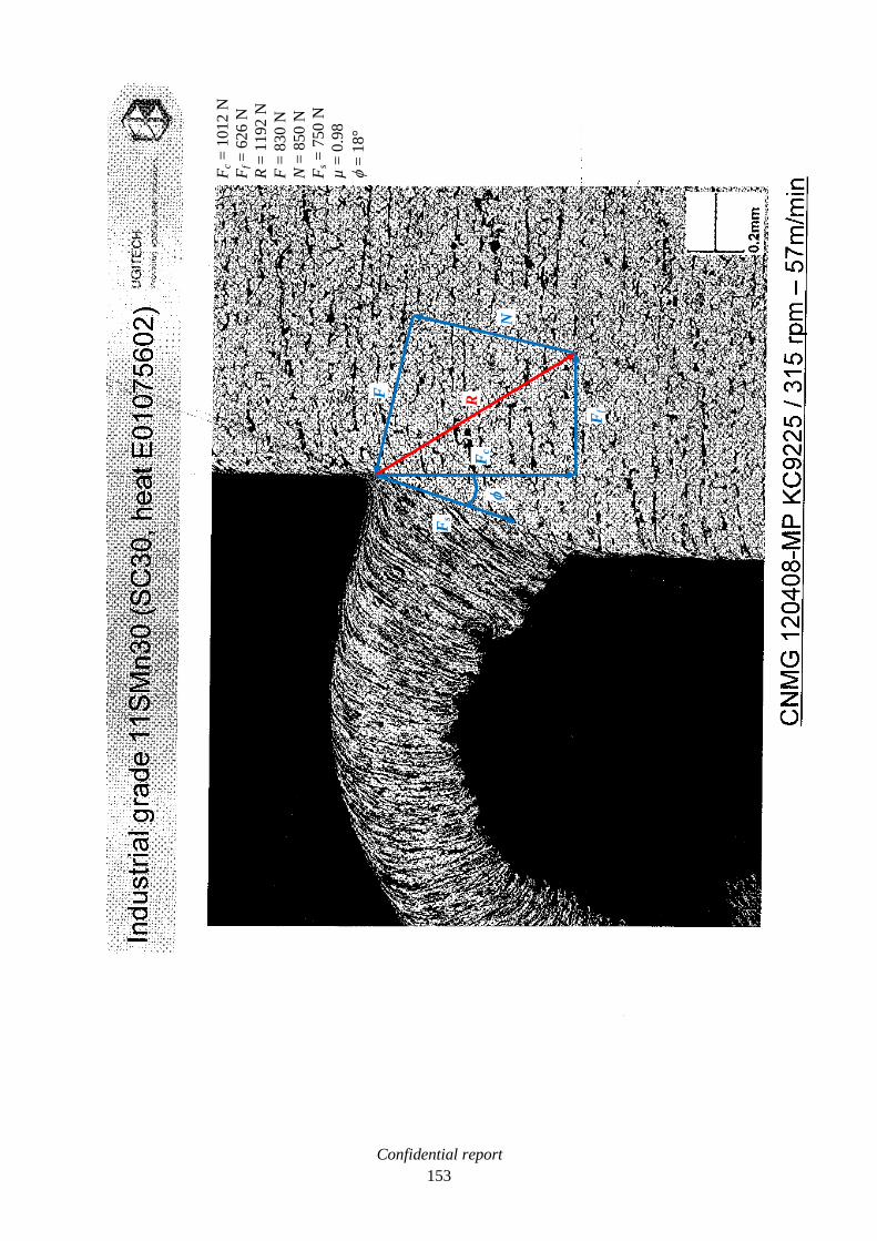
Confidential report
153
Fc
= 1
01
2 N
Ff =
62
6 N
R =
11
92
N
F =
830 N
N =
85
0 N
Fs
= 7
50
N
µ =
0.9
8
f =
18
°
R F
Fs
Fc
f
N
Ff

Confidential report
154
Fc
= 1
05
9 N
Ff =
66
5 N
R =
12
53
N
F =
900 N
N =
87
0 N
Fs =
84
0 N
µ =
1.0
3
f =
16
°
R F
Fs
f
Fc
N
Ff

Confidential report
155
Fc
= 9
98
N
Ff =
59
8 N
R =
11
66
N
F =
770 N
N =
88
0 N
Fs
= 8
60
N
µ =
0.8
8
f =
11
°
R
F
Fs
f
Fc
N
Ff

Confidential report
156

Confidential report
157
VII.2. Annex B: quick-stop measurements, industrial 11SMnPb30
Fc
= 6
59
N
Ff =
18
7 N
R =
68
5 N
F =
41
0 N
N =
54
5 N
Fs
= 5
35
N
µ =
0.7
5
f =
22
°
R
F
Fs
f
Fc
N
Ff

Confidential report
158
Fc
= 6
32
N
Ff =
17
4 N
R =
65
5 N
F =
29
5 N
N =
58
5 N
Fs
= 4
90
N
µ =
0.5
f =
26
°
R F
Fs
Fc
f
N
Ff

Confidential report
159
Fc
= 6
32
N
Ff =
17
4 N
R =
65
5 N
F =
265 N
N =
59
5 N
Fs
= 4
95
N
µ =
0.4
4
f =
25
°
Fs
f
Fc
F
N
Ff R

Confidential report
160
Fc
= 6
21
N
Ff =
17
1 N
R =
64
5 N
F =
260 N
N =
59
0 N
Fs
= 3
95
N
µ =
0.4
4
f =
36
° F
s
f
Fc
F
N
Ff R

Confidential report
161
Fc
= 6
13
N
Ff =
17
5 N
R =
64
0 N
F =
265 N
N =
58
0 N
Fs
= 5
45
N
µ =
0.4
6
f =
14
°
Fs
f
Fc
F
N
Ff
R

Confidential report
162
Fc
= 7
90
N
Ff =
35
2 N
R =
86
5 N
F =
505 N
N =
70
0 N
Fs =
68
0 N
µ =
0.7
2
f =
14
°
Fs
f
Fc
F
N
Ff
R

Confidential report
163
Fc
= 7
86
N
Ff =
37
8 N
R =
87
5 N
F =
510 N
N =
71
0 N
Fs
= 6
20
N
µ =
0.7
1
f =
18
°
Fs
f
Fc
F
N
Ff
R

Confidential report
164
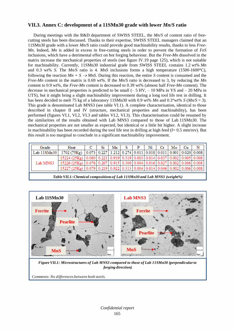
Confidential report
165
VII.3. Annex C: development of a 11SMn30 grade with lower Mn/S ratio
During meetings with the R&D department of SWISS STEEL, the Mn/S of content ratio of free-
cutting steels has been discussed. Thanks to their expertise, SWISS STEEL managers claimed that an
11SMn30 grade with a lower Mn/S ratio could provide good machinability results, thanks to less Free-
Mn. Indeed, Mn is added in excess in free-cutting steels in order to prevent the formation of FeS
inclusions, which have a detrimental effect on hot forging behaviour. But the Free-Mn dissolved in the
matrix increase the mechanical properties of steels (see figure IV.19 page 125), which is not suitable
for machinability. Currently, 11SMn30 industrial grade from SWISS STEEL contains 1.2 wt% Mn
and 0.3 wt% S. The Mn/S ratio is 4. MnS inclusions forms a high temperature (1500-1600°C),
following the reaction Mn + S MnS. During this reaction, the entire S content is consumed and the
Free-Mn content in the matrix is 0.69 wt%. If the Mn/S ratio is decreased to 3, by reducing the Mn
content to 0.9 wt%, the Free-Mn content is decreased to 0.39 wt% (almost half Free-Mn content). The
decrease in mechanical properties is predicted to be small (– 5 HV, – 10 MPa in YS and – 20 MPa in
UTS), but it might bring a slight machinability improvement during a long tool life test in drilling. It
has been decided to melt 75 kg of a laboratory 11SMn30 with 0.9 wt% Mn and 0.3°wt% S (Mn/S = 3).
This grade is denominated Lab MNS3 (see table VI.1). A complete characterisation, identical to those
described in chapter II and IV (structure, mechanical properties and machinability), has been
performed (figures VI.1, VI.2, VI.3 and tables VI.2, VI.3). This characterisation could be resumed by
the similarities of the results obtained with Lab MNS3 compared to those of Lab 11SMn30. The
mechanical properties are not smaller as expected, but identical or a little bit higher. A slight increase
in machinability has been recorded during the tool life test in drilling at high feed (f= 0.5 mm/rev). But
this result is too marginal to conclude in a significant machinability improvement.
Table VII.1: Chemical compositions of Lab 11SMn30 and Lab MNS3 (weight%)
Figure VII.1: Microstructures of Lab MNS3 compared to those of Lab 11SMn30 (perpendicular to
forging direction)
Comments: No differences between both steels.
Lab 11SMn30
Ferrite
Pearlite
MnS
Ferrite
Pearlite
MnS
Lab MNS3

Confidential report
166
Table VII.2: Characterisation of manganese sulphide inclusions in Lab MNS3 compared to those of
Lab 11SMn30
Comments: Equivalent sulphides population between both grades.
- Mean values among 5 sulphides
Table VI.3: Tensile test report of lab MNS3 compared to that of Lab 11SMn30
Comments: Similar mechanical properties between both grades.
- Mean values among 3 samples
Figure VII.2: Lab 11SMn30 and Lab 11SMnPb30 hardness profiles, compared to those of Ind 11SMn30
and Ind 11SMnPb30.
Comments: Lab MNS3 and Lab 11SMn30 present an equivalent hardness profile.
Uncertainty of measurement = 4%

Confidential report
167
Figure VII.3: Hot forging test on Lab MNS3 compared to those of Lab 11SMn30
Comments: Similar behaviour observed on both grades.

Confidential report
168
Figure VII.4: Tool life test in drilling with 4mm diameter HSS Tivoly tool on Lab MNS3 compared to that
of Lab 11SMn30 (superposition of results on industrial reference lines)
Comments: The machinability of Lab MNS3 is equivalent to that of Lab 11SMn30.

Confidential report
169
VII.4. Annex D: CHARPY impact test
The CHARPY impact test, also known as the CHARPY v-notch test, is a standardised high strain-rate
test which determines the amount of energy absorbed by a material during fracture. This absorbed
energy is a measure of a given material's toughness. This test has been performed on industrial and
laboratory steels for a comparative study. These results have not been incorporated to the
characterisation described in chapters II and IV, because of the large standard deviation (up to 25% of
the mean value), that made any comparison irrelevant (see table VII.4). Nevertheless, a qualitative
analyse could be achieved on medium carbon steels (Lab G1 to Lab G5). Indeed, at the initial state
(ferrite + pearlite structure) the medium carbon steel presented low fracture energies (from 6 to 17 J).
It has been remarked that Al added steels (Lab G2 and Lab G3), which presented the highest
mechanical properties (YS, UTS, HV), showed the lowest toughness (7 J for lab G2 and 6 J for
lab G3).At the graphitised state (ferrite + graphite structure), the samples exhibited fracture energies at
least twice more important (up to 33 J for lab G5g). It could be assumed that the transformation of the
structure from the ferrite + pearlite state to the ferrite + graphite state, provides significant gains in
toughness.
Table VII.4: CHARPY impact test results on industrial and laboratory steels.

Confidential report
170
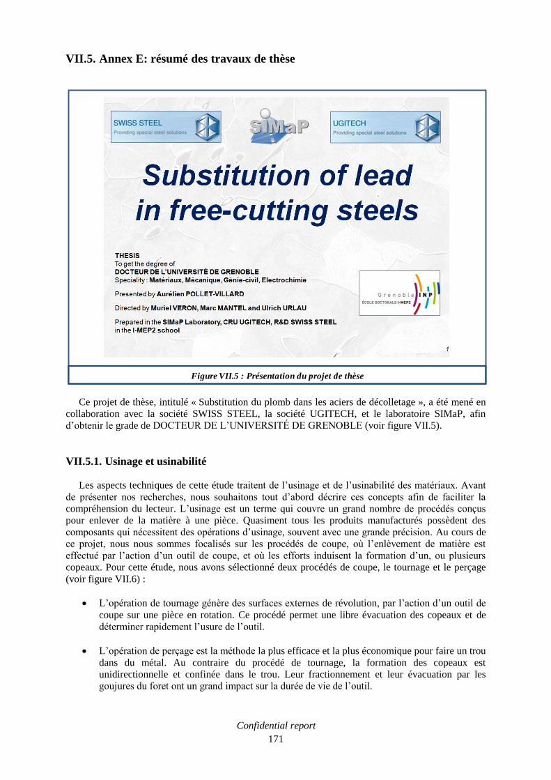
Confidential report
171
VII.5. Annex E: résumé des travaux de thèse
Ce projet de thèse, intitulé « Substitution du plomb dans les aciers de décolletage », a été mené en
collaboration avec la société SWISS STEEL, la société UGITECH, et le laboratoire SIMaP, afin
d’obtenir le grade de DOCTEUR DE L’UNIVERSITÉ DE GRENOBLE (voir figure VII.5).
VII.5.1. Usinage et usinabilité
Les aspects techniques de cette étude traitent de l’usinage et de l’usinabilité des matériaux. Avant
de présenter nos recherches, nous souhaitons tout d’abord décrire ces concepts afin de faciliter la
compréhension du lecteur. L’usinage est un terme qui couvre un grand nombre de procédés conçus
pour enlever de la matière à une pièce. Quasiment tous les produits manufacturés possèdent des
composants qui nécessitent des opérations d’usinage, souvent avec une grande précision. Au cours de
ce projet, nous nous sommes focalisés sur les procédés de coupe, où l’enlèvement de matière est
effectué par l’action d’un outil de coupe, et où les efforts induisent la formation d’un, ou plusieurs
copeaux. Pour cette étude, nous avons sélectionné deux procédés de coupe, le tournage et le perçage
(voir figure VII.6) :
L’opération de tournage génère des surfaces externes de révolution, par l’action d’un outil de
coupe sur une pièce en rotation. Ce procédé permet une libre évacuation des copeaux et de
déterminer rapidement l’usure de l’outil.
L’opération de perçage est la méthode la plus efficace et la plus économique pour faire un trou
dans du métal. Au contraire du procédé de tournage, la formation des copeaux est
unidirectionnelle et confinée dans le trou. Leur fractionnement et leur évacuation par les
goujures du foret ont un grand impact sur la durée de vie de l’outil.
Figure VII.5 : Présentation du projet de thèse

Confidential report
172
Les procédés de coupe sont chers, par conséquent, si un aciériste améliore les capacités d’usinage de
ses nuances (appelée usinabilité), des gains significatifs peuvent être engrangés. Cette usinabilité peut
être augmentée :
En réduisant l’usure de l’outil.
En facilitant le fractionnement des copeaux.
Les développements métallurgiques menés afin d’améliorer l’usinabilité ont conduit à la production
d’aciers spécifiquement conçus pour les opérations d’usinage. Ce sont les aciers de décolletage. Ils
sont regroupés dans la norme européenne EN 10087, et répondent à une définition simple : ils ont un
taux de soufre supérieur à 0,1% (nous précisons que les taux mentionnés dans ce résumé sont en
poids%). Les aciers de références choisis pour cette étude sont le 11SMn30 et le 11SMnPb30. Ils ont
un bas taux de carbone et un taux important de soufre (voir figure VII.7). La différence majeure entre
ces deux aciers de décolletage réside dans l’importante addition de plomb (Pb) dans le 11SMnPb30
(jusqu’à 0,35%). La différence d’usinabilité entre ces deux nuances permettra de comprendre le rôle
du plomb. Nous pouvons également citer les caractéristiques mécaniques attendues avec un Rp 0,2
jusqu’à 400 MPa et un Rm inférieur à 500 MPa.
Figure VII.6 : Procédés de coupe sélectionnés (tournage et perçage)
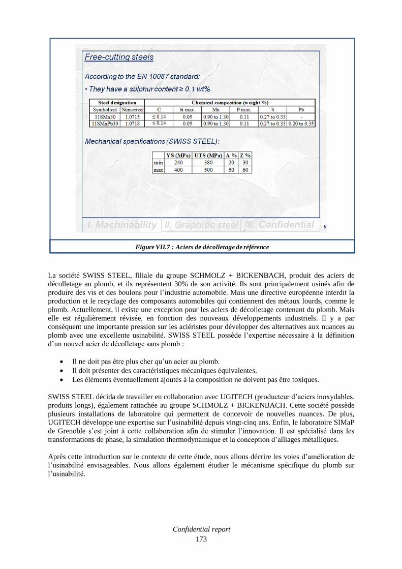
Confidential report
173
La société SWISS STEEL, filiale du groupe SCHMOLZ + BICKENBACH, produit des aciers de
décolletage au plomb, et ils représentent 30% de son activité. Ils sont principalement usinés afin de
produire des vis et des boulons pour l’industrie automobile. Mais une directive européenne interdit la
production et le recyclage des composants automobiles qui contiennent des métaux lourds, comme le
plomb. Actuellement, il existe une exception pour les aciers de décolletage contenant du plomb. Mais
elle est régulièrement révisée, en fonction des nouveaux développements industriels. Il y a par
conséquent une importante pression sur les aciéristes pour développer des alternatives aux nuances au
plomb avec une excellente usinabilité. SWISS STEEL possède l’expertise nécessaire à la définition
d’un nouvel acier de décolletage sans plomb :
Il ne doit pas être plus cher qu’un acier au plomb.
Il doit présenter des caractéristiques mécaniques équivalentes.
Les éléments éventuellement ajoutés à la composition ne doivent pas être toxiques.
SWISS STEEL décida de travailler en collaboration avec UGITECH (producteur d’aciers inoxydables,
produits longs), également rattachée au groupe SCHMOLZ + BICKENBACH. Cette société possède
plusieurs installations de laboratoire qui permettent de concevoir de nouvelles nuances. De plus,
UGITECH développe une expertise sur l’usinabilité depuis vingt-cinq ans. Enfin, le laboratoire SIMaP
de Grenoble s’est joint à cette collaboration afin de stimuler l’innovation. Il est spécialisé dans les
transformations de phase, la simulation thermodynamique et la conception d’alliages métalliques.
Après cette introduction sur le contexte de cette étude, nous allons décrire les voies d’amélioration de
l’usinabilité envisageables. Nous allons également étudier le mécanisme spécifique du plomb sur
l’usinabilité.
Figure VII.7 : Aciers de décolletage de référence

Confidential report
174
VII.5.2. Les voies d’amélioration de l’usinabilité
VII.5.2.1. Le sulfure de manganèse (MnS)
Le sulfure de manganèse est la solution la plus couramment utilisée. Il est dispersé dans la matrice
métallique sous forme d’inclusions d’environ 10 µm, et allongées dans la direction du laminage. Ce
type d’inclusion se ramollit au cours de l’usinage à vitesse moyenne (Vc = 150-300 m/min), là où la
température excède localement 700°C. Le sulfure de manganèse est alors plus plastique que la matrice
métallique. La présence d’une phase facilement déformable induit la localisation du cisaillement
autour des sulfures, ce qui améliore le fractionnement des copeaux (voir figure VII.8). De plus, le
sulfure de manganèse présente un effet lubrifiant à l’interface outil-copeau, ce qui augmente la durée
de vie de l’outil [JIA96]. Ces effets augmentent quand la vitesse de coupe, et donc la température,
augmentent, car les sulfures de manganèse deviennent de plus en plus plastique.
VII.5.2.2. Le plomb (Pb)
Le plomb (Pb) est ajouté aux aciers de décolletage afin d’améliorer encore d’avantage l’usinabilité.
Le plomb présente des mécanismes équivalents à ceux du sulfure de manganèse [YAG89]. Mais les
petites inclusions de plomb, dispersées dans la matrice métallique, ou à l’extrémité des sulfures de
manganèse (voir figure VII.9), ont une température de fusion peu élevée : 327°C. Par conséquent, le
plomb est plus plastique que la matrice à relativement basse température. Ainsi, à basse vitesse de
coupe, le plomb se ramollit et devient visqueux. Il protège l’interface outil-copeau. Donc le plomb a
un effet bénéfique sur l’usinabilité dès les basses vitesses de coupe (Vc < 100 m/min). Lorsque la
vitesse de coupe augmente, pour des valeurs supérieures à 100 m/min, le plomb finit par fondre à
l’interface outil-copeau. Il n’est plus assez visqueux pour protéger l’outil. Mais à ces vitesses, les
sulfures de manganèse commencent à lubrifier cette interface. Donc nous pouvons dire que les effets
du plomb complètent ceux du sulfure de manganèse, et ce, à très basse vitesse de coupe.
Figure VII.8 : Effet du sulfure de manganèse (MnS) sur l’usinabilité

Confidential report
175
VII.5.2.3. Autres voies d’amélioration de l’usinabilité
D’autres voies d’amélioration de l’usinabilité ont été rencontrées au cours de notre recherche
bibliographique.
Le bismuth (Bi) améliore l’usinabilité aussi bien que le plomb. Mais cette alternative a été
écartée car la production mondiale ne serait pas suffisante pour remplacer l’entière production
d’aciers au plomb [NRC08]. De plus, il dégrade fortement le travail à chaud des aciers qui
présentent des défauts de surface important (fissures).
Le tellure (Te) et le sélénium (Se) forment des phases à bas point de fusion comme MnTe et
MnSe qui facilitent le fractionnement des copeaux. Mais ils ne sont pas adaptés à notre
recherche d’alternatives car ils n’améliorent pas l’usinabilité aux basses vitesses de coupe. De
plus, le sélénium est toxique [SIM03], et par conséquent, inapproprié.
L’addition d’étain (Sn) est présentée comme une possible alternative. L’étain ségrége aux
joints de grains et procure un effet fragilisant. Mais l’usinabilité n’a pas été concluante dans
les études antérieures [REY05]. Nous avons élaboré des aciers à l’étain, et nous n’avons pas
réussi à concentrer l’étain aux joints de grains grâce à un traitement thermique. L’usinabilité
n’a pas été améliorée. De plus, nous avons essayé de développer une phase Pb-Sn à bas point
de fusion, sans succès.
Les oxydes sont développés dans les aciers de décolletage afin d’améliorer l’usinabilité pour
les hautes conditions de coupe [TRO08]. Mais nous avons souligné auparavant que le plomb
agissait principalement aux basses vitesses de coupe.
Le graphite est supposé améliorer l’usinabilité [SEK04], et le développement d’un acier
graphitique est l’objet d’un prochain chapitre.
Figure VII.9 : Effet du plomb (Pb) sur l’usinabilité

Confidential report
176
VII.5.3. Etude expérimentale de l’effet du plomb sur l’usinabilité
La première étape expérimentale de cette étude est de comprendre et de quantifier l’effet du plomb
sur l’usinabilité. Le gain obtenu par l’addition de plomb devra être au moins équivalent dans les
futures alternatives développées.
VII.5.3.1. Essais en tournage
Nous avons mené des essais spécifiques en tournage sur les nuances industrielles de SWISS
STEEL : 11SMn30 et 11SMnPb30. Un outil SECO, en carbure revêtu, a été choisi. Puis les conditions
de coupes ont été définies (voir figure VII.10):
La vitesse de coupe Vc, qui reflète la rotation de la pièce à usiner, augmente de façon continue
de 10 à 400 m/min.
La profondeur de passe ap, qui est l’épaisseur de matière à enlever, est fixée à 1,5 mm.
L’avance f, qui détermine le déplacement de l’outil le long de la barre, est fixée à 0,25 mm/tr.
Parallèlement, les efforts de coupe sont enregistrés grâce à un dynamomètre installé dans le porte-
outil.
Le traitement des résultats permet d’établir un graphique représentant les efforts de coupe en fonction
de la vitesse de coupe (voir figure VII.11). La ligne verte représente les résultats obtenus avec l’acier
sans plomb, et la bleue, les résultats de l’acier au plomb. Dans ce dernier cas, une chute importante des
efforts de coupe peut être observée entre Vc = 20 et 90 m/min. Dans cette fenêtre de vitesse, le plomb
doit être visqueux et lubrifier l’interface outil-copeau. C’est l’effet typique du plomb qui apparait
uniquement aux basses vitesses de coupe. Au-delà de Vc = 90 m/min, la courbe rejoint celle de l’acier
sans plomb. Ce comportement très brusque pourrait être dû à la température qui attendrait localement
la température de fusion du plomb. Mais ceci est très difficile à vérifier. La face dépouille d’un outil a
Figure VII.10 : Définition de l’essai en tournage

Confidential report
177
été observé au MEB après un essai en tournage à Vc = 100 m/min (voir figure VII.11). Des particules
de plomb sont observables loin de l’interface outil-copeau. Le plomb devait être liquide et il a été
pulvérisé loin de l’interface. Il ne lubrifiait plus l’interface et les efforts de coupe ont augmenté. Au
contraire, une grande quantité de sulfure de manganèse (MnS) a été identifiée à l’interface outil-
copeau. Il a un effet lubrifiant qui protège l’outil. Par conséquent, nous pouvons supposer que, passé
Vc = 100 m/min, les effets du plomb s’arrêtent, et ceux du sulfure de manganèse débutent. Du fer (Fe),
en provenance de la pièce usinée, a été détecté à la surface de l’outil. C’est ce qu’on appelle l’arête
rapportée. Enfin, du carbure de tungstène (WC) a été identifié, car il constitue le substrat de l’outil.
VII.5.3.2. Essais quick-stop
Afin de comprendre encore d’avantage comment le plomb entraine la diminution des efforts de
coupe, l’étude du coefficient de frottement à l’interface outil-copeau a été menée. Pour cela, la
technique quick-stop a été utilisée (voir figure VII.12). Tout d’abord, des barres d’aciers industriels de
SWISS STEEL ont été percées afin d’obtenir des tubes de 60 mm de diamètre externe et 2 mm
d’épaisseur. Ensuite, les tubes sont dressés en conditions orthogonales. Dans ces conditions, l’effort de
coupe ne présente que deux composantes : la coupe et l’avance. Ces composantes sont enregistrées
grâce à un dynamomètre installé dans le porte outil. L’opération de dressage consomme la longueur du
tube, puis elle est soudainement interrompue grâce à un dispositif pyrotechnique. Cela permet de
préserver le copeau à l’endroit où il se forme. Finalement, le copeau est coupé du tube et préparé pour
une observation métallographique. La préparation doit être faite à mi épaisseur du tube, où les
conditions orthogonales sont les mieux vérifiées. Les essais quick-stop sont relativement longs et un
unique essai a été réalisé pour chaque vitesse de coupe. Sur une photographie de l’observation
métallographique, les efforts de coupe Fc et d’avance Ff appliqués par l’outil peuvent être reportés, ce
qui permet d’en déduire la résultante R (voir figure VII.13). Cette résultante est projetée selon la
direction de la face de dépouille, ce qui constitue l’effort de frottement F appliqué à l’outil. La
résultante est ensuite projetée perpendiculairement à la face de dépouille, c’est l’effort normal N
appliqué à l’outil. Enfin, la résultante est projetée le long du plan de cisaillement afin de mesurer
Figure VII.11 : Evolution des efforts de coupe en fonction de la vitesse de coupe en tournage
Uncertainty of measurement = 3%

Confidential report
178
l’effort de cisaillement Fs appliqué par l’outil. Le coefficient de frottement µ à l’interface outil-copeau
est calculé grâce à la loi de COULOMB. Il est égal à l’effort de frottement divisé par l’effort normal.
Figure VII.12 : Principe de l’essai quick-stop
Figure VII.13 : Détermination graphique des paramètres de coupe

Confidential report
179
L’ensemble des résultats permet de tracer l’évolution du coefficient de frottement en fonction de la
vitesse de coupe (voir figure VII.14). En vert, les résultats obtenus avec l’acier sans plomb, et en bleu
ceux de l’acier au plomb. Dans ce dernier cas, le coefficient de frottement présente un comportement
typique entre Vc = 20 et 80 m/min, avec une importante chute. Elle entraine la chute des efforts de
coupe observée précédemment. Après Vc = 80 m/min, le coefficient tend à augmenter, le plomb perd
ses effets.
VII.5.3.3. Conclusion sur l’effet du plomb sur l’usinabilité
Il est supposé que l’effet bénéfique du plomb sur l’usinage n’a lieu qu’aux basses vitesses de coupe
(Vc < 100 m/min). Le plomb se ramollit, il est visqueux et il diminue le coefficient de frottement à
l’interface outil-copeau. Les efforts de coupe décroissent et l’usure des outils est réduite. Pour les
vitesses de coupe supérieures, le plomb ne présente plus d’effet lubrifiant parce qu’il n’est plus assez
visqueux. Mais pour ces hautes vitesses de coupe, le sulfure de manganèse commence à être plus
plastique que la matrice métallique et il a un effet lubrifiant qui diminue l’usure des outils. Par
conséquent, il peut être avancé que le plomb et le sulfure de manganèse ont des effets
complémentaires sur l’usinabilité. Enfin, l’effet du plomb sur le fractionnement des copeaux a été
difficilement apprécié en comparant les résultats obtenus avec le 11SMn30 et le 11SMnPb30. En effet,
l’opération de tournage permet une évacuation libre des copeaux.
Figure VII.14 : Evolution du coefficient de frottement en fonction de la vitesse de coupe
Uncertainty of measurement = 3%

Confidential report
180
VII.5.4. Développement d’un acier graphitique
VII.5.4.1. Etude bibliographique sur le graphite
Le graphite, sélectionné comme une possible voie d’amélioration de l’usinabilité, est supposé agir
aux basses vitesses de coupe. Dans l’industrie, il est connu comme un lubrifiant solide. En effet, la
structure du graphite est constituée d’un empilement de plans hexagonaux. Ce sont des plans de
graphène (voir figure VII.15). Les liaisons entre les atomes de carbone dans les plans sont fortes, mais
elles sont, au contraire, faibles entre les atomes des plans voisins. Ces plans faiblement reliés glissent
facilement les uns par rapport aux autres [KAT96]. Cette propriété pourrait améliorer l’usinabilité.
Mais le développement de graphite dans un acier demande une étude approfondie.
Dans le diagramme fer-carbone, l’équilibre s’effectue entre la ferrite et le graphite (en traits pointillés
sur la figure VII.16). La cémentite est une phase métastable et elle est cinétiquement favorisée (en
traits pleins sur la figure VII.16). Le graphite apparaît en grande quantité dans les fontes, grâce à
l’importante teneur en carbone (2 à 4%). Mais il est difficile d’obtenir du graphite dans les aciers, du
fait de leur faible teneur en carbone (0,03 à 2%). Un très long revenu est nécessaire afin de regagner
l’état d’équilibre : de l’ordre d’une dizaine à une centaine d’heures. Ce qui est totalement inapproprié
dans l’industrie. La littérature met en lumière que certains éléments d’alliage accélèrent le processus
de graphitisation (voir figure VII.15) [DUP08]. Seuls les éléments ayant l’influence la plus forte sont
étudiés dans notre projet : le silicium (Si) et l’aluminium (Al). Le nickel (Ni) et le zirconium (Zr) sont
trop chers compte tenu des quantités à ajouter pour obtenir un effet significatif. D’autres éléments
ralentissent le processus de graphitisation : manganèse (Mn), chrome (Cr), soufre (S) etc. (voir figure
VII.16). Seul le manganèse est étudié dans notre projet car il est couramment ajouté dans les aciers. En
conclusion, des simulations thermodynamiques doivent être réalisées afin de déterminer une
composition d’acier qui permettrait une graphitisation rapide.
Figure VII.15 : Structure du graphite

Confidential report
181
VII.5.4.2. Etude thermodynamique de la graphitisation
Afin de développer un acier graphitique, il faut tout d’abord étudier la thermodynamique de la
graphitisation. La théorie classique de la germination montre que le rayon critique de germination r*
est inversement proportionnel au changement d’énergie de Gibbs du système par unité de volume de
précipité formé, appelée Gv. L’énergie d’activation G*est inversement proportionnelle au carré de
cette même quantité (voir figure VII.17). Gv présente deux composantes : un terme chimique et un
terme d’énergie de déformation dû au changement de volume. Le but de ces travaux n’est pas de
développer un modèle de germination, mais de montrer les effets des éléments d’alliage sur la
germination du graphite. Il est supposé, en première approximation, que ces additions ne changent pas
le terme d’énergie de déformation. Seule la contribution chimique est considérée afin d’obtenir l’effet
des éléments d’alliage sur la germination du graphite (voir figure VII.17). La contribution chimique
est simplement donnée par la force motrice de précipitation du graphite Gm (qui est positive quand la
précipitation est thermodynamiquement possible) divisée par le volume molaire du graphite. Sur la
figure VII.18 sont illustrées les courbes d’énergie de Gibbs des différentes phases : ferrite, cémentite
et graphite. L’état métastable est un mélange de ferrite et de cémentite. Cet état a un surplus d’énergie
comparé à l’état stable ferrite + graphite. La force motrice de précipitation d’une mole de graphite
Gm, depuis le mélange ferrite + cémentite, est simplement le changement de potentiel chimique du
carbone entre ces deux états. Au cours de cette étude, Gm a été calculée grâce au logiciel Thermo-
Calc® et à la base de donnée TCFE6.
Figure VII.16 : Diagramme de phase fer-carbone, éléments graphitisants et antigraphitisants

Confidential report
182
Figure VII.17 : Théorie classique de la germination appliquée à la graphitisation
Figure VII.18 : Détermination de la force motrice de précipitation du graphite Gm
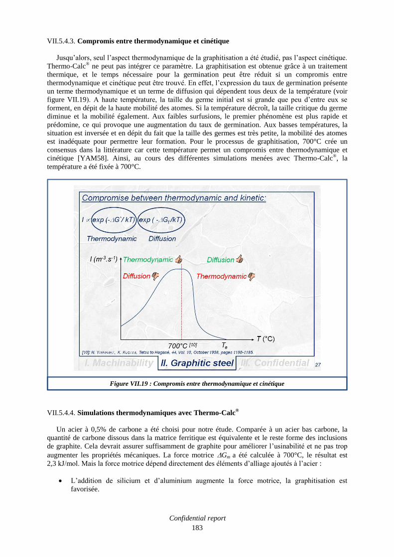
Confidential report
183
VII.5.4.3. Compromis entre thermodynamique et cinétique
Jusqu’alors, seul l’aspect thermodynamique de la graphitisation a été étudié, pas l’aspect cinétique.
Thermo-Calc® ne peut pas intégrer ce paramètre. La graphitisation est obtenue grâce à un traitement
thermique, et le temps nécessaire pour la germination peut être réduit si un compromis entre
thermodynamique et cinétique peut être trouvé. En effet, l’expression du taux de germination présente
un terme thermodynamique et un terme de diffusion qui dépendent tous deux de la température (voir
figure VII.19). A haute température, la taille du germe initial est si grande que peu d’entre eux se
forment, en dépit de la haute mobilité des atomes. Si la température décroît, la taille critique du germe
diminue et la mobilité également. Aux faibles surfusions, le premier phénomène est plus rapide et
prédomine, ce qui provoque une augmentation du taux de germination. Aux basses températures, la
situation est inversée et en dépit du fait que la taille des germes est très petite, la mobilité des atomes
est inadéquate pour permettre leur formation. Pour le processus de graphitisation, 700°C crée un
consensus dans la littérature car cette température permet un compromis entre thermodynamique et
cinétique [YAM58]. Ainsi, au cours des différentes simulations menées avec Thermo-Calc®, la
température a été fixée à 700°C.
VII.5.4.4. Simulations thermodynamiques avec Thermo-Calc®
Un acier à 0,5% de carbone a été choisi pour notre étude. Comparée à un acier bas carbone, la
quantité de carbone dissous dans la matrice ferritique est équivalente et le reste forme des inclusions
de graphite. Cela devrait assurer suffisamment de graphite pour améliorer l’usinabilité et ne pas trop
augmenter les propriétés mécaniques. La force motrice Gm a été calculée à 700°C, le résultat est
2,3 kJ/mol. Mais la force motrice dépend directement des éléments d’alliage ajoutés à l’acier :
L’addition de silicium et d’aluminium augmente la force motrice, la graphitisation est
favorisée.
Figure VII.19 : Compromis entre thermodynamique et cinétique
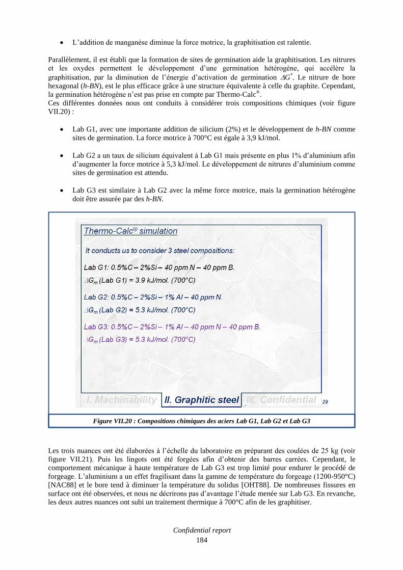
Confidential report
184
L’addition de manganèse diminue la force motrice, la graphitisation est ralentie.
Parallèlement, il est établi que la formation de sites de germination aide la graphitisation. Les nitrures
et les oxydes permettent le développement d’une germination hétérogène, qui accélère la
graphitisation, par la diminution de l’énergie d’activation de germination G*. Le nitrure de bore
hexagonal (h-BN), est le plus efficace grâce à une structure équivalente à celle du graphite. Cependant,
la germination hétérogène n’est pas prise en compte par Thermo-Calc®.
Ces différentes données nous ont conduits à considérer trois compositions chimiques (voir figure
VII.20) :
Lab G1, avec une importante addition de silicium (2%) et le développement de h-BN comme
sites de germination. La force motrice à 700°C est égale à 3,9 kJ/mol.
Lab G2 a un taux de silicium équivalent à Lab G1 mais présente en plus 1% d’aluminium afin
d’augmenter la force motrice à 5,3 kJ/mol. Le développement de nitrures d’aluminium comme
sites de germination est attendu.
Lab G3 est similaire à Lab G2 avec la même force motrice, mais la germination hétérogène
doit être assurée par des h-BN.
Les trois nuances ont été élaborées à l’échelle du laboratoire en préparant des coulées de 25 kg (voir
figure VII.21). Puis les lingots ont été forgées afin d’obtenir des barres carrées. Cependant, le
comportement mécanique à haute température de Lab G3 est trop limité pour endurer le procédé de
forgeage. L’aluminium a un effet fragilisant dans la gamme de température du forgeage (1200-950°C)
[NAC88] et le bore tend à diminuer la température du solidus [OHT88]. De nombreuses fissures en
surface ont été observées, et nous ne décrirons pas d’avantage l’étude menée sur Lab G3. En revanche,
les deux autres nuances ont subi un traitement thermique à 700°C afin de les graphitiser.
Figure VII.20 : Compositions chimiques des aciers Lab G1, Lab G2 et Lab G3

Confidential report
185
L’évolution de la graphitisation a été suivie en fonction du temps de maintien à 700°C (voir figure
VII.22). Dans le cas de Lab G1, à l’état initial, une structure ferrite + perlite peut être observée. Après
2 heures de traitement, la décomposition de la perlite est amorcée et les premières inclusions de
graphite apparaissent. La graphitisation est complète après 4 heures. C’est encore plus rapide dans le
cas de Lab G2 qui présente une structure ferrite + graphite après seulement 1 heure. Les simulations
thermodynamiques sont confirmées, la graphitisation est d’autant plus favorisée et rapide que la force
motrice est élevée.
Une autre façon d’observer l’évolution de la graphitisation consiste à mesurer la dureté en fonction du
temps de maintien à 700°C (voir figure VII.23). A l’état initial, la cémentite est une phase dure. La
transition vers une matrice ferritique molle, avec des inclusions de graphite dispersées, peut être
appréciée par la diminution de la dureté. Cette dernière se stabilise après 16 heures pour Lab G1 et
8 heures pour Lab G2. L’ensemble des barres des deux nuances ont été traitées durant 16 heures, afin
de garantir une comparaison pertinente entre elles. Ces aciers graphitiques sont appelés Lab G1g et
Lab G2g.
VII.5.4.5. Usinabilité des aciers graphitiques
Une fois les barres graphitisées, leur usinabilité doit être évaluée et comparée à celle des aciers de
décolletage conventionnels. L’opération de perçage a été sélectionnée pour déterminer l’usinabilité des
aciers graphitiques. Ce procédé de coupe permet d’observer en même temps l’usure des outils et le
fractionnement des copeaux. Comparée à l’opération de tournage, une quantité moindre d’acier est
nécessaire pour une caractérisation complète. Des essais de durée de vie d’outil ont été menés, et ils
consistent à définir un domaine, en termes de vitesse de coupe Vc et d’avance f, pour lequel la durée de
vie du foret est satisfaisante. Dans le cas d’un foret de 4 mm de diamètre, au moins 1125 trous de
16 mm de profondeur doivent être réalisés afin d’atteindre 18 m de longueur percée (soit 225 cm3 de
matière enlevée). C’est le critère de durée de vie choisi pour cette étude. La première chose à faire est
de définir le niveau d’usinabilité de références. Par conséquent, des essais de durée de vie d’outil ont
été réalisés sur les aciers de décolletage 11SMn30 et 11SMnPb30 en provenance de SWISS STEEL.
Figure VII.21 : Elaboration à l’échelle du laboratoire des aciers Lab G1, Lab G2 et Lab G3

Confidential report
186
Figure VII.22 : Evolution des microstructures de Lab G1 et Lab G2 au cours de la graphitisation
Figure VII.23 : Evolution de la dureté de Lab G1 et Lab G2 au cours de la graphitisation

Confidential report
187
La figure VII.24 présente les résultats obtenus avec les nuances industrielles 11SMn30 et 11SMnPb30.
Les axes des diagrammes sont gradués en avance f (abscisses) et en vitesse de coupe Vc (ordonnées).
Chaque point de la grille est une condition de coupe. Si une condition vérifie le critère de durée de vie
d’outil, elle est représentée en bleu. Si plus de la moitié du critère est atteinte, la condition de coupe est
représentée en jaune. Et finalement, si la condition n’atteint pas la moitié du critère, elle est
représentée en rouge.
Grâce à ces résultats, une ligne de référence peut être tracée pour les deux nuances (voir figure
VII.25). Il convient de préciser que des coulées de laboratoire avec les mêmes compositions que les
aciers industriels ont confirmé ces résultats. L’amélioration de l’usinabilité en termes de vitesse de
coupe Vc et d’avance f par l’ajout de plomb est conséquente. Afin de mettre en évidence l’amélioration
apportée par le plomb, les courbes de productivité des deux nuances ont été représentées (voir figure
VII.25). Pour des vitesses de coupe inférieures à 90 m/min, la nuance 11SMn30, sans plomb, peut être
usinée à 8 cm3/min. Alors que la nuance 11SMnPb30, au plomb, peut être usinée à 17 cm
3/min. Par
conséquent, la productivité est doublée aux basses vitesses de coupe grâce l’addition de plomb. Les
aciers graphitiques doivent présentés les mêmes performances aux basses vitesses de coupe pour
prétendre remplacer le plomb. L’écart entre les deux lignes de références est plus prononcé a moyenne
et haute avance. Les aciers graphitiques ont par conséquent été testés dans les mêmes conditions (voir
figure VII.26). Lab G1g montre un comportement intermédiaire entre les nuances avec, et sans plomb.
Ce qui tend à prouver l’efficacité du graphite. Mais dans le cas de Lab G2g, les résultats sont
particulièrement faibles. Il faut donc comprendre pourquoi la durée de vie d’outil est si courte, malgré
l’effet lubrifiant du graphite. Les propriétés mécaniques peuvent expliquer ces résultats. En effet, la
dureté d’un acier graphitique est bien plus importante que celle d’un acier bas carbone de décolletage
(11SMn30). Et une matrice dure tend à réduire la durée de vie d’outil. Les hautes valeurs de dureté
mesurées sur les deux nuances graphitiques sont dues aux additions de silicium et d’aluminium. Dans
le cas de Lab G1g (addition de silicium uniquement), le durcissement structural attendu dans la
littérature en comparaison du 11SMn30 [MUR93], est équivalent aux valeurs expérimentales : 55
contre 60 HV (voir figure VII.27). Les autres caractéristiques mécaniques suivent la même tendance.
Elles sont beaucoup plus importantes que celles d’un acier de décolletage classique type 11SMn30
Figure VII.24 : Essais de durée de vie d’outil en perçage avec les nuances 11SMn30 et 11SMnPb30

Confidential report
188
(voir figure VII.28). L’écart sur la limite élastique est de 108 MPa au lieu de 140 MPa dans la
littérature [MUR93]. De la même manière, l’écart sur la limite à la rupture est de 123 MPa, ce qui est
proche des 140 MPa attendus dans la littérature [MUR93].
Figure VII.25 : Lignes de références et courbes de productivité des nuances 11SMn30 et 11SMnPb30
Figure VII.26 : Essais de durée de vie d’outil avec les nuances LabG1g et LabG2g

Confidential report
189
Figure VII.27 : Durcissement structural par ajout de silicium
Figure VII.28 : Comparaison des propriétés mécaniques entre Lab G1g et Lab 11SMn30

Confidential report
190
VII.5.4.6. Conclusion
Lab G1g présente des résultats d’usinabilité prometteurs, ce qui signifie que l’effet lubrifiant du
graphite est efficace, et qu’il remplace partiellement les effets du plomb et des sulfures de manganèse.
Mais les importantes propriétés mécaniques limitent la durée de vie d’outil, et l’usinabilité est
globalement inférieure à celle d’un acier de décolletage au plomb. Il faut par conséquent considérer,
dans les prochains développements, deux paramètres :
La diminution des caractéristiques mécaniques, afin qu’elles soient plus proches de celles des
aciers bas carbone de décolletage.
La préservation de l’effet lubrifiant du graphite.
VII.5.5. Développement d’un substitut aux aciers de décolletage au plomb
Lab G1, Lab G2 et Lab G3 constituaient le premier pas de ce projet. Afin d’améliorer l’usinabilité
des aciers graphitiques, il a été décidé de combiner les effets du graphite et des sulfures de manganèse.
C’est la partie la plus innovante de notre étude. Les inclusions de sulfures de manganèse vont aider le
graphite au cours des opérations difficiles de perçage. L’effet nuisible du manganèse sur la
graphitisation est contrôlé grâce à des simulations thermodynamiques. Ainsi, la graphitisation de ces
nouveaux développements est assurée. Enfin, la réduction du taux de silicium, afin de limiter les
caractéristiques mécaniques, nous a conduits à définir un substitut aux aciers au plomb qui serait
industrialisable.
VII.5.5.1. Définition de deux nouvelles compositions d’aciers graphitiques
Les conclusions exposées précédemment ont permis de considérer deux nouvelles compositions
(voir figure VII.29) :
Lab G4 suggère d’aider l’effet lubrifiant du graphite pour les dures conditions d’usinage avec
des inclusions de sulfure de manganèse. Pour cela, 0,9% de manganèse et 0,3% de soufre sont
ajoutés à la composition de Lab G1.
Lab G5 propose d’ajuster les caractéristiques mécaniques et d’aider l’effet lubrifiant du
graphite. Pour cela, le taux de silicium est réduit à 1,2% et des inclusions de sulfure de
manganèse sont développées avec le taux minimal de manganèse envisageable à l’échelle
industrielle (0,6% à l’aciérie de SWISS STEEL). Car il faut conserver à l’esprit que le
manganèse a un effet nuisible sur la graphitisation, et cet effet doit être prédit.
VII.5.5.2. Prédiction de l’effet du manganèse sur la graphitisation
Des simulations thermodynamiques ont été menées sur les effets combinés du manganèse et du
silicium sur la force motrice de précipitation du graphite (voir figure VII.30). Précédemment, il a été
établi que la graphitisation est favorisée si la force motrice à 700°C est supérieure à 2,3 kJ/mol. Cela
permet de définir une zone de travail, où la force motrice à 700°C est supérieure à 2,3 kJ/mol, et où les
compositions doivent être sélectionnées. Il doit être remarqué que le manganèse qui a un effet nuisible
sur la graphitisation est le manganèse qui ne réagit pas avec le soufre pour former des sulfures de
manganèse. Ce manganèse, dissous dans la matrice ferritique, est appelé Free-Mn. Il a été calculé avec
Thermo-Calc®. Il est égal à 0,39% pour Lab G4 et 0,26% pour Lab G5. La force motrice est supérieure
à 2,3 kJ/mol pour Lab G4 et Lab G5 (respectivement 3,4 kJ/mol et 2,8 kJ/mol) la graphitisation à
700°C doit être efficace.

Confidential report
191
Figure VII.29 : Définition de deux nouvelles compositions d’aciers graphitiques
Figure VII.30 : Effets combinés du silicium et du manganèse sur la force motrice de précipitation du
graphite dans un acier à 0,5% de carbone
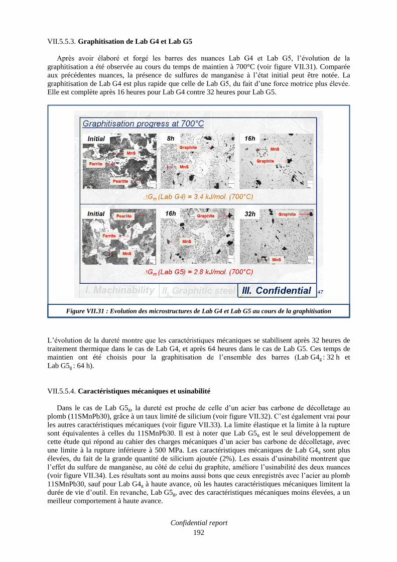
Confidential report
192
VII.5.5.3. Graphitisation de Lab G4 et Lab G5
Après avoir élaboré et forgé les barres des nuances Lab G4 et Lab G5, l’évolution de la
graphitisation a été observée au cours du temps de maintien à 700°C (voir figure VII.31). Comparée
aux précédentes nuances, la présence de sulfures de manganèse à l’état initial peut être notée. La
graphitisation de Lab G4 est plus rapide que celle de Lab G5, du fait d’une force motrice plus élevée.
Elle est complète après 16 heures pour Lab G4 contre 32 heures pour Lab G5.
L’évolution de la dureté montre que les caractéristiques mécaniques se stabilisent après 32 heures de
traitement thermique dans le cas de Lab G4, et après 64 heures dans le cas de Lab G5. Ces temps de
maintien ont été choisis pour la graphitisation de l’ensemble des barres (Lab G4g : 32 h et
Lab G5g : 64 h).
VII.5.5.4. Caractéristiques mécaniques et usinabilité
Dans le cas de Lab G5g, la dureté est proche de celle d’un acier bas carbone de décolletage au
plomb (11SMnPb30), grâce à un taux limité de silicium (voir figure VII.32). C’est également vrai pour
les autres caractéristiques mécaniques (voir figure VII.33). La limite élastique et la limite à la rupture
sont équivalentes à celles du 11SMnPb30. Il est à noter que Lab G5g est le seul développement de
cette étude qui répond au cahier des charges mécaniques d’un acier bas carbone de décolletage, avec
une limite à la rupture inférieure à 500 MPa. Les caractéristiques mécaniques de Lab G4g sont plus
élevées, du fait de la grande quantité de silicium ajoutée (2%). Les essais d’usinabilité montrent que
l’effet du sulfure de manganèse, au côté de celui du graphite, améliore l’usinabilité des deux nuances
(voir figure VII.34). Les résultats sont au moins aussi bons que ceux enregistrés avec l’acier au plomb
11SMnPb30, sauf pour Lab G4g à haute avance, où les hautes caractéristiques mécaniques limitent la
durée de vie d’outil. En revanche, Lab G5g, avec des caractéristiques mécaniques moins élevées, a un
meilleur comportement à haute avance.
Figure VII.31 : Evolution des microstructures de Lab G4 et Lab G5 au cours de la graphitisation
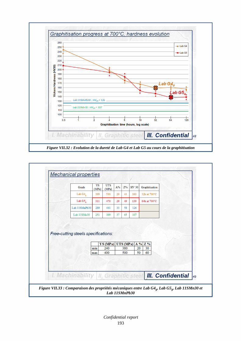
Confidential report
193
Figure VII.32 : Evolution de la dureté de Lab G4 et Lab G5 au cours de la graphitisation
Figure VII.33 : Comparaison des propriétés mécaniques entre Lab G4g, Lab G5g, Lab 11SMn30 et
Lab 11SMnPb30

Confidential report
194
VII.5.5.5. Conclusion
Lab G4g a montré que l’effet positif des sulfures de manganèse sur l’usinabilité aidait le graphite.
En effet, cette nuance présente une excellente usinabilité sauf à haute avance, où la durée de vie
d’outil est limitée par ses hautes caractéristiques mécaniques. Elles sont dues à l’importante addition
de silicium. Dans le cas de Lab G5g, la diminution du taux de silicium permet de diminuer les
caractéristiques mécaniques qui sont proches de celles d’un acier bas carbone de décolletage au plomb
(11SMnPb30). Malgré le taux de silicium plus faible, la graphitisation est toujours efficace, bien que
relativement longue (64 heures). Enfin, les effets combinés du graphite, des sulfures de manganèse et
des caractéristiques mécaniques limitées, permettent d’observer une usinabilité au moins aussi bonne
que celle du 11SMnPb30.
En conséquence, Lab G5, à l’état graphitique, est notre meilleure alternative aux aciers bas carbone de
décolletage au plomb.
Figure VII.34 : Essais de durée de vie d’outil avec les nuances LabG4g et LabG5g
* : quantité d’acier insuffisante pour finaliser l’essai

Confidential report
195
VII.5.6. Conclusion générale et perspectives
Au cours de ce projet, il a été observé que les aciers de décolletage au plomb montraient une
excellente usinabilité, uniquement aux basses vitesses de coupe (Vc < 100 m/min). Nous avons montré
que cela était dû à l’effet lubrifiant du plomb.
Par conséquent, et afin de remplacer les aciers de décolletage au plomb, un acier graphitique a été
développé : Lab G5. Il présente une usinabilité au moins aussi bonne que celle des aciers de
décolletage au plomb, parce qu’il propose un compromis entre les caractéristiques mécaniques et le
temps de graphitisation.
Nous avons donc appris lors de cette étude que les propriétés mécaniques étaient aussi importantes que
le développement des inclusions de graphite. Ce nouveau paramètre peut être pris en compte sur la
zone de travail définie dans la partie thermodynamique. Sur le graphique reliant la force motrice aux
taux de silicium et de manganèse, il peut être ajouté une diagonale rouge qui relie l’écart de limite
élastique (UTS) en fonction du taux de silicium (voir figure VII.35). L’écart correspondant à l’acier
de référence 11SMn30 (0,2% de silicium) peut être facilement déduit. La limite élastique d’un tel acier
approche les 400 MPa, cette valeur peut être placée sur un nouvel axe (UTS en bleu). Le cahier des
charges mécaniques d’un acier bas carbone de décolletage stipule que la limite élastique ne doit pas
excéder 500 MPa. Cette donnée permet de déterminer le taux maximal de silicium autorisé. Une
nouvelle zone de travail peut alors être définie, avec le silicium compris entre 0,6 et 1,5%, et un
manganèse libre (Free-Mn) toujours inférieur à 0,6%. Il peut être remarqué que Lab G5 est le seul
développement de cette étude qui vérifie cette zone.
La prochaine étape de ce projet est de produire à l’aciérie de SWISS STEEL une coulée avec la
composition de Lab G5. La caractérisation de ce métal industriel devrait confirmer la pertinence de la
substitution du plomb par le graphite dans les aciers de décolletage.
Enfin, la réduction du temps de graphitisation serait une voie d’amélioration de cette nuance. Dans ce
but, des études supplémentaires sur la germination hétérogène pourraient mener à une composition qui
accélérerait la graphitisation. Par exemple, la dispersion et le nombre de h-BN sont des paramètres à
ajuster.

Confidential report
196
Figure VII.35 : Définition d’une nouvelle zone de travail qui prend en compte les caractéristiques
mécaniques

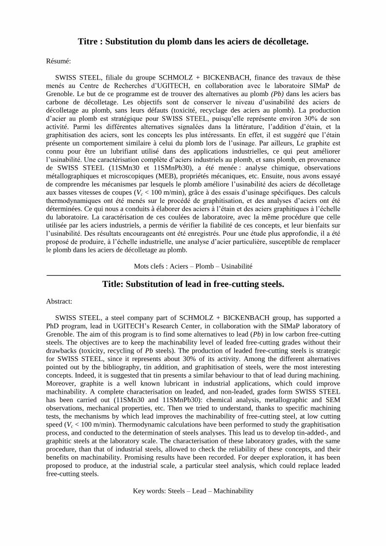
Titre : Substitution du plomb dans les aciers de décolletage.
Résumé:
SWISS STEEL, filiale du groupe SCHMOLZ + BICKENBACH, finance des travaux de thèse
menés au Centre de Recherches d’UGITECH, en collaboration avec le laboratoire SIMaP de
Grenoble. Le but de ce programme est de trouver des alternatives au plomb (Pb) dans les aciers bas
carbone de décolletage. Les objectifs sont de conserver le niveau d’usinabilité des aciers de
décolletage au plomb, sans leurs défauts (toxicité, recyclage des aciers au plomb). La production
d’acier au plomb est stratégique pour SWISS STEEL, puisqu’elle représente environ 30% de son
activité. Parmi les différentes alternatives signalées dans la littérature, l’addition d’étain, et la
graphitisation des aciers, sont les concepts les plus intéressants. En effet, il est suggéré que l’étain
présente un comportement similaire à celui du plomb lors de l’usinage. Par ailleurs, Le graphite est
connu pour être un lubrifiant utilisé dans des applications industrielles, ce qui peut améliorer
l’usinabilité. Une caractérisation complète d’aciers industriels au plomb, et sans plomb, en provenance
de SWISS STEEL (11SMn30 et 11SMnPb30), a été menée : analyse chimique, observations
métallographiques et microscopiques (MEB), propriétés mécaniques, etc. Ensuite, nous avons essayé
de comprendre les mécanismes par lesquels le plomb améliore l’usinabilité des aciers de décolletage
aux basses vitesses de coupes (Vc < 100 m/min), grâce à des essais d’usinage spécifiques. Des calculs
thermodynamiques ont été menés sur le procédé de graphitisation, et des analyses d’aciers ont été
déterminées. Ce qui nous a conduits à élaborer des aciers à l’étain et des aciers graphitiques à l’échelle
du laboratoire. La caractérisation de ces coulées de laboratoire, avec la même procédure que celle
utilisée par les aciers industriels, a permis de vérifier la fiabilité de ces concepts, et leur bienfaits sur
l’usinabilité. Des résultats encourageants ont été enregistrés. Pour une étude plus approfondie, il a été
proposé de produire, à l’échelle industrielle, une analyse d’acier particulière, susceptible de remplacer
le plomb dans les aciers de décolletage au plomb.
Mots clefs : Aciers – Plomb – Usinabilité
Title: Substitution of lead in free-cutting steels.
Abstract:
SWISS STEEL, a steel company part of SCHMOLZ + BICKENBACH group, has supported a
PhD program, lead in UGITECH’s Research Center, in collaboration with the SIMaP laboratory of
Grenoble. The aim of this program is to find some alternatives to lead (Pb) in low carbon free-cutting
steels. The objectives are to keep the machinability level of leaded free-cutting grades without their
drawbacks (toxicity, recycling of Pb steels). The production of leaded free-cutting steels is strategic
for SWISS STEEL, since it represents about 30% of its activity. Among the different alternatives
pointed out by the bibliography, tin addition, and graphitisation of steels, were the most interesting
concepts. Indeed, it is suggested that tin presents a similar behaviour to that of lead during machining.
Moreover, graphite is a well known lubricant in industrial applications, which could improve
machinability. A complete characterisation on leaded, and non-leaded, grades form SWISS STEEL
has been carried out (11SMn30 and 11SMnPb30): chemical analysis, metallographic and SEM
observations, mechanical properties, etc. Then we tried to understand, thanks to specific machining
tests, the mechanisms by which lead improves the machinability of free-cutting steel, at low cutting
speed (Vc < 100 m/min). Thermodynamic calculations have been performed to study the graphitisation
process, and conducted to the determination of steels analyses. This lead us to develop tin-added-, and
graphitic steels at the laboratory scale. The characterisation of these laboratory grades, with the same
procedure, than that of industrial steels, allowed to check the reliability of these concepts, and their
benefits on machinability. Promising results have been recorded. For deeper exploration, it has been
proposed to produce, at the industrial scale, a particular steel analysis, which could replace leaded
free-cutting steels.
Key words: Steels – Lead – Machinability