SUBCHAPTER D—AIRMEN - GovInfo
378
5 SUBCHAPTER D—AIRMEN PART 60—FLIGHT SIMULATION TRAINING DEVICE INITIAL AND CONTINUING QUALIFICATION AND USE Sec. 60.1 Applicability. 60.2 Applicability of sponsor rules to per- sons who are not sponsors and who are engaged in certain unauthorized activi- ties. 60.3 Definitions. 60.4 Qualification Performance Standards. 60.5 Quality management system. 60.7 Sponsor qualification requirements. 60.9 Additional responsibilities of the spon- sor. 60.11 FSTD use. 60.13 FSTD objective data requirements. 60.14 Special equipment and personnel re- quirements for qualification of the FSTD. 60.15 Initial qualification requirements. 60.16 Additional qualifications for a cur- rently qualified FSTD. 60.17 Previously qualified FSTDs. 60.19 Inspection, continuing qualification evaluation, and maintenance require- ments. 60.20 Logging FSTD discrepancies. 60.21 Interim qualification of FSTDs for new aircraft types or models. 60.23 Modifications to FSTDs. 60.25 Operation with missing, malfunc- tioning, or inoperative components. 60.27 Automatic loss of qualification and procedures for restoration of qualifica- tion. 60.29 Other losses of qualification and pro- cedures for restoration of qualification. 60.31 Recordkeeping and reporting. 60.33 Applications, logbooks, reports, and records: Fraud, falsification, or incorrect statements. 60.35 Specific full flight simulator compli- ance requirements. 60.37 FSTD qualification on the basis of a Bilateral Aviation Safety Agreement (BASA). APPENDIX A TO PART 60—QUALIFICATION PER- FORMANCE STANDARDS FOR AIRPLANE FULL FLIGHT SIMULATORS APPENDIX B TO PART 60—QUALIFICATION PER- FORMANCE STANDARDS FOR AIRPLANE FLIGHT TRAINING DEVICES APPENDIX C TO PART 60—QUALIFICATION PER- FORMANCE STANDARDS FOR HELICOPTER FULL FLIGHT SIMULATORS APPENDIX D TO PART 60—QUALIFICATION PER- FORMANCE STANDARDS FOR HELICOPTER FLIGHT TRAINING DEVICES APPENDIX E TO PART 60—QUALIFICATION PER- FORMANCE STANDARDS FOR QUALITY MAN- AGEMENT SYSTEMS FOR FLIGHT SIMULA- TION TRAINING DEVICES APPENDIX F TO PART 60—DEFINITIONS AND AB- BREVIATIONS FOR FLIGHT SIMULATION TRAINING DEVICES AUTHORITY: 49 U.S.C. 106(g), 40113, and 44701. SOURCE: Doc. No. FAA–2002–12461, 71 FR 63426, Oct. 30, 2006, unless otherwise noted. § 60.1 Applicability. (a) This part prescribes the rules gov- erning the initial and continuing quali- fication and use of all aircraft flight simulation training devices (FSTD) used for meeting training, evaluation, or flight experience requirements of this chapter for flight crewmember cer- tification or qualification. (b) The rules of this part apply to each person using or applying to use an FSTD to meet any requirement of this chapter. (c) The requirements of § 60.33 regard- ing falsification of applications, records, or reports also apply to each person who uses an FSTD for training, evaluation, or obtaining flight experi- ence required for flight crewmember certification or qualification under this chapter. § 60.2 Applicability of sponsor rules to persons who are not sponsors and who are engaged in certain unau- thorized activities. (a) The rules of this part that are di- rected to a sponsor of an FSTD also apply to any person who uses or causes the use of an FSTD when— (1) That person knows that the FSTD does not have an FAA-approved spon- sor; and (2) The use of the FSTD by that per- son is nonetheless claimed for purposes of meeting any requirement of this chapter or that person knows or should have known that the person’s acts or omissions would cause another person to mistakenly credit use of the FSTD for purposes of meeting any require- ment of this chapter. (b) A situation in which paragraph (a) of this section would not apply to a VerDate Mar<15>2010 18:16 Mar 01, 2012 Jkt 226045 PO 00000 Frm 00015 Fmt 8010 Sfmt 8010 Q:\14\14V2 ofr150 PsN: PC150
-
Upload
khangminh22 -
Category
Documents
-
view
0 -
download
0
Transcript of SUBCHAPTER D—AIRMEN - GovInfo

5
SUBCHAPTER D—AIRMEN
PART 60—FLIGHT SIMULATION TRAINING DEVICE INITIAL AND CONTINUING QUALIFICATION AND USE
Sec. 60.1 Applicability. 60.2 Applicability of sponsor rules to per-
sons who are not sponsors and who are engaged in certain unauthorized activi-ties.
60.3 Definitions. 60.4 Qualification Performance Standards. 60.5 Quality management system. 60.7 Sponsor qualification requirements. 60.9 Additional responsibilities of the spon-
sor. 60.11 FSTD use. 60.13 FSTD objective data requirements. 60.14 Special equipment and personnel re-
quirements for qualification of the FSTD.
60.15 Initial qualification requirements. 60.16 Additional qualifications for a cur-
rently qualified FSTD. 60.17 Previously qualified FSTDs. 60.19 Inspection, continuing qualification
evaluation, and maintenance require-ments.
60.20 Logging FSTD discrepancies. 60.21 Interim qualification of FSTDs for
new aircraft types or models. 60.23 Modifications to FSTDs. 60.25 Operation with missing, malfunc-
tioning, or inoperative components. 60.27 Automatic loss of qualification and
procedures for restoration of qualifica-tion.
60.29 Other losses of qualification and pro-cedures for restoration of qualification.
60.31 Recordkeeping and reporting. 60.33 Applications, logbooks, reports, and
records: Fraud, falsification, or incorrect statements.
60.35 Specific full flight simulator compli-ance requirements.
60.37 FSTD qualification on the basis of a Bilateral Aviation Safety Agreement (BASA).
APPENDIX A TO PART 60—QUALIFICATION PER-FORMANCE STANDARDS FOR AIRPLANE FULL FLIGHT SIMULATORS
APPENDIX B TO PART 60—QUALIFICATION PER-FORMANCE STANDARDS FOR AIRPLANE FLIGHT TRAINING DEVICES
APPENDIX C TO PART 60—QUALIFICATION PER-FORMANCE STANDARDS FOR HELICOPTER FULL FLIGHT SIMULATORS
APPENDIX D TO PART 60—QUALIFICATION PER-FORMANCE STANDARDS FOR HELICOPTER FLIGHT TRAINING DEVICES
APPENDIX E TO PART 60—QUALIFICATION PER-FORMANCE STANDARDS FOR QUALITY MAN-AGEMENT SYSTEMS FOR FLIGHT SIMULA-TION TRAINING DEVICES
APPENDIX F TO PART 60—DEFINITIONS AND AB-BREVIATIONS FOR FLIGHT SIMULATION TRAINING DEVICES
AUTHORITY: 49 U.S.C. 106(g), 40113, and 44701.
SOURCE: Doc. No. FAA–2002–12461, 71 FR 63426, Oct. 30, 2006, unless otherwise noted.
§ 60.1 Applicability. (a) This part prescribes the rules gov-
erning the initial and continuing quali-fication and use of all aircraft flight simulation training devices (FSTD) used for meeting training, evaluation, or flight experience requirements of this chapter for flight crewmember cer-tification or qualification.
(b) The rules of this part apply to each person using or applying to use an FSTD to meet any requirement of this chapter.
(c) The requirements of § 60.33 regard-ing falsification of applications, records, or reports also apply to each person who uses an FSTD for training, evaluation, or obtaining flight experi-ence required for flight crewmember certification or qualification under this chapter.
§ 60.2 Applicability of sponsor rules to persons who are not sponsors and who are engaged in certain unau-thorized activities.
(a) The rules of this part that are di-rected to a sponsor of an FSTD also apply to any person who uses or causes the use of an FSTD when—
(1) That person knows that the FSTD does not have an FAA-approved spon-sor; and
(2) The use of the FSTD by that per-son is nonetheless claimed for purposes of meeting any requirement of this chapter or that person knows or should have known that the person’s acts or omissions would cause another person to mistakenly credit use of the FSTD for purposes of meeting any require-ment of this chapter.
(b) A situation in which paragraph (a) of this section would not apply to a
VerDate Mar<15>2010 18:16 Mar 01, 2012 Jkt 226045 PO 00000 Frm 00015 Fmt 8010 Sfmt 8010 Q:\14\14V2 ofr150 PsN: PC150

6
14 CFR Ch. I (1–1–12 Edition) § 60.3
person would be when each of the fol-lowing conditions are met:
(1) The person sold or leased the FSTD and merely represented to the purchaser or lessee that the FSTD is in a condition in which it should be able to obtain FAA approval and qualifica-tion under this part;
(2) The person does not falsely claim to be the FAA-approved sponsor for the FSTD;
(3) The person does not falsely make representations that someone else is the FAA-approved sponsor of the FSTD at a time when that other person is not the FAA-approved sponsor of the FSTD; and
(4) The person’s acts or omissions do not cause another person to detrimen-tally rely on such acts or omissions for the mistaken conclusion that the FSTD is FAA-approved and qualified under this part at the time the FSTD is sold or leased.
§ 60.3 Definitions. In addition to the definitions in part
1 of this chapter, other terms and defi-nitions applicable to this part are found in appendix F of this part.
§ 60.4 Qualification Performance Standards.
The Qualification Performance Standards (QPS) are published in ap-pendices to this part as follows:
(a) Appendix A contains the QPS for Airplane Flight Simulators.
(b) Appendix B contains the QPS for Airplane Flight Training Devices.
(c) Appendix C contains the QPS for Helicopter Flight Simulators.
(d) Appendix D contains the QPS for Helicopter Flight Training Devices.
(e) Appendix E contains the QPS for Quality Management Systems for FSTDs.
(f) Appendix F contains the QPS for Definitions and Abbreviations for FSTDs.
§ 60.5 Quality management system. (a) After May 30, 2010, no sponsor
may use or allow the use of or offer the use of an FSTD for flight crewmember training or evaluation or for obtaining flight experience to meet any require-ment of this chapter unless the sponsor has established and follows a quality
management system (QMS), currently approved by the National Simulator Program Manager (NSPM), for the con-tinuing surveillance and analysis of the sponsor’s performance and effective-ness in providing a satisfactory FSTD for use on a regular basis as described in QPS appendix E of this part.
(b) The QMS program must provide a process for identifying deficiencies in the program and for documenting how the program will be changed to address these deficiencies.
(c) Whenever the NSPM finds that the QMS program does not adequately address the procedures necessary to meet the requirements of this part, the sponsor must, after notification by the NSPM, change the program so the pro-cedures meet the requirements of this part. Each such change must be ap-proved by the NSPM prior to imple-mentation.
(d) Within 30 days after the sponsor receives a notice described in para-graph (c) of this section, the sponsor may file a petition with the Director of Flight Standards Service (the Director) for reconsideration of the NSPM find-ing. The sponsor must address its peti-tion to the Director, Flight Standards Service, AFS–1, Federal Aviation Ad-ministration, 800 Independence Ave., SW., Washington, DC 20591. The filing of such a petition to reconsider stays the notice pending a decision by the Director. However, if the Director finds that there is a situation that requires immediate action in the interest of safety in air commerce, he may, upon a statement of the reasons, require a change effective without stay.
[Doc. No. FAA–2002–12461, 71 FR 63426, Oct. 30, 2006; Amdt. 60–2, 72 FR 59599, Oct. 22, 2007]
§ 60.7 Sponsor qualification require-ments.
(a) A person is eligible to apply to be a sponsor of an FSTD if the following conditions are met:
(1) The person holds, or is an appli-cant for, a certificate under part 119, 141, or 142 of this chapter; or holds, or is an applicant for, an approved flight engineer course in accordance with part 63 of this chapter.
(2) The FSTD will be used, or will be offered for use, in the sponsor’s FAA- approved flight training program for
VerDate Mar<15>2010 18:16 Mar 01, 2012 Jkt 226045 PO 00000 Frm 00016 Fmt 8010 Sfmt 8010 Q:\14\14V2 ofr150 PsN: PC150

7
Federal Aviation Administration, DOT § 60.9
the aircraft being simulated as evi-denced in a request for evaluation sub-mitted to the NSPM.
(b) A person is a sponsor if the fol-lowing conditions are met:
(1) The person is a certificate holder under part 119, 141, or 142 of this chap-ter or has an approved flight engineer course in accordance with part 63 of this chapter.
(2) The person has— (i) Operations specifications author-
izing the use of the specific aircraft or set of aircraft and has an FAA-ap-proved training program under which at least one FSTD, simulating the air-craft or set of aircraft and for which the person is the sponsor, is used by the sponsor as described in paragraphs (b)(5) or (b)(6) of this section; or
(ii) Training specifications or an FAA-approved course of training under which at least one FSTD, simulating that aircraft or set of aircraft and for which the person is the sponsor, is used by the sponsor as described in para-graphs (b)(5) or (b)(6) of this section.
(3) The person has a quality manage-ment system currently approved by the NSPM in accordance with § 60.5.
(4) The NSPM has accepted the per-son as the sponsor of the FSTD and that acceptance has not been with-drawn by the FAA.
(5) At least one FSTD (as referenced in paragraph (b)(2)(i) or (b)(2)(ii) of this section) that is initially qualified on or after May 30, 2008, is used within the sponsor’s FAA-approved flight training program for the aircraft or set of air-craft at least once within the 12-month period following the initial/upgrade evaluation, and at least once within each subsequent 12-month period there-after.
(6) At least one FSTD (as referenced in paragraph (b)(2)(i) or (b)(2)(ii) of this section) that was qualified before May 30, 2008, is used within the sponsor’s FAA-approved flight training program for the aircraft or set of aircraft at least once within the 12-month period following the first continuing quali-fication evaluation conducted by the NSPM after May 30, 2008 and at least once within each subsequent 12-month period thereafter.
(c) If the use requirements of para-graphs (b)(2) and either (b)(5) or (b)(6)
of this section are not met, the person will forfeit the right to sponsor that FSTD and that person will not be eligi-ble to apply to sponsor that FSTD for at least 12 calendar months following the expiration of the qualification sta-tus.
(d) In addition to the FSTD described in paragraph (b) of this section, an FSTD sponsor may sponsor any num-ber of other FSTDs regardless of spe-cific aircraft or set of aircraft provided either—
(1) During the preceding 12-month pe-riod, all of the other FSTDs are used within the sponsor’s or another certifi-cate holder’s FAA-approved flight training program for the aircraft or set of aircraft simulated; or
(2) The sponsor obtains a written statement at least annually from a qualified pilot who has flown the air-craft or set of aircraft (as appropriate) during the preceding 12-month period stating that the subject FSTD’s per-formance and handling qualities, with-in the normal operating envelope, rep-resent the aircraft or set of aircraft de-scribed in the FAA Type Certificate and the type data sheet, if appropriate. The sponsor must retain the two most current written statements for review by the NSPM.
[Doc. No. FAA–2002–12461, 71 FR 63426, Oct. 30, 2006; Amdt. 60–2, 72 FR 59599, Oct. 22, 2007]
§ 60.9 Additional responsibilities of the sponsor.
(a) The sponsor must allow the NSPM upon request to inspect the FSTD as soon as practicable. This in-spection may include all records and documents relating to the FSTD, to de-termine its compliance with this part.
(b) The sponsor must do the following for each FSTD:
(1) Establish a mechanism to receive written comments regarding the FSTD and its operation in accordance with the QPS appendix E of this part.
(2) Post in or adjacent to the FSTD the Statement of Qualification issued by the NSPM. An electronic copy of the Statement of Qualification that may be accessed by an appropriate ter-minal or display in or adjacent to the FSTD is satisfactory.
VerDate Mar<15>2010 18:16 Mar 01, 2012 Jkt 226045 PO 00000 Frm 00017 Fmt 8010 Sfmt 8010 Q:\14\14V2 ofr150 PsN: PC150
8
14 CFR Ch. I (1–1–12 Edition) § 60.11
(c) Each sponsor of an FSTD must identify to the NSPM by name, one in-dividual to be the management rep-resentative (MR).
(1) One person may serve as an MR for more than one FSTD, but one FSTD must not have more than one person serving in this capacity.
(2) Each MR must be an employee of the sponsor with the responsibility and authority to—
(i) Monitor the on-going qualification of assigned FSTDs to ensure that all matters regarding FSTD qualification are being carried out as provided for in this part;
(ii) Ensure that the QMS is properly established, implemented, and main-tained by overseeing the structure (and modifying where necessary) of the QMS policies, practices, and procedures; and
(iii) Regularly brief sponsor’s man-agement on the status of the on-going FSTD qualification program and the effectiveness and efficiency of the QMS.
(3) The MR serves as the primary contact point for all matters between the sponsor and the NSPM regarding the qualification of that FSTD as pro-vided for in this part.
(4) The MR may delegate the duties described in paragraph (c)(2) and (c)(3) of this section to an individual at each of the sponsor’s locations.
§ 60.11 FSTD use.
No person may use or allow the use of or offer the use of an FSTD for flight crewmember training or evaluation or for obtaining flight experience to meet any of the requirements under this chapter unless, in accordance with the QPS for the specific device, the FSTD meets all of the following:
(a) Has a single sponsor who is quali-fied under § 60.7. The sponsor may ar-range with another person for services of document preparation and presen-tation, as well as FSTD inspection, maintenance, repair, and servicing; however, the sponsor remains respon-sible for ensuring that these functions are conducted in a manner and with a result of continually meeting the re-quirements of this part.
(b) Is qualified as described in the Statement of Qualification.
(c) Remains qualified, through satis-factory inspection, continuing quali-fication evaluations, appropriate main-tenance, and use requirements in ac-cordance with this part and the appli-cable QPS.
(d) Functions during day-to-day training, evaluation, or flight experi-ence activities with the software and hardware that was evaluated as satis-factory by the NSPM and, if modified, modified only in accordance with the provisions of this part. However, this section does not apply to routine soft-ware or hardware changes that do not fall under the requirements of § 60.23.
(e) Is operated in accordance with the provisions and limitations of § 60.25.
§ 60.13 FSTD objective data require-ments.
(a) Except as provided in paragraph (b) and (c) of this section, for the pur-poses of validating FSTD performance and handling qualities during evalua-tion for qualification, the data made available to the NSPM (the validation data package) must include the air-craft manufacturer’s flight test data and all relevant data developed after the type certificate was issued (e.g., data developed in response to an air-worthiness directive) if such data re-sults from a change in performance, handling qualities, functions, or other characteristics of the aircraft that must be considered for flight crew-member training, evaluation, or for meeting experience requirements of this chapter.
(b) The validation data package may contain flight test data from a source in addition to or independent of the aircraft manufacturer’s data in support of an FSTD qualification, but only if this data is gathered and developed by that source in accordance with flight test methods, including a flight test plan, as described in the applicable QPS.
(c) The validation data package may also contain predicted data, engineer-ing simulation data, data from pilot owner or pilot operating manuals, or data from public domain sources, pro-vided this data is acceptable to the NSPM. If found acceptable the data may then be used in particular applica-tions for FSTD qualification.
VerDate Mar<15>2010 18:16 Mar 01, 2012 Jkt 226045 PO 00000 Frm 00018 Fmt 8010 Sfmt 8010 Q:\14\14V2 ofr150 PsN: PC150

9
Federal Aviation Administration, DOT § 60.15
(d) Data or other material or ele-ments must be submitted in a form and manner acceptable to the NSPM.
(e) The NSPM may require additional objective data, which may include flight testing if necessary, if the vali-dation data package does not support FSTD qualification requirements as described in this part and the applica-ble QPS appendix.
(f) When an FSTD sponsor learns, or is advised by an aircraft manufacturer or other data provider, that an addi-tion to, an amendment to, or a revision of data that may relate to FSTD per-formance or handling characteristics is available, the sponsor must notify the NSPM as described in the applicable QPS.
§ 60.14 Special equipment and per-sonnel requirements for qualifica-tion of the FSTD.
When notified by the NSPM, the sponsor must make available all spe-cial equipment and qualified personnel needed to accomplish or assist in the accomplishment of tests during initial qualification, continuing qualification, or special evaluations.
§ 60.15 Initial qualification require-ments.
(a) For each FSTD, the sponsor must submit a request to the NSPM to evaluate the FSTD for initial qualifica-tion at a specific level and simulta-neously request the Training Program Approval Authority (TPAA) forward a concurring letter to the NSPM. The re-quest must be submitted in the form and manner described in the applicable QPS.
(b) The management representative described in § 60.9(c) must sign a state-ment (electronic signature is accept-able for electronic transmissions) after confirming the following:
(1) The performance and handling qualities of the FSTD represent those of the aircraft or set of aircraft within the normal operating envelope. This determination must be made by a pilot(s) meeting the requirements of paragraph (d) of this section after hav-ing flown all of the Operations Tasks listed in the applicable QPS appendix relevant to the qualification level of the FSTD. Exceptions, if any, must be
noted. The name of the person(s) mak-ing this determination must be avail-able to the NSPM upon request.
(2) The FSTD systems and sub-sys-tems (including the simulated aircraft systems) functionally represent those in the aircraft or set of aircraft. This determination must be made by the pilot(s) described in paragraph (b)(1) of this section, or by a person(s) trained on simulator systems/sub-systems and trained on the operation of the simu-lated aircraft systems, after having ex-ercised the operation of the FSTD and the pertinent functions available through the Instructor Operating Sta-tion(s). Exceptions, if any, must be noted. The name of the person(s) mak-ing this determination must be avail-able to the NSPM upon request.
(3) The cockpit represents the con-figuration of the specific type; or air-craft make, model, and series aircraft being simulated, as appropriate. This determination must be made by the pilot(s) described in paragraph (b)(1) of this section, or by a person(s) trained on the configuration and operation of the aircraft simulated. Exceptions, if any, must be noted. The name of the person(s) making this determination must be available to the NSPM upon request.
(c) Except for those FSTDs pre-viously qualified and described in § 60.17, each FSTD evaluated for initial qualification must meet the standard that is in effect at the time of the eval-uation. However—
(1) If the FAA publishes a change to the existing standard or publishes a new standard for the evaluation for ini-tial qualification, a sponsor may re-quest that the NSPM apply the stand-ard that was in effect when an FSTD was ordered for delivery if the spon-sor—
(i) Within 30 days of the publication of the change to the existing standard or publication of the new standard, no-tifies the NSPM that an FSTD has been ordered;
(ii) Within 90 days of the NSPM noti-fication described in paragraph (c)(1)(i) of this section, requests that the stand-ard in effect at the time the order was placed be used for the evaluation for initial qualification; and
VerDate Mar<15>2010 18:16 Mar 01, 2012 Jkt 226045 PO 00000 Frm 00019 Fmt 8010 Sfmt 8010 Q:\14\14V2 ofr150 PsN: PC150

10
14 CFR Ch. I (1–1–12 Edition) § 60.16
(iii) The evaluation is conducted within 24 months following the publica-tion of the change to the existing standard or publication of the new standard.
(2) This notification must include a description of the FSTD; the antici-pated qualification level of the FSTD; the make, model, and series of aircraft simulated; and any other pertinent in-formation.
(3) Any tests, tolerances, or other re-quirements that are current at the time of the evaluation may be used during the initial evaluation, at the re-quest of the sponsor, if the sponsor pro-vides acceptable updates to the re-quired qualification test guide.
(4) The standards used for the evalua-tion for initial qualification will be used for all subsequent evaluations of the FSTD.
(d) The pilot(s) who contributes to the confirmation statement required by paragraph (b) of this section must—
(1) Be designated by the sponsor; and (2) Be qualified in— (i) The aircraft or set of aircraft
being simulated; or (ii) For aircraft not yet issued a type
certificate, or aircraft not previously operated by the sponsor or not having previous FAA-approved training pro-grams conducted by the sponsor, an aircraft similar in size and configura-tion.
(e) The subjective tests that form the basis for the statements described in paragraph (b) of this section and the objective tests referenced in paragraph (f) of this section must be accom-plished at the sponsor’s training facil-ity, except as provided for in the appli-cable QPS.
(f) The person seeking to qualify the FSTD must provide the NSPM access to the FSTD for the length of time nec-essary for the NSPM to complete the required evaluation of the FSTD for initial qualification, which includes the conduct and evaluation of objective and subjective tests, including general FSTD requirements, as described in the applicable QPS, to determine that the FSTD meets the standards in that QPS.
(g) When the FSTD passes an evalua-tion for initial qualification, the NSPM
issues a Statement of Qualification that includes all of the following:
(1) Identification of the sponsor. (2) Identification of the make, model,
and series of the aircraft or set of air-craft being simulated.
(3) Identification of the configuration of the aircraft or set of aircraft being simulated (e.g., engine model or mod-els, flight instruments, or navigation or other systems).
(4) A statement that the FSTD is qualified as either a full flight simu-lator or a flight training device.
(5) Identification of the qualification level of the FSTD.
(6) A statement that (with the excep-tion of the noted exclusions for which the FSTD has not been subjectively tested by the sponsor or the NSPM and for which qualification is not sought) the qualification of the FSTD includes the tasks set out in the applicable QPS appendix relevant to the qualification level of the FSTD.
(h) After the NSPM completes the evaluation for initial qualification, the sponsor must update the Qualification Test Guide (QTG), with the results of the FAA-witnessed tests together with the results of all the objective tests de-scribed in the applicable QPS.
(i) Upon issuance of the Statement of Qualification the updated QTG be-comes the Master Qualification Test Guide (MQTG). The MQTG must be made available to the NSPM upon re-quest.
§ 60.16 Additional qualifications for a currently qualified FSTD.
(a) A currently qualified FSTD is re-quired to undergo an additional quali-fication process if a user intends to use the FSTD for meeting training, evalua-tion, or flight experience requirements of this chapter beyond the qualifica-tion issued for that FSTD. This process consists of the following:
(1) The sponsor: (i) Must submit to the NSPM all
modifications to the MQTG that are re-quired to support the additional quali-fication.
(ii) Must describe to the NSPM all modifications to the FSTD that are re-quired to support the additional quali-fication.
VerDate Mar<15>2010 18:16 Mar 01, 2012 Jkt 226045 PO 00000 Frm 00020 Fmt 8010 Sfmt 8010 Q:\14\14V2 ofr150 PsN: PC150

11
Federal Aviation Administration, DOT § 60.19
(iii) Must submit to the NSPM a con-firmation statement as described in § 60.15(c) that a pilot, designated by the sponsor in accordance with § 60.15(d), has subjectively evaluated the FSTD in those areas not previously evaluated.
(2) The FSTD must successfully pass an evaluation—
(i) Consisting of all the elements of an initial evaluation for qualification in those circumstances where the NSPM has determined that all the ele-ments of an initial evaluation for qual-ification is necessary; or
(ii) Consisting of those elements of an initial evaluation for qualification designated as necessary by the NSPM.
(b) In making the determinations de-scribed in paragraph (a)(2) of this sec-tion, the NSPM considers factors in-cluding the existing qualification of the FSTD, any modifications to the FSTD hardware or software that are involved, and any additions or modi-fications to the MQTG.
(c) The FSTD is qualified for the ad-ditional uses when the NSPM issues an amended Statement of Qualification in accordance with § 60.15(h).
(d) The sponsor may not modify the FSTD except as described in § 60.23.
§ 60.17 Previously qualified FSTDs.
(a) Unless otherwise specified by an FSTD Directive, further referenced in the applicable QPS, or as specified in paragraph (e) of this section, an FSTD qualified before May 30, 2008 will retain its qualification basis as long as it con-tinues to meet the standards, including the objective test results recorded in the MQTG and subjective tests, under which it was originally evaluated, re-gardless of sponsor. The sponsor of such an FSTD must comply with the other applicable provisions of this part.
(b) For each FSTD qualified before May 30, 2008, no sponsor may use or allow the use of or offer the use of such an FSTD after May 30, 2014 for flight crewmember training, evaluation or flight experience to meet any of the re-quirements of this chapter, unless that FSTD has been issued a Statement of Qualification, including the Configura-tion List and the List of Qualified Tasks in accordance with the proce-dures set out in the applicable QPS.
(c) If the FSTD qualification is lost under § 60.27 and—
(i) Restored under § 60.27 in less than (2) years, then the qualification basis (in terms of objective tests and subjec-tive tests) for the re-qualification will be those against which the FSTD was originally evaluated and qualified.
(ii) Not restored under § 60.27 for two (2) years or more, then the qualifica-tion basis (in terms of objective tests and subjective tests) for the re-quali-fication will be those standards in ef-fect and current at the time of re-qual-ification application.
(d) Except as provided in paragraph (e) of this section, any change in FSTD qualification level initiated on or after May 30, 2008 requires an evaluation for initial qualification in accordance with this part.
(e) A sponsor may request that an FSTD be permanently downgraded. In such a case, the NSPM may downgrade a qualified FSTD without requiring and without conducting an initial eval-uation for the new qualification level. Subsequent continuing qualification evaluations will use the existing MQTG, modified as necessary to reflect the new qualification level.
(f) When the sponsor has appropriate validation data available and receives approval from the NSPM, the sponsor may adopt tests and associated toler-ances described in the current quali-fication standards as the tests and tol-erances applicable for the continuing qualification of a previously qualified FSTD. The updated test(s) and toler-ance(s) must be made a permanent part of the MQTG.
[Doc. No. FAA–2002–12461, 71 FR 63426, Oct. 30, 2006; Amdt. 60–2, 72 FR 59599, Oct. 22, 2007]
§ 60.19 Inspection, continuing quali-fication evaluation, and mainte-nance requirements.
(a) Inspection. No sponsor may use or allow the use of or offer the use of an FSTD for flight crewmember training, evaluation, or flight experience to meet any of the requirements of this chapter unless the sponsor does the fol-lowing:
(1) Accomplishes all appropriate ob-jective tests each year as specified in the applicable QPS.
VerDate Mar<15>2010 18:16 Mar 01, 2012 Jkt 226045 PO 00000 Frm 00021 Fmt 8010 Sfmt 8010 Q:\14\14V2 ofr150 PsN: PC150

12
14 CFR Ch. I (1–1–12 Edition) § 60.20
(2) Completes a functional preflight check within the preceding 24 hours.
(b) Continuing qualification evaluation. (1) This evaluation consists of objec-tive tests, and subjective tests, includ-ing general FSTD requirements, as de-scribed in the applicable QPS or as may be amended by an FSTD Direc-tive.
(2) The sponsor must contact the NSPM to schedule the FSTD for con-tinuing qualification evaluations not later than 60 days before the evalua-tion is due.
(3) The sponsor must provide the NSPM access to the objective test re-sults in the MQTG and access to the FSTD for the length of time necessary for the NSPM to complete the required continuing qualification evaluations.
(4) The frequency of NSPM-conducted continuing qualification evaluations for each FSTD will be established by the NSPM and specified in the MQTG.
(5) Continuing qualification evalua-tions conducted in the calendar month before or after the calendar month in which these continuing qualification evaluations are required will be consid-ered to have been conducted in the cal-endar month in which they were re-quired.
(6) No sponsor may use or allow the use of or offer the use of an FSTD for flight crewmember training or evalua-tion or for obtaining flight experience for the flight crewmember to meet any requirement of this chapter unless the FSTD has passed an NSPM-conducted continuing qualification evaluation within the time frame specified in the MQTG or within the grace period as de-scribed in paragraph (b)(5) of this sec-tion.
(c) Maintenance. The sponsor is re-sponsible for continuing corrective and preventive maintenance on the FSTD to ensure that it continues to meet the requirements of this part and the appli-cable QPS appendix. No sponsor may use or allow the use of or offer the use of an FSTD for flight crewmember training, evaluation, or flight experi-ence to meet any of the requirements of this chapter unless the sponsor does the following:
(1) Maintains a discrepancy log.
(2) Ensures that, when a discrepancy is discovered, the following require-ments are met:
(i) A description of each discrepancy is entered in the log and remains in the log until the discrepancy is corrected as specified in § 60.25(b).
(ii) A description of the corrective action taken for each discrepancy, the identity of the individual taking the action, and the date that action is taken is entered in the log.
(iii) The discrepancy log is kept in a form and manner acceptable to the Ad-ministrator and is kept in or adjacent to the FSTD. An electronic log that may be accessed by an appropriate ter-minal or display in or adjacent to the FSTD is satisfactory.
§ 60.20 Logging FSTD discrepancies. Each instructor, check airman, or
representative of the Administrator conducting training, evaluation, or flight experience, and each person con-ducting the preflight inspection who discovers a discrepancy, including any missing, malfunctioning, or inoper-ative components in the FSTD, must write or cause to be written a descrip-tion of that discrepancy into the dis-crepancy log at the end of the FSTD preflight or FSTD use session.
§ 60.21 Interim qualification of FSTDs for new aircraft types or models.
(a) A sponsor may apply for and the NSPM may issue an interim qualifica-tion level for an FSTD for a new type or model of aircraft, even though the aircraft manufacturer’s aircraft data package is preliminary, if the sponsor provides the following to the satisfac-tion of the NSPM—
(1) The aircraft manufacturer’s data, which consists of at least predicted data, validated by a limited set of flight test data;
(2) The aircraft manufacturer’s de-scription of the prediction method-ology used to develop the predicted data; and
(3) The QTG test results. (b) An FSTD that has been issued in-
terim qualification is deemed to have been issued initial qualification unless the NSPM rescinds the qualification. Interim qualification terminates two years after its issuance, unless the
VerDate Mar<15>2010 18:16 Mar 01, 2012 Jkt 226045 PO 00000 Frm 00022 Fmt 8010 Sfmt 8010 Q:\14\14V2 ofr150 PsN: PC150

13
Federal Aviation Administration, DOT § 60.25
NSPM determines that specific condi-tions warrant otherwise.
(c) Within twelve months of the re-lease of the final aircraft data package by the aircraft manufacturer, but no later than two years after the issuance of the interim qualification status, the sponsor must apply for initial quali-fication in accordance with § 60.15 based on the final aircraft data package ap-proved by the aircraft manufacturer, unless the NSPM determines that spe-cific conditions warrant otherwise.
(d) An FSTD with interim qualifica-tion may be modified only in accord-ance with § 60.23.
§ 60.23 Modifications to FSTDs. (a) Description of a modification. For
the purposes of this part, an FSTD is said to have been modified when:
(1) Equipment or devices intended to simulate aircraft appliances are added to or removed from FSTD, which change the Statement of Qualification or the MQTG; or
(2) Changes are made to either soft-ware or hardware that are intended to impact flight or ground dynamics; changes are made that impact perform-ance or handling characteristics of the FSTD (including motion, visual, con-trol loading, or sound systems for those FSTD levels requiring sound tests and measurements); or changes are made to the MQTG.
(b) FSTD Directive. When the FAA de-termines that FSTD modification is necessary for safety of flight reasons, the sponsor of each affected FSTD must ensure that the FSTD is modified according to the FSTD Directive re-gardless of the original qualification standards applicable to any specific FSTD.
(c) Using the modified FSTD. The spon-sor may not use, or allow the use of, or offer the use of, the FSTD with the proposed modification for flight crew-member training or evaluation or for obtaining flight experience for the flight crewmember to meet any re-quirement of this chapter unless:
(1) The sponsor has notified the NSPM and the TPAA of their intent to incorporate the proposed modification, and one of the following has occurred;
(i) Twenty-one days have passed since the sponsor notified the NSPM
and the TPAA of the proposed modi-fication and the sponsor has not re-ceived any response from either the NSPM or the TPAA;
(ii) Twenty-one days have passed since the sponsor notified the NSPM and the TPAA of the proposed modi-fication and one has approved the pro-posed modification and the other has not responded;
(iii) Fewer than twenty-one days have passed since the sponsor notified the NSPM and the TPAA of the pro-posed modification and the NSPM and TPAA both approve the proposed modi-fication;
(iv) The sponsor has successfully completed any evaluation the NSPM may require in accordance with the standards for an evaluation for initial qualification or any part thereof before the modified FSTD is placed in service.
(2) The notification is submitted with the content as, and in a form and man-ner as, specified in the applicable QPS.
(d) User notification. When a modifica-tion is made to an FSTD that affects the Statement of Qualification, the sponsor must post an addendum to the Statement of Qualification until such time as a permanent, updated state-ment is posted.
(e) MQTG update. The MQTG must be updated with current objective test re-sults in accordance with § 60.15(h) and (i) and appropriate objective data in accordance with § 60.13, each time an FSTD is modified and an objective test or other MQTG section is affected by the modification. If an FSTD Directive is the cause of this update, the direc-tion to make the modification and the record of the modification completion must be filed in the MQTG.
§ 60.25 Operation with missing, mal-functioning, or inoperative compo-nents.
(a) No person may knowingly use or allow the use of or misrepresent the ca-pability of an FSTD for any maneuver, procedure, or task that is to be accom-plished to meet training, evaluation, or flight experience requirements of this chapter for flight crewmember certifi-cation or qualification when there is a
VerDate Mar<15>2010 18:16 Mar 01, 2012 Jkt 226045 PO 00000 Frm 00023 Fmt 8010 Sfmt 8010 Q:\14\14V2 ofr150 PsN: PC150

14
14 CFR Ch. I (1–1–12 Edition) § 60.27
missing, malfunctioning, or inoper-ative (MMI) component that is re-quired to be present and correctly oper-ate for the satisfactory completion of that maneuver, procedure, or task.
(b) Each MMI component as de-scribed in paragraph (a) of this section, or any MMI component installed and required to operate correctly to meet the current Statement of Qualification, must be repaired or replaced within 30 calendar days, unless otherwise re-quired or authorized by the NSPM.
(c) A list of the current MMI compo-nents must be readily available in or adjacent to the FSTD for review by users of the device. Electronic access to this list via an appropriate terminal or display in or adjacent to the FSTD is satisfactory. The discrepancy log may be used to satisfy this require-ment provided each currently MMI component is listed in the discrepancy log.
§ 60.27 Automatic loss of qualification and procedures for restoration of qualification.
(a) An FSTD qualification is auto-matically lost when any of the fol-lowing occurs:
(1) The FSTD is not used in the spon-sor’s FAA-approved flight training pro-gram in accordance with § 60.7(b)(5) or (b)(6) and the sponsor does not obtain and maintain the written statement as described in § 60.7(d)(2).
(2) The FSTD is not inspected in ac-cordance with § 60.19.
(3) The FSTD is physically moved from one location and installed in a different location, regardless of dis-tance.
(4) The MQTG is missing or otherwise not available and a replacement is not made within 30 days.
(b) If FSTD qualification is lost under paragraph (a) of this section, qualification is restored when either of the following provisions is met:
(1) The FSTD successfully passes an evaluation:
(i) For initial qualification, in ac-cordance with §§ 60.15 and 60.17(c) in those circumstances where the NSPM has determined that a full evaluation for initial qualification is necessary; or
(ii) For those elements of an evalua-tion for initial qualification, in accord-
ance with §§ 60.15 and 60.17(c), as deter-mined to be necessary by the NSPM.
(2) The NSPM advises the sponsor that an evaluation is not necessary.
(c) In making the determinations de-scribed in paragraph (b) of this section, the NSPM considers factors including the number of continuing qualification evaluations missed, the number of sponsor-conducted quarterly inspec-tions missed, and the care that had been taken of the device since the last evaluation.
§ 60.29 Other losses of qualification and procedures for restoration of qualification.
(a) Except as provided in paragraph (c) of this section, when the NSPM de-termines that the FSTD no longer meets qualification standards, the fol-lowing procedure applies:
(1) The NSPM notifies the sponsor in writing that the FSTD no longer meets some or all of its qualification stand-ards.
(2) The NSPM sets a reasonable pe-riod (but not less than 7 days) within which the sponsor may submit written information, views, and arguments on the FSTD qualification.
(3) After considering all material pre-sented, the NSPM notifies the sponsor about the determination with regard to the qualification of the FSTD.
(4) When the NSPM notifies the spon-sor that some or all of the FSTD is no longer qualified, the action described in the notification becomes effective not less than 30 days after the sponsor receives that notice unless—
(i) The NSPM finds under paragraph (c) of this section that there is an emergency requiring immediate action with respect to safety in air commerce; or
(ii) The sponsor petitions the Direc-tor of Flight Standards Service for re-consideration of the NSPM finding under paragraph (b) of this section.
(b) When a sponsor seeks reconsider-ation of a decision from the NSPM con-cerning the FSTD qualification, the following procedure applies:
(1) The sponsor must petition for re-consideration of that decision within 30 days of the date that the sponsor re-ceives a notice that some or all of the FSTD is no longer qualified.
VerDate Mar<15>2010 18:16 Mar 01, 2012 Jkt 226045 PO 00000 Frm 00024 Fmt 8010 Sfmt 8010 Q:\14\14V2 ofr150 PsN: PC150

15
Federal Aviation Administration, DOT § 60.33
(2) The sponsor must address its peti-tion to the Director, Flight Standards Service, AFS–1, Federal Aviation Ad-ministration, 800 Independence Ave., SW., Washington, DC 20591.
(3) A petition for reconsideration, if filed within the 30-day period, suspends the effectiveness of the determination by the NSPM that the FSTD is no longer qualified unless the NSPM has found, under paragraph (c) of this sec-tion, that an emergency exists requir-ing immediate action with respect to safety in air commerce.
(c) If the NSPM find that an emer-gency exists requiring immediate ac-tion with respect to safety in air com-merce that makes the procedures set out in this section impracticable or contrary to the public interest:
(1) The NSPM withdraws qualifica-tion of some or all of the FSTD and makes the withdrawal of qualification effective on the day the sponsor re-ceives notice of it.
(2) In the notice to the sponsor, the NSPM articulates the reasons for its finding that an emergency exists re-quiring immediate action with respect to safety in air transportation or air commerce or that makes it impracti-cable or contrary to the public interest to stay the effectiveness of the finding.
(d) FSTD qualification lost under paragraph (a) or (c) of this section may be restored when either of the fol-lowing provisions are met:
(1) The FSTD successfully passes an evaluation for initial qualification, in accordance with §§ 60.15 and 60.17(c) in those circumstances where the NSPM has determined that a full evaluation for initial qualification is necessary; or
(2) The FSTD successfully passes an evaluation for those elements of an ini-tial qualification evaluation, in accord-ance with §§ 60.15 and 60.17(c), as deter-mined to be necessary by the NSPM.
(e) In making the determinations de-scribed in paragraph (d) of this section, the NSPM considers factors including the reason for the loss of qualification, any repairs or replacements that may have to have been completed, the num-ber of continuing qualification evalua-tions missed, the number of sponsor- conducted quarterly inspections missed, and the care that had been
taken of the device since the loss of qualification.
§ 60.31 Recordkeeping and reporting.
(a) The FSTD sponsor must maintain the following records for each FSTD it sponsors:
(1) The MQTG and each amendment thereto.
(2) A record of all FSTD modifica-tions affected under § 60.23 since the issuance of the original Statement of Qualification.
(3) A copy of all of the following: (i) Results of the qualification eval-
uations (initial and each upgrade) since the issuance of the original Statement of Qualification.
(ii) Results of the objective tests con-ducted in accordance with § 60.19(a) for a period of 2 years.
(iii) Results of the previous three continuing qualification evaluations, or the continuing qualification evalua-tions from the previous 2 years, which-ever covers a longer period.
(iv) Comments obtained in accord-ance with § 60.9(b) for a period of at least 90 days.
(4) A record of all discrepancies en-tered in the discrepancy log over the previous 2 years, including the fol-lowing:
(i) A list of the components or equip-ment that were or are missing, mal-functioning, or inoperative.
(ii) The action taken to correct the discrepancy.
(iii) The date the corrective action was taken.
(iv) The identity of the person deter-mining that the discrepancy has been corrected.
(b) The records specified in this sec-tion must be maintained in plain lan-guage form or in coded form if the coded form provides for the preserva-tion and retrieval of information in a manner acceptable to the NSPM.
§ 60.33 Applications, logbooks, reports, and records: Fraud, falsification, or incorrect statements.
(a) No person may make, or cause to be made, any of the following:
(1) A fraudulent or intentionally false statement in any application or any
VerDate Mar<15>2010 18:16 Mar 01, 2012 Jkt 226045 PO 00000 Frm 00025 Fmt 8010 Sfmt 8010 Q:\14\14V2 ofr150 PsN: PC150
16
14 CFR Ch. I (1–1–12 Edition) § 60.35
amendment thereto, or any other re-port or test result required by this part.
(2) A fraudulent or intentionally false statement in or a known omission from any record or report that is kept, made, or used to show compliance with this part, or to exercise any privileges under this chapter.
(3) Any reproduction or alteration, for fraudulent purpose, of any report, record, or test result required under this part.
(b) The commission by any person of any act prohibited under paragraph (a) of this section is a basis for any one or any combination of the following:
(1) A civil penalty. (2) Suspension or revocation of any
certificate held by that person that was issued under this chapter.
(3) The removal of FSTD qualifica-tion and approval for use in a training program.
(c) The following may serve as a basis for removal of qualification of an FSTD including the withdrawal of ap-proval for use of an FSTD; or denying an application for a qualification:
(1) An incorrect statement, upon which the FAA relied or could have re-lied, made in support of an application for a qualification or a request for ap-proval for use.
(2) An incorrect entry, upon which the FAA relied or could have relied, made in any logbook, record, or report that is kept, made, or used to show compliance with any requirement for an FSTD qualification or an approval for use.
§ 60.35 Specific full flight simulator compliance requirements.
(a) No device will be eligible for ini-tial or upgrade qualification to a FFS at Level C or Level D under this part unless it includes the equipment and appliances installed and operating to the extent necessary for the issuance of an airman certificate or rating.
(b) No device will be eligible for ini-tial or upgrade qualification to a FFS at Level A or Level B under this part unless it includes the equipment and appliances installed and operating to the extent necessary for the training, testing, and/or checking that comprise the simulation portion of the require-
ments for issuance of an airman cer-tificate or rating.
§ 60.37 FSTD qualification on the basis of a Bilateral Aviation Safety Agree-ment (BASA).
(a) The evaluation and qualification of an FSTD by a contracting State to the Convention on International Civil Aviation for the sponsor of an FSTD located in that contracting State may be used as the basis for issuing a U.S. statement of qualification (see applica-ble QPS, attachment 4, figure 4) by the NSPM to the sponsor of that FSTD in accordance with—
(1) A BASA between the United States and the Contracting State that issued the original qualification; and
(2) A Simulator Implementation Pro-cedure (SIP) established under the BASA.
(b) The SIP must contain any condi-tions and limitations on validation and issuance of such qualification by the U.S.
APPENDIX A TO PART 60—QUALIFICATION PERFORMANCE STANDARDS FOR AIR-PLANE FULL FLIGHT SIMULATORS
lllllllllllllllllllllll
BEGIN INFORMATION
This appendix establishes the standards for Airplane FFS evaluation and qualification. The NSPM is responsible for the develop-ment, application, and implementation of the standards contained within this appen-dix. The procedures and criteria specified in this appendix will be used by the NSPM, or a person assigned by the NSPM, when con-ducting airplane FFS evaluations.
TABLE OF CONTENTS
1. Introduction. 2. Applicability (§§ 60.1 and 60.2). 3. Definitions (§ 60.3). 4. Qualification Performance Standards
(§ 60.4). 5. Quality Management System (§ 60.5). 6. Sponsor Qualification Requirements
(§ 60.7). 7. Additional Responsibilities of the Sponsor
(§ 60.9). 8. FFS Use (§ 60.11). 9. FFS Objective Data Requirements (§ 60.13). 10. Special Equipment and Personnel Re-
quirements for Qualification of the FFS (§ 60.14).
11. Initial (and Upgrade) Qualification Re-quirements (§ 60.15).
VerDate Mar<15>2010 18:16 Mar 01, 2012 Jkt 226045 PO 00000 Frm 00026 Fmt 8010 Sfmt 8002 Q:\14\14V2 ofr150 PsN: PC150

17
Federal Aviation Administration, DOT Pt. 60, App. A
12. Additional Qualifications for a Currently Qualified FFS (§ 60.16).
13. Previously Qualified FFSs (§ 60.17). 14. Inspection, Continuing Qualification
Evaluation, and Maintenance Require-ments (§ 60.19).
15. Logging FFS Discrepancies (§ 60.20). 16. Interim Qualification of FFSs for New
Airplane Types or Models (§ 60.21). 17. Modifications to FFSs (§ 60.23). 18. Operations With Missing, Malfunctioning,
or Inoperative Components (§ 60.25). 19. Automatic Loss of Qualification and Pro-
cedures for Restoration of Qualification (§ 60.27).
20. Other Losses of Qualification and Proce-dures for Restoration of Qualification (§ 60.29).
21. Record Keeping and Reporting (§ 60.31). 22. Applications, Logbooks, Reports, and
Records: Fraud, Falsification, or Incor-rect Statements (§ 60.33).
23. Specific FFS Compliance Requirements (§ 60.35).
24. [Reserved] 25. FFS Qualification on the Basis of a Bilat-
eral Aviation Safety Agreement (BASA) (§ 60.37).
Attachment 1 to Appendix A to Part 60— General Simulator Requirements.
Attachment 2 to Appendix A to Part 60—FFS Objective Tests.
Attachment 3 to Appendix A to Part 60— Simulator Subjective Evaluation.
Attachment 4 to Appendix A to Part 60— Sample Documents.
Attachment 5 to Appendix A to Part 60— Simulator Qualification Requirements for Windshear Training Program Use.
Attachment 6 to Appendix A to Part 60— FSTD Directives Applicable to Airplane Flight Simulators.
END INFORMATION
lllllllllllllllllllllll
1. INTRODUCTION
lllllllllllllllllllllll
BEGIN INFORMATION
a. This appendix contains background in-formation as well as regulatory and inform-ative material as described later in this sec-tion. To assist the reader in determining what areas are required and what areas are permissive, the text in this appendix is di-vided into two sections: ‘‘QPS Require-ments’’ and ‘‘Information.’’ The QPS Re-quirements sections contain details regard-ing compliance with the part 60 rule lan-guage. These details are regulatory, but are found only in this appendix. The Information sections contain material that is advisory in nature, and designed to give the user general information about the regulation.
b. Questions regarding the contents of this publication should be sent to the U.S. De-partment of Transportation, Federal Avia-tion Administration, Flight Standards Serv-ice, National Simulator Program Staff, AFS–205, 100 Hartsfield Centre Parkway, Suite 400, Atlanta, Georgia 30354. Telephone contact numbers for the NSP are: Phone, 404–832–4700; fax, 404–761–8906. The general e- mail address for the NSP office is: 9-aso-avr- [email protected]. The NSP Internet Web site address is: http://www.faa.gov/safety/ programslinitiatives/aircraftlaviation/nsp/. On this Web site you will find an NSP personnel list with telephone and e-mail contact infor-mation for each NSP staff member, a list of qualified flight simulation devices, advisory circulars (ACs), a description of the quali-fication process, NSP policy, and an NSP ‘‘In-Works’’ section. Also linked from this site are additional information sources, handbook bulletins, frequently asked ques-tions, a listing and text of the Federal Avia-tion Regulations, Flight Standards Inspec-tor’s handbooks, and other FAA links.
c. The NSPM encourages the use of elec-tronic media for all communication, includ-ing any record, report, request, test, or statement required by this appendix. The electronic media used must have adequate security provisions and be acceptable to the NSPM. The NSPM recommends inquiries on system compatibility, and minimum system requirements are also included on the NSP Web site.
d. Related Reading References. (1) 14 CFR part 60. (2) 14 CFR part 61. (3) 14 CFR part 63. (4) 14 CFR part 119. (5) 14 CFR part 121. (6) 14 CFR part 125. (7) 14 CFR part 135. (8) 14 CFR part 141. (9) 14 CFR part 142. (10) AC 120–28, as amended, Criteria for Ap-
proval of Category III Landing Weather Minima.
(11) AC 120–29, as amended, Criteria for Ap-proving Category I and Category II Landing Minima for part 121 operators.
(12) AC 120–35, as amended, Line Oper-ational Simulations: Line-Oriented Flight Training, Special Purpose Operational Training, Line Operational Evaluation.
(13) AC 120–40, as amended, Airplane Simu-lator Qualification.
(14) AC 120–41, as amended, Criteria for Operational Approval of Airborne Wind Shear Alerting and Flight Guidance Sys-tems.
(15) AC 120–57, as amended, Surface Move-ment Guidance and Control System (SMGCS).
(16) AC 150/5300–13, as amended, Airport De-sign.
VerDate Mar<15>2010 18:16 Mar 01, 2012 Jkt 226045 PO 00000 Frm 00027 Fmt 8010 Sfmt 8002 Q:\14\14V2 ofr150 PsN: PC150

18
14 CFR Ch. I (1–1–12 Edition) Pt. 60, App. A
(17) AC 150/5340–1, as amended, Standards for Airport Markings.
(18) AC 150/5340–4, as amended, Installation Details for Runway Centerline Touchdown Zone Lighting Systems.
(19) AC 150/5340–19, as amended, Taxiway Centerline Lighting System.
(20) AC 150/5340–24, as amended, Runway and Taxiway Edge Lighting System.
(21) AC 150/5345–28, as amended, Precision Approach Path Indicator (PAPI) Systems.
(22) International Air Transport Associa-tion document, ‘‘Flight Simulator Design and Performance Data Requirements,’’ as amended.
(23) AC 25–7, as amended, Flight Test Guide for Certification of Transport Category Air-planes.
(24) AC 23–8, as amended, Flight Test Guide for Certification of Part 23 Airplanes.
(25) International Civil Aviation Organiza-tion (ICAO) Manual of Criteria for the Quali-fication of Flight Simulators, as amended.
(26) Airplane Flight Simulator Evaluation Handbook, Volume I, as amended and Vol-ume II, as amended, The Royal Aeronautical Society, London, UK.
(27) FAA Publication FAA–S–8081 series (Practical Test Standards for Airline Trans-port Pilot Certificate, Type Ratings, Com-mercial Pilot, and Instrument Ratings).
(28) The FAA Aeronautical Information Manual (AIM). An electronic version of the AIM is on the Internet at http://www.faa.gov/ atpubs.
(29) Aeronautical Radio, Inc. (ARINC) doc-ument number 436, titled Guidelines For Elec-tronic Qualification Test Guide (as amended).
(30) Aeronautical Radio, Inc. (ARINC) doc-ument 610, Guidance for Design and Integra-tion of Aircraft Avionics Equipment in Simula-tors (as amended).
END INFORMATION
lllllllllllllllllllllll
2. APPLICABILITY (§§ 60.1 AND 60.2)
lllllllllllllllllllllll
BEGIN INFORMATION
No additional regulatory or informational material applies to § 60.1, Applicability, or to § 60.2, Applicability of sponsor rules to per-sons who are not sponsors and who are en-gaged in certain unauthorized activities.
END INFORMATION
lllllllllllllllllllllll
3. DEFINITIONS (§ 60.3)
lllllllllllllllllllllll
BEGIN INFORMATION
See Appendix F of this part for a list of definitions and abbreviations from part 1 and
part 60, including the appropriate appendices of part 60.
END INFORMATION
lllllllllllllllllllllll
4. QUALIFICATION PERFORMANCE STANDARDS (§ 60.4)
lllllllllllllllllllllll
BEGIN INFORMATION
No additional regulatory or informational material applies to § 60.4, Qualification Per-formance Standards.
END INFORMATION
lllllllllllllllllllllll
5. QUALITY MANAGEMENT SYSTEM (§ 60.5)
lllllllllllllllllllllll
BEGIN INFORMATION
See Appendix E of this part for additional regulatory and informational material re-garding Quality Management Systems.
END INFORMATION
lllllllllllllllllllllll
6. SPONSOR QUALIFICATION REQUIREMENTS (§ 60.7)
lllllllllllllllllllllll
BEGIN INFORMATION
a. The intent of the language in § 60.7(b) is to have a specific FFS, identified by the sponsor, used at least once in an FAA-ap-proved flight training program for the air-plane simulated during the 12-month period described. The identification of the specific FFS may change from one 12-month period to the next 12-month period as long as the sponsor sponsors and uses at least one FFS at least once during the prescribed period. No minimum number of hours or minimum FFS periods are required.
b. The following examples describe accept-able operational practices:
(1) Example One. (a) A sponsor is sponsoring a single, spe-
cific FFS for its own use, in its own facility or elsewhere—this single FFS forms the basis for the sponsorship. The sponsor uses that FFS at least once in each 12-month pe-riod in the sponsor’s FAA-approved flight training program for the airplane simulated. This 12-month period is established accord-ing to the following schedule:
(i) If the FFS was qualified prior to May 30, 2008, the 12-month period begins on the date of the first continuing qualification evalua-tion conducted in accordance with § 60.19 after May 30, 2008, and continues for each subsequent 12-month period;
VerDate Mar<15>2010 18:16 Mar 01, 2012 Jkt 226045 PO 00000 Frm 00028 Fmt 8010 Sfmt 8002 Q:\14\14V2 ofr150 PsN: PC150

19
Federal Aviation Administration, DOT Pt. 60, App. A
(ii) A device qualified on or after May 30, 2008, will be required to undergo an initial or upgrade evaluation in accordance with § 60.15. Once the initial or upgrade evaluation is complete, the first continuing qualifica-tion evaluation will be conducted within 6 months. The 12-month continuing qualifica-tion evaluation cycle begins on that date and continues for each subsequent 12-month pe-riod.
(b) There is no minimum number of hours of FFS use required.
(c) The identification of the specific FFS may change from one 12-month period to the next 12-month period as long as the sponsor sponsors and uses at least one FFS at least once during the prescribed period.
(2) Example Two. (a) A sponsor sponsors an additional num-
ber of FFSs, in its facility or elsewhere. Each additionally sponsored FFS must be—
(i) Used by the sponsor in the sponsor’s FAA-approved flight training program for the airplane simulated (as described in § 60.7(d)(1));
OR (ii) Used by another FAA certificate holder
in that other certificate holder’s FAA-ap-proved flight training program for the air-plane simulated (as described in § 60.7(d)(1)). This 12-month period is established in the same manner as in example one;
OR (iii) Provided a statement each year from a
qualified pilot (after having flown the air-plane, not the subject FFS or another FFS, during the preceding 12-month period), stat-ing that the subject FFS’s performance and handling qualities represent the airplane (as described in § 60.7(d)(2)). This statement is provided at least once in each 12-month pe-riod established in the same manner as in ex-ample one.
(b) No minimum number of hours of FFS use is required.
(3) Example Three. (a) A sponsor in New York (in this exam-
ple, a Part 142 certificate holder) establishes ‘‘satellite’’ training centers in Chicago and Moscow.
(b) The satellite function means that the Chicago and Moscow centers must operate under the New York center’s certificate (in accordance with all of the New York center’s practices, procedures, and policies; e.g., in-structor and/or technician training/checking requirements, record keeping, QMS pro-gram).
(c) All of the FFSs in the Chicago and Mos-cow centers could be dry-leased (i.e., the cer-tificate holder does not have and use FAA- approved flight training programs for the FFSs in the Chicago and Moscow centers) be-cause—
(i) Each FFS in the Chicago center and each FFS in the Moscow center is used at least once each 12-month period by another
FAA certificate holder in that other certifi-cate holder’s FAA-approved flight training program for the airplane (as described in § 60.7(d)(1));
OR (ii) A statement is obtained from a quali-
fied pilot (having flown the airplane, not the subject FFS or another FFS, during the pre-ceding 12-month period) stating that the per-formance and handling qualities of each FFS in the Chicago and Moscow centers rep-resents the airplane (as described in § 60.7(d)(2)).
END INFORMATION
lllllllllllllllllllllll
7. ADDITIONAL RESPONSIBILITIES OF THE SPONSOR (§ 60.9)
lllllllllllllllllllllll
BEGIN INFORMATION
The phrase ‘‘as soon as practicable’’ in § 60.9(a) means without unnecessarily dis-rupting or delaying beyond a reasonable time the training, evaluation, or experience being conducted in the FFS.
END INFORMATION
lllllllllllllllllllllll
8. FFS USE (§ 60.11)
lllllllllllllllllllllll
BEGIN INFORMATION
No additional regulatory or informational material applies to § 60.11, Simulator Use.
END INFORMATION
lllllllllllllllllllllll
9. FFS OBJECTIVE DATA REQUIREMENTS (§ 60.13)
lllllllllllllllllllllll
BEGIN QPS REQUIREMENTS
a. Flight test data used to validate FFS performance and handling qualities must have been gathered in accordance with a flight test program containing the following:
(1) A flight test plan consisting of: (a) The maneuvers and procedures required
for aircraft certification and simulation pro-gramming and validation.
(b) For each maneuver or procedure— (i) The procedures and control input the
flight test pilot and/or engineer used. (ii) The atmospheric and environmental
conditions. (iii) The initial flight conditions. (iv) The airplane configuration, including
weight and center of gravity. (v) The data to be gathered.
VerDate Mar<15>2010 18:16 Mar 01, 2012 Jkt 226045 PO 00000 Frm 00029 Fmt 8010 Sfmt 8002 Q:\14\14V2 ofr150 PsN: PC150

20
14 CFR Ch. I (1–1–12 Edition) Pt. 60, App. A
(vi) All other information necessary to recreate the flight test conditions in the FFS.
(2) Appropriately qualified flight test per-sonnel.
(3) An understanding of the accuracy of the data to be gathered using appropriate alter-native data sources, procedures, and instru-mentation that is traceable to a recognized standard as described in Attachment 2, Table A2E of this appendix.
(4) Appropriate and sufficient data acquisi-tion equipment or system(s), including ap-propriate data reduction and analysis meth-ods and techniques, as would be acceptable to the FAA’s Aircraft Certification Service.
b. The data, regardless of source, must be presented as follows:
(1) In a format that supports the FFS vali-dation process.
(2) In a manner that is clearly readable and annotated correctly and completely.
(3) With resolution sufficient to determine compliance with the tolerances set forth in Attachment 2, Table A2A of this appendix.
(4) With any necessary instructions or other details provided, such as yaw damper or throttle position.
(5) Without alteration, adjustments, or bias. Data may be corrected to address known data calibration errors provided that an explanation of the methods used to cor-rect the errors appears in the QTG. The cor-rected data may be re-scaled, digitized, or otherwise manipulated to fit the desired presentation.
c. After completion of any additional flight test, a flight test report must be submitted in support of the validation data. The report must contain sufficient data and rationale to support qualification of the FFS at the level requested.
d. As required by § 60.13(f), the sponsor must notify the NSPM when it becomes aware that an addition to, an amendment to, or a revision of data that may relate to FFS performance or handling characteristics is available. The data referred to in this para-graph is data used to validate the perform-ance, handling qualities, or other character-istics of the aircraft, including data related to any relevant changes occurring after the type certificate was issued. The sponsor must—
(1) Within 10 calendar days, notify the NSPM of the existence of this data; and
(2) Within 45 calendar days, notify the NSPM of—
(a) The schedule to incorporate this data into the FFS; or
(b) The reason for not incorporating this data into the FFS.
e. In those cases where the objective test results authorize a ‘‘snapshot test’’ or a ‘‘se-ries of snapshot tests’’ results in lieu of a time-history result, the sponsor or other data provider must ensure that a steady
state condition exists at the instant of time captured by the ‘‘snapshot.’’ The steady state condition must exist from 4 seconds prior to, through 1 second following, the in-stant of time captured by the snapshot.
END QPS REQUIREMENTS
lllllllllllllllllllllll
BEGIN INFORMATION
f. The FFS sponsor is encouraged to main-tain a liaison with the manufacturer of the aircraft being simulated (or with the holder of the aircraft type certificate for the air-craft being simulated if the manufacturer is no longer in business), and, if appropriate, with the person having supplied the aircraft data package for the FFS in order to facili-tate the notification required by § 60.13(f).
g. It is the intent of the NSPM that for new aircraft entering service, at a point well in advance of preparation of the Qualifica-tion Test Guide (QTG), the sponsor should submit to the NSPM for approval, a descrip-tive document (see Table A2C, Sample Vali-dation Data Roadmap for Airplanes) con-taining the plan for acquiring the validation data, including data sources. This document should clearly identify sources of data for all required tests, a description of the validity of these data for a specific engine type and thrust rating configuration, and the revision levels of all avionics affecting the perform-ance or flying qualities of the aircraft. Addi-tionally, this document should provide other information, such as the rationale or expla-nation for cases where data or data param-eters are missing, instances where engineer-ing simulation data are used or where flight test methods require further explanations. It should also provide a brief narrative describ-ing the cause and effect of any deviation from data requirements. The aircraft manu-facturer may provide this document.
h. There is no requirement for any flight test data supplier to submit a flight test plan or program prior to gathering flight test data. However, the NSPM notes that in-experienced data gatherers often provide data that is irrelevant, improperly marked, or lacking adequate justification for selec-tion. Other problems include inadequate in-formation regarding initial conditions or test maneuvers. The NSPM has been forced to refuse these data submissions as valida-tion data for an FFS evaluation. It is for this reason that the NSPM recommends that any data supplier not previously experienced in this area review the data necessary for pro-gramming and for validating the perform-ance of the FFS, and discuss the flight test plan anticipated for acquiring such data with the NSPM well in advance of commencing the flight tests.
i. The NSPM will consider, on a case-by- case basis, whether to approve supplemental
VerDate Mar<15>2010 18:16 Mar 01, 2012 Jkt 226045 PO 00000 Frm 00030 Fmt 8010 Sfmt 8002 Q:\14\14V2 ofr150 PsN: PC150
21
Federal Aviation Administration, DOT Pt. 60, App. A
validation data derived from flight data re-cording systems, such as a Quick Access Re-corder or Flight Data Recorder.
END INFORMATION
lllllllllllllllllllllll
10. SPECIAL EQUIPMENT AND PERSONNEL RE QUIREMENTS FOR QUALIFICATION OF THE FFSS (§ 60.14)
lllllllllllllllllllllll
BEGIN INFORMATION
a. In the event that the NSPM determines that special equipment or specifically quali-fied persons will be required to conduct an evaluation, the NSPM will make every at-tempt to notify the sponsor at least one (1) week, but in no case less than 72 hours, in advance of the evaluation. Examples of spe-cial equipment include spot photometers, flight control measurement devices, and sound analyzers. Examples of specially quali-fied personnel include individuals specifi-cally qualified to install or use any special equipment when its use is required.
b. Examples of a special evaluation include an evaluation conducted after an FFS is moved, at the request of the TPAA, or as a result of comments received from users of the FFS that raise questions about the con-tinued qualification or use of the FFS.
END INFORMATION
lllllllllllllllllllllll
11. INITIAL (AND UPGRADE) QUALIFICATION REQUIREMENTS (§ 60.15)
lllllllllllllllllllllll
BEGIN QPS REQUIREMENTS
a. In order to be qualified at a particular qualification level, the FFS must:
(1) Meet the general requirements listed in Attachment 1 of this appendix;
(2) Meet the objective testing requirements listed in Attachment 2 of this appendix; and
(3) Satisfactorily accomplish the subjec-tive tests listed in Attachment 3 of this ap-pendix.
b. The request described in § 60.15(a) must include all of the following:
(1) A statement that the FFS meets all of the applicable provisions of this part and all applicable provisions of the QPS.
(2) A confirmation that the sponsor will forward to the NSPM the statement de-scribed in § 60.15(b) in such time as to be re-ceived no later than 5 business days prior to the scheduled evaluation and may be for-warded to the NSPM via traditional or elec-tronic means.
(3) A QTG, acceptable to the NSPM, that includes all of the following:
(a) Objective data obtained from tradi-tional aircraft testing or another approved source.
(b) Correlating objective test results ob-tained from the performance of the FFS as prescribed in the appropriate QPS.
(c) The result of FFS subjective tests pre-scribed in the appropriate QPS.
(d) A description of the equipment nec-essary to perform the evaluation for initial qualification and the continuing qualifica-tion evaluations.
c. The QTG described in paragraph (a)(3) of this section, must provide the documented proof of compliance with the simulator ob-jective tests in Attachment 2, Table A2A of this appendix.
d. The QTG is prepared and submitted by the sponsor, or the sponsor’s agent on behalf of the sponsor, to the NSPM for review and approval, and must include, for each objec-tive test:
(1) Parameters, tolerances, and flight con-ditions;
(2) Pertinent and complete instructions for the conduct of automatic and manual tests;
(3) A means of comparing the FFS test re-sults to the objective data;
(4) Any other information as necessary, to assist in the evaluation of the test results;
(5) Other information appropriate to the qualification level of the FFS.
e. The QTG described in paragraphs (a)(3) and (b) of this section, must include the fol-lowing:
(1) A QTG cover page with sponsor and FAA approval signature blocks (see Attach-ment 4, Figure A4C, of this appendix for a sample QTG cover page).
(2) A continuing qualification evaluation requirements page. This page will be used by the NSPM to establish and record the fre-quency with which continuing qualification evaluations must be conducted and any sub-sequent changes that may be determined by the NSPM in accordance with § 60.19. See At-tachment 4, Figure A4G, of this appendix for a sample Continuing Qualification Evalua-tion Requirements page.
(3) An FFS information page that provides the information listed in this paragraph (see Attachment 4, Figure A4B, of this appendix for a sample FFS information page). For convertible FFSs, the sponsor must submit a separate page for each configuration of the FFS.
(a) The sponsor’s FFS identification num-ber or code.
(b) The airplane model and series being simulated.
(c) The aerodynamic data revision number or reference.
(d) The source of the basic aerodynamic model and the aerodynamic coefficient data used to modify the basic model.
(e) The engine model(s) and its data revi-sion number or reference.
VerDate Mar<15>2010 18:16 Mar 01, 2012 Jkt 226045 PO 00000 Frm 00031 Fmt 8010 Sfmt 8002 Q:\14\14V2 ofr150 PsN: PC150
22
14 CFR Ch. I (1–1–12 Edition) Pt. 60, App. A
(f) The flight control data revision number or reference.
(g) The flight management system identi-fication and revision level.
(h) The FFS model and manufacturer. (i) The date of FFS manufacture. (j) The FFS computer identification. (k) The visual system model and manufac-
turer, including display type. (l) The motion system type and manufac-
turer, including degrees of freedom. (4) A Table of Contents. (5) A log of revisions and a list of effective
pages. (6) A list of all relevant data references. (7) A glossary of terms and symbols used
(including sign conventions and units). (8) Statements of Compliance and Capa-
bility (SOCs) with certain requirements. (9) Recording procedures or equipment re-
quired to accomplish the objective tests. (10) The following information for each ob-
jective test designated in Attachment 2, Table A2A, of this appendix as applicable to the qualification level sought:
(a) Name of the test. (b) Objective of the test. (c) Initial conditions. (d) Manual test procedures. (e) Automatic test procedures (if applica-
ble). (f) Method for evaluating FFS objective
test results. (g) List of all relevant parameters driven
or constrained during the automatically con-ducted test(s).
(h) List of all relevant parameters driven or constrained during the manually con-ducted test(s).
(i) Tolerances for relevant parameters. (j) Source of Validation Data (document
and page number). (k) Copy of the Validation Data (if located
in a separate binder, a cross reference for the identification and page number for pertinent data location must be provided).
(l) Simulator Objective Test Results as ob-tained by the sponsor. Each test result must reflect the date completed and must be clearly labeled as a product of the device being tested.
f. A convertible FFS is addressed as a sepa-rate FFS for each model and series airplane to which it will be converted and for the FAA qualification level sought. If a sponsor seeks qualification for two or more models of an airplane type using a convertible FFS, the sponsor must submit a QTG for each air-plane model, or a QTG for the first airplane model and a supplement to that QTG for each additional airplane model. The NSPM will conduct evaluations for each airplane model.
g. Form and manner of presentation of ob-jective test results in the QTG:
(1) The sponsor’s FFS test results must be recorded in a manner acceptable to the
NSPM, that allows easy comparison of the FFS test results to the validation data (e.g., use of a multi-channel recorder, line printer, cross plotting, overlays, transparencies).
(2) FFS results must be labeled using ter-minology common to airplane parameters as opposed to computer software identifica-tions.
(3) Validation data documents included in a QTG may be photographically reduced only if such reduction will not alter the graphic scaling or cause difficulties in scale interpre-tation or resolution.
(4) Scaling on graphical presentations must provide the resolution necessary to evaluate the parameters shown in Attach-ment 2, Table A2A of this appendix.
(5) Tests involving time histories, data sheets (or transparencies thereof) and FFS test results must be clearly marked with ap-propriate reference points to ensure an accu-rate comparison between the FFS and the airplane with respect to time. Time histories recorded via a line printer are to be clearly identified for cross plotting on the airplane data. Over-plots must not obscure the ref-erence data.
h. The sponsor may elect to complete the QTG objective and subjective tests at the manufacturer’s facility or at the sponsor’s training facility. If the tests are conducted at the manufacturer’s facility, the sponsor must repeat at least one-third of the tests at the sponsor’s training facility in order to substantiate FFS performance. The QTG must be clearly annotated to indicate when and where each test was accomplished. Tests conducted at the manufacturer’s facility and at the sponsor’s training facility must be conducted after the FFS is assembled with systems and sub-systems functional and op-erating in an interactive manner. The test results must be submitted to the NSPM.
i. The sponsor must maintain a copy of the MQTG at the FFS location.
j. All FFSs for which the initial qualifica-tion is conducted after May 30, 2014, must have an electronic MQTG (eMQTG) including all objective data obtained from airplane testing, or another approved source (refor-matted or digitized), together with corre-lating objective test results obtained from the performance of the FFS (reformatted or digitized) as prescribed in this appendix. The eMQTG must also contain the general FFS performance or demonstration results (refor-matted or digitized) prescribed in this appen-dix, and a description of the equipment nec-essary to perform the initial qualification evaluation and the continuing qualification evaluations. The eMQTG must include the original validation data used to validate FFS performance and handling qualities in either the original digitized format from the data supplier or an electronic scan of the
VerDate Mar<15>2010 18:16 Mar 01, 2012 Jkt 226045 PO 00000 Frm 00032 Fmt 8010 Sfmt 8002 Q:\14\14V2 ofr150 PsN: PC150

23
Federal Aviation Administration, DOT Pt. 60, App. A
original time-history plots that were pro-vided by the data supplier. A copy of the eMQTG must be provided to the NSPM.
k. All other FFSs not covered in subpara-graph ‘‘j’’ must have an electronic copy of the MQTG by May 30, 2014. An electronic copy of the MQTG must be provided to the NSPM. This may be provided by an elec-tronic scan presented in a Portable Docu-ment File (PDF), or similar format accept-able to the NSPM.
l. During the initial (or upgrade) qualifica-tion evaluation conducted by the NSPM, the sponsor must also provide a person who is a user of the device (e.g., a qualified pilot or instructor pilot with flight time experience in that aircraft) and knowledgeable about the operation of the aircraft and the oper-ation of the FFS.
END QPS REQUIREMENTS
lllllllllllllllllllllll
BEGIN INFORMATION
m. Only those FFSs that are sponsored by a certificate holder as defined in Appendix F of this part will be evaluated by the NSPM. However, other FFS evaluations may be con-ducted on a case-by-case basis as the Admin-istrator deems appropriate, but only in ac-cordance with applicable agreements.
n. The NSPM will conduct an evaluation for each configuration, and each FFS must be evaluated as completely as possible. To ensure a thorough and uniform evaluation, each FFS is subjected to the general simu-lator requirements in Attachment 1 of this appendix, the objective tests listed in At-tachment 2 of this appendix, and the subjec-tive tests listed in Attachment 3 of this ap-pendix. The evaluations described herein will include, but not necessarily be limited to the following:
(1) Airplane responses, including longitu-dinal and lateral-directional control re-sponses (see Attachment 2 of this appendix);
(2) Performance in authorized portions of the simulated airplane’s operating envelope, to include tasks evaluated by the NSPM in the areas of surface operations, takeoff, climb, cruise, descent, approach, and landing as well as abnormal and emergency oper-ations (see Attachment 2 of this appendix);
(3) Control checks (see Attachment 1 and Attachment 2 of this appendix);
(4) Flight deck configuration (see Attach-ment 1 of this appendix);
(5) Pilot, flight engineer, and instructor station functions checks (see Attachment 1 and Attachment 3 of this appendix);
(6) Airplane systems and sub-systems (as appropriate) as compared to the airplane simulated (see Attachment 1 and Attach-ment 3 of this appendix);
(7) FFS systems and sub-systems, includ-ing force cueing (motion), visual, and aural
(sound) systems, as appropriate (see Attach-ment 1 and Attachment 2 of this appendix); and
(8) Certain additional requirements, de-pending upon the qualification level sought, including equipment or circumstances that may become hazardous to the occupants. The sponsor may be subject to Occupational Safety and Health Administration require-ments.
o. The NSPM administers the objective and subjective tests, which includes an examina-tion of functions. The tests include a quali-tative assessment of the FFS by an NSP pilot. The NSP evaluation team leader may assign other qualified personnel to assist in accomplishing the functions examination and/or the objective and subjective tests per-formed during an evaluation when required.
(1) Objective tests provide a basis for meas-uring and evaluating FFS performance and determining compliance with the require-ments of this part.
(2) Subjective tests provide a basis for: (a) Evaluating the capability of the FFS to
perform over a typical utilization period; (b) Determining that the FFS satisfac-
torily simulates each required task; (c) Verifying correct operation of the FFS
controls, instruments, and systems; and (d) Demonstrating compliance with the re-
quirements of this part. p. The tolerances for the test parameters
listed in Attachment 2 of this appendix re-flect the range of tolerances acceptable to the NSPM for FFS validation and are not to be confused with design tolerances specified for FFS manufacture. In making decisions regarding tests and test results, the NSPM relies on the use of operational and engineer-ing judgment in the application of data (in-cluding consideration of the way in which the flight test was flown and the way the data was gathered and applied), data presen-tations, and the applicable tolerances for each test.
q. In addition to the scheduled continuing qualification evaluation, each FFS is subject to evaluations conducted by the NSPM at any time without prior notification to the sponsor. Such evaluations would be accom-plished in a normal manner (i.e., requiring exclusive use of the FFS for the conduct of objective and subjective tests and an exam-ination of functions) if the FFS is not being used for flight crewmember training, testing, or checking. However, if the FFS were being used, the evaluation would be conducted in a non-exclusive manner. This non-exclusive evaluation will be conducted by the FFS evaluator accompanying the check airman, instructor, Aircrew Program Designee (APD), or FAA inspector aboard the FFS along with the student(s) and observing the operation of the FFS during the training, testing, or checking activities.
VerDate Mar<15>2010 18:16 Mar 01, 2012 Jkt 226045 PO 00000 Frm 00033 Fmt 8010 Sfmt 8002 Q:\14\14V2 ofr150 PsN: PC150

24
14 CFR Ch. I (1–1–12 Edition) Pt. 60, App. A
r. Problems with objective test results are handled as follows:
(1) If a problem with an objective test re-sult is detected by the NSP evaluation team during an evaluation, the test may be re-peated or the QTG may be amended.
(2) If it is determined that the results of an objective test do not support the level re-quested but do support a lower level, the NSPM may qualify the FFS at that lower level. For example, if a Level D evaluation is requested and the FFS fails to meet sound test tolerances, it could be qualified at Level C.
s. After an FFS is successfully evaluated, the NSPM issues a Statement of Qualifica-tion (SOQ) to the sponsor. The NSPM rec-ommends the FFS to the TPAA, who will ap-prove the FFS for use in a flight training program. The SOQ will be issued at the satis-factory conclusion of the initial or con-tinuing qualification evaluation and will list the tasks for which the FFS is qualified, ref-erencing the tasks described in Table A1B in Attachment 1 of this appendix. However, it is the sponsor’s responsibility to obtain TPAA approval prior to using the FFS in an FAA- approved flight training program.
t. Under normal circumstances, the NSPM establishes a date for the initial or upgrade evaluation within ten (10) working days after determining that a complete QTG is accept-able. Unusual circumstances may warrant establishing an evaluation date before this determination is made. A sponsor may schedule an evaluation date as early as 6 months in advance. However, there may be a delay of 45 days or more in rescheduling and completing the evaluation if the sponsor is unable to meet the scheduled date. See At-tachment 4 of this appendix, Figure A4A, Sample Request for Initial, Upgrade, or Re-instatement Evaluation.
u. The numbering system used for objec-tive test results in the QTG should closely follow the numbering system set out in At-tachment 2 of this appendix, FFS Objective Tests, Table A2A.
v. Contact the NSPM or visit the NSPM Web site for additional information regard-ing the preferred qualifications of pilots used to meet the requirements of § 60.15(d).
w. Examples of the exclusions for which the FFS might not have been subjectively tested by the sponsor or the NSPM and for which qualification might not be sought or granted, as described in § 60.15(g)(6), include windshear training and circling approaches.
END INFORMATION
lllllllllllllllllllllll
12. ADDITIONAL QUALIFICATIONS FOR A CURRENTLY QUALIFIED FFS (§ 60.16)
lllllllllllllllllllllll
BEGIN INFORMATION
No additional regulatory or informational material applies to § 60.16, Additional Quali-fications for a Currently Qualified FFS.
END INFORMATION
lllllllllllllllllllllll
13. PREVIOUSLY QUALIFIED FFSS (§ 60.17)
lllllllllllllllllllllll
BEGIN QPS REQUIREMENTS
a. In instances where a sponsor plans to re-move an FFS from active status for a period of less than two years, the following proce-dures apply:
(1) The NSPM must be notified in writing and the notification must include an esti-mate of the period that the FFS will be inac-tive;
(2) Continuing Qualification evaluations will not be scheduled during the inactive pe-riod;
(3) The NSPM will remove the FFS from the list of qualified FSTDs on a mutually es-tablished date not later than the date on which the first missed continuing qualifica-tion evaluation would have been scheduled;
(4) Before the FFS is restored to qualified status, it must be evaluated by the NSPM. The evaluation content and the time re-quired to accomplish the evaluation is based on the number of continuing qualification evaluations and sponsor-conducted quarterly inspections missed during the period of inac-tivity.
(5) The sponsor must notify the NSPM of any changes to the original scheduled time out of service;
b. Simulators qualified prior to May 30, 2008, are not required to meet the general simulation requirements, the objective test requirements or the subjective test require-ments of attachments 1, 2, and 3 of this ap-pendix as long as the simulator continues to meet the test requirements contained in the MQTG developed under the original quali-fication basis.
c. After May 30, 2009, each visual scene or airport model beyond the minimum required for the FFS qualification level that is in-stalled in and available for use in a qualified FFS must meet the requirements described in attachment 3 of this appendix.
d. Simulators qualified prior to May 30, 2008, may be updated. If an evaluation is deemed appropriate or necessary by the NSPM after such an update, the evaluation will not require an evaluation to standards beyond those against which the simulator was originally qualified.
END QPS REQUIREMENTS
lllllllllllllllllllllll
VerDate Mar<15>2010 18:16 Mar 01, 2012 Jkt 226045 PO 00000 Frm 00034 Fmt 8010 Sfmt 8002 Q:\14\14V2 ofr150 PsN: PC150

25
Federal Aviation Administration, DOT Pt. 60, App. A
BEGIN INFORMATION
e. Other certificate holders or persons de-siring to use an FFS may contract with FFS sponsors to use FFSs previously qualified at a particular level for an airplane type and approved for use within an FAA-approved flight training program. Such FFSs are not required to undergo an additional qualifica-tion process, except as described in § 60.16.
f. Each FFS user must obtain approval from the appropriate TPAA to use any FFS in an FAA-approved flight training program.
g. The intent of the requirement listed in § 60.17(b), for each FFS to have a SOQ within 6 years, is to have the availability of that statement (including the configuration list and the limitations to authorizations) to provide a complete picture of the FFS inven-tory regulated by the FAA. The issuance of the statement will not require any addi-tional evaluation or require any adjustment to the evaluation basis for the FFS.
h. Downgrading of an FFS is a permanent change in qualification level and will neces-sitate the issuance of a revised SOQ to re-flect the revised qualification level, as ap-propriate. If a temporary restriction is placed on an FFS because of a missing, mal-functioning, or inoperative component or on- going repairs, the restriction is not a perma-nent change in qualification level. Instead, the restriction is temporary and is removed when the reason for the restriction has been resolved.
i. The NSPM will determine the evaluation criteria for an FFS that has been removed from active status. The criteria will be based on the number of continuing qualification evaluations and quarterly inspections missed during the period of inactivity. For example, if the FFS were out of service for a 1 year pe-riod, it would be necessary to complete the entire QTG, since all of the quarterly evalua-tions would have been missed. The NSPM will also consider how the FFS was stored, whether parts were removed from the FFS and whether the FFS was disassembled.
j. The FFS will normally be requalified using the FAA-approved MQTG and the cri-teria that was in effect prior to its removal from qualification. However, inactive periods of 2 years or more will require requalifica-tion under the standards in effect and cur-rent at the time of requalification.
END INFORMATION
lllllllllllllllllllllll
14. INSPECTION, CONTINUING QUALIFICATION EVALUATION, AND MAINTENANCE REQUIRE-MENTS (§ 60.19)
lllllllllllllllllllllll
BEGIN QPS REQUIREMENTS
a. The sponsor must conduct a minimum of four evenly spaced inspections throughout
the year. The objective test sequence and content of each inspection must be developed by the sponsor and must be acceptable to the NSPM.
b. The description of the functional pre-flight check must be contained in the spon-sor’s QMS.
c. Record ‘‘functional preflight’’ in the FFS discrepancy log book or other accept-able location, including any item found to be missing, malfunctioning, or inoperative.
d. During the continuing qualification evaluation conducted by the NSPM, the sponsor must also provide a person knowl-edgeable about the operation of the aircraft and the operation of the FFS.
e. The NSPM will conduct continuing qual-ification evaluations every 12 months unless:
(1) The NSPM becomes aware of discrep-ancies or performance problems with the de-vice that warrants more frequent evalua-tions; or
(2) The sponsor implements a QMS that justifies less frequent evaluations. However, in no case shall the frequency of a con-tinuing qualification evaluation exceed 36 months.
END QPS REQUIREMENTS
lllllllllllllllllllllll
BEGIN INFORMATION
f. The sponsor’s test sequence and the con-tent of each quarterly inspection required in § 60.19(a)(1) should include a balance and a mix from the objective test requirement areas listed as follows:
(1) Performance. (2) Handling qualities. (3) Motion system (where appropriate). (4) Visual system (where appropriate). (5) Sound system (where appropriate). (6) Other FFS systems. g. If the NSP evaluator plans to accom-
plish specific tests during a normal con-tinuing qualification evaluation that re-quires the use of special equipment or tech-nicians, the sponsor will be notified as far in advance of the evaluation as practical; but not less than 72 hours. Examples of such tests include latencies, control dynamics, sounds and vibrations, motion, and/or some visual system tests.
h. The continuing qualification evalua-tions, described in § 60.19(b), will normally re-quire 4 hours of FFS time. However, flexi-bility is necessary to address abnormal situ-ations or situations involving aircraft with additional levels of complexity (e.g., com-puter controlled aircraft). The sponsor should anticipate that some tests may re-quire additional time. The continuing quali-fication evaluations will consist of the fol-lowing:
(1) Review of the results of the quarterly inspections conducted by the sponsor since
VerDate Mar<15>2010 18:16 Mar 01, 2012 Jkt 226045 PO 00000 Frm 00035 Fmt 8010 Sfmt 8002 Q:\14\14V2 ofr150 PsN: PC150

26
14 CFR Ch. I (1–1–12 Edition) Pt. 60, App. A
the last scheduled continuing qualification evaluation.
(2) A selection of approximately 8 to 15 ob-jective tests from the MQTG that provide an adequate opportunity to evaluate the per-formance of the FFS. The tests chosen will be performed either automatically or manu-ally and should be able to be conducted with-in approximately one-third (1⁄3) of the allot-ted FFS time.
(3) A subjective evaluation of the FFS to perform a representative sampling of the tasks set out in attachment 3 of this appen-dix. This portion of the evaluation should take approximately two-thirds (2⁄3) of the al-lotted FFS time.
(4) An examination of the functions of the FFS may include the motion system, visual system, sound system, instructor operating station, and the normal functions and simu-lated malfunctions of the airplane systems. This examination is normally accomplished simultaneously with the subjective evalua-tion requirements.
END INFORMATION
lllllllllllllllllllllll
15. LOGGING FFS DISCREPANCIES (§ 60.20)
BEGIN INFORMATION
No additional regulatory or informational material applies to § 60.20. Logging FFS Dis-crepancies.
END INFORMATION
lllllllllllllllllllllll
16. INTERIM QUALIFICATION OF FFSS FOR NEW AIRPLANE TYPES OR MODELS (§ 60.21)
lllllllllllllllllllllll
BEGIN INFORMATION
No additional regulatory or informational material applies to § 60.21, Interim Qualifica-tion of FFSs for New Airplane Types or Mod-els.
END INFORMATION
lllllllllllllllllllllll
17. MODIFICATIONS TO FFSS (§ 60.23)
BEGIN QPS REQUIREMENTS
a. The notification described in § 60.23(c)(2) must include a complete description of the planned modification, with a description of the operational and engineering effect the proposed modification will have on the oper-ation of the FFS and the results that are ex-pected with the modification incorporated.
b. Prior to using the modified FFS: (1) All the applicable objective tests com-
pleted with the modification incorporated, including any necessary updates to the
MQTG (e.g., accomplishment of FSTD Direc-tives) must be acceptable to the NSPM; and
(2) The sponsor must provide the NSPM with a statement signed by the MR that the factors listed in § 60.15(b) are addressed by the appropriate personnel as described in that section.
END QPS REQUIREMENTS
lllllllllllllllllllllll
BEGIN INFORMATION
FSTD Directives are considered modifica-tions of an FFS. See Attachment 4 of this appendix for a sample index of effective FSTD Directives. See Attachment 6 of this appendix for a list of all effective FSTD Di-rectives applicable to Airplane FFSs.
END INFORMATION
lllllllllllllllllllllll
18. OPERATION WITH MISSING, MALFUNC TIONING, OR INOPERATIVE COMPONENTS (§ 60.25)
BEGIN INFORMATION
a. The sponsor’s responsibility with respect to § 60.25(a) is satisfied when the sponsor fair-ly and accurately advises the user of the cur-rent status of an FFS, including any miss-ing, malfunctioning, or inoperative (MMI) component(s).
b. It is the responsibility of the instructor, check airman, or representative of the ad-ministrator conducting training, testing, or checking to exercise reasonable and prudent judgment to determine if any MMI compo-nent is necessary for the satisfactory com-pletion of a specific maneuver, procedure, or task.
c. If the 29th or 30th day of the 30-day pe-riod described in § 60.25(b) is on a Saturday, a Sunday, or a holiday, the FAA will extend the deadline until the next business day.
d. In accordance with the authorization de-scribed in § 60.25(b), the sponsor may develop a discrepancy prioritizing system to accom-plish repairs based on the level of impact on the capability of the FFS. Repairs having a larger impact on FFS capability to provide the required training, evaluation, or flight experience will have a higher priority for re-pair or replacement.
END INFORMATION
lllllllllllllllllllllll
19. AUTOMATIC LOSS OF QUALIFICATION AND PROCEDURES FOR RESTORATION OF QUALI-FICATION (§ 60.27)
lllllllllllllllllllllll
VerDate Mar<15>2010 18:16 Mar 01, 2012 Jkt 226045 PO 00000 Frm 00036 Fmt 8010 Sfmt 8002 Q:\14\14V2 ofr150 PsN: PC150

27
Federal Aviation Administration, DOT Pt. 60, App. A
BEGIN INFORMATION
If the sponsor provides a plan for how the FFS will be maintained during its out-of- service period (e.g., periodic exercise of me-chanical, hydraulic, and electrical systems; routine replacement of hydraulic fluid; con-trol of the environmental factors in which the FFS is to be maintained) there is a greater likelihood that the NSPM will be able to determine the amount of testing re-quired for requalification.
END INFORMATION
lllllllllllllllllllllll
20. OTHER LOSSES OF QUALIFICATION AND PRO CEDURES FOR RESTORATION OF QUALIFICA-TION (§ 60.29)
lllllllllllllllllllllll
BEGIN INFORMATION
If the sponsor provides a plan for how the FFS will be maintained during its out-of- service period (e.g., periodic exercise of me-chanical, hydraulic, and electrical systems; routine replacement of hydraulic fluid; con-trol of the environmental factors in which the FFS is to be maintained) there is a greater likelihood that the NSPM will be able to determine the amount of testing re-quired for requalification.
END INFORMATION
lllllllllllllllllllllll
21. RECORDKEEPING AND REPORTING (§ 60.31)
lllllllllllllllllllllll
BEGIN QPS REQUIREMENTS
a. FFS modifications can include hardware or software changes. For FFS modifications involving software programming changes, the record required by § 60.31(a)(2) must con-sist of the name of the aircraft system soft-ware, aerodynamic model, or engine model change, the date of the change, a summary of the change, and the reason for the change.
b. If a coded form for record keeping is used, it must provide for the preservation and retrieval of information with appro-priate security or controls to prevent the in-appropriate alteration of such records after the fact.
END QPS REQUIREMENTS
lllllllllllllllllllllll
22. APPLICATIONS, LOGBOOKS, REPORTS, AND RECORDS: FRAUD, FALSIFICATION, OR INCOR-RECT STATEMENTS (§ 60.33)
lllllllllllllllllllllll
BEGIN INFORMATION
No additional regulatory or informational material applies to § 60.33, Applications, Logbooks, Reports, and Records: Fraud, Fal-sification, or Incorrect Statements.
23. SPECIFIC FFS COMPLIANCE REQUIREMENTS (§ 60.35)
No additional regulatory or informational material applies to § 60.35, Specific FFS Com-pliance Requirements.
24. [RESERVED]
25. FFS QUALIFICATION ON THE BASIS OF A BI-LATERAL AVIATION SAFETY AGREEMENT (BASA) (§ 60.37)
No additional regulatory or informational material applies to § 60.37, FFS Qualification on the Basis of a Bilateral Aviation Safety Agreement (BASA).
END INFORMATION
lllllllllllllllllllllll
ATTACHMENT 1 TO APPENDIX A TO PART 60— GENERAL SIMULATOR REQUIREMENTS
BEGIN QPS REQUIREMENTS
1. REQUIREMENTS
a. Certain requirements included in this appendix must be supported with an SOC as defined in Appendix F, which may include objective and subjective tests. The require-ments for SOCs are indicated in the ‘‘General Simulator Requirements’’ column in Table A1A of this appendix.
b. Table A1A describes the requirements for the indicated level of FFS. Many devices include operational systems or functions that exceed the requirements outlined in this section. However, all systems will be tested and evaluated in accordance with this appendix to ensure proper operation.
END QPS REQUIREMENTS
lllllllllllllllllllllll
BEGIN INFORMATION
2. DISCUSSION
a. This attachment describes the general simulator requirements for qualifying an airplane FFS. The sponsor should also con-sult the objective tests in Attachment 2 of this appendix and the examination of func-tions and subjective tests listed in Attach-ment 3 of this appendix to determine the complete requirements for a specific level simulator.
b. The material contained in this attach-ment is divided into the following cat-egories:
(1) General flight deck configuration. (2) Simulator programming.
VerDate Mar<15>2010 18:16 Mar 01, 2012 Jkt 226045 PO 00000 Frm 00037 Fmt 8010 Sfmt 8002 Q:\14\14V2 ofr150 PsN: PC150

28
14 CFR Ch. I (1–1–12 Edition) Pt. 60, App. A
(3) Equipment operation. (4) Equipment and facilities for instructor/
evaluator functions. (5) Motion system. (6) Visual system. (7) Sound system. c. Table A1A provides the standards for the
General Simulator Requirements. d. Table A1B provides the tasks that the
sponsor will examine to determine whether the FFS satisfactorily meets the require-ments for flight crew training, testing, and
experience, and provides the tasks for which the simulator may be qualified.
e. Table A1C provides the functions that an instructor/check airman must be able to con-trol in the simulator.
f. It is not required that all of the tasks that appear on the List of Qualified Tasks (part of the SOQ) be accomplished during the initial or continuing qualification evalua-tion.
END INFORMATION
lllllllllllllllllllllll
TABLE A1A—MINIMUM SIMULATOR REQUIREMENTS
QPS requirements Simulator levels Information
Entry No. General simulator requirements A B C D Notes
1. General Flight deck Configuration.
1.a. ........... The simulator must have a flight deck that is a replica of the airplane simu-lated with controls, equipment, ob-servable flight deck indicators, circuit breakers, and bulkheads properly lo-cated, functionally accurate and repli-cating the airplane. The direction of movement of controls and switches must be identical to the airplane. Pilot seats must allow the occupant to achieve the design ‘‘eye position’’ established for the airplane being simulated. Equipment for the oper-ation of the flight deck windows must be included, but the actual windows need not be operable. Additional equipment such as fire axes, extin-guishers, and spare light bulbs must be available in the FFS but may be relocated to a suitable location as near as practical to the original posi-tion. Fire axes, landing gear pins, and any similar purpose instruments need only be represented in sil-houette.
X X X X For simulator purposes, the flight deck consists of all that space forward of a cross section of the flight deck at the most extreme aft setting of the pilots’ seats, including additional required crewmember duty stations and those required bulkheads aft of the pilot seats. For clarification, bulkheads con-taining only items such as landing gear pin stor-age compartments, fire axes and extinguishers, spare light bulbs, and aircraft document pouches are not considered essential and may be omitted.
1.b. ........... Those circuit breakers that affect pro-cedures or result in observable flight deck indications must be properly lo-cated and functionally accurate.
X X X X
2. Programming.
2.a. ........... A flight dynamics model that accounts for various combinations of drag and thrust normally encountered in flight must correspond to actual flight con-ditions, including the effect of change in airplane attitude, thrust, drag, alti-tude, temperature, gross weight, mo-ments of inertia, center of gravity lo-cation, and configuration.
An SOC is required
X X X X
2.b. ........... The simulator must have the computer capacity, accuracy, resolution, and dynamic response needed to meet the qualification level sought.
An SOC is required.
X X X X
VerDate Mar<15>2010 18:16 Mar 01, 2012 Jkt 226045 PO 00000 Frm 00038 Fmt 8010 Sfmt 8002 Q:\14\14V2 ofr150 PsN: PC150

29
Federal Aviation Administration, DOT Pt. 60, App. A
TABLE A1A—MINIMUM SIMULATOR REQUIREMENTS—Continued
QPS requirements Simulator levels Information
Entry No. General simulator requirements A B C D Notes
2.c. ............ Surface operations must be rep-resented to the extent that allows turns within the confines of the run-way and adequate controls on the landing and roll-out from a crosswind approach to a landing.
X
2.d. ........... Ground handling and aerodynamic pro-gramming must include the following:
2.d.1. ........ Ground effect ........................................ X X X Ground effect includes modeling that accounts for roundout, flare, touchdown, lift, drag, pitching mo-ment, trim, and power while in ground effect.
2.d.2. ........ Ground reaction .................................... X X X Ground reaction includes modeling that accounts for strut deflections, tire friction, and side forces. This is the reaction of the airplane upon contact with the runway during landing, and may differ with changes in factors such as gross weight, air-speed, or rate of descent on touchdown.
2.d.3. ........ Ground handling characteristics, includ-ing aerodynamic and ground reaction modeling including steering inputs, operations with crosswind, braking, thrust reversing, deceleration, and turning radius.
X X X
2.e. ........... If the aircraft being simulated is one of the aircraft listed in § 121.358, Low- altitude windshear system equipment requirements, the simulator must em-ploy windshear models that provide training for recognition of windshear phenomena and the execution of re-covery procedures. Models must be available to the instructor/evaluator for the following critical phases of flight:
(1) Prior to takeoff rotation. (2) At liftoff. (3) During initial climb. (4) On final approach, below 500 ft
AGL.
X X If desired, Level A and B simulators may qualify for windshear training by meeting these standards; see Attachment 5 of this appendix. Windshear models may consist of independent variable winds in multiple simultaneous components. The FAA Windshear Training Aid presents one acceptable means of compliance with simulator wind model requirements.
The QTG must reference the FAA Windshear Training Aid or present al-ternate airplane related data, includ-ing the implementation method(s) used. If the alternate method is se-lected, wind models from the Royal Aerospace Establishment (RAE), the Joint Airport Weather Studies (JAWS) Project and other recognized sources may be implemented, but must be supported and properly ref-erenced in the QTG. Only those sim-ulators meeting these requirements may be used to satisfy the training requirements of part 121 pertaining to a certificate holder’s approved low- altitude windshear flight training pro-gram as described in § 121.409.
VerDate Mar<15>2010 18:16 Mar 01, 2012 Jkt 226045 PO 00000 Frm 00039 Fmt 8010 Sfmt 8002 Q:\14\14V2 ofr150 PsN: PC150

30
14 CFR Ch. I (1–1–12 Edition) Pt. 60, App. A
TABLE A1A—MINIMUM SIMULATOR REQUIREMENTS—Continued
QPS requirements Simulator levels Information
Entry No. General simulator requirements A B C D Notes
2.f. ............ The simulator must provide for manual and automatic testing of simulator hardware and software programming to determine compliance with simu-lator objective tests as prescribed in Attachment 2 of this appendix.
An SOC is required.
X X Automatic ‘‘flagging’’ of out-of-tolerance situations is encouraged.
2.g. ........... Relative responses of the motion sys-tem, visual system, and flight deck instruments, measured by latency tests or transport delay tests. Motion onset should occur before the start of the visual scene change (the start of the scan of the first video field con-taining different information) but must occur before the end of the scan of that video field. Instrument response may not occur prior to motion onset. Test results must be within the fol-lowing limits:
The intent is to verify that the simulator provides in-strument, motion, and visual cues that are, within the stated time delays, like the airplane re-sponses. For airplane response, acceleration in the appropriate, corresponding rotational axis is preferred.
2.g.1. ........ 300 milliseconds of the airplane re-sponse.
X X
2.g.2. ........ 150 milliseconds of the airplane re-sponse.
X X
2.h. ........... The simulator must accurately repro-duce the following runway conditions:
X X
(1) Dry.(2) Wet.(3) Icy.(4) Patchy Wet.(5) Patchy Icy.(6) Wet on Rubber Residue in Touch-
down Zone.An SOC is required.
2.i. ............. The simulator must simulate: (1) brake and tire failure dynamics, in-
cluding antiskid failure.(2) decreased brake efficiency due to
high brake temperatures, if applica-ble.
An SOC is required.
X X Simulator pitch, side loading, and directional control characteristics should be representative of the air-plane.
2.j. ............. The simulator must replicate the effects of airframe and engine icing.
X X
2.k. ............ The aerodynamic modeling in the simu-lator must include:
(1) Low-altitude level-flight ground ef-fect;
(2) Mach effect at high altitude; ............(3) Normal and reverse dynamic thrust
effect on control surfaces;
X See Attachment 2 of this appendix, paragraph 5, for further information on ground effect.
(4) Aeroelastic representations; and (5) Nonlinearities due to sideslip. An SOC is required and must include
references to computations of aeroelastic representations and of nonlinearities due to sideslip.
2.l. ............. The simulator must have aerodynamic and ground reaction modeling for the effects of reverse thrust on direc-tional control, if applicable.
An SOC is required.
X X X
VerDate Mar<15>2010 18:16 Mar 01, 2012 Jkt 226045 PO 00000 Frm 00040 Fmt 8010 Sfmt 8002 Q:\14\14V2 ofr150 PsN: PC150

31
Federal Aviation Administration, DOT Pt. 60, App. A
TABLE A1A—MINIMUM SIMULATOR REQUIREMENTS—Continued
QPS requirements Simulator levels Information
Entry No. General simulator requirements A B C D Notes
3. Equipment Operation.
3.a. ........... All relevant instrument indications in-volved in the simulation of the air-plane must automatically respond to control movement or external disturb-ances to the simulated airplane; e.g., turbulence or windshear. Numerical values must be presented in the ap-propriate units.
X X X X
3.b. ........... Communications, navigation, caution, and warning equipment must be in-stalled and operate within the toler-ances applicable for the airplane.
X X X X See Attachment 3 of this appendix for further infor-mation regarding long-range navigation equip-ment.
3.c. ............ Simulated airplane systems must oper-ate as the airplane systems operate under normal, abnormal, and emer-gency operating conditions on the ground and in flight.
X X X X
3.d. ........... The simulator must provide pilot con-trols with control forces and control travel that correspond to the simu-lated airplane. The simulator must also react in the same manner as in the airplane under the same flight conditions.
X X X X
3.e. ........... Simulator control feel dynamics must replicate the airplane. This must be determined by comparing a recording of the control feel dynamics of the simulator to airplane measurements. For initial and upgrade qualification evaluations, the control dynamic characteristics must be measured and recorded directly from the flight deck controls, and must be accom-plished in takeoff, cruise, and landing flight conditions and configurations.
X X
4. Instructor or Evaluator Facilities.
4.a. ........... In addition to the flight crewmember stations, the simulator must have at least two suitable seats for the in-structor/check airman and FAA in-spector. These seats must provide adequate vision to the pilot’s panel and forward windows. All seats other than flight crew seats need not rep-resent those found in the airplane, but must be adequately secured to the floor and equipped with similar positive restraint devices.
X X X X The NSPM will consider alternatives to this standard for additional seats based on unique flight deck configurations.
4.b. ........... The simulator must have controls that enable the instructor/evaluator to control all required system variables and insert all abnormal or emergency conditions into the simulated airplane systems as described in the spon-sor’s FAA-approved training program; or as described in the relevant oper-ating manual as appropriate.
X X X X
VerDate Mar<15>2010 18:16 Mar 01, 2012 Jkt 226045 PO 00000 Frm 00041 Fmt 8010 Sfmt 8002 Q:\14\14V2 ofr150 PsN: PC150

32
14 CFR Ch. I (1–1–12 Edition) Pt. 60, App. A
TABLE A1A—MINIMUM SIMULATOR REQUIREMENTS—Continued
QPS requirements Simulator levels Information
Entry No. General simulator requirements A B C D Notes
4.c. ............ The simulator must have instructor con-trols for all environmental effects ex-pected to be available at the IOS; e.g., clouds, visibility, icing, precipita-tion, temperature, storm cells, and wind speed and direction.
X X X X
4.d. ........... The simulator must provide the instruc-tor or evaluator the ability to present ground and air hazards.
X X For example, another airplane crossing the active runway or converging airborne traffic.
5. Motion System.
5.a. ........... The simulator must have motion (force) cues perceptible to the pilot that are representative of the motion in an airplane.
X X X X For example, touchdown cues should be a function of the rate of descent (RoD) of the simulated air-plane.
5.b. ........... The simulator must have a motion (force cueing) system with a min-imum of three degrees of freedom (at least pitch, roll, and heave).
An SOC is required.
X X
5.c. ............ The simulator must have a motion (force cueing) system that produces cues at least equivalent to those of a six-degrees-of-freedom, synergistic platform motion system (i.e., pitch, roll, yaw, heave, sway, and surge).
An SOC is required.
X X
5.d. ........... The simulator must provide for the re-cording of the motion system re-sponse time.
An SOC is required.
X X X X
5.e. ........... The simulator must provide motion ef-fects programming to include:
X X X
(1) Thrust effect with brakes set. (2) Runway rumble, oleo deflections,
effects of ground speed, uneven run-way, centerline lights, and taxiway characteristics.
(3) Buffets on the ground due to spoil-er/speedbrake extension and thrust reversal.
(4) Bumps associated with the landing gear.
(5 O=’xl’) Buffet during extension and retraction of landing gear..
(6) Buffet in the air due to flap and spoiler/speedbrake extension.
(7) Approach-to-Stall buffet. (8) Representative touchdown cues for
main and nose gear. (9) Nosewheel scuffing, if applicable. (10) Mach and maneuver buffet.
5.f. ............ The simulator must provide char-acteristic motion vibrations that result from operation of the airplane if the vibration marks an event or airplane state that can be sensed in the flight deck.
X The simulator should be programmed and instru-mented in such a manner that the characteristic buffet modes can be measured and compared to airplane data.
6. Visual System.
VerDate Mar<15>2010 18:16 Mar 01, 2012 Jkt 226045 PO 00000 Frm 00042 Fmt 8010 Sfmt 8002 Q:\14\14V2 ofr150 PsN: PC150

33
Federal Aviation Administration, DOT Pt. 60, App. A
TABLE A1A—MINIMUM SIMULATOR REQUIREMENTS—Continued
QPS requirements Simulator levels Information
Entry No. General simulator requirements A B C D Notes
6.a. ........... The simulator must have a visual sys-tem providing an out-of-the-flight deck view.
X X X X
6.b. ........... The simulator must provide a contin-uous collimated field-of-view of at least 45° horizontally and 30° vertically per pilot seat or the number of degrees necessary to meet the visual ground segment requirement, whichever is greater. Both pilot seat visual systems must be operable si-multaneously. The minimum hori-zontal field-of-view coverage must be plus and minus one-half (1⁄2) of the minimum continuous field-of-view re-quirement, centered on the zero de-gree azimuth line relative to the air-craft fuselage.
An SOC is required and must explain the system geometry measurements including system linearity and field- of-view.
X X Additional field-of-view capability may be added at the sponsor’s discretion provided the minimum fields of view are retained.
6.c. ............ (Reserved).
6.d. ........... The simulator must provide a contin-uous collimated visual field-of-view of at least 176° horizontally and 36° vertically or the number of degrees necessary to meet the visual ground segment requirement, whichever is greater. The minimum horizontal field-of-view coverage must be plus and minus one-half (1⁄2) of the min-imum continuous field-of-view re-quirement, centered on the zero de-gree azimuth line relative to the air-craft fuselage.
An SOC is required and must explain the system geometry measurements including system linearity and field- of-view.
X X The horizontal field-of-view is traditionally described as a 180° field-of-view. However, the field-of-view is technically no less than 176°. Additional field-of- view capability may be added at the sponsor’s dis-cretion provided the minimum fields-of-view are retained.
6.e. ........... The visual system must be free from optical discontinuities and artifacts that create non-realistic cues.
X X X X Non-realistic cues might include image ‘‘swimming’’ and image ‘‘roll-off,’’ that may lead a pilot to make incorrect assessments of speed, acceleration, or situational awareness.
6.f. ............ The simulator must have operational landing lights for night scenes. Where used, dusk (or twilight) scenes require operational landing lights.
X X X X
6.g. ........... The simulator must have instructor con-trols for the following:
(1) Visibility in statute miles (km) and runway visual range (RVR) in ft. (m).
(2) Airport selection. (3) Airport lighting.
X X X X
6.h. ........... The simulator must provide visual sys-tem compatibility with dynamic re-sponse programming.
X X X X
VerDate Mar<15>2010 18:16 Mar 01, 2012 Jkt 226045 PO 00000 Frm 00043 Fmt 8010 Sfmt 8002 Q:\14\14V2 ofr150 PsN: PC150

34
14 CFR Ch. I (1–1–12 Edition) Pt. 60, App. A
TABLE A1A—MINIMUM SIMULATOR REQUIREMENTS—Continued
QPS requirements Simulator levels Information
Entry No. General simulator requirements A B C D Notes
6.i. ............. The simulator must show that the seg-ment of the ground visible from the simulator flight deck is the same as from the airplane flight deck (within established tolerances) when at the correct airspeed, in the landing con-figuration, at the appropriate height above the touchdown zone, and with appropriate visibility.
X X X X This will show the modeling accuracy of RVR, glideslope, and localizer for a given weight, con-figuration, and speed within the airplane’s oper-ational envelope for a normal approach and land-ing.
6.j. ............. The simulator must provide visual cues necessary to assess sink rates (pro-vide depth perception) during take-offs and landings, to include:
(1) Surface on runways, taxiways, and ramps.
(2) Terrain features.
X X X
6.k. ............ The simulator must provide for accu-rate portrayal of the visual environ-ment relating to the simulator attitude.
X X X X Visual attitude vs. simulator attitude is a comparison of pitch and roll of the horizon as displayed in the visual scene compared to the display on the atti-tude indicator.
6.l. ............. The simulator must provide for quick confirmation of visual system color, RVR, focus, and intensity.
An SOC is required.
X X
6.m. .......... The simulator must be capable of pro-ducing at least 10 levels of occulting.
X X
6.n. ........... Night Visual Scenes. When used in training, testing, or checking activi-ties, the simulator must provide night visual scenes with sufficient scene content to recognize the airport, the terrain, and major landmarks around the airport. The scene content must allow a pilot to successfully accom-plish a visual landing. Scenes must include a definable horizon and typ-ical terrain characteristics such as fields, roads and bodies of water and surfaces illuminated by airplane land-ing lights.
X X X X
VerDate Mar<15>2010 18:16 Mar 01, 2012 Jkt 226045 PO 00000 Frm 00044 Fmt 8010 Sfmt 8002 Q:\14\14V2 ofr150 PsN: PC150

35
Federal Aviation Administration, DOT Pt. 60, App. A
TABLE A1A—MINIMUM SIMULATOR REQUIREMENTS—Continued
QPS requirements Simulator levels Information
Entry No. General simulator requirements A B C D Notes
6.o. ........... Dusk (or Twilight) Visual Scenes. When used in training, testing, or checking activities, the simulator must provide dusk (or twilight) visual scenes with sufficient scene content to recognize the airport, the terrain, and major landmarks around the airport. The scene content must allow a pilot to successfully accomplish a visual landing. Dusk (or twilight) scenes, as a minimum, must provide full color presentations of reduced ambient in-tensity, sufficient surfaces with ap-propriate textural cues that include self-illuminated objects such as road networks, ramp lighting and airport signage, to conduct a visual ap-proach, landing and airport move-ment (taxi). Scenes must include a definable horizon and typical terrain characteristics such as fields, roads and bodies of water and surfaces il-luminated by airplane landing lights. If provided, directional horizon light-ing must have correct orientation and be consistent with surface shading effects. Total night or dusk (twilight) scene content must be comparable in detail to that produced by 10,000 visible textured surfaces and 15,000 visible lights with sufficient system capacity to display 16 simultaneously moving objects.
An SOC is required.
X X
6.p. ........... Daylight Visual Scenes. The simulator must provide daylight visual scenes with sufficient scene content to rec-ognize the airport, the terrain, and major landmarks around the airport. The scene content must allow a pilot to successfully accomplish a visual landing. Any ambient lighting must not ‘‘washout’’ the displayed visual scene. Total daylight scene content must be comparable in detail to that produced by 10,000 visible textured surfaces and 6,000 visible lights with sufficient system capacity to display 16 simultaneously moving objects. The visual display must be free of apparent and distracting quantization and other distracting visual effects while the simulator is in motion.
An SOC is required.
X X
6.q. ........... The simulator must provide operational visual scenes that portray physical relationships known to cause landing illusions to pilots.
X X For example: short runways, landing approaches over water, uphill or downhill runways, rising ter-rain on the approach path, unique topographic features.
VerDate Mar<15>2010 18:16 Mar 01, 2012 Jkt 226045 PO 00000 Frm 00045 Fmt 8010 Sfmt 8002 Q:\14\14V2 ofr150 PsN: PC150

36
14 CFR Ch. I (1–1–12 Edition) Pt. 60, App. A
TABLE A1A—MINIMUM SIMULATOR REQUIREMENTS—Continued
QPS requirements Simulator levels Information
Entry No. General simulator requirements A B C D Notes
6.r. ............ The simulator must provide special weather representations of light, me-dium, and heavy precipitation near a thunderstorm on takeoff and during approach and landing. Representa-tions need only be presented at and below an altitude of 2,000 ft. (610 m) above the airport surface and within 10 miles (16 km) of the airport.
X X
6.s. ............ The simulator must present visual scenes of wet and snow-covered runways, including runway lighting reflections for wet conditions, partially obscured lights for snow conditions, or suitable alternative effects.
X X
6.t. ............ The simulator must present realistic color and directionality of all airport lighting.
X X
7. Sound System.
7.a. ........... The simulator must provide flight deck sounds that result from pilot actions that correspond to those that occur in the airplane.
X X X X
7.b. ........... The volume control must have an indi-cation of sound level setting which meets all qualification requirements..
X X X X
7.c. ............ The simulator must accurately simulate the sound of precipitation, windshield wipers, and other significant airplane noises perceptible to the pilot during normal and abnormal operations, and include the sound of a crash (when the simulator is landed in an unusual attitude or in excess of the structural gear limitations); normal engine and thrust reversal sounds; and the sounds of flap, gear, and spoiler ex-tension and retraction.
An SOC is required.
X X
7.d. ........... The simulator must provide realistic amplitude and frequency of flight deck noises and sounds. Simulator performance must be recorded, com-pared to amplitude and frequency of the same sounds recorded in the air-plane, and be made a part of the QTG.
X
TABLE A1B—TABLE OF TASKS VS. SIMULATOR LEVEL
QPS requirements Information
Entry No.
Subjective requirements In order to be qualified at the simulator qualification level indi-
cated, the simulator must be able to perform at least the tasks associated with that level of qualification.
Simulator levels Notes
A B C D
1. Preflight Procedures
1.a. ........... Preflight Inspection (flight deck only) ........................................ X X X X
1.b. ........... Engine Start .............................................................................. X X X X
VerDate Mar<15>2010 18:16 Mar 01, 2012 Jkt 226045 PO 00000 Frm 00046 Fmt 8010 Sfmt 8002 Q:\14\14V2 ofr150 PsN: PC150
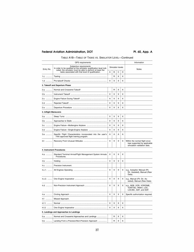
37
Federal Aviation Administration, DOT Pt. 60, App. A
TABLE A1B—TABLE OF TASKS VS. SIMULATOR LEVEL—Continued
QPS requirements Information
Entry No.
Subjective requirements In order to be qualified at the simulator qualification level indi-
cated, the simulator must be able to perform at least the tasks associated with that level of qualification.
Simulator levels Notes
A B C D
1.c. ........... Taxiing ....................................................................................... R X X
1.d. ........... Pre-takeoff Checks ................................................................... X X X X
2. Takeoff and Departure Phase
2.a. ........... Normal and Crosswind Takeoff R X X
2.b. ........... Instrument Takeoff .................................................................... X X X X
2.c. ........... Engine Failure During Takeoff .................................................. A X X X
2.d. ........... Rejected Takeoff ....................................................................... X X X X
2.e. ........... Departure Procedure ................................................................ X X X X
3. Inflight Maneuvers
3.a. ........... Steep Turns .............................................................................. X X X X
3.b. ........... Approaches to Stalls ................................................................. X X X X
3.c. ........... Engine Failure—Multiengine Airplane ...................................... X X X X
3.d. ........... Engine Failure—Single-Engine Airplane .................................. X X X X
3.e. ........... Specific Flight Characteristics incorporated into the user’s FAA approved flight training program.
A A A A
3.f. ............ Recovery From Unusual Attitudes ............................................ X X X X Within the normal flight enve-lope supported by applicable simulation validation data.
4. Instrument Procedures
4.a. ........... Standard Terminal Arrival/Flight Management System Arrivals Procedures.
X X X X
4.b. ........... Holding ...................................................................................... X X X X
4.c. ........... Precision Instrument.
4.c.1. ........ All Engines Operating ............................................................... X X X X e.g., Autopilot, Manual (Flt. Dir. Assisted), Manual (Raw Data).
4.c.2. ........ One Engine Inoperative ............................................................ X X X X e.g., Manual (Flt. Dir. As-sisted), Manual (Raw Data).
4.d. ........... Non-Precision Instrument Approach ......................................... X X X X e.g., NDB, VOR, VOR/DME, VOR/TAC, RNAV, LOC, LOC/BC, ADF, and SDF.
4.e. ........... Circling Approach ...................................................................... X X X X Specific authorization required.
4.f. ............ Missed Approach.
4.f.1. ......... Normal ....................................................................................... X X X X
4.f.2. ......... One Engine Inoperative ............................................................ X X X X
5. Landings and Approaches to Landings
5.a. ........... Normal and Crosswind Approaches and Landings .................. R X X
5.b. ........... Landing From a Precision/Non-Precision Approach ................ R X X
VerDate Mar<15>2010 18:16 Mar 01, 2012 Jkt 226045 PO 00000 Frm 00047 Fmt 8010 Sfmt 8002 Q:\14\14V2 ofr150 PsN: PC150
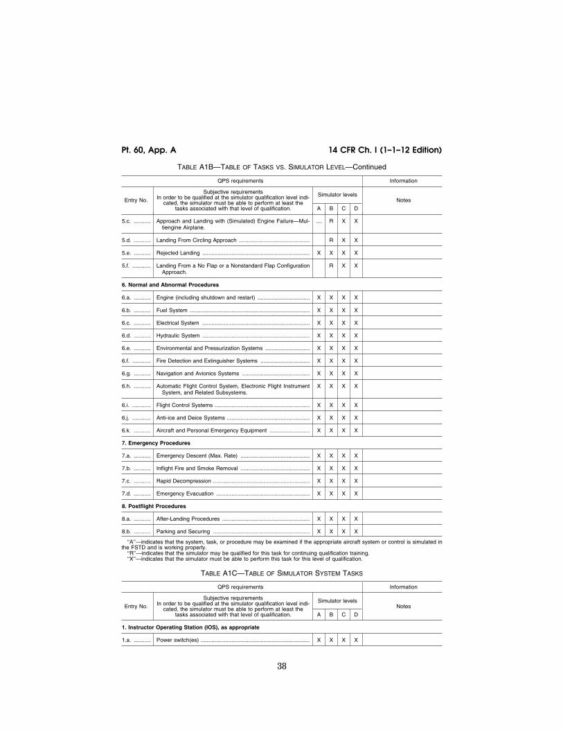
38
14 CFR Ch. I (1–1–12 Edition) Pt. 60, App. A
TABLE A1B—TABLE OF TASKS VS. SIMULATOR LEVEL—Continued
QPS requirements Information
Entry No.
Subjective requirements In order to be qualified at the simulator qualification level indi-
cated, the simulator must be able to perform at least the tasks associated with that level of qualification.
Simulator levels Notes
A B C D
5.c. ........... Approach and Landing with (Simulated) Engine Failure—Mul-tiengine Airplane.
.... R X X
5.d. ........... Landing From Circling Approach .............................................. R X X
5.e. ........... Rejected Landing ...................................................................... X X X X
5.f. ............ Landing From a No Flap or a Nonstandard Flap Configuration Approach.
R X X
6. Normal and Abnormal Procedures
6.a. ........... Engine (including shutdown and restart) .................................. X X X X
6.b. ........... Fuel System .............................................................................. X X X X
6.c. ........... Electrical System ...................................................................... X X X X
6.d. ........... Hydraulic System ...................................................................... X X X X
6.e. ........... Environmental and Pressurization Systems ............................. X X X X
6.f. ............ Fire Detection and Extinguisher Systems ................................ X X X X
6.g. ........... Navigation and Avionics Systems ............................................ X X X X
6.h. ........... Automatic Flight Control System, Electronic Flight Instrument System, and Related Subsystems.
X X X X
6.i. ............ Flight Control Systems .............................................................. X X X X
6.j. ............ Anti-ice and Deice Systems ...................................................... X X X X
6.k. ........... Aircraft and Personal Emergency Equipment .......................... X X X X
7. Emergency Procedures
7.a. ........... Emergency Descent (Max. Rate) ............................................. X X X X
7.b. ........... Inflight Fire and Smoke Removal ............................................. X X X X
7.c. ........... Rapid Decompression ............................................................... X X X X
7.d. ........... Emergency Evacuation ............................................................. X X X X
8. Postflight Procedures
8.a. ........... After-Landing Procedures ......................................................... X X X X
8.b. ........... Parking and Securing ............................................................... X X X X
‘‘A’’—indicates that the system, task, or procedure may be examined if the appropriate aircraft system or control is simulated in the FSTD and is working properly.
‘‘R’’—indicates that the simulator may be qualified for this task for continuing qualification training. ‘‘X’’—indicates that the simulator must be able to perform this task for this level of qualification.
TABLE A1C—TABLE OF SIMULATOR SYSTEM TASKS
QPS requirements Information
Entry No.
Subjective requirements In order to be qualified at the simulator qualification level indi-
cated, the simulator must be able to perform at least the tasks associated with that level of qualification.
Simulator levels Notes
A B C D
1. Instructor Operating Station (IOS), as appropriate
1.a. ........... Power switch(es) ....................................................................... X X X X
VerDate Mar<15>2010 18:16 Mar 01, 2012 Jkt 226045 PO 00000 Frm 00048 Fmt 8010 Sfmt 8002 Q:\14\14V2 ofr150 PsN: PC150

39
Federal Aviation Administration, DOT Pt. 60, App. A
TABLE A1C—TABLE OF SIMULATOR SYSTEM TASKS—Continued
QPS requirements Information
Entry No.
Subjective requirements In order to be qualified at the simulator qualification level indi-
cated, the simulator must be able to perform at least the tasks associated with that level of qualification.
Simulator levels Notes
A B C D
1.b. ........... Airplane conditions .................................................................... X X X X e.g., GW, CG, Fuel loading and Systems.
1.c. ........... Airports/Runways ...................................................................... X X X X e.g., Selection, Surface, Presets, Lighting controls.
1.d. ........... Environmental controls ............................................................. X X X X e.g., Clouds, Visibility, RVR, Temp, Wind, Ice, Snow, Rain, and Windshear.
1.e. ........... Airplane system malfunctions (Insertion/deletion) .................... X X X X
1.f. ............ Locks, Freezes, and Repositioning .......................................... X X X X
2. Sound Controls
2.a. ........... On/off/adjustment ...................................................................... X X X X
3. Motion/Control Loading System
3.a. ........... On/off/emergency stop .............................................................. X X X X
4. Observer Seats/Stations
4.a. ........... Position/Adjustment/Positive restraint system .......................... X X X X
ATTACHMENT 2 TO APPENDIX A TO PART 60— FFS OBJECTIVE TESTS
TABLE OF CONTENTS
Paragraph No. Title
1. .................... Introduction.
2. .................... Test Requirements.
Table A2A, Objective Tests.
3. .................... General.
4. .................... Control Dynamics.
5. .................... Ground Effect.
6. .................... Motion System.
7. .................... Sound System.
8. .................... Additional Information About Flight Simulator Qualification for New or Derivative Air-planes.
9. .................... Engineering Simulator—Validation Data.
10. .................. [Reserved]
11. .................. Validation Test Tolerances.
12. .................. Validation Data Roadmap.
13. .................. Acceptance Guidelines for Alternative En-gines Data.
TABLE OF CONTENTS—Continued
Paragraph No. Title
14. .................. Acceptance Guidelines for Alternative Avi-onics (Flight-Related Computers and Con-trollers).
15. .................. Transport Delay Testing.
16. .................. Continuing Qualification Evaluations—Vali-dation Test Data Presentation.
17. .................. Alternative Data Sources, Procedures, and Instrumentation: Level A and Level B Sim-ulators Only.
lllllllllllllllllllllll
BEGIN INFORMATION
1. INTRODUCTION
a. For the purposes of this attachment, the flight conditions specified in the Flight Con-ditions Column of Table A2A of this appen-dix, are defined as follows:
(1) Ground—on ground, independent of air-plane configuration;
(2) Take-off—gear down with flaps/slats in any certified takeoff position;
(3) First segment climb—gear down with flaps/slats in any certified takeoff position (normally not above 50 ft AGL);
(4) Second segment climb—gear up with flaps/slats in any certified takeoff position (normally between 50 ft and 400 ft AGL);
(5) Clean—flaps/slats retracted and gear up;
VerDate Mar<15>2010 18:16 Mar 01, 2012 Jkt 226045 PO 00000 Frm 00049 Fmt 8010 Sfmt 8002 Q:\14\14V2 ofr150 PsN: PC150

40
14 CFR Ch. I (1–1–12 Edition) Pt. 60, App. A
(6) Cruise—clean configuration at cruise altitude and airspeed;
(7) Approach—gear up or down with flaps/ slats at any normal approach position as rec-ommended by the airplane manufacturer; and
(8) Landing—gear down with flaps/slats in any certified landing position.
b. The format for numbering the objective tests in Appendix A, Attachment 2, Table A2A, and the objective tests in Appendix B, Attachment 2, Table B2A, is identical. How-ever, each test required for FFSs is not nec-essarily required for FTDs. Also, each test required for FTDs is not necessarily required for FFSs. Therefore, when a test number (or series of numbers) is not required, the term ‘‘Reserved’’ is used in the table at that loca-tion. Following this numbering format pro-vides a degree of commonality between the two tables and substantially reduces the po-tential for confusion when referring to objec-tive test numbers for either FFSs or FTDs.
c. The reader is encouraged to review the Airplane Flight Simulator Evaluation Hand-book, Volumes I and II, published by the Royal Aeronautical Society, London, UK, and AC 25–7, as amended, Flight Test Guide for Certification of Transport Category Air-planes, and AC 23–8, as amended, Flight Test Guide for Certification of Part 23 Airplanes, for references and examples regarding flight testing requirements and techniques.
d. If relevant winds are present in the ob-jective data, the wind vector should be clear-ly noted as part of the data presentation, ex-pressed in conventional terminology, and re-lated to the runway being used for the test.
END INFORMATION
lllllllllllllllllllllll
BEGIN QPS REQUIREMENTS
2. TEST REQUIREMENTS
a. The ground and flight tests required for qualification are listed in Table A2A, FFS Objective Tests. Computer generated simu-lator test results must be provided for each test except where an alternative test is spe-cifically authorized by the NSPM. If a flight condition or operating condition is required for the test but does not apply to the air-plane being simulated or to the qualification level sought, it may be disregarded (e.g., an engine out missed approach for a single-en-gine airplane or a maneuver using reverse thrust for an airplane without reverse thrust capability). Each test result is compared against the validation data described in § 60.13 and in this appendix. Although use of a driver program designed to automatically accomplish the tests is encouraged for all simulators and required for Level C and Level D simulators, it must be possible to conduct each test manually while recording all appropriate parameters. The results must
be produced on an appropriate recording de-vice acceptable to the NSPM and must in-clude simulator number, date, time, condi-tions, tolerances, and appropriate dependent variables portrayed in comparison to the val-idation data. Time histories are required un-less otherwise indicated in Table A2A. All re-sults must be labeled using the tolerances and units given.
b. Table A2A in this attachment sets out the test results required, including the pa-rameters, tolerances, and flight conditions for simulator validation. Tolerances are pro-vided for the listed tests because mathe-matical modeling and acquisition and devel-opment of reference data are often inexact. All tolerances listed in the following tables are applied to simulator performance. When two tolerance values are given for a param-eter, the less restrictive may be used unless otherwise indicated. In those cases where a tolerance is expressed only as a percentage, the tolerance percentage applies to the max-imum value of that parameter within its normal operating range as measured from the neutral or zero position unless otherwise indicated.
c. Certain tests included in this attach-ment must be supported with an SOC. In Table A2A, requirements for SOCs are indi-cated in the ‘‘Test Details’’ column.
d. When operational or engineering judg-ment is used in making assessments for flight test data applications for simulator validity, such judgment must not be limited to a single parameter. For example, data that exhibit rapid variations of the measured parameters may require interpolations or a ‘‘best fit’’ data selection. All relevant param-eters related to a given maneuver or flight condition must be provided to allow overall interpretation. When it is difficult or impos-sible to match simulator to airplane data throughout a time history, differences must be justified by providing a comparison of other related variables for the condition being assessed.
e. It is not acceptable to program the FFS so that the mathematical modeling is cor-rect only at the validation test points. Un-less otherwise noted, simulator tests must represent airplane performance and handling qualities at operating weights and centers of gravity (CG) typical of normal operation. If a test is supported by airplane data at one extreme weight or CG, another test sup-ported by airplane data at mid-conditions or as close as possible to the other extreme must be included. Certain tests that are rel-evant only at one extreme CG or weight con-dition need not be repeated at the other ex-treme. Tests of handling qualities must in-clude validation of augmentation devices.
f. When comparing the parameters listed to those of the airplane, sufficient data must also be provided to verify the correct flight condition and airplane configuration
VerDate Mar<15>2010 18:16 Mar 01, 2012 Jkt 226045 PO 00000 Frm 00050 Fmt 8010 Sfmt 8002 Q:\14\14V2 ofr150 PsN: PC150

41
Federal Aviation Administration, DOT Pt. 60, App. A
changes. For example, to show that control force is within the parameters for a static stability test, data to show the correct air-speed, power, thrust or torque, airplane con-figuration, altitude, and other appropriate datum identification parameters must also be given. If comparing short period dynam-ics, normal acceleration may be used to es-tablish a match to the airplane, but airspeed, altitude, control input, airplane configura-tion, and other appropriate data must also be given. If comparing landing gear change dynamics, pitch, airspeed, and altitude may be used to establish a match to the airplane, but landing gear position must also be pro-vided. All airspeed values must be properly annotated (e.g., indicated versus calibrated). In addition, the same variables must be used for comparison (e.g., compare inches to inches rather than inches to centimeters).
g. The QTG provided by the sponsor must clearly describe how the simulator will be set up and operated for each test. Each simu-lator subsystem may be tested independ-ently, but overall integrated testing of the simulator must be accomplished to assure that the total simulator system meets the prescribed standards. A manual test proce-dure with explicit and detailed steps for completing each test must also be provided.
h. For previously qualified simulators, the tests and tolerances of this attachment may be used in subsequent continuing qualifica-tion evaluations for any given test if the sponsor has submitted a proposed MQTG re-vision to the NSPM and has received NSPM approval.
i. Simulators are evaluated and qualified with an engine model simulating the air-plane data supplier’s flight test engine. For qualification of alternative engine models (either variations of the flight test engines or other manufacturer’s engines) additional tests with the alternative engine models may be required. This attachment contains guidelines for alternative engines.
j. For testing Computer Controlled Air-craft (CCA) simulators, or other highly aug-mented airplane simulators, flight test data is required for the Normal (N) and/or Non- normal (NN) control states, as indicated in this attachment. Where test results are inde-pendent of control state, Normal or Non-nor-mal control data may be used. All tests in Table A2A require test results in the Normal control state unless specifically noted other-wise in the Test Details section following the CCA designation. The NSPM will determine what tests are appropriate for airplane sim-ulation data. When making this determina-tion, the NSPM may require other levels of control state degradation for specific air-plane tests. Where Non-normal control
states are required, test data must be pro-vided for one or more Non-normal control states, and must include the least aug-mented state. Where applicable, flight test data must record Normal and Non-normal states for:
(1) Pilot controller deflections or electroni-cally generated inputs, including location of input; and
(2) Flight control surface positions unless test results are not affected by, or are inde-pendent of, surface positions.
k. Tests of handling qualities must include validation of augmentation devices. FFSs for highly augmented airplanes will be validated both in the unaugmented configuration (or failure state with the maximum permitted degradation in handling qualities) and the augmented configuration. Where various lev-els of handling qualities result from failure states, validation of the effect of the failure is necessary. Requirements for testing will be mutually agreed to between the sponsor and the NSPM on a case-by-case basis.
l. Some tests will not be required for air-planes using airplane hardware in the simu-lator flight deck (e.g., ‘‘side stick con-troller’’). These exceptions are noted in Sec-tion 2 ‘‘Handling Qualities’’ in Table A2A of this attachment. However, in these cases, the sponsor must provide a statement that the airplane hardware meets the appropriate manufacturer’s specifications and the spon-sor must have supporting information to that fact available for NSPM review.
m. For objective test purposes, see Appen-dix F of this part for the definitions of ‘‘Near maximum,’’ ‘‘Light,’’ and ‘‘Medium’’ gross weight.
END QPS REQUIREMENTS
lllllllllllllllllllllll
BEGIN INFORMATION
n. In those cases where the objective test results authorize a ‘‘snapshot test’’ or a ‘‘se-ries of snapshot tests’’ results in lieu of a time-history result, the sponsor or other data provider must ensure that a steady state condition exists at the instant of time captured by the ‘‘snapshot.’’ The steady state condition should exist from 4 seconds prior to, through 1 second following, the in-stant of time captured by the snap shot.
o. For references on basic operating weight, see AC 120–27, ‘‘Aircraft Weight and Balance;’’ and FAA–H–8083–1, ‘‘Aircraft Weight and Balance Handbook.’’
END INFORMATION
lllllllllllllllllllllll
VerDate Mar<15>2010 18:16 Mar 01, 2012 Jkt 226045 PO 00000 Frm 00051 Fmt 8010 Sfmt 8002 Q:\14\14V2 ofr150 PsN: PC150

42
14 CFR Ch. I (1–1–12 Edition) Pt. 60, App. A
TABLE A2A—FULL FLIGHT SIMULATOR (FFS) OBJECTIVE TESTS
QPS Requirements Information
Test
Tolerance Flight con-ditions Test details
Simulator level Notes Entry
No. Title A B C D
1. Performance.
1.a. ....... Taxi.
1.a.1. .... Minimum Ra-dius Turn.
±3 ft (0.9m) or 20% of airplane turn radius.
Ground ..... Record both Main and Nose gear turning ra-dius. This test is to be accomplished without the use of brakes and only minimum thrust, ex-cept for airplanes requir-ing asymmetric thrust or braking to turn.
X X X
1.a.2 ..... Rate of Turn vs. Nosewheel Steering Angle (NWA).
±10% or ±2°/sec. turn rate.
Ground ..... Record a minimum of two speeds, greater than minimum turning radius speed, with a spread of at least 5 knots ground-speed, in normal taxi speed conditions.
X X X
1.b. ....... Takeoff. All commonly used takeoff flap settings are to be demonstrated at least once in the tests for min-imum unstick (1.b.3.), normal takeoff (1.b.4.), critical engine failure on takeoff (1.b.5.), or cross-wind takeoff (1.b.6.).
1.b.1. .... Ground Ac-celeration Time and Distance.
±5% time and distance or ±5% time and ±200 ft (61 m) of distance.
Takeoff ..... Record acceleration time and distance for a min-imum of 80% of the time from brake release to VR.
Preliminary aircraft certifi-cation data may be used.
X X X X May be com-bined with nor-mal takeoff (1.b.4.) or re-jected takeoff (1.b.7.). Plot-ted data should be shown using appropriate scales for each portion of the maneuver.
VerDate Mar<15>2010 18:16 Mar 01, 2012 Jkt 226045 PO 00000 Frm 00052 Fmt 8010 Sfmt 8002 Q:\14\14V2 ofr150 PsN: PC150

43
Federal Aviation Administration, DOT Pt. 60, App. A
TABLE A2A—FULL FLIGHT SIMULATOR (FFS) OBJECTIVE TESTS—Continued
QPS Requirements Information
Test
Tolerance Flight con-ditions Test details
Simulator level Notes Entry
No. Title A B C D
1.b.2. .... Minimum Control Speed ¥
ground (Vmcg) using aero-dynamic controls only (per applicable airworthi-ness standard) or alter-native low speed en-gine inop-erative test to dem-onstrate ground control character-istics.
±25% of max-imum airplane lateral deviation or ±5 ft (1.5 m). Additionally, for those simula-tors of air-planes with re-versible flight control sys-tems: Rudder pedal force; ±10% or ±5 lb (2.2 daN).
Takeoff ..... Engine failure speed must be within ±1 knot of air-plane engine failure speed. Engine thrust decay must be that re-sulting from the mathe-matical model for the en-gine variant applicable to the FFS under test. If the modeled engine is not the same as the air-plane manufacturer’s flight test engine, a fur-ther test may be run with the same initial condi-tions using the thrust from the flight test data as the driving parameter.
X X X X If a Vmcg test is not available an acceptable alternative is a flight test snap engine decel-eration to idle at a speed be-tween V1 and V1 ¥10 knots, followed by control of heading using aerodynamic control only. Recovery should be achieved with the main gear on the ground. To ensure only aerodynamic control is used, nosewheel steering should be disabled (i.e., castored) or the nosewheel held slightly off the ground.
1.b.3. .... Minimum Un-stick Speed (Vmu) or equivalent test to dem-onstrate early rota-tion takeoff character-istics.
±3 kts airspeed ±1.5° pitch angle.
Takeoff ..... Record main landing gear strut compression or equivalent air/ground signal. Record from 10 kt before start of rotation until at least 5 seconds after the occurrence of main gear lift-off.
X X X X Vmu is defined as the minimum speed at which the last main landing gear leaves the ground. Main landing gear strut compres-sion or equiva-lent air/ground signal should be recorded. If a Vmu test is not available, alternative ac-ceptable flight tests are a constant high- attitude take- off run through main gear lift- off or an early rotation take- off.
VerDate Mar<15>2010 18:16 Mar 01, 2012 Jkt 226045 PO 00000 Frm 00053 Fmt 8010 Sfmt 8002 Q:\14\14V2 ofr150 PsN: PC150

44
14 CFR Ch. I (1–1–12 Edition) Pt. 60, App. A
TABLE A2A—FULL FLIGHT SIMULATOR (FFS) OBJECTIVE TESTS—Continued
QPS Requirements Information
Test
Tolerance Flight con-ditions Test details
Simulator level Notes Entry
No. Title A B C D
1.b.4. .... Normal Take-off.
±3 kts airspeed ±1.5° pitch angle ±1.5° angle of attack ±20 ft (6 m) height. Addi-tionally, for those simula-tors of air-planes with re-versible flight control sys-tems: Stick/Col-umn Force; ±10% or ±5 lb (2.2 daN).
Takeoff ..... Record takeoff profile from brake release to at least 200 ft (61 m) above ground level (AGL). If the airplane has more than one certificated takeoff configurations, a different configuration must be used for each weight. Data are re-quired for a takeoff weight at near maximum takeoff weight with a mid-center of gravity and for a light takeoff weight with an aft center of gravity, as defined in Ap-pendix F of this part.
X X X X This test may be used for ground accel-eration time and distance (1.b.1.). Plot-ted data should be shown using appropriate scales for each portion of the maneuver.
1.b.5. .... Critical En-gine Fail-ure on Takeoff.
±3 kts airspeed ±1.5° pitch angle, ±1.5° angle of attack, ±20 ft (6 m) height, ±3° heading angle, ±2° bank angle, ±2° side-slip angle. Ad-ditionally, for those simula-tors of air-planes with re-versible flight control sys-tems: Stick/Col-umn Force; ±10% or ±5 lb (2.2 daN)); Wheel Force; ±10% or ±3 lb (1.3 daN); and Rudder Pedal Force; ±10% or ±5 lb (2.2 daN).
Takeoff ..... Record takeoff profile at near maximum takeoff weight from prior to en-gine failure to at least 200 ft (61 m) AGL. En-gine failure speed must be within ±3 kts of air-plane data.
X X X X
VerDate Mar<15>2010 18:16 Mar 01, 2012 Jkt 226045 PO 00000 Frm 00054 Fmt 8010 Sfmt 8002 Q:\14\14V2 ofr150 PsN: PC150

45
Federal Aviation Administration, DOT Pt. 60, App. A
TABLE A2A—FULL FLIGHT SIMULATOR (FFS) OBJECTIVE TESTS—Continued
QPS Requirements Information
Test
Tolerance Flight con-ditions Test details
Simulator level Notes Entry
No. Title A B C D
1.b.6. .... Crosswind Takeoff.
±3 kts airspeed, ±1.5° pitch angle, ±1.5° angle of attack, ±20 ft (6 m) height, ±2° bank angle, ±2° sideslip angle; ±3° heading angle. Correct trend at groundspeeds below 40 kts. for rudder/ pedal and heading. Addi-tionally, for those simula-tors of air-planes with re-versible flight control sys-tems: ±10% or ±5 lb (2.2 daN) stick/column force, ±10% or ±3 lb (1.3 daN) wheel force, ±10% or ±5 lb (2.2 daN) rud-der pedal force.
Takeoff ..... Record takeoff profile from brake release to at least 200 ft (61 m) AGL. Re-quires test data, includ-ing information on wind profile for a crosswind (expressed as direct head-wind and direct cross-wind components) of at least 60% of the maximum wind meas-ured at 33 ft (10 m) above the runway.
X X X X In those situa-tions where a maximum crosswind or a maximum demonstrated crosswind is not known, contact the NSPM.
1.b.7. .... Rejected Takeoff.
±5% time or ±1.5 sec ±7.5% dis-tance or ±250 ft (±76 m).
Takeoff ..... Record time and distance from brake release to full stop. Speed for initi-ation of the reject must be at least 80% of V1 speed. The airplane must be at or near the maximum takeoff gross weight. Use maximum braking effort, auto or manual.
X X X X Autobrakes will be used where applicable.
1.b.8. .... Dynamic En-gine Fail-ure After Takeoff.
±20% or ±2°/sec body angular rates.
Takeoff ..... Engine failure speed must be within ±3 Kts of air-plane data. Record Hands Off from 5 secs. before to at least 5 secs. after engine failure or 30° Bank, whichever oc-curs first. Engine failure may be a snap decelera-tion to idle. CCA: Test in Normal and Non-normal control state.
X X For safety con-siderations, airplane flight test may be performed out of ground ef-fect at a safe altitude, but with correct airplane con-figuration and airspeed.
1.c. ....... Climb.
VerDate Mar<15>2010 18:16 Mar 01, 2012 Jkt 226045 PO 00000 Frm 00055 Fmt 8010 Sfmt 8002 Q:\14\14V2 ofr150 PsN: PC150

46
14 CFR Ch. I (1–1–12 Edition) Pt. 60, App. A
TABLE A2A—FULL FLIGHT SIMULATOR (FFS) OBJECTIVE TESTS—Continued
QPS Requirements Information
Test
Tolerance Flight con-ditions Test details
Simulator level Notes Entry
No. Title A B C D
1.c.1. .... Normal Climb, all engines operating.
±3 kts airspeed, ±5% or ±100 FPM (0.5 m/ Sec.) climb rate.
Clean ........ Flight test data is pre-ferred, however, airplane performance manual data is an acceptable al-ternative. Record at nominal climb speed and mid-initial climb alti-tude. Flight simulator performance must be re-corded over an interval of at least 1,000 ft. (300 m).
X X X X
1.c.2. .... One engine Inoperative.
±3 kts airspeed, ±5% or ±100 FPM (0.5 m/ Sec.) climb rate, but not less than the climb gradient requirements of 14 CFR part 23 or part 25, as appropriate.
For part 23 air-planes, in ac-cordance with part 23. For part 25 air-planes, Second Segment Climb.
Flight test data is pre-ferred, however, airplane performance manual data is an acceptable al-ternative. Test at weight, altitude, or temperature limiting conditions. Record at nominal climb speed. Flight simulator performance must be re-corded over an interval of at least 1,000 ft. (300 m).
X X X X
1.c.3. .... One Engine Inoperative En route Climb.
±10% time, ±10% distance, ±10% fuel used.
Clean ........ Record results for at least a 5000 ft (1550 m) climb segment. Flight test data or airplane performance manual data may be used.
X X
1.c.4. .... One Engine Inoperative Approach Climb (if operations in icing conditions are author-ized).
±3 kts airspeed, ±5% or ±100 FPM (0.5 m/ Sec.) climb rate, but not less than the climb gradient requirements of 14 CFR parts 23 or 25 climb gradient, as ap-propriate.
Approach .. Record results at near maximum gross landing weight as defined in Ap-pendix F of this part. Flight test data or air-plane performance man-ual data may be used. Flight simulator perform-ance must be recorded over an interval of at least 1,000 ft. (300 m).
X X X X The airplane should be con-figured with all anti-ice and de-ice systems operating nor-mally, with the gear up and go-around flaps set. All icing account-ability consid-erations should be applied in accordance with the air-craft certifi-cation or au-thorization for an approach in icing condi-tions.
1.d. ....... Cruise/Descent.
1.d.1. .... Level flight accelera-tion.
±5% Time ........... Cruise ....... Record results for a min-imum of 50 kts speed in-crease using maximum continuous thrust rating or equivalent.
X X X X
VerDate Mar<15>2010 18:16 Mar 01, 2012 Jkt 226045 PO 00000 Frm 00056 Fmt 8010 Sfmt 8002 Q:\14\14V2 ofr150 PsN: PC150

47
Federal Aviation Administration, DOT Pt. 60, App. A
TABLE A2A—FULL FLIGHT SIMULATOR (FFS) OBJECTIVE TESTS—Continued
QPS Requirements Information
Test
Tolerance Flight con-ditions Test details
Simulator level Notes Entry
No. Title A B C D
1.d.2. .... Level flight decelera-tion.
±5% Time ........... Cruise ....... Record results for a min-imum of 50 kts. speed decrease using idle power.
X X X X
1.d.3. .... Cruise per-formance.
±0.05 EPR or ±5% of N1, or ±5% of Torque, ±5% of fuel flow.
Cruise ....... May be a single snapshot showing instantaneous fuel flow or a minimum of 2 consecutive snap-shots with a spread of at least 3 minutes in steady flight.
X X
1.d.4. .... Idle descent ±3 kt airspeed, ±5% or ±200 ft/ min (1.0m/sec) descent rate.
Clean ........ Record a stabilized, idle power descent at normal descent speed at mid-al-titude. Flight simulator performance must be re-corded over an interval of at least 1,000 ft. (300 m).
X X X X
1.d.5. .... Emergency descent.
±5 kt airspeed, ±5% or ±300 ft/ min (1.5m/s) descent rate.
N/A ........... Performance must be re-corded over an interval of at least 3,000 ft (900 m).
X X X X The stabilized descent should be conducted with speed brakes ex-tended, if ap-plicable, at mid-altitude and near Vmo speed or in ac-cordance with emergency de-scent proce-dures.
1.e. ....... Stopping.
1.e.1. .... Stopping time and distance, using man-ual appli-cation of wheel brakes and no reverse thrust on a dry runway.
±5% of time. For distance up to 4000 ft (1220 m): ±200 ft (61 m) or ±10%, whichever is smaller. For distance great-er than 4000 ft (1220 m): ±5% of distance.
Landing .... Record time and distance for at least 80% of the total time from touch down to full stop. Data is required for weights at medium and near max-imum landing weights. Data for brake system pressure and position of ground spoilers (includ-ing method of deploy-ment, if used) must be provided. Engineering data may be used for the medium gross weight condition.
X X X X
VerDate Mar<15>2010 18:16 Mar 01, 2012 Jkt 226045 PO 00000 Frm 00057 Fmt 8010 Sfmt 8002 Q:\14\14V2 ofr150 PsN: PC150

48
14 CFR Ch. I (1–1–12 Edition) Pt. 60, App. A
TABLE A2A—FULL FLIGHT SIMULATOR (FFS) OBJECTIVE TESTS—Continued
QPS Requirements Information
Test
Tolerance Flight con-ditions Test details
Simulator level Notes Entry
No. Title A B C D
1.e.2. .... Stopping time and distance, using re-verse thrust and no wheel brakes on a dry run-way.
±5% time and the smaller of ±10% or ±200 ft (61 m) of dis-tance.
Landing .... Record time and distance for at least 80% of the total time from initiation of reverse thrust to the minimum operating speed with full reverse thrust. Data is required for medium and near maximum landing gross weights. Data on the po-sition of ground spoilers, (including method of de-ployment, if used) must be provided. Engineer-ing data may be used for the medium gross weight condition.
X X X X
1.e.3. .... Stopping dis-tance, using wheel brakes and no reverse thrust on a wet runway.
±10% of distance or ±200 ft (61 m).
Landing .... Either flight test data or manufacturer’s perform-ance manual data must be used where avail-able. Engineering data based on dry runway flight test stopping dis-tance modified by the ef-fects of contaminated runway braking coeffi-cients are an acceptable alternative.
X X
1.e.4. .... Stopping dis-tance, using wheel brakes and no reverse thrust on an icy run-way.
±10% of distance or ±200 ft (61 m).
Landing .... Either flight test or manu-facturer’s performance manual data must be used, where available. Engineering data based on dry runway flight test stopping distance modi-fied by the effects of contaminated runway braking coefficients are an acceptable alter-native.
X X
1.f. ........ Engines.
1.f.1. ..... Acceleration (±10% Tt) and (±10% Ti, or ±0.25 sec.).
Approach or land-ing.
Record engine power (N1, N2, EPR, Torque) from flight idle to go-around power for a rapid (slam) throttle movement.
X X X X See Appendix F of this part for definitions of Ti and Tt.
1.f.2. ..... Deceleration (±10% Tt) and (±10% Ti, or ±0.25 sec.).
Ground ..... Record engine power (N1, N2, EPR, Torque) from Max T/O power to 90% decay of Max T/O power for a rapid (slam) throttle movement.
X X X X See Appendix F of this part for definitions of Ti and Tt.
2. Handling Qualities.
VerDate Mar<15>2010 18:16 Mar 01, 2012 Jkt 226045 PO 00000 Frm 00058 Fmt 8010 Sfmt 8002 Q:\14\14V2 ofr150 PsN: PC150

49
Federal Aviation Administration, DOT Pt. 60, App. A
TABLE A2A—FULL FLIGHT SIMULATOR (FFS) OBJECTIVE TESTS—Continued
QPS Requirements Information
Test
Tolerance Flight con-ditions Test details
Simulator level Notes Entry
No. Title A B C D
.......... For simulators requiring Static or Dynamic tests at the controls (i.e., column, wheel, rudder pedal), special test fixtures will not be required during initial or upgrade evaluations if the sponsor’s QTG/MQTG shows both test fixture re-sults and the results of an alternative approach, such as computer plots pro-duced concurrently, that provide satisfactory agreement. Repeat of the alter-native method during the initial or upgrade evaluation satisfies this test re-quirement. For initial and upgrade evaluations, the control dynamic character-istics must be measured at and recorded directly from the flight deck con-trols, and must be accomplished in takeoff, cruise, and landing flight condi-tions and configurations. Testing of position versus force is not applicable if forces are generated solely by use of airplane hardware in the FFS.
Contact the NSPM for clari-fication of any issue regard-ing airplanes with reversible controls.
2.a. ....... Static Control Tests.
2.a.1.a. Pitch Con-troller Posi-tion vs. Force and Surface Position Calibration.
±2 lb (0.9 daN) breakout, ±10% or ±5 lb (2.2 daN) force, ±2° elevator.
Ground ..... Record results for an unin-terrupted control sweep to the stops.
X X X X Test results should be vali-dated (where possible) with in-flight data from tests such as longi-tudinal static stability or stalls. Static and dynamic flight control tests should be accomplished at the same feel or impact pressures.
2.a.1.b. (Reserved)
2.a.2.a. Roll Con-troller Posi-tion vs. Force and Surface Position Calibration.
±2 lb (0.9 daN) breakout, ±10% or ±3 lb (1.3 daN) force, ±2° aileron, ±3° spoiler angle.
Ground ..... Record results for an unin-terrupted control sweep to the stops.
X X X X Test results should be vali-dated with in- flight data from tests such as engine out trims, or steady state sideslips. Stat-ic and dynamic flight control tests should be accomplished at the same feel or impact pressures.
2.a.2.b. (Reserved)
VerDate Mar<15>2010 18:16 Mar 01, 2012 Jkt 226045 PO 00000 Frm 00059 Fmt 8010 Sfmt 8002 Q:\14\14V2 ofr150 PsN: PC150

50
14 CFR Ch. I (1–1–12 Edition) Pt. 60, App. A
TABLE A2A—FULL FLIGHT SIMULATOR (FFS) OBJECTIVE TESTS—Continued
QPS Requirements Information
Test
Tolerance Flight con-ditions Test details
Simulator level Notes Entry
No. Title A B C D
2.a.3.a. Rudder Pedal Po-sition vs. Force and Surface Position Calibration.
±5 lb (2.2 daN) breakout, ±10% or ±5 lb (2.2 daN) force, ±2° rudder angle.
Ground ..... Record results for an unin-terrupted control sweep to the stops.
X X X X Test results should be vali-dated with in- flight data from tests such as engine out trims, or steady state sideslips. Stat-ic and dynamic flight control tests should be accomplished at the same feel or impact pressures.
2.a.3.b. (Reserved)
2.a.4. .... Nosewheel Steering Controller Force and Position Calibration.
±2 lb (0.9 daN) breakout, ±10% or ±3 lb (1.3 daN) force, ±2° nosewheel angle.
Ground ..... Record results of an unin-terrupted control sweep to the stops.
X X X X
2.a.5. .... Rudder Pedal Steering Calibration.
±2° nosewheel angle.
Ground ..... Record results of an unin-terrupted control sweep to the stops.
X X X X
2.a.6. .... Pitch Trim In-dicator vs. Surface Position Calibration.
±0.5° of com-puted trim sur-face angle.
Ground ..... X X X X The purpose of the test is to compare FFS against design data or equiva-lent.
2.a.7. .... Pitch Trim Rate.
±10% trim rate (°/ sec).
Ground and ap-proach.
The trim rate must be checked using the pilot primary trim (ground) and using the autopilot or pilot primary trim in flight at go-around flight conditions.
X X X X
2.a.8. .... Alignment of Flight Deck Throttle Lever vs. Selected Engine Pa-rameter.
±5° of throttle lever angle, or ±3% N1, or ±.03 EPR, or ±3% maximum rated manifold pressure, or ±3% torque. For propeller- driven air-planes where the propeller control levers do not have angular travel, a tolerance of ±0.8 inch (±2 cm.) applies.
Ground ..... Requires simultaneous re-cording for all engines. The tolerances apply against airplane data and between engines. In the case of propeller powered airplanes, if a propeller lever is present, it must also be checked. For airplanes with throttle ‘‘detents,’’ all detents must be pre-sented. May be a series of snapshot test results.
X X X X
VerDate Mar<15>2010 18:16 Mar 01, 2012 Jkt 226045 PO 00000 Frm 00060 Fmt 8010 Sfmt 8002 Q:\14\14V2 ofr150 PsN: PC150

51
Federal Aviation Administration, DOT Pt. 60, App. A
TABLE A2A—FULL FLIGHT SIMULATOR (FFS) OBJECTIVE TESTS—Continued
QPS Requirements Information
Test
Tolerance Flight con-ditions Test details
Simulator level Notes Entry
No. Title A B C D
2.a.9. .... Brake Pedal Position vs. Force and Brake System Pressure Calibration.
±5 lb (2.2 daN) or 10% force, ±150 psi (1.0 MPa) or ±10% brake system pressure.
Ground ..... Hydraulic system pressure must be related to pedal position through a ground static test.
X X X X FFS computer output results may be used to show com-pliance.
2.b. ....... Dynamic Control Tests.
.......... Tests 2.b.1., 2.b.2., and 2.b.3. are not applicable if dynamic response is gen-erated solely by use of airplane hardware in the FFS. Power setting is that required for level flight unless otherwise specified.
.... .... .... ....
2.b.1. .... Pitch Control For underdamped systems: ±10% of time from 90% of initial displacement (0.9 Ad) to first zero crossing and ±10 (n+1)% of pe-riod thereafter. ±10% ampli-tude of first overshoot ap-plied to all overshoots greater than 5% of initial displacement (.05 Ad). ±1 overshoot (first significant over-shoot must be matched). For overdamped systems: ±10% of time from 90% of initial displacement (0.9 Ad) to 10% of initial dis-placement (0.1 Ad). For the al-ternate method see paragraph 4 of this attach-ment. The slow sweep is the equivalent to the static test 2.a.1. For the moderate and rapid sweeps: ±2 lb (0.9 daN) or ±10% dy-namic incre-ment above the static force.
Takeoff, Cruise, and Landing.
Data must show normal control displacement in both directions. Toler-ances apply against the absolute values of each period (considered inde-pendently). Normal con-trol displacement for this test is 25% to 50% of full throw or 25% to 50% of the maximum allow-able pitch controller de-flection for flight condi-tions limited by the ma-neuvering load envelope.
X X ‘‘n’’ is the se-quential period of a full cycle of oscillation. Refer to para-graph 4 of this attachment for more informa-tion. Static and dynamic flight control tests should be ac-complished at the same feel or impact pres-sures.
VerDate Mar<15>2010 18:16 Mar 01, 2012 Jkt 226045 PO 00000 Frm 00061 Fmt 8010 Sfmt 8002 Q:\14\14V2 ofr150 PsN: PC150

52
14 CFR Ch. I (1–1–12 Edition) Pt. 60, App. A
TABLE A2A—FULL FLIGHT SIMULATOR (FFS) OBJECTIVE TESTS—Continued
QPS Requirements Information
Test
Tolerance Flight con-ditions Test details
Simulator level Notes Entry
No. Title A B C D
2.b.2. .... Roll Control For underdamped systems: ±10% of time from 90% of initial displacement (0.9 Ad) to first zero crossing, and ±10 (n+1)% of pe-riod thereafter. ±10% ampli-tude of first overshoot, ap-plied to all overshoots greater than 5% of initial displacement (.05 Ad), ±1 overshoot (first significant over-shoot must be matched). For overdamped systems: ±10% of time from 90% of initial displacement (0.9 Ad) to 10% of initial dis-placement (0.1Ad). For the alternate meth-od see para-graph 4 of this attachment. The slow sweep is the equivalent to the static test 2.a.2. For the moderate and rapid sweeps: ±2 lb (0.9 daN) or ±10% dy-namic incre-ment above the static force.
Takeoff, Cruise, and Landing.
Data must show normal control displacement in both directions. Toler-ance applies against the absolute values of each period (considered inde-pendently). Normal con-trol displacement for this test is 25% to 50% of the maximum allowable roll controller deflection for flight conditions lim-ited by the maneuvering load envelope.
X X ‘‘n’’ is the se-quential period of a full cycle of oscillation. Refer to para-graph 4 of this attachment for more informa-tion. Static and dynamic flight control tests should be ac-complished at the same feel or impact pres-sures.
VerDate Mar<15>2010 18:16 Mar 01, 2012 Jkt 226045 PO 00000 Frm 00062 Fmt 8010 Sfmt 8002 Q:\14\14V2 ofr150 PsN: PC150

53
Federal Aviation Administration, DOT Pt. 60, App. A
TABLE A2A—FULL FLIGHT SIMULATOR (FFS) OBJECTIVE TESTS—Continued
QPS Requirements Information
Test
Tolerance Flight con-ditions Test details
Simulator level Notes Entry
No. Title A B C D
2.b.3. .... Yaw Control For underdamped systems: ±10% of time from 90% of initial displacement (0.9 Ad) to first zero crossing, and ±10 (n+1)% of pe-riod thereafter. ±10% ampli-tude of first overshoot ap-plied to all overshoots greater than 5% of initial displacement (.05 Ad). ±1 overshoot (first significant over-shoot must be matched). For overdamped systems: ±10% of time from 90% of initial displacement (0.9 Ad) to 10% of initial dis-placement (0.1 Ad). For the al-ternate method (see paragraph 4 of this attach-ment). The slow sweep is the equivalent to the static test 2.a.3. For the moderate and rapid sweeps: ±2 lb (0.9 daN) or ±10% dynamic increment above the stat-ic force.
Takeoff, Cruise, and Landing.
Data must show normal control displacement in both directions. Toler-ance applies against the absolute values of each period (considered inde-pendently). Normal con-trol displacement for this test is 25% to 50% of the maximum allowable yaw controller deflection for flight conditions lim-ited by the maneuvering load envelope.
X X ‘‘n’’ is the se-quential period of a full cycle of oscillation. Refer to para-graph 4 of this attachment for more informa-tion. Static and dynamic flight control tests should be ac-complished at the same feel or impact pres-sures.
2.b.4. .... Small Control Inputs— Pitch.
±0.15°/sec body pitch rate or ±20% of peak body pitch rate applied throughout the time history.
Approach or land-ing.
Control inputs must be typ-ical of minor corrections made while established on an ILS approach course, using from 0.5°/ sec to 2°/sec pitch rate. The test must be in both directions, showing time history data from 5 sec-onds before until at least 5 seconds after initiation of control input.
CCA: Test in normal and non-normal control states.
X X
VerDate Mar<15>2010 18:16 Mar 01, 2012 Jkt 226045 PO 00000 Frm 00063 Fmt 8010 Sfmt 8002 Q:\14\14V2 ofr150 PsN: PC150

54
14 CFR Ch. I (1–1–12 Edition) Pt. 60, App. A
TABLE A2A—FULL FLIGHT SIMULATOR (FFS) OBJECTIVE TESTS—Continued
QPS Requirements Information
Test
Tolerance Flight con-ditions Test details
Simulator level Notes Entry
No. Title A B C D
2.b.5. .... Small Control Inputs— Roll.
±0.15°/sec body roll rate or ±20% of peak body roll rate applied throughout the time history.
Approach or land-ing.
Control inputs must be typ-ical of minor corrections made while established on an ILS approach course, using from 0.5°/ sec to 2°/sec roll rate. The test may be run in only one direction; how-ever, for airplanes that exhibit non-symmetrical behavior, the test must include both directions. Time history data must be recorded from 5 sec-onds before until at least 5 seconds after initiation of control input.
CCA: Test in normal and non-normal control states.
X X
2.b.6. .... Small Control Inputs— Yaw.
±0.15°/sec body yaw rate or ±20% of peak body yaw rate applied throughout the time history.
Approach or land-ing.
Control inputs must be typ-ical of minor corrections made while established on an ILS approach course, using from 0.5°/ sec to 2°/sec yaw rate. The test may be run in only one direction; how-ever, for airplanes that exhibit non-symmetrical behavior, the test must include both directions. Time history data must be recorded from 5 sec-onds before until at least 5 seconds after initiation of control input.
CCA: Test in normal and non-normal control states.
X X
2.c. ....... Longitudinal Control Tests.
.......... Power setting is that required for level flight unless otherwise specified.
2.c.1. .... Power Change Dynamics.
±3 kt airspeed, ±100 ft (30 m) altitude, ±20% or ±1.5° pitch angle.
Approach .. Power is changed from the thrust setting required for approach or level flight to maximum con-tinuous thrust or go- around power setting. Record the uncontrolled free response from at least 5 seconds before the power change is ini-tiated to 15 seconds after the power change is completed.
CCA: Test in normal and non-normal control states.
X X X X
VerDate Mar<15>2010 18:16 Mar 01, 2012 Jkt 226045 PO 00000 Frm 00064 Fmt 8010 Sfmt 8002 Q:\14\14V2 ofr150 PsN: PC150

55
Federal Aviation Administration, DOT Pt. 60, App. A
TABLE A2A—FULL FLIGHT SIMULATOR (FFS) OBJECTIVE TESTS—Continued
QPS Requirements Information
Test
Tolerance Flight con-ditions Test details
Simulator level Notes Entry
No. Title A B C D
2.c.2. .... Flap/Slat Change Dynamics.
±3 kt airspeed, ±100 ft (30 m) altitude, ±20% or ±1.5° pitch angle.
Takeoff through initial flap retrac-tion, and approach to land-ing.
Record the uncontrolled free response from at least 5 seconds before the configuration change is initiated to 15 seconds after the configuration change is completed.
CCA: Test in normal and non-normal control states.
X X X X
2.c.3. .... Spoiler/ Speedbra-ke Change Dynamics.
±3 kt airspeed, ±100 ft (30 m) altitude, ±20% or ±1.5° pitch angle.
Cruise ....... Record the uncontrolled free response from at least 5 seconds before the configuration change is initiated to 15 seconds after the configuration change is completed. Record results for both extension and retraction.
CCA: Test in normal and non-normal control states.
X X X X
2.c.4. .... Gear Change Dynamics.
±3 kt airspeed, ±100 ft (30 m) altitude, ±20% or ±1.5° pitch angle.
Takeoff (re-traction), and Ap-proach (exten-sion).
Record the time history of uncontrolled free re-sponse for a time incre-ment from at least 5 seconds before the con-figuration change is initi-ated to 15 seconds after the configuration change is completed.
CCA: Test in normal and non-normal control states.
X X X X
2.c.5. .... Longitudinal Trim.
±0.5° trim surface angle, ±1° ele-vator, ±1° pitch angle, ±5% net thrust or equiv-alent.
Cruise, Ap-proach, and Landing.
Record steady-state condi-tion with wings level and thrust set for level flight. May be a series of snap-shot tests.
CCA: Test in normal or non-normal control states.
X X X X
VerDate Mar<15>2010 18:16 Mar 01, 2012 Jkt 226045 PO 00000 Frm 00065 Fmt 8010 Sfmt 8002 Q:\14\14V2 ofr150 PsN: PC150
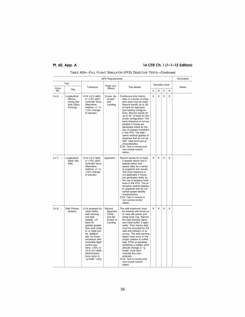
56
14 CFR Ch. I (1–1–12 Edition) Pt. 60, App. A
TABLE A2A—FULL FLIGHT SIMULATOR (FFS) OBJECTIVE TESTS—Continued
QPS Requirements Information
Test
Tolerance Flight con-ditions Test details
Simulator level Notes Entry
No. Title A B C D
2.c.6. .... Longitudinal Maneu-vering Sta-bility (Stick Force/g).
±5 lb (±2.2 daN) or ±10% pitch controller force. Alternative method: ±1° or ±10% change of elevator.
Cruise, Ap-proach, and Landing.
Continuous time history data or a series of snap-shot tests may be used. Record results up to 30° of bank for approach and landing configura-tions. Record results for up to 45° of bank for the cruise configuration. The force tolerance is not ap-plicable if forces are generated solely by the use of airplane hardware in the FFS. The alter-native method applies to airplanes that do not ex-hibit ‘‘stick-force-per-g’’ characteristics.
CCA: Test in normal and non-normal control states.
X X X X
2.c.7. .... Longitudinal Static Sta-bility.
±5 lb (±2.2 daN) or ±10% pitch controller force. Alternative method: ±1° or ±10% change of elevator.
Approach .. Record results for at least 2 speeds above and 2 speeds below trim speed. May be a series of snapshot test results. The force tolerance is not applicable if forces are generated solely by the use of airplane hard-ware in the FFS. The al-ternative method applies to airplanes that do not exhibit speed stability characteristics.
CCA: Test in normal or non-normal control states.
X X X X
2.c.8. .... Stall Charac-teristics.
±3 kt airspeed for initial buffet, stall warning, and stall speeds. ±2° bank for speeds greater than stick shak-er or initial buf-fet. Addition-ally, for those simulators with reversible flight control sys-tems: ±10% or ±5 lb (2.2 daN) Stick/Column force (prior to ‘‘g break’’ only).
Second Segment Climb, and Ap-proach or Landing.
The stall maneuver must be entered with thrust at or near idle power and wings level (1g). Record the stall warning signal and initial buffet, if appli-cable. Time history data must be recorded for full stall and initiation of re-covery. The stall warning signal must occur in the proper relation to buffet/ stall. FFSs of airplanes exhibiting a sudden pitch attitude change or ‘‘g break’’ must dem-onstrate this char-acteristic.
CCA: Test in normal and non-normal control states.
X X X X
VerDate Mar<15>2010 18:16 Mar 01, 2012 Jkt 226045 PO 00000 Frm 00066 Fmt 8010 Sfmt 8002 Q:\14\14V2 ofr150 PsN: PC150

57
Federal Aviation Administration, DOT Pt. 60, App. A
TABLE A2A—FULL FLIGHT SIMULATOR (FFS) OBJECTIVE TESTS—Continued
QPS Requirements Information
Test
Tolerance Flight con-ditions Test details
Simulator level Notes Entry
No. Title A B C D
2.c.9. .... Phugoid Dy-namics.
±10% period, ±10% of time to 1⁄2 or double amplitude or ±.02 of damp-ing ratio.
Cruise ....... The test must include whichever is less of the following: Three full cy-cles (six overshoots after the input is com-pleted), or the number of cycles sufficient to deter-mine time to 1⁄2 or dou-ble amplitude.
CCA: Test in Non-normal control states
X X X X
2.c.10. .. Short Period Dynamics..
±1.5° pitch angle or ±2°/sec pitch rate, ±0.10g acceleration.
Cruise ....... CCA: Test in Normal and Non-normal control states.
X X X X
2.c.11. .. (Reserved)
2.d. ....... Lateral Directional Tests.
.......... Power setting is that required for level flight unless otherwise specified.
2.d.1. .... Minimum Control Speed, Air (Vmca or Vmcl), per Applicable Airworthi-ness Standard or Low Speed En-gine Inop-erative Handling Character-istics in the Air.
±3 kt airspeed. Takeoff or Landing (which-ever is most crit-ical in the air-plane).
Takeoff thrust must be used on the operating engine(s). A time history or a series of snapshot tests may be used.
CCA: Test in Normal or Non-normal control state.
X X X X Low Speed En-gine Inoper-ative Handling may be gov-erned by a performance or control limit that prevents demonstration of Vmca or Vmcl in the conven-tional manner.
2.d.2. .... Roll Re-sponse (Rate)..
±10% or ±2°/sec roll rate. Addi-tionally, for those simula-tors of air-planes with re-versible flight control sys-tems: ±10% or ±3 lb (1.3 daN) wheel force.
Cruise, and Approach or Land-ing.
Record results for normal roll controller deflection (about one-third of max-imum roll controller trav-el). May be combined with step input of flight deck roll controller test (2.d.3.).
X X X X
VerDate Mar<15>2010 18:16 Mar 01, 2012 Jkt 226045 PO 00000 Frm 00067 Fmt 8010 Sfmt 8002 Q:\14\14V2 ofr150 PsN: PC150

58
14 CFR Ch. I (1–1–12 Edition) Pt. 60, App. A
TABLE A2A—FULL FLIGHT SIMULATOR (FFS) OBJECTIVE TESTS—Continued
QPS Requirements Information
Test
Tolerance Flight con-ditions Test details
Simulator level Notes Entry
No. Title A B C D
2.d.3. .... Roll Re-sponse to Flight Deck Roll Con-troller Step Input.
±10% or ±2° bank angle.
Approach or Land-ing.
Record from initiation of roll through 10 seconds after control is returned to neutral and released. May be combined with roll response (rate) test (2.d.2).
CCA: Test in Normal and Non-normal control states
X X X X With wings level, apply a step roll control input using ap-proximately one-third of the roll controller travel. When reaching ap-proximately 20° to 30° of bank, abruptly return the roll controller to neutral and allow approxi-mately 10 sec-onds of air-plane free re-sponse.
2.d.4. .... Spiral Sta-bility.
Correct trend and ±2° or ±10% bank angle in 20 seconds. Al-ternate test re-quires correct trend and ±2° aileron.
Cruise, and Approach or Land-ing.
Record results for both di-rections. Airplane data averaged from multiple tests may be used. As an alternate test, dem-onstrate the lateral con-trol required to maintain a steady turn with a bank angle of 28° to 32°.
CCA: Test in Non-normal control state
X X X X
2.d.5. .... Engine Inop-erative Trim.
±1° rudder angle or ±1° tab angle or equiv-alent pedal, ±2° sideslip angle.
Second Segment Climb, and Ap-proach or Landing.
May be a series of snap-shot tests.
X X X X The test should be performed in a manner similar to that for which a pilot is trained to trim an en-gine failure condition. Sec-ond segment climb test should be at takeoff thrust. Approach or landing test should be at thrust for level flight.
2.d.6. .... Rudder Re-sponse.
±2°/sec or ±10% yaw rate.
Approach or Land-ing.
Record results for stability augmentation system ON and OFF. A rudder step input of 20%–30% rudder pedal throw is used.
CCA: Test in Normal and Non-normal control states
X X X X
VerDate Mar<15>2010 18:16 Mar 01, 2012 Jkt 226045 PO 00000 Frm 00068 Fmt 8010 Sfmt 8002 Q:\14\14V2 ofr150 PsN: PC150

59
Federal Aviation Administration, DOT Pt. 60, App. A
TABLE A2A—FULL FLIGHT SIMULATOR (FFS) OBJECTIVE TESTS—Continued
QPS Requirements Information
Test
Tolerance Flight con-ditions Test details
Simulator level Notes Entry
No. Title A B C D
2.d.7. .... Dutch Roll, (Yaw Damper OFF).
±0.5 sec or ±10% of period, ±10% of time to 1⁄2 or double amplitude or ±.02 of damp-ing ratio. ±20% or ±1 sec of time difference between peaks of bank and sideslip.
Cruise, and Approach or Land-ing.
Record results for at least 6 complete cycles with stability augmentation OFF.
CCA: Test in Non-normal control state.
X X X
2.d.8. .... Steady State Sideslip.
For given rudder position ±2° bank angle, ±1° sideslip angle, ±10% or ±2° aileron, ±10% or ±5° spoiler or equivalent roll, controller posi-tion or force. Additionally, for those simula-tors of air-planes with re-versible flight control sys-tems: ±10% or ±3 lb (1.3 daN) wheel force ±10% or ±5 lb (2.2 daN) rud-der pedal force.
Approach or Land-ing.
Use at least two rudder positions, one of which must be near maximum allowable rudder. Pro-peller driven airplanes must test in each direc-tion. May be a series of snapshot test results.
X X X X
2.e. ....... Landings.
2.e.1. .... Normal Land-ing.
±3 kt airspeed, ±1.5° pitch angle, ±1.5° angle of attack, ±10% or ±10 ft (3 m) height. Additionally, for those simula-tors of air-planes with re-versible flight control sys-tems: ±10% or ±5 lbs (±2.2 daN) stick/col-umn force.
Landing .... Record results from a min-imum of 200 ft (61 m) AGL to nosewheel touchdown.
CCA: Test in Normal and Non-normal control states.
X X X Tests should be conducted with two normal landing flap settings (if ap-plicable). One should be at or near maximum certificated landing weight. The other should be at light or me-dium landing weight.
VerDate Mar<15>2010 18:16 Mar 01, 2012 Jkt 226045 PO 00000 Frm 00069 Fmt 8010 Sfmt 8002 Q:\14\14V2 ofr150 PsN: PC150

60
14 CFR Ch. I (1–1–12 Edition) Pt. 60, App. A
TABLE A2A—FULL FLIGHT SIMULATOR (FFS) OBJECTIVE TESTS—Continued
QPS Requirements Information
Test
Tolerance Flight con-ditions Test details
Simulator level Notes Entry
No. Title A B C D
2.e.2. .... Minimum Flap Land-ing.
±3 kt airspeed, ±1.5° pitch angle, ±1.5° angle of attack, ±10% or ±10 ft (3 m) height. Additionally, for those simula-tors of air-planes with re-versible flight control sys-tems: ±10% or ±5 lbs (2.2 daN) stick/col-umn force.
Minimum Certified Landing Flap Configu-ration.
Record results from a min-imum of 200 ft (61 m) AGL to nosewheel touchdown with airplane at near Maximum Land-ing Weight.
X X
2.e.3. .... Crosswind Landing.
±3 kt airspeed, ±1.5° pitch angle, ±1.5° angle of attack, ±10% or ±10 ft (3 m) height ±2° bank angle, ±2° side-slip angle ±3° heading angle. Additionally, for those simula-tors of air-planes with re-versible flight control sys-tems: ±10% or ±3 lb (1.3 daN) wheel force ±10% or ±5 lb (2.2 daN) rud-der pedal force.
Landing .... Record results from a min-imum of 200 ft (61 m) AGL, through nosewheel touch-down, to 50% de-crease in main landing gear touchdown speed. Test data must include information on wind pro-file, for a crosswind (ex-pressed as direct head- wind and direct cross- wind components) of 60% of the maximum wind measured at 33 ft (10 m) above the run-way.
X X X In those situa-tions where a maximum crosswind or a maximum demonstrated crosswind is not known, contact the NSPM.
2.e.4. .... One Engine Inoperative Landing.
±3 kt airspeed, ±1.5° pitch angle, ±1.5° angle of attack, ±10% height or ±10 ft (3 m); ±2° bank angle, ±2° side-slip angle, ±3° heading.
Landing .... Record results from a min-imum of 200 ft (61 m) AGL, through nosewheel touch-down, to 50% de-crease in main landing gear touchdown speed or less.
X X X
2.e.5. .... Autopilot landing (if applicable).
±5 ft (1.5 m) flare height, ±0.5 sec Tf, or ±10%Tf, ±140 ft/min (0.7 m/ sec) rate of de-scent at touch- down. ±10 ft (3 m) lateral devi-ation during rollout.
Landing .... If autopilot provides rollout guidance, record lateral deviation from touch-down to a 50% de-crease in main landing gear touchdown speed or less. Time of autopilot flare mode engage and main gear touchdown must be noted.
X X X See Appendix F of this part for definition of Tf.
VerDate Mar<15>2010 18:16 Mar 01, 2012 Jkt 226045 PO 00000 Frm 00070 Fmt 8010 Sfmt 8002 Q:\14\14V2 ofr150 PsN: PC150

61
Federal Aviation Administration, DOT Pt. 60, App. A
TABLE A2A—FULL FLIGHT SIMULATOR (FFS) OBJECTIVE TESTS—Continued
QPS Requirements Information
Test
Tolerance Flight con-ditions Test details
Simulator level Notes Entry
No. Title A B C D
2.e.6. .... All engines operating, autopilot, go around.
±3 kt airspeed, ±1.5° pitch angle, ±1.5° angle of attack.
Normal, all-engines-oper-ating, go around with the autopilot engaged (if ap-plicable) at medium landing weight.
CCA: Test in normal or non-normal control states.
X X X
2.e.7. .... One engine inoperative go around.
±3 kt airspeed, ±1.5° pitch angle, ±1.5° angle of attack, ±2° bank angle, ±2° slideslip angle.
The one engine inoper-ative go around is re-quired at near maximum certificated landing weight with the critical engine inoperative using manual controls. If appli-cable, an additional en-gine inoperative go around test must be ac-complished with the autopilot engaged.
CCA: Non-autopilot test in Non-normal control state.
X X X
2.e.8. .... Directional control (rudder ef-fective-ness) with symmetric reverse thrust.
±2°/sec yaw rate. ±5 kts airspeed.
Landing .... Record results starting from a speed approxi-mating touchdown speed to the minimum thrust reverser operation speed. With full reverse thrust, apply yaw control in both directions until reaching minimum thrust reverser operation speed.
X X X
2.e.9. .... Directional control (rudder ef-fective-ness) with asymmetric reverse thrust.
±5 kt airspeed. ±3° heading angle.
Landing .... Maintain heading with yaw control with full reverse thrust on the operating engine(s). Record re-sults starting from a speed approximating touchdown speed to a speed at which control of yaw cannot be main-tained or until reaching minimum thrust reverser operation speed, which-ever is higher. The toler-ance applies to the low speed end of the data recording.
X X X
2.f. ........ Ground Effect.
.......... Test to dem-onstrate Ground Ef-fect.
±1° elevator ±0.5° stabilizer angle, ±5% net thrust or equiv-alent, ±1° angle of attack, ±10% height or ±5 ft (1.5 m), ±3 kt airspeed, ±1° pitch angle.
Landing .... The Ground Effect model must be validated by the test selected and a ra-tionale must be provided for selecting the par-ticular test.
X X X See paragraph on Ground Ef-fect in this at-tachment for additional in-formation.
VerDate Mar<15>2010 18:16 Mar 01, 2012 Jkt 226045 PO 00000 Frm 00071 Fmt 8010 Sfmt 8002 Q:\14\14V2 ofr150 PsN: PC150

62
14 CFR Ch. I (1–1–12 Edition) Pt. 60, App. A
TABLE A2A—FULL FLIGHT SIMULATOR (FFS) OBJECTIVE TESTS—Continued
QPS Requirements Information
Test
Tolerance Flight con-ditions Test details
Simulator level Notes Entry
No. Title A B C D
2.g. ....... Windshear.
.......... Four tests, two takeoff and two landing, with one of each con-ducted in still air and the other with windshear active to dem-onstrate windshear models.
See Attachment 5 of this appen-dix.
Takeoff and Landing.
Requires windshear mod-els that provide training in the specific skills needed to recognize windshear phenomena and to execute recovery procedures. See Attach-ment 5 of this appendix for tests, tolerances, and procedures.
X X See Attachment 5 of this ap-pendix for in-formation re-lated to Level A and B sim-ulators.
2.h. ....... Flight Maneuver and Envelope Protection Functions.
.......... The requirements of tests h(1) through (6) of this attachment are applicable to computer controlled aircraft only. Time history results are required for sim-ulator response to control inputs during entry into envelope protection limits including both normal and degraded control states if the function is different. Set thrust as required to reach the envelope protection function.
2.h.1. .... Overspeed ... ±5 kt airspeed .... Cruise ....... X X X
2.h.2. .... Minimum Speed.
±3 kt airspeed .... Takeoff, Cruise, and Ap-proach or Landing.
X X X
2.h.3. .... Load Factor ±0.1 g normal load factor.
Takeoff, Cruise.
X X X
2.h.4. .... Pitch Angle .. ±1.5° pitch angle Cruise, Ap-proach.
X X X
2.h.5. .... Bank Angle .. ±2° or ±10% bank angle.
Approach .. X X X
2.h.6. .... Angle of At-tack.
±1.5° angle of at-tack.
Second Segment Climb, and Ap-proach or Landing.
X X X
3. Motion System.
3.a. ....... Frequency response.
.......... Based on Simu-lator Capability.
N/A ........... Required as part of the MQTG. The test must demonstrate frequency response of the motion system.
X X X X
3.b. ....... Leg balance.
VerDate Mar<15>2010 18:16 Mar 01, 2012 Jkt 226045 PO 00000 Frm 00072 Fmt 8010 Sfmt 8002 Q:\14\14V2 ofr150 PsN: PC150

63
Federal Aviation Administration, DOT Pt. 60, App. A
TABLE A2A—FULL FLIGHT SIMULATOR (FFS) OBJECTIVE TESTS—Continued
QPS Requirements Information
Test
Tolerance Flight con-ditions Test details
Simulator level Notes Entry
No. Title A B C D
Based on Simu-lator Capability.
N/A ........... Required as part of the MQTG. The test must demonstrate motion sys-tem leg balance as specified by the appli-cant for flight simulator qualification.
X X X X
3.c. ....... Turn-around check.
.......... Based on Simu-lator Capability.
N/A ........... Required as part of the MQTG. The test must demonstrate a smooth turn-around (shift to op-posite direction of move-ment) of the motion sys-tem as specified by the applicant for flight simu-lator qualification.
X X X X
3.d. ....... Motion system repeatability.
.......... With the same input signal, the test results must be re-peatable to within ±0.05 g actual platform linear accelera-tion.
Accom-plished in both the ‘‘ground’’ mode and in the ‘‘flight’’ mode of the mo-tion sys-tem op-eration.
Required as part of the MQTG. The assessment procedures must be de-signed to ensure that the motion system hard-ware and software (in normal flight simulator operating mode) con-tinue to perform as origi-nally qualified.
X X X X This test ensures that motion system hard-ware and soft-ware (in nor-mal flight simu-lator operating mode) con-tinue to per-form as origi-nally qualified. Performance changes from the original baseline can be readily identified with this informa-tion.
3.e. ....... Motion cueing performance signature. Required as part of MQTG. For the fol-lowing set of maneuvers record the relevant motion variables.
These tests should be run with the motion buffet mode disabled. See paragraph 6.d., of this attach-ment, Motion cueing per-formance sig-nature.
3.e.1. .... Takeoff rota-tion (VR to V2).
As specified by the sponsor for flight simulator qualification.
Ground ..... Pitch attitude due to initial climb must dominate over cab tilt due to longi-tudinal acceleration.
X X X X Associated with test 1.b.4.
3.e.2. .... Engine fail-ure be-tween V1 and VR.
As specified by the sponsor for flight simulator qualification.
Ground ..... X X X X Associated with test 1.b.5.
VerDate Mar<15>2010 18:16 Mar 01, 2012 Jkt 226045 PO 00000 Frm 00073 Fmt 8010 Sfmt 8002 Q:\14\14V2 ofr150 PsN: PC150

64
14 CFR Ch. I (1–1–12 Edition) Pt. 60, App. A
TABLE A2A—FULL FLIGHT SIMULATOR (FFS) OBJECTIVE TESTS—Continued
QPS Requirements Information
Test
Tolerance Flight con-ditions Test details
Simulator level Notes Entry
No. Title A B C D
3.e.3. .... Pitch change during go- around.
As specified by the sponsor for flight simulator qualification.
Flight ........ X X X Associated with test 2.e.6.
3.e.4. .... Configuration changes.
As specified by the sponsor for flight simulator qualification.
Flight ........ X X X X Associated with tests 2.c.2. and 2.c.4.
3.e.5. .... Power change dy-namics.
As specified by the sponsor for flight simulator qualification.
Flight ........ X X X X Associated with test 2.c.1.
3.e.6. .... Landing flare As specified by the sponsor for flight simulator qualification.
Flight ........ X X X Associated with test 2.e.1.
3.e.7. .... Touchdown bump.
As specified by the sponsor for flight simulator qualification.
Ground ..... X X Associated with test 2.e.1.
3.f. ........ Characteristic motion vibrations. The recorded test results for characteristic buffets must allow the comparison of relative amplitude versus frequency.
3.f.1. ..... Thrust effect with brakes set.
Simulator test re-sults must ex-hibit the overall appearance and trends of the airplane data, with at least three (3) of the predomi-nant frequency ‘‘spikes’’ being present within ±2 Hz.
Ground ..... The test must be con-ducted within 5% of the maximum possible thrust with brakes set.
X
3.f.2. ..... Buffet with landing gear ex-tended.
Simulator test re-sults must ex-hibit the overall appearance and trends of the airplane data, with at least three (3) of the predomi-nant frequency ‘‘spikes’’ being present within ±2 Hz.
Flight ........ The test must be con-ducted at a nominal, mid-range airspeed; i.e., sufficiently below landing gear limiting airspeed to avoid inadvertently ex-ceeding this limitation.
X
VerDate Mar<15>2010 18:16 Mar 01, 2012 Jkt 226045 PO 00000 Frm 00074 Fmt 8010 Sfmt 8002 Q:\14\14V2 ofr150 PsN: PC150

65
Federal Aviation Administration, DOT Pt. 60, App. A
TABLE A2A—FULL FLIGHT SIMULATOR (FFS) OBJECTIVE TESTS—Continued
QPS Requirements Information
Test
Tolerance Flight con-ditions Test details
Simulator level Notes Entry
No. Title A B C D
3.f.3. ..... Buffet with flaps ex-tended.
Simulator test re-sults must ex-hibit the overall appearance and trends of the airplane data, with at least three (3) of the predomi-nant frequency ‘‘spikes’’ being present within ±2 Hz.
Flight ........ The test must be con-ducted at a nominal, mid-range airspeed; i.e., sufficiently below flap extension limiting air-speed to avoid inadvert-ently exceeding this limi-tation.
X
3.f.4. ..... Buffet with speedbrak-es de-ployed.
Simulator test re-sults must ex-hibit the overall appearance and trends of the airplane data, with at least three (3) of the predomi-nant frequency ‘‘spikes’’ being present within ±2 Hz.
Flight ........ X
3.f.5. ..... Buffet at ap-proach-to- stall.
Simulator test re-sults must ex-hibit the overall appearance and trends of the airplane data, with at least three (3) of the predomi-nant frequency ‘‘spikes’’ being present within ±2 Hz.
Flight ........ The test must be con-ducted for approach to stall. Post stall charac-teristics are not required.
X
3.f.6. ..... Buffet at high airspeeds or high Mach.
Simulator test re-sults must ex-hibit the overall appearance and trends of the airplane data, with at least three (3) of the predomi-nant frequency ‘‘spikes’’ being present within ±2 Hz.
Flight ........ X The test may be conducted dur-ing either a high speed maneuver (e.g., ‘‘wind- up’’ turn) or at high Mach.
VerDate Mar<15>2010 18:16 Mar 01, 2012 Jkt 226045 PO 00000 Frm 00075 Fmt 8010 Sfmt 8002 Q:\14\14V2 ofr150 PsN: PC150
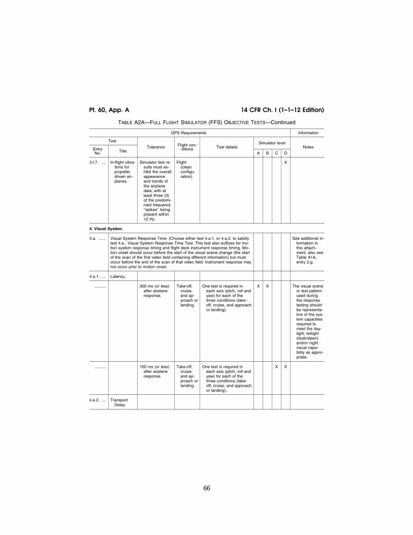
66
14 CFR Ch. I (1–1–12 Edition) Pt. 60, App. A
TABLE A2A—FULL FLIGHT SIMULATOR (FFS) OBJECTIVE TESTS—Continued
QPS Requirements Information
Test
Tolerance Flight con-ditions Test details
Simulator level Notes Entry
No. Title A B C D
3.f.7. ..... In-flight vibra-tions for propeller driven air-planes.
Simulator test re-sults must ex-hibit the overall appearance and trends of the airplane data, with at least three (3) of the predomi-nant frequency ‘‘spikes’’ being present within ±2 Hz.
Flight (clean configu-ration).
X
4. Visual System.
4.a. ....... Visual System Response Time: (Choose either test 4.a.1. or 4.a.2. to satisfy test 4.a., Visual System Response Time Test. This test also suffices for mo-tion system response timing and flight deck instrument response timing. Mo-tion onset should occur before the start of the visual scene change (the start of the scan of the first video field containing different information) but must occur before the end of the scan of that video field. Instrument response may not occur prior to motion onset.
See additional in-formation in this attach-ment; also see Table A1A, entry 2.g.
4.a.1. .... Latency..
.......... 300 ms (or less) after airplane response.
Take-off, cruise, and ap-proach or landing.
One test is required in each axis (pitch, roll and yaw) for each of the three conditions (take- off, cruise, and approach or landing).
X X The visual scene or test pattern used during the response testing should be representa-tive of the sys-tem capacities required to meet the day-light, twilight (dusk/dawn) and/or night visual capa-bility as appro-priate.
.......... 150 ms (or less) after airplane response.
Take-off, cruise, and ap-proach or landing.
One test is required in each axis (pitch, roll and yaw) for each of the three conditions (take- off, cruise, and approach or landing)..
X X
4.a.2. .... Transport Delay.
VerDate Mar<15>2010 18:16 Mar 01, 2012 Jkt 226045 PO 00000 Frm 00076 Fmt 8010 Sfmt 8002 Q:\14\14V2 ofr150 PsN: PC150

67
Federal Aviation Administration, DOT Pt. 60, App. A
TABLE A2A—FULL FLIGHT SIMULATOR (FFS) OBJECTIVE TESTS—Continued
QPS Requirements Information
Test
Tolerance Flight con-ditions Test details
Simulator level Notes Entry
No. Title A B C D
.......... 300 ms (or less) after controller movement.
N/A ........... A separate test is required in each axis (pitch, roll, and yaw).
X X If Transport Delay is the chosen meth-od to dem-onstrate rel-ative re-sponses, the sponsor and the NSPM will use the latency values to en-sure proper simulator re-sponse when reviewing those existing tests where la-tency can be identified (e.g., short period, roll response, rudder re-sponse)
.......... 150 ms (or less) after controller movement.
N/A ........... A separate test is required in each axis (pitch, roll, and yaw).
X X
4.b. ....... Field-of-view.
4.b.1. .... Continuous collimated visual field- of-view.
Continuous col-limated field-of- view providing at least 45° horizontal and 30° vertical field-of-view for each pilot seat. Both pilot seat visual systems must be oper-able simulta-neously.
N/A ........... Required as part of MQTG but not required as part of continuing evaluations.
X X A vertical field-of- view of 30° may be insuffi-cient to meet visual ground segment re-quirements.
4.b.2. .... (Reserved)
VerDate Mar<15>2010 18:16 Mar 01, 2012 Jkt 226045 PO 00000 Frm 00077 Fmt 8010 Sfmt 8002 Q:\14\14V2 ofr150 PsN: PC150

68
14 CFR Ch. I (1–1–12 Edition) Pt. 60, App. A
TABLE A2A—FULL FLIGHT SIMULATOR (FFS) OBJECTIVE TESTS—Continued
QPS Requirements Information
Test
Tolerance Flight con-ditions Test details
Simulator level Notes Entry
No. Title A B C D
4.b.3. .... Continuous, collimated, field-of- view.
Continuous field- of-view of at least 176° hori-zontally and 36° vertically.
N/A ........... An SOC is required and must explain the geom-etry of the installation. Horizontal field-of-view must be at least 176° (including not less than 88° either side of the center line of the design eye point). Additional horizontal field-of-view capability may be added at the sponsor’s discre-tion provided the min-imum field-of-view is re-tained. Vertical field-of- view must be at least 36° from each pilot’s eye point. Required as part of MQTG but not re-quired as part of con-tinuing qualification eval-uations.
X X The horizontal field-of-view is traditionally de-scribed as a 180° field-of- view. However, the field-of- view is tech-nically no less than 176°. Field-of-view should be measured using a visual test pattern fill-ing the entire visual scene (all channels) with a matrix of black and white 5° squares. The installed align-ment should be addressed in the SOC.
4.c. ....... System geometry.
.......... 5° even angular spacing within ±1° as meas-ured from ei-ther pilot eye point and within 1.5° for adja-cent squares.
N/A ........... The angular spacing of any chosen 5° square and the relative spacing of adjacent squares must be within the stat-ed tolerances.
X X X X The purpose of this test is to evaluate local linearity of the displayed image at either pilot eye point. System geom-etry should be measured using a visual test pattern fill-ing the entire visual scene (all channels) with a matrix of black and white 5° squares with light points at the intersec-tions.
4.d. ....... Surface contrast ratio.
VerDate Mar<15>2010 18:16 Mar 01, 2012 Jkt 226045 PO 00000 Frm 00078 Fmt 8010 Sfmt 8002 Q:\14\14V2 ofr150 PsN: PC150

69
Federal Aviation Administration, DOT Pt. 60, App. A
TABLE A2A—FULL FLIGHT SIMULATOR (FFS) OBJECTIVE TESTS—Continued
QPS Requirements Information
Test
Tolerance Flight con-ditions Test details
Simulator level Notes Entry
No. Title A B C D
.......... Not less than 5:1. N/A ........... The ratio is calculated by dividing the brightness level of the center, bright square (providing at least 2 foot-lamberts or 7 cd/m2) by the bright-ness level of any adja-cent dark square. This requirement is applica-ble to any level of simu-lator equipped with a daylight visual system.
X X Measurements should be made using a 1° spot pho-tometer and a raster drawn test pattern fill-ing the entire visual scene (all channels) with a test pat-tern of black and white squares, 5° per square, with a white square in the center of each channel. Dur-ing contrast ratio testing, simulator aft- cab and flight deck ambient light levels should be zero.
4.e. ....... Highlight brightness.
.......... Not less than six (6) foot-lam-berts (20 cd/ m2).
N/A ........... Measure the brightness of a white square while superimposing a high-light on that white square. The use of calli-graphic capabilities to enhance the raster brightness is acceptable; however, measuring lightpoints is not accept-able. This requirement is applicable to any level of simulator equipped with a daylight visual system.
X X Measurements should be made using a 1° spot pho-tometer and a raster drawn test pattern fill-ing the entire visual scene (all channels) with a test pat-tern of black and white squares, 5° per square, with a white square in the center of each channel.
4.f. ........ Surface resolution
VerDate Mar<15>2010 18:16 Mar 01, 2012 Jkt 226045 PO 00000 Frm 00079 Fmt 8010 Sfmt 8002 Q:\14\14V2 ofr150 PsN: PC150

70
14 CFR Ch. I (1–1–12 Edition) Pt. 60, App. A
TABLE A2A—FULL FLIGHT SIMULATOR (FFS) OBJECTIVE TESTS—Continued
QPS Requirements Information
Test
Tolerance Flight con-ditions Test details
Simulator level Notes Entry
No. Title A B C D
.......... Not greater than two (2) arc minutes.
N/A ........... An SOC is required and must include the rel-evant calculations and an explanation of those calculations. This re-quirement is applicable to any level of simulator equipped with a daylight visual system.
X X When the eye is positioned on a 3° glide slope at the slant range distances indi-cated with white runway markings on a black runway surface, the eye will sub-tend two (2) arc minutes: (1) A slant range of 6,876 ft with stripes 150 ft long and 16 ft wide, spaced 4 ft apart. (2) For Configuration A; a slant range of 5,157 feet with stripes 150 ft long and 12 ft wide, spaced 3 ft apart. (3) For Configuration B; a slant range of 9,884 feet, with stripes 150 ft long and 5.75 ft wide, spaced 5.75 ft apart.
4.g. ....... Light point size.
.......... Not greater than five (5) arc- minutes.
N/A ........... An SOC is required and must include the rel-evant calculations and an explanation of those calculations. This re-quirement is applicable to any level of simulator equipped with a daylight visual system.
X X Light point size should be measured using a test pattern con-sisting of a centrally lo-cated single row of light points reduced in length until modulation is just discernible in each visual channel. A row of 48 lights will form a 4° angle or less.
4.h. ....... Light point contrast ratio.
VerDate Mar<15>2010 18:16 Mar 01, 2012 Jkt 226045 PO 00000 Frm 00080 Fmt 8010 Sfmt 8002 Q:\14\14V2 ofr150 PsN: PC150

71
Federal Aviation Administration, DOT Pt. 60, App. A
TABLE A2A—FULL FLIGHT SIMULATOR (FFS) OBJECTIVE TESTS—Continued
QPS Requirements Information
Test
Tolerance Flight con-ditions Test details
Simulator level Notes Entry
No. Title A B C D
4.h.1 ..... For Level A and B sim-ulators.
Not less than 10:1.
N/A ........... An SOC is required and must include the rel-evant calculations.
X X A 1° spot pho-tometer is used to meas-ure a square of at least 1° filled with light points (where light point modulation is just discern-ible) and com-pare the re-sults to the measured ad-jacent back-ground. During contrast ratio testing, simu-lator aft-cab and flight deck ambient light levels should be zero.
4.h.2. .... For Level C and D sim-ulators.
Not less than 25:1.
N/A ........... An SOC is required and must include the rel-evant calculations.
X X A 1° spot pho-tometer is used to meas-ure a square of at least 1° filled with light points (where light point modulation is just discern-ible) and com-pare the re-sults to the measured ad-jacent back-ground. During contrast ratio testing, simu-lator aft-cab and flight deck ambient light levels should be zero.
4.i. ........ Visual ground segment.
VerDate Mar<15>2010 18:16 Mar 01, 2012 Jkt 226045 PO 00000 Frm 00081 Fmt 8010 Sfmt 8002 Q:\14\14V2 ofr150 PsN: PC150

72
14 CFR Ch. I (1–1–12 Edition) Pt. 60, App. A
TABLE A2A—FULL FLIGHT SIMULATOR (FFS) OBJECTIVE TESTS—Continued
QPS Requirements Information
Test
Tolerance Flight con-ditions Test details
Simulator level Notes Entry
No. Title A B C D
.......... The visible seg-ment in the simulator must be ±20% of the segment com-puted to be visible from the airplane flight deck. This tol-erance may be applied at the far end of the displayed seg-ment. However, lights and ground objects computed to be visible from the airplane flight deck at the near end of the visible segment must be visible in the simulator.
Landing configu-ration, with the aircraft trimmed for the appro-priate air-speed, where the MLG are at 100 ft (30 m) above the plane of the touch-down zone, while on the elec-tronic glide slope with an RVR value set at 1,200 ft (350 m).
The QTG must contain ap-propriate calculations and a drawing showing the pertinent data used to establish the airplane location and the seg-ment of the ground that is visible considering de-sign eyepoint, the air-plane attitude, flight deck cut-off angle, and a visibility of 1200 ft (350 m) RVR. Simulator per-formance must be meas-ured against the QTG calculations. The data submitted must include at least the following:.
(1) Static airplane dimen-sions as follows:
(i) Horizontal and vertical distance from main land-ing gear (MLG) to glideslope reception an-tenna.
(ii) Horizontal and vertical distance from MLG to pi-lot’s eyepoint.
(iii) Static flight deck cutoff angle.
(2) Approach data as fol-lows:
(i) Identification of runway. (ii) Horizontal distance
from runway threshold to glideslope intercept with runway.
(iii) Glideslope angle. (iv) Airplane pitch angle on
approach. (3) Airplane data for man-
ual testing: (i) Gross weight. (ii) Airplane configuration. (iii) Approach airspeed. If
non-homogenous fog is used to obscure visi-bility, the vertical vari-ation in horizontal visi-bility must be described and be included in the slant range visibility cal-culation used in the computations.
X X X X Pre-position for this test is en-couraged but may be achieved via manual or autopilot con-trol to the de-sired position.
5. Sound System.
VerDate Mar<15>2010 18:16 Mar 01, 2012 Jkt 226045 PO 00000 Frm 00082 Fmt 8010 Sfmt 8002 Q:\14\14V2 ofr150 PsN: PC150

73
Federal Aviation Administration, DOT Pt. 60, App. A
TABLE A2A—FULL FLIGHT SIMULATOR (FFS) OBJECTIVE TESTS—Continued
QPS Requirements Information
Test
Tolerance Flight con-ditions Test details
Simulator level Notes Entry
No. Title A B C D
The sponsor will not be required to repeat the airplane tests (i.e., tests 5.a.1. through 5.a.8. (or 5.b.1. through 5.b.9.) and 5.c., as appropriate) during continuing qualification evaluations if frequency response and background noise test results are within toler-ance when compared to the initial qualification evaluation results, and the sponsor shows that no software changes have occurred that will affect the airplane test results. If the frequency response test method is chosen and fails, the sponsor may elect to fix the frequency response problem and repeat the test or the sponsor may elect to re-peat the airplane tests. If the airplane tests are repeated during continuing qualification evaluations, the results may be compared against initial qualification evaluation results or airplane master data. All tests in this section must be presented using an unweighted 1⁄3-octave band format from band 17 to 42 (50 Hz to 16 kHz). A minimum 20 second average must be taken at the location corresponding to the airplane data set. The airplane and flight simulator results must be produced using comparable data analysis techniques..
5.a. ....... Turbo-jet airplanes.
5.a.1. .... Ready for engine start.
±5 dB per 1⁄3 oc-tave band.
Ground ..... Normal conditions prior to engine start with the Auxiliary Power Unit op-erating, if appropriate.
X
5.a.2. .... All engines at idle..
±5 dB per 1⁄3 oc-tave band.
Ground ..... Normal condition prior to takeoff.
X
5.a.3. .... All engines at maximum allowable thrust with brakes set.
±5 dB per 1⁄3 oc-tave band.
Ground ..... Normal condition prior to takeoff.
X
5.a.4. .... Climb ........... ±5 dB per 1⁄3 oc-tave band.
En-route climb.
Medium altitude ................. X
5.a.5. .... Cruise .......... ±5 dB per 1⁄3 oc-tave band.
Cruise ....... Normal cruise configura-tion.
X
5.a.6. .... Speedbrake / spoilers extended (as appro-priate).
±5 dB per 1⁄3 oc-tave band.
Cruise ....... Normal and constant speedbrake deflection for descent at a constant airspeed and power set-ting.
X
5.a.7. .... Initial ap-proach.
±5 dB per 1⁄3 oc-tave band.
Approach .. Constant airspeed, gear up, flaps and slats, as appropriate.
X
5.a.8. .... Final ap-proach.
±5 dB per 1⁄3 oc-tave band.
Landing .... Constant airspeed, gear down, full flaps.
X
5.b. ....... Propeller airplanes.
5.b.1. .... Ready for engine start.
±5 dB per 1⁄3 oc-tave band.
Ground ..... Normal conditions prior to engine start with the Auxiliary Power Unit op-erating, if appropriate.
X
5.b.2. .... All propellers feathered.
±5 dB per 1⁄3 oc-tave band.
Ground ..... Normal condition prior to takeoff.
X
5.b.3. .... Ground idle or equiva-lent.
±5 dB per 1⁄3 oc-tave band.
Ground ..... Normal condition prior to takeoff.
X
5.b.4 ..... Flight idle or equivalent.
±5 dB per 1⁄3 oc-tave band.
Ground ..... Normal condition prior to takeoff.
X
VerDate Mar<15>2010 18:16 Mar 01, 2012 Jkt 226045 PO 00000 Frm 00083 Fmt 8010 Sfmt 8002 Q:\14\14V2 ofr150 PsN: PC150

74
14 CFR Ch. I (1–1–12 Edition) Pt. 60, App. A
TABLE A2A—FULL FLIGHT SIMULATOR (FFS) OBJECTIVE TESTS—Continued
QPS Requirements Information
Test
Tolerance Flight con-ditions Test details
Simulator level Notes Entry
No. Title A B C D
5.b.5. .... All engines at maximum allowable power with brakes set.
±5 dB per 1⁄3 oc-tave band.
Ground ..... Normal condition prior to takeoff.
X
5.b.6. .... Climb ........... ±5 dB per 1⁄3 oc-tave band.
En-route climb.
Medium altitude ................. X
5.b.7. .... Cruise .......... ±5 dB per 1⁄3 oc-tave band.
Cruise ....... Normal cruise configura-tion.
X
5.b.8. .... Initial ap-proach.
±5 dB per 1⁄3 oc-tave band.
Approach .. Constant airspeed, gear up, flaps extended as appropriate, RPM as per operating manual.
X
5.b.9. .... Final Ap-proach.
±5 dB per 1⁄3 oc-tave band.
Landing .... Constant airspeed, gear down, full flaps, RPM as per operating manual.
X
5.c. ....... Special cases.
.......... ±5 dB per 1⁄3 oc-tave band.
As appro-priate.
X These special cases are identified as particularly sig-nificant during critical phases of flight and ground oper-ations for a specific air-plane type or model.
5.d. ....... Background noise.
.......... ±3 dB per 1⁄3 oc-tave band.
Results of the background noise at initial qualifica-tion must be included in the MQTG. Measure-ments must be made with the simulation run-ning, the sound muted and a ‘‘dead’’ flight deck.
X The sound in the simulator will be evaluated to ensure that the back-ground noise does not inter-fere with train-ing, testing, or checking.
5.e. ....... Frequency response.
VerDate Mar<15>2010 18:16 Mar 01, 2012 Jkt 226045 PO 00000 Frm 00084 Fmt 8010 Sfmt 8002 Q:\14\14V2 ofr150 PsN: PC150

75
Federal Aviation Administration, DOT Pt. 60, App. A
TABLE A2A—FULL FLIGHT SIMULATOR (FFS) OBJECTIVE TESTS—Continued
QPS Requirements Information
Test
Tolerance Flight con-ditions Test details
Simulator level Notes Entry
No. Title A B C D
.......... ±5 dB on three (3) consecutive bands when compared to initial evalua-tion; and ±2 dB when com-paring the av-erage of the absolute dif-ferences be-tween initial and continuing qualification evaluation.
Applicable only to Con-tinuing Qualification Evaluations. If frequency response plots are pro-vided for each channel at the initial qualification evaluation, these plots may be repeated at the continuing qualification evaluation with the fol-lowing tolerances ap-plied: (a) The continuing qualification 1⁄3 octave band amplitudes must not exceed ±5 dB for three consecutive bands when compared to initial results. (b) The average of the sum of the abso-lute differences between initial and continuing qualification results must not exceed 2 dB (refer to Table A2B in this at-tachment).
X Measurements are compared to those taken during initial qualification evaluation.
lllllllllllllllllllllll
BEGIN INFORMATION
3. GENERAL
a. If relevant winds are present in the ob-jective data, the wind vector should be clear-ly noted as part of the data presentation, ex-pressed in conventional terminology, and re-lated to the runway being used for test near the ground.
b. The reader is encouraged to review the Airplane Flight Simulator Evaluation Hand-book, Volumes I and II, published by the Royal Aeronautical Society, London, UK, and AC 25–7, as amended, Flight Test Guide for Certification of Transport Category Air-planes, and AC 23–8, as amended, Flight Test Guide for Certification of Part 23 Airplanes, for references and examples regarding flight testing requirements and techniques.
4. CONTROL DYNAMICS
a. General. The characteristics of an air-plane flight control system have a major ef-fect on handling qualities. A significant con-sideration in pilot acceptability of an air-plane is the ‘‘feel’’ provided through the flight controls. Considerable effort is ex-pended on airplane feel system design so that pilots will be comfortable and will consider the airplane desirable to fly. In order for an FFS to be representative, it should ‘‘feel’’ like the airplane being simulated. Compli-
ance with this requirement is determined by comparing a recording of the control feel dy-namics of the FFS to actual airplane meas-urements in the takeoff, cruise and landing configurations.
(1) Recordings such as free response to an impulse or step function are classically used to estimate the dynamic properties of electromechanical systems. In any case, it is only possible to estimate the dynamic prop-erties as a result of being able to estimate true inputs and responses. Therefore, it is imperative that the best possible data be col-lected since close matching of the FFS con-trol loading system to the airplane system is essential. The required dynamic control tests are described in Table A2A of this at-tachment.
(2) For initial and upgrade evaluations, the QPS requires that control dynamics charac-teristics be measured and recorded directly from the flight controls (Handling Quali-ties—Table A2A). This procedure is usually accomplished by measuring the free response of the controls using a step or impulse input to excite the system. The procedure should be accomplished in the takeoff, cruise and landing flight conditions and configurations.
(3) For airplanes with irreversible control systems, measurements may be obtained on the ground if proper pitot-static inputs are provided to represent airspeeds typical of those encountered in flight. Likewise, it may be shown that for some airplanes, takeoff,
VerDate Mar<15>2010 18:16 Mar 01, 2012 Jkt 226045 PO 00000 Frm 00085 Fmt 8010 Sfmt 8002 Q:\14\14V2 ofr150 PsN: PC150

76
14 CFR Ch. I (1–1–12 Edition) Pt. 60, App. A
cruise, and landing configurations have like effects. Thus, one may suffice for another. In either case, engineering validation or air-plane manufacturer rationale should be sub-mitted as justification for ground tests or for eliminating a configuration. For FFSs re-quiring static and dynamic tests at the con-trols, special test fixtures will not be re-quired during initial and upgrade evalua-tions if the QTG shows both test fixture re-sults and the results of an alternate ap-proach (e.g., computer plots that were pro-duced concurrently and show satisfactory agreement). Repeat of the alternate method during the initial evaluation satisfies this test requirement.
b. Control Dynamics Evaluation. The dy-namic properties of control systems are often stated in terms of frequency, damping and a number of other classical measure-ments. In order to establish a consistent means of validating test results for FFS con-trol loading, criteria are needed that will clearly define the measurement interpreta-tion and the applied tolerances. Criteria are needed for underdamped, critically damped and overdamped systems. In the case of an underdamped system with very light damp-ing, the system may be quantified in terms of frequency and damping. In critically damped or overdamped systems, the fre-quency and damping are not readily meas-ured from a response time history. There-fore, the following suggested measurements may be used:
(1) For Level C and D simulators. Tests to verify that control feel dynamics represent the airplane should show that the dynamic damping cycles (free response of the con-trols) match those of the airplane within specified tolerances. The NSPM recognizes that several different testing methods may be used to verify the control feel dynamic re-sponse. The NSPM will consider the merits of testing methods based on reliability and consistency. One acceptable method of eval-uating the response and the tolerance to be applied is described below for the under-damped and critically damped cases. A spon-sor using this method to comply with the QPS requirements should perform the tests as follows:
(a) Underdamped response. Two measure-ments are required for the period, the time to first zero crossing (in case a rate limit is present) and the subsequent frequency of os-cillation. It is necessary to measure cycles on an individual basis in case there are non- uniform periods in the response. Each period will be independently compared to the re-spective period of the airplane control sys-tem and, consequently, will enjoy the full tolerance specified for that period. The damping tolerance will be applied to over-shoots on an individual basis. Care should be taken when applying the tolerance to small overshoots since the significance of such
overshoots becomes questionable. Only those overshoots larger than 5 per cent of the total initial displacement should be considered. The residual band, labeled T(Ad) on Figure A2A is ±5 percent of the initial displacement amplitude Ad from the steady state value of the oscillation. Only oscillations outside the residual band are considered significant. When comparing FFS data to airplane data, the process should begin by overlaying or aligning the FFS and airplane steady state values and then comparing amplitudes of os-cillation peaks, the time of the first zero crossing and individual periods of oscilla-tion. The FFS should show the same number of significant overshoots to within one when compared against the airplane data. The pro-cedure for evaluating the response is illus-trated in Figure A2A.
(b) Critically damped and overdamped re-sponse. Due to the nature of critically damped and overdamped responses (no over-shoots), the time to reach 90 percent of the steady state (neutral point) value should be the same as the airplane within ±10 percent. Figure A2B illustrates the procedure.
(c) Special considerations. Control systems that exhibit characteristics other than clas-sical overdamped or underdamped responses should meet specified tolerances. In addi-tion, special consideration should be given to ensure that significant trends are main-tained.
(2) Tolerances. (a) The following table summarizes the tol-
erances, T, for underdamped systems, and ‘‘n’’ is the sequential period of a full cycle of oscillation. See Figure A2A of this attach-ment for an illustration of the referenced measurements.
T(P0) .......... ±10% of P0. T(P1) .......... ±20% of P1. T(P2) .......... ±30% of P2. T(Pn) .......... ±10(n+1)% of Pn. T(An) .......... ±10% of A1. T(Ad) .......... ±5% of Ad = residual
band.
Significant overshoots, First overshoot and ±1 subsequent overshoots.
(b) The following tolerance applies to criti-cally damped and overdamped systems only. See Figure A2B for an illustration of the ref-erence measurements:
T(P0) .......... ±10% of P0
END INFORMATION
lllllllllllllllllllllll
BEGIN QPS REQUIREMENT
c. Alternative method for control dynam-ics evaluation.
(1) An alternative means for validating control dynamics for aircraft with hydrau-lically powered flight controls and artificial
VerDate Mar<15>2010 18:16 Mar 01, 2012 Jkt 226045 PO 00000 Frm 00086 Fmt 8010 Sfmt 8002 Q:\14\14V2 ofr150 PsN: PC150

77
Federal Aviation Administration, DOT Pt. 60, App. A
feel systems is by the measurement of con-trol force and rate of movement. For each axis of pitch, roll, and yaw, the control must be forced to its maximum extreme position for the following distinct rates. These tests are conducted under normal flight and ground conditions.
(a) Static test—Slowly move the control so that a full sweep is achieved within 95 to 105 seconds. A full sweep is defined as movement of the controller from neutral to the stop, usually aft or right stop, then to the oppo-site stop, then to the neutral position.
(b) Slow dynamic test—Achieve a full sweep within 8–12 seconds.
(c) Fast dynamic test—Achieve a full sweep within 3–5 seconds.
NOTE: Dynamic sweeps may be limited to forces not exceeding 100 lbs. (44.5 daN).
(d) Tolerances
(i) Static test; see Table A2A, FFS Objec-tive Tests, Entries 2.a.1., 2.a.2., and 2.a.3.
(ii) Dynamic test—± 2 lbs (0.9 daN) or ± 10% on dynamic increment above static test.
END QPS REQUIREMENT
lllllllllllllllllllllll
BEGIN INFORMATION
d. The FAA is open to alternative means such as the one described above. The alter-natives should be justified and appropriate to the application. For example, the method described here may not apply to all manufac-turers’ systems and certainly not to aircraft with reversible control systems. Each case is considered on its own merit on an ad hoc basis. If the FAA finds that alternative methods do not result in satisfactory per-formance, more conventionally accepted methods will have to be used.
VerDate Mar<15>2010 18:16 Mar 01, 2012 Jkt 226045 PO 00000 Frm 00087 Fmt 8010 Sfmt 8002 Q:\14\14V2 ofr150 PsN: PC150

78
14 CFR Ch. I (1–1–12 Edition) Pt. 60, App. A
VerDate Mar<15>2010 18:16 Mar 01, 2012 Jkt 226045 PO 00000 Frm 00088 Fmt 8010 Sfmt 8006 Q:\14\14V2 ofr150 PsN: PC150 ER
09M
Y08
.000
</G
PH
>
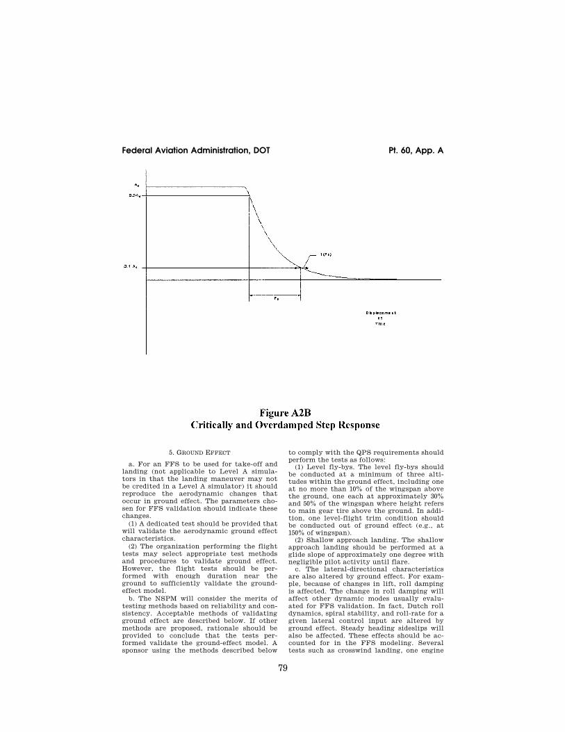
79
Federal Aviation Administration, DOT Pt. 60, App. A
5. GROUND EFFECT
a. For an FFS to be used for take-off and landing (not applicable to Level A simula-tors in that the landing maneuver may not be credited in a Level A simulator) it should reproduce the aerodynamic changes that occur in ground effect. The parameters cho-sen for FFS validation should indicate these changes.
(1) A dedicated test should be provided that will validate the aerodynamic ground effect characteristics.
(2) The organization performing the flight tests may select appropriate test methods and procedures to validate ground effect. However, the flight tests should be per-formed with enough duration near the ground to sufficiently validate the ground- effect model.
b. The NSPM will consider the merits of testing methods based on reliability and con-sistency. Acceptable methods of validating ground effect are described below. If other methods are proposed, rationale should be provided to conclude that the tests per-formed validate the ground-effect model. A sponsor using the methods described below
to comply with the QPS requirements should perform the tests as follows:
(1) Level fly-bys. The level fly-bys should be conducted at a minimum of three alti-tudes within the ground effect, including one at no more than 10% of the wingspan above the ground, one each at approximately 30% and 50% of the wingspan where height refers to main gear tire above the ground. In addi-tion, one level-flight trim condition should be conducted out of ground effect (e.g., at 150% of wingspan).
(2) Shallow approach landing. The shallow approach landing should be performed at a glide slope of approximately one degree with negligible pilot activity until flare.
c. The lateral-directional characteristics are also altered by ground effect. For exam-ple, because of changes in lift, roll damping is affected. The change in roll damping will affect other dynamic modes usually evalu-ated for FFS validation. In fact, Dutch roll dynamics, spiral stability, and roll-rate for a given lateral control input are altered by ground effect. Steady heading sideslips will also be affected. These effects should be ac-counted for in the FFS modeling. Several tests such as crosswind landing, one engine
VerDate Mar<15>2010 18:16 Mar 01, 2012 Jkt 226045 PO 00000 Frm 00089 Fmt 8010 Sfmt 8002 Q:\14\14V2 ofr150 PsN: PC150 ER
09M
Y08
.001
</G
PH
>

80
14 CFR Ch. I (1–1–12 Edition) Pt. 60, App. A
inoperative landing, and engine failure on take-off serve to validate lateral-directional ground effect since portions of these tests are accomplished as the aircraft is descend-ing through heights above the runway at which ground effect is an important factor.
6. MOTION SYSTEM
a. General. (1) Pilots use continuous information sig-
nals to regulate the state of the airplane. In concert with the instruments and outside- world visual information, whole-body motion feedback is essential in assisting the pilot to control the airplane dynamics, particularly in the presence of external disturbances. The motion system should meet basic objective performance criteria, and should be subjec-tively tuned at the pilot’s seat position to represent the linear and angular accelera-tions of the airplane during a prescribed minimum set of maneuvers and conditions. The response of the motion cueing system should also be repeatable.
(2) The Motion System tests in Section 3 of Table A2A are intended to qualify the FFS motion cueing system from a mechanical performance standpoint. Additionally, the list of motion effects provides a representa-tive sample of dynamic conditions that should be present in the flight simulator. An additional list of representative, training- critical maneuvers, selected from Section 1 (Performance tests), and Section 2 (Handling Qualities tests), in Table A2A, that should be recorded during initial qualification (but without tolerance) to indicate the flight sim-ulator motion cueing performance signature have been identified (reference Section 3.e). These tests are intended to help improve the overall standard of FFS motion cueing.
b. Motion System Checks. The intent of test 3a, Frequency Response, test 3b, Leg Balance, and test 3c, Turn-Around Check, as described in the Table of Objective Tests, is to demonstrate the performance of the mo-tion system hardware, and to check the in-tegrity of the motion set-up with regard to calibration and wear. These tests are inde-pendent of the motion cueing software and should be considered robotic tests.
c. Motion System Repeatability. The in-tent of this test is to ensure that the motion system software and motion system hard-ware have not degraded or changed over time. This diagnostic test should be com-pleted during continuing qualification checks in lieu of the robotic tests. This will allow an improved ability to determine changes in the software or determine deg-radation in the hardware. The following in-formation delineates the methodology that should be used for this test.
(1) Input: The inputs should be such that rotational accelerations, rotational rates, and linear accelerations are inserted before the transfer from airplane center of gravity
to pilot reference point with a minimum am-plitude of 5 deg/sec/sec, 10 deg/sec and 0.3 g, respectively, to provide adequate analysis of the output.
(2) Recommended output: (a) Actual platform linear accelerations;
the output will comprise accelerations due to both the linear and rotational motion ac-celeration;
(b) Motion actuators position. d. Motion Cueing Performance Signature. (1) Background. The intent of this test is
to provide quantitative time history records of motion system response to a selected set of automated QTG maneuvers during initial qualification. This is not intended to be a comparison of the motion platform accelera-tions against the flight test recorded accel-erations (i.e., not to be compared against air-plane cueing). If there is a modification to the initially qualified motion software or motion hardware (e.g., motion washout fil-ter, simulator payload change greater than 10%) then a new baseline may need to be es-tablished.
(2) Test Selection. The conditions identi-fied in Section 3.e. in Table A2A are those maneuvers where motion cueing is the most discernible. They are general tests applicable to all types of airplanes and should be com-pleted for motion cueing performance signa-ture at any time acceptable to the NSPM prior to or during the initial qualification evaluation, and the results included in the MQTG.
(3) Priority. Motion system should be de-signed with the intent of placing greater im-portance on those maneuvers that directly influence pilot perception and control of the airplane motions. For the maneuvers identi-fied in section 3.e. in Table A2A, the flight simulator motion cueing system should have a high tilt co-ordination gain, high rota-tional gain, and high correlation with re-spect to the airplane simulation model.
(4) Data Recording. The minimum list of parameters provided should allow for the de-termination of the flight simulator’s motion cueing performance signature for the initial qualification evaluation. The following pa-rameters are recommended as being accept-able to perform such a function:
(a) Flight model acceleration and rota-tional rate commands at the pilot reference point;
(b) Motion actuators position; (c) Actual platform position; (d) Actual platform acceleration at pilot
reference point. e. Motion Vibrations. (1) Presentation of results. The char-
acteristic motion vibrations may be used to verify that the flight simulator can repro-duce the frequency content of the airplane when flown in specific conditions. The test results should be presented as a Power Spec-tral Density (PSD) plot with frequencies on
VerDate Mar<15>2010 18:16 Mar 01, 2012 Jkt 226045 PO 00000 Frm 00090 Fmt 8010 Sfmt 8002 Q:\14\14V2 ofr150 PsN: PC150
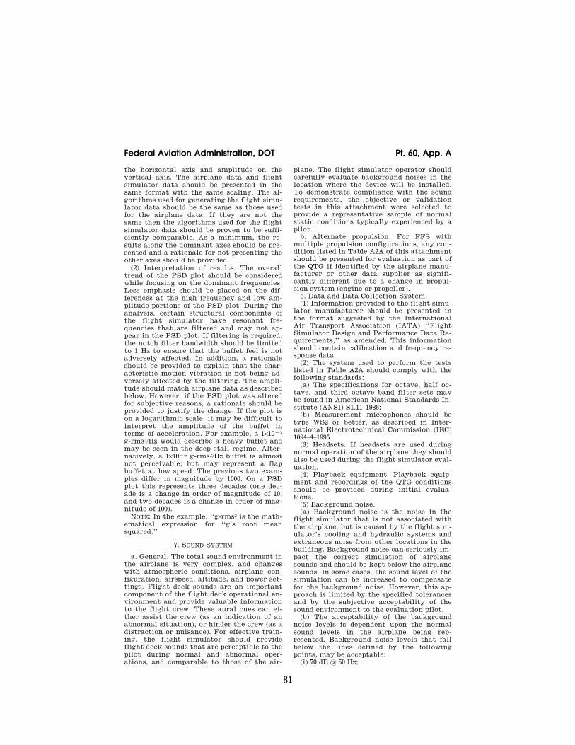
81
Federal Aviation Administration, DOT Pt. 60, App. A
the horizontal axis and amplitude on the vertical axis. The airplane data and flight simulator data should be presented in the same format with the same scaling. The al-gorithms used for generating the flight simu-lator data should be the same as those used for the airplane data. If they are not the same then the algorithms used for the flight simulator data should be proven to be suffi-ciently comparable. As a minimum, the re-sults along the dominant axes should be pre-sented and a rationale for not presenting the other axes should be provided.
(2) Interpretation of results. The overall trend of the PSD plot should be considered while focusing on the dominant frequencies. Less emphasis should be placed on the dif-ferences at the high frequency and low am-plitude portions of the PSD plot. During the analysis, certain structural components of the flight simulator have resonant fre-quencies that are filtered and may not ap-pear in the PSD plot. If filtering is required, the notch filter bandwidth should be limited to 1 Hz to ensure that the buffet feel is not adversely affected. In addition, a rationale should be provided to explain that the char-acteristic motion vibration is not being ad-versely affected by the filtering. The ampli-tude should match airplane data as described below. However, if the PSD plot was altered for subjective reasons, a rationale should be provided to justify the change. If the plot is on a logarithmic scale, it may be difficult to interpret the amplitude of the buffet in terms of acceleration. For example, a 1×10¥3 g-rms2/Hz would describe a heavy buffet and may be seen in the deep stall regime. Alter-natively, a 1×10¥6 g-rms2/Hz buffet is almost not perceivable; but may represent a flap buffet at low speed. The previous two exam-ples differ in magnitude by 1000. On a PSD plot this represents three decades (one dec-ade is a change in order of magnitude of 10; and two decades is a change in order of mag-nitude of 100).
NOTE: In the example, ‘‘g-rms2 is the math-ematical expression for ‘‘g’s root mean squared.’’
7. SOUND SYSTEM
a. General. The total sound environment in the airplane is very complex, and changes with atmospheric conditions, airplane con-figuration, airspeed, altitude, and power set-tings. Flight deck sounds are an important component of the flight deck operational en-vironment and provide valuable information to the flight crew. These aural cues can ei-ther assist the crew (as an indication of an abnormal situation), or hinder the crew (as a distraction or nuisance). For effective train-ing, the flight simulator should provide flight deck sounds that are perceptible to the pilot during normal and abnormal oper-ations, and comparable to those of the air-
plane. The flight simulator operator should carefully evaluate background noises in the location where the device will be installed. To demonstrate compliance with the sound requirements, the objective or validation tests in this attachment were selected to provide a representative sample of normal static conditions typically experienced by a pilot.
b. Alternate propulsion. For FFS with multiple propulsion configurations, any con-dition listed in Table A2A of this attachment should be presented for evaluation as part of the QTG if identified by the airplane manu-facturer or other data supplier as signifi-cantly different due to a change in propul-sion system (engine or propeller).
c. Data and Data Collection System. (1) Information provided to the flight simu-
lator manufacturer should be presented in the format suggested by the International Air Transport Association (IATA) ‘‘Flight Simulator Design and Performance Data Re-quirements,’’ as amended. This information should contain calibration and frequency re-sponse data.
(2) The system used to perform the tests listed in Table A2A should comply with the following standards:
(a) The specifications for octave, half oc-tave, and third octave band filter sets may be found in American National Standards In-stitute (ANSI) S1.11–1986;
(b) Measurement microphones should be type WS2 or better, as described in Inter-national Electrotechnical Commission (IEC) 1094–4–1995.
(3) Headsets. If headsets are used during normal operation of the airplane they should also be used during the flight simulator eval-uation.
(4) Playback equipment. Playback equip-ment and recordings of the QTG conditions should be provided during initial evalua-tions.
(5) Background noise. (a) Background noise is the noise in the
flight simulator that is not associated with the airplane, but is caused by the flight sim-ulator’s cooling and hydraulic systems and extraneous noise from other locations in the building. Background noise can seriously im-pact the correct simulation of airplane sounds and should be kept below the airplane sounds. In some cases, the sound level of the simulation can be increased to compensate for the background noise. However, this ap-proach is limited by the specified tolerances and by the subjective acceptability of the sound environment to the evaluation pilot.
(b) The acceptability of the background noise levels is dependent upon the normal sound levels in the airplane being rep-resented. Background noise levels that fall below the lines defined by the following points, may be acceptable:
(i) 70 dB @ 50 Hz;
VerDate Mar<15>2010 18:16 Mar 01, 2012 Jkt 226045 PO 00000 Frm 00091 Fmt 8010 Sfmt 8002 Q:\14\14V2 ofr150 PsN: PC150

82
14 CFR Ch. I (1–1–12 Edition) Pt. 60, App. A
(ii) 55 dB @ 1000 Hz; (iii) 30 dB @ 16 kHz (NOTE: These limits are for unweighted 1/3
octave band sound levels. Meeting these lim-its for background noise does not ensure an acceptable flight simulator. Airplane sounds that fall below this limit require careful re-view and may require lower limits on back-ground noise.)
(6) Validation testing. Deficiencies in air-plane recordings should be considered when applying the specified tolerances to ensure that the simulation is representative of the airplane. Examples of typical deficiencies are:
(a) Variation of data between tail numbers; (b) Frequency response of microphones; (c) Repeatability of the measurements.
TABLE A2B—EXAMPLE OF CONTINUING QUALIFICATION FREQUENCY RESPONSE TEST TOLERANCE
Band center frequency Initial results (dBSPL)
Continuing qualification
results (dBSPL)
Absolute difference
50 ....................................................................................................................... 75.0 73.8 1.2 63 ....................................................................................................................... 75.9 75.6 0.3 80 ....................................................................................................................... 77.1 76.5 0.6 100 ..................................................................................................................... 78.0 78.3 0.3 125 ..................................................................................................................... 81.9 81.3 0.6 160 ..................................................................................................................... 79.8 80.1 0.3 200 ..................................................................................................................... 83.1 84.9 1.8 250 ..................................................................................................................... 78.6 78.9 0.3 315 ..................................................................................................................... 79.5 78.3 1.2 400 ..................................................................................................................... 80.1 79.5 0.6 500 ..................................................................................................................... 80.7 79.8 0.9 630 ..................................................................................................................... 81.9 80.4 1.5 800 ..................................................................................................................... 73.2 74.1 0.9 1000 ................................................................................................................... 79.2 80.1 0.9 1250 ................................................................................................................... 80.7 82.8 2.1 1600 ................................................................................................................... 81.6 78.6 3.0 2000 ................................................................................................................... 76.2 74.4 1.8 2500 ................................................................................................................... 79.5 80.7 1.2 3150 ................................................................................................................... 80.1 77.1 3.0 4000 ................................................................................................................... 78.9 78.6 0.3 5000 ................................................................................................................... 80.1 77.1 3.0 6300 ................................................................................................................... 80.7 80.4 0.3 8000 ................................................................................................................... 84.3 85.5 1.2 10000 ................................................................................................................. 81.3 79.8 1.5 12500 ................................................................................................................. 80.7 80.1 0.6 16000 ................................................................................................................. 71.1 71.1 0.0
Average ............................................................................................... ........................ ........................ 1.1
8. ADDITIONAL INFORMATION ABOUT FLIGHT SIMULATOR QUALIFICATION FOR NEW OR DE-RIVATIVE AIRPLANES
a. Typically, an airplane manufacturer’s approved final data for performance, han-dling qualities, systems or avionics is not available until well after a new or derivative airplane has entered service. However, flight crew training and certification often begins several months prior to the entry of the first airplane into service. Consequently, it may be necessary to use preliminary data pro-vided by the airplane manufacturer for in-terim qualification of flight simulators.
b. In these cases, the NSPM may accept certain partially validated preliminary air-plane and systems data, and early release (‘‘red label’’) avionics data in order to permit the necessary program schedule for training, certification, and service introduction.
c. Simulator sponsors seeking qualifica-tion based on preliminary data should con-sult the NSPM to make special arrange-
ments for using preliminary data for flight simulator qualification. The sponsor should also consult the airplane and flight simu-lator manufacturers to develop a data plan and flight simulator qualification plan.
d. The procedure to be followed to gain NSPM acceptance of preliminary data will vary from case to case and between airplane manufacturers. Each airplane manufactur-er’s new airplane development and test pro-gram is designed to suit the needs of the par-ticular project and may not contain the same events or sequence of events as another manufacturer’s program, or even the same manufacturer’s program for a different air-plane. Therefore, there cannot be a pre-scribed invariable procedure for acceptance of preliminary data, but instead there should be a statement describing the final sequence of events, data sources, and validation proce-dures agreed by the simulator sponsor, the airplane manufacturer, the flight simulator manufacturer, and the NSPM.
VerDate Mar<15>2010 18:16 Mar 01, 2012 Jkt 226045 PO 00000 Frm 00092 Fmt 8010 Sfmt 8002 Q:\14\14V2 ofr150 PsN: PC150

83
Federal Aviation Administration, DOT Pt. 60, App. A
NOTE: A description of airplane manufac-turer-provided data needed for flight simu-lator modeling and validation is to be found in the IATA Document ‘‘Flight Simulator Design and Performance Data Require-ments,’’ as amended.
e. The preliminary data should be the man-ufacturer’s best representation of the air-plane, with assurance that the final data will not significantly deviate from the prelimi-nary estimates. Data derived from these pre-dictive or preliminary techniques should be validated against available sources includ-ing, at least, the following:
(1) Manufacturer’s engineering report. The report should explain the predictive method used and illustrate past success of the meth-od on similar projects. For example, the manufacturer could show the application of the method to an earlier airplane model or predict the characteristics of an earlier model and compare the results to final data for that model.
(2) Early flight test results. This data is often derived from airplane certification tests, and should be used to maximum ad-vantage for early flight simulator valida-tion. Certain critical tests that would nor-mally be done early in the airplane certifi-cation program should be included to vali-date essential pilot training and certifi-cation maneuvers. These include cases where a pilot is expected to cope with an airplane failure mode or an engine failure. Flight test data that will be available early in the flight test program will depend on the airplane manufacturer’s flight test program design and may not be the same in each case. The flight test program of the airplane manufac-turer should include provisions for genera-tion of very early flight test results for flight simulator validation.
f. The use of preliminary data is not indefi-nite. The airplane manufacturer’s final data should be available within 12 months after the airplane’s first entry into service or as agreed by the NSPM, the simulator sponsor, and the airplane manufacturer. When apply-ing for interim qualification using prelimi-nary data, the simulator sponsor and the NSPM should agree on the update program. This includes specifying that the final data update will be installed in the flight simu-lator within a period of 12 months following the final data release, unless special condi-tions exist and a different schedule is accept-able. The flight simulator performance and handling validation would then be based on data derived from flight tests or from other approved sources. Initial airplane systems data should be updated after engineering tests. Final airplane systems data should also be used for flight simulator program-ming and validation.
g. Flight simulator avionics should stay essentially in step with airplane avionics (hardware and software) updates. The per-
mitted time lapse between airplane and flight simulator updates should be minimal. It may depend on the magnitude of the up-date and whether the QTG and pilot training and certification are affected. Differences in airplane and flight simulator avionics versions and the resulting effects on flight simulator qualification should be agreed be-tween the simulator sponsor and the NSPM. Consultation with the flight simulator man-ufacturer is desirable throughout the quali-fication process.
h. The following describes an example of the design data and sources that might be used in the development of an interim quali-fication plan.
(1) The plan should consist of the develop-ment of a QTG based upon a mix of flight test and engineering simulation data. For data collected from specific airplane flight tests or other flights, the required design model or data changes necessary to support an acceptable Proof of Match (POM) should be generated by the airplane manufacturer.
(2) For proper validation of the two sets of data, the airplane manufacturer should com-pare their simulation model responses against the flight test data, when driven by the same control inputs and subjected to the same atmospheric conditions as recorded in the flight test. The model responses should result from a simulation where the following systems are run in an integrated fashion and are consistent with the design data released to the flight simulator manufacturer:
(a) Propulsion; (b) Aerodynamics; (c) Mass properties; (d) Flight controls; (e) Stability augmentation; and (f) Brakes/landing gear. i. A qualified test pilot should be used to
assess handling qualities and performance evaluations for the qualification of flight simulators of new airplane types.
END INFORMATION
lllllllllllllllllllllll
BEGIN QPS REQUIREMENT
9. ENGINEERING SIMULATOR—VALIDATION DATA
a. When a fully validated simulation (i.e., validated with flight test results) is modified due to changes to the simulated airplane configuration, the airplane manufacturer or other acceptable data supplier must coordi-nate with the NSPM if they propose to sup-ply validation data from an ‘‘audited’’ engi-neering simulator/simulation to selectively supplement flight test data. The NSPM must be provided an opportunity to audit the engi-neering simulation or the engineering simu-lator used to generate the validation data. Validation data from an audited engineering simulation may be used for changes that are
VerDate Mar<15>2010 18:16 Mar 01, 2012 Jkt 226045 PO 00000 Frm 00093 Fmt 8010 Sfmt 8002 Q:\14\14V2 ofr150 PsN: PC150

84
14 CFR Ch. I (1–1–12 Edition) Pt. 60, App. A
incremental in nature. Manufacturers or other data suppliers must be able to dem-onstrate that the predicted changes in air-craft performance are based on acceptable aeronautical principles with proven success history and valid outcomes. This must in-clude comparisons of predicted and flight test validated data.
b. Airplane manufacturers or other accept-able data suppliers seeking to use an engi-neering simulator for simulation validation data as an alternative to flight-test derived validation data, must contact the NSPM and provide the following:
(1) A description of the proposed aircraft changes, a description of the proposed sim-ulation model changes, and the use of an in-tegral configuration management process, including a description of the actual simula-tion model modifications that includes a step-by-step description leading from the original model(s) to the current model(s).
(2) A schedule for review by the NSPM of the proposed plan and the subsequent valida-tion data to establish acceptability of the proposal.
(3) Validation data from an audited engi-neering simulator/simulation to supplement specific segments of the flight test data.
c. To be qualified to supply engineering simulator validation data, for aerodynamic, engine, flight control, or ground handling models, an airplane manufacturer or other acceptable data supplier must:
(1) Be able to verify their ability able to: (a) Develop and implement high fidelity
simulation models; and (b) Predict the handling and performance
characteristics of an airplane with sufficient accuracy to avoid additional flight test ac-tivities for those handling and performance characteristics.
(2) Have an engineering simulator that: (a) Is a physical entity, complete with a
flight deck representative of the simulated class of airplane;
(b) Has controls sufficient for manual flight;
(c) Has models that run in an integrated manner;
(d) Has fully flight-test validated simula-tion models as the original or baseline sim-ulation models;
(e) Has an out-of-the-flight deck visual sys-tem;
(f) Has actual avionics boxes interchange-able with the equivalent software simula-tions to support validation of released soft-ware;
(g) Uses the same models as released to the training community (which are also used to produce stand-alone proof-of-match and checkout documents);
(h) Is used to support airplane development and certification; and
(i) Has been found to be a high fidelity rep-resentation of the airplane by the manufac-
turer’s pilots (or other acceptable data sup-plier), certificate holders, and the NSPM.
(3) Use the engineering simulator/simula-tion to produce a representative set of inte-grated proof-of-match cases.
(4) Use a configuration control system cov-ering hardware and software for the oper-ating components of the engineering simu-lator/simulation.
(5) Demonstrate that the predicted effects of the change(s) are within the provisions of sub-paragraph ‘‘a’’ of this section, and con-firm that additional flight test data are not required.
d. Additional Requirements for Validation Data
(1) When used to provide validation data, an engineering simulator must meet the sim-ulator standards currently applicable to training simulators except for the data pack-age.
(2) The data package used must be: (a) Comprised of the engineering pre-
dictions derived from the airplane design, de-velopment, or certification process;
(b) Based on acceptable aeronautical prin-ciples with proven success history and valid outcomes for aerodynamics, engine oper-ations, avionics operations, flight control ap-plications, or ground handling;
(c) Verified with existing flight-test data; and
(d) Applicable to the configuration of a production airplane, as opposed to a flight- test airplane.
(3) Where engineering simulator data are used as part of a QTG, an essential match must exist between the training simulator and the validation data.
(4) Training flight simulator(s) using these baseline and modified simulation models must be qualified to at least internationally recognized standards, such as contained in the ICAO Document 9625, the ‘‘Manual of Cri-teria for the Qualification of Flight Simula-tors.’’
END QPS REQUIREMENT
lllllllllllllllllllllll
10. [RESERVED]
11. VALIDATION TEST TOLERANCES
lllllllllllllllllllllll
BEGIN INFORMATION
a. Non-Flight-Test Tolerances (1) If engineering simulator data or other
non-flight-test data are used as an allowable form of reference validation data for the ob-jective tests listed in Table A2A of this at-tachment, the data provider must supply a well-documented mathematical model and testing procedure that enables a replication of the engineering simulation results within
VerDate Mar<15>2010 18:16 Mar 01, 2012 Jkt 226045 PO 00000 Frm 00094 Fmt 8010 Sfmt 8002 Q:\14\14V2 ofr150 PsN: PC150
85
Federal Aviation Administration, DOT Pt. 60, App. A
20% of the corresponding flight test toler-ances.
b. Background (1) The tolerances listed in Table A2A of
this attachment are designed to measure the quality of the match using flight-test data as a reference.
(2) Good engineering judgment should be applied to all tolerances in any test. A test is failed when the results clearly fall outside of the prescribed tolerance(s).
(3) Engineering simulator data are accept-able because the same simulation models used to produce the reference data are also used to test the flight training simulator (i.e., the two sets of results should be ‘‘es-sentially’’ similar).
(4) The results from the two sources may differ for the following reasons:
(a) Hardware (avionics units and flight controls);
(b) Iteration rates; (c) Execution order; (d) Integration methods; (e) Processor architecture; (f) Digital drift, including: (i) Interpolation methods; (ii) Data handling differences; and (iii) Auto-test trim tolerances. (5) The tolerance limit between the ref-
erence data and the flight simulator results is generally 20% of the corresponding ‘‘flight-test’’ tolerances. However, there may be cases where the simulator models used are of higher fidelity, or the manner in which they are cascaded in the integrated testing loop have the effect of a higher fidelity, than those supplied by the data provider. Under these circumstances, it is possible that an error greater than 20% may be generated. An error greater than 20% may be acceptable if simulator sponsor can provide an adequate explanation.
(6) Guidelines are needed for the applica-tion of tolerances to engineering-simulator- generated validation data because:
(a) Flight-test data are often not available due to technical reasons;
(b) Alternative technical solutions are being advanced; and
(c) High costs.
12. VALIDATION DATA ROADMAP
a. Airplane manufacturers or other data suppliers should supply a validation data roadmap (VDR) document as part of the data package. A VDR document contains guid-
ance material from the airplane validation data supplier recommending the best pos-sible sources of data to be used as validation data in the QTG. A VDR is of special value when requesting interim qualification, quali-fication of simulators for airplanes certifi-cated prior to 1992, and qualification of alter-nate engine or avionics fits. A sponsor seek-ing to have a device qualified in accordance with the standards contained in this QPS ap-pendix should submit a VDR to the NSPM as early as possible in the planning stages. The NSPM is the final authority to approve the data to be used as validation material for the QTG. The NSPM and the Joint Aviation Au-thorities’ Synthetic Training Devices Advi-sory Board have committed to maintain a list of agreed VDRs.
b. The VDR should identify (in matrix for-mat) sources of data for all required tests. It should also provide guidance regarding the validity of these data for a specific engine type, thrust rating configuration, and the re-vision levels of all avionics affecting air-plane handling qualities and performance. The VDR should include rationale or expla-nation in cases where data or parameters are missing, engineering simulation data are to be used, flight test methods require expla-nation, or there is any deviation from data requirements. Additionally, the document should refer to other appropriate sources of validation data (e.g., sound and vibration data documents).
c. The Sample Validation Data Roadmap (VDR) for airplanes, shown in Table A2C, de-picts a generic roadmap matrix identifying sources of validation data for an abbreviated list of tests. This document is merely a sam-ple and does not provide actual data. A com-plete matrix should address all test condi-tions and provide actual data and data sources.
d. Two examples of rationale pages are pre-sented in Appendix F of the IATA ‘‘Flight Simulator Design and Performance Data Re-quirements.’’ These illustrate the type of airplane and avionics configuration informa-tion and descriptive engineering rationale used to describe data anomalies or provide an acceptable basis for using alternative data for QTG validation requirements.
END INFORMATION
lllllllllllllllllllllll
VerDate Mar<15>2010 18:16 Mar 01, 2012 Jkt 226045 PO 00000 Frm 00095 Fmt 8010 Sfmt 8002 Q:\14\14V2 ofr150 PsN: PC150

86
14 CFR Ch. I (1–1–12 Edition) Pt. 60, App. A
VerDate Mar<15>2010 18:16 Mar 01, 2012 Jkt 226045 PO 00000 Frm 00096 Fmt 8010 Sfmt 8002 Q:\14\14V2 ofr150 PsN: PC150 ER
09M
Y08
.002
</G
PH
>
87
Federal Aviation Administration, DOT Pt. 60, App. A
BEGIN INFORMATION
lllllllllllllllllllllll
13. ACCEPTANCE GUIDELINES FOR ALTERNATIVE ENGINES DATA.
a. Background
(1) For a new airplane type, the majority of flight validation data are collected on the first airplane configuration with a ‘‘base-line’’ engine type. These data are then used to validate all flight simulators representing that airplane type.
(2) Additional flight test validation data may be needed for flight simulators rep-resenting an airplane with engines of a dif-ferent type than the baseline, or for engines with thrust rating that is different from pre-viously validated configurations.
(3) When a flight simulator with alternate engines is to be qualified, the QTG should contain tests against flight test validation data for selected cases where engine dif-ferences are expected to be significant.
b. Approval Guidelines For Validating Alternate Engine Applications
(1) The following guidelines apply to flight simulators representing airplanes with alter-nate engine applications or with more than one engine type or thrust rating.
(2) Validation tests can be segmented into two groups, those that are dependent on en-gine type or thrust rating and those that are not.
(3) For tests that are independent of engine type or thrust rating, the QTG can be based on validation data from any engine applica-tion. Tests in this category should be des-ignated as independent of engine type or thrust rating.
(4) For tests that are affected by engine type, the QTG should contain selected en-gine-specific flight test data sufficient to validate that particular airplane-engine con-figuration. These effects may be due to en-gine dynamic characteristics, thrust levels or engine-related airplane configuration changes. This category is primarily charac-terized by variations between different en-gine manufacturers’ products, but also in-cludes differences due to significant engine design changes from a previously flight-vali-dated configuration within a single engine type. See Table A2D, Alternate Engine Vali-dation Flight Tests in this section for a list of acceptable tests.
(5) Alternate engine validation data should be based on flight test data, except as noted in sub-paragraphs 13.c.(1) and (2), or where other data are specifically allowed (e.g., en-gineering simulator/simulation data). If cer-tification of the flight characteristics of the airplane with a new thrust rating (regardless of percentage change) does require certifi-
cation flight testing with a comprehensive stability and control flight instrumentation package, then the conditions described in Table A2D in this section should be obtained from flight testing and presented in the QTG. Flight test data, other than throttle calibration data, are not required if the new thrust rating is certified on the airplane without need for a comprehensive stability and control flight instrumentation package.
(6) As a supplement to the engine-specific flight tests listed in Table A2D and baseline engine-independent tests, additional engine- specific engineering validation data should be provided in the QTG, as appropriate, to fa-cilitate running the entire QTG with the al-ternate engine configuration. The sponsor and the NSPM should agree in advance on the specific validation tests to be supported by engineering simulation data.
(7) A matrix or VDR should be provided with the QTG indicating the appropriate val-idation data source for each test.
(8) The flight test conditions in Table A2D are appropriate and should be sufficient to validate implementation of alternate en-gines in a flight simulator.
END INFORMATION
lllllllllllllllllllllll
BEGIN QPS REQUIREMENT
c. Test Requirements
(1) The QTG must contain selected engine- specific flight test data sufficient to validate the alternative thrust level when:
(a) the engine type is the same, but the thrust rating exceeds that of a previously flight-test validated configuration by five percent (5%) or more; or
(b) the engine type is the same, but the thrust rating is less than the lowest pre-viously flight-test validated rating by fifteen percent (15%) or more. See Table A2D for a list of acceptable tests.
(2) Flight test data is not required if the thrust increase is greater than 5%, but flight tests have confirmed that the thrust in-crease does not change the airplane’s flight characteristics.
(3) Throttle calibration data (i.e., com-manded power setting parameter versus throttle position) must be provided to vali-date all alternate engine types and engine thrust ratings that are higher or lower than a previously validated engine. Data from a test airplane or engineering test bench with the correct engine controller (both hardware and software) are required.
END QPS REQUIREMENT
lllllllllllllllllllllll
BEGIN QPS REQUIREMENT
VerDate Mar<15>2010 18:16 Mar 01, 2012 Jkt 226045 PO 00000 Frm 00097 Fmt 8010 Sfmt 8002 Q:\14\14V2 ofr150 PsN: PC150
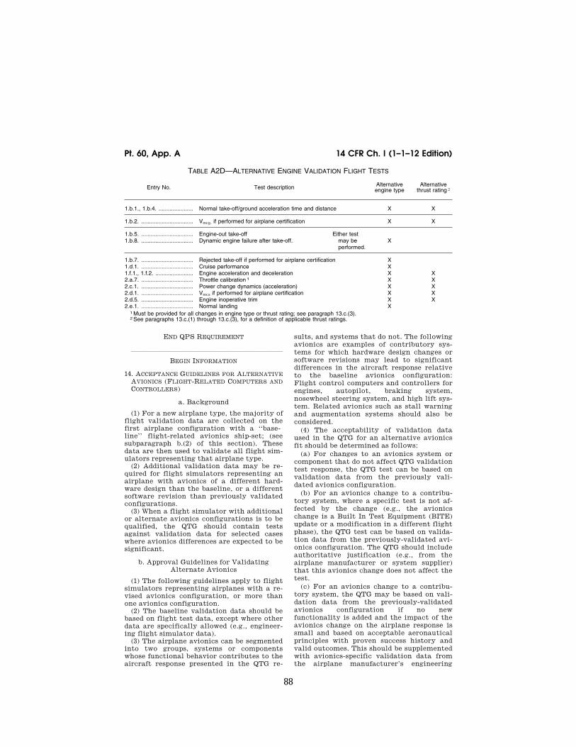
88
14 CFR Ch. I (1–1–12 Edition) Pt. 60, App. A
TABLE A2D—ALTERNATIVE ENGINE VALIDATION FLIGHT TESTS
Entry No. Test description Alternative engine type
Alternative thrust rating 2
1.b.1., 1.b.4. ...................... Normal take-off/ground acceleration time and distance X X
1.b.2. ................................. Vmcg, if performed for airplane certification X X
1.b.5. .................................1.b.8. .................................
Engine-out take-off Dynamic engine failure after take-off.
Either test may be performed.
X
1.b.7. ................................. Rejected take-off if performed for airplane certification X 1.d.1. ................................. Cruise performance X 1.f.1., 1.f.2. ........................ Engine acceleration and deceleration X X 2.a.7. ................................. Throttle calibration 1 X X 2.c.1. ................................. Power change dynamics (acceleration) X X 2.d.1. ................................. Vmca if performed for airplane certification X X 2.d.5. ................................. Engine inoperative trim X X 2.e.1. ................................. Normal landing X
1 Must be provided for all changes in engine type or thrust rating; see paragraph 13.c.(3). 2 See paragraphs 13.c.(1) through 13.c.(3), for a definition of applicable thrust ratings.
END QPS REQUIREMENT
lllllllllllllllllllllll
BEGIN INFORMATION
14. ACCEPTANCE GUIDELINES FOR ALTERNATIVE AVIONICS (FLIGHT-RELATED COMPUTERS AND CONTROLLERS)
a. Background
(1) For a new airplane type, the majority of flight validation data are collected on the first airplane configuration with a ‘‘base-line’’ flight-related avionics ship-set; (see subparagraph b.(2) of this section). These data are then used to validate all flight sim-ulators representing that airplane type.
(2) Additional validation data may be re-quired for flight simulators representing an airplane with avionics of a different hard-ware design than the baseline, or a different software revision than previously validated configurations.
(3) When a flight simulator with additional or alternate avionics configurations is to be qualified, the QTG should contain tests against validation data for selected cases where avionics differences are expected to be significant.
b. Approval Guidelines for Validating Alternate Avionics
(1) The following guidelines apply to flight simulators representing airplanes with a re-vised avionics configuration, or more than one avionics configuration.
(2) The baseline validation data should be based on flight test data, except where other data are specifically allowed (e.g., engineer-ing flight simulator data).
(3) The airplane avionics can be segmented into two groups, systems or components whose functional behavior contributes to the aircraft response presented in the QTG re-
sults, and systems that do not. The following avionics are examples of contributory sys-tems for which hardware design changes or software revisions may lead to significant differences in the aircraft response relative to the baseline avionics configuration: Flight control computers and controllers for engines, autopilot, braking system, nosewheel steering system, and high lift sys-tem. Related avionics such as stall warning and augmentation systems should also be considered.
(4) The acceptability of validation data used in the QTG for an alternative avionics fit should be determined as follows:
(a) For changes to an avionics system or component that do not affect QTG validation test response, the QTG test can be based on validation data from the previously vali-dated avionics configuration.
(b) For an avionics change to a contribu-tory system, where a specific test is not af-fected by the change (e.g., the avionics change is a Built In Test Equipment (BITE) update or a modification in a different flight phase), the QTG test can be based on valida-tion data from the previously-validated avi-onics configuration. The QTG should include authoritative justification (e.g., from the airplane manufacturer or system supplier) that this avionics change does not affect the test.
(c) For an avionics change to a contribu-tory system, the QTG may be based on vali-dation data from the previously-validated avionics configuration if no new functionality is added and the impact of the avionics change on the airplane response is small and based on acceptable aeronautical principles with proven success history and valid outcomes. This should be supplemented with avionics-specific validation data from the airplane manufacturer’s engineering
VerDate Mar<15>2010 18:16 Mar 01, 2012 Jkt 226045 PO 00000 Frm 00098 Fmt 8010 Sfmt 8002 Q:\14\14V2 ofr150 PsN: PC150

89
Federal Aviation Administration, DOT Pt. 60, App. A
simulation, generated with the revised avi-onics configuration. The QTG should also in-clude an explanation of the nature of the change and its effect on the airplane re-sponse.
(d) For an avionics change to a contribu-tory system that significantly affects some tests in the QTG or where new functionality is added, the QTG should be based on valida-tion data from the previously validated avi-onics configuration and supplemental avi-onics-specific flight test data sufficient to validate the alternate avionics revision. Ad-ditional flight test validation data may not be needed if the avionics changes were cer-tified without the need for testing with a comprehensive flight instrumentation pack-age. The airplane manufacturer should co-ordinate flight simulator data requirements, in advance with the NSPM.
(5) A matrix or ‘‘roadmap’’ should be pro-vided with the QTG indicating the appro-priate validation data source for each test. The roadmap should include identification of the revision state of those contributory avi-onics systems that could affect specific test responses if changed.
15. TRANSPORT DELAY TESTING
a. This paragraph explains how to deter-mine the introduced transport delay through the flight simulator system so that it does not exceed a specific time delay. The trans-port delay should be measured from control inputs through the interface, through each of the host computer modules and back through the interface to motion, flight in-strument, and visual systems. The transport delay should not exceed the maximum allow-able interval.
b. Four specific examples of transport delay are:
(1) Simulation of classic non-computer controlled aircraft;
(2) Simulation of computer controlled air-craft using real airplane black boxes;
(3) Simulation of computer controlled air-craft using software emulation of airplane boxes;
(4) Simulation using software avionics or re-hosted instruments.
c. Figure A2C illustrates the total trans-port delay for a non-computer-controlled air-plane or the classic transport delay test. Since there are no airplane-induced delays for this case, the total transport delay is equivalent to the introduced delay.
d. Figure A2D illustrates the transport delay testing method using the real airplane controller system.
e. To obtain the induced transport delay for the motion, instrument and visual signal, the delay induced by the airplane controller should be subtracted from the total trans-port delay. This difference represents the in-troduced delay and should not exceed the standards prescribed in Table A1A.
f. Introduced transport delay is measured from the flight deck control input to the re-action of the instruments and motion and visual systems (See Figure A2C).
g. The control input may also be intro-duced after the airplane controller system and the introduced transport delay measured directly from the control input to the reac-tion of the instruments, and simulator mo-tion and visual systems (See Figure A2D).
h. Figure A2E illustrates the transport delay testing method used on a flight simu-lator that uses a software emulated airplane controller system.
i. It is not possible to measure the intro-duced transport delay using the simulated airplane controller system architecture for the pitch, roll and yaw axes. Therefore, the signal should be measured directly from the pilot controller. The flight simulator manu-facturer should measure the total transport delay and subtract the inherent delay of the actual airplane components because the real airplane controller system has an inherent delay provided by the airplane manufacturer. The flight simulator manufacturer should ensure that the introduced delay does not ex-ceed the standards prescribed in Table A1A.
j. Special measurements for instrument signals for flight simulators using a real air-plane instrument display system instead of a simulated or re-hosted display. For flight in-strument systems, the total transport delay should be measured and the inherent delay of the actual airplane components subtracted to ensure that the introduced delay does not exceed the standards prescribed in Table A1A.
(1) Figure A2FA illustrates the transport delay procedure without airplane display simulation. The introduced delay consists of the delay between the control movement and the instrument change on the data bus.
(2) Figure A2FB illustrates the modified testing method required to measure intro-duced delay due to software avionics or re- hosted instruments. The total simulated in-strument transport delay is measured and the airplane delay should be subtracted from this total. This difference represents the in-troduced delay and should not exceed the standards prescribed in Table A1A. The in-herent delay of the airplane between the data bus and the displays is indicated in fig-ure A2FA. The display manufacturer should provide this delay time.
k. Recorded signals. The signals recorded to conduct the transport delay calculations should be explained on a schematic block diagram. The flight simulator manufacturer should also provide an explanation of why each signal was selected and how they relate to the above descriptions.
l. Interpretation of results. Flight simu-lator results vary over time from test to test due to ‘‘sampling uncertainty.’’ All flight simulators run at a specific rate where all
VerDate Mar<15>2010 18:16 Mar 01, 2012 Jkt 226045 PO 00000 Frm 00099 Fmt 8010 Sfmt 8002 Q:\14\14V2 ofr150 PsN: PC150

90
14 CFR Ch. I (1–1–12 Edition) Pt. 60, App. A
modules are executed sequentially in the host computer. The flight controls input can occur at any time in the iteration, but these data will not be processed before the start of the new iteration. For example, a flight sim-ulator running at 60 Hz may have a dif-ference of as much as 16.67 msec between test results. This does not mean that the test has failed. Instead, the difference is attributed to variations in input processing. In some con-ditions, the host simulator and the visual
system do not run at the same iteration rate, so the output of the host computer to the visual system will not always be syn-chronized.
m. The transport delay test should account for both daylight and night modes of oper-ation of the visual system. In both cases, the tolerances prescribed in Table A1A must be met and the motion response should occur before the end of the first video scan con-taining new information.
VerDate Mar<15>2010 18:16 Mar 01, 2012 Jkt 226045 PO 00000 Frm 00100 Fmt 8010 Sfmt 8002 Q:\14\14V2 ofr150 PsN: PC150

91
Federal Aviation Administration, DOT Pt. 60, App. A
VerDate Mar<15>2010 18:16 Mar 01, 2012 Jkt 226045 PO 00000 Frm 00101 Fmt 8010 Sfmt 8006 Q:\14\14V2 ofr150 PsN: PC150 ER
09M
Y08
.003
</G
PH
>

92
14 CFR Ch. I (1–1–12 Edition) Pt. 60, App. A
lllllllllllllllllllllll
BEGIN INFORMATION
16. CONTINUING QUALIFICATION EVALUATIONS— VALIDATION TEST DATA PRESENTATION
a. Background
(1) The MQTG is created during the initial evaluation of a flight simulator. This is the master document, as amended, to which flight simulator continuing qualification evaluation test results are compared.
(2) The currently accepted method of pre-senting continuing qualification evaluation test results is to provide flight simulator re-sults over-plotted with reference data. Test results are carefully reviewed to determine if the test is within the specified tolerances. This can be a time consuming process, par-ticularly when reference data exhibits rapid variations or an apparent anomaly requiring engineering judgment in the application of the tolerances. In these cases, the solution is to compare the results to the MQTG. The continuing qualification results are com-
pared to the results in the MQTG for accept-ance. The flight simulator operator and the NSPM should look for any change in the flight simulator performance since initial qualification.
b. Continuing Qualification Evaluation Test Results Presentation
(1) Flight simulator operators are encour-aged to over-plot continuing qualification validation test results with MQTG flight simulator results recorded during the initial evaluation and as amended. Any change in a validation test will be readily apparent. In addition to plotting continuing qualification validation test and MQTG results, operators may elect to plot reference data as well.
(2) There are no suggested tolerances be-tween flight simulator continuing qualifica-tion and MQTG validation test results. In-vestigation of any discrepancy between the MQTG and continuing qualification flight simulator performance is left to the discre-tion of the flight simulator operator and the NSPM.
VerDate Mar<15>2010 18:16 Mar 01, 2012 Jkt 226045 PO 00000 Frm 00102 Fmt 8010 Sfmt 8002 Q:\14\14V2 ofr150 PsN: PC150 ER
09M
Y08
.004
</G
PH
>

93
Federal Aviation Administration, DOT Pt. 60, App. A
(3) Differences between the two sets of re-sults, other than variations attributable to repeatability issues that cannot be ex-plained, should be investigated.
(4) The flight simulator should retain the ability to over-plot both automatic and man-ual validation test results with reference data.
END INFORMATION
lllllllllllllllllllllll
BEGIN QPS REQUIREMENTS
17. ALTERNATIVE DATA SOURCES, PROCE-DURES, AND INSTRUMENTATION: LEVEL A AND LEVEL B SIMULATORS ONLY
a. Sponsors are not required to use the al-ternative data sources, procedures, and in-strumentation. However, a sponsor may choose to use one or more of the alternative sources, procedures, and instrumentation de-scribed in Table A2E.
END QPS REQUIREMENTS
lllllllllllllllllllllll
BEGIN INFORMATION
b. It has become standard practice for ex-perienced simulator manufacturers to use modeling techniques to establish data bases for new simulator configurations while awaiting the availability of actual flight test data. The data generated from the aero-dynamic modeling techniques is then com-pared to the flight test data when it becomes available. The results of such comparisons have become increasingly consistent, indi-cating that these techniques, applied with the appropriate experience, are dependable and accurate for the development of aero-dynamic models for use in Level A and Level B simulators.
c. Based on this history of successful com-parisons, the NSPM has concluded that those who are experienced in the development of aerodynamic models may use modeling tech-niques to alter the method for acquiring flight test data for Level A or Level B sim-ulators.
d. The information in Table A2E (Alter-native Data Sources, Procedures, and Instru-mentation) is presented to describe an ac-ceptable alternative to data sources for sim-ulator modeling and validation and an ac-ceptable alternative to the procedures and instrumentation traditionally used to gather such modeling and validation data.
(1) Alternative data sources that may be used for part or all of a data requirement are the Airplane Maintenance Manual, the Air-plane Flight Manual (AFM), Airplane Design Data, the Type Inspection Report (TIR), Cer-tification Data or acceptable supplemental flight test data.
(2) The sponsor should coordinate with the NSPM prior to using alternative data sources in a flight test or data gathering ef-fort.
e. The NSPM position regarding the use of these alternative data sources, procedures, and instrumentation is based on the fol-lowing presumptions:
(1) Data gathered through the alternative means does not require angle of attack (AOA) measurements or control surface posi-tion measurements for any flight test. How-ever, AOA can be sufficiently derived if the flight test program ensures the collection of acceptable level, unaccelerated, trimmed flight data. All of the simulator time history tests that begin in level, unaccelerated, and trimmed flight, including the three basic trim tests and ‘‘fly-by’’ trims, can be a suc-cessful validation of angle of attack by com-parison with flight test pitch angle. (Note: Due to the criticality of angle of attack in the development of the ground effects model, particularly critical for normal landings and landings involving cross-control input appli-cable to Level B simulators, stable ‘‘fly-by’’ trim data will be the acceptable norm for normal and cross-control input landing ob-jective data for these applications.)
(2) The use of a rigorously defined and fully mature simulation controls system model that includes accurate gearing and cable stretch characteristics (where applicable), determined from actual aircraft measure-ments. Such a model does not require con-trol surface position measurements in the flight test objective data in these limited ap-plications.
f. The sponsor is urged to contact the NSPM for clarification of any issue regard-ing airplanes with reversible control sys-tems. Table A2E is not applicable to Com-puter Controlled Aircraft FFSs.
g. Utilization of these alternate data sources, procedures, and instrumentation (Table A2E) does not relieve the sponsor from compliance with the balance of the in-formation contained in this document rel-ative to Level A or Level B FFSs.
h. The term ‘‘inertial measurement sys-tem’’ is used in the following table to include the use of a functional global positioning system (GPS).
i. Synchronized video for the use of alter-native data sources, procedures, and instru-mentation should have:
(1) Sufficient resolution to allow mag-nification of the display to make appropriate measurement and comparisons; and
(2) Sufficient size and incremental mark-ing to allow similar measurement and com-parison. The detail provided by the video should provide sufficient clarity and accu-racy to measure the necessary parameter(s) to at least 1⁄2 of the tolerance authorized for the specific test being conducted and allow
VerDate Mar<15>2010 18:16 Mar 01, 2012 Jkt 226045 PO 00000 Frm 00103 Fmt 8010 Sfmt 8002 Q:\14\14V2 ofr150 PsN: PC150

94
14 CFR Ch. I (1–1–12 Edition) Pt. 60, App. A
an integration of the parameter(s) in ques-tion to obtain a rate of change.
END INFORMATION
lllllllllllllllllllllll
TABLE A2E—ALTERNATIVE DATA SOURCES, PROCEDURES, AND INSTRUMENTATION
QPS REQUIREMENTS The standards in this table are required if the data gathering methods described in paragraph
9 of Appendix A are not used.
Information
Table of objective tests Sim level Alternative data sources, procedures, and instrumentation
Notes
Test entry number and title A B
1.a.1. Performance. Taxi. Min-imum Radius turn.
X X TIR, AFM, or Design data may be used.
1.a.2. Performance. Taxi Rate of Turn vs. Nosewheel Steer-ing Angle.
X Data may be acquired by using a constant tiller position, measured with a pro-tractor or full rudder pedal application for steady state turn, and synchronized video of heading indicator. If less than full rudder pedal is used, pedal position must be recorded.
A single procedure may not be adequate for all airplane steering systems, therefore appropriate measurement procedures must be devised and proposed for NSPM con-currence.
1.b.1. Performance. Takeoff. Ground Acceleration Time and Distance.
X X Preliminary certification data may be used. Data may be acquired by using a stop watch, calibrated airspeed, and runway markers during a takeoff with power set before brake release. Power settings may be hand recorded. If an in-ertial measurement system is installed, speed and distance may be derived from acceleration measurements.
1.b.2. Performance. Takeoff. Minimum Control Speed— ground (Vmcg) using aero-dynamic controls only (per ap-plicable airworthiness stand-ard) or low speed, engine in-operative ground control char-acteristics.
X X Data may be acquired by using an inertial measurement system and a syn-chronized video of calibrated airplane instruments and force/position measure-ments of flight deck controls.
Rapid throttle reductions at speeds near Vmcg may be used while recording appro-priate parameters. The nosewheel must be free to caster, or equivalently freed of sideforce generation.
1.b.3. Performance. Takeoff. Minimum Unstick Speed (Vmu) or equivalent test to dem-onstrate early rotation takeoff characteristics.
X X Data may be acquired by using an inertial measurement system and a syn-chronized video of calibrated airplane instruments and the force/position measurements of flight deck controls.
1.b.4. Performance. Takeoff. Normal Takeoff.
X X Data may be acquired by using an inertial measurement system and a syn-chronized video of calibrated airplane instruments and force/position measure-ments of flight deck controls. AOA can be calculated from pitch attitude and flight path.
1.b.5. Performance. Takeoff. Critical Engine Failure during Takeoff.
X X Data may be acquired by using an inertial measurement system and a syn-chronized video of calibrated airplane instruments and force/position measure-ments of flight deck controls.
Record airplane dynamic re-sponse to engine failure and control inputs required to cor-rect flight path.
1.b.6. Performance. Takeoff. Crosswind Takeoff.
X X Data may be acquired by using an inertial measurement system and a syn-chronized video of calibrated airplane instruments and force/position measure-ments of flight deck controls.
The ‘‘1:7 law’’ to 100 feet (30 meters) is an acceptable wind profile.
VerDate Mar<15>2010 18:16 Mar 01, 2012 Jkt 226045 PO 00000 Frm 00104 Fmt 8010 Sfmt 8002 Q:\14\14V2 ofr150 PsN: PC150

95
Federal Aviation Administration, DOT Pt. 60, App. A
TABLE A2E—ALTERNATIVE DATA SOURCES, PROCEDURES, AND INSTRUMENTATION—Continued
QPS REQUIREMENTS The standards in this table are required if the data gathering methods described in paragraph
9 of Appendix A are not used.
Information
Table of objective tests Sim level Alternative data sources, procedures, and instrumentation
Notes
Test entry number and title A B
1.b.7. Performance. Takeoff. Rejected Takeoff.
X X Data may be acquired with a syn-chronized video of calibrated airplane instruments, thrust lever position, en-gine parameters, and distance (e.g., runway markers). A stop watch is re-quired..
1.c. 1. Performance. Climb. Nor-mal Climb all engines oper-ating..
X X Data may be acquired with a syn-chronized video of calibrated airplane instruments and engine power through-out the climb range.
1.c.2. Performance. Climb. One engine Inoperative Climb.
X X Data may be acquired with a syn-chronized video of calibrated airplane instruments and engine power through-out the climb range.
1.c.4. Performance. Climb. One Engine Inoperative Approach Climb (if operations in icing conditions are authorized).
X X Data may be acquired with a syn-chronized video of calibrated airplane instruments and engine power through-out the climb range.
1.d.1. Cruise/Descent. Level flight acceleration..
X X Data may be acquired with a syn-chronized video of calibrated airplane instruments, thrust lever position, en-gine parameters, and elapsed time.
1.d.2. Cruise/Descent. Level flight deceleration..
X X Data may be acquired with a syn-chronized video of calibrated airplane instruments, thrust lever position, en-gine parameters, and elapsed time.
1.d.4. Cruise/Descent. Idle de-scent.
X X Data may be acquired with a syn-chronized video of calibrated airplane instruments, thrust lever position, en-gine parameters, and elapsed time.
1.d.5. Cruise/Descent. Emer-gency Descent.
X X Data may be acquired with a syn-chronized video of calibrated airplane instruments, thrust lever position, en-gine parameters, and elapsed time.
1.e.1. Performance. Stopping. Deceleration time and dis-tance, using manual applica-tion of wheel brakes and no reverse thrust on a dry run-way.
X X Data may be acquired during landing tests using a stop watch, runway markers, and a synchronized video of calibrated airplane instruments, thrust lever posi-tion and the pertinent parameters of en-gine power.
1.e.2. Performance. Ground. Deceleration Time and Dis-tance, using reverse thrust and no wheel brakes.
X X Data may be acquired during landing tests using a stop watch, runway markers, and a synchronized video of calibrated airplane instruments, thrust lever posi-tion and pertinent parameters of engine power.
1.f.1. Performance. Engines. Acceleration.
X X Data may be acquired with a syn-chronized video recording of engine in-struments and throttle position.
1.f.2. Performance. Engines. Deceleration.
X X Data may be acquired with a syn-chronized video recording of engine in-struments and throttle position.
VerDate Mar<15>2010 18:16 Mar 01, 2012 Jkt 226045 PO 00000 Frm 00105 Fmt 8010 Sfmt 8002 Q:\14\14V2 ofr150 PsN: PC150

96
14 CFR Ch. I (1–1–12 Edition) Pt. 60, App. A
TABLE A2E—ALTERNATIVE DATA SOURCES, PROCEDURES, AND INSTRUMENTATION—Continued
QPS REQUIREMENTS The standards in this table are required if the data gathering methods described in paragraph
9 of Appendix A are not used.
Information
Table of objective tests Sim level Alternative data sources, procedures, and instrumentation
Notes
Test entry number and title A B
2.a.1.a. Handling Qualities. Stat-ic Control Checks. Pitch Con-troller Position vs. Force and Surface Position Calibration.
X X Surface position data may be acquired from flight data recorder (FDR) sensor or, if no FDR sensor, at selected, sig-nificant column positions (encom-passing significant column position data points), acceptable to the NSPM, using a control surface protractor on the ground. Force data may be acquired by using a hand held force gauge at the same column position data points.
For airplanes with reversible control systems, surface po-sition data acquisition should be accomplished with winds less than 5 kts.
2.a.2.a. Handling Qualities. Stat-ic Control Checks. Roll Con-troller Position vs. Force and Surface Position Calibration.
X X Surface position data may be acquired from flight data recorder (FDR) sensor or, if no FDR sensor, at selected, sig-nificant wheel positions (encompassing significant wheel position data points), acceptable to the NSPM, using a con-trol surface protractor on the ground. Force data may be acquired by using a hand held force gauge at the same wheel position data points.
For airplanes with reversible control systems, surface po-sition data acquisition should be accomplished with winds less than 5 kts.
2.a.3.a. Handling Qualities. Stat-ic Control Checks. Rudder Pedal Position vs. Force and Surface Position Calibration.
X X Surface position data may be acquired from flight data recorder (FDR) sensor or, if no FDR sensor, at selected, sig-nificant rudder pedal positions (encom-passing significant rudder pedal position data points), acceptable to the NSPM, using a control surface protractor on the ground. Force data may be acquired by using a hand held force gauge at the same rudder pedal position data points.
For airplanes with reversible control systems, surface po-sition data acquisition should be accomplished with winds less than 5 kts.
2.a.4. Handling Qualities. Static Control Checks. Nosewheel Steering Controller Force and Position.
X X Breakout data may be acquired with a hand held force gauge. The remainder of the force to the stops may be cal-culated if the force gauge and a pro-tractor are used to measure force after breakout for at least 25% of the total displacement capability.
2.a.5. Handling Qualities. Static Control Checks. Rudder Pedal Steering Calibration.
X X Data may be acquired through the use of force pads on the rudder pedals and a pedal position measurement device, to-gether with design data for nosewheel position.
2.a.6. Handling Qualities. Static Control Checks. Pitch Trim In-dicator vs. Surface Position Calibration.
X X Data may be acquired through calcula-tions.
2.a.7. Handling qualities. Static control tests. Pitch trim rate.
X X Data may be acquired by using a syn-chronized video of pitch trim indication and elapsed time through range of trim indication.
2.a.8. Handling Qualities. Static Control tests. Alignment of Flight deck Throttle Lever Angle vs. Selected engine pa-rameter.
X X Data may be acquired through the use of a temporary throttle quadrant scale to document throttle position. Use a syn-chronized video to record steady state instrument readings or hand-record steady state engine performance read-ings.
VerDate Mar<15>2010 18:16 Mar 01, 2012 Jkt 226045 PO 00000 Frm 00106 Fmt 8010 Sfmt 8002 Q:\14\14V2 ofr150 PsN: PC150

97
Federal Aviation Administration, DOT Pt. 60, App. A
TABLE A2E—ALTERNATIVE DATA SOURCES, PROCEDURES, AND INSTRUMENTATION—Continued
QPS REQUIREMENTS The standards in this table are required if the data gathering methods described in paragraph
9 of Appendix A are not used.
Information
Table of objective tests Sim level Alternative data sources, procedures, and instrumentation
Notes
Test entry number and title A B
2.a.9. Handling qualities. Static control tests. Brake pedal po-sition vs. force and brake sys-tem pressure calibration.
X X Use of design or predicted data is accept-able. Data may be acquired by meas-uring deflection at ‘‘zero’’ and ‘‘max-imum’’ and calculating deflections be-tween the extremes using the airplane design data curve.
2.c.1. Handling qualities. Longi-tudinal control tests. Power change dynamics.
X X Data may be acquired by using an inertial measurement system and a syn-chronized video of calibrated airplane instruments and throttle position.
2.c.2. Handling qualities. Longi-tudinal control tests. Flap/slat change dynamics.
X X Data may be acquired by using an inertial measurement system and a syn-chronized video of calibrated airplane instruments and flap/slat position.
2.c.3. Handling qualities. Longi-tudinal control tests. Spoiler/ speedbrake change dynamics.
X X Data may be acquired by using an inertial measurement system and a syn-chronized video of calibrated airplane instruments and spoiler/speedbrake po-sition.
2.c.4. Handling qualities. Longi-tudinal control tests. Gear change dynamics.
X X Data may be acquired by using an inertial measurement system and a syn-chronized video of calibrated airplane instruments and gear position.
2.c.5. Handling qualities. Longi-tudinal control tests. Longitu-dinal trim.
X X Data may be acquired through use of an inertial measurement system and a syn-chronized video of flight deck controls position (previously calibrated to show related surface position) and the engine instrument readings.
2.c.6. Handling qualities. Longi-tudinal control tests. Longitu-dinal maneuvering stability (stick force/g).
X X Data may be acquired through the use of an inertial measurement system and a synchronized video of calibrated air-plane instruments; a temporary, high resolution bank angle scale affixed to the attitude indicator; and a wheel and column force measurement indication.
2.c.7. Handling qualities. Longi-tudinal control tests. Longitu-dinal static stability.
X X Data may be acquired through the use of a synchronized video of airplane flight instruments and a hand held force gauge.
2.c.8. Handling qualities. Longi-tudinal control tests. Stall characteristics.
X X Data may be acquired through a syn-chronized video recording of a stop watch and calibrated airplane airspeed indicator. Hand-record the flight condi-tions and airplane configuration.
Airspeeds may be cross checked with those in the TIR and AFM.
2.c.9. Handling qualities. Longi-tudinal control tests. Phugoid dynamics.
X X Data may be acquired by using an inertial measurement system and a syn-chronized video of calibrated airplane instruments and force/position measure-ments of flight deck controls.
2.c.10. Handling qualities. Lon-gitudinal control tests. Short period dynamics.
X Data may be acquired by using an inertial measurement system and a syn-chronized video of calibrated airplane instruments and force/position measure-ments of flight deck controls.
VerDate Mar<15>2010 18:16 Mar 01, 2012 Jkt 226045 PO 00000 Frm 00107 Fmt 8010 Sfmt 8002 Q:\14\14V2 ofr150 PsN: PC150
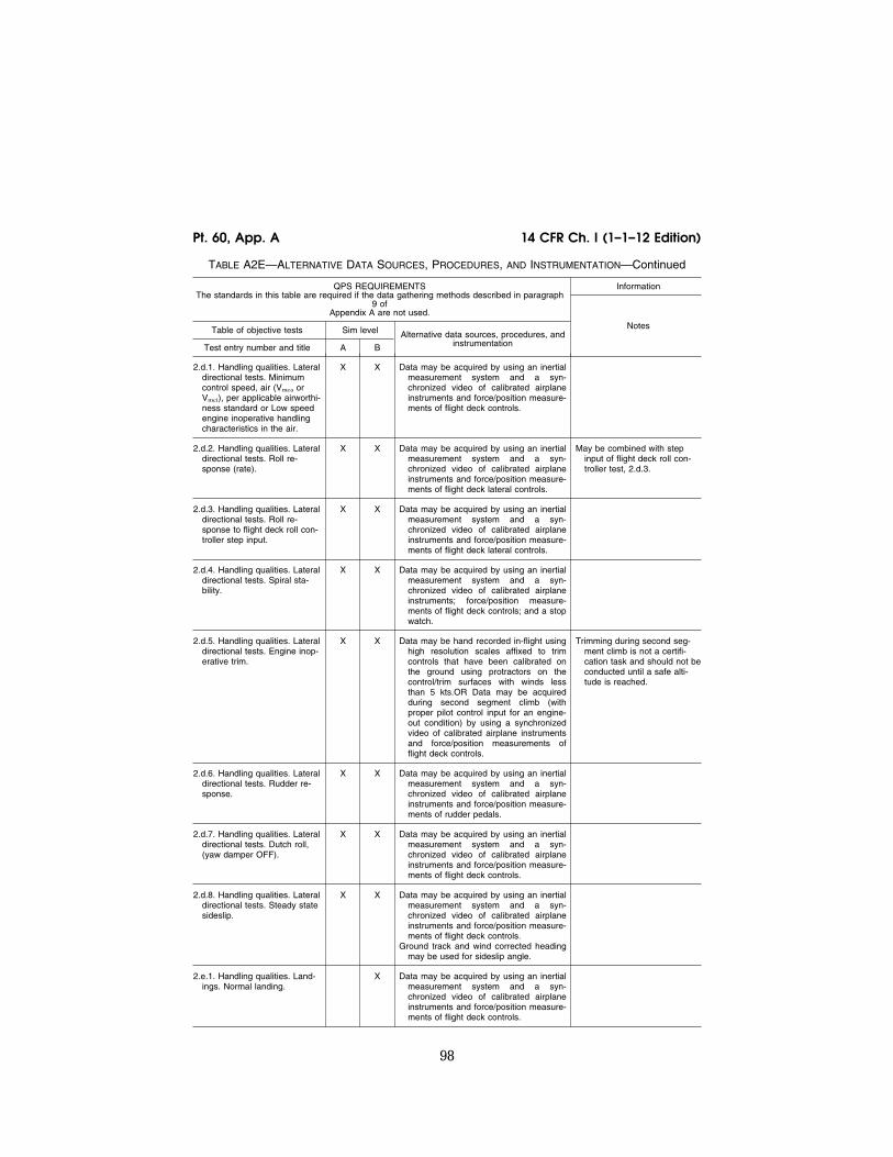
98
14 CFR Ch. I (1–1–12 Edition) Pt. 60, App. A
TABLE A2E—ALTERNATIVE DATA SOURCES, PROCEDURES, AND INSTRUMENTATION—Continued
QPS REQUIREMENTS The standards in this table are required if the data gathering methods described in paragraph
9 of Appendix A are not used.
Information
Table of objective tests Sim level Alternative data sources, procedures, and instrumentation
Notes
Test entry number and title A B
2.d.1. Handling qualities. Lateral directional tests. Minimum control speed, air (Vmca or Vmci), per applicable airworthi-ness standard or Low speed engine inoperative handling characteristics in the air.
X X Data may be acquired by using an inertial measurement system and a syn-chronized video of calibrated airplane instruments and force/position measure-ments of flight deck controls.
2.d.2. Handling qualities. Lateral directional tests. Roll re-sponse (rate).
X X Data may be acquired by using an inertial measurement system and a syn-chronized video of calibrated airplane instruments and force/position measure-ments of flight deck lateral controls.
May be combined with step input of flight deck roll con-troller test, 2.d.3.
2.d.3. Handling qualities. Lateral directional tests. Roll re-sponse to flight deck roll con-troller step input.
X X Data may be acquired by using an inertial measurement system and a syn-chronized video of calibrated airplane instruments and force/position measure-ments of flight deck lateral controls.
2.d.4. Handling qualities. Lateral directional tests. Spiral sta-bility.
X X Data may be acquired by using an inertial measurement system and a syn-chronized video of calibrated airplane instruments; force/position measure-ments of flight deck controls; and a stop watch.
2.d.5. Handling qualities. Lateral directional tests. Engine inop-erative trim.
X X Data may be hand recorded in-flight using high resolution scales affixed to trim controls that have been calibrated on the ground using protractors on the control/trim surfaces with winds less than 5 kts.OR Data may be acquired during second segment climb (with proper pilot control input for an engine- out condition) by using a synchronized video of calibrated airplane instruments and force/position measurements of flight deck controls.
Trimming during second seg-ment climb is not a certifi-cation task and should not be conducted until a safe alti-tude is reached.
2.d.6. Handling qualities. Lateral directional tests. Rudder re-sponse.
X X Data may be acquired by using an inertial measurement system and a syn-chronized video of calibrated airplane instruments and force/position measure-ments of rudder pedals.
2.d.7. Handling qualities. Lateral directional tests. Dutch roll, (yaw damper OFF).
X X Data may be acquired by using an inertial measurement system and a syn-chronized video of calibrated airplane instruments and force/position measure-ments of flight deck controls.
2.d.8. Handling qualities. Lateral directional tests. Steady state sideslip.
X X Data may be acquired by using an inertial measurement system and a syn-chronized video of calibrated airplane instruments and force/position measure-ments of flight deck controls.
Ground track and wind corrected heading may be used for sideslip angle.
2.e.1. Handling qualities. Land-ings. Normal landing.
X Data may be acquired by using an inertial measurement system and a syn-chronized video of calibrated airplane instruments and force/position measure-ments of flight deck controls.
VerDate Mar<15>2010 18:16 Mar 01, 2012 Jkt 226045 PO 00000 Frm 00108 Fmt 8010 Sfmt 8002 Q:\14\14V2 ofr150 PsN: PC150
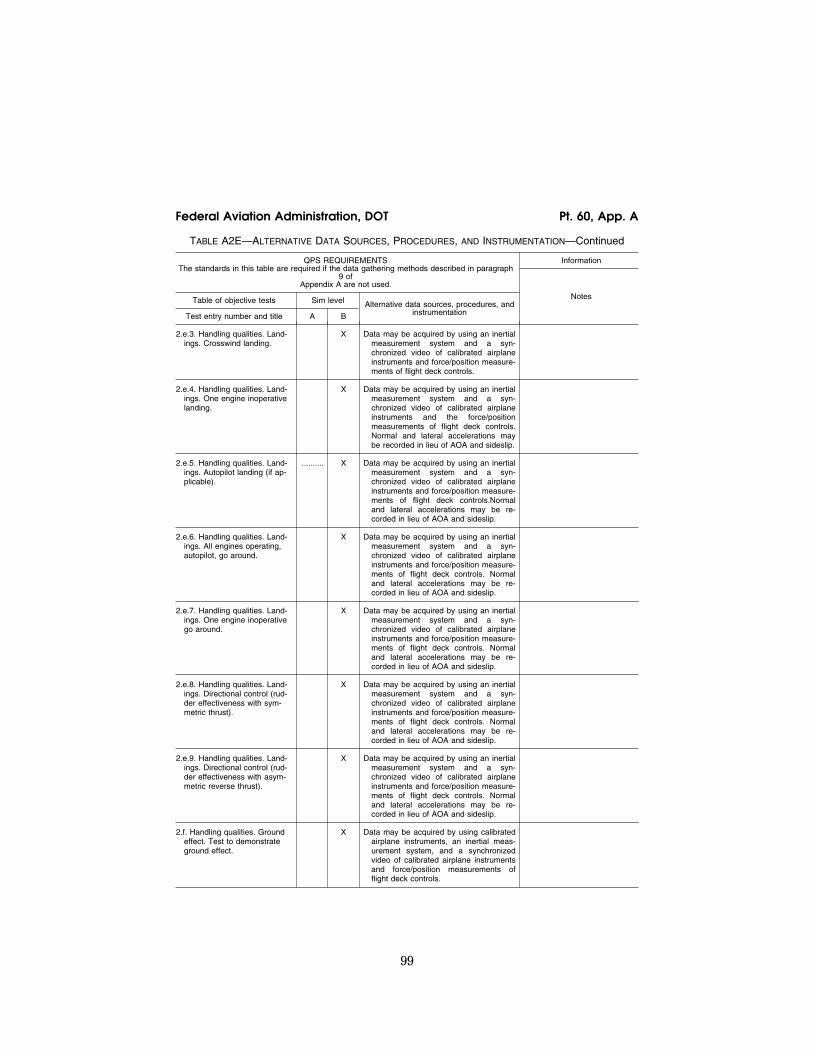
99
Federal Aviation Administration, DOT Pt. 60, App. A
TABLE A2E—ALTERNATIVE DATA SOURCES, PROCEDURES, AND INSTRUMENTATION—Continued
QPS REQUIREMENTS The standards in this table are required if the data gathering methods described in paragraph
9 of Appendix A are not used.
Information
Table of objective tests Sim level Alternative data sources, procedures, and instrumentation
Notes
Test entry number and title A B
2.e.3. Handling qualities. Land-ings. Crosswind landing.
X Data may be acquired by using an inertial measurement system and a syn-chronized video of calibrated airplane instruments and force/position measure-ments of flight deck controls.
2.e.4. Handling qualities. Land-ings. One engine inoperative landing.
X Data may be acquired by using an inertial measurement system and a syn-chronized video of calibrated airplane instruments and the force/position measurements of flight deck controls. Normal and lateral accelerations may be recorded in lieu of AOA and sideslip.
2.e.5. Handling qualities. Land-ings. Autopilot landing (if ap-plicable).
.......... X Data may be acquired by using an inertial measurement system and a syn-chronized video of calibrated airplane instruments and force/position measure-ments of flight deck controls.Normal and lateral accelerations may be re-corded in lieu of AOA and sideslip.
2.e.6. Handling qualities. Land-ings. All engines operating, autopilot, go around.
X Data may be acquired by using an inertial measurement system and a syn-chronized video of calibrated airplane instruments and force/position measure-ments of flight deck controls. Normal and lateral accelerations may be re-corded in lieu of AOA and sideslip.
2.e.7. Handling qualities. Land-ings. One engine inoperative go around.
X Data may be acquired by using an inertial measurement system and a syn-chronized video of calibrated airplane instruments and force/position measure-ments of flight deck controls. Normal and lateral accelerations may be re-corded in lieu of AOA and sideslip.
2.e.8. Handling qualities. Land-ings. Directional control (rud-der effectiveness with sym-metric thrust).
X Data may be acquired by using an inertial measurement system and a syn-chronized video of calibrated airplane instruments and force/position measure-ments of flight deck controls. Normal and lateral accelerations may be re-corded in lieu of AOA and sideslip.
2.e.9. Handling qualities. Land-ings. Directional control (rud-der effectiveness with asym-metric reverse thrust).
X Data may be acquired by using an inertial measurement system and a syn-chronized video of calibrated airplane instruments and force/position measure-ments of flight deck controls. Normal and lateral accelerations may be re-corded in lieu of AOA and sideslip.
2.f. Handling qualities. Ground effect. Test to demonstrate ground effect.
X Data may be acquired by using calibrated airplane instruments, an inertial meas-urement system, and a synchronized video of calibrated airplane instruments and force/position measurements of flight deck controls.
VerDate Mar<15>2010 18:16 Mar 01, 2012 Jkt 226045 PO 00000 Frm 00109 Fmt 8010 Sfmt 8002 Q:\14\14V2 ofr150 PsN: PC150

100
14 CFR Ch. I (1–1–12 Edition) Pt. 60, App. A
END INFORMATION
lllllllllllllllllllllll
ATTACHMENT 3 TO APPENDIX A TO PART 60— SIMULATOR SUBJECTIVE EVALUATION
lllllllllllllllllllllll
BEGIN QPS REQUIREMENTS
1. REQUIREMENTS
a. Except for special use airport models, described as Class III, all airport models re-quired by this part must be representations of real-world, operational airports or rep-resentations of fictional airports and must meet the requirements set out in Tables A3B or A3C of this attachment, as appropriate.
b. If fictional airports are used, the sponsor must ensure that navigational aids and all appropriate maps, charts, and other naviga-tional reference material for the fictional airports (and surrounding areas as nec-essary) are compatible, complete, and accu-rate with respect to the visual presentation of the airport model of this fictional airport. An SOC must be submitted that addresses navigation aid installation and performance and other criteria (including obstruction clearance protection) for all instrument ap-proaches to the fictional airports that are available in the simulator. The SOC must reference and account for information in the terminal instrument procedures manual and the construction and availability of the re-quired maps, charts, and other navigational material. This material must be clearly marked ‘‘for training purposes only.’’
c. When the simulator is being used by an instructor or evaluator for purposes of train-ing, checking, or testing under this chapter, only airport models classified as Class I, Class II, or Class III may be used by the in-structor or evaluator. Detailed descriptions/ definitions of these classifications are found in Appendix F of this part.
d. When a person sponsors an FFS main-tained by a person other than a U.S. certifi-cate holder, the sponsor is accountable for that FFS originally meeting, and continuing to meet, the criteria under which it was originally qualified and the appropriate Part 60 criteria, including the airport models that may be used by instructors or evaluators for purposes of training, checking, or testing under this chapter.
e. Neither Class II nor Class III airport vis-ual models are required to appear on the SOQ, and the method used for keeping in-structors and evaluators apprised of the air-port models that meet Class II or Class III requirements on any given simulator is at the option of the sponsor, but the method used must be available for review by the TPAA.
f. When an airport model represents a real world airport and a permanent change is
made to that real world airport (e.g., a new runway, an extended taxiway, a new lighting system, a runway closure) without a written extension grant from the NSPM (described in paragraph 1.g. of this section), an update to that airport model must be made in accord-ance with the following time limits:
(1) For a new airport runway, a runway ex-tension, a new airport taxiway, a taxiway ex-tension, or a runway/taxiway closure—with-in 90 days of the opening for use of the new airport runway, runway extension, new air-port taxiway, or taxiway extension; or with-in 90 days of the closure of the runway or taxiway.
(2) For a new or modified approach light system—within 45 days of the activation of the new or modified approach light system.
(3) For other facility or structural changes on the airport (e.g., new terminal, relocation of Air Traffic Control Tower)—within 180 days of the opening of the new or changed fa-cility or structure.
g. If a sponsor desires an extension to the time limit for an update to a visual scene or airport model or has an objection to what must be updated in the specific airport model requirement, the sponsor must pro-vide a written extension request to the NSPM stating the reason for the update delay and a proposed completion date, or ex-plain why the update is not necessary (i.e., why the identified airport change will not have an impact on flight training, testing, or checking). A copy of this request or objec-tion must also be sent to the POI/TCPM. The NSPM will send the official response to the sponsor and a copy to the POI/TCPM. If there is an objection, after consultation with the appropriate POI/TCPM regarding the training, testing, or checking impact, the NSPM will send the official response to the sponsor and a copy to the POI/TCPM.
END QPS REQUIREMENTS
lllllllllllllllllllllll
BEGIN INFORMATION
2. DISCUSSION
a. The subjective tests provide a basis for evaluating the capability of the simulator to perform over a typical utilization period; de-termining that the simulator accurately simulates each required maneuver, proce-dure, or task; and verifying correct oper-ation of the simulator controls, instruments, and systems. The items listed in the fol-lowing Tables are for simulator evaluation purposes only. They may not be used to limit or exceed the authorizations for use of a given level of simulator, as described on the SOQ, or as approved by the TPAA.
b. The tests in Table A3A, Operations Tasks, in this attachment, address pilot functions, including maneuvers and proce-dures (called flight tasks), and are divided by
VerDate Mar<15>2010 18:16 Mar 01, 2012 Jkt 226045 PO 00000 Frm 00110 Fmt 8010 Sfmt 8002 Q:\14\14V2 ofr150 PsN: PC150

101
Federal Aviation Administration, DOT Pt. 60, App. A
flight phases. The performance of these tasks by the NSPM includes an operational exam-ination of the visual system and special ef-fects. There are flight tasks included to ad-dress some features of advanced technology airplanes and innovative training programs. For example, ‘‘high angle-of-attack maneu-vering’’ is included to provide a required al-ternative to ‘‘approach to stalls’’ for air-planes employing flight envelope protection functions.
c. The tests in Table A3A, Operations Tasks, and Table A3G, Instructor Operating Station of this attachment, address the over-all function and control of the simulator in-cluding the various simulated environmental conditions; simulated airplane system oper-ations (normal, abnormal, and emergency); visual system displays; and special effects necessary to meet flight crew training, eval-uation, or flight experience requirements.
d. All simulated airplane systems func-tions will be assessed for normal and, where appropriate, alternate operations. Normal, abnormal, and emergency operations associ-ated with a flight phase will be assessed dur-ing the evaluation of flight tasks or events within that flight phase. Simulated airplane systems are listed separately under ‘‘Any Flight Phase’’ to ensure appropriate atten-tion to systems checks. Operational naviga-tion systems (including inertial navigation systems, global positioning systems, or other long-range systems) and the associated elec-tronic display systems will be evaluated if installed. The NSP pilot will include in his report to the TPAA, the effect of the system operation and any system limitation.
e. Simulators demonstrating a satisfactory circling approach will be qualified for the circling approach maneuver and may be ap-proved for such use by the TPAA in the spon-sor’s FAA-approved flight training program. To be considered satisfactory, the circling approach will be flown at maximum gross weight for landing, with minimum visibility for the airplane approach category, and must allow proper alignment with a landing run-way at least 90° different from the instru-ment approach course while allowing the pilot to keep an identifiable portion of the airport in sight throughout the maneuver (reference—14 CFR 91.175(e)).
f. At the request of the TPAA, the NSPM may assess a device to determine if it is ca-pable of simulating certain training activi-ties in a sponsor’s training program, such as a portion of a Line Oriented Flight Training (LOFT) scenario. Unless directly related to a requirement for the qualification level, the results of such an evaluation would not af-fect the qualification level of the simulator. However, if the NSPM determines that the simulator does not accurately simulate that training activity, the simulator would not be approved for that training activity.
g. The FAA intends to allow the use of Class III airport models when the sponsor provides the TPAA (or other regulatory au-thority) an appropriate analysis of the skills, knowledge, and abilities (SKAs) necessary for competent performance of the tasks in which this particular media element is used. The analysis should describe the ability of the FFS/visual media to provide an adequate environment in which the required SKAs are satisfactorily performed and learned. The analysis should also include the specific media element, such as the airport model. Additional sources of information on the conduct of task and capability analysis may be found on the FAA’s Advanced Qualifica-tion Program (AQP) Web site at: http:// www.faa.gov/educationlresearch/training/aqp/.
h. The TPAA may accept Class III airport models without individual observation pro-vided the sponsor provides the TPAA with an acceptable description of the process for de-termining the acceptability of a specific air-port model, outlines the conditions under which such an airport model may be used, and adequately describes what restrictions will be applied to each resulting airport or landing area model. Examples of situations that may warrant ClasslIII model designa-tion by the TPAA include the following:
(a) Training, testing, or checking on very low visibility operations, including SMGCS operations.
(b) Instrument operations training (includ-ing instrument takeoff, departure, arrival, approach, and missed approach training, testing, or checking) using—
(i) A specific model that has been geo-graphically ‘‘moved’’ to a different location and aligned with an instrument procedure for another airport.
(ii) A model that does not match changes made at the real-world airport (or landing area for helicopters) being modeled.
(iii) A model generated with an ‘‘off-board’’ or an ‘‘on-board’’ model development tool (by providing proper latitude/longitude ref-erence; correct runway or landing area ori-entation, length, width, marking, and light-ing information; and appropriate adjacent taxiway location) to generate a facsimile of a real world airport or landing area.
i. Previously qualified simulators with cer-tain early generation Computer Generated Image (CGI) visual systems, are limited by the capability of the Image Generator or the display system used. These systems are:
(1) Early CGI visual systems that are ex-cepted from the requirement of including runway numbers as a part of the specific runway marking requirements are:
(a) Link NVS and DNVS. (b) Novoview 2500 and 6000. (c) FlightSafety VITAL series up to, and
including, VITAL III, but not beyond. (d) Redifusion SP1, SP1T, and SP2.
VerDate Mar<15>2010 18:16 Mar 01, 2012 Jkt 226045 PO 00000 Frm 00111 Fmt 8010 Sfmt 8002 Q:\14\14V2 ofr150 PsN: PC150

102
14 CFR Ch. I (1–1–12 Edition) Pt. 60, App. A
(2) Early CGI visual systems are excepted from the requirement of including runway numbers unless the runways are used for LOFT training sessions. These LOFT airport models require runway numbers but only for the specific runway end (one direction) used in the LOFT session. The systems required to display runway numbers only for LOFT scenes are:
(a) FlightSafety VITAL IV. (b) Redifusion SP3 and SP3T. (c) Link-Miles Image II. (3) The following list of previously quali-
fied CGI and display systems are incapable of
generating blue lights. These systems are not required to have accurate taxi-way edge lighting:
(a) Redifusion SP1. (b) FlightSafety Vital IV. (c) Link-Miles Image II and Image IIT (d) XKD displays (even though the XKD
image generator is capable of generating blue colored lights, the display cannot ac-commodate that color).
END INFORMATION
lllllllllllllllllllllll
TABLE A3A—FUNCTIONS AND SUBJECTIVE TESTS
QPS Requirements
Entry No. Operations tasks Simulator level
A B C D
Tasks in this table are subject to evaluation if appropriate for the airplane simulated as indicated in the SOQ Configuration List or the level of simulator qualification involved. Items not installed or not functional on the simulator and, therefore, not appearing on the SOQ Configuration List, are not required to be listed as exceptions on the SOQ.
1. ......................... Preparation For Flight .........................................................................................................Preflight. Accomplish a functions check of all switches, indicators, systems, and equip-
ment at all crewmembers’ and instructors’ stations and determine that the flight deck design and functions are identical to that of the airplane simulated.
X X X X
2. ......................... Surface Operations (Pre-Take-Off)
2.a. ............... Engine Start
2.a.1. ..... Normal start ......................................................................................................................... X X X X
2.a.2. ..... Alternate start procedures ................................................................................................... X X X X
2.a.3. ..... Abnormal starts and shutdowns (e.g., hot/hung start, tail pipe fire) ................................... X X X X
2.b. ............... Pushback/Powerback .......................................................................................................... X X X
2.c. ............... Taxi
2.c.1. ..... Thrust response .................................................................................................................. X X X X
2.c.2. ..... Power lever friction .............................................................................................................. X X X X
2.c.3. ..... Ground handling .................................................................................................................. X X X X
2.c.4. ..... Nosewheel scuffing ............................................................................................................. X X
2.c.5. ..... Brake operation (normal and alternate/emergency) ........................................................... X X X X
2.c.6. ..... Brake fade (if applicable) .................................................................................................... X X X X
3. ......................... Take-off.
3.a. ............... Normal.
3.a.1. ..... Airplane/engine parameter relationships ............................................................................. X X X X
3.a.2. ..... Acceleration characteristics (motion) .................................................................................. X X X X
3.a.3. ..... Nosewheel and rudder steering .......................................................................................... X X X X
3.a.4. ..... Crosswind (maximum demonstrated) ................................................................................. X X X X
3.a.5. ..... Special performance (e.g., reduced V1, max de-rate, short field operations) .................... X X X X
3.a.6. ..... Low visibility take-off ........................................................................................................... X X X X
3.a.7. ..... Landing gear, wing flap leading edge device operation ..................................................... X X X X
VerDate Mar<15>2010 18:16 Mar 01, 2012 Jkt 226045 PO 00000 Frm 00112 Fmt 8010 Sfmt 8002 Q:\14\14V2 ofr150 PsN: PC150

103
Federal Aviation Administration, DOT Pt. 60, App. A
TABLE A3A—FUNCTIONS AND SUBJECTIVE TESTS—Continued
QPS Requirements
Entry No. Operations tasks Simulator level
A B C D
3.a.8. ..... Contaminated runway operation ......................................................................................... X X
3.b. ............... Abnormal/emergency
3.b.1. ..... Rejected Take-off ................................................................................................................ X X X X
3.b.2. ..... Rejected special performance (e.g., reduced V1, max de-rate, short field operations) ..... X X X X
3.b.3. ..... Takeoff with a propulsion system malfunction (allowing an analysis of causes, symp-toms, recognition, and the effects on aircraft performance and handling) at the fol-lowing points: ..(i) Prior to V1 decision speed ..........................................................................................(ii) Between V1 and Vr (rotation speed) ..........................................................................(iii) Between Vr and 500 feet above ground level ...........................................................
X X X X
3.b.4. ..... With wind shear ................................................................................................................... X X X X
3.b.5. ..... Flight control system failures, reconfiguration modes, manual reversion and associated handling.
X X X X
3.b.6. ..... Rejected takeoff with brake fade ........................................................................................ X X
3.b.7. ..... Rejected, contaminated runway .......................................................................................... X X
4. ......................... Climb.
4.a. ............... Normal ................................................................................................................................. X X X X
4.b. ............... One or more engines inoperative ....................................................................................... X X X X
5. ......................... Cruise
5.a. ............... Performance characteristics (speed vs. power) .................................................................. X X X X
5.b. ............... High altitude handling .......................................................................................................... X X X X
5.c. ............... High Mach number handling (Mach tuck, Mach buffet) and recovery (trim change) ......... X X X X
5.d. ............... Overspeed warning (in excess of Vmo or Mmo) ................................................................... X X X X
5.e. ............... High IAS handling ............................................................................................................... X X X X
6. ......................... Maneuvers
6.a. ............... High angle of attack, approach to stalls, stall warning, buffet, and g-break (take-off, cruise, approach, and landing configuration).
X X X X
6.b. ............... Flight envelope protection (high angle of attack, bank limit, overspeed, etc.) ................... X X X X
6.c. ............... Turns with/without speedbrake/spoilers deployed .............................................................. X X X X
6.d. ............... Normal and steep turns ....................................................................................................... X X X X
6.e. ............... In flight engine shutdown and restart (assisted and windmill) ............................................ X X X X
6.f. ................ Maneuvering with one or more engines inoperative, as appropriate ................................. X X X X
6.g. ............... Specific flight characteristics (e.g., direct lift control) .......................................................... X X X X
6.h. ............... Flight control system failures, reconfiguration modes, manual reversion and associated handling.
X X X X
7. ......................... Descent.
7.a. ............... Normal ................................................................................................................................. X X X X
7.b. ............... Maximum rate (clean and with speedbrake, etc.) ............................................................... X X X X
7.c. ............... With autopilot ....................................................................................................................... X X X X
VerDate Mar<15>2010 18:16 Mar 01, 2012 Jkt 226045 PO 00000 Frm 00113 Fmt 8010 Sfmt 8002 Q:\14\14V2 ofr150 PsN: PC150
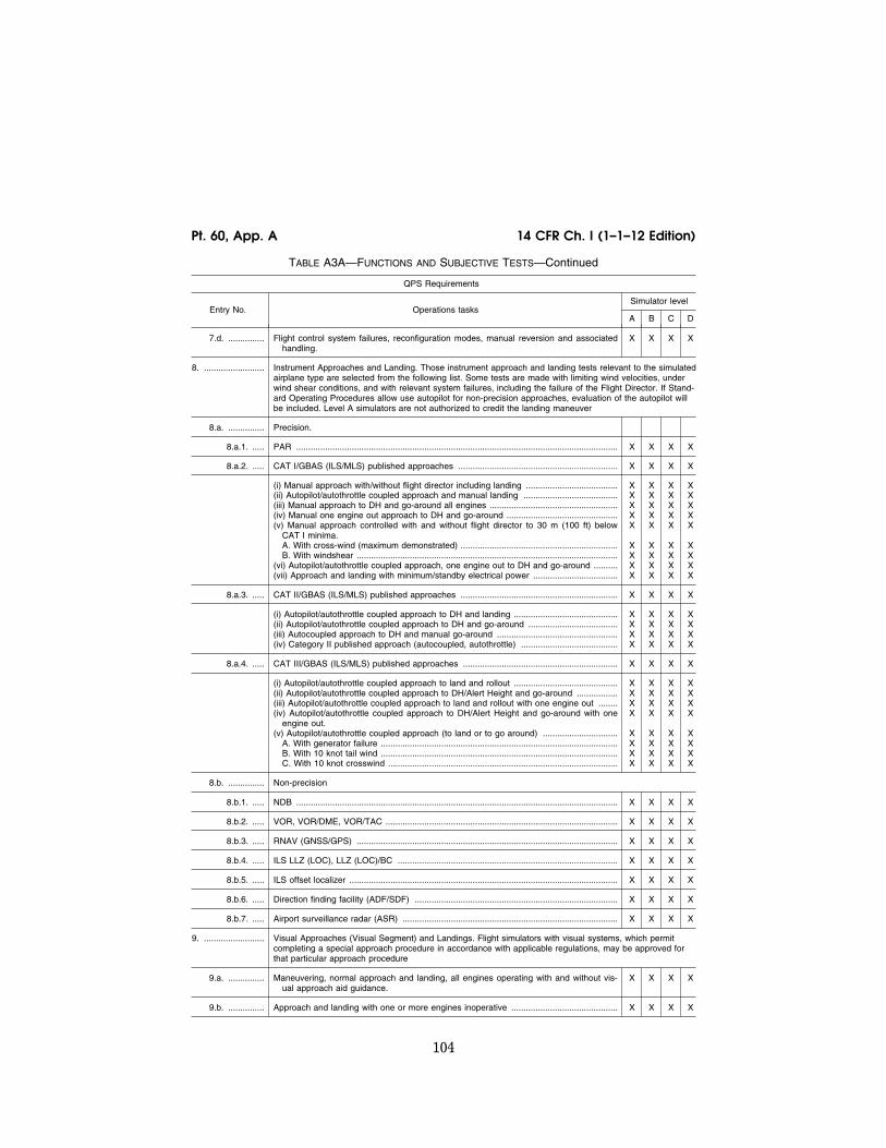
104
14 CFR Ch. I (1–1–12 Edition) Pt. 60, App. A
TABLE A3A—FUNCTIONS AND SUBJECTIVE TESTS—Continued
QPS Requirements
Entry No. Operations tasks Simulator level
A B C D
7.d. ............... Flight control system failures, reconfiguration modes, manual reversion and associated handling.
X X X X
8. ......................... Instrument Approaches and Landing. Those instrument approach and landing tests relevant to the simulated airplane type are selected from the following list. Some tests are made with limiting wind velocities, under wind shear conditions, and with relevant system failures, including the failure of the Flight Director. If Stand-ard Operating Procedures allow use autopilot for non-precision approaches, evaluation of the autopilot will be included. Level A simulators are not authorized to credit the landing maneuver
8.a. ............... Precision.
8.a.1. ..... PAR ..................................................................................................................................... X X X X
8.a.2. ..... CAT I/GBAS (ILS/MLS) published approaches .................................................................. X X X X
(i) Manual approach with/without flight director including landing ...................................... X X X X (ii) Autopilot/autothrottle coupled approach and manual landing ....................................... X X X X (iii) Manual approach to DH and go-around all engines ..................................................... X X X X (iv) Manual one engine out approach to DH and go-around .............................................. X X X X (v) Manual approach controlled with and without flight director to 30 m (100 ft) below
CAT I minima.X X X X
A. With cross-wind (maximum demonstrated) ................................................................. X X X X B. With windshear ............................................................................................................ X X X X
(vi) Autopilot/autothrottle coupled approach, one engine out to DH and go-around .......... X X X X (vii) Approach and landing with minimum/standby electrical power ................................... X X X X
8.a.3. ..... CAT II/GBAS (ILS/MLS) published approaches ................................................................. X X X X
(i) Autopilot/autothrottle coupled approach to DH and landing ........................................... X X X X (ii) Autopilot/autothrottle coupled approach to DH and go-around ..................................... X X X X (iii) Autocoupled approach to DH and manual go-around .................................................. X X X X (iv) Category II published approach (autocoupled, autothrottle) ........................................ X X X X
8.a.4. ..... CAT III/GBAS (ILS/MLS) published approaches ................................................................ X X X X
(i) Autopilot/autothrottle coupled approach to land and rollout ........................................... X X X X (ii) Autopilot/autothrottle coupled approach to DH/Alert Height and go-around ................. X X X X (iii) Autopilot/autothrottle coupled approach to land and rollout with one engine out ........ X X X X (iv) Autopilot/autothrottle coupled approach to DH/Alert Height and go-around with one
engine out.X X X X
(v) Autopilot/autothrottle coupled approach (to land or to go around) ............................... X X X X A. With generator failure .................................................................................................. X X X X B. With 10 knot tail wind .................................................................................................. X X X X C. With 10 knot crosswind ............................................................................................... X X X X
8.b. ............... Non-precision
8.b.1. ..... NDB ..................................................................................................................................... X X X X
8.b.2. ..... VOR, VOR/DME, VOR/TAC ................................................................................................ X X X X
8.b.3. ..... RNAV (GNSS/GPS) ............................................................................................................ X X X X
8.b.4. ..... ILS LLZ (LOC), LLZ (LOC)/BC ........................................................................................... X X X X
8.b.5. ..... ILS offset localizer ............................................................................................................... X X X X
8.b.6. ..... Direction finding facility (ADF/SDF) .................................................................................... X X X X
8.b.7. ..... Airport surveillance radar (ASR) ......................................................................................... X X X X
9. ......................... Visual Approaches (Visual Segment) and Landings. Flight simulators with visual systems, which permit completing a special approach procedure in accordance with applicable regulations, may be approved for that particular approach procedure
9.a. ............... Maneuvering, normal approach and landing, all engines operating with and without vis-ual approach aid guidance.
X X X X
9.b. ............... Approach and landing with one or more engines inoperative ............................................ X X X X
VerDate Mar<15>2010 18:16 Mar 01, 2012 Jkt 226045 PO 00000 Frm 00114 Fmt 8010 Sfmt 8002 Q:\14\14V2 ofr150 PsN: PC150

105
Federal Aviation Administration, DOT Pt. 60, App. A
TABLE A3A—FUNCTIONS AND SUBJECTIVE TESTS—Continued
QPS Requirements
Entry No. Operations tasks Simulator level
A B C D
9.c. ............... Operation of landing gear, flap/slats and speedbrakes (normal and abnormal) ................ X X X X
9.d. ............... Approach and landing with crosswind (max. demonstrated) .............................................. X X X X
9.e. ............... Approach to land with wind shear on approach ................................................................. X X X X
9.f. ................ Approach and landing with flight control system failures, reconfiguration modes, manual reversion and associated handling (most significant degradation which is probable).
X X X X
9.g. ............... Approach and landing with trim malfunctions ..................................................................... X X X X
9.g.1. ..... Longitudinal trim malfunction .............................................................................................. X X X X
9.g.2. ..... Lateral-directional trim malfunction ..................................................................................... X X X X
9.h. ............... Approach and landing with standby (minimum) electrical/hydraulic power ........................ X X X X
9.i. ................ Approach and landing from circling conditions (circling approach) .................................... X X X X
9.j. ................ Approach and landing from visual traffic pattern ................................................................ X X X X
9.k. ............... Approach and landing from non-precision approach .......................................................... X X X X
9.l. ................ Approach and landing from precision approach ................................................................. X X X X
9.m. .............. Approach procedures with vertical guidance (APV), e.g., SBAS ....................................... X X X X
10. ....................... Missed Approach
10.a. ............. All engines ........................................................................................................................... X X X X
10.b. ............. One or more engine(s) out .................................................................................................. X X X X
10.c. ............. With flight control system failures, reconfiguration modes, manual reversion and associ-ated handling.
X X X X
11. ....................... Surface Operations (Landing roll and taxi).
11.a. ............. Spoiler operation ................................................................................................................. X X X X
11.b. ............. Reverse thrust operation ..................................................................................................... X X X X
11.c. ............. Directional control and ground handling, both with and without reverse thrust ................. X X X
11.d. ............. Reduction of rudder effectiveness with increased reverse thrust (rear pod-mounted en-gines).
X X X
11.e. ............. Brake and anti-skid operation with dry, patchy wet, wet on rubber residue, and patchy icy conditions.
X X
11.f. .............. Brake operation, to include auto-braking system where applicable ................................... X X X X
12. ....................... Any Flight Phase.
12.a. ............. Airplane and engine systems operation.
12.a.1. ... Air conditioning and pressurization (ECS) .......................................................................... X X X X
12.a.2. ... De-icing/anti-icing ................................................................................................................ X X X X
12.a.3. ... Auxiliary power unit (APU) .................................................................................................. X X X X
12.a.4. ... Communications .................................................................................................................. X X X X
12.a.5. ... Electrical .............................................................................................................................. X X X X
12.a.6. ... Fire and smoke detection and suppression ........................................................................ X X X X
12.a.7. ... Flight controls (primary and secondary) ............................................................................. X X X X
VerDate Mar<15>2010 18:16 Mar 01, 2012 Jkt 226045 PO 00000 Frm 00115 Fmt 8010 Sfmt 8002 Q:\14\14V2 ofr150 PsN: PC150

106
14 CFR Ch. I (1–1–12 Edition) Pt. 60, App. A
TABLE A3A—FUNCTIONS AND SUBJECTIVE TESTS—Continued
QPS Requirements
Entry No. Operations tasks Simulator level
A B C D
12.a.8. ... Fuel and oil, hydraulic and pneumatic ................................................................................ X X X X
12.a.9. ... Landing gear ....................................................................................................................... X X X X
12.a.10. Oxygen ................................................................................................................................ X X X X
12.a.11. Engine ................................................................................................................................. X X X X
12.a.12. Airborne radar ..................................................................................................................... X X X X
12.a.13. Autopilot and Flight Director ................................................................................................ X X X X
12.a.14. Collision avoidance systems. (e.g., (E)GPWS, TCAS) ....................................................... X X X X
12.a.15. Flight control computers including stability and control augmentation ............................... X X X X
12.a.16. Flight display systems ......................................................................................................... X X X X
12.a.17. Flight management computers ............................................................................................ X X X X
12.a.18. Head-up guidance, head-up displays ................................................................................. X X X X
12.a.19. Navigation systems ............................................................................................................. X X X X
12.a.20. Stall warning/avoidance ...................................................................................................... X X X X
12.a.21. Wind shear avoidance equipment ....................................................................................... X X X X
12.a.22. Automatic landing aids. ....................................................................................................... X X X X
12.b. ............. Airborne procedures
12.b.1. ... Holding ................................................................................................................................ X X X X
12.b.2. ... Air hazard avoidance (traffic, weather) ............................................................................... X X
12.b.3. ... Wind shear .......................................................................................................................... X X
12.b.4. ... Effects of airframe ice ......................................................................................................... X X
12.c. ............. Engine shutdown and parking
12.c.1. ... Engine and systems operation ............................................................................................ X X X X
12.c.2. ... Parking brake operation ...................................................................................................... X X X X
TABLE A3B—FUNCTIONS AND SUBJECTIVE TESTS
QPS Requirements
Entry No. For qualification at the stated level—Class I airport models Simulator level
A B C D
This table specifies the minimum airport model content and functionality to qualify a simulator at the indicated level. This table applies only to the airport models required for simulator qualification; i.e., one airport model for Level A and Level B simula-tors; three airport models for Level C and Level D simulators.
Begin QPS Requirements
1. ........................... Functional test content requirements for Level A and Level B simulators. The following is the minimum air-port model content requirement to satisfy visual capability tests, and provides suitable visual cues to allow completion of all functions and subjective tests described in this attachment for simulators at Levels A and B.
1.a. ................. A minimum of one (1) representative airport model. This model identification must be acceptable to the sponsor’s TPAA, selectable from the IOS, and listed on the SOQ.
X X
VerDate Mar<15>2010 18:16 Mar 01, 2012 Jkt 226045 PO 00000 Frm 00116 Fmt 8010 Sfmt 8002 Q:\14\14V2 ofr150 PsN: PC150

107
Federal Aviation Administration, DOT Pt. 60, App. A
TABLE A3B—FUNCTIONS AND SUBJECTIVE TESTS—Continued
QPS Requirements
Entry No. For qualification at the stated level—Class I airport models Simulator level
A B C D
1.b. ................. The fidelity of the airport model must be sufficient for the aircrew to visually identify the airport; determine the position of the simulated airplane within a night visual scene; successfully accomplish take-offs, approaches, and landings; and maneuver around the airport on the ground as necessary.
X X
1.c. ................. Runways: ........................................................................................................................... X X
1.c.1. ....... Visible runway number ...................................................................................................... X X
1.c.2. ....... Runway threshold elevations and locations must be modeled to provide sufficient cor-relation with airplane systems (e.g., altimeter).
X X
1.c.3. ....... Runway surface and markings .......................................................................................... X X
1.c.4. ....... Lighting for the runway in use including runway edge and centerline ............................. X X
1.c.5. ....... Lighting, visual approach aid and approach lighting of appropriate colors ...................... X X
1.c.6. ....... Representative taxiway lights ............................................................................................ X X
2. ........................... Functional test content requirements for Level C and Level D simulators. The following is the minimum air-port model content requirement to satisfy visual capability tests, and provide suitable visual cues to allow completion of all functions and subjective tests described in this attachment for simulators at Levels C and D. Not all of the elements described in this section must be found in a single airport model. However, all of the elements described in this section must be found throughout a combination of the three (3) airport models described in entry 2.a.
2.a. ................. A minimum of three (3) representative airport models. The model identifications must be acceptable to the sponsor’s TPAA, selectable from the IOS, and listed on the SOQ.
X X
2.a.1. ....... Night and Twilight (Dusk) scenes required ....................................................................... X X
2.a.2. ....... Daylight scenes required ................................................................................................... X
2.b. .......... Two parallel runways and one crossing runway, displayed simultaneously; at least two of the runways must be able to be lighted fully and simultaneously.
Note: This requirement may be demonstrated at either a fictional airport or a real-world airport. However, if a fictional airport is used, this airport must be listed on the SOQ.
X X
2.c. ................. Runway threshold elevations and locations must be modeled to provide sufficient cor-relation with airplane systems (e.g., HGS, GPS, altimeter); slopes in runways, taxiways, and ramp areas must not cause distracting or unrealistic effects, including pilot eye-point height variation.
X X
2.d. ................. Representative airport buildings, structures and lighting .................................................. X X
2.e. ................. At least one useable gate, at the appropriate height (required only for those airplanes that typically operate from terminal gates).
X X
2.f. .................. Representative moving and static gate clutter (e.g., other airplane, power carts, tugs, fuel trucks, and additional gates).
X X
2.g. ................. Representative gate/apron markings (e.g., hazard markings, lead-in lines, gate num-bering) and lighting.
X X
2.h. ................. Representative runway markings, lighting, and signage, including a windsock that gives appropriate wind cues.
X X
2.i. .................. Representative taxiway markings, lighting, and signage necessary for position identi-fication, and to taxi from parking to a designated runway and return to parking.
X X
2.j. .................. A low visibility taxi route (e.g., Surface Movement Guidance Control System, follow-me truck, daylight taxi lights) must also be demonstrated.
X
2.k. ................. Representative moving and static ground traffic (e.g., vehicular and airplane), including the capability to present ground hazards (e.g., another airplane crossing the active runway).
X X
VerDate Mar<15>2010 18:16 Mar 01, 2012 Jkt 226045 PO 00000 Frm 00117 Fmt 8010 Sfmt 8002 Q:\14\14V2 ofr150 PsN: PC150

108
14 CFR Ch. I (1–1–12 Edition) Pt. 60, App. A
TABLE A3B—FUNCTIONS AND SUBJECTIVE TESTS—Continued
QPS Requirements
Entry No. For qualification at the stated level—Class I airport models Simulator level
A B C D
2.l. .................. Representative moving airborne traffic, including the capability to present air hazards (e.g., airborne traffic on a possible collision course).
X X
2.m. ................ Representative depiction of terrain and obstacles as well as significant and identifiable natural and cultural features, within 25 NM of the reference airport.
X X
2.n. ................. Appropriate approach lighting systems and airfield lighting for a VFR circuit and land-ing, non-precision approaches and landings, and Category I, II and III precision ap-proaches and landings.
X X
2.o. ................. Representative gate docking aids or a marshaller ........................................................... X X
2.p. ................. Portrayal of physical relationships known to cause landing illusions (e.g., short run-ways, landing approaches over water, uphill or downhill runways, rising terrain on the approach path).
This requirement may be met by a SOC and a demonstration of two landing illusions. The illusions are not required to be beyond the normal operational capabilities of the airplane being simulated. The demonstrated illusions must be available to the in-structor or check airman at the IOS for training, testing, checking, or experience ac-tivities.
X
2.q. ................. Portrayal of runway surface contaminants, including runway lighting reflections when wet and partially obscured lights when snow is present, or suitable alternative effects.
X
3. ........................... Airport model management. The following is the minimum airport model management requirements for simulators at Levels A, B, C, and D.
3.a. ................. Runway and approach lighting must fade into view in accordance with the environ-mental conditions set in the simulator, and the distance from the object.
X X X X
3.b. ................. The direction of strobe lights, approach lights, runway edge lights, visual landing aids, runway centerline lights, threshold lights, and touchdown zone lights must be rep-licated.
X X X X
4. ........................... Visual feature recognition. The following is the minimum distances at which runway features must be visi-ble for simulators at Levels A, B, C, and D. Distances are measured from runway threshold to an airplane aligned with the runway on an extended 3° glide-slope in simulated meteorological conditions that recreate the minimum distances for visibility. For circling approaches, all tests apply to the runway used for the ini-tial approach and to the runway of intended landing.
4.a. ................. Runway definition, strobe lights, approach lights, and runway edge white lights from 5 sm (8 km) of the runway threshold.
X X X X
4.b. ................. Visual Approach Aid lights (VASI or PAPI) from 5 sm (8 km) of the runway threshold .. X X
4.c. ................. Visual Approach Aid lights (VASI or PAPI) from 3 sm (5 km) of the runway threshold .. X X
4.d. ................. Runway centerline lights and taxiway definition from 3 sm (5 km) .................................. X X X X
4.e. ................. Threshold lights and touchdown zone lights from 2 sm (3 km) ........................................ X X X X
4.f. .................. Runway markings within range of landing lights for night scenes as required by the surface resolution test on day scenes.
X X X X
4.g. ................. For circling approaches, the runway of intended landing and associated lighting must fade into view in a non-distracting manner.
X X X X
VerDate Mar<15>2010 18:16 Mar 01, 2012 Jkt 226045 PO 00000 Frm 00118 Fmt 8010 Sfmt 8002 Q:\14\14V2 ofr150 PsN: PC150

109
Federal Aviation Administration, DOT Pt. 60, App. A
TABLE A3B—FUNCTIONS AND SUBJECTIVE TESTS—Continued
QPS Requirements
Entry No. For qualification at the stated level—Class I airport models Simulator level
A B C D
5. ........................... Airport model content. The following sets out the minimum requirements for what must be provided in an airport model and also identifies the other aspects of the airport environment that must correspond with that model for simulators at Levels A, B, C, and D. For circling approaches, all tests apply to the runway used for the initial approach and to the runway of intended landing. If all runways in an airport model used to meet the requirements of this attachment are not designated as ‘‘in use,’’ then the ‘‘in use’’ runways must be listed on the SOQ (e.g., KORD, Rwys 9R, 14L, 22R). Models of airports with more than one run-way must have all significant runways not ‘‘in-use’’ visually depicted for airport and runway recognition pur-poses. The use of white or off white light strings that identify the runway threshold, edges, and ends for twilight and night scenes are acceptable for this requirement. Rectangular surface depictions are accept-able for daylight scenes. A visual system’s capabilities must be balanced between providing airport models with an accurate representation of the airport and a realistic representation of the surrounding environ-ment. Airport model detail must be developed using airport pictures, construction drawings and maps, or other similar data, or developed in accordance with published regulatory material; however, this does not require that such models contain details that are beyond the design capability of the currently qualified vis-ual system. Only one ‘‘primary’’ taxi route from parking to the runway end will be required for each ‘‘in-use’’ runway.
5.a. ................. The surface and markings for each ‘‘in-use’’ runway must include the following:
5.a.1. ....... Threshold markings ........................................................................................................... X X X X
5.a.2. ....... Runway numbers ............................................................................................................... X X X X
5.a.3. ....... Touchdown zone markings ............................................................................................... X X X X
5.a.4. ....... Fixed distance markings .................................................................................................... X X X X
5.a.5. ....... Edge markings ................................................................................................................... X X X X
5.a.6. ....... Centerline stripes ............................................................................................................... X X X X
5.b. ................. Each runway designated as an ‘‘in-use’’ runway must include the following:
5.b.1. ....... The lighting for each ‘‘in-use’’ runway must include the following:
(i) Threshold lights ............................................................................................................. X X X X
(ii) Edge lights .................................................................................................................... X X X X
(iii) End lights ..................................................................................................................... X X X X
(iv) Centerline lights, if appropriate ................................................................................... X X X X
(v) Touchdown zone lights, if appropriate ......................................................................... X X X X
(vi) Leadoff lights, if appropriate ........................................................................................ X X X X
(vii) Appropriate visual landing aid(s) for that runway ...................................................... X X X X
(viii) Appropriate approach lighting system for that runway .............................................. X X X X
5.b.2. ....... The taxiway surface and markings associated with each ‘‘in-use’’ runway must include the following:
(i) Edge .............................................................................................................................. X X X X
(ii) Centerline ..................................................................................................................... X X X X
(iii) Runway hold lines ....................................................................................................... X X X X
(iv) ILS critical area marking ............................................................................................. X X X X
5.b.3. ....... The taxiway lighting associated with each ‘‘in-use’’ runway must include the following:
(i) Edge .............................................................................................................................. X X X X
(ii) Centerline, if appropriate .............................................................................................. X X X X
(iii) Runway hold and ILS critical area lights ..................................................................... X X X X
VerDate Mar<15>2010 18:16 Mar 01, 2012 Jkt 226045 PO 00000 Frm 00119 Fmt 8010 Sfmt 8002 Q:\14\14V2 ofr150 PsN: PC150

110
14 CFR Ch. I (1–1–12 Edition) Pt. 60, App. A
TABLE A3B—FUNCTIONS AND SUBJECTIVE TESTS—Continued
QPS Requirements
Entry No. For qualification at the stated level—Class I airport models Simulator level
A B C D
(iv) Edge lights of correct color ......................................................................................... X X
5.b.4. ....... Airport signage associated with each ‘‘in-use’’ runway must include the following:
(i) Distance remaining signs, if appropriate ...................................................................... X X X X
(ii) Signs at intersecting runways and taxiways ................................................................ X X X X
(iii) Signs described in entries 2.h. and 2.i. of this table ................................................... X X X X
5.b.5. ....... Required airport model correlation with other aspects of the airport environment simulation:
(i) The airport model must be properly aligned with the navigational aids that are asso-ciated with operations at the runway ‘‘in-use’’.
X X X X
(ii) The simulation of runway contaminants must be correlated with the displayed run-way surface and lighting where applicable.
X
6. ........................... Correlation with airplane and associated equipment. The following are the minimum correlation compari-sons that must be made for simulators at Levels A, B, C, and D.
6.a. ................. Visual system compatibility with aerodynamic programming ............................................ X X X X
6.b. ................. Visual cues to assess sink rate and depth perception during landings ........................... X X X
6.c. ................. Accurate portrayal of environment relating to flight simulator attitudes ............................ X X X X
6.d. ................. The airport model and the generated visual scene must correlate with integrated air-plane systems (e.g., terrain, traffic and weather avoidance systems and Head-up Guidance System (HGS)).
X X
6.e. ................. Representative visual effects for each visible, own-ship, airplane external light(s)—taxi and landing light lobes (including independent operation, if appropriate).
X X X X
6.f. .................. The effect of rain removal devices .................................................................................... X X
7. .................... Scene quality. The following are the minimum scene quality tests that must be conducted for simulators at Levels A, B, C, and D.
7.a. ................. Surfaces and textural cues must be free from apparent and distracting quantization (aliasing).
X X
7.b. ................. System capable of portraying full color realistic textural cues .......................................... X X
7.c. ................. The system light points must be free from distracting jitter, smearing or streaking ......... X X X X
7.d. ................. Demonstration of occulting through each channel of the system in an operational scene.
X X
7.e. ................. Demonstration of a minimum of ten levels of occulting through each channel of the system in an operational scene.
X X
7.f. .................. System capable of providing focus effects that simulate rain .......................................... X X
7.g. ................. System capable of providing focus effects that simulate light point perspective growth X X
7.h. ................. System capable of six discrete light step controls (0–5) .................................................. X X X X
8. ........................... Environmental effects. The following are the minimum environmental effects that must be available as indi-cated.
8.a. ................. The displayed scene corresponding to the appropriate surface contaminants and in-clude runway lighting reflections for wet, partially obscured lights for snow, or alter-native effects.
X X
8.a.1. ....... Special weather representations which include:
VerDate Mar<15>2010 18:16 Mar 01, 2012 Jkt 226045 PO 00000 Frm 00120 Fmt 8010 Sfmt 8002 Q:\14\14V2 ofr150 PsN: PC150

111
Federal Aviation Administration, DOT Pt. 60, App. A
TABLE A3B—FUNCTIONS AND SUBJECTIVE TESTS—Continued
QPS Requirements
Entry No. For qualification at the stated level—Class I airport models Simulator level
A B C D
(i) The sound, motion and visual effects of light, medium and heavy precipitation near a thunderstorm on take-off, approach, and landings at and below an altitude of 2,000 ft (600 m) above the airport surface and within a radius of 10 sm (16 km) from the airport.
X X
(ii) One airport with a snow scene to include terrain snow and snow-covered taxiways and runways.
X X
8.b. ................. In-cloud effects such as variable cloud density, speed cues and ambient changes ....... X X
8.c. ................. The effect of multiple cloud layers representing few, scattered, broken and overcast conditions giving partial or complete obstruction of the ground scene.
X X
8.d. ................. Visibility and RVR measured in terms of distance. Visibility/RVR checked at 2,000 ft (600 m) above the airport and at two heights below 2000 ft with at least 500 ft of separation between the measurements. The measurements must be taken within a radius of 10 sm (16 km) from the airport.
X X X X
8.e. ................. Patchy fog giving the effect of variable RVR .................................................................... X X
8.f. .................. Effects of fog on airport lighting such as halos and defocus ............................................ X X
8.g. ................. Effect of own-ship lighting in reduced visibility, such as reflected glare, including land-ing lights, strobes, and beacons.
X X
8.h. ................. Wind cues to provide the effect of blowing snow or sand across a dry runway or taxi-way selectable from the instructor station.
X X
9. ........................... Instructor control of the following: The following are the minimum instructor controls that must be available in simulators at Levels A, B, C, and D.
9.a. ................. Environmental effects, e.g., cloud base, cloud effects, cloud density, visibility in statute miles/kilometers and RVR in feet/meters.
X X X X
9.b. ................. Airport selection ................................................................................................................. X X X X
9.c. ................. Airport lighting, including variable intensity ....................................................................... X X X X
9.d. ................. Dynamic effects including ground and flight traffic ........................................................... X X
End QPS Requirement
Begin Information
10. ......................... An example of being able to ‘‘combine two airport models to achieve two ‘‘in-use’’ run-ways:
One runway designated as the ‘‘in use’’ runway in the first model of the airport, and the second runway designated as the ‘‘in use’’ runway in the second model of the same airport. For example, the clearance is for the ILS approach to Runway 27, Cir-cle to Land on Runway 18 right. Two airport visual models might be used: the first with Runway 27 designated as the ‘‘in use’’ runway for the approach to runway 27, and the second with Runway 18 Right designated as the ‘‘in use’’ runway. When the pilot breaks off the ILS approach to runway 27, the instructor may change to the second airport visual model in which runway 18 Right is designated as the ‘‘in use’’ runway, and the pilot would make a visual approach and landing. This process is ac-ceptable to the FAA as long as the temporary interruption due to the visual model change is not distracting to the pilot, does not cause changes in navigational radio frequencies, and does not cause undue instructor/evaluator time.
11. ......................... Sponsors are not required to provide every detail of a runway, but the detail that is provided should be correct within the capabilities of the system.
End Information
VerDate Mar<15>2010 18:16 Mar 01, 2012 Jkt 226045 PO 00000 Frm 00121 Fmt 8010 Sfmt 8002 Q:\14\14V2 ofr150 PsN: PC150

112
14 CFR Ch. I (1–1–12 Edition) Pt. 60, App. A
TABLE A3C—FUNCTIONS AND SUBJECTIVE TESTS
QPS requirements
Entry No. Additional airport models beyond minimum required for qualification—Class II airport mod-els
Simulator level
A B C D
This table specifies the minimum airport model content and functionality necessary to add airport models to a simulator’s model library, beyond those necessary for qualification at the stated level, without the necessity of further involvement of the NSPM or TPAA.
Begin QPS Requirements
1. .................... Airport model management. The following is the minimum airport model management requirements for simula-tors at Levels A, B, C, and D.
1.a. .......... The direction of strobe lights, approach lights, runway edge lights, visual landing aids, run-way centerline lights, threshold lights, and touchdown zone lights on the ‘‘in-use’’ runway must be replicated.
X X X X
2. .................... Visual feature recognition. The following are the minimum distances at which runway features must be visible for simulators at Levels A, B, C, and D. Distances are measured from runway threshold to an airplane aligned with the runway on an extended 3° glide-slope in simulated meteorological conditions that recreate the min-imum distances for visibility. For circling approaches, all requirements of this section apply to the runway used for the initial approach and to the runway of intended landing.
2.a. .......... Runway definition, strobe lights, approach lights, and runway edge white lights from 5 sm (8 km) from the runway threshold.
X X X X
2.b. .......... Visual Approach Aid lights (VASI or PAPI) from 5 sm (8 km) from the runway threshold ..... X X
2.c. .......... Visual Approach Aid lights (VASI or PAPI) from 3 sm (5 km) from the runway threshold ..... X X
2.d. .......... Runway centerline lights and taxiway definition from 3 sm (5 km) from the runway thresh-old.
X X X X
2.e. .......... Threshold lights and touchdown zone lights from 2 sm (3 km) from the runway threshold ... X X X X
2.f. ........... Runway markings within range of landing lights for night scenes and as required by the surface resolution requirements on day scenes.
X X X X
2.g. .......... For circling approaches, the runway of intended landing and associated lighting must fade into view in a non-distracting manner.
X X X X
3. .................... Airport model content. The following prescribes the minimum requirements for what must be provided in an air-port model and identifies other aspects of the airport environment that must correspond with that model for sim-ulators at Levels A, B, C, and D. The detail must be developed using airport pictures, construction drawings and maps, or other similar data, or developed in accordance with published regulatory material; however, this does not require that airport models contain details that are beyond the designed capability of the currently qualified visual system. For circling approaches, all requirements of this section apply to the runway used for the initial approach and to the runway of intended landing. Only one ‘‘primary’’ taxi route from parking to the runway end will be required for each ‘‘in-use’’ runway.
3.a. .......... The surface and markings for each ‘‘in-use’’ runway:
3.a.1. Threshold markings .................................................................................................................. X X X X
3.a.2. Runway numbers ...................................................................................................................... X X X X
3.a.3. Touchdown zone markings ....................................................................................................... X X X X
3.a.4. Fixed distance markings ........................................................................................................... X X X X
3.a.5. Edge markings .......................................................................................................................... X X X X
3.a.6. Centerline stripes ...................................................................................................................... X X X X
3.b. .......... The lighting for each ‘‘in-use’’ runway
3.b.1. Threshold lights ........................................................................................................................ X X X X
3.b.2. Edge lights ................................................................................................................................ X X X X
3.b.3. End lights .................................................................................................................................. X X X X
3.b.4. Centerline lights ........................................................................................................................ X X X X
VerDate Mar<15>2010 18:16 Mar 01, 2012 Jkt 226045 PO 00000 Frm 00122 Fmt 8010 Sfmt 8002 Q:\14\14V2 ofr150 PsN: PC150

113
Federal Aviation Administration, DOT Pt. 60, App. A
TABLE A3C—FUNCTIONS AND SUBJECTIVE TESTS—Continued
QPS requirements
Entry No. Additional airport models beyond minimum required for qualification—Class II airport mod-els
Simulator level
A B C D
3.b.5. Touchdown zone lights, if appropriate ..................................................................................... X X X X
3.b.6. Leadoff lights, if appropriate ..................................................................................................... X X X X
3.b.7. Appropriate visual landing aid(s) for that runway ..................................................................... X X X X
3.b.8. Appropriate approach lighting system for that runway ............................................................. X X X X
3.c. .......... The taxiway surface and markings associated with each ‘‘in-use’’ runway:
3.c.1. Edge .......................................................................................................................................... X X X X
3.c.2. Centerline .................................................................................................................................. X X X X
3.c.3. Runway hold lines .................................................................................................................... X X X X
3.c.4. ILS critical area markings ......................................................................................................... X X X X
3.d. .......... The taxiway lighting associated with each ‘‘in-use’’ runway:
3.d.1. Edge .......................................................................................................................................... X X
3.d.2. Centerline .................................................................................................................................. X X X X
3.d.3. Runway hold and ILS critical area lights .................................................................................. X X X X
4. .................... Required model correlation with other aspects of the airport environment simulation The following are the minimum model correlation tests that must be conducted for simulators at Levels A, B, C, and D.
4.a. .......... The airport model must be properly aligned with the navigational aids that are associated with operations at the ‘‘in-use’’ runway.
X X X X
4.b. .......... Slopes in runways, taxiways, and ramp areas, if depicted in the visual scene, must not cause distracting or unrealistic effects.
X X X X
5. .................... Correlation with airplane and associated equipment. The following are the minimum correlation comparisons that must be made for simulators at Levels A, B, C, and D.
5.a. ............. Visual system compatibility with aerodynamic programming ................................................... X X X X
5.b. .......... Accurate portrayal of environment relating to flight simulator attitudes ................................... X X X X
5.c. .......... Visual cues to assess sink rate and depth perception during landings ................................... X X X
5.d. .......... Visual effects for each visible, own-ship, airplane external light(s) ......................................... X X X
6. .................... Scene quality. The following are the minimum scene quality tests that must be conducted for simulators at Lev-els A, B, C, and D.
6.a. .......... Surfaces and textural cues must be free of apparent and distracting quantization (aliasing) X X
6.b. ................. Correct color and realistic textural cues ................................................................................... X X
6.c. ................. Light points free from distracting jitter, smearing or streaking ................................................. X X X X
7. .................... Instructor controls of the following: The following are the minimum instructor controls that must be available in simulators at Levels A, B, C, and D.
7.a. .......... Environmental effects, e.g., cloud base (if used), cloud effects, cloud density, visibility in statute miles/kilometers and RVR in feet/meters.
X X X X
7.b. .......... Airport selection ........................................................................................................................ X X X X
7.c. .......... Airport lighting including variable intensity ............................................................................... X X X X
7.d. .......... Dynamic effects including ground and flight traffic .................................................................. X X
VerDate Mar<15>2010 18:16 Mar 01, 2012 Jkt 226045 PO 00000 Frm 00123 Fmt 8010 Sfmt 8002 Q:\14\14V2 ofr150 PsN: PC150

114
14 CFR Ch. I (1–1–12 Edition) Pt. 60, App. A
TABLE A3C—FUNCTIONS AND SUBJECTIVE TESTS—Continued
QPS requirements
Entry No. Additional airport models beyond minimum required for qualification—Class II airport mod-els
Simulator level
A B C D
End QPS Requirements
Begin Information
8. .................... Sponsors are not required to provide every detail of a runway, but the detail that is pro-vided must be correct within the capabilities of the system.
X X X X
End Information
TABLE A3D—FUNCTIONS AND SUBJECTIVE TESTS
QPS Requirements Information
Entry no. Motion system effects Simulator level
Notes A B C D
This table specifies motion effects that are required to indicate when a flight crewmember must be able to recognize an event or situation. Where applicable, flight simulator pitch, side loading and directional control characteristics must be representative of the airplane.
1. .............. Runway rumble, oleo deflection, ground speed, uneven runway, runway and taxiway centerline light characteristics:
Procedure: After the airplane has been pre- set to the takeoff position and then re-leased, taxi at various speeds with a smooth runway and note the general char-acteristics of the simulated runway rumble effects of oleo deflections. Repeat the ma-neuver with a runway roughness of 50%, then with maximum roughness. Note the associated motion vibrations affected by ground speed and runway roughness.
X X X X Different gross weights can also be selected, which may also affect the associated vibra-tions depending on airplane type. The asso-ciated motion effects for the above tests should also include an assessment of the effects of rolling over centerline lights, sur-face discontinuities of uneven runways, and various taxiway characteristics.
2. .............. Buffets on the ground due to spoiler/ speedbrake extension and reverse thrust:
Procedure: Perform a normal landing and use ground spoilers and reverse thrust—either individually or in combination—to decelerate the simulated airplane. Do not use wheel braking so that only the buffet due to the ground spoilers and thrust reversers is felt.
X X X X
3. .............. Bumps associated with the landing gear: Procedure: Perform a normal take-off paying
special attention to the bumps that could be perceptible due to maximum oleo extension after lift-off. When the landing gear is ex-tended or retracted, motion bumps can be felt when the gear locks into position.
X X X X
4. .............. Buffet during extension and retraction of land-ing gear:
Procedure: Operate the landing gear. Check that the motion cues of the buffet experi-enced represent the actual airplane.
X X X X
VerDate Mar<15>2010 18:16 Mar 01, 2012 Jkt 226045 PO 00000 Frm 00124 Fmt 8010 Sfmt 8002 Q:\14\14V2 ofr150 PsN: PC150
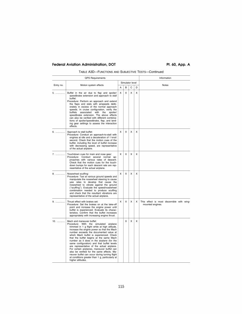
115
Federal Aviation Administration, DOT Pt. 60, App. A
TABLE A3D—FUNCTIONS AND SUBJECTIVE TESTS—Continued
QPS Requirements Information
Entry no. Motion system effects Simulator level
Notes A B C D
5. .............. Buffet in the air due to flap and spoiler/ speedbrake extension and approach to stall buffet:
Procedure: Perform an approach and extend the flaps and slats with airspeeds delib-erately in excess of the normal approach speeds. In cruise configuration, verify the buffets associated with the spoiler/ speedbrake extension. The above effects can also be verified with different combina-tions of spoiler/speedbrake, flap, and land-ing gear settings to assess the interaction effects.
X X X X
6. .............. Approach to stall buffet: Procedure: Conduct an approach-to-stall with
engines at idle and a deceleration of 1 knot/ second. Check that the motion cues of the buffet, including the level of buffet increase with decreasing speed, are representative of the actual airplane.
X X X X
7. .............. Touchdown cues for main and nose gear: Procedure: Conduct several normal ap-
proaches with various rates of descent. Check that the motion cues for the touch-down bumps for each descent rate are rep-resentative of the actual airplane.
X X X X
8. .............. Nosewheel scuffing: Procedure: Taxi at various ground speeds and
manipulate the nosewheel steering to cause yaw rates to develop that cause the nosewheel to vibrate against the ground (‘‘scuffing’’). Evaluate the speed/nosewheel combination needed to produce scuffing and check that the resultant vibrations are representative of the actual airplane.
X X X X
9. .............. Thrust effect with brakes set: Procedure: Set the brakes on at the take-off
point and increase the engine power until buffet is experienced. Evaluate its charac-teristics. Confirm that the buffet increases appropriately with increasing engine thrust.
X X X X This effect is most discernible with wing- mounted engines.
10. ............ Mach and maneuver buffet: Procedure: With the simulated airplane
trimmed in 1 g flight while at high altitude, increase the engine power so that the Mach number exceeds the documented value at which Mach buffet is experienced. Check that the buffet begins at the same Mach number as it does in the airplane (for the same configuration) and that buffet levels are representative of the actual airplane. For certain airplanes, maneuver buffet can also be verified for the same effects. Ma-neuver buffet can occur during turning flight at conditions greater than 1 g, particularly at higher altitudes.
X X X
VerDate Mar<15>2010 18:16 Mar 01, 2012 Jkt 226045 PO 00000 Frm 00125 Fmt 8010 Sfmt 8002 Q:\14\14V2 ofr150 PsN: PC150

116
14 CFR Ch. I (1–1–12 Edition) Pt. 60, App. A
TABLE A3D—FUNCTIONS AND SUBJECTIVE TESTS—Continued
QPS Requirements Information
Entry no. Motion system effects Simulator level
Notes A B C D
11. ............ Tire failure dynamics: Procedure: Simulate a single tire failure and a
multiple tire failure.
X X The pilot may notice some yawing with a mul-tiple tire failure selected on the same side. This should require the use of the rudder to maintain control of the airplane.
Dependent on airplane type, a single tire fail-ure may not be noticed by the pilot and should not have any special motion effect. Sound or vibration may be associated with the actual tire losing pressure.
12. ............ Engine malfunction and engine damage: Procedure: The characteristics of an engine
malfunction as stipulated in the malfunction definition document for the particular flight simulator must describe the special motion effects felt by the pilot. Note the associated engine instruments varying according to the nature of the malfunction and note the rep-lication of the effects of the airframe vibra-tion.
X X X
13. ............ Tail strikes and engine pod strikes: Procedure: Tail-strikes can be checked by
over-rotation of the airplane at a speed below Vr while performing a takeoff. The ef-fects can also be verified during a landing.
Excessive banking of the airplane during its take-off/landing roll can cause a pod strike.
X X X The motion effect should be felt as a notice-able bump. If the tail strike affects the air-plane angular rates, the cueing provided by the motion system should have an associ-ated effect.
TABLE A3E—FUNCTIONS AND SUBJECTIVE TESTS
QPS Requirements
Entry No. Sound system Simulator level
A B C D
The following checks are performed during a normal flight profile with motion system ON.
1. ............... Precipitation .................................................................................................................................... X X
2. ............... Rain removal equipment. ............................................................................................................... X X
3. ............... Significant airplane noises perceptible to the pilot during normal operations ............................... X X
4. ............... Abnormal operations for which there are associated sound cues including, engine malfunc-tions, landing gear/tire malfunctions, tail and engine pod strike and pressurization malfunc-tion.
X X
5. ............... Sound of a crash when the flight simulator is landed in excess of limitations ............................. X X
TABLE A3F—FUNCTIONS AND SUBJECTIVE TESTS
QPS Requirements
Entry No. Special effects Simulator level
A B C D
This table specifies the minimum special effects necessary for the specified simulator level.
1. ............... Braking Dynamics: Representations of the dynamics of brake failure (flight simulator pitch, side-loading, and direc-
tional control characteristics representative of the airplane), including antiskid and decreased brake efficiency due to high brake temperatures (based on airplane related data), sufficient to enable pilot identification of the problem and implementation of appropriate procedures.
X X
2. ............... Effects of Airframe and Engine Icing: X X
VerDate Mar<15>2010 18:16 Mar 01, 2012 Jkt 226045 PO 00000 Frm 00126 Fmt 8010 Sfmt 8002 Q:\14\14V2 ofr150 PsN: PC150

117
Federal Aviation Administration, DOT Pt. 60, App. A
TABLE A3F—FUNCTIONS AND SUBJECTIVE TESTS—Continued
QPS Requirements
Entry No. Special effects Simulator level
A B C D
Required only for those airplanes authorized for operations in known icing conditions.Procedure: With the simulator airborne, in a clean configuration, nominal altitude and cruise
airspeed, autopilot on and auto-throttles off, engine and airfoil anti-ice/de-ice systems deacti-vated; activate icing conditions at a rate that allows monitoring of simulator and systems re-sponse. Icing recognition will include an increase in gross weight, airspeed decay, change in simulator pitch attitude, change in engine performance indications (other than due to air-speed changes), and change in data from pitot/static system. Activate heating, anti-ice, or de-ice systems independently. Recognition will include proper effects of these systems, eventually returning the simulated airplane to normal flight.
TABLE A3G—FUNCTIONS AND SUBJECTIVE TESTS
QPS Requirements
Entry No. Special effects Simulator level
A B C D
Functions in this table are subject to evaluation only if appropriate for the airplane and/or the system is installed on the specific simulator.
1. ............... Simulator Power Switch(es) ........................................................................................................... X X X X
2. ............... Airplane conditions
2.a. .... Gross weight, center of gravity, fuel loading and allocation .......................................................... X X X X
2.b. .... Airplane systems status ................................................................................................................. X X X X
2.c. ..... Ground crew functions (e.g., ext. power, push back) .................................................................... X X X X
3. ............... Airports
3.a. .... Number and selection .................................................................................................................... X X X X
3.b. .... Runway selection ........................................................................................................................... X X X X
3.c. ..... Runway surface condition (e.g., rough, smooth, icy, wet) ............................................................ X X
3.d. .... Preset positions (e.g., ramp, gate, #1 for takeoff, takeoff position, over FAF) ............................. X X X X
3.e. .... Lighting controls ............................................................................................................................. X X X X
4. ............... Environmental controls
4.a ..... Visibility (statute miles (kilometers)) .............................................................................................. X X X X
4.b. .... Runway visual range (in feet (meters)) ......................................................................................... X X X X
4.c. ..... Temperature ................................................................................................................................... X X X X
4.d. .... Climate conditions (e.g., ice, snow, rain) ....................................................................................... X X X X
4.e. .... Wind speed and direction .............................................................................................................. X X X X
4.f. ..... Windshear ...................................................................................................................................... X X
4.g. .... Clouds (base and tops) .................................................................................................................. X X X X
5. ............... Airplane system malfunctions (Inserting and deleting malfunctions into the simulator) ............... X X X X
6. ............... Locks, Freezes, and Repositioning
6.a. .... Problem (all) freeze/release ........................................................................................................... X X X X
6.b. .... Position (geographic) freeze/release ............................................................................................. X X X X
6.c. ..... Repositioning (locations, freezes, and releases) ........................................................................... X X X X
VerDate Mar<15>2010 18:16 Mar 01, 2012 Jkt 226045 PO 00000 Frm 00127 Fmt 8010 Sfmt 8002 Q:\14\14V2 ofr150 PsN: PC150

118
14 CFR Ch. I (1–1–12 Edition) Pt. 60, App. A
TABLE A3G—FUNCTIONS AND SUBJECTIVE TESTS—Continued
QPS Requirements
Entry No. Special effects Simulator level
A B C D
6.d. .... Ground speed control .................................................................................................................... X X X X
7. ............... Remote IOS ................................................................................................................................... X X X X
8. ............... Sound Controls. On/off/adjustment ................................................................................................ X X X X
9. ............... Motion/Control Loading System
9.a. .... On/off/emergency stop ................................................................................................................... X X X X
10. ............. Observer Seats/Stations. Position/Adjustment/Positive restraint system ...................................... X X X X
lllllllllllllllllllllll
BEGIN INFORMATION
1. INTRODUCTION
a. The following is an example test sched-ule for an Initial/Upgrade evaluation that covers the majority of the requirements set out in the Functions and Subjective test re-quirements. It is not intended that the schedule be followed line by line, rather, the example should be used as a guide for pre-paring a schedule that is tailored to the air-plane, sponsor, and training task.
b. Functions and subjective tests should be planned. This information has been orga-nized as a reference document with the con-siderations, methods, and evaluation notes for each individual aspect of the simulator task presented as an individual item. In this way the evaluator can design his or her own test plan, using the appropriate sections to provide guidance on method and evaluation criteria. Two aspects should be present in any test plan structure:
(1) An evaluation of the simulator to deter-mine that it replicates the aircraft and per-forms reliably for an uninterrupted period equivalent to the length of a typical training session.
(2) The simulator should be capable of op-erating reliably after the use of training de-vice functions such as repositions or mal-functions.
c. A detailed understanding of the training task will naturally lead to a list of objec-tives that the simulator should meet. This list will form the basis of the test plan. Addi-tionally, once the test plan has been formu-lated, the initial conditions and the evalua-tion criteria should be established. The eval-uator should consider all factors that may have an influence on the characteristics ob-served during particular training tasks in order to make the test plan successful.
2. EVENTS
a. Initial Conditions
(1) Airport. (2) QNH. (3) Temperature. (4) Wind/Crosswind. (5) Zero Fuel Weight /Fuel/Gross Weight
/Center of Gravity.
b. Initial Checks
(1) Documentation of Simulator. (a) Simulator Acceptance Test Manuals. (b) Simulator Approval Test Guide. (c) Technical Logbook Open Item List. (d) Daily Functional Pre-flight Check. (2) Documentation of User/Carrier Flight
Logs. (a) Simulator Operating/Instructor Man-
ual. (b) Difference List (Aircraft/Simulator). (c) Flight Crew Operating Manuals. (d) Performance Data for Different Fields. (e) Crew Training Manual. (f) Normal/Abnormal/Emergency Check-
lists. (3) Simulator External Checks. (a) Appearance and Cleanliness. (b) Stairway/Access Bridge. (c) Emergency Rope Ladders. (d) ‘‘Motion On’’/‘‘Flight in Progress’’
Lights. (4) Simulator Internal Checks. (a) Cleaning/Disinfecting Towels (for clean-
ing oxygen masks). (b) Flight deck Layout (compare with dif-
ference list). (5) Equipment. (a) Quick Donning Oxygen Masks. (b) Head Sets. (c) Smoke Goggles. (d) Sun Visors. (e) Escape Rope. (f) Chart Holders. (g) Flashlights. (h) Fire Extinguisher (inspection date). (i) Crash Axe. (j) Gear Pins.
VerDate Mar<15>2010 18:16 Mar 01, 2012 Jkt 226045 PO 00000 Frm 00128 Fmt 8010 Sfmt 8002 Q:\14\14V2 ofr150 PsN: PC150

119
Federal Aviation Administration, DOT Pt. 60, App. A
c. Power Supply and APU Start Checks
(1) Batteries and Static Inverter. (2) APU Start with Battery. (3) APU Shutdown using Fire Handle. (4) External Power Connection. (5) APU Start with External Power. (6) Abnormal APU Start/Operation.
d. Flight deck Checks
(1) Flight deck Preparation Checks. (2) FMC Programming. (3) Communications and Navigational Aids
Checks.
e. Engine Start
(1) Before Start Checks. (2) Battery start with Ground Air Supply
Unit. (3) Engine Crossbleed Start. (4) Normal Engine Start. (5) Abnormal Engine Starts. (6) Engine Idle Readings. (7) After Start Checks.
f. Taxi Checks
(1) Pushback/Powerback. (2) Taxi Checks. (3) Ground Handling Check: (a) Power required to initiate ground roll. (b) Thrust response. (c) Nosewheel and Pedal Steering. (d) Nosewheel Scuffing. (e) Perform 180 degree turns. (f) Brakes Response and Differential Brak-
ing using Normal, Alternate and Emergency. (g) Brake Systems. (h) Eye height and fore/aft position. (4) Runway Roughness. g. Visual Scene—Ground Assessment. Select 3
different airport models and perform the fol-lowing checks with Day, Dusk and Night se-lected, as appropriate:
(1) Visual Controls. (a) Daylight, Dusk, Night Scene Controls. (b) Flight deck ‘‘Daylight’’ ambient light-
ing. (c) Environment Light Controls. (d) Runway Light Controls. (e) Taxiway Light Controls. (2) Airport Model Content. (a) Ramp area for buildings, gates,
airbridges, maintenance ground equipment, parked aircraft.
(b) Daylight shadows, night time light pools.
(c) Taxiways for correct markings, taxi-way/runway, marker boards, CAT I and II/III hold points, taxiway shape/grass areas, taxi-way light (positions and colors).
(d) Runways for correct markings, lead-off lights, boards, runway slope, runway light positions, and colors, directionality of run-way lights.
(e) Airport environment for correct terrain and significant features.
(f) Visual scene quantization (aliasing), color, and occulting levels.
(3) Ground Traffic Selection. (4) Environment Effects. (a) Low cloud scene. (i) Rain: (A) Runway surface scene. (B) Windshield wiper—operation and sound. (ii) Hail: (A) Runway surface scene. (B) Windshield wiper—operation and sound. (b) Lightning/thunder. (c) Snow/ice runway surface scene. (d) Fog. h. Takeoff. Select one or several of the fol-
lowing test cases: (1) T/O Configuration Warnings. (2) Engine Takeoff Readings. (3) Rejected Takeoff (Dry/Wet/Icy Runway)
and check the following: (a) Autobrake function. (b) Anti-skid operation. (c) Motion/visual effects during decelera-
tion. (d) Record stopping distance (use runway
plot or runway lights remaining). Continue taxiing along the runway while
applying brakes and check the following: (e) Center line lights alternating red/white
for 2000 feet/600 meters. (f) Center line lights all red for 1000 feet/300
meters. (g) Runway end, red stop bars. (h) Braking fade effect. (i) Brake temperature indications. (4) Engine Failure between VI and V2. (5) Normal Takeoff: (a) During ground roll check the following: (i) Runway rumble. (ii) Acceleration cues. (iii) Groundspeed effects. (iv) Engine sounds. (v) Nosewheel and rudder pedal steering. (b) During and after rotation, check the
following: (i) Rotation characteristics. (ii) Column force during rotation. (iii) Gear uplock sounds/bumps. (iv) Effect of slat/flap retraction during
climbout. (6) Crosswind Takeoff (check the fol-
lowing): (a) Tendency to turn into or out of the
wind. (b) Tendency to lift upwind wing as air-
speed increases. (7) Windshear during Takeoff (check the
following): (a) Controllable during windshear encoun-
ter. (b) Performance adequate when using cor-
rect techniques. (c) Windshear Indications satisfactory. (d) Motion cues satisfactory (particularly
turbulence). (8) Normal Takeoff with Control Malfunc-
tion.
VerDate Mar<15>2010 18:16 Mar 01, 2012 Jkt 226045 PO 00000 Frm 00129 Fmt 8010 Sfmt 8002 Q:\14\14V2 ofr150 PsN: PC150

120
14 CFR Ch. I (1–1–12 Edition) Pt. 60, App. A
(9) Low Visibility T/O (check the fol-lowing):
(a) Visual cues. (b) Flying by reference to instruments. (c) SID Guidance on LNAV. i. Climb Performance. Select one or several
of the following test cases: (1) Normal Climb—Climb while maintain-
ing recommended speed profile and note fuel, distance and time.
(2) Single Engine Climb—Trim aircraft in a zero wheel climb at V2.
NOTE: Up to 5° bank towards the operating engine(s) is permissible. Climb for 3 minutes and note fuel, distance, and time. Increase speed toward en route climb speed and re-tract flaps. Climb for 3 minutes and note fuel, distance, and time.
j. Systems Operation During Climb. Check normal operation and malfunctions
as appropriate for the following systems: (1) Air conditioning/Pressurization/Ven-
tilation. (2) Autoflight. (3) Communications. (4) Electrical. (5) Fuel. (6) Icing Systems. (7) Indicating and Recording Systems. (8) Navigation/FMS. (9) Pneumatics. k. Cruise Checks. Select one or several of
the following test cases: (1) Cruise Performance. (2) High Speed/High Altitude Handling
(check the following): (a) Overspeed warning. (b) High Speed buffet. (c) Aircraft control satisfactory. (d) Envelope limiting functions on Com-
puter Controlled Aircraft. Reduce airspeed to below level flight buffet
onset speed, start a turn, and check the fol-lowing:
(e) High Speed buffet increases with G loading.
Reduce throttles to idle and start descent, deploy the speedbrake, and check the fol-lowing:
(f) Speedbrake indications. (g) Symmetrical deployment. (h) Airframe buffet. (i) Aircraft response hands off. (3) Yaw Damper Operation. Switch off yaw
dampers and autopilot. Initiate a Dutch roll and check the following:
(a) Aircraft dynamics. (b) Simulator motion effects. Switch on yaw dampers, re-initiate a
Dutch roll and check the following: (c) Damped aircraft dynamics. (4) APU Operation. (5) Engine Gravity Feed. (6) Engine Shutdown and Driftdown Check:
FMC operation Aircraft performance. (7) Engine Relight.
l. Descent. Select one of the following test cases:
(1) Normal Descent. Descend while main-taining recommended speed profile and note fuel, distance and time.
(2) Cabin Depressurization/Emergency De-scent.
m. Medium Altitude Checks. Select one or several of the following test cases:
(1) High Angle of Attack/Stall. Trim the aircraft at 1.4 Vs, establish 1 kt/sec 2 decel-eration rate, and check the following—
(a) System displays/operation satisfactory. (b) Handling characteristics satisfactory. (c) Stall and Stick shaker speed. (d) Buffet characteristics and onset speed. (e) Envelope limiting functions on Com-
puter Controlled Aircraft. Recover to straight and level flight and
check the following: (f) Handling characteristics satisfactory. (2) Turning Flight. Roll aircraft to left, es-
tablish a 30° to 45° bank angle, and check the following:
(a) Stick force required, satisfactory. (b) Wheel requirement to maintain bank
angle. (c) Slip ball response, satisfactory. (d) Time to turn 180°. Roll aircraft from 45° bank one way to 45°
bank the opposite direction while maintain-ing altitude and airspeed—check the fol-lowing:
(e) Controllability during maneuver. (3) Degraded flight controls. (4) Holding Procedure (check the fol-
lowing:) (a) FMC operation. (b) Autopilot auto thrust performance. (5) Storm Selection (check the following:) (a) Weather radar controls. (b) Weather radar operation. (c) Visual scene corresponds with WXR
pattern. (Fly through storm center, and check the
following:) (d) Aircraft enters cloud. (e) Aircraft encounters representative tur-
bulence. (f) Rain/hail sound effects evident. As aircraft leaves storm area, check the fol-
lowing: (g) Storm effects disappear. (6) TCAS (check the following:) (a) Traffic appears on visual display. (b) Traffic appears on TCAS display(s). As conflicting traffic approaches, take rel-
evant avoiding action, and check the fol-lowing:
(c) Visual and TCAS system displays. n. Approach and Landing. Select one or sev-
eral of the following test cases while moni-toring flight control and hydraulic systems for normal operation and with malfunctions selected:
(1) Flaps/Gear Normal Operation. Check the following:
VerDate Mar<15>2010 18:16 Mar 01, 2012 Jkt 226045 PO 00000 Frm 00130 Fmt 8010 Sfmt 8002 Q:\14\14V2 ofr150 PsN: PC150
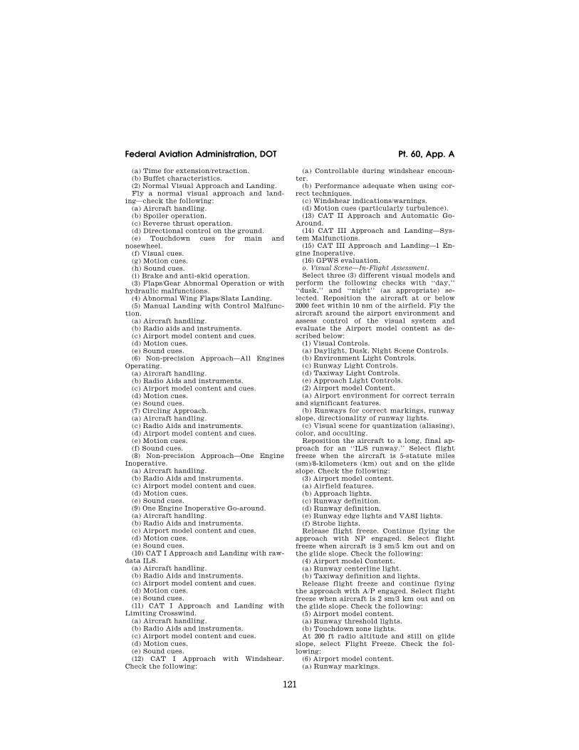
121
Federal Aviation Administration, DOT Pt. 60, App. A
(a) Time for extension/retraction. (b) Buffet characteristics. (2) Normal Visual Approach and Landing. Fly a normal visual approach and land-
ing—check the following: (a) Aircraft handling. (b) Spoiler operation. (c) Reverse thrust operation. (d) Directional control on the ground. (e) Touchdown cues for main and
nosewheel. (f) Visual cues. (g) Motion cues. (h) Sound cues. (i) Brake and anti-skid operation. (3) Flaps/Gear Abnormal Operation or with
hydraulic malfunctions. (4) Abnormal Wing Flaps/Slats Landing. (5) Manual Landing with Control Malfunc-
tion. (a) Aircraft handling. (b) Radio aids and instruments. (c) Airport model content and cues. (d) Motion cues. (e) Sound cues. (6) Non-precision Approach—All Engines
Operating. (a) Aircraft handling. (b) Radio Aids and instruments. (c) Airport model content and cues. (d) Motion cues. (e) Sound cues. (7) Circling Approach. (a) Aircraft handling. (c) Radio Aids and instruments. (d) Airport model content and cues. (e) Motion cues. (f) Sound cues. (8) Non-precision Approach—One Engine
Inoperative. (a) Aircraft handling. (b) Radio Aids and instruments. (c) Airport model content and cues. (d) Motion cues. (e) Sound cues. (9) One Engine Inoperative Go-around. (a) Aircraft handling. (b) Radio Aids and instruments. (c) Airport model content and cues. (d) Motion cues. (e) Sound cues. (10) CAT I Approach and Landing with raw-
data ILS. (a) Aircraft handling. (b) Radio Aids and instruments. (c) Airport model content and cues. (d) Motion cues. (e) Sound cues. (11) CAT I Approach and Landing with
Limiting Crosswind. (a) Aircraft handling. (b) Radio Aids and instruments. (c) Airport model content and cues. (d) Motion cues. (e) Sound cues. (12) CAT I Approach with Windshear.
Check the following:
(a) Controllable during windshear encoun-ter.
(b) Performance adequate when using cor-rect techniques.
(c) Windshear indications/warnings. (d) Motion cues (particularly turbulence). (13) CAT II Approach and Automatic Go-
Around. (14) CAT III Approach and Landing—Sys-
tem Malfunctions. (15) CAT III Approach and Landing—1 En-
gine Inoperative. (16) GPWS evaluation. o. Visual Scene—In-Flight Assessment. Select three (3) different visual models and
perform the following checks with ‘‘day,’’ ‘‘dusk,’’ and ‘‘night’’ (as appropriate) se-lected. Reposition the aircraft at or below 2000 feet within 10 nm of the airfield. Fly the aircraft around the airport environment and assess control of the visual system and evaluate the Airport model content as de-scribed below:
(1) Visual Controls. (a) Daylight, Dusk, Night Scene Controls. (b) Environment Light Controls. (c) Runway Light Controls. (d) Taxiway Light Controls. (e) Approach Light Controls. (2) Airport model Content. (a) Airport environment for correct terrain
and significant features. (b) Runways for correct markings, runway
slope, directionality of runway lights. (c) Visual scene for quantization (aliasing),
color, and occulting. Reposition the aircraft to a long, final ap-
proach for an ‘‘ILS runway.’’ Select flight freeze when the aircraft is 5-statute miles (sm)/8-kilometers (km) out and on the glide slope. Check the following:
(3) Airport model content. (a) Airfield features. (b) Approach lights. (c) Runway definition. (d) Runway definition. (e) Runway edge lights and VASI lights. (f) Strobe lights. Release flight freeze. Continue flying the
approach with NP engaged. Select flight freeze when aircraft is 3 sm/5 km out and on the glide slope. Check the following:
(4) Airport model Content. (a) Runway centerline light. (b) Taxiway definition and lights. Release flight freeze and continue flying
the approach with A/P engaged. Select flight freeze when aircraft is 2 sm/3 km out and on the glide slope. Check the following:
(5) Airport model content. (a) Runway threshold lights. (b) Touchdown zone lights. At 200 ft radio altitude and still on glide
slope, select Flight Freeze. Check the fol-lowing:
(6) Airport model content. (a) Runway markings.
VerDate Mar<15>2010 18:16 Mar 01, 2012 Jkt 226045 PO 00000 Frm 00131 Fmt 8010 Sfmt 8002 Q:\14\14V2 ofr150 PsN: PC150

122
14 CFR Ch. I (1–1–12 Edition) Pt. 60, App. A
Set the weather to Category I conditions and check the following:
(7) Airport model content. (a) Visual ground segment. Set the weather to Category II conditions,
release Flight Freeze, re-select Flight Freeze at 100 feet radio altitude, and check the fol-lowing:
(8) Airport model content. (a) Visual ground segment. Select night/dusk (twilight) conditions and
check the following: (9) Airport model content. (a) Runway markings visible within land-
ing light lobes. Set the weather to Category III conditions,
release Flight Freeze, re-select Flight Freeze at 50 feet radio altitude and check the fol-lowing:
(10) Airport model content. (a) Visual ground segment. Set WX to a typical ‘‘missed approach?
weather condition, release Flight Freeze, re- select Flight Freeze at 15 feet radio altitude, and check the following:
(11) Airport model content.
(a) Visual ground segment. When on the ground, stop the aircraft. Set
0 feet RVR, ensure strobe/beacon tights are switched on and check the following:
(12) Airport model content. (a) Visual effect of strobe and beacon. Reposition to final approach, set weather
to ‘‘Clear,’’ continue approach for an auto-matic landing, and check the following:
(13) Airport model content. (a) Visual cues during flare to assess sink
rate. (b) Visual cues during flare to assess Depth
perception. (c) Flight deck height above ground. After Landing Operations. (1) After Landing Checks. (2) Taxi back to gate. Check the following: (a) Visual model satisfactory. (b) Parking brake operation satisfactory. (3) Shutdown Checks. q. Crash Function. (1) Gear-up Crash. (2) Excessive rate of descent Crash. (3) Excessive bank angle Crash.
VerDate Mar<15>2010 18:16 Mar 01, 2012 Jkt 226045 PO 00000 Frm 00132 Fmt 8010 Sfmt 8002 Q:\14\14V2 ofr150 PsN: PC150

123
Federal Aviation Administration, DOT Pt. 60, App. A
VerDate Mar<15>2010 18:16 Mar 01, 2012 Jkt 226045 PO 00000 Frm 00133 Fmt 8010 Sfmt 8006 Q:\14\14V2 ofr150 PsN: PC150 ER
09M
Y08
.005
</G
PH
>

124
14 CFR Ch. I (1–1–12 Edition) Pt. 60, App. A
VerDate Mar<15>2010 18:16 Mar 01, 2012 Jkt 226045 PO 00000 Frm 00134 Fmt 8010 Sfmt 8006 Q:\14\14V2 ofr150 PsN: PC150 ER
09M
Y08
.006
</G
PH
>

125
Federal Aviation Administration, DOT Pt. 60, App. A
VerDate Mar<15>2010 18:16 Mar 01, 2012 Jkt 226045 PO 00000 Frm 00135 Fmt 8010 Sfmt 8006 Q:\14\14V2 ofr150 PsN: PC150 ER
09M
Y08
.008
</G
PH
>

126
14 CFR Ch. I (1–1–12 Edition) Pt. 60, App. A
VerDate Mar<15>2010 18:16 Mar 01, 2012 Jkt 226045 PO 00000 Frm 00136 Fmt 8010 Sfmt 8006 Q:\14\14V2 ofr150 PsN: PC150 ER
09M
Y08
.009
</G
PH
>

127
Federal Aviation Administration, DOT Pt. 60, App. A
VerDate Mar<15>2010 18:16 Mar 01, 2012 Jkt 226045 PO 00000 Frm 00137 Fmt 8010 Sfmt 8006 Q:\14\14V2 ofr150 PsN: PC150 ER
09M
Y08
.010
</G
PH
>

128
14 CFR Ch. I (1–1–12 Edition) Pt. 60, App. A
VerDate Mar<15>2010 18:16 Mar 01, 2012 Jkt 226045 PO 00000 Frm 00138 Fmt 8010 Sfmt 8006 Q:\14\14V2 ofr150 PsN: PC150 ER
09M
Y08
.011
</G
PH
>

129
Federal Aviation Administration, DOT Pt. 60, App. A
VerDate Mar<15>2010 18:16 Mar 01, 2012 Jkt 226045 PO 00000 Frm 00139 Fmt 8010 Sfmt 8006 Q:\14\14V2 ofr150 PsN: PC150 ER
09M
Y08
.012
</G
PH
>

130
14 CFR Ch. I (1–1–12 Edition) Pt. 60, App. A
VerDate Mar<15>2010 18:16 Mar 01, 2012 Jkt 226045 PO 00000 Frm 00140 Fmt 8010 Sfmt 8006 Q:\14\14V2 ofr150 PsN: PC150 ER
09M
Y08
.013
</G
PH
>

131
Federal Aviation Administration, DOT Pt. 60, App. A
VerDate Mar<15>2010 18:16 Mar 01, 2012 Jkt 226045 PO 00000 Frm 00141 Fmt 8010 Sfmt 8006 Q:\14\14V2 ofr150 PsN: PC150 ER
09M
Y08
.014
</G
PH
>

132
14 CFR Ch. I (1–1–12 Edition) Pt. 60, App. A
VerDate Mar<15>2010 18:16 Mar 01, 2012 Jkt 226045 PO 00000 Frm 00142 Fmt 8010 Sfmt 8006 Q:\14\14V2 ofr150 PsN: PC150 ER
09M
Y08
.015
</G
PH
>
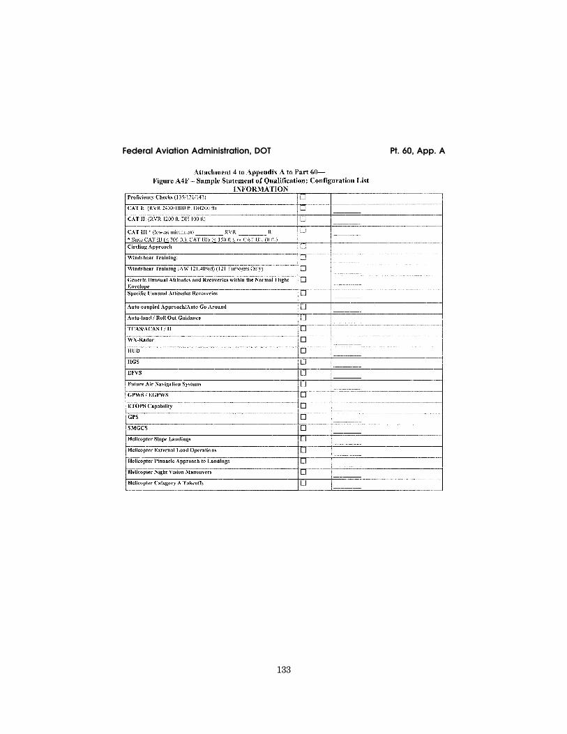
133
Federal Aviation Administration, DOT Pt. 60, App. A
VerDate Mar<15>2010 18:16 Mar 01, 2012 Jkt 226045 PO 00000 Frm 00143 Fmt 8010 Sfmt 8006 Q:\14\14V2 ofr150 PsN: PC150 ER
09M
Y08
.016
</G
PH
>

134
14 CFR Ch. I (1–1–12 Edition) Pt. 60, App. A
VerDate Mar<15>2010 18:16 Mar 01, 2012 Jkt 226045 PO 00000 Frm 00144 Fmt 8010 Sfmt 8006 Q:\14\14V2 ofr150 PsN: PC150 ER
09M
Y08
.017
</G
PH
>

135
Federal Aviation Administration, DOT Pt. 60, App. A
VerDate Mar<15>2010 18:16 Mar 01, 2012 Jkt 226045 PO 00000 Frm 00145 Fmt 8010 Sfmt 8006 Q:\14\14V2 ofr150 PsN: PC150 ER
09M
Y08
.018
</G
PH
>
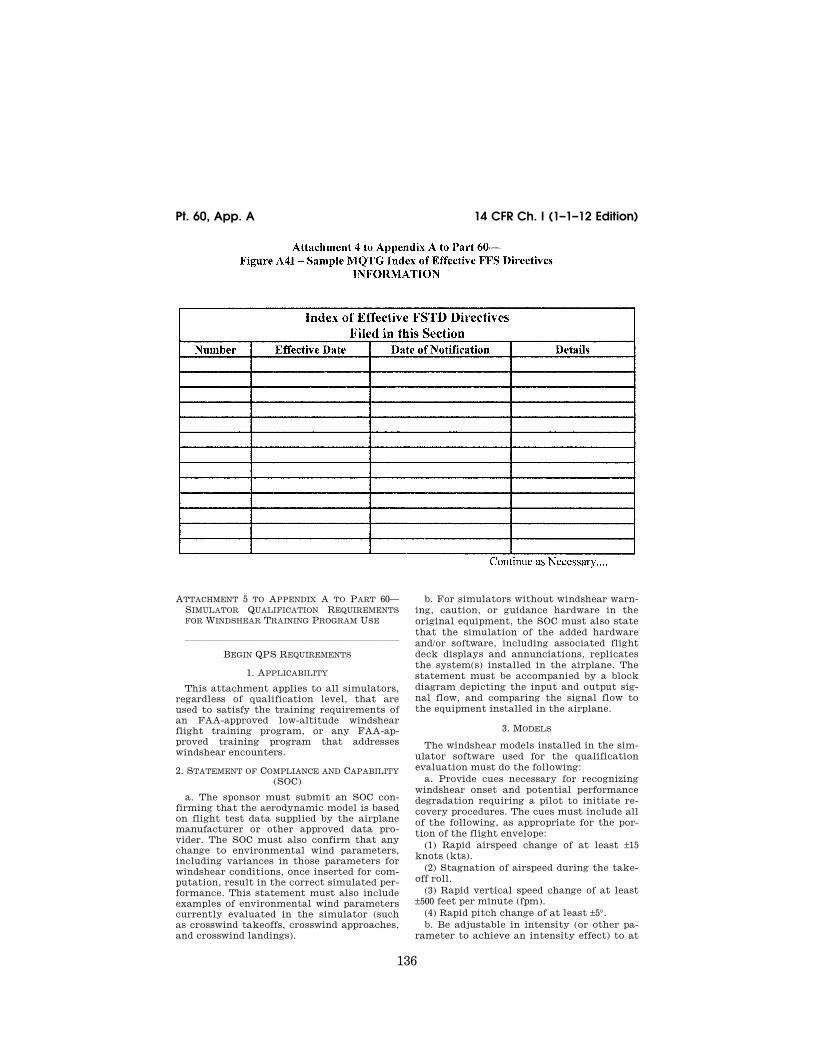
136
14 CFR Ch. I (1–1–12 Edition) Pt. 60, App. A
ATTACHMENT 5 TO APPENDIX A TO PART 60— SIMULATOR QUALIFICATION REQUIREMENTS FOR WINDSHEAR TRAINING PROGRAM USE
lllllllllllllllllllllll
BEGIN QPS REQUIREMENTS
1. APPLICABILITY
This attachment applies to all simulators, regardless of qualification level, that are used to satisfy the training requirements of an FAA-approved low-altitude windshear flight training program, or any FAA-ap-proved training program that addresses windshear encounters.
2. STATEMENT OF COMPLIANCE AND CAPABILITY (SOC)
a. The sponsor must submit an SOC con-firming that the aerodynamic model is based on flight test data supplied by the airplane manufacturer or other approved data pro-vider. The SOC must also confirm that any change to environmental wind parameters, including variances in those parameters for windshear conditions, once inserted for com-putation, result in the correct simulated per-formance. This statement must also include examples of environmental wind parameters currently evaluated in the simulator (such as crosswind takeoffs, crosswind approaches, and crosswind landings).
b. For simulators without windshear warn-ing, caution, or guidance hardware in the original equipment, the SOC must also state that the simulation of the added hardware and/or software, including associated flight deck displays and annunciations, replicates the system(s) installed in the airplane. The statement must be accompanied by a block diagram depicting the input and output sig-nal flow, and comparing the signal flow to the equipment installed in the airplane.
3. MODELS
The windshear models installed in the sim-ulator software used for the qualification evaluation must do the following:
a. Provide cues necessary for recognizing windshear onset and potential performance degradation requiring a pilot to initiate re-covery procedures. The cues must include all of the following, as appropriate for the por-tion of the flight envelope:
(1) Rapid airspeed change of at least ±15 knots (kts).
(2) Stagnation of airspeed during the take-off roll.
(3) Rapid vertical speed change of at least ±500 feet per minute (fpm).
(4) Rapid pitch change of at least ±5°. b. Be adjustable in intensity (or other pa-
rameter to achieve an intensity effect) to at
VerDate Mar<15>2010 18:16 Mar 01, 2012 Jkt 226045 PO 00000 Frm 00146 Fmt 8010 Sfmt 8002 Q:\14\14V2 ofr150 PsN: PC150 ER
09M
Y08
.019
</G
PH
>

137
Federal Aviation Administration, DOT Pt. 60, App. A
least two (2) levels so that upon encoun-tering the windshear the pilot may identify its presence and apply the recommended pro-cedures for escape from such a windshear.
(1) If the intensity is lesser, the perform-ance capability of the simulated airplane in the windshear permits the pilot to maintain a satisfactory flightpath; and
(2) If the intensity is greater, the perform-ance capability of the simulated airplane in the windshear does not permit the pilot to maintain a satisfactory flightpath (crash). Note: The means used to accomplish the ‘‘nonsurvivable’’ scenario of paragraph 3.b.(2) of this attachment, that involve operational elements of the simulated airplane, must re-flect the dispatch limitations of the air-plane.
c. Be available for use in the FAA-approved windshear flight training program.
4. DEMONSTRATIONS
a. The sponsor must identify one surviv-able takeoff windshear training model and one survivable approach windshear training model. The wind components of the surviv-able models must be presented in graphical format so that all components of the windshear are shown, including initiation point, variance in magnitude, and time or distance correlations. The simulator must be operated at the same gross weight, airplane configuration, and initial airspeed during the takeoff demonstration (through calm air and through the first selected survivable windshear), and at the same gross weight, airplane configuration, and initial airspeed during the approach demonstration (through calm air and through the second selected survivable windshear).
b. In each of these four situations, at an ‘‘initiation point’’ (i.e., where windshear onset is or should be recognized), the rec-ommended procedures for windshear recov-ery are applied and the results are recorded as specified in paragraph 5 of this attach-ment.
c. These recordings are made without in-serting programmed random turbulence. Turbulence that results from the windshear model is to be expected, and no attempt may be made to neutralize turbulence from this source.
d. The definition of the models and the re-sults of the demonstrations of all four?(4) cases described in paragraph 4.a of this at-tachment, must be made a part of the MQTG.
5. RECORDING PARAMETERS
a. In each of the four MQTG cases, an elec-tronic recording (time history) must be made of the following parameters:
(1) Indicated or calibrated airspeed. (2) Indicated vertical speed. (3) Pitch attitude.
(4) Indicated or radio altitude. (5) Angle of attack. (6) Elevator position. (7) Engine data (thrust, N1, or throttle po-
sition). (8) Wind magnitudes (simple windshear
model assumed). b. These recordings must be initiated at
least 10 seconds prior to the initiation point, and continued until recovery is complete or ground contact is made.
6. EQUIPMENT INSTALLATION AND OPERATION
All windshear warning, caution, or guid-ance hardware installed in the simulator must operate as it operates in the airplane. For example, if a rapidly changing wind speed and/or direction would have caused a windshear warning in the airplane, the simu-lator must respond equivalently without in-structor/evaluator intervention.
7. QUALIFICATION TEST GUIDE
a. All QTG material must be forwarded to the NSPM.
b. A simulator windshear evaluation will be scheduled in accordance with normal pro-cedures. Continuing qualification evaluation schedules will be used to the maximum ex-tent possible.
c. During the on-site evaluation, the eval-uator will ask the operator to run the per-formance tests and record the results. The results of these on-site tests will be com-pared to those results previously approved and placed in the QTG or MQTG, as appro-priate.
d. QTGs for new (or MQTGs for upgraded) simulators must contain or reference the in-formation described in paragraphs 2, 3, 4, and 5 of this attachment.
END QPS REQUIREMENTS
lllllllllllllllllllllll
BEGIN INFORMATION
8. SUBJECTIVE EVALUATION
The NSPM will fly the simulator in at least two of the available windshear sce-narios to subjectively evaluate simulator performance as it encounters the pro-grammed windshear conditions.
a. One scenario will include parameters that enable the pilot to maintain a satisfac-tory flightpath.
b. One scenario will include parameters that will not enable the pilot to maintain a satisfactory flightpath (crash).
c. Other scenarios may be examined at the NSPM’s discretion.
9. QUALIFICATION BASIS
The addition of windshear programming to a simulator in order to comply with the qualification for required windshear training
VerDate Mar<15>2010 18:16 Mar 01, 2012 Jkt 226045 PO 00000 Frm 00147 Fmt 8010 Sfmt 8002 Q:\14\14V2 ofr150 PsN: PC150

138
14 CFR Ch. I (1–1–12 Edition) Pt. 60, App. A
does not change the original qualification basis of the simulator.
10. DEMONSTRATION REPEATABILITY
For the purposes of demonstration repeat-ability, it is recommended that the simu-lator be flown by means of the simulator’s autodrive function (for those simulators that have autodrive capability) during the dem-onstrations.
END INFORMATION
lllllllllllllllllllllll
ATTACHMENT 6 TO APPENDIX A TO PART 60— FSTD DIRECTIVES APPLICABLE TO AIRPLANE FLIGHT SIMULATORS
FLIGHT SIMULATION TRAINING DEVICE (FSTD) DIRECTIVE
FSTD Directive 1. Applicable to all Full Flight Simulators (FFS), regardless of the original qualification basis and qualification date (original or upgrade), having Class II or Class III airport models available.
Agency: Federal Aviation Administration (FAA), DOT.
Action: This is a retroactive requirement to have all Class II or Class III airport models meet current requirements.
lllllllllllllllllllllll
Summary: Notwithstanding the authoriza tion listed in paragraph 13b in Appendices A and C of this part, this FSTD Directive re-quires each certificate holder to ensure that by May 30, 2009, except for the airport model(s) used to qualify the simulator at the designated level, each airport model used by the certificate holder’s instructors or eval-uators for training, checking, or testing under this chapter in an FFS, meets the defi-nition of a Class II or Class III airport model as defined in 14CFR part 60. The completion of this requirement will not require a report, and the method used for keeping instructors and evaluators apprised of the airport mod-els that meet Class II or Class III require-ments on any given simulator is at the op-tion of the certificate holder whose employ-ees are using the FFS, but the method used must be available for review by the TPAA for that certificate holder.
Dates: FSTD Directive 1 becomes effective on May 30, 2008.
For Further Information Contact: Ed Cook, Senior Advisor to the Division Manager, Air Transportation Division, AFS–200, 800 Inde-pendence Ave, SW., Washington, DC 20591; telephone: (404) 832–4701; fax: (404) 761–8906.
SPECIFIC REQUIREMENTS:
1. Part 60 requires that each FSTD be: a. Sponsored by a person holding or apply-
ing for an FAA operating certificate under Part 119, Part 141, or Part 142, or holding or applying for an FAA-approved training pro-
gram under Part 63, Appendix C, for flight engineers, and
b. Evaluated and issued an SOQ for a spe-cific FSTD level.
2. FFSs also require the installation of a visual system that is capable of providing an out-of-the-flight-deck view of airport mod-els. However, historically these airport mod-els were not routinely evaluated or required to meet any standardized criteria. This has led to qualified simulators containing air-port models being used to meet FAA-ap-proved training, testing, or checking require-ments with potentially incorrect or inappro-priate visual references.
3. To prevent this from occurring in the fu-ture, by May 30, 2009, except for the airport model(s) used to qualify the simulator at the designated level, each certificate holder must assure that each airport model used for training, testing, or checking under this chapter in a qualified FFS meets the defini-tion of a Class II or Class III airport model as defined in Appendix F of this part.
4. These references describe the require-ments for visual scene management and the minimum distances from which runway or landing area features must be visible for all levels of simulator. The airport model must provide, for each ‘‘in-use runway’’ or ‘‘in-use landing area,’’ runway or landing area sur-face and markings, runway or landing area lighting, taxiway surface and markings, and taxiway lighting. Additional requirements include correlation of the v airport models with other aspects of the airport environ-ment, correlation of the aircraft and associ-ated equipment, scene quality assessment features, and the control of these models the instructor must be able to exercise.
5. For circling approaches, all require-ments of this section apply to the runway used for the initial approach and to the run-way of intended landing.
6. The details in these models must be de-veloped using airport pictures, construction drawings and maps, or other similar data, or developed in accordance with published regu-latory material. However, this FSTD DIREC-TIVE 1 does not require that airport models contain details that are beyond the initially designed capability of the visual system, as currently qualified. The recognized limita-tions to visual systems are as follows:
a. Visual systems not required to have run-way numbers as a part of the specific runway marking requirements are:
(1) Link NVS and DNVS. (2) Novoview 2500 and 6000. (3) FlightSafety VITAL series up to, and
including, VITAL III, but not beyond. (4) Redifusion SP1, SP1T, and SP2. b. Visual systems required to display run-
way numbers only for LOFT scenes are: (1) FlightSafety VITAL IV. (2) Redifusion SP3 and SP3T. (3) Link-Miles Image II.
VerDate Mar<15>2010 18:16 Mar 01, 2012 Jkt 226045 PO 00000 Frm 00148 Fmt 8010 Sfmt 8002 Q:\14\14V2 ofr150 PsN: PC150

139
Federal Aviation Administration, DOT Pt. 60, App. B
c. Visual systems not required to have ac-curate taxiway edge lighting are:
(1) Redifusion SP1. (2) FlightSafety Vital IV. (3) Link-Miles Image II and Image IIT (4) XKD displays (even though the XKD
image generator is capable of generating blue colored lights, the display cannot ac-commodate that color).
7. A copy of this Directive must be filed in the MQTG in the designated FSTD Directive Section, and its inclusion must be annotated on the Index of Effective FSTD Directives chart. See Attachment 4, Appendices A through D for a sample MQTG Index of Effec-tive FSTD Directives chart.
[Doc. No. FAA–2002–12461, 73 FR 26490, May 9, 2008]
APPENDIX B TO PART 60—QUALIFICATION PERFORMANCE STANDARDS FOR AIR-PLANE FLIGHT TRAINING DEVICES
lllllllllllllllllllllll
BEGIN INFORMATION
This appendix establishes the standards for Airplane FTD evaluation and qualification at Level 4, Level 5, or Level 6. The Flight Standards Service, NSPM, is responsible for the development, application, and implemen-tation of the standards contained within this appendix. The procedures and criteria speci-fied in this appendix will be used by the NSPM, or a person or persons assigned by the NSPM when conducting airplane FTD evaluations.
TABLE OF CONTENTS
1. Introduction 2. Applicability (§§ 60.1 and 60.2). 3. Definitions (§ 60.3). 4. Qualification Performance Standards
(§ 60.4). 5. Quality Management System (§ 60.5). 6. Sponsor Qualification Requirements
(§ 60.7). 7. Additional Responsibilities of the Sponsor
(§ 60.9). 8. FTD Use (§ 60.11). 9. FTD Objective Data Requirements (§ 60.13). 10. Special Equipment and Personnel Re-
quirements for Qualification of the FTD (§ 60.14).
11. Initial (and Upgrade) Qualification Re-quirements (§ 60.15).
12. Additional Qualifications for Currently Qualified FTDs (§ 60.16).
13. Previously Qualified FTDs (§ 60.17). 14. Inspection, Continuing Qualification
Evaluation, and Maintenance Require-ments (§ 60.19).
15. Logging FTD Discrepancies (§ 60.20). 16. Interim Qualification of FTDs for New
Airplane Types or Models (§ 60.21). 17. Modifications to FTDs (§ 60.23).
18. Operations with Missing, Malfunctioning, or Inoperative Components (§ 60.25).
19. Automatic Loss of Qualification and Pro-cedures for Restoration of Qualification (§ 60.27).
20. Other Losses of Qualification and Proce-dures for Restoration of Qualification (§ 60.29).
21. Record Keeping and Reporting (§ 60.31). 22. Applications, Logbooks, Reports, and
Records: Fraud, Falsification, or Incor-rect Statements (§ 60.33).
23. [Reserved] 24. Levels of FTD. 25. FTD Qualification on the Basis of a Bilat-
eral Aviation Safety Agreement (BASA) (§ 60.37).
Attachment 1 to Appendix B to Part 60—Gen-eral FTD Requirements.
Attachment 2 to Appendix B to Part 60— Flight Training Device (FTD) Objective Tests.
Attachment 3 to Appendix B to Part 60— Flight Training Device (FTD) Subjective Evaluation.
Attachment 4 to Appendix B to Part 60— Sample Documents.
END INFORMATION
lllllllllllllllllllllll
1. INTRODUCTION
lllllllllllllllllllllll
BEGIN INFORMATION
a. This appendix contains background in-formation as well as regulatory and inform-ative material as described later in this sec-tion. To assist the reader in determining what areas are required and what areas are permissive, the text in this appendix is di-vided into two sections: ‘‘QPS Require-ments’’ and ‘‘Information.’’ The QPS Re-quirements sections contain details regard-ing compliance with the part 60 rule lan-guage. These details are regulatory, but are found only in this appendix. The Information sections contain material that is advisory in nature, and designed to give the user general information about the regulation.
b. Questions regarding the contents of this publication should be sent to the U.S. De-partment of Transportation, Federal Avia-tion Administration, Flight Standards Serv-ice, National Simulator Program Staff, AFS–205, 100 Hartsfield Centre Parkway, Suite 400, Atlanta, Georgia, 30354. Telephone contact numbers for the NSP are: phone, 404– 832–4700; fax, 404–761–8906. The general e-mail address for the NSP office is: 9-aso-avr-sim- [email protected]. The NSP Internet Web Site ad-dress is: http://www.faa.gov/safety/ programslinitiatives/aircraftlaviation/nsp/. On this Web Site you will find an NSP personnel list with telephone and e-mail contact infor-mation for each NSP staff member, a list of
VerDate Mar<15>2010 18:16 Mar 01, 2012 Jkt 226045 PO 00000 Frm 00149 Fmt 8010 Sfmt 8002 Q:\14\14V2 ofr150 PsN: PC150

140
14 CFR Ch. I (1–1–12 Edition) Pt. 60, App. B
qualified flight simulation devices, ACs, a description of the qualification process, NSP policy, and an NSP ‘‘In-Works’’ section. Also linked from this site are additional informa-tion sources, handbook bulletins, frequently asked questions, a listing and text of the Federal Aviation Regulations, Flight Stand-ards Inspector’s handbooks, and other FAA links.
c. The NSPM encourages the use of elec-tronic media for all communication, includ-ing any record, report, request, test, or statement required by this appendix. The electronic media used must have adequate security provisions and be acceptable to the NSPM. The NSPM recommends inquiries on system compatibility, and minimum system requirements are also included on the NSP Web site.
d. Related Reading References. (1) 14 CFR part 60. (2) 14 CFR part 61. (3) 14 CFR part 63. (4) 14 CFR part 119. (5) 14 CFR part 121. (6) 14 CFR part 125. (7) 14 CFR part 135. (8) 14 CFR part 141. (9) 14 CFR part 142. (10) AC 120–28, as amended, Criteria for Ap-
proval of Category III Landing Weather Minima.
(11) AC 120–29, as amended, Criteria for Ap-proving Category I and Category II Landing Minima for part 121 operators.
(12) AC 120–35, as amended, Line Oper-ational Simulations: Line-Oriented Flight Training, Special Purpose Operational Training, Line Operational Evaluation.
(13) AC 120–41, as amended, Criteria for Operational Approval of Airborne Wind Shear Alerting and Flight Guidance Sys-tems.
(14) AC 120–45, as amended, Airplane Flight Training Device Qualification.
(14) AC 120–57, as amended, Surface Move-ment Guidance and Control System (SMGCS).
(15) AC 150/5300–13, as amended, Airport De-sign.
(16) AC 150/5340–1, as amended, Standards for Airport Markings.
(17) AC 150/5340–4, as amended, Installation Details for Runway Centerline Touchdown Zone Lighting Systems.
(18) AC 150/5340–19, as amended, Taxiway Centerline Lighting System.
(19) AC 150/5340–24, as amended, Runway and Taxiway Edge Lighting System.
(20) AC 150/5345–28, as amended, Precision Approach Path Indicator (PAPI) Systems.
(21) International Air Transport Associa-tion document, ‘‘Flight Simulator Design and Performance Data Requirements,’’ as amended.
(22) AC 25–7, as amended, Flight Test Guide for Certification of Transport Category Air-planes.
(23) AC 23–8A, as amended, Flight Test Guide for Certification of Part 23 Airplanes.
(24) International Civil Aviation Organiza-tion (ICAO) Manual of Criteria for the Quali-fication of Flight Simulators, as amended.
(25) Airplane Flight Simulator Evaluation Handbook, Volume I, as amended and Vol-ume II, as amended, The Royal Aeronautical Society, London, UK.
(26) FAA Publication FAA–S–8081 series (Practical Test Standards for Airline Trans-port Pilot Certificate, Type Ratings, Com-mercial Pilot, and Instrument Ratings).
(27) The FAA Aeronautical Information Manual (AIM). An electronic version of the AIM is on the Internet at http://www.faa.gov/ atpubs.
(28) Aeronautical Radio, Inc. (ARINC) doc-ument number 436, titled Guidelines For Elec-tronic Qualification Test Guide (as amended).
(29) Aeronautical Radio, Inc. (ARINC) doc-ument 610, Guidance for Design and Integra-tion of Aircraft Avionics Equipment in Simula-tors (as amended).
lllllllllllllllllllllll
END INFORMATION
2. APPLICABILITY (§§ 60.1 AND 60.2)
lllllllllllllllllllllll
BEGIN INFORMATION
No additional regulatory or informational material applies to § 60.1, Applicability, or to § 60.2, Applicability of sponsor rules to person who are not sponsors and who are engaged in certain unauthorized activities.
3. DEFINITIONS (§ 60.3)
See Appendix F of this part for a list of definitions and abbreviations from part 1, part 60, and the QPS appendices of part 60.
4. QUALIFICATION PERFORMANCE STANDARDS (§ 60.4)
No additional regulatory or informational material applies to § 60.4, Qualification Per-formance Standards.
5. QUALITY MANAGEMENT SYSTEM (§ 60.5)
Additional regulatory material and infor-mational material regarding Quality Man-agement Systems for FTDs may be found in Appendix E of this part.
END INFORMATION
lllllllllllllllllllllll
6. SPONSOR QUALIFICATION REQUIREMENTS. (§ 60.7).
lllllllllllllllllllllll
VerDate Mar<15>2010 18:16 Mar 01, 2012 Jkt 226045 PO 00000 Frm 00150 Fmt 8010 Sfmt 8002 Q:\14\14V2 ofr150 PsN: PC150

141
Federal Aviation Administration, DOT Pt. 60, App. B
BEGIN INFORMATION
a. The intent of the language in § 60.7(b) is to have a specific FTD, identified by the sponsor, used at least once in an FAA-ap-proved flight training program for the air-plane simulated during the 12-month period described. The identification of the specific FTD may change from one 12-month period to the next 12-month period as long as that sponsor sponsors and uses at least one FTD at least once during the prescribed period. There is no minimum number of hours or minimum FTD periods required.
b. The following examples describe accept-able operational practices:
(1) Example One. (a) A sponsor is sponsoring a single, spe-
cific FTD for its own use, in its own facility or elsewhere— this single FTD forms the basis for the sponsorship. The sponsor uses that FTD at least once in each 12-month pe-riod in that sponsor’s FAA-approved flight training program for the airplane simulated. This 12-month period is established accord-ing to the following schedule:
(i) If the FTD was qualified prior to May 30, 2008, the 12-month period begins on the date of the first continuing qualification evaluation conducted in accordance with § 60.19 after May 30, 2008, and continues for each subsequent 12-month period;
(ii) A device qualified on or after May 30, 2008, will be required to undergo an initial or upgrade evaluation in accordance with § 60.15. Once the initial or upgrade evaluation is complete, the first continuing qualifica-tion evaluation will be conducted within 6 months. The 12 month continuing qualifica-tion evaluation cycle begins on that date and continues for each subsequent 12-month pe-riod.
(b) There is no minimum number of hours of FTD use required.
(c) The identification of the specific FTD may change from one 12-month period to the next 12-month period as long as that sponsor sponsors and uses at least one FTD at least once during the prescribed period.
(2) Example Two. (a) A sponsor sponsors an additional num-
ber of FTDs, in its facility or elsewhere. Each additionally sponsored FTD must be—
(i) Used by the sponsor in the sponsor’s FAA-approved flight training program for the airplane simulated (as described in § 60.7(d)(1)); or
(ii) Used by another FAA certificate holder in that other certificate holder’s FAA-ap-proved flight training program for the air-plane simulated (as described in § 60.7(d)(1)). This 12-month period is established in the same manner as in example one; or
(iii) Provided a statement each year from a qualified pilot, (after having flown the air-plane, not the subject FTD or another FTD, during the preceding 12-month period) stat-
ing that the subject FTD’s performance and handling qualities represent the airplane (as described in § 60.7(d)(2)). This statement is provided at least once in each 12-month pe-riod established in the same manner as in ex-ample one.
(b) There is no minimum number of hours of FTD use required.
(3) Example Three. (a) A sponsor in New York (in this exam-
ple, a Part 142 certificate holder) establishes ‘‘satellite’’ training centers in Chicago and Moscow.
(b) The satellite function means that the Chicago and Moscow centers must operate under the New York center’s certificate (in accordance with all of the New York center’s practices, procedures, and policies; e.g., in-structor and/or technician training/checking requirements, record keeping, QMS pro-gram).
(c) All of the FTDs in the Chicago and Mos-cow centers could be dry-leased (i.e., the cer-tificate holder does not have and use FAA- approved flight training programs for the FTDs in the Chicago and Moscow centers) because—
(i) Each FTD in the Chicago center and each FTD in the Moscow center is used at least once each 12-month period by another FAA certificate holder in that other certifi-cate holder’s FAA-approved flight training program for the airplane (as described in § 60.7(d)(1)); or
(ii) A statement is obtained from a quali-fied pilot (having flown the airplane, not the subject FTD or another FTD during the pre-ceding 12-month period) stating that the per-formance and handling qualities of each FTD in the Chicago and Moscow centers rep-resents the airplane (as described in § 60.7(d)(2)).
END INFORMATION
lllllllllllllllllllllll
7. ADDITIONAL RESPONSIBILITIES OF THE SPONSOR (§ 60.9)
lllllllllllllllllllllll
BEGIN INFORMATION
The phrase ‘‘as soon as practicable’’ in § 60.9(a) means without unnecessarily dis-rupting or delaying beyond a reasonable time the training, evaluation, or experience being conducted in the FTD.
8. FTD USE (§ 60.11)
No additional regulatory or informational material applies to § 60.11, FTD use.
END INFORMATION
lllllllllllllllllllllll
9. FTD Objective Data Requirements (§ 60.13)
lllllllllllllllllllllll
VerDate Mar<15>2010 18:16 Mar 01, 2012 Jkt 226045 PO 00000 Frm 00151 Fmt 8010 Sfmt 8002 Q:\14\14V2 ofr150 PsN: PC150

142
14 CFR Ch. I (1–1–12 Edition) Pt. 60, App. B
BEGIN QPS REQUIREMENTS
a. Flight test data used to validate FTD performance and handling qualities must have been gathered in accordance with a flight test program containing the following:
(1) A flight test plan consisting of: (a) The maneuvers and procedures required
for aircraft certification and simulation pro-gramming and validation.
(b) For each maneuver or procedure— (i) The procedures and control input the
flight test pilot and/or engineer used. (ii) The atmospheric and environmental
conditions. (iii) The initial flight conditions. (iv) The airplane configuration, including
weight and center of gravity. (v) The data to be gathered. (vi) All other information necessary to
recreate the flight test conditions in the FTD.
(2) Appropriately qualified flight test per-sonnel.
(3) An understanding of the accuracy of the data to be gathered using appropriate alter-native data sources, procedures, and instru-mentation that is traceable to a recognized standard as described in Attachment 2, Table B2F of this appendix.
(4) Appropriate and sufficient data acquisi-tion equipment or system(s), including ap-propriate data reduction and analysis meth-ods and techniques, acceptable to the FAA’s Aircraft Certification Service.
b. The data, regardless of source, must be presented:
(1) In a format that supports the FTD vali-dation process;
(2) In a manner that is clearly readable and annotated correctly and completely;
(3) With resolution sufficient to determine compliance with the tolerances set forth in Attachment 2, Table B2A, Appendix B;
(4) With any necessary guidance informa-tion provided; and
(5) Without alteration, adjustments, or bias. Data may be corrected to address known data calibration errors provided that an explanation of the methods used to cor-rect the errors appears in the QTG. The cor-rected data may be re-scaled, digitized, or otherwise manipulated to fit the desired presentation.
c. After completion of any additional flight test, a flight test report must be submitted in support of the validation data. The report must contain sufficient data and rationale to support qualification of the FTD at the level requested.
d. As required by § 60.13(f), the sponsor must notify the NSPM when it becomes aware that an addition to or a revision of the flight related data or airplane systems re-lated data is available if this data is used to program and operate a qualified FTD. The data referred to in this sub-section are those
data that are used to validate the perform-ance, handling qualities, or other character-istics of the aircraft, including data related to any relevant changes occurring after the type certification is issued. The sponsor must—
(1) Within 10 calendar days, notify the NSPM of the existence of this data; and
(2) Within 45 calendar days, notify the NSPM of—
(i) The schedule to incorporate this data into the FTD; or
(ii) The reason for not incorporating this data into the FTD.
e. In those cases where the objective test results authorize a ‘‘snapshot test’’ or a ‘‘se-ries of snapshot test results’’ in lieu of a time-history result, the sponsor or other data provider must ensure that a steady state condition exists at the instant of time captured by the ‘‘snapshot.’’ The steady state condition must exist from 4 seconds prior to, through 1 second following, the in-stant of time captured by the snap shot.
END QPS REQUIREMENTS
lllllllllllllllllllllll
BEGIN INFORMATION
f. The FTD sponsor is encouraged to main-tain a liaison with the manufacturer of the aircraft being simulated (or with the holder of the aircraft type certificate for the air-craft being simulated if the manufacturer is no longer in business), and if appropriate, with the person having supplied the aircraft data package for the FTD in order to facili-tate the notification described in this para-graph.
g. It is the intent of the NSPM that for new aircraft entering service, at a point well in advance of preparation of the QTG, the sponsor should submit to the NSPM for ap-proval, a descriptive document (see Appendix A, Table A2C, Sample Validation Data Road-map for Airplanes) containing the plan for acquiring the validation data, including data sources. This document should clearly iden-tify sources of data for all required tests, a description of the validity of these data for a specific engine type and thrust rating con-figuration, and the revision levels of all avi-onics affecting the performance or flying qualities of the aircraft. Additionally, this document should provide other information such as the rationale or explanation for cases where data or data parameters are missing, instances where engineering sim-ulation data are used, or where flight test methods require further explanations. It should also provide a brief narrative describ-ing the cause and effect of any deviation from data requirements. The aircraft manu-facturer may provide this document.
h. There is no requirement for any flight test data supplier to submit a flight test
VerDate Mar<15>2010 18:16 Mar 01, 2012 Jkt 226045 PO 00000 Frm 00152 Fmt 8010 Sfmt 8002 Q:\14\14V2 ofr150 PsN: PC150

143
Federal Aviation Administration, DOT Pt. 60, App. B
plan or program prior to gathering flight test data. However, the NSPM notes that in-experienced data gatherers often provide data that is irrelevant, improperly marked, or lacking adequate justification for selec-tion. Other problems include inadequate in-formation regarding initial conditions or test maneuvers. The NSPM has been forced to refuse these data submissions as valida-tion data for an FTD evaluation. It is for this reason that the NSPM recommends that any data supplier not previously experienced in this area review the data necessary for programming and for validating the perform-ance of the FTD and discuss the flight test plan anticipated for acquiring such data with the NSPM well in advance of commencing the flight tests.
i. The NSPM will consider, on a case-by- case basis, whether to approve supplemental validation data derived from flight data re-cording systems such as a Quick Access Re-corder or Flight Data Recorder.
END INFORMATION
lllllllllllllllllllllll
10. SPECIAL EQUIPMENT AND PERSONNEL RE QUIREMENTS FOR QUALIFICATION OF THE FTD (§&60.14).
lllllllllllllllllllllll
BEGIN INFORMATION
a. In the event that the NSPM determines that special equipment or specifically quali-fied persons will be required to conduct an evaluation, the NSPM will make every at-tempt to notify the sponsor at least one (1) week, but in no case less than 72 hours, in advance of the evaluation. Examples of spe-cial equipment include flight control meas-urement devices, accelerometers, or oscillo-scopes. Examples of specially qualified per-sonnel include individuals specifically quali-fied to install or use any special equipment when its use is required.
b. Examples of a special evaluation include an evaluation conducted after: An FTD is moved; at the request of the TPAA; or as a result of comments received from users of the FTD that raise questions about the con-tinued qualification or use of the FTD.
END INFORMATION
lllllllllllllllllllllll
11. INITIAL (AND UPGRADE) QUALIFICATION REQUIREMENTS (§ 60.15).
lllllllllllllllllllllll
BEGIN QPS REQUIREMENT
a. In order to be qualified at a particular qualification level, the FTD must:
(1) Meet the general requirements listed in Attachment 1 of this appendix;
(2) Meet the objective testing requirements listed in Attachment 2 of this appendix (Level 4 FTDs do not require objective tests); and
(3) Satisfactorily accomplish the subjec-tive tests listed in Attachment 3 of this ap-pendix.
b. The request described in § 60.15(a) must include all of the following:
(1) A statement that the FTD meets all of the applicable provisions of this part and all applicable provisions of the QPS.
(2) A confirmation that the sponsor will forward to the NSPM the statement de-scribed in § 60.15(b) in such time as to be re-ceived no later than 5 business days prior to the scheduled evaluation and may be for-warded to the NSPM via traditional or elec-tronic means.
(3) Except for a Level 4 FTD, a QTG, ac-ceptable to the NSPM, that includes all of the following:
(a) Objective data obtained from aircraft testing or another approved source.
(b) Correlating objective test results ob-tained from the performance of the FTD as prescribed in the appropriate QPS.
(c) The result of FTD subjective tests pre-scribed in the appropriate QPS.
(d) A description of the equipment nec-essary to perform the evaluation for initial qualification and the continuing qualifica-tion evaluations.
c. The QTG described in paragraph a(3) of this section, must provide the documented proof of compliance with the FTD objective tests in Attachment 2, Table B2A of this ap-pendix.
d. The QTG is prepared and submitted by the sponsor, or the sponsor?s agent on behalf of the sponsor, to the NSPM for review and approval, and must include, for each objec-tive test:
(1) Parameters, tolerances, and flight con-ditions;
(2) Pertinent and complete instructions for conducting automatic and manual tests;
(3) A means of comparing the FTD test re-sults to the objective data;
(4) Any other information as necessary to assist in the evaluation of the test results;
(5) Other information appropriate to the qualification level of the FTD.
e. The QTG described in paragraphs (a)(3) and (b) of this section, must include the fol-lowing:
(1) A QTG cover page with sponsor and FAA approval signature blocks (see Attach-ment 4, Figure B4C, of this appendix, for a sample QTG cover page).
(2) A continuing qualification evaluation requirements page. This page will be used by the NSPM to establish and record the fre-quency with which continuing qualification evaluations must be conducted and any sub-sequent changes that may be determined by
VerDate Mar<15>2010 18:16 Mar 01, 2012 Jkt 226045 PO 00000 Frm 00153 Fmt 8010 Sfmt 8002 Q:\14\14V2 ofr150 PsN: PC150

144
14 CFR Ch. I (1–1–12 Edition) Pt. 60, App. B
the NSPM in accordance with § 60.19. See At-tachment 4, Figure B4G, of this appendix, for a sample Continuing Qualification Evalua-tion Requirements page.
(3) An FTD information page that provides the information listed in this paragraph, if applicable (see Attachment 4, Figure B4B, of this appendix, for a sample FTD information page). For convertible FTDs, the sponsor must submit a separate page for each con-figuration of the FTD.
(a) The sponsor’s FTD identification num-ber or code.
(b) The airplane model and series being simulated.
(c) The aerodynamic data revision number or reference.
(d) The source of the basic aerodynamic model and the aerodynamic coefficient data used to modify the basic model.
(e) The engine model(s) and its data revi-sion number or reference.
(f) The flight control data revision number or reference.
(g) The flight management system identi-fication and revision level.
(h) The FTD model and manufacturer. (i) The date of FTD manufacture. (j) The FTD computer identification. (k) The visual system model and manufac-
turer, including display type. (l) The motion system type and manufac-
turer, including degrees of freedom. (4) A Table of Contents. (5) A log of revisions and a list of effective
pages. (6) List of all relevant data references. (7) A glossary of terms and symbols used
(including sign conventions and units). (8) Statements of compliance and capa-
bility (SOCs) with certain requirements. (9) Recording procedures or equipment re-
quired to accomplish the objective tests. (10) The following information for each ob-
jective test designated in Attachment 2 of this appendix, as applicable to the qualifica-tion level sought:
(a) Name of the test. (b) Objective of the test. (c) Initial conditions. (d) Manual test procedures. (e) Automatic test procedures (if applica-
ble). (f) Method for evaluating FTD objective
test results. (g) List of all relevant parameters driven
or constrained during the automatic test(s). (h) List of all relevant parameters driven
or constrained during the manual test(s). (i) Tolerances for relevant parameters. (j) Source of Validation Data (document
and page number). (k) Copy of the Validation Data (if located
in a separate binder, a cross reference for the identification and page number for pertinent data location must be provided).
(l) FTD Objective Test Results as obtained by the sponsor. Each test result must reflect the date completed and must be clearly la-beled as a product of the device being tested.
f. A convertible FTD is addressed as a sepa-rate FTD for each model and series airplane to which it will be converted and for the FAA qualification level sought. The NSPM will conduct an evaluation for each configu-ration. If a sponsor seeks qualification for two or more models of an airplane type using a convertible FTD, the sponsor must provide a QTG for each airplane model, or a QTG for the first airplane model and a supplement to that QTG for each additional airplane model. The NSPM will conduct evaluations for each airplane model.
g. The form and manner of presentation of objective test results in the QTG must in-clude the following:
(1) The sponsor’s FTD test results must be recorded in a manner acceptable to the NSPM, that allows easy comparison of the FTD test results to the validation data (e.g., use of a multi-channel recorder, line printer, cross plotting, overlays, transparencies).
(2) FTD results must be labeled using ter-minology common to airplane parameters as opposed to computer software identifica-tions.
(3) Validation data documents included in a QTG may be photographically reduced only if such reduction will not alter the graphic scaling or cause difficulties in scale interpre-tation or resolution.
(4) Scaling on graphical presentations must provide the resolution necessary to evaluate the parameters shown in Attach-ment 2, Table B2A of this appendix.
(5) Tests involving time histories, data sheets (or transparencies thereof) and FTD test results must be clearly marked with ap-propriate reference points to ensure an accu-rate comparison between FTD and airplane with respect to time. Time histories recorded via a line printer are to be clearly identified for cross-plotting on the airplane data. Over- plots may not obscure the reference data.
h. The sponsor may elect to complete the QTG objective and subjective tests at the manufacturer’s facility or at the sponsor’s training facility. If the tests are conducted at the manufacturer’s facility, the sponsor must repeat at least one-third of the tests at the sponsor’s training facility in order to substantiate FTD performance. The QTG must be clearly annotated to indicate when and where each test was accomplished. Tests conducted at the manufacturer’s facility and at the sponsor’s training facility must be conducted after the FTD is assembled with systems and sub-systems functional and op-erating in an interactive manner. The test results must be submitted to the NSPM.
i. The sponsor must maintain a copy of the MQTG at the FTD location.
VerDate Mar<15>2010 18:16 Mar 01, 2012 Jkt 226045 PO 00000 Frm 00154 Fmt 8010 Sfmt 8002 Q:\14\14V2 ofr150 PsN: PC150

145
Federal Aviation Administration, DOT Pt. 60, App. B
j. All FTDs for which the initial qualifica-tion is conducted after May 30, 2014, must have an electronic MQTG (eMQTG) including all objective data obtained from airplane testing, or another approved source (refor-matted or digitized), together with corre-lating objective test results obtained from the performance of the FTD (reformatted or digitized) as prescribed in this appendix. The eMQTG must also contain the general FTD performance or demonstration results (refor-matted or digitized) prescribed in this appen-dix, and a description of the equipment nec-essary to perform the initial qualification evaluation and the continuing qualification evaluations. The eMQTG must include the original validation data used to validate FTD performance and handling qualities in either the original digitized format from the data supplier or an electronic scan of the original time-history plots that were pro-vided by the data supplier. A copy of the eMQTG must be provided to the NSPM.
k. All other FTDs (not covered in subpara-graph ‘‘j’’) must have an electronic copy of the MQTG by and after May 30, 2014. An elec-tronic copy of the copy of the MQTG must be provided to the NSPM. This may be provided by an electronic scan presented in a Portable Document File (PDF), or similar format ac-ceptable to the NSPM.
l. During the initial (or upgrade) qualifica-tion evaluation conducted by the NSPM, the sponsor must also provide a person knowl-edgeable about the operation of the aircraft and the operation of the FTD.
END QPS REQUIREMENTS
lllllllllllllllllllllll
BEGIN INFORMATION
m. Only those FTDs that are sponsored by a certificate holder as defined in Appendix F will be evaluated by the NSPM. However, other FTD evaluations may be conducted on a case-by-case basis as the Administrator deems appropriate, but only in accordance with applicable agreements.
n. The NSPM will conduct an evaluation for each configuration, and each FTD must be evaluated as completely as possible. To ensure a thorough and uniform evaluation, each FTD is subjected to the general FTD re-quirements in Attachment 1 of this appen-dix, the objective tests listed in Attachment 2 of this appendix, and the subjective tests listed in Attachment 3 of this appendix. The evaluations described herein will include, but not necessarily be limited to the fol-lowing:
(1) Airplane responses, including longitu-dinal and lateral-directional control re-sponses (see Attachment 2 of this appendix);
(2) Performance in authorized portions of the simulated airplane’s operating envelope, to include tasks evaluated by the NSPM in
the areas of surface operations, takeoff, climb, cruise, descent, approach and landing, as well as abnormal and emergency oper-ations (see Attachment 2 of this appendix);
(3) Control checks (see Attachment 1 and Attachment 2 of this appendix);
(4) Flight deck configuration (see Attach-ment 1 of this appendix);
(5) Pilot, flight engineer, and instructor station functions checks (see Attachment 1 and Attachment 3 of this appendix);
(6) Airplane systems and sub-systems (as appropriate) as compared to the airplane simulated (see Attachment 1 and Attach-ment 3 of this appendix);
(7) FTD systems and sub-systems, includ-ing force cueing (motion), visual, and aural (sound) systems, as appropriate (see Attach-ment 1 and Attachment 2 of this appendix); and
(8) Certain additional requirements, de-pending upon the qualification level sought, including equipment or circumstances that may become hazardous to the occupants. The sponsor may be subject to Occupational Safety and Health Administration require-ments.
o. The NSPM administers the objective and subjective tests, which includes an examina-tion of functions. The tests include a quali-tative assessment of the FTD by an NSP pilot. The NSP evaluation team leader may assign other qualified personnel to assist in accomplishing the functions examination and/or the objective and subjective tests per-formed during an evaluation when required.
(1) Objective tests provide a basis for meas-uring and evaluating FTD performance and determining compliance with the require-ments of this part.
(2) Subjective tests provide a basis for: (a) Evaluating the capability of the FTD to
perform over a typical utilization period; (b) Determining that the FTD satisfac-
torily simulates each required task; (c) Verifying correct operation of the FTD
controls, instruments, and systems; and (d) Demonstrating compliance with the re-
quirements of this part. p. The tolerances for the test parameters
listed in Attachment 2 of this appendix re-flect the range of tolerances acceptable to the NSPM for FTD validation and are not to be confused with design tolerances specified for FTD manufacture. In making decisions regarding tests and test results, the NSPM relies on the use of operational and engineer-ing judgment in the application of data (in-cluding consideration of the way in which the flight test was flown and way the data was gathered and applied), data presen-tations, and the applicable tolerances for each test.
q. In addition to the scheduled continuing qualification evaluation, each FTD is subject to evaluations conducted by the NSPM at any time without prior notification to the
VerDate Mar<15>2010 18:16 Mar 01, 2012 Jkt 226045 PO 00000 Frm 00155 Fmt 8010 Sfmt 8002 Q:\14\14V2 ofr150 PsN: PC150

146
14 CFR Ch. I (1–1–12 Edition) Pt. 60, App. B
sponsor. Such evaluations would be accom-plished in a normal manner (i.e., requiring exclusive use of the FTD for the conduct of objective and subjective tests and an exam-ination of functions) if the FTD is not being used for flight crewmember training, testing, or checking. However, if the FTD were being used, the evaluation would be conducted in a non-exclusive manner. This non-exclusive evaluation will be conducted by the FTD evaluator accompanying the check airman, instructor, Aircrew Program Designee (APD), or FAA inspector aboard the FTD along with the student(s) and observing the operation of the FTD during the training, testing, or checking activities.
r. Problems with objective test results are handled as follows:
(1) If a problem with an objective test re-sult is detected by the NSP evaluation team during an evaluation, the test may be re-peated or the QTG may be amended.
(2) If it is determined that the results of an objective test do not support the qualifica-tion level requested but do support a lower level, the NSPM may qualify the FTD at a lower level. For example, if a Level 6 evalua-tion is requested, but the FTD fails to meet the spiral stability test tolerances, it could be qualified at Level 5.
s. After an FTD is successfully evaluated, the NSPM issues an SOQ to the sponsor, the NSPM recommends the FTD to the TPAA, who will approve the FTD for use in a flight training program. The SOQ will be issued at the satisfactory conclusion of the initial or continuing qualification evaluation and will list the tasks for which the FTD is qualified, referencing the tasks described in Table B1B in Attachment 1 of this appendix. However, it is the sponsor’s responsibility to obtain TPAA approval prior to using the FTD in an FAA-approved flight training program.
t. Under normal circumstances, the NSPM establishes a date for the initial or upgrade evaluation within ten (10) working days after determining that a complete QTG is accept-able. Unusual circumstances may warrant establishing an evaluation date before this determination is made. A sponsor may schedule an evaluation date as early as 6 months in advance. However, there may be a delay of 45 days or more in rescheduling and completing the evaluation if the sponsor is unable to meet the scheduled date. See At-tachment 4, Figure B4A, Sample Request for Initial, Upgrade, or Reinstatement Evalua-tion, of this appendix.
u. The numbering system used for objec-tive test results in the QTG should closely follow the numbering system set out in At-tachment 2, FTD Objective Tests, Table B2A, of this appendix.
v. Contact the NSPM or visit the NSPM Web site for additional information regard-ing the preferred qualifications of pilots used to meet the requirements of § 60.15(d).
w. Examples of the exclusions for which the FTD might not have been subjectively tested by the sponsor or the NSPM and for which qualification might not be sought or granted, as described in § 60.15(g)(6), include engine out maneuvers or circling approaches.
12. ADDITIONAL QUALIFICATIONS FOR CURRENTLY QUALIFIED FTDS (§ 60.16).
No additional regulatory or informational material applies to § 60.16, Additional Quali-fications for a Currently Qualified FTD.
END INFORMATION
lllllllllllllllllllllll
13. PREVIOUSLY QUALIFIED FTDS (§ 60.17).
lllllllllllllllllllllll
BEGIN QPS REQUIREMENTS
a. In instances where a sponsor plans to re-move an FTD from active status for a period of less than two years, the following proce-dures apply:
(1) The NSPM must be notified in writing and the notification must include an esti-mate of the period that the FTD will be inac-tive;
(2) Continuing Qualification evaluations will not be scheduled during the inactive pe-riod;
(3) The NSPM will remove the FTD from the list of qualified FTDs on a mutually es-tablished date not later than the date on which the first missed continuing qualifica-tion evaluation would have been scheduled;
(4) Before the FTD is restored to qualified status, it must be evaluated by the NSPM. The evaluation content and the time re-quired to accomplish the evaluation is based on the number of continuing qualification evaluations and sponsor-conducted quarterly inspections missed during the period of inac-tivity.
(5) The sponsor must notify the NSPM of any changes to the original scheduled time out of service;
b. FTDs qualified prior to May 30, 2008, and replacement FTD systems, are not required to meet the general FTD requirements, the objective test requirements, and the subjec-tive test requirements of Attachments 1, 2, and 3 of this appendix as long as the FTD continues to meet the test requirements con-tained in the MQTG developed under the original qualification basis.
c. [Reserved] d. FTDs qualified prior to May 30, 2008,
may be updated. If an evaluation is deemed appropriate or necessary by the NSPM after such an update, the evaluation will not re-quire an evaluation to standards beyond those against which the FTD was originally qualified.
VerDate Mar<15>2010 18:16 Mar 01, 2012 Jkt 226045 PO 00000 Frm 00156 Fmt 8010 Sfmt 8002 Q:\14\14V2 ofr150 PsN: PC150

147
Federal Aviation Administration, DOT Pt. 60, App. B
END QPS REQUIREMENTS
lllllllllllllllllllllll
BEGIN INFORMATION
e. Other certificate holders or persons de-siring to use an FTD may contract with FTD sponsors to use FTDs previously qualified at a particular level for an airplane type and approved for use within an FAA-approved flight training program. Such FTDs are not required to undergo an additional qualifica-tion process, except as described in § 60.16.
f. Each FTD user must obtain approval from the appropriate TPAA to use any FTD in an FAA-approved flight training program.
g. The intent of the requirement listed in § 60.17(b), for each FTD to have an SOQ with-in 6 years, is to have the availability of that statement (including the configuration list and the limitations to authorizations) to provide a complete picture of the FTD inven-tory regulated by the FAA. The issuance of the statement will not require any addi-tional evaluation or require any adjustment to the evaluation basis for the FTD.
h. Downgrading of an FTD is a permanent change in qualification level and will neces-sitate the issuance of a revised SOQ to re-flect the revised qualification level, as ap-propriate. If a temporary restriction is placed on an FTD because of a missing, mal-functioning, or inoperative component or on- going repairs, the restriction is not a perma-nent change in qualification level. Instead, the restriction is temporary and is removed when the reason for the restriction has been resolved.
i. The NSPM will determine the evaluation criteria for an FTD that has been removed from active status for a prolonged period. The criteria will be based on the number of continuing qualification evaluations and quarterly inspections missed during the pe-riod of inactivity. For example, if the FTD were out of service for a 1 year period, it would be necessary to complete the entire QTG, since all of the quarterly evaluations would have been missed. The NSPM will also consider how the FTD was stored, whether parts were removed from the FTD and whether the FTD was disassembled.
j. The FTD will normally be requalified using the FAA-approved MQTG and the cri-teria that was in effect prior to its removal from qualification. However, inactive periods of 2 years or more will require re-qualifica-tion under the standards in effect and cur-rent at the time of requalification.
END INFORMATION
lllllllllllllllllllllll
14. INSPECTION, CONTINUING QUALIFICATION, EVALUATION, AND MAINTENANCE REQUIRE-MENTS (§ 60.19).
lllllllllllllllllllllll
BEGIN QPS REQUIREMENT
a. The sponsor must conduct a minimum of four evenly spaced inspections throughout the year. The objective test sequence and content of each inspection in this sequence must be developed by the sponsor and must be acceptable to the NSPM.
b. The description of the functional pre-flight check must be contained in the spon-sor’s QMS.
c. Record ‘‘functional preflight’’ in the FTD discrepancy log book or other accept-able location, including any item found to be missing, malfunctioning, or inoperative.
d. During the continuing qualification evaluation conducted by the NSPM, the sponsor must also provide a person knowl-edgeable about the operation of the aircraft and the operation of the FTD.
END QPS REQUIREMENTS
lllllllllllllllllllllll
BEGIN INFORMATION
e. The sponsor’s test sequence and the con-tent of each quarterly inspection required in § 60.19(a)(1) should include a balance and a mix from the objective test requirement areas listed as follows:
(1) Performance. (2) Handling qualities. (3) Motion system (where appropriate). (4) Visual system (where appropriate). (5) Sound system (where appropriate). (6) Other FTD systems. f. If the NSP evaluator plans to accomplish
specific tests during a normal continuing qualification evaluation that requires the use of special equipment or technicians, the sponsor will be notified as far in advance of the evaluation as practical; but not less than 72 hours. Examples of such tests include latencies, control sweeps, or motion or vis-ual system tests.
g. The continuing qualification evalua-tions described in § 60.19(b) will normally re-quire 4 hours of FTD time. However, flexi-bility is necessary to address abnormal situ-ations or situations involving aircraft with additional levels of complexity (e.g., com-puter controlled aircraft). The sponsor should anticipate that some tests may re-quire additional time. The continuing quali-fication evaluations will consist of the fol-lowing:
(1) Review of the results of the quarterly inspections conducted by the sponsor since the last scheduled continuing qualification evaluation.
(2) A selection of approximately 8 to 15 ob-jective tests from the MQTG that provide an adequate opportunity to evaluate the per-formance of the FTD. The tests chosen will
VerDate Mar<15>2010 18:16 Mar 01, 2012 Jkt 226045 PO 00000 Frm 00157 Fmt 8010 Sfmt 8002 Q:\14\14V2 ofr150 PsN: PC150

148
14 CFR Ch. I (1–1–12 Edition) Pt. 60, App. B
be performed either automatically or manu-ally and should be able to be conducted with-in approximately one-third (1/3) of the allot-ted FTD time.
(3) A subjective evaluation of the FTD to perform a representative sampling of the tasks set out in attachment 3 of this appen-dix. This portion of the evaluation should take approximately two-thirds (2/3) of the al-lotted FTD time.
(4) An examination of the functions of the FTD may include the motion system, visual system, sound system as applicable, instruc-tor operating station, and the normal func-tions and simulated malfunctions of the air-plane systems. This examination is normally accomplished simultaneously with the sub-jective evaluation requirements.
h. The requirement established in § 60.19(b)(4) regarding the frequency of NSPM-conducted continuing qualification evaluations for each FTD is typically 12 months. However, the establishment and sat-isfactory implementation of an approved QMS for a sponsor will provide a basis for ad-justing the frequency of evaluations to ex-ceed 12-month intervals.
15. LOGGING FTD DISCREPANCIES (§ 60.20)
No additional regulatory or informational material applies to § 60.20. Logging FTD Dis-crepancies.
16. INTERIM QUALIFICATION OF FTDS FOR NEW AIRPLANE TYPES OR MODELS (§ 60.21)
No additional regulatory or informational material applies to § 60.21, Interim Qualifica-tion of FTDs for New Airplane Types or Mod-els.
END INFORMATION
lllllllllllllllllllllll
17. MODIFICATIONS TO FTDS (§ 60.23)
lllllllllllllllllllllll
BEGIN QPS REQUIREMENTS
a. The notification described in § 60.23(c)(2) must include a complete description of the planned modification, with a description of the operational and engineering effect the proposed modification will have on the oper-ation of the FTD and the results that are ex-pected with the modification incorporated.
b. Prior to using the modified FTD: (1) All the applicable objective tests com-
pleted with the modification incorporated, including any necessary updates to the MQTG (e.g., accomplishment of FSTD Direc-tives) must be acceptable to the NSPM; and
(2) The sponsor must provide the NSPM with a statement signed by the MR that the factors listed in § 60.15(b) are addressed by the appropriate personnel as described in that section.
END QPS REQUIREMENTS
lllllllllllllllllllllll
BEGIN INFORMATION
c. FSTD Directives are considered modi-fication of an FTD. See Attachment 4 of this appendix for a sample index of effective FSTD Directives.
END INFORMATION
lllllllllllllllllllllll
18. OPERATION WITH MISSING, MALFUNC TIONING, OR INOPERATIVE COMPONENTS (§ 60.25)
lllllllllllllllllllllll
BEGIN INFORMATION
a. The sponsor’s responsibility with respect to § 60.25(a) is satisfied when the sponsor fair-ly and accurately advises the user of the cur-rent status of an FTD, including any miss-ing, malfunctioning, or inoperative (MMI) component(s).
b. It is the responsibility of the instructor, check airman, or representative of the ad-ministrator conducting training, testing, or checking to exercise reasonable and prudent judgment to determine if any MMI compo-nent is necessary for the satisfactory com-pletion of a specific maneuver, procedure, or task.
c. If the 29th or 30th day of the 30-day pe-riod described in 60.25(b) is on a Saturday, a Sunday, or a holiday, the FAA will extend the deadline until the next business day.
d. In accordance with the authorization de-scribed in § 60.25(b), the sponsor may develop a discrepancy prioritizing system to accom-plish repairs based on the level of impact on the capability of the FTD. Repairs having a larger impact on the FTD’s ability to pro-vide the required training, evaluation, or flight experience will have a higher priority for repair or replacement.
END INFORMATION
lllllllllllllllllllllll
19. AUTOMATIC LOSS OF QUALIFICATION AND PROCEDURES FOR RESTORATION OF QUALI-FICATION (§ 60.27)
lllllllllllllllllllllll
BEGIN INFORMATION
If the sponsor provides a plan for how the FTD will be maintained during its out-of- service period (e.g., periodic exercise of me-chanical, hydraulic, and electrical systems; routine replacement of hydraulic fluid; con-trol of the environmental factors in which the FTD is to be maintained) there is a greater likelihood that the NSPM will be able to determine the amount of testing that required for requalification.
VerDate Mar<15>2010 18:16 Mar 01, 2012 Jkt 226045 PO 00000 Frm 00158 Fmt 8010 Sfmt 8002 Q:\14\14V2 ofr150 PsN: PC150

149
Federal Aviation Administration, DOT Pt. 60, App. B
END INFORMATION
lllllllllllllllllllllll
20. OTHER LOSSES OF QUALIFICATION AND PRO CEDURES FOR RESTORATION OF QUALIFICA-TION (§ 60.29)
lllllllllllllllllllllll
BEGIN INFORMATION
If the sponsor provides a plan for how the FTD will be maintained during its out-of- service period (e.g., periodic exercise of me-chanical, hydraulic, and electrical systems; routine replacement of hydraulic fluid; con-trol of the environmental factors in which the FTD is to be maintained) there is a greater likelihood that the NSPM will be able to determine the amount of testing that required for requalification.
END INFORMATION
lllllllllllllllllllllll
21. RECORDKEEPING AND REPORTING (§ 60.31)
lllllllllllllllllllllll
BEGIN QPS REQUIREMENTS
a. FTD modifications can include hardware or software changes. For FTD modifications involving software programming changes, the record required by § 60.31(a)(2) must con-sist of the name of the aircraft system soft-ware, aerodynamic model, or engine model change, the date of the change, a summary of the change, and the reason for the change.
b. If a coded form for record keeping is used, it must provide for the preservation and retrieval of information with appro-priate security or controls to prevent the in-appropriate alteration of such records after the fact.
END QPS REQUIREMENTS
lllllllllllllllllllllll
22. APPLICATIONS, LOGBOOKS, REPORTS, AND RECORDS: FRAUD, FALSIFICATION, OR INCOR-RECT STATEMENTS (§ 60.33)
lllllllllllllllllllllll
BEGIN INFORMATION
No additional regulatory or informational material applies to § 60.33, Applications, Logbooks, Reports, and Records: Fraud, Fal-sification, or Incorrect Statements.
END INFORMATION
lllllllllllllllllllllll
23. [RESERVED]
24. LEVELS OF FTD.
lllllllllllllllllllllll
BEGIN INFORMATION
a. The following is a general description of each level of FTD. Detailed standards and tests for the various levels of FTDs are fully defined in Attachments 1 through 3 of this appendix.
(1) Level 4. A device that may have an open airplane-specific flight deck area, or an en-closed airplane-specific flight deck and at least one operating system. Air/ground logic is required (no aerodynamic programming required). All displays may be flat/LCD panel representations or actual representations of displays in the aircraft. All controls, switch-es, and knobs may be touch sensitive activa-tion (not capable of manual manipulation of the flight controls) or may physically rep-licate the aircraft in control operation.
(2) Level 5. A device that may have an open airplane-specific flight deck area, or an en-closed airplane-specific flight deck; generic aerodynamic programming; at least one op-erating system; and control loading that is representative of the simulated airplane only at an approach speed and configuration. All displays may be flat/LCD panel represen-tations or actual representations of displays in the aircraft. Primary and secondary flight controls (e.g., rudder, aileron, elevator, flaps, spoilers/speed brakes, engine controls, land-ing gear, nosewheel steering, trim, brakes) must be physical controls. All other con-trols, switches, and knobs may be touch sen-sitive activation.
(3) Level 6. A device that has an enclosed airplane-specific flight deck; airplane-spe-cific aerodynamic programming; all applica-ble airplane systems operating; control load-ing that is representative of the simulated airplane throughout its ground and flight en-velope; and significant sound representation. All displays may be flat/LCD panel represen-tations or actual representations of displays in the aircraft, but all controls, switches, and knobs must physically replicate the air-craft in control operation.
END INFORMATION
lllllllllllllllllllllll
25. FTD QUALIFICATION ON THE BASIS OF A BI LATERAL AVIATION SAFETY AGREEMENT (BASA) (§ 60.37)
lllllllllllllllllllllll
BEGIN INFORMATION
No additional regulatory or informational material applies to § 60.37, FTD Qualification on the Basis of a Bilateral Aviation Safety Agreement (BASA).
END INFORMATION
lllllllllllllllllllllll
VerDate Mar<15>2010 18:16 Mar 01, 2012 Jkt 226045 PO 00000 Frm 00159 Fmt 8010 Sfmt 8002 Q:\14\14V2 ofr150 PsN: PC150

150
14 CFR Ch. I (1–1–12 Edition) Pt. 60, App. B
ATTACHMENT 1 TO APPENDIX B TO PART 60— GENERAL FTD REQUIREMENTS
lllllllllllllllllllllll
BEGIN QPS REQUIREMENTS
1. REQUIREMENTS
a. Certain requirements included in this appendix must be supported with an SOC as defined in Appendix F, which may include objective and subjective tests. The require-ments for SOCs are indicated in the ‘‘General FTD Requirements’’ column in Table B1A of this appendix.
b. Table B1A describes the requirements for the indicated level of FTD. Many devices include operational systems or functions that exceed the requirements outlined in this section. In any event, all systems will be tested and evaluated in accordance with this appendix to ensure proper operation.
END QPS REQUIREMENTS
lllllllllllllllllllllll
BEGIN INFORMATION
2. DISCUSSION
a. This attachment describes the general requirements for qualifying Level 4 through Level 6 FTDs. The sponsor should also con-sult the objectives tests in Attachment 2 of this appendix and the examination of func-tions and subjective tests listed in Attach-
ment 3 of this appendix to determine the complete requirements for a specific level FTD.
b. The material contained in this attach-ment is divided into the following cat-egories:
(1) General Flight deck Configuration. (2) Programming. (3) Equipment Operation. (4) Equipment and facilities for instructor/
evaluator functions. (5) Motion System. (6) Visual System. (7) Sound System. c. Table B1A provides the standards for the
General FTD Requirements. d. Table B1B provides the tasks that the
sponsor will examine to determine whether the FTD satisfactorily meets the require-ments for flight crew training, testing, and experience, and provides the tasks for which the simulator may be qualified.
e. Table B1C provides the functions that an instructor/check airman must be able to con-trol in the simulator.
f. It is not required that all of the tasks that appear on the List of Qualified Tasks (part of the SOQ) be accomplished during the initial or continuing qualification evalua-tion.
END INFORMATION
lllllllllllllllllllllll
TABLE B1A—MINIMUM FTD REQUIREMENTS
QPS Requirements Information
Entry No. General FTD requirements FTD level
Notes 4 5 6
1. General Flight Deck Configuration
1.a. ............. The FTD must have a flight deck that is a rep-lica of the airplane simulated with controls, equipment, observable flight deck indicators, circuit breakers, and bulkheads properly lo-cated, functionally accurate and replicating the airplane. The direction of movement of controls and switches must be identical to that in the airplane. Pilot seat(s) must afford the capability for the occupant to be able to achieve the design ‘‘eye position.’’ Equipment for the operation of the flight deck windows must be included, but the actual windows need not be operable. Fire axes, extin-guishers, and spare light bulbs must be avail-able in the flight simulator, but may be relo-cated to a suitable location as near as prac-tical to the original position. Fire axes, landing gear pins, and any similar purpose instru-ments need only be represented in silhouette.
X For FTD purposes, the flight deck consists of all that space forward of a cross section of the fuselage at the most extreme aft setting of the pilots’ seats including additional, required flight crewmember duty stations and those re-quired bulkheads aft of the pilot seats. For clarification, bulkheads containing only items such as landing gear pin storage compart-ments, fire axes and extinguishers, spare light bulbs, aircraft documents pouches are not considered essential and may be omitted.
VerDate Mar<15>2010 18:16 Mar 01, 2012 Jkt 226045 PO 00000 Frm 00160 Fmt 8010 Sfmt 8002 Q:\14\14V2 ofr150 PsN: PC150

151
Federal Aviation Administration, DOT Pt. 60, App. B
TABLE B1A—MINIMUM FTD REQUIREMENTS—Continued
QPS Requirements Information
Entry No. General FTD requirements FTD level
Notes 4 5 6
1.b. ............. The FTD must have equipment (e.g., instru-ments, panels, systems, circuit breakers, and controls) simulated sufficiently for the author-ized training/checking events to be accom-plished. The installed equipment must be lo-cated in a spatially correct location and may be in a flight deck or an open flight deck area. Additional equipment required for the author-ized training/checking events must be avail-able in the FTD, but may be located in a suit-able location as near as practical to the spa-tially correct position. Actuation of equipment must replicate the appropriate function in the airplane. Fire axes, landing gear pins, and any similar purpose instruments need only be represented in silhouette.
X X
2. Programming
2.a. ............. The FTD must provide the proper effect of aero-dynamic changes for the combinations of drag and thrust normally encountered in flight. This must include the effect of change in air-plane attitude, thrust, drag, altitude, tempera-ture, and configuration.
X X
Level 6 additionally requires the effects of changes in gross weight and center of gravity.
Level 5 requires only generic aerodynamic pro-gramming.
An SOC is required.
2.b. ............. The FTD must have the computer (analog or digital) capability (i.e., capacity, accuracy, res-olution, and dynamic response) needed to meet the qualification level sought.
An SOC is required.
X X X
2.c. ............. Relative responses of the flight deck instru-ments must be measured by latency tests, or transport delay tests, and may not exceed 300 milliseconds. The instruments must re-spond to abrupt input at the pilot’s position within the allotted time, but not before the time when the airplane responds under the same conditions.
X X The intent is to verify that the FTD provides in-strument cues that are, within the stated time delays, like the airplane responses. For air-plane response, acceleration in the appro-priate, corresponding rotational axis is pre-ferred. Additional information regarding La-tency and Transport Delay testing may be found in Appendix A, Attachment 2, para-graph 15.
• Latency: The FTD instrument and, if applica-ble, the motion system and the visual system response must not be prior to that time when the airplane responds and may respond up to 300 milliseconds after that time under the same conditions.
• Transport Delay: As an alternative to the La-tency requirement, a transport delay objective test may be used to demonstrate that the FTD system does not exceed the specified limit. The sponsor must measure all the delay encountered by a step signal migrating from the pilot’s control through all the simulation software modules in the correct order, using a handshaking protocol, finally through the nor-mal output interfaces to the instrument display and, if applicable, the motion system, and the visual system.
3. Equipment Operation
VerDate Mar<15>2010 18:16 Mar 01, 2012 Jkt 226045 PO 00000 Frm 00161 Fmt 8010 Sfmt 8002 Q:\14\14V2 ofr150 PsN: PC150

152
14 CFR Ch. I (1–1–12 Edition) Pt. 60, App. B
TABLE B1A—MINIMUM FTD REQUIREMENTS—Continued
QPS Requirements Information
Entry No. General FTD requirements FTD level
Notes 4 5 6
3.a. ............. All relevant instrument indications involved in the simulation of the airplane must automati-cally respond to control movement or external disturbances to the simulated airplane; e.g., turbulence or winds.
X X
3.b. ............. Navigation equipment must be installed and op-erate within the tolerances applicable for the airplane.
X X
Level 6 must also include communication equip-ment (inter-phone and air/ground) like that in the airplane and, if appropriate to the oper-ation being conducted, an oxygen mask microphone system.
Level 5 need have only that navigation equip-ment necessary to fly an instrument approach.
3.c. ............. Installed systems must simulate the applicable airplane system operation, both on the ground and in flight. Installed systems must be opera-tive to the extent that applicable normal, ab-normal, and emergency operating procedures included in the sponsor’s training programs can be accomplished.
X X X
Level 6 must simulate all applicable airplane flight, navigation, and systems operation.
Level 5 must have at least functional flight and navigational controls, displays, and instrumen-tation.
Level 4 must have at least one airplane system installed and functional.
3.d. ............. The lighting environment for panels and instru-ments must be sufficient for the operation being conducted.
X X X Back-lighted panels and instruments may be in-stalled but are not required.
3.e. ............. The FTD must provide control forces and con-trol travel that correspond to the airplane being simulated. Control forces must react in the same manner as in the airplane under the same flight conditions.
X
3.f. ............. The FTD must provide control forces and con-trol travel of sufficient precision to manually fly an instrument approach.
X
4. Instructor or Evaluator Facilities
4.a. ............. In addition to the flight crewmember stations, suitable seating arrangements for an instruc-tor/check airman and FAA Inspector must be available. These seats must provide adequate view of crewmember’s panel(s).
X X X These seats need not be a replica of an aircraft seat and may be as simple as an office chair placed in an appropriate position.
4.b. ............. The FTD must have instructor controls that per-mit activation of normal, abnormal, and emer-gency conditions as appropriate. Once acti-vated, proper system operation must result from system management by the crew and not require input from the instructor controls.
X X X
5. Motion System (not required)
VerDate Mar<15>2010 18:16 Mar 01, 2012 Jkt 226045 PO 00000 Frm 00162 Fmt 8010 Sfmt 8002 Q:\14\14V2 ofr150 PsN: PC150

153
Federal Aviation Administration, DOT Pt. 60, App. B
TABLE B1A—MINIMUM FTD REQUIREMENTS—Continued
QPS Requirements Information
Entry No. General FTD requirements FTD level
Notes 4 5 6
5.a. ............. The FTD may have a motion system, if desired, although it is not required. If a motion system is installed and additional training, testing, or checking credits are being sought on the basis of having a motion system, the motion system operation may not be distracting and must be coupled closely to provide integrated sensory cues. The motion system must also respond to abrupt input at the pilot’s position within the allotted time, but not before the time when the airplane responds under the same conditions.
X X The motion system standards set out in part 60, Appendix A for at least Level A simulators is acceptable.
5.b. ............. If a motion system is installed, it must be meas-ured by latency tests or transport delay tests and may not exceed 300 milliseconds. Instru-ment response may not occur prior to motion onset.
X The motion system standards set out in part 60, Appendix A for at least Level A simulators is acceptable.
6. Visual System
6.a. ............. The FTD may have a visual system, if desired, although it is not required. If a visual system is installed, it must meet the following criteria:
X X X
6.a.1. .......... The visual system must respond to abrupt input at the pilot’s position.
An SOC is required.
X X
6.a.2. .......... The visual system must be at least a single channel, non-collimated display.
An SOC is required.
X X X
6.a.3. .......... The visual system must provide at least a field- of-view of 18° vertical / 24° horizontal for the pilot flying.
An SOC is required.
X X X
6.a.4. .......... The visual system must provide for a maximum parallax of 10° per pilot.
An SOC is required.
X X X
6.a.5. .......... The visual scene content may not be distracting An SOC is required.
X X X
6.a.6. .......... The minimum distance from the pilot’s eye posi-tion to the surface of a direct view display may not be less than the distance to any front panel instrument.
An SOC is required.
X X X
6.a.7. .......... The visual system must provide for a minimum resolution of 5 arc-minutes for both computed and displayed pixel size.
An SOC is required.
X X X
VerDate Mar<15>2010 18:16 Mar 01, 2012 Jkt 226045 PO 00000 Frm 00163 Fmt 8010 Sfmt 8002 Q:\14\14V2 ofr150 PsN: PC150

154
14 CFR Ch. I (1–1–12 Edition) Pt. 60, App. B
TABLE B1A—MINIMUM FTD REQUIREMENTS—Continued
QPS Requirements Information
Entry No. General FTD requirements FTD level
Notes 4 5 6
6.b. ............. If a visual system is installed and additional training, testing, or checking credits are being sought on the basis of having a visual sys-tem, a visual system meeting the standards set out for at least a Level A FFS (see Ap-pendix A of this part) will be required. A ‘‘di-rect-view,’’ non-collimated visual system (with the other requirements for a Level A visual system met) may be considered satisfactory for those installations where the visual system design ‘‘eye point’’ is appropriately adjusted for each pilot’s position such that the parallax error is at or less than 10° simultaneously for each pilot.
An SOC is required.
X Directly projected, non-collimated visual displays may prove to be unacceptable for dual pilot applications.
7. Sound System
7.a. ............. The FTD must simulate significant flight deck sounds resulting from pilot actions that cor-respond to those heard in the airplane.
X
TABLE B1B—TABLE OF TASKS VS. FTD LEVEL
QPS requirements Information
Entry No.
Subjective Requirements—In order to be quali-fied at the FTD qualification level indicated, the FTD must be able to perform at least the tasks associated with that level of qualification. See
Notes 1 and 2 at the end of the Table
FTD level Notes
4 5 6
1. Preflight Procedures.
1.a. ............. Preflight Inspection (flight deck only) .................. A A X
1.b. ............. Engine Start ......................................................... A A X
1.c. ............. Pre-takeoff Checks .............................................. A A X
2. Takeoff and Departure Phase.
2.a. ............. Rejected Takeoff (requires visual system) .......... .... .... A
2.b. ............. Departure Procedure ........................................... .... X X
3. In-flight Maneuvers.
3.a. ............. a. Steep Turns ..................................................... .... X X
3.b. ............. b. Approaches to Stalls ....................................... .... A X
3.c. ............. c. Engine Failure (procedures only)—Multien-gine Airplane.
.... A X
3.d. ............. d. Engine Failure (procedures only)—Single-En-gine Airplane.
.... A X
3.e. ............. e. Specific Flight Characteristics incorporated into the user’s FAA approved flight training program.
A A A
4. Instrument Procedures.
4.a. ............. Standard Terminal Arrival/Flight Management System Arrival.
.... A X
4.b. ............. Holding ................................................................ .... A X
VerDate Mar<15>2010 18:16 Mar 01, 2012 Jkt 226045 PO 00000 Frm 00164 Fmt 8010 Sfmt 8002 Q:\14\14V2 ofr150 PsN: PC150

155
Federal Aviation Administration, DOT Pt. 60, App. B
TABLE B1B—TABLE OF TASKS VS. FTD LEVEL—Continued
QPS requirements Information
Entry No.
Subjective Requirements—In order to be quali-fied at the FTD qualification level indicated, the FTD must be able to perform at least the tasks associated with that level of qualification. See
Notes 1 and 2 at the end of the Table
FTD level Notes
4 5 6
4.c. ............. Precision Instrument, all engines operating ........ .... A X e.g., Autopilot, Manual (Flt. Dir. Assisted), Man-ual (Raw Data).
4.d. ............. Non-precision Instrument, all engines operating .... A X e.g., NDB, VOR, VOR/DME, VOR/TAC, RNAV, LOC, LOC/BC, ADF, and SDF.
4.e. ............. Circling Approach (requires visual system) ........ .... .... A
4.f. ............. Missed Approach ................................................. .... A X
5. Normal and Abnormal Procedures.
5.a. ............. Engine (including shutdown and restart—proce-dures only).
A A X
5.b. ............. Fuel System ........................................................ A A X
5.c. ............. Electrical System ................................................. A A X
5.d. ............. Hydraulic System ................................................ A A X
5.e. ............. Environmental and Pressurization Systems ....... A A X
5.f. ............. Fire Detection and Extinguisher Systems ........... A A X
5.g. ............. Navigation and Avionics Systems ....................... A A X
5.h. ............. Automatic Flight Control System, Electronic Flight Instrument System, and Related Sub-systems.
A A X
5.i. .............. Flight Control Systems ........................................ A A X
5.j. .............. Anti-ice and Deice Systems ................................ A A X
5.k. ............. Aircraft and Personal Emergency Equipment ..... A A X
6. Emergency Procedures.
6.a. ............. Emergency Descent (maximum rate) ................. .... A X
6.b. ............. Inflight Fire and Smoke Removal ........................ .... A X
6.c. ............. Rapid Decompression ......................................... .... A X
6.d. ............. Emergency Evacuation ....................................... A A X
7. Postflight Procedures.
7.a. ............. After-Landing Procedures ................................... A A X
7.b. ............. Parking and Securing .......................................... A A X
Note 1: An ‘‘A’’ in the table indicates that the system, task, or procedure, although not required to be present, may be exam-ined if the appropriate airplane system is simulated in the FTD and is working properly.
Note 2: Items not installed or not functional on the FTD and not appearing on the SOQ Configuration List, are not required to be listed as exceptions on the SOQ.
TABLE B1C—TABLE OF FTD SYSTEM TASKS QPS REQUIREMENTS
QPS Requirements Information
Entry No.
Subjective Requirements In order to be qualified at the FTD qualification level indicated, the FTD must be able to per-
form at least the tasks associated with that level of qualification.
FTD level Notes
4 5 6
1. Instructor Operating Station (IOS).
VerDate Mar<15>2010 18:16 Mar 01, 2012 Jkt 226045 PO 00000 Frm 00165 Fmt 8010 Sfmt 8002 Q:\14\14V2 ofr150 PsN: PC150
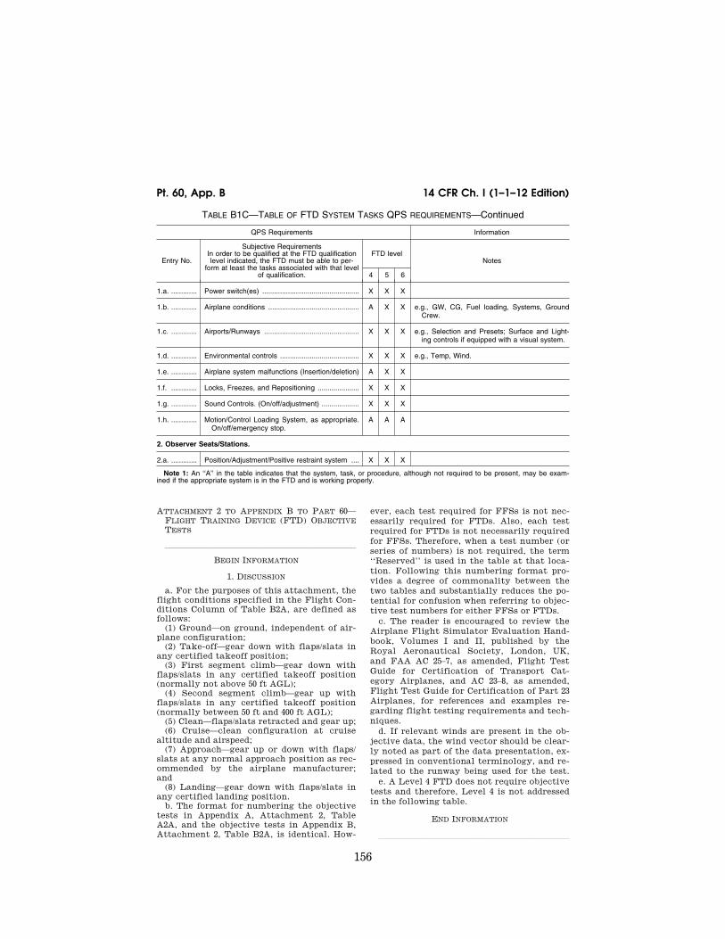
156
14 CFR Ch. I (1–1–12 Edition) Pt. 60, App. B
TABLE B1C—TABLE OF FTD SYSTEM TASKS QPS REQUIREMENTS—Continued
QPS Requirements Information
Entry No.
Subjective Requirements In order to be qualified at the FTD qualification level indicated, the FTD must be able to per-
form at least the tasks associated with that level of qualification.
FTD level Notes
4 5 6
1.a. ............. Power switch(es) ................................................. X X X
1.b. ............. Airplane conditions .............................................. A X X e.g., GW, CG, Fuel loading, Systems, Ground Crew.
1.c. ............. Airports/Runways ................................................ X X X e.g., Selection and Presets; Surface and Light-ing controls if equipped with a visual system.
1.d. ............. Environmental controls ........................................ X X X e.g., Temp, Wind.
1.e. ............. Airplane system malfunctions (Insertion/deletion) A X X
1.f. ............. Locks, Freezes, and Repositioning ..................... X X X
1.g. ............. Sound Controls. (On/off/adjustment) ................... X X X
1.h. ............. Motion/Control Loading System, as appropriate. On/off/emergency stop.
A A A
2. Observer Seats/Stations.
2.a. ............. Position/Adjustment/Positive restraint system .... X X X
Note 1: An ‘‘A’’ in the table indicates that the system, task, or procedure, although not required to be present, may be exam-ined if the appropriate system is in the FTD and is working properly.
ATTACHMENT 2 TO APPENDIX B TO PART 60— FLIGHT TRAINING DEVICE (FTD) OBJECTIVE TESTS
lllllllllllllllllllllll
BEGIN INFORMATION
1. DISCUSSION
a. For the purposes of this attachment, the flight conditions specified in the Flight Con-ditions Column of Table B2A, are defined as follows:
(1) Ground—on ground, independent of air-plane configuration;
(2) Take-off—gear down with flaps/slats in any certified takeoff position;
(3) First segment climb—gear down with flaps/slats in any certified takeoff position (normally not above 50 ft AGL);
(4) Second segment climb—gear up with flaps/slats in any certified takeoff position (normally between 50 ft and 400 ft AGL);
(5) Clean—flaps/slats retracted and gear up; (6) Cruise—clean configuration at cruise
altitude and airspeed; (7) Approach—gear up or down with flaps/
slats at any normal approach position as rec-ommended by the airplane manufacturer; and
(8) Landing—gear down with flaps/slats in any certified landing position.
b. The format for numbering the objective tests in Appendix A, Attachment 2, Table A2A, and the objective tests in Appendix B, Attachment 2, Table B2A, is identical. How-
ever, each test required for FFSs is not nec-essarily required for FTDs. Also, each test required for FTDs is not necessarily required for FFSs. Therefore, when a test number (or series of numbers) is not required, the term ‘‘Reserved’’ is used in the table at that loca-tion. Following this numbering format pro-vides a degree of commonality between the two tables and substantially reduces the po-tential for confusion when referring to objec-tive test numbers for either FFSs or FTDs.
c. The reader is encouraged to review the Airplane Flight Simulator Evaluation Hand-book, Volumes I and II, published by the Royal Aeronautical Society, London, UK, and FAA AC 25–7, as amended, Flight Test Guide for Certification of Transport Cat-egory Airplanes, and AC 23–8, as amended, Flight Test Guide for Certification of Part 23 Airplanes, for references and examples re-garding flight testing requirements and tech-niques.
d. If relevant winds are present in the ob-jective data, the wind vector should be clear-ly noted as part of the data presentation, ex-pressed in conventional terminology, and re-lated to the runway being used for the test.
e. A Level 4 FTD does not require objective tests and therefore, Level 4 is not addressed in the following table.
END INFORMATION
lllllllllllllllllllllll
VerDate Mar<15>2010 18:16 Mar 01, 2012 Jkt 226045 PO 00000 Frm 00166 Fmt 8010 Sfmt 8002 Q:\14\14V2 ofr150 PsN: PC150

157
Federal Aviation Administration, DOT Pt. 60, App. B
BEGIN QPS REQUIREMENTS
2. TEST REQUIREMENTS
a. The ground and flight tests required for qualification are listed in Table B2A Objec-tive Tests. Computer generated FTD test re-sults must be provided for each test except where an alternate test is specifically au-thorized by the NSPM. If a flight condition or operating condition is required for the test but does not apply to the airplane being simulated or to the qualification level sought, it may be disregarded (e.g., an engine out missed approach for a single-engine air-plane; a maneuver using reverse thrust for an airplane without reverse thrust capa-bility). Each test result is compared against the validation data described in § 60.13, and in Appendix B. The results must be produced on an appropriate recording device accept-able to the NSPM and must include FTD number, date, time, conditions, tolerances, and appropriate dependent variables por-trayed in comparison to the validation data. Time histories are required unless otherwise indicated in Table B2A. All results must be labeled using the tolerances and units given.
b. Table B2A in this attachment sets out the test results required, including the pa-rameters, tolerances, and flight conditions for FTD validation. Tolerances are provided for the listed tests because mathematical modeling and acquisition and development of reference data are often inexact. All toler-ances listed in the following tables are ap-plied to FTD performance. When two toler-ance values are given for a parameter, the less restrictive may be used unless otherwise indicated. In those cases where a tolerance is expressed only as a percentage, the tolerance percentage applies to the maximum value of that parameter within its normal operating range as measured from the neutral or zero position unless otherwise indicated.
c. Certain tests included in this attach-ment must be supported with a SOC. In Table B2A, requirements for SOCs are indi-cated in the ‘‘Test Details’’ column.
d. When operational or engineering judg-ment is used in making assessments for flight test data applications for FTD valid-ity, such judgment may not be limited to a single parameter. For example, data that ex-hibit rapid variations of the measured pa-rameters may require interpolations or a ‘‘best fit’’ data section. All relevant param-eters related to a given maneuver or flight condition must be provided to allow overall interpretation. When it is difficult or impos-sible to match FTD to airplane data throughout a time history, differences must be justified by providing a comparison of other related variables for the condition being assessed.
e. It is not acceptable to program the FTD so that the mathematical modeling is cor-rect only at the validation test points. Un-
less noted otherwise, tests must represent airplane performance and handling qualities at operating weights and centers of gravity (CG) typical of normal operation. If a test is supported by aircraft data at one extreme weight or CG, another test supported by air-craft data at mid-conditions or as close as possible to the other extreme is necessary. Certain tests that are relevant only at one extreme CG or weight condition need not be repeated at the other extreme. The results of the tests for Level 6 are expected to be indic-ative of the device’s performance and han-dling qualities throughout all of the fol-lowing:
(1) The airplane weight and CG envelope; (2) The operational envelope; and (3) Varying atmospheric ambient and envi-
ronmental conditions—including the ex-tremes authorized for the respective airplane or set of airplanes.
f. When comparing the parameters listed to those of the airplane, sufficient data must also be provided to verify the correct flight condition and airplane configuration changes. For example, to show that control force is within the parameters for a static stability test, data to show the correct air-speed, power, thrust or torque, airplane con-figuration, altitude, and other appropriate datum identification parameters must also be given. If comparing short period dynam-ics, normal acceleration may be used to es-tablish a match to the airplane, but airspeed, altitude, control input, airplane configura-tion, and other appropriate data must also be given. If comparing landing gear change dynamics, pitch, airspeed, and altitude may be used to establish a match to the airplane, but landing gear position must also be pro-vided. All airspeed values must be properly annotated (e.g., indicated versus calibrated). In addition, the same variables must be used for comparison (e.g., compare inches to inches rather than inches to centimeters).
g. The QTG provided by the sponsor must clearly describe how the FTD will be set up and operated for each test. Each FTD sub-system may be tested independently, but overall integrated testing of the FTD must be accomplished to assure that the total FTD system meets the prescribed standards. A manual test procedure with explicit and detailed steps for completing each test must also be provided.
h. For previously qualified FTDs, the tests and tolerances of this attachment may be used in subsequent continuing qualification evaluations for any given test if the sponsor has submitted a proposed MQTG revision to the NSPM and has received NSPM approval.
i. FTDs are evaluated and qualified with an engine model simulating the airplane data supplier’s flight test engine. For qualifica-tion of alternative engine models (either variations of the flight test engines or other manufacturer’s engines) additional tests
VerDate Mar<15>2010 18:16 Mar 01, 2012 Jkt 226045 PO 00000 Frm 00167 Fmt 8010 Sfmt 8002 Q:\14\14V2 ofr150 PsN: PC150

158
14 CFR Ch. I (1–1–12 Edition) Pt. 60, App. B
with the alternative engine models may be required. This attachment contains guide-lines for alternative engines.
j. Testing Computer Controlled Aircraft (CCA) simulators, or other highly augmented airplane simulators, flight test data is re-quired for the Normal (N) and/or Non-normal (NN) control states, as indicated in this at-tachment. Where test results are inde-pendent of control state, Normal or Non-nor-mal control data may be used. All tests in Table B2A require test results in the Normal control state unless specifically noted other-wise in the Test Details section following the CCA designation. The NSPM will determine what tests are appropriate for airplane sim-ulation data. When making this determina-tion, the NSPM may require other levels of control state degradation for specific air-plane tests. Where Non-normal control states are required, test data must be pro-vided for one or more Non-normal control states, and must include the least aug-mented state. Where applicable, flight test data must record Normal and Non-normal states for:
(1) Pilot controller deflections or electroni-cally generated inputs, including location of input; and
(2) Flight control surface positions unless test results are not affected by, or are inde-pendent of, surface positions.
k. Tests of handling qualities must include validation of augmentation devices. FTDs for highly augmented airplanes will be vali-dated both in the unaugmented configura-tion (or failure state with the maximum per-mitted degradation in handling qualities) and the augmented configuration. Where various levels of handling qualities result from failure states, validation of the effect of the failure is necessary. Requirements for
testing will be mutually agreed to between the sponsor and the NSPM on a case-by-case basis.
l. Some tests will not be required for air-planes using airplane hardware in the FTD flight deck (e.g., ‘‘side stick controller’’). These exceptions are noted in Section 2 ‘‘Handling Qualities’’ in Table B2A of this at-tachment. However, in these cases, the spon-sor must provide a statement that the air-plane hardware meets the appropriate manu-facturer’s specifications and the sponsor must have supporting information to that fact available for NSPM review.
m. For objective test purposes, see Appen-dix F of this part for the definitions of ‘‘Near maximum,’’ ‘‘Light,’’ and ‘‘Medium’’ gross weight.
END QPS REQUIREMENTS
lllllllllllllllllllllll
BEGIN INFORMATION
n. In those cases where the objective test results authorize a ‘‘snapshot test’’ or a ‘‘se-ries of snapshot test results’’ in lieu of a time-history result, the sponsor or other data provider must ensure that a steady state condition exists at the instant of time captured by the ‘‘snapshot.’’ The steady state condition must exist from 4 seconds prior to, through 1 second following, the in-stant of time captured by the snap shot.
o. Refer to AC 120–27, ‘‘Aircraft Weight and Balance’’ and FAA–H–8083–1, ‘‘Aircraft Weight and Balance Handbook’’ for more in-formation.
END INFORMATION
lllllllllllllllllllllll
VerDate Mar<15>2010 18:16 Mar 01, 2012 Jkt 226045 PO 00000 Frm 00168 Fmt 8010 Sfmt 8002 Q:\14\14V2 ofr150 PsN: PC150

159
Federal Aviation Administration, DOT Pt. 60, App. B
TA
BLE
B2A
—F
LIG
HT
TR
AIN
ING
DE
VIC
E(F
TD
) O
BJE
CT
IVE
TE
ST
S
QP
S r
equi
rem
ents
Tes
t T
oler
ance
s F
light
con
ditio
ns
Tes
t de
tails
FT
D
leve
l In
form
atio
n
Ent
ry N
o.
Titl
e 5
6 N
otes
1. P
erfo
rman
ce
1.a.
......
.....
(Res
erve
d)
1.b.
......
.....
Tak
eoff
1.b.
1....
.....
Gro
und
Acc
eler
atio
n T
ime
..±5
% t
ime
or ±
1 se
c...
......
....
Tak
eoff
......
......
......
......
......
..R
ecor
d ac
cele
ratio
n tim
e fo
r a
min
imum
of
80%
of
the
segm
ent
from
bra
ke r
e-le
ase
to V
R.
Pre
limin
ary
airc
raft
cert
ifica
tion
data
may
be
use
d.
X
Thi
s te
st is
req
uire
d on
ly if
R
TO
tra
inin
g cr
edit
is
soug
ht.
1.b.
2.
thro
ugh
1.b.
6.
(Res
erve
d)
1.b.
7....
.....
Rej
ecte
d T
akeo
ff...
......
......
..±5
% t
ime
or ±
1.5
sec
......
....
Dry
Run
way
......
......
......
......
Rec
ord
time
for
at l
east
80%
of
the
seg-
men
t fr
om
initi
atio
n of
th
e R
ejec
ted
Tak
eoff
to f
ull s
top.
X
Thi
s te
st is
req
uire
d on
ly if
R
TO
tra
inin
g cr
edit
is
soug
ht.
1.b.
8....
.....
(Res
erve
d)
1.c.
......
.....
Clim
b
1.c.
1....
.....
Nor
mal
Clim
b al
l eng
ines
op
erat
ing.
±3 k
t ai
rspe
ed,
±5%
or
±100
ft/m
in (
0.5
m/s
ec)
clim
b ra
te.
Cle
an...
......
......
......
......
......
..F
light
te
st
data
or
ai
rpla
ne
perf
orm
ance
m
anua
l da
ta m
ay b
e us
ed.
Rec
ord
at
nom
inal
clim
b sp
eed
and
at n
omin
al a
l-tit
ude.
May
be
a sn
apsh
ot t
est
resu
lt.
FT
D
perf
orm
ance
m
ust
be
reco
rded
ov
er a
n in
terv
al o
f at
lea
st 1
,000
ft
(300
m
).
X
X
1.c.
2.
thro
ugh
1.c.
4.
(Res
erve
d)
1.d.
......
.....
(Res
erve
d)
1.e.
......
.....
(Res
erve
d)
1.f.
......
......
Eng
ines
VerDate Mar<15>2010 18:16 Mar 01, 2012 Jkt 226045 PO 00000 Frm 00169 Fmt 8010 Sfmt 8002 Q:\14\14V2 ofr150 PsN: PC150

160
14 CFR Ch. I (1–1–12 Edition) Pt. 60, App. B
TA
BLE
B2A
—F
LIG
HT
TR
AIN
ING
DE
VIC
E(F
TD
) O
BJE
CT
IVE
TE
ST
S—
Con
tinue
d
QP
S r
equi
rem
ents
Tes
t T
oler
ance
s F
light
con
ditio
ns
Tes
t de
tails
FT
D
leve
l In
form
atio
n
Ent
ry N
o.
Titl
e 5
6 N
otes
1.f.1
....
......
Acc
eler
atio
n...
......
......
......
...Le
vel 6
: ±1
0% T
t, or
±0.
25
sec.
Le
vel 5
: ±1
sec
......
......
......
.
App
roac
h or
Lan
ding
......
....
Rec
ord
engi
ne
pow
er
(N1,
N2,
EP
R,
Tor
que,
Man
ifold
Pre
ssur
e) f
rom
idl
e to
m
axim
um
take
off
pow
er
for
a ra
pid
(sla
m)
thro
ttle
mov
emen
t.
X
X
See
App
endi
x F
of
this
par
t fo
r de
finiti
ons
of T
ian
d T
t.
1.f.2
....
......
Dec
eler
atio
n...
......
......
......
...Le
vel 6
: ±1
0% T
t, or
±0.
25
sec.
Leve
l 5:
±1 s
ec...
......
......
....
Gro
und
......
......
......
......
......
..R
ecor
d en
gine
po
wer
(N
1,
N2,
EP
R,
Tor
que,
Man
ifold
Pre
ssur
e) f
rom
max
-im
um t
akeo
ff po
wer
to
idle
for
a r
apid
(s
lam
) th
rottl
e m
ovem
ent.
X
X
See
App
endi
x F
of
this
par
t fo
r de
finiti
ons
of T
ian
d T
t.
2. H
and
ling
Qu
alit
ies
For
FT
Ds
requ
iring
Sta
tic t
ests
at
the
cont
rols
(i.e
., co
lum
n, w
heel
, ru
dder
ped
al),
spe
cial
tes
t fix
ture
s w
ill n
ot b
e re
quire
d du
ring
initi
al
or u
pgra
de e
valu
atio
ns if
the
spo
nsor
’s Q
TG
/MQ
TG
sho
ws
both
tes
t fix
ture
res
ults
and
the
res
ults
of
an a
ltern
ativ
e ap
proa
ch,
such
as
com
pute
r pl
ots
prod
uced
con
curr
ently
, th
at s
how
sat
isfa
ctor
y ag
reem
ent.
Rep
eat
of t
he a
ltern
ativ
e m
etho
d du
ring
the
initi
al o
r up
grad
e ev
alua
tion
wou
ld t
hen
satis
fy t
his
test
req
uire
men
t.
Tes
ting
of p
ositi
on v
ersu
s fo
rce
is n
ot a
pplic
able
if
forc
es a
re g
ener
ated
so
lely
by
use
of a
irpla
ne
hard
war
e in
the
FT
D.
2.a.
......
.....
Sta
tic C
ontr
ol T
ests
2.a.
1.a.
.....
Pitc
h C
ontr
olle
r P
ositi
on v
s.
For
ce a
nd S
urfa
ce P
osi-
tion
Cal
ibra
tion.
±2 lb
(0.
9 da
N)
brea
kout
, ±1
0% o
r ±5
lb (
2.2
daN
) fo
rce,
±2°
ele
vato
r.
Gro
und
......
......
......
......
......
..R
ecor
d re
sults
for
an
unin
terr
upte
d co
ntro
l sw
eep
to t
he s
tops
.X
2.a.
1.b.
.....
Pitc
h C
ontr
olle
r P
ositi
on v
s.
For
ce.
±2 lb
(0.
9 da
N)
brea
kout
, ±1
0% o
r ±5
lb (
2.2
daN
) fo
rce.
As
dete
rmin
ed b
y sp
onso
r..
Rec
ord
resu
lts
durin
g in
itial
qu
alifi
catio
n ev
alua
tion
for
an
unin
terr
upte
d co
ntro
l sw
eep
to t
he s
tops
. T
he r
ecor
ded
tole
r-an
ces
appl
y to
sub
sequ
ent
com
paris
ons
on c
ontin
uing
qua
lific
atio
n ev
alua
tions
.
X
App
licab
le o
nly
on c
on-
tinui
ng q
ualif
icat
ion
eval
-ua
tions
. T
he in
tent
is t
o de
sign
the
con
trol
fee
l for
Le
vel 5
to
be a
ble
to
man
ually
fly
an
inst
ru-
men
t ap
proa
ch;
and
not
to c
ompa
re r
esul
ts t
o fli
ght
test
or
othe
r su
ch
data
.
2.a.
2.a.
.....
Rol
l Con
trol
ler
Pos
ition
vs.
F
orce
and
Sur
face
Pos
i-tio
n C
alib
ratio
n.
±2 lb
(0.
9 da
N)
brea
kout
, ±1
0% o
r ±3
lb (
1.3
daN
) fo
rce,
±2°
aile
ron,
±3°
sp
oile
r an
gle.
Gro
und
......
......
......
......
......
..R
ecor
d re
sults
for
an
unin
terr
upte
d co
ntro
l sw
eep
to t
he s
tops
.X
VerDate Mar<15>2010 18:16 Mar 01, 2012 Jkt 226045 PO 00000 Frm 00170 Fmt 8010 Sfmt 8002 Q:\14\14V2 ofr150 PsN: PC150
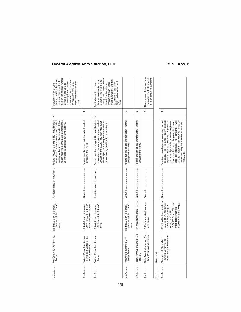
161
Federal Aviation Administration, DOT Pt. 60, App. B
2.a.
2.b.
.....
Rol
l Con
trol
ler
Pos
ition
vs.
F
orce
.±2
lb (
0.9
daN
) br
eako
ut,
±10%
or
±3 lb
(1.
3 da
N)
forc
e.
As
dete
rmin
ed b
y sp
onso
r..
Rec
ord
resu
lts
durin
g in
itial
qu
alifi
catio
n ev
alua
tion
for
an
unin
terr
upte
d co
ntro
l sw
eep
to t
he s
tops
. T
he r
ecor
ded
tole
r-an
ces
appl
y to
sub
sequ
ent
com
paris
ons
on c
ontin
uing
qua
lific
atio
n ev
alua
tions
.
X
App
licab
le o
nly
on c
on-
tinui
ng q
ualif
icat
ion
eval
-ua
tions
. T
he in
tent
is t
o de
sign
the
con
trol
fee
l for
Le
vel 5
to
be a
ble
to
man
ually
fly
an
inst
ru-
men
t ap
proa
ch;
and
not
to c
ompa
re r
esul
ts t
o fli
ght
test
or
othe
r su
ch
data
.
2.a.
3.a.
.....
Rud
der
Ped
al P
ositi
on v
s.
For
ce a
nd S
urfa
ce P
osi-
tion
Cal
ibra
tion.
±5 lb
(2.
2 da
N)
brea
kout
, ±1
0% o
r ±5
lb (
2.2
daN
) fo
rce,
±2°
rudd
er a
ngle
.
Gro
und
......
......
......
......
......
..R
ecor
d re
sults
for
an
unin
terr
upte
d co
ntro
l sw
eep
to t
he s
tops
.X
2.a.
3.b.
.....
Rud
der
Ped
al P
ositi
on v
s.
For
ce.
±5 lb
(2.
2 da
N)
brea
kout
, ±1
0% o
r ±5
lb (
2.2
daN
) fo
rce.
As
dete
rmin
ed b
y sp
onso
r..
Rec
ord
resu
lts
durin
g in
itial
qu
alifi
catio
n ev
alua
tion
for
an
unin
terr
upte
d co
ntro
l sw
eep
to t
he s
tops
. T
he r
ecor
ded
tole
r-an
ces
appl
y to
sub
sequ
ent
com
paris
ons
on c
ontin
uing
qua
lific
atio
n ev
alua
tions
.
X
App
licab
le o
nly
on c
on-
tinui
ng q
ualif
icat
ion
eval
-ua
tions
. T
he in
tent
is t
o de
sign
the
con
trol
fee
l for
Le
vel 5
to
be a
ble
to
man
ually
fly
an
inst
ru-
men
t ap
proa
ch;
and
not
to c
ompa
re r
esul
ts t
o fli
ght
test
or
othe
r su
ch
data
.
2.a.
4....
.....
Nos
ewhe
el S
teer
ing
Con
-tr
olle
r F
orce
.±2
lb (
0.9
daN
) br
eako
ut,
±10%
or
±3 lb
(1.
3 da
N)
forc
e.
Gro
und
......
......
......
......
......
..R
ecor
d re
sults
of
an u
nint
erru
pted
con
trol
sw
eep
to t
he s
tops
.X
2.a.
5....
.....
Rud
der
Ped
al S
teer
ing
Cal
i-br
atio
n.±2
° no
sew
heel
ang
le...
......
.G
roun
d...
......
......
......
......
.....
Rec
ord
resu
lts o
f an
uni
nter
rupt
ed c
ontr
ol
swee
p to
the
sto
ps.
X
2.a.
6....
.....
Pitc
h T
rim I
ndic
ator
vs.
Sur
-fa
ce P
ositi
on C
alib
ratio
n.±0
.5°
of c
ompu
ted
trim
sur
-fa
ce a
ngle
.G
roun
d...
......
......
......
......
.....
X
The
pur
pose
of
the
test
is t
o co
mpa
re t
he F
TD
aga
inst
de
sign
dat
a or
equ
ival
ent.
2.a.
7....
.....
(Res
erve
d)
2.a.
8....
.....
Alig
nmen
t of
Flig
ht d
eck
Thr
ottle
Lev
er v
s. S
e-le
cted
Eng
ine
Par
amet
er.
±5°
of t
hrot
tle le
ver
angl
e or
±0
.8 in
(2
cm)
for
pow
er
cont
rol w
ithou
t an
gula
r tr
avel
, or
±3%
N1,
or
±0.0
3 E
PR
, or
±3%
max
-im
um r
ated
man
ifold
pr
essu
re,
or ±
3% t
orqu
e.
Gro
und
......
......
......
......
......
..R
equi
res
sim
ulta
neou
s re
cord
ing
for
all
engi
nes.
T
he
tole
ranc
es
appl
y ag
ains
t ai
rpla
ne d
ata
and
betw
een
engi
nes.
In
the
case
of
prop
elle
r po
wer
ed a
irpla
nes,
if
a pr
opel
ler
leve
r is
pre
sent
, it
mus
t al
so
be
chec
ked.
F
or
airp
lane
s w
ith
thro
ttle
‘‘det
ents
,’’
all
dete
nts
mus
t be
pr
esen
ted.
May
be
a se
ries
of s
naps
hot
test
res
ults
.
X
VerDate Mar<15>2010 18:16 Mar 01, 2012 Jkt 226045 PO 00000 Frm 00171 Fmt 8010 Sfmt 8002 Q:\14\14V2 ofr150 PsN: PC150

162
14 CFR Ch. I (1–1–12 Edition) Pt. 60, App. B
TA
BLE
B2A
—F
LIG
HT
TR
AIN
ING
DE
VIC
E(F
TD
) O
BJE
CT
IVE
TE
ST
S—
Con
tinue
d
QP
S r
equi
rem
ents
Tes
t T
oler
ance
s F
light
con
ditio
ns
Tes
t de
tails
FT
D
leve
l In
form
atio
n
Ent
ry N
o.
Titl
e 5
6 N
otes
2.a.
9....
.....
Bra
ke P
edal
Pos
ition
vs.
F
orce
.±5
lb (
2.2
daN
) or
10%
fo
rce.
Gro
und
......
......
......
......
......
..T
wo
data
poi
nts
are
requ
ired:
Zer
o an
d m
axim
um
defle
ctio
n.
Com
pute
r ou
tput
re
sults
m
ay
be
used
to
sh
ow
com
pli-
ance
.
X
Tes
t no
t re
quire
d un
less
R
TO
cre
dit
is s
ough
t.
2.b.
......
.....
(Res
erve
d)
2.c.
......
.....
Long
itudi
nal C
ontr
ol T
ests
Pow
er s
ettin
g is
tha
t re
quire
d fo
r le
vel f
light
unl
ess
othe
rwis
e sp
ecifi
ed.
2.c.
1....
.....
Pow
er C
hang
e F
orce
......
....
±5 lb
(2.
2 da
N)
or,
±20%
pi
tch
conr
ol f
orce
.A
ppro
ach
......
......
......
......
.....
May
be
a se
ries
of s
naps
hot
test
res
ults
. P
ower
ch
ange
dy
nam
ics
test
as
de
-sc
ribed
in t
est
2.c.
1 of
Tab
le A
2A o
f th
is
part
will
be
acce
pted
. C
CA
: T
est
in N
or-
mal
and
Non
-nor
mal
con
trol
sta
tes.
X
X
2.c.
2....
.....
Fla
p/S
lat
Cha
nge
For
ce...
...±5
lb (
2.2
daN
) or
, ±2
0%
pitc
h co
nrol
for
ce.
Tak
eoff
thro
ugh
initi
al f
lap
retr
actio
n, a
nd a
ppro
ach
to la
ndin
g.
May
be
a se
ries
of s
naps
hot
test
res
ults
. F
lap/
Sla
t ch
ange
dyn
amic
s te
st a
s de
-sc
ribed
in t
est
2.c.
2 of
Tab
le A
2A o
f th
is
part
will
be
acce
pted
. C
CA
: T
est
in N
or-
mal
and
Non
-nor
mal
con
trol
sta
tes.
X
X
2.c.
3....
.....
(Res
erve
d)
2.c.
4....
.....
Gea
r C
hang
e F
orce
......
......
±5 lb
(2.
2 da
N)
or,
±20%
pi
tch
conr
ol f
orce
.T
akeo
ff (r
etra
ctio
n) a
nd A
p-pr
oach
(ex
tens
ion)
.M
ay b
e a
serie
s of
sna
psho
t te
st r
esul
ts.
Gea
r ch
ange
dy
nam
ics
test
as
de
-sc
ribed
in t
est
2.c.
4 of
Tab
le A
2A o
f th
is
part
will
be
acce
pted
. C
CA
: T
est
in N
or-
mal
and
Non
-nor
mal
con
trol
sta
tes.
X
X
2.c.
5....
.....
Long
itudi
nal T
rim...
......
......
.±0
.5°
trim
sur
face
ang
le ±
1°
elev
ator
±1°
pitc
h an
gle
±5%
net
thr
ust
or e
quiv
a-le
nt.
Cru
ise,
App
roac
h, a
nd
Land
ing.
Rec
ord
stea
dy-s
tate
con
ditio
n w
ith w
ings
le
vel
and
thru
st s
et f
or l
evel
flig
ht.
May
be
a s
erie
s of
sna
psho
t te
sts
Leve
l 5
may
use
equ
ival
ent
stic
k an
d tr
im c
on-
trol
lers
in
lieu
of e
leva
tor
and
trim
sur
-fa
ce.
CC
A:
Tes
t in
N
orm
al
and
Non
- no
rmal
con
trol
sta
tes.
X
X
VerDate Mar<15>2010 18:16 Mar 01, 2012 Jkt 226045 PO 00000 Frm 00172 Fmt 8010 Sfmt 8002 Q:\14\14V2 ofr150 PsN: PC150

163
Federal Aviation Administration, DOT Pt. 60, App. B
2.c.
6....
.....
Long
itudi
nal M
aneu
verin
g S
tabi
lity
(Stic
k F
orce
/g).
±5 lb
(±2
.2 d
aN)
or ±
10%
pi
tch
cont
rolle
r fo
rce
Al-
tern
ativ
e m
etho
d: ±
1° o
r ±1
0% c
hang
e of
ele
vato
r.
Cru
ise,
App
roac
h, a
nd
Land
ing.
Con
tinuo
us t
ime
hist
ory
data
or
a se
ries
of s
naps
hot
test
s m
ay b
e us
ed.
Rec
ord
resu
lts u
p to
30°
of
bank
for
app
roac
h an
d la
ndin
g co
nfig
urat
ions
. R
ecor
d re
-su
lts f
or u
p to
45°
of
bank
for
the
cru
ise
conf
igur
atio
n. T
he f
orce
tol
eran
ce i
s no
t ap
plic
able
if
forc
es a
re g
ener
ated
sol
ely
by t
he u
se o
f ai
rpla
ne h
ardw
are
in t
he
FT
D.
The
alte
rnat
ive
met
hod
appl
ies
to
airp
lane
s th
at
do
not
exhi
bit
‘‘stic
k-
forc
e-pe
r-g’
’ ch
arac
teris
tics.
C
CA
: T
est
in
Nor
mal
an
d N
on-n
orm
al
cont
rol
stat
es.
X
2.c.
7....
.....
Long
itudi
nal S
tatic
Sta
bilit
y±5
lb (
±2.2
daN
) or
±10
%
pitc
h co
ntro
ller
forc
e.A
ltern
ativ
e m
etho
d: ±
1° o
r ±1
0% c
hang
e of
ele
vato
r.
App
roac
h...
......
......
......
......
..M
ay b
e a
serie
s of
sna
psho
t te
st r
esul
ts.
Rec
ord
resu
lts
for
at
leas
t 2
spee
ds
abov
e an
d 2
spee
ds b
elow
trim
spe
ed.
The
for
ce t
oler
ance
is
not
appl
icab
le i
f fo
rces
are
gen
erat
ed s
olel
y by
the
use
of
airp
lane
har
dwar
e in
the
FT
D.
The
al
tern
ativ
e m
etho
d ap
plie
s to
airp
lane
s th
at d
o no
t ex
hibi
t sp
eed
stab
ility
cha
r-ac
teris
tics.
Lev
el 5
mus
t ex
hibi
t po
sitiv
e st
atic
sta
bilit
y, b
ut n
eed
not
com
ply
with
th
e nu
mer
ical
tol
eran
ce.
CC
A:
Tes
t in
N
orm
al a
nd N
on-n
orm
al c
ontr
ol s
tate
s.
X
X
2.c.
8....
.....
Sta
ll W
arni
ng (
actu
atio
n of
st
all w
arni
ng d
evic
e.).
±3 k
ts.
airs
peed
, ±2
° ba
nk
for
spee
ds g
reat
er t
han
actu
atio
n of
sta
ll w
arni
ng
devi
ce o
r in
itial
buf
fet.
Sec
ond
Seg
men
t C
limb,
an
d A
ppro
ach
or L
andi
ng.
The
sta
ll m
aneu
ver
mus
t be
ent
ered
with
th
rust
at
or n
ear
idle
pow
er a
nd w
ings
le
vel
(1g)
. R
ecor
d th
e st
all
war
ning
sig
-na
l an
d in
itial
buf
fet
if ap
plic
able
. C
CA
: T
est
in N
orm
al a
nd N
on-n
orm
al c
ontr
ol
stat
es.
X
X
2.c.
9.a.
.....
Phu
goid
Dyn
amic
s...
......
.....
±10%
per
iod,
±10
% o
f tim
e to
1⁄2
or d
oubl
e am
plitu
de
or ±
.02
of d
ampi
ng r
atio
.
Cru
ise
......
......
......
......
......
....
The
tes
t m
ust
incl
ude
whi
chev
er i
s le
ss o
f th
e fo
llow
ing:
Thr
ee f
ull c
ycle
s (s
ix o
ver-
shoo
ts a
fter
the
inpu
t is
com
plet
ed),
or
the
num
ber
of c
ycle
s su
ffici
ent
to d
eter
-m
ine
time
to
1⁄2
or
doub
le
ampl
itude
. C
CA
: T
est
in N
on-n
orm
al c
ontr
ol s
tate
.
X
2.c.
9.b.
.....
Phu
goid
Dyn
amic
s...
......
.....
±10%
per
iod,
Rep
rese
nta-
tive
dam
ping
.C
ruis
e...
......
......
......
......
......
.T
he t
est
mus
t in
clud
e w
hich
ever
is
less
of
the
follo
win
g: T
hree
ful
l cyc
les
(six
ove
r-sh
oots
afte
r th
e in
put
is c
ompl
eted
), o
r th
e nu
mbe
r of
cyc
les
suffi
cien
t to
det
er-
min
e re
pres
enta
tive
dam
ping
. C
CA
: T
est
in N
on-n
orm
al c
ontr
ol s
tate
.
X
VerDate Mar<15>2010 18:16 Mar 01, 2012 Jkt 226045 PO 00000 Frm 00173 Fmt 8010 Sfmt 8002 Q:\14\14V2 ofr150 PsN: PC150
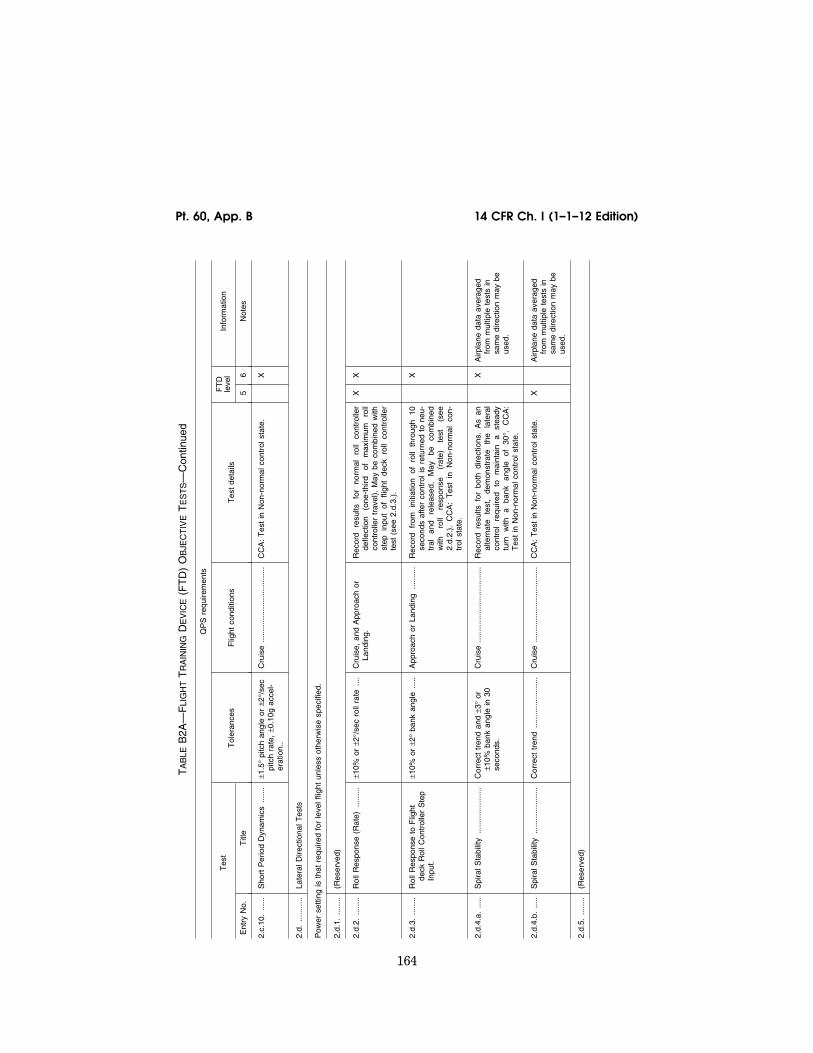
164
14 CFR Ch. I (1–1–12 Edition) Pt. 60, App. B
TA
BLE
B2A
—F
LIG
HT
TR
AIN
ING
DE
VIC
E(F
TD
) O
BJE
CT
IVE
TE
ST
S—
Con
tinue
d
QP
S r
equi
rem
ents
Tes
t T
oler
ance
s F
light
con
ditio
ns
Tes
t de
tails
FT
D
leve
l In
form
atio
n
Ent
ry N
o.
Titl
e 5
6 N
otes
2.c.
10.
......
Sho
rt P
erio
d D
ynam
ics
......
.±1
.5°
pitc
h an
gle
or ±
2°/s
ec
pitc
h ra
te,
±0.1
0g a
ccel
-er
atio
n..
Cru
ise
......
......
......
......
......
....
CC
A:
Tes
t in
Non
-nor
mal
con
trol
sta
te.
X
2.d.
......
.....
Late
ral D
irect
iona
l Tes
ts
Pow
er s
ettin
g is
tha
t re
quire
d fo
r le
vel f
light
unl
ess
othe
rwis
e sp
ecifi
ed.
2.d.
1....
.....
(Res
erve
d)
2.d.
2....
.....
Rol
l Res
pons
e (R
ate)
......
...±1
0% o
r ±2
°/se
c ro
ll ra
te...
.C
ruis
e, a
nd A
ppro
ach
or
Land
ing.
Rec
ord
resu
lts
for
norm
al
roll
cont
rolle
r de
flect
ion
(one
-thi
rd
of
max
imum
ro
ll co
ntro
ller
trav
el).
May
be
com
bine
d w
ith
step
in
put
of
fligh
t de
ck
roll
cont
rolle
r te
st (
see
2.d.
3.).
X
X
2.d.
3....
.....
Rol
l Res
pons
e to
Flig
ht
deck
Rol
l Con
trol
ler
Ste
p In
put.
±10%
or
±2°
bank
ang
le...
..A
ppro
ach
or L
andi
ng...
......
.R
ecor
d fr
om
initi
atio
n of
ro
ll th
roug
h 10
se
cond
s af
ter
cont
rol i
s re
turn
ed t
o ne
u-tr
al
and
rele
ased
. M
ay
be
com
bine
d w
ith
roll
resp
onse
(r
ate)
te
st
(see
2.
d.2.
). C
CA
: T
est
in N
on-n
orm
al c
on-
trol
sta
te.
X
2.d.
4.a.
.....
Spi
ral S
tabi
lity
......
......
......
...C
orre
ct t
rend
and
±3°
or
±10%
ban
k an
gle
in 3
0 se
cond
s.
Cru
ise
......
......
......
......
......
....
Rec
ord
resu
lts f
or b
oth
dire
ctio
ns.
As
an
alte
rnat
e te
st,
dem
onst
rate
th
e la
tera
l co
ntro
l re
quire
d to
m
aint
ain
a st
eady
tu
rn
with
a
bank
an
gle
of
30°.
C
CA
: T
est
in N
on-n
orm
al c
ontr
ol s
tate
.
X
Airp
lane
dat
a av
erag
ed
from
mul
tiple
tes
ts in
sa
me
dire
ctio
n m
ay b
e us
ed.
2.d.
4.b.
.....
Spi
ral S
tabi
lity
......
......
......
...C
orre
ct t
rend
......
......
......
.....
Cru
ise
......
......
......
......
......
....
CC
A:
Tes
t in
Non
-nor
mal
con
trol
sta
te.
X
Airp
lane
dat
a av
erag
ed
from
mul
tiple
tes
ts in
sa
me
dire
ctio
n m
ay b
e us
ed.
2.d.
5....
.....
(Res
erve
d)
VerDate Mar<15>2010 18:16 Mar 01, 2012 Jkt 226045 PO 00000 Frm 00174 Fmt 8010 Sfmt 8002 Q:\14\14V2 ofr150 PsN: PC150
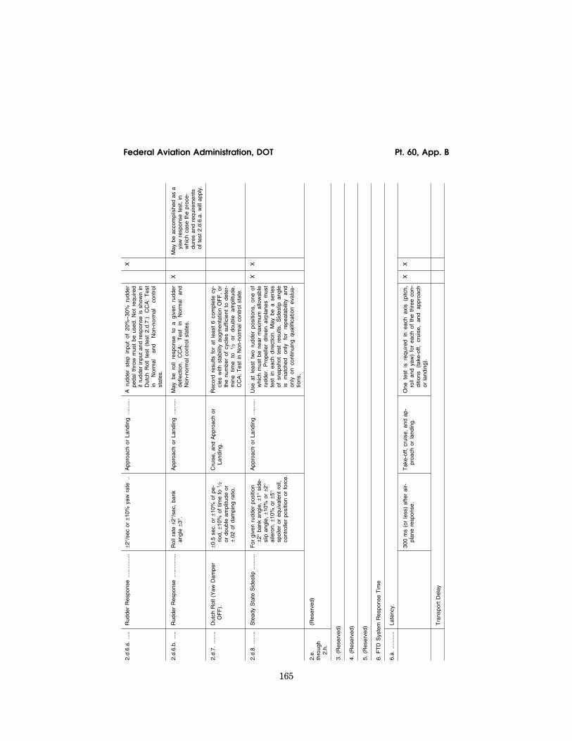
165
Federal Aviation Administration, DOT Pt. 60, App. B
2.d.
6.a.
.....
Rud
der
Res
pons
e...
......
......
±2°/
sec
or ±
10%
yaw
rat
e..
App
roac
h or
Lan
ding
......
....
A r
udde
r st
ep i
nput
of
20%
–30%
rud
der
peda
l th
row
mus
t be
use
d. N
ot r
equi
red
if ru
dder
inpu
t an
d re
spon
se is
sho
wn
in
Dut
ch R
oll
test
(te
st 2
.d.7
.).
CC
A:
Tes
t in
N
orm
al
and
Non
-nor
mal
co
ntro
l st
ates
.
X
2.d.
6.b.
.....
Rud
der
Res
pons
e...
......
......
Rol
l rat
e ±2
°/se
c, b
ank
angl
e ±3
°.A
ppro
ach
or L
andi
ng...
......
.M
ay b
e ro
ll re
spon
se t
o a
give
n ru
dder
de
flect
ion.
C
CA
: T
est
in
Nor
mal
an
d N
on-n
orm
al c
ontr
ol s
tate
s.
X
May
be
acco
mpl
ishe
d as
a
yaw
res
pons
e te
st,
in
whi
ch c
ase
the
proc
e-du
res
and
requ
irem
ents
of
tes
t 2.
d.6.
a. w
ill a
pply
.
2.d.
7....
.....
Dut
ch R
oll (
Yaw
Dam
per
OF
F).
±0.5
sec
. or
±10
% o
f pe
-rio
d, ±
10%
of
time
to 1
⁄2
or d
oubl
e am
plitu
de o
r ±.
02 o
f da
mpi
ng r
atio
.
Cru
ise,
and
App
roac
h or
La
ndin
g.R
ecor
d re
sults
for
at
leas
t 6
com
plet
e cy
-cl
es w
ith s
tabi
lity
augm
enta
tion
OF
F,
or
the
num
ber
of c
ycle
s su
ffici
ent
to d
eter
-m
ine
time
to
1⁄2
or
doub
le
ampl
itude
. C
CA
: T
est
in N
on-n
orm
al c
ontr
ol s
tate
.
2.d.
8....
.....
Ste
ady
Sta
te S
ides
lip...
......
.F
or g
iven
rud
der
posi
tion
±2°
bank
ang
le,
±1°
side
-sl
ip a
ngle
, ±1
0% o
r ±2
° ai
lero
n, ±
10%
or
±5°
spoi
ler
or e
quiv
alen
t ro
ll,
cont
rolle
r po
sitio
n or
for
ce.
App
roac
h or
Lan
ding
......
....
Use
at
leas
t tw
o ru
dder
pos
ition
s, o
ne o
f w
hich
mus
t be
nea
r m
axim
um a
llow
able
ru
dder
. P
rope
ller
driv
en a
irpla
nes
mus
t te
st i
n ea
ch d
irect
ion.
May
be
a se
ries
of s
naps
hot
test
res
ults
. S
ides
lip a
ngle
is
m
atch
ed
only
fo
r re
peat
abili
ty
and
only
on
cont
inui
ng q
ualif
icat
ion
eval
ua-
tions
.
X
X
2.e.
th
roug
h 2.
h.
(Res
erve
d)
3. (
Res
erve
d)
4. (
Res
erve
d)
5. (
Res
erve
d)
6. F
TD
Sys
tem
Res
pons
e T
ime
6.a.
......
.....
Late
ncy.
300
ms
(or
less
) af
ter
air-
plan
e re
spon
se.
Tak
e-of
f, cr
uise
, an
d ap
-pr
oach
or
land
ing.
One
tes
t is
req
uire
d in
eac
h ax
is (
pitc
h,
roll
and
yaw
) fo
r ea
ch o
f th
e th
ree
con-
ditio
ns
(tak
e-of
f, cr
uise
, an
d ap
proa
ch
or la
ndin
g).
X
X
Tra
nspo
rt D
elay
VerDate Mar<15>2010 18:16 Mar 01, 2012 Jkt 226045 PO 00000 Frm 00175 Fmt 8010 Sfmt 8002 Q:\14\14V2 ofr150 PsN: PC150

166
14 CFR Ch. I (1–1–12 Edition) Pt. 60, App. B
TA
BLE
B2A
—F
LIG
HT
TR
AIN
ING
DE
VIC
E(F
TD
) O
BJE
CT
IVE
TE
ST
S—
Con
tinue
d
QP
S r
equi
rem
ents
Tes
t T
oler
ance
s F
light
con
ditio
ns
Tes
t de
tails
FT
D
leve
l In
form
atio
n
Ent
ry N
o.
Titl
e 5
6 N
otes
300
ms
(or
less
) af
ter
con-
trol
ler
mov
emen
t.N
/A...
......
......
......
......
......
.....
A s
epar
ate
test
is
requ
ired
in e
ach
axis
(p
itch,
rol
l, an
d ya
w).
X
X
If T
rans
port
Del
ay is
the
ch
osen
met
hod
to d
em-
onst
rate
rel
ativ
e re
-sp
onse
s, t
he s
pons
or a
nd
the
NS
PM
will
use
the
la-
tenc
y va
lues
to
ensu
re
prop
er s
imul
ator
res
pons
e w
hen
revi
ewin
g th
ose
ex-
istin
g te
sts
whe
re la
tenc
y ca
n be
iden
tifie
d (e
.g.,
shor
t pe
riod,
rol
l re-
spon
se,
rudd
er r
e-sp
onse
).
VerDate Mar<15>2010 18:16 Mar 01, 2012 Jkt 226045 PO 00000 Frm 00176 Fmt 8010 Sfmt 8002 Q:\14\14V2 ofr150 PsN: PC150

167
Federal Aviation Administration, DOT Pt. 60, App. B
lllllllllllllllllllllll
BEGIN INFORMATION
3. FOR ADDITIONAL INFORMATION ON THE FOL-LOWING TOPICS, PLEASE REFER TO APPENDIX A, ATTACHMENT 2, AND THE INDICATED PARA-GRAPH WITHIN THAT ATTACHMENT
• Control Dynamics, paragraph 4. • Motion System, paragraph 6. • Sound System, paragraph 7. • Engineering Simulator Validation Data,
paragraph 9. • Validation Test Tolerances, paragraph
11. • Validation Data Road Map, paragraph 12. • Acceptance Guidelines for Alternative
Engines Data, paragraph 13. • Acceptance Guidelines for Alternative
Avionics, paragraph 14. • Transport Delay Testing, paragraph 15. • Continuing Qualification Evaluation Val-
idation Data Presentation, paragraph 16.
END INFORMATION
lllllllllllllllllllllll
4. ALTERNATIVE OBJECTIVE DATA FOR FTD LEVEL 5
lllllllllllllllllllllll
BEGIN QPS REQUIREMENTS
a. This paragraph (including the following tables) is relevant only to FTD Level 5. It is provided because this level is required to simulate the performance and handling char-acteristics of a set of airplanes with similar characteristics, such as normal airspeed/alti-tude operating envelope and the same num-ber and type of propulsion systems (engines).
b. Tables B2B through B2E reflect FTD performance standards that are acceptable to the FAA. A sponsor must demonstrate that a device performs within these param-eters, as applicable. If a device does not meet the established performance parameters for some or for all of the applicable tests listed in Tables B2B through B2E, the sponsor may
use NSP accepted flight test data for com-parison purposes for those tests.
c. Sponsors using the data from Tables B2B through B2E must comply with the fol-lowing:
(1) Submit a complete QTG, including re-sults from all of the objective tests appro-priate for the level of qualification sought as set out in Table B2A. The QTG must high-light those results that demonstrate the per-formance of the FTD is within the allowable performance ranges indicated in Tables B2B through B2E, as appropriate.
(2) The QTG test results must include all relevant information concerning the condi-tions under which the test was conducted; e.g., gross weight, center of gravity, airspeed, power setting, altitude (climbing, descend-ing, or level), temperature, configuration, and any other parameter that impacts the conduct of the test.
(3) The test results become the validation data against which the initial and all subse-quent continuing qualification evaluations are compared. These subsequent evaluations will use the tolerances listed in Table B2A.
(4) Subjective testing of the device must be performed to determine that the device per-forms and handles like an airplane within the appropriate set of airplanes.
END QPS REQUIREMENTS
lllllllllllllllllllllll
BEGIN INFORMATION
d. The reader is encouraged to consult the Airplane Flight Simulator Evaluation Hand-book, Volumes I and II, published by the Royal Aeronautical Society, London, UK, and AC 25–7, Flight Test Guide for Certifi-cation of Transport Category Airplanes, and AC 23–8A, Flight Test Guide for Certification of Part 23 Airplanes, as amended, for ref-erences and examples regarding flight test-ing requirements and techniques.
END INFORMATION
lllllllllllllllllllllll
TABLE B2B—ALTERNATIVE DATA SOURCE FOR FTD LEVEL 5 SMALL, SINGLE ENGINE (RECIPROCATING) AIRPLANE
QPS requirement The performance parameters in this table must be used to program the FTD if flight test data is not used to program the FTD.
Applicable test Authorized performance range
Entry No. Title and procedure
1. ................ Performance.
1.c .............. Climb
1.c.1. .......... Normal climb with nominal gross weight, at best rate-of- climb airspeed.
Climb rate = 500–1200 fpm (2.5–6 m/sec).
1.f. .............. Engines.
VerDate Mar<15>2010 18:16 Mar 01, 2012 Jkt 226045 PO 00000 Frm 00177 Fmt 8010 Sfmt 8002 Q:\14\14V2 ofr150 PsN: PC150

168
14 CFR Ch. I (1–1–12 Edition) Pt. 60, App. B
TABLE B2B—ALTERNATIVE DATA SOURCE FOR FTD LEVEL 5 SMALL, SINGLE ENGINE (RECIPROCATING) AIRPLANE—Continued
QPS requirement The performance parameters in this table must be used to program the FTD if flight test data is not used to program the FTD.
Applicable test Authorized performance range
Entry No. Title and procedure
1.f.1. ........... Acceleration; idle to takeoff power .................................. 2–4 Seconds.
1.f.2. ........... Deceleration; takeoff power to idle ................................. 2–4 Seconds.
2. ................ Handling Qualities
2.c. ............. Longitudinal Tests
2.c.1. .......... Power change force
(a) Trim for straight and level flight at 80% of normal cruise airspeed with necessary power. Reduce power to flight idle. Do not change trim or configuration. After stabilized, record column force necessary to maintain original airspeed.
5–15 lbs (2.2–6.6 daN) of force (Pull).
OR
(b) Trim for straight and level flight at 80% of normal cruise airspeed with necessary power. Add power to maximum setting. Do not change trim or configura-tion. After stabilized, record column force necessary to maintain original airspeed..
5–15 lbs (2.2–6.6 daN) of force (Push).
2.c.2. .......... Flap/slat change force
(a) Trim for straight and level flight with flaps fully re-tracted at a constant airspeed within the flaps-ex-tended airspeed range. Do not adjust trim or power. Extend the flaps to 50% of full flap travel. After sta-bilized, record stick force necessary to maintain origi-nal airspeed.
5–15 lbs (2.2–6.6 daN) of force (Pull).
OR
(b) Trim for straight and level flight with flaps extended to 50% of full flap travel, at a constant airspeed with-in the flaps-extended airspeed range. Do not adjust trim or power. Retract the flaps to zero. After sta-bilized, record stick force necessary to maintain origi-nal airspeed.
5–15 lbs (2.2–6.6 daN) of force (Push).
2.c.4. .......... Gear change force
(a) Trim for straight and level flight with landing gear re-tracted at a constant airspeed within the landing gear-extended airspeed range. Do not adjust trim or power. Extend the landing gear. After stabilized, record stick force necessary to maintain original air-speed.
2–12 lbs (0.88–5.3 daN) of force (Pull).
OR
(b) Trim for straight and level flight with landing gear extended, at a constant airspeed within the landing gear-extended airspeed range. Do not adjust trim or power. Retract the landing gear. After stabilized, record stick force necessary to maintain original air-speed.
2–12 lbs (0.88–5.3 daN) of force (Push).
2.c.5. .......... Longitudinal trim .............................................................. Must be able to trim longitudinal stick force to ‘‘zero’’ in each of the following configurations: cruise; ap-proach; and landing.
2.c.7. .......... Longitudinal static stability .............................................. Must exhibit positive static stability.
VerDate Mar<15>2010 18:16 Mar 01, 2012 Jkt 226045 PO 00000 Frm 00178 Fmt 8010 Sfmt 8002 Q:\14\14V2 ofr150 PsN: PC150

169
Federal Aviation Administration, DOT Pt. 60, App. B
TABLE B2B—ALTERNATIVE DATA SOURCE FOR FTD LEVEL 5 SMALL, SINGLE ENGINE (RECIPROCATING) AIRPLANE—Continued
QPS requirement The performance parameters in this table must be used to program the FTD if flight test data is not used to program the FTD.
Applicable test Authorized performance range
Entry No. Title and procedure
2.c.8. .......... Stall warning (actuation of stall warning device) with nominal gross weight; wings level; and a deceleration rate of not more than three (3) knots per second.
(a) Landing configuration ................................................ 40–60 knots; ± 5° of bank.
(b) Clean configuration .................................................... Landing configuration speed + 10–20%.
2.c.9.b. ....... Phugoid dynamics ........................................................... Must have a phugoid with a period of 30–60 seconds. May not reach 1⁄2 or double amplitude in less than 2 cycles.
2.d. ............. Lateral Directional Tests.
2.d.2. .......... Roll response (rate). Roll rate must be measured through at least 30° of roll. Aileron control must be deflected 1⁄3 (33.3 percent) of maximum travel.
Must have a roll rate of 40°–25°/second.
2.d.4.b. ....... Spiral stability. Cruise configuration and normal cruise airspeed. Establish a 20°–30° bank. When stabilized, neutralize the aileron control and release. Must be completed in both directions of turn.
Initial bank angle (± 5°) after 20 seconds.
2.d.6.b. ....... Rudder response. Use 25 percent of maximum rudder deflection. (Applicable to approach or landing con-figuration.).
2°–6°/second yaw rate.
2.d.7. .......... Dutch roll, yaw damper off. (Applicable to cruise and approach configurations.).
A period of 2–5 seconds; and 1⁄2–2 cycles.
2.d.8. .......... Steady state sideslip. Use 50 percent rudder deflection. (Applicable to approach and landing configurations.).
2°–10° of bank; 4°–10° of sideslip; and 2°–10° of aile-ron.
6. ................ FTD System Response Time
6.a. ............. Latency. Flight deck instrument systems response to an abrupt pilot controller input. One test is required in each axis (pitch, roll, yaw).
300 milliseconds or less.
TABLE B2C—ALTERNATIVE DATA SOURCE FOR FTD LEVEL 5 SMALL, MULTI-ENGINE (RECIPROCATING) AIRPLANE
QPS requirement The performance parameters in this table must be used to program the FTD if flight test data is not used to program the FTD.
Applicable test Authorized performance range
Entry No. Title and procedure
1. Performance
1.c .............. Climb
1.c.1. .......... Normal climb with nominal gross weight, at best rate-of- climb airspeed.
Climb airspeed = 95–115 knots. Climb rate = 500–1500 fpm (2.5–7.5 m/sec)
1.f. .............. Engines
1.f.1. ........... Acceleration; idle to takeoff power .................................. 2–5 Seconds.
1.f.2. ........... Deceleration; takeoff power to idle ................................. 2–5 Seconds.
2. Handling Qualities
2.c. ............. Longitudinal Tests.
VerDate Mar<15>2010 18:16 Mar 01, 2012 Jkt 226045 PO 00000 Frm 00179 Fmt 8010 Sfmt 8002 Q:\14\14V2 ofr150 PsN: PC150

170
14 CFR Ch. I (1–1–12 Edition) Pt. 60, App. B
TABLE B2C—ALTERNATIVE DATA SOURCE FOR FTD LEVEL 5 SMALL, MULTI-ENGINE (RECIPROCATING) AIRPLANE—Continued
QPS requirement The performance parameters in this table must be used to program the FTD if flight test data is not used to program the FTD.
Applicable test Authorized performance range
Entry No. Title and procedure
2.c.1. .......... Power change force.
(a) Trim for straight and level flight at 80% of normal cruise airspeed with necessary power. Reduce power to flight idle. Do not change trim or configuration. After stabilized, record column force necessary to maintain original airspeed.
10–25 lbs (2.2–6.6 daN) of force (Pull).
OR
(b) Trim for straight and level flight at 80% of normal cruise airspeed with necessary power. Add power to maximum setting. Do not change trim or configura-tion. After stabilized, record column force necessary to maintain original airspeed.
5–15 lbs (2.2–6.6 daN) of force (Push).
2.c.2. .......... Flap/slat change force.
(a) Trim for straight and level flight with flaps fully re-tracted at a constant airspeed within the flaps-ex-tended airspeed range. Do not adjust trim or power. Extend the flaps to 50% of full flap travel. After sta-bilized, record stick force necessary to maintain origi-nal airspeed.
5–15 lbs (2.2–6.6 daN) of force (Pull).
OR
(b) Trim for straight and level flight with flaps extended to 50% of full flap travel, at a constant airspeed with-in the flaps-extended airspeed range. Do not adjust trim or power. Retract the flaps to zero. After sta-bilized, record stick force necessary to maintain origi-nal airspeed.
5–15 lbs (2.2–6.6 daN) of force (Push).
2.c.4. .......... Gear change force.
(a) Trim for straight and level flight with landing gear re-tracted at a constant airspeed within the landing gear-extended airspeed range. Do not adjust trim or power. Extend the landing gear. After stabilized, record stick force necessary to maintain original air-speed.
2–12 lbs (0.88–5.3 daN) of force (Pull).
OR
(b) Trim for straight and level flight with landing gear extended, at a constant airspeed within the landing gear-extended airspeed range. Do not adjust trim or power. Retract the landing gear. After stabilized, record stick force necessary to maintain original air-speed.
2–12 lbs (0.88–5.3 daN) of force (Push).
2.c.4. .......... Longitudinal trim .............................................................. Must be able to trim longitudinal stick force to ‘‘zero’’ in each of the following configurations: cruise; ap-proach; and landing.
2.c.7. .......... Longitudinal static stability .............................................. Must exhibit positive static stability.
2.c.8. .......... Stall warning (actuation of stall warning device) with nominal gross weight; wings level; and a deceleration rate of not more than three (3) knots per second.
(a) Landing configuration ................................................ 60–90 knots; ± 5° of bank.
(b) Clean configuration .................................................... Landing configuration speed + 10–20%.
VerDate Mar<15>2010 18:16 Mar 01, 2012 Jkt 226045 PO 00000 Frm 00180 Fmt 8010 Sfmt 8002 Q:\14\14V2 ofr150 PsN: PC150

171
Federal Aviation Administration, DOT Pt. 60, App. B
TABLE B2C—ALTERNATIVE DATA SOURCE FOR FTD LEVEL 5 SMALL, MULTI-ENGINE (RECIPROCATING) AIRPLANE—Continued
QPS requirement The performance parameters in this table must be used to program the FTD if flight test data is not used to program the FTD.
Applicable test Authorized performance range
Entry No. Title and procedure
2.c.9.b. ....... Phugoid dynamics ........................................................... Must have a phugoid with a period of 30–60 seconds. May not reach 1⁄2 or double amplitude in less than 2 cy-
cles.
2.d. ............. Lateral Directional Tests
2.d.2. .......... Roll response ..................................................................Roll rate must be measured through at least 30° of roll.
Aileron control must be deflected 1⁄3 (33.3 percent) of maximum travel.
Must have a roll rate of 41⁄2–251⁄2/second.
2.d.4.b. ....... Spiral stability .................................................................. Initial bank angle (± 5°) after 20 seconds. Cruise configuration and normal cruise airspeed. Estab-
lish a 20°–30° bank. When stabilized, neutralize the aileron control and release. Must be completed in both directions of turn.
2.d.6.b. ....... Rudder response ............................................................. 3°–6°/second yaw rate. Use 25 percent of maximum rudder deflection. (Appli-
cable to approach landing configuration.)
2.d.7. .......... Dutch roll, yaw damper off. (Applicable to cruise and approach configurations.).
A period of 2–5 seconds; and 1⁄2–2 cycles.
2.d.8. .......... Steady state sideslip ....................................................... 2°–10° of bank; 4–10 degrees of sideslip; and 2°–10° of aileron.
Use 50 percent rudder deflection. (Applicable to ap-proach and landing configurations.)
6. FTD System Response Time
6.a. ............. Flight deck instrument systems response to an abrupt pilot controller input. One test is required in each axis (pitch, roll, yaw).
300 milliseconds or less.
TABLE B2D—ALTERNATIVE DATA SOURCE FOR FTD LEVEL 5 SMALL, SINGLE ENGINE (TURBO- PROPELLER) AIRPLANE
QPS requirement The performance parameters in this table must be used to program the FTD if flight test data is not used to program the FTD.
Applicable Test Authorized performance range
Entry No. Title and procedure
1. Performance
1.c .............. Climb.
1.c.1. .......... Normal climb with nominal gross weight, at best rate-of- climb airspeed.
Climb airspeed = 95–115 knots. Climb rate = 800–1800 fpm (4–9 m/sec).
1.f. .............. Engines
1.f.1. ........... Acceleration; idle to takeoff power .................................. 4–8 Seconds.
1.f.2. ........... Deceleration; takeoff power to idle ................................. 3–7 Seconds.
2. Handling Qualities
2.c. ............. Longitudinal Tests
2.c.1. .......... Power change force
VerDate Mar<15>2010 18:16 Mar 01, 2012 Jkt 226045 PO 00000 Frm 00181 Fmt 8010 Sfmt 8002 Q:\14\14V2 ofr150 PsN: PC150

172
14 CFR Ch. I (1–1–12 Edition) Pt. 60, App. B
TABLE B2D—ALTERNATIVE DATA SOURCE FOR FTD LEVEL 5 SMALL, SINGLE ENGINE (TURBO- PROPELLER) AIRPLANE—Continued
QPS requirement The performance parameters in this table must be used to program the FTD if flight test data is not used to program the FTD.
Applicable Test Authorized performance range
Entry No. Title and procedure
(a) Trim for straight and level flight at 80% of normal cruise airspeed with necessary power. Reduce power to flight idle. Do not change trim or configuration. After stabilized, record column force necessary to maintain original airspeed.
8 lbs (3.5 daN) of Push force—8 lbs (3.5 daN) of Pull force.
OR
(b) Trim for straight and level flight at 80% of normal cruise airspeed with necessary power. Add power to maximum setting. Do not change trim or configura-tion. After stabilized, record column force necessary to maintain original airspeed.
12–22 lbs (5.3–9.7 daN) of force (Push).
2.c.2. .......... Flap/slat change force
(a) Trim for straight and level flight with flaps fully re-tracted at a constant airspeed within the flaps-ex-tended airspeed range. Do not adjust trim or power. Extend the flaps to 50% of full flap travel. After sta-bilized, record stick force necessary to maintain origi-nal airspeed.
5–15 lbs (2.2–6.6 daN) of force (Pull).
OR
(b) Trim for straight and level flight with flaps extended to 50% of full flap travel, at a constant airspeed with-in the flaps-extended airspeed range. Do not adjust trim or power. Retract the flaps to zero. After sta-bilized, record stick force necessary to maintain origi-nal airspeed..
5–15 lbs (2.2–6.6 daN) of force (Push).
2.c.4. .......... Gear change force.
(a) Trim for straight and level flight with landing gear re-tracted at a constant airspeed within the landing gear-extended airspeed range. Do not adjust trim or power. Extend the landing gear. After stabilized, record stick force necessary to maintain original air-speed..
2–12 lbs (0.88–5.3 daN) of force (Pull).
OR
(b) Trim for straight and level flight with landing gear extended, at a constant airspeed within the landing gear-extended airspeed range. Do not adjust trim or power. Retract the landing gear. After stabilized, record stick force necessary to maintain original air-speed.
2–12 lbs (0.88–5.3 daN) of force (Push).
2.b.5. .......... Longitudinal trim .............................................................. Must be able to trim longitudinal stick force to ‘‘zero’’ in each of the following configurations: cruise; ap-proach; and landing.
2.c.7. .......... Longitudinal static stability .............................................. Must exhibit positive static stability.
2.c.8. .......... Stall warning (actuation of stall warning device) with nominal gross weight; wings level; and a deceleration rate of not more than three (3) knots per second.
(a) Landing configuration ................................................ 60–90 knots; ± 5° of bank.
(b) Clean configuration. ................................................... Landing configuration speed + 10–20%.
VerDate Mar<15>2010 18:16 Mar 01, 2012 Jkt 226045 PO 00000 Frm 00182 Fmt 8010 Sfmt 8002 Q:\14\14V2 ofr150 PsN: PC150
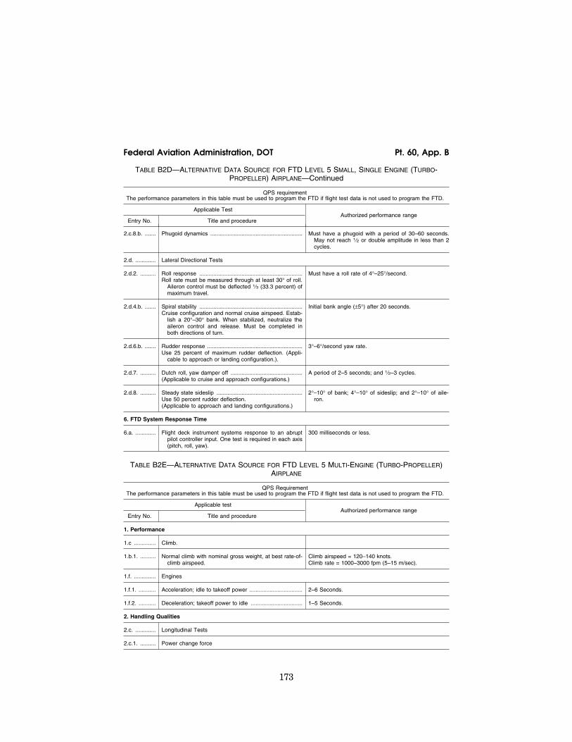
173
Federal Aviation Administration, DOT Pt. 60, App. B
TABLE B2D—ALTERNATIVE DATA SOURCE FOR FTD LEVEL 5 SMALL, SINGLE ENGINE (TURBO- PROPELLER) AIRPLANE—Continued
QPS requirement The performance parameters in this table must be used to program the FTD if flight test data is not used to program the FTD.
Applicable Test Authorized performance range
Entry No. Title and procedure
2.c.8.b. ....... Phugoid dynamics ........................................................... Must have a phugoid with a period of 30–60 seconds. May not reach 1⁄2 or double amplitude in less than 2 cycles.
2.d. ............. Lateral Directional Tests
2.d.2. .......... Roll response ..................................................................Roll rate must be measured through at least 30° of roll.
Aileron control must be deflected 1⁄3 (33.3 percent) of maximum travel.
Must have a roll rate of 4°–25°/second.
2.d.4.b. ....... Spiral stability ..................................................................Cruise configuration and normal cruise airspeed. Estab-
lish a 20°–30° bank. When stabilized, neutralize the aileron control and release. Must be completed in both directions of turn.
Initial bank angle (±5°) after 20 seconds.
2.d.6.b. ....... Rudder response .............................................................Use 25 percent of maximum rudder deflection. (Appli-
cable to approach or landing configuration.).
3°–6°/second yaw rate.
2.d.7. .......... Dutch roll, yaw damper off ..............................................(Applicable to cruise and approach configurations.)
A period of 2–5 seconds; and 1⁄2–3 cycles.
2.d.8. .......... Steady state sideslip .......................................................Use 50 percent rudder deflection. (Applicable to approach and landing configurations.)
2°–10° of bank; 4°–10° of sideslip; and 2°–10° of aile-ron.
6. FTD System Response Time
6.a. ............. Flight deck instrument systems response to an abrupt pilot controller input. One test is required in each axis (pitch, roll, yaw).
300 milliseconds or less.
TABLE B2E—ALTERNATIVE DATA SOURCE FOR FTD LEVEL 5 MULTI-ENGINE (TURBO-PROPELLER) AIRPLANE
QPS Requirement The performance parameters in this table must be used to program the FTD if flight test data is not used to program the FTD.
Applicable test Authorized performance range
Entry No. Title and procedure
1. Performance
1.c .............. Climb.
1.b.1. .......... Normal climb with nominal gross weight, at best rate-of- climb airspeed.
Climb airspeed = 120–140 knots. Climb rate = 1000–3000 fpm (5–15 m/sec).
1.f. .............. Engines
1.f.1. ........... Acceleration; idle to takeoff power .................................. 2–6 Seconds.
1.f.2. ........... Deceleration; takeoff power to idle ................................. 1–5 Seconds.
2. Handling Qualities
2.c. ............. Longitudinal Tests
2.c.1. .......... Power change force
VerDate Mar<15>2010 18:16 Mar 01, 2012 Jkt 226045 PO 00000 Frm 00183 Fmt 8010 Sfmt 8002 Q:\14\14V2 ofr150 PsN: PC150

174
14 CFR Ch. I (1–1–12 Edition) Pt. 60, App. B
TABLE B2E—ALTERNATIVE DATA SOURCE FOR FTD LEVEL 5 MULTI-ENGINE (TURBO-PROPELLER) AIRPLANE—Continued
QPS Requirement The performance parameters in this table must be used to program the FTD if flight test data is not used to program the FTD.
Applicable test Authorized performance range
Entry No. Title and procedure
(a) Trim for straight and level flight at 80% of normal cruise airspeed with necessary power. Reduce power to flight idle. Do not change trim or configuration. After stabilized, record column force necessary to maintain original airspeed.
8 lbs (3.5 daN) of Push force to 8 lbs (3.5 daN) of Pull force.
OR
(b) Trim for straight and level flight at 80% of normal cruise airspeed with necessary power. Add power to maximum setting. Do not change trim or configura-tion. After stabilized, record column force necessary to maintain original airspeed.
12–22 lbs (5.3–9.7 daN) of force (Push).
2.c.2. .......... Flap/slat change force
(a) Trim for straight and level flight with flaps fully re-tracted at a constant airspeed within the flaps-ex-tended airspeed range. Do not adjust trim or power. Extend the flaps to 50% of full flap travel. After sta-bilized, record stick force necessary to maintain origi-nal airspeed.
5–15 lbs (2.2–6.6 daN) of force (Pull).
OR
(b) Trim for straight and level flight with flaps extended to 50% of full flap travel, at a constant airspeed with-in the flaps-extended airspeed range. Do not adjust trim or power. Retract the flaps to zero. After sta-bilized, record stick force necessary to maintain origi-nal airspeed.
5–15 lbs (2.2–6.6 daN) of force (Push).
2.c.4. .......... Gear change force
(a) Trim for straight and level flight with landing gear re-tracted at a constant airspeed within the landing gear-extended airspeed range. Do not adjust trim or power. Extend the landing gear. After stabilized, record stick force necessary to maintain original air-speed.
2–12 lbs (0.88–5.3 daN) of force (Pull).
OR
(b) Trim for straight and level flight with landing gear extended, at a constant airspeed within the landing gear-extended airspeed range. Do not adjust trim or power. Retract the landing gear. After stabilized, record stick force necessary to maintain original air-speed.
2–12 lbs (0.88–5.3 daN) of force (Push).
2.b.5. .......... Longitudinal trim .............................................................. Must be able to trim longitudinal stick force to ‘‘zero’’ in each of the following configurations: cruise; ap-proach; and landing.
2.c.7. .......... Longitudinal static stability .............................................. Must exhibit positive static stability.
2.c.8. .......... Stall warning (actuation of stall warning device) with nominal gross weight; wings level; and a deceleration rate of not more than three (3) knots per second.
(a) Landing configuration ................................................ 80–100 knots; # 5° of bank.
(b) Clean configuration .................................................... Landing configuration speed + 10–20%.
VerDate Mar<15>2010 18:16 Mar 01, 2012 Jkt 226045 PO 00000 Frm 00184 Fmt 8010 Sfmt 8002 Q:\14\14V2 ofr150 PsN: PC150

175
Federal Aviation Administration, DOT Pt. 60, App. B
TABLE B2E—ALTERNATIVE DATA SOURCE FOR FTD LEVEL 5 MULTI-ENGINE (TURBO-PROPELLER) AIRPLANE—Continued
QPS Requirement The performance parameters in this table must be used to program the FTD if flight test data is not used to program the FTD.
Applicable test Authorized performance range
Entry No. Title and procedure
2.c.8.b. ....... Phugoid dynamics ........................................................... Must have a phugoid with a period of 30–60 seconds. May not reach 1⁄2 or double amplitude in less than 2 cycles.
2.d. ............. Lateral Directional Tests
2.d.2. .......... Roll response ..................................................................Roll rate must be measured through at least 30° of roll.
Aileron control must be deflected 1/3 (33.3 percent) of maximum travel.
Must have a roll rate of 4–25 degrees/second.
2.d.4.b. ....... Spiral stability ..................................................................Cruise configuration and normal cruise airspeed. Estab-
lish a 20°–30° bank. When stabilized, neutralize the aileron control and release. Must be completed in both directions of turn.
Initial bank angle (± 5°) after 20 seconds.
2.d.6.b. ....... Rudder response .............................................................Use 25 percent of maximum rudder deflection. (Appli-
cable to approach or landing configuration.)
3°–6° /second yaw rate.
2.d.7. .......... Dutch roll, yaw damper off ..............................................(Applicable to cruise and approach configurations.)
A period of 2–5 seconds; and 1⁄2–2 cycles.
2.d.8. .......... Steady state sideslip .......................................................Use 50 percent rudder deflection. (Applicable to ap-
proach and landing configurations.)
2°–10° of bank; 4°–10° of sideslip; and 2°–10° of aileron.
6. FTD System Response Time
6.a. ............. Flight deck instrument systems response to an abrupt pilot controller input. One test is required in each axis (pitch, roll, yaw).
300 milliseconds or less.
END QPS REQUIREMENTS
lllllllllllllllllllllll
BEGIN QPS REQUIREMENTS
5. ALTERNATIVE DATA SOURCES, PROCEDURES, AND INSTRUMENTATION: LEVEL 6 FTD ONLY
a. Sponsors are not required to use the al-ternative data sources, procedures, and in-strumentation. However, a sponsor may choose to use one or more of the alternative sources, procedures, and instrumentation de-scribed in Table B2F.
END QPS REQUIREMENTS
lllllllllllllllllllllll
BEGIN INFORMATION
b. It has become standard practice for ex-perienced FTD manufacturers to use such techniques as a means of establishing data bases for new FTD configurations while awaiting the availability of actual flight test data; and then comparing this new data with the newly available flight test data. The re-
sults of such comparisons have, as reported by some recognized and experienced simula-tion experts, become increasingly consistent and indicate that these techniques, applied with appropriate experience, are becoming dependably accurate for the development of aerodynamic models for use in Level 6 FTDs.
c. In reviewing this history, the NSPM has concluded that, with proper care, those who are experienced in the development of aero-dynamic models for FTD application can successfully use these modeling techniques to acceptably alter the method by which flight test data may be acquired and, when applied to Level 6 FTDs, does not com-promise the quality of that simulation.
d. The information in the table that fol-lows (Table of Alternative Data Sources, Procedures, and Information: Level 6 FTD Only) is presented to describe an acceptable alternative to data sources for Level 6 FTD modeling and validation, and an acceptable alternative to the procedures and instrumen-tation found in the flight test methods tradi-tionally accepted for gathering modeling and validation data.
VerDate Mar<15>2010 18:16 Mar 01, 2012 Jkt 226045 PO 00000 Frm 00185 Fmt 8010 Sfmt 8002 Q:\14\14V2 ofr150 PsN: PC150

176
14 CFR Ch. I (1–1–12 Edition) Pt. 60, App. B
(1) Alternative data sources that may be used for part or all of a data requirement are the Airplane Maintenance Manual, the Air-plane Flight Manual (AFM), Airplane Design Data, the Type Inspection Report (TIR), Cer-tification Data or acceptable supplemental flight test data.
(2) The NSPM recommends that use of the alternative instrumentation noted in Table B2F be coordinated with the NSPM prior to employment in a flight test or data gath-ering effort.
e. The NSPM position regarding the use of these alternative data sources, procedures, and instrumentation is based on three pri-mary preconditions and presumptions re-garding the objective data and FTD aero-dynamic program modeling.
(1) Data gathered through the alternative means does not require angle of attack (AOA) measurements or control surface posi-tion measurements for any flight test. AOA can be sufficiently derived if the flight test program insures the collection of acceptable level, unaccelerated, trimmed flight data. Angle of attack may be validated by con-ducting the three basic ‘‘fly-by’’ trim tests.
The FTD time history tests should begin in level, unaccelerated, and trimmed flight, and the results should be compared with the flight test pitch angle.
(2) A simulation controls system model should be rigorously defined and fully ma-ture. It should also include accurate gearing and cable stretch characteristics (where ap-plicable) that are determined from actual aircraft measurements. Such a model does not require control surface position measure-ments in the flight test objective data for Level 6 FTD applications.
f. Table B2F is not applicable to Computer Controlled Aircraft FTDs.
g. Utilization of these alternate data sources, procedures, and instrumentation does not relieve the sponsor from compliance with the balance of the information con-tained in this document relative to Level 6 FTDs.
h. The term ‘‘inertial measurement sys-tem’’ allows the use of a functional global positioning system (GPS).
END INFORMATION
lllllllllllllllllllllll
TABLE B2F—ALTERNATIVE DATA SOURCES, PROCEDURES, AND INSTRUMENTATION LEVEL 6 FTD
QPS Requirements The standards in this table are required if the data gathering methods described in paragraph 9 of Appendix
B are not used.
Information
Objective test reference number and title Alternative data sources, procedures, and instrumentation Notes
1.b.1. ................................................Performance. Takeoff. Ground acceleration time.
Data may be acquired through a synchronized video recording of a stop watch and the calibrated airplane airspeed indicator. Hand- record the flight conditions and airplane configuration.
This test is re-quired only if RTO is sought.
1.b.7. ................................................Performance. Takeoff. Rejected takeoff.
Data may be acquired through a synchronized video recording of a stop watch and the calibrated airplane airspeed indicator. Hand- record the flight conditions and airplane configuration.
This test is re-quired only if RTO is sought.
1.c.1. ................................................Performance. Climb. Normal climb all engines operating.
Data may be acquired with a synchronized video of calibrated airplane instruments and engine power throughout the climb range.
1.f.1. .................................................Performance. Engines. Acceleration
Data may be acquired with a synchronized video recording of engine instruments and throttle position.
1.f.2. .................................................Performance. Engines. Deceleration
Data may be acquired with a synchronized video recording of engine instruments and throttle position.
VerDate Mar<15>2010 18:16 Mar 01, 2012 Jkt 226045 PO 00000 Frm 00186 Fmt 8010 Sfmt 8002 Q:\14\14V2 ofr150 PsN: PC150

177
Federal Aviation Administration, DOT Pt. 60, App. B
TABLE B2F—ALTERNATIVE DATA SOURCES, PROCEDURES, AND INSTRUMENTATION LEVEL 6 FTD— Continued
QPS Requirements The standards in this table are required if the data gathering methods described in paragraph 9 of Appendix
B are not used.
Information
Objective test reference number and title Alternative data sources, procedures, and instrumentation Notes
2.a.1.a. .............................................Handling qualities. Static control tests. Pitch controller position vs. force
and surface position calibration.
Surface position data may be acquired from flight data recorder (FDR) sensor or, if no FDR sensor, at selected, significant column positions (encompassing significant column position data points), acceptable to the NSPM, using a control surface protractor on the ground. Force data may be acquired by using a hand held force gauge at the same column position data points.
For airplanes with reversible control sys-tems, surface position data acquisition should be ac-complished with winds less than 5 kts.
2.a.2.a. .............................................Handling qualities. Static control tests. Wheel position vs. force and sur-
face position calibration.
Surface position data may be acquired from flight data recorder (FDR) sensor or, if no FDR sensor, at selected, significant wheel positions (encompassing significant wheel position data points), acceptable to the NSPM, using a control surface protractor on the ground. Force data may be acquired by using a hand held force gauge at the same wheel position data points.
For airplanes with reversible control sys-tems, surface position data acquisition should be ac-complished with winds less than 5 kts.
2.a.3.a. .............................................Handling qualities. Static control tests. Rudder pedal position vs. force and
surface position calibration.
Surface position data may be acquired from flight data recorder (FDR) sensor or, if no FDR sensor, at selected, significant rudder pedal po-sitions (encompassing significant rudder pedal position data points), acceptable to the NSPM, using a control surface protractor on the ground. Force data may be acquired by using a hand held force gauge at the same rudder pedal position data points.
For airplanes with reversible control sys-tems, surface position data acquisition should be ac-complished with winds less than 5 kts.
2.a.4. ................................................Handling qualities. Static control tests. Nosewheel steering force.
Breakout data may be acquired with a hand held force gauge. The re-mainder of the force to the stops may be calculated if the force gauge and a protractor are used to measure force after breakout for at least 25% of the total displacement capability.
2.a.5. ................................................Handling qualities. Static control tests. Rudder pedal steering calibration.
Data may be acquired through the use of force pads on the rudder pedals and a pedal position measurement device, together with de-sign data for nosewheel position.
2.a.6. ................................................Handling qualities. Static control tests. Pitch trim indicator vs. surface posi-
tion calibration.
Data may be acquired through calculations.
2.a.8. ................................................Handling qualities. Static control tests. Alignment of power lever angle vs.
selected engine parameter (e.g., EPR, N1, Torque, Manifold pres-sure).
Data may be acquired through the use of a temporary throttle quadrant scale to document throttle position. Use a synchronized video to record steady state instrument readings or hand-record steady state engine performance readings.
2.a.9. ................................................Handling qualities. Static control tests. Brake pedal position vs. force.
Use of design or predicted data is acceptable. Data may be acquired by measuring deflection at ‘‘zero’’ and at ‘‘maximum.’’
VerDate Mar<15>2010 18:16 Mar 01, 2012 Jkt 226045 PO 00000 Frm 00187 Fmt 8010 Sfmt 8002 Q:\14\14V2 ofr150 PsN: PC150

178
14 CFR Ch. I (1–1–12 Edition) Pt. 60, App. B
TABLE B2F—ALTERNATIVE DATA SOURCES, PROCEDURES, AND INSTRUMENTATION LEVEL 6 FTD— Continued
QPS Requirements The standards in this table are required if the data gathering methods described in paragraph 9 of Appendix
B are not used.
Information
Objective test reference number and title Alternative data sources, procedures, and instrumentation Notes
2.c.1. ................................................Handling qualities. Longitudinal control tests. Power change force.
Data may be acquired by using an inertial measurement system and a synchronized video of the calibrated airplane instruments, throttle po-sition, and the force/position measurements of flight deck controls.
Power change dynamics test is acceptable using the same data ac-quisition methodology.
2.c.2. ................................................Handling qualities. Longitudinal control tests. Flap/slat change force.
Data may be acquired by using an inertial measurement system and a synchronized video of calibrated airplane instruments, flap/slat posi-tion, and the force/position measurements of flight deck controls.
Flap/slat change dynamics test is acceptable using the same data ac-quisition methodology.
2.c.4. ................................................Handling qualities. Longitudinal control tests. Gear change force.
Data may be acquired by using an inertial measurement system and a synchronized video of the calibrated airplane instruments, gear posi-tion, and the force/position measurements of flight deck controls.
Gear change dy-namics test is acceptable using the same data ac-quisition methodology.
2.c.5. ................................................Handling qualities. Longitudinal control tests. Longitudinal trim.
Data may be acquired through use of an inertial measurement system and a synchronized video of flight deck controls position (previously calibrated to show related surface position) and engine instrument readings.
2.c.6. ................................................Handling qualities. Longitudinal control tests. Longitudinal maneuvering stability
(stick force/g).
Data may be acquired through the use of an inertial measurement sys-tem and a synchronized video of the calibrated airplane instruments; a temporary, high resolution bank angle scale affixed to the attitude indicator; and a wheel and column force measurement indication.
2.c.7. ................................................Handling qualities. Longitudinal control tests. Longitudinal static stability
Data may be acquired through the use of a synchronized video of the airplane flight instruments and a hand held force gauge.
2.c.8. ................................................Handling qualities. Longitudinal control tests. Stall Warning (activation of stall
warning device).
Data may be acquired through a synchronized video recording of a stop watch and the calibrated airplane airspeed indicator. Hand- record the flight conditions and airplane configuration.
Airspeeds may be cross checked with those in the TIR and AFM.
2.c.9.a. .............................................Handling qualities. Longitudinal control tests. Phugoid dynamics.
Data may be acquired by using an inertial measurement system and a synchronized video of the calibrated airplane instruments and the force/position measurements of flight deck controls.
2.c.10. ..............................................Handling qualities. Longitudinal control tests. Short period dynamics.
Data may be acquired by using an inertial measurement system and a synchronized video of the calibrated airplane instruments and the force/position measurements of flight deck controls.
2.c.11. ..............................................Handling qualities. Longitudinal control tests. Gear and flap/slat operating times.
May use design data, production flight test schedule, or maintenance specification, together with an SOC.
2.d.2. ................................................Handling qualities. Lateral directional tests. Roll response (rate).
Data may be acquired by using an inertial measurement system and a synchronized video of the calibrated airplane instruments and the force/position measurements of flight deck lateral controls.
VerDate Mar<15>2010 18:16 Mar 01, 2012 Jkt 226045 PO 00000 Frm 00188 Fmt 8010 Sfmt 8002 Q:\14\14V2 ofr150 PsN: PC150

179
Federal Aviation Administration, DOT Pt. 60, App. B
TABLE B2F—ALTERNATIVE DATA SOURCES, PROCEDURES, AND INSTRUMENTATION LEVEL 6 FTD— Continued
QPS Requirements The standards in this table are required if the data gathering methods described in paragraph 9 of Appendix
B are not used.
Information
Objective test reference number and title Alternative data sources, procedures, and instrumentation Notes
2.d.3. ................................................Handling qualities. Lateral directional tests. (a) Roll overshoot. OR (b) Roll response to flight deck roll
controller step input.
Data may be acquired by using an inertial measurement system and a synchronized video of the calibrated airplane instruments and the force/position measurements of flight deck lateral controls.
2.d.4. ................................................Handling qualities. Lateral directional tests. Spiral stability.
Data may be acquired by using an inertial measurement system and a synchronized video of the calibrated airplane instruments; the force/ position measurements of flight deck controls; and a stop watch.
2.d.6.a. .............................................Handling qualities. Lateral directional tests. Rudder response.
Data may be acquired by using an inertial measurement system and a synchronized video of the calibrated airplane instruments; the force/ position measurements of rudder pedals.
2.d.7. ................................................Handling qualities. Lateral directional tests. Dutch roll, (yaw damper OFF).
Data may be acquired by using an inertial measurement system and a synchronized video of the calibrated airplane instruments and the force/position measurements of flight deck controls.
2.d.8. ................................................Handling qualities. Lateral directional tests. Steady state sideslip.
Data may be acquired by using an inertial measurement system and a synchronized video of the calibrated airplane instruments and the force/position measurements of flight deck controls.
ATTACHMENT 3 TO APPENDIX B TO PART 60— FLIGHT TRAINING DEVICE (FTD) SUBJECTIVE EVALUATION
lllllllllllllllllllllll
BEGIN INFORMATION
1. DISCUSSION
a. The subjective tests provide a basis for evaluating the capability of the FTD to per-form over a typical utilization period. The items listed in the Table of Functions and Subjective Tests are used to determine whether the FTD competently simulates each required maneuver, procedure, or task; and verifying correct operation of the FTD controls, instruments, and systems. The tasks do not limit or exceed the authoriza-tions for use of a given level of FTD as de-scribed on the SOQ or as approved by the TPAA. All items in the following paragraphs are subject to examination.
b. All simulated airplane systems func-tions will be assessed for normal and, where appropriate, alternate operations. Simulated
airplane systems are listed separately under ‘‘Any Flight Phase’’ to ensure appropriate attention to systems checks. Operational navigation systems (including inertial navi-gation systems, global positioning systems, or other long-range systems) and the associ-ated electronic display systems will be eval-uated if installed. The NSP pilot will include in his report to the TPAA, the effect of the system operation and any system limitation.
c. At the request of the TPAA, the NSP Pilot may assess the FTD for a special as-pect of a sponsor’s training program during the functions and subjective portion of an evaluation. Such an assessment may include a portion of a specific operation (e.g., a Line Oriented Flight Training (LOFT) scenario) or special emphasis items in the sponsor’s training program. Unless directly related to a requirement for the qualification level, the results of such an evaluation would not af-fect the qualification of the FTD.
END INFORMATION
lllllllllllllllllllllll
VerDate Mar<15>2010 18:16 Mar 01, 2012 Jkt 226045 PO 00000 Frm 00189 Fmt 8010 Sfmt 8002 Q:\14\14V2 ofr150 PsN: PC150

180
14 CFR Ch. I (1–1–12 Edition) Pt. 60, App. B
TABLE B3A—TABLE OF FUNCTIONS AND SUBJECTIVE TESTS LEVEL 6 FTD
QPS requirements
Entry No. Operations tasks
Tasks in this table are subject to evaluation if appropriate for the airplane system or systems simulated as indicated in the SOQ Configuration List as defined in Appendix B, Attachment 2 of this part.
1. Preflight
Accomplish a functions check of all installed switches, indicators, systems, and equipment at all crewmembers’ and instructors’ stations, and determine that the flight deck (or flight deck area) design and functions replicate the appropriate airplane.
2. Surface Operations (pre-takeoff)
2.a. ............ Engine start:
2.a.1. ......... Normal start.
2.a.2. ......... Alternative procedures start.
2.a.3. ......... Abnormal procedures start/shut down.
2.b. ............ Pushback/Powerback (powerback requires visual system).
3. Takeoff (requires appropriate visual system as set out in Table B1A, item 6; Appendix B, Attachment 1.)
3.a. ............ Instrument takeoff:
3.a.1. ......... Engine checks (e.g., engine parameter relationships, propeller/mixture controls).
3.a.2. ......... Acceleration characteristics.
3.a.3. ......... Nosewheel/rudder steering.
3.a.4. ......... Landing gear, wing flap, leading edge device operation.
3.b. ............ Rejected takeoff:
3.b.1. ......... Deceleration characteristics.
3.b.2. ......... Brakes/engine reverser/ground spoiler operation.
3.b.3. ......... Nosewheel/rudder steering.
4. In-Flight Operations
4.a. ............ Normal climb.
4.b. ............ Cruise:
4.b.1. ......... Demonstration of performance characteristics (speed vs. power).
4.b.2. ......... Normal turns.
4.b.3. ......... Demonstration of high altitude handling.
4.b.4. ......... Demonstration of high airspeed handling/overspeed warning.
4.b.5. ......... Demonstration of Mach effects on control and trim.
4.b.6. ......... Steep turns.
4.b.7. ......... In-Flight engine shutdown (procedures only).
4.b.8. ......... In-Flight engine restart (procedures only).
4.b.9. ......... Specific flight characteristics.
4.b.10. ....... Response to loss of flight control power.
4.b.11. ....... Response to other flight control system failure modes.
4.b.12. ....... Operations during icing conditions.
VerDate Mar<15>2010 18:16 Mar 01, 2012 Jkt 226045 PO 00000 Frm 00190 Fmt 8010 Sfmt 8002 Q:\14\14V2 ofr150 PsN: PC150
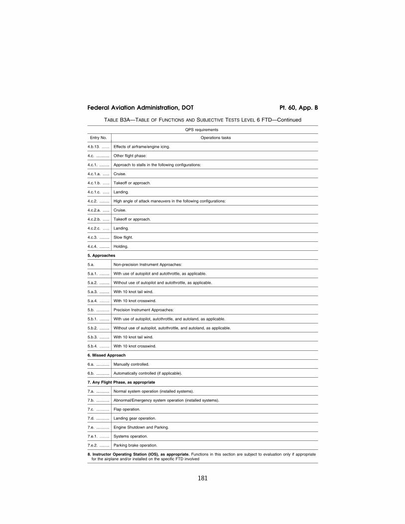
181
Federal Aviation Administration, DOT Pt. 60, App. B
TABLE B3A—TABLE OF FUNCTIONS AND SUBJECTIVE TESTS LEVEL 6 FTD—Continued
QPS requirements
Entry No. Operations tasks
4.b.13. ....... Effects of airframe/engine icing.
4.c. ............ Other flight phase:
4.c.1. ......... Approach to stalls in the following configurations:
4.c.1.a. ...... Cruise.
4.c.1.b. ...... Takeoff or approach.
4.c.1.c. ...... Landing.
4.c.2. ......... High angle of attack maneuvers in the following configurations:
4.c.2.a. ...... Cruise.
4.c.2.b. ...... Takeoff or approach.
4.c.2.c. ...... Landing.
4.c.3. ......... Slow flight.
4.c.4. ......... Holding.
5. Approaches
5.a. Non-precision Instrument Approaches:
5.a.1. ......... With use of autopilot and autothrottle, as applicable.
5.a.2. ......... Without use of autopilot and autothrottle, as applicable.
5.a.3. ......... With 10 knot tail wind.
5.a.4. ......... With 10 knot crosswind.
5.b. ............ Precision Instrument Approaches:
5.b.1. ......... With use of autopilot, autothrottle, and autoland, as applicable.
5.b.2. ......... Without use of autopilot, autothrottle, and autoland, as applicable.
5.b.3. ......... With 10 knot tail wind.
5.b.4. ......... With 10 knot crosswind.
6. Missed Approach
6.a. ............ Manually controlled.
6.b. ............ Automatically controlled (if applicable).
7. Any Flight Phase, as appropriate
7.a. ............ Normal system operation (installed systems).
7.b. ............ Abnormal/Emergency system operation (installed systems).
7.c. ............ Flap operation.
7.d. ............ Landing gear operation.
7.e. ............ Engine Shutdown and Parking.
7.e.1. ......... Systems operation.
7.e.2. ......... Parking brake operation.
8. Instructor Operating Station (IOS), as appropriate. Functions in this section are subject to evaluation only if appropriate for the airplane and/or installed on the specific FTD involved
VerDate Mar<15>2010 18:16 Mar 01, 2012 Jkt 226045 PO 00000 Frm 00191 Fmt 8010 Sfmt 8002 Q:\14\14V2 ofr150 PsN: PC150

182
14 CFR Ch. I (1–1–12 Edition) Pt. 60, App. B
TABLE B3A—TABLE OF FUNCTIONS AND SUBJECTIVE TESTS LEVEL 6 FTD—Continued
QPS requirements
Entry No. Operations tasks
8.a. ............ Power Switch(es).
8.b. ............ Airplane conditions.
8.b.1. ......... Gross weight, center of gravity, and fuel loading and allocation.
8.b.2. ......... Airplane systems status.
8.b.3. ......... Ground crew functions (e.g., external power, push back).
8.c. ............ Airports.
8.c.1. ......... Selection.
8.c.2. ......... Runway selection.
8.c.3. ......... Preset positions (e.g., ramp, over FAF).
8.d. ............ Environmental controls.
8.d.1. ......... Temperature.
8.d.2. ......... Climate conditions (e.g., ice, rain).
8.d.3. ......... Wind speed and direction.
8.e. ............ Airplane system malfunctions.
8.e.1. ......... Insertion/deletion.
8.e.2. ......... Problem clear.
8.f. ............. Locks, Freezes, and Repositioning.
8.f.1. .......... Problem (all) freeze/release.
8.f.2. .......... Position (geographic) freeze/release.
8.f.3. .......... Repositioning (locations, freezes, and releases).
8.f.4. .......... Ground speed control.
8.f.5. .......... Remote IOS, if installed.
9. Sound Controls. On/off/adjustment
10. Control Loading System (as applicable) On/off/emergency stop.
11. Observer Stations.
11.a. .......... Position.
11.b. .......... Adjustments.
End QPS Requirements
TABLE B3B—TABLE OF FUNCTIONS AND SUBJECTIVE TESTS LEVEL 5 FTD
QPS requirements
Entry No. Operations tasks
Tasks in this table are subject to evaluation if appropriate for the airplane system or systems simulated as indi-cated in the SOQ Configuration List as defined in Appendix B, Attachment 2 of this part.
1. Preflight
Accomplish a functions check of all installed switches, indicators, systems, and equipment at all crewmembers’ and instructors’ stations, and determine that the flight deck (or flight deck area) design and functions replicate the appropriate airplane.
2. Surface Operations (pre-takeoff)
VerDate Mar<15>2010 18:16 Mar 01, 2012 Jkt 226045 PO 00000 Frm 00192 Fmt 8010 Sfmt 8002 Q:\14\14V2 ofr150 PsN: PC150

183
Federal Aviation Administration, DOT Pt. 60, App. B
TABLE B3B—TABLE OF FUNCTIONS AND SUBJECTIVE TESTS LEVEL 5 FTD—Continued
QPS requirements
Entry No. Operations tasks
Tasks in this table are subject to evaluation if appropriate for the airplane system or systems simulated as indi-cated in the SOQ Configuration List as defined in Appendix B, Attachment 2 of this part.
2.a. ............ Engine start (if installed):
2.a.1. ......... Normal start.
2.a.2. ......... Alternative procedures start.
2.a.3. ......... Abnormal/Emergency procedures start/shut down.
3. In-Flight Operations
3.a. ............ Normal climb.
3.b. ............ Cruise:
3.b.1. ......... Performance characteristics (speed vs. power).
3.b.2. ......... Normal turns.
3.c. ............ Normal descent.
4. Approaches
4.a. ............ Coupled instrument approach maneuvers (as applicable for the systems installed).
5. Any Flight Phase
5.a. ............ Normal system operation (Installed systems).
5.b. ............ Abnormal/Emergency system operation (Installed systems).
5.c. ............ Flap operation.
5.d. ............ Landing gear operation
5.e. ............ Engine Shutdown and Parking (if installed).
5.e.1. ......... Systems operation.
5.e.2. ......... Parking brake operation.
6. Instructor Operating Station (IOS)
6.a. ............ Power Switch(es).
6.b. ............ Preset positions—ground, air.
6.c. ............ Airplane system malfunctions (Installed systems).
6.c.1. ......... Insertion/deletion.
6.c.2. ......... Problem clear.
TABLE B3C—TABLE OF FUNCTIONS AND SUBJECTIVE TESTS LEVEL 4 FTD
QPS requirements
Entry No. Operations tasks
Tasks in this table are subject to evaluation if appropriate for the airplane system or systems simulated as indi-cated in the SOQ Configuration List as defined in Appendix B, Attachment 2 of this part.
1. ............... Level 4 FTDs are required to have at least one operational system. The NSPM will accomplish a functions check of all installed systems, switches, indicators, and equipment at all crewmembers’ and instructors’ stations, and determine that the flight deck (or flight deck area) design and functions replicate the appropriate airplane.
VerDate Mar<15>2010 18:16 Mar 01, 2012 Jkt 226045 PO 00000 Frm 00193 Fmt 8010 Sfmt 8002 Q:\14\14V2 ofr150 PsN: PC150

184
14 CFR Ch. I (1–1–12 Edition) Pt. 60, App. B
ATTACHMENT 4 TO APPENDIX B TO PART 60— SAMPLE DOCUMENTS
lllllllllllllllllllllll
BEGIN INFORMATION
TABLE OF CONTENTS
Title of Sample
Figure B4A Sample Letter, Request for Ini-tial, Upgrade, or Reinstatement Evalua-tion
Figure B4B Attachment: FTD Information Form
Figure B4C Sample Letter of Compliance Figure B4D Sample Qualification Test
Guide Cover Page Figure B4E Sample Statement of Qualifica-
tion—Certificate Figure B4F Sample Statement of Qualifica-
tion—Configuration List Figure B4G Sample Statement of Qualifica-
tion—List of Qualified Tasks Figure B4H Sample Continuing Qualifica-
tion Evaluation Requirements Page Figure B4I Sample MQTG Index of Effective
FTD Directives
VerDate Mar<15>2010 18:16 Mar 01, 2012 Jkt 226045 PO 00000 Frm 00194 Fmt 8010 Sfmt 8002 Q:\14\14V2 ofr150 PsN: PC150

185
Federal Aviation Administration, DOT Pt. 60, App. B
VerDate Mar<15>2010 18:16 Mar 01, 2012 Jkt 226045 PO 00000 Frm 00195 Fmt 8010 Sfmt 8006 Q:\14\14V2 ofr150 PsN: PC150 ER
09M
Y08
.020
</G
PH
>

186
14 CFR Ch. I (1–1–12 Edition) Pt. 60, App. B
VerDate Mar<15>2010 18:16 Mar 01, 2012 Jkt 226045 PO 00000 Frm 00196 Fmt 8010 Sfmt 8006 Q:\14\14V2 ofr150 PsN: PC150 ER
09M
Y08
.021
</G
PH
>

187
Federal Aviation Administration, DOT Pt. 60, App. B
VerDate Mar<15>2010 18:16 Mar 01, 2012 Jkt 226045 PO 00000 Frm 00197 Fmt 8010 Sfmt 8006 Q:\14\14V2 ofr150 PsN: PC150 ER
09M
Y08
.022
</G
PH
>

188
14 CFR Ch. I (1–1–12 Edition) Pt. 60, App. B
VerDate Mar<15>2010 18:16 Mar 01, 2012 Jkt 226045 PO 00000 Frm 00198 Fmt 8010 Sfmt 8006 Q:\14\14V2 ofr150 PsN: PC150 ER
09M
Y08
.023
</G
PH
>

189
Federal Aviation Administration, DOT Pt. 60, App. B
VerDate Mar<15>2010 18:16 Mar 01, 2012 Jkt 226045 PO 00000 Frm 00199 Fmt 8010 Sfmt 8006 Q:\14\14V2 ofr150 PsN: PC150 ER
09M
Y08
.024
</G
PH
>

190
14 CFR Ch. I (1–1–12 Edition) Pt. 60, App. B
VerDate Mar<15>2010 18:16 Mar 01, 2012 Jkt 226045 PO 00000 Frm 00200 Fmt 8010 Sfmt 8006 Q:\14\14V2 ofr150 PsN: PC150 ER
09M
Y08
.025
</G
PH
>

191
Federal Aviation Administration, DOT Pt. 60, App. B
VerDate Mar<15>2010 18:16 Mar 01, 2012 Jkt 226045 PO 00000 Frm 00201 Fmt 8010 Sfmt 8006 Q:\14\14V2 ofr150 PsN: PC150 ER
09M
Y08
.026
</G
PH
>

192
14 CFR Ch. I (1–1–12 Edition) Pt. 60, App. B
VerDate Mar<15>2010 18:16 Mar 01, 2012 Jkt 226045 PO 00000 Frm 00202 Fmt 8010 Sfmt 8006 Q:\14\14V2 ofr150 PsN: PC150 ER
09M
Y08
.028
</G
PH
>

193
Federal Aviation Administration, DOT Pt. 60, App. B
VerDate Mar<15>2010 18:16 Mar 01, 2012 Jkt 226045 PO 00000 Frm 00203 Fmt 8010 Sfmt 8006 Q:\14\14V2 ofr150 PsN: PC150 ER
09M
Y08
.029
</G
PH
>

194
14 CFR Ch. I (1–1–12 Edition) Pt. 60, App. B
VerDate Mar<15>2010 18:16 Mar 01, 2012 Jkt 226045 PO 00000 Frm 00204 Fmt 8010 Sfmt 8006 Q:\14\14V2 ofr150 PsN: PC150 ER
09M
Y08
.030
</G
PH
>

195
Federal Aviation Administration, DOT Pt. 60, App. B
VerDate Mar<15>2010 18:16 Mar 01, 2012 Jkt 226045 PO 00000 Frm 00205 Fmt 8010 Sfmt 8006 Q:\14\14V2 ofr150 PsN: PC150 ER
09M
Y08
.031
</G
PH
>

196
14 CFR Ch. I (1–1–12 Edition) Pt. 60, App. B
VerDate Mar<15>2010 18:16 Mar 01, 2012 Jkt 226045 PO 00000 Frm 00206 Fmt 8010 Sfmt 8006 Q:\14\14V2 ofr150 PsN: PC150 ER
09M
Y08
.032
</G
PH
>

197
Federal Aviation Administration, DOT Pt. 60, App. C
[Doc. No. FAA–2002–12461, 73 FR 26490, May 9, 2008]
APPENDIX C TO PART 60—QUALIFICATION PERFORMANCE STANDARDS FOR HEL-ICOPTER FULL FLIGHT SIMULATORS
lllllllllllllllllllllll
BEGIN INFORMATION
This appendix establishes the standards for Helicopter FFS evaluation and qualification. The NSPM is responsible for the develop-ment, application, and implementation of the standards contained within this appen-dix. The procedures and criteria specified in this appendix will be used by the NSPM, or a person assigned by the NSPM, when con-ducting helicopter FFS evaluations.
TABLE OF CONTENTS
1. Introduction. 2. Applicability (§ 60.1) and (§ 60.2). 3. Definitions (§ 60.3). 4. Qualification Performance Standards
(§ 60.4). 5. Quality Management System (§ 60.5). 6. Sponsor Qualification Requirements
(§ 60.7). 7. Additional Responsibilities of the Sponsor
(§ 60.9). 8. FFS Use (§ 60.11). 9. FFS Objective Data Requirements (§ 60.13).
10. Special Equipment and Personnel Re-quirements for Qualification of the FFS (§ 60.14).
11. Initial (and Upgrade) Qualification Re-quirements (§ 60.15).
12. Additional Qualifications for a Currently Qualified FFS (§ 60.16).
13. Previously Qualified FFSs (§ 60.17). 14. Inspection, Continuing Qualification
Evaluation, and Maintenance Require-ments (§ 60.19).
15. Logging FFS Discrepancies (§ 60.20). 16. Interim Qualification of FFSs for New
Helicopter Types or Models (§ 60.21). 17. Modifications to FFSs (§ 60.23). 18. Operations with Missing, Malfunctioning,
or Inoperative Components (§ 60.25). 19. Automatic Loss of Qualification and Pro-
cedures for Restoration of Qualification (§ 60.27).
20. Other Losses of Qualification and Proce-dures for Restoration of Qualification (§ 60.29).
21. Record Keeping and Reporting (§ 60.31). 22. Applications, Logbooks, Reports, and
Records: Fraud, Falsification, or Incor-rect Statements (§ 60.33).
23. [Reserved] 24. [Reserved] 25. FFS Qualification on the Basis of a Bilat-
eral Aviation Safety Agreement (BASA) (§ 60.37).
Attachment 1 to Appendix C to Part 60—Gen-eral Simulator Requirements.
Attachment 2 to Appendix C to Part 60—FFS Objective Tests.
VerDate Mar<15>2010 18:16 Mar 01, 2012 Jkt 226045 PO 00000 Frm 00207 Fmt 8010 Sfmt 8002 Q:\14\14V2 ofr150 PsN: PC150 ER
09M
Y08
.033
</G
PH
>

198
14 CFR Ch. I (1–1–12 Edition) Pt. 60, App. C
Attachment 3 to Appendix C to Part 60— Simulator Subjective Evaluation.
Attachment 4 to Appendix C to Part 60— Sample Documents.
Attachment 5 to Appendix C to Part 60— FSTD Directives Applicable to Heli-copter FFSs
END INFORMATION
lllllllllllllllllllllll
1. INTRODUCTION
lllllllllllllllllllllll
BEGIN INFORMATION
a. This appendix contains background in-formation as well as regulatory and inform-ative material as described later in this sec-tion. To assist the reader in determining what areas are required and what areas are permissive, the text in this appendix is di-vided into two sections: ‘‘QPS Require-ments’’ and ‘‘Information.’’ The QPS Re-quirements sections contain details regard-ing compliance with the part 60 rule lan-guage. These details are regulatory, but are found only in this appendix. The Information sections contain material that is advisory in nature, and designed to give the user general information about the regulation.
b. Questions regarding the contents of this publication should be sent to the U.S. De-partment of Transportation, Federal Avia-tion Administration, Flight Standards Serv-ice, National Simulator Program Staff, AFS–205, 100 Hartsfield Centre Parkway, Suite 400, Atlanta, Georgia, 30354. Telephone contact numbers for the NSP are: phone, 404– 832–4700; fax, 404–761–8906. The general e-mail address for the NSP office is: 9-aso-avr-sim- [email protected]. The NSP Internet Web site ad-dress is: http://www.faa.gov/safety/ programslinitiatives/aircraftlaviation/nsp/. On this Web Site you will find an NSP personnel list with telephone and e-mail contact infor-mation for each NSP staff member, a list of qualified flight simulation devices, ACs, a description of the qualification process, NSP policy, and an NSP ‘‘In-Works’’ section. Also linked from this site are additional informa-tion sources, handbook bulletins, frequently asked questions, a listing and text of the Federal Aviation Regulations, Flight Stand-ards Inspector’s handbooks, and other FAA links.
c. The NSPM encourages the use of elec-tronic media for all communication, includ-ing any record, report, request, test, or statement required by this appendix. The electronic media used must have adequate security provisions and be acceptable to the NSPM. The NSPM recommends inquiries on system compatibility, and minimum system requirements are also included on the NSP Web site.
d. Related Reading References.
(1) 14 CFR part 60. (2) 14 CFR part 61. (3) 14 CFR part 63. (4) 14 CFR part 119. (5) 14 CFR part 121. (6) 14 CFR part 125. (7) 14 CFR part 135. (8) 14 CFR part 141. (9) 14 CFR part 142. (10) AC 120–35, as amended, Line Oper-
ational Simulations: Line-Oriented Flight Training, Special Purpose Operational Training, Line Operational Evaluation.
(11) AC 120–57, as amended, Surface Move-ment Guidance and Control System (SMGCS).
(12) AC 120–63, as amended, Helicopter Sim-ulator Qualification.
(13) AC 150/5300–13, as amended, Airport De-sign.
(14) AC 150/5340–1, as amended, Standards for Airport Markings.
(15) AC 150/5340–4, as amended, Installation Details for Runway Centerline Touchdown Zone Lighting Systems.
(16) AC 150/5340–19, as amended, Taxiway Centerline Lighting System.
(17) AC 150/5340–24, as amended, Runway and Taxiway Edge Lighting System.
(18) AC 150/5345–28, as amended, Precision Approach Path Indicator (PAPI) Systems
(19) AC 150/5390–2, as amended, Heliport De-sign
(20) International Air Transport Associa-tion document, ‘‘Flight Simulator Design and Performance Data Requirements,’’ as amended.
(21) AC 29–2, as amended, Flight Test Guide for Certification of Transport Category Rotorcraft.
(22) AC 27–1, as amended, Flight Test Guide for Certification of Normal Category Rotor-craft.
(23) International Civil Aviation Organiza-tion (ICAO) Manual of Criteria for the Quali-fication of Flight Simulators, as amended.
(24) Airplane Flight Simulator Evaluation Handbook, Volume I, as amended and Vol-ume II, as amended, The Royal Aeronautical Society, London, UK.
(25) FAA Publication FAA–S–8081 series (Practical Test Standards for Airline Trans-port Pilot Certificate, Type Ratings, Com-mercial Pilot, and Instrument Ratings).
(26) The FAA Aeronautical Information Manual (AIM). An electronic version of the AIM is on the Internet at http://www.faa.gov/ atpubs.
(27) Aeronautical Radio, Inc. (ARINC) doc-ument number 436, titled Guidelines For Elec-tronic Qualification Test Guide (as amended).
(28) Aeronautical Radio, Inc. (ARINC) doc-ument 610, Guidance for Design and Integra-tion of Aircraft Avionics Equipment in Simula-tors (as amended).
VerDate Mar<15>2010 18:16 Mar 01, 2012 Jkt 226045 PO 00000 Frm 00208 Fmt 8010 Sfmt 8002 Q:\14\14V2 ofr150 PsN: PC150

199
Federal Aviation Administration, DOT Pt. 60, App. C
END INFORMATION
lllllllllllllllllllllll
2. APPLICABILITY (§§ 60.1 AND 60.2)
lllllllllllllllllllllll
BEGIN INFORMATION
No additional regulatory or informational material applies to § 60.1, Applicability, or to § 60.2, Applicability of sponsor rules to person who are not sponsors and who are engaged in certain unauthorized activities.
END INFORMATION
lllllllllllllllllllllll
3. DEFINITIONS (§ 60.3)
lllllllllllllllllllllll
BEGIN INFORMATION
See Appendix F of this part for a list of definitions and abbreviations from part 1 and part 60, including the appropriate appendices of part 60.
END INFORMATION
lllllllllllllllllllllll
4. QUALIFICATION PERFORMANCE STANDARDS (§ 60.4)
lllllllllllllllllllllll
BEGIN INFORMATION
No additional regulatory or informational material applies to § 60.4, Qualification Per-formance Standards.
END INFORMATION
lllllllllllllllllllllll
5. QUALITY MANAGEMENT SYSTEM (§ 60.5)
lllllllllllllllllllllll
BEGIN INFORMATION
See Appendix E of this part for additional regulatory and informational material re-garding Quality Management Systems.
END INFORMATION
lllllllllllllllllllllll
6. SPONSOR QUALIFICATION REQUIREMENTS (§ 60.7)
lllllllllllllllllllllll
BEGIN INFORMATION
a. The intent of the language in § 60.7(b) is to have a specific FFS, identified by the sponsor, used at least once in an FAA-ap-proved flight training program for the heli-copter simulated during the 12-month period described. The identification of the specific FFS may change from one 12-month period
to the next 12-month period as long as that sponsor sponsors and uses at least one FFS at least once during the prescribed period. There is no minimum number of hours or minimum FFS periods required.
b. The following examples describe accept-able operational practices:
(1) Example One. (a) A sponsor is sponsoring a single, spe-
cific FFS for its own use, in its own facility or elsewhere—this single FFS forms the basis for the sponsorship. The sponsor uses that FFS at least once in each 12-month pe-riod in that sponsor’s FAA-approved flight training program for the helicopter simu-lated. This 12-month period is established ac-cording to the following schedule:
(i) If the FFS was qualified prior to May 30, 2008, the 12-month period begins on the date of the first continuing qualification evalua-tion conducted in accordance with § 60.19 after May 30, 2008, and continues for each subsequent 12-month period;
(ii) A device qualified on or after May 30, 2008, will be required to undergo an initial or upgrade evaluation in accordance with § 60.15. Once the initial or upgrade evaluation is complete, the first continuing qualifica-tion evaluation will be conducted within 6 months. The 12 month continuing qualifica-tion evaluation cycle begins on that date and continues for each subsequent 12-month pe-riod.
(b) There is no minimum number of hours of FFS use required.
(c) The identification of the specific FFS may change from one 12-month period to the next 12-month period as long as that sponsor sponsors and uses at least one FFS at least once during the prescribed period.
(2) Example Two. (a) A sponsor sponsors an additional num-
ber of FFSs, in its facility or elsewhere. Each additionally sponsored FFS must be—
(i) Used by the sponsor in the sponsor’s FAA-approved flight training program for the helicopter simulated (as described in § 60.7(d)(1)); or
(ii) Used by another FAA certificate holder in that other certificate holder’s FAA-ap-proved flight training program for the heli-copter simulated (as described in § 60.7(d)(1)). This 12-month period is established in the same manner as in example one; or
(iii) Provided a statement each year from a qualified pilot, (after having flown the heli-copter, not the subject FFS or another FFS, during the preceding 12-month period) stat-ing that the subject FFS’s performance and handling qualities represent the helicopter (as described in § 60.7(d)(2)). This statement is provided at least once in each 12-month pe-riod established in the same manner as in ex-ample one.
(b) There is no minimum number of hours of FFS use required.
(3) Example Three.
VerDate Mar<15>2010 18:16 Mar 01, 2012 Jkt 226045 PO 00000 Frm 00209 Fmt 8010 Sfmt 8002 Q:\14\14V2 ofr150 PsN: PC150

200
14 CFR Ch. I (1–1–12 Edition) Pt. 60, App. C
(a) A sponsor in New York (in this exam-ple, a Part 142 certificate holder) establishes ‘‘satellite’’ training centers in Chicago and Moscow.
(b) The satellite function means that the Chicago and Moscow centers must operate under the New York center’s certificate (in accordance with all of the New York center’s practices, procedures, and policies; e.g., in-structor and/or technician training/checking requirements, record keeping, QMS pro-gram).
(c) All of the FFSs in the Chicago and Mos-cow centers could be dry-leased (i.e., the cer-tificate holder does not have and use FAA- approved flight training programs for the FFSs in the Chicago and Moscow centers) be-cause—
(i) Each FFS in the Chicago center and each FFS in the Moscow center is used at least once each 12-month period by another FAA certificate holder in that other certifi-cate holder’s FAA-approved flight training program for the helicopter (as described in § 60.7(d)(1)); OR
(ii) A statement is obtained from a quali-fied pilot (having flown the helicopter, not the subject FFS or another FFS during the preceding 12-month period) stating that the performance and handling qualities of each FFS in the Chicago and Moscow centers rep-resents the helicopter (as described in § 60.7(d)(2)).
END INFORMATION
lllllllllllllllllllllll
7. Additional Responsibilities of the Spon sor (§ 60.9).
BEGIN INFORMATION
The phrase ‘‘as soon as practicable’’ in § 60.9(a) means without unnecessarily dis-rupting or delaying beyond a reasonable time the training, evaluation, or experience being conducted in the FFS.
END INFORMATION
lllllllllllllllllllllll
8. FFS USE (§ 60.11)
lllllllllllllllllllllll
BEGIN INFORMATION
No additional regulatory or informational material applies to § 60.11, FFS Use.
END INFORMATION
lllllllllllllllllllllll
9. FFS OBJECTIVE DATA REQUIREMENTS (§ 60.13)
lllllllllllllllllllllll
BEGIN QPS REQUIREMENTS
a. Flight test data used to validate FFS performance and handling qualities must have been gathered in accordance with a flight test program containing the following:
(1) A flight test plan consisting of: (a) The maneuvers and procedures required
for aircraft certification and simulation pro-gramming and validation
(b) For each maneuver or procedure— (i) The procedures and control input the
flight test pilot and/or engineer used. (ii) The atmospheric and environmental
conditions. (iii) The initial flight conditions. (iv) The helicopter configuration, includ-
ing weight and center of gravity. (v) The data to be gathered. (vi) All other information necessary to
recreate the flight test conditions in the FFS.
(2) Appropriately qualified flight test per-sonnel.
(3) An understanding of the accuracy of the data to be gathered using appropriate alter-native data sources, procedures, and instru-mentation that is traceable to a recognized standard as described in Attachment 2, Table C2D of this appendix.
(4) Appropriate and sufficient data acquisi-tion equipment or system(s), including ap-propriate data reduction and analysis meth-ods and techniques, acceptable to the FAA’s Aircraft Certification Service.
b. The data, regardless of source, must be presented:
(1) In a format that supports the FFS vali-dation process;
(2) In a manner that is clearly readable and annotated correctly and completely;
(3) With resolution sufficient to determine compliance with the tolerances set forth in Attachment 2, Table C2A of this appendix.
(4) With any necessary instructions or other details provided, such as Stability Augmentation System (SAS) or throttle po-sition; and
(5) Without alteration, adjustments, or bias. Data may be corrected to address known data calibration errors provided that an explanation of the methods used to cor-rect the errors appears in the QTG. The cor-rected data may be re-scaled, digitized, or otherwise manipulated to fit the desired presentation.
c. After completion of any additional flight test, a flight test report must be submitted in support of the validation data. The report must contain sufficient data and rationale to support qualification of the FFS at the level requested.
d. As required by § 60.13(f), the sponsor must notify the NSPM when it becomes aware that an addition to, an amendment to, or a revision of data that may relate to FFS performance or handling characteristics is
VerDate Mar<15>2010 18:16 Mar 01, 2012 Jkt 226045 PO 00000 Frm 00210 Fmt 8010 Sfmt 8002 Q:\14\14V2 ofr150 PsN: PC150

201
Federal Aviation Administration, DOT Pt. 60, App. C
available. The data referred to in this para-graph is data used to validate the perform-ance, handling qualities, or other character-istics of the aircraft, including data related to any relevant changes occurring after the type certificate was issued. The sponsor must—
(1) Within 10 calendar days, notify the NSPM of the existence of this data; and
(2) Within 45 calendar days, notify the NSPM of—
(a) The schedule to incorporate this data into the FFS; or
(b) The reason for not incorporating this data into the FFS.
e. In those cases where the objective test results authorize a ‘‘snapshot test’’ or a ‘‘se-ries of snapshot test results’’ in lieu of a time-history result, the sponsor or other data provider must ensure that a steady state condition exists at the instant of time captured by the ‘‘snapshot.’’ The steady state condition must exist from 4 seconds prior to, through 1 second following, the in-stant of time captured by the snap shot.
END QPS REQUIREMENTS
lllllllllllllllllllllll
BEGIN INFORMATION
f. The FFS sponsor is encouraged to main-tain a liaison with the manufacturer of the aircraft being simulated (or with the holder of the aircraft type certificate for the air-craft being simulated if the manufacturer is no longer in business), and, if appropriate, with the person who supplied the aircraft data package for the FFS in order to facili-tate the notification required by § 60.13(f).
g. It is the intent of the NSPM that for new aircraft entering service, at a point well in advance of preparation of the QTG, the sponsor should submit to the NSPM for ap-proval, a descriptive document (see Table C2D, Sample Validation Data Roadmap for Helicopters) containing the plan for acquir-ing the validation data, including data sources. This document should clearly iden-tify sources of data for all required tests, a description of the validity of these data for a specific engine type and thrust rating con-figuration, and the revision levels of all avi-onics affecting the performance or flying qualities of the aircraft. Additionally, this document should provide other information, such as the rationale or explanation for cases where data or data parameters are missing, instances where engineering sim-ulation data are used or where flight test methods require further explanations. It should also provide a brief narrative describ-ing the cause and effect of any deviation from data requirements. The aircraft manu-facturer may provide this document.
h. There is no requirement for any flight test data supplier to submit a flight test
plan or program prior to gathering flight test data. However, the NSPM notes that in-experienced data gatherers often provide data that is irrelevant, improperly marked, or lacking adequate justification for selec-tion. Other problems include inadequate in-formation regarding initial conditions or test maneuvers. The NSPM has been forced to refuse these data submissions as valida-tion data for an FFS evaluation. It is for this reason that the NSPM recommends that any data supplier not previously experienced in this area review the data necessary for pro-gramming and for validating the perform-ance of the FFS, and discuss the flight test plan anticipated for acquiring such data with the NSPM well in advance of commencing the flight tests.
i. The NSPM will consider, on a case-by- case basis, whether to approve supplemental validation data derived from flight data re-cording systems such as a Quick Access Re-corder or Flight Data Recorder.
END INFORMATION
10. SPECIAL EQUIPMENT AND PERSONNEL RE-QUIREMENTS FOR QUALIFICATION OF THE FFS (§ 60.14)
lllllllllllllllllllllll
BEGIN INFORMATION
a. In the event that the NSPM determines that special equipment or specifically quali-fied persons will be required to conduct an evaluation, the NSPM will make every at-tempt to notify the sponsor at least one (1) week, but in no case less than 72 hours, in advance of the evaluation. Examples of spe-cial equipment include spot photometers, flight control measurement devices, and sound analyzers. Examples of specially quali-fied personnel include individuals specifi-cally qualified to install or use any special equipment when its use is required.
b. Examples of a special evaluation include an evaluation conducted after an FFS is moved, at the request of the TPAA, or as a result of comments received from users of the FFS that raise questions about the con-tinued qualification or use of the FFS.
END INFORMATION
lllllllllllllllllllllll
11. INITIAL (AND UPGRADE) QUALIFICATION REQUIREMENTS (§ 60.15)
lllllllllllllllllllllll
BEGIN QPS REQUIREMENTS
a. In order to be qualified at a particular qualification level, the FFS must:
(1) Meet the general requirements listed in Attachment 1 of this appendix;
(2) Meet the objective testing requirements listed in Attachment 2 of this appendix; and
VerDate Mar<15>2010 18:16 Mar 01, 2012 Jkt 226045 PO 00000 Frm 00211 Fmt 8010 Sfmt 8002 Q:\14\14V2 ofr150 PsN: PC150

202
14 CFR Ch. I (1–1–12 Edition) Pt. 60, App. C
(3) Satisfactorily accomplish the subjec-tive tests listed in Attachment 3 of this ap-pendix.
b. The request described in § 60.15(a) must include all of the following:
(1) A statement that the FFS meets all of the applicable provisions of this part and all applicable provisions of the QPS.
(2) A confirmation that the sponsor will forward to the NSPM the statement de-scribed in § 60.15(b) in such time as to be re-ceived no later than 5 business days prior to the scheduled evaluation and may be for-warded to the NSPM via traditional or elec-tronic means.
(3) A QTG, acceptable to the NSPM, that includes all of the following:
(a) Objective data obtained from aircraft testing or another approved source.
(b) Correlating objective test results ob-tained from the performance of the FFS as prescribed in the appropriate QPS.
(c) The result of FFS subjective tests pre-scribed in the appropriate QPS.
(d) A description of the equipment nec-essary to perform the evaluation for initial qualification and the continuing qualifica-tion evaluations.
c. The QTG described in paragraph (a)(3) of this section, must provide the documented proof of compliance with the simulator ob-jective tests in Attachment 2, Table C2A of this appendix.
d. The QTG is prepared and submitted by the sponsor, or the sponsor’s agent on behalf of the sponsor, to the NSPM for review and approval, and must include, for each objec-tive test:
(1) Parameters, tolerances, and flight con-ditions.
(2) Pertinent and complete instructions for the conduct of automatic and manual tests.
(3) A means of comparing the FFS test re-sults to the objective data.
(4) Any other information as necessary, to assist in the evaluation of the test results.
(5) Other information appropriate to the qualification level of the FFS.
e. The QTG described in paragraphs (a)(3) and (b) of this section, must include the fol-lowing:
(1) A QTG cover page with sponsor and FAA approval signature blocks (see Attach-ment 4, Figure C4C, of this appendix, for a sample QTG cover page).
(2) A continuing qualification evaluation schedule requirements page. This page will be used by the NSPM to establish and record the frequency with which continuing quali-fication evaluations must be conducted and any subsequent changes that may be deter-mined by the NSPM in accordance with § 60.19. See Attachment 4 of this appendix, Figure C4G, for a sample Continuing Quali-fication Evaluation Requirements page.
(3) An FFS information page that provides the information listed in this paragraph (see
Attachment 4, Figure C4B, of this appendix for a sample FFS information page). For convertible FFSs, the sponsor must submit a separate page for each configuration of the FFS.
(a) The sponsor’s FFS identification num-ber or code.
(b) The helicopter model and series being simulated.
(c) The aerodynamic data revision number or reference.
(d) The source of the basic aerodynamic model and the aerodynamic coefficient data used to modify the basic model.
(e) The engine model(s) and its data revi-sion number or reference.
(f) The flight control data revision number or reference.
(g) The flight management system identi-fication and revision level.
(h) The FFS model and manufacturer. (i) The date of FFS manufacture. (j) The FFS computer identification. (k) The visual system model and manufac-
turer, including display type. (l) The motion system type and manufac-
turer, including degrees of freedom. (4) A Table of Contents. (5) A log of revisions and a list of effective
pages. (6) List of all relevant data references. (7) A glossary of terms and symbols used
(including sign conventions and units). (8) Statements of compliance and capa-
bility (SOCs) with certain requirements. (9) Recording procedures or equipment re-
quired to accomplish the objective tests. (10) The following information for each ob-
jective test designated in Attachment 2 of this appendix, Table C2A, as applicable to the qualification level sought:
(a) Name of the test. (b) Objective of the test. (c) Initial conditions. (d) Manual test procedures. (e) Automatic test procedures (if applica-
ble). (f) Method for evaluating FFS objective
test results. (g) List of all relevant parameters driven
or constrained during the automatically con-ducted test(s).
(h) List of all relevant parameters driven or constrained during the manually con-ducted test(s).
(i) Tolerances for relevant parameters. (j) Source of Validation Data (document
and page number). (k) Copy of the Validation Data (if located
in a separate binder, a cross reference for the identification and page number for pertinent data location must be provided).
(l) Simulator Objective Test Results as ob-tained by the sponsor. Each test result must reflect the date completed and must be clearly labeled as a product of the device being tested.
VerDate Mar<15>2010 18:16 Mar 01, 2012 Jkt 226045 PO 00000 Frm 00212 Fmt 8010 Sfmt 8002 Q:\14\14V2 ofr150 PsN: PC150

203
Federal Aviation Administration, DOT Pt. 60, App. C
f. A convertible FFS is addressed as a sepa-rate FFS for each model and series heli-copter to which it will be converted and for the FAA qualification level sought. If a spon-sor seeks qualification for two or more mod-els of a helicopter type using a convertible FFS, the sponsor must submit a QTG for each helicopter model, or a QTG for the first helicopter model and a supplement to that QTG for each additional helicopter model. The NSPM will conduct evaluations for each helicopter model.
g. Form and manner of presentation of ob-jective test results in the QTG:
(1) The sponsor’s FFS test results must be recorded in a manner acceptable to the NSPM, that allows easy comparison of the FFS test results to the validation data (e.g., use of a multi-channel recorder, line printer, cross plotting, overlays, transparencies).
(2) FFS results must be labeled using ter-minology common to helicopter parameters as opposed to computer software identifica-tions.
(3) Validation data documents included in a QTG may be photographically reduced only if such reduction will not alter the graphic scaling or cause difficulties in scale interpre-tation or resolution.
(4) Scaling on graphical presentations must provide the resolution necessary to evaluate the parameters shown in Attach-ment 2, Table C2A of this appendix.
(5) Tests involving time histories, data sheets (or transparencies thereof) and FFS test results must be clearly marked with ap-propriate reference points to ensure an accu-rate comparison between the FFS and the helicopter with respect to time. Time his-tories recorded via a line printer are to be clearly identified for cross plotting on the helicopter data. Over-plots must not obscure the reference data.
h. The sponsor may elect to complete the QTG objective and subjective tests at the manufacturer’s facility or at the sponsor’s training facility. If the tests are conducted at the manufacturer’s facility, the sponsor must repeat at least one-third of the tests at the sponsor’s training facility in order to substantiate FFS performance. The QTG must be clearly annotated to indicate when and where each test was accomplished. Tests conducted at the manufacturer’s facility and at the sponsor’s training facility must be conducted after the FFS is assembled with systems and sub-systems functional and op-erating in an interactive manner. The test results must be submitted to the NSPM.
i. The sponsor must maintain a copy of the MQTG at the FFS location.
j. All FFSs for which the initial qualifica-tion is conducted after May 30, 2014, must have an electronic MQTG (eMQTG) including all objective data obtained from helicopter testing, or another approved source (refor-matted or digitized), together with corre-
lating objective test results obtained from the performance of the FFS (reformatted or digitized) as prescribed in this appendix. The eMQTG must also contain the general FFS performance or demonstration results (refor-matted or digitized) prescribed in this appen-dix, and a description of the equipment nec-essary to perform the initial qualification evaluation and the continuing qualification evaluations. The eMQTG must include the original validation data used to validate FFS performance and handling qualities in either the original digitized format from the data supplier or an electronic scan of the original time-history plots that were pro-vided by the data supplier. A copy of the eMQTG must be provided to the NSPM.
k. All other FFSs not covered in subpara-graph ‘‘j’’ must have an electronic copy of the MQTG by May 30, 2014. An electronic copy of the MQTG must be provided to the NSPM. This may be provided by an elec-tronic scan presented in a Portable Docu-ment File (PDF), or similar format accept-able to the NSPM.
l. During the initial (or upgrade) qualifica-tion evaluation conducted by the NSPM, the sponsor must also provide a person who is a user of the device (e.g., a qualified pilot or instructor pilot with flight time experience in that aircraft) and knowledgeable about the operation of the aircraft and the oper-ation of the FFS.
END QPS REQUIREMENTS
lllllllllllllllllllllll
BEGIN INFORMATION
m. Only those FFSs that are sponsored by a certificate holder as defined in Appendix F of this part will be evaluated by the NSPM. However, other FFS evaluations may be con-ducted on a case-by-case basis as the Admin-istrator deems appropriate, but only in ac-cordance with applicable agreements.
n. The NSPM will conduct an evaluation for each configuration, and each FFS must be evaluated as completely as possible. To ensure a thorough and uniform evaluation, each FFS is subjected to the general simu-lator requirements in Attachment 1 of this appendix, the objective tests listed in At-tachment 2 of this appendix, and the subjec-tive tests listed in Attachment 3 of this ap-pendix. The evaluations described herein will include, but not necessarily be limited to the following:
(1) Helicopter responses, including longitu-dinal and lateral-directional control re-sponses (see Attachment 2 of this appendix).
(2) Performance in authorized portions of the simulated helicopter’s operating enve-lope, to include tasks evaluated by the NSPM in the areas of surface operations, takeoff, climb, cruise, descent, approach, and landing as well as abnormal and emergency
VerDate Mar<15>2010 18:16 Mar 01, 2012 Jkt 226045 PO 00000 Frm 00213 Fmt 8010 Sfmt 8002 Q:\14\14V2 ofr150 PsN: PC150
204
14 CFR Ch. I (1–1–12 Edition) Pt. 60, App. C
operations (see Attachment 2 of this appen-dix).
(3) Control checks (see Attachment 1 and Attachment 2 of this appendix).
(4) Flight deck configuration (see Attach-ment 1 of this appendix).
(5) Pilot, flight engineer, and instructor station functions checks (see Attachment 1 and Attachment 3 of this appendix).
(6) Helicopter systems and sub-systems (as appropriate) as compared to the helicopter simulated (see Attachment 1 and Attach-ment 3 of this appendix).
(7) FFS systems and sub-systems, includ-ing force cueing (motion), visual, and aural (sound) systems, as appropriate (see Attach-ment 1 and Attachment 2 of this appendix).
(8) Certain additional requirements, de-pending upon the qualification level sought, including equipment or circumstances that may become hazardous to the occupants. The sponsor may be subject to Occupational Safety and Health Administration require-ments.
o. The NSPM administers the objective and subjective tests, which includes an examina-tion of functions. The tests include a quali-tative assessment of the FFS by an NSP pilot. The NSP evaluation team leader may assign other qualified personnel to assist in accomplishing the functions examination and/or the objective and subjective tests per-formed during an evaluation when required.
(1) Objective tests provide a basis for meas-uring and evaluating FFS performance and determining compliance with the require-ments of this part.
(2) Subjective tests provide a basis for: (a) Evaluating the capability of the FFS to
perform over a typical utilization period; (b) Determining that the FFS satisfac-
torily simulates each required task; (c) Verifying correct operation of the FFS
controls, instruments, and systems; and (d) Demonstrating compliance with the re-
quirements of this part. p. The tolerances for the test parameters
listed in Attachment 2 of this appendix re-flect the range of tolerances acceptable to the NSPM for FFS validation and are not to be confused with design tolerances specified for FFS manufacture. In making decisions regarding tests and test results, the NSPM relies on the use of operational and engineer-ing judgment in the application of data (in-cluding consideration of the way in which the flight test was flown and way the data was gathered and applied), data presen-tations, and the applicable tolerances for each test.
q. In addition to the scheduled continuing qualification evaluation, each FFS is subject to evaluations conducted by the NSPM at any time without prior notification to the sponsor. Such evaluations would be accom-plished in a normal manner (i.e., requiring exclusive use of the FFS for the conduct of
objective and subjective tests and an exam-ination of functions) if the FFS is not being used for flight crewmember training, testing, or checking. However, if the FFS were being used, the evaluation would be conducted in a non-exclusive manner. This non-exclusive evaluation will be conducted by the FFS evaluator accompanying the check airman, instructor, Aircrew Program Designee (APD), or FAA inspector aboard the FFS along with the student(s) and observing the operation of the FFS during the training, testing, or checking activities.
r. Problems with objective test results are handled as follows:
(1) If a problem with an objective test re-sult is detected by the NSP evaluation team during an evaluation, the test may be re-peated or the QTG may be amended.
(2) If it is determined that the results of an objective test do not support the level re-quested but do support a lower level, the NSPM may qualify the FFS at that lower level. For example, if a Level D evaluation is requested and the FFS fails to meet sound test tolerances, it could be qualified at Level C.
s. After an FFS is successfully evaluated, the NSPM issues a certificate of qualifica-tion (COQ) to the sponsor. The NSPM rec-ommends the FFS to the TPAA, who will ap-prove the FFS for use in a flight training program. The COQ will be issued at the satis-factory conclusion of the initial or con-tinuing qualification evaluation and will list the tasks for which the FFS is qualified, ref-erencing the tasks described in Table C1B in Attachment 1 of this appendix. However, it is the sponsor’s responsibility to obtain TPAA approval prior to using the FFS in an FAA- approved flight training program.
t. Under normal circumstances, the NSPM establishes a date for the initial or upgrade evaluation within ten (10) working days after determining that a complete QTG is accept-able. Unusual circumstances may warrant establishing an evaluation date before this determination is made. A sponsor may schedule an evaluation date as early as 6 months in advance. However, there may be a delay of 45 days or more in rescheduling and completing the evaluation if the sponsor is unable to meet the scheduled date. See At-tachment 4, of this appendix, Figure C4A, Sample Request for Initial, Upgrade, or Re-instatement Evaluation.
u. The numbering system used for objec-tive test results in the QTG should closely follow the numbering system set out in At-tachment 2, FFS Objective Tests, Table C2A of this appendix.
v. Contact the NSPM or visit the NSPM Web site for additional information regard-ing the preferred qualifications of pilots used to meet the requirements of § 60.15(d).
w. Examples of the exclusions for which the FFS might not have been subjectively
VerDate Mar<15>2010 18:16 Mar 01, 2012 Jkt 226045 PO 00000 Frm 00214 Fmt 8010 Sfmt 8002 Q:\14\14V2 ofr150 PsN: PC150

205
Federal Aviation Administration, DOT Pt. 60, App. C
tested by the sponsor or the NSPM and for which qualification might not be sought or granted, as described in § 60.15(g)(6), include takeoffs and landing from slopes and pin-nacles.
END INFORMATION
lllllllllllllllllllllll
12. ADDITIONAL QUALIFICATIONS FOR A CURRENTLY QUALIFIED FFS (§ 60.16)
No additional regulatory or informational material applies to § 60.16, Additional Quali-fications for a Currently Qualified FFS.
13. PREVIOUSLY QUALIFIED FFSS (§ 60.17)
lllllllllllllllllllllll
BEGIN QPS REQUIREMENTS
a. In instances where a sponsor plans to re-move an FFS from active status for a period of less than two years, the following proce-dures apply:
(1) The NSPM must be notified in writing and the notification must include an esti-mate of the period that the FFS will be inac-tive.
(2) Continuing Qualification evaluations will not be scheduled during the inactive pe-riod.
(3) The NSPM will remove the FFS from the list of qualified FSTDs on a mutually es-tablished date not later than the date on which the first missed continuing qualifica-tion evaluation would have been scheduled.
(4) Before the FFS is restored to qualified status, it must be evaluated by the NSPM. The evaluation content and the time re-quired to accomplish the evaluation is based on the number of continuing qualification evaluations and sponsor-conducted quarterly inspections missed during the period of inac-tivity.
(5) The sponsor must notify the NSPM of any changes to the original scheduled time out of service.
b. Simulators qualified prior to May 30, 2008, are not required to meet the general simulation requirements, the objective test requirements, and the subjective test re-quirements of attachments 1, 2, and 3, of this appendix as long as the simulator continues to meet the test requirements contained in the MQTG developed under the original qual-ification basis.
c. After May 30, 2009, each visual scene or airport model beyond the minimum required for the FFS qualification level that is in-stalled in and available for use in a qualified FFS must meet the requirements described in Attachment 3 of this appendix.
d. Simulators qualified prior to May 30, 2008, may be updated. If an evaluation is deemed appropriate or necessary by the NSPM after such an update, the evaluation will not require an evaluation to standards
beyond those against which the simulator was originally qualified.
END QPS REQUIREMENTS
lllllllllllllllllllllll
BEGIN INFORMATION
e. Other certificate holders or persons de-siring to use an FFS may contract with FFS sponsors to use FFSs previously qualified at a particular level for a helicopter type and approved for use within an FAA-approved flight training program. Such FFSs are not required to undergo an additional qualifica-tion process, except as described in § 60.16.
f. Each FFS user must obtain approval from the appropriate TPAA to use any FFS in an FAA-approved flight training program.
g. The intent of the requirement listed in § 60.17(b), for each FFS to have an SOQ with-in 6 years, is to have the availability of that statement (including the configuration list and the limitations to authorizations) to provide a complete picture of the FFS inven-tory regulated by the FAA. The issuance of the statement will not require any addi-tional evaluation or require any adjustment to the evaluation basis for the FFS.
h. Downgrading of an FFS is a permanent change in qualification level and will neces-sitate the issuance of a revised SOQ to re-flect the revised qualification level, as ap-propriate. If a temporary restriction is placed on an FFS because of a missing, mal-functioning, or inoperative component or on- going repairs, the restriction is not a perma-nent change in qualification level. Instead, the restriction is temporary and is removed when the reason for the restriction has been resolved.
i. The NSPM will determine the evaluation criteria for an FFS that has been removed from active status. The criteria will be based on the number of continuing qualification evaluations and quarterly inspections missed during the period of inactivity. For example, if the FFS were out of service for a 1 year pe-riod, it would be necessary to complete the entire QTG, since all of the quarterly evalua-tions would have been missed. The NSPM will also consider how the FFS was stored, whether parts were removed from the FFS and whether the FFS was disassembled.
j. The FFS will normally be requalified using the FAA-approved MQTG and the cri-teria that was in effect prior to its removal from qualification. However, inactive periods of 2 years or more will require requalifica-tion under the standards in effect and cur-rent at the time of requalification.
END INFORMATION
lllllllllllllllllllllll
VerDate Mar<15>2010 18:16 Mar 01, 2012 Jkt 226045 PO 00000 Frm 00215 Fmt 8010 Sfmt 8002 Q:\14\14V2 ofr150 PsN: PC150

206
14 CFR Ch. I (1–1–12 Edition) Pt. 60, App. C
14. INSPECTION, CONTINUING QUALIFICATION EVALUATION, AND MAINTENANCE REQUIRE-MENTS (§ 60.19)
lllllllllllllllllllllll
BEGIN QPS REQUIREMENTS
a. The sponsor must conduct a minimum of four evenly spaced inspections throughout the year. The objective test sequence and content of each inspection must be developed by the sponsor and must be acceptable to the NSPM.
b. The description of the functional pre-flight check must be contained in the spon-sor’s QMS.
c. Record ‘‘functional preflight’’ in the FFS discrepancy log book or other accept-able location, including any item found to be missing, malfunctioning, or inoperative.
d. During the continuing qualification evaluation conducted by the NSPM, the sponsor must also provide a person knowl-edgeable about the operation of the aircraft and the operation of the FFS.
e. The NSPM will conduct continuing qual-ification evaluations every 12 months unless:
(1) The NSPM becomes aware of discrep-ancies or performance problems with the de-vice that warrants more frequent evalua-tions; or
(2) The sponsor implements a QMS that justifies less frequent evaluations. However, in no case shall the frequency of a con-tinuing qualification evaluation exceed 36 months.
END QPS REQUIREMENTS
lllllllllllllllllllllll
BEGIN INFORMATION
f. The sponsor’s test sequence and the con-tent of each quarterly inspection required in § 60.19(a)(1) should include a balance and a mix from the objective test requirement areas listed as follows:
(1) Performance. (2) Handling qualities. (3) Motion system (where appropriate). (4) Visual system (where appropriate). (5) Sound system (where appropriate). (6) Other FFS systems. g. If the NSP evaluator plans to accom-
plish specific tests during a normal con-tinuing qualification evaluation that re-quires the use of special equipment or tech-nicians, the sponsor will be notified as far in advance of the evaluation as practical; but not less than 72 hours. Examples of such tests include latencies, control dynamics, sounds and vibrations, motion, and/or some visual system tests.
h. The continuing qualification evalua-tions, described in § 60.19(b), will normally re-quire 4 hours of FFS time. However, flexi-bility is necessary to address abnormal situ-ations or situations involving aircraft with
additional levels of complexity (e.g., com-puter controlled aircraft). The sponsor should anticipate that some tests may re-quire additional time. The continuing quali-fication evaluations will consist of the fol-lowing:
(1) Review of the results of the quarterly inspections conducted by the sponsor since the last scheduled continuing qualification evaluation.
(2) A selection of approximately 8 to 15 ob-jective tests from the MQTG that provide an adequate opportunity to evaluate the per-formance of the FFS. The tests chosen will be performed either automatically or manu-ally and should be able to be conducted with-in approximately one-third (1/3) of the allot-ted FFS time.
(3) A subjective evaluation of the FFS to perform a representative sampling of the tasks set out in attachment 3 of this appen-dix. This portion of the evaluation should take approximately two-thirds (2/3) of the al-lotted FFS time.
(4) An examination of the functions of the FFS may include the motion system, visual system, sound system, instructor operating station, and the normal functions and simu-lated malfunctions of the simulated heli-copter systems. This examination is nor-mally accomplished simultaneously with the subjective evaluation requirements.
END INFORMATION
lllllllllllllllllllllll
15. LOGGING FFS DISCREPANCIES (§ 60.20)
lllllllllllllllllllllll
BEGIN INFORMATION
No additional regulatory or informational material applies to § 60.20. Logging FFS Dis-crepancies.
END INFORMATION
lllllllllllllllllllllll
16. INTERIM QUALIFICATION OF FFSS FOR NEW HELICOPTER TYPES OR MODELS (§ 60.21)
lllllllllllllllllllllll
BEGIN INFORMATION
No additional regulatory or informational material applies to § 60.21, Interim Qualifica-tion of FFSs for New Helicopter Types or Models.
END INFORMATION
lllllllllllllllllllllll
17. MODIFICATIONS TO FFSS (§ 60.23)
lllllllllllllllllllllll
VerDate Mar<15>2010 18:16 Mar 01, 2012 Jkt 226045 PO 00000 Frm 00216 Fmt 8010 Sfmt 8002 Q:\14\14V2 ofr150 PsN: PC150

207
Federal Aviation Administration, DOT Pt. 60, App. C
BEGIN QPS REQUIREMENTS
a. The notification described in § 60.23(c)(2) must include a complete description of the planned modification, with a description of the operational and engineering effect the proposed modification will have on the oper-ation of the FFS and the results that are ex-pected with the modification incorporated.
b. Prior to using the modified FFS: (1) All the applicable objective tests com-
pleted with the modification incorporated, including any necessary updates to the MQTG (e.g., accomplishment of FSTD Direc-tives) must be acceptable to the NSPM; and
(2) The sponsor must provide the NSPM with a statement signed by the MR that the factors listed in § 60.15(b) are addressed by the appropriate personnel as described in that section.
END QPS REQUIREMENTS
lllllllllllllllllllllll
BEGIN INFORMATION
(3) FSTD Directives are considered modi-fications of an FFS. See Attachment 4 of this appendix for a sample index of effective FSTD Directives. See Attachment 6 of this appendix for a list of all effective FSTD Di-rectives applicable to Helicopter FFSs.
END INFORMATION
lllllllllllllllllllllll
18. OPERATION WITH MISSING, MALFUNC TIONING, OR INOPERATIVE COMPONENTS (§ 60.25)
lllllllllllllllllllllll
BEGIN INFORMATION
a. The sponsor’s responsibility with respect to § 60.25(a) is satisfied when the sponsor fair-ly and accurately advises the user of the cur-rent status of an FFS, including any miss-ing, malfunctioning, or inoperative (MMI) component(s).
b. It is the responsibility of the instructor, check airman, or representative of the ad-ministrator conducting training, testing, or checking to exercise reasonable and prudent judgment to determine if any MMI compo-nent is necessary for the satisfactory com-pletion of a specific maneuver, procedure, or task.
c. If the 29th or 30th day of the 30-day pe-riod described in § 60.25(b) is on a Saturday, a Sunday, or a holiday, the FAA will extend the deadline until the next business day.
d. In accordance with the authorization de-scribed in § 60.25(b), the sponsor may develop a discrepancy prioritizing system to accom-plish repairs based on the level of impact on the capability of the FFS. Repairs having a larger impact on FFS capability to provide the required training, evaluation, or flight
experience will have a higher priority for re-pair or replacement.
END INFORMATION
lllllllllllllllllllllll
19. AUTOMATIC LOSS OF QUALIFICATION AND PROCEDURES FOR RESTORATION OF QUALI-FICATION (§ 60.27)
lllllllllllllllllllllll
BEGIN INFORMATION
If the sponsor provides a plan for how the FFS will be maintained during its out-of- service period (e.g., periodic exercise of me-chanical, hydraulic, and electrical systems; routine replacement of hydraulic fluid; con-trol of the environmental factors in which the FFS is to be maintained) there is a greater likelihood that the NSPM will be able to determine the amount of testing re-quired for requalification.
END INFORMATION
lllllllllllllllllllllll
20. OTHER LOSSES OF QUALIFICATION AND PRO CEDURES FOR RESTORATION OF QUALIFICA-TION (§ 60.29)
lllllllllllllllllllllll
BEGIN INFORMATION
If the sponsor provides a plan for how the FFS will be maintained during its out-of- service period (e.g., periodic exercise of me-chanical, hydraulic, and electrical systems; routine replacement of hydraulic fluid; con-trol of the environmental factors in which the FFS is to be maintained) there is a greater likelihood that the NSPM will be able to determine the amount of testing re-quired for requalification.
END INFORMATION
lllllllllllllllllllllll
21. RECORD KEEPING AND REPORTING (§ 60.31)
lllllllllllllllllllllll
BEGIN QPS REQUIREMENTS
a. FFS modifications can include hardware or software changes. For FFS modifications involving software programming changes, the record required by § 60.31(a)(2) must con-sist of the name of the aircraft system soft-ware, aerodynamic model, or engine model change, the date of the change, a summary of the change, and the reason for the change.
b. If a coded form for record keeping is used, it must provide for the preservation and retrieval of information with appro-priate security or controls to prevent the in-appropriate alteration of such records after the fact.
VerDate Mar<15>2010 18:16 Mar 01, 2012 Jkt 226045 PO 00000 Frm 00217 Fmt 8010 Sfmt 8002 Q:\14\14V2 ofr150 PsN: PC150

208
14 CFR Ch. I (1–1–12 Edition) Pt. 60, App. C
END QPS REQUIREMENTS
lllllllllllllllllllllll
22. APPLICATIONS, LOGBOOKS, REPORTS, AND RECORDS: FRAUD, FALSIFICATION, OR INCOR-RECT STATEMENTS (§ 60.33)
lllllllllllllllllllllll
BEGIN INFORMATION
No additional regulatory or informational material applies to § 60.33, Applications, Logbooks, Reports, and Records: Fraud, Fal-sification, or Incorrect Statements.
23. [RESERVED]
24. [RESERVED]
25. FFS QUALIFICATION ON THE BASIS OF A BI-LATERAL AVIATION SAFETY AGREEMENT (BASA) (§ 60.37)
No additional regulatory or informational material applies to § 60.37, FFS Qualification on the Basis of a Bilateral Aviation Safety Agreement (BASA).
END INFORMATION
lllllllllllllllllllllll
ATTACHMENT 1 TO APPENDIX C TO PART 60— GENERAL SIMULATOR REQUIREMENTS
lllllllllllllllllllllll
BEGIN QPS REQUIREMENTS
1. REQUIREMENTS
a. Certain requirements included in this appendix must be supported with an SOC as defined in Appendix F of this part, which may include objective and subjective tests. The requirements for SOCs are indicated in the ‘‘General Simulator Requirements’’ col-umn in Table C1A of this appendix.
b. Table C1A describes the requirements for the indicated level of FFS. Many devices include operational systems or functions that exceed the requirements outlined in this section. However, all systems will be tested and evaluated in accordance with this appendix to ensure proper operation.
END QPS REQUIREMENTS
lllllllllllllllllllllll
BEGIN INFORMATION
2. DISCUSSION
a. This attachment describes the general simulator requirements for qualifying a heli-copter FFS. The sponsor should also consult the objective tests in Attachment 2 of this appendix and the examination of functions and subjective tests listed in Attachment 3 of this appendix to determine the complete requirements for a specific level simulator.
b. The material contained in this attach-ment is divided into the following cat-egories:
(1) General flight deck configuration. (2) Simulator programming. (3) Equipment operation. (4) Equipment and facilities for instructor/
evaluator functions. (5) Motion system. (6) Visual system. (7) Sound system. c. Table C1A provides the standards for the
General Simulator Requirements. d. Table C1B provides the tasks that the
sponsor will examine to determine whether the FFS satisfactorily meets the require-ments for flight crew training, testing, and experience, and provides the tasks for which the simulator may be qualified.
e. Table C1C provides the functions that an instructor/check airman must be able to con-trol in the simulator.
f. It is not required that all of the tasks that appear on the List of Qualified Tasks (part of the SOQ) be accomplished during the initial or continuing qualification evalua-tion.
g. Table C1A addresses only Levels B, C, and D helicopter simulators because there are no Level A Helicopter simulators.
END INFORMATION
lllllllllllllllllllllll
TABLE C1A—MINIMUM SIMULATOR REQUIREMENTS
Entry No. QPS requirements Simulator levels Information
General simulator requirements B C D Notes
1. .............. General Flight Deck Configuration
VerDate Mar<15>2010 18:16 Mar 01, 2012 Jkt 226045 PO 00000 Frm 00218 Fmt 8010 Sfmt 8002 Q:\14\14V2 ofr150 PsN: PC150

209
Federal Aviation Administration, DOT Pt. 60, App. C
TABLE C1A—MINIMUM SIMULATOR REQUIREMENTS—Continued
Entry No. QPS requirements Simulator levels Information
General simulator requirements B C D Notes
1.a. ........... The simulator must have a flight deck that is a replica of the helicopter being simulated.
The simulator must have controls, equipment, observable flight deck indicators, circuit breakers, and bulkheads properly located, functionally accurate and replicating the heli-copter. The direction of movement of con-trols and switches must be identical to that in the helicopter. Pilot seats must afford the capability for the occupant to be able to achieve the design ‘‘eye position’’ estab-lished for the helicopter being simulated. Equipment for the operation of the flight deck windows must be included, but the ac-tual windows need not be operable. Fire axes, extinguishers, and spare light bulbs must be available in the FFS but may be re-located to a suitable location as near as practical to the original position. Fire axes, landing gear pins, and any similar purpose instruments need only be represented in sil-houette.
X X X For simulator purposes, the flight deck con-sists of all that space forward of a cross section of the fuselage at the most extreme aft setting of the pilots’ seats including addi-tional, required flight crewmember duty sta-tions and those required bulkheads aft of the pilot seats. For clarification, bulkheads containing only items such as landing gear pin storage compartments, fire axes and ex-tinguishers, spare light bulbs, and aircraft documents pouches are not considered es-sential and may be omitted.
1.b. ........... Those circuit breakers that affect procedures or result in observable flight deck indications must be properly located and functionally accurate.
X X X
2. .............. Programming
2.a. ........... A flight dynamics model that accounts for var-ious combinations of air speed and power normally encountered in flight must cor-respond to actual flight conditions, including the effect of change in helicopter attitude, aerodynamic and propulsive forces and mo-ments, altitude, temperature, mass, center of gravity location, and configuration.
An SOC is required
X X X
2.b. ........... The simulator must have the computer capac-ity, accuracy, resolution, and dynamic re-sponse needed to meet the qualification level sought.
An SOC is required
X X X
2.c. ........... Ground handling (where appropriate) and aer-odynamic programming must include the fol-lowing:.
2.c.1. ........ Ground effect ....................................................Level B does not require hover programming An SOC is required
X X X Applicable areas include flare and touch down from a running landing as well as for in- ground-effect (IGE) hover. A reasonable simulation of ground effect includes mod-eling of lift, drag, pitching moment, trim, and power while in ground effect.
2.c.2. ........ Ground reaction ................................................Level B does not require hover programming An SOC is required
X X X Reaction of the helicopter upon contact with the landing surface during landing (e.g., strut deflection, tire or skid friction, side forces) may differ with changes in gross weight, airspeed, rate of descent on touch-down, and slide slip.
VerDate Mar<15>2010 18:16 Mar 01, 2012 Jkt 226045 PO 00000 Frm 00219 Fmt 8010 Sfmt 8002 Q:\14\14V2 ofr150 PsN: PC150

210
14 CFR Ch. I (1–1–12 Edition) Pt. 60, App. C
TABLE C1A—MINIMUM SIMULATOR REQUIREMENTS—Continued
Entry No. QPS requirements Simulator levels Information
General simulator requirements B C D Notes
2.d. ........... The simulator must provide for manual and automatic testing of simulator hardware and software programming to determine compli-ance with simulator objective tests as pre-scribed in Attachment 2 of this appendix.
An SOC is required
X X This may include an automated system, which could be used for conducting at least a por-tion of the QTG tests. Automatic ‘‘flagging’’ of out-of-tolerance situations is encouraged.
2.e. ........... The relative responses of the motion system, visual system, and flight deck instruments must be measured by latency tests or trans-port delay tests. Motion onset must occur before the end of the scan of that video field. Instrument response may not occur prior to motion onset. Test results must be within the following limits:
The intent is to verify that the simulator pro-vides instrument, motion, and visual cues that are like the helicopter responses within the stated time delays. It is preferable mo-tion onset occur before the start of the vis-ual scene change (the start of the scan of the first video field containing different infor-mation). For helicopter response, accelera-tion in the appropriate corresponding rota-tional axis is preferred.
2.e.1. ........ Response must be within 150 milliseconds of the helicopter response.
X
2.e.2. ........ Response must be within 100 milliseconds of the helicopter response.
X X
2.f. ............ The simulator must simulate brake and tire failure dynamics (including antiskid failure, if appropriate).
An SOC is required. ..........................................
X X The simulator should represent the motion (in the appropriate axes) and the directional control characteristics of the helicopter when experiencing simulated brake or tire failures.
2.g. ........... The aerodynamic modeling in the simulator must include:.
(1) Ground effect, (2) Effects of airframe and rotor icing (if appli-
cable), (3) Aerodynamic interference effects between
the rotor wake and fuselage, (4) Influence of the rotor on control and sta-
bilization systems, (5) Representations of settling with power, and (6) Retreating blade stall. An SOC is required.
X X See Attachment 2 of this appendix for further information on ground effect.
2.h. ........... The simulator must provide for realistic mass properties, including gross weight, center of gravity, and moments of inertia as a function of payload and fuel loading.
An SOC is required.
X X X
3. .............. Equipment Operation
3.a. ........... All relevant instrument indications involved in the simulation of the helicopter must auto-matically respond to control movement or external disturbances to the simulated heli-copter; e.g., turbulence or windshear. Nu-merical values must be presented in the ap-propriate units.
X X X
3.b. ........... Communications, navigation, caution, and warning equipment must be installed and operate within the tolerances applicable for the helicopter being simulated.
X X X See Attachment 3 of this appendix for further information regarding long-range navigation equipment.
3.c. ........... Simulated helicopter systems must operate as the helicopter systems operate under nor-mal, abnormal, and emergency operating conditions on the ground and in flight.
X X X
VerDate Mar<15>2010 18:16 Mar 01, 2012 Jkt 226045 PO 00000 Frm 00220 Fmt 8010 Sfmt 8002 Q:\14\14V2 ofr150 PsN: PC150

211
Federal Aviation Administration, DOT Pt. 60, App. C
TABLE C1A—MINIMUM SIMULATOR REQUIREMENTS—Continued
Entry No. QPS requirements Simulator levels Information
General simulator requirements B C D Notes
3.d. ........... The simulator must provide pilot controls with control forces and control travel that cor-respond to the simulated helicopter. The simulator must also react in the same man-ner as the helicopter under the same flight conditions.
X X X
3.e. ........... Simulator control feel dynamics must replicate the helicopter simulated. This must be deter-mined by comparing a recording of the con-trol feel dynamics of the simulator to heli-copter measurements. For initial and up-grade evaluations, the control dynamic char-acteristics must be measured and recorded directly from the flight deck controls, and must be accomplished in takeoff, cruise, and landing conditions and configurations.
X X
4. .............. Instructor/Evaluator Facilities
4.a. ........... In addition to the flight crewmember stations, the simulator must have at least two suitable seats for the instructor/check airman and FAA inspector. These seats must provide adequate vision to the pilot’s panel and for-ward windows. All seats other than flight crew seats need not represent those found in the helicopter but must be adequately se-cured to the floor and equipped with similar positive restraint devices.
X X X The NSPM will consider alternatives to this standard for additional seats based on unique flight deck configurations.
4.b. ........... The simulator must have controls that enable the instructor/evaluator to control all required system variables and insert all abnormal or emergency conditions into the simulated hel-icopter systems as described in the spon-sor’s FAA-approved training program, or as described in the relevant operating manual as appropriate.
X X X
4.c. ........... The simulator must have instructor controls for all environmental effects expected to be available at the IOS; e.g., clouds, visibility, icing, precipitation, temperature, storm cells, and wind speed and direction.
X X X
4.d. ........... The simulator must provide the instructor or evaluator the ability to present ground and air hazards.
X X For example, another aircraft crossing the ac-tive runway and converging airborne traffic.
4.e. ........... The simulator must provide the instructor or evaluator the ability to present the effect of re-circulating dust, water vapor, or snow conditions that develop as a result of rotor downwash.
X X This is a selectable condition that is not re-quired for all operations on or near the sur-face.
5. .............. Motion System
5.a. ........... The simulator must have motion (force) cues perceptible to the pilot that are representa-tive of the motion in a helicopter.
X X X For example, touchdown cues should be a function of the rate of descent (RoD) of the simulated helicopter.
5.b. ........... The simulator must have a motion (force cue-ing) system with a minimum of three de-grees of freedom (at least pitch, roll, and heave).
An SOC is required.
X
VerDate Mar<15>2010 18:16 Mar 01, 2012 Jkt 226045 PO 00000 Frm 00221 Fmt 8010 Sfmt 8002 Q:\14\14V2 ofr150 PsN: PC150

212
14 CFR Ch. I (1–1–12 Edition) Pt. 60, App. C
TABLE C1A—MINIMUM SIMULATOR REQUIREMENTS—Continued
Entry No. QPS requirements Simulator levels Information
General simulator requirements B C D Notes
5.c. ........... The simulator must have a motion (force cue-ing) system that produces cues at least equivalent to those of a six-degrees-of-free-dom, synergistic platform motion system (i.e., pitch, roll, yaw, heave, sway, and surge).
An SOC is required.
X X
5.d. ........... The simulator must provide for the recording of the motion system response time.
An SOC is required.
X X X
5.e. ........... The simulator must provide motion effects pro-gramming to include the following:.
(1) Runway rumble, oleo deflections, effects of ground speed, uneven runway, characteris-tics.
X X X
(2) Buffets due to transverse flow effects. (3) Buffet during extension and retraction of
landing gear. (4) Buffet due to retreating blade stall. (5) Buffet due to vortex ring (settling with
power). (6) Representative cues resulting from touch-
down. (7) High speed rotor vibrations. (8) Tire failure dynamics ................................... X X (9) Engine malfunction and engine damage (10) Airframe ground strike (11) Motion vibrations that result from atmos-
pheric disturbances.X For air turbulence, general purpose disturb-
ance models are acceptable if, when used, they produce test results that approximate demonstrable flight test data.
5.f. ............ The simulator must provide characteristic mo-tion vibrations that result from operation of the helicopter (for example, retreating blade stall, extended landing gear, settling with power) in so far as vibration marks an event or helicopter state, which can be sensed in the flight deck.
X The simulator should be programmed and in-strumented in such a manner that the char-acteristic buffet modes can be measured and compared to helicopter data.
6. .............. Visual System ................................................ Additional horizontal field-of-view capability may be added at the sponsor’s discretion provided the minimum field-of-view is re-tained.
6.a. ........... The simulator must have a visual system pro-viding an out-of-the-flight deck view.
X X X
6.b. ........... The simulator must provide a continuous field- of-view of at least 75° horizontally and 30° vertically per pilot seat. Both pilot seat visual systems must be operable simultaneously. The minimum horizontal field-of-view cov-erage must be plus and minus one-half (1⁄2) of the minimum continuous field-of-view re-quirement, centered on the zero degree azi-muth line relative to the aircraft fuselage. An SOC must explain the geometry of the in-stallation.
An SOC is required.
X
VerDate Mar<15>2010 18:16 Mar 01, 2012 Jkt 226045 PO 00000 Frm 00222 Fmt 8010 Sfmt 8002 Q:\14\14V2 ofr150 PsN: PC150

213
Federal Aviation Administration, DOT Pt. 60, App. C
TABLE C1A—MINIMUM SIMULATOR REQUIREMENTS—Continued
Entry No. QPS requirements Simulator levels Information
General simulator requirements B C D Notes
6.c. ........... The simulator must provide a continuous vis-ual field-of-view of at least 146° horizontally and 36° vertically per pilot seat. Both pilot seat visual systems must be operable simul-taneously. Horizontal field-of-view is cen-tered on the zero degree azimuth line rel-ative to the aircraft fuselage. The minimum horizontal field-of-view coverage must be plus and minus one-half (1⁄2) of the minimum continuous field-of-view requirement, cen-tered on the zero degree azimuth line rel-ative to the aircraft fuselage.
An SOC must explain the geometry of the in-stallation. Capability for a field-of-view in ex-cess of the minimum is not required for qualification at Level C. However, where specific tasks require extended fields of view beyond the 146° by 36° (e.g., to accommo-date the use of ‘‘chin windows’’ where the accommodation is either integral with or separate from the primary visual system dis-play), then the extended fields of view must be provided. When considering the installa-tion and use of augmented fields of view, the sponsor must meet with the NSPM to determine the training, testing, checking, and experience tasks for which the aug-mented field-of-view capability may be re-quired.
An SOC is required.
X Optimization of the vertical field-of-view may be considered with respect to the specific helicopter flight deck cut-off angle. The sponsor may request the NSPM to evaluate the FFS for specific authorization(s) for the following:
(1) Specific areas within the database needing higher resolution to support landings, take- offs and ground cushion exercises and train-ing away from a heliport, including elevated heliport, helidecks and confined areas.
(2) For cross-country flights, sufficient scene details to allow for ground to map navigation over a sector length equal to 30 minutes at an average cruise speed.
(3) For offshore airborne radar approaches (ARA), harmonized visual/radar representa-tions of installations.
6.d. ........... The simulator must provide a continuous vis-ual field-of-view of at least 176° horizontally and 56° vertically per pilot seat. Both pilot seat visual systems must be operable simul-taneously. Horizontal field-of-view is cen-tered on the zero degree azimuth line rel-ative to the aircraft fuselage. The minimum horizontal field-of-view coverage must be plus and minus one-half (1⁄2) of the minimum continuous field-of-view requirement, cen-tered on the zero degree azimuth line rel-ative to the aircraft fuselage. An SOC must explain the geometry of the installation. Ca-pability for a field-of-view in excess of the minimum is not required for qualification at Level D. However, where specific tasks re-quire extended fields of view beyond the 176° by 56° (e.g., to accommodate the use of ‘‘chin windows’’ where the accommoda-tion is either integral with or separate from the primary visual system display), then the extended fields of view must be provided. When considering the installation and use of augmented fields of view, the sponsor must meet with the NSPM to determine the train-ing, testing, checking, and experience tasks for which the augmented field-of-view capa-bility may be required.
An SOC is required.
X Optimization of the vertical field-of-view may be considered with respect to the specific helicopter flight deck cut-off angle.The spon-sor may request the NSPM to evaluate the FFS for specific authorization(s) for the fol-lowing:
(1) Specific areas within the database needing higher resolution to support landings, take- offs and ground cushion exercises and train-ing away from a heliport, including elevated heliport, helidecks and confined areas.
(2) For cross-country flights, sufficient scene details to allow for ground to map navigation over a sector length equal to 30 minutes at an average cruise speed.
(3) For offshore airborne radar approaches (ARA), harmonized visual/radar representa-tions of installations.
6.e. ........... The visual system must be free from optical discontinuities and artifacts that create non- realistic cues.
X X X Nonrealistic cues might include image ‘‘swim-ming’’ and image ‘‘roll-off,’’ that may lead a pilot to make incorrect assessments of speed, acceleration and/or situational awareness.
VerDate Mar<15>2010 18:16 Mar 01, 2012 Jkt 226045 PO 00000 Frm 00223 Fmt 8010 Sfmt 8002 Q:\14\14V2 ofr150 PsN: PC150

214
14 CFR Ch. I (1–1–12 Edition) Pt. 60, App. C
TABLE C1A—MINIMUM SIMULATOR REQUIREMENTS—Continued
Entry No. QPS requirements Simulator levels Information
General simulator requirements B C D Notes
6.f. ............ The simulator must have operational landing lights for night scenes.Where used, dusk (or twilight) scenes require operational landing lights..
X X X
6.g. ........... The simulator must have instructor controls for the following:
(1) Visibility in statute miles (kilometers) and runway visual range (RVR) in ft. (meters).
(2) Airport or landing area selection (3) Airport or landing area lighting
X X X
6.h. ........... Each airport scene displayed must include the following:
(1) Airport runways and taxiways (2) Runway definition (a) Runway surface and markings (b) Lighting for the runway in use, including
runway threshold, edge, centerline, touch-down zone, VASI (or PAPI), and approach lighting of appropriate colors, as appropriate
(c) Taxiway lights
X X X
6.i. ............ The simulator must provide visual system compatibility with dynamic response pro-gramming.
X X X
6.j. ............ The simulator must show that the segment of the ground visible from the simulator flight deck is the same as from the helicopter flight deck (within established tolerances) when at the correct airspeed and altitude above the touchdown zone.
X X X This will show the modeling accuracy of the scene with respect to a predetermined posi-tion from the end of the runway ‘‘in use.’’
6.k. ........... The simulator must provide visual cues nec-essary to assess rate of change of height, height AGL, and translational displacement and rates during takeoffs and landings.
X
6.l. ............ The simulator must provide visual cues nec-essary to assess rate of change of height, height AGL, as well as translational dis-placement and rates during takeoff, low alti-tude/low airspeed maneuvering, hover, and landing.
X X
6.m. .......... The simulator must provide for accurate por-trayal of the visual environment relating to the simulator attitude.
X X X Visual attitude vs. simulator attitude is a com-parison of pitch and roll of the horizon as displayed in the visual scene compared to the display on the attitude indicator.
6.n ............ The simulator must provide for quick confirma-tion of visual system color, RVR, focus, and intensity.
An SOC is required.
X X
6.o. ........... The simulator must be capable of producing at least 10 levels of occulting.
X X
VerDate Mar<15>2010 18:16 Mar 01, 2012 Jkt 226045 PO 00000 Frm 00224 Fmt 8010 Sfmt 8002 Q:\14\14V2 ofr150 PsN: PC150
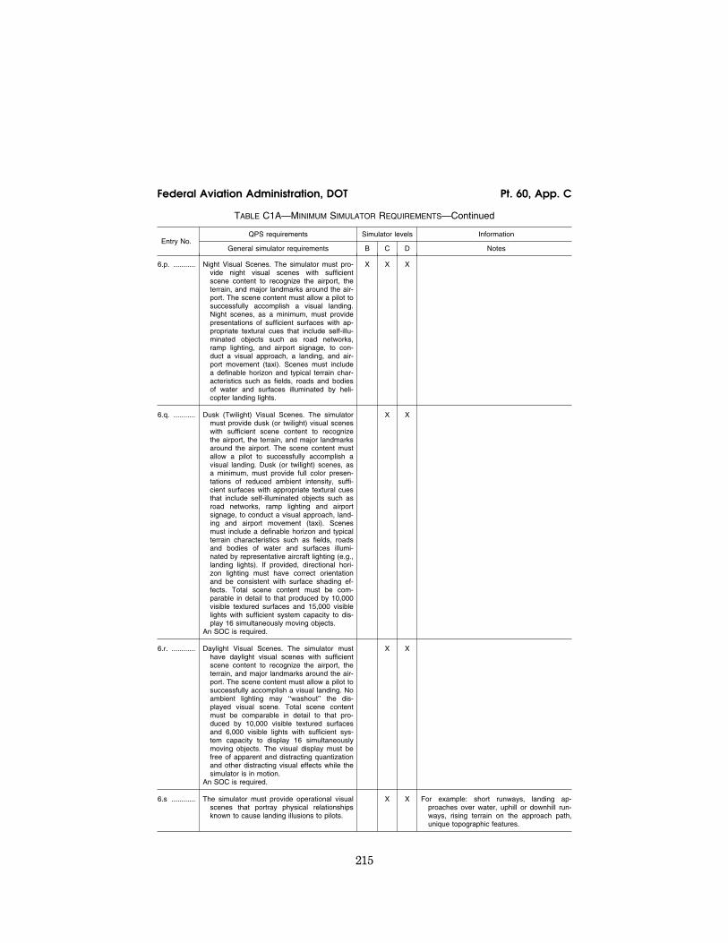
215
Federal Aviation Administration, DOT Pt. 60, App. C
TABLE C1A—MINIMUM SIMULATOR REQUIREMENTS—Continued
Entry No. QPS requirements Simulator levels Information
General simulator requirements B C D Notes
6.p. ........... Night Visual Scenes. The simulator must pro-vide night visual scenes with sufficient scene content to recognize the airport, the terrain, and major landmarks around the air-port. The scene content must allow a pilot to successfully accomplish a visual landing. Night scenes, as a minimum, must provide presentations of sufficient surfaces with ap-propriate textural cues that include self-illu-minated objects such as road networks, ramp lighting, and airport signage, to con-duct a visual approach, a landing, and air-port movement (taxi). Scenes must include a definable horizon and typical terrain char-acteristics such as fields, roads and bodies of water and surfaces illuminated by heli-copter landing lights.
X X X
6.q. ........... Dusk (Twilight) Visual Scenes. The simulator must provide dusk (or twilight) visual scenes with sufficient scene content to recognize the airport, the terrain, and major landmarks around the airport. The scene content must allow a pilot to successfully accomplish a visual landing. Dusk (or twilight) scenes, as a minimum, must provide full color presen-tations of reduced ambient intensity, suffi-cient surfaces with appropriate textural cues that include self-illuminated objects such as road networks, ramp lighting and airport signage, to conduct a visual approach, land-ing and airport movement (taxi). Scenes must include a definable horizon and typical terrain characteristics such as fields, roads and bodies of water and surfaces illumi-nated by representative aircraft lighting (e.g., landing lights). If provided, directional hori-zon lighting must have correct orientation and be consistent with surface shading ef-fects. Total scene content must be com-parable in detail to that produced by 10,000 visible textured surfaces and 15,000 visible lights with sufficient system capacity to dis-play 16 simultaneously moving objects.
An SOC is required.
X X
6.r. ............ Daylight Visual Scenes. The simulator must have daylight visual scenes with sufficient scene content to recognize the airport, the terrain, and major landmarks around the air-port. The scene content must allow a pilot to successfully accomplish a visual landing. No ambient lighting may ‘‘washout’’ the dis-played visual scene. Total scene content must be comparable in detail to that pro-duced by 10,000 visible textured surfaces and 6,000 visible lights with sufficient sys-tem capacity to display 16 simultaneously moving objects. The visual display must be free of apparent and distracting quantization and other distracting visual effects while the simulator is in motion.
An SOC is required.
X X
6.s ............ The simulator must provide operational visual scenes that portray physical relationships known to cause landing illusions to pilots.
X X For example: short runways, landing ap-proaches over water, uphill or downhill run-ways, rising terrain on the approach path, unique topographic features.
VerDate Mar<15>2010 18:16 Mar 01, 2012 Jkt 226045 PO 00000 Frm 00225 Fmt 8010 Sfmt 8002 Q:\14\14V2 ofr150 PsN: PC150

216
14 CFR Ch. I (1–1–12 Edition) Pt. 60, App. C
TABLE C1A—MINIMUM SIMULATOR REQUIREMENTS—Continued
Entry No. QPS requirements Simulator levels Information
General simulator requirements B C D Notes
6.t. ............ The simulator must provide special weather representations of light, medium, and heavy precipitation near a thunderstorm on takeoff and during approach and landing. Rep-resentations need only be presented at and below an altitude of 2,000 ft. (610 m) above the airport surface and within 10 miles (16 km) of the airport.
X X
6.u. ........... The simulator must present visual scenes of wet and snow-covered runways, including runway lighting reflections for wet condi-tions, and partially obscured lights for snow conditions.
X X The NSPM will consider suitable alternative ef-fects.
6.v. ........... The simulator must present realistic color and directionality of all airport lighting.
X X
7. .............. Sound System
7.a. ........... The simulator must provide flight deck sounds that result from pilot actions that correspond to those that occur in the helicopter.
X X X
7.b. ........... Volume control, if installed, must have an indi-cation of the sound level setting.
X X X
7.c. ........... The simulator must accurately simulate the sound of precipitation, windshield wipers, and other significant helicopter noises per-ceptible to the pilot during normal and ab-normal operations, and include the sound of a crash (when the simulator is landed in an unusual attitude or in excess of the struc-tural gear limitations); normal engine sounds; and the sounds of gear extension and retraction.
An SOC is required.
X X
7.d. ........... The simulator must provide realistic amplitude and frequency of flight deck noises and sounds. Simulator performance must be re-corded, compared to amplitude and fre-quency of the same sounds recorded in the helicopter, and made a part of the QTG.
X
TABLE C1B—TABLE OF TASKS VS. SIMULATOR LEVEL
QPS requirements Information
Entry No. Subjective requirements
The simulator must be able to perform the tasks associated with that level of qualification.
Simulator levels Notes
B C D
1. Preflight Procedures
1.a. ............ Preflight Inspection (Flight deck Only) switches, indicators, sys-tems, and equipment.
X X X
1.b. ............ APU/Engine start and run-up.
1.b.1. ......... Normal start procedures ................................................................ X X X
1.b.2. ......... Alternate start procedures ............................................................. X X X
1.b.3. ......... Abnormal starts and shutdowns (hot start, hung start) ................. X X X
1.c. ............ Taxiing—Ground ............................................................................ X X X
VerDate Mar<15>2010 18:16 Mar 01, 2012 Jkt 226045 PO 00000 Frm 00226 Fmt 8010 Sfmt 8002 Q:\14\14V2 ofr150 PsN: PC150

217
Federal Aviation Administration, DOT Pt. 60, App. C
TABLE C1B—TABLE OF TASKS VS. SIMULATOR LEVEL—Continued
QPS requirements Information
Entry No. Subjective requirements
The simulator must be able to perform the tasks associated with that level of qualification.
Simulator levels Notes
B C D
1.d. ............ Taxiing—Hover .............................................................................. X X X
1.e. ............ Pre-takeoff Checks ........................................................................ X X X
2. Takeoff and Departure Phase
2.a. ............ Normal takeoff.
2.a.1. ......... From ground .................................................................................. X X X
2.a.2. ......... From hover .................................................................................... X X
2.a.3. ......... Running .......................................................................................... X X X
2.b. ............ Instrument ...................................................................................... X X X
2.c. ............ Powerplant Failure During Takeoff ................................................ X X X
2.d. ............ Rejected Takeoff ............................................................................ X X X
2.e. ............ Instrument Departure ..................................................................... X X X
3. Climb
3.a. ............ Normal ........................................................................................... X X X
3.b. ............ Obstacle clearance ........................................................................ X X X
3.c. ............ Vertical ........................................................................................... X X X
3.d. ............ One engine inoperative ................................................................. X X X
4. In-flight Maneuvers
4.a. ............ Turns (timed, normal, steep) ......................................................... X X X
4.b. ............ Powerplant Failure—Multiengine Helicopters ................................ X X X
4.c. ............ Powerplant Failure—Single-Engine Helicopters ............................ X X X
4.d. ............ Recovery From Unusual Attitudes ................................................. X X X
4.e. ............ Settling with Power ........................................................................ X X X
4.f. ............. Specific Flight Characteristics incorporated into the user’s FAA approved flight training program.
A A A
5. Instrument Procedures
5.a. ............ Instrument Arrival ........................................................................... X X X
5.b. ............ Holding ........................................................................................... X X X
5.c. ............ Precision Instrument Approach.
5.c.1. ......... Normal—All engines operating ...................................................... X X X
5.c.2. ......... Manually controlled—One or more engines inoperative ............... X X X
5.d. ............ Non-precision Instrument Approach .............................................. X X X
5.e. ............ Missed Approach.
5.e.1. ......... All engines operating ..................................................................... X X X
5.e.2. ......... One or more engines inoperative .................................................. X X X
5.e.3. ......... Stability augmentation system failure ............................................ X X X
VerDate Mar<15>2010 18:16 Mar 01, 2012 Jkt 226045 PO 00000 Frm 00227 Fmt 8010 Sfmt 8002 Q:\14\14V2 ofr150 PsN: PC150

218
14 CFR Ch. I (1–1–12 Edition) Pt. 60, App. C
TABLE C1B—TABLE OF TASKS VS. SIMULATOR LEVEL—Continued
QPS requirements Information
Entry No. Subjective requirements
The simulator must be able to perform the tasks associated with that level of qualification.
Simulator levels Notes
B C D
6. Landings and Approaches to Landings
6.a. ............ Visual Approaches (normal, steep, shallow) ................................. X X X
6.b. ............ Landings.
6.b.1. ......... Normal/crosswind.
6.b.1.a. ...... Running ......................................................................................... X X X
6.b.1.b. ...... From Hover .................................................................................... X X
6.b.2. ......... One or more engines inoperative .................................................. X X X
6.b.3. ......... Rejected Landing ........................................................................... X X X
7. Normal and Abnormal Procedures
7.a. ............ Powerplant ..................................................................................... X X X
7.b. ............ Fuel System ................................................................................... X X X
7.c. ............ Electrical System ........................................................................... X X X
7.d. ............ Hydraulic System ........................................................................... X X X
7.e. ............ Environmental System(s) ............................................................... X X X
7.f. ............. Fire Detection and Extinguisher Systems ..................................... X X X
7.g. ............ Navigation and Aviation Systems .................................................. X X X
7.h. ............ Automatic Flight Control System, Electronic Flight Instrument System, and Related Subsystems.
X X X
7.i. ............. Flight Control Systems .................................................................. X X X
7.j. ............. Anti-ice and Deice Systems .......................................................... X X X
7.k. ............ Aircraft and Personal Emergency Equipment ............................... X X X
7.l. ............. Special Missions tasks (e.g., Night Vision goggles, Forward Looking Infrared System, External Loads and as listed on the SOQ).
A A X
8. Emergency procedures (as applicable)
8.a. ............ Emergency Descent ...................................................................... X X X
8.b. ............ Inflight Fire and Smoke Removal .................................................. X X X
8.c. ............ Emergency Evacuation .................................................................. X X X
8.d. ............ Ditching .......................................................................................... X X X
8.e. ............ Autorotative Landing ...................................................................... X X X
8.f. ............. Retreating blade stall recovery ...................................................... X X X
8.g. ............ Mast bumping ................................................................................ X X X
8.h. ............ Loss of tail rotor effectiveness ....................................................... X X X
8.i. ............. Vortex recovery .............................................................................. X X X
9. Postflight Procedures
9.a ............. After-Landing Procedures .............................................................. X X X
VerDate Mar<15>2010 18:16 Mar 01, 2012 Jkt 226045 PO 00000 Frm 00228 Fmt 8010 Sfmt 8002 Q:\14\14V2 ofr150 PsN: PC150

219
Federal Aviation Administration, DOT Pt. 60, App. C
TABLE C1B—TABLE OF TASKS VS. SIMULATOR LEVEL—Continued
QPS requirements Information
Entry No. Subjective requirements
The simulator must be able to perform the tasks associated with that level of qualification.
Simulator levels Notes
B C D
9.b. ............ Parking and Securing.
9.b.1. ......... Rotor brake operation .................................................................... X X X
9.b.2. ......... Abnormal/emergency procedures .................................................. X X X
Note: An ‘‘A’’ in the table indicates that the system, task, or procedure may be examined if the appropriate aircraft system or control is simulated in the FFS and is working properly
TABLE C1C—TABLE OF TASKS VS. SIMULATOR LEVEL
QPS requirements Information
Entry No. Subjective requirements
The simulator must be able to perform the tasks associated with that level of qualification.
Simulator levels Notes
B C D
1. ............... Instructor Operating Station (IOS), as appropriate
1.a. ............ Power switch(es) ........................................................................... X X X
1.b. ............ Helicopter conditions ..................................................................... X X X e.g., GW, CG, Fuel loading, Systems, Ground Crew.
1.c. ............ Airports/Heliports/Helicopter Landing Areas .................................. X X X e.g., Selection, Surface, Presets, Lighting controls
1.d. ............ Environmental controls. ................................................................. X X X e.g., Clouds, Visibility, RVR, Temp, Wind, Ice, Snow, Rain, and Windshear.
1.e. ............ Helicopter system malfunctions (Insertion/deletion) ...................... X X X
1.f. ............. Locks, Freezes, and Repositioning ............................................... X X X
2. ............... Sound Controls.
2.a. ............ On/off/adjustment ........................................................................... X X X
3. ............... Motion/Control Loading System
3.a. ............ On/off/emergency stop .................................................................. X X X
4. ............... Observer Seats/Stations
4.a. ............ Position/Adjustment/Positive restraint system ............................... X X X
ATTACHMENT 2 TO APPENDIX C TO PART 60— FFS OBJECTIVE TESTS
lllllllllllllllllllllll
BEGIN INFORMATION
TABLE OF CONTENTS
Paragraph No. Title
1. .............. Introduction.
2. .............. Test Requirements.
Table C2A, Objective Tests.
TABLE OF CONTENTS—Continued
Paragraph No. Title
3. .............. General.
4. .............. Control Dynamics.
5. .............. [Reserved]
6. .............. Motion System.
7. .............. Sound System.
8. .............. Additional Information About Flight Simulator Qualification for New or Derivative Heli-copters.
VerDate Mar<15>2010 18:16 Mar 01, 2012 Jkt 226045 PO 00000 Frm 00229 Fmt 8010 Sfmt 8002 Q:\14\14V2 ofr150 PsN: PC150

220
14 CFR Ch. I (1–1–12 Edition) Pt. 60, App. C
TABLE OF CONTENTS—Continued
Paragraph No. Title
9. .............. Engineering Simulator—Validation Data.
10. ............ [Reserved]
11. ............ Validation Test Tolerances.
12. ............ Validation Data Roadmap.
13. ............ Acceptance Guidelines for Alternative Engines Data.
14. ............ Acceptance Guidelines for Alternative Avionics (Flight-Related Computers and Controllers).
15. ............ Transport Delay Testing.
16. ............ Continuing Qualification Evaluations—Validation Test Data Presentation.
17. ............ Alternative Data Sources, Procedures, and In-strumentation: Level A and Level B Simula-tors Only.
1. INTRODUCTION
a. If relevant winds are present in the ob-jective data, the wind vector (magnitude and direction) should be clearly noted as part of the data presentation, expressed in conven-tional terminology, and related to the run-way being used for the test.
b. The NSPM will not evaluate any simu-lator unless the required SOC indicates that the motion system is designed and manufac-tured to safely operate within the simula-tor’s maximum excursion, acceleration, and velocity capabilities (see Motion System in the following table).
c. Table C2A addresses helicopter simula-tors at Levels B, C, and D because there are no Level A Helicopter simulators.
END INFORMATION
lllllllllllllllllllllll
BEGIN QPS REQUIREMENTS
2. TEST REQUIREMENTS
a. The ground and flight tests required for qualification are listed in Table of C2A, FFS Objective Tests. Computer-generated simu-lator test results must be provided for each test except where an alternative test is spe-cifically authorized by the NSPM. If a flight condition or operating condition is required for the test but does not apply to the heli-copter being simulated or to the qualifica-tion level sought, it may be disregarded (e.g., an engine out missed approach for a single- engine helicopter, or a hover test for a Level B simulator). Each test result is compared against the validation data described in § 60.13 and in this appendix. Although use of a driver program designed to automatically accomplish the tests is encouraged for all
simulators and required for Level C and Level D simulators, each test must be able to be accomplished manually while recording all appropriate parameters. The results must be produced on an appropriate recording de-vice acceptable to the NSPM and must in-clude simulator number, date, time, condi-tions, tolerances, and appropriate dependent variables portrayed in comparison to the val-idation data. Time histories are required un-less otherwise indicated in Table C2A. All re-sults must be labeled using the tolerances and units given.
b. Table C2A sets out the test results re-quired, including the parameters, tolerances, and flight conditions for simulator valida-tion. Tolerances are provided for the listed tests because mathematical modeling and acquisition/development of reference data are often inexact. All tolerances listed in the following tables are applied to simulator per-formance. When two tolerance values are given for a parameter, the less restrictive value may be used unless otherwise indi-cated. In those cases where a tolerance is ex-pressed only as a percentage, the tolerance percentage applies to the maximum value of that parameter within its normal operating range as measured from the neutral or zero position unless otherwise indicated.
c. Certain tests included in this attach-ment must be supported with an SOC. In Table C2A, requirements for SOCs are indi-cated in the ‘‘Test Details’’ column.
d. When operational or engineering judg-ment is used in making assessments for flight test data applications for simulator validity, such judgment may not be limited to a single parameter. For example, data that exhibit rapid variations of the measured parameters may require interpolations or a ‘‘best fit’’ data selection. All relevant param-eters related to a given maneuver or flight condition must be provided to allow overall interpretation. When it is difficult or impos-sible to match simulator to helicopter data throughout a time history, differences must be justified by providing a comparison of other related variables for the condition being assessed.
e. The FFS may not be programmed so that the mathematical modeling is correct only at the validation test points. Unless noted otherwise, simulator tests must rep-resent helicopter performance and handling qualities at operating weights and centers of gravity (CG) typical of normal operation. If a test is supported by helicopter data at one extreme weight or CG, another test sup-ported by helicopter data at mid-conditions or as close as possible to the other extreme must be included. Certain tests that are rel-evant only at one extreme CG or weight con-dition need not be repeated at the other ex-treme. Tests of handling qualities must in-clude validation of augmentation devices.
VerDate Mar<15>2010 18:16 Mar 01, 2012 Jkt 226045 PO 00000 Frm 00230 Fmt 8010 Sfmt 8002 Q:\14\14V2 ofr150 PsN: PC150

221
Federal Aviation Administration, DOT Pt. 60, App. C
f. When comparing the parameters listed to those of the helicopter, sufficient data must also be provided to verify the correct flight condition and helicopter configuration changes. For example, to show that control force is within ±0.5 pound (0.22 daN) in a stat-ic stability test, data to show the correct airspeed, power, thrust or torque, helicopter configuration, altitude, and other appro-priate datum identification parameters must also be given. If comparing short period dy-namics, normal acceleration may be used to establish a match to the helicopter, but air-speed, altitude, control input, helicopter configuration, and other appropriate data must also be given. All airspeed values must be properly annotated (e.g., indicated versus calibrated). In addition, the same variables must be used for comparison (e.g., compare inches to inches rather than inches to centi-meters).
g. The QTG provided by the sponsor must clearly describe how the simulator will be set up and operated for each test. Each simu-lator subsystem may be tested independ-ently, but overall integrated testing of the simulator must be accomplished to assure that the total simulator system meets the prescribed standards. A manual test proce-dure with explicit and detailed steps for completing each test must also be provided.
h. For previously qualified simulators, the tests and tolerances of this attachment may be used in subsequent continuing qualifica-tion evaluations for any given test if the sponsor has submitted a proposed MQTG re-vision to the NSPM and has received NSPM approval.
i. Motion System Tests: (a) The minimum excursions, accelera-
tions, and velocities for pitch, roll, and yaw must be measurable about a single, common reference point and must be achieved by driving one degree of freedom at a time.
(b) The minimum excursions, accelera-tions, and velocities for heave, sway, and surge may be measured about different, iden-tifiable reference points and must be achieved by driving one degree of freedom at a time.
j. Tests of handling qualities must include validation of augmentation devices. FFSs for highly augmented helicopters will be vali-dated both in the unaugmented configura-tion (or failure state with the maximum per-mitted degradation in handling qualities) and the augmented configuration. Where
various levels of handling qualities result from failure states, validation of the effect of the failure is necessary. For those per-formance and static handling qualities tests where the primary concern is control posi-tion in the unaugmented configuration, un-augmented data are not required if the de-sign of the system precludes any affect on control position. In those instances where the unaugmented helicopter response is di-vergent and non-repeatable, it may not be feasible to meet the specified tolerances. Al-ternative requirements for testing will be mutually agreed upon by the sponsor and the NSPM on a case-by-case basis.
k. Some tests will not be required for heli-copters using helicopter hardware in the simulator flight deck (e.g., ‘‘helicopter mod-ular controller’’). These exceptions are noted in Table C2A of this attachment. However, in these cases, the sponsor must provide a statement that the helicopter hardware meets the appropriate manufacturer’s speci-fications and the sponsor must have sup-porting information to that fact available for NSPM review.
l. In cases where light-class helicopters are being simulated, prior coordination with the NSPM on acceptable weight ranges is re-quired. The terms ‘‘light’’, ‘‘medium’’, and ‘‘near maximum’’, as defined in Appendix F of this part, may not be appropriate for the simulation of light-class helicopters.
END QPS REQUIREMENTS
lllllllllllllllllllllll
BEGIN INFORMATION
m. In those cases where the objective test results authorize a ‘‘snapshot test’’ or a ‘‘se-ries of snapshot test results’’ in lieu of a time-history result, the sponsor or other data provider must ensure that a steady state condition exists at the instant of time captured by the ‘‘snapshot’’. The steady state condition must exist from 4 seconds prior to, through 1 second following, the in-stant of time captured by the snap shot.
n. For references on basic operating weight, see AC 120–27, Aircraft Weight and Balance; and FAA–H–8083–1, Aircraft Weight and Balance Handbook.
END INFORMATION
lllllllllllllllllllllll
VerDate Mar<15>2010 18:16 Mar 01, 2012 Jkt 226045 PO 00000 Frm 00231 Fmt 8010 Sfmt 8002 Q:\14\14V2 ofr150 PsN: PC150

222
14 CFR Ch. I (1–1–12 Edition) Pt. 60, App. C
TA
BLE
C2A
—F
ULL
FLI
GH
TS
IMU
LAT
OR
(FF
S)
OB
JEC
TIV
ET
ES
TS
QP
S r
equi
rem
ents
In
form
atio
n
Tes
t T
oler
ance
(s)
Flig
ht c
ondi
tion
Tes
t de
tails
Sim
ulat
or
leve
l N
otes
Ent
ry N
o.
Titl
e B
C
D
1. P
erfo
rman
ce
1.a.
......
......
.E
ngin
e A
sses
smen
t
1.a.
1....
......
.S
tart
Ope
ratio
ns
1.a.
1.a
......
..E
ngin
e st
art
and
acce
lera
tion
(tra
nsie
nt).
Ligh
t O
ff T
ime—
±10%
or
±1
sec.
, T
orqu
e—±5
%,
Rot
or
Spe
ed—
±3%
, F
uel F
low
—
±10%
, G
as G
ener
ator
S
peed
—±5
%,
Pow
er T
ur-
bine
Spe
ed—
±5%
, G
as
Tur
bine
Tem
p.—
±30
°C.
Gro
und
with
the
Rot
or B
rake
U
sed
and
Not
Use
d, if
ap-
plic
able
.
Rec
ord
each
eng
ine
star
t fr
om t
he in
itiat
ion
of t
he
star
t se
quen
ce t
o st
eady
st
ate
idle
and
fro
m s
tead
y st
ate
idle
to
oper
atin
g R
PM
.
X
X
X
1.a.
1.b.
......
.S
tead
y S
tate
Idl
e an
d O
per-
atin
g R
PM
con
ditio
ns.
Tor
que—
±3%
, R
otor
S
peed
—±1
.5%
, F
uel
Flo
w—
±5%
, G
as G
ener
ator
S
peed
—±2
%,
Pow
er T
ur-
bine
Spe
ed—
±2%
, T
urbi
ne
Gas
Tem
p.—
±20
°C.
Gro
und
......
......
......
......
......
.....
Rec
ord
both
ste
ady
stat
e id
le
and
oper
atin
g R
PM
con
di-
tions
. M
ay b
e a
serie
s of
sn
apsh
ot t
ests
.
X
X
X
1.a.
2....
......
.P
ower
Tur
bine
Spe
ed T
rim...
±10%
of
tota
l cha
nge
of
pow
er t
urbi
ne s
peed
, or
±0
.5%
cha
nge
of r
otor
sp
eed.
Gro
und
......
......
......
......
......
.....
Rec
ord
engi
ne r
espo
nse
to
trim
sys
tem
act
uatio
n in
bo
th d
irect
ions
.
X
X
X
1.a.
3....
......
.E
ngin
e an
d R
otor
Spe
ed
Gov
erni
ng.
Tor
que—
±5%
, R
otor
S
peed
—1.
5%.
Clim
b an
d de
scen
t...
......
......
.R
ecor
d re
sults
usi
ng a
ste
p in
put
to t
he c
olle
ctiv
e. M
ay
be c
ondu
cted
con
curr
ently
w
ith c
limb
and
desc
ent
per-
form
ance
tes
ts.
X
X
X
1.b.
......
......
.S
urfa
ce O
pera
tions
1.b.
1....
......
.M
inim
um R
adiu
s T
urn
......
.....
±3 f
t. (0
.9m
) or
20%
of
heli-
copt
er t
urn
radi
us.
Gro
und
......
......
......
......
......
.....
If br
akes
are
use
d, b
rake
pe
dal p
ositi
on a
nd b
rake
sy
stem
pre
ssur
e m
ust
be
mat
ched
to
the
helic
opte
r fli
ght
test
val
ue.
X
X
X
VerDate Mar<15>2010 18:16 Mar 01, 2012 Jkt 226045 PO 00000 Frm 00232 Fmt 8010 Sfmt 8002 Q:\14\14V2 ofr150 PsN: PC150

223
Federal Aviation Administration, DOT Pt. 60, App. C
1.b.
2....
......
.R
ate
of T
urn
vs.
Ped
al D
e-fle
ctio
n, B
rake
App
licat
ion,
or
Nos
ewhe
el A
ngle
, as
ap
plic
able
.
±10%
or
±2°/
sec.
Tur
n R
ate.
G
roun
d T
akeo
ff...
......
......
......
If br
akes
are
use
d, b
rake
pe
dal p
ositi
on a
nd b
rake
sy
stem
pre
ssur
e m
ust
be
mat
ched
to
the
helic
opte
r fli
ght
test
val
ue.
X
X
X
1.b.
3....
......
.T
axi
......
......
......
......
......
......
....
Pitc
h A
ngle
—±1
.5°,
Tor
que—
±3
%,
Long
itudi
nal C
ontr
ol
Pos
ition
—±5
%,
Late
ral
Con
trol
Pos
ition
—±5
%,
Di-
rect
iona
l Con
trol
Pos
ition
—
±5%
, C
olle
ctiv
e C
ontr
ol P
o-si
tion—
±5%
.
Gro
und
......
......
......
......
......
.....
Rec
ord
resu
lts f
or c
ontr
ol p
o-si
tion
and
pitc
h at
titud
e du
ring
grou
nd t
axi f
or a
sp
ecifi
c gr
ound
spe
ed,
win
d sp
eed
and
dire
ctio
n,
and
dens
ity a
ltitu
de.
X
X
X
1.b.
4....
......
.B
rake
Effe
ctiv
enes
s...
......
......
±10%
of
time
and
dist
ance
. G
roun
d...
......
......
......
......
......
..X
X
X
1.c.
......
......
..T
akeo
ff W
hen
the
spee
d ra
nge
for
the
follo
win
g te
sts
is le
ss t
han
40 k
nots
, th
e ap
plic
able
airs
peed
tol
eran
ce m
ay b
e ap
plie
d to
eith
er a
irspe
ed o
r gr
ound
spe
ed,
as a
ppro
pria
te.
1.c.
1....
......
..A
ll E
ngin
es...
......
......
......
......
.A
irspe
ed—
±3 k
t, A
ltitu
de—
±2
0 ft
(6.1
m),
Tor
que—
±3
%,
Rot
or S
peed
—±1
.5%
, V
ertic
al V
eloc
ity—
±100
fpm
(0
.50m
/sec
) or
10%
, P
itch
Atti
tude
—±1
.5°,
Ban
k A
tti-
tude
—±2
°, H
eadi
ng—
±2°,
Lo
ngitu
dina
l Con
trol
Pos
i-tio
n—±1
0%,
Late
ral C
ontr
ol
Pos
ition
—±1
0%,
Dire
c-tio
nal C
ontr
ol P
ositi
on—
±1
0%,
Col
lect
ive
Con
trol
P
ositi
on—
±10%
.
Gro
und/
Tak
eoff
and
Initi
al
Seg
men
t of
Clim
b.
Rec
ord
resu
lts o
f ta
keof
f fli
ght
path
as
appr
opria
te t
o he
licop
ter
mod
el s
imul
ated
(r
unni
ng t
akeo
ff fo
r Le
vel
B,
take
off
from
a h
over
for
Le
vel C
and
D).
For
Lev
el
B,
the
crite
ria a
pply
onl
y to
th
ose
segm
ents
at
air-
spee
ds a
bove
effe
ctiv
e tr
ansl
atio
nal l
ift.
Res
ults
m
ust
be r
ecor
ded
from
the
in
itiat
ion
of t
he t
akeo
ff to
at
leas
t 20
0 ft
(61m
) A
GL.
X
X
X
1.c.
2....
......
..O
ne E
ngin
e In
oper
ativ
e co
n-tin
ued
take
off.
Airs
peed
—±3
kt,
Alti
tude
—
±20
ft (6
.1m
), T
orqu
e—
±3%
, R
otor
Spe
ed—
±1.5
%,
Ver
tical
Vel
ocity
—±1
00 f
pm
(0.5
0m/s
ec)
or 1
0%,
Pitc
h A
ttitu
de—
±1.5
°, B
ank
Atti
-tu
de—
±2°,
Hea
ding
—±2
°,
Long
itudi
nal C
ontr
ol P
osi-
tion—
±10%
Lat
eral
Con
trol
P
ositi
on—
±10%
, D
irec-
tiona
l Con
trol
Pos
ition
—
±10%
, C
olle
ctiv
e C
ontr
ol
Pos
ition
—±1
0%.
Gro
und/
Tak
eoff;
and
Ini
tial
Seg
men
t of
Clim
b.
Rec
ord
take
off
fligh
t pa
th a
s ap
prop
riate
to
helic
opte
r m
odel
sim
ulat
ed.
Res
ults
m
ust
be r
ecor
ded
from
the
in
itiat
ion
of t
he t
akeo
ff to
at
leas
t 20
0 ft
(61m
) A
GL.
X
X
X
Bec
ause
sev
eral
kin
ds o
f ta
keof
f pr
oced
ures
can
be
perf
orm
ed,
the
spec
ific
type
of
take
off
prof
ile
shou
ld b
e re
cord
ed t
o en
-su
re t
he p
rope
r ta
keof
f pr
o-fil
e co
mpa
rison
tes
t is
us
ed.
VerDate Mar<15>2010 18:16 Mar 01, 2012 Jkt 226045 PO 00000 Frm 00233 Fmt 8010 Sfmt 8002 Q:\14\14V2 ofr150 PsN: PC150

224
14 CFR Ch. I (1–1–12 Edition) Pt. 60, App. C
TA
BLE
C2A
—F
ULL
FLI
GH
TS
IMU
LAT
OR
(FF
S)
OB
JEC
TIV
ET
ES
TS—
Con
tinue
d
QP
S r
equi
rem
ents
In
form
atio
n
Tes
t T
oler
ance
(s)
Flig
ht c
ondi
tion
Tes
t de
tails
Sim
ulat
or
leve
l N
otes
Ent
ry N
o.
Titl
e B
C
D
1.c.
3....
......
..O
ne E
ngin
e in
oper
ativ
e, r
e-je
cted
tak
e of
f. A
irspe
ed—
±3 k
t, A
ltitu
de—
±2
0 ft
(6.1
m),
Tor
que—
±3
%,
Rot
or S
peed
—±1
.5%
, P
itch
Atti
tude
—±1
.5°,
Rol
l an
gle—
± 1.
5°,
Hea
ding
—
±2°,
Lon
gitu
dina
l Con
trol
P
ositi
on—
±10%
, La
tera
l C
ontr
ol P
ositi
on—
±10%
, D
irect
iona
l Con
trol
Pos
i-tio
n—±1
0%,
Col
lect
ive
Con
trol
Pos
ition
—±1
0%,
Dis
tanc
e—±7
.5%
or
±30m
(1
00ft)
.
Gro
und,
Tak
eoff
......
......
......
..T
ime
hist
ory
from
the
tak
e of
f po
int
to t
ouch
dow
n. T
est
cond
ition
s ne
ar li
miti
ng p
er-
form
ance
.
X
X
1.d.
......
......
.H
over
Per
form
ance
......
......
......
......
..T
orqu
e—±3
%,
Pitc
h A
tti-
tude
—±1
.5°,
Ban
k A
tti-
tude
—±1
.5°,
Lon
gitu
dina
l C
ontr
ol P
ositi
on—
±5%
, La
tera
l Con
trol
Pos
ition
—
±5%
, D
irect
iona
l Con
trol
P
ositi
on—
±5%
, C
olle
ctiv
e C
ontr
ol P
ositi
on—
±5%
.
In G
roun
d E
ffect
(IG
E);
and
O
ut o
f G
roun
d E
ffect
(O
GE
).
Rec
ord
resu
lts f
or li
ght
and
heav
y gr
oss
wei
ghts
. M
ay
be a
ser
ies
of s
naps
hot
test
s.
X
X
1.e.
......
......
.V
ertic
al C
limb
Per
form
ance
......
......
......
......
..V
ertic
al V
eloc
ity—
±100
fpm
(0
.50
m/s
ec)
or ±
10%
, D
i-re
ctio
nal C
ontr
ol P
ositi
on—
±5
%,
Col
lect
ive
Con
trol
Po-
sitio
n—±5
%.
Fro
m O
GE
Hov
er...
......
......
...R
ecor
d re
sults
for
ligh
t an
d he
avy
gros
s w
eigh
ts.
May
be
a s
erie
s of
sna
psho
t te
sts.
X
X
1.f.
......
......
..Le
vel F
light
VerDate Mar<15>2010 18:16 Mar 01, 2012 Jkt 226045 PO 00000 Frm 00234 Fmt 8010 Sfmt 8002 Q:\14\14V2 ofr150 PsN: PC150

225
Federal Aviation Administration, DOT Pt. 60, App. C
Per
form
ance
and
Trim
med
F
light
Con
trol
Pos
ition
s.
Tor
que—
±3%
, P
itch
Atti
-tu
de—
±1.5
°, S
ides
lip
Ang
le—
±2°,
Lon
gitu
dina
l C
ontr
ol P
ositi
on—
±5%
, La
tera
l Con
trol
Pos
ition
—
±5%
, D
irect
iona
l Con
trol
P
ositi
on—
±5%
, C
olle
ctiv
e C
ontr
ol P
ositi
on—
±5%
.
Cru
ise
(Aug
men
tatio
n O
n an
d O
ff).
Rec
ord
resu
lts f
or t
wo
gros
s w
eigh
t an
d C
G c
ombi
na-
tions
with
var
ying
trim
sp
eeds
thr
ough
out
the
air-
spee
d en
velo
pe.
May
be
a se
ries
of s
naps
hot
test
s.
X
X
X
Thi
s te
st v
alid
ates
per
form
-an
ce a
t sp
eeds
abo
ve
max
imum
end
uran
ce a
ir-sp
eed.
1.g.
......
......
.C
limb
Per
form
ance
and
Trim
med
F
light
Con
trol
Pos
ition
s.
Ver
tical
Vel
ocity
—±1
00 f
pm
(6.1
m/s
ec)
or ±
10%
, P
itch
Atti
tude
—±1
.5°,
Sid
eslip
A
ngle
—±2
°, L
ongi
tudi
nal
Con
trol
Pos
ition
—±5
%,
Late
ral C
ontr
ol P
ositi
on—
±5
%,
Dire
ctio
nal C
ontr
ol
Pos
ition
—±5
%,
Col
lect
ive
Con
trol
Pos
ition
—±5
%.
All
engi
nes
oper
atin
g; O
ne
engi
ne in
oper
ativ
e; A
ug-
men
tatio
n S
yste
m(s
) O
n an
d O
ff.
Rec
ord
resu
lts f
or t
wo
gros
s w
eigh
t an
d C
G c
ombi
na-
tions
. T
he d
ata
pres
ente
d m
ust
be f
or n
orm
al c
limb
pow
er c
ondi
tions
. M
ay b
e a
serie
s of
sna
psho
t te
sts.
X
X
X
1.h.
......
......
.D
esce
nt
1.h.
1....
......
.D
esce
nt P
erfo
rman
ce a
nd
Trim
med
Flig
ht C
ontr
ol P
o-si
tions
.
Tor
que—
±3%
, P
itch
Atti
-tu
de—
±1.5
°, S
ides
lip
Ang
le—
±2°,
Lon
gitu
dina
l C
ontr
ol P
ositi
on—
±5%
, La
tera
l Con
trol
Pos
ition
—
±5%
, D
irect
iona
l Con
trol
P
ositi
on—
±5%
, C
olle
ctiv
e C
ontr
ol P
ositi
on—
±5%
.
At
or n
ear
1,00
0 fp
m (
5 m
/ se
c) r
ate
of d
esce
nt (
RoD
) at
nor
mal
app
roac
h sp
eed.
A
ugm
enta
tion
Sys
tem
(s)
On
and
Off.
Res
ults
mus
t be
rec
orde
d fo
r tw
o gr
oss
wei
ght
and
CG
co
mbi
natio
ns.
May
be
a se
ries
of s
naps
hot
test
s.
X
X
X
1.h.
2....
......
.A
utor
otat
ion
Per
form
ance
an
d T
rimm
ed F
light
Con
trol
P
ositi
ons.
Pitc
h A
ttitu
de—
±1.5
°, S
ides
lip
Ang
le—
±2°,
Lon
gitu
dina
l C
ontr
ol P
ositi
on—
±5%
, La
tera
l Con
trol
Pos
ition
—
±5%
, D
irect
iona
l Con
trol
P
ositi
on—
±5%
, C
olle
ctiv
e C
ontr
ol P
ositi
on—
±5%
, V
ertic
al V
eloc
ity—
±100
fpm
or
10%
, R
otor
Spe
ed—
±1
.5%
.
Ste
ady
desc
ents
. A
ugm
enta
-tio
n S
yste
m(s
) O
n an
d O
ff.
Rec
ord
resu
lts f
or t
wo
gros
s w
eigh
t co
nditi
ons.
Dat
a m
ust
be r
ecor
ded
for
nor-
mal
ope
ratin
g R
PM
. (R
otor
sp
eed
tole
ranc
e ap
plie
s on
ly if
col
lect
ive
cont
rol p
o-si
tion
is f
ull d
own.
) D
ata
mus
t be
rec
orde
d fo
r sp
eeds
fro
m 5
0 kt
s, ±
5 kt
s,
thro
ugh
at le
ast
max
imum
gl
ide
dist
ance
airs
peed
, or
m
axim
um a
llow
able
aut
o-ro
tatio
n ai
rspe
ed,
whi
ch-
ever
is s
low
er.
May
be
a se
ries
of s
naps
hot
test
s.
X
X
X
1.i.
......
......
...A
utor
otat
ion
VerDate Mar<15>2010 18:16 Mar 01, 2012 Jkt 226045 PO 00000 Frm 00235 Fmt 8010 Sfmt 8002 Q:\14\14V2 ofr150 PsN: PC150

226
14 CFR Ch. I (1–1–12 Edition) Pt. 60, App. C
TA
BLE
C2A
—F
ULL
FLI
GH
TS
IMU
LAT
OR
(FF
S)
OB
JEC
TIV
ET
ES
TS—
Con
tinue
d
QP
S r
equi
rem
ents
In
form
atio
n
Tes
t T
oler
ance
(s)
Flig
ht c
ondi
tion
Tes
t de
tails
Sim
ulat
or
leve
l N
otes
Ent
ry N
o.
Titl
e B
C
D
Ent
ry...
......
......
......
......
......
.....
Rot
or S
peed
—±3
%,
Pitc
h A
t-tit
ude—
±2°,
Rol
l Atti
tude
—
±3°,
Yaw
Atti
tude
—±5
°,
Airs
peed
—±5
kts
., V
ertic
al
Vel
ocity
—±2
00 f
pm (
1.00
m
/sec
) or
10%
.
Cru
ise
or C
limb
......
......
......
...R
ecor
d re
sults
of
a ra
pid
thro
ttle
redu
ctio
n to
idle
. If
the
crui
se c
ondi
tion
is s
e-le
cted
, co
mpa
rison
mus
t be
m
ade
for
the
max
imum
ra
nge
airs
peed
. If
the
clim
b co
nditi
on is
sel
ecte
d, c
om-
paris
on m
ust
be m
ade
for
the
max
imum
rat
e of
clim
b ai
rspe
ed a
t or
nea
r m
ax-
imum
con
tinuo
us p
ower
.
X
X
1.j.
......
......
...La
ndin
g W
hen
the
spee
d ra
nge
for
test
s 1.
j.1.,
1.j.2
., or
1.j.
3. is
less
tha
n 40
kno
ts,
the
appl
icab
le a
irspe
ed t
oler
ance
may
be
appl
ied
to e
ither
airs
peed
or
grou
nd s
peed
, as
app
ro-
pria
te.
1.j.1
....
......
...A
ll E
ngin
es...
......
......
......
......
.A
irspe
ed—
±3 k
ts.,
Alti
tude
—
±20
ft. (
6.1m
), T
orqu
e—
±3%
, R
otor
Spe
ed—
±1.5
%,
Pitc
h A
ttitu
de—
±1.5
°, B
ank
Atti
tude
—±1
.5°,
Hea
ding
—
±2°,
Lon
gitu
dina
l Con
trol
P
ositi
on—
±10%
, La
tera
l C
ontr
ol P
ositi
on—
±10%
, D
irect
iona
l Con
trol
Pos
i-tio
n—±1
0%,
Col
lect
ive
Con
trol
Pos
ition
—±1
0%.
App
roac
h...
......
......
......
......
....
Rec
ord
resu
lts o
f th
e ap
-pr
oach
and
land
ing
prof
ile
as a
ppro
pria
te t
o th
e he
li-co
pter
mod
el s
imul
ated
(r
unni
ng la
ndin
g fo
r Le
vel
B,
or a
ppro
ach
to a
hov
er
for
Leve
l C a
nd D
). F
or
Leve
l B,
the
crite
ria a
pply
on
ly t
o th
ose
segm
ents
at
airs
peed
s ab
ove
effe
ctiv
e tr
ansl
atio
nal l
ift.
X
X
X
1.j.2
....
......
...O
ne E
ngin
e In
oper
ativ
e.
Airs
peed
—±3
kts
., A
ltitu
de—
±2
0 ft.
(6.
1m),
Tor
que—
±3
%,
Rot
or S
peed
—±1
.5%
, P
itch
Atti
tude
—±1
.5°,
Ban
k A
ttitu
de—
±1.5
°, H
eadi
ng—
±2
°, L
ongi
tudi
nal C
ontr
ol
Pos
ition
—±1
0%,
Late
ral
Con
trol
Pos
ition
—±1
0%,
Dire
ctio
nal C
ontr
ol P
osi-
tion—
±10%
, C
olle
ctiv
e C
ontr
ol P
ositi
on—
±10%
.
App
roac
h...
......
......
......
......
....
Rec
ord
resu
lts f
or b
oth
Cat
-eg
ory
A a
nd C
ateg
ory
B
appr
oach
es a
nd la
ndin
g as
ap
prop
riate
to
helic
opte
r m
odel
sim
ulat
ed.
For
Lev
el
B,
the
crite
ria a
pply
onl
y to
th
ose
segm
ents
at
air-
spee
ds a
bove
effe
ctiv
e tr
ansl
atio
nal l
ift.
X
X
X
VerDate Mar<15>2010 18:16 Mar 01, 2012 Jkt 226045 PO 00000 Frm 00236 Fmt 8010 Sfmt 8002 Q:\14\14V2 ofr150 PsN: PC150

227
Federal Aviation Administration, DOT Pt. 60, App. C
1.j.3
....
......
...B
alke
d La
ndin
g...
......
......
......
.A
irspe
ed—
±3 k
ts,
Alti
tude
—
±20
ft. (
6.1m
), T
orqu
e—
±3%
, R
otor
Spe
ed—
±1.5
%,
Pitc
h A
ttitu
de—
±1.5
°, B
ank
Atti
tude
—±1
.5°,
Hea
ding
—
±2°,
Lon
gitu
dina
l Con
trol
P
ositi
on—
±10%
, La
tera
l C
ontr
ol P
ositi
on—
±10%
, D
irect
iona
l Con
trol
Pos
i-tio
n—±1
0%,
Col
lect
ive
Con
trol
Pos
ition
—±1
0%.
App
roac
h...
......
......
......
......
....
Rec
ord
the
resu
lts f
or t
he
man
euve
r in
itiat
ed f
rom
a
stab
ilize
d ap
proa
ch a
t th
e la
ndin
g de
cisi
on p
oint
(L
DP
).
X
X
X
1.j.4
....
......
...A
utor
otat
iona
l Lan
ding
. T
orqu
e—±3
%,
Rot
or
Spe
ed—
±3%
, V
ertic
al V
e-lo
city
—±1
00 f
pm (
0.50
m/
sec)
or
10%
, P
itch
Atti
-tu
de—
±2°,
Ban
k A
ttitu
de—
±2
°, H
eadi
ng—
±5°,
Lon
gi-
tudi
nal C
ontr
ol P
ositi
on—
±1
0%,
Late
ral C
ontr
ol P
osi-
tion—
±10%
, D
irect
iona
l C
ontr
ol P
ositi
on—
±10%
, C
olle
ctiv
e C
ontr
ol P
osi-
tion—
±10%
.
Land
ing
......
......
......
......
......
....
Rec
ord
the
resu
lts o
f an
au
toro
tatio
nal d
ecel
erat
ion
and
land
ing
from
a s
ta-
biliz
ed a
utor
otat
iona
l de-
scen
t, to
tou
ch d
own.
If
fligh
t te
st d
ata
cont
aini
ng
all r
equi
red
para
met
ers
for
a co
mpl
ete
pow
er-o
ff la
nd-
ing
is n
ot a
vaila
ble
from
th
e ai
rcra
ft m
anuf
actu
rer
for
this
tes
t an
d ot
her
qual
i-fie
d fli
ght
test
per
sonn
el
are
not
avai
labl
e to
acq
uire
th
is d
ata,
the
spo
nsor
may
co
ordi
nate
with
the
NS
PM
to
det
erm
ine
if it
is a
ppro
-pr
iate
to
acce
pt a
ltern
ativ
e te
stin
g m
eans
.
X
X
Alte
rnat
ive
appr
oach
es f
or
acqu
iring
thi
s da
ta m
ay b
e ac
cept
able
, de
pend
ing
on
the
airc
raft
as w
ell a
s th
e pe
rson
nel a
nd t
he d
ata
re-
cord
ing,
red
uctio
n, a
nd in
-te
rpre
tatio
n fa
cilit
ies
to b
e us
ed,
are:
(1)
a s
imul
ated
au
toro
tatio
nal f
lare
and
re-
duct
ion
of r
ate
of d
esce
nt
(RO
D)
at a
ltitu
de;
or (
2) a
po
wer
-on
term
inat
ion
fol-
low
ing
an a
utor
otat
iona
l ap
proa
ch a
nd f
lare
.
2. H
and
ling
Qu
alit
ies
2.a.
......
......
.C
ontr
ol S
yste
m M
echa
nica
l Cha
ract
eris
tics
For
sim
ulat
ors
requ
iring
Sta
tic o
r D
ynam
ic t
ests
at
the
cont
rols
(i.e
., cy
clic
, co
llect
ive,
and
ped
al),
spe
cial
tes
t fix
ture
s w
ill n
ot
be r
equi
red
durin
g in
itial
or
upgr
ade
eval
uatio
ns if
the
spo
nsor
’s Q
TG
/MQ
TG
sho
ws
both
tes
t fix
ture
res
ults
and
the
res
ults
of
an a
ltern
ativ
e ap
proa
ch,
such
as
com
pute
r pl
ots
prod
uced
con
curr
ently
sho
win
g sa
tisfa
ctor
y ag
reem
ent.
Rep
eat
of t
he a
lter-
nativ
e m
etho
d du
ring
the
initi
al o
r up
grad
e ev
alua
tion
satis
fies
this
tes
t re
quire
men
t. F
or in
itial
and
upg
rade
eva
luat
ions
, th
e co
ntro
l dyn
amic
cha
ract
eris
tics
mus
t be
mea
sure
d at
and
rec
orde
d di
rect
ly f
rom
the
flig
ht d
eck
cont
rols
, an
d m
ust
be a
ccom
-pl
ishe
d in
hov
er,
clim
b, c
ruis
e, a
nd a
utor
otat
ion.
Con
tact
the
NS
PM
for
cla
ri-fic
atio
n of
any
issu
e re
-ga
rdin
g he
licop
ters
with
re-
vers
ible
con
trol
s or
whe
re
the
requ
ired
valid
atio
n da
ta
is n
ot a
ttain
able
.
VerDate Mar<15>2010 18:16 Mar 01, 2012 Jkt 226045 PO 00000 Frm 00237 Fmt 8010 Sfmt 8002 Q:\14\14V2 ofr150 PsN: PC150
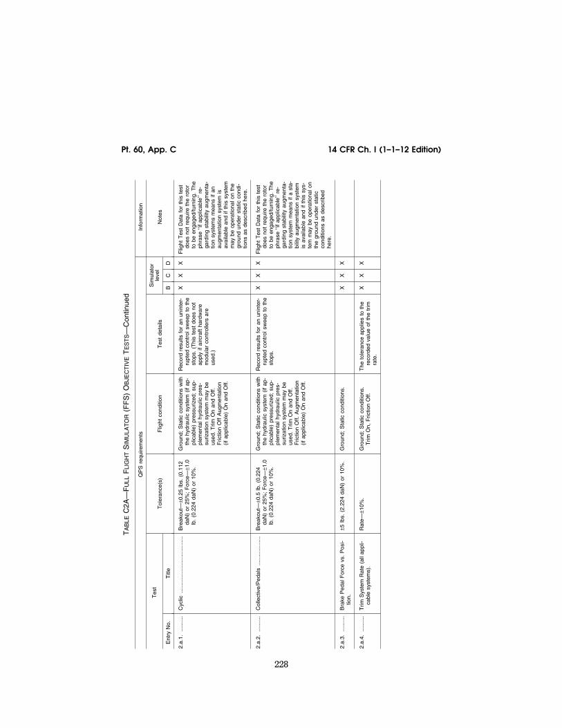
228
14 CFR Ch. I (1–1–12 Edition) Pt. 60, App. C
TA
BLE
C2A
—F
ULL
FLI
GH
TS
IMU
LAT
OR
(FF
S)
OB
JEC
TIV
ET
ES
TS—
Con
tinue
d
QP
S r
equi
rem
ents
In
form
atio
n
Tes
t T
oler
ance
(s)
Flig
ht c
ondi
tion
Tes
t de
tails
Sim
ulat
or
leve
l N
otes
Ent
ry N
o.
Titl
e B
C
D
2.a.
1....
......
.C
yclic
......
......
......
......
......
......
.B
reak
out—
±0.2
5 lb
s. (
0.11
2 da
N)
or 2
5%;
For
ce—
±1.0
lb
. (0
.224
daN
) or
10%
.
Gro
und;
Sta
tic c
ondi
tions
with
th
e hy
drau
lic s
yste
m (
if ap
-pl
icab
le)
pres
suriz
ed;
sup-
plem
enta
l hyd
raul
ic p
res-
suriz
atio
n sy
stem
may
be
used
. T
rim O
n an
d O
ff.
Fric
tion
Off
Aug
men
tatio
n (if
app
licab
le)
On
and
Off.
Rec
ord
resu
lts f
or a
n un
inte
r-ru
pted
con
trol
sw
eep
to t
he
stop
s. (
Thi
s te
st d
oes
not
appl
y if
airc
raft
hard
war
e m
odul
ar c
ontr
olle
rs a
re
used
.)
X
X
X
Flig
ht T
est
Dat
a fo
r th
is t
est
does
not
req
uire
the
rot
or
to b
e en
gage
d/tu
rnin
g. T
he
phra
se ‘‘
if ap
plic
able
’’ re
-ga
rdin
g st
abili
ty a
ugm
enta
-tio
n sy
stem
s m
eans
if a
n au
gmen
tatio
n sy
stem
is
avai
labl
e an
d if
this
sys
tem
m
ay b
e op
erat
iona
l on
the
grou
nd u
nder
sta
tic c
ondi
-tio
ns a
s de
scrib
ed h
ere.
2.a.
2....
......
.C
olle
ctiv
e/P
edal
s...
......
......
....
Bre
akou
t—±0
.5 lb
. (0
.224
da
N)
or 2
5%;
For
ce—
±1.0
lb
. (0
.224
daN
) or
10%
.
Gro
und;
Sta
tic c
ondi
tions
with
th
e hy
drau
lic s
yste
m (
if ap
-pl
icab
le)
pres
suriz
ed;
sup-
plem
enta
l hyd
raul
ic p
res-
suriz
atio
n sy
stem
may
be
used
. T
rim O
n an
d O
ff.
Fric
tion
Off.
Aug
men
tatio
n (if
app
licab
le)
On
and
Off.
Rec
ord
resu
lts f
or a
n un
inte
r-ru
pted
con
trol
sw
eep
to t
he
stop
s.
X
X
X
Flig
ht T
est
Dat
a fo
r th
is t
est
does
not
req
uire
the
rot
or
to b
e en
gage
d/tu
rnin
g. T
he
phra
se ‘‘
if ap
plic
able
’’ re
-ga
rdin
g st
abili
ty a
ugm
enta
-tio
n sy
stem
mea
ns if
a s
ta-
bilit
y au
gmen
tatio
n sy
stem
is
ava
ilabl
e an
d if
this
sys
-te
m m
ay b
e op
erat
iona
l on
the
grou
nd u
nder
sta
tic
cond
ition
s as
des
crib
ed
here
.
2.a.
3....
......
.B
rake
Ped
al F
orce
vs.
Pos
i-tio
n.
±5 lb
s. (
2.22
4 da
N)
or 1
0%.
Gro
und;
Sta
tic c
ondi
tions
. X
X
X
2.a.
4....
......
.T
rim S
yste
m R
ate
(all
appl
i-ca
ble
syst
ems)
.R
ate—
±10%
. G
roun
d; S
tatic
con
ditio
ns.
Trim
On,
Fric
tion
Off.
T
he t
oler
ance
app
lies
to t
he
reco
rded
val
ue o
f th
e tr
im
rate
.
X
X
X
VerDate Mar<15>2010 18:16 Mar 01, 2012 Jkt 226045 PO 00000 Frm 00238 Fmt 8010 Sfmt 8002 Q:\14\14V2 ofr150 PsN: PC150
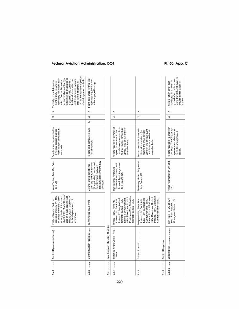
229
Federal Aviation Administration, DOT Pt. 60, App. C
2.a.
5....
......
.C
ontr
ol D
ynam
ics
(all
axes
)..
±10%
of
time
for
first
zer
o cr
ossi
ng a
nd ±
10 (
N+
1)%
of
per
iod
ther
eafte
r, ±
10%
of
am
plitu
de o
f fir
st o
ver-
shoo
t, 20
% o
f am
plitu
de o
f 2n
d an
d su
bseq
uent
ove
r-sh
oots
gre
ater
tha
n 5%
of
initi
al d
ispl
acem
ent,
±1
over
shoo
t.
Hov
er/C
ruis
e, T
rim O
n, F
ric-
tion
Off.
R
esul
ts m
ust
be r
ecor
ded
for
a no
rmal
con
trol
dis
plac
e-m
ent
in b
oth
dire
ctio
ns in
ea
ch a
xis.
X
X
Typ
ical
ly,
cont
rol d
ispl
ace-
men
t of
25%
to
50%
is
nece
ssar
y fo
r pr
oper
exc
i-ta
tion.
Con
trol
Dyn
amic
s fo
r irr
ever
sibl
e co
ntro
l sys
-te
ms
may
be
eval
uate
d in
a
grou
nd/s
tatic
con
ditio
n.
Add
ition
al in
form
atio
n on
co
ntro
l dyn
amic
s is
fou
nd
late
r in
thi
s at
tach
men
t. ‘‘N
’’ is
the
seq
uent
ial p
erio
d of
a f
ull c
ycle
of
osci
llatio
n.
2.a.
6....
......
.C
ontr
ol S
yste
m F
reep
lay
......
.±0
.10
inch
es (
±2.5
mm
).
Gro
und;
Sta
tic c
ondi
tions
; w
ith t
he h
ydra
ulic
sys
tem
(if
app
licab
le)
pres
suriz
ed;
supp
lem
enta
l hyd
raul
ic
pres
suriz
atio
n sy
stem
may
be
use
d.
Rec
ord
and
com
pare
res
ults
fo
r al
l con
trol
s.
X
X
X
Flig
ht T
est
Dat
a fo
r th
is t
est
does
not
req
uire
the
rot
or
to b
e en
gage
d/tu
rnin
g.
2.b.
......
......
.Lo
w A
irspe
ed H
andl
ing
Qua
litie
s
2.b.
1....
......
.T
rimm
ed F
light
Con
trol
Pos
i-tio
ns.
Tor
que—
±3%
, P
itch
Atti
-tu
de—
±1.5
°, B
ank
Atti
-tu
de—
±2°,
Lon
gitu
dina
l C
ontr
ol P
ositi
on—
±5%
. La
tera
l Con
trol
Pos
ition
—
±5%
, D
irect
iona
l Con
trol
P
ositi
on—
±5%
, C
olle
ctiv
e C
ontr
ol P
ositi
on—
±5%
.
Tra
nsla
tiona
l Flig
ht I
GE
—
Sid
ewar
d, r
earw
ard,
and
fo
rwar
d fli
ght.
Aug
men
ta-
tion
On
and
Off.
Rec
ord
resu
lts f
or s
ever
al a
ir-sp
eed
incr
emen
ts t
o th
e tr
ansl
atio
nal a
irspe
ed li
mits
an
d fo
r 45
kts
. fo
rwar
d ai
r-sp
eed.
May
be
a se
ries
of
snap
shot
tes
ts.
X
X
2.b.
2....
......
.C
ritic
al A
zim
uth
......
......
......
...T
orqu
e—±3
%,
Pitc
h A
tti-
tude
—±1
.5°,
Ban
k A
tti-
tude
—±2
°, L
ongi
tudi
nal
Con
trol
Pos
ition
—±5
%,
Late
ral C
ontr
ol P
ositi
on—
±5
%,
Dire
ctio
nal C
ontr
ol
Pos
ition
—±5
%,
Col
lect
ive
Con
trol
Pos
ition
—±5
%.
Sta
tiona
ry H
over
. A
ugm
enta
-tio
n O
n an
d O
ff.
Rec
ord
resu
lts f
or t
hree
rel
-at
ive
win
d di
rect
ions
(in
-cl
udin
g th
e m
ost
criti
cal
case
) in
the
crit
ical
qua
d-ra
nt.
May
be
a se
ries
of
snap
shot
tes
ts.
X
X
2.b.
3....
......
.C
ontr
ol R
espo
nse
2.b.
3.a.
......
.Lo
ngitu
dina
l...
......
......
......
......
Pitc
h R
ate—
±10%
or
±2°/
se
c.,
Pitc
h A
ttitu
de
Cha
nge—
±10%
or
1.5°
.
Hov
er A
ugm
enta
tion
On
and
Off.
R
ecor
d re
sults
for
a s
tep
con-
trol
inpu
t. T
he O
ff-ax
is r
e-sp
onse
mus
t sh
ow c
orre
ct
tren
d fo
r un
augm
ente
d ca
ses.
X
X
Thi
s is
a ‘‘
shor
t tim
e’’ t
est
cond
ucte
d in
a h
over
, in
gr
ound
effe
ct,
with
out
en-
terin
g tr
ansl
atio
nal f
light
, to
pr
ovid
e be
tter
visu
al r
ef-
eren
ce.
VerDate Mar<15>2010 18:16 Mar 01, 2012 Jkt 226045 PO 00000 Frm 00239 Fmt 8010 Sfmt 8002 Q:\14\14V2 ofr150 PsN: PC150

230
14 CFR Ch. I (1–1–12 Edition) Pt. 60, App. C
TA
BLE
C2A
—F
ULL
FLI
GH
TS
IMU
LAT
OR
(FF
S)
OB
JEC
TIV
ET
ES
TS—
Con
tinue
d
QP
S r
equi
rem
ents
In
form
atio
n
Tes
t T
oler
ance
(s)
Flig
ht c
ondi
tion
Tes
t de
tails
Sim
ulat
or
leve
l N
otes
Ent
ry N
o.
Titl
e B
C
D
2.b.
3.b.
......
.La
tera
l....
......
......
......
......
......
..R
oll R
ate—
±10%
or
±3°/
sec.
, R
oll A
ttitu
de C
hang
e—
±10%
or
±3°.
Hov
er A
ugm
enta
tion
On
and
Off.
R
ecor
d re
sults
for
a s
tep
con-
trol
inpu
t. T
he O
ff-ax
is r
e-sp
onse
mus
t sh
ow c
orre
ct
tren
d fo
r un
augm
ente
d ca
ses.
X
X
Thi
s is
a ‘‘
shor
t tim
e’’ t
est
cond
ucte
d in
a h
over
, in
gr
ound
effe
ct,
with
out
en-
terin
g tr
ansl
atio
nal f
light
, to
pr
ovid
e be
tter
visu
al r
ef-
eren
ce.
2.b.
3.c.
......
..D
irect
iona
l....
......
......
......
......
..Y
aw R
ate—
±10%
or
±2°/
sec.
, H
eadi
ng C
hang
e—±1
0% o
r ±2
°.
Hov
er A
ugm
enta
tion
On
and
Off.
R
ecor
d re
sults
for
a s
tep
con-
trol
inpu
t. T
he O
ff-ax
is r
e-sp
onse
mus
t sh
ow c
orre
ct
tren
d fo
r un
augm
ente
d ca
ses.
X
X
Thi
s is
a ‘‘
shor
t tim
e’’ t
est
cond
ucte
d in
a h
over
, in
gr
ound
effe
ct,
with
out
en-
terin
g tr
ansl
atio
nal f
light
, to
pr
ovid
e be
tter
visu
al r
ef-
eren
ce.
2.b.
3.d.
......
.V
ertic
al...
......
......
......
......
......
..N
orm
al A
ccel
erat
ion—
±0.1
g.
Hov
er A
ugm
enta
tion
On
and
Off.
R
ecor
d re
sults
for
a s
tep
con-
trol
inpu
t. T
he O
ff-ax
is r
e-sp
onse
mus
t sh
ow c
orre
ct
tren
d fo
r un
augm
ente
d ca
ses.
X
X
2.c.
......
......
..Lo
ngitu
dina
l Han
dlin
g Q
ualit
ies
2.c.
1....
......
..C
ontr
ol R
espo
nse
......
......
......
Pitc
h R
ate—
±10%
or
±2°/
se
c.,
Pitc
h A
ttitu
de
Cha
nge—
±10%
or
±1.5
°.
Cru
ise
Aug
men
tatio
n O
n an
d O
ff.
Res
ults
mus
t be
rec
orde
d fo
r tw
o cr
uise
airs
peed
s to
in-
clud
e m
inim
um p
ower
re-
quire
d sp
eed.
Rec
ord
data
fo
r a
step
con
trol
inpu
t. T
he O
ff-ax
is r
espo
nse
mus
t sh
ow c
orre
ct t
rend
for
un
augm
ente
d ca
ses.
X
X
X
2.c.
2....
......
..S
tatic
Sta
bilit
y...
......
......
......
...Lo
ngitu
dina
l Con
trol
Pos
ition
: ±1
0% o
f ch
ange
fro
m t
rim
or ±
0.25
in.
(6.3
mm
) or
Lo
ngitu
dina
l Con
trol
For
ce
: ±0
.5 lb
. (0
.223
daN
) or
±1
0%.
Cru
ise
or C
limb.
Aut
orot
atio
n.
Aug
men
tatio
n O
n an
d O
ff.
Rec
ord
resu
lts f
or a
min
imum
of
tw
o sp
eeds
on
each
sid
e of
the
trim
spe
ed.
May
be
a se
ries
of s
naps
hot
test
s.
X
X
X
2.c.
3....
......
..D
ynam
ic S
tabi
lity
VerDate Mar<15>2010 18:16 Mar 01, 2012 Jkt 226045 PO 00000 Frm 00240 Fmt 8010 Sfmt 8002 Q:\14\14V2 ofr150 PsN: PC150

231
Federal Aviation Administration, DOT Pt. 60, App. C
2.c.
3.a.
......
..Lo
ng-T
erm
Res
pons
e.
±10%
of
calc
ulat
ed p
erio
d,
±10%
of
time
to 1
⁄2or
dou
-bl
e am
plitu
de,
or ±
0.02
of
dam
ping
rat
io.F
or n
on-p
eri-
odic
res
pons
es,
the
time
hist
ory
mus
t be
mat
ched
w
ithin
±3°
pitc
h; a
nd ±
5 kt
s ai
rspe
ed o
ver
a 20
sec
pe-
riod
follo
win
g re
leas
e of
the
co
ntro
ls.
Cru
ise
Aug
men
tatio
n O
n an
d O
ff.
For
per
iodi
c re
spon
ses,
re
cord
res
ults
for
thr
ee f
ull
cycl
es (
6 ov
ersh
oots
afte
r in
put
com
plet
ed)
or t
hat
suffi
cien
t to
det
erm
ine
time
to 1
⁄2or
dou
ble
ampl
itude
, w
hich
ever
is le
ss.
The
tes
t m
ay b
e te
rmin
ated
pr
ior
to 2
0 se
c. if
the
tes
t pi
lot
dete
rmin
es t
hat
the
re-
sults
are
bec
omin
g un
con-
trol
labl
y di
verg
ent.
X
X
X
The
res
pons
e m
ay b
e un
repe
atab
le t
hrou
ghou
t th
e st
ated
tim
e fo
r ce
rtai
n he
licop
ters
. In
the
se c
ases
, th
e te
st s
houl
d sh
ow a
t le
ast
that
a d
iver
genc
e is
id
entif
iabl
e. F
or e
xam
ple:
D
ispl
acin
g th
e cy
clic
for
a
give
n tim
e no
rmal
ly e
xcite
s th
is t
est
or u
ntil
a gi
ven
pitc
h at
titud
e is
ach
ieve
d an
d th
en r
etur
n th
e cy
clic
to
the
orig
inal
pos
ition
. F
or
non-
perio
dic
resp
onse
s, r
e-su
lts s
houl
d sh
ow t
he
sam
e co
nver
gent
or
dive
r-ge
nt c
hara
cter
as
the
fligh
t te
st d
ata.
2.c.
3.b.
......
..S
hort
-Ter
m R
espo
nse.
±1
.5°
Pitc
h or
±2°
/sec
. P
itch
Rat
e. ±
0.1
g N
orm
al A
ccel
-er
atio
n.
Cru
ise
or C
limb.
Aug
men
ta-
tion
On
and
Off.
R
ecor
d re
sults
for
at
leas
t tw
o ai
rspe
eds.
X
X
X
A
con
trol
dou
blet
inse
rted
at
the
natu
ral f
requ
ency
of
the
airc
raft
norm
ally
exc
ites
this
tes
t. H
owev
er,
whi
le
inpu
t do
uble
ts a
re p
re-
ferr
ed o
ver
puls
e in
puts
for
A
ugm
enta
tion-
Off
test
s, f
or
Aug
men
tatio
n-O
n te
sts,
w
hen
the
shor
t-te
rm r
e-sp
onse
exh
ibits
1st
-ord
er
or d
eadb
eat
char
acte
ristic
s,
long
itudi
nal p
ulse
inpu
ts
may
pro
duce
a m
ore
co-
here
nt r
espo
nse.
2.c.
4....
......
..M
aneu
verin
g S
tabi
lity.
Lo
ngitu
dina
l Con
trol
Pos
i-tio
n—±1
0% o
f ch
ange
fro
m
trim
or
±0.2
5 in
. (6
.3 m
m)
or L
ongi
tudi
nal C
ontr
ol
For
ces—
±0.5
lb.
(0.2
23
daN
) or
±10
%.
Cru
ise
or C
limb.
Aug
men
ta-
tion
On
and
Off.
R
ecor
d re
sults
for
at
leas
t tw
o ai
rspe
eds
at 3
0°–4
5°
roll
angl
e. T
he f
orce
may
be
sho
wn
as a
cro
ss p
lot
for
irrev
ersi
ble
syst
ems.
M
ay b
e a
serie
s of
sna
p-sh
ot t
ests
.
X
X
X
2.d.
......
......
.La
tera
l and
Dire
ctio
nal H
andl
ing
Qua
litie
s
2.d.
1....
......
.C
ontr
ol R
espo
nse
VerDate Mar<15>2010 18:16 Mar 01, 2012 Jkt 226045 PO 00000 Frm 00241 Fmt 8010 Sfmt 8002 Q:\14\14V2 ofr150 PsN: PC150

232
14 CFR Ch. I (1–1–12 Edition) Pt. 60, App. C
TA
BLE
C2A
—F
ULL
FLI
GH
TS
IMU
LAT
OR
(FF
S)
OB
JEC
TIV
ET
ES
TS—
Con
tinue
d
QP
S r
equi
rem
ents
In
form
atio
n
Tes
t T
oler
ance
(s)
Flig
ht c
ondi
tion
Tes
t de
tails
Sim
ulat
or
leve
l N
otes
Ent
ry N
o.
Titl
e B
C
D
2.d.
1.a
......
..La
tera
l....
......
......
......
......
......
..R
oll R
ate—
±10%
or
±3°/
sec.
, R
oll A
ttitu
de C
hang
e—
±10%
or
±3°.
Cru
ise
Aug
men
tatio
n O
n an
d O
ff.
Rec
ord
resu
lts f
or a
t le
ast
two
airs
peed
s, in
clud
ing
the
spee
d at
or
near
the
m
inim
um p
ower
req
uire
d ai
rspe
ed.
Rec
ord
resu
lts f
or a
ste
p co
n-tr
ol in
put.
The
Off-
axis
re-
spon
se m
ust
show
cor
rect
tr
end
for
unau
gmen
ted
case
s.
X
X
X
2.d.
1.b.
......
.D
irect
iona
l....
......
......
......
......
..Y
aw R
ate—
±10%
or
±2°/
sec.
, Y
aw A
ttitu
de C
hang
e—
±10%
or
±2°.
Cru
ise
Aug
men
tatio
n O
n an
d O
ff.
Rec
ord
data
for
at
leas
t tw
o ai
rspe
eds,
incl
udin
g th
e sp
eed
at o
r ne
ar t
he m
in-
imum
pow
er r
equi
red
air-
spee
d.
Rec
ord
resu
lts f
or a
ste
p co
n-tr
ol in
put.
The
Off-
axis
re-
spon
se m
ust
show
cor
rect
tr
end
for
unau
gmen
ted
case
s.
X
X
X
2.d.
2....
......
.D
irect
iona
l Sta
tic S
tabi
lity.
La
tera
l Con
trol
Pos
ition
—
±10%
of
chan
ge f
rom
trim
or
±0.
25 in
. (6
.3 m
m)
or
Late
ral C
ontr
ol F
orce
—
±0.5
lb.
(0.2
23 d
aN)
or
10%
, R
oll A
ttitu
de—
±1.5
, D
irect
iona
l Con
trol
Pos
i-tio
n—±1
0% o
f ch
ange
fro
m
trim
or
±0.2
5 in
. (6
.3 m
m)
or D
irect
iona
l Con
trol
F
orce
—±1
lb.
(0.4
48 d
aN)
or 1
0%,
Long
itudi
nal C
on-
trol
Pos
ition
—±1
0% o
f ch
ange
fro
m t
rim o
r ±0
.25
in.
(6.3
mm
), V
ertic
al V
e-lo
city
—±1
00 f
pm (
0.50
m/
sec)
or
10%
.
Cru
ise;
or
Clim
b (m
ay u
se
Des
cent
inst
ead
of C
limb
if de
sire
d),
Aug
men
tatio
n O
n an
d O
ff.
Rec
ord
resu
lts f
or a
t le
ast
two
side
slip
ang
les
on e
i-th
er s
ide
of t
he t
rim p
oint
. T
he f
orce
may
be
show
n as
a c
ross
plo
t fo
r irr
ever
s-ib
le s
yste
ms.
May
be
a se
-rie
s of
sna
psho
t te
sts.
X
X
X
Thi
s is
a s
tead
y he
adin
g si
desl
ip t
est
at a
fix
ed c
ol-
lect
ive
posi
tion.
VerDate Mar<15>2010 18:16 Mar 01, 2012 Jkt 226045 PO 00000 Frm 00242 Fmt 8010 Sfmt 8002 Q:\14\14V2 ofr150 PsN: PC150

233
Federal Aviation Administration, DOT Pt. 60, App. C
2.d.
3....
......
.D
ynam
ic L
ater
al a
nd D
irect
iona
l Sta
bilit
y
2.d.
3.a.
......
.La
tera
l-Dire
ctio
nal O
scill
a-tio
ns.
±0.5
sec
. or
±10
% o
f pe
riod,
±1
0% o
f tim
e to
1⁄2
or d
ou-
ble
ampl
itude
or
±0.0
2 of
da
mpi
ng r
atio
, ±2
0% o
r ±1
se
c of
tim
e di
ffere
nce
be-
twee
n pe
aks
of b
ank
and
side
slip
. F
or n
on-p
erio
dic
resp
onse
s, t
he t
ime
hist
ory
mus
t be
mat
ched
with
in
±10
knot
s A
irspe
ed;
±5°/
s R
oll R
ate
or ±
5° R
oll A
tti-
tude
; ±4
°/s
Yaw
Rat
e or
±4
° Y
aw A
ngle
ove
r a
20
sec
perio
d ro
ll an
gle
fol-
low
ing
rele
ase
of t
he c
on-
trol
s.
Cru
ise
or C
limb.
Aug
men
ta-
tion
On
and
Off.
R
ecor
d re
sults
for
at
leas
t tw
o ai
rspe
eds.
The
tes
t m
ust
be in
itiat
ed w
ith a
cy-
clic
or
a pe
dal d
oubl
et
inpu
t. R
ecor
d re
sults
for
six
fu
ll cy
cles
(12
ove
rsho
ots
afte
r in
put
com
plet
ed)
or
that
suf
ficie
nt t
o de
term
ine
time
to 1
⁄2or
dou
ble
ampl
i-tu
de,
whi
chev
er is
less
. T
he t
est
may
be
term
inat
ed
prio
r to
20
sec
if th
e te
st
pilo
t de
term
ines
tha
t th
e re
-su
lts a
re b
ecom
ing
unco
n-tr
olla
bly
dive
rgen
t.
X
X
X
2.d.
3.b.
......
.S
pira
l Sta
bilit
y.
±2°
or ±
10%
rol
l ang
le.
Cru
ise
or C
limb.
Aug
men
ta-
tion
On
and
Off.
R
ecor
d th
e re
sults
of
a re
-le
ase
from
ped
al o
nly
or
cycl
ic o
nly
turn
s fo
r 20
sec
. R
esul
ts m
ust
be r
ecor
ded
from
tur
ns in
bot
h di
rec-
tions
. T
erm
inat
e ch
eck
at
zero
rol
l ang
le o
r w
hen
the
test
pilo
t de
term
ines
tha
t th
e at
titud
e is
bec
omin
g un
cont
rolla
bly
dive
rgen
t.
X
X
X
2.d.
3.c.
......
..A
dver
se/P
rove
rse
Yaw
. C
orre
ct T
rend
, ±2
° tr
ansi
ent
side
slip
ang
le.
Cru
ise
or C
limb.
Aug
men
ta-
tion
On
and
Off.
R
ecor
d th
e tim
e hi
stor
y of
ini-
tial e
ntry
into
cyc
lic o
nly
turn
s, u
sing
onl
y a
mod
-er
ate
rate
for
cyc
lic in
put.
Res
ults
mus
t be
rec
orde
d fo
r tu
rns
in b
oth
dire
ctio
ns.
X
X
X
3. M
oti
on
Sys
tem
3.a.
......
......
.F
requ
ency
res
pons
e
Bas
ed o
n S
imul
ator
Cap
a-bi
lity.
N
/A...
......
......
......
......
......
......
..R
equi
red
as p
art
of t
he
MQ
TG
. T
he t
est
mus
t de
m-
onst
rate
fre
quen
cy r
e-sp
onse
of
the
mot
ion
sys-
tem
as
spec
ified
by
the
ap-
plic
ant
for
fligh
t si
mul
ator
qu
alifi
catio
n.
X
X
X
VerDate Mar<15>2010 18:16 Mar 01, 2012 Jkt 226045 PO 00000 Frm 00243 Fmt 8010 Sfmt 8002 Q:\14\14V2 ofr150 PsN: PC150

234
14 CFR Ch. I (1–1–12 Edition) Pt. 60, App. C
TA
BLE
C2A
—F
ULL
FLI
GH
TS
IMU
LAT
OR
(FF
S)
OB
JEC
TIV
ET
ES
TS—
Con
tinue
d
QP
S r
equi
rem
ents
In
form
atio
n
Tes
t T
oler
ance
(s)
Flig
ht c
ondi
tion
Tes
t de
tails
Sim
ulat
or
leve
l N
otes
Ent
ry N
o.
Titl
e B
C
D
3.b.
......
......
.Le
g B
alan
ce
Leg
Bal
ance
......
......
......
......
..B
ased
on
Sim
ulat
or C
apa-
bilit
y.
N/A
......
......
......
......
......
......
.....
Req
uire
d as
par
t of
the
M
QT
G.
The
tes
t m
ust
dem
-on
stra
te m
otio
n sy
stem
leg
bala
nce
as s
peci
fied
by t
he
appl
ican
t fo
r fli
ght
sim
ulat
or
qual
ifica
tion.
X
X
X
3.c.
......
......
..T
urn
Aro
und
Tur
n A
roun
d...
......
......
......
.....
Bas
ed o
n S
imul
ator
Cap
a-bi
lity.
N
/A...
......
......
......
......
......
......
..R
equi
red
as p
art
of t
he
MQ
TG
. T
he t
est
mus
t de
m-
onst
rate
a s
moo
th t
urn-
ar
ound
(sh
ift t
o op
posi
te d
i-re
ctio
n of
mov
emen
t) o
f th
e m
otio
n sy
stem
as
spec
ified
by
the
app
lican
t fo
r fli
ght
sim
ulat
or q
ualif
icat
ion.
X
X
X
3.d.
......
......
.M
otio
n sy
stem
rep
eata
bilit
y
With
the
sam
e in
put
sign
al,
the
test
res
ults
mus
t be
re-
peat
able
to
with
in ±
0.05
g ac
tual
pla
tform
line
ar a
ccel
-er
atio
n in
eac
h ax
is.
Acc
ompl
ishe
d in
bot
h th
e ‘‘g
roun
d’’ m
ode
and
in t
he
‘‘flig
ht’’
mod
e of
the
mot
ion
syst
em o
pera
tion.
Req
uire
d as
par
t of
the
the
M
QT
G.
The
tes
t is
acc
om-
plis
hed
by in
ject
ing
a m
o-tio
n si
gnal
to
gene
rate
m
ovem
ent
of t
he p
latfo
rm.
The
inpu
t m
ust
be s
uch
that
the
rot
atio
nal a
ccel
era-
tions
, ro
tatio
nal r
ates
, an
d lin
ear
acce
lera
tions
are
in-
sert
ed b
efor
e th
e tr
ansf
er
from
hel
icop
ter
cent
er o
f gr
avity
to
the
pilo
t re
f-er
ence
poi
nt w
ith a
min
-im
um a
mpl
itude
of
5°/s
ec/
sec,
10°
/sec
and
0.3
g, r
e-sp
ectiv
ely.
X
X
X
See
Par
agra
ph 6
.c.
in t
his
at-
tach
men
t fo
r ad
ditio
nal i
n-fo
rmat
ion.
Not
e: if
the
re is
no
diff
eren
ce in
the
mod
el
for
‘‘gro
und’
’ and
‘‘fli
ght’’
op
erat
ion
of t
he m
otio
n sy
stem
, th
is s
houl
d be
de-
scrib
ed in
an
SO
C a
nd w
ill
not
requ
ire t
ests
in b
oth
mod
es.
3.e.
......
......
.M
otio
n cu
eing
per
form
ance
sig
natu
re
VerDate Mar<15>2010 18:16 Mar 01, 2012 Jkt 226045 PO 00000 Frm 00244 Fmt 8010 Sfmt 8002 Q:\14\14V2 ofr150 PsN: PC150
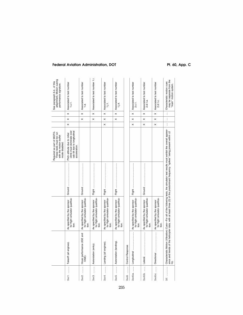
235
Federal Aviation Administration, DOT Pt. 60, App. C
Req
uire
d as
par
t of
MQ
TG
. T
hese
tes
ts m
ust
be r
un
with
the
mot
ion
buffe
t m
ode
disa
bled
.
See
par
agra
ph 6
.d.,
of t
his
atta
chm
ent,
Mot
ion
cuei
ng
perf
orm
ance
sig
natu
re.
3.e.
1....
......
.T
akeo
ff (a
ll en
gine
s).
As
spec
ified
by
the
spon
sor
for
fligh
t si
mul
ator
qua
lific
a-tio
n.
Gro
und
......
......
......
......
......
.....
Pitc
h at
titud
e du
e to
initi
al
clim
b m
ust
dom
inat
e ov
er
cab
tilt
due
to lo
ngitu
dina
l ac
cele
ratio
n.
X
X
X
Ass
ocia
ted
to t
est
num
ber
1.c.
1.
3.e.
2....
......
.H
over
per
form
ance
(IG
E a
nd
OG
E).
A
s sp
ecifi
ed b
y th
e sp
onso
r fo
r fli
ght
sim
ulat
or q
ualif
ica-
tion.
Gro
und
......
......
......
......
......
.....
X
X
Ass
ocia
ted
to t
est
num
ber
1.d.
3.e.
3....
......
.A
utor
otat
ion
(ent
ry).
A
s sp
ecifi
ed b
y th
e sp
onso
r fo
r fli
ght
sim
ulat
or q
ualif
ica-
tion.
Flig
ht...
......
......
......
......
......
.....
X
X
Ass
ocia
ted
to t
est
num
ber
1.i.
3.e.
4....
......
.La
ndin
g (a
ll en
gine
s).
As
spec
ified
by
the
spon
sor
for
fligh
t si
mul
ator
qua
lific
a-tio
n.
Flig
ht...
......
......
......
......
......
.....
X
X
X
Ass
ocia
ted
to t
est
num
ber
1.j.1
.
3.e.
5....
......
.A
utor
otat
ion
(land
ing)
. A
s sp
ecifi
ed b
y th
e sp
onso
r fo
r fli
ght
sim
ulat
or q
ualif
ica-
tion.
Flig
ht...
......
......
......
......
......
.....
X
X
Ass
ocia
ted
to t
est
num
ber
1.j.4
.
3.e.
6....
......
.C
ontr
ol R
espo
nse
3.e.
6.a.
......
.Lo
ngitu
dina
l...
......
......
......
......
As
spec
ified
by
the
spon
sor
for
fligh
t si
mul
ator
qua
lific
a-tio
n.
Flig
ht...
......
......
......
......
......
.....
X
X
X
Ass
ocia
ted
to t
est
num
ber
2.c.
1.
3.e.
6.b.
......
.La
tera
l....
......
......
......
......
......
..A
s sp
ecifi
ed b
y th
e sp
onso
r fo
r fli
ght
sim
ulat
or q
ualif
ica-
tion.
Gro
und
......
......
......
......
......
.....
X
X
X
Ass
ocia
ted
to t
est
num
ber
2.d.
1.a.
3.e.
6.c.
......
..D
irect
iona
l....
......
......
......
......
..A
s sp
ecifi
ed b
y th
e sp
onso
r fo
r fli
ght
sim
ulat
or q
ualif
ica-
tion.
X
X
X
Ass
ocia
ted
to t
est
num
ber
2.d.
1.c.
3.f.
......
......
..C
hara
cter
istic
Mot
ion
(Vib
ratio
n) C
ues—
For
all
of t
he f
ollo
win
g te
sts,
the
sim
ulat
or t
est
resu
lts m
ust
exhi
bit
the
over
all a
ppea
r-an
ce a
nd t
rend
s of
the
hel
icop
ter
data
, w
ith a
t le
ast
thre
e (3
) of
the
pre
dom
inan
t fr
eque
ncy
‘‘spi
kes’
’ bei
ng p
rese
nt w
ithin
±2
Hz.
....
....
....
Cha
ract
eris
tic m
otio
n cu
es
may
be
sepa
rate
fro
m t
he
‘‘mai
n’’ m
otio
n sy
stem
.
VerDate Mar<15>2010 18:16 Mar 01, 2012 Jkt 226045 PO 00000 Frm 00245 Fmt 8010 Sfmt 8002 Q:\14\14V2 ofr150 PsN: PC150

236
14 CFR Ch. I (1–1–12 Edition) Pt. 60, App. C
TA
BLE
C2A
—F
ULL
FLI
GH
TS
IMU
LAT
OR
(FF
S)
OB
JEC
TIV
ET
ES
TS—
Con
tinue
d
QP
S r
equi
rem
ents
In
form
atio
n
Tes
t T
oler
ance
(s)
Flig
ht c
ondi
tion
Tes
t de
tails
Sim
ulat
or
leve
l N
otes
Ent
ry N
o.
Titl
e B
C
D
3.f.1
....
......
..V
ibra
tions
—to
incl
ude
1/R
ev
and
n/R
ev v
ibra
tions
(w
here
‘‘n’
’ is
the
num
ber
of m
ain
roto
r bl
ades
).
+3d
b to
¥6d
b or
±10
% o
f no
min
al v
ibra
tion
leve
l in
fligh
t cr
uise
and
cor
rect
tr
end
(see
com
men
t).
(a)
On
grou
nd (
idle
);
(b)
In f
light
C
hara
cter
istic
vib
ratio
ns in
-cl
ude
thos
e th
at r
esul
t fr
om
oper
atio
n of
the
hel
icop
ter
(for
exa
mpl
e, h
igh
air-
spee
d, r
etre
atin
g bl
ade
stal
l, ex
tend
ed la
ndin
g ge
ar,
vort
ex r
ing
or s
ettli
ng
with
pow
er)
in s
o fa
r as
vi-
brat
ion
mar
ks a
n ev
ent
or
helic
opte
r st
ate,
whi
ch c
an
be s
ense
d in
the
flig
ht
deck
. [S
ee T
able
C1A
, ta
ble
entr
ies
5.e.
and
5.f.
]
X
Cor
rect
tre
nd r
efer
s to
a c
om-
paris
on o
f vi
brat
ion
ampl
i-tu
des
betw
een
diffe
rent
m
aneu
vers
; e.
g.,
if th
e 1/
re
v vi
brat
ion
ampl
itude
in
the
helic
opte
r is
hig
her
dur-
ing
stea
dy s
tate
tur
ns t
han
in le
vel f
light
thi
s in
crea
sing
tr
end
shou
ld b
e de
m-
onst
rate
d in
the
sim
ulat
or.
Add
ition
al e
xam
ples
of
vi-
brat
ions
may
incl
ude:
(a
) Lo
w &
Hig
h sp
eed
tran
si-
tion
to a
nd f
rom
hov
er;
(b)
Leve
l flig
ht;
(c)
Clim
b an
d de
scen
t (in
-cl
udin
g ve
rtic
al c
limb;
(d
) A
uto-
rota
tion;
(e
) S
tead
y T
urns
.
3.f.2
....
......
..B
uffe
t—T
est
agai
nst
reco
rded
re
sults
for
cha
ract
eris
tic
buffe
t m
otio
n th
at c
an b
e se
nsed
in t
he f
light
dec
k.
+3d
b to
¥6d
b or
±10
% o
f no
min
al v
ibra
tion
leve
l in
fligh
t cr
uise
and
cor
rect
tr
end
(see
com
men
t).
On
grou
nd a
nd in
flig
ht.
Cha
ract
eris
tic b
uffe
ts in
clud
e th
ose
that
res
ult
from
ope
r-at
ion
of t
he h
elic
opte
r (f
or
exam
ple,
hig
h ai
rspe
ed,
re-
trea
ting
blad
e st
all,
ex-
tend
ed la
ndin
g ge
ar,
vort
ex
ring
or s
ettli
ng w
ith p
ower
) in
so
far
as a
buf
fet
mar
ks
an e
vent
or
helic
opte
r st
ate,
whi
ch c
an b
e se
nsed
in
the
flig
ht d
eck.
[S
ee T
able
C1A
, ta
ble
entr
ies
5.e.
and
5.f.
]
X
The
rec
orde
d te
st r
esul
ts f
or
char
acte
ristic
buf
fets
sh
ould
allo
w t
he c
heck
ing
of r
elat
ive
ampl
itude
for
dif-
fere
nt f
requ
enci
es.
For
atm
osph
eric
dis
turb
ance
, ge
nera
l pur
pose
mod
els
are
acce
ptab
le w
hich
ap-
prox
imat
e de
mon
stra
ble
fligh
t te
st d
ata.
4. V
isu
al S
yste
m
4.a.
......
......
.V
isua
l Sys
tem
Res
pons
e T
ime:
(C
hoos
e ei
ther
tes
t 4.
a.1.
or
4.a.
2. t
o sa
tisfy
tes
t 4.
a.,
Vis
ual S
yste
m R
espo
nse
Tim
e T
est.
Thi
s te
st is
als
o su
ffici
ent
for
mot
ion
syst
em r
e-sp
onse
tim
ing
and
fligh
t de
ck in
stru
men
t re
spon
se t
imin
g.)
4.a.
1....
......
.La
tenc
y
VerDate Mar<15>2010 18:16 Mar 01, 2012 Jkt 226045 PO 00000 Frm 00246 Fmt 8010 Sfmt 8002 Q:\14\14V2 ofr150 PsN: PC150

237
Federal Aviation Administration, DOT Pt. 60, App. C
150
ms
(or
less
) af
ter
heli-
copt
er r
espo
nse.
T
akeo
ff, c
limb,
and
des
cent
. O
ne t
est
is r
equi
red
in e
ach
axis
(pi
tch,
rol
l and
yaw
) fo
r ea
ch o
f th
e th
ree
cond
i-tio
ns (
take
-off,
cru
ise,
and
ap
proa
ch o
r la
ndin
g).
X
100
ms
(or
less
) af
ter
heli-
copt
er r
espo
nse.
C
limb,
cru
ise,
des
cent
, an
d ho
ver.
O
ne t
est
is r
equi
red
in e
ach
axis
(pi
tch,
rol
l and
yaw
) fo
r ea
ch o
f th
e th
ree
cond
i-tio
ns (
take
-off,
cru
ise,
and
ap
proa
ch o
r la
ndin
g).
X
X
4.a.
2....
......
.T
rans
port
Del
ay
If T
rans
port
Del
ay is
the
cho
-se
n m
etho
d to
dem
onst
rate
re
lativ
e re
spon
ses,
the
sp
onso
r an
d th
e N
SP
M w
ill
use
the
late
ncy
valu
es t
o en
sure
pro
per
sim
ulat
or r
e-sp
onse
whe
n re
view
ing
thos
e ex
istin
g te
sts
whe
re
late
ncy
can
be id
entif
ied
(e.g
., sh
ort
perio
d, r
oll r
e-sp
onse
, ru
dder
res
pons
e).
150
ms
(or
less
) af
ter
con-
trol
ler
mov
emen
t. N
/A...
......
......
......
......
......
......
..A
sep
arat
e te
st is
req
uire
d in
ea
ch a
xis
(pitc
h, r
oll,
and
yaw
).
X
100
ms
(or
less
) af
ter
con-
trol
ler
mov
emen
t. N
/A...
......
......
......
......
......
......
..A
sep
arat
e te
st is
req
uire
d in
ea
ch a
xis
(pitc
h, r
oll,
and
yaw
)..
X
X
4.b.
......
......
.F
ield
-of-
view
VerDate Mar<15>2010 18:16 Mar 01, 2012 Jkt 226045 PO 00000 Frm 00247 Fmt 8010 Sfmt 8002 Q:\14\14V2 ofr150 PsN: PC150

238
14 CFR Ch. I (1–1–12 Edition) Pt. 60, App. C
TA
BLE
C2A
—F
ULL
FLI
GH
TS
IMU
LAT
OR
(FF
S)
OB
JEC
TIV
ET
ES
TS—
Con
tinue
d
QP
S r
equi
rem
ents
In
form
atio
n
Tes
t T
oler
ance
(s)
Flig
ht c
ondi
tion
Tes
t de
tails
Sim
ulat
or
leve
l N
otes
Ent
ry N
o.
Titl
e B
C
D
4.b.
1....
......
.C
ontin
uous
fie
ld-o
f-vi
ew.
The
sim
ulat
or m
ust
prov
ide
a co
ntin
uous
fie
ld-o
f-vi
ew o
f at
leas
t 75
° ho
rizon
tally
an
d 30
° ve
rtic
ally
per
pilo
t se
at o
r th
e nu
mbe
r of
de-
gree
s ne
cess
ary
to m
eet
the
visu
al g
roun
d se
gmen
t re
quire
men
t, w
hich
ever
is
grea
ter.
Bot
h pi
lot
seat
vis
-ua
l sys
tem
s m
ust
be o
per-
able
sim
ulta
neou
sly.
Wid
e-
angl
e sy
stem
s pr
ovid
ing
cros
s-fli
ght
deck
vie
win
g (f
or b
oth
pilo
ts s
imul
ta-
neou
sly)
mus
t pr
ovid
e a
min
imum
fie
ld-o
f-vi
ew o
f at
le
ast
146°
hor
izon
tally
and
36
° ve
rtic
ally
. A
ny g
eo-
met
ric e
rror
bet
wee
n th
e Im
age
Gen
erat
or e
ye p
oint
an
d th
e pi
lot
eye
poin
t m
ust
be 8
° or
less
.
N/A
......
......
......
......
......
......
.....
An
SO
C is
req
uire
d an
d m
ust
expl
ain
the
geom
etry
of
the
inst
alla
tion.
A
dditi
onal
hor
izon
tal f
ield
-of-
vi
ew c
apab
ility
may
be
adde
d at
the
spo
nsor
’s d
is-
cret
ion
prov
ided
the
min
-im
um f
ield
-of-
view
is r
e-ta
ined
.
X
Hor
izon
tal f
ield
-of-
view
is
cent
ered
on
the
zero
de-
gree
azi
mut
h lin
e re
lativ
e to
the
airc
raft
fuse
lage
. F
ield
-of-
view
may
be
mea
sure
d us
ing
a vi
sual
te
st p
atte
rn f
illin
g th
e en
tire
visu
al s
cene
(al
l cha
nnel
s)
with
a m
atrix
of
blac
k an
d w
hite
5°
squa
res.
VerDate Mar<15>2010 18:16 Mar 01, 2012 Jkt 226045 PO 00000 Frm 00248 Fmt 8010 Sfmt 8002 Q:\14\14V2 ofr150 PsN: PC150

239
Federal Aviation Administration, DOT Pt. 60, App. C
4.b.
2....
......
.C
ontin
uous
fie
ld-o
f-vi
ew.
The
sim
ulat
or m
ust
prov
ide
a co
ntin
uous
fie
ld-o
f-vi
ew o
f at
leas
t 14
6° h
oriz
onta
lly
and
36°
vert
ical
ly o
r th
e nu
mbe
r of
deg
rees
nec
-es
sary
to
mee
t th
e vi
sual
gr
ound
seg
men
t re
quire
-m
ent,
whi
chev
er is
gre
ater
. T
he m
inim
um h
oriz
onta
l fie
ld-o
f-vi
ew c
over
age
mus
t be
plu
s an
d m
inus
one
-hal
f (1
⁄2)
of t
he m
inim
um c
ontin
-uo
us f
ield
-of-
view
req
uire
-m
ent,
cent
ered
on
the
zero
de
gree
azi
mut
h lin
e re
lativ
e to
the
airc
raft
fuse
lage
. A
ny
geom
etric
err
or b
etw
een
the
Imag
e G
ener
ator
eye
po
int
and
the
pilo
t ey
e po
int
mus
t be
8°
or le
ss.
N/A
......
......
......
......
......
......
.....
An
SO
C is
req
uire
d an
d m
ust
expl
ain
the
geom
etry
of
the
inst
alla
tion.
H
oriz
onta
l fie
ld-o
f-vi
ew o
f at
le
ast
146°
(inc
ludi
ng n
ot
less
tha
n 73
° m
easu
red
ei-
ther
sid
e of
the
cen
ter
of
the
desi
gn e
ye p
oint
). A
ddi-
tiona
l hor
izon
tal f
ield
-of-
vi
ew c
apab
ility
may
be
adde
d at
the
spo
nsor
’s d
is-
cret
ion
prov
ided
the
min
-im
um f
ield
-of-
view
is r
e-ta
ined
. V
ertic
al f
ield
-of-
view
of
at
leas
t 36
° m
easu
red
from
th
e pi
lot’s
and
co-
pilo
t’s
eye
poin
t.
X
Hor
izon
tal f
ield
-of-
view
is
cent
ered
on
the
zero
de-
gree
azi
mut
h lin
e re
lativ
e to
the
airc
raft
fuse
lage
. F
ield
-of-
view
may
be
mea
sure
d us
ing
a vi
sual
te
st p
atte
rn f
illin
g th
e en
tire
visu
al s
cene
(al
l cha
nnel
s)
with
a m
atrix
of
blac
k an
d w
hite
5°
squa
res.
4.b.
3....
......
.C
ontin
uous
fie
ld-o
f-vi
ew.
Con
tinuo
us f
ield
-of-
view
of
at
leas
t 17
6° h
oriz
onta
l and
56
° ve
rtic
al f
ield
-of-
view
for
ea
ch p
ilot
sim
ulta
neou
sly.
A
ny g
eom
etric
err
or b
e-tw
een
the
Imag
e G
ener
ator
ey
e po
int
and
the
pilo
t ey
e po
int
mus
t be
8°
or le
ss.
N/A
......
......
......
......
......
......
.....
An
SO
C is
req
uire
d an
d m
ust
expl
ain
the
geom
etry
of
the
inst
alla
tion.
H
oriz
onta
l fie
ld-o
f-vi
ew is
ce
nter
ed o
n th
e ze
ro d
e-gr
ee a
zim
uth
line
rela
tive
to t
he a
ircra
ft fu
sela
ge.
Hor
izon
tal f
ield
-of-
view
m
ust
be a
t le
ast
176°
(in-
clud
ing
not
less
tha
n 88
° ei
ther
sid
e of
the
cen
ter
of
the
desi
gn e
ye p
oint
). A
ddi-
tiona
l hor
izon
tal f
ield
-of-
vi
ew c
apab
ility
may
be
adde
d at
the
spo
nsor
’s d
is-
cret
ion
prov
ided
the
min
-im
um f
ield
-of-
view
is r
e-ta
ined
. V
ertic
al f
ield
-of-
view
mus
t no
t be
less
tha
n a
tota
l of
56°
mea
sure
d fr
om t
he p
ilot’s
an
d co
-pilo
t’s e
ye p
oint
.
X
The
hor
izon
tal f
ield
-of-
view
is
trad
ition
ally
des
crib
ed a
s a
180°
fiel
d-of
-vie
w.
How
-ev
er,
the
field
-of-
view
is
tech
nica
lly n
o le
ss t
han
176°
. F
ield
-of-
view
may
be
mea
sure
d us
ing
a vi
sual
te
st p
atte
rn f
illin
g th
e en
tire
visu
al s
cene
(al
l cha
nnel
s)
with
a m
atrix
of
blac
k an
d w
hite
5°
squa
res.
VerDate Mar<15>2010 18:16 Mar 01, 2012 Jkt 226045 PO 00000 Frm 00249 Fmt 8010 Sfmt 8002 Q:\14\14V2 ofr150 PsN: PC150

240
14 CFR Ch. I (1–1–12 Edition) Pt. 60, App. C
TA
BLE
C2A
—F
ULL
FLI
GH
TS
IMU
LAT
OR
(FF
S)
OB
JEC
TIV
ET
ES
TS—
Con
tinue
d
QP
S r
equi
rem
ents
In
form
atio
n
Tes
t T
oler
ance
(s)
Flig
ht c
ondi
tion
Tes
t de
tails
Sim
ulat
or
leve
l N
otes
Ent
ry N
o.
Titl
e B
C
D
4.c.
......
......
..S
urfa
ce c
ontr
ast
ratio
. N
ot le
ss t
han
5:1.
N
/A...
......
......
......
......
......
......
..T
he r
atio
is c
alcu
late
d by
di-
vidi
ng t
he b
right
ness
leve
l of
the
cen
ter,
brig
ht s
quar
e (p
rovi
ding
at
leas
t 2
foot
- la
mbe
rts
or 7
cd/
m2)
by t
he
brig
htne
ss le
vel o
f an
y ad
-ja
cent
dar
k sq
uare
.
X
Mea
sure
men
ts m
ay b
e m
ade
usin
g a
1° s
pot
phot
omet
er
and
a ra
ster
dra
wn
test
pa
ttern
fill
ing
the
entir
e vi
s-ua
l sce
ne (
all c
hann
els)
w
ith a
tes
t pa
ttern
of
blac
k an
d w
hite
squ
ares
, 5
per
squa
re,
with
a w
hite
squ
are
in t
he c
ente
r of
eac
h ch
an-
nel.
Dur
ing
cont
rast
rat
io
test
ing,
sim
ulat
or a
ft-ca
b an
d fli
ght
deck
am
bien
t lig
ht le
vels
sho
uld
be z
ero.
4.d.
......
......
.H
ighl
ight
brig
htne
ss.
Not
less
tha
n si
x (6
) fo
ot-la
m-
bert
s (2
0 cd
/m2).
N
/A...
......
......
......
......
......
......
..M
easu
re t
he b
right
ness
of
the
cent
er,
whi
te s
quar
e w
hile
sup
erim
posi
ng a
hi
ghlig
ht o
n th
at w
hite
sq
uare
. T
he u
se o
f ca
lli-
grap
hic
capa
bilit
ies
to e
n-ha
nce
the
rast
er b
right
ness
is
acc
epta
ble;
how
ever
, m
easu
ring
light
poi
nts
is
not
acce
ptab
le.
X
Mea
sure
men
ts m
ay b
e m
ade
usin
g a
1° s
pot
phot
omet
er
and
a ra
ster
dra
wn
test
pa
ttern
fill
ing
the
entir
e vi
s-ua
l sce
ne (
all c
hann
els)
w
ith a
tes
t pa
ttern
of
blac
k an
d w
hite
squ
ares
, 5
per
squa
re,
with
a w
hite
squ
are
in t
he c
ente
r of
eac
h ch
an-
nel.
VerDate Mar<15>2010 18:16 Mar 01, 2012 Jkt 226045 PO 00000 Frm 00250 Fmt 8010 Sfmt 8002 Q:\14\14V2 ofr150 PsN: PC150

241
Federal Aviation Administration, DOT Pt. 60, App. C
4.e.
......
......
.S
urfa
ce r
esol
utio
n.
Not
gre
ater
tha
n tw
o (2
) ar
c m
inut
es.
N/A
......
......
......
......
......
......
.....
An
SO
C is
req
uire
d an
d m
ust
incl
ude
the
appr
opria
te c
al-
cula
tions
and
an
expl
a-na
tion
of t
hose
cal
cula
-tio
ns.
Leve
l B r
equi
res
sur-
face
res
olut
ion
not
grea
ter
than
thr
ee (
3) a
rc m
inut
es.
X
X
Whe
n th
e ey
e is
pos
ition
ed
on a
3°
glid
e sl
ope
at t
he
slan
t ra
nge
dist
ance
s in
di-
cate
d w
ith w
hite
run
way
m
arki
ngs
on a
bla
ck r
un-
way
sur
face
, th
e ey
e w
ill
subt
end
two
(2)
arc
min
-ut
es:
(1)
A s
lant
ran
ge o
f 6,
876
ft w
ith s
trip
es 1
50 f
t lo
ng a
nd 1
6 ft
wid
e,
spac
ed 4
ft
apar
t. (2
) F
or
Con
figur
atio
n A
, a
slan
t ra
nge
of 5
,157
fee
t w
ith
strip
es 1
50 f
t lo
ng a
nd 1
2 ft
wid
e, s
pace
d 3
ft ap
art.
(3)
For
Con
figur
atio
n B
, a
slan
t ra
nge
of 9
,884
fee
t, w
ith
strip
es 1
50 f
t lo
ng a
nd 5
.75
ft w
ide,
spa
ced
5.75
ft
apar
t.
4.f.
......
......
..Li
ght
poin
t si
ze...
......
......
......
.N
ot g
reat
er t
han
five
(5)
arc
min
utes
. N
/A...
......
......
......
......
......
......
..A
n S
OC
is r
equi
red
and
mus
t in
clud
e th
e re
leva
nt c
al-
cula
tions
and
an
expl
a-na
tion
of t
hose
cal
cula
-tio
ns.
X
X
Ligh
t po
int
size
may
be
mea
sure
d us
ing
a te
st p
at-
tern
con
sist
ing
of a
cen
-tr
ally
loca
ted
sing
le r
ow o
f lig
ht p
oint
s re
duce
d in
le
ngth
unt
il m
odul
atio
n is
ju
st d
isce
rnib
le in
eac
h vi
s-ua
l cha
nnel
. A
row
of
48
light
s w
ill f
orm
a 4
° an
gle
or le
ss.
4.g.
......
......
.Li
ght
poin
t co
ntra
st r
atio
. A
1°
spot
pho
tom
eter
may
be
used
to
mea
sure
a s
quar
e of
at
leas
t 1°
fille
d w
ith li
ght
poin
ts (
whe
re li
ght
poin
t m
odul
atio
n is
just
dis
cern
-ib
le)
and
com
pare
the
re-
sults
to
the
mea
sure
d ad
ja-
cent
bac
kgro
und.
Dur
ing
cont
rast
rat
io t
estin
g, s
imu-
lato
r af
t-ca
b an
d fli
ght
deck
am
bien
t lig
ht le
vels
sho
uld
be z
ero.
4.g.
1....
......
.N
ot le
ss t
han
10:1
......
......
.....
N/A
......
......
......
......
......
......
.....
An
SO
C is
req
uire
d an
d m
ust
incl
ude
the
rele
vant
cal
-cu
latio
ns.
X
VerDate Mar<15>2010 18:16 Mar 01, 2012 Jkt 226045 PO 00000 Frm 00251 Fmt 8010 Sfmt 8002 Q:\14\14V2 ofr150 PsN: PC150

242
14 CFR Ch. I (1–1–12 Edition) Pt. 60, App. C
TA
BLE
C2A
—F
ULL
FLI
GH
TS
IMU
LAT
OR
(FF
S)
OB
JEC
TIV
ET
ES
TS—
Con
tinue
d
QP
S r
equi
rem
ents
In
form
atio
n
Tes
t T
oler
ance
(s)
Flig
ht c
ondi
tion
Tes
t de
tails
Sim
ulat
or
leve
l N
otes
Ent
ry N
o.
Titl
e B
C
D
4.g.
2....
......
.N
ot le
ss t
han
25:1
......
......
.....
N/A
......
......
......
......
......
......
.....
An
SO
C is
req
uire
d an
d m
ust
incl
ude
the
rele
vant
cal
-cu
latio
ns.
X
X
4.h.
......
......
.V
isua
l gro
und
segm
ent
The
vis
ible
seg
men
t in
the
si
mul
ator
mus
t be
±20
% o
f th
e se
gmen
t co
mpu
ted
to
be v
isib
le f
rom
the
hel
i-co
pter
flig
ht d
eck.
Thi
s to
l-er
ance
may
be
appl
ied
at
the
far
end
of t
he d
ispl
ayed
se
gmen
t. H
owev
er,
light
s an
d gr
ound
obj
ects
com
-pu
ted
to b
e vi
sibl
e fr
om t
he
helic
opte
r fli
ght
deck
at
the
near
end
of
the
visi
ble
seg-
men
t m
ust
be v
isib
le in
the
si
mul
ator
.
Land
ing
conf
igur
atio
n, w
ith
the
airc
raft
trim
med
for
the
ap
prop
riate
airs
peed
, w
here
the
MLG
are
at
100
ft (3
0 m
) ab
ove
the
plan
e of
the
tou
chdo
wn
zone
, on
th
e el
ectr
onic
glid
e sl
ope
with
an
RV
R v
alue
set
at
1,20
0 ft
(350
m).
The
QT
G m
ust
cont
ain
ap-
prop
riate
cal
cula
tions
and
a
draw
ing
show
ing
the
data
us
ed t
o es
tabl
ish
the
heli-
copt
er lo
catio
n an
d th
e se
gmen
t of
the
gro
und
that
is
vis
ible
con
side
ring
de-
sign
eye
poi
nt,
the
heli-
copt
er a
ttitu
de,
fligh
t de
ck
cut-
off
angl
e, a
nd a
vis
i-bi
lity
of 1
200
ft (3
50 m
) R
VR
. S
imul
ator
per
form
-an
ce m
ust
be m
easu
red
agai
nst
the
QT
G c
alcu
la-
tions
. T
he d
ata
subm
itted
m
ust
incl
ude
at le
ast
the
follo
win
g:
X
X
X
Pre
-pos
ition
ing
for
this
tes
t is
en
cour
aged
, an
d m
ay b
e ac
hiev
ed v
ia m
anua
l or
auto
pilo
t co
ntro
l to
the
de-
sire
d po
sitio
n.
VerDate Mar<15>2010 18:16 Mar 01, 2012 Jkt 226045 PO 00000 Frm 00252 Fmt 8010 Sfmt 8002 Q:\14\14V2 ofr150 PsN: PC150
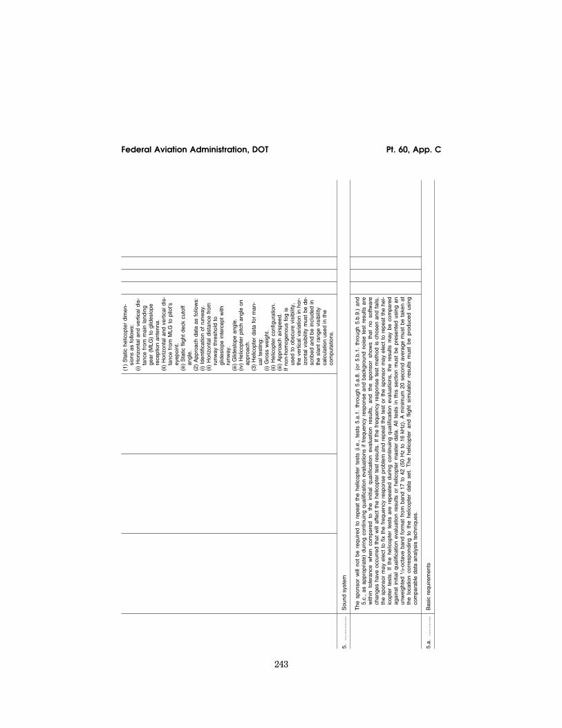
243
Federal Aviation Administration, DOT Pt. 60, App. C
(1)
Sta
tic h
elic
opte
r di
men
-si
ons
as f
ollo
ws:
(i)
Hor
izon
tal a
nd v
ertic
al d
is-
tanc
e fr
om m
ain
land
ing
gear
(M
LG)
to g
lides
lope
re
cept
ion
ante
nna.
(ii
) H
oriz
onta
l and
ver
tical
dis
-ta
nce
from
MLG
to
pilo
t’s
eyep
oint
. (ii
i) S
tatic
flig
ht d
eck
cuto
ff an
gle.
(2
) A
ppro
ach
data
as
follo
ws:
(i)
Ide
ntifi
catio
n of
run
way
. (ii
) H
oriz
onta
l dis
tanc
e fr
om
runw
ay t
hres
hold
to
glid
eslo
pe in
terc
ept
with
ru
nway
. (ii
i) G
lides
lope
ang
le.
(iv)
Hel
icop
ter
pitc
h an
gle
on
appr
oach
. (3
) H
elic
opte
r da
ta f
or m
an-
ual t
estin
g:
(i) G
ross
wei
ght.
(ii)
Hel
icop
ter
conf
igur
atio
n.
(iii)
App
roac
h ai
rspe
ed.
If no
n-ho
mog
enou
s fo
g is
us
ed t
o ob
scur
e vi
sibi
lity,
th
e ve
rtic
al v
aria
tion
in h
or-
izon
tal v
isib
ility
mus
t be
de-
scrib
ed a
nd b
e in
clud
ed in
th
e sl
ant
rang
e vi
sibi
lity
calc
ulat
ion
used
in t
he
com
puta
tions
.
5....
......
......
.S
ound
sys
tem
The
spo
nsor
will
not
be
requ
ired
to r
epea
t th
e he
licop
ter
test
s (i.
e.,
test
s 5.
a.1.
thr
ough
5.a
.8.
(or
5.b.
1. t
hrou
gh 5
.b.9
.) a
nd
5.c.
, as
app
ropr
iate
) du
ring
cont
inui
ng q
ualif
icat
ion
eval
uatio
ns i
f fr
eque
ncy
resp
onse
and
bac
kgro
und
nois
e te
st r
esul
ts a
re
with
in t
oler
ance
whe
n co
mpa
red
to t
he i
nitia
l qu
alifi
catio
n ev
alua
tion
resu
lts,
and
the
spon
sor
show
s th
at n
o so
ftwar
e ch
ange
s ha
ve o
ccur
red
that
will
affe
ct t
he h
elic
opte
r te
st r
esul
ts.
If th
e fr
eque
ncy
resp
onse
tes
t m
etho
d is
cho
sen
and
fails
, th
e sp
onso
r m
ay e
lect
to
fix t
he f
requ
ency
res
pons
e pr
oble
m a
nd r
epea
t th
e te
st o
r th
e sp
onso
r m
ay e
lect
to
repe
at t
he h
el-
icop
ter
test
s. I
f th
e he
licop
ter
test
s ar
e re
peat
ed d
urin
g co
ntin
uing
qua
lific
atio
n ev
alua
tions
, th
e re
sults
may
be
com
pare
d ag
ains
t in
itial
qua
lific
atio
n ev
alua
tion
resu
lts o
r he
licop
ter
mas
ter
data
. A
ll te
sts
in t
his
sect
ion
mus
t be
pre
sent
ed u
sing
an
unw
eigh
ted
1⁄3
-oct
ave
band
for
mat
fro
m b
and
17 t
o 42
(50
Hz
to 1
6 kH
z).
A m
inim
um 2
0 se
cond
ave
rage
mus
t be
tak
en a
t th
e lo
catio
n co
rres
pond
ing
to t
he h
elic
opte
r da
ta s
et.
The
hel
icop
ter
and
fligh
t si
mul
ator
res
ults
mus
t be
pro
duce
d us
ing
com
para
ble
data
ana
lysi
s te
chni
ques
.
5.a.
......
......
.B
asic
req
uire
men
ts
VerDate Mar<15>2010 18:16 Mar 01, 2012 Jkt 226045 PO 00000 Frm 00253 Fmt 8010 Sfmt 8002 Q:\14\14V2 ofr150 PsN: PC150

244
14 CFR Ch. I (1–1–12 Edition) Pt. 60, App. C
TA
BLE
C2A
—F
ULL
FLI
GH
TS
IMU
LAT
OR
(FF
S)
OB
JEC
TIV
ET
ES
TS—
Con
tinue
d
QP
S r
equi
rem
ents
In
form
atio
n
Tes
t T
oler
ance
(s)
Flig
ht c
ondi
tion
Tes
t de
tails
Sim
ulat
or
leve
l N
otes
Ent
ry N
o.
Titl
e B
C
D
5.a.
1....
......
.R
eady
for
eng
ine
star
t. ±
5 dB
per
1⁄3
octa
ve b
and.
G
roun
d...
......
......
......
......
......
..N
orm
al c
ondi
tion
prio
r to
en-
gine
sta
rt.
The
AP
U m
ust
be o
n if
appr
opria
te.
X
5.a.
2....
......
.A
ll en
gine
s at
idle
; ro
tor
not
turn
ing
(if a
pplic
able
) an
d ro
tor
turn
ing.
± 5
dB p
er 1
⁄3oc
tave
ban
d.
Gro
und
......
......
......
......
......
.....
Nor
mal
con
ditio
n pr
ior
to li
ft-
off.
X
5.a.
3....
......
.H
over
......
......
......
......
......
......
.±
5 dB
per
1⁄3
octa
ve b
and.
H
over
......
......
......
......
......
......
.X
5.a.
4....
......
.C
limb
......
......
......
......
......
......
.±
5 dB
per
1⁄3
octa
ve b
and.
E
n-ro
ute
clim
b...
......
......
......
..M
ediu
m a
ltitu
de...
......
......
......
X
5.a.
5....
......
.C
ruis
e...
......
......
......
......
......
...±
5 dB
per
1⁄3
octa
ve b
and.
C
ruis
e...
......
......
......
......
......
...N
orm
al c
ruis
e co
nfig
urat
ion.
X
5.a.
6....
......
.F
inal
app
roac
h...
......
......
......
..±
5 dB
per
1⁄3
octa
ve b
and.
La
ndin
g...
......
......
......
......
......
.C
onst
ant
airs
peed
, ge
ar
dow
n.
X
5.b.
......
......
.S
peci
al c
ases
±5 d
B p
er 1
⁄3oc
tave
ban
d.
As
appr
opria
te...
......
......
......
..X
T
hese
spe
cial
cas
es a
re
iden
tifie
d as
par
ticul
arly
si
gnifi
cant
dur
ing
criti
cal
phas
es o
f fli
ght
and
grou
nd
oper
atio
ns f
or a
spe
cific
he
licop
ter
type
or
mod
el.
5.c.
......
......
..B
ackg
roun
d no
ise
±3 d
B p
er 1
⁄3oc
tave
ban
d.
As
appr
opria
te...
......
......
......
..R
esul
ts o
f th
e ba
ckgr
ound
no
ise
at in
itial
qua
lific
atio
n m
ust
be in
clud
ed in
the
M
QT
G.
Mea
sure
men
ts
mus
t be
mad
e w
ith t
he
sim
ulat
ion
runn
ing,
the
so
und
mut
ed,
and
a ‘‘d
ead’
’ flig
ht d
eck.
X
The
sim
ulat
ed s
ound
will
be
eval
uate
d to
ens
ure
that
th
e ba
ckgr
ound
noi
se d
oes
not
inte
rfer
e w
ith t
rain
ing,
te
stin
g, o
r ch
ecki
ng.
5.d.
......
......
.F
requ
ency
res
pons
e
VerDate Mar<15>2010 18:16 Mar 01, 2012 Jkt 226045 PO 00000 Frm 00254 Fmt 8010 Sfmt 8002 Q:\14\14V2 ofr150 PsN: PC150

245
Federal Aviation Administration, DOT Pt. 60, App. C
±5 d
B o
n th
ree
(3)
cons
ecu-
tive
band
s w
hen
com
pare
d to
initi
al e
valu
atio
n; a
nd ±
2 dB
whe
n co
mpa
ring
the
av-
erag
e of
the
abs
olut
e di
f-fe
renc
es b
etw
een
initi
al
and
cont
inui
ng q
ualif
icat
ion
eval
uatio
n.
App
licab
le o
nly
to C
ontin
uing
Q
ualif
icat
ion
Eva
luat
ions
. If
freq
uenc
y re
spon
se p
lots
ar
e pr
ovid
ed f
or e
ach
chan
nel a
t th
e in
itial
eva
l-ua
tion,
the
se p
lots
may
be
repe
ated
at
the
cont
inui
ng
qual
ifica
tion
eval
uatio
n w
ith
the
follo
win
g to
lera
nces
ap-
plie
d:
(a)
The
con
tinui
ng q
ualif
ica-
tion
1⁄3
octa
ve b
and
ampl
i-tu
des
mus
t no
t ex
ceed
± 5
dB
for
thr
ee c
onse
cutiv
e ba
nds
whe
n co
mpa
red
to
initi
al r
esul
ts.
(b)
The
ave
rage
of
the
sum
of
the
abs
olut
e di
ffere
nces
be
twee
n in
itial
and
con
-tin
uing
qua
lific
atio
n re
sults
m
ust
not
exce
ed 2
dB
(r
efer
to
tabl
e C
2C in
Ap-
pend
ix C
).
X
Mea
sure
men
ts a
re c
ompa
red
to t
hose
tak
en d
urin
g in
itial
qu
alifi
catio
n ev
alua
tion.
VerDate Mar<15>2010 18:16 Mar 01, 2012 Jkt 226045 PO 00000 Frm 00255 Fmt 8010 Sfmt 8002 Q:\14\14V2 ofr150 PsN: PC150
246
14 CFR Ch. I (1–1–12 Edition) Pt. 60, App. C
lllllllllllllllllllllll
BEGIN INFORMATION
3. GENERAL
a. If relevant winds are present in the ob-jective data, the wind vector should be clear-ly noted as part of the data presentation, ex-pressed in conventional terminology, and re-lated to the runway being used for test near the ground.
b. The reader is encouraged to review the Airplane Flight Simulator Evaluation Hand-book, Volumes I and II, published by the Royal Aeronautical Society, London, UK, and FAA AC 25–7, as amended, Flight Test Guide for Certification of Transport Cat-egory Airplanes, and AC 23–8, as amended, Flight Test Guide for Certification of Part 23 Airplanes, for references and examples re-garding flight testing requirements and tech-niques.
4. CONTROL DYNAMICS
a. General. The characteristics of a heli-copter flight control system have a major ef-fect on the handling qualities. A significant consideration in pilot acceptability of a heli-copter is the ‘‘feel’’ provided through the flight controls. Considerable effort is ex-pended on helicopter feel system design so that pilots will be comfortable and will con-sider the helicopter desirable to fly. In order for an FFS to be representative, it should ‘‘feel’’ like the helicopter being simulated. Compliance with this requirement is deter-mined by comparing a recording of the con-trol feel dynamics of the FFS to actual heli-copter measurements in the hover and cruise configurations.
(1) Recordings such as free response to an impulse or step function are classically used to estimate the dynamic properties of electromechanical systems. In any case, it is only possible to estimate the dynamic prop-erties as a result of only being able to esti-mate true inputs and responses. Therefore, it is imperative that the best possible data be collected since close matching of the FFS control loading system to the helicopter sys-tem is essential. The required dynamic con-trol tests are described in Table C2A of this attachment.
(2) For initial and upgrade evaluations, the QPS requires that control dynamics charac-teristics be measured and recorded directly from the flight controls (Handling Quali-ties—Table C2A). This procedure is usually accomplished by measuring the free response of the controls using a step or impulse input to excite the system. The procedure should be accomplished in the hover and cruise flight conditions and configurations.
(3) For helicopters with irreversible con-trol systems, measurements may be obtained on the ground if proper pitot-static inputs are provided to represent airspeeds typical of
those encountered in flight. Likewise, it may be shown that for some helicopters, hover, climb, cruise, and autorotation have like ef-fects. Thus, one may suffice for another. If either or both considerations apply, engi-neering validation or helicopter manufac-turer rationale should be submitted as jus-tification for ground tests or for eliminating a configuration. For FFSs requiring static and dynamic tests at the controls, special test fixtures will not be required during ini-tial and upgrade evaluations if the QTG shows both test fixture results and the re-sults of an alternate approach (e.g., com-puter plots that were produced concurrently and show satisfactory agreement). Repeat of the alternate method during the initial eval-uation satisfies this test requirement.
b. Control Dynamics Evaluations. The dy-namic properties of control systems are often stated in terms of frequency, damping, and a number of other classical measure-ments. In order to establish a consistent means of validating test results for FFS con-trol loading, criteria are needed that will clearly define the measurement interpreta-tion and the applied tolerances. Criteria are needed for underdamped, critically damped and overdamped systems. In the case of an underdamped system with very light damp-ing, the system may be quantified in terms of frequency and damping. In critically damped or overdamped systems, the fre-quency and damping are not readily meas-ured from a response time history. There-fore, the following suggested measurements may be used:
(1) For Levels C and D simulators. Tests to verify that control feel dynamics represent the helicopter should show that the dynamic damping cycles (free response of the con-trols) match those of the helicopter within specified tolerances. The NSPM recognizes that several different testing methods may be used to verify the control feel dynamic re-sponse. The NSPM will consider the merits of testing methods based on reliability and consistency. One acceptable method of eval-uating the response and the tolerance to be applied is described below for the under-damped and critically damped cases. A spon-sor using this method to comply with the QPS requirements should perform the tests as follows:
(a) Underdamped Response. Two measure-ments are required for the period, the time to first zero crossing (in case a rate limit is present) and the subsequent frequency of os-cillation. It is necessary to measure cycles on an individual basis in case there are non- uniform periods in the response. Each period will be independently compared to the re-spective period of the helicopter control sys-tem and, consequently, will enjoy the full tolerance specified for that period. The damping tolerance will be applied to over-shoots on an individual basis. Care should be
VerDate Mar<15>2010 18:16 Mar 01, 2012 Jkt 226045 PO 00000 Frm 00256 Fmt 8010 Sfmt 8002 Q:\14\14V2 ofr150 PsN: PC150
247
Federal Aviation Administration, DOT Pt. 60, App. C
taken when applying the tolerance to small overshoots since the significance of such overshoots becomes questionable. Only those overshoots larger than 5 percent of the total initial displacement should be considered significant. The residual band, labeled T(Ad) on Figure C2A is ±5 percent of the initial dis-placement amplitude Ad from the steady state value of the oscillation. Only oscilla-tions outside the residual band are consid-ered significant. When comparing FFS data to helicopter data, the process should begin by overlaying or aligning the FFS and heli-copter steady state values and then com-paring amplitudes of oscillation peaks, the time of the first zero crossing, and individual periods of oscillation. The FFS should show the same number of significant overshoots to within one when compared against the heli-copter data. The procedure for evaluating the response is illustrated in Figure C2A.
(b) Critically damped and Overdamped Re-sponse. Due to the nature of critically damped and overdamped responses (no over-shoots), the time to reach 90 percent of the steady state (neutral point) value should be the same as the helicopter within ±10 per-cent. The simulator response must be criti-cally damped also. Figure C2B illustrates the procedure.
(c) Special considerations. Control systems that exhibit characteristics other than clas-sical overdamped or underdamped responses should meet specified tolerances. In addi-tion, special consideration should be given to ensure that significant trends are main-tained.
(2) Tolerances. (a) The following summarizes the toler-
ances, ‘‘T’’ for underdamped systems, and ‘‘n’’ is the sequential period of a full cycle of oscillation. See Figure C2A of this attach-ment for an illustration of the referenced measurements.
T(P0) .................... ±10% of P0 T(P1) .................... ±20% of P1 T(P2) .................... ±30% of P2 T(Pn) .................... ±10(n+1)% of Pn T(An) .................... ±10% of A1, ±20%
of Subsequent Peaks
T(Ad) .................... ±5% of Ad = resid-ual band
Significant overshoots. First overshoot and ±1 subsequent overshoots
(b) The following tolerance applies to criti-cally damped and overdamped systems only. See Figure C2B for an illustration of the ref-erence measurements:
T(P0) .................... ±10% of P0
END INFORMATION
lllllllllllllllllllllll
BEGIN QPS REQUIREMENT
c. Alternative method for control dynam-ics evaluation.
(1) An alternative means for validating control dynamics for aircraft with hydrau-lically powered flight controls and artificial feel systems is by the measurement of con-trol force and rate of movement. For each axis of pitch, roll, and yaw, the control must be forced to its maximum extreme position for the following distinct rates. These tests are conducted under normal flight and ground conditions.
(a) Static test—Slowly move the control so that a full sweep is achieved within 95–105 seconds. A full sweep is defined as movement of the controller from neutral to the stop, usually aft or right stop, then to the oppo-site stop, then to the neutral position.
(b) Slow dynamic test—Achieve a full sweep within 8–12 seconds.
(c) Fast dynamic test—Achieve a full sweep in within 3–5 seconds.
NOTE: Dynamic sweeps may be limited to forces not exceeding 100 lbs. (44.5 daN).
(d) Tolerances (i) Static test—see Table C2A, FFS Objec-
tive Tests, Entries 2.a.1., 2.a.2., and 2.a.3. (ii) Dynamic test—±2 lbs (0.9 daN) or ±10%
on dynamic increment above static test.
END QPS REQUIREMENT
lllllllllllllllllllllll
BEGIN INFORMATION
d. The FAA is open to alternative means that are justified and appropriate to the ap-plication. For example, the method described here may not apply to all manufacturers sys-tems and certainly not to aircraft with re-versible control systems. Each case is con-sidered on its own merit on an ad hoc basis. If the FAA finds that alternative methods do not result in satisfactory performance, more conventionally accepted methods will have to be used.
VerDate Mar<15>2010 18:16 Mar 01, 2012 Jkt 226045 PO 00000 Frm 00257 Fmt 8010 Sfmt 8002 Q:\14\14V2 ofr150 PsN: PC150

248
14 CFR Ch. I (1–1–12 Edition) Pt. 60, App. C
END INFORMATION
lllllllllllllllllllllll
5. [RESERVED]
lllllllllllllllllllllll
BEGIN INFORMATION
6. MOTION SYSTEM.
a. General. (1) Pilots use continuous information sig-
nals to regulate the state of the helicopter. In concert with the instruments and outside- world visual information, whole-body motion feedback is essential in assisting the pilot to
VerDate Mar<15>2010 18:16 Mar 01, 2012 Jkt 226045 PO 00000 Frm 00258 Fmt 8010 Sfmt 8002 Q:\14\14V2 ofr150 PsN: PC150 ER
09M
Y08
.034
</G
PH
>
249
Federal Aviation Administration, DOT Pt. 60, App. C
control the helicopter dynamics, particu-larly in the presence of external disturb-ances. The motion system should meet basic objective performance criteria, and be sub-jectively tuned at the pilot’s seat position to represent the linear and angular accelera-tions of the helicopter during a prescribed minimum set of maneuvers and conditions. The response of the motion cueing system should be repeatable.
(2) The Motion System tests in Section 3 of Table C2A are intended to qualify the FFS motion cueing system from a mechanical performance standpoint. Additionally, the list of motion effects provides a representa-tive sample of dynamic conditions that should be present in the flight simulator. An additional list of representative, training- critical maneuvers, selected from Section 1, (Performance tests) and Section 2, (Handling Qualities tests) in Table C2A, that should be recorded during initial qualification (but without tolerance) to indicate the flight sim-ulator motion cueing performance signature have been identified (reference Section 3.e). These tests are intended to help improve the overall standard of FFS motion cueing.
b. Motion System Checks. The intent of test 3a, Frequency Response, test 3b, Leg Balance, and test 3c, Turn-Around Check, as described in the Table of Objective Tests, is to demonstrate the performance of the mo-tion system hardware, and to check the in-tegrity of the motion set-up with regard to calibration and wear. These tests are inde-pendent of the motion cueing software and should be considered robotic tests.
c. Motion System Repeatability. The in-tent of this test is to ensure that the motion system software and motion system hard-ware have not degraded or changed over time. This diagnostic test should be com-pleted during continuing qualification checks in lieu of the robotic tests. This will allow an improved ability to determine changes in the software or determine deg-radation in the hardware. The following in-formation delineates the methodology that should be used for this test.
(1) Input: The inputs should be such that rotational accelerations, rotational rates, and linear accelerations are inserted before the transfer from helicopter center of grav-ity to pilot reference point with a minimum amplitude of 5 deg/sec/sec, 10 deg/sec and 0.3 g, respectively, to provide adequate analysis of the output.
(2) Recommended output: (a) Actual platform linear accelerations;
the output will comprise accelerations due to both the linear and rotational motion ac-celeration;
(b) Motion actuators position. d. Motion Cueing Performance Signature. (1) Background. The intent of this test is
to provide quantitative time history records of motion system response to a selected set
of automated QTG maneuvers during initial qualification. It is not intended to be a com-parison of the motion platform accelerations against the flight test recorded accelerations (i.e., not to be compared against helicopter cueing). If there is a modification to the ini-tially qualified motion software or motion hardware (e.g., motion washout filter, simu-lator payload change greater than 10%) then a new baseline may need to be established.
(2) Test Selection. The conditions identi-fied in Section 3.e. in Table C2A are those maneuvers where motion cueing is the most discernible. They are general tests applicable to all types of helicopters and should be com-pleted for motion cueing performance signa-ture at any time acceptable to the NSPM prior to or during the initial qualification evaluation, and the results included in the MQTG.
(3) Priority. Motion system should be de-signed with the intent of placing greater im-portance on those maneuvers that directly influence pilot perception and control of the helicopter motions. For the maneuvers iden-tified in section 3.e. in Table C2A, the flight simulator motion cueing system should have a high tilt co-ordination gain, high rota-tional gain, and high correlation with re-spect to the helicopter simulation model.
(4) Data Recording. The minimum list of parameters provided should allow for the de-termination of the flight simulator’s motion cueing performance signature for the initial qualification evaluation. The following pa-rameters are recommended as being accept-able to perform such a function:
(a) Flight model acceleration and rota-tional rate commands at the pilot reference point;
(b) Motion actuators position; (c) Actual platform position; (d) Actual platform acceleration at pilot
reference point. e. Motion Vibrations. (1) Presentation of results. The char-
acteristic motion vibrations may be used to verify that the flight simulator can repro-duce the frequency content of the helicopter when flown in specific conditions. The test results should be presented as a Power Spec-tral Density (PSD) plot with frequencies on the horizontal axis and amplitude on the vertical axis. The helicopter data and flight simulator data should be presented in the same format with the same scaling. The al-gorithms used for generating the flight simu-lator data should be the same as those used for the helicopter data. If they are not the same then the algorithms used for the flight simulator data should be proven to be suffi-ciently comparable. As a minimum the re-sults along the dominant axes should be pre-sented and a rationale for not presenting the other axes should be provided.
(2) Interpretation of results. The overall trend of the PSD plot should be considered
VerDate Mar<15>2010 18:16 Mar 01, 2012 Jkt 226045 PO 00000 Frm 00259 Fmt 8010 Sfmt 8002 Q:\14\14V2 ofr150 PsN: PC150

250
14 CFR Ch. I (1–1–12 Edition) Pt. 60, App. C
while focusing on the dominant frequencies. Less emphasis should be placed on the dif-ferences at the high frequency and low am-plitude portions of the PSD plot. During the analysis, certain structural components of the flight simulator have resonant fre-quencies that are filtered and may not ap-pear in the PSD plot. If filtering is required, the notch filter bandwidth should be limited to 1 Hz to ensure that the buffet feel is not adversely affected. In addition, a rationale should be provided to explain that the char-acteristic motion vibration is not being ad-versely affected by the filtering. The ampli-tude should match helicopter data as de-scribed below. However, if the PSD plot was altered for subjective reasons, a rationale should be provided to justify the change. If the plot is on a logarithmic scale it may be difficult to interpret the amplitude of the buffet in terms of acceleration. For example, a 1×10¥3 g-rms2/Hz would describe a heavy buffet and may be seen in the deep stall re-gime. Alternatively, a 1×10¥6 g-rms2/Hz buf-fet is almost imperceptable, but may rep-resent a flap buffet at low speed. The pre-
vious two examples differ in magnitude by 1000. On a PSD plot this represents three dec-ades (one decade is a change in order of mag-nitude of 10, and two decades is a change in order of magnitude of 100).
NOTE: In the example, ‘‘g-rms2’’ is the mathematical expression for ‘‘g’s root mean squared.’’
f. Table C2B, Motion System Recommenda-tions for Level C and Level D Helicopter Simulators, contains a description of the pa-rameters that should be present in simulator motion systems to provide adequate onset motion cues to helicopter pilots. The infor-mation provided covers the six axes of mo-tion (pitch, roll, yaw, vertical, lateral, and longitudinal) and addresses displacement, velocity, and acceleration. Also included is information about the parameters for initial rotational and linear acceleration. The pa-rameters listed in this table apply only to Level C and Level D simulators, and are pre-sented here as recommended targets for mo-tion system capability. They are not require-ments.
TABLE C2B—MOTION SYSTEM RECOMMENDATIONS FOR LEVEL C AND LEVEL D HELICOPTER SIMULATORS
a. ........... Motion System Envelope a.1. ........ Pitch a.1.a. ..... Displacement ...................................................................... ±25° a.1.b. ..... Velocity ............................................................................... ±20°/sec a.1.c. ..... Acceleration ........................................................................ ±100°/sec2 a.2. ........ Roll a.2.a. ..... Displacement ...................................................................... ±25° a.2.b. ..... Velocity ............................................................................... ±20°/sec a.2.c. ..... Acceleration ........................................................................ ±100°/sec2 a.3. ........ Yaw a.3.a. ..... Displacement ...................................................................... ±25° a.3.b. ..... Velocity— ............................................................................ ±20°/sec a.3.c. ..... Acceleration ........................................................................ ±100°/sec2 a.4. ........ Vertical a.4.a. ..... Displacement ...................................................................... ±34 in. a.4.b. ..... Velocity ............................................................................... ±24 in. a.4.c. ..... Acceleration ........................................................................ ±0.8 g. a.5. ........ Lateral a.5.a. ..... Displacement ...................................................................... ±45 in. a.5.b. ..... Velocity ............................................................................... ±28 in/sec. a.5.c. ..... Acceleration ........................................................................ ±0.6 g. a.6. ........ Longitudinal a.6.a. ..... Displacement ...................................................................... ±34 in. a.6.b. ..... Velocity ............................................................................... ±28 in/sec. a.6.c. ..... Acceleration ........................................................................ ±0.6 g. a.7. ........ Initial Rotational Acceleration Ratio.
All axes 300°/ sec2/sec a.8. ........ Initial Linear Acceleration Ratio. a.8.a. ..... Vertical ................................................................................ ±6g/sec a.8.b. ..... Lateral ................................................................................. ±3g/sec a.8.c. ..... Longitudinal ......................................................................... ±3g/sec
VerDate Mar<15>2010 18:16 Mar 01, 2012 Jkt 226045 PO 00000 Frm 00260 Fmt 8010 Sfmt 8002 Q:\14\14V2 ofr150 PsN: PC150

251
Federal Aviation Administration, DOT Pt. 60, App. C
7. SOUND SYSTEM
a. General. The total sound environment in the helicopter is very complex, and changes with atmospheric conditions, helicopter con-
figuration, airspeed, altitude, and power set-tings. Flight deck sounds are an important component of the flight deck operational en-vironment and provide valuable information
VerDate Mar<15>2010 18:16 Mar 01, 2012 Jkt 226045 PO 00000 Frm 00261 Fmt 8010 Sfmt 8002 Q:\14\14V2 ofr150 PsN: PC150 ER
09M
Y08
.035
</G
PH
>

252
14 CFR Ch. I (1–1–12 Edition) Pt. 60, App. C
to the flight crew. These aural cues can ei-ther assist the crew (as an indication of an abnormal situation), or hinder the crew (as a distraction or nuisance). For effective train-ing, the flight simulator should provide flight deck sounds that are perceptible to the pilot during normal and abnormal oper-ations, and that are comparable to those of the helicopter. The flight simulator operator should carefully evaluate background noises in the location where the device will be in-stalled. To demonstrate compliance with the sound requirements, the objective or valida-tion tests in this attachment were selected to provide a representative sample of normal static conditions typically experienced by a pilot.
b. Alternate propulsion. For FFS with multiple propulsion configurations, any con-dition listed in Table C2A in this attachment should be presented for evaluation as part of the QTG if identified by the helicopter man-ufacturer or other data supplier as signifi-cantly different due to a change in propul-sion system (engine or propeller).
c. Data and Data Collection System. (1) Information provided to the flight simu-
lator manufacturer should comply be pre-sented in the format suggested by the ‘‘International Air Transport Association (IATA) Flight Simulator Design and Per-formance Data Requirements,’’ as amended. This information should contain calibration and frequency response data.
(2) The system used to perform the tests listed in Table C2A should comply with the following standards:
(a) The specifications for octave, half oc-tave, and third octave band filter sets may be found in American National Standards In-stitute (ANSI) S1.11–1986.
(b) Measurement microphones should be type WS2 or better, as described in Inter-national Electrotechnical Commission (IEC) 1094–4–1995.
(3) Headsets. If headsets are used during normal operation of the helicopter they
should also be used during the flight simu-lator evaluation.
(4) Playback equipment. Playback equip-ment and recordings of the QTG conditions should be provided during initial evalua-tions.
(5) Background noise. (a) Background noise is the noise in the
flight simulator that is not associated with the helicopter, but is caused by the flight simulator’s cooling and hydraulic systems and extraneous noise from other locations in the building. Background noise can seriously impact the correct simulation of helicopter sounds, and should be kept below the heli-copter sounds. In some cases, the sound level of the simulation can be increased to com-pensate for the background noise. However, this approach is limited by the specified tol-erances and by the subjective acceptability of the sound environment to the evaluation pilot.
(b) The acceptability of the background noise levels is dependent upon the normal sound levels in the helicopter being rep-resented. Background noise levels that fall below the lines defined by the following points, may be acceptable:
(i) 70 dB @ 50 Hz; (ii) 55 dB @ 1000 Hz; (iii) 30 dB @ 16 kHz. (NOTE: These limits are for unweighted 1/3
octave band sound levels. Meeting these lim-its for background noise does not ensure an acceptable flight simulator. Helicopter sounds that fall below this limit require careful review and may require lower limits on background noise.)
(6) Validation testing. Deficiencies in heli-copter recordings should be considered when applying the specified tolerances to ensure that the simulation is representative of the helicopter. Examples of typical deficiencies are:
(a) Variation of data between tail numbers. (b) Frequency response of microphones. (c) Repeatability of the measurements.
TABLE C2C—EXAMPLE OF CONTINUING QUALIFICATION FREQUENCY RESPONSE TEST TOLERANCE
Band center frequency Initial results (dBSPL)
Continuing qualification
results (dBSPL)
Absolute difference
50 ....................................................................................................................... 75.0 73.8 1.2 63 ....................................................................................................................... 75.9 75.6 0.3 80 ....................................................................................................................... 77.1 76.5 0.6 100 ..................................................................................................................... 78.0 78.3 0.3 125 ..................................................................................................................... 81.9 81.3 0.6 160 ..................................................................................................................... 79.8 80.1 0.3 200 ..................................................................................................................... 83.1 84.9 1.8 250 ..................................................................................................................... 78.6 78.9 0.3 315 ..................................................................................................................... 79.5 78.3 1.2 400 ..................................................................................................................... 80.1 79.5 0.9 500 ..................................................................................................................... 80.7 79.8 0.9 630 ..................................................................................................................... 81.9 80.4 1.5 800 ..................................................................................................................... 73.2 74.1 0.9 1000 ................................................................................................................... 79.2 80.1 0.9 1250 ................................................................................................................... 80.7 82.8 2.1
VerDate Mar<15>2010 18:16 Mar 01, 2012 Jkt 226045 PO 00000 Frm 00262 Fmt 8010 Sfmt 8002 Q:\14\14V2 ofr150 PsN: PC150

253
Federal Aviation Administration, DOT Pt. 60, App. C
TABLE C2C—EXAMPLE OF CONTINUING QUALIFICATION FREQUENCY RESPONSE TEST TOLERANCE— Continued
Band center frequency Initial results (dBSPL)
Continuing qualification
results (dBSPL)
Absolute difference
1600 ................................................................................................................... 81.6 78.6 3.0 2000 ................................................................................................................... 76.2 74.4 1.8 2500 ................................................................................................................... 79.5 80.7 1.2 3150 ................................................................................................................... 80.1 77.1 3.0 4000 ................................................................................................................... 78.9 78.6 0.3 5000 ................................................................................................................... 80.1 77.1 3.0 6300 ................................................................................................................... 80.7 80.4 0.3 8000 ................................................................................................................... 84.3 85.5 1.2 10000 ................................................................................................................. 81.3 79.8 1.5 12500 ................................................................................................................. 80.7 80.1 0.6 16000 ................................................................................................................. 71.1 71.1 0.0
Average 1.1
8. ADDITIONAL INFORMATION ABOUT FLIGHT SIMULATOR QUALIFICATION FOR NEW OR DE-RIVATIVE HELICOPTERS
a. Typically, a helicopter manufacturer’s approved final data for performance, han-dling qualities, systems or avionics is not available until well after a new or derivative helicopter has entered service. However, flight crew training and certification often begins several months prior to the entry of the first helicopter into service. Con-sequently, it may be necessary to use pre-liminary data provided by the helicopter manufacturer for interim qualification of flight simulators.
b. In these cases, the NSPM may accept certain partially validated preliminary heli-copter and systems data, and early release (‘‘red label’’) avionics data in order to permit the necessary program schedule for training, certification, and service introduction.
c. Simulator sponsors seeking qualifica-tion based on preliminary data should con-sult the NSPM to make special arrange-ments for using preliminary data for flight simulator qualification. The sponsor should also consult the helicopter and flight simu-lator manufacturers to develop a data plan and flight simulator qualification plan.
d. The procedure to be followed to gain NSPM acceptance of preliminary data will vary from case to case and between heli-copter manufacturers. Each helicopter man-ufacturer’s new helicopter development and test program is designed to suit the needs of the particular project and may not contain the same events or sequence of events as an-other manufacturer’s program or even the same manufacturer’s program for a different helicopter. Therefore, there cannot be a pre-scribed invariable procedure for acceptance of preliminary data; instead there should be a statement describing the final sequence of events, data sources, and validation proce-dures agreed by the simulator sponsor, the
helicopter manufacturer, the flight simu-lator manufacturer, and the NSPM.
NOTE: A description of helicopter manufac-turer-provided data needed for flight simu-lator modeling and validation is to be found in the ‘‘Royal Aeronautical Society Data Package Requirements for Design and Per-formance Evaluation of Rotary Wing Syn-thetic Training Devices.’’
e. The preliminary data should be the man-ufacturer’s best representation of the heli-copter, with assurance that the final data will not deviate significantly from the pre-liminary estimates. Data derived from these predictive or preliminary techniques should be validated by available sources including, at least, the following:
(1) Manufacturer’s engineering report. The report should explain the predictive method used and illustrate past success of the meth-od on similar projects. For example, the manufacturer could show the application of the method to an earlier helicopter model or predict the characteristics of an earlier model and compare the results to final data for that model.
(2) Early flight test results. This data is often derived from helicopter certification tests and should be used to maximum advan-tage for early flight simulator validation. Certain critical tests that would normally be done early in the helicopter certification program should be included to validate es-sential pilot training and certification ma-neuvers. These tests include cases where a pilot is expected to cope with a helicopter failure mode or an engine failure. The early data available will depend on the helicopter manufacturer’s flight test program design and may not be the same in each case. The flight test program of the helicopter manu-facturer should include provisions for gen-eration of very early flight tests results for flight simulator validation.
VerDate Mar<15>2010 18:16 Mar 01, 2012 Jkt 226045 PO 00000 Frm 00263 Fmt 8010 Sfmt 8002 Q:\14\14V2 ofr150 PsN: PC150

254
14 CFR Ch. I (1–1–12 Edition) Pt. 60, App. C
f. The use of preliminary data is not indefi-nite. The helicopter manufacturer’s final data should be available within 12 months after the helicopter first entry into service or as agreed by the NSPM, the simulator sponsor, and the helicopter manufacturer. When applying for interim qualification using preliminary data, the simulator spon-sor and the NSPM should agree on the up-date program. This includes specifying that the final data update will be installed in the flight simulator within a period of 12 months following the final data release, unless spe-cial conditions exist and a different schedule is acceptable. The flight simulator perform-ance and handling validation would then be based on data derived from flight tests. Ini-tial helicopter systems data should be up-dated after engineering tests. Final heli-copter systems data should also be used for flight simulator programming and valida-tion.
g. Flight simulator avionics should stay essentially in step with helicopter avionics (hardware and software) updates. The per-mitted time lapse between helicopter and flight simulator updates should be minimal. It may depend on the magnitude of the up-date and whether the QTG and pilot training and certification are affected. Differences in helicopter and flight simulator avionics versions and the resulting effects on flight simulator qualification should be agreed be-tween the simulator sponsor and the NSPM. Consultation with the flight simulator man-ufacturer is desirable throughout the quali-fication process.
h. The following describes an example of the design data and sources that might be used in the development of an interim quali-fication plan.
(1) The plan should consist of the develop-ment of a QTG based upon a mix of flight test and engineering simulation data. For data collected from specific helicopter flight tests or other flights the required design model or data changes necessary to support an acceptable Proof of Match (POM) should be generated by the helicopter manufacturer.
(2) For proper validation of the two sets of data, the helicopter manufacturer should compare their simulation model responses against the flight test data, when driven by the same control inputs and subjected to the same atmospheric conditions as recorded in the flight test. The model responses should result from a simulation where the following systems are run in an integrated fashion and are consistent with the design data released to the flight simulator manufacturer:
(a) Propulsion. (b) Aerodynamics. (c) Mass properties. (d) Flight controls. (e) Stability augmentation. (f) Brakes/landing gear.
i. A qualified test pilot should be used to assess handling qualities and performance evaluations for the qualification of flight simulators of new helicopter types.
END INFORMATION
lllllllllllllllllllllll
BEGIN QPS REQUIREMENT
9. ENGINEERING SIMULATOR—VALIDATION DATA
a. When a fully validated simulation (i.e., validated with flight test results) is modified due to changes to the simulated helicopter configuration, the helicopter manufacturer or other acceptable data supplier must co-ordinate with the NSPM to supply validation data from an ‘‘audited’’ engineering simu-lator/simulation to selectively supplement flight test data. The NSPM must be provided an opportunity to audit the use of the engi-neering simulation or the engineering simu-lator during the acquisition of the data that will be used as validation data. Audited data may be used for changes that are incre-mental in nature. Manufacturers or other data suppliers must be able to demonstrate that the predicted changes in helicopter per-formance are based on acceptable aero-nautical principles with proven success his-tory and valid outcomes. This must include comparisons of predicted and flight test vali-dated data.
b. Helicopter manufacturers or other ac-ceptable data suppliers seeking to use an en-gineering simulator for simulation valida-tion data as an alternative to flight-test de-rived validation data, must contact the NSPM and provide the following:
(1) A description of the proposed aircraft changes, a description of the proposed sim-ulation model changes, and the use of an in-tegral configuration management process, including an audit of the actual simulation model modifications that includes a step-by- step description leading from the original model(s) to the current model(s).
(2) A schedule for review by the NSPM of the proposed plan and the subsequent valida-tion data to establish acceptability of the proposal.
(3) Validation data from an audited engi-neering simulator/simulation to supplement specific segments of the flight test data.
c. To be qualified to supply engineering simulator validation data, for aerodynamic, engine, flight control, or ground handling models, a helicopter manufacturer or other acceptable data supplier must:
(1) Be able to verify their ability to: (a) Develop and implement high fidelity
simulation models; and (b) Predict the handling and performance
characteristics of a helicopter with suffi-cient accuracy to avoid additional flight test
VerDate Mar<15>2010 18:16 Mar 01, 2012 Jkt 226045 PO 00000 Frm 00264 Fmt 8010 Sfmt 8002 Q:\14\14V2 ofr150 PsN: PC150
255
Federal Aviation Administration, DOT Pt. 60, App. C
activities for those handling and perform-ance characteristics.
(2) Have an engineering simulator that: (a) Is a physical entity, complete with a
flight deck representative of the simulated class of helicopter;
(b) Has controls sufficient for manual flight;
(c) Has models that run in an integrated manner;
(d) Had fully flight-test validated simula-tion models as the original or baseline sim-ulation models;
(e) Has an out-of-the-flight deck visual sys-tem;
(f) Has actual avionics boxes interchange-able with the equivalent software simula-tions to support validation of released soft-ware;
(g) Uses the same models as released to the training community (which are also used to produce stand-alone proof-of-match and checkout documents);
(h) Is used to support helicopter develop-ment and certification; and
(i) Has been found to be a high fidelity rep-resentation of the helicopter by the manu-facturer’s pilots (or other acceptable data supplier), certificate holders, and the NSPM.
(3) Use the engineering simulator to produce a representative set of integrated proof-of-match cases.
(4) Use a configuration control system cov-ering hardware and software for the oper-ating components of the engineering simu-lator.
(5) Demonstrate that the predicted effects of the change(s) are within the provisions of sub-paragraph ‘‘a’’ of this section, and con-firm that additional flight test data are not required.
d. Additional Requirements for Validation Data
(1) When used to provide validation data, an engineering simulator must meet the sim-ulator standards currently applicable to training simulators except for the data pack-age.
(2) The data package used must be: (a) Comprised of the engineering pre-
dictions derived from the helicopter design, development, or certification process;
(b) Based on acceptable aeronautical prin-ciples with proven success history and valid outcomes for aerodynamics, engine oper-ations, avionics operations, flight control ap-plications, or ground handling;
(c) Verified with existing flight-test data; and
(d) Applicable to the configuration of a production helicopter, as opposed to a flight- test helicopter.
(3) Where engineering simulator data are used as part of a QTG, an essential match must exist between the training simulator and the validation data.
(4) Training flight simulator(s) using these baseline and modified simulation models must be qualified to at least internationally recognized standards, such as contained in the ICAO Document 9625, the ‘‘Manual of Cri-teria for the Qualification of Flight Simula-tors.’’
END QPS REQUIREMENT
lllllllllllllllllllllll
10. [RESERVED]
11. VALIDATION TEST TOLERANCES
lllllllllllllllllllllll
BEGIN INFORMATION
a. Non-Flight-Test Tolerances. If engineer-ing simulator data or other non-flight-test data are used as an allowable form of ref-erence validation data for the objective tests listed in Table C2A of this attachment, the data provider must supply a well-docu-mented mathematical model and testing pro-cedure that enables a replication of the engi-neering simulation results within 20% of the corresponding flight test tolerances.
b. Background (1) The tolerances listed in Table C2A of
this attachment are designed to measure the quality of the match using flight-test data as a reference.
(2) Good engineering judgment should be applied to all tolerances in any test. A test is failed when the results fall outside of the prescribed tolerance(s).
(3) Engineering simulator data are accept-able because the same simulation models used to produce the reference data are also used to test the flight training simulator (i.e., the two sets of results should be ‘‘es-sentially’’ similar).
(4) The results from the two sources may differ for the following reasons:
(a) Hardware (avionics units and flight controls);
(b) Iteration rates; (c) Execution order; (d) Integration methods; (e) Processor architecture; (f) Digital drift, including: (i) Interpolation methods; (ii) Data handling differences; (iii) Auto-test trim tolerances. (5) The tolerance limit between the ref-
erence data and the flight simulator results is generally 20% of the corresponding ‘‘flight-test’’ tolerances. However, there may be cases where the simulator models used are of higher fidelity, or the manner in which they are cascaded in the integrated testing loop have the effect of a higher fidelity, than those supplied by the data provider. Under these circumstances, it is possible that an error greater than 20% may be generated. An error greater than 20% may be acceptable if
VerDate Mar<15>2010 18:16 Mar 01, 2012 Jkt 226045 PO 00000 Frm 00265 Fmt 8010 Sfmt 8002 Q:\14\14V2 ofr150 PsN: PC150

256
14 CFR Ch. I (1–1–12 Edition) Pt. 60, App. C
the simulator sponsor can provide an ade-quate explanation.
(6) Guidelines are needed for the applica-tion of tolerances to engineering-simulator- generated validation data because:
(a) Flight-test data are often not available due to sound technical reasons;
(b) Alternative technical solutions are being advanced; and
(c) The costs are high.
12. VALIDATION DATA ROADMAP
a. Helicopter manufacturers or other data suppliers should supply a validation data roadmap (VDR) document as part of the data package. A VDR document contains guid-ance material from the helicopter validation data supplier recommending the best pos-sible sources of data to be used as validation data in the QTG. A VDR is of special value when requesting interim qualification, quali-fication of simulators for helicopters certifi-cated prior to 1992, and qualification of alter-nate engine or avionics fits. A sponsor seek-ing to have a device qualified in accordance with the standards contained in this QPS ap-pendix should submit a VDR to the NSPM as early as possible in the planning stages. The NSPM is the final authority to approve the data to be used as validation material for the QTG. The NSPM and the Joint Aviation Au-thorities’ Synthetic Training Devices Advi-sory Board have committed to maintain a list of agreed VDRs.
b. The VDR should identify (in matrix for-mat) sources of data for all required tests. It should also provide guidance regarding the
validity of these data for a specific engine type, thrust rating configuration, and the re-vision levels of all avionics affecting heli-copter handling qualities and performance. The VDR should include rationale or expla-nation in cases where data or parameters are missing, engineering simulation data are to be used, flight test methods require expla-nation, or where there is any deviation from data requirements. Additionally, the docu-ment should refer to other appropriate sources of validation data (e.g., sound and vi-bration data documents).
c. The Sample Validation Data Roadmap (VDR) for helicopters, shown in Table C2D, depicts a generic roadmap matrix identifying sources of validation data for an abbreviated list of tests. This sample document uses fixed wing parameters instead of helicopter values. It is merely a sample and does not provide actual data. A complete matrix should address all test conditions for heli-copter application and provide actual data and data sources.
d. Two examples of rationale pages are pre-sented in Appendix F of IATA Flight Simu-lator Design and Performance Data Require-ments document. These illustrate the type of helicopter and avionics configuration infor-mation and descriptive engineering rationale used to describe data anomalies or provide an acceptable basis for using alternative data for QTG validation requirements.
END INFORMATION
lllllllllllllllllllllll
VerDate Mar<15>2010 18:16 Mar 01, 2012 Jkt 226045 PO 00000 Frm 00266 Fmt 8010 Sfmt 8002 Q:\14\14V2 ofr150 PsN: PC150

257
Federal Aviation Administration, DOT Pt. 60, App. C
VerDate Mar<15>2010 18:16 Mar 01, 2012 Jkt 226045 PO 00000 Frm 00267 Fmt 8010 Sfmt 8002 Q:\14\14V2 ofr150 PsN: PC150 ER
09M
Y08
.036
</G
PH
>

258
14 CFR Ch. I (1–1–12 Edition) Pt. 60, App. C
BEGIN INFORMATION
lllllllllllllllllllllll
13. [RESERVED]
14. ACCEPTANCE GUIDELINES FOR ALTERNATIVE AVIONICS (FLIGHT-RELATED COMPUTERS AND CONTROLLERS)
a. Background
(1) For a new helicopter type, the majority of flight validation data are collected on the first helicopter configuration with a ‘‘base-line’’ flight-related avionics ship-set; (see subparagraph b.(2) of this section). These data are then used to validate all flight sim-ulators representing that helicopter type.
(2) Additional validation data may be need-ed for flight simulators representing a heli-copter with avionics of a different hardware design than the baseline, or a different soft-ware revision than that of previously vali-dated configurations.
(3) When a flight simulator with additional or alternate avionics configurations is to be qualified, the QTG should contain tests against validation data for selected cases where avionics differences are expected to be significant.
b. Approval Guidelines For Validating Alternate Avionics
(1) The following guidelines apply to flight simulators representing helicopters with a revised avionics configuration, or more than one avionics configuration.
(2) The baseline validation data should be based on flight test data, except where other data are specifically allowed (e.g., engineer-ing flight simulator data).
(3) The helicopter avionics can be seg-mented into two groups, systems or compo-nents whose functional behavior contributes to the aircraft response presented in the QTG results, and systems that do not. The following avionics are examples of contribu-tory systems for which hardware design changes or software revisions may lead to significant differences in the aircraft re-sponse relative to the baseline avionics con-figuration: Flight control computers and controllers for engines, autopilot, braking system, and nosewheel steering system, if applicable. Related avionics such as aug-mentation systems should also be consid-ered.
(4) The acceptability of validation data used in the QTG for an alternative avionics fit should be determined as follows:
(a) For changes to an avionics system or component that do not affect QTG validation test response, the QTG test can be based on validation data from the previously vali-dated avionics configuration.
(b) For an avionics change to a contribu-tory system, where a specific test is not af-
fected by the change (e.g., the avionics change is a Built In Test Equipment (BITE) update or a modification in a different flight phase), the QTG test can be based on valida-tion data from the previously-validated avi-onics configuration. The QTG should include authoritative justification (e.g., from the helicopter manufacturer or system supplier) that this avionics change does not affect the test.
(c) For an avionics change to a contribu-tory system, the QTG may be based on vali-dation data from the previously-validated avionics configuration if no new functionality is added and the impact of the avionics change on the helicopter response is based on acceptable aeronautical principles with proven success history and valid out-comes. This should be supplemented with avionics-specific validation data from the helicopter manufacturer’s engineering sim-ulation, generated with the revised avionics configuration. The QTG should include an explanation of the nature of the change and its effect on the helicopter response.
(d) For an avionics change to a contribu-tory system that significantly affects some tests in the QTG, or where new functionality is added, the QTG should be based on valida-tion data from the previously validated avi-onics configuration and supplemental avi-onics-specific flight test data sufficient to validate the alternate avionics revision. Ad-ditional flight test validation data may not be needed if the avionics changes were cer-tified without the need for testing with a comprehensive flight instrumentation pack-age. The helicopter manufacturer should co-ordinate flight simulator data requirements in advance with the NSPM.
(5) A matrix or ‘‘roadmap’’ should be pro-vided with the QTG indicating the appro-priate validation data source for each test. The roadmap should include identification of the revision state of those contributory avi-onics systems that could affect specific test responses.
15. TRANSPORT DELAY TESTING
a. This paragraph describes how to deter-mine the introduced transport delay through the flight simulator system so that it does not exceed a specific time delay. The trans-port delay should be measured from control inputs through the interface, through each of the host computer modules and back through the interface to motion, flight in-strument, and visual systems. The transport delay should not exceed the maximum allow-able interval.
b. Four specific examples of transport delay are:
(1) Simulation of classic non-computer controlled aircraft;
(2) Simulation of Computer Controlled Air-craft using real helicopter black boxes;
VerDate Mar<15>2010 18:16 Mar 01, 2012 Jkt 226045 PO 00000 Frm 00268 Fmt 8010 Sfmt 8002 Q:\14\14V2 ofr150 PsN: PC150
259
Federal Aviation Administration, DOT Pt. 60, App. C
(3) Simulation of Computer Controlled Air-craft using software emulation of helicopter boxes;
(4) Simulation using software avionics or rehosted instruments.
c. Figure C2C illustrates the total trans-port delay for a non-computer-controlled helicopter or the classic transport delay test. Since there are no helicopter-induced delays for this case, the total transport delay is equivalent to the introduced delay.
d. Figure C2D illustrates the transport delay testing method using the real heli-copter controller system.
e. To obtain the induced transport delay for the motion, instrument and visual signal, the delay induced by the helicopter con-troller should be subtracted from the total transport delay. This difference represents the introduced delay and should not exceed the standards prescribed in Table C1A.
f. Introduced transport delay is measured from the flight deck control input to the re-action of the instruments and motion and visual systems (See Figure C2C).
g. The control input may also be intro-duced after the helicopter controller system input and the introduced transport delay may be measured directly from the control input to the reaction of the instruments, and simulator motion and visual systems (See Figure C2D).
h. Figure C2E illustrates the transport delay testing method used on a flight simu-lator that uses a software emulated heli-copter controller system.
i. It is not possible to measure the intro-duced transport delay using the simulated helicopter controller system architecture for the pitch, roll and yaw axes. Therefore, the signal should be measured directly from the pilot controller. The flight simulator manu-facturer should measure the total transport delay and subtract the inherent delay of the actual helicopter components because the real helicopter controller system has an in-herent delay provided by the helicopter man-ufacturer. The flight simulator manufac-turer should ensure that the introduced delay does not exceed the standards pre-scribed in Table C1A.
j. Special measurements for instrument signals for flight simulators using a real hel-icopter instrument display system instead of a simulated or re-hosted display. For flight instrument systems, the total transport
delay should be measured and the inherent delay of the actual helicopter components subtracted to ensure that the introduced delay does not exceed the standards pre-scribed in Table C1A.
(1) Figure C2FA illustrates the transport delay procedure without helicopter display simulation. The introduced delay consists of the delay between the control movement and the instrument change on the data bus.
(2) Figure C2FB illustrates the modified testing method required to measure intro-duced delay due to software avionics or re- hosted instruments. The total simulated in-strument transport delay is measured and the helicopter delay should be subtracted from this total. This difference represents the introduced delay and should not exceed the standards prescribed in Table C1A. The inherent delay of the helicopter between the data bus and the displays is indicated in fig-ure C2FA. The display manufacturer should provide this delay time.
k. Recorded signals. The signals recorded to conduct the transport delay calculations should be explained on a schematic block diagram. The flight simulator manufacturer should also provide an explanation of why each signal was selected and how they relate to the above descriptions.
l. Interpretation of results. Flight simu-lator results vary over time from test to test due to ‘‘sampling uncertainty.’’ All flight simulators run at a specific rate where all modules are executed sequentially in the host computer. The flight controls input can occur at any time in the iteration, but these data will not be processed before the start of the new iteration. For example, a flight sim-ulator running at 60 Hz may have a dif-ference of as much as 16.67 msec between re-sults. This does not mean that the test has failed. Instead, the difference is attributed to variation in input processing. In some condi-tions, the host simulator and the visual sys-tem do not run at the same iteration rate, so the output of the host computer to the visual system will not always be synchronized.
m. The transport delay test should account for both daylight and night modes of oper-ation of the visual system. In both cases, the tolerances prescribed in Table C1A should be met and the motion response should occur before the end of the first video scan con-taining new information.
VerDate Mar<15>2010 18:16 Mar 01, 2012 Jkt 226045 PO 00000 Frm 00269 Fmt 8010 Sfmt 8002 Q:\14\14V2 ofr150 PsN: PC150

260
14 CFR Ch. I (1–1–12 Edition) Pt. 60, App. C
VerDate Mar<15>2010 18:16 Mar 01, 2012 Jkt 226045 PO 00000 Frm 00270 Fmt 8010 Sfmt 8006 Q:\14\14V2 ofr150 PsN: PC150 ER
09M
Y08
.037
</G
PH
>

261
Federal Aviation Administration, DOT Pt. 60, App. C
16. CONTINUING QUALIFICATION EVALUATIONS— VALIDATION TEST DATA PRESENTATION
a. Background
(1) The MQTG is created during the initial evaluation of a flight simulator. This is the master document, as amended, to which flight simulator continuing qualification evaluation test results are compared.
(2) The currently accepted method of pre-senting continuing qualification evaluation test results is to provide flight simulator re-sults over-plotted with reference data. Test results are carefully reviewed to determine if the test is within the specified tolerances. This can be a time consuming process, par-ticularly when reference data exhibits rapid variations or an apparent anomaly requiring engineering judgment in the application of
VerDate Mar<15>2010 18:16 Mar 01, 2012 Jkt 226045 PO 00000 Frm 00271 Fmt 8010 Sfmt 8002 Q:\14\14V2 ofr150 PsN: PC150 ER
09M
Y08
.038
</G
PH
>

262
14 CFR Ch. I (1–1–12 Edition) Pt. 60, App. C
the tolerances. In these cases, the solution is to compare the results to the MQTG. The continuing qualification results are com-pared to the results in the MQTG for accept-ance. The flight simulator operator and the NSPM should look for any change in the flight simulator performance since initial qualification.
b. Continuing Qualification Evaluation Test Results Presentation
(1) Flight simulator operators are encour-aged to over-plot continuing qualification validation test results with MQTG flight simulator results recorded during the initial evaluation and as amended. Any change in a validation test will be readily apparent. In addition to plotting continuing qualification validation test and MQTG results, operators may elect to plot reference data.
(2) There are no suggested tolerances be-tween flight simulator continuing qualifica-tion and MQTG validation test results. In-vestigation of any discrepancy between the MQTG and continuing qualification flight simulator performance is left to the discre-tion of the flight simulator operator and the NSPM.
(3) Differences between the two sets of re-sults, other than variations attributable to repeatability issues that cannot be explained should be investigated.
(4) The flight simulator should retain the ability to over-plot both automatic and man-ual validation test results with reference data.
END INFORMATION
lllllllllllllllllllllll
BEGIN QPS REQUIREMENTS
17. ALTERNATIVE DATA SOURCES, PROCE-DURES, AND INSTRUMENTATION: LEVEL B SIMULATORS ONLY
a. Sponsors are not required to use the al-ternative data sources, procedures, and in-strumentation. However, any sponsor choos-ing to use alternative sources must comply with the requirements in Table C2E.
END QPS REQUIREMENTS
lllllllllllllllllllllll
BEGIN INFORMATION
b. It has become standard practice for ex-perienced simulator manufacturers to use such techniques as a means of establishing data bases for new simulator configurations while awaiting the availability of actual flight test data. The data generated from the aerodynamic modeling techniques is then compared to the flight test data when it be-comes available. The results of such com-parisons have become increasingly con-sistent, indicating that these techniques, ap-
plied with appropriate experience, are de-pendable and accurate for the development of aerodynamic models for use in Level B simulators.
c. Based on this history of successful com-parisons, the NSPM has concluded that those who are experienced in the development of aerodynamic models for simulator applica-tion can successfully use these modeling techniques to alter the method for acquiring flight test data for Level B simulators.
d. The information in Table C2E (Alter-native Data Sources, Procedures, and Infor-mation) is presented to describe an accept-able alternative to data sources for simu-lator modeling and validation and an accept-able alternative to the procedures and in-strumentation traditionally used to gather such modeling and validation data.
(1) Alternative data sources that may be used for part or all of a data requirement are the Helicopter Maintenance Manual, the Rotorcraft Flight Manual (RFM), Helicopter Design Data, the Type Inspection Report (TIR), Certification Data or acceptable sup-plemental flight test data.
(2) The sponsor should coordinate with the NSPM prior to using alternative data sources in a flight test or data gathering ef-fort.
e. The NSPM position on the use of these alternative data sources, procedures, and in-strumentation is based on the use of a rigor-ously defined and fully mature simulation controls system model that includes accu-rate gearing and cable stretch characteris-tics (where applicable), determined from ac-tual aircraft measurements. The model does not require control surface position measure-ments in the flight test objective data in these limited applications.
f. Data may be acquired by using an iner-tial measurement system and a synchronized video of the calibrated helicopter instru-ments, including the inclinometer; the force/ position measurements of flight deck con-trols; and a clear visual directional reference for a known magnetic bearing (e.g., a runway centerline). Ground track and wind corrected heading may be used for sideslip angle.
g. The sponsor is urged to contact the NSPM for clarification of any issue regard-ing helicopters with reversible control sys-tems. This table is not applicable to Com-puter Controlled Aircraft flight simulators.
h. Use of these alternate data sources, pro-cedures, and instrumentation does not re-lieve the sponsor from compliance with the balance of the information contained in this document relative to Level B FFSs.
i. The term ‘‘inertial measurement sys-tem’’ is used in table C2E includes the use of a functional global positioning system (GPS).
j. Synchronized video for the use of alter-native data sources, procedures, and instru-mentation should have:
VerDate Mar<15>2010 18:16 Mar 01, 2012 Jkt 226045 PO 00000 Frm 00272 Fmt 8010 Sfmt 8002 Q:\14\14V2 ofr150 PsN: PC150

263
Federal Aviation Administration, DOT Pt. 60, App. C
(1) sufficient resolution to allow mag-nification of the display to make appropriate measurement and comparisons; and
(2) sufficient size and incremental marking to allow similar measurement and compari-son. The detail provided by the video should provide sufficient clarity and accuracy to measure the necessary parameter(s) to at
least 1⁄2 of the tolerance authorized for the specific test being conducted and allow an integration of the parameter(s) in question to obtain a rate of change.
END INFORMATION
lllllllllllllllllllllll
TABLE C2E—ALTERNATIVE DATA SOURCES, PROCEDURES, AND INSTRUMENTATION [The standards in this table are required if the data gathering methods described in paragraph 9 of Appendix C are not used]
QPS requirements Information
Table of objective tests Level By
only Alternative data sources, procedures, and instrumentation Notes
Test entry number and title
1.a.1.a. Performance. En-gine Start and Accelera-tions.
X Data may be acquired using a synchronized video recording of all engine instruments, start buttons, means for fuel introduction and means for moving from ‘‘idle’’ to ‘‘flight.’’ A stopwatch is nec-essary.
1.a.1.b. Performance. Steady State Idle and Operating RPM Condi-tions.
X Data may be acquired using a synchronized video recording of all engine instruments, and include the status of the means for mov-ing from ‘‘idle’’ to ‘‘flight.’’.
1.a.2. Performance. Power Turbine Speed Trim.
X Data may be acquired using a synchronized video recording of all engine instruments. Speed trim actuator position may be hand re-corded.
1.a.3. Performance. Engine and Rotor Speed Gov-erning.
X Data may be acquired by using a synchronized video of the cali-brated helicopter instruments and the force/position measure-ments of flight deck controls.
1.b.1. Performance. On Surface Taxi. Minimum Radius Turn.
X TIR, AFM, or Design data may be used.
1.b.2. Performance. On Surface Taxi Rate of Turn vs. Nosewheel Steering Angle.
X Data may be acquired by using a constant tiller position (measured with a protractor), or full pedal application for steady state turn, and synchronized video of heading indicator. If less than full pedal is used, pedal position must be recorded.
A single procedure may not be ade-quate for all rotor-craft steering sys-tems. Appropriate measurement procedures must be devised and proposed for NSPM concur-rence.
1.b.3. Performance. Taxi ... X Data may be acquired by using a synchronized video of the cali-brated helicopter instruments and the force/position measure-ments of flight deck controls.
1.b.4. Performance. Brake X Data may be acquired using a stopwatch and a means for meas-uring distance such as runway distance markers conforming with runway distance marker standards.
1.c.1. Performance. Run-ning Takeoff.
X Preliminary certification data may be used. Data may be acquired by using a synchronized video of the calibrated helicopter instru-ments and the force/position measurements of flight deck con-trols. Collective, cyclic, and pedal position time history must be recorded from the start of collective movement through to normal climb. Indicated torque settings may be hand recorded at the mo-ment of lift-off and in a steady normal climb.
1.c.2. Performance. One Engine Inoperative (OEI), continued takeoff.
X Data may be acquired by using a synchronized video of the cali-brated helicopter instruments and the force/position measure-ments of flight deck controls. Collective, cyclic, and pedal position time history must be recorded from the start of collective move-ment through to normal OEI climb. Indicated torque settings may be hand recorded at the moment of lift-off and in a steady normal OEI climb.
1.f. Performance. Level Flight. Trimmed Flight Control Positions.
X Data may be acquired by using a synchronized video of the cali-brated helicopter instruments and the force/position measure-ments of flight deck controls.
1.g. Performance. Normal Climb. Trimmed Flight Control Positions.
X Data may be acquired by using a synchronized video of the cali-brated helicopter instruments and the force/position measure-ments of flight deck controls.
1.h.1. Descent Perform-ance and Trimmed Flight Control Positions.
X Data may be acquired by using a synchronized video of the cali-brated helicopter instruments and the force/position measure-ments of flight deck controls.
VerDate Mar<15>2010 18:16 Mar 01, 2012 Jkt 226045 PO 00000 Frm 00273 Fmt 8010 Sfmt 8002 Q:\14\14V2 ofr150 PsN: PC150

264
14 CFR Ch. I (1–1–12 Edition) Pt. 60, App. C
TABLE C2E—ALTERNATIVE DATA SOURCES, PROCEDURES, AND INSTRUMENTATION—Continued [The standards in this table are required if the data gathering methods described in paragraph 9 of Appendix C are not used]
QPS requirements Information
Table of objective tests Level By
only Alternative data sources, procedures, and instrumentation Notes
Test entry number and title
1.h.2. Autorotation Perform-ance and Trimmed Flight Control Positions.
X Data may be acquired by using a synchronized video of the cali-brated helicopter instruments and the force/position measure-ments of flight deck controls.
1.j.1. Performance. Run-ning Landing All Engines.
X Data may be acquired by using a synchronized video of the cali-brated helicopter instruments and the force/position measure-ments of flight deck controls.
1.j.2. Performance. Run-ning Landing One Engine Inoperative.
X Data may be acquired by using a synchronized video of the cali-brated helicopter instruments and the force/position measure-ments of flight deck controls.
1.j.3. Performance. Balked Landing.
X Data may be acquired by using a synchronized video of the cali-brated helicopter instruments and the force/position measure-ments of flight deck controls. The synchronized video must record the time of the ‘‘balk landing’’ decision.
2.a.1. Handling Qualities. Static Control Checks. Cyclic Controller Position vs. Force.
X Control positions can be obtained using continuous control position recordings. Force data may be acquired by using a hand held force gauge so that the forces can be cross-plotted against con-trol position in each of the control axes.
2.a.2. Handling Qualities. Static Control Checks. Collective/Pedals vs. Force.
X Control positions can be obtained using continuous control position recordings. Force data may be acquired by using a hand held force gauge so that the forces can be cross-plotted against con-trol position in each of the control axes.
2.a.3. Handling Qualities. Brake Pedal Force vs. Position.
X Brake pedal positions can be obtained using continuous position re-cordings. Force data may be acquired by using a hand held force gauge so that the forces can be cross-plotted against brake pedal position.
2.a.4. Handling Qualities. Trim System Rate (all applicable systems).
X Control positions can be obtained using continuous control position recordings plotted against time to provide rate in each applicable system.
2.a.6. Handling Qualities. Control System Freeplay.
X Data may be acquired by direct measurement.
2.c.1. Longitudinal Handling Qualities. Control Re-sponse.
X Data may be acquired by using an inertial measurement system, a synchronized video of the calibrated helicopter instruments and the force/position measurements of flight deck controls.
2.c.2. Longitudinal Handling Qualities. Static Stability.
X Data may be acquired by using an inertial measurement system, a synchronized video of the calibrated helicopter instruments and the force/position measurements of flight deck controls.
2.c.3.a. Longitudinal Han-dling Qualities. Dynamic Stability, Long Term Re-sponse.
X Data may be acquired by using an inertial measurement system, a synchronized video of the calibrated helicopter instruments and the force/position measurements of flight deck controls.
2.c.3.b. Longitudinal Han-dling Qualities. Dynamic Stability, Short Term Re-sponse.
X Data may be acquired by using an inertial measurement system, a synchronized video of the calibrated helicopter instruments and the force/position measurements of flight deck controls.
2.c.4. Longitudinal Handling Qualities. Maneuvering stability.
X Data may be acquired by using an inertial measurement system, a synchronized video of the calibrated helicopter instruments and the force/position measurements of flight deck controls.
2.d.1.a. Lateral Handling Qualities. Control Re-sponse.
X Data may be acquired by using an inertial measurement system, a synchronized video of the calibrated helicopter instruments and the force/position measurements of flight deck controls.
2.d.1.b Directional Handling Qualities. Control Re-sponse..
X Data may be acquired by using an inertial measurement system and a synchronized video of calibrated helicopter instruments and force/position measurements of flight deck directional controls.
2.d.2. Handling Qualities. Directional Static Stability.
X Data may be acquired by using an inertial measurement system and a synchronized video of calibrated helicopter instruments and force/position measurements of flight deck directional controls.
2.d.3.a. Handling Qualities. Dynamic Lateral and Di-rectional Stability Lateral- Directional Oscillations.
X Data may be acquired by using an inertial measurement system and a synchronized video of the calibrated helicopter instruments, the force/position measurements of flight deck controls, and a stop watch.
2.d.3.b. Handling Qualities. Dynamic Lateral and Di-rectional Stability Spiral Stability.
X Data may be acquired by using an inertial measurement system and a synchronized video of the calibrated helicopter instruments, the force/position measurements of flight deck controls, and a stop watch.
VerDate Mar<15>2010 18:16 Mar 01, 2012 Jkt 226045 PO 00000 Frm 00274 Fmt 8010 Sfmt 8002 Q:\14\14V2 ofr150 PsN: PC150

265
Federal Aviation Administration, DOT Pt. 60, App. C
TABLE C2E—ALTERNATIVE DATA SOURCES, PROCEDURES, AND INSTRUMENTATION—Continued [The standards in this table are required if the data gathering methods described in paragraph 9 of Appendix C are not used]
QPS requirements Information
Table of objective tests Level By
only Alternative data sources, procedures, and instrumentation Notes
Test entry number and title
2.d.3.c. Handling Qualities. Dynamic Lateral and Di-rectional Stability. Ad-verse/Proverse Yaw.
X Data may be acquired by using an inertial measurement system and a synchronized video of the calibrated helicopter instruments, the force/position measurements of flight deck controls.
lllllllllllllllllllllll
BEGIN INFORMATION
18. VISUAL DISPLAY SYSTEMS.
a. Basic principles of a FFS collimated dis-play:
(1) The essential feature of a collimated display is that light rays coming from a given point in a picture are parallel. There are two main implications of the parallel rays:
(a) The viewer’s eyes focus at infinity and have zero convergence, providing a cue that the object is distant; and
(b) The angle to any given point in the pic-ture does not change when viewed from a dif-ferent position so the object behaves geo-metrically as though it were located at a sig-nificant distance from the viewer. These cues are self-consistent, and are appropriate for any object that has been modeled as being at a significant distance from the viewer.
(2) In an ideal situation the rays are per-fectly parallel, but most implementations provide only an approximation to the ideal. Typically, an FFS display provides an image located not closer than about 20–33 ft (6–10 m) from the viewer, with the distance vary-ing over the field-of-view. A schematic rep-resentation of a collimated display is pro-vided in Figure C2A.
(3) Collimated displays are well suited to many simulation applications as the area of interest is relatively distant from the ob-server so the angles to objects should remain independent of viewing position. Consider the view of the runway seen by the flight crew lined up on an approach. In the real world, the runway is distant and the light rays from the runway to the eyes are par-allel. The runway appears to be straight ahead to both crew members. This situation is well simulated by a collimated display and is presented in Figure C2B. Note that the dis-tance to the runway has been shortened for clarity. If drawn to scale, the runway would be farther away and the rays from the two seats would be closer to being parallel.
(4) While the horizontal field-of-view of a collimated display can be extended to ap-proximately 210°–220°, the vertical field-of-
view has been limited to about 40°–45°. These limitations result from tradeoffs in optical quality and interference between the display components and flight deck structures, but were sufficient to meet FFS regulatory ap-proval for Helicopter FFSs. However, recent designs have been introduced with vertical fields of view of up to 60° for helicopter appli-cations.
b. Basic principles of a FFS dome (or non- collimated) display:
(1) The situation in a dome display is shown in Figure C2C. As the angles can be correct for only one eye point at a time, the visual system in the figure has been aligned for the right seat eye point position. The runway appears to be straight ahead of the aircraft for this viewer. For the left seat viewer, however, the runway appears to be somewhat to the right of the aircraft. As the aircraft is still moving towards the runway, the perceived velocity vector will be directed towards the runway and this will be inter-preted as the aircraft having some yaw off-set.
(2) The situation is substantially different for near field objects encountered in heli-copter operations close to the ground. In those cases, objects that should be inter-preted as being close to the viewer will be misinterpreted as being distant in a col-limated display. The errors can actually be reduced in a dome display.
(3) The field-of-view possible with a dome display can be larger than that of a col-limated display. Depending on the configura-tion, a field-of-view of 240° by 90° is possible and can be exceeded.
c. Additional display considerations
(1) While the situations described above are for discrete viewing positions, the same arguments can be extended to moving eye points produced by the viewer’s head move-ment. In the real world, the parallax effects resulting from head movement provide dis-tance cues. The effect is particularly strong for relative movement of flight deck struc-ture in the near field and modeled objects in the distance. Collimated displays will pro-vide accurate parallax cues for distant ob-jects, but increasingly inaccurate cues for
VerDate Mar<15>2010 18:16 Mar 01, 2012 Jkt 226045 PO 00000 Frm 00275 Fmt 8010 Sfmt 8002 Q:\14\14V2 ofr150 PsN: PC150

266
14 CFR Ch. I (1–1–12 Edition) Pt. 60, App. C
near field objects. The situation is reversed for dome displays.
(2) Stereopsis cues resulting from the dif-ferent images presented to each eye for ob-jects relatively close to the viewer also pro-vide depth cues. Again, the collimated and dome displays provide more or less accurate cues depending on the modeled distance of the objects being viewed.
d. Training implications
(1) In view of the basic principles described above, it is clear that neither display ap-
proach provides a completely accurate image for all possible object distances. The sponsor should consider the training role of the FFS when configuring the display system to make the optimum choice. Factors that should be considered include relative impor-tance of training tasks at low altitudes, the role of the two crew members in the flying tasks, and the field-of-view required for spe-cific training tasks.
VerDate Mar<15>2010 18:16 Mar 01, 2012 Jkt 226045 PO 00000 Frm 00276 Fmt 8010 Sfmt 8002 Q:\14\14V2 ofr150 PsN: PC150

267
Federal Aviation Administration, DOT Pt. 60, App. C
ATTACHMENT 3 TO APPENDIX C TO PART 60— SIMULATOR SUBJECTIVE EVALUATION
lllllllllllllllllllllll
BEGIN QPS REQUIREMENTS
1. REQUIREMENTS
a. Except for special use airport models, all airport models required by this part must be
representations of real-world, operational airports or representations of fictional air-ports and must meet the requirements set out in Tables C3B or C3C of this attachment, as appropriate.
b. If fictional airports are used, the sponsor must ensure that navigational aids and all appropriate maps, charts, and other naviga-tional reference material for the fictional
VerDate Mar<15>2010 18:16 Mar 01, 2012 Jkt 226045 PO 00000 Frm 00277 Fmt 8010 Sfmt 8002 Q:\14\14V2 ofr150 PsN: PC150 ER
09M
Y08
.039
</G
PH
>

268
14 CFR Ch. I (1–1–12 Edition) Pt. 60, App. C
airports (and surrounding areas as nec-essary) are compatible, complete, and accu-rate with respect to the visual presentation and airport model of this fictional airport. An SOC must be submitted that addresses navigation aid installation and performance and other criteria (including obstruction clearance protection) for all instrument ap-proaches to the fictional airports that are available in the simulator. The SOC must reference and account for information in the terminal instrument procedures manual and the construction and availability of the re-quired maps, charts, and other navigational material. This material must be clearly marked ‘‘for training purposes only.’’
c. When the simulator is being used by an instructor or evaluator for purposes of train-ing, checking, or testing under this chapter, only airport models classified as Class I, Class II, or Class III may be used by the in-structor or evaluator. Detailed descriptions/ definitions of these classifications are found in Appendix F of this part.
d. When a person sponsors an FFS main-tained by a person other than a U.S. certifi-cate holder, the sponsor is accountable for that FFS originally meeting, and continuing to meet, the criteria under which it was originally qualified and the appropriate Part 60 criteria, including the visual scenes and airport models that may be used by instruc-tors or evaluators for purposes of training, checking, or testing under this chapter.
e. Neither Class II nor Class III airport vis-ual models are required to appear on the SOQ, and the method used for keeping in-structors and evaluators apprised of the air-port models that meet Class II or Class III requirements on any given simulator is at the option of the sponsor, but the method used must be available for review by the TPAA.
f. When an airport model represents a real world airport and a permanent change is made to that real world airport (e.g., a new runway, an extended taxiway, a new lighting system, a runway closure) without a written extension grant from the NSPM (described in paragraph 1.g., of this section), an update to that airport model must be made in accord-ance with the following time limits:
(1) For a new airport runway, a runway ex-tension, a new airport taxiway, a taxiway ex-tension, or a runway/taxiway closure—with-in 90 days of the opening for use of the new airport runway, runway extension, new air-port taxiway, or taxiway extension; or with-in 90 days of the closure of the runway or taxiway.
(2) For a new or modified approach light system—within 45 days of the activation of the new or modified approach light system.
(3) For other facility or structural changes on the airport (e.g., new terminal, relocation of Air Traffic Control Tower)—within 180
days of the opening of the new or changed fa-cility or structure.
g. If a sponsor desires an extension to the time limit for an update to a visual scene or airport model or has an objection to what must be updated in the specific airport model requirement, the sponsor must pro-vide a written extension request to the NSPM stating the reason for the update delay and a proposed completion date or pro-vide an explanation for the objection, ex-plaining why the identified airport change will not have an impact on flight training, testing, or checking. A copy of this request or objection must also be sent to the POI/ TCPM. The NSPM will send the official re-sponse to the sponsor and a copy to the POI/ TCPM; however, if there is an objection, after consultation with the appropriate POI/ TCPM regarding the training, testing, or checking impact, the NSPM will send the of-ficial response to the sponsor and a copy to the POI/TCPM.
END QPS REQUIREMENTS
lllllllllllllllllllllll
BEGIN INFORMATION
2. DISCUSSION
a. The subjective tests provide a basis for evaluating the capability of the simulator to perform over a typical utilization period; de-termining that the simulator competently simulates each required maneuver, proce-dure, or task; and verifying correct oper-ation of the simulator controls, instruments, and systems. The items listed in the fol-lowing Tables are for simulator evaluation purposes only. They may not be used to limit or exceed the authorizations for use of a given level of simulator as described on the SOQ or as approved by the TPAA. All items in the following paragraphs are subject to an examination.
b. The tests in Table C3A, Operations Tasks, in this attachment address pilot func-tions, including maneuvers and procedures (called flight tasks), and are divided by flight phases. The performance of these tasks by the NSPM includes an operational exam-ination of the visual system and special ef-fects. There are flight tasks included to ad-dress some features of advanced technology helicopters and innovative training pro-grams.
c. The tests in Table C3A, Operations Tasks, and Table C3G, Instructor Operating Station, in this attachment address the over-all function and control of the simulator in-cluding the various simulated environmental conditions; simulated helicopter system op-eration (normal, abnormal, and emergency); visual system displays; and special effects necessary to meet flight crew training, eval-uation, or flight experience requirements.
VerDate Mar<15>2010 18:16 Mar 01, 2012 Jkt 226045 PO 00000 Frm 00278 Fmt 8010 Sfmt 8002 Q:\14\14V2 ofr150 PsN: PC150

269
Federal Aviation Administration, DOT Pt. 60, App. C
d. All simulated helicopter systems func-tions will be assessed for normal and, where appropriate, alternate operations. Normal, abnormal, and emergency operations associ-ated with a flight phase will be assessed dur-ing the evaluation of flight tasks or events within that flight phase. Simulated heli-copter systems are listed separately under ‘‘Any Flight Phase’’ to ensure appropriate attention to systems checks. Operational navigation systems (including inertial navi-gation systems, global positioning systems, or other long-range systems) and the associ-ated electronic display systems will be eval-uated if installed. The NSP pilot will include in his report to the TPAA, the effect of the system operation and any system limitation.
e. Simulators demonstrating a satisfactory circling approach will be qualified for the circling approach maneuver and may be ap-proved for such use by the TPAA in the spon-sor’s FAA-approved flight training program. To be considered satisfactory, the circling approach will be flown at maximum gross weight for landing, with minimum visibility for the helicopter approach category, and must allow proper alignment with a landing runway at least 90° different from the instru-ment approach course while allowing the pilot to keep an identifiable portion of the airport in sight throughout the maneuver (reference—14 CFR 91.175(e)).
f. At the request of the TPAA, the NSP Pilot may assess the simulator for a special aspect of a sponsor’s training program dur-ing the functions and subjective portion of an evaluation. Such an assessment may in-clude a portion of a Line Oriented Flight Training (LOFT) scenario or special empha-sis items in the sponsor’s training program. Unless directly related to a requirement for the qualification level, the results of such an evaluation would not affect the qualification of the simulator.
g. This appendix addresses helicopter sim-ulators at Levels B, C, and D because there are no Level A Helicopter simulators.
h. The FAA intends to allow the use of Class III airport models on a limited basis when the sponsor provides the TPAA (or other regulatory authority) an appropriate analysis of the skills, knowledge, and abili-ties (SKAs) necessary for competent per-formance of the tasks in which this par-ticular media element is used. The analysis should describe the ability of the FFS/visual media to provide an adequate environment in which the required SKAs are satisfac-torily performed and learned. The analysis should also include the specific media ele-ment, such as the visual scene or airport model. Additional sources of information on the conduct of task and capability analysis may be found on the FAA’s Advanced Quali-fication Program (AQP) Web site at: http:// www.faa.gov/educationlresearch/training/aqp/.
h. The TPAA may accept Class III airport models without individual observation pro-vided the sponsor provides the TPAA with an acceptable description of the process for de-termining the acceptability of a specific air-port model, outlines the conditions under which such an airport model may be used, and adequately describes what restrictions will be applied to each resulting airport or landing area model. Examples of situations that may warrant Class III model designa-tion by the TPAA include the following:
(a) Training, testing, or checking on very low visibility operations, including SMGCS operations.
(b) Instrument operations training (includ-ing instrument takeoff, departure, arrival, approach, and missed approach training, testing, or checking) using—
(i) A specific model that has been geo-graphically ‘‘moved’’ to a different location and aligned with an instrument procedure for another airport.
(ii) A model that does not match changes made at the real-world airport (or landing area for helicopters) being modeled.
(iii) A model generated with an ‘‘off-board’’ or an ‘‘on-board’’ model development tool (by providing proper latitude/longitude ref-erence; correct runway or landing area ori-entation, length, width, marking, and light-ing information; and appropriate adjacent taxiway location) to generate a facsimile of a real world airport or landing area.
i. Previously qualified simulators with cer-tain early generation Computer Generated Image (CGI) visual systems, are limited by the capability of the Image Generator or the display system used. These systems are:
(1) Early CGI visual systems that are ex-empt from the necessity of including runway numbers as a part of the specific runway marking requirements are:
(a) Link NVS and DNVS. (b) Novoview 2500 and 6000. (c) FlightSafety VITAL series up to, and
including, VITAL III, but not beyond. (d) Redifusion SP1, SP1T, and SP2. (2) Early CGI visual systems are excepted
from the necessity of including runway num-bers unless the runway is used for LOFT training sessions. These LOFT airport mod-els require runway numbers, but only for the specific runway end (one direction) used in the LOFT session. The systems required to display runway numbers only for LOFT scenes are:
(a) FlightSafety VITAL IV. (b) Redifusion SP3 and SP3T. (c) Link-Miles Image II. (3) The following list of previously quali-
fied CGI and display systems are incapable of generating blue lights. These systems are not required to have accurate taxi-way edge lighting are:
(a) Redifusion SP1 and SP1T. (b) FlightSafety Vital IV.
VerDate Mar<15>2010 18:16 Mar 01, 2012 Jkt 226045 PO 00000 Frm 00279 Fmt 8010 Sfmt 8002 Q:\14\14V2 ofr150 PsN: PC150

270
14 CFR Ch. I (1–1–12 Edition) Pt. 60, App. C
(c) Link-Miles Image II and Image IIT (d) XKD displays (even though the XKD
image generator is capable of generating blue colored lights, the display cannot ac-commodate that color).
END INFORMATION
lllllllllllllllllllllll
TABLE C3A—FUNCTIONS AND SUBJECTIVE TESTS
QPS requirements
Entry No. Operations tasks
Simulator level
B C D
Tasks in this table are subject to evaluation if appropriate for the helicopter simulated as indicated in the SOQ Configuration List or the level of simulator qualification involved. Items not installed or not functional on the simulator and, therefore, not ap-pearing on the SOQ Configuration List, are not required to be listed as exceptions on the SOQ.
1. Preparation for Flight
1.a. ............................. Flight deck check: Switches, indicators, systems, and equipment ...................................... X X X
2. APU/Engine start and run-up
2.a. ............................. Normal start procedures ....................................................................................................... X X X
2.b. ............................. Alternate start procedures ..................................................................................................... X X X
2.c. ............................. Abnormal starts and shutdowns (e.g., hot start, hung start) ................................................ X X X
2.d. ............................. Rotor engagement ................................................................................................................ X X X
2.e. ............................. System checks ...................................................................................................................... X X X
3. Taxiing—Ground
3.a .............................. Power required to taxi ........................................................................................................... X X X
3.b. ............................. Brake effectiveness ............................................................................................................... X X X
3.c. ............................. Ground handling .................................................................................................................... X X X
3.d. ............................. Water handling (if applicable) ............................................................................................... X X
3.e. ............................. Abnormal/emergency procedures:
3.e.1. .......................... Brake system failure ............................................................................................................. X X X
3.e.2. .......................... Ground resonance ................................................................................................................ X X
3.e.3. .......................... Dynamic rollover ................................................................................................................... X X
3.e.4. .......................... Deployment of emergency floats/water landing .................................................................... X X
3.e.5. .......................... Others listed on the SOQ ..................................................................................................... A X X
4. Taxiing—Hover
4.a. ............................. Takeoff to a hover ................................................................................................................. X X X
4.b. ............................. Instrument response:
4.b.1. .......................... Engine instruments ............................................................................................................... X X X
4.b.2. .......................... Flight instruments .................................................................................................................. X X X
4.b.3. .......................... Hovering turns ....................................................................................................................... X X X
4.c. ............................. Hover power checks:
4.c.1. .......................... In ground effect (IGE) ........................................................................................................... X X X
4.c.2. .......................... Out of ground effect (OGE) .................................................................................................. X X X
4.d. ............................. Crosswind/tailwind hover ...................................................................................................... X X X
VerDate Mar<15>2010 18:16 Mar 01, 2012 Jkt 226045 PO 00000 Frm 00280 Fmt 8010 Sfmt 8002 Q:\14\14V2 ofr150 PsN: PC150

271
Federal Aviation Administration, DOT Pt. 60, App. C
TABLE C3A—FUNCTIONS AND SUBJECTIVE TESTS—Continued
QPS requirements
Entry No. Operations tasks
Simulator level
B C D
4.e. ............................. Translating tendency ............................................................................................................. X X X
4.f. .............................. External load operations:
4.f.1. ........................... Hookup .................................................................................................................................. X X
4.f.2. ........................... Release ................................................................................................................................. X X
4.f.3. ........................... Winch operations .................................................................................................................. X X
4.g. ............................. Abnormal/emergency procedures:
4.g.1. .......................... Engine failure ........................................................................................................................ X X X
4.g.2. .......................... Fuel governing system failure ............................................................................................... X X X
4.g.3. .......................... Settling with power (OGE) .................................................................................................... X X X
4.g.4. .......................... Hovering autorotation ............................................................................................................ X X
4.g.5. .......................... Stability augmentation system failure ................................................................................... X X X
4.g.6. .......................... Directional control malfunction .............................................................................................. X X X
4.g.7. .......................... Loss of tail rotor effectiveness (LTE) .................................................................................... X X
4.g.8. .......................... Others listed on the SOQ ..................................................................................................... A X X
4.h. ............................. Pre-takeoff checks ................................................................................................................ X X X
5. Takeoff/Translational Flight
5.a. ............................. Forward (up to effective translational lift) ............................................................................. X X
5.b. ............................. Sideward (up to limiting airspeed) ........................................................................................ X X
5.c. ............................. Rearward (up to limiting airspeed) ........................................................................................ X X
6. Takeoff and Departure Phase
6.a. ............................. Normal ................................................................................................................................... X X X
6.a.1. .......................... From ground .......................................................................................................................... X X X
6.a.2. .......................... From hover ............................................................................................................................ X X X
6.a.2.a. ....................... Cat A ..................................................................................................................................... X X X
6.a.2.b. ....................... Cat B ..................................................................................................................................... X X X
6.a.3. .......................... Running ................................................................................................................................. X X X
6.a.4. .......................... Crosswind/tailwind ................................................................................................................. X X X
6.a.5. .......................... Maximum performance ......................................................................................................... X X X
6.a.6. .......................... Instrument ............................................................................................................................. X X X
6.a.7. .......................... Takeoff from a confined area ................................................................................................ X X X
6.a.8. .......................... Takeoff from a pinnacle/platform .......................................................................................... X X X
6.a.9. .......................... Takeoff from a slope ............................................................................................................. X X X
6.a.10. ........................ External load operations ....................................................................................................... X X
6.b. ............................. Abnormal/emergency procedures: ........................................................................................ X X X
6.b.1. .......................... Takeoff with engine failure after critical decision point (CDP) ............................................. X X X
VerDate Mar<15>2010 18:16 Mar 01, 2012 Jkt 226045 PO 00000 Frm 00281 Fmt 8010 Sfmt 8002 Q:\14\14V2 ofr150 PsN: PC150

272
14 CFR Ch. I (1–1–12 Edition) Pt. 60, App. C
TABLE C3A—FUNCTIONS AND SUBJECTIVE TESTS—Continued
QPS requirements
Entry No. Operations tasks
Simulator level
B C D
6.b.1.a. ....................... Cat A ..................................................................................................................................... X X
6.b.1.b. ....................... Cat B ..................................................................................................................................... X X
6.c. ............................. Rejected takeoff ....................................................................................................................
6.c.1. .......................... Land ...................................................................................................................................... X X X
6.c.2. .......................... Water (if appropriate) ............................................................................................................ X X X
6.d. ............................. Instrument departure ............................................................................................................. X X X
6.e. ............................. Others as listed on the SOQ ................................................................................................ A X X
7. Climb
7.a. ............................. Normal ................................................................................................................................... X X X
7.b. ............................. Obstacle clearance ............................................................................................................... X X X
7.c. ............................. Vertical .................................................................................................................................. X X
7.d. ............................. One engine inoperative ......................................................................................................... X X X
7.e. ............................. Others as listed on the SOQ ................................................................................................ A X X
8. Cruise
8.a .............................. Performance .......................................................................................................................... X X X
8.b. ............................. Flying qualities ...................................................................................................................... X X X
8.c. ............................. Turns ..................................................................................................................................... X X X
8.c.1. .......................... Timed .................................................................................................................................... X X X
8.c.2. .......................... Normal ................................................................................................................................... X X X
8.c.3. .......................... Steep ..................................................................................................................................... X X X
8.d. ............................. Accelerations and decelerations ........................................................................................... X X X
8.e. ............................. High speed vibrations ........................................................................................................... X X X
8.f. .............................. External Load Operations (see entry 4.f. of this table) ........................................................ X X
8.g. ............................. Abnormal/emergency procedures ......................................................................................... X X X
8.g.1. .......................... Engine fire ............................................................................................................................. X X X
8.g.2 ........................... Engine failure ........................................................................................................................ X X X
8.g.3. .......................... Inflight engine shutdown and restart ..................................................................................... X X X
8.g.4. .......................... Fuel governing system failures ............................................................................................. X X X
8.g.5. .......................... Directional control malfunction .............................................................................................. X X X
8.g.6. .......................... Hydraulic failure .................................................................................................................... X X X
8.g.7. .......................... Stability system failure .......................................................................................................... X X X
8.g.8. .......................... Rotor vibrations ..................................................................................................................... X X X
8.g.9. .......................... Recovery from unusual attitudes .......................................................................................... X X X
9. Descent
9.a. ............................. Normal ................................................................................................................................... X X X
VerDate Mar<15>2010 18:16 Mar 01, 2012 Jkt 226045 PO 00000 Frm 00282 Fmt 8010 Sfmt 8002 Q:\14\14V2 ofr150 PsN: PC150

273
Federal Aviation Administration, DOT Pt. 60, App. C
TABLE C3A—FUNCTIONS AND SUBJECTIVE TESTS—Continued
QPS requirements
Entry No. Operations tasks
Simulator level
B C D
9.b. ............................. Maximum rate ....................................................................................................................... X X X
9.c. ............................. Autorotative ...........................................................................................................................
9.c.1. .......................... Straight-in .............................................................................................................................. X X X
9.c.2. .......................... With turn ................................................................................................................................ X X X
9.d. ............................. External Load ........................................................................................................................ X X
10. Approach
10.a. ........................... Non-precision ........................................................................................................................ X X X
10.a.1. ........................ All engines operating ............................................................................................................ X X X
10.a.2. ........................ One or more engines inoperative ......................................................................................... X X X
10.a.3. ........................ Approach procedures: X X X
10.a.3.a. ..................... NDB ....................................................................................................................................... X X X
10.a.3.b. ..................... VOR, RNAV, TACAN ............................................................................................................ X X X
10.a.3.c. ..................... ASR ....................................................................................................................................... X X X
10.a.3.d. ..................... Circling .................................................................................................................................. X X X
10.a.3.e. ..................... Helicopter only ...................................................................................................................... X X X
10.a.4. ........................ Missed approach ................................................................................................................... X X X
10.a.4.a. ..................... All engines operating ............................................................................................................ X X X
10.a.4.b. ..................... One or more engines inoperative ......................................................................................... X X X
10.b. ........................... Precision ................................................................................................................................ X X X
10.b.1. ........................ All engines operating ............................................................................................................ X X X
10.b.2. ........................ Manually controlled—one or more engines inoperative ....................................................... X X X
10.b.3. ........................ Approach procedures: X X X
10.b.3.a. ..................... PAR ....................................................................................................................................... X X X
10.b.3.b. ..................... MLS ....................................................................................................................................... X X X
10.b.3.c. ..................... ILS ......................................................................................................................................... X X X
10.b.3.c. ..................... (1) Manual (raw data) ........................................................................................................... X X X
10.b.3.c. ..................... (2) Flight director only ........................................................................................................... X X X
10.b.3.c. ..................... (3) Autopilot * only ................................................................................................................. X X X
10.b.3.c. ..................... (4) Cat I ................................................................................................................................. X X X
10.b.3.c. ..................... (5) Cat II ................................................................................................................................ X X X
10.b.4. ........................ Missed approach:
10.b.4.a. ..................... All engines operating ............................................................................................................ X X X
10.b.4.b. ..................... One or more engines inoperative ......................................................................................... X X X
10.b.4.c. ..................... Stability system failure .......................................................................................................... X X X
10.c. ........................... Others as listed on the SOQ ................................................................................................ A X X
VerDate Mar<15>2010 18:16 Mar 01, 2012 Jkt 226045 PO 00000 Frm 00283 Fmt 8010 Sfmt 8002 Q:\14\14V2 ofr150 PsN: PC150

274
14 CFR Ch. I (1–1–12 Edition) Pt. 60, App. C
TABLE C3A—FUNCTIONS AND SUBJECTIVE TESTS—Continued
QPS requirements
Entry No. Operations tasks
Simulator level
B C D
11. Landings and Approaches to Landings
11.a. ........................... Visual Approaches:
11.a.1. ........................ Normal ................................................................................................................................... X X X
11.a.2. ........................ Steep ..................................................................................................................................... X X X
11.a.3. ........................ Shallow .................................................................................................................................. X X X
11.a.4. ........................ Crosswind .............................................................................................................................. X X X
11.a.5. ........................ Category A profile ................................................................................................................. X X
11.a.6. ........................ Category B profile ................................................................................................................. X X
11.a.7. ........................ External Load ........................................................................................................................ X X
11.b. ........................... Abnormal/emergency procedures:
11.b.1. ........................ Directional control failure ...................................................................................................... X X X
11.b.2. ........................ Hydraulics failure ................................................................................................................... X X X
11.b.3. ........................ Fuel governing failure ........................................................................................................... X X X
11.b.4. ........................ Autorotation ........................................................................................................................... X X X
11.b.5. ........................ Stability system failure .......................................................................................................... X X X
11.b.6. ........................ Others listed on the SOQ ..................................................................................................... A X X
11c. ............................ Landings:
11.c.1. ........................ Normal:
11.c.1.a. ..................... Running ................................................................................................................................. X X X
11.c.1.b. ..................... From Hover ........................................................................................................................... X X X
11.c.2. ........................ Pinnacle/platform ................................................................................................................... X X X
11.c.3. ........................ Confined area ........................................................................................................................ X X X
11.c.4. ........................ Slope ..................................................................................................................................... X X
11.c.5. ........................ Crosswind .............................................................................................................................. X X X
11.c.6. ........................ Tailwind ................................................................................................................................. X X X
11.c.7. ........................ Rejected Landing .................................................................................................................. X X X
11.c.8. ........................ Abnormal/emergency procedures:
11.c.8.a. ..................... From autorotation .................................................................................................................. X X
11.c.8.b. ..................... One or more engines inoperative ......................................................................................... X X X
11.c.8.c. ..................... Directional control failure ...................................................................................................... X X X
11.c.8.d. ..................... Hydraulics failure ................................................................................................................... X X X
11.c.8.e. ..................... Stability augmentation system failure ................................................................................... X X X
11.c.9. ........................ Other (listed on the SOQ) ..................................................................................................... A X X
12. Any Flight Phase
12.a.1. ........................ Air conditioning ...................................................................................................................... X X X
VerDate Mar<15>2010 18:16 Mar 01, 2012 Jkt 226045 PO 00000 Frm 00284 Fmt 8010 Sfmt 8002 Q:\14\14V2 ofr150 PsN: PC150

275
Federal Aviation Administration, DOT Pt. 60, App. C
TABLE C3A—FUNCTIONS AND SUBJECTIVE TESTS—Continued
QPS requirements
Entry No. Operations tasks
Simulator level
B C D
12.a.2. ........................ Anti-icing/deicing ................................................................................................................... X X X
12.a.3. ........................ Auxiliary power-plant ............................................................................................................. X X X
12.a.4. ........................ Communications .................................................................................................................... X X X
12.a.5. ........................ Electrical ................................................................................................................................ X X X
12.a.6. ........................ Fire detection and suppression ............................................................................................. X X X
12.a.7. ........................ Stabilizer ................................................................................................................................ X X X
12.a.8. ........................ Flight controls ........................................................................................................................ X X X
12.a.9. ........................ Fuel and oil ........................................................................................................................... X X X
12.a.10. ...................... Hydraulic ............................................................................................................................... X X X
12.a.11. ...................... Landing gear ......................................................................................................................... X X X
12.a.12. ...................... Oxygen .................................................................................................................................. X X X
12.a.13. ...................... Pneumatic ............................................................................................................................. X X X
12.a.14. ...................... Powerplant ............................................................................................................................ X X X
12.a.15. ...................... Flight control computers ........................................................................................................ X X X
12.a.16. ...................... Stability and control augmentation ........................................................................................ X X X
12.b. ........................... Flight management and guidance system:
12.b.1. ........................ Airborne radar ....................................................................................................................... X X X
12.b.2. ........................ Automatic landing aids .......................................................................................................... X X X
12.b.3. ........................ Autopilot ................................................................................................................................ X X X
12.b.4. ........................ Collision avoidance system ................................................................................................... X X X
12.b.5. ........................ Flight data displays ............................................................................................................... X X X
12.b.6. ........................ Flight management computers ............................................................................................. X X X
12.b.7. ........................ Heads-up displays ................................................................................................................. X X X
12.b.8. ........................ Navigation systems ............................................................................................................... X X X
12.c. ........................... Airborne procedures:
12.c.1. ........................ Holding .................................................................................................................................. X X X
12.c.2. ........................ Air hazard avoidance ............................................................................................................ X X X
12.c.3. ........................ Retreating blade stall recovery ............................................................................................. X X X
12.c.4. ........................ Mast bumping ........................................................................................................................ X X X
12.c.5 ......................... Loss of directional control ..................................................................................................... X X X
12.c.6. ........................ Loss of tail rotor effectiveness .............................................................................................. X X
12.c.7. ........................ Other (listed on the SOQ) ..................................................................................................... A X X
13. Engine Shutdown and Parking
13.a. ........................... Engine and systems operation ............................................................................................. X X X
13.b. ........................... Parking brake operation ........................................................................................................ X X X
VerDate Mar<15>2010 18:16 Mar 01, 2012 Jkt 226045 PO 00000 Frm 00285 Fmt 8010 Sfmt 8002 Q:\14\14V2 ofr150 PsN: PC150

276
14 CFR Ch. I (1–1–12 Edition) Pt. 60, App. C
TABLE C3A—FUNCTIONS AND SUBJECTIVE TESTS—Continued
QPS requirements
Entry No. Operations tasks
Simulator level
B C D
13.c. ........................... Rotor brake operation ........................................................................................................... X X X
13.d. ........................... Abnormal/emergency procedures ......................................................................................... X X X
* ‘‘Autopilot’’ means attitude retention mode of operation. Note: An ‘‘A’’ in the table indicates that the system, task, or procedure may be examined if the appropriate aircraft system or
control is simulated in the FFS and is working properly.
TABLE C3B—FUNCTIONS AND SUBJECTIVE TESTS
QPS requirements
Entry No. Visual requirements for qualification at the stated level class I airport or landing area models
Simulator level
B C D
This table specifies the minimum airport visual model content and functionality to qualify a simulator at the indicated level. This table applies only to the airport scenes required for simulator qualification; i.e., two helicopter landing area models for Level B simulators; four helicopter landing area models for Level C and Level D simulators.
1. .............. Functional test content requirements The following is the minimum airport/landing area model content requirement to satisfy visual capability tests, and provides suitable visual cues to allow completion of all functions and subjective tests described in this attachment for simulators at Level B.
1.a. ........... A minimum of one (1) representative airport and one (1) representative helicopter landing area model. The airport and the helicopter landing area may be contained within the same model. If but if this option is selected, the approach path to the airport runway(s) and the approach path to the helicopter landing area must be different. The model(s) used to meet the following require-ments may be demonstrated at either a fictional or a real-world airport or helicopter landing area, but each must be acceptable to the sponsor’s TPAA, selectable from the IOS, and listed on the SOQ.
X
1.b. ........... The fidelity of the visual scene must be sufficient for the aircrew to visually identify the airport and/or helicopter landing area; determine the position of the simulated helicopter within the visual scene; successfully accomplish take-offs, approaches, and landings; and maneuver around the airport on the ground, or hover taxi, as necessary.
X
1.c. ........... Runways:
1.c.1. ........ Visible runway number ............................................................................................................................ X
1.c.2. ........ Runway threshold elevations and locations must be modeled to provide sufficient correlation with helicopter systems (e.g., altimeter).
X
1.c.3. ........ Runway surface and markings ............................................................................................................... X
1.c.4. ........ Lighting for the runway in use including runway edge and centerline ................................................... X
1.c.5. ........ Lighting, visual approach aid (VASI or PAPI) and approach lighting of appropriate colors .................. X
1.c.6. ........ Representative taxiway lights ................................................................................................................. X
1.d. ........... Other helicopter landing area:
1.d.1. ........ Standard heliport designation (‘‘H’’) marking, properly sized and oriented ............................................ X
1.d.2. ........ Perimeter markings for the Touchdown and Lift-Off Area (TLOF) or the Final Approach and Takeoff Area (FATO), as appropriate.
X
1.d.3. ........ Perimeter lighting for the TLOF or the FATO areas, as appropriate ..................................................... X
1.d.4. ........ Appropriate markings and lighting to allow movement from the runway or helicopter landing area to another part of the landing facility.
X
2. .............. Functional test content requirements for Level C and Level D simulators
VerDate Mar<15>2010 18:16 Mar 01, 2012 Jkt 226045 PO 00000 Frm 00286 Fmt 8010 Sfmt 8002 Q:\14\14V2 ofr150 PsN: PC150

277
Federal Aviation Administration, DOT Pt. 60, App. C
TABLE C3B—FUNCTIONS AND SUBJECTIVE TESTS—Continued
QPS requirements
Entry No. Visual requirements for qualification at the stated level class I airport or landing area models
Simulator level
B C D
The following is the minimum airport/landing area model content requirement to satisfy visual capability tests, and provide suitable visual cues to allow completion of all functions and subjective tests described in this attachment for simulators at Level C and Level D. Not all of the elements described in this section must be found in a single airport/landing area scene. However, all of the elements described in this section must be found throughout a com-bination of the four (4) airport/landing area models described in entry 2.a. The representations of the hazards (as described in 2.d.) must be ‘‘hard objects’’ that interact as such if contacted by the simulated helicopter. Additionally, surfaces on which the helicopter lands must be ‘‘hard surfaces.’’ The model(s) used to meet the following require-ments must be demonstrated at either a fictional or a real-world airport or helicopter landing area, and each must be acceptable to the sponsor’s TPAA, selectable from the IOS, and listed on the SOQ.
2.a. ........... There must be at least the following airport/helicopter landing areas.
2.a.1. ........ At least one (1) representative airport .................................................................................................... X X
2.a.2. ........ At least three representative non-airport landing areas, as follows:
2.a.2.a ...... At least one (1) representative helicopter landing area situated on a substantially elevated surface with respect to the surrounding structures or terrain (e.g., building top, offshore oil rig).
X X
2.a.2.b. ..... At least one (1) helicopter landing area that meets the definition of a ‘‘confined landing area’’ ........... X X
2.a.2.c. ..... At least one (1) helicopter landing area on a sloped surface where the slope is at least 21⁄2° ............ X X
2.b. ........... For each of the airport/helicopter landing areas described in 2.a., the simulator must be able to pro-vide at least the following:
X X
2.b.1. ........ A night and twilight (dusk) environment. ................................................................................................ X X
2.b.2. ........ A daylight environment ........................................................................................................................... X
2.c. ........... Non-airport helicopter landing areas must have the following:
2.c.1. ........ Representative buildings, structures, and lighting within appropriate distances .................................... X X
2.c.2. ........ Representative moving and static clutter (e.g., other aircraft, power carts, tugs, fuel trucks) ............... X X
2.c.3. ........ Representative depiction of terrain and obstacles as well as significant and identifiable natural and cultural features, within 25 NM of the reference landing area.
X X
2.c.4. ........ Standard heliport designation (‘‘H’’) marking, properly sized and oriented ............................................ X X
2.c.5. ........ Perimeter markings for the Touchdown and Lift-Off Area (TLOF) or the Final Approach and Takeoff Area (FATO), as appropriate.
X X
2.c.6. ........ Perimeter lighting for the TLOF or the FATO areas, as appropriate ..................................................... X X
2.c.7. ........ Appropriate markings and lighting to allow movement from the area to another part of the landing facility, if appropriate.
X X
2.c.8. ........ Representative markings, lighting, and signage, including a windsock that gives appropriate wind cues.
X X
2.c.9. ........ Appropriate markings, lighting, and signage necessary for position identification, and to allow move-ment from the landing area to another part of the landing facility.
X X
2.c.10. ...... Representative moving and static ground traffic (e.g., vehicular and aircraft), including the ability to present surface hazards (e.g., conflicting traffic, vehicular or aircraft, on or approaching the land-ing area).
X X
2.c.11. ...... Portrayal of landing surface contaminants, including lighting reflections when wet and partially ob-scured lights when snow is present, or suitable alternative effects.
X X
2.d. ........... All of the following three (3) hazards must be presented in a combination of the three (3) non-airport landing areas (described in entry 2.a.2. of this table) and each of these non-airport landing areas must have at least one of the following hazards:
2.d.1. ........ Other airborne traffic ............................................................................................................................... X X
VerDate Mar<15>2010 18:16 Mar 01, 2012 Jkt 226045 PO 00000 Frm 00287 Fmt 8010 Sfmt 8002 Q:\14\14V2 ofr150 PsN: PC150

278
14 CFR Ch. I (1–1–12 Edition) Pt. 60, App. C
TABLE C3B—FUNCTIONS AND SUBJECTIVE TESTS—Continued
QPS requirements
Entry No. Visual requirements for qualification at the stated level class I airport or landing area models
Simulator level
B C D
2.d.2. ........ Buildings, trees, or other vertical obstructions in the immediate landing area ...................................... X X
2.d.3. ........ Suspended wires in the immediate landing area ................................................................................... X X
2.e. ........... Airport applications. Each airport must have the following:
2.e.1. ........ At least one runway designated as ‘‘in-use’’, appropriately marked and capable of being lighted fully X X
2.e.2. ........ Runway threshold elevations and locations must be modeled to provide sufficient correlation with helicopter systems (e.g., HGS, GPS, altimeter). Slopes in runways, taxiways, and ramp areas, if depicted in the visual scene, may not cause distracting or unrealistic effects, including pilot eye- point height variation.
X X X
2.e.3. ........ Appropriate approach lighting systems and airfield lighting for a VFR circuit and landing, non-preci-sion approaches and landings, and precision approaches and landings, as appropriate..
X X
2.e.4. ........ Representative taxiway lights ................................................................................................................. X
3. .............. Airport or landing area model management The following is the minimum visual scene management requirements
3.a. ........... Runway and helicopter landing area approach lighting must fade into view in accordance with the environmental conditions set in the simulator.
X X X
3.b. ........... The direction of strobe lights, approach lights, runway edge lights, visual landing aids, runway cen-terline lights, threshold lights, touchdown zone lights, and TLOF or FATO lights must be replicated.
X X X
4. .............. Visual feature recognition. The following are the minimum distances at which runway features must be visible. Distances are measured from runway threshold or a helicopter landing area to a helicopter aligned with the runway or helicopter landing area on an extended 3° glide-slope in simulated meteorological conditions. For circling approaches, all tests apply to the runway used for the initial approach and to the runway of intended landing
4.a. ........... For runways: Runway definition, strobe lights, approach lights, and runway edge lights from 5 sm (8 km) of the runway threshold.
X X X
4.b. ........... For runways: Centerline lights and taxiway definition from 3 sm (5 km) ............................................... X X X
4.c. ........... For runways: Visual Approach Aid lights (VASI or PAPI) from 3 sm (5 km) of the threshold ............... X
4.d. ........... For runways: Visual Approach Aid lights (VASI or PAPI) from 5 sm (8 km) of the threshold ............... X X
4.e. ........... For runways: Runway threshold lights and touchdown zone lights from 2 sm (3 km) .......................... X X X
4.f. ............ For runways and helicopter landing areas: Markings within range of landing lights for night/twilight scenes and the surface resolution test on daylight scenes, as required.
X X X
4.g. ........... For circling approaches, the runway of intended landing and associated lighting must fade into view in a non-distracting manner.
X X X
4.h. ........... For helicopter landing areas: Landing direction lights and raised FATO lights from 1 sm (1.5 km) ..... X X X
4.i. ............ For helicopter landing areas: Flush mounted FATO lights, TOFL lights, and the lighted windsock from 0.5 sm (750 m).
X
4.j. ............ Hover taxiway lighting (yellow/blue/yellow cylinders) from TOFL area .................................................. X
5. .............. Airport or helicopter landing area model content
VerDate Mar<15>2010 18:16 Mar 01, 2012 Jkt 226045 PO 00000 Frm 00288 Fmt 8010 Sfmt 8002 Q:\14\14V2 ofr150 PsN: PC150

279
Federal Aviation Administration, DOT Pt. 60, App. C
TABLE C3B—FUNCTIONS AND SUBJECTIVE TESTS—Continued
QPS requirements
Entry No. Visual requirements for qualification at the stated level class I airport or landing area models
Simulator level
B C D
The following prescribes the minimum requirements for an airport/helicopter landing area model and identifies other aspects of the environment that must correspond with that model for simulators at Level B, Level C, and Level D. For circling approaches, all tests apply to the runway used for the initial approach and to the runway of intended landing. If all runways or landing areas in a visual model used to meet the requirements of this attachment are not designated as ‘‘in use,’’ then the ‘‘in use’’ runways/landing areas must be listed on the SOQ (e.g., KORD, Rwys 9R, 14L, 22R). Models of airports or helicopter landing areas with more than one runway or landing area must have all significant runways or landing areas not ‘‘in-use’’ visually depicted for airport runway/landing area recogni-tion purposes. The use of white or off-white light strings that identify the runway or landing area for twilight and night scenes are acceptable for this requirement; and rectangular surface depictions are acceptable for daylight scenes. A visual system’s capabilities must be balanced between providing visual models with an accurate rep-resentation of the airport and a realistic representation of the surrounding environment. Each runway or helicopter landing area designated as an ‘‘in-use’’ runway or area must include the following detail that is developed using airport pictures, construction drawings and maps, or other similar data, or developed in accordance with published regulatory material; however, this does not require that such models contain details that are beyond the design ca-pability of the currently qualified visual system. Only one ‘‘primary’’ taxi route from parking to the runway end or helicopter takeoff/landing area will be required for each ‘‘in-use’’ runway or helicopter takeoff/landing area.
5.a. ........... The surface and markings for each ‘‘in-use’’ runway or helicopter landing area must include the following:
5.a.1. ........ For airports: Runway threshold markings, runway numbers, touchdown zone markings, fixed dis-tance markings, runway edge markings, and runway centerline stripes.
X X X
5.a.2. ........ For helicopter landing areas: Markings for standard heliport identification (‘‘H’’) and TOFL, FATO, and safety areas.
X X X
5.b. ........... The lighting for each ‘‘in-use’’ runway or helicopter landing area must include the following:
5.b.1. ........ For airports: Runway approach, threshold, edge, end, centerline (if applicable), touchdown zone (if applicable), leadoff, and visual landing aid lights or light systems for that runway.
X X X
5.b.2. ........ For helicopter landing areas: landing direction, raised and flush FATO, TOFL, windsock lighting ....... X X X
5.c. ........... The taxiway surface and markings associated with each ‘‘in-use’’ runway or helicopter landing area must include the following:
5.c.1. ........ For airports: Taxiway edge, centerline (if appropriate), runway hold lines, and ILS critical area(s) ..... X X X
5.c.2. ........ For helicopter landing areas: taxiways, taxi routes, and aprons ............................................................ X X X
5.d. ........... The taxiway lighting associated with each ‘‘in-use’’ runway or helicopter landing area must include the following:
5.d.1. ........ For airports: Runway edge, centerline (if appropriate), runway hold lines, ILS critical areas ............... X X X
5.d.2. ........ For helicopter landing areas: taxiways, taxi routes, and aprons ............................................................ X X X
5.d.3. ........ For airports: taxiway lighting of correct color .......................................................................................... X
5.e. ........... Airport signage associated with each ‘‘in-use’’ runway or helicopter landing area must include the following:
5.e.1. ........ For airports: Signs for runway distance remaining, intersecting runway with taxiway, and intersecting taxiway with taxiway.
X X X
5.e.2. ........ For helicopter landing areas: as appropriate for the model used .......................................................... X X X
5.f. ............ Required visual model correlation with other aspects of the airport or helicopter landing environment simulation:
5.f.1. ......... The airport or helicopter landing area model must be properly aligned with the navigational aids that are associated with operations at the ‘‘in-use’’ runway or helicopter landing area.
X X X
5.f.2. ......... The simulation of runway or helicopter landing area contaminants must be correlated with the dis-played runway surface and lighting where applicable.
X X
6. .............. Correlation with helicopter and associated equipment The following are the minimum correlation comparisons that must be made for simulators at Level B, Level C, and Level D
6.a. ........... Visual system compatibility with aerodynamic programming ................................................................. X X X
VerDate Mar<15>2010 18:16 Mar 01, 2012 Jkt 226045 PO 00000 Frm 00289 Fmt 8010 Sfmt 8002 Q:\14\14V2 ofr150 PsN: PC150

280
14 CFR Ch. I (1–1–12 Edition) Pt. 60, App. C
TABLE C3B—FUNCTIONS AND SUBJECTIVE TESTS—Continued
QPS requirements
Entry No. Visual requirements for qualification at the stated level class I airport or landing area models
Simulator level
B C D
6.b. ........... Visual cues to assess sink rate and depth perception during landings ................................................. X X X
6.c. ........... Accurate portrayal of environment relating to flight simulator attitudes ................................................. X X X
6.d. ........... The visual scene must correlate with integrated helicopter systems (e.g., terrain, traffic and weather avoidance systems and Head-up Guidance System (HGS)).
X X
6.e. ........... Representative visual effects for each visible, own-ship, helicopter external light(s)—taxi and landing light lobes (including independent operation, if appropriate).
X X X
6.f. ............ The effect of rain removal devices ......................................................................................................... X X
7. .............. Scene quality The following are the minimum scene quality tests that must be conducted for simulators at Level B, Level C, and Level D.
7.a. ........... Surfaces and textural cues must be free from apparent and distracting quantization (aliasing) ........... X X
7.b. ........... System capable of portraying full color realistic textural cues ............................................................... X X
7.c. ........... The system light points must be free from distracting jitter, smearing or streaking .............................. X X X
7.d. ........... Demonstration of occulting through each channel of the system in an operational scene ................... X X X
7.e. ........... Demonstration of a minimum of ten levels of occulting through each channel of the system in an operational scene.
X X
7.f. ............ System capable of providing focus effects that simulate rain. ............................................................... X X
7.g. ........... System capable of providing focus effects that simulate light point perspective growth ....................... X X
7.h. ........... Runway light controls capable of six discrete light steps (0–5) ............................................................. X X X
8. .............. Environmental effects. The following are the minimum environmental effects that must be available in simulators at Level B, Level C, and Level D.
8.a. ........... The displayed scene corresponding to the appropriate surface contaminants and include appropriate lighting reflections for wet, partially obscured lights for snow, or alternative effects.
X
8.b. ........... Special weather representations which include:
8.b.1. ........ The sound, motion and visual effects of light, medium and heavy precipitation near a thunderstorm on take-off, approach, and landings at and below an altitude of 2,000 ft (600 m) above the sur-face and within a radius of 10 sm (16 km) from the airport or helicopter landing area.
X
8.b.2. ........ One airport or helicopter landing area with a snow scene to include terrain snow and snow-covered surfaces.
X
8.c. ........... In-cloud effects such as variable cloud density, speed cues and ambient changes ............................. X X
8.d. ........... The effect of multiple cloud layers representing few, scattered, broken and overcast conditions giv-ing partial or complete obstruction of the ground scene.
X X
8.e. ........... Visibility and RVR measured in terms of distance. Visibility/RVR checked at 2,000 ft (600 m) above the airport or helicopter landing area and at two heights below 2,000 ft with at least 500 ft of sep-aration between the measurements. The measurements must be taken within a radius of 10 sm (16 km) from the airport or helicopter landing area.
X X X
8.f. ............ Patchy fog giving the effect of variable RVR .......................................................................................... X
8.g. ........... Effects of fog on airport lighting such as halos and defocus ................................................................. X X
8.h. ........... Effect of own-ship lighting in reduced visibility, such as reflected glare, including landing lights, strobes, and beacons.
X X
8.i. ............ Wind cues to provide the effect of blowing snow or sand across a dry runway or taxiway selectable from the instructor station.
X
VerDate Mar<15>2010 18:16 Mar 01, 2012 Jkt 226045 PO 00000 Frm 00290 Fmt 8010 Sfmt 8002 Q:\14\14V2 ofr150 PsN: PC150

281
Federal Aviation Administration, DOT Pt. 60, App. C
TABLE C3B—FUNCTIONS AND SUBJECTIVE TESTS—Continued
QPS requirements
Entry No. Visual requirements for qualification at the stated level class I airport or landing area models
Simulator level
B C D
8.j. ............ ‘‘White-out’’ or ‘‘Brown-out’’ effects due to rotor downwash beginning at a distance above the ground equal to the rotor diameter.
X
9. .............. Instructor control of the following: The following are the minimum instructor controls that must be available in Level B, Level C, and Level D simula-tors, as indicated.
9.a. ........... Environmental effects, e.g. cloud base, cloud effects, cloud density, visibility in statute miles/ kilo-meters and RVR in feet/meters.
X X X
9.b. ........... Airport or helicopter landing area selection ............................................................................................ X X X
9.c. ........... Airport or helicopter landing area lighting, including variable intensity .................................................. X X X
9.d. ........... Dynamic effects including ground and flight traffic ................................................................................. X X
End QPS Requirement
Begin Information
10. ............ An example of being able to ‘‘combine two airport models to achieve two ‘‘in-use’’ runways: One runway des-ignated as the ‘‘in-use’’ runway in the first model of the airport, and the second runway designated as the ‘‘in-use’’ runway in the second model of the same airport. For example, the clearance is for the ILS approach to Runway 27, Circle to Land on Runway 18 right. Two airport visual models might be used: the first with Runway 27 des-ignated as the ‘‘in use’’ runway for the approach to runway 27, and the second with Runway 18 Right designated as the ‘‘in use’’ runway. When the pilot breaks off the ILS approach to runway 27, the instructor may change to the second airport visual model in which runway 18 Right is designated as the ‘‘in use’’ runway, and the pilot would make a visual approach and landing. This process is acceptable to the FAA as long as the temporary interruption due to the visual model change is not distracting to the pilot.
11. ............ Sponsors are not required to provide every detail of a runway, but the detail that is provided should be correct within reasonable limits.
End Information
TABLE C3C—FUNCTIONS AND SUBJECTIVE TESTS
QPS requirements
Entry No. Visual scene content additional airport or landing area models beyond minimum required for quali-
fication Class II airport or landing area models
Simulator level
B C D
This table specifies the minimum airport or helicopter landing area visual model content and functionality necessary to add vis-ual models to a simulator’s visual model library (i.e., beyond those necessary for qualification at the stated level) without the necessity of further involvement of the NSPM or TPAA.
1. .............. Airport or landing area model management The following is the minimum visual scene management requirements for simulators at Levels B, C, and D.
1.a. ........... The installation and direction of the following lights must be replicated for the ‘‘in-use’’ surface:
1.a.1. ........ For ‘‘in-use’’ runways: Strobe lights, approach lights, runway edge lights, visual landing aids, runway centerline lights, threshold lights, and touchdown zone lights.
X X X
1.a.2. ........ For ‘‘in-use’’ helicopter landing areas: ground level TLOF perimeter lights, elevated TLOF perimeter lights (if applicable), Optional TLOF lights (if applicable), ground FATO perimeter lights, elevated TLOF lights (if applicable), landing direction lights.
X X X
2. .............. Visual feature recognition The following are the minimum distances at which runway or landing area features must be visible for simulators at Levels B, C, and D. Distances are measured from runway threshold or a helicopter landing area to an aircraft aligned with the runway or helicopter landing area on a 3° glide-slope from the aircraft to the touchdown point, in simulated meteorological conditions. For circling approaches, all tests apply to the runway used for the initial ap-proach and to the runway of intended landing.
VerDate Mar<15>2010 18:16 Mar 01, 2012 Jkt 226045 PO 00000 Frm 00291 Fmt 8010 Sfmt 8002 Q:\14\14V2 ofr150 PsN: PC150

282
14 CFR Ch. I (1–1–12 Edition) Pt. 60, App. C
TABLE C3C—FUNCTIONS AND SUBJECTIVE TESTS—Continued
QPS requirements
Entry No. Visual scene content additional airport or landing area models beyond minimum required for quali-
fication Class II airport or landing area models
Simulator level
B C D
2.a. ........... For Runways:
2.a.1. ........ Strobe lights, approach lights, and edge lights from 5 sm (8 km) of the threshold ............................... X X X
2.a.2. ........ Centerline lights and taxiway definition from 3 sm (5 km) ..................................................................... X X X
2.a.3. ........ Visual Approach Aid lights (VASI or PAPI) from 3 sm (5 km) of the threshold ..................................... X
2.a.4. ........ Visual Approach Aid lights (VASI or PAPI) from 5 sm (8 km) of the threshold ..................................... X X
2.a.5. ........ Threshold lights and touchdown zone lights from 2 sm (3 km) ............................................................. X X X
2.a.6. ........ Markings within range of landing lights for night/twilight (dusk) scenes and as required by the sur-face resolution test on daylight scenes.
X X X
2.a.7. ........ For circling approaches, the runway of intended landing and associated lighting must fade into view in a non-distracting manner.
X X X
2.b. ........... For Helicopter landing areas:
2.b.1. ........ Landing direction lights and raised FATO lights from 1 sm (1.5 km) .................................................... X X X
2.b.2. ........ Flush mounted FATO lights, TOFL lights, and the lighted windsock from 0.5 sm (750 m) .................. X X
2.b.3. ........ Hover taxiway lighting (yellow/blue/yellow cylinders) from TOFL area .................................................. X X
2.b.4. ........ Markings within range of landing lights for night/twilight (dusk) scenes and as required by the sur-face resolution test on daylight scenes.
X X X
3. .............. Airport or Helicopter landing area model content The following prescribes the minimum requirements for what must be provided in an airport visual model and iden-tifies other aspects of the airport environment that must correspond with that model for simulators at Level B, C, and D. The detail must be developed using airport pictures, construction drawings and maps, or other similar data, or developed in accordance with published regulatory material; however, this does not require that airport or heli-copter landing area models contain details that are beyond the designed capability of the currently qualified visual system. For circling approaches, all requirements of this section apply to the runway used for the initial approach and to the runway of intended landing. Only one ‘‘primary’’ taxi route from parking to the runway end or helicopter takeoff/landing area will be required for each ‘‘in-use’’ runway or helicopter takeoff/landing area.
3.a. ........... The surface and markings for each ‘‘in-use’’ runway or helicopter landing area must include the following:
3.a.1. ........ For airports: Runway threshold markings, runway numbers, touchdown zone markings, fixed dis-tance markings, runway edge markings, and runway centerline stripes.
X X X
3.a.2. ........ For helicopter landing areas: Standard heliport marking (‘‘H’’), TOFL, FATO, and safety areas .......... X X X
3.b. ........... The lighting for each ‘‘in-use’’ runway or helicopter landing area must include the following:
3.b.1. ........ For airports: Runway approach, threshold, edge, end, centerline (if applicable), touchdown zone (if applicable), leadoff, and visual landing aid lights or light systems for that runway.
X X X
3.b.2. ........ For helicopter landing areas: Landing direction, raised and flush FATO, TOFL, windsock lighting ...... X X X
3.c. ........... The taxiway surface and markings associated with each ‘‘in-use’’ runway or helicopter landing area must include the following:
3.c.1. ........ For airports: Taxiway edge, centerline (if appropriate), runway hold lines, and ILS critical area(s) ..... X X X
3.c.2. ........ For helicopter landing areas: Taxiways, taxi routes, and aprons ........................................................... X X X
3.d. ........... The taxiway lighting associated with each ‘‘in-use’’ runway or helicopter landing area must include the following:
3.d.1. ........ For airports: Runway edge, centerline (if appropriate), runway hold lines, ILS critical areas ............... X X X
3.d.2. ........ For helicopter landing areas: Taxiways, taxi routes, and aprons ........................................................... X X X
3.d.3. ........ For airports: Taxiway lighting of correct color ........................................................................................ X
4. .............. Required visual model correlation with other aspects of the airport environment simulation
VerDate Mar<15>2010 18:16 Mar 01, 2012 Jkt 226045 PO 00000 Frm 00292 Fmt 8010 Sfmt 8002 Q:\14\14V2 ofr150 PsN: PC150

283
Federal Aviation Administration, DOT Pt. 60, App. C
TABLE C3C—FUNCTIONS AND SUBJECTIVE TESTS—Continued
QPS requirements
Entry No. Visual scene content additional airport or landing area models beyond minimum required for quali-
fication Class II airport or landing area models
Simulator level
B C D
The following are the minimum visual model correlation tests that must be conducted for Level B, Level C, and Level D simulators, as indicated.
4.a. ........... The airport model must be properly aligned with the navigational aids that are associated with oper-ations at the ‘‘in-use’’ runway.
X X X
4.b. ........... Slopes in runways, taxiways, and ramp areas, if depicted in the visual scene, must not cause dis-tracting or unrealistic effects.
X X X
5. .............. Correlation with helicopter and associated equipment The following are the minimum correlation comparisons that must be made for simulators at Level B, C, and D.
5.a. ........... Visual system compatibility with aerodynamic programming ................................................................. X X X
5.b. ........... Accurate portrayal of environment relating to flight simulator attitudes ................................................. X X X
5.c. ........... Visual cues to assess sink rate and depth perception during landings ................................................. X X X
6. .............. Scene quality The following are the minimum scene quality tests that must be conducted for simulators at Level B, C, and D.
6.a. ........... Light points free from distracting jitter, smearing or streaking ............................................................... X X X
6.b. ........... Surfaces and textural cues free from apparent and distracting quantization (aliasing) ......................... X X
6.c. ........... Correct color and realistic textural cues ................................................................................................. X
7. .............. Instructor controls of the following: The following are the minimum instructor controls that must be available in Level B, Level C, and Level D simula-tors, as indicated.
7.a. ........... Environmental effects, e.g., cloud base (if used), cloud effects, cloud density, visibility in statute miles/kilometers and RVR in feet/meters.
X X X
7.b. ........... Airport/Heliport selection ......................................................................................................................... X X X 7.c. ........... Airport lighting including variable intensity .............................................................................................. X X X 7.d. ........... Dynamic effects including ground and flight traffic ................................................................................. X X
End QPS Requirements
Begin Information
8. .............. Sponsors are not required to provide every detail of a runway or helicopter landing area, but the de-tail that is provided must be correct within the capabilities of the system.
X X X
End Information
TABLE C3D—FUNCTIONS AND SUBJECTIVE TESTS
QPS requirements Information
Entry No. Motion system (and special aerodynamic model) effects
Simulator level Notes
B C D
This table specifies motion effects that are required to indicate the threshold at which a flight crewmember must be able to rec-ognize an event or situation. Where applicable, flight simulator pitch, side loading and directional control characteristics must be representative of the helicopter.
VerDate Mar<15>2010 18:16 Mar 01, 2012 Jkt 226045 PO 00000 Frm 00293 Fmt 8010 Sfmt 8002 Q:\14\14V2 ofr150 PsN: PC150

284
14 CFR Ch. I (1–1–12 Edition) Pt. 60, App. C
TABLE C3D—FUNCTIONS AND SUBJECTIVE TESTS—Continued
QPS requirements Information
Entry No. Motion system (and special aerodynamic model) effects
Simulator level Notes
B C D
1 ............... Runway rumble, oleo deflection, ground speed, uneven runway, runway and taxi-way centerline light characteristics:
Procedure: After the helicopter has been pre- set to the takeoff position and then released, taxi at various speeds with a smooth runway and note the general characteristics of the simulated runway rumble effects of oleo de-flections. Repeat the maneuver with a run-way roughness of 50%, then with maximum roughness. Note the associated motion vi-brations affected by ground speed and run-way roughness
X X X If time permits, different gross weights can also be selected as this may also affect the associated vibrations depending on heli-copter type. The associated motion effects for the above tests should also include an assessment of the effects of rolling over centerline lights, surface discontinuities of uneven runways, and various taxiway char-acteristics.
2 ............... Friction Drag from Skid-type Landing Gear: Procedure: Perform a running takeoff or a run-
ning landing and note an increase in a fuse-lage vibration (as opposed to rotor vibration) due to the friction of dragging the skid along the surface. This vibration will lessen as the ground speed decreases
X X
3. .............. Rotor Out-of-Track and/or Out-of-Balance condition:
Procedure: Select the malfunction or condition from the IOS. Start the engine(s) normally and check for an abnormal vibration for an Out-of-Track condition and check for an ab-normal vibration for an Out-of-Balance con-dition
X X X Does not require becoming airborne. The ab-normal vibration for Out-of-Track and Out-of- Balance conditions should be recognized in the frequency range of the inverse of the period for each; i.e., 1/P for vertical vibra-tion, and 1/P for lateral vibration.
4. .............. Bumps associated with the landing gear: Procedure: Perform a normal take-off paying
special attention to the bumps that could be perceptible due to maximum oleo extension after lift-off
X X X When the landing gear is extended or re-tracted, motion bumps can be felt when the gear locks into position.
5. .............. Buffet during extension and retraction of landing gear:
Procedure: Operate the landing gear. Check that the motion cues of the buffet experi-enced represent the actual helicopter
X X X
6. .............. Failure of Dynamic Vibration Absorber or similar system as appropriate for the hel-icopter (e.g., droop stop or static stop):
Procedure: May be accomplished any time the rotor is engaged. Select the appropriate fail-ure at the IOS, note an appropriate increase in vibration and check that the vibration in-tensity and frequency increases with an in-crease in RPM and an increase in collective application
X X X
7. .............. Tail Rotor Drive Failure: Procedure: With the engine(s) running and the
rotor engaged—select the malfunction and note the immediate increase of medium fre-quency vibration
X X X The tail rotor operates in the medium fre-quency range, normally estimated by multi-plying the tail rotor gear box ratio by the main rotor RPM. The failure can be recog-nized by an increase in the vibrations in this frequency range.
8. .............. Touchdown cues for main and nose gear: Procedure: Conduct several normal ap-
proaches with various rates of descent. Check that the motion cues for the touch-down bumps for each descent rate are rep-resentative of the actual helicopter
X X X
VerDate Mar<15>2010 18:16 Mar 01, 2012 Jkt 226045 PO 00000 Frm 00294 Fmt 8010 Sfmt 8002 Q:\14\14V2 ofr150 PsN: PC150

285
Federal Aviation Administration, DOT Pt. 60, App. C
TABLE C3D—FUNCTIONS AND SUBJECTIVE TESTS—Continued
QPS requirements Information
Entry No. Motion system (and special aerodynamic model) effects
Simulator level Notes
B C D
9. .............. Tire failure dynamics: Procedure: Simulate a single tire failure and a
multiple tire failure
X X The pilot may notice some yawing with a mul-tiple tire failure selected on the same side. This should require the use of the pedal to maintain control of the helicopter. Depend-ent on helicopter type, a single tire failure may not be noticed by the pilot and may not cause any special motion effect. Sound or vibration may be associated with the actual tire losing pressure.
10. ............ Engine malfunction and engine damage: Procedure: The characteristics of an engine
malfunction as prescribed in the malfunction definition document for the particular flight simulator must describe the special motion effects felt by the pilot. Note the associated engine instruments varying according to the nature of the malfunction and note the rep-lication of the effects of the airframe vibra-tion
X X X
11. ............ Tail boom strikes: Procedure: Tail-strikes can be checked by
over-rotation of the helicopter at a quick stop or autorotation to the ground
X X X The motion effect should be felt as a notice-able nose down pitching moment.
12. ............ Vortex Ring State (Settling with Power): Procedure: Specific procedures may differ be-
tween helicopters and may be prescribed by the Helicopter Manufacturer or other subject matter expert. However, the following infor-mation is provided for illustrative purposes * * * To enter the maneuver, reduce power below hover power. Hold altitude with aft cy-clic until the airspeed approaches 20 knots. Then allow the sink rate to increase to 300 feet per minute or more as the attitude is adjusted to obtain an airspeed of less than 10 knots
X X When the aircraft begins to shudder, the appli-cation of additional up collective increases the vibration and sink rate. One recovery method is to decrease collective to enter vertical autorotation and/or use cyclic inputs to gain horizontal airspeed and exit from vortex ring state.
13. ............ Retreating Blade Stall: Procedure: Specific procedures may differ be-
tween helicopters and may be prescribed by the Helicopter Manufacturer or other subject matter expert. However, the following infor-mation is provided for illustrative purposes: To enter the maneuver, increase forward airspeed; the effect will be recognized through the development of a low frequency vibration, pitching up of the nose, and a roll in the direction of the retreating blade. High weight, low rotor RPM, high density altitude, turbulence or steep, abrupt turns are all con-ducive to retreating blade stall at high for-ward airspeeds
X X Correct recovery from retreating blade stall re-quires the collective to be lowered first, which reduces blade angles and the angle of attack. Aft cyclic can then be used to slow the helicopter.
VerDate Mar<15>2010 18:16 Mar 01, 2012 Jkt 226045 PO 00000 Frm 00295 Fmt 8010 Sfmt 8002 Q:\14\14V2 ofr150 PsN: PC150

286
14 CFR Ch. I (1–1–12 Edition) Pt. 60, App. C
TABLE C3D—FUNCTIONS AND SUBJECTIVE TESTS—Continued
QPS requirements Information
Entry No. Motion system (and special aerodynamic model) effects
Simulator level Notes
B C D
14. ............ Translational Lift Effects: Procedure: From a stabilized in-ground-effect
(IGE) Hover begin a forward acceleration. When passing through the effective translational lift range, the noticeable effect will be a possible nose pitch-up in some hel-icopters, an increase in the rate of climb, and a temporary increase in vibration level (in some cases this vibration may be pro-nounced). This effect is experienced again upon deceleration through the appropriate speed range. During deceleration, the pitch and rate of climb will have the reverse ef-fect, but there will be a similar, temporary in-crease in vibration level
X X X
TABLE C3E—FUNCTIONS AND SUBJECTIVE TESTS
QPS Requirements
Entry num-ber Sound system
Simulator level
B C D
The following checks are performed during a normal flight profile, motion system ON.
1. .............. Precipitation. ...................................................................................................................................... X X
2. .............. Rain removal equipment. .................................................................................................................. X X
3. .............. Helicopter noises used by the pilot for normal helicopter operation. ............................................... X X
4. .............. Abnormal operations for which there are associated sound cues, including engine malfunctions, landing gear or tire malfunctions, tail boom.
X X
5. .............. Sound of a crash when the flight simulator is landed in excess of limitations ................................ X X
TABLE C3F—FUNCTIONS AND SUBJECTIVE TESTS
QPS Requirements
Entry num-ber Special effects
Simulator level
B C D
This table specifies the minimum special effects necessary for the specified simulator level.
1. .............. Braking Dynamics: ..........................................................................................................................Representations of the dynamics of brake failure (flight simulator pitch, side-loading, and direc-
tional control characteristics representative of the helicopter), including antiskid and decreased brake efficiency due to high brake temperatures (based on helicopter related data), sufficient to enable pilot identification of the problem and implementation of appropriate procedures.
X X
2. .............. Effects of Airframe and Engine Icing: Required only for those helicopters authorized for operations in known icing conditions.
Procedure: With the simulator airborne, in a clean configuration, nominal altitude and cruise air-speed, autopilot on and auto-throttles off, engine and airfoil anti-ice/de-ice systems deacti-vated; activate icing conditions at a rate that allows monitoring of simulator and systems re-sponse.
Icing recognition will include an increase in gross weight, airspeed decay, change in simulator pitch attitude, change in engine performance indications (other than due to airspeed changes), and change in data from pitot/static system, or rotor out-of-track/balance. Activate heating, anti-ice, or de-ice systems independently. Recognition will include proper effects of these sys-tems, eventually returning the simulated helicopter to normal flight.
X X
VerDate Mar<15>2010 18:16 Mar 01, 2012 Jkt 226045 PO 00000 Frm 00296 Fmt 8010 Sfmt 8002 Q:\14\14V2 ofr150 PsN: PC150

287
Federal Aviation Administration, DOT Pt. 60, App. C
TABLE C3G—FUNCTIONS AND SUBJECTIVE TESTS
QPS Requirements
Entry num-ber Instructor Operating Station (IOS)
Simulator level
B C D
Functions in this table are subject to evaluation only if appropriate for the helicopter or the system is installed on the specific simulator.
1. .............. Simulator Power Switch(es) ........................................................................................................... X X X
2. .............. Helicopter conditions.
2.a. ........... Gross weight, center of gravity, fuel loading and allocation ............................................................. X X X
2.b. ........... Helicopter systems status ................................................................................................................. X X X
2.c. ........... Ground crew functions ...................................................................................................................... X X X
3. .............. Airports/Heliports.
3.a. ........... Number and selection ....................................................................................................................... X X X
3.b. ........... Runway or landing area selection .................................................................................................... X X X
3.c. ........... Landing surface conditions (rough, smooth, icy, wet, dry, snow) .................................................... X X X
3.d. ........... Preset positions ................................................................................................................................. X X X
3.e. ........... Lighting controls ................................................................................................................................ X X X
4. .............. Environmental controls.
4.a ............ Visibility (statute miles/kilometers) .................................................................................................... X X X
4.b. ........... Runway visual range (in feet/meters) ............................................................................................... X X X
4.c. ........... Temperature ...................................................................................................................................... X X X
4.d. ........... Climate conditions ............................................................................................................................. X X X
4.e. ........... Wind speed and direction ................................................................................................................. X X X
5. .............. Helicopter system malfunctions (Insertion/deletion). .................................................................... X X X
6. .............. Locks, Freezes, and Repositioning.
6.a. ........... Problem (all) freeze/release .............................................................................................................. X X X
6.b. ........... Position (geographic) freeze/release ................................................................................................ X X X
6.c. ........... Repositioning (locations, freezes, and releases) .............................................................................. X X X
6.d. ........... Ground speed control ....................................................................................................................... X X X
7. .............. Remote IOS. ..................................................................................................................................... X X X
8. .............. Sound Controls. On/off/adjustment ................................................................................................. X X X
9. .............. Motion/Control Loading System.
9.a. ........... On/off/emergency stop ...................................................................................................................... X X X
10. ............ Observer Seats/Stations. Position/Adjustment/Positive restraint system ...................................... X X X
VerDate Mar<15>2010 18:16 Mar 01, 2012 Jkt 226045 PO 00000 Frm 00297 Fmt 8010 Sfmt 8002 Q:\14\14V2 ofr150 PsN: PC150

288
14 CFR Ch. I (1–1–12 Edition) Pt. 60, App. C
ATTACHMENT 4 TO APPENDIX C TO PART 60— SAMPLE DOCUMENTS
TABLE OF CONTENTS
Title of Sample
Figure C4A Sample Letter, Request for Ini-tial, Upgrade, or Reinstatement Evalua-tion.
Figure C4B Attachment: FFS Information Form
Figure A4C Sample Letter of Compliance
Figure C4D Sample Qualification Test Guide Cover Page
Figure C4E Sample Statement of Qualifica-tion—Certificate
Figure C4F Sample Statement of Qualifica-tion—Configuration List
Figure C4G Sample Statement of Qualifica-tion—List of Qualified Tasks
Figure C4H Sample Continuing Qualifica-tion Evaluation Requirements Page
Figure C4I Sample MQTG Index of Effective FFS Directives
VerDate Mar<15>2010 18:16 Mar 01, 2012 Jkt 226045 PO 00000 Frm 00298 Fmt 8010 Sfmt 8002 Q:\14\14V2 ofr150 PsN: PC150

289
Federal Aviation Administration, DOT Pt. 60, App. C
VerDate Mar<15>2010 18:16 Mar 01, 2012 Jkt 226045 PO 00000 Frm 00299 Fmt 8010 Sfmt 8006 Q:\14\14V2 ofr150 PsN: PC150 ER
09M
Y08
.040
</G
PH
>

290
14 CFR Ch. I (1–1–12 Edition) Pt. 60, App. C
VerDate Mar<15>2010 18:16 Mar 01, 2012 Jkt 226045 PO 00000 Frm 00300 Fmt 8010 Sfmt 8006 Q:\14\14V2 ofr150 PsN: PC150 ER
09M
Y08
.041
</G
PH
>

291
Federal Aviation Administration, DOT Pt. 60, App. C
VerDate Mar<15>2010 18:16 Mar 01, 2012 Jkt 226045 PO 00000 Frm 00301 Fmt 8010 Sfmt 8006 Q:\14\14V2 ofr150 PsN: PC150 ER
09M
Y08
.042
</G
PH
>

292
14 CFR Ch. I (1–1–12 Edition) Pt. 60, App. C
VerDate Mar<15>2010 18:16 Mar 01, 2012 Jkt 226045 PO 00000 Frm 00302 Fmt 8010 Sfmt 8006 Q:\14\14V2 ofr150 PsN: PC150 ER
09M
Y08
.043
</G
PH
>

293
Federal Aviation Administration, DOT Pt. 60, App. C
VerDate Mar<15>2010 18:16 Mar 01, 2012 Jkt 226045 PO 00000 Frm 00303 Fmt 8010 Sfmt 8006 Q:\14\14V2 ofr150 PsN: PC150 ER
09M
Y08
.044
</G
PH
>

294
14 CFR Ch. I (1–1–12 Edition) Pt. 60, App. C
VerDate Mar<15>2010 18:16 Mar 01, 2012 Jkt 226045 PO 00000 Frm 00304 Fmt 8010 Sfmt 8006 Q:\14\14V2 ofr150 PsN: PC150 ER
09M
Y08
.045
</G
PH
>

295
Federal Aviation Administration, DOT Pt. 60, App. C
VerDate Mar<15>2010 18:16 Mar 01, 2012 Jkt 226045 PO 00000 Frm 00305 Fmt 8010 Sfmt 8006 Q:\14\14V2 ofr150 PsN: PC150 ER
09M
Y08
.046
</G
PH
>

296
14 CFR Ch. I (1–1–12 Edition) Pt. 60, App. C
VerDate Mar<15>2010 18:16 Mar 01, 2012 Jkt 226045 PO 00000 Frm 00306 Fmt 8010 Sfmt 8006 Q:\14\14V2 ofr150 PsN: PC150 ER
09M
Y08
.047
</G
PH
>

297
Federal Aviation Administration, DOT Pt. 60, App. C
VerDate Mar<15>2010 18:16 Mar 01, 2012 Jkt 226045 PO 00000 Frm 00307 Fmt 8010 Sfmt 8006 Q:\14\14V2 ofr150 PsN: PC150 ER
09M
Y08
.048
</G
PH
>
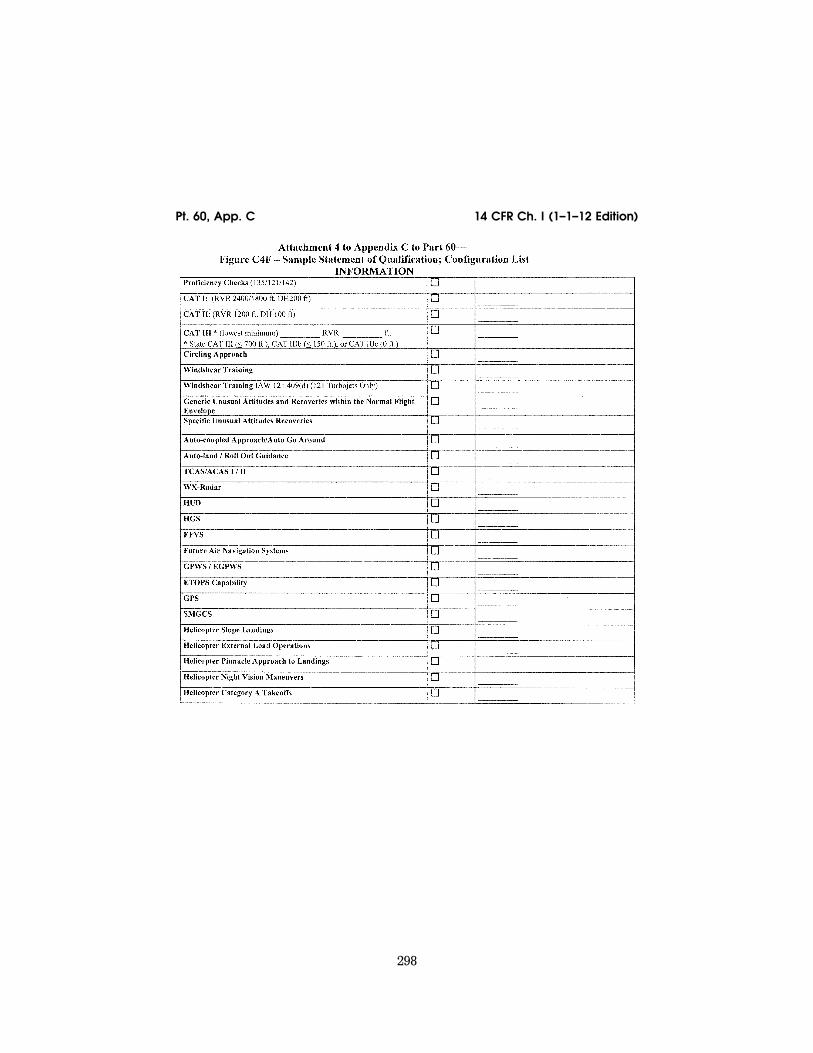
298
14 CFR Ch. I (1–1–12 Edition) Pt. 60, App. C
VerDate Mar<15>2010 18:16 Mar 01, 2012 Jkt 226045 PO 00000 Frm 00308 Fmt 8010 Sfmt 8006 Q:\14\14V2 ofr150 PsN: PC150 ER
09M
Y08
.049
</G
PH
>

299
Federal Aviation Administration, DOT Pt. 60, App. C
VerDate Mar<15>2010 18:16 Mar 01, 2012 Jkt 226045 PO 00000 Frm 00309 Fmt 8010 Sfmt 8006 Q:\14\14V2 ofr150 PsN: PC150 ER
09M
Y08
.050
</G
PH
>

300
14 CFR Ch. I (1–1–12 Edition) Pt. 60, App. C
VerDate Mar<15>2010 18:16 Mar 01, 2012 Jkt 226045 PO 00000 Frm 00310 Fmt 8010 Sfmt 8006 Q:\14\14V2 ofr150 PsN: PC150 ER
09M
Y08
.051
</G
PH
>

301
Federal Aviation Administration, DOT Pt. 60, App. C
ATTACHMENT 5 TO APPENDIX C TO PART 60— FSTD DIRECTIVES APPLICABLE TO HELICOPTER FFSS
FLIGHT SIMULATION TRAINING DEVICE (FSTD) DIRECTIVE
FSTD Directive 1. Applicable to all FFSs, regardless of the original qualification basis and qualification date (original or upgrade), having Class II or Class III airport models available.
Agency: Federal Aviation Administration (FAA), DOT
Action: This is a retroactive requirement to have all Class II or Class III airport models meet current requirements.
lllllllllllllllllllllll
Summary: Notwithstanding the authoriza tion listed in paragraph 13b in Appendices A and C of this part, this FSTD Directive re-quires each certificate holder to ensure that by May 30, 2009, except for the airport model(s) used to qualify the simulator at the designated level, each airport model used by the certificate holder’s instructors or eval-uators for training, checking, or testing under this chapter in an FFS, meets the defi-nition of a Class II or Class III airport model as defined in 14CFR part 60. The completion of this requirement will not require a report, and the method used for keeping instructors and evaluators apprised of the airport mod-els that meet Class II or Class III require-ments on any given simulator is at the op-
tion of the certificate holder whose employ-ees are using the FFS, but the method used must be available for review by the TPAA for that certificate holder.
Dates: FSTD Directive 1 becomes effective on May 30, 2008.
For Further Information Contact: Ed Cook, Senior Advisor to the Division Manager, Air Transportation Division, AFS–200, 800 Inde-pendence Ave, SW, Washington, DC, 20591: telephone: (404) 832–4701; fax: (404) 761–8906.
SPECIFIC REQUIREMENTS:
1. Part 60 requires that each FSTD be: a. Sponsored by a person holding or apply-
ing for an FAA operating certificate under Part 119, Part 141, or Part 142, or holding or applying for an FAA-approved training pro-gram under Part 63, Appendix C, for flight engineers, and
b. Evaluated and issued an SOQ for a spe-cific FSTD level.
2. FFSs also require the installation of a visual system that is capable of providing an out-of-the-flight-deck view of airport mod-els. However, historically these airport mod-els were not routinely evaluated or required to meet any standardized criteria. This has led to qualified simulators containing air-port models being used to meet FAA-ap-proved training, testing, or checking require-ments with potentially incorrect or inappro-priate visual references.
VerDate Mar<15>2010 18:16 Mar 01, 2012 Jkt 226045 PO 00000 Frm 00311 Fmt 8010 Sfmt 8002 Q:\14\14V2 ofr150 PsN: PC150 ER
09M
Y08
.052
</G
PH
>

302
14 CFR Ch. I (1–1–12 Edition) Pt. 60, App. D
3. To prevent this from occurring in the fu-ture, by May 30, 2009, except for the airport model(s) used to qualify the simulator at the designated level, each certificate holder must assure that each airport model used for training, testing, or checking under this chapter in a qualified FFS meets the defini-tion of a Class II or Class III airport model as defined in Appendix F of this part.
4. These references describe the require-ments for visual scene management and the minimum distances from which runway or landing area features must be visible for all levels of simulator. The visual scene or air-port model must provide, for each ‘‘in-use runway’’ or ‘‘in-use landing area,’’ runway or landing area surface and markings, runway or landing area lighting, taxiway surface and markings, and taxiway lighting. Additional requirements include correlation of the vis-ual scenes or airport models with other as-pects of the airport environment, correlation of the aircraft and associated equipment, scene quality assessment features, and the extent to which the instructor is able to ex-ercise control of these scenes or models.
5. For circling approaches, all require-ments of this section apply to the runway used for the initial approach and to the run-way of intended landing.
6. The details in these scenes or models must be developed using airport pictures, construction drawings and maps, or other similar data, or be developed in accordance with published regulatory material. How-ever, FSTD Directive 1 does not require that airport models contain details that are be-yond the initially designed capability of the visual system, as currently qualified. The recognized limitations to visual systems are as follows:
a. Visual systems not required to have run-way numbers as a part of the specific runway marking requirements are:
(1) Link NVS and DNVS. (2) Novoview 2500 and 6000. (3) FlightSafety VITAL series up to, and
including, VITAL III, but not beyond. (4) Redifusion SP1, SP1T, and SP2. b. Visual systems required to display run-
way numbers only for LOFT scenes are: (1) FlightSafety VITAL IV. (2) Redifusion SP3 and SP3T. (3) Link-Miles Image II. c. Visual systems not required to have ac-
curate taxiway edge lighting are: (1) Redifusion SP1. (2) FlightSafety Vital IV. (3) Link-Miles Image II and Image IIT (4) XKD displays (even though the XKD
image generator is capable of generating blue colored lights, the display cannot ac-commodate that color).
7. A copy of this Directive must be filed in the MQTG in the designated FSTD Directive Section, and its inclusion must be annotated on the Index of Effective FSTD Directives
chart. See Attachment 4, Appendices A through D of this part for a sample MQTG Index of Effective FSTD Directives chart.
[Doc. No. FAA–2002–12461, 73 FR 26490, May 9, 2008]
APPENDIX D TO PART 60—QUALIFICATION PERFORMANCE STANDARDS FOR HEL-ICOPTER FLIGHT TRAINING DEVICES
lllllllllllllllllllllll
BEGIN INFORMATION
This appendix establishes the standards for Helicopter Flight Training Device (FTD) evaluation and qualification at Level 4, Level 5, Level 6, or Level 7. The NSPM is re-sponsible for the development, application, and implementation of the standards con-tained within this appendix. The procedures and criteria specified in this appendix will be used by the NSPM, or a person or persons as-signed by the NSPM when conducting heli-copter FTD evaluations.
TABLE OF CONTENTS
1. Introduction. 2. Applicability (§§ 60.1, 60.2). 3. Definitions (§ 60.3). 4. Qualification Performance Standards
(§ 60.4). 5. Quality Management System (§ 60.5). 6. Sponsor Qualification Requirements
(§ 60.7). 7. Additional Responsibilities of the Spon-
sor (§ 60.9). 8. FTD Use (§ 60.11). 9. FTD Objective Data Requirements
(§ 60.13). 10. Special Equipment and Personnel Re-
quirements for Qualification of the FTD (§ 60.14).
11. Initial (and Upgrade) Qualification Re-quirements (§ 60.15).
12. Additional Qualifications for Currently Qualified FTDs (§ 60.16).
13. Previously Qualified FTDs (§ 60.17). 14. Inspection, Continuing Qualification
Evaluation, and Maintenance Requirements (§ 60.19).
15. Logging FTD Discrepancies (§ 60.20). 16. Interim Qualification of FTDs for New
Helicopter Types or Models (§ 60.21). 17. Modifications to FTDs (§ 60.23). 18. Operations with Missing, Malfunc-
tioning, or Inoperative Components (§ 60.25). 19. Automatic Loss of Qualification and
Procedures for Restoration of Qualification (§ 60.27).
20. Other Losses of Qualification and Pro-cedures for Restoration of Qualification (§ 60.29).
21. Recordkeeping and Reporting (§ 60.31). 22. Applications, Logbooks, Reports, and
Records: Fraud, Falsification, or Incorrect Statements (§ 60.33).
VerDate Mar<15>2010 18:16 Mar 01, 2012 Jkt 226045 PO 00000 Frm 00312 Fmt 8010 Sfmt 8002 Q:\14\14V2 ofr150 PsN: PC150

303
Federal Aviation Administration, DOT Pt. 60, App. D
23. [Reserved] 24. Levels of FTD. 25. FTD Qualification on the Basis of a Bi-
lateral Aviation Safety Agreement (BASA) (§ 60.37).
Attachment 1 to Appendix D to Part 60— General FTD Requirements.
Attachment 2 to Appendix D to Part 60— Flight Training Device (FTD) Objective Tests.
Attachment 3 to Appendix D to Part 60— Flight Training Device (FTD) Subjective Evaluation.
Attachment 4 to Appendix D to Part 60— Sample Documents.
END INFORMATION
lllllllllllllllllllllll
1. INTRODUCTION
lllllllllllllllllllllll
BEGIN INFORMATION
a. This appendix contains background in-formation as well as regulatory and inform-ative material as described later in this sec-tion. To assist the reader in determining what areas are required and what areas are permissive, the text in this appendix is di-vided into two sections: ‘‘QPS Require-ments’’ and ‘‘Information.’’ The QPS Re-quirements sections contain details regard-ing compliance with the part 60 rule lan-guage. These details are regulatory, but are found only in this appendix. The Information sections contain material that is advisory in nature, and designed to give the user general information about the regulation.
b. Questions regarding the contents of this publication should be sent to the U.S. De-partment of Transportation, Federal Avia-tion Administration, Flight Standards Serv-ice, National Simulator Program Staff, AFS–205, 100 Hartsfield Centre Parkway, Suite 400, Atlanta, Georgia 30354. Telephone contact numbers for the NSP are: Phone, 404–832–4700; fax, 404–761–8906. The general e- mail address for the NSP office is: 9-aso-avr- [email protected]. The NSP Internet Web Site address is: http://www.faa.gov/safety/ programslinitiatives/aircraftlaviation/nsp/. On this Web Site you will find an NSP personnel list with telephone and e-mail contact infor-mation for each NSP staff member, a list of qualified flight simulation devices, ACs, a description of the qualification process, NSP policy, and an NSP ‘‘In-Works’’ section. Also linked from this site are additional informa-tion sources, handbook bulletins, frequently asked questions, a listing and text of the Federal Aviation Regulations, Flight Stand-ards Inspector’s handbooks, and other FAA links.
c. The NSPM encourages the use of elec-tronic media for all communication, includ-ing any record, report, request, test, or
statement required by this appendix. The electronic media used must have adequate security provisions and be acceptable to the NSPM. The NSPM recommends inquiries on system compatibility, and minimum system requirements are also included on the NSP Web site.
d. Related Reading References. (1) 14 CFR part 60. (2) 14 CFR part 61. (3) 14 CFR part 63. (4) 14 CFR part 119. (5) 14 CFR part 121. (6) 14 CFR part 125. (7) 14 CFR part 135. (8) 14 CFR part 141. (9) 14 CFR part 142. (10) AC 120–28, as amended, Criteria for Ap-
proval of Category III Landing Weather Minima.
(11) AC 120–29, as amended, Criteria for Ap-proving Category I and Category II Landing Minima for part 121 operators.
(12) AC 120–35, as amended, Line Oper-ational Simulations: Line-Oriented Flight Training, Special Purpose Operational Training, Line Operational Evaluation.
(13) AC 120–41, as amended, Criteria for Operational Approval of Airborne Wind Shear Alerting and Flight Guidance Sys-tems.
(14) AC 120–57, as amended, Surface Move-ment Guidance and Control System (SMGCS).
(15) AC 120–63, as amended, Helicopter Sim-ulator Qualification.
(16) AC 150/5300–13, as amended, Airport De-sign.
(17) AC 150/5340–1, as amended, Standards for Airport Markings.
(18) AC 150/5340–4, as amended, Installation Details for Runway Centerline Touchdown Zone Lighting Systems.
(19) AC 150/5390–2, as amended, Heliport De-sign.
(20) AC 150/5340–19, as amended, Taxiway Centerline Lighting System.
(21) AC 150/5340–24, as amended, Runway and Taxiway Edge Lighting System.
(22) AC 150/5345–28, as amended, Precision Approach Path Indicator (PAPI) Systems.
(23) International Air Transport Associa-tion document, ‘‘Flight Simulator Design and Performance Data Requirements,’’ as amended.
(24) AC 29–2, as amended, Flight Test Guide for Certification of Transport Category Rotorcraft.
(25) AC 27–1, as amended, Flight Test Guide for Certification of Normal Category Rotor-craft.
(26) International Civil Aviation Organiza-tion (ICAO) Manual of Criteria for the Quali-fication of Flight Simulators, as amended.
VerDate Mar<15>2010 18:16 Mar 01, 2012 Jkt 226045 PO 00000 Frm 00313 Fmt 8010 Sfmt 8002 Q:\14\14V2 ofr150 PsN: PC150

304
14 CFR Ch. I (1–1–12 Edition) Pt. 60, App. D
(27) Airplane Flight Simulator Evaluation Handbook, Volume I, as amended and Vol-ume II, as amended, The Royal Aeronautical Society, London, UK.
(28) FAA Publication FAA–S–8081 series (Practical Test Standards for Airline Trans-port Pilot Certificate, Type Ratings, Com-mercial Pilot, and Instrument Ratings).
(29) The FAA Aeronautical Information Manual (AIM). An electronic version of the AIM is on the Internet at http://www.faa.gov/ atpubs.
(30) Aeronautical Radio, Inc. (ARINC) doc-ument number 436, Guidelines For Electronic Qualification Test Guide (as amended).
(31) Aeronautical Radio, Inc. (ARINC) doc-ument 610, Guidance for Design and Integra-tion of Aircraft Avionics Equipment in Simula-tors (as amended).
END INFORMATION
lllllllllllllllllllllll
2. APPLICABILITY (§ 60.1 AND 60.2)
lllllllllllllllllllllll
BEGIN INFORMATION
No additional regulatory or informational material applies to § 60.1, Applicability, or to § 60.2, Applicability of sponsor rules to person who are not sponsors and who are engaged in certain unauthorized activities.
END INFORMATION
lllllllllllllllllllllll
3. DEFINITIONS (§ 60.3)
lllllllllllllllllllllll
BEGIN INFORMATION
See Appendix F of this part for a list of definitions and abbreviations from part 1, part 60, and the QPS appendices of part 60.
END INFORMATION
lllllllllllllllllllllll
4. QUALIFICATION PERFORMANCE STANDARDS (§ 60.4)
BEGIN INFORMATION
No additional regulatory or informational material applies to § 60.4, Qualification Per-formance Standards.
END INFORMATION
lllllllllllllllllllllll
5. QUALITY MANAGEMENT SYSTEM (§ 60.5)
lllllllllllllllllllllll
BEGIN INFORMATION
Additional regulatory material and infor-mational material regarding Quality Man-
agement Systems for FTDs may be found in Appendix E of this part.
END INFORMATION
lllllllllllllllllllllll
6. SPONSOR QUALIFICATION REQUIREMENTS (§ 60.7)
lllllllllllllllllllllll
BEGIN INFORMATION
a. The intent of the language in § 60.7(b) is to have a specific FTD, identified by the sponsor, used at least once in an FAA-ap-proved flight training program for the heli-copter simulated during the 12-month period described. The identification of the specific FTD may change from one 12-month period to the next 12-month period as long as that sponsor sponsors and uses at least one FTD at least once during the prescribed period. There is no minimum number of hours or minimum FTD periods required.
b. The following examples describe accept-able operational practices:
(1) Example One. (a) A sponsor is sponsoring a single, spe-
cific FTD for its own use, in its own facility or elsewhere—this single FTD forms the basis for the sponsorship. The sponsor uses that FTD at least once in each 12-month pe-riod in that sponsor’s FAA-approved flight training program for the helicopter simu-lated. This 12-month period is established ac-cording to the following schedule:
(i) If the FTD was qualified prior to May 30, 2008, the 12-month period begins on the date of the first continuing qualification evaluation conducted in accordance with § 60.19 after May 30, 2008, and continues for each subsequent 12-month period;
(ii) A device qualified on or after May 30, 2008, will be required to undergo an initial or upgrade evaluation in accordance with § 60.15. Once the initial or upgrade evaluation is complete, the first continuing qualifica-tion evaluation will be conducted within 6 months. The 12 month continuing qualifica-tion evaluation cycle begins on that date and continues for each subsequent 12-month pe-riod.
(b) There is no minimum number of hours of FTD use required.
(c) The identification of the specific FTD may change from one 12-month period to the next 12-month period as long as that sponsor sponsors and uses at least one FTD at least once during the prescribed period.
(2) Example Two. (a) A sponsor sponsors an additional num-
ber of FTDs, in its facility or elsewhere. Each additionally sponsored FTD must be—
(i) Used by the sponsor in the sponsor’s FAA-approved flight training program for the helicopter simulated (as described in § 60.7(d)(1)); or
VerDate Mar<15>2010 18:16 Mar 01, 2012 Jkt 226045 PO 00000 Frm 00314 Fmt 8010 Sfmt 8002 Q:\14\14V2 ofr150 PsN: PC150
305
Federal Aviation Administration, DOT Pt. 60, App. D
(ii) Used by another FAA certificate holder in that other certificate holder’s FAA-ap-proved flight training program for the heli-copter simulated (as described in § 60.7(d)(1)). This 12-month period is established in the same manner as in example one; or
(iii) Provided a statement each year from a qualified pilot, (after having flown the heli-copter not the subject FTD or another FTD, during the preceding 12-month period) stat-ing that the subject FTD’s performance and handling qualities represent the helicopter (as described in § 60.7(d)(2)). This statement is provided at least once in each 12-month pe-riod established in the same manner as in ex-ample one.
(b) There is no minimum number of hours of FTD use required.
(3) Example Three. (a) A sponsor in New York (in this exam-
ple, a Part 142 certificate holder) establishes ‘‘satellite’’ training centers in Chicago and Moscow.
(b) The satellite function means that the Chicago and Moscow centers must operate under the New York center’s certificate (in accordance with all of the New York center’s practices, procedures, and policies; e.g., in-structor and/or technician training/checking requirements, record keeping, QMS pro-gram).
(c) All of the FTDs in the Chicago and Mos-cow centers could be dry-leased (i.e., the cer-tificate holder does not have and use FAA- approved flight training programs for the FTDs in the Chicago and Moscow centers) because—
(i) Each FTD in the Chicago center and each FTD in the Moscow center is used at least once each 12-month period by another FAA certificate holder in that other certifi-cate holder’s FAA-approved flight training program for the helicopter (as described in § 60.7(d)(1)); or
(ii) A statement is obtained from a quali-fied pilot (having flown the helicopter, not the subject FTD or another FTD during the preceding 12-month period) stating that the performance and handling qualities of each FTD in the Chicago and Moscow centers rep-resents the helicopter (as described in § 60.7(d)(2)).
END INFORMATION
lllllllllllllllllllllll
7. ADDITIONAL RESPONSIBILITIES OF THE SPONSOR (§ 60.9)
lllllllllllllllllllllll
BEGIN INFORMATION
The phrase ‘‘as soon as practicable’’ in § 60.9(a) means without unnecessarily dis-rupting or delaying beyond a reasonable time the training, evaluation, or experience being conducted in the FTD.
END INFORMATION
lllllllllllllllllllllll
8. FTD USE (§ 60.11).
lllllllllllllllllllllll
BEGIN INFORMATION
No additional regulatory or informational material applies to § 60.11, FTD Use.
END INFORMATION
lllllllllllllllllllllll
9. FTD OBJECTIVE DATA REQUIREMENTS (§ 60.13)
lllllllllllllllllllllll
BEGIN QPS REQUIREMENTS
a. Flight test data used to validate FTD performance and handling qualities must have been gathered in accordance with a flight test program containing the following:
(1) A flight test plan consisting of: (a) The maneuvers and procedures required
for aircraft certification and simulation pro-gramming and validation.
(b) For each maneuver or procedure— (i) The procedures and control input the
flight test pilot and/or engineer used. (ii) The atmospheric and environmental
conditions. (iii) The initial flight conditions. (iv) The helicopter configuration, includ-
ing weight and center of gravity. (v) The data to be gathered. (vi) All other information necessary to
recreate the flight test conditions in the FTD.
(2) Appropriately qualified flight test per-sonnel.
(3) Appropriate and sufficient data acquisi-tion equipment or system(s), including ap-propriate data reduction and analysis meth-ods and techniques, acceptable to the FAA’s Aircraft Certification Service.
b. The data, regardless of source, must be presented:
(1) In a format that supports the FTD vali-dation process;
(2) In a manner that is clearly readable and annotated correctly and completely;
(3) With resolution sufficient to determine compliance with the tolerances set forth in Attachment 2, Table D2A Appendix D;
(4) With any necessary guidance informa-tion provided; and
(5) Without alteration, adjustments, or bias. Data may be corrected to address known data calibration errors provided that an explanation of the methods used to cor-rect the errors appears in the QTG. The cor-rected data may be re-scaled, digitized, or otherwise manipulated to fit the desired presentation
VerDate Mar<15>2010 18:16 Mar 01, 2012 Jkt 226045 PO 00000 Frm 00315 Fmt 8010 Sfmt 8002 Q:\14\14V2 ofr150 PsN: PC150

306
14 CFR Ch. I (1–1–12 Edition) Pt. 60, App. D
c. After completion of any additional flight test, a flight test report must be submitted in support of the validation data. The report must contain sufficient data and rationale to support qualification of the FTD at the level requested.
d. As required by § 60.13(f), the sponsor must notify the NSPM when it becomes aware that an addition to or a revision of the flight related data or helicopter systems re-lated data is available if this data is used to program and operate a qualified FTD. The data referred to in this sub-section is data used to validate the performance, handling qualities, or other characteristics of the air-craft, including data related to any relevant changes occurring after the type certifi-cation is issued. The sponsor must—
(1) Within 10 calendar days, notify the NSPM of the existence of this data; and
(a) Within 45 calendar days, notify the NSPM of—
(b) The schedule to incorporate this data into the FTD; or
(c) The reason for not incorporating this data into the FTD.
e. In those cases where the objective test results authorize a ‘‘snapshot test’’ or a ‘‘se-ries of snapshot tests’’ results in lieu of a time-history result, the sponsor or other data provider must ensure that a steady state condition exists at the instant of time captured by the ‘‘snapshot.’’ The steady state condition must exist from 4 seconds prior to, through 1 second following, the in-stant of time captured by the snap shot.
END QPS REQUIREMENTS
lllllllllllllllllllllll
BEGIN INFORMATION
f. The FTD sponsor is encouraged to main-tain a liaison with the manufacturer of the aircraft being simulated (or with the holder of the aircraft type certificate for the air-craft being simulated if the manufacturer is no longer in business), and if appropriate, with the person having supplied the aircraft data package for the FTD in order to facili-tate the notification described in this para-graph.
g. It is the intent of the NSPM that for new aircraft entering service, at a point well in advance of preparation of the QTG, the sponsor should submit to the NSPM for ap-proval, a descriptive document (see Appendix C of this part, Table C2D, Sample Validation Data Roadmap for Helicopters) containing the plan for acquiring the validation data, including data sources. This document should clearly identify sources of data for all required tests, a description of the validity of these data for a specific engine type and thrust rating configuration, and the revision levels of all avionics affecting the perform-ance or flying qualities of the aircraft. Addi-
tionally, this document should provide other information such as the rationale or expla-nation for cases where data or data param-eters are missing, instances where engineer-ing simulation data are used, or where flight test methods require further explanations. It should also provide a brief narrative describ-ing the cause and effect of any deviation from data requirements. The aircraft manu-facturer may provide this document.
h. There is no requirement for any flight test data supplier to submit a flight test plan or program prior to gathering flight test data. However, the NSPM notes that in-experienced data gatherers often provide data that is irrelevant, improperly marked, or lacking adequate justification for selec-tion. Other problems include inadequate in-formation regarding initial conditions or test maneuvers. The NSPM has been forced to refuse these data submissions as valida-tion data for an FTD evaluation. For this reason the NSPM recommends that any data supplier not previously experienced in this area review the data necessary for program-ming and for validating the performance of the FTD and discuss the flight test plan an-ticipated for acquiring such data with the NSPM well in advance of commencing the flight tests.
i. The NSPM will consider, on a case-by- case basis, whether to approve supplemental validation data derived from flight data re-cording systems such as a Quick Access Re-corder or Flight Data Recorder.
END INFORMATION
lllllllllllllllllllllll
10. SPECIAL EQUIPMENT AND PERSONNEL RE QUIREMENTS FOR QUALIFICATION OF THE FTD (§ 60.14).
lllllllllllllllllllllll
BEGIN INFORMATION
a. In the event that the NSPM determines that special equipment or specifically quali-fied persons will be required to conduct an evaluation, the NSPM will make every at-tempt to notify the sponsor at least one (1) week, but in no case less than 72 hours, in advance of the evaluation. Examples of spe-cial equipment include flight control meas-urement devices, accelerometers, or oscillo-scopes. Examples of specially qualified per-sonnel include individuals specifically quali-fied to install or use any special equipment when its use is required.
b. Examples of a special evaluation include an evaluation conducted after an FTD is moved; at the request of the TPAA; or as a result of comments received from users of the FTD that raise questions about the con-tinued qualification or use of the FTD.
VerDate Mar<15>2010 18:16 Mar 01, 2012 Jkt 226045 PO 00000 Frm 00316 Fmt 8010 Sfmt 8002 Q:\14\14V2 ofr150 PsN: PC150

307
Federal Aviation Administration, DOT Pt. 60, App. D
END INFORMATION
lllllllllllllllllllllll
11. INITIAL (AND UPGRADE) QUALIFICATION REQUIREMENTS (§ 60.15).
lllllllllllllllllllllll
BEGIN QPS REQUIREMENT
a. In order to be qualified at a particular qualification level, the FTD must:
(1) Meet the general requirements listed in Attachment 1 of this appendix.
(2) Meet the objective testing requirements listed in Attachment 2 of this appendix (Level 4 FTDs do not require objective tests).
(3) Satisfactorily accomplish the subjec-tive tests listed in Attachment 3 of this ap-pendix.
b. The request described in § 60.15(a) must include all of the following:
(1) A statement that the FTD meets all of the applicable provisions of this part and all applicable provisions of the QPS.
(2) A confirmation that the sponsor will forward to the NSPM the statement de-scribed in § 60.15(b) in such time as to be re-ceived no later than 5 business days prior to the scheduled evaluation and may be for-warded to the NSPM via traditional or elec-tronic means.
(3) Except for a Level 4 FTD, a QTG, ac-ceptable to the NSPM, that includes all of the following:
(a) Objective data obtained from aircraft testing or another approved source.
(b) Correlating objective test results ob-tained from the performance of the FTD as prescribed in the appropriate QPS.
(c) The result of FTD subjective tests pre-scribed in the appropriate QPS.
(d) A description of the equipment nec-essary to perform the evaluation for initial qualification and the continuing qualifica-tion evaluations.
c. The QTG described in paragraph a(3) of this section must provide the documented proof of compliance with the FTD objective tests in Attachment 2, Table D2A of this ap-pendix.
d. The QTG is prepared and submitted by the sponsor, or the sponsor’s agent on behalf of the sponsor, to the NSPM for review and approval, and must include, for each objec-tive test:
(1) Parameters, tolerances, and flight con-ditions.
(2) Pertinent and complete instructions for conducting automatic and manual tests.
(3) A means of comparing the FTD test re-sults to the objective data.
(4) Any other information as necessary to assist in the evaluation of the test results.
(5) Other information appropriate to the qualification level of the FTD.
e. The QTG described in paragraphs (a)(3) and (b) of this section, must include the fol-lowing:
(1) A QTG cover page with sponsor and FAA approval signature blocks (see Attach-ment 4, Figure D4C, of this appendix, for a sample QTG cover page).
(2) A continuing qualification evaluation requirements page. This page will be used by the NSPM to establish and record the fre-quency with which continuing qualification evaluations must be conducted and any sub-sequent changes that may be determined by the NSPM in accordance with § 60.19. See At-tachment 4, Figure D4G, of this appendix for a sample Continuing Qualification Evalua-tion Requirements page.
(3) An FTD information page that provides the information listed in this paragraph, if applicable (see Attachment 4, Figure D4B, of this appendix, for a sample FTD information page). For convertible FTDs, the sponsor must submit a separate page for each con-figuration of the FTD.
(a) The sponsor’s FTD identification num-ber or code.
(b) The helicopter model and series being simulated.
(c) The aerodynamic data revision number or reference.
(d) The source of the basic aerodynamic model and the aerodynamic coefficient data used to modify the basic model.
(e) The engine model(s) and its data revi-sion number or reference.
(f) The flight control data revision number or reference.
(g) The flight management system identi-fication and revision level.
(h) The FTD model and manufacturer. (i) The date of FTD manufacture. (j) The FTD computer identification. (k) The visual system model and manufac-
turer, including display type. (l) The motion system type and manufac-
turer, including degrees of freedom. (4) A Table of Contents. (5) A log of revisions and a list of effective
pages. (6) List of all relevant data references. (7) A glossary of terms and symbols used
(including sign conventions and units). (8) Statements of Compliance and Capa-
bility (SOC) with certain requirements. (9) Recording procedures or equipment re-
quired to accomplish the objective tests. (10) The following information for each ob-
jective test designated in Attachment 2 of this appendix, as applicable to the qualifica-tion level sought:
(a) Name of the test. (b) Objective of the test. (c) Initial conditions. (d) Manual test procedures. (e) Automatic test procedures (if applica-
ble).
VerDate Mar<15>2010 18:16 Mar 01, 2012 Jkt 226045 PO 00000 Frm 00317 Fmt 8010 Sfmt 8002 Q:\14\14V2 ofr150 PsN: PC150

308
14 CFR Ch. I (1–1–12 Edition) Pt. 60, App. D
(f) Method for evaluating FTD objective test results.
(g) List of all relevant parameters driven or constrained during the automatic test(s).
(h) List of all relevant parameters driven or constrained during the manual test(s).
(i) Tolerances for relevant parameters. (j) Source of Validation Data (document
and page number). (k) Copy of the Validation Data (if located
in a separate binder, a cross reference for the identification and page number for pertinent data location must be provided).
(l) FTD Objective Test Results as obtained by the sponsor. Each test result must reflect the date completed and must be clearly la-beled as a product of the device being tested.
f. A convertible FTD is addressed as a sepa-rate FTD for each model and series heli-copter to which it will be converted and for the FAA qualification level sought. The NSPM will conduct an evaluation for each configuration. If a sponsor seeks qualifica-tion for two or more models of a helicopter type using a convertible FTD, the sponsor must provide a QTG for each helicopter model, or a QTG for the first helicopter model and a supplement to that QTG for each additional helicopter model. The NSPM will conduct evaluations for each helicopter model.
g. The form and manner of presentation of objective test results in the QTG must in-clude the following:
(1) The sponsor’s FTD test results must be recorded in a manner acceptable to the NSPM, that allows easy comparison of the FTD test results to the validation data (e.g., use of a multi-channel recorder, line printer, cross plotting, overlays, transparencies).
(2) FTD results must be labeled using ter-minology common to helicopter parameters as opposed to computer software identifica-tions.
(3) Validation data documents included in a QTG may be photographically reduced only if such reduction will not alter the graphic scaling or cause difficulties in scale interpre-tation or resolution.
(4) Scaling on graphical presentations must provide the resolution necessary to evaluate the parameters shown in Attach-ment 2, Table D2A of this appendix.
(5) Tests involving time histories, data sheets (or transparencies thereof) and FTD test results must be clearly marked with ap-propriate reference points to ensure an accu-rate comparison between FTD and helicopter with respect to time. Time histories recorded via a line printer are to be clearly identified for cross-plotting on the helicopter data. Over-plots may not obscure the reference data.
h. The sponsor may elect to complete the QTG objective and subjective tests at the manufacturer’s facility or at the sponsor’s training facility. If the tests are conducted
at the manufacturer’s facility, the sponsor must repeat at least one-third of the tests at the sponsor’s training facility in order to substantiate FTD performance. The QTG must be clearly annotated to indicate when and where each test was accomplished. Tests conducted at the manufacturer’s facility and at the sponsor’s training facility must be conducted after the FTD is assembled with systems and sub-systems functional and op-erating in an interactive manner. The test results must be submitted to the NSPM.
i. The sponsor must maintain a copy of the MQTG at the FTD location.
j. All FTDs for which the initial qualifica-tion is conducted after May 30, 2014, must have an electronic MQTG (eMQTG) including all objective data obtained from helicopter testing, or another approved source (refor-matted or digitized), together with corre-lating objective test results obtained from the performance of the FTD (reformatted or digitized) as prescribed in this appendix. The eMQTG must also contain the general FTD performance or demonstration results (refor-matted or digitized) prescribed in this appen-dix, and a description of the equipment nec-essary to perform the initial qualification evaluation and the continuing qualification evaluations. The eMQTG must include the original validation data used to validate FTD performance and handling qualities in either the original digitized format from the data supplier or an electronic scan of the original time-history plots that were pro-vided by the data supplier. A copy of the eMQTG must be provided to the NSPM.
k. All other FTDs (not covered in subpara-graph ‘‘j’’) must have an electronic copy of the MQTG by and after May 30, 2014. An elec-tronic copy of the MQTG must be provided to the NSPM. This may be provided by an elec-tronic scan presented in a Portable Docu-ment File (PDF), or similar format accept-able to the NSPM.
l. During the initial (or upgrade) qualifica-tion evaluation conducted by the NSPM, the sponsor must also provide a person knowl-edgeable about the operation of the aircraft and the operation of the FTD.
END QPS REQUIREMENTS
lllllllllllllllllllllll
BEGIN INFORMATION
m. Only those FTDs that are sponsored by a certificate holder as defined in Appendix F of this part will be evaluated by the NSPM. However, other FTD evaluations may be con-ducted on a case-by-case basis as the Admin-istrator deems appropriate, but only in ac-cordance with applicable agreements.
n. The NSPM will conduct an evaluation for each configuration, and each FTD must be evaluated as completely as possible. To ensure a thorough and uniform evaluation,
VerDate Mar<15>2010 18:16 Mar 01, 2012 Jkt 226045 PO 00000 Frm 00318 Fmt 8010 Sfmt 8002 Q:\14\14V2 ofr150 PsN: PC150

309
Federal Aviation Administration, DOT Pt. 60, App. D
each FTD is subjected to the general FTD re-quirements in Attachment 1 of this appen-dix, the objective tests listed in Attachment 2 of this appendix, and the subjective tests listed in Attachment 3 of this appendix. The evaluations described herein will include, but not necessarily be limited to the fol-lowing:
(1) Helicopter responses, including longitu-dinal and lateral-directional control re-sponses (see Attachment 2 of this appendix).
(2) Performance in authorized portions of the simulated helicopter’s operating enve-lope, to include tasks evaluated by the NSPM in the areas of surface operations, takeoff, climb, cruise, descent, approach and landing, as well as abnormal and emergency operations (see Attachment 2 of this appen-dix).
(3) Control checks (see Attachment 1 and Attachment 2 of this appendix).
(4) Flight deck configuration (see Attach-ment 1 of this appendix).
(5) Pilot, flight engineer, and instructor station functions checks (see Attachment 1 and Attachment 3 of this appendix).
(6) Helicopter systems and sub-systems (as appropriate) as compared to the helicopter simulated (see attachment 1 and attachment 3 of this appendix).
(7) FTD systems and sub-systems, includ-ing force cueing (motion), visual, and aural (sound) systems, as appropriate (see Attach-ment 1 and Attachment 2 of this appendix).
(8) Certain additional requirements, de-pending upon the qualification level sought, including equipment or circumstances that may become hazardous to the occupants. The sponsor may be subject to Occupational Safety and Health Administration require-ments.
o. The NSPM administers the objective and subjective tests, which include an examina-tion of functions. The tests include a quali-tative assessment of the FTD by an NSP pilot. The NSP evaluation team leader may assign other qualified personnel to assist in accomplishing the functions examination and/or the objective and subjective tests per-formed during an evaluation when required.
(1) Objective tests provide a basis for meas-uring and evaluating FTD performance and determining compliance with the require-ments of this part.
(2) Subjective tests provide a basis for: (a) Evaluating the capability of the FTD to
perform over a typical utilization period; (b) Determining that the FTD satisfac-
torily simulates each required task; (c) Verifying correct operation of the FTD
controls, instruments, and systems; and (d) Demonstrating compliance with the re-
quirements of this part. p. The tolerances for the test parameters
listed in Attachment 2 of this appendix re-flect the range of tolerances acceptable to the NSPM for FTD validation and are not to
be confused with design tolerances specified for FTD manufacture. In making decisions regarding tests and test results, the NSPM relies on the use of operational and engineer-ing judgment in the application of data (in-cluding consideration of the way in which the flight test was flown and way the data was gathered and applied), data presen-tations, and the applicable tolerances for each test.
q. In addition to the scheduled continuing qualification evaluation, each FTD is subject to evaluations conducted by the NSPM at any time without prior notification to the sponsor. Such evaluations would be accom-plished in a normal manner (i.e., requiring exclusive use of the FTD for the conduct of objective and subjective tests and an exam-ination of functions) if the FTD is not being used for flight crewmember training, testing, or checking. However, if the FTD were being used, the evaluation would be conducted in a non-exclusive manner. This non-exclusive evaluation will be conducted by the FTD evaluator accompanying the check airman, instructor, Aircrew Program Designee (APD), or FAA inspector aboard the FTD along with the student(s) and observing the operation of the FTD during the training, testing, or checking activities.
r. Problems with objective test results are handled as follows:
(1) If a problem with an objective test re-sult is detected by the NSP evaluation team during an evaluation, the test may be re-peated or the QTG may be amended.
(2) If it is determined that the results of an objective test do not support the qualifica-tion level requested but do support a lower level, the NSPM may qualify the FTD at a lower level.
s. After an FTD is successfully evaluated, the NSPM issues an SOQ to the sponsor. The NSPM recommends the FTD to the TPAA, who will approve the FTD for use in a flight training program. The SOQ will be issued at the satisfactory conclusion of the initial or continuing qualification evaluation and will list the tasks for which the FTD is qualified, referencing the tasks described in Table D1B in Attachment 1 of this appendix. However, it is the sponsor’s responsibility to obtain TPAA approval prior to using the FTD in an FAA-approved flight training program.
t. Under normal circumstances, the NSPM establishes a date for the initial or upgrade evaluation within ten (10) working days after determining that a complete QTG is accept-able. Unusual circumstances may warrant establishing an evaluation date before this determination is made. A sponsor may schedule an evaluation date as early as 6 months in advance. However, there may be a delay of 45 days or more in rescheduling and completing the evaluation if the sponsor is unable to meet the scheduled date. See At-tachment 4, of this appendix, Figure D4A,
VerDate Mar<15>2010 18:16 Mar 01, 2012 Jkt 226045 PO 00000 Frm 00319 Fmt 8010 Sfmt 8002 Q:\14\14V2 ofr150 PsN: PC150

310
14 CFR Ch. I (1–1–12 Edition) Pt. 60, App. D
Sample Request for Initial, Upgrade, or Re-instatement Evaluation.
u. The numbering system used for objec-tive test results in the QTG should closely follow the numbering system set out in At-tachment 2, FTD Objective Tests, Table D2A of this appendix.
v. Contact the NSPM or visit the NSPM Web site for additional information regard-ing the preferred qualifications of pilots used to meet the requirements of § 60.15(d).
w. Examples of the exclusions for which the FTD might not have been subjectively tested by the sponsor or the NSPM and for which qualification might not be sought or granted, as described in § 60.15(g)(6), include approaches to and departures from slopes and pinnacles.
END INFORMATION
lllllllllllllllllllllll
12. ADDITIONAL QUALIFICATIONS FOR CURRENTLY QUALIFIED FTDS (§ 60.16)
lllllllllllllllllllllll
BEGIN INFORMATION
No additional regulatory or informational material applies to § 60.16, Additional Quali-fications for a Currently Qualified FTD.
END INFORMATION
lllllllllllllllllllllll
13. PREVIOUSLY QUALIFIED FTDS (§ 60.17)
lllllllllllllllllllllll
BEGIN QPS REQUIREMENTS
a. In instances where a sponsor plans to re-move an FTD from active status for a period of less than two years, the following proce-dures apply:
(1) The NSPM must be notified in writing and the notification must include an esti-mate of the period that the FTD will be inac-tive.
(2) Continuing Qualification evaluations will not be scheduled during the inactive pe-riod.
(3) The NSPM will remove the FTD from the list of qualified FTDs on a mutually es-tablished date not later than the date on which the first missed continuing qualifica-tion evaluation would have been scheduled.
(4) Before the FTD is restored to qualified status, it must be evaluated by the NSPM. The evaluation content and the time re-quired to accomplish the evaluation is based on the number of continuing qualification evaluations and sponsor-conducted quarterly inspections missed during the period of inac-tivity.
(5) The sponsor must notify the NSPM of any changes to the original scheduled time out of service.
b. FTDs and replacement FTD systems qualified prior to May 30, 2008, are not re-quired to meet the general FTD require-ments, the objective test requirements, and the subjective test requirements of Attach-ments 1, 2, and 3, respectively, of this appen-dix as long as the FTD continues to meet the test requirements contained in the MQTG developed under the original qualification basis.
c. After (1 year after date of publication of the final rule in the FEDERAL REGISTER) each visual scene and airport model installed in and available for use in a qualified FTD must meet the requirements described in Attach-ment 3 of this appendix.
d. Simulators qualified prior to May 30, 2008, may be updated. If an evaluation is deemed appropriate or necessary by the NSPM after such an update, the evaluation will not require an evaluation to standards beyond those against which the simulator was originally qualified.
END QPS REQUIREMENTS
lllllllllllllllllllllll
BEGIN INFORMATION
e. Other certificate holders or persons de-siring to use an FTD may contract with FTD sponsors to use FTDs previously qualified at a particular level for a helicopter type and approved for use within an FAA-approved flight training program. Such FTDs are not required to undergo an additional qualifica-tion process, except as described in § 60.16.
f. Each FTD user must obtain approval from the appropriate TPAA to use any FTD in an FAA-approved flight training program.
g. The intent of the requirement listed in § 60.17(b), for each FTD to have an SOQ with-in 6 years, is to have the availability of that statement (including the configuration list and the limitations to authorizations) to provide a complete picture of the FTD inven-tory regulated by the FAA. The issuance of the statement will not require any addi-tional evaluation or require any adjustment to the evaluation basis for the FTD.
h. Downgrading of an FTD is a permanent change in qualification level and will neces-sitate the issuance of a revised SOQ to re-flect the revised qualification level, as ap-propriate. If a temporary restriction is placed on an FTD because of a missing, mal-functioning, or inoperative component or on- going repairs, the restriction is not a perma-nent change in qualification level. Instead, the restriction is temporary and is removed when the reason for the restriction has been resolved.
i. It is not the intent of the NSPM to dis-courage the improvement of existing simula-tion (e.g., the ‘‘updating’’ of a control load-ing system, or the replacement of the IOS with a more capable unit) by requiring the
VerDate Mar<15>2010 18:16 Mar 01, 2012 Jkt 226045 PO 00000 Frm 00320 Fmt 8010 Sfmt 8002 Q:\14\14V2 ofr150 PsN: PC150

311
Federal Aviation Administration, DOT Pt. 60, App. D
‘‘updated’’ device to meet the qualification standards current at the time of the update. Depending on the extent of the update, the NSPM may require that the updated device be evaluated and may require that an eval-uation include all or a portion of the ele-ments of an initial evaluation. However, the standards against which the device would be evaluated are those that are found in the MQTG for that device.
j. The NSPM will determine the evaluation criteria for an FTD that has been removed from active status for a prolonged period. The criteria will be based on the number of continuing qualification evaluations and quarterly inspections missed during the pe-riod of inactivity. For example, if the FTD were out of service for a 1 year period, it would be necessary to complete the entire QTG, since all of the quarterly evaluations would have been missed. The NSPM will also consider how the FTD was stored, whether parts were removed from the FTD and whether the FTD was disassembled.
k. The FTD will normally be requalified using the FAA-approved MQTG and the cri-teria that was in effect prior to its removal from qualification. However, inactive periods of 2 years or more will require re-qualifica-tion under the standards in effect and cur-rent at the time of requalification.
END INFORMATION
lllllllllllllllllllllll
14. INSPECTION, CONTINUING QUALIFICATION, EVALUATION, AND MAINTENANCE REQUIRE-MENTS (§ 60.19)
lllllllllllllllllllllll
BEGIN QPS REQUIREMENT
a. The sponsor must conduct a minimum of four evenly spaced inspections throughout the year. The objective test sequence and content of each inspection in this sequence must be developed by the sponsor and must be acceptable to the NSPM.
b. The description of the functional pre-flight check must be contained in the spon-sor’s QMS.
c. Record ‘‘functional preflight’’ in the FTD discrepancy log book or other accept-able location, including any item found to be missing, malfunctioning, or inoperative.
d. During the continuing qualification evaluation conducted by the NSPM, the sponsor must also provide a person knowl-edgeable about the operation of the aircraft and the operation of the FTD.
END QPS REQUIREMENTS
lllllllllllllllllllllll
BEGIN INFORMATION
e. The sponsor’s test sequence and the con-tent of each quarterly inspection required in
§ 60.19(a)(1) should include a balance and a mix from the objective test requirement areas listed as follows:
(1) Performance. (2) Handling qualities. (3) Motion system (where appropriate). (4) Visual system (where appropriate). (5) Sound system (where appropriate). (6) Other FTD systems. f. If the NSP evaluator plans to accomplish
specific tests during a normal continuing qualification evaluation that requires the use of special equipment or technicians, the sponsor will be notified as far in advance of the evaluation as practical; but not less than 72 hours. Examples of such tests include latencies and control sweeps.
g. The continuing qualification evalua-tions described in § 60.19(b) will normally re-quire 4 hours of FTD time. However, flexi-bility is necessary to address abnormal situ-ations or situations involving aircraft with additional levels of complexity (e.g., com-puter controlled aircraft). The sponsor should anticipate that some tests may re-quire additional time. The continuing quali-fication evaluations will consist of the fol-lowing:
(1) Review of the results of the quarterly inspections conducted by the sponsor since the last scheduled continuing qualification evaluation.
(2) A selection of approximately 8 to 15 ob-jective tests from the MQTG that provide an adequate opportunity to evaluate the per-formance of the FTD. The tests chosen will be performed either automatically or manu-ally and should be able to be conducted with-in approximately one-third (1/3) of the allot-ted FTD time.
(3) A subjective evaluation of the FTD to perform a representative sampling of the tasks set out in attachment 3 of this appen-dix. This portion of the evaluation should take approximately two-thirds (2/3) of the al-lotted FTD time.
(4) An examination of the functions of the FTD may include the motion system, visual system, sound system as applicable, instruc-tor operating station, and the normal func-tions and simulated malfunctions of the sim-ulated helicopter systems. This examination is normally accomplished simultaneously with the subjective evaluation requirements.
h. The requirement established in § 60.19(b)(4) regarding the frequency of NSPM-conducted continuing qualification evaluations for each FTD is typically 12 months. However, the establishment and sat-isfactory implementation of an approved QMS for a sponsor will provide a basis for ad-justing the frequency of evaluations to ex-ceed 12-month intervals.
END INFORMATION
lllllllllllllllllllllll
VerDate Mar<15>2010 18:16 Mar 01, 2012 Jkt 226045 PO 00000 Frm 00321 Fmt 8010 Sfmt 8002 Q:\14\14V2 ofr150 PsN: PC150

312
14 CFR Ch. I (1–1–12 Edition) Pt. 60, App. D
15. LOGGING FTD DISCREPANCIES (§ 60.20)
lllllllllllllllllllllll
BEGIN INFORMATION
No additional regulatory or informational material applies to § 60.20. Logging FTD Dis-crepancies.
END INFORMATION
lllllllllllllllllllllll
16. INTERIM QUALIFICATION OF FTDS FOR NEW HELICOPTER TYPES OR MODELS (§ 60.21)
lllllllllllllllllllllll
BEGIN INFORMATION
No additional regulatory or informational material applies to § 60.21, Interim Qualifica-tion of FTDs for New Helicopter Types or Models.
END INFORMATION
lllllllllllllllllllllll
17. MODIFICATIONS TO FTDS (§ 60.23)
lllllllllllllllllllllll
BEGIN QPS REQUIREMENTS
a. The notification described in § 60.23(c)(2) must include a complete description of the planned modification, with a description of the operational and engineering effect the proposed modification will have on the oper-ation of the FTD and the results that are ex-pected with the modification incorporated.
b. Prior to using the modified FTD: (1) All the applicable objective tests com-
pleted with the modification incorporated, including any necessary updates to the MQTG (e.g., accomplishment of FSTD Direc-tives) must be acceptable to the NSPM; and
(2) The sponsor must provide the NSPM with a statement signed by the MR that the factors listed in § 60.15(b) are addressed by the appropriate personnel as described in that section.
END QPS REQUIREMENTS
lllllllllllllllllllllll
BEGIN INFORMATION
c. FSTD Directives are considered modi-fication of an FTD. See Attachment 4 of this appendix, Figure D4H for a sample index of effective FSTD Directives. See Attachment 6 of this appendix for a list of all effective FSTD Directives applicable to Helicopter FTDs.
END INFORMATION
lllllllllllllllllllllll
18. OPERATION WITH MISSING, MALFUNC TIONING, OR INOPERATIVE COMPONENTS (§ 60.25)
lllllllllllllllllllllll
BEGIN INFORMATION
a. The sponsor’s responsibility with respect to § 60.25(a) is satisfied when the sponsor fair-ly and accurately advises the user of the cur-rent status of an FTD, including any miss-ing, malfunctioning, or inoperative (MMI) component(s).
b. It is the responsibility of the instructor, check airman, or representative of the ad-ministrator conducting training, testing, or checking to exercise reasonable and prudent judgment to determine if any MMI compo-nent is necessary for the satisfactory com-pletion of a specific maneuver, procedure, or task.
c. If the 29th or 30th day of the 30-day pe-riod described in § 60.25(b) is on a Saturday, a Sunday, or a holiday, the FAA will extend the deadline until the next business day.
d. In accordance with the authorization de-scribed in § 60.25(b), the sponsor may develop a discrepancy prioritizing system to accom-plish repairs based on the level of impact on the capability of the FTD. Repairs having a larger impact on the FTD’s ability to pro-vide the required training, evaluation, or flight experience will have a higher priority for repair or replacement.
END INFORMATION
lllllllllllllllllllllll
19. AUTOMATIC LOSS OF QUALIFICATION AND PROCEDURES FOR RESTORATION OF QUALI-FICATION (§ 60.27)
lllllllllllllllllllllll
BEGIN INFORMATION
If the sponsor provides a plan for how the FTD will be maintained during its out-of- service period (e.g., periodic exercise of me-chanical, hydraulic, and electrical systems; routine replacement of hydraulic fluid; con-trol of the environmental factors in which the FTD is to be maintained) there is a greater likelihood that the NSPM will be able to determine the amount of testing that is required for requalification.
END INFORMATION
lllllllllllllllllllllll
20. OTHER LOSSES OF QUALIFICATION AND PRO CEDURES FOR RESTORATION OF QUALIFICA-TION (§ 60.29)
lllllllllllllllllllllll
BEGIN INFORMATION
If the sponsor provides a plan for how the FTD will be maintained during its out-of-
VerDate Mar<15>2010 18:16 Mar 01, 2012 Jkt 226045 PO 00000 Frm 00322 Fmt 8010 Sfmt 8002 Q:\14\14V2 ofr150 PsN: PC150

313
Federal Aviation Administration, DOT Pt. 60, App. D
service period (e.g., periodic exercise of me-chanical, hydraulic, and electrical systems; routine replacement of hydraulic fluid; con-trol of the environmental factors in which the FTD is to be maintained) there is a greater likelihood that the NSPM will be able to determine the amount of testing that is required for requalification.
END INFORMATION
lllllllllllllllllllllll
21. RECORD KEEPING AND REPORTING (§ 60.31)
lllllllllllllllllllllll
BEGIN QPS REQUIREMENTS
a. FTD modifications can include hardware or software changes. For FTD modifications involving software programming changes, the record required by § 60.31(a)(2) must con-sist of the name of the aircraft system soft-ware, aerodynamic model, or engine model change, the date of the change, a summary of the change, and the reason for the change.
b. If a coded form for record keeping is used, it must provide for the preservation and retrieval of information with appro-priate security or controls to prevent the in-appropriate alteration of such records after the fact.
END INFORMATION
lllllllllllllllllllllll
22. APPLICATIONS, LOGBOOKS, REPORTS, AND RECORDS: FRAUD, FALSIFICATION, OR INCOR-RECT STATEMENTS (§ 60.33)
lllllllllllllllllllllll
BEGIN INFORMATION
No additional regulatory or informational material applies to § 60.33, Applications, Logbooks, Reports, and Records: Fraud, Fal-sification, or Incorrect Statements
23. [RESERVED]
END INFORMATION
lllllllllllllllllllllll
24. LEVELS OF FTD
lllllllllllllllllllllll
BEGIN INFORMATION
a. The following is a general description of each level of FTD. Detailed standards and tests for the various levels of FTDs are fully defined in Attachments 1 through 3 of this appendix.
(1) Level 4. A Level 4 device is one that may have an open helicopter-specific flight deck area, or an enclosed helicopter-specific flight deck and at least one operating sys-tem. Air/ground logic is required (no aero-dynamic programming required). All dis-
plays may be flat/LCD panel representations or actual representations of displays in the aircraft. All controls, switches, and knobs may be touch sensitive activation (not capa-ble of manual manipulation of the flight con-trols) or may physically replicate the air-craft in control operation.
(2) Level 5. A Level 5 device is one that may have an open helicopter-specific flight deck area, or an enclosed helicopter-specific flight deck and a generic aerodynamic pro-gram with at least one operating system and control loading representative of the simu-lated helicopter. The control loading need only represent the helicopter at an approach speed and configuration. All displays may be flat/LCD panel representations or actual rep-resentations of displays in the aircraft. Pri-mary and secondary flight controls (e.g., rudder, aileron, elevator, flaps, spoilers/speed brakes, engine controls, landing gear, nosewheel steering, trim, brakes) must be physical controls. All other controls, switch-es, and knobs may be touch sensitive activa-tion.
(3) Level 6. A Level 6 device is one that has an enclosed helicopter-specific flight deck and aerodynamic program with all applica-ble helicopter systems operating and control loading that is representative of the simu-lated helicopter throughout its ground and flight envelope and significant sound rep-resentation. All displays may be flat/LCD panel representations or actual representa-tions of displays in the aircraft, but all con-trols, switches, and knobs must physically replicate the aircraft in control operation.
(4) Level 7. A Level 7 device is one that has an enclosed helicopter-specific flight deck and aerodynamic program with all applica-ble helicopter systems operating and control loading that is representative of the simu-lated helicopter throughout its ground and flight envelope and significant sound rep-resentation. All displays may be flat/LCD panel representations or actual representa-tions of displays in the aircraft, but all con-trols, switches, and knobs must physically replicate the aircraft in control operation. It also has a visual system that provides an out-of-the-flight deck view, providing cross- flight deck viewing (for both pilots simulta-neously) of a field-of-view of at least 146° horizontally and 36° vertically as well as a vibration cueing system for characteristic helicopter vibrations noted at the pilot sta-tion(s).
END INFORMATION
lllllllllllllllllllllll
25. FTD QUALIFICATION ON THE BASIS OF A BI LATERAL AVIATION SAFETY AGREEMENT (BASA) (§ 60.37)
lllllllllllllllllllllll
VerDate Mar<15>2010 18:16 Mar 01, 2012 Jkt 226045 PO 00000 Frm 00323 Fmt 8010 Sfmt 8002 Q:\14\14V2 ofr150 PsN: PC150

314
14 CFR Ch. I (1–1–12 Edition) Pt. 60, App. D
BEGIN INFORMATION
No additional regulatory or informational material applies to § 60.37, FTD Qualification on the Basis of a Bilateral Aviation Safety Agreement (BASA).
END INFORMATION
lllllllllllllllllllllll
ATTACHMENT 1 TO APPENDIX D TO PART 60— GENERAL FTD REQUIREMENTS
lllllllllllllllllllllll
BEGIN QPS REQUIREMENTS
1. REQUIREMENTS
a. Certain requirements included in this appendix must be supported with an SOC as defined in Appendix F, which may include objective and subjective tests. The require-ments for SOCs are indicated in the ‘‘General FTD Requirements’’ column in Table D1A of this appendix.
b. Table D1A describes the requirements for the indicated level of FTD. Many devices include operational systems or functions that exceed the requirements outlined in this section. In any event, all systems will be tested and evaluated in accordance with this appendix to ensure proper operation.
END QPS REQUIREMENTS
lllllllllllllllllllllll
BEGIN INFORMATION
2. DISCUSSION
a. This attachment describes the general requirements for qualifying Level 4 through
Level 7 FTDs. The sponsor should also con-sult the objectives tests in Attachment 2 of this appendix and the examination of func-tions and subjective tests listed in Attach-ment 3 of this appendix to determine the complete requirements for a specific level FTD.
b. The material contained in this attach-ment is divided into the following cat-egories:
(1) General Flight Deck Configuration. (2) Programming. (3) Equipment Operation. (4) Equipment and Facilities for Instructor/
Evaluator Functions. (5) Motion System. (6) Visual System. (7) Sound System. c. Table D1A provides the standards for the
General FTD Requirements. d. Table D1B provides the tasks that the
sponsor will examine to determine whether the FTD satisfactorily meets the require-ments for flight crew training, testing, and experience.
e. Table D1C provides the functions that an instructor/check airman must be able to con-trol in the simulator.
f. It is not required that all of the tasks that appear on the List of Qualified Tasks (part of the SOQ) be accomplished during the initial or continuing qualification evalua-tion.
END INFORMATION
lllllllllllllllllllllll
TABLE D1A—MINIMUM FTD REQUIREMENTS
QPS requirements Information
Entry No. General FTD requirements FTD level
Notes 4 5 6 7
1. General Flight Deck Configuration.
VerDate Mar<15>2010 18:16 Mar 01, 2012 Jkt 226045 PO 00000 Frm 00324 Fmt 8010 Sfmt 8002 Q:\14\14V2 ofr150 PsN: PC150

315
Federal Aviation Administration, DOT Pt. 60, App. D
TABLE D1A—MINIMUM FTD REQUIREMENTS—Continued
QPS requirements Information
Entry No. General FTD requirements FTD level
Notes 4 5 6 7
1.a. ............ The FTD must have a flight deck that is a replica of the helicopter, or set of heli-copters simulated with controls, equipment, observable flight deck indicators, circuit breakers, and bulkheads properly located, functionally accurate and replicating the helicopter or set of helicopters. The direc-tion of movement of controls and switches must be identical to that in the helicopter or set of helicopters. Crewmember seats must afford the capability for the occupant to be able to achieve the design ‘‘eye position.’’ Equipment for the operation of the flight deck windows must be included, but the ac-tual windows need not be operable. Those circuit breakers that affect procedures or re-sult in observable flight deck indications must be properly located and functionally accurate. Fire axes, extinguishers, landing gear pins, and spare light bulbs must be available, and may be represented in sil-houette, in the flight simulator. This equip-ment must be present as near as practical to the original position
X X For FTD purposes, the flight deck consists of all that space forward of a cross section of the flight deck at the most extreme aft set-ting of the pilots’ seats including additional, required crewmember duty stations and those required bulkheads aft of the pilot seats. Bulkheads containing only items such as landing gear pin storage compart-ments, fire axes and extinguishers, spare light bulbs, and aircraft documents pouches are not considered essential and may be omitted. If omitted, these items, or the sil-houettes of these items, may be placed on the wall of the simulator, or in any other lo-cation as near as practical to the original position of these items.
1.b. ............ The FTD must have equipment (i.e., instru-ments, panels, systems, circuit breakers, and controls) simulated sufficiently for the authorized training/checking events to be accomplished. The installed equipment, must be located in a spatially correct con-figuration, and may be in a flight deck or an open flight deck area. Those circuit break-ers that affect procedures or result in ob-servable flight deck indications must be properly located and functionally accurate. Additional equipment required for the au-thorized training and checking events must be available in the FTD but may be located in a suitable location as near as practical to the spatially correct position. Actuation of this equipment must replicate the appro-priate function in the helicopter. Fire axes, landing gear pins, and any similar purpose instruments need only be represented in sil-houette
X X
2. Programming.
2.a. ............ The FTD must provide the proper effect of aerodynamic changes for the combinations of drag and thrust normally encountered in flight. This must include the effect of change in helicopter attitude, thrust, drag, altitude, temperature, and configuration. Levels 6 and 7 additionally require the ef-fects of changes in gross weight and center of gravity.Level 5 requires only generic aer-odynamic programming.
An SOC is required .........................................
X X X
2.b. ............ The FTD must have the computer (analog or digital) capability (i.e., capacity, accuracy, resolution, and dynamic response) needed to meet the qualification level sought.
An SOC is required .........................................
X X X X
VerDate Mar<15>2010 18:16 Mar 01, 2012 Jkt 226045 PO 00000 Frm 00325 Fmt 8010 Sfmt 8002 Q:\14\14V2 ofr150 PsN: PC150

316
14 CFR Ch. I (1–1–12 Edition) Pt. 60, App. D
TABLE D1A—MINIMUM FTD REQUIREMENTS—Continued
QPS requirements Information
Entry No. General FTD requirements FTD level
Notes 4 5 6 7
2.c. ............ Relative responses of the flight deck instru-ments must be measured by latency tests or transport delay tests, and may not ex-ceed 150 milliseconds. The instruments must respond to abrupt input at the pilot’s position within the allotted time, but not be-fore the time that the helicopter or set of helicopters respond under the same condi-tions
• Latency: The FTD instrument and, if appli-cable, the motion system and the visual system response must not be prior to that time when the helicopter responds and may respond up to 150 milliseconds after that time under the same conditions.
• Transport Delay: As an alternative to the Latency requirement, a transport delay ob-jective test may be used to demonstrate that the FTD system does not exceed the specified limit. The sponsor must measure all the delay encountered by a step signal migrating from the pilot’s control through all the simulation software modules in the cor-rect order, using a handshaking protocol, fi-nally through the normal output interfaces to the instrument display and, if applicable, the motion system, and the visual system.
X X X The intent is to verify that the FTD provides instrument cues that are, within the stated time delays, like the helicopter responses. For helicopter response, acceleration in the appropriate, corresponding rotational axis is preferred.
3. Equipment Operation.
3.a. ............ All relevant instrument indications involved in the simulation of the helicopter must auto-matically respond to control movement or external disturbances to the simulated heli-copter or set of helicopters; e.g., turbulence or winds
A X X X
3.b. ............ Navigation equipment must be installed and operate within the tolerances applicable for the helicopter or set of helicopters. Levels 6 and 7 must also include communication equipment (inter-phone and air/ground) like that in the helicopter. Level 5 only needs that navigation equipment necessary to fly an instrument approach
A X X X
3.c. ............ Installed systems must simulate the applica-ble helicopter system operation both on the ground and in flight. At least one helicopter system must be represented. Systems must be operative to the extent that applicable normal, abnormal, and emergency oper-ating procedures included in the sponsor’s training programs can be accomplished. Levels 6 and 7 must simulate all applicable helicopter flight, navigation, and systems operation. Level 5 must have functional flight and navigational controls, displays, and instrumentation
A X X X
3.d. ............ The lighting environment for panels and in-struments must be sufficient for the oper-ation being conducted
X X X X Back-lighted panels and instruments may be installed but are not required.
VerDate Mar<15>2010 18:16 Mar 01, 2012 Jkt 226045 PO 00000 Frm 00326 Fmt 8010 Sfmt 8002 Q:\14\14V2 ofr150 PsN: PC150

317
Federal Aviation Administration, DOT Pt. 60, App. D
TABLE D1A—MINIMUM FTD REQUIREMENTS—Continued
QPS requirements Information
Entry No. General FTD requirements FTD level
Notes 4 5 6 7
3.e. ............ The FTD must provide control forces and control travel that correspond to the rep-licated helicopter or set of helicopters. Con-trol forces must react in the same manner as in the helicopter or set of helicopters under the same flight conditions
X X
3.f. ............. The FTD must provide control forces and control travel of sufficient precision to manually fly an instrument approach. The control forces must react in the same man-ner as in the helicopter or set of helicopters under the same flight conditions
X
4. Instructor or Evaluator Facilities.
4.a. ............ In addition to the flight crewmember stations, suitable seating arrangements for an in-structor/check airman and FAA Inspector must be available. These seats must pro-vide adequate view of crewmember’s panel(s)
X X X X These seats need not be a replica of an air-craft seat and may be as simple as an of-fice chair placed in an appropriate position.
4.b. ............ The FTD must have instructor controls that permit activation of normal, abnormal, and emergency conditions, as appropriate. Once activated, proper system operation must result from system management by the crew and not require input from the in-structor controls.
X X X X
5. Motion System
5.a. ............ A motion system may be installed in an FTD. If installed, the motion system operation must not be distracting. If a motion system is installed and additional training, testing, or checking credits are being sought, sen-sory cues must also be integrated. The mo-tion system must respond to abrupt input at the pilot’s position within the allotted time, but not before the time when the helicopter responds under the same conditions. The motion system must be measured by la-tency tests or transport delay tests and may not exceed 150 milliseconds. Instrument re-sponse must not occur prior to motion onset
X X X X
5.b. ............ The FTD must have at least a vibration cue-ing system for characteristic helicopter vi-brations noted at the pilot station(s)
X May be accomplished by a ‘‘seat shaker’’ or a bass speaker sufficient to provide the nec-essary cueing.
6. Visual System
6.a. ............ The FTD may have a visual system, if de-sired, although it is not required. If a visual system is installed, it must meet the fol-lowing criteria:
6.a.1. ......... The visual system must respond to abrupt input at the pilot’s position.
An SOC is required .........................................
X X X
6.a.2. ......... The visual system must be at least a single channel, non-collimated display.
An SOC is required .........................................
X X X
VerDate Mar<15>2010 18:16 Mar 01, 2012 Jkt 226045 PO 00000 Frm 00327 Fmt 8010 Sfmt 8002 Q:\14\14V2 ofr150 PsN: PC150

318
14 CFR Ch. I (1–1–12 Edition) Pt. 60, App. D
TABLE D1A—MINIMUM FTD REQUIREMENTS—Continued
QPS requirements Information
Entry No. General FTD requirements FTD level
Notes 4 5 6 7
6.a.3. ......... The visual system must provide at least a field-of-view of 18° vertical/24° horizontal for the pilot flying.
An SOC is required .........................................
X X X
6.a.4. ......... The visual system must provide for a max-imum parallax of 10° per pilot.
An SOC is required .........................................
X X X
6.a.5. ......... The visual scene content may not be dis-tracting.
An SOC is required .........................................
X X X
6.a.6. ......... The minimum distance from the pilot’s eye position to the surface of a direct view dis-play may not be less than the distance to any front panel instrument.
An SOC is required .........................................
X X X
6.a.7. ......... The visual system must provide for a min-imum resolution of 5 arc-minutes for both computed and displayed pixel size.
An SOC is required .........................................
X X X
6.b. ............ If a visual system is installed and additional training, testing, or checking credits are being sought on the basis of having a vis-ual system, a visual system meeting the standards set out for at least a Level A FFS (see Appendix A of this part) will be re-quired. A ‘‘direct-view,’’ non-collimated vis-ual system (with the other requirements for a Level A visual system met) may be con-sidered satisfactory for those installations where the visual system design ‘‘eye point’’ is appropriately adjusted for each pilot’s po-sition such that the parallax error is at or less than 10° simultaneously for each pilot.
An SOC is required .........................................
X X X
6.c. ............ The FTD must provide a continuous visual field-of-view of at least 146° horizontally and 36° vertically for both pilot seats, simul-taneously. The minimum horizontal field-of- view coverage must be plus and minus one-half (1⁄2) of the minimum continuous field-of-view requirement, centered on the zero degree azimuth line relative to the air-craft fuselage. Additional horizontal field-of- view capability may be added at the spon-sor’s discretion provided the minimum field- of-view is retained. Capability for a field-of- view in excess of these minima is not re-quired for qualification at Level 7. However, where specific tasks require extended fields of view beyond the 146° by 36° (e.g., to ac-commodate the use of ‘‘chin windows’’ where the accommodation is either integral with or separate from the primary visual system display), then such extended fields of view must be provided.
An SOC is required and must explain the ge-ometry of the installation.
X Optimization of the vertical field-of-view may be considered with respect to the specific helicopter flight deck cut-off angle. When considering the installation/use of aug-mented fields of view, as described here, it will be the responsibility of the sponsor to meet with the NSPM to determine the train-ing, testing, checking, or experience tasks for which the augmented field-of-view capa-bility may be critical to that approval.
7. Sound System
VerDate Mar<15>2010 18:16 Mar 01, 2012 Jkt 226045 PO 00000 Frm 00328 Fmt 8010 Sfmt 8002 Q:\14\14V2 ofr150 PsN: PC150

319
Federal Aviation Administration, DOT Pt. 60, App. D
TABLE D1A—MINIMUM FTD REQUIREMENTS—Continued
QPS requirements Information
Entry No. General FTD requirements FTD level
Notes 4 5 6 7
7.a. ............ The FTD must simulate significant flight deck sounds resulting from pilot actions that cor-respond to those heard in the helicopter
X X
Note: An ‘‘A’’ in the table indicates that the system, task, or procedure may be examined if the appropriate helicopter system or control is simulated in the FTD and is working properly.
TABLE D1B—MINIMUM FTD REQUIREMENTS
QPS requirements Information
Entry No.
Subjective requirements The FTD must be able to perform the tasks
associated with the level of qualification sought.
FTD level Notes
4 5 6 7
1. Preflight Procedures
1.a. ........... Preflight Inspection (Flight Deck Only) switch-es, indicators, systems, and equipment.
A A X X
1.b. ........... APU/Engine start and run-up.
1.b.1. ........ Normal start procedures .................................. A A X X
1.b.2. ........ Alternate start procedures ............................... A A X X
1.b.3. ........ Abnormal starts and shutdowns (hot start, hung start).
A A X X
1.c. ........... Taxiing—Ground .............................................. X
1.d. ........... Taxiing—Hover ................................................ X
1.e. ........... Pre-takeoff Checks .......................................... A A X X
2. Takeoff and Departure Phase
2.a. ........... Normal takeoff.
2.a.1. ........ From ground .................................................... X
2.a.2. ........ From hover ....................................................... X
2.a.3 ......... Running ............................................................ X
2.b. ........... Instrument ........................................................ X X
2.c. ........... Powerplant Failure During Takeoff .................. X X
2.d. ........... Rejected Takeoff .............................................. X
2.e. ........... Instrument Departure ....................................... X X
3. Climb
3.a. ........... Normal .............................................................. X X
3.b. ........... Obstacle clearance .......................................... X
3.c. ........... Vertical ............................................................. X X
3.d. ........... One engine inoperative .................................... X X
4. In-flight Maneuvers
4.a. ........... Turns (timed, normal, steep) ........................... X X X
4.b. ........... Powerplant Failure—Multiengine Helicopters .. X X
VerDate Mar<15>2010 18:16 Mar 01, 2012 Jkt 226045 PO 00000 Frm 00329 Fmt 8010 Sfmt 8002 Q:\14\14V2 ofr150 PsN: PC150

320
14 CFR Ch. I (1–1–12 Edition) Pt. 60, App. D
TABLE D1B—MINIMUM FTD REQUIREMENTS—Continued
QPS requirements Information
Entry No.
Subjective requirements The FTD must be able to perform the tasks
associated with the level of qualification sought.
FTD level Notes
4 5 6 7
4.c. ........... Powerplant Failure—Single-Engine Heli-copters.
X X
4.d. ........... Recovery From Unusual Attitudes ................... X
4.e. ........... Settling with Power .......................................... X
5. Instrument Procedures
5.a. ........... Instrument Arrival ............................................. X X
5.b. ........... Holding ............................................................. X X
5.c. ........... Precision Instrument Approach
5.c.1. ........ Normal—All engines operating ........................ X X X
5.c.2. ........ Manually controlled—One or more engines in-operative.
X X
5.d. ........... Non-precision Instrument Approach ................ X X X
5.e. ........... Missed Approach.
5.e.1. ........ All engines operating ....................................... X X
5.e.2. ........ One or more engines inoperative .................... X X
5.e.3. ........ Stability augmentation system failure .............. X X
6. Landings and Approaches to Landings
6.a. ........... Visual Approaches (normal, steep, shallow) ... X X X
6.b. ........... Landings.
6.b.1. ........ Normal/crosswind.
6.b.1.a. ..... Running ............................................................ X
6.b.1.b. ..... From Hover ...................................................... X
6.b.2. ........ One or more engines inoperative .................... X
6.b.3. ........ Rejected Landing ............................................. X
7. Normal and Abnormal Procedures
7.a. ........... Powerplant ....................................................... A A X X
7.b. ........... Fuel System ..................................................... A A X X
7.c. ........... Electrical System ............................................. A A X X
7.d. ........... Hydraulic System ............................................. A A X X
7.e. ........... Environmental System(s) ................................. A A X X
7.f. ............ Fire Detection and Extinguisher Systems ....... A A X X
7.g. ........... Navigation and Aviation Systems .................... A A X X
7.h. ........... Automatic Flight Control System, Electronic Flight Instrument System, and Related Sub-systems.
A A X X
7.i. ............ Flight Control Systems ..................................... A A X X
7.j. ............ Anti-ice and Deice Systems ............................. A A X X
VerDate Mar<15>2010 18:16 Mar 01, 2012 Jkt 226045 PO 00000 Frm 00330 Fmt 8010 Sfmt 8002 Q:\14\14V2 ofr150 PsN: PC150

321
Federal Aviation Administration, DOT Pt. 60, App. D
TABLE D1B—MINIMUM FTD REQUIREMENTS—Continued
QPS requirements Information
Entry No.
Subjective requirements The FTD must be able to perform the tasks
associated with the level of qualification sought.
FTD level Notes
4 5 6 7
7.k. ........... Aircraft and Personal Emergency Equipment A A X X
7.l. ............ Special Missions tasks (e.g., Night Vision gog-gles, Forward Looking Infrared System, Ex-ternal Loads and as listed on the SOQ.).
X
8. Emergency procedures (as applicable)
8.a. ........... Emergency Descent ......................................... X X
8.b. ........... Inflight Fire and Smoke Removal .................... X X
8.c. ........... Emergency Evacuation .................................... X X
8.d. ........... Ditching ............................................................ X
8.e. ........... Autorotative Landing ........................................ X
8.f. ............ Retreating blade stall recovery ........................ X
8.g. ........... Mast bumping .................................................. X
8.h. ........... Loss of tail rotor effectiveness ......................... X X
9. Postflight Procedures
9.a. ........... After-Landing Procedures ................................ A A X X
9.b. ........... Parking and Securing
9.b.1. ........ Rotor brake operation ...................................... A A X X
9.b.2. ........ Abnormal/emergency procedures .................... A A X X
Note: An ‘‘A’’ in the table indicates that the system, task, or procedure may be examined if the appropriate aircraft system or control is simulated in the FTD and is working properly.
TABLE D1C—TABLE OF FTD SYSTEM TASKS
QPS requirements Information
Entry No.
Subjective requirements In order to be qualified at the FTD qualification level indi-
cated, the FTD must be able to perform at least the tasks as-sociate with that level of qualification.
FTD level Notes
4 5 6 7
1. Instructor Operating Station (IOS)
1.a. ........... Power switch(es) ....................................................................... A X X X
1.b. ........... Helicopter conditions ................................................................. A A X X e.g., GW, CG, Fuel loading, Systems, Ground. Crew.
1.c. ........... Airports/Heliports/Helicopter Landing Areas ............................. A X X X e.g., Selection, Surface, Presets, Lighting controls.
1.d. ........... Environmental controls ............................................................. A X X X e.g., Temp and Wind.
1.e. ........... Helicopter system malfunctions (Insertion/deletion) ................. A A X X
1.f. ............ Locks, Freezes, and Repositioning (as appropriate) ................ A X X X
1.g. ........... Sound Controls. (On/off/adjustment) ........................................ X X X
1.h. ........... Motion/Control Loading System, as appropriate. On/off/emer-gency stop.
A X X
2. Observer Seats/Stations
VerDate Mar<15>2010 18:16 Mar 01, 2012 Jkt 226045 PO 00000 Frm 00331 Fmt 8010 Sfmt 8002 Q:\14\14V2 ofr150 PsN: PC150

322
14 CFR Ch. I (1–1–12 Edition) Pt. 60, App. D
TABLE D1C—TABLE OF FTD SYSTEM TASKS—Continued
QPS requirements Information
Entry No.
Subjective requirements In order to be qualified at the FTD qualification level indi-
cated, the FTD must be able to perform at least the tasks as-sociate with that level of qualification.
FTD level Notes
4 5 6 7
2.a. ........... Position/Adjustment/Positive restraint system .......................... A X X X
Note: An ‘‘A’’ in the table indicates that the system, task, or procedure may be examined if the appropriate simulator system or control is in the FTD and is working properly.
ATTACHMENT 2 TO APPENDIX D TO PART 60— FLIGHT TRAINING DEVICE (FTD) OBJECTIVE TESTS
lllllllllllllllllllllll
BEGIN INFORMATION
1. DISCUSSION
a. If relevant winds are present in the ob-jective data, the wind vector (magnitude and direction) should be noted as part of the data presentation, expressed in conventional ter-minology, and related to the runway being used for the test.
b. The format for numbering the objective tests in Appendix C of this part, Attachment 2, Table C2A, and the objective tests in Ap-pendix D of this part, Attachment 2, Table D2A, is identical. However, each test re-quired for FFSs is not necessarily required for FTDs, and each test required for FTDs is not necessarily required for FFSs. When a test number (or series of numbers) is not re-quired, the term ‘‘Reserved’’ is used in the table at that location. Following this num-bering format provides a degree of com-monality between the two tables and sub-stantially reduces the potential for confu-sion when referring to objective test num-bers for either FFSs or FTDs.
c. A Level 4 FTD does not require objective tests and is not addressed in the following table.
END INFORMATION
lllllllllllllllllllllll
BEGIN QPS REQUIREMENTS
2. TEST REQUIREMENTS
a. The ground and flight tests required for qualification are listed in Table D2A Objec-tive Evaluation Tests. Computer generated FTD test results must be provided for each test except where an alternate test is specifi-cally authorized by the NSPM. If a flight condition or operating condition is required for the test but does not apply to the heli-copter being simulated or to the qualifica-tion level sought, it may be disregarded (e.g., engine out climb capability for a single-en-gine helicopter). Each test result is com-pared against the validation data described
in § 60.13, and in Appendix B of this part. The results must be produced on an appropriate recording device acceptable to the NSPM and must include FTD number, date, time, conditions, tolerances, and appropriate de-pendent variables portrayed in comparison to the validation data. Time histories are re-quired unless otherwise indicated in Table D2A. All results must be labeled using the tolerances and units given.
b. Table D2A in this attachment sets out the test results required, including the pa-rameters, tolerances, and flight conditions for FTD validation. Tolerances are provided for the listed tests because mathematical modeling and acquisition and development of reference data are often inexact. All toler-ances listed in the following tables are ap-plied to FTD performance. When two toler-ance values are given for a parameter, the less restrictive may be used unless otherwise indicated. In those cases where a tolerance is expressed only as a percentage, the tolerance percentage applies to the maximum value of that parameter within its normal operating range as measured from the neutral or zero position unless otherwise indicated.
c. Certain tests included in this attach-ment must be supported with an SOC. In Table D2A, requirements for SOCs are indi-cated in the ‘‘Test Details’’ column.
d. When operational or engineering judg-ment is used in making assessments for flight test data applications for FTD valid-ity, such judgment must not be limited to a single parameter. For example, data that ex-hibit rapid variations of the measured pa-rameters may require interpolations or a ‘‘best fit’’ data section. All relevant param-eters related to a given maneuver or flight condition must be provided to allow overall interpretation. When it is difficult or impos-sible to match FTD to helicopter data throughout a time history, differences must be justified by providing a comparison of other related variables for the condition being assessed.
e. The FTD may not be programmed so that the mathematical modeling is correct only at the validation test points. Unless noted otherwise, tests must represent heli-copter performance and handling qualities at operating weights and centers of gravity (CG) typical of normal operation. If a test is
VerDate Mar<15>2010 18:16 Mar 01, 2012 Jkt 226045 PO 00000 Frm 00332 Fmt 8010 Sfmt 8002 Q:\14\14V2 ofr150 PsN: PC150

323
Federal Aviation Administration, DOT Pt. 60, App. D
supported by aircraft data at one extreme weight or CG, another test supported by air-craft data at mid-conditions or as close as possible to the other extreme is necessary. Certain tests that are relevant only at one extreme CG or weight condition need not be repeated at the other extreme. The results of the tests for Level 6 are expected to be indic-ative of the device’s performance and han-dling qualities throughout all of the fol-lowing:
(1) The helicopter weight and CG envelope. (2) The operational envelope. (3) Varying atmospheric ambient and envi-
ronmental conditions—including the ex-tremes authorized for the respective heli-copter or set of helicopters.
f. When comparing the parameters listed to those of the helicopter, sufficient data must also be provided to verify the correct flight condition and helicopter configuration changes. For example, to show that control force is within the parameters for a static stability test, data to show the correct air-speed, power, thrust or torque, helicopter configuration, altitude, and other appro-priate datum identification parameters must also be given. If comparing short period dy-namics, normal acceleration may be used to establish a match to the helicopter, but air-speed, altitude, control input, helicopter configuration, and other appropriate data must also be given. If comparing landing gear change dynamics, pitch, airspeed, and altitude may be used to establish a match to the helicopter, but landing gear position must also be provided. All airspeed values must be properly annotated (e.g., indicated versus calibrated). In addition, the same variables must be used for comparison (e.g., compare inches to inches rather than inches to centimeters).
g. The QTG provided by the sponsor must clearly describe how the FTD will be set up and operated for each test. Each FTD sub-system may be tested independently, but overall integrated testing of the FTD must be accomplished to assure that the total FTD system meets the prescribed standards. A manual test procedure with explicit and detailed steps for completing each test must also be provided.
h. For previously qualified FTDs, the tests and tolerances of this attachment may be used in subsequent continuing qualification evaluations for any given test if the sponsor has submitted a proposed MQTG revision to the NSPM and has received NSPM approval.
i. Tests of handling qualities must include validation of augmentation devices. FTDs
for highly augmented helicopters will be validated both in the unaugmented configu-ration (or failure state with the maximum permitted degradation in handling qualities) and the augmented configuration. Where various levels of handling qualities result from failure states, validation of the effect of the failure is necessary. For those per-formance and static handling qualities tests where the primary concern is control posi-tion in the unaugmented configuration, un-augmented data are not required if the de-sign of the system precludes any affect on control position. In those instances where the unaugmented helicopter response is di-vergent and non-repeatable, it may not be feasible to meet the specified tolerances. Al-ternative requirements for testing will be mutually agreed upon by the sponsor and the NSPM on a case-by-case basis.
j. Some tests will not be required for heli-copters using helicopter hardware in the FTD flight deck (e.g., ‘‘helicopter modular controller’’). These exceptions are noted in Section 2 ‘‘Handling Qualities’’ in Table D2A of this attachment. However, in these cases, the sponsor must provide a statement that the helicopter hardware meets the appro-priate manufacturer’s specifications and the sponsor must have supporting information to that fact available for NSPM review.
k. In cases where light-class helicopters are being simulated, prior coordination with the NSPM on acceptable weight ranges is re-quired. The terms ‘‘light,’’ ‘‘medium,’’ and ‘‘near maximum,’’ may not be appropriate for the simulation of light-class helicopters.
END QPS REQUIREMENTS
lllllllllllllllllllllll
BEGIN INFORMATION
l. In those cases where the objective test results authorize a ‘‘snapshot test’’ or a ‘‘se-ries of snapshot test’’ results in lieu of a time-history result, the sponsor or other data provider must ensure that a steady state condition exists at the instant of time captured by the ‘‘snapshot.’’ The steady state condition must exist from 4 seconds prior to, through 1 second following, the in-stant of time captured by the snap shot.
m. Refer to AC 120–27, Aircraft Weight and Balance; and FAA–H–8083–1, Aircraft Weight and Balance Handbook, for more informa-tion.
END INFORMATION
lllllllllllllllllllllll
VerDate Mar<15>2010 18:16 Mar 01, 2012 Jkt 226045 PO 00000 Frm 00333 Fmt 8010 Sfmt 8002 Q:\14\14V2 ofr150 PsN: PC150

324
14 CFR Ch. I (1–1–12 Edition) Pt. 60, App. D
TA
BLE
D2A
—F
LIG
HT
TR
AIN
ING
DE
VIC
E(F
TD
) O
BJE
CT
IVE
TE
ST
S
QP
S r
equi
rem
ents
In
form
atio
n
Tes
t T
oler
ance
s F
light
con
ditio
ns
Tes
t de
tails
F
TD
leve
l N
otes
E
ntry
No.
T
itle
5 6
7
1.
Per
form
ance
1.a.
......
......
......
......
Eng
ine
Ass
essm
ent.
1.a.
1....
......
......
......
Sta
rt O
pera
tions
.
1.a.
1.a.
......
......
......
Eng
ine
star
t an
d ac
cel-
erat
ion
(tra
nsie
nt).
Ligh
t O
ff T
ime—
±10%
or
±1 s
ec.
Tor
que—
±5%
R
otor
S
peed
—
±3%
F
uel
Flo
w—
±10%
G
as
Gen
erat
or S
peed
—±5
% P
ower
T
urbi
ne S
peed
—±5
% G
as T
ur-
bine
Tem
p—±3
0 °C
.
Gro
und
with
the
R
otor
Bra
ke U
sed
and
Not
Use
d.
Rec
ord
each
en
gine
st
art
from
th
e in
itiat
ion
of
the
star
t se
-qu
ence
to
stea
dy s
tate
idl
e an
d fr
om s
tead
y st
ate
idle
to
oper
-at
ing
RP
M.
X
X
1.a.
1.b.
......
......
......
Ste
ady
Sta
te I
dle
and
Ope
ratin
g R
PM
con
di-
tions
.
Tor
que—
±3%
R
otor
S
peed
—
±1.5
%
Fue
l F
low
—±5
%
Gas
G
ener
ator
Spe
ed—
±2%
Pow
er
Tur
bine
S
peed
—±2
%
Tur
bine
G
as T
emp—
±20
°C.
Gro
und
......
......
......
...R
ecor
d bo
th s
tead
y st
ate
idle
and
op
erat
ing
RP
M c
ondi
tions
. M
ay
be a
ser
ies
of s
naps
hot
test
s.
X
X
X
1.a.
2....
......
......
......
Pow
er T
urbi
ne S
peed
T
rim.
±10%
of
to
tal
chan
ge
of
pow
er
turb
ine
spee
d;
or
±0.5
%
chan
ge o
f ro
tor
spee
d.
Gro
und
......
......
......
...R
ecor
d en
gine
re
spon
se
to
trim
sy
stem
act
uatio
n in
bot
h di
rec-
tions
.
X
X
1.a.
3....
......
......
......
Eng
ine
and
Rot
or S
peed
G
over
ning
.T
orqu
e—±5
%
Rot
or
Spe
ed—
±1
.5%
.C
limb
Des
cent
......
....
Rec
ord
resu
lts u
sing
a s
tep
inpu
t to
the
col
lect
ive.
May
be
con-
duct
ed
conc
urre
ntly
w
ith
clim
b an
d de
scen
t pe
rfor
man
ce t
ests
.
X
X
1.b.
......
......
......
......
Res
erve
d.
1.c.
......
......
......
......
.T
akeo
ff.
VerDate Mar<15>2010 18:16 Mar 01, 2012 Jkt 226045 PO 00000 Frm 00334 Fmt 8010 Sfmt 8002 Q:\14\14V2 ofr150 PsN: PC150

325
Federal Aviation Administration, DOT Pt. 60, App. D
1.c.
1....
......
......
......
.A
ll E
ngin
es...
......
......
.....
Airs
peed
—±3
kt,
Alti
tude
—±2
0 ft
(6.1
m
) T
orqu
e—±3
%,
Rot
or
Spe
ed—
±1.5
%,
Ver
tical
Vel
oc-
ity—
±100
fpm
(0.
50 m
/sec
) or
10
%,
Pitc
h A
ttitu
de—
±1.5
°,
Ban
k A
ttitu
de—
±2°,
Hea
ding
—
±2°,
Lon
gitu
dina
l C
ontr
ol P
osi-
tion—
±10%
, La
tera
l Con
trol
Po-
sitio
n—±1
0%,
Dire
ctio
nal
Con
-tr
ol
Pos
ition
—±1
0%,
Col
lect
ive
Con
trol
Pos
ition
—±1
0%.
Gro
und/
Tak
eoff
and
Initi
al S
egm
ent
of
Clim
b.
Rec
ord
resu
lts
of
take
off
fligh
t pa
th (
runn
ing
take
off
and
take
-of
f fr
om a
hov
er).
The
crit
eria
ap
ply
only
to
th
ose
segm
ents
at
ai
rspe
eds
abov
e ef
fect
ive
tran
slat
iona
l lif
t. R
esul
ts
mus
t be
rec
orde
d fr
om t
he i
nitia
tion
of t
he t
akeo
ff to
at
leas
t 20
0 ft
(61
m)
AG
L.
X
1.c.
2. t
hrou
gh 1
.c.3
R
eser
ved.
1.d.
......
......
......
......
Hov
er.
Per
form
ance
......
......
......
Tor
que—
±3%
, P
itch
Atti
tude
—
±1.5
°,
Ban
k A
ttitu
de—
±1.5
°,
Long
itudi
nal
Con
trol
Pos
ition
—
±5%
, La
tera
l C
ontr
ol P
ositi
on—
±5
%,
Dire
ctio
nal
Con
trol
P
osi-
tion—
±5%
, C
olle
ctiv
e C
ontr
ol
Pos
ition
—±5
%.
In G
roun
d E
ffect
(I
GE
); a
nd O
ut o
f G
roun
d E
ffect
(O
GE
).
Rec
ord
resu
lts f
or l
ight
and
hea
vy
gros
s w
eigh
ts.
May
be
a se
ries
of s
naps
hot
test
s.
X
1.e.
......
......
......
......
Ver
tical
Clim
b.
Per
form
ance
......
......
......
Ver
tical
Vel
ocity
—±1
00 f
pm (
0.50
m
/sec
) or
±1
0%,
Dire
ctio
nal
Con
trol
Pos
ition
—±5
%,
Col
lec-
tive
Con
trol
Pos
ition
—±5
%.
Fro
m O
GE
Hov
er...
..R
ecor
d re
sults
for
lig
ht a
nd h
eavy
gr
oss
wei
ghts
. M
ay b
e a
serie
s of
sna
psho
t te
sts.
X
1.f.
......
......
......
......
.Le
vel F
light
.
Per
form
ance
and
T
rimm
ed F
light
Con
-tr
ol P
ositi
ons.
Tor
que—
±3%
P
itch
Atti
tude
—
±1.5
° S
ides
lip A
ngle
—±2
° Lo
n-gi
tudi
nal
Con
trol
Pos
ition
—±5
%
Late
ral
Con
trol
po
sitio
n—±5
%
Dire
ctio
nal
Con
trol
P
ositi
on—
±5
%
Col
lect
ive
Con
trol
P
osi-
tion—
±5%
.
Cru
ise
(Aug
men
tatio
n O
n an
d O
ff).
Rec
ord
resu
lts
for
two
gros
s w
eigh
t an
d C
G
com
bina
tions
w
ith
vary
ing
trim
sp
eeds
th
roug
hout
th
e ai
rspe
ed
enve
-lo
pe.
May
be
a se
ries
of s
nap-
shot
tes
ts.
X
X
X
Thi
s te
st v
alid
ates
per
form
-an
ce a
t sp
eeds
abo
ve
max
imum
end
uran
ce a
ir-sp
eed.
1.g.
......
......
......
......
Clim
b.
VerDate Mar<15>2010 18:16 Mar 01, 2012 Jkt 226045 PO 00000 Frm 00335 Fmt 8010 Sfmt 8002 Q:\14\14V2 ofr150 PsN: PC150
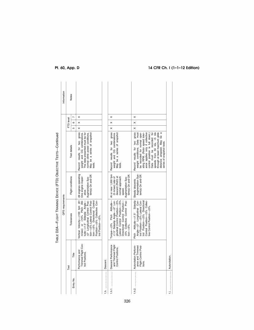
326
14 CFR Ch. I (1–1–12 Edition) Pt. 60, App. D
TA
BLE
D2A
—F
LIG
HT
TR
AIN
ING
DE
VIC
E(F
TD
) O
BJE
CT
IVE
TE
ST
S—
Con
tinue
d
QP
S r
equi
rem
ents
In
form
atio
n
Tes
t T
oler
ance
s F
light
con
ditio
ns
Tes
t de
tails
F
TD
leve
l N
otes
E
ntry
No.
T
itle
5 6
7
Per
form
ance
and
T
rimm
ed F
light
Con
-tr
ol P
ositi
ons.
Ver
tical
V
eloc
ity—
±100
fp
m
(61
m/s
ec)
or
±10%
P
itch
Atti
-tu
de—
±1.5
° S
ides
lip
Ang
le—
±2
° Lo
ngitu
dina
l C
ontr
ol
Pos
i-tio
n—±5
% L
ater
al C
ontr
ol P
osi-
tion—
±5%
D
irect
iona
l C
ontr
ol
Pos
ition
—±5
%
Col
lect
ive
Con
-tr
ol P
ositi
on—
±5%
.
All
engi
nes
oper
atin
g O
ne e
ngin
e in
oper
-at
ive.
Aug
men
tatio
n S
ys-
tem
(s)
On
and
Off.
Rec
ord
resu
lts
for
two
gros
s w
eigh
t an
d C
G
com
bina
tions
. T
he d
ata
pres
ente
d m
ust
be f
or
norm
al c
limb
pow
er c
ondi
tions
. M
ay
be
a se
ries
of
snap
shot
te
sts.
X
X
X
1.h.
......
......
......
......
Des
cent
.
1.h.
1....
......
......
......
Des
cent
Per
form
ance
an
d T
rimm
ed F
light
C
ontr
ol P
ositi
ons.
Tor
que—
±3%
P
itch
Atti
tude
—
±1.5
° S
ides
lip A
ngle
—±2
° Lo
n-gi
tudi
nal
Con
trol
Pos
ition
—±5
%
Late
ral
Con
trol
P
ositi
on—
±5%
D
irect
iona
l C
ontr
ol
Pos
ition
—
±5%
C
olle
ctiv
e C
ontr
ol
Pos
i-tio
n—±5
%.
At
or n
ear
1,00
0 fp
m
(5 m
/sec
) ra
te o
f de
scen
t (R
oD)
at
norm
al a
ppro
ach
spee
d.A
ugm
enta
tion
Sys
-te
m(s
) O
n an
d O
ff.
Rec
ord
resu
lts
for
two
gros
s w
eigh
t an
d C
G
com
bina
tions
. M
ay
be
a se
ries
of
snap
shot
te
sts.
X
X
X
1.h.
2....
......
......
......
Aut
orot
atio
n P
erfo
rm-
ance
and
Trim
med
F
light
Con
trol
Pos
i-tio
ns.
Pitc
h A
ttitu
de—
±1.5
° S
ides
lip
Ang
le—
±2°
Long
itudi
nal
Con
-tr
ol P
ositi
on—
±5%
Lat
eral
Con
-tr
ol
Pos
ition
—±5
%
Dire
ctio
nal
Con
trol
P
ositi
on—
±5%
C
olle
c-tiv
e C
ontr
ol P
ositi
on—
±5%
.
Ste
ady
desc
ents
. A
ugm
enta
tion
Sys
-te
m(s
) O
n an
d O
ff.
Rec
ord
resu
lts
for
two
gros
s w
eigh
t co
nditi
ons.
D
ata
mus
t be
re
cord
ed
for
norm
al
oper
-at
ing
RP
M.
(Rot
or s
peed
tol
er-
ance
ap
plie
s on
ly
if co
llect
ive
cont
rol
posi
tion
is
full
dow
n.)
Dat
a m
ust
be
reco
rded
fo
r sp
eeds
fr
om
50
kts,
±5
kt
s th
roug
h at
lea
st m
axim
um g
lide
dist
ance
ai
rspe
ed.
May
be
a
serie
s of
sna
psho
t te
sts.
X
X
X
1.i.
......
......
......
......
..A
utor
otat
ion.
VerDate Mar<15>2010 18:16 Mar 01, 2012 Jkt 226045 PO 00000 Frm 00336 Fmt 8010 Sfmt 8002 Q:\14\14V2 ofr150 PsN: PC150

327
Federal Aviation Administration, DOT Pt. 60, App. D
Ent
ry...
......
......
......
......
...R
otor
Spe
ed—
±3%
Pitc
h A
ttitu
de
±2°
Rol
l A
ttitu
de—
±3°
Yaw
Atti
-tu
de—
±5°
Airs
peed
—±5
kt
s.
Ver
tical
V
eloc
ity—
±200
fp
m
(1.0
0 m
/sec
) or
10%
.
Cru
ise;
or
Clim
b...
....
Rec
ord
resu
lts o
f a
rapi
d th
rottl
e re
duct
ion
to
idle
. If
acco
m-
plis
hed
in c
ruis
e, r
esul
ts m
ust
be f
or t
he m
axim
um r
ange
air-
spee
d.
If ac
com
plis
hed
in
clim
b,
resu
lts
mus
t be
fo
r th
e m
axim
um
rate
of
cl
imb
air-
spee
d at
or
ne
ar
max
imum
co
ntin
uous
pow
er.
X
X
1.j.
......
......
......
......
..La
ndin
g.
1.j.1
....
......
......
......
..A
ll E
ngin
es...
......
......
.....
Airs
peed
—±3
kts
, A
ltitu
de—
±20
ft (6
.1
m)
Tor
que—
±3%
, R
otor
S
peed
—±1
.5%
, P
itch
Atti
tude
—
±1.5
°,
Ban
k A
ttitu
de—
±1.5
°,
Hea
ding
—±2
°,
Long
itudi
nal
Con
trol
P
ositi
on—
±10%
, La
t-er
al
Con
trol
P
ositi
on—
±10%
, D
irect
iona
l C
ontr
ol
Pos
ition
—
±10%
, C
olle
ctiv
e C
ontr
ol P
osi-
tion—
±10%
.
App
roac
h...
......
......
...R
ecor
d re
sults
of
th
e ap
proa
ch
and
land
ing
prof
ile
(run
ning
la
ndin
g or
ap
proa
ch
to
a ho
ver)
. T
he c
riter
ia a
pply
onl
y to
tho
se s
egm
ents
at
airs
peed
s ab
ove
effe
ctiv
e tr
ansl
atio
nal
lift.
Rec
ord
the
resu
lts f
rom
200
ft
AG
L (6
1 m
) to
the
lan
ding
or
to
whe
re t
he h
over
is
esta
blis
hed
prio
r to
land
ing.
X
1.j.2
. th
roug
h 1.
j.3R
eser
ved.
VerDate Mar<15>2010 18:16 Mar 01, 2012 Jkt 226045 PO 00000 Frm 00337 Fmt 8010 Sfmt 8002 Q:\14\14V2 ofr150 PsN: PC150

328
14 CFR Ch. I (1–1–12 Edition) Pt. 60, App. D
TA
BLE
D2A
—F
LIG
HT
TR
AIN
ING
DE
VIC
E(F
TD
) O
BJE
CT
IVE
TE
ST
S—
Con
tinue
d
QP
S r
equi
rem
ents
In
form
atio
n
Tes
t T
oler
ance
s F
light
con
ditio
ns
Tes
t de
tails
F
TD
leve
l N
otes
E
ntry
No.
T
itle
5 6
7
1.j.4
....
......
......
......
..A
utor
otat
iona
l Lan
ding
..T
orqu
e—±3
%,
Rot
or
Spe
ed—
±3
%,
Ver
tical
V
eloc
ity—
±100
fp
m (
0.50
m/s
ec)
or 1
0%,
Pitc
h A
ttitu
de—
±2°,
B
ank
Atti
tude
—
±2°,
H
eadi
ng—
±5°,
Lo
ngitu
-di
nal
Con
trol
P
ositi
on—
±10%
, La
tera
l C
ontr
ol
Pos
ition
—
±10%
, D
irect
iona
l C
ontr
ol P
osi-
tion—
±10%
, C
olle
ctiv
e C
ontr
ol
Pos
ition
—±1
0%.
Land
ing
......
......
......
...R
ecor
d th
e re
sults
of
an
au
toro
tatio
nal
dece
lera
tion
and
land
ing
from
a
stab
ilize
d au
toro
tatio
nal
desc
ent,
to t
ouch
do
wn.
X
If fli
ght
test
dat
a co
ntai
ning
al
l req
uire
d pa
ram
eter
s fo
r a
com
plet
e po
wer
-off
land
ing
is n
ot a
vaila
ble
from
the
airc
raft
man
u-fa
ctur
er f
or t
his
test
, an
d ot
her
qual
ified
flig
ht t
est
pers
onne
l are
not
ava
il-ab
le t
o ac
quire
thi
s da
ta,
the
spon
sor
mus
t co
ordi
-na
te w
ith t
he N
SP
M t
o de
term
ine
if it
wou
ld b
e ap
prop
riate
to
acce
pt a
l-te
rnat
ive
test
ing
mea
ns.
Alte
rnat
ive
appr
oach
es t
o th
is d
ata
acqu
isiti
on t
hat
may
be
acce
ptab
le a
re:
(1)
A s
imul
ated
au
toro
tatio
nal f
lare
and
re
duct
ion
of r
ate
of d
e-sc
ent
(RO
D)
at a
ltitu
de;
or (
2) a
pow
er-o
n te
rmi-
natio
n fo
llow
ing
an
auto
rota
tiona
l app
roac
h an
d fla
re.
2.
Han
dlin
g Q
ual
itie
s
2.a.
......
......
......
......
Con
trol
Sys
tem
Mec
han-
ical
Cha
ract
eris
tics.
Con
tact
the
NS
PM
for
cla
rific
atio
n of
an
y is
sue
rega
rdin
g he
li-co
pter
s w
ith r
ever
sibl
e co
ntro
ls.
2.a.
1....
......
......
......
Cyc
lic...
......
......
......
......
..B
reak
out—
±0.2
5 lb
s (0
.112
daN
) or
25%
. F
orce
—±1
.0 l
b (0
.224
da
N)
or 1
0%.
Gro
und;
Sta
tic c
ondi
-tio
ns.
Trim
On
and
Off.
Fric
tion
Off.
A
ugm
enta
tion
On
and
Off.
Rec
ord
resu
lts
for
an
unin
ter-
rupt
ed
cont
rol
swee
p to
th
e st
ops.
(T
his
test
doe
s no
t ap
ply
if ai
rcra
ft ha
rdw
are
mod
ular
co
ntro
llers
are
use
d.).
X
X
X
VerDate Mar<15>2010 18:16 Mar 01, 2012 Jkt 226045 PO 00000 Frm 00338 Fmt 8010 Sfmt 8002 Q:\14\14V2 ofr150 PsN: PC150

329
Federal Aviation Administration, DOT Pt. 60, App. D
2.a.
2....
......
......
......
Col
lect
ive
and
Ped
als
...B
reak
out—
±0.5
lb
(0.2
24 d
aN)
or
25%
. F
orce
—±1
.0
lb
(0.2
24
daN
) or
10%
.
Gro
und;
Sta
tic c
ondi
-tio
ns.
Trim
On
and
Off.
Fric
tion
Off.
A
ugm
enta
tion
On
and
Off.
Rec
ord
resu
lts
for
an
unin
ter-
rupt
ed
cont
rol
swee
p to
th
e st
ops.
X
X
X
2.a.
3....
......
......
......
Bra
ke P
edal
For
ce v
s.
Pos
ition
.±5
lbs
(2.2
24 d
aN)
or 1
0%...
......
.G
roun
d; S
tatic
con
di-
tions
....
......
......
......
......
......
......
......
......
....
X
X
X
2.a.
4....
......
......
......
Trim
Sys
tem
Rat
e (a
ll ap
plic
able
sys
tem
s).
Rat
e—±1
0%...
......
......
......
......
......
Gro
und;
Sta
tic c
ondi
-tio
ns.
Trim
On.
F
rictio
n O
ff.
The
tol
eran
ce a
pplie
s to
the
re-
cord
ed v
alue
of
the
trim
rat
e.X
X
X
2.a.
5....
......
......
......
Con
trol
Dyn
amic
s (a
ll ax
es).
±10%
of
time
for
first
zer
o cr
oss-
ing
and
±10
(N+
1)%
of
perio
d th
erea
fter.
±1
0%
of
ampl
itude
of
firs
t ov
ersh
oot.
±20%
of
am-
plitu
de o
f 2n
d an
d su
bseq
uent
ov
ersh
oots
gre
ater
tha
n 5%
of
initi
al
disp
lace
men
t. ±1
ov
er-
shoo
t.
Hov
er/C
ruis
e T
rim
On
Fric
tion
Off.
Res
ults
m
ust
be
reco
rded
fo
r a
norm
al c
ontr
ol d
ispl
acem
ent
in
both
di
rect
ions
in
ea
ch
axis
, us
ing
25%
to
50%
of
full
thro
w.
X
X
Con
trol
Dyn
amic
s fo
r irr
e-ve
rsib
le c
ontr
ol s
yste
ms
may
be
eval
uate
d in
a
grou
nd/s
tatic
con
ditio
n.
Ref
er t
o pa
ragr
aph
3 of
th
is a
ttach
men
t fo
r ad
di-
tiona
l inf
orm
atio
n. ‘‘
N’’
is
the
sequ
entia
l per
iod
of a
fu
ll cy
cle
of o
scill
atio
n.
2.a.
6....
......
......
......
Fre
epla
y...
......
......
......
...±0
.10
in.
(±2.
5 m
m)
......
......
......
....
Gro
und;
Sta
tic c
ondi
-tio
ns.
Rec
ord
and
com
pare
re
sults
fo
r al
l con
trol
s.X
X
X
2.b.
......
......
......
......
Low
Airs
peed
Han
dlin
g Q
ualit
ies.
2.b.
1....
......
......
......
Trim
med
Flig
ht C
ontr
ol
Pos
ition
s.T
orqu
e ±3
% P
itch
Atti
tude
±1.
5°
Ban
k A
ttitu
de ±
2° L
ongi
tudi
nal
Con
trol
P
ositi
on
±5%
La
tera
l C
ontr
ol
Pos
ition
±5
%
Dire
c-tio
nal
Con
trol
P
ositi
on
±5%
C
olle
ctiv
e C
ontr
ol P
ositi
on ±
5%.
Tra
nsla
tiona
l Flig
ht
IGE
—S
idew
ard,
re
arw
ard,
and
for
-w
ard
fligh
t. A
ug-
men
tatio
n O
n an
d O
ff.
Rec
ord
resu
lts
for
seve
ral
air-
spee
d in
crem
ents
to
th
e tr
ansl
atio
nal
airs
peed
lim
its a
nd
for
45
kts.
fo
rwar
d ai
rspe
ed.
May
be
a
serie
s of
sn
apsh
ot
test
s.
X
2.b.
2....
......
......
......
Crit
ical
Azi
mut
h...
......
....
Tor
que
±3%
Pitc
h A
ttitu
de ±
1.5°
, B
ank
Atti
tude
±2°
, Lo
ngitu
dina
l C
ontr
ol
Pos
ition
±5
%,
Late
ral
Con
trol
P
ositi
on
±5%
, D
irec-
tiona
l C
ontr
ol
Pos
ition
±5
%,
Col
lect
ive
Con
trol
Pos
ition
±5%
.
Sta
tiona
ry H
over
. A
ugm
enta
tion
On
and
Off.
Rec
ord
resu
lts
for
thre
e re
lativ
e w
ind
dire
ctio
ns
(incl
udin
g th
e m
ost
criti
cal
case
) in
the
crit
ical
qu
adra
nt.
May
be
a
serie
s of
sn
apsh
ot t
ests
.
X
2.b.
3....
......
......
......
Con
trol
Res
pons
e.
VerDate Mar<15>2010 18:16 Mar 01, 2012 Jkt 226045 PO 00000 Frm 00339 Fmt 8010 Sfmt 8002 Q:\14\14V2 ofr150 PsN: PC150

330
14 CFR Ch. I (1–1–12 Edition) Pt. 60, App. D
TA
BLE
D2A
—F
LIG
HT
TR
AIN
ING
DE
VIC
E(F
TD
) O
BJE
CT
IVE
TE
ST
S—
Con
tinue
d
QP
S r
equi
rem
ents
In
form
atio
n
Tes
t T
oler
ance
s F
light
con
ditio
ns
Tes
t de
tails
F
TD
leve
l N
otes
E
ntry
No.
T
itle
5 6
7
2.b.
3.a.
......
......
......
Long
itudi
nal
......
......
......
.P
itch
Rat
e—±1
0%
or
±2°/
sec.
P
itch
Atti
tude
C
hang
e—±1
0%
or 1
.5°.
Hov
er.
Aug
men
tatio
n O
n an
d O
ff.R
ecor
d re
sults
for
a s
tep
cont
rol
inpu
t. T
he
Off-
axis
re
spon
se
mus
t sh
ow c
orre
ct t
rend
for
un-
augm
ente
d ca
ses.
T
his
test
m
ust
be c
ondu
cted
in
a ho
ver,
in
gro
und
effe
ct,
with
out
ente
r-in
g tr
ansl
atio
nal f
light
.
X
Thi
s is
a ‘‘
shor
t tim
e’’ t
est.
2.b.
3.b.
......
......
......
Late
ral
......
......
......
......
...R
oll
Rat
e—±1
0% o
r ±3
°/se
c. R
oll
Atti
tude
Cha
nge—
±10%
or
±3°.
Hov
er A
ugm
enta
tion
On
and
Off.
Rec
ord
resu
lts f
or a
ste
p co
ntro
l in
put.
The
O
ff-ax
is
resp
onse
m
ust
show
cor
rect
tre
nd f
or u
n-au
gmen
ted
case
s.
X
Thi
s is
a ‘‘
shor
t tim
e’’ t
est
cond
ucte
d in
a h
over
, in
gr
ound
effe
ct,
with
out
en-
terin
g tr
ansl
atio
nal f
light
, to
pro
vide
bet
ter
visu
al
refe
renc
e.
2.b.
3.c.
......
......
......
.D
irect
iona
l...
......
......
......
Yaw
R
ate—
±10%
or
±2
°/se
c.
Hea
ding
Cha
nge—
±10%
or
±2°.
Hov
er A
ugm
enta
tion
On
and
Off.
Rec
ord
resu
lts f
or a
ste
p co
ntro
l in
put.
The
O
ff-ax
is
resp
onse
m
ust
show
cor
rect
tre
nd f
or u
n-au
gmen
ted
case
s.
Thi
s te
st
mus
t be
con
duct
ed i
n a
hove
r,
in g
roun
d ef
fect
, w
ithou
t en
ter-
ing
tran
slat
iona
l flig
ht.
X
Thi
s is
a ‘‘
shor
t tim
e’’ t
est.
2.b.
3.d.
......
......
......
Ver
tical
......
......
......
......
..N
orm
al A
ccel
erat
ion
±0.1
g...
......
..H
over
Aug
men
tatio
n O
n an
d O
ff.R
ecor
d re
sults
for
a s
tep
cont
rol
inpu
t. T
he
Off-
axis
re
spon
se
mus
t sh
ow c
orre
ct t
rend
for
un-
augm
ente
d ca
ses.
X
2.c.
......
......
......
......
.Lo
ngitu
dina
l Han
dlin
g Q
ualit
ies.
2.c.
1....
......
......
......
.C
ontr
ol R
espo
nse
......
...P
itch
Rat
e—±1
0%
or
±2°/
sec.
P
itch
Atti
tude
C
hang
e—±1
0%
or ±
1.5°
.
Cru
ise
Aug
men
tatio
n O
n an
d O
ff.R
esul
ts m
ust
be r
ecor
ded
for
two
crui
se a
irspe
eds
to in
clud
e m
in-
imum
po
wer
re
quire
d sp
eed.
R
ecor
d da
ta f
or a
ste
p co
ntro
l in
put.
The
O
ff-ax
is
resp
onse
m
ust
show
cor
rect
tre
nd f
or u
n-au
gmen
ted
case
s.
X
X
X
VerDate Mar<15>2010 18:16 Mar 01, 2012 Jkt 226045 PO 00000 Frm 00340 Fmt 8010 Sfmt 8002 Q:\14\14V2 ofr150 PsN: PC150

331
Federal Aviation Administration, DOT Pt. 60, App. D
2.c.
2....
......
......
......
.S
tatic
Sta
bilit
y...
......
......
.Lo
ngitu
dina
l C
ontr
ol
Pos
ition
: ±1
0%
of
chan
ge
from
tr
im
or
±0.2
5 in
. (6
.3 m
m)
or L
ongi
tu-
dina
l C
ontr
ol
For
ce:
±0.5
lb
. (0
.223
daN
) or
±10
%.
Cru
ise
or C
limb.
A
utor
otat
ion.
Aug
-m
enta
tion
On
and
Off.
Rec
ord
resu
lts f
or a
min
imum
of
two
spee
ds o
n ea
ch s
ide
of t
he
trim
spe
ed.
May
be
a se
ries
of
snap
shot
tes
ts.
X
X
X
2.c.
3....
......
......
......
.D
ynam
ic S
tabi
lity.
2.c.
3.a.
......
......
......
.Lo
ng T
erm
Res
pons
e...
±10%
of
calc
ulat
ed p
erio
d. ±
10%
of
tim
e to
1⁄2
or d
oubl
e am
pli-
tude
, or
±0.
02 o
f da
mpi
ng r
atio
. F
or n
on-p
erio
dic
resp
onse
s, t
he
time
hist
ory
mus
t be
m
atch
ed
with
in ±
3° p
itch;
and
±5
kts
air-
spee
d ov
er a
20
sec
perio
d fo
l-lo
win
g re
leas
e of
the
con
trol
s.
Cru
ise
Aug
men
tatio
n O
n an
d O
ff.R
ecor
d re
sults
fo
r th
ree
full
cy-
cles
(6
ov
ersh
oots
af
ter
inpu
t co
mpl
eted
) or
tha
t su
ffici
ent
to
dete
rmin
e tim
e to
1⁄2
or d
oubl
e am
plitu
de,
whi
chev
er
is
less
. F
or n
on-p
erio
dic
resp
onse
s, t
he
test
may
be
term
inat
ed p
rior
to
20
sec
if th
e te
st
pilo
t de
ter-
min
es t
hat
the
resu
lts a
re b
e-co
min
g un
cont
rolla
bly
dive
r-ge
nt.
Dis
plac
e th
e cy
clic
fo
r on
e se
cond
or
le
ss
to
exci
te
the
test
. T
he r
esul
t w
ill b
e ei
-th
er
conv
erge
nt
or
dive
rgen
t an
d m
ust
be
reco
rded
. If
this
m
etho
d fa
ils t
o ex
cite
the
tes
t, di
spla
ce t
he c
yclic
to
the
pre-
dete
rmin
ed
max
imum
de
sire
d pi
tch
attit
ude
and
retu
rn t
o th
e or
igin
al p
ositi
on.
If th
is m
etho
d is
use
d, r
ecor
d th
e re
sults
.
X
X
X
The
res
pons
e fo
r ce
rtai
n he
licop
ters
may
be
unre
peat
able
thr
ough
out
the
stat
ed t
ime.
In
thes
e ca
ses,
the
tes
t sh
ould
sh
ow a
t le
ast
that
a d
i-ve
rgen
ce is
iden
tifia
ble.
F
or e
xam
ple:
Dis
plac
ing
the
cycl
ic f
or a
giv
en t
ime
norm
ally
exc
ites
this
tes
t or
unt
il a
give
n pi
tch
atti-
tude
is a
chie
ved
and
then
ret
urn
the
cycl
ic t
o th
e or
igin
al p
ositi
on.
For
no
n-pe
riodi
c re
spon
ses,
re
sults
sho
uld
show
the
sa
me
conv
erge
nt o
r di
-ve
rgen
t ch
arac
ter
as t
he
fligh
t te
st d
ata.
2.c.
3.b.
......
......
......
.S
hort
Ter
m R
espo
nse
...±1
.5°
Pitc
h or
±2
°/se
c.
Pitc
h R
ate.
±0.
1 g
Nor
mal
Acc
eler
a-tio
n.
Cru
ise
or C
limb.
Aug
-m
enta
tion
On
and
Off.
Rec
ord
resu
lts f
or a
t le
ast
two
air-
spee
ds.
X
X
A c
ontr
ol d
oubl
et in
sert
ed
at t
he n
atur
al f
requ
ency
of
the
airc
raft
norm
ally
ex
cite
s th
is t
est.
How
-ev
er,
whi
le in
put
doub
lets
ar
e pr
efer
red
over
pul
se
inpu
ts f
or A
ugm
enta
tion-
O
ff te
sts,
for
Aug
men
ta-
tion-
On
case
s, w
hen
the
shor
t te
rm r
espo
nse
ex-
hibi
ts 1
st-o
rder
or
dead
-be
at c
hara
cter
istic
s, lo
n-gi
tudi
nal p
ulse
inpu
ts
may
pro
duce
a m
ore
co-
here
nt r
espo
nse.
VerDate Mar<15>2010 18:16 Mar 01, 2012 Jkt 226045 PO 00000 Frm 00341 Fmt 8010 Sfmt 8002 Q:\14\14V2 ofr150 PsN: PC150

332
14 CFR Ch. I (1–1–12 Edition) Pt. 60, App. D
TA
BLE
D2A
—F
LIG
HT
TR
AIN
ING
DE
VIC
E(F
TD
) O
BJE
CT
IVE
TE
ST
S—
Con
tinue
d
QP
S r
equi
rem
ents
In
form
atio
n
Tes
t T
oler
ance
s F
light
con
ditio
ns
Tes
t de
tails
F
TD
leve
l N
otes
E
ntry
No.
T
itle
5 6
7
2.c.
4....
......
......
......
.M
aneu
verin
g S
tabi
lity
....
Long
itudi
nal
Con
trol
P
ositi
on—
±1
0%
of
chan
ge
from
tr
im
or
±0.2
5 in
. (6
.3 m
m)
or L
ongi
tu-
dina
l C
ontr
ol
For
ces—
±0.5
lb
. (0
.223
daN
) or
±10
%.
Cru
ise
or C
limb.
Aug
-m
enta
tion
On
and
Off.
Rec
ord
resu
lts f
or a
t le
ast
two
air-
spee
ds a
t 30
°–45
° ba
nk a
ngle
. T
he f
orce
may
be
show
n as
a
cros
s pl
ot
for
irrev
ersi
ble
sys-
tem
s. M
ay b
e a
serie
s of
sna
p-sh
ot t
ests
.
X
X
2.d.
......
......
......
......
Late
ral a
nd D
irect
iona
l Han
dlin
g Q
ualit
ies.
2.d.
1....
......
......
......
Con
trol
Res
pons
e.
2.d.
1.a.
......
......
......
Late
ral
......
......
......
......
...R
oll
Rat
e—±1
0% o
r ±3
°/se
c. R
oll
Atti
tude
Cha
nge—
±10%
or
±3°.
Cru
ise
Aug
men
tatio
n O
n an
d O
ffd.
Rec
ord
resu
lts f
or a
t le
ast
two
air-
spee
ds,
incl
udin
g th
e sp
eed
at
or n
ear
the
min
imum
pow
er r
e-qu
ired
airs
peed
. R
ecor
d re
sults
fo
r a
step
co
ntro
l in
put.
The
O
ff-ax
is
resp
onse
m
ust
show
co
rrec
t tr
end
for
unau
gmen
ted
case
s.
X
X
X
2.d.
1.b.
......
......
......
Dire
ctio
nal
......
......
......
...Y
aw
Rat
e—±1
0%
or
±2°/
sec.
Y
aw A
ttitu
de C
hang
e—±1
0% o
r ±2
°.
Cru
ise
Aug
men
tatio
n O
n an
d O
ff.R
ecor
d da
ta f
or a
t le
ast
two
Air-
spee
ds,
incl
udin
g th
e sp
eed
at
or n
ear
the
min
imum
pow
er r
e-qu
ired
airs
peed
. R
ecor
d re
sults
fo
r a
step
co
ntro
l in
put.
The
O
ff-ax
is
resp
onse
m
ust
show
co
rrec
t tr
end
for
unau
gmen
ted
case
s.
X
X
X
VerDate Mar<15>2010 18:16 Mar 01, 2012 Jkt 226045 PO 00000 Frm 00342 Fmt 8010 Sfmt 8002 Q:\14\14V2 ofr150 PsN: PC150

333
Federal Aviation Administration, DOT Pt. 60, App. D
2.d.
2....
......
......
......
Dire
ctio
nal S
tatic
Sta
-bi
lity.
Late
ral
Con
trol
Pos
ition
—±1
0% o
f ch
ange
fr
om
trim
or
±0
.25
in.
(6.3
m
m)
or
Late
ral
Con
trol
F
orce
—±0
.5 l
b. (
0.22
3 da
N)
or
10%
. R
oll
Atti
tude
—±1
.5 D
irec-
tiona
l C
ontr
ol
Pos
ition
—±1
0%
of c
hang
e fr
om t
rim o
r ±0
.25
in.
(6.3
mm
) or
Dire
ctio
nal
Con
trol
F
orce
—±1
lb
. (0
.448
da
N)
or
10%
. Lo
ngitu
dina
l C
ontr
ol P
osi-
tion—
±10%
of
chan
ge f
rom
trim
or
±0.
25 i
n. (
6.3
mm
). V
ertic
al
Vel
ocity
—±1
00
fpm
(0
.50m
/ se
c) o
r 10
%.
Cru
ise;
or
Clim
b (m
ay u
se D
esce
nt
inst
ead
of C
limb
if de
sire
d) A
ug-
men
tatio
n O
n an
d O
ff.
Rec
ord
resu
lts
for
at
leas
t tw
o si
desl
ip a
ngle
s on
eith
er s
ide
of
the
trim
po
int.
The
fo
rce
may
be
sho
wn
as a
cro
ss p
lot
for
ir-re
vers
ible
sy
stem
s.
May
be
a
serie
s of
sna
psho
t te
sts.
X
X
X
Thi
s is
a s
tead
y he
adin
g si
desl
ip t
est
at a
fix
ed
colle
ctiv
e po
sitio
n.
2.d.
3....
......
......
......
Dyn
amic
Lat
eral
and
Dire
ctio
nal S
tabi
lity.
2.d.
3.a.
......
......
......
Late
ral-D
irect
iona
l Osc
il-la
tions
.±0
.5
sec.
or
±1
0%
of
perio
d.
±10%
of
time
to 1
⁄2or
dou
ble
ampl
itude
or
±0.0
2 of
dam
ping
ra
tio.
±20%
or
±1 s
ec o
f tim
e di
ffere
nce
betw
een
peak
s of
ba
nk a
nd s
ides
lip.
For
non
-per
i-od
ic r
espo
nses
, th
e tim
e hi
stor
y m
ust
be
mat
ched
w
ithin
±1
0 kn
ots
Airs
peed
; ±5
°/s
Rol
l R
ate
or ±
5° R
oll
Atti
tude
; ±4
°/s
Yaw
R
ate
or ±
4° Y
aw A
ngle
ove
r a
20
sec
perio
d ro
ll an
gle
fol-
low
ing
rele
ase
of t
he c
ontr
ols.
Cru
ise
or C
limb
Aug
-m
enta
tion
On
and
Off.
Rec
ord
resu
lts f
or a
t le
ast
two
air-
spee
ds.
The
tes
t m
ust
be i
niti-
ated
w
ith
a cy
clic
or
a
peda
l do
uble
t in
put.
Rec
ord
resu
lts
for
six
full
cycl
es
(12
over
-sh
oots
afte
r in
put
com
plet
ed)
or
that
suf
ficie
nt t
o de
term
ine
time
to
1⁄2
or
doub
le
ampl
itude
, w
hich
ever
is
less
. T
he t
est
may
be
ter
min
ated
prio
r to
20
sec
if th
e te
st
pilo
t de
term
ines
th
at
the
resu
lts
are
beco
min
g un
-co
ntro
llabl
y di
verg
ent.
X
X
X
2.d.
3.b.
......
......
......
Spi
ral S
tabi
lity
......
......
...±2
° or
±10
% r
oll a
ngle
......
......
.....
Cru
ise
or C
limb.
Aug
-m
enta
tion
On
and
Off.
Rec
ord
the
resu
lts
of
a re
leas
e fr
om p
edal
onl
y or
cyc
lic o
nly
turn
s fo
r 20
sec
. R
esul
ts m
ust
be r
ecor
ded
from
tur
ns i
n bo
th
dire
ctio
ns.
Ter
min
ate
chec
k at
ze
ro r
oll
angl
e or
whe
n th
e te
st
pilo
t de
term
ines
th
at
the
atti-
tude
is
beco
min
g un
cont
rolla
bly
dive
rgen
t.
X
X
X
2.d.
3.c.
......
......
......
.A
dver
se/P
rove
rse
Yaw
..C
orre
ct T
rend
, ±2
° tr
ansi
ent
side
-sl
ip a
ngle
.C
ruis
e or
Clim
b. A
ug-
men
tatio
n O
n an
d O
ff.
Rec
ord
the
time
hist
ory
of i
nitia
l en
try
into
cy
clic
on
ly
turn
s,
usin
g on
ly a
mod
erat
e ra
te f
or
cycl
ic
inpu
t. R
esul
ts
mus
t be
re
cord
ed f
or t
urns
in b
oth
dire
c-tio
ns.
X
X
X
3.
Res
erve
d
VerDate Mar<15>2010 18:16 Mar 01, 2012 Jkt 226045 PO 00000 Frm 00343 Fmt 8010 Sfmt 8002 Q:\14\14V2 ofr150 PsN: PC150

334
14 CFR Ch. I (1–1–12 Edition) Pt. 60, App. D
TA
BLE
D2A
—F
LIG
HT
TR
AIN
ING
DE
VIC
E(F
TD
) O
BJE
CT
IVE
TE
ST
S—
Con
tinue
d
QP
S r
equi
rem
ents
In
form
atio
n
Tes
t T
oler
ance
s F
light
con
ditio
ns
Tes
t de
tails
F
TD
leve
l N
otes
E
ntry
No.
T
itle
5 6
7
4.
Vis
ual
Sys
tem
4.a.
......
......
......
......
Vis
ual S
yste
m R
espo
nse
Tim
e: (
Cho
ose
eith
er t
est
4.a.
1. o
r 4.
a.2.
to
satis
fy t
est
4.a.
, V
isua
l Sys
tem
Res
pons
e T
ime
Tes
t. T
his
test
is a
lso
suffi
cien
t fo
r fli
ght
deck
inst
rum
ent
resp
onse
tim
ing.
) ...
....
.
4.a.
1....
......
......
......
Late
ncy.
150
ms
(or
less
) af
ter
helic
opte
r re
spon
se.
Tak
eoff,
clim
b, a
nd
desc
ent.
One
tes
t is
req
uire
d in
eac
h ax
is
(pitc
h, r
oll
and
yaw
) fo
r ea
ch o
f th
e th
ree
cond
ition
s (t
ake-
off,
crui
se,
and
appr
oach
or
la
nd-
ing)
.
X
4.a.
2....
......
......
......
Tra
nspo
rt D
elay
.
150
ms
(or
less
) af
ter
cont
rolle
r m
ovem
ent.
N/A
......
......
......
......
...A
se
para
te
test
is
re
quire
d in
ea
ch a
xis
(pitc
h, r
oll,
and
yaw
).X
4.b.
......
......
......
......
Fie
ld-o
f-vi
ew.
4.b.
1....
......
......
......
Res
erve
d.
4.b.
2....
......
......
......
Con
tinuo
us v
isua
l fie
ld-
of-v
iew
.M
inim
um c
ontin
uous
fie
ld-o
f-vi
ew
prov
idin
g 14
6°
horiz
onta
l an
d 36
° ve
rtic
al
field
-of-
view
fo
r ea
ch
pilo
t si
mul
tane
ousl
y an
d an
y ge
omet
ric
erro
r be
twee
n th
e Im
age
Gen
erat
or e
ye p
oint
an
d th
e pi
lot
eye
poin
t is
8°
or
less
.
N/A
......
......
......
......
...A
n S
OC
is
requ
ired
and
mus
t ex
-pl
ain
the
geom
etry
of
the
inst
al-
latio
n.
Hor
izon
tal
field
-of-
view
m
ust
not
be l
ess
than
a t
otal
of
146°
(in
clud
ing
not
less
th
an
73°
mea
sure
d ei
ther
sid
e of
the
ce
nter
of
the
desi
gn e
ye p
oint
).
Add
ition
al
horiz
onta
l fie
ld-o
f-
view
ca
pabi
lity
may
be
ad
ded
at t
he s
pons
or’s
dis
cret
ion
pro-
vide
d th
e m
inim
um f
ield
-of-
view
is
re
tain
ed.
Ver
tical
fie
ld-o
f-
view
: N
ot l
ess
than
a t
otal
of
36°
mea
sure
d fr
om
the
pilo
t’s
and
co-p
ilot’s
eye
poi
nt.
X
Hor
izon
tal f
ield
-of-
view
is
cent
ered
on
the
zero
de-
gree
azi
mut
h lin
e re
lativ
e to
the
airc
raft
fuse
lage
.
4.b.
3....
......
......
......
Res
erve
d.
VerDate Mar<15>2010 18:16 Mar 01, 2012 Jkt 226045 PO 00000 Frm 00344 Fmt 8010 Sfmt 8002 Q:\14\14V2 ofr150 PsN: PC150

335
Federal Aviation Administration, DOT Pt. 60, App. D
4.c.
......
......
......
......
.S
urfa
ce c
ontr
ast
ratio
....
Not
less
tha
n 5:
1...
......
......
......
.....
N/A
......
......
......
......
...T
he r
atio
is
calc
ulat
ed b
y di
vidi
ng
the
brig
htne
ss l
evel
of
the
cen-
ter,
brig
ht s
quar
e (p
rovi
ding
at
leas
t 2
foot
-lam
bert
s or
7
cd/
m2)
by t
he b
right
ness
lev
el o
f an
y ad
jace
nt d
ark
squa
re.
X
Mea
sure
men
ts m
ay b
e m
ade
usin
g a
1° s
pot
phot
omet
er a
nd a
ras
ter
draw
n te
st p
atte
rn f
illin
g th
e en
tire
visu
al s
cene
(a
ll ch
anne
ls)
with
a t
est
patte
rn o
f bl
ack
and
whi
te s
quar
es,
5 pe
r sq
uare
, w
ith a
whi
te
squa
re in
the
cen
ter
of
each
cha
nnel
. D
urin
g co
ntra
st r
atio
tes
ting,
si
mul
ator
aft-
cab
and
fligh
t de
ck a
mbi
ent
light
le
vels
sho
uld
be z
ero.
4.d.
......
......
......
......
Hig
hlig
ht b
right
ness
......
.N
ot l
ess
than
thr
ee (
3) f
oot-
lam
-be
rts
(10
cd/m
2).
N/A
......
......
......
......
...M
easu
re
the
brig
htne
ss
of
the
cent
er
whi
te
squa
re
whi
le
supe
rimpo
sing
a
high
light
on
th
at w
hite
squ
are.
The
use
of
calli
grap
hic
capa
bilit
ies
to
en-
hanc
e th
e ra
ster
brig
htne
ss i
s ac
cept
able
, bu
t m
easu
ring
light
po
ints
is n
ot a
ccep
tabl
e.
X
Mea
sure
men
ts m
ay b
e m
ade
usin
g a
1° s
pot
phot
omet
er a
nd a
ras
ter
draw
n te
st p
atte
rn f
illin
g th
e en
tire
visu
al s
cene
(a
ll ch
anne
ls)
with
a t
est
patte
rn o
f bl
ack
and
whi
te s
quar
es,
5 pe
r sq
uare
, w
ith a
whi
te
squa
re in
the
cen
ter
of
each
cha
nnel
.
4.e.
......
......
......
......
Sur
face
res
olut
ion
......
...N
ot g
reat
er t
han
two
(2)
arc
min
-ut
es.
N/A
......
......
......
......
...A
n S
OC
is
requ
ired
and
mus
t in
-cl
ude
the
rele
vant
cal
cula
tions
.X
W
hen
the
eye
is p
ositi
oned
on
a 3
° gl
ide
slop
e at
the
sl
ant
rang
e di
stan
ces
in-
dica
ted
with
whi
te r
un-
way
mar
king
s on
a b
lack
ru
nway
sur
face
, th
e ey
e w
ill s
ubte
nd t
wo
(2)
arc
min
utes
: (1
) A
sla
nt
rang
e of
6,8
76 f
t w
ith
strip
es 1
50 f
t lo
ng a
nd 1
6 ft
wid
e, s
pace
d 4
ft ap
art.
(2)
For
Con
figur
atio
n A
; a
slan
t ra
nge
of 5
,157
fee
t w
ith s
trip
es 1
50 f
t lo
ng
and
12 f
t w
ide,
spa
ced
3 ft
apar
t. (3
) F
or C
onfig
u-ra
tion
B;
a sl
ant
rang
e of
9,
884
feet
, w
ith s
trip
es
150
ft lo
ng a
nd 5
.75
ft w
ide,
spa
ced
5.75
ft
apar
t.
VerDate Mar<15>2010 18:16 Mar 01, 2012 Jkt 226045 PO 00000 Frm 00345 Fmt 8010 Sfmt 8002 Q:\14\14V2 ofr150 PsN: PC150

336
14 CFR Ch. I (1–1–12 Edition) Pt. 60, App. D
TA
BLE
D2A
—F
LIG
HT
TR
AIN
ING
DE
VIC
E(F
TD
) O
BJE
CT
IVE
TE
ST
S—
Con
tinue
d
QP
S r
equi
rem
ents
In
form
atio
n
Tes
t T
oler
ance
s F
light
con
ditio
ns
Tes
t de
tails
F
TD
leve
l N
otes
E
ntry
No.
T
itle
5 6
7
4.f.
......
......
......
......
.Li
ght
poin
t si
ze...
......
.....
Not
gre
ater
tha
n fiv
e (5
) ar
c-m
in-
utes
.N
/A...
......
......
......
......
An
SO
C i
s re
quire
d an
d m
ust
in-
clud
e th
e re
leva
nt c
alcu
latio
ns.
X
Ligh
t po
int
size
may
be
mea
sure
d us
ing
a te
st
patte
rn c
onsi
stin
g of
a
cent
rally
loca
ted
sing
le
row
of
light
poi
nts
re-
duce
d in
leng
th u
ntil
mod
ulat
ion
is ju
st d
is-
cern
ible
in e
ach
visu
al
chan
nel.
A r
ow o
f 48
lig
hts
will
for
m a
4°
angl
e or
less
.
4.g.
......
......
......
......
Ligh
t po
int
cont
rast
rat
io
......
......
......
......
......
......
......
......
......
....
......
......
......
......
......
.....
......
......
......
......
......
......
......
......
....
A 1
° sp
ot p
hoto
met
er m
ay
be u
sed
to m
easu
re a
sq
uare
of
at le
ast
1° fi
lled
with
ligh
t po
ints
(w
here
lig
ht p
oint
mod
ulat
ion
is
just
dis
cern
ible
) an
d co
mpa
re t
he r
esul
ts t
o th
e m
easu
red
adja
cent
ba
ckgr
ound
. D
urin
g co
n-tr
ast
ratio
tes
ting,
sim
u-la
tor
aft-
cab
and
fligh
t de
ck a
mbi
ent
light
leve
ls
shou
ld b
e ze
ro.
4.g.
1....
......
......
......
Res
erve
d.
4.g.
2....
......
......
......
......
......
......
......
......
......
....
Not
less
tha
n 25
:1...
......
......
......
...N
/A...
......
......
......
......
An
SO
C i
s re
quire
d an
d m
ust
in-
clud
e th
e re
leva
nt c
alcu
latio
ns.
X
4.h.
......
......
......
......
Vis
ual g
roun
d se
gmen
t.
VerDate Mar<15>2010 18:16 Mar 01, 2012 Jkt 226045 PO 00000 Frm 00346 Fmt 8010 Sfmt 8002 Q:\14\14V2 ofr150 PsN: PC150

337
Federal Aviation Administration, DOT Pt. 60, App. D
The
vis
ible
seg
men
t in
the
sim
u-la
tor
mus
t be
with
in 2
0% o
f th
e se
gmen
t co
mpu
ted
to b
e vi
sibl
e fr
om t
he h
elic
opte
r fli
ght
deck
. T
he
tole
ranc
e(s)
m
ay
be
ap-
plie
d at
ei
ther
en
d or
at
bo
th
ends
of
the
disp
laye
d se
gmen
t. H
owev
er,
light
s an
d gr
ound
ob-
ject
s co
mpu
ted
to
be
visi
ble
from
th
e he
licop
ter
fligh
t de
ck
at t
he n
ear
end
of t
he v
isib
le
segm
ent
mus
t be
vis
ible
in
the
sim
ulat
or.
Land
ing
conf
igur
a-tio
n, t
rimm
ed f
or
appr
opria
te a
ir-sp
eed,
at
100
ft (3
0m)
abov
e th
e to
uchd
own
zone
, on
glid
e sl
ope
with
an
RV
R v
alue
set
at
1,2
00 f
t (3
50m
).
The
Q
TG
m
ust
cont
ain
rele
vant
ca
lcul
atio
ns
and
a dr
awin
g sh
owin
g th
e da
ta
used
to
es
-ta
blis
h th
e he
licop
ter
loca
tion
and
the
segm
ent
of t
he g
roun
d th
at
is
visi
ble
cons
ider
ing
de-
sign
ey
epoi
nt,
helic
opte
r at
ti-tu
de,
fligh
t de
ck
cut-
off
angl
e,
and
a vi
sibi
lity
of 1
200
ft (3
50
m)
RV
R.
Sim
ulat
or
perf
orm
-an
ce
mus
t be
m
easu
red
agai
nst
the
QT
G
calc
ulat
ions
. T
he
data
su
bmitt
ed
mus
t in
-cl
ude
at l
east
the
fol
low
ing:
(1)
S
tatic
hel
icop
ter
dim
ensi
ons
as
follo
ws:
(i)
H
oriz
onta
l an
d ve
rtic
al
dist
ance
fr
om
mai
n la
ndin
g ge
ar
(MLG
) to
gl
ides
lope
re
cept
ion
ante
nna.
(ii
) H
oriz
onta
l an
d ve
rtic
al d
is-
tanc
e fr
om
MLG
to
pi
lot’s
ey
epoi
nt.
(iii)
Sta
tic f
light
dec
k cu
toff
angl
e. (
2) A
ppro
ach
data
as
fo
llow
s:
(i)
Iden
tific
atio
n of
ru
nway
. (ii
) H
oriz
onta
l di
stan
ce
from
ru
nway
th
resh
old
to
glid
eslo
pe
inte
rcep
t w
ith
run-
way
. (ii
i) G
lides
lope
ang
le.
(iv)
Hel
icop
ter
pitc
h an
gle
on
ap-
proa
ch.
(3)
Hel
icop
ter
data
for
m
anua
l te
stin
g:
(i)
Gro
ss
wei
ght.
(ii)
Hel
icop
ter
conf
igur
a-tio
n. (
iii)
App
roac
h ai
rspe
ed.
If no
n-ho
mog
enou
s fo
g is
use
d to
ob
scur
e vi
sibi
lity,
th
e ve
rtic
al
varia
tion
in
horiz
onta
l vi
sibi
lity
mus
t be
des
crib
ed a
nd b
e in
-cl
uded
in
the
slan
t ra
nge
visi
-bi
lity
calc
ulat
ion
used
in
th
e co
mpu
tatio
ns.
X
Pre
-pos
ition
for
thi
s te
st is
en
cour
aged
, bu
t m
ay b
e ac
hiev
ed v
ia m
anua
l or
auto
pilo
t co
ntro
l to
the
desi
red
posi
tion.
5.
Res
erve
d
VerDate Mar<15>2010 18:16 Mar 01, 2012 Jkt 226045 PO 00000 Frm 00347 Fmt 8010 Sfmt 8002 Q:\14\14V2 ofr150 PsN: PC150

338
14 CFR Ch. I (1–1–12 Edition) Pt. 60, App. D
lllllllllllllllllllllll
BEGIN INFORMATION
3. CONTROL DYNAMICS
a. The characteristics of a helicopter flight control system have a major effect on the handling qualities. A significant consider-ation in pilot acceptability of a helicopter is the ‘‘feel’’ provided through the flight deck controls. Considerable effort is expended on helicopter feel system design in order to de-liver a system with which pilots will be com-fortable and consider the helicopter desir-able to fly. In order for an FTD to be rep-resentative, it too must present the pilot with the proper feel; that of the respective helicopter. Compliance with this require-ment is determined by comparing a record-ing of the control feel dynamics of the FFS to actual helicopter measurements in the hover and cruise configurations.
(1) Recordings such as free response to an impulse or step function are classically used to estimate the dynamic properties of electromechanical systems. It is only pos-sible to estimate the dynamic properties as a result of only being able to estimate true in-puts and responses. Therefore, it is impera-tive that the best possible data be collected since close matching of the FTD control loading system to the helicopter systems is essential. Control feel dynamic tests are de-scribed in the Table of Objective Tests in this appendix. Where accomplished, the free response is measured after a step or pulse input is used to excite the system.
(2) For initial and upgrade evaluations, it is required that control dynamic characteris-tics be measured at and recorded directly from the flight deck controls. This procedure is usually accomplished by measuring the free response of the controls using a step or pulse input to excite the system. The proce-dure must be accomplished in hover, climb, cruise, and autorotation. For helicopters with irreversible control systems, measure-ments may be obtained on the ground. The procedure should be accomplished in the hover and cruise flight conditions and con-figurations. Proper pitot-static inputs (if ap-propriate) must be provided to represent air-speeds typical of those encountered in flight.
(3) It may be shown that for some heli-copters, climb, cruise, and autorotation have like effects. Thus, some tests for one may suffice for some tests for another. If either or both considerations apply, engineering vali-dation or helicopter manufacturer rationale must be submitted as justification for ground tests or for eliminating a configura-tion. For FTDs requiring static and dynamic tests at the controls, special test fixtures will not be required during initial and up-grade evaluations if the sponsor’s QTG shows both test fixture results and the results of an alternative approach, such as computer plots
which were produced concurrently and show satisfactory agreement. Repeat of the alter-native method during the initial evaluation satisfies this test requirement.
b. Control Dynamics Evaluations. The dy-namic properties of control systems are often stated in terms of frequency, damping, and a number of other classical measure-ments which can be found in texts on control systems. In order to establish a consistent means of validating test results for FTD con-trol loading, criteria are needed that will clearly define the interpretation of the measurements and the tolerances to be ap-plied. Criteria are needed for both the under-damped system and the overdamped system, including the critically damped case. In the case of an underdamped system with very light damping, the system may be quantified in terms of frequency and damping. In criti-cally damped or overdamped systems, the frequency and damping is not readily meas-ured from a response time history. There-fore, some other measurement must be used.
(1) Tests to verify that control feel dynam-ics represent the helicopter must show that the dynamic damping cycles (free response of the control) match that of the helicopter within specified tolerances. The method of evaluating the response and the tolerance to be applied are described below for the under-damped and critically damped cases.
(a) Underdamped Response. Two measure-ments are required for the period, the time to first zero crossing (in case a rate limit is present) and the subsequent frequency of os-cillation. It is necessary to measure cycles on an individual basis in case there are non-uniform periods in the response. Each period will be independently compared to the re-spective period of the helicopter control sys-tem and, consequently, will enjoy the full tolerance specified for that period.
(b) The damping tolerance will be applied to overshoots on an individual basis. Care must be taken when applying the tolerance to small overshoots since the significance of such overshoots becomes questionable. Only those overshoots larger than 5 percent of the total initial displacement will be considered significant. The residual band, labeled T(Ad) on Figure 1 of this attachment is ±5 percent of the initial displacement amplitude, Ad, from the steady state value of the oscilla-tion. Oscillations within the residual band are considered insignificant. When com-paring simulator data to helicopter data, the process would begin by overlaying or align-ing the simulator and helicopter steady state values and then comparing amplitudes of os-cillation peaks, the time of the first zero crossing, and individual periods of oscilla-tion. To be satisfactory, the simulator must show the same number of significant over-shoots to within one when compared against
VerDate Mar<15>2010 18:16 Mar 01, 2012 Jkt 226045 PO 00000 Frm 00348 Fmt 8010 Sfmt 8002 Q:\14\14V2 ofr150 PsN: PC150
339
Federal Aviation Administration, DOT Pt. 60, App. D
the helicopter data. The procedure for evalu-ating the response is illustrated in Figure 1 of this attachment.
(c) Critically Damped and Overdamped Re-sponse. Due to the nature of critically damped responses (no overshoots), the time to reach 90 percent of the steady state (neu-tral point) value must be the same as the helicopter within ±10 percent. The simulator response must be critically damped also. Figure 2 of this attachment illustrates the procedure.
(d) Special considerations. Control systems that exhibit characteristics other than clas-sical overdamped or underdamped responses should meet specified tolerances. In addi-tion, special consideration should be given to ensure that significant trends are main-tained.
(2) Tolerances.
(a) The following summarizes the toler-ances, ‘‘T’’ for underdamped systems, and ‘‘n’’ is the sequential period of a full cycle of oscillation. See Figure D2A of this attach-ment for an illustration of the referenced measurements.
T(P0) ±10% of P0 T(P1) ±20% of P1 T(P2) ±30% of P2 T(Pn) ±10(n+1)% of Pn T(An) ±10% of A1 T(Ad) ±5% of Ad = residual band Significant overshoots First overshoot and
±1 subsequent overshoots
(b) The following tolerance applies to criti-cally damped and overdamped systems only. See Figure D2B for an illustration of the ref-erence measurements:
T(P0) ±10% of P0
VerDate Mar<15>2010 18:16 Mar 01, 2012 Jkt 226045 PO 00000 Frm 00349 Fmt 8010 Sfmt 8002 Q:\14\14V2 ofr150 PsN: PC150

340
14 CFR Ch. I (1–1–12 Edition) Pt. 60, App. D
c. Alternative method for control dynam-ics evaluation.
(1) An alternative means for validating control dynamics for aircraft with hydrau-lically powered flight controls and artificial feel systems is by the measurement of con-
trol force and rate of movement. For each axis of pitch, roll, and yaw, the control must be forced to its maximum extreme position for the following distinct rates. These tests are conducted under normal flight and ground conditions.
VerDate Mar<15>2010 18:16 Mar 01, 2012 Jkt 226045 PO 00000 Frm 00350 Fmt 8010 Sfmt 8002 Q:\14\14V2 ofr150 PsN: PC150 ER
09M
Y08
.053
</G
PH
>
341
Federal Aviation Administration, DOT Pt. 60, App. D
(a) Static test—Slowly move the control so that a full sweep is achieved within 95–105 seconds. A full sweep is defined as movement of the controller from neutral to the stop, usually aft or right stop, then to the oppo-site stop, then to the neutral position.
(b) Slow dynamic test—Achieve a full sweep within 8–12 seconds.
(c) Fast dynamic test—Achieve a full sweep within 3–5 seconds.
NOTE: Dynamic sweeps may be limited to forces not exceeding 100 lbs. (44.5 daN).
(d) Tolerances. (i) Static test; see Table D2A, Flight Train-
ing Device (FTD) Objective Tests, Entries 2.a.1., 2.a.2., and 2.a.3.
(ii) Dynamic test—± 2 lbs (0.9 daN) or ± 10% on dynamic increment above static test.
END QPS REQUIREMENT
lllllllllllllllllllllll
BEGIN INFORMATION
d. The FAA is open to alternative means that are justified and appropriate to the ap-plication. For example, the method described here may not apply to all manufacturers’ systems and certainly not to aircraft with reversible control systems. Each case is con-sidered on its own merit on an ad hoc basis. If the FAA finds that alternative methods do not result in satisfactory performance, more conventionally accepted methods will have to be used.
4. FOR ADDITIONAL INFORMATION ON THE FOL-LOWING TOPICS, PLEASE REFER TO APPENDIX C OF THIS PART, ATTACHMENT 2, AND THE INDICATED PARAGRAPH WITHIN THAT AT-TACHMENT
• Additional Information About Flight Simulator Qualification for New or Deriva-tive Helicopters, paragraph 8.
• Engineering Simulator Validation Data, paragraph 9.
• Validation Test Tolerances, paragraph 11.
• Validation Data Road Map, paragraph 12. • Acceptance Guidelines for Alternative
Avionics, paragraph 13. • Transport Delay Testing, paragraph 15. • Continuing Qualification Evaluation Val-
idation Data Presentation, paragraph 16.
END INFORMATION
lllllllllllllllllllllll
ATTACHMENT 3 TO APPENDIX D TO PART 60— FLIGHT TRAINING DEVICE (FTD) SUB-JECTIVE EVALUATION
lllllllllllllllllllllll
BEGIN QPS REQUIREMENTS
1. REQUIREMENTS
a. Except for special use airport models, all airport models required by this part must be representations of real-world, operational airports or representations of fictional air-ports and must meet the requirements set out in Tables D3B or D3C of this attachment, as appropriate.
b. If fictional airports are used, the sponsor must ensure that navigational aids and all appropriate maps, charts, and other naviga-tional reference material for the fictional airports (and surrounding areas as nec-essary) are compatible, complete, and accu-rate with respect to the visual presentation and the airport model of this fictional air-port. An SOC must be submitted that ad-dresses navigation aid installation and per-formance and other criteria (including ob-struction clearance protection) for all in-strument approaches to the fictional air-ports that are available in the simulator. The SOC must reference and account for in-formation in the terminal instrument proce-dures manual and the construction and availability of the required maps, charts, and other navigational material. This material must be clearly marked ‘‘for training pur-poses only.’’
c. When the simulator is being used by an instructor or evaluator for purposes of train-ing, checking, or testing under this chapter, only airport models classified as Class I, Class II, or Class III may be used by the in-structor or evaluator. Detailed descriptions/ definitions of these classifications are found in Appendix F of this part.
d. When a person sponsors an FTD main-tained by a person other than a U.S. certifi-cate holder, the sponsor is accountable for that FTD originally meeting, and continuing to meet, the criteria under which it was originally qualified and the appropriate Part 60 criteria, including the visual scenes and airport models that may be used by instruc-tors or evaluators for purposes of training, checking, or testing under this chapter.
e. Neither Class II nor Class III airport vis-ual models are required to appear on the SOQ, and the method used for keeping in-structors and evaluators apprised of the air-port models that meet Class II or Class III requirements on any given simulator is at the option of the sponsor, but the method used must be available for review by the TPAA.
f. When an airport model represents a real world airport and a permanent change is made to that real world airport (e.g., a new runway, an extended taxiway, a new lighting system, a runway closure) without a written extension grant from the NSPM (described in paragraph 1.g., of this section), an update to that airport model must be made in accord-ance with the following time limits:
VerDate Mar<15>2010 18:16 Mar 01, 2012 Jkt 226045 PO 00000 Frm 00351 Fmt 8010 Sfmt 8002 Q:\14\14V2 ofr150 PsN: PC150

342
14 CFR Ch. I (1–1–12 Edition) Pt. 60, App. D
(1) For a new airport runway, a runway ex-tension, a new airport taxiway, a taxiway ex-tension, or a runway/taxiway closure—with-in 90 days of the opening for use of the new airport runway, runway extension, new air-port taxiway, or taxiway extension; or with-in 90 days of the closure of the runway or taxiway.
(2) For a new or modified approach light system—within 45 days of the activation of the new or modified approach light system.
(3) For other facility or structural changes on the airport (e.g., new terminal, relocation of Air Traffic Control Tower)—within 180 days of the opening of the new or changed fa-cility or structure.
g. If a sponsor desires an extension to the time limit for an update to a visual scene or airport model or has an objection to what must be updated in the specific airport model requirement, the sponsor must pro-vide a written extension request to the NPSM stating the reason for the update delay and a proposed completion date or pro-vide an explanation for the objection, ex-plaining why the identified airport change will not have an impact on flight training, testing, or checking. A copy of this request or objection must also be sent to the POI/ TCPM. The NSPM will send the official re-sponse to the sponsor and a copy to the POI/ TCPM; however, if there is an objection, after consultation with the appropriate POI/ TCPM regarding the training, testing, or checking impact, the NSPM will send the of-ficial response to the sponsor and a copy to the POI/TCPM.
h. Examples of situations that may war-rant ClasslIII model designation by the TPAA include the following:
(a) Training, testing, or checking on very low visibility operations, including SMGCS operations.
(b) Instrument operations training (includ-ing instrument takeoff, departure, arrival, approach, and missed approach training, testing, or checking) using—
(i) A specific model that has been geo-graphically ‘‘moved’’ to a different location and aligned with an instrument procedure for another airport.
(ii) A model that does not match changes made at the real-world airport (or landing area for helicopters) being modeled.
(iii) A model generated with an ‘‘off-board’’ or an ‘‘on-board’’ model development tool (by providing proper latitude/longitude ref-erence; correct runway or landing area ori-entation, length, width, marking, and light-ing information; and appropriate adjacent taxiway location) to generate a facsimile of a real world airport or landing area.
These airport models may be accepted by the TPAA without individual observation provided the sponsor provides the TPAA with an acceptable description of the process for determining the acceptability of a spe-
cific airport model, outlines the conditions under which such an airport model may be used, and adequately describes what restric-tions will be applied to each resulting air-port or landing area model.
END QPS REQUIREMENTS
lllllllllllllllllllllll
BEGIN INFORMATION
2. DISCUSSION
a. The subjective tests and the examina-tion of functions provide a basis for evalu-ating the capability of the FTD to perform over a typical utilization period; deter-mining that the FTD satisfactorily meets the appropriate training/testing/checking ob-jectives and competently simulates each re-quired maneuver, procedure, or task; and verifying correct operation of the FTD con-trols, instruments, and systems. The items in the list of operations tasks are for FTD evaluation purposes only. They must not be used to limit or exceed the authorizations for use of a given level of FTD as found in the Practical Test Standards or as approved by the TPAA. All items in the following paragraphs are subject to an examination of function.
b. The List of Operations Tasks in Table D3A addressing pilot functions and maneu-vers is divided by flight phases. All simu-lated helicopter systems functions will be as-sessed for normal and, where appropriate, al-ternate operations. Normal, abnormal, and emergency operations associated with a flight phase will be assessed during the eval-uation of maneuvers or events within that flight phase.
c. Systems to be evaluated are listed sepa-rately under ‘‘Any Flight Phase’’ to ensure appropriate attention to systems checks. Operational navigation systems (including inertial navigation systems, global posi-tioning systems, or other long-range sys-tems) and the associated electronic display systems will be evaluated if installed. The NSP pilot will include in his report to the TPAA, the effect of the system operation and any system limitation.
d. At the request of the TPAA, the NSP Pilot may assess the FTD for a special as-pect of a sponsor’s training program during the functions and subjective portion of an evaluation. Such an assessment may include a portion of a specific operation (e.g., a Line Oriented Flight Training (LOFT) scenario) or special emphasis items in the sponsor’s training program. Unless directly related to a requirement for the qualification level, the results of such an evaluation would not nec-essarily affect the qualification of the FTD.
e. The FAA intends to allow the use of Class III airport models on a limited basis when the sponsor provides the TPAA (or other regulatory authority) an appropriate
VerDate Mar<15>2010 18:16 Mar 01, 2012 Jkt 226045 PO 00000 Frm 00352 Fmt 8010 Sfmt 8002 Q:\14\14V2 ofr150 PsN: PC150

343
Federal Aviation Administration, DOT Pt. 60, App. D
analysis of the skills, knowledge, and abili-ties (SKAs) necessary for competent per-formance of the tasks in which this par-ticular media element is used. The analysis should describe the ability of the FTD/visual media to provide an adequate environment in which the required SKAs are satisfac-torily performed and learned. The analysis should also include the specific media ele-
ment, such as the visual scene or airport model. Additional sources of information on the conduct of task and capability analysis may be found on the FAA’s Advanced Quali-fication Program (AQP) Web site at: http:// www.faa.gov/educationlresearch/training/aqp.
END INFORMATION
lllllllllllllllllllllll
TABLE D3A—TABLE OF FUNCTIONS AND SUBJECTIVE TESTS LEVEL 7 FTD
QPS requirements
Entry No. Operations tasks
Tasks in this table are subject to evaluation if appropriate for the helicopter simulated as indicated in the SOQ Configuration List or a Level 7 FTD. Items not installed, not functional on the FTD, and not appearing on the SOQ Configuration List, are not required to be listed as exceptions on the SOQ.
1. Preflight Procedures
1.a. ........................ Preflight Inspection (Flight Deck Only) switches, indicators, systems, and equipment.
1.b. ........................ APU/Engine start and run-up.
1.b.1. ..................... Normal start procedures.
1.b.2. ..................... Alternate start procedures.
1.b.3. ..................... Abnormal starts and shutdowns (hot start, hung start).
1.b.4. ..................... Rotor engagement.
1.b.5. ..................... System checks.
1.c. ........................ Taxiing—Ground.
1.c.1. ..................... Power required to taxi.
1.c.2. ..................... Brake effectiveness.
1.c.3. ..................... Ground handling.
1.c.4. ..................... Abnormal/emergency procedures, for example:
1.c.4.a. .................. Brake system failure.
1.c.4.b. .................. Ground resonance.
1.c.4.c. .................. Other (listed on the SOQ).
1.d. ........................ Taxiing—Hover.
1.d.1. ..................... Takeoff to a hover.
1.d.2. ..................... Instrument response.
1.d.2.a. .................. Engine instruments.
1.d.2.a. .................. Flight instruments.
1.d.3. ..................... Hovering turns.
1.d.4. ..................... Hover power checks.
1.d.4.a. .................. In ground effect (IGE).
1.d.4.b. .................. Out of ground effect (OGE).
1.d.5. ..................... Crosswind/tailwind hover.
1.d.6. ..................... Abnormal/emergency procedures:
1.d.6.a. .................. Engine failure.
VerDate Mar<15>2010 18:16 Mar 01, 2012 Jkt 226045 PO 00000 Frm 00353 Fmt 8010 Sfmt 8002 Q:\14\14V2 ofr150 PsN: PC150
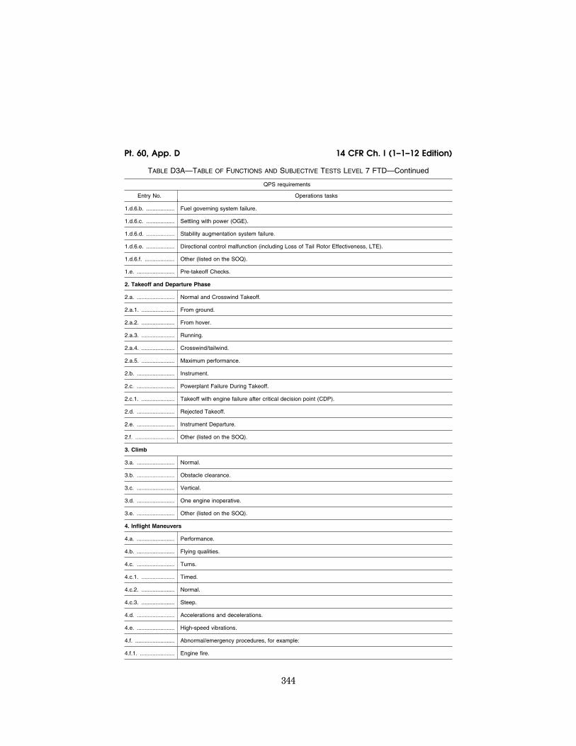
344
14 CFR Ch. I (1–1–12 Edition) Pt. 60, App. D
TABLE D3A—TABLE OF FUNCTIONS AND SUBJECTIVE TESTS LEVEL 7 FTD—Continued
QPS requirements
Entry No. Operations tasks
1.d.6.b. .................. Fuel governing system failure.
1.d.6.c. .................. Settling with power (OGE).
1.d.6.d. .................. Stability augmentation system failure.
1.d.6.e. .................. Directional control malfunction (including Loss of Tail Rotor Effectiveness, LTE).
1.d.6.f. ................... Other (listed on the SOQ).
1.e. ........................ Pre-takeoff Checks.
2. Takeoff and Departure Phase
2.a. ........................ Normal and Crosswind Takeoff.
2.a.1. ..................... From ground.
2.a.2. ..................... From hover.
2.a.3. ..................... Running.
2.a.4. ..................... Crosswind/tailwind.
2.a.5. ..................... Maximum performance.
2.b. ........................ Instrument.
2.c. ........................ Powerplant Failure During Takeoff.
2.c.1. ..................... Takeoff with engine failure after critical decision point (CDP).
2.d. ........................ Rejected Takeoff.
2.e. ........................ Instrument Departure.
2.f. ......................... Other (listed on the SOQ).
3. Climb
3.a. ........................ Normal.
3.b. ........................ Obstacle clearance.
3.c. ........................ Vertical.
3.d. ........................ One engine inoperative.
3.e. ........................ Other (listed on the SOQ).
4. Inflight Maneuvers
4.a. ........................ Performance.
4.b. ........................ Flying qualities.
4.c. ........................ Turns.
4.c.1. ..................... Timed.
4.c.2. ..................... Normal.
4.c.3. ..................... Steep.
4.d. ........................ Accelerations and decelerations.
4.e. ........................ High-speed vibrations.
4.f. ......................... Abnormal/emergency procedures, for example:
4.f.1. ...................... Engine fire.
VerDate Mar<15>2010 18:16 Mar 01, 2012 Jkt 226045 PO 00000 Frm 00354 Fmt 8010 Sfmt 8002 Q:\14\14V2 ofr150 PsN: PC150

345
Federal Aviation Administration, DOT Pt. 60, App. D
TABLE D3A—TABLE OF FUNCTIONS AND SUBJECTIVE TESTS LEVEL 7 FTD—Continued
QPS requirements
Entry No. Operations tasks
4.f.2. ...................... Engine failure.
4.f.2.a. ................... Powerplant Failure—Multiengine Helicopters.
4.f.2.b. ................... Powerplant Failure—Single-Engine Helicopters.
4.f.3. ...................... Inflight engine shutdown (and restart, if applicable).
4.f.4. ...................... Fuel governing system failures (e.g., FADEC malfunction).
4.f.5. ...................... Directional control malfunction.
4.f.6. ...................... Hydraulic failure.
4.f.7. ...................... Stability augmentation system failure.
4.f.8. ...................... Rotor vibrations.
4.f.9. ...................... Recovery From Unusual Attitudes.
4.f.10. .................... Settling with Power.
4.g. ........................ Other (listed on the SOQ).
5. Instrument Procedures
5.a. ........................ Instrument Arrival.
5.b. ........................ Holding.
5.c. ........................ Precision Instrument Approach.
5.c.1. ..................... Normal—All engines operating.
5.c.2. ..................... Manually controlled—One or more engines inoperative.
5.c.3. ..................... Approach procedures:
5.c.3.a. .................. PAR.
5.c.3.b. .................. GPS.
5.c.3.c. .................. ILS.
5.c.3.c.1. ............... Manual (raw data).
5.c.3.c.2. ............... Autopilot * only.
5.c.3.c.3. ............... Flight director only.
5.c.3.c.4. ............... Autopilot * and flight director (if appropriate) coupled.
5.c.3.d. .................. Other (listed on the SOQ).
5.d. ........................ Non-precision Instrument Approach.
5.d.1. ..................... Normal—All engines operating.
5.d.2. ..................... One or more engines inoperative.
5.d.3. ..................... Approach procedures:
5.d.3.a. .................. NDB.
5.d.3.b. .................. VOR, RNAV, TACAN, GPS.
5.d.3.c. .................. ASR.
5.d.3.d. .................. Circling.
5.d.3.e. .................. Helicopter only.
VerDate Mar<15>2010 18:16 Mar 01, 2012 Jkt 226045 PO 00000 Frm 00355 Fmt 8010 Sfmt 8002 Q:\14\14V2 ofr150 PsN: PC150

346
14 CFR Ch. I (1–1–12 Edition) Pt. 60, App. D
TABLE D3A—TABLE OF FUNCTIONS AND SUBJECTIVE TESTS LEVEL 7 FTD—Continued
QPS requirements
Entry No. Operations tasks
5.d.3.f. ................... Other (listed on the SOQ).
5.e. ........................ Missed Approach.
5.e.1. ..................... All engines operating.
5.e.2. ..................... One or more engines inoperative.
5.e.3. ..................... Stability augmentation system failure.
5.e.4. ..................... Other (listed on the SOQ).
6. Landings and Approaches to Landings
6.a. ........................ Visual Approaches.
6.a.1. ..................... Normal.
6.a.2. ..................... Steep.
6.a.3. ..................... Shallow.
6.a.4. ..................... Crosswind.
6.b. ........................ Landings.
6.b.1. ..................... Normal.
6.b.1.a. .................. Running.
6.b.1.b. .................. From Hover.
6.b.2. ..................... Crosswind.
6.b.3. ..................... Tailwind.
6.b.4. ..................... One or more engines inoperative.
6.b.5. ..................... Rejected Landing.
6.b.6. ..................... Other (listed on the SOQ).
7. Normal and Abnormal Procedures (any phase of flight)
7.a. ........................ Helicopter and powerplant systems operation (as applicable).
7.a.1. ..................... Anti-icing/deicing systems.
7.a.2. ..................... Auxiliary powerplant.
7.a.3. ..................... Communications.
7.a.4. ..................... Electrical system.
7.a.5. ..................... Environmental system.
7.a.6. ..................... Fire detection and suppression.
7.a.7. ..................... Flight control system.
7.a.8. ..................... Fuel system.
7.a.9. ..................... Engine oil system.
7.a.10. ................... Hydraulic system.
7.a.11. ................... Landing gear.
7.a.12. ................... Oxygen.
7.a.13. ................... Pneumatic.
VerDate Mar<15>2010 18:16 Mar 01, 2012 Jkt 226045 PO 00000 Frm 00356 Fmt 8010 Sfmt 8002 Q:\14\14V2 ofr150 PsN: PC150

347
Federal Aviation Administration, DOT Pt. 60, App. D
TABLE D3A—TABLE OF FUNCTIONS AND SUBJECTIVE TESTS LEVEL 7 FTD—Continued
QPS requirements
Entry No. Operations tasks
7.a.14. ................... Powerplant.
7.a.15. ................... Flight control computers.
7.a.16. ................... Fly-by-wire controls.
7.a.17. ................... Stabilizer.
7.a.18. ................... Stability augmentation and control augmentation system(s).
7.a.19. ................... Other (listed on the SOQ).
7.b. ........................ Flight management and guidance system (as applicable).
7.b.1. ..................... Airborne radar.
7.b.2. ..................... Automatic landing aids.
7.b.3. ..................... Autopilot.*
7.b.4. ..................... Collision avoidance system.
7.b.5. ..................... Flight data displays.
7.b.6. ..................... Flight management computers.
7.b.7. ..................... Head-up displays.
7.b.8. ..................... Navigation systems.
7.b.9. ..................... Other (listed on the SOQ).
8. Emergency Procedures (as applicable)
8.a. ........................ Autorotative Landing.
8.b. ........................ Air hazard avoidance.
8.c. ........................ Ditching.
8.d. ........................ Emergency evacuation.
8.e. ........................ Inflight fire and smoke removal.
8.f. ......................... Retreating blade stall recovery.
8.g. ........................ Mast bumping.
8.h. ........................ Loss of tail rotor effectiveness.
8.i. ......................... Other (listed on the SOQ).
9. Postflight Procedures
9.a. ........................ After-Landing Procedures.
9.b. ........................ Parking and Securing.
9.b.1. ..................... Engine and systems operation.
9.b.2. ..................... Parking brake operation.
9.b.3. ..................... Rotor brake operation.
9.b.4. ..................... Abnormal/emergency procedures.
10. Instructor Operating Station (IOS), as appropriate
10.a. ...................... Power Switch(es).
10.b. ...................... Helicopter conditions.
VerDate Mar<15>2010 18:16 Mar 01, 2012 Jkt 226045 PO 00000 Frm 00357 Fmt 8010 Sfmt 8002 Q:\14\14V2 ofr150 PsN: PC150

348
14 CFR Ch. I (1–1–12 Edition) Pt. 60, App. D
TABLE D3A—TABLE OF FUNCTIONS AND SUBJECTIVE TESTS LEVEL 7 FTD—Continued
QPS requirements
Entry No. Operations tasks
10.b.1. ................... Gross weight, center of gravity, fuel loading and allocation, etc.
10.b.2. ................... Helicopter systems status.
10.b.3. ................... Ground crew functions (e.g., ext. power).
10.c. ...................... Airports.
10.c.1. ................... Selection.
10.c.2. ................... Runway selection.
10.c.3. ................... Preset positions (e.g., ramp, over final approach fix).
10.d. ...................... Environmental controls.
10.d.1. ................... Temperature.
10.d.2. ................... Climate conditions (e.g., ice, rain).
10.d.3. ................... Wind speed and direction.
10.e. ...................... Helicopter system malfunctions.
10.e.1. ................... Insertion/deletion.
10.e.2. ................... Problem clear.
10.f. ....................... Locks, Freezes, and Repositioning.
10.f.1. .................... Problem (all) freeze/release.
10.f.2. .................... Position (geographic) freeze/release.
10.f.3. .................... Repositioning (locations, freezes, and releases).
10.f.4. .................... Ground speed control.
10.g. ...................... Sound Controls.
10.g.1. ................... On/off/adjustment.
10.h. ...................... Control Loading System (as applicable).
10.h.1. ................... On/off/emergency stop.
10.i. ....................... Observer Stations.
10.i.1. .................... Position.
10.i.2. .................... Adjustments.
* ‘‘Autopilot’’ means attitude retention mode of operation.
TABLE D3B—TABLE OF FUNCTIONS AND SUBJECTIVE TESTS AIRPORT OR LANDING AREA CONTENT REQUIREMENTS FOR QUALIFICATION AT LEVEL 7 FTD
QPS requirements
Entry No. Operations tasks
This table specifies the minimum airport visual model content and functionality to qualify an FTD at the indicated level. This table applies only to the airport/helicopter landing area scenes required for FTD qualification.
1. .............. Functional test content requirements for Level 7 FTDs. The following is the minimum airport/landing area model content requirement to satisfy visual capability tests, and provides suitable visual cues to allow completion of all functions and subjective tests described in this attachment for Level 7 FTDs.
VerDate Mar<15>2010 18:16 Mar 01, 2012 Jkt 226045 PO 00000 Frm 00358 Fmt 8010 Sfmt 8002 Q:\14\14V2 ofr150 PsN: PC150
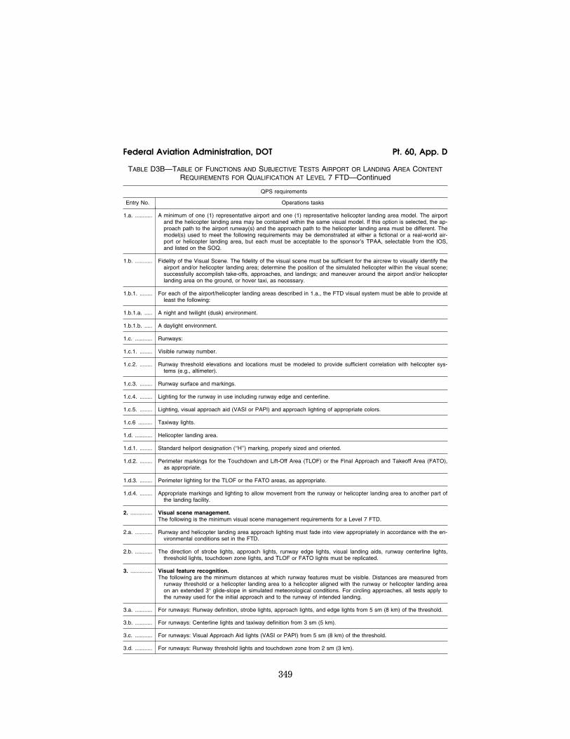
349
Federal Aviation Administration, DOT Pt. 60, App. D
TABLE D3B—TABLE OF FUNCTIONS AND SUBJECTIVE TESTS AIRPORT OR LANDING AREA CONTENT REQUIREMENTS FOR QUALIFICATION AT LEVEL 7 FTD—Continued
QPS requirements
Entry No. Operations tasks
1.a. ........... A minimum of one (1) representative airport and one (1) representative helicopter landing area model. The airport and the helicopter landing area may be contained within the same visual model. If this option is selected, the ap-proach path to the airport runway(s) and the approach path to the helicopter landing area must be different. The model(s) used to meet the following requirements may be demonstrated at either a fictional or a real-world air-port or helicopter landing area, but each must be acceptable to the sponsor’s TPAA, selectable from the IOS, and listed on the SOQ.
1.b. ........... Fidelity of the Visual Scene. The fidelity of the visual scene must be sufficient for the aircrew to visually identify the airport and/or helicopter landing area; determine the position of the simulated helicopter within the visual scene; successfully accomplish take-offs, approaches, and landings; and maneuver around the airport and/or helicopter landing area on the ground, or hover taxi, as necessary.
1.b.1. ........ For each of the airport/helicopter landing areas described in 1.a., the FTD visual system must be able to provide at least the following:
1.b.1.a. ..... A night and twilight (dusk) environment.
1.b.1.b. ..... A daylight environment.
1.c. ........... Runways:
1.c.1. ........ Visible runway number.
1.c.2. ........ Runway threshold elevations and locations must be modeled to provide sufficient correlation with helicopter sys-tems (e.g., altimeter).
1.c.3. ........ Runway surface and markings.
1.c.4. ........ Lighting for the runway in use including runway edge and centerline.
1.c.5. ........ Lighting, visual approach aid (VASI or PAPI) and approach lighting of appropriate colors.
1.c.6 ......... Taxiway lights.
1.d. ........... Helicopter landing area.
1.d.1. ........ Standard heliport designation (‘‘H’’) marking, properly sized and oriented.
1.d.2. ........ Perimeter markings for the Touchdown and Lift-Off Area (TLOF) or the Final Approach and Takeoff Area (FATO), as appropriate.
1.d.3. ........ Perimeter lighting for the TLOF or the FATO areas, as appropriate.
1.d.4. ........ Appropriate markings and lighting to allow movement from the runway or helicopter landing area to another part of the landing facility.
2. .............. Visual scene management. The following is the minimum visual scene management requirements for a Level 7 FTD.
2.a. ........... Runway and helicopter landing area approach lighting must fade into view appropriately in accordance with the en-vironmental conditions set in the FTD.
2.b. ........... The direction of strobe lights, approach lights, runway edge lights, visual landing aids, runway centerline lights, threshold lights, touchdown zone lights, and TLOF or FATO lights must be replicated.
3. .............. Visual feature recognition. The following are the minimum distances at which runway features must be visible. Distances are measured from
runway threshold or a helicopter landing area to a helicopter aligned with the runway or helicopter landing area on an extended 3° glide-slope in simulated meteorological conditions. For circling approaches, all tests apply to the runway used for the initial approach and to the runway of intended landing.
3.a. ........... For runways: Runway definition, strobe lights, approach lights, and edge lights from 5 sm (8 km) of the threshold.
3.b. ........... For runways: Centerline lights and taxiway definition from 3 sm (5 km).
3.c. ........... For runways: Visual Approach Aid lights (VASI or PAPI) from 5 sm (8 km) of the threshold.
3.d. ........... For runways: Runway threshold lights and touchdown zone from 2 sm (3 km).
VerDate Mar<15>2010 18:16 Mar 01, 2012 Jkt 226045 PO 00000 Frm 00359 Fmt 8010 Sfmt 8002 Q:\14\14V2 ofr150 PsN: PC150

350
14 CFR Ch. I (1–1–12 Edition) Pt. 60, App. D
TABLE D3B—TABLE OF FUNCTIONS AND SUBJECTIVE TESTS AIRPORT OR LANDING AREA CONTENT REQUIREMENTS FOR QUALIFICATION AT LEVEL 7 FTD—Continued
QPS requirements
Entry No. Operations tasks
3.e. ........... For runways and helicopter landing areas: Markings within range of landing lights for night/twilight scenes and the surface resolution test on daylight scenes, as required.
3.f. ............ For circling approaches: The runway of intended landing and associated lighting must fade into view in a non-dis-tracting manner.
3.g. ........... For helicopter landing areas: Landing direction lights and raised FATO lights from 1 sm (1.5 km).
3.h. ........... For helicopter landing areas: Flush mounted FATO lights, TLOF lights, and the lighted windsock from 0.5 sm (750 m).
4. .............. Airport or Helicopter Landing Area Model Content. The following prescribes the minimum requirements for an airport/helicopter landing area visual model and identi-
fies other aspects of the environment that must correspond with that model for a Level 7 FTD. For circling ap-proaches, all tests apply to the runway used for the initial approach and to the runway of intended landing. If all runways or landing areas in a visual model used to meet the requirements of this attachment are not designated as ‘‘in use,’’ then the ‘‘in use’’ runways/landing areas must be listed on the SOQ (e.g., KORD, Rwys 9R, 14L, 22R). Models of airports or helicopter landing areas with more than one runway or landing area must have all significant runways or landing areas not ‘‘in-use’’ visually depicted for airport/runway/landing area recognition purposes. The use of white or off white light strings that identify the runway or landing area for twilight and night scenes are acceptable for this requirement; and rectangular surface depictions are acceptable for daylight scenes. A visual system’s capabilities must be balanced between providing visual models with an accurate rep-resentation of the airport and a realistic representation of the surrounding environment. Each runway or heli-copter landing area designated as an ‘‘in-use’’ runway or area must include the following detail that is developed using airport pictures, construction drawings and maps, or other similar data, or developed in accordance with published regulatory material; however, this does not require that such models contain details that are beyond the design capability of the currently qualified visual system. Only one ‘‘primary’’ taxi route from parking to the runway end or helicopter takeoff/landing area will be required for each ‘‘in-use’’ runway or helicopter takeoff/land-ing area.
4.a. ........... The surface and markings for each ‘‘in-use’’ runway or helicopter landing area must include the following:
4.a.1. ........ For airports: Runway threshold markings, runway numbers, touchdown zone markings, fixed distance markings, runway edge markings, and runway centerline stripes.
4.a.2. ........ For helicopter landing areas: Markings for standard heliport identification (‘‘H’’) and TLOF, FATO, and safety areas.
4.b. ........... The lighting for each ‘‘in-use’’ runway or helicopter landing area must include the following:
4.b.1. ........ For airports: Runway approach, threshold, edge, end, centerline (if applicable), touchdown zone (if applicable), leadoff, and visual landing aid lights or light systems for that runway.
4.b.2. ........ For helicopter landing areas: Landing direction, raised and flush FATO, TLOF, windsock lighting.
4.c. ........... The taxiway surface and markings associated with each ‘‘in-use’’ runway or helicopter landing area must include the following:
4.c.1. ........ For airports: Taxiway edge, centerline (if appropriate), runway hold lines, and ILS critical area(s).
4.c.2. ........ For helicopter landing areas: Taxiways, taxi routes, and aprons.
4.d. ........... The taxiway lighting associated with each ‘‘in-use’’ runway or helicopter landing area must include the following:
4.d.1. ........ For airports: Taxiway edge, centerline (if appropriate), runway hold lines, ILS critical areas.
4.d.2. ........ For helicopter landing areas: Taxiways, taxi routes, and aprons.
4.d.3. ........ For airports: Taxiway lighting of correct color.
4.e. ........... Airport signage associated with each ‘‘in-use’’ runway or helicopter landing area must include the following:
4.e.1. ........ For airports: Signs for runway distance remaining, intersecting runway with taxiway, and intersecting taxiway with taxiway.
4.e.2. ........ For helicopter landing areas: As appropriate for the model used.
4.f. ............ Required visual model correlation with other aspects of the airport or helicopter landing environment simulation:
VerDate Mar<15>2010 18:16 Mar 01, 2012 Jkt 226045 PO 00000 Frm 00360 Fmt 8010 Sfmt 8002 Q:\14\14V2 ofr150 PsN: PC150

351
Federal Aviation Administration, DOT Pt. 60, App. D
TABLE D3B—TABLE OF FUNCTIONS AND SUBJECTIVE TESTS AIRPORT OR LANDING AREA CONTENT REQUIREMENTS FOR QUALIFICATION AT LEVEL 7 FTD—Continued
QPS requirements
Entry No. Operations tasks
4.f.1. ......... The airport or helicopter landing area model must be properly aligned with the navigational aids that are associated with operations at the ‘‘in-use’’ runway or helicopter landing area.
4.f.2. ......... The simulation of runway or helicopter landing area contaminants must be correlated with the displayed runway surface and lighting, if applicable.
5. .............. Correlation with helicopter and associated equipment. The following are the minimum correlation comparisons that must be made for a Level 7 FTD.
5.a. ........... Visual system compatibility with aerodynamic programming.
5.b. ........... Visual cues to assess sink rate and depth perception during landings.
5.c. ........... Accurate portrayal of environment relating to FTD attitudes.
5.d. ........... The visual scene must correlate with integrated helicopter systems, where installed (e.g., terrain, traffic and weath-er avoidance systems and Head-up Guidance System (HGS)).
5.e. ........... Representative visual effects for each visible, own-ship, helicopter external light(s)—taxi and landing light lobes (in-cluding independent operation, if appropriate).
5.f. ............ The effect of rain removal devices.
6. .............. Scene quality. The following are the minimum scene quality tests that must be conducted for a Level 7 FTD.
6.a. ........... System light points must be free from distracting jitter, smearing and streaking.
6.b. ........... Demonstration of occulting through each channel of the system in an operational scene.
6.c. ........... Six discrete light step controls (0–5).
7. .............. Special weather representations, which include visibility and RVR, measured in terms of distance. Visibility/RVR checked at 2,000 ft (600 m) above the airport or helicopter landing area and at two heights below
2,000 ft with at least 500 ft of separation between the measurements. The measurements must be taken within a radius of 10 sm (16 km) from the airport or helicopter landing area.
7.a. ........... Effects of fog on airport lighting such as halos and defocus.
7.b. ........... Effect of own-ship lighting in reduced visibility, such as reflected glare, including landing lights, strobes, and bea-cons.
8. .............. Instructor control of the following: The following are the minimum instructor controls that must be available in a Level 7 FTD.
8.a. ........... Environmental effects: E.g., cloud base, cloud effects, cloud density, visibility in statute miles/kilometers and RVR in feet/meters.
8.b. ........... Airport or helicopter landing area selection.
8.c. ........... Airport or helicopter landing area lighting, including variable intensity.
8.d. ........... Dynamic effects including ground and flight traffic.
End QPS Requirement
Begin Information
9. .............. An example of being able to combine two airport models to achieve two ‘‘in-use’’ runways: One runway designated as the ‘‘in-use’’ runway in the first model of the airport, and the second runway designated as the ‘‘in-use’’ run-way in the second model of the same airport. For example, the clearance is for the ILS approach to Runway 27, Circle to Land on Runway 18 right. Two airport visual models might be used: The first with Runway 27 des-ignated as the ‘‘in use’’ runway for the approach to runway 27, and the second with Runway 18 Right designated as the ‘‘in use’’ runway. When the pilot breaks off the ILS approach to runway 27, the instructor may change to the second airport visual model in which runway 18 Right is designated as the ‘‘in use’’ runway, and the pilot would make a visual approach and landing. This process is acceptable to the FAA as long as the temporary interruption due to the visual model change is not distracting to the pilot.
VerDate Mar<15>2010 18:16 Mar 01, 2012 Jkt 226045 PO 00000 Frm 00361 Fmt 8010 Sfmt 8002 Q:\14\14V2 ofr150 PsN: PC150

352
14 CFR Ch. I (1–1–12 Edition) Pt. 60, App. D
TABLE D3B—TABLE OF FUNCTIONS AND SUBJECTIVE TESTS AIRPORT OR LANDING AREA CONTENT REQUIREMENTS FOR QUALIFICATION AT LEVEL 7 FTD—Continued
QPS requirements
Entry No. Operations tasks
10. ............ Sponsors are not required to provide every detail of a runway, but the detail that is provided should be correct within reasonable limits.
End Information
TABLE D3C—TABLE OF FUNCTIONS AND SUBJECTIVE TESTS LEVEL 7 FTD VISUAL REQUIREMENTS ADDITIONAL VISUAL MODELS BEYOND MINIMUM REQUIRED FOR QUALIFICATION CLASS II AIRPORT OR HELICOPTER LANDING AREA MODELS
QPS requirements
Entry No. Operations tasks
This table specifies the minimum airport or helicopter landing area visual model content and functionality necessary to add vis-ual models to an FTD’s visual model library (i.e., beyond those necessary for qualification at the stated level) without the ne-cessity of further involvement of the NSPM or TPAA.
1. .............. Visual scene management. The following is the minimum visual scene management requirements.
1.a. ........... The installation and direction of the following lights must be replicated for the ‘‘in-use’’ surface:
1.a.1. ........ For ‘‘in-use’’ runways: Strobe lights, approach lights, runway edge lights, visual landing aids, runway centerline lights, threshold lights, and touchdown zone lights.
1.a.2. ........ For ‘‘in-use’’ helicopter landing areas: Ground level TLOF perimeter lights, elevated TLOF perimeter lights (if appli-cable), Optional TLOF lights (if applicable), ground FATO perimeter lights, elevated TLOF lights (if applicable), landing direction lights.
2. .............. Visual feature recognition. The following are the minimum distances at which runway or landing area features must be visible. Distances are
measured from runway threshold or a helicopter landing area to an aircraft aligned with the runway or helicopter landing area on a 3° glide-slope from the aircraft to the touchdown point, in simulated meteorological conditions. For circling approaches, all tests apply to the runway used for the initial approach and to the runway of intended landing.
2.a. ........... For Runways.
2.a.1. ........ Strobe lights, approach lights, and edge lights from 5 sm (8 km) of the threshold.
2.a.2. ........ Centerline lights and taxiway definition from 3 sm (5 km).
2.a.3. ........ Visual Approach Aid lights (VASI or PAPI) from 5 sm (8 km) of the threshold.
2.a.4. ........ Threshold lights and touchdown zone lights from 2 sm (3 km).
2.a.5. ........ Markings within range of landing lights for night/twilight (dusk) scenes and as required by the surface resolution test on daylight scenes.
2.a.6. ........ For circling approaches, the runway of intended landing and associated lighting must fade into view in a non-dis-tracting manner.
2.b. ........... For Helicopter landing areas.
2.b.1. ........ Landing direction lights and raised FATO lights from 2 sm (3 km).
2.b.2. ........ Flush mounted FATO lights, TOFL lights, and the lighted windsock from 1 sm (1500 m).
2.b.3. ........ Hover taxiway lighting (yellow/blue/yellow cylinders) from TOFL area.
2.b.4. ........ Markings within range of landing lights for night/twilight (dusk) scenes and as required by the surface resolution test on daylight scenes.
VerDate Mar<15>2010 18:16 Mar 01, 2012 Jkt 226045 PO 00000 Frm 00362 Fmt 8010 Sfmt 8002 Q:\14\14V2 ofr150 PsN: PC150

353
Federal Aviation Administration, DOT Pt. 60, App. D
TABLE D3C—TABLE OF FUNCTIONS AND SUBJECTIVE TESTS LEVEL 7 FTD VISUAL REQUIREMENTS ADDITIONAL VISUAL MODELS BEYOND MINIMUM REQUIRED FOR QUALIFICATION CLASS II AIRPORT OR HELICOPTER LANDING AREA MODELS—Continued
QPS requirements
Entry No. Operations tasks
3. .............. Airport or Helicopter Landing Area Model Content. The following prescribes the minimum requirements for what must be provided in an airport visual model and iden-
tifies other aspects of the airport environment that must correspond with that model. The detail must be devel-oped using airport pictures, construction drawings and maps, or other similar data, or developed in accordance with published regulatory material; however, this does not require that airport or helicopter landing area models contain details that are beyond the designed capability of the currently qualified visual system. For circling ap-proaches, all requirements of this section apply to the runway used for the initial approach and to the runway of intended landing. Only one ‘‘primary’’ taxi route from parking to the runway end or helicopter takeoff/landing area will be required for each ‘‘in-use’’ runway or helicopter takeoff/landing area.
3.a. ........... The surface and markings for each ‘‘in-use’’ runway or helicopter landing area must include the following:
3.a.1. ........ For airports: Runway threshold markings, runway numbers, touchdown zone markings, fixed distance markings, runway edge markings, and runway centerline stripes.
3.a.2. ........ For helicopter landing areas: Standard heliport marking (‘‘H’’), TOFL, FATO, and safety areas.
3.b. ........... The lighting for each ‘‘in-use’’ runway or helicopter landing area must include the following:
3.b.1. ........ For airports: Runway approach, threshold, edge, end, centerline (if applicable), touchdown zone (if applicable), leadoff, and visual landing aid lights or light systems for that runway.
3.b.2. ........ For helicopter landing areas: Landing direction, raised and flush FATO, TOFL, windsock lighting.
3.c. ........... The taxiway surface and markings associated with each ‘‘in-use’’ runway or helicopter landing area must include the following:
3.c.1. ........ For airports: Taxiway edge, centerline (if appropriate), runway hold lines, and ILS critical area(s).
3.c.2. ........ For helicopter landing areas: Taxiways, taxi routes, and aprons.
3.d. ........... The taxiway lighting associated with each ‘‘in-use’’ runway or helicopter landing area must include the following:
3.d.1. ........ For airports: Runway edge, centerline (if appropriate), runway hold lines, ILS critical areas.
3.d.2. ........ For helicopter landing areas: Taxiways, taxi routes, and aprons.
4. .............. Required visual model correlation with other aspects of the airport environment simulation. The following are the minimum visual model correlation tests that must be conducted for Level 7 FTD.
4.a. ........... The airport model must be properly aligned with the navigational aids that are associated with operations at the ‘‘in-use’’ runway.
4.b. ........... Slopes in runways, taxiways, and ramp areas, if depicted in the visual scene, must not cause distracting or unreal-istic effects.
5. .............. Correlation with helicopter and associated equipment. The following are the minimum correlation comparisons that must be made.
5.a. ........... Visual system compatibility with aerodynamic programming.
5.b. ........... Accurate portrayal of environment relating to flight simulator attitudes.
5.c. ........... Visual cues to assess sink rate and depth perception during landings.
6. .............. Scene quality. The following are the minimum scene quality tests that must be conducted.
6.a. ........... Light points free from distracting jitter, smearing or streaking.
6.b. ........... Surfaces and textural cues free from apparent and distracting quantization (aliasing).
7. .............. Instructor controls of the following. The following are the minimum instructor controls that must be available.
7.a. ........... Environmental effects, e.g., cloud base (if used), cloud effects, cloud density, visibility in statute miles/kilometers and RVR in feet/meters.
VerDate Mar<15>2010 18:16 Mar 01, 2012 Jkt 226045 PO 00000 Frm 00363 Fmt 8010 Sfmt 8002 Q:\14\14V2 ofr150 PsN: PC150

354
14 CFR Ch. I (1–1–12 Edition) Pt. 60, App. D
TABLE D3C—TABLE OF FUNCTIONS AND SUBJECTIVE TESTS LEVEL 7 FTD VISUAL REQUIREMENTS ADDITIONAL VISUAL MODELS BEYOND MINIMUM REQUIRED FOR QUALIFICATION CLASS II AIRPORT OR HELICOPTER LANDING AREA MODELS—Continued
QPS requirements
Entry No. Operations tasks
7.b. ........... Airport/Heliport selection.
7.c. ........... Airport/Heliport lighting including variable intensity.
7.d. ........... Dynamic effects including ground and flight traffic.
End QPS Requirements
Begin Information
8. .............. Sponsors are not required to provide every detail of a runway or helicopter landing area, but the detail that is pro-vided must be correct within the capabilities of the system.
End Information
TABLE D3D—TABLE OF FUNCTIONS AND SUBJECTIVE TESTS LEVEL 6 FTD
QPS requirements
Entry No. Operations tasks
Tasks in this table are subject to evaluation if appropriate for the helicopter simulated as indicated in the SOQ Configuration List or for a Level 6 FTD. Items not installed or not functional on the FTD and not appearing on the SOQ Configuration List, are not required to be listed as exceptions on the SOQ.
1. Preflight Procedures
1.a. ........................ Preflight Inspection (Flight Deck Only) switches, indicators, systems, and equipment.
1.b. ........................ APU/Engine start and run-up.
1.b.1. ..................... Normal start procedures.
1.b.2. ..................... Alternate start procedures.
1.b.3. ..................... Abnormal starts and shutdowns.
1.b.4. ..................... Rotor engagement.
1.b.5 ...................... System checks.
2. Takeoff and Departure Phase
2.a. ........................ Instrument.
2.b. ........................ Takeoff with engine failure after critical decision point (CDP).
3. Climb
3.a. ........................ Normal.
3.b. ........................ One engine inoperative.
4. Inflight Maneuvers
4.a. ........................ Performance.
4.b. ........................ Flying qualities.
4.c. ........................ Turns.
4.c.1. ..................... Timed.
4.c.2. ..................... Normal.
4.c.3. ..................... Steep.
4.d. ........................ Accelerations and decelerations.
VerDate Mar<15>2010 18:16 Mar 01, 2012 Jkt 226045 PO 00000 Frm 00364 Fmt 8010 Sfmt 8002 Q:\14\14V2 ofr150 PsN: PC150
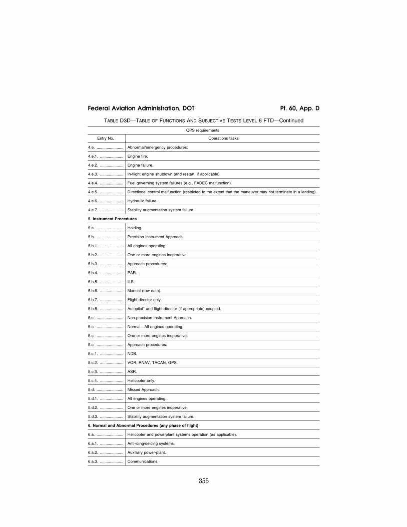
355
Federal Aviation Administration, DOT Pt. 60, App. D
TABLE D3D—TABLE OF FUNCTIONS AND SUBJECTIVE TESTS LEVEL 6 FTD—Continued
QPS requirements
Entry No. Operations tasks
4.e. ........................ Abnormal/emergency procedures:
4.e.1. ..................... Engine fire.
4.e.2. ..................... Engine failure.
4.e.3. ..................... In-flight engine shutdown (and restart, if applicable).
4.e.4. ..................... Fuel governing system failures (e.g., FADEC malfunction).
4.e.5. ..................... Directional control malfunction (restricted to the extent that the maneuver may not terminate in a landing).
4.e.6. ..................... Hydraulic failure.
4.e.7. ..................... Stability augmentation system failure.
5. Instrument Procedures
5.a. ........................ Holding.
5.b. ........................ Precision Instrument Approach.
5.b.1. ..................... All engines operating.
5.b.2. ..................... One or more engines inoperative.
5.b.3. ..................... Approach procedures:
5.b.4. ..................... PAR.
5.b.5. ..................... ILS.
5.b.6. ..................... Manual (raw data).
5.b.7. ..................... Flight director only.
5.b.8. ..................... Autopilot* and flight director (if appropriate) coupled.
5.c. ........................ Non-precision Instrument Approach.
5.c. ........................ Normal—All engines operating.
5.c. ........................ One or more engines inoperative.
5.c. ........................ Approach procedures:
5.c.1. ..................... NDB.
5.c.2. ..................... VOR, RNAV, TACAN, GPS.
5.c.3. ..................... ASR.
5.c.4. ..................... Helicopter only.
5.d. ........................ Missed Approach.
5.d.1. ..................... All engines operating.
5.d.2. ..................... One or more engines inoperative.
5.d.3. ..................... Stability augmentation system failure.
6. Normal and Abnormal Procedures (any phase of flight)
6.a. ........................ Helicopter and powerplant systems operation (as applicable).
6.a.1. ..................... Anti-icing/deicing systems.
6.a.2. ..................... Auxiliary power-plant.
6.a.3. ..................... Communications.
VerDate Mar<15>2010 18:16 Mar 01, 2012 Jkt 226045 PO 00000 Frm 00365 Fmt 8010 Sfmt 8002 Q:\14\14V2 ofr150 PsN: PC150

356
14 CFR Ch. I (1–1–12 Edition) Pt. 60, App. D
TABLE D3D—TABLE OF FUNCTIONS AND SUBJECTIVE TESTS LEVEL 6 FTD—Continued
QPS requirements
Entry No. Operations tasks
6.a.4. ..................... Electrical system.
6.a.5. ..................... Environmental system.
6.a.6. ..................... Fire detection and suppression.
6.a.7. ..................... Flight control system.
6.a.8. ..................... Fuel system.
6.a.9. ..................... Engine oil system.
6.a.10. ................... Hydraulic system.
6.a.11 .................... Landing gear.
6.a.12. ................... Oxygen.
6.a.13. ................... Pneumatic.
6.a.14. ................... Powerplant.
6.a.15. ................... Flight control computers.
6.a.16. ................... Stability augmentation and control augmentation system(s).
6.b. ........................ Flight management and guidance system (as applicable).
6.b.1. ..................... Airborne radar.
6.b.2. ..................... Automatic landing aids.
6.b.3. ..................... Autopilot.*
6.b.4. ..................... Collision avoidance system.
6.b.5. ..................... Flight data displays.
6.b.6. ..................... Flight management computers.
6.b.7. ..................... Navigation systems.
7. Postflight Procedures
7.a. ........................ Parking and Securing.
7.b. ........................ Engine and systems operation.
7.c. ........................ Parking brake operation.
7.d. ........................ Rotor brake operation.
7.e. ........................ Abnormal/emergency procedures.
8. Instructor Operating Station (IOS), as appropriate
8.a. ........................ Power Switch(es).
8.b.1. ..................... Helicopter conditions.
8.b.2. ..................... Gross weight, center of gravity, fuel loading and allocation, etc.
8.b.3. ..................... Helicopter systems status.
8.b.4. ..................... Ground crew functions (e.g., ext. power).
8.c. ........................ Airports and landing areas.
8.c.1. ..................... Number and selection.
8.c.2. ..................... Runway or landing area selection.
VerDate Mar<15>2010 18:16 Mar 01, 2012 Jkt 226045 PO 00000 Frm 00366 Fmt 8010 Sfmt 8002 Q:\14\14V2 ofr150 PsN: PC150

357
Federal Aviation Administration, DOT Pt. 60, App. D
TABLE D3D—TABLE OF FUNCTIONS AND SUBJECTIVE TESTS LEVEL 6 FTD—Continued
QPS requirements
Entry No. Operations tasks
8.c.3. ..................... Preset positions (e.g., ramp, over FAF).
8.c.4. ..................... Lighting controls.
8.d. ........................ Environmental controls.
8.d.1 ...................... Temperature.
8.d.2. ..................... Climate conditions (e.g., ice, rain).
8.d.3. ..................... Wind speed and direction.
8.e. ........................ Helicopter system malfunctions.
8.e.1. ..................... Insertion/deletion.
8.e.2. ..................... Problem clear.
8.f. ......................... Locks, Freezes, and Repositioning.
8.f.1. ...................... Problem (all) freeze/release.
8.f.2. ...................... Position (geographic) freeze/release.
8.f.3. ...................... Repositioning (locations, freezes, and releases).
8.f.4. ...................... Ground speed control.
8.g. ........................ Sound Controls. On/off/adjustment.
8.h. ........................ Control Loading System (as applicable) On/off/emergency stop.
8.i. ......................... Observer Stations.
8.i.1. ...................... Position.
8.i.2. ...................... Adjustments.
* ‘‘Autopilot’’ means attitude retention mode of operation.
TABLE D3E—TABLE OF FUNCTIONS AND SUBJECTIVE TESTS LEVEL 5 FTD
QPS requirements
Entry No. Operations tasks
Tasks in this table are subject to evaluation if appropriate for the helicopter simulated as indicated in the SOQ Configuration List or for a Level 5 FTD. Items not installed or not functional on the FTD and not appearing on the SOQ Configuration List, are not required to be listed as exceptions on the SOQ.
1. Preflight Procedures
1.a. ........................ Preflight Inspection (Flight Deck Only) switches, indicators, systems, and equipment.
1.b. ........................ APU/Engine start and run-up.
1.b.1. ..................... Normal start procedures.
1.b.2. ..................... Alternate start procedures.
1.b.3. ..................... Abnormal starts and shutdowns.
2. Climb
2.a. ........................ Normal.
3. Inflight Maneuvers
3.a. ........................ Performance.
3.b. ........................ Turns, Normal.
VerDate Mar<15>2010 18:16 Mar 01, 2012 Jkt 226045 PO 00000 Frm 00367 Fmt 8010 Sfmt 8002 Q:\14\14V2 ofr150 PsN: PC150

358
14 CFR Ch. I (1–1–12 Edition) Pt. 60, App. D
TABLE D3E—TABLE OF FUNCTIONS AND SUBJECTIVE TESTS LEVEL 5 FTD—Continued
QPS requirements
Entry No. Operations tasks
4. Instrument Procedures
4.a. ........................ Coupled instrument approach maneuvers (as applicable for the systems installed).
5. Normal and Abnormal Procedures (any phase of flight)
5.a. ........................ Normal system operation (installed systems).
5.b. ........................ Abnormal/Emergency system operation (installed systems).
6. Postflight Procedures
6.a. ........................ Parking and Securing.
6.b. ........................ Engine and systems operation.
6.c. ........................ Parking brake operation.
6.d. ........................ Rotor brake operation.
6.e. ........................ Abnormal/emergency procedures.
7. Instructor Operating Station (IOS), as appropriate
7.a. ........................ Power Switch(es).
7.b. ........................ Preset positions (ground; air)
7.c. ........................ Helicopter system malfunctions.
7.c.1. ..................... Insertion/deletion.
7.c.2. ..................... Problem clear.
7.d. ........................ Control Loading System (as applicable) On/off/emergency stop.
7.e. ........................ Observer Stations.
7.e.1. ..................... Position.
7.e.2. ..................... Adjustments.
TABLE D3F—TABLE OF FUNCTIONS AND SUBJECTIVE TESTS LEVEL 4 FTD
QPS requirements
Entry No. Operations tasks
Tasks in this table are subject to evaluation if appropriate for the helicopter simulated as indicated in the SOQ Configuration List or for a Level 4 FTD. Items not installed or not functional on the FTD and not appearing on the SOQ Configuration List, are not required to be listed as exceptions on the SOQ.
1. Preflight Procedures
1.a. ........................ Preflight Inspection (Flight Deck Only) switches, indicators, systems, and equipment.
1.b. ........................ APU/Engine start and run-up.
1.b.1. ..................... Normal start procedures.
1.b.2. ..................... Alternate start procedures.
1.b.3. ..................... Abnormal starts and shutdowns.
2. Normal and Abnormal Procedures (any phase of flight)
2.a. ........................ Normal system operation (installed systems).
2.b. ........................ Abnormal/Emergency system operation (installed systems).
VerDate Mar<15>2010 18:16 Mar 01, 2012 Jkt 226045 PO 00000 Frm 00368 Fmt 8010 Sfmt 8002 Q:\14\14V2 ofr150 PsN: PC150

359
Federal Aviation Administration, DOT Pt. 60, App. D
TABLE D3F—TABLE OF FUNCTIONS AND SUBJECTIVE TESTS LEVEL 4 FTD—Continued
QPS requirements
Entry No. Operations tasks
3. Postflight Procedures
3.a. ........................ Parking and Securing.
3.b. ........................ Engine and systems operation.
3.c. ........................ Parking brake operation.
4. Instructor Operating Station (IOS), as appropriate
4.a. ........................ Power Switch(es).
4.b. ........................ Preset positions (ground; air)
4.c. ........................ Helicopter system malfunctions.
4.c.1. ..................... Insertion/deletion.
4.c.2. ..................... Problem clear.
ATTACHMENT 4 TO APPENDIX D TO PART 60— SAMPLE DOCUMENTS
TABLE OF CONTENTS
Figure D4A Sample Letter, Request for Ini-tial, Upgrade, or Reinstatement Evalua-tion
Figure D4B Attachment: FTD Information Form
Figure A4C Sample Letter of Compliance Figure D4D Sample Qualification Test
Guide Cover Page
Figure D4E Sample Statement of Qualifica-tion—Certificate
Figure D4F Sample Statement of Qualifica-tion—Configuration List
Figure D4G Sample Statement of Qualifica-tion—List of Qualified Tasks
Figure D4H Sample Continuing Qualifica-tion Evaluation Requirements Page
Figure D4I Sample MQTG Index of Effective FTD Directives
VerDate Mar<15>2010 18:16 Mar 01, 2012 Jkt 226045 PO 00000 Frm 00369 Fmt 8010 Sfmt 8002 Q:\14\14V2 ofr150 PsN: PC150
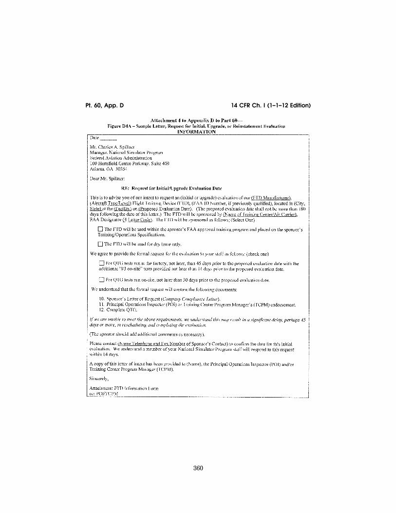
360
14 CFR Ch. I (1–1–12 Edition) Pt. 60, App. D
VerDate Mar<15>2010 18:16 Mar 01, 2012 Jkt 226045 PO 00000 Frm 00370 Fmt 8010 Sfmt 8006 Q:\14\14V2 ofr150 PsN: PC150 ER
09M
Y08
.054
</G
PH
>

361
Federal Aviation Administration, DOT Pt. 60, App. D
VerDate Mar<15>2010 18:16 Mar 01, 2012 Jkt 226045 PO 00000 Frm 00371 Fmt 8010 Sfmt 8006 Q:\14\14V2 ofr150 PsN: PC150 ER
09M
Y08
.055
</G
PH
>

362
14 CFR Ch. I (1–1–12 Edition) Pt. 60, App. D
VerDate Mar<15>2010 18:16 Mar 01, 2012 Jkt 226045 PO 00000 Frm 00372 Fmt 8010 Sfmt 8006 Q:\14\14V2 ofr150 PsN: PC150 ER
09M
Y08
.056
</G
PH
>

363
Federal Aviation Administration, DOT Pt. 60, App. D
VerDate Mar<15>2010 18:16 Mar 01, 2012 Jkt 226045 PO 00000 Frm 00373 Fmt 8010 Sfmt 8006 Q:\14\14V2 ofr150 PsN: PC150 ER
09M
Y08
.057
</G
PH
>

364
14 CFR Ch. I (1–1–12 Edition) Pt. 60, App. D
VerDate Mar<15>2010 18:16 Mar 01, 2012 Jkt 226045 PO 00000 Frm 00374 Fmt 8010 Sfmt 8006 Q:\14\14V2 ofr150 PsN: PC150 ER
09M
Y08
.058
</G
PH
>

365
Federal Aviation Administration, DOT Pt. 60, App. D
VerDate Mar<15>2010 18:16 Mar 01, 2012 Jkt 226045 PO 00000 Frm 00375 Fmt 8010 Sfmt 8006 Q:\14\14V2 ofr150 PsN: PC150 ER
09M
Y08
.059
</G
PH
>
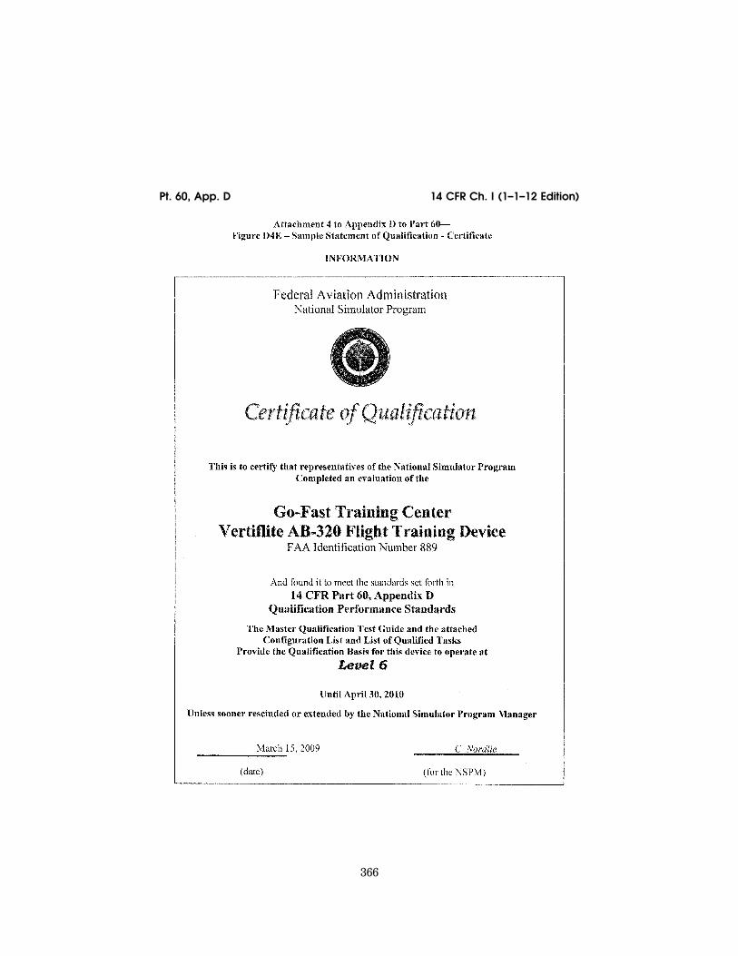
366
14 CFR Ch. I (1–1–12 Edition) Pt. 60, App. D
VerDate Mar<15>2010 18:16 Mar 01, 2012 Jkt 226045 PO 00000 Frm 00376 Fmt 8010 Sfmt 8006 Q:\14\14V2 ofr150 PsN: PC150 ER
09M
Y08
.060
</G
PH
>

367
Federal Aviation Administration, DOT Pt. 60, App. D
VerDate Mar<15>2010 18:16 Mar 01, 2012 Jkt 226045 PO 00000 Frm 00377 Fmt 8010 Sfmt 8006 Q:\14\14V2 ofr150 PsN: PC150 ER
09M
Y08
.061
</G
PH
>

368
14 CFR Ch. I (1–1–12 Edition) Pt. 60, App. D
VerDate Mar<15>2010 18:16 Mar 01, 2012 Jkt 226045 PO 00000 Frm 00378 Fmt 8010 Sfmt 8006 Q:\14\14V2 ofr150 PsN: PC150 ER
09M
Y08
.062
</G
PH
>
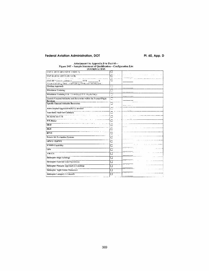
369
Federal Aviation Administration, DOT Pt. 60, App. D
VerDate Mar<15>2010 18:16 Mar 01, 2012 Jkt 226045 PO 00000 Frm 00379 Fmt 8010 Sfmt 8006 Q:\14\14V2 ofr150 PsN: PC150 ER
09M
Y08
.063
</G
PH
>

370
14 CFR Ch. I (1–1–12 Edition) Pt. 60, App. D
VerDate Mar<15>2010 18:16 Mar 01, 2012 Jkt 226045 PO 00000 Frm 00380 Fmt 8010 Sfmt 8006 Q:\14\14V2 ofr150 PsN: PC150 ER
09M
Y08
.064
</G
PH
>

371
Federal Aviation Administration, DOT Pt. 60, App. D
VerDate Mar<15>2010 18:16 Mar 01, 2012 Jkt 226045 PO 00000 Frm 00381 Fmt 8010 Sfmt 8006 Q:\14\14V2 ofr150 PsN: PC150 ER
09M
Y08
.065
</G
PH
>
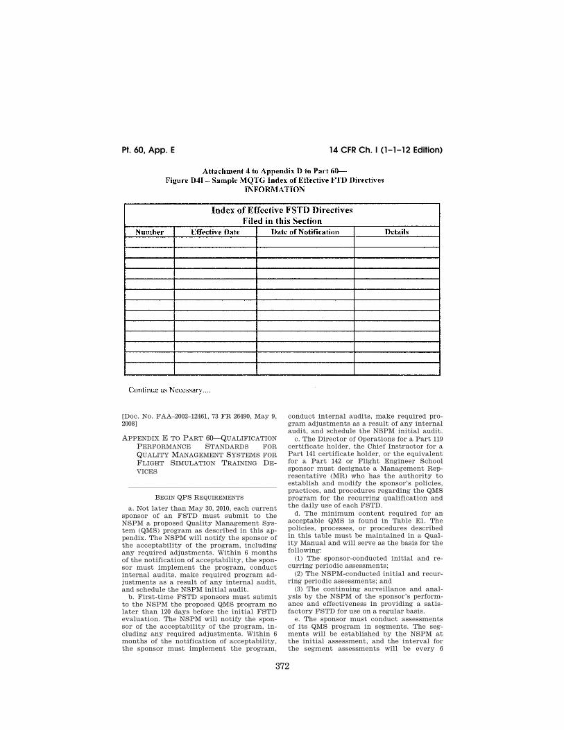
372
14 CFR Ch. I (1–1–12 Edition) Pt. 60, App. E
[Doc. No. FAA–2002–12461, 73 FR 26490, May 9, 2008]
APPENDIX E TO PART 60—QUALIFICATION PERFORMANCE STANDARDS FOR QUALITY MANAGEMENT SYSTEMS FOR FLIGHT SIMULATION TRAINING DE-VICES
lllllllllllllllllllllll
BEGIN QPS REQUIREMENTS
a. Not later than May 30, 2010, each current sponsor of an FSTD must submit to the NSPM a proposed Quality Management Sys-tem (QMS) program as described in this ap-pendix. The NSPM will notify the sponsor of the acceptability of the program, including any required adjustments. Within 6 months of the notification of acceptability, the spon-sor must implement the program, conduct internal audits, make required program ad-justments as a result of any internal audit, and schedule the NSPM initial audit.
b. First-time FSTD sponsors must submit to the NSPM the proposed QMS program no later than 120 days before the initial FSTD evaluation. The NSPM will notify the spon-sor of the acceptability of the program, in-cluding any required adjustments. Within 6 months of the notification of acceptability, the sponsor must implement the program,
conduct internal audits, make required pro-gram adjustments as a result of any internal audit, and schedule the NSPM initial audit.
c. The Director of Operations for a Part 119 certificate holder, the Chief Instructor for a Part 141 certificate holder, or the equivalent for a Part 142 or Flight Engineer School sponsor must designate a Management Rep-resentative (MR) who has the authority to establish and modify the sponsor’s policies, practices, and procedures regarding the QMS program for the recurring qualification and the daily use of each FSTD.
d. The minimum content required for an acceptable QMS is found in Table E1. The policies, processes, or procedures described in this table must be maintained in a Qual-ity Manual and will serve as the basis for the following:
(1) The sponsor-conducted initial and re-curring periodic assessments;
(2) The NSPM-conducted initial and recur-ring periodic assessments; and
(3) The continuing surveillance and anal-ysis by the NSPM of the sponsor’s perform-ance and effectiveness in providing a satis-factory FSTD for use on a regular basis.
e. The sponsor must conduct assessments of its QMS program in segments. The seg-ments will be established by the NSPM at the initial assessment, and the interval for the segment assessments will be every 6
VerDate Mar<15>2010 18:16 Mar 01, 2012 Jkt 226045 PO 00000 Frm 00382 Fmt 8010 Sfmt 8002 Q:\14\14V2 ofr150 PsN: PC150 ER
09M
Y08
.066
</G
PH
>

373
Federal Aviation Administration, DOT Pt. 60, App. E
months. The intervals for the segment as-sessments may be extended beyond 6 months as the QMS program matures, but will not be extended beyond 12 months. The entire QMS program must be assessed every 24 months.
f. The periodic assessments conducted by the NSPM will be conducted at intervals not less than once every 24 months, and include a comprehensive review of the QMS program. These reviews will be conducted more fre-quently if warranted.
END QPS REQUIREMENTS
lllllllllllllllllllllll
BEGIN INFORMATION
g. An example of a segment assessment— At the initial QMS assessment, the NSPM will divide the QMS program into segments (e.g., 6 separate segments). There must be an assessment of a certain number of segments every 6 months (i.e., segments 1 and 2 at the end of the first 6 month period; segments 3 and 4 at the end of the second 6 month period (or one year); and segments 5 and 6 at the end of the third 6 month period (or 18 months). As the program matures, the inter-val between assessments may be extended to 12 months (e.g., segments 1, 2, and 3 at the end of the first year; and segments 4, 5, and 6 at the end of the second year). In both cases, the entire QMS program is assessed at least every 24 months.
h. The following materials are presented to assist sponsors in preparing for an NSPM evaluation of the QMS program. The sample documents include:
(1) The NSPM desk assessment tool for ini-tial evaluation of the required elements of a QMS program.
(2) The NSPM on-site assessment tool for initial and continuing evaluation of the re-quired elements of a QMS program.
(3) An Element Assessment Table that de-scribes the circumstances that exist to war-rant a finding of ‘‘non-compliance,’’ or ‘‘non- conformity’’; ‘‘partial compliance,’’ or ‘‘par-tial conformity’’; and ‘‘acceptable compli-ance,’’ or ‘‘acceptable conformity.’’
(4) A sample Continuation Sheet for addi-tional comments that may be added by the sponsor or the NSPM during a QMS evalua-tion.
(5) A sample Sponsor Checklist to assist the sponsor in verifying the elements that comprise the required QMS program.
(6) A table showing the essential functions, processes, and procedures that relate to the required QMS components and a cross-ref-erence to each represented task.
i. Additional Information. (1) In addition to specifically designated
QMS evaluations, the NSPM will evaluate the sponsor’s QMS program as part of regu-larly scheduled FSTD continuing qualifica-tion evaluations and no-notice FSTD evalua-
tions, focusing in part on the effectiveness and viability of the QMS program and its contribution to the overall capability of the FSTD to meet the requirements of this part.
(2) The sponsor or MR may delegate duties associated with maintaining the qualifica-tion of the FSTD (e.g., corrective and pre-ventive maintenance, scheduling and con-ducting tests or inspections, functional pre-flight checks) but retain the responsibility and authority for the day-to-day qualifica-tion of the FSTD. One person may serve as the sponsor or MR for more than one FSTD, but one FSTD may not have more than one sponsor or MR.
(3) A QMS program may be applicable to more than one certificate holder (e.g., part 119 and part 142 or two part 119 certificate holders) and an MR may work for more than one certificate holder (e.g., part 119 and part 142 or two part 119 certificate holders) as long as the sponsor’s QMS program require-ments and the MR requirements are met for each certificate holder.
(4) Standard Measurements for Flight Sim-ulator Quality: A quality system based on FSTD performance will improve and main-tain training quality. See http://www.faa.gov/ safety/programslinitiatives/aircraftlaviation/ nsp/sqms/ for more information on measuring FSTD performance.
j. The FAA does not mandate a specific QMS program format, but an acceptable QMS program should contain the following:.
(1) A Quality Policy. This is a formal writ-ten Quality Policy Statement that is a com-mitment by the sponsor outlining what the Quality System will achieve.
(2) A MR who has overall authority for monitoring the on-going qualification of as-signed FSTDs to ensure that all FSTD quali-fication issues are resolved as required by this part. The MR should ensure that the QMS program is properly implemented and maintained, and should:
(a) Brief the sponsor’s management on the qualification processes;
(b) Serve as the primary contact point for all matters between the sponsor and the NSPM regarding the qualification of the as-signed FSTDs; and
(c) Oversee the day-to-day quality control. (3) The system and processes outlined in
the QMS should enable the sponsor to mon-itor compliance with all applicable regula-tions and ensure correct maintenance and performance of the FSTD in accordance with part 60.
(4) A QMS program and a statement ac-knowledging completion of a periodic review by the MR should include the following:
(a) A maintenance facility that provides suitable FSTD hardware and software tests and maintenance capability.
(b) A recording system in the form of a technical log in which defects, deferred de-fects, and development projects are listed,
VerDate Mar<15>2010 18:16 Mar 01, 2012 Jkt 226045 PO 00000 Frm 00383 Fmt 8010 Sfmt 8002 Q:\14\14V2 ofr150 PsN: PC150

374
14 CFR Ch. I (1–1–12 Edition) Pt. 60, App. E
assigned and reviewed within a specified time period.
(c) Routine maintenance of the FSTD and performance of the QTG tests with adequate staffing to cover FSTD operating periods.
(d) A planned internal assessment schedule and a periodic review should be used to verify that corrective action was complete and effective. The assessor should have ade-
quate knowledge of FSTDs and should be ac-ceptable to the NSPM.
(5) The MR should receive Quality System training and brief other personnel on the procedures.
END INFORMATION
lllllllllllllllllllllll
TABLE E1—FSTD QUALITY MANAGEMENT SYSTEM
Entry No. QPS requirement Information (reference)
E1.1. ...................... A QMS manual that prescribes the policies, processes, or procedures outlined in this table.
§ 60.5(a).
E1.2. ...................... A policy, process, or procedure specifying how the sponsor will identify defi-ciencies in the QMS.
§ 60.5(b).
E1.3. ...................... A policy, process, or procedure specifying how the sponsor will document how the QMS program will be changed to address deficiencies.
§ 60.5(b).
E1.4. ...................... A policy, process, or procedure specifying how the sponsor will address pro-posed program changes (for programs that do not meet the minimum re-quirements as notified by the NSPM) to the NSPM and receive approval prior to their implementation.
§ 60.5(c).
E1.5. ...................... A policy, process, or procedure specifying how the sponsor will document that at least one FSTD is used within the sponsor’s FAA-approved flight training program for the aircraft or set of aircraft at least once within the 12-month period following the initial or upgrade evaluation conducted by the NSPM and at least once within each subsequent 12-month period thereafter.
§ 60.7(b)(5).
E1.6. ...................... A policy, process, or procedure specifying how the sponsor will document that at least one FSTD is used within the sponsor’s FAA-approved flight training program for the aircraft or set of aircraft at least once within the 12-month period following the first continuing qualification evaluation conducted by the NSP and at least once within each subsequent 12-month period there-after.
§ 60.7(b)(6).
E1.7. ...................... A policy, process, or procedure specifying how the sponsor will obtain an an-nual written statement from a qualified pilot (who has flown the subject air-craft or set of aircraft during the preceding 12-month period) that the per-formance and handling qualities of the subject FSTD represents the subject aircraft or set of aircraft (within the normal operating envelope). Required only if the subject FSTD is not used in the sponsor’s FAA-approved flight training program for the aircraft or set of aircraft at least once within the preceding 12-month period.
§ 60.5(b)(7) and § 60.7(d)(2).
E1.8. ...................... A policy, process, or procedure specifying how independent feedback (from persons recently completing training, evaluation, or obtaining flight experi-ence; instructors and check airmen using the FSTD for training, evaluation, or flight experience sessions; and FSTD technicians and maintenance per-sonnel) will be received and addressed by the sponsor regarding the FSTD and its operation.
§ 60.9(b)(1).
E1.9. ...................... A policy, process, or procedure specifying how and where the FSTD SOQ will be posted, or accessed by an appropriate terminal or display, in or adjacent to the FSTD.
§ 60.9(b)(2).
E1.10. .................... A policy, process, or procedure specifying how the sponsor’s management representative (MR) is selected and identified by name to the NSPM.
§ 60.9(c) and Appendix E, paragraph (d).
E1.11. .................... A policy, process, or procedure specifying the MR authority and responsibility for the following:
§ 60.9(c)(2), (3), and (4).
E1.11.a. ................. Monitoring the on-going qualification of assigned FSTDs to ensure all matters regarding FSTD qualification are completed as required by this part.
E1.11.b. ................. Ensuring that the QMS is properly maintained by overseeing the QMS poli-cies, practices, or procedures and modifying as necessary.
VerDate Mar<15>2010 18:16 Mar 01, 2012 Jkt 226045 PO 00000 Frm 00384 Fmt 8010 Sfmt 8002 Q:\14\14V2 ofr150 PsN: PC150

375
Federal Aviation Administration, DOT Pt. 60, App. E
TABLE E1—FSTD QUALITY MANAGEMENT SYSTEM—Continued
Entry No. QPS requirement Information (reference)
E1.11.c. .................. Regularly briefing sponsor’s management on the status of the on-going FSTD qualification program and the effectiveness and efficiency of the QMS.
E1.11.d. ................. Serving as the primary contact point for all matters between the sponsor and the NSPM regarding the qualification of assigned FSTDs.
E1.11.e. ................. Delegating the MR assigned duties to an individual at each of the sponsor’s locations, as appropriate.
E1.12. .................... A policy, process, or procedure specifying how the sponsor will: § 60.13; QPS Appendices A, B, C, and D.
E1.12.a. ................. Ensure that the data made available to the NSPM (the validation data pack-age) includes the aircraft manufacturer’s flight test data (or other data ap-proved by the NSPM) and all relevant data developed after the type certifi-cate was issued (e.g., data developed in response to an airworthiness di-rective) if the data results from a change in performance, handling qualities, functions, or other characteristics of the aircraft that must be considered for flight crewmember training, evaluation, or experience requirements.
E1.12.b. ................. Notify the NSPM within 10 working days of becoming aware that an addition to or a revision of the flight related data or airplane systems related data is available if this data is used to program or operate a qualified FSTD.
E1.12.c. .................. Maintain a liaison with the manufacturer of the aircraft being simulated (or with the holder of the aircraft type certificate for the aircraft being simulated if the manufacturer is no longer in business), and if appropriate, with the person who supplied the aircraft data package for the FFS for the purposes of receiving notification of data package changes.
E1.13. .................... A policy, process, or procedure specifying how the sponsor will make avail-able all special equipment and qualified personnel needed to conduct tests during initial, continuing qualification, or special evaluations.
§ 60.14.
E1.14. .................... A policy, process, or procedure specifying how the sponsor will submit to the NSPM a request to evaluate the FSTD for initial qualification at a specific level and simultaneously request the TPAA forward a concurring letter to the NSPM; including how the MR will use qualified personnel to confirm the following:
§ 60.15(a)–(d); § 60.15(b); § 60.15(b)(i); § 60.15(b)(ii); § 60.15(b)(iii).
E1.14.a. ................. That the performance and handling qualities of the FSTD represent those of the aircraft or set of aircraft within the normal operating envelope.
E1.14.b. ................. The FSTD systems and sub-systems (including the simulated aircraft sys-tems) functionally represent those in the aircraft or set of aircraft.
E1.14.c. .................. The flight deck represents the configuration of the specific type or aircraft make, model, and series aircraft being simulated, as appropriate.
E1.15. .................... A policy, process, or procedure specifying how the subjective and objective tests are completed at the sponsor’s training facility for an initial evaluation.
§ 60.15(e).
E1.16. .................... A policy, process, or procedure specifying how the sponsor will update the QTG with the results of the FAA-witnessed tests and demonstrations to-gether with the results of the objective tests and demonstrations after the NSPM completes the evaluation for initial qualification.
§ 60.15(h).
E1.17. .................... A policy, process, or procedure specifying how the sponsor will make the MQTG available to the NSPM upon request.
§ 60.15(i).
E1.18. .................... A policy, process, or procedure specifying how the sponsor will apply to the NSPM for additional qualification(s) to the SOQ.
§ 60.16(a); § 60.16(a)(1)(i); and § 60.16(a)(1)(ii).
E1.19. .................... A policy, process, or procedure specifying how the sponsor completes all re-quired Attachment 2 objective tests each year in a minimum of four evenly spaced inspections as specified in the appropriate QPS.
§ 60.19(a)(1) QPS Appen-dices A, B, C, or D.
E1.20. .................... A policy, process, or procedure specifying how the sponsor completes and records a functional preflight check of the FSTD within the preceding 24 hours of FSTD use, including a description of the functional preflight.
§ 60.19(a)(2) QPS Appen-dices A, B, C, or D.
VerDate Mar<15>2010 18:16 Mar 01, 2012 Jkt 226045 PO 00000 Frm 00385 Fmt 8010 Sfmt 8002 Q:\14\14V2 ofr150 PsN: PC150

376
14 CFR Ch. I (1–1–12 Edition) Pt. 60, App. E
TABLE E1—FSTD QUALITY MANAGEMENT SYSTEM—Continued
Entry No. QPS requirement Information (reference)
E1.21. .................... A policy, process, or procedure specifying how the sponsor schedules con-tinuing qualification evaluations with the NSPM.
§ 60.19(b)(2).
E1.22. .................... A policy, process, or procedure specifying how the sponsor ensures that the FSTD has received a continuing qualification evaluation at the interval de-scribed in the MQTG.
§ 60.19(b)(5)–(6).
E1.23. .................... A policy, process, or procedure describing how discrepancies are recorded in the FSTD discrepancy log, including:
§ 60.19(c); § 60.19(c)(2)(i); § 60.19(c)(2)(ii).
E1.23.a. ................. A description of how the discrepancies are entered and maintained in the log until corrected.
E1.23.b. ................. A description of the corrective action taken for each discrepancy, the identity of the individual taking the action, and the date that action is taken.
E1.24. .................... A policy, process, or procedure specifying how the discrepancy log is kept in a form and manner acceptable to the Administrator and kept in or adjacent to the FSTD. (An electronic log that may be accessed by an appropriate terminal or display in or adjacent to the FSTD is satisfactory.).
§ 60.19(c)(2)(iii).
E1.25. .................... A policy, process, or procedure that requires each instructor, check airman, or representative of the Administrator conducting training, evaluation, or flight experience, and each person conducting the preflight inspection, who dis-covers a discrepancy, including any missing, malfunctioning, or inoperative components in the FSTD, to write or cause to be written a description of that discrepancy into the discrepancy log at the end of the FSTD preflight or FSTD use session.
§ 60.20.
E1.26. .................... A policy, process, or procedure specifying how the sponsor will apply for ini-tial qualification based on the final aircraft data package approved by the aircraft manufacturer if operating an FSTD based on an interim qualification.
§ 60.21(c).
E1.27. .................... A policy, process, or procedure specifying how the sponsor determines whether an FSTD change qualifies as a modification as defined in § 60.23.
§ 60.23(a)(1)–(2).
E1.28. .................... A policy, process, or procedure specifying how the sponsor will ensure the FSTD is modified in accordance with any FSTD Directive regardless of the original qualification basis.
§ 60.23(b).
E1.29. .................... A policy, process, or procedure specifying how the sponsor will notify the NSPM and TPAA of their intent to use a modified FSTD and to ensure that the modified FSTD will not be used prior to:
§ 60.23(c)(1)(i), (ii), and (iv).
E1.29.a. ................. Twenty-one days since the sponsor notified the NSPM and the TPAA of the proposed modification and the sponsor has not received any response from either the NSPM or the TPAA; or
E1.29.b. ................. Twenty-one days since the sponsor notified the NSPM and the TPAA of the proposed modification and one has approved the proposed modification and the other has not responded; or
E1.29.c. .................. The FSTD successfully completing any evaluation the NSPM may require in accordance with the standards for an evaluation for initial qualification or any part thereof before the modified FSTD is placed in service.
E1.30. .................... A policy, process, or procedure specifying how, after an FSTD modification is approved by the NSPM, the sponsor will:
§ 60.23(d)–(e).
E1.30.a. ................. Post an addendum to the SOQ until as the NSPM issues a permanent, up-dated SOQ.
E1.30.b. ................. Update the MQTG with current objective test results and appropriate objective data for each affected objective test or other MQTG section affected by the modification.
E1.30.c. .................. File in the MQTG the requirement from the NSPM to make the modification and the record of the modification completion.
VerDate Mar<15>2010 18:16 Mar 01, 2012 Jkt 226045 PO 00000 Frm 00386 Fmt 8010 Sfmt 8002 Q:\14\14V2 ofr150 PsN: PC150

377
Federal Aviation Administration, DOT Pt. 60, App. F
TABLE E1—FSTD QUALITY MANAGEMENT SYSTEM—Continued
Entry No. QPS requirement Information (reference)
E1.31. .................... A policy, process, or procedure specifying how the sponsor will track the length of time a component has been missing, malfunctioning, or inoper-ative (MMI), including:
§ 60.25(b)–(c), and QPS Appendices A, B, C, or D.
E1.31.a. ................. How the sponsor will post a list of MMI components in or adjacent to the FSTD.
E1.31.b. ................. How the sponsor will notify the NSPM if the MMI has not been repaired or re-placed within 30 days.*
E1.32. .................... A policy, process, or procedure specifying how the sponsor will notify the NSPM and how the sponsor will seek requalification of the FSTD if the FSTD is moved and reinstalled in a different location.
§ 60.27(a)(3).
E1.33. .................... A policy, process, or procedure specifying how the sponsor will maintain con-trol of the following: (The sponsor must specify how these records are maintained in plain language form or in coded form; but if the coded form is used, the sponsor must specify how the preservation and retrieval of infor-mation will be conducted.).
§ 60.31.
E1.33.a. ................. The MQTG and each amendment.
E1.33.b. ................. A record of all FSTD modifications required by this part since the issuance of the original SOQ.
E1.33.c. .................. Results of the qualification evaluations (initial and each upgrade) since the issuance of the original SOQ.
E1.33.d. ................. Results of the objective tests conducted in accordance with this part for a pe-riod of 2 years.
E1.33.e. ................. Results of the previous three continuing qualification evaluations, or the con-tinuing qualification evaluations from the previous 2 years, whichever cov-ers a longer period.
E1.33.f. .................. Comments obtained in accordance with § 60.9(b);
E1.33.g. ................. A record of all discrepancies entered in the discrepancy log over the previous 2 years, including the following:
E1.33.g.1. .............. A list of the components or equipment that were or are missing, malfunc-tioning, or inoperative.
E1.33.g.2. .............. The action taken to correct the discrepancy.
E1.33.g.3. .............. The date the corrective action was taken.
E1.33.g.4. .............. The identity of the person determining that the discrepancy has been cor-rected.
* Note: If the sponsor has an approved discrepancy prioritization system, this item is satisfied by describing how discrepancies are prioritized, what actions are taken, and how the sponsor will notify the NSPM if the MMI has not been repaired or replaced within the specified timeframe.
[Doc. No. FAA–2002–12461, 73 FR 26490, May 9, 2008]
APPENDIX F TO PART 60—DEFINITIONS AND ABBREVIATIONS FOR FLIGHT SIMULATION TRAINING DEVICES
lllllllllllllllllllllll
BEGIN INFORMATION
1. SOME OF THE DEFINITIONS PRESENTED BELOW ARE REPEATED FROM THE DEFINITIONS FOUND IN 14 CFR PART 1, AS INDICATED PAR-ENTHETICALLY
END INFORMATION
lllllllllllllllllllllll
VerDate Mar<15>2010 18:16 Mar 01, 2012 Jkt 226045 PO 00000 Frm 00387 Fmt 8010 Sfmt 8002 Q:\14\14V2 ofr150 PsN: PC150

378
14 CFR Ch. I (1–1–12 Edition) Pt. 60, App. F
BEGIN QPS REQUIREMENTS
2. DEFINITIONS
1st Segment—the portion of the takeoff pro-file from liftoff to gear retraction.
2nd Segment—the portion of the takeoff profile from after gear retraction to initial flap/slat retraction.
3rd Segment—the portion of the takeoff pro-file after flap/slat retraction is complete.
Aircraft Data Package—a combination of the various types of data used to design, pro-gram, manufacture, modify, and test the FSTD.
Airspeed—calibrated airspeed unless other-wise specified and expressed in terms of nau-tical miles per hour (knots).
Airport Model— Class I. Whether modeling real world or fic-
tional airports (or landing areas for heli-copters), these airport models (or landing areas for helicopters) are those that meet the requirements of Table A3B or C3B, found in attachment 2 of Appendix A or C, as ap-propriate, are evaluated by the NSPM, and are listed on the SOQ.
Class II. Whether modeling real world or fictional airports (or landing areas for heli-copters), these airport models (or landing areas for helicopters) are those models that are in excess of those used for simulator qualification at a specified level. The FSTD sponsor is responsible for determining that these models meet the requirements set out in Table A3C or C3C, found in attachment 2 of Appendix A or C, as appropriate.
Class III. This is a special class of airport model (or landing area for helicopters), used for specific purposes, and includes models that may be incomplete or inaccurate when viewed without restriction, but when appro-priate limits are applied (e.g., ‘‘valid for use only in visibility conditions less than 1⁄2 stat-ue mile or RVR2400 feet,’’ ‘‘valid for use only for approaches to Runway 22L and 22R’’), those features that may be incomplete or in-accurate may not be able to be recognized as such by the crewmember being trained, test-ed, or checked. Class III airport models used for training, testing, or checking activities under this Chapter requires the certificate holder to submit to the TPAA an appropriate analysis of the skills, knowledge, and abili-ties necessary for competent performance of the task(s) in which this particular model is to be used, and requires TPAA acceptance of each Class III model.
Altitude—pressure altitude (meters or feet) unless specified otherwise.
Angle of Attack—the angle between the air-plane longitudinal axis and the relative wind vector projected onto the airplane plane of symmetry.
Automatic Testing—FSTD testing where all stimuli are under computer control.
Bank—the airplane attitude with respect to or around the longitudinal axis, or roll angle (degrees).
Breakout—the force required at the pilot’s primary controls to achieve initial move-ment of the control position.
Certificate Holder—a person issued a certifi-cate under parts 119, 141, or 142 of this chap-ter or a person holding an approved course of training for flight engineers in accordance with part 63 of this chapter.
Closed Loop Testing—a test method where the input stimuli are generated by control-lers that drive the FSTD to follow a pre-de-fined target response.
Computer Controlled Aircraft—an aircraft where all pilot inputs to the control surfaces are transferred and augmented by com-puters.
Confined Area (helicopter operations)—an area where the flight of the helicopter is lim-ited in some direction by terrain or the pres-ence of natural or man-made obstructions (e.g., a clearing in the woods, a city street, or a road bordered by trees or power lines are regarded as confined areas).
Control Sweep—movement of the appro-priate pilot controller from neutral to an ex-treme limit in one direction (Forward, Aft, Right, or Left), a continuous movement back through neutral to the opposite extreme po-sition, and then a return to the neutral posi-tion.
Convertible FSTD—an FSTD in which hard-ware and software can be changed so that the FSTD becomes a replica of a different model, usually of the same type aircraft. The same FSTD platform, flight deck shell, motion system, visual system, computers, and pe-ripheral equipment can be used in more than one simulation.
Critical Engine Parameter—the parameter that is the most accurate measure of propul-sive force.
Deadband—the amount of movement of the input for a system for which there is no reac-tion in the output or state of the system ob-served.
Distance—the length of space between two points, expressed in terms of nautical miles unless otherwise specified.
Discrepancy—as used in this part, an aspect of the FSTD that is not correct with respect to the aircraft being simulated. This in-cludes missing, malfunctioning, or inoper-ative components that are required to be present and operate correctly for training, evaluation, and experience functions to be creditable. It also includes errors in the doc-umentation used to support the FSTD (e.g., MQTG errors, information missing from the MQTG, or required statements from appro-priately qualified personnel).
Downgrade—a permanent change in the qualification level of an FSTD to a lower level.
VerDate Mar<15>2010 18:16 Mar 01, 2012 Jkt 226045 PO 00000 Frm 00388 Fmt 8010 Sfmt 8002 Q:\14\14V2 ofr150 PsN: PC150

379
Federal Aviation Administration, DOT Pt. 60, App. F
Driven—a test method where the input stimulus or variable is positioned by auto-matic means, usually a computer input.
Electronic Copy of the MQTG—an electronic copy of the MQTG provided by an electronic scan presented in a format, acceptable to the NSPM.
Electronic Master Qualification Test Guide— an electronic version of the MQTG (eMQTG), where all objective data obtained from air-plane testing, or another approved source, together with correlating objective test re-sults obtained from the performance of the FSTD and a description of the equipment necessary to perform the evaluation for the initial and the continuing qualification eval-uations is stored, archived, or presented in either reformatted or digitized electronic format.
Engine—as used in this part, the appliance or structure that supplies propulsive force for movement of the aircraft: i.e., The tur-bine engine for turbine powered aircraft; the turbine engine and propeller assembly for turbo-propeller powered aircraft; and the re-ciprocating engine and propeller assembly for reciprocating engine powered aircraft. For purposes of this part, engine failure is the failure of either the engine or propeller assembly to provide thrust higher than idle power thrust due to a failure of either the engine or the propeller assembly.
Evaluation—with respect to an individual, the checking, testing, or review associated with flight crewmember qualification, train-ing, and certification under parts 61, 63, 121, or 135 of this chapter. With respect to an FSTD, the qualification activities for the de-vice (e.g., the objective and subjective tests, the inspections, or the continuing qualifica-tion evaluations) associated with the re-quirements of this part.
Fictional Airport—a visual model of an air-port that is a collection of ‘‘non-real world’’ terrain, instrument approach procedures, navigation aids, maps, and visual modeling detail sufficient to enable completion of an Airline Transport Pilot Certificate or Type Rating.
Flight Experience—recency of flight experi-ence for landing credit purposes.
Flight Simulation Training Device (FSTD)—a full flight simulator (FFS) or a flight train-ing device (FTD). (Part 1)
Flight Test Data—(a subset of objective data) aircraft data collected by the aircraft manufacturer or other acceptable data sup-plier during an aircraft flight test program.
Flight Training Device (FTD)—a replica of aircraft instruments, equipment, panels, and controls in an open flight deck area or an en-closed aircraft flight deck replica. It in-cludes the equipment and computer pro-grams necessary to represent aircraft (or set of aircraft) operations in ground and flight conditions having the full range of capabili-ties of the systems installed in the device as
described in part 60 of this chapter and the qualification performance standard (QPS) for a specific FTD qualification level. (Part 1)
Free Response—the response of the FSTD after completion of a control input or dis-turbance.
Frozen—a test condition where one or more variables are held constant with time.
FSTD Approval—the extent to which an FSTD may be used by a certificate holder as authorized by the FAA.
FSTD Directive—a document issued by the FAA to an FSTD sponsor requiring a modi-fication to the FSTD due to a safety-of-flight issue and amending the qualification basis for the FSTD.
FSTD Latency—the additional time for the FSTD to respond to input that is beyond the response time of the aircraft.
FSTD Performance—the overall perform-ance of the FSTD, including aircraft per-formance (e.g., thrust/drag relationships, climb, range) and flight and ground han-dling.
Full Flight Simulator (FFS)—a replica of a specific type, make, model, or series aircraft. It includes the equipment and computer pro-grams necessary to represent aircraft oper-ations in ground and flight conditions, a vis-ual system providing an out-of-the-flight deck view, a system that provides cues at least equivalent to those of a three-degree- of-freedom motion system, and has the full range of capabilities of the systems installed in the device as described in part 60 of this chapter and the QPS for a specific FFS qual-ification level. (Part 1)
Gate Clutter—the static and moving ground traffic (e.g., other airplanes; tugs; power or baggage carts; fueling, catering, or cargo trucks; pedestrians) presented to pose a po-tential conflict with the simulated aircraft during ground operations around the point where the simulated airplane is to be parked between flights
Generic Airport Model—a Class III visual model that combines correct navigation aids for a real world airport with a visual model that does not depict that same airport.
Grandfathering—as used in this part, the practice of assigning a qualification basis for an FSTD based on the period of time during which a published set of standards governed the requirements for the initial and con-tinuing qualification of FSTDs. Each FSTD manufactured during this specified period of time is ‘‘grandfathered’’ or held to the stand-ards that were in effect during that time pe-riod. The grandfathered standards remain applicable to each FSTD manufactured dur-ing the stated time period regardless of any subsequent modification to those standards and regardless of the sponsor, as long as the FSTD remains qualified or is maintained in a non-qualified status in accordance with the specific requirements and time periods pre-scribed in this part.
VerDate Mar<15>2010 18:16 Mar 01, 2012 Jkt 226045 PO 00000 Frm 00389 Fmt 8010 Sfmt 8002 Q:\14\14V2 ofr150 PsN: PC150

380
14 CFR Ch. I (1–1–12 Edition) Pt. 60, App. F
Gross Weight—For objective test purposes: Basic Operating Weight (BOW)—the empty
weight of the aircraft plus the weight of the following: Normal oil quantity; lavatory servicing fluid; potable water; required crew-members and their baggage; and emergency equipment.
Light Gross Weight—a weight chosen by the sponsor or data provider that is not more than 120% of the BOW of the aircraft being simulated or the minimum practical oper-ating weight of the test aircraft.
Medium Gross Weight—a weight chosen by the sponsor or data provider that is within 10% of the average of the numerical values of the BOW and the maximum certificated gross weight.
Near Maximum Gross Weight—a weight cho-sen by the sponsor or data provider that is not less than the BOW of the aircraft being simulated plus 80% of the difference between the maximum certificated gross weight (ei-ther takeoff weight or landing weight, as ap-propriate for the test) and the BOW.
Ground Effect—the change in aerodynamic characteristics due to of the change in the airflow past the aircraft caused by the prox-imity of the earth’s surface to the airplane.
Hands Off—a test maneuver conducted without pilot control inputs.
Hands On—a test maneuver conducted with pilot control inputs as required.
Heave—FSTD movement with respect to or along the vertical axis.
Height—the height above ground level (or AGL) expressed in meters or feet.
‘‘In Use’’ Runway—as used in this part, the runway that is currently selected, able to be used for takeoffs and landings, and has the surface lighting and markings required by this part. Also known as the ‘‘active’’ run-way.
Integrated Testing—testing of the FSTD so that all aircraft system models are active and contribute appropriately to the results. With integrated testing, none of the models used are substituted with models or other al-gorithms intended for testing only.
Irreversible Control System—a control sys-tem where movement of the control surface will not backdrive the pilot’s control on the flight deck.
Locked—a test condition where one or more variables are held constant with time.
Manual Testing—FSTD testing conducted without computer inputs except for initial setup, and all modules of the simulation are active.
Master Qualification Test Guide (MQTG)— the FAA-approved Qualification Test Guide with the addition of the FAA-witnessed test results, applicable to each individual FSTD.
Medium—the normal operational weight for a given flight segment.
National Simulator Program Manager (NSPM)—the FAA manager responsible for the overall administration and direction of
the National Simulator Program (NSP), or a person approved by that FAA manager.
Near Limiting Performance—the perform-ance level the operating engine must be re-quired to achieve to have sufficient power to land a helicopter after experiencing a single engine failure during takeoff of a multien-gine helicopter. The operating engine must be required to operate within at least 5 per-cent of the maximum RPM or temperature limits of the gas turbine or power turbine, or operate within at least 5 percent of the max-imum drive train torque limits. Near lim-iting performance is based on the existing combination of density altitude, tempera-ture, and helicopter gross weight.
Nominal—the normal operating configura-tion, atmospheric conditions, and flight pa-rameters for the specified flight segment.
Non-Normal Control—a term used in ref-erence to Computer Controlled Aircraft. It is the state where one or more of the intended control, augmentation, or protection func-tions are not fully working. Note: Specific terms such as ALTERNATE, DIRECT, SEC-ONDARY, or BACKUP may be used to define an actual level of degradation.
Normal Control—a term used in reference to Computer Controlled Aircraft. It is the state where the intended control, augmentation, and protection functions are fully working.
Objective Data—quantitative data, accept-able to the NSPM, used to evaluate the FSTD.
Objective Test—a quantitative measurement and evaluation of FSTD performance.
Pitch—the airplane attitude with respect to, or around, the lateral axis expressed in degrees.
Power Lever Angle (PLA)—the angle of the pilot’s primary engine control lever(s) on the flight deck. This may also be referred to as THROTTLE or POWER LEVER.
Predicted Data—estimations or extrapo-lations of existing flight test data or data from other simulation models using engi-neering analyses, engineering simulations, design data, or wind tunnel data.
Protection Functions—systems functions de-signed to protect an airplane from exceeding its flight maneuver limitations.
Pulse Input—a step input to a control fol-lowed by an immediate return to the initial position.
Qualification Level—the categorization of an FSTD established by the NSPM based on the FSTDs demonstrated technical and oper-ational capabilities as prescribed in this part.
Qualification Performance Standard (QPS)— the collection of procedures and criteria used when conducting objective and subjective tests, to establish FSTD qualification levels. The QPS are published in the appendices to this part, as follows: Appendix A, for Air-plane Simulators; Appendix B, for Airplane
VerDate Mar<15>2010 18:16 Mar 01, 2012 Jkt 226045 PO 00000 Frm 00390 Fmt 8010 Sfmt 8002 Q:\14\14V2 ofr150 PsN: PC150

381
Federal Aviation Administration, DOT Pt. 60, App. F
Flight Training Devices; Appendix C, for Hel-icopter Simulators; Appendix D, for Heli-copter Flight Training Devices; Appendix E, for Quality Management Systems for Flight Simulation Training Devices; and Appendix F, for Definitions and Abbreviations for Flight Simulation Training Devices.
Qualification Test Guide (QTG)—the pri-mary reference document used for evalu-ating an aircraft FSTD. It contains test re-sults, statements of compliance and capa-bility, the configuration of the aircraft sim-ulated, and other information for the eval-uator to assess the FSTD against the appli-cable regulatory criteria.
Quality Management System (QMS)—a flight simulation quality-systems that can be used for external quality-assurance purposes. It is designed to identify the processes needed, de-termine the sequence and interaction of the processes, determine criteria and methods required to ensure the effective operation and control of the processes, ensure the availability of information necessary to sup-port the operation and monitoring of the processes, measure, monitor, and analyze the processes, and implement the actions nec-essary to achieve planned results.
Real-World Airport—as used in this part in reference to airport visual models, a com-puter generated visual depiction of an exist-ing airport.
Representative—when used as an adjective in this part, typical, demonstrative, or char-acteristic of, the feature being described. For example, ‘‘representative sampling of tests’’ means a sub-set of the complete set of all tests such that the sample includes one or more of the tests in each of the major cat-egories, the results of which provide the evaluator with an overall understanding of the performance and handling characteris-tics of the FSTD.
Reversible Control System—a control system in which movement of the control surface will backdrive the pilot’s control on the flight deck.
Roll—the airplane attitude with respect to, or around, the longitudinal axis expressed in degrees.
Set of Aircraft—aircraft that share similar handling and operating characteristics, simi-lar operating envelopes, and have the same number and type of engines or powerplants.
Sideslip Angle—the angle between the rel-ative wind vector and the airplane plane of symmetry. (Note: this definition replaces the current definition of ‘‘sideslip.’’)
Simulation Quality Management System (SQMS)—the elements of a quality manage-ment system for FSTD continuing qualifica-tion.
Snapshot—a presentation of one or more variables at a given instant of time.
Special Evaluation—an evaluation of the FSTD for purposes other than initial, up-grade, or continuing qualification. Cir-
cumstances that may require a special eval-uation include movement of the FSTD to a different location, or an update to FSTD software or hardware that might affect per-formance or flying qualities.
Sponsor—a certificate holder who seeks or maintains FSTD qualification and is respon-sible for the prescribed actions as prescribed in this part and the QPS for the appropriate FSTD and qualification level.
Statement of Compliance and Capability (SOC)—a declaration that a specific require-ment has been met and explaining how the requirement was met (e.g., gear modeling ap-proach, coefficient of friction sources). The SOC must also describe the capability of the FSTD to meet the requirement, including references to sources of information for showing compliance, rationale to explain how the referenced material is used, mathe-matical equations and parameter values used, and conclusions reached.
Step Input—an abrupt control input held at a constant value.
Subjective Test—a qualitative assessment of the performance and operation of the FSTD.
Surge—FSTD movement with respect to or along the longitudinal axis.
Sway—FSTD movement with respect to or along the lateral axis.
Tf—Total time of the flare maneuver. Ti—Total time from initial throttle move-
ment until a 10% response of a critical en-gine parameter.
Tt—Total time from initial throttle move-ment to an increase of 90% of go around power or a decrease of 90% from maximum take-off power.
Time History—a presentation of the change of a variable with respect to time.
Training Program Approval Authority (TPAA)—a person authorized by the Adminis-trator to approve the aircraft flight training program in which the FSTD will be used.
Training Restriction—a temporary condition where an FSTD with missing, malfunc-tioning, or inoperative (MMI) components may continue to be used at the qualification level indicated on its SOQ, but restricted from completing the tasks for which the cor-rect function of the MMI component is re-quired.
Transport Delay or ‘‘Throughput’’—the total FSTD system processing time required for an input signal from a pilot primary flight control until motion system, visual system, or instrument response. It is the overall time delay incurred from signal input to output response. It does not include the char-acteristic delay of the airplane simulated.
Update—an improvement to or moderniza-tion of the quality or the accuracy of the FSTD without affecting the qualification level of the FSTD.
Upgrade—the improvement or enhance-ment of an FSTD for the purpose of achiev-ing a higher qualification level.
VerDate Mar<15>2010 18:16 Mar 01, 2012 Jkt 226045 PO 00000 Frm 00391 Fmt 8010 Sfmt 8002 Q:\14\14V2 ofr150 PsN: PC150
382
14 CFR Ch. I (1–1–12 Edition) Pt. 60, App. F
Validation Data—objective data used to de-termine if the FSTD performance is within the tolerances prescribed in the QPS.
Validation Test—an objective test where FSTD parameters are compared to the rel-evant validation data to ensure that the FSTD performance is within the tolerances prescribed in the QPS.
Visual Data Base—a display that may in-clude one or more airport models.
Visual System Response Time—the interval from a control input to the completion of the visual display scan of the first video field containing the resulting different informa-tion.
Yaw—the airplane attitude with respect to, or around, the vertical axis expressed in de-grees.
3. Abbreviations AFM Airplane Flight Manual. AGL Above Ground Level (meters or feet). AOA Angle of Attack (degrees). APD Aircrew Program Designee. CCA Computer Controlled Aircraft. cd/m2 candela/meter2, 3.4263 candela/m2 = 1
ft-Lambert. CFR Code of Federal Regulations. cm(s) centimeter, centimeters. daN decaNewtons, one (1) decaNewton = 2.27
pounds. deg(s) degree, degrees. DOF Degrees-of-freedom. eMQTG Electronic Master Qualification
Test Guide. EPR Engine Pressure Ratio. FAA Federal Aviation Administration
(U.S.). FATO Final Approach and Take Off area fpm feet per minute. ft foot/feet, 1 foot = 0.304801 meters. ft-Lambert foot-Lambert, 1 ft-Lambert =
3.4263 candela/m2. g Acceleration due to Gravity (meters or
feet/sec2); 1g = 9.81 m/sec2 or 32.2 feet/sec2. G/S Glideslope. IATA International Airline Transport Asso-
ciation. ICAO International Civil Aviation Organi-
zation. IGE In ground effect. ILS Instrument Landing System. IOS Instructor Operating Station. IQTG International Qualification Test
Guide. km Kilometers; 1 km = 0.62137 Statute
Miles. kPa KiloPascal (Kilo Newton/Meters2). 1 psi
= 6.89476 kPa. kts Knots calibrated airspeed unless other-
wise specified, 1 knot = 0.5148 m/sec or 1.689 ft/sec.
lb(s) pound(s), one (1) pound = 0.44 decaNewton.
LDP Landing decision point. MQTG Master Qualification Test Guide M,m Meters, 1 Meter = 3.28083 feet. Min(s) Minute, minutes.
MLG Main Landing Gear. Mpa MegaPascals (1 psi = 6894.76 pascals). ms millisecond(s). N NORMAL CONTROL Used in reference to
Computer Controlled Aircraft. nm Nautical Mile(s) 1 Nautical Mile = 6,080
feet. NN NON-NORMAL CONTROL Used in ref-
erence to Computer Controlled Aircraft. N1 Low Pressure Rotor revolutions per
minute, expressed in percent of maximum. N2 High Pressure Rotor revolutions per
minute, expressed in percent of maximum. N3 High Pressure Rotor revolutions per
minute, expressed in percent of maximum. NSPM National Simulator Program Man-
ager. NWA Nosewheel Angle (degrees). OGE Out of ground effect. PAPI Precision Approach Path Indicator
System. Pf Impact or Feel Pressure, often expressed
as ‘‘q.’’ PLA Power Lever Angle. PLF Power for Level Flight. psi pounds per square inch. QPS Qualification Performance Standard. QTG Qualification Test Guide. RAE Royal Aerospace Establishment. R/C Rate of Climb (meters/sec or feet/min). R/D Rate of Descent (meters/sec or feet/
min). REIL Runway End Identifier Lights. RVR Runway Visual Range (meters or
feet). s second(s). sec(s) second, seconds. sm Statute Mile(s) 1 Statute Mile = 5,280
feet. SMGCS Surface Movement Guidance and
Control System. SOC Statement of Compliance and Capa-
bility. SOQ Statement of Qualification. TIR Type Inspection Report. TLOF Touchdown and Loft Off area. T/O Takeoff. VASI Visual Approach Slope Indicator Sys-
tem. VGS Visual Ground Segment. V1 Decision speed. V2 Takeoff safety speed. Vmc Minimum Control Speed. Vmca Minimum Control Speed in the air. Vmcg Minimum Control Speed on the
ground. Vmcl Minimum Control Speed—Landing. Vmu The speed at which the last main
landing gear leaves the ground. VR Rotate Speed. VS Stall Speed or minimum speed in the
stall. WAT Weight, Altitude, Temperature.
END QPS REQUIREMENTS
[Doc. No. FAA–2002–12461, 73 FR 26490, May 9, 2008]
VerDate Mar<15>2010 18:16 Mar 01, 2012 Jkt 226045 PO 00000 Frm 00392 Fmt 8010 Sfmt 8002 Q:\14\14V2 ofr150 PsN: PC150