


List of participants 40th Session Sub-Committee of Experts on ...
Upload
khangminh22Category
view
0download
0
PJM©2017
Sub Regional RTEP Committee PJM West
December 18, 2017
SRRTEP - West - 12/18/2017

PJM©2017 2
Second Review Baseline Reliability and Supplemental Projects
SRRTEP - West - 12/18/2017

PJM©2017 3
Previously Presented:11/2/2017 SRRTEP
Problem Statement: New customer requesting to interconnect near Fisk station at 138kV in Chicago January of 2019. Initial 2019 load of approximately 11 MW expected to grow to 110 MW by 2030. The distribution system does not have enough capacity to meet the customer’s future needs. Selected Solution: Install 2 circuit breakers at Fisk 138KV substation and extend two 138kV lines from Fisk for 0.3 miles to a new customer substation. (S1438) Estimated Cost: $3.8M Projected In-service: 1/1/2019 Status: Engineering
SRRTEP - West - 12/18/2017
ComEd Transmission Zone: Supplemental QTS Data Center Interconnection at Fisk

PJM©2017 4
Previously Presented:11/2/2017 SRRTEP
Problem Statement: Existing distribution customer in Franklin Park 34KV requesting to interconnect to transmission system in December 2018. Current load of approximately 20 MW expected to grow to 88 MW by 2024. The distribution system does not have enough capacity to meet the future customer needs.
Selected Solution: Add 5 138kV CB’s and reconfigure Bellwood 138kV substation bus from a straight bus to a ring bus to create 2 new line bays. Extend two new 138kV lines from Bellwood for 3.3 miles to a new customer substation. (S1439)
Estimated Cost: $12M Projected In-service: 12/1/2018 Status: Engineering
SRRTEP - West - 12/18/2017
ComEd Transmission Zone: Supplemental Digital Realty Data Center Interconnection

PJM©2017 5
Previously Presented:11/2/2017 SRRTEP
Problem Statement: Blue Island is a ASEA 345/138KV transformer that cannot be re-blocked Acoustic testing shows high vibration and an unexpected increase in frequencies associated with looseness in core assembly. Low ability to withstand a through fault. Tertiary cap banks no longer allowed per ComEd standards. Tertiary cap bank failures stress the 345/138kV transformers and have caused transformer failures in the past.
Selected Solution: Replace Blue Island 345/138kV transformer 82. Remove tertiary cap bank and install 115MVAr 138kV bus cap. (S1440)
Estimated Cost: $12M Projected In-service: 12/1/2018 Status: Engineering
SRRTEP - West - 12/18/2017
ComEd Transmission Zone: Supplemental Blue Island Transformer 82

PJM©2017 6
Previously Presented:11/2/2017 SRRTEP
Problem Statement: Forced Cooling equipment on the Elmhurst – Franklin Park138kV line needs to be replaced. Availability of replacement parts is diminishing and O&M costs are increasing
Selected Solution: Replace forced cooling equipment for the Elmhurst – Franklin Park138kV line; Install additional cooling equipment to increase thermal capability of 138kV line. (S1441)
Estimated Cost: $3.5M Projected In-service: 12/1/2019 Status: Engineering
SRRTEP - West - 12/18/2017
ComEd Transmission Zone: Supplemental Elmhurst – Franklin Park138kV line (ACOP)

PJM©2017 7
Previously Presented:11/2/2017 SRRTEP
Problem Statement: McCook Tertiary cap banks no longer allowed per ComEd standards. Tertiary cap bank failures stress the 345-138kV transformers and have caused transformer failures in the past. Increased load levels at Bellwood substation are increasing the loading of the McCook 345-138kV auto-transformers and reducing the phase shifter adjustability
Selected Solution: Remove McCook 345/138kV Transformer 84 tertiary capacitor banks and install 138kV 115MVar capacitor banks. (S1442)
Estimated Cost: $6.0M Projected In-service: 12/1/2018 Status: Engineering
SRRTEP - West - 12/18/2017
ComEd Transmission Zone: Supplemental McCook TR 84 Cap Bank

PJM©2017 8
Previously Presented:11/2/2017 SRRTEP Problem Statement: Equipment Material/Condition/Performance/Risk: The Darrah – Sheridan 69kV line has experienced approximately 8 million customer minutes of interruption between 2013-2016, including 19 momentary and 7 permanent outages. Darrah – Sheridan 69kV line was originally built in the 1920s with 4/0 ACSR conductor (63/83 MVA winter ratings). The majority of the structures on the line are 1950s wood pole. The 17 mile long circuit currently has 45 open category A conditions associated with it. The Hopkins – Logan 138kV line has experienced approximately 2.6 million customer minutes of interruption between 2013-2016, including 15 momentary and 3 permanent outages. The new Chapman station will replace the existing 4-way switching structure at Trace Fork that exposes North Point, Stone Branch and Sharples to any outage on the ~20 mile Hopkins – Logan 138kV circuit. MPOI calculation performed on Hopkins – Logan 138kV circuit supports installing breakers to the line at Chapman station. Operational Flexibility and Efficiency: Sheridan 69kV station, with a projected load of 19 MVA, is currently being served radially on a 17 mile long line. Stone Branch 138kV station, with a projected load of 40 MVA, is currently being served radially on a 6 mile long line. Midkiff 138kV station, with a projected load of 17 MVA, is currently being served radially on a 27 mile long line. Selected Solution: • Sheridan: Retire 69/12kV Sheridan station. Rebuild Sheridan on property near existing Sheridan station as
138/34.5kV in and out station. Install two 138kV line circuit breakers, one 138/34.5kV 30 MVA XFR, one 138kV circuit switcher, one 138kV cap bank, and distribution line exits with breakers. (S1377.1)
Estimated Trans. Cost: $7.1M • Midkiff: Install a motorized phase-over-phase switch outside Midkiff Station to maintain 138kV service.
(S1377.2) Estimated Trans. Cost: $0.7M
SRRTEP - West - 12/18/2017
AEP Transmission Zone: Supplemental Sheridan Area Improvements

PJM©2017 9
Continued from previous slide… • Lavalette: Install 138kV MOAB facing West Huntington. Replace high-speed ground switch/MOAB combo
on XFR #1 with a circuit switcher. (S1377.3) Estimated Trans. Cost: $0.1M • Stone Branch: Replace high-speed ground switch/MOAB combo on XFRs #1 and #2 with circuit switchers.
Install 138kV MOABs facing Midkiff and Chapman. (S1377.4) Estimated Trans. Cost: $0.2M • Chapman: Retire Trace Fork S.S. and 4-way switch and replace with Chapman Switching Station located
~1 mile away. Install 4 138kV 3000 A 40 kA CB ring bus at new Chapman. (S1377.5) Estimated Trans. Cost: $5.7M • Darrah: Retire 69kV CBs H and M. (S1377.6) Estimated Trans. Cost: $0.1M • Construct an 8 mile 138kV double circuit line between Sheridan and Midkiff utilizing 1033.5 ACSR (375/464
MVA winter ratings) and OPGW. (S1377.7) Estimated Trans. Cost: $25.7M
• Construct a 17 mile 138kV line between Midkiff and Stone Branch utilizing 1033.5 ACSR (375/464 MVA winter ratings) and OPGW. (S1377.8) Estimated Trans. Cost: $28.1M
• Construct 138kV double circuit line from Chapman to existing 138kV Stone Branch – Trace Fork line utilizing 1033.5 ACSR (375/464 MVA winter ratings). Install OPGW on new line sections. (S1377.9) Estimated Trans. Cost: $5.5M
• Construct 138kV double circuit line from Chapman to existing 138kV Logan – Hopkins line utilizing 1590 ACSR (493/624 MVA winter ratings) to match the existing Logan-Hopkins line capabilities. Install OPGW on new line sections. (S1377.10) Estimated Trans. Cost: $5.7M
• Retire Darrah – Sheridan 69kV line. (S1377.11) Estimated Trans. Cost: $9.2M
Projected In-service: 12/01/2020 Project Status: Scoping
SRRTEP - West - 12/18/2017
AEP Transmission Zone: Supplemental Sheridan Area Improvements

PJM©2017 10
Previously Presented:11/2/2017 SRRTEP
Problem Statement: Equipment Material/Condition/Performance/Risk: Breakers ‘J’ and ‘H’ at Jay station are vintage 1967 1200 A 21 kA oil medium models with fault counts of 16 and 100 respectively. Oil breaker maintenance has become more difficult due to the oil handling required to maintain them. Oil spills are frequent with breaker failures and routine maintenance and can become an environmental hazard. The drivers for replacement of these breakers are age, number of fault operations, a lack of available repair parts, and PCB content. Selected Solution: At Jay station, replace 69kV breaker ‘J’ and ‘H’ with 3000A 40KV breakers and associated equipment. (S1413) Estimated Cost: $1.97M Projected In-service: 4/30/2018 Project Status: Engineering
SRRTEP - West - 12/18/2017
AEP Transmission Zone: Supplemental Jay Breaker Replacement

PJM©2017 11
Previously Presented:11/2/2017 SRRTEP Problem Statement: Equipment Material/Condition/Performance/Risk: The 1957 vintage 4kV circuit breaker A at Anaconda Substation is an oil filled breaker without oil containment. Additionally, the foundation of the unit is poor and should be addressed. AEP recommends the replacement of this circuit breaker due to the mentioned notices. The 1950 vintage transformer 1 at Anaconda Substation was oil processed but the combustible gases continued to rise even after the processing. The CO/CO2 ratio is above the warning threshold and the interfacial tension is below the acceptable limit. This data shows that the units insulation is nearing end of life and should be addressed. Additionally, the foundation of the unit is poor and should be addressed. Due to the mentioned notices, AEP recommends the replacement of this transformer. Anaconda substation currently deploys 3 relays, implemented to ensure the adequate protection and operation of the substation. Currently all of the relays are of the electromechanical type which have significant limitations with regards to fault data collection and retention. All relays should be replaced. The metering and battery enclosures also need replaced due to rust on the enclosure and the general status of the wood structure they are installed on. A new DICM should be considered in this replacement to reduce the duration of construction outages as well as reduce the overall project cost associated with P&C crew labor. Anaconda substation is supported primarily by deteriorating wood structures that should be replaced. Additionally, Transformer 1 and Circuit Breaker A are both mounted on wood tie structures that should be replaced. Lastly, the battery and metering enclosures are rusted and mounted on wood structures and should be replaced. Currently in Anaconda station, there is no separation between customer and I&M owned equipment. In order to bring station to current standards, Anaconda station will need to be rebuilt in the clear with no customer equipment in the AEP fence. The current Anaconda Tap has two unique structures with open conditions across its 8 total structures.
SRRTEP - West - 12/18/2017
AEP Transmission Zone: Supplemental Anaconda Station Rebuild

PJM©2017 12
Continued from previous slide…
Selected Solution: • Anaconda: Retire the current Anaconda 34.5 kV station. No transmission costs. (s1414.1) • Anaconda Tap switch : Retire Anaconda Tap and reconnect Hummel Creek – Deer Creek
34.5 kV circuit. Estimated Transmission Cost: $0.2M (s1414.2) • Wire Mill Station – No transmission costs (s1414.3)
• Install a 4kV bus built to 12kV standards with a 1200A 25kA CB protecting the Anaconda load.
• Install a 34.5kV bus built at 69kV standards. • Install a 6.25MVA 69/34.5/4kV non-LTC transformer to connect the 4kV and 34.5kV
busses. • Install a 2000A 25kA circuit switcher on the high side of the transformer rated at 69kV
but operated at 34.5kV • Shunk Street 34.5 kV Switch: Install a new 1200A 3 way PoP ground operated switching
structure. Estimated Transmission Cost: $0.45M (s1414.4) • Fifth Street 34.5 kV Extension: Install roughly .5 miles of 556.5 ACSR (WE: 80MVA) from
Shunk Street Switch to the new station location. This line will be built to 69kV but operated at 34.5kV. Estimated Transmission Cost: $0.8M (s1414.5)
• Anaconda Tap: Retire the Anaconda - Anaconda Tap 34.5kV line. Estimated Transmission Cost: $0.04M (s1414.6)
Total Estimated Transmission Cost: $1.49M
Projected In-service: 7/27/2018 Project Status: Engineering
SRRTEP - West - 12/18/2017
AEP Transmission Zone: Supplemental Anaconda Station Rebuild

PJM©2017 13
Previously Presented:11/2/2017 SRRTEP Problem Statement: Equipment Material/Condition/Performance/Risk: Circuit breakers S (1100A, 11.3kA) and E (1800A, 27kA) at Hazard station are FK type breakers all over 40 years old. Circuit breaker F at Hazard is a 1200A, 31.5kA CG type breaker. These are oil breakers that have come more difficult to maintain due to the required oil handling. In general, oil spills occur often during routine maintenance and failures with these types of breakers. Other drivers include PCB content, damage to bushings and number of fault operations exceeding the recommendations of the manufacturer. Breakers S, E, and F have experienced 82, 184, and 193 fault operations respectively, well above the manufactures recommendation of 10. Circuit breaker M (2000A, 40kA) will need to be relocated in association with the baseline project to replace the existing 161/138 kV transformer at Hazard station (b2761) in order to limit outage times. The breaker is an SF6-gas breaker, 29 years old and has experienced 21 fault operations, which exceeds the manufacturer recommendation of 10. Transformer #1 (1974 vintage, 50 MVA) and #2 (1973 vintage, 130 MVA) show dielectric breakdown (insulation), accessory damage (bushings/windings) and short circuit breakdown (due to amount of through faults). Transformer #1 also shows signs of corrosion on radiators as well as oil leaks. Circuit Switcher BB a MARK V unit which have presented AEP with a large amount of failures and mis-operations. AEP has determined that all MARK V’s will be replaced and upgraded with the latest AEP cap-switcher design standard. Capacitor bank BB will need to be relocated in association with the baseline project to replace the existing 161/138 kV transformer at Hazard station (b2761).
SRRTEP - West - 12/18/2017
AEP Transmission Zone: Supplemental Hazard Station
PJM©2017 14
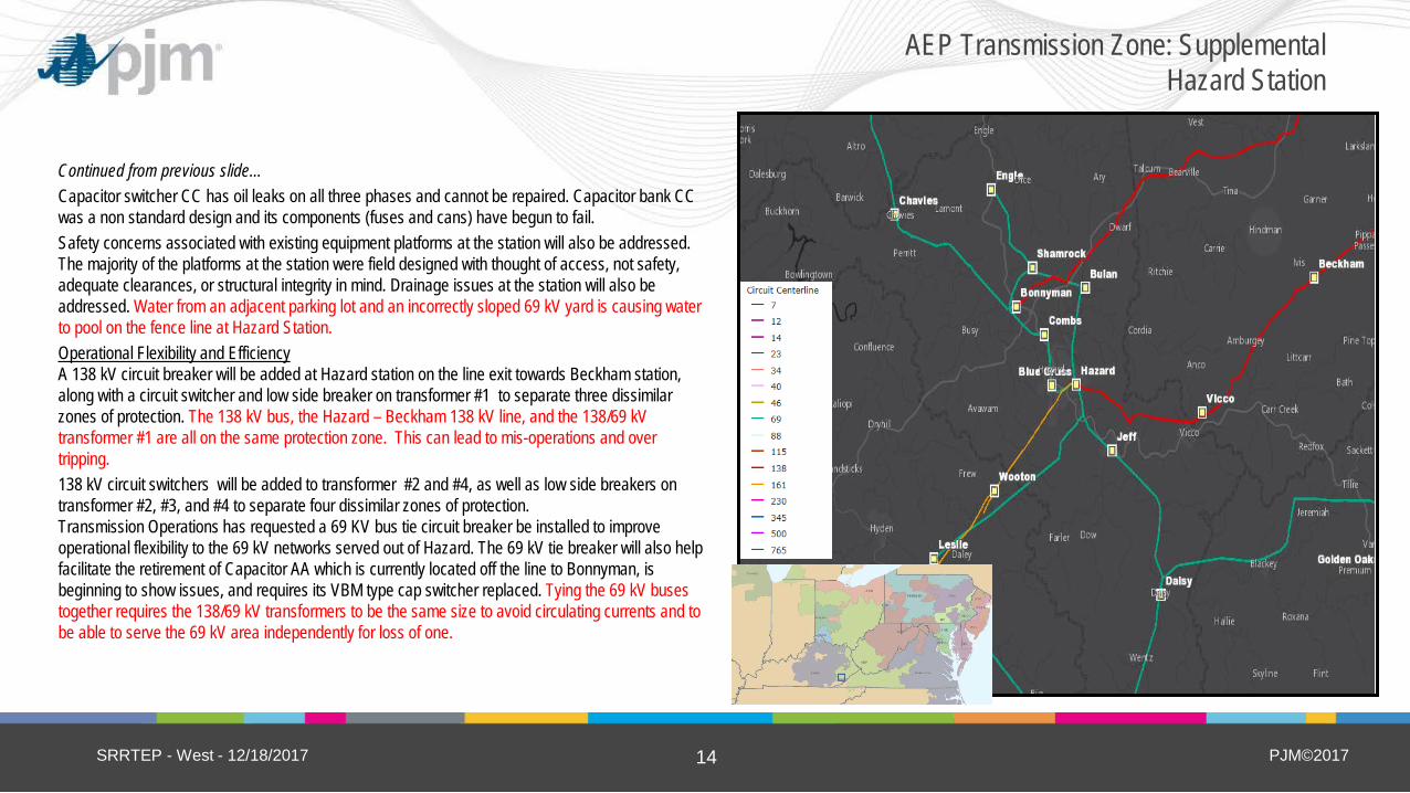
Continued from previous slide… Capacitor switcher CC has oil leaks on all three phases and cannot be repaired. Capacitor bank CC was a non standard design and its components (fuses and cans) have begun to fail. Safety concerns associated with existing equipment platforms at the station will also be addressed. The majority of the platforms at the station were field designed with thought of access, not safety, adequate clearances, or structural integrity in mind. Drainage issues at the station will also be addressed. Water from an adjacent parking lot and an incorrectly sloped 69 kV yard is causing water to pool on the fence line at Hazard Station. Operational Flexibility and Efficiency A 138 kV circuit breaker will be added at Hazard station on the line exit towards Beckham station, along with a circuit switcher and low side breaker on transformer #1 to separate three dissimilar zones of protection. The 138 kV bus, the Hazard – Beckham 138 kV line, and the 138/69 kV transformer #1 are all on the same protection zone. This can lead to mis-operations and over tripping. 138 kV circuit switchers will be added to transformer #2 and #4, as well as low side breakers on transformer #2, #3, and #4 to separate four dissimilar zones of protection. Transmission Operations has requested a 69 KV bus tie circuit breaker be installed to improve operational flexibility to the 69 kV networks served out of Hazard. The 69 kV tie breaker will also help facilitate the retirement of Capacitor AA which is currently located off the line to Bonnyman, is beginning to show issues, and requires its VBM type cap switcher replaced. Tying the 69 kV buses together requires the 138/69 kV transformers to be the same size to avoid circulating currents and to be able to serve the 69 kV area independently for loss of one.
SRRTEP - West - 12/18/2017
AEP Transmission Zone: Supplemental Hazard Station

PJM©2017 15
Continued from previous slide…
Selected Solution: Install a new 3000A 40 kA 138 kV circuit breaker at Hazard station on the line exit towards Beckham station. (s1412.1) Add a 138 kV circuit switcher to the high side of transformer #4. (s1412.2) Replace 138 kV capacitor bank and switcher BB with a new switcher and 43.2 MVAR capacitor bank. (s1412.3) Replace 138/69 kV transformers #1 and #2 with new 138/69 kV 130 MVA transformers with 138 kV circuit switchers on the high side and 3000A 40 kA 69 kV breakers on the low side. (s1412.4) Replaces 69 kV circuit breakers S, E, and F with 3000A 40 kA 69 kV circuit breakers with a bus tie 3000A 69 kV circuit breaker being installed between the existing 69 kV box bays. (s1412.5) Replace 69 kV capacitor bank and switcher CC with a new switcher and 28.8 MVAR capacitor bank. 69 kV capacitor bank and switcher AA will be retired. Replace 161 kV circuit breaker M towards Wooton with a 161 kV 3000 A 40 kA breaker. (s1412.6) Add a 3000A 40 kA 138 kV circuit breaker to the low side of 161/138 kV transformer #3. (s1412.7) Address safety and access issues associated with existing equipment platforms and drainage issues at the station. (s1412.8)
Estimated Transmission Cost: $20.0M Projected In-service: 12/31/2019 Project Status: Scoping
SRRTEP - West - 12/18/2017
AEP Transmission Zone: Supplemental Hazard Station

PJM©2017 16
Previously Presented:11/2/2017 SRRTEP Problem Statement: Customer Service: Obligation to serve customer request. The Lavalette 138/34.5 kV, 30 MVA #1 transformer is projected to exceed it’s rated capability (45 MVA) during the winter of 2018/2019 season. The West Huntington Station transformer is going to exceed its rated capability in 2020. To alleviate these two transformer overloads, Shoals Station is being constructed. Shoals will serve 15 MVA peak in summer and 16 MVA peak in winter.
Selected Solution: Construct a new 138/34.5 kV Station (Shoals Station). Install a 138 kV line breaker and 138 kV MOAB’s. Tap the Midkiff-West Huntington 138 kV line into the new station. (s1415)
Estimated Transmission Cost: $1.27M Projected In-service: 12/1/2017 Project Status: Construction
SRRTEP - West - 12/18/2017
AEP Transmission Zone: Supplemental Shoals Station
Shoals
West Huntington
Midkiff
Lavalette

PJM©2017 17
Previously Presented:11/2/2017 SRRTEP Problem Statement: Customer Service: Obligation to serve customer delivery point. Future load at the station is estimated to be approximately 10 MVA during Summer Peak and 16 MVA during Winter Peak. Load will be partially transferred from Milton, Hash Ridge, and Grassy Fork. MPOI calculations justify the installation of breakers at Balls Gap (804, above the 200 threshold). Selected Solution: Tap the Amos - West Huntington 138 kV line utilizing 1033.5 ACSR conductor (167 MVA rating) and extend 3.6 miles in and out of the new Balls Gap Station. Estimated Transmission Cost: $9.6M (s1416.1) Construct a new 138-34.5 kV Station. Install a 138/34.5 kV 30 MVA transformer, high side circuit switcher and two 138 kV 40 kA CBs. Estimated Transmission Cost: $2.5M (s1416.2)
Total Estimated Transmission Cost: $12.1M Projected In-service: 12/1/2017 Project Status: Construction
SRRTEP - West - 12/18/2017
AEP Transmission Zone: Supplemental Balls Gap Station Construction
Balls Gap
PJM©2017 18
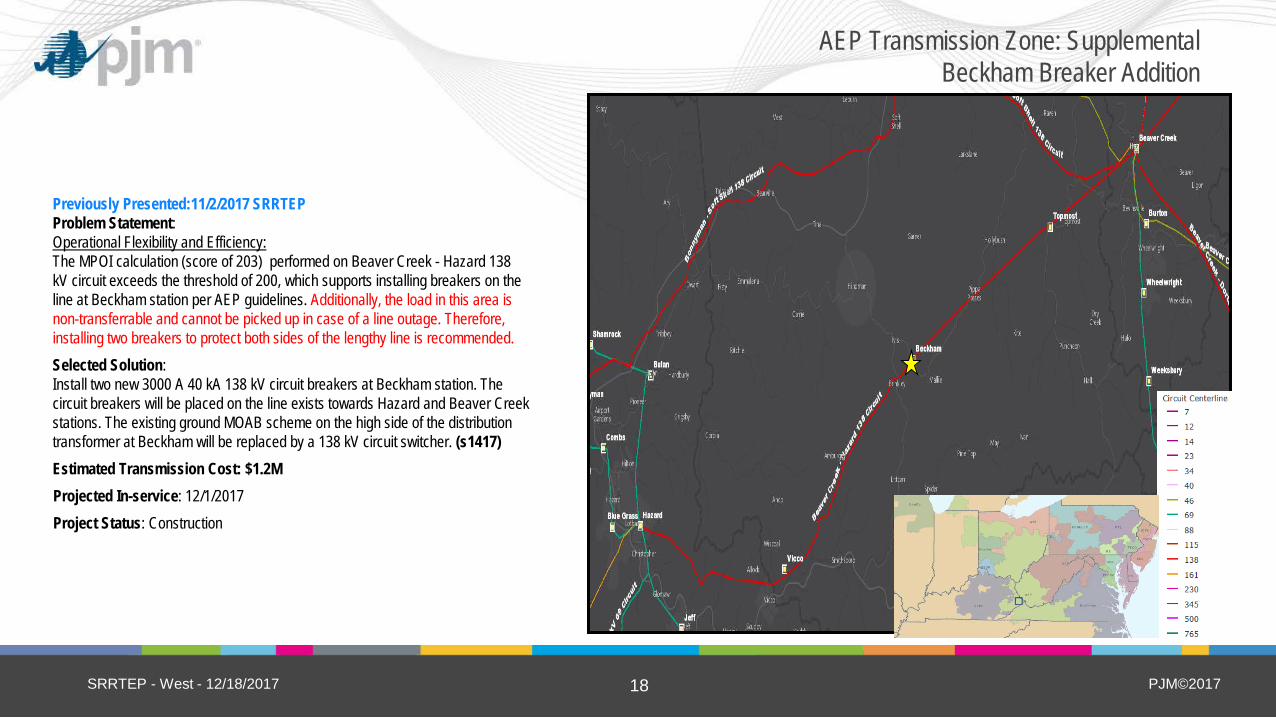
Previously Presented:11/2/2017 SRRTEP Problem Statement: Operational Flexibility and Efficiency: The MPOI calculation (score of 203) performed on Beaver Creek - Hazard 138 kV circuit exceeds the threshold of 200, which supports installing breakers on the line at Beckham station per AEP guidelines. Additionally, the load in this area is non-transferrable and cannot be picked up in case of a line outage. Therefore, installing two breakers to protect both sides of the lengthy line is recommended. Selected Solution: Install two new 3000 A 40 kA 138 kV circuit breakers at Beckham station. The circuit breakers will be placed on the line exists towards Hazard and Beaver Creek stations. The existing ground MOAB scheme on the high side of the distribution transformer at Beckham will be replaced by a 138 kV circuit switcher. (s1417) Estimated Transmission Cost: $1.2M Projected In-service: 12/1/2017 Project Status: Construction
SRRTEP - West - 12/18/2017
AEP Transmission Zone: Supplemental Beckham Breaker Addition
PJM©2017 19
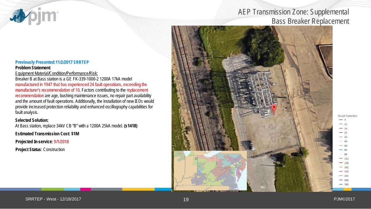
Previously Presented:11/2/2017 SRRTEP Problem Statement: Equipment Material/Condition/Performance/Risk: Breaker B at Bass station is a GE FK-339-1000-2 1200A 17kA model manufactured in 1947 that has experienced 24 fault operations, exceeding the manufacturer’s recommendation of 10. Factors contributing to the replacement recommendation are age, bushing maintenance issues, no repair part availability and the amount of fault operations. Additionally, the installation of new IEDs would provide increased protection reliability and enhanced oscillography capabilities for fault analysis. Selected Solution: At Bass station, replace 34kV CB “B” with a 1200A 25kA model. (s1418) Estimated Transmission Cost: $1M Projected In-service: 9/1/2018 Project Status: Construction
SRRTEP - West - 12/18/2017
AEP Transmission Zone: Supplemental Bass Breaker Replacement

PJM©2017 20
Previously Presented:11/2/2017 SRRTEP Problem Statement: Equipment Material/Condition/Performance/Risk: Breakers ‘C’, ‘C2’, ‘E’, and ‘E2’ are from vintage PK style 3000A 50 kA air blast breakers from 1973. The PK air blast medium breakers have a documented history of exploding violently upon failure and are an identified safety hazard. These breakers have been subject to a large amount of fault operations with Breaker C experiencing 15 operations, C2 experiencing 26 operations, breaker E experiencing 36 operations and breaker E2 experiencing 35 operations. Due to the age, number of operations and condition of these breakers, replacement is required. Operational Flexibility and Efficiency: Currently the Fall Creek busses are exposed to 6.7 miles of line fault through the Delco Remy 1949 line and 7.5 miles of line fault through the Madison 1940 line. In order to provide the busses protection from these 70+ year old lines breakers are needed. Currently a fault on the Delco Remy or the line requires 5 breakers to operate to clear the fault. The high number of breaker operations required significantly increases the complexity of the protection circuits and increases the likelihood of misoperations and human error.
SRRTEP - West - 12/18/2017
AEP Transmission Zone: Supplemental Fall Creek Breaker Replacement
PJM©2017 21
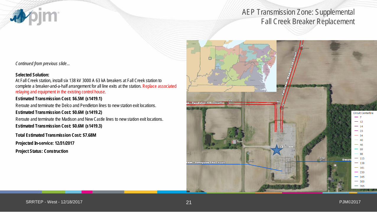
Continued from previous slide… Selected Solution: At Fall Creek station, install six 138 kV 3000 A 63 kA breakers at Fall Creek station to complete a breaker-and-a-half arrangement for all line exits at the station. Replace associated relaying and equipment in the existing control house. Estimated Transmission Cost: $6.5M (s1419.1) Reroute and terminate the Delco and Pendleton lines to new station exit locations. Estimated Transmission Cost: $0.6M (s1419.2) Reroute and terminate the Madison and New Castle lines to new station exit locations. Estimated Transmission Cost: $0.6M (s1419.3)
Total Estimated Transmission Cost: $7.68M Projected In-service: 12/31/2017 Project Status: Construction
SRRTEP - West - 12/18/2017
AEP Transmission Zone: Supplemental Fall Creek Breaker Replacement

PJM©2017 22
(5) New Carlisle
Include map of the area from TGIS South Bend
Previously Presented:11/2/2017 SRRTEP Problem Statement: Equipment Material/Condition/Performance/Risk: Transformer #1 is showing signs of deterioration. Drivers for replacement include dielectric strength breakdown (winding insulation), short circuit strength breakdown (due to the amount of through fault events), and accessory damage (bushings). Transformer #1 is a 1961 vintage and has high levels of Ethane and Hydrogen. For transformer 1, Asset Health Center shows a reading of 125 PPM for Ethane (at Condition 3 of 101-150) and 1,122 for Hydrogen (at IEEE Condition 3 of 701-1,800). Gas formation within an operating transformer are caused by electrical disturbances and thermal decomposition. All transformers generate gases to some extent at normal operating temperatures. Utilities abide by the IEEE Conditions, with 4 being the worst and 1 being normal, to assess transformer health. Transformer #2 is a 1966 vintage 75MVA bank that is no longer needed at this station. By removing this bank and connecting the 34.5 winding of existing transformer 5 to the 34.5kV network, the reliability of the 34.5kV network is maintained. Transformer 5 was manufactured in 1992.
SRRTEP - West - 12/18/2017
AEP Transmission Zone: Supplemental South Bend Station Upgrades
Heppner Sw
Rhodes

PJM©2017 23
(5) New Carlisle
Include map of the area from TGIS South Bend
Continued from previous slide… Potential Solution At South Bend station, retire 138/34kV transformer #2. Replace transformer #1 with a 138/69-34.5kV 78/104/130MVA transformer. (s1420.1) Transformer #1 will feed the 34.5kV bus through the 34.5 kV winding until the station is upgraded to 69kV. Connect the 34.5 kV winding of transformer #5 to the 34.5kV bus 2. Install high side circuit switchers on both transformer #1 and #5. (s1420.2) Reroute the South Bend – West Side, South Bend – Colfax and South Bend – Dragoon line to the new station exits. (s1420.3)
Estimated Transmission Cost $1.15M Projected In-service: 12/01/2017 Project Status: Construction
SRRTEP - West - 12/18/2017
AEP Transmission Zone: Supplemental South Bend Station Upgrades
Heppner Sw
Rhodes
PJM©2017 24
Previously Presented:11/2/2017 SRRTEP Problem Statement: Equipment Material/Condition/Performance/Risk:
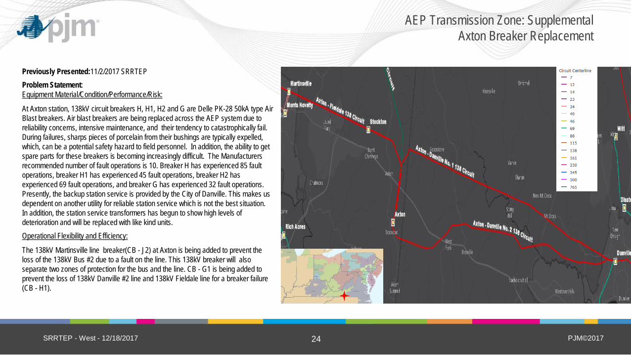
At Axton station, 138kV circuit breakers H, H1, H2 and G are Delle PK-28 50kA type Air Blast breakers. Air blast breakers are being replaced across the AEP system due to reliability concerns, intensive maintenance, and their tendency to catastrophically fail. During failures, sharps pieces of porcelain from their bushings are typically expelled, which, can be a potential safety hazard to field personnel. In addition, the ability to get spare parts for these breakers is becoming increasingly difficult. The Manufacturers recommended number of fault operations is 10. Breaker H has experienced 85 fault operations, breaker H1 has experienced 45 fault operations, breaker H2 has experienced 69 fault operations, and breaker G has experienced 32 fault operations. Presently, the backup station service is provided by the City of Danville. This makes us dependent on another utility for reliable station service which is not the best situation. In addition, the station service transformers has begun to show high levels of deterioration and will be replaced with like kind units. Operational Flexibility and Efficiency:
The 138kV Martinsville line breaker(CB - J2) at Axton is being added to prevent the loss of the 138kV Bus #2 due to a fault on the line. This 138kV breaker will also separate two zones of protection for the bus and the line. CB - G1 is being added to prevent the loss of 138kV Danville #2 line and 138kV Fieldale line for a breaker failure (CB - H1).
SRRTEP - West - 12/18/2017
AEP Transmission Zone: Supplemental Axton Breaker Replacement

PJM©2017 25
Continued from previous slide…
Selected Solution: At Axton 138kV Station, replace 138kV PK breakers with new 3000A, 145/170kV, 63kA circuit breakers and install new control relays. (S1421.1) At Axton 138kV Station, install a new 3000A, 145/170kV, 63kA circuit breaker on the Martinsville line and install new line relays. (S1421.2) At Axton 138kV station, install a new 3000A, 145/170kV, 63kA circuit breaker to complete 138kV G string for Danville 32 138kV line and install new line relays. (S1421.3) At Axton 138kV station, install new relays for 138kV Danville #1 line, 138kV Danville #2 line, 138kV Fieldale line, 138kV Bus #1 and 138kV Bus #2. (S1421.4)
Estimated Transmission Cost: $3.79M Projected In-service: 11/1/2018 Project Status: Engineering
SRRTEP - West - 12/18/2017
AEP Transmission Zone: Supplemental Axton Breaker Replacement

PJM©2017 26
Previously Presented:11/2/2017 SRRTEP
Problem Statement: Equipment Material/Condition/Performance/Risk: CB’s A, B, and C at Berne and Breaker E at Adams are oil type breakers. Oil breakers, in general, have become more difficult to maintain due to the required oil handling. Oil spills occur often during routine maintenance and failures, which can become an environmental concern. Other drivers include age, bushing damage, and number of fault operations. 69kV breakers ‘A’ and ‘B’ at Berne are Penn CF 1200A 23kA models manufactured in 1967 and have experienced 16 and 79 fault operations respectively. 69kV breaker ‘C’ at Berne is a McG CF 1200A 23kA breaker model manufactured in 1970 and has experienced 121 fault operations. 69kV circuit switcher ‘AA’ being replaced is a S&C model 400A 20kA. 69kV breaker ‘E’ at Adams is a P.T.CO CF 1200A 21kA model manufactured in 1966 and has experienced 12 fault operations.
SRRTEP - West - 12/18/2017
AEP Transmission Zone: Supplemental Berne and Adams Breaker Replacements

PJM©2017 27
Continued from previous slide…
Selected Solution: At Berne station, retire 69 kV CB’s “A”,”B”,”C”, foundations and associated disconnects and replace them with 69kV 3000A 40kA CB’s. Replace Cap Switcher “AA” along with its foundation and controls with a 69kV 420A 18kA cap switcher. (S1422.1) Estimated Transmission Cost: $2.6M At Adams Station, replace breaker ‘E’ with a 69kV 3000A 40kA breaker. (S1422.2) Estimated Transmission Cost: $0.7M
Total Estimated Transmission Cost: $3.3M Projected In-service: 12/31/2018 Project Status: Engineering
SRRTEP - West - 12/18/2017
AEP Transmission Zone: Supplemental Berne and Adams Breaker Replacements

PJM©2017 28
(5) New Carlisle
Include map of the area from TGIS
Hartford City
Bosman
Previously Presented:11/2/2017 SRRTEP Problem Statement: Equipment Material/Condition/Performance/Risk: The Delaware – Hartford City line is constructed of wooden poles from 1950 and is currently subject to 75 open conditions including elongated crossarm bolt holes; heart rotted, top rotted and split crossarms; broken and missing ground lead wires; broken insulators; and heart rotted, top rotted and split poles. The existing conductor is 3/0 copper (23 MVA rating). Selected Solution: Rebuild the 17.6 mile Bosman – Hartford City 34.5 kV line utilizing 795 ACSR 26/7 (64 MVA rating). This line will be built to 69kV standards but operated at 34.5kV (S1423) Estimated Transmission Cost: $13.6M Projected In-service: 8/31/2018 Project Status: Engineering
SRRTEP - West - 12/18/2017
AEP Transmission Zone: Supplemental Bosman-Hartford City Rebuild
PJM©2017 29
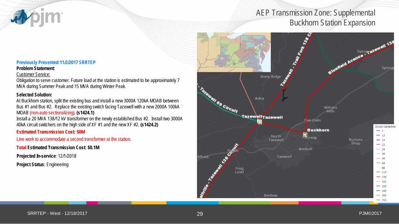
Previously Presented:11/2/2017 SRRTEP Problem Statement: Customer Service: Obligation to serve customer. Future load at the station is estimated to be approximately 7 MVA during Summer Peak and 15 MVA during Winter Peak. Selected Solution: At Buckhorn station, split the existing bus and install a new 3000A 120kA MOAB between Bus #1 and Bus #2. Replace the existing switch facing Tazewell with a new 2000A 100kA MOAB (non-auto sectionalizing). (s1424.1) Install a 20 MVA 138/12 kV transformer on the newly established Bus #2. Install two 3000A 40kA circuit switchers on the high side of XF #1 and the new XF #2. (s1424.2) Estimated Transmission Cost: $0M Line work to accommodate a second transformer at the station. Total Estimated Transmission Cost: $0.1M Projected In-service: 12/1/2018 Project Status: Engineering
SRRTEP - West - 12/18/2017
AEP Transmission Zone: Supplemental Buckhorn Station Expansion

PJM©2017 30
Previously Presented:11/2/2017 SRRTEP Problem Statement: Equipment Material/Condition/Performance/Risk: The existing 19.8-mile, 138 kV line section between Carrollton and Sunnyside stations was constructed in 1916 using lattice towers and 6-wired 200 kcmil copper conductor (221 MVA summer rating). There are numerous condition concerns on this line, including rusting towers on 60% of the line, worn insulators and hardware. The copper conductor has become very brittle after 100 years in the field and is difficult for crews to repair. Some towers are sitting in water. Many tower legs under ground have been found to be significantly deteriorated. The circuit has experienced zero minutes of customer interruption, due to not directly serving customers. However, it does serve as an important pathway in transporting power from south to north, from the Ohio River generation to the load center in northeast Ohio. This area also has high load growth potential due to shale loads in the area. Keeping the existing ROW and line is advantageous to maintaining future flexibility in the area.
Selected Solution: Rebuild the Carrollton-Sunnyside 138kV circuit. Install double-circuit steel poles with 6-wired 1234 ACSS/TW Yukon conductor. Future circuit rating = 335 MVA SN / 392 MVA SE (non-conductor limited). (s1425) Estimated Transmission Cost: $50.4M Projected In-service: 12/1/2019 Project Status: Engineering
SRRTEP - West - 12/18/2017
AEP Transmission Zone: Supplemental Carrolton-Sunnyside Rebuild
Carrolton
Sunnyside

PJM©2017 31
Previously Presented:11/2/2017 SRRTEP Problem Statement: Equipment Material/Condition/Performance/Risk: The College Corner station breakers are 1950 manufactured FK-439 type Oil breakers. These breakers are currently experiencing leaking bushings, bushings leaking into the breaker tank, high C2 PF and steadily increasing contact resistance. Each breaker contains 2,400 gallons of oil for a total of 16,800 gallons and must be toped off twice a year. In addition to this, the breaker bushings are likely PCB and create a potential risk to the local environment. The leaking air tanks are resulting in high compressor run time which, in conjunction with the oil breaker maintenance, is causing higher O&M costs. The breaker switches are obsolete models with breaded shunts and cap and pin insulators. The current breaker switch and station service transformer bus selector switches are mechanically difficult to operate and need to be replaced. The relay equipment with the exception of the Ohio line exits are electromechanical. The carrier protection schemes are now starting to exhibit repetitive problems. The stations RTU is a legacy model that is no longer supported by our vendor which means if an issue would occur, repairs would be costly and timely if possible. The control house is in very poor condition and needs replaced. The roof currently needs to be patched periodically to stop leaks that spring up, the walls are deteriorated to the point that wildlife is entering the control house, and current cable exits are full and have no room for expansion. In addition to this many of the yard cabinets are in very deteriorated condition and need replacement.
SRRTEP - West - 12/18/2017
AEP Transmission Zone: Supplemental College Corner Rebuild

PJM©2017 32
Continued from previous slide… Equipment Material/Condition/Performance/Risk: From 2002-2012 there have been 6 relay miss-operations which can be linked to either the age of the equipment or the poor protection scheme. Breakers ‘A’, ‘B’, ‘D’, ‘E’, ‘F’ and ‘G’ are FK-439 1200A 17.5kA models Breakers ‘A’, ‘E’, ‘F’, ‘G’, and ‘H’ are all above the recommended fault limit of 10 with the following amount of fault operations; A: 24 E: 88 F: 47 G: 37 H: 19 Breaker ‘C’ is a 140SFMT 3000A 40kA model and recently failed in the field. Breaker ‘H’ is a HVB HS170 3000A 40kA model and recently failed in the field. At Richmond station, the vintage 1959, 138kV circuit breaker C is a GE, FK Type oil filled breaker without oil containment that has had 91 fault operations which significantly exceeded the designed number of fault operations. Breaker ‘C’ is a FK 439-138-5-3Y 1200A 50000MVA model. The Richmond MOAB’s are in deteriorated condition and have vintage delta star mechanisms. In addition to this, the MOAB toward College Corner is no longer operational and the MOAB toward Selma Parker requires a mobile transformer to operate.
SRRTEP - West - 12/18/2017
AEP Transmission Zone: Supplemental College Corner Rebuild

PJM©2017 33
Continued from previous slide…
Selected Solution: Rebuild College Corner 138 kV station in the clear at the existing station site with ten 3000A 40 kA circuit breakers in a breaker and a half arrangement to terminate seven line positions. Replace the control house with a new DICM. Estimated Transmission Cost: $12.3M (s1426.1) At Richmond station, replace 138 kV Breaker C with a 3000A 40kA model and replace MOAB’s U, V, W, and Y with 3000A MOAB switches Estimated Transmission Cost: $1.5 (s1426.2) Total Estimated Transmission Cost: $13.8M Projected In-service: 11/30/2018 Project Status: Engineering
SRRTEP - West - 12/18/2017
AEP Transmission Zone: Supplemental College Corner Rebuild
PJM©2017 34
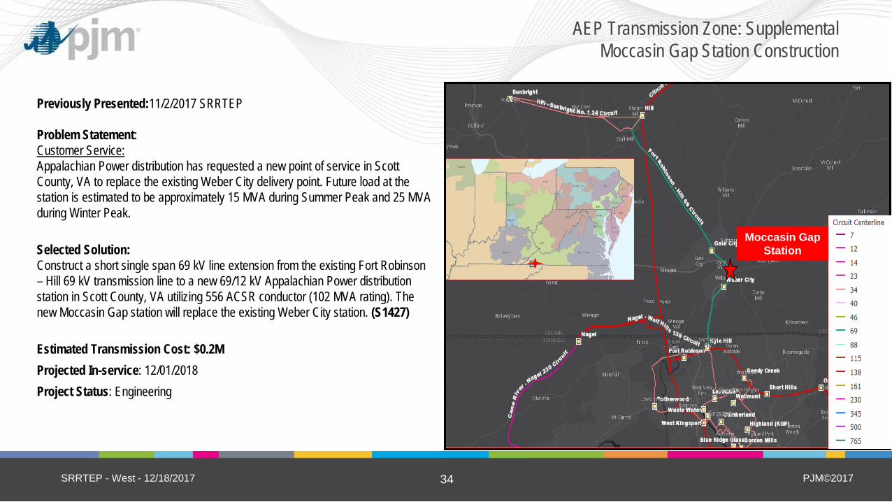
Previously Presented:11/2/2017 SRRTEP Problem Statement: Customer Service: Appalachian Power distribution has requested a new point of service in Scott County, VA to replace the existing Weber City delivery point. Future load at the station is estimated to be approximately 15 MVA during Summer Peak and 25 MVA during Winter Peak. Selected Solution: Construct a short single span 69 kV line extension from the existing Fort Robinson – Hill 69 kV transmission line to a new 69/12 kV Appalachian Power distribution station in Scott County, VA utilizing 556 ACSR conductor (102 MVA rating). The new Moccasin Gap station will replace the existing Weber City station. (S1427) Estimated Transmission Cost: $0.2M Projected In-service: 12/01/2018 Project Status: Engineering
SRRTEP - West - 12/18/2017
AEP Transmission Zone: Supplemental Moccasin Gap Station Construction
Moccasin Gap Station

PJM©2017 35
Fogwell
Previously Presented:11/2/2017 SRRTEP Problem Statement: Customer Service: General Motors has set in motion a plan to increase production capabilities at their Fort Wayne Truck Plant by adding new facilities and therefore additional load. The existing peak load at the plant is approximately 28 MVA, with a new projected peak load of 45 MVA. This significant increase in load has required Wabash Valley Power Authority (WVPA), who owns the transformers serving the GM Truck Plant, to add a third transformer in order to support the new load and maintain reliability. In order to provide reliable service off the 138kV AEP facilities serving WVPA and GM going forward, a new AEP 138kV yard (Fogwell Station), will be established directly adjacent to the existing station facilities.
SRRTEP - West - 12/18/2017
AEP Transmission Zone: Supplemental Fogwell Station

PJM©2017 36
Continued from previous slide…
Selected Solution: Build a new 138kV station (Fogwell) in the clear near existing GM Fort Wayne station. Station configuration will consist of two breaker and a half strings, totaling six 138kV, 3000 A, 40 kA circuit breakers. Transmission line and transformer positions will be configured such that at least one 138kV line and two transformers will be in-service in the event of a breaker failure. (S1428.1) Estimated Cost: $5.9 M Install metering for GM tie line 3 at Fogwell station. (S1428.2) Estimated Cost: $0.27 M Reroute 0.25 miles of the Sorenson line to the F-F1 Fogwell breaker position. (S1428.3) Estimated Cost: $0.8M Reroute 0.1 miles of the GM 1 tie line to terminate at Fogwell138kV bus 1. (S1428.4) Estimated Cost: $0.56M Reroute 0.1 miles of the GM 2 line to the F-F2 Fogwell breaker position. (S1428.5) Estimated Cost: $0.56M Reroute 0.1 miles of the GM 3 line to the G-G2 Fogwell breaker position. (S1428.6) Estimated Cost: $0.26M
Total Estimated Transmission Cost: $8.4M Projected In-service: 6/01/2018 Project Status: Engineering
SRRTEP - West - 12/18/2017
AEP Transmission Zone: Supplemental Fogwell Station
Fogwell

PJM©2017 37
Previously Presented:11/2/2017 SRRTEP Problem Statement: Equipment Material/Condition/Performance/Risk: The Marion-Parsons 40kV line is 1926 vintage and in poor condition and in need of a complete rebuild. It has 38 A conditions along the 5 mile length. Due to the fact that this is a double circuit line and the only source to Parsons station, a planned outage cannot be taken to rebuild the line. The 636 AAC & 636 ACSR conductors are rated for SN/SE=62/62 MVA. Parsons records show 25 fault operations on CB 42 and 11 fault operations on CB 44. The manufacturer recommends a limit of 10 fault operations. Parsons circuit breakers #42 & #44 are showing signs of deterioration and use oil as the interrupting medium. Oil breaker maintenance has become more difficult due to the oil handling required to maintain them. Oil spills are frequent with breaker failures and routine maintenance can become an environmental hazard. The drivers for replacement of these breakers are age, bushing damage, no repair part availability, amount of fault operations and PCB content. PCBs have been used as coolants and lubricants in transformers, breakers, and other electrical equipment because they don't burn easily and are good insulators. The manufacture of PCBs was stopped in the U.S. in 1977 because of evidence they build up in the environment and can cause harmful health effect. Operational Flexibility and Efficiency: Due to the fact that the Marion-Parsons 40kV line is the only source to Parsons station, it cannot be taken out of service for basic maintenance or to facilitate future conversion from the obsolete 40kV system to 69kV.
SRRTEP - West - 12/18/2017
AEP Transmission Zone: Supplemental Harrison-Parsons-Marion 40 kV
Harrison
Parsons
Marion

PJM©2017 38
Harrison
Parsons
Marion
Continued from previous slide… Selected Solution: Construct a new Harrison-Parsons 69kV Line (energized @40kV), New 795 ACSR Drake in new ROW, SN/SE = 73 MVA Estimated Transmission Cost: $7.7M (s1429.1) Rebuild the Marion-Parson double circuit 40kV Line as single circuit 69kV (energized @40kV), SN/SE = 73 MVA, Estimated Transmission Cost: $14.0M (s1429.2) Harrison station, Relocate and install existing spare 138/40kV 46MVA transformer, 3,000A 138kV CB, & 2,000A 69kV CB Estimated Transmission Cost: $2.0M (s1429.3) Parsons station, Replace 2-40kV CB’s with 2-2,000A 69KV CB’s, install 9.4MVAr capacitor bank Estimated Transmission Cost: $1.0M (s1429.4) Marion station, Install 9.4 MVAr capacitor bank and retire unused equipment. Estimated Transmission Cost: $0.3M. (s1429.5)
Total Estimated Transmission Cost: $25.0M Projected In-service: 12/01/2018 Project Status: Engineering
SRRTEP - West - 12/18/2017
AEP Transmission Zone: Supplemental Harrison-Parsons-Marion 40 kV
PJM©2017 39
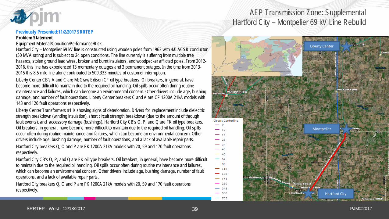
Previously Presented:11/2/2017 SRRTEP Problem Statement: Equipment Material/Condition/Performance/Risk: Hartford City – Montpelier 69 kV line is constructed using wooden poles from 1963 with 4/0 ACSR conductor (50 MVA rating) and is subject to 24 open conditions. The line currently is suffering from multiple tree hazards, stolen ground lead wires, broken and burnt insulators, and woodpecker afflicted poles. From 2012-2016, this line has experienced 13 momentary outages and 3 permanent outages. In the time from 2013-2015 this 8.5 mile line alone contributed to 500,333 minutes of customer interruption. Liberty Center CB’s A and C are McGraw Edison CF oil type breakers. Oil breakers, in general, have become more difficult to maintain due to the required oil handling. Oil spills occur often during routine maintenance and failures, which can become an environmental concern. Other drivers include age, bushing damage, and number of fault operations. Liberty Center breakers C and A are CF 1200A 21kA models with 143 and 126 fault operations respectively. Liberty Center Transformers #1 is showing signs of deterioration. Drivers for replacement include dielectric strength breakdown (winding insulation), short circuit strength breakdown (due to the amount of through fault events), and accessory damage (bushings). Hartford City CB’s O, P, and Q are FK oil type breakers. Oil breakers, in general, have become more difficult to maintain due to the required oil handling. Oil spills occur often during routine maintenance and failures, which can become an environmental concern. Other drivers include age, bushing damage, number of fault operations, and a lack of available repair parts. Hartford City breakers Q, O and P are FK 1200A 21kA models with 20, 59 and 170 fault operations respectively. Hartford City CB’s O, P, and Q are FK oil type breakers. Oil breakers, in general, have become more difficult to maintain due to the required oil handling. Oil spills occur often during routine maintenance and failures, which can become an environmental concern. Other drivers include age, bushing damage, number of fault operations, and a lack of available repair parts. Hartford City breakers Q, O and P are FK 1200A 21kA models with 20, 59 and 170 fault operations respectively.
SRRTEP - West - 12/18/2017
AEP Transmission Zone: Supplemental Hartford City – Montpelier 69 kV Line Rebuild
(5) New Carlisle
Hartford City
Montpelier
Liberty Center

PJM©2017 40
Continued from previous slide…
Selected Solution: Replace circuit breakers F and E at Liberty Center and install a new high side 69kV circuit switcher. Replace circuit breakers A and C at Liberty Center with 3000A 40kA models. Replace the current 69/12 kV transformer at Liberty Center with a new model. Estimated Cost: $1.0M (s1430.1) Replace circuit breakers Q, O and P at Hartford City with 3000A 40kA models Estimated Cost: $0.9M (s1430.2) Rebuild the ~8.5 miles of the Hartford City – Montpelier 69 kV line utilizing 556.5 ACSR (68 MVA rating, non-conductor limited) Estimated Cost: $13.4M (s1430.3) Total Estimated Transmission Cost: $15.3M Projected In-service: 04/01/2019 Project Status: Scoping
SRRTEP - West - 12/18/2017
AEP Transmission Zone: Supplemental Hartford City – Montpelier 69 kV Line Rebuild
(5) New Carlisle Liberty Center
Hartford City
Montpelier
PJM©2017 41
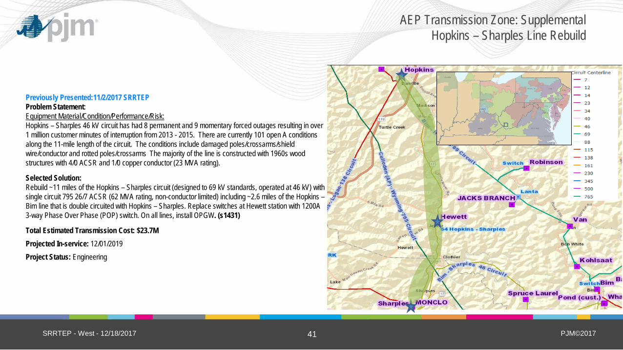
Previously Presented:11/2/2017 SRRTEP Problem Statement: Equipment Material/Condition/Performance/Risk: Hopkins – Sharples 46 kV circuit has had 8 permanent and 9 momentary forced outages resulting in over 1 million customer minutes of interruption from 2013 - 2015. There are currently 101 open A conditions along the 11-mile length of the circuit. The conditions include damaged poles/crossarms/shield wire/conductor and rotted poles/crossarms The majority of the line is constructed with 1960s wood structures with 4/0 ACSR and 1/0 copper conductor (23 MVA rating).
Selected Solution: Rebuild ~11 miles of the Hopkins – Sharples circuit (designed to 69 kV standards, operated at 46 kV) with single circuit 795 26/7 ACSR (62 MVA rating, non-conductor limited) including ~2.6 miles of the Hopkins – Bim line that is double circuited with Hopkins – Sharples. Replace switches at Hewett station with 1200A 3-way Phase Over Phase (POP) switch. On all lines, install OPGW. (s1431)
Total Estimated Transmission Cost: $23.7M Projected In-service: 12/01/2019 Project Status: Engineering
SRRTEP - West - 12/18/2017
AEP Transmission Zone: Supplemental Hopkins – Sharples Line Rebuild
(5) New Carlisle (5) New Carlisle
PJM©2017 42
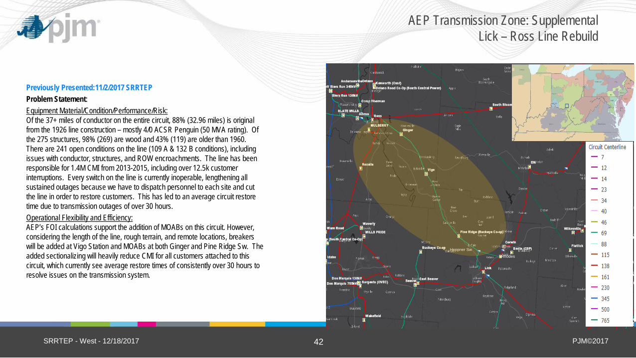
Previously Presented:11/2/2017 SRRTEP Problem Statement: Equipment Material/Condition/Performance/Risk: Of the 37+ miles of conductor on the entire circuit, 88% (32.96 miles) is original from the 1926 line construction – mostly 4/0 ACSR Penguin (50 MVA rating). Of the 275 structures, 98% (269) are wood and 43% (119) are older than 1960. There are 241 open conditions on the line (109 A & 132 B conditions), including issues with conductor, structures, and ROW encroachments. The line has been responsible for 1.4M CMI from 2013-2015, including over 12.5k customer interruptions. Every switch on the line is currently inoperable, lengthening all sustained outages because we have to dispatch personnel to each site and cut the line in order to restore customers. This has led to an average circuit restore time due to transmission outages of over 30 hours. Operational Flexibility and Efficiency: AEP’s FOI calculations support the addition of MOABs on this circuit. However, considering the length of the line, rough terrain, and remote locations, breakers will be added at Vigo Station and MOABs at both Ginger and Pine Ridge Sw. The added sectionalizing will heavily reduce CMI for all customers attached to this circuit, which currently see average restore times of consistently over 30 hours to resolve issues on the transmission system.
SRRTEP - West - 12/18/2017
AEP Transmission Zone: Supplemental Lick – Ross Line Rebuild
Heppner Sw
Rhodes

PJM©2017 43
Continued from previous slide… Selected Solution: Rebuild from Ross to Heppner Sw (formerly Coalton Sw). Single Circuit 138kV Rebuild (Energized at 69kV) with 1033 ACSR Curlew Conductor (148 MVA SN rating) Estimated Cost: $46.2M (s1432.1) Replace switches at Ginger with a new 138kV, 2000A phase-over-phase switch with MOABs. Replace switches at Vigo with a new box bay and 138kV, 3000A breakers. Replace Pine Ridge Switch with a new 138kV, 2000A phase-over-phase switch with MOABs. Estimated Cost: $4.1M (s1432.2)
Total Estimated Transmission Cost: $50.3M Projected In-service: 12/31/2021 Project Status: Scoping
SRRTEP - West - 12/18/2017
AEP Transmission Zone: Supplemental Lick – Ross Line Rebuild
Heppner Sw
Rhodes

PJM©2017 44
(5) New Carlisle
Previously Presented:11/2/2017 SRRTEP Problem Statement: Equipment Material/Condition/Performance/Risk: The Midway 69 kV circuit breaker A is an FK 25 kA 1200 A oil-filled breaker manufactured in 1965. In general, oil breakers have become increasingly difficult to maintain due to the oil handling associated with them. Oil spills occur frequently with failures and while performing routine maintenance, which, is an environmental hazard. Selected Solution: Replace Midway’s existing 69 kV circuit breaker A with a new 69 kV 40kA 3000A circuit breaker. Line relays at remote ends will be upgraded. (S1433) Estimated Transmission Cost $0.52M Projected In-service: 05/25/2018 Project Status: Engineering
SRRTEP - West - 12/18/2017
AEP Transmission Zone: Supplemental Midway Breaker Replacement
Heppner Sw
Rhodes

PJM©2017 45
Problem Statement: Equipment Material/Condition/Performance/Risk: The wood pole structure supporting the line MOAB switches outside Monroe Station is decaying due to heart rot. The pole base will eventually collapse and render the switches inoperable. This will cause Monroe stations load to be dropped. Currently there are 4 in line Motor Operated Air Break Switches (MOABs) on the Berne – Decatur line. Having more than 3 MOABs in line leads to increased chances of misoperations and increases the complexity of the protection scheme. AEP guidelines recommend a maximum of three Motor Operated Air Break Switches (MOABs) in series based on experience with mis-operations in applications with more than three MOABs. In order to increase the reliability of this circuit and to reduce the chances of a mis-operation, a breaker will be added at Monroe station. Operational Flexibility and Efficiency: Ground switching MOABs have been identified by AEP as a reliability concern due to the PQ issues that result upon operation and due to the absence of bus 1-shot capability for distribution bus faults. Replacing this switch with a circuit switcher will fix both of these reliability issues. A second distribution transformer will be needed at this station in the future. Rebuilding the station entrance and upgrading its protection allows for that future expansion to take place. Selected Solution: At Monroe station, install a 2000A circuit switcher on the high side of the transformer. Install a 69kV 3000A 40kA circuit breaker on the Decatur line. Install a 2000A MOAB on the Berne line. Retire entrance structure and span, replace with two exit spans. (S1434) Estimated Transmission Cost: $1.9M Projected In-service: 3/01/2018 Project Status: Construction
SRRTEP - West - 12/18/2017
AEP Transmission Zone: Supplemental Monroe Station Line MOAB Replacement
(5) New Carlisle
Monroe Station
Heppner Sw
Rhodes

PJM©2017 46
(5) New Carlisle
Include map of the area from TGIS
Moore Park
Wheeler St.
Dock Foundry
Three Rivers
Previously Presented:11/2/2017 SRRTEP
Problem Statement: Equipment Material/Condition/Performance/Risk: 24% of the wood poles used for the Moore Park – Three Rivers 69 kV line were installed in the 1950’s and the remaining 76% were installed in the 1960’s. This 5.7 mile line currently has 55 open conditions, which include rotten poles, broken insulators, cracked poles, and broken cross-arms. Circuit breakers A and B at Moore Park station are 1960s vintage oil type (1200A 19kA CF) breakers. CB A has a total of 115 fault operations and CB A has a total of 210 fault operations. Both breakers have exceeded the maximum number of fault operations recommended by the manufacturer. Oil breakers, in general, have become more difficult to maintain due to the required oil handling. Oil spills occur often during routine maintenance and failures, which can become an environmental concern. Other drivers include age, number of fault operations, and PCB content. PCBs have been used as coolants and lubricants in transformers, breakers, and other electrical equipment because they don't burn easily and are good insulators. The manufacture of PCBs was stopped in the U.S. in 1977 because of evidence they build up in the environment and may have a negative health effect. 69 kV circuit breakers A, C, D and E at Three Rivers are 1950/60s vintage and are all showing signs of deterioration. CB A, C, and D have fault operations of 148, 161, 71, respectively. The drivers for replacement of these breakers are age, number of fault operations, and PCB content. At Three Rivers, transformer 1 is also showing significant signs of deterioration. Drivers for replacement include dielectric strength breakdown (winding insulation), short circuit strength breakdown (due to the amount of through fault events), and accessory damage (bushings). Transformer 1 also has high levels of Carbon Dioxide dissolved in the oil. Asset Health Center shows a reading of 13,265 PPM (above IEEE Condition 4 of >10,000). Gas formation within an operating transformer are caused by electrical disturbances and thermal decomposition. All transformers generate gases to some extent at normal operating temperatures. Utilities abide by the IEEE Conditions, with 4 being the worst and 1 being normal, to assess transformer health.
SRRTEP - West - 12/18/2017
AEP Transmission Zone: Supplemental Moore Park – Three River Rebuild
PJM©2017 47
(5) New Carlisle
Include map of the area from TGIS
Moore Park
Wheeler St.
Dock Foundry
Three Rivers
Continued from previous slide…
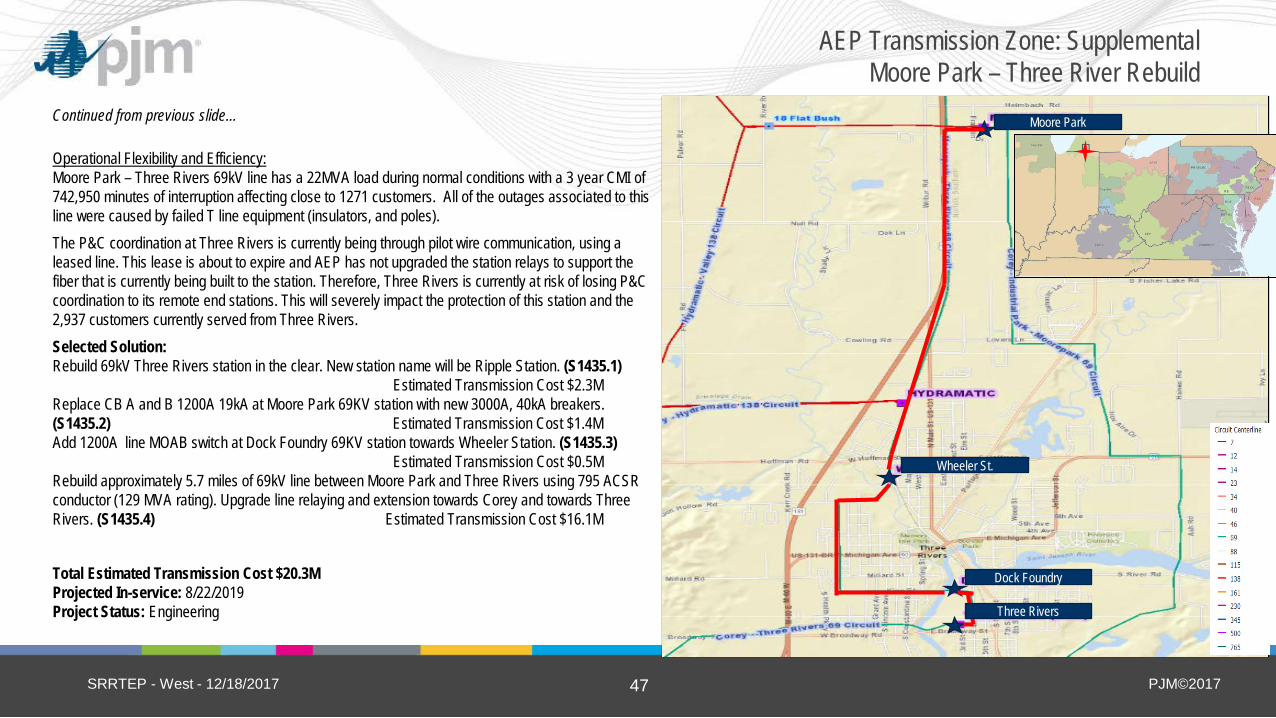
Operational Flexibility and Efficiency: Moore Park – Three Rivers 69kV line has a 22MVA load during normal conditions with a 3 year CMI of 742,950 minutes of interruption affecting close to 1271 customers. All of the outages associated to this line were caused by failed T line equipment (insulators, and poles). The P&C coordination at Three Rivers is currently being through pilot wire communication, using a leased line. This lease is about to expire and AEP has not upgraded the station relays to support the fiber that is currently being built to the station. Therefore, Three Rivers is currently at risk of losing P&C coordination to its remote end stations. This will severely impact the protection of this station and the 2,937 customers currently served from Three Rivers. Selected Solution: Rebuild 69kV Three Rivers station in the clear. New station name will be Ripple Station. (S1435.1) Estimated Transmission Cost $2.3M Replace CB A and B 1200A 19kA at Moore Park 69KV station with new 3000A, 40kA breakers. (S1435.2) Estimated Transmission Cost $1.4M Add 1200A line MOAB switch at Dock Foundry 69KV station towards Wheeler Station. (S1435.3) Estimated Transmission Cost $0.5M Rebuild approximately 5.7 miles of 69kV line between Moore Park and Three Rivers using 795 ACSR conductor (129 MVA rating). Upgrade line relaying and extension towards Corey and towards Three Rivers. (S1435.4) Estimated Transmission Cost $16.1M
Total Estimated Transmission Cost $20.3M Projected In-service: 8/22/2019 Project Status: Engineering
SRRTEP - West - 12/18/2017
AEP Transmission Zone: Supplemental Moore Park – Three River Rebuild

PJM©2017 48
Previously Presented:11/2/2017 SRRTEP Problem Statement: Equipment Material/Condition/Performance/Risk: The synchronous condenser at Opossum Creek station is a 1972 vintage model with multiple concerns involving the cooling and control systems. The control system has been replaced within the last 20 years but has never worked correctly. Currently, every time the condenser experiences an abnormal system event, it will go offline. Once the unit is back online, an engineer must monitor its controls or it will go offline again. This control system issue has lead to decreased reliability and performance of a critical system asset. The breakers for this machine are “rack in – rack out” breakers that are two of a kind in AEP’s system; when they fail they need to be shipped to G.E. to get fixed. These breakers have also led to prolonged outages for the condenser. AEP’s main issue is that the water in the cooling system is acidic and is continually causing corrosion. The cooling towers and the cooling system are in a state where new leaks are appearing constantly. Additional leaks are being addressed, but this is a costly procedure that involves taking the condenser offline for an extended period of time. In addition, we cannot find all the leaks at the rate they are appearing, so we are having to refill the cooling system frequently which is costly. We can address the exterior corrosion, but we cannot see what the acidic water is doing to the inside of the condenser. To inspect and repair the internal corrosion, we would have to take this critical asset offline for a significant period. The breakers at Opossum Creek are 1970’s PK type air blast breakers which, have a tendency to explode upon failure and are therefore a safety hazard. Transformers 1, 2, 3 and 5 are all from the 1970’s and are becoming a liability to system performance due to their condition.
SRRTEP - West - 12/18/2017
AEP Transmission Zone: Supplemental Opossum Creek Condenser
Heppner Sw
Rhodes
PJM©2017 49
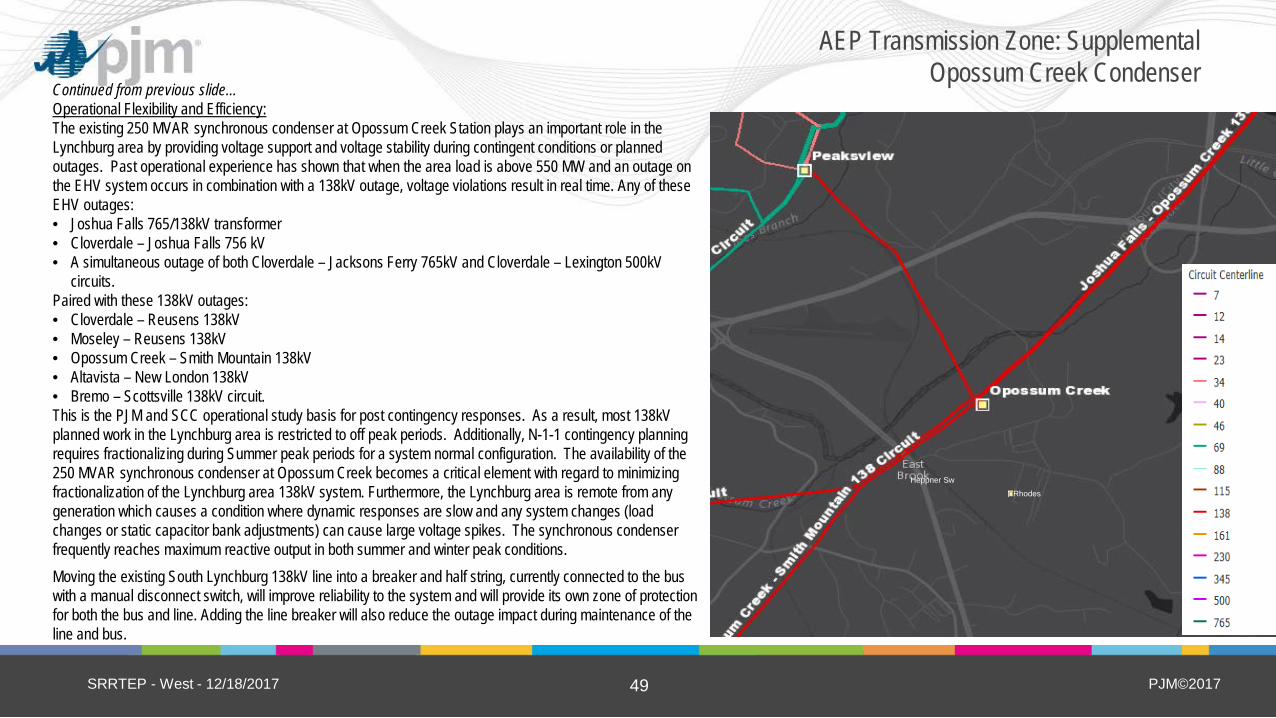
Continued from previous slide… Operational Flexibility and Efficiency: The existing 250 MVAR synchronous condenser at Opossum Creek Station plays an important role in the Lynchburg area by providing voltage support and voltage stability during contingent conditions or planned outages. Past operational experience has shown that when the area load is above 550 MW and an outage on the EHV system occurs in combination with a 138kV outage, voltage violations result in real time. Any of these EHV outages: • Joshua Falls 765/138kV transformer • Cloverdale – Joshua Falls 756 kV • A simultaneous outage of both Cloverdale – Jacksons Ferry 765kV and Cloverdale – Lexington 500kV
circuits. Paired with these 138kV outages: • Cloverdale – Reusens 138kV • Moseley – Reusens 138kV • Opossum Creek – Smith Mountain 138kV • Altavista – New London 138kV • Bremo – Scottsville 138kV circuit. This is the PJM and SCC operational study basis for post contingency responses. As a result, most 138kV planned work in the Lynchburg area is restricted to off peak periods. Additionally, N-1-1 contingency planning requires fractionalizing during Summer peak periods for a system normal configuration. The availability of the 250 MVAR synchronous condenser at Opossum Creek becomes a critical element with regard to minimizing fractionalization of the Lynchburg area 138kV system. Furthermore, the Lynchburg area is remote from any generation which causes a condition where dynamic responses are slow and any system changes (load changes or static capacitor bank adjustments) can cause large voltage spikes. The synchronous condenser frequently reaches maximum reactive output in both summer and winter peak conditions. Moving the existing South Lynchburg 138kV line into a breaker and half string, currently connected to the bus with a manual disconnect switch, will improve reliability to the system and will provide its own zone of protection for both the bus and line. Adding the line breaker will also reduce the outage impact during maintenance of the line and bus.
SRRTEP - West - 12/18/2017
AEP Transmission Zone: Supplemental Opossum Creek Condenser
Heppner Sw
Rhodes

PJM©2017 50
Continued from previous slide… Selected Solution: Install a new 138kV 3000A bus (3 & 4) at Opossum Creek and the replacement condenser units. (S1443.1) Replace 138kV breakers A, A1, A2, B1, C, C1 and D1 with 138kV 40kA breakers at Opossum Creek. Using 138kV 40kA breakers, complete the breaker string B for the East Lynchburg exit and the new condenser #1 unit. Using 138kV 40kA breakers, complete the breaker string D for the Smith Mountain and Reusens lines. Replace Circuit switchers AA & BB with 138kV 40kA circuit switchers. (S1443.2) Create a new 138kV bus 3 for the new condenser unit #2 at Opossum Creek. Create a new 138kV bus 4 for the new condenser unit #1. In between the two GSU banks, install a spare transformer that will be separated by normally open switches. Remove both 34.5kV buses and their associated transformers. Install primary and secondary station service off of the 138kV bus 1&2 respectively. (S1443.3) Change relay settings at South Lynchburg and Joshua Falls. At East Lynchburg, Smith Mountain and Peaksview, relay work will be needed. (S1443.4) Estimated Transmission Cost $65.5M Projected In-service: 12/31/2018 Project Status: Engineering
SRRTEP - West - 12/18/2017
AEP Transmission Zone: Supplemental Opossum Creek Condenser
Heppner Sw
Rhodes
PJM©2017 51
First Preliminary Review Baseline Reliability and Supplemental Projects
SRRTEP - West - 12/18/2017
PJM©2017 52
Map limited to transmission info.
Could show a distribution SS dot (Non CEII information)
Map should fit within this window Use FE TAMI Maps or PJM Maps
Proposed new Southerly Sewage substation
location
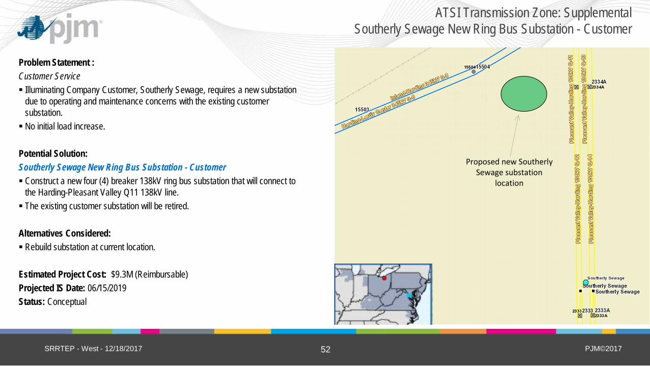
ATSI Transmission Zone: Supplemental Southerly Sewage New Ring Bus Substation - Customer
Problem Statement : Customer Service Illuminating Company Customer, Southerly Sewage, requires a new substation
due to operating and maintenance concerns with the existing customer substation. No initial load increase. Potential Solution: Southerly Sewage New Ring Bus Substation - Customer Construct a new four (4) breaker 138kV ring bus substation that will connect to
the Harding-Pleasant Valley Q11 138kV line. The existing customer substation will be retired. Alternatives Considered: Rebuild substation at current location. Estimated Project Cost: $9.3M (Reimbursable) Projected IS Date: 06/15/2019 Status: Conceptual
SRRTEP - West - 12/18/2017

PJM©2017 53
ATSI Transmission Zone: Supplemental First Solar New Substation - Customer
Problem Statement (Scope and Need/Drivers): Customer Service Support customer’s load increase. Potential Solution: First Solar New Substation - Customer Install new line tap on the Chrysler-Dowling 138kV circuit with 336 kcmil ACSR.
Alternatives Considered: Expand existing substation. Estimated Project Cost: $0.4M (Reimbursable) Projected IS Date: 03/01/2018 Status: Engineering
SRRTEP - West - 12/18/2017
New Toledo Edison Facilities
Customer owned transformer
First Solar
New ATSI Facilities
Key
New Customer Facilities
Existing Line

PJM©2017 54
Remove the Fowles-NASA Q17 & Q18 138kV line exits
ATSI Transmission Zone: Supplemental Ford Brookpark Substation - Customer
Problem Statement (Scope and Need/Drivers): Customer Service Support customer’s substation reconfiguration. Customer to retire in place two existing transformers. No increase in customer load. Potential Solution: Ford Brookpark Substation - Customer Eliminate two line exits at customer Ford Brookpark substation
– Remove the Q17 & Q18 Fowles-NASA 138kV lines; by-pass existing customer substation.
– Maintain the Q13 & Q12 Fowles-Fox 138kV Lines for transmission service to customer substation.
Alternatives Considered: None Estimated Project Cost: $0.4M (Reimbursable) Projected IS Date: 05/31/2018 Status: Conceptual
SRRTEP - West - 12/18/2017

PJM©2017 55
ATSI Transmission Zone: Supplemental New four breaker ring bus near Nash
Problem Statement (Scope and Need/Drivers): Operational Flexibility and Efficiency Minimize significant local load loss for the common tower
outage of Eastlake-Leroy Center Q15 and Q16 138kV lines. Improve operational flexibility during maintenance and
restoration efforts. Potential Solution: New four breaker ring bus near Nash Construct a four (4) breaker 138kV ring bus substation near
the existing Nash substation. Loop and terminate the Eastlake-Leroy Center Q15 and Q16
138kV lines through the new ring bus. Alternatives Considered: Additional in-line SCADA control switches. Estimated Project Cost: $8.6M Projected IS Date: 06/01/2019 Status: Conceptual
SRRTEP - West - 12/18/2017
Eastlake
Leroy Center
Nash
Nathan
Key
Transmission Line Substation

PJM©2017 56
ATSI Transmission Zone: Supplemental Nathan Substation Connection Reconfiguration
Problem Statement (Scope and Need/Drivers): Operational Flexibility and Efficiency Minimize local load loss for the common tower outage of Eastlake-Leroy Center Q15
and Q16 138kV lines. Potential Solution: Nathan Substation Connection Reconfiguration Construct new line taps to Nathan substation from the Eastlake-Mayfield Q3 and Q4
138kV lines. Transfer Nathan substation from the Eastlake-Leroy Center Q15 and Q16 138kV
Lines to the Eastlake-Mayfield Q3 and Q4 138kV lines. Alternatives Considered: None Estimated Project Cost: $2.3M Projected IS Date: 12/31/2018 Status: Conceptual
SRRTEP - West - 12/18/2017
Map limited to transmission info.
Could show a distribution SS dot (Non CEII information)
Map should fit within this window Use FE TAMI Maps or PJM Maps

PJM©2017 57
ATSI Transmission Zone: Supplemental Stevens 69 kV Ring Bus
Problem Statement (Scope and Need/Drivers): Operational Flexibility and Efficiency Improve operational flexibility during maintenance and restoration efforts. Reduce amount of potential local load loss under contingency conditions. Potential Solution: Stevens 69 kV Ring Bus Galion-Leaside 69 kV line Convert Stevens substation to a four (4) breaker ring bus. Reconfigure Stevens substation to include terminals for: Galion-Stevens 69 kV,
Stevens-Leaside 69 kV, Stevens-Galion Muni (Chevy) 69 kV, and Stevens transformer. Station layout to support line-load-line configuration. Alternatives Considered: Auto-sectionalizing scheme SCADA control switches Estimated Project Cost: $5.6M Projected IS Date: 12/31/2018 Status: Conceptual
SRRTEP - West - 12/18/2017
Galion
Stevens
Leaside
Galion Muni Dawsett
Galion Muni Chevy
Key
Transmission Line Substation

PJM©2017 58
ATSI Transmission Zone: Supplemental Tyrrell – Ring Bus and Add 69 kV Cap Banks
Problem Statement (Scope and Need/Drivers): Operational Flexibility and Efficiency Improve operational flexibility during maintenance and restoration efforts. Reduce amount of potential local load loss under contingency conditions. Potential Solution: Tyrrell – Ring Bus and Add 69 kV Cap Banks Convert Tyrrell 69 kV substation into a four (4) breaker, future five (5), for future cap
bank(s). Incorporate the radial tap to Vienna Air Force Base and Aero sub into dedicated ring bus
position Reconfigure the line exits at Tyrell substation for Masury-Tyrrell 69kV line, Tyrrell-Salt
Springs 69kV line, Tyrrell-Aero (radial), and Tyrrell transformer. Substation layout to support line-load-line configuration. Alternatives Considered: Auto-sectionalizing scheme SCADA control switches Estimated Project Cost: $6.1M Projected IS Date: 06/01/2019 Status: Conceptual
SRRTEP - West - 12/18/2017
Key
Transmission Line Substation
Key
Transmission Line Substation

PJM©2017 59
ATSI Transmission Zone: Supplemental Ford Road 69 kV Ring Bus
Problem Statement (Scope and Need/Drivers): Operational Flexibility and Efficiency Improve operational flexibility during maintenance and restoration efforts. Reduce amount of potential local load loss under contingency conditions.
Potential Solution: Ford Road 69 kV Ring Bus Maclean-Vulcan 69 kV line Convert Ford Road substation to a four (4) breaker ring bus Reconfigure the line exits at Ford Road substation for: Ford Road-Maclean 69
kV, Ford Road-Vulcan 69 kV, 69 kV capacitor bank, and Ford Road transformer. Substation layout to support line-load-line configuration Alternatives Considered: Auto-sectionalizing scheme SCADA control switches Estimated Project Cost: $5.0M Projected IS Date: 12/31/2018 Status: Conceptual
SRRTEP - West - 12/18/2017
Ford Road
Tracy
Key
Transmission Line Substation

PJM©2017 60
ATSI Transmission Zone: Supplemental Vulcan - Add high-side breaker to transformer #10
Problem Statement (Scope and Need/Drivers): Operational Flexibility and Efficiency Improve operational flexibility during maintenance and restoration efforts. Reduce amount of potential local load loss under contingency conditions. Eliminate the simultaneous outages to three or more system elements.
Potential Solution: Vulcan - Add high-side breaker to transformer #10 Add new 138 kV breaker on high-side of the Vulcan #10 138/69 kV transformer.
Alternatives Considered: Full ring bus configuration Estimated Project Cost: $0.6M Projected IS Date: 5/1/2018 Status: Conceptual
SRRTEP - West - 12/18/2017
Vulcan
Key
Substation
PJM©2017 61
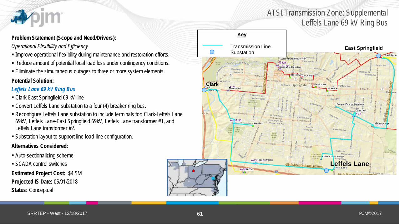
ATSI Transmission Zone: Supplemental Leffels Lane 69 kV Ring Bus
Problem Statement (Scope and Need/Drivers): Operational Flexibility and Efficiency Improve operational flexibility during maintenance and restoration efforts. Reduce amount of potential local load loss under contingency conditions. Eliminate the simultaneous outages to three or more system elements. Potential Solution: Leffels Lane 69 kV Ring Bus Clark-East Springfield 69 kV line Convert Leffels Lane substation to a four (4) breaker ring bus. Reconfigure Leffels Lane substation to include terminals for: Clark-Leffels Lane
69kV, Leffels Lane-East Springfield 69kV, Leffels Lane transformer #1, and Leffels Lane transformer #2. Substation layout to support line-load-line configuration. Alternatives Considered: Auto-sectionalizing scheme SCADA control switches Estimated Project Cost: $4.5M Projected IS Date: 05/01/2018 Status: Conceptual
SRRTEP - West - 12/18/2017
Clark
Leffels Lane
East Springfield
Key
Transmission Line Substation
PJM©2017 62
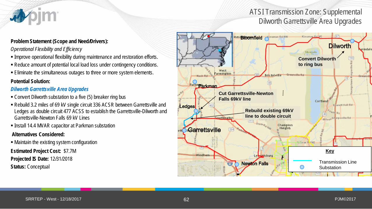
ATSI Transmission Zone: Supplemental Dilworth Garrettsville Area Upgrades
Problem Statement (Scope and Need/Drivers): Operational Flexibility and Efficiency Improve operational flexibility during maintenance and restoration efforts. Reduce amount of potential local load loss under contingency conditions. Eliminate the simultaneous outages to three or more system elements. Potential Solution: Dilworth Garrettsville Area Upgrades Convert Dilworth substation to a five (5) breaker ring bus Rebuild 3.2 miles of 69 kV single circuit 336 ACSR between Garrettsville and
Ledges as double circuit 477 ACSS to establish the Garrettsville-Dilworth and Garrettsville-Newton Falls 69 kV Lines Install 14.4 MVAR capacitor at Parkman substation Alternatives Considered: Maintain the existing system configuration Estimated Project Cost: $7.7M Projected IS Date: 12/31/2018 Status: Conceptual
SRRTEP - West - 12/18/2017
Rebuild existing 69kV line to double circuit
Cut Garrettsville-Newton Falls 69kV line
Key
Transmission Line Substation
Convert Dilworth to ring bus
PJM©2017 63
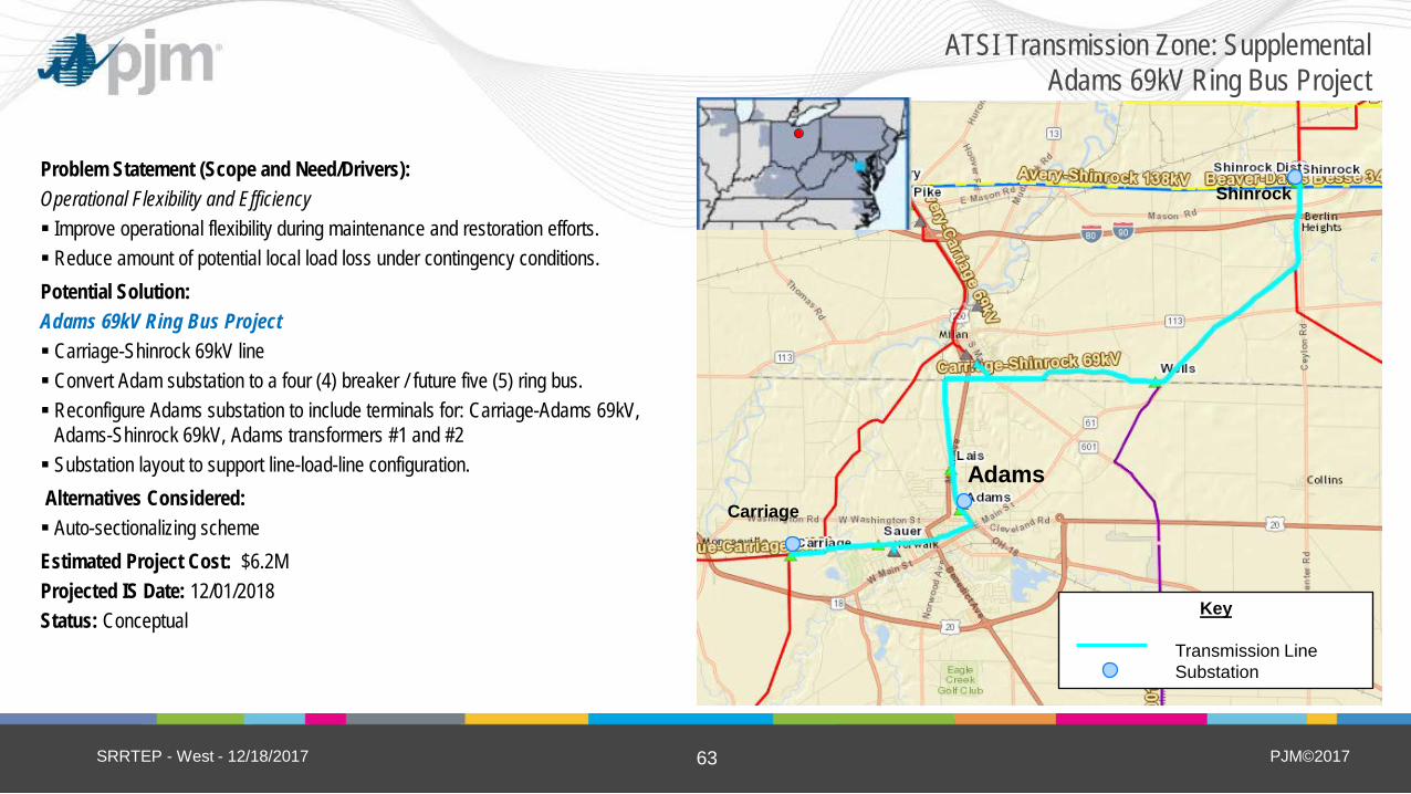
ATSI Transmission Zone: Supplemental Adams 69kV Ring Bus Project
Problem Statement (Scope and Need/Drivers): Operational Flexibility and Efficiency Improve operational flexibility during maintenance and restoration efforts. Reduce amount of potential local load loss under contingency conditions. Potential Solution: Adams 69kV Ring Bus Project Carriage-Shinrock 69kV line Convert Adam substation to a four (4) breaker / future five (5) ring bus. Reconfigure Adams substation to include terminals for: Carriage-Adams 69kV,
Adams-Shinrock 69kV, Adams transformers #1 and #2 Substation layout to support line-load-line configuration. Alternatives Considered: Auto-sectionalizing scheme Estimated Project Cost: $6.2M Projected IS Date: 12/01/2018 Status: Conceptual
SRRTEP - West - 12/18/2017
Shinrock
Carriage
Adams
Key
Transmission Line Substation

PJM©2017 65
ATSI Transmission Zone: Supplemental Richwood (Kirby) 69 kV Rebuild
Problem Statement (Scope and Need/Drivers): Equipment Material Condition, Performance and Risk Improve system reliability and performance. Remove obsolete and deteriorated equipment. Upgrade to current FE Standards Potential Solution: Richwood (Kirby) 69 kV Rebuild Kirby-Radnor 69 kV line Rebuild 12.6 miles of single circuit 3/0 ACSR 69 kV line with 336 ACSR from
Kirby to Radnor Substation. Replace existing two-way switch with two (2) separate one-way switches. Alternatives Considered: Maintain the existing equipment Estimated Project Cost: $14.3M Projected IS Date: 05/01/2019 Status: Conceptual
SRRTEP - West - 12/18/2017
Kirby
Richwood
Radnor
Location of switch replacements Prospect
Muni
Key
Transmission Line Transmission Line Not In
Service Substation
PJM©2017 66
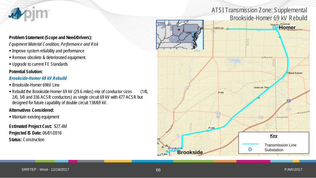
ATSI Transmission Zone: Supplemental Brookside-Homer 69 kV Rebuild
Problem Statement (Scope and Need/Drivers): Equipment Material Condition, Performance and Risk Improve system reliability and performance Remove obsolete & deteriorated equipment. Upgrade to current FE Standards Potential Solution: Brookside-Homer 69 kV Rebuild Brookside-Homer 69kV Line Rebuild the Brookside-Homer 69 kV (29.6 miles) mix of conductor sizes (1/0,
2/0, 3/0 and 336 ACSR conductors) as single circuit 69 kV with 477 ACSR but designed for future capability of double circuit 138/69 kV.
Alternatives Considered: Maintain existing equipment
Estimated Project Cost: $27.4M Projected IS Date: 06/01/2018 Status: Construction
SRRTEP - West - 12/18/2017
Homer
Brookside
Key
Transmission Line Substation
PJM©2017 67
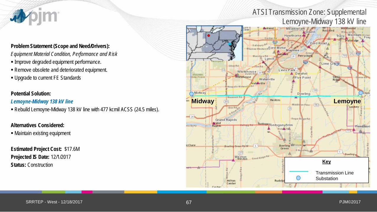
ATSI Transmission Zone: Supplemental Lemoyne-Midway 138 kV line
Problem Statement (Scope and Need/Drivers): Equipment Material Condition, Performance and Risk Improve degraded equipment performance. Remove obsolete and deteriorated equipment. Upgrade to current FE Standards Potential Solution: Lemoyne-Midway 138 kV line Rebuild Lemoyne-Midway 138 kV line with 477 kcmil ACSS (24.5 miles). Alternatives Considered: Maintain existing equipment Estimated Project Cost: $17.6M Projected IS Date: 12/1/2017 Status: Construction
SRRTEP - West - 12/18/2017
Midway Lemoyne
Key
Transmission Line Substation
PJM©2017 68
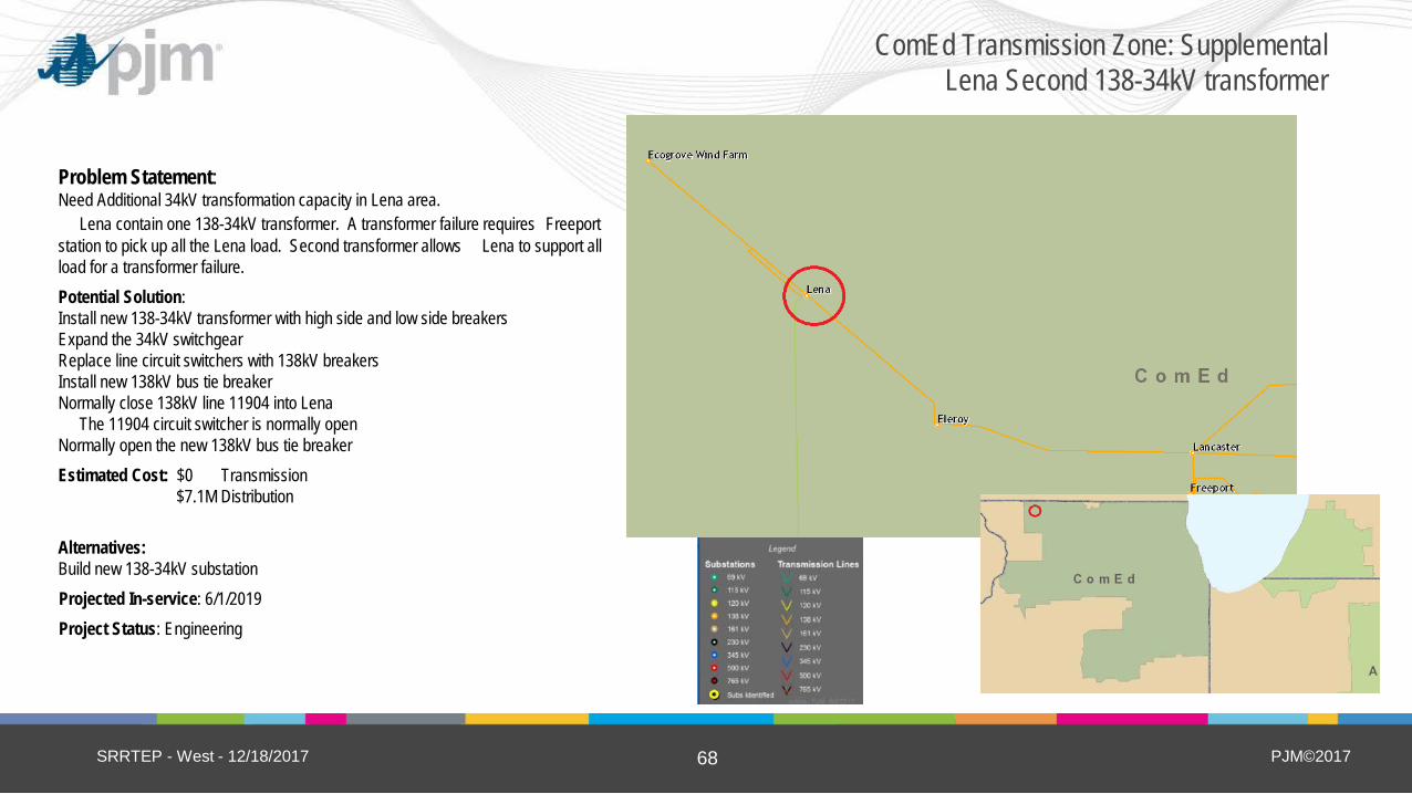
Problem Statement: Need Additional 34kV transformation capacity in Lena area. Lena contain one 138-34kV transformer. A transformer failure requires Freeport station to pick up all the Lena load. Second transformer allows Lena to support all load for a transformer failure. Potential Solution: Install new 138-34kV transformer with high side and low side breakers Expand the 34kV switchgear Replace line circuit switchers with 138kV breakers Install new 138kV bus tie breaker Normally close 138kV line 11904 into Lena The 11904 circuit switcher is normally open Normally open the new 138kV bus tie breaker Estimated Cost: $0 Transmission $7.1M Distribution Alternatives: Build new 138-34kV substation Projected In-service: 6/1/2019 Project Status: Engineering
SRRTEP - West - 12/18/2017
ComEd Transmission Zone: Supplemental Lena Second 138-34kV transformer
Add map here (with legend)
PJM©2017 69
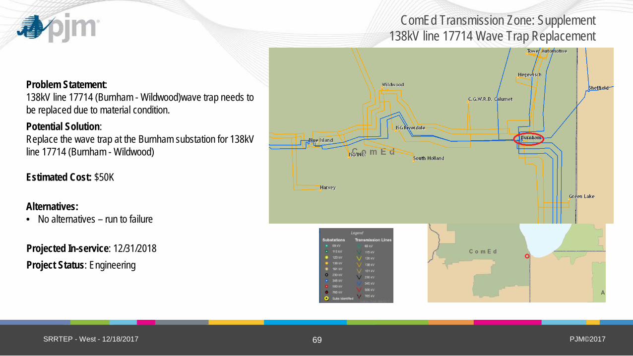
Problem Statement: 138kV line 17714 (Burnham - Wildwood)wave trap needs to be replaced due to material condition. Potential Solution: Replace the wave trap at the Burnham substation for 138kV line 17714 (Burnham - Wildwood) Estimated Cost: $50K Alternatives: • No alternatives – run to failure
Projected In-service: 12/31/2018 Project Status: Engineering
SRRTEP - West - 12/18/2017
ComEd Transmission Zone: Supplement 138kV line 17714 Wave Trap Replacement
Add map here (with legend)

PJM©2017 71
Problem Statement: Replacing obsolete electromechanically relays with microprocessor relays • Improved performance • Add SCADA connectivity • Allow real time data gathering of relay events • Replacement relays may be difficult to obtain 138kV Lines to be updated 11603 (Goodings Grove) 12016 (Lombard) 12016 (Itasca) 12411 (Dixon) 12411 (Sterling) 15508 (Nelson) 15508 (Dixon) 18513 (Tollway) 7306 (Bloom) 7306 (Chicago Heights) 6701 (Congress) 6702 (Congress) Potential Solution: Update relay packages at various location: • 138kV Line 11603 (Goodings Grove -Crestwood), the upgrade is at Goodings Grove. • 138kV Line 12016 (Lombard - Itasca), the upgrade is at Lombard and Itasca. • 138kV Line 12411 (a three terminal line from Maryland, Dixon, and Sterling), the upgrade is at Dixon and
Sterling. • 138kV Line 15508 (a three terminal line from Nelson, Dixon, and Kewanee), the upgrade is at Nelson and
Dixon. • 138kV Line 18513 (a three terminal line from Tollway, Rockford Energy Center and Dundee), the upgrade
is at Tollway. • 138kV Line 7306 (Bloom - Chicago Heights), The upgrade is at Bloom and Chicago Heights. • 138kV Line 6701 (Congress - Medical Center), Upgrade is at Congress. • 138kV Line 6702 (Congress - Medical Center), Upgrade is at Congress.
Estimated Cost: Transmission $320K per terminal Alternatives: None Projected In-service: 6/1/2018 Project Status: Engineering
SRRTEP - West - 12/18/2017
ComEd Transmission Zone: Supplemental Modernize 138kV Relays

PJM©2017 72
Problem Statement: 138kV line 17714 (Burnham - Wildwood) relays need to be upgraded for NERC PRC-023 Compliance
Potential Solution: Update 138kV line 17714 (Burnham - Wildwood) relays at Wildwood Estimated Cost: Transmission $320K Alternatives: • None Projected In-service: 6/1/2018 Project Status: Engineering
SRRTEP - West - 12/18/2017
ComEd Transmission Zone: Supplemental Modernize 138kV Relays

PJM©2017 73
Problem Statement: Augustine had a single transformer with two secondary windings each feeding individual distribution buses. When that transformer failed its emergency replacement did not have the full capacity of the failed transformer. More capacity is needed for the substation. Driver : Operational Flexibility and Efficiency, Risk Potential Solution: Add a second 138/13 kV, 22 MVA transformer to feed the Augustine bus. Reconfigure the substation so that the load is distributed across the three transformer/buses. Estimated Cost: $0.35M Alternatives: • none Projected In-service: 12/1/2018 Project Status: Engineering
SRRTEP - West - 12/18/2017
DEOK Transmission Zone: Supplemental Augustine – Install 138/13 kV Transformer

PJM©2017 74
Problem Statement: The 138 kV feeder between Warren and Nickel substations is aged and in deteriorating condition (1940’s era). The feeder has seen an increase in outages in the recent past due to its condition. Driver: Equipment Material Condition, Performance and Risk Potential Solution: Rebuild 5.8 miles of feeder between Warren and Nickel substations with 76 new structures, hardware, and conductor. Capacity of the line will increase from 198MVA to 300MVA. Estimated Cost: $15M Alternatives: • none Projected In-service: 12/1/2018 Project Status: Engineering
SRRTEP - West - 12/18/2017
DEOK Transmission Zone: Supplemental Warren-Nickel 138 kV Feeder Rebuild
Add map here (with legend)

PJM©2017 75
Problem Statement: Equipment Material/Condition/Performance/Risk: The existing 12.8 mile, 69 kV line section between East End Fostoria and Riverview was originally constructed in 1912 using wood pole & lattice structures with #1 Copper and 3/0 Copper conductor (31 MVA rating). There are 81 open conditions on this line. The line has also experienced 50,680 Customer Minutes of Interruption (CMI). As part of the line rebuild, the switching structures for Bascom will also be replaced. Potential Solution: Rebuild 11.3 miles of line between East End Fostoria – Riverview 69kV with 795 ACSR (129 MVA rating) and steel poles. Estimated Cost: $12.4M Install new Bascom 69 kV 1200 amp line switches. Estimated Cost: $0.8M Total Estimated Transmission Cost: $13.2M
Alternatives: No cost effective alternatives were identified.
Projected In-service: 11/01/2018 Project Status: Under Construction
SRRTEP - West - 12/18/2017
AEP Transmission Zone: Supplemental East End Fostoria-Riverview

PJM©2017 76
Problem Statement: Equipment Material/Condition/Performance/Risk: The Poston - Harrison 138 kV Line is 54.4 miles long and was built in 1953 utilizing wood pole H-Frame structures and 636 ACSR conductor (223 MVA rating). The existing 138 kV line is in need of major repair. The poles and crossarms are deteriorated so severely that they have become a hazard to effective maintenance practices. There are 269 open conditions spread along the entire distance of this line.
Potential Solution: Rebuild 54.4 miles of line between Harrison and Poston 138kV stations with 1033 ACSR (296 MVA rating) and steel poles. Estimated Transmission Cost: $61.9M
Alternatives: No cost effective alternatives were identified. Projected In-service: 12/31/2019 Project Status: Under Construction
SRRTEP - West - 12/18/2017
AEP Transmission Zone: Supplemental Harrison-Poston Line Rebuild
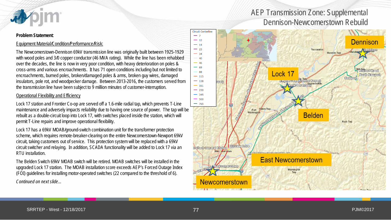
PJM©2017 77
Problem Statement: Equipment Material/Condition/Performance/Risk: The Newcomerstown-Dennison 69kV transmission line was originally built between 1925-1929 with wood poles and 3/0 copper conductor (46 MVA rating). While the line has been rehabbed over the decades, the line is now in very poor condition, with heavy deterioration on poles & cross-arms and various encroachments. It has 71 open conditions including but not limited to encroachments, burned poles, broken/damaged poles & arms, broken guy wires, damaged insulators, pole rot, and woodpecker damage. Between 2013-2016, the customers served from the transmission line have been subject to 9 million minutes of customer-interruption. Operational Flexibility and Efficiency Lock 17 station and Frontier Co-op are served off a 1.6-mile radial tap, which prevents T-Line maintenance and adversely impacts reliability due to having one source of power. The tap will be rebuilt as a double-circuit loop into Lock 17, with switches placed inside the station, which will permit T-Line repairs and improve operational flexibility. Lock 17 has a 69kV MOAB/ground-switch combination unit for the transformer protection scheme, which requires remote-breaker-clearing on the entire Newcomerstown-Newport 69kV circuit, taking customers out of service. This protection system will be replaced with a 69kV circuit switcher and relaying. In addition, SCADA functionality will be added to Lock 17 via an RTU installation. The Belden Switch 69kV MOAB switch will be retired. MOAB switches will be installed in the upgraded Lock 17 station. The MOAB installation score exceeds AEP’s Forced Outage Index (FOI) guidelines for installing motor-operated switches (22 compared to the threshold of 6). Continued on next slide…
SRRTEP - West - 12/18/2017
AEP Transmission Zone: Supplemental Dennison-Newcomerstown Rebuild

PJM©2017 78
Continued from previous slide…
Potential Solution: Rebuild the 20-mile 69kV transmission line between Newcomerstown and Dennison stations with 1033 ACSR (148 MVA rating). Estimated Cost = $28.5M Rebuild the 1.6-mile radial tap to Lock 17 station as a double-circuit 69kV loop with 1033 ACSR (148 MVA rating). Estimated Cost = $3.4M At Lock 17 69kV station, add a 69kV station bay structure and 2- 69kV MOAB switches. Relocate the 69kV cap bank and expand to 10.8 MVAR. Replace the transformer protection with a circuit switcher. Estimated Cost = $1.3M Replace East Newcomerstown 69kV Switch with a new 2-way switch. Retire Belden 69kV switch. Estimated Cost = $0.2M Total Estimated Transmission Cost: $33.4M Alternatives: No cost effective alternatives were identified. Projected In-service: 12/01/2019 Project Status: Under Construction
SRRTEP - West - 12/18/2017
AEP Transmission Zone: Supplemental Dennison-Newcomerstown Rebuild

PJM©2017 79
Problem Statement: Equipment Material/Condition/Performance/Risk: At Southwest Lima station, circuit breakers J, J1, J2 and K are all 138 kV 40 kA air blast, PK-type breakers manufactured in 1969. Air blast breakers tends to fail violently and when they do bushings usually explode which expel shards of ceramic and could potentially harm anyone at the station. In addition, PKs are no longer supported by vendors and cannot be integrated to modern relaying packages. Breaker K2 is an SF6 type 145-PA. Even though PAs are SF6, they have started giving the field problems due to significant seal issues in their design that result in low SF6 gas pressure. Field crews have tried repairing these breakers but after seal issues pop up it is very difficult to return the breaker to 100% operation. SF6 has been added in the past, with little to no improvement on the condition on this breaker type. Fault operation counts for CB J2, J, and K2 are 20, 25, and 39 respectively. Potential Solution: Replace existing 138 kV breakers J, J1, J2, K, and K2 at Southwest Lima with new 138 kV 3000 A 63 KA breakers. Estimated Transmission Cost: $1.8M Alternatives: No cost effective alternatives were identified. Projected In-service: 06/01/2019 Project Status: Engineering
SRRTEP - West - 12/18/2017
AEP Transmission Zone: Supplemental Southwest Lima Breaker Replacement

PJM©2017 80
Problem Statement: Equipment Material/Condition/Performance/Risk: The Portland area is non-recoverable in case of a failure. Load growth is slow but steady and transformer maintenance is restricted to only a few weeks per year. A transformer failure recovery has to be by a mobile transformer. To mitigate this, there needs to be a second distribution feeder at North Portland. There currently are four Motor Operated Air Break Switches (MOABs) in series on the Portland – Berne circuit. Having more than three MOABs in series on a circuit introduces increased chance of mis-operation and requires complex protection schemes. It is AEP current standard to not allow more than 3-MOABs in series. To mitigate this, a line breaker is required at a new station. Transformer #1 at North Portland is beginning to show signs of deterioration. Drivers for replacement include dielectric strength breakdown (winding insulation), short circuit strength breakdown (due to the amount of through fault events), and accessory damage (bushings). Operational Flexibility and Efficiency: The Berne – Portland line has experienced 39 momentary forced outages over the past 10 years and has a CMI of 1,040,639 over the last 3 years. 69% of this CMI value was triggered by the multiple unprotected stations on this line. Installing a breaker will effectively separate the City of Portland from the REMC owned Trinity Tap as well as 14.3 miles of exposure and will significantly improve the area system performance and overall reliability.
SRRTEP - West - 12/18/2017
AEP Transmission Zone: Supplemental North Portland Station
New Station
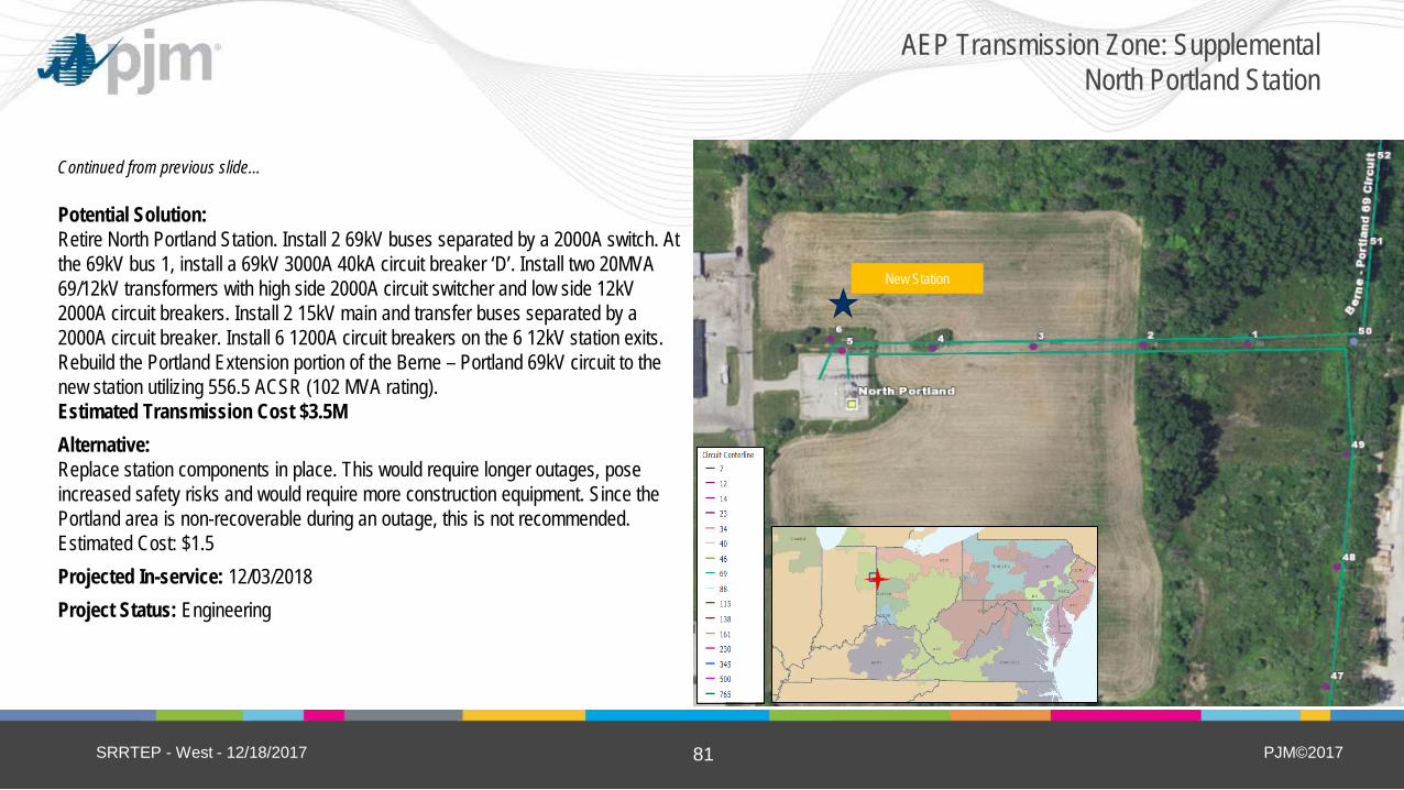
PJM©2017 81
Continued from previous slide… Potential Solution: Retire North Portland Station. Install 2 69kV buses separated by a 2000A switch. At the 69kV bus 1, install a 69kV 3000A 40kA circuit breaker ‘D’. Install two 20MVA 69/12kV transformers with high side 2000A circuit switcher and low side 12kV 2000A circuit breakers. Install 2 15kV main and transfer buses separated by a 2000A circuit breaker. Install 6 1200A circuit breakers on the 6 12kV station exits. Rebuild the Portland Extension portion of the Berne – Portland 69kV circuit to the new station utilizing 556.5 ACSR (102 MVA rating). Estimated Transmission Cost $3.5M Alternative: Replace station components in place. This would require longer outages, pose increased safety risks and would require more construction equipment. Since the Portland area is non-recoverable during an outage, this is not recommended. Estimated Cost: $1.5 Projected In-service: 12/03/2018 Project Status: Engineering
SRRTEP - West - 12/18/2017
AEP Transmission Zone: Supplemental North Portland Station
New Station

PJM©2017 82
(5) New Carlisle
Station 1
North Wellsville
Problem Statement: Equipment Material/Condition/Performance/Risk: North Wellsville 69kV breakers L & M are GE ‘FK’ 600 A 8kA oil-filled breakers made in 1951. They have operated for 74 and 43 faults respectively, above the manufacturer recommendation of 10. These breakers have had problems with oil leaks in recent years. The breaker foundations have deteriorated significantly. Finding spare repair parts for these breakers is very challenging. There are 6- 69kV 600-amp switches in need of replacement. The 69kV circuits utilize electromechanical relays which are recommended for an upgrade. Pilot wire relaying is used on the circuit to Hammondsville, which has been unreliable. The 69kV bus CCVT’s are also in poor condition. Of the 40 protective relays in the control house, 36 are electromechanical and 2 are solid-state units which are recommended for replacement due to poor performance, high maintenance costs, and lack of fault event recording capabilities. Due to the extent of protection upgrades needed, a prefabricated drop-in-control-module (DICM) will be utilized, as the station can’t be completely taken out of service during construction. Operational Flexibility and Efficiency: The 69-12kV distribution transformer lacks a high-side protective device, so the entire 69kV bus is tripped for a distribution transformer fault or 12kV bus fault (opens 3- 69kV circuits plus a 69kV cap bank). There are three overlapping zones of protection (69kV bus, 69-12kV transformer, 12kV bus). This arrangement reduces the life of the transmission breakers by tripping for faults in any zone. Installing a 69kV circuit switcher for the transformer will address these problems. The existing AEP fiber-optic telecom network in the area will be extended into North Wellsville and 69kV remote terminals, to improve the capability of EMS, SCADA, and system protection equipment.
SRRTEP - West - 12/18/2017
AEP Transmission Zone: Supplemental North Wellsville 69 kV Station Upgrades
Heppner Sw
Rhodes

PJM©2017 83
(5) New Carlisle
Station 1
North Wellsville
Continued from previous slide…
Potential Solution: At North Wellsville station, replace 69kV oil breakers L & M with new 3000A 40 kA breakers; replace all 69kV disconnect switches; add 69kV transformer protection with circuit switcher & relaying; install distribution DICM to house new 69 & 12kV protection/communications; replace 12kV bus voltage regulator; replace both 12kV feeder breakers and protection/controls. Estimated Transmission Cost $1.3M Alternatives: • Purchase new property in the area (3-5 acres at least) to facilitate a greenfield 69-12kV station to
replace North Wellsville, with ample space for a future 138-69kV source. This option was investigated, but ultimately was ruled out due to: hilly terrain, proximity to Ohio River, lack of suitable land, and the need to keep the 12kV distribution source close to the city of Wellsville. This option would have been simpler from an engineering & construction standpoint, and made outage-scheduling easier. However, it would have been several times more expensive.
Estimated Cost: $12-$15M • Build a separate green-field 138kV station in the area and add a new 138-69kV source, while
keeping the existing North Wellsville station in-service. The area’s transmission infrastructure is entirely 69kV, including a newly rebuilt 69kV circuit (to East Liverpool). Based on the area’s load growth characteristics, a 138-69kV station should not be needed for some time, and would be overly expensive. In addition, we’d still have the risk of equipment failures from the aging breakers & relays at North Wellsville. Estimated Cost: $30M
Projected In-service: 12/1/2019 Project Status: Scoping
SRRTEP - West - 12/18/2017
AEP Transmission Zone: Supplemental North Wellsville 69 kV Station Upgrades
Heppner Sw
Rhodes

PJM©2017 84
Problem Statement: Equipment Material/Condition/Performance/Risk/Operational Flexibility: The 34.5 kV oil breakers E, F, G, H, and K at Pendleton station are 2000 A 36 kA FK and CF type breakers manufactured between 1952 and 1971. Oil breakers, in general, have become more difficult to maintain due to the required oil handling. Oil spills occur often during routine maintenance and failures, which can become an environmental concern. Other drivers include age, bushing damage, number of fault operations, and a lack of available repair parts. Breaker G has experienced 30 fault operations. Breaker E has experienced 42 fault operations. Breaker F has experienced 36 fault operations. The manufacturer recommendation for fault interruptions is 10. 138kV breakers M and N at Pendleton station are 1200A 17.5kA models from 1951 and have had 18 and 13 fault operations respectively, which is higher than the manufacturer recommendation of 10. 138kV Breaker P being replaced is a 800A 17.5A model manufactured in 1946. Operational Flexibility and Efficiency: Currently a fault from transformer 2 requires 3 138kV breakers to operate in order to clear. Adding a circuit switcher is recommended to prolong the life of the new 138kV breakers.
SRRTEP - West - 12/18/2017
AEP Transmission Zone: Supplemental Pendleton Breaker and Relay Replacement

PJM©2017 85
Continued from previous slide…
Potential Solution At Pendleton station, replace 34kV CBs “H”, “F”, “E”, “G”, and “K” with 2000A 38kV 25kA breakers. Replace 138kV CB’s “M”, “P”, and “N” with 3000A 40kA breakers. Install a 3000A 40kA circuit switcher on the high side of transformer #2. Estimated Transmission Cost $6.1M Alternative: Replace breakers with 69kV rated equipment and operate them at 34.5kV. The 34.5kV network fed off of Pendleton station is owned by IMPA and is not controlled by AEP. Since IMPA’s network is operated at 34.5kV, installing 69kV rated equipment would not offer the system any added flexibility and so is not advisable.
Projected In-service: 2/09/2018 Project Status: Construction
SRRTEP - West - 12/18/2017
AEP Transmission Zone: Supplemental Pendleton Breaker and Relay Replacement

PJM©2017 86
Problem Statement: Equipment Material/Condition/Performance/Risk: Breakers ‘A’ and ‘B’ at Tiffin Center station are 1200A 21 kA oil medium breakers manufactured in 1965 with fault counts of 149 and 73 respectively. Oil breaker maintenance has become more difficult due to the oil handling required to maintain them. Oil spills are frequent with breaker failures and routine maintenance and can become an environmental hazard. The drivers for replacement of these breakers are age, number of fault operations, a lack of available repair parts, and PCB content. Potential Solution: At Tiffin Center station, replace 69kV breaker ‘A’ and ‘B’ with 3000A 40kA breakers and associated equipment. Estimated Transmission Cost: $1.24M Alternative: • No viable cost-effective alternatives identified Projected In-service: 03/16/2018 Project Status: Engineering
SRRTEP - West - 12/18/2017
AEP Transmission Zone: Supplemental Tiffin Center Breaker Replacements
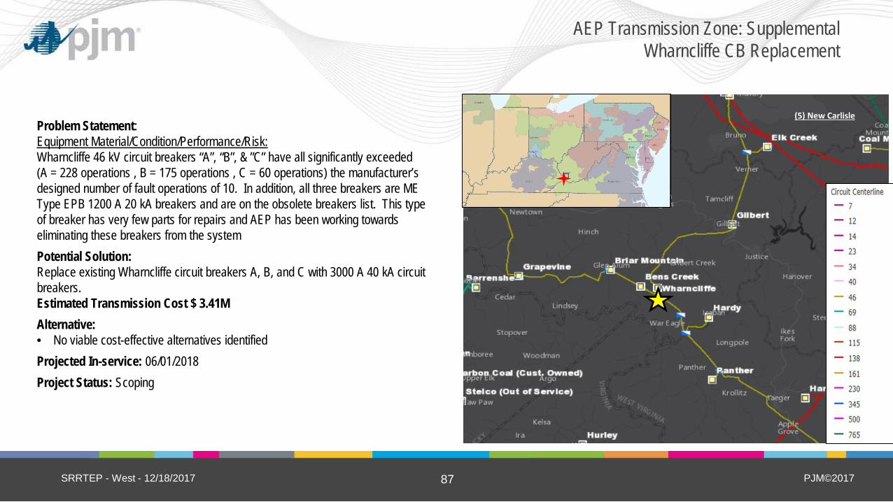
PJM©2017 87
(5) New Carlisle Problem Statement: Equipment Material/Condition/Performance/Risk: Wharncliffe 46 kV circuit breakers “A”, “B”, & ”C” have all significantly exceeded (A = 228 operations , B = 175 operations , C = 60 operations) the manufacturer’s designed number of fault operations of 10. In addition, all three breakers are ME Type EPB 1200 A 20 kA breakers and are on the obsolete breakers list. This type of breaker has very few parts for repairs and AEP has been working towards eliminating these breakers from the system Potential Solution: Replace existing Wharncliffe circuit breakers A, B, and C with 3000 A 40 kA circuit breakers. Estimated Transmission Cost $ 3.41M Alternative: • No viable cost-effective alternatives identified Projected In-service: 06/01/2018 Project Status: Scoping
SRRTEP - West - 12/18/2017
AEP Transmission Zone: Supplemental Wharncliffe CB Replacement
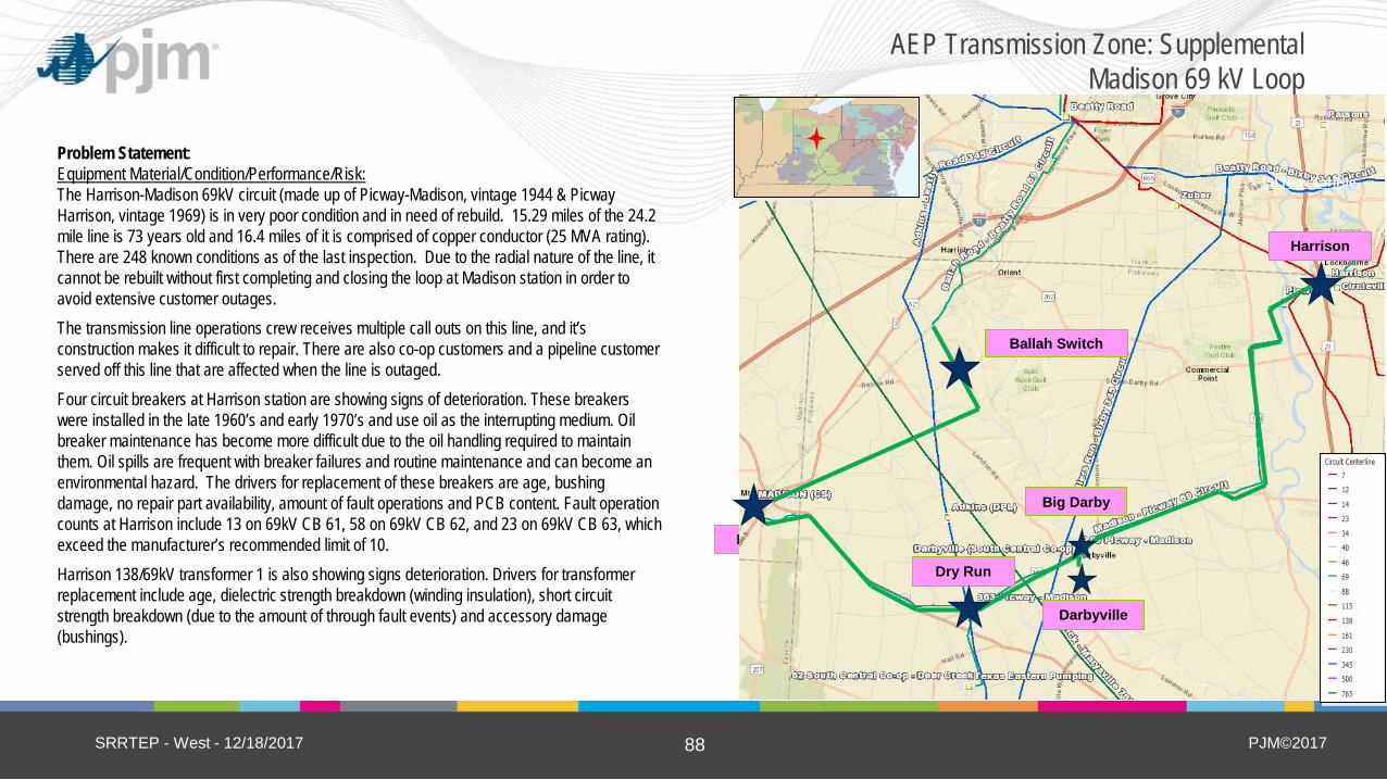
PJM©2017 88
Problem Statement: Equipment Material/Condition/Performance/Risk: The Harrison-Madison 69kV circuit (made up of Picway-Madison, vintage 1944 & Picway Harrison, vintage 1969) is in very poor condition and in need of rebuild. 15.29 miles of the 24.2 mile line is 73 years old and 16.4 miles of it is comprised of copper conductor (25 MVA rating). There are 248 known conditions as of the last inspection. Due to the radial nature of the line, it cannot be rebuilt without first completing and closing the loop at Madison station in order to avoid extensive customer outages. The transmission line operations crew receives multiple call outs on this line, and it’s construction makes it difficult to repair. There are also co-op customers and a pipeline customer served off this line that are affected when the line is outaged. Four circuit breakers at Harrison station are showing signs of deterioration. These breakers were installed in the late 1960’s and early 1970’s and use oil as the interrupting medium. Oil breaker maintenance has become more difficult due to the oil handling required to maintain them. Oil spills are frequent with breaker failures and routine maintenance and can become an environmental hazard. The drivers for replacement of these breakers are age, bushing damage, no repair part availability, amount of fault operations and PCB content. Fault operation counts at Harrison include 13 on 69kV CB 61, 58 on 69kV CB 62, and 23 on 69kV CB 63, which exceed the manufacturer’s recommended limit of 10. Harrison 138/69kV transformer 1 is also showing signs deterioration. Drivers for transformer replacement include age, dielectric strength breakdown (winding insulation), short circuit strength breakdown (due to the amount of through fault events) and accessory damage (bushings).
SRRTEP - West - 12/18/2017
AEP Transmission Zone: Supplemental Madison 69 kV Loop
Madison
Ballah Switch
Harrison
(5) New Carlisle
Darbyville
Dry Run
Big Darby

PJM©2017 89
Continued from previous slide…
Operational Flexibility and Efficiency: A normally opened configuration at Str. 280 (near the Darbyville tap location) allows for limited temporary recovery of loads at Deer Creek, Darbyville, Clark Lakes, Texas Eastern Co., and Madison stations for outages involving Str. 280 to Harrison branch. This configuration depends on utilizing normally radial customer owned 69kV transmission line. However, there are not recovery options if the outages involve Str. 280 to Madison branch. Existing small conductors also limit the load recovery options in this configuration. Customer Service: SCP has approached AEP to help address numerous outages affecting customers in this area. Potential Solution: Build a new Beatty-Madison 69 kV line utilizing 795 ACSR (129MVA rating) in new ROW. Acquire existing 636 ACSR & 336 ACSR (73 MVA rating) in existing ROW. Estimated Transmission Cost: $16.2M Rebuild single circuit 69kV line from Harrison to Madison with 795 ACSR (129 MVA rating), mostly in existing ROW. Estimated Transmission Cost: $23.4M Rebuild tap to Darbyville as double circuit 795 ACSR (129 MVA rating). Estimated Transmission Cost: $0.9M At Harrison station, replace the 138/69kV transformer with a 90 MVA. Install 3-69kV CB’s with 2,000A 40kA breakers. Install 1-138kV CB with a 3,000A 63kA breaker. Install a 14.4 MVAr 69kV capacitor. Estimated Transmission Cost: $5.8M At Madison station, install 2 new 69kV 2,000A 40kA CB’s and 1 600A 40kA ckt switcher. Estimated Transmission Cost: $3.0M At Big Darby Switch, Dry Run Switch, and Ballah Switch, upgrade with 2000A switches at new locations. Retire old switches. Estimated Transmission Cost: $1.3M Total Estimated Transmission Cost: $50.6M
SRRTEP - West - 12/18/2017
AEP Transmission Zone: Supplemental Madison 69 kV Loop
(5) New Carlisle
Ballah Switch
Harrison
(5) New Carlisle
Darbyville
Dry Run
Big Darby
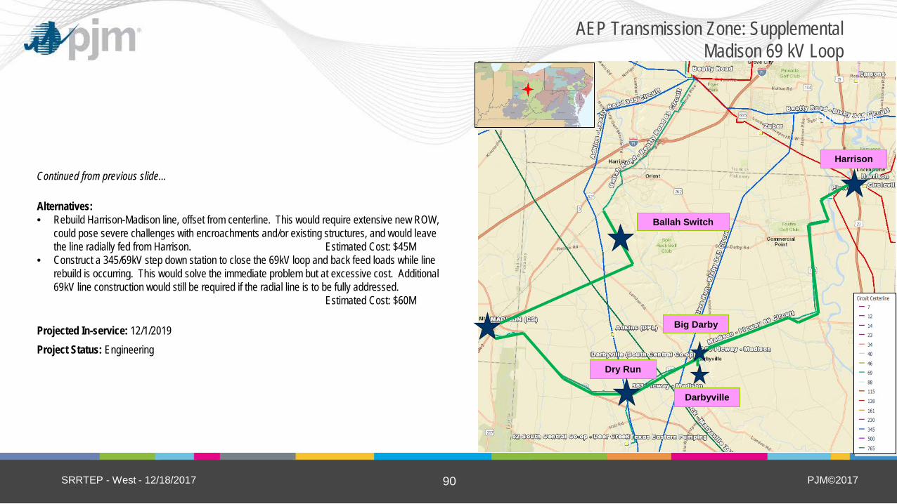
PJM©2017 90
Continued from previous slide…
Alternatives: • Rebuild Harrison-Madison line, offset from centerline. This would require extensive new ROW,
could pose severe challenges with encroachments and/or existing structures, and would leave the line radially fed from Harrison. Estimated Cost: $45M
• Construct a 345/69kV step down station to close the 69kV loop and back feed loads while line rebuild is occurring. This would solve the immediate problem but at excessive cost. Additional 69kV line construction would still be required if the radial line is to be fully addressed.
Estimated Cost: $60M
Projected In-service: 12/1/2019 Project Status: Engineering
SRRTEP - West - 12/18/2017
AEP Transmission Zone: Supplemental Madison 69 kV Loop
(5) New Carlisle
Ballah Switch
Harrison
(5) New Carlisle
Darbyville
Dry Run
Big Darby

PJM©2017 91
(5) New Carlisle
Problem Statement: Equipment Material/Condition/Performance/Risk: Breakers C and D are currently not in use and are accruing yearly O&M costs. Due to the cost, retirement is recommended. Operational Flexibility and Efficiency Currently there are three overlapping zones of protection at Meadowbrook station: the 34.5kV bus, the 138/34.5kV transformer and the Pendleton – Madison line. It is AEP’s current standard to not allow for an overlap of more than two protection zones. The configuration at Meadowbrook does not meet AEP’s current standards as three protection zones share the same relays thus increasing the probability of mis-operations. Also, a transformer protection zone overlapping with a bus and line protection zones does not allow for bus one-shot and high-speed reclosing schemes, respectively. This adds restoration delays and significantly reduces reliability. Also, this arrangement reduces the life of breakers by tripping them for events in any of the three protection zones. Potential Solution: Retire out of service breakers “C” and “D” and install a high side 138kV 3000A 40kA breaker for transformer protection. Estimated Transmission Cost: $2.5M Alternative: • Install the breaker on the low side of the transformer instead of the high side.
While this would protect the 34.5kV bus from a transformer fault, it would leave the transformer exposed to a line fault. Since line faults are a more common occurrence, protecting the station equipment from a line fault was chosen as the optimal solution. Estimated Cost: $2M
Projected In-service: 4/16/2018 Project Status: Scoping
SRRTEP - West - 12/18/2017
AEP Transmission Zone: Supplemental Meadowbrook Station

PJM©2017 92
Problem Statement: Equipment Material/Condition/Performance/Risk: The Deer Creek – Sorenson double circuit line has 236 open conditions and is comprised of conductor and towers from 1928 with mostly 397 ACSR conductor (167 MVA rating) along the 36 mile length. It is currently subject to corroded towers; broken clamps; broken dampers; burnt insulators; vine hazards and broken shield wire. Design standards from the 1920s do not meet modern standards for strength, resilience, and horizontal and vertical clearances for safety. Underlying land rights secured prior to the line’s original construction do not contain modern protective language which would provide the ability to properly manage non-conforming land uses. The ability to control building encroachments and intrusive vegetation were often not included in the language of the original easements. This transmission line has exceeded its original life expectancy. Age and normal deterioration of the line, now over ninety (90) years old, warrants its complete replacement. Operational Flexibility and Efficiency Due to the relative length of the line, wind exposure, and perpendicularity of this line to the prevailing winds, the Deer Creek – Sorenson circuit has had a history of “galloping” which has led to 30 momentary interruptions across the Deer Creek – Hummel Creek – Sorenson circuit and 43 momentary interruptions on the Delaware – Sorenson circuit in the last 10 years alone. Rebuilding this line with structures and configurations more suited for high wind environments is required.
SRRTEP - West - 12/18/2017
AEP Transmission Zone: Supplemental Deer Creek-Sorenson Rebuild
Sorenson
Deer Creek

PJM©2017 93
Continued from previous slide…
Potential Solution: Rebuild ~32 miles of the Delaware – Sorenson & Sorenson – Deer Creek 138kV double circuit line using 795ACSR (257 MVA rating). Estimated Transmission Cost: $82.6M Rebuild ~3 miles of the Deer Creek 138kV double circuit extension using 795 ACSR (257 MVA rating). Estimated Transmission Cost: $1.7M Total Estimated Transmission Cost: $84.3M Alternative: • Retire existing line and build a new greenfield line in new right of way to
reduce outage time. However, outages on this line have not been difficult to secure in the past. Estimated Cost: $90M
Projected In-service: 12/2/2019 Project Status: Engineering
SRRTEP - West - 12/18/2017
AEP Transmission Zone: Supplemental Deer Creek-Sorenson Rebuild
Sorenson
Deer Creek
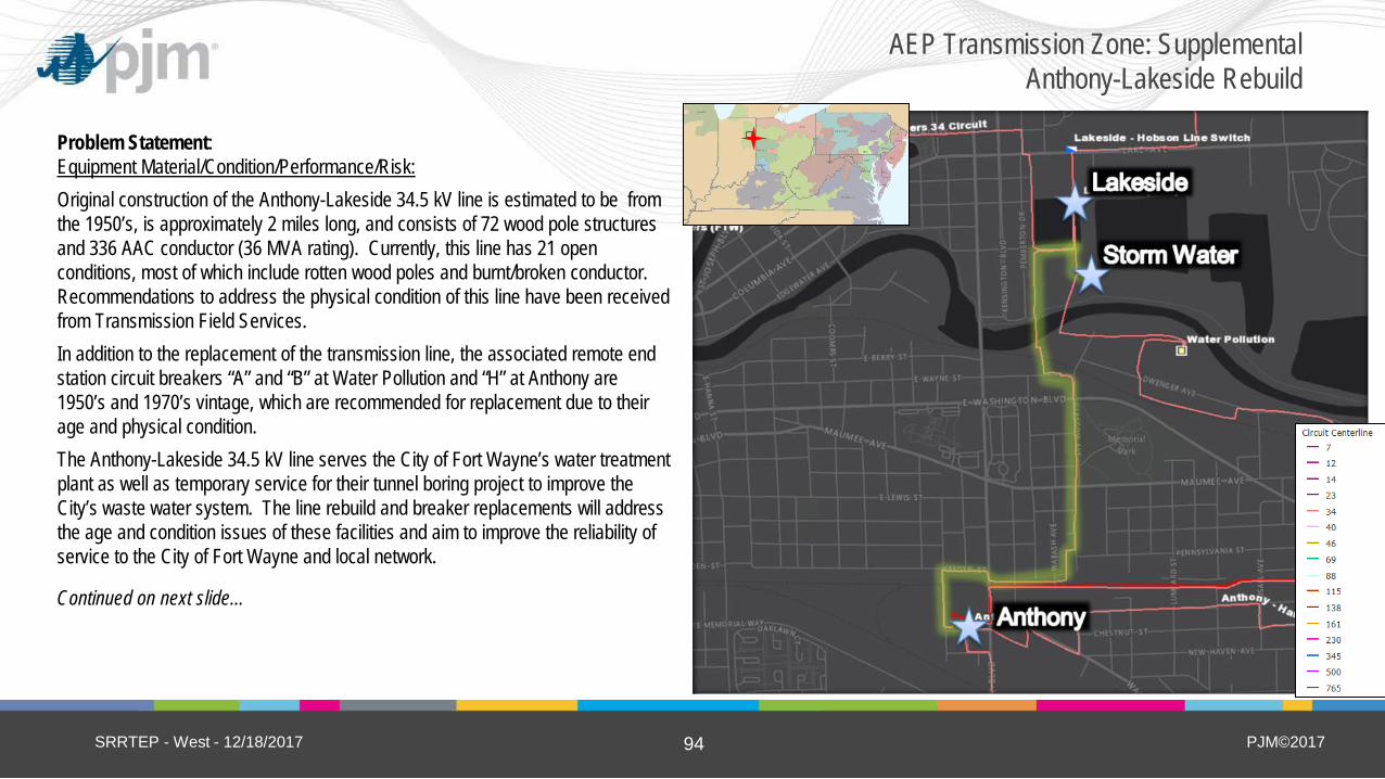
PJM©2017 94
Problem Statement: Equipment Material/Condition/Performance/Risk: Original construction of the Anthony-Lakeside 34.5 kV line is estimated to be from the 1950’s, is approximately 2 miles long, and consists of 72 wood pole structures and 336 AAC conductor (36 MVA rating). Currently, this line has 21 open conditions, most of which include rotten wood poles and burnt/broken conductor. Recommendations to address the physical condition of this line have been received from Transmission Field Services. In addition to the replacement of the transmission line, the associated remote end station circuit breakers “A” and “B” at Water Pollution and “H” at Anthony are 1950’s and 1970’s vintage, which are recommended for replacement due to their age and physical condition. The Anthony-Lakeside 34.5 kV line serves the City of Fort Wayne’s water treatment plant as well as temporary service for their tunnel boring project to improve the City’s waste water system. The line rebuild and breaker replacements will address the age and condition issues of these facilities and aim to improve the reliability of service to the City of Fort Wayne and local network.
Continued on next slide…
SRRTEP - West - 12/18/2017
AEP Transmission Zone: Supplemental Anthony-Lakeside Rebuild

PJM©2017 95
Continued from previous slide… Potential Solution: Rebuild approximately 2 miles of single circuit line with 795 ACSR from Anthony Station to structure 66 (just south of Lakeside station) and continue to Storm Water Station. This conductor type was selected to match the remaining overhead conductor capability of the circuit. The remaining portion of line (north of structure 66) will be retired along with Lakeside station. The rebuilt 34.5 kV circuit from Anthony-Storm Water 34.5 kV will be limited by 600 A switches at Storm Water creating an overall rating of 41/45 MVA (SN/SE) and 53/57 MVA (WN/WE). Estimated Cost: $7.0M At Water Pollution Station, replace 34.5 kV circuit breakers “A” and “B” with 1200 A, 25 kA ABB breakers. Estimated Cost: $0.8M At Anthony Station, replace 34.5 kV circuit breaker “H” with a 1200 A, 25 kA ABB breaker. Estimated Cost: $0.9M Total Estimated Transmission Cost: $8.7M Continued on next slide…
SRRTEP - West - 12/18/2017
AEP Transmission Zone: Supplemental Anthony-Lakeside Rebuild

PJM©2017 96
Continued from previous slide… Alternatives: • Convert and energize the line to 69 kV, however the existing network would
require additional transformers and line conversions including a new 138/69 kV transformer at Anthony, replacement of two City of Ft. Wayne’s transformers at Storm Water Station, two Distribution transformers serving the City of Ft. Wayne at Water Pollution Station, a customer transformer owned by Omni Source and a replacement of the temporary 34.5/12 kV Skid Station serving the City of Ft. Wayne’s Tunnel Project. However, the rebuild will be constructed at 69 kV standards which will allow for future conversion of the area to 69 kV while addressing the age and condition of the line today.
Estimated Cost: $17,000,000 • Perform a new line inspection addressing only those structures and spans with
the worst open conditions. This was discussed, but ultimately anything not addressed as part of this effort would soon need replaced due to the age of the wood pole structures.
Projected In-service: 05/30/2020 Project Status: Scoping
SRRTEP - West - 12/18/2017
AEP Transmission Zone: Supplemental Anthony-Lakeside Rebuild
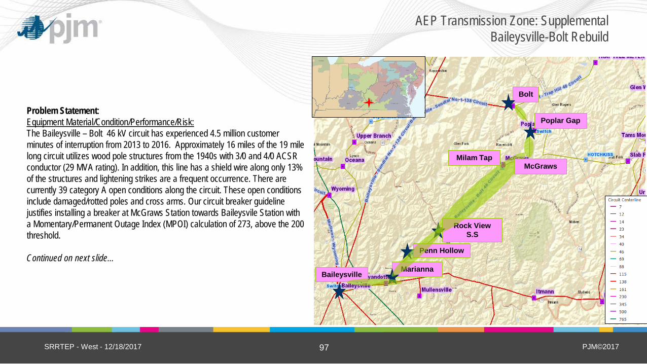
PJM©2017 97
(5) New Carlisle
Include map of the area from TGIS
Baileysville
Bolt
Poplar Gap
Marianna
Rock View S.S
Penn Hollow
McGraws Milam Tap
Problem Statement: Equipment Material/Condition/Performance/Risk: The Baileysville – Bolt 46 kV circuit has experienced 4.5 million customer minutes of interruption from 2013 to 2016. Approximately 16 miles of the 19 mile long circuit utilizes wood pole structures from the 1940s with 3/0 and 4/0 ACSR conductor (29 MVA rating). In addition, this line has a shield wire along only 13% of the structures and lightening strikes are a frequent occurrence. There are currently 39 category A open conditions along the circuit. These open conditions include damaged/rotted poles and cross arms. Our circuit breaker guideline justifies installing a breaker at McGraws Station towards Baileysvile Station with a Momentary/Permanent Outage Index (MPOI) calculation of 273, above the 200 threshold. Continued on next slide…
SRRTEP - West - 12/18/2017
AEP Transmission Zone: Supplemental Baileysville-Bolt Rebuild

PJM©2017 98
Continued from previous slide… Potential Solution: Rebuild ~16.6 miles of the Baileysville-Bolt line with 795 ACSR conductor to 138 kV standards (energized at 46 kV, 86 MVA rating). Existing ROW will be used when possible but supplemental ROW may be needed in order to build to 138kV standards. ADSS will be installed on the new line. Estimated Cost: $25.8M At Baileysville Station, replace 46kV bus/risers and switches on circuit breaker E. Estimated Cost: $0.6M At Marianna Station, replace the existing switches with a 1200A phase-over-phase switch and replace the bus/risers. Estimated Cost: $0.0M At Rock View Station, replace the existing switches with a 1200A phase-over-phase switch. Estimated Cost: $0.4M At Poplar Gap Station, replace the existing switches with a 1200A phase-over-phase switch. Estimated Cost: $0.6M Retire Milam Tap Station. Estimated Cost: $0.0M Retire Penn Hollow Tap Station. Estimated Cost: $0.0M Install a 3000A circuit breaker at McGraws Station towards Baileysville. Estimated Cost: $1.2M Total Estimated Transmission Cost: $28.6M Continued on next slide…
SRRTEP - West - 12/18/2017
AEP Transmission Zone: Supplemental Baileysville-Bolt Rebuild
(5) New Carlisle
Include map of the area from TGIS
Baileysville
Bolt
Poplar Gap
Marianna
Rock View S.S
Penn Hollow
McGraws Milam Tap

PJM©2017 99
Continued from previous slide… Alternatives: Construct a new Baileysville – Bolt to 138 kV circuit in parallel with the existing 46 kV line. Convert and energize each station on the line (Marianna, Marsh Fork, McGraws and Poplar Gap) to 138 kV. However, distribution would not be able to fund the conversion of each station at this time. Estimated Cost: $50M Projected In-service: 12/01/2019 Project Status: Scoping
SRRTEP - West - 12/18/2017
AEP Transmission Zone: Supplemental Baileysville-Bolt Rebuild
(5) New Carlisle
Include map of the area from TGIS
Baileysville
Bolt
Poplar Gap
Marianna
Rock View S.S
Penn Hollow
McGraws Milam Tap

PJM©2017 100
Problem Statement: Equipment Material/Condition/Performance/Risk: The Delaware – Madison 138kV line is a 1928 vintage circuit that has a total of 100 open conditions across its ~19 miles including burnt insulators, broken shield wire, loose conductor hardware, broken guy wires, and broken ground lead wires. It was constructed with 397 ACSR conductor (167 MVA rating). In addition, the line riser at Delaware will be replaced so that it doesn’t limit the new ~19 mile long line. Operational Flexibility and Efficiency Daleville station is configured in a non-standard configuration. Because of this, any work on the transformer requires that the line be taken out of service. Reconfiguring this station’s switches will eliminate unnecessary maintenance outages. Potential Solution: Rebuild the ~19 miles of the Delaware – Madison double circuit 138kV line utilizing double circuit 556.5 ACSR 26/7 (SN:204 SE:284 WN: 258 WE: 319). Estimated Cost: $54.3M Replace risers at Delaware station with 1200A AAC jumpers. Estimated Cost: $0.3M Replace the switches at Daleville station with 2000A 100kA switches Estimated Cost: $0.1M Total Estimated Transmission Cost: $54.7M Alternatives: Build in the clear. Due to the ability to take outages on this line, and the increased cost and community impact associated with building this line in the clear, this is not recommended.
Projected In-service: 12/31/2021 Project Status: Scoping
SRRTEP - West - 12/18/2017
AEP Transmission Zone: Supplemental Delaware-Madison Rebuild

PJM©2017 101
Problem Statement: Equipment Material/Condition/Performance/Risk: Breaker L at West New Philadelphia station is a McGraw-Edison oil breaker manufactured in 1962. In general, oil breakers have become increasingly difficult to maintain due to the oil handling associated with them. Oil spills occur frequently with failures and while performing routine maintenance, which, is an environmental hazard. Additionally, breaker L has experienced 104 fault operations. Operational Flexibility and Efficiency Dennison – West New Philadelphia 69kV has been responsible for 3.9 million minutes of CMI over the prior 3 years. 60% of the outage-duration was due to Station Equipment problems. Malfunctioning MOAB flip-flop switching scheme at New Philadelphia has been inoperable since 2012. Lack of SCADA at Schoenbrunn & New Philly limits system operator’s ability. RTU’s will be installed at both stations, to provide real-time power flow data (voltage, currents, MW/MVAR) to system operators. Continued on next slide…
SRRTEP - West - 12/18/2017
AEP Transmission Zone: Supplemental Dennison-West New Philadelphia Upgrades

PJM©2017 102
Continued from previous slide… Two 69kV hard taps will be eliminated as part of the project (just outside West New Philly station, and near New Philly). Hard taps are problematic when doing maintenance on the circuit or stations involved. The New Philly 69kV breakers prevent a 69kV T-Line outage from taking out the 69kV cap bank there; this cap bank is valuable for supporting system voltages. The Momentary Permanent Outage Index (MPOI) calculations support installing breakers at New Philadelphia (230, above the 200 threshold). There are large AEP Ohio distribution load centers served from New Philly station (24 MVA peak, 4800 customers) and Schoenbrunn (23 MVA, 3500 customers). Today, a line fault would outage 8300 customers or 47 MVA of load at summer peak. Additional breakers at Schoenbrunn are recommended to help keep these customers in service for line faults. The MOAB/ground switch at Schoenbrunn will be replaced. MOAB/ground switch combinations induce a fault on the system, tripping remote breakers for a transformer fault, reducing the life and increasing relay coordination complexity for the transformer protection. Continued on next slide…
SRRTEP - West - 12/18/2017
AEP Transmission Zone: Supplemental Dennison-West New Philadelphia Upgrades

PJM©2017 103
Continued from previous slide… Potential Solution: Remove the 69kV hard taps outside of West New Philly & New Philly stations. 6-wire the between West New Philly-New Philly stations (2.4 miles). Modify the Schoenbrunn double-circuit loop due to station expansion. Estimated Cost: $1.7M At West New Philly 69kV station, upgrade relaying toward Dennison; replace 69kV circuit breaker ‘L’ (to Beartown); install a breaker on the low-side of the 138-69kV transformer. Estimated Cost: $2.6M At New Philly 69-34kV station, replace inoperable 69kV MOAB flip-flop switching scheme with breakers and relays. Upgrade RTU & expand SCADA functionality. Install a distribution bus-tie breaker. Estimated Cost: $1.2M At Schoenbrunn 69-12kV station, replace 69kV MOAB/ground-switch transformer protection with circuit switcher protection scheme. Add RTU & SCADA. Install 69kV bay with 2- circuit breakers. Estimated Cost: $1.7M At Dennison 69kV station, upgrade relaying toward West New Philly. Estimated Cost: $0.3M Extend ADSS fiber into Schoenbrunn and New Philly stations for SCADA/protection needs. Estimated Cost: $0.1M Total Estimated Transmission Cost: $7.6M Continued on next slide…
SRRTEP - West - 12/18/2017
AEP Transmission Zone: Supplemental Dennison-West New Philadelphia Upgrades

PJM©2017 104
Continued from previous slide… Alternatives: • Rebuild the 69kV T-Line circuit (13.2 miles) and acquire new ROW
where possible, to get the T-Line out of challenging terrain or environmental constraints. This would have been a significantly more expensive undertaking and still would not have addressed the faulty substation equipment at these stations. After reviewing the causes of the poor reliability of this 69kV circuit, the majority of the problems were due to Station & Protection/ Communications issues.
Estimated Cost: $25M
Projected In-service: 06/01/2019 Project Status: Scoping
SRRTEP - West - 12/18/2017
AEP Transmission Zone: Supplemental Dennison-West New Philadelphia Upgrades

PJM©2017 105
Problem Statement: Equipment Material/Condition/Performance/Risk: Circuit Breaker #103, #104, #106, & #107 at Bethel Road station are late 1960’s vintage oil filled breakers without oil containment. All of these oil filled breakers have exceeded their life expectancy for full fault operations. The Distribution transformers #1 & #2 are both large units with load transferability both at the distribution bus and at the distribution circuit level. XF#1 is nearly 40 years old with no automated high side protection and XF#2 only utilizes a MOAB for high side protection. In the existing configuration, failure of either unit will interrupt part of the transmission 138kV through path and failure of both XF’s will fragment the 138kV ring bus. Operational Flexibility and Efficiency Addition of the distribution high side circuit switchers will allow automatic isolation for transformer faults as well as remote isolation for better control by operations. Potential Solution: Replace 4-138kV 1600A 40kA CB’s and associated disconnect switches with equipment rated for 3000A 40kA. Replace various 138kV switches and miscellaneous hardware for rehab needs. Install new DICM with multiple relay packages and remote relaying. Install 450 ft of plastibeton trench, 300ft of conduit, 500 ft of 4/0 copper grounding. Install 3-3ph sets of CCVT’s. Install 2-138kV distribution transformer ckt switchers Total Estimated Transmission Cost: $3.5M Alternatives: Rebuild Bethel Road station as a greenfield station. No suitable property is available as the station is surrounded by residential and commercial structures. This station is required largely to serve distribution load is situated near distribution load centers. Significant relocation would be counter productive and is not warranted for any other reason. Estimated Cost $30M
Projected In-service: 12/01/2018 Project Status: Engineering
SRRTEP - West - 12/18/2017
AEP Transmission Zone: Supplemental Bethel Upgrades

PJM©2017 106
Problem Statement: Equipment Material/Condition/Performance/Risk: From 2013 – 2016, the Boone – Ward Hollow 46 kV circuit has experienced 8 Permanent and 5 Momentary outages resulting in 393,000 customer minutes of interruption. Over 90% of the structures that make up the approximately 17.5 mile circuit were installed in 1920 with 2/0 Copper conductor (27 MVA rating) and only 21% of the circuit is shielded for lightning protection. These service interruptions are due to a lack of shielding. Additionally, there are 35 current open A conditions consisting of pole, conductor and hardware damage. Potential Solution: Rebuild ~17.5 miles of the Boone – Ward Hollow circuit utilizing 795 26/7 ACSR (86 MVA rating) at 69 kV standards (operated at 46 kV). Switching structures at Mikes Run, Emmons, and Alum Creek will be replaced with a standard 3-way Phase Over Phase Switch. Retire Timberland Switching Station. Total Estimated Transmission Cost: $32.7M Alternatives: No viable alternative. There are 3 distribution/customer station loads served along this circuit between Boone and Ward Hollow which cannot be transferred to another location. Projected In-service: 12/01/2020 Project Status: Engineering
SRRTEP - West - 12/18/2017
AEP Transmission Zone: Supplemental Boone – Ward Hollow Rebuild
Ward Hollow
Boone

PJM©2017 107
Problem Statement: Equipment Material/Condition/Performance/Risk: Breakers “B” & “D” at Byllesby are FK type breakers and are over 50 years old. These are oil breakers that have become more difficult to maintain due to oil handling requirements. In general, oil spills occur often during routine maintenance and failures with these types of breakers. Other drivers include potential PCB content, damage to bushings, and exceeding the manufacturer recommended number of fault operations (10). Byllesby breakers “B” & “D” have experienced 39 and 50 fault operations, respectively. Potential Solution: Replace existing 69 kV 1200A 17.5kA circuit breaker “B” with 3000 A 40 kA breaker. Replace existing 69 kV 1200A 21 kA circuit breaker “D” with 3000 A 40 kA breaker. Total Estimated Transmission Cost: $0.4M Alternatives: No cost effective transmission alternative could be identified.
Projected In-service: 9/01/2018 Project Status: Scoping
SRRTEP - West - 12/18/2017
AEP Transmission Zone: Supplemental Byllesby Breaker Replacement
Byllesby Station

PJM©2017 108
Problem Statement: Equipment Material/Condition/Performance/Risk: Breakers “A” & “B” at Clinchfield are FK type oil breakers and are 1958 vintage. These oil breakers are difficult to maintain due to oil handling requirements. In general, oil spills occur often during routine maintenance and failures with these types of breakers. Other drivers include potential PCB content, damage to bushings, and exceeding the manufacturer’s recommended number of fault operations (10). Clinchfield breakers “A” & “B” have experienced 101 and 58 fault operations, respectively. The MOAB/ground switch at Clinchfield will be replaced. MOAB/ground switch combinations induce a fault on the system, tripping remote breakers for a transformer fault, reducing the life and increasing relay coordination complexity for the transformer protection. Potential Solution: Replace the existing ground switch MOAB on the high side of the 138/69 kV transformer #1 with a circuit switcher. Replace the existing 69 kV 1200 A 12.5 kA circuit breakers “A” and “B” with 3000 A 40 kA breakers. Total Estimated Transmission Cost: $0.4M Alternatives: No cost effective transmission alternative could be identified.
Projected In-service: 9/01/2018 Project Status: Scoping
SRRTEP - West - 12/18/2017
AEP Transmission Zone: Supplemental Clinchfield Breaker Replacement
Clinchfield Station

PJM©2017 109
Problem Statement: Operational Flexibility and Efficiency This project will eliminate an existing hard tap and serve the customer with a 69kV phase over phase switch, which is more efficient, convenient, and safer for our field service employees. In addition, the new circuit that the customer will be served off of has 30% less outages per 100 miles for both permanent and momentary outages, as well as having 13% reduced permanent outage duration. One switch on the through-path of the line (towards Bremen) will be have fully rated attachments (loop-splitting/line–dropping/load-dropping), auto-sectionalizing and SCADA indication/control. The Forced Outage Index (FOI) calculation supports the installation of MOABs at this location (11.9 score, above the threshold of 6). Customer Service: The existing circuit that the customer is on will be undergoing structure replacements that would require the customer to take numerous outages that they are unable to manage. By changing circuits, they can take a more manageable outage that is shorter in duration due to our ability to build the new switch in the clear. Continued on next slide…
SRRTEP - West - 12/18/2017
AEP Transmission Zone: Supplemental Heft Switch Installation

PJM©2017 110
Continued from previous slide… Potential Solution: Install new 69kV 2-way switch with MOAB on the E. Lancaster – Ralston – W. Lancaster 69kV circuit. Retire existing structures that are no longer required Total Estimated Transmission Cost: $1.6M Alternatives: Create temporary connection point for the customer to the Ralston – South Lancaster 69kV circuit during the future line structure replacements and swap them back to the initial circuit after the rebuild is complete. This is not feasible because it increases the total number of outages the customer must take. This alternative does not eliminate the hard tap. ~$1M
Projected In-service: 06/01/2018 Project Status: Engineering
SRRTEP - West - 12/18/2017
AEP Transmission Zone: Supplemental Heft Switch Installation

PJM©2017 111
Problem Statement: Equipment Material/Condition/Performance/Risk: Breakers “A” & “B” at Huff Creek are FK type breakers and are over 50 years old. These are oil breakers that have become more difficult to maintain due to oil handling requirements. In general, oil spills occur often during routine maintenance and failures with these types of breakers. Other drivers include potential PCB content, damage to bushings, and exceeding the manufacturer’s recommended number of fault operations (10). Huff Creek breakers “A” & “B” have experienced 166 and 219 fault operations, respectively. Operational Flexibility and Efficiency The MOAB/ground switch will be replaced. MOAB/ground switch combinations induce a fault on the system, tripping remote breakers for a transformer fault, reducing the life of the transformer and increasing relay coordination complexity for the transformer protection. Potential Solution: Replace existing 46 kV 1200A 21 kA circuit breakers “A” and “B” with 69 kV 3000 A 40 kA breakers. Replace the 138 kV Ground Switch MOAB with a new 3000 A 40 kA circuit switcher. Total Estimated Transmission Cost: $0.8M Alternatives: No cost effective transmission alternative could be identified. Projected In-service: 09/01/2018 Project Status: Scoping
SRRTEP - West - 12/18/2017
AEP Transmission Zone: Supplemental Huff Creek Breaker Replacement
Huff Creek Station

PJM©2017 112
Problem Statement: This project is an extension of the PJM Baseline project B2605, Kammer-Moundsville 69kV, which resolves thermal overloads and has a need-date of 6/1/2019. Equipment Material/Condition/Performance/Risk: The 5 Kammer 69kV breakers are McGraw-Edison oil-filled units manufactured between 1968-1975 and all lack oil containment systems. The breakers have experienced lifetime fault operations in the range of 12 to 94 operations, above the manufacturer’s recommendation of 10 fault operations. The breaker foundations and support structures are deteriorating. The 138-69kV transformer lacks an oil containment system; several surge arrestors are missing from the 69kV circuit exits. The 138kV steel take-off structure is in very poor condition due to rust/corrosion. The 41 relays in the existing control building consist of 39 electromechanical relays, 1 legacy GE microprocessor relay, 1 static relay, and a legacy RTU unit. Electromechanical relays have significant limitations with regard to fault data collection and retention. The GE microprocessor relay model (DLP) is one of the worst-performing types on the AEP system, due to many sister unit failures, and static relays are very labor-intensive to keep operating. There is not sufficient space in the existing control building to replace these relays and RTU; therefore, a drop-in control module will be installed. The carrier equipment on the George Washington 69kV circuit needs replaced due to not being compliant with AEP Protection standards. Continued on next slide…
SRRTEP - West - 12/18/2017
AEP Transmission Zone: Supplemental Kammer 69 kV Station Rebuild

PJM©2017 113
Continued from previous slide… Operational Flexibility and Efficiency Currently, a breaker-failure condition of 69kV bus-tie breaker GG would trip 69kV breakers KK, JJ, II, HH, as well as 138kV breakers B & B2, for a total of 6 breakers required to isolated the fault, requiring an overly complex protection scheme. In addition, the bus protection zone for 69kV bus 1 overlaps with the 138-69kV transformer protection zone, creating a large differential zone of protection. Also, the 69kV station lacks full SCADA control and real-time metering capabilities, reducing the effectiveness of Transmission Operations when monitoring the local area. As part of the station rebuild, full SCADA and EMS capabilities will be added to the station. Due to the criticality of the Kammer 138-69kV transformer to the area, it could not be taken out of service for 3 months and relocated during construction, so a new transformer will be installed as part of the project. There are also no mobile 138-69KV transformers of high enough capacity to meet the local subtransmission loading requirements. The existing Kammer transformer will be returned to stock as a spare for other projects.
Customer Service: The Kammer 69kV station provides critical start-up power to the nearby Mitchell power plant, so the entire 69kV station cannot be taken out of service for a lengthy duration. In addition, taking the Kammer 69kV station out of service would make the following customer stations radially served during construction (6-9 months): AEP Distribution stations- 2, Industrial stations- 4. Plus, the Kammer-Powhattan 69kV loop (circuits #1 & #2) is only sourced from Kammer 69kV, with no alternate feed on the system, so it is impossible to take Kammer 69kV entirely out, due to the customers served on this local loop (1 AEP Distribution & 1 Industrial load). Continued on next slide…
SRRTEP - West - 12/18/2017
AEP Transmission Zone: Supplemental Kammer 69 kV Station Rebuild

PJM©2017 114
Continued from previous slide… Potential Solution: Station: Construct a new 69kV breaker-and-a-half station with 8 breakers (3000 A, 40kA); 4- 69kV circuit exits and 1- 138-69kV transformer position; install a 28.8 MVAR, 69kV cap bank; install a new 138-69kV transformer (130 MVA) to facilitate construction in-the-clear. Estimated Cost: $7.7M Remove existing 69kV station entirely (5 breakers, bus-work, etc.). Estimated Cost: $0.2M Total Estimated Transmission Cost: $7.9M Alternatives: No viable cost-effective transmission alternative could be identified. The PJM Baseline project (B2605) required ISD of June 2019 presented an opportune time to address the aging infrastructure and operational shortcomings at the station.
Projected In-service: 06/01/2019 Project Status: Engineering
SRRTEP - West - 12/18/2017
AEP Transmission Zone: Supplemental Kammer 69 kV Station Rebuild

PJM©2017 115
Problem Statement: Equipment Material/Condition/Performance/Risk: From 2013-2016, this circuit has had 3 permanent outages mainly due to T-Line related issues and accumulated 215,119 CMI. Due to the historical performance of this line, replacement of the 6.5 mile section is recommended. This line has a vintage of 1951, is wood pole construction with 4/0 ACSR conductor (50 MVA rating), and has 20 open conditions. The original poles, crossarms and support braces are undersized in terms of both height and strength with respect to current standards, and may not be able to sustain higher wind speeds. In addition, many of the poles are constructed using crossarms with suspension insulator assemblies which have proven to be susceptible to failures across AEP footprint and are not part of AEP’s current standards. The life expectancy of these crossarms is far less than the poles and requires constant replacement. The line currently uses 3#8 Copperweld shield wire which is also obsolete and very difficult to repair and splice due to lack of availability. Finally, the line is currently only grounded at every other pole, which increases safety risk to personnel and general public. Continued on next slide…
SRRTEP - West - 12/18/2017
AEP Transmission Zone: Supplemental Anchor Hocking - Price Rebuild
Anchor Hocking
Price

PJM©2017 116
Continued from previous slide… Potential Solution: Rebuild from Structure 1 near Anchor Hocking Station to structure 139A near Price station (~6.5 miles) using 556.5 ACSR 26/7 (SN:102 SE:141 WN:129 WE:159) Total Estimated Transmission Cost: $10.6M Alternatives: Remove the existing 69 kV line between Anchor Hocking and Price stations. Construction of a new 69 kV greenfield line, ~19 miles in length, between Anchor Hocking, Lynn, and Price station. In addition, construction of a new switching station near Buena Vista tap switch to address the three terminal Modoc-Lynn-Winchester ckt that will be formed under the alternate solution. The alternate solution establishes looped service for ~5MW load at Lynn in addition to addressing the age and condition concerns on the 69 kV line section b/w Anchor Hocking and Price stations. Cost: ~$35M Projected In-service: 12/01/2019 Project Status: Scoping
SRRTEP - West - 12/18/2017
AEP Transmission Zone: Supplemental Anchor Hocking - Price Rebuild
Anchor Hocking
Price

PJM©2017 117
Problem Statement: Equipment Material/Condition/Performance/Risk: From 2013 – 2016 the Carbondale – Tower 117 69 kV (vintage 1938) circuit has experienced 23 permanent and 8 momentary outages resulting in over 3.4M customer minutes of interruption. 5.6 miles of this line has no shielding, which leaves it susceptible to outages due to lightening. AEP’s Transmission Line Engineering group has determined shielding cannot be added to the existing structures In addition, the 9.8 miles we are rebuilding (out of a total of 21.1 miles) have 23 current open A conditions on 79 structures of single circuit wood pole construction. These conditions consist of rotted/broken poles, rotted/broken crossarms, damaged shield wires, burnt poles, and woodpecker/insect damage. The conductor on the sections being rebuilt varies in size from 3/0 ACSR, 4/0 ACSR, and 556 ACSR (44 MVA rating). The original conductor over the course of its 79 year life has endured multiple contacts and severe weather conditions. The existing 600 A phase over phase (P.O.P.) switch will be replaced with a 1200 A P.O.P. due to the line rebuild at Gauley Mountain. Continued on next slide…
SRRTEP - West - 12/18/2017
AEP Transmission Zone: Supplemental Carbondale - Tower 117 Rebuild

PJM©2017 118
Continued from previous slide… Potential Solution: Rebuild ~4 miles of the Carbondale – Brownsville 69 kV line utilizing 795 ACSR conductor (125 MVA rating) at 69 kV standards with steel equivalent H frame structures. Rebuild ~5.6 miles of the Brownsville – Gauley Mountain 69 kV line utilizing 795 ACSR conductor at 69 kV standards with steel equivalent H frame structures. Rebuild 0.1 miles of the Elmo – Tower 117 69 kV line over route 19 with 795 ACSR conductor at 69 kV standards. Estimated Cost: $25.5M Replace Gauley Mountain switches with a new 3 way motorized Phase Over Phase structure. Estimated Cost: $0.5M Total Estimated Transmission Cost: $26.0 M Alternatives: No viable alternative. Brownsville, Gauley Mountain, Elmo and Fayetteville are all served off Carbondale – Tower 117 so retirement is not an option as there are no other sources in the area to serve these loads. Projected In-service: 12/01/2019 Project Status: Engineering
SRRTEP - West - 12/18/2017
AEP Transmission Zone: Supplemental Carbondale - Tower 117 Rebuild

PJM©2017 119
Problem Statement: Equipment Material/Condition/Performance/Risk: Several circuit breakers at Kirk station are showing signs of deterioration. These breakers are all (with the exception of CB 106N) oil breakers installed in 1975. Oil breaker maintenance has become more difficult due to the oil handling required to maintain them. Oil spills are frequent with breaker failures and routine maintenance and can become an environmental hazard. CB 106N is an SF-6 breaker manufactured in 1986. To maximize cost effectiveness, CB 106N will be replaced at the same time. The drivers for replacement of these breakers are bushing damage, no repair part availability, number of fault operations, system impact scoring, and trouble report scoring. The following CB’s will be replaced: 102S, 102C, 106S, 106C, & 106N. CB 102N will be retired. Transformers 1 and 4 are also showing signs of deterioration. Drivers for Transformer 1 replacement include accessory damage (bushings), dielectric strength breakdown (winding insulation), and short circuit strength breakdown (due to the amount of through fault events). Drivers for Transformer 4 replacement include those same drivers associated with Transformer 1 with the addition of high temperature scoring (winding thermal condition). Continued on next slide…
SRRTEP - West - 12/18/2017
AEP Transmission Zone: Supplemental Kirk Rehab and Upgrades
Kirk
Bixby
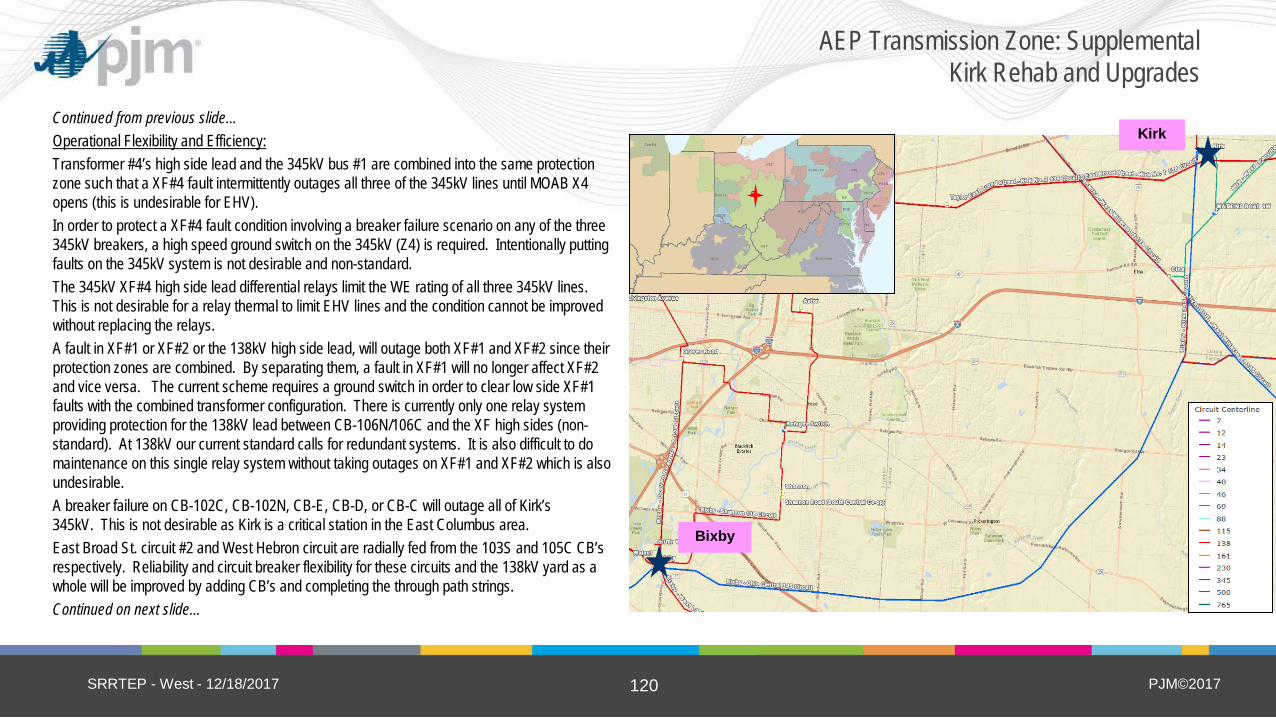
PJM©2017 120
Continued from previous slide… Operational Flexibility and Efficiency: Transformer #4’s high side lead and the 345kV bus #1 are combined into the same protection zone such that a XF#4 fault intermittently outages all three of the 345kV lines until MOAB X4 opens (this is undesirable for EHV). In order to protect a XF#4 fault condition involving a breaker failure scenario on any of the three 345kV breakers, a high speed ground switch on the 345kV (Z4) is required. Intentionally putting faults on the 345kV system is not desirable and non-standard. The 345kV XF#4 high side lead differential relays limit the WE rating of all three 345kV lines. This is not desirable for a relay thermal to limit EHV lines and the condition cannot be improved without replacing the relays. A fault in XF#1 or XF#2 or the 138kV high side lead, will outage both XF#1 and XF#2 since their protection zones are combined. By separating them, a fault in XF#1 will no longer affect XF#2 and vice versa. The current scheme requires a ground switch in order to clear low side XF#1 faults with the combined transformer configuration. There is currently only one relay system providing protection for the 138kV lead between CB-106N/106C and the XF high sides (non-standard). At 138kV our current standard calls for redundant systems. It is also difficult to do maintenance on this single relay system without taking outages on XF#1 and XF#2 which is also undesirable. A breaker failure on CB-102C, CB-102N, CB-E, CB-D, or CB-C will outage all of Kirk’s 345kV. This is not desirable as Kirk is a critical station in the East Columbus area. East Broad St. circuit #2 and West Hebron circuit are radially fed from the 103S and 105C CB’s respectively. Reliability and circuit breaker flexibility for these circuits and the 138kV yard as a whole will be improved by adding CB’s and completing the through path strings. Continued on next slide…
SRRTEP - West - 12/18/2017
AEP Transmission Zone: Supplemental Kirk Rehab and Upgrades
Kirk
Bixby
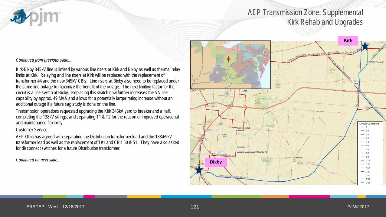
PJM©2017 121
Continued from previous slide…
Kirk-Bixby 345kV line is limited by various line risers at Kirk and Bixby as well as thermal relay limits at Kirk. Relaying and line risers at Kirk will be replaced with the replacement of transformer #4 and the new 345kV CB’s. Line risers at Bixby also need to be replaced under the same line outage to maximize the benefit of the outage. The next limiting factor for the circuit is a line switch at Bixby. Replacing this switch now further increases the SN line capability by approx. 49 MVA and allows for a potentially larger rating increase without an additional outage if a future sag study is done on the line. Transmission operations requested upgrading the Kirk 345kV yard to breaker and a half, completing the 138kV strings, and separating T1 & T2 for the reason of improved operational and maintenance flexibility. Customer Service: AEP-Ohio has agreed with separating the Distribution transformer lead and the 138/69kV transformer lead as well as the replacement of T#1 and CB’s 50 & 51. They have also asked for disconnect switches for a future Distribution transformer. Continued on next slide…
SRRTEP - West - 12/18/2017
AEP Transmission Zone: Supplemental Kirk Rehab and Upgrades
Kirk
Bixby

PJM©2017 122
Continued from previous slide… Potential Solution: At Kirk, Install 4-345kV 3,000A CB’s & end bus and complete the 345kV breaker and a half configuration. Replace 345/138kV XF with 675 MVA unit. Connect in different 345kV bay and on new 138kV string before removing old unit. Upgrade 2-138kV 4,000A CB’s & retire 1 CB on 102 string. Install 2-138kV 4,000A CB’s on new 104 string. Install 3 new 3,000A 138kV CB’s and complete 103 & 105 strings. Upgrade 3-138kV CB’s with 3,000A on 106 string. Separate 138/69 & 138/34kV XF connections and install 1-138kV ckt switcher on distribution bank. Replace 138/34kV XF and 2-34kV CB’s. Estimated Cost: $19.7M At Bixby, replace Kirk 345kV line risers and line switch and upgrade relaying Estimated Cost: $1.9M Upgrade relaying at Jug Street Estimated Cost: $0.4M Upgrade relaying at West Millersport Estimated Cost: $0.8M Upgrade relaying at West Hebron Estimated Cost: $0.2M Total Estimated Transmission Cost: $23.0M Continued on next slide…
SRRTEP - West - 12/18/2017
AEP Transmission Zone: Supplemental Kirk Rehab and Upgrades
Kirk
Bixby

PJM©2017 123
Continued from previous slide… Alternatives: Alternate #1: Replace existing Transformer #4 in place rather than on a new pad connecting at new positions. Leave T#1 & T#2 connected at the same 138kV point. No additional 138kV or 345kV CB’s added. Rehab replacements still done. This alternative would be far more disruptive to short term reliability and outage coordination. The CB 102 string would need to be upgraded to 4,000A first to avoid limiting Transformer #4 under N-1 conditions. CB maintenance would remain unnecessarily difficult for East Broad St #2 & West Hebron circuits. Significant reliability risks would remain for the 345kV yard as well as for the 138/69kV and 138/34.5kV transformers. Non-standard ground switch installations would remain in place. Alternative Cost: $11.4M Alternate #2: No riser or switch upgrades at Bixby. Although improved capacity would still be gained, this alternative would continue to limit the Kirk-Bixby line by approximately 170 MVA. Upon completion of sag study and remediation, the limitation would likely be even greater, though it is likely these upgrades would be done at that time under an additional 345kV outage. Alternative Cost: $24.7M Alternative #3: Rather than separate the feeds to T#1 & T#2, replace the MOABs & ground switch with two circuit switchers. This is an improvement but still subjects both transformers to common event outages. Alternative Cost: $24.0M
Projected In-service: 12/01/2019 Project Status: Engineering
SRRTEP - West - 12/18/2017
AEP Transmission Zone: Supplemental Kirk Rehab and Upgrades
Kirk
Bixby

PJM©2017 124
Problem Statement: Customer Service: LuK USA, LLC has requested a new 69kV delivery point (Clutch Switch) to serve a peak demand of 11 MVA, as their load growth has outgrown the local distribution in the area. LuK USA, LLC in Wooster, OH performs sales, design, development and manufacturing of clutch systems and torque converters for the automotive industry. A fully executed Letter of Commitment (LOC) has been established with the customer. Equipment Material/Condition/Performance/Risk: North Wooster has two long radial circuits (7.5 miles & 5 miles) serving three Holmes-Wayne Co-Op delivery points, two AEP Ohio substations, and LuK USA. These radials were constructed in the 1940s with a mix of 556 ACSR, 4/0 AL, #2 CU, and 1/0 ACSR (37 MVA rating) and have roughly 100 open category A conditions combined. The total peak summer load connected to these radials will be approximately 35 MW. These radials serve the largest shopping area for the Wooster community, four different medical offices, Green Local Schools and the Wayne County Vocational school. Any extended outage on these radials not only negatively impacts a large number of customers in numerous industries, it is harmful in the eyes of the customer and Holmes-Wayne/AEP Ohio’s public image suffers because of it. Operational Flexibility and Efficiency: On the 20 miles of 69kV in North Wooster, only two automatic sectionalizing devices exist to support the four AEP Ohio substations and three Holmes-Wayne Co-Op delivery points. Most outages on the 69kV network would thus require manual operation of switching devices, which leads to longer outage times for sensitive customers (shopping centers, medical facilities, and local schools). Continued on next slide…
SRRTEP - West - 12/18/2017
AEP Transmission Zone: Supplemental LuK USA and Madisonburg Loop
Geyer Switch

PJM©2017 125
Continued from previous slide… Potential Solution: Construct double-circuit line extension to Clutch Switch (0.5 miles) Estimated Cost: $1.6M Construct a single circuit line to close the loop between Schafrath Sw and Madisonburg (2 miles) Estimated Cost: $3.1M Rebuild Clutch Switch to Tigers as single circuit (1.5 miles) Estimated Cost: $3.7M Rebuild from Schafrath Sw to Oakhills Switch (3.0 miles single circuit) and from Oakhills to Highland (0.4 miles double circuit) Estimated Cost: $8.5M Establish a new station to serve customer (Clutch) Estimated Cost: $3.4M Establish a new station at Schafrath Switch to eliminate hard tap and loop lines Estimated Cost: $1.0M Expand Madisonburg station to establish new line exit to Schafrath Estimated Cost: $1.4M Construct new station at Tigers to eliminate hard tap and replace Smithville station Estimated Cost: $8.4M Install new phase-over-phase switch at Geyer Switch Estimated Cost: $0.8M Retire Oakhills Switch and establish a new box bay at Highland Avenue for the double circuit line Estimated Cost: $5.2M Retire Orrville Road Switch Estimated Cost: $0.1M Upgrade relaying at West Wooster Estimated Cost: $0.8M Upgrade relaying at East Wooster Estimated Cost: $0.8M Retire Smithville station Estimated Cost: $0.4M *Note: AEP already owns 99% of Right of Way (ROW) in sections where loops will be closed. All new line construction will be 69kV with 556 ACSR conductor (126 MVA rating) Total Estimated Transmission Cost: $39.2M Continued on next slide…
SRRTEP - West - 12/18/2017
AEP Transmission Zone: Supplemental LuK USA and Madisonburg Loop
Geyer Switch
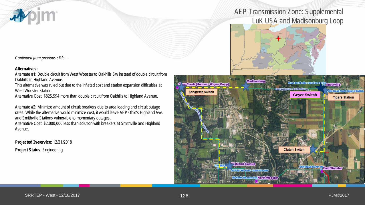
PJM©2017 126
Continued from previous slide… Alternatives: Alternate #1: Double circuit from West Wooster to Oakhills Sw instead of double circuit from Oakhills to Highland Avenue. This alternative was ruled out due to the inflated cost and station expansion difficulties at West Wooster Station. Alternative Cost: $825,594 more than double circuit from Oakhills to Highland Avenue. Alternate #2: Minimize amount of circuit breakers due to area loading and circuit outage rates. While the alternative would minimize cost, it would leave AEP Ohio’s Highland Ave. and Smithville Stations vulnerable to momentary outages. Alternative Cost: $2,000,000 less than solution with breakers at Smithville and Highland Avenue.
Projected In-service: 12/31/2018 Project Status: Engineering
SRRTEP - West - 12/18/2017
AEP Transmission Zone: Supplemental LuK USA and Madisonburg Loop
Geyer Switch

PJM©2017 127
Problem Statement: Customer Service: Mid-Vol Coal request to serve 8 MW of load on the Jim Branch – Switchback 138 kV line. Obligation to serve customer request. Potential Solution: Tap the existing Jim Branch – Switchback 138 kV line. Estimated Customer Cost: $0.52M Estimated Transmission Cost: $0.0M Establish the new Thorpe Switching Station and install a new 2000 A 138 kV phase-over-phase switch and install necessary 138 kV metering equipment. Estimated Customer Cost: $0.95M Estimated Transmission Cost: $0.0M Total Estimated Transmission Cost: $0 M Alternatives: No viable transmission alternatives could be identified. Projected In-service: 4/16/2018 Project Status: Scoping
SRRTEP - West - 12/18/2017
AEP Transmission Zone: Supplemental Mid-Vol Station

PJM©2017 128
Problem Statement: Operational Flexibility and Efficiency: Newcomerstown – North Coshocton 34.5 kV circuit is approximately 27.61 miles long. Many of the structures were replaced in 1989. This circuit currently has 218,976 customer minute interruptions. The Newcomerstown – North Coshocton 34.5 kV circuit serves approximately 14.67 MW. The customer minute interruptions can be reduced by either rebuilding the line or improving sectionalizing. Installing circuit breakers is more cost effective than rebuilding to reduce the CMI. Potential Solution: Establish Morgan Run Switch and install three 69 kV (to be operated at 34.5 kV) circuit breakers 2000 A 40 kA in a ring bus layout as a breaker and a half standard. Estimated Cost: $4.7M Relocate Morgan Run – Alleghany 34.5 kV line to accommodate the new circuit breakers. Estimated Cost: $1.1M Total Estimated Transmission Cost: $5.8 M Alternatives: Rebuild/reconductor the Newcomerstown – North Coshocton 34.5 kV circuit. Estimated Cost: Between $15-$26M, depending on condition of all structures Projected In-service: 12/15/2020 Project Status: Scoping
SRRTEP - West - 12/18/2017
AEP Transmission Zone: Supplemental Morgan Rd Switching Station
Morgan Run Sw

PJM©2017 129
Problem Statement: Equipment Material/Condition/Performance/Risk: Mount Sterling – South Fultonham 69kV line is a 7.22-mile radial line serving ~8 MW of peak demand. This line was built in 1959 and has 47 open A-type conditions. The line has contributed to 2.4 million customer minutes of interruptions (CMI) between 2013 and 2016. The Zanesville 69 kV circuit breakers “J”, “K” and “L” are FK oil type circuit breakers. Oil breaker maintenance has become more difficult due to the oil handling required to maintain them. Oil spills are frequent with breaker failures and routine maintenance and can become an environmental hazard. They have fault operations of 43, 45 and 47 respectively, higher than the manufacturer recommended number of 10 fault operations. Potential Solution: Build a new 5.7-mile 69 kV line from Mount Sterling to Zanesville station with 556.5 ACSR (102 MVA rating) to close the radial loop. Estimated Cost: $8.1M Zanesville – Linden Avenue 69 kV structure removal. Estimated Cost: $0.8M Mount Sterling – Zanesville 69 kV fiber cable. Estimated Cost: $0.3M At Zanesville station, install a 69 kV 40 kA 2000A circuit breaker. Replace 69 kV breakers J, K, and L. Install a 138 kV high side circuit breaker and a 69 kV low side circuit breaker for the 138/69 kV transformer. Estimated Cost: $4.3M At Mount Sterling station, install two 69 kV 40 kA 2000A circuit breakers in a box bay configuration. Estimated Cost: $3.0M Total Estimated Transmission Cost: $16.5M Continued on next slide…
SRRTEP - West - 12/18/2017
AEP Transmission Zone: Supplemental Mt Sterling – Zanesville 69 kV Circuit
Mount Sterling Zanesville

PJM©2017 130
Continued from previous slide… Alternatives: Rebuild the Mount Sterling - South Fultonham 69 kV 7.22 mile line as a double circuit line. This alternative is not as reliable because a structure failure on the double circuit line will outage the service to the Guernsey Muskingum Electric Coop delivery point and to the AEP Ohio delivery point. The radial line also cannot be taken out of service to rebuild. Estimated Cost: $15M Install a 138/69 kV transformer at Mount Sterling and a 138 kV line to connect to the Crooksville – North Newark 138 kV circuit via a new switching station with phase over phase switches. Estimated cost: $25 M
Projected In-service: 12/15/2019 Project Status: Engineering
SRRTEP - West - 12/18/2017
AEP Transmission Zone: Supplemental Mt Sterling – Zanesville 69 kV Circuit
Mount Sterling Zanesville

PJM©2017 131
Problem Statement: Customer Service: Lakeland Memorial Hospital has requested AEP Transmission provide a new dual feed point of service to their current location. The hospital is currently served from the Distribution system but construction is underway to expand their facilities to add 4 MW of additional loading to their current location. The customer has expressed sensitivity to any potential reliability issues and will install two transformers for the dual feeds. Potential Solution: Create an in & out from the existing Hickory Creek – Main Street No. 2 34.5 kV circuit Estimated Cost: $1.7M Construct a new Napier station with a single circuit breaker between two customer feeds. The two feeds will serve two customer owned transformers. Estimated Cost: $2.9M Total Estimated Transmission Cost: $4.6 M Alternatives: Serve the customer from a phase over phase switch. This was dismissed after learning that the customer was very concerned about reliability. Estimated Cost: $5.6M Projected In-service: 06/30/2019 Project Status: Scoping
SRRTEP - West - 12/18/2017
AEP Transmission Zone: Supplemental Napier (Lakeland Hospital) Station
Napier Station

PJM©2017 132
Problem Statement: Equipment Material/Condition/Performance/Risk: North Bristol 138 kV circuit breakers A and B (vintage 1975) are type Air Blast breakers. Air blast breakers are being replaced across the AEP system due to reliability concerns, intensive maintenance, and their tendency to catastrophically fail. During failures, sharps pieces of porcelain from their bushings are typically expelled, which can be a potential safety hazard to field personnel. In addition, the ability to get spare parts for these breakers is becoming increasingly difficult. Circuit breaker B has exceeded (40 operations) the manufacturers recommended number of fault interruption (10 operations). Potential Solution: North Bristol 138 kV: Replace existing 3000 A 50 kA 138 kV circuit breakers ‘A’ and ‘B’ with new 3000 A 40 kA 138 kV circuit breakers. Total Estimated Transmission Cost: $2.5 M Alternatives: No viable and cost effective alternative could be identified. Projected In-service: 05/31/2018 Project Status: Engineering
SRRTEP - West - 12/18/2017
AEP Transmission Zone: Supplemental North Bristol CB Replacement
North Bristol
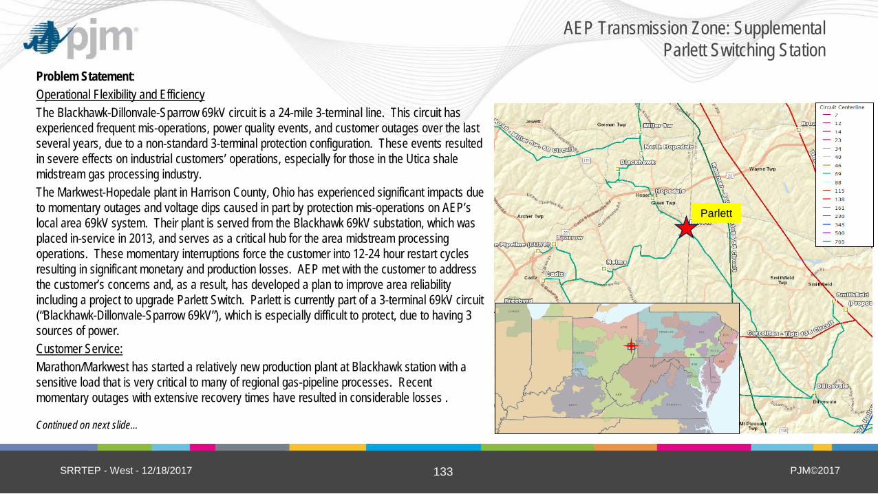
PJM©2017 133
Problem Statement: Operational Flexibility and Efficiency The Blackhawk-Dillonvale-Sparrow 69kV circuit is a 24-mile 3-terminal line. This circuit has experienced frequent mis-operations, power quality events, and customer outages over the last several years, due to a non-standard 3-terminal protection configuration. These events resulted in severe effects on industrial customers’ operations, especially for those in the Utica shale midstream gas processing industry. The Markwest-Hopedale plant in Harrison County, Ohio has experienced significant impacts due to momentary outages and voltage dips caused in part by protection mis-operations on AEP’s local area 69kV system. Their plant is served from the Blackhawk 69kV substation, which was placed in-service in 2013, and serves as a critical hub for the area midstream processing operations. These momentary interruptions force the customer into 12-24 hour restart cycles resulting in significant monetary and production losses. AEP met with the customer to address the customer’s concerns and, as a result, has developed a plan to improve area reliability including a project to upgrade Parlett Switch. Parlett is currently part of a 3-terminal 69kV circuit (“Blackhawk-Dillonvale-Sparrow 69kV”), which is especially difficult to protect, due to having 3 sources of power. Customer Service: Marathon/Markwest has started a relatively new production plant at Blackhawk station with a sensitive load that is very critical to many of regional gas-pipeline processes. Recent momentary outages with extensive recovery times have resulted in considerable losses . Continued on next slide…
SRRTEP - West - 12/18/2017
AEP Transmission Zone: Supplemental Parlett Switching Station
Parlett
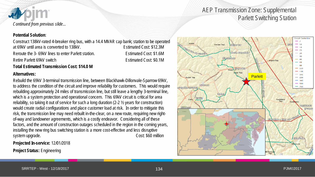
PJM©2017 134
Continued from previous slide… Potential Solution: Construct 138kV-rated 4-breaker ring bus, with a 14.4 MVAR cap bank; station to be operated at 69kV until area is converted to 138kV. Estimated Cost: $12.3M Reroute the 3- 69kV lines to enter Parlett station. Estimated Cost: $1.6M Retire Parlett 69kV switch Estimated Cost: $0.1M Total Estimated Transmission Cost: $14.0 M Alternatives: Rebuild the 69kV 3-terminal transmission line, between Blackhawk-Dillonvale-Sparrow 69kV, to address the condition of the circuit and improve reliability for customers. This would require rebuilding approximately 24 miles of transmission line, but still leave a lengthy 3-terminal line, which is a system protection and operational concern. This 69kV circuit is critical for area reliability, so taking it out of service for such a long duration (2-2 ½ years for construction) would create radial configurations and place customer load at risk. In order to mitigate this risk, the transmission line may need rebuilt in-the-clear, on a new route, requiring new right-of-way and landowner agreements, which is a costly endeavor. Considering all of these factors, and the amount of construction outages scheduled in the region in the coming years, installing the new ring bus switching station is a more cost-effective and less disruptive system upgrade. Cost: $60 million Projected In-service: 12/01/2018 Project Status: Engineering
SRRTEP - West - 12/18/2017
AEP Transmission Zone: Supplemental Parlett Switching Station
Parlett

PJM©2017 135
Problem Statement: Other: Obligation to serve new customer request. Summer projected load 14 MVA, Winter Projected load 23 MVA. Potential Solution: Tap the Holston – Sullivan Gardens 138kV circuit. Estimated Cost: $0.4M Construct a 138/34.5kV distribution station (Riggs). Install a new 138/34.5 kV 30 MVA, two 3000 A 100kA 138 kV MOABs and a 3000 A 40 kA 138 kV circuit switcher. Estimated Cost: $0.0M Total Estimated Transmission Cost: $0.4M Alternatives: No viable and cost effective alternative could be identified. Projected In-service: 12/31/2018 Project Status: Engineering
SRRTEP - West - 12/18/2017
AEP Transmission Zone: Supplemental Riggs Station
Riggs

PJM©2017 136
Problem Statement: Equipment Material/Condition/Performance/Risk: Transformer 2 (560 MVA unit) at Roberts station is 43 years old with dielectric strength breakdown (winding insulation), short circuit strength breakdown (due to the amount of through fault events), and accessory damage (bushings). The ratings on Transformer 1 are currently limited by equipment in the 138 kV yard. Replacing this equipment will allow both transformers to operate at their full capabilities. Potential Solution: Replace XF#2 with a 675 MVA 345/138kV unit and upgrade all XF#2 risers and XF#2 138kV lead to 4,000A ratings. Add 138kV 4,000A XF#2 switch. Upgrade XF#1 risers to 4,000A ratings. Estimated Transmission Cost: $8.4M Alternatives: No cost effective alternates identified. Projected In-service: 12/01/2019 Project Status: Engineering
SRRTEP - West - 12/18/2017
AEP Transmission Zone: Supplemental Roberts Rehab & Upgrades
Roberts

PJM©2017 137
Problem Statement: Customer Service: Rockwell Mining request to serve a new 6 MW load on the Bim – Skin Fork 46 kV line. Potential Solution: Tap existing Bim – Skin Fork 46 kV line and re-enforce structures for the new delivery point and switch installation. Estimated Cost: $0.3M Install a 1200 A 3-way phase-over-phase switch on Bim – Skin Fork 46 kV circuit at newly established Saunders Switching Station. Estimated Cost: $0.0M Total Estimated Transmission Cost: $0.3M Alternatives: Initial scope planned to tap the Bim – Skin Fork 46 kV line between structures 416-62 and 416-63 at the top of the hill. Upon the site visit it was determined that the customer preferred tapping between structures 416-65 and 416-66 due to the location of their site at the base of the hill to reduce the amount of mileage to connect to the initial site. Projected In-service: 10/01/2018 Project Status: Scoping
SRRTEP - West - 12/18/2017
AEP Transmission Zone: Supplemental Rockwell Mining
Skin Fork
Saunders

PJM©2017 138
Problem Statement: Operational Flexibility and Efficiency The New Lexington – South Fultonham 69 kV circuit serves 6.74 MW of load. In three years the New Lexington – South Fultonham 69 kV circuit has experienced customer minute interruptions of 1,732,378. Much of this line was rebuilt in 2013. CMI can be reduced by either rebuilding the line or improving sectionalizing. Installing circuit breakers is more cost effective. Potential Solution: Relocate three lines to the new Somerset Switching Station. Estimated Cost: $2.7M Install four 69 kV circuit breakers in a ring bus configuration at Somerset Switch. Estimated Cost: $5.7M Total Estimated Transmission Cost: $8.4 M Alternatives: Rebuild 12.74 miles of the New Lexington – South Fultonham 69 kV circuit. The cost of this alternative would be approximately $19M. Projected In-service: 12/15/2020 Project Status: Engineering
SRRTEP - West - 12/18/2017
AEP Transmission Zone: Supplemental Somerset 69 kV Switching Station

PJM©2017 139
Problem Statement: Equipment Material/Condition/Performance/Risk: The 3 mile long Stubey Road – Sturgis line portion currently is subject to 18 open conditions and is wood pole construction from 1953 with 4/0 ACSR and 556 ACSR conductor (50 MVA rating). This line is currently subject to stolen, broken and missing ground lead wire; corroded shield wire; and burnt or broken insulators. Potential Solution: Rebuild the ~3 miles of the Stubey Road – Sturgis 69kV circuit utilizing 795 ACSR (76 MVA rating) Estimated Transmission Cost: $5.3 M Alternatives: No viable cost effective transmission alternates were found Projected In-service: 03/30/2018 Project Status: Construction
SRRTEP - West - 12/18/2017
AEP Transmission Zone: Supplemental Stubey Road – Sturgis Rebuild

PJM©2017 140
Problem Statement: Equipment Material/Condition/Performance/Risk: Vicksburg – Schoolcraft 69kV is a 5 mile 1970’s vintage radial line that currently has 22 structures with open conditions affecting 36% of the total number of structures. With our current system configuration this line cannot be addressed as it will result in significant outages to Vicksburg station, which cannot be recovered from a backup facility. Schoolcraft station equipment is mostly 1970s vintage. The 1967 vintage 69kV circuit breaker A at Schoolcraft Substation is an oil filled FK-breaker without oil containment. It has also operated through 175 fault operations, exceeding the manufacturer’s recommendation of 10. In general, oil breakers have become increasingly difficult to maintain due to the oil handling associated with them. Oil spills are frequent with failures and routine maintenance which is also an environmental hazard. Schoolcraft substation currently deploys 17 relays, implemented to ensure the adequate protection and operation of the substation. Currently, 9 of the relays are of the electromechanical type which have significant limitations with regards to fault data collection and retention. Operational Flexibility and Efficiency: The Moore Park – Schoolcraft 69kV line has averaged 5 million customer minutes of interruption per year over the last three years. For the past 10 years this line has experienced a total of 23 momentary outages, and 7 permanent outages. Continued on next slide…
SRRTEP - West - 12/18/2017
AEP Transmission Zone: Supplemental Vicksburg – Schoolcraft Improvements
Schoolcraft (Kalamazoo)
Moore Park

PJM©2017 141
Continued from previous slide… Vicksburg 69kV station, with a projected load of 14MW, is currently being served radially. Also, the current configuration at Schoolcraft station combines 3 elements into one protection zone. This protection scheme exposes the only transformer at Schoolcraft and both transformers at Vicksburg to line faults and increases the probability of relay mis-operations. This has been a historical issue to the customers in the Schoolcraft area because there is zero distribution recoverability or load transferability between Schoolcraft and Vicksburg station. Customer Service: In addition to the transmission facilities, I&M Distribution has identified switchgear replacements at Schoolcraft. Historically, 12 kV switchgear distribution facilities like the one at Schoolcraft are very problematic due to the many complications associated to maintenance and repairs. The cost of the switchgear is not a part of the scope as it is a distribution asset. Continued on next slide…
SRRTEP - West - 12/18/2017
AEP Transmission Zone: Supplemental Vicksburg – Schoolcraft Improvements
Schoolcraft (Kalamazoo)
Moore Park

PJM©2017 142
Continued from previous slide… Potential Solution: Rebuild Schoolcraft 69kV station as Kalamazoo 69kV station in the clear. Kalamazoo station will have a breaker and half configuration with (6) 69kV CBs , (2) 69/12kV transformers, 12kV bus with associated feeders, and a 14.4MVAR cap bank. One transformer will be transferred from the existing Schoolcraft station and the second will be new. Estimated Cost: $5.2M Install (2) 69kV CBs and install DICM at Vicksburg to accommodate the new, second line. Estimated Cost: $1.5M Construct a new 5 mile 69kV line between Kalamazoo and Vicksburg stations with 336.4 ACSR conductor (73 MVA rating). Install Fiber between Kalamazoo and Vicksburg Station. Extend Moore Park-Schoolcraft line into Kalamazoo. Estimated Cost: $12.5M Total Estimated Transmission Cost: $19.2 M Alternatives: Construct a new 11 mile long 69kV line between Moore Park and Vicksburg stations. This solution will be more expensive and will not address the identified concerns at Schoolcraft station. Estimated cost: $30 million. Rebuild the Vicksburg - Schoolcraft line (5 miles). This solution exposes customers at Vicksburg station to long outages during construction as Vicksburg’s load cannot be transferred. Estimated cost: $15 million. Projected In-service: 12/01/2018 Project Status: Scoping
SRRTEP - West - 12/18/2017
AEP Transmission Zone: Supplemental Vicksburg – Schoolcraft Improvements
Schoolcraft (Kalamazoo)
Moore Park

PJM©2017 143
Problem Statement: Equipment Material/Condition/Performance/Risk: Thelma Station 69 kV circuit breaker ‘D’ (vintage 1965) and 46 kV circuit breaker ‘B’ (vintage 1961) are both showing signs of deterioration. Circuit breaker ‘B’ is an oil type FZO Allis-Chalmers type that has historically presented AEP with catastrophic failures which have resulted in AEP targeting them for replacement. Circuit breaker ‘D’ is a GE FK oil type that was installed without oil containment and are prone to failure. This risk of contamination upon a failures has driven AEP to target them for replacement. In addition, the manufacturers recommended number of fault operations is 10. Breaker ‘B’ has experienced 260 operations and breaker ‘D’ has experienced 45 operations. Circuit switcher BB is a MARK V unit. Mark III’s, IV’s and V’s do no longer work with modern relaying packages and are recommended to be replaced. Potential Solution: Replace existing 1200 A 12.5 kA 46 kV circuit breaker ‘B’ with a new 3000 A 40 kA 46 kV circuit breaker. Replace existing 1200 A 21 kA 69 kV circuit breaker ‘D’ with a new 3000 A 40 kA 69 kV circuit breaker. Replace existing 1200 A 30 kA 138 kV cap switcher ‘BB’ with a new 650 A 31.5 kA 138 kV cap switcher. Estimated Transmission Cost: $1.7 M Alternatives: No viable cost effective transmission alternates were found Projected In-service: 06/07/2018 Project Status: Engineering
SRRTEP - West - 12/18/2017
AEP Transmission Zone: Supplemental Thelma Station
Thelma

PJM©2017 145
Problem Statement: Equipment Material/Condition/Performance/Risk: The Liberty Center – Van Buren line currently is subject to 44 open conditions including broken and damaged conductor; broken ground wire; and broken and damaged shield wire. The circuit was built in 1959 and 1968 using wooden poles. From 2013-2016 there have been five permanent outages with the majority cause being T-Line. The existing line was constructed predominantly using shorter poles with wood crossarms and vertical post insulators. This type of construction is not a current AEP standard. Many of the crossarms are smaller cross-section, typical of those used for less resilient distribution construction. End splitting and bowing are common reasons for crossarms failing to pass periodic visual inspection, carrying an elevated risk of failure and line outages. In addition, crossarm construction results in a poor shielding angle, leading to a higher frequency of lightning strikes and momentary interruptions during lightning activity. Design standards from 1950s do not meet modern standards for strength, resilience, and horizontal and vertical clearances for safety for these poles. Original conductors between Van Buren and Warren, and between Bluffton and Liberty Center were re-conductored with 4/0 ACSR conductors (50 MVA rating) in 1963. A 5/16” EHS steel shield wire was added in 1963. To avoid changing poles, most poles were retrofitted with a crossarm-type “bay-o-net” attached to the pole tops to support the shield wire addition. Bay-o-nets are prone to inspection rejection and occasional failure and are no longer an acceptable method of supporting a shield wire attachment. Continued on next slide…
SRRTEP - West - 12/18/2017
AEP Transmission Zone: Supplemental Van Buren – Liberty Center Rebuild
Buckeye Tap Switch Liberty Center
Van Buren

PJM©2017 146
Continued from previous slide… Existing grounding is only every other structure, at best, which is not the current AEP standard and may contribute to a higher frequency of momentary interruptions during lightning activity. Legacy underlying land rights, where they exist, are typically inadequate by present day AEP Transmission standards. Some sections of the lines were originally constructed within public road rights-of-way with no easement rights acquired on the adjacent private properties. The lack of easement rights provides no ability to properly manage non-conforming land uses. Where easement rights do exist, the ability to control building encroachments and intrusive vegetation were often not included in the language of the original easements. These wood pole transmission lines have exceeded their original life expectancy. Age and normal deterioration of the lines warrant their complete replacement. As the Buckeye Switch Tap is part of the line, the switching structure will have to be replaced. Operational Flexibility and Efficiency The Liberty Center – Bluffton, Liberty Center – Montpelier, Montpelier – Hartford City and the Hartford City – Bosman all are either built using 795 ACSR or are being built using 795 ACSR. If anything less than 795 ACSR is installed on this line, it will effectively limit the network Continued on next slide…
SRRTEP - West - 12/18/2017
AEP Transmission Zone: Supplemental Van Buren – Liberty Center Rebuild
Buckeye Tap Switch Liberty Center
Van Buren

PJM©2017 147
Continued from previous slide… Potential Solution: Rebuild 16.3 miles of the Van Buren – Liberty Center line utilizing 795 ACSR (129 MVA rating) Estimated Cost: $22.1M Install a new 3-way phase-over-phase 1200A steel switching structure at the Buckeye Tap Switch. Estimated Cost: $0.3M Total Estimated Transmission Cost: $22.4 M Alternatives: No cost effective alternatives were identified. Projected In-service: 06/05/2019 Project Status: Engineering
SRRTEP - West - 12/18/2017
AEP Transmission Zone: Supplemental Van Buren – Liberty Center Rebuild
Buckeye Tap Switch Liberty Center
Van Buren
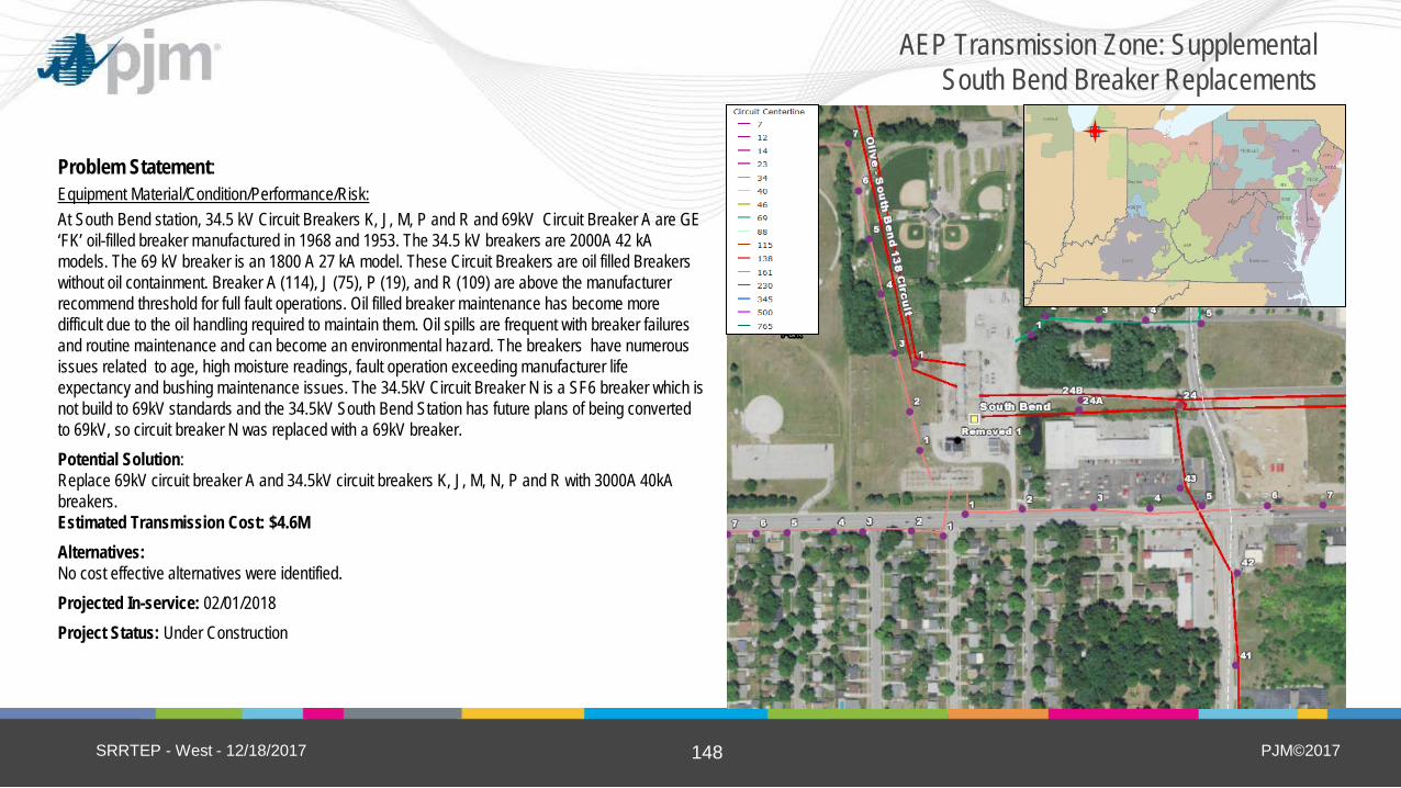
PJM©2017 148
Problem Statement: Equipment Material/Condition/Performance/Risk: At South Bend station, 34.5 kV Circuit Breakers K, J, M, P and R and 69kV Circuit Breaker A are GE ‘FK’ oil-filled breaker manufactured in 1968 and 1953. The 34.5 kV breakers are 2000A 42 kA models. The 69 kV breaker is an 1800 A 27 kA model. These Circuit Breakers are oil filled Breakers without oil containment. Breaker A (114), J (75), P (19), and R (109) are above the manufacturer recommend threshold for full fault operations. Oil filled breaker maintenance has become more difficult due to the oil handling required to maintain them. Oil spills are frequent with breaker failures and routine maintenance and can become an environmental hazard. The breakers have numerous issues related to age, high moisture readings, fault operation exceeding manufacturer life expectancy and bushing maintenance issues. The 34.5kV Circuit Breaker N is a SF6 breaker which is not build to 69kV standards and the 34.5kV South Bend Station has future plans of being converted to 69kV, so circuit breaker N was replaced with a 69kV breaker. Potential Solution: Replace 69kV circuit breaker A and 34.5kV circuit breakers K, J, M, N, P and R with 3000A 40kA breakers. Estimated Transmission Cost: $4.6M Alternatives: No cost effective alternatives were identified. Projected In-service: 02/01/2018 Project Status: Under Construction
SRRTEP - West - 12/18/2017
AEP Transmission Zone: Supplemental South Bend Breaker Replacements

PJM©2017 150
Upcoming Western SRRTEP Dates
SRRTEP - West - 12/18/2017
West Start End
** 1/8/208 ** 12:00 4:00
1/30/2018 12:00 4:00
3/27/2018 12:00 4:00
5/30/2018 12:00 4:00
7/27/2018 12:00 4:00
9/28/2018 12:00 4:00
11/29/2018 12:00 4:00
Please note new meeting on January 8, 2018

PJM©2017 151
Questions?
SRRTEP - West - 12/18/2017

PJM©2017 152
Revision History
SRRTEP - West - 12/18/2017
4/18/2018 – V6 – Updated slides to reflect stakeholder feedback (changes in red) - Slides 11 – 23:Anaconda, Hazard, Shoals, Balls Gap, Beckham, Fall Creek, and South Bend - Slides 29 - 33: Buckhorn, Carlton-Sunnyside, College Corner - Slides 37 – 43: Harrison-Parsons-Marion, Hartford City-Montpelier, Hopkins-Sharples, and Lick-Ross
2/1/2018 – V5 – Slide #73: update project status, problem statement and estimated cost - Slide #74: update project status
1/23/2018 – V4 – Remove Slide #64. 1/5/2018 – V4 – Corrected incorrect (inconsistent) date in footed.
- Spelling corrections 12/29/2017 – V3 – Slide #73, update the cost estimate and description
- Slide #70, removed - Slide #144, removed and move it to TEAC since the project is 345KV - Slide #68, #69, #71, #72, update the slides with more details
12/15/2017 – V2 – Formatting updates to original slides - Added note about extra meeting on 1/8/2018
12/12/2017 – V1 – Original version posted to PJM.com
Copyright © 2022 FDOKUMEN


![Structural and thermoelectric properties of Bi[sub 2]Sr[sub 2]Co[sub 2]O[sub y] thin films on LaAlO[sub 3] (100) and fused silica substrates](https://static.fdokumen.com/doc/165x107/634467196cfb3d406409325f/structural-and-thermoelectric-properties-of-bisub-2srsub-2cosub-2osub-y.jpg)