Study of the vibrational behaviour of the components of a car ...
6
* Corresponding author: [email protected] Study of the vibrational behaviour of the components of a car suspension Zlatin Georgiev 1,* , and Lilo Kunchev 1 1 Technical University – Sofia, Faculty of Transport, 8 Kliment Ohridski Blvd., 1000 Sofia, Bulgaria Abstract. The paper presents a study of the vibrational behaviour of a car suspension in the frequency range from 50 to 200 Hz. The vehicle has a torsion spring suspension. The aim of the study is to provide a numerical approach, which evaluates the impact of the tyre vibration characteristics and the elastic properties of suspension elements on the vibrational behaviour of the "tyre-suspension-body" system. The object of the study are the elements of the suspension – stub-axle, upper and lower suspension arms, strut rod, torsion bar and others. The suspension is equipped with pneumatic tyres with different vibration characteristics. Laboratory experiments are done. The tyre contact patch is disturbed by harmonic force. The accelerations of the wheel axle and specific points of the suspension are obtained. A numerical model of the system is created by using the Finite Element Method available in SolidWorks Simulation software. The model allows to determinate the accelerations at different points of the suspension. The results of the experimental and theoretical studies are compared. The values obtained in the two studies are similar. 1 Introduction The pneumatic tyre perceives the road unevenness and roughness and transmits them to the suspension elements during the movement of a vehicle. The generated vibrations enter into the passenger compartment through connections between the suspension and the vehicle body. Correctly selected elastic and damping characteristics of the suspension elements (shock absorber, spring, rubber mounts), and modal parameters of the metal elements (rods, shells, plates) can improve car comfort in terms of noise and vibrations. This reduces driver fatigue. Depending on the vehicle class, the vibration and noise levels in its cabin are different. The driver feels these vibrations in the seat, the floor panels and the steering wheel. It is known from the physiological tests made on a person on a vibrating platform that he perceives vibrations in a different way. The vibrations up to 5 Hz have effect on the entire human body. Those of up to 10 Hz affect the limbs and the torso, up to 20 Hz - the lower torso and limbs, up to 60 Hz - the limbs. A person perceives vibrations of over 60 Hz only with the receptors of the skin. 2 Overview of the problem and setting the aim The interaction between the tyre and the road surface is a source of vibrations. These vibrations affect the ride and the vibro-acoustic comfort as well as the road holding [1, 2]. They depend on the tyre characteristics, which are similar to those of air-springs [3] for frequencies below 30 Hz. The natural frequencies of the pneumatic tyre depend on its construction. In [4, 5], the authors conduct theoretical and experimental studies, showing that the sidewall stiffness has the greatest impact on the tyre natural frequencies. In [6, 7], the authors study the effect of circular velocity on their natural frequencies. They determine that the first natural frequency is the same for both unloaded, non-rotating tyre, and for loaded, rotating tyre. There is a splitting of modes associated with higher frequencies [8] and in case of a loaded rotating tyre, the natural frequency decreases as the circular velocity increases. Kindt et al. [9] conduct a theoretical and experimental study showing that the transmission ratio between the road excitations and the wheel axis as well as the tyre dynamic transfer stiffness depend on its natural frequencies. Despite the small amplitude of high frequency vibrations, the vibrations generated by the interaction between the tyre and the road are not absorbed by the elastic elements and the shock absorbers. Through the contact points of the suspension, they are transmitted to the vehicle body without noticeably lowering their levels. Klerk and Ossipov [10] conduct experiments with six different types of radial tyres (from slicks to off-road profile, as well as various seasonal tyres). The analysis shows that, up to 650 Hz, structure-borne noise is critical for vibro-acoustic comfort. They point out about the given suspension (McPherson type), that the transmission ratios between the wheel axle acceleration and structure-borne noise in the passenger compartment are similar for different tyre types and for different road surfaces. In work [11], the authors examine the dampening effect of the tyre, the elastic element and the shock , MATEC Web of Conferences https://doi.org/10.1051/matecconf/20182 234 0 (201 ) 8 0 340 05 BulTrans-2018 20 20 5 © The Authors, published by EDP Sciences. This is an open access article distributed under the terms of the Creative Commons Attribution License 4.0 (http://creativecommons.org/licenses/by/4.0/).
-
Upload
khangminh22 -
Category
Documents
-
view
3 -
download
0
Transcript of Study of the vibrational behaviour of the components of a car ...

* Corresponding author: [email protected]
Study of the vibrational behaviour of the components of a car suspension
Zlatin Georgiev1,*, and Lilo Kunchev1
1Technical University – Sofia, Faculty of Transport, 8 Kliment Ohridski Blvd., 1000 Sofia, Bulgaria
Abstract. The paper presents a study of the vibrational behaviour of a car suspension in the frequency range from 50 to 200 Hz. The vehicle has a torsion spring suspension. The aim of the study is to provide a numerical approach, which evaluates the impact of the tyre vibration characteristics and the elastic properties of suspension elements on the vibrational behaviour of the "tyre-suspension-body" system. The object of the study are the elements of the suspension – stub-axle, upper and lower suspension arms, strut rod, torsion bar and others. The suspension is equipped with pneumatic tyres with different vibration characteristics. Laboratory experiments are done. The tyre contact patch is disturbed by harmonic force. The accelerations of the wheel axle and specific points of the suspension are obtained. A numerical model of the system is created by using the Finite Element Method available in SolidWorks Simulation software. The model allows to determinate the accelerations at different points of the suspension. The results of the experimental and theoretical studies are compared. The values obtained in the two studies are similar.
1 Introduction
The pneumatic tyre perceives the road unevenness and roughness and transmits them to the suspension elements during the movement of a vehicle. The generated vibrations enter into the passenger compartment through connections between the suspension and the vehicle body. Correctly selected elastic and damping characteristics of the suspension elements (shock absorber, spring, rubber mounts), and modal parameters of the metal elements (rods, shells, plates) can improve car comfort in terms of noise and vibrations. This reduces driver fatigue. Depending on the vehicle class, the vibration and noise levels in its cabin are different.
The driver feels these vibrations in the seat, the floor panels and the steering wheel. It is known from the physiological tests made on a person on a vibrating platform that he perceives vibrations in a different way. The vibrations up to 5 Hz have effect on the entire human body. Those of up to 10 Hz affect the limbs and the torso, up to 20 Hz - the lower torso and limbs, up to 60 Hz - the limbs. A person perceives vibrations of over 60 Hz only with the receptors of the skin.
2 Overview of the problem and setting the aim
The interaction between the tyre and the road surface is a source of vibrations. These vibrations affect the ride and the vibro-acoustic comfort as well as the road holding [1, 2]. They depend on the tyre characteristics, which are similar to those of air-springs [3] for frequencies below
30 Hz. The natural frequencies of the pneumatic tyre depend on its construction. In [4, 5], the authors conduct theoretical and experimental studies, showing that the sidewall stiffness has the greatest impact on the tyre natural frequencies. In [6, 7], the authors study the effect of circular velocity on their natural frequencies. They determine that the first natural frequency is the same for both unloaded, non-rotating tyre, and for loaded, rotating tyre. There is a splitting of modes associated with higher frequencies [8] and in case of a loaded rotating tyre, the natural frequency decreases as the circular velocity increases. Kindt et al. [9] conduct a theoretical and experimental study showing that the transmission ratio between the road excitations and the wheel axis as well as the tyre dynamic transfer stiffness depend on its natural frequencies.
Despite the small amplitude of high frequency vibrations, the vibrations generated by the interaction between the tyre and the road are not absorbed by the elastic elements and the shock absorbers. Through the contact points of the suspension, they are transmitted to the vehicle body without noticeably lowering their levels. Klerk and Ossipov [10] conduct experiments with six different types of radial tyres (from slicks to off-road profile, as well as various seasonal tyres). The analysis shows that, up to 650 Hz, structure-borne noise is critical for vibro-acoustic comfort. They point out about the given suspension (McPherson type), that the transmission ratios between the wheel axle acceleration and structure-borne noise in the passenger compartment are similar for different tyre types and for different road surfaces.
In work [11], the authors examine the dampening effect of the tyre, the elastic element and the shock
,MATEC Web of Conferences https://doi.org/10.1051/matecconf/20182234 0 (201 )80 340 05BulTrans-2018
20 205
© The Authors, published by EDP Sciences. This is an open access article distributed under the terms of the Creative Commons Attribution License 4.0 (http://creativecommons.org/licenses/by/4.0/).
absorber in vertical direction. At frequencies above 25 Hz, the vibrations are absorbed only by the pneumatic tyre and the upper insulator mounted between the McPherson strut and the car body (the coil spring and the shock absorber can be considered as rigid bodies with a specific mass). In semi-active suspensions, it is noted that even with the change of the damping coefficient, for frequencies over 50 Hz, it does not affect the vibrations of the sprung mass [12].
The vibration behaviour is specific for each type of suspension. Many authors focus on describing different methods of study of structural vibrations. One of them is the method of transmission ratios, in which a specific connection (ball joint, bushing, etc.) as well as a whole system, which contains several such connections, are analyzed [13]. The transmission ratio shows the quantitative relation between the output and the input vibrations of the connection (system). It should be noted that the source transfer formulations are expressed in the form of spectra and frequency response functions. Another way to determine the parameters of the high frequency vibrations in the connection points between the suspension elements and the vehicle body is by using an equivalent model and applying the dynamic stiffness method [14]. The frequencies and the amplitudes of the vibrations are used to assess the impact of the suspension elements on the frame at the different connection points. On the other hand, changing the stiffness of the rubber insulators at the connection points affects the natural frequencies of metal elements of the suspension [15].
The acoustic noise created by the interaction between the tyre and the road is a subject of new and more restrictive regulations of the European Union [16]. Reduction of the acoustic noise can be achieved by developing new tyre design strategies [17, 18] or by installing reflective noise barriers [19].
The aim of the study is to provide a numerical approach, which evaluates the impact of the tyre vibration characteristics and the modal parameters of suspension elements on the vibrational behaviour of the "tyre-suspension-body" system in the frequency range from 50 to 200 Hz. This frequency range contains the first five natural frequencies of the tyre, so it gives good representation of tyre vibrational behaviour [20].
3 Method of the experimental investigation
The study uses the method of transmission ratios for investigation and evaluation of high frequency vibrations in the vehicle suspension elements. For the measurements, the ratio of the output acceleration to the input acceleration is chosen. The accelerations are measured in a vertical direction. The measurement points are shown in Fig. 1.
The study is focused on the following steps: • transmission of vibrations to the wheel axle when the
tyre is being disturbed; • transmission of vibrations through the insulators, joints,
dampers, etc.;
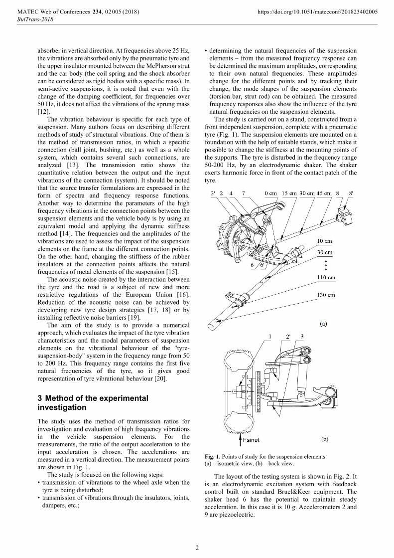
• determining the natural frequencies of the suspension elements – from the measured frequency response can be determined the maximum amplitudes, corresponding to their own natural frequencies. These amplitudes change for the different points and by tracking their change, the mode shapes of the suspension elements (torsion bar, strut rod) can be obtained. The measured frequency responses also show the influence of the tyre natural frequencies on the suspension elements.
The study is carried out on a stand, constructed from a front independent suspension, complete with a pneumatic tyre (Fig. 1). The suspension elements are mounted on a foundation with the help of suitable stands, which make it possible to change the stiffness at the mounting points of the supports. The tyre is disturbed in the frequency range 50-200 Hz, by an electrodynamic shaker. The shaker exerts harmonic force in front of the contact patch of the tyre.
Fig. 1. Points of study for the suspension elements: (a) – isometric view, (b) – back view.
The layout of the testing system is shown in Fig. 2. It is an electrodynamic excitation system with feedback control built on standard Bruel&Keer equipment. The shaker head 6 has the potential to maintain steady acceleration. In this case it is 10 g. Accelerometers 2 and 9 are piezoelectric.
,MATEC Web of Conferences https://doi.org/10.1051/matecconf/20182234 0 (201 )80 340 05BulTrans-2018
20 205
2

Fig. 2. Layout of the testing system (1 – test object, 2 and 9 – accelerometer, 3 and 10 – preamplifier, 4 – amplifier, 5 – read out, 6 – shaker, 7 – amplifier of the disturbing signal, 8 – generator).
The experiment is carried out in the following manner. First, a pre-check of the pneumatic tyre pressure is performed. After that, the force of the shaker head on the pneumatic tyre is checked (≈16 kg). Preliminary tests are made to determine the scale of measurements. Three consecutive measurements are performed in which the accelerometer 2 (Fig. 2) is placed on the wheel axle (point 1 in Fig. 1) in a position to measure the accelerations in the vertical direction. Successive tests are made to obtain the transmission ratios of the ball joints (positions 2-2', 3-3' in Fig. 1), of the mounting points of the shock absorber (positions 6, 6', 7 in Fig. 1) and of the strut rod insulator (positions 8, 8' in Fig. 1). Measurements at different points, marked along the torsion bar and the strut rod (Fig. 1), are performed. The corresponding mode shapes are determined.
4 Method of the numerical investigation
For the purpose of the study, it has been used Frequency response analysis called Harmonic study in the SolidWorks Simulation software. A Harmonic analysis assumes that the load is a function of the frequency rather than being directly dependent on time as is the case with Time response analysis [21]:
sin , (1)
where – mass matrix; – damping matrix; К – stiffness matrix; – vector of nodal loads (this vector is a function of frequency); d – unknown vector of nodal displacements; – excitation frequency; – time.
A model based on Finite Element Method (FEM) is built in SolidWorks Simulation software. The construc-tion of the suspension is shown in Fig. 1. The metal elements are made of Plain Carbon Steel. The Elastic modulus for this steel is Е = 2,1×10¹¹ N/m2, the Poisson’s ratio is µ = 0,28 and the mass density is ρ = 7800 kg/m3. The rubber bushings and the connections between the suspension elements and the stand supports (vehicle body) are set by means of elastic elements without their own mass and damping – Spring Connection in SolidWorks Simulation software. The corresponding values of the spring connections’ stiffness are presented in Table 1. The friction in the spline connection of the torsion bar is represented by radially distributed springs (Spring Connection).
The bearings between the hub and the wheel axle are set using the Bearing Connection in the SolidWorks Simulation software. The ball joints between the wheel axle (wheel spindle) and the upper arm (2'-2 in Fig. 1), the wheel axle and the lower arm (3'-3 in Fig. 1) are represented by Pin Connection (link without any play). For frequencies over 50 Hz, the shock absorber is modelled as a rigid body (hollow cylinder with a piston) with mass equal to that of the actual shock absorber.
Fig. 3. Positions of the rubber bushings and connections in the vehicle suspension represented as springs in the FEM model.
Table 1. Stiffness values for rubber bushings and connections in the vehicle suspension.
Position in Fig. 3
Stiffness, N/m
Description
А 220000 Rubber bushing between the lower arm and the shock absorber
B 220000 Rubber bushing between the shock absorber and stand supports
C 5100000 Rubber bushing between the upper arm and the stand supports
D 800000 Rubber bushing between the strut rod and the stand supports
E 5100000 Rubber bushing between the lower arm and the stand supports
F 50000 Friction in the spline connection of the torsion bar
The mesh is constructed by linear tetrahedral solid elements with a total size of 10 mm and tolerance of 0,5 mm.
Input parameters are different vertical accelerations for the wheel hub, simulating the excitation from the road surface. For this purpose, it has been used the experimen-tally obtained transmission ratio of accelerations between the response in the wheel hub and the excitation from the electrodynamic shaker. Besides a standard radial tyre, a tyre with different vibrational behaviour is also tested. In this way, the influence of the tyre natural frequencies on the suspension elements can be evaluated. The wheel hub is subjected to harmonic motion (Selected Base Excitation in SolidWorks Simulation) with amplitude and frequency from the measured transmission ratio (Fig. 4).
Fig. 4 shows that the first two natural frequencies of the standard radial tyre are at 96 and 115 Hz, and for the modified tyre – at 150 and 175 Hz.
A modal analysis of the individual suspension elements is performed. The natural frequencies and mode shapes of vibration of the suspension elements, falling within the frequency range of the study (50-200 Hz), are determined. From the performed modal analysis, it is established that the natural frequencies of the torsion bar and the strut rod fall within this frequency range (Table 2).
,MATEC Web of Conferences https://doi.org/10.1051/matecconf/20182234 0 (201 )80 340 05BulTrans-2018
20 205
3

Fig.4. Experimental transmission ratio of accelerations between the response in the wheel hub and the excitation from the electrodynamic shaker (a_rad – acceleration for a standard radial tyre, a_mod - acceleration for a modified tyre).
Table 2. Natural frequencies of the suspension elements within the frequency range 50-200 Hz.
Mod
e
Natural frequencies ω, Hz torsion bar strut rod
experimental value
calculated value
experimental value
calculated value
I 55-58 56 90-95 91 II 145-155 158 125-130 121
For the numerical study the suspension is divided into individual subsystems. The separation is made at points of connection, where we assume that the transmission ratio between the subsystems is one (rigid connections). In this case, this is the bolt connection between the lower arm and the strut rod as well as the spline connection between the lower arm and the torsion bar. For the following subsystems, the input parameter is the frequency response of vertical acceleration at the point of connection. It is determined from the previous subsystem.
It is necessary to perform a numerical solution with smaller element size of the mesh to eliminate the impact of so-called artificial stiffness (stiffness which depends on the element size of the mesh) on the results. The transmission ratios (experimental and numerical) allow us to determine the contribution of the tyre natural frequencies on the vibrations of each suspension component. Also critical points with maximum amplitude of vibration can be located.
The FEM model makes it possible to determine the numerical values of the vibrations (displacement, velocity or acceleration) at the selected specific points (Fig. 1). In this case, the frequency responses of acceleration are best suited for the study, the values of which are compared to those of the experiment.
5 Results
In the following figures, the experimental and numerical results are denoted by (exp) or (num) respectively. The results for the standard radial tyre are denoted by (r) and for the modified tyre by (m).
Figures 5 and 6 illustrate the vertical accelerations before and after the ball joint connection between the wheel axle and the upper arm (position 2' and 2 in Fig. 1).
From these curves it can be determined that the transmission ratio for the ball joint connection is approximately one.
Fig. 5. Frequency response of acceleration at point 2' (a_exp_r – experimentally measured acceleration for a standard radial tyre, a_num_r – numerically calculated acceleration for a standard radial tyre, a_exp_m – experimentally measured acceleration for a modified tyre, a_num_m – numerically calculated acceleration for a modified tyre).
Fig. 6. Frequency response of acceleration at point 2.
Fig. 7. Frequency response of acceleration at point 6.
Fig. 8 shows the vertical accelerations at the upper end of the shock absorber piston rod. The calculated values have a peak at 55 Hz due to the simplification of the shock absorber. This value is the natural frequency of a rigid body (with mass equal to that of the shock absorber) attached to springs with stiffness equal to that of the rubber elements (discrete system).
0
0,1
0,2
0,3
0,4
0,5
50 75 100 125 150 175 200
Acc
eler
atio
n, g
Frequency, Hz
Vertical acceleration at point 1
a_rada_mod
0
0,1
0,2
0,3
0,4
0,5
0,6
50 75 100 125 150 175 200
Acc
eler
atio
n, g
Frequency, Hz
Vertical acceleration at point 2' a_exp_ra_num_ra_exp_mа_num_m
0
0,1
0,2
0,3
0,4
0,5
0,6
50 75 100 125 150 175 200
Acc
eler
atio
n, g
Frequency, Hz
Vertical acceleration at point 2 a_exp_ra_num_ra_exp_ma_num_m
0
0,1
0,2
0,3
0,4
0,5
50 75 100 125 150 175 200
Acc
eler
atio
n, g
Frequency, Hz
Vertical acceleration at point 6 a_exp_ra_num_ra_exp_ma_num_m
,MATEC Web of Conferences https://doi.org/10.1051/matecconf/20182234 0 (201 )80 340 05BulTrans-2018
20 205
4

Fig. 8. Frequency response of acceleration at point 7.
Figures 9 and 10 show the vertical accelerations of the 10th and 130th cm of the torsion bar. The peak at 100 Hz is maintained for the standard radial tyre as well as for the modified tyre. This indicates that the torsion bar vibration is not affected by the tyre natural frequencies. Its natural frequencies depend on the boundary conditions (the friction in the spline connection).
Fig. 9. Frequency response of acceleration at the 10th cm of the torsion bar.
Fig. 10. Frequency response of acceleration at the 130th cm of the torsion bar.
Figures 11 and 12 show the vertical accelerations at the beginning and the end of the strut rod. Amplitude peaks are observed at frequencies, corresponding to the different natural frequencies of the two pneumatic tyres. It can be concluded, that the natural frequency of the standard radial tyre at 115 Hz coincides with the natural frequency of the strut rod and a resonance occurs.
This resonance amplifies the vibrations that pass through the strut rod to the vehicle body. One way to overcome the problem is to shift the strut rod natural frequencies by varying the stiffness of the insulator at its end. The impact of the insulator stiffness on the strut rod natural frequencies and the acceleration values is shown in Fig. 13.
Fig. 11. Frequency response of acceleration at the 0th cm of the strut rod.
Fig. 12. Frequency response of acceleration at the 45th cm of the strut rod
Fig. 13. Transmission ratio of resultant acceleration at the 45th cm of the strut rod for different stiffness of the insulator.
6 Conclusion
The work presents a numerical model of a vehicle suspension built using SolidWorks Simulation software and the Finite Element Method. It describes the vibrational behaviour of the suspension elements in the 50-200 Hz frequency range. It is assumed that the rubber insulators can be represented as springs without their own mass and damping. Also, it is assumed that the frequency response of acceleration, at a connection point between two subsystems, can be used as input excitation for the
0
0,2
0,4
0,6
0,8
1
50 75 100 125 150 175 200
Acc
eler
atio
n, g
Frequency, Hz
Vertical acceleration at point 7
a_exp_ra_num_ra_exp_ma_num_m
0
0,2
0,4
0,6
50 75 100 125 150 175 200
Acc
eler
atio
n, g
Frequency, Hz
Vertical acceleration at 10th cm of torsion bara_exp_ra_num_ra_exp_ma_num_m
0
0,5
1
1,5
2
50 75 100 125 150 175 200
Acc
eler
atio
n, g
Frequency, Hz
Vertical acceleration at 130th cm of torsion bara_exp_ra_num_ra_exp_ma_num_m
0
0,1
0,2
0,3
0,4
0,5
0,6
0,7
50 75 100 125 150 175 200
Acc
eler
atio
n, g
Frequency, Hz
Vertical acceleration at 0th cm of strud sod
a_exp_ra_num_ra_exp_ma_num_m
0
0,5
1
1,5
2
2,5
50 75 100 125 150 175 200
Acc
eler
atio
n, g
Frequency, Hz
Vertical acceleration at 45th cm of stud rod
a_exp_ra_num_ra_exp_ma_num_m
0
0,5
1
1,5
2
2,5
50 75 100 125 150 175 200
Tra
nsm
issi
on r
atio
, -
Frequency, Hz
Transmission ratio of acceleration at 45th cm of stud rod
1e+5 N/m2e+5 N/m6e+5 N/m8e+5 N/m1.6e+6 N/m
,MATEC Web of Conferences https://doi.org/10.1051/matecconf/20182234 0 (201 )80 340 05BulTrans-2018
20 205
5

sequent subsystem. The work presents methods for conducting the natural and the numerical experiments. The methods in the study are used to determine the influence of the vibrational behaviour of a pneumatic tyre on the suspension elements. The model is confirmed to be fairly accurate, showing a good correlation between the measured and calculated values despite the assumptions made. The comparability of the experimental and numerical results by frequency is by up to 9% and the difference in amplitudes is by up to 70%. The model can be used to predict the effects of structural changes such as changing the input forces, different transmission ratios of connections or other characteristics of the suspension elements. In this way, it is possible to evaluate the effects of structural changes on the facelift of a car model or to set the correct objectives for the next model.
This work is part of a research project № 182ПД0009-04 in support of PhD students funded by the Research Centre at the Technical University – Sofia.
References
1. N. Pavlov, Influence of the shock absorber tempera-ture on the vehicle ride comfort and road holding, BulTrans-2017, MATEC Web of Conferences, 133 (2017)
2. J. Genov, S. Tashkov, Multi-objective synthesis of vehicle semi-active suspension control represented in a vertical plane: Part 1 Model and algorithm for multi-objective synthesis, BulTrans-2015 Proceedings, 77-83 (2015)
3. N. Pavlov, E. Sokolov, V. Dimitrova, D. Cekov, А method and test equipment for obtaining characteristics of air springs (in Bulgarian), 54-th Annual Scientific Conference of Angel Kanchev University of Ruse and Union of Scientists – Ruse, Proceedings Transport and Machine Science, 54, 54-58 (2015)
4. N. Kang, Prediction of Tire Natural Frequency with Consideration of the Enveloping Property, International Journal of Automotive Technology, 10, 65−71 (2009)
5. P. Petkov, Analytical determine the parameters is characterized the vibration activity of pneumatic tire (in Bulgarian), Mechanics Transport Communications Academic journal, 14, 45-51 (2016)
6. I. Kozhevnikov, Vibrations of a rolling tyre, Journal of Sound and Vibration, 331, 1669-1685 (2012)
7. C. Diaz, P. Kindt, J. Middelberg, S. Vercammen, C. Thiry, R. Close, J. Leyssens, Dynamic behaviour of a rolling tyre: Experimental and numerical analyses, Journal of Sound and Vibration, 364, 147-164 (2016)
8. T. Vu, D. Duhamel, Z. Abbadi, H. Yin, A. Gaudin, A nonlinear circular ring model with rotating effects for tire vibrations, Journal of Sound and Vibration, 388, 245-271 (2017)
9. P. Kindt, F. De Coninck, P. Sas, W. Desmet, Measurement of the tire dynamic transfer stiffness at
operational excitation levels, Proceedings of ISMA 2010 /International Conference on Noise and Vibration Engineering/, 3991-4002 (2010)
10. D. de Klerk, A. Ossipov, Operational transfer path analysis: Theory, guidelines & tire noise application, Proceedings of ISMA 2010 /International Conference on Noise and Vibration Engineering/, 3961-3976 (2010)
11. A. Chiesa, L. Oberto, L. Tamburini, Transmission of tyre vibrations, Automobile Engineer, 54, 520-530 (1964)
12. N. Pavlov, E. Sokolov, Vibration characteristics of quarter car semi-active suspension model - Numerical simulations and indoor testing, Trans Motauto World, 1, 11-16 (2017)
13. P. van der Linden, K. Wyckaert, Module target setting and substructuring for vehicle NVH development, Proceedings of ISMA 2002 /International Conference on Noise and Vibration Engineering/, 5, 1921-1938 (2002)
14. P. Petkov, Studying the vibro-insulators parameters impact of automobile suspension on high vibrations transmissions (in Bulgarian), Mechanics Transport Communications Academic journal, 13, 23-29 (2015)
15. I. Kralov, P. Sinapov, K. Nedelchev, I Ignatov, Influence of the stiffness of the support on the cantilever beam on its natural frequencies (in Bulgarian), BulTrans-2013 Proceedings, 5(1), 206-211 (2013)
16. European Parliament and Council, Regulation (EU) No 540/2014 on the Sound Level of Motor Vehicles and of Replacement Silencing Systems and Amending Directive 2007/46/EC and Repealing Directive 70/157/EEC, Official Journal of the European Union, L 158, 131-195 (2014)
17. A. Ossipov, W. Gnoerich, Tire/Road Noise Reduction, Proceedings of ISMA 2004 /International Conference on Noise and Vibration Engineering/, 3483-3486 (2004)
18. Société de Technologie Michelin, The tyre – Mechanical and acoustic comfort, (2002)
19. I. Kralov, New solution for transport and industrial noise protection through reflective noise barriers, BulTrans-2017, MATEC Web of Conferences, 133 (2017)
20. P. Kindt, F. de Coninck, P. Sas, W. Desmet, Analysis of tire/road noise caused by road impact excitations, SAE Technical Paper 2007-01-2248 (2007)
21. P. Kurowski, Vibration Analysis with SolidWorks Simulation 2016 (2016)
,MATEC Web of Conferences https://doi.org/10.1051/matecconf/20182234 0 (201 )80 340 05BulTrans-2018
20 205
6