STUDY OF A DELAMINATION FAILURE IN A THREE LAYER COATING OF A 24” GAS PIPELINE IN VERACRUZ, SOUTH...
10
2010 STUDY OF A DELAMINATION FAILURE IN A THREE LAYER COATING OF A 24” GAS PIPELINE IN VERACRUZ, SOUTH EAST MEXICO. Francisco Fernandez Lagos, 1 Carlos Sanchez Magaña, 1 Miguel Angel Lopez, 1 PEMEX DCO. Torre Ejecutiva, Marina Nacional 329, Col. Huasteca, México, Distrito Federal, C.P. 11311. Jose Padilla, 2 Jorge Canto, 2 William Villamizar, 2 Lorenzo M. Martinez-de la-Escalera, 2 Corrosion y Proteccion Ingeneria, S.C. Rio Nazas 6. Cuernavaca, Morelos. Mexico. 62290. Jorge A. Ascencio 3 , and Lorenzo Martínez 3* Instituto de Ciencias Físicas, Universidad Nacional Autonoma de Mexico, Universidad 1001, Chamilpa, Cuernavaca, Morelos. 62210. Also at Corrosion y Proteccion Ingenieria SC ABSTRACT The three layer pipeline coating system is one of the fastest growing and more accepted systems in the world, in great part due to the combination of the excellent adhesion properties of the FBE, and the excellent water impermeability and mechanical resistance of the HDPE. We report a case study of a disbondment failure occurred at a 24” gas pipeline and the steps taken to try to determine the root cause of the failure. KEY WORDS.- Fusion bonded epoxy, three layer pipeline coating system, cathodic protection shielding, material characterization. ©2010 by NACE International. Requests for permission to publish this manuscript in any form, in part or in whole, must be in writing to NACE International, Publications Division, 1440 South Creek Drive, Houston, Texas 77084. The material presented and the views expressed in this paper are solely those of the author(s) and are not necessarily endorsed by the Association. 1 Paper No. 10003
-
Upload
it-acapulco -
Category
Documents
-
view
1 -
download
0
Transcript of STUDY OF A DELAMINATION FAILURE IN A THREE LAYER COATING OF A 24” GAS PIPELINE IN VERACRUZ, SOUTH...
2010
STUDY OF A DELAMINATION FAILURE IN A THREE LAYER COATING OF A 24” GAS PIPELINE IN VERACRUZ, SOUTH EAST MEXICO.
Francisco Fernandez Lagos,1 Carlos Sanchez Magaña,1 Miguel Angel Lopez,1
PEMEX DCO. Torre Ejecutiva, Marina Nacional 329, Col. Huasteca, México, Distrito Federal, C.P. 11311.
Jose Padilla,2 Jorge Canto,2 William Villamizar,2 Lorenzo M. Martinez-de la-Escalera,2
Corrosion y Proteccion Ingeneria, S.C. Rio Nazas 6. Cuernavaca, Morelos. Mexico. 62290.
Jorge A. Ascencio3, and Lorenzo Martínez3*
Instituto de Ciencias Físicas, Universidad Nacional Autonoma de Mexico, Universidad 1001, Chamilpa, Cuernavaca, Morelos. 62210. Also at Corrosion y Proteccion Ingenieria SC
ABSTRACT
The three layer pipeline coating system is one of the fastest growing and more accepted systems in the world, in great part due to the combination of the excellent adhesion properties of the FBE, and the excellent water impermeability and mechanical resistance of the HDPE. We report a case study of a disbondment failure occurred at a 24” gas pipeline and the steps taken to try to determine the root cause of the failure.
KEY WORDS.- Fusion bonded epoxy, three layer pipeline coating system, cathodic protection shielding, material characterization.
©2010 by NACE International. Requests for permission to publish this manuscript in any form, in part or in whole, must be in writing to NACEInternational, Publications Division, 1440 South Creek Drive, Houston, Texas 77084. The material presented and the views expressed in this paper aresolely those of the author(s) and are not necessarily endorsed by the Association.
1
Paper No.
10003
INTRODUCTION
Corrosion in metallic underground pipelines is an electrochemical process, caused by the anodic and cathodic sites generation on the pipeline surface with the consequent continuous current flux between those areas. On anodic sites, electrons from the metal dissolution are generated. Those electrons travel through the metallic substrate to the cathodic zones, where they are used during reduction reactions (oxidation); and the electric circuit is completed by means of the ionic flux in the land between the cathodic and the anodic sites (electrolyte), this involves the media where the structure is located in the electrochemical cell. Because external corrosion is one of the mayor causes of leaks in buried pipelines, the pipes are protected against these effects by means of a combination of dielectric coatings and cathodic protection systems.
The dielectric coatings are the first line of defense against the external corrosion. Even when the coatings generally induce an excellent protection, most of them suffer damage after a period of time. Examples include water absorption, soil stress, abrasion with rocks, bacterial attack and loss of protective properties due to aging. Those damages allow corrosion to occur in sites where there is contact between the corrosive media and the steel surface by the coating defects. If these conditions remain, corrosion will cause metal loss and eventual product leaks. For this reason, CP is an important component of the corrosion protection system.
The region of the Gulf of Mexico has a tremendous importance in the hydrocarbon extraction and transportation, Veracruz State has an important amount of pipelines and consequently there are continuous programs to inspect them by in-line methods. During the routine program of indirect inspections of the gas pipeline operator (PEMEX), the report of the in-line inspection indicated three anomalies localized in a section of approximately 7 Km in length, on the 610 mm. (24’’) Ø ERG Playuela – EMC Playuela gas pipeline with five years in operation.
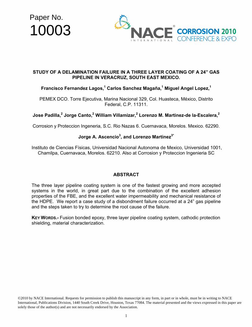
This motivated the operator to perform a direct inspection in the three indicated points by the instrumented tool (Km. 11+500, 19+273 and 23+372); when the coating was being removed to make the wall measurements, a massive adhesion loss of the three layer coating system was detected, leaving the pipe surface totally exposed (Figure 1a and 1b).
The PEMEX authorities (sub-direction of the transportation by pipelines coordination – Direction of Corporative Operations) in collaboration with corrosion specialists took the initiative of identifying the cause of the failures observed in the three layer coating system of the gas pipeline. Consequently, a specialized inspection to perform a failure analysis resulted in a deep study of the three-layer coating system that suffered the adhesion failure.
Such failures were detected approximately after five years in service of the gas pipeline. In nine of the inspected trenches a complete disbondment of the three-layer systems was observed, whereas in just one of the trenches (Km. 23+327) a delamination of the adhesive copolymer layer and the HDPE top coat was observed, while the FBE remained very well adhered to the steel structure (see Figure 2a). Figure 1c shows the location of the inspected trenches along the gas pipeline path. The red dots indicate the zones where the study of DCVG identified sections with exposed metal.
It must pointed out that during the course of this investigation, the quality control reports from the applicator or the results of their routine lab tests were not available. They would have provided more data to reach a more assured root cause of the failure.
2
ca
Inspection sites by dates
Gas pipelineDetected failures by DCVG
Trenches
b
30, 31/March/ 200919/June/ 20094,11/June/ 2009
Figure 1. a) and b) Details of the delamination failure; c) a scheme of the sites where failures
were found over the length of the gas pipeline.
THE THREE-LAYER COATING SYSTEM.-
The use of coatings for pipeline protection is well sustained in the own properties of the materials, because of the requirements for mechanical and chemical resistance to reduce corrosion related problems or other types of damages to the structure; in fact, the confidence about pipelines is related to the confidence in the coating system. The use of the three layer coating system has been vastly accepted in many countries around the world, where they account for between 65 and 90% of new coatings use; with the exception of Africa and the Middle East, where the use is between 45 and 50%, and USA, Canada and the UK, where they only account for 15% of new coatings as it was reported previously.(1) This is due to its ability to combine the properties of two different coatings, which individually have been successfully on their own. This coating system combines the excellent adhesion and oxygen impermeability of FBE, with the good abrasion resistance and excellent impermeability to water provided by the polyolefin.
The three layer system consists of the application of a first coat of FBE, that can be applied from 50 to 100 µm (2 to 4 mils). Today, it is more common to find systems with more than 150 µm (6 mils) thickness of this coat, with the premise that the higher the FBE thickness, the better the impact and cathodic disbondment resistance.
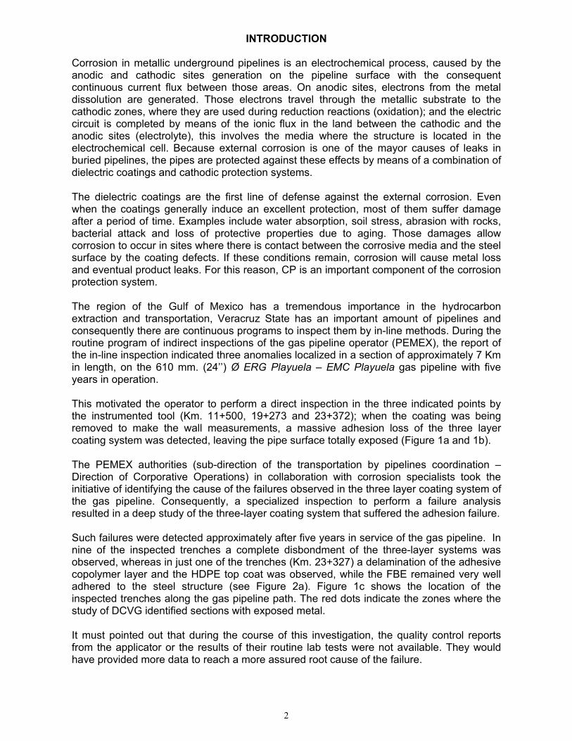
After the application of the FBE, and just before its gel stage concludes, a layer of polyolefin copolymer adhesive is applied, usually between 150 to 250 µm (6 to 10 mils). This layer provides the necessary adhesion between the final polyolefin layer with the FBE. The final layer is an extruded polyolefin (polyethylene or polypropylene, depending on the service conditions) to reach the final thickness between 2 and 4.5 mm.(2) A scheme of this system is illustrated in figure 2b, where all of the individual layers can be visualized.
In particular, the use of FBE has proved to be a reliable coating because of its capability to adhere to the metal substrate. Consequently FBE is commonly used as a standalone coating and there are not many reports in the literature about failures of this type of coating. Based on that, the use of this type of coating is a good solution, and the singular cases where failure occurs requires a deep analysis to recognize the reasons and the conditions that caused it. Following this tradition, we are reporting the results of field and laboratory
3
evaluations to the materials that presented the generalized disbondment failure on the coating system of the above mentioned gas pipeline.
b
c d
a
Figure 2. a) Adhesive copolymer layer and the HDPE top coat delamination, with the FBE showing excellent adhesion to the pipeline b) Three layer coating system scheme, and
procedures of c) CIS and d) DCVG.
PIPELINE CONSTRUCTION AND COATING APPLICATION PARAMETERS.-
The construction parameters are listed in Table 1, which are common in gas transportation pipelines, and particularly the three layer coating system is well accepted for the protection of these metal pipelines.
TABLE 1
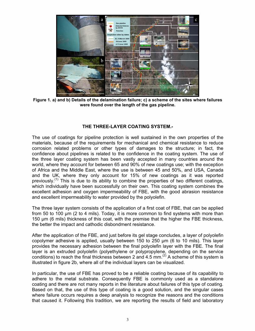
PIPELINE CONSTRUCTION SPECIFICATIONS Steel type API X5L Pipe thickness 16.7 mm. (0.659’’) Pipe diameter 610 mm. (24”) Pipeline length 24 Km. (14.9 miles) Product Sweet gas Coating operations First semester of 2003
Coating system Three layer: - FBE - Copolymer Adhesive - HDPE
Complete coating thickness 3.5 mm. (average) Time in service 5 years
4
However the gas pipeline operator contracted the procurement and construction to a third party; project specifications were not issued, neither an independent inspection was hired by the operator during the application and lay down operations. The operator subcontracted a company to certify the coating and lay down process of the pipeline, but the visits made by this company to the application plant during this stage of the project were scarce and simply were limited to support the written reports from the applicator without any verification. This motivated an evaluation to try to identify the root cause of the problem and also the real extension of the failure.
FIELD ANALYSIS
CIS/DCVG procedure for the study:
The pipeline localization was done using “RIDGY” detectors in inductive mode, which allows a fast analysis because it does not need excavations as in the conductive mode, particularly in zones with high concentration of metallic structures. A “Measuremark” wheel odometer with a precision of less than 10 centimeters was also used, which allows the identification of the line path during the Close Interval Survey (CIS) and Direct Current Voltage Gradient (DCVG) inspection as it is shown in figure 2c.
The first stage of the CIS inspection consisted in the installation of satellite interrupters in the rectifiers with influence on the pipe sections under study. The interrupters controlled interruption cycles of 0.8 seconds in “on” with 0.2 seconds in “off”, receiving satellite pulses each second to keep an exact synchronization; this right of way (ROW) has two rectifiers that were synchronized for the study.
The studies were performed with a “MGM G1” device. In high soil resistivity or low humidity zones the ROW is wetted to reduce measurement errors that use to happen because of wrong contact between reference cells and the soil. The potential measurements were performed in the exact position using the installed temporal marks during the detection of the pipelines. The CIS cables were exchanged at each localized test station and it was verified that they were connected to the pipeline, reducing to the minimum the typical “staircase” effects in the “on” profiles of the CIS graphs. The reference cells were prepared each day with saturated solutions of copper sulfate to obtain exact values for the polarization potentials. The design of the cells avoided the influence of solar rays, consequently eliminating erroneous readings because of the possible degeneration of the electrode by ultraviolet radiations.
During the DCVG studies, the same interrupters used for the CIS studies were utilized for the pulsed signal of DCVG (dV). The study was done employing the “DCVG” instruments as in figure 2d. Temporal marks were applied over land with aerosol paint on the exact location of the coating defects with respect to the test posts, line markers, etc., to establish fixed references using the wheel odometer. In the localization of each defect, the potential fall was evaluated from the epicenter of the failure to remote earth for calculating the degree of %IR. The corrosion characteristics for each defect were examined with activated and inactivated current to determine the cathodic protection efficiency in the exposed steel zones. Additionally, the potential gradients around each defect were examined to determine the type of defect (punctual or continuous).
As a result of these studies, seven additional sites were chosen where the DCVG found coating failures, the purpose was to excavate and evaluate the behavior of the three layer system in those sites (Km. 9+591, 9+914, 11+142, 13+106, 19+372, 22+381 and 22+600); evaluating an additional eight pipe segments. Similar to the initial excavations, the visual
5
Area around a holiday
Good adhesionArea
WeldPoor adhesionArea
d e
a
b c
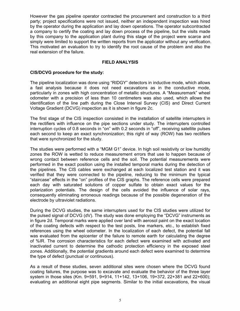
inspection did not find coating blisters or carbonate residues (calcarious deposits) over the coating film. In some areas, mechanical damages were found caused by the excavation method and wrong practices during the laying of gas pipeline. It is important to mention that at least on one of the pipes inspected; the coating system could not be removed, showing excellent adhesion to the substrate (see Figure 3a).
Figure 3. Visual inspection of the coating over the pipeline.
In seven of the eight pipelines the same original failure was found; additionally, in two excavations (Km. 9+591 and 22+381) there was evidence of cathodic protection shielding (see Figures 3b, 3c and 3d); at both sites, the penetration of the electrolyte through a holiday was observed, ultimately getting trapped under the film due to the poor adhesion of the FBE. The high electrical resistivity of the HDPE prevented the cathodic protection current to reach the adjacent zones around the holiday, creating corrosion under the disbonded film with severe risks to the pipeline integrity. The observations allowed the recognition of a generalized attack without evidence of pitting corrosion, which can be associated to an early stage of the pitting process. Evaluation of pH is also illustrated in figure 3e, which was considered important in the determination of the incidence of the cathodic protection system in the failure observed over the pipeline.
The evidences found (shown in figure 3) denote an important presence of generalized corrosion under the film, with the corresponding risk to the integrity of the pipe, in some of the areas where the 3-layer coating failed.
LABORATORY ANALYSIS
Because of the many derived questions about why the coating failed, it was needed to collect and evaluate samples of the metal substrate and of the disbonded coating, in order to evaluate them in independent specialized labs by different techniques, such as: Scanning electron microscopy with energy dispersive spectroscopy (SEM-EDS), X-ray diffraction (XRD), Fourier transform infrared spectroscopy (FT-IR) and differential scanning calorimeter (DSC).
6
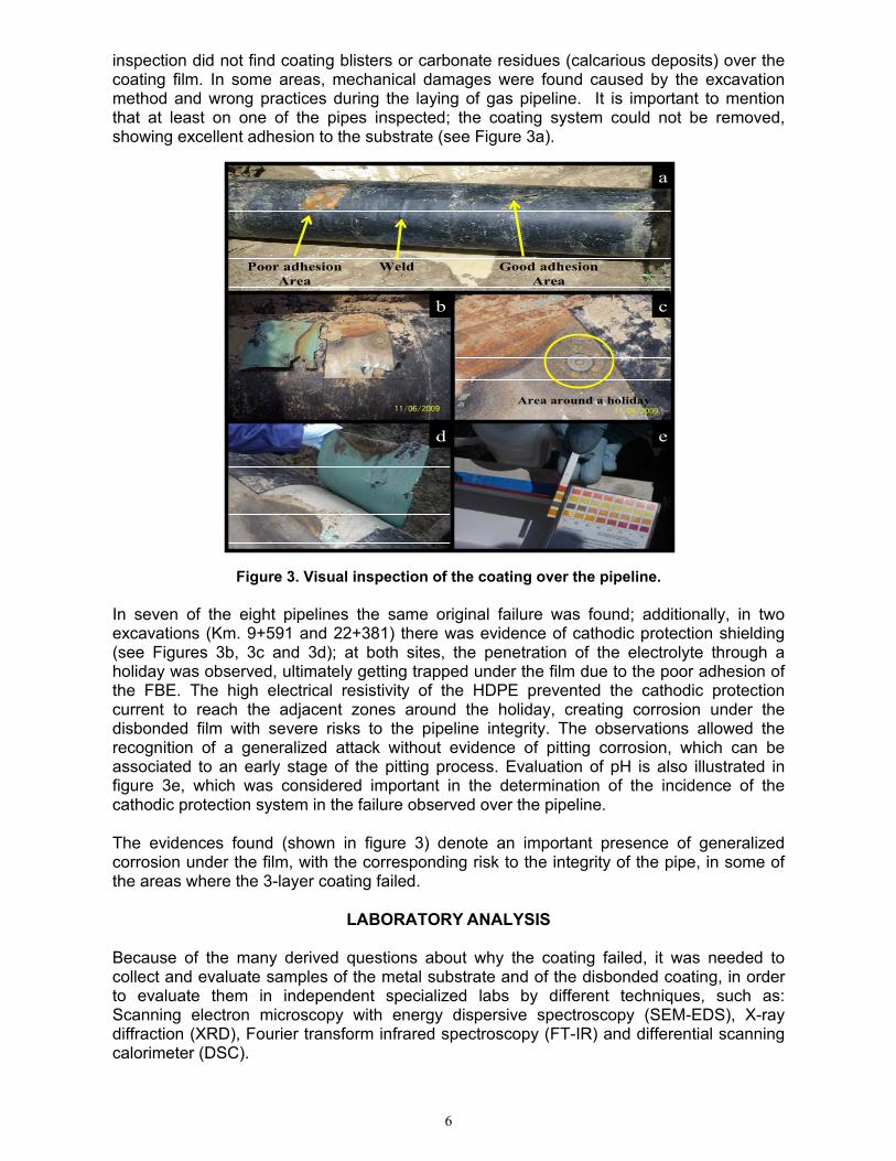
SEM allows obtaining microscopic images from surface of different types of samples; in addition, the use of EDS gives the microanalysis from points or selected areas to derive into compositional patterns or elemental maps, which opens the possibility to evaluate corrosion products, impurities or organic aggregates to help in the sample characterization. We used a TESCAN SEM of the VEGA II Easy Probe series, and a Bruker EDS. We focused our analysis on the metal substrate and samples of the coating collected from the sites. As it can be observed in figure 4a the laminar structures are associated with iron aggregates, which can be confirmed by the EDS spectra, which also denotes the presence of manganese as expected for the type of steel of the pipelines.
a
b
c
Figure 4. SEM micrographs of clusters with a) Mn and b) Cr, besides their corresponding EDS spectra; and c) elemental mapping of a general view.
The use of elemental mapping allows identifying the iron matrix with small aggregates with Si and Cr, besides inclusions on the alloy of Al and Mn. The general view of figure 4c with the composition evaluation allows the determination of the presence of no contaminating materials even at this microscopic scale.
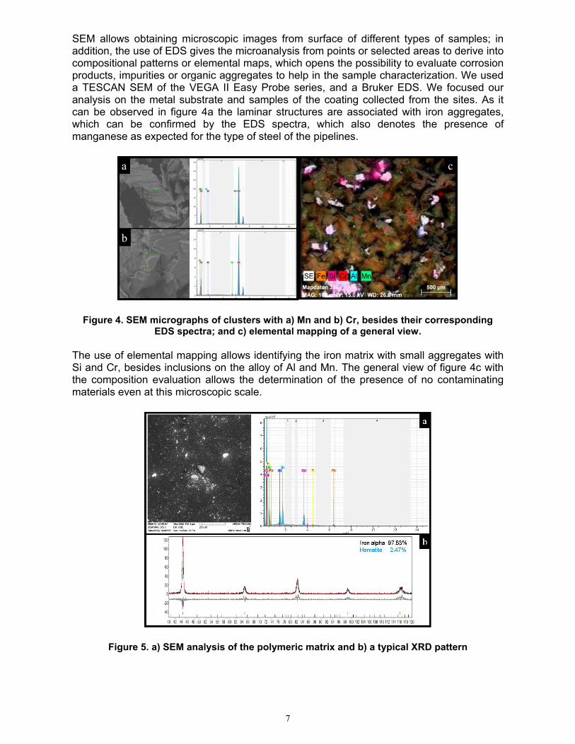
Figure 5. a) SEM analysis of the polymeric matrix and b) a typical XRD pattern
7
From the use of the SEM methods for the evaluation of the organic matrix (figure 5a), which is obtained from the residues of the coating collected from the disbonded segments, it is clear that the elements that compose the sample correspond to the expected elements, which is reported in the specifications from the manufacturer.
The fundamental application of XRD is the identification of crystalline samples; because this method is based on the optical interference between X-rays when they diffract in the atomistic array of the samples. This particular behavior is studied under the fulfilling of “Bragg law”, that allows identifying the conditions to diffract beams in a lattice. The use of this technique was to identify the iron phases and the possible identification of major contaminant materials. In figure 5b, a common X-ray pattern is shown, where the peaks are associated to the expected iron crystals (alpha iron and hematite phases).
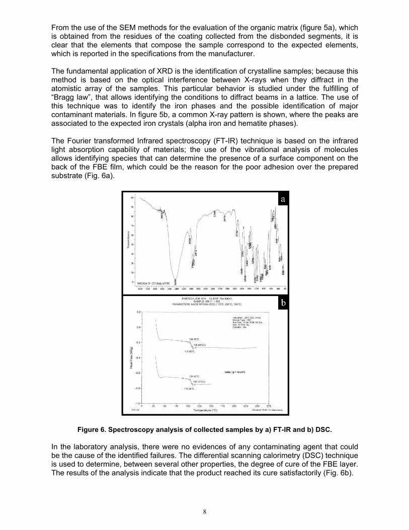
The Fourier transformed Infrared spectroscopy (FT-IR) technique is based on the infrared light absorption capability of materials; the use of the vibrational analysis of molecules allows identifying species that can determine the presence of a surface component on the back of the FBE film, which could be the reason for the poor adhesion over the prepared substrate (Fig. 6a).
Figure 6. Spectroscopy analysis of collected samples by a) FT-IR and b) DSC.
In the laboratory analysis, there were no evidences of any contaminating agent that could be the cause of the identified failures. The differential scanning calorimetry (DSC) technique is used to determine, between several other properties, the degree of cure of the FBE layer. The results of the analysis indicate that the product reached its cure satisfactorily (Fig. 6b).
8
DISCUSSION AND CONCLUSIONS
The direct assessment made on the gas pipeline in the different excavations (illustrated in figure 3a -3f) indicated the following:
• Unusual values of the anchor profile on the pipeline surface (84 µm or 3.4 mils average) were not found; these measured values meet those reported by the applicator in its quality program; additionally, viewed under 30X magnification, the surface profile seemed to be angular in shape. In all of the sites where disbondment of the FBE was found, it could clearly be seen that the coating copied the angular profile on the steel substrate (anchor profile values measured on the back of the disbonded coating matched those taken on the pipe surface).
• Chloride was not found at any of the site evaluations the presence. Also, no bacterial activity under the disbonded coating film was detected. The pH values found under the coating film were between 6 and 7 (Figure 3d), which indicates that the cathodic protection current did not contribute to the failure generation. Only in the surrounding zones around a holiday could we obtain a pH value of 9, which indicates cathodic activity around a discontinuity in the coating.
• In the segment of the pipeline where we found a delamination failure between the adhesive layer and the FBE, the dry film thickness values (117.5 µm or 4.7 mils average) coincide with those reported by the applicator in its quality program. In this segment, the FBE first layer was found to have an exceptional adhesion to the steel, which is characteristic of this type of coating. The inspection by UV light did not detect grease, oil or any superficial agent that could have interfered with the adhesion of the first layer of the coating system. In total, of the thirteen sections of the gas pipeline evaluated, the disbondment failure of the three layers system was identified in twelve of them, mainly in the substrate/FBE interface. Only one of the pipelines showed a delamination failure at the FBE/adhesive interface.
• The evaluation of the cathodic protection system installed did not show indications of overprotection, determining a mean potential “ON” value of -1.2 V and an average “OFF” potential of -0.88 V. The DCVG inspection detected 67 defects in the coating along the gas pipeline path; 2 in the range of 16 to 35 %IR drop and 65 between 0 to 15% IR drop. This indicates that the majority of the defects founds were very small, which implies that even though the tendency to repair the areas with larger IR drops because it’s the most commonly attacked, our findings show that there is the possibility of corrosion under smaller identified IR drops; in this manner, although the exposed metal section is considerably minor, under the circumstances that this phenomenon is occurring, these areas require immediate attention and cannot be postponed. The laboratory analysis using SEM-EDS, XRD and FT-IR did not detect the presence of contaminants in the substrate or on the disbonded film. The DSC analysis of the FBE film indicated that it was well cured.
There are several conclusions that can be derived from this case study:
1. Due to the fact that the massive adhesion failure occurred in most of the pipes evaluated, but not in all of them, with the majority of the pipes presenting complete disbonding of the FBE, at least one presenting a delamination failure in the FBE/Adhesive interface, and at least one of the segments evaluated presented excellent adhesion of the three-layer coating system, leads us to consider that the most probable cause is the lack of control of the different parameters during the surface preparation and application process.(1) However, under theoretical considerations and
9
recent reports, such as the fact that the FBE should thoroughly wet the surface,(3-5) our own characterization results and field findings demonstrated this did not occur, and because the known and documented performance of FBE, specially its adhesion to the steel, we can also be conclusive about it.
2. The cathodic protection system did not have an observable effect in the failures observed. The CIS evaluation showed no areas with an excess of cathodic protection current that could be associated to the failures observed. This was also corroborated during the field investigations.
3. Although the majority of the coating failures found by indirect inspection with the DCVG were very small in size, the risk of underfilm corrosion and cathodic protection shielding caused by the combination of poor adhesion of the FBE and high dielectric strength of the HDPE is very high. More frequent in-line-inspections (ILI) are necessary to assess the integrity of the gas pipeline and monitor the development of corrosion in areas not evaluated directly.
4. More control of the project on behalf of the operator, through more strict project specifications and the involvement of a third party coatings inspector during every step of the process along the entire project, could have prevented or provided early detection to the problem, helping the owner of the pipe take the necessary corrective actions early on in the project, and minimizing the costly site rehabilitations and more frequent in-line-inspections, and the possible loss of integrity of the gas pipeline.
REFERENCES
1. Colin Argent, David Norman, “Three Layer Polyolefin Coatings: Fulfilling Their Potential?”
2. Alan J. Kehr, “Fusion Bonded Epoxy”, NACE International Publication, 2003.
3. Ali Ehsan Nazarbeygi, Ali Reza Moeini, “Three-Layer Polyethylene Coating Performance in Iran”, MP November, 2009, page 32 – 34.
4. Benjamin T. A: Chang, Hung-Jue Sue, Han Jiang, Dennis Wong, Alan Kehr, Fabio
Aquirre, “Residual Stresses in 3LPO External Pipeline Coatings –Disbondment and Craking”. BHR Europe Conference 2009.
5. Benjamin T. A. Chang, Han Jiang, Hung-Jue Sue, Shu Guo, Guylaine StJean, Ha Pham,
Dennis Wong, Al Kehr, Kim Him Lo, “Disbondment Mechanism of 3LPE Pipeline Coatings”. BHR Europe Conference 2007.
10