Study Mechanism for Providing Emergency Services using VoIP/IP Network (Match 2014
14
Department of Computer Engineering Oklahoma Christian University Abstract—The current communication infrastructure of 9-1-1 is based on analog technology that doesn’t support many advanced telecommunication features (texting, emailing picture…) that most end users are expecting to be part of emergency communication system.To remedy these problem emergency services have to be provided using IP networks. Providing Voice over Internet Protocol (VoIP) based Emergency services is not only a success of VoIP but it will also give opportunities to enhance the existing emergency call processing infrastructure. The intent of this paper is to study mechanism that can be used to provide emergency services using IP Networks; we will discuss how VoIP can be used to provide Emergency services, how to identify emergency calls, determining the caller’s locations and routing him/her to the appropriate Public Safety Answering Points will be addressed and then finally we will discuss how Internet can be used to alert the public about the pending or current emergency situations.The solution that we propose is based on Session Initiation Protocol (SIP). Index Terms—Emergency Network, SIP/VoIP, emergency alerting,emergency communication I.INTRODUCTION Voice over Internet Protocol (VoIP) is a technology that allows communication IP networks instead of traditional analog system. VoIP is becoming a predominant Desire Aheza is with the Computer Engineering Department,Oklahoma Christian University,Edmond,OK,(e- mail:[email protected]). technology in the world of telecommunication systems. As many people around the world are adopting VoIP due to its attractive service with advanced features (video calls…)and cost saving. Everyone around the world expect to be able to reach 9-1-1 or 1-1-2 in Europe in order to obtain emergency assistance from their public safety agencies i.e.First Responders (fire fighter,medical,law enforcement).With the growing popularity of VoIP services,3G/4G wireless phones, and other advanced communications technologies, customers subscribed to these technologies expect that they can use them to reach 911 services,just as they can by using ordinary public landline communication system to reach 9-1-1.Most of the subscribers are unaware of the current limitations of the 9-1-1 network infrastructure with respect to some wireless technology or internet based technology. Sometime they got disappointed due to the fact that the technology that they use most the time can’t help them to reach 9-1-1.This has been enhanced when a student at Virginia Tech, have tried to reach 9-1-1 using text message and disappointed when he found that text message are not supported to his local PSAP. With this growth in use of VoIP,it is evident that calls to 9-1-1 Public Safety Answering Point will be originated from these VoIP users. The high expectations of the public that they can reach the 9-1-1 systems using any communication device, testifies the need of EMERGENCY SERVICES OVER IP NETWORK.This will enhance the current emergency systems as IP networks allow high speed redundant links, Study Mechanism for Providing Emergency Services using VoIP/IP Network (Match 2014) Desire AHEZA,Department of Computer Engineering Oklahoma Christian University, Edmond,OK 1
-
Upload
independent -
Category
Documents
-
view
2 -
download
0
Transcript of Study Mechanism for Providing Emergency Services using VoIP/IP Network (Match 2014

Department of Computer Engineering Oklahoma Christian University
Abstract —The current communication infrastructure of 9-1-1 is based on analog
technology that doesn’t support many advanced telecommunication features
(texting, emailing picture…) that most end users are expecting to be part of emergency
communication system.To remedy these problem emergency services have to be provided using
IP networks. Providing Voice over Internet Protocol (VoIP) based Emergency services is
not only a success of VoIP but it will also give opportunities to enhance the existing
emergency call processing infrastructure. The intent of this paper is to study mechanism
that can be used to provide emergency services using IP Networks; we will discuss
how VoIP can be used to provide Emergency services, how to identify emergency calls,
determining the caller’s locations and routing him/her to the appropriate Public
Safety Answering Points will be addressed and then finally we will discuss how Internet can
be used to alert the public about the pending or current emergency situations.The solution
that we propose is based on Session Initiation Protocol (SIP).
Index Terms —Emergency Network, SIP/VoIP, emergency alerting,emergency communication
I.INTRODUCTION
V oice over Internet Protocol (VoIP) is a technology that allows communication IP
networks instead of traditional analog system. VoIP is becoming a predominant
Desire Aheza is with the Computer Engineering Department,Oklahoma Christian University,Edmond,OK,(e-
mail:[email protected]).
technology in the world of telecommunication systems. As many people around the world are adopting VoIP due to its attractive service
with advanced features (video calls…)and costsaving.
Everyone around the world expect to be able to reach 9-1-1 or 1-1-2 in Europe in order to
obtain emergency assistance from their public safety agencies i.e.First Responders
(fire fighter,medical,law enforcement).With the growing popularity of VoIP services,3G/4G
wireless phones, and other advanced communications technologies, customers
subscribed to these technologies expect that they can use them to reach 911 services,just
as they can by using ordinary public landline communication system to reach 9-1-1. Most of
the subscribers are unaware of the current limitations of the 9-1-1 network
infrastructure with respect to some wireless technology or internet based technology.
Sometime they got disappointed due to the fact that the technology that they use most
the time can’t help them to reach 9-1-1. This has been enhanced when a student at Virginia
Tech, have tried to reach 9-1-1 using text message and disappointed when he found that
text message are not supported to his local PSAP.
With this growth in use of VoIP,it is evident that calls to 9-1-1 Public Safety Answering Point will be
originated from these VoIP users. The high expectations of the public that they can
reach the 9-1-1 systems using any communication device, testifies the need of
EMERGENCY SERVICES OVER IP NETWORK.This will enhance the current emergency systems as IP
networks allow high speed redundant links,
Study Mechanism for Providing Emergency Services using VoIP/IP
Network (Match 2014)
Desire AHEZA,Department of Computer Engineering Oklahoma Christian University, Edmond,OK
1

Department of Computer Engineering Oklahoma Christian University
Failover, backup systems, Standardized protocols, resilient and reliable networks,
faster call setup, faster response and lower cost.
In this project we study a mechanism that can be adopted to achieve the enhancement of the
emergency network. The mechanisms will be based on an architecture that can provide
emergency service in VoIP network based on Session Initiation Protocol (SIP) which is a
signaling communications protocol, used for setting, maintaining and terminating
multimedia communication sessions such as voice and video calls over Internet Protocol
(IP)networks 1. The following section presents an
introduction to the current emergency network and its deficiencies.Section
Current 9-1-1 network infrastructure
The current systems for 9-1-1 calls today operate almost exclusively on analog
communication technology, using an architecture of circuits switched networks
developed when the American Telephone & Telegraph Company was a regulated monopoly providing most of the nation’s telephone
service2 .Systems for 9-1-1,nowadays is unable to accommodate the latest advances or
features in telecommunications technology, the 9-1-1 systems are increasingly outdated,
costly to maintain, and in danger of failure with many single point of failure entities in
the current emergency communication network3. The old (1970s)network architecture of 9-1-1 is
still in use in some parts of emergency services in the U.S. nowadays. The kind of
architecture is presented in figure 1, this was simply the switching in the local
telephone company central office (CO)that was interpreting the dialed sequence of 9-1-1 then
route the call to the local single Public Safety Answering Point see Figure 1. No
additional information is transmitted along with the call.
Figure1:Basic 9-1-1 network architecture
This architecture suffers 3 significantlimitations1:
There is no automatic mechanism to deliver the telephone number of the caller this means that no callback number available to the calltaker
(dispatcher) that he/she can use in case the call has been disconnected.
Secondly the architecture in Figure 1 can’t provide to the calltaker the information related to the
LOCATION of the calling party summoning emergency assistance.
The last constraint is that routing calls to wrong PSAPs might occur. This is due to the
fact that geographic area served by a certain telephone carrier; their CO might not match
the relevant political boundaries to the proper PSAP.
In this architecture it is relevant that time is wasted every time in emergency events
because no location information is identified.
Over the time, progresses in technology were taken to overcome all of these 3 limitations.
The 9-1-1 system has evolved to Enhanced 9-1-1 i.e.E9-1-1 which is an emergency system that can handle new forms of call delivery (VoIP
calls and call from Wireless mobile),although the core of the E9-1-1 was still is based on the analog technology.
The adoption of the Automatic Number Identification (“ANI”)has solved the issue of
the CALL BACK NUMBER on the caller taker post. The caller number has to be captured by the CO
switch and relayed to PSAP along with the calls summoning the emergency in order to
provide the calltaker the CALLBACK NUMBER1 . The lack of the location information in the
legacy 9-1-1 was overcome by creating and using a dedicated database for emergency service1.
This is a time Local Exchange Carrier (LEC)
2
Department of Computer Engineering Oklahoma Christian University
that was in use for the billing purpose, its role was to associate particular phone lines
and numbers with corresponding subscribers identities (Address and Name). Information
queued in the LEC were used to create a specialized database in 9-1-1 known as
Automatic Location Identification (ALI)with major takes of associating telephone numbers
and the names and the address information.But still constraints associated to the analog
platform were still present as the PSAPs were using SEPARATE LINKs to access the ALI
databases.
To overcome these limitations associated to the routing of emergency calls to the proper
PSAP, additional equipment has been introduced” Selective Routing Database”
(“SRDB”). In this architecture, emergency calls (9-1-1) originating from a number of COs
are aggregated at the SRDB and then delivered over a group of trunks to the proper PSAP1 .Note that also a Master Street and Address Guide
(MSAG)has been introduced in order to create the logical association between the proper
PSAP and the calling party’s number. This is was a major advancement in the 9-1-1; MSAG
associates streets addresses and telephone numbers to their corresponding (particular)
Public Safety Answering Point and provides details about the different emergency
service agencies that can respond to that particular location.
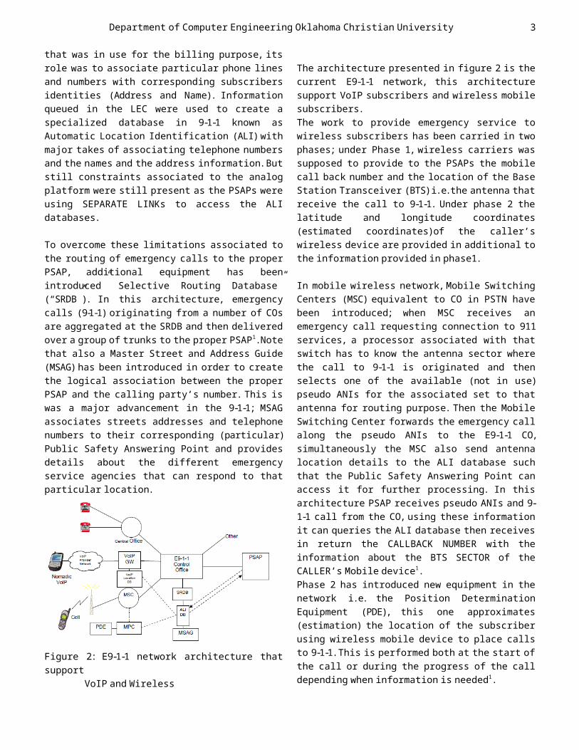
Figure 2: E9-1-1 network architecture that support
VoIP and Wireless
The architecture presented in figure 2 is the current E9-1-1 network, this architecture
support VoIP subscribers and wireless mobile subscribers.
The work to provide emergency service to wireless subscribers has been carried in two
phases; under Phase 1, wireless carriers was supposed to provide to the PSAPs the mobile
call back number and the location of the Base Station Transceiver (BTS)i.e.the antenna that receive the call to 9-1-1. Under phase 2 the
latitude and longitude coordinates (estimated coordinates)of the caller’s
wireless device are provided in additional to the information provided in phase1.
In mobile wireless network,Mobile Switching Centers (MSC) equivalent to CO in PSTN have
been introduced; when MSC receives an emergency call requesting connection to 911 services, a processor associated with that
switch has to know the antenna sector where the call to 9-1-1 is originated and then
selects one of the available (not in use) pseudo ANIs for the associated set to that
antenna for routing purpose. Then the Mobile Switching Center forwards the emergency call
along the pseudo ANIs to the E9-1-1 CO, simultaneously the MSC also send antenna
location details to the ALI database such that the Public Safety Answering Point can
access it for further processing. In this architecture PSAP receives pseudo ANIs and 9-
1-1 call from the CO, using these information it can queries the ALI database then receives in return the CALLBACK NUMBER with the
information about the BTS SECTOR of the CALLER’s Mobile device1.
Phase 2 has introduced new equipment in the network i.e. the Position Determination
Equipment (PDE), this one approximates (estimation) the location of the subscriber
using wireless mobile device to place calls to 9-1-1.This is performed both at the start of
the call or during the progress of the call depending when information is needed1 .
3

Department of Computer Engineering Oklahoma Christian University
To introduce VoIP devices in 9-1-1, VoIP providers have obliged their customers to
manually provide their address over the Internet and then the caller location
information were directly forwarded to the proper 9-1-1 databases. With this
architecture presented in figure 2, an emergency VoIP call to 9-1-1 is passed, along
with the ANI details,through “VoIP gateways” that are used to convert digital packet into
analog format and then pass it to the E9-1-1 CO and, then passed it to the appropriate PSAP. Then the Customer Premise Equipment at the PSAP uses the connection to the ALI database
to retrieve and display the address, subscriber name, callback number, and
emergency services details corresponding to the calling party’s number.
However the infrastructure presented in Figure 2 presents some constraints
associated with the use of analog technology1:
i. Limitations of Exploiting and/or Serving Current Technology
Subscriber Devices
The technology of 9-1-1 that has been established in 1968was developed for users of
ordinary telephone handsets. Today’s the public has switched to VoIP and wireless
devices that use different technologies (digital) comparing to ordinary telephone handsets.These digital devices have built in
processors and memory chips that are capable of creating and handling not only voice
messages but also text messages, data, video, and image signals and multimedia information
as well. Protocols have been developed to allow these devices to communicate using packet switched networks.These networks are
capable of transporting multimedia signals from these digital devices.
Current technology implemented in PSAPS is not capable of exploiting or serving these
modern digital devices, if a subscriber sent to 9-1-1 for example a picture of a car leaving
a crime scene the PSAP will not have the technology to treat the kind of message
because it has been designed with voice capability only. We need a new technology to
overcome this limitation
ii. Constraints associated with analog circuit switching
and selective routers
The current 9-1-1 network can only handle voice traffic/data in a world of digital technology.
Most of the equipment used in the current 9-1-1 network architecture are optimized to
support only voice communication1 ,and hence there is limited bandwidth available for data
communication. The use of Selective Routers (SR) in the
current architecture of 9-1-1 also create single point of failure; let’s say if the SR fails, all calls to 9-1-1 routed via the CO
connected to that SR will not reach to their destination.To correct this issue;redundant
links to two different SRs located in different locations are required. Note that
also the same problem of one point of failure exists as the PSAPs have no back up
infrastructures. The current architecture based on analog technology cannot allow PSAPs
to back up each other in case of high volume calls at one PSAPs,call or any data exchange can’t be transferred between PSAPs and this
is due to the use of old signaling protocols.
This limit the sharing of foreign language speaking call-centers or some specialized databases or software.
iii. Limitations due to In-band Multi- frequency signaling (CAMA)
The inBand analog Multi-Frequency (MF) signaling that is used to carry the ANI
information between the PSAP and the E9-1-1 CO is an outdated form of signaling; it is slow
(slow speed this means that the call setup time is delayed;the caller can think that has
not gone through and hangs up the call)and has
4
Department of Computer Engineering Oklahoma Christian University
limited capacities vis-a-via to modern form of signaling (MF signals are transmitted in
analog form so they can face more errors).
With MF signaling there is no way to carry emergency call along with location and the
call back number 1 , rather the PSAPs request the necessary information to the ALI database
using a separate link thus an additional delay in the delivery of details (content)
associated with the call. All limitations between the 9-1-1 Control
Office and the PSAP are tighten to the Centralized Automatic Message Accounting
(CAMA) signaling used between these entities as it relays to analogy technology1 .
iv. Limitations due to the fixed point to point Data links
The current E9-1-1 network architecture includes a Point-to-Point (P2P) link between
the ALI database and the PSAP.According to the current technology it is unusual to find a P2P
links over low speed analogy facilities; these low speed links slow down the
connection and the time between when a query is initiated and the ALI information is
delivered is increased.Note that the lack of broadband communication links between PSAPs
limits the ability of calltakers to automatically share by transferring data
that has been collected from the calling party along with the call when it is
transferred from one PSAP to others1 . This architecture isolates PSAPs as they can’t
share expensive or specialized personnel and information between them.
Public Expectations
Public expectations for timely and accurate response to 9-1-1 calls are based on the high-
tech features presented in most of their communication devices,but not on the reality
of the current technology (analogy transmission) that the 9-1-1 system uses. For
example, analog systems cannot allow the transmission of video, picture or text
messages. Calls setup are delayed or dropped during the communication progress.There are losses of information related to the location
of the caller because the information are digital and they cannot be transmitted by
means of the current switching technology or understood (treated) by the computers at the
PSAPs centers3 . A report of the National Emergency Number Association (NENA)summarize
that the 9-1-1 network infrastructure has not kept pace with the advance in technology and
now is of the critical systems that need to bemoderated4 . The current emergency network
need to be enhanced such that it can provide the QoS that approaches the expectations and
needs of its consumers and this refers to the investments in new technologies “IP
telephony/VoIP”.
The study we conducted on the current E9-1-1 network shows that a new network
infrastructure is needed in order to provide emergency service to the public
independently of their communication technologies.
IP networks are based on the same type of network infrastructures as the one
businesses and consumers use to access to the Internet and share capacities with other
subscribers. Broadband connections built to hospitals,libraries,or campuses have also to
reach 9-1-1 PSAP/call center.
The next section introduces IP networks and the Session Initiation Protocol (SIP)which is
a signaling communications protocol,used for setting, maintaining and terminating
multimedia communication sessions such as voice and video calls over Internet Protocol
(IP)networks.
Brief VoIP Standards and Protocols Internet Telephony/VoIP is the communication
over IP networks; it allows the transmission of voice and video, voice-messaging
application and/or facsimile via Internet rather than the PSTN.The basic steps involved
5
Department of Computer Engineering Oklahoma Christian University
in Internet based communication is the conversion of the analog signal to digital
format, compression and translation of the signal into IP packets that can be
transmitted over the Internet;the process is reversed at the receiving end.
Signaling protocols are used to set up and tear down calls and carry information
required to locate users.
To make VoIP popular;products from different vendors need to operate with each other to
grant the interoperability, to achieve this task different standards has been developed
and the most common standards for VoIP are the Session Initiation Protocol (SIP) and H3235.
The following sections present a description of one of these standards “SIP”. Figure 3
displays the setup of a VoIP system and how audio signals are processed by it.
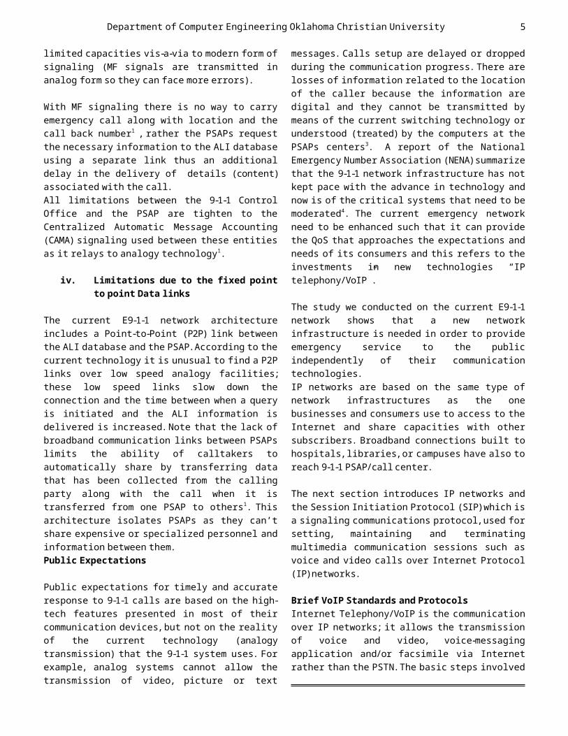
Figure 3 Treatment of audio signal in a VoIPsystem 5
The digitized voice from the sending speaker is encoded by a voice encoder,and then packets
are sent using a protocol stack. When the speaker is silent, the Voice Activity
Detection has to recognize that and then generate a packet without payload (sometime
no packet will be generated).Then packets are sent over the network e.g. IP LAN. When the
packet reaches the receiver side it is processed by the protocol stack. Packets
losses and transmission errors are detected and corrected. Packets might not arrive in a
constant flow;so they have to be collected in a buffer (called jitter buffer) that adjusts
time differences and the sequence (arrival) order. Finally the decoder decodes the
packets and outputs them via the sound system5.
There are a number of standards used for signaling,speech coding and the transport of
the voice packets over IP. This modularization makes VoIP flexible and the
standards interchangeable when new requirements and applications emerge. The
following sections introduce the widely used standards (protocols)in VoIP.
Standards and Protocols
IP telephony requires some protocols for establishing and controlling the connection,
which is signaling the connection. Real Time Transfer (RTP) Protocol is used to send
multimedia data packets with session setup via signaling protocol i.e.SIP.
RTP protocol
The RTP protocol is a real time protocol which is oriented to the transmission of
information in real time such as voice or video. This protocol is a user session
protocol which relies on User Datagram Protocol (UDP),making use of the checksum and
multiplexing services to allow programs which make transmission of this kind of data
handling the real time unicast or multicast transmissions. RTP does not guarantee real
time delivery of multimedia data. To achieve real time transmissions; RTP uses the Real Time Control Protocol (RTCP);which provides a
feedback about some control information.With this,it is possible to monitor the quality of
the transmission and also possible to diagnose possible network problems.
RTP is composed of 4 main fields;below each isdescribed6:
RTP Payload type:this field indicates codecs
6

Department of Computer Engineering Oklahoma Christian University
and the specific media encoding to use.Codecs convey the type of multimedia data (video or voice) and information about how it must be
encoded or decoded.It is important to say that changing codecs will be necessary,if we have
to adapt to the variations in bandwidth, frames indications;which mark the limitation
(start&end)of each frame.
Sequence number (SN ): packet reassembling, detection of packet losses and duplication of
packets are performed at the receiver based on SN.
Time Stamp this is one is used to rebuild the timing of the original video&audio. The
receiver uses the time stamps in order to determine the variation in time of arriving
packets.To make RTP transmission possible;at the receiver, each packet is compared with time stamp to be made.
Source ID : this is utilized to differentiate multiple incoming streams. In this paper we
use RTP as voice transmission protocol to send real time packets.
To place calls over IP network, VoIP uses 2 protocols; call-setup protocol(s) and voice
transmission protocols. Protocols involved in call-setup are known as VoIP signaling
protocol(s) i.e. (SIP, H.323 and IAX (Inter Asterisk eXchange)) are most common choices.
Next paragraph introduces SIP.
Session Initiation Protocol (SIP)
SIP is an Internet Engineering Task Force (IETF)defined signaling protocol,widely used
for controlling multimedia communication sessions such as voice and video calls over Internet Protocol. This protocol is used for
creating, modifying and terminating communication (multimedia) session between
subscribers. Sessions are considered to be communication states kept between the
sending party & the receiving party during the interactions (IP calls, distribution of
multimedia etc).The modification can involve changing addresses or ports, inviting more
participants, and adding or deleting media streams. SIP clients typically use TCP
(Transmission Control Protocol)or UDP on port numbers 5060 and/or 5061 to connect to SIP servers and other SIP endpoints.Port 5060 is
commonly used for non-encrypted signaling traffic whereas port 5061 is typically used
for encrypted traffic. The following paragraphs, explains the functional and
characteristics features of SIP:
Distributed Architecture of SIP
As shown in Figure 4 the SIP protocol defines a collection of entities that take part on a SIP
communication, which are, User Agent, Registrar and Redirect Servers, Location
Servers,Proxy Servers.
Figure 4 SIP Distributed Architecture
Location Server (LS) One of SIP entities (servers) used by the
redirect and proxy servers to obtain data about the calling’s party possible location.
By using registration process this server stores the current locations of the
subscribers.
7

Department of Computer Engineering Oklahoma Christian University
Figure 5 Communication example of RegistrarServer 7
Redirect Server
Those servers are UA servers that accept and receive SIP requests.It checks requests from
the LS databases and produces list of current position of the subscriber and it uses some of
3xx responses to send back the request to the sender. When the UA client receives the list
(showing the exact destination position) it sends requests directly to appropriate
destination.See figure 6 for more details.
Figure 6 Redirect Server operational
behaviors 7
SIP network entities exchanges between them, SIP transactions are composed of sequence of SIP messages (request&responses) in order to
communicate.These transactions are utilized in many steps in order to complete the call
process7.
SIP messages
SIP is a text-based protocol with syntax similar to that of Hyper Text Transfer Protocol (HTTP).There are two different types
of SIP messages: requests and responses. The first line of a request has a method ,defining
the nature of the request, and a Request-URI
(Uniform Resource Indictor),indicating where the request should be sent.The first line of a
response has a response code 6
We need method in field of the request line because it is used to determine the function
of request; there are 6 types of SIP methods, these methods are explained below;
REGISTER:Used by a UA to indicate its current IP address and the URIs (Uniform Resource
Locators) for which it would like to receive calls. INVITE: Used to establish a media
session between user agents. ACK:Confirms reliable message exchanges
CANCEL:Terminates a pending request (this is activated when the calling party want to
refuse the call invitations from Calledparty).
BYE messages are utilized to close communication sessions.
OPTIONS: Requests information about the capabilities of a caller,without setting up a
call (Information discovery:about extension, supported method,type of contents,codecs …).
It allows that discovery without “ringing” the called party6.
SIP Responses
When a UA receives requests it has to reply using response methods. These responses
matches requests messages, except to the first line; the response’s first line is
composed of the protocol version number (SIP/2.0),reason phrase and reply code. The
reply code is integer number from 100 to 699 that indicates the response type.
There are 6 classes of responses:1xx : called provisional or informational
responses. They indicate that request has been received and is being processed; we can
say for example 181 to mean that the call is being forwarded,100 trying to connect and 180
Ringing2xx : This type shows that processing of calls
is successfully and accepted. This type of message (200 OK) is sent back to indicate that
8

Department of Computer Engineering Oklahoma Christian University
call is successful.3xx: i.e.redirect response,gives the current
location details of the calling party.4xx : These responses indicate at the sender
side that there is problem (bad syntax or negative responses from the receiver) and it
cannot be treated at the proxy.5xx : Servers’ failures response that means
the request is valid and the servers can’t process the request.
6xx : Global Failure responses.No server that can process requests and they also show that
declines response from UA when it doesn’t want to participate in the session.
Architecture of the 9-1-1 network over IPNetwork
IP telephony carries multimedia as packets over IP networks i.e.Internet. These packets
are transmitted using RTP protocol with sessions established using signaling protocols for example SIP or H.323. In this
project we will focus on the use of SIP as it the most widely used signaling protocol in
VoIP. SIP subscribers are identified either by an SIP URIs such as
sip:[email protected] or by ordinary E164 telephone numbers.
In general handling emergency calls can be done in 4 steps that might be executed in
sequences for each emergency call (figure 7).
Figure 7 steps in emergency call handling
It the first step the user agent (UA) client and the proxy server determine if the
multimedia message (example:call)is destined to 9-1-1 or not . It the call is identified as an
emergency call then the second step determine the calling party’s location,and forward the
location information along with setup messages (INVITE). The next step is to
determine the correct PSAP based on the location information from step 2 and the proxy
will route call to that PSAP. The last step presents the emergency call to the call-taker
at the PSAP. The information within the call setup can be utilized by the dispatcher at the
PSAP to handle the emergency call or plan for the type of the rescue to send (fire fighters,
Medical, Police…).In order to explain these steps, I use the architecture presented in figure 8;it has been proposed and implemented
in (Mintz-Habib, Rawat, Schulzrinne and Wu, 2005), as a VoIP based on SIP emergency
services architecture and prototype.
Identifying Emergency call
According to H. Schulzrinne, “Emergency services URI for the session initiation
protocol,” call/video packets to 9-1-1 can be identified by their destination and the
location of the call provided in the SIP URIs from the caller.Note that also progress works
are now being carried in order to standardize the national emergency number to be “sos”; this one will be the username part of the SIP
URI to represent an emergency call according to (Mintz-Habib, Rawat, Schulzrinne and Wu,
2005). Telephone URIs9 for conventional emergency numbers, i.e. “tel:911”, can be
aliased to the emergency URI “sos ”,either by a SIP UA or a SIP proxy,based on the location of the calling party.
Figure8. Emergency services system architecture (Mintz-Habib,et al.,2005)
Determine the Caller’s Location
9
Identif yemergen
cy calls
Determi ne
location
Route call to
the correct
PSAP
Presen t call
to thecall-
taker
Department of Computer Engineering Oklahoma Christian University
The location information of the subscriber is essential for emergency call routing and
handling. The proxy server requires calling part’s location details to route calls to the proper PSAP, which in turn is supposed to provide emergency services to the caller.The
location information is required also in dispatching help to 9-1-1 callers. Since VoIP subscribers are nomadic,their location most
of the time are not easy to determinable.Some intelligent algorithm should be established.
Let’s consider a VoIP subscriber located in Edmond registered to IMS SIP server located
in Kigali,Rwanda,if the subscriber requests emergency services,the call should be routed
to the PSAP located in Edmond not in Kigali. Using the outbound proxy it is possible to
determine the caller’s MAC address. To determine this location the outbound can send
a DHCPINFOM query with the MAC retrieved from the packets it has received.
According to [8], it is possible for UA to determine its location by contacting the
Location Server.Note also that the MS with the use of SIP event notifications architecture
could subscribe to its own location using the location servers’ content.
Emergency Call Routing This step is implemented using Selective
Router in the current E9-1-1 network architecture,we have highlighted that using
SR in the 9-1-1 network create single point of failure; we need a way to provide
backups/redundant of these equipment. In the architecture presented in figure 8 DNS Naming
Authority Pointer Resource Records (NAPTR) are used to determine the correct PSAPs.
Call Presentation to the dispatcher in PSAPs The National Emergency Number Association
NENA has specified a list of features for presenting emergency calls to the call-takers
in PSAPs.Displays in PSAPs have to be able to display caller’s location on a map,log calls details into databases,store multimedia call
content, view call logs and generate statistics, and monitor currently active
calls and automatically distribute incoming calls to the available dispatchers.
Prototype 911system using VoIP
Voice over Internet Protocol (VoIP)has become a key technology of communication systems.
This section aims to the development of a VoIP system based on Asterisk that will work as UA agents and PROXY servers of an enhanced
emergency communication system . Previously we discussed necessities to deploy VoIP
systems such as IP networks, Signaling protocols i.e. SIP and how the current 9-1-1
system works to offer its daily functionalities services (call
identification, call routing, determine the location of the caller,and call presentation
to the dispatcher in PSAPs plus the drawbacks due to the fact that the current systems that
is still based on analogy transmissions).
I am proposing a prototype of emergency system based on ASTERISK;which “is a free and
open source framework for building communications applications and is sponsored
by Digium. Asterisk turns an ordinary computer into a communications server.
Asterisk powers IP PBX systems,VoIP gateways, and conference servers and is used by small
businesses, large businesses, call centers, carriers and governments worldwide) can be
used to test some of these requiredfeatures”10 and SIP softphone “this a software
(written programming java, C#...)for making phone calls over IP network using general
purpose computers,instead of using specific hardware.Most of the time softphone acts like
hardphones (CISCO IP phones or ALCATEL phones…) when runs on personal computer they
can be used to make telephone calls. Some appears like normal phones with smart
interactive interfaces (buttons, they can ring,they can display image or video calls...)
figure 10 show the look of a softphone. Note that those softphone in SIP architecture will be working as UA devices that make calls
10
Department of Computer Engineering Oklahoma Christian University
or requests to the 9-1-1 dispatchers through the SIP proxy server in this paper considered
as ASTERISK server.
In this prototype we are assuming that locations of people who are summoning for emergency help can be looked up using Dynamic
Host Configuration protocol (DHCP)which is a host specific services offered by many
routing devices or there network entities retrieved from Global positioning systems
that can query information from the SIP entities called LOCATION SERVER.
ASTERISK softPBX will be running on Ubuntu 12.04installed Oracle VM VirtualBox;which is free software that can be used to run many
operating system (OS) on one main OS. The purpose of Asterisk is for call routing it
will be situated in the CORE LAYER as the SIP proxy server in the. It will be handling
registrations process, location determination and providing advanced
telephony features like Voice and Video calls,Voicemail,Ring group,IVR (Interactive Voice Response), queuing, call parking &
transfer,and conferencing calls.
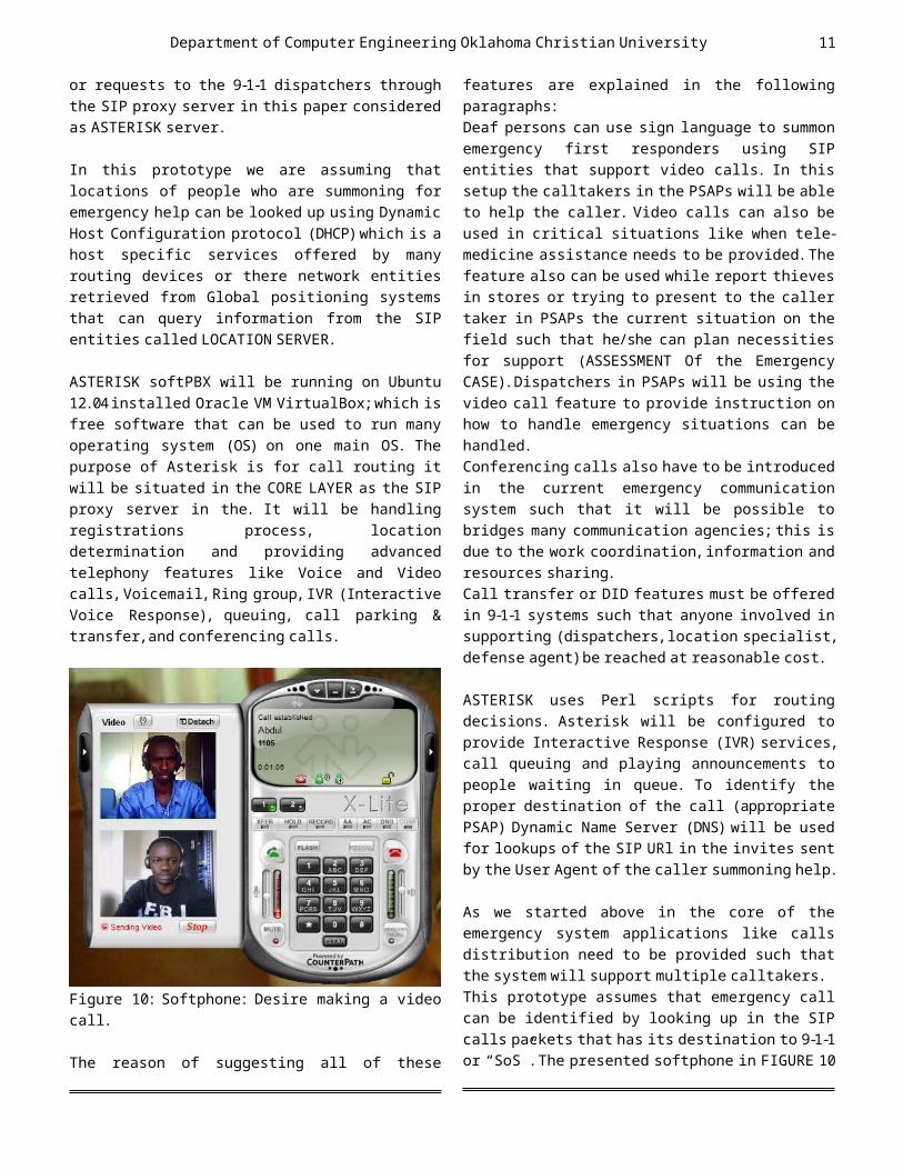
Figure 10: Softphone: Desire making a video call.
The reason of suggesting all of these
features are explained in the following paragraphs:
Deaf persons can use sign language to summon emergency first responders using SIP
entities that support video calls. In this setup the calltakers in the PSAPs will be able
to help the caller. Video calls can also be used in critical situations like when tele-
medicine assistance needs to be provided.The feature also can be used while report thieves
in stores or trying to present to the caller taker in PSAPs the current situation on the field such that he/she can plan necessities
for support (ASSESSMENT Of the Emergency CASE).Dispatchers in PSAPs will be using the video call feature to provide instruction on
how to handle emergency situations can behandled.
Conferencing calls also have to be introduced in the current emergency communication
system such that it will be possible to bridges many communication agencies; this is
due to the work coordination,information and resources sharing.
Call transfer or DID features must be offered in 9-1-1 systems such that anyone involved in
supporting (dispatchers,location specialist, defense agent)be reached at reasonable cost.
ASTERISK uses Perl scripts for routing
decisions. Asterisk will be configured to provide Interactive Response (IVR) services,
call queuing and playing announcements to people waiting in queue. To identify the proper destination of the call (appropriate
PSAP) Dynamic Name Server (DNS) will be used for lookups of the SIP URl in the invites sent
by the User Agent of the caller summoning help.
As we started above in the core of the emergency system applications like calls
distribution need to be provided such that the system will support multiple calltakers.
This prototype assumes that emergency call can be identified by looking up in the SIP
calls packets that has its destination to 9-1-1 or “SoS”.The presented softphone in FIGURE 10
11

Department of Computer Engineering Oklahoma Christian University
can be enhanced also in order to speed-up the emergency call dialing steps by adding
emergency call button such that anyone using the application can press the button that will ring 9-1-1 instead of dialing 3 times.
To determine the collect location of SIP UA, automatic look-up step in the Asterisk proxy
server has to be implemented. This process will be carried using DHCPINFM query of the
calling party MAC.This MAC address has to be carried in the SIP header of the packets calling an emergency call. Finally to complete the look-up; the SIP proxy will be
responsible for also find the current location of calls from a Public Switched
Telephone Network to VoIP network by retrieving the source phone number. Using
this number SIP proxy can contact the Home Location Register (HLR) or the Visitor Location Register) an entities in
Telecommunication networks that store the current locations of the subscribers. I am
assuming that they should be tracing mechanism that can be adopted to trace retrieved MAC address in the emergency call
packets such that the location of the caller UA be determined. After finding the location of caller via SIP INVITE requests the proxy
server will encapsulate the information (locations details).As described in FIGURE 11
a SIP UA will register to the network and then send a call to 9-1-1. This call will be first
directed to the outbound proxy server will used DHCP INFOM to retrieve the location of
the caller and encapsulate the call for further treatment in the core and routing decision issues.
Figure 11:identify emergency calls,determine the caller location and forward the call to PSAP Server.
Emergency calls will be routed to the appropriate PSAPs based on the location of
the caller. DNS lookups are preferred here that will be using MAPInfo’s ENVINSA which is
a “location platform providing a broad suite of capabilities that can be applied to solve
anywhere from a single location need to a wide variety of problems11 ” the Envinsa will be
implemented in the HLR register (see figure 11) It will help to find appropriate PSAP
information based on geographic location. Scripts running on the SIP proxy server have
to able to queries the HLR (based on Envinsa) in order to route call to the correct PSAP.
Locations information along with the calls must be routed to correct PSAPS in the
architecture presented in figure 11. SIP and signaling protocol can be used to
deliver emergency services over IP networks. This means that based on gateways call from
other protocols. The presented architecture can be enhanced by adding gatekeepers and
gateways such that other protocol may be supported.
Implementing emergency Notification s
The Emergency notification subsystem in 9-1-1 network architecture is responsible of
12
Department of Computer Engineering Oklahoma Christian University
allowing government officials notifying the public about an emergency and the required
measures to take as preventions mechanisms. Those notifications maybe exchange between
from national law enforcement agencies to police stations, public first responders,
government agencies, private first responders agencies or form the government to
public. In this section I am proposing an emergency alerting system based SIP that can
be used instead of the existing one based on PSTN that is not scalable, slow and lacking
advanced features. The current Emergency Alert System (EAS) has
been revised by the Federal Communications Commission from Emergency Broadcast System
that was only configured to be used by the President, to an the EAS that is able to be
called up by local &states authority. The EAS system use Frequency Modulation (FM) and Amplitude Modulation (AM)and TV stations
to broadcast information. Every station is supposed to listens to 2 other stations for
emergency ALERTS and automatically broadcasts them for its geographical area.
The component of this alert is the alert tone, audio-messages and an end of message
indication.These old systems also use sirens for notifications but offer limited
information.
The advanced architecture of EAS can be build based on SIP event notification system. I am
assuming that subscribers to 3G/4G networks have UA agents on their devices that can
process SIP event notifications. The architecture of this system has its basis
on where the information come from; first of all alerts are originated from the government
agencies to states and local governments and the public; all information will be shared
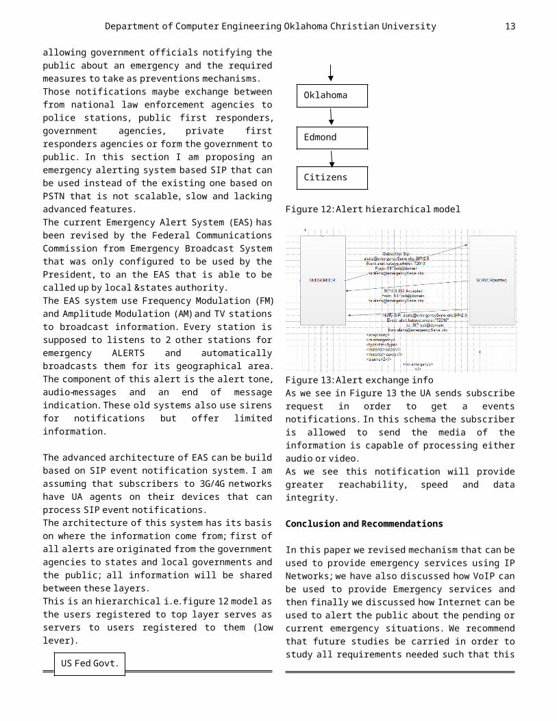
between these layers. This is an hierarchical i.e.figure 12 model as
the users registered to top layer serves as servers to users registered to them (low
lever).
Figure 12:Alert hierarchical model
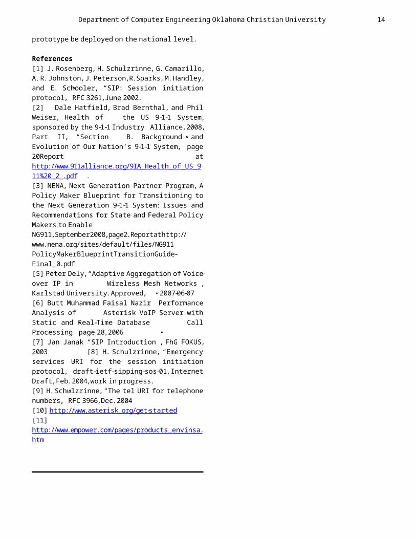
Figure 13:Alert exchange info As we see in Figure 13 the UA sends subscribe
request in order to get a events notifications.In this schema the subscriber
is allowed to send the media of the information is capable of processing either
audio or video. As we see this notification will provide
greater reachability, speed and data integrity.
Conclusion and Recommendations
In this paper we revised mechanism that can be used to provide emergency services using IP
Networks;we have also discussed how VoIP can be used to provide Emergency services and
then finally we discussed how Internet can be used to alert the public about the pending or
current emergency situations. We recommend that future studies be carried in order to study all requirements needed such that this
13
US Fed Govt.
Oklahoma
Edmond
Citizens
Department of Computer Engineering Oklahoma Christian University
prototype be deployed on the national level.
References [1] J. Rosenberg, H. Schulzrinne, G. Camarillo,
A.R.Johnston,J.Peterson,R.Sparks,M.Handley, and E. Schooler, “SIP: Session initiation
protocol,”RFC 3261,June 2002. [2] Dale Hatfield, Brad Bernthal, and Phil
Weiser, Health of the US 9-1-1 System, sponsored by the 9-1-1 Industry Alliance,2008,
Part II, “Section B. Background and Evolution of Our Nation’s 9-1-1 System,” page
20Report athttp://www.911alliance.org/9IA_Health_of_US_911%20_2_.pdf .
[3] NENA, Next Generation Partner Program, A Policy Maker Blueprint for Transitioning to
the Next Generation 9-1-1 System: Issues and Recommendations for State and Federal Policy
Makers to EnableNG911,September2008,page2.Reportathttp://www.nena.org/sites/default/files/NG911PolicyMakerBlueprintTransitionGuide-Final_0.pdf [5] Peter Dely,“Adaptive Aggregation of Voice
over IP in Wireless Mesh Networks”, Karlstad University.Approved, 2007-06-07
[6] Butt Muhammad Faisal Nazir” Performance Analysis of Asterisk VoIP Server with
Static and Real-Time Database Call Processing” page 28,2006
[7] Jan Janak “SIP Introduction”, FhG FOKUS, 2003 [8] H. Schulzrinne, “Emergency
services URI for the session initiation protocol,”draft-ietf-sipping-sos-01,Internet
Draft,Feb.2004,work in progress. [9] H.Schulzrinne,“The tel URI for telephone
numbers,”RFC 3966,Dec.2004 [10] http://www.asterisk.org/get-started
[11]http://www.empower.com/pages/products_envinsa.htm
14