B.Sc_Forensic_Science.pdf - Government Institute of Forensic ...
Upload
khangminh22Category
view
0download
0

VOIP NETWORK SECURITY AND FORENSIC MODELS USING PATTERNS
by
Juan C. Pelaez
A Doctoral Dissertation Submitted to the Faculty of the
College of Computer Science and Engineering
In Partial Fulfillment of the Requirements for the Degree of
Doctor of Philosophy
Florida Atlantic University
Boca Raton, Florida
August 2007
Reproduced with permission of the copyright owner. Further reproduction prohibited without permission.

VOIP NETWORK SECURITY AND FORENSIC MODELS USING PATTERNS
by Juan C. Pelaez
This doctoral dissertation was prepared under the direction of the candidate's dissertation advisor, Dr. Eduardo B. Fernandez, Department of Computer Science and Engineering, and has been approved by the members of his supervisory committee. It was submitted to the faculty of The College of Computer science and Engineering and was accepted in partial fulfillment of the requirements for the degree of Doctor of Philosophy.
fairperson, Department of
Computer Science and Engineering
Dean, College of Computer
Science and Engineering
Dissertation Advisor
Dean, Graduate Studies and Programs
3 f , 7 J & 7 ’A
Date
u
Reproduced with permission of the copyright owner. Further reproduction prohibited without permission.

Acknowledgements
First, I would like to thank God for giving me strength, hope, and perseverance in my
studies. Without Him none of this would be possible or worthwhile.
I would also like to thank my dissertation advisor, Dr. Eduardo B. Fernandez, for his
guidance and helpful criticism throughout this research. To my Committee Members
and my good friend Ruby Grant, thank you for taking the time to read and revise my
written and oral presentation of this dissertation. I also thank my employer, the
United States Army Research Laboratory, for their financial and technical support
during this research.
Last but not least, I would like to thank my lovely wife, Pitty Pelaez, and my devoted
mother, Martha Henao, for their unconditional loving support throughout my
educational endeavors. I am very grateful for having a family that has encouraged me
at each and every step of my life.
iii
Reproduced with permission of the copyright owner. Further reproduction prohibited without permission.

Abstract
Author: Juan C. Pelaez
VoIP Network Security and Forensic Models using
Patterns
Florida Atlantic University
Dr. Eduardo B. Fernandez
Doctor of Philosophy
Title:
Institution:
Thesis Advisor:
Degree:
Year: 2007
Voice over Internet Protocol (VoIP) networks is becoming the most popular
telephony system in the world. However, studies of the security of VoIP networks are
still in their infancy. VoIP devices and networks are commonly attacked, and it is
therefore necessary to analyze the threats against the converged network and the
techniques that exist today to stop or mitigate these attacks. We also need to
understand what evidence can be obtained from the VoIP system after an attack has
occurred.
Many of these attacks occur in similar ways in different contexts or environments.
Generic solutions to these issues can be expressed as patterns. A pattern can be used
to guide the design or simulation of VoIP systems as an abstract solution to a problem
in this environment. Patterns have shown their value in developing good quality
software and we expect that their application to VoIP will also prove valuable to build
secure systems.
This dissertation presents a variety of patterns (architectural, attack, forensic and
security patterns). These patterns will help forensic analysts as well, as secure systems
developers because they provide a systematic approach to structure the required
information and help understand system weaknesses. The patterns will also allow us
to specify, analyze and implement network security investigations for different
architectures. The pattern system uses object-oriented modeling (Unified Modeling
Language) as a way to formalize the information and dynamics of attacks and
systems.
IV
Reproduced with permission of the copyright owner. Further reproduction prohibited without permission.

Table of Contents
LIST OF FIG U R E S......................................................................................... viii
LIST OF T A B L ES.........................................................................................................xi
CHAPTER
1 INTRODUCTION................................................................................................... 1
2 BACKGROUND........................ ...6
2.1 Introduction............................. ...6
2.2 Internet Protocol Networks ............................................................... 6
2.3 IP Telephony.........................................................................................................7
2.3.1 Signaling and Media Protocols.................................................... 9
2.3.2 VoIP Building Blocks...............................................................................11
2.3.3 VoIP Network Operation........................................ 13
2.3.4 Wireless VoIP ................. 15
2.4 Network Forensics................................................. 16
2.4.1 Reference F orensic Model.........................................................................17
2.4.2 Network Forensic Tools and Techniques .................................................19
2.4.3 Post-mortems vs. Real-time Analysis ......................................................282.4.4 What is Network Evidence?...................................................................... 29
2.5 Summary ......... .30
3 VoIP ARCHITECTURES .......................................................................32
3.1 Introduction........................................................................................................32
v
Reproduced with permission of the copyright owner. Further reproduction prohibited without permission.

3.2 Patterns for VoIP Signaling Protocol Architectures.............................................33
3.2.1 H.323 Signaling Protocol Architectures.................................................... 34
3.2.2 Hybrid VoIP Signaling Protocol Architectures..........................................40
3.3 VoIP Wireless Architectures................................................................................ 51
3.3.1 VoIP in WLANs ................................................................................ 51
3.3.2 VoIP in Cellular Networks................. 52
3.3.3 VoIP in GPRS .................................................................................. 55
3.3.4 VoIP in UMTS.................................................................................. .........56
3.3.5 Mobile Internet Telephony ................ 56
3.3.6 VoIP in Satellite Networks.......................................................................... 57
3.4 VoIP in Tactical Internet......................................................................................... 57
3.4.1 Tactical Internet .......... 59
3.4.2 Joint Network Node ................................................................................... 61
3.5 Summary................................................................................................................. 64
4 ATTA CK S A N D SECURITY PA TTERN S FO R VoIP
N E T W O R K S ...................................................................................................... 66
4.1 Introduction........... ........... 66
4.2 Roles in a basic VoIP model...................................................................... 67
4.2.1 Internal roles.................................................................................................67
4.2.2 External roles................................................. 68
4.3 Attacks against the VoIP network..........................................................................70
4.3.1 Attacks when making/receiving a voice call..............................................71
4.3.2 Registration attacks....................................... 73
4.3.3 Attacks against Audit.................................................. 74
4.4 VoIP security patterns..................................................................................... 75
4.4.1 Network segmentation.................................................................................75
4.4.2 VoIP tunneling..................................................................................... 78
4.4.3 Signed authenticated call ................................................................... ........ 81
4.4.4 Secure VoIP call................................................................................... 85
4.5 Summary......................................................................................................... 88
vi
Reproduced with permission of the copyright owner. Further reproduction prohibited without permission.
5 ATTACK PATTERNS........................................... 89
5.1 Introduction.............................. 89
5.2 A template for attack patterns..............................................................................90
5.3 Attack pattern: Denial-of Service (DoS) in VoIP ............................................ 92
5.4 Attack pattern: Call interception in VoIP......................................................... 104
5.5 Attack pattern: Theft of service in VoIP.......................................................... 116
5.6 Attack pattern: Call hijacking in VoIP............................................................ 123
5.7 Attack pattern: IP spoofing in VoIP ............. 133
5.8 Summary and discussion................................................................................ 139
6 VoIP NETW ORK FORENSIC PA TTERN S...................................................143
6.1 Introduction.................................................................... 143
6.2 VoIP evidence collector................................................................................... 144
6.3 VoIP evidence analyzer.................................................................................... 155
6.4 Summary ................................................................................................ 163
7 CONCLUSION AND FUTURE W O R K .........................................................164
REFERENCES.......................................................................... 169
ACRONYM S................................................................................................................ 180
vii
Reproduced with permission of the copyright owner. Further reproduction prohibited without permission.

List of Figures
Figure 2.1 Class diagram for a VoIP development................ .............................................10
Figure 2.2 Sequence diagram for a telephone-to-telephone connection..............................14
Figure 3.1 Relationships between VoIP architectural and security patterns......................34
Figure 3.2 Class diagram for a H.323 architecture............................................................. 37
Figure 3.3 Sequence diagram for call connection in H.323................................. 38
Figure 3.4 Hybrid VoIP signaling protocol architecture.................................................... 44
Figure 3.5 Sequence diagram for a call connection in hybrid configurations................. .....45
Figure 3.6 Class diagram for a VoIPoW application using WLANs...................................52
Figure 3.7 Class diagram for a VoIPoW application using GSM........................................54
Figure 3.8 Class diagram for Verisign network routing directory........................................55
Figure 3.9 Class diagram for a simplified Tactical Internet architecture.............................. 59
Figure 3.10 Class diagram for a Joint Network Node architecture..................................... ..63
Figure 4.1 Use Case diagram for a VoIP system..................................................................69
viii
Reproduced with permission of the copyright owner. Further reproduction prohibited without permission.

Figure 4.2 Relationships between VoIP security patterns................................................... 76
Figure 4.3 VoEP Segmentation..............................................................................................78
Figure 4.4 Authenticated Call sequence diagram ............................................................... 83
Figure 4.5 Class diagram for a VoEP Secure Channel......................................................... 87
Figure 5.1 Class diagram for an H.323 architecture............................................................ 96
Figure 5.2 Class diagram for DoS attacks in H.323............................................................ 97
Figure 5.3 Sequence diagram for a DoS attack in H.323.................................................... 98
Figure 5.4 Class diagram for a MGCP environment........................................................... 99
Figure 5.5 Sequence diagram for a call interception............................. ............................108
Figure 5.6 Class diagram for CALEA model.................................................................... 114
Figure 5.7 Sequence diagram for a Theft of Service attack.................................................119
Figure 5.8 Class diagram for a SIP architecture................................................................ 126
Figure 5.9 Class diagram for a VoIP Call Hijacking attack............... 128
Figure 5.10 Sequence diagram for Call Hijacking attack in SIP..................... 128
Figure 6.1 Relationships between VoIP patterns.............................................................. 144
Figure 6.2 Evidence Collector class diagram...................................................................... 148
ix
Reproduced with permission of the copyright owner. Further reproduction prohibited without permission.

Figure 6.3 Sequence Diagram for evidence collection in VoIP .............................. 152
Figure 6.4 Class diagram for a VoIP network forensic system..........................................158
Figure 6.5 Sequence diagram for evidence analysis in VoIP............................................160
Figure 7.1 VoIP pattern system ........................... 167
x
Reproduced with permission of the copyright owner. Further reproduction prohibited without permission.

List of Tables
Table 2.1 DFRWS digital investigative framework
XI
Reproduced with permission of the copyright owner. Further reproduction prohibited without permission.

To Lissie and Sophie the most precious gifts God has given me
Reproduced with permission of the copyright owner. Further reproduction prohibited without permission.

Chapter 1
Introduction
VoIP is defined as the transport of voice over Internet Protocol based networks. Any
data network that uses IP can be used to establish this service. VoIP uses IP to
transmit voice as packets over an IP network. Therefore, VoIP can be achieved on
any data network that uses IP, such as the Internet, intranets and Local Area Networks
(LAN), where digitized voice packets are transmitted over the IP network.
VoIP has had a strong effect on global communications by allowing human voice and
video to travel over existing packet data networks along with traditional data packets.
Consequently, the overwhelming majority of Public Switched Telephone Networks
(PSTN) in service today will be replaced by the VoIP infrastructure within the next
decade.
In carrier networks, VoIP has been mainly deployed in enterprise networks or as a
trunking technology to reduce transport costs in voice backbone networks [Dre03].
To alleviate the increment in network capacity needs, one unified trunk network is
created based on the concept of converged networks. Here, the IP network is used as
a backbone between two voice switches/gateways. VoIP over Wireless (VoIPoW)
which is considered a typical application in IP telephony, is becoming the most
1
Reproduced with permission of the copyright owner. Further reproduction prohibited without permission.

popular system for mobile communication in the world. However, studies of the
security of wireless VoIP networks are still in their infancy. Wireless devices are
commonly used by terrorists, and it is therefore necessary for network investigators to
understand which evidence can be obtained from the VoIP system after an attack has
occurred.
Many forums have discussed the benefits of VoIP, but only a few of them have
openly discussed its security risks. Current VoIP products are still weak and there is a
need to improve their security [Wie06], Security patterns are useful to guide the
design of security systems by providing generic solutions that can stop a variety of
attacks. In this research we will present some security patterns that describe
mechanisms that can control many of the possible attacks and which could be used to
design secure systems.
In order to avoid attacks and discover security vulnerabilities, it is necessary to be
aware of typical risks and to have a good understanding of how vulnerabilities can be
exploited. Without this understanding we may produce a VoIP system that is more
expensive than necessary and that has a large performance overhead.
We show here an approach to list all potential attacks by using use case diagrams,
considering each action in each use case and analyzing how it can be attacked by an
internal or external attacker. From the list of threats we can deduce what security
patterns are necessary to prevent or mitigate the threats.
Many of these attacks occur in similar ways in different contexts or environments.
Generic solutions to these issues can be expressed as patterns. A pattern is an
encapsulated solution to a problem in a given context and can be used to guide the
2
Reproduced with permission of the copyright owner. Further reproduction prohibited without permission.

design or evaluation of systems [Gam94]. Patterns have shown their value in
developing good quality software and we expect that their application to VoIP will
also prove valuable to build secure systems. VoIP patterns were introduced in [Pel04]
and only one other paper has shown this type of patterns [Anw06], who also describe
our Secure VoIP Call pattern as well as three other different patterns.
The purpose of this dissertation is to generate a comprehensive pattern system
including a collection of architectural, attack, forensic and security patterns,
providing best practices for IP telephony systems. Our goal is to analyze the attacks
against a VoIP network and the techniques that exist today to mitigate these attacks,
and then to understand network forensic investigations in a VoIP converged
environment, using the existing methods for this basis. The proposed pattern system
will help network designers to improve the level of security not only in voice but also
in data, video, and fax over IP networks. The pattern system will also allow us to
specify, analyze and implement network security investigations for different
architectures. We will make use of UML (Unified Modeling Language) [Boo98] to
describe these patterns. This dissertation will address some of the most important
existing VoIP network security and forensic issues, and will give a detailed
presentation of problems which exist or are likely to exist in the future. However, this
research does not guarantee to provide a generalized framework for every network
forensic technique in VoIP.
In VoIP network forensics a systematic approach is needed to detect vulnerabilities
and the resulting attacks. We will introduce attack patterns as a helpful investigative
method which should be integrated in the VoIP network forensic process. This pattern
3
Reproduced with permission of the copyright owner. Further reproduction prohibited without permission.

describes, from the point of view of the attacker, how a type of attack is performed
(what system units it uses and how), proposes ways of stopping the attack by
enumerating possible security patterns that can be applied for this purpose, and helps
analyzing the attack once it has happened by indicating where we can find forensics
data as well as what type of data. Attack patterns enable us to discover vulnerable
parts of the VoIP network and allow us to be better able to secure them. There are
various threats to a VoIP deployment from external domains and internal sources.
The goal is to prevent those attacks that have the potential to affect a VoIP
environment.
To address the needs of forensic investigations in VoIP, we will also propose a new
type of pattern, the forensic pattern. Forensic Patterns provide an abstract view of
forensic information to network investigators. Forensic patterns would also be useful
for training apprentice forensics technicians about common investigative techniques
and tools. Developing forensic patterns will result in a better and faster response and
investigation of network attacks [Moh03].
To effectively analyze security and network forensic issues in VoIP networks, we
start by giving an overview of VoIP and its applications including its internetworking
with Wireless Networks. Then we will continue modeling the actual IP telephony
infrastructure to develop object oriented patterns; characteristics of the most
important VoIP architectures are reviewed, including a VoIP network infrastructure
deployment in a Tactical Internet environment. To develop security patterns, we
analyze the attacks against the VoIP infrastructure from the H.323 and Session
4
Reproduced with permission of the copyright owner. Further reproduction prohibited without permission.

Initiation Protocol (SIP) standards, and from a hybrid architecture perspective, which
will give a clear set of use cases to which we can relate these attacks.
We will analyze network forensics in a converged environment and the most popular
network forensic tools available today for investigators. Further, we will introduce the
concept of attack patterns and provide some examples. Finally we will introduce the
forensic patterns in order to complete the VoIP pattern system which constitutes the
core of this research report. The use of automated mechanisms for evidence collection
in real time is fundamental when conducting network forensics investigations in a
VoIP environment.
Likewise, in today’s mobile communications world network investigators are in need
for network models that allow not only the detection of complex attacks, but also that
support forensic evidence collection, storage and analysis. The analysis of different
types of records in VoIP devices and the use of these records to reconstruct any attack
related event are not automated. Those forensic manual methods make the analysis
almost impossible due to the large volume of data in IP networks.
This dissertation is organized as follows: in Section 2, an overview of VoIP
technology is provided together with the necessary background for this dissertation.
In Section 3, characteristics of the most important VoIP architectures are briefly
reviewed. In Section 4, a set of security patterns are presented. In Section 5, the
concept of attack patterns is introduced. Finally in Section 6, network forensic
patterns are presented. This dissertation ends with Section 7, where conclusions are
presented and future work is proposed.
5
Reproduced with permission of the copyright owner. Further reproduction prohibited without permission.

Chapter 2
Background
2.1 Introduction
This chapter provides the reader with the background and an overview of IP
telephony, followed by an analysis of PSTN versus voice over IP telephone systems.
Likewise, an introduction to network forensics and the forensic process is presented
in order to outline the functionalities of forensic patterns that will be introduced later
in this dissertation. This forensic process also outlines the sequence of events during
forensic investigations. This chapter concludes with the analysis of some relevant
network forensic methods and tools.
2.2 Internet Protocol Networks
Internet Protocol (IP) networks are those that use IP to provide the functionality for
interconnecting end systems across multiple networks [Sta02], VoIP technology uses
IP-based networks to establish and manage communication sessions between terminal
devices. IP is the network level protocol that encapsulates the higher layer PDU
6
Reproduced with permission of the copyright owner. Further reproduction prohibited without permission.

(protocol data unit) into IP datagrams. One of the most important features of IPv4 is its
32-bit IP (128-bit for IPv6) address: a virtual address given to each host and router in
the network. The Address Resolution Protocol (ARP) is used to obtain the actual
physical address of the device. IP networks are “best-effort” delivery networks i.e. the
network will attempt to deliver the traffic, but if problems occur or the destination host
cannot be found, the traffic is discarded [Bla02], It is necessary for higher layers, such
as the Transmission Control Protocol (TCP), to compensate for this. This is a major
disadvantage for real-time traffic over IP networks that require a certain QoS in order to
produce acceptable service. Therefore, in order to transfer voice over IP networks with
an acceptable quality, it is necessary to develop and implement separate protocols.
2.3 IP Telephony
VoIP (a.k.a. IP Telephony) is defined as the transport of voice over IP-based
networks. Any data network that uses IP can be used to establish this service. VoIP
uses IP to transmit voice as packets over an IP network rather than the traditional
circuit-switched networks of today’s telecoms. Therefore, VoIP can be achieved on
any data network that uses IP, such as the Internet, intranets, and Local Area
Networks (LAN), where digitized voice packets are transmitted over the IP network.
VoIP can be considered as one more transport technique within the IP layer.
Existing network infrastructures can be used to carry both data and voice traffic, a
combination which is very attractive to new users. Savings come from eliminating the
need to purchase new Private Branch Exchanges (PBX) equipment, and from
7
Reproduced with permission of the copyright owner. Further reproduction prohibited without permission.

reducing staff and maintenance costs, as only one network needs to be supported
[WeiOl]. The possible savings on the present cost of transmitting long distance
messages by voice and fax traffic via existing carriers provide extra incentives for
moving to VoIP.
In the mid-90’s when VoIP was first introduced, its implementations consisted of
using the Internet for low-cost PC-to-PC voice communication. Today this
technology has improved due to adoption of standards, interoperability among
networking equipment, and improvements in Quality of Service (QoS). In addition,
signaling protocols are used to set up and end calls and to carry infonnation required
to locate users and negotiate capabilities. Major communication companies like
Siemens and Cisco have developed numerous VoIP products and security solutions
that are already available on the market.
In carrier networks, VoIP has been mainly deployed in enterprise networks or as a
trunking technology to reduce transport costs in voice backbone networks [Dre03].
The transmission of VoIP networks enables a wide variety of applications, and VoIP can
be applied to almost any voice communications requirement. VoIP over wireless
(VoIPoW) is considered a typical application within the VoIP technology.
In VoIP, in addition to delivering voice, the IP protocol performs some of the related
functions of the voice network that are necessary to convert the whole network into a
full system. Some of these functions include special features, collect calling,
gateways into the public voice network, and associated actions [GorOO].
When using the IP protocol, there are three different types of connections for setting
up the call. In all of the cases of VoIP, the IP Protocol is used: (1) PC-to-PC, in
8
Reproduced with permission of the copyright owner. Further reproduction prohibited without permission.

which individuals online talk through their PCs, (2) PC-to-telephone, in which
individuals make and receive voice calls and messages while on the Internet, and (3)
telephone-to-telephone, in which calls are made and received using regular phones
connected to PSTN or IP-telephones connected to a data net (an example of this type
of connection will be given in section 2.3.3).
Figure 2.1 shows a class diagram describing how an IP telephony system integrates
with the PSTN. This model shows how it becomes possible to place a call from a
regular telephone number to a PC running an H.323 client. The PBX that supports the
standard phone (caller) formats Caller and Callee numbers and forwards them to the
VoIP gateway via PSTN network. The gateway takes the voice call from circuit
switched PSTN and places it on the IP network. The Gateway then queries the
gatekeeper via IP network with Caller/Callee numbers (note that the voice packets do
not go through the gatekeeper, only the call signaling) and the gatekeeper translates
them into a routing number based upon service logic. Finally, the gateway routes the
call to the called party (i.e., Callee).
The call quality of VoIP has improved to such a high level that it is difficult for a
subscriber to differentiate between packetized voice and a digital circuit. This makes
it possible for VoIP to compete successfully with the traditional telephone system
(i.e., PSTN).
2.3.1 Signaling and Media VoIP Protocols
Two types of protocols are used in VoIP: signaling protocols and media transport
protocols. Signaling allows call information to be carried across network boundaries
9
Reproduced with permission of the copyright owner. Further reproduction prohibited without permission.

transmit packets
AnalogPhone
PC Router
Gateway
PBX
Gatekeeper
Figure 2 .1 . Class Diagram for a VoIP deployment
providing session setup, control and teardown. VoIP signaling protocols generally can
be divided into two main groups, client-server and user-to-user. In the latter group,
SIP and H.323 are the two most popular. Media exchange (Client-server type)
protocols are out of the scope of this dissertation; however in chapter 6, the
Megaco/H.248 control protocol architecture is used to analyze Denial of Service
attacks.
H.323 defines a family of protocols specified by the ITU research group [ITU06].
The standard provides a foundation for signaling in order to exchange voice, video,
and data communications in an IP-based network. H.323 supports Secure Real-Time
protocol (SRTP) for media confidentiality and Multimedia Internet Keying (MIKEY)
for key exchange. It is important to emphasize that the signaling is only protected up
to the gateway.
10
Reproduced with permission of the copyright owner. Further reproduction prohibited without permission.

SIP is a more recent standard for multimedia conferencing over IP. The standard was
defined by the Internet Engineering Task Force (IETF) [Ros02] and is conceptually
simpler than H.323. SIP is used for creating, modifying and terminating sessions
between endpoints. SIP supports the Secure Real Time Protocol (SRTP) for securing
media traffic and Transport Level Security (TLS) and Secure / Multipurpose Internet
Mail Extensions (S/MIME) for signaling protection. Although most VoIP
implementations today use the H.323 protocol for IP services, SIP is gaining more
acceptance in the network telephony market due partly to its flexibility and lower
implementation costs. It is possible to use each protocol alone or both protocols
within the same network in order to provide universal connectivity.
2.3.2 VoIP Building Blocks
A typical VoIP deployment consists of the following physical elements: terminal
devices, gateways, call servers, and optional elements.
Terminal Devices
Terminal device refers to any device used by an end-user that supports placing and
receiving calls in a VoIP network. IP phones connected to LANs (a.k.a. hardphones)
are included as well as PC-based IP Phones (a.k.a. Softphones). Softphones are
applications installed on user systems (e.g., desktops) with speakers and
microphones; they reside in the data segment (implemented by VLANs). On the other
hand, Hardphones are located in VLANs that support only IP telephony services. This
11
Reproduced with permission of the copyright owner. Further reproduction prohibited without permission.

segmentation technique will be further explained in Section 4. IP phones offer
services such as user directory lookups, Web browsing, instant messaging, and multi-
media conferencing; these IP services are accessed via a proxy server.
Gateways
Gateways are devices that provide voice services, including such features as PSTN
access, IP packet routing, and backup call-processing. This is the device that provides
access to legacy voice systems for local calls, toll bypass, and WAN backup in case
of failure. Gateways convert data packets from the IP network into voice before
sending them over a carrier network such as Integrated Services Digital Network
(ISDN) or PSTN. On the other side, when VoIP is used internally, the gateway
basically routes packetized voice data between the source and the destination.
Call Servers
The IP-PBX is a server that provides call control and configuration management for
IP telephony devices. This device provides the core functionality to bootstrap IP
telephony devices, provide call setup, and route calls throughout the network to other
voice devices, including voice gateways and voice-mail systems [MarOl], This
basically moves the standard functions of Private Branch Exchange (PBX) to a
dedicated server.
12
Reproduced with permission of the copyright owner. Further reproduction prohibited without permission.

Optional Elements
Optional elements in a VoIP environment are Multipoint Control Units (MCU) used
for conferencing and back-end-services (BES), which provides such services as data
tracking of call endpoints and authentication servers.
2.3.3 VoIP Network Operation
Initially, the terminal devices access a Dynamic Host Configuration Protocol (DHCP)
server to obtain an IP address; all IP telephony devices are then required to complete
a registration with the call server before placing a call. After completing the
registration process, the IP telephony devices are configured with access to voice
mail, data services, time-of-day, speed-dials, any other custom configurations, and an
extension. Then the devices will be ready to make and receive a call. In order to
support directory services, the call server will add the registered device to the DNS.
The caller will pick up the IP-phone and dial the extension of the remote user with
whom [s]he wants to speak. The extension number is sent to the IP-PBX, which in
turn notifies the destination device that a call is incoming. The IP-PBX will be able to
complete the call because the destination device went through the registration
process. Once the remote user takes the device off the hook, the remote device
notifies the IP-PBX that it is willing to accept the call. The IP-PBX will then notify
both devices that a channel is available to start the conversation.
In a telephone-to-telephone connection type, if the call is made using regular phones
that are connected to a PSTN, the network-based call would proceed as follows:
13
Reproduced with permission of the copyright owner. Further reproduction prohibited without permission.

1. The caller picks up a standard telephone, which is supported by a PBX. The
PBX is physically connected to the gateway over one of the access cards.
2. The caller then dials an access code (e.g., 7) that tells the PBX to route this
call over the PBX trunk connected to the gateway. Next, the caller types in the
branch or extension number (e.g., 123-4567).
3. The gateway routes call setup messages over the enterprise network to the
remote gateway. The gateway sets up the call via the PBX, and if the called
party is available, voice bits will be encapsulated within the IP payload
[Min02],
Figure 2.2 shows a sequence diagram for a telephone-to-telephone connection type.
In this case, the model presented in figure 2.1 could easily be altered to have analog
telephones rather than PCs, as endpoints.
dial access code
iprocesses
dial n u m b erroute call
rou te ca llroute ca ll
setup ca li
setup ca ll
estab lishes ca ll
:PBX :VolPGatewav « a c t o r »aCallee:
« a c to r »aCaller: :RemotePBX:RemoteGatewav
Figure 2 .2 . Sequence diagram for a telephone-to-telephone connection
14
Reproduced with permission of the copyright owner. Further reproduction prohibited without permission.

2.3.4 Wireless VoIP
VoIP has not only been gaining ground on landline networks but also is developing
considerable interest in wireless networks. The main advantage of VoIP over
Wireless (VoIPoW) is service flexibility. With this technology, users will be able to
use a variety of wireless devices, including cellular phones, two-way radios, PDAs,
laptop computers, and similar devices. The low cost of transport and switching is
another benefit of this technology.
VoIPoW is targeted at data (e.g. mobile laptop) users allowing mobile workers to
make and receive telephone calls on a shared wireless infrastructure. VoIPoW is
becoming available for both wireless LAN and wireless WAN applications.
This technology has two major disadvantages: security and header compression. The
security issues of wireless devices are as serious as any attack on the corporate
database and may have damaging effects on the privacy of individuals and the
protection of resources of an enterprise. The increase in functions in cellular devices
creates new possibilities for attacks, these attacks will be discussed later in this
dissertation.
On the other hand, the large headers of the protocols (IP/UDP/RTP) used when voice
data is sent over the Internet, consume too much bandwidth and make inefficient use
of valuable radio spectrum [EriOO], The data size is only 15-30 octets, whereas the
headers amount to 40 (IPv4) - 60 (IPv6) octets. Header compression protocols like
ROCCO (Robust-Checksum based header Compression) and CRTP (Compressed
Real Time Protocol) can solve this inefficient use of the spectrum. There exist many
15
Reproduced with permission of the copyright owner. Further reproduction prohibited without permission.

different forms of implementing VoIP in wireless communications and networking
which will be discussed in Chapter 3.
2.4 Network Forensics
Network forensics is the act of capturing, recording, and analyzing information
collected on active networks from various intrusion detection, auditing, and
monitoring points in order to discover the source of security breaches or other
information assurance problems [Case06, Fer05, Ran06], Network forensics
technology is useful not only to law enforcement, but also to the military and the
private sector. Examples of these network analysis procedures are the examination of
router and firewall logs, or eavesdropped data from a network. Network forensics
adds another dimension of protection to the VoIP system in addition to the well
known security mechanisms discussed in the previous chapter.
Computer and network forensics has been developed to ensure thorough
investigations in a converged environment. Network forensics support VoIP
investigations by providing information about the location and the way that attackers
perform their crimes. The collection of this evidence is crucial in the prosecution of
criminals. Thus, network forensics not only helps to find criminals but also to
indirectly stop network crimes and reduce their incidence. Network forensic models
allow not only the detection of complex attacks, but also the understanding of what
happened after a system is breached.
16
Reproduced with permission of the copyright owner. Further reproduction prohibited without permission.

By providing information about the location and the way that attackers perform their
crimes, network forensics support investigations in VoIP. These methods can
illuminate issues such as bandwidth use in terms of machines, protocols, users, or
content. Issues like unauthorized services, cleartext-password protocols, or
implementations that violate protocol standards can also be summarized using these
methods [Cor02].
The collection of data in real time and the use of automatic mechanisms are vital
when conducting network forensics investigations in a VoIP environment. This will
result in a better and faster response to network attacks.
Most network forensic systems are based on inspection traces in order to detect
predefined attack patterns and deviations from normal behavior. Its function is
therefore to assist network forensic specialists in the investigation of crimes
perpetrated through the use of computers and networks.
The major features of network forensics analysis can be summarized into two
fundamental goals [Wan05]: (1) Attack scenario reconstruction, which is the process
of understanding the actions taken by the attacker to complete her job. (2) Attack
group identification, which is the process of discovering the group of hosts involved
in the attack and determining the roles of each host in the group.
2.4.1 Reference Forensic Model
Several models are used for investigation in forensic science. We chose the
framework from The Digital Forensics Research Workshop (DFRWS) because it is a
17
Reproduced with permission of the copyright owner. Further reproduction prohibited without permission.

comprehensive approach and is more oriented to this dissertation’s goals. The
DFRWS model shows the sequential steps for digital forensic analysis [DFRWS01].
These steps are shown in Table 2.1.
IDENTIFICATION PRESERVATION COLLECTION EXAMINATION ANALYSIS PRESENTATIONEvent/CrimeDetection
CaseM anagement Preservation Preservation Preservation Documentation
ResolveSignature
ImagingTechnologies
ApprovedM ethods Traceability Traceability Expert Testimony
Profile DetectionChain of C ustody
ApprovedSoftware
ValidationTechniques Statistical Clarification
AnomalousDetection Time Synch. Approved
HardwareFilteringTechniques Protocols Mission Impact
Statement
Complaints LegalAuthority
PatternMatching Data Mining
RecommendedCountermeasure
SystemMonitoring
LosslessCompression
Hidden Data Discovery Timeline Statistical
Interpretation
Audit Analysis Sampling Hidden Data Extraction LinK
DataReduction Spatial
RecoveryTechniques
Table 2.1 - DFRWS Digital Investigative
Framework [DFRWS01]
The initial phase or the Identification of potential digital evidence (i.e., where might
the evidence be found) is covered by the Intrusion Detection Systems (IDS) and in
some sense by the attack patterns. The Preservation phase involves acquiring,
isolating, securing, and preserving the state of the digital evidence; making forensic
images of the evidence; and establishing the chain of custody. A chain of custody
refers to documenting the seizure, custody, control, transfer, analysis, and disposition
of physical and electronic evidence [Wik07]; this process is carried out from the
instant voice packets are collected, through and beyond its final presentation in a
court of law.
18
Reproduced with permission of the copyright owner. Further reproduction prohibited without permission.

The Collection phase involves the process of identifying, labeling, recording, and
acquiring forensic data from the possible sources of evidence, according to standard
procedures in forensics. The Examination phase consists of processing large
amounts of collected voice packets. This is achieved by combining automated and
manual methods to assess and extract interesting data while preserving the integrity of
the data. The Analysis phase involves the analysis of the results from the examination
phase, using legally justifiable (automated) methods to determine significance,
reconstruct fragments of data, and derive conclusions based on the collected
evidence.
We will concentrate on the middle phases of the forensic process (i.e. the collection,
examination, and analysis of the evidence) which will be revisited and presented as
patterns in chapter 7. This process provides network investigators a structured method
to collect more and better evidence and to reduce the analysis time in VoIP networks.
The presentation phase involves the legal aspects of the forensic investigation -
presenting the findings in court and corporate investigative units by applying laws
and policies to the expert testimony and securing the admissibility of the evidence
and analysis. This phase is outside of the scope of this research, but it must be
considered in order to create a comprehensive model.
2.4.2 Network Forensics Tools and Techniques
Network forensic investigators need various types of tools to identify and collect
network evidence and to confront the unique forensic challenges presented by a
19
Reproduced with permission of the copyright owner. Further reproduction prohibited without permission.

converged network environment. Because voice travels in packets over the data
network, various tools and techniques can be used for network forensic purposes,
such as Network Forensic Analysis Tools (NFAT) or IP traceback and packet
marking across VoIP systems, just to mention a few. They can assist network
investigators in the collection, examination, and analysis of forensic data in order to
identify, store and play back voice communications traversing the network.
This section will address some of the most important existing forensic tools and
techniques and will discuss some of the problems which exist or are likely to exist in
the future. However, this research does not guarantee the creation of a generalized
framework for every forensic method in VoIP.
Previous Work
Several papers have been written about network forensic models by different network
security specialists and organizations, but in general, none of these authors did a
systematic work of identifying formal security patterns for attacks against the VoIP
network infrastructure. One of the earliest discussions about this topic is a paper by
Stephenson [Ste03] discussing an approach to post-incident root cause analysis of
digital incidents (a.k.a. digital post mortems) that has structure and rigor and the
results of which can be modeled formally using Colored Petri Nets. He focuses upon
the investigative approach in forensic digital analysis and the modeling of the
outcome.
20
Reproduced with permission of the copyright owner. Further reproduction prohibited without permission.

Shanmugasundaram et al [Sha03] created ForNet, a distributed network logging
mechanism to aid digital forensics over wide area networks. This network forensics
system was designed to integrate forensic, capabilities into network infrastructures.
The system incorporates the use of synopses to tracing payloads, detecting network
attacks and collecting forensic data.
Tang [Tan05] developed a network forensics framework based on distributed
techniques which provides an integrated model for automatic forensic evidence
collection and data storage, supporting the integration of known attribution methods,
and an attack attribution graph generation mechanism to illustrate hacking
procedures. Likewise, Wang and Daniels [Wan05] propose an evidence graph model
to facilitate the presentation and manipulation of intrusion evidence. For automated
evidence analysis, they developed a hierarchical reasoning framework that included
local reasoning and global reasoning.
Ren and Jin [Ren05] developed a model based on distributed adaptive network
forensics and active real time network investigation. The Ren/Jin model seems to be a
more complete and more realistic approach with respect to other existing network
forensic models.
On the other hand, Bogen [Bog05] proposes a core set of modeling views for a
unified computer forensics modeling methodology: investigative process view, case
domain view, and, evidence view. Bogen doesn’t specify network forensic patterns;
he is focused in computer forensics evaluating the utility of case domain modeling to
the problem of deriving keyword search terms for cases.
21
Reproduced with permission of the copyright owner. Further reproduction prohibited without permission.

When analyzing the existing network forensic work, we concluded that the use of
UML models in VoIP forensic analysis has not been common. None of these authors
have discussed object-oriented models or attack patterns for VoIP networks.
Packet Sniffers and Protocol Analyzers
Packet Sniffers are also referred to as network monitors or packet analyzers. They are
software applications that capture and decode network traffic. Packet sniffers use a
network adapter card in promiscuous mode to capture voice packets traveling the IP
network. In order to monitor VoIP traffic, an examiner can place packet sniffers on
any backbone device or network aggregation point. Packet sniffers are good tools for
network investigators who want to monitor the information that enters and leaves the
system.
Protocol analyzers usually are able to process not only live network traffic but also
packets that have been recorded previously in capture files by packet sniffers.
Protocol analyzers are useful in displaying network traffic data in an understandable
format [Ken06]. With these tools, investigators are able to capture the packets and
decode the voice packet payload in order to analyze VoIP calls for example.
Unfortunately, however this software is also available for hackers. One of the
currently most popular packet-collection tools is tcpdump; this software can be
downloaded freely on the Internet and is available on most Unix and Windows
platforms.
22
Reproduced with permission of the copyright owner. Further reproduction prohibited without permission.

Intrusion Detection Systems
Intrusion Detection Systems (IDS) is another important evidence tool for network
forensics analysis. IDS is a method that identifies suspicious patterns that may
indicate a network attack by inspecting all inbound and outbound network activity.
IDS data is often the starting point for examining suspicious activity. In addition to
identifying malicious network traffic at all TCP/IP layers, IDS also logs many data
fields that can be useful in validating events and correlating them with other data
sources [Ken06].
IDS can be classified into two categories: anomaly detection and misuse (knowledge-
based) detection. Anomaly detection systems require the building of profiles for each
user group on the system. This profile defines an established baseline for the activities
that a normal user routinely does to perform his/her job [Cor02], However these
systems have several drawbacks: these IDS alerts are not well-adapted for forensics
investigation, they are complicated and impractical, and they have a high false
negative rate.
In contrast, misuse detection methods, also known as signature-based detection, look
for intrusive activity that matches specific signatures. These signatures are based on a
set of rules that match typical patterns and exploits used by attackers to gain access to
a network [Fer05]. The disadvantage with misuse detection methods is that they
cannot detect new attacks because they don’t have a known signature.
23
Reproduced with permission of the copyright owner. Further reproduction prohibited without permission.

The best solution is to combine signature based systems and anomaly detection
systems that can decrease false alarm rates using a lightweight IDS, e.g. snort
[Casw06]. Snort can be used as a straight packet sniffer, a packet logger, and a full
blown network intrusion detection system.
The problem is that snort is still a misuse detection system, and therefore it only
catches known attacks or unusual behavior. In general, much redundancy exists in
IDS technology as well as high false alarm rates while relevant information may be
missing or incomplete.
Likewise, an IDS system records information that may indicate a suspicious event. In
this way, IDS software records the same basic event characteristics that firewalls and
routers record (e.g., date and time, source and destination IP addresses, protocol,
basic protocol characteristics), in addition to application-specific information (e.g.,
username, filename, command, status code) [Gra05],
Network Forensic Analysis Tools
Network Forensic Analysis Tools (NFAT) are defined as a set of network tools used
to analyze traffic from a forensic point of view. NFATs typically provide the same
functionality as packet sniffers and protocol analyzers as they focus on collecting and
analyzing network traffic [Nis05].
Some of the most popular NFATs available today are Sandstorm Netlntercept,
Niksun NetVCR and eTrust Network Forensics. This software is designed to allow
investigators to discover useful details about the analyzed traffic. In order to analyze
24
Reproduced with permission of the copyright owner. Further reproduction prohibited without permission.

the attack behavior by replaying the attacking procedure, NFATs are used to
reorganize the packets into individual transport-layer connections between terminal
devices.
This reconstructive traffic analysis is often limited to data collection and packet level
inspection; however, a NFAT can provide a richer view of the data collected,
allowing investigators to inspect the traffic from further up the protocol stack
[Cor02]. By using these tools, investigators can also observe the voice packet streams
and the associations between terminal devices. Some NFAT tools can even tie IP
addresses, domain names, or other data to physical locations and produce a
geographic map of the activity [Gra05].
IP Traceback and Packet Marking
IP traceback and packet marking are important network forensic analysis techniques
used for attack attribution. IP traceback is defined as any method for reliably
determining the origin of a packet on the Internet [Wik07]. Existing approaches to
solve the problem of finding the source of a VoIP packet are based on probabilistic
packet marking, which overloads existing header fields in order to encode the path
traversed by a packet in a way that will have minimal impact on existing users. In a
denial of service attack, the victim will receive enough traceback packets to be able to
reconstruct the entire attack path [Sha03], To perform IP traceback Alex C. Snoeren
[Sno02] developed what he called a “Source Path Isolation Engine (SPIE)” using a
Bloom Filter as the data storage mechanism.
25
Reproduced with permission of the copyright owner. Further reproduction prohibited without permission.

The increase in cellular and wireless handheld devices provides a unique challenge
for network investigators. While an attack on a wired network is investigated by
tracing it back to a physical location, no physical access is required when a wireless
medium is attacked. In this case it is harder to extract evidence.
One form of documented wireless misuse is when wireless networks that allow
anonymous connectivity are used as an anonymous launch pad to commit further
crime. In the event that this crime is discovered, the origin of the attack can only be
traced back as far as the wireless comiection [Sla06]. Likewise, IP telephony allows
attackers to spoof source IP information, which can result in investigative dead-ends.
For instance, even if an IP address has not been spoofed, if the attack has been
launched from a public access machine, this will limit investigative options.
In summary, locating attackers with the IP traceback technology is a potential
security mechanism to counter DoS and many other type of attacks. IP traceback
works even when criminals conceal their geographic locations by spoofing source
addresses.
Logging
The collection of evidence before, during, and after an attack occurs is another
important forensic technique. The best available IP telephony system evidence is
generally provided by logging. Basically, logging is the tracking of all the
information going across a network. With the proper amount of logging information,
investigators will be able to trace a hacker.
26
Reproduced with permission of the copyright owner. Further reproduction prohibited without permission.

Log files provide useful audit trails of system activity; they can provide investigators
detailed event information about occurrences within a specific scope. On the other
hand, most applications allow for minimal logging to avoid performance impact
[Sol05],
Ideally, a network administrator would like to keep track of every packet that goes
across the VoIP network. This unfortunately is not an achievable goal because the
storing of network data for forensic analysis in converged networks is complicated.
Current issues about this technique, such as the required data storage (in real-time
networks) and the proposed solution, will be studied in the network forensic patterns
section in Chapter 7.
Reverse engineering
Reverse engineering can be considered another forensic method in the Object-
Oriented Design domain. When using this method, the UML tool loads all the files of
the application and the system, identifies dependencies among the different classes,
and essentially reconstructs the entire application structure along with all the
associations between the classes [Chi03]. This reconstructive traffic analysis is often
limited to data collection and packet level inspection. However, in combination with a
network forensics analysis tool (NFAT) it can provide a better view of the data
collected.
27
Reproduced with permission of the copyright owner. Further reproduction prohibited without permission.

2.4.3 Post-mortem vs. Real-time Analysis
In network forensics, the forensic examination of logs can be generally classified into
two categories: post-mortem and real-time analysis. Post-mortem examination refers
to the analysis of network evidence about a crime or other event that already has
occurred and about which nothing can now be done. On the other hand, real-time
analysis is an ongoing process that yields results at a rate that enables the VoIP
system to respond to attacks.
To be effective, real-time analysis requires an automated collection of forensic data in
order to provide data reduction and correlation. In a real-time application like VoIP,
post-mortem data may not be useful. Post-mortem analysis can be used to conduct a
more detailed examination of attacks against the converged network.
Attacks on VoIP applications such as VoIP in Tactical Internet require real-time
evaluation and analysis, in contrast to the traditional method (i.e. post-mortem) used
in law enforcement, in which the victim’s device is taken off-line after an attack has
occurred. Therefore, VoIP in Tactical Internet requires the on-line analysis of its own
compromised systems, whether on-site or at some geographically distant locale. Tools
will need to address the impact of data integrity and transport issues when collecting
information across the network [Gio02]. Although this research focuses on real-time
analysis, post-mortem analysis is also of interest because there are several ideas that
investigators can borrow from it.
28
Reproduced with permission of the copyright owner. Further reproduction prohibited without permission.
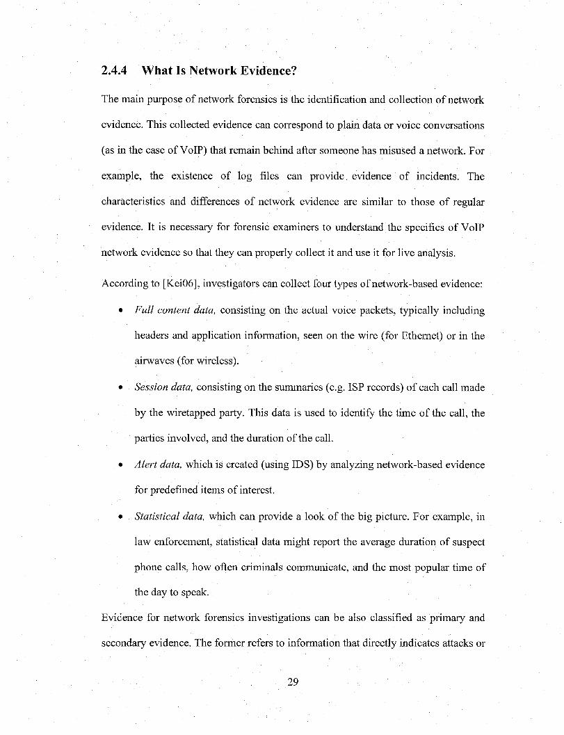
2.4.4 What Is Network Evidence?
The main purpose of network forensics is the identification and collection of network
evidence. This collected evidence can correspond to plain data or voice conversations
(as in the case of VoIP) that remain behind after someone has misused a network. For
example, the existence of log files can provide, evidence of incidents. The
characteristics and differences of network evidence are similar to those of regular
evidence. It is necessary for forensic examiners to understand the specifics of VoIP
network evidence so that they can properly collect it and use it for live analysis.
According to [Kei06], investigators can collect four types of network-based evidence:
• Full content data, consisting on the actual voice packets, typically including
headers and application information, seen on the wire (for Ethernet) or in the
airwaves (for wireless).
• Session data, consisting on the summaries (e.g. ISP records) of each call made
by the wiretapped party. This data is used to identify the time of the call, the
parties involved, and the duration of the call.
• Alert data, which is created (using IDS) by analyzing network-based evidence
for predefined items of interest.
• Statistical data, which can provide a look of the big picture. For example, in
law enforcement, statistical data might report the average duration of suspect
phone calls, how often criminals communicate, and the most popular time of
the day to speak.
Evidence for network forensics investigations can be also classified as primary and
secondary evidence. The former refers to information that directly indicates attacks or
29
Reproduced with permission of the copyright owner. Further reproduction prohibited without permission.

security policy violations. The latter refers to information that does not directly
represent attacks but could provide complementary information for investigation. In
general, primary evidence is the starting point of forensic investigation and provides
the basis for searches for secondary evidence [Wan05], In cases in which primary
sources of forensic data don’t contain enough evidence, investigators need to look for
secondary sources in order to determine additional alleged events and to corroborate
the primary sources of evidence. In our current forensic model, we use network IDS
alerts and NFATs as the primary sources of evidence. The most obvious and common
secondary sources of data are terminal devices (including wireless devices), servers,
and network storage devices. In a converged environment the infrastructure and its
connective elements are also considered secondary sources of evidence in case of
attack.
In order to properly investigate an attack and possibly take action against the
perpetrator, investigators require evidence providing proof of the identity and actions
of an attacker. The first activity in the process of evidence collection is identifying
hardware, software, and data that investigators can use. This process will be described
in the next chapter as a pattern.
2.5 Summary
In this chapter we provided an overview of the VoIP technology and presented
various ways in which VoIP system designers can more effectively streamline the use
of IP telephony. We also presented a brief overview of network forensics and a
30
Reproduced with permission of the copyright owner. Further reproduction prohibited without permission.

sample network forensic investigation methodology. The forensic process highlighted
that data collection, examination, and analysis within a typical forensic investigation.
In conclusion, this chapter provided a comprehensive list of the most important
network forensic tools and techniques now available. The opinion conveyed is that
network forensics is still at an early stage of development. However, the use of this
science together with the appropriate network forensic tools is one of the best ways to
protect VoIP networks against criminals. With the information provided on network
forensic tools and techniques, the reader is now able to understand the following two
chapters, which will provide a more detailed analysis of the network forensic issues
mentioned before as well as the proposed abstract solutions for them.
31
Reproduced with permission of the copyright owner. Further reproduction prohibited without permission.

Chapter 3
VoIP Architectures
3.1 Introduction
VoIP uses the Real-Time Protocol (RTP) for transport, the Real-Time Transport
Protocol (RTCP) for Quality of Service (QoS) and H.323, SIP, MGCP (Media
Gateway Control Protocol/Megaco) for signaling. These protocols operate in the
application layer; that is, on top of the IP protocol. Most current VoIP
implementations use the H.323 protocol, the same protocol used for IP video. Until
now, users prefer H.323 over SIP, but this may be primarily due to the earlier release
of H.323 (in the 9Q’s) [WeiOl], This situation may change in the near future.
In this chapter, we present here UML models for some aspects of VoIP infrastructure.
We will develop an architectural pattern based methodology where patterns are used
for high-level specification of the VoIP system. These patterns can also be used to
guide the design of VoIP systems and products as well as to simulate these systems.
32
Reproduced with permission of the copyright owner. Further reproduction prohibited without permission.
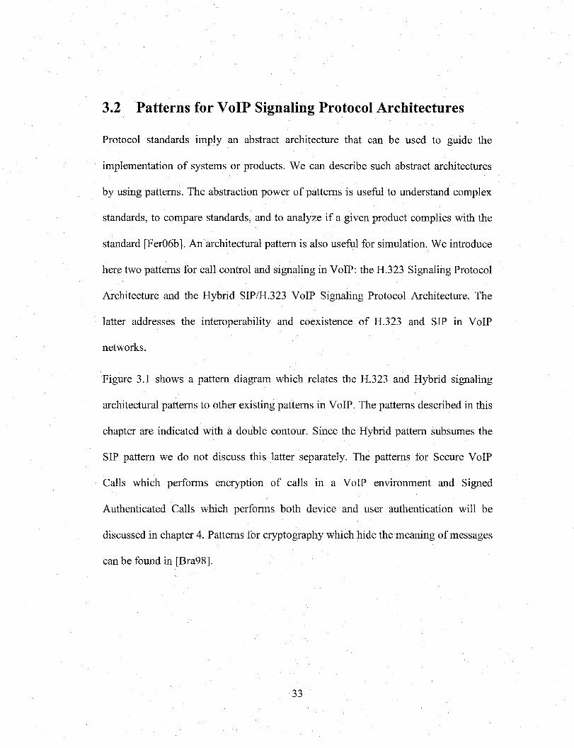
3.2 Patterns for VoIP Signaling Protocol Architectures
Protocol standards imply an abstract architecture that can be used to guide the
implementation of systems or products. We can describe such abstract architectures
by using patterns. The abstraction power of patterns is useful to understand complex
standards, to compare standards, and to analyze if a given product complies with the
standard [Fer06b], An architectural pattern is also useful for simulation. We introduce
here two patterns for call control and signaling in VoIP: the H.323 Signaling Protocol
Architecture and the Hybrid SIP/H.323 VoIP Signaling Protocol Architecture. The
latter addresses the interoperability and coexistence of H.323 and SIP in VoIP
networks.
Figure 3.1 shows a pattern diagram which relates the H.323 and Hybrid signaling
architectural patterns to other existing patterns in VoIP. The patterns described in this
chapter are indicated with a double contour. Since the Hybrid pattern subsumes the
SIP pattern we do not discuss this latter separately. The patterns for Secure VoIP
Calls which performs encryption of calls in a VoIP environment and Signed
Authenticated Calls which performs both device and user authentication will be
discussed in chapter 4. Patterns for cryptography which hide the meaning of messages
can be found in [Bra98],
33
Reproduced with permission of the copyright owner. Further reproduction prohibited without permission.

H ybridS ignalingProtocol
H.323SignalingProtocol
uses
au then tica tion uses
SIPSignalingProtocol
SignedA uthen ticated
call
Secure VoIP call
uses uses
Secure C hannel Sym m etric
C ryptographyPK I
F ig u re 3.1 R elationsh ips betw een VoIP a rch itectu ral and security patterns
3.2.1 H.323 Signaling Protocol Architecture
This pattern describes an abstract generic architecture to support the H.323 VoIP
signaling protocol. This protocol is used to set up and terminate voice calls, and to
support the transport of voice, video and data packets over IP-based networks.
Context
In VoIP networks, voice and signaling are multiplexed and travel as normal data
inside LANs, WANs or the Internet. Signaling protocols are required in packet
networks for transport and control. The VoIP infrastructure is designed to initially
support simultaneous users and is capable of scaling. This pattern assumes the
availability of multiple Internet Service Provider (ISP) partners to provide edge
termination for diverse users.
34
Reproduced with permission of the copyright owner. Further reproduction prohibited without permission.

Problem
The H.323 protocol is rather complex and requires a combination of components to
perform its functions. How can we structure the components and procedures required
for delivering multimedia communication services (i.e. voice, video and data) across
packet-based networks (e.g. Internet, intranets and Local Area Networks (LANs)?
The solution to this problem is affected by the following forces:
• We need to define an abstract architecture that can be used to guide the design
of products and systems.
• There is a need to maintain a stable and reliable transmission throughout VoIP
conversations.
• Incompatible VoIP products are the result of the absence of industry standards
within this technology. Standards need precise and clear expressions but the
standards documents are textual and long descriptions that are hard to follow
[ITU06].
• Interoperability with other multimedia service networks and terminals is vital
in VoIP. Terminal devices in disparate networks (e.g. softphone
communicating with an analog phone) communicate frequently.
• In order to transport real-time data over VoIP, call signaling is needed to set
up the connections between terminal devices.
35
Reproduced with permission of the copyright owner. Further reproduction prohibited without permission.

Solution
Define an abstract architecture using terminals (to make/receive calls), gateways (to
connect different networks), gatekeepers (for control and setup) and multi-point
control units (MCU) (for conferencing).
H.323-based networks have the ability to manage available resources for call routing
via H.323 gatekeepers. Gatekeepers are used for address resolution, terminal devices
admission control (based on bandwidth availability, concurrent call limitations, or
registration privileges), bandwidth management, and zone management (the routing
of calls originating or terminating in the gatekeeper zone, including multiple path
reroute). Gateways coordinate calls by communicating with gatekeepers using the
Registration, Admission, and Status (RAS) protocol [Cis02]. Gatekeepers are the
central part of an H.323 network.
Structure
Figure 3.2 shows the UML class diagram of the H.323 architecture. The components
inside the dotted lines indicate the specific units of the standard while the external
units are the network components that participate in the whole system. The Layer 2
Switch provides connectivity between H.323 components and the rest of the system.
The Gateway takes a voice call from a circuit-switched Public Switched Telephone
Network (PSTN) and places it on the IP network. The PSTN uses PBX switches and
Analog Phones. The Internet (IP network) contains Routers that connect to each
other and Firewalls to filter traffic to the Terminal Devices (i.e. where users interact
36
Reproduced with permission of the copyright owner. Further reproduction prohibited without permission.

with the system). The gateway also queries the Gatekeeper via the Internet with
caller/callee numbers and the gatekeeper translates them into routing numbers based
upon service logic. Gatekeepers act like central managers providing call setup and
routing the calls throughout the network to other voice devices. The MCU
(Multipoint Control Unit) is used for conferencing. Softphones are applications
installed in Terminal Devices (e.g. PCs or wireless devices) used to send/receive
calls.
! H.323 ‘
filters
PSTN-to-PSTN
IP-to-IP
AnalogPhone
PSTN
Layer 2 Switch
Firewall
MCU
Router
PBX
Gateway
Internet
TerminalDevice
G atekeeper
Figure 3 .2 Class Diagram for an H.323 architecture
Dynamics
The sequence diagram in Figure 3.3 shows the necessary steps for call connection
between terminal devices in H.323. When Terminal devices (i.e. Caller and Callee)
37
Reproduced with permission of the copyright owner. Further reproduction prohibited without permission.

are communicating with each other in disparate networks, more than one gatekeeper
may be necessary, as shown in the figure.
« a c to r »aCaller: S:Gatekeeoer1 !:IGatekeeDer2 « a c to r »
aCallee:
S .dial(Callee.setupO ) vi .
1. connect (Callee. setup! W
1
)
0
^ Caller.callproceedO
Callee.setupO v
S,coimect(Caller.callprocccd() I.connecHCaller.callproccalt
^ Caller.alertingQ ^.connect(C aller.alerting( 1̂ connect (Caller, alerting! ]
^ Caller.connect() S ,connect(C aller.connect( Lconncct(Caller.connect(
jrotifv(C allH stablished)
_
Figure 3.3 Sequence diagram for call connection in H.323
Implementation
Most existing VoIP implementations use the H.323 protocol, and the same protocol is
used for IP video (although SIP is more popular for new systems). H.323 references
many other of the ITU telecommunication standardization sector (ITU-T) [ITU06]
protocols such as:
• H.225.0 protocol is used to describe call signaling, the media (audio and
video), the stream packetization, media stream synchronization and control
message formats.
38
Reproduced with permission of the copyright owner. Further reproduction prohibited without permission.

• H.245 control protocol for multimedia communication, describes the
messages and procedures used for opening and closing logical channels for
audio, video and data, capability exchange, control and indications.
• H.450 describes the Supplementary Services
• H.235 describes security in H.323
• H.239 describes dual stream use in videoconferencing, usually one for live
video, the other for presentation
• H.460.17-19 describes firewall traversal in H.323
• H.261 H.263 H.264 describes video encoding
Consequences
This pattern has the following advantages:
• It is possible to establish a phone conversation between different domains and to
. use all type of telephony devices throughout IP networks.
• It contains components that can maintain a stable and reliable transmission
between two or more VoIP users.
• The reference architecture lets vendors produce compatible products.
• The components in the H.323 architecture enable network interoperability (e.g.
packet switch-to-circuit switch).
This pattern has the following disadvantages:
39
Reproduced with permission of the copyright owner. Further reproduction prohibited without permission.

• H.323 is a rather complex protocol and even its abstract architecture is rather
complex.
• H.323 defines several associated protocols and many services require interactions
between those sub-protocols, which increases complexity and decreases
scalability [Dal99].
• Security features are more easily implemented in SIP when compared to H.323
because of the SIP client-server operation mode.
• H.323 protocols frequently use ASN.l encoding roles. The H.323 ASN.l parser
showed vulnerable to implementation level attacks [OUS04],
Known uses
Cisco [Cis02], and others.
Related patterns
This pattern is related to the Hybrid VoIP Signaling Protocol Pattern described next and
to the security patterns indicated in Figure 3.1. The model of Figure 3.2 is based on an
early model in [Pel04], An E/R model for H.323 is given in [OUS04].
3.2.2 Hybrid VoIP Signaling Protocol Architecture
The Hybrid Protocol Architecture pattern describes an abstract architecture to
combine the H.323 and SIP architectures using a shared infrastructure of interworking
40
Reproduced with permission of the copyright owner. Further reproduction prohibited without permission.

functions between both protocols. This architecture allows coexistence and
transparent translation of signaling between both architectures.
Context
In VoIP networks, voice and signaling are multiplexed and travel as normal data
inside LANs, WANs or the Internet. Signaling protocols are required in packet
networks for transport and control. The VoIP infrastructure is designed to initially
support simultaneous users and is capable of scaling. This pattern assumes the
availability of multiple Internet Service Provider (ISP) partners to provide edge
termination for diverse users.
Problem
Some environments have a large variety of users and require the use of multiple
signaling protocols. How do we design an architecture that provides support for both
SIP and H.323 calls, is capable of scaling, and can be made secure?
The solution to this problem is affected by the following forces:
• VoIP must be able to accommodate multiple existing and potential signaling
protocols.
• Provision must be made for the necessary security mechanisms in order to protect
the VoIP network and its users. As VoIP operates on a converged network, voice
and video packets are subject to the same threats than those associated with data
networks [Pel04], In contrast to PSTN, signaling in VoIP is sent through the
41
Reproduced with permission of the copyright owner. Further reproduction prohibited without permission.

public Internet. This leads to easy access to the voice packets (i.e. call
interception) by attackers and its consequent security problems [Wie06],
• Because the interworking function combines both SIP and H.323 functionality,
security considerations for both of these protocols apply [Sch04],
• Because all data elements in SIP or H.323 have to terminate at the interworking
function, the resulting security cannot be expected to be end-to-end. Thus, the
interworking function terminates not only the signaling protocols but also the
security in each domain [Sch04],
• VoIP networks must be based on industry standards so as to provide functionality
between disparate networks and product compatibility.
• Interoperability and coexistence between SIP and H.323 is essential in order to
support new deployments that might use SIP as a substitute VoIP signaling
protocol.
• In deployments where both protocols are used, it is important that there are no
performance limitations related to the call mix between SIP and H.323 calls, and
that there is no significant deviation in calls-per-second measurements compared
to a homogeneous SIP or H.323 network [Cis02],
Solution
The key component of this architecture is defined as the interworking function (IWF)
which provides this SIP-H.323 translation. The main functionality of this
interworking function includes user registration, address translation, establishment of
call connect, and service provision. This functionality can be implemented as part of a
42
Reproduced with permission of the copyright owner. Further reproduction prohibited without permission.

VoIP network server such as an H.323 Gatekeeper, a SIP Proxy, or a Softswitch,
which might include a gatekeeper and SIP Proxy. Or, the functionality can be
implemented via an external SIP-H.323 signaling gateway [RadOl].
Structure
The class diagram in Figure 3.4 shows a hybrid configuration where a SIP architecture
(within dotted lines) is combined with an H.323 network. The gateway in the H.323
side takes the voice call from the PSTN network and routes it to the called party. In a
similar way, the SIP protocol uses redirect or proxy servers for call routing. The proxy
server provides security mechanisms for terminal devices such as access control,
authentication and authorization. A hybrid signaling setting may involve two types of
Endpoints: H.323 Terminal devices and SIP User Agents. User Agents (UAs), are
combinations of User Agent Clients (UAC) and User Agent Servers (UAS). The UA is
the phone in the SIP side and the Register server receives registrations and requests
updates of the Location server, which keeps track of the UAs. A UAC is responsible
for initiating a call by sending a URL-addressed INVITE to the intended recipient. A
UAS receives requests and sends back responses. The Proxy server is connected to a
VoIP gateway (to make possible a call from a regular telephone to an IP phone) and to
other proxy servers. The registrar and location server may be integrated in the proxy
server. Once the call has been established, the RTP media packets flow between
endpoints.
43
Reproduced with permission of the copyright owner. Further reproduction prohibited without permission.

i InternetSIP Layer 2 switch
signalingS IP server
Routeri
Proxyserver
IP-to-IP
Firewall
tfilter
i
Locationserver
Redirect Register UserAgent
Terminal Device
i. IWF
DirectoryGatekeeper
PSTN-to-PSTN
PBX
Gatekeeper
AnalogPhone
PSTN
Figure 3.4 Hybrid VoIP Signaling Protocol Architecture
Dynamics
The sequence diagram in Figure 3.5 shows the necessary steps for calling from a SIP
phone to an H.323 terminal device using call signaling between a SIP Proxy Server
and a H.323 gatekeeper. As mentioned earlier, these servers provide registration and
address resolution services. For all phases of the voice call, the interworking function
component provides signaling translation.
44
Reproduced with permission of the copyright owner. Further reproduction prohibited without permission.

P.dial(SIPinviteO)
K.RASQ
P.RASQ
setupQ
nngingQ
OKQ.OKQ.
RTP/RTCP
K:Gatekeeper« a c to r »S1P-UA:
P:ProxvServer G:IWFH.323-EP:
F ig u re 3.5 Sequence diagram for call connection in Hybrid configurations
Implementation
The implementation of VoIP services (e.g. Call waiting) must be uniform, consistent,
and must effectively work with other signaling protocols. Existing H.323-based
systems must update their existing signaling gateways in order to support additional
SIP-based services.
The capability for H.323 gatekeepers and SIP proxies to interwork in VoIP sharing
routing capabilities is crucial. While the SIP Proxy Server could supply routing
information to SIP gateways, this scheme allows a packet voice carrier to not only use
its existing routing structure on its H.323 gatekeepers, but to also take advantage of
the H.323 Resource Availability Indicator (RAI) functionality for a more efficient
network. The SIP Proxy Server actually acts like another gatekeeper to the H.323
network [Cis02]. Likewise, the SIP proxy server provides registration, address
resolution, and a session initiation services. It is important to note that this type of
45
Reproduced with permission of the copyright owner. Further reproduction prohibited without permission.

message exchange between SIP and H.323-based components is only for signaling
purposes. VoIP uses another standard the Real-Time Protocol (RTP) for transport of
media packets between terminal devices.
Additionally to what is shown in Figure 3.5, the interworking function may provide
and update the H.323 gatekeeper with the addresses of SIP UAs. Similarly, the
interworking function can provide information about H.323 endpoints to a SIP
registrar. This allows the SIP proxy using this SIP registrar to direct calls to the
H.323 endpoints via the interworking function [Sch04] and vice versa. Provisions for
communication between the SIP Proxy Server and H.323 gatekeepers, along with
other features that allow SIP and H.323 to coexist on a common network, allow users
the ability to build out hybrid networks that include both SIP and H.323 traffic.
Interworking can be achieved via multi-protocol endpoints (such as IP Phones that
support both SIP and H.323) or via network bridging entities (such as Softswitches or
Signaling Gateways) [RadOl]. When signaling messages are sent from an H.323
gatekeeper, the interworking function translates them into the corresponding SIP
messages and routes them to the equivalent SIP component. By providing translation
of signaling messages from SIP to H.323 and vice versa, the hybrid connects calls
between VoIP devices using disparate signaling protocols. In this setting, address
resolution and registration functions for both H.323 and SIP protocols, are supported
by the interworking component.
An interworking function contains functions [Sch04] from the following list, inter
alia:
Mapping of the call setup and teardown sequences;
46
Reproduced with permission of the copyright owner. Further reproduction prohibited without permission.

Registering H.323 and SIP endpoints with SIP registrars and H.323
gatekeepers;
Resolving H.323 and SIP addresses;
Maintaining the H.323 and SIP state machines;
Negotiating terminal capabilities;
Opening and closing media channels;
Mapping media-coding algorithms for H.323 and SIP networks;
Reserving and releasing call-related resources;
• Processing of mid-call signaling messages;
Handling of services and features.
In order to transfer of voice traffic over a packet switched network, some vendor offer
a hybrid or IP enabled design using an existing telephone switch (TDM type), while
others are based on a pure IP or IP centric architecture and only trunk into the local
telephone switch. There are two basic architecture types: IP-enabled and IP-centric
[Gha02], The two are differentiated by:
Where the PSTN to IP conversion takes place
Where supporting call center functions, such as queuing, queue slots,
prompting, music-on-hold, and announcements, take place.
47
Reproduced with permission of the copyright owner. Further reproduction prohibited without permission.
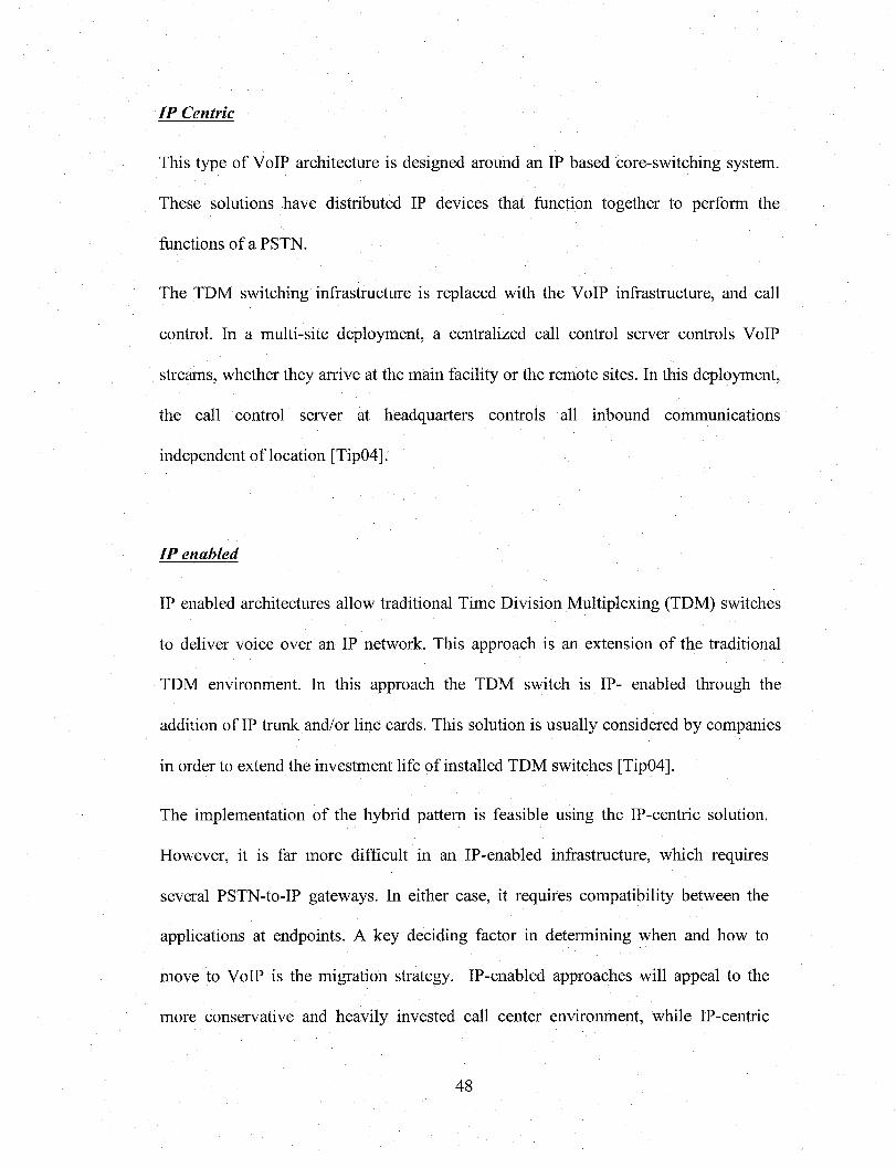
IP Centric
This type of VoIP architecture is designed around an IP based core-switching system.
These solutions have distributed IP devices that function together to perform the
functions of a PSTN.
The TDM switching infrastructure is replaced with the VoIP infrastructure, and call
control. In a multi-site deployment, a centralized call control server controls VoIP
streams, whether they arrive at the main facility or the remote sites. In this deployment,
the call control server at headquarters controls all inbound communications
independent of location [Tip04],
IP enabled
IP enabled architectures allow traditional Time Division Multiplexing (TDM) switches
to deliver voice over an IP network. This approach is an extension of the traditional
TDM environment. In this approach the TDM switch is IP- enabled through the
addition of IP trunk and/or line cards. This solution is usually considered by companies
in order to extend the investment life of installed TDM switches [Tip04],
The implementation of the hybrid pattern is feasible using the IP-centric solution.
However, it is far more difficult in an IP-enabled infrastructure, which requires
several PSTN-to-IP gateways. In either case, it requires compatibility between the
applications at endpoints. A key deciding factor in determining when and how to
move to VoIP is the migration strategy. IP-enabled approaches will appeal to the
more conservative and heavily invested call center environment, while IP-centric
48
Reproduced with permission of the copyright owner. Further reproduction prohibited without permission.
methods will be the choice of smaller, newer, and more aggressive centers who can
bear some reliability risk to move faster to a more advanced platform [Gha02],
Consequences
The advantages of this pattern include:
• The hybrid pattern provides call connection between VoIP devices using
disparate signaling protocols.
• The hybrid architectural pattern provides protocol flexibility for users to
incorporate SIP networks on established converged infrastructures, while
keeping H.323 functionality within their networks and interoperability with
traditional PSTN networks.
• By using this pattern H.323-based carriers are able to incorporate new VoIP
services to the existing infrastructure by allowing the SIP Server to register
and acquire the address resolution with the H.323 gatekeeper using the RAS
protocol.
• It is possible for a SIP Proxy Server to obtain updated routing information
from VoIP gateways deployed in the hybrid network by enabling the server to
communicate with an H.323 gatekeeper using the RAS protocol.
• This solution provides origination and termination of VoIP calls and more
flexible billing and usage options for several other service providers.
• This solution support additional SIP-based services for H.323-based users that
want to use their existing signaling gateway infrastructure.
49
Reproduced with permission of the copyright owner. Further reproduction prohibited without permission.

• This optimized routing structure provides shorter post-dial delay and more
efficient usage of gateway resources.
Possible disadvantages include:
• The combined architecture is complex.
• The deployment of hybrid protocol networks may be affected by QoS and
bandwidth issues.
Known Uses
Vendor solutions that fall into the IP-enabled category include Aspect, Avaya, Nortel,
and other switch providers. Cisco uses IP-centric solutions.
Related Patterns
The Hybrid VoIP Signaling Protocol pattern includes as a subpattem the H.323 pattern
which was previously introduced. The model of Figure 3.4 is based on an early model
in [Pel04]. The pattern is also related to the concept of Attack patterns [Fer07a] and to
the following security patterns [Fer07b]:
• The Secure VoIP Call pattern.
• The Authenticated Call and other similar authentication patterns used to
establish trust relationships between the VPN endpoints.
• The VoIP Tunneling pattern.
50
Reproduced with permission of the copyright owner. Further reproduction prohibited without permission.

• The Network Segmentation pattern.
3.3 VoIP Wireless Architectures
There exist many different forms of implementing VoIP in wireless communications
and networking. Some popular forms of wireless VoIP include:
3.3.1 VoIP in WLANs
VoIPoW using the 802.11 standard for wireless local area networks (WLANs) is an
important technology used for converged voice and data on mobile computers.
Most VoIP programs will automatically connect via an accessible internet connection,
and are linked with a particular handset or user account. This would provide an
802.11 equivalent of two-way radio or video broadcasting within a mesh network
without the need for reliance on permanent infrastructure, such as is required for
mobile phone usage. Another advantage of wireless communications via 802.11
wireless networks is that, being packet-based, they can be afforded cryptographic
protection available to all wireless networks. This is a great advantage over Citizen’s
Band (CB) or other analogue communications, which are unable to offer protection
from eavesdropping [Sla06],
Using the installed 802.11 wireless infrastructure for both voice and data is an ideal
approach to solving most communication requirements for mobile users; but this also
increases many existing VoIP security concerns.
51
Reproduced with permission of the copyright owner. Further reproduction prohibited without permission.

Figure 3.6 shows a class diagram for a VoIPoW application using the WLAN
approach. Packet networks are used to transmit the compressed voice packets. The
fixed IP terminals (i.e. hardphones and softphones) exchange voice samples with
wireless IP terminals using the RTP protocol.
transrrit packetsPSTN
W irdess Access Poin t
AnalogPhone
Router P B X
W irelessDevice
TP-PBX
Figure 3.6 C lass d iagram for a V oIP oW application u sing W L A N s.
3.3.2 VoIP in Cellular Networks
In the Global System for Mobile communication (GSM) approach, packet networks
are used to transmit the compressed voice packets offering bandwidth savings. The
base station controller (BSC) or base transceiver station (BTS) provides wireless
access to the IP network. Connectivity between the Base Stations (BTSs), Base
52
Reproduced with permission of the copyright owner. Further reproduction prohibited without permission.

Station Controllers (BSCs), and the Mobile Switching Center (MSC) is also achieved
using IP networks. The fixed IP terminals (i.e. IP phones/ Softphones) exchange
voice samples with cellular IP terminals using RTP. GSM provides mobility to users
allowing them to use either GSM devices or H.323 terminals (IP phones or PCs) to
access telecommunication services, using VoIP. Thus, a user can move from a GSM
network into an IP network and can use his/her H.323 terminal to receive calls and
other VoIP services. The hardware for a VoIP system is less expensive that of a GSM
or cellular service.
At the present time, some wireless communication companies are offering “dual
mode” wireless phone solutions for enabling seamless roaming between wide-area
cellular networks and Wi-Fi networks (e.g. DSL). These mobile devices are capable
of automatically detecting Wi-Fi access points in order to connect to the IP network.
Figure 3.7 shows a class diagram (adapted from a figure in [Pel04]) for the GSM
approach where packet networks are used to transmit the compressed voice packets
offering a save of bandwidth. Connectivity between the Base Stations (BTSs), Base
Station Controllers (BSCs), and the Mobile Switching Center (MSC) is achieved
using IP networks. The fixed IP terminals (i.e. IPP/PCIPP) exchange voice samples
with cellular IP terminals using RTP.
The main functions in a cellular network that enable mobility are the home location
register (HLR) and the visitor location register (VLR). Through an overlay of these
functions on the landline network, in the form of a third-generation partnership
project (3GPP)-compliant IMS network environment, operators are able to offer subs-
53
Reproduced with permission of the copyright owner. Further reproduction prohibited without permission.
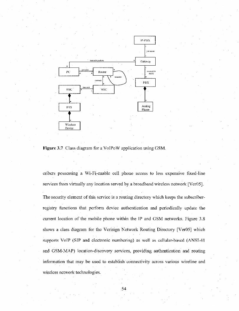
transmit packets
MSC
AnalogPhone
Router
Gateway
PC
PBX
BTS
WirelessDevice
IP-PBX
BSC
Figure 3.7 Class diagram for a VoIPoW application using GSM.
cribers possessing a Wi-Fi-enable cell phone access to less expensive fixed-line
services from virtually any location served by a broadband wireless network [Ver05].
The security element of this service is a routing directory which keeps the subscriber-
registry functions that perform device authentication and periodically update the
current location of the mobile phone within the IP and GSM networks. Figure 3.8
shows a class diagram for the Verisign Network Routing Directory [Ver05] which
supports VoIP (SIP and electronic numbering) as well as cellular-based (ANSI-41
and GSM-MAP) location-discovery services, providing authentication and routing
information that may be used to establish connectivity across various wireline and
wireless network technologies.
54
Reproduced with permission of the copyright owner. Further reproduction prohibited without permission.

PSTN-to-PSTN
IP-to-IPPSTN
Media Server Router
InterconnectServices
Session Control
GSM
ApplicationServer
PBX
GatewayControllerDatabase
F ig u re 3 .8 C lass D iagram for the V erisign N etw ork R outing D irecto iy
3.3.3 VoIP in GPRS
A challenging task is allowing VoIP applications over packet switched mobile
networks such as GPRS. GPRS (general packet radio service) is a new non-voice
service that is being added to existing IS-136 TDMA (time division multiple access)
networks in the United States and GSM (Global System for Mobile Communications)
networks in the United States and Europe. It provides for the transmission of IP
packets over existing cellular networks, bringing the Internet to the mobile phone
[SchOO]. Anything the Internet offers, from Web browsing to chat and e-mail, is
available from GSM and TDMA service providers via GPRS-enabled devices.
55
Reproduced with permission of the copyright owner. Further reproduction prohibited without permission.

3.3.4 VoIP in UMTS
Third Generation (3G) partnership projects (3GPP) allow universal roaming
characteristics and hence 3G mobile systems are referred as Universal Mobile
Telecommunication Systems (UMTS).
Usage of VoIP, which results in end-to-end IP sessions with higher bandwidths as in
UMTS, opens a whole new set of multimedia services for mobile end users.
Delivering these services is one of the main drivers for UMTS. Also using the same
IP technology in both fixed and mobile networks facilitate interworking between
them and the development of new services is provided in a consistent way. One big
challenge ahead for real-time VoIP service is provisioning of enough QoS especially
in this context of mobile networking, controlling the delays introduced by handover,
manage scarce radio resources and also perform admission control.
3GPP has decided to use SIP as call control protocol between terminals and mobile
network [BosOl]. Dedicated server in the network will provide interworking with
other H.323 terminals.
UMTS uses GPRS for data traffic and for voice it uses GPRS Tunneling Protocol
(GTP) on top of IP for packed switched mobile terminals. The mobility problems are
solved by GPRS protocols.
3.3.5 Mobile Internet Telephony
A Mobile Internet Telephony (MVoIP) system that integrates VoIP and mobile
computing can be established using handsets with multiple adapters that will have
different coverage range of communication area and should be used in
56
Reproduced with permission of the copyright owner. Further reproduction prohibited without permission.
complementary [CheOO], The system integrates Internet, Cellular Network (which
will broad coverage area but small bandwidth), Wireless Local Network (which will
have high bandwidth but small coverage) and PSTN. Hence the handsets should have
Ethernet, wireless local area network and cellular phone network adapters.
3.3.6 VoIP in Satellite Networks
Satellite systems are part of communications infrastructure and have global coverage
to be able to reach remote areas. Satellite networks have an increasing portion of
their capacities used to carry data packets and are well positioned to enable growth of
VoIP services. New satellite systems provide high-speed internet access to business,
home and military users; these systems offer VoIP service also. COMSAT, a global
satellite communications provider, has a VoIP test bed using commercial VoIP
solution [NguOl]. Satellite links also provide a reliable medium for VoIP transport
and satellite propagation delay does not affect normal operation of VoIP gatekeepers
and gateways.
3.4 VoIP in a Tactical Internet
The war theatre has changed in these modem times, the US Army today needs for
smaller, individual units to combat terrorist cells in an urban environment. In this new
environment new types of strategies and tools are also required: a need for rapid
decision making, clear understanding of tactical assets and their locations, and
reliable, secure, near-real time communications.
57
Reproduced with permission of the copyright owner. Further reproduction prohibited without permission.

The US Army is converging on a standard IP backbone in all of the tactical systems,
whether they are sensor, intelligence, surveillance and reconnaissance, unmanned
aerial vehicle or intelligence systems. All Army systems are converging on IP
[Bou06],
Today the US Army is using VoIP on high level units (i.e. battalion, brigade and
division). According to the Army’s Research and Development Communications
center in New Jersey, it is expected that this technology will be fully implemented all
the way from combat units to division level by 2016.
In addition to combining voice, video and data onto the same network, VoIP has the
inherent benefit that it can traverse different types of radio networks. This capability
would provide an advantage in a tactical network, however routing, bandwidth, and
QoS issues may mitigate this advantage [Dur03].
VoIP includes support for these tactical radios. For example, VoIP data could be sent
over an IP network until the point it reached a Single Channel Ground and Airborne
Radio System (SINCGARS) radio net. At the SINCGARS radio, the system would
convert the VoIP packets into an analog voice stream and allow transmission of the
previous VoIP data stream over the tactical SINCGARS network [Dur03], With IP on
the backbone, all the analog systems can co-exist with most of the digital systems. In
addition, VoIP may generate certain inherent benefits over an analog or a proprietary
digital approach. The IP network offers a secure voice channel for sensitive
communications.
58
Reproduced with permission of the copyright owner. Further reproduction prohibited without permission.

3.4.1 Tactical Internet
The Tactical Internet is the glue that ties the Force XXI Battle Command Brigade and
Below (FBCB2) digital communications systems together digitally. It is formed by
the integration of tactical digital radios, combat net radios, and commercial Internet
technology. Primary components are the SINCGARS radio used in a data mode, the
Enhanced Position Location Reporting System (EPLRS), and the Near Term Digital
Radio (NTDR) [CamOO]. Figure 3.9 shows a class diagram of the Tactical Internet
where radio networks integrate with the IP network.
transmit packets
PSTN-to-PSTNT e rm in a l D e v ic e
IP-to-lP
SINCGARS NTDREPLRS
Softphone Hardphone
AnalogPhone
PSTN
Router
PBX
Gatekeeper
Internet
Gateway
RadioNetwork
Figure 3.9 Class Diagram for a simplified Tactical Internet architecture
The Tactical Internet is extended beyond the horizon with the Movement Tracking
System, or MTS. This global system utilizes a secure network of commercial
geostationary satellites to provide packet data for long range tracking and messaging
that extends over the horizon to vehicles on the move and in combat situations. The
59
Reproduced with permission of the copyright owner. Further reproduction prohibited without permission.

Movement Tracking System has two configurations, The Control Station and the V2
Mobile Unit.
The function and connectivity features of the command/control station allow it to be
operated from a fixed location or from mobile headquarters. The station can operate
independently of phone lines or Internet connection. Likewise, the V2 mobile unit
offers quick installation on a vehicle and provides text messaging and maps that
display MTS-equipped vehicles.
By providing Command and Control Centers with an accurate, continuously updated
digital picture of the battlefield, commanders can exchange critical data with their
troops in near-real time such as position and status. In Tactical Internet today, VoIP
is considered the interface between the tactical radio network and the tactical access
hub [She04],
In the Tactical Internet, for example, VoIP is provided through software running on a
laptop computer communicating with the TOC (Tactical Operations Center) Media
Control Server Unit (MCSU).
The MTS provides near real-time communications through harsh environmental
conditions like dust storms, blizzards, and blistering heat. For this reason, it has
become the backbone for the dissemination of battlefield situational awareness to US
and coalition war fighters in both Operation Iraqi Freedom, and Operation Enduring
Freedom. During these operations, the Blue Force Tracker (BFT) and comparable
systems that provided position location information and basic text capabilities were
extremely valuable during the conduct of a rapidly based war.
60
Reproduced with permission of the copyright owner. Further reproduction prohibited without permission.

The inclusion of VoIPoW in a tactical Internet environment is important because of
the interest in wireless configurations within the tactical and command post
communities to enable mobile combat units to roam around the command post. The
goal is to improve the ability of the soldier to perform his/her mission in the battle-
space.
On the battlefield, VoIPoW may provide benefits to mobile combat units. The most
significant benefit is that VoIP allows the voice and data packets to travel over the
same network. The result is that all traffic such as voice, data and video, are passed
over the IP based network. However, the possible savings from the cost of long
distance is not obvious in a Tactical Internet environment. This is because long
distance or over the horizon typical satellite communication connectivity is already
provided at the Department of Defense expense. In the Tactical Internet today, VoIP
is considered the interface between the tactical radio network and the tactical access
hub [She04],
3.4.2 Joint Network Node - Network
Today the U.S Army is using VoIP as a tactical battlefield communications system
with Joint Network Node (JNN) terminal. The JNN architecture is an off-the-shelf
solution for voice, data and video teleconferencing (VTC) over IP.
This IP-centric architecture has been deployed to support units from division down to
battalion level. VoIP phones in the JNN terminals enable commanders to make calls
on the Defense Department’s Secret IP Router Network (SIPRNET) and the Non-
61
Reproduced with permission of the copyright owner. Further reproduction prohibited without permission.

secure IP Router Network (NIPRNET). A typical node also gives battalion
commanders broadband data access to the Defense Information Systems Network.
The Joint Network Node uses satellite links for beyond line-of-sight communications
[Bre06],
The JNN architecture is composed of three primary systems that support user
requirements and provide intra-JNN network connectivity and inter-theater
connectivity. A Unit Hub Node (UHN) provides satellite connection management for
all elements of a unit’s network and acts as a base-band or tactical technical node
facility; a Ku/Ka Satellite Communications Time Division Multiple Access (TDMA)
network for intra-JNN connectivity; and a Frequency Division Multiple Access
(FDMA) satellite network for long range BLOS connectivity to the U.S. Department
of Defense Information Systems Network (DISN) Global Information Grid (GIG)
architecture [Edw05], By using this architecture, VoIP phones are connected to
commercial routers, and then supported by Ku/KA satellite technology.
Figure 3.10 shows the components for a JNN architecture. Network connectivity is
provided through a 2.4 meter Ku/Ka satellite terminal that supports both TDMA and
FDMA transmissions. The JNN is deployed with an AN/TRC-190 (V3) High-
Capacity Line-of-Sight (HCLOS) terrestrial radio system to provide redundant
connectivity between JNNs. Parallel to its connectivity to the UHN, the JNN can
establish direct connectivity to GIG and/or DISN Strategic Tactical Entry Point
and/or another tactical network through current military satellite systems such as the
AN/TSC-85 or 93, Secure Mobile Anti-jam Reliable Tactical-Terminal (SMART-T)
or Phoenix terminal and terrestrial radio systems [Edw05].
62
Reproduced with permission of the copyright owner. Further reproduction prohibited without permission.

filter
C onnected to o ther nodes
SM ART-T TSC 85/93
Firewall
LOS TRC-190
Figure 3.2
D1SN U H N
JN NKu/Ka
Satellite
Tactical Hub
O ther M ilitary Satellite Systems
Figure 3.10 Class Diagram for a Joint Network Node architecture
The VoIP system is connected to the Tactical Internet thru a VoIP gateway (to make
possible a call from a radio or a regular telephone to an IP phone). In order to support
brigade and battalion units the JNN also includes commercial routers and switches.
The rest of the tactical architecture is similar to Figure 3.2 and represented by a UML
package.
The UHN base-band unit performs two key functions: intra-JNN network routing and
GIG/ DISN connectivity. At the Brigade level, the JNN node provides an operational
Command Post (CP) with services such as Nonclassified/Secret Internet Protocol
Router (NIPR/SIPR), VTC and tactical and strategic voice. At the Battalion level,
network services are limited to SIPR and secure voice-over IP.
Today, 80 percent of the Army and many of the National Guard and Reserve units
have been converted or are converting. To date, seven US Army Divisions, nine US
Army National Guard and one US Army Stryker Brigade have been funded to field
63
Reproduced with permission of the copyright owner. Further reproduction prohibited without permission.
and deploy with JNN-N [W0 0 O6 ]. For example, in Iraq and Afghanistan the 10th
Mountain Division, 4th Infantry Division and 101st Airborne have all IP-based C2
systems.
The JNN Network (JNN-N) also includes a Coalition Wide Area Network, Defense
Red Switch network access, e-mail Defense Message System, Special Circuit
requirements and a Battlefield Video-Teleconferencing capability. JNN also provides
connectivity to the global information grid as well as to all the Army Battle
Command Systems [W0 0 O6 ].
In today’s Tactical Internet, the JNN is still a work in progress. The US Army is
currently using VoIP on high level units however (according to the Army’s Research
and Development Communications center in New Jersey), is expected that this
technology will be fully implemented all the way from combat units to division level
by 2016.
3.5 Summary
We have presented two patterns that describe the architectures implied by the two
main VoIP protocols. The H.323 Signaling Protocol Architecture pattern offers a way
to complement and support the transport of data, voice and video packets in VoIP
systems. The Hybrid Signaling Protocol pattern allows architectural and protocol
flexibility by supporting both H.323 and SIP. These patterns complement our work in
VoIP security patterns [Fer07b] and provide a model of the environment where
specific VoIP security patterns can be implemented, thus adding security to the
64
Reproduced with permission of the copyright owner. Further reproduction prohibited without permission.

structure. Patterns describing generic architectures can guide systems development,
be used to evaluate existing designs, be a basis for simulation, and be a pedagogical
tool. We have also discussed existing wireless VoIP implementations and provided
UML models for their architecture. In particular, VoIP in a Tactical Internet is an
important wireless application that is still considered a work in progress.
65
Reproduced with permission of the copyright owner. Further reproduction prohibited without permission.

Chap ter 4
Attack and Security patterns for VoIP Networks
4.1 Introduction
In the previous chapter, we have discussed existing VoIP architectures. In VoIP the
convergence of voice and data in the same network brings both benefits and
constraints to users. Among the several issues that need to be addressed when
deploying this technology, security is one of the most critical. In this Chapter, we
considered possible security attacks and relate them to the ways the system is used.
This is a convenient and systematic way of finding most attacks. We also present
some security patterns that describe mechanisms that can control many of the possible
attacks and which could be used to design secure systems. Patterns have shown their
value in developing good quality software and we expect that their application to
VoIP will also prove valuable to build secure systems. We present here four security
patterns, including Network Segmentation, VoIP Tunneling, Signed Authenticated
Call, and Secure VoIP Call. Current VoIP products are still weak and there is a need
to improve their security [Wie06],
66
Reproduced with permission of the copyright owner. Further reproduction prohibited without permission.

4.2 Roles in a basic VoIP Model
A VoIP infrastructure is basically composed of network devices and human
components. From the security point of view, the roles and rights of the latter will be
studied in this section with the aid of Use Cases.
Because VoIP networks are vulnerable to attacks from external domains and internal
sources, the human component of this system can be classified as follows:
4.2.1 Internal Roles
• Internal subscriber is a VoIP user, such as an employee. Internal subscribers
are allowed to make and receive voice calls by either using standard or IP
phones (hardphones and softphones). They also have access to data services
by using terminal devices (e.g. PCs).
• Administrator. This role is responsible for maintaining the VoIP network
perimeter and auditing the VoIP system in order to monitor user activities.
The network security administrator is also responsible of properly configuring
security mechanisms and reacting in the presence of attacks.
• Auditor. This role is responsible for performing audit logs to verify the
integrity of the VoIP system. Auditing is especially useful for identifying
potential security breaches or break-in attempts.
67
Reproduced with permission of the copyright owner. Further reproduction prohibited without permission.

• Operator is responsible of protecting the system from being compromised, so
that each voice call can be accounted to the appropriate user. [s]he is also
responsible for booting and shutting down the system, performing routine
maintenance of servers, performing system performance metering and on-line
tests, and in general responding to various relevant user requests.
4.2.2 External Roles
• Remote subscribers are users such as employees who occasionally work
from home. They are given access to voice and services only from their
homes.
• Forensic Examiner refers to an investigator who has access (if legally
authorized) to corporate servers in order to inspect data and voice packets.
Forensic investigators need to have a wide range of technical skills including
those necessary for collecting evidence from VoIP networks and components.
They also need a sound understanding of the legal procedures and
requirements related to their investigations. A forensic investigator will be
actively involved in using the VoIP forensic model which will be introduced
later in this dissertation.
Figure 4.1 shows a Use Case diagram for a simplified VoIP system with typical use
cases and internal and external roles. For example, the subscriber role can be
classified as internal or remote, and also according to the type of device used. In
68
Reproduced with permission of the copyright owner. Further reproduction prohibited without permission.

addition to these roles, the use case diagram can be used to systematically analyze the
different types of attacks against the VoIP network, following the approach in
[Fer06],
SubscriberRegister/unregister
subscriber
Setup network configuration
AdministratorH ardphone)
Remote Internal Make VoIP call
Softphone)_
Run network
O perator
Make conference call
Use voice-mail
Audit
A uditor
ForensicExaminer Inspect calls
Figure 4.1 U se case diagram for a V oIP system
This set of use cases defines the necessary interactions of a user with the VoIP
system. It outlines a method of listing all potential attacks by considering every action
in a use case and analyzing the ways in which it can be attacked by an internal or
external attacker. From the list of attacks we can decide what security patterns are
required to prevent these attacks.
69
Reproduced with permission of the copyright owner. Further reproduction prohibited without permission.

4. 3 Attacks against the VoIP Network
As VoIP operates on a converged (voice, data, and video) network, voice and video
packets are subject to the same threats than those associated with data networks. In
this type of environment not only is it difficult to block network attackers but also in
many cases, examiners are unable to find them out. Likewise, all the vulnerabilities
that exist in a VoIP wired network apply to VoIPoW technologies plus the new risks
introduced by weaknesses in wireless protocols.
Based on the Use Case Diagram of Figure 4.1, we can identify potential internal and
external attackers (hackers). Internal attackers could be a subscriber with a malicious
behavior. Therefore, this Use Case Diagram will help us to determine the possible
attacks against the VoIP infrastructure.
Most of the possible attacks against the VoIP infrastructure will be listed
systematically. Although completeness cannot be assured, we are confident that at
least all important possible attacks were considered. This research does not guarantee
to provide a complete list of every possible threat in VoIP. The threats that we assume
are based on the knowledge of the VoIP application, and from the study of similar
systems.
It should be noted that only attacks against the VoIP system are considered. Attacks
to systems that collaborate with this system are beyond our control (e.g. attacks gainst
radio networks). Additional security issues relevant to telecom, physical networks,
and switches are beyond the scope of this dissertation.
70
Reproduced with permission of the copyright owner. Further reproduction prohibited without permission.

Based on the Use Case Diagram of Figure 4.1, we can determine the possible attacks
against the VoIP infrastructure and classified as: Registration Attacks, Attacks when
Making/Receiving a voice call and attacks against Audit.
4.3.1 Attacks when making/receiving a VoIP Call
Many of the already well-known security vulnerabilities in data networks can have an
adverse impact on voice communications and need to be protected against [Pog03].
The attacks when making/receiving a voice call can be classified as follows:
Theft of service is the ability of a malicious user to place fraudulent calls. In this case
the attacker simply wants to use a service without paying for it, so this attack is
against the service provider. A more detailed analysis of this attack will be provided
in the attack pattern section (Chapter 6 ) of this dissertation.
Masquerading, occurs when a hacker is able to trick a remote user into believing
[s]he is talking to his/her intended recipient when in fact [s]he is really talking to the
hacker. Such an attack typically occurs with the hacker assuming the identity of
someone who is not well-known to the target. A masquerade attack usually includes
one of the other forms of active attacks [Sta02],
IP Spoofing, occurs when a hacker inside or outside a network impersonates a trusted
computer. A more detailed analysis of this attack will be provided in the attack
pattern section (Chapter 6 ) of this dissertation.
71
Reproduced with permission of the copyright owner. Further reproduction prohibited without permission.

Call Interception is the unauthorized monitoring of voice packets or RTCP
transmissions. Hackers could capture the packets and decode their voice packet
payload as they traverse a large network. This kind of attack is the equivalent of
wiretapping in a circuit-switched telephone system. A more detailed analysis of this
attack will be provided in the attack pattern section (Chapter 5) of this dissertation.
Repudiation attacks can take place when two parties talk over the phone and later on
one party denies that the conversation occurred.
Call Hijacking or Redirect attacks could replace a voice mail address with a hacker-
specified IP address, opening a channel to the hacker [Gre04]. In this way, all calls
placed over the VoIP network will fail to reach the end user. A more detailed analysis
of this attack will be provided in the attack pattern section (Chapter 6) of this
dissertation.
Denial-of-service (DoS) attacks prevent legitimate users of a network from accessing
the features and services provided by the network. A more detailed analysis of this
attack will be provided in the attack pattern section (Chapter 6) of this dissertation.
Signal protocol tampering occurs when a malicious user can monitor and capture
the packets that set up the call. By doing so, that user could manipulate fields in the
data stream and make VoIP calls without using a VoIP phone [Pog03]. The malicious
72
Reproduced with permission of the copyright owner. Further reproduction prohibited without permission.
user could also make an expensive call, and mislead the IP-PBX into believing that it
was originated from another user.
Attacks against Softphones occur because as they reside in the data VLAN, they
require open access to the voice VLAN in order to access call control, place calls to
IP phones, and leave voice messages. Therefore, the deployment of Softphones
provides a path for attacks against the voice VLAN. VoIP systems are capable of
handling large volumes of calls using both IP phones and Softphones. Unlike
traditional phones, which must be hardwired to a specific PBX port, IP phones can be
plugged into any Ethernet jack and assigned an IP address. These features not only
represent advantages but also they may make them targets of security attacks.
Note that all these attacks apply also to conference calls and some may apply to the
use of voice mail.
4.3.2 Registration attacks
Brute Force attacks are simply an attempt to try all possible values when attempting
to authenticate with a system or crack the crypto key used to create ciphertext
[Bre99],
Reflection attacks are specifically aimed at SIP systems. It may happen when using
http digest authentication (i.e. challenge-response with a shared secret) for both
request and response. If the same shared secret is used in both directions, an attacker
can obtain credentials by reflecting a challenge in a response back in request. This
73
Reproduced with permission of the copyright owner. Further reproduction prohibited without permission.

attack can be eliminated by using different shared secrets in each direction. This kind
of attack is not a problem when PGP is used for authentication [MarOl].
The IP Spoofing attacks described earlier can also be classified as registration
attacks.
4.3.3 Attacks against Audit (IP-PBX and Operating Systems)
Due to their critical role in providing voice service and the complexity of the software
running on them, IP PBXs are the primary target for attackers. Some of their
vulnerabilities include [Col04]:
Operating system attack exploits a vulnerability in an operating system.
Support software attack exploits a vulnerability in a key supporting software
system, such as a database or web server.
Protocol attack exploits a vulnerability in a protocol implementation, such as SIP or
H.323.
Application attack exploits a vulnerability in the underlying voice application,
which is not filtered by the protocol implementation.
Application manipulation exploits a weakness in security, such as weak
authentication or poor configuration, to allow abuse of the voice service.
Unauthorized access occurs when an attacker obtains administrative access to the IP
PBX.
74
Reproduced with permission of the copyright owner. Further reproduction prohibited without permission.

The Denial of Service attack described earlier can also be classified as an attack
against audit.
4.4 VoIP Security Patterns
We can now find out what security patterns are needed to stop these attacks. A
security pattern describes a recurring security problem that arises in a specific context
and presents a well-proven generic scheme for its solution. We present four security
patterns which provide a collection of good security practices in VoIP. They should
be helpful to system’s designers in identifying and understanding the mechanisms
needed to protect this type of systems. They will also enable the rapid development
and documentation of new methods for preventing future attacks against VoIP
networks. Figure 4.2 shows the relationships between these security patterns and
related (more general) cryptographic patterns. The patterns presented here are
indicated with a double line.
4.4.1 Network Segmentation
The Network Segmentation pattern performs separation of the voice and data services
to counter possible attacks against the voice VLAN by an attacker in the data VLAN.
Using network segmentation, an attack aimed at the data network won’t impact
critical voice traffic and vice versa.
75
Reproduced with permission of the copyright owner. Further reproduction prohibited without permission.

Networksegm entation
usesVoIPT unneling
au then tication
SignedA uthen ticated
call
Secure VoIP call
uses uses
S ecure C hannel Sym m etric
C ryp tographyPKI
F ig u re 4 .2 R elationships betw een VoIP security pa tte rns
Context
Two or more VoIP remote users on different private networks need to establish a
voice call.
Problem
How to prevent data network attacks from affecting voice traffic in a VoIP
environment?
The solution to this problem is affected by the following forces:
• Data and voice have different characteristics and can be attacked in different
ways.
• If an attacker takes control of the data segment she can easily overcome the
voice section of the system.
76
Reproduced with permission of the copyright owner. Further reproduction prohibited without permission.

• Softphones by their nature reside in the data section and are vulnerable to a
variery of attacks, e.g. O/S attacks, application attacks, service attacks, etc.
Solution
Technologies such as virtual LANs (VLANs), and access control, provide the Layer 2
with segmentation necessary to keep the voice and data segments separate at the
access layer. In a VoIP network, terminal devices (i.e. IP phones) must be located in
VLANs that support only IP telephony services, but not existing data services.
Likewise, VoIP servers must be placed on a separate segment protected by a VoIP-
aware firewall. Alternatively, packet filtering can be easily configured on the
existing router or routing switch connecting the voice and data VLANs. The solution
can be optimized by adding a stateful firewall to protect the VoIP VLANs from the
data VLANs. Figure 4.3 shows a segmentation technique in VoIP that is achieved by
sending voice and data on separate VLANs. A stateful firewall is used in the data
VLAN in order to prevent attacks against the voice VLAN when using PCIPPs (i.e.
softphones). On the other hand, the voice VLAN uses a proxy firewall to solve the
firewall/NAT traversal issue.
Consequences
The advantages of this pattern include:
• Critical voice traffic will remain unaffected if an attack occur on the data
network and vice versa.
77
Reproduced with permission of the copyright owner. Further reproduction prohibited without permission.

send data
send data
send data/voice
send voice
send voice
Internet
Soft-phone
Hard-phone
Router
Voice segment Application level gateway
QoS enabled switch
Statefulfirewall
D ata segment
Figure 4.3 VoIP Segmentation
• Segmentation will minimize disruption in the event of an attack.
• The addition of another IP segment to host VoIP is a simple task, which
requires only slight reconfiguration of existing network elements.
Related patterns
VoIP Tunneling can be used for segmentation.
4.4.2 VoIP Tunneling
The VoIP Tunneling pattern provides a way of guaranteeing the confidentiality and
integrity of calls in IP telephony by the encapsulation of data from one protocol into
the protocol stream of another.
78
Reproduced with permission of the copyright owner. Further reproduction prohibited without permission.

Context
Two or more VoIP remote users on different private networks need to establish a
voice call.
Problem
Voice traffic will be exposed to hackers when traversing a public network such as the
Internet. How to counter Call Interception and other related attacks against VoIP
services when voice packets traverse an external network?
The solution will be affected by the following forces
• A VoIP network has potential problems when sending IP voice through a
firewall (i.e ., the firewall/NAT traversal problem).
• VoIP users need to establish secure communication over public networks (i.e.
the Internet).
• Both endpoints must be authenticated before a voice call is established.
• Softphones need to establish a secured channel for communication with
terminal devices.
Solution
The simplest method to counter Call Interception and other related attacks is to route
the voice traffic over a private network using either point-to-point connections or a
carrier-based IP VPNs. Tunnels are virtual connections between a network ingress
point and a network egress point. At the ingress point, data is encapsulated using
79
Reproduced with permission of the copyright owner. Further reproduction prohibited without permission.

encryption, while at the egress point, data is returned to the original source format.
VPNs create private end-to-end pipes or “tunnels” out of the public bandwidth of the
Internet providing secure links between distinct locations on the public network. In
order to establish such a secure channel one endpoint of the tunnel initiates the
connection. The combined use of IP Security (IPSec) tunneling and data encryption
to protect from intruders accessing information is also a good alternative for the use
of firewalls.
Implementation
These tunnels use encryption and other security mechanisms to ensure confidentiality
and data integrity in VoIP networks. Due to performance requirements a symmetric
encryption algorithm should be preferred for the data transport. For this encryption
algorithm, a single key is necessary. This key has to be distributed to the involved
terminal devices. Tunneling uses an Authentication Protocol to establish a trust
relationship between network terminal devices prior to establishing a connection.
Consequences
The advantages of this pattern include:
• Tunnels allow secure transport of the VoIP traffic over the external network.
• It eliminates the risk of exposing a network to intruders when opening ports
on a firewall to allow VoIP to flow through.
• VPNs are cost-effective solutions because users can connect to the Internet
locally and tunnel back to connect to institution resources.
• VPNs improve flexibility and scalability.
80
Reproduced with permission of the copyright owner. Further reproduction prohibited without permission.
The disadvantage of this approach is that end-to-end encryption in VPNs will
introduce latency.
Related Patterns
The VoIP Tunneling pattern has direct relationships (see Figure 4.2) to the following
security patterns:
• The Secure VoIP Call which will be presented next.
• The Authenticated Call which will be presented later and other similar
authentication protocols used to establish trust relationships between the VPN
endpoints.
• The Network Segmentation pattern which was previously introduced.
4.4.3 Signed Authenticated Call
The Authenticated Call pattern performs both device and user authentication before
deciding access to VoIP services.
Context
A VoIP subscriber establishes a voice call over a VoIP channel. The subscriber
needs to distinguish whether she is talking with the intended recipient or with an
impostor.
81
Reproduced with permission of the copyright owner. Further reproduction prohibited without permission.

Problem
How can an attacker be prevented from masquerading as a VoIP terminal device,
either IP or standard, when network subscribers want to establish a voice call? How
to guarantee that the caller cannot repudiate a call that the callee believes was made
by her?
The following forces affect the solution:
• It is very important to associate a voice call with its legitimate caller.
• Attackers are interested in passing for legitimate users to gain access to
the system.
• Users may deny having made specific calls.
• Users may need to make calls through different administrative domains.
Solution
Digital signatures is an authentication method where subscribers can tie the
identity of a caller with a voice call made by him. In this way, the sender of a signed
voice call is authenticated and cannot deny having sent it.
Implementation
Participants in a VoIP call agree on the use of a mathematical method to prove
identities such as the public key digital signature protocol. Public key cryptography is
typically used for mutual authentication and key agreement. The call can be
established after it is first encrypted, using the caller’s private key and the public key
82
Reproduced with permission of the copyright owner. Further reproduction prohibited without permission.

of the remote user (callee). The caller sends the signed voice call to the callee who
also has caller’s public key. [s]he deciphers the signed voice call with the caller's
public key in order to verify it. If the enciphered call makes sense to the callee, since
only the caller's private key could have been used to generate a meaningful call after
decipherment by the callee, both parties can trust each other and are successfully
authenticated.
Public key cryptography-based authentication is the only means of authentication that
scales up to arbitrarily large networks by making it possible to securely distribute
keys relatively easily through unsecured networks [MarOl ].
Figure 4.4 shows a sequence diagram (Refer to the class diagram of Figure 3.2)
illustrating an authenticated call. This solution uses PKI for user authentication
combined with hash between two phones either IP or standard.
com pute hash
\ encrypt/private key
Dial num berconnect call process call
process call
establish call
Send voice packets
decrypt/ public key
com pute hash
~ verify integrity
:IP-PBX« a c to r »aCaller:
:Laver2/3Switch« a c to r »aCailee:
Figure 4 .4 Authenticated Call sequence diagram
83
Reproduced with permission of the copyright owner. Further reproduction prohibited without permission.
Consequences
The advantages of this pattern include:
• Digital signatures provide a convenient way for authentication of messages in
VoIP, because verifying the authorship of a message is based solely on the
secrecy of the author's private key.
• Authentication is also the best countermeasure for theft of service attacks
where stolen user identification details may be use to charge calls to someone
else’s account.
• VoIP systems with a global PKI are able to manage trust relationships across
multiple administrative domains.
The disadvantage of this approach is that PKI requires significant amount of
infrastructure.
Known Uses
IPSec-based connection and TLS are authentication mechanisms that can be specified
as those to be used with SIP. IPSec uses either The Authentication Header (AH) or
The Encapsulating Security Protocol (ESP) for providing cryptographic
authentication to IP (v4 and v6) datagrams. The authentication data is computed by
using any of the standard message digest algorithms such as HMAC-MD5 and
HMAC-SHA. [RanOl],
84
Reproduced with permission of the copyright owner. Further reproduction prohibited without permission.

Related Patterns
The Authenticated Call pattern is related to other cryptographic authentication
patterns such as the Sender Authentication [Bra98] and The Authenticator [Bro99].
4.4.4 Secure VoIP call
The Secure VoIP call pattern hides the meaning of messages by performing
encryption of calls in a VoIP environment.
Context
Two or more subscribers are participating in a voice call over a VoIP channel. In
public IP networks such as the Internet, it is easy to capture the packets meant for
another user.
Problem
When making or receiving a call, the transported voice packets between the VoIP
network nodes are exposed to interception. How to prevent attackers from listening to
a voice call conversation when voice packets are intercepted on public IP networks?
The solution will be affected by the following forces:
• Packets sent in a public network are easy to intercept and read or change. We
need a way to hide their contents.
• The protection method must be transparent to the users and easy to apply.
85
Reproduced with permission of the copyright owner. Further reproduction prohibited without permission.
• The protection method should not significantly affect the quality of the
call.
Solution
To achieve confidentiality, we use encryption and decryption of VoIP calls.
Implementation
In cases where performance is an important issue, symmetric algorithms are
preferred. Such algorithms require the same cryptographic key (a shared secret key)
on both sides of the channel.
If the IPSec standard is used, it is necessary for participants in a call (i.e. Caller and
Callee) to agree previously on a data encryption algorithm (e.g. DES, 3DES, AES)
and on a shared secret key. The Internet Key Exchange (IKE) protocol is used for
setting up the IPSEC connections between terminal devices. The caller encrypts the
voice call with the secret key and sends it to the remote user. The callee decrypts the
voice call and recovers the original voice packets.
Additionally, the Secure Real Time Protocol (SRTP) can be used for encrypting
media traffic and the Multimedia Internet KEYing (MIKEY) for exchanging keying
materials in VoIP.
If public key cryptography is used, the callee must obtain the caller's public key
before establishing a connection. The caller encrypts the voice call with the callee’s
public key and sends it to her. The callee decrypts the voice call and recovers the
original voice packets.
86
Reproduced with permission of the copyright owner. Further reproduction prohibited without permission.

The class diagram of Figure 4.5 shows a Secure-channel communication in VoIP
(adapted from the Cryptographic Metapattem in [Bra98]).This model uses the
Strategy pattern to indicate choice of encryption algorithems. Both the Caller and
Callee roles use the same set of algorithms although they are shown only in trhe
caller side.
AlgorithmEncrypter
ft)
DES 3DES AES
Principal
SRTP
IPSec
role
Caller Com m unicates with Callee
make _call* *
answer call
Decrypter
go
Figure 4 .5 Class Diagram for a VoIP Secure Channel
Consequences
The advantages of this pattern include:
• Symmetric encryption approaches provide good confidentiality.
• Encryption is performed transparently to the user’s activities.
• The need to provide separate VLANs for VoIP security could possibly be
removed.
87
Reproduced with permission of the copyright owner. Further reproduction prohibited without permission.

• It may no longer be necessary to use IPSec tunneling that was previously
required in the MAN/WAN.
Possible disadvantages include:
• The quality of the call can be affected if encryption is not performed very
carefully [Wal05].
• It is hard to scale because of the need for shared keys.
Related Patterns
This Secure VoIP pattern is related to the Cryptographic Metapattem [Bra98] and
other
similar encryption protocol patterns.
4.5 Summary and Discussion
This Security patterns chapter focused on the security mechanisms and standards to
stop attacks against the VoIP system. We presented the attacks in an unstructured
form. A systematic study can be done using the approach proposed in [Fer06]. From
the list of threats we can deduce what security patterns are necessary to prevent or
mitigate the threats. Further, this section provided security patterns based on these
well known countermeasures.
88
Reproduced with permission of the copyright owner. Further reproduction prohibited without permission.

Chapter 5
Attack Patterns
5.1 Introduction
In this chapter we introduce a new type of pattern, the attack pattern. This pattern
describes, from the point of view of the attacker, how a type of attack is performed
(what system units it uses and how), proposes ways of stopping the attack by
enumerating possible security patterns that can be applied for this purpose, and helps
analyzing the attack once it has happened by indicating where we can find forensics
data as well as identify the type of data. Attack patterns enable us to focus on the
vulnerable parts of a specific VoIP network and allow us to be better able to secure
them. There are various threats to a VoIP deployment from external domains and
internal sources. The goal is to prevent those attacks that have the potential to affect a
VoIP environment. We illustrate this type of pattern by presenting a specific attack
patterns for: Denial of Service (DoS), VoIP Call Interception, Theft of Service, Call
hijacking, and IP Spoofing attacks in VoIP.
89
Reproduced with permission of the copyright owner. Further reproduction prohibited without permission.

5.2 A Template for Attack Patterns
An attack pattern describes, from the point of view of an attacker, a generic way of
performing an attack that takes advantage of the specific vulnerabilities of some
environment. It also presents a way to counteract its development in the form of
security patterns as well as a way to analyze the information collected at each stage of
the attack. We describe this type of patterns using a template based on the one used in
[Bus96], which is commonly used for architectural patterns as well as security
patterns [Sch06]. We have reinterpreted its sections to fit the new viewpoint of attack
instead of defense. The sections of the template are described below.
Name -The name of the pattern should correspond to the generic name given to the
specific type of attack in standard attack repositories such as CERT [CERT07] or
Symantec [Sym06],
Intent or thumbnail description -A short description of the intended purpose of the
pattern (what problem it solves for an attacker).
Context -This section describes the general environment, including the conditions
under which the attack may occur. These may include minimal defenses usually
present in the system as well as typical vulnerabilities of the system.
Problem -Defines the goal of the attack pattern. From a hacker’s perspective, the
problem is how to find a way to attack the system. An additional problem occurs
whenever a system is protected by some defense mechanisms and there may be
indications of how to overcome them. The forces indicate what factors may be
required in order to accomplish the attack and what way, for example, which
90
Reproduced with permission of the copyright owner. Further reproduction prohibited without permission.

vulnerabilities can be exploited. Also, which factors may obstruct or delay
accomplishing the attack.
Solution -This section describes the solution of the hacker’s problem, i.e., how the
attack can be performed in order for it to reach its objectives and the expected results
of the attack. UML class diagrams show the system before and during the attack.
Sequence diagrams show the exchange of messages needed to accomplish the attack.
State or activity diagrams may add further detail.
Known uses -Specific incidents where this attack occurred. Details of past attacks are
useful to decide where to look for evidence and how to stop the attack.
Consequences -Discusses the benefits and drawbacks of an attack pattern from the
attacker’s viewpoint. Is the effort and cost of the attack commensurate with the results
obtained? Which are the possible sources of failure?
Countermeasures and forensics -This is a new section compared to the template for
standard security patterns. It describes the security measures necessary in order to
stop, mitigate, or trace this type of attack. This implies an enumeration of which
security patterns are effective against this attack. From a forensic viewpoint, it
describes what information can be obtained at each stage tracing back the attack and
what can be deduced from this data in order to identify this specific attack. Finally, it
may indicate what additional information should be collected at the involved units to
improve forensic analysis.
Where to look for forensic evidence -This section may include a diagram with only
the selected classes and associations relevant to the forensic examination. The attack
91
Reproduced with permission of the copyright owner. Further reproduction prohibited without permission.

pattern should not be a comprehensive representation of all classes (that represent
network components) and associations involved in an attack. The pattern should
represent those UML classes that are relevant to the forensic examination. In fact,
UML class diagrams are useful for this purpose because of their abstraction
properties. In cases where primary sources of forensic data (i.e. firewalls, IDS and
NFATs) don’t contain enough evidence, investigators need to look for secondary
sources. The most obvious and common secondary sources of data are terminal
devices (including wireless devices), servers, and network storage devices.
Related Patterns -Discusses other attack patterns with different objectives but
performed in a similar way, or with similar objectives but performed in a different
way.
5.3 Attack pattern: Denial-of-Service (DoS) in VoIP
Intent
The VoIP DoS attack is intended to overwhelm either client and/or server resources
and disrupt VoIP operations through a flood of messages or by degrading the quality
of messages, thus preventing subscribers from effectively using the service.
92
Reproduced with permission of the copyright owner. Further reproduction prohibited without permission.

Context
We must take into account two different scenarios when studying DoS attacks:
those where end systems are targets and those that target gateways. In the former,
subscribers try to establish a voice call conversation over a VoIP channel. VoIP
services should be available to subscribers when requested. In the latter, some VoIP
systems use control protocols (e.g. MGCP and Megaco/H.248) and security
mechanisms, in order to manage the Media gateways deployed across the
infrastructure. In general, the VoIP system should have adequate capability (i.e.
routing, bandwidth, and QoS) to meet the peak communication load. The system may
have a minimum set of defenses, e.g. a firewall. More secure VoIP implementations
may have an intrusion detection system (IDS), firewall on the phone itself to check
the media packet flow, or perform authentication.
Problem
IP telephony subscribers need to be blocked from using VoIP services. The attack can
be carried out taking advantage of the following vulnerabilities:
• VoIP security is in an incipient phase at the moment, there is lack of expertise
and security standards. Users might inadvertently expose the system. While
there exist some basic countermeasures such as IDS and firewalls,
administrators may not configure them appropriately.
• Until now VoIP has been developed and deployed focusing on functionality
with less thought for security [Wie06]. That means that not very advanced
93
Reproduced with permission of the copyright owner. Further reproduction prohibited without permission.

defenses are in place. For example, strong authentication is not common in
VoIP.
• VoIP is vulnerable to DoS attacks which have not previously been a security
issue with the circuit-switched telephony system because of its analog nature.
• With the rush to implement new VoIP systems, features and standards,
implementation flaws are common. IP PBXs include many layers of software
that may contain vulnerabilities. Programming mistakes, such as not properly
checking the size of the parameters of a protocol request, when exploited, can
result in the following issues [Col04]:
o Remote access. An attacker obtaining remote (often administrator
level) access.
o Malformed request DoS. A carefully crafted protocol request (a
packet) exploiting a vulnerability which results in a partial or complete
loss of function.
o Load-based DoS. A “flood” of legitimate requests overwhelming a
system.
• As with any network-based service, enterprise VoIP must communicate with
other components on a LAN and possibly over an untrusted network such as
the Internet, where packets are easy to intercept.
• Because RTP carries media, which must be delivered in real-time to be usable
for an acceptable conversation, VoIP is vulnerable to DoS attacks that impact
the quality delivery of audio such as those that affect jitter and delay.
94
Reproduced with permission of the copyright owner. Further reproduction prohibited without permission.

• VoIP tools can offer very good cover traffic for DoS attacks because VoIP
runs continuous media over IP packets [CRN06].
Solution
Two basic standards are used for VoIP systems: H.323 and SIP. We consider here an
attack in an H.323 environment (see [Anw06] for details of a SIP attack). The SIP
attack can be considered a variant of this pattern or a separate pattern. Likewise,
specific DoS attacks against gateways will be analyzed from the supporting
Megaco/H.248 protocol viewpoint.
Figure 5.1 shows the class diagram of the structure of an H.323 system. The Layer 2
Switch provides connectivity between H.323 components. The Gateway takes a
voice call from a circuit-switched Public Switched Telephone Network (PSTN) and
places it on the IP network. The PSTN uses PBX switches and Analog Phones. The
Internet (IP network) contains Routers and Firewalls to filter traffic to the Terminal
Devices. The gateway also queries the Gatekeeper via the Internet with caller/callee
numbers and the gatekeeper translates them into routing numbers based upon service
logic. The IP-PBX Server acts like a call-processing manager providing call setup
and routing the calls throughout the network to other voice devices. Softphones are
applications installed in Terminal Devices (e.g. PCs or wireless devices).
One method to launch a DoS attack is to flood a server with repeated requests for
legal service in an attempt to overload it. This may cause severe degradation or
complete unavailability of the voice service.
95
Reproduced with permission of the copyright owner. Further reproduction prohibited without permission.

TerminalDevice
Layer 2 Switch
Gatekeepermanages
conference IP-PBXInternet
connect
Gateway
PSTN-to-PSTN
connect
PSTN
connectFirewall Router
* *
AnalogPhone
Figure 5.1 Class Diagram for an H.323 architecture
A flooding attack can also be launched against IP phones and Gateways (e.g. a flood
of “register” or “invite” events). With this form of DoS attacks, the target system is so
busy processing packets from the attack that it will be unable to process legitimate
packets, which will either be ignored or processed so slowly that the VoIP service is
unusable. Attackers can also use the TCP SYN Flood attack (also known as resource
starvation attack) to obtain similar results. This attack floods the port with
synchronization packets, normally used to start a connection. In a Distributed DoS,
multiple systems are used to generate a massive flood of packets. To launch a
massive DDoS attack the hacker previously installs malicious software on
compromised terminal devices (infected with a Trojan Horse) that can be triggered at
a later time (a.k.a. “zombies”) to send fake traffic to targeted VoIP components.
Targeted DoS attacks are also possible where the attacker disrupts specific
connections.
96
Reproduced with permission of the copyright owner. Further reproduction prohibited without permission.

The class diagram of Figure 5.2 shows the structure for a DDoS attack in an H.323
architecture where any VoIP component can be a target for DoS. Classes Attack
Control Mechanism and Zombie describe the software introduced by the attacker.
Note that the zombie is just a terminal device in a different role.
H.323
Terminal ■ ■ Layer 2 1 i * GatekeeperDevice Switch manages1
Internet IP-PBX
Firewall connect* *
Zombie
Gateway
PSTN-to-PSTN
connect
Attack Control M echanism
AnalogPhone
Figure 5 .2 Class Diagram for DoS attacks in H.323
The sequence diagram of Figure 5.3 shows the sequence of steps necessary to
perform an instance of a DoS attack of the first type mentioned above. An attacker
(internal or remote), with knowledge of a valid user name on a VoIP system, could
generate enough call requests to over-whelm the IP-PBX server. An attacker may
disrupt a subscriber’s call attempt by sending specially crafted messages to his/her
ISP server or IP PBX
97
Reproduced with permission of the copyright owner. Further reproduction prohibited without permission.

S.dial(Callee.setupQ )
l.m essage(attackM essageQ )
Callee.sc
I .message! attackM essage())
notify(busyTone)
^ q til^ (c a n n o tP ro cessCall) _
aCaller: l:IP-PBXS:Laver2/3switchaC allee :
Figure 5.3 Sequence diagram for a DoS attack in H.323
component, causing it to over allocate resources such that the Caller receives a
“service not available” (busy tone) message. This is an example of a targeted attack.
Similarly, out-of-sequence voice packets (such as receiving media packets before a
session is accepted) or a very large phone number could open the way to Application
Layer attacks (a.k.a. Attacks against Network Services). Buffer Overflow attacks
might paralyze a VoIP number using repeated calling. For example, an attacker
intermittently sends garbage (i.e. both the header and the payload are filled with
random bytes corrupting the Callee’s jitter buffer voice packets) to the Callee’s phone
in between those of the Caller’s voice packets. Therefore the Callee’s phone is so
busy trying to process the increased packet flow that the jitter (delay variation) causes
any conversation to be incomprehensible [Anw06],
Figure 5.4 shows the class diagram of the structure of a Megaco/H.248 environment.
Megaco/H.248 is the media gateway control protocol, this is a master-slave,
98
Reproduced with permission of the copyright owner. Further reproduction prohibited without permission.

transaction-oriented protocol in which Media Gateway Controllers (MGC) control
the operation of Media Gateways (MG) [E1103]. VoIP media gateways are
vulnerable to DoS because they accept signaling messages.
M edia Gateway signaling MGC connect* 1 * *
PSTN Media Gateway
ISDN Media Gateway
<► i >
*
Analog Terminalphone device
Figure 5.4 Class Diagram for an MGCP environment
In this setting, a DoS attack would occur at a MGC when the attacker sends large
amount of UDP packets to the protocol’s default port 2944 or 2945, which keeps the
MGC busy handling illegal messages, and finally blocks the normal service. An
attacker can keep sending Service change or Audit capabilities command to a MG
and thereby bring down the MG [Vuo04], Therefore, VoIP Gateways will not be able
to initiate calls or maintain a voice call during a DoS attack. The audio quality will be
affected as well. An alternative to launch DoS attacks is when an attacker redirects
99
Reproduced with permission of the copyright owner. Further reproduction prohibited without permission.

media sessions to a media gateway. The attack will overwhelm this voice component
and prevent it from processing legitimate requests.
Signaling DoS attacks on media gateways can consume all available Time Division
Multiplexing (TDM) bandwidth, preventing other outbound and inbound calls and
affecting other sites that use TDM. On the other hand, due to the fact that VoIP media
sessions are very sensitive to latency and jitter, DoS on media is a serious problem.
VoIP media, which is normally carried with RTP, is vulnerable to any attack that
congests the network or slows the ability of an end device (phone or gateway) to
process the packets in real time. An attacker with access to the portion of the network
where media is present simply needs to inject large numbers of either RTP packets or
high QoS packets, which will contend with the legitimate RTP packets [Col04],
Consequences
The success of this attack implies:
• DoS can be especially damaging if key voice resources are targeted (e.g.,
media gateways).
• Flooding of the firewall can prevent it from properly managing ports for
legitimate calls.
• VoIP QoS can be degraded by jitter and delay and may become totally
unusable.
100
Reproduced with permission of the copyright owner. Further reproduction prohibited without permission.

• The zombies in the targeted network can also be used as DoS launching points
from which to attack another network.
Possible sources of failure include:
• Threats and attacks can be defined but are difficult to carry out in practice,
mainly due to the lack of knowledge and testing opportunities for attackers.
Countermeasures and Forensics
The attack can be stopped or mitigated by the following countermeasures:
• DoS is mitigated by disabling and removing unnecessary network services,
reinforcing the operating system, and using host-based intrusion detection
systems (IDS pattern in [Fer05]). This makes it harder to introduce Trojan
horses that may make the terminal device to become a zombie.
• IDS and firewalls ensure that packets with very large sequence numbers and
garbage packets are discarded. Again the IDS pattern is relevant as well as the
Firewalls patterns [Sch06].
• Use of Stateful-Inspection Firewalls (See [Sch06] for a pattern) with Deep
Packet Inspection technology in order to look inside the voice packet, and
analyze the contents of the packet as well as the headers to decide if the
information is safe or not (Proxy Firewall pattern [Sch06]).
101
Reproduced with permission of the copyright owner. Further reproduction prohibited without permission.

• Use the Authenticated Call pattern [Fer07b] which performs both device and
user authentication before deciding access to VoIP services. Although this
takes longer it can protect from targeted attacks.
Likewise, the following network forensics mechanisms are possible:
• Logs in the terminal devices not only provide call details (e.g. start/end times
and dates of each call) but they can also reveal the presence of Trojan Horses.
As we indicated, some attacks come from compromised devices that become
zombies.
• Selective use of events sent to the ISP or IP PBX was shown to produce
another range of attacks. Those could be traced through logs on these devices.
• Network forensic analysis techniques such as IP Traceback and Packet
Marking are useful for attack attribution. During a denial of service attack the
victim will receive sufficient traceback packets to reconstruct the attack path
[Sha03]. Locating attackers with the IP traceback technology is also a
potential security mechanism to counter DoS attacks. The deployment of a
traceback mechanism on a single router would provide minimal benefit. This
process requires the cooperation of all network operators along the attack path
in order to trace it back to the source. IP traceback works even when criminals
conceal their geographic locations by spoofing source addresses.
• Comparing traffic patterns against predefined thresholds (as done by some
IDS) is an effective method of detecting DDoS attacks. Such a method can
produce an alert, helping network examiners to detect malicious traffic (e.g.
102
Reproduced with permission of the copyright owner. Further reproduction prohibited without permission.

observing congestion in a router’s buffer) from entering or leaving their
networks.
• Event logging allows network administrators to collect important information
(e.g. date, time and result of each action) during the setup and execution of the
attack. For example, logs may identify the type of DDoS attack used against a
targeted system.
• The use of Honeypots placed on selected VoIP components (see Figure 2) and
other network forensics tools can help in the event of a successful attack.
• Network monitoring software is helpful in identifying significant deviations
from normal traffic flows. Network monitoring software can document the
impact of DDoS attacks on network bandwidth and availability, as well as
providing information about the apparent targets [Ken06],
Where to look for evidence
Based on Figure 5.2, the following may be considered secondary sources of forensic
information in a VoIP environment: Terminal devices (i.e. softphones, hardphones
and wireless VoIP phones), gatekeepers, gateways, and IP-PBXs.
Known Uses
DoS attacks are performed on different systems in the Internet every day. Some of
those attacks affect VoIP systems.
103
Reproduced with permission of the copyright owner. Further reproduction prohibited without permission.

Related Patterns
Several security patterns for defending against these (and related) attacks are listed in
[Anw06], [Pel04], and [Fer07b], Some general security patterns such as firewalls
[Sch06], IDS [Fer05], and authentication [Sch06] can be used to control these attacks
as discussed earlier. An attack pattern can be developed to describe similar attacks on
SIP networks.
5.4 Attack pattern: Call Interception in VoIP
Intent
The VoIP Call Interception pattern provides a way of monitoring voice packets or
RTCP transmissions. This kind of attack is the equivalent of wiretapping in a circuit-
switched telephone system.
Context
Two or more subscribers are participating in a voice call conversation over a VoIP
channel. In public IP networks such as the Internet, anyone can capture the packets
meant for another user. In order to achieve confidentiality, enterprises may use
encryption and decryption techniques when making or receiving VoIP calls. Since
cryptographic algorithms are typically implemented in hardware, they are difficult to
implement in VoIP, which is software-based. In VoIP networks, transport-protocol-
104
Reproduced with permission of the copyright owner. Further reproduction prohibited without permission.

based threats rely upon a non-encrypted RTP stream [Mih06], On the other hand,
enterprises may route voice traffic over a private network using either point-to-point
connections or a carrier-based IP VPN service. Two basic standards are used for
VoIP systems: H.323 and SIP. We consider here an attack in an H.323 environment.
The SIP attack can be considered a variant of this pattern or a separate pattern.
Problem
A call that traverses in a converged network needs to be intercepted. The attack can
be carried out taking advantage of the following vulnerabilities:
• The Real Time Protocol (RTP) is not a complete protocol but rather a
framework where vendors are provided implementation freedom according to
their specific application profiles [Mih06], This means that specific
implementations may have diverse degrees of security.
• In RTP, information on the used codec is available in the header of every RTP
packet, via the PT header field [Mih06].
• PC-based IP Phones (a.k.a. Softphones) are applications installed on user
systems (e.g. desktops) with speakers and microphones that reside in the data
segment. It is possible for worms, viruses and other malicious software
common on PCs to infect the voice segment in VoIP.
• In wireless VoIP (i.e. VoIPoW), publicly available software can be used to
crack Wired Equivalent Privacy (WEP) products.
105
Reproduced with permission of the copyright owner. Further reproduction prohibited without permission.

• As VoIP in a wireless environment operates on a converged (voice, data, and
video) network, voice and video packets are subject to the same threats than
those associated with data networks. Likewise, all the vulnerabilities that
exist in a VoIP wired network apply to VoIPoW technologies plus the new
risks introduced by weaknesses in wireless protocols.
• The tools used for call interception purposes can be downloaded freely on the
internet, greatly increasing the potential of this type of attack.
• VoIP security is in an incipient phase at the moment, there is lack of expertise
and security standards. Users might inadvertently expose the system. While
there exist some basic countermeasures such as IDS and firewalls,
administrators may not configure them appropriately.
• Until now VoIP has been developed and deployed focusing on functionality
with less thought for security [Wie06], That means that not very advanced
defenses are in place. For example, strong authentication is not common in
VoIP.
• Because of the many nodes in a packet network, call interception can be
applied in many places.
• The transport of voice data over public networks (i.e. the Internet), facilitates
the possibility of attacks on this technology.
• It is much easier to hack VoIP network hubs than traditional phone switches.
Although hackers cannot intercept voice calls, they can have access to packets
traversing the converged network.
106
Reproduced with permission of the copyright owner. Further reproduction prohibited without permission.

• Anyone can record, duplicate and distribute to unintended parties voice calls
over IP
• IP Phones have become available for software developers. The increase in
features and complexity comes however with a security cost: more
applications equal more avenues of attack [Nic07],
• VoIP is vulnerable to call interception attacks which have not previously been
a security issue with circuit-switched networks where tapping requires
physical access to the system. Therefore tapping is a serious concern in IP
telephony when compared with the traditional telephony environment.
Solution
VoIP Call Interception gives attackers the ability to listen and record private phone
conversations by intercepting both the signaling and the media stream. The attacker is
also able to modify the content of the packets being intercepted acting as a man in the
middle. In principle this threat affects both the signaling and the data depending on
the ability of the attacker of intercepting both [Nic07],
Due to the fact that voice travels in packets over the data network, hackers can use
data-sniffmg and other hacking tools to identify, modify, store and play back
unprotected voice communications traversing the network, thus violating
confidentiality. A packet sniffer is a software application that uses a network adapter
card in promiscuous mode (a mode in which the network adapter card sends all
packets received on the physical network wire to an application for processing) to
107
Reproduced with permission of the copyright owner. Further reproduction prohibited without permission.

capture all network packets that are sent across a particular collision domain. This
packet sniffer application can reside in a general-purpose computer attached, for
example, in a local area network [Fer05]. For example, the tool "voice over
misconfigured Internet telephones" (a.k.a. “vomit”), takes an IP phone conversation
trace captured by the UNIX tool tcpdump, and reassembles it into a wave file which
makes listening easy [Pog03, Sco04], using MP3 or alternative audio files. The
reassembled files can be collected later, emailed or otherwise sent on to the
eavesdropper. Figure 5.5 shows the sequence of the steps necessary to monitor a
VoIP conversation.
dial num berconnect call
process call
establishes callidentify IP/M AC addresses
A RP sp o o f
im personate callee
create default gatew ay
capture VoIP packets
playback packets
« a c t o r »aCaller: aCallee:
Figure 5.5 Sequence diagram for a call interception
With tcpdump, hackers can identify the IP and MAC addresses of the phone to be
attacked. By using an Address Resolution Protocol (ARP) spoofing tool, the attacker
could impersonate the local gateway and the IP phone on the network, creating a
108
Reproduced with permission of the copyright owner. Further reproduction prohibited without permission.

default gateway [Pog03]. This allows RTP streams to and from the target IP phone to
be monitored by the attacker.
The communication between the Gateway and Gatekeeper is equally vulnerable to
call interception using the same techniques described for terminals devices. The RTP
streams can be intercepted between the IP end-stations or between the Gateway and
Gatekeeper (IP Trunk) [Kle03].
Likewise, the FragRouter tool would have to be enabled on the attacking machine so
the data packets would reach their ultimate destination. If the hacker has access to the
local switched segment, she may be able to intercept a call by inserting a phone into
the voice segment with a spoofed Media Access Control (MAC) address, and
assuming the target phone's identity.
Consequences
The success of this attack implies:
• It is possible to listen in on a conversation by intercepting the unencrypted
media stream between the two terminal devices.
• Attackers may use telephone systems for divulging crucial information such
as Social Security numbers, Credit Card numbers or any other confidential
information. Inside a company, eavesdropping could allow access to
confidential business information.
• Hackers could capture the packets and decode their voice packet payload
between two or more VoIP terminal devices.
109
Reproduced with permission of the copyright owner. Further reproduction prohibited without permission.

• Due to the fact that voice travels in packets over the data network, hackers can
use data-sniffmg and other hacking tools to identify, modify, store and play
back unprotected voice communications traversing the network, thus violating
confidentiality.
• A hacker breaking into a VoIP data stream has access to many more calls than
she would with traditional telephone tapping. Consequently, she has a much
greater opportunity of obtaining useful information from tapping a VoIP data
stream than from monitoring traditional phone systems.
• Call interception attacks result in the attacker being able to use the intercepted
data for other malicious intents, such as: call pattern tracking, number
harvesting, and conversation reconstruction [Nic07],
• The interception and modification threat results in the attacker being able to
modify the packets for malicious actions, examples are [Nic07]:
o Call blackholing - the attacker intentionally drops essential packets
(e.g. INVITE) of the VoIP protocol resulting the call initiation to fail;
o Call rerouting - the attacker redirects the packets on a different path in
order to include unauthorized nodes in the path or to exclude
authorized ones from it;
o Conversation alteration - the attacker alters the packets in order to
modify the conversation between two users;
110
Reproduced with permission of the copyright owner. Further reproduction prohibited without permission.

o Conversation degrading - the attacker intentionally drops a selection of
packets or modify the content of them with the objective of degrading
the overall quality of the conversation.
Possible sources of failure include:
• Call Interception is somewhat limited because it would require physical access
to the local network or remote access to a compromised host on the local
network.
• Intercepting voice traffic as it crosses the Internet is more difficult because
once the packetized voice hits the carrier, it becomes much harder to single
out among other traffic.
• It is more difficult to intercept calls on VoIP networks than capturing and
reading text messages on public networks.
Countermeasures and Forensics
The attack can be stopped or mitigated by the following countermeasures:
• Call interception is mitigated by encrypting the sensitive data being
transferred using an encryption technique such as secure sockets layer (SSL),
IPSec, or secure shell (SSH).
I l l
Reproduced with permission of the copyright owner. Further reproduction prohibited without permission.

• In order to improve performance, it is better to use encryption at routers or
other gateways instead of at terminal devices.
• Use the Secure Real-time Protocol, a profile of the Real-time Transport
Protocol (RTP) which offers confidentiality, message authentication, and
replay protection for the RTP and RTCP traffic [Mih06], This end-to-end
encryption is performed at the media level.
• Use the Secure VoIP Channel pattern [Fer07b] which hides the meaning of
messages by performing encryption of calls in a VoIP environment.
• Use the Network Segmentation pattern [Fer07b] which performs separation of
the voice and data services to counter possible attacks against the voice
VLAN by an attacker in the data VLAN. Using network segmentation, an
attack aimed at the data network (i.e. against softphones) won’t impact critical
voice traffic and vice versa.
• Use the VoIP Tunneling pattern [Fer07b] which provides a way of
guaranteeing the confidentiality and integrity of calls in IP telephony by the
encapsulation of data from one protocol into the protocol stream of another.
Likewise, the following network forensics mechanisms are possible:
• Use packet sniffers (also referred to as network monitors or packet analyzers).
A packet sniffer may be installed on any VoIP component or inter-network
link to monitor VoIP traffic. Packet sniffers are good tools for network
112
Reproduced with permission of the copyright owner. Further reproduction prohibited without permission.

investigators who want to monitor the information that enters and leaves the
system.
• Use Network Forensic Analysis Tools (NFAT), which typically provide the
same functionality as packet sniffers and protocol analyzers. NFAT software
is primarily focused on collecting and analyzing network traffic [Nis05].
• The collection of data in real time and the use of automatic mechanisms is
also useful when conducting network forensics investigations in a VoIP
environment.
• With the appropriate tools, investigators could capture the packets and decode
their voice packet payloads in order to analyze VoIP calls.
Where to look for evidence
Based on Figure 5.4, the following may be considered secondary sources of forensic
infonnation in a VoIP environment: Terminal devices (i.e. softphones, hardphones
and wireless VoIP phones), gatekeepers, and gateways.
Known Uses
Government Surveillance is a special case of call interception. Communications
Assistance for Law Enforcement Act (CALEA) is another term for this electronic
surveillance. It means that the legal enforcement agent taps into a communication
channel to intercept, but not alter, the information [Sco04], The wiretap facility is
based on the MAC address of the cable modem so it can be used for either data or
113
Reproduced with permission of the copyright owner. Further reproduction prohibited without permission.

digitized voice connections. This feature is controlled by the interface command,
cable intercept, which requires a MAC address, an IP address, and a UDP port
number as its parameters. When activated, the router examines each packet for the
desired MAC address; when a matching MAC address is found (for either the
origination or destination endpoint), a copy of the packet is encapsulated into a UDP
packet which is then sent to the server at the specified IP address and port.
Figure 5.6 shows how the CALEA model components (i.e. Delivery Function (DF),
Collection Function (CF) and Law Enforcement Agency (LEA)) integrate with a
VoIP system providing a transparent lawful interception. Calls are routed via an
access gateway that hides any intercepts in place.
Gatekeeper
transmit packetsdeliver
LEAPSTN
AnalogPhone
PC RouterPBX
CF
LEA
Gateway
Intercept call _
DF
collect
Figure 5.6 Class Diagram for CALEA Model
Wiretaps fall into two categories:
114
Reproduced with permission of the copyright owner. Further reproduction prohibited without permission.

Call detail is a tap in which the details of the calls made and received by a subscriber
are passed to LEA. Call records generated from signaling messages can be very
valuable in criminal investigations. Signaling messages provide data about phone
calls - not the content of phone conversations. Therefore, collecting and analyzing
signaling messages may not be subject to the same legal restrictions as recording
voice conversations [Moo05], In the second kind of tap Call content, the actual
contents of a call are passed to LEA. The suspect must not detect the tap, so the tap
must occur within the network and not at the subscriber gateway. Also, the tap may
not be detectable by any change in timing, feature availability or operation. In order
for LEA to tap the content of calls without the subscriber noticing any change, all
calls must be routed via a device competent in duplicating the content and passing it
to that agency.
Lawful interception requirements in many countries could prevent a public carrier
from allowing direct connection between IP phones [Dre03], With regard to fighting
terrorism, support for CALEA over IP is a matter of special concern because many
terrorist activities have taken place by using the Internet. VoIP services that cannot be
monitored and lawfully intercepted may be used to perform criminal or terrorist
activity. Thus, lawful interception in VoIP is vital for national security but because it
threatens user’s privacy it must be performed only in authorized cases.
115
Reproduced with permission of the copyright owner. Further reproduction prohibited without permission.

Related Patterns
Several patterns for defending against these (and related) attacks are listed in
[Anw06], [Fer07b], A pattern can be developed to describe similar attacks on SIP
networks.
5.5 Attack pattern: Theft of Service in VoIP
Intent
The Theft of Service pattern provides an opportunity for hackers to gain access to
the VoIP network by imitating subscribers or seizing control of terminal devices and
performing free calls.
Context
The VoIP system should have adequate capability (i.e. routing, bandwidth, and QoS)
to meet the peak communication load. The system may have a minimum set of
defenses, e.g. a firewall. Some VoIP systems use control protocols (e.g. MGCP and
Megaco/H.248) and security mechanisms, in order to manage the Media gateways
deployed across the infrastructure as well as to make it difficult for an attacker to
overcome system resources. In a converged network both the signaling and media
traffic must be monitored. Similarly, secure VoIP implementations have an intrusion
detection system (IDS) or firewall on the phone itself to check the media packet flow.
116
Reproduced with permission of the copyright owner. Further reproduction prohibited without permission.

Theft of service attack (a.k.a. IP telephony fraud) is intended against service
providers.
Problem
An unauthorized user wants to make expensive phone calls without paying for them.
The attack can be carried out taking advantage of the following vulnerabilities:
• Theft of service attacks may be caused by inadequate security mechanisms in
VoIP, the insertion of malicious software that modifies the normal behavior of
terminal devices, and the unauthorized connection of devices to the network.
• It is possible to charge calls to another user’s account by using stolen user
identification details.
• Phone usage and billing systems can be manipulated by fraudulent telephone
users in order to make profit.
• The benefits of portability and accessibility introduced by IP Telephony have
a downside of an increased risk of service theft [Kle03].
• When using “Hoteling,” the primary protection against theft of service in the
traditional telephony environment, the physical security of the handset, is no
longer enough [Kle03].
• Unattended IP telephone.
• Rogue telephones can be installed.
• MAC addresses are easy to spoof.
117
Reproduced with permission of the copyright owner. Further reproduction prohibited without permission.
Solution
This attack could be accomplished using several techniques. An attacker may just
simply want to place calls using an unattended IP phone or assuming the identity of
the legitimate user of a terminal device. The attacker uses the identity of the owner
(i.e. identity theft) without the owner’s consent. She then charges the call to the
owner’s account. A more complex method is when the attacker places a rogue IP
phone on the network or uses a breached VoIP gateway to make fraudulent calls.
In a service volume fraud, the attacker injects in the network more traffic than
what declared in the session request in order to avoid paying for the used
resources [Nic07]. Theft of service can also be perpetrated using falsified
authentication credentials. A number of IP Telephony vendors authenticate their end
points via Ethernet media access control addresses (MACs). MAC addresses are
notoriously easy to spoof. [Kle03], An attacker might impersonate as an IP Telephony
signaling server and “request” an end-device to perform authentication before dealing
with its call request. Using the end-point’s IP Telephony network credentials the
malicious party will be able to authenticate to any IP Telephony based server as well
as to place free of charge phone calls.
Figure 5.7 shows the sequence of the steps necessary to commit theft of service in
VoIP (Figure 1 shows the units involved). First, the attacker uses a brute force attack
to find the special prefixes that Internet phone companies use to identify authorized
calls to be routed over their networks. The attacker then looks for vulnerable ports
and routers in private companies and gets their IP addresses. On finding vulnerable
118
Reproduced with permission of the copyright owner. Further reproduction prohibited without permission.

ports, she hacks into the network to get administrator names and passwords. The
attacker then reprograms the routers to allow them to handle VoIP calls, and to
masquerade the true source of the traffic. The attacker then routes her calls to the
targeted network via the routers she has hacked, and then sends the calls from the
targeted network to Internet phone service providers. She may also attach the access
codes to the calls, so that the Internet phone providers believe they are legitimate
calls. Finally, unauthorized calls will go through successfully and will be completed
over the Internet phone provider networks.
:ISP
Send test call
G et proper prefix
S c a n p o i ts
G et PW
ro u te call ro u te callsetup call
establishes call
« a c to r »aCallee:
:VolPRouter« a c to r »
anAttacker: RemotePBX:iP-PBX:
Figure 5.7 Sequence diagram for a Theft of Service attack
Another method of attack is by receiving an application in a spam email, or
accidentally downloaded from the Internet. This application can direct the phone to
call premium rate numbers by installing itself on a softphone (i.e. applications
installed on user systems with speakers and microphones). Finally, the reduction in
costs for Moves, Adds, and Changes (MAC) in an IP Telephony environment has led
119
Reproduced with permission of the copyright owner. Further reproduction prohibited without permission.

to the addition of daemons/services on many vendors IP Telephones. Some of the
more popular services include HTTP, SNMP, and Telnet. [Kle03]. Attackers may
take advantage of the benefits of portability and accessibility introduced by VoIP to
perform theft of service. “Hoteling” is one of the most popular features of VoIP, it
consist of moving all the features, including address book, access abilities and
personalized speed dial from one phone to another [Kle03]. When using hoteling, the
physical security of the IP phone is no longer enough.
Consequences
The success of this attack implies:
• In order to make expensive calls to premium rate numbers, rogue devices
could be attached to an organization’s network without the user’s knowledge.
• Weaknesses in wireless security policies could also be exploited by rogue
devices.
• Unauthorized phone calls will seem to originate from subscribers inside the
attacked VoIP network.
• Attackers could also steal minutes from VoIP service providers and resell
them on the black market.
• Attackers will be able to register for unauthorized services taking advantage
of the virtual communication paths in IP networks.
• In IP telephony, premium rate numbers will be dialed automatically.
120
Reproduced with permission of the copyright owner. Further reproduction prohibited without permission.

Possible sources of failure include:
• Threats and attacks can be defined and theorized but are difficult to carry out
in practice, mainly due to the lack of knowledge and testing opportunities for
attackers.
Countermeasures and Forensics
The attack can be stopped or mitigated by the following countermeasures:
• Authentication of terminal devices and users to the VoIP system. Use of the
Authenticated Call pattern [Fer07b] coupled with device identification
measures will help prevent unauthorized access.
• The IP-PBX will prevent unknown terminal devices from being configured
protecting the VoIP system from theft of service
• Limited administrative access to IP-PBXs and VoIP gateways
• VoIP call servers should be configured to reduce the opportunity for dial-
through fraud.
• Guard log-on details and install anti-virus solutions to stop malware infecting
IP phones.
• When signaling message is being used to generate billing information, a good
user authentication is necessary in order to provide non-repudiation
mechanisms for service providers.
121
Reproduced with permission of the copyright owner. Further reproduction prohibited without permission.

• Repudiation attacks can take place when two parties talk over the phone and
later on one party denies that the conversation occurred. This type of attack is
not common and it can be easily mitigated with Challenge-response based
client authentication - a cryptographic process that proves the identity of a
user logging onto the network - can also ensure that only authorized personnel
are able to use the phone system.
Likewise, the following network forensics mechanisms are possible:
• Comparing traffic patterns against predefined thresholds (Threshold-based
analysis) is a method used to compare how much data is sent to the user and
how much [s]he actually pays for it [IEC04], Such information can be
obtained from primary evidence sources like routers or IDS systems.
• In order to reconstruct and analyze the inappropriate VoIP network usage,
examiners can use data from network traffic collectors.
• Use NFAT tools to monitor call patterns and events to ensure that
vulnerabilities in VoIP are not being exploited and to identify those that are.
Known uses
Edwin Andres Pena of Miami, FL, USA hacked into the networks of Internet
telephone providers and fraudulently sold more than 10 million minutes of VoIP calls
122
Reproduced with permission of the copyright owner. Further reproduction prohibited without permission.

in June 2006 [Sea06]. Likewise, a Panamanian telecom lost $110,000 due to
phreakers (i.e. those who use a computer or other device to trick a phone system)
[Sut07],
Related patterns
The Theft of Service in VoIP pattern has direct relationships to the following attack
patterns:
• The Call Hijacking in VoIP pattern which will be presented next.
• The IP Spoofing in VoIP pattern which will be presented in section 5.7.
• The Call Interception pattern which was previously introduced.
5.6 Attack pattern: Call Hijacking in VoIP
Intent
The Call Hijacking attack pattern is intended to direct a participant or participants of a
VoIP call to a terminal device other than the intended recipient. The hacker is able to
trick a remote user into believing [s]he is talking to his/her intended recipient when in
fact [s]he is really talking to the hacker.
123
Reproduced with permission of the copyright owner. Further reproduction prohibited without permission.

Context
Two or more call participants exchanging information (signaling information and the
packetized voice) between them. This call related information is exposed to a number
of possible attacks when traversing public IP networks such as the Internet.
Problem
A call traversing a converged network needs to be redirected to an unintended
recipient. The attack can be carried out taking advantage of the following
vulnerabilities:
• SIP messages have no built-in means to insure integrity. SIP does offer
limited built-in security.
• SIP is a technology still in development; it doesn’t provide security built in
capabilities. This protocol does not support integrity of the message contents.
• Sniffing tools are more effective when using SIP, which is a text-based
protocol.
• Registration in SIP is normally performed using UDP, which makes it easier
to spoof requests. Authentication is often not required and if present, it’s
usually weak [Col05],
• When authentication in SIP is used, it is not strong.
• Failed registrations are not always logged. SIP proxies will not normally
detect directory scanning and registration hijacking attempts [Col05].
124
Reproduced with permission of the copyright owner. Further reproduction prohibited without permission.
• Since the data packets do not flow over a dedicated connection for the
duration of a session, an adversary could manipulate the routing of packets
and cause delay in certain paths forcing the packets to take a path chosen by
the adversary. [DISA04]
• The signaling messages are sent in the clear, which allows an attacker to
collect, modify and replay them as they wish.
• Attackers who successfully perform Call Interception attacks can compromise
wireless networks with improperly configured access points.
Solution
Although VoIP is implemented using various signaling protocols, we consider here an
attack in an SIP environment. The H.323 attack can be considered a variant of this
pattern or a separate pattern. In a SIP environment, a proxy server is used to initiate
calls on behalf of endpoints and control call routing. The proxy server also performs
security functions such as authentication, authorization and network access control.
Figure 5.8 shows the components for a SIP-based network. User Agents (UAs), are
combinations of User Agent Clients (UAC) and User Agent Servers (UAS). The UA
is the phone and the register server receives registrations and requests updates of the
location server, which keep track of the UA's. A UAC is responsible for initiating a
call by sending a URL-addressed INVITE to the intended recipient. A UAS receives
requests and sends back responses. The UAC and UAS are identified by SIP
addresses. The proxy server is connected to a VoIP gateway (to make possible a call
125
Reproduced with permission of the copyright owner. Further reproduction prohibited without permission.

from a regular telephone to an IP phone) and to other proxy servers. The registrar and
location server may be integrated in the proxy server. The rest of the VoIP
architecture is similar to Figure 5.1 and represented by a UML package. Once the call
has been established, the RTP media streams flow between the end stations directly.
Layer 2 switch
signalingSIP server
Rest o f Fig. 5.1
connect *
ProxyGateway
Locationserver
Redirect Registerserver
UserAgent
F ig u re 5.8 C lass d iagram for a SIP arch itectu re
Call Hijacking in VoIP requires breaking into a converged network and intercepting
packets being sent between two or more subscribers participating in a voice call
conversation (please refer to Call Interception attack pattern). After the IP address or
phone number of either party is discovered, malicious users can use this information
to hijack the call.
This attack is achieved by impersonating a legitimate UA to a SIP register
substituting a legitimate IP address with an attacker IP address. The attacker then
manipulates the registration associated with the victims SIP URI [Mih06],
126
Reproduced with permission of the copyright owner. Further reproduction prohibited without permission.

In this way, by manipulating outgoing call requests, the attacker is able to substitute a
legitimate IP address (of either party) in the header (e.g. the “From” header of a SIP
request) of the intercepted packet with her own address.
The hijacking attack can be also be done by performing a DoS attack against the
user's device deregistering the user. Generating a registration race-condition in which
the attacker sends repeatedly REGISTER requests in a shorter timeframe (such as
every 15 seconds) in order to override the legitimate user's registration request
[The04],
The class diagram of Figure 5.9 shows the structure for a VoIP Call Hijacking attack
in an SIP architecture. The sequence diagram of Figure 5.10 shows the sequence of
steps necessary to perform this type of attack. The hijack begins with the attacker
sending a specially crafted REGISTER request to the target proxy/registrar, to unbind
all existing registrations. If the server requires authentication, it replies to the
REGISTER requests with a challenge. Once all legitimate contacts have been deleted,
the attacker sends a second REGISTER message containing a new Contact header
line with the attacker’s address [Col05].
Registration hijacking can also be performed by intercepting and editing REGISTER
requests sent between a valid UA and registrar. This attack is possible, but is less of a
concern than the attack described above [Col05], Likewise, the attacker can spoof a
SIP response, indicating to the caller that the called party has moved to a rogue SIP
address, and hijack the call.
127
Reproduced with permission of the copyright owner. Further reproduction prohibited without permission.

Layer 2 switch
signalingSIP server
Rest o fF ig . 5.1
ProxyGateway
to-PSTN
attack
interact attackRedirectserver
RegisterLocationserver
UserAgent
Attacker
F ig u re 5 .9 C lass d iagram for a VoIP C all H ijack ing a ttack
U A 2.connect(SlP inviteQ )1
OKO
M I
ACKQACKQ
« a c to r »SIP-UA1:
P:ProxvServer2P:ProxyServer1 « a c to r »Attacker:
« a c to r »SIP-UA2:
F ig u re 5.10 Sequence diagram for Call H ijacking attack in SIP
128
Reproduced with permission of the copyright owner. Further reproduction prohibited without permission.

Consequences
The success of this attack implies:
• This attack causes all the victim’s calls to be received by the attacker or other
unauthorized parties. Call hijacking can result in violation of confidentiality to
the legitimate endpoint.
• By performing call hijack in VoIP, an attacker has complete control (i.e.
manipulating, blocking, conferencing, recording) of the call and has access to
all SIP messages.
• The attacker’s station can also capture authentication or other call related
information. Likewise it can masquerade as a voice mail system opening a
channel to the attacker.
• By hijacking the call, the attacker can also perform a Man-In-The-Middle
(MITM) attack, where it transparently sits between the calling and called
UAs, able to collect and modify both the signaling and media. Another type of
MITM attack involves redirection of an inbound call to a media gateway,
generating toll fraud [Col05],
• This attack can be successful even if the remote SIP proxy server requires
authentication of user registration, because the SIP messages are transmitted
in the clear and can be captured, modified and replayed.
• Through call hijacking, the attacker can perform various attacks including
theft of service in VoIP or message tampering. It will also enhance the DoS
vulnerability which will make the user’s device useless.
129
Reproduced with permission of the copyright owner. Further reproduction prohibited without permission.

• When this attack is applied to a VoIP network, the Quality of Service (QoS)
may be diminished to a noticeable level [DISA04],
Possible sources of failure include:
• Successful attacks require that the fake responses coming from the attacker
station contains the right header content to be accepted as legitimate. Some
fields are especially hard to estimate or intercept and thus mirror [Mih06].
Countermeasures and Forensics
The attack can be stopped or mitigated by the following countermeasures:
• Strong authentication mechanisms for the registration process in SIP reduces
the opportunities for call hijacking
• Use encryption pattern.
• The implementation of Transport Layer Security (TLS) in the Session
Initiation Protocol (SIP) which is known as SIPS [Gur06]; allows to send SIP
messages over an encrypted TLS channel. SIPS also provides strong
authentication between your SIP components
• Use implementations that support TCP/IP for signaling to prevent spoofing
related attacks.
• The VoIP system can be secured by using implementations that support
TCP/IP for signaling, making it more difficult for an attacker to spoof SIP
messages [Col05],
130
Reproduced with permission of the copyright owner. Further reproduction prohibited without permission.

• Use of Authenticated Call pattern [Fer07b] coupled with device identification
measures will help prevent unauthorized access.
• Use the VoIP Tunneling pattern [Fer07b] which provides a way of
guaranteeing the confidentiality and integrity of calls in IP telephony by the
encapsulation of data from one protocol into the protocol stream of another.
• Use strong authentication for softphones in order to prevent a rogue
application from attacking the voice network.
Likewise, the following network forensics mechanisms are possible:
• Logs in the terminal devices not only provide call details (e.g. start/end times
and dates of each call) but they can also log all SIP request messages.
• Likewise the examination of SIP server logs will detect and alert upon any
failed authentication attempts; specifically upon any attempts to use
dictionaries to guess passwords.
• Comparing traffic patterns against predefined thresholds (as done by some
IDS) is an effective method of detecting call hijacking attacks. Such a method
can produce an alert upon any unusual pattern of SIP requests.
131
Reproduced with permission of the copyright owner. Further reproduction prohibited without permission.

Where to look for evidence
Based on Figure 5.8, the following may be considered secondary sources of forensic
information in a VoIP environment: endpoint devices (i.e. softphones, hardphones
and wireless VoIP phones), proxies and register servers.
Related Patterns
Several security patterns for defending against these (and related) attacks are listed in
[Anw06] and [Fer07b], Some general security patterns such as firewalls [Schu06],
IDS [Fer05], and authentication [Schu06] can be used to control these attacks as
discussed earlier. An attack pattern can be developed to describe similar attacks on
FI.323 networks.
Known uses
A VoIP Call hijacking attack was perpetrated against a U.S. company called Sunbelt
Software. An attacker gained access to their VoIP application system through its
remote access features. In consequence, the company found itself facing an expensive
phone bill showing long-distance calls to all over the Middle East [Hen03],
132
Reproduced with permission of the copyright owner. Further reproduction prohibited without permission.

5.7 Attack pattern: IP Spoofing in VoIP
Intent
The VoIP Spoofing pattern is intended to allow hackers (internal or external), to
masquerade a legitimate terminal device.
Context
Two or more subscribers are participating in a voice call conversation over a VoIP
channel that may be intercepted. In public IP networks such as the Internet, anyone
can capture the packets meant for another user.
Problem
An attacker needs to trick a remote user into believing [s]he is talking to his/her
intended recipient when in fact they are really talking to the hacker. The attack can be
carried out taking advantage of the following vulnerabilities:
• VoIP devices such as IP phones, Gatekeepers, Gateways, and Proxy servers
inherit the same vulnerabilities of the operating system or firmware [Shi06] on
top of which they run.
• Many SIP implementations still use the Universal Datagram Protocol (UDP)
for transporting SIP messages, which is an unreliable form of packet transfer.
133
Reproduced with permission of the copyright owner. Further reproduction prohibited without permission.

UDP does not use re-transmissions or sequence numbers, so it is easier for an
attacker to spoof UDP packets [Col05],
• Attackers may take advantage of the connectionless nature of the UDP
protocol to spoof registration requests.
Solution
IP spoofing gives attackers the ability to generate an IP packet with an IP source
address other than its own. There are two methods of doing this. The hacker can use
either an IP address that is within the range of trusted IP addresses for a network or an
authorized external trusted IP address that has access to specified resources on a
network.
With user identification based on the IP layer and the IP layer easily tampered with, it is
easy for unauthorized users to impersonate legitimate ones by marking packets sent over
these networks with a “borrowed” IP address. These abuses of services and benefits (e.g.
making international calls) occur at the expense of legitimate users, who are often
completely unsuspecting until the bill arrives—long after the abuser has disappeared
[IEC04],
IP spoofing is possible because the routing of VoIP packets is based only on the
destination address. Due to the fact that the routing mechanism is not based on source
addresses, when the packet is delivered to its destination address, the attacker address
is that of the source and not of the original sender.
134
Reproduced with permission of the copyright owner. Further reproduction prohibited without permission.

An IP Softphone can spoof the functionality and appearance of an IP hardphone to the
call processing platform. Using tools such as SMAC (Spoof MAC) which allows
users to change MAC address for almost any Network Interface Cards (NIC) on the
Windows 2000 and XP systems, the IP Softphone can be configured quite easily to
assume the full functionality and rights of any extension given only the MAC address
of that extension. [Kle03].
Some voice mail systems use Caller ID to authenticate administrative access to
individual voice mail accounts. If the Caller ID of an inbound call matches the
number assigned to the telephone associated with the voice mailbox, the system
assumes that the call is originating from that phone, and the call is routed to the voice
mailbox with administrative privileges. Caller ID can be readily spoofed using freely
available PBX software and a H.323/VoIP gateway service, and possibly via other
methods. Caller ID should not be trusted for authentication [Man07].
Consequences
The success of this attack implies:
• Attackers can hide their identity for launching DoS attacks. Call hijacking and
theft of service can also be accomplished using IP spoofing.
• When using this attack pattern, malicious users can bypass authentication and
filtering in order to cause information leak, data modification, and arbitrary
code execution.
135
Reproduced with permission of the copyright owner. Further reproduction prohibited without permission.

• Without spoof mitigation filters a hacker might be able to spoof the address of
the IP-PBX and UDP flood the entire voice segment [IEC04],
• Attackers will obtain access to sensitive logging data and routing information
from subscribers, even if they are not capable of intercepting VoIP calls.
• IP spoofing attacks against VoIPoW networks makes other type of attacks
possible. Attackers can establish itself as a routing node and perform call
interception for example.
• By using IP spoofing, attackers can take advantage of trust relationships based
on the caller IP address.
• IP spoofing can also be used to gain important VoIP logging information in
order to modify a call session.
• When spoofing weak authenticated voicemail systems, attackers can listen to
and delete messages, modify the greeting, and perform other administrative
functions [Man07].
Possible sources of failure include:
• The Transmission Control Protocol (TCP) is a connection-oriented,
guaranteed-delivery transport. TCP is more secure than UDP, because it
involves a negotiated setup and tear down, sequence numbers, and
retransmissions for lost packets [Col05].
• Successful attacks require that the forged responses coming from the attacker
machines contains the right header content to be accepted as legitimate. Some
136
Reproduced with permission of the copyright owner. Further reproduction prohibited without permission.

header fields are especially hard to estimate or intercept and thus mirror
[Mih06],
Countermeasures and Forensics
The attack can be stopped or mitigated by the following countermeasures:
• The VoIP system can be secured by using implementations that support
TCP/IP for signaling, making it more difficult for an attacker to spoof SIP
messages [Col05].
• It can also be greatly improved by using a security standard, such as the
Transport Layer Security (TLS), to provide strong authentication and
encryption between your SIP components [Col05],
• Authentication of end-points and users to the VoIP system
• Use of Authenticated Call pattern [Pel04] coupled with device identification
measures will help prevent unauthorized access.
• Use the Network Segmentation pattern [Pel04] which performs separation of
the voice and data services to counter possible attacks against the voice
VLAN by an attacker in the data VLAN. Using network segmentation, an
attack aimed at the data network (i.e. against softphones) won’t impact critical
voice traffic and vice versa.
• Use the VoIP Tunneling pattern [Pel04] which provides a way of
guaranteeing the confidentiality and integrity of calls in IP telephony by the
encapsulation of data from one protocol into the protocol stream of another.
137
Reproduced with permission of the copyright owner. Further reproduction prohibited without permission.

• It is necessary to secure all VoIP components (including IP-PBXs and
routers).
• In order to prevent a rogue application from attacking the voice VLAN,
softphones must use strong authentication.
• All solutions require some kind of trust relationship (i.e. shared secret or
certificates authorities) [Nic06],
• Identity management is also an important piece of security framework in SIP
[Nic06],
• Routers can be programmed to discard any outbound packets whose source IP
address does not belong to the router’s client networks. Likewise, inbound or
“ingress” filtering of any IP packets with un-trusted source addresses, before
they have a chance to enter the network, can also be effective [Vat02].
Likewise, the following network forensics mechanisms are possible:
• Network analysis procedures such as the examination of router logs (e.g.
directory scanning attempts, denied connection attempts) and firewall logs,
provide information about the location (i.e. where the attack entered the
network) and the way that attackers performed their exploits.
• In VoIP, the attack pattern technique may be complemented with the use of a
network forensics analysis tool (NFAT) to offer a better view (interpretation)
of the collected voice packets.
138
Reproduced with permission of the copyright owner. Further reproduction prohibited without permission.

Related Patterns
The IP Spoofing pattern is related to (i.e. can be used for) other attack patterns such
as the Call Hijacking , Masquerading and Theft of Service in VoIP which were
previously introduced.
Known uses
K.C. Hatcher, a San Francisco graphic artist is among the victims of IP spoofing. She
was billed $12,000 dollars for calls that both she and AT&T agree she didn’t make.
The attack was carried out on her business line on New Year’s Eve 2003 [Del03].
5.8 Summary and Discussion
Attack patterns will guide forensic examiners in the process of searching for
evidence. They could also serve as a structured method for obtaining and representing
relevant network forensics information. Analysts often face a major challenge in
determining which data should be collected. In some situations, collecting the
necessary data might involve identifying all components of the application, deciding
which were most likely to be of interest (based on the details of the situation and the
need), finding the location of each component, and collecting data from those
components [Ken06].
139
Reproduced with permission of the copyright owner. Further reproduction prohibited without permission.

Attack patterns are particularly useful in cases where criminals break into a VoIP
network segment that is not monitored by network security devices. Therefore,
investigators should look for evidence in other network components (e.g. terminal
devices) considered as secondary data sources. An attack pattern is also an important
technique that helps examiners to ensure that they have considered all possible
contexts and evidence sources by using the proposed template.
A good part of the value of the proposed approach comes from the fact that the attack,
described dynamically in a sequence diagram, makes direct reference to the
components of the system, described in turn by the class diagram. The sequence
diagram uses objects from classes in the class diagram and we can then relate
messages to the components where they are sent (classes represent the components of
the system). The parameters in these messages are data that can be found in the
corresponding component. In other words, the combination of sequence and class
diagrams tells us where to look and what information we can find after some attack.
Other approaches to describe attacks and their effects include attack or fault trees
[Lev94]. A fault tree analysis indicates using AND OR nodes the conditions for a
system to fail. An attack tree specializes this idea by looking for conditions for an
attack to succeed. Attack trees can also assign probabilities of occurrence for each
condition or event. The problem with fault/attack trees is that they are not associated
to specific places in the network and do not indicate a time sequence for the steps;
therefore, it is hard to trace the attack through them. The supposed formality lent by
event probabilities is fictitious because these probabilities are very hard to estimate
and require a detailed description of a given system, which makes them not practical
140
Reproduced with permission of the copyright owner. Further reproduction prohibited without permission.

for generic analyses or for systems not yet built. Attack trees are mostly useful to
determine attack risk or cost values. Another tool is an attack net, which is a Petri net
where places represent attack steps and transitions indicate events that activate steps
[McDOO], Attack nets have been combined with a web-based system to collect expert
knowledge about attacks [Ste02], Attack nets represent well the dynamics of the
attacks but they still have no relation to the system components and their value for
forensics is not clear. A product, “Analyst’s Notebook”, can be used to trace the
propagation of attacks along computer networks [Case06]. However, it works at the
hardware element level and cannot abstract similar types of components, which leads
to a proliferation of units to consider. The name ‘attack patterns'1 was also used in
[Hog04] and their intention is close to ours. Their attack patterns are descriptions of
some step in a generic attack, e.g., string format overflow in syslog(). In addition to
applying to only one step, they do not provide a systematic discussion of each pattern
and don’t consider forensic aspects. Moore et al. [MooOl] also talk of attack patterns.
Their patterns describe the goal of the pattern, its steps, preconditions, and post
conditions. Again, their patterns are similar to one step in our patterns, e.g.,
“Unexpected operator”. [Anw06] provided a systematic listing of problems caused by
attacks leading to specific solutions to avoid them.
What they propose are really security patterns (in fact, they call them design
patterns), they don’t try to relate the attack to the components of the network and
don’t consider forensic aspects. While useful for some type of analyses, none of the
related concepts described above performs the functions that can be provided by our
approach. We consider the context or environment as part of the pattern, a pattern for
141
Reproduced with permission of the copyright owner. Further reproduction prohibited without permission.

VoIP using the SIP protocol or using a fixed network would be a different pattern.
This is because we want to relate specific events or data with specific parts of the
network. Preconditions for an attack would be part of the context. Because of the
association with system components we think that our approach is useful to define
where defenses are needed and where to look for evidence of attacks. Developers are
familiar with patterns and using this type of patterns should be easy for them when
looking for ways to correct the security of the system. The fact that each pattern
corresponds to a specific attack would make easy the selection of which security
pattern to use once the possible attacks to the system are determined using a method
such as [Fer06b] or similar. Their value for forensics comes from having an
indication of where to look for attack data, which components of the network may be
more useful to find evidence, and which parts of the network should have additional
capabilities to collect forensic data. The systematic structure provided by the template
is useful to organize information and compare the effects of different attacks. Some of
the methods described in this section can be complementary and it is worthwhile to
look for possible combinations.
142
Reproduced with permission of the copyright owner. Further reproduction prohibited without permission.

Chapter 6
VoIP Network Forensic Patterns
6.1 Introduction
In this chapter we propose a new type of pattern, the Forensic pattern. We introduce it
in terms of in Voice over IP (VoIP) networks and it represents a systematic approach
to network forensic collection and analysis of data. In conducting network forensics
investigations in a VoIP environment, the collection of voice packets in real time and
the use of automatic mechanisms are fundamental. We expect that forensic patterns
will enable a faster response and more structured investigations of network attacks.
Attacks on some VoIP applications such as VoIP in Tactical Internet require real-time
evaluation and analysis, in contrast to the traditional method used in law enforcement,
in which the victim’s device is taken off-line after an attack has occurred. Forensic
Patterns provide an abstract view of forensic information to network investigators.
Forensic patterns would also be useful for training apprentice forensics technicians
about common investigative techniques and tools.
In chapter four we introduced several security patterns and Figure 6.1 shows the
relationships between our forensic patterns and existing security patterns. The
143
Reproduced with permission of the copyright owner. Further reproduction prohibited without permission.

patterns presented here are indicated with a double line and those under development
with a dash line. The first set of Network Evidence forensic patterns provide abstract
methods for collection and analysis of evidence; on the other hand, Tactical Evidence
patterns are intended for military use (i.e. Tactical Internet). These forensic patterns
will also be applicable to law enforcement, and to some degree the relevant industry.
The collection of all these patterns can be used to build a VoIP network forensic
model.
SecurityPatterns
Secure VoIP call
ufe
m essagesecrecy
VoIPTunneling
| I N d W U l K j j
| Evidence j ] Evidence1 Collector i 1 Analyzer
ForensicPatterns
VoIP Evidence Collector
VoIP Evidence Analyzer
implements
Tactical ] Evidence j Collector i
im plem ent
TZV
Tactical ] Evidence j Analyzer i
implements
AttackPatterns
VoIP/I V I ,
j Network 1im plem en t s ^ Forensic ]
Figure 6.1 Relationship between VoIP patterns
6.2 VoIP Evidence Collector
The VoIP Evidence Collector pattern defines a structure and process to collect attack
packets on the basis of adaptively setting filtering rules for real-time collection. The
144
Reproduced with permission of the copyright owner. Further reproduction prohibited without permission.

collected forensic data is sent to a network forensics analyzer for further analysis.
This data is used to discover and reconstruct attacking behaviors.
Context
We are considering a VoIP environment, where the monitored network should not be
aware of the collection process. We assume that evidence is being preserved securely.
We also assume a high-speed network with an authentication mechanism and secure
transport channel between forensic components.
Problem
How to efficiently collect digital attack evidence in real-time from a variety of VoIP
components and networks?
The solution to this problem is affected by the following forces:
• General security mechanisms, such as firewalls and Intrusion Detection
Systems (IDS), cannot detect or prevent all attacks. They are unable to
stop/detect unknown, internal attacks, and attacks that come in the body of the
messages (at a higher level). We need to analyze how an attack happened so
we can try to stop it in the future.
A real-time application, like VoIP, requires an automated collection of
forensic data in order to provide data reduction and correlation. Current
techniques dealing with evidence collection in converged networks are based
145
Reproduced with permission of the copyright owner. Further reproduction prohibited without permission.

on post-mortem (dead forensic) analysis. A potential source of valuable
evidence (instant evidence) may be lost when using this type of forensics
approaches.
• Even though there are a number of best practices in forensic science, there are
no universal processes used to collect or analyze digital information. We need
some systematic structure.
The amount of effort required to collect information from different data
sources is considerable. In a VoIP environment we need automated methods
to filter through huge volumes of collected data and extract and identify data
of particular interest.
The large amount of redundancy in raw alerts makes it difficult to analyze the
underlying attacks efficiently [Wan05]
Since internet telephony uses IP, a considerable percentage of attacks are
perfonned by exploiting IP networks, and a significant amount of evidential
data come from the network [Bru05]. We need to find better ways to collect
this data.
There’s a need for forensic methods with shorter response times. Because the
large volume of irrelevant information and increasingly complex attack
strategies make manual analysis impossible in a timely manner [Wan05].
The waiving of checks in some traffic may result in the missing of traces or
evidence. Data preservation and integrity is needed.
146
Reproduced with permission of the copyright owner. Further reproduction prohibited without permission.

Solution
Collect details about the attacker’s activities against VoIP components (e.g.
gatekeeper) and the voice packets on the VoIP network, and send them to a forensic
server. A forensic server is a mechanism that combines, analyzes and stores the
collected evidence data in its database for real-time response.
A common way of collecting data is to use sensors with examination capabilities for
evidence collection. In VoIP forensic investigations, these devices will be deployed in
the converged environment reducing human intervention. We will call these sensors
“Network Evidence collectors.” These hardware devices are attached in front of the
target servers (e.g. Call server) or sensitive VoIP components, in order to capture all
voice packet entering or leaving the system. These sensors are also used by the
Intrusion Detection System (IDS) to monitor the VoIP network. Examiners can also
use packet sniffers and NFAT tools (see sections 5.3.1 and 5.3.3) to capture and
decode VoIP network traffic.
When the IDS detects any attempt to illegally use the call server or a known attack
against VoIP components, it gives alarms to the forensic server which in turn makes
the Evidence Collector start collecting forensic data.
The Evidence Collector then collects and combines the forensic information from
several information sources in the network under investigation. It will also filter out
certain types of evidence to reduce redundancy.
147
Reproduced with permission of the copyright owner. Further reproduction prohibited without permission.

Structure
Figure 6.2 shows the UML class diagram of the evidence collector, (modified from
[Ren05]). The Evidence Collector is attached to hosts (e.g. Call server) where we
need to collect evidence in a VoIP network. Forensic data is collected using
embedded sensors attached to key VoIP components or NFAT tools. VoIP
components that are monitored can provide forensics information once an attack
occurs. The Evidence collector should be designed to extract forensic data and
securely transport it (i.e. hash and encrypt) to the forensic server using a VoIP secure
channel [Fer07b], The forensic server combines the logs collected from the target
servers and the VoIP network, and stores them in its database to allow queries via
command user interfaces. The network forensics server also controls the Evidence
Collectors.
VoTPN etwork
Evidence Call Server
ycollectForensiccomponents
EmbeddedSensor Network
TrafficEvidenceCollector Filter
NFAT
Send data M onitor real traffic
Send alarmForensicServer
IDS
Figure 6.2 Evidence Collector Class Diagram
148
Reproduced with permission of the copyright owner. Further reproduction prohibited without permission.

The evidence data collected from VoIP key components includes the IDS log files,
system log files and other forensic files. Other sensitive files may include the system
configuration files and temp files. When attached to a terminal device, the Evidence
Collector captures the network traffic to record the whole procedure of the intrusion
and can be used to reconstruct the intrusion behavior [Ren05], The evidence collector
is also able to filter out certain types of evidence to reduce redundancy.
Implementation
After collecting the desired forensic data, the evidence collectors will send two types
of data to the network forensics server depending on the function performed. If the
sensor is attached to a key VoIP component, it will collect Logging system and audit
data; otherwise (i.e. attached to terminal device) it will act as packet sniffers (with the
Network Interface Card (NIC) set to promiscuous mode) or NFAT tools extracting
raw network traffic data (e.g. entire frames including the payloads are captured with
tcpdump). These data is used to discover and reconstruct attacking behaviors.
As mentioned before, after each attack against the VoIP network, the forensic data
collected from key components may include logging data. The following data may
also be included:
• VoIP System information
o Registry
o Logs
149
Reproduced with permission of the copyright owner. Further reproduction prohibited without permission.

o Configuration data
o Raw packets (entire frames including the payloads are captured with
tcpdump);
o DNS reverse lookups
• VoIP telephones
o Numbers called
o Incoming calls
o Start/end times and duration
o Voice mail access numbers
o Debit/credit card numbers
o Email addresses
o Call forwarding numbers
o Incoming/outgoing messages
o Access codes for voice mail systems
o Contact lists
• Dual/Smart Phones
o Above, plus contacts, maps, pictures, passwords, documents, ...
o IP geographical localization
150
Reproduced with permission of the copyright owner. Further reproduction prohibited without permission.

Likewise, information that characterizes the attacking source may also be collected.
This includes its IP address, the date it has been observed, the domain and ,
geographical location associated to this address, etc [Che05],
In order to keep efficiency when capturing network traffic, we select the data to save:
such as source and destination addresses and ports, protocol type, etc. The evidence
collector can then extract all or selective voice packets (i.e. incoming or outgoing)
over the VoIP network by applying a filter. The database on the forensics server will
store the data sent by evidence collectors in order to perform the corresponding
forensics analysis. We can use network segmentation techniques [Fer07b] to monitor
the voice VLAN traffic independently from data VLAN traffic although the two share
the same converged network.
Dynamics
The sequence diagram of Figure 6.3 shows the sequence of steps necessary to perform
evidence collection in VoIP. In this scenario, as soon as an attack is detected against
the call server (i.e. gatekeeper) by the IDS, the evidence collector starts capturing all
activities of the possible attackers. The Evidence collector will then send the collected
data to the forensic server using a secure VoIP channel. Additionally, the collected
forensic data is filtered and stored in the system database.
151
Reproduced with permission of the copyright owner. Further reproduction prohibited without permission.

( n ionitorO
transm itf)
detectOattackf)
transm itO
ifilter()
HDS« a o to r »
anAttacker: :CallServerEvidenceCollecto :ForensicServer
F ig u re 6.3 Sequence diagram for evidence collection in VoIP
Consequences
The advantages of this pattern include:
• The use of automated forensic tools required in this pattern will reduce the
investigation time in VoIP incidents.
• Important logging information such as IP and MAC addresses can be
collected using this approach.
• The approach should be helpful to network investigators in identifying and
understanding the mechanisms needed to collect real-time evidence in
converged systems.
152
Reproduced with permission of the copyright owner. Further reproduction prohibited without permission.

• The VoIP Evidence Collector pattern will also enable the rapid development
and documentation of methods for preventing future attacks against VoIP
networks.
• It’s possible to investigate alleged voice calls using the evidence collector
since voice travels in packets over the data network.
• For efficiency, the evidence collector can be set up for capturing selectively
network packet streams over particular servers such as call, database and web
servers. The network forensics server can control the filter rules on the
collector.
• On the other hand, based on the source/destination information, the evidence
collector can filter the packets of a particular phone conversation.
• When encryption is present, the evidence collector can capture the headers
and contents of packets separately.
• The evidence collector pattern could provide data reduction if the size of the
extracted files becomes very large.
The disadvantage of this approach is the scalability and efficiency of the traffic’s
monitor and record. In large volume traffic environments, there is a tradeoff between
the monitored traffic and the available disk space. [Ren05],
153
Reproduced with permission of the copyright owner. Further reproduction prohibited without permission.

Known uses
QRadar is a module designed by Q1 labs to offer security monitoring for Voice over
IP (VoIP) networks. This product combines network behavior analysis and security
event correlation for monitoring across the network protocol, application, and security
services layers of a VoIP network [Hic07].
Related patterns
The VoIP Evidence Collector pattern has direct relationships to the VoIP Evidence
Analyzer pattern which will be presented next and to the Secure VoIP Call pattern
presented in section 4.4.4. This pattern is based on ideas of Ren and Jin [Ren05], who
developed a model based on distributed adaptive network forensics and active real
time network investigation. Likewise, Tang [Tan05] developed a network forensics
framework based on distributed techniques which provides an integrated platform for
automatic forensic evidence collection and data storage, supporting the integration of
known attribution methods, and an attack attribution graph generation mechanism to
illustrate hacking procedures. Finally, Wang and Daniels [Wan05] propose an
evidence graph model to facilitate the presentation and manipulation of intrusion
evidence. For automated evidence analysis, they developed a hierarchical reasoning
framework that included local reasoning and global reasoning.
154
Reproduced with permission of the copyright owner. Further reproduction prohibited without permission.

6.3 VoIP Evidence Analyzer
The VoIP Evidence Analyzer pattern defines a structure and process to analyze the
collected forensic data packets, and presents a method of investigating an alleged IP
attack scene and tracing back attackers.
Context
We are considering a VoIP environment, where the monitored network should not be
aware of the collection process. We assume the existence of a mechanism to collect
real-time evidence in converged systems and the preservation of such evidence in a
secure way. We also assume a high-speed network with an authentication mechanism
and secure transport channel between forensic components. We also that evidence has
been collected by a VoIP Evidence Collector.
Problem
How to analyze evidence identified and extracted by the VoIP Evidence Collector in
order to discover the attack source and other characteristics of the attack?
The solution is affected by the following forces:
• One of the most costly, time-consuming and human intensive tasks is the
analysis and reconstruction of attacks in a compromised system.
• In order to correlate and interpret attacks against real-time converged
networks examiners need a structure for forensic analysis.
155
Reproduced with permission of the copyright owner. Further reproduction prohibited without permission.

• An automated technique is fundamental to locate the attackers and reconstruct
their criminal actions.
• We need shorter response times: Large volume of irrelevant information and
increasingly complex attack strategies make manual analysis impossible in a
timely manner [Wan05].
• Because the amount of data generated by VoIP networks is huge, the storing
of network data for forensic analysis may be complicated.
• Encrypted packets are difficult to analyze.
• The forensic analysis process must guarantee data preservation and integrity
• Attacks in converged networks are becoming more frequent and more
complex to counter.
A method is required for reusing network forensic knowledge and
documenting forensic investigations.
• Forensic incidents in VoIP are often faced with examiners who don’t have
experience executing investigations or using similar forensic tools.
Solution
Combine (i.e. pre-process and store) all forensic logs and network traffic captured by
the Evidence Collector into a forensic data repository (database and files) and analyze
them using techniques such as log correlation and normalization [For04],
Logs are processed and converted into a simple format, and then compared with the
set of predefined misuse and attack patterns to identify possible security violations
156
Reproduced with permission of the copyright owner. Further reproduction prohibited without permission.

[Ren05]. The raw traffic data must also be converted into a readable format and
stored in a separate database.
The evidence analyzer then performs automated inference based on the evidence
database and presents results to the forensic investigator. The analysis process
involves using automated methods to sift through large amounts of acquired data and
extract and identify data of particular interest [Gra05].
Structure
Figure 6.4 shows a class diagram describing how an IP telephony and a forensic
system integrate together. This model shows the three primary forensic components:
the Evidence Collector, the forensic server and the network investigator. The
Evidence collector is attached to a host that may be attacked in a VoIP network (e.g.
Gatekeeper).
The main function of the forensic server is combing the logs collected from the target
servers and the VoIP network, and storing them in its database to allow queries via
command user interfaces. The system therefore provides an integrated analysis and a
centralized management for system logging activities.
On the other hand, the network investigator acquires information about attackers and
their sources by using techniques such as IP traceback and packet marking, and by
mapping topology to geographic locations so as to conduct further investigations.
157
Reproduced with permission of the copyright owner. Further reproduction prohibited without permission.

manages
IP-to-IPv
conferencing
VoIP Network
Forensic LAN
manages
MCU
Layer 2 Switch
NetworkInvestigator
ForensicServer
EvidenceDatabase
Gateway
EvidenceCollector
TerminalDevice
Gatekeeper
ForensicComponent
Figure 6.4 Class diagram for a VoIP network forensics system
Implementation
After the IDS gives the alert, the network forensics server will send a command to the
Network Investigator (the response is in real-time). The network investigator receives
information from the forensic server about sensitive spots on the VoIP network. Then
the Network Investigator surveys the network in order to obtain useful information,
such as the attacker location, phone numbers, etc. The Network Investigator will also
scan the network for mapping topology to find, for example, a false proxy server, or
traceback the location of the attacker [Ren05], Finally, the network investigator sends
the scan and survey result to the Forensic server using a VoIP secure channel
[Fer07b], This result will include the topology of the network, the IP address, the
MAC address, the possible geographic location of the IP, etc.
158
Reproduced with permission of the copyright owner. Further reproduction prohibited without permission.

The network forensics server can also analyze the attack behavior by replaying the
attacking procedures. Network forensics tools can reorganize the packets into
individual transport-layer connections between machines [Ren05].
The forensics server provides correlations in forensics data in order to discover the
attack behavior. This process will provide network investigators a better way to
monitor voice traffic data and correlate events from VoIP security mechanisms (e.g.
IDS).
To construct the given same events, it is necessary to correlate the different format
logs to a single-layer data format by time, IP and User ID. This task is known as
normalization [For04], Correlation in forensics is based on the knowledge of previous
attacks gained by historical methods, geographical location, strength of signal, and
the behavior of the attacker. Likewise, Attack Patterns [Fer07a] will provide prior
knowledge of known exploits. VoIP Correlation Rules correlate events taken from
multiple VoIP source devices including Call Managers, IP PBXs, and voice gateways
[Hic07]. These correlation rules will detect for example theft of service attempts as
well as DoS attacks against VoIP servers.
Even if the communication was encrypted, it is common to perform the so called
“traffic analysis”, inspecting every IP packet containing destination and sender
address. By examining the flow of packets over time, it is possible to infer when a
user is calling, whom they communicate with, the Web sites they visit, etc. Flowever,
the quality of reconstruction relies entirely on the correlation tool one is using
159
Reproduced with permission of the copyright owner. Further reproduction prohibited without permission.

[Bra06]. With the appropriate tools, investigators could capture the packets and
decode their voice packet payloads in order to analyze VoIP calls.
Dynamics
The sequence diagram of Figure 6.5 shows the sequence of steps necessary to perform
evidence analysis in VoIP. In the initial phase, the forensic evidence sent by the Evidence
Collector is preprocessed and stored in the Forensic Server Database. After scanning and
surveying the network, the Network Investigator sends the results to the Forensic
Server for further analysis and replay of the attacking procedures.
:VolPNetwork
sendcommandO
scan/surveyQsenddatafl
transmits
analyze ()
sendresultO
analyze ()
:EvidenceCollector :ForensicServer
F ig u re 6.5 Sequence diagram for evidence analysis in VoIP
Consequences
The advantages of this pattern include:
160
Reproduced with permission of the copyright owner. Further reproduction prohibited without permission.

• Investigators will be able to perform network forensic investigations in
converged networks in a structured way.
• Designers will be able to correct weak points in a VoIP network perimeter in
order to prevent future similar attacks.
• Forensic investigators can find information on what has occurred to the VoIP
system by looking in the network packet flow.
• Automated evidence analysis will produce an immediate impact on the
forensic investigator’s ability to reduce response times [Wan05],
• The information that is collected could be used to predict or anticipate
adversarial actions, understand the current state of affairs, and help in
determining appropriate courses-of-action. [Gio02].
• The Evidence Analyzer can provide information about analyzing logs and
tracing back attackers.
• All the data from the monitored host, NFAT and investigator will be stored as
the evidence and analyzed for the final presentation.
• Encrypted data can be examined using traffic analysis. By examining the flow
of packets over time, it is possible to infer when a user is using the VoIP
device, whom they communicate with, the call history, etc.
• Investigators can use network traffic data to reconstruct and analyze (in real
time) attacks against the VoIP network as well as to detect inappropriate
network usage.
Possible disadvantages include:
161
Reproduced with permission of the copyright owner. Further reproduction prohibited without permission.

• Disk storage space time overhead requirements may be a concern in some
environments.
• The stored attack patterns need to be continually updated, and this will
normally require human expertise.
• The breaking of any encryption used, including WPA, is an involved process
that cannot be done in real-time [Sla06]. The key used by the attacker to
encrypt/decrypt a voice call conversation is necessary to complete the forensic
analysis.
Known uses
QRadar is a module designed by Q1 labs to offer security monitoring for Voice over
IP (VoIP) networks. This product combines network behavior analysis and security
event correlation for monitoring across the network protocol, application, and security
services layers of a VoIP network [Hic07],
Related patterns
The VoIP evidence analyzer pattern has direct relationships to the VoIP Evidence
Collector pattern which was previously introduced and the Secure VoIP Call pattern.
162
Reproduced with permission of the copyright owner. Further reproduction prohibited without permission.

6.4 Summary
We have introduced the concept of forensic patterns as they relate to VoIP
investigations. We illustrated these ideas using UML object oriented models.
Likewise, some issues involved in VoIP forensic investigations were studied. Since
attacks cannot be completely avoided, it is necessary to have appropiate forensics
systems.
The proposed VoIP Evidence Collector pattern could use NFATs in combination with
hardware sensors for real-time collection. Likewise, the VoIP Evidence Analyzer
pattern analyzes the collected forensic data packets, and presents a process of
investigating attacks against the VoIP network. The Evidence Analyzer also uses IP
traceback and packet marking techniques, to map attackers to their geographic
locations.
By using these forensic patterns, investigators will have an structured method to
collect, search and analyze network forensic data. The usefulness of VoIP forensic
patterns will depend on the creation and implementation of a VoIP pattern system
(see figure 6.1). These are the first steps toward a methodology for modeling network
forensics.
163
Reproduced with permission of the copyright owner. Further reproduction prohibited without permission.

Chapter 7
Conclusions and Future Work
Due to the fact that VoIP will become more mainstream in the near future, with the
probability of being the most popular system for mobile communication, it is valuable
to study the mechanisms and tools for forensic analysis of converged networks. We
considered possible security attacks and related them to the ways the system is used.
We have applied an approach that generates most of the attacks in a VoIP
environment. This happens because we consider systematically all actions within a
use case and we see how they could be attacked. The set of all use cases introduced in
this dissertation defines all the uses of the VoIP system and from all the use cases we
can determine all the rights for each actor. We have also discussed existing VoIP
architectures and provided UML models for them. This approach provides a precise
framework where to apply security.
One of the best security approaches in VoIP is to use the Secure VoIP Call pattern to
encrypt all voice traffic and the Network Segmentation pattern to separate VoIP from
data traffic in order to increase security and performance; even though it may not be
appropriate for all environments. This would ensure that the critical voice traffic
would be unaffected if an attack did occur on the data network.
164
Reproduced with permission of the copyright owner. Further reproduction prohibited without permission.
We have introduced the concept of attack pattern as a systematic description of the
steps and objectives of an attack as well as of ways to defend against it and to trace its
application in a system. Attack patterns as an investigative method help to provide an
understanding of the attacker’s point of view, as the attacker4s goals and methods are
the main focus in almost all forensic investigations. Therefore, attack patterns should
be integrated in the VoIP network forensic process. Developers are familiar with
patterns and using this type of patterns should be easy for them when looking for
ways to correct the security of the system. The fact that each pattern corresponds to a
specific attack would make easy the selection of which security pattern to use once
the possible attacks to the system are determined using a method such as [Fer06a] or
similar.
We introduced an attack pattern template in order to describe how to document and
organize generic attack patterns. The systematic structure provided by the template is
useful to organize information and compare the effects of different attacks. We
applied this approach to the construction of a complete catalog of the most typical
attack patterns in VoIP was introduced, as well as the corresponding security and
forensic patterns.
In addition, we introduced the concept of forensic patterns as they relate to VoIP
investigations. By using these forensic patterns, investigators will have a structured
method to collect, search and analyze network forensic data. Since attacks cannot be
completely avoided, it is necessary to deploy forensics systems. Forensic patterns use
network forensic tools (e.g. NFAT software) and methods like IDS and IP traceback
165
Reproduced with permission of the copyright owner. Further reproduction prohibited without permission.

valuable to network investigators in collecting network traffic data. The forensic
information found in VoIP systems has a great potential to be used as evidence.
Forensic patterns can contribute positively towards the efficiency of forensic
investigations in a converged environment. Their value may be realized when semi-
formal UML models are reused on similar investigations.
This research presented effective ways in which network investigators can more
effectively implement the use of network forensics as a secure and convenient method
of collecting digital evidence in a wireless VoIP environment. Our main contribution
in this research is to demonstrate the usefulness of security patterns for network
forensics purposes; as well as the creation of a complete pattern system to be used
during forensic investigation processes. Figure 7.1 shows a pattern system diagram
integrating the four types of patterns (i.e. architectural, attack, security and forensic)
introduced in this dissertation in order to create a semi-formal network forensic model
for a simplified environment. The usefulness of a VoIP network forensic model will
directly depend on this comprehensive VoIP pattern system. We focused on the
functionality offered by these semi-formal UML patterns and their efficacy. These are
the first steps toward a methodology for modeling network forensics.
Future work will include the generation of a UML network forensic model combining
this pattern system as well as new patterns. This Forensic model will help network
investigators to identify actual intrusions, collect more and better evidence, reduce
analysis time, and help to stop attacks against the VoIP network. The forensic model
will also allow examiners to specify, analyze and implement network security investi-
166
Reproduced with permission of the copyright owner. Further reproduction prohibited without permission.

implements implementsu sesu ses
m essag€secrecy limplements
implements
lessadeauthenticatio -implementssec rec
implements
VoIP Network Forensic
Model
AttackPatterns
SIPSignalingProtocol
SignedAuthenticated
call
u se s rEvidenceAnalyzer
HybridSignalingProtocol
VoIPTunneling
H.323SignalingProtocol
Secure VoIP call
EvidenceCollector
Networksegm entation
Figure 7.1 VoIP Pattern System
gations for different architectures. Likewise, the proposed model will help network
designers to improve the level of security not only in voice but also in data, video,
and fax over IP networks.
Future work will also include extending VoIP architectures to describe models and
security patterns for Tactical Internet including wireless aspects and the development
of attack patterns for that environment. The tactical internetworking model will also
include the development of more general forensic patterns (i.e. not just for VoIP), as
well as the corresponding security patterns. The VoIP network infrastructure can also
be extended using new wireless technologies such as WiMAX. Another possibility is
the development of simpler patterns that can be used as components in complex
architectures (e.g. an Inter-working Function (IWF) pattern).
167
Reproduced with permission of the copyright owner. Further reproduction prohibited without permission.

It is the author’s opinion that in the near future, we will see the development of new
series of mobile communication devices using VoIPoW technology. For example the
US Army is expecting that this technology will be fully implemented all the way from
mobile combat units to division level by 2016. Therefore additional forensic research
for a wireless Tactical Internet is needed.
Advances in network forensics and network forensic patterns can be achieved by
performing further research in the areas of scalability and efficiency of the traffic
monitor for the VoIP evidence collector. Another area that could be addressed, and
consequently improved, is the decryption (for forensic purposes) of VoIP
communications in real-time.
168
Reproduced with permission of the copyright owner. Further reproduction prohibited without permission.

References
[Anw06] Z. Anwar, W. Yurcik, R. Johnson, M. Hafiz and R. Campbell.
“Multiple Design Patterns for Voice over IP (VoIP) Security. Procs. o f
the IEEE Workshop on Information Assurance (WIA 2006), Phoenix, AZ,
April 2006.
[Bla02] U. Black. “Voice over IP,” Prentice Hall, Upper Saddle River, 2002.
[Bog05] C. Bogen, D. Dampier. “Preparing for Large-Scale Investigations with
Case Domain Modeling.” Procs. o f 2005 Digital Forensic Research
Workshop (DFRWS) New Orleans, LA August, 2005.
[Boo98] G. Booch, and J. Rumbaugh. “The Unified Modeling Language User
Guide”, Addison-Wesley Pub Co; 1st edition, Boston (September 30,
1998).
[BosOl] L. Bos. “Toward an All-IP-Based UMTS System Architecture”, IEEE
Network, Jan/Feb 2001.
[Bou06] S. Boutelle. “Frontline CIO Report.” Military Information Technology,
Volume: 10 Issue: 4, May 02, 2006.
[Bra98] A. Braga, C. Rubira, and R. Dahab, “Tropyc: A pattern language for
cryptographic object-oriented software”, Chapter 16 in Pattern
Languages o f Program Design 4 (N. Harrison, B. Foote, and H. Rohnert,
Eds.). Also in Procs. of PLoP’98.
[Bre99] C. Brenton. “Mastering Network Security,” Network Press, San
Francisco, 1999.
[Bre06] B. Brewin. “Army sets new benchmark for IP telephony.” April 10,
2006. http://www.fcw.com/article93980-04-10-06-Print
Reproduced with permission of the copyright owner. Further reproduction prohibited without permission.

[Bro99] F. Brown, J. DiVietri, G. Diaz de Villegas, and E. B. Fernandez. “The
authenticator pattern”. In Procs. o f the Pattern Languages o f programs
Conference (PLoP1999).
[Bru05] D. Bruschi M. Monga E. Rosti. “Trusted Internet Forensics: design of a
network forensics appliance.” Workshop o f the 1st international
conference on security and privacy for emerging areas in communication
networks 2005, pp. 33-35. September, 2005.
[Bus96] F. Buschmann, R. Meunier, H. Rohnert, P. Sommerlad, M. Stal.
Pattern-Oriented Software Architecture: A System of Patterns, Volume 1,
Wiley, New York, 1996.
[CamOO] W. Campbell. “Statement of Lieutenant General William H. Campbell
Director for Command, Control, Communications, and Computers”,
March 8 , 2000. http://www.house.gov/hasc/testimony/106thcongress/00-
03-08campbell.htm
[Case06] E. Casey. “Investigating sophisticated security breaches”, Comm, o f
the ACM, vol. 43, No 2, February 2006, 48-54.
[Casw06] B. Caswell. “Snort Users Manual.
http ://www. snort.org/docs/snort_manual/
[CERT07] CERT Coordination Center. Carnegie Mellon University, 2007.
http://www.cert.org
[CheOO] C. Chen. “The study of Mobile Internet Telephony”, Multimedia
Software Engineering, 2000.
[Che05] P.T. Chen, C.S. Laih. “Comparative Survey of Local Honeypot Sensors
to Assist Network Forensics.” Proceedings o f the First International
Workshop on Systematic Approaches to Digital Forensic Engineering
(SADFE’05).
[Chi03] M. Chitnis, P. Tiwari, L. Ananthamurthy. “UML Tools.” February 21, 2003.
http://www.developer.com/design/article.php/1593811
[Cis02] Cisco Systems. “H.323 and SIP Integration”, March 2002.
http://www.cisco.com
170
Reproduced with permission of the copyright owner. Further reproduction prohibited without permission.
[Col04] M. Collier. “The Value of VoIP Security”, July 2004.
http://www.voipsecurityblog.typepad.com/
[Col05] M. Collier. “Basic Vulnerability Issues for SIP.” March 2005.
http://voipsecurityblog.typepad.eom/marks_voip_security_blog/2007/03/i
ndex.html
[Cor02] V. Corey. “Forensic Analysis.” Sandstorm Enterprises, December 2002.
http://computer.org/intemet/ NOVEMBER
[CRN06] The Communications Research Network (CRN). “VoIP loophole aids
service deniers?” February 2006. http://www.networkengineering.org.au
[Dal99] I. Dalgic, H. Fang. “Comparison of H.323 and SIP for IP Telephony
Signaling.”
http://www.cs.columbia.edu/~hgs/papers/others/1999/Dalg9909_Compari
son.pdf
[Del03] M. Delio. “Voicemail Hackers Phone It In.” April 2003.
http ://www.wired, com/techbiz/it/news/2003/04/58517
[DFRWS01] Digital Forensics Research Workshop. "A Road Map for Digital
Forensics Research 2001." Digital Forensics Research Workshop 6
November (2001): http://www.dfrws.org
[DISA04] Defense Information Systems Agency. “IP Telephony & Voice over
Internet protocol.” Security Technical Implementation Guide, Version 2,
Release 0. 30 December 2004.
[Dre03] P. Drew. “Next-Generation VoIP Network Architecture” March, 2003.
http://www.msf0 mm.0 rg/Y aBB.pl?num=l 077906803/0
[Dur03] S. Durbano, and T. Krout. “Tactical VoIP in secure wireless networks”,
June 2003 http://www.cengen.com/DEFENSE/VOIPRE~l.PDF
[Edw05] T. Edwards. “Linking the 3rd Infantry Division (3ID) Into the Joint
Network Node (JNN).” Army AL&T Magazine, July-August 2005, pp.4-
9.
[E1103] J. Ellis. “Voice, Video and Data Network” Academic Press, Amsterdam,
2003.
Reproduced with permission of the copyright owner. Further reproduction prohibited without permission.

[EriOO] G. Eriksson. “The challenges of voice-over-IP-over-wireless,” Ericsson
Review Vol. 1, 2000, pp. 20-31.
[Fer05] E.B.Femandez and A.Kumar, “A security pattern for rule-based
intrusion detection”, Procs. o f the Nordic Pattern Languages o f
Programs Conference (VikingPLoP 2005 ).
[Fer06a] E. B. Fernandez, M. VanHilst, M. M. Larrondo Petrie, S. Huang,
“Defining Security Requirements through Misuse Actions”, in Advanced
Software Engineering: Expanding the Frontiers o f Software Technology,
S. F. Ochoa and G.-C. Roman (Eds.), International Federation for
Information Processing, Springer, 2006, 123-137.
[Fer06b] E. B. Fernandez, M.M. Larrondo-Petrie, T. Sorgente, and M. Van-Hilst,
“A methodology to develop secure systems using patterns”, Chapter 5 in
“Integrating security and software engineering: Advances and future
vision”, H. Mouratidis and P. Giorgini (Eds.), IDEA Press, 2006, 107-
126.
[Fer06c] E.B.Femandez and N. Delessy, ""Using patterns to understand and
compare web services security products and standards", Proceedings o f
the IEEE Int. Conference on Web Applications and Services (ICIW'06),
Guadeloupe, February 2006.
[Fer07a] E. B. Fernandez, J. C. Pelaez, and M. M. Larrondo-Petrie. “Attack
patterns: A new forensic and design tool.” Procs. o f the Third Annual
IFIP WG 11.9 International. Conference on Digital Forensics, Orlando,
FL, Jan. 29-31,2007.
[Fer07b] E.B.Femandez, J.C. Pelaez, and M.M. Larrondo-Petrie, "Security
patterns for voice over IP networks", Procs. o f the 2nd IEEE Int.
Multiconference on Computing in the Global Information Technology
(ICCGI 2007), March 4-9, Guadeloupe, French Caribbean.
[Fer07c] E.B. Fernandez, M. VanHilst and J.C. Pelaez. “Patterns for WiMAX
Security.” Proceedings o f the 12th European Conference on Pattern
Languages o f Programs (EuroPLoP), Bavaria, Germany, 4-8 July 2007.
172
Reproduced with permission of the copyright owner. Further reproduction prohibited without permission.

[Fer08] E. B. Fernandez, E. Gudes, and M. Olivier. The Design of Secure
Systems, Addison-Wesley, Boston, 2008.
[For04] D. Valentino Forte, The Art of Log Correlation - Tools and Techniques
for Correlating Events and Log Files, IR Italy Project, 2004.
[Gam94] E. Gamma, R. Flelm, R. Johnson, J. Vlissides. Design Patterns:
Elements of Reusable Object-Oriented Software, Addison-Wesley,
Boston, Mass., 1994.
[Gha02] A. Gharakhanian. “Which VoIP Architecture Makes Sense For Your
Contact Center?” August 2002. http://www.vanguard.net
[Gio02] J. Giordano, C. Maciag. “Cyber Forensics: A Military Operations
Perspective.” International Journal o f Digital Evidence Summer 2002,
Volume 1, Issue 2.
[GorOO] W. Goralski. “IP Telephony,” McGraw-Hill, New York, 2000.
[Gra05] T. Grance, S. Chevalier. “Guide to Computer and Network Data
Analysis: Applying Forensic Techniques to Incident Response (Draft).”
Recommendations o f the National Institute o f Standards and Technology.
August, 2005.
[Gree04] D. Greenfield, “Securing The IP Telephony Perimeter”, April 5,2004.
http ://www.networkmagazine. com/ shared/article/ showArticle.jhtml?articl
eld=l8900070
[Greg04] P.H. Gregory. 2004. “Microsoft ignoring the biggest source of
security threats?” Computerworld, February 2004.
http: / / www. computerworld. com/securitytopics/security/story/
[Gur06] V. Gurbani, A. Jeffrey. “The Use of Transport Layer Security (TLS) in
the Session Initiation Protocol (SIP).” SIP WG Internet-Draft. February
26, 2006.
[Hen03] L. Hensell. “The new security risk of VoIP.” E-Commerce Times,
October 2003. http://www.ecommercetimes.com/story/31731.html.
173
Reproduced with permission of the copyright owner. Further reproduction prohibited without permission.

[Hic07] A. Hickey. “VoIP security monitoring gets proactive.”
SearchVoIP.com, 25 Jan 2007.
[Hog04] G. Hoglund and G. McGraw, Exploiting software-How to break code,
Addison-Wesley, Boston, 2004.
[IEC04] The International Engineering Consortium. “Fraud analysis in IP and
Next Generation Networks.” Web ProForum Tutorials.
http://www.iec.org/tutorials/fraud_analysis/.
[ITU06] International Telecommunication Union. “Packet-based multimedia
communication systems.” ITU-T recommendation H.323. June, 2006.
[Kei06] K. Jones, R. Bejtlich, C. Rose. “Real Digital Forensics.” Addison
Wesley, Upper Saddle River, NJ, 2006.
[Ken06] K. Kent, S. Chevalier, T. Grance and H. Dang. “Guide to Integrating
Forensic Techniques into Incident Response.’’’National Institute o f
Standards and Technology, NIST Special Publication 800-86, August
2006.
[Kle03] A. Klein. “Security Analysis: Traditional Telephony and IP Telephony.”
Assignment: v.l.4b. SANS Institute, April 2003.
[Lap05] P. A. Laplante, and J.N. Colin. AntiPattems: Identification, Refactoring
and Management. Auerbach Publications, 2005.
[Lev94] N. G. Leveson, M.P.E. Heimdahl, H. Hildreth, and J.D. Reese,
“Requirements specification for process control systems”, IEEE
Transactions on Software Engineering, Vol. 20, No 9, September 1994,
IEEE Computer Society Press, Los Alamitos, California, USA (1994)
684-707.
[Man07] A. Manion. “Voice mail systems allow administrative access based on
Caller ID.” CERT Vulnerability Note VU#726548. January 2007.
http://www.kb.cert.org/vuls/id/726548
[MarOl] M. Marjalaakso. “Security requirements and Constraints of VoIP.”
Helsinki University of Technology. September 17 2001.
http ://www.hut. fi/~mmarj ala/voip
174
Reproduced with permission of the copyright owner. Further reproduction prohibited without permission.

[McDOO] J. McDermott, “Attack net penetration testing”, Procs. o f the 2000 New
Security Paradigms Workshop, ACM SIGSAC, ACM Press, Sept. 2000,
15-22.
[Mih06] A. Mihai. “Voice over IP Security: A layered approach.” March 2006.
www.xmcopartners.com/whitepapers/voip-security-layered-approach.pdf
[Min02] D. Minoli. “Delivering voice over IP networks” , Wiley Publishing,
Indianapolis, 2002.
[Moh03] G. Mohay. “Computer and Intrusion Forensics.” Artech Flouse,
Boston, MA, 2003.
[MooOl] A.P. Moore, R.J. Ellison, and R.C. Linger, “Attack modeling for
information security and survability”. Tech. Note CMU/SEI-2001-TN-
001, March 2001.
[Moo05] T. Moore, A. Meehan, G. Manes, and S. Shenoi. “Using Signaling
Information in Telecom Network forensics.” Advances in Digital
Forensics: IFIP International Conference on Digital Forensics, National
Center for Forensic Science, Orlando, Florida, February 13-16, 2005.
[NguOl] T. Nguyen. “Voice over IP Service and Performance in Satellite
Networks”, IEEE Communications Magazine, March 2001
[Nic07] S. Niccolini. ‘VoIP Security Threats.” Internet-Draft, NEC SPEERMINT
Working Group. March 1, 2007.
[Nis05] National Institute of Standards and Technology, “Guide to Computer and
Network Data Analysis: Applying Forensic Techniques to Incident
Response”, August 2005 http://csrc.nist.gov/publications/drafts.html
[OUS04] Oulu University Secure Programming Group, University of Oulu,
Finland, PROTOS Test-Suite: c07-h2250v4, October 2004.
http://www.ee.oulu.fi/research/ouspg/protos/testing/c07/h2250v4/index.ht
ml
[Pel04] J.C. Pelaez. “Security in VoIP networks”. Master’s thesis, Florida
Atlantic University, August 2004.
175
Reproduced with permission of the copyright owner. Further reproduction prohibited without permission.

[Pel05] J.C. Pelaez and E.B. Fernandez. “Security in VoIP networks”.
Proceedings o f the International Latin American and Caribbean
Conference for Engineering and Technology (LACCEI), June 2005.
[Pel06] J. Pelaez and E.B. Fernandez. “Wireless VoIP Network Forensics”.
Proceedings o f the International Latin American and Caribbean
Conference for Engineering and Technology (LACCEI), June 2006.
[Pel07a] J.C. Pelaez, E.B. Fernandez and C. Wieser. “Patterns for VoIP
Signaling Protocol Architectures.” Proceedings o f the 12th European
Conference on Pattern Languages o f Programs (EuroPLoP), Bavaria,
Germany, 4-8 July 2007.
[Pel07b] J.C. Pelaez, E.B. Fernandez, M.M. Larrondo-Petrie and C. Wieser.
“Attack Patterns in VoIP.” Proceedings o f the on Pattern Languages o f
Programs Conference (PLoP), September 2007, to appear.
[Pog03] J. Pogar. “Data Security in a Converged Network.” July 23, 2003.
http ://www. computerworld. com/securitytopics/security/story/0,10801,83
107,00.html
[RadOl] Radvision. “An Overview of H.323 - SIP Interworking.” October 2001.
http://www.radvision.com/NR/rdonlyres/lB7C291A-148C-4506-8312
D6DA2C58C7B7/0/Overvi ewofH323SIPInterworking.pdf
[RanOl] M Ranganathan. “Investigations into the Impact of Key Exchange
Mechanisms for Security Protocols in VoIP Networks,” Proceedings o f
the First Joint IEI/IEE Symposium on Telecommunication Systems
Research, 27 November 2001, Dublin, Ireland.
http://telecoms.eeng.dcu.ie/symposium/papers/D2.pdf
[Ran06] M. Ranum. “Network Flight Recorder.” 2006.
http://www.nfr.com/forum/publications/monitor.html
[Ren05] W. Ren, H. Jin. “Distributed Agent-based Real Time Network Intrusion
Forensics System Architecture Design.” Proceedings o f the 19th
International Conference on Advanced Information Networking and
Applications (AINA’05). March, 2005.
176
Reproduced with permission of the copyright owner. Further reproduction prohibited without permission.

[Ros02] J. Rosenberg. “SIP: Session Initiation Protocol.” Network Working
Group. Request for Comments: 3261. June, 2002.
[SchOO] A. Schieder. “Enhanced voice over IP Support in GPRS and EGPRS”,
Wireless Communications and Networking Conference, 2000.
[Sch04] H. Schulzrinne. “Session Initiation Protocol (SIP)-H.323 Interworking
Requirements draft-agrawal-sip-h323-interworking-reqs-07.” Network
Working Group Internet-draft. October 2004.
[Sch06] M. Schumacher, E.B.Femandez, D. Hybertson, F. Buschmann, and P.
Sommerlad, Security Patterns: Integrating Security and Systems
Engineering, Wiley publishing, New York, 2006.
[Sco04] S. Scoggins. “Security Challenges for CALEA in Voice over Packet
Networks”. April 16, 2004. http://www.interesting-people.org/archives/
interesting-people/200412/msg00044.html
[Sea06] D. Searcey, S. Young. “Arrests Reveal Vulnerability Of Web Phone
Service to Fraud.” The Wall Street Journal, June 8 , 2006.
[Sha03] K. Shanmugasundaram, N. Memon, A. Savant and H. Bronnimann.
“ForNet: A Distributed Forensics Network.” Proceedings o f the Second
International Workshop on Mathematical Methods, Models and
Architectures for Computer Network Security, 2003.
[She04] C. Sheehy. “Tactical Network versatility keeps Warfighter in touch”,
September 2004.
http://www.afcea.org/SIGNAL/subjectindex/command.html
[Shi06] R. Singhai, A. Sahoo. “VoIP Security.” M.Tech. Seminar March 2006.
http://www.it.iitb.ac.in/~rahuls/resources/MTech_seminar_VoIP_Securit
y.pdf
[Sla06] J. Slay, B. Turnbull. “The Need for a Technical Approach to Digital
Forensic Evidence Collection for Wireless Technologies.” Proceedings o f
the 2006 IEEE Workshop on Information Assurance, West Point, NY
July2006.
[Sno02] A. Snoeren. “Single-Packet IP Traceback.” July 2002.
http://www-cse.ucsd.edu/~snoeren/papers/spie-ton.pdf
177
Reproduced with permission of the copyright owner. Further reproduction prohibited without permission.
[Sol05] M. Solomon, D. Barrett, N. Broom. “Computer Forensics JumpStart.”
Sybex Books, San Francisco, 2006.
[Sta02]W. Stallings. “Network Security Essentials: Applications and standards.”
Prentice Hall, Upper Saddle River, 2002, 5 - 21.
[Ste02] J. Steffan and M. Schumacher, “Collaborative attack modeling”, Procs.
of ACM SAC 2002.
[Ste03] P. Stephenson. “Modeling of Post-Incident Root Cause Analysis.”
October 2003. http://www.e-evidence.info/1203.html
[Sut07] B. Sutherland. “Stealing Minutes.” Newsweek International, March 19,
2007.
[Sym07] Symantec Corporation. Antivirus Research Center, 2007.
http:// www. Symantec, com
[Tan05] Y. Tang. “A Simple Framework for Distributed Forensics.” January
2005. http://doi.ieeecomputersociety.org/10.1109/ICDCSW.2005.24
[The04] P. Thermos. “Two attacks against VoIP.” April 2004.
http://www.securityfocus.com/infocus/1862
[Tip04] TippingPoint Technologies, Inc. “Intrusion Prevention: The Future of
VoIP Security.” June 2004. http://www.tippingpoint.com
[Vat02] M. Vatis. “Law Enforcement Tools and Technologies for Investigating
Cyber Attacks: a National Needs Assessment.” Institute for Security
Technology Studies at Dartmouth College, June 2002.
[Ver05] Verisign. “Wi-Fi VoIP and Cellular Network Integration: The Power of
Dual-Mode Handsets and Wi-Fi.”
http://www.verisign.com/static/031270.pdf
[Vuo04] S. Vuong, Y. Bai. “A survey of VoIP intrusions and intrusion detection
systems.” Proceedings o f the 6th International Conference on Advanced
Communication Technology, August 2004.
[Wal05] T.J. Walsh and D.R. Kuhn, “Challenges in security Voice over IP”,
IEEE Security and Privacy, Vol. 3 No. 3, May/June 2005, 44-49.
178
Reproduced with permission of the copyright owner. Further reproduction prohibited without permission.

[Wan05] W. Wang, T. Daniels. “Building Evidence Graphs for Network
Forensics Analysis.” Proceedings o f the 21st Annual Computer Security
Applications Conference (ACSAC 2005). September 2005.
[WeiOl] E. Weiss. “Security concerns with VoIP.” August 20, 2001, IP
Telephony (VoIP) Threats, Defenses and Countermeasures, Core
competence Inc. http://www.sans.org/rr/paper s/i n dcx. php ?i d=3 2 3
[Wie06] C. Wieser, J. Roning, and A. Takanen, “Security analysis and ex
periments for Voice over IP RTP media streams”, Procs. o f the 8th Intl.
Symp. on System and Information Security (SSI’2006), Sao Jose dos
Campos, Sao Paolo, Brazil, 8-10 November 2006 .
[Wik07] Wikipedia, the free encyclopedia.
http://en.wikipedia.Org/wiki/H epting_vs._AT&T
[W0 0 O6 ] C. Wood, D. Kuehl. “Joint Network Node-Network.” Army
Communicator. PB 11-06-3, Summer 2006, Vol. 31, No. 3.
179
Reproduced with permission of the copyright owner. Further reproduction prohibited without permission.

Acronyms
3GPP 3rd Generation Partnership Project
AES Advanced Encryption Standard
ARP Address Resolution Protocol
ASCII American Standard Code for Information Interchange
ATM Asynchronous Transmission Mode
BDE Brigade
BES Back End Service
C2 Command and Control
C4I Command, Control, Communications,
CA Certification Authority
CALEA Communications Assistance for Law Enforcement Act
CD Compact Disc
180
Reproduced with permission of the copyright owner. Further reproduction prohibited without permission.

CDR Call Detail Recording
CERT Computer Emergency Readiness Team
CF Collection Function
COTS Commercial-Off-The-Shelf
CP command posts
CRTP Compressed Real Time Protocol
DDoS Distributed Denial of Service
DF Delivery Function
DHCP Dynamic Host Configuration Protocol
DISA Defense Information Systems Agency
DISN Defense Information Systems Network
DLL Dynamic Link Library
DNS Domain Name System
DoD Department of Defense
DoS Denial of Service
DRSN Defense Red Switched Network
DSN Defense Switched Network
EMS Element Management System
EPLRS Enhanced Position Location Reporting System
ESP Encapsulating Security Payload
FAT File Allocation Table
FBCB2 Force XXI Battle Command Brigade and Below
FBI Federal Bureau of Investigation
181
Reproduced with permission of the copyright owner. Further reproduction prohibited without permission.

FM frequency modulation
FTP File Transfer Protocol
GB Gigabyte
GPS Global Positioning System
GPRS General Packet Radio Service
GUI Graphical User Interface
HMAC-MD5 keyed-hash message authentication code- Message-Digest algorithm 5
HMAC-SHA keyed-hash message authentication code- Secure Hash Algorithm
HTTP Hypertext Transfer Protocol
ICMP Internet Control Message Protocol
ID Identification
IDE Integrated Drive Electronics
IDS Intrusion Detection System
IETF Internet Engineering Task Force
IM Instant Messaging
INFOSEC Information Systems Security
IP Internet Protocol
IPsec Internet Protocol Security
IPT IP Telephony
ISDN Integrated Services Digital Network
ISO International Organization for Standardization
ISP Internet Service Provider
182
Reproduced with permission of the copyright owner. Further reproduction prohibited without permission.

IT Information Technology
ITU International Telecommunications Union
IVR Interactive Voice Response
JNN Joint Node Network
JNTC Joint Network Transport Capability
JOC Joint Operations Center
KB Kilobyte
LAN Local Area Network
LOS Line of Sight
MAC Media Access Control
MAC Modification, Access, and Creation
MAN Metropolitan Area Network
MB Megabyte
Mbps Megabits Per Second
MCSU Media Control Server Unit
MCU Multipoint Control Units
MD Message Digest
MG Media Gateway
MGC Media Gateway Controller
MGCP Media Gateway Control Protocol
MITM Man-In-The-Middle
MS Microsoft
MSE Mobile subscriber equipment
183
Reproduced with permission of the copyright owner. Further reproduction prohibited without permission.

MTS Movement Tracking System
MUX Multiplexer
NAT Network Address Translation
NFAT Network Forensic Analysis Tool
NFS Network File Sharing
NIC Network Interface Card
NIPRNet Non-Classified (But Sensitive) Internet Protocol Router Network
NSA National Security Agency
NIST National Institute of Standards and Technology
NTFS Windows NT File System
NTDR Near Term Digital Radio
NTP Network Time Protocol
OS Operating System
OSI Open Systems Interconnection
PBX Public Branch eXchange
PC Personal Computer
PDA Personal Digital Assistant
PDU Protocol Data Unit
PSTN Public Switched Telephone Network
QoS Quality of Service
RAM Random Access Memory
RAS Remote Access Service
RF Radio frequency
184
Reproduced with permission of the copyright owner. Further reproduction prohibited without permission.

RFC Request for Comment
ROCCO Robust-Checksum based header Compression
RTCP Real Time Conferencing Protocol
RTP Real-time Transport Protocol
SATCOM satellite communications
SCSI Small Computer System Interface
SD Secure Digital
SDP Session Description Protocol
SFTP Secure FTP
SG Signaling Gateway
SHA-1 Secure Flash Algorithm 1
SINCGAR Single Channel Ground to Air Radio System
SIP Session Initiation Protocol
SIPRNet Secret Internet Protocol Router Network
S/MIME Secure / Multipurpose Internet Mail Extensions
SMTP Simple Mail Transfer Protocol
SNMP Simple Network Management Protocol
SS7 Signaling System Seven
SSH Secure Shell
SSL Secure Sockets Layer
TACSAT Tactical Satellite
TB Terabytes
TCP Transmission Control Protocol
185
Reproduced with permission of the copyright owner. Further reproduction prohibited without permission.

TCP Tactical Command Post
TCP/IP Transmission Control Protocol/Internet Protocol
TDM Time Division Multiplexing
TDMA Time Division Multiplexing Access
TFTP Trivial File Transfer Protocol
TLS Transport Level Security
TOC Tactical Operations Center
UA User Agent
UAC User Agent Client
UAS User Agent Server
UDP User Datagram Protocol
UFS UNIX File System
UHF Ultra-High Frequency
UMTS Universal Mobile Telecommunication Systems
UPS Uninterruptible Power Supply
URL Uniform Resource Locator
USB Universal Serial Bus
VLAN Virtual Local Area Network
VLR Visitor Location Register
VoIP Voice Over Internet Protocol
VPN Virtual Private Network
VS AT Very Small Aperture Terminal
WAN Wide Area Network
186
Reproduced with permission of the copyright owner. Further reproduction prohibited without permission.

WLAN Wireless Local Area Network
187
Reproduced with permission of the copyright owner. Further reproduction prohibited without permission.

Copyright © 2022 FDOKUMEN