Structure, defects, and impurities at the rutile TiO2(011)-(2×1) surface: A scanning tunneling...
11
Structure, defects, and impurities at the rutile TiO 2 (0 1 1)-(2 · 1) surface: A scanning tunneling microscopy study Olga Dulub a , Cristiana Di Valentin b , Annabella Selloni c , Ulrike Diebold a, * a Department of Physics, Tulane University, New Orleans, Louisiana 70118, USA b Dipartimento di Scienza dei Materiali, Universita ` degli Studi di Milano-Bicocca, Milano, Italy c Department of Chemistry, Princeton University, Princeton, NJ 08544, USA Received 23 January 2006; accepted for publication 28 June 2006 Available online 21 July 2006 Abstract The titanium dioxide rutile (0 1 1) (equivalent to (1 0 1)) surface reconstructs to a stable (2 · 1) structure upon sputtering and annealing in ultrahigh vacuum. A previously proposed model (T.J. Beck, A. Klust, M. Batzill, U. Diebold, C. Di Valentin, A. Selloni, Phys. Rev. Lett. 93 (2004) 036104/1) containing onefold coordinated oxygen atoms (titanyl groups, Ti@O) is supported by Scanning Tunneling Microscopy (STM) measurements. These Ti@O sites are imaged bright in empty-states STM. A few percent of these terminal oxygen atoms are missing at vacuum-annealed surfaces of bulk-reduced samples. These O vacancies are imaged as dark spots. Their number density depends on the reduction state of the bulk. Double vacancies are the most commonly observed defect configuration; single vacan- cies and vacancies involving several O atoms are present as well. Formation of oxygen vacancies can be suppressed by annealing a sput- tered surface first in vacuum and then in oxygen; annealing a sputtered surface in oxygen results in surface restructuring and a (3 · 1) phase. Anti-phase domain boundaries in the (2 · 1) structure are active adsorption sites. Segregation of calcium impurities from the bulk results in an ordered overlayer that exhibits domains with a centered (2 · 1) periodicity in STM. Ó 2006 Elsevier B.V. All rights reserved. Keywords: Titanium oxide; Scanning tunneling microscopy; Surface defects; Segregation; Domain boundaries 1. Introduction Titanium dioxide is a versatile material that finds appli- cations in a wide range of technical fields. Its surface prop- erties play a role in many TiO 2 -based devices and TiO 2 has become one of the most investigated metal oxides in sur- face science [1]. Most surface studies of TiO 2 have focused on the thermodynamically most-stable rutile form, in par- ticular on the lowest-energy (1 1 0) surface. In this paper we discuss in detail the preparation and structural proper- ties of the rutile (0 1 1) surface. The rutile crystal structure is tetragonal, and the (1 1 0) plane is inequivalent to the (0 1 1) (or (1 0 1)) plane. Several surface chemistry investigations on {0 1 1}-faceted TiO 2 (0 0 1) surfaces exist, see for example Refs. [2,3]. Atomic-scale structural information is easier obtained from flat single crystals. Yet, with the exception of work from our group [4–6], very few previous experi- mental surface studies of flat TiO 2 (0 1 1) have been reported [7,8]. Three main reasons have motivated us to conduct the work presented in this paper: Firstly, the (0 1 1) face of rutile is a low-energy surface. First-principles DFT calculations of bulk-terminated rutile surfaces predict it to have the third-lowest surface energy, somewhat higher than (1 1 0) and (1 0 0) [9]. In a Wulff con- struction, a large part of the equilibrium-shape crystal terminates with the (0 1 1) orientation [9]. In nano- and microcrystalline powder materials the (0 1 1) surface planes are quite common, and it is essential to study this plane if one wants to obtain a complete surface characterization of rutile. 0039-6028/$ - see front matter Ó 2006 Elsevier B.V. All rights reserved. doi:10.1016/j.susc.2006.06.042 * Corresponding author. Tel.: +1 504 862 8279; fax: +1 504 862 8702. E-mail address: [email protected] (U. Diebold). www.elsevier.com/locate/susc Surface Science 600 (2006) 4407–4417
Transcript of Structure, defects, and impurities at the rutile TiO2(011)-(2×1) surface: A scanning tunneling...

www.elsevier.com/locate/susc
Surface Science 600 (2006) 4407–4417
Structure, defects, and impurities at the rutile TiO2(011)-(2 · 1)surface: A scanning tunneling microscopy study
Olga Dulub a, Cristiana Di Valentin b, Annabella Selloni c, Ulrike Diebold a,*
a Department of Physics, Tulane University, New Orleans, Louisiana 70118, USAb Dipartimento di Scienza dei Materiali, Universita degli Studi di Milano-Bicocca, Milano, Italy
c Department of Chemistry, Princeton University, Princeton, NJ 08544, USA
Received 23 January 2006; accepted for publication 28 June 2006Available online 21 July 2006
Abstract
The titanium dioxide rutile (011) (equivalent to (101)) surface reconstructs to a stable (2 · 1) structure upon sputtering and annealingin ultrahigh vacuum. A previously proposed model (T.J. Beck, A. Klust, M. Batzill, U. Diebold, C. Di Valentin, A. Selloni, Phys. Rev.Lett. 93 (2004) 036104/1) containing onefold coordinated oxygen atoms (titanyl groups, Ti@O) is supported by Scanning TunnelingMicroscopy (STM) measurements. These Ti@O sites are imaged bright in empty-states STM. A few percent of these terminal oxygenatoms are missing at vacuum-annealed surfaces of bulk-reduced samples. These O vacancies are imaged as dark spots. Their numberdensity depends on the reduction state of the bulk. Double vacancies are the most commonly observed defect configuration; single vacan-cies and vacancies involving several O atoms are present as well. Formation of oxygen vacancies can be suppressed by annealing a sput-tered surface first in vacuum and then in oxygen; annealing a sputtered surface in oxygen results in surface restructuring and a (3 · 1)phase. Anti-phase domain boundaries in the (2 · 1) structure are active adsorption sites. Segregation of calcium impurities from the bulkresults in an ordered overlayer that exhibits domains with a centered (2 · 1) periodicity in STM.� 2006 Elsevier B.V. All rights reserved.
Keywords: Titanium oxide; Scanning tunneling microscopy; Surface defects; Segregation; Domain boundaries
1. Introduction
Titanium dioxide is a versatile material that finds appli-cations in a wide range of technical fields. Its surface prop-erties play a role in many TiO2-based devices and TiO2 hasbecome one of the most investigated metal oxides in sur-face science [1]. Most surface studies of TiO2 have focusedon the thermodynamically most-stable rutile form, in par-ticular on the lowest-energy (110) surface. In this paperwe discuss in detail the preparation and structural proper-ties of the rutile (011) surface. The rutile crystal structure istetragonal, and the (11 0) plane is inequivalent to the (011)(or (101)) plane. Several surface chemistry investigationson {011}-faceted TiO2(001) surfaces exist, see for example
0039-6028/$ - see front matter � 2006 Elsevier B.V. All rights reserved.
doi:10.1016/j.susc.2006.06.042
* Corresponding author. Tel.: +1 504 862 8279; fax: +1 504 862 8702.E-mail address: [email protected] (U. Diebold).
Refs. [2,3]. Atomic-scale structural information is easierobtained from flat single crystals. Yet, with the exceptionof work from our group [4–6], very few previous experi-mental surface studies of flat TiO2(01 1) have been reported[7,8].
Three main reasons have motivated us to conduct thework presented in this paper:
Firstly, the (01 1) face of rutile is a low-energy surface.First-principles DFT calculations of bulk-terminated rutilesurfaces predict it to have the third-lowest surface energy,somewhat higher than (11 0) and (10 0) [9]. In a Wulff con-struction, a large part of the equilibrium-shape crystalterminates with the (011) orientation [9]. In nano- andmicrocrystalline powder materials the (011) surface planesare quite common, and it is essential to study this plane ifone wants to obtain a complete surface characterization ofrutile.

4408 O. Dulub et al. / Surface Science 600 (2006) 4407–4417
Secondly, recent photocatalytic experiments point to-wards a special reactivity of rutile (011). In Refs. [10–12],the photoreduction of Ag+ to Ag0 in solution was investi-gated on a polished, polycrystalline sample. The (011)-oriented grains were more active than grains with otherorientations. In Ref. [13], the (011) faces of the large, iso-lated rutile microcrystals showed a higher reactivity in oxi-dative photocatalytic reactions; the reductive half-reactiontook place predominantly on the (110) surface. The resultsin Refs. [10–13] are somewhat conflicting, and there couldbe many different reasons for the observed phenomena.Nevertheless, the strong face-dependence observed in bothexperiments does point towards the importance of under-standing the TiO2(011) face. In fact, a special surfacestructure has been invoked as a tentative explanation forthe experimental results observed in Ref. [12].
A third motivation to investigate this surface more thor-oughly comes from our own previous work, where we havefound that the rutile (01 1) surface forms a rather stable(2 · 1) reconstruction. Based on STM and first-principlesDFT calculations [4], we have proposed a model with a –for TiO2 surfaces – rather unique structural element. Inaddition to the fivefold coordinated Ti atoms (Ti(5)) thatare present on most TiO2 surfaces, the structure containsonefold coordinated O(1) atoms, see Fig. 1. Instead, thereare no twofold oxygens (O(2)), which are also usuallypresent on TiO2 surfaces. This is significant, as surfacereactivity is critically influenced by the coordinative under-saturation of surface atoms. The short bond length derivedfrom the DFT calculations [4] suggests to consider these asTi@O (‘titanyl’) groups. Such Me@O groups seem to be acommon feature in early transition metal oxides. They area key structural element of V2O5 [14–16], and have beenobserved on V2O3 [17,18], Cr2O3(0001) [19], and, more re-
Fig. 1. Top and side views of the TiO2(011) surface. The unreconstructed,bulk-terminated (1 · 1) surface and the (2 · 1) reconstructed surfaces areindicated at the left and right side, respectively.
cently, on Fe2O3(0001) surfaces [20]. Ti@O species exist inmetallorganic compounds and silicates [21–24], but theyare not very common. They have been invoked to resideon the step edges of nanocrystalline TiO2 materials, how-ever [25]. While our previous experimental and computa-tional results have already provided strong evidence forthe validity of the structure displayed in Fig. 1 [4–6],a further confirmation is desirable.
In this paper, we give a detailed account of the prepara-tion and structural properties of the TiO2 rutile (011) sur-face. Because of its special structure, the rutile (011)-(2 · 1)surface is very well suited for insightful fundamental stud-ies, and this work is meant to provide the base for otherresearchers who are interested in using this system for fur-ther investigations. In particular, we discuss the predomi-nant defects that develop on this surface upon standardpreparation procedures. We find that domain boundariesin the (2 · 1) surface are quite reactive. As is true for otherrutile surfaces [1], oxygen vacancies can be produced easilyin the reducing environment of an ultrahigh vacuum(UHV) chamber. Such oxygen vacancies are of criticalimportance in the surface chemistry of rutile (110), andhave been investigated in a large number of studies, e.g.,in Refs. [1,26–31]. We discuss the appearance of oxygenvacancies on rutile (011) in STM, and determine theirstructure and stability with first-principles DFT calcula-tions. Previous work on rutile (110) [28,32–38] has shownthat annealing in oxygen can result in rather complex sur-face structures. Annealing the reconstructed (2 · 1) surfacein oxygen reduces the number of oxygen vacancies; anneal-ing the sputtered surface in oxygen induces formation of a(3 · 1) reconstruction. This paper also gives an account ofthe surface structure that forms when Ca, a common bulkimpurity in commercial TiO2 wafers, segregates to thesurface.
2. Experimental and computational approach
The experiments were carried out in a UHV system witha base pressure of less than 1 · 10�10 mbar. The system isequipped with Low-energy He+ Ion Scattering Spectro-scopy (LEIS), Low-Energy Electron Diffraction (LEED),and a room temperature Scanning Tunneling Microscope(STM). Several single-crystal TiO2 sample were obtainedfrom MTI Corporation. They were oriented to within0.5� of the (011) plane and mechanically polished by thecompany.
The sample was cleaned by cycles of 1 keV Ar+ ionbombardment at room temperature and annealing up to750 �C for 5–40 min. The sample was heated radiatively,and its temperature was monitored by a thermocouplespot-welded to the sample holder. The main contaminantsin the sample were Ca and Mg; some K was observed aswell. Removal of Mg required only a few cleaning cycles.Calcium was harder to clean off, and resulted in the struc-tures discussed in Section 3.4. Annealing and sputtering forseveral hours at elevated temperatures was tried for a
O. Dulub et al. / Surface Science 600 (2006) 4407–4417 4409
highly contaminated sample. Once the samples were rela-tively clean, they were prepared by a final cycle of 1 keVAr+ sputtering for 15–20 min and annealing at 650 �C for5–20 min in UHV. Re-annealing in oxygen for 2–5 minwas also performed in order to improve surface quality.In this final cleaning step, the annealing time was keptshort to avoid impurity segregation, but still sufficient toheal the sputter damage and form wide terraces. For LEISmeasurements, an incident beam of 1225 eV He+ ions wasanalyzed with a cylindrical sector analyzer at 160 eV passenergy and a scattering angle of 138�. The backgroundHe pressure was kept at 1 · 10�7 mbar, which yielded asample current of �7–12 nA. LEED measurements wereperformed at close-to-normal electron incidence. Accom-panying X-ray Photoelectron Spectroscopy (XPS) mea-surements were carried out in a separate UHV chamberequipped with a dual anode X-ray source and LEEDoptics. Ultraviolet Photoelectron Spectroscopy (UPS)experiments were performed at the Louisiana synchrotronradiation source at CAMD, Baton Rouge. Details of thesemeasurements are provided in Refs. [4–6].
The STM experiments were carried out using an Omi-cron UHV-STM-1. All STM data were collected at roomtemperature in constant current mode at a positive samplebias of 0.8–2.5 V (negative bias voltage generally resultedin unstable tunneling) and with a feedback current of0.1–20 nA. For each of the STM images shown below,the positive sample bias and the tunneling current are indi-cated. STM tips (electrochemically etched from a 0.25 mmW wire) were cleaned by argon ion sputtering and byapplying voltage pulses during operation.
First-principles DFT calculations have been performedusing the m-ESPRESSO package [39] and the same compu-tational setup as in Ref. [4]. The Car–Parrinello (CP)
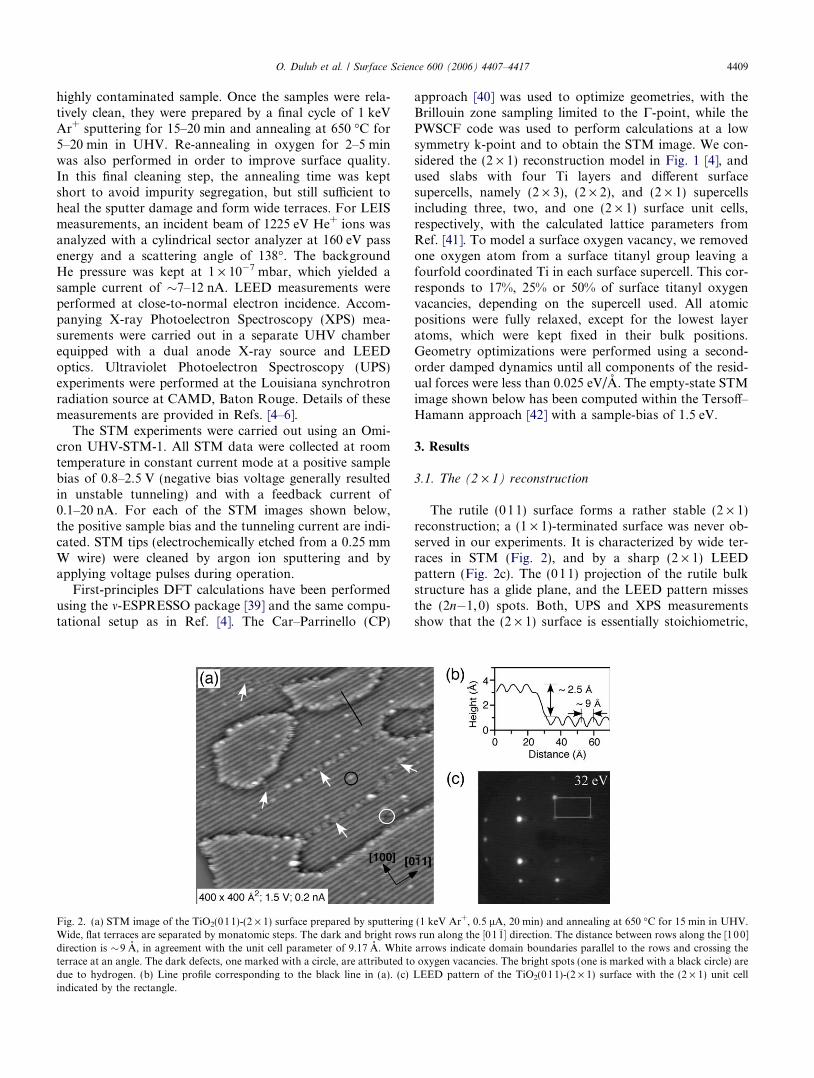
Fig. 2. (a) STM image of the TiO2(011)-(2 · 1) surface prepared by sputteringWide, flat terraces are separated by monatomic steps. The dark and bright rowdirection is �9 A, in agreement with the unit cell parameter of 9.17 A. Whiteterrace at an angle. The dark defects, one marked with a circle, are attributed todue to hydrogen. (b) Line profile corresponding to the black line in (a). (c)indicated by the rectangle.
approach [40] was used to optimize geometries, with theBrillouin zone sampling limited to the C-point, while thePWSCF code was used to perform calculations at a lowsymmetry k-point and to obtain the STM image. We con-sidered the (2 · 1) reconstruction model in Fig. 1 [4], andused slabs with four Ti layers and different surfacesupercells, namely (2 · 3), (2 · 2), and (2 · 1) supercellsincluding three, two, and one (2 · 1) surface unit cells,respectively, with the calculated lattice parameters fromRef. [41]. To model a surface oxygen vacancy, we removedone oxygen atom from a surface titanyl group leaving afourfold coordinated Ti in each surface supercell. This cor-responds to 17%, 25% or 50% of surface titanyl oxygenvacancies, depending on the supercell used. All atomicpositions were fully relaxed, except for the lowest layeratoms, which were kept fixed in their bulk positions.Geometry optimizations were performed using a second-order damped dynamics until all components of the resid-ual forces were less than 0.025 eV/A. The empty-state STMimage shown below has been computed within the Tersoff–Hamann approach [42] with a sample-bias of 1.5 eV.
3. Results
3.1. The (2 · 1) reconstruction
The rutile (011) surface forms a rather stable (2 · 1)reconstruction; a (1 · 1)-terminated surface was never ob-served in our experiments. It is characterized by wide ter-races in STM (Fig. 2), and by a sharp (2 · 1) LEEDpattern (Fig. 2c). The (011) projection of the rutile bulkstructure has a glide plane, and the LEED pattern missesthe (2n�1,0) spots. Both, UPS and XPS measurementsshow that the (2 · 1) surface is essentially stoichiometric,
(1 keV Ar+, 0.5 lA, 20 min) and annealing at 650 �C for 15 min in UHV.s run along the ½01�1� direction. The distance between rows along the [100]arrows indicate domain boundaries parallel to the rows and crossing theoxygen vacancies. The bright spots (one is marked with a black circle) are
LEED pattern of the TiO2(011)-(2 · 1) surface with the (2 · 1) unit cell

Fig. 3. XPS of the (011)-(2 · 1) surfaces of rutile TiO2. (a) Aftersputtering and annealing in vacuum; (b) surface from (a) annealed inp = 1 · 10�6 mbar oxygen at 750 �C for 5 min, followed by cooling inoxygen. The spectra were collected using an electron take-off angle of 25�.The intensity of the Ti3+ feature is estimated as �1.7%.
4410 O. Dulub et al. / Surface Science 600 (2006) 4407–4417
see Fig. 3 for XPS results. (UPS results have been re-ported previously [4].) Samples that have been annealedin UHV show a small Ti3+-derived shoulder at lower
Fig. 4. (a) Atomically resolved STM image of the TiO2(011)-(2 · 1) surface pIndicated by a circle in the inset is a single O vacancy. A double-vacancy is markLine profiles along the lines (i)–(ii) marked in (a). The very bright spot slightly oa surface where several O(1) atoms at the same side of the zigzag row are mis
binding energies that is indicative of oxygen vacancies.Such vacancies manifest themselves also in a small gapstate at 0.8 eV binding energy in photoemission spectrafrom the valence band [1,4–6]. STM images are character-ized by bright stripes running along the ½0�1 1� direction.The corrugation is high, and it is fairly easy to obtainatomically resolved images in STM. A characteristic zig-zag pattern of bright atoms is observed in STM imageswith higher resolution, see Fig. 4.
Based on experimental results and first-principles DFTcalculations [4], we have previously proposed the modelfor the (2 · 1) structure depicted at the right side ofFig. 1. It consists of ‘added rows’ that are 9.17 A apart.The left side of Fig. 1 shows the bulk-terminated (011) sur-face. Schematically, one can derive the (2 · 1)-recon-structed surface from the (1 · 1)-terminated one in severalsteps. If one removes the center TiO2 units (labeled withcircles in Fig. 1), the surface stays stoichiometric and exhib-its deep groves with O(1) atoms at both sides. The adjacentTi atoms are rendered fourfold coordinated. If one thenshifts the resulting added rows by half a unit cell in the½0�1 1� direction, these Ti atoms become fivefold coordi-nated (or, if one counts the Ti@O bond as a double bond,completely saturated). A further relaxation of the O(1)atoms and the other surface and near-surface atoms resultsin the (2 · 1) structure proposed in Ref. [4]. Despite anextensive search with DFT techniques this structure wasthe only one with a (2 · 1) periodicity that was lower in en-ergy than the (1 · 1)-terminated surface. Calculations with-in the Tersoff–Haman approach [4] show that the brightatoms in atomically resolved empty-states STM images
repared as in Fig. 2. The bright zigzag rows are attributed to O(1) atoms.ed by an oval and a more extended array of vacancies by a rectangle. (b, c)ff-center of the image is due to some unknown impurity. (d) STM image ofsing.

Fig. 5. STM images of (a) slightly reduced and (b) highly reducedTiO2(011)-(2 · 1) samples (250 A · 150 A, 2.4 V, 0.1 nA). The sampleswere prepared simultaneously by sputtering and annealing at 700 �C for10 min in UHV. The concentration of defects is 9% in (a) and 20% in (b)with respect to the total number of O(1) atoms in each image.
Fig. 6. STM images of a slightly sputtered TiO2(011)-(2 · 1) surface. Thesurface was prepared by annealing in UHV for 15 min, followed by 700 eVAr+ sputtering (current of 0.25 lA) for 8 min. The surface exhibits manydeep ‘holes’.
O. Dulub et al. / Surface Science 600 (2006) 4407–4417 4411
(Fig. 4) originate from the O(1) sites. The density of theO(1) atoms on TiO2(011)-(2 · 1) is slightly lower thanthe density of O(2) atoms on TiO2(110), 4 · 1014 cm�2
vs. 5 · 1014 cm�2, respectively.Fig. 2 gives an overview of the dominant defects that ap-
pear on clean TiO2(01 1) surfaces. The terraces are sepa-rated by monoatomic step edges, many of which runparallel to the rows, along the ½0�11� direction. The (2 · 1)structure shows antiphase domain boundaries (bright ar-rows in Fig. 2). Domain boundaries parallel to the rowsare five (1 · 1) unit cells wide, the ones that cut acrossthe rows are quite narrow (see the white arrow at the upperleft side of Fig. 2). We find that these domain boundariesare particularly reactive for adsorption of both gas mole-cules and small metal clusters. The bright spots are dueto hydrogen atoms. These stem from either H2 (crackedat a hot filament) or H2O molecules that are typicallypresent in the residual gas of a UHV chamber. In previouswork it was found that water dissociates on the TiO2(011)surface at room temperature with a low saturation cover-age [5,6] and that the resulting hydroxyls appear as brightspots on the bright rows in STM. Evidence for the assign-ment of dark spots (circled in Fig. 2) as O vacancies is givenin the next section.
3.2. Oxygen vacancies
Shown in Fig. 4 is an atomically resolved image withhigher resolution. Some darker spots are apparent on thebright zigzag rows of O(1) atoms. We will argue in follow-ing that these dark spots represent missing oxygen atoms(point defects). They appear in various configurations. Sin-gle, isolated dark spots (see circle in the inset of Fig. 4) dooccur but are relatively rare. The most commonly-observedstructure is a configuration where two neighboring atoms(on opposite sides of the zigzag row) are darker, see theoval marker in Fig. 4. These darker atoms do not havethe same height, however, see the line profiles (ii) inFig. 4c. The darkest atom, 0.4–0.6 A below the regularO(1) atoms, resides on one side of the zigzag row. One ofneighboring atoms on the other side of the zigzag appearsless deep (0.2 A). Quite often, several dark spots are locatedon both sides of the zigzag structure. One of these more ex-tended defects is marked with a rectangle in Fig. 4. The lineprofile (i) shows that the apparent ‘hole’ is quite deep; it ispossible that not only O atoms but also Ti atoms are miss-ing in these extended defects. Sometimes we observe config-urations where all the bright atoms on one side of thezigzag are gone, see Fig. 4d.
The density of the dark spots depends on the sample his-tory. Fig. 5 shows STM images taken on two different sam-ples, a ‘pristine’ one, very light in color (top panel), and onereduced, darker one (bottom panel). (The color of a TiO2
sample is a qualitative measure of the bulk’s reduction state[36].) Both samples were mounted next to each other onone sample platen and treated exactly the same way. Thenumber of defects on the darker sample was about twice
as high (ca. 20% of total O(1) sites) than on the lighterone (with 9% missing atoms).
It is firmly established [1] that sputtering of TiO2 resultsin a preferential removal of oxygen atoms, albeit the exactatomic structure of the resulting defects is hard to deter-mine. Slightly sputtered rutile (110) surfaces have beenused in many experiments in order to test the influence ofsurface reduction on adsorption of gases and metal over-layer growth [43–48]. Fig. 6 shows an STM image of a

4412 O. Dulub et al. / Surface Science 600 (2006) 4407–4417
slightly sputtered rutile (01 1)-(2 · 1) sample. It containsmany extended dark spots. When such a sputtered surfaceis exposed to a small dose of molecular oxygen, the darkspots do not disappear. This is not further surprising; ithas been shown that sputter-induced defects cannot becompletely healed upon oxygen exposure at room temper-ature. Some thermal energy is needed to restore the localdisorder that has been induced by the ion irradiation.The sputter results in Fig. 6 corroborate the interpretationof the deep, extended defects as several missing (mostlyoxygen, but potentially also titanium) atoms.
It is well established that single oxygen vacancies appearas bright spots in empty-states STM images on rutile (11 0)[1,30,49] under ‘normal’ tip and tunneling conditions. Onrutile (110) the image contrast is dominated by high den-sity of Ti-derived states in the empty conduction band.The image contrast on rutile (011) is dominated by theheight of the O(1) atoms, however, despite the fact thatthe conduction band is mainly Ti-3d derived. This assign-ment is supported by DFT calculations using the simpleTersoff–Hamann approach. In the calculated image(Fig. 7), the dominant features originate from the oxygensof the surface titanyl groups, as already reported for thenon-defective surface in Ref. [4]. In agreement with exper-iment, isolated point defects appear darker (see Fig. 7).
As is common in STM studies of oxides, spontaneoustip changes occur frequently. The STM image in Fig. 8awas taken by scanning from the lower to the upper part.Despite the clearly resolved zigzag structure in the lowerpart of the image the tip was not very stable; note the strea-ky appearance along some horizontal lines. At the scan linemarked with the lower black arrow, the tip suddenly chan-
Fig. 7. Calculated empty-states STM image in a plane 2.7 A above theoutermost Ti atoms. A (2 · 3) surface supercell with one O(1) vacancy(here periodically repeated for better visualization) was used for thecalculations. Empty states within a 1.5 eV window above the conductionband edge have been included.
ged. The zigzag structure, though still apparent, is not aswell resolved. At the scan line marked with the upper ar-row, the tip returned to its original state. Interestingly,the rows appear narrower in the poorly resolved regionthan in the regions imaged with the ‘normal’ tip. This issomewhat unusual, as a loss in resolution (for example,when tunneling occurs through more than one tip atom)is often connected with a broader appearance of surfacefeatures. One possible explanation is that some adsorbateat the tip apex could make tunneling into O states lessprobable, and that the image contrast stems from tunnelinginto the Ti states underneath the O(1) atoms (see Fig. 1).We can only speculate about the nature of this adsorbate,but hydrogen (which can easily be ‘cleaned off’ from thesurface with the STM tip at high tunneling currents) ap-pears to be a likely candidate. In Fig. 8b and c two consec-utive images of the same area of the sample are shown.Image (Fig. 8b) was taken with what we call the ‘normal’tip state. The zigzag structure is apparent, as well as doublevacancies and the more extended defects. (The latter aremarked with white arrows in both images.) When the tipswitches to the state where the rows appear narrow andthe atomic structure is not as well resolved (Fig. 8c), the ex-tended defects are hardly visible. Also, they appear whiterather than dark. This is consistent with the proposal thatthis ‘changed tip’ images Ti states. It is conceivable that thehigher density of electrons at the reduced Ti atoms, next toO vacancies, give rise to an increased density of empty Tistates; similar to the rutile (110) surface, where O vacanciesare imaged bright. Interestingly, the double defects that areapparent in Fig. 8b are not visible at all with the changedtip in Fig. 8c. The strong dependence of the appearanceof oxygen vacancies on tip condition and bias voltage isnot uncommon for TiO2 [26].
The more extended defects are quite reactive. For exam-ple, the unidentified impurity in Fig. 8b and c (big, whitespot marked with dashed circles) resides on an extended de-fect. It should also be mentioned that, occasionally, othertypes of dark ‘defects’ appear at the sample. These can eas-ily be pushed along the rows with the STM tip, and areprobably some sort of adsorbate or impurity.
3.3. Annealing in oxygen
When a UHV-annealed surface with oxygen vacancies isre-annealed in oxygen, the number density of dark spots issubstantially reduced, see Fig. 9. The STM image in Fig. 9ashows the surface before exposure to oxygen. It containsdefects in various configurations, the density of all the darkzigzag atoms amounts to �15% of surface titanyl oxygenatoms. After annealing in oxygen, the density of O vacan-cies is far smaller, see Fig. 9b. Also, the defect-related Ti3+
feature in the Ti2p core level spectrum is suppressed afteroxygen annealing, see the XPS results in Fig. 3. While thisappears as an encouraging way to produce vacancy-freesurfaces, it needs to be pointed out that not all the vacan-cies could be healed each time this procedure was tried.

Fig. 8. (a) Atomically resolved image with spontaneous tip changes at the positions marked by the black arrows. (b, c) Two consecutive images taken atanother area. The image in (b) is well resolved with dark extended defects marked with white arrows. These defects appear slightly brighter in the image (c)where the tip has changed. Note that a surface impurity (bright spot marked with a dashed circle in (c)) resides on an extended defect in (b).
Fig. 9. STM images of the TiO2(011)-(2 · 1) surface. (a) Surface prepared by sputtering and annealing at 650 �C for 20 min in UHV. A high density ofoxygen vacancies in different configurations is observed. Single vacancies are marked by circles, double vacancies by ovals, and defects with three vacanciesare marked with triangles. (b) The surface after sputtering and annealing at 650 �C for 20 min in UHV, followed by annealing in P = 1 · 10�5 mbar of O2
(the sample was cooled in 1 · 10�5–1 · 10�8 mbar of O2). The number of defects decreased significantly after such treatment.
O. Dulub et al. / Surface Science 600 (2006) 4407–4417 4413
Also, as pointed out in the context of Fig. 8, a modified tipcan result in images with a seemingly low defect concentra-tion. One should also caution that a similar sample treat-ment caused segregation of Ca on samples that showed ahigher degree of bulk impurities, see Section 3.4.
Annealing in oxygen results in a very different surfacestructure when it is performed directly after sputtering,see Fig. 10. The surface is much rougher, with many small,½0�11�-oriented islands, ca. 100 · 30 A in size. This effectwas observed when the sputtered sample was annealed atrelatively high pressures of O2, between 5 · 10�6 and2 · 10�5 mbar. The rough patches exhibit a (3 · 1) period-icity. This structure is visible more clearly when the surfacefrom Fig. 10a was subsequently re-annealed at 650 �C for5 min in UHV. The rough areas developed into well-ordered islands with a (3 · 1) structure.
It is now firmly established [28,32–38] that heating bulk-reduced TiO2 crystals can cause a diffusion of bulk defects,especially Ti interstitials [50], to the surface. Oxidizinggases such as oxygen, sulfur, or formic acid can react withthis excess Ti and form various superstructures such asadded rows or ‘rosettes’. It is quite likely that the observed(3 · 1) features on the TiO2(01 1) result from similar pro-cesses. Such oxygen-induced structural features are richand complex, and we refrain from a further structural char-acterization of the (3 · 1) reconstructed surface areas.
3.4. Segregation of impurities
Alkali and alkaline earth metals are the common impu-rities at the surface of commercial TiO2 crystals. Whiletheir concentration is not very high in high-quality crystals,

Fig. 10. STM images of the TiO2(011) surface after annealing of apreviously sputtered surface in 1 · 10�5 mbar of O2 at 650 �C, followed bycooling in oxygen. The surface features rough areas with a multitude ofterraces �100 A long and 30 A wide, elongated along the ½0�11� directions.As shown on the small scale image (b), these small terraces exhibit a (3 · 1)reconstruction. (The sample in (b) was re-annealed in UHV at 650 �C.)
Fig. 11. (a) STM image with Ca impurities segregated to the TiO2(011)-(2 · 1) surface. The sample was prepared by annealing in UHV (700 �C for5 min) and re-annealing in 10�6 – 10�8 mbar of O2 at 450–550 �C. Small,stripe-like domains with segregated Ca are an even number (4, 6 or 8) of(1 · 1) unit cells wide, and neighboring domains are shifted by half a unitcell in the ½0�11� direction. (b) Small-scale image of the regular, cleansurface (top) and a Ca-segregated area (bottom). The unit cell in the Ca-segregated areas appears to be centered in STM.
4414 O. Dulub et al. / Surface Science 600 (2006) 4407–4417
they have a strong tendency to segregate to the surface.This can represent a problem when working with freshsamples. Such segregated impurities can give rise to ratherwell-ordered overlayer structures with flat surfaces [51,52].The structure of Ca-segregated rutile (110) has been inves-tigated by several groups [53–56].
A significant amount of Ca was observed with LEISafter annealing a pristine rutile (011) sample at elevatedtemperatures (450–750 �C) in an oxygen background pres-sure of 10�8–10�5 mbar. Segregated calcium gives rise to anordered superstructure, see Fig. 11. In STM the structureappears with a centered (2 · 1) unit cell (Fig. 11b),although LEED shows only a simple (2 · 1) periodicity,without additional spots at the center. The Ca-rich over-layer forms striped domains with an even number of (sub-strate) unit cells in the [100] direction (e.g., 4, 6, or 8
substrate unit cells wide, see Fig. 11a). The domains areseparated by 2.5 A-wide trenches, where a row of atomsappears to be missing along the ½0�11� direction. Neighbor-ing domains are out of registry by half a unit cell in the½0�1 1� direction. The sketch in Fig. 11b shows a possibleregistry of the bright spots in the Ca-segregated areas withthe TiO2(01 1)-(2 · 1) surface. In order to derive a crediblemodel for the overlayer structure, a more quantitativemeasurement of its composition and structure would beneeded.
4. Discussion
The TiO2 rutile (011)-(2 · 1) surface shows many simi-larities with the extensively-studied rutile (110) surface,but there are also important differences between the twosystems. Clearly, the most interesting features are the Ti@Ogroups that are part of the proposed structural model(Fig. 1). The STM results presented in this work are consis-tent with, and provide further evidence for, this proposedstructure. In recent surface science work on early transitionmetal oxide surfaces, M@O species have evolved as a struc-tural element that is much more common than originallyanticipated. Metal–oxygen double bonds are part of thebulk structure of several oxides, e.g., in V2O5 [14–16].For certain oxygen chemical potentials Me@O species also

O. Dulub et al. / Surface Science 600 (2006) 4407–4417 4415
form on the (0001) plane of early transition metal oxideswith the corundum structure, i.e., on V2O3(000 1)[17,18,57] and Cr2O3(0001)) [19]. They have also been in-voked as a possible surface termination of Fe2O3(000 1)[20], even though ferryl species are relatively rare. Titanylspecies are known to exist in Ti(IV) complexes [22,24,58–60], and Ti@O groups have been invoked as importantreaction centers in titanium-containing zeolites [61,62],although their presence has been questioned in Ref. [21].Interestingly, the Ti@O groups have also been proposedto be important in TiO2 nanoparticles on the basis of X-ray Adsorption Near Edge Structure (XANES) experi-ments [25].
While this suggests that a structure containing Ti@Ospecies is not only reasonable, but might also be an inter-esting model surface for probing reactivity of related nano-structures, it should be pointed out that the driving forcefor formation of this reconstruction is unclear at this point.The bulk-terminated (1 · 1) surface is already relativelylow in energy [9]. In first-principles DFT calculations [4]the proposed structure was the only surface with a (2 · 1)periodicity that was found to have a surface energy lowerthan the (1 · 1) surface, despite an extensive search foralternative models. The reconstruction at the surface isquite substantial and relaxations reach several layers deep;in slab calculations many layers (at least 6) are required be-fore the energy of the system drops below the one for thebulk-terminated (1 · 1) structure. This is quite differentfrom other reconstructed TiO2 surfaces; e.g., the TiO2 ana-tase (001)-(1 · 1) surface is under substantial strain, whichis lifted by the formation of a (1 · 4) reconstruction [41].Experimentally we find that the (2 · 1) structure is quitestable, however. A (1 · 1) structure was never observed, de-spite a wide variation of surface preparation parameters.
The deep troughs in the (2 · 1) structure present a tem-plate for highly directed one-dimensional diffusion; preli-minary results in our lab show that molecular as well asmetallic adsorbates stay within the deep grooves and donot easily cross over along the [100] direction. They will,however, be stopped at the domain boundaries that cutacross the ½0�11� direction and represent sites for strongadsorption. In fact, preliminary results in our lab show thatone has resort to ‘mild’ tunneling conditions (relativelylarge bias voltages and small currents) in order to preventthe tip from pushing adsorbates along the troughs.
On TiO2 surfaces the propensity of forming surface oxy-gen vacancies is somewhat dependent on the reductionstate of the bulk [33–36]. For slightly reduced, ‘light’ sam-ples, few vacancies form after annealing in vacuo. On rutile(110), removal of a bridging O(2) atoms results in the typ-ical Ti3+ feature in XPS, UPS, and related spectroscopictechniques. In empty-states STM these oxygen vacanciesare imaged as small bright spots, connecting the brightTi(5) rows [30,49]. (Again, this is only true under ‘normal’tip and tunneling conditions.) At the TiO2(011)-(2 · 1) sur-face dark spots represent oxygen vacancies. This assign-ment is based on the observations that (i) the number
density of the dark spots is higher on more bulk-reducedsamples (Fig. 5); (ii) their density can be reduced substan-tially by exposure to oxygen (Fig. 9); (iii) more dark spotsappear on sputtered surfaces (Fig. 6); (iv) when the darkspots are present, the typical XPS feature for slightly re-duced is observed (Fig. 3), and (v) Tersoff–Haman calcula-tions predict that isolated O vacancies are imaged as darkfeatures (Fig. 7).
Interestingly, a number of different configurations areobserved for O vacancies on TiO2(011)-(2 · 1). For exam-ple, in the image displayed in Fig. 9a, 15% of O(1) atoms ismissing: 1% correspond to isolated, single vacancies, 6% todark spots arranged in double-vacancies, and 2% to aconfiguration where three oxygen atoms are missing in atriangular arrangement. The remaining 5% are located inextended defects with more then three atoms missing,which often are just a mixture of vacancies and the remain-ing O. In contrast, oxygen vacancies on rutile (110) arenever observed to be located next to each other on onebridging oxygen row. This could be explained by a repul-sive interaction between neighboring oxygen vacancies onTiO2(110), as indicated by several computational studies[63–65]. Such a repulsive interaction between O vacanciesdoes not seem to be operational on TiO2(011)-(2 · 1). Thisis consistent with preliminary DFT calculations whichshow very little change of the vacancy formation energywhen a (2 · 2) or (2 · 1) surface supercell is used. The pro-pensity of forming predominantly double-vacancies couldthen be explained easily. Most likely, oxygen desorbs fromthe surface as a di-atomic molecule when the sample isheated under the reducing conditions of a UHV environ-ment, leaving behind two neighboring vacancies.
It is to be expected that missing O(1) atoms would affectsurface chemistry in a different way than an O(2) atommissing from the rutile (110) surface. The latter leaves be-hind two Ti(5) atoms, both with a formal charge state ofTi3+. These O(2) vacancies are very important for the sur-face chemistry of TiO2, e.g. they are necessary for the dis-sociation of water [31,66] and activate adsorbed oxygen[29,67]. When an O(1) atom is removed from the structureshown in Fig. 1, it leaves behind one fourfold coordinatedTi atom. In addition, relatively large spots of the surfacecan be stripped off of these O(1) atoms, resulting in ex-tended arrays of defects. It would be interesting to testthe resulting effects on surface chemical reactivity withappropriate probe molecules.
So far, only a few studies have probed the surface chem-istry of TiO2(011)-(2 · 1). Dissociation of water can be ex-pected based on the close proximity between the highlyundercoordinated O(1) atom and the H atom of a watermolecule adsorbed at a neighboring Ti(5) [68,69]. Indeed,the combined theoretical and experimental results in Refs.[5,6] show that water dissociates on this surface at elevatedtemperatures, although the strong water–water interactionstabilizes part of a water monolayer in molecular form be-low 200 ± 20 K. While hydrogen in its molecular form isnot expected to adsorb at this or other TiO2 surfaces, the

4416 O. Dulub et al. / Surface Science 600 (2006) 4407–4417
hot tungsten filaments that are used in UHV chambers areknown to crack H2. The resulting H atoms or ions readilystick to the surface. In fact, one has to be careful not tocontaminate the surface with H that either comes from thissource or from dissociated water. In STM, H atoms appearas bright spots and O vacancies as dark ones (Fig. 2), so itis easy to distinguish between the two. This is different fromthe TiO2(110) surface, where H adsorbates and O vacan-cies look fairly similar [30,70,71], which can lead to errone-ous results [72,73]. More details on the adsorption ofhydrogen on TiO2(011)-2 · 1 will be given in a forthcom-ing article.
The local arrangement of adsorption sites is importantfor the adsorption of many molecules; for example formicacid adsorbs on the Ti(5) atoms within the troughs ofTiO2(01 1)-(2 · 1) [4], but does not form the well-ordered(2 · 1) structure that is observed for carboxylates onTiO2(11 0) [1,74,75]. Formation of a (2 · 1) formate over-layer is facilitated by the 3 A-spacing between two Ti(5)atoms that makes possible a bi-dentate configuration ofthe adsorbed carboxylate. The distance between two Ti(5)atoms on the TiO2(011)-(2 · 1) structure is somewhat lar-ger (3.7 A), likely too wide to be straddled in a bi-dentatefashion.
Under UHV conditions, M@O species at V2O3 andCr2O3 surfaces are virtually inert in the adsorption of H2,CO, and CO2 [76], while it has been speculated that theferryl species on Fe2O3(0001) could be active in selectiveoxidation and hydrogenation reactions [20]. On a vana-dyl-terminated V2O3(0001) film grown on Rh(1 11), thesurface vanadyl species were reacted away when the surfacewas exposed to oxygen at elevated temperatures, leavingbehind a more oxygen-rich surface termination [57].Annealing of a reconstructed TiO2(011)-(2 · 1) surface inoxygen does not change the surface structure; annealingof a sputter-damaged TiO2(011) surface results in a roughsurface structure with a (3 · 1) periodicity. This is likelydue to the well-known interaction between oxygen gasand defects (Ti interstitials and O atoms) diffusing to thesurface, which can give rise to metastable TiOx structures[28,32–38]. It would be quite interesting to investigate theinteraction of nucleophilic molecules with the titanylgroups of TiO2(011)-(2 · 1); or to see whether the titanylgroups can be ‘reacted off’ with CO2.
5. Summary
In summary, we have presented a detailed experimentalstudy on the (2 · 1)-reconstructed surface of rutileTiO2(01 1). Results presented here are in agreement withthe previously proposed surface reconstruction model thatcontains Ti@O species (Fig. 1). The formation of the recon-struction can be rationalized by removing TiO2 units from a(1 · 1)-terminated surface and shifting the resulting ‘addedrows’ by half a unit cell in the ½0�11� direction. PreviousDFT calculations indicate that relaxations reach deep intothe surface of the (2 · 1)-reconstructed structure; the driv-
ing force for such a reconstruction has yet to be determined.In empty-states STM, the O atoms of the Ti@O species areimaged as bright atoms at high bias voltages. Typical de-fects on vacuum-annealed surfaces consist of oxygen vacan-cies that manifest as darker spots in STM (Fig. 4).Neighboring oxygen vacancies form easily, and double-de-fects, where O(1) atoms are missing from opposite sides of azigzag row, are quite common. The (2 · 1) reconstruction israther stable; attempts to prepare a well-ordered TiO2(011)surface with a (1 · 1) configuration were not successful.Annealing of the sputtered surface in oxygen results in a rel-atively rough (3 · 1) surface (Fig. 10). For some samplesannealing in oxygen caused segregation of Ca and resultedin well-ordered overlayers (Fig. 11).
The TiO2(011)-(2 · 1) surface could represent an inter-esting system for detailed studies on the orientation-depen-dent surface reactivity of titania. It is easy to prepare thissurface, and because of the large size of the unit cell andthe high corrugation of the ‘added rows’, it is straightfor-ward to image this surface with scanning probe techniques.Under ‘normal’ tunneling conditions O vacancies andadsorbed H atoms can easily be distinguished as they are im-aged as dark and bright features, respectively. TiO2(011)-(2 · 1) has a surface structure that is sufficiently differentfrom the well-studied TiO2(110) surface to allow a distinc-tion between effects based on local atomic configurationsand the overall properties of TiO2 surfaces. The TiO2(011)-(2 · 1) surface could thus provide an important test casefor furthering our understanding of the structure-reactivityrelationship on titania and related oxides.
Acknowledgements
The authors thank T.J. Beck, Jimi Burst, and MatthiasBatzill for assistance with taking XPS and UPS data,XueQing Gong for help with the theoretical STM image,and T.E. Madey for useful discussions. Support by theNational Science Foundation (CHE-010908) and theDepartment of Energy (DE-TG02-05ER15702) is grate-fully acknowledged.
References
[1] U. Diebold, Surf. Sci. Rep. 48 (2003) 53.[2] M.A. Barteau, Chem. Rev. 96 (1996) 1413.[3] H. Idriss, M.A. Barteau, Adv. Catal. 45 (2000) 261.[4] T.J. Beck, A. Klust, M. Batzill, U. Diebold, C. Di Valentin, A.
Selloni, Phys. Rev. Lett. 93 (2004) 036104/1.[5] T.J. Beck, A. Klust, M. Batzill, U. Diebold, C. Di Valentin, A.
Tilocca, A. Selloni, Surf. Sci. 591 (2005) L267.[6] C. Di Valentin, A. Tilocca, A. Selloni, T.J. Beck, A. Klust, M. Batzill,
Y. Losovij, U. Diebold, J. Am. Chem. Soc. 127 (2005) 9895.[7] Y. Yamamoto, Y. Matsumoto, H. Koinuma, Appl. Surf. Sci. 238
(2004) 189.[8] Y. Yamamoto, K. Nakajima, T. Ohsawa, Y. Matsumoto, H.
Koinuma, Jpn. J. Appl. Phys. Part 2 44 (2005) L511.[9] M. Ramamoorthy, D. Vanderbilt, Phys. Rev. B: Condens. Matter 49
(1994) 16721.

O. Dulub et al. / Surface Science 600 (2006) 4407–4417 4417
[10] J.B. Lowekamp, G.S. Rohrer, P.A.M. Hotsenpiller, J.D. Bolt, W.E.Farneth, J. Phys. Chem. B 102 (1998) 7323.
[11] P.A.M. Hotsenpiller, J.D. Bolt, W.E. Farneth, J.B. Lowekamp, G.S.Rohrer, J. Phys. Chem. B 102 (1998) 3216.
[12] G.S. Rohrer, The chemical physics of solid surfaces, in: D.P.Woodruff (Ed.), Oxide Surfaces, vol. 9, Elsevier, Amsterdam, 2001,p. 485.
[13] T. Ohno, K. Sarukawa, M. Matsumura, New J. Chem. 26 (2002)1167.
[14] K. Hermann, M. Witko, R. Druzinic, A. Chakrabarti, B. Tepper, M.Elsner, A. Gorschluter, H. Kuhlenbeck, H.-J. Freund, J. Electron.Spectrosc. Relat. Phenom. 98–99 (1999) 245.
[15] R.L. Smith, W. Lu, G.S. Rohrer, Surf. Sci. 322 (1995) 293.[16] B. Tepper, B. Richter, A.C. Dupuis, H. Kuhlenbeck, C. Hucho, P.
Schilbe, M.A. bin Yarmo, H.-J. Freund, Surf. Sci. 496 (2002) 64.[17] A.C. Dupuis, M. Abu Haija, B. Richter, H. Kuhlenbeck, H.-J.
Freund, Surf. Sci. 539 (2003) 99.[18] S. Surnev, G. Kresse, M. Sock, M.G. Ramsey, F.P. Netzer, Surf. Sci.
495 (2001) 91.[19] H.-J. Freund, B. Dillmann, O. Seiferth, G. Klivenyi, M. Bender, D.
Ehrlich, I. Hemmerich, D. Cappus, Catal. Today 32 (1996) 1.[20] C. Lemire, S. Bertarione, A. Zecchina, D. Scarano, A. Chaka, S.
Shaikhutdinov, H.-J. Freund, Phys. Rev. Lett. 94 (2005) 166101/1.[21] M. Crocker, K.A. Emeis, R.H.M. Herold, J. Mol. Catal. A: Chem.
110 (1996) L7.[22] S. De Angelis, E. Solari, C. Floriani, A. Chiesi-Villa, C. Rizzoli,
Organometallics 14 (1995) 4505.[23] C.E. Housmekerides, D.L. Ramage, C.M. Kretz, J.T. Shontz, R.S.
Pilato, G.L. Geoffroy, A.L. Rheingold, B.S. Haggerty, Inorg. Chem.31 (1992) 4453.
[24] P. Jeske, G. Haselhorst, T. Weyhermueller, K. Wieghardt, B. Nuber,Inorg. Chem. 33 (1994) 2462.
[25] P.C. Redfern, P. Zapol, L.A. Curtiss, T. Rajh, M.C. Thurnauer, J.Phys. Chem. B: Condens. Matter 107 (2003) 11419.
[26] U. Diebold, J. Lehman, T. Mahmoud, M. Kuhn, G. Leonardelli, W.Hebenstreit, M. Schmid, P. Varga, Surf. Sci. 411 (1998) 137.
[27] S. Mezhenny, P. Maksymovych, T.L. Thompson, O. Diwald, D.Stahl, S.D. Walck, J.T. Yates Jr., Chem. Phys. Lett. 369 (2003) 152.
[28] H. Onishi, Y. Iwasawa, Phys. Rev. Lett. 76 (1996) 791.[29] C.N. Rusu, J.T. Yates Jr., Langmuir 13 (1997) 4311.[30] R. Schaub, P. Thostrup, N. Lopez, E. Laegsgaard, I. Stensgaard, J.K.
Nørskov, F. Besenbacher, Phys. Rev. Lett. 87 (2001) 266104/1.[31] M.A. Henderson, Surf. Sci. 355 (1996) 151.[32] R.A. Bennett, P. Stone, N.J. Price, M. Bowker, Phys. Rev. Lett. 82
(1999) 3831.[33] M. Li, W. Hebenstreit, U. Diebold, Surf. Sci. 414 (1998) L951.[34] M. Li, W. Hebenstreit, U. Diebold, Phys. Rev. B: Condens. Matter 61
(2000) 4926.[35] M. Li, W. Hebenstreit, U. Diebold, M.A. Henderson, D.R. Jennison,
Faraday Discuss. 114 (1999) 245.[36] M. Li, W. Hebenstreit, L. Gross, U. Diebold, M.A. Henderson, D.R.
Jennison, P.A. Schultz, M.P. Sears, Surf. Sci. 437 (1999) 173.[37] K.F. McCarty, N.C. Bartelt, Surf. Sci. 527 (2003) L203.[38] P. Stone, R.A. Bennett, M. Bowker, New J. Phys. 1 (1999) 8.[39] S. Baroni, A. dal Corso, S. de Gironcoli, P. Gianozzi, C. Cavazzoni,
G. Ballabio, S. Scandolo, G. Chiarotti, P. Focher, A. Pasquarello, K.Laasonen, A. Trave, R. Car, N. Marzari, and A. Kokalj, <http://www.pwscf.org.>.
[40] R. Car, M. Parrinello, Phys. Rev. Lett. 1985 (1985) 2471.[41] M. Lazzeri, A. Selloni, Phys. Rev. Lett. 87 (2001) 266105/1.[42] J. Tersoff, D.R. Hamann, Phys. Rev. Lett. 50 (1983) 1998.
[43] K. Onda, B. Li, H. Petek, Phys. Rev. B: Condens. Matter 70 (2004)045415/1.
[44] J.M. Pan, B.L. Maschhoff, U. Diebold, T.E. Madey, J. Vac. Sci.Technol. A10 (1992) 2470.
[45] M.C. Torquemada, J.L. de Segovia, E. Roman, Surf. Sci. 337 (1995)31.
[46] L.-Q. Wang, A.N. Shultz, D.R. Baer, M.H. Engelhard, J. Vac. Sci.Technol. A14 (1996) 1532.
[47] Q. Wang, J. Biener, X.-C. Guo, E. Farfan-Arribas, R.J. Madix, J.Phys. Chem. B107 (2003) 11709.
[48] H. Mostefa-Sba, B. Domenichini, S. Bourgeois, Surf. Sci. 437 (1999)107.
[49] U. Diebold, J.F. Anderson, K.O. Ng, D. Vanderbilt, Phys. Rev. Lett.77 (1996) 1322.
[50] M.A. Henderson, Surf. Sci. 343 (1995) L1156.[51] J.F. Anderson, M. Kuhn, U. Diebold, K. Shaw, P. Stoyanov, D.
Lind, Phys. Rev. B: Condens. Matter 56 (1997) 9902.[52] G. Mariotto, S. Murphy, N. Berdunov, S.F. Ceballos, I.V. Shvets,
Surf. Sci. 564 (2004) 79.[53] O. Bikondoa, C.L. Pang, C.A. Muryn, B.G. Daniels, S. Ferrero, E.
Michelangeli, G. Thornton, J. Phys. Chem. B 108 (2004) 16768.[54] H. Norenberg, J.H. Harding, Appl. Surf. Sci. 142 (1999) 174.[55] H. Norenberg, J.H. Harding, Surf. Sci. 473 (2001) 151.[56] L.P. Zhang, M. Li, U. Diebold, Surf. Sci. 412 (1998) 242.[57] J. Schoiswohl, M. Sock, S. Surnev, M.G. Ramsey, F.P. Netzer, G.
Kresse, J.N. Andersen, Surf. Sci. 555 (2004) 101.[58] A. Bodner, P. Jeske, T. Weyhermueller, K. Wieghardt, E. Dubler, H.
Schmalle, B. Nuber, Inorg. Chem. 31 (1992) 3737.[59] M.M. Olmstead, P.P. Power, M. Viggiano, J. Am. Chem. Soc. 105
(1983) 2927.[60] K. Wieghardt, U. Quilitzsch, J. Weiss, B. Nuber, Inorg. Chem. 19
(1980) 2514.[61] B. Notari, Stud. Surf. Sci. Catal. 37 (1988) 413.[62] R.A. Sheldon, J. Mol. Catal. 7 (1980) 107.[63] A. Tilocca, A. Selloni, Chem. Phys. Chem. 6 (2005) 1911.[64] M.D. Rasmussen, L.M. Molina, B. Hammer, J. Chem. Phys. 120
(2004) 988.[65] X. Wu, A. Selloni, M. Lazzeri, S.K. Nayak, Phys. Rev. B: Condens.
Matter 68 (2003) 241402, R.[66] I.M. Brookes, C.A. Muryn, G. Thornton, Phys. Rev. Lett. 87 (2001)
266103/1.[67] M.A. Henderson, W.S. Epling, C.L. Perkins, C.H.F. Peden, U.
Diebold, J. Phys. Chem. B 103 (1999) 5328.[68] M.A. Henderson, Surf. Sci. Rep. 46 (2002) 1.[69] P.A. Thiel, T.E. Madey, Surf. Sci. Rep. 7 (1987) 211.[70] S. Suzuki, K.-I. Fukui, H. Onishi, Y. Iwasawa, Phys. Rev. Lett. 84
(2000) 002156.[71] O. Bikonda, C.L. Pang, R. Ithnin, C.A. Mury, H. Onishi, G.
Thornton, Nat. Mater. 5 (2006) 189.[72] R. Schaub, E. Wahlstrom, A. Rønnau, E. Lægsgaard, I. Stensgaard,
F. Besenbacher, Science 299 (2003) 377.[73] S. Wendt, R. Schaub, J. Matthiesen, E.K. Vestergaard, E. Wahl-
strom, M.D. Rasmussen, P. Thostrup, L.M. Molina, E. Lægsgaard, I.Stensgaard, B. Hammer, F. Besenbacher, Surf. Sci. 598 (2005) 226.
[74] H. Onishi, Y. Iwasawa, Chem. Phys. Lett. 226 (1994) 111.[75] S.A. Chambers, S. Thevuthasan, Y.J. Kim, G.S. Herman, Z. Wang,
E. Tober, R. Ynzunza, J. Morais, C.H.F. Peden, K. Ferris, C.S.Fadley, Chem. Phys. Lett. 267 (1997) 51.
[76] B. Dillmann, F. Rohr, O. Seiferth, G. Klivenyi, M. Bender, K.Homann, I.N. Yakovkin, D. Ehrlich, M. Baeumer, H. Kuhlenbeck,H.-J. Freund, Faraday Discuss. 105 (1997) 295.