Structural Calculations - Dr. Maya Angelou Sculpture
16
Structural Calculations Dr. Maya Angelou Sculpture – SF Public Library 100 Larkin Street San Francisco, CA 94102 TSE Job No. 2020.180 April 12, 2022 Address questions or comments to: Ian Kelso, SE AIA ext. 232
-
Upload
khangminh22 -
Category
Documents
-
view
1 -
download
0
Transcript of Structural Calculations - Dr. Maya Angelou Sculpture
Structural Calculations
Dr. Maya Angelou Sculpture – SF Public Library
100 Larkin Street
San Francisco, CA 94102
TSE Job No. 2020.180
April 12, 2022
Address questions or comments to:
Ian Kelso, SE AIA
ext. 232

V=86 mph | (Fig 26.5-1B) Basic wind speed.
Kd=0.85 | (Tbl. 26.6-1) Wind directionality factor.
ExpCat=B | (§ 26.7) Exposure Category.
qz=0.00256×Kz×Kzt×Kd×Ke×V
mphæè
öø
2
×psf ® 9.25psf | (Eqn. 26.10-1) Velocity pressure.
Kzt=1 | (§26.8.2) Topographic factor.
Ke=1 | (§26.9) Ground elevation factor.
G=0.85 | (§26.11) Gust-effect factor.
Calculate Velocity Pressure
Elev= s ® 96 in | Height of sculpture.
As=Hbronze×Bbronze ® 48ft2 | Total surface area of book.
Bbase=80 in | Length of stone base.
s=Hbronze ® 96 in | Elevation of sculpture above base.
d=wbronze-2×1.5 in ® 21 in | Assumed width of anchor points.
2020,180 - Maya Angelou Sculpture - Book Check
Structure and Base Parameters
Hbronze=96 in | Height of bronze sculpture.
Bbronze=72 in | Length of bronze sculpture.
wbronze=24 in | Width of bronze sculpture.
wbase=30 in | Width of stone base.
Hbase=12 in | Height of stone base.
Self-weight
Wind Check
Wbronze=8.6 psf× 2×Bbronze+2×wbronzeæè
öø×Hbronze
æè
öø ® 1,101 lbs | 3
16" thick bronze walls weight.
Wbase=170 pcf× Bbase×wbase×Hbaseæè
öø ® 2,833 lbs | Granite base weight.
Wp=Wbronze+Wbase ® 3,934 lbs | Total weight of sculpture.
zg=1,200 ft | (Table 26.11-1) Nominal height of the atmospheric boundary layer.
a=7 | (Table 26.11-1) Gust-speed power law exponent.
Kz= if Elev<15 ft
2.01×15 ft
zg
æçè
ö÷ø
2a
æè
öø
2.01×Elevzg
æçè
ö÷ø
2a
æè
öø
® 0.57 | (Notes under Table 26.10-1) Velocity pressure exposure coefficient.
Wind Loading Parameters: ASCE 7-16, Section 29.3 - Solid Freestanding Walls and Solid Signs
Author: kelsoDate: April 12, 2022, 12:00
File name: 20180 - Maya Angelou Sculpture_Anchorage.chuLayout: Default Layout
page 1 of 9

Forces
Fw=qz×G×Cf×As ® 611 lbs | (Eq. 29.3-1) Total wind force on surface for solid signs.
Cf,A=1.55 | (Fig. 29.3-1) Force coefficient, Case A (conservative).
Net Force Coefficients
Case A
Cf,B=1.55 | (Fig. 29.3-1) Force coefficient, Case B (conservative).Case B
Cf,C=2.25× 0.9( ) 1.8-s
Elevæè
öø ® 1.62 | (Fig. 29.3-1) Force coefficient with reduction factor, Case C.Case C
Bbronze
s® 0.75
sElev
® 1
Cf=max Cf,A , Cf,B , Cf,Cæè
öø ® 1.62
Moverturning,wind=F× 0.55×Elevæè
öø ® 3.13kip×ft | Overturning moment about long axis (per Case C).
T=Mwind
d® 1,159 lbs | Total tension on each anchor per wind force.
n=2×ceilingBbase
67 in
æçè
ö÷ø® 4 | Assumed number of anchors in total (2 rows).
Tu=Tn2
® 580 lbs | Tension demand per anchor per wind force.
FLL=200 lbs ® 200 lbs | Horizontal Live Load force.
F=0.5× FLLæè
öø+1.0× Fw
æè
öø ® 711 lbs | LRFD horizontal force (0.5L+1.0W) (reduced LL).
2020,180 - Maya Angelou Sculpture - Book Check
Vu=Fn® 178 lbs | Shear demand per anchor per wind force.
Mrestoring,wind=Wbronze×wbronze
2® 1.1kip×ft | Restoring moment about long axis.
Mwind=max 0 , Moverturning,wind-Mrestoring,windæè
öø ® 2.03kip×ft | Net moment demand on book per wind force.
Author: kelsoDate: April 12, 2022, 12:00
File name: 20180 - Maya Angelou Sculpture_Anchorage.chuLayout: Default Layout
page 2 of 9

2020,180 - Maya Angelou Sculpture - Book Check
Ip=1.0 | (Sec. 13.1.3) Importance factor.
SDS=1.2 | Design Spectral Response at short period per Hazard Tool.
Fp,min=0.3×SDS×Ip ® 0.36 | Eqn. 13.3-3 Min. horizontal force.
Fp,coeff=bounded Fp,eqn , Fp,min , Fp,maxæè
öø ® 0.48
Rp=2.5 | Component response modification factor.
Fpvert,coeff=0.2×SDS ® 0.24 | Sec. 13.3.1 Vertical force.
W0=2 | Component overstrength factor.
ap=2.5 | Component amplification factor.
Fp,eqn=0.4×ap×SDS
Rp
Ip
× 1+2zh
æèöø
æè
öø ® 0.48 | Eqn. 13.3-1 Horizontal force.
Fp,max=1.6×SDS×Ip ® 1.92 | Eqn. 13.3-2 Max. horizontal force.
Fp
Seismic Calculation - ASCE 7-10 Ch. 13 Seismic Design Req. for Nonstructural Components
Table 13.5-1 Coefficients for Architectural Components: Appendages and ornamentations
z=0 in | Attachment height (above base).
h= s ® 96 in | Total height of sculpture.
Fp=Fp,coeff×Wbronze ® 528 lbs | Shear demand at the base of the book.
Vu,seismic=1.0×Fp+1.0×FLL
n® 182 lbs | Shear demand per anchor.
Tu,seismic=W0×Tseismic
n2
æççè
ö÷÷ø
® 870 lbs | Tension demand per anchor.
Tseismic=Mseismic
d® 870 lbs | Total tension per seismic force.
Mrestoring,seismic=0.9×Wbronze×wbronze
2
æçè
ö÷ø® 0.99kip×ft | Restoring moment from weight about long axis.
Mseismic=max 0 , M-Mrestoring,seismicæè
öø ® 1.52kip×ft | Net moment demand on book per seismic forces.
Controlling shear demand.
Controlling tension demand
M= Fp,coeff× Wbronze×Hbronze
2
æçè
ö÷ø
æçè
ö÷ø
æçè
ö÷ø+0.5×
FLL×Hbronze
2
æçè
ö÷ø® 2.51kip×ft | Unfactored moment with reduced LL.
Seismic parameters & Fp coefficients
Force Analysis
Seismic Check
Author: kelsoDate: April 12, 2022, 12:00
File name: 20180 - Maya Angelou Sculpture_Anchorage.chuLayout: Default Layout
page 3 of 9

2020,180 - Maya Angelou Sculpture - Book Check
Flexural Capacity Check
Overall section check: AISC, F7 - Rectangular HSS
Fy,bronze=24.7 ksi | Bronze yield strength.
Fu,bronze=55.1 ksi | Bronze ultimate tensile strength.
Ebronze=15,200 ksi | Bronze Young's Modulus.
t=3 in
16| Bronze walls thickness.
2'-
6'
Material Properties
Box Parameters
Flange Local Buckling Check
dcrMMn
æçè
ö÷ø® OK (0.017)
Determining the type of flanges
l=Bbronze
t® 384 | Width-to-thickness ratio of bronze box.
6'-8"
31
6"
be=1.92×t×Ebronze
Fy,bronze
æçè
ö÷ø× 1-
0.34Bbronze
t
æççè
ö÷÷ø
×Ebronze
Fy,bronze
æçè
ö÷ø
æççè
ö÷÷ø
® 8.73 in | (Eqn. F7-5) Effective width of box.
Plan view
Mn=Fy,bronze×Se ® 150kip×ft | Nominal Flexural Strength for slender flanges.
lr=1.40×Ebronze
Fy,bronze® 34.7 | (AISC, Tbl. B4.1a) Limiting width-to-thickness Ratio.
if l>lrBox flanges are considered slender.Box flanges are NOT consider slender.
® Box flanges are considered slender.
Se=be×wbronze
3æè
öø- be-2×tæ
èöø× wbronze-2×tæ
èöø
3æè
öø
6×wbronze® 73in 3 | (AISC Tbl. 17-27) Properties of Geometric Sections.
Author: kelsoDate: April 12, 2022, 12:00
File name: 20180 - Maya Angelou Sculpture_Anchorage.chuLayout: Default Layout
page 4 of 9
2020,180 - Maya Angelou Sculpture - Book Check
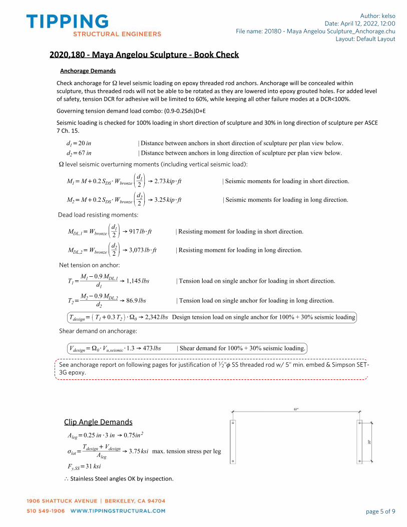
Anchorage Demands
Check anchorage for W level seismic loading on epoxy threaded rod anchors. Anchorage will be concealed within
sculpture, thus threaded rods will not be able to be rotated as they are lowered into epoxy grouted holes. For added level
of safety, tension DCR for adhesive will be limited to 60%, while keeping all other failure modes at a DCR<100%.
Governing tension demand load combo: (0.9-0.2Sds)D+E
Seismic loading is checked for 100% loading in short direction of sculpture and 30% in long direction of sculpture per ASCE
7 Ch. 15.
d1=20 in | Distance between anchors in short direction of sculpture per plan view below.
Aleg=0.25 in×3 in ® 0.75in 2
slat=Tdesign+Vdesign
Aleg® 3.75ksi max. tension stress per leg
Fy,SS=31 ksi
Clip Angle Demands
M1=M+0.2SDS×Wbronze
d12
æçè
ö÷ø® 2.73kip×ft | Seismic moments for loading in short direction.
d2=67 in | Distance between anchors in long direction of sculpture per plan view below.
M2=M+0.2SDS×Wbronze
d22
æçè
ö÷ø® 3.25kip×ft | Seismic moments for loading in long direction.
W level seismic overturning moments (including vertical seismic load):
Dead load resisting moments:
MDL,1=Wbronze
d12
æçè
ö÷ø® 917 lb×ft | Resisting moment for loading in short direction.
MDL,2=Wbronze
d22
æçè
ö÷ø® 3,073 lb×ft | Resisting moment for loading in long direction.
Net tension on anchor:
T1=M1-0.9MDL,1
d1® 1,145 lbs | Tension load on single anchor for loading in short direction.
T2=M2-0.9MDL,2
d2® 86.9 lbs | Tension load on single anchor for loading in long direction.
Tdesign= T1+0.3T2æè
öø×W0 ® 2,342 lbs Design tension load on single anchor for 100% + 30% seismic loading
Shear demand on anchorage:
Vdesign=W0×Vu,seismic×1.3 ® 473 lbs | Shear demand for 100% + 30% seismic loading.
See anchorage report on following pages for justification of 12"f SS threaded rod w/ 5" min. embed & Simpson SET-
3G epoxy.
\ Stainless Steel angles OK by inspection.
Author: kelsoDate: April 12, 2022, 12:00
File name: 20180 - Maya Angelou Sculpture_Anchorage.chuLayout: Default Layout
page 5 of 9

Company: Tipping Structural Engineers Date: 12/2/2021
Engineer: Page: 1/5
Project:
Address: 1906 Shattuck Ave. Berkeley CA. 94704
Phone: 510-549-1906
E-mail: [email protected]
Anchor Designer™SoftwareVersion 2.9.7376.0
1.Project information
Customer company: Customer contact name: Customer e-mail: Comment:
Project description: Maya Angelou Sculpture in SFMLLocation: Fastening description:
2. Input Data & Anchor Parameters
GeneralDesign method:ACI 318-14Units: Imperial units
Anchor Information:Anchor type: Bonded anchorMaterial: A193 Grade B8/B8M (304/316SS)Diameter (inch): 0.500Effective Embedment depth, hef (inch): 5.000Code report: ICC-ES ESR-4057Anchor category: -Anchor ductility: Yeshmin (inch): 6.25cac (inch): 8.60Cmin (inch): 1.75Smin (inch): 2.50
Base MaterialConcrete: Normal-weightConcrete thickness, h (inch): 12.00State: CrackedCompressive strength, f’c (psi): 3000Ψc,V: 1.0Reinforcement condition: B tension, B shearSupplemental reinforcement: Not applicableReinforcement provided at corners: NoIgnore concrete breakout in tension: NoIgnore concrete breakout in shear: NoHole condition: Dry concreteInspection: ContinuousTemperature range, Short/Long: 176/110°FIgnore 6do requirement: Not applicableBuild-up grout pad: No
Recommended AnchorAnchor Name: SET-3G - SET-3G w/ 1/2"Ø A193 Gr. B8/B8M (304/316SS)Code Report: ICC-ES ESR-4057
5956 W. Las Positas Boulevard Pleasanton, CA 94588 Phone: 925.560.9000 Fax: 925.847.3871 www.strongtie.comSimpson Strong-Tie Company Inc.
Input data and results must be checked for agreement with the existing circumstances, the standards and guidelines must be checked for plausibility.

Company: Tipping Structural Engineers Date: 12/2/2021
Engineer: Page: 2/5
Project:
Address: 1906 Shattuck Ave. Berkeley CA. 94704
Phone: 510-549-1906
E-mail: [email protected]
Anchor Designer™SoftwareVersion 2.9.7376.0
Load and GeometryLoad factor source: ACI 318 Section 5.3Load combination: not setSeismic design: YesAnchors subjected to sustained tension: NoDuctility section for tension: 17.2.3.4.2 not applicableDuctility section for shear: 17.2.3.5.2 not applicableΩ0 factor: not setApply entire shear load at front row: NoAnchors only resisting wind and/or seismic loads: No
Strength level loads:
Nua [lb]: 2342Vuax [lb]: 0Vuay [lb]: 473
<Figure 1>
5956 W. Las Positas Boulevard Pleasanton, CA 94588 Phone: 925.560.9000 Fax: 925.847.3871 www.strongtie.comSimpson Strong-Tie Company Inc.
Input data and results must be checked for agreement with the existing circumstances, the standards and guidelines must be checked for plausibility.

Company: Tipping Structural Engineers Date: 12/2/2021
Engineer: Page: 4/5
Project:
Address: 1906 Shattuck Ave. Berkeley CA. 94704
Phone: 510-549-1906
E-mail: [email protected]
Anchor Designer™SoftwareVersion 2.9.7376.0
Shear load y,Vuay (lb)
Anchor Tension load,Nua (lb)
3. Resulting Anchor Forces
Shear load combined,√(Vuax)²+(Vuay)² (lb)
Shear load x,Vuax (lb)
2342.01 0.0 473.0473.0
0.0 473.0Sum 2342.0 473.0
Maximum concrete compression strain (‰): 0.00Maximum concrete compression stress (psi): 0Resultant tension force (lb): 2342Resultant compression force (lb): 0Eccentricity of resultant tension forces in x-axis, e'Nx (inch): 0.00Eccentricity of resultant tension forces in y-axis, e'Ny (inch): 0.00Eccentricity of resultant shear forces in x-axis, e'Vx (inch): 0.00Eccentricity of resultant shear forces in y-axis, e'Vy (inch): 0.00
4. Steel Strength of Anchor in Tension (Sec. 17.4.1)
Nsa (lb) f fNsa (lb)
8095 0.75 6071
5. Concrete Breakout Strength of Anchor in Tension (Sec. 17.4.2)
Nb = kclaÖf’chef1.5 (Eq. 17.4.2.2a)
kc la f’c (psi) hef (in) Nb (lb)
17.0 1.00 3000 5.000 10410
0.75fNcb = 0.75f (ANc / ANco)Yed,NYc,NYcp,NNb (Sec. 17.3.1 & Eq. 17.4.2.1a)
ANc (in2) ANco (in2 ca,min (in) Yed,N Yc,N Ycp,N Nb (lb) f 0.75fNcb (lb)
225.00 225.00 - 1.000 1.00 1.000 10410 0.65 5075
6. Adhesive Strength of Anchor in Tension (Sec. 17.4.5)
tk,cr = tk,crfshort-termKsat(f’c / 2,500)naN.seis
tk,cr (psi) fshort-term Ksat aN.seis f’c (psi) n tk,cr (psi)
1163 1.00 1.00 0.90 3000 0.24 1094
Nba = l atcrpdahef (Eq. 17.4.5.2)
l a tcr (psi) da (in) hef (in) Nba (lb)
1.00 1094 0.50 5.000 8588
0.75fNa = 0.75f (ANa / ANa0)Yed,NaYcp,NaNba (Sec. 17.3.1 & Eq. 17.4.5.1a)
ANa (in2) ANa0 (in2) cNa (in) ca,min (in) Yed,Na Yp,Na Na0 (lb) f 0.75fNa (lb)
170.55 170.55 6.53 - 1.000 1.000 8588 0.65 4187
5956 W. Las Positas Boulevard Pleasanton, CA 94588 Phone: 925.560.9000 Fax: 925.847.3871 www.strongtie.comSimpson Strong-Tie Company Inc.
Input data and results must be checked for agreement with the existing circumstances, the standards and guidelines must be checked for plausibility.

Company: Tipping Structural Engineers Date: 12/2/2021
Engineer: Page: 5/5
Project:
Address: 1906 Shattuck Ave. Berkeley CA. 94704
Phone: 510-549-1906
E-mail: [email protected]
Anchor Designer™SoftwareVersion 2.9.7376.0
8. Steel Strength of Anchor in Shear (Sec. 17.5.1)
Vsa (lb) fgrout f aV,seis fgroutaV,seisfVsa (lb)
4855 1.0 0.65 0.80 2525
10. Concrete Pryout Strength of Anchor in Shear (Sec. 17.5.3)
fVcp = f min|kcpNa ; kcpNcb| = f min|kcp(ANa / ANa0)Yed,NaYcp,NaNba ; kcp(ANc / ANco)Yed,NYc,NYcp,NNb| (Sec. 17.3.1 & Eq. 17.5.3.1a)
kcp ANa (in2) ANa0 (in2) Yed,Na Ycp,Na Nba (lb) Na (lb)
2.0 170.55 170.55 1.000 1.000 8588 8588
ANc (in2) ANco (in2) Yed,N Yc,N Ycp,N Nb (lb) Ncb (lb) f fVcp (lb)
225.00 225.00 1.000 1.000 1.000 10410 10410 0.70 12024
11. Results
Interaction of Tensile and Shear Forces (Sec. 17.6.)
Tension Factored Load, Nua (lb) Design Strength, øNn (lb) Ratio Status
Steel 2342 6071 0.39 Pass
Concrete breakout 2342 5075 0.46 Pass
Adhesive 2342 4187 0.56 Pass (Governs)
Shear Factored Load, Vua (lb) Design Strength, øVn (lb) Ratio Status
Steel 473 2525 0.19 Pass (Governs)
Pryout 473 12024 0.04 Pass
Interaction check Nua/fNn Vua/fVn Combined Ratio Permissible Status
Sec. 17.6..1 0.56 0.00 55.9% 1.0 Pass
SET-3G w/ 1/2"Ø A193 Gr. B8/B8M (304/316SS) with hef = 5.000 inch meets the selected design criteria.
12. Warnings
- Per designer input, the tensile component of the strength-level earthquake force applied to anchors does not exceed 20 percent of the total factored anchor tensile force associated with the same load combination. Therefore the ductility requirements of ACI 318 17.2.3.4.2 for tension need not be satisfied – designer to verify.
- Per designer input, the shear component of the strength-level earthquake force applied to anchors does not exceed 20 percent of the total factored anchor shear force associated with the same load combination. Therefore the ductility requirements of ACI 318 17.2.3.5.2 for shear need not be satisfied – designer to verify.
- Designer must exercise own judgement to determine if this design is suitable.
- Refer to manufacturer’s product literature for hole cleaning and installation instructions.
5956 W. Las Positas Boulevard Pleasanton, CA 94588 Phone: 925.560.9000 Fax: 925.847.3871 www.strongtie.comSimpson Strong-Tie Company Inc.
Input data and results must be checked for agreement with the existing circumstances, the standards and guidelines must be checked for plausibility.

Forces
Fw=qz×G×Cf×As ® 696 lbs | (Eq. 29.3-1) Total wind force on surface for solid signs.
Moverturning,wind=F× 0.55×Elevæè
öø ® 3.94kip×ft | Overturning moment about long axis (per Case C).
T=Mwind
d® 0 | Total tension on each anchor per wind force.
n=2×ceilingBbase
67 in
æçè
ö÷ø® 4 | Assumed number of anchors in total (2 rows).
Tu=Tn2
® 0 | Tension demand per anchor per wind force.
FLL=200 lbs ® 200 lbs | Horizontal Live Load force.
F=0.5× FLLæè
öø+1.0× Fw
æè
öø ® 796 lbs | LRFD horizontal force (0.5L+1.0W) (reduced LL).
2020,180 - Maya Angelou Sculpture - Base + Book Check
Vu=Fn® 199 lbs | Shear demand per anchor per wind force.
Mrestoring,wind=Wbronze×wbronze
2
æçè
ö÷ø+
Wbase×wbase
2
æçè
ö÷ø® 4.64kip×ft | Restoring moment about long axis.
Mwind=max 0 , Moverturning,wind-Mrestoring,windæè
öø ® 0kip×ft | Net moment demand on book per wind force.
Structure and Base Parameters
NOTE: Parameters not enlisted here have the same value that those found in "Book Check" section.
Elev= s ® 108 in | Height of sculpture.
As= Hbronze×Bbronzeæè
öø+ Hbase×Bbase
æè
öø ® 54.7ft2 | Total surface area of base + book.
s=Hbronze+Hbase ® 108 in | Elevation of sculpture above ground.
d=wbase-2×1.5 in ® 27 in | Assumed width of anchor points.
Wind Check
Author: kelsoDate: April 12, 2022, 12:00
File name: 20180 - Maya Angelou Sculpture_Anchorage.chuLayout: Default Layout
page 6 of 9

Force Analysis
Seismic Check
2020,180 - Maya Angelou Sculpture - Base + Book Check
Fp,min=0.3×SDS×Ip ® 0.36 | Eqn. 13.3-3 Min. horizontal force.
Fp,coeff=bounded Fp,eqn , Fp,min , Fp,maxæè
öø ® 0.48
Fpvert,coeff=0.2×SDS ® 0.24 | Sec. 13.3.1 Vertical force.
Fp,eqn=0.4×ap×SDS
Rp
Ip
× 1+2zh
æèöø
æè
öø ® 0.48 | Eqn. 13.3-1 Horizontal force.
Fp,max=1.6×SDS×Ip ® 1.92 | Eqn. 13.3-2 Max. horizontal force.
Fp=Fp,coeff×Wp ® 1,888 lbs | Shear demand at the base.
Vu,seismic=1.0×Fp+1.0×FLL
n® 522 lbs | Shear demand per anchor.
Tu,seismic=W0×Tseismic
n2
æççè
ö÷÷ø
® 0 | Tension demand per anchor.
Tseismic=Mseismic
d® 0 | Total tension per seismic force.
Mrestoring,seismic=0.9×Wbronze×wbronze
2
æçè
ö÷ø+
Wbase×wbase
2
æçè
ö÷ø
æçè
ö÷ø® 4.18kip×ft | Restoring moment from weight about long axis.
Mseismic=max 0 , M-Mrestoring,seismicæè
öø ® 0kip×ft | Net moment demand on book per seismic forces.
M= Fp,coeff× Wbronze×Hbronze
2
æçè
ö÷ø+Wbase×
Hbase
2
æçè
ö÷ø
æçè
ö÷ø
æçè
ö÷ø+0.5×
FLL×Hbronze
2
æçè
ö÷ø® 3.19kip×ft | Unfactored moment with red. LL.
Seismic parameters & Fp coefficients
h= s ® 108 in | Total height of base + book.
Even though the tension demands are zero, please provide (4) 12" SS threaded rod w/3" min. embed &
Simpson SET-3G epoxy.
NOTE: Parameters not enlisted here have the same value that those found in "Book Check" section.
Author: kelsoDate: April 12, 2022, 12:00
File name: 20180 - Maya Angelou Sculpture_Anchorage.chuLayout: Default Layout
page 7 of 9

Checking Bearing stresses per CBC Ch. 18
CBC Ch. 18.
PCBC,Vert=1,500 psf×43
æèöø ® 2,000psf | Max. vertical pressure (conservative) + 1
3 per Section 1806.1 on CBC Ch. 18.
Wp ® 3,934 lbs | Total weight of sculpture.
2020,180 - Maya Angelou Sculpture - Base + Book Check
Sculpture contribution
Areabase=Bbase×wbase ® 16.7ft2 | Total base area.
Existent layers contribution
Pgranite=20 psf | 1 14" granite layer. See (e) dwgs.
Psculp=Wp
Areabase® 236psf | Sculpture pressure.
gconc=150 pcf | Density of SOG.
Pconc=gconc×5 in ® 62.5psf | 5" Concrete slab. See (e) dwgs.
PT=Psculp+Pgranite+Pconc ® 319psf | Total pressure on soil (DL).
VERTICAL PRESSURE
(E) dwgs.
DL
M
Bearing stresses
qmax= if e<Bbase_
6
PT+6× PT×Areabase
æè
öø×e
wbase_×Bbase_
2
æçè
ö÷ø
2×PT×Areabase
3×wbase_×Bbase_
2- e
æçè
ö÷ø
® 531psf
e=Moverturning,wind
PT×Areabase® 0.74 ft | Eccentricity.
qmax
DL + Wind Moment
where
e
Author: kelsoDate: April 12, 2022, 12:00
File name: 20180 - Maya Angelou Sculpture_Anchorage.chuLayout: Default Layout
page 8 of 9

Pcheck= if PCBC,Vert>PT+qmaxVertical Pressure is OKVertical pressure exceeds maximum
® Vertical Pressure is OK
LATERAL BEARING PRESSURE
There is not Lateral Bearing Pressure since the sculpture is sitting on topof the SOG and Granite layer.
2020,180 - Maya Angelou Sculpture - Base + Book Check
Author: kelsoDate: April 12, 2022, 12:00
File name: 20180 - Maya Angelou Sculpture_Anchorage.chuLayout: Default Layout
page 9 of 9

KEY PLAN
FULTON ST
MAYA ANGELOU
SCULPTURE LOCATION
LA
RK
IN
S
T
HY
DE
S
T
GROVE ST
SAN FRANCISCO
MAIN LIBRARY
1
S2.1
S.F. LIBRARY PLAN VIEW
NTS
2
S2.1
(E) PLANTER
6"
TYP.(E) CLADDING
STEPS
1
9'-1"
13'-11"
3
"
T
Y
P
.
4
"
T
Y
P
.
FA
CE
O
F LIB
RA
RY
B
UILD
IN
G
(E) 18" BASEMENT
WALL BLW.
STONE BASE
6'-8"x2'-6"x1'-0"
SCULPTURE
6'-0"x2'-0"x8'-0"
(E) STONE TILE o/
CONC. S.O.G.
(E) PLAZA SLOPE
3
16
IN. PER FT.
18'-3"
21'-0"
2
S2.1
SCULPTURE ENLARGED PLAN VIEW
1/4" = 1'-0"
19'-7
1
2
"
24'-2
5
8
"
(E) DRAIN
(E) SEAT WALL
C
D
A
B
1
S2.2
A
POINT DISTANCE WEST OF
LIBRARY FACADE
ELEVATION DROP
FROM POINT A
B
C
D
19'-7 1/2" 0.00" 12.00"
21'-5 1/4" 0.34" 12.34"
24'-2 5/8"
26'-0 3/8"
0.86" 12.86"
1.20" 13.20"
3
S2.1
STONE BASE THICKNESS
STONE
THICKNESS
NOTE: TOP OF STONE BASE SHALL BE FLAT AND LEVEL.
BOTTOM OF BASE SHALL BE MILLED AS A FLAT PLANE TO
PROVIDE CORNER THICKNESSES AS NOTED.
DATE
SCALE
DRAWN
JOB
SHEET
OF SHEETS
2020.180.00
04-12-22
MA
YA
A
NG
ELO
U
SC
ULP
TU
RE
S
UP
PO
RT
SA
N F
RA
NC
IS
CO
, C
A
Plotted: T
uesday, A
pril 12, 2022 12:54:53 P
M - B
y: kelso - S
heet S
ize: 11x17 - F
ile: X
:\2020dw
gs\20180\S
truct\180S
2-1.dw
g
S2.1
AS NOTED
MH
SC
ULP
TU
RE
LO
CA
TIO
N
100%
C
ON
ST
RU
CT
IO
N D
OC
UM
EN
TS
N
3
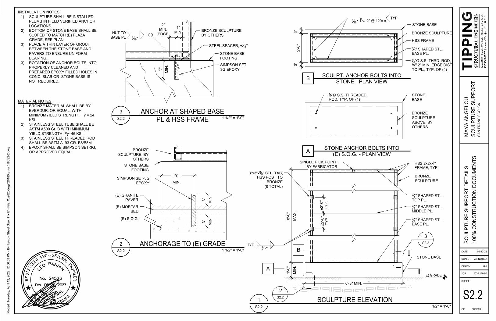
S2.2
1'-0"
MIN
.
1
S2.2
SCULPTURE ELEVATION
1/2" = 1'-0"
B
B
SCULPT. ANCHOR BOLTS INTO
STONE - PLAN VIEW
STONE BASE
3"
2'-0"
3"
BRONZE SCULPTURE
1
2
"Ø S.S. THRD. ROD,
W/ 2" MIN. EDGE DIST.
TO PL., TYP. OF (4)
8'-0"
MA
X.
BRONZE
SCULPTURE
STONE BASE
(E) GRADE
A
STONE ANCHOR BOLTS INTO
(E) S.O.G. - PLAN VIEW
STONE
BASE
BRONZE
SCULPTURE
ABOVE, BY
OTHERS
1
2
"Ø S.S. THREADED
ROD, TYP. OF (4)
2
S2.2
A
6'-8" MIN.
HSS 2x2x
1
4
"
FRAME, TYP.
HSS FRAME
3
8
" SHAPED STL.
BASE PL.
TYP.
2" @ 12"o.c.
3
16
"
3
8
" SHAPED STL.
BASE PL.
3
8
" SHAPED STL.
MIDDLE PL.
3
8
" SHAPED STL.
TOP PL.
3"x3"x
3
8
" STL. TAB,
HSS POST TO
BRONZE
(8 TOTAL)
TYP.
3
16
"
±2'-0"
TY
P.
±2'-0"
TY
P.
SINGLE PICK POINT,
BY FABRICATOR
STONE BASE
FOOTING
SIMPSON SET
3G EPOXY
3
S2.2
ANCHOR AT SHAPED BASE
PL & HSS FRAME
1 1/2" = 1'-0"
BRONZE SCULPTURE
BY OTHERS
1"
MIN.
2
S2.2
ANCHORAGE TO (E) GRADE
1 1/2" = 1'-0"
9"
MIN.
STONE BASE
FOOTING
(E) GRANITE
PAVER
(E) MORTAR
BED
(E) S.O.G.
5"
MIN
.
3"
MIN
.
3"
MIN
.
SIMPSON SET-3G
EPOXY
BRONZE
SCULPTURE, BY
OTHERS
2"
MIN.
EDGE
NUT TO
BASE PL
3
16
"
STEEL SPACER, ±
1
16
"
MATERIAL NOTES:
1) BRONZE MATERIAL SHALL BE BY
EVERDUR, OR EQUAL, WITH
MINIMUMYIELD STRENGTH, Fy = 24
KSI.
2) STAINLESS STEEL TUBE SHALL BE
ASTM A500 Gr. B WITH MINIMUM
YIELD STRENGTH, Fy=46 KSI.
3) STAINLESS STEEL THREADED ROD
SHALL BE ASTM A193 GR. B8/B8M
4) EPOXY SHALL BE SIMPSON SET-3G,
OR APPROVED EQUAL.
INSTALLATION NOTES:
1) SCULPTURE SHALL BE INSTALLED
PLUMB IN FIELD VERIFIED ANCHOR
LOCATIONS.
2) BOTTOM OF STONE BASE SHALL BE
SLOPED TO MATCH (E) PLAZA
GRADE, SEE PLAN.
3) PLACE A THIN LAYER OF GROUT
BETWEEN THE STONE BASE AND
PAVERS TO ENSURE UNIFORM
BEARING.
3) ROTATION OF ANCHOR BOLTS INTO
PROPERLY CLEANED AND
PREPARED EPOXY FILLED HOLES IN
CONC. SLAB OR STONE BASE IS
NOT REQUIRED.
DATE
SCALE
DRAWN
JOB
SHEET
OF SHEETS
2020.180.00
04-12-22
MA
YA
A
NG
ELO
U
SC
ULP
TU
RE
S
UP
PO
RT
SA
N F
RA
NC
IS
CO
, C
A
Plotted: T
uesday, A
pril 12, 2022 12:56:58 P
M - B
y: kelso - S
heet S
ize: 11x17 - F
ile: X
:\2020dw
gs\20180\S
truct\180S
2-2.dw
g
S2.2
AS NOTED
MH
SC
ULP
TU
RE
S
UP
PO
RT
D
ET
AILS
100%
C
ON
ST
RU
CT
IO
N D
OC
UM
EN
TS