String Searching Engine for Virus Scanning - CiteSeerX
15
String Searching Engine for Virus Scanning Derek Pao, Xing Wang, Xiaoran Wang, Cong Cao, Yuesheng Zhu Abstract— A memory efficient hardware string searching engine for anti-virus applications is presented. The proposed QSV method is based on quick sampling of the input stream against fixed-length pattern prefixes, and on-demand verification of variable-length pattern suffixes. Patterns handled by the QSV method are required to have at least 16 bytes, and possess distinct 16-byte prefixes. The latter requirement can be fulfilled by a preprocessing procedure. The search engine uses the pipelined Aho-Corasick (P-AC) architecture developed by the first author to process 4- to 15-byte short patterns and a small number of exception cases. Our design was evaluated using the ClamAV virus database having 82888 strings with a total size that exceeds 8 Mbyte. In terms of byte count, 99.3% of the pattern set is handled by the QSV method and 0.7% of the pattern set is handled by P-AC. A pattern with distinct 16-byte prefix only occupies up to 3 lookup table entries in QSV. The overall memory cost of our system is about 1.4Mbyte, i.e. 1.4 bit per character of the ClamAV pattern set. The proposed method is memory-based, hence, updates to the pattern set can be accommodated by modifying the contents of the lookup tables without reconfiguring the hardware circuits. Index Terms—string searching, anti-virus system, system security, embedded system. —————————— —————————— 1 INTRODUCTION very computer connected to the Internet is subject to various kinds of attack. Intrusion detection system (IDS) and anti-virus software are essential security tools for today’s computer systems. Many users have complained that their personal computers are slowed down significantly by the IDS/anti-virus software. This is understandable because these tools will need to scan any data retrieved from storage devices or received via the Internet against a very large pattern set with thousands of attack patterns. The computation resource consumed by the IDS/anti-virus software depends on the amount of data to be scanned and the size of the pattern set. If the IDS/anti-virus software is deployed to protect a server machine, software-based pattern matching engines may not meet the required throughput. For example, an email server needs to scan all incoming and outgoing mails to ensure that emails delivered to end-users are virus-free. The amount of data involved is in the order of multi-tera bytes per day. Hence, there have been active researches on hardware-assisted methods to speed up the pattern matching process. Patterns in IDS/anti-virus rule sets can be broadly divided into two categories, namely, static string and regular expression. Up to now, majority of the patterns in a rule set are static strings. For example, in the ClamAV [6] virus database, there are 82,888 static strings and 7017 regular expressions. However, the number of regular expression is catching up steadily. In this paper, we shall present a memory efficient hardware string searching engine to handle the 82K static strings. In the following discussion, the term “pattern” is used to refer to static string. There have been attempts to implement hardware- assisted string matching engines based on the Aho- Corasick (AC) algorithm [1, 10, 16-18, 22, 25, 26], Knuth- Morris-Pratt (KMP) algorithm [3, 14], hashing [20], Bloom Filters [8, 9], ternary content addressable memory (TCAM) [2, 27], and hardwired logic circuits [4, 7, 23, 24]. Researchers mostly evaluated their designs using pattern sets extracted from the Snort IDS [21]. The number of patterns used in their evaluations varies from 2 to 6 thousands. The average pattern length in the Snort rule set is about 19 characters (bytes). The overall size of the Snort pattern set is about 100K characters. There are two major challenges in anti-virus applications, namely, scalability and dynamic updates to the pattern set. In an anti-virus system, e.g. ClamAV, the rule database contains over 82K static strings. The average pattern length is about 102 bytes. The total size of the ClamAV pattern set is more than 80 times the size of the Snort pattern set. If the previously published methods were applied to the ClamAV pattern set, the hardware string matching engine would require at least 20 Mbyte to over 200 Mbyte of embedded memory. Such a large amount of embedded memory is very expensive. Moreover, implementation using FPGA is not feasible since today’s FPGA devices can only have about 2Mbyte of embedded memory. Updates to the pattern set in an anti-virus system can be quite frequent. For example, by default the ClamAV system will check for virus database updates once every 2 hours. Reconfiguration of a FPGA device may take a couple of hours to over a day, depending on the complexity of the circuits and device utilization. In order xxxx-xxxx/0x/$xx.00 © 200x IEEE E ———————————————— • D. Pao, Xiaoran Wang, and C. Cao are with the Department of Electronic Engineering, City University of Hong Kong. E-mail: d.pao@ cityu.edu.hk. • Xing Wang and Y. Zhu are with the Communication and Information Security Lab, Shenzhen Graduate School, Peking University, PRC. E-mail: [email protected]. • This work was supported by the Hong Kong University Grant Council GRF Grant No. 9041500, and Research Program of Shenzhen-Hong Kong Innovation Circle.
-
Upload
khangminh22 -
Category
Documents
-
view
3 -
download
0
Transcript of String Searching Engine for Virus Scanning - CiteSeerX

String Searching Engine for Virus Scanning Derek Pao, Xing Wang, Xiaoran Wang, Cong Cao, Yuesheng Zhu
Abstract— A memory efficient hardware string searching engine for anti-virus applications is presented. The proposed QSV method is based on quick sampling of the input stream against fixed-length pattern prefixes, and on-demand verification of variable-length pattern suffixes. Patterns handled by the QSV method are required to have at least 16 bytes, and possess distinct 16-byte prefixes. The latter requirement can be fulfilled by a preprocessing procedure. The search engine uses the pipelined Aho-Corasick (P-AC) architecture developed by the first author to process 4- to 15-byte short patterns and a small number of exception cases. Our design was evaluated using the ClamAV virus database having 82888 strings with a total size that exceeds 8 Mbyte. In terms of byte count, 99.3% of the pattern set is handled by the QSV method and 0.7% of the pattern set is handled by P-AC. A pattern with distinct 16-byte prefix only occupies up to 3 lookup table entries in QSV. The overall memory cost of our system is about 1.4Mbyte, i.e. 1.4 bit per character of the ClamAV pattern set. The proposed method is memory-based, hence, updates to the pattern set can be accommodated by modifying the contents of the lookup tables without reconfiguring the hardware circuits.
Index Terms—string searching, anti-virus system, system security, embedded system.
—————————— ——————————
1 INTRODUCTION very computer connected to the Internet is subject to various kinds of attack. Intrusion detection system (IDS) and anti-virus software are essential security
tools for today’s computer systems. Many users have complained that their personal computers are slowed down significantly by the IDS/anti-virus software. This is understandable because these tools will need to scan any data retrieved from storage devices or received via the Internet against a very large pattern set with thousands of attack patterns. The computation resource consumed by the IDS/anti-virus software depends on the amount of data to be scanned and the size of the pattern set. If the IDS/anti-virus software is deployed to protect a server machine, software-based pattern matching engines may not meet the required throughput. For example, an email server needs to scan all incoming and outgoing mails to ensure that emails delivered to end-users are virus-free. The amount of data involved is in the order of multi-tera bytes per day. Hence, there have been active researches on hardware-assisted methods to speed up the pattern matching process.
Patterns in IDS/anti-virus rule sets can be broadly divided into two categories, namely, static string and regular expression. Up to now, majority of the patterns in a rule set are static strings. For example, in the ClamAV [6] virus database, there are 82,888 static strings and 7017 regular expressions. However, the number of regular expression is catching up steadily. In this paper, we shall present a memory efficient hardware string searching
engine to handle the 82K static strings. In the following discussion, the term “pattern” is used to refer to static string.
There have been attempts to implement hardware-assisted string matching engines based on the Aho-Corasick (AC) algorithm [1, 10, 16-18, 22, 25, 26], Knuth-Morris-Pratt (KMP) algorithm [3, 14], hashing [20], Bloom Filters [8, 9], ternary content addressable memory (TCAM) [2, 27], and hardwired logic circuits [4, 7, 23, 24]. Researchers mostly evaluated their designs using pattern sets extracted from the Snort IDS [21]. The number of patterns used in their evaluations varies from 2 to 6 thousands. The average pattern length in the Snort rule set is about 19 characters (bytes). The overall size of the Snort pattern set is about 100K characters.
There are two major challenges in anti-virus applications, namely, scalability and dynamic updates to the pattern set. In an anti-virus system, e.g. ClamAV, the rule database contains over 82K static strings. The average pattern length is about 102 bytes. The total size of the ClamAV pattern set is more than 80 times the size of the Snort pattern set. If the previously published methods were applied to the ClamAV pattern set, the hardware string matching engine would require at least 20 Mbyte to over 200 Mbyte of embedded memory. Such a large amount of embedded memory is very expensive. Moreover, implementation using FPGA is not feasible since today’s FPGA devices can only have about 2Mbyte of embedded memory.
Updates to the pattern set in an anti-virus system can be quite frequent. For example, by default the ClamAV system will check for virus database updates once every 2 hours. Reconfiguration of a FPGA device may take a couple of hours to over a day, depending on the complexity of the circuits and device utilization. In order
xxxx-xxxx/0x/$xx.00 © 200x IEEE
E
———————————————— • D. Pao, Xiaoran Wang, and C. Cao are with the Department of Electronic
Engineering, City University of Hong Kong. E-mail: d.pao@ cityu.edu.hk. • Xing Wang and Y. Zhu are with the Communication and Information
Security Lab, Shenzhen Graduate School, Peking University, PRC. E-mail: [email protected].
• This work was supported by the Hong Kong University Grant Council GRF Grant No. 9041500, and Research Program of Shenzhen-Hong Kong Innovation Circle.
to support dynamic updates to the pattern set, the design of the hardware string searching engine should be memory-based. The system should be able to update the lookup tables without reconfiguring the hardware circuits.
The terms “string matching” and “string searching” are often used interchangeably by the research community. However, in this paper the two terms have slightly different meanings. For an input stream I and a pattern set Γ, the string matching problem is to locate and identify all substrings of I which are patterns in Γ. Outputs of the string matching algorithm are two-tuples <i, pid>, where pid is the pattern ID and i is the location at which the pattern is found. For string searching, the problem requirement is slightly relaxed, and the outputs are interpreted as possible matches only, i.e. the given pattern is very likely to be found at location i. Methods based on the AC or KMP algorithm solve the string matching problem. When the system reports a match, no further processing is required to verify the match result. Methods based on hashing and Bloom filters only solve the string searching problem. When the system reports a possible match, the result needs to be verified by the general purpose processor or other devices to eliminate false positives.
For methods based on the AC algorithm, the complete pattern set is stored in the match engine for comparison with the input data. Sharing of states in the AC transition graph is mostly restricted to nodes that are within 3 hops from the root. For virus patterns with average length of 102 bytes, state sharing can only help to reduce the storage of the pattern set by a few percents. Hence, the memory cost of pure AC-based methods cannot be lower than 8 bits per character. If the problem statement is relaxed to string searching, the system only needs to store the hash codes or pattern checksums. It is possible to reduce the memory cost to less than 8 bits per character.
In this paper, a string searching method for very large pattern sets that would require substantially smaller amount of embedded memory is presented. In this study, the system parameters are derived based on the ClamAV pattern set. However, the proposed method is applicable to other pattern sets. For the ClamAV pattern set with 82888 patterns, our method only requires 1.4 Mbyte of embedded memory, i.e. about 1.4 bits per character of the pattern set. The proposed method is based on quick sampling of the input stream against fixed-length pattern prefixes, and on-demand verification of variable-length pattern suffixes. The effectiveness of a string searching engine depends on the hit rate (including false positives). When a genuine virus is found, the data file concerned is tagged. How to handle the infected file will be the responsibility of the software system. If the hit rate is sufficiently low, e.g. 10-7 or lower, the workload of the general purpose processor for verification is negligible. In our evaluation using different data files as input stream
with total size that exceeds 900 Mbyte, only 3 matches are reported and none of them are false positive.
Organization of the paper is as follows. In section 2, we shall present the general strategy and architecture of the proposed method. Some of the system parameters will be devised based on the statistical properties of the ClamAV pattern set. In section 3, we shall discuss the necessary preprocessing and explain how the lookup tables and related data structures are computed. Design of the aggregation unit will be discussed in section 4. Performance evaluation and comparison with related work will be discussed in section 5. Section 6 is the conclusion.
2 PROPOSED METHOD The string searching problem can be solved using a simple strategy outlined in the pseudo code shown below. Let Γ be the pattern set, and L be the set of discrete pattern lengths. Let Cj be the set of checksum for patterns in Γ with length equal to j. The checksums can be generated using a user defined CRC polynomial.
//Pseudo code of the string searching method for (i = 0; i < in_stream.length; i++) { for each j in L { if(i+j < in_stream.length) { c_in=checksum of in_stream[i..(i+j-1)];
if(c_in==pattern_k.checksum in Cj) report a possible match (i, pattern_k); } } }
There are over 82K static strings in the ClamAV pattern set. The minimum and maximum pattern lengths are 4 and 392, respectively. Running the above algorithm on a sequential machine is very inefficient. However, the above computation can be mapped to hardware with good efficiency. A prerequisite is that all patterns in the pattern set are required to have distinct fixed-length (e.g. 16-byte) prefix. This property can be ensured by the preprocessing procedure. The system will do a quick sampling of fixed-length segments in the input stream. If the sampled input data segment does not match any pattern prefixes in the pattern set, then no further processing at this byte location is necessary. If the sampled segment matches the prefix of a pattern, then the system will continue to compute the checksum of the input stream data for the corresponding pattern length. If the checksum is equal to the expected value, then a match result is generated. We shall show that an overall system throughput of 1 byte per cycle can be achieved using a combination of techniques including pipelining, parallel processing, hashing, and pattern set preprocessing.
In the next subsection, we shall first highlight some statistical properties of the ClamAV pattern set. These statistical properties are used to guide the selection of appropriate system parameters in the hardware architecture. Details of the hardware architecture will be
explained in section 2.2. The required preprocessing of the pattern set will be discussed in section 3.
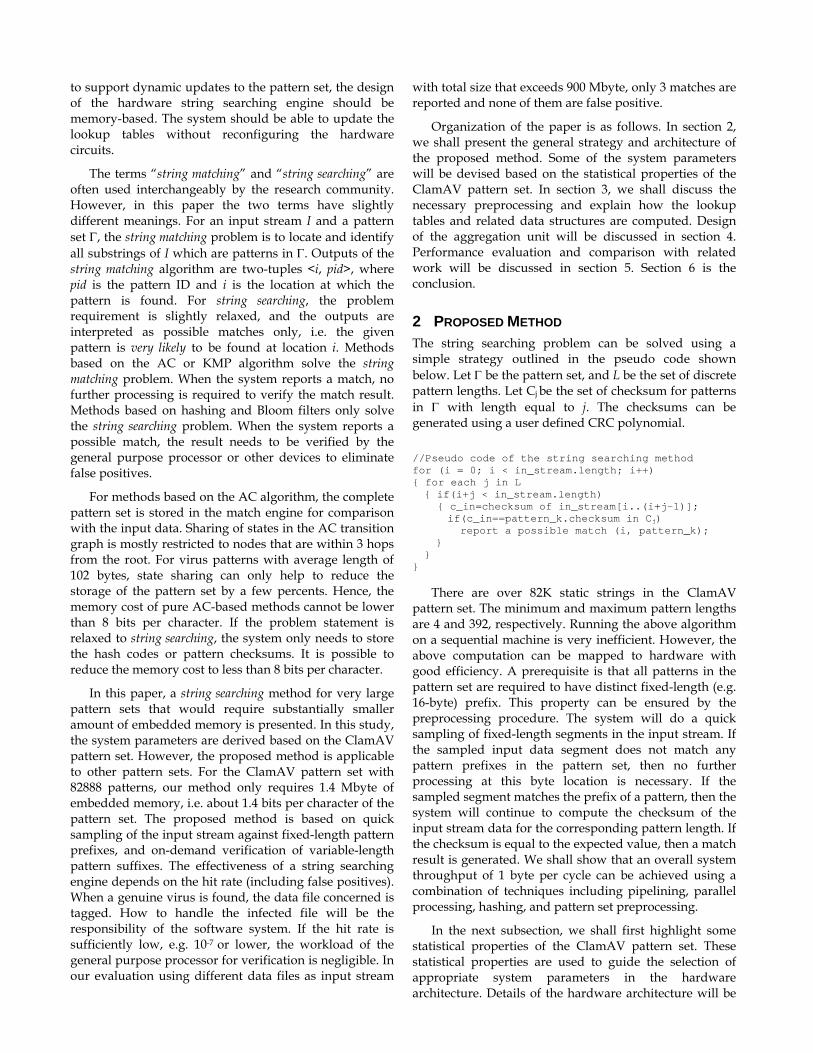
2.1 STATISTICAL PROPERTIES OF THE CLAMAV DATABASE The ClamAV virus database main.cvd version 51 released on 14 May 2009 is used in this study. Only static strings are considered. MD5 checksums and regular expressions in the database are excluded. A total of 82,888 static strings are found in the main.db and main.ndb files. The minimum, maximum, and average pattern lengths are 4, 392, and 102 bytes, respectively. 1258 (1.5%) patterns have less than 16 bytes. 81,630 (98.5%) patterns have 16 bytes or more. Only 172 patterns have more than 180 bytes. Detailed pattern length distribution of the pattern set is shown in Fig. 1. Patterns with 16 bytes or more are called long patterns. Patterns with less than 16 bytes are called short patterns. The short patterns only account for less than 0.2% of the total size of the pattern set. 94% of the long patterns have distinct 16-byte prefixes.
Fig. 1. Pattern length distribution in the ClamAV pattern set. Since zero value cannot be shown using logarithmic scale, the number of patterns for each length in the plot is set to 1 plus the actual value.
2.2 QSV ARCHITECTURE In the proposed string searching engine, we use our previously developed pipelined Aho-Corasick (P-AC) match engine [17, 18] to process short patterns and a small number of exception cases. The vast majority of long patterns will be processed using the quick sampling plus verification (QSV) approach. In terms of byte count, 99.3% of the pattern set will be processed by the QSV module.
The block diagram of the string searching engine is depicted in Fig. 2. There are three major components, namely, the P-AC module, the QSV module, and the aggregation unit (AU). The P-AC module and the QSV module operate synchronously. Both of them consume 1 input character per cycle. The P-AC architecture utilizes pipelined processing to eliminate all the failure and backward transition edges in the state transition graph of the AC algorithm such that the overall size of the lookup
table can be reduced very significantly. Readers are referred to [18] for the detailed design of the P-AC module. In the following discussion, we shall focus on the QSV module.
Fig. 2. System block diagram.
The QSV module is composed of the prefix sampling unit (PS) and the CRC checksum verification unit (CRC). Patterns processed by the QSV method are required to possess unique 16-byte prefixes. Patterns that share common 16-byte (or longer) prefixes will be divided into multiple segments with 16 bytes or more, except for the last segment, such that each long segment has distinct 16-byte prefix. Short segments with 4 to 15 bytes are handled by the P-AC module. Segments with 1 to 3 bytes are ignored by the search engine. They will be verified by the post-searching verification procedure. The aggregation unit (AU) is used to combine the partial match results (detection of individual segments) to produce the final results. The segmentation process will be discussed in section 3.1, and the design of the AU will be discussed in section 4.
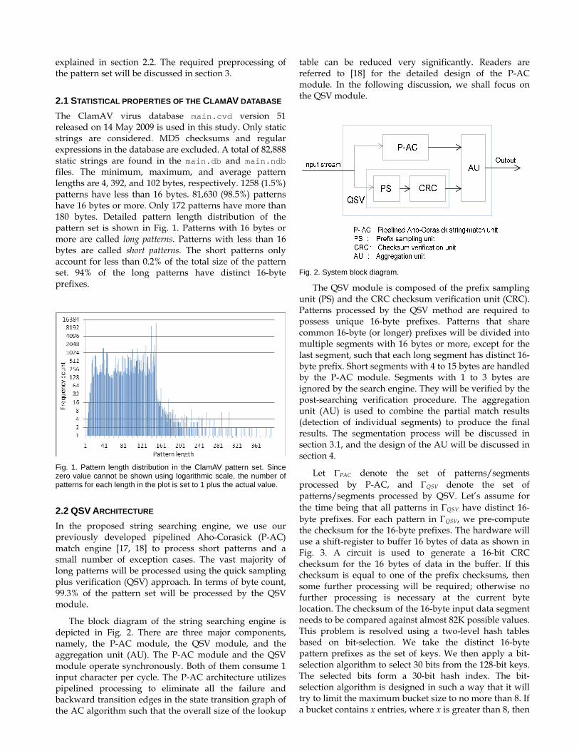
Let ΓPAC denote the set of patterns/segments processed by P-AC, and ΓQSV denote the set of patterns/segments processed by QSV. Let’s assume for the time being that all patterns in ΓQSV have distinct 16-byte prefixes. For each pattern in ΓQSV, we pre-compute the checksum for the 16-byte prefixes. The hardware will use a shift-register to buffer 16 bytes of data as shown in Fig. 3. A circuit is used to generate a 16-bit CRC checksum for the 16 bytes of data in the buffer. If this checksum is equal to one of the prefix checksums, then some further processing will be required; otherwise no further processing is necessary at the current byte location. The checksum of the 16-byte input data segment needs to be compared against almost 82K possible values. This problem is resolved using a two-level hash tables based on bit-selection. We take the distinct 16-byte pattern prefixes as the set of keys. We then apply a bit-selection algorithm to select 30 bits from the 128-bit keys. The selected bits form a 30-bit hash index. The bit-selection algorithm is designed in such a way that it will try to limit the maximum bucket size to no more than 8. If a bucket contains x entries, where x is greater than 8, then
Fig. 3. Block diagram of the QSV module
x−8 patterns in the given bucket will be transferred from ΓQSV to ΓPAC. By restricting the maximum bucket size to 8, we only need to compare the checksum of the input data segment with up to 8 prefix checksums in parallel. The advantages of using the bit-selection approach are that (i) the bucket size can be controlled, (ii) the generation of the hash index is very straightforward, and (iii) the hash function can be reprogrammed without the needs to reconfigure the hardware. The last property is particularly desirable in view of the dynamic updates to the pattern set. The bit-selection algorithm will be discussed in section 2.3.
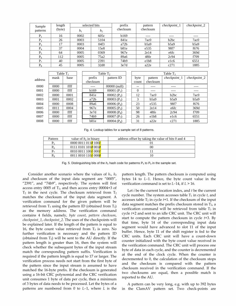
With a 30-bit hash value, the size of the logical hash table is equal to 230. However, only up to about 82K entries in the hash table are occupied. We implement the logical hash table with a two-level structure containing tables T1 and T2 as shown in Fig. 3. Table T2 is implemented using up to 8 parallel memory modules. Size of table T1 is equal to 32K, and size of table T2 (sum of the 8 memory modules) is 93K. Table T1 is a direct indexed array, and table T2 is implemented using the direct indexing plus bit-selection (DIBS) technique of [18]. The DIBS approach was later found to be similar to the BaRTS of [15]. We shall illustrate the table lookup operation using an example. In this example, T2 is assumed to be constructed using 1 memory module. Refer to the sample set of 8 patterns shown in Fig. 4. The 30 selected bits are divided into two groups, h1 and h2, where each group contains 15 bits. The values of h1, h2, the bit mask, and the checksums are shown as hexadecimal numbers. h1 is used as the address to access table T1. In this example, the values of h1 are artificially set to 0002 to 0005 so that the size of the array shown in the figure is kept to a minimum. Patterns P2 and P3 are mapped to bucket 0003 in T1, and patterns P5 to P8 are mapped to bucket 0005 in T1. An entry in T1 stores a 15-
bit mask vector and a 16-bit base address for accessing T2. Note that table T2 is implemented with up to 8 parallel memories. Its overall capacity is 93K, but the address range is less than 64K. When there is more than one pattern mapped to the same bucket in T1, the bit mask will be used to generate an offset value for accessing T2. If an entry in table T1 is empty, the base address field is set to all ‘1’.
Consider the group of patterns P5 to P8 that are mapped to bucket 0005 in T1. The 4 patterns can be distinguished by taking bits 0 and 4 of their h2 hash values as shown in Fig. 5. Hence, the bit mask stored in entry 0005 of T1 is equal to 0011 (hexadecimal). The bit-extraction circuit takes the bit mask and the value of h2 as inputs to generate the address offset. Assume g bits of the bit mask, bs1, bs2, ... bsg, are equal to 1, where s1 < s2 … < sg ≤ 15. Let the value of h2 be i14…i1i0. The offset value produced by the bit-extraction circuit is equal to 0..0isg…is2is1. If g bits in the bit mask are set to 1, a block of 2g entries in T2 will be allocated for the corresponding T1 bucket. If the base address is an integral multiple of 2g, then the least significant g bits of the base address must equal to ‘0’. Hence, the offset can be added to the base address by a simple bitwise logical-OR operation. In our study, the value of g is no more than 8.
Assume the values of h1, h2 and the checksum of the input data segment are “0005”, “1234”, and “abcd”, respectively. The system will first access entry 0005 of T1. The base address retrieved from T1 is equal to 0004. Bits 4 and 0 of “1234” are equal to “10” binary. The system will then access entry 0004+2 of T2 in the next cycle. The checksum retrieved from T2 is “3e7d”, which is not equal to “abcd”. Hence, no further processing at the current byte location is required.
Sample patterns
length (byte)
selected bits prefix checksum
pattern checksum
checkpoint_1
checkpoint_2 h1 h2
P1 16 0002 605c b169 ---- ---- ---- P2 26 0003 5104 841e 7ac0 b2bc 7ac0 P3 17 0003 04f3 a72b b5a9 b5a9 b5a9 P4 37 0004 15e8 b81e e535 98f7 f676 P5 64 0005 0369 967e 2e14 e6fc 369d P6 112 0005 75a2 89a6 48fe 2c94 f709 P7 40 0005 2391 74b9 e1b8 e1c6 6551 P8 45 0005 32d0 3e7d a22e c271 1885
Table T1 Table T2 Table T3
address mask base prefix checksum
pattern ID byte count
pattern checksum
checkpoint_1 checkpoint_2
0000 0000 ffff ---- 00000 (null) -- ---- ---- ---- 0001 0000 ffff b169 00001 (P1) 0 ---- ---- ---- 0002 0000 0001 841e 00002 (P2) 12 7ac0 b2bc 7ac0 0003 0001 0002 a72b 00003 (P3) 3 b5a9 b5a9 b5a9 0004 0000 0008 89a6 00006 (P6) 23 e535 98f7 f676 0005 0011 0004 967e 00005 (P5) 50 2e14 e6fc 369d 0006 0000 ffff 3e7d 00008 (P8) 98 48fe 2c94 f709 0007 0000 ffff 74b9 00007 (P7) 26 e1b8 e1c6 6551 0008 0000 ffff b81e 00004 (P4) 31 a22e c271 1885
Fig. 4. Lookup tables for a sample set of 8 patterns.
Pattern value of h2 in binary address offset by taking the value of bits 0 and 4
P5 0000 0011 0110 1001 01 P6 0111 0101 1010 0010 00 P7 0010 0011 1001 0001 11 P8 0011 0010 1101 0000 10
Fig. 5. Distinguishing bits of the h2 hash code for patterns P5 to P8 in the sample set.
Consider another scenario where the values of h1, h2 and checksum of the input data segment are “0005”, “2391”, and “74b9”, respectively. The system will first access entry 0005 of T1, and then access entry 00004+3 of T2 in the next cycle. The checksum retrieved from T2 matches the checksum of the input data segment. A verification command for the given pattern will be retrieved from T3 using the pattern ID (obtained from T2) as the memory address. The verification command contains 4 fields, namely, byte count, pattern checksum, checkpoint_1, checkpoint_2. The uses of the checkpoints will be explained later. If the length of the pattern is equal to 16, the byte count value retrieved from T3 is zero. No further verification is necessary and the pattern ID (obtained from T2) will be sent to the AU directly. If the pattern length is greater than 16, then the system will check whether the subsequent bytes of the input stream match the corresponding pattern suffix. Verification is required if the pattern length is equal to 17 or larger. The verification process needs not start from the first byte of the pattern since the input stream is assumed to have matched the 16-byte prefix. If the checksum is generated using a 16-bit CRC polynomial and the CRC verification unit consumes 1 byte of data per cycle, then a minimum of 3 bytes of data needs to be processed. Let the bytes of a patterns are numbered from 0 to L−1, where L is the
pattern length. The pattern checksum is computed using bytes 14 to L−1. Hence, the byte count value in the verification command is set to L−14, if L > 16.
Let i be the current location index, and t be the current cycle number. The system accesses table T1 in cycle t, and accesses table T2 in cycle t+1. If the checksum of the input data segment matches the prefix checksum stored in T2, a verification command will be retrieved from table T3 in cycle t+2 and sent to an idle CRC unit. The CRC unit will start to compute the pattern checksum in cycle t+3. By that time, byte 14 of the corresponding input data segment would have advanced to slot 11 of the input buffer. Hence, byte 11 of the shift register is fed to the CRC units. Each CRC unit will have a count-down counter initialized with the byte count value received in the verification command. The CRC unit will process one byte of data in each cycle, and the counter is decremented at the end of the clock cycle. When the counter is decremented to 0, the calculation of the checksum stops and the checksum is compared with the pattern checksum received in the verification command. If the two checksums are equal, then a possible match is reported to the AU.
A pattern can be very long, e.g. with up to 392 bytes in the ClamAV pattern set. Two check-points are
introduced in the verification process after cycles 7 and 17. The value of checkpoint_1 (checkpoint_2) corresponds to the checksum computed with bytes 14 to 20 (14 to 30) of the given pattern. If the pattern length is between 17 to 21 bytes, the two checkpoints are equal to the pattern checksum. If the pattern length is between 22 to 31 bytes, checkpoint_2 is equal to the pattern checksum. The CRC unit will decide whether it needs to continue with the verification process after processing 7 and 17 bytes of data, respectively. If the current checksum is not equal to the corresponding checkpoint, the verification process will be aborted.
The QSV module will report a match for patterns with 16 bytes if the input data matches the 15-bit hash index h1 (and in most cases some bits in h2) and the 16-bit prefix checksum. There are 728 16-byte patterns in ΓQSV. Assume the input data and hash function outputs are uniformly distributed. The expected hit rate for 16-byte pattern is 728×2-31 = 3.4×10⁻⁷. For patterns with 17 to 21 bytes, the input data must match the hash index h1, the prefix checksum and the pattern checksum. About 82K patterns in ΓQSV are longer than 16 bytes. The hit rate for patterns with at least 17 bytes is less than 82000×2-47 = 5.8×10‐10. Hence, the overall expected hit rate is about 3.4×10⁻⁷.
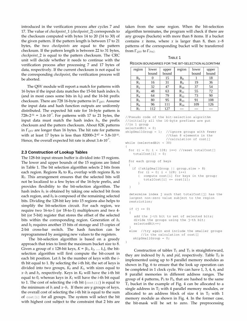
2.3 Construction of Lookup Tables The 128-bit input stream buffer is divided into 15 regions. The lower and upper bounds of the 15 regions are listed in Table 1. The bit selection algorithm selects 2 bits from each region. Regions R8 to R14 overlap with regions R0 to R7. This arrangement ensures that the selected bits will not be localized to a few bytes of the 16-byte prefix, and provides flexibility to the bit-selection algorithm. The hash index h1 is obtained by taking one selected bit from each region, and h2 is composed of the remaining selected bits. Dividing the 128-bit key into 15 regions also helps to simplify the bit-selection circuit. For each region, we require two 16-to-1 (or 18-to-1) multiplexors and two 4-bit (or 5-bit) register that stores the offset of the selected bits within the corresponding region. Generation of h1 and h2 requires another 15 bits of storage and 15 copies of 2-bit cross-bar switch. The hash function can be reprogrammed by assigning new values to the registers.
The bit-selection algorithm is based on a greedy approach that tries to limit the maximum bucket size to 8. Given a group of x 128-bit keys, K = {k1, k2, … kx}, the bit-selection algorithm will first compute the bit-count in each bit position. Let bi be the number of keys with the i-th bit equal to 1. By selecting the i-th bit, the set of keys is divided into two groups, K0 and K1, with sizes equal to x−bi and bi, respectively. Keys in K0 will have the i-th bit equal to 0, whereas keys in K1 will have the i-th bit equal to 1. The cost of selecting the i-th bit (cost[i]) is equal to the minimum of bi and x−bi. If there are y groups of keys, the overall cost of selecting the i-th bit is equal to the sum of cost[i] for all groups. The system will select the bit with highest cost subject to the constraint that 2 bits are
taken from the same region. When the bit-selection algorithm terminates, the program will check if there are any groups (buckets) with more than 8 items. If a bucket contains x items, where x is larger than 8, then x−8 patterns of the corresponding bucket will be transferred from ΓQSV to ΓPAC.
TABLE 1 REGION BOUNDARIES FOR THE BIT-SELECTION ALGORITHM
region lower bound
upper bound
region lower bound
upper bound
R0 0 15 R8 1 18 R1 16 31 R9 19 36 R2 32 47 R10 37 54 R3 48 63 R11 55 72 R4 64 79 R12 73 90 R5 80 95 R13 91 108 R6 96 111 R14 109 126 R7 112 127 --- --- ---
//Pseudo code of the bit-selection algorithm //initially all the 16-byte prefixes are put //in 1 group selectedBit = 0; skipSmallGroup = 1; //ignore groups with fewer //than 8 elements in the //calculation of cost[] while (selectedBit < 30) { for (i = 0; i < 128; i++) //reset totalCost[]
totalCost[i] = 0; for each group of keys { if (!skipSmallGroup || group.size > 8)
for (i = 0; i < 128; i++) { compute cost[i] for keys in the group;
totalCost[i] += cost[i]; } } determine index j such that totalCost[j] has the largest non-zero value subject to the region restriction; if (j >= 0) {
add the j-th bit to set of selected bits; divide the groups using the j-th bit; selectedBit++;
} else //try again and include the smaller groups //in the calculation of cost[] skipSmallGroup = 0; }
Construction of tables T1 and T3 is straightforward, they are indexed by h1 and pid, respectively. Table T2 is implemented using up to 8 parallel memory modules as shown in Fig. 6 to ensure that the look up operation can be completed in 1 clock cycle. We can have 1, 3, 4, 6, and 8 parallel memories in different address ranges. The group of 4 patterns, P5 to P8, that are hashed to the same T1 bucket in the example of Fig. 4 can be allocated to a single address in T2 with 4 parallel memory modules, or allocated to an address block of size 4 in T2 with 1 memory module as shown in Fig. 4. In the former case, the bit-mask will be set to zero. The preprocessing
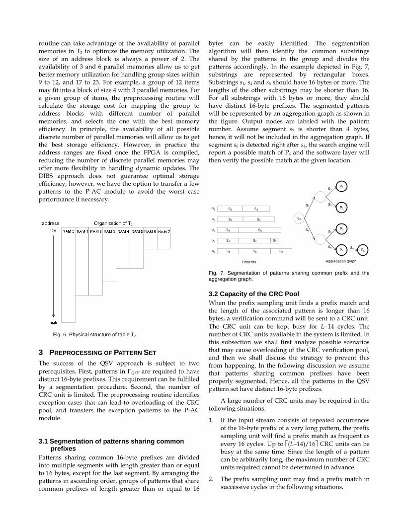
routine can take advantage of the availability of parallel memories in T2 to optimize the memory utilization. The size of an address block is always a power of 2. The availability of 3 and 6 parallel memories allow us to get better memory utilization for handling group sizes within 9 to 12, and 17 to 23. For example, a group of 12 items may fit into a block of size 4 with 3 parallel memories. For a given group of items, the preprocessing routine will calculate the storage cost for mapping the group to address blocks with different number of parallel memories, and selects the one with the best memory efficiency. In principle, the availability of all possible discrete number of parallel memories will allow us to get the best storage efficiency. However, in practice the address ranges are fixed once the FPGA is compiled, reducing the number of discrete parallel memories may offer more flexibility in handling dynamic updates. The DIBS approach does not guarantee optimal storage efficiency, however, we have the option to transfer a few patterns to the P-AC module to avoid the worst case performance if necessary.
Fig. 6. Physical structure of table T2.
3 PREPROCESSING OF PATTERN SET The success of the QSV approach is subject to two prerequisites. First, patterns in ΓQSV are required to have distinct 16-byte prefixes. This requirement can be fulfilled by a segmentation procedure. Second, the number of CRC unit is limited. The preprocessing routine identifies exception cases that can lead to overloading of the CRC pool, and transfers the exception patterns to the P-AC module.
3.1 Segmentation of patterns sharing common prefixes
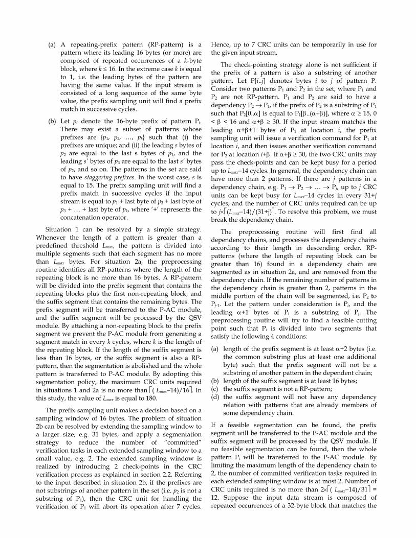
Patterns sharing common 16-byte prefixes are divided into multiple segments with length greater than or equal to 16 bytes, except for the last segment. By arranging the patterns in ascending order, groups of patterns that share common prefixes of length greater than or equal to 16
bytes can be easily identified. The segmentation algorithm will then identify the common substrings shared by the patterns in the group and divides the patterns accordingly. In the example depicted in Fig. 7, substrings are represented by rectangular boxes. Substrings s1, s4 and s6 should have 16 bytes or more. The lengths of the other substrings may be shorter than 16. For all substrings with 16 bytes or more, they should have distinct 16-byte prefixes. The segmented patterns will be represented by an aggregation graph as shown in the figure. Output nodes are labeled with the pattern number. Assume segment s7 is shorter than 4 bytes, hence, it will not be included in the aggregation graph. If segment s6 is detected right after s4, the search engine will report a possible match of P4 and the software layer will then verify the possible match at the given location.
S1 S2
S1 S3
S4 S5
S4 S6 S7
S4 S6 S8
P1
P2
P3
P4
P5
q0
P1
P2
P3
P4 P5
S1
S4
S2
S3
S5
S6 S8
Patterns Aggregation graph Fig. 7. Segmentation of patterns sharing common prefix and the aggregation graph.
3.2 Capacity of the CRC Pool When the prefix sampling unit finds a prefix match and the length of the associated pattern is longer than 16 bytes, a verification command will be sent to a CRC unit. The CRC unit can be kept busy for L−14 cycles. The number of CRC units available in the system is limited. In this subsection we shall first analyze possible scenarios that may cause overloading of the CRC verification pool, and then we shall discuss the strategy to prevent this from happening. In the following discussion we assume that patterns sharing common prefixes have been properly segmented. Hence, all the patterns in the QSV pattern set have distinct 16-byte prefixes.
A large number of CRC units may be required in the following situations.
1. If the input stream consists of repeated occurrences of the 16-byte prefix of a very long pattern, the prefix sampling unit will find a prefix match as frequent as every 16 cycles. Up to ⎡(L−14)/16⎤ CRC units can be busy at the same time. Since the length of a pattern can be arbitrarily long, the maximum number of CRC units required cannot be determined in advance.
2. The prefix sampling unit may find a prefix match in successive cycles in the following situations.
(a) A repeating-prefix pattern (RP-pattern) is a pattern where its leading 16 bytes (or more) are composed of repeated occurrences of a k-byte block, where k ≤ 16. In the extreme case k is equal to 1, i.e. the leading bytes of the pattern are having the same value. If the input stream is consisted of a long sequence of the same byte value, the prefix sampling unit will find a prefix match in successive cycles.
(b) Let pi denote the 16-byte prefix of pattern Pi. There may exist a subset of patterns whose prefixes are {p1, p2, …, pk} such that (i) the prefixes are unique; and (ii) the leading s bytes of p2 are equal to the last s bytes of p1, and the leading s’ bytes of p3 are equal to the last s’ bytes of p2, and so on. The patterns in the set are said to have staggering prefixes. In the worst case, s is equal to 15. The prefix sampling unit will find a prefix match in successive cycles if the input stream is equal to p1 + last byte of p2 + last byte of p3 + … + last byte of pk, where ‘+’ represents the concatenation operator.
Situation 1 can be resolved by a simple strategy. Whenever the length of a pattern is greater than a predefined threshold Lmax, the pattern is divided into multiple segments such that each segment has no more than Lmax bytes. For situation 2a, the preprocessing routine identifies all RP-patterns where the length of the repeating block is no more than 16 bytes. A RP-pattern will be divided into the prefix segment that contains the repeating blocks plus the first non-repeating block, and the suffix segment that contains the remaining bytes. The prefix segment will be transferred to the P-AC module, and the suffix segment will be processed by the QSV module. By attaching a non-repeating block to the prefix segment we prevent the P-AC module from generating a segment match in every k cycles, where k is the length of the repeating block. If the length of the suffix segment is less than 16 bytes, or the suffix segment is also a RP-pattern, then the segmentation is abolished and the whole pattern is transferred to P-AC module. By adopting this segmentation policy, the maximum CRC units required in situations 1 and 2a is no more than ⎡( Lmax−14)/16⎤. In this study, the value of Lmax is equal to 180.
The prefix sampling unit makes a decision based on a sampling window of 16 bytes. The problem of situation 2b can be resolved by extending the sampling window to a larger size, e.g. 31 bytes, and apply a segmentation strategy to reduce the number of “committed” verification tasks in each extended sampling window to a small value, e.g. 2. The extended sampling window is realized by introducing 2 check-points in the CRC verification process as explained in section 2.2. Referring to the input described in situation 2b, if the prefixes are not substrings of another pattern in the set (i.e. p2 is not a substring of P1), then the CRC unit for handling the verification of P1 will abort its operation after 7 cycles.
Hence, up to 7 CRC units can be temporarily in use for the given input stream.
The check-pointing strategy alone is not sufficient if the prefix of a pattern is also a substring of another pattern. Let P[i..j] denotes bytes i to j of pattern P. Consider two patterns P1 and P2 in the set, where P1 and P2 are not RP-pattern. P1 and P2 are said to have a dependency P2 → P1, if the prefix of P2 is a substring of P1 such that P2[0..α] is equal to P1[β..(α+β)], where α ≥ 15, 0 < β < 16 and α+β ≥ 30. If the input stream matches the leading α+β+1 bytes of P1 at location i, the prefix sampling unit will issue a verification command for P1 at location i, and then issues another verification command for P2 at location i+β. If α+β ≥ 30, the two CRC units may pass the check-points and can be kept busy for a period up to Lmax−14 cycles. In general, the dependency chain can have more than 2 patterns. If there are j patterns in a dependency chain, e.g. P1 → P2 → … → Pj, up to j CRC units can be kept busy for Lmax−14 cycles in every 31+j cycles, and the number of CRC units required can be up to j×⎡(Lmax−14)/(31+j)⎤. To resolve this problem, we must break the dependency chain.
The preprocessing routine will first find all dependency chains, and processes the dependency chains according to their length in descending order. RP-patterns (where the length of repeating block can be greater than 16) found in a dependency chain are segmented as in situation 2a, and are removed from the dependency chain. If the remaining number of patterns in the dependency chain is greater than 2, patterns in the middle portion of the chain will be segmented, i.e. P2 to Pj-1. Let the pattern under consideration is Pi, and the leading α+1 bytes of Pi is a substring of Pj. The preprocessing routine will try to find a feasible cutting point such that Pi is divided into two segments that satisfy the following 4 conditions:
(a) length of the prefix segment is at least α+2 bytes (i.e. the common substring plus at least one additional byte) such that the prefix segment will not be a substring of another pattern in the dependent chain;
(b) length of the suffix segment is at least 16 bytes; (c) the suffix segment is not a RP-pattern; (d) the suffix segment will not have any dependency
relation with patterns that are already members of some dependency chain.
If a feasible segmentation can be found, the prefix segment will be transferred to the P-AC module and the suffix segment will be processed by the QSV module. If no feasible segmentation can be found, then the whole pattern Pi will be transferred to the P-AC module. By limiting the maximum length of the dependency chain to 2, the number of committed verification tasks required in each extended sampling window is at most 2. Number of CRC units required is no more than 2×⎡( Lmax−14)/31⎤ = 12. Suppose the input data stream is composed of repeated occurrences of a 32-byte block that matches the

prefixes of two dependent patterns followed by the input sequence described in situation 2b, then the maximum number of CRC units that can be in use at the same time is 12 + 7 = 19.
3.3 Preprocessing Procedure The major steps of the preprocessing procedure are listed below.
1. Sort the patterns in ascending order. Eliminate duplicated patterns. Put patterns with less than 16 bytes in ΓPAC, and patterns with 16 bytes or more in ΓQSV. ΓQSV and ΓPAC are maintained in sorted order in the subsequent steps.
2. Extract patterns in ΓQSV that start with sequence of repeating character or short substrings. Segment these patterns and put the prefix segments in ΓPAC, and put the suffix segments in ΓQSV. Enter the segment code sequences in the segment code table to be used by the AU.
3. Extract patterns in ΓQSV that share common 16-byte prefixes. Apply the segmentation algorithm to divide the extracted patterns into segments with distinct 16-byte prefixes. If a long segment is found to share a common 16-byte prefix with an existing pattern in ΓQSV, the segment will be transferred to ΓPAC. Note that only the last segment of a pattern can be shorter than 16 bytes. Segments with 4 to 15 bytes are put in ΓPAC, and segments longer than or equal to 16 bytes are put in ΓQSV. The last segment of some patterns can be very short, e.g. less than 4 bytes. These last few bytes will be verified by the post-matching verification routine. Enter the segment code sequences in the segment code table to be used by the AU.
4. Find pattern chains with staggering prefixes in ΓQSV. Divide the patterns and move exception patterns to ΓPAC according to the criteria mentioned in section 3.2.
5. Extract distinct 16-byte prefixes from ΓQSV and apply the bit-selection algorithm. If a bucket contains more than 8 patterns, move the excess patterns to ΓPAC if required.
6. Compute the prefix checksum, pattern checksum, checkpoint_1 and checkpoint_2 for patterns in ΓQSV. Let ΓH represent the group of patterns that are mapped to the same address (bucket) in T2. Conflict is said to have occurred if
(i) two patterns in a ΓH group share the same prefix checksum; or
(ii) two equal-length patterns in a ΓH group share the same pattern checksum.
When conflict is detected, one of the conflicting patterns will be transferred to ΓPAC. The probability
of having conflicts is close to zero since the number of patterns in a ΓH group is no more than 8. In our evaluation using the ClamAV pattern set, no checksum conflict has been found.
7. Set up the lookup tables.
4 AGGREGATION UNIT A few percents of the patterns are divided into multiple segments in the preprocessing phase. In our system, patterns are numbered from 1 to N, and segments are assigned IDs that starts from M, where M > N. Hence, if the pattern ID associated with a match result is smaller than M, then the match result is sent to the output interface directly. If the pattern ID is greater than or equal to M, then the match result corresponds to a partial match (matching of a segment) of a long pattern. The AU is responsible for aggregating the partial matches to produce the final result.
A partial match result received from the P-AC/QSV module is a 4-tuple <pid, patLoc, refLoc, verified>, where pid is the pattern ID, patLoc corresponds to the location of the last byte of the pattern found in the input stream, refLoc is the location of last byte of the 16-byte prefix, and the verified bit represents whether the pattern has been verified by a CRC unit. The uses of the verified bit and refLoc will be explained in section 4.1. The conventional approach to aggregate partial matches is to model the AU as a deterministic finite automaton (DFA). However, this approach is not applicable to the hybrid P-AC/QSV architecture. In our system, segments can have variable lengths. Hence, input symbols (i.e. pid) to the FA are not mutual exclusive. Typically the initial state, q0, of the aggregation graph can have many out-going edges (current state, input symbol, next state). Consider two transition edges e1=(q0, pid1, ns1) and e2=( q0, pid2, ns2). The length of segment pid1 and segment pid2 can be different, and we do not rule out the possibility of having segment pid1 to be a substring of segment pid2, or vice versa. Assume the FA receives an input symbol pid1 and makes a transition to state ns1. While the FA is waiting for the next input symbol at state ns1, another valid input symbol pid2 may arrive. To overcome this issue, we shall implement the AU as a non-deterministic FA (NFA) that allows multiple active states.
A transition edge in the NFA contains 7 fields (current state, segment ID, segment length, next state, bit-mask, TTL, state-type). The TTL (time-to-live counter) is equal to the maximum length among all segments that appear in the out-going edges of the corresponding next state. The state-type field indicates whether the next state is an output state, a terminal state, both or none. There are two transition rule tables, A0 and A1. Table A0 stores all the transition rules originating from the initial state, and table A1 stores the rest of the transition rules. If the transition rule symbols for the edges originating from the initial state are numbered from M to M+δ, where δ is
equal to the fanout of the initial state, then the address used to access table A0 is equal to the segment ID – M.
Table A1 is implemented using the DIBS approach, the same method for implementing table T2 described in section 2.2. The address used to access table A1 is equal to the base address (current state value) plus an offset. The address offset is generated using the bit-mask and the input symbol (i.e. the segment ID). Note that the segment IDs are assigned by the preprocessing routine. We can incorporate simple heuristics in the ID assignment process such that the bit-mask will contain a minimum of ‘1’. Segmented patterns and patterns processed by the P-AC module are numbered within the range of 1 to 16K-1. By doing so, the state ID of the aggregation graph can be used to represented the pattern ID of the patterns concerned.
The AU maintains a list of active states (AS_list). Each active state is associated with a bit-mask, a reference location and an expiry location. The bit-mask is used to generate the address offset for accessing table A1. The reference location of an active state is equal to the location of the last byte of the segment (patLoc) that triggers the state transition. The expiry location is equal to the reference location plus the time-to-live counter retrieved from the lookup table. Entries in the AS_list can be purged using two approaches. The first approach is based on the expiry location. If partial match events are delivered to the AU in ascending order of the patLoc, expired entries in the list of active state can be purged by simple comparison of the expiry location of the active state and the patLoc of the partial match. The second approach is based on the “compatibility property” of segments. Let pattern Pi is divided into segments s1, s2 and so on. Segment s1 is referred to as the first-segment of a long pattern. If s1 is not a midfix of any other segmented patterns, s1 is said to be an incompatible segment. When the AU receives a segment match event of s1, all the current entries in the AS_list can be removed. This is because if s1 is not a midfix of any other segmented patterns, then the detection of s1 implies that the expected suffix segments corresponding to the current active states in the AS_list cannot be found within the required location range. To avoid possible confusion, the definition of compatibility property is based on the h1 hash code, the prefix and pattern checksums rather than the actual byte values. Let the length of s1 be len1. s1 is not compatible with pattern Pj if there does not exist any midfix substring of length len1 in Pj that possesses the same h1 hash code, prefix and pattern checksums of s1. If s1 is not compatible will all segmented patterns, then the compatible bit of the corresponding transition rule entry in table A0 is set to 0. In our study, 84% of the first-segments have their compatible bit equal to 0.
The operation of the AU is described by the pseudo code shown below. //pseudo code for the aggregation process //PM = partial match result; AS = active state
for each entry in the AS_list before the arrival of the partialMatch { if((PM.verified==1 && PM.patLoc > AS.expiryLoc) ||(PM.verified==0 && PM.refLoc > AS.expiryLoc)) remove the active state from the list; else { retrieve the transition rule from table A1; if(rule.segment_ID==PM.segment_ID && AS.location + rule.segment_len == PM.patLoc) { if (rule.next_state is an output state)
report a possible match(rule.next_state, PM.patLoc);
if (rule.next_state is not a terminal state) addToList(rule.next_state, PM.location, PM.patLoc + rule.TTL, bit_mask); } } } if (PM.segment_ID is within the range M to M+delta) { retrieve the transition rule from table A0; if (PM.verified == 1 && rule.compatible == 0) remove all current entries in AS_list;
addToList(rule.next_state,
PM.location, PM.patLoc + rule.TTL, bit_mask);
if (rule.next_state is an output state)
report a possible match (rule.next_state, PM.patLoc);
}
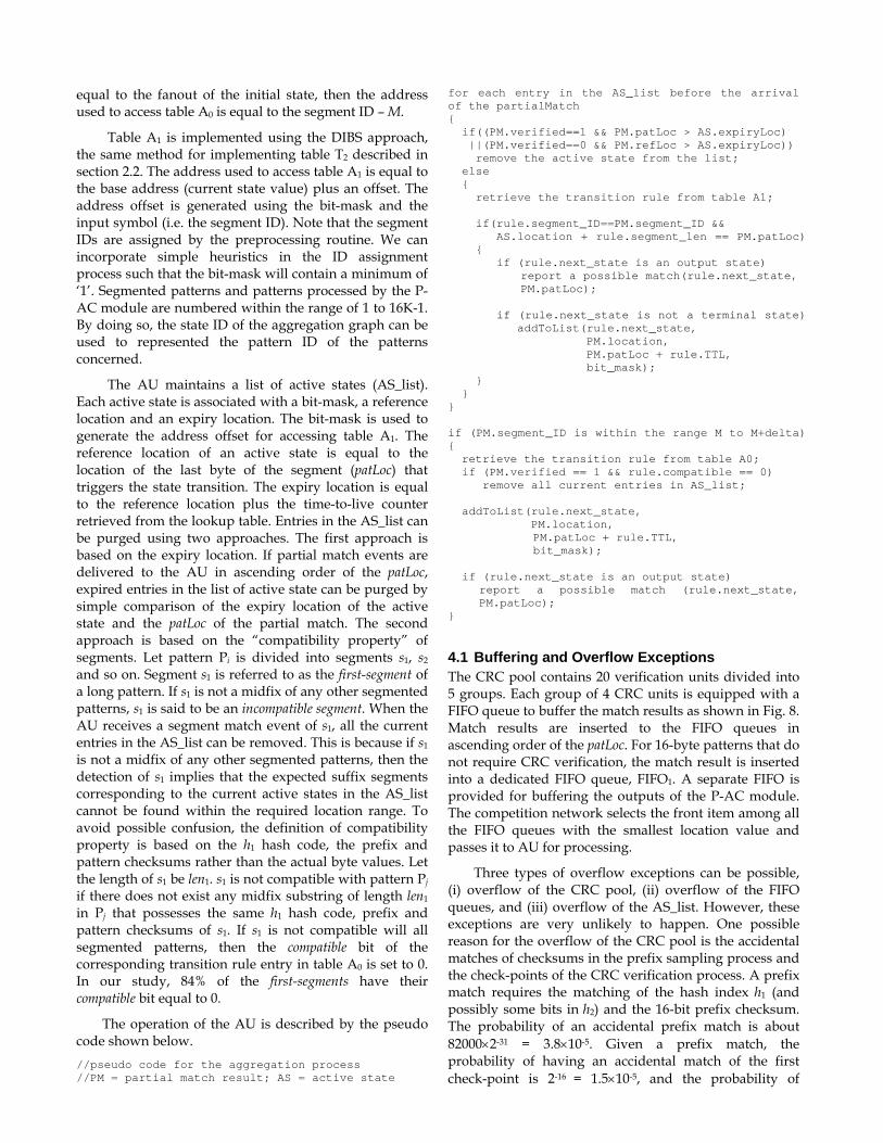
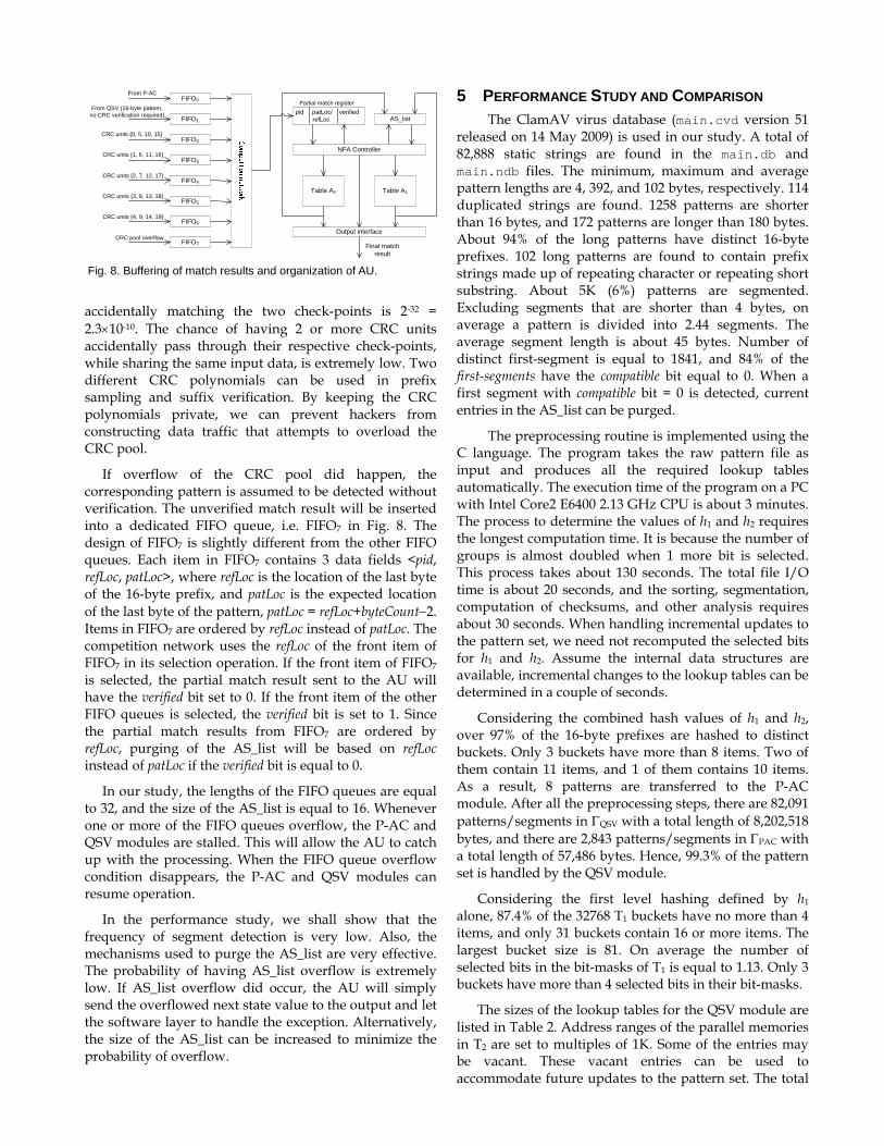
4.1 Buffering and Overflow Exceptions The CRC pool contains 20 verification units divided into 5 groups. Each group of 4 CRC units is equipped with a FIFO queue to buffer the match results as shown in Fig. 8. Match results are inserted to the FIFO queues in ascending order of the patLoc. For 16-byte patterns that do not require CRC verification, the match result is inserted into a dedicated FIFO queue, FIFO1. A separate FIFO is provided for buffering the outputs of the P-AC module. The competition network selects the front item among all the FIFO queues with the smallest location value and passes it to AU for processing.
Three types of overflow exceptions can be possible, (i) overflow of the CRC pool, (ii) overflow of the FIFO queues, and (iii) overflow of the AS_list. However, these exceptions are very unlikely to happen. One possible reason for the overflow of the CRC pool is the accidental matches of checksums in the prefix sampling process and the check-points of the CRC verification process. A prefix match requires the matching of the hash index h1 (and possibly some bits in h2) and the 16-bit prefix checksum. The probability of an accidental prefix match is about 82000×2-31 = 3.8×10⁻⁵. Given a prefix match, the probability of having an accidental match of the first check-point is 2-16 = 1.5×10⁻⁵, and the probability of
FIFO0
FIFO1
FIFO2
FIFO3
FIFO4
FIFO5
FIFO6
FIFO7
From P-AC
From QSV (16-byte pattern, no CRC verification required)
CRC units {0, 5, 10, 15}
CRC units {1, 6, 11, 16}
CRC units {2, 7, 12, 17}
CRC units {3, 8, 13, 18}
CRC units {4, 9, 14, 19}
CRC pool overflow
pid patLoc/ verifiedrefLoc AS_list
NFA Controller
Table A0 Table A1
Output interface
Final match result
Partial match register
Fig. 8. Buffering of match results and organization of AU.
accidentally matching the two check-points is 2-32 = 2.3×10⁻¹⁰. The chance of having 2 or more CRC units accidentally pass through their respective check-points, while sharing the same input data, is extremely low. Two different CRC polynomials can be used in prefix sampling and suffix verification. By keeping the CRC polynomials private, we can prevent hackers from constructing data traffic that attempts to overload the CRC pool.
If overflow of the CRC pool did happen, the corresponding pattern is assumed to be detected without verification. The unverified match result will be inserted into a dedicated FIFO queue, i.e. FIFO7 in Fig. 8. The design of FIFO7 is slightly different from the other FIFO queues. Each item in FIFO7 contains 3 data fields <pid, refLoc, patLoc>, where refLoc is the location of the last byte of the 16-byte prefix, and patLoc is the expected location of the last byte of the pattern, patLoc = refLoc+byteCount−2. Items in FIFO7 are ordered by refLoc instead of patLoc. The competition network uses the refLoc of the front item of FIFO7 in its selection operation. If the front item of FIFO7 is selected, the partial match result sent to the AU will have the verified bit set to 0. If the front item of the other FIFO queues is selected, the verified bit is set to 1. Since the partial match results from FIFO7 are ordered by refLoc, purging of the AS_list will be based on refLoc instead of patLoc if the verified bit is equal to 0.
In our study, the lengths of the FIFO queues are equal to 32, and the size of the AS_list is equal to 16. Whenever one or more of the FIFO queues overflow, the P-AC and QSV modules are stalled. This will allow the AU to catch up with the processing. When the FIFO queue overflow condition disappears, the P-AC and QSV modules can resume operation.
In the performance study, we shall show that the frequency of segment detection is very low. Also, the mechanisms used to purge the AS_list are very effective. The probability of having AS_list overflow is extremely low. If AS_list overflow did occur, the AU will simply send the overflowed next state value to the output and let the software layer to handle the exception. Alternatively, the size of the AS_list can be increased to minimize the probability of overflow.
5 PERFORMANCE STUDY AND COMPARISON The ClamAV virus database (main.cvd version 51
released on 14 May 2009) is used in our study. A total of 82,888 static strings are found in the main.db and main.ndb files. The minimum, maximum and average pattern lengths are 4, 392, and 102 bytes, respectively. 114 duplicated strings are found. 1258 patterns are shorter than 16 bytes, and 172 patterns are longer than 180 bytes. About 94% of the long patterns have distinct 16-byte prefixes. 102 long patterns are found to contain prefix strings made up of repeating character or repeating short substring. About 5K (6%) patterns are segmented. Excluding segments that are shorter than 4 bytes, on average a pattern is divided into 2.44 segments. The average segment length is about 45 bytes. Number of distinct first-segment is equal to 1841, and 84% of the first-segments have the compatible bit equal to 0. When a first segment with compatible bit = 0 is detected, current entries in the AS_list can be purged.
The preprocessing routine is implemented using the C language. The program takes the raw pattern file as input and produces all the required lookup tables automatically. The execution time of the program on a PC with Intel Core2 E6400 2.13 GHz CPU is about 3 minutes. The process to determine the values of h1 and h2 requires the longest computation time. It is because the number of groups is almost doubled when 1 more bit is selected. This process takes about 130 seconds. The total file I/O time is about 20 seconds, and the sorting, segmentation, computation of checksums, and other analysis requires about 30 seconds. When handling incremental updates to the pattern set, we need not recomputed the selected bits for h1 and h2. Assume the internal data structures are available, incremental changes to the lookup tables can be determined in a couple of seconds.
Considering the combined hash values of h1 and h2, over 97% of the 16-byte prefixes are hashed to distinct buckets. Only 3 buckets have more than 8 items. Two of them contain 11 items, and 1 of them contains 10 items. As a result, 8 patterns are transferred to the P-AC module. After all the preprocessing steps, there are 82,091 patterns/segments in ΓQSV with a total length of 8,202,518 bytes, and there are 2,843 patterns/segments in ΓPAC with a total length of 57,486 bytes. Hence, 99.3% of the pattern set is handled by the QSV module.
Considering the first level hashing defined by h1 alone, 87.4% of the 32768 T1 buckets have no more than 4 items, and only 31 buckets contain 16 or more items. The largest bucket size is 81. On average the number of selected bits in the bit-masks of T1 is equal to 1.13. Only 3 buckets have more than 4 selected bits in their bit-masks.
The sizes of the lookup tables for the QSV module are listed in Table 2. Address ranges of the parallel memories in T2 are set to multiples of 1K. Some of the entries may be vacant. These vacant entries can be used to accommodate future updates to the pattern set. The total
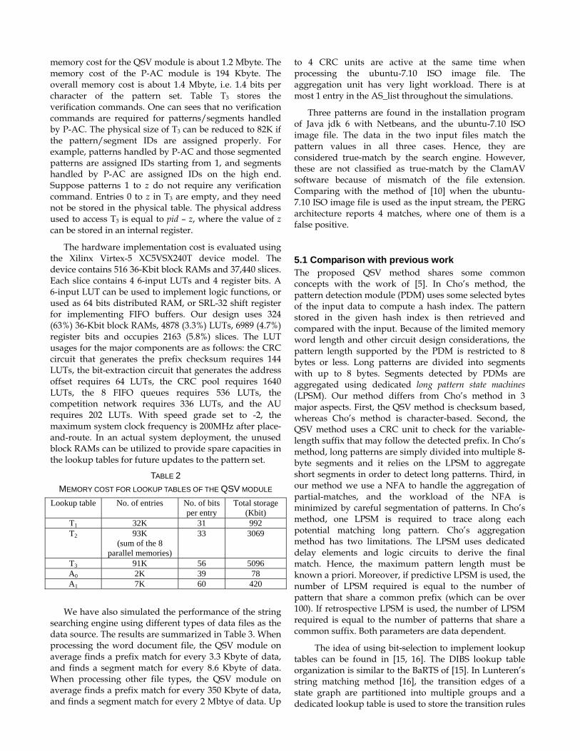
memory cost for the QSV module is about 1.2 Mbyte. The memory cost of the P-AC module is 194 Kbyte. The overall memory cost is about 1.4 Mbyte, i.e. 1.4 bits per character of the pattern set. Table T3 stores the verification commands. One can sees that no verification commands are required for patterns/segments handled by P-AC. The physical size of T3 can be reduced to 82K if the pattern/segment IDs are assigned properly. For example, patterns handled by P-AC and those segmented patterns are assigned IDs starting from 1, and segments handled by P-AC are assigned IDs on the high end. Suppose patterns 1 to z do not require any verification command. Entries 0 to z in T3 are empty, and they need not be stored in the physical table. The physical address used to access T3 is equal to pid – z, where the value of z can be stored in an internal register.
The hardware implementation cost is evaluated using the Xilinx Virtex-5 XC5VSX240T device model. The device contains 516 36-Kbit block RAMs and 37,440 slices. Each slice contains 4 6-input LUTs and 4 register bits. A 6-input LUT can be used to implement logic functions, or used as 64 bits distributed RAM, or SRL-32 shift register for implementing FIFO buffers. Our design uses 324 (63%) 36-Kbit block RAMs, 4878 (3.3%) LUTs, 6989 (4.7%) register bits and occupies 2163 (5.8%) slices. The LUT usages for the major components are as follows: the CRC circuit that generates the prefix checksum requires 144 LUTs, the bit-extraction circuit that generates the address offset requires 64 LUTs, the CRC pool requires 1640 LUTs, the 8 FIFO queues requires 536 LUTs, the competition network requires 336 LUTs, and the AU requires 202 LUTs. With speed grade set to -2, the maximum system clock frequency is 200MHz after place-and-route. In an actual system deployment, the unused block RAMs can be utilized to provide spare capacities in the lookup tables for future updates to the pattern set.
TABLE 2 MEMORY COST FOR LOOKUP TABLES OF THE QSV MODULE
Lookup table No. of entries No. of bits per entry
Total storage (Kbit)
T1 32K 31 992 T2 93K
(sum of the 8 parallel memories)
33 3069
T3 91K 56 5096 A0 2K 39 78 A1 7K 60 420
We have also simulated the performance of the string searching engine using different types of data files as the data source. The results are summarized in Table 3. When processing the word document file, the QSV module on average finds a prefix match for every 3.3 Kbyte of data, and finds a segment match for every 8.6 Kbyte of data. When processing other file types, the QSV module on average finds a prefix match for every 350 Kbyte of data, and finds a segment match for every 2 Mbtye of data. Up
to 4 CRC units are active at the same time when processing the ubuntu-7.10 ISO image file. The aggregation unit has very light workload. There is at most 1 entry in the AS_list throughout the simulations.
Three patterns are found in the installation program of Java jdk 6 with Netbeans, and the ubuntu-7.10 ISO image file. The data in the two input files match the pattern values in all three cases. Hence, they are considered true-match by the search engine. However, these are not classified as true-match by the ClamAV software because of mismatch of the file extension. Comparing with the method of [10] when the ubuntu-7.10 ISO image file is used as the input stream, the PERG architecture reports 4 matches, where one of them is a false positive.
5.1 Comparison with previous work The proposed QSV method shares some common concepts with the work of [5]. In Cho’s method, the pattern detection module (PDM) uses some selected bytes of the input data to compute a hash index. The pattern stored in the given hash index is then retrieved and compared with the input. Because of the limited memory word length and other circuit design considerations, the pattern length supported by the PDM is restricted to 8 bytes or less. Long patterns are divided into segments with up to 8 bytes. Segments detected by PDMs are aggregated using dedicated long pattern state machines (LPSM). Our method differs from Cho’s method in 3 major aspects. First, the QSV method is checksum based, whereas Cho’s method is character-based. Second, the QSV method uses a CRC unit to check for the variable-length suffix that may follow the detected prefix. In Cho’s method, long patterns are simply divided into multiple 8-byte segments and it relies on the LPSM to aggregate short segments in order to detect long patterns. Third, in our method we use a NFA to handle the aggregation of partial-matches, and the workload of the NFA is minimized by careful segmentation of patterns. In Cho’s method, one LPSM is required to trace along each potential matching long pattern. Cho’s aggregation method has two limitations. The LPSM uses dedicated delay elements and logic circuits to derive the final match. Hence, the maximum pattern length must be known a priori. Moreover, if predictive LPSM is used, the number of LPSM required is equal to the number of pattern that share a common prefix (which can be over 100). If retrospective LPSM is used, the number of LPSM required is equal to the number of patterns that share a common suffix. Both parameters are data dependent.
The idea of using bit-selection to implement lookup tables can be found in [15, 16]. The DIBS lookup table organization is similar to the BaRTS of [15]. In Lunteren’s string matching method [16], the transition edges of a state graph are partitioned into multiple groups and a dedicated lookup table is used to store the transition rules
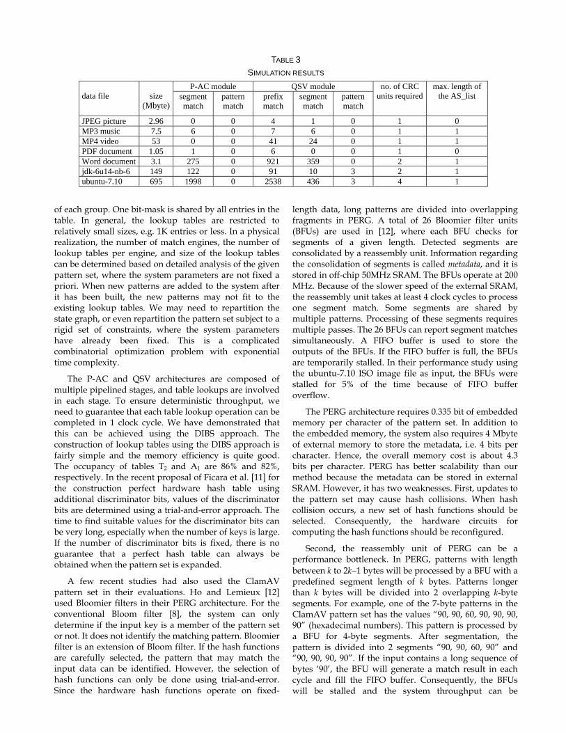
TABLE 3 SIMULATION RESULTS
data file
size
(Mbyte)
P-AC module QSV module no. of CRC units required
max. length of the AS_list segment
match pattern match
prefix match
segment match
pattern match
JPEG picture 2.96 0 0 4 1 0 1 0 MP3 music 7.5 6 0 7 6 0 1 1 MP4 video 53 0 0 41 24 0 1 1 PDF document 1.05 1 0 6 0 0 1 0 Word document 3.1 275 0 921 359 0 2 1 jdk-6u14-nb-6 149 122 0 91 10 3 2 1 ubuntu-7.10 695 1998 0 2538 436 3 4 1
of each group. One bit-mask is shared by all entries in the table. In general, the lookup tables are restricted to relatively small sizes, e.g. 1K entries or less. In a physical realization, the number of match engines, the number of lookup tables per engine, and size of the lookup tables can be determined based on detailed analysis of the given pattern set, where the system parameters are not fixed a priori. When new patterns are added to the system after it has been built, the new patterns may not fit to the existing lookup tables. We may need to repartition the state graph, or even repartition the pattern set subject to a rigid set of constraints, where the system parameters have already been fixed. This is a complicated combinatorial optimization problem with exponential time complexity.
The P-AC and QSV architectures are composed of multiple pipelined stages, and table lookups are involved in each stage. To ensure deterministic throughput, we need to guarantee that each table lookup operation can be completed in 1 clock cycle. We have demonstrated that this can be achieved using the DIBS approach. The construction of lookup tables using the DIBS approach is fairly simple and the memory efficiency is quite good. The occupancy of tables T2 and A1 are 86% and 82%, respectively. In the recent proposal of Ficara et al. [11] for the construction perfect hardware hash table using additional discriminator bits, values of the discriminator bits are determined using a trial-and-error approach. The time to find suitable values for the discriminator bits can be very long, especially when the number of keys is large. If the number of discriminator bits is fixed, there is no guarantee that a perfect hash table can always be obtained when the pattern set is expanded.
A few recent studies had also used the ClamAV pattern set in their evaluations. Ho and Lemieux [12] used Bloomier filters in their PERG architecture. For the conventional Bloom filter [8], the system can only determine if the input key is a member of the pattern set or not. It does not identify the matching pattern. Bloomier filter is an extension of Bloom filter. If the hash functions are carefully selected, the pattern that may match the input data can be identified. However, the selection of hash functions can only be done using trial-and-error. Since the hardware hash functions operate on fixed-
length data, long patterns are divided into overlapping fragments in PERG. A total of 26 Bloomier filter units (BFUs) are used in [12], where each BFU checks for segments of a given length. Detected segments are consolidated by a reassembly unit. Information regarding the consolidation of segments is called metadata, and it is stored in off-chip 50MHz SRAM. The BFUs operate at 200 MHz. Because of the slower speed of the external SRAM, the reassembly unit takes at least 4 clock cycles to process one segment match. Some segments are shared by multiple patterns. Processing of these segments requires multiple passes. The 26 BFUs can report segment matches simultaneously. A FIFO buffer is used to store the outputs of the BFUs. If the FIFO buffer is full, the BFUs are temporarily stalled. In their performance study using the ubuntu-7.10 ISO image file as input, the BFUs were stalled for 5% of the time because of FIFO buffer overflow.
The PERG architecture requires 0.335 bit of embedded memory per character of the pattern set. In addition to the embedded memory, the system also requires 4 Mbyte of external memory to store the metadata, i.e. 4 bits per character. Hence, the overall memory cost is about 4.3 bits per character. PERG has better scalability than our method because the metadata can be stored in external SRAM. However, it has two weaknesses. First, updates to the pattern set may cause hash collisions. When hash collision occurs, a new set of hash functions should be selected. Consequently, the hardware circuits for computing the hash functions should be reconfigured.
Second, the reassembly unit of PERG can be a performance bottleneck. In PERG, patterns with length between k to 2k−1 bytes will be processed by a BFU with a predefined segment length of k bytes. Patterns longer than k bytes will be divided into 2 overlapping k-byte segments. For example, one of the 7-byte patterns in the ClamAV pattern set has the values “90, 90, 60, 90, 90, 90, 90” (hexadecimal numbers). This pattern is processed by a BFU for 4-byte segments. After segmentation, the pattern is divided into 2 segments “90, 90, 60, 90” and “90, 90, 90, 90”. If the input contains a long sequence of bytes ‘90’, the BFU will generate a match result in each cycle and fill the FIFO buffer. Consequently, the BFUs will be stalled and the system throughput can be
degraded significantly. Other scenarios that will cause FIFO overflow are possible. For example, two 7-byte patterns in the pattern set have the values “52, 52, 83, c4, 04, 89, 3c” and “52, 57, 03, fa, 5f, 52, 52”. After segmentation, two of the segments are “52, 52, 83, c4” and “fa, 5f, 52, 52”. If the input contains repeated occurrences of the 6-byte block “fa, 5f, 52, 52, 83, c4”, the BFU will generate 2 matches in every 6 cycles.
Hua et al. [13] presented an interesting idea to reduce the memory cost and improve the processing speed of the Aho-Corasick automaton. In their approach, the input data as well as the patterns are transformed to another alphabet set using a “content-invariant” variable-stride segmentation method. A symbol in the new alphabet set may represent 1 to w characters (bytes), where w is the window size used by the preprocessing unit in transforming the input data. On average, one symbol in the new alphabet set represents 2 to 3 bytes of the original data. A pattern is divided into the head-block, core-block, and tail-block. The search engine will only compare the input against the core-block. Verifications of the head-block and tail-block are performed by dedicated hardware. Short patterns with empty core-block are handled using other techniques, e.g. TCAM. The advantages of Hua’s method diminish if the pattern or input stream is composed of a long sequence of the same byte value. The memory cost of Hua’s design is about 2.5 bytes per character of the pattern set.
In the method of Song et al. [22], the DFA maintains one additional cached state in addition to the normal active state. By doing so, backward transition edges pointing back to nodes that are two hops from the initial state can be eliminated. The memory cost of Song’s method when applied to the ClamAV pattern set is 4.2 to 6.0 bytes per character.
6 CONCLUSION In this paper we have presented a memory efficient method to do string searching. The proposed QSV method is based on quick sampling of fixed-length data segments and on-demand verification of the variable-length suffix segment. The QSV method has good scalability. The prefix sampling (PS) unit has 3 lookup tables, T1, T2 and T3. The size of T1 is fixed with 32K entries. The sizes of T2 and T3 are proportional to the number of patterns. For a pattern with distinct 16-byte prefix, the system only need to store up to 3 entries in tables T1 to T3. The storage cost is independent of the pattern length.
In the QSV method, patterns are required to have distinct 16-byte prefixes. Patterns that share common 16-byte prefixes will be divided into multiple segments with distinct prefixes. In our evaluation with the ClamAV pattern set, about 6% percents of patterns are segmented. Short patterns with less than 16 bytes, and a small number of exception patterns that cannot be handled by
the QSV module will be processed by a pipelined Aho-Corasick (P-AC) string matching engine [17, 18]. The memory cost of P-AC is considerably higher than that of QSV. However, the P-AC module will only be responsible for handling 0.7% of the pattern set in terms of byte count. The overall memory cost of the search engine is only 1.4 bits per character of the pattern set, which is much lower than other known methods. For the current ClamAV pattern set with 82888 static strings, the total memory required is about 1.4 Mbyte.
Comparing version 50 (released on 15 Feb. 2009) and version 51 (released on 14 May 2009) of the ClamAV database main.cvd, version 51 contains 653 new static strings. Hence, on average 7 static strings are added to the database per day within the 3 months period. Both P-AC and QSV are memory-based. When new patterns are added to the pattern set, the lookup tables can be modified without reconfiguring the hardware circuits. This is an essential feature for anti-virus applications, where updates to the pattern set can be quite frequent and the system would require short update latency.
The method presented in this paper is only for the handling of static strings. Given the fact that over 90% patterns in today’s ClamAV pattern set are static strings, the result of this study is significant. Our future work [19] will focus on the study of hardware architecture for matching regular expressions. It is generally agreed that the matching of regular expressions is a more difficult problem, especially when one aims to optimize for speed, hardware efficiency (memory and logic elements), scalability, and flexibility (i.e. ability to update the pattern set without hardware reconfiguration).
ACKNOWLEDGEMENTS The authors would like to express their sincere thanks to the reviewers for their critical comments and valuable suggestions. The reviewers gave us very detailed reports that helped us a lot in improving the paper.
REFERENCES [1] A. V. Aho, and M. J. Corasick, “Efficient string matching: an
aid to bibliographic search”, Communications of the ACM, Vol. 18, No. 6, 333-340, 1975.
[2] M. Alicherry, M. Muthuprasanna and V. Kumar, “High speed matching for network IDS/IPS”, In Proceedings of the IEEE Int. Conf. on Network Protocols, 187-196, 2006.
[3] Z. K. Baker and V. K. Prasanna, “A computationally efficient engine for flexible intrusion detection”, IEEE Trans. on VLSI Systems, Vol. 13, No. 10, 1179-1189, 2005.
[4] Z. K. Baker and V. K. Prasanna, “Automatic synthesis of efficient intrusion detection systems on FPGAs”, IEEE Trans. on Dependable and Secure Computing, Vol. 3, No. 4, 289-300, 2006.
[5] Y. H. Cho and W. H. Mangione-Smith, “Fast reconfiguring deep packet filter for 1+ Gigabit network”, In Proceedings of the IEEE Symp. on Field-Programmable Custom Computing Machines, 2005.
[6] ClamAV anti-virus software, http://www.clamav.net [7] C. R. Clark and D. E. Schimmel, “Efficient reconfigurable logic
circuits for matching complex network intrusion detection patterns”, In Field-Programmable Logic and Applications, LNCS, 2778, 956-959, 2005.
[8] S. Dharmapurikar, P. Krishnamurthy, T. S. Sproull and J. W. Lockwood, “Deep packet inspection using parallel Bloom filters”, IEEE Micro, Vol. 24, No. 1, 52-61, 2004.
[9] S. Dharmapurikar and J. Lockwood, “Fast and scalable pattern matching for network intrusion detection systems”, IEEE J. on Selected Areas in Comm., Vol. 24, No. 10, 1781-1792, 2006.
[10] V. Dimopoulos, I. Papaefstathiou and D. Pnevmatikatos, “A memory-efficient reconfigurable Aho-Corasick FSM implementation for intrusion detection systems”, In Proceedings of the IEEE Int. Conf. on Embedded Computer Systems: Architectures, Modeling and Simulations, 186-193, 2007.
[11] D. Ficara, S. Giordano, S. Kumar, B. Lynch, “Divide and discriminate: algorithm for deterministic and fast hash lookups”, In Proceedings of the ACM/IEEE ANCS, 133-142, 2009.
[12] J. T. L. Ho and G. F. Lemieux, “PERG: A scalable FPGA-based pattern-matching engine with consolidated Bloomier filters”, in Proceedings of IEEE Int. Conf. Field-Programmable Tech., 73-80, Dec 2008.
[13] N. Hua, H. Song and T. V. Lakshman, “Variable-stride multi-pattern matching for scalable deep packet inspection”, In Proceedings of the IEEE INFOCOM, 415-423, 2009.
[14] D. Knuth, J. Morris and V. Pratt, “Fast pattern matching in strings”, SIAM J. Computing, Vol. 6, 323-350, 1977.
[15] J. van Junteren, “Searching very large routing tables in wide embedded memory”, In Proceedings of the IEEE GlobeCom, 1615-1619, 2001.
[16] J. van Lunteren, “High-performance pattern-matching for intrusion detection”, In Proceedings of the IEEE INFOCOM, 1-13, 2006.
[17] D. Pao, W. Lin and B. Liu, “Pipelined architecture for multi-string matching”, IEEE Computer Architecture Letters, Vol. 7, No. 2, 33-36, July-Dec. 2008.
[18] D. Pao, W. Lin and B. Liu, “A memory efficient pipelined implementation of the Aho-Corasick string matching algorithm”, ACM Trans. on Architecture and Code Optimization, accepted for publication.
[19] D. Pao, “A NFA-based programmable regular expression match engine”, In Proceedings of the ACM/IEEE ANCS, 60-61, 2009.
[20] G. Papadopoulos and D. Pnevmatikatos, “Hashing + memory = low cost, exact pattern matching”, In Proceedings of the IEEE Int. Conf. on Field Programmable Logic and Applications, 39-44, 2005.
[21] Snort intrusion detection system, http://www.snort.org [22] T. Song, W. Zhang, D. Wang and Y. Xue, “A memory efficient
multiple pattern matching architecture for network security”, In Proceedings of the IEEE INFOCOM, 673-681, 2008.
[23] I. Sourdis and V. Pnevmatikatos, “Pre-decoded CAMs for efficient and high-speed NIDS pattern matching”, In Proceedings of the 12th IEEE Symp. on Field-Programmable Custom Computing Machines, 2004.
[24] I. Sourdis, V. Pnevmatikatos and S. Vassiliadis, “Scalable multigigabit pattern matching for packet inspection”, IEEE Trans. on VLSI Systems, Vol. 16, No. 2, 156-166, 2008.
[25] L. Tan, B. Brotherton and T. Sherwood, “Bit-split string-matching engines for intrusion detection and prevention”, ACM Trans. on Architecture and Code Optimization, Vol. 3, No. 1, 3-34, 2006.
[26] N. Tuck, T. Sherwood, B. Calder and G. Varghese, “Deterministic memory-efficient string matching algorithms for intrusion detection”, In Proceedings of the IEEE INFOCOM, 2628-2639, 2004.
[27] F. Yu, R. H. Katz and T. V. Lakshman, “Gigabit rate packet pattern-matching using TCAM”, In Proceedings of the IEEE Int. Conf. Network Protocols, 174-183, 2004.
Derek Pao received the B.Sc.(Eng.) degree in Electrical Engineering from the University of Hong Kong, and the M. Comp. Sc. and Ph.D. degree in Computer Science from Concordia University, Canada. He is an Associate Professor with the Electronic Engineering Department, City University of Hong Kong. His research interests include architectures for network processing, and high speed
pattern matching for network and system security.
Xing Wang received his M.Sc. degree from Peking University in 2007. He is currently an Engineer in Peking University Shenzhen Graduate School. His research interests include network security, architecture for network processing and computer network.
Xiaoran Wang received the B. Eng. degree in Information Engineering with 1st Class Honors from the City University of Hong Kong in 2010. He will pursue graduate studies at Carnegie Mellon University, USA. His research interests include network and system security, and forensic.
Cong Cao received the B.Eng. degree in Information Engineering with 1st Class Honors from the City University of Hong Kong in 2010. He will pursue graduate studies at the same university. His research interests include performance analysis of telecommunications networks.
Yuesheng Zhu received his B.Eng. degree in Radio Engineering, M. Eng. degree in Circuits and Systems, and Ph.D. degree in Electronic Engineering in 1982, 1989 and 1996, respectively. He has been working with the Communication and Security Lab, Shenzhen Graduate School of Peking University since 2005. Prof. Zhu is a senior member of IEEE, Fellow of China Institute of
Electronics, and senior member of China Institute of Communications. His current interests include cryptography and internet security, digital home networking, multimedia signal processing and wireless communications.