Stress–damage–flow coupling model and its application to pressure relief coal bed methane in...
10
Stress–damage–flow coupling model and its application to pressure relief coal bed methane in deep coal seam T.H. Yang a, ⁎, T. Xu a,b , H.Y. Liu c , C.A. Tang a , B.M. Shi d , Q.X. Yu e a Center for Rock Instability & Seismicity Research, Northeastern University, Shenyang 110004, PR China b State Key Laboratory of Geo-hazard Prevention and Geo-environment Protection, Chengdu University of Technology, Chengdu 610059, PR China c School of Engineering, the University of Tasmania, Hobart TAS7001, Australia d School of Energy and Safety Engineering, Anhui University of Science and Technology, Huainan 232001, PR China e School of Safety Engineering, China University of Mining and Technology, Xuzhou 221116, PR China abstract article info Article history: Received 2 August 2010 Received in revised form 10 April 2011 Accepted 11 April 2011 Available online 16 April 2011 Keywords: Gas permeability Numerical simulation Stress-damage-flow coupling Pressure relief gas drainage Long-distance pressure relief gas drainage technology has recently been applied in mining areas with multiple coal seams of low permeability in China. This study briefly described a coupled stress–damage–flow model, which combined the evolution of stress, damage, and gas permeability with the deformation of coal and rock. The coupled model was then used to investigate the deformation and fracture characteristics of overburden strata, the evolution of gas permeability and gas flow in target coal seams. The effectiveness of long-distance pressure relief gas drainage was evaluated on the basis of the calculated results from a dynamic modelling of extraction of protective coal seam at great depths. The numerical results revealed that the stress was remarkably relieved in the target coal seam above 67 m away from the coal seam being mined. Moreover, the range of stress relief extended above 70 m and the gas permeability increased by more than 2000 times. The modelled results reasonably well agreed with the field results observed in the PANYI coal mine. It was concluded that the long-distance pressure relief gas drainage technology could effectively improve the safety and productivity in underground coal mines, especially in mining areas with multiple coal seams of low permeability. © 2011 Elsevier B.V. All rights reserved. 1. Introduction Underground coal mining has been considered a high risk activity worldwide. Violent roof failure or coal and gas outbursts induced by coal mining have always been a serious threat to the safety and efficiency of coal mines in China. A great number of accidents have taken place throughout history in coal mines of this kind, leading to the loss of human lives in many cases. Most of these accidents are induced by gas released from coal seams. Gas release is potentially dangerous when encountered in sufficient quantities in the coal seam, not only due to the explosive risk but also the risk of coal and gas outburst. There are many serious gas accidents, which results in numerous casualties in each year in China. With the depth and intensity of coal mining increasing, the possible occurrence of gas disasters in coal mines poses a great potential threat to underground coal mining. In recent years, a new mining technique called pressure relief gas drainage technology has been applied in mining areas with multiple high-gassy coal seams of low gas permeability (Chen et al., 2004; Yu et al., 2004). The main idea of the technique is to first mine the coal seam with low gas contents and low-risks of coal and gas outburst, which serves to relieve the stress in the protected coal seam and improve the gas permeability of the protected coal seam. Further- more, the technique promotes considerably the desorption of coal methane in protected coal seam and the formation of a high-efficiency extraction conditions, which facilitates the subsequent gas drainage in protected target coal seam. Correspondingly, the technique not only avoids the pollution of air by gas released from coal seams and gob, but also greatly reduces the gas content in the coal seams to eliminate the danger of gas explosion and coal and gas outburst. Thus, the technique secures a fast and high-efficiency exploitation of gas and coal in the pressure relieved coal seams. The pressure relief gas drainage technology is used too in mining areas with multiple high-gassy coal seams in many countries (such as Russia, USA, Germany, Britain, Australia, Poland, and Ukraine) to control gas emission of the upper coal seams during multiple coal seams mining. For a mining height of 1.3–2.0 m, the distance between the pressure relief coal seam and underlying coal seam being extracted is usually no more than 50 m, and the relative coal seam distance is normally less than 25–30. The relative coal seam distance is defined as the ratio of the normal distance between the pressure relief coal seam and the protective coal seam to the thickness of the International Journal of Coal Geology 86 (2011) 357–366 ⁎ Corresponding author. Tel./fax: + 86 24 83681889. E-mail address: [email protected] (T.H. Yang). 0166-5162/$ – see front matter © 2011 Elsevier B.V. All rights reserved. doi:10.1016/j.coal.2011.04.002 Contents lists available at ScienceDirect International Journal of Coal Geology journal homepage: www.elsevier.com/locate/ijcoalgeo
Transcript of Stress–damage–flow coupling model and its application to pressure relief coal bed methane in...

International Journal of Coal Geology 86 (2011) 357–366
Contents lists available at ScienceDirect
International Journal of Coal Geology
j ourna l homepage: www.e lsev ie r.com/ locate / i j coa lgeo
Stress–damage–flow coupling model and its application to pressure relief coal bedmethane in deep coal seam
T.H. Yang a,⁎, T. Xu a,b, H.Y. Liu c, C.A. Tang a, B.M. Shi d, Q.X. Yu e
a Center for Rock Instability & Seismicity Research, Northeastern University, Shenyang 110004, PR Chinab State Key Laboratory of Geo-hazard Prevention and Geo-environment Protection, Chengdu University of Technology, Chengdu 610059, PR Chinac School of Engineering, the University of Tasmania, Hobart TAS7001, Australiad School of Energy and Safety Engineering, Anhui University of Science and Technology, Huainan 232001, PR Chinae School of Safety Engineering, China University of Mining and Technology, Xuzhou 221116, PR China
⁎ Corresponding author. Tel./fax: +86 24 83681889.E-mail address: [email protected] (T.H. Yang
0166-5162/$ – see front matter © 2011 Elsevier B.V. Aldoi:10.1016/j.coal.2011.04.002
a b s t r a c t
a r t i c l e i n f oArticle history:Received 2 August 2010Received in revised form 10 April 2011Accepted 11 April 2011Available online 16 April 2011
Keywords:Gas permeabilityNumerical simulationStress-damage-flow couplingPressure relief gas drainage
Long-distance pressure relief gas drainage technology has recently been applied inmining areas withmultiplecoal seams of low permeability in China. This study briefly described a coupled stress–damage–flow model,which combined the evolution of stress, damage, and gas permeability with the deformation of coal and rock.The coupled model was then used to investigate the deformation and fracture characteristics of overburdenstrata, the evolution of gas permeability and gas flow in target coal seams. The effectiveness of long-distancepressure relief gas drainage was evaluated on the basis of the calculated results from a dynamic modellingof extraction of protective coal seam at great depths. The numerical results revealed that the stress wasremarkably relieved in the target coal seam above 67 m away from the coal seam being mined. Moreover,the range of stress relief extended above 70 m and the gas permeability increased by more than 2000 times.The modelled results reasonably well agreed with the field results observed in the PANYI coal mine. It wasconcluded that the long-distance pressure relief gas drainage technology could effectively improve the safetyand productivity in underground coal mines, especially in mining areas with multiple coal seams of lowpermeability.
).
l rights reserved.
© 2011 Elsevier B.V. All rights reserved.
1. Introduction
Underground coal mining has been considered a high risk activityworldwide. Violent roof failure or coal and gas outbursts induced bycoal mining have always been a serious threat to the safety andefficiency of coal mines in China. A great number of accidents havetaken place throughout history in coalmines of this kind, leading to theloss of human lives in many cases. Most of these accidents are inducedby gas released from coal seams. Gas release is potentially dangerouswhen encountered in sufficient quantities in the coal seam, not onlydue to the explosive risk but also the risk of coal and gas outburst.There are many serious gas accidents, which results in numerouscasualties in each year in China. With the depth and intensity of coalmining increasing, the possible occurrence of gas disasters in coalmines poses a great potential threat to underground coal mining.
In recent years, a new mining technique called pressure relief gasdrainage technology has been applied in mining areas with multiplehigh-gassy coal seams of low gas permeability (Chen et al., 2004; Yu
et al., 2004). The main idea of the technique is to first mine the coalseam with low gas contents and low-risks of coal and gas outburst,which serves to relieve the stress in the protected coal seam andimprove the gas permeability of the protected coal seam. Further-more, the technique promotes considerably the desorption of coalmethane in protected coal seam and the formation of a high-efficiencyextraction conditions, which facilitates the subsequent gas drainage inprotected target coal seam. Correspondingly, the technique not onlyavoids the pollution of air by gas released from coal seams and gob,but also greatly reduces the gas content in the coal seams to eliminatethe danger of gas explosion and coal and gas outburst. Thus, thetechnique secures a fast and high-efficiency exploitation of gas andcoal in the pressure relieved coal seams.
The pressure relief gas drainage technology is used too in miningareas with multiple high-gassy coal seams in many countries (suchas Russia, USA, Germany, Britain, Australia, Poland, and Ukraine) tocontrol gas emission of the upper coal seams during multiple coalseams mining. For a mining height of 1.3–2.0 m, the distance betweenthe pressure relief coal seam and underlying coal seam beingextracted is usually no more than 50 m, and the relative coal seamdistance is normally less than 25–30. The relative coal seam distanceis defined as the ratio of the normal distance between the pressurerelief coal seam and the protective coal seam to the thickness of the

358 T.H. Yang et al. / International Journal of Coal Geology 86 (2011) 357–366
protective coal seam, which is used to describe the pressure reliefdegree. For example, the maximum relative coal seam distance inGermany, USA, Ukraine, and Russia are 37, 33, 37.5 and 35,respectively (Huainan Mining Group, 2002; Noack, 1998; Schneiderand Preuße, 1995). Moreover, it is suggested that the spacing oftwo target coal seams exceeding 70 m is unfavorable. Russia and theEuropean Community carried out a systematical investigation onthe pressure relief gas drainage in multiple coal seams and madesome invaluable achievements in the drainage method and drainageparameters. Though great progress has been made in recent years,there is limited work on the application of pressure relief gas drainagein bending zone for pressure relief with a separation of 70 m betweentwo target coal seams. Both theoretical research and engineeringpractice are needed to investigate for the technique of pressure reliefgas drainage, the associated gas flow characteristics in coal seam, andthe formulation of coupled solid–gas model for underground coalmining.
It is the theoretical basis of implementing the new miningconception mentioned above to study the gas permeability change insurrounding rock, the gas flow law in coal seam induced byexploitation, and the gas–solid coupled model in the process ofexploitation. Currently, considerable efforts have been made to studythe evolution of gas permeability, the gas flow law in coal seam, andthe coupled effect of coal and gas during coal seam mining throughlaboratory experiments, numerical simulations, and field tests.Among the work, reviews on the hypothesis and mechanism of coaland gas outbursts were made by some researchers at early stage(Beamish and Crosdale, 1998; Hargraves, 1983; Hyman, 1987;Shepherd et al., 1981). Thereafter some more complex models forcoal and gas outburst were proposed to gain insight into themechanical mechanism of coal seam and gas (Otuonye and Sheng,1994; Paterson, 1986; Valliappan and Zhang, 1999; Yu, 1992).Considerable efforts were also spent on the mathematical model ofcoupled solid–gas for gas flow in porous media, the modeling of gasmigration and outbursts in coal mines and the efficient recovery ofmethane from coal seams(Chan et al., 1993; Sun and Wan, 2004;Valliappan and Zhang, 1996; Zhao and Valliappan, 1995). Bauer andLydzba (1994) presented constitutive equations of a gas–coal two-phase medium with a local mass exchange due to a sorption–desorption phenomenon. As for the change of permeability, Viete andRanjith (2006) studied the effect of CO2 on the geomechanical andpermeability behaviour of brown coal to be potential for coal seamCO2 sequestration. Zhu et al. (2007) analyzed the coupled gas flowand deformation process with desorption and Klinkenberg effects incoal seams. Concise relationships were developed for variations ofpermeability on the basis of the nature of the coal matrix shrinkingwith gas desorption and swelling with adsorption (Connell, 2009).Recently, the method of pressure relief long-distance gas drainagein thick and high-gassy seams has been experimented in fields forsafe and high-efficient exploitation of coal and pressure relief gas(Chen et al., 2004). Although great progress has been made, it isdifficult to study the large deformation, dynamic caving process ofstrata, gas permeability change, and gas flow law, using the existingmethods due to the geological complexity of coal seam, overburdenstrata, and the coupled effect of gas and surrounding stresses duringthe exploitation.
In this paper, based on mechanical analysis and engineeringpractice of pressure relief long-distance gas drainage at the PANYI coalmine, in Huainan coal mining Co. Ltd, a coupled stress–damage–flowmathematical model for gassy coal and rock failure is firstly described.Then the extraction of coal seam at great depth with this techniquewas numerically simulated. On the basis of the modeled results, thedeformation and fracture characteristics of overburden strata, theevolution of gas permeability, and the gas migration in target coalseams were analyzed. It is expected throughout this study to gain aninsight into the gas flow and migration mechanism and to offer some
theoretical basis and scientific evidence for the application of thepressure relief long-distance gas drainage technique.
2. Theoretical model
Numerical model is currently the most commonly used method inthe solution of complex problems in rock mechanics and engineering,such as reservoir simulation and coal bed methane recovery (Connelland Detournay, 2009; Karacan et al., 2007; Lunarzewski, 1998; Panand Connell, 2009; Xu et al., 2007). In this paper, a quantitativemodel,i.e. the two-dimensional Rock Failure Process Analysis for Gas Flowmodel (abbreviated as RFPA2D-GasFlow) (Xu et al., 2006; Yang et al.,2004), was proposed to describe the coupled gas flow and rock failureproblems associated with coal seam mining. The model was thenapplied to investigate the mechanism of the complex gas migrationduring coal mining intending to gain an insight into the couplingmechanism between gas flow and coal deformation.
When the model is formulated in mathematical language, variouslevels of complexity can be incorporated into each component,with the accuracy and versatility of the model depending on therefinement of the components description. For porous medium likecoal seam, the coupled effect of the medium deformation and fluidflow may be important to be formulated. The formulation of thecoupled model may help understand the mechanism of gas migrationin gas drainage, coal and gas outbursts in mining or drilling and gasdisposal in engineering practice. As we know, for a model that can beused to describe the coupling effect between gas flow and coaldeformation, three components must be accounted for: (i) a gas flowdescription, (ii) a stress description, and (iii) a failure description.Hereby, the gas flow, the stress analysis, and the failure criterion,which are implemented in the RFPA2D-GasFlow model, are presentedin the following sections.
2.1. Gas flow
The fundamental assumption in the stress–damage–flow modelpresented here is that the coal is saturated with gas. Thus theequations for two-phase flow in porous media should be used. In1856, Henry Philibert Gaspard Darcy (Hubbert, 1957) first developedthe equation to describe fluid flow through a porous media. Basedon the Darcy's Law, Zhou and Lin (1998) further developed the gasfiltration equation followed by linear law in Eq. (1) (see Appendix A).
qi = −λijdPdn
ð1Þ
where, qi denotes gas filtration rate (i=1, 2, 3) in m/s; λij iscoefficient of gas filtration (i , j=1, 2, 3) in m2/(MPa2 S); and P issquare of gas pressure in MPa2. Normally, the coefficient of gasfiltration λij is about 2.5×10⁻¹⁷ m2 times that of the intrinsicpermeability k in value. Note that the parameters λij and P is differentfrom those in Darcy's law though they are similar in form, as shownin Appendix A.
Generally, gas occurs in coal as two distinct forms, free gas andadsorbed gas. The adsorbed gas typically accounts for over 95% ofthe total gas, depending on the pressure at which the gas is adsorbed.The free gas, only a little fraction of the total gas, is stored in the poresor cleats either free or in solution. The total gas content in coal canbe approximated by empirical relationship in Eq. (2) (Zhou and Lin,1998)
X = Affiffiffip
p ð2Þ
where, X is gas content in gassy coal in m3/m3; A is the empiricalcoefficient of gas content in m3/(m3 MPa1/2), and p is gas pressure inMPa.

Fig. 1. Gas permeability versus stress under different coupling parameters β.
359T.H. Yang et al. / International Journal of Coal Geology 86 (2011) 357–366
According to the fundamental seepage theory of gas flow in porousmedia, the isothermal filtration gas flow in gassy coal and rock can bedescribed as Eq. (3)
αp ⋅∇2P =
∂P∂t ð3Þ
where, αp = 4λA−1P34.
2.2. Stress analysis
The stress calculations can be formulated in a number of ways.For a stress analysis in terms of effective stress, the stress equilibriumequations take the form
σ ij; j + fi = 0 ð4Þ
where, σij is stress tensor, (i, j=1, 2, 3) in MPa; fi is stress caused bythe body forces per unit volume in MPa.
On the basis of Terzaghi's effective stress principle (Terzaghi et al.,1996), the stress equilibrium equation can be expressed as Eq. (5) forone- to two-phase materials:
σ ij = σ0ij + α⋅p⋅δij ð5Þ
where, σij is the total stress tensor; σij' is the effective stress tensor of
the solid phase; p is the gas pressure; α is a positive constant, which isequal to 1 when individual grains are muchmore incompressible thanthe grain skeleton; and δij is the Kronecker delta function.
Substitution of Eq. (5) into Eq. (4) leads to Eq. (6) as follows:
σ0ij; j + fi + α⋅p⋅δij
� �; j= 0 ð6Þ
The equilibrium equation is then expressed according to theeffective stress principle.
According to the continuous conditions, for a perfectly elasticisotropic continuum, the geometrical equation can be expressed asEq. (7)
εij =12
ui; j + uj;i
� �ð7Þ
where, εij is strain tensor, (i, j=1, 2, 3); εv is the volumetric strain;εv=ε11+ε22+ε33; and u is the displacement of element.
The constitutive equation of deformation fields can be expressedas Eq. (8) for elastic isotropic materials.
σ0ij = Kδijεv + 2Gεij ð8Þ
where, G is shear modulus and K is Lame's constant.On the basis of the equilibrium (Eq. (6)), continuity (Eq. (7)), and
constitutive (Eq. (8)) equations, the governing equations can berepresented as Eq. (9) for mathematical model of coal/rock deforma-tion considering the gas pressure in coal/rock:
K + Gð Þ ⋅uj; ji + Gui; jj + fi + α ⋅pð Þ; i = 0 ð9Þ
2.3. Stress induced permeability evolution
Generally, the stress decrease is the main factor leading to theincrease of the gas permeability. In the numerical model, gas flow iscoupled to stress describing the permeability change induced by thedecrease of the stress field. The coupling function can be described asEq. (10) (Louis, 1974):
λ = λ0 = e−βσ 0ð10Þ
where, λ is current gas permeability; λ0 is original gas permeability;β is coupling coefficient (stress sensitive factor to be measured byexperiment); and σ′ is effective stress. Fig. 1 shows the evolutionof the permeability coefficient, which indicates that the larger theparameter β is, the greater the range of stress induced permeability.
2.4. Damage induced permeability evolution
In the model, only elastic constitutive law with linear behaviourhas been introduced for all elements, which have been assigned tohave different strength and elastic constant parameters depending onthe heterogeneity of rock materials. When the stress of the elementsatisfies the strength criterion (such as the Coulomb–Mohr criterion),the element begins to undergo damage. In elastic damage mechanics,the elastic modulus of the element may degrade gradually as damageprogresses. If the element and its damage are assumed to be isotropic,the elastic modulus of the damaged element is defined as follows(Lemaitre and Desmorat, 2005):
E = E0 1−Dð Þ ð11Þ
where, D represents the damage variable, and E and E0 are the elasticmoduli of the damaged and undamaged elements, respectively. Theparameters E, E0, and D are all scalar.
Under compression states, the Mohr–Coulomb criterion is chosenas the strength criterion for the elements:
σ1−σ31 + sinϕ1− sinϕ
≥ fc ð12Þ
where, σ1and σ3 are the maximum principal stress and minimumprincipal stress, respectively, ϕ is the internal friction angle, and fc isthe threshold of the compressive strength of the element.
Correspondingly, the damage variable D in compression can beexpressed as (Tang et al., 2002):
D =
0 ε b εc0
1− fcrE0ε
εc0≤ ε
8><>: ð13Þ
where, fcr is the residual compressive strength; ε and εc0 are thecompressive strain and the compressive threshold strain, respectively.
Similarly, the maximum tensile stress criterion is chosen as thestrength criterion for the elements in tension
σ3 ≤−ft ð14Þ
where, ft is the threshold of the tensile strength of the element.

End
0λλ ⇒
Yes
Yes
No
No
?/ 00 ωλλλ ≤−
Set initial value and
iterative error ω
Seepage analysis by Eq. 3 to
determine p
Stress analysis by Eq. 8 to determine
'σ
Determine gas
permeability λ from
Eq. 10
Calculate stiffness degradation
and damage variable D
Update gas
permeability λ consistent
with Eq. 10
Determine if elementfails against damage
criterion?
Start
No Determine if control
step is satisfied?
Yes
Fig. 2. Flow chart of the numerical model.
360 T.H. Yang et al. / International Journal of Coal Geology 86 (2011) 357–366
Correspondingly, the damage variable D in tension can beexpressed as
D =
0 εt0 ≤ ε
1− ftrE0ε
εtu≤ ε b εt0
1 ε≤ εtu
8>>>><>>>>:
ð15Þ
where ftr is the residual tensile strength of the elements; εt0and εtu arethe tensile threshold strain of the damage elements and the ultimatetensile strain of the failed elements, respectively.
For damage induced permeability change, most of the theories areonly valid in pre-failure regions. During elastic deformations, rockpermeability may either decreases when the rock compacts orincreases when the rock extends. However, a dramatic and remark-able increase in rock permeability can be expected as a result of thegeneration of numerous micro fractures while the peak load reaches.Once passing the peak load, the permeability may gradually dropagain should the failed rock be further compacted, or the permeabilitymay increase continuously should the failed rock be further extended.The gas permeability coefficients in uniaxial compression and tensioncan be described as Eqs. (16) and (17), respectively. For the elementsin compression, the gas permeability can be described as Eq. (16):
λ = λ0e−β σ1−αpð Þ D = 0
ξλ0e−β σ1−αpð Þ D N 0
(ð16Þ
where, λ0 is the initial gas permeability for unloaded coal and rock;β is the coupling factor of stress to pore pressure; α is the coefficientof pore pressure; and ξ is the coefficient of sudden jump of gaspermeability for loaded elements in compression.
For the elements in tension, the gas permeability–stress equationis expressed as Eq. (17)
λ =λ0e
−β σ3−αpð Þ D = 0ξλ0e
−β σ3−αpð Þ
ξ′λ0e−β σ3−pð Þ
0 bD b 1D = 1
8><>: ð17Þ
where, ξ' is the coefficient of sudden jump of gas permeability forfailed elements in tension.
The other parameters are the same as those in the equationsmentioned above. In this way, the damage induced stiffnessdegradation and damage induced permeability variation werepresented in the RFPA2D-GasFlow model. Fig. 2 illustrates the flowchart of the mathematical model.
3. A case study
3.1. Description of the area under study
The PANYI coal mine of HuainanMining Group Co. Ltd, is located inthe Huainan coal mining area, one of the largest coal fields in China. Ithas been being mined since 1983. Currently, the annual productioncapacity is three million tons per year. It is a typical highly gassy mineand considerable attentions should be paid to ensuring mining safetyduring coal extraction. At present, the coal seams No C13, B11, and B8are being mined. The mining level is between −530 m and −650 m.Long-wall mining method is adopted in the coal mine. The zonestudied in this paper was in the DONGYI and the DONG'ER miningsections. The planned daily production was 2,000 tons when full-mechanized exploitationwas adopted. The initial protective coal seamwas the coal seam No B11 and the district was the No 2351 workingface. The strike and dip length of the working face was 1640 mand 190 m, respectively. The thickness of the coal seam No B11 was1.5–2.4 m, with an average thickness of 2 m. The slope angle of the
coal seam was 6–13°, with an average angle of 9°. The original gascontent of coal seam No B11 is 4–7.5 m3/t, with an average gas contentgradient of 75.7 m/(m3/t), the relative gas emission of 5.23–7.32 m3/t,and the absolute gas emission of 3.07–3.38 m3/min, far below thoseof coal seam No C13. Thus, the coal seam No B11 had no coal and gasoutburst danger. The thickness of the coal seam No B11 is stableand the geological structure is simple. In contrary, the thickness ofthe coal seam No C13 was 5.57–6.25 m and the average thicknesswas 6 m. The slope angle of the coal seam varied from 6° to 13° andwas 9° on average. The measured gas pressure of the coal seam No C13in this district was about 4.4 MPa on average, with a fluctuation of5.0 MPa at the level of −580 m and 5.6 MPa at the level of −620 m.The gas content was 14.2 m3/t and the average gas pressure gradientwas 2.42×10 MPa/m. The initial gas permeability coefficient was2.84×10−4 in milli-darcy and gas content coefficient was 9 m3/m3
(MPa0.5). The gas permeability coefficients of coal and rock areexpressed in the international unit of milli-darcy in this paper thoughthey are commonly expressed in m2/(MPa2 d) in the coal mines inChina. During coal mining, the relative gas emission is 14.8–38.6 m3/t,with an average gas emission up to 25.0 m3/t. The absolute gasemission is 22.7–33.1 m3/min and was 27.0 m3/min on average. Fig. 3

Fig. 3. Relationship between the gas pressure and the gas content of the coal seamNo C13. Fig. 4.Deformation of the roof and the floor in the coal seamNo C13 along the advancingdirection of the working face.
Fig. 5. Relationship between the floor subsidence of the gas drainage testing lanewayand the mining distance measured from the working face.
361T.H. Yang et al. / International Journal of Coal Geology 86 (2011) 357–366
shows the relationship between gas pressure and gas content of coalseam No C13. The thickness of the coal seam No C13 is stable and thegeological structure is simple as well. The strike and dip length of theworking face in coal seam No C13 was 1680 and 160 m, respectively.Coal and gas outburst and gas explosion accidents have everfrequently occurred in the coal seam No C13 in recent years. It wasabout 67 m away from the roof of the coal seam No B11 to coal seamNo C13 and the relative coal seam distance was 35 m. Due to low gascontent of coal seam No B11, and high gas content and lowpermeability of coal seam No C13, coal seam No B11 was first minedto reduce the stress fields and increase the gas permeability of the coalseam No C13. Meanwhile, the pressure relief gas drainage by long-distance boreholes was performed to capture the released gas andavoid possible coal and gas outbursts. In this study, the No 2151working face of the coal seam No B11 was first extracted and the coalseam No C13 was considered as the pressure relief coal seam. TheNo 2121 working face of the coal seam No C13 was then worked afterthe gas permeability of the coal seam No C13 was enhanced by thepressure relief induced by the extraction of the coal seam No B11.
3.2. Case study
After the coal seam No B11 is mined, the height of the fracturedzone measured in field is 30.1–36.1 m, which is formed by horizontalbedding plane separations and vertical mining induced fractures. Theheight of the caving zone, characterized as fragmented rock mass,is 8.5–11.0 m. The coal seam No C13 just lies in the bending zone ofthe overlying strata induced by coal mining. It is indicated that theextraction of the coal seam No B11 only causes the subsidence of thecoal seam No C13 as a whole, in which parallel layered fissures and afew vertical cross fissures form.
Monitoring points were installed through drilling two boreholes atthe top and bottom of gas drainage testing laneway below the coalseam No C13 to determine the deformation of coal seam by measuringthe relative displacement of two points. Fig. 4 shows the testing curveof the relative displacement between roof and floor in the coal seamNo C13 along the advancing direction. It can be seen from Fig. 4 thatthe compressive deformation of both sides of the coal seam No C13 isup to 27 mm and the expansive deformation of the coal seam No C13
in the centre reaches to 210.44 mm. The largest relative compressivedeformation of the coal seam No C13 is 3.37‰ and the largest relativeexpansive deformation is 26.3‰, indicating that the in-situ stress inthe coal seam No C13 remarkably decreases and correspondinglythe fractures in the coal seam No C13 considerably increases due tothe extraction of the coal seam No B11. In addition, the monitoringpoints were installed, too, along the floor of the gas drainage testinglaneway in the coal seam No C13 before mining the coal seam No B11.The final relative displacement of the floor in the coal seam No C13
was measured during mining the coal seam No B11. Fig. 5 shows the
relationship between the floor subsidence of the coal seam No C13 andthe mining distance away from the working face obtained throughthe in-situ testing. It can be seen from Fig. 5 that the subsidencedisplacement reaches the maximum average value of 1.56 m at about40 m away from the open-off cut of the working face. On the whole,the support of the roadway is still stable and the roadways in thebending zone are suitable for gas drainage.
Three gas drainage testing boreholes, which lie within theboundary of unloading stress induced by mining coal seam B11,were installed in the coal seam No C13 (Fig. 6) to determine thechanges of gas pressure, gas flow, and gas permeability with theadvance of the working face in the coal seam No B11. As the workingface advances, the gas flow in the borehole No.3 reaches to 4.48 L/min(6.45 m3/d), specific gas flow 1.82 m3/(d·m2) and the coefficient ofgas permeability 0.284 mD. It is noted that the coefficient of gaspermeability increases 2800 times, at the intervals of four and a halfdays, from the 11:40 am, July 31, 2000 to 10:00 am, August 4, 2000(Fig. 7). Moreover, Fig. 7 depicted, too, the variation of the gaspressure measured around the borehole in the coal seam No C13 astheworking face advances. It can be seen that the gas pressure sharplydecrease from 4.4 MPa to 0.4 MPa as the working face advances fromabout 100 m to 80 m away from the borehole in the coal seam No C13along the strike projection direction. Subsequently, the gas pressurestabilizes at approximately 0.4 MPa as the working face advancesfrom about 80 m to further away from the borehole.
4. Numerical simulation
4.1. Model setup
According to the in-situ stresses, gas pressures, gas permeability,and other mechanic parameters measured in the field, a plain strain

60°
54m
66.7m
30m
10m 10m
Gateway
coal seam C13
coal seam B11
gas drainage testing boreholes
gas drainage testing laneway
No.1 No.3 No.2
boundary of pressure relief coal bed methane
subsidence monitoring points
Fig. 6. Position of the gas drainage testing boreholes in the coal seam No C13.
362 T.H. Yang et al. / International Journal of Coal Geology 86 (2011) 357–366
model is setup for the case mentioned above using the RFPA2D-GasFlow code, as shown in Fig. 8. The grayness level in the Fig. 8represents the magnitude of elastic modulus. The lighter the gray is,the higher the elastic modulus. The domain of the numerical model is110 m in height and 300 m in length. The thickness of the upper coalseam No C13 is 6 m, which is located at 500 m below the earth surface.The pressure of 10 MPa is loaded on the model surface boundary torepresent the dead weight of 500 m strata in thickness. The thicknessof the coal seam No B11, sixty-seven meters away from the upper coalseam No C13, is 2 m. The numerical model contains a total of 10 layersbased on the site-specific geological conditions. With the effect ofbedding and weak planes on the failure of rock mass in the mind, it isnecessary to embed some bedding planes in the model. The mininglength of the coal seam B11 is 100 m, which is mined in 20 steps intotal, i.e. 5 m per step. In the light of site-specific mining conditions,it is assumed that the time interval of each step is a half day. Forexample, the extraction of the coal seam No B11 lasts 10 days in thesimulation. The initial gas pressure in the coal seam No C13 is 5 MPaand the initial gas pressure in the strata above and below the coalseamNo C13 are assumed to be approximately zero, as shown in Fig. 8.The gas drainage hole is located in the middle of the coal seam No C13
and its initial gas pressure is 20 kPa. The time interval of drainage atthe hole is 0.5 day per step. As the working face advances, the seepageof gas from the coal seam gradually continues. In this model,gas permeability λ at zero stress condition is 0.284 mD, and stresssensitive factor β is 2.0. The physical, mechanical, and seepageparameters in the model are listed in Table 1. The numericalsimulation was carried out to investigate the strata deformation andfailure, the change of gas permeability and the characteristics of gasflow in the coal seam C13 during the extraction of the coal seam B11.
Fig. 7. Variation of the gas pressure around the borehole in the coal seam No C13 withthe working face advancing.
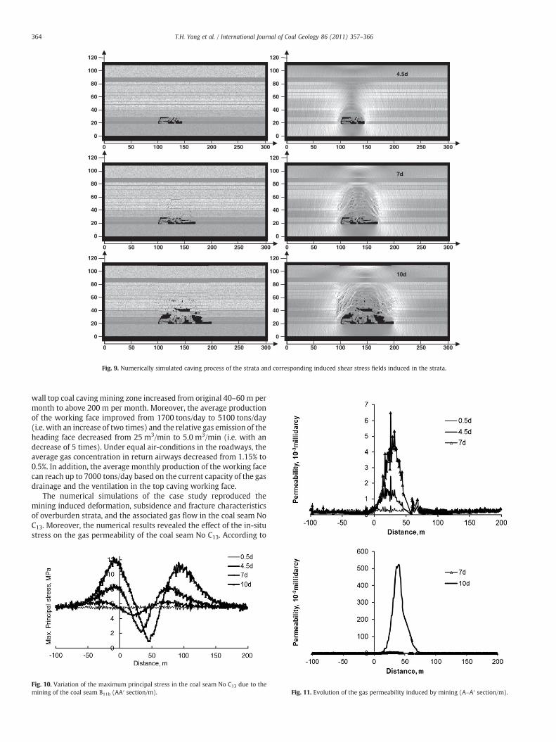
4.2. Deformation and fracture characteristics of overburden strata
Fig. 9 depicts dynamic evolution of fracturing, caving processesand corresponding stress field evolution in the overburden strataduring mining. The grayness levels represent the magnitude ofstresses. The lighter the gray is, the higher the stress, and vice versa.It can be seen that, with the working face advancing, the strata abovethe mined coal seam gradually fracture and cave. Correspondingly,the three zones (i.e., caving, fractured, and bending zones) form inthe overburden strata above the mined coal seam. Moreover, thenumerical results show that the initial caving spacing is 30 m andsequent periodic caving spacing is about 15 m, which agrees well withthe field observations. When the working face advances close to100 m, the height of the caving zone in the overburden strata abovethe coal seam No B11 is between 15 m and 20 m, and the height ofthe fractured zone is between 40 m and 45 m. In addition, the resultsindicate that the extraction of the coal seam No B11 does not cause thefracture of the coal seam No C13, but does cause the subsidence of thecoal seam No C13 since it lies in the mining induced bending zone inthe overburden strata.
4.3. Effect of in-situ stress on gas permeability of coal seam
The extraction of the coal seamNo B11 leads to the redistribution ofthe stress fields in the overburden strata, which in turn causes thechange of gas permeability in the coal seam. Figs. 10 and 11 depictthe evolution of stress and gas permeability, respectively, along thehorizontal direction of the coal seam No C13 with the mining of thecoal seam No B11. It can be seen that there is considerably widechanges in the stress and gas permeability. When the working faceadvances 0.5 day (2.5 m), the ground stress in the protected coal seamNo C13 decreases slightly. A stress-relief area is produced and the gaspermeability of the coal seam increases. However, the range of thestress-relief area is small and the degree of pressure relief is low,indicating that the relief effect on the protected coal seam is small. Atthe same time, a stress concentration region appears in the protectedcoal seam. When the working face continuously advances about7 days (35 m), the overlying coal or rock mass subsides. The stress-relief area of the protected coal seam No C13 increases above the goaf,the in-situ stress decreases and the seam permeability furtherincreases. The magnitude and range of the stress concentration alsoincrease slightly.When the coal face is advances to 10 days, the stress-relief area in the protected coal seam further increases and theoverburden strata above working face caved. It is found that themagnitude of the gas permeability in the coal seam No C13 increasesby 2100 times compared to the initial gas permeability. Moreover,the horizontal range of the coal seam with an obvious increase ofthe gas permeability is up to 70 m when the stress sensitivity factor βis 2.0. The effect of the pressure relief and the increase of the gas

300 m
gas hole 1
Strata No. Overburden rock strata pressure 10MPa
100 m
234
5
678
910
11
Gateway, excavation length is 5m per step.
There are totally 20 steps.
110
m
A A’
Fig. 8. Numerical model.
363T.H. Yang et al. / International Journal of Coal Geology 86 (2011) 357–366
permeability are obvious in the protected coal seam No C13. Incontrary, when the stress sensitivity factor β is 1.6 but other stressconditions are the same, the magnitude of the gas permeabilitychange in the coal seam No C13 is 1000 times, compared to the initialgas permeability and the horizontal range of the coal seam with anobvious increase of the gas permeability is about 50 m. It is concludedthat the stress sensitivity factor β is an important factor for modelingthe coupled gas flow in coal seams during coalmining. Comparedwiththe field observations, it may be suitable to use the stress sensitivityfactor β=2.0 for modeling the coupled gas flow in coal seams for thecase study. Fig. 12 shows the gas permeability changes in the coalseam No C13 along the A–A′ section in Fig. 8 with different sensitivityparameterβ=2.0 and β=1.6. Meanwhile, these results show that thein-situ stress in the coal seam No C13 is greatly decreased by miningthe coal seam No B11. Pressure relief and expansion deformation areinduced by mining, and a large number of bed separation crannies arecreated in the coal seam No C13. The field measurement results are inagreement with the numerical simulation.
4.4. Subsidence of the coal seam No C13 and associated gas flow
The simulatedmaximum subsidence of the coal seam are 1400 mm,1500 mm, and 1600mm as the working face advances 45 m, 70 m,and 100 m, respectively, and the range of the stress-relief zone inoverburden strata is about 50 m. The numerical results agree well withthe field observations depicted in Fig. 5.
Fig. 13 shows the change of the gas pressure in the coal seam NoC13. It can be seen that the gas pressure around the gas drainageboreholes sharply decreases from pre-drainage to post-drainage. Forexample, it decreases from 5 MPa at pre-drainage to 2.2 MPa at post-drainage after ten days' gas drainage and the working face's advancesof 100 m. Moreover, the decreasing range of gas pressure gradually
Table 1Physical, mechanical and seepage parameters used in the numerical model.
No. Lithology Elastic ModulusE(GPa)
Uniaxial compressivestrenth RC(MPa)
Unstr
1 sandy mudstone 27.0 63 62 C13 coal seam 2 20 23 siltstnoe 31.1 60 64 siltstnoe 27.21 68 55 medium-grain sandstone 28.05 100.2 86 sandy mudstone 36.44 60 67 mudstone 27.58 86.5 48 fine sandstone 19.18 48.72 59 gritty mudstone 57.4. 30.61 310 B11b coal seam 2 20 211 gritty mudstone 12.0 70 7
expands as the days of the gas drainage extends and the working faceadvances. The reason is that the coal seam No C13 above the goaf fallsin the mining induced stress release zone, where the gas permeabilityof the coal seam remarkably increases, promoting the gas flow in coalseam and leading to an obvious decrease of the gas pressure aroundgas drainage boreholes. This is called the effect of reducing the stressto increase the permeability.
Compared with the field observations and the numerical resultsdepicted in Figs. 7 and 13, respectively, there are some difference be-tween the simulated results and the field observations. The differencesare probably due to the 2D model simplification of the 3D case inpractice and the assumed gas pressure of 25 kPa in the gas drainageboreholes. Anyway, the modeled dynamic process of the pressure reliefgas drainage during coal mining on the whole agrees well with these infield observations.
4.5. Analyses and discussions
This paper revisited the engineering practices and conductedthe numerical simulations for the long-distance pressure relief gasdrainage in the coal seam No B11 at the PANYI coal mine, where thereis nearly 70 m spacing between the coal seams No B11 and No C13, anda relative coal seam distance of 35.
Through the fields observations, it was found that the gas pressurearound the borehole in the coal seam No C13 decreased from 4.4 MPato 0.4 MPa; the gas content in the coal seam No C13 decreased from13 m3/t to 5 m3/t; the gas permeability of the coal seam No C13increased from 2.84×10⁻⁴ mD to 0.817 mD by an increase of 2800times; dilatational deformation of the coal seam No B11 reached up to26.33‰; and the whole ratio of the gas emissions amount to above60%. Comparing with some working faces without an application ofthe technique, the roadway driving speed in fully-mechanized long-
iaxial tensileength Rt (MPa)
Poisson Ratio λ Frictionangle (˚)
Cohesion(MPa)
Layer thickness(m)
0.4 29 5.0 20.00.4 30 8 6.00.27 30.5 9.4 6.00.12 25.6 11.46 12.00.12 30.5 25.7 12.00.38 26.1 7.48 15.00.21 20.9 10.68 40.40 24.4 9.0 12.00.26 37 4.8 60.4 30 8 20.26 26 4.0 14
0
120
20
80
60
40
100
0
120
20
80
60
40
100
0
120
20
80
60
40
100
0
120
20
80
60
40
100
0
120
20
80
60
40
100
0
120
20
80
60
40
100
3000 20050 150 250100
4.5d
7d
10d
3000 20050 150 250100
3000 20050 150 250100 3000 20050 150 250100
3000 20050 150 250100 3000 20050 150 250100
Fig. 9. Numerically simulated caving process of the strata and corresponding induced shear stress fields induced in the strata.
364 T.H. Yang et al. / International Journal of Coal Geology 86 (2011) 357–366
wall top coal caving mining zone increased from original 40–60 m permonth to above 200 m per month. Moreover, the average productionof the working face improved from 1700 tons/day to 5100 tons/day(i.e. with an increase of two times) and the relative gas emission of theheading face decreased from 25 m3/min to 5.0 m3/min (i.e. with andecrease of 5 times). Under equal air-conditions in the roadways, theaverage gas concentration in return airways decreased from 1.15% to0.5%. In addition, the average monthly production of the working facecan reach up to 7000 tons/day based on the current capacity of the gasdrainage and the ventilation in the top caving working face.
The numerical simulations of the case study reproduced themining induced deformation, subsidence and fracture characteristicsof overburden strata, and the associated gas flow in the coal seam NoC13. Moreover, the numerical results revealed the effect of the in-situstress on the gas permeability of the coal seam No C13. According to
Fig. 10. Variation of the maximum principal stress in the coal seam No C13 due to themining of the coal seam B11b (AA′ section/m). Fig. 11. Evolution of the gas permeability induced by mining (A–A′ section/m).

Fig. 12. Evolution of the gas permeability in the coal seam No C13 along the A–A′ sectionin Fig. 8 under different coupling parameters β.
365T.H. Yang et al. / International Journal of Coal Geology 86 (2011) 357–366
the numerical simulations, the height of the caving zone is between15 m and 20 m and the height of fractured zone is between 40 m and45 m in the overburden strata above the B11 coal seam as the workingface advances to about 100 m. Due to the extraction of the coal seamNo B11, the coal seam No C13 subsides on a whole in the mininginduced sagging zone of the overburden strata. The modeleddeformation of the coal seam is basically in accordance with that infield observations. When the working face is advanced to 10 days, anobvious increase of the gas permeability is observed in the horizontalrange of up to 70 m in the coal seam No C13. The magnitude of the gaspermeability increase is up to about 2100 times higher than the initialgas permeability in the coal seam No C13. The calculated increaseis close to that observed in the field, which about 2800 times,considering the simplification in this paper and complex of theproblem. The remarkable increase of the gas permeability indicatedthat the pressure relief and the expansion deformation are induced bycoal mining and a large number of bed separations are created in thecoal seam No C13. In addition, the numerical results indicated that thegas pressure around the gas drainage boreholes sharply decreasedfrom 5 MPa to 2.2 MPa after the gas drainage of ten days and theadvance working face of 100 m. The decreasing range of the gaspressure gradually expanded as the gas drainage extends and theworking face advances. Compared with the field observations andthe numerical results in Figs. 7 and 13, respectively, there are somedifferences between the simulation and observations. It is concludedthat the differences are probably caused by the 2D simplification of the3D problem in practice and the assumption of the 25 kPa gas pressurein the gas drainage boreholes. Anyway, the modeled dynamic processof the pressure relief gas drainage during coal mining on the wholeagrees well with these in field observations. Moreover, it was foundthat the gas pressure in the coal seam No B11 decreased from 4.4 MPato 0.5 MPa; the gas content decreased from 13 m3/t to 5 m3/t; the gaspermeability increased from 2.84×10⁻⁴ mD to 0.817 mD by an
Fig. 13. Evolution of the gas pressure in the coal seam No C13 induced by mining.
increase of 2880 times; the dilatational deformation reached up to26.33‰; and the whole ratio of gas emissions amount to above 60%.
Both the field observations and the numerical simulations revealedthat the protective coal seam mining method should be adoptedcombining with the pressure relief gas drainage technique in high-gassy and outburst coal mine. As mentioned above, the methodobviously eliminates the outburst hazard and also changes the coalseam No C13 from a high gas and outburst coal seam into a low non-outburst coal seam in the case study. Moreover, the method may leadto the high production and high-efficiency for high-gassy and outburstcoal mine.
5. Conclusions
A mathematical model was proposed to simulate the deformationand fracture characteristics of overburden strata, the evolution of gaspermeability, and the gas flow in protected coal seam, in which stress,damage, and seepage coupling are taken into accounted. In the casestudy, the engineering practice of the pressure relief gas drainageby mining protective coal seam was firstly revisited for the PANYIcoal mine, which was owned by Huainan coal mining Co. Ltd. Thenumerical simulations were then performed to evaluate the effec-tiveness of the long-distance pressure relief gas drainage duringextraction of protective coal seams at great depths. The numericalresults visualized the three zones (i.e. caving, fractured and bendingzones) in the overburden strata and three stress zones (i.e. stressconcentration, stress relaxed and intact stress zones) in the protectivecoal seam induced by coal mining. The numerical simulationsgenerally agree well with the field observations, especially, theincreasing ratio of the gas permeability and the range of the pressurerelief induced by the protective coal seam mining. Moreover, thenumerical simulations indicate that the extraction of the coal seamscauses the deformation, bed separation, and caving of overburdenstrata at a large scale, and the remarkable enhancement of the gaspermeability of the protected coal seam, which in turn leads toobvious decrease of the gas pressure around boreholes in thesurrounding rock mass. It is demonstrated that the technique of thepressure relief gas drainage by long-distance boreholes remarkablyalleviates the risk of the coal and gas outbursts in the high-gassy coalseam of the low gas permeability, such as the coal seam No C13 in thecase study. In addition, the technique also significantly reduces the gascontent in the coal seam C13 and the gas emission in the working face.Correspondingly, a safe and high-efficient mining is secured in themain protected coal seam No C13.
The numerical results offered some important theoretical in-dications of the mechanism of the gas flow in the coal seam.Furthermore, the results also provided some practical instructions ofusing the technique of the pressure relief gas drainage in the high-gassy coal seam of the low gas permeability to achieve the safe andhigh-efficient mining in fully-mechanized top coal caving and preventthe occurrences of the coal and gas outbursts in underground coalmining. Therefore, it is concluded that the model proposed in thepaper is of significant help to deep the understanding of the gasflowmechanism in both theory and practice. It is pointed out that thelong-distance pressure relief gas drainage technology can effectivelyimprove the safety and productivity in underground coal mines,especially in themining areas with themultiple high-gassy coal seamsof the low permeability.
Acknowledgments
The work presented in this paper was financially jointlysupported from the National Basic Research Program of China(2007CB209405), the Key Project of the National Natural ScienceFoundation of China (Grant No. 51034001, 50934006), the GeneralProject of the National Natural Science Foundation of China (Grant

366 T.H. Yang et al. / International Journal of Coal Geology 86 (2011) 357–366
No. 10872046, 50874024), Doctoral Fund of Ministry of Education ofChina (No. 200801450003), Group Program (No. 90101001) ofNortheastern University and the opening fund of State KeyLaboratory of Geo-hazard Prevention and Geo-environment Protec-tion, Chengdu University of Technology (SKLGP2010K008). Besides,the authors would like to thank the editor and the reviewers for theirmeticulous examinations, valuable comments and constructivesuggestions on the manuscript.
Appendix A
Darcy's law describes fluid flow through a porous media, whichcan be expressed as
q = − kAμ ⋅
dpdx
ða:1Þ
where q is the volumetric flow, k is the permeability, μ is the viscosity,A is cross-sectional area, and dp/dx is the pressure gradient.
As for compressible ideal fluid, the change of density with pressuremust be considered. According to the Boyle's law
p⋅q⋅t = pa⋅qa⋅t ða:2Þ
where p and pa are the gas pressure at a certain cross-section andoutlet end of specimen, respectively. qand qa are the volumetric flowat a certain cross-section and outlet end of specimen, respectively. t isthe flow time.
Substitution of Eq. (a.2) into Eq. (a.1) yields
k⋅A⋅p⋅dp = −μ⋅pa⋅qa⋅dx ða:3Þ
Integration of Eq. (a.3) along the length of specimen yields
k⋅A⋅p⋅∫pa
p1dp = −μ⋅pa⋅qa⋅∫
L
0dx ða:4Þ
in which p1 is the gas pressure of the inlet end of the specimen and L isthe length of the tested specimen.
The following Eq. (a.5) can be obtained from Eq. (a.4)
qa = − kA2μ⋅pa ⋅
dPdx
ða:5Þ
Let qx =qaA, λ =
k2μ⋅pa
, P=p2, Eq. (a.5) becomes
qx = −λ⋅dPdx
ða:6Þ
in which qi is the flow velocity, λ is defined as the coefficient of gasfiltration, and P is the square gas pressure.
Eq. (a.6) for two-dimensional or three-dimensional flow can beexpressed in tensor form as
qi = −λij⋅dPdn
ða:7Þ
This is the generalization of Darcy's law in terms of the square gaspressure.
References
Bauer, J., Lydzba, D., 1994. Model of gas–coal medium with a sorption phenomenon.Transport in Porous Media 14, 207–217.
Beamish, B.B., Crosdale, P.J., 1998. Instantaneous outbursts in underground coal mines:An overview and association with coal type. International Journal of Coal Geology35, 27–55.
Chan, D.Y.C., Hughes, B.D., Paterson, L., 1993. Transient gas flow around boreholes.Transport in Porous Media 10, 137–152.
Chen, Y.P., Yu, Q.X., Yuan, L., 2004. Experimental research of safe and high-efficientexploitation of coal and pressure relief gas in long distance. Journal of ChinaUniversity of Mining & Technology 33, 132–136 (In Chinese with English abstract).
Connell, L.D., 2009. Coupled flow and geomechanical processes during gas productionfrom coal seams. International Journal of Coal Geology 79, 18–28.
Connell, L.D., Detournay, C., 2009. Coupled flow and geomechanical processes duringenhanced coal seam methane recovery through CO2 sequestration. InternationalJournal of Coal Geology 77, 222–233.
Hargraves, A.J., 1983. Instantaneous outbursts of coal and gas: A review. Proceedings ofthe Australian Institute of Mining and Metallurgy 285, 1–37.
Huainan Mining Group, C.L., 2002. Long-distance Pressure Relief Gas DrainageTechnology in High Gassy and Low Permeable Soft and Thick Coal Seam. ChinaUniversity of Mining and Technology, Xuzhou. (in Chinese).
Hubbert, M.K., 1957. Darcy's law and the field equations of the flow of undergroundfluids. Hydrological Sciences Journal 2, 23–59.
Hyman, D.M., 1987. A Review of the Mechanisms of Gas Outbursts in Coal. USDepartment of the Interior, Bureau of Mines, IC 9155, Pittsburgh, PA. http://dx.doi.org/10.1080/02626665709493062.
Karacan, C.Ö., Diamond, W.P., Schatzel, S.J., 2007. Numerical analysis of the influence ofin-seam horizontal methane drainage boreholes on longwall face emission rates.International Journal of Coal Geology 72, 15–32.
Lemaitre, J., Desmorat, R., 2005. Engineering Damage Mechanics. Springer-Verlag,Berlin.
Louis, C., 1974. Rock hydraulics. In: Muller, L. (Ed.), Rock Mechanics. Springer-Verlag,New York, pp. 287–299.
Lunarzewski, L.W., 1998. Gas emission prediction and recovery in underground coalmines. International Journal of Coal Geology 35, 117–145.
Noack, K., 1998. Control of gas emissions in underground coal mines. InternationalJournal of Coal Geology 35, 57–82.
Otuonye, F., Sheng, J., 1994. A numerical simulation of gas flow during coal/gasoutbursts. Geotechnical and Geological Engineering 12, 15–34.
Pan, Z., Connell, L.D., 2009. Comparison of adsorption models in reservoir simulation ofenhanced coalbed methane recovery and CO2 sequestration in coal. InternationalJournal of Greenhouse Gas Control 3, 77–89.
Paterson, L., 1986. A model for outbursts in coal. International Journal of RockMechanics and Mining Sciences & Geomechanics Abstracts 23, 327–332.
Schneider, T., Preuße, A., 1995. Recovery and utilisation of coal seam gas — impetus bythe German hard coal mining industry. Erdöl Erdgas Kohle 111, 515–519.
Shepherd, J., Rixon, L.K., Griffiths, L., 1981. Outbursts and geological structures in coalmines: A review. International Journal of Rock Mechanics and Mining Sciences &Geomechanics Abstracts 18, 267–283.
Sun, P.D., Wan, H.G., 2004. A coupled model for solid deformation and gas leak flow.International Journal for Numerical and Analytical Methods in Geomechanics 28,1083–1104.
Tang, C.A., Tham, L.G., Lee, P.K.K., Yang, T.H., Li, L.C., 2002. Coupled analysis of flow,stress and damage (FSD) in rock failure. International Journal of Rock Mechanicsand Mining Sciences 39, 477–489.
Terzaghi, K., Peck, R.B., Mesri, G., 1996. Soil Mechanics in Engineering Practice. JohnWiley & Sons, New York.
Valliappan, S., Zhang, W.H., 1996. Numerical modelling of methane gas migration indry coal seams. International Journal for Numerical and Analytical Methods inGeomechanics 20, 571–593.
Valliappan, S., Zhang, W.H., 1999. Role of gas energy during coal outbursts.International Journal for Numerical Methods in Engineering 44, 875–895.
Viete, D.R., Ranjith, P.G., 2006. The effect of CO2 on the geomechanical and permeabilitybehaviour of brown coal: Implications for coal seam CO2 sequestration. Interna-tional Journal of Coal Geology 66, 204–216.
Xu, T., Tang, C.A., Yang, T.H., Zhu, W.C., Liu, J., 2006. Numerical investigation of coal andgas outbursts in underground collieries. International Journal of Rock Mechanicsand Mining Sciences 43, 905–919.
Xu, T., Yan, A., Hao, T., Yu, S., 2007. Numerical modeling of cross measure borehole gasdrainage. In: Jin, G., Zhou, A., Gao, J., et al. (Eds.), Progress in Mining Science andSafety Technology. Science Press, Beijing, pp. 1358–1363.
Yang, T.H., Tang, C.A., Xu, T., Rui, Y.Q., 2004. Seepage Characteristic in Rock Failure.Science Press, Beijing. (in Chinese).
Yu, Q.X., Chen, Y.P., Jiang, C.L., 2004. Principles and applications of exploitation of coaland pressure relief gas in thick and high-gas seams. Journal of China University ofMining & Technology 33, 127–131 (In Chinese with English abstract).
Yu, S.B., 1992. One-dimensional flow model for coal–gas outbursts and initiationcriterion. Acta Mechanica Sinica 8, 363–373 (In Chinese with English abstract).
Zhao, C., Valliappan, S., 1995. Finite element modelling of methane gas migration in coalseams. Computers & Structures 55, 625–629.
Zhou, S.N., Lin, B.Q., 1998. The Theory of Gas Flow and storage in Coal Seams. China CoalIndustry Publishing House, Beijing. (in Chinese).
Zhu, W.C., Liu, J., Sheng, J.C., Elsworth, D., 2007. Analysis of coupled gas flow anddeformation process with desorption and Klinkenberg effects in coal seams.International Journal of Rock Mechanics and Mining Sciences 44, 971–980.