Strength of Materials - MADE EASY
37
Mechanical Engineering Strength of Materials Answer Key of Objective & Conventional Questions 2019 MPROVEMENT
-
Upload
khangminh22 -
Category
Documents
-
view
2 -
download
0
Transcript of Strength of Materials - MADE EASY

Mechanical Engineering
Strength of MaterialsAnswer Key of Objective & Conventional Questions
2019MPROVEMENT

© Copyrightwww.madeeasypublications.org
©C
opyrig
ht: Sub
ject matter to M
AD
E E
AS
Y P
ublications, N
ew D
elhi. No p
art of this book m
ay be rep
roduced
or utilised in any form
without the w
ritten perm
ission.
1. (c)
2. (c)
3. (b)
4. (c)
5. (b)
6. (b)
7. (c)
8. (b)
9. (b)
10. (a)
11. (d)
Mechanical Properties ofMaterials & Elastic Constants1
12. (c)
13. (b)
14. (c)
15. (d)
16. (d)
17. (b)
18. (a)
19. (c)
20. (0.4)
21. (c)
22. (b)

© Copyright www.madeeasypublications.org
3Rank Improvement Workbook
Solution : 23Elastic modulus, E = 199.289 ≈ 199.3 GPa
Modulus of Rigidity, G = 78.44 GPaν = 0.27 (Poisson’s ratio)
Bulk modulus, K = 144.42 GPa
Solution : 24
Hence σ2 = 123 1
μ σ− μ
1e′ =2
1 3 3 43(1 )E
⎡ ⎤σ − μ − μ⎢ ⎥− μ⎣ ⎦
compressive.
Solution : 25μ = 0.267K = 1.359 × 10⁵ N/mm2
Maximum % error in μ = 9.475%
Solution : 26
GB =1.01 101
1.01 3(1.01 1) 101 3A A A A
A A A A
E G E GE G E G
=− − −
Solution : 27
m = 3.126 and 1
0.32m
≈
E = 1.32 × 10⁵ N/mm2
Solution : 28% reduction in volume = 0.00249
δV = 321 mm3
Solution : 29G = 40 GPaK = 66.7 GPa Ans.
Change in volume = dV = 1588.56 mm3
© Copyrightwww.madeeasypublications.org
©C
opyrig
ht: Sub
ject matter to M
AD
E E
AS
Y P
ublications, N
ew D
elhi. No p
art of this book m
ay be rep
roduced
or utilised in any form
without the w
ritten perm
ission.
1. (b)
2. (a)
3. (d)
4. (c)
5. (b)
6. (c)
7. (c)
8. (a)
9. (a)
10. (c)
11. (b)
Stress and Strain212. (d)
13. (d)
14. (c)
15. (a)
16. (b)
17. (b)
18. (b)
19. (d)
© Copyright www.madeeasypublications.org
5Rank Improvement Workbook
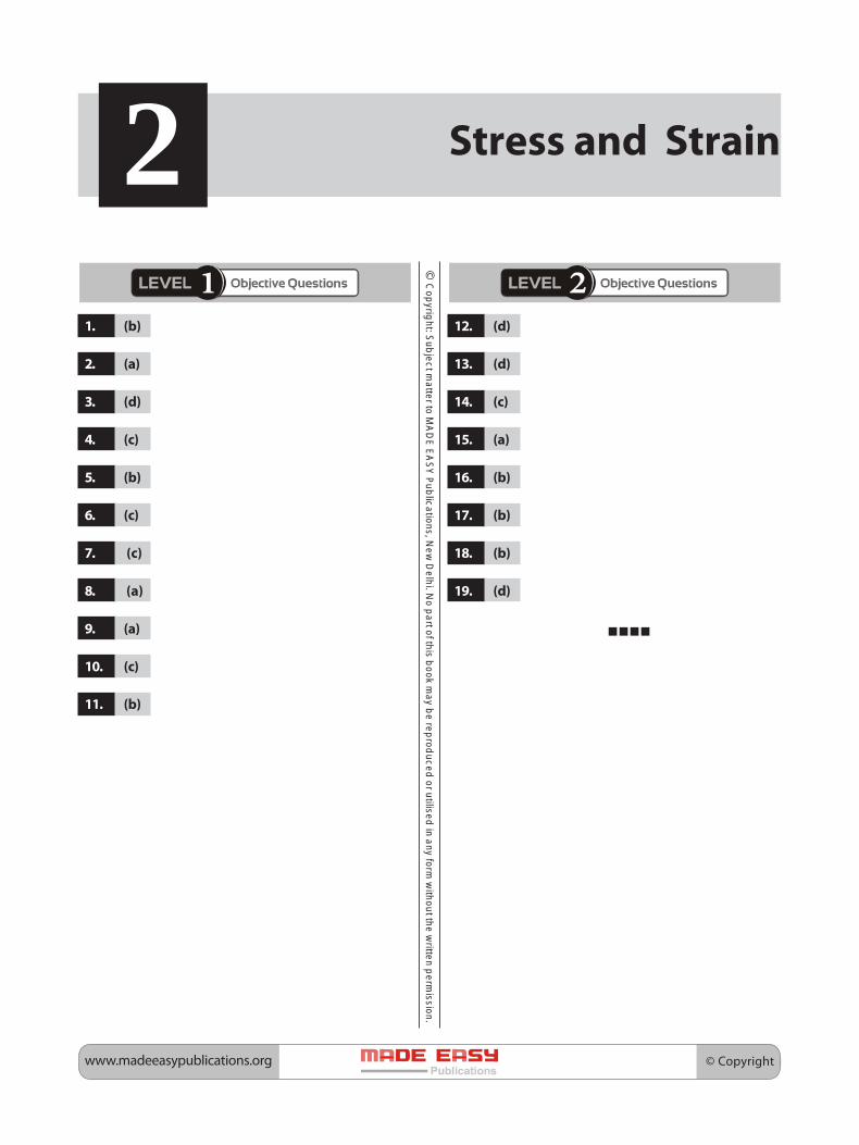
Solution : 20σmax = –240 MPa (in portion AB)
Change in length = –2.817 mm (contraction)
Solution : 21σc = –33.86 N/mm2
σs = 1.543 × σc = 52.26 N/mm2
Solution : 22
d = 1 2d d
σbar = 21
4Pdπ
σavg = 2
4Pdπ
Solution : 23d2 = 41.2 mmL2 = 188.62 mmL1 = 155.69 mm
Solution : 24Total elongation = Δ1 + Δ2 = 23.41 + 4.30 = 27.71 mm
Solution : 25
Δ = 2 21 2
1 1PLE d d
⎡ ⎤+⎢ ⎥π ⎣ ⎦
Solution : 26t = 25.45 mm, say 26 mm.
Solution : 27
δ lc = 0.2 mmδl1 = 0.05 mm
δlB = 0.15 mm
Solution : 28
PCu = 36.93 kN
PZn = 42.61 kN
PAl = 45.45 kN
σCu = 147.72 MPa
σZn = 113.63 MPa
σAl = 90.9 MPa

© Copyrightwww.madeeasypublications.org
©C
opyrig
ht: Sub
ject matter to M
AD
E E
AS
Y P
ublications, N
ew D
elhi. No p
art of this book m
ay be rep
roduced
or utilised in any form
without the w
ritten perm
ission.
1. (c)
2. (d)
3. (c)
4. (a)
5. (a)
6. (d)
7. (c)
8. (d)
9. (d)
10. (c)
11. (d)
12. (c)
13. (a)
14. (a)
15. (a)
16. (c)
17. (c)
18. (b)
Shear force& Bending Moment3
19. (c)
20. (a)
21. (d)
22. (c)
23. (b)
24. (b)
25. 4.47 (4.40-4.50)
26. (50)
27. (d)
28. (d)
29. 150 (148 to 153)
30. (a)
31. (a)
32. (b)
33. (c)

© Copyright www.madeeasypublications.org
7Rank Improvement Workbook
Solution : 34
L/2
A BC (Simply supported beam)
C B
–W/2
W/2
AL/2 L/2
(SFD)
WL/4
A B(BMD)
L/2
Deflection diagram:
AC
B
δmax = WLE3
48 I
Deflection diagram:
B
l
A
W
C
+W
BCA
(SFD)
AC
B
–Wl/2
(BMD)
C BA
⎛ ⎞δ =⎜ ⎟⎜ ⎟⎝ ⎠I
3
max5( )48B
WLE
(ii) (ii) (ii) (ii) (ii) Structural members subjected to compression and which are relatively long compared to their lateraldimensions are called columns or struts. Generally, the term column is used to denote vertical membersand the term strut denotes inclined members.
Columns are generally fixed at the both ends while strut can have any end fixation conditions like bothend fixed, both ends hinged, one end fixed other end free, etc.
According to Rankine’s formulae,

© Copyrightwww.madeeasypublications.org
8 Mechanical Engineering • Strength of Materials
1
RP=
1 1
e cP P+
where Pe = buckling load
Pc = crushing load
For short column Pe>>>> Pc
or1
eP <<< 1 1can be neglected
c eP P⇒ ,
1
RP =1
cP
PR ≈ Pc ≈ AσcFor long columns Pc >>> Pe
1
cP <<< 1
eP 1can be neglected
cP⇒
PR ≈ Pe =2
min2e
EL
π I
∴ PR = 21 ( )cA
c Seσ
+
where, c = Rankine’s constant and Se = slenderness ratio
Solution : 35
16 kN-MA B
EC
2 kN 9 kN5 kN11 11 kN
4 m 4 m 4 m 4 m 4 m
16 kN
(a)BEAM
2 2(+)
(–)
5 5
88 kN-m
8
30 kN-m
( )B.M.D.
c(+)
(–)
(+)A B
C
( )S.F.D.
b
Considering L.H.S MB = 0 = RA × 8 – 16

© Copyright www.madeeasypublications.org
9Rank Improvement Workbook
RA =168
= 2 kN(↑)
RD = 5 kN(↑) and RC = 9 kN(↑)
Question : 36
RC =1600 200
kN216 27
=
Solution : 37
3 3
33.463
3.464
(BMD)
(SFD)
Solution : 38RE = 55 KN
∴ RB = 100 – 55 = 45 KN
10 kN15 kN 15 kN
35 kN35 kN
40 kN40 kN
2.5 2.5
6.75
20
BM Diagram
para
bolic
© Copyrightwww.madeeasypublications.org
10 Mechanical Engineering • Strength of Materials
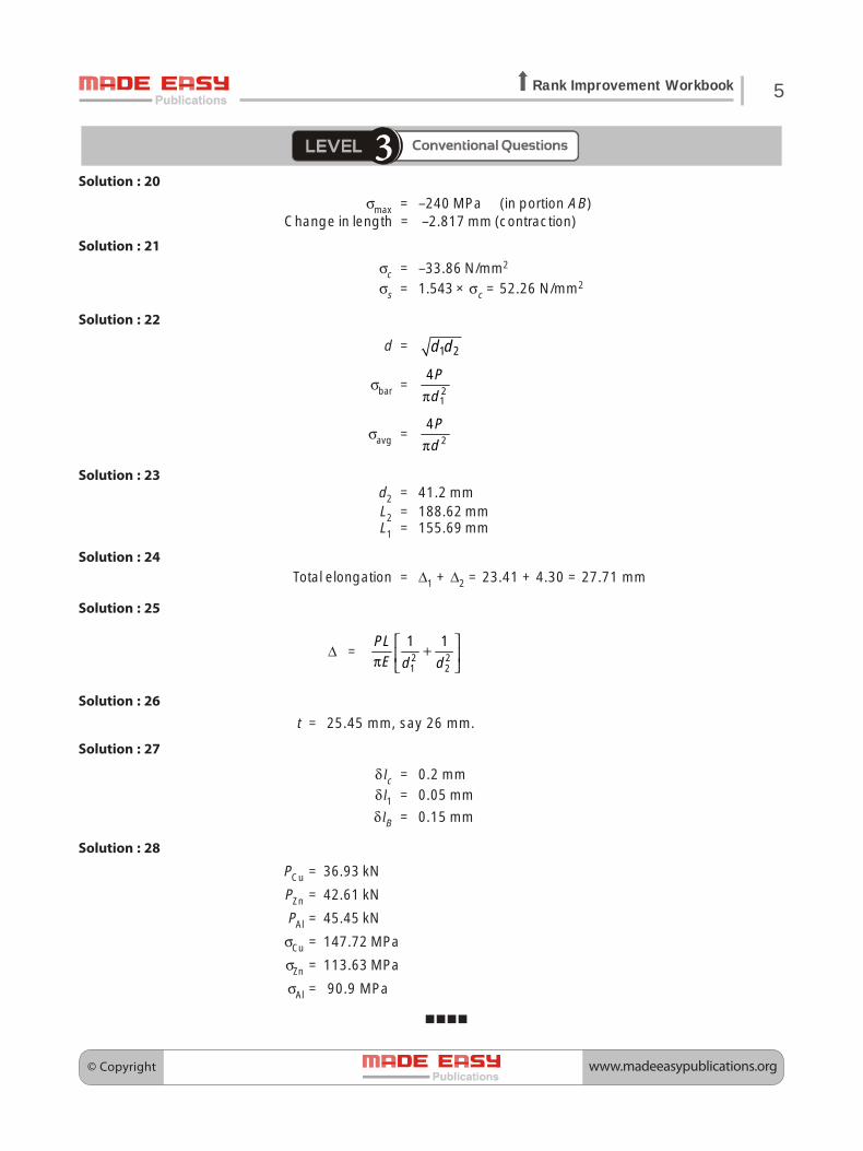
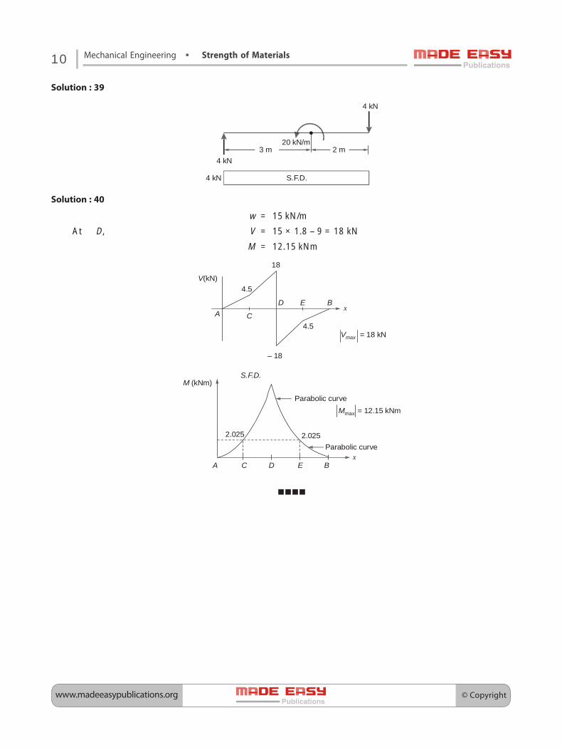
Solution : 39
3 m 2 m20 kN/m
4 kN
4 kN
4 kN S.F.D.
Solution : 40
w = 15 kN/m
At D, V = 15 × 1.8 – 9 = 18 kN
M = 12.15 kNm
4.5
4.5A
B
C
D Ex
Vmax = 18 kN
– 18
18
V(kN)
A BC D Ex
Parabolic curveMmax = 12.15 kNm
2.0252.025Parabolic curve
M (kNm)S.F.D.

© Copyright www.madeeasypublications.org
©C
opyrig
ht: Sub
ject matter to M
AD
E E
AS
Y P
ublications, N
ew D
elhi. No p
art of this book m
ay be rep
roduced
or utilised in any form
without the w
ritten perm
ission.
1. (a)
2. (c)
3. (b)
4. (c)
5. (c)
6. (b)
7. (d)
8. (a)
9. (a)
10. (c)
11. (b)
12. (c)
13. (b)
14. (a)
15. (c)
16. (b)
17. (d)
18. (a)
19. (b)
Shear Stressand Bending Stress4
20. (c)
21. (d)
22. (b)
23. (b)
24. (b)
25. 1.36 (1.30 to 1.40)
26. 89.05 (88 to 90)
27. (b)
28. 56.25 (56-57)
29. (d)
30. 6.25 (6.21 to 6.27)
31. 266.67 (264 to 268)
32. (b)
33. 166.67 (166-167)
34. (a)
35. (c)
36. 120 (119 to 121)

© Copyrightwww.madeeasypublications.org
12 Mechanical Engineering • Strength of Materials
Solution : 37
Z1 : Z2 : Z3 = 0.9025 : 0.20529 : 0.122845
= 7.346 : 1.671 : 1sss
Solution : 38
y =10 2
8 = 1.76 cm from neutral axis.
Solution : 39W = 413.76 kN
Minimum length of plate = 5 – (0.942 × 2) = 3.116 m
Solution : 40Breadth of beam, b = 71.8 mmDepth of beam, d = 316.7 mm
⎫⎬⎭
Ans.
Solution : 41
4.71
τmax= 14.71 N/mm2
14.12
Shear Stress Distribution
τmax = 14.71 N/mm2
Shear stress in the flange at the junction of flange and web = 14.12 N/mm2
The shear stress distribution is shown in figure.
Solution : 42d = 86.3 mm say 90 mm
Solution : 43Allowable load, W = 15 kN/m (taking lower of two)

© Copyright www.madeeasypublications.org
13Rank Improvement Workbook
Solution : 44D = 0.0248 m = 24.78 mm
Solution : 45σmax = 964.63 MPa
M = 20455.627 Nmm
Mmax = 20.455 Nm
Solution : 46
M = 80.24 × 10³ Nm
Solution : 47
RA =13
kN3
RB =17
kN3
σ1 = – 23.3674 N/mm2
σ2 = 0.8586 N/mm2

© Copyrightwww.madeeasypublications.org
©C
opyrig
ht: Sub
ject matter to M
AD
E E
AS
Y P
ublications, N
ew D
elhi. No p
art of this book m
ay be rep
roduced
or utilised in any form
without the w
ritten perm
ission.
1. (b)
2. (d)
3. (a)
4. (d)
5. (d)
6. (a)
7. (b)
8. (b)
9. (d)
10. (b)
11. (b)
12. (d)
13. (d)
14. (c)
15 (b)
16. (d)
17. (b)
Torsion of Shafts518. (b)
19. 20.00 (20.00 to 20.00)
20. (400)
21. (b)
22. (b)
23. 0.12 (0.11 to 0.15)
24. (b)
25. (d)
26. 34.17 (34.00 to 34.50)

© Copyright www.madeeasypublications.org
15Rank Improvement Workbook
Solution : 27T = 1.335 kNm
Solution : 28
Weight of hollow shaft is 0.6431 times the weight of solid shaft.
Solution : 29
d2 = 184.16 mm, d1 = 69.06 mm
Solution : 30D1 = 95.5 mm Ans.Ans.Ans.Ans.Ans.
Ratio of torsional rigidity = 2.093
Solution : 31d = 0.108 m
Hence percentage savings in weight = 38.78%
Solution : 32D = 137.57 mm
Hence minimum external diameter of shaft = 137.57 mm (taking bigger one value).
Solution : 33
s
h
ZZ
= ( )0
02 22
D D
D D
×−
Solution : 34Maximum shear stress in the shaft = 42.56 N/mm2
Twist of the end D with respect to the end A = 0.03089 radian = 1.77 degrees
Solution : 35
TA =6ot L
−
TB = – 3ot L
T Lo
6
TB
to
Expression for φ(x) =31 ·
6 2 3o ot L t
GJ L⎡ ⎤− ×⎢ ⎥⎣ ⎦
xx +
φ is φmax at x =3
L

© Copyrightwww.madeeasypublications.org
16 Mechanical Engineering • Strength of Materials
φmax =23
27ot L
GJ−
Solution : 36
Torque = 1.1 kNm
Solution : 37
Power = 98 kW

© Copyright www.madeeasypublications.org
©C
opyrig
ht: Sub
ject matter to M
AD
E E
AS
Y P
ublications, N
ew D
elhi. No p
art of this book m
ay be rep
roduced
or utilised in any form
without the w
ritten perm
ission.
1. (d)
2. (c)
3. (a)
4. (c)
5. (d)
6. (c)
7. (a)
8. (b)
9. (c)
10. (b)
11. (d)
12. (a)
13. (c)
14. (c)
15. (c)
16. (c)
17. (d)
18. (c)
Principle Stress &Strain, Mohr’s Circle6
19. (a)
20. (70)
21. (d)
22. (75)
23. (b)
24. (a)
25. (a)
26. (c)
27. (b)
28. (a)
29. (b)
30. 6.98 (6.8 to 7.2)
31. (0)
32. (86.60)

© Copyrightwww.madeeasypublications.org
18 Mechanical Engineering • Strength of Materials
Solution : 33
Hooke’s Law, σx = 91.6 MPaSolution : 34
Given: σ1, σ2 are the principal stresses.(i) According to plane stress transformation equations
σx′ = x xxcos2 sin2
2 2y y
y
σ + σ σ − σ⎛ ⎞ ⎛ ⎞+ θ + τ θ⎜ ⎟ ⎜ ⎟⎝ ⎠ ⎝ ⎠
... (i)
σy′ = x xxcos2 sin2
2 2y y
y
σ + σ σ − σ⎛ ⎞ ⎛ ⎞− θ − τ θ⎜ ⎟ ⎜ ⎟⎝ ⎠ ⎝ ⎠
... (ii)
Adding equation (i) and (ii),σx′ + σy′ = σx + σy
Similarly, σ1 = x xx
22
2 2y y
y
σ + σ σ − σ⎛ ⎞ ⎛ ⎞+ + τ⎜ ⎟ ⎜ ⎟⎝ ⎠ ⎝ ⎠
... (i)
σ2 = x xx
22
2 2y y
y
σ + σ σ − σ⎛ ⎞ ⎛ ⎞− + τ⎜ ⎟ ⎜ ⎟⎝ ⎠ ⎝ ⎠
... (ii)
Adding, (i) and (ii),
σ1 + σ2 = σx + σy
∴ σx + σy = σx′ + σy′ = σ1 + σ2
(ii) Mohr(ii) Mohr(ii) Mohr(ii) Mohr(ii) Mohr’’’’’s cirs cirs cirs cirs circle for purcle for purcle for purcle for purcle for pure shear stre shear stre shear stre shear stre shear stress state.ess state.ess state.ess state.ess state.
– τ τ
τ
τRadius = τ
MohrMohrMohrMohrMohr’’’’’s cirs cirs cirs cirs circle for hydrcle for hydrcle for hydrcle for hydrcle for hydrostatic state.ostatic state.ostatic state.ostatic state.ostatic state.
( , 0)σ
Solution : 35
σ1 = 12.73 N/mm2, θ = 45°
σ2 = – 12.73 N/mm2, θ =135°
Solution : 36Principal stress, σ1 = 38.55 N/mm2
σ2 = –38.55 N/mm2
θp = –14.3°, 75.7°

© Copyright www.madeeasypublications.org
19Rank Improvement Workbook
Solution : 37
θ1 = 36.6992°, θ2 = 126.6992°
Maximum shear stress, τmax = 70 MPa
Solution : 38If σ11, σ22, σ33 be the three principle stresses, then the principle strains t11, t22, t33 obtained by GeneralizedHooke’s law as:
∈11 = 22 3311
E mEσ + σσ
− ...(i)
∈22 = 33 1122
E mEσ + σσ
− ...(ii)
∈33 = 33 11 22
E mEσ σ + σ
− ...(iii)
where, E = Modulus of elasticity
and1m
= Poisson’s Ratio
From equation (i), we have
E∈11 = σ11 – 3322
m mσσ
− ...(iv)
From equation (ii), we have
E∈22 = σ22 – 33 11
m mσ σ
− ...(v)
From equation, (iii) we have
E∈33 = σ33 – 11 22
m mσ σ
− ...(vi)
Subtracting equation (v) from equation (iv), we get
E(∈11 – ∈22) = (σ11 – σ22) 21a
m⎛ ⎞+⎜ ⎟⎝ ⎠ ...(vii)
From equations (i) and (iii), (vi), we get
E(∈11 + ∈33) = σ11 2
11
m⎛ ⎞−⎜ ⎟⎝ ⎠ –σ22 2
1 11
mm⎛ ⎞+⎜ ⎟⎝ ⎠ ...(viii)
σ11 =( )11 22 33
1 11
1 21 1
Em m
m m
⎛ ⎞− ∈ + ∈ + ∈⎜ ⎟⎝ ⎠⎛ ⎞ ⎛ ⎞+ −⎜ ⎟ ⎜ ⎟⎝ ⎠ ⎝ ⎠
Similarly, σ22 =( )22 33 22
1 11
1 21 1
Em m
m m
⎛ ⎞− ∈ + ∈ + ∈⎜ ⎟⎝ ⎠⎛ ⎞ ⎛ ⎞− −⎜ ⎟ ⎜ ⎟⎝ ⎠ ⎝ ⎠
Similarly, σ33 =( )33 11 22
1 11
1 21 1
Em m
m m
⎛ ⎞− ∈ + ∈ + ∈⎜ ⎟⎝ ⎠⎛ ⎞ ⎛ ⎞− −⎜ ⎟ ⎜ ⎟⎝ ⎠ ⎝ ⎠
© Copyrightwww.madeeasypublications.org
20 Mechanical Engineering • Strength of Materials
Solution : 39Hence major axis of the ellipse = 100 + 0.839 = 100.839 mm
Minor axis of the ellipse = 100 – 0.633 = 99.367 mmθ1 = 12.22°θ2 = 102.22°
Solution : 40
σmax(σ1) = 280.62 MPa
σmin (σ2) = 119.38 MPaθ1 = 14.87°θ2 = 104.87°
Maximum shearing stress = ±80.62 MPai.e., 59.87° and 149.87°
Solution : 41
σ1 = 205.625 MPa, σ2 = –155.625 MPa
θP = 20.815° and 110.815°Position of the plane on which normal stress is zero,
θ = 69.8°
Solution : 42Same as question 40.

© Copyright www.madeeasypublications.org
©C
opyrig
ht: Sub
ject matter to M
AD
E E
AS
Y P
ublications, N
ew D
elhi. No p
art of this book m
ay be rep
roduced
or utilised in any form
without the w
ritten perm
ission.
1. (b)
2. (a)
3. (a)
4. (d)
5. (a)
6. (a) (*)
7. (d)
8. (a)
9. (80)
10. (d)
11. (c)
12. (1)
13. 187.5 (185 to 190)
14. (d)
15. (c)
16. (a)
17. (b)
18. (d)
19. (b)
Strain Energy andThermal Stress7

© Copyrightwww.madeeasypublications.org
22 Mechanical Engineering • Strength of Materials
Solution : 20
Given:
w N/m
A B
Simple supported beam loaded by uniformly distributed load.
Let Ue be the elastic strain energy due to bending of beam.
Ue =2
0 2LM d
E∫x
I
RA =2
wL
A B
RA
M
x
M =2
2 2wL w−x x
Ue =2
20
1 ( )2 2
L w L dE
⎡ ⎤−⎢ ⎥⎣ ⎦∫ x x xI
Ue =2
2 2 4 30
1 ( 2 )2 4
Lw L L dE
× + −∫ x x x xI
Ue =2 5 5 52
8 3 5 4w L L LE
⎡ ⎤+ −⎢ ⎥
⎢ ⎥⎣ ⎦I = 2
520 12 308 60w
LE
+ −⎡ ⎤× ⎢ ⎥⎣ ⎦I
Ue =2 5 2 5 2 5
331240 2024012
w L w L w LE E bhE bh
⎛ ⎞= =⎜ ⎟⎜ ⎟⎝ ⎠ × ×I
Now, σmax =2 2
2 2 2
6 6 3
8 4
My M wL wLbd bh bh
×= = =×I
Volume of beam = A × L = (b × h)L
=2max 8 volume of beam2 45E
⎛ ⎞σ ⎛ ⎞× ×⎜ ⎟ ⎜ ⎟⎜ ⎟ ⎝ ⎠⎝ ⎠
=2 4
2 4
9 8( )
4532
w Lb h L
b h E× × × × =
2 5
3240 ew L U
Ebh=
This expression is same as obtained by equation (i).

© Copyright www.madeeasypublications.org
23Rank Improvement Workbook
Solution : 21σb1 = 15 N/mm2
σs1 = 4 σb1 = 60 N/mm2
σb2 = 9.33 N/mm2, σs2 = 37.33 N/mm2
σb = 24.33 N/mm2 (compressive)σb = 24.33 N/mm2 (tensile)
Solution : 22σs = 91.77 MPa (tensile)σc = 108.3 MPa (compressive)
Solution : 23
σc = 198.486 MPaσa = 49.62 MPaσs = 198.486 MPaσs = 94.309 MPaσa = 23.577 MPa
Solution : 24
Vertical deflection =3
6PLE I
Solution : 25
As = Ab = ( )236 104
−π × × = 28.27 × 10⁻⁶ m2
σs1= σb1 = 123.8 MPaσs2 = 29.62 MPa (tensile)σb2 = 16.36 MPa (compressive)
σsf = 153.42 – 56.84 = 96.58 MPa (tensile)
σbf = 107.44 – 56.84 = 50.6 MPa (tensile)
Solution : 26
E = 79.6 GPa
UT = 8 N-mU = 7.9 N-m
Solution : 27
Resultant stress in aluminium= 25.3 MPa (tensile)
Resultant stress in steel = 79.3 MPa (tensile)ΔT = 85.138°C
Solution : 28
Length of circular portion = 0.12 m or 120 mm
d = 0.0255 m or 25.5 mm
strain energy = 1.4 J

© Copyrightwww.madeeasypublications.org
©C
opyrig
ht: Sub
ject matter to M
AD
E E
AS
Y P
ublications, N
ew D
elhi. No p
art of this book m
ay be rep
roduced
or utilised in any form
without the w
ritten perm
ission.
1. (b)
2. (d)
3. (d)
4. (c)
5. (a)
6. (b)
7. (c)
8. (a)
9. (d)
10. (a)
11. (d)
12. (d)
13. (d)
14. (b)
15. (d)
16. (d)
17. (0.67)
18. 0.78
19. (0.21)
20. 2.2 (2.15-2.25)
Deflection of Beams821. (b)
22. (a)
23. (a)
24. (b)
25. (d)
26. (b)
27. (34.91)
28. (c)
29. (c)

© Copyright www.madeeasypublications.org
25Rank Improvement Workbook
Solution : 30Equation of elastic curve:
EIy =3 4 3
12 24 24wL w wL− −x x x
ymax =I
45384
wLE
−
Solution : 31
yC =I
45384
wLE
(downwards)
yC =2 2
16wa L
E−
I(upward direction)
Solution : 32
3 m 1 m
10000 kN
Deflected position
CB
B′
C′
yC
y2
θC
A
yC = 1.125 cm
θB = θC = 9
radians1600
YB = 1.6875 cm
Solution : 33Total deflection of B = 8.69 mm
Solution : 34
A BCD E
30 cm
20 kN
30 cm 40 cm
xx
x50 cm

© Copyrightwww.madeeasypublications.org
26 Mechanical Engineering • Strength of Materials
Taking moment about A,20 kN × 30 = RB × 100
RB = 6 kNRA = 20 – 6 = 14 kN
At a distance x from A in the DB portion,
Ix
2
2
d yE
d= RA ⋅ x – W(x – 30) ...(1)
Integrating, (For BD section)
Ix
dyE
d=
x x− − +2
21( 30)
2 2AWR C ...(2)
Again integrating, (For BD section)
E I y =x x x− − + +
×
33
1 2( 30)6 2 3A
WR C C ...(3)
Boundary conditions,At x = 0, y = 0, So, C2 = 0
At x = L, y = 0 0 = − × + +3
3170 0
6 6AL WR CL
−⎡ ⎤×× − ×⎢ ⎥⎣ ⎦
3 33 420 14 100 10
70 106 6 100
= C1 [C1 = –1190]
Putting value of C1 in equation (2) and (3),
Ix
dyE
d=
x x− − −2
2( 30) 11902 2A
WR ...(4)
E I y =x x x− − −
33( 30) 1190
6 6AWR ...(5)
For slopes at different points,
Slope at point, A, θA = I− 1190
radianE
Slope at point B, θB =I
− −⎡ ⎤×× × × − × × −⎢ ⎥⎣ ⎦
2 33 4 2 41 100 20 10
14 10 10 (70) 10 11902 2E
= I I− − =1 910
[7000 4900 1190] radianE E
Slope at point C, θC =I
− −⎡ ⎤×× × × − × × −⎢ ⎥⎣ ⎦
2 33 4 2 41 50 20 10
14 10 10 20 10 11902 2E
= I− −1
[1750 400 1190]E
θC = I+ 160
radianE
Slope at point D, θD = I I−⎡ ⎤× × × − = −⎢ ⎥⎣ ⎦
3 2 41 14 56010 30 10 1190 radian2E E

© Copyright www.madeeasypublications.org
27Rank Improvement Workbook
Slope at point E, θE =I
⎡ ⎤× × − × × −⎢ ⎥⎣ ⎦
32 3 21 14 10 20
0.6 10 0.3 11902 2E
= I430
radianE
Deflection at different points,Deflection of point A, yA = 0Deflection of point B, yB = 0
Deflection of point C, yC =I
⎡ ⎤×× × − × − ×⎢ ⎥⎣ ⎦
3 33 31 0.5 20 10
14 10 0.2 1190 0.56 2E
= I−1150
units3E
Deflection of point D, yD =I I
⎡ ⎤ −× × − × =⎢ ⎥⎣ ⎦
331 0.3 294
14 10 1190 0.3 units6E E
Deflections of point E, yE =I
⎡ ⎤× × − × − ×⎢ ⎥⎣ ⎦
33 31 0.6 20000
14 10 0.3 1190 0.66 6E
= I−300
unitsE
Solution : 35
θD = 72WEI
δD =I
301 33. WE
Slope of the free end, θD = 3.6 × 10⁻³ radDeflection at the free end, δD = 15.06 mm

© Copyrightwww.madeeasypublications.org
©C
opyrig
ht: Sub
ject matter to M
AD
E E
AS
Y P
ublications, N
ew D
elhi. No p
art of this book m
ay be rep
roduced
or utilised in any form
without the w
ritten perm
ission.
1. (c)
2. 4.5 (4.45-4.55)
3. (a)
4. (b)
5. (d)
6. (d)
7. (c)
8. (b)
9. (a)
10. (c)
11. (d)
12. (b)
13. (d)
14. (d)
15. (b)
16. (c)
Theories of Failure &Springs9
17. (d)
18. 112.51 (112 to 113.5)
19. (b)
20. (d)
21. (d)
22. (b)
23. (d)
24. (c)
25. (b)
26. (a)
27. (d)
28. (d)
29. (d)

© Copyright www.madeeasypublications.org
29Rank Improvement Workbook
Solution : 30
Strain energy theory, d = 13.48 or 14 mm
Shear strain energy theory, d = 13.68 mm
Solution : 31(i) According to Von-misses criterion.
(σ1 – σ2)2 + (σ2 – σ3)
2 + (σ3 – σ1)2 ≤ 2(σy)
2 [Considering bi-axial stress]
For stress state, σ3 = 0
σ1 = τ
σ2 = –τ
[τ – (–τ)]2 + τ2 + τ2 ≤ σy2
6τys2 ≤ 2σyt
2
3ytσ
= τys [Relation between tensile and shear yield stress]
τ = Shear yield stressσy = Tensile stress
(ii) Accroding to Tresca criteria:
1 2
2σ − σ
≤2yσ
For Stress State, σ1 = τ [Considering bi-axial stress]σ2 = –τ, σ3 = 0
( )2
τ − −τ≤
2yσ
τys =2yσ
[Relation between tensile and shear yield stress.]
Solution : 32d = 5.229 or 6 mm (say)
Total length of wire = 1922.65 mm or 1.92 m
Solution : 33 According to maximum principal stress theory
d = 2.029 × 10⁻² m = 20.29 mmAccording to shear strain energy theory
d = 0.02143 m = 21.43 mm
Solution : 34Given, W = 120 N, d = 80 mm, T = 500 N.mm, θ = 90°, D = 25 mm
δ(Deflection of close coiled spring) = W D nGd
3
48
© Copyrightwww.madeeasypublications.org
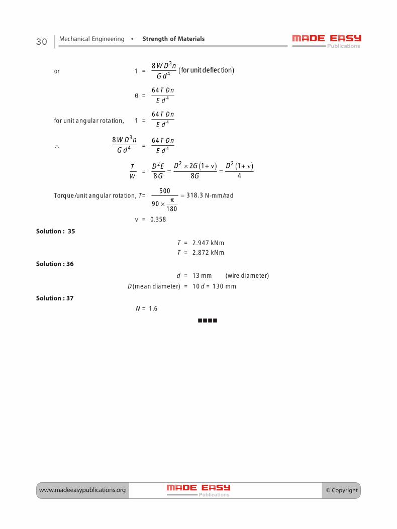
30 Mechanical Engineering • Strength of Materials
or 1 = ( )W D nGd
3
48 for unit deflection
θ =T Dn
E d 4
64
for unit angular rotation, 1 =T Dn
E d 4
64
∴W D nGd
3
48
=T Dn
E d 4
64
TW
=( ) ( )D G DD E
G G× + ν + ν
= =2 22 2 1 1
8 8 4
Torque/unit angular rotation, T= .=π×
500318 3
90180
N-mm/rad
ν = 0.358
Solution : 35
T = 2.947 kNmT = 2.872 kNm
Solution : 36
d = 13 mm (wire diameter)
D(mean diameter) = 10d = 130 mm
Solution : 37
N = 1.6

© Copyright www.madeeasypublications.org
©C
opyrig
ht: Sub
ject matter to M
AD
E E
AS
Y P
ublications, N
ew D
elhi. No p
art of this book m
ay be rep
roduced
or utilised in any form
without the w
ritten perm
ission.
1. (b)
2. (b)
3. (c)
4. (c)
5. (a)
6. (a)
7. (c)
8. (d)
9. (a)
10 (c)
Euler’s theory of column1011. (b)
12. (d)
13. (c)
14. (c)
15. (a)
16. (b)
17. (d)
© Copyrightwww.madeeasypublications.org
32 Mechanical Engineering • Strength of Materials
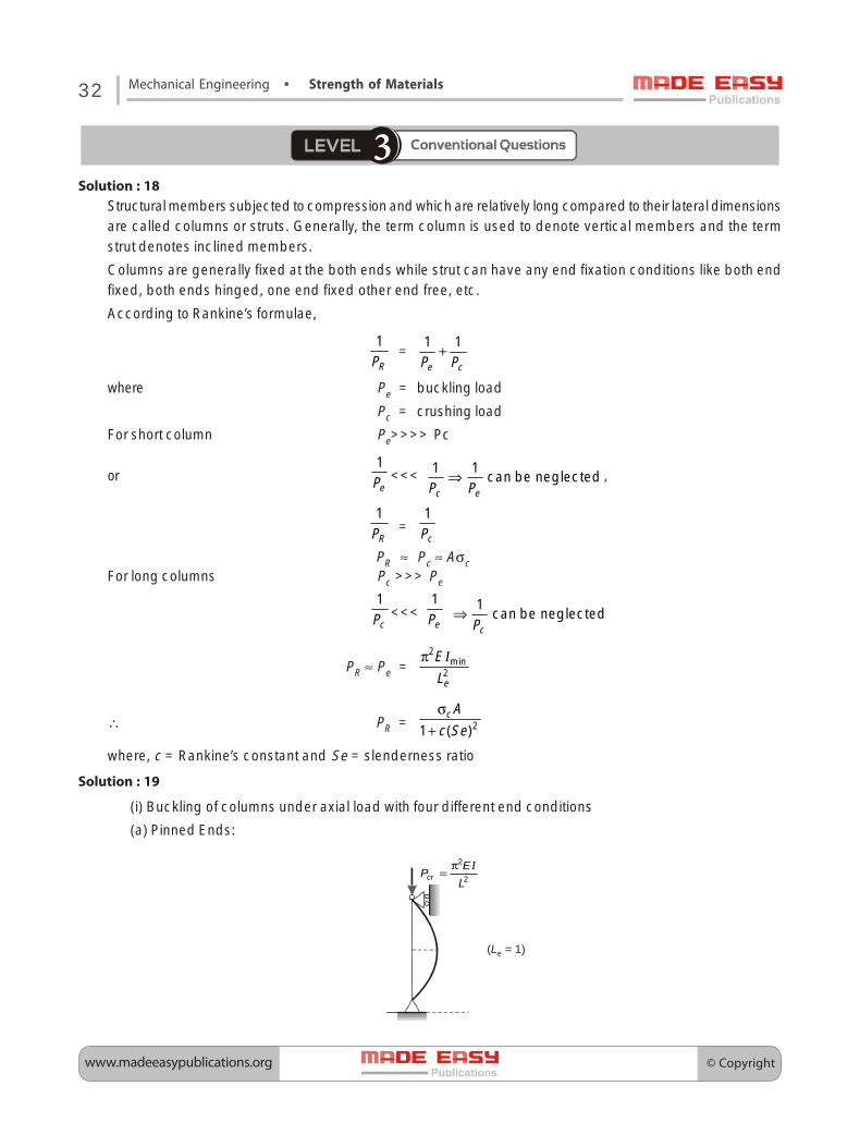
Solution : 18Structural members subjected to compression and which are relatively long compared to their lateral dimensionsare called columns or struts. Generally, the term column is used to denote vertical members and the termstrut denotes inclined members.
Columns are generally fixed at the both ends while strut can have any end fixation conditions like both endfixed, both ends hinged, one end fixed other end free, etc.
According to Rankine’s formulae,
1
RP=
1 1
e cP P+
where Pe = buckling load
Pc = crushing load
For short column Pe>>>> Pc
or1
eP <<< 1 1can be neglected
c eP P⇒ ,
1
RP =1
cP
PR ≈ Pc ≈ AσcFor long columns Pc >>> Pe
1
cP <<< 1
eP 1can be neglected
cP⇒
PR ≈ Pe =2
min2e
EL
π I
∴ PR = 21 ( )cA
c Seσ
+
where, c = Rankine’s constant and Se = slenderness ratio
Solution : 19
(i) Buckling of columns under axial load with four different end conditions
(a) Pinned Ends:
π=
I2
2crEP
L
( = 1)Le

© Copyright www.madeeasypublications.org
33Rank Improvement Workbook
(b) One end fixed, other end free
π=
I2
24crEPL
( = 2 )L Le
(c) Both ends fixed
π= I2
24
crEP
L
( = /2)L Le
(d) One end fixed, other end pinned
( )L e ≈
Pcr
π= I2
22.0
crEP
LL2
crP =2
2
2 EL
π I
Le ≈ 2L
Solution : 20d0 = 74.9 mm
Solution : 21Pcr = 55.51 × 10³ N
σcr = 237.01 N/mmcrPA
=
L = 769.5 mm ≈ 0.77 m which is minimum length.
© Copyrightwww.madeeasypublications.org
34 Mechanical Engineering • Strength of Materials
Solution : 22Euler‘s buckling load = 8576 kN.
Solution : 23Pcr = 8216.33 kNPcr = 4108.167 kN
Solution : 24
L = 11252 mmSafe load = 1185.12 kN

© Copyright www.madeeasypublications.org
©C
opyrig
ht: Sub
ject matter to M
AD
E E
AS
Y P
ublications, N
ew D
elhi. No p
art of this book m
ay be rep
roduced
or utilised in any form
without the w
ritten perm
ission.
1. (c)
2. (c)
3. (a)
4. (b)
5. (c)
6. (b)
7. (b)
8. (b)
9. (b)
10. (b)
11. (b)
Pressure Vessel1112. (c)
13. (d)
14. (a)
15. (c)
16. (c)
17. (6.68)
18. (34.17)
19. (b)
20. (d)

© Copyrightwww.madeeasypublications.org
36 Mechanical Engineering • Strength of Materials
Solution : 21
In a pressure vessel, D is internal diameter and t is wall thickness, if 20Dt
> , then it is a thin shell. When
the shell is subjected to internal pressure, the hoop stress developed in the shell does not vary much
across the thickness. If 20Dt
< . Then it is thick shell; i.e., thickness of shell is considerable in comparison
to diameter, then there is variation of hoop and radial stresses across the thickness of thick shell.
Figure shows a thin cylindrical shell with hemispherical ends, subjected to internal pressure p.In cylindrical portion:
Hoop stress, chσ =12
pDt
p
pp
t1
t2Axial stress, caσ =14
pDt
Hoop strain, chε = ( )1 1 1
22 4 4pD pD pDt E t E t E
ν− = − ν
In hemispherical portion at junction
Hoop stress, shσ = 24
pDt
Hoop strain, shε = ( )2
14pDt E
− ν
For no distortion
chε = shε
( )1
24pDt E
− ν = ( )2
11
4pDt E
− ν
or 2
1
tt
=1 1 0.3 0.7 72 2 .07 1.7 17
− ν −= = =
− ν −
Maximum stress in cylindrical portion =12 ch
pDt
= σ
Maximum stress in hemispherical portion = 24 sh
pDt
= σ
chσ = shσ
12pD
t=
24pDt ;
2
1
tt
= 0.5

© Copyright www.madeeasypublications.org
37Rank Improvement Workbook
Solution : 22Poisson’s ratio, ν = 0.308
Solution : 23
Force required to push the rod = 91.25 kN
Solution : 24Change in length = 2.25 × 10⁻⁴ m
Change in diameter = 3.188 × 10⁻⁴ mMaximum shear stress = 38.25 MPa
δV = 1.67 × 10⁻³ m3
Solution : 25
(σw)P = 184.95 MPa
(σc)P = 184.95 – 82.575 = 102.37 MPa
Solution : 26
Thickness of the shell = 7.55 mm
Solution : 27
K = 2.497 Gpa
Solution : 28
P = 2.86 N/mm2
Solution : 29
τmax =2
tσ = 30 MPa
δd = 0.199 mm
δL = 0.117
δV = 559050 mm3 (increase)
Solution : 30I = 0.12784 mm
Solution : 31
Factor of safety = 4.32