
STIHL MS 170, 180 - FR Jones
44
MS 170, 180 Instruction Manual 2 - 41
-
Upload
khangminh22 -
Category
Documents
-
view
1 -
download
0
Transcript of STIHL MS 170, 180 - FR Jones

MS 170, 180
Instruction Manual2 - 41

Contents1 Guide to Using this Manual.........................22 Safety Precautions......................................33 Reactive Forces.......................................... 74 Working Techniques................................... 85 Cutting Attachment................................... 156 Mounting the Bar and Chain (front chain
tensioner).................................................. 157 Mounting the Bar and Chain (quick chain
tensioner).................................................. 168 Mounting the Bar and Chain (side chain ten‐
sioner)....................................................... 189 Tensioning the Saw Chain (front chain ten‐
sioner)....................................................... 1910 Tensioning the Saw Chain (quick chain ten‐
sioner)....................................................... 1911 Tensioning the Saw Chain (side chain ten‐
sioner)....................................................... 2012 Checking Chain Tension...........................2013 Fuel........................................................... 2014 Fueling...................................................... 2115 Chain Lubricant.........................................2216 Filling Chain Oil Tank................................2217 Checking Chain Lubrication...................... 2318 Chain Brake.............................................. 2319 Starting / Stopping the Engine.................. 2420 Operating Instructions...............................2721 Taking Care of the Guide Bar................... 2822 Shroud...................................................... 2823 Cleaning the Air Filter............................... 2824 Adjusting the Carburetor........................... 2925 Spark Plug................................................ 2926 Storing the Machine.................................. 3027 Checking and Replacing the Chain
Sprocket....................................................3028 Maintaining and Sharpening the Saw Chain
.................................................................. 3129 Maintenance and Care..............................3530 Minimize Wear and Avoid Damage...........3631 Main Parts.................................................3732 Specifications............................................3733 Ordering Spare Parts................................ 3934 Maintenance and Repairs......................... 3935 Disposal.................................................... 3936 EC Declaration of Conformity................... 4037 UKCA Declaration of Conformity.............. 40
Dear Customer,
Thank you for choosing a quality engineeredSTIHL product.
It has been built using modern production techni‐ques and comprehensive quality assurance.Every effort has been made to ensure your satis‐faction and trouble-free use of the product.
Please contact your dealer or our sales companyif you have any queries concerning this product.
Your
Dr. Nikolas Stihl
1 Guide to Using this ManualThis Instruction Manual refers to a STIHL chainsaw, also called a machine in this InstructionManual.
1.1 PictogramsPictograms that appear on the machine areexplained in this Instruction Manual.
Depending on the machine and equipment ver‐sion, the following pictograms may appear on themachine.
Fuel tank; fuel mixture of gasolineand engine oil
Tank for chain oil; chain oil
Engage and release chain brake
Coasting brake
Direction of chain travel
Ematic; chain oil flow adjustment
Tension saw chain
Intake air baffle: winter operation
Intake air baffle: summer operation
Handle heating
Actuate decompression valve
English
2 0458-206-0121-D
© AN
DR
EAS STIHL AG
& Co. KG
20220458-206-0121-D
. VA0.B22.Printed on chlorine-free paperPrinting inks contain vegetable oils, paper can be recycled.
Original Instruction M
anual0000006734_015_G
B
Actuate manual fuel pump
1.2 Symbols in text
WARNING
Warning where there is a risk of an accident orpersonal injury or serious damage to property.
NOTICE
Caution where there is a risk of damaging themachine or its individual components.
1.3 Engineering improvementsSTIHL's philosophy is to continually improve allof its products. For this reason we may modifythe design, engineering and appearance of ourproducts periodically.
Therefore, some changes, modifications andimprovements may not be covered in this man‐ual.
2 Safety PrecautionsSpecial safety precautions must beobserved to reduce the risk of per‐sonal injury when working with achain saw because of the very highchain speed and very sharp cutters.It is important that you read theinstruction manual before first useand keep it in a safe place for futurereference. Non-observance of theinstruction manual may result in seri‐ous or even fatal injury.
2.1 GeneralObserve all applicable local safety regulations,standards and ordinances.
The use of noise emitting power tools may berestricted to certain times by national or localregulations.
If you have not used this model before: Haveyour dealer or other experienced user show youhow to operate your machine or attend a specialcourse in its operation.
Minors should never be allowed to use a chainsaw.
Keep bystanders, especially children, and ani‐mals away from the work area.
The user is responsible for avoiding injury to thirdparties or damage to their property.
Do not lend or rent your chain saw without theinstruction manual. Be sure that anyone using itunderstands the information contained in thismanual.
To operate a chain saw you must be rested, ingood physical condition and mental health. If youhave any condition that might be aggravated bystrenuous work, check with your doctor beforeoperating a chain saw.
Do not operate the chain saw if you are underthe influence of any substance (drugs, alcohol)which might impair vision, dexterity or judgment.
To reduce the risk of accidents or injury, put offthe work in poor weather conditions (rain, snow,ice, wind).
Persons with pacemakers only: The ignition sys‐tem of your chain saw produces an electromag‐netic field of a very low intensity. This field mayinterfere with some pacemakers. To reducehealth risks, STIHL recommends that personswith pacemakers consult their physician and thepacemaker manufacturer before operating thispower tool.
2.2 Intended useThe machine may only be used to saw wood andwooden objects.
Do not use the machine for any other purpose –risk of accidents!
Do not modify the machine in any way – this mayincrease the risk of personal injury. STIHLexcludes all liability for personal injury and dam‐age to property caused while using unauthorisedattachments.
2.3 Clothing and EquipmentWear proper protective clothing and equipment.
Clothing must be sturdy and snug-fit‐ting, but allow complete freedom ofmovement. Wear snug fitting clothingwith cut-retardant pads – no loose-fit‐ting jacket.
Avoid clothing that could get caught onbranches, brush or moving parts of the machine.Do not wear a scarf, necktie or jewellery. Tie upand confine long hair (headscarf, cap, hard hat,etc.).
2 Safety Precautions English
0458-206-0121-D 3

Wear suitable safety shoes – with cut-retardant material, non-slip soles andsteel toe caps.
WARNING
To reduce the risk of eye injuries,wear tight-fitting safety goggles con‐forming to standard EN 166 or a faceshield. Make sure that the safety gog‐gles and the face shield fit correctly.
Wear "personal" hearing protection – for exam‐ple, ear defenders.
Wear a hard hat wherever there is any risk offalling objects.
Wear sturdy protective gloves madeof a resistant material (e.g. leather).
STIHL can supply a comprehensive range of per‐sonal protective equipment.
2.4 TransportingBefore any transport – even over short distances– switch off the machine, engage the chain brakeand attach the chain scabbard. This avoids therisk of the saw chain starting unintentionally.
001B
A11
5 K
N
Always carry the chain saw by the handle – withthe hot muffler away from your body, the guidebar must point to the rear. To avoid serious burninjuries, avoid touching hot parts of the machine,especially the surface of the muffler.
In vehicles: Properly secure your saw to preventturnover, fuel spillage and damage.
2.5 CleaningClean plastic parts with a cloth. Harsh detergentscan damage the plastic.
Clean the dust and dirt off the machine – do notuse any grease solvents for this purpose.
Clean the ventilation slots if necessary.
Do not use a high-pressure cleaner to clean themachine. The hard jet of water can damage partsof the machine.
2.6 AccessoriesOnly use those tools, guide bars, chains, chainsprockets, accessories or technically equivalentcomponents that have been approved by STIHLfor this machine. If you have any questions inthis respect, consult a servicing dealer. Use onlyhigh quality tools and accessories. Otherwise,there may be a risk of accidents and damage tothe machine.
STIHL recommends the use of genuine STIHLtools, guide bars, chains, chain sprockets andaccessories. They are specifically designed tomatch your model and meet your performancerequirements.
2.7 RefuellingGasoline is an extremely flammablefuel – keep clear of naked flames andfire – do not spill any fuel – no smok‐ing.
Switch off the engine before refuelling.
Never refuel the machine while the engine is stillhot – the fuel may spill over – risk of fire!
Open the fuel filler cap carefully so that anyexcess pressure is relieved gradually and fueldoes not splash out.
The machine may only be refuelled in a well ven‐tilated place. Clean the machine immediately iffuel is spilled. Do not spill fuel over your clothing– contaminated clothing must be changed imme‐diately.
The machines can be equipped with the follow‐ing filler caps as standard:
Screw-type tank capAfter fueling, tighten down the screw-type fuel cap as securely as possible.
This reduces the risk of unit vibrations causingthe fuel cap to loosen or come off and spill quan‐tities of fuel.
Check for leakage. To reduce the riskof serious of fatal burn injuries, do notstart or run the engine until leak isfixed.
English 2 Safety Precautions
4 0458-206-0121-D

2.8 Before Starting WorkCheck that your saw is properly assembled andin good condition – refer to appropriate chaptersin the instruction manual.– Check the fuel system for leaks, paying spe‐
cial attention to visible parts such as the tankcap, hose connections and the manual fuelpump (on machines so equipped). If there areany leaks or damage, do not start the engine –risk of fire. Have your saw repaired by a serv‐icing dealer before using it again.
– Check operation of chain brake, front handguard
– Correctly mounted guide bar– Correctly tensioned chain– The trigger and trigger lockout must move
freely and spring back to the idle positionwhen they are released.
– Master Control lever must move easily toSTOP, 0 or †
– Check that the spark plug boot is secure – aloose boot may cause arcing that could ignitecombustible fumes and cause a fire.
– Never attempt to modify the controls or safetydevices in any way.
– Keep the handles dry and clean – free from oiland dirt – for safe control of the saw.
– Make sure there is sufficient fuel and chain oilin the tanks.
To reduce the risk of personal injury, do notoperate your saw if it is damaged or not properlyassembled.
2.9 Starting the chain sawAlways work on a level surface. Ensure a firmand secure footing. Hold the machine securely –the chain must not touch any objects or the floor– danger of injury due to the rotating saw chain.
Your chain saw is a one-person saw. Do notallow other persons to be in the working area –not even while starting.
Do not start the chain saw if the chain is in a cut.
Move at least 3 meters away from the placewhere the machine was refuelled and never startthe motor in enclosed spaces.
Lock the chain with the chain brake before start‐ing – risk of injury due to rotating chain!
Do not drop-start the engine – start as describedin the Instruction Manual.
2.10 During operationEnsure you always have a firm and safe footing.Take special care when the bark is wet – dangerof slipping!
001B
A08
7 LÄ
Always hold the chain saw firmly with bothhands: Right hand on the rear handle – even ifyou are left-handed. To ensure reliable control,wrap your thumbs tightly around the handlebarand handle.
In the event of impending danger or in an emer‐gency, switch off the engine immediately by mov‐ing the Master Control lever / stop switch toSTOP, 0 or †.
Never let the machine run unattended.
Exercise caution with slippery surfaces, water,snow, ice, steep slopes, uneven ground or greenwood that has just been stripped of its bark –danger of slipping!
Use caution with tree stumps, roots, ditches –danger of stumbling!
Do not work alone – keep within calling distanceof others who are trained in emergency proce‐dures and can provide help in an emergency.Helpers at the cutting site must also wear protec‐tive clothing (helmet!) and stand well clear of thebranches being cut.
More care and attention than usual are requiredwhen wearing ear protection, as warning sounds(shouts, beeps, etc.) cannot be heard properly.
Take a break in good time to avoid tiredness orexhaustion – risk of accidents!
Dust (e. g., sawdust), fumes and smoke pro‐duced while using the machine may be hazard‐ous to health. If dust is generated, wear a dustmask.
When the engine is running: Note that the sawchain continues to rotate for a short period afteryou let go of the throttle trigger – coasting effect.
2 Safety Precautions English
0458-206-0121-D 5

No smoking when working with or near the chainsaw - risk of fire! Combustible fuel vapour mayescape from the fuel system.
Examine the saw chain periodically at short inter‐vals and as soon as you note any tangiblechanges:– Switch off the engine; wait until the saw chain
is stationary– Check condition and secure fitting– Check sharpness
Never touch the saw chain when the engine isrunning. If the saw chain becomes jammed by anobject, switch off the engine immediately beforeattempting to remove the object – risk of injury!
Always turn off the engine before leaving themachine unattended.
To change the saw chain, switch off the engine.Risk of injury from the motor starting unintention‐ally!
Keep easily combustible materials (e. g., woodchips, bark, dry grass, fuel) away from hotexhaust gases and hot mufflers – risk of fire!Mufflers with catalytic converters can becomeespecially hot.
Never work without chain lubrication – monitorthe oil level in the oil tank. Stop work immediatelyif the oil level in the oil tank is too low and top upwith chain oil – see also "Topping up with chainoil" and "Check chain lubrication".
If the machine is subjected to unusually highloads for which it was not designed (e. g., heavyimpact or a fall), always check that it is in goodcondition before continuing work – see also"Before starting work".
Check the fuel system for leaks and make surethe safety devices are working properly. Nevercontinue using a machine that is not in perfectworking order. In case of doubt, have the unitchecked by your servicing dealer.
Check for correct idling, so that the saw chainstops moving when the throttle trigger isreleased. Check the idle setting regularly andcorrect when possible. Have the machinerepaired by a STIHL servicing dealer if the sawchain still continues to move during idling.
The chain saw produces poisonousexhaust gases as soon as the enginestarts. These gases may be colour‐less and odourless and may containunburnt hydrocarbons and benzene.Never work with the machine indoorsor in poorly ventilated areas, even if
your machine is equipped with a cata‐lytic converter.
Ensure proper ventilation when working intrenches, hollows or other confined locations –risk of fatal injury from breathing toxic fumes!
If you feel sick, have a headache, vision prob‐lems (e. g., your field of vision gets smaller),hearing problems, dizziness or inability to con‐centrate, stop work immediately. Such symptomsmay be caused by an excessively high concen‐tration of exhaust emissions – risk of accident!
2.11 After finishing workSwitch off the motor, engage the chain brake andattach the chain scabbard.
2.12 StorageWhen the machine is not in use, it should bestored in such a way that no-one is endangered.Secure the machine against unauthorised use.
Store the machine in a safe, dry room.
2.13 VibrationsProlonged use of the power tool may result invibration-induced circulation problems in thehands (whitefinger disease).
No general recommendation can be given for thelength of usage because it depends on severalfactors.
The period of usage is prolonged by:– Hand protection (wearing warm gloves)– Work breaks
The period of usage is shortened by:– Any personal tendency to suffer from poor cir‐
culation (symptoms: frequently cold fingers,tingling sensations).
– Low outside temperatures.– The force with which the handles are held (a
tight grip restricts circulation).
Continual and regular users should monitorclosely the condition of their hands and fingers. Ifany of the above symptoms appear (e.g. tinglingsensation in fingers), seek medical advice.
2.14 Maintenance and repairsAlways switch off the engine before any repair,cleaning or maintenance work and any work onthe chain. Risk of injury if the engine starts inad‐vertently!
Exception: adjustment of carburettor and idlespeed.
English 2 Safety Precautions
6 0458-206-0121-D

The machine must be serviced regularly. Do notattempt any maintenance or repair work notdescribed in the Instruction Manual. All otherwork should be carried out by a servicing dealer.
STIHL recommends that maintenance and repairwork be carried out only by authorised STIHLdealers. STIHL dealers receive regular trainingand are supplied with technical information.
Use only high-quality spare parts. Otherwise,there may be a risk of accidents and damage tothe machine. If you have any questions in thisrespect, consult a servicing dealer.
Do not modify the machine in any way – this mayincrease the risk of personal injury –risk of acci‐dents!
To reduce the risk of fire due to ignition outsidethe cylinder, move the master control level toSTOP, 0 or † before turning the engine over onthe starter when the spark plug boot is removedor the spark plug is unscrewed!
Do not service or store the machine near anaked flame – risk of fire due to the fuel.
Check fuel cap regularly for tightness.
Use only spark plugs that are in perfect conditionand have been approved by STIHL – see "Speci‐fications".
Check ignition lead (insulation in good condition,secure connection).
Check that the muffler is in perfect working con‐dition.
Do not use the machine if the muffler is damagedor missing – risk of fire, damage to hearing!
Never touch a hot muffler – risk of burns!
The condition of the anti-vibration elements influ‐ences vibration behaviour – inspect anti-vibrationelements periodically.
Inspect chain catcher – replace if damaged.
Switch off the engine– To check the chain tension– To retension the chain– To replace the chain– For remedying malfunctions
Observe sharpening instructions – for safe andproper handling, always keep the chain andguide bar in flawless condition. Keep the chainproperly sharpened, tensioned and well lubrica‐ted.
Change chain, guide bar and chain sprocket indue time.
Regularly check that the clutch drum is in perfectworking condition.
Always store fuel and chain lubricant only in thespecified type of containers and ensure they arecorrectly labelled. Store in a dry, cool and secureplace protected against light and sunlight.
In the event of a chain brake malfunction, switchoff the machine immediately – risk of injury! Con‐sult a servicing dealer – do not use the machineuntil the malfunction has been remedied, see"Chain brake".
3 Reactive ForcesThe most common reactive forces that occur dur‐ing cutting are: kickback, pushback and pull-in.
3.1 Dangers of kickbackKickback can result in serious or fatalinjury.
001B
A036
KN
(Kickback) occurs when the saw is suddenlythrown up and back in an uncontrolled arctowards the operator.
3.2 Kickback occurs if, e. g.,
001B
A257
KN
– when the upper quadrant of the bar nose unin‐tentionally contacts wood or another solid
3 Reactive Forces English
0458-206-0121-D 7
object, e.g. when another limb is touched acci‐dentally during limbing.
– when the chain at the nose of the guide bar ispinched in the cut.
3.3 Quickstop chain brake:This device reduces the risk of injury in certainsituations – it cannot prevent kickback. Whenactivated, the chain brake stops the saw chainwithin a fraction of a second –see the section "Saw chain" in this InstructionManual.
3.4 To reduce the risk of kickback– Work cautiously and avoid situations which
could cause kickback.– Hold the saw firmly with both hands and main‐
tain a secure grip.– always cut at full throttle.– Be aware of the location of the guide bar nose
at all times.– do not cut with the bar nose.– Take special care with small, tough limbs, they
may catch the chain.– never cut several limbs at once.– do not overreach.– never cut above shoulder height.– Use extreme caution when re-entering a previ‐
ous cut.– Do not attempt plunge cuts if you are not
experience in this cutting technique.– be alert for shifting of the log or other forces
that may cause the cut to close and pinch thechain.
– always cut with a correctly sharpened, prop‐erly tensioned chain – the depth gauge settingmust not be too large.
– Use a low kickback chain and a narrow radiusguide bar.
3.5 Pull-in (A)
001B
A03
7 K
N
APull-in occurs when the chain on the bottom ofthe bar is suddenly pinched, caught or encoun‐ters a foreign object in the wood. The reaction of
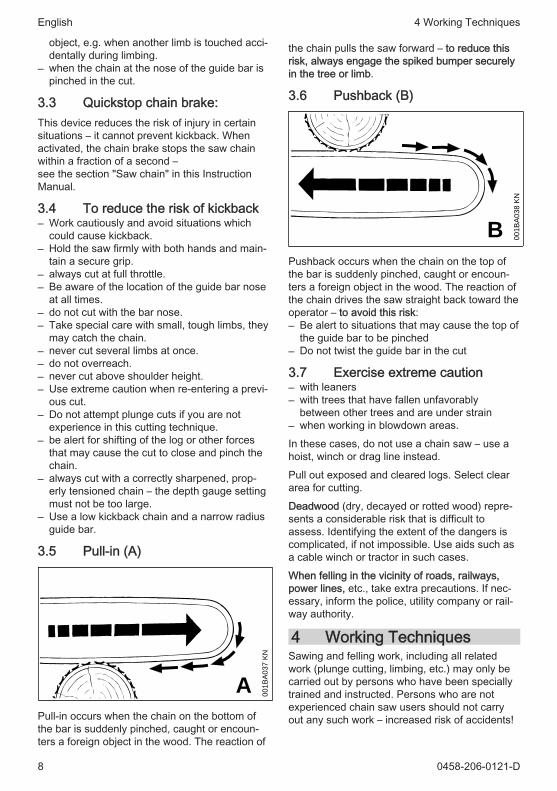
the chain pulls the saw forward – to reduce thisrisk, always engage the spiked bumper securelyin the tree or limb.
3.6 Pushback (B)
001B
A03
8 K
N
BPushback occurs when the chain on the top ofthe bar is suddenly pinched, caught or encoun‐ters a foreign object in the wood. The reaction ofthe chain drives the saw straight back toward theoperator – to avoid this risk:– Be alert to situations that may cause the top of
the guide bar to be pinched– Do not twist the guide bar in the cut
3.7 Exercise extreme caution– with leaners– with trees that have fallen unfavorably
between other trees and are under strain– when working in blowdown areas.
In these cases, do not use a chain saw – use ahoist, winch or drag line instead.
Pull out exposed and cleared logs. Select cleararea for cutting.
Deadwood (dry, decayed or rotted wood) repre‐sents a considerable risk that is difficult toassess. Identifying the extent of the dangers iscomplicated, if not impossible. Use aids such asa cable winch or tractor in such cases.
When felling in the vicinity of roads, railways,power lines, etc., take extra precautions. If nec‐essary, inform the police, utility company or rail‐way authority.
4 Working TechniquesSawing and felling work, including all relatedwork (plunge cutting, limbing, etc.) may only becarried out by persons who have been speciallytrained and instructed. Persons who are notexperienced chain saw users should not carryout any such work – increased risk of accidents!
English 4 Working Techniques
8 0458-206-0121-D

Country-specific legislation on felling techniquemust be complied with during felling work.
4.1 SawingDo not operate your saw with the starting throttlelock engaged. Engine speed cannot be control‐led with the throttle trigger in this position.
Work calmly and carefully – in daylight conditionsand only when visibility is good. Ensure you donot endanger others – stay alert at all times.
It is advisable for first-time users to practice cut‐ting logs on a sawbuck – see "Sawing thinwood".
Use the shortest possible guide bar: The chain,guide bar and chain sprocket must match eachother and your saw.
001B
A08
2 K
N
Position the saw so that your body is clear of thecutting attachment.
Always pull the saw out of the cut with the chainrunning.
Use your chain saw for cutting only. It is notdesigned for prying or shoveling away limbs,roots or other objects.
Do not underbuck freely hanging limbs.
Be careful when cutting scrub and young trees.Thin shoots can be scooped up by the chain sawand hurled towards the user.
Be careful when cutting splintered wood – Risk ofinjury from ejected pieces of wood!
Make sure your saw does not touch any foreignmaterials: Stones, nails, etc. may be flung offand damage the saw chain. The chain saw maykick back unexpectedly – risk of accident!
If a rotating saw chain hits a stone or anotherhard object, sparks may be generated which mayignite easily flammable materials under certainconditions. Also dried-out plants and brushwoodare combustible, above all in hot and dryweather. If there is a risk of fire, do not use the
chain saw in the vicinity of easily combustiblematerials, dry plants or scrub. It is mandatorythat you ask the responsible forestry office aboutthe current fire hazard.
001B
A033
KN
If on a slope, stand on the uphill side of the log.Watch out for rolling logs.
When working at heights:– Always use a lift bucket– Never use the machine while standing on a
ladder or in a tree– Never work on an insecure support– Never work above shoulder height– Never use the machine with just one hand
Begin cutting with the saw at full throttle andengage the spiked bumper firmly in the wood,and then continue cutting.
Never work without the spiked bumper becausethe saw may pull you forwards and off balance.Always hold the spiked bumper securely againstthe tree or limb.
At the end of the cut, the chain saw is no longersupported by the cutting attachment in the cut.The chain saw's weight must be borne by theuser – risk of loss of control!
Sawing thin wood:– Use a sturdy and stable support – sawhorse.– Never hold the log with your leg or foot.– never allow another person to hold the log or
help in any other way.
Limbing– use a low kickback chain.– Work with the saw supported wherever possi‐
ble.– do not stand on the log while limbing it.– do not cut with the bar nose.– watch for limbs which are under tension.– never cut several limbs at once.
Lying or standing logs under tension:
Always make the cuts in the correct order (firstcompression side (1), then tension side (2)), oth‐
4 Working Techniques English
0458-206-0121-D 9

erwise the cutting attachment may stick in the cutor kick back – risk of injury!
1
001B
A15
1 K
N2
1
001B
A15
2 K
N2
► Make relieving cut at the compression side (1)► Make bucking cut at the tension side (2)
Be wary of pushback when making bucking cutfrom the bottom upwards (underbuck).
NOTICE
Do not cut a lying log at a point where it is touch‐ing the ground because the saw chain will other‐wise be damaged.
Ripping:
001B
A189
KN
Sawing technique without use of the spikedbumper – risk of pull-in – position the guide bar atas shallow an angle as possible – be especiallycareful – increased risk of kickback!
4.2 Preparing for fellingCheck that there are no other persons in the fell‐ing area – other than helpers.
Make sure no-one is endangered by the fallingtree – the noise of your engine may drown anywarning calls.
001B
A08
8 LÄ
2 /1 2
1 1/1 2
Maintain a distance of at least 2 1/2 tree lengthsfrom the next felling site.
Determining direction of fall and escape path
Select gap in stand into which you want the treeto fall.
Pay special attention to the following points:– The natural inclination of the tree– Unusually heavy limb structure, asymmetrical
growth, damage to tree– The wind direction and speed – do not fell in
high winds– Direction of slope– Neighboring trees– Snow load– Take the general condition of the tree into
account – be especially careful with trunkdamage or deadwood (brittle, rotten or deadwood)
001B
A040
KN
BBA Direction of fallB Escape path (escape routes)
– Establish escape paths for each worker –approx. 45° diagonally opposite to the direc‐tion of fall
English 4 Working Techniques
10 0458-206-0121-D

– Clear escape paths, eliminate obstacles– Put down tools and equipment at a safe dis‐
tance – but not on the escape paths– When felling, stand only to the side of the fall‐
ing trunk and only move back laterally onto theescape path
– Plan escape paths on slopes parallel to theslope
– When walking away along the escape path,watch out for falling limbs and watch the top ofthe tree.
Preparing work area at base of tree– First clear the tree base and work area from
interfering limbs and brush to provide a securefooting.
– Carefully clear the base of the trunk (e.g., withan axe) – sand, stones and other foreignobjects will blunt the saw chain
001B
A14
6 K
N
– Remove largest buttresses: first the largestbuttress – saw first vertically, then horizontally– only if the tree is in sound condition
4.3 Felling notchPreparing the felling notch
001B
A271
KN
CC
The felling notch (C) determines the direction offall.
Important:– Make a felling notch at right angle to direction
of fall– Saw as close to the ground as possible– Cut to a depth of approx. 1/5 to 1/3 of the
diameter of the trunk
Determine direction of fall with gunning sight oncover and fan housing
001B
A15
3 K
N
Your chainsaw has a gunning sight on the coverand fan housing. Use this gunning sight.
Making the felling notch
When making a felling notch, align the chainsawso that the notch lies at a right angle to the direc‐tion of fall.
During the procedure, various sequences arepermitted for making a felling notch with a bottom(horizontal) cut and top (angled) cut – complywith national legislation regarding felling techni‐que.► Make a bottom (horizontal) cut► Make the top (angled) cut approx. 45°‑ 60° to
the bottom cut
Checking the direction of fall
001B
A15
3 K
N
► Insert the chainsaw with guide bar in the bot‐tom of the felling notch. The gunning sightmust point in the planned direction of fall – ifnecessary, correct direction of fall by re-cuttingthe felling notch.
4 Working Techniques English
0458-206-0121-D 11
4.4 Sapwood cuts
001B
A150
KN
Sapwood cuts in long-fibered softwood help pre‐vent sapwood splintering when the tree falls.Make cuts at both sides of the trunk at sameheight as bottom of felling notch to a depth ofabout 1/10 of trunk diameter. On large diametertrees, cut to no more than width of guide bar.
Do not make sapwood cuts if wood is diseased.
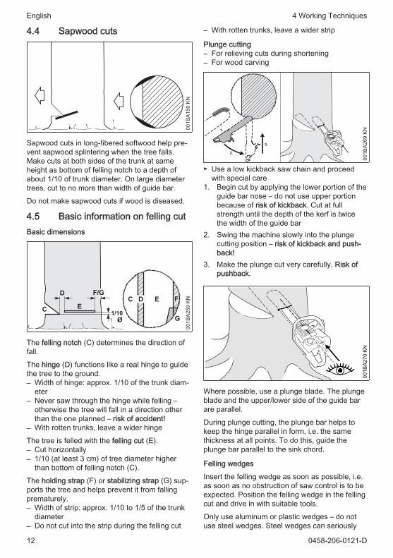
4.5 Basic information on felling cutBasic dimensions
001B
A259
KN
G
ECC
Ø1/10
The felling notch (C) determines the direction offall.
The hinge (D) functions like a real hinge to guidethe tree to the ground.– Width of hinge: approx. 1/10 of the trunk diam‐
eter– Never saw through the hinge while felling –
otherwise the tree will fall in a direction otherthan the one planned – risk of accident!
– With rotten trunks, leave a wider hinge
The tree is felled with the felling cut (E).– Cut horizontally– 1/10 (at least 3 cm) of tree diameter higher
than bottom of felling notch (C).
The holding strap (F) or stabilizing strap (G) sup‐ports the tree and helps prevent it from fallingprematurely.– Width of strip: approx. 1/10 to 1/5 of the trunk
diameter– Do not cut into the strip during the felling cut
– With rotten trunks, leave a wider strip
Plunge cutting– For relieving cuts during shortening– For wood carving
001B
A269
KN
3.
1.
2.
► Use a low kickback saw chain and proceedwith special care
1. Begin cut by applying the lower portion of theguide bar nose – do not use upper portionbecause of risk of kickback. Cut at fullstrength until the depth of the kerf is twicethe width of the guide bar
2. Swing the machine slowly into the plungecutting position – risk of kickback and push‐back!
3. Make the plunge cut very carefully. Risk ofpushback.
001B
A270
KN
Where possible, use a plunge blade. The plungeblade and the upper/lower side of the guide barare parallel.
During plunge cutting, the plunge bar helps tokeep the hinge parallel in form, i.e. the samethickness at all points. To do this, guide theplunge bar parallel to the sink chord.
Felling wedges
Insert the felling wedge as soon as possible, i.e.as soon as no obstruction of saw control is to beexpected. Position the felling wedge in the fellingcut and drive in with suitable tools.
Only use aluminum or plastic wedges – do notuse steel wedges. Steel wedges can seriously
English 4 Working Techniques
12 0458-206-0121-D

damage the saw chain and cause dangerouskickback.
Select suitable felling wedges dependent on thetrunk diameter and the width of the kerf (ana‐logue to felling cut (E)).
Contact the STIHL dealer for the selection of thefelling wedge (suitable length, width and height).
4.6 Selecting the appropriate fellingcut
The selection of the appropriate felling cut isdependent on the same tree characteristics thatmust be noted when determining the direction offall and the escape paths.
There are various different features of thesecharacteristics. This User Manual will onlydescribe the two most commonly occurring var‐iants:
001B
A260
KN
left: Normal tree – vertically upright treewith uniform crown
right: Leaner tree - crown pointing in direc‐tion of fall
4.7 Felling cut with stabilizing strap(normal tree)
A) Thin trunks
Implement this felling cut when the trunk diame‐ter is smaller than the cutting length of the chain‐saw.
001B
A261
KN
1.2.
Shout a warning before starting the felling cut.► Plunge cut the felling cut (E) – plunge the
guide bar fully in► Engage the spiked bumper behind the hinge
and use this as the rotation point – repositionthe chainsaw as little as possible
► Make the felling cut up to the hinge (1)– Do not cut into the hinge
► Make the felling cut up to the stabilizingstrap (2)– Do not cut into the stabilizing strap
001B
A273
KN
3.
► Set the felling wedge (3)
Shout a second warning immediately before thetree falls.► Cut through the stabilizing strap, horizontal
level with the felling cut, with arms fully exten‐ded
B) Thick trunks
Implement this felling cut when the trunk diame‐ter is greater than the cutting length of themachine.
001B
A263
KN
4. 5.1.
2. 3.
Shout a warning before starting the felling cut.► Engage the spiked bumper at the height of the
felling cut and use this as the rotation point –reposition the chainsaw as little as possible
► Tip of the guide bar must penetrate the woodbefore the hinge (1) – guide the chainsawabsolutely horizontally and swivel as widely aspossible
► Make the felling cut up to the hinge (2)– Do not cut into the hinge
4 Working Techniques English
0458-206-0121-D 13

► Make the felling cut up to the stabilizingstrap (3)– Do not cut into the stabilizing strap
The felling cut must be continued on the oppo‐site side of the trunk.
Ensure that the second cut is at the same levelas the first cut.► Plunge cut the felling cut► Make the felling cut up to the hinge (4)– Do not cut into the hinge
► Make the felling cut up to the stabilizingstrap (5)– Do not cut into the stabilizing strap
001B
A274
KN
6.
► Set the felling wedge (6)
Shout a second warning immediately before thetree falls.► Cut through the stabilizing strap, horizontal
level with the felling cut, with arms fully exten‐ded
4.8 Felling Cut with Holding Strap(Leaner)
A) Thin trunks
Implement this felling cut when the trunk diame‐ter is smaller than the cutting length of the chain‐saw.
001B
A265
KN
1. 2.
► Plunge cut the guide bar into the trunk until itexits on the other side
► Make the felling cut (E) towards the hinge (1)– Cut horizontally– Do not cut into the hinge
► Make the felling cut towards the holding strap(2)– Cut horizontally– Do not cut into the holding strap.
001B
A266
KN
Shout a second warning immediately before thetree falls.► With outstretched arms, cut through the hold‐
ing strap at a downward angle from outside.
B) Thick trunks
001B
A267
KN
1.2. 3.
4.
5. 6.
Perform this felling cut when the tree diameter isgreater than the cutting length of the chainsaw.► Engage the spiked bumper behind the holding
strap and use it as a pivot – avoid reposition‐ing the chainsaw more than necessary.
► The guide bar nose enters the wood (1) beforeit reaches the hinge – hold the chainsaw hori‐zontally and swing it as far as possible.– Do not cut into the holding strap or hinge.
► Make the felling cut up to the hinge (2)– Do not cut into the hinge
► Make the felling cut up to the holding strap (3)– Do not cut into the holding strap.
The felling cut must be continued on the oppo‐site side of the trunk.
Ensure that the second cut is at the same levelas the first cut.► Engage the spiked bumper behind the hinge
and use this as the rotation point – repositionthe chainsaw as little as possible
English 4 Working Techniques
14 0458-206-0121-D
► Tip of the guide bar must penetrate the woodbefore the holding strap (4) – guide the chain‐saw absolutely horizontally and swivel aswidely as possible
► Make the felling cut up to the hinge (5)– Do not cut into the hinge
► Make the felling cut up to the holding strap (6)– Do not cut into the holding strap.
001B
A268
KN
Shout a second warning immediately before thetree falls.► With outstretched arms, cut through the hold‐
ing strap at a downward angle from outside.
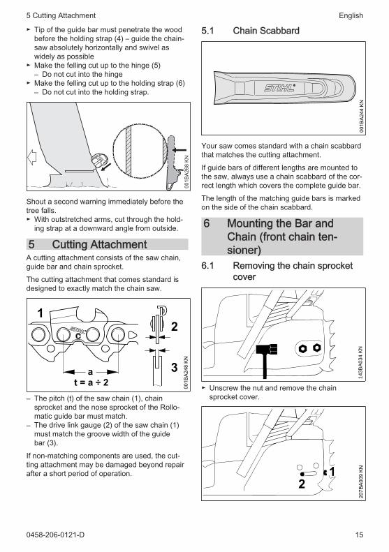
5 Cutting AttachmentA cutting attachment consists of the saw chain,guide bar and chain sprocket.
The cutting attachment that comes standard isdesigned to exactly match the chain saw.
001B
A248
KN
12
3a
– The pitch (t) of the saw chain (1), chainsprocket and the nose sprocket of the Rollo‐matic guide bar must match.
– The drive link gauge (2) of the saw chain (1)must match the groove width of the guidebar (3).
If non-matching components are used, the cut‐ting attachment may be damaged beyond repairafter a short period of operation.
5.1 Chain Scabbard
001B
A244
KN
Your saw comes standard with a chain scabbardthat matches the cutting attachment.
If guide bars of different lengths are mounted tothe saw, always use a chain scabbard of the cor‐rect length which covers the complete guide bar.
The length of the matching guide bars is markedon the side of the chain scabbard.
6 Mounting the Bar andChain (front chain ten‐sioner)
6.1 Removing the chain sprocketcover
143B
A03
4 K
N
► Unscrew the nut and remove the chainsprocket cover.
12
207B
A009
KN
5 Cutting Attachment English
0458-206-0121-D 15

► Turn the screw (1) counterclockwise until thetensioning nut (2) butts against the left end ofthe housing slot.
6.2 Disengage the chain brake.
001B
A186
KN
► Pull the hand guard towards the front handleuntil there is an audible click – the chain brakeis disengaged.
6.3 Fitting the chain
143B
A00
3 K
N
WARNING
Wear work gloves to protect your hands from thesharp cutters.► Fit the chain – start at the bar nose.
411
23
207B
A010
KN
► Fit the guide bar over the studs (1) – the cut‐ting edges on the top of the bar must point tothe right.
► Engage the peg of the tensioner slide in thelocating hole (2) –- place the chain over thesprocket (3) at the same time.
► Turn the tensioning screw (4) clockwise untilthere is very little chain sag on the undersideof the bar – and the drive link tangs areengaged in the bar groove.
► Refit the sprocket cover and screw on the nutonly fingertight.
► Go to chapter on "Tensioning the Saw Chain"
7 Mounting the Bar andChain (quick chain ten‐sioner)
7.1 Removing the chain sprocketcover
123
2310
BA01
3 KN
► Swing grip (1) into position (until it engages)► Turn the wing nut (2) to the left until it hangs
loosely in the chain sprocket cover (3)► Remove chain sprocket cover (3)
7.2 Mounting the tensioning gear
123
10BA
014
KN
► Remove and reverse tensioning gear (1)
2310
BA01
5 KN
2
English 7 Mounting the Bar and Chain (quick chain tensioner)
16 0458-206-0121-D

► Remove screw (2)
1
3
2310
BA01
6 KN
► Position tensioning gear (1) and guide bar (3)relative to one another
223
10BA
017
KN
► Insert and tighten screw (2)
7.3 Releasing the chain brake
001B
A186
KN
► Pull hand guard towards the front handle untilit engages audibly – chain brake is released
7.4 Fitting the saw chain
1
181B
A012
KN
WARNING
Put on protective gloves – risk of injury by thesharp cutters.► Fit the saw chain – starting at the nose of the
guide bar – pay attention to the position of thetensioning gear and the cutting edges
► Turn tensioning gear (1) to the right as far aspossible
► Turn the guide bar so that the tensioning gearfaces the user
23
181B
A013
KN
► Place the saw chain on the chain sprocket (2)► Slide the guide bar over the collar screw (3);
the head of the rear collar screw must pro‐trude into the oblong hole
7 Mounting the Bar and Chain (quick chain tensioner) English
0458-206-0121-D 17

135B
A01
1 K
N
► Guide the drive link into the bar groove (seearrow) and turn the tensioning gear to the leftas far as possible
► Fit chain sprocket cover, sliding the guide lugsinto the engine housing openings
45
2310
BA01
8 KN
When fitting the chain sprocket cover, the teethof the adjusting wheel and the tensioning gearmust mesh; if necessary,► turn the adjusting wheel (4) a little until the
chain sprocket cover can be slid completelyagainst the engine housing
► Swing grip (5) into position (until it engages)► Fit wing nut and tighten lightly► Next step: see "Tensioning the Saw Chain"
8 Mounting the Bar andChain (side chain ten‐sioner)
8.1 Removing the chain sprocketcover
143B
A03
4 K
N
► Unscrew nuts and remove chain sprocketcover
1
2
001B
A185
KN
► Turn screw (1) to the left until the tensionerslide (2) butts against the left end of the hous‐ing slot
8.2 Releasing the chain brake00
1BA1
86 K
N
► Pull hand guard towards the front handle untilit engages audibly – chain brake is released
English 8 Mounting the Bar and Chain (side chain tensioner)
18 0458-206-0121-D

8.3 Fitting the saw chain
143B
A00
3 K
N
WARNING
Put on protective gloves – risk of injury by thesharp cutters► Fit the chain starting at the nose of the guide
bar
3 112 4
001B
A187
KN
► Position the guide bar over the bolts (1) – thecutting edges of the saw chain must point tothe right
► Position the locating hole (2) over the peg ofthe tensioner slide – simultaneously place thesaw chain over the sprocket wheel (3)
► Turn screw (4) to the right until there is very lit‐tle chain sag on the underside of the bar – andthe drive link tangs engage in the bar groove
► Refit the chain sprocket cover – and thenscrew on the nut by hand until it is fingertight
► Go to chapter "Tensioning the saw chain"
9 Tensioning the Saw Chain(front chain tensioner)
1
143B
A04
5 K
N
Retensioning during cutting work:► Switch off the engine.► Loosen the nuts.► Hold the bar nose up.► Use a screwdriver to turn the tensioning
screw (1) clockwise until the chain fits snuglyagainst the underside of the bar.
► While still holding the bar nose up, tightendown the nuts firmly.
► Go to "Checking Chain Tension".
A new chain has to be retensioned more oftenthan one that has been in use for some time.► Check chain tension frequently – see chapter
on "Operating Instructions".
10 Tensioning the Saw Chain(quick chain tensioner)
1
200
1BA
112
KN
Retensioning during cutting work:► Shut off the engine.► Pull out the hinged clip and loosen the wing‐
nut.► Turn the adjusting wheel (1) clockwise as far
as stop.► Tighten down the wingnut (2) firmly by hand.► Fold down the hinged clip.► Go to "Checking Chain Tension"
A new chain has to be retensioned more oftenthan one that has been in use for some time.
9 Tensioning the Saw Chain (front chain tensioner) English
0458-206-0121-D 19

► Check chain tension frequently – see chapteron "Operating Instructions".
11 Tensioning the Saw Chain(side chain tensioner)
1
133B
A02
4 K
NRetensioning during cutting work:► Shut off the engine.► Loosen the nuts.► Hold the bar nose up.► Use a screwdriver to turn the tensioning
screw (1) clockwise until the chain fits snuglyagainst the underside of the bar.
► While still holding the bar nose up, tightendown the nuts firmly.
► Go to "Checking Chain Tension".
A new chain has to be retensioned more oftenthan one that has been in use for some time.► Check chain tension frequently – see chapter
on "Operating Instructions".
12 Checking Chain Tension
143B
A00
7 K
N
► Shut off the engine.► Wear work gloves to protect your hands.► The chain must fit snugly against the under‐
side of the bar and it must still be possible topull the chain along the bar by hand.
► If necessary, retension the chain.
A new chain has to be retensioned more oftenthan one that has been in use for some time.► Check chain tension frequently – see chapter
on "Operating Instructions".
13 FuelThe engine requires a mixture of gasoline andengine oil.
WARNING
Avoid direct skin contact with fuel and breathingin of gasoline fumes.
13.1 STIHL MotoMixSTIHL recommends using STIHL MotoMix. Thispre-blended fuel is free of benzene and lead, isdistinguished by a high octane rating, andalways provides the proper mixing ratio.
STIHL MotoMix uses STIHL HP Ultra two-strokeengine oil for optimum engine life.
MotoMix is not available in all markets.
13.2 Mixing fuel
NOTICE
Unsuitable fuels or a mixing ratio that deviatesfrom the specification can lead to severe enginedamage. The engine, seals, fuel lines and fueltank may be damaged if low-quality gasoline orengine oil is used.
13.2.1 Gasoline
Use only high-quality gasoline with an octane rat‐ing of at least 90 ROC – leaded or unleaded.
Gasoline with an alcohol component exceeding10% can cause impaired engine performance inengines with manually adjustable carburetorsand thus should not be used in these engines.
Engines with M-Tronic deliver full engine per‐formance using gasoline with an alcohol compo‐nent of up to 27% (E27).
13.2.2 Engine oil
If you mix the fuel yourself, use only STIHL two-stroke engine oil or another high-performanceengine oil classified as JASO FB, JASO FC,JASO FD, ISO-L-EGB, ISO-L-EGC or ISO-L-EGD.
STIHL specifies STIHL HP Ultra two-strokeengine oil or an equivalent high-performanceengine oil in order to maintain emission limitsover the machine’s service life.
English 11 Tensioning the Saw Chain (side chain tensioner)
20 0458-206-0121-D

13.2.3 Mixing ratio
with STIHL two-stroke engine oil 1:50; 1:50 =1 part oil + 50 parts gasoline
13.2.4 ExamplesQuantity of gaso‐line
STIHL two-strokeengine oil 1:50
Liters Liters (ml)1 0.02 (20)5 0.10 (100)10 0.20 (200)15 0.30 (300)20 0.40 (400)25 0.50 (500)► Pour oil into an approved safety fuel canister
first, then add gasoline and mix thoroughly
13.3 Storing fuel mixtureStore in approved safety fuel canisters only in adry, cool and secure place protected against lightand sunlight.
Fuel mixture deteriorates with age – mix only asmuch as needed for a few weeks. Do not storefuel mixture for longer than 30 days. The fuelmixture can become unusable more quickly ifexposed to light, sunlight or low or high tempera‐tures.
STIHL MotoMix however can be stored for up to5 years without any problems.► Shake the canister containing the fuel mixture
thoroughly before refueling
WARNING
Pressure may have built up in the canister –open it carefully.► The fuel tank and the canister in which fuel
mixture is stored should be cleaned thoroughlyfrom time to time
Residual fuel and the liquid used for cleaningmust be disposed of in accordance with regula‐tions and without harming the environment!
14 Fueling
14.1 Preparing the machine
143B
A00
0 K
N
► Before fueling, clean the filler cap and the areaaround it so that dirt cannot fall into the tank.
► Always position the machine so that the fillercap is facing upwards
► Open the filler cap
14.2 RefuelingTake care not to spill fuel while fueling and donot overfill the tank.
STIHL recommends use of the STIHL filling sys‐tem for fuel (special accessory).
WARNING
After fueling, tighten down the filler cap by handas securely as possible.
Use a suitable tool (e. g., screwdriver of the com‐bination wrench) for slotted filler caps.
14 Fueling English
0458-206-0121-D 21

14.3 Fuel pick-up body replacement
143B
A00
9 K
N
Change the fuel pick-up body every year; to dothis:► Drain the fuel tank► Pull the fuel pick-up body out of the tank with a
hook and disconnect it from the hose► Connect a new fuel pick-up body to the hose► Return the fuel pick-up body to the tank
15 Chain LubricantFor automatic and reliable lubrication of thechain and guide bar – use only an environmen‐tally compatible quality chain and bar lubricant.Rapidly biodegradable STIHL BioPlus is recom‐mended.
NOTICE
Biological chain oil must be resistant to aging(e.g. STIHL BioPlus), since it will otherwisequickly turn to resin. This results in hard depositsthat are difficult to remove, especially in the areaof the chain drive and chain. It may even causethe oil pump to seize.
The service life of the chain and guide bardepends on the quality of the lubricant. It istherefore essential to use only a specially formu‐lated chain lubricant.
WARNING
Do not use waste oil. Renewed contact withwaste oil can cause skin cancer. Moreover,waste oil is environmentally harmful.
NOTICE
Waste oil does not have the necessary lubricat‐ing properties and is unsuitable for chain lubrica‐tion.
16 Filling Chain Oil Tank
16.1 Preparations
001B
A15
8 K
N
► Thoroughly clean the oil filler cap and the areaaround it to ensure that no dirt falls into thetank.
► Position the machine so that the filler cap isfacing up.
► Open the filler cap.
16.2 Fill up with chain oil.► Refill the chain oil tank every time you refuel.
Take care not to spill chain oil while refilling anddo not overfill the tank.
STIHL recommends you use the STIHL filler noz‐zle for chain oil (special accessory).► Close the filler cap.
There must still be a small amount of oil in the oiltank when the fuel tank is empty.
If the oil level in the tank does not go down, thereason may be a fault in the oil supply system:Check chain lubrication, clean the oilways, con‐tact your dealer for assistance if necessarySTIHL recommends that you have servicing andrepair work carried out exclusively by an author‐ized STIHL servicing dealer.
English 15 Chain Lubricant
22 0458-206-0121-D

17 Checking Chain Lubrica‐tion
143B
A024
KN
The saw chain must always spin off a smallamount of oil.
NOTICE
Never operate your machine without chain lubri‐cation. If the saw chain runs dry, the cuttingattachment may very quickly be damagedbeyond repair. Before starting work, alwayscheck the chain lubrication and oil level in thetank.
Every new saw chain needs a run-in time of 2 to3 minutes.
After the saw chain has run in, check the tensionof the chain and correct if necessary – see"Checking the chain tension".
18 Chain Brake
18.1 Saw chain, lock
143B
A011
KN
– in an emergency– when starting– when idling
Press the hand guard towards the nose of theguide bar with the left hand - or automatically
due to kickback: Saw chain is blocked - andstops running.
18.2 Disengage the chain brake.
143B
A012
KN
► Pull the hand guard back towards the fronthandle.
NOTICE
The chain brake must be released before open‐ing the throttle (except during functional check‐out) and before sawing.
Running the engine at high revs with the chainbrake engaged (chain locked) will quickly dam‐age the engine and chain drive (clutch, chainbrake).
The chain brake is also activated by the inertia ofthe front hand guard if the kickback force of thesaw is high enough: The hand guard is acceler‐ated toward the bar nose – even if your left handis not behind the hand guard, e.g. during fellingcut.
The chain brake will operate only if the handguard has not been modified in any way.
18.3 Checking Operation of theChain Brake
Before starting work: Run engine at idle speed,engage the chain brake (push hand guardtowards bar nose) and open the throttle wide for(no more than 3 seconds) – the chain must notrotate. The hand guard must be free of dirt andeasily moveable.
18.4 Chain Brake MaintenanceThe chain brake is subject to (normal wear). It isnecessary to have it serviced and maintainedregularly by trained personnel. STIHL recom‐mends that maintenance and repair work be car‐ried out only by authorised STIHL dealers. Thefollowing intervals must be complied with:Full-time use: quarterly
17 Checking Chain Lubrication English
0458-206-0121-D 23
Part-time use: every six monthsoccasional use: annually
19 Starting / Stopping theEngine
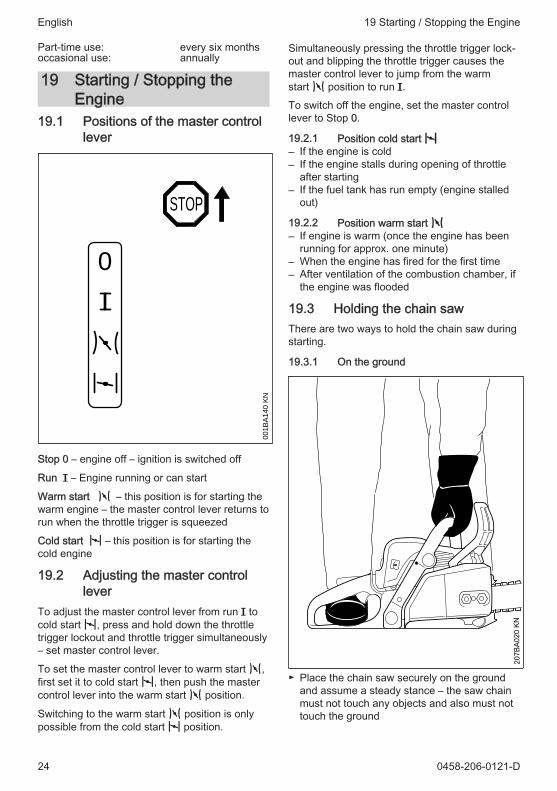
19.1 Positions of the master controllever
STOP
000
1BA
140
KN
Stop 0 – engine off – ignition is switched off
Run F – Engine running or can start
Warm start n – this position is for starting thewarm engine – the master control lever returns torun when the throttle trigger is squeezed
Cold start l – this position is for starting thecold engine
19.2 Adjusting the master controllever
To adjust the master control lever from run F tocold start l, press and hold down the throttletrigger lockout and throttle trigger simultaneously– set master control lever.
To set the master control lever to warm start n,first set it to cold start l, then push the mastercontrol lever into the warm start n position.
Switching to the warm start n position is onlypossible from the cold start l position.
Simultaneously pressing the throttle trigger lock‐out and blipping the throttle trigger causes themaster control lever to jump from the warmstart n position to run F.
To switch off the engine, set the master controllever to Stop 0.
19.2.1 Position cold start l– If the engine is cold– If the engine stalls during opening of throttle
after starting– If the fuel tank has run empty (engine stalled
out)
19.2.2 Position warm start n– If engine is warm (once the engine has been
running for approx. one minute)– When the engine has fired for the first time– After ventilation of the combustion chamber, if
the engine was flooded
19.3 Holding the chain sawThere are two ways to hold the chain saw duringstarting.
19.3.1 On the ground
207B
A020
KN
► Place the chain saw securely on the groundand assume a steady stance – the saw chainmust not touch any objects and also must nottouch the ground
English 19 Starting / Stopping the Engine
24 0458-206-0121-D
► With the left hand on handlebar, press thechain saw firmly against the ground – thumbwrapped around the handlebar
► Place your right foot into the rear handle
19.3.2 Between the knees or thighs
207B
A021
KN
► Clamp the rear handle between the knees orthighs
► Grip the handlebar firmly with the left hand –thumb wrapped around the handlebar
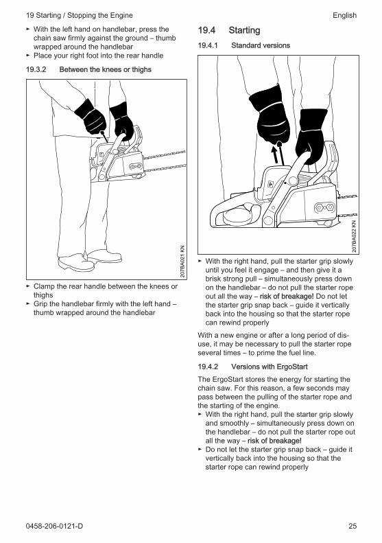
19.4 Starting19.4.1 Standard versions
207B
A022
KN
► With the right hand, pull the starter grip slowlyuntil you feel it engage – and then give it abrisk strong pull – simultaneously press downon the handlebar – do not pull the starter ropeout all the way – risk of breakage! Do not letthe starter grip snap back – guide it verticallyback into the housing so that the starter ropecan rewind properly
With a new engine or after a long period of dis‐use, it may be necessary to pull the starter ropeseveral times – to prime the fuel line.
19.4.2 Versions with ErgoStart
The ErgoStart stores the energy for starting thechain saw. For this reason, a few seconds maypass between the pulling of the starter rope andthe starting of the engine.► With the right hand, pull the starter grip slowly
and smoothly – simultaneously press down onthe handlebar – do not pull the starter rope outall the way – risk of breakage!
► Do not let the starter grip snap back – guide itvertically back into the housing so that thestarter rope can rewind properly
19 Starting / Stopping the Engine English
0458-206-0121-D 25

19.5 Starting the chain saw
WARNING
There must not be anyone within the swivelrange of the chain saw.► Observe safety precautions
19.5.1 For all versions
1
2
207B
A025
KN
0
► Push the hand guard (1) forwards – the sawchain is blocked
► Simultaneously press and hold down the throt‐tle trigger lockout (2) and throttle trigger – setmaster control lever
Position cold start l– If engine is cold (even if the engine has stalled
during opening of throttle after starting)
Position warm start n– If engine is warm (once the engine has been
running for approx. one minute)► Hold and start the chain saw
19.6 When the engine has turnedover for the first time
3
207B
A023
KN
STOP
0
► Move master control lever (3) to warm start nand continue cranking
19.7 Once the engine is running
423
207B
A024
KN
STOP
0
► Press the throttle trigger lockout (2) and blipthe throttle trigger (4); the master controllever (3) jumps to run F and the engine beginsto idle
NOTICE
The engine must be switched to idle immediately– otherwise, damage to the engine housing andchain brake may occur when the chain brake islocked.
207B
A019
KN
► Pull the hand guard toward the handlebar
The chain brake is released - the chain saw isready for use.
English 19 Starting / Stopping the Engine
26 0458-206-0121-D

NOTICE
Open the throttle only when the chain brake isoff. Increased engine speeds with the chainbrake on (saw chain is stationary) will quicklydamage the clutch and chain brake.
19.8 At very low temperatures► Let the engine warm up briefly with the throttle
slightly open
19.9 Switching off the engine► Move the master control lever to the stop posi‐
tion 0
19.10 If the engine does not startThe master control lever was not returned fromthe position cold start l to warm start n intime, the engine may be flooded.► Move the master control lever to the stop posi‐
tion 0► Remove the spark plug - see "Spark plug"► Dry the spark plug► Crank the engine several times with the starter
– to clear the combustion chamber► Replace the spark plug – see "Spark plug"► Set the master control lever to warm start n –
even if the engine is cold► Restart the engine
20 Operating Instructions20.1 During the break-in periodA factory new machine should not be run at highrevs (full throttle off load) for the first three tankfillings. This avoids unnecessarily high loads dur‐ing the break-in period. As all moving parts haveto bed in during the break-in period, the frictionalresistances in the shortblock are greater duringthis period. The engine develops its maximumpower after about 5 to 15 tank fillings.
20.2 During work
NOTICE
Do not make the mixture leaner to achieve anapparent increase in power – this could damagethe engine – see "Adjusting the Carburetor".
NOTICE
Open the throttle only when the chain brake isoff. Running the engine at high revs with thechain brake engaged (chain locked) will quicklydamage the shortblock and chain drive (clutch,chain brake).
20.2.1 Check chain tension frequently
A new saw chain must be retensioned more fre‐quently than one that has been in use already foran extended period.
20.2.2 Chain cold
Tension is correct when the chain fits snuglyagainst the underside of the bar but can still bepulled along the bar by hand. Retension if neces‐sary – see "Tensioning the Saw Chain".
20.2.3 Chain at operating temperature
The chain stretches and begins to sag. The drivelinks must not come out of the bar groove on theunderside of the bar – the chain may otherwisejump off the bar. Retension the chain – see "Ten‐sioning the Saw Chain".
NOTICE
The chain contracts as it cools down. If it is notslackened off, it can damage the crankshaft andbearings.
20.2.4 After a long period of full-throttle oper‐ation
After a long period of full-throttle operation, allowengine to run for a while at idle speed so that theheat in the engine can be dissipated by flow ofcooling air. This protects engine-mounted com‐ponents (ignition, carburetor) from thermal over‐load.
20.3 After finishing work► Slacken off the chain if you have retensioned it
at operating temperature during work.
20 Operating Instructions English
0458-206-0121-D 27

NOTICE
Always slacken off the chain again after finishingwork. The chain contracts as it cools down. If it isnot slackened off, it can damage the crankshaftand bearings.
20.3.1 Short-term storage
Wait for engine to cool down. Keep the machinewith a full tank of fuel in a dry place, well awayfrom sources of ignition, until you need it again.
20.3.2 Long-term storage
See "Storing the machine"
21 Taking Care of the GuideBar
31
2
143B
A026
KN
► Turn the guide bar over – every time yousharpen the chain and every time you replacethe chain – this helps avoid one-sided wear,especially at the nose and underside of thebar.
► Regularly clean the oil inlet hole (1), the oil‐way (2) and the bar groove (3)
► Measure the groove depth – with the scale onthe filing gauge (special accessory) – in thearea used most for cutting
Chain type Chain pitch Minimumgroovedepth
Picco 1/4" P 4.0 mmRapid 1/4“ 4.0 mmPicco 3/8" P 5.0 mmRapid 3/8“; 0.325“ 6.0 mmRapid 0.404“ 7.0 mmIf groove depth is less than specified:► Replace the guide bar
The drive link tangs will otherwise scrape alongthe bottom of the groove – the cutters and tiestraps will not ride on the bar rails.
22 Shroud22.1 Removing the shroud
207B
A039
KN
► Use a suitable tool to open the catch by turn‐ing it 90° to the left
► Lift off the shroud
22.2 Refitting the shroudInstall parts in reverse order.
23 Cleaning the Air Filter23.1 If there is a noticeable loss of
engine power► Simultaneously press the throttle trigger lock‐
out and throttle trigger and set the MasterControl lever to cold start l
► Clean away loose dirt from around the filter► Remove the shroud – see "Shroud"
MS 170, MS 180
207B
A037
KN
MS 170 2-MIX, 180 2-MIX
English 21 Taking Care of the Guide Bar
28 0458-206-0121-D

207B
A028
KN
► Pull the filter upwards to remove► Knock out the filter or blow it clear with com‐
pressed air from the inside outwards - do notwash
Do not clean fleece filters with a brush!
If the filter cannot be cleaned or is damaged,replace the filter► Reinstall air filter
24 Adjusting the Carburetor24.1 Basic informationThe carburetor has been factory-adjusted to pro‐vide the engine with a optimal fuel-air mixture inall operating states.
207B
A029
KN
24.2 Standard setting► Check the air filter - replace if necessary► Carefully screw the idle speed screw (LD)
down counterclockwise (left-hand thread) untilit is firmly seated, then 2 turns clockwise(standard setting LD = 2)
24.3 Setting the idle speed► Start and warm up the engine► Using the idle speed screw (LD), set the idle
speed correctly: The saw chain must notrotate
Engine speed too low when idling:► Turn the idle speed adjusting screw (LD)
slowly clockwise until the saw chain begins torotate – then back off 1/2 turn
Saw chain rotates at idle speed:► Turn the idle speed adjusting screw (LD)
slowly counterclockwise until the saw chainstops rotating – then turn an additional 1/2 turnin the same direction
WARNING
If the saw chain continues to keep rotating in idleeven after adjustment, have the chain sawchecked by a servicing dealer.
25 Spark Plug► If the engine is down on power, difficult to start
or runs poorly at idle speed, first check thespark plug.
► Fit a new spark plug after about 100 operatinghours – or sooner if the electrodes are badlyeroded. Install only suppressed spark plugs ofthe type approved by STIHL – see "Specifica‐tions".
25.1 Removing the spark plug► Simultaneously press the throttle trigger lock‐
out and throttle trigger and set the MasterControl lever to cold start l
► Remove the shroud – see "Shroud"
MS 170, MS 180
207B
A036
KN
MS 170 2-MIX, 180 2-MIX
207B
A030
KN
► Pull off the spark plug boot► Unscrew spark plug
24 Adjusting the Carburetor English
0458-206-0121-D 29
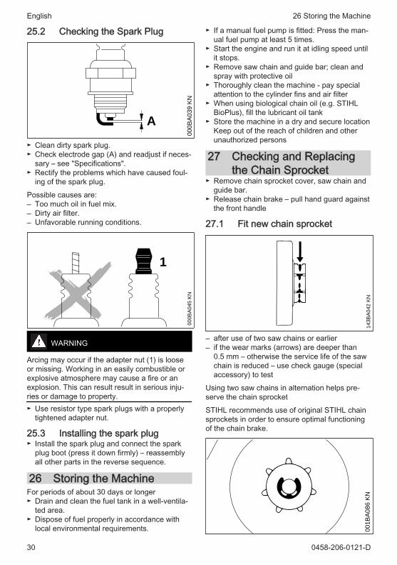
25.2 Checking the Spark Plug
000B
A03
9 K
N
A
► Clean dirty spark plug.► Check electrode gap (A) and readjust if neces‐
sary – see "Specifications".► Rectify the problems which have caused foul‐
ing of the spark plug.
Possible causes are:– Too much oil in fuel mix.– Dirty air filter.– Unfavorable running conditions.
1
000B
A04
5 K
N
WARNING
Arcing may occur if the adapter nut (1) is looseor missing. Working in an easily combustible orexplosive atmosphere may cause a fire or anexplosion. This can result result in serious inju‐ries or damage to property.► Use resistor type spark plugs with a properly
tightened adapter nut.
25.3 Installing the spark plug► Install the spark plug and connect the spark
plug boot (press it down firmly) – reassemblyall other parts in the reverse sequence.
26 Storing the MachineFor periods of about 30 days or longer► Drain and clean the fuel tank in a well-ventila‐
ted area.► Dispose of fuel properly in accordance with
local environmental requirements.
► If a manual fuel pump is fitted: Press the man‐ual fuel pump at least 5 times.
► Start the engine and run it at idling speed untilit stops.
► Remove saw chain and guide bar; clean andspray with protective oil
► Thoroughly clean the machine - pay specialattention to the cylinder fins and air filter
► When using biological chain oil (e.g. STIHLBioPlus), fill the lubricant oil tank
► Store the machine in a dry and secure locationKeep out of the reach of children and otherunauthorized persons
27 Checking and Replacingthe Chain Sprocket
► Remove chain sprocket cover, saw chain andguide bar.
► Release chain brake – pull hand guard againstthe front handle
27.1 Fit new chain sprocket
143B
A04
2 K
N
– after use of two saw chains or earlier– if the wear marks (arrows) are deeper than
0.5 mm – otherwise the service life of the sawchain is reduced – use check gauge (specialaccessory) to test
Using two saw chains in alternation helps pre‐serve the chain sprocket
STIHL recommends use of original STIHL chainsprockets in order to ensure optimal functioningof the chain brake.
001B
A08
6 K
N
English 26 Storing the Machine
30 0458-206-0121-D

► Use a screwdriver to remove the E-clip► Remove washer► Remove the chain sprocket together with the
needle cage from the crankshaft
27.2 Install chain sprocket► Clean crankshaft stub and needle cage and
lubricate with STIHL lubricant (special acces‐sory)
► Slide needle cage onto the crankshaft stub► After refitting, turn the chain sprocket approx.
1 full turn so that the carrier for the oil pumpdrive engages
► Refit washer and E-clip on the crankshaft
28 Maintaining and Sharpen‐ing the Saw Chain
28.1 Sawing effortlessly with a prop‐erly sharpened saw chain
A properly sharpened saw chain cuts throughwood effortlessly even with very little pushing.
Never use a dull or damaged saw chain – thisleads to increased physical strain, increasedvibration load, unsatisfactory cutting results andincreased wear.► Clean the saw chain► Check the saw chain for cracks and damaged
rivets► Replace damaged or worn chain components
and adapt these parts to the remaining parts interms of shape and level of wear – reworkaccordingly
Carbide-tipped (Duro) saw chains are especiallywear-resistant. For an optimal sharpening result,STIHL recommends STIHL servicing dealers.
WARNING
Compliance with the angles and dimensions lis‐ted below is absolutely necessary. An improperlysharpened saw chain – especially depth gaugesthat are too low – can lead to increased kickbacktendency of the chain saw – risk of injury!
28.2 Chain pitch
689B
A027
KN
a
The chain pitch marking (a) is embossed in thearea of the depth gauge of each cutter.Marking (a) Chain pitch Inches mm7 1/4 P 6.351 or 1/4 1/4 6.356, P or PM 3/8 P 9.322 or 325 0.325 8.253 or 3/8 3/8 9.324 or 404 0.404 10.26The diameter of file to be used depends on thechain pitch – see table "Sharpening tools".
The angles of the cutter must be maintained dur‐ing resharpening.
28.3 Sharpening and side plateangles
A
B
689B
A02
1 K
N
A Sharpening angle
STIHL saw chains are sharpened with a 30°sharpening angle. Ripping chains, which aresharpened with a 10° sharpening angle, are
28 Maintaining and Sharpening the Saw Chain English
0458-206-0121-D 31
exceptions. Ripping chains have an X in the des‐ignation.
B Side plate angle
The correct side plate angle results automaticallywhen the specified file holder and file diameterare used.Tooth shapes Angle (°) A BMicro = semi-chisel tooth, e. g.,63 PM3, 26 RM3, 36 RM
30 75
Super = full chisel tooth, e. g.,63 PS3, 26 RS, 36 RS3
30 60
Ripping chain, e. g., 63 PMX,36 RMX
10 75
The angles must be identical for all cutters in thesaw chain. Varying angles: Rough, uneven run‐ning of the saw chain, increased wear – even tothe point of saw chain breakage.
28.4 File holder
689B
A02
5 K
N
► Use a file holder
Always use a file holder (special accessory, seetable "Sharpening tools") when sharpening sawchains by hand. File holders have markings forthe sharpening angle.
Use only special saw chain files! Other files areunsuitable in terms of shape and type of cutting.
28.5 To check the angles
001B
A203
KN
STIHL filing gauge (special accessory, see table"Sharpening tools") – a universal tool for check‐
ing sharpening and side plate angles, depthgauge setting, and tooth length, as well as clean‐ing grooves and oil inlet holes.
28.6 Proper sharpening► Select sharpening tools in accordance with
chain pitch► Clamp guide bar if necessary► Block saw chain – push the hand guard for‐
ward► To advance the saw chain, pull the hand
guard toward the handlebar: The chain brakeis disengaged. With the Quickstop Superchain brake system, additionally press thethrottle trigger lockout
► Sharpen frequently, removing little material –two or three strokes of the file are usually suffi‐cient for simple resharpening
689B
A01
8 K
N90°
689B
A04
3 K
N
► Guide the file: horizontally (at a right angle tothe side surface of the guide bar) in accord‐ance with the specified angle – according tothe markings on the file holder – rest the fileholder on the tooth head and the depth gauge
► File only from the inside outward► The file only sharpens on the forward stroke –
lift the file on the backstroke► Do not file tie straps and drive links► Rotate the file a little periodically in order to
avoid uneven wear► To remove file burr, use a piece of hardwood► Check angle with file gauge
All cutters must be equally long.
English 28 Maintaining and Sharpening the Saw Chain
32 0458-206-0121-D

With varying cutter lengths, the cutter heightsalso vary and cause rough running of the sawchain and chain breakage.► All cutters must be filed down equal to the
length of the shortest cutter – ideally, oneshould have this done by a servicing dealerusing an electric sharpener
28.7 Depth gauge setting
689B
A02
3 K
N
a
The depth gauge determines the depth to whichthe cutter penetrates the wood and thus the chipthickness.
a Required distance between depth gauge andcutting edge
When cutting softwood outside of the frost sea‐son, the distance can be increased by up to0.2 mm (0.008").Chain pitch Depth gauge Distance (a)Inches (mm) mm (Inches)1/4 P (6.35) 0.45 (0.018)1/4 (6.35) 0.65 (0.026)3/8 P (9.32) 0.65 (0.026)0.325 (8.25) 0.65 (0.026)3/8 (9.32) 0.65 (0.026)0.404 (10.26) 0.80 (0.031)
28.8 Lowering the depth gaugesThe depth gauge setting is lowered when thecutter is sharpened.► Check the depth gauge setting after each
sharpening
2
689B
A061
KN1
► Lay the appropriate file gauge (1) for the chainpitch on the saw chain and press it against thecutter to be checked – if the depth gauge pro‐trudes past the file gauge, the depth gaugemust be reworked
Saw chains with humped drive link (2) – upperpart of the humped drive link (2) (with servicemark) is lowered at the same time as the depthgauge of the cutter.
WARNING
The rest of the humped drive link must not befiled; otherwise, this could increase the tendencyof the chain saw to kick back.
689B
A05
1 K
N
► Rework the depth gauge so that it is flush withthe file gauge
689B
A04
4 K
N
► Afterwards, dress the leading edge of thedepth gauge parallel to the service mark (seearrow) – when doing this, be careful not to fur‐ther lower the highest point of the depth gauge
28 Maintaining and Sharpening the Saw Chain English
0458-206-0121-D 33

WARNING
Depth gauges that are too low increase the kick‐back tendency of the chain saw.
689B
A05
2 K
N
► Lay the file gauge on the saw chain – the high‐est point of the depth gauge must be flush withthe file gauge
► After sharpening, clean the saw chain thor‐oughly, removing any filings or grinding dust –lubricate the saw chain thoroughly
► In the event of extended periods of disuse,store saw chains in cleaned and oiled condi‐tion
Sharpening tools (special accessories)Chain pitch Round file
^Round file File holder File gauge Taper square
fileSharpeningset1)
Inches (mm) mm (Inches)
Part number Part number Part number Part number Part number
1/4P (6.35) 3.2 (1/8) 5605 7713206
5605 7504300
0000 8934005
0814 2523356
5605 0071000
1/4 (6.35) 4.0 (5/32) 5605 772 40065605 750 43271110 893 40000814 252 33565605 0071027
3/8 P (9.32) 4.0 (5/32) 5605 7724006
5605 7504327
1110 8934000
0814 2523356
5605 0071027
0.325 (8.25) 4.8 (3/16) 5605 7724806
5605 7504328
1110 8934000
0814 2523356
5605 0071028
3/8 (9.32) 5.2 (13/64) 5605 7725206
5605 7504329
1110 8934000
0814 2523356
5605 0071029
0.404 (10.26)5.5 (7/32) 5605 7725506
5605 7504330
1106 8934000
0814 2523356
5605 0071030
1)consisting of file holder with round file, taper square file and file gauge
English 28 Maintaining and Sharpening the Saw Chain
34 0458-206-0121-D

29 Maintenance and CareThe following maintenance intervals apply for normal operat‐ing conditions only. When working under difficult conditions(high accumulation of dust, highly resinous lumber, lumberfrom tropical trees, etc.) or longer than normal each day, thespecified intervals must be shortened accordingly. If you onlyuse the tool occasionally, extend the intervals accordingly.
Befo
re s
tarti
ng w
ork
At th
e en
d of
wor
k an
d/or
dai
ly
Whe
neve
r tan
k is
refil
led
Wee
kly
Mon
thly
Annu
ally
If fa
ulty
If da
mag
ed
As re
quire
d
Complete machine Visual inspection (condition,leaks)
X X
Clean XThrottle trigger, throttle triggerlockout, choke lever, stopswitch, master control lever(dependent on equipment)
Function test X X
Chain brake Function test X XHave checked by dealer1) X
Manual fuel pump (if present) check X Have repaired by a specialistdealer1)
X
Fuel pick-up body / filter in fueltank
check XClean, replace filter insert X Xreplace X X X
Fuel tank Clean XLubricating oil tank Clean XChain lubrication check XSaw chain Check, pay attention to
sharpnessX X
Checking the chain tension X Xsharpen X
Guide bar Check (wear, damage) XClean and turn over XDeburr Xreplace X X
Chain sprocket check XAir filter Clean X X
replace XAnti-vibration elements check X X
Have replaced by servicingdealer1)
X
1) STIHL recommends STIHL servicing dealer
2) When using professional chainsaws (with a power output of 3.4 kW or more) for the first time,tighten the cylinder block screws after 10 to 20 hours of operation
29 Maintenance and Care English
0458-206-0121-D 35

The following maintenance intervals apply for normal operat‐ing conditions only. When working under difficult conditions(high accumulation of dust, highly resinous lumber, lumberfrom tropical trees, etc.) or longer than normal each day, thespecified intervals must be shortened accordingly. If you onlyuse the tool occasionally, extend the intervals accordingly.
Befo
re s
tarti
ng w
ork
At th
e en
d of
wor
k an
d/or
dai
ly
Whe
neve
r tan
k is
refil
led
Wee
kly
Mon
thly
Annu
ally
If fa
ulty
If da
mag
ed
As re
quire
d
Air intake on fan housing Clean X X XCylinder fins Clean X X XCarburetor Check idle adjustment – saw
chain must not rotateX X
Set the idle speed; if requiredhave the chainsaw repairedby a specialist dealer1)
X
Spark plug Adjust electrode gap XReplace after 100 hours ofoperation
Accessible screws and nuts(except adjusting screws)
Tighten2) X
Chain catcher check Xreplace X
Safety information label replace X
30 Minimize Wear and AvoidDamage
Observing the instructions in this manual helpsreduce the risk of unnecessary wear and dam‐age to the power tool.
The power tool must be operated, maintainedand stored with the due care and attentiondescribed in this owner's manual.
The user is responsible for all damage caused bynon-observance of the safety precautions, oper‐ating and maintenance instructions in this man‐ual. This includes in particular:– Alterations or modifications to the product not
approved by STIHL.– Using tools or accessories which are neither
approved or suitable for the product or are of apoor quality.
– Using the product for purposes for which itwas not designed.
– Using the product for sports or competitiveevents.
– Consequential damage caused by continuingto use the product with defective components.
30.1 Maintenance WorkAll the operations described in the "MaintenanceChart" must be performed on a regular basis. Ifthese maintenance operations cannot be per‐formed by the owner, they should be performedby a servicing dealer.
STIHL recommends that you have servicing andrepair work carried out exclusively by an author‐ized STIHL servicing dealer. STIHL dealers areregularly given the opportunity to attend trainingcourses and are supplied with the necessarytechnical information.
If these maintenance operations are not carriedout as specified, the user assumes responsibility
1) STIHL recommends STIHL servicing dealer
2) When using professional chainsaws (with a power output of 3.4 kW or more) for the first time,tighten the cylinder block screws after 10 to 20 hours of operation
English 30 Minimize Wear and Avoid Damage
36 0458-206-0121-D

for any damage that may occur. Among otherparts, this includes:– Damage to the engine due to neglect or defi‐
cient maintenance (e.g. air and fuel filters),incorrect carburetor adjustment or inadequatecleaning of cooling air inlets (intake ports, cyl‐inder fins).
– Corrosion and other consequential damageresulting from improper storage.
– Damage to the machine resulting from the useof poor quality replacement parts.
30.2 Parts Subject to Wear and TearSome parts of the power tool are subject to nor‐mal wear and tear even during regular operationin accordance with instructions and, dependingon the type and duration of use, have to bereplaced in good time. Among other parts, thisincludes:– Saw chain, guide bar– Drive components (clutch, clutch drum, chain
sprocket)– Filters (air, oil, fuel)– Starter mechanism– Spark plug– Components of antivibration system
31 Main Parts
16
15 14
25
24
22
23
21
20
19
1817
8
1
5
2 347
13
#
7
910
611
12
6
207B
A040
KN
1 Shroud catch2 Carburetor adjusting screw
3 Chain brake4 Muffler5 Chain sprocket6 Chain sprocket cover7 Chain catcher8 Side chain tensioner9 Chain tensioner (frontal)10 Guide bar11 Oilomatic saw chain12 Adjusting wheel (quick tensioner)13 Handle14 Oil filler cap15 Bumper spike16 Front hand guard17 Front handle (handlebar)18 Spark plug boot19 Starter grip20 Master control lever21 Fuel filler cap22 Throttle trigger23 Throttle lever lock24 Rear handle25 Rear hand guard# Machine number
32 Specifications32.1 EngineSTIHL single cylinder two-stroke engine
32.1.1 MS 170, MS 170 CDisplacement: 30.1 cm3
Cylinder bore: 37 mmPiston stroke: 28 mmEngine power accordingto ISO 7293:
1.3 kW (1.8 HP) at8500 rpm
Idle speed:1) 2800 rpm
32.1.2 MS 170 2-MIXDisplacement: 30.1 cm3
Cylinder bore: 37 mmPiston stroke: 28 mmEngine power accordingto ISO 7293:
1.2 kW (1.6 HP) at10000 rpm
Idle speed:1) 2800 rpm
32.1.3 MS 180 2-MIXDisplacement: 31.8 cm3
Cylinder bore: 38 mm
31 Main Parts English
0458-206-0121-D 37

Piston stroke: 28 mmEngine power accordingto ISO 7293:
1.4 kW (1.9 HP) at10000 rpm
Idle speed:1) 2800 rpm
32.1.4 MS 180, MS 180 CDisplacement: 31.8 cm3
Cylinder bore: 38 mmPiston stroke: 28 mmEngine power accordingto ISO 7293:
1.5 kW (2.0 HP) at9000 rpm
Idle speed:1) 2800 rpm
32.2 Ignition systemElectronic magneto ignitionSpark plug (suppressed):MS 170, MS 180: Bosch WSR 6 F,
NGK BPMR 7 AMS 170 2-MIX, MS 180 2-MIX: NGK CMR6HElectrode gap: 0.5 mm
32.3 Fuel systemAll position diaphragm carburetor with integralfuel pumpFuel tank capacity: 250 cm3 (0.25 l)
32.4 Chain lubricationFully automatic, speed-controlled oil pump withrotary pistonOil tank capacity: 145 cm3 (0.145 l)
32.5 WeightDry, without cutting attachmentMS 170: 4.0 k
gMS 170 C with ErgoStart: 4.2 k
gMS 170 2-MIX: 4.1 k
gMS 180: 4.1 k
gMS 180 C with quick tensioner and
ErgoStart:4.2 kg
MS 180 2-MIX: 4.1 kg
32.6 Bar and chain MS 170,MS 170 C
The actual cutting length can be less than thespecified cutting length.
32.6.1 Rollomatic guide barsCutting length (3/8" pitch): 30, 35, 40 cmGroove width: 1.1 mm
32.6.2 Saw chain 3/8" PiccoPicco Micro Mini 3 (61 PMM3) Type 3610Pitch: 3/8"P (9.32 mm)Drive link gauge: 1.1 mm
32.6.3 Chain sprockets6-tooth for 3/8" PMS 170, MS 170 C:Max. chain speed to ISO 11681: 21.1 m/sChain speed at maximum poweroutput:
18.6 m/s
:MS 170 2-MIX:Max. chain speed to ISO 11681: 24.8 m/sChain speed at maximum poweroutput:
18.6 m/s
32.7 Bar and chain MS 180,MS 180 C
The actual cutting length can be less than thespecified cutting length.
32.7.1 Rollomatic guide barsCutting length (3/8" pitch): 30, 35, 40 cmGroove width: 1.1 mmGroove width: 1.3 mm
32.7.2 Saw chains 3/8"PiccoPicco Micro Mini 3 (61 PMM3) Type 3610Pitch: 3/8"P (9.32 mm)Drive link gauge: 1.1 mm
Picco Micro 3 (63 PM3) Type 3636Picco Duro (63 PD3) Type 3612Pitch: 3/8"P (9.32 mm)Drive link gauge: 1.3 mm
32.7.3 Chain sprocket6-tooth for 3/8" PMS 180, MS 180 C:Max. chain speed to ISO 11681: 22.3 m/sChain speed at maximum poweroutput:
18.6 m/s
MS 180 2-MIX:Max. chain speed to ISO 11681: 24.8 m/sChain speed at maximum poweroutput:
18.6 m/s
32.8 Sound and Vibration LevelsFor further details on compliance with VibrationDirective 2002/44/EC, see
www.stihl.com/vib
32.8.1 Sound pressure level Lpeq in accord‐ance with ISO 22868
MS 170: 98 dB(A)
1) to ISO 11681 +/- 50 rpm
English 32 Specifications
38 0458-206-0121-D

MS 170 C: 98 dB(A)MS 170 2-MIX: 100 dB(A)MS 180: 98 dB(A)MS 180 C: 98 dB(A)MS 180 2-MIX: 100 dB(A)
32.8.2 Sound power level Lw in accordancewith ISO 22868
MS 170: 109 dB(A)MS 170 C: 109 dB(A)MS 170 2-MIX: 111 dB(A)MS 180: 110 dB(A)MS 180 C: 110 dB(A)MS 180 2-MIX: 112 dB(A)
32.8.3 Vibration level ahv,eq in accordancewith ISO 22867
Handle, left Handle,right
MS 170: 4.2 m/s2 5.9 m/s2
MS 170 C: 4.2 m/s2 5.9 m/s2
MS 170 2-MIX: 6.9 m/s2 6.4 m/s2
MS 180: 6.6 m/s2 7.8 m/s2
MS 180 C: 7.6 m/s2 7.4 m/s2
MS 180 2-MIX 6.6 m/s2 7.8 m/s2
The K‑factor in accordance with Directive2006/42/EC is 2.0 dB(A) for the sound pressurelevel and sound power level; the K‑factor inaccordance with Directive 2006/42/EC is2.0 m/s2 for the vibration level.
32.9 REACHREACH is an EC regulation and stands for theRegistration, Evaluation, Authorization andRestriction of Chemical substances.
For information on compliance with the REACHregulation (EC) No. 1907/2006 see
www.stihl.com/reach
32.10 Exhaust EmissionsThe CO2 value measured in the EU type appro‐val procedure is specified at
www.stihl.com/co2
in the product-specific technical data.
The measured CO2 value was determined on arepresentative engine in accordance with astandardized test procedure under laboratoryconditions and does not represent either anexplicit or implied guarantee of the performanceof a specific engine.
The applicable exhaust emission requirementsare fulfilled by the intended usage and mainte‐nance described in this User Manual. The oper‐
ating license shall be void if the engine is modi‐fied in any way.
33 Ordering Spare PartsPlease enter your saw model, serial number aswell as the part numbers of the guide bar andsaw chain in the spaces provided. This will makere-ordering simpler.
The guide bar and saw chain are subject to nor‐mal wear and tear. When purchasing theseparts, always quote the saw model, the partnumbers and names of the parts.Model
Serial number
Guide bar part number
Chain part number
34 Maintenance and RepairsUsers of this machine may only carry out themaintenance and service work described in thisuser manual. All other repairs must be carriedout by a servicing dealer.
STIHL recommends that you have servicing andrepair work carried out exclusively by an author‐ized STIHL servicing dealer. STIHL dealers areregularly given the opportunity to attend trainingcourses and are supplied with the necessarytechnical information.
When repairing the machine, only use replace‐ment parts which have been approved by STIHLfor this power tool or are technically identical.Only use high-quality replacement parts in orderto avoid the risk of accidents and damage to themachine.
STIHL recommends the use of original STIHLreplacement parts.
Original STIHL parts can be identified by theSTIHL part number, the { logo and theSTIHL parts symbol K (the symbol may appearalone on small parts).
35 DisposalContact the local authorities or your STIHL serv‐icing dealer for information on disposal.
Improper disposal can be harmful to health andpollute the environment.
33 Ordering Spare Parts English
0458-206-0121-D 39

000B
A073
KN
► Take STIHL products including packaging to asuitable collection point for recycling in accord‐ance with local regulations.
► Do not dispose with domestic waste.
36 EC Declaration of Con‐formity
ANDREAS STIHL AG & Co. KGBadstr. 115D‑71336 Waiblingen
Germany
declare in exclusive responsibility that the prod‐uctModel: Chain sawMake: STIHLType: MS 170
MS 180MS 180 C
Serial identification number: 1130Displacementall MS 170: 30,1 cm3
all MS 180: 31,8 cm3
conforms to the provisions of Directives2011/65/EU, 2006/42/EC, 2014/30/EU and2000/14/EC and has been developed and manu‐factured in compliance with the following stand‐ards in the versions valid at the time of produc‐tion:
EN ISO 11681‑1, EN 55012, EN 61000‑6‑1
The measured and guaranteed equivalent soundpower level has been determined in accordancewith Directive 2000/14/EC, Annex V, and stand‐ard ISO 9207.
Measured sound power levelall MS 170: 109 dB(A)all MS 170 2-MIX: 111 dB(A)all MS 180: 110 dB(A)all MS 180 2-MIX: 112 dB(A)
Guaranteed sound power levelall MS 170: 111 dB(A)
all MS 170 2-MIX: 113 dB(A)all MS 180: 112 dB(A)all MS 180 2-MIX: 114 dB(A)
The EC type approval test was carried out at the
DPLFDeutsche Prüf- und Zertifizierungsstelle für Land-und Forsttechnik (NB 0363)Spremberger Straße 1D‑64823 Groß-UmstadtCertification No.:all MS 170: K-EG-2009/3408all MS 180: K-EG-2009/3409The technical documentation has been retainedby:
ANDREAS STIHL AG & Co. KGProduct approval
The year of construction and the serial numberare shown on the machine.
Done at Waiblingen, 03.02.2020
ANDREAS STIHL AG & Co. KG
p p.
Dr. Jürgen Hoffmann
Director Product Certification & RegulatoryAffairs
37 UKCA Declaration of Con‐formity
ANDREAS STIHL AG & Co. KGBadstr. 115D‑71336 Waiblingen
Germany
declares under our sole responsibility thatDesignation: ChainsawMake: STIHLSeries: MS 170 MS 180 MS 180 CSerial identification number: 1130Displacement all MS 170: 30.1 cm3
all MS 180: 31.8 cm3
English 36 EC Declaration of Conformity
40 0458-206-0121-D

conforms to the relevant provisions of UK regula‐tions The Restriction of the Use of Certain Haz‐ardous Substances in Electrical and ElectronicEquipment Regulations 2012, Supply of Machi‐nery (Safety) Regulations 2008, ElectromagneticCompatibility Regulations 2016 and Noise Emis‐sion in the Environment by Equipment for useOutdoors Regulations 2001 and has been manu‐factured in compliance with the following stand‐ards in the versions valid on the date of produc‐tion:
EN ISO 11681‑1, EN 55012, EN 61000‑6‑1
The measured and guaranteed sound power lev‐els have been determined in accordance with UKregulation Noise Emission in the Environment byEquipment for use Outdoors Regulations 2001,Annex 8, using the ISO 9207 standard.
Measured sound power levelall MS 170: 109 dB(A)all MS 170 2-MIX: 111 dB(A)all MS 180: 110 dB(A)all MS 180 2-MIX: 112 dB(A)
Guaranteed sound power levelall MS 170: 111 dB(A)all MS 170 2-MIX: 113 dB(A)all MS 180: 112 dB(A)all MS 180 2-MIX: 114 dB(A)
The type examination was carried out by
Intertek Testing & Certification Ltd, AcademyPlace, 1 – 9 Brook Street, Brentwood Essex,CM14 5NQ, United KingdomCertification No.all MS 170: ITS UK MCR 34all MS 180: ITS UK MCR 35Technical documents deposited at:
ANDREAS STIHL AG & Co. KG
The year of manufacture and serial number areapplied to the product.
Waiblingen, 31.03.2022
ANDREAS STIHL AG & Co. KG
pp
Dr. Jürgen Hoffmann
Director Product Certification & RegulatoryAffairs
37 UKCA Declaration of Conformity English
0458-206-0121-D 41

English 37 UKCA Declaration of Conformity
42 0458-206-0121-D

37 UKCA Declaration of Conformity English
0458-206-0121-D 43

www.stihl.com
*04582060121D*
*04582060121D*
0458-206-0121-D
0458
-206
-012
1-D