STIHL 019 T - Small Engine Discount
50
STIHL 019 T 1 CONTENTS 1. Introduction 2 2. Specifications 3 2.1 Engine 3 2.2 Fuel System 3 2.3 Ignition System 4 2.4 Cutting Attachment 4 2.5 Special Accessories 4 2.5.1 For User 4 2.5.2 For Service 4 2.6 Tightening Torques 5 3. Clutch, Chain Drive, Chain Brake and Chain Tensioner 6 3.1 Chain Sprocket 6 3.2 Clutch 7 3.3 Chain Brake 7 3.3.1 Checking Function 7 3.3.2 Disassembly 8 3.3.3 Assembly 9 3.4 Chain Tensioner 11 3.5 Bar Stud 11 4. Engine 12 4.1 Removal 12 4.2 Assembly 13 4.3 Exhaust Muffler/ Spark Arresting Screen 14 4.4 Leakage Test 15 4.4.1 Preparations 15 4.4.2 Pressure Test 16 4.4.3 Vacuum Test (for diaphragm) 17 4.4.4 Vacuum Test (for oil seal) 17 4.5 Oil Seals 19 4.6 Cylinder 20 4.7 Piston 22 4.8 Piston Ring 23 4.9 Crankshaft 23 5. Ignition System 25 5.1 Spark Plug Boot 25 5.2 Ignition Module 26 5.2.1 Ignition Timing 26 5.2.2 Removing and Installing 26 5.3 Flywheel 27 5.4 Ground Wire/ Short Circuit Wire 28 5.5 Contact Spring 29 6. Rewind Starter 30 6.1 General 30 6.2 Fan Housing 30 6.3 Rewind Spring 31 6.3.1 Replacing 31 6.3.2 Tensioning 32 6.4 Starter Rope (ElastoStart) 32 6.5 Starter Grip (ElastoStart) 33 7. AV Handle System 34 8. Master Control/ Handle System 36 8.1 Interlock Lever/ Throttle Trigger 36 8.2 Switch Shaft 36 8.3 Handle Molding 37 8.4 Handlebar 37 8.5 Top Handle 37 9. Chain Lubrication 39 9.1 Pickup Body 39 9.2 Oil Tank/Suction Hose 39 9.3 Oil Pump 40 9.4 Worm 41 10. Fuel System 42 10.1 Air Filter 42 10.2 Pickup Body 42 10.3 Tank Vent 43 10.4 Fuel Tank/ Fuel Hose 43 10.5 Carburetor 44 10.5.1 Leakage Test 44 10.5.2 Removing and Installing 45 10.5.3 Adjustment 45 10.6 Throttle Cable 46 10.7 Spacer Flange/ Diaphragm 47 11. Special Servicing Tools and Aids 48 11.1 Special Servicing Tools 48 11.2 Servicing Aids 50 STIHl STIHl STIHl STIHl ©1996, Andreas Stihl, Waiblingen
-
Upload
khangminh22 -
Category
Documents
-
view
6 -
download
0
Transcript of STIHL 019 T - Small Engine Discount
STIHL 019 T 1
CONTENTS
1. Introduction 2
2. Specifications 3
2.1 Engine 32.2 Fuel System 32.3 Ignition System 42.4 Cutting Attachment 42.5 Special Accessories 42.5.1 For User 42.5.2 For Service 42.6 Tightening Torques 5
3. Clutch, Chain Drive,Chain Brake andChain Tensioner 6
3.1 Chain Sprocket 63.2 Clutch 73.3 Chain Brake 73.3.1 Checking Function 73.3.2 Disassembly 83.3.3 Assembly 93.4 Chain Tensioner 113.5 Bar Stud 11
4. Engine 12
4.1 Removal 124.2 Assembly 134.3 Exhaust Muffler/
Spark Arresting Screen 144.4 Leakage Test 154.4.1 Preparations 154.4.2 Pressure Test 164.4.3 Vacuum Test
(for diaphragm) 174.4.4 Vacuum Test
(for oil seal) 174.5 Oil Seals 194.6 Cylinder 204.7 Piston 224.8 Piston Ring 234.9 Crankshaft 23
5. Ignition System 25
5.1 Spark Plug Boot 255.2 Ignition Module 265.2.1 Ignition Timing 265.2.2 Removing and
Installing 265.3 Flywheel 275.4 Ground Wire/
Short Circuit Wire 285.5 Contact Spring 29
6. Rewind Starter 30
6.1 General 306.2 Fan Housing 306.3 Rewind Spring 316.3.1 Replacing 316.3.2 Tensioning 326.4 Starter Rope
(ElastoStart) 326.5 Starter Grip
(ElastoStart) 33
7. AV Handle System 34
8. Master Control/Handle System 36
8.1 Interlock Lever/Throttle Trigger 36
8.2 Switch Shaft 368.3 Handle Molding 378.4 Handlebar 378.5 Top Handle 37
9. Chain Lubrication 39
9.1 Pickup Body 399.2 Oil Tank/Suction Hose 399.3 Oil Pump 409.4 Worm 41
10. Fuel System 42
10.1 Air Filter 4210.2 Pickup Body 4210.3 Tank Vent 4310.4 Fuel Tank/
Fuel Hose 4310.5 Carburetor 4410.5.1 Leakage Test 4410.5.2 Removing and
Installing 4510.5.3 Adjustment 4510.6 Throttle Cable 4610.7 Spacer Flange/
Diaphragm 47
11. Special ServicingTools and Aids 48
11.1 Special Servicing Tools 4811.2 Servicing Aids 50
STIHlSTIHlSTIHlSTIHl©1996, Andreas Stihl, Waiblingen
STIHL 019 T 2
1. INTRODUCTION
This service manual contains detaileddescriptions of all the repair andservicing procedures specific to thisseries of chainsaws There are separatehandbooks for servicing procedures onstandardized parts and assemblies thatare installed in several STIHL powertool models. Reference is made tothese handbooks in the appropriatechapters of this manual.
You should make use of the illustratedparts lists while carrying out repairwork. They show the installed positionsof the individual components andassemblies.
Always use the latest edition of theparts list to determine the part numbersof any replacement parts required.Microfilmed parts list are always moreup to date than printed lists.
A fault on the machine may haveseveral causes. Consult thetroubleshooting charts for allassemblies in the "Standard Repairs,Troubleshooting" handbook.
Refer to the "Technical Information"bulletins for engineering changes whichhave been introduced since publicationof this service manual. Technicalinformation bulletins also supplementthe parts list until a revised edition isissued.
Special servicing tools mentioned inthe descriptions are listed in the lastchapter of this manual. Use the partnumbers to identify the tools in the"STIHL Special Tools" manual. Themanual lists all special servicing toolscurrently available from STIHL.Symbols are included in the text andpictures for greater clarity. Themeanings are as follows:
In the descriptions:
• = Action to be taken as shown inthe illustration (above the text)
- = Action to be taken thatis not shown in the illustration(above the text)
In the illustrations:
P = Pointer
= Direction of movement
Service manuals and all technicalinformation bulletins describingengineering changes are intendedexclusively for the use of STIHLservicing dealers. They must not bepassed to third parties.
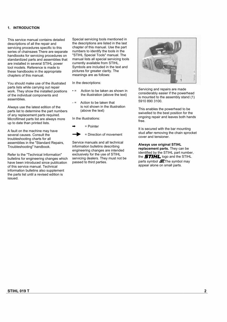
Servicing and repairs are madeconsiderably easier if the powerheadis mounted to the assembly stand (1)5910 890 3100.
This enables the powerhead to beswivelled to the best position for theongoing repair and leaves both handsfree.
It is secured with the bar mountingstud after removing the chain sprocketcover and tensioner.
Always use original STIHLreplacement parts. They can beidentified by the STIHL part number,the STIHLSTIHLSTIHLSTIHL logo and the STIHLparts symbol (The symbol mayappear alone on small parts.

STIHL 019 T 3
2. SPECIFICATIONS
2.1 Engine STIHL single cylinder two-stroke engine with specialimpregnated cylinder bore
Displacement:Bore:Stroke:Engine power to ISO 8893:Max. engine speedwith bar and chain:Idle speed:Bearings:
Piston pin diameter:Connecting rod length:Rewind starter:Reserve pull on rope rotor:Starter rope:
Clutch:Diameter:Clutch engages at:Crankcase leakage testat gauge pressure:under vacuum:
35.2 cm3 (2.15 cu.in)40 mm (1.57 in)28 mm (1.10 in)1.2 kW (1.6 bhp)
12,000 rpm2,800 rpmCrankshaft supported in heavy-duty ball bearings, needle cageson small and big ends8 mm (0.3 in)51 mm (2 in)Single pawl systemmin. 1/2 turn3.0 mm (0.12 in) dia.,800 mm (31.5 in) longCentrifugal clutch without linings64 mm (2.52 in)3,700 rpm
0.5 bar (7.25 psi)0.4 bar (5.8 psi)
Carburetor:Standard settingHigh speed screw H:Low speed screw L:Carburetor leakage testat gauge pressure:Fuel tank capacity:Octane number:
Fuel mixture:
Mix ratio:
Air filter:
Diaphragm carburetor
Open approx. 1 turnOpen approx. 1 turn
0.4 bar (4.8 psi)0.29 1 (0.61 US pt)min. 90 RON (US/CAN: pumpoctane min. 87 unleaded)Regular brand-name gasolineand two-stroke engine oil1:50 with STIHL 50:1 two-strokeengine oil25:1 with other brand-nametwo-stroke, air-cooled engine oilsFelt element
2.2 Fuel System
STIHL 019 T 4
STIHL repair kit6-tooth 3/8" P spur sprocket8-tooth 1/4" spur sprocketElastoStart
Carburetor parts kit
1132 900 50001123 640 20051123 640 20100000 190 3400
1132 007 1060
2.5 Special Accessories
2.5.1 For User
2.5.2 For Service
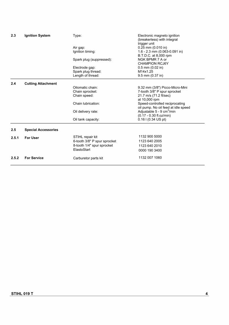
2.3 Ignition System
2.4 Cutting Attachment
Electronic magneto ignition(breakerless) with integraltrigger unit0.25 mm (0.010 in)1.6 - 2.3 mm (0.063-0.091 in)B.T.D.C. at 8,000 rpmNGK BPMR 7 A orCHAMPION RCJ6Y0.5 mm (0.02 in)M14x1.259.5 mm (0.37 in)
9.32 mm (3/8") Picco-Micro-Mini7-tooth 3/8" P spur sprocket21.7 m/s (71.2 ft/sec)at 10,000 rpmSpeed-controlled reciprocatingoil pump. No oil feed at idle speedAdjustable 5 - 9 cm3/min(0.17 - 0.30 fl.oz/min)0.16 l (0.34 US pt)
Type:
Air gap:Ignition timing:
Spark plug (suppressed):
Electrode gap:Spark plug thread:Length of thread:
Oilomatic chain:Chain sprocket:Chain speed:
Chain lubrication:
Oil delivery rate:
Oil tank capacity:
STIHL 019 T 5
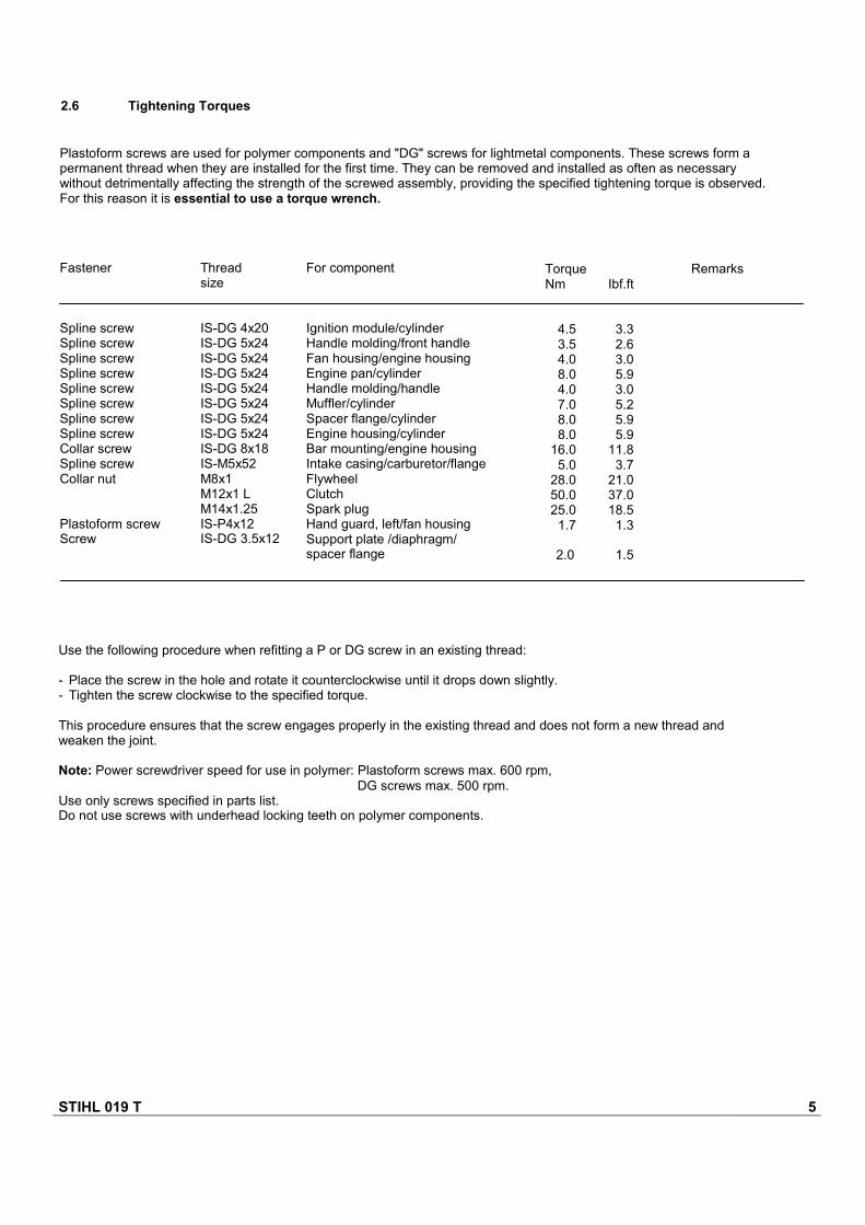
2.6 Tightening Torques
Plastoform screws are used for polymer components and "DG" screws for lightmetal components. These screws form apermanent thread when they are installed for the first time. They can be removed and installed as often as necessarywithout detrimentally affecting the strength of the screwed assembly, providing the specified tightening torque is observed.For this reason it is essential to use a torque wrench.
Fastener
Spline screwSpline screwSpline screwSpline screwSpline screwSpline screwSpline screwSpline screwCollar screwSpline screwCollar nut
Plastoform screwScrew
Threadsize
IS-DG 4x20IS-DG 5x24IS-DG 5x24IS-DG 5x24IS-DG 5x24IS-DG 5x24IS-DG 5x24IS-DG 5x24IS-DG 8x18IS-M5x52M8x1M12x1 LM14x1.25IS-P4x12IS-DG 3.5x12
For component
Ignition module/cylinderHandle molding/front handleFan housing/engine housingEngine pan/cylinderHandle molding/handleMuffler/cylinderSpacer flange/cylinderEngine housing/cylinderBar mounting/engine housingIntake casing/carburetor/flangeFlywheelClutchSpark plugHand guard, left/fan housingSupport plate /diaphragm/spacer flange
TorqueNm Ibf.ft
4.5 3.33.5 2.64.0 3.08.0 5.94.0 3.07.0 5.28.0 5.98.0 5.9
16.0 11.85.0 3.7
28.0 21.050.0 37.025.0 18.5
1.7 1.3
2.0 1.5
Remarks
Use the following procedure when refitting a P or DG screw in an existing thread:
- Place the screw in the hole and rotate it counterclockwise until it drops down slightly.- Tighten the screw clockwise to the specified torque.
This procedure ensures that the screw engages properly in the existing thread and does not form a new thread andweaken the joint.
Note: Power screwdriver speed for use in polymer: Plastoform screws max. 600 rpm,DG screws max. 500 rpm.
Use only screws specified in parts list.Do not use screws with underhead locking teeth on polymer components.
STIHL 019 T 6
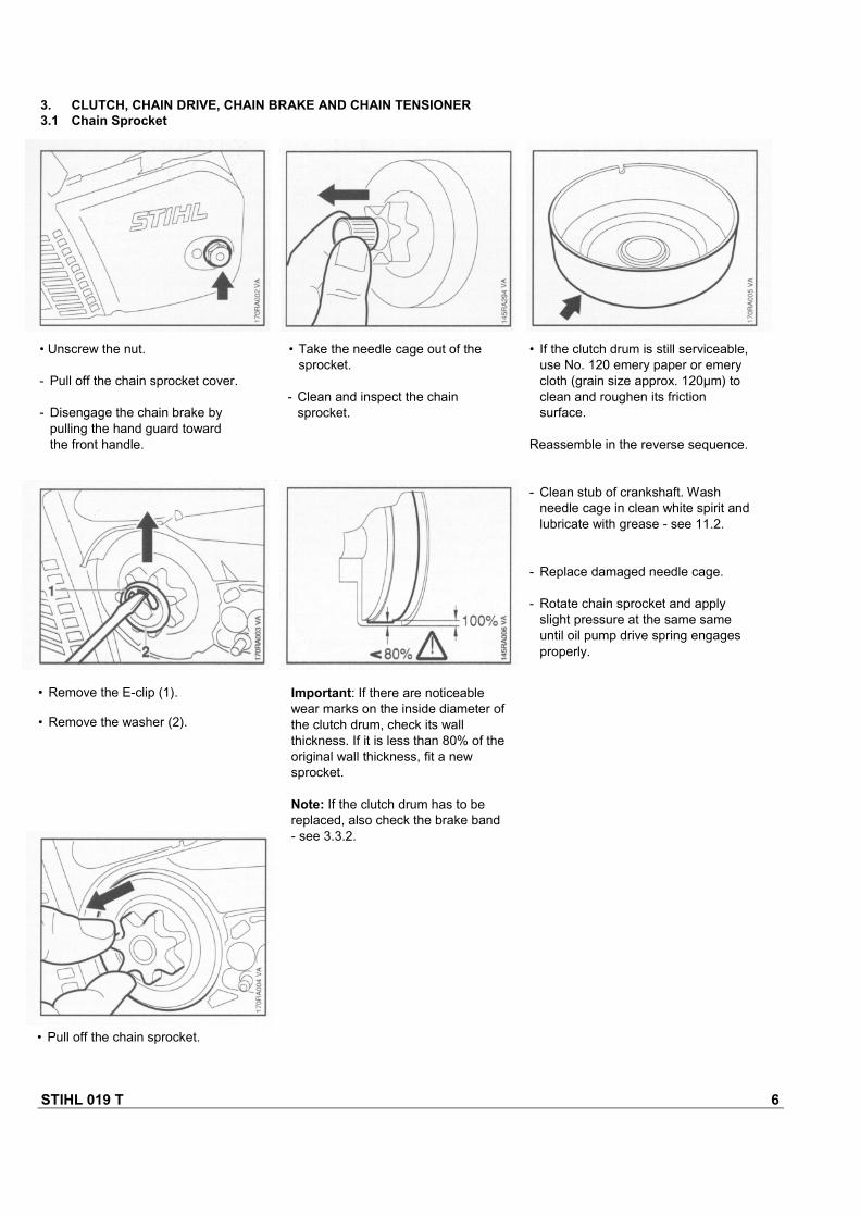
• Remove the E-clip (1).
• Remove the washer (2).
• Pull off the chain sprocket.
• If the clutch drum is still serviceable,use No. 120 emery paper or emerycloth (grain size approx. 120µm) toclean and roughen its frictionsurface.
Reassemble in the reverse sequence.
- Clean stub of crankshaft. Washneedle cage in clean white spirit and lubricate with grease - see 11.2.
- Replace damaged needle cage.
- Rotate chain sprocket and applyslight pressure at the same sameuntil oil pump drive spring engagesproperly.
• Take the needle cage out of thesprocket.
- Clean and inspect the chainsprocket.
• Unscrew the nut.
- Pull off the chain sprocket cover.
- Disengage the chain brake bypulling the hand guard towardthe front handle.
3. CLUTCH, CHAIN DRIVE, CHAIN BRAKE AND CHAIN TENSIONER3.1 Chain Sprocket
Important: If there are noticeablewear marks on the inside diameter ofthe clutch drum, check its wallthickness. If it is less than 80% of theoriginal wall thickness, fit a newsprocket.
Note: If the clutch drum has to bereplaced, also check the brake band- see 3.3.2.
STIHL 019 T 7
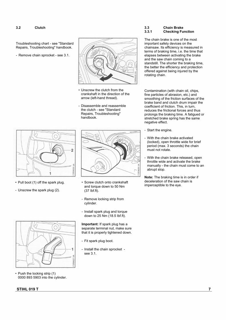
3.2 Clutch
Troubleshooting chart - see "StandardRepairs, Troubleshooting" handbook.
- Remove chain sprocket - see 3.1.
3.3 Chain Brake3.3.1 Checking Function
The chain brake is one of the mostimportant safety devices on thechainsaw. Its efficiency is measured interms of braking time, i.e. the time thatelapses between activating the brakeand the saw chain coming to astandstill. The shorter the braking time,the better the efficiency and protectionoffered against being injured by therotating chain.
Contamination (with chain oil, chips,fine particles of abrasion, etc.) andsmoothing of the friction surfaces of thebrake band and clutch drum impair thecoefficient of friction. This, in turn,reduces the frictional forces and thusprolongs the braking time. A fatigued orstretched brake spring has the samenegative effect.
- Start the engine.
- With the chain brake activated(locked), open throttle wide for briefperiod (max. 3 seconds) the chainmust not rotate.
- With the chain brake released, openthrottle wide and activate the brakemanually - the chain must come to anabrupt stop.
Note: The braking time is in order ifdeceleration of the saw chain isimperceptible to the eye.
• Pull boot (1) off the spark plug.
- Unscrew the spark plug (2).
• Push the locking strip (1)0000 893 5903 into the cylinder.
• Unscrew the clutch from thecrankshaft in the direction of thearrow (left-hand thread).
- Disassemble and reassemblethe clutch - see "StandardRepairs, Troubleshooting"handbook.
• Screw clutch onto crankshaftand torque down to 50 Nm(37 Ibf.ft).
- Remove locking strip fromcylinder.
- Install spark plug and torquedown to 25 Nm (18.5 Ibf.ft).
Important: If spark plug has aseparate terminal nut, make surethat it is properly tightened down.
- Fit spark plug boot.
- Install the chain sprocket -see 3.1.
STIHL 019 T 8
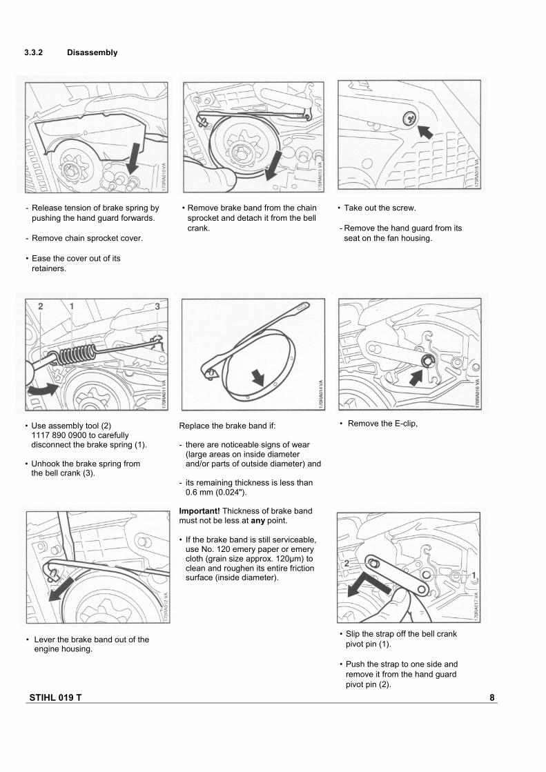
• Lever the brake band out of theengine housing.
• Slip the strap off the bell crankpivot pin (1).
• Push the strap to one side andremove it from the hand guardpivot pin (2).
Replace the brake band if:
- there are noticeable signs of wear(large areas on inside diameterand/or parts of outside diameter) and
- its remaining thickness is less than0.6 mm (0.024").
Important! Thickness of brake bandmust not be less at any point.
• If the brake band is still serviceable,use No. 120 emery paper or emerycloth (grain size approx. 120µm) toclean and roughen its entire frictionsurface (inside diameter).
• Take out the screw.
- Remove the hand guard from itsseat on the fan housing.
• Remove brake band from the chainsprocket and detach it from the bellcrank.
- Release tension of brake spring bypushing the hand guard forwards.
- Remove chain sprocket cover.
• Ease the cover out of itsretainers.
3.3.2 Disassembly
• Use assembly tool (2)1117 890 0900 to carefullydisconnect the brake spring (1).
• Unhook the brake spring fromthe bell crank (3).
• Remove the E-clip,
STIHL 019 T 9
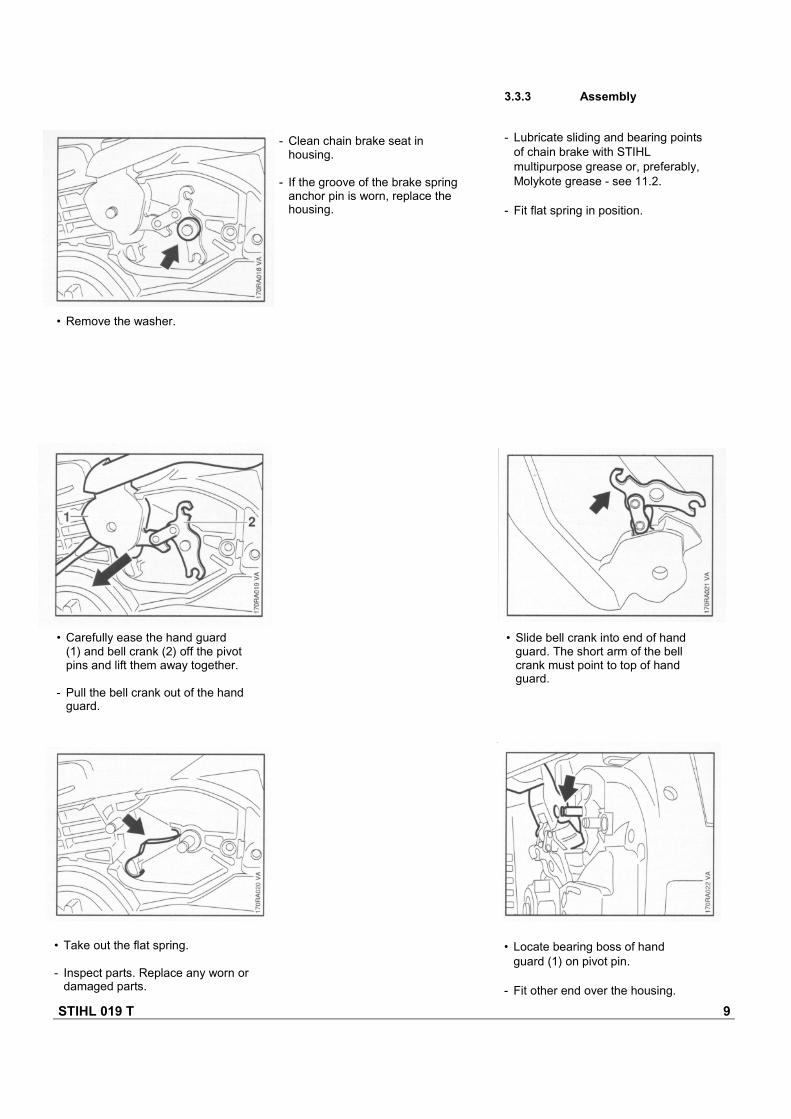
- Clean chain brake seat inhousing.
- If the groove of the brake springanchor pin is worn, replace thehousing.
3.3.3 Assembly
- Lubricate sliding and bearing pointsof chain brake with STIHLmultipurpose grease or, preferably,Molykote grease - see 11.2.
- Fit flat spring in position.
• Remove the washer.
• Carefully ease the hand guard(1) and bell crank (2) off the pivotpins and lift them away together.
- Pull the bell crank out of the handguard.
• Take out the flat spring.
- Inspect parts. Replace any worn ordamaged parts.
• Locate bearing boss of handguard (1) on pivot pin.
- Fit other end over the housing.
• Slide bell crank into end of handguard. The short arm of the bellcrank must point to top of hand guard.
STIHL 019 T 10
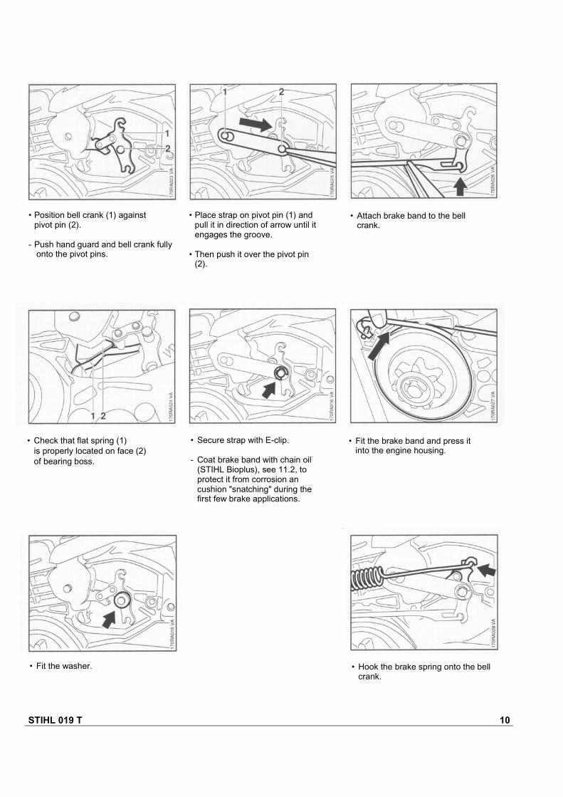
• Fit the washer. • Hook the brake spring onto the bellcrank.
• Fit the brake band and press itinto the engine housing.
• Secure strap with E-clip.
- Coat brake band with chain oil(STIHL Bioplus), see 11.2, toprotect it from corrosion ancushion "snatching" during thefirst few brake applications.
• Check that flat spring (1)is properly located on face (2)of bearing boss.
• Attach brake band to the bellcrank.
• Place strap on pivot pin (1) andpull it in direction of arrow until itengages the groove.
• Then push it over the pivot pin(2).
• Position bell crank (1) againstpivot pin (2).
- Push hand guard and bell crank fullyonto the pivot pins.

STIHL 019 T 11
3.4 Chain Tensioner 3.5 Bar Stud
• Use the assembly tool (2)1117 890 0900 to attach thebrake spring (1) to the anchorpin.
- Remove the chain sprocket cover.
• Pull the cover out of the enginehousing.
- Remove the chain sprocket cover.
• Push the stud puller (1)5910 893 0501 onto the stud as faras it will go.
• Unscrew the stud.
- Insert stud and torque down to16 Nm (11.8 Ibf.ft).
• Push cover over chain brake untilit snaps into position and then tapit home carefully with a plasticmallet.
• Unscrew the nut (1) from theadjusting screw (2).
• Take the adjusting screw out of thecover (3).
Reverse the above sequence toinstall the chain tensioner.
• Fit hand guard (1) over boss (2)on the fan housing.
- Insert screw and tighten to1.7 Nm (1.25 Ibf.ft).
STIHL 019 T 12
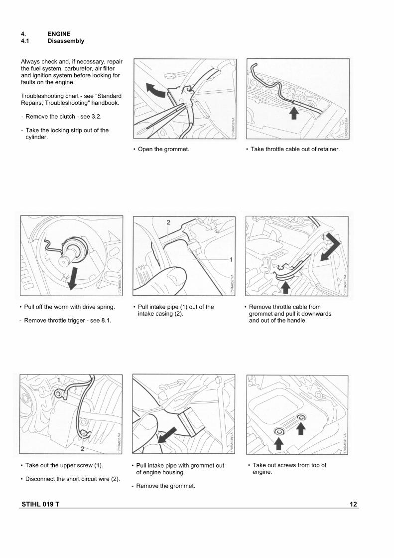
• Take out the upper screw (1).
• Disconnect the short circuit wire (2).
• Pull intake pipe with grommet outof engine housing.
- Remove the grommet.
• Take out screws from top ofengine.
• Remove throttle cable fromgrommet and pull it downwardsand out of the handle.
• Pull intake pipe (1) out of theintake casing (2).
• Pull off the worm with drive spring.
- Remove throttle trigger - see 8.1.
4. ENGINE4.1 Disassembly
Always check and, if necessary, repairthe fuel system, carburetor, air filterand ignition system before looking forfaults on the engine.
Troubleshooting chart - see "StandardRepairs, Troubleshooting" handbook.
- Remove the clutch - see 3.2.
- Take the locking strip out of thecylinder.
• Open the grommet. • Take throttle cable out of retainer.
STIHL 019 T 13
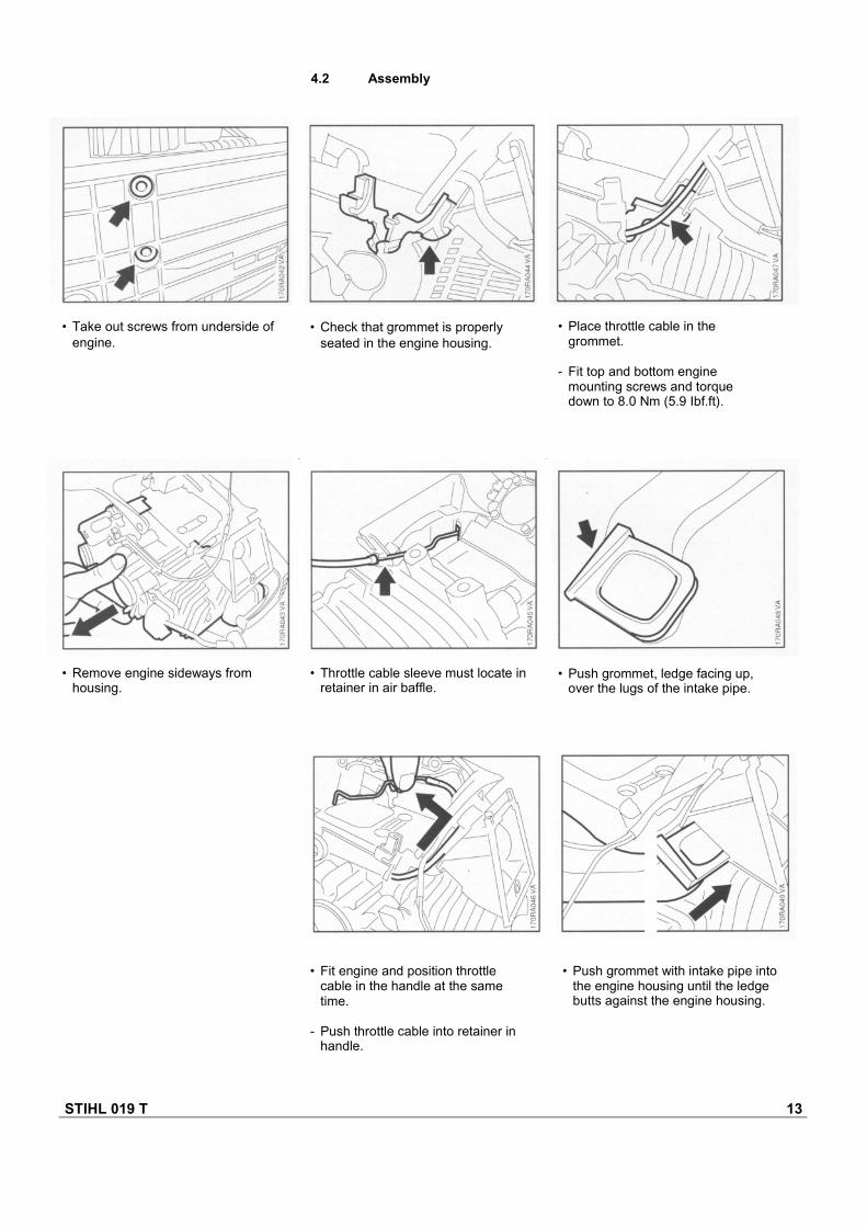
4.2 Assembly
• Take out screws from underside ofengine.
• Check that grommet is properlyseated in the engine housing.
• Place throttle cable in thegrommet.
- Fit top and bottom enginemounting screws and torquedown to 8.0 Nm (5.9 Ibf.ft).
• Remove engine sideways fromhousing.
• Throttle cable sleeve must locate inretainer in air baffle.
• Push grommet, ledge facing up,over the lugs of the intake pipe.
• Fit engine and position throttlecable in the handle at the sametime.
- Push throttle cable into retainer inhandle.
• Push grommet with intake pipe intothe engine housing until the ledgebutts against the engine housing.

STIHL 019 T 14
• Fit the short circuit and groundwires (pull them downward and outof handle as far as possible) in thegrommet and close the grommet.
- Connect short circuit and groundwires to ignition module.
- Fit throttle trigger - see 8.1.
- Fit the worm with drive spring inposition.
- Install the clutch - see 3.2.
• Remove the spark arresting screen.
- Clean the spark arresting screen orfit a new one if necessary.
• Remove the cover plate.
Muffler
- Remove the engine - see 4.1.
• Take out the screws.
- Remove the muffler.
Reassemble in the reversesequence.
- Tighten screws to 7.0 Nm(5.2 Ibf.ft).
- Install the engine - see 4.2.
Spark arresting screen
• Take out the screw.
• Fit the intake pipe (1) in theintake casing (2).
4.3 Exhaust Muffler/Spark Arresting Screen
STIHL 019 T 15
4.4 Leakage Test
Defective oil seals, diaphragms andgaskets or cracks in castings or thespacer flange cause leaks. Suchfaults allow supplementary air toenter the engine and thus upset thefuel-air mixture.
This makes adjustment of theprescribed idle speed difficult, if notimpossible.
Moreover, the transition from idlespeed to part or full throttle is notsmooth.
The engine housing can be checkedthoroughly for leaks with thecarburetor and crankcase tester andthe vacuum pump.
4.4.1 Preparations
- Remove the carburetor - see 1 0.5.2.
- Set the piston to top dead center(T.D.C.). This can be checkedthrough the spark plug hole.
- Remove the air baffle - see 10.6.
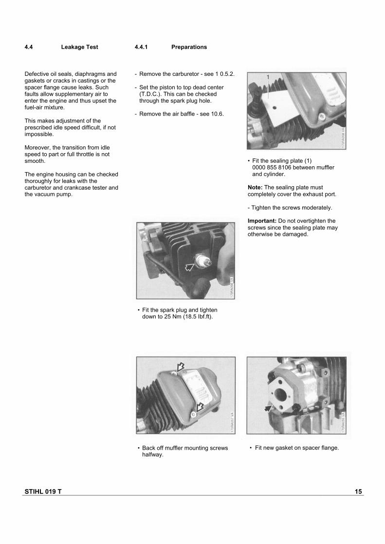
• Fit the spark plug and tightendown to 25 Nm (18.5 Ibf.ft).
• Back off muffler mounting screwshalfway.
• Fit new gasket on spacer flange.
• Fit the sealing plate (1)0000 855 8106 between mufflerand cylinder.
Note: The sealing plate mustcompletely cover the exhaust port.
- Tighten the screws moderately.
Important: Do not overtighten thescrews since the sealing plate mayotherwise be damaged.
STIHL 019 T 16
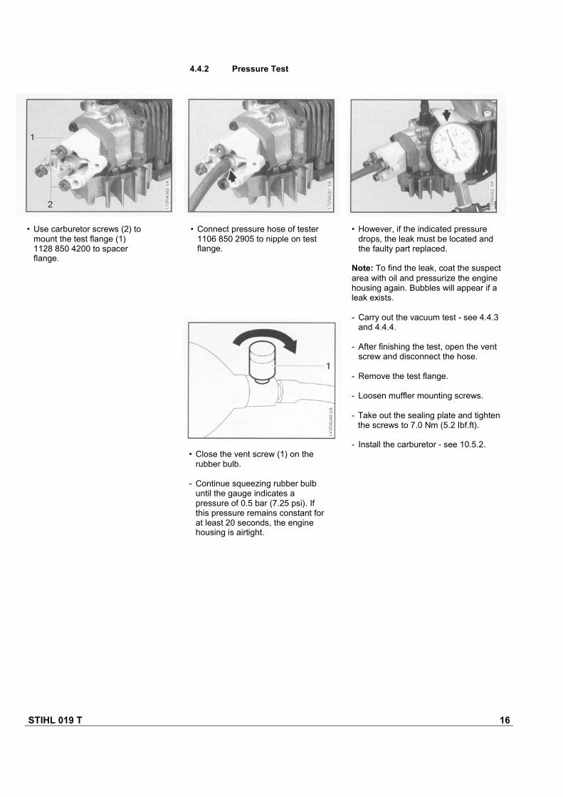
• Close the vent screw (1) on therubber bulb.
- Continue squeezing rubber bulbuntil the gauge indicates apressure of 0.5 bar (7.25 psi). Ifthis pressure remains constant forat least 20 seconds, the enginehousing is airtight.
• However, if the indicated pressuredrops, the leak must be located andthe faulty part replaced.
Note: To find the leak, coat the suspectarea with oil and pressurize the enginehousing again. Bubbles will appear if aleak exists.
- Carry out the vacuum test - see 4.4.3and 4.4.4.
- After finishing the test, open the ventscrew and disconnect the hose.
- Remove the test flange.
- Loosen muffler mounting screws.
- Take out the sealing plate and tightenthe screws to 7.0 Nm (5.2 Ibf.ft).
- Install the carburetor - see 10.5.2.
• Connect pressure hose of tester1106 850 2905 to nipple on testflange.
• Use carburetor screws (2) tomount the test flange (1)1128 850 4200 to spacerflange.
4.4.2 Pressure Test
STIHL 019 T 17
4.4.3 Vacuum Test(for diaphragm)
In these chainsaws the fuel-airmixture is sucked into the crankcasevia a diaphragm valve. This valvecloses to prevent the gas mixtureflowing back into the carburetor.
If the diaphragm seating face on thespacer flange is dirty or thediaphragm is fatigued or faulty, themixture may flow back and result inan irregular running behavior.
A test can be carried out with thevacuum pump to detect this kind offault. The preparations for this testare the same as for the pressure test- see 4.4.1.
4.4.4 Vacuum Test(for oil seal)
Oil seals tend to fail when subjected toa vacuum, i.e. the sealing lip lifts awayfrom the crankshaft during the piston'sinduction stroke because there is nointernal counterpressure.
An additional test can be carried outwith the vacuum pump to detect thiskind of fault.
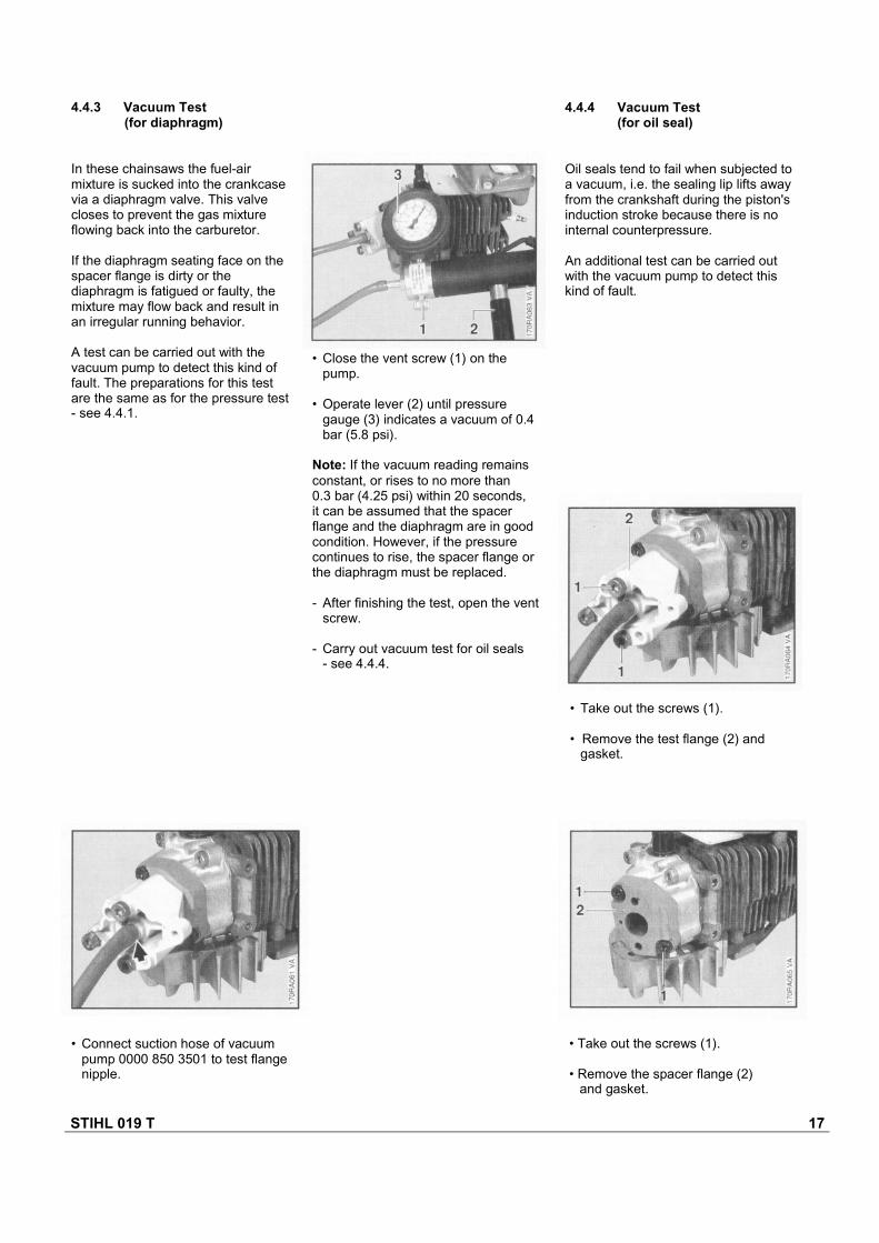
• Close the vent screw (1) on thepump.
• Operate lever (2) until pressuregauge (3) indicates a vacuum of 0.4bar (5.8 psi).
Note: If the vacuum reading remainsconstant, or rises to no more than0.3 bar (4.25 psi) within 20 seconds,it can be assumed that the spacerflange and the diaphragm are in goodcondition. However, if the pressurecontinues to rise, the spacer flange orthe diaphragm must be replaced.
- After finishing the test, open the ventscrew.
- Carry out vacuum test for oil seals- see 4.4.4.
• Take out the screws (1).
• Remove the test flange (2) andgasket.
• Take out the screws (1).
• Remove the spacer flange (2)and gasket.
• Connect suction hose of vacuumpump 0000 850 3501 to test flangenipple.
STIHL 019 T 18
- Fit test flange with suction hose ofvacuum pump 0000 850 3501 to thespacer flange.
- Remove the spacer flange.
- Fit the diaphragm and support plate- see 10.7.
- Fit the spacer flange - see 10.7.
- Loosen muffler mounting screws.
- Take out the sealing plate and tightenthe screws to 7.0 Nm (5.2 Ibf.ft).
- Install the carburetor - see 10.5.2.
• Check that gasket is in goodcondition or fit new one ifnecessary.
- Fit spacer flange, insert screwsand tighten down to 8.0 Nm(5.9 Ibf.ft).
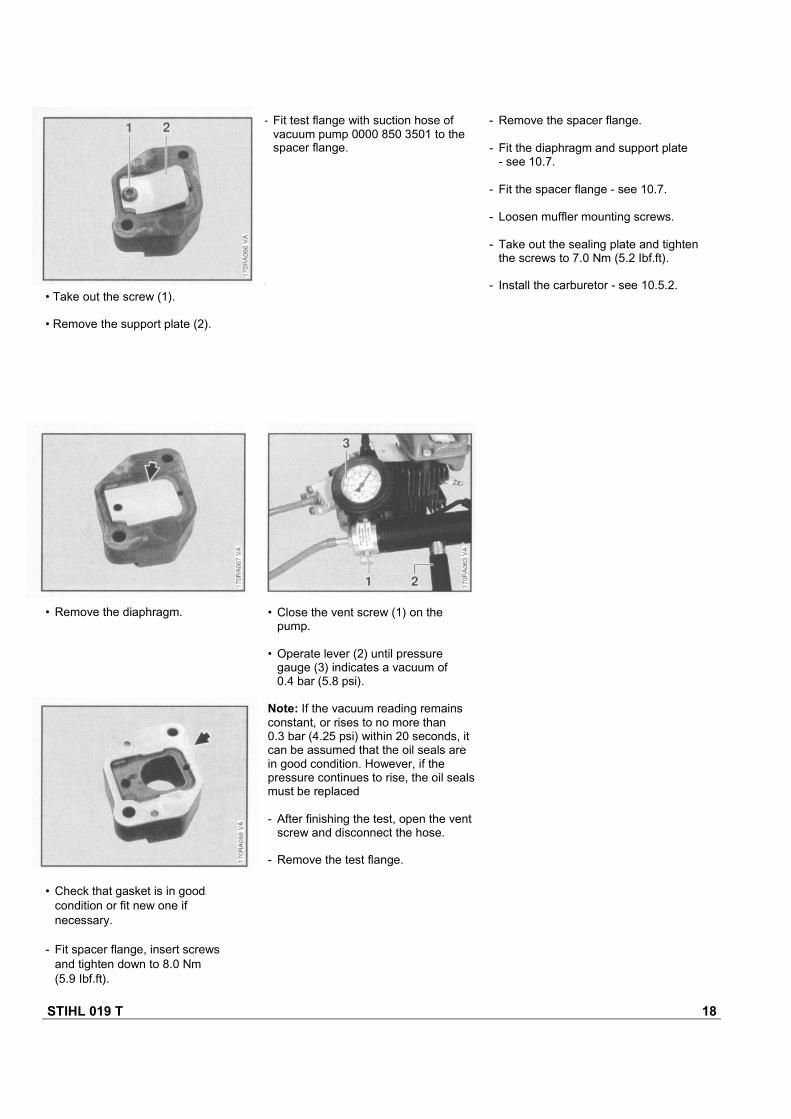
• Close the vent screw (1) on thepump.
• Operate lever (2) until pressuregauge (3) indicates a vacuum of0.4 bar (5.8 psi).
Note: If the vacuum reading remainsconstant, or rises to no more than0.3 bar (4.25 psi) within 20 seconds, itcan be assumed that the oil seals arein good condition. However, if thepressure continues to rise, the oil sealsmust be replaced
- After finishing the test, open the ventscrew and disconnect the hose.
- Remove the test flange.
• Remove the diaphragm.
• Take out the screw (1).
• Remove the support plate (2).
STIHL 019 T 19
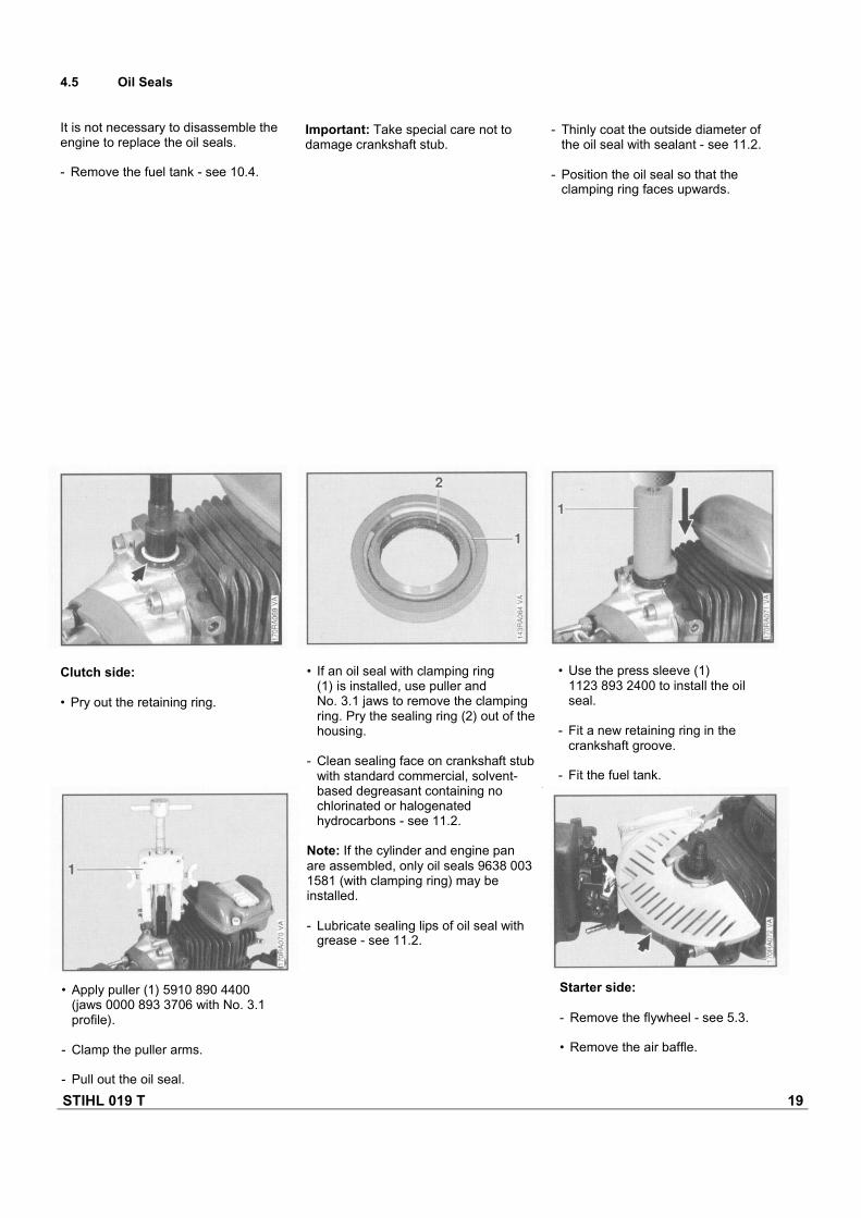
4.5 Oil Seals
It is not necessary to disassemble theengine to replace the oil seals.
- Remove the fuel tank - see 10.4.
Important: Take special care not todamage crankshaft stub.
- Thinly coat the outside diameter ofthe oil seal with sealant - see 11.2.
- Position the oil seal so that theclamping ring faces upwards.
Clutch side:
• Pry out the retaining ring.
• If an oil seal with clamping ring(1) is installed, use puller andNo. 3.1 jaws to remove the clampingring. Pry the sealing ring (2) out of thehousing.
- Clean sealing face on crankshaft stubwith standard commercial, solvent-based degreasant containing nochlorinated or halogenatedhydrocarbons - see 11.2.
Note: If the cylinder and engine panare assembled, only oil seals 9638 0031581 (with clamping ring) may beinstalled.
- Lubricate sealing lips of oil seal withgrease - see 11.2.
• Apply puller (1) 5910 890 4400(jaws 0000 893 3706 with No. 3.1profile).
- Clamp the puller arms.
- Pull out the oil seal.
Starter side:
- Remove the flywheel - see 5.3.
• Remove the air baffle.
• Use the press sleeve (1)1123 893 2400 to install the oilseal.
- Fit a new retaining ring in thecrankshaft groove.
- Fit the fuel tank.
STIHL 019 T 20
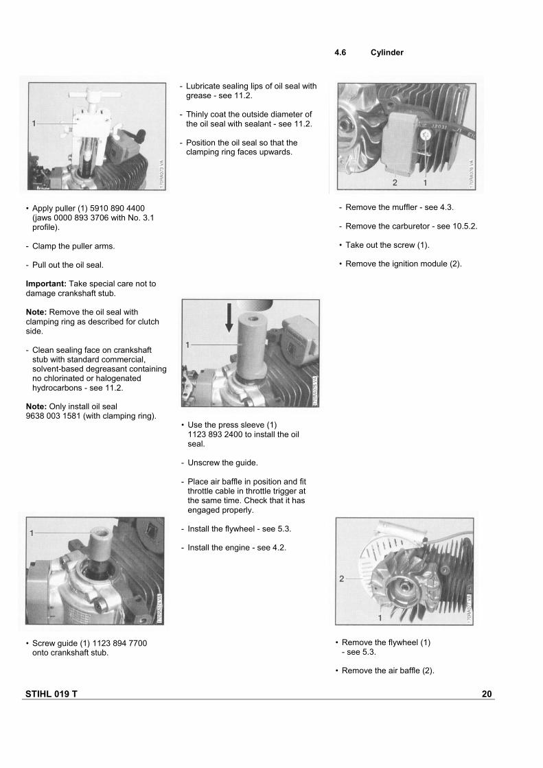
- Lubricate sealing lips of oil seal withgrease - see 11.2.
- Thinly coat the outside diameter ofthe oil seal with sealant - see 11.2.
- Position the oil seal so that theclamping ring faces upwards.
• Screw guide (1) 1123 894 7700onto crankshaft stub.
• Remove the flywheel (1)- see 5.3.
• Remove the air baffle (2).
• Use the press sleeve (1)1123 893 2400 to install the oilseal.
- Unscrew the guide.
- Place air baffle in position and fitthrottle cable in throttle trigger atthe same time. Check that it hasengaged properly.
- Install the flywheel - see 5.3.
- Install the engine - see 4.2.
- Remove the muffler - see 4.3.
- Remove the carburetor - see 10.5.2.
• Take out the screw (1).
• Remove the ignition module (2).
• Apply puller (1) 5910 890 4400(jaws 0000 893 3706 with No. 3.1profile).
- Clamp the puller arms.
- Pull out the oil seal.
Important: Take special care not todamage crankshaft stub.
Note: Remove the oil seal withclamping ring as described for clutchside.
- Clean sealing face on crankshaftstub with standard commercial,solvent-based degreasant containingno chlorinated or halogenatedhydrocarbons - see 11.2.
Note: Only install oil seal9638 003 1581 (with clamping ring).
4.6 Cylinder
STIHL 019 T 21
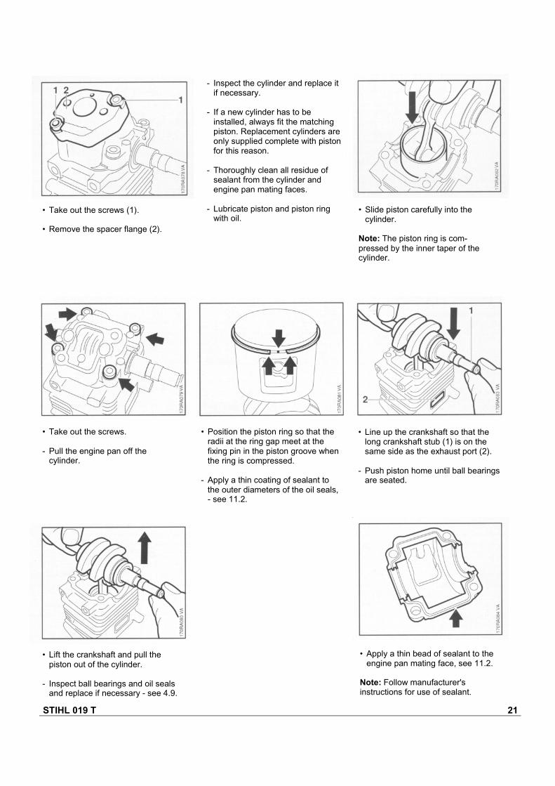
- Inspect the cylinder and replace itif necessary.
- If a new cylinder has to beinstalled, always fit the matchingpiston. Replacement cylinders areonly supplied complete with pistonfor this reason.
- Thoroughly clean all residue ofsealant from the cylinder andengine pan mating faces.
- Lubricate piston and piston ringwith oil.
• Slide piston carefully into thecylinder.
Note: The piston ring is com-pressed by the inner taper of thecylinder.
• Take out the screws (1).
• Remove the spacer flange (2).
• Take out the screws.
- Pull the engine pan off thecylinder.
• Lift the crankshaft and pull thepiston out of the cylinder.
- Inspect ball bearings and oil sealsand replace if necessary - see 4.9.
• Apply a thin bead of sealant to theengine pan mating face, see 11.2.
Note: Follow manufacturer'sinstructions for use of sealant.
• Line up the crankshaft so that thelong crankshaft stub (1) is on thesame side as the exhaust port (2).
- Push piston home until ball bearingsare seated.
• Position the piston ring so that theradii at the ring gap meet at thefixing pin in the piston groove whenthe ring is compressed.
- Apply a thin coating of sealant tothe outer diameters of the oil seals,- see 11.2.
STIHL 019 T 22
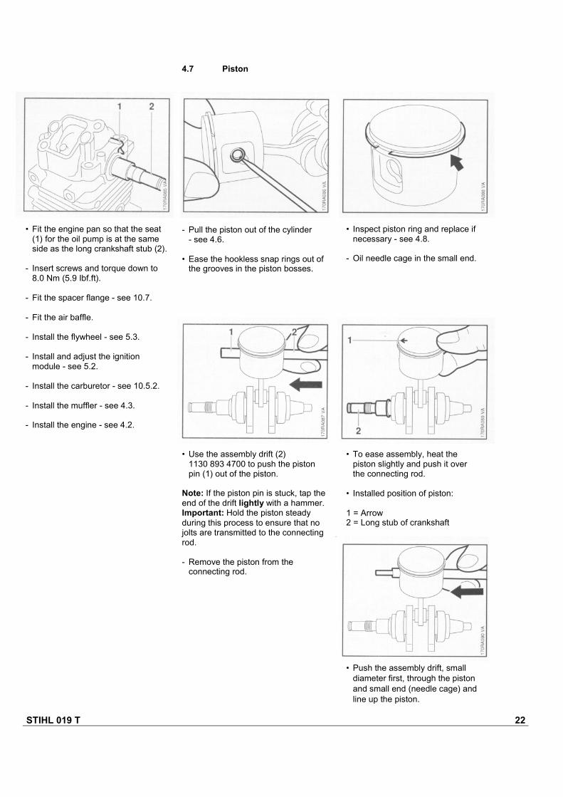
4.7 Piston
- Pull the piston out of the cylinder- see 4.6.
• Ease the hookless snap rings out ofthe grooves in the piston bosses.
• Inspect piston ring and replace ifnecessary - see 4.8.
- Oil needle cage in the small end.
• Fit the engine pan so that the seat(1) for the oil pump is at the sameside as the long crankshaft stub (2).
- Insert screws and torque down to8.0 Nm (5.9 Ibf.ft).
- Fit the spacer flange - see 10.7.
- Fit the air baffle.
- Install the flywheel - see 5.3.
- Install and adjust the ignitionmodule - see 5.2.
- Install the carburetor - see 10.5.2.
- Install the muffler - see 4.3.
- Install the engine - see 4.2.
• Use the assembly drift (2)1130 893 4700 to push the pistonpin (1) out of the piston.
Note: If the piston pin is stuck, tap theend of the drift lightly with a hammer.Important: Hold the piston steadyduring this process to ensure that nojolts are transmitted to the connectingrod.
- Remove the piston from theconnecting rod.
• To ease assembly, heat thepiston slightly and push it overthe connecting rod.
• Installed position of piston:
1 = Arrow2 = Long stub of crankshaft
• Push the assembly drift, smalldiameter first, through the pistonand small end (needle cage) andline up the piston.
STIHL 019 T 23
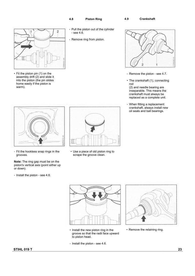
4.9 Crankshaft4.8 Piston Ring
- Pull the piston out of the cylinder- see 4.6.
- Remove ring from piston.
- Fit the hookless snap rings in thegrooves.
Note: The ring gap must be on thepiston's vertical axis (point either upor down).
- Install the piston - see 4.6.
• Use a piece of old piston ring toscrape the groove clean.
• Install the new piston ring in thegroove so that the radii face upwardto piston head.
- Install the piston - see 4.6.
• Remove the retaining ring.
• Fit the piston pin (1) on theassembly drift (2) and slide itinto the piston (the pin slideshome easily if the piston iswarm).
- Remove the piston - see 4.7.
• The crankshaft (1), connectingrod(2) and needle bearing areinseparable. This means thecrankshaft must always bereplaced as a complete unit.
- When fitting a replacementcrankshaft, always install newoil seals and ball bearings.
STIHL 019 T 24
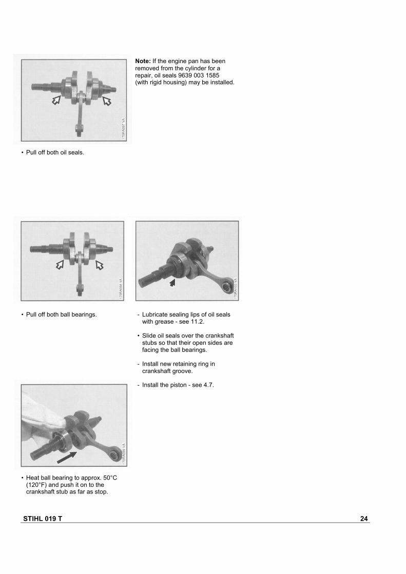
Note: If the engine pan has beenremoved from the cylinder for arepair, oil seals 9639 003 1585(with rigid housing) may be installed.
• Pull off both oil seals.
• Pull off both ball bearings. - Lubricate sealing lips of oil sealswith grease - see 11.2.
• Slide oil seals over the crankshaftstubs so that their open sides arefacing the ball bearings.
- Install new retaining ring incrankshaft groove.
- Install the piston - see 4.7.
• Heat ball bearing to approx. 50°C(120°F) and push it on to thecrankshaft stub as far as stop.
STIHL 019 T 25
5.1 Spark Plug Boot5. IGNITION SYSTEM
Warning! Exercise extreme cautionwhen carrying out maintenance andrepair work on the ignition system.The high voltages which occur cancause serious or even fatalaccidents!
Troubleshooting on the ignitionsystem should always begin at thespark plug. See "General Servicing,Troubleshooting" handbook.
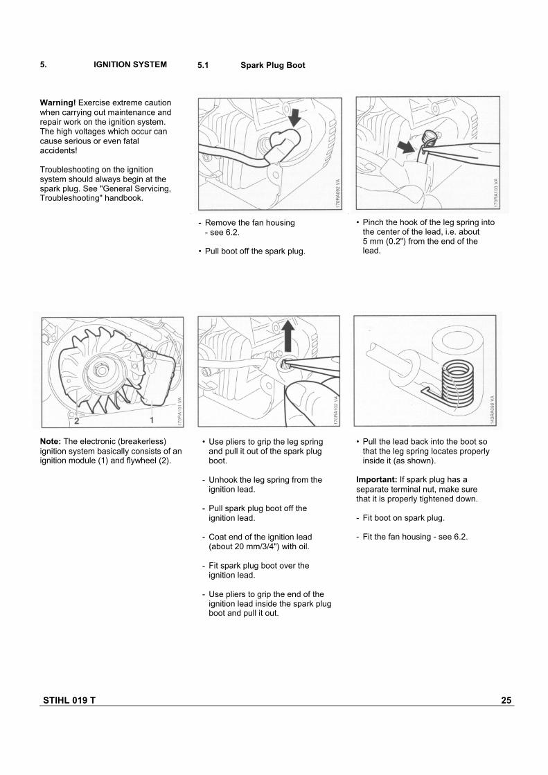
- Remove the fan housing- see 6.2.
• Pull boot off the spark plug.
Note: The electronic (breakerless)ignition system basically consists of anignition module (1) and flywheel (2).
• Use pliers to grip the leg springand pull it out of the spark plugboot.
- Unhook the leg spring from theignition lead.
- Pull spark plug boot off theignition lead.
- Coat end of the ignition lead(about 20 mm/3/4") with oil.
- Fit spark plug boot over theignition lead.
- Use pliers to grip the end of theignition lead inside the spark plugboot and pull it out.
• Pull the lead back into the boot sothat the leg spring locates properlyinside it (as shown).
Important: If spark plug has aseparate terminal nut, make surethat it is properly tightened down.
- Fit boot on spark plug.
- Fit the fan housing - see 6.2.
• Pinch the hook of the leg spring intothe center of the lead, i.e. about5 mm (0.2") from the end of thelead.
STIHL 019 T 26
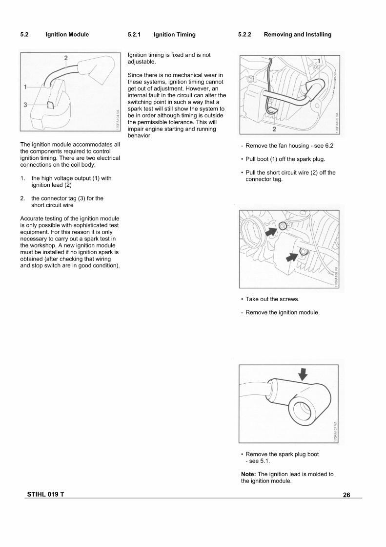
- Remove the fan housing - see 6.2
• Pull boot (1) off the spark plug.
• Pull the short circuit wire (2) off theconnector tag.
5.2 Ignition Module 5.2.1 Ignition Timing
Ignition timing is fixed and is notadjustable.
Since there is no mechanical wear inthese systems, ignition timing cannotget out of adjustment. However, aninternal fault in the circuit can alter theswitching point in such a way that aspark test will still show the system tobe in order although timing is outsidethe permissible tolerance. This willimpair engine starting and runningbehavior.
5.2.2 Removing and Installing
• Take out the screws.
- Remove the ignition module.
• Remove the spark plug boot- see 5.1.
Note: The ignition lead is molded tothe ignition module.
The ignition module accommodates allthe components required to controlignition timing. There are two electricalconnections on the coil body:
1. the high voltage output (1) withignition lead (2)
2. the connector tag (3) for theshort circuit wire
Accurate testing of the ignition moduleis only possible with sophisticated testequipment. For this reason it is onlynecessary to carry out a spark test inthe workshop. A new ignition modulemust be installed if no ignition spark isobtained (after checking that wiringand stop switch are in good condition).
STIHL 019 T 27
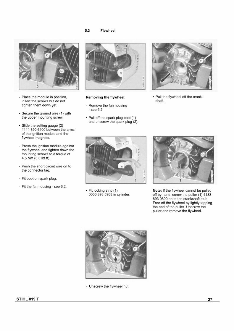
- Place the module in position,insert the screws but do nottighten them down yet.
• Secure the ground wire (1) withthe upper mounting screw.
• Slide the setting gauge (2)1111 890 6400 between the armsof the ignition module and theflywheel magnets.
- Press the ignition module againstthe flywheel and tighten down themounting screws to a torque of4.5 Nm (3.3 Ibf.ft).
- Push the short circuit wire on tothe connector tag.
- Fit boot on spark plug.
- Fit the fan housing - see 6.2.• Fit locking strip (1)
0000 893 5903 in cylinder.Note: If the flywheel cannot be pulledoff by hand, screw the puller (1) 4133893 0800 on to the crankshaft stub.Free off the flywheel by lightly tappingthe end of the puller. Unscrew thepuller and remove the flywheel.
Removing the flywheel:
- Remove the fan housing- see 6.2.
• Pull off the spark plug boot (1)and unscrew the spark plug (2).
• Pull the flywheel off the crank-shaft.
• Unscrew the flywheel nut.
5.3 Flywheel
STIHL 019 T 28
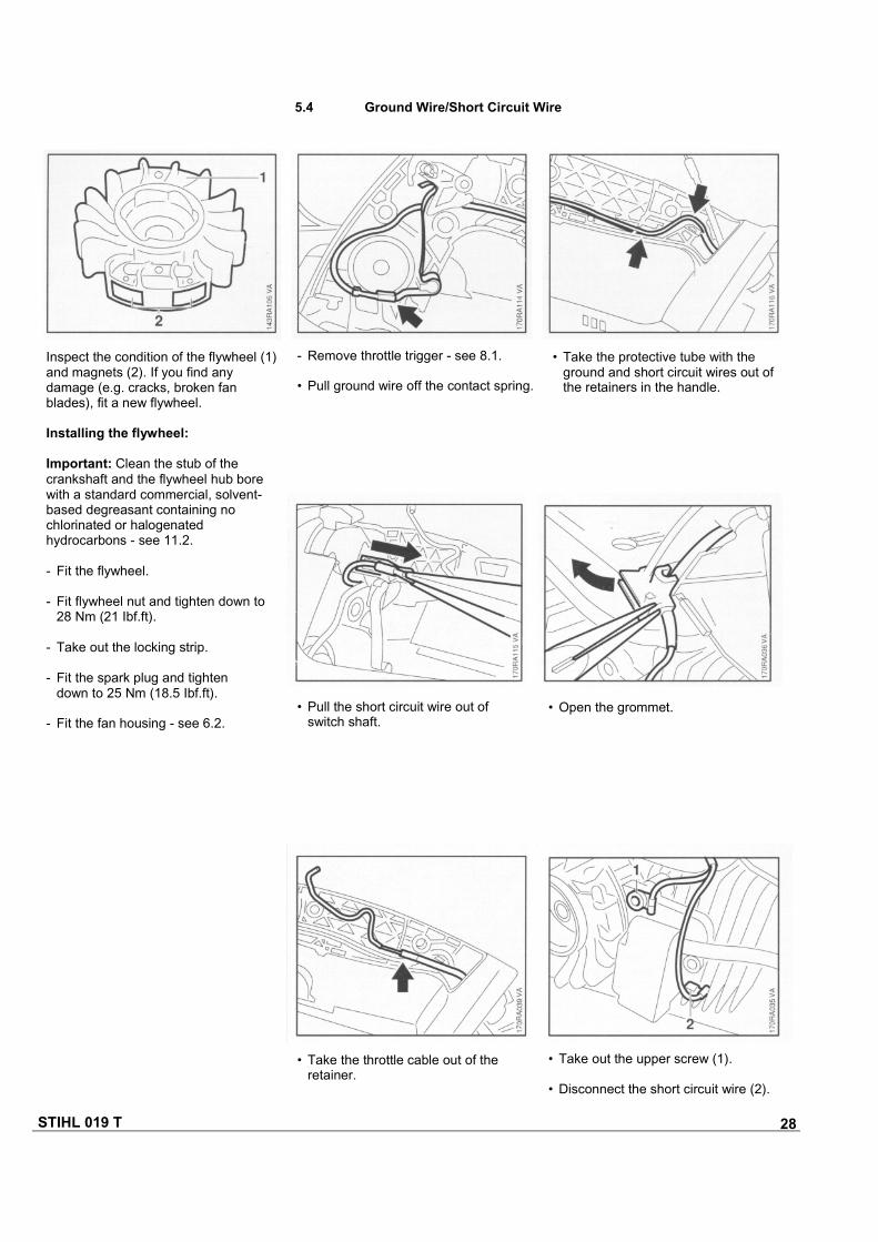
• Pull the short circuit wire out ofswitch shaft.
• Open the grommet.
• Take the throttle cable out of theretainer.
• Take out the upper screw (1).
• Disconnect the short circuit wire (2).
5.4 Ground Wire/Short Circuit Wire
• Take the protective tube with theground and short circuit wires out ofthe retainers in the handle.
- Remove throttle trigger - see 8.1.
• Pull ground wire off the contact spring.
Inspect the condition of the flywheel (1)and magnets (2). If you find anydamage (e.g. cracks, broken fanblades), fit a new flywheel.
Installing the flywheel:
Important: Clean the stub of thecrankshaft and the flywheel hub borewith a standard commercial, solvent-based degreasant containing nochlorinated or halogenatedhydrocarbons - see 11.2.
- Fit the flywheel.
- Fit flywheel nut and tighten down to28 Nm (21 Ibf.ft).
- Take out the locking strip.
- Fit the spark plug and tightendown to 25 Nm (18.5 Ibf.ft).
- Fit the fan housing - see 6.2.
STIHL 019 T 29
5.5 Contact Spring
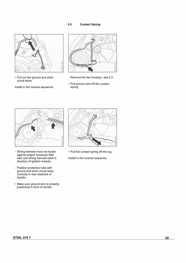
• Pull out the ground and shortcircuit wires.
Install in the reverse sequence.
- Remove the fan housing - see 6.2.
• Pull ground wire off the contactspring.
- Wiring harness must not locateagainst engine housing's filterwall; pull wiring harness back indirection of ignition module.
- Position protective tube withground and short circuit wirescorrectly in rear retainers ofhandle.
• Make sure ground wire is properlypositioned in front of handle.
• Pull the contact spring off the lug.
Install in the reverse sequence.
STIHL 019 T 30
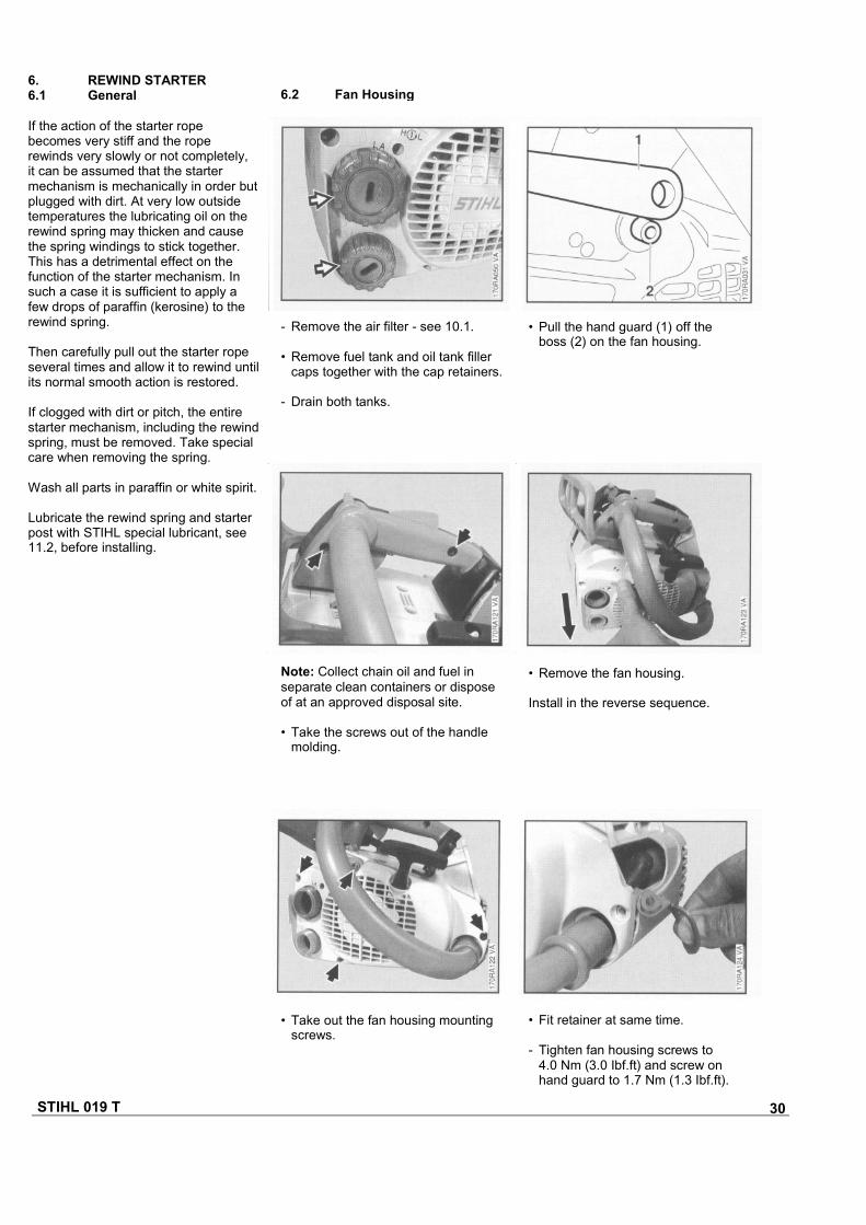
Note: Collect chain oil and fuel inseparate clean containers or disposeof at an approved disposal site.
• Take the screws out of the handlemolding.
• Remove the fan housing.
Install in the reverse sequence.
• Take out the fan housing mountingscrews.
• Fit retainer at same time.
- Tighten fan housing screws to4.0 Nm (3.0 Ibf.ft) and screw onhand guard to 1.7 Nm (1.3 Ibf.ft).
6.2 Fan Housing
• Pull the hand guard (1) off theboss (2) on the fan housing.
- Remove the air filter - see 10.1.
• Remove fuel tank and oil tank fillercaps together with the cap retainers.
- Drain both tanks.
6. REWIND STARTER6.1 General
If the action of the starter ropebecomes very stiff and the roperewinds very slowly or not completely,it can be assumed that the startermechanism is mechanically in order butplugged with dirt. At very low outsidetemperatures the lubricating oil on therewind spring may thicken and causethe spring windings to stick together.This has a detrimental effect on thefunction of the starter mechanism. Insuch a case it is sufficient to apply afew drops of paraffin (kerosine) to therewind spring.
Then carefully pull out the starter ropeseveral times and allow it to rewind untilits normal smooth action is restored.
If clogged with dirt or pitch, the entirestarter mechanism, including the rewindspring, must be removed. Take specialcare when removing the spring.
Wash all parts in paraffin or white spirit.
Lubricate the rewind spring and starterpost with STIHL special lubricant, see11.2, before installing.
STIHL 019 T 31
6.3 Rewind Spring6.3.1 Replacing
Troubleshooting chart - see"General Servicing, Troubleshooting"handbook.
- Remove the fan housing -see 6.2.
- Remove the rope rotor, see"General Servicing, Troubleshooting"handbook, use pliers to remove anyremaining pieces of spring from thefan housing.
Note: The replacement spring comesready for installation and is heldtogether by a wire retainer.
- It should be lubricated with a fewdrops of STIHL special lubricantbefore installation - see 11.2.
- The wire retainer slips off as therewind spring is pressed into the fanhousing.
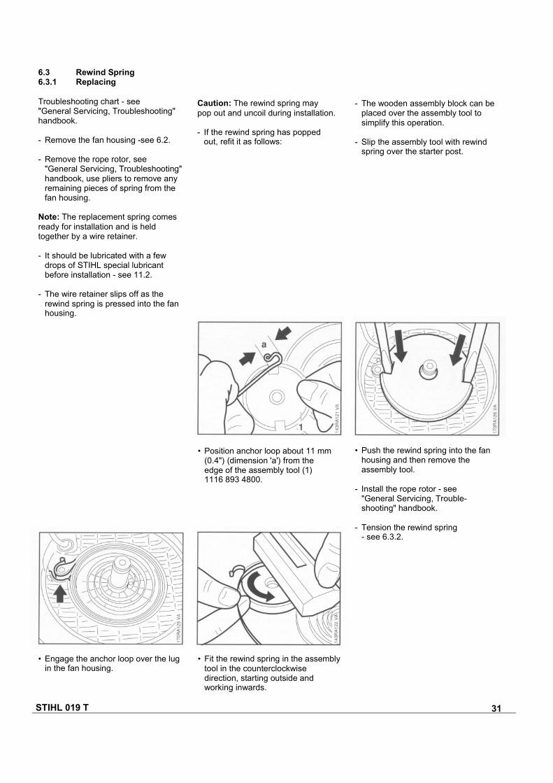
Caution: The rewind spring maypop out and uncoil during installation.
- If the rewind spring has poppedout, refit it as follows:
- The wooden assembly block can beplaced over the assembly tool tosimplify this operation.
- Slip the assembly tool with rewindspring over the starter post.
• Position anchor loop about 11 mm(0.4") (dimension 'a') from theedge of the assembly tool (1)1116 893 4800.
• Push the rewind spring into the fanhousing and then remove theassembly tool.
- Install the rope rotor - see"General Servicing, Trouble-shooting" handbook.
- Tension the rewind spring- see 6.3.2.
• Engage the anchor loop over the lugin the fan housing.
• Fit the rewind spring in the assemblytool in the counterclockwisedirection, starting outside andworking inwards.
STIHL 019 T 32
6.3.2 Tensioning 6.4 Starter Rope (ElastoStart)
- Remove the fan housing - see 6.2.
- Remove the starter rope from therotor, see "General Servicing,Troubleshooting" handbook.
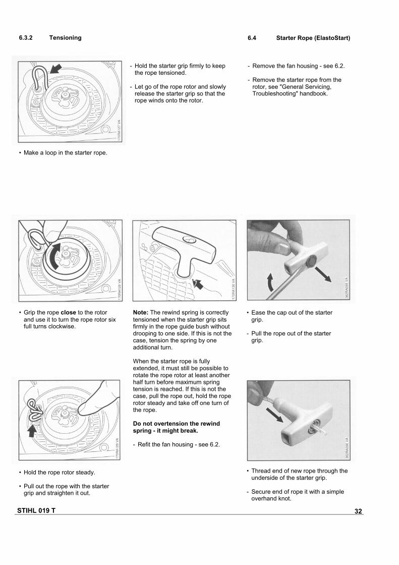
- Hold the starter grip firmly to keepthe rope tensioned.
- Let go of the rope rotor and slowlyrelease the starter grip so that therope winds onto the rotor.
• Hold the rope rotor steady.
• Pull out the rope with the startergrip and straighten it out.
• Grip the rope close to the rotorand use it to turn the rope rotor sixfull turns clockwise.
• Thread end of new rope through theunderside of the starter grip.
- Secure end of rope it with a simpleoverhand knot.
• Make a loop in the starter rope.
Note: The rewind spring is correctlytensioned when the starter grip sitsfirmly in the rope guide bush withoutdrooping to one side. If this is not thecase, tension the spring by oneadditional turn.
When the starter rope is fullyextended, it must still be possible torotate the rope rotor at least anotherhalf turn before maximum springtension is reached. If this is not thecase, pull the rope out, hold the roperotor steady and take off one turn ofthe rope.
Do not overtension the rewindspring - it might break.
- Refit the fan housing - see 6.2.
• Ease the cap out of the startergrip.
- Pull the rope out of the startergrip.

STIHL 019 T 33
6.5 Starter Grip (ElastoStart)
The starter grip is supplied completewith starter rope.
- Remove the fan housing - see 6.2.
- Remove the rope rotor - see"General Servicing, Trouble-shooting" handbook.
• Pull rope back until the knot locatesin the starter grip.
- Press cap into the starter grip.
- Fit the starter rope on the rotor, see"General Servicing, Trouble-shooting" handbook.
• Thread rope through the side of therotor.
- Push it through the inner bore fromthe underside, pull it out at the topand secure with a simple overhandknot.
- Grip knot and pull it out of roperotor.
• Undo the knot and remove thestarter rope from the rotor and fanhousing.
• Pull the rope back into the rotorso that the knot locates in therecess.
- Install the rope rotor - see"General Servicing, Trouble-shooting" handbook.
- Tension the rewind spring- see 6.3.2.
- Refit the fan housing - see 6.2.
• Thread the new starter ropethrough the guide bush fromoutside.
STIHL 019 T 34
7. AV HANDLE SYSTEM
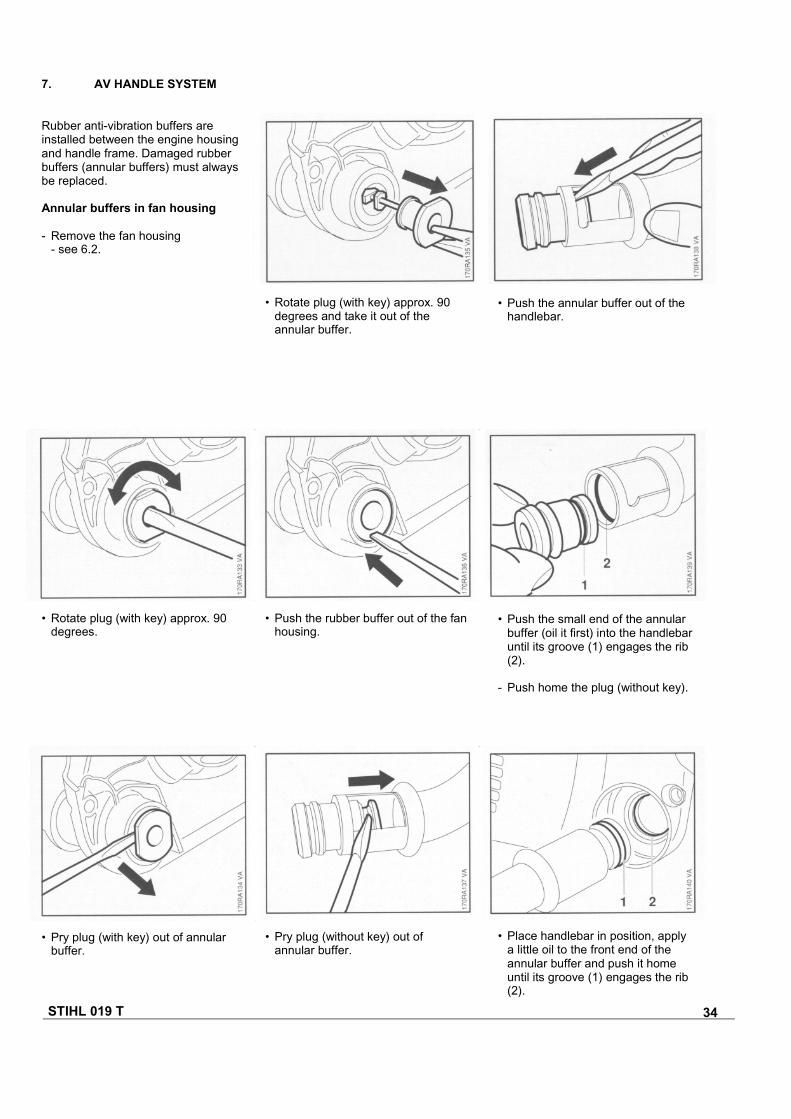
Rubber anti-vibration buffers areinstalled between the engine housingand handle frame. Damaged rubberbuffers (annular buffers) must alwaysbe replaced.
Annular buffers in fan housing
- Remove the fan housing- see 6.2.
• Pry plug (with key) out of annularbuffer.
• Pry plug (without key) out ofannular buffer.
• Place handlebar in position, applya little oil to the front end of theannular buffer and push it homeuntil its groove (1) engages the rib(2).
• Push the small end of the annularbuffer (oil it first) into the handlebaruntil its groove (1) engages the rib(2).
- Push home the plug (without key).
• Push the rubber buffer out of the fanhousing.
• Rotate plug (with key) approx. 90degrees.
• Rotate plug (with key) approx. 90degrees and take it out of theannular buffer.
• Push the annular buffer out of thehandlebar.
STIHL 019 T 35
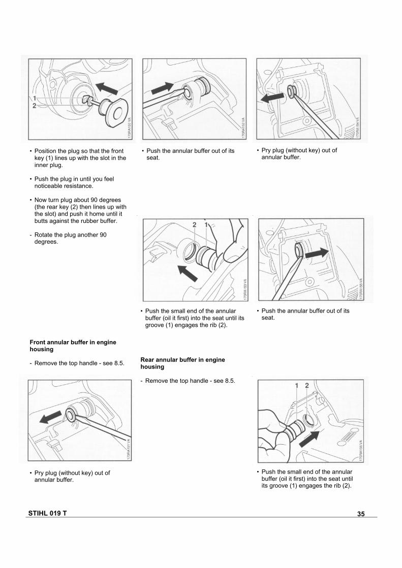
• Position the plug so that the frontkey (1) lines up with the slot in theinner plug.
• Push the plug in until you feelnoticeable resistance.
• Now turn plug about 90 degrees(the rear key (2) then lines up withthe slot) and push it home until itbutts against the rubber buffer.
- Rotate the plug another 90degrees.
• Push the annular buffer out of itsseat.
• Pry plug (without key) out ofannular buffer.
• Push the small end of the annularbuffer (oil it first) into the seat until itsgroove (1) engages the rib (2).
Rear annular buffer in enginehousing
- Remove the top handle - see 8.5.
• Push the annular buffer out of itsseat.
Front annular buffer in enginehousing
- Remove the top handle - see 8.5.
• Pry plug (without key) out ofannular buffer.
• Push the small end of the annularbuffer (oil it first) into the seat untilits groove (1) engages the rib (2).
STIHL 019 T 36
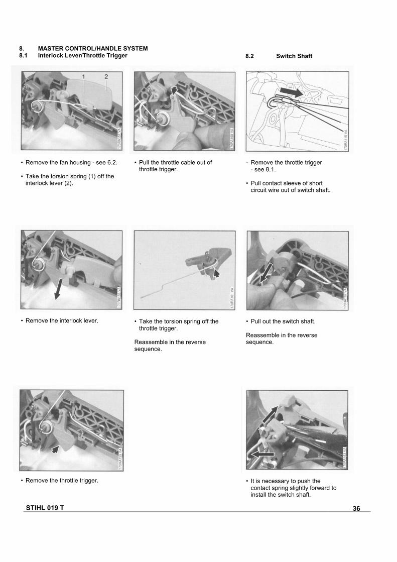
• Remove the interlock lever. • Take the torsion spring off thethrottle trigger.
Reassemble in the reversesequence.
• Pull out the switch shaft.
Reassemble in the reversesequence.
• It is necessary to push thecontact spring slightly forward toinstall the switch shaft.
• Remove the throttle trigger.
- Remove the throttle trigger- see 8.1.
• Pull contact sleeve of shortcircuit wire out of switch shaft.
• Pull the throttle cable out ofthrottle trigger.
• Remove the fan housing - see 6.2.
• Take the torsion spring (1) off theinterlock lever (2).
8. MASTER CONTROL/HANDLE SYSTEM8.1 Interlock Lever/Throttle Trigger 8.2 Switch Shaft
STIHL 019 T 37
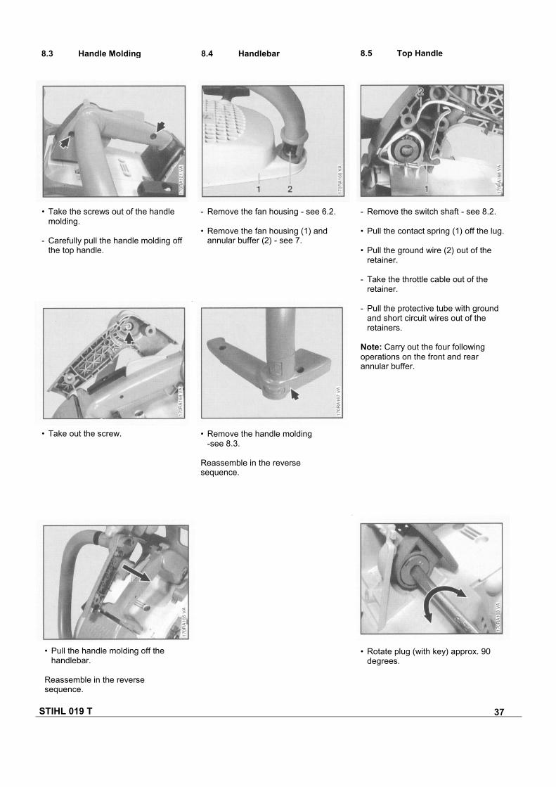
8.3 Handle Molding 8.4 Handlebar 8.5 Top Handle
• Take the screws out of the handlemolding.
- Carefully pull the handle molding offthe top handle.
- Remove the fan housing - see 6.2.
• Remove the fan housing (1) andannular buffer (2) - see 7.
- Remove the switch shaft - see 8.2.
• Pull the contact spring (1) off the lug.
• Pull the ground wire (2) out of theretainer.
- Take the throttle cable out of theretainer.
- Pull the protective tube with groundand short circuit wires out of theretainers.
Note: Carry out the four followingoperations on the front and rearannular buffer.
• Remove the handle molding-see 8.3.
Reassemble in the reversesequence.
• Take out the screw.
• Rotate plug (with key) approx. 90degrees.
• Pull the handle molding off thehandlebar.
Reassemble in the reversesequence.
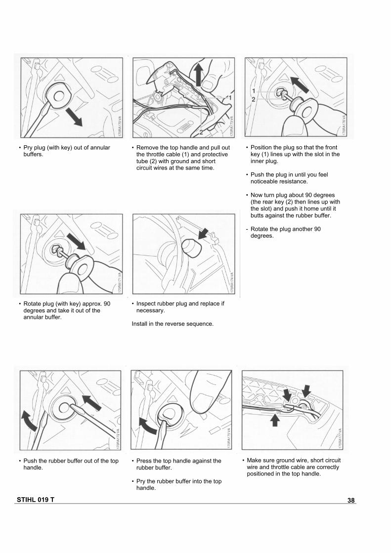
STIHL 019 T 38
• Push the rubber buffer out of the tophandle.
• Press the top handle against therubber buffer.
• Pry the rubber buffer into the tophandle.
• Make sure ground wire, short circuitwire and throttle cable are correctlypositioned in the top handle.
• Inspect rubber plug and replace ifnecessary.
Install in the reverse sequence.
• Rotate plug (with key) approx. 90degrees and take it out of theannular buffer.
• Position the plug so that the frontkey (1) lines up with the slot in theinner plug.
• Push the plug in until you feelnoticeable resistance.
• Now turn plug about 90 degrees(the rear key (2) then lines up withthe slot) and push it home until itbutts against the rubber buffer.
- Rotate the plug another 90degrees.
• Remove the top handle and pull outthe throttle cable (1) and protectivetube (2) with ground and shortcircuit wires at the same time.
• Pry plug (with key) out of annularbuffers.
STIHL 019 T 39
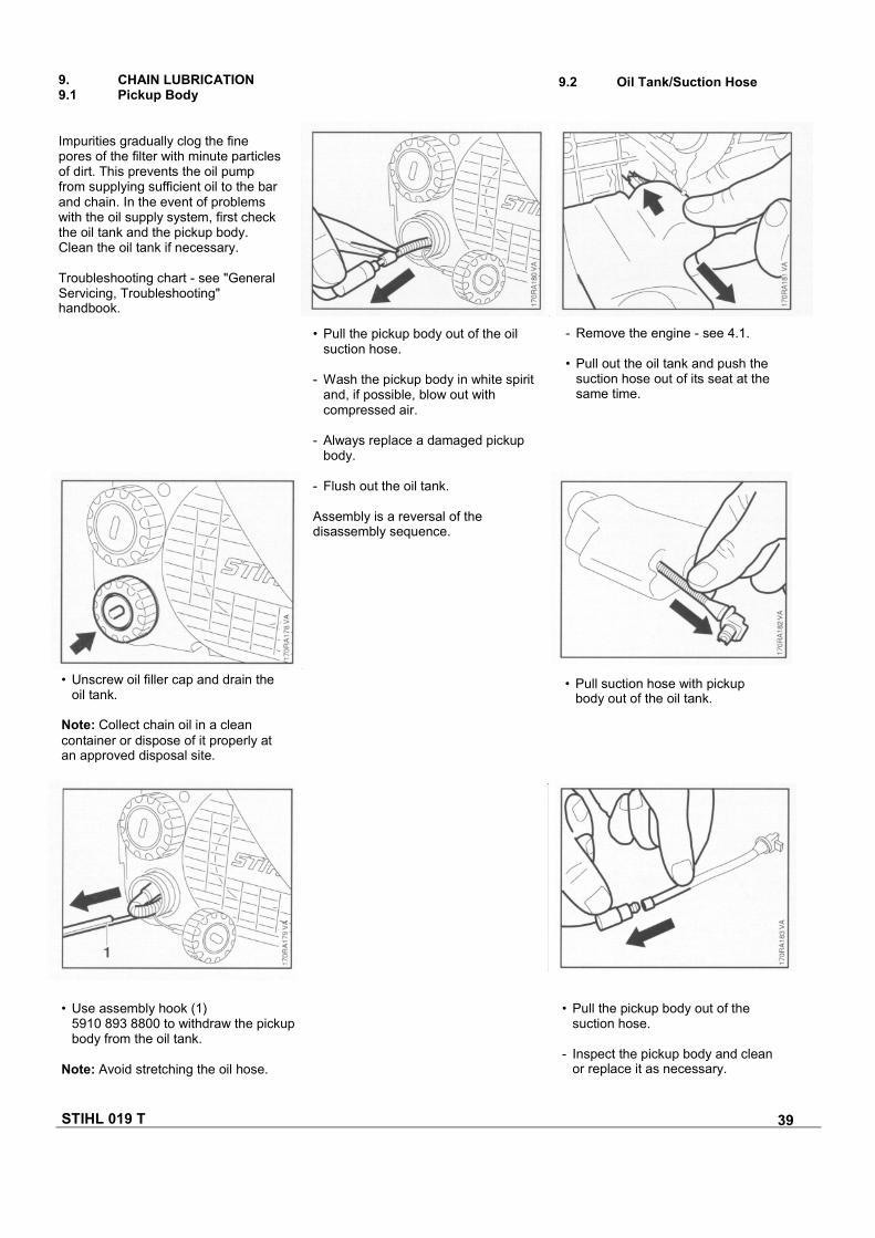
9.2 Oil Tank/Suction Hose9. CHAIN LUBRICATION9.1 Pickup Body
Impurities gradually clog the finepores of the filter with minute particlesof dirt. This prevents the oil pumpfrom supplying sufficient oil to the barand chain. In the event of problemswith the oil supply system, first checkthe oil tank and the pickup body.Clean the oil tank if necessary.
Troubleshooting chart - see "GeneralServicing, Troubleshooting"handbook.
• Pull the pickup body out of the oilsuction hose.
- Wash the pickup body in white spiritand, if possible, blow out withcompressed air.
- Always replace a damaged pickupbody.
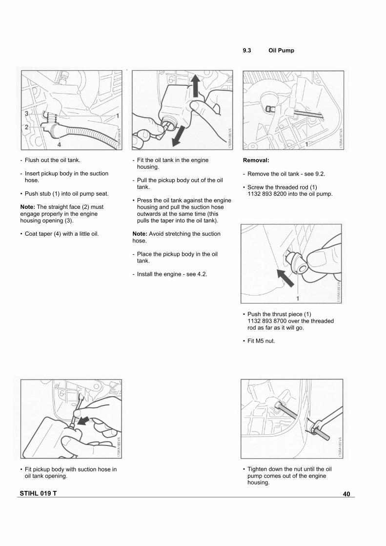
- Flush out the oil tank.
Assembly is a reversal of thedisassembly sequence.
- Remove the engine - see 4.1.
• Pull out the oil tank and push thesuction hose out of its seat at thesame time.
• Pull suction hose with pickupbody out of the oil tank.
• Pull the pickup body out of thesuction hose.
- Inspect the pickup body and cleanor replace it as necessary.
• Use assembly hook (1)5910 893 8800 to withdraw the pickupbody from the oil tank.
Note: Avoid stretching the oil hose.
• Unscrew oil filler cap and drain theoil tank.
Note: Collect chain oil in a cleancontainer or dispose of it properly atan approved disposal site.
STIHL 019 T 40
• Fit pickup body with suction hose in oil tank opening.
• Tighten down the nut until the oilpump comes out of the enginehousing.
• Push the thrust piece (1)1132 893 8700 over the threadedrod as far as it will go.
• Fit M5 nut.
Removal:
- Remove the oil tank - see 9.2.
• Screw the threaded rod (1)1132 893 8200 into the oil pump.
- Fit the oil tank in the enginehousing.
- Pull the pickup body out of the oiltank.
• Press the oil tank against the enginehousing and pull the suction hoseoutwards at the same time (thispulls the taper into the oil tank).
Note: Avoid stretching the suctionhose.
- Place the pickup body in the oiltank.
- Install the engine - see 4.2.
- Flush out the oil tank.
- Insert pickup body in the suctionhose.
• Push stub (1) into oil pump seat.
Note: The straight face (2) mustengage properly in the enginehousing opening (3).
• Coat taper (4) with a little oil.
9.3 Oil Pump
STIHL 019 T 41
9.4 Worm
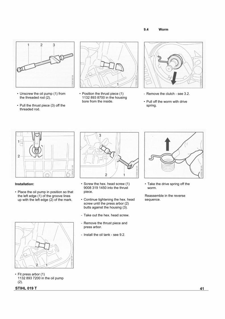
- Remove the clutch - see 3.2.
• Pull off the worm with drivespring.
• Position the thrust piece (1)1132 893 8700 in the housingbore from the inside.
• Unscrew the oil pump (1) fromthe threaded rod (2).
• Pull the thrust piece (3) off thethreaded rod.
Installation:
• Place the oil pump in position so thatthe left edge (1) of the groove linesup with the left edge (2) of the mark.
• Screw the hex. head screw (1)9008 319 1450 into the thrustpiece.
• Continue tightening the hex. headscrew until the press arbor (2)butts against the housing (3).
- Take out the hex. head screw.
- Remove the thrust piece andpress arbor.
- Install the oil tank - see 9.2.
• Take the drive spring off theworm.
Reassemble in the reversesequence.
• Fit press arbor (1)1132 893 7200 in the oil pump(2).
STIHL 019 T 42
10. FUEL SYSTEM10.1 Air Filter
Dirty and clogged air filters reduceengine power, increase fuelconsumption and make starting moredifficult.
The air filter should always becleaned when there is a noticeableloss of engine power.
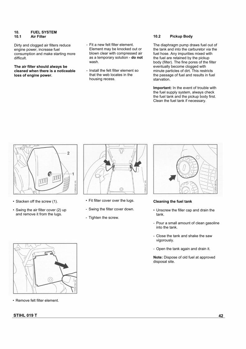
- Fit a new felt filter element.Element may be knocked out orblown clear with compressed airas a temporary solution - do notwash.
- Install the felt filter element sothat the web locates in thehousing recess.
10.2 Pickup Body
The diaphragm pump draws fuel out ofthe tank and into the carburetor via thefuel hose. Any impurities mixed withthe fuel are retained by the pickupbody (filter). The fine pores of the filtereventually become clogged withminute particles of dirt. This restrictsthe passage of fuel and results in fuelstarvation.
Important: In the event of trouble withthe fuel supply system, always checkthe fuel tank and the pickup body first.Clean the fuel tank if necessary.
• Slacken off the screw (1).
• Swing the air filter cover (2) upand remove it from the lugs.
Cleaning the fuel tank
• Unscrew the filler cap and drain thetank.
- Pour a small amount of clean gasolineinto the tank.
- Close the tank and shake the sawvigorously.
- Open the tank again and drain it.
Note: Dispose of old fuel at approveddisposal site.
• Remove felt filter element.
• Fit filter cover over the lugs.
- Swing the filter cover down.
- Tighten the screw.
STIHL 019 T 43
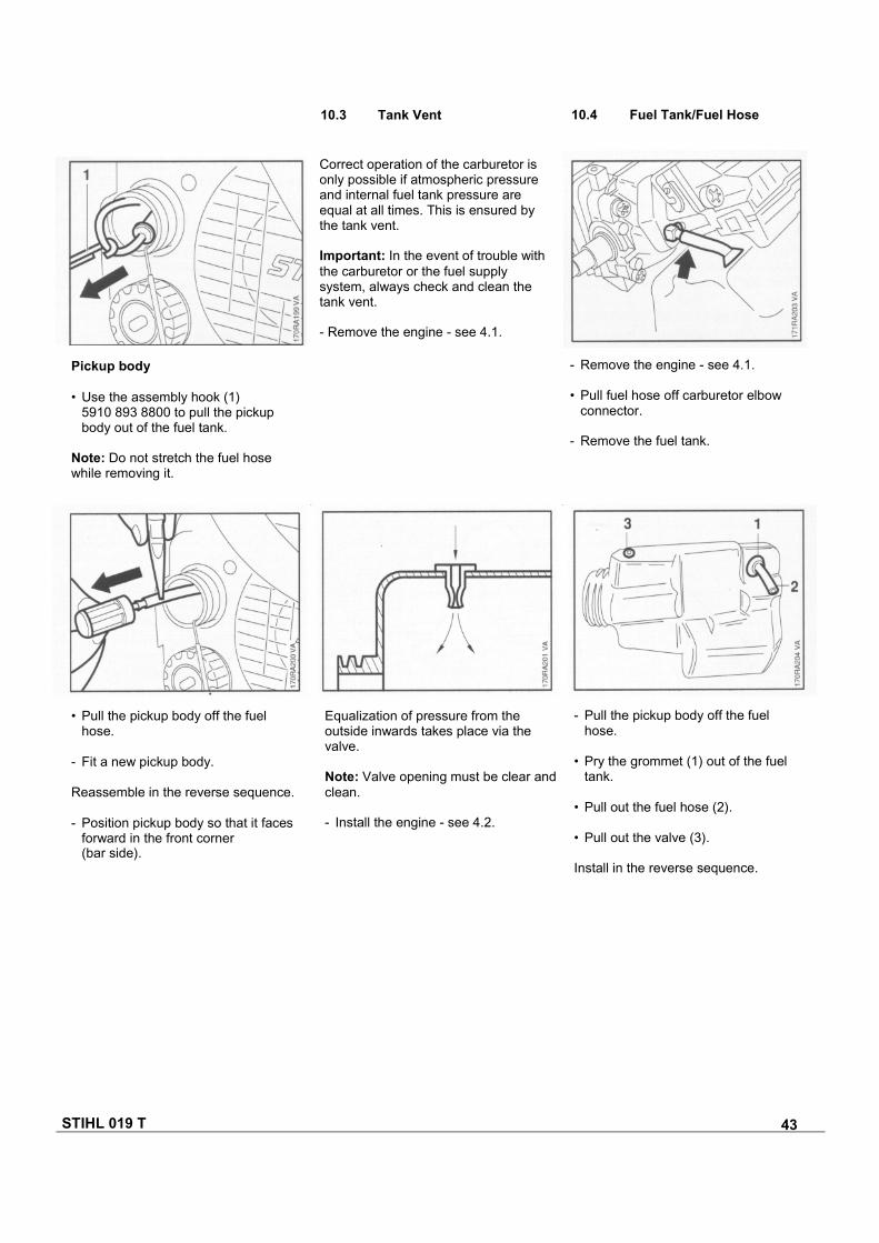
• Pull the pickup body off the fuelhose.
- Fit a new pickup body.
Reassemble in the reverse sequence.
- Position pickup body so that it facesforward in the front corner(bar side).
Equalization of pressure from theoutside inwards takes place via thevalve.
Note: Valve opening must be clear andclean.
- Install the engine - see 4.2.
- Pull the pickup body off the fuelhose.
• Pry the grommet (1) out of the fueltank.
• Pull out the fuel hose (2).
• Pull out the valve (3).
Install in the reverse sequence.
- Remove the engine - see 4.1.
• Pull fuel hose off carburetor elbowconnector.
- Remove the fuel tank.
10.4 Fuel Tank/Fuel Hose10.3 Tank Vent
Correct operation of the carburetor isonly possible if atmospheric pressureand internal fuel tank pressure areequal at all times. This is ensured bythe tank vent.
Important: In the event of trouble withthe carburetor or the fuel supplysystem, always check and clean thetank vent.
- Remove the engine - see 4.1.
Pickup body
• Use the assembly hook (1)5910 893 8800 to pull the pickupbody out of the fuel tank.
Note: Do not stretch the fuel hosewhile removing it.
STIHL 019 T 44
10.5 Carburetor10.5.1 Leakage Test
Troubleshooting chart - see "GeneralServicing, Troubleshooting" handbook.
Important: In the event of trouble withthe carburetor or the fuel supplysystem, also check and clean the tankvent - see 10.3.
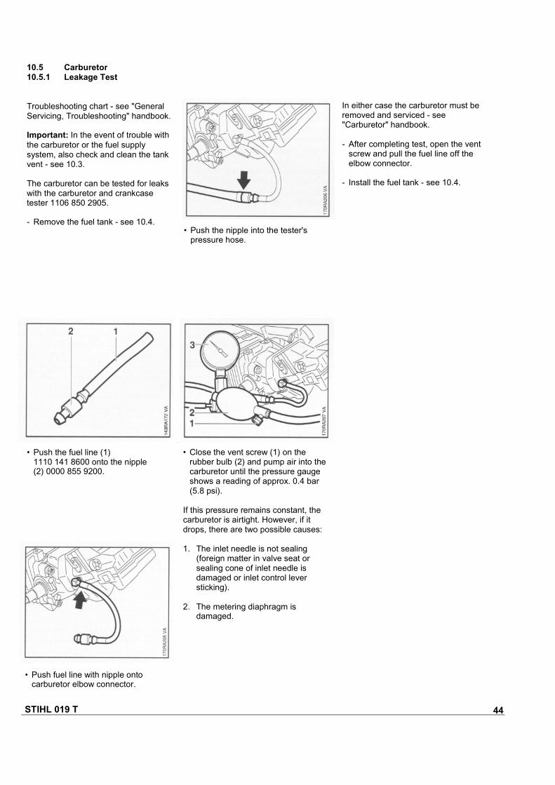
The carburetor can be tested for leakswith the carburetor and crankcasetester 1106 850 2905.
- Remove the fuel tank - see 10.4.
In either case the carburetor must beremoved and serviced - see"Carburetor" handbook.
- After completing test, open the ventscrew and pull the fuel line off theelbow connector.
- Install the fuel tank - see 10.4.
• Push the nipple into the tester'spressure hose.
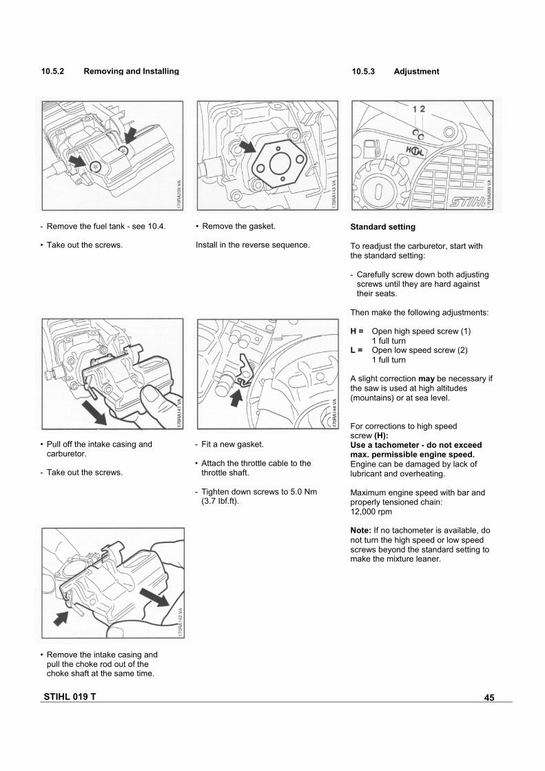
• Push the fuel line (1)1110 141 8600 onto the nipple(2) 0000 855 9200.
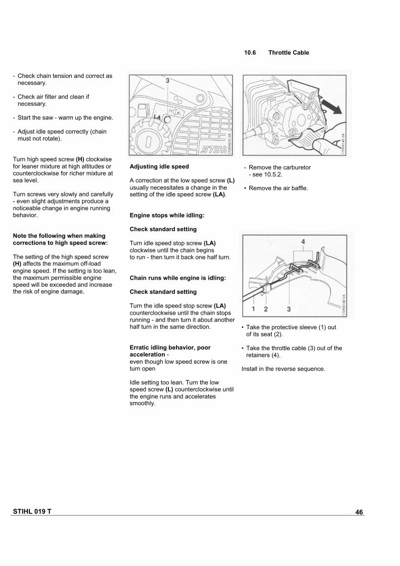
• Close the vent screw (1) on therubber bulb (2) and pump air into thecarburetor until the pressure gaugeshows a reading of approx. 0.4 bar(5.8 psi).
If this pressure remains constant, thecarburetor is airtight. However, if itdrops, there are two possible causes:
1. The inlet needle is not sealing(foreign matter in valve seat orsealing cone of inlet needle isdamaged or inlet control leversticking).
2. The metering diaphragm isdamaged.
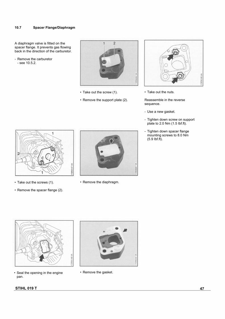
• Push fuel line with nipple ontocarburetor elbow connector.
STIHL 019 T 45
- Remove the fuel tank - see 10.4.
• Take out the screws.
• Remove the gasket.
Install in the reverse sequence.
Standard setting
To readjust the carburetor, start withthe standard setting:
- Carefully screw down both adjustingscrews until they are hard againsttheir seats.
Then make the following adjustments:
H = Open high speed screw (1)1 full turn
L = Open low speed screw (2)1 full turn
A slight correction may be necessary ifthe saw is used at high altitudes(mountains) or at sea level.
For corrections to high speedscrew (H):Use a tachometer - do not exceedmax. permissible engine speed.Engine can be damaged by lack oflubricant and overheating.
Maximum engine speed with bar andproperly tensioned chain:12,000 rpm
Note: If no tachometer is available, donot turn the high speed or low speedscrews beyond the standard setting tomake the mixture leaner.
- Fit a new gasket.
• Attach the throttle cable to thethrottle shaft.
- Tighten down screws to 5.0 Nm(3.7 Ibf.ft).
• Pull off the intake casing andcarburetor.
- Take out the screws.
• Remove the intake casing andpull the choke rod out of thechoke shaft at the same time.
10.5.3 Adjustment10.5.2 Removing and Installing
STIHL 019 T 46
• Take the protective sleeve (1) outof its seat (2).
• Take the throttle cable (3) out of theretainers (4).
Install in the reverse sequence.
- Remove the carburetor- see 10.5.2.
• Remove the air baffle.
10.6 Throttle Cable
- Check chain tension and correct asnecessary.
- Check air filter and clean ifnecessary.
- Start the saw - warm up the engine.
- Adjust idle speed correctly (chainmust not rotate).
Turn high speed screw (H) clockwisefor leaner mixture at high altitudes orcounterclockwise for richer mixture atsea level.
Turn screws very slowly and carefully- even slight adjustments produce anoticeable change in engine runningbehavior.
Note the following when makingcorrections to high speed screw:
The setting of the high speed screw(H) affects the maximum off-loadengine speed. If the setting is too lean,the maximum permissible enginespeed will be exceeded and increasethe risk of engine damage.
Adjusting idle speed
A correction at the low speed screw (L)usually necessitates a change in thesetting of the idle speed screw (LA).
Engine stops while idling:
Check standard setting
Turn idle speed stop screw (LA)clockwise until the chain beginsto run - then turn it back one half turn.
Chain runs while engine is idling:
Check standard setting
Turn the idle speed stop screw (LA)counterclockwise until the chain stopsrunning - and then turn it about anotherhalf turn in the same direction.
Erratic idling behavior, pooracceleration -even though low speed screw is oneturn open
Idle setting too lean. Turn the lowspeed screw (L) counterclockwise untilthe engine runs and acceleratessmoothly.
STIHL 019 T 47
10.7 Spacer Flange/Diaphragm
A diaphragm valve is fitted on thespacer flange. It prevents gas flowingback in the direction of the carburetor.
- Remove the carburetor- see 10.5.2.
• Seal the opening in the enginepan.
• Take out the screw (1).
• Remove the support plate (2).
• Take out the nuts.
Reassemble in the reversesequence.
- Use a new gasket.
- Tighten down screw on supportplate to 2.0 Nm (1.5 Ibf.ft).
- Tighten down spacer flangemounting screws to 8.0 Nm(5.9 Ibf.ft).
• Take out the screws (1).
• Remove the spacer flange (2).
• Remove the diaphragm.
• Remove the gasket.
STIHL 019 T 48
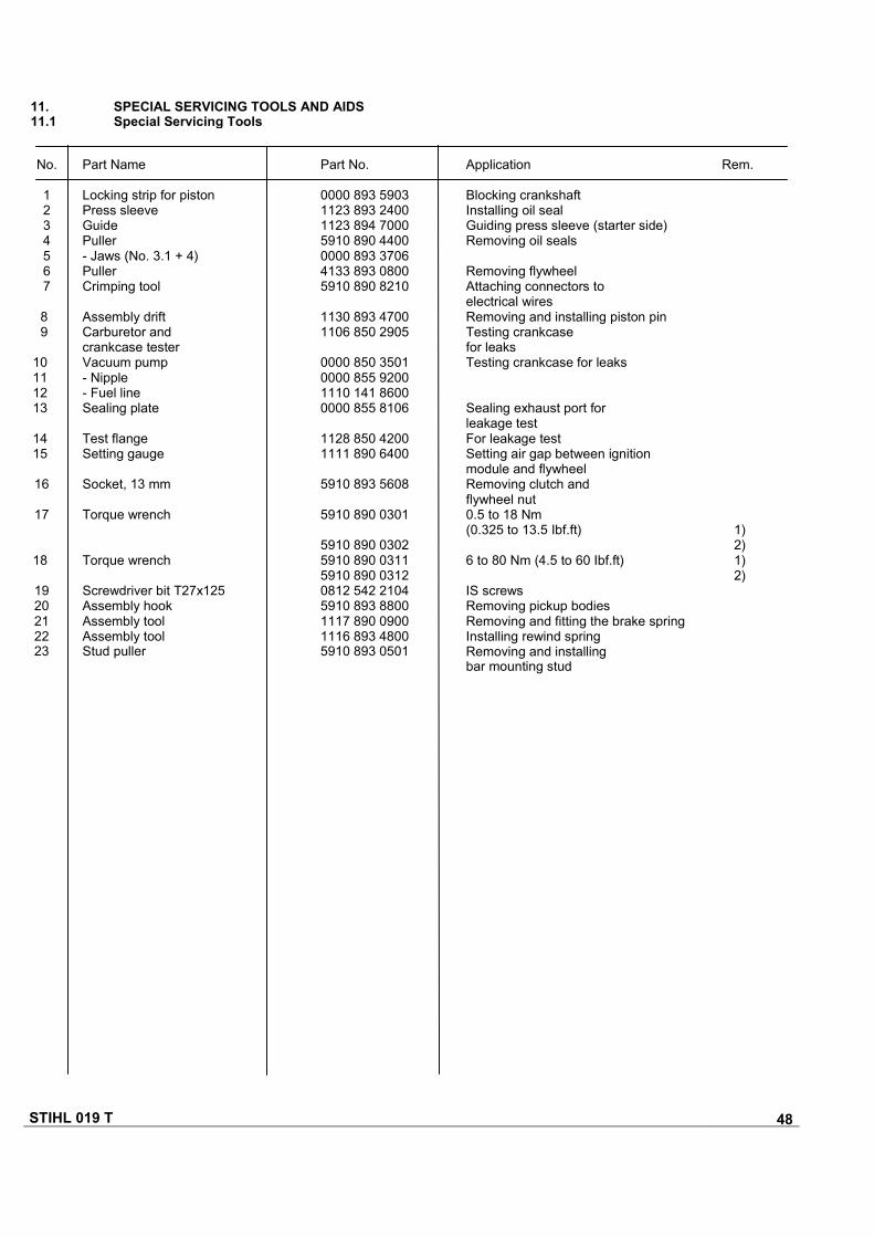
11. SPECIAL SERVICING TOOLS AND AIDS11.1 Special Servicing Tools
No.
1234567
89
10111213
1415
16
17
18
1920212223
Part Name
Locking strip for pistonPress sleeveGuidePuller- Jaws (No. 3.1 + 4)PullerCrimping tool
Assembly driftCarburetor andcrankcase testerVacuum pump- Nipple- Fuel lineSealing plate
Test flangeSetting gauge
Socket, 13 mm
Torque wrench
Torque wrench
Screwdriver bit T27x125Assembly hookAssembly toolAssembly toolStud puller
Part No.
0000 893 59031123 893 24001123 894 70005910 890 44000000 893 37064133 893 08005910 890 8210
1130 893 47001106 850 2905
0000 850 35010000 855 92001110 141 86000000 855 8106
1128 850 42001111 890 6400
5910 893 5608
5910 890 0301
5910 890 03025910 890 03115910 890 03120812 542 21045910 893 88001117 890 09001116 893 48005910 893 0501
Application Rem.
Blocking crankshaftInstalling oil sealGuiding press sleeve (starter side)Removing oil seals
Removing flywheelAttaching connectors toelectrical wiresRemoving and installing piston pinTesting crankcasefor leaksTesting crankcase for leaks
Sealing exhaust port forleakage testFor leakage testSetting air gap between ignitionmodule and flywheelRemoving clutch andflywheel nut0.5 to 18 Nm(0.325 to 13.5 Ibf.ft) 1)
2)6 to 80 Nm (4.5 to 60 Ibf.ft) 1)
2)IS screwsRemoving pickup bodiesRemoving and fitting the brake springInstalling rewind springRemoving and installingbar mounting stud

STIHL 019 T 49
No
242526272829
30
Part Name
Service tool- Threaded rod- Thrust piece- Press arbor- Hex. head screwT-handle screwdriverQI-T27x150Assembly stand
Part No.
1132 890 17001132 893 82001132 893 87001132 893 72009008 319 1450
5910 890 24005910 890 3100
Application
Removing and installing oil pump
For all IS screwsHolding saw for repairs
Remarks:
1) Always use torque wrench to tighten Plastoform and DG screws.2) Wrench has optical/acoustic signal.3) On DG and P screws, use for releasing only.
Rem.
3)
STIHL 019 T 50
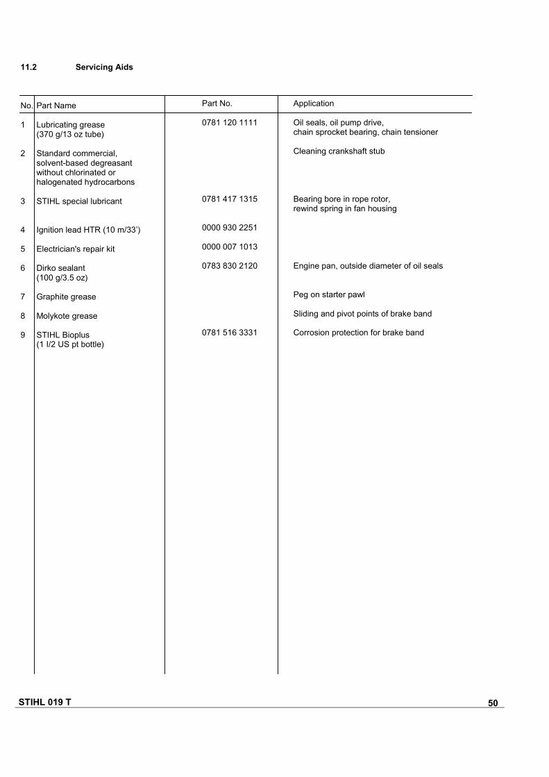
11.2 Servicing Aids
No. Part Name
1 Lubricating grease(370 g/13 oz tube)
2 Standard commercial,solvent-based degreasantwithout chlorinated orhalogenated hydrocarbons
3 STIHL special lubricant
4 Ignition lead HTR (10 m/33’)
5 Electrician's repair kit
6 Dirko sealant(100 g/3.5 oz)
7 Graphite grease
8 Molykote grease
9 STIHL Bioplus(1 I/2 US pt bottle)
Part No.
0781 120 1111
0781 417 1315
0000 930 2251
0000 007 1013
0783 830 2120
0781 516 3331
Application
Oil seals, oil pump drive,chain sprocket bearing, chain tensioner
Cleaning crankshaft stub
Bearing bore in rope rotor,rewind spring in fan housing
Engine pan, outside diameter of oil seals
Peg on starter pawl
Sliding and pivot points of brake band
Corrosion protection for brake band