Stefan Martynkiw - University of Alberta
116
Stefan Martynkiw ECE 487 : Data Communications Networks Friday, May 29, 2015 8:58 AM Front Matter Page 1
-
Upload
khangminh22 -
Category
Documents
-
view
0 -
download
0
Transcript of Stefan Martynkiw - University of Alberta
Stefan Martynkiw
ECE 487 : Data Communications NetworksFriday, May 29, 2015 8:58 AM
Front Matter Page 1
Untitled page
Front Matter•
1.2 Categories of networks
1.0 Introduction to Data Communications
1.3 The Internet
1.4 Protocols and Standards
1.5 Circuit Switching vs. Packet Switching
Lecture 1•
Lecture 2: Network Models
2.2 The OSI Model
2.3.1 Physical Layer
2.3.2 Data Link Layer
2.3.3 Network Layer
2.3.4 Transport Layer
2.3.5 Session Layer
2.3.6 Presentation Layer
2.3.7 Application Layer
2.3 Layers in the OSI Model
2.4 TCP/IP Protocol Suite
2.5.a Examples
2.5.1 Physical Addressing
2.5.2 Logical Addressing
2.5.3 Port Addressing
2.5.4 Specific Addresses
2.5 Addressing
Lecture 2•
Lecture 3: Error Detection and Correction
10.1 Introduction
10.2.1 Hamming Distance
10.2 Block Coding
10.3.1 Parity Check Codes
10.3.2 Two-dimensional Parity-check code
10.3.2.a Two-dimensional Parity-check code Example (Midterm)
10.3.3 Hamming Code C(7,4)
10.3.3.1 Midterm Example
10.3 Linear Block Codes
10.4.1 Encoding/Decoding CRC Codewords
10.4.1.1 Hardware Division for the CRC
10.4.2 CRC Examples (Midterm)
10.4 Cyclic Codes
10.5 Checksum
Lecture 3•
Lecture 5: Multiple Access
12.1.1 ALOHA
12.1.1.a ALOHA Vulnerable Time
12.1.1.b ALOHA Throughput
12.1.1.c Slotted ALOHA Vulnerability Time
12.1.1.d Slotted ALOHA Throughput
12.1 Random Access
12.1.2 Carrier Sense Multiple Access (CSMA)
Lecture 5•
Table of ContentsFriday, May 29, 2015 8:58 AM
Front Matter Page 2
12.1.2.1 CSMA Persistence Methods.
12.1.2 Carrier Sense Multiple Access (CSMA)
12.1.3.a Minimum Frame Size
12.1.3.b Flow Diagram for CSMA/CD
12.1.3.c Energy Level in CSMA/CD
12.1.3 (CSMA/CD) Carrier Sense Multiple Access with Collision Detection
12.2.1 Reservation Access Method
12.2.2 Polling
12.2.3 Token Passing
12.2 Controlled Access
Lecture 6: Ethernet
13.1 IEEE Standards
13.2.1 Frame Length
13.2.2 Addressing
13.3.3 Physical Layer
13.2 Standard Ethernet
13.3.1 Bridges
13.3 Changes In The Standard
13.3.2 Learning Bridges
Lecture 6•
Lecture 8: Packet Switched Networks
8.1 Switching
8.2.1 Efficiency and Delay
8.2 Datagram Networks
8.3.1 Three Phases: Setup, Transfer, Teardown
8.3.1.a Setup ACK Frames / Teardowns
8.3.2 Efficiency and Delay
8.3 Virtual-Circuit Networks
22.3.1 Forwarding
22.3.2 Intra- and Inter- Domain Routing
22.3.2.1 Distance Vector Routing
22.3.2.2 When to share
22.3.2.3. Two-node instability
22.3.3 Routing Information Protocol (RIP)
22.3.4 Link State Routing
22.3.4.1 Dijkstra's Algorithm
22.3.4.2 Assignment Solutions
22.3 Unicast Routing Protocols
24.5 Quality of Service
24.6 Techniques to Improve QoS
24.7 Integrated Services
24.8 Differentiated Services
Lecture 8•
Lecture 9: Addressing
19.1.1 Classful Addressing
19.1.2 Class-less Addressing
19.1.3 IPv4 Address Hierarchy
19.1.3.1 Assignment Solutions
19.1 IPv4 Addresses
19.1.4 (NAT) Network Address Translation
Lecture 9•
Lecture 10: Network Layer: Internet Protocol
20.2 IPv4
20.3 IPv4 Datagram Format
Lecture 10•
Front Matter Page 3
20.3.1 Protocol Field & Examples
20.3 IPv4 Datagram Format
20.4.1 Fragmentation Examples.
20.4 Fragmentation
20.5 IPv4 Assignment Examples
20.6 Checksum
Lecture 11: Transport Layer
23.1 Process-to-Process Delivery
23.2 (UDP) User Datagram Protocol
23.3.1 TCP Header
23.3.2 TCP Exchange
23.3 TCP
Lecture 11•
Assignment #9
ASSIGNMENTS•
Front Matter Page 4
Telecommunication = Communication at a distance•Data = Information presented in whatever form agreed upon by parties creating and using the data
•
Data Communications = Exchange of data between two devices vis some form of transmission medium.
•
Components of Data Communication
Message. The information to be communicated1.Sender. Devices that sends data messages.2.Receiver. Device that receives the data message.3.Transmission Medium. Physical path by which a message travels from the sender to receiver.
4.
Protocol. Set of rules that govern data communications. Represents agreement between the communicating devices.
5.
Dataflow
Simplex. Communication is unidirectional. Only one of the two devices can transmit; the other must receive.
•
Like a one-lane road with traffic allowed in both directions.
Half-duplex. Each station can transmit or receive, but not at the same time. •
Full-duplex. Both stations can transmit and receive simultaneously.•
NetworksA network is a set of devices (nodes) connected by communication links.
Types of connectionsThere are point-to-point and multipoint.
1.0 Introduction to Data CommunicationsMonday, March 30, 2015 4:00 PM
Lecture 1 Page 5
Point-to-point: Dedicated link between the two devices. The entire capacity of the link is reserved for the only two devices on it.
•
Spatially Shared: Several devides can use the link simultaneously.
Time-shared: Users must take turns
The capacity of the channel is shared:
Multipoint: (multidrop). More than two specific devices share a single link.•
TopologyPhysical topology: Which way the network is laid out physically. Two or more devices connect to a link. Two or more links form a topology.
The topology of a network is the geometric representation of the relationship of all links and nodes to one another.
Four main types of topology:
Mesh TopologyDedicated point-to-point link for every pair.
Need n(n-1)/2 full-duplex links.
Robust-
Good privacy-
Easy to identify faults-
Pros:Lots of hardware
-
Cons:•
Backbone connecting-
Examples:•
Star TopologyEach device has dedicated point-to-point link
If a hub is used, no privacy, since hubs just dumbly repeat signals to all ports. If a switch/router is used, it only sends the received signal to the target port.
Pros: Cheaper, privacy.Cons: Single point of failure.Example: LAN
Bus TopologyDropline: Connection between device and main
Lecture 1 Page 6
Dropline: Connection between device and main cable.Tap: Connector that splices into the main cable.
As signals travel further along the backbone, they get weaker ==> Need a limit on the number of taps.
Pros: Easy to installCons: Poor fault isolation. Signal reflection causes quality degradation -> Hard to add new nodes.
Show work here.
Ring Topology
Each device is linked only to its physical neighbours. Only constraints are media/traffic considerations: maximum ring length and number of devices.
Fault isolation is simplified. If one device does not receive a signal within a specified period, it can signal an alarm.
In a unidirectional ring, one break (such as a disabled station) can disable the entire network. We can solve this by using a dual ring.
Hybrid Topology
Lecture 1 Page 7

Local Area Network (LAN)
For resource sharing in a local area (office, campus, etc)•Max range is a few kilometers.•One LAN will only use one time of transmission medium.•
Early LAN: 4Mbps. Later, >1Gbps
Speed:•
Bus, Ring, Star.
Common topologies:•
Wide Area Network (WAN)
Long distance transmission of information: a country, continent, or world.•
As complex as backbones that connect the internet (switched WAN)
As simple as a dial-up line that connects a home to the internet. (point-to-point WAN)
Complexity:•
Connects the end systems, which usually have a router that connects another LAN or WAN.
Switched WAN.•
Typically a line leased from a telephone or cable TV provider that connects a home computer or small LAN to an ISP.
Point-to-point WAN>•
Interconnection of Networks
1.2 Categories of networksTuesday, March 31, 2015 9:20 AM
Lecture 1 Page 8

Lecture 1 Page 9
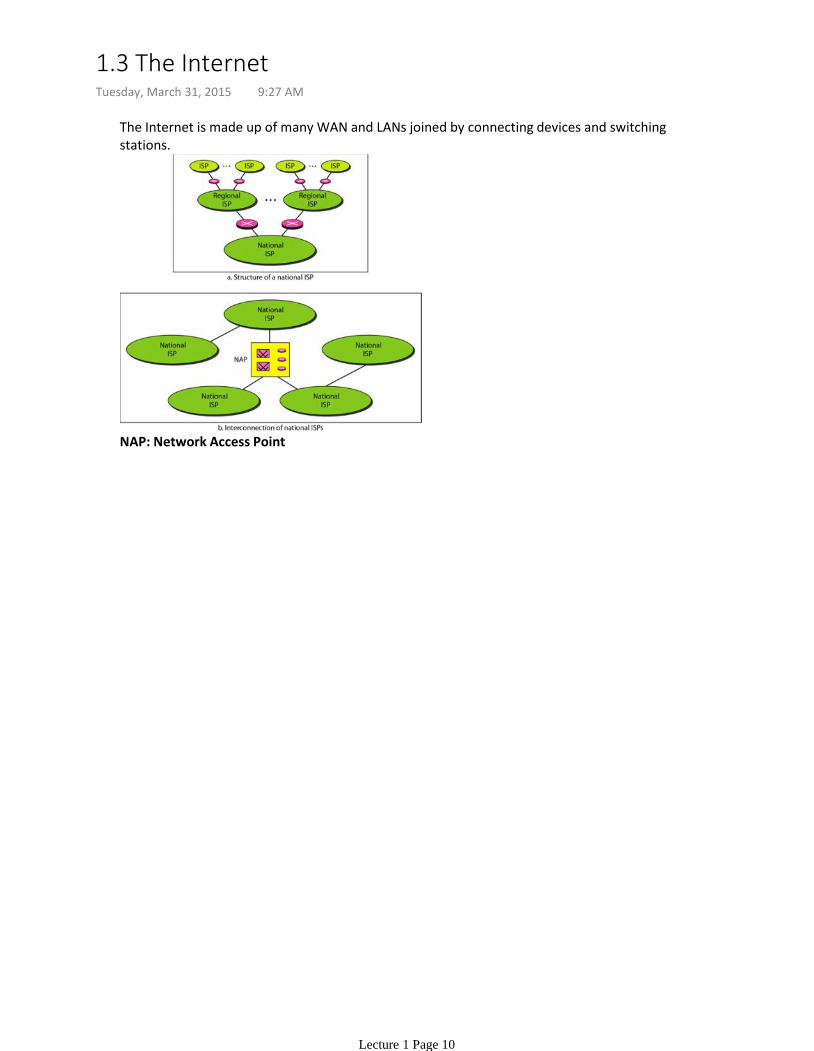
The Internet is made up of many WAN and LANs joined by connecting devices and switching stations.
NAP: Network Access Point
1.3 The InternetTuesday, March 31, 2015 9:27 AM
Lecture 1 Page 10
Protocol: Set of rules that govern data communicationsStandard: Protocol widely recognized.
Page 56 of the PDF for the textbook.
1.4 Protocols and StandardsTuesday, March 31, 2015 9:30 AM
Lecture 1 Page 11
A circuit is set up between two terminals for the duration of the conversation.•Resources (bandwidth, time slot, buffer, etc.) reserved among the circuit, used by the two terminals exlusively.
•
Circuit is released when the call terminates.•Example: Telephone Network•
Circuit Switching
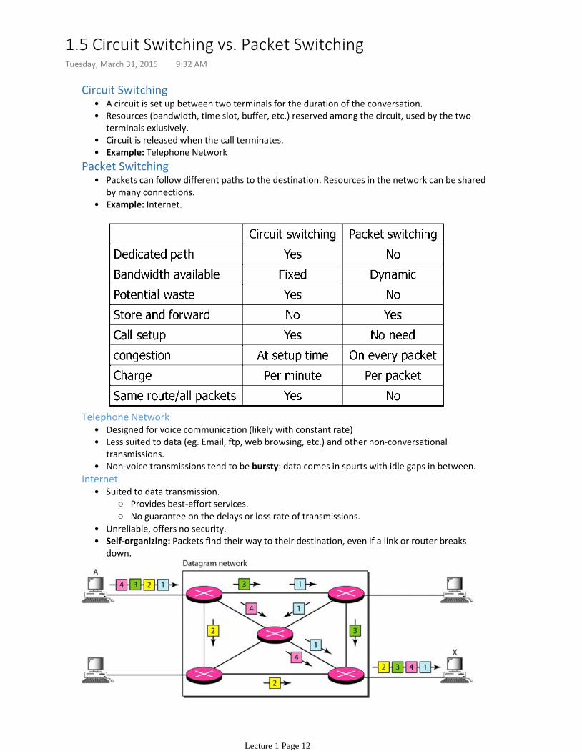
Packets can follow different paths to the destination. Resources in the network can be shared by many connections.
•
Example: Internet.•
Packet Switching
Designed for voice communication (likely with constant rate)•Less suited to data (eg. Email, ftp, web browsing, etc.) and other non-conversational transmissions.
•
Non-voice transmissions tend to be bursty: data comes in spurts with idle gaps in between.•
Telephone Network
Provides best-effort services.
No guarantee on the delays or loss rate of transmissions.
Suited to data transmission.•
Unreliable, offers no security.•Self-organizing: Packets find their way to their destination, even if a link or router breaks down.
•
Internet
1.5 Circuit Switching vs. Packet SwitchingTuesday, March 31, 2015 9:32 AM
Lecture 1 Page 12

Lecture 2: Network ModelsTuesday, March 31, 2015 9:39 AM
Lecture 2 Page 13
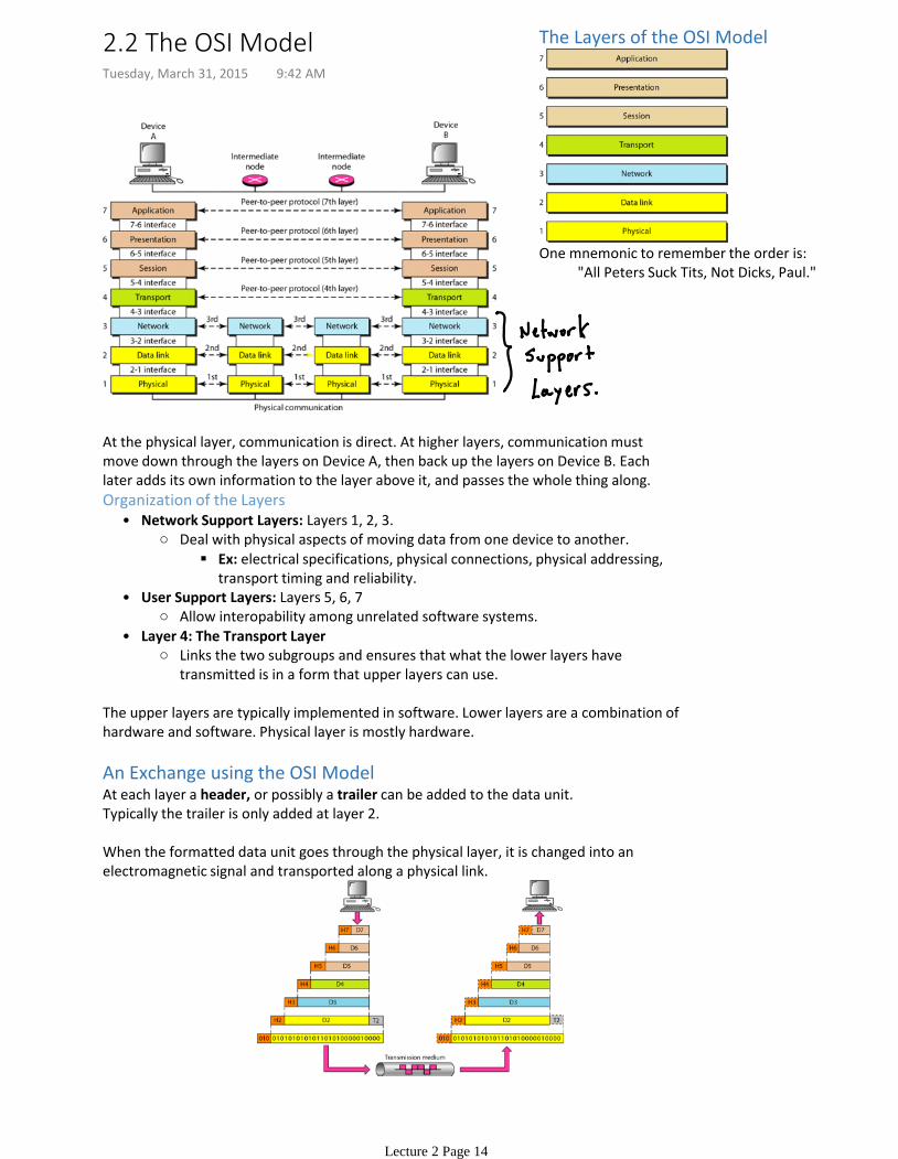
At the physical layer, communication is direct. At higher layers, communication must move down through the layers on Device A, then back up the layers on Device B. Each later adds its own information to the layer above it, and passes the whole thing along.
Ex: electrical specifications, physical connections, physical addressing, transport timing and reliability.
Deal with physical aspects of moving data from one device to another.
Network Support Layers: Layers 1, 2, 3.•
Allow interopability among unrelated software systems.
User Support Layers: Layers 5, 6, 7•
Links the two subgroups and ensures that what the lower layers have transmitted is in a form that upper layers can use.
Layer 4: The Transport Layer•
Organization of the Layers
The upper layers are typically implemented in software. Lower layers are a combination of hardware and software. Physical layer is mostly hardware.
An Exchange using the OSI ModelAt each layer a header, or possibly a trailer can be added to the data unit.Typically the trailer is only added at layer 2.
When the formatted data unit goes through the physical layer, it is changed into an electromagnetic signal and transported along a physical link.
The Layers of the OSI Model
"All Peters Suck Tits, Not Dicks, Paul."One mnemonic to remember the order is:
2.2 The OSI ModelTuesday, March 31, 2015 9:42 AM
Lecture 2 Page 14
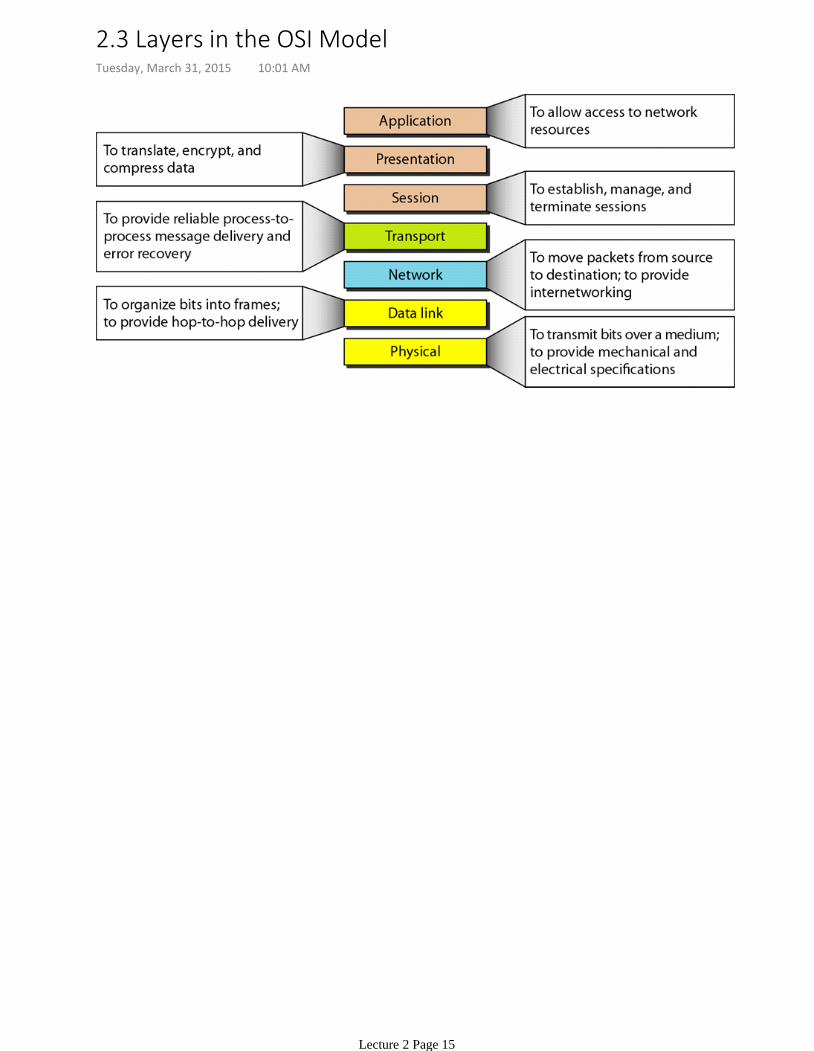
2.3 Layers in the OSI ModelTuesday, March 31, 2015 10:01 AM
Lecture 2 Page 15
Mechanical and electrical specifications of the interface and transmission medium.•Defines procedures and functions for physical devices and interfaces•
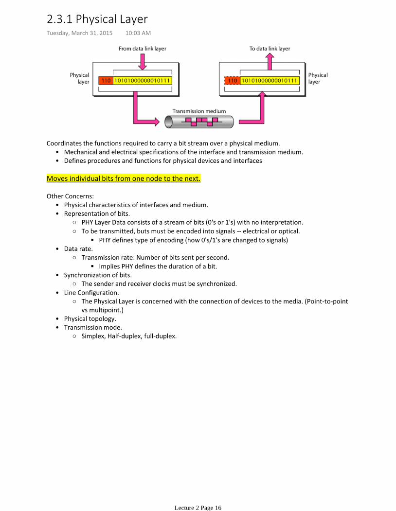
Coordinates the functions required to carry a bit stream over a physical medium.
Moves individual bits from one node to the next.
Physical characteristics of interfaces and medium.•
PHY Layer Data consists of a stream of bits (0's or 1's) with no interpretation.
PHY defines type of encoding (how 0's/1's are changed to signals)
To be transmitted, buts must be encoded into signals -- electrical or optical.
Representation of bits.•
Implies PHY defines the duration of a bit.
Transmission rate: Number of bits sent per second.
Data rate.•
The sender and receiver clocks must be synchronized.
Synchronization of bits.•
The Physical Layer is concerned with the connection of devices to the media. (Point-to-point vs multipoint.)
Line Configuration.•
Physical topology.•
Simplex, Half-duplex, full-duplex.
Transmission mode.•
Other Concerns:
2.3.1 Physical LayerTuesday, March 31, 2015 10:03 AM
Lecture 2 Page 16
Transforms the PHY layer into a reliable link. Makes PHY appear error-free to the upper layer.
Moves frames from one node to the next.
Divides the stream of bits received from network layer into manageable data units called frames.
Framing.•
Adds a header to the frame to define sender/receiver of the frame.
If frame going to somewhere in same network:
Receiver address is the one that connects this network to the next one.
If frame intended for outside the current network,
Physical addressing.•
If rate(receiver data absorption) < rate(sender data produced)
Try to avoid overwhelming the receiver
Flow control.•
Add mechanisms to detect and retransmit damaged or lost frames.
Recognizes duplicate frames.
Typically achieved through trailer added to end of frame.
Error Control.•
When two or more devices connected to the same link, data link layer determines which device has control over the link at any time.
Access Control•
Other responsibilities:
2.3.2 Data Link LayerTuesday, March 31, 2015 10:12 AM
Lecture 2 Page 17
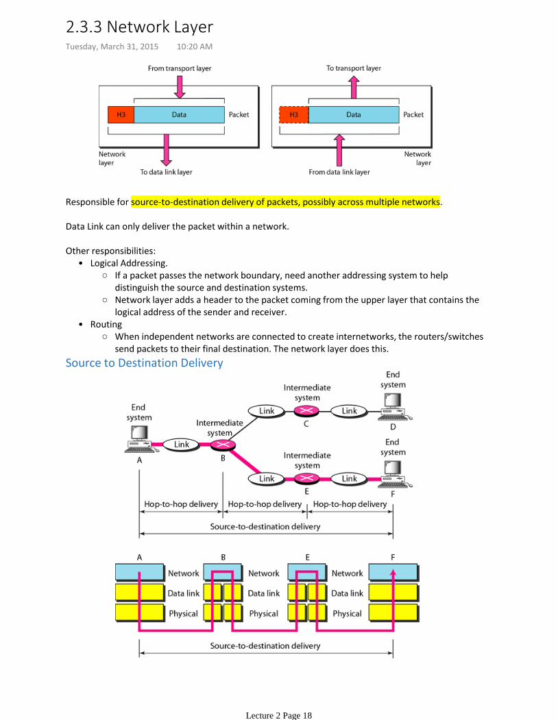
Responsible for source-to-destination delivery of packets, possibly across multiple networks.
Data Link can only deliver the packet within a network.
If a packet passes the network boundary, need another addressing system to help distinguish the source and destination systems.
Network layer adds a header to the packet coming from the upper layer that contains the logical address of the sender and receiver.
Logical Addressing.•
When independent networks are connected to create internetworks, the routers/switches send packets to their final destination. The network layer does this.
Routing•
Other responsibilities:
Source to Destination Delivery
2.3.3 Network LayerTuesday, March 31, 2015 10:20 AM
Lecture 2 Page 18
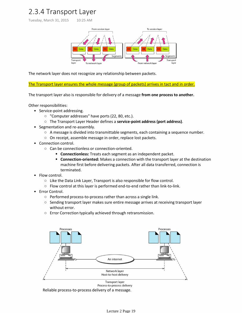
The network layer does not recognize any relationship between packets.
The Transport layer ensures the whole message (group of packets) arrives in tact and in order.
The transport layer also is responsible for delivery of a message from one process to another.
"Computer addresses" have ports (22, 80, etc.).
The Transport Layer Header defines a service-point address (port address).
Service-point addressing.•
A message is divided into transmittable segments, each containing a sequence number.
On receipt, assemble message in order, replace lost packets.
Segmentation and re-assembly.•
Connectionless: Treats each segment as an independent packet.
Connection-oriented: Makes a connection with the transport layer at the destination machine first before delivering packets. After all data transferred, connection is terminated.
Can be connectionless or connection-oriented.
Connection control.•
Like the Data Link Layer, Transport is also responsible for flow control.
Flow control at this layer is performed end-to-end rather than link-to-link.
Flow control.•
Performed process-to-process rather than across a single link.
Sending transport layer makes sure entire message arrives at receiving transport layer without error.
Error Correction typically achieved through retransmission.
Error Control.•
Other responsibilities:
Reliable process-to-process delivery of a message.
2.3.4 Transport LayerTuesday, March 31, 2015 10:25 AM
Lecture 2 Page 19
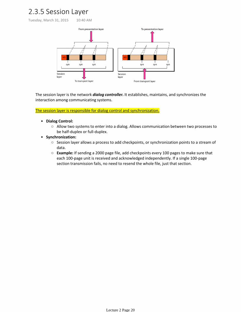
The session layer is the network dialog controller. It establishes, maintains, and synchronizes the interaction among communicating systems.
The session layer is responsible for dialog control and synchronization.
Allow two systems to enter into a dialog. Allows communication between two processes to be half-duplex or full-duplex.
Dialog Control:•
Session layer allows a process to add checkpoints, or synchronization points to a stream of data.
Example: If sending a 2000 page file, add checkpoints every 100 pages to make sure that each 100-page unit is received and acknowledged independently. If a single 100-page section transmission fails, no need to resend the whole file, just that section.
Synchronization:•
2.3.5 Session LayerTuesday, March 31, 2015 10:40 AM
Lecture 2 Page 20
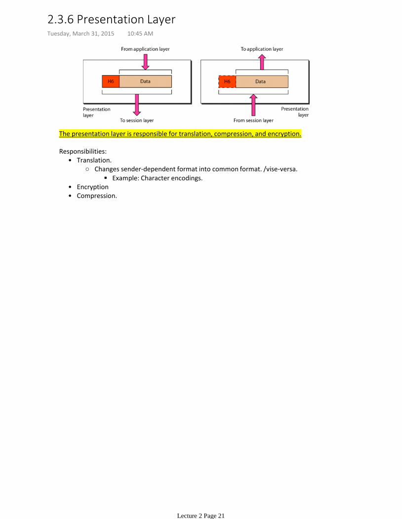
The presentation layer is responsible for translation, compression, and encryption.
Example: Character encodings.
Changes sender-dependent format into common format. /vise-versa.
Translation.•
Encryption•Compression.•
Responsibilities:
2.3.6 Presentation LayerTuesday, March 31, 2015 10:45 AM
Lecture 2 Page 21

The Application Layer is responsible for providing services to the user.
2.3.7 Application LayerTuesday, March 31, 2015 10:48 AM
Lecture 2 Page 22
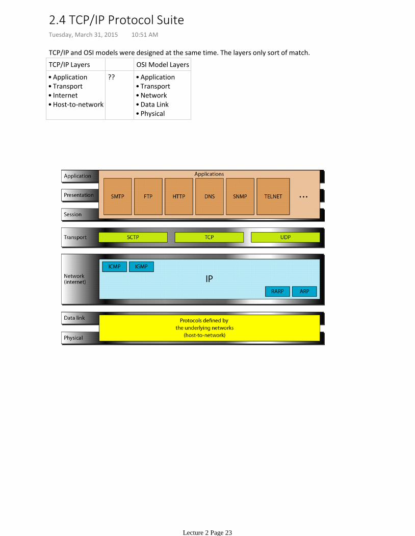
TCP/IP and OSI models were designed at the same time. The layers only sort of match.
TCP/IP Layers OSI Model Layers
Application•Transport•Internet•Host-to-network•
?? Application•Transport•Network•Data Link •Physical•
2.4 TCP/IP Protocol SuiteTuesday, March 31, 2015 10:51 AM
Lecture 2 Page 23
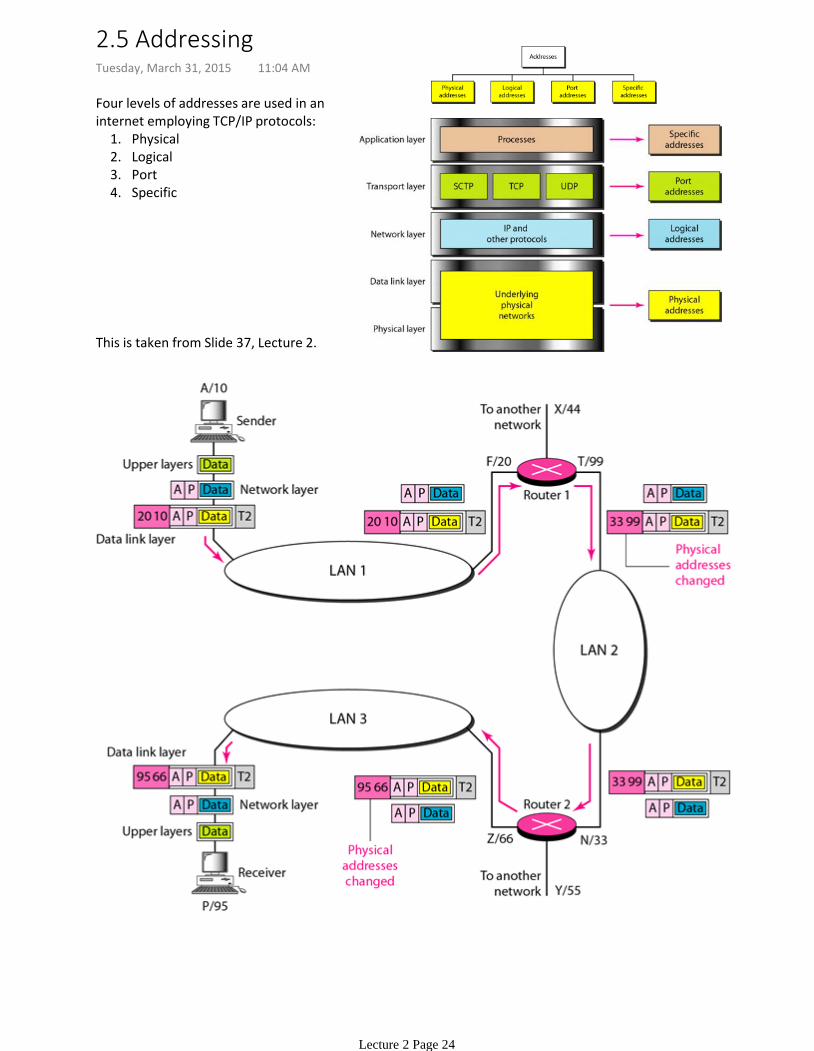
Physical1.Logical2.Port3.Specific4.
Four levels of addresses are used in an internet employing TCP/IP protocols:
This is taken from Slide 37, Lecture 2.
2.5 AddressingTuesday, March 31, 2015 11:04 AM
Lecture 2 Page 24

2.5.a ExamplesTuesday, March 31, 2015 11:12 AM
Lecture 2 Page 25
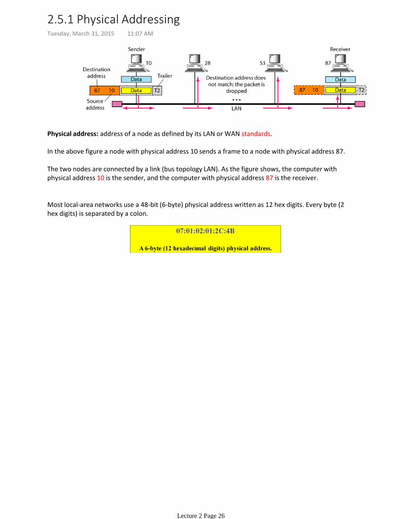
Physical address: address of a node as defined by its LAN or WAN standards.
In the above figure a node with physical address 10 sends a frame to a node with physical address 87.
The two nodes are connected by a link (bus topology LAN). As the figure shows, the computer with physical address 10 is the sender, and the computer with physical address 87 is the receiver.
Most local-area networks use a 48-bit (6-byte) physical address written as 12 hex digits. Every byte (2 hex digits) is separated by a colon.
2.5.1 Physical AddressingTuesday, March 31, 2015 11:07 AM
Lecture 2 Page 26
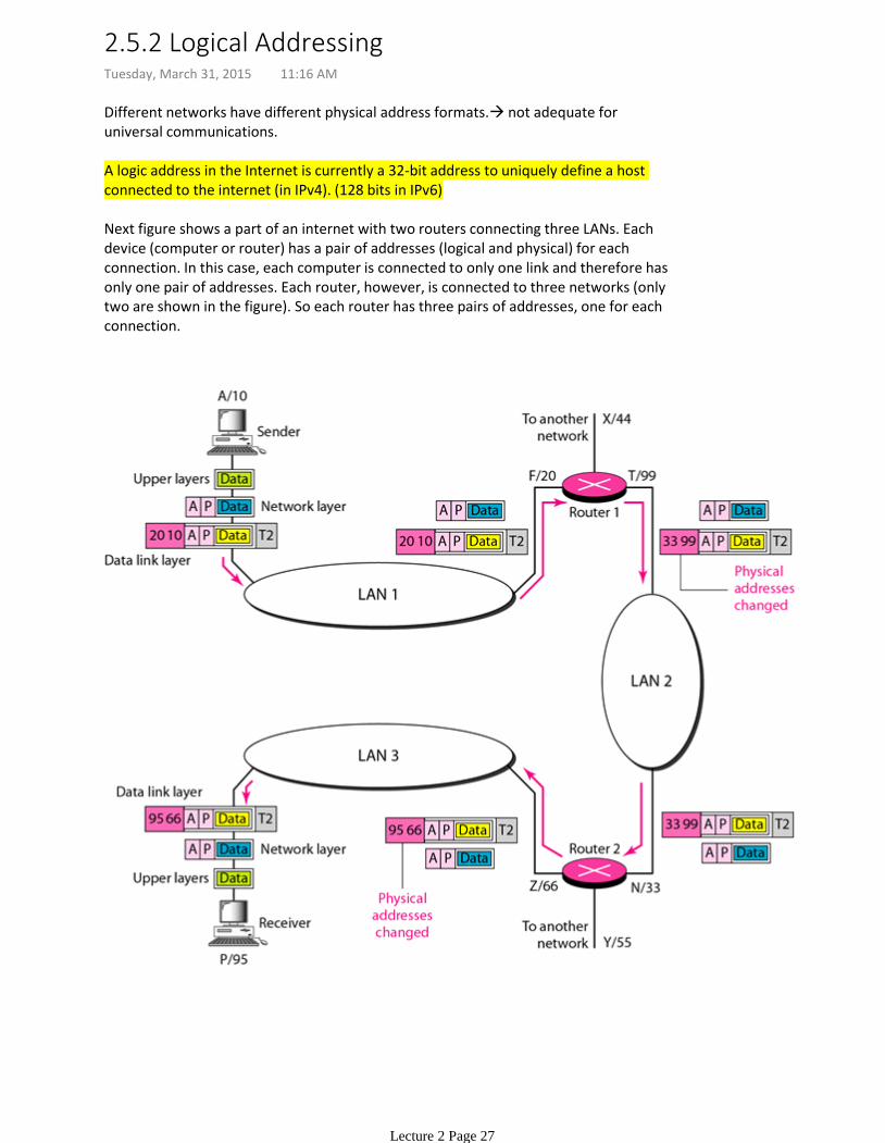
Different networks have different physical address formats. not adequate for universal communications.
A logic address in the Internet is currently a 32-bit address to uniquely define a host connected to the internet (in IPv4). (128 bits in IPv6)
Next figure shows a part of an internet with two routers connecting three LANs. Each device (computer or router) has a pair of addresses (logical and physical) for each connection. In this case, each computer is connected to only one link and therefore has only one pair of addresses. Each router, however, is connected to three networks (only two are shown in the figure). So each router has three pairs of addresses, one for each connection.
2.5.2 Logical AddressingTuesday, March 31, 2015 11:16 AM
Lecture 2 Page 27
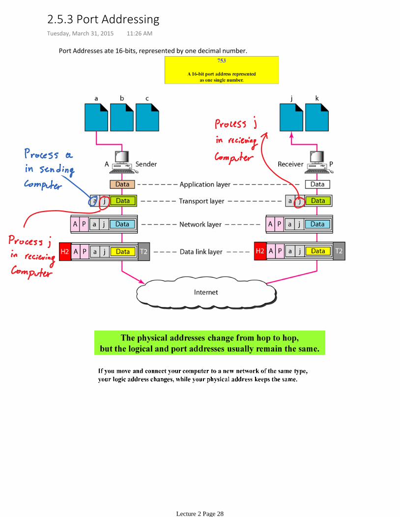
Port Addresses ate 16-bits, represented by one decimal number.
2.5.3 Port AddressingTuesday, March 31, 2015 11:26 AM
Lecture 2 Page 28
2.5.4 Specific AddressesTuesday, March 31, 2015 11:35 AM
Lecture 2 Page 29
Chapter 10 in the textbook.
Lecture 3: Error Detection and CorrectionTuesday, March 31, 2015 11:36 AM
Lecture 3 Page 30
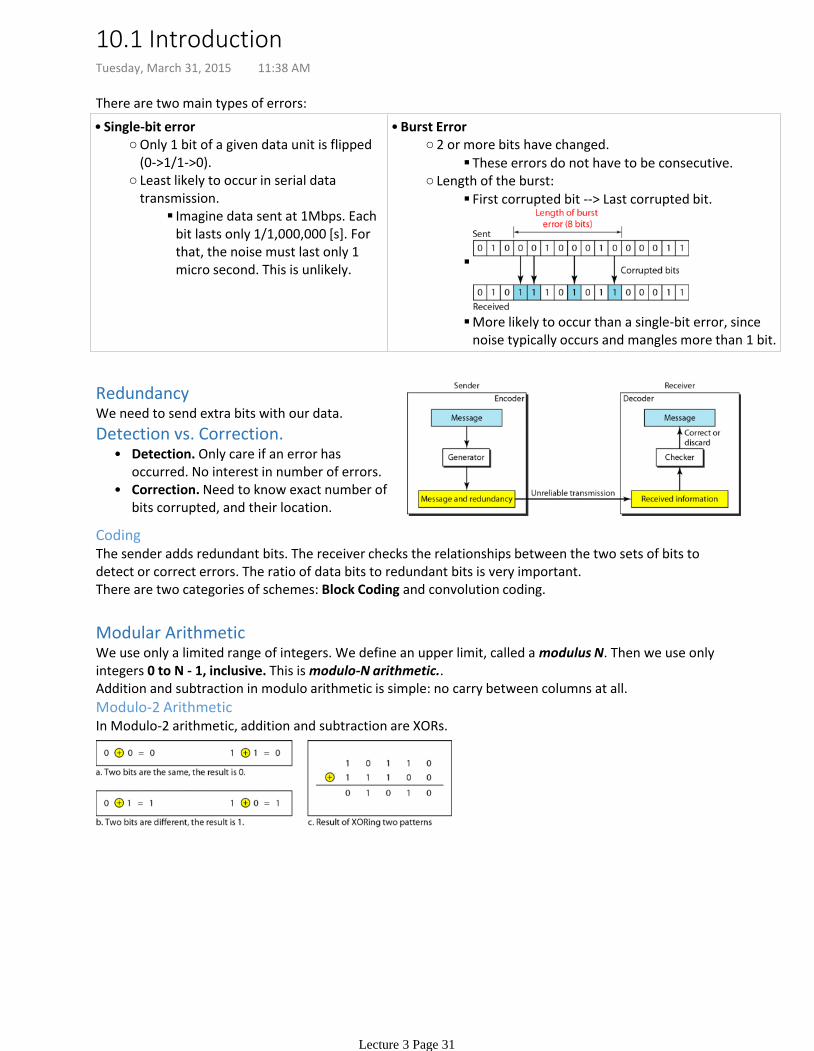
There are two main types of errors:
Only 1 bit of a given data unit is flipped (0->1/1->0).
Imagine data sent at 1Mbps. Each bit lasts only 1/1,000,000 [s]. For that, the noise must last only 1 micro second. This is unlikely.
Least likely to occur in serial data transmission.
Single-bit error•
These errors do not have to be consecutive.
2 or more bits have changed.
First corrupted bit --> Last corrupted bit.
More likely to occur than a single-bit error, since noise typically occurs and mangles more than 1 bit.
Length of the burst:
Burst Error•
RedundancyWe need to send extra bits with our data.
Detection. Only care if an error has occurred. No interest in number of errors.
•
Correction. Need to know exact number of bits corrupted, and their location.
•
Detection vs. Correction.
CodingThe sender adds redundant bits. The receiver checks the relationships between the two sets of bits to detect or correct errors. The ratio of data bits to redundant bits is very important.There are two categories of schemes: Block Coding and convolution coding.
Modular ArithmeticWe use only a limited range of integers. We define an upper limit, called a modulus N. Then we use only integers 0 to N - 1, inclusive. This is modulo-N arithmetic..Addition and subtraction in modulo arithmetic is simple: no carry between columns at all.
Modulo-2 ArithmeticIn Modulo-2 arithmetic, addition and subtraction are XORs.
10.1 IntroductionTuesday, March 31, 2015 11:38 AM
Lecture 3 Page 31

We divide our message into blocks, each of k-bits into datawords. We add r redundant bits to each block to make it length n = k + r.
There's some fun math that makes error checking work.
There are datawords. There are codewords. Since , then the number of possible codewords is larger than the number of possible
datawords. This means that Codewords are invalid/illegal.
Error Detection
The receiver has (or can find) a list of valid codewords.•The original codeword has changed to an invalid one.•
If the following two conditions are met, the receiver can detect a change in the original codeword:
Bogus ExampleLet us assume that k = 2 and n = 3. Table 10.1 shows the list of datawords and codewords. Later, we will see how to derive a codeword from a dataword.
Assume the sender encodes the dataword 01 as 011 andsends it to the receiver. Consider the following cases:
The receiver receives 011. It is a valid codeword. The receiver extracts the dataword 01 from it.
1.
The codeword is corrupted during transmission, and 111 is received. This is not a valid codeword and is discarded.
2.
The codeword is corrupted during transmission, and 000 is received. This is a valid codeword. The receiver incorrectly extracts the dataword 00. Two corrupted bits have made the error undetectable.
3.
Error CorrectionWe need more redundant bits to perform error correction, compared to detection. The idea is similar to error detection, but the checker functions are more complex.
Bogus ExampleLet us add more redundant bits to Example 10.2 to see if the receiver can correct an error without knowing what was actually sent.
We add 3 redundant bits to the 2-bit dataword to make 5-bit codewords. Table 10.2 shows the datawords and codewords.
Assume the dataword is 01. •The sender creates the codeword 01011. •The codeword is corrupted during transmission, and 01001 is received.
•
First, the receiver finds that the received codeword is not in the table. This means an error has occurred. The receiver, assuming that there is only 1 bit corrupted, uses the following strategy to guess the correct dataword.
1. Comparing the received codeword with the first codeword in the table (01001 versus 00000), the receiver decides that the first codeword is not the one that was sent because there are two different bits.2. By the same reasoning, the original codeword cannot be the third or fourth one in the table.3. The original codeword must be the second one in the table because this is the only one that differs from the received codeword by 1 bit. The receiver replaces 01001 with 01011 and consults the table to find the dataword 01.
10.2 Block CodingTuesday, March 31, 2015 11:57 AM
Lecture 3 Page 32
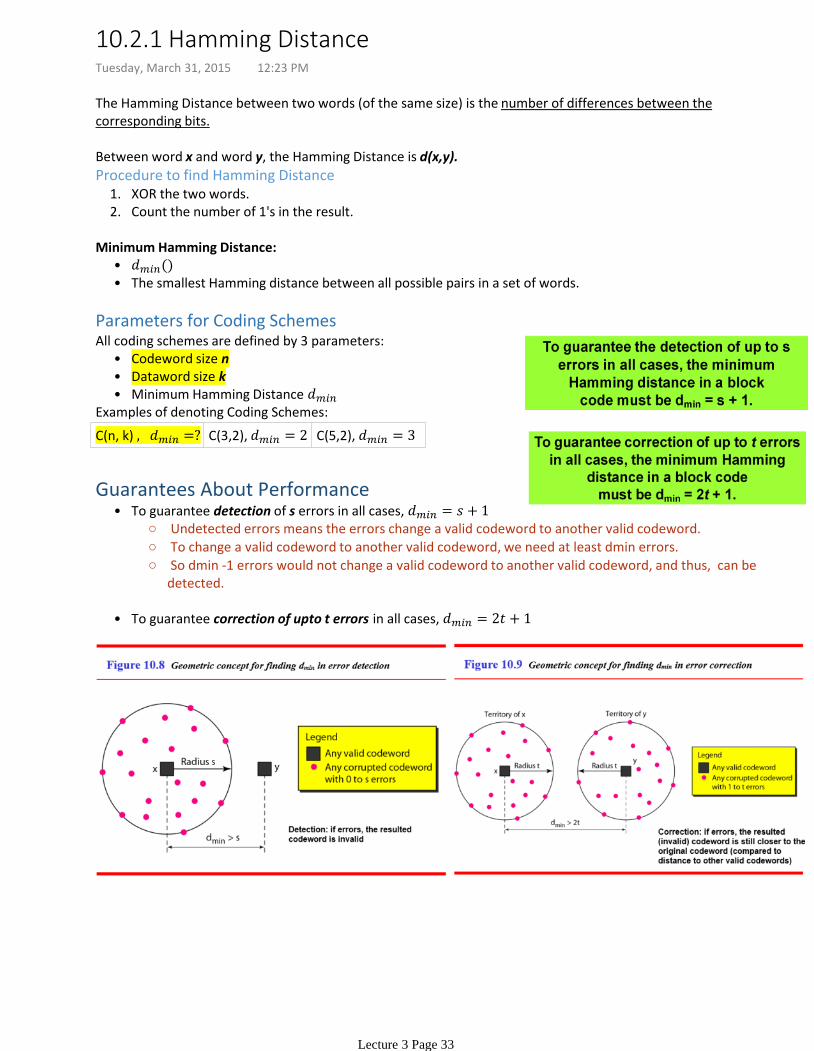
The Hamming Distance between two words (of the same size) is the number of differences between the corresponding bits.
Between word x and word y, the Hamming Distance is d(x,y).
XOR the two words.1.Count the number of 1's in the result.2.
Procedure to find Hamming Distance
•The smallest Hamming distance between all possible pairs in a set of words.•
Minimum Hamming Distance:
Parameters for Coding Schemes
Codeword size n•Dataword size k•Minimum Hamming Distance •
All coding schemes are defined by 3 parameters:
Examples of denoting Coding Schemes:
C(n, k) C(3,2), C(5,2),
Undetected errors means the errors change a valid codeword to another valid codeword.
To change a valid codeword to another valid codeword, we need at least dmin errors.
So dmin -1 errors would not change a valid codeword to another valid codeword, and thus, can be detected.
To guarantee detection of s errors in all cases, •
To guarantee correction of upto t errors in all cases, •
Guarantees About Performance
10.2.1 Hamming DistanceTuesday, March 31, 2015 12:23 PM
Lecture 3 Page 33
Most block codes used today are Linear Block Codes.
Linear Block Code: The XOR of two valid codewords creates another codeword.
The number of 1's in the smallest non-zero valid codeword.•
Minimum Hamming Distance for Linear Block Codes
Check XORing any codeword with another one creates a valid codeword.1.
Checking if a "code" belongs to Linear Block Codes
10.3 Linear Block CodesTuesday, March 31, 2015 12:41 PM
Lecture 3 Page 34
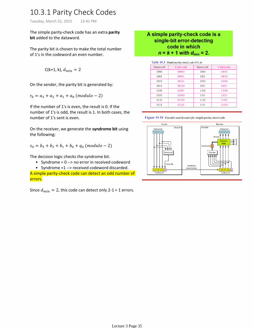
The simple parity-check code has an extra parity bit added to the dataword.
The parity bit is chosen to make the total number of 1's in the codeword an even number.
C(k+1, k),
On the sender, the parity bit is generated by:
If the number of 1's is even, the result is 0. If the number of 1's is odd, the result is 1. In both cases, the number of 1's sent is even.
On the receiver, we generate the syndrome bit using the following:
Syndrome = 0 --> no error in received codeword•Syndrome =1 --> received codeword discarded.•
The decision logic checks the syndrome bit.
A simple parity-check code can detect an odd number of errors.
Since , this code can detect only 2-1 = 1 errors.
10.3.1 Parity Check CodesTuesday, March 31, 2015 12:41 PM
Lecture 3 Page 35
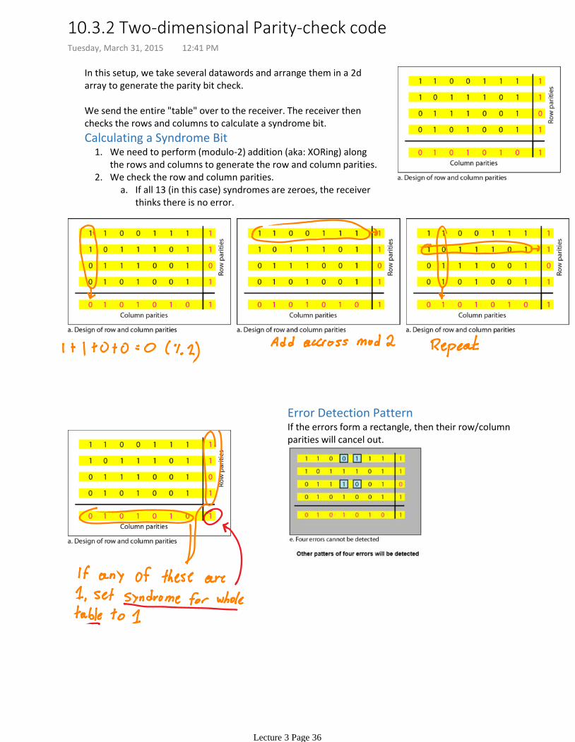
In this setup, we take several datawords and arrange them in a 2d array to generate the parity bit check.
We send the entire "table" over to the receiver. The receiver then checks the rows and columns to calculate a syndrome bit.
We need to perform (modulo-2) addition (aka: XORing) along the rows and columns to generate the row and column parities.
1.
If all 13 (in this case) syndromes are zeroes, the receiver thinks there is no error.
a.We check the row and column parities.2.
Calculating a Syndrome Bit
Error Detection PatternIf the errors form a rectangle, then their row/column parities will cancel out.
10.3.2 Two-dimensional Parity-check codeTuesday, March 31, 2015 12:41 PM
Lecture 3 Page 36
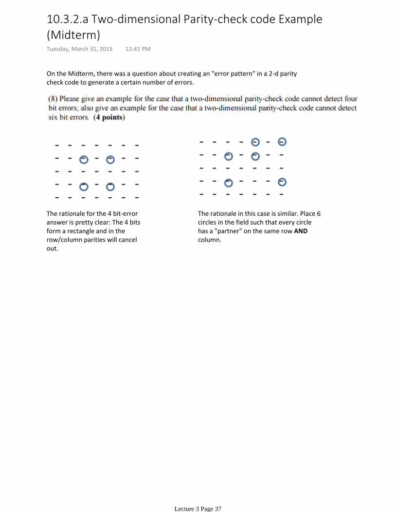
On the Midterm, there was a question about creating an "error pattern" in a 2-d parity check code to generate a certain number of errors.
The rationale for the 4 bit-error answer is pretty clear: The 4 bits form a rectangle and in the row/column parities will cancel out.
The rationale in this case is similar. Place 6 circles in the field such that every circle has a "partner" on the same row AND column.
10.3.2.a Two-dimensional Parity-check code Example (Midterm)Tuesday, March 31, 2015 12:41 PM
Lecture 3 Page 37
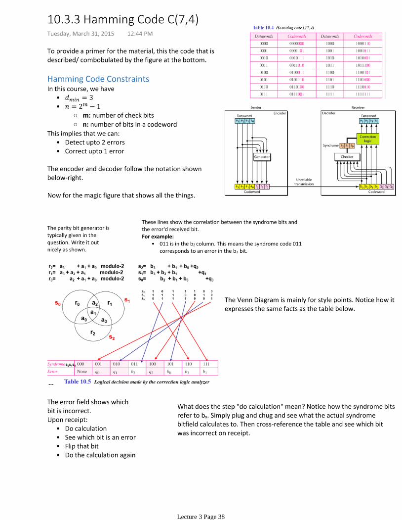
To provide a primer for the material, this the code that is described/ combobulated by the figure at the bottom.
Hamming Code Constraints
•
m: number of check bits
n: number of bits in a codeword
•
In this course, we have
Detect upto 2 errors•Correct upto 1 error•
This implies that we can:
The encoder and decoder follow the notation shown below-right.
Now for the magic figure that shows all the things.
The error field shows which bit is incorrect.
Do calculation•See which bit is an error•Flip that bit•Do the calculation again•
Upon receipt:
The parity bit generator is typically given in the question. Write it out nicely as shown.
These lines show the correlation between the syndrome bits and the error'd received bit.
011 is in the b2 column. This means the syndrome code 011 corresponds to an error in the b2 bit.
•For example:
The Venn Diagram is mainly for style points. Notice how it expresses the same facts as the table below.
What does the step "do calculation" mean? Notice how the syndrome bits refer to bx. Simply plug and chug and see what the actual syndrome bitfield calculates to. Then cross-reference the table and see which bit was incorrect on receipt.
10.3.3 Hamming Code C(7,4)Tuesday, March 31, 2015 12:44 PM
Lecture 3 Page 38
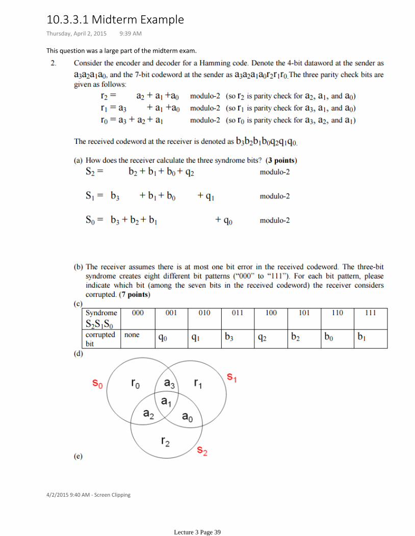
This question was a large part of the midterm exam.
4/2/2015 9:40 AM - Screen Clipping
10.3.3.1 Midterm ExampleThursday, April 2, 2015 9:39 AM
Lecture 3 Page 39
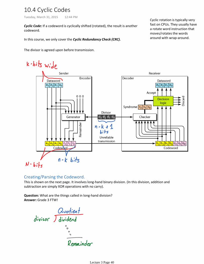
Cyclic Code: If a codeword is cyclically shifted (rotated), the result is another codeword.
In this course, we only cover the Cyclic Redundancy Check (CRC).
Cyclic rotation is typically very fast on CPUs. They usually have a rotate word instruction that moves/rotates the words around with wrap-around.
The divisor is agreed upon before transmission.
Creating/Parsing the Codeword.This is shown on the next page. It involves long-hand binary division. (In this division, addition and subtraction are simply XOR operations with no carry).
Question: What are the things called in long-hand division?Answer: Grade 3 FTW!
10.4 Cyclic CodesTuesday, March 31, 2015 12:44 PM
Lecture 3 Page 40
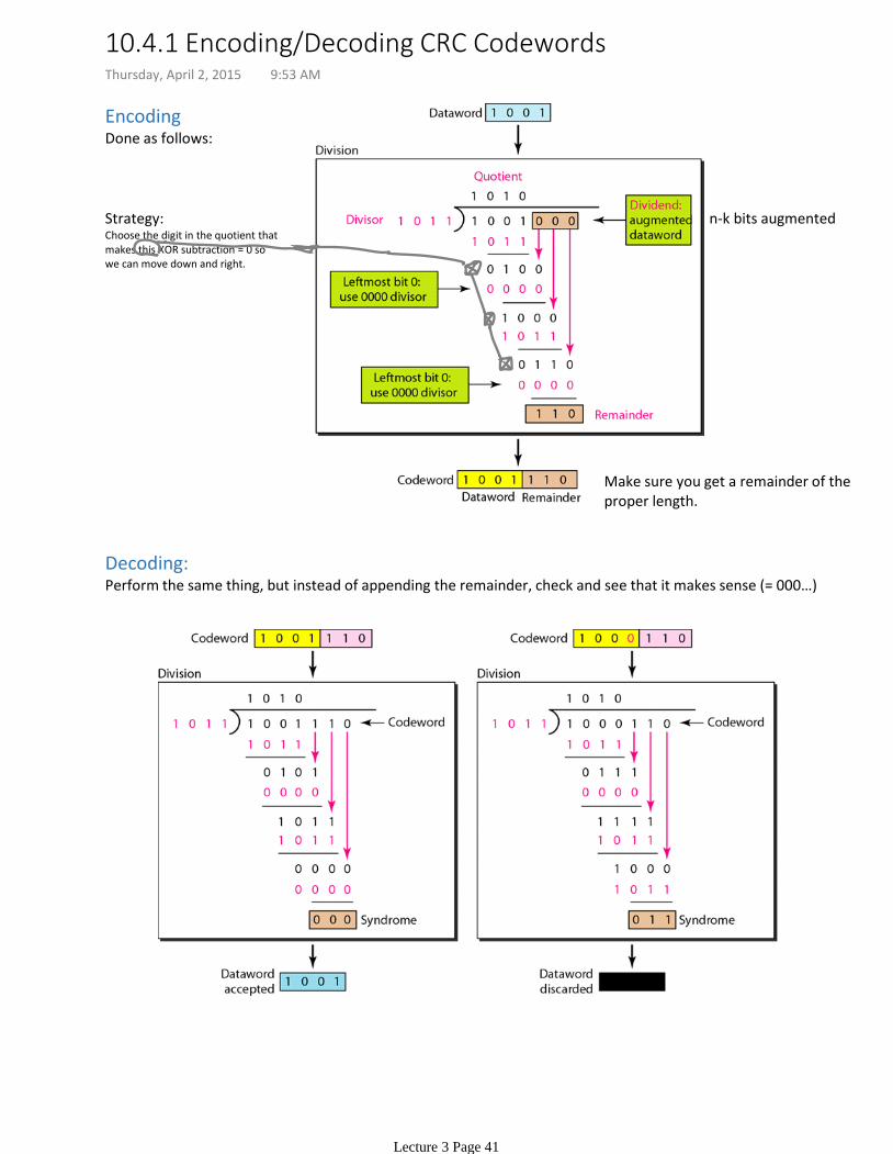
Encoding Done as follows:
n-k bits augmented
Make sure you get a remainder of the proper length.
Strategy:Choose the digit in the quotient that makes this XOR subtraction = 0 so we can move down and right.
Decoding:Perform the same thing, but instead of appending the remainder, check and see that it makes sense (= 000…)
10.4.1 Encoding/Decoding CRC CodewordsThursday, April 2, 2015 9:53 AM
Lecture 3 Page 41
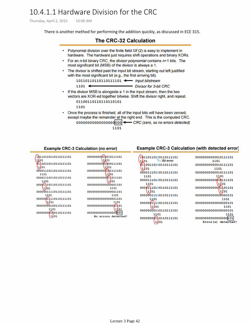
There is another method for performing the addition quickly, as discussed in ECE 315.
10.4.1.1 Hardware Division for the CRCThursday, April 2, 2015 10:00 AM
Lecture 3 Page 42

The bottom one is from the ECE 315 Midterm.
10.4.2 CRC Examples (Midterm)Thursday, April 2, 2015 10:09 AM
Lecture 3 Page 43

We don't really touch on Checksums in this course too much, but it's included in the lecture slides.
Suppose our data is a list of five 8-bit numbers that we want to send to a destination. •
If the two are the same, the receiver assumes no error, accepts the five numbers, and discards the sum.
Otherwise, there is an error somewhere and the data are not accepted.
The receiver adds the five numbers and compares the result with the sum.
For example, if the set of numbers is (7, 11, 12, 0, 6), we send (7, 11, 12, 0, 6, 36), where 36 is the sum of the original numbers.
In addition to sending these numbers, we send the sum of the numbers. •
We can make the job of the receiver easier if we send the negative (complement) of the sum, called the checksum. In this case, we send (7, 11, 12, 0, 6, −36). The receiver can add all the numbers received (including the checksum). If the result is 0, it assumes no error; otherwise, there is an error.
•
Example 10.18
10.5 ChecksumTuesday, March 31, 2015 12:44 PM
Lecture 3 Page 44
Chapter 12 in the textbook.
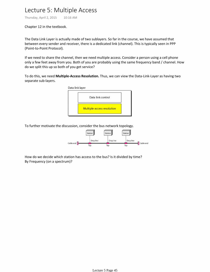
The Data Link Layer is actually made of two sublayers. So far in the course, we have assumed that between every sender and receiver, there is a dedicated link (channel). This is typically seen in PPP (Point-to-Point Protocol).
If we need to share the channel, then we need multiple access. Consider a person using a cell phone only a few feet away from you. Both of you are probably using the same frequency band / channel. How do we split this up so both of you get service?
To do this, we need Multiple-Access Resolution. Thus, we can view the Data-Link-Layer as having two separate sub-layers.
To further motivate the discussion, consider the bus network topology.
How do we decide which station has access to the bus? Is it divided by time? By Frequency (on a spectrum)?
Lecture 5: Multiple AccessThursday, April 2, 2015 10:16 AM
Lecture 5 Page 45
No station assigned control over another.
(Aka: is the bus busy with things on it?).The decision is based on the state of the medium
No station does not permit/not permit another station to send.
No station is superior.•
Every station transmits whenever it feels like it.
There is no scheduled time for a station to transmit.•
Stations compete (contention) on who takes the medium next.
There is no agreement on who transmits next.•
Random Access (Contention) methods:
To avoid this, we need to follow a procedure.•
If more than one station attempts to send at the same time there is an access conflict/collision and frames are either destroyed/lost/or modified.
When can the station access the medium?•What can the station do if the medium is busy?•How can the station determine the success for failure of the transmission?•What can the station do if there is an access conflict?•
Any procedure for multiple access must answer the following questions:
ALOHA•Carrier Sense Multiple Access (CSMA)•Carrier Sense Multiple Access with Collision Detection•Carrier Sense Multiple Access with Collision Avoidance.•
The following protocols for random-access are discussed:
12.1 Random AccessThursday, April 2, 2015 10:22 AM
Lecture 5 Page 46

Each station sends a frame whenever it has a frame to send.
•
Since there is only one channel, there is a possibility of collisions.
•
Main Idea
In the figure above, there are 4 stations. Each station sends two frames, making 8 frames total on one medium. Some of these frames collide. The above figure shows that only two frames survive.
Problem: If two stations re-send frames at the exact same times on the same medium, both frame will be lost. (Hello Race Condition!)
•
Solution: Pure ALOHA dictates that a sender, upon failing to get an ACK (ACK timed out), will wait a random amount of time before re-sending the frame. This is the back-off time,
•
Pure ALOHA relies on ACKnowledgements from the server. If the ACK does not arrive in a specific time period, then the sender just re-sends the frame.
After a maximum number of re-transmission attempts ( ), a station must give up and try again later.
Pure ALOHA prevents congesting the channel with re-transmitted frames.•What if the channel is really crappy and it gets filled with re-sends? This creates congestion.
The above discussion is shown in the figure below.
= maximum possible round-tip delay.
Time-out Period:•
Typically related to K (maximum re-transmission attempts.
Implementation Specific.
Back-off Time •
Constraints/Figures:
Back-off Time Calculation.In this course, we have a formula for calculating
Randomly pick a number between . Call this number Z. (Where Z is a discrete range of integers).
1.
, where is the maximum propigation time.
2.
OR , where is the average time required to send out a frame.
3.
Procedure:
The value of is typically chosen as 15.
ExampleThe stations on a wireless ALOHA network are a maximum of 600 km apart. If we assume that signals propagate at 3 × 10⁸ m/s, we find Tp = (600 × 105 ) / (3 × 10⁸ ) = 2 ms.Now we can find the value of TB for different values of K .a. For K = 1, the range is 0, 1. The station needs to generate a random number with a value of 0 or 1. This means that TB is either 0 ms (0 × 2) or 2 ms (1 × 2), based on the outcome of the random variable.b. For K = 2, the range is 0, 1, 2, 3. This means that TB can be 0, 2, 4, or 6 ms, based on the outcome of the random variable.c. For K = 3, the range is 0, 1, 2, 3, 4, 5, 6, 7. This means that TB can be 0, 2, 4, . . . , 14 ms, based on the outcome of the random variable.d. We need to mention that if K > 10, it is normally set to 10. (in other words, the range is 0,1,2,…,1023)
12.1.1 ALOHA Thursday, April 2, 2015 10:28 AM
Lecture 5 Page 47
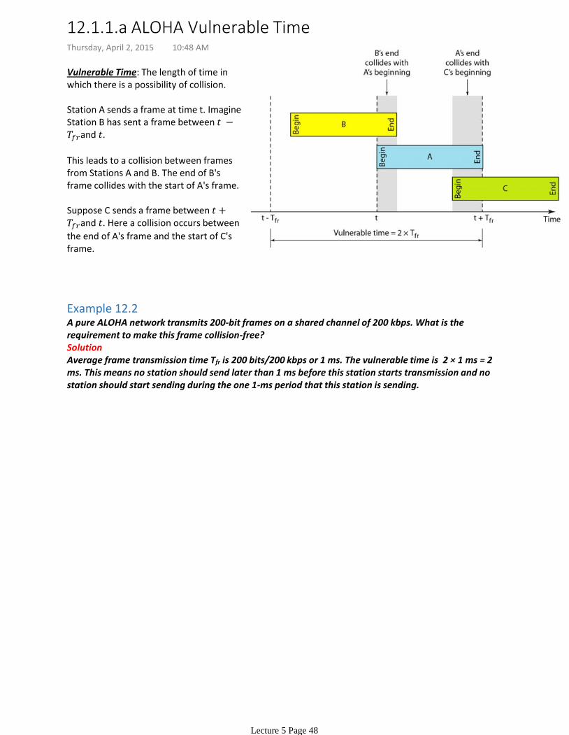
Vulnerable Time: The length of time in which there is a possibility of collision.
Station A sends a frame at time t. Imagine Station B has sent a frame between and .
This leads to a collision between frames from Stations A and B. The end of B's frame collides with the start of A's frame.
Suppose C sends a frame between and . Here a collision occurs between
the end of A's frame and the start of C's frame.
Example 12.2A pure ALOHA network transmits 200-bit frames on a shared channel of 200 kbps. What is the requirement to make this frame collision-free?SolutionAverage frame transmission time Tfr is 200 bits/200 kbps or 1 ms. The vulnerable time is 2 × 1 ms = 2 ms. This means no station should send later than 1 ms before this station starts transmission and no station should start sending during the one 1-ms period that this station is sending.
12.1.1.a ALOHA Vulnerable TimeThursday, April 2, 2015 10:48 AM
Lecture 5 Page 48
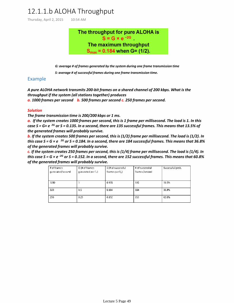
G: average # of frames generated by the system during one frame transmission time
S: average # of successful frames during one frame transmission time.
Example
A pure ALOHA network transmits 200-bit frames on a shared channel of 200 kbps. What is the throughput if the system (all stations together) producesa. 1000 frames per second b. 500 frames per second c. 250 frames per second.
SolutionThe frame transmission time is 200/200 kbps or 1 ms.a. If the system creates 1000 frames per second, this is 1 frame per millisecond. The load is 1. In this case S = G× e
−
2G or S = 0.135. In a second, there are 135 successful frames. This means that 13.5% of the generated frames will probably survive. b. If the system creates 500 frames per second, this is (1/2) frame per millisecond. The load is (1/2). In this case S = G × e
−
2G or S = 0.184. In a second, there are 184 successful frames. This means that 36.8% of the generated frames will probably survive.c. If the system creates 250 frames per second, this is (1/4) frame per millisecond. The load is (1/4). In this case S = G × e -2G or S = 0.152. In a second, there are 152 successful frames. This means that 60.8% of the generated frames will probably survive.
12.1.1.b ALOHA ThroughputThursday, April 2, 2015 10:54 AM
Lecture 5 Page 49

Pure ALOHA did not have a restriction on when stations can send. This means that stations could start spamming, sending just after/before another station has finished sending stuff.
Slotted ALOHA: We divide time into time slots of size We force the station to send only at the beginning of the timeslot.
These timeslots are agreed upon by all stations.
This means that we no longer have a vulnerability as shown.
This implies the station which started at the beginning of the time slot has already finished sending its frame.
•
A station is only allowed to send at the beginning of a time slot. If it misses the start of the slot, it must wait until the beginning of the next time slot.
Slotted ALOHA Vulnerable Time =
12.1.1.c Slotted ALOHA Vulnerability TimeThursday, April 2, 2015 10:58 AM
Lecture 5 Page 50

Example 12.4A slotted ALOHA network transmits 200-bit frames on a shared channel of 200 kbps. What is the throughput if the system (all stations together) producesa. 1000 frames per second b. 500 frames per second c. 250 frames per second.
SolutionThe frame transmission time is 200/200 kbps or 1 ms.a. If the system creates 1000 frames per second, this is 1 frame per millisecond. The load is 1. In this case S = G× e
−
G or S = 0.368. In a second, there are 368 successful frames. This means that 36.8% of the generated frames will probably survive.b. If the system creates 500 frames per second, this is (1/2) frame per millisecond. The load is (1/2). In this case S = G × e
−
G or S = 0.303. In a second, there are 303 successful frames. This means that 60.6% of the generated frames will probably survive.c. If the system creates 250 frames per second, this is (1/4) frame per millisecond. The load is (1/4). In this case S = G × e
−
G or S = 0.195. In a second, there are 195 successful frames. This means that 78% of the generated frames will probably survive.
12.1.1.d Slotted ALOHA ThroughputThursday, April 2, 2015 11:10 AM
Lecture 5 Page 51
The chance of collision can be reduced if a station senses the medium before trying to use it.
Each station first listen to the medium (aka: check the state) before sending
•
"Sense before transmit" / "Listen before talk"•
CSMA requires:
CSMA can reduce possibility of collision, but not eliminate it.
A station may sense the medium and find it idle, only because the first bit sent by another station had not been received (due to propagation delay).
•
The possibility of collision still exists because of propagation delay. When a station sends a frame, it still takes time for the first bit to reach every station and for every station to sense it.
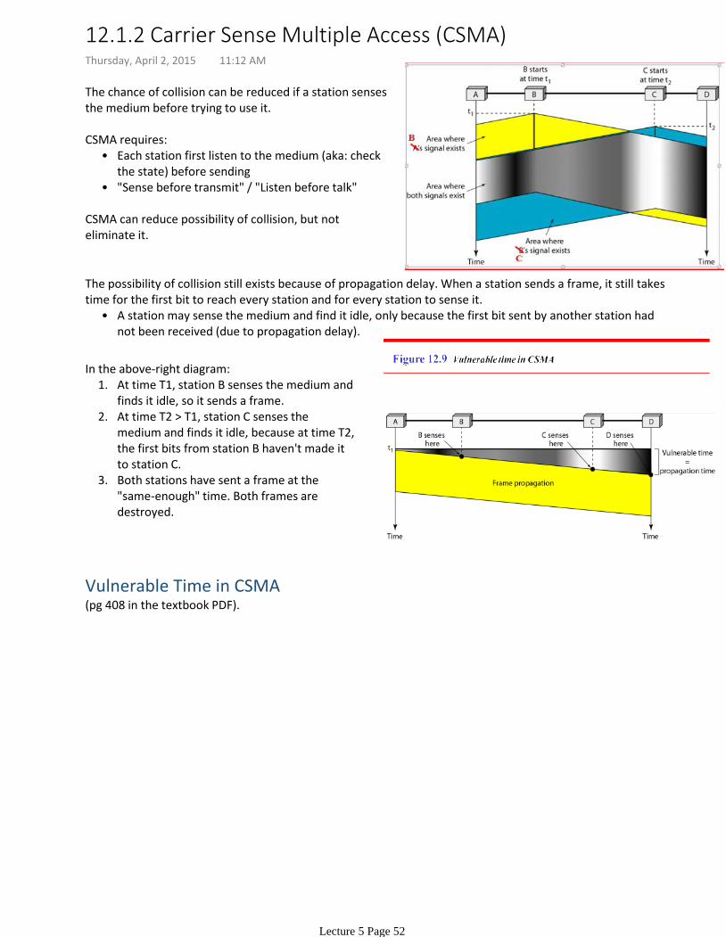
At time T1, station B senses the medium and finds it idle, so it sends a frame.
1.
At time T2 > T1, station C senses the medium and finds it idle, because at time T2, the first bits from station B haven't made it to station C.
2.
Both stations have sent a frame at the "same-enough" time. Both frames are destroyed.
3.
In the above-right diagram:
Vulnerable Time in CSMA(pg 408 in the textbook PDF).
12.1.2 Carrier Sense Multiple Access (CSMA)Thursday, April 2, 2015 11:12 AM
Lecture 5 Page 52
What should a station do if the channel is busy?•What should it do if the channel is idle?•
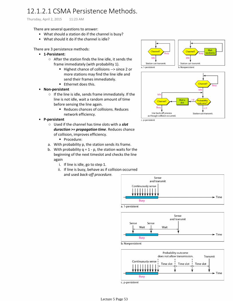
There are several questions to answer:
Highest chance of collisions --> since 2 or more stations may find the line idle and send their frames immediately.
Ethernet does this.
After the station finds the line idle, it sends the frame immediately (with probability 1).
1-Persistent:•
Reduces chances of collisions. Reduces network efficiency.
If the line is idle, sends frame immediately. If the line is not idle, wait a random amount of time before sensing the line again.
Non-persistent•
Procedure:
Used if the channel has time slots with a slot duraction >= propagation time. Reduces chance of collision, improves efficiency.
With probability p, the station sends its frame.a.
If line is idle, go to step 1.i.If line is busy, behave as if collision occurred and used back-off procedure.
ii.
With probability q = 1 - p, the station waits for the beginning of the next timeslot and checks the line again
b.
P-persistent•
There are 3 persistence methods:
12.1.2.1 CSMA Persistence Methods.Thursday, April 2, 2015 11:23 AM
Lecture 5 Page 53
CSMA does not specify what to do if there is a collision. CSMA/CD augments the algorithm the handle the collision.
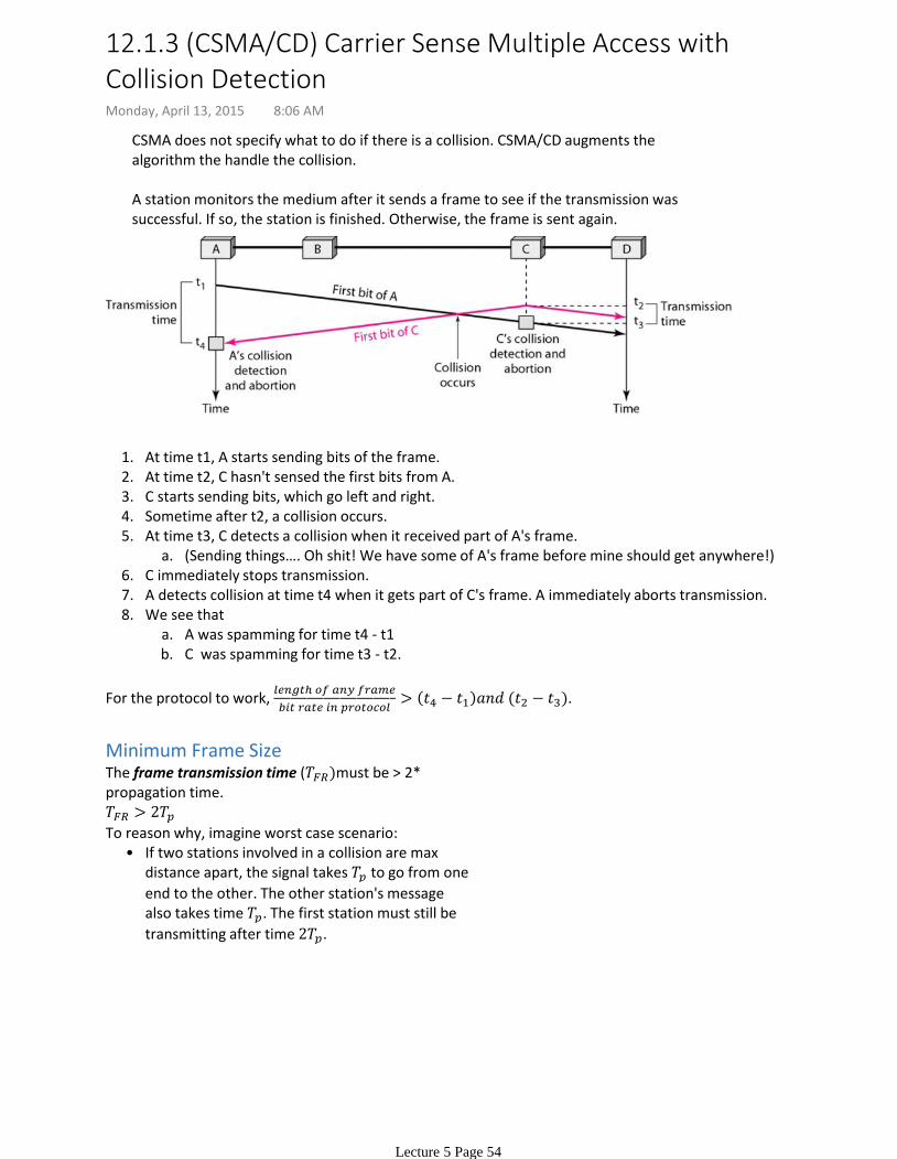
A station monitors the medium after it sends a frame to see if the transmission was successful. If so, the station is finished. Otherwise, the frame is sent again.
At time t1, A starts sending bits of the frame.1.At time t2, C hasn't sensed the first bits from A.2.C starts sending bits, which go left and right.3.Sometime after t2, a collision occurs.4.
(Sending things…. Oh shit! We have some of A's frame before mine should get anywhere!)a.At time t3, C detects a collision when it received part of A's frame.5.
C immediately stops transmission.6.A detects collision at time t4 when it gets part of C's frame. A immediately aborts transmission.7.
A was spamming for time t4 - t1a.C was spamming for time t3 - t2.b.
We see that8.
For the protocol to work,
.
Minimum Frame SizeThe frame transmission time ( must be > 2* propagation time.
If two stations involved in a collision are max distance apart, the signal takes to go from one
end to the other. The other station's message also takes time . The first station must still be
transmitting after time .
•To reason why, imagine worst case scenario:
12.1.3 (CSMA/CD) Carrier Sense Multiple Access with Collision DetectionMonday, April 13, 2015 8:06 AM
Lecture 5 Page 54
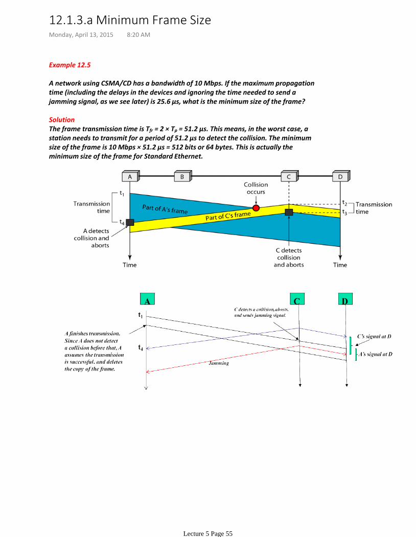
Example 12.5
A network using CSMA/CD has a bandwidth of 10 Mbps. If the maximum propagation time (including the delays in the devices and ignoring the time needed to send a jamming signal, as we see later) is 25.6 μs, what is the minimum size of the frame?
SolutionThe frame transmission time is Tfr = 2 × Tp = 51.2 μs. This means, in the worst case, a station needs to transmit for a period of 51.2 μs to detect the collision. The minimum size of the frame is 10 Mbps × 51.2 μs = 512 bits or 64 bytes. This is actually the minimum size of the frame for Standard Ethernet.
12.1.3.a Minimum Frame SizeMonday, April 13, 2015 8:20 AM
Lecture 5 Page 55
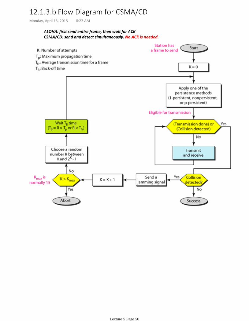
ALOHA: first send entire frame, then wait for ACKCSMA/CD: send and detect simultaneously. No ACK is needed.
12.1.3.b Flow Diagram for CSMA/CDMonday, April 13, 2015 8:22 AM
Lecture 5 Page 56

Channel is idle
Zero:•
A station has successfully captured the channel and is sending its frame.
Normal:•
Collision. --> Energy level is twice of normal.
Abnormal:•
There are three energy levels on a channel: zero, normal, abnormal.
Monitoring the channel is simply measuring the energy level on the channel.
However, the above method only works for wired networks. Wireless is different.
12.1.3.c Energy Level in CSMA/CDMonday, April 13, 2015 8:23 AM
Lecture 5 Page 57

The stations consult one another to find which station has the right to send. A station cannot send unless it has been authorized by other stations.
Topics discussed in this section:ReservationPollingToken Passing
12.2 Controlled AccessMonday, April 13, 2015 8:28 AM
Lecture 5 Page 58
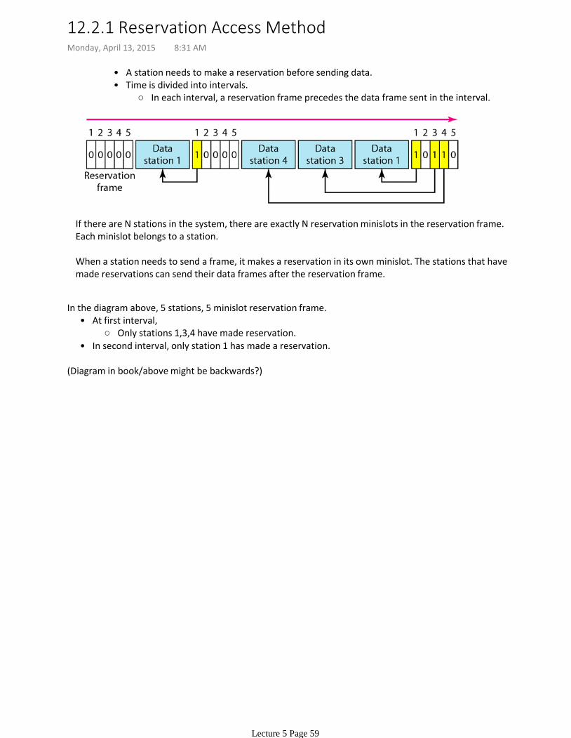
A station needs to make a reservation before sending data.•
In each interval, a reservation frame precedes the data frame sent in the interval.
Time is divided into intervals.•
If there are N stations in the system, there are exactly N reservation minislots in the reservation frame.Each minislot belongs to a station.
When a station needs to send a frame, it makes a reservation in its own minislot. The stations that have made reservations can send their data frames after the reservation frame.
Only stations 1,3,4 have made reservation.
At first interval,•
In second interval, only station 1 has made a reservation.•
In the diagram above, 5 stations, 5 minislot reservation frame.
(Diagram in book/above might be backwards?)
12.2.1 Reservation Access MethodMonday, April 13, 2015 8:31 AM
Lecture 5 Page 59

Polling works with topologies in which one device is designated at the primary station, and the others are secondary stations.
•
The primary device controls the link, the secondary devices follow its instructions.
It is up to the primary device to determine which device is allowed to use the channel at a given time.
All data exchanges must be made through the primary device even when the ultimate destination is a secondary device.
•
The primary device, therefore, is always the initiator of a session.•
Ask the secondaries if they have anything to send --> poll function•If the primary wants to receive data,
Tells the secondaries to get ready to receive --> select function.•If the primary wants to send data,
The primary alerts a secondary that data is coming.•Needs an ACK from the secondary so that the receiver is ready. (The ACK is in response to a SEL frame).
•
SEL is like "YOU'RE GONNA GET DATA WHEN YOU'RE READY. YOU READY BRO?" •
Select
Primary asks everyone in turn if they have something to send. If NAK, then ask the next station.•
Poll
12.2.2 PollingMonday, April 13, 2015 8:35 AM
Lecture 5 Page 60

The stations are organized in a logical ring. Think of this as a doubly-linked list. Every node has a *prev and *next. In Token passing, this is called the predecessor and successor. The current station is the one accessing the network.
When a station has data to send, it waits till it gets the token. (from *prev).•When a station is done sending data, it passes the token along to *next.•
A special packet called a token circulates through the ring. A station who has the token can access the channel and send data.
Considerations
Token possession time must be limited.•The token must be monitored to make sure it is not lost or destroyed.•Need to assign priorities to the stations and to the types of data being transmitted.•Token management is needed to make sure low-priority stations release the token to high-priority stations.
•
We need some token management.
Logical vs. Physical RingsThe stations do not have to be physically connected in a ring.
Dual-ring: Auxiliary ring operates in reverse direction. Used for emergencies only. If one link fails, the secondary ring and part of the main ring form a weird-shaped "backup system"
•
Token Bus LAN uses this.
Bus ring (token bus). Stations connected to a bus. Logically arranged as a ring, however. When a station has finished sending data, inserts successor address into the token. Only the station with matching token destination address gets the token.
•
Star-ring. Physical topology is a star. There is a hub. The wiring inside the hub makes a ring. This topology is used by IBM Token Ring.
•
In a physical ring topology, a single link failure brings down the whole network.
12.2.3 Token PassingMonday, April 13, 2015 8:43 AM
Lecture 5 Page 61

Chapter 13 of the textbook.
Lecture 6: EthernetMonday, April 13, 2015 8:59 AM
Lecture 6 Page 62
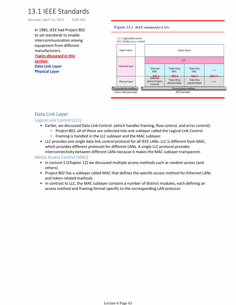
In 1985, IEEE had Project 802 to set standards to enable intercommunication among equipment from different manufacturers. Topics discussed in this section:Data Link LayerPhysical Layer
Data Link Layer
Project 802, all of these are collected into one sublayer called the Logical Link Control.
Framing is handled in the LLC sublayer and the MAC sublayer.
Earlier, we discussed Data Link Control. (which handles framing, flow control, and error control).•
LLC provides one single data link control protocol for all IEEE LANs. LLC is different from MAC, which provides different protocols for different LANs. A single LLC protocol provides interconnectivity between different LANs because it makes the MAC sublayer transparent.
•
Logical Link Control (LLC)
In Lecture 5 (Chapter 12) we discussed multiple access methods such as random access (and others).
•
Project 802 has a sublayer called MAC that defines the specific access method for Ethernet LANs and token-related mathods.
•
In contrast to LLC, the MAC sublayer contains a number of distinct modules, each defining an access method and framing format specific to the corresponding LAN protocol.
•
Media Access Control (MAC)
13.1 IEEE StandardsMonday, April 13, 2015 9:00 AM
Lecture 6 Page 63
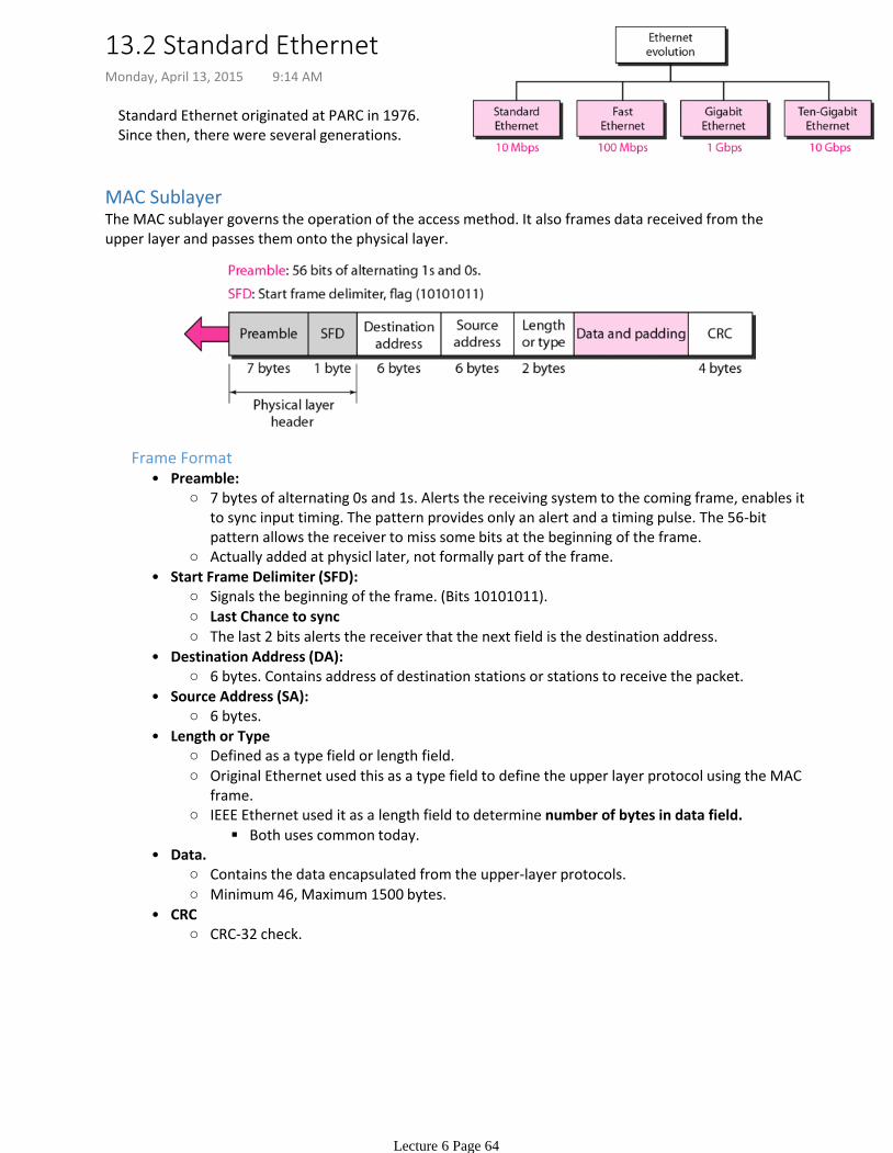
Standard Ethernet originated at PARC in 1976. Since then, there were several generations.
MAC SublayerThe MAC sublayer governs the operation of the access method. It also frames data received from the upper layer and passes them onto the physical layer.
7 bytes of alternating 0s and 1s. Alerts the receiving system to the coming frame, enables it to sync input timing. The pattern provides only an alert and a timing pulse. The 56-bit pattern allows the receiver to miss some bits at the beginning of the frame.
Actually added at physicl later, not formally part of the frame.
Preamble:•
Signals the beginning of the frame. (Bits 10101011).
Last Chance to sync
The last 2 bits alerts the receiver that the next field is the destination address.
Start Frame Delimiter (SFD):•
6 bytes. Contains address of destination stations or stations to receive the packet.
Destination Address (DA):•
6 bytes.
Source Address (SA):•
Defined as a type field or length field.
Original Ethernet used this as a type field to define the upper layer protocol using the MAC frame.
Both uses common today.
IEEE Ethernet used it as a length field to determine number of bytes in data field.
Length or Type•
Contains the data encapsulated from the upper-layer protocols.
Minimum 46, Maximum 1500 bytes.
Data.•
CRC-32 check.
CRC•
Frame Format
13.2 Standard EthernetMonday, April 13, 2015 9:14 AM
Lecture 6 Page 64
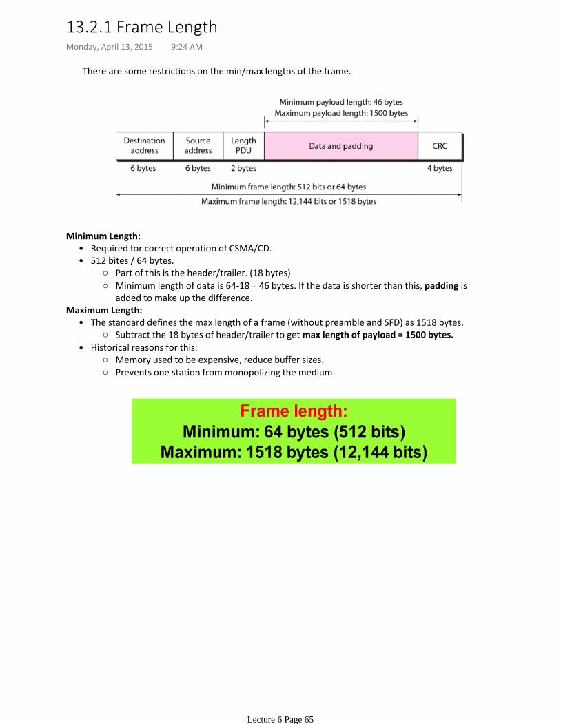
There are some restrictions on the min/max lengths of the frame.
Required for correct operation of CSMA/CD. •
Part of this is the header/trailer. (18 bytes)
Minimum length of data is 64-18 = 46 bytes. If the data is shorter than this, padding is added to make up the difference.
512 bites / 64 bytes. •
Minimum Length:
Subtract the 18 bytes of header/trailer to get max length of payload = 1500 bytes.
The standard defines the max length of a frame (without preamble and SFD) as 1518 bytes. •
Memory used to be expensive, reduce buffer sizes.
Prevents one station from monopolizing the medium.
Historical reasons for this:•
Maximum Length:
13.2.1 Frame LengthMonday, April 13, 2015 9:24 AM
Lecture 6 Page 65
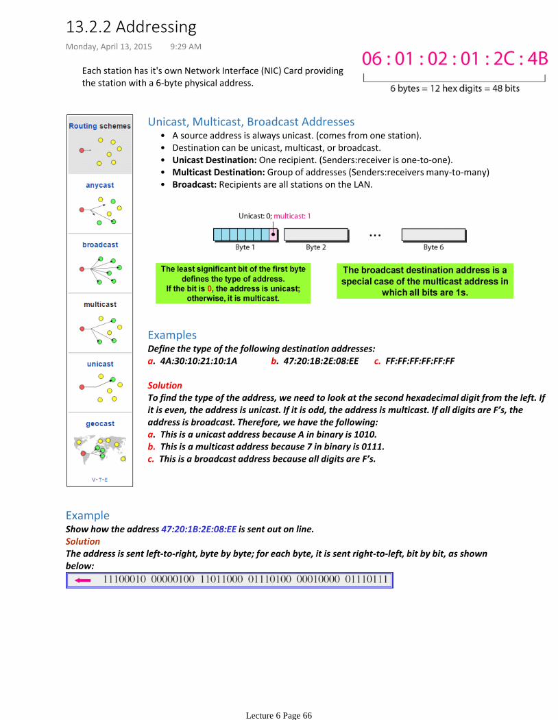
Each station has it's own Network Interface (NIC) Card providing the station with a 6-byte physical address.
A source address is always unicast. (comes from one station).•Destination can be unicast, multicast, or broadcast.•Unicast Destination: One recipient. (Senders:receiver is one-to-one).•Multicast Destination: Group of addresses (Senders:receivers many-to-many)•Broadcast: Recipients are all stations on the LAN.•
Unicast, Multicast, Broadcast Addresses
ExamplesDefine the type of the following destination addresses:a. 4A:30:10:21:10:1A b. 47:20:1B:2E:08:EE c. FF:FF:FF:FF:FF:FF
SolutionTo find the type of the address, we need to look at the second hexadecimal digit from the left. If it is even, the address is unicast. If it is odd, the address is multicast. If all digits are F’s, the address is broadcast. Therefore, we have the following:a. This is a unicast address because A in binary is 1010.b. This is a multicast address because 7 in binary is 0111.c. This is a broadcast address because all digits are F’s.
ExampleShow how the address 47:20:1B:2E:08:EE is sent out on line.SolutionThe address is sent left-to-right, byte by byte; for each byte, it is sent right-to-left, bit by bit, as shown below:
13.2.2 AddressingMonday, April 13, 2015 9:29 AM
Lecture 6 Page 66
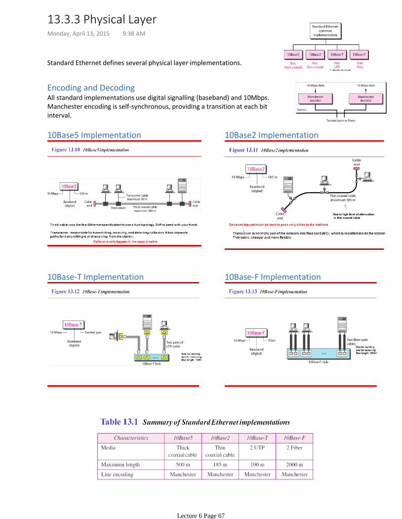
Standard Ethernet defines several physical layer implementations.
Encoding and DecodingAll standard implementations use digital signalling (baseband) and 10Mbps. Manchester encoding is self-synchronous, providing a transition at each bit interval.
10Base5 Implementation 10Base2 Implementation
10Base-T Implementation 10Base-F Implementation
13.3.3 Physical LayerMonday, April 13, 2015 9:38 AM
Lecture 6 Page 67
10-Mbps Standard Ethernet has changed before moving to higher data rates. These changes have made it compatible with other high-data-rate LANs.
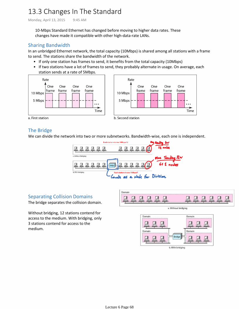
Sharing Bandwidth
If only one station has frames to send, it benefits from the total capacity (10Mbps) •If two stations have a lot of frames to send, they probably alternate in usage. On average, each station sends at a rate of 5Mbps.
•
In an unbridged Ethernet network, the total capacity (10Mbps) is shared among all stations with a frame to send. The stations share the bandwidth of the network.
The BridgeWe can divide the network into two or more subnetworks. Bandwidth-wise, each one is independent.
Separating Collision DomainsThe bridge separates the collision domain.
Without bridging, 12 stations contend for access to the medium. With bridging, only 3 stations contend for access to the medium.
13.3 Changes In The StandardMonday, April 13, 2015 9:45 AM
Lecture 6 Page 68
Regenerates the signal it receives.
Physical Layer Device:•
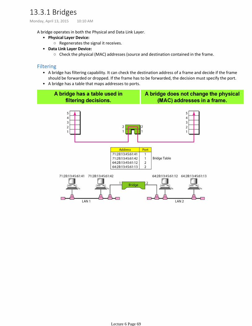
Check the physical (MAC) addresses (source and destination contained in the frame.
Data Link Layer Device:•
A bridge operates in both the Physical and Data Link Layer.
A bridge has filtering capability. It can check the destination address of a frame and decide if the frame should be forwarded or dropped. If the frame has to be forwarded, the decision must specify the port.
•
A bridge has a table that maps addresses to ports.•
Filtering
13.3.1 BridgesMonday, April 13, 2015 10:10 AM
Lecture 6 Page 69

Static BridgesThe earliest bridges has static forwarding tables. The sysadmin would manually enter each table entry during bridge setup. If a station was added or deleted, or even when MAC addresses changed, the table would have to be modified.
Learning Bridges
Destination is used for forwarding decision (table lookup)
Source is used for adding entries to the table and updating.
Bridge inspects destination and source addresses. •
A better solution is a dynamic table that maps addresses to ports automatically, gradually learning from frame movements.
ProcedureUsing the above figure:
However, the bridge has learned that Station A is connected to port 1. All future traffic to station A goes through port 1.
a.
When station A sends a frame to Station D, the bridge does not have an entry for D or A. The frame goes out from all 3 ports, flooding the network.
1.
Afterwards, Station E sends a message to Station A. The Bridge knows A is on port 1. It also learns E is on Port 3.
2.
The process continues.3.
13.3.2 Learning BridgesMonday, April 13, 2015 10:23 AM
Lecture 6 Page 70
Lecture 8: Packet Switched Networks Monday, April 13, 2015 10:34 AM
Lecture 8 Page 71
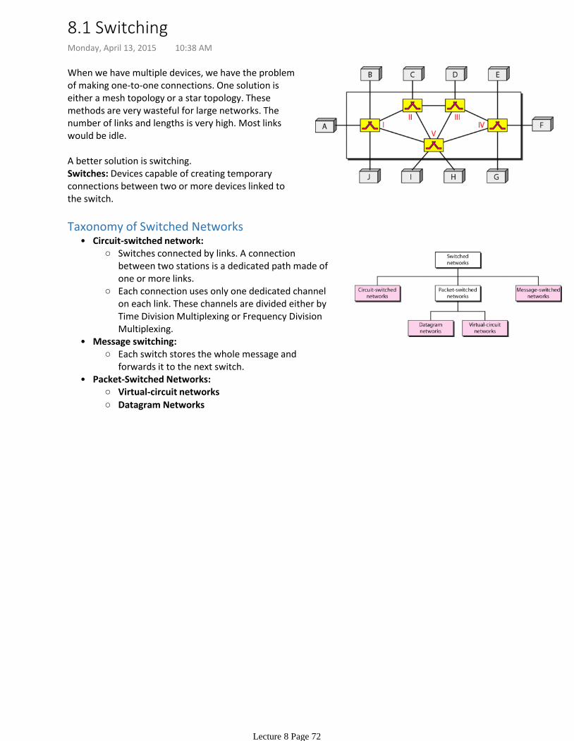
When we have multiple devices, we have the problem of making one-to-one connections. One solution is either a mesh topology or a star topology. These methods are very wasteful for large networks. The number of links and lengths is very high. Most links would be idle.
A better solution is switching. Switches: Devices capable of creating temporary connections between two or more devices linked to the switch.
Switches connected by links. A connection between two stations is a dedicated path made of one or more links.
Each connection uses only one dedicated channel on each link. These channels are divided either by Time Division Multiplexing or Frequency Division Multiplexing.
Circuit-switched network:•
Each switch stores the whole message and forwards it to the next switch.
Message switching:•
Virtual-circuit networks
Datagram Networks
Packet-Switched Networks:•
Taxonomy of Switched Networks
8.1 SwitchingMonday, April 13, 2015 10:38 AM
Lecture 8 Page 72
The packet size is determined by the network and governing protocol.•
-> No reserved bandwidth on links,
No scheduled processing time for each packet
There is no resource allocation for a packet.
When a switch receives a packet, no matter what is the source or destination, the packet must wait if there are other packets being processed.
Resources allocated on First-Come, First-Served basis.
Packets in this approach are referred to as datagrams.
Each packet is treated independently of all others, even if it's part of a multi-packet transmission.
In Packet-switching:•
If a message goes through a packet-switched network, it needs to be divided into packets.
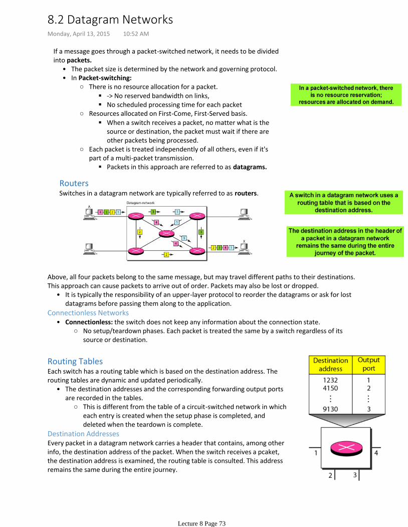
RoutersSwitches in a datagram network are typically referred to as routers.
It is typically the responsibility of an upper-layer protocol to reorder the datagrams or ask for lost datagrams before passing them along to the application.
•
Above, all four packets belong to the same message, but may travel different paths to their destinations. This approach can cause packets to arrive out of order. Packets may also be lost or dropped.
No setup/teardown phases. Each packet is treated the same by a switch regardless of its source or destination.
Connectionless: the switch does not keep any information about the connection state.•Connectionless Networks
Routing Tables
This is different from the table of a circuit-switched network in which each entry is created when the setup phase is completed, and deleted when the teardown is complete.
The destination addresses and the corresponding forwarding output ports are recorded in the tables.
•
Each switch has a routing table which is based on the destination address. The routing tables are dynamic and updated periodically.
Destination AddressesEvery packet in a datagram network carries a header that contains, among other info, the destination address of the packet. When the switch receives a pcaket, the destination address is examined, the routing table is consulted. This address remains the same during the entire journey.
8.2 Datagram NetworksMonday, April 13, 2015 10:52 AM
Lecture 8 Page 73
Resources allocated only when packets need to be transferred.
The efficiency of a datagram network is better than circuit-switched network.•
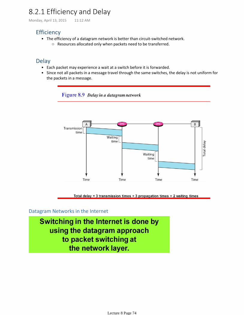
Efficiency
Each packet may experience a wait at a switch before it is forwarded. •Since not all packets in a message travel through the same switches, the delay is not uniform for the packets in a message.
•
Delay
Datagram Networks in the Internet
8.2.1 Efficiency and DelayMonday, April 13, 2015 11:12 AM
Lecture 8 Page 74
As in a circuit-switched network, there are setup and teardown phases in addition to the data transfer phase.
1.
Resources can be allocated during the setup phase, as in a circuit-switched network, or on demand, as in a packet-switched network.
2.
Virtual-circuit identifiersi.
How do intermediate switches know where to send the packet?
a.
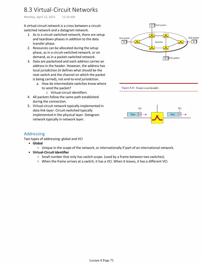
Data are packetized and each address carries an address in the header. However, the address has local jurisdiction (it defines what should be the next switch and the channel on which the packet is being carried), not end-to-end jurisidction.
3.
All packets follow the same path established during the connection.
4.
Virtual-circuit network typically implemented in data link layer. Circuit-switched typically implemented in the physical layer. Datagram network typically in network layer.
5.
A virtual-circuit network is a cross between a circuit-switched network and a datagram network.
Addressing
Unique in the scope of the network, or internationally if part of an international network.
Global•
Small number that only has switch scope. (used by a frame between two switches).
When the frame arrives at a switch, it has a VCI. When it leaves, it has a different VCI.
Virtual-Circuit Identifier•
Two types of addressing: global and VCI
8.3 Virtual-Circuit NetworksMonday, April 13, 2015 11:16 AM
Lecture 8 Page 75
Source and destination use global addresses to help switches make table entries for the connection.
Setup•
Data transfer•
Source and destination inform the switches to delete the corresponding entry
Teardown•
Three phases:
Data Transfer Phase
Active until the source sends all its frames to the destination. The procedure at the switch is the same for each frame of a message. The process creates a virtual circuit, not a real circuit, between the source and destination.
•
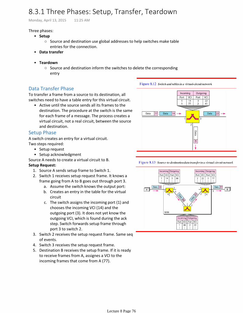
To transfer a frame from a source to its destination, all switches need to have a table entry for this virtual circuit.
Setup PhaseA switch creates an entry for a virtual circuit.
Setup request•Setup acknowledgment•
Two steps required:
Source A needs to create a virtual circuit to B.
Source A sends setup frame to Switch 1.1.
Assume the switch knows the output port:a.Creates an entry in the table for the virtual circuit
b.
The switch assigns the incoming port (1) and chooses the incoming VCI (14) and the outgoing port (3). It does not yet know the outgoing VCI, which is found during the ack step. Switch forwards setup frame through port 3 to switch 2.
c.
Switch 1 receives setup request frame. It knows a frame going from A to B goes out through port 3.
2.
Switch 2 receives the setup request frame. Same seq of events.
3.
Switch 3 receives the setup request frame. 4.Destination B receives the setup frame. If it is ready to receive frames from A, assignes a VCI to the incoming frames that come from A (77).
5.
Setup Request:
8.3.1 Three Phases: Setup, Transfer, TeardownMonday, April 13, 2015 11:25 AM
Lecture 8 Page 76
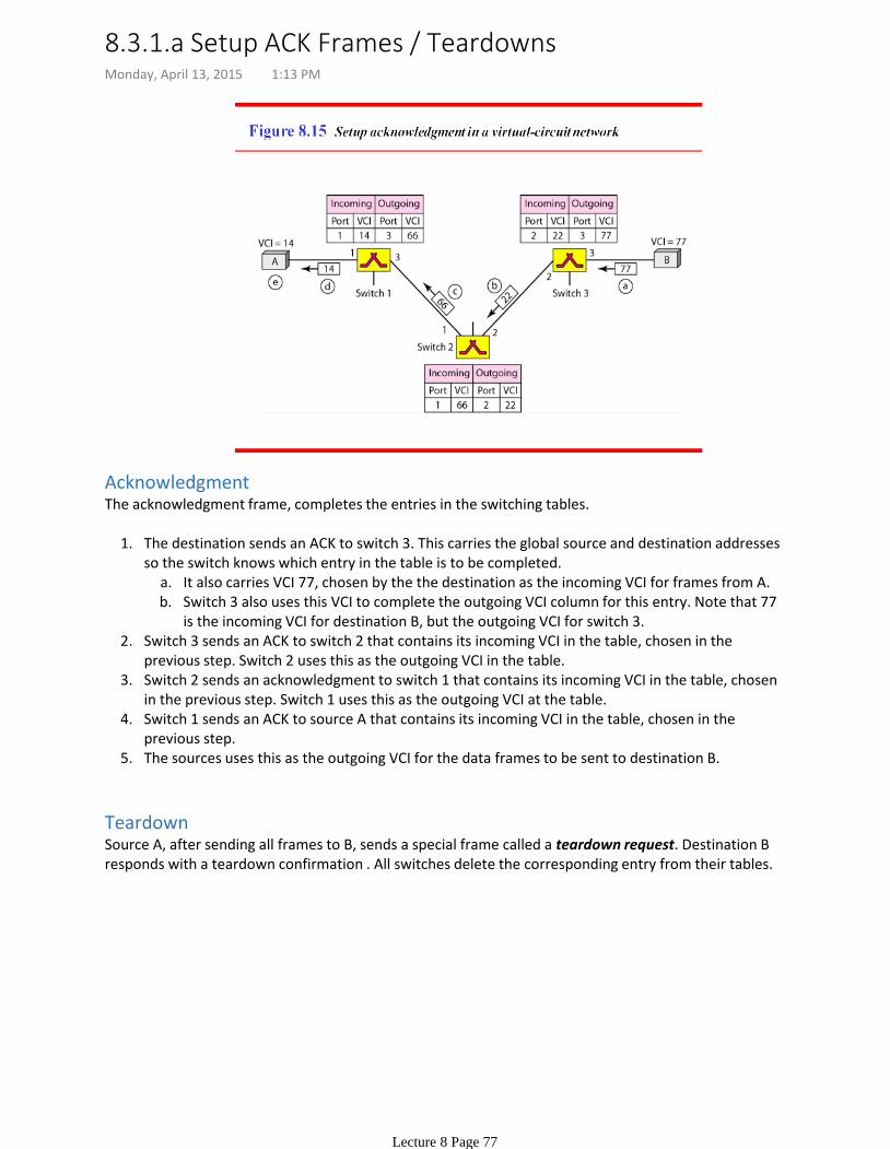
AcknowledgmentThe acknowledgment frame, completes the entries in the switching tables.
It also carries VCI 77, chosen by the the destination as the incoming VCI for frames from A. a.Switch 3 also uses this VCI to complete the outgoing VCI column for this entry. Note that 77 is the incoming VCI for destination B, but the outgoing VCI for switch 3.
b.
The destination sends an ACK to switch 3. This carries the global source and destination addresses so the switch knows which entry in the table is to be completed.
1.
Switch 3 sends an ACK to switch 2 that contains its incoming VCI in the table, chosen in the previous step. Switch 2 uses this as the outgoing VCI in the table.
2.
Switch 2 sends an acknowledgment to switch 1 that contains its incoming VCI in the table, chosen in the previous step. Switch 1 uses this as the outgoing VCI at the table.
3.
Switch 1 sends an ACK to source A that contains its incoming VCI in the table, chosen in the previous step.
4.
The sources uses this as the outgoing VCI for the data frames to be sent to destination B.5.
TeardownSource A, after sending all frames to B, sends a special frame called a teardown request. Destination B responds with a teardown confirmation . All switches delete the corresponding entry from their tables.
8.3.1.a Setup ACK Frames / TeardownsMonday, April 13, 2015 1:13 PM
Lecture 8 Page 77
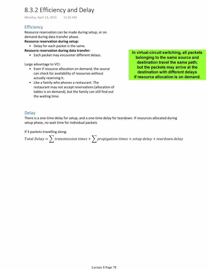
EfficiencyResource reservation can be made during setup, or on demand during data transfer phase.
Delay for each packet is the same.•Resource reservation during setup:
Each packet may encounter different delays.•Resource reservation during data transfer:
Even if resource allocation on demand, the source can check for availability of resources without actually reserving it.
•
Like a family who phones a restaurant. The restaurant may not accept reservations (allocation of tables is on demand), but the family can still find out the waiting time.
•
Large advantage to VCI:
DelayThere is a one-time delay for setup, and a one-time delay for teardown. If resources allocated during setup phase, no wait time for individual packets
If 3 packets travelling along:
8.3.2 Efficiency and DelayMonday, April 13, 2015 11:25 AM
Lecture 8 Page 78
A routing table can be static or dynamic.
Static table: manual entriesDynamic table : Updated automatically when there is a change somewhere in the internet.
A routing protocol is a combination of rules and procedures that lets routers in the Internet inform each other of changes.
OptimizationA router recieves a packet from a network and passes it to another network. How does a router know to which network to pass a packet?
One approach is to assign a cost for passing through a network. Some simple protocols, such a Routing Information Protocol (RIP) treat all networks as equals: the cost os passing through a network is the same --> one hop count.
Open Shortest Path First (OSPF): allow the administrator to assign a cost for passing through a network based on the type of service required. A route through a network can have different costs (metrics).
Routers use routing tables to help decide the best route. OSPF allows different tables for different levels of service.
Border Gateway Protocol (BGP) the criterion in the policy, set by the administrator. The policy defines what paths should be chosen.
22.3 Unicast Routing ProtocolsMonday, April 13, 2015 1:28 PM
Lecture 8 Page 79
Impossible in the Internet, since the routing table would be huge.
When a host has a packet to send, or when a router has received a packet to be forwarded, it looks at this table to find the route to the final destination.
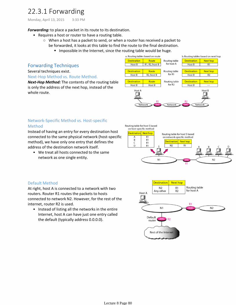
Requires a host or router to have a routing table.•Forwarding: to place a packet in its route to its destination.
Forwarding TechniquesSeveral techniques exist.
Next-Hop Method vs. Route Method.Next-Hop Method: The contents of the routing table is only the address of the next hop, instead of the whole route.
Network-Specific Method vs. Host-specific Method
We treat all hosts connected to the same network as one single entity.
•
Instead of having an entry for every destination host connected to the same physical network (host-specific method), we have only one entry that defines the address of the destination network itself.
Default Method
Instead of listing all the networks in the entire Internet, host A can have just one entry called the default (typically address 0.0.0.0).
•
At right, host A is connected to a network with two routers. Router R1 routes the packets to hosts connected to network N2. However, for the rest of the internet, router R2 is used.
22.3.1 ForwardingMonday, April 13, 2015 3:33 PM
Lecture 8 Page 80
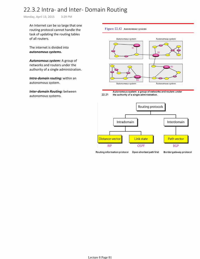
An Internet can be so large that one routing protocol cannot handle the task of updating the routing tables of all routers.
The internet is divided into autonomous systems.
Autonomous system: A group of networks and routers under the authority of a single administration.
Intra-domain routing: within an autonomous system.
Inter-domain Routing: between autonomous systems.
22.3.2 Intra- and Inter- Domain RoutingMonday, April 13, 2015 3:29 PM
Lecture 8 Page 81
The least-cost route between any two nodes is the route with minimum distance.
Each node maintains a vector (table) of minimum distances to every node. The table at each node also guides the packets to the desired node by showing the next stop in the route (next-hop routing).
InitializationAt the beginning, the tables are not initialized. Each node only knows the distance to its immediate neighbors.
SharingThe whole idea of distance vector routing is the sharing of information between neighbours. Nodes A and C can improve their routing tables if they help each other.
The 3rd column (next) is not useful for the neighbor. When the neighbor receives a table, this column needs to be replaced with a sender's name.
Sharing means only sharing the first two clolumns.
A node is not aware of its neighbor's table. The best solution is for each node to send its entire table to the neighbor and let the neighbor decide what part to use/discard.
How much of a table must be shared with each neighbor? •Problem?
Updating.
Receiving node adds the cost between itself and the sending node.1.The receiving node adds the name of the sending node to each row as the 3rd column if the receiving node uses information from any row. The sending node is the next node in the route.
2.
Receiving node choses the row with the smaller cost. If tied, keep the old one.a.
Suppose node C previously advertized a route to node X with distance 3.i.Suppose now there is no path between C and X; node C advertises this route with distance infinity.ii.Node A must not ignore this value even though the old entry is smaller. The old route does not exist anymore. The new route has a distance of infinity.
iii.
If the next-node entry is the same, the receving node choses the new row. b.
Compare each row of the old table to the new one.3.
The figure shows how node A updates its routing table after receiving a partial table from Node C.
Infinity + infinity = infinity.
22.3.2.1 Distance Vector RoutingMonday, April 13, 2015 3:32 PM
Lecture 8 Page 82

When does a node send its partial routing table to its immediate neighbors?
It is sent periodically and when there is a change in the table.
Periodic update:A node sends its routing table, normally every 30s, in a periodic update. Protocol dependent.
Triggered Update
Node receives a table from a neighbor, resulting in changes in its own table after updating.•Node detects some failure in the neighboring links which results in a distance change to infinity.•
Sends its two-column routing table to its neighbors any-time there is a change in its routing table. The change can result from:
22.3.2.2 When to shareMonday, April 13, 2015 3:59 PM
Lecture 8 Page 83
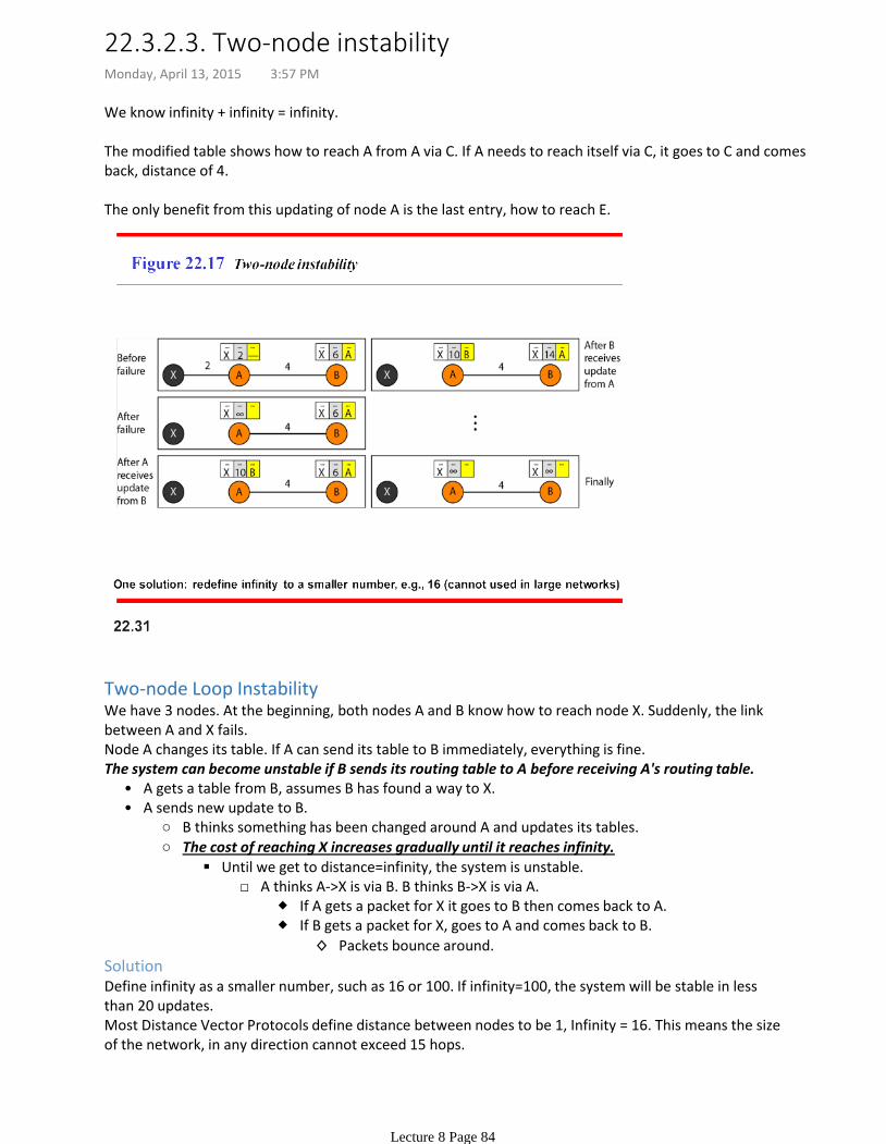
We know infinity + infinity = infinity.
The modified table shows how to reach A from A via C. If A needs to reach itself via C, it goes to C and comes back, distance of 4.
The only benefit from this updating of node A is the last entry, how to reach E.
Two-node Loop InstabilityWe have 3 nodes. At the beginning, both nodes A and B know how to reach node X. Suddenly, the link between A and X fails.Node A changes its table. If A can send its table to B immediately, everything is fine.
A gets a table from B, assumes B has found a way to X.•
B thinks something has been changed around A and updates its tables.
If A gets a packet for X it goes to B then comes back to A.
Packets bounce around.◊
If B gets a packet for X, goes to A and comes back to B.
A thinks A->X is via B. B thinks B->X is via A. Until we get to distance=infinity, the system is unstable.
The cost of reaching X increases gradually until it reaches infinity.
A sends new update to B.•
The system can become unstable if B sends its routing table to A before receiving A's routing table.
SolutionDefine infinity as a smaller number, such as 16 or 100. If infinity=100, the system will be stable in less than 20 updates.Most Distance Vector Protocols define distance between nodes to be 1, Infinity = 16. This means the size of the network, in any direction cannot exceed 15 hops.
22.3.2.3. Two-node instabilityMonday, April 13, 2015 3:57 PM
Lecture 8 Page 84
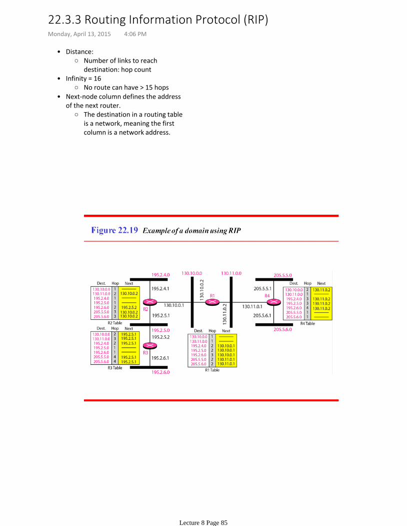
Number of links to reach destination: hop count
Distance:•
No route can have > 15 hops
Infinity = 16•
The destination in a routing table is a network, meaning the first column is a network address.
Next-node column defines the address of the next router.
•
22.3.3 Routing Information Protocol (RIP)Monday, April 13, 2015 4:06 PM
Lecture 8 Page 85
Page 703 of the PDF.22.3.4 Link State RoutingMonday, April 13, 2015 4:10 PM
Lecture 8 Page 86

22.3.4.1 Dijkstra's AlgorithmMonday, April 13, 2015 4:12 PM
Lecture 8 Page 87
22.3.4.2 Assignment SolutionsMonday, April 13, 2015 4:12 PM
Lecture 8 Page 88
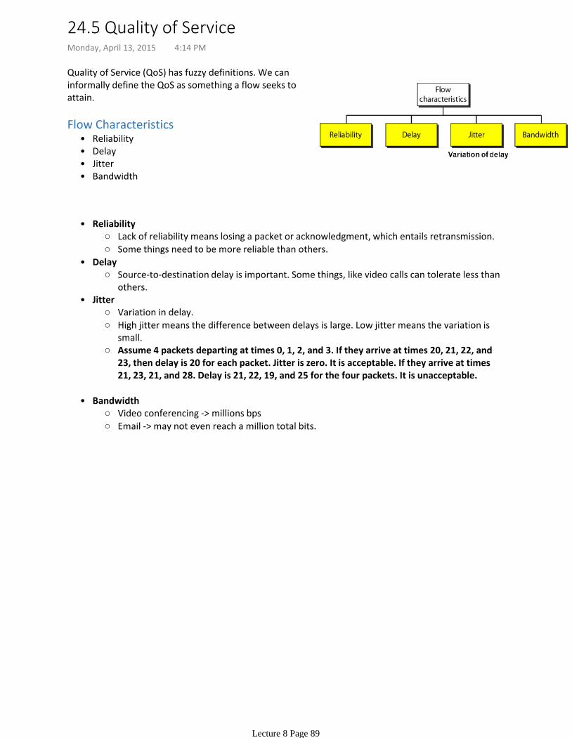
Quality of Service (QoS) has fuzzy definitions. We can informally define the QoS as something a flow seeks to attain.
Reliability•Delay•Jitter•Bandwidth•
Flow Characteristics
Lack of reliability means losing a packet or acknowledgment, which entails retransmission.
Some things need to be more reliable than others.
Reliability•
Source-to-destination delay is important. Some things, like video calls can tolerate less than others.
Delay•
Variation in delay.
High jitter means the difference between delays is large. Low jitter means the variation is small.
Assume 4 packets departing at times 0, 1, 2, and 3. If they arrive at times 20, 21, 22, and 23, then delay is 20 for each packet. Jitter is zero. It is acceptable. If they arrive at times 21, 23, 21, and 28. Delay is 21, 22, 19, and 25 for the four packets. It is unacceptable.
Jitter•
Video conferencing -> millions bps
Email -> may not even reach a million total bits.
Bandwidth•
24.5 Quality of ServiceMonday, April 13, 2015 4:14 PM
Lecture 8 Page 89
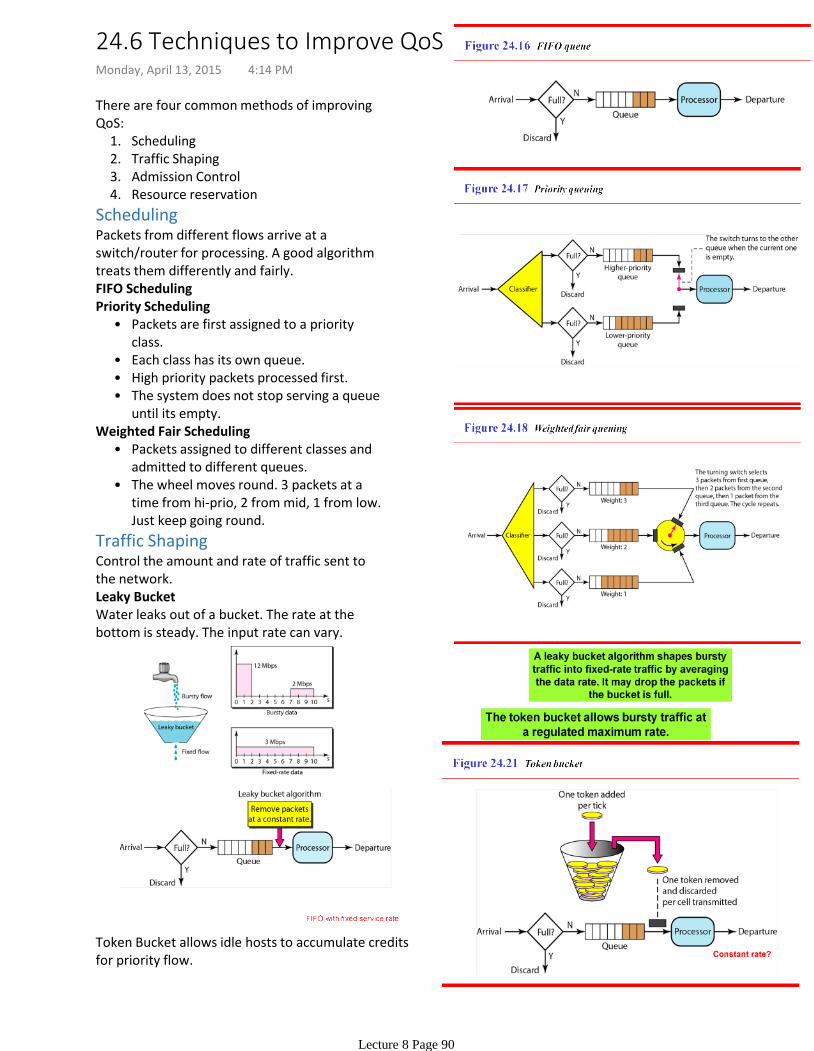
Scheduling1.Traffic Shaping2.Admission Control3.Resource reservation4.
There are four common methods of improving QoS:
SchedulingPackets from different flows arrive at a switch/router for processing. A good algorithm treats them differently and fairly. FIFO Scheduling
Packets are first assigned to a priority class.
•
Each class has its own queue. •High priority packets processed first.•The system does not stop serving a queue until its empty.
•
Priority Scheduling
Packets assigned to different classes and admitted to different queues.
•
The wheel moves round. 3 packets at a time from hi-prio, 2 from mid, 1 from low. Just keep going round.
•
Weighted Fair Scheduling
Traffic ShapingControl the amount and rate of traffic sent to the network.Leaky BucketWater leaks out of a bucket. The rate at the bottom is steady. The input rate can vary.
Token Bucket allows idle hosts to accumulate credits for priority flow.
24.6 Techniques to Improve QoSMonday, April 13, 2015 4:14 PM
Lecture 8 Page 90
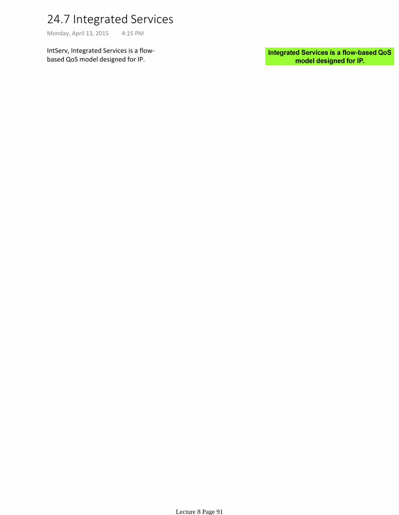
IntServ, Integrated Services is a flow-based QoS model designed for IP.
24.7 Integrated ServicesMonday, April 13, 2015 4:15 PM
Lecture 8 Page 91
24.8 Differentiated ServicesMonday, April 13, 2015 4:15 PM
Lecture 8 Page 92

Lecture 9: AddressingMonday, April 13, 2015 2:07 PM
Lecture 9 Page 93

They are unique in the sense that each address defines one, and only one, connection to the Internet.
•
By using some strategies, an address may be assigned to a device for a time period and then taken away and assigned to another device.
Two devices on the Internet can never have the same address at the same time. •
A router is such a device.
If a device operating at the network layer has m connections to the Internet, it needs to have m addresses.
•
They IPv4 addresses are universal in the sense that the addressing system must be accepted by any host that wants to be connected to the Internet.
•
An IPv4 is a 32 bit address that uniquely and univerally defines the connection of a device to the internet.
19.1 IPv4 AddressesTuesday, April 14, 2015 11:25 AM
Lecture 9 Page 94

At its inception, IPv4 used classes for addressing. It is obsolete. Divided into 5 classes: A, B, C, D, E.
We can find the class of the address based on binary or dotted decimal notation.
Classes and BlocksEach class is divided into a fixed number of blocks, each with fixed size. Because of the block size, there are many addresses wasted. Class D was designed for multicasting. Each address in this group is used to define one group of hosts on the internet. Class E was designed for future use. These addresess are wasted too.
mask in the form “/n” where n can be 8, 16, or 24 in classful addressing.
•
This notation is also called slash notation or Classless Interdomain Routing (CIDR) notation.
•
CIDR Notation
The Netid is in color. The hostid is in black.
19.1.1 Classful AddressingTuesday, April 14, 2015 11:29 AM
Lecture 9 Page 95
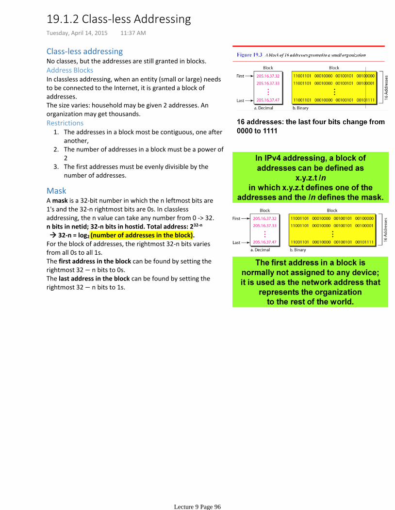
Class-less addressingNo classes, but the addresses are still granted in blocks.
Address BlocksIn classless addressing, when an entity (small or large) needs to be connected to the Internet, it is granted a block of addresses. The size varies: household may be given 2 addresses. An organization may get thousands.
The addresses in a block most be contiguous, one after another,
1.
The number of addresses in a block must be a power of 2
2.
The first addresses must be evenly divisible by the number of addresses.
3.
Restrictions
MaskA mask is a 32-bit number in which the n leftmost bits are 1's and the 32-n rightmost bits are 0s. In classless addressing, the n value can take any number from 0 -> 32.n bits in netid; 32-n bits in hostid. Total address: 232-n
32-n = log2 (number of addresses in the block).For the block of addresses, the rightmost 32-n bits varies from all 0s to all 1s.The first address in the block can be found by setting the rightmost 32 − n bits to 0s.The last address in the block can be found by setting the rightmost 32 − n bits to 1s.
19.1.2 Class-less AddressingTuesday, April 14, 2015 11:37 AM
Lecture 9 Page 96
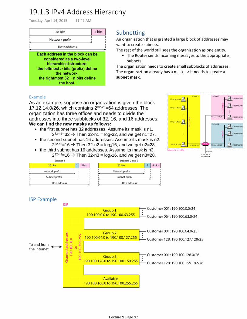
SubnettingAn organization that is granted a large block of addresses may want to create subnets.
The Router sends incoming messages to the appropriate subnets.
•The rest of the world still sees the organization as one entity.
The organization needs to create small subblocks of addresses. The organizaztion already has a mask --> it needs to create a subnet mask.
ExampleAs an example, suppose an organization is given the block 17.12.14.0/26, which contains 232-26=64 addresses. The organization has three offices and needs to divide the addresses into three subblocks of 32, 16, and 16 addresses.
232-n1=32 Then 32-n1 = log232, and we get n1=27.the first subnet has 32 addresses. Assume its mask is n1. •
232-n2=16 Then 32-n2 = log216, and we get n2=28.the second subnet has 16 addresses. Assume its mask is n2. •
232-n3=16 Then 32-n3 = log216, and we get n3=28.the third subnet has 16 addresses. Assume its mask is n3. •
We can find the new masks as follows:
ISP Example
19.1.3 IPv4 Address Hierarchy Tuesday, April 14, 2015 11:47 AM
Lecture 9 Page 97

19.1.3.1 Assignment SolutionsTuesday, April 14, 2015 11:55 AM
Lecture 9 Page 98
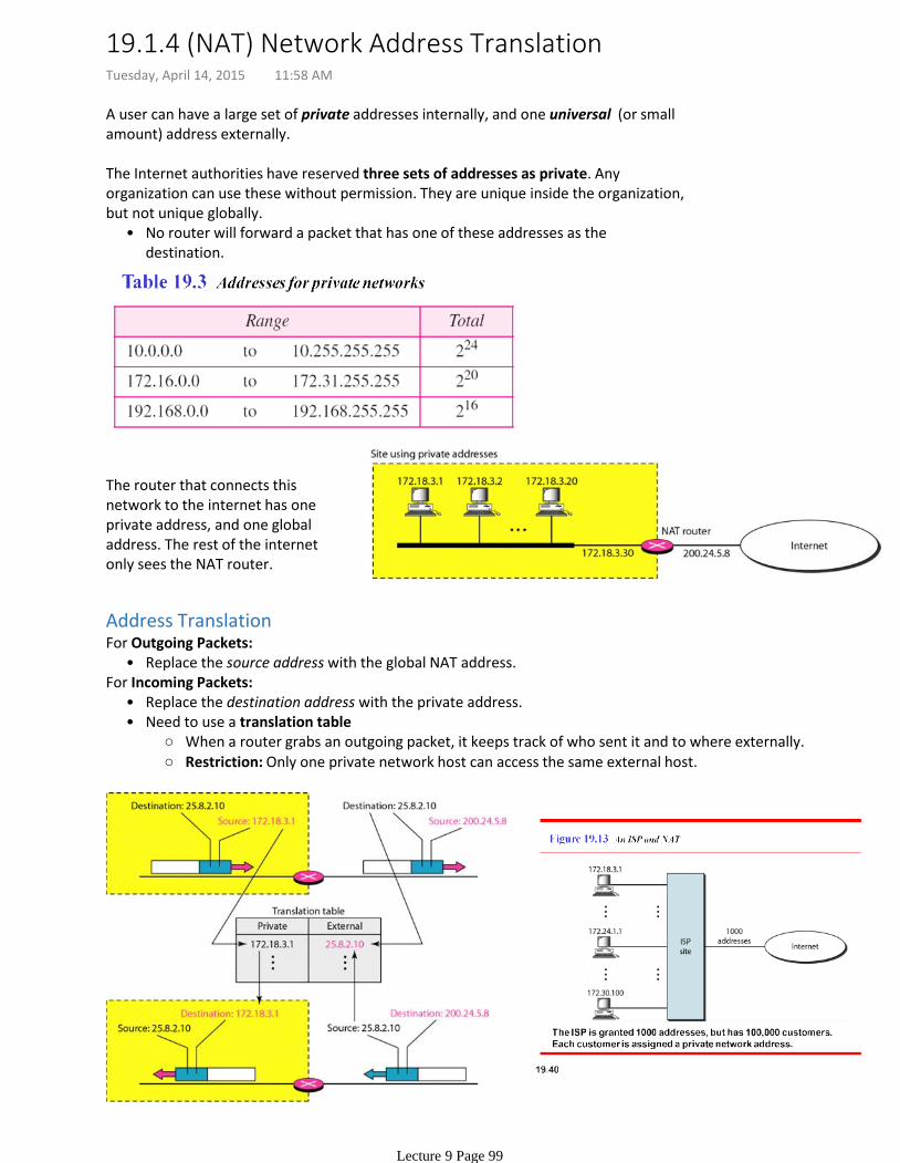
A user can have a large set of private addresses internally, and one universal (or small amount) address externally.
No router will forward a packet that has one of these addresses as the destination.
•
The Internet authorities have reserved three sets of addresses as private. Any organization can use these without permission. They are unique inside the organization, but not unique globally.
The router that connects this network to the internet has one private address, and one global address. The rest of the internet only sees the NAT router.
Address Translation
Replace the source address with the global NAT address.•For Outgoing Packets:
Replace the destination address with the private address.•
When a router grabs an outgoing packet, it keeps track of who sent it and to where externally.
Restriction: Only one private network host can access the same external host.
Need to use a translation table•
For Incoming Packets:
19.1.4 (NAT) Network Address TranslationTuesday, April 14, 2015 11:58 AM
Lecture 9 Page 99
Chapter 20 of the textbook.
Lecture 10: Network Layer: Internet ProtocolTuesday, April 14, 2015 12:14 PM
Lecture 10 Page 100
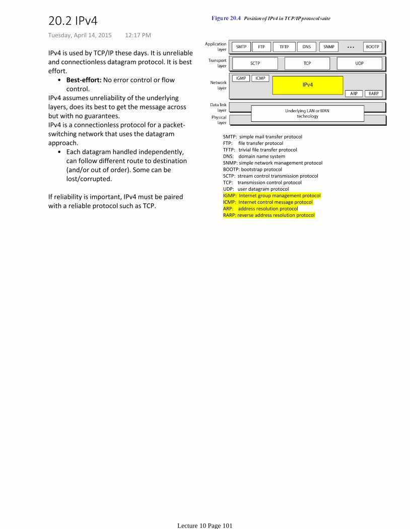
Best-effort: No error control or flow control.
•
IPv4 is used by TCP/IP these days. It is unreliable and connectionless datagram protocol. It is best effort.
IPv4 assumes unreliability of the underlying layers, does its best to get the message across but with no guarantees.
Each datagram handled independently, can follow different route to destination (and/or out of order). Some can be lost/corrupted.
•
IPv4 is a connectionless protocol for a packet-switching network that uses the datagram approach.
If reliability is important, IPv4 must be paired with a reliable protocol such as TCP.
SMTP: simple mail transfer protocolFTP: file transfer protocolTFTP: trivial file transfer protocolDNS: domain name systemSNMP: simple network management protocolBOOTP: bootstrap protocolSCTP: stream control transmission protocolTCP: transmission control protocolUDP: user datagram protocolIGMP: Internet group management protocolICMP: Internet control message protocolARP: address resolution protocolRARP: reverse address resolution protocol
20.2 IPv4Tuesday, April 14, 2015 12:17 PM
Lecture 10 Page 101
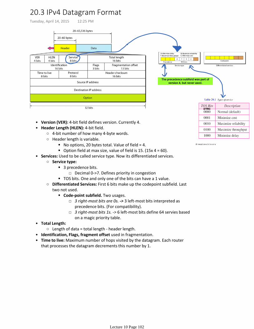
Version (VER): 4-bit field defines version. Currently 4.•
4-bit number of how many 4-byte words.
No options, 20 bytes total. Value of field = 4.
Option field at max size, value of field is 15. (15x 4 = 60).
Header length is variable.
Header Length (HLEN): 4-bit field.•
Decimal 0->7. Defines priority in congestion3 precedence bits.
TOS bits. One and only one of the bits can have a 1 value.
Service type:
3 right-most bits are 0s. -> 3 left-most bits interpreted as precedence bits. (For compatibility).
3 right-most bits 1s. -> 6 left-most bits define 64 servies based on a magic priority table.
Code-point subfield. Two usages.
Differentiated Services: First 6 bits make up the codepoint subfield. Last two not used.
Services: Used to be called service type. Now its differentiated services.•
Length of data = total length - header length.
Total Length:•
Identification, Flags, fragment offset used in fragmentation.•Time to live: Maximum number of hops visited by the datagram. Each router that processes the datagram decrements this number by 1.
•
20.3 IPv4 Datagram FormatTuesday, April 14, 2015 12:25 PM
Lecture 10 Page 102

Example
01000010An IPv4 packet has arrived with the first 8 bits as shown:
The receiver discards the packet. Why?SolutionThere is an error in this packet. The 4 leftmost bits (0100) show the version, which is correct. The next 4 bits (0010) show an invalid header length (2 × 4 = 8). The minimum number of bytes in the header must be 20. The packet has been corrupted in transmission.
ExampleIn an IPv4 packet, the value of HLEN is 1000 in binary. How many bytes of options are being carried by this packet?SolutionThe HLEN value is 8, which means the total number of bytes in the header is 8 × 4, or 32 bytes. The first 20 bytes are the base header, the next 12 bytes are the options.
ExampleIn an IPv4 packet, the value of HLEN is 5, and the value of the total length field is 0x0028. How many bytes of data are being carried by this packet?SolutionThe HLEN value is 5, which means the total number of bytes in the header is 5 × 4, or 20 bytes (no options). The total length is 40 bytes, which means the packet is carrying 20 bytes of data (40 − 20).
ExampleAn IPv4 packet has arrived with the first few hexadecimal digits as shown.0x4500002800010000|0102 . . .How many hops can this packet travel before being dropped? The data belong to what upper-layer protocol?SolutionTo find the time-to-live field, we skip 8 bytes. The time-to-live field is the ninth byte, which is 01. This means the packet can travel only one hop. The protocol field is the next byte (02), which means that the upper-layer protocol is IGMP.
20.3.1 Protocol Field & ExamplesTuesday, April 14, 2015 12:43 PM
Lecture 10 Page 103
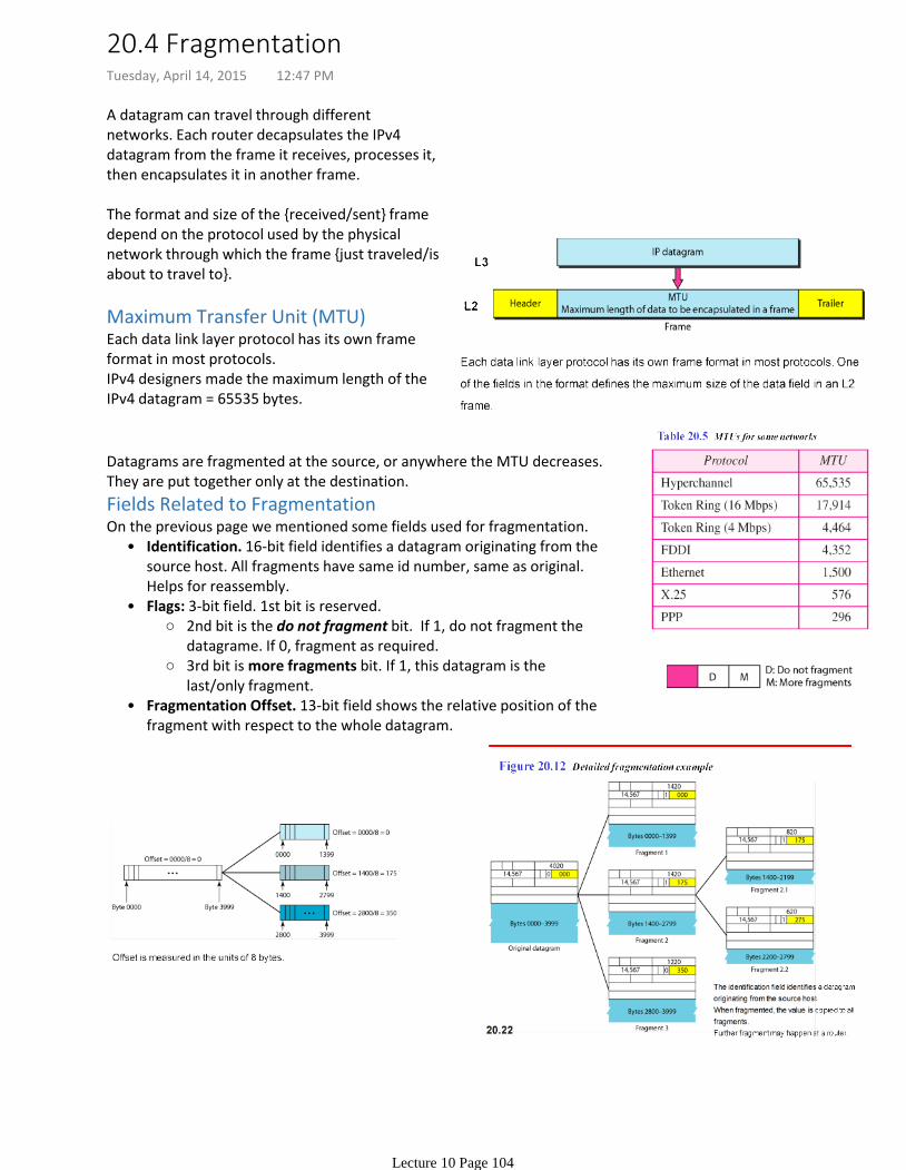
A datagram can travel through different networks. Each router decapsulates the IPv4 datagram from the frame it receives, processes it, then encapsulates it in another frame.
The format and size of the received/sent frame depend on the protocol used by the physical network through which the frame just traveled/is about to travel to.
Maximum Transfer Unit (MTU)Each data link layer protocol has its own frame format in most protocols. IPv4 designers made the maximum length of the IPv4 datagram = 65535 bytes.
Datagrams are fragmented at the source, or anywhere the MTU decreases. They are put together only at the destination.
Fields Related to Fragmentation
Identification. 16-bit field identifies a datagram originating from the source host. All fragments have same id number, same as original. Helps for reassembly.
•
2nd bit is the do not fragment bit. If 1, do not fragment the datagrame. If 0, fragment as required.
3rd bit is more fragments bit. If 1, this datagram is the last/only fragment.
Flags: 3-bit field. 1st bit is reserved. •
Fragmentation Offset. 13-bit field shows the relative position of the fragment with respect to the whole datagram.
•
On the previous page we mentioned some fields used for fragmentation.
20.4 FragmentationTuesday, April 14, 2015 12:47 PM
Lecture 10 Page 104
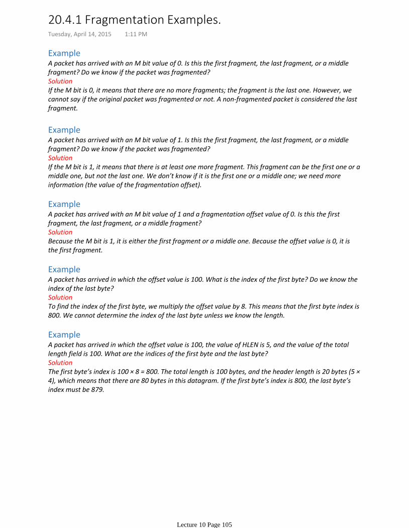
ExampleA packet has arrived with an M bit value of 0. Is this the first fragment, the last fragment, or a middle fragment? Do we know if the packet was fragmented?SolutionIf the M bit is 0, it means that there are no more fragments; the fragment is the last one. However, we cannot say if the original packet was fragmented or not. A non-fragmented packet is considered the last fragment.
ExampleA packet has arrived with an M bit value of 1. Is this the first fragment, the last fragment, or a middle fragment? Do we know if the packet was fragmented?SolutionIf the M bit is 1, it means that there is at least one more fragment. This fragment can be the first one or a middle one, but not the last one. We don’t know if it is the first one or a middle one; we need more information (the value of the fragmentation offset).
ExampleA packet has arrived with an M bit value of 1 and a fragmentation offset value of 0. Is this the first fragment, the last fragment, or a middle fragment?SolutionBecause the M bit is 1, it is either the first fragment or a middle one. Because the offset value is 0, it is the first fragment.
ExampleA packet has arrived in which the offset value is 100. What is the index of the first byte? Do we know the index of the last byte?SolutionTo find the index of the first byte, we multiply the offset value by 8. This means that the first byte index is 800. We cannot determine the index of the last byte unless we know the length.
ExampleA packet has arrived in which the offset value is 100, the value of HLEN is 5, and the value of the total length field is 100. What are the indices of the first byte and the last byte?SolutionThe first byte’s index is 100 × 8 = 800. The total length is 100 bytes, and the header length is 20 bytes (5 × 4), which means that there are 80 bytes in this datagram. If the first byte’s index is 800, the last byte’s index must be 879.
20.4.1 Fragmentation Examples.Tuesday, April 14, 2015 1:11 PM
Lecture 10 Page 105
20.5 IPv4 Assignment ExamplesTuesday, April 14, 2015 1:13 PM
Lecture 10 Page 106
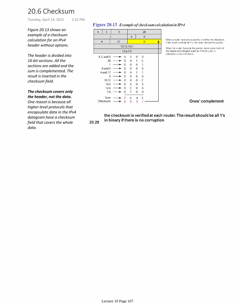
Figure 20.13 shows an example of a checksum calculation for an IPv4 header without options.
The header is divided into 16-bit sections. All the sections are added and the sum is complemented. The result is inserted in the checksum field.
The checksum covers only the header, not the data.One reason is because all higher-level protocols that encapsulate data in the IPv4 datagram have a checksum field that covers the whole data.
20.6 ChecksumTuesday, April 14, 2015 1:15 PM
Lecture 10 Page 107
Chapter 23 of the textbook PDF.
Lecture 11: Transport LayerTuesday, April 14, 2015 1:19 PM
Lecture 11 Page 108
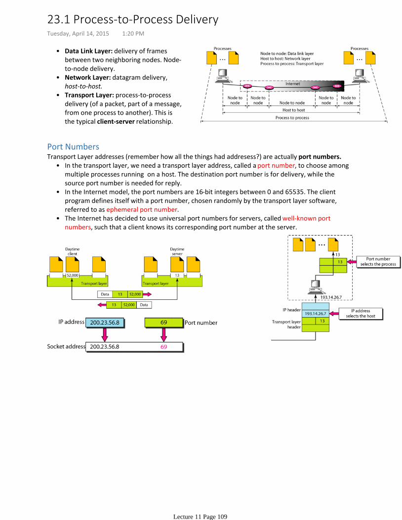
Data Link Layer: delivery of frames between two neighboring nodes. Node-to-node delivery.
•
Network Layer: datagram delivery, host-to-host.
•
Transport Layer: process-to-process delivery (of a packet, part of a message, from one process to another). This is the typical client-server relationship.
•
Port Numbers
In the transport layer, we need a transport layer address, called a port number, to choose among multiple processes running on a host. The destination port number is for delivery, while the source port number is needed for reply.
•
In the Internet model, the port numbers are 16-bit integers between 0 and 65535. The client program defines itself with a port number, chosen randomly by the transport layer software, referred to as ephemeral port number.
•
The Internet has decided to use universal port numbers for servers, called well-known port numbers, such that a client knows its corresponding port number at the server.
•
Transport Layer addresses (remember how all the things had addresess?) are actually port numbers.
23.1 Process-to-Process DeliveryTuesday, April 14, 2015 1:20 PM
Lecture 11 Page 109
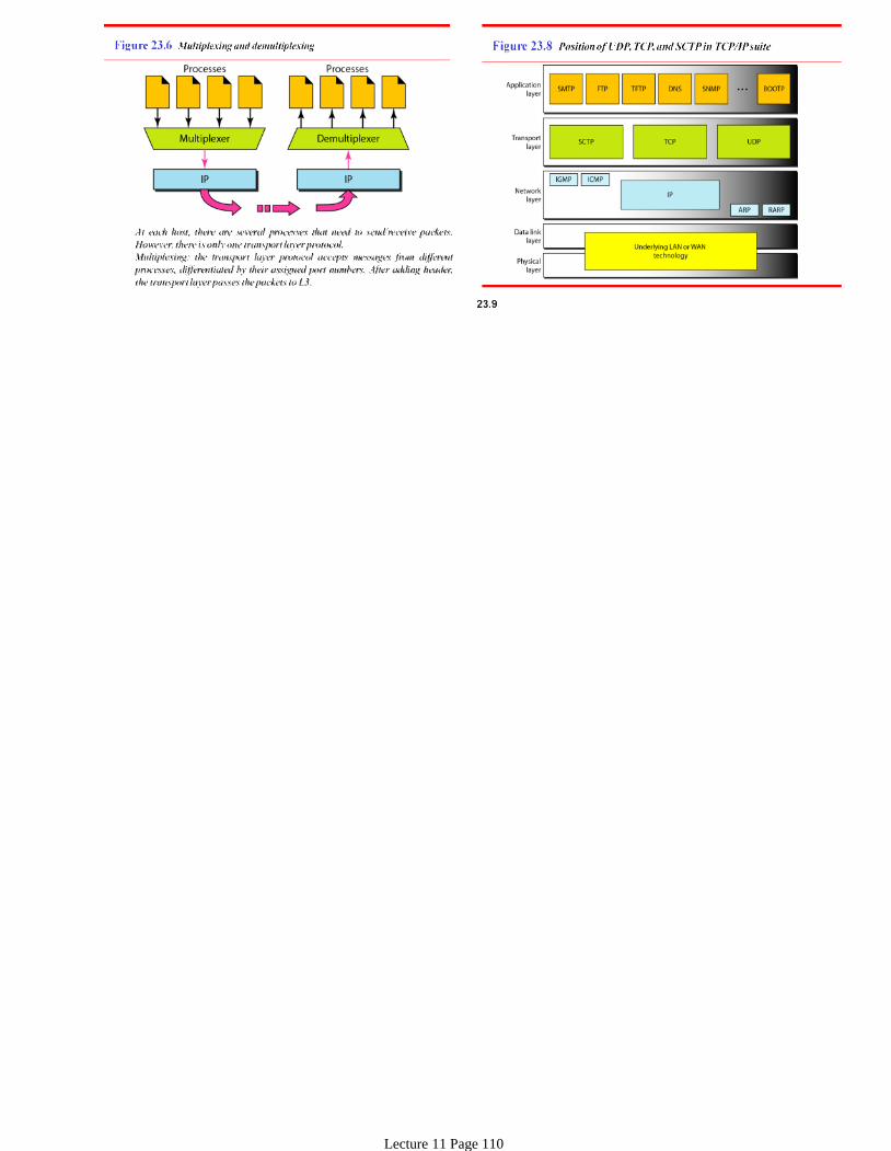
Lecture 11 Page 110
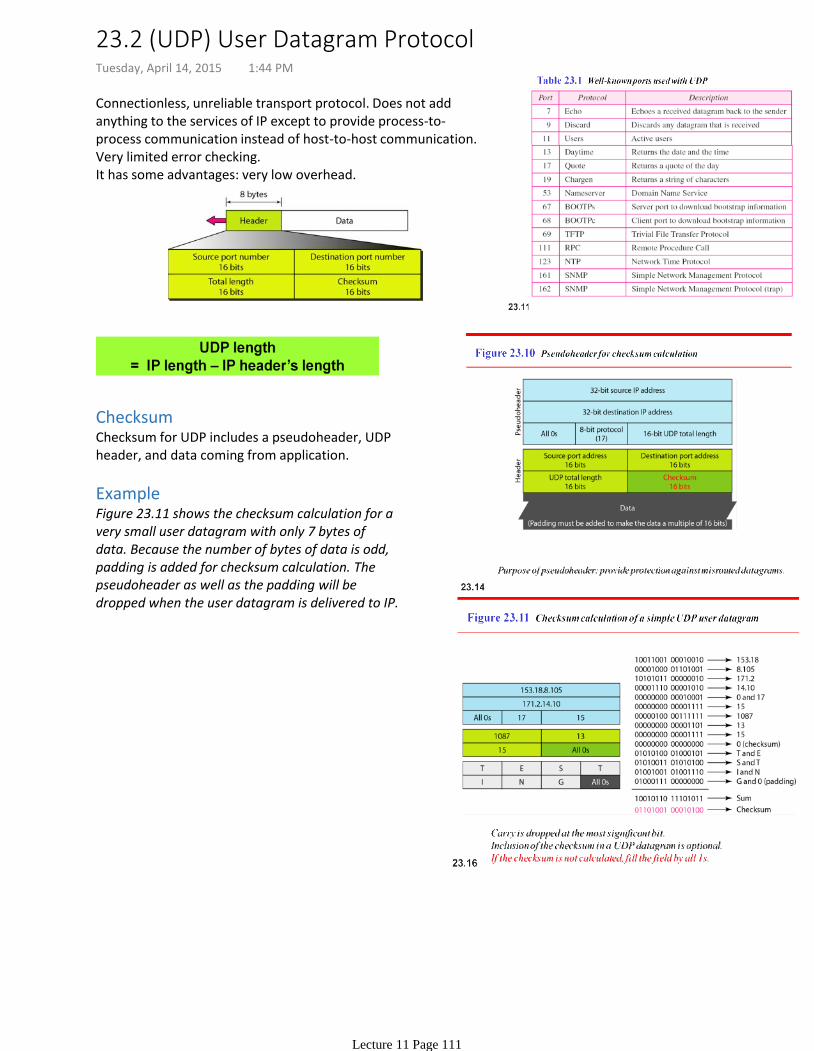
Connectionless, unreliable transport protocol. Does not add anything to the services of IP except to provide process-to-process communication instead of host-to-host communication. Very limited error checking.It has some advantages: very low overhead.
ChecksumChecksum for UDP includes a pseudoheader, UDP header, and data coming from application.
ExampleFigure 23.11 shows the checksum calculation for a very small user datagram with only 7 bytes of data. Because the number of bytes of data is odd, padding is added for checksum calculation. The pseudoheader as well as the padding will be dropped when the user datagram is delivered to IP.
23.2 (UDP) User Datagram ProtocolTuesday, April 14, 2015 1:44 PM
Lecture 11 Page 111
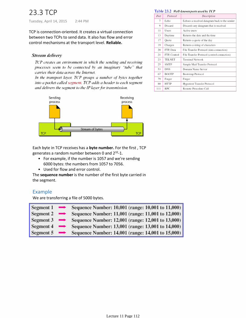
TCP is connection-oriented. It creates a virtual connection between two TCPs to send data. It also has flow and error control mechanisms at the transport level. Reliable.
For example, if the number is 1057 and we're sending 6000 bytes: the numbers from 1057 to 7056.
•
Used for flow and error control.•
Each byte in TCP receives has a byte number. For the first , TCP generates a random number between 0 and 232-1.
The sequence number is the number of the first byte carried in the segment.
ExampleWe are transferring a file of 5000 bytes.
23.3 TCPTuesday, April 14, 2015 2:44 PM
Lecture 11 Page 112
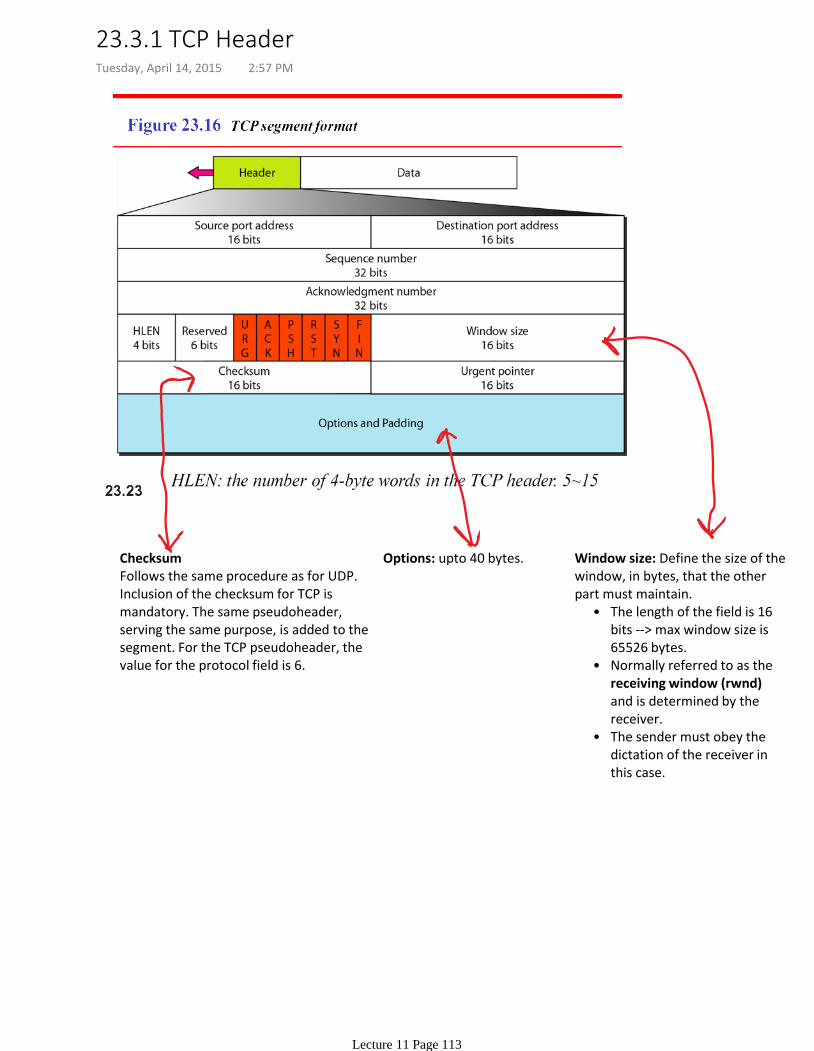
ChecksumFollows the same procedure as for UDP. Inclusion of the checksum for TCP is mandatory. The same pseudoheader, serving the same purpose, is added to the segment. For the TCP pseudoheader, the value for the protocol field is 6.
Options: upto 40 bytes.
The length of the field is 16 bits --> max window size is 65526 bytes.
•
Normally referred to as the receiving window (rwnd) and is determined by the receiver.
•
The sender must obey the dictation of the receiver in this case.
•
Window size: Define the size of the window, in bytes, that the other part must maintain.
23.3.1 TCP HeaderTuesday, April 14, 2015 2:57 PM
Lecture 11 Page 113

23.3.2 TCP ExchangeTuesday, April 14, 2015 3:08 PM
Lecture 11 Page 114
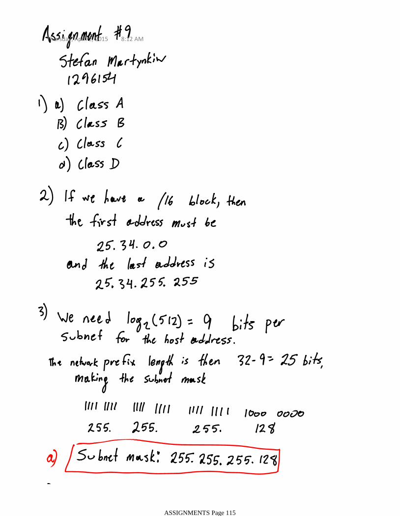
Thursday, April 2, 2015 8:12 AM
ASSIGNMENTS Page 115

ASSIGNMENTS Page 116