Static-Stability Analysis of an Unmanned Airplane as a Flexible-Body
7
American Institute of Aeronautics and Astronautics 1 Static-Stability Analysis of a Unmanned Airplane as a Flexible-Body Oscar E. González P. 1 Universidad Nacional Experimental Politécnica de la Fuerza Armada, Caracas, 1060, Venezuela and Pedro J. Boschetti, 2 Elsa M. Cárdenas 3 and Andrea Amerio 4 Universidad Simón Bolívar, Naiguatá, Estado Vargas, 1160, Venezuela The aerodynamic and static stability analysis of the Unmanned Airplane for Ecological Conservation as a flexible-body is the aim of present paper. The aerodynamic and structural analyses were performed using the ASWING code. This is a program for the aerodynamic, structural, and control-response analysis of airplanes with flexible components. The aerodynamic data obtained were compared against data obtained by an analytical-empirical method and potential flow codes. A good correlation is achieved for the longitudinal stability coefficients, but for lateral and directional coefficients there is a poor correlation. The distributed aerodynamic loads on surfaces (wing and horizontal tail) produce variations in the wing beam, changing the elastic twist distribution and reducing the lift-slope respect to the rigid-body analysis. In general, the comparison of flexible-body data to rigid-body results shows slight differences. Nomenclature C Do = viscous drag coefficient or parasite drag coefficient C Lo , C Mo = lift and pitching moment coefficient at zero angle of attack C Lq , C Mq = variation of lift, and pitching moment coefficients with pitch rate C Lu , C Du , C Mu = variation of lift, drag, and pitching moment coefficients with non-dimensional speed C Lα , C Dα , C Mα = lift, drag, and pitching moment slopes C Lδe , C Mδe = variation of lift, and pitching moment coefficients with elevator deflection C ℓp , C np , C Yp = variation of rolling, yawing and side force coefficients with roll rate C ℓr , C nr , C Yr = variation of rolling, yawing and side force coefficients with yaw rate C ℓβ , C nβ , C Yβ = variation of rolling, yawing and side force coefficients with sideslip angle C ℓδr , C nδr , C Yδr = variation of rolling, yawing and side force coefficients with rudder deflection C ℓδa , C nδa , C Yδa = variation of rolling, yawing and side force coefficients with aileron deflection c = medium chord e n = two–dimensional free transition criterion h o = stick fixed neutral point k = lift dependent drag factor or induced drag factor n = fixed parameter for two–dimensional free transition criterion α = angle of attack 1 Undergraduate Student, Department of Aeronautical Engineering, Av. La Estancia, Chuao. 2 Assistant Professor, Department of Industrial Technology, Camurí Grande, Senior Member AIAA. 3 Assistant Professor, Department of Industrial Technology, Camurí Grande, Senior Member AIAA. 4 Aggregate Professor, Department of Industrial Technology, Camurí Grande, Senior Member AIAA. AIAA Guidance, Navigation, and Control Conference 2 - 5 August 2010, Toronto, Ontario Canada AIAA 2010-8230 Copyright © 2010 by The Authors. Published by the American Institute of Aeronautics and Astronautics, Inc., with permission.
Transcript of Static-Stability Analysis of an Unmanned Airplane as a Flexible-Body

American Institute of Aeronautics and Astronautics
1
Static-Stability Analysis of a Unmanned Airplane as a Flexible-Body
Oscar E. González P.1 Universidad Nacional Experimental Politécnica de la Fuerza Armada, Caracas, 1060, Venezuela
and
Pedro J. Boschetti,2 Elsa M. Cárdenas3 and Andrea Amerio4 Universidad Simón Bolívar, Naiguatá, Estado Vargas, 1160, Venezuela
The aerodynamic and static stability analysis of the Unmanned Airplane for Ecological Conservation as a flexible-body is the aim of present paper. The aerodynamic and structural analyses were performed using the ASWING code. This is a program for the aerodynamic, structural, and control-response analysis of airplanes with flexible components. The aerodynamic data obtained were compared against data obtained by an analytical-empirical method and potential flow codes. A good correlation is achieved for the longitudinal stability coefficients, but for lateral and directional coefficients there is a poor correlation. The distributed aerodynamic loads on surfaces (wing and horizontal tail) produce variations in the wing beam, changing the elastic twist distribution and reducing the lift-slope respect to the rigid-body analysis. In general, the comparison of flexible-body data to rigid-body results shows slight differences.
Nomenclature CDo = viscous drag coefficient or parasite drag coefficient CLo, CMo = lift and pitching moment coefficient at zero angle of attack CLq, CMq = variation of lift, and pitching moment coefficients with pitch rate CLu, CDu, CMu = variation of lift, drag, and pitching moment coefficients with non-dimensional speed CLα, CDα, CMα = lift, drag, and pitching moment slopes CLδe, CMδe = variation of lift, and pitching moment coefficients with elevator deflection Cℓp, Cnp, CYp = variation of rolling, yawing and side force coefficients with roll rate Cℓr, Cnr, CYr = variation of rolling, yawing and side force coefficients with yaw rate Cℓβ, Cnβ, CYβ = variation of rolling, yawing and side force coefficients with sideslip angle Cℓδr, Cnδr, CYδr = variation of rolling, yawing and side force coefficients with rudder deflection Cℓδa, Cnδa, CYδa = variation of rolling, yawing and side force coefficients with aileron deflection c = medium chord en = two–dimensional free transition criterion ho = stick fixed neutral point k = lift dependent drag factor or induced drag factor
n = fixed parameter for two–dimensional free transition criterion α = angle of attack
1 Undergraduate Student, Department of Aeronautical Engineering, Av. La Estancia, Chuao. 2 Assistant Professor, Department of Industrial Technology, Camurí Grande, Senior Member AIAA. 3 Assistant Professor, Department of Industrial Technology, Camurí Grande, Senior Member AIAA. 4 Aggregate Professor, Department of Industrial Technology, Camurí Grande, Senior Member AIAA.
AIAA Guidance, Navigation, and Control Conference2 - 5 August 2010, Toronto, Ontario Canada
AIAA 2010-8230
Copyright © 2010 by The Authors. Published by the American Institute of Aeronautics and Astronautics, Inc., with permission.

American Institute of Aeronautics and Astronautics
2
I. Introduction HE Unmanned Aerial Vehicle for Ecological Conservation (ANCE) is a monoplane twin-boom, pusher–propeller airplane designed to patrol over petroleum extraction areas looking for oil leakages. This light aircraft
has a rectangular wing of 3.133 m2 of surface area, 5.187 m of wingspan, and a wing aspect ratio of 8.57, with a maximum take-off mass of 182.055 kg, and with the center of gravity at 0.25c.1,2 Figure 1 illustrates a three-dimensional view of the ANCE.
The structure of the ANCE is conceived in carbon fiber and epoxy resin. The fuselage has four frames and an aft bulkhead to hold the powerplant support.3 This is a complex reticular type structure.2 The wing has a main spar, a rear spar and six stringers joined with sixteen ribs, eight in each semi-span. The horizontal tail structure is composed by a main spar, a rear spar and five ribs. Each vertical tail has a main spar, a rear spar and three ribs. The booms are formed by a thin-skin circular transversal section.3 Figure 2 shows the main components of ANCE structure without the skin.
The rigid-body stability coefficients of the ANCE have been obtained by vortex lattice methods,4-6 low7 and high5 order panel methods, and an analytical-empirical method.7 If the airframe is assumed as a flexible-body, all the bending, torsional and extensional stiffness distributions have finite values, and for a given load distribution, the structure would be deformed. This variation in the airframe shape could modify the distributed aerodynamic loads, as well as the aerodynamic and stability coefficients.
For this reason, the aim of the present work is to analyze aerodynamic and static stability the of Unmanned Airplane for Ecological Conservation as a flexible-body using ASWING.8 This is a computer program to analyze the aerodynamic and elastic structure of airplanes with moderate and high aspect ratio. The airplane’s aerodynamic coefficients are obtained supposing its airframe as flexible and an engine-off condition.
The computer program ASWING version 8.08 was used to analyze the ANCE using flexible surfaces and fuselage beams. This software was created to predict static and quasi-static loads and deformations of airplanes of high aspect ratio. The surface and fuselage structures are analyzed using a fully nonlinear Bernoulli-Euler beam representation, and the characteristics of the aerodynamic surfaces are modeled by means of an improved lifting-line representation. The lifting-line model used by ASWING employs a Prandtl-Glauert compressibility transformation, wind-aligned trailing vorticity by a vortex-lattice type approach (enhanced Weissinger method), and local-stall lift coefficient limiting.9
II. Aerodynamic and Structural Model of the ANCE A representation of the ANCE was simulated in ASWING. Seven beams were represented; four defined as
lifting beams (wing, horizontal tail, and two vertical tails), and three as non-lifting beams (main body fuselage and two tail-booms). The camera, power-plant and main and nose landing gear are not included in the model.
The lifting beams are defined by the span, the chord distribution, the angle of zero-lift line, the twist angle, the friction drag coefficient of the section profile and the pressure drag coefficient, the section pitching moment coefficient about a quarter chord, the section maximum and minimum lift coefficient, and the section lift-curve slope. The control surfaces sections (aileron, elevator, and rudder) are defined by the variation of lift, and pitching moment coefficients with control surface deflection.
T
Figure 1. Image of the Unmanned Airplane forEcological Conservation created by CAD tools.
Figure 2. General view of the internal structurecomponents of ANCE generated by CAD tools.

American Institute of Aeronautics and Astronautics
3
The section aerodynamic characteristics were obtained by the vortex-panel code Xfoil version 6.94. This software employs a simple linear-vorticity stream function panel method for the inviscid formulation, and it incorporates a Karman–Tsien compressibility correction. The boundary-layer free transition occurs when an en criterion is achieved.10
Each airfoil section of the wing and the empennage was simulated using this software. The airfoil section was tested at a Reynolds number equal to 1.413×10⁶ (cruise flight condition) at angles of attack from –10 to 22 deg in steady, incompressible, and viscous flow with free transition criteria at n=9 and 250 panels around the section.
Based in the structural design previously cited,3 the characteristics of each beam were defined. These characteristics are the location of the section mass centroid, the bending, torsional and extensional stiffness distributions, the weight-span ratio, and the distance-chord ratio from leading edge. Extensional stiffness was only defined for the horizontal tail beam. Figure 3 illustrates the aerodynamic and structural model of the ANCE modeled for ASWING.
III. Aerodynamic Model Validation The data of the aerodynamic and structural representation of the ANCE modeled for ASWING was modified in
order to be comparable with aerodynamic data obtained in previous works where the ANCE was simulated as a rigid-body.4-7 Therefore, the model of the ANCE modeled for ASWING was described as a rigid body. The bending, torsional and extensional stiffness distributions were equaled to infinity. The bending, torsional and extensional stiffness distributions of the horizontal tail beam can not be defined equal to infinity, because they become statically indeterminate. Consequently, the bending, the torsional and the extensional stiffness values of the horizontal tail have to be finite.
The simulations were performed at 41.18 m/s of flow speed, with an air density of 0.9158 kg/m3 (standard atmosphere conditions at 2438 m of altitude in Venezuela). The lift, drag and lateral forces, and pitching, yawing, and rolling moments were computed at different angles of attack, sideslip angles, yaw, pitch and roll rates, aileron, elevator and rudder deflection angles.
The program gives the results in forces and moments on the three axes, and these had to be converted to aerodynamic coefficients. Then, those values were used to estimate the stability coefficients.
Since the aerodynamic model does not include the camera, the engine and the landing gear, the drag contribution of these components had to be estimated separately and then added to the viscous drag coefficient obtained by ASWING.
Figures 4-7 and Table 1 present a summary of the aerodynamic and stability coefficients obtained for the ANCE using ASWING, against data obtained from the analytical-empirical Digital DATCOM,7 the vortex lattice codes Tornado6 and Athena,5 the high-order panel code PANAIR,5 and the low-order panel code CMARC.7
Figure 4 shows the lift coefficient as a function of the angle of attack achieved with ASWING against the data obtained by the other methods. Some differences are found in lift slope, and the values of lift coefficient at zero angle of attack are in good correlation.
Figure 5 shows the drag polar curve of the airplane obtained by the different methods against that one achieved by ASWING. In this case, the viscous drag coefficient was added to the induced drag computed by the potential
Figure 3. ASWING model of the ANCE.
American Institute of Aeronautics and Astronautics
4
flow analysis methods (Athena, Tornado, PANAIR and CMARC). Figure 6 shows the lift-drag ratio as a function of lift coefficient. Excellent correlation is achieved by the minimum drag coefficient, the induced drag factor, and the maximum lift-drag ratio estimated via ASWING against those ones attained using the Digital DATCOM. Significant differences are observed when the former are compared to data from the other methods.
Figure 7 illustrates a comparison of the pitching moment coefficient as a function of angle of attack acquired with ASWING to that one achieved by the other methods. It is observed that the pitching moment slope calculated by ASWING is in good correlation with that one computed by the two vortex lattice methods and PANAIR.
Table 1 shows that the lateral-directional stability coefficients calculated using ASWING are not in good correlation with the values obtained by the other methods. As a general observation, the lateral-directional stability coefficients obtained by the different methods cited herein are not in good agreement among them.
IV. Aerodynamic and Structural Model of the ANCE The simulations of the airplane as a flexible-body were made employing the same flow conditions stated
previously. Table 2 summarizes the aerodynamic and stability coefficients of the ANCE computed by ASWING as a rigid
and as an elastic body. The percent difference is presented in this table. A difference for CLα of 7.05 % and for CMα
Figure 4. Lift coefficient as a function of angle ofattack calculated by ASWING and other methods.
Figure 6. Lift-drag ratio as a function of lift coefficient calculated by ASWING and other methods.
Figure 5. Lift coefficient as a function of dragcoefficient calculated by ASWING and othermethods.
Figure 7. Pitching moment coefficient as a function of angle of attack calculated by ASWING and other methods.

American Institute of Aeronautics and Astronautics
5
of 12.20 % could be appreciated. The variations of lift, and pitching moment coefficients with elevator deflection accomplish differences of 45.45 % and 10.64 %, respectively. A few differences are observed among the lateral-directional stability coefficients achieved for the rigid-body model and those for the flexible model. Only significant dissimilarities are found for the variation of side force coefficients with roll rate and the variation of side force coefficients with aileron angle, reaching a percent difference of 95.39% and 95.02%, respectively. The airplane can be described as longitudinal, directional, and lateral statically stable, because CMα <0, Cℓβ <0, Cnβ >0.
Figure 8 shows the comparison of the lift coefficient as a function of angle of attack of the ANCE as a rigid-body to that one as flexible-body. It is observed that the lift slope of the rigid-body model is larger than CLα attained from the flexible model. For angles of attack higher than 6 deg, the values of lift coefficients from the rigid-body model are larger than those ones from the flexible model, and an opposite behavior occurs for angles of attacks smaller than 2 deg. This could be explained since the distributed aerodynamic loads on surfaces (wing and horizontal tail) can produce a non-zero elastic twist distribution in the wing beam,11 increasing or diminishing the effective angle of attack.
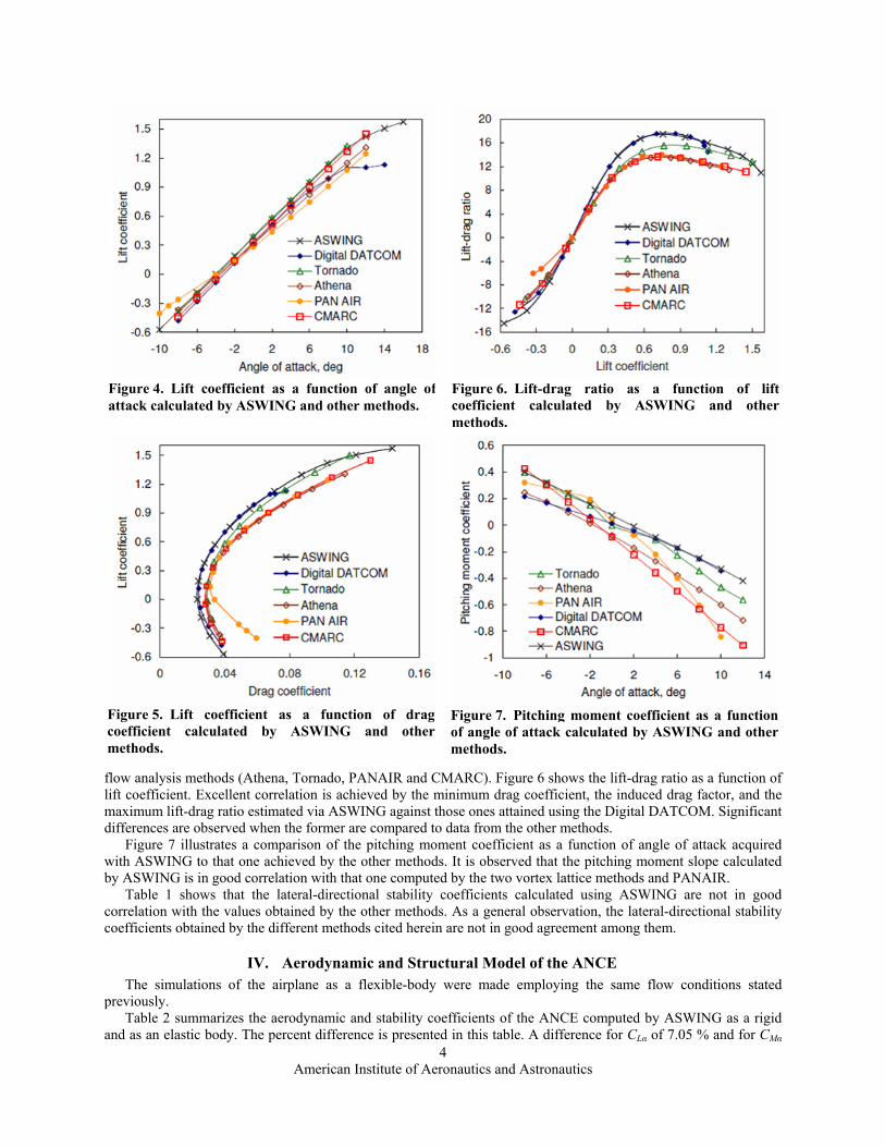
Figure 9 displays the elastic twist distribution in the wing beam at α equal to 12 and –8 deg. For both cases, the net twist magnitude increases as far as the place of attachment of the boom to the wing and then the net twist magnitude is approximately constant. At α=12 deg, the distributed aerodynamic loads on the wing and horizontal tail reduces the spanwise incidence angle, generating the diminution of the lift coefficient respect to the rigid-body model. The opposite happens at α=–8 deg. The elastic twist distribution in the wing beam changes the effective angle of attack of the horizontal tail. Figure 10 shows the deformed ANCE geometry at angles of attack equal to 12 and –8 deg. It could be appreciated that the horizontal tail moves up 4 cm at α=12 deg, and it scrolls down –5 cm at α=–8 deg, varying the angle of attack of the horizontal tail in both case.
Figure 11 illustrates the lift coefficient as a function of the induced drag coefficient of the ANCE as a rigid and as a flexible-body. It could be appreciated that the deformations on the airframe structure reduce the induced drag
Table 1. Aerodynamic and stability coefficients of the ANCE as a rigid-body computed with ASWING compared to those obtained by the other methods given in 1/rad.
ASWING DATCOM7 Tornado6 Athena5 PANAIR5 CMARC7 k 0.0383 0.0364 0.0365 0.0506 0.0493 0.0488 ho 0.9678c 0.7917c 0.7505c 0.8262c 0.8934c 0.9582c
CLo 0.3794 0.3110 0.3740 0.3111 0.3089 0.3273 CMo 0.0739 –0.0807 0.0339 –0.1004 –0.0090 –0.0959 CDα 0.1424 0.1276 0.1491 0.1515 0.1302 0.1731 CLα 5.2827 5.6379 5.4603 4.8128 4.2743 5.4202 CLq 12.3311 8.4740 20.4159 10.1565 – 6.2209 CLδe 0.6303 – 0.6761 0.6532 – 0.6303 CMα –2.3491 –3.0539 –2.7330 –2.7731 –2.7502 –3.8388 CMq –36.9652 –26.0753 –51.5770 –28.1258 – –18.6627 CMδe –2.6929 – –2.8533 –2.7387 – –2.6872 CYβ –0.3208 –0.7615 –0.5959 –0.5271 – –0.3266 CYp –0.0017 –0.0828 –0.1251 –0.0546 – –0.0048 CYr 0.2868 – 1.3763 0.4549 – 0.4212 CYδr –0.2121 – –0.2693 –0.3323 – –0.2807 CYδa 0.0001 – 0.0052 –0.0023 – 0.0029 Cℓβ –0.0036 –0.0592 –0.0057 –0.0573 – –0.1375 Cℓp –0.5347 –0.5301 –0.8759 –0.5459 – –1.1268 Cℓr 0.0723 0.0686 0.1251 0.0910 – 0.2106 Cℓδr –0.0022 – –0.0057 –0.0229 – –0.0172 Cℓδa –0.1523 – –0.2005 –0.3209 – –0.4297 Cnβ 0.1157 0.1749 0.1719 0.1318 – 0.1891 Cnp –0.0262 –0.0306 –0.0038 –0.0008 – –0.0322 Cnr –0.1880 –0.2331 –0.7507 –0.1820 – –0.5265 Cnδr 0.1128 – 0.1490 0.1719 – 0.2922 Cnδa 0.0047 – 0.0057 0.0115 – 0.0172

American Institute of Aeronautics and Astronautics
6
coefficient and increase the lift-drag ratio. These same deformations increase the viscous drag coefficient at higher and at smaller lift coefficients; as a consequence, the drag polar curves of the airplane as a flexible and as a rigid-body are very similar as it is shown in Fig. 12.
V. Conclusion The aerodynamic and static stability analysis of the Unmanned Airplane for Ecological Conservation as a
flexible-body has been discussed in the present paper. The ASWING code for the preliminary analysis of flexible airplanes was used to reach the objective.
It is possible to conclude that the airplane is statically stable in the three axes when it is studied as a flexible-body. Although the flexible-body analysis presents some variations respect to that one as a rigid-body, the static stability analysis is not significantly affected. The elastic twist distribution into the wing beam changes the distributed aerodynamic loads, especially when the elevator is deflected. This phenomenon modifies the pitching moment slope respect to the rigid-body analysis. In general, the comparison of flexible-body data to the rigid-body results shows slight differences.
Table 2. Aerodynamic and stability coefficients of the ANCE as a rigid-body and as a flexible-body computed with ASWING given in 1/rad.
Rigid-body Flexible-body
Percent difference
k 0.0383 0.0392 2.35 ho 0.9678 0.9456 2.30
CLo 0.3794 0.3996 5.32 CMo 0.0739 0.0539 27.04 CDα 0.1424 0.1434 0.69 CLα 5.2827 4.9102 7.05 CLq 12.3311 8.6526 29.83 CLδe 0.6303 0.3438 45.45 CMα –2.3491 –2.0626 12.20 CMq –36.9652 –33.5954 9.12 CMδe –2.6929 –2.4064 10.64 CYβ –0.3208 –0.3208 0.00 CYp –0.0017 –0.0032 95.39 CYr 0.2868 0.2866 0.09 CYδr –0.2121 –0.2119 0.11 CYδa 0.0001 0.0000 95.02 Cℓβ –0.0036 –0.0036 0.82 Cℓp –0.5347 –0.5343 0.07 Cℓr 0.0723 0.0762 5.31 Cℓδr –0.0022 –0.0022 2.48 Cℓδa –0.1523 –0.1479 2.88 Cnβ 0.1157 0.1156 0.06 Cnp –0.0262 –0.0281 7.39 Cnr –0.1880 –0.1880 0.00 Cnδr 0.1128 0.1127 0.08 Cnδa 0.0047 0.0049 4.48
Figure 8. Lift coefficient as a function of angle ofattack obtained for the rigid-body and the flexible-body models.
Figure 9. Net twist as a function of dimensionlesssemi-span on the wing beam at angles of attacksequal to 12 and –8 deg .
American Institute of Aeronautics and Astronautics
7
Acknowledgments The authors thank the financial support from the
Decanato de Investigación y Desarrollo, Universidad Simón Bolívar, Caracas, Venezuela. P. J. Boschetti thanks to Massachusetts Institute of Technology for providing the academic license of ASWING.
References 1Boschetti, P., and Cárdenas, E., “Diseño de un Avión No
Tripulado de Conservación Ecológica,” Engineering Thesis, Department of Aeronautical Engineering, Universidad Nacional Experimental Politécnica de la Fuerza Armada, Maracay, Venezuela, 2003.
2Cárdenas, E., Boschetti, P., Amerio, A., and Velásquez, C., “Design of an Unmanned Aerial Vehicle for Ecological Conservation,” AIAA Paper 2005-7056, Sep. 2005.
3Gaetano, J. “Diseño estructural en materiales compuestos del Avión No Tripulado de Conservación Ecológica (ANCE X-3d),” Engineering Thesis, Department of Aeronautical Engineering, Universidad Nacional Experimental Politécnica de la Fuerza Armada, Caracas, Venezuela, 2009.
4Cárdenas, E., Boschetti, P., and Amerio, A., “Stability and Flying Qualities of an Unmanned Airplane using the Vortex Lattice Method,” Journal of Aircraft, Vol. 46, No. 4, 2009, pp. 1461–1465. doi: 10.2514/1.44306.
5Boschetti, P. J., Cárdenas, E. M., Amerio, A., and Arévalo, A. “Stability and Performance of Light Unmanned Airplane in Ground Effect,” AIAA Paper 2010-293. Jan. 2010.
6Gonzalez, P. J., Boschetti, P. J., Cárdenas, E. M., and Amerio, A. “Evaluation of the Flying Qualities of a Half-Scale Unmanned Airplane via Flight Simulation,” AIAA Paper 2010-298. Jan. 2010.
7Boschetti, P. J., Cárdenas, E. M., and Amerio, A., “Stability of an Unmanned Airplane using a Low-Order Panel Method,” AIAA Atmospheric Flight Mechanics Conference, Aug. 2010 (to be published).
8Drela, M., “ASWING 5.75 User Guide,” Massachusetts Institute of Technology, Cambridge, MA, 2007. 9Drela, M., “ASWING 5.81 Technical Description–Steady Formulation,” Massachusetts Institute of Technology, Cambridge,
MA, 2009. 10Drela, M., and Youngren, H., “XFOIL 6.9 User Primer,” Massachusetts Institute of Technology, Cambridge, MA, 2001. 11Hodges, D. H., Pierce, G. A., Bauchau, O. A., and Smith, M. J., “AE 6200: Aeroelasticity class notes,” The Daniel
Guggenheim School of Aerospace Engineering Georgia Institute of Technology, Atlanta, Georgia, 2009, pp. 80–84.
Figure 11. Lift coefficient as a function of induced drag coefficient obtained for the rigid-body and the flexible-body models.
Figure 10. Deformed airplane at angles of attacksequal to 12 and –8 deg .
Figure 12. Lift coefficient as a function of dragcoefficient obtained for the rigid-body and theflexible-body models.