Cumulative distribution of the stretching of vortical structures in isotropic turbulence
KSME International Journal, VoL 16 No.2, pp. 165-174, 2002 165
Static and Dynamic Fracture Analysis for the Interface Crack ofIsotropic-Orthotropic Bimaterial
Kwang Ho Lee *Department of Mechanical Engineering, Sangju National University,
Sangju City, Kyungbuk 742-711, Korea
Arun Shukla, Venkitanarayanan Parameswaran, Vijaya ChalivendraDepartment of Mechanical Engineering and Applied Mechanics, University of Rhode Island,
Kingston, RI, 02881, USA
Jae Sug HawongDepartment of Mechanical Engineering, Yeoungnam University, Gyungsan City,
Kyungbuk 712-749, Korea
In the present study, interfacial cracks between an isotropic and orthotropic material,subjected to static far field tensile loading are analyzed using the technique of photoelasticity.The fracture parameters are extracted from the full-field isochromatic data and the same arecompared with that obtained using boundary collocation method. Dynamic photoelasticitycombined with high-speed digital photography is employed for capturing the isochrornatics inthe case of propagating interfacial cracks. The normalized stress intensity factors for static cracksare greater when a=90° (fibers perpendicular to the interface) than when a=O° (fibers parallelto the interface), and those when a=90° are similar to ones of isotropic material. The dynamicstress intensity factors for interfacial propagating cracks are greater when a=O° than a=90°.For the velocity ranges (0.1 < c/Cst <0.7) observed in this study, the complex dynamic stressintensity factor IKv I increases with crack speed c, however, the rate of increase of IKs I withcrack speed is not as drastic as that reported for homogeneous materials.
Key Words: Static and Dynamic Stress Intensity Factor, Interface Crack, Isotropic-OrthotropicBimaterial Energy Release Rate, Photoelasticity
1. Introduction
Recent years have seen a resurgence of interest
in the field of interfacial fracture mechanics due
to the oscillatory behavior of stress and dis
placements as the crack-tip is approached.Interface cracks in view of their importance in
numerous applications have received considerable
attention in the literature devoted to fracture
mechanics (Yang et aI., 1991, Deng, 1993, Lee,
• Corresponding Author,E-mail: [email protected]: +82-54-530-5404; FAX: +82-54-530-5401Department of Mechanical Engineering, SangjuNational University, Sangju City, Kyungbuk 742-711,Korea. (Manuscript Received February 6. 2001; RevisedNovember 19, 2001)
1999). Gdoutos (Gdoutos et al., 1982) and Lu(Lu et al., 1993) had determined the static stress
intensity factors for bimaterial specimens using
photoelatiscity. Lambrous and Rosakis(Lambrous et aI., 1995a, 1995b) and Kavaturu
and Shukla (Kavaturu et aI., 1998) have
independently proposed fracture criteria for
dynamic propagating interfacial cracks.
While the static and dynamic fracture ofisotropic-orthotropic bimaterial fracture has
extensively been considered theoretically, the
experimental investigations of this problem is
rather limited. The failure, both static and
dynamic, of such interfaces needs to be
understood in order to exploit the possibility of
bonding together isotropic materials such as
metals to orthotropic materials like the fiber

166 Kwang Ho Lee, Arun Shukla, Venkitanarayanan Parameswaran, Vijaya Chalivendra and Jae Sug Hawong
II Material 1 IIsotropic material
y ..
Crack Xe!4-a-to x
IIIII1a=90
Q a=OQ
II Material 2material IOrthotropic
x
a=OQ
1I1111~ 2a~~
IMaterial 1 IIsotropic material
IMaterial 2 IOrthotropic material
(a) Center Crack Tension (CCT) (b) Single Edge Crack Tension (SECT)
Fig. 1 Interface crack in an isotropic-orthotropic birnaterial
( I)
reinforced composites.
In the present study, a detailed experimental
investigation is conducted to determine stress in
tensity factor and energy release rate associated
with stationary and propagating cracks along the
interface of isorropic-orthotropic bimaterial.
High-speed photography coupled with
photoelasticity is used to capture the isochromatic
fringe pattern. The full field isochromatic data is
used to extract the fracture parameters of interest.
2. Stress and Displacement Fields
The oscillatory stress fields (Lee, 1999) with
odd power series (n= 1,3,5, ... ) for the material
above the interface (the isotropic material) in an
finite bimaterial (Fig. I) can be represented as
<1xn = 2:: K% {-(1+2!3~-!3D[eS(lf-8')n=odd 2,ffiDcoshen
A (In YI + n-2 B) -s(lf-8zlA ( c Incos e T -2- 1 -e cos c,
YI n-2 ) n-2T--2-B1 JYI-z
-2!3s[eS(lf-8s ) 13 cos ( c In ?+ n~2 Bs) +e-S(lf-8s)
B cos (c In ?- n~2 Bs)J y."~2}
+ 2:: K; {(1+2!3~-!3D[e S( lt-8zlA sin
n=odd 2,ffiDcoshex
( In YI + n-2 B) -s(lf-8,lA' ( In YIC T -2- I - e sm C T-
n-2 ) n-2-2-B, JYI-z
+2!3s[eS(lf-8,lif sin ( e In ?+ n~2 Bs) + e-S(lf-8,lB
. ( Ys n - 2 ) n-2}sm e InT--2-Bs JYs-z
" Kg {( I + (32s ) [e s(1r-8zlA-{Jyn= n!o'dd 2/2iiDcosheJr
cos ( e In ?+ n~2 8/ ) _e- s(1r-8zlA cos ( e In
r, n-2 )J n-2-/---2-'0/ r/-z
+2(3s[e«1r-8s) B cos ( s In ?+ n~2 Os)+
-<(If-8slB (In.!2...- n-2 e)J ¥}e cos e l 2 s r,
+ ~ K; {-(I+(3~)[e«1r-8ZlAn=odd 2/2iiDcosheJr
sin ( e In ?+ n~2 0/ ) _e-e(lt-8zlA sin ( e In
r, n-2 ) n-2-/---2-0/ ] r/-2-
-2(3s[e€(1r-8 SlB sin ( e In ?+ n~2 Os)+
e-«lt-8slB sin ( e In ?- n ~ 2 Os)] r» n22} (2)
rXY1l
= ~ Kg f 2(31 [e€(1r-8zlA sin (n=odd 2/2iiDcoshest l
e In r. + n~2 0/ ) +e-e<1r-8zlA sin ( c In ri>:

Static and Dynamic Fracture Analysis for the Interface Crack··· 167
The G for a propagating crack In isotropic
material becomes infinite when crack tip speed
approaches the Rayleigh wave speed but remains
finite for an interfacial propagating crack, where
A o= Kg an/z-1 A*= K; an/z-1 e=_I- Inn!2ii ' n j2i , 2ir
1- /3 /3 huI + /3 ' ..)h1Zhz1
s:Uyn= L: n
nw odd: j2i(nz+4e2) pDcoshcir
{ eE(1t-OIlI3Jr[n sin ( e In 7+ ; (JI) -2e cos ( e
In 7+ ~ at)] r;+e- E(1t- OllI3A [n sin ( e
In~-!!:-.(Jt)-2- cos (c In~-!!:-.al)]rlI 2 c I 2
+eE(1t-OS) B[n sin ( e In ?+ ~ as) -2c cos
(eln ?+~(Js)]ri-e-E(1t-OS)B[nsin(c
In ?-~as)-2ecos(cln ?-~as)]ri}
+ L: K:n=odd !2ii(nz+4e2) pDCOSheir
{ eE(1t-O,II3Jr[ n cos ( e In 7+ ~ al) +2e cos (c
In 7+~(JI) ]d+e-E(1t-O'll3tA[n cos (c 1
n~-!!:-.al)+2csin (cIn~- ~ al)]r;I 2 I _
+ eE(1t-OS)B[n cos ( e In ?+ ~ as)+2e sin
(c In ? + ~ 8s)]ri-e-E(1t-OSlB[n cos (c
In ?-~(Js)+2esin(cln ?-~(Js)]ri} (5)
where n>O, n=odd. When n=l, Eqs, (1)-(5)are stress and displacement fields around the
propagating interfacial crack tip. Thus, Klo and
Kt are stress intensity factors K[ and KIl. For far
field stress 15;' and r~ at infinity, the stress inten
sity factors K[ and KIl are given' as
and the energy release rate is given by
(7)(Kf+KA) hZ14 cosh2(cir)G
where n >0, n=odd, A =2/3s7J + (I +/3~), A=2I3s7J-(I+I3~), B=2/31+ (1+/3i) 7J, B=2/3t(I + /3~) 7J. Oscillatory displacement fields withodd power series (n = I, 3, 5, ... ) for the material
above the interface can be represented as
KgUxn= L: e2n=odd !2ii(nz+4 ) pDcoshcir
{ -eE(1t-811A[n cos (e In 7+; al) +2 e sin (c
In 7+ ; (JI) ]d+e- E(1t-OI)A[n cos ( e In 7- ; (JI) +2e sin ( e In 7- ; (JI ) ] r;
- eE(1t-OslI3sB[ n cos ( e In ? + ; (Js ) +2c sin
(c In ?+;as)]ri-e-E(1t-OSI/3sB[n cos (e
In ? - ; (Js) + 2e sin ( e In ? - ; (Js ) ] ri }
+ L: K;n=odd !2ii (nZ+4e2) ulrcoshen
{ eE(1t-O,lA[n sin ( e In 7+; (JI )-2e cos (c In
7+; al ) ]r;-e-«1t-O,lA [n sin ( e In 7- ; (JI) - 2c cos ( e In 7- ; al) ] d
+ eE(1t-Osl I3sB[ n sin ( c In ? + ; as ) - 2e cos
( e In ?+ ; (Js) ]ri+e-E(1t-OSl/3sB[ n sin ( c
In ?-~as)-2cCos(cIn ?-~(Js)]ri} (4)
n-2 ) n-z-2-(JI Jrl----Z
+ (I + /3~) [eE(lr-OS) B sin ( e In rs+ n~2 (Js)
e-EUHslB sin ( e In rsr: n~2 as)Jr,n2z}
+ ~ K; {2/3 [E(1t-OI)A- (Inn=~ 2!2iiDcoSheir 1 e cos e
r, + n-2 (J ) + -E(1t-OllA (In r, n-2-,- z- 1 e cos e -'---2-
(JI)J r/2z
+ (I +/3~) [e«Jt-Os)B cos ( e In ? + n~2 as)
-E(1t-OslB (lnI!..- n-2 f})J n-z} (3)e cos e , 2 s r, z
168 Kwang Ho Lee. Arun Shukla, Venkitanarayanan Parameswaran, Vijaya Chalivendra and Jae Sug Hawong
TC
e
...I
H
I
-;1~
r
,B
Crack
i~ 2a--..11.-- W~D 2
Iso.
Orth.
where, the HtJ", HJn, V~ and Vi" canbe obtained from boundary collocation points
and material properties. The (Jyn and Uxn also are
known from the boundary collocation points.
Thus, A~ and A;, which are unknown values,
can be obtained from Eq. (8). Therefore, the KFand Kt, which are K1 and K Il , are respectively,
can be obtained from A~ and A;. Equation (8)is expanded for n= 1,3,5, "',59 thus giving us 60unknown coefficients: Af, ..., A~9 and At, ...,A;9. When the boundary conditions, material
properties and coordinates r ; 8 of the selectedboundary are substituted into the general stress
and displacement fields, 120 simultaneous
equations with unknown coefficients A~, A; are
constructed. The solutions, which satisfy theboundary conditions, are obtained by using least
squares method.If the external traction and elastic properties
are symmetric about x-axis, rX)O is zero along the
x-axis. Under these circumstances, only the term
A~ which is related to stress intensity factor K 1 is
used, and the exact value K 1 (=Af )2JCa) can be
obtained. For interface crack in bimaterials,
although external traction is symmetric about thex-axis, rxY exists along the x-axis because the
elastic properties are not symmetric about x -axis.
Under these circumstances, the coefficients A~
and A; must be used.
Ty
Fig. 2 Model of rectangular isotropic-orthotropicbimaterial plate
The bimaterial model which was used in this
study is shown in Fig. 2 with the traction T;applied on upper and lower boundaries. In the
figure rX)O=O on AB, Ty=a on BC, rX)O=O, U x =o on CD, Ty=(J on DA.
Since the loading, material and geometry are
symmetric about vertical axis, only one half
(right) of the plate is considered. The total num
ber of the selected points along the boundary are120 (40 along AB, 20 along Be, 40 along CD, 20
along DA). Meanwhile, the stress and dis
placements of Eqs. (1) - (5) can be represented
as Eq.(8).
6ii=~ (A~H&.+A~H;').Ui=~ (AW~+A~U~) (8)n=l n=l
3. The Determination of StressIntensity Factors by Boundary
Collocation
hu = (/u ) 1 - (/u ) 2, h12= (h2) 1+ (/12)2,h21= ( 121) 1+ (/21) 2, 7J = (h2d h12) 1/2,
(Ill) 1= { 2/3d3s- (1 + /3~) }f.lDl '
( h2) 1= { (3s (1- (3D }f.lDl
(121) 1= { (31 (~D~~) },
(I) psal-Plas qs-qlU 2 D2 asr ai'
( I ) (I+Ma) (PI-PS) (I) asql-alqs122 ~ ,212 D
2
D1= [4/3I/3s- (1 +/3~)2],
D2= (1+Ma) (as-az) ,
131=/ 1- (tr /3s=/I-( ~sr./ (C )2 .rl=ry 1- c; sm2 8,
rs=r/l-( ~sr sin" 8,
I =crack length (2a for center crack and a for
edge crack), and the C, CI and c, are the crack
propagation velocity, longitudinal and shear
wave velocity for material 1 (isotropic material)
respectively. Meanwhile, the PI, Ps, ql, qs, ai, as,
Ma and the fields for the material below theinterface (the orthotropic material) are given in
reference (Lee, 1999).

Static and Dynamic Fracture Analysis for the Interface Crack···
Table 1 Material properties for bimaterials
169
4. Experimental Details and Analysis
4.1 Extraction of fracture parameters from
isochromatic fringes
The stress field Eqs. (I) - (3) combined with
the stress optic law (equation 9) define the order
of the isochromatics at any given point around
the crack tip.
~ = }/(<Jx-<Jy)2+ (2rxy)2 (9)
where N is fringe order, t the thickness of spec
imen and f the material fringe constant. The
fringe order at a selected set of points wasobtained from the digital photographs of com
puter, and the fracture parameters were evaluated
from the selected points U< r<3t) around crack
tip using the non-linear least squares method in
conjection with the Newton-Raphson technique(Robert, 1980). The fracture parameters of sta
tionary crack were obtained using the dynamic
equations by giving c/CS! a value close to zero.
4.2 Static experiments
A series of experiments was conducted usingthe center crack geometry having different crack
length for two fiber orientations. The two fiber
orientations considered were fibers paraller to theinterface (a=O") and fibers perpendicular to the
interface (a=90 0) . The bimaterials used to eval
uate the fracture parameters consist of the PSM-lfor isotropic material (Mat. I) and Scotchply
-1002 for orthotropic material (Mat. 2). The
material properties are shown in Table I. The
width, height and thickness of specimen are254mm, 508mm and 9.525mm respectively. The
bonding faces of the plates were machined to
obtain a flat surface, roughened with 400-grit
sand paper and thoroughly cleaned with
methanol. Teflon tape (25 j.J.ffi thick) of therequired length was used to create the initial
crack during bonding process. Epoxy adhesive,
having properties same as those of the matrix was
used for bonding the two plates in order to obtain
a true bimaterial system. During debonding of the
bond between PSM and Scothchply under impact
PSM ScotchplyProperty
. Dyna.Property
Stat. IDyna.Stat.
I E L 39.3 ! 47.12E(GPa) 2.50 2.76
9.67 13.05E T
,u(GPa) .905 1.0 ,uLT 3.10 3.89
v .38 .35 VLT .254 .254
p(kg/m3) 1200 1200 P 1860 1860
Ill" (kN/m) 6.45 7.0 Ill" - -
E: Young's modulus, fJ. : Shear modulus,v : Poisson's ratio, p : Density,Ill" : Material fringe constant, L : Fiber direction,T : Normal direction to fiber one.
load, the bond membrane sticks on the face of
PSM. The fact proves that the PSM and bond are
one material which bonded perfectly.
A far field uniform tensile load was applied tothe specimen using an Instron machine, and the
isochromatics corresponding to load increments
of 225 N were recorded using a light field circular
polariscope and a digital camera for each cracklength and fiber orientation. The experiments
were conducted for five crack length correspond
ing to 2a/ W ratio varying from 0.2 to 0.6.
4.3 Dynamic experiments
Dynamic fracture experiments- were performed
for both fiber orientations using the single edge
crack geometry. The specimen preparation wasidentical to that followed for static experiments.
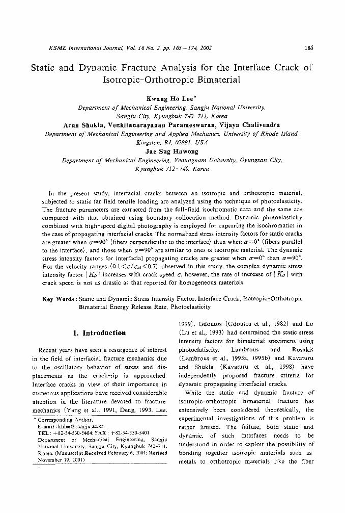
The experimental setup shown in Fig. 3
comprised of a high-speed digital carmer, a lightfield polariscope, the bimaterial and flash light
source.
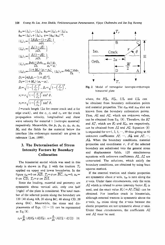
Figure 4 shows the static isochromatic fringepatterns in the PSM for a static center crack in
PSM-ljScotchply-1002 bimaterial. As known,
the fringe orders (N =3.5, 4.0, 4.5, 5.0) at crack
are greater when a=90" than when a=O". Theorthotropic material of a=O° is more compliant
than that of a=90° for loading direction. Thus, it
can be inferred that the stress intensity factor atcrack tip of the isotropic material bonded with
orthotropic material of a=90° is greater than thatbonded with orthotropic material of a=O° under
170 Kwang Ho Lee. Arun Shukla. Venkitanarayanan Parameswaran, Vijaya Chalivendra and Jae Sug Hawong
Fig. 3 Experimental setup for investigating thefracture of a bimaterial interface
same load.
Meanwhile, the isochromatic fringe patterns are
normal about crack direction at crack tip.
Increasing the Y, they tilt to the (+) x direction
because of the remote stress (Jox of x direction,
where, a value of (Jox >0 tends to compressive
stress along the crack line and (Jox< 0 produces
tensile stress. The (Jox increases as the crack tip
speed increases, and the (Jox in the stiff material is
greater than that in compliant one. The greater
the difference of physical properties in two
materials, the greater the (Jox in stiff material, and
the smaller the (Jox in compliant one. When the
crack propagates at high speed, even if the Oox has
high value, the isochromatic fringe patterns at
remote zone move to reverse direction of crack
BimaterialSpecimen
Figure 6 shows the normalized stress intensity
factors (NSIFs) obtained from the numerical
analysis and the experiments for static crack in
PSM-I/Scotchply-I002 bimaterial. The nor
malized stress intensity factors for a=O° are less
than those for a=90° which are very close to
those of isotropic material. As the normalized
crack length approaches to 0.2, the normalized
stress intensity factors approach to 1.0095, which
is a good agreement with the results from Eq. (6)
for stationary crack. Generally, the normalized
stress intensity factor for embedded cracks aligned
normal to fibers is greater than those of crack
aligned with fiber (Lee et al., 1999). It can be
identified that NSIFs for the isotropic
-orthotropic bimaterial also show the same tend
ency as those of orthotropic materials.
5. Evaluation of Fracture Parameters
propagating one.
Figure 5 shows the dynamic isochromatic
fringe patterns in the PSM -I half for an edge
crack propagating along the interface of a PSM
-1/Scotchply-I002 bimaterial photoed by speed
digital carmer (IMACON-200), with which 16
images of the propagating crack were captured.
-, I /
-0-/ , "-
Light Source
High Speed
Digital Carm er
Fig. 4 Isochromatic fringe patterns for a static center crack in PSM/Scotchply bimaterial photoed by digitalcarmer. 2a/W=O.3, Load=3.56KN, W=254mm. t=9.525mm, H/W=2

Static and Dynamic Fracture Analysis for the Interface Crack··· 171
Crack tip -.a!W 0_81, c=500m/s
t C! .•~. 90)
«J = 0")
Fig. 5 Isochromatic fringe patterns for a propagating crack in PSM/Scotchply bimaterial photoed by high
speed digital canner
•Plane stress condition
0.2< a!W <0.75cR,Ic., =0.9235
• : PSM/Scol.(a=90·)
A : PSM/Scot(CL=O·)
0.50 '-----'----'_-'----'-_-'----l.._.J..--..L..---l
0.0 0.1 0.2 0.3 0.4 0.5 0.6 0.7 0.8 0.9Normalized crack tip velocity, clc
S1
Fig. 7 The v KIn +KlID with normalized crack
length for a propagating crack
0.80 ,----------------,
~~
-....... 0.75grf 0.70~
S....... 0.65N c
¥' 0.60N c~--- 0.55
-<>-: Nurn.,a=90·, HlW=1.5
-v-: Nurn.,a=O·, H1W=1.5
-<>-: ISO.Mat.(Nurn.,HlW=1.5)• . Exp.,a=90·, HlW=2
? : Exp.,a=O·, HlW=2
1.4 ,----------------,
1.3
0.7
~
-co 1.2-!::.b 1.1-..
~
;::....... 1.0':ZN~0.9
--- 0.8
0.6 L~====;:=:======:e:::::---l0.2 0.3 0.4 0.5 0.6 O.
Normalized crack length, 2aIW
Fig. 6 The.jKI-'- KA (J hra wi th normalized crack
length for static load

172 Kwang Ho Lee. Arun Shukla. Venkitanarayanan Parameswaran, Vijaya Chalivendra and Jae Sug Hawong
mismatch, proposed by Kavaturu and Shukla
(Kavaturu et al., 1998), indicates that the IKv Iinitially increased with crack velocity and then
decreases and remains finite as the crack velocity
approaches the Rayleigh wave speed of the more
compliant material. Especially, the decrease in
IKv Ioccurs in the velocity range of 0.8<c/ CSl <0.9, under shear dominated crack growth
(Kavaturu et al., 1998). The 1 Kv I in the present
study registers an increasing trend with increasing
crack velocity for the velocity ranges observed.
This is could be due to the low mismatch levels
(e=0.07-0.14) and opening mode dominated
nature of the crack growth. As shown in Fig. 9,
even though the IKv I vs C relationship is similar
to that for isotropic homogeneous materials(Homolite-100), the rate of increase of G or
1 Kv I with crack speed is not as drastic as that
reported for homogeneous materials (Kobayashiet al., 1977). Hence, further experimental data in
the high velocity regime is necessary to confirm
this similarity.The energy release rate G, as a function of
normalized crack speed, shown in Fig. 8, also
indicate the same trend as the IKv I. The dynamicenergy release rate for an isotropic material
increases rapidly with crack propagation velocity,
and becomes infinite value when a crack velocity
approaches the Rayleigh wave speed. It causes the
crack to branch at low velocity. But the dynamicenergy release rate for an interfacial propagating
crack of bimaterial increases slowly with crack
propagation velocity, and remains finite for the
velocity ranges observed in this study.
Figure 10 shows the comparison of theoretical
isochromatic fringes between the a=90° and the
a=O° by stress-optic law combined with the
stress fields. The theoretical isochromatic fringe
patterns for static crack and propagating crack
are similar to the experimental isochromaticfringe ones (Fig. 4, Fig. 5). The stress intensity
factors for static crack obtained in this study are
greater when a=90° than when a=O° but the
dynamic stress intensity factors are reverse. It can
be inferred that the actual fringe ratio r / r' for
static crack is somewhat greater than 1. 19 and for
propagating crack, it is somewhat less than 1.86.
HlW=2.0
Planestresscondition
• : PSMlScOl(a=90·)
& : PSMlScol(a=O·)
~ Homolite-100
-- Branching
0.2< aJW<0.75
• : PSMlScol(CL=90j
& : PSMlSCOl(CL=oj
HlW=2.0
",""'150
~140<5 130
.$120~ 110
~ 100col!2 90<0~ 80e> 70<0
LIi 60
50 l..---'----'_-'-----I._..l----'-_'---'----'
0.0 0.1 0.2 0.3 0.4 0.5 0.6 0.7 0.8 0.9Normalized crack tip velocity. dcs,
Fig. 8 The energy release rate G with normalizedcrack length for a propagating crack
Fig. 9 The comparison of dynamic stress intensityfactors between an isotropic material and anisotropic-orthotropic bimaterial for apropagating crack
cR,Ic.,=0.9235 Planestress condition
160 ,-----------------,
0.0 l..---'----''---'----'_...J----J._-'-----I.----J
0.0 0.1 0.2 0.3 0.4 0.5 0.6 0.7 0.8 0.9
Normalized crack tip velocity, dc.,
2.5 ,-----------------,
Figure 7 shows the amplitude of dynamic com
plex stress intensity factor, 1Kv I, as a function of
the normalized crack speed for propagatinginterfacial crack for both fiber orientations (a=
O· and a=900). As opposed to the stationary
crack, the IKv I values are higher when the fibersare aligned parallel to the interface (a=OO).
When the fibers are perpendicular to the interface,the ends of the fibers meeting the interface act as
weak spots in the path of the propagating crack
resulting in smaller values of the IKv I· The 1Kv Iversus c relationship for bi-rnaterials having high

Static and Dynamic Fracture Analysis for the Interface Crack-s- 173
( 1F900) (a=O')( a=tJ0
)
;. -1.19
3.5"'.",-Xl!.
..~Jj/
;. -1.86
4.5"'..---rll
(a) Static crack (b) Propagating crack
Fig. 10 The comparison of theoretical isochromatic fringes between the a=90· and the a=O' by stress optic
law. KI!(j!iUi=I.05, K II/(j!iUi=O.15, Kz"=2.6Mpa, 2a/W=O.3, Load=3.56KN for static crack andK1=O.6MPa(m) 1/2, KII=O.15MPa(m) 1/2, lG.°((jox parameter) =7.58MPa, a=O.I27m, c=547m/s forpropagating crack
University grant.
5. ConclusionsReference
The fracture parameters for isotropic
-orthotropic bimaterial are studied for interfacial
static and dynamic crack under opening mode
load. It is confirmed from numerical and
experimental method that the normalized stress
intensity factors for static crack is greater when
a=90· than when a=O', and those when a=90·
are similar to ones of isotropic material. The
dynamic stress intensity factors for interfacial
propagating crack are greater when a=O° than
a=90°. It can be inferred that the bonding force
at interface is greater when a=O· than when a=
90·. For the velocity ranges (0.1 < c/cs1< 0.7)
observed in this study, the complex dynamic stress
intensity factor IKD I increases with crack speed
c, however, the rate of increase of IKD I with
crack speed is not as drastic as that reported for
homogeneous materials.
Acknowledgement
This study is supported by Sangju National
Deng, X., 1993, "General Crack-Tip Fields for
Stationary and Steadily Growing Interface Cracks
in Anisotropic Bimaterials," J. of AppL Mech.,
Vol. 60, pp. 183-189.
Gdoutos, E. E. and Papakaliatakis, 1982,
"Photoelastic Study of a Bimaterial Plate with a
Crack Along the Interface," Engng. Fract. Mech.
Vol. 16, No.2, pp. 177-182.
Kavaturu, M. and Shukla, A., 1998, "Dynamic
Fracture Criteria for Crack Growth Along
Bimaterial Interfaces," J. of Appl. Mech., Vol. 65,
pp.293-299.
Kobayashi, T. and Dally, J. W, 1977, "The
relation Between Crack Velocity and Sress Inten
sity Factor in Birefringent Polymers, Fast
Fracture and Crack Arrest," ASTM STP 627,257
-273.
Lambros J. and Rosakis, A. J., 1995a, "Devel
opment a Dynamic Decohesion Criterion for
Subsonic Fracture of the Interface Between Two
Dissimilar Materials," Proc. R. Soc. Lond. (A),

174 Kwang Ho Lee, Arun Shukla. Venkitanarayanan Parameswaran, Vijaya Chalivendra and Jae Sug Hawong
451, pp. 711-736.
Lambros J. and Rosakis, A. J., 1995b,
"Dynamic decohesion of Bimaterial: Experimen
tal Observation and Failure Criteria," Int. J.
Solids Struct.; Vol. 32, No. 17, 18, pp. 2677
-2702.
Lee, K. H., 1999, "Stress and Displacement
Fields for Propagating Crack along Interface of
Isotropic-Orthotropic Material under Dynamic
Mode I and II Load," Transactions of the KSME(A), Vol. 23, No.9, pp. 1463-1475.
Lee, K. H. and Choi, Y. c., 1999, "Analysis of
Propagating Flat Crack in Orthotropic Rectan-
gular Plate," Transactions of the KSME (A),
Vol. 23, No. I, pp. 89-98.
Lu, H. and Chiang F. P., 1993, "Photoelastic
Determination of Stress Intensity Factor of an
Interfacial Crack in a Bi-rnaterial," J. of Appl.
Mech., Vol. 60, pp. 93-100.
Robert, J. S., 1980, "Application of the Least
Square Method to Photoelastic Analysis," Exp.Mech. pp. 192-197.
Yang, W., Suo, Z. and Shih, C. F., 1991,
"Mechanics of Dynamic Debonding," Proc., R.Soc. of Lond, A. 433, pp. 679-697.
Copyright © 2022 FDOKUMEN