. Alaska Resources Library & Infonnation Services Anchorage, Alaska
Upload
khangminh22Category
view
0download
0
STATE OF ALASKA
DEPARTMENT OF TRANSPORTATION
AND PUBLIC FACILITIES CONTRACT DOCUMENTS
AND SPECIFICATIONS
Sand Point Dock Replacement
PROJECT NO. 0003194/SFHWY00006
CONTRACT DOCUMENT FEE: $100.00
SOUTHCOAST REGION
To be used in conjunction with the State of Alaska Standard Specifications for
Highway Construction dated 2017, and the plans for the above referenced
project
As Advertised:
February 20, 2019


Project No. 0003194/SFHWY00006 Sand Point Dock Replacement
08/18
TABLE OF CONTENTS (Federal-Aid Highways)
1. Invitation (goldenrod)INVITATION TO BID 25D-7 (7/18)
2. Bid Notices (green)REQUIRED DOCUMENTS 25D-4H (7/18) FEDERAL EEO BID CONDITIONS 25A-301 (12/14)
3. Forms (yellow)SUBCONTRACTOR LIST 25D-5 (5/17) BIDDER REGISTRATION 25D-6 (1/16) CONTRACTOR'S QUESTIONNAIRE 25D-8 (8/01) BID FORMS (10 PAGES)
A. BID COVER SHEET B. BID SCHEDULE C. BID ATTACHMENTS (AS APPLICABLE) D. ADDENDA ACKNOWLEDGEMENT E. BIDDERS ACKNOWLEDGEMENT AND CERTIFICATION
CONSTRUCTION CONTRACT 25D-10H (1/15) PAYMENT BOND 25D-12 (8/01) PERFORMANCE BOND 25D-13 (8/01) BID BOND 25D-14 (8/01) BID MODIFICATION 25D-16 (7/18) MATIERAL ORIGIN CERTIFICATE 25D-60 (5/17) EEO-1 CERTIFICATION 25A-304 (8/01) TRAINING PROGRAM REQUEST 25A-310 (5/13) TRAINING UTILIZATION REPORT 25A-311 (1/16) CONTACT REPORT 25A-321A (10/16) DBE UTILIZATION REPORT 25A-325C (7/15) PRIME CONTRACTOR'S WRITTEN DBE COMMITMENT 25A-326 (8/01) SUMMARY OF GOOD FAITH EFFORT DOCUMENTATION 25A-332A (8/01)
4. Contract Provisions and Specifications (white)STANDARD MODIFICATIONS SPECIAL PROVISIONS
APPENDIX A – CONSTRUCTION SURVEYING MANUAL APPENDIX B – ENVIRONMENTAL COMMITMENTS & PERMITS APPENDIX C – MATERIAL CERTIFICATION LIST APPRNDIX D – EROSION & SEDIMENTATION CONTROL PLAN
REQUIRED CONTRACT PROVISIONS FOR FEDERAL-AID (FHWA) CONSTRUCTION CONTRACTS 25D-55H (2/16)
5. Federal Wage RatesFederal wage rates can be obtained at http://www.wdol.gov/dba.aspx#0 for the State of Alaska. Use thefederal wage rates that are in effect 10 days before Bid Opening. The Department will include a paper copyof the federal wage rates in the signed Contract. This project uses AK1 and AK6.
6. State Wage RatesState wage rates can be obtained at http://www.labor.state.ak.us/lss/pamp600.htm. Use the State wagerates that are in effect 10 days before Bid Opening. The Department will include a paper copy of the Statewage rates in the signed Contract.
7. Standard DrawingsDownload the applicable Standard Drawings referenced on the cover page of the plans from the followingwebsite: http://www.dot.state.ak.us/stwddes/dcsprecon/stddwgeng.shtml


Form 25D-7 (7/18) Page 1 of 2
STATE OF ALASKA DEPARTMENT OF TRANSPORTATION AND PUBLIC FACILITIES
INVITATION TO BID for Construction Contract
Date 02/20/2019
Sand Point Dock Replacement, 0003194/SFHWY00006 Project Name and Number
The Department invites bidders to submit bids for furnishing all labor, equipment, and materials and performing all work for the project described below. The Department will only consider bids received before 2:00 PM local time (per the Department’s time source) on the 14th day of March, 2019. On that date, the Department will assemble, open, and then publicly announce the timely-received bids at 6860 Glacier Highway, at 2:30 PM, or as soon thereafter as practicable.
Location of Project: Sand Point, AK
Contracting Officer: D. Lance Mearig, P.E.; Director, Southcoast Region Issuing Office: Southcoast Region State Funded Federal Aid
Description of Work: The proposed project would construct a new dock adjacent to the southwest end of the existing dock and would be approximately 70-ft wide and 220-ft long and will include constructing a pile supported dock with concrete deck and concrete framing, adding a fender pile system, dock face beam, bull-rails and heavy duty bollards along the entire face of the new section of pier, adding a new dolphin and access catwalk to provide moorage for large vessels, placing new shot rock fill behind the structure to extend the existing breakwater and create additional uplands area for safe passenger staging and maneuvering of equipment, installing revetment rock to dissipate wave action at the pier face, to protect and stabilize the underlying new fill slopes and refurbishing the existing adjacent dolphin and catwalk structure. Project DBE Utilization Goal: Race-Neutral, Goal is 0.00% Race-Conscious, Goal is 0.00%
The Engineer’s Estimate is between $5,000,000 and $10,000,000
All work shall be completed in ____N/A____ Calendar Days, or by May 31, 2020. The Department will identify interim completion dates, if any, in the Special Provisions.
The apparent successful bidder must furnish a payment bond in the amount of 50% of the contract and a performance bond in the amount of 50% of the contract as security conditioned for the full, complete and faithful performance of the contract. The apparent successful bidder must execute the said contract and bonds within fifteen calendar days, or such further time as may be allowed in writing by the Contracting Officer, after receiving notification of the acceptance of their bid.
Submission of Bidding Documents Bidders may submit bidding documents electronically via the Department’s approved online bidding service, through the mail or hand delivered. For mailed or hand delivered bids and for electronically submitted bids with a paper bid guaranty, documents shall be submitted in a sealed envelope marked as follows:
Bidding Documents for Project: Project No. 0003194/SFHWY00006 Sand Point Dock Replacement
ATTN: Contracts Officer State of Alaska Department of Transportation & Public Facilities__ 6860 Glacier Highway Juneau, Alaska 99801-7999 or P.O. Box 112506, Juneau, AK 99811-2506
It is incumbent upon the bidder to ensure its bid, any amendments, and/or withdrawal arrive, in its entirety, at the location and before the deadline stated above. A bidder sending a bid amendment or withdrawal via email or fax must transmit its documentation to the Department at this email address: [email protected] __________ or fax number: (907) 465-4238.
To be responsive, a bid must include a bid guaranty equal to 5% of the amount bid. (When calculating the bid amount for purposes of determining the 5% value of the bid guaranty, a bidder shall include its base bid amount, plus the amount bid for alternate and supplemental bid items, if any.)
The Department hereby notifies all bidders that it will affirmatively ensure that in any contract entered into pursuant to this Invitation, Disadvantaged Business Enterprises will be afforded full opportunity to submit bids and will not be discriminated against on the grounds of race, color, national origin, or sex in consideration for an award.

Form 25D-7 (7/18) Page 2 of 2
NOTICE TO BIDDERS
Bidders must have a Vendor ID or your bid may not be accepted. More information can be obtained at the following website: http://dot.alaska.gov/aashtoware/docs/AWP-Vendor-List-Guidance.pdf The following data may assist a bidder in preparing its bid:
A bidder may obtain hard copy project plans and specifications for the price of $ 100.00, from: Contracts Office 6860 Glacier Highway Juneau, Alaska 99801 Fax: (907) 465-4238 E-Mail: [email protected] Phone: (907) 465-4493
If a bidder has a question relating to design features, constructability, quantities, or other technical aspects of the project, it may direct its inquiry to the questions and answers area of the Bid Express proposal page: __________________________ David Lowell, P.E. Phone: (907) 465-4812 Construction Project Manager, Box 112506, Juneau, AK 99811-2506 Fax: (907) 465-2030 E-Mail: [email protected] A bidder requesting assistance in viewing the project site must make arrangements at least 48 hours in advance. The point of contract for inquiries for this project is __David Lowell, P.E.__________________________________________. Email: [email protected]__ Phone: (907) 465-4812______________
For questions relating to electronic bidding or for assistance with your Bid Express account, contact Bid Express customer support at [email protected] or call toll free (888)352-BIDX(2439) Monday through Friday 7:00am to 8:00pm (Eastern). A bidder may direct questions concerning bidding procedures and requirements to: Email: [email protected] _ Phone: (907) 465-4493_______________
Other Information:
To report bid rigging activities call: 1-800-424-9071 The U.S. Department of Transportation (DOT) operates the above toll-free “hotline” Monday through Friday, 8:00am to 5:00pm Eastern Time. Anyone with knowledge of possible bid rigging, bidder collusion, or other fraudulent activities should use the “hotline” to report such activities. The “hotline” is part of DOT’s continuing efforts to identify and investigate highway construction contract fraud and abuse and is operated under the direction of the DOT Inspector General. All information will be treated confidentially and caller anonymity will be respected.

(Electronic Bidding, 07/01/18)
Special Notice to Bidders
CROSS-REFERENCE FOR PAY ITEM NUMBERS
Pay item numbers in the Bid Schedule are cross-referenced to the pay item numbers in all other
contract documents. The cross-reference for pay item numbers is included in the Estimate of
Quantities table on the plans.


(Electronic Bidding, 07/01/18)
Special Notice to Bidders CARGO PREFERENCE ACT REQUIREMENTS The provisions of the Cargo Preference Act (CPA) must be physically incorporated into all Federal-aid Projects awarded after February 15, 2016, and must be physically incorporated in all agreements with subcontractors and lower tier subcontractors. Form 25D-55 (2/16) is revised to include the CPA provisions to the Required Contract Provisions for Federal-Aid Construction Contracts. See the last page of Form 25D-55 for the CPA requirements. For additional details, please visit http://www.marad.dot.gov/ships-and-shipping/cargo-preference/laws-and-regulations/


(Electronic Bidding, 07/01/18)
Special Notice to Bidders On December 22, 2015, U.S. District Court for the District of Columbia issued a decision vacating the Federal Highway Administration (FHWA) 90 percent threshold exemption for manufactured steel and iron products and the miscellaneous steel or iron components, subcomponents and hardware waiver. As a result of the federal court decision, FHWA withdrew their December 21, 2012 policy memorandum clarifying provisions of the Buy America Act requirements.


SPECIAL NOTICE TO BIDDERS
Questions from bidders on this project as associated Department responses will be published as
Informational Notice to Bidders.
All questions must be submitted in writing in sufficient time to receive a reply prior to
submitting a bid (Reference Standard Specification 102-1.04). Questions submitted
within two business days of bid opening may or may not be considered at the
Department’s discretion. If a significant question is asked just prior to bid opening, the
Department will determine whether the issue raised is significant enough to delay the
bid opening and issue an addendum or to proceed with the scheduled bid opening.
Bidders submitting questions will not receive individual responses
All questions must be submitted on the Bid Express website
(https://www.bidx.com/ak/lettings) or to the Construction Manager identified on the
Invitation to bid. Questions submitted to the Bidder Registration Inbox, or a location
other than the identified Construction Manager, will not be answered.
At increments of time determined by the Department, all questions and answers on the
project received will be published on the Bid Express website, and as such are not
contractual.
The Department will publish only questions and answers. The Department will not
publish contractor’s name or contact information.


NOTICE TO BIDDERS
Bidders are advised that the Department will provide the successful contractor with the
following documents upon award of the contract:
Two (2) copies of Conformed Full Sized Plans.
Two (2) copies of Conformed 11 X 17 Plans
Two (2) copies of Conformed Specifications
One (1) copy of Conformed Plans & Specification in electronic format (.pdf) on CD-
ROM
Additional copies of contract documents are the responsibility of the contractor.


February 8, 2011
Special Notice to Bidders Change in Prevailing Wage Requirements
Notice: The Department of Labor and Workforce Development (DOLWD) proposed a revised regulatory definition of “on-site” in 8 AAC 30.910 to clarify the scope of activities covered by Alaska’s Little Davis Bacon Act (AS 36.05.010 – AS 36.05.110). For a copy of the revised definition of 8 AAC 30.910, go to: http://labor.alaska.gov/commish/12-2010-OT-language.pdf DOLWD will enforce the revised provisions on all projects with a bid opening date on or after February 15, 2011. Prospective bidders on projects with a bid opening date on or after February 15, 2011, must consider the impact of the revised regulation and bid accordingly. DOLWD will not enforce the new “on-site” definition on projects with a bid opening date prior to February 15, 2011.


Special Notice to Bidders
Statewide Special Provision SSP-38 Section 120 for the Disadvantaged Business Enterprise (DBE) Program
Effective for FHWA funded projects advertised on or after July 1, 2015; there is a new Statewide Special Provision SSP-38 that replaces Standard Modification E114 for Section 120 DBE Program. The Department, in coordination with the Federal Highway Administration (FHWA), adopted a Race-Neutral DBE Program with an overall DBE Utilization Goal of 8.83% for Alaska’s FHWA Federal-Aid program. Although the Race-Neutral program does not establish or require individual project DBE Utilization Goals, 49 CFR establishes the Bidder is responsible to make a portion of the work available to DBEs and to select those portions of the work or material needs consistent with the available DBEs to facilitate DBE participation. If the Department, in collaboration with our contractors, does not meet the overall program DBE Utilization Goal and cannot demonstrate good faith effort to meet the program goal, the program may be modified to Race-Conscious, with individual DBE Utilization Goals established for each Federal-Aid project. The Department and FHWA will use the data collected under Section 120 to evaluate the program for compliance with Section 120 and with 49 CFR Part 26. Contractors are encouraged to review the construction and contract forms and the new Statewide Special Provision SSP-38 for Section 120 DBE program. For information about the Plan Holder Self Registration List, A guide (titled “Plan Holder Self Registration List”) can be found on the Civil Rights website http://www.dot.state.ak.us/cvlrts/index.shtml. This offers further instructions and guidance. Any questions about this notice may be directed to Dennis Good, Manager of the Civil Rights Office, (907) 269-0851, or email [email protected].
07/01/15


SPECIAL NOTICE TO BIDDERS
On November 10, 2015, Governor Walker issued Administrative Order (AO) 278. The order establishes a
15% goal for utilizing registered apprentices in certain job categories on construction projects awarded by
the Alaska Department of Transportation & Public Facilities. AO 278 applies to all projects with a contract
award amount that equals or exceeds 2.5 million dollars.
To view AO 278 in its entirety, please visit Office of the Governor: Administrative Orders- AO 278


Form 25D-4H (7/18) Page 1 of 1
STATE OF ALASKA DEPARTMENT OF TRANSPORTATION AND PUBLIC FACILITIES
REQUIRED DOCUMENTS Federal-Aid Contracts
(FHWA)
REQUIRED FOR BID. Bids will not be considered if the following documents are not completely filled out and submitted at the time of bidding:
1. Bid Forms
a. Bid Cover Sheet
b. Bid Schedule
c. Bid Attachments (as applicable)
i. There are no attachments for this project
d. Addenda Acknowledgement
e. Bidder’s Acknowledgement and Certification
2. Bid Security REQUIRED FOR BID MODIFICATIONS. Any bid revisions must be submitted by the bidder prior to bid opening. Use the following form to modify Manual (paper) bids:
3. Bid Modification (Form 25D-16)
REQUIRED AFTER NOTICE OF APPARENT LOW BIDDER. The apparent low bidder is required to complete and submit the following documents within 5 working days after receipt of written notification:
1. Subcontractor List (Form 25D-5)
2. Summary of Good Faith Effort Documentation (Form 25A-332A), and Contact Reports (Form 25A-321A)
3. DBE Utilization Report (Form 25A-325C)
4. Prime Contractor’s Written DBE Commitment (Form 25A-326) for each DBE to be used on the project. REQUIRED FOR AWARD. In order to be awarded the contract, the successful bidder must completely fill out and submit the following documents within the time specified in the intent to award letter:
1. Construction Contract (Form 25D-10H)
2. Payment Bond (Form 25D-12)
3. Performance Bond (Form 25D-13)
4. Contractor's Questionnaire (25D-8)
5. Certificate of Insurance (from carrier)
6. EEO-1 Certification (Form 25A-304)
7. Training Utilization Report (Form 25A-311), and/or DOT&PF Training Program Request (Form 25A-310), if
required
8. Material Origin Certificate (Form 25D-60)
9. Bidder Registration (Form 25D-6) Bidders must register annually with the Civil Rights Office in order to be
eligible for award.


Form 25A-301 (12/14) Page 1 of 4
STATE OF ALASKA DEPARTMENT OF TRANSPORTATION AND PUBLIC FACILITIES
FEDERAL EEO BID CONDITIONS
STANDARD FEDERAL EQUAL EMPLOYMENT OPPORTUNITY CONSTRUCTION CONTRACT
SPECIFICATIONS FOR ALL NON-EXEMPT FEDERAL AND FEDERALLY-ASSISTED CONSTRUCTION CONTRACTS TO BE AWARDED IN THE STATE OF ALASKA
Authority and Guidelines. The Alaska Department of Transportation & Public Facilities (Department), as a State Transportation Agency
(STA), has authority under 23 U.S.C. 140 and its implementing regulations to conduct a compliance program addressing Equal Employment Opportunity (EEO) and Affirmative Action (AA) in employment on non-exempt federal and federally-assisted construction contracts that are awarded in the State of Alaska. The STA's authority to administer a contract compliance with Nondiscrimination, EEO and AA programs are authorized under 23 U.S.C., 49 U.S.C., Title VI of the Civil Rights Act of 1964, MAP-21 and implementing regulations. The provisions of 23 CFR 200 and 49 CFR 21 provide authority to determine, and where necessary obtain compliance with the nondiscrimination provisions of Title VI. Under the provisions of Title VI 23 USC and related regulations, including 49 CFR 21 and 26, and 23 CFR Part 200, 230 and 633, it is the STA's responsibility to ensure compliance with and to enforce on all projects of Federal-aid contractors and subcontractors, whether a particular contract or work-site involves Federal-aid funds or not.
These citations confirm the requirement for contractors to provide, and States to obtain information that ensure non-
discrimination in employment on all of Federal and federally-assisted projects, and through these provisions, provide for EEO for minorities and women in all terms and conditions of their employment at all of their facilities and on all projects.
1. Definitions. As used in these specifications:
a. “Covered area” means the geographical area described in the solicitation from which this contract resulted; b. “Employer identification number” means the Federal Social Security number used on the Employer’s
Quarterly Federal Tax Return, U.S. Treasury Department Form 941. c. “Minority” includes:
(1) Black (all persons having origins in any of the Black African racial groups not of Hispanic origin); (2) Hispanic (all persons of Mexican, Puerto Rican, Cuban, Central or South American or other Spanish culture
or origin, regardless of race); (3) Asian and Pacific Islander (all persons having origins in any of the original peoples of the Far East, Southeast
Asia, the Indian Subcontinent, or the Pacific Islands); and (4) American Indian or Alaska Native (all persons having origins in any of the original peoples of North
America and maintaining identifiable tribal affiliations through membership and participation or community identification).

Form 25A-301 (12/14) Page 2 of 4
2. Whenever the Contractor, or any subcontractor at any tier, subcontracts a portion of the work involving any construction trade, it shall physically include in each subcontract in excess of $10,000 the provisions of these specifications and which is set forth in the solicitations from which this contract resulted.
3. If the Contractor is participating (pursuant to 41 CFR 60-4.5) in a Hometown Plan approved by the DOL in the
covered area, either individually or through an association, its affirmative action obligations on all work in the Plan area shall be in accordance with that Plan for those trades that have unions participating in the Plan. Contractors must be able to demonstrate their participation in and compliance with the provisions of any such Hometown Plan. Each Contractor or subcontractor participating in an approved Plan is individually required to comply with its obligations under the EEO clause, and to make good faith effort to achieve an equal representation of minority and female employment under the Plan in each trade in which it has employees. The overall good faith performance by other Contractors or subcontractors in an approved Plan does not excuse any covered Contractor’s or subcontractor’s failure to make good faith efforts to achieve the Plan.
4. The Contractor shall implement the specific affirmative action standards provided in paragraphs 5(a) through 5(p)
of these specifications. 5. The Contractor shall take specific affirmative actions to ensure equal employment opportunity. The evaluation of
the Contractor’s compliance with these specifications shall be based upon its effort to achieve maximum results from its actions. The Contractor shall document these efforts fully, and shall implement affirmative action steps at least as extensive as the following:
a. Ensure and maintain a working environment free of harassment, intimidation, and coercion at all sites, and in
all facilities at which the Contractor’s employees are assigned to work. The Contractor shall specifically ensure that all foremen, superintendents, and other on-site supervisory personnel are aware of and carry out the Contractor’s obligations to maintain such a working environment, with specific attention to minority or female individuals working at such sites or in such facilities.
b. Establish and maintain a current list of minority and female recruitment sources, provide written notification to
minority and female recruitment sources and to community organizations when the Contractor or its unions have employment opportunities available, and maintain a record of the organizations’ responses.
c. Maintain a current file of the names, addresses and telephone numbers of each minority and female off-the-
street applicant and minority or female referral from a union, a recruitment source or community organization and of what action was taken with respect to each such individual. If such individual was sent to the union hiring hall for referral and was not referred back to the Contractor by the union or, if referred, not employed by the Contractor, this shall be documented in the file with the reason therefor, along with whatever additional actions the Contractor may have taken.
d. Provide immediate written notification to the Civil Rights Office’s Contract Compliance Officer when the union
or unions with which the Contractor has a collective bargaining agreement has not referred to the Contractor a minority person or woman sent by the Contractor, or when the Contractor has other information that the union referral process has impeded the Contractor’s efforts to meet its obligations.
e. Develop on-the-job training opportunities and/or participate in training programs for the area which expressly
include minorities and women, including upgrading programs and apprenticeship and trainee programs relevant to the Contractor’s employment needs, especially those programs funded or approved by the Department of Labor. The Contractor shall provide notice of these programs to the sources compiled under 5(b) above.
f. Disseminate the Contractor’s EEO policy by providing notice of the policy to unions and training programs and
requesting their cooperation in assisting the Contractor in meeting its EEO obligations; by including it in any policy manual and collective bargaining agreement; by publicizing it in the company newspaper, annual report, etc.; by specific review of the policy with all management personnel and with all minority and female employees

Form 25A-301 (12/14) Page 3 of 4
at least once a year; and by posting the company EEO policy on bulletin boards accessible to all employees at each location where construction work is performed.
g. Review, at least annually, the company’s EEO policy and affirmative action obligations under these
specifications with all employees having any responsibility for hiring, assignment, layoff, termination or other employment decisions including specific review of these items with on-site supervisory personnel such as Superintendent, general foreman, etc., prior to the initiation of construction work at any job site. A written record shall be made and maintained identifying the time and place of these meetings, persons attending, subject matter discussed, and dispositions of the subject matter.
h. Disseminate the Contractor’s EEO policy externally by including it in any advertising in the news media,
specifically including minority and female news media, and providing written notification to and discussing the Contractor’s EEO policy with other Contractors and Subcontractors with whom the Contractor does or anticipates doing business.
i. Direct its recruitment efforts, both oral and written, to minority, female and community organizations, to schools
with minority and female students and to minority and female recruitment and training organizations serving the Contractor’s recruitment area and employment needs. Not later than one month prior to the date for the acceptance of applications for apprenticeship or other training by any recruitment source, the Contractor shall send written notification to organizations such as the above, describing the openings, screening procedures, and tests to be used in the selection process.
j. Encourage present minority and female employees to recruit other minority persons and women and, where
reasonable, provide after school, summer and vacation employment to minority and female youth both on the site and in other areas of a Contractor’s workforce.
k. Validate all tests and other selection requirements where there is an obligation to do so under 41 CFR Part
60-3. l. Conduct, at least annually, an inventory and evaluation of all minority and female personnel for promotional
opportunities and encourage these employees to seek or to prepare for, through appropriate training, etc., such opportunities.
m. Ensure that seniority practices, job classifications, work assignments and other personnel practices do not have
a discriminatory effect by continually monitoring all personnel and employment related activities to ensure that the EEO policy and the Contractor’s obligations under these specifications are being carried out.
n. Ensure that all facilities and company activities are nonsegregated except that separate or single-use toilet,
necessary changing facilities and necessary sleeping facilities shall be provided to assure privacy between the sexes.
o. Document and maintain a record of all solicitations of offers for subcontractors from minority and female
construction contractors and suppliers, including circulations of solicitations to minority and female contractor associations and other business associations.
p. Conduct a review, at least annually, of all supervisors’ adherence to and performance under the Contractor’s
EEO policies and affirmative action obligations.
6. Contractors are encouraged to participate in voluntary associations which assist in fulfilling one or more of their affirmative action obligations 5(a) through 5(p). The efforts of a contractor association, joint contractor-union, contractor-community, or other similar group of which the Contractor is a member and participant, may be asserted as fulfilling any or more of its obligations under 5(a) through 5(p) of these specifications provided that the Contractor actively participates in the group, makes every effort to assure that the group has a positive impact on the employment of minorities and women in the industry, ensures that the concrete benefits of the program are reflected

Form 25A-301 (12/14) Page 4 of 4
in the Contractor’s minority and female work force participation, makes a good faith effort to meet its individual EEO obligations, and can provide access to documentation which demonstrates the effectiveness of actions taken on behalf of the Contractor. The obligation to comply, however, is the Contractor’s and failure of such a group to fulfill an obligation shall not be a defense for the Contractor’s noncompliance.
7. The Contractor is required to provide equal employment opportunity and to take affirmative action for all minority
groups, both male and female, and all women, both minority and non-minority. Consequently, the Contractor may be in violation if a particular group is employed in a substantially disparate manner.
8. The Contractor shall not use the equal employment or affirmative action standards to discriminate against any person
because of race, color, religion, sex, or national origin. 9. The Contractor shall not enter into any subcontract with any person or firm debarred from government contracts. 10. The Contractor, in fulfilling its obligations under these specifications, shall implement specific affirmative action
steps, at least as extensive as those standards prescribed in item 5(a-p) above, so as to achieve maximum results from its efforts to ensure equal employment opportunities.
11. The Contractor shall designate a responsible official to monitor all employment related activity to ensure that the
company EEO policy is being carried out, to submit reports relating to the provisions hereof as may be required by the Government and to keep records. Records shall at least include for each employee the name, address, telephone numbers, construction trade, union affiliation if any, employee identification number when assigned, social security number, race, sex, status (e.g., mechanic apprentice, trainees, helper, or laborer), dates of changes in status, hours worked per week in the indicated trade, rate of pay, and locations at which the work was performed. Records shall be maintained in an easily understandable and retrievable form; however, to the degree that the existing records satisfy this requirement, Contractors shall not be required to maintain separate records.
12. Nothing herein provided shall be construed as a limitation upon the application of other laws that establish different
standards of compliance or upon the application of requirements for the hiring of local or other area residents (e.g., those under the Public Works Employment Act of 1977 and the Community Development Block Grant Programs).
13. The Bidder’s attention is called to the “Equal Opportunity Clause” and the “Standard Federal Equal Employment
Opportunity Construction Contract Specifications” set forth herein. 14. EEO/AA obligations are applicable to all of the Contractor’s construction work (whether or not it is federal or
federally-assisted) performed in the covered area. The hours on minority and female employment and training must be substantially uniform throughout the length of the contract, and in each trade, and the Contractor shall make a good faith effort to employ minorities and women evenly on each of its projects. The transfer of minority or female employees or trainees from Contractor to Contractor or from project to project for the sole purpose of equalizing minority and female employment percentages shall be a violation of the contract. Compliance with equal minority and female employment utilization will be measured against the total work hours performed.
15. The Contractor shall provide written notification to the Department, for all subcontracts documents as follows: the
name, address and telephone number of subcontractors and their employer identification number; the estimated dollar amount of the subcontracts; estimated starting and completion dates of the subcontracts; and the geographical area in which the contract is to be performed.
This written notification shall be required for all construction subcontracts in excess of $10,000 at any tier for
construction work under the contract resulting from this project’s solicitation. 16. As used in the Bid Notice, and in the contract resulting from this project’s solicitation, the “covered area” is the
State of Alaska.

Form 25D-5 (5/17) Page 1 of 2
STATE OF ALASKA DEPARTMENT OF TRANSPORTATION AND PUBLIC FACILITIES
SUBCONTRACTOR LIST
Sand Point Dock Replacement; 0003194/SFHWY00006 Project Name and Number
The apparent low bidder shall complete this form and submit it so as to be received by the Contracting Officer prior to the close of business on the fifth working day after receipt of written notice from the Department.
An apparent low bidder who fails to submit a completed Subcontractor List form within the time allowed will be declared nonresponsible and may be required to forfeit the bid security.
Scope of work must be clearly defined. If an item of work is to be performed by more than one firm, indicate the portion or percent of work to be done by each.
Check as applicable: [ ] All Work on the above-referenced project will be accomplished without subcontracts
Or [ ] List all first tier Subcontractors as follows:
FIRM NAME, ADDRESS, PHONE NO.
AK BUSINESS LICENSE NO., CONTRACTOR'S
REGISTRATION NO.
SCOPE OF WORK TO BE PERFORMED
CONTINUE SUBCONTRACTOR INFORMATION ON REVERSE For projects with federal-aid funding, I hereby certify Alaska Business Licenses and Contractor Registrations will be
valid for all subcontractors prior to award of the subcontract. For projects without federal-aid funding (State funding only), I hereby certify the listed Alaska Business Licenses and Contractor Registrations were valid at the time bids were opened for this project.
Signature of Authorized Company Representative Title
Company Name Company Address (Street or PO Box, City, State, Zip)
Date Phone Number

Form 25D-5 (5/17) Page 2 of 2
FIRM NAME, ADDRESS, PHONE NO.
AK BUSINESS LICENSE NO., CONTRACTOR'S
REGISTRATION NO.
SCOPE OF WORK TO BE PERFORMED

Form 25D-6 (1/16)
STATE OF ALASKA DEPARTMENT OF TRANSPORTATION AND PUBLIC FACILITIES
Civil Rights Office – DBE Program
BIDDER REGISTRATION
All firms are required to submit a Bidder’s Registration form before an Alaska Department of Transportation and Public Facilities (DOT&PF) project can be awarded. The Bidder Registration form must be submitted to the Civil Rights Officer (CRO) on an annual basis by January 1 and is valid thru December 31. Complete this form for each contractor and subcontractor. Firms will be listed on the bidder registration online directory http://www.dot.state.ak.us/cvlrts/bidreg.shtml.
Name of Firm:
Street Address:
Mailing Address:
Contact Name:
Telephone Number:
Fax number:
E-mail Address:
Date Firm was Established:
The firm listed above is a (check all that apply): Prime Contractor? Subcontractor? Identify specialty: ______________________
Service Provider? Identify service: ______________________ Material Supplier? Identify material: ______________________ Manufacturer? Identify product: ______________________ Certified DBE? * *DBE- Disadvantaged Business Enterprise Self-Certified SBE? * *SBE- Small Business Enterprise (Complete page 2 of this form.)
Firm’s gross annual receipts:
< $500,000
$500,000- $999,999
$1,000,000- $4,999,999
$5,000,000- $9,999,999
$10,000,000- $16,999,999
> $17,000,000
Type of contracts/proposals bid by the firm (check all that apply):
Highways Airports Transit AMHS
Signature of Company Representative Title Date
Send this completed form to: OR You may fax your completed form to: ADOT&PF Civil Rights Office (907) 269-0847 PO Box 196900 Anchorage, Alaska 99519-6900
If you have any questions, please call (907) 269-0851.

Form 25D-6 (1/16)
SMALL BUSINESS ENTERPRISE PROGRAM (SBE) BIDDER’S REGISTRATION
Fostering Small business Participation (SBE) (49 CFR 26.39): To meet the requirements of 49 CFR 26.39, DOT&PF has implemented a Small Business Enterprise Program. This component is only applicable to federally funded projects. [Complete the below only if you are a Self-Certified SBE Firm] All businesses wishing to be eligible as a SBE are required to submit a SBE Bidder’s Registration form before a DOT&PF contract can be awarded. The bidder’s Registration from must be submitted on an annual basis by January 1 and is valid thru December 31. In order to verify your firm’s compliance with business size standards under 49 CFR 26.67(2)(i) and 26.65(b), at the
time of award you will be required to submit the following documents: SBE Affidavit of Certification Eligibility Personal Financial Statement Past three years of your corporations and/or individual tax returns If not a certified DBE, please provide documentation that you are self-certified as a small business (please contact Procurement Technical Assistance Center (PTAC) at 907-274-7232 if you require assistance on becoming a self-certified small business)
At time of award send required documentation to: DOT&PF Civil Rights Office Attn: Certification PO Box 196900 Anchorage, Alaska 99519-6900 Phone: (907) 269-0851 Fax: (907) 269-0847
A. SBE Directory Information
1. Can you verify at time of award that your firm (including affiliates) does not exceed the small business size standards as described by the Small Business Administration (SBA) for the last three years of gross annual receipts per 49 CFR 26.65(a)? To find more information about the SBA size standards, visit the SBA website https://www.sba.gov/content/small-business-size-standards.
*If you marked “No” you do not qualify for the SBE Program
[ ]Yes [ ] No*
2. Can you verify at time of award that your firm (including affiliates) does not exceed the personal net worth standards of $1.32 million per 49 CFR 26.67(2)(i)?
*If you marked “No” you do not qualify for the SBE Program
[ ]Yes [ ] No*
3. Can you verify at time of award that each individual owner of your firm does not exceed the personal net worth standards of $1.32 million per 49 CFR 26.67(2)(i)?
*If you marked “No” you do not qualify for the SBE Program
[ ]Yes [ ] No*
4. Contact Info.
Name of Firm Contact Name
Telephone Number Fax Number
Email Address Company Website

Form 25D-8 (8/01) Page 1 of 2
STATE OF ALASKA DEPARTMENT OF TRANSPORTATION AND PUBLIC FACILITIES
CONTRACTOR’S QUESTIONNAIRE
Sand Point Dock Replacement; 0003194/SFHWY00006 Project Name and Number
A. FINANCIAL
1. Have you ever failed to complete a contract due to insufficient resources? No Yes If YES, explain:
2. Describe any arrangements you have made to finance this work: ________________________________________
B. EQUIPMENT
1. Describe below the equipment you have available and intend to use for this project.
ITEM QUAN. MAKE MODEL SIZE/ CAPACITY
PRESENT MARKET VALUE

Form 25D-8 (8/01) Page 2 of 2
2. What percent of the total value of this contract do you intend to subcontract? ________ % 3. Do you propose to purchase any equipment for use on this project?
No Yes If YES, describe type, quantity, and approximate cost: 4. Do you propose to rent any equipment for this work?
No Yes If YES, describe type and quantity: 5. Is your bid based on firm offers for all materials necessary for this project?
Yes No If NO, please explain:
C. EXPERIENCE
1. Have you had previous construction contracts or subcontracts with the State of Alaska?
Yes No Describe the most recent or current contract, its completion date, and scope of work:
2. List, as an attachment to this questionnaire, other construction projects you have completed, the dates of completion, scope of
work, and total contract amount for each project completed in the past 12 months. I hereby certify that the above statements are true and complete.
Name of Contractor
Name and Title of Person Signing
Signature
Date

STATE OF ALASKADEPARTMENT OF TRANSPORTATION AND PUBLIC FACILITIES
Bid Cover Sheet
Letting ID: SFHWY00006
3/14/2019 2:00 PM
Proposal ID: SFHWY00006
SAND POINT CITY DOCK REPLACEMENT
Bid Forms - As-Advertised
Company Name
Company Address
Phone Number
Project ID(s):
SFHWY00006
STATE OF ALASKA
AND PUBLIC FACILITIES
DEPARTMENT OF TRANSPORTATION
Proposal ID: SFHWY00006
Federal #: 0003194
Letting ID: SFHWY00006
Letting Date & Time: 3/14/2019 2:00 PM
Bid Forms As-Advertised
Page 1
Vendor ID: ____________


Bid Schedule - As-AdvertisedSection 1 - Basic Bid
QuantityItem DescriptionItem NumberPropLine # Unit Unit Bid Price Amount Bid
Aggregate Surface Course, Grading E-110 301.0004.00E1 Cubic Yard650
Subbase, Grading A20 304.0002.000A Cubic Yard1,300
Class DS Concrete30 501.0009.0000 Linear Foot2,886
Dock Structure40 501.MF15.0001 Lump SumAll Required Lump Sum
Miscellaneous - Concrete Cleat Repair50 501.MF95.0001 Lump SumAll Required Lump Sum
Miscellaneous -Life Rings & FireExtinguishers60 501.MF95.0002 Lump SumAll Required Lump Sum
Dock -Structural Steel70 504.MF15.0001 Lump SumAll Required Lump Sum
Dolphin Cap - Structural Steel80 504.MF70.0001 Lump SumAll Required Lump Sum
Fender System - Dock90 504.MF80.0001 Lump SumAll Required Lump Sum
Pile, Furnished 24" x 0.500"100 505.MF01.2404 Linear Foot1,560
Pile, Furnished 30" x 0.500"110 505.MF01.3004 Linear Foot6,370
Pile, Driven 24" x 0.500" - Fender PinPile120 505.MF02.2404 Each10
Pile, Driven 24" x 0.500" -Dolphin Pile130 505.MF02.2404 Each3
Pile, Driven 30" x 0.500"140 505.MF02.3004 Each52
Miscellaneous - Fin Pile Tips150 505.MF95.0021 Each3
Cathodic Protection - Pile Anodes160 514.MF01.0001 Lump SumAll Required Lump Sum
Armor Rock - Class A170 611.2007.0000 Lump SumAll Required Lump Sum
Armor Rock - Class B180 611.2007.0000 Lump SumAll Required Lump Sum
Armor Rock - Salvaged Class A190 611.2007.0000 Lump SumAll Required Lump Sum
Armor Rock - Salvaged Class B200 611.2007.0000 Lump SumAll Required Lump Sum
Core Rock210 611.2008.0000 Lump SumAll Required Lump Sum
Standard Sign220 615.MF01.0001 Lump SumAll Required Lump Sum
Mobilization and Demobilization230 640.0001.0000 Lump SumAll Required Lump Sum
Worker Meals and Lodging, or Per Diem240 640.0004.0000 Lump SumAll Required Lump Sum
Erosion, Sediment and Pollution ControlAdministration250 641.0001.0000 Lump SumAll Required Lump Sum
Temporary Erosion, Sediment andPollution Control260 641.0003.0000 Lump SumAll Required Lump Sum
Temporary Erosion, Sediment andPollution Control by Directive270 641.0005.0000 Contingent SumAll Required Contingent Sum $20,000.00
STATE OF ALASKA
AND PUBLIC FACILITIES
DEPARTMENT OF TRANSPORTATION
Proposal ID: SFHWY00006
Federal #: 0003194
Letting ID: SFHWY00006
Letting Date & Time: 3/14/2019 2:00 PM
Bid Forms As-Advertised
Page 2
Vendor ID: ____________


STATE OF ALASKA
AND PUBLIC FACILITIES
DEPARTMENT OF TRANSPORTATION
Proposal ID: SFHWY00006
Federal #: 0003194
Letting ID: SFHWY00006
Letting Date & Time: 3/14/2019 2:00 PM
Total Bid:
Section 1 - Basic Bid
QuantityItem DescriptionItem NumberPropLine # Unit Unit Bid Price Amount Bid
Withholding280 641.0006.0000 Contingent SumAll Required Contingent Sum $0.00
Traffic Maintenance290 643.0002.0000 Lump SumAll Required Lump Sum
Traffic Control300 643.0025.0000 Contingent SumAll Required Contingent Sum $20,000.00
Field Office310 644.0001.0000 Lump SumAll Required Lump Sum
Vehicle (s)320 644.0006.0000 Lump SumAll Required Lump Sum
Training Program, 1Trainees/Apprentices330 645.0001.0000 Labor Hour500
Marine Mammal Monitoring & EiderObservation340 654.MF01.0001 Lump SumAll Required Lump Sum
Electrical - Uplands350 662.MF01.0001 Lump SumAll Required Lump Sum
Electrical - Marine360 662.MF01.0002 Lump SumAll Required Lump Sum
Generator Building370 695.MF20.0001 Lump SumAll Required Lump Sum
Section 1 Total:
Bid Forms As-Advertised
Page 3
Vendor ID: ____________

STATE OF ALASKA
DEPARTMENT OF TRANSPORTATION AND PUBLIC FACILITIES
Proposal ID: SFHWY00006
SAND POINT CITY DOCK REPLACEMENT
BID SCHEDULE INFORMATION - As-Advertised
Bidders Please Note: Before preparing this Bid Schedule read carefully theInvitation to Bid.
The Bidder shall insert a unit bid price or a lump sum price in figuresfor each pay item in the bid schedule. The estimated quantity of work forpayment on a lump sum basis will be "all required" and as furtherspecified in the contract documents.
Wherever a contingent amount is shown for any item in this bid schedulesuch amount shall govern and be included in the bid total.
The bidder shall insert a price for each pay item listed below. Type orprint legibly.
Additional information, including the basis of award, can be found in theSpecifications, Information to Bidders, General Provisions, and GeneralConditions, as applicable.
Conditioned or qualified bids will be considered nonresponsive.
STATE OF ALASKA
AND PUBLIC FACILITIES
DEPARTMENT OF TRANSPORTATION
Proposal ID: SFHWY00006
Federal #: 0003194
Letting ID: SFHWY00006
Letting Date & Time: 3/14/2019 2:00 PM
Bid Forms As-Advertised
Page 4
Vendor ID: ____________


STATE OF ALASKA
DEPARTMENT OF TRANSPORTATION AND PUBLIC FACILITIES
Proposal ID: SFHWY00006
SAND POINT CITY DOCK REPLACEMENT
ADDENDA ACKNOWLEDGMENT - As-Advertised
An addendum is a clarification, correction, or change to the plans,specifications, or other documents in the bid package issued graphicallyor in writing by the Department after the advertisement but prior to bidopening.
The bidder can view, download, and print addenda from the AKDOT&PF'sBidExpress Proposal page. The bidder is solely responsible for obtaining,reviewing, applying and acknowledging all addenda. Bidder's failure toacknowledge all addenda that the Department has issued for thisadvertisement may cause the Department to reject the bid as nonresponsive.
The Undersigned acknowledges receipt of the following addenda (give numberand date of each).
Addendum Number:
Additional Addenda Acknowledgment (if required):
Addendum Number:
Addendum Number:
Addendum Number:
Addendum Number:
Addendum Number:
Addendum Number:
Addendum Number:
Addendum Number:
Addendum Number:
Addendum Number:
Addendum Number:
Date Issued:
Date Issued:
Date Issued:
Date Issued:
Date Issued:
Date Issued:
Date Issued:
Date Issued:
Date Issued:
Date Issued:
Date Issued:
Date Issued:
/ / (MM/DD/YYYY)
/ / (MM/DD/YYYY)
/ / (MM/DD/YYYY)
/ / (MM/DD/YYYY)
/ / (MM/DD/YYYY)
/ / (MM/DD/YYYY)
/ / (MM/DD/YYYY)
/ / (MM/DD/YYYY)
/ / (MM/DD/YYYY)
/ / (MM/DD/YYYY)
/ / (MM/DD/YYYY)
/ / (MM/DD/YYYY)
[Addendum XX, MM/DD/YYYY]
STATE OF ALASKA
AND PUBLIC FACILITIES
DEPARTMENT OF TRANSPORTATION
Proposal ID: SFHWY00006
Federal #: 0003194
Letting ID: SFHWY00006
Letting Date & Time: 3/14/2019 2:00 PM
Bid Forms As-Advertised
Page 5
Vendor ID: ____________


STATE OF ALASKA
AND PUBLIC FACILITIES
DEPARTMENT OF TRANSPORTATION
Proposal ID: SFHWY00006
Federal #: 0003194
Letting ID: SFHWY00006
Letting Date & Time: 3/14/2019 2:00 PM
Additional Addenda Acknowledgment (if required):
Addendum Number: Date Issued: / / (MM/DD/YYYY)
[Addendum XX, MM/DD/YYYY]
Bid Forms As-Advertised
Page 6
Vendor ID: ____________


STATE OF ALASKA
DEPARTMENT OF TRANSPORTATION AND PUBLIC FACILITIES
Proposal ID: SFHWY00006
SAND POINT CITY DOCK REPLACEMENT
BIDDER'S ACKNOWLEDGMENT & CERTIFICATION - As-Advertised
The undersigned bidder acknowledges that:
1. It has carefully examined the bid package; the Department has affordedthe bidder sufficient opportunity to examine the site of the work; it isfamiliar with regulatory and construction-related code requirements thatmay affect cost, progress, and performance of the work; and it possessessufficient information to formulate its bid for performance of the projectaccording to the terms and conditions of the bid package;
2. The quantities, where specified in the bid schedule or on the plans forthis project, are approximate only and subject to increase or decrease andthe undersigned bidder is willing to perform increased or decreasedquantities of work at unit prices bid under the conditions set forth inthe bid package;
3. If the Department accepts its bid, the bidder will execute theadvertised contract and provide required bonds within the time and in theamount specified in the Invitation to Bid; if the bidder fails to do so,it further agrees that it will forfeit its bid bond to the Department asliquidated damages and that the Department may award the contract toanother bidder;
4. If the Department awards the bidder the advertised contract, the bidderwill furnish and deliver all materials and do all work and labor requiredfor the timely completion of the project according to the plans andspecifications and for the amount and prices stated in its bid schedule,which is made a part of this bid; and
5. In a matter relating to a procurement or a contract claim, it isunlawful for a person to make a misrepresentation to the State through atrick, scheme, or device. AS 36.30.687.
STATE OF ALASKA
AND PUBLIC FACILITIES
DEPARTMENT OF TRANSPORTATION
Proposal ID: SFHWY00006
Federal #: 0003194
Letting ID: SFHWY00006
Letting Date & Time: 3/14/2019 2:00 PM
Bid Forms As-Advertised
Page 7
Vendor ID: ____________

Signature
Company Address
Company Name
By applying my signature below, I certify under penalty of perjury that:
1. The undersigned bidder has not made a misrepresentation to theDepartment in connection with this procurement;
2. Consistent with 2 AAC 12.800, the undersigned bidder has neitherdirectly nor indirectly entered into any agreement, participated in anycollusion, or otherwise taken any action in restraint of free competitivebidding. This bidder, its employees, and its agents have not divulged thecontents of this proposal to any person who is not an employee or agent ofthe bidder or the surety furnishing bond(s) for bidder on this project;nor will they divulge such contents before the Department's public openingof bidder's proposal; and
3. I am the duly appointed representative of the undersigned bidder, whohas authorized and empowered me to legally bind it concerning this bidproposal.
Phone Number
Date
Printed Name and Title
/ / (MM/DD/YYYY)
STATE OF ALASKA
AND PUBLIC FACILITIES
DEPARTMENT OF TRANSPORTATION
Proposal ID: SFHWY00006
Federal #: 0003194
Letting ID: SFHWY00006
Letting Date & Time: 3/14/2019 2:00 PM
Bid Forms As-Advertised
Page 8
Vendor ID: ____________


Form 25D-10H (1/15) Page 1 of 2
STATE OF ALASKA DEPARTMENT OF TRANSPORTATION AND PUBLIC FACILITIES
CONSTRUCTION CONTRACT
Sand Point Dock Replacement; 0003194/SFHWY00006 Project Name and Number
This CONTRACT, between the STATE OF ALASKA, DEPARTMENT OF TRANSPORTATION AND PUBLIC FACILITIES, herein called the Department, acting by and through its Contracting Officer, and
Company Name Company Address (Street or PO Box, City, State, Zip)
a/an [ ] Individual [ ] Partnership [ ]Joint Venture [ ] Sole Proprietorship [ ] Corporation incorporated under the laws of the State of , its successors and assigns, herein called the Contractor, is effective the date of the signature of the Contracting Officer on this document. WITNESSETH: That the Contractor, for and in consideration of the payment or payments herein specified and agreed to by the Department, hereby covenants and agrees to furnish and deliver all the materials and to do and perform all the work and labor required in the construction of the above-referenced project at the prices bid by the Contractor for the respective estimated quantities aggregating approximately the sum of Dollars ($ ), and such other items as are mentioned in the original Bid, which Bid and prices named, together with the Contract Documents are made a part of this Contract and accepted as such. The Alaska Standard Specifications for Highway Construction, 2017 Edition is incorporated by reference and made a part hereof as if set forth in full. The Alaska Standard Specifications for Highway Construction can be downloaded at http://www.dot.state.ak.us/stwddes/dcsspecs/index.shtml. It is distinctly understood and agreed that no claim for additional work or materials, done or furnished by the Contractor and not specifically herein provided for, will be allowed by the Department, nor shall the Contractor do any work or furnish any material not covered by this Contract, unless such work is ordered in writing by the Department. In no event shall the Department be liable for any materials furnished or used, or for any work or labor done, unless the materials, work, or labor are required by the Contract or on written order furnished by the Department. Any such work or materials which may be done or furnished by the Contractor without written order first being given shall be at the Contractor's own risk, cost, and expense and the Contractor hereby covenants and agrees to make no claim for compensation for work or materials done or furnished without such written order. The Contractor further covenants and agrees that all materials shall be furnished and delivered and all labor shall be done and performed, in every respect, to the satisfaction of the Department, on or before: Pending or within N/A calendar days. It is expressly understood and agreed that in case of the failure on the part of the Contractor, for any reason, except with the written consent of the Department, to complete the furnishing and delivery of materials and the doing and performance of the work before the aforesaid date, the Department shall have th e right to deduct from any money due or which may become due the Contractor, or if no money shall be due, the Department shall have the right to recover dollars ($ ) per day for each calendar day elapsing between the time stipulated for the completion and the actual date of completion in accordance with the terms hereof; such deduction to be made, or sum to be recovered, not as a penalty but as liquidated damages.

Form 25D-10H (1/15) Page 2 of 2
The bonds given by the Contractor in the sum of $ Payment Bond, and $ Performance Bond, to secure the proper compliance with the terms and provisions of this Contract, are submitted herewith and made a part hereof.
IN WITNESS WHEREOF, the parties hereto have executed this Contract and hereby agree to its terms and conditions.
CONTRACTOR
Company Name
Signature of Authorized Company Representative
Typed Name and Title Date
(Corporate Seal)
STATE OF ALASKA DEPARTMENT OF TRANSPORTATION
AND PUBLIC FACILITIES
Signature of Contracting Officer Typed Name
Date

Form 25D-12 (8/01) Page 1 of 2
STATE OF ALASKA DEPARTMENT OF TRANSPORTATION AND PUBLIC FACILITIES
PAYMENT BOND Bond No. ______________________
For Sand Point Dock Replacement; 0003194/SFHWY00006
Project Name and Number
KNOW ALL WHO SHALL SEE THESE PRESENTS:
That
of as Principal, and
of as Surety, firmly bound and held unto the State of Alaska in the penal sum of Dollars ($ ), good and lawful money of the United States of America for the payment whereof, well and truly to be paid to the State of Alaska, we bind ourselves, our heirs, successors, executors, administrators, and assigns, jointly and severally, firmly by these presents.
WHEREAS, the said Principal has entered into a written contract with said State of Alaska, on the of A.D., 20 , for construction of the above-referenced project, said work to be done according to the terms of said contract.
Now, THEREFORE, the conditions of the foregoing obligation are such that if the said Principal shall comply with all requirements of law and pay, as they become due, all just claims for labor performed and materials and supplies furnished upon or for the work under said contract, whether said labor be performed and said materials and supplies be furnished under the original contract, any subcontract, or any and all duly authorized modifications thereto, then these presents shall become null and void; otherwise they shall remain in full force and effect. IN WITNESS WHEREOF, we have hereunto set our hands and seals at _____________________________, __________________ this ___________ day of _______________________ A.D., 20_____.
Principal: Address: By: Contact Name: Phone: ( )
Surety: Address: By: Contact Name: Phone: ( )
The offered bond has been checked for adequacy under the applicable statutes and regulations: _____________________________________________________________________________________
_______________________________
Alaska Department of Transportation & Public Facilities Authorized Representative Date
See Instructions on Reverse

Form 25D-12 (8/01) Page 2 of 2
INSTRUCTIONS
1. This form, for the protection of persons supplying labor and material, shall be used whenever a payment bond is required. There shall be no deviation from this form without approval from the Contracting Officer.
2. The full legal name, business address, phone number, and point of contact of the Principal and Surety shall
be typed on the face of the form. Where more than a single surety is involved, a separate form shall be executed for each surety.
3. The penal amount of the bond, or in the case of more than one surety the amount of obligation, shall be
typed in words and in figures. 4. Where individual sureties are involved, a completed Affidavit of Individual Surety shall accompany the
bond. Such forms are available upon request from the Contracting Officer. 5. The bond shall be signed by authorized persons. Where such persons are signing in a representative
capacity (e.g., an attorney-in-fact), but is not a member of the firm, partnership, or joint venture, or an officer of the corporation involved, evidence of authority must be furnished.

Form 25D-13 (8/01) Page 1 of 2
STATE OF ALASKA DEPARTMENT OF TRANSPORTATION AND PUBLIC FACILITIES
PERFORMANCE BOND Bond No. ______________________
For
Sand Point Dock Replacement; 0003194/SFHWY00006 Project Name and Number
KNOW ALL WHO SHALL SEE THESE PRESENTS:
That
of as Principal, and
of as Surety, firmly bound and held unto the State of Alaska in the penal sum of Dollars ($ ), good and lawful money of the United States of America for the payment whereof, well and truly to be paid to the State of Alaska, we bind ourselves, our heirs, successors, executors, administrators, and assigns, jointly and severally, firmly by these presents.
WHEREAS, the said Principal has entered into a written contract with said State of Alaska, on the of A.D., 20 , for construction of the above-referenced project, said work to be done according to the terms of said contract.
Now, THEREFORE, the conditions of the foregoing obligation are such that if the said Principal shall well and truly perform and complete all obligations and work under said contract and if the Principal shall reimburse upon demand of the Department of Transportation and Public Facilities any sums paid him which exceed the final payment determined to be due upon completion of the project, then these presents shall become null and void; otherwise they shall remain in full force and effect. IN WITNESS WHEREOF, we have hereunto set our hands and seals at _____________________________, __________________ this ___________ day of _______________________ A.D., 20_____.
Principal: Address: By: Contact Name: Phone: ( )
Surety: Address: By: Contact Name: Phone: ( )
The offered bond has been checked for adequacy under the applicable statutes and regulations: _____________________________________________________________________________________
_______________________________
Alaska Department of Transportation & Public Facilities Authorized Representative Date

Form 25D-13 (8/01) Page 2 of 2
INSTRUCTIONS
1. This form shall be used whenever a performance bond is required. There shall be no deviation from this
form without approval from the Contracting Officer. 2. The full legal name, business address, phone number, and point of contact of the Principal and Surety shall
be typed on the face of the form. Where more than a single surety is involved, a separate form shall be executed for each surety.
3. The penal amount of the bond, or in the case of more than one surety the amount of obligation, shall be
typed in words and in figures. 4. Where individual sureties are involved, a completed Affidavit of Individual Surety shall accompany the
bond. Such forms are available upon request from the Contracting Officer. 5. The bond shall be signed by authorized persons. Where such person is signing in a representative capacity
(e.g., an attorney-in-fact), but is not a member of the firm, partnership, or joint venture, or an officer of the corporation involved, evidence of authority must be furnished.
Form 25D-14 (8/01) Page 1 of 2
STATE OF ALASKA DEPARTMENT OF TRANSPORTATION AND PUBLIC FACILITIES
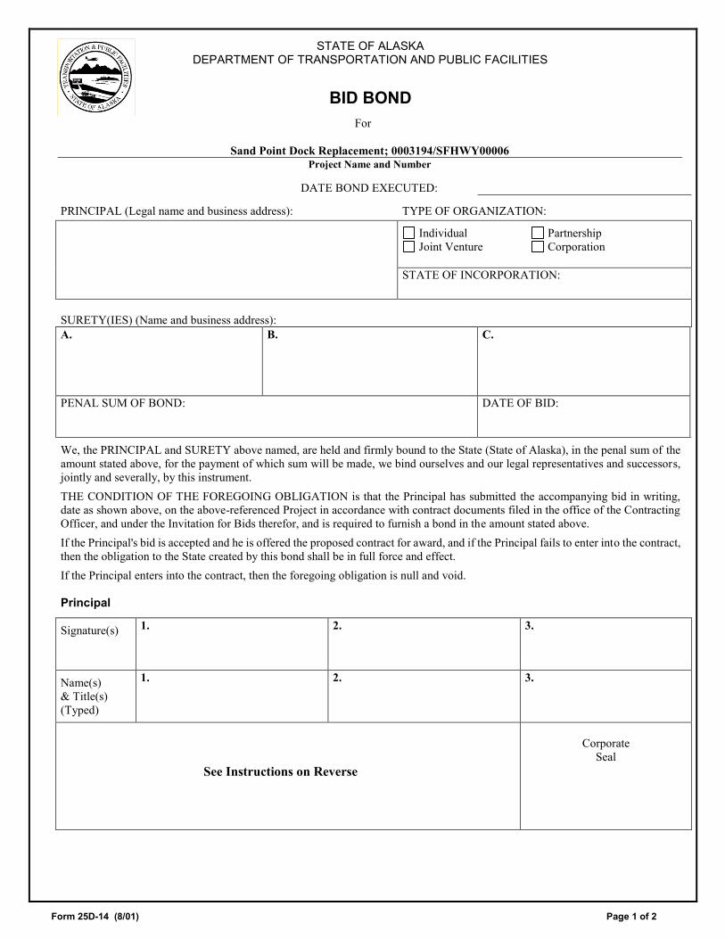
BID BOND For
Sand Point Dock Replacement; 0003194/SFHWY00006
Project Name and Number
DATE BOND EXECUTED: PRINCIPAL (Legal name and business address): TYPE OF ORGANIZATION:
Individual Partnership Joint Venture Corporation
STATE OF INCORPORATION:
SURETY(IES) (Name and business address): A.
B. C.
PENAL SUM OF BOND:
DATE OF BID:
We, the PRINCIPAL and SURETY above named, are held and firmly bound to the State (State of Alaska), in the penal sum of the amount stated above, for the payment of which sum will be made, we bind ourselves and our legal representatives and successors, jointly and severally, by this instrument.
THE CONDITION OF THE FOREGOING OBLIGATION is that the Principal has submitted the accompanying bid in writing, date as shown above, on the above-referenced Project in accordance with contract documents filed in the office of the Contracting Officer, and under the Invitation for Bids therefor, and is required to furnish a bond in the amount stated above.
If the Principal's bid is accepted and he is offered the proposed contract for award, and if the Principal fails to enter into the contract, then the obligation to the State created by this bond shall be in full force and effect.
If the Principal enters into the contract, then the foregoing obligation is null and void.
Principal
Signature(s)
1.
2.
3.
Name(s) & Title(s) (Typed)
1. 2. 3.
See Instructions on Reverse
Corporate
Seal

Form 25D-14 (8/01) Page 2 of 2
CORPORATE SURETY(IES)
SURETY A Name of Corporation
State of Incorporation Liability Limit $
Signature(s)
1.
2.
Corporate
Name(s) & Titles (Typed)
1. 2.
Seal
Surety B Name of Corporation
State of Incorporation Liability Limit
$
Signature(s)
1.
2.
Corporate
Name(s) & Titles (Typed)
1. 2.
Seal
Surety C Name of Corporation
State of Incorporation Liability Limit
$
Signature(s)
1.
2.
Corporate
Name(s) & Titles (Typed)
1. 2.
Seal
INSTRUCTIONS
1. This form shall be used whenever a bid bond is submitted.
2. Insert the full legal name and business address of the Principal in the space designated. If the Principal is a partnership or joint venture, the names of all principal parties must be included (e.g., "Smith Construction, Inc. and Jones Contracting, Inc. DBA Smith/Jones Builders, a joint venture"). If the Principal is a corporation, the name of the state in which incorporated shall be inserted in the space provided.
3. Insert the full legal name and business address of the Surety in the space designated. The Surety on the bond may be any corporation or partnership authorized to do business in Alaska as an insurer under AS 21.09. Individual sureties will not be accepted.
4. The penal amount of the bond may be shown either as an amount (in words and figures) or as a percent of the contract bid price (a not-to-exceed amount may be included).
5. The scheduled bid opening date shall be entered in the space marked Date of Bid.
6. The bond shall be executed by authorized representatives of the Principal and Surety. Corporations executing the bond shall also affix their corporate seal.
7. Any person signing in a representative capacity (e.g., an attorney-in-fact) must furnish evidence of authority if that representative is not a member of the firm, partnership, or joint venture, or an officer of the corporation involved.
8. The states of incorporation and the limits of liability of each surety shall be indicated in the spaces provided.
9. The date that bond is executed must not be later than the bid opening date.

Form 25D-16 (7/18) Page _____ of _____
STATE OF ALASKA DEPARTMENT OF TRANSPORTATION AND PUBLIC FACILITIES
BID MODIFICATION
Sand Point Dock Replacement, 0003194/SFHWY00006 Project Name and Number
Modification Number: ___________________
Note: Use this form to modify Manual (paper) bids only. Group items and provide subtotals by bid schedule section. All revisions shall be made to the unadjusted bid amount(s). Changes to the adjusted bid amounts will be computed by the Department.
LINE NO. ITEM NO. PAY ITEM DESCRIPTION
REVISION TO UNIT BID PRICE +/-
REVISION TO BID AMOUNT +/-
TOTAL REVISION: $__________________________________________________________________
Name of Bidding Firm
Responsible Party Signature Date
This form may be duplicated if additional pages are needed. .


Form 25D-60 (05/17) Page 1 of 2
MATERIAL ORIGIN CERTIFICATE Federal-Aid Highway Contracts
Project Name and Number: Sand Point Dock Replacement; 0003194/SFHWY00006
FOREIGN MANUFACTURED PRODUCTS1 COUNTRY OF ORIGIN COST2
I certify under penalty of law that all steel and iron products to be furnished for this project are manufactured in the United States, and comply with the requirements of 23 CFR 635.410 and Contract subsection 106-1.01, Buy America Provisions; except for those foreign manufactured products that are listed on this page or on a separate and clearly identified attachment.3 The term “manufactured in the United States” is defined in Contract subsection 106-1.01, Buy America Provision.
I certify that I have knowledge that submitting false statements and/or information may result in civil and criminal penalties.
Authorized Corporate Signature Date
Printed Name Contractor’s Company Name
Position Title

Form 25D-60 (05/17) Page 2 of 2
Form 25D-60 Instructions:
1. Enter “NONE” on the first line if there are no exceptions.
2. Invoice cost for foreign manufactured products as delivered to the project including freight.
3. When the Contractor becomes aware of a change from or error in a previously submitted Material Origin Certificate, the Contractor shall submit an updated Material Origin Certificate. The Department of Transportation and Public Facilities shall not accept or approve any Material Origin Certificate over the limit specified in the contract.
4. Attach additional complete form sheets if necessary to include more than one page of products.

Form 25A-304 (8/01) Page 1 of 1
STATE OF ALASKA DEPARTMENT OF TRANSPORTATION AND PUBLIC FACILITIES
EEO-1 CERTIFICATION
Federal-Aid Contracts
Sand Point Dock Replacement; 0003194/SFHWY00006 Project Name and Number
This certification is required by the Equal Employment Opportunity Regulations of the Secretary of Labor [41 CFR 60-1.7 (b) (1)] and must be completed by the successful Bidder and each proposed Subcontractor participating in this contract.
PLEASE CHECK APPROPRIATE BOXES The Bidder Proposed Subcontractor hereby CERTIFIES: PART A. Bidders and proposed Subcontractors with 50 or more year-round employees and a federal contract amounting to $50,000 or more are required to submit one federal Standard Report Form 100 during each year that the two conditions exist (50 employees and a $50,000 federal contract). The company named below (Part C) is exempt from the requirements of submitting the Standard Report Form 100 this year. NO (go to PART B) YES (go to PART C) Instructions and blank Standard Report Form 100's may be obtained from a local U.S. Department of Labor office, or by writing to: The Joint Reporting Committee P.O. Box 779 Norfolk, Virginia 23501 Telephone number: (757) 461-1213 PART B. The company named below has submitted the Standard Report Form 100 this year. NO YES Note: Bidders and proposed Subcontractors who have not filed the required Standard Report Form 100 and are not exempt from filing requirements will not be awarded this contract or subcontract until Form 100 has been filed for the current year ending June 30. PART C.
Signature of Authorized Company Representative
Title
Company Name
Company Address (Street or PO Box, City, State, Zip) ( )
Date Phone Number


Form 25A-310 (5/13) Page 1 of 5
STATE OF ALASKA DEPARTMENT OF TRANSPORTATION AND PUBLIC FACILITIES
DOT&PF TRAINING PROGRAM REQUEST Federal-Aid Contracts
Project Name: Sand Point Dock Replacement
Project Number: 0003194/SFHWY00006
Project Hours -
Section 645, entitled “Training Program” in the Special Provisions, specifies the number of minorities and/or woman to be trained and the number of hours of training provided under the term of this contract. Contractors desiring to use DOT&PF OJT approved training program(s) (instead of those approved by USDOL/OA) must:
Complete Sections 1(A) through 5; use additional sheets, if necessary and reference appropriately Must provide training in skilled construction trades Contractors complete OJT form Contractors are encouraged to contact the DOT&PF Civil Rights Office for assistance with
developing approvable training programs prior to bid opening
Section 1: Contractor Information
Contractor Name:_______________________ Contact Person:_______________________
Telephone #____________________________ E-mail ______________________________
Section 1A: Trainee Minimum Qualifications
Minimum Starting Age: __________________
High School Diploma Yes No Other Level of Education and/or Experience: ____________________________________________________________________________________________________________________________________________________________________________________________________________________________________________________________________________________________________________________________________________________________________________________________________________________________________________________________________________________
500

Form 25A-310 (5/13) Page 2 of 5
Section 2: Job Classification Information Job Classification (Title):___________________________________________
REQUIRED SKILLS FOR POSITION STARTING CAPABILITY DATE MEASURED
1. JOB SKILL NEEDED NOT SKILLED: SOME SKILL:
SKILLED:
2. JOB SKILL NEEDED NOT SKILLED: SOME SKILL:
SKILLED:
3. JOB SKILL NEEDED NOT SKILLED: SOME SKILL:
SKILLED:
4. JOB SKILL NEEDED NOT SKILLED: SOME SKILL:
SKILLED:
5. JOB SKILL NEEDED NOT SKILLED: SOME SKILL:
SKILLED:
*ATTACH JOB DESCRIPTION
Section 3: Employer Training Information
Complete the training outline and estimated time for each skill. TRAINING TO BE PROVIDED ESTIMATED
TRAINING HOURS END CAPABILITY DATE MEASURED
1. SKILL TO BE ACQUIRED ESTIMATED TRAINING HOURS
BEGINNING: INTERMEDIATE:
SKILLED:
2. SKILL TO BE ACQUIRED ESTIMATED TRAINING HOURS
BEGINNING: INTERMEDIATE:
SKILLED:
3. SKILL TO BE ACQUIRED ESTIMATED TRAINING HOURS
BEGINNING: INTERMEDIATE:
SKILLED:
4. SKILL TO BE ACQUIRED ESTIMATED TRAINING HOURS
BEGINNING: INTERMEDIATE:
SKILLED:
5. SKILL TO BE ACQUIRED ESTIMATED TRAINING HOURS
BEGINNING: INTERMEDIATE:
SKILLED:
LIST EQUIPMENT AND TOOLS NEEDED FOR TRAINING RELATED TO THE POSITION:

Form 25A-310 (5/13) Page 3 of 5
Section 4: Third-Party Related Instruction
Complete the training outline and estimated time for each skill. SKILLS TO BE LEARNED: ESTIMATED
TRAINING HOURS END CAPABILITY DATE MEASURED
1. SKILL TO BE LEARNED ESTIMATED TRAINING HOURS
BEGINNING: INTERMEDIATE:
SKILLED:
2. SKILL TO BE LEARNED ESTIMATED TRAINING HOURS
BEGINNING: INTERMEDIATE:
SKILLED:
3. SKILL TO BE LEARNED ESTIMATED TRAINING HOURS
BEGINNING: INTERMEDIATE:
SKILLED:
4. SKILL TO BE LEARNED ESTIMATED TRAINING HOURS
BEGINNING: INTERMEDIATE:
SKILLED:
5. SKILL TO BE LEARNED ESTIMATED TRAINING HOURS
BEGINNING: INTERMEDIATE:
SKILLED:
LIST EQUIPMENT AND TOOLS NEEDED FOR TRAINING RELATED TO THE POSITION:

Form 25A-310 (5/13) Page 4 of 5
Section 5: Required Certifications for the Position The Contractor shall actively assist the Trainee with getting certification(s) in order to gain marketable skills.
OSHA 10 CPR/First Aid/AED Fork Lift
Fitness Card CDL A Fast Track CDL
Department of Labor National Career Readiness Certificate (where feasible)
Other Certificates Provided by Employer: _____________________________________________ * Contractor will provide copies of the certifications received no later than the completion of project to the Civil Rights Office.
Section 6: OJT Wages Trainee Wages shall be paid prevailing Davis-Bacon fringes, plus the following during their training (See Section 645 wage requirements).
1st Half: $___________ = __________ % journey scale
3rd Quarter: $___________ = __________ % journey scale
4th Quarter: $___________ = __________ % journey scale
This OJT Training Program has been developed and approval is hereby requested for use on the above referenced project.
____________________________________ ___________________________ Signature of Authorized Company Representative Title
________________ _______________________ ___________________ Phone E-mail Date

Form 25A-310 (5/13) Page 5 of 5
Approved Disapproved
Remarks:
______________________________________ ______________ ADOT&PF Civil Rights Office OJT Coordinator Date
Section 7: Contractor Responsibility 1. It is the responsibility of the Contractor to provide each Trainee with a copy of the OJT Training
Program, Job Description and Training Timeline prior to the start of the project. 2. Each Trainee will be reviewed upon completion of each section of training. The review shall be in
writing and indicate the number of hours of training received. 3. The Trainee shall participate in the review, sign and receive a copy of the review. 4. The close out evaluation should indicate capability level reached. 5. The area in which the Trainee did not advance in level from its initial starting capability, the
Contractor will attach documentation as part of the close out evaluation which explains the reason(s) a higher capability was not reached.
6. If the Contractor fails to comply with their OJT approved training program the ADOT&PF will enforce the measures outlined in the Spec 645-5.01
Section 8: DOT & PF Civil Rights Office (CRO) Monitoring 1. The CRO will conduct an on-site visit to assess the OJT Training program at the project hour’s half-
way mark when feasible. 2. The CRO will coordinate the on-site with the Project Engineer
Section 9: Trainee Assistance 1. On a case-by-case basis the CRO may be able to assist with partial funding for the Trainee to receive
certification(s). 2. The CRO upon completion of the Trainee OJT Training Program will issue a “DOT&PF Civil Rights
Office” Certificate of On-the-Job Completion for FHWA funded Projects” that will reflect completed hours.
3. The Trainee will go on a list that will be posted on the CRO website for Primes to solicit for future employment opportunities
4. The Trainee will be eligible for the OJT 50% Reimbursement Program not to exceed $500 dollars which administer through the CRO. The dollar amount may change due to FHWA grant monies received per fiscal year.


Form 25A-311 (1/16) Page 1 of 2
STATE OF ALASKA DEPARTMENT OF TRANSPORTATION AND PUBLIC FACILITIES
TRAINING UTILIZATION REPORTFederal-Aid Highway Contracts
Sand Point Dock Replacement; 0003194/SFHWY00006 Project Name and Number
Training Program Special Provision, Section 645 specifies the number of minorities and/or women to be trained and the number of hours of training to be provided under this Contract; the Contractor may train non-minority males in compliance with Section 645, but only if documentation of good faith efforts has been submitted to, and approved by, the Engineer, prior to the employment of such non-minority male(s). Good faith efforts, at a minimum, must be as extensive as the recruitment efforts listed in the EEO Bid Conditions (Form 25A-301).
The number of individuals to be trained under this Contract is .
The number of hours of training to be provided is .
This Training Special Provision implements 23CFR 230, Subpart A, Appendix B. Contractors can use either training programs approved by the U.S. Department of Labor, Office of Apprenticeship (USDOL/OA), or training programs approved by DOT&PF. The Contractor must complete this form indicating the type of training to be provided, the number of individuals to be trained in each trade or job classification, the number of hours of training to be provided,3 and the anticipated training start date.
1. To be completed by Contractors using USDOL/OA Training Programs: Indicate below the number of apprentices, totalnumber of hours, type of training, and anticipated start dates for each craft selected:
APPROVED CRAFTS, CERTIFICATION NUMBERS AND JURISDICTIONAL AREAS STATEWIDE JURISDICTION SOUTH OF THE 63° PARALLEL
Craft/Cert Number No. of Appr.
No. of Hrs.
Start Date
Craft/Cert Number No. of Appr.
No. of Hrs.
Start Date
Asbestos Worker #90032 Carpenter #74032
Bricklayer #85040 Painter #72820
Cement Mason & Plasterer #78533
Pipefitter #72586
Electrician #81299 Plumber #83534 1 Ironworker #76779 Sheetmetal Worker #74072
Op. Engineer #X90349 Other #
Roofer #X90317 NORTH OF THE 63° PARALLEL Piledriver 2 (3/30/75) Carpenter #47990
Camp Culinary 2 (4/25/74) Painter #77750
Laborer #XAK92T017 Fitter/Plumber #75055
Other # __________ Sheetmetal #76781
Other # __________ Other # __________
Other # __________
1. Juneau Jurisdictional area is #83534 and Anchorage area is #72586.2. U.S. DOL does not assign Certification numbers to these training programs. Only approval dates.3. The total number of hours of training shall equal the hours of training shown in the Bid Schedule, Pay Item 645(1).
1 500

Form 25A-311 (1/16) Page 2 of 2
2. To be completed by Contractors using DOT&PF training programs: Indicate below the type of training, number of trainees, number of hours of training (500 hours per trainee), and anticipated start dates.
Job Classification No. Trainees Total No. Hrs. Anticipated Start Date(s)
3. To be completed by all Contractors as part of the Contractor’s EEO affirmative action program, the Contractor certifies that
all training will be provided by the Contractor as stated in items 1 OR 2 above, in accordance with Training Program Special Provision, Section 645.
Company Name
______________________________________________________
Point of Contact
Company Address
_______________________________________________________ E-mail / Phone Number
Signature of Authorized Company Representative Date
To be completed by the DOT&PF OJT Coordinator prior to contract award: Training Program(s) approve for this Project and Date Approved: Training Program Trainee (s) / Apprentice (s) Hours Date Approved
Signature of DOT&PF OJT Coordinator Date

Form 25A-321A (10/16) Page 1 of 2
STATE OF ALASKA DEPARTMENT OF TRANSPORTATION AND PUBLIC FACILITIES
CONTACT REPORT Federal-Aid Contracts
Sand Point Dock Replacement; 0003194/SFHWY00006 Project Name and Number
Specific Work or Materials (by pay Item): _____________________________________________________________________
DBE Firm Contacted:
( ) _____________ Name Address Phone Number
A. INITIAL CONTACT: (See important contact information on instruction sheet)
1. Date Method:
Phone Publication Email FAX Other 2. Person
Contacted
Name Title
3. DBE's Response: Date: __________________ Method: Phone Email FAX Other
Submitted an acceptable sub-bid. (If sub-bid accepted, skip to Section D) Not interested: Indicate Reason(s) _________________________________________________________ Needs more information: Date Prime provided requested information________________ Will provide quote by: Date_______________________ Received unacceptable sub-bid (complete Section C)
B. FOLLOW-UP CONTACT:
1. Date
Method:
Phone Publication Email FAX Other 2. Person
Contacted
Name Title
3. DBE's Response: Date: __________________ Method: Phone Email FAX Other
Submitted an acceptable sub-bid. (If sub-bid accepted, skip to Section D) Received unacceptable sub-bid (complete Section C) Other result: ______________________________________________________________________________
C. EXPLANATION OF FAILURE TO ACHIEVE AN ACCEPTABLE SUB-BID: 1. Were the following required efforts made?
a. Yes No Identified specific items of work, products, materials, etc. when asking for quote(s).
b. Yes No Offered assistance in acquiring necessary bonding, insurance, and business development related assistance
c. Yes No Provided all appropriate information concerning the specific work items or materials.
2. Was the DBE's quote non-competitive? Yes No 3. Was the DBE unable to perform in some capacity? Yes No If "Yes", explain: _______________________ D. CERTIFICATION: I certify that the information provided above is accurate and that efforts to solicit sub-bids were made in
good faith.
Signature of Company Representative Title Date
Name of DOT&PF Reviewer Title Date

Form 25A-321A (10/16) Page 2 of 2
INSTRUCTIONS Project Name and Number: Enter project name and number as they appear on bid
documents. Work or Materials: Identify the specific work item or material that you
requested this firm to furnish. Firm Contacted: Enter name of firm as it appears in
the current DOT&PF DBE directory.
Address: Enter address of firm contacted. Phone Number: Enter phone number of firm contacted. A. INITIAL CONTACT (Must be made at least seven calendar days prior to bid opening.) 1. Date and Method of Initial Contact: Indicate the method and date that actual contact was made or the
date correspondence was postmarked. Leaving a "please call me" message does not constitute a contact. Attach a copy of dated letter or fax.
2. Name and Title of Person Contacted. Enter name and title of company representative with whom you
corresponded or discussed submitting a sub-bid. 3. DBE's Response: Indicate one or more of the responses listed. If a firm bid was received and accepted, skip
to section D. B. FOLLOW-UP CONTACT If no response or an inconclusive response was received from the initial contact, a follow-up contact is required to determine for a certainty that the firm does not intend to submit a sub-bid or to conclude discussions with a sub-bid submittal.
1. Date and Method of Follow-up Contact: Indicate the method and date that actual contact was made
or the date correspondence was postmarked. Leaving a "please call me" message does not constitute a contact. Attach a copy of dated letter or fax.
2. Name and Title of Person Contacted. Enter name and title of company representative with whom you
corresponded or discussed submitting a sub-bid. 3. DBE's Response: Indicate one or more of the responses listed. If a firm bid was received and accepted, skip
to section D. C. EXPLANATION OF FAILURE TO ACHIEVE AN ACCEPTABLE SUB-BID 1. A NO response to items 1a., b., or c. will result in rejection of this contact. Be specific on results of
discussions.
2. A YES answer to item 2. is grounds for rejecting a DBE sub-bid.
3. A YES answer to item 3. is grounds for rejecting a DBE sub-bid, only if the inability to perform is in an area of work specifically identified as a sub-item under the applicable bid item.
D. CERTIFICATION This certification of accuracy and good faith by the Contractor will be verified by contact with the listed firm. Falsification of information on the DBE Contact Report is grounds for debarment action under AS 36.30.640(4).

25A-325C (7/15) Page 1 of 1
STATE OF ALASKA DEPARTMENT OF TRANSPORTATION AND PUBLIC FACILITIES
DISADVANTAGED BUSINESS ENTERPRISE
UTILIZATION REPORT Federal-Aid Contracts
Sand Point Dock Replacement; 0003194/SFHWY00006 Project Name and Number
The undersigned hereby certifies on behalf of the bidder that:
A. It [ ] is [ ] is not a DOT&PF certified DBE or DBE joint venture. B. The required good faith efforts (GFE) documentation is attached. C. Listed below are the certified DBEs to be used in this contract. Included are the firm name, bid items or portions of work to
be performed by the item number, type of DBE credit claimed, and the creditable dollar amount to be counted toward the Department’s overall DBE Utilization Goal.
FIRM NAME BID ITEM, WORK, OR PRODUCT
SUBCONTRACT AMOUNT*
TYPE OF CREDIT CREDITABLE DOLLAR
AMOUNT**
$
$
$
$
$
$
$ *or expenditure amount or fee/commission amount. **(Subcontract amount x Creditable CUF% per 120-4.01).
If more room is necessary, submit additional, signed copies of this form.
Total creditable DBE Utilization Amount $ ______________ Basic Bid Amount $ ______________ DBE Utilization % of Basic Bid Amount _____________ % Department’s Overall DBE Utilization Goal*** 8.83 % ***This is the overall goal of the Department and is not a set DBE Goal specific to this contract.
Signature of Authorized Company Representative
Title
Company Name
Company Address (Street or PO Box, City, State, Zip) ( )
Date Phone Number


25A-326 (8/01) Page 1 of 1
STATE OF ALASKA DEPARTMENT OF TRANSPORTATION AND PUBLIC FACILITIES
Civil Rights Office – DBE Program
PRIME CONTRACTOR’S WRITTEN DBE COMMITMENT
Federal-Aid Contracts
Sand Point Dock Replacement; 0003194/SFHWY00006 Project Name and Number
All firms bidding on Alaska Department of Transportation and Public Facilities (DOT&PF) projects must have a written commitment from each DBE firm to be subcontracted. Please complete this form for each DBE firm and submit to the DOT&PF Regional Compliance Officer. If you have any questions, please call (907) 269-0851. Name of DBE Firm:
Street Address:
Mailing Address: City:
State: Zip Code:
Telephone Number: Fax number:
Description of the work that DBE firm will perform:
Please provide additional information on a separate sheet of paper.
The dollar amount of participation by the DBE firm: $ Signatures of Authorized representatives of the Prime Contractor and the DBE firm below represent the written commitment by the Prime Contractor to subcontract with the DBE firm as described above and a written commitment by the DBE firm to subcontract for the work described above:
Prime Contractor Signature Date DBE Firm Signature Date Prime Contractor Firm: Address:
Telephone Number: Fax number:


STATE OF ALASKA DEPARTMENT OF TRANSPORTATION AND PUBLIC FACILITIES
SUMMARY OF GOOD FAITH EFFORT DOCUMENTATION Federal-Aid Contracts
Sand Point Dock Replacement; 0003194/SFHWY00006
Project Name and Number
Contractor: _________________________________________________________________________
List all items considered for DBE utilization. GFE requires at a minimum that the Contractor consider all items identified on Form 25A-324. a.
MATERIAL OR SPECIFIC ITEM OF WORK (SPECIFY PAY ITEM)
b. ACCEPTABLE DBE QUOTE RECEIVED1
c. # OF DBES
CONTACTED IN DBE DIRECTORY
d. # OF DBES THAT
RESPONDED2
e. # OF DBE QUOTES
RECEIVED 1.
2.
3.
4.
5.
6.
7.
8.
1. Check if acceptable DBE quote was received (if so, skip c, d, and e) 2. Attach completed Contact Reports, Form 25A-321A
LIST ADDITIONAL ITEMS ON REVERSE SIDE
Form
25A-332A
(8/01)P
age1
of2

a. MATERIAL OR SPECIFIC ITEM
OF WORK (SPECIFY PAY ITEM)
b. ACCEPTABLE DBE QUOTE RECEIVED1
c. # OF DBES CONTACTED
IN DBE DIRECTORY
d. # OF DBES THAT
RESPONDED2
e. # OF DBE QUOTES
RECEIVED 9.
10.
11.
12.
13.
14.
15.
1. Check if acceptable DBE quote was received (if so, skip c, d, and e) 2. Attach completed Contact Reports, Form 25A-321A Comments:
Form
25A-332A
(8/01)P
age2
of2

State of Alaska, Standard Specifications for Highway Construction, 2017 English Edition, are Incorporated and Modified as Follows:
SPECIAL PROVISIONS AND
STANDARD MODIFICATIONS FOR
SAND POINT CITY DOCK REPLACEMENT
FEBRUARY 2019
PROJECT NO. SFHWY00006 / 0003194
All Provisions contained in this section are considered Special Provisions unless otherwise designated as a Standard Modification (E), Statewide Special Provision (S or ES), or Southeast Regional Special Provision (SES).


INDEX
Section Title 101 Definition and Terms 102 Bidding Requirements and Conditions 103 Award and Execution of Contract 106 Control of Material 107 Legal Relations and Responsibility to Public 108 Prosecution and Progress 109 Measurement and Payment 120 Disadvataged Business Enterprise (DBE) Program 203 Excavation and Embankment 301 Aggregate Base and Surface Course 304 Subbase 501 Concrete for Structures 502 Prestressing Concrete 503 Reinforcing Steel 504 Structural and Miscellaneous Steel 505 Piling 514 Anodes 515 Drilled Shafts 611 Armor Revetment 615 Standard Signs 640 Mobilization and Demobilization 641 Erosion, Sediment, and Pollution Control 642 Construction Surveying and Monuments 644 Services to be Furnished by the Contractor 645 Training Program 647 Protected Species Observation 662 Electrical Power and Lighting System 695 Generator Building 701 Hydraulic Cement and Supplementary Cementitious Materials 708 Paints 709 Reinforcing Steel and Wire Rope 712 Miscellaneous 715 Steel for Piles 716 Structural & Miscellaneous Steel 720 Bearings
Appendix A Construction Surveying Requirements Appendix B Environmental Commitments & Permits Appendix C Materials Certification List Appendix D Erosion and Sediment Control Plan


Sand Point City Dock Replacement SFHWY00006 / 0003194 101-1 2/19/2019
SECTION 101
DEFINITIONS AND TERMS STANDARD MODIFICATION 101-1.03 DEFINITIONS. Delete the definition for BID and replace with the following: BID (OR PROPOSAL). The bidder’s offer, on the prescribed forms, to perform the specified work at the prices quoted. Add the following five definitions: BID FORMS. Department-furnished forms that a bidder must complete and submit when making a bid in response to an advertised project. Bid forms may include a bid schedule, certification forms, acknowledgement forms, and other documents. DIGITAL SIGNATURE. An electronic signatures that conforms to the Uniform Electronic Transactions Act, AS 09.80.010 et seq. ELECTRONIC BID. A bid that a bidder (i) prepares on the Department’s bid forms accessed through the Department’s approved online bidding service and (ii) submits to the Department through use of that bidding service’s online submittal process. ELECTRONIC MAIL (EMAIL). A system for sending messages from one person to another via telecommunications links between computers or terminals using dedicated software. MANUAL BID. A bid that a bidder (i) prepares on the Department’s bid forms accessed either through the Department’s approved online bidding service or obtained from the Department’s Regional Contracts Office and (ii) submits to the Department in physical paper form by hand delivery, U.S. Mail, or courier service. HSM18-1 07/01/2018 STANDARD MODIFICATION 101-1.01 GENERAL. Add the following paragraph after the sixth paragraph: Delete “Standard Drawing” throughout the Alaska Standard Specifications for Highway Construction and throughout the Alaska Traffic Manual Supplement and replace in both documents with, “Alaska Standard Plan”. 101-1.03 DEFINITIONS. Add the following definition: ALASKA STANDARD PLAN. Detail Drawing adopted by the Department for repetitive use, showing details to be used where appropriate. Delete the following definition: STANDARD DRAWING. HSM18-4 02/08/2019
Sand Point City Dock Replacement SFHWY00006 / 0003194 102-1 2/19/2019
SECTION 102
BIDDING REQUIREMENTS AND CONDITIONS STANDARD MODIFICATION 102-1.05 PREPARATION OF BID. Delete the subsection in its entirety and replace with the following: A bidder shall prepare its bid using either the Department approved bid preparation software or the Department provided bid forms or legible copies of the Department’s forms. All entries shall be legible and in ink or type. Bidders shall: 1. Enter all prices required on the Bid Schedule, in figures; 2. Enter a unit price for each contract item for which a quantity is given; 3. Enter the products of the respective unit prices and quantities in the column provided; 4. Enter lump sum prices for lump sum contract items in the column(s) provided; and 5. Enter the total amount of all contract items for the basic bid and, when specified, any alternates. When a bid item contains a choice to be made by the bidder, the bidder shall indicate a choice according to the Specifications for that item. No further choice is permitted. The bid must be signed in ink or by a digital signature by the person or persons authorized to sign the Contract for the bidder. If a bidder is a corporation, the bid must be signed by a corporate officer or agent with authority to bind the corporation. If a bidder is a partnership, a partner must sign. If the bidder is a joint venture, each principal member must sign. If a bidder is a sole proprietorship, the owner must sign. Each person signing the bid must initial any changes made to entries on the bid forms. A bidder submitting an electronic bid agrees that its digital signature constitutes a binding signature. The bidder shall make no claim against the Department in the event it is unable to submit its bid through approved online bidding service and/or approved online bidding service is unable to submit the bid(s) to the Department. The Department reserves the right to postpone the public bid opening in the event of technical problems. For multiple-project bid openings, the bidder may limit the total dollar amount or number of projects to be accepted by completing and attaching the following statement with its bid for at least one of the projects. The Department will then determine which of the low bids it will accept, up to the total indicated. “We wish to disqualify all of our successful bids at this bid opening which exceed the total of $_____________ or ____ contracts and hereby authorize the Department to determine which bids to disqualify, based on this limit.” 102-1.06 NONRESPONSIVE BIDS. Delete the subsection in its entirety and replace with the following: 1. A bid shall be rejected as nonresponsive if it:
a. Is not properly signed by an authorized representative of the bidder and in a legally binding manner; b. Contains unauthorized additions, conditional or alternative bids, or other irregularities that make
the bid incomplete, indefinite, or ambiguous; c. Includes a reservation of the right to accept or reject any award, or to enter into a contract pursuant
to an award, except for an award limitation under Subsection 102-1.05; d. Fails to include an acceptable bid guaranty with the bid; e. Is materially unbalanced; or f. Fails to meet any other material requirement of the Invitation To Bid.
2. A bid may be rejected as nonresponsive, in the Department's discretion, if it:
a. Is not typed or completed in ink;

Sand Point City Dock Replacement SFHWY00006 / 0003194 102-2 2/19/2019
b. Fails to include an acknowledgement of receipt of each addendum by assigned number and date of issue; or
c. Is missing a bid price for any pay item, except when alternate pay items are authorized. 102-1.07 BID GUARANTY. Delete the subsection in its entirety and replace with the following: Bids shall be accompanied by a bid guaranty in the amount specified on the Invitation To Bid. The guaranty shall be unconditionally payable to the State of Alaska and shall be in the form of an acceptable paper Bid Bond (Form 25D-14), an electronic bid bond acceptable to the Department and verified through its online bidding service, a certified check, a cashier's check, or a money order. The surety of a Bid Bond may be any corporation or partnership authorized to do business in Alaska as an insurer under AS 21.09. A legible power of attorney shall be included with each paper Bid Bond (Form 25D-14). An individual surety will not be accepted as a bid guaranty. 102-1.08 DELIVERY OF BIDS. Delete the subsection in its entirety and replace with the following: Bids shall be submitted electronically through the online bidding service, or shall be submitted in a sealed envelope. When bids are submitted in a sealed envelope, the envelope shall clearly indicate its contents and the designated address, as specified on the Invitation to Bid. Bids for other work may not be included in the envelope. In the event of a bid delay, electronic bidders that have already submitted their bid prior to the bid delay must resubmit their bid utilizing all Bid Forms EBSX Files or their bid will not be received. The Department will not accept a bid submitted by email or fax unless specifically called for in the Invitation to Bid. 102-1.09 WITHDRAWAL OR REVISION OF BIDS. Delete the subsection in its entirety and replace with the following: Manual Bids may be withdrawn or revised in writing delivered by mail, fax, or email , provided that the designated office receives the withdrawal or revision before the deadline stated in the in the Invitation To Bid. Withdraw requests must be signed and submitted by the bidder’s duly appointed representative who is legally authorized to bind the bidder. Revisions shall include both the modification of the unit bid price and the total modification of each item modified but shall not reveal the amount of the total original or revised bids. Electronic Bids may be withdrawn or resubmitted through the online bidding service. Revisions to electronic bids delivered by mail, fax, or email will not be permitted. If electronic bid withdrawal is unsuccessful, electronic bids may be withdrawn in writing delivered by mail, fax, or email provided that the designated office receives the withdrawal before the deadline stated in the Invitation To Bid. Written withdrawal requests must be signed and submitted by the bidder’s duly appointed representative who is legally authorized to bind the bidder. 102-1.11 ADDENDA REQUIREMENTS. Delete the subsection in its entirety and replace with the following: The Department will issue addenda if it determines, in its discretion, that clarifications or changes to the Contract documents or bid opening date are needed. The Department may send addenda by any reasonable method such as fax, email, or may post the addenda on its website or online bidding service. Unless picked up in person or included with the bid documents, addenda or notice that an addendum has been issued will be addressed to the individual or company to whom bidding documents were issued and sent to the email address or fax number on the plan holders’ list. Notwithstanding the Department’s efforts to distribute addenda, bidders are responsible for ensuring that they have received all addenda affecting the Invitation To Bid. Bidders must acknowledge all addenda on the Bid Forms, by fax, or by email before the deadline stated in the Invitation to Bid. 102-1.12 RECEIPT AND OPENING OF BIDS. Delete the subsection in its entirety and replace with the following: The Department will only consider bids, revisions, and withdrawals received before the deadline stated in the Invitation to Bid.

Sand Point City Dock Replacement SFHWY00006 / 0003194 102-3 2/19/2019
The Department will assemble, open, and publicly announce bids at the time and place indicated in the Invitation to Bid, or as soon thereafter as practicable. The Department is not responsible for prematurely opening or failing to open bids that are improperly addressed or identified. Add the following subsection: 102-1.14 ELECTRONIC MAIL Within its submitted bid, a bidder must include a current electronic mail (email) address of bidder’s representative who possesses authority to receive, process, and respond to Department emails regarding the advertised project. The Department may send notices and information to a bidder by using the furnished email address of the bidder’s authorized representative. A bidder shall notify the Department if the bidder requests the Department to send email notices or information to an address different from the email address initially provided in its bid forms. The bidder shall notify the Department of such change by sending a request in writing to the Contract’s point of contact identified on the Invitation to Bid that is signed by a representative who is authorized and empowered to legally bind the bidder. Delivery of an email sent by the Department is complete upon receipt in the addressee’s email account. An email sent after 4:30 pm shall be deemed to have occurred at the opening of business on the next working day. If needed, the Department may demonstrate proof of email delivery by affidavit or certification that includes the following:
1. The date and time that the Department sent the email message;
2. The email address from which the Department sent the message;
3. The name and email address to which the Department sent the message;
4. A statement that the Department sent the email message and that the person signing the affidavit or certification believes the transmission to have been complete and without error; and
5. An attached copy of the subject email. HSM18-1 07/01/2018

Sand Point City Dock Replacement SFHWY00006 / 0003194 103-1 2/19/2019
SECTION 103
AWARD AND EXECUTION OF CONTRACT STANDARD MODIFICATION 103-1.01 CONSIDERATION OF BIDS. Delete the subsection in its entirety and replace with the following: After the bids are opened and read, the bids will be mathematically checked and compared on the basis of the sum of the products of the bid schedule quantities and the unit bid prices. The unit bid prices govern if there is an error in extending the unit bid prices, or in totaling the extensions, or if an extension is missing. The results of the bid comparisons will be made available to the public as soon as practicable. Until the Award, the Department may reject any or all bids, waive minor informalities or advertise for new bids without liability to any bidder if the Department, in its discretion, determines that to do so is in the best interests of the State. A bidder may request withdrawal of a bid after opening and before the Award only in accordance with AS 36.30.160(b) and State procurement regulations. Submit the request to the Contracting Officer. An interested party, as defined in AS 36.30.699, may protest a proposed Award of contract as per AS 36.30.560 and AS 36.30.565. Submit the protest to the Contracting Officer. WHOLLY STATE-FUNDED PROJECTS. On wholly state-funded projects, determination of the low bidder will include bidder preferences as required under AS 36.30.321, according to subsections 1-3 below. Alaska Bidder Preference, Alaska Veteran Preference, and Alaska Product Preference are not applicable on projects with federal funding. 1. Alaska Bidder Preference: A bidder claiming this preference shall provide with their bid an Alaska
Bidder Preference Certification, certifying they qualify as an Alaska bidder eligible for Alaska Bidder Preference according to AS 36.30.
If the bidder qualifies as an Alaska bidder, a five percent (5%) preference will be applied to the price of the bid. "Alaska bidder" means a person who: a. holds a current Alaska business license; b. submits a bid for goods, services, or construction under the name as appearing on the person's
current Alaska business license; c. has maintained a place of business within the state staffed by the bidder or an employee of the
bidder for a period of six months immediately preceding the date of the bid; d. is incorporated or qualified to do business under the laws of the state, is a sole proprietorship and
the proprietor is a resident of the state, is a limited liability company organized under AS 10.50 and all members are residents of the state, or is a partnership under former AS 32.05, AS 32.06, or AS 32.11 and all partners are residents of the state; and
e. If a joint venture, is composed entirely of ventures that qualify under (a) through (d), above.
2. Alaska Veteran Preference: A bidder claiming this preference shall provide an Alaska Veteran Preference Certification, certifying they qualify as an Alaska bidder eligible for Alaska Veteran preference according to AS 36.30.
If a bidder qualifies as an Alaska bidder and is a qualifying entity, an Alaska Veteran Preference of 5 percent shall be applied to the bid price. The preference may not exceed $5,000 (AS 36.30.321). A “qualifying entity” means a: a. sole proprietorship owned by an Alaska veteran; b. partnership under AS 32.06 or AS 32.11 if a majority of the partners are Alaska veterans;

Sand Point City Dock Replacement SFHWY00006 / 0003194 103-2 2/19/2019
c. limited liability company organized under AS 10.50 if a majority of the members are Alaska veterans; or
d. corporation that is wholly owned by individuals, and a majority of the individuals are Alaska veterans.
A preference under this section is in addition to any other preference for which the bidder qualifies. To qualify for this preference, the bidder must add value by the bidder itself actually performing, controlling, managing and supervising a significant part of the services provided or the bidder must have sold supplies of the general nature solicited to other state agencies, governments, or the general public. An Alaska veteran is a resident of Alaska who:
(1) served in the Armed forces of the United States, including a reserve unit of the United States armed forces; or the Alaska Territorial Guard, the Alaska Army National Guard, the Alaska Air National Guard, or the Alaska Naval Militia; and
(2) was separated from service under a condition that was not dishonorable.
3. Alaska Product Preference: A bidder claiming this preference shall complete and sign the Alaska Product Preference Worksheet, according to the worksheet instructions, and submit the completed worksheet with their bid.
Except for timber, lumber and manufactured lumber products used in the construction project under AS 36.30.322(b), an Alaska products preference will be given as required under AS 36.30.326 - 36.30.332 when the bidder designates the use of Alaska products. If the successful bidder/contractor proposes to use an Alaska product and does not do so, a penalty will be assessed against the successful bidder/contractor according to AS 36.30.330(a). Each Alaska product declared on the Alaska Product Preference Worksheet must have an “Approval” date on the Alaska Product Preference Program List, that is on or before the bid opening date for this contract, and that does not expire before the bid opening date for this contract.
103-1.03 AWARD OF CONTRACT. Delete the subsection in its entirety and replace with the following: The Department will award the Contract to the lowest responsible and responsive bidder unless it rejects all bids. The Department will notify all bidders in writing via email, fax, or U.S. Mail of its intent to award. The Department will notify the successful bidder in writing of its intent to award the Contract and request that certain required documents, including the Contract Form, bonds, and insurance be submitted within the time specified. The successful bidder's refusal to sign the Contract and provide the requested documents within the time specified may result in cancellation of the notice of intent to award and forfeiture of the bid security. If an award is made, it will be made as soon as practicable and usually within 40 days after bid opening. Award may be delayed due to bid irregularities or a bid protest, or if the award date is extended by mutual consent. Bids shall be valid for 120 days after bid opening, and may be extended by mutual consent. HSM18-1 07/01/2018
SR SPECIAL PROVISION 103-1.06 INSURANCE REQUIREMENTS. Delete the first unnumbered paragraph below “4. Umbrella Coverage” and replace with the following: The State of Alaska and the City of Sand Point shall be named as an additional insured on policies required by paragraphs 2 thru 4 above. All of the above insurance coverages shall be considered to be primary and

Sand Point City Dock Replacement SFHWY00006 / 0003194 103-3 2/19/2019
non-contributory to any other insurance carried by the State of Alaska and the City of Sand Point, whether through self-insurance or otherwise. SRS-2 04/06/2017

Sand Point City Dock Replacement SFHWY00006 / 0003194 106-1 2/19/2019
SECTION 106
CONTROL OF MATERIAL
SR STANDARD MODIFICATION 106-1.03. TESTING AND ACCEPTANCE. Add the following: When ATM 207 is specified, Method D will be performed unless otherwise stated. SRM-1 10/24/2017

Sand Point City Dock Replacement SFHWY00006 / 0003194 108-1 2/15/2019
SECTION 108
PROSECUTION AND PROGRESS
SR STANDARD MODIFICATION 108-1.03 PROSECUTION AND PROGRESS. Add the following after the list of documents submitted prior to the preconstruction conference: The Contractor must submit three copies of the Contractor’s Civil Rights Representatives contact information (Form 25A-302) identifying representatives of the Contractor and for representatives of each Subcontractor. Submit the completed form at the preconstruction conference and at the time any subcontract documents are submitted for approval. All contractors and subcontractors are required to update this information within 10 days after a personnel change occurs involving the individuals named in Form 25A-302. Add the following new paragraph after the paragraph beginning “The Engineer’s review or approval…”: The Contractor’s Superintendent, SWPPP Manager, Worksite Traffic Supervisor, and Subcontractors scheduled to perform work shall attend a weekly meeting chaired by the Engineer to report project progress and action items. SRM-2 04/06/2017

Sand Point City Dock Replacement SFHWY00006 / 0003194 109-1 2/19/2019
SECTION 109
MEASUREMENT AND PAYMENT STANDARD MODIFICATION 109-1.01 GENERAL. Insert the following after the second paragraph: Pay item numbers in the Bid Schedule are cross-referenced to the pay item numbers in all other contract documents. The cross-reference for pay item numbers is included in the Estimate of Quantities table on the plans. HSM18-1 07/01/2018 SR STANDARD MODIFICATION 109-1.02 MEASUREMENT OF QUANTITIES. Replace item “14. Weighing Procedures” with “Weighing Procedures”. “Weighing procedures” is a subtopic under item “13. Ton (2,000 pounds).” SRM-3 04/06/2017 SR STANDARD MODIFICATION 109-1.08 FINAL PAYMENT. Replace the first sentence of the second paragraph with the following: If the Contractor certifies the final estimate, or does not file a claim within 90 days of receiving the final estimate, the estimate shall be processed for final payment. Replace the third paragraph with the following: When the Contractor executes the Certification of Final Estimate (Form 25D-116) and executes the Contractor’s Release (Form 25D-117), final payment will be processed. SRM-4 04/06/2017

Sand Point City Dock Replacement SFHWY00006 / 0003194 120-1 2/19/2019
SECTION 120
DISADVANTAGED BUSINESS ENTERPRISE (DBE) PROGRAM STANDARD MODIFICATION 120-1.01 DESCRIPTION. Delete the second paragraph of Subsection 120-1.01 and replace with the following: The Department, in coordination with the Federal Highway Administration (FHWA), adopted a Race-Neutral DBE Program with an overall DBE utilization Goal of 8.83 percent for Alaska’s FHWA Federal-Aid program. Although the Race-Neutral program does not establish or require individual project DBE Utilization Goals, 49 CFR establishes the Bidder is responsible to make a portion of the work available to DBEs and to select those portions of the work or material needs consistent with the available DBEs to facilitate DBE participation. SM-3 12/22/2017

Sand Point City Dock Replacement SFHWY00006 / 0003194 203-1 2/15/2019
SECTION 203 EXCAVATION AND EMBANKMENT
203-2.01 MATERIALS. Add the following: 7. Core Rock. See Section 207 for requirements. 203-3.03 EMBANKMENT CONSTRUCTION. Replace with the following: Prepare the areas upon which embankments are to be placed, construct dikes within or outside the right-of-way when required, place and compact approved material within the roadway areas where unsuitable material has been removed, and place and compact embankment material in holes, pits, and other depressions within the roadway area. Use only approved materials in the construction of embankments and backfills. Embankment material will be approved for gradation following placement but prior to compaction. Construct the embankment with core rock meeting the requirements of Section 207. Scarify existing roadways, lying within 3 feet of subgrade, to a depth of 6 inches and recompact to meet Subsection 203-3.05. When permanently frozen soils are encountered, place backfill or embankment materials in a timely manner, as directed, to minimize degradation of the foundation material. Do not place embankment over seasonally frozen ground unless authorized in writing. Thaw and drain frozen material deemed acceptable for fill before placing in the embankment. Frozen cuts may require stage excavation: remove thawed material and allow the cut to thaw while work continues on some other portions of the project. After the material in the cut has thawed to a sufficient depth, remove the thawed material. Repeat this operation until all frozen material is removed or the cut is excavated to grade. When excavation is performed when freezing weather is imminent, place the specified backfill promptly, following the excavation work, at least up to a level which will allow the surface to adequately drain. Make arrangements for the timely availability of such embankment or backfill materials prior to commencement of the stripping or excavation operations, when required. All core rock placed below elevation +9 feet MLLW shall be placed and shaped in accordance with the plans. The Contractor shall stabilize this material as soon as possible to minimize erosion. It is the Contractor’s responsibility to maintain a safe and stable slope during all phases of construction and excavation. Prior to placing fill above elevation +9 feet MLLW, the Contractor shall thoroughly compact and add additional material until there is no further yielding or pumping at the surface. All fill placed above elevation +9ft MLLW shall be placed in horizontal layers not exceeding 12-inches prior to compaction. Compaction shall be per Subsection 203-3.05. Use spreading equipment on each lift to obtain uniform thickness prior to compacting. The Contractor shall route equipment uniformly over the entire surface of the placed material throughout construction. Finish the subgrade surface so it will not vary more than 0.10 foot when tested using a 10-foot straightedge nor vary more than 0.10 ft from the established grade. Repair damage to embankment caused by hauling equipment.

Sand Point City Dock Replacement SFHWY00006 / 0003194 203-2 2/15/2019
203-3.05 COMPACTION WITHOUT MOISTURE AND DENSITY CONTROL. Replace with the following: Adjust moisture content as required to provide the approximate optimum moisture content for compaction. Over saturated material shall be removed from the embankment and allowed to de-water prior to reincorporating. Lifts shall be compacted by no less than five (5) passes of a minimum 10-ton vibratory roller. One pass shall consist of the compactor traveling over an area once with the vibratory system operating (at least mid-setting) with a travel speed less than 2.0 feet per second (1.5 miles per hour). Route compaction equipment uniformly over the entire surface of each layer. 203-4.01 METHOD OF MEASUREMENT. Delete this subsection
203-5.01 BASIS OF PAYMENT. Replace this entire subsection with the following: Payment for embankment work will be considered subsidiary to the fill material with which it is associated. Payment for armor rock toe excavation work will be considered subsidiary to the Contract price paid for Class A Armor Rock. The following work is subsidiary:
1. scarifying material in place
2. hauling of material
3. excavating overbreak material
4. slope rounding excavation and benching of slopes
5. water for compaction

Sand Point City Dock Replacement SFHWY00006 / 0003194 301-1 2/15/2019
SECTION 301 AGGREGATE BASE AND SURFACE COURSE
301-3.03 SHAPING AND COMPACTION. Delete paragraph two and replace with the following: Spread and shape the material to the required grade and section. Water or aerate as necessary to provide the approximate optimum moisture content for compaction. Compact each layer as defined in Section 203-3.05.

Sand Point City Dock Replacement SFHWY00006 / 0003194 304-1 2/15/2019
SECTION 304 SUBBASE
304-3.01 CONSTRUCTION REQUIREMENTS. Delete the first sentence and replace with the following: Place and compact subbase material to meet the requirements of Subsections 203-3.01, 203-3.03, and 203-3.05.

Sand Point City Dock Replacement SFHWY00006 / 0003194 501-1 2/15/2019
Replace Section 501 with the following:
SECTION 501 CONCRETE FOR STRUCTURES
501-1.01 DESCRIPTION. Furnish, place, finish, and cure Portland cement concrete for structure construction.
CLASSES OF CONCRETE
Class Description Notes A Normal Strength Cast-In-Place Concrete Only use when specifically
specified in the Plans A-A High Strength Cast-In-Place Concrete All cast-in-place concrete unless
otherwise noted P High Strength Precast Concrete All precast concrete unless
otherwise noted DS Drilled Shaft Concrete All concrete infill for steel piles
501-1.02 DEFINITIONS. ADMIXTURE. A material other than water, aggregate, hydraulic cement, pozzolan, and fiber reinforcement, added to the batch before or during mixing, used as an ingredient of a cementitious mixture to modify its freshly mixed, setting, or hardened properties.
Air-Entraining Admixture. An admixture causing the development of a system of microscopic air bubbles in concrete, mortar, or cementitious material paste during mixing, usually to improve its workability and resistance to damage by freezing and thawing.
Set-Accelerating Admixture. An admixture causing an increase in the rate of hydration of the hydraulic cement and shortens the time of setting, increases the rate of strength development, or both.
Set-Retarding Admixture. An admixture causing a decrease in the rate of hydration of the hydraulic cement and lengthens the time of setting, decreases the rate of strength development, or both.
Water-Reducing Admixture. An admixture either increasing slump of freshly mixed mortar or concrete without increasing water content or maintaining slump with a reduced amount of water, due to factors other than air entrainment.
AGITATION. The process of providing motion in mixed concrete just sufficient to prevent segregation or loss of plasticity. BLEED WATER. The autogenous flow of water emerging from newly placed concrete, and caused by the settlement of the solid materials within the mass. The relative quantity of mix water that will bleed can be estimated by AASHTO T 158. CAMBER. For prestressed concrete members, camber is the net upward deflection of an eccentrically prestressed concrete member due to the combined loads, shrinkage, creep, and eccentricity of the prestress force. For non-prestressed members, camber is a deflection intentionally built into a structural element or form to improve appearance or to nullify the deflection of the element under the effects of loads, shrinkage, and creep. CEMENT. A binding material that sets and hardens by hydration and is capable of doing so underwater, sometimes called hydraulic cements. CEMENTITIOUS MATERIAL. Hydraulic cements and pozzolans with cementing properties.

Sand Point City Dock Replacement SFHWY00006 / 0003194 501-2 2/15/2019
CHAMFER. A beveled edge or corner formed into finished concrete. COMPRESSIVE STRENGTH TEST. The average strength test of concrete, from at least two 6.0 x 12.0 inch or at least three 4.0 x 8.0 inch compressive strength test cylinders sampled according to AASHTO T 141 or ATM 501, cured according to AASHTO R 39 or ATM 506, and tested according to AASHTO T 22 or sampled, cured, and tested to equivalent ASTM test methods. Or the average strength test of grout, from at least three specimens sampled and tested according to ATM 507, AASHTO T 106, or ASTM C 109, unless otherwise noted, tested at an age of 28 days. COMPRESSIVE STRENGTH, (f’c). The measured maximum resistance of a concrete, grout, or mortar specimen to axial compressive loading; expressed as force per unit cross-sectional area; or the specified resistance used in design calculations. CONCRETE ANCHOR. Cast-in-place or post-installed fastening device installed in the concrete for the purpose of transferring loads to the concrete. See ASTM E2265 for standard terminology. CONSOLIDATION. The process of inducing a closer arrangement of the solid particles in freshly mixed concrete during placement by the reduction of voids, usually by vibration, rodding, tamping, or some combination of these actions. CONSTRUCTION JOINT. The surface where two successive placements of concrete meet. CURING COMPOUND. A liquid applied as a coating to the surface of newly placed concrete to retard the loss of water and, in the case of pigmented compounds, reflects heat to provide an opportunity for the concrete to develop its properties in a favorable temperature and moisture environment. CURING PERIOD. The length of time in which continuous curing operations are maintained thereby allowing the concrete to properly hydrate and develop its required strength and durability. CURING. Action taken to maintain moisture and temperature conditions in a freshly placed cementitious mixture to allow hydraulic cement hydration and (if applicable) pozzolanic reactions to occur so the desired properties of the mixture develop. DURABILITY. The ability of concrete to resist weathering action, chemical attack, abrasion, and other conditions of service. EVAPORATION RATE REDUCER. A material generating a continuous thin film when spread over water on the surface of fresh concrete to retard the evaporation of bleed water. FIELD TEST RECORD. A record of compressive strength test results from concrete used on prior projects and produced by the concrete production facility. FINAL CURING PERIOD. The time period after the concrete achieves final set in which deliberate action is taken, without damaging or marring the concrete surface, to maintain satisfactory moisture content and temperature in concrete. FINAL SET. Attainment of significant rigidity in which rainfall, foot traffic, and curing materials contacting the concrete surface do not damage or mar the concrete surface and do not alter the properties of the finished surface. INFORMATIONAL FIELD TEST. A compressive strength test, determined by the Engineer, from field test cylinders cured on the site under temperature and moisture conditions similar to the concrete in the structure; except, the compressive strength test may consist of one 6.0 x 12.0 inch or one 4.0 x 8.0 inch compressive strength test cylinder.

Sand Point City Dock Replacement SFHWY00006 / 0003194 501-3 2/15/2019
INITIAL CURING PERIOD. The time period between placement and implementation of final curing methods in which deliberate action is taken to reduce the loss of moisture from the surface of the concrete. INITIAL SET. The first stiffening of concrete. KEYWAY. A recess or groove in one lift or placement of concrete and filled with concrete of the next lift or grout, giving shear strength to the joint. LAITANCE. A layer of weak material derived from cementitious material and aggregate fines either: 1) carried by bleeding to the surface or to internal cavities of freshly placed concrete; or 2) separated from the concrete and deposited on the concrete surface or internal cavities during placement of concrete underwater. MORTAR. A mixture of cementitious material paste and fine aggregate occupying the space between particles of coarse aggregate. REQUIRED AVERAGE COMPRESSIVE STRENGTH, (F’cr). The 28-day compressive strength, used as the basis for selection of concrete proportions in the mix design process, sufficiently greater than the Specified Compressive Strength to ensure the acceptance criteria are met. RETEMPER. To add water and remix concrete or mortar to restore workability to a condition in which the mixture is placeable or usable. ROCK POCKET. A porous, mortar-deficient portion of hardened concrete consisting primarily of coarse aggregate and open voids. SCREED. To strike off concrete lying beyond the desired plane or shape. A tool for striking off the concrete surface, sometimes referred to as a strikeoff. SET. The condition reached by a cementitious material paste, mortar, or concrete that has lost plasticity to a degree of stiffening generally stated as the time in hours and minutes required for cementitious material paste to stiffen sufficiently to resist the penetration of a weighted test needle as prescribed by AASHTO T 197, SPECIFIED COMPRESSIVE STRENGTH, (F’C). The 28-day compressive strength used in structural design and specified in the Contract documents. TREMIE. A pipe or tube with a hopper for filling at its upper end through which concrete is deposited. 501-1.03 EXPERIENCE. Contractor, partnering firms, sub-contractors, or supervisory staff participating as members of a proponents’ team shall demonstrate concrete experience on a minimum of three (3) concrete projects of similar size, complexity and environmental conditions as the scope of work for this project. All personnel that will perform concrete finishing shall possess an up to date “ACI Concrete Flatwork Finisher” certification. At least 7 days prior to the start of work, Contractor shall submit resumes for all key personnel that will be assigned to the concrete portion of this project. List name, title, intended role and responsibilities for the duration of the contract, specific qualifications related to role and responsibilities, past relevant experience the individual was associated with during the last five years, including type of project and project cost. Include references with contact information for the three most recent relevant projects for each key individual. Each team member’s resume shall not exceed two pages in length.

Sand Point City Dock Replacement SFHWY00006 / 0003194 501-4 2/15/2019
501-2.01 MATERIALS. Use materials conforming to the following: 1. Cementitious Materials
Portland Cement Subsection 701-2.01 Blended Hydraulic Cement Subsection 701-2.02 Fly Ash Subsection 701-2.04 Ground Granulated Blast-Furnace Slag Subsection 701-2.05 Silica Fume Subsection 701-2.06
2. Aggregate Materials
Fine Aggregate Subsection 703-2.01 Coarse Aggregate Subsection 703-2.02 Aggregate for Abrasive Finish Subsection 703-2.14
3. Water, Admixtures and Curing Materials
Curing Materials Subsection 711-2.01 Chemical Admixtures Subsection 711-2.02 Water and Ice Subsection 712-2.01
4. Anchors and Inserts
Concrete Anchor Inserts and Bolts Subsection 712-2.20 Utiliduct, HDPE Subsection 706-2.08 Utiliduct, Steel Section 716 Structural Steel Section 716 Asphalt Felt ASTM D226, Type I (No. 15 Asphalt Felt)
5. Grout and Epoxy
Grout Subsection 701-2.03 Epoxy Adhesive for Crack Sealing AASHTO M 235, Type IV, Grade 3 Epoxy Adhesive for Crack Injection AASHTO M 235, Type IV, Grade 1 Low-Viscosity Resin Subsection 712-2.19 Epoxy Bonding Agents AASHTO M235, Type V
6. Embedded Galvanic Anodes Anode Type 1A Class C with a nominal 160 grams of zinc in compliance with ASTM B418 Type II cast around a pair of uncoated, non-galvanized steel tie wires and encased in a highly alkaline cementitious shell. Anodes shall be alkali-activated and shall contain no intentionally added chloride, bromide or other constituents that are corrosive to reinforcing steel as per ACI 562-13. Anode units shall be supplied with integral unspliced wires for directly tying to the reinforcing steel.
7. Life Rings & Fire Extinguishers Provide U.S. Coast Guard approved 30-inch diameter life rings that are highly visible orange or red in color. Life ring shall be equipped with 100 feet of ½ inch diameter flexible polypropylene rope. Life ring shall be constructed of inherently buoyant material that does not depend upon loose granulated material or any air compartment requiring inflation for buoyancy.
Life ring cabinets shall be manufactured by Cheyenne Manufacturing, Inc. (855-337-1227), Glasdon, Inc. (855-874-5273), or Engineer approved equal. Life ring cabinets shall be painted in a highly visible orange or red color. The front of the life ring cabinet shall have the lettering “SAND POINT FERRY DOCK” stenciled with 3 inch tall block style lettering that is black in color. Cabinet shall be provided with a non-lockable “T-handle”.

Sand Point City Dock Replacement SFHWY00006 / 0003194 501-5 2/15/2019
Portable fire extinguishers shall conform to Type 2A, 120 B:C 20 lb capacity. Each fire extinguisher will be installed in an approved fiberglass or metal cabinet that is clearly marked, designed, and equipped for emergency access. Fire extinguisher cabinets shall be manufactured Cheyenne Manufacturing, Inc (855-337-1227), American Dock Boxes (866-928-4999) or Engineer approved equal. Cabinets shall be weather tight, red in color, and marked “FIRE EXTINGUISHER”. Cabinet shall be provided with a non-lockable “T-handle”. All materials shall be rot-proof and resistant to deterioration from sunlight exposure, petroleum products, salt water and anticipated weather conditions encountered in a marine environment. All cabinets shall include Stainless Steel Hardware (hinge, rivets, handle, etc), UV-Inhibiting Gel Coat Finish, and Rubber Weather Gaskets. Mounting hardware and materials for cabinets shall be as shown on the Drawings, or an Engineer approved equal.
501-2.02 COMPOSITION OF MIXTURE - JOB MIX DESIGN. Provide a Job Mix Design, for each required class of concrete and Specified Compressive Strength (f'c), which meets the requirements of this Subsection and provides workability and consistency so the concrete can be worked readily into the forms and around reinforcement without segregation or bleeding. Determine proportions using the absolute volume method according to ACI 211.1.
1. Water-Cement Ratio and Cementitious Materials. Provide a Job Mix Design meeting the water-
cement ratio requirements in Table 501-1.
Calculate the water-cement ratio based on the total weights of water and cementitious material. The weight of water includes all water as defined in Subsection 501-3.01.2d. The following are considered cementitious materials: Portland cement, blended hydraulic cement, fly ash, ground granulated blast-furnace slag, and silica fume.
Fly ash, ground granulated blast-furnace slag, silica fume, and combinations of these materials may be used as a substitute for Portland cement provided the quantity meets the limits of Table 501-2 and the total quantity of combined fly ash, ground granulated blast- furnace slag, and silica fume does not exceed 40 percent of the total cementitious material by weight. Do not use Type III Portland cement for cast in place concrete decks and approach slabs.
TABLE 501-1 WATER-CEMENT RATIO REQUIREMENTS
Class of Concrete
Water-Cement Ratio, maximum
lbs/lbs A 0.45
A-A 0.40 P 0.35
DS 0.45

Sand Point City Dock Replacement SFHWY00006 / 0003194 501-6 2/15/2019
TABLE 501-2 SUPPLEMENTARY CEMENTITIOUS MATERIAL LIMITS1
Class of Concrete
Fly Ash Silica Fume Ground Granulated Blast-Furnace Slag
Min Max Min Max A -
35%
-
35%
40% Max A-A - 35 lbs/CY
P - 35 lbs/CY
DS 25% - 1Percentages are of total cementitious material by weight, including initial quantities in blended
hydraulic cement plus additional supplementary cementations materials.
2. Aggregate Gradations. Provide a Job Mix Design meeting the fine aggregate gradation requirements in Subsection 703-2.01 and the coarse aggregate gradation requirements in Table 501-3. Alternative sizes of coarse aggregate, as shown in Table 1 of AASHTO M 43, may be used only when approved in writing.
TABLE 501-3 COARSE AGGREGATE GRADATION REQUIREMENTS
Class of Concrete
Coarse Aggregate Size Number
AASHTO M 43 A No. 57 or 67
A-A No. 57 or 67 P No. 67
DS No. 7 or 8 3. Air Content. Provide a Job Mix Design with a total air content of 6.0 +/- 0.5 percent for Class A, Class
A-A and any Class P with a water/cement ratio equal to or greater than 0.33. Provide a Job Mix Design with a minimum total air content of 3.0 for Class P concrete having a water/cement ratio less than 0.33. Use air-entrained concrete in the deck portion of precast, prestressed concrete decked girders. Air-entrained concrete is not required for Class DS concrete.
4. Slump & Segregation. Provide a Job Mix Design meeting the slump and segregation requirements in
Table 501-4. Class DS Concrete shall utilize a viscosity-modifying admixture (antiwash) in proportion per manufacture recommendations and such that no appreciable bleed water is developed, as determined by ASTM C232. Bleed water testing shall be performed in lab conditions during mix development and during a single pre verification field test.
5. Chloride Ion Content. Provide Job Mix Designs with water-soluble chloride ion contents determined
by percent weight of cementitious material according to ASTM C1218 for the concrete mixture aged between 28 and 42 days. For Class P and Class A-A Concrete the limit is 0.06 percent. For Class A and DS concrete the limit is 0.08 percent.
6. Required Averaged Compressive Strength. Provide a Job Mix Design meeting a Required Average
Compressive Strength (f'cr) established from either the Empirical Method or the Statistical Method. If the Specified Compressive Strength (f'c) is not designated on the Plans, use a Specified Compressive Strength listed in Table 501-5.

Sand Point City Dock Replacement SFHWY00006 / 0003194 501-7 2/15/2019
TABLE 501-4
SLUMP & SEGREGATION REQUIREMENTS
Condition
Vertical Slump
Slump Flow
Visual
Stability Index
Static Segregation (Mix Design
Only)
Rapid Assessment of
Static Segregation
Concrete without a water-reducing admixture
4" max. -
Concrete with a Type A, D, or E water-reducing admixture
6" max. -
-
- -
-
Concrete with a Type F or G high-range water- reducing admixture
9" max.
Class DS concrete, wet-shaft process 8" min.
10" max. 18” min 24” max
1.0 max 10% max ASTM C1610
20 mm max
Class DS concrete, dry-shaft process 6" min.
9" max. - - - -
TABLE 501-5 COMPRESSIVE STRENGTH REQUIREMENTS
Class of Concrete
Specified Compressive Strength (f'c) (psi)
A 4000 A-A 6000 P 8000
DS 5000
a. Empirical Method. Establish the Required Average Compressive Strength from the following equations:
f'cr = f'c + 1200 for f'c ≤ 5000 psi f'cr = 1.1f'c + 700 for f'c > 5000 psi
Where: f'cr = Required Average Compressive Strength, psi f'c = Specified Compressive
Strength, psi
b. Statistical Method. If the production facility has field test records of compressive strength tests, establish the Required Average Compressive Strength based on the calculated standard deviation of the field test records and using the largest result of the following equations:
f'cr = f'c + 1.34ks for all f'c or, f'cr = f'c + 2.33ks – 500 for f'c ≤ 5000 psi, f'cr = 0.90f'c + 2.33ks for f'c > 5000 psi,

Sand Point City Dock Replacement SFHWY00006 / 0003194 501-8 2/15/2019
Where: f'cr = Required Average Compressive Strength, psi f'c = Specified Compressive Strength, psi
k = 1.16 if 15 total tests are considered 1.08 if 20 total tests are considered 1.03 if 25 total tests are considered 1.00 if 30 or more total tests are considered
s = standard deviation, psi
Use linear interpolation to determine k for intermediate number of tests.
Use field test records performed within the past 12 months and spanning a period of more than 60 days for a class of concrete within 1000 psi of the Specified Compressive Strength. Use field test records from concrete produced at the production facility, which represent materials, quality-control procedures, and climatic conditions similar to those expected in the work. Do not use field test records from concrete in which acceptance requirements for materials or concrete proportions were more closely restricted than those in the proposed work. Use field test records meeting one of the following:
(1) One Group of Field Test Records. Use field test records representing a group of at least
15 consecutive compressive strength tests in which all concrete was produced using the same mixture proportions. Calculate the standard deviation using the following equation:
Where: s = standard deviation, psi
n = number of compressive strength test results considered Xi = individual compressive strength test result, psi
= average of n compressive strength test results, psi
(2) Two Groups of Field Test Records. Use field test records representing two groups of consecutive compressive strength tests totaling at least 30 tests. Ensure each group is comprised of at least 10 consecutive compressive strength tests, and all concrete in each group was produced using the same mixture proportions. Calculate the standard deviation using the following equation:
Where: s = standard deviation for the two groups combined, psi
s1, s2 = standard deviation for groups 1 and 2, respectively, calculated according to Subsection 501-2.02.6.b.(1), psi
n1, n2 = number of test results in groups 1 and 2, respectively
Job Mix Design Verification.
a. Required Average Compressive Strength. Verify the Job Mix Design satisfies the Required

Sand Point City Dock Replacement SFHWY00006 / 0003194 501-9 2/15/2019
Average Compressive Strength by meeting at least one of the following requirements: (1) Field Test Records. Use field test records that:
(a) use materials of the same brand and type and from the same manufacturer as the
materials used in the work; (b) were from concrete produced at the production facility; (c) use quality-control procedures, and had climatic conditions similar to those expected in
the work; and (d) encompass a period of not less than 60 days.
Do not use field test records from concrete in which acceptance requirements for materials or concrete proportions were more closely restricted than those in the proposed work. For a single group of at least 10 consecutive compressive strength tests for one mixture, verify the average of the compressive strength tests equals or exceeds the Required Average Compressive Strength. For two groups, each having at least 10 consecutive compressive strength tests, for two mixtures representing classes of concrete within 1000 psi of the Specified Compressive Strength, plot the average strength of each group versus the water- cementitious material ratio of the corresponding mixture proportions and interpolate between them to determine the compressive strength corresponding to the water- cementitious material ratio of the Job Mix Design. Verify the interpolated compressive strength equals or exceeds the Required Average Compressive Strength.
(2) Laboratory Trial Mixtures. Use materials and material combinations for trial mixtures of the same brand and type and from the same manufacturer as the materials used in the work. Record the temperature of the freshly mixed concrete according to ASTM C1064 and ensure the temperature is within 10°F of the intended maximum temperature of the concrete as mixed and delivered. For each trial mixture, make and cure at least two 6.0 x 12.0 inch or at least three 4.0 x 8.0 inch compressive strength test cylinders for each test age according to AASHTO R 39. Test for compressive strength according to AASHTO T 22 at test ages of 3, 7 and 28 days. For a single trial mixture, verify the compressive strength test equals or exceeds the Required Average Compressive Strength. For a group of trial mixtures, make at least three trial mixtures with each mixture having a different cementitious material content. Select water-cement ratios producing a range of compressive strengths encompassing the Required Average Compressive Strength. From the results of the 28-day compressive strength tests, plot a curve showing the relationship between water-cement ratio and compressive strength. From the curve of water-cement ratio versus compressive strength, determine the compressive strength corresponding to the water-cementitious material ratio of the Job Mix Design. Verify the compressive strength equals or exceeds the Required Average Compressive Strength.
b. Flowability Requirements for Class DS Concrete (Wet-Shaft Process). Verify the Job Mix Design
satisfies the concrete flowability requirements of Subsection 501-3.05.6.a.(1.) Develop a slump loss table showing the slump at 1 hour intervals since batching until the concrete takes initial set.
c. Plasticity Requirements for Class DS Concrete (Dry-Shaft Process). Verify the Job Mix Design
satisfies the concrete plasticity requirements of Subsection 501-3.05.6.b.(1.) Ensure initial set occurs after placement operations are complete.

Sand Point City Dock Replacement SFHWY00006 / 0003194 501-10 2/15/2019
7. Job Mix Design Submittal. Submit a written mix design, signed and sealed by a Professional Engineer registered in the State of Alaska, for each specified class of concrete and for each Specified Compressive Strength, to the Engineer at least 45 days prior to scheduled production. Submit the mix design on Form 25D-203. Include the following:
a. Job Mix Design Proportions and Test Results. Submit concrete mixture proportions per cubic yard
and test results for the proposed Job Mix Design. Include the following information: (1) Weights of cementitious materials
(2) Weights of aggregates in saturated surface dry condition
(3) Volume or weight dosage range of each admixture.
(4) Weight of water
(5) Water-cement ratio
(6) Percentage of air by volume
(7) Total water soluble chloride ion content
(8) Wet unit weight
(9) Expected slump
(10) Expected 3, 7 and 28-day compressive strength (Include 1-day compressive
strength for Class P concrete.)
(11) Slump loss table, VSI, segregation, & bleed water for Class DS concrete (if applicable)
(12) Time of initial set for Class DS concrete (if applicable) and for other classes where extending Time for Placement (Subsection 501-3.02.2) will be requested
(13) Compressive strength test results showing the Required Average Compressive Strength is met or exceeded
b. Materials Documentation. Submit the following: (1) For each cementitious material, include:
(a) Type/Class
(b) Brand
(c) Producer
(d) Plant location
(e) Certified test reports confirming the cementitious material meets these
Specifications.
(2) For aggregates, include: (a) Pit or quarry location(s)

Sand Point City Dock Replacement SFHWY00006 / 0003194 501-11 2/15/2019
(b) Bulk dry specific gravity, bulk saturated surface dry specific gravity, and apparent specific
gravity (c) Absorption values (d) AASHTO size number for coarse aggregates (e) Gradations for aggregates
(3) For each admixture, include:
(a) Type (b) Manufacturer (c) Manufacturer's product data sheet giving the procedure for admixture use and confirming
the admixture meets these Specifications. (d) The batching process step and mixing instructions when each admixture is added. (e) Manufacture’s certificates demonstrating admixture compatibility and manufacture’s
recommended dosage range.
(4) Include the source of supply for water and ice.
c. Materials Samples. The Engineer may require samples of aggregate, cementitious materials, and admixtures to verify the mix design. If requested, furnish representative samples (330 pounds each) of both coarse and fine aggregates, 94 pounds of each cementitious material, and one-quart of each admixture to allow for Job Mix Design verification testing. Ensure the Department receives these samples at least 45 days before the mixture’s scheduled production for the project.
d. Basis of Required Average Compressive Strength. If the Statistical Method is used, submit the following for each field test record: (1) Compressive strength test results of the tested concrete.
(2) Standard test method used for determining compressive strength.
(3) Date the compressive strength tests were performed
(4) Aggregate source used for the tested concrete.
(5) Specified strength of the tested concrete.
(6) Batched weights of constituent materials or the producer’s mix design identification number for
the concrete used for each compressive strength test.
e. Documentation of Required Average Compressive Strength. Submit documentation indicating the proposed concrete proportions will produce an average compressive strength equal to or greater than the Required Average Compressive Strength meeting one of the following requirements: (1) Field Test Records. If field test records were used to verify the Required Average Compressive
Strength, submit the following for each field test record: (a) Compressive strength test results of the tested concrete.

Sand Point City Dock Replacement SFHWY00006 / 0003194 501-12 2/15/2019
(b) Standard test method used for determining compressive strength.
(c) Date the compressive strength tests were performed
(d) Aggregate source used for the tested concrete
(e) Specified strength of the tested concrete.
(f) Batched weights of constituent materials or the producer’s mix design identification number
for the concrete used for each compressive strength test.
(2) Trial Mixtures. If a single or group of trial mixtures were used to verify the Required Average Compressive Strength, submit concrete mixture proportions per cubic yard and test results for each trial mixture. Include the following information: (a) Weights of cementitious materials
(b) Weight of aggregates in saturated surface dry condition
(c) Volume or weight of each admixture
(d) Weight of water
(e) Water-cement ratio
(f) 3-day, 7-day, and 28-day compressive strength test results (Include 1-day compressive
strength test results for Class P concrete)
(g) Percentage of air by volume
(h) Wet unit weight
(i) Slump, Slump Flow, VSI, & Segregation
8. Approval. Obtain the Engineer’s approval of each mix design prior to use. Approval of the Job Mix Design does not constitute acceptance of produced concrete and will not obligate the Department to accept or pay for concrete that does not meet the mix acceptance requirements of Subsection 501-3.03.
9. Changes. Provide a new Job Mix Design and obtain the Engineer’s approval according to Subsection 501-2.02 for a change in approved Job Mix Design proportions, materials, aggregate gradation, aggregate quality, or admixtures.
501-2.03 PROCESS QUALITY CONTROL. Provide qualified personnel and sufficient equipment meeting the requirements listed in this section to conduct quality control testing. Maintain control charts on an ongoing basis. File all reports, records and diaries developed during the progress of construction activities as directed by the Department. Files become the property of the Department. Make all test results and control charts readily available to the Engineer at the project site. Copies of all test results and summary sheet shall be submitted on a daily basis to the Engineer. 1. Quality Control Organization. Prior to commencing work, submit a listing of the names and phone
numbers of individuals and alternates responsible for quality control administration and inspection along

Sand Point City Dock Replacement SFHWY00006 / 0003194 501-13 2/15/2019
with the proposed mix design data. Provide an organizational chart that shows the specified lines of authority relating both to mix design and quality control operations during production. Post a copy of the organizational chart in the Contractor’s test facility.
The Contractor’s quality control organization or private testing firms representing the Contractor must include individuals who are certified by ACI, or an approved equivalent, for the appropriate test methods. Only technicians certified in accordance with these requirements may perform process control testing on the project.
2. Quality Control Plan. Prepare a Quality Control Plan detailing the type and frequency of inspection,
sampling and testing deemed necessary to measure and control the various properties of materials and construction governed by these Specifications. As a minimum, detail sampling location and techniques, and test frequency to be utilized in the sampling and testing plan. Submit the Quality Control Plan to the Engineer in writing a minimum of 30 days before work begins.
Identify the personnel responsible for the Contractor’s quality control in the plan. This should include the company official who will act as a liaison with the Engineer, as well as the Certified Technician who will direct the inspection program. The class or classes of concrete involved will be listed separately. If existing mix designs are to be utilized, list the mix design numbers. Quality control sampling, testing, and inspection should be an integral part of the Contractor’s quality control system. In addition to the above requirements, the Contractor’s quality control system should document the quality control requirements considered to be normal activities necessary to control the production and placing of a given product or material at an acceptable quality level. Retain the latest ten gradation samples for use by the Engineer. It is intended that sampling and testing be in accordance with standard methods and procedures, and that measuring and testing equipment be standard, properly calibrated and documented in the Quality Manual. Detail in the Quality Control Plan any alternative sampling method, procedure and inspection equipment to be used.
Elements of the Plan. Include all elements that affect the quality of the concrete including but not limited to the following:
a. Mix Designs
b. Aggregate production, including gradation and testing, and moisture monitoring
c. Quality of Components
d. Stockpile Management
e. Proportioning, including added water
f. Mixing and transportation, including time from batching to completion of delivery
g. Initial mix properties, including temperature, air content, and consistency
h. Placement and consolidation, including a schedule for calibrating and checking vibrators
i. Concrete yield versus Plan quantity records
j. Compressive strength
k. Finishing and curing

Sand Point City Dock Replacement SFHWY00006 / 0003194 501-14 2/15/2019
3. Personnel Requirements. Detail the following in the Plan:
a. The frequency of sampling and testing, coordination of activities, corrective actions to be taken, and documentation.
b. How the duties and responsibilities are to be accomplished and documented, and whether more than one Certified Technician is required.
c. The criteria utilized by the Technician to correct or reject unsatisfactory materials. Certified Technicians required duties include: (1) Perform and utilize quality control tests and other quality control practices to assure that
delivered materials and proportioning meet the requirements of the mix designs, including temperature, slump, air content, and strength. Be available on the project site whenever concrete is being produced for use on or being placed on the project site.
(2) Periodically inspect all equipment utilized in transporting, proportioning, mixing, placing,
consolidating, finishing, and curing to assure it is operating properly and that placement, consolidation, finishing, and curing conform to the mix design and other contract requirements.
4. Documentation. Maintain adequate records of all inspections and tests. Indicate the nature and
number of observations made, the number and type of deficiencies found, the quantities approved and rejected, and the nature of corrective action taken as appropriate in the records. The Contractor’s documentations procedures will be subject to approval of the Engineer before the start of the work and to compliance checks during the progress of the work.
Keep all conforming and non-conforming inspections and test results complete and available at all times to the Engineer during the performance of the work. Provide forms on a computer-acceptable medium where required. Document batch tickets and gradation data in accordance with the Specifications. Chart test data for Portland cement concrete, including gradation, in accordance with the applicable requirements. The Contractor may use other types of control charts as deemed appropriate. It is normally expected that testing and charting will be completed within 24 hours after sampling. All charts and records documenting the Contractor’s quality control inspections and tests shall become part of the Project record upon completion of the Work.
5. Corrective Action. Notify the Engineer when the moving average test result trend line for any property
approaches the Specified limits. Cease operations if two consecutive moving average points fall outside the Specified limits. Ceasing operations is the Contractor’s responsibility. Quality control tests for this determination includes aggregate gradation, compliance with the mix design band, entrained air content, concrete unit mass, and density of fresh concrete in place. Production will be suspended pending the satisfactory results of a pre-production sample, unless waived by the Engineer.
Failure to cease operations for the conditions cited above will subject all subsequent material to rejection by the Engineer, or acceptance at a reduced price, as determined by the Department. The Engineer may examine materials represented by individual test results which lie beyond the Contractor’s normal quality control testing variation. The investigation may be based on either Contractor’s test results or the Department’s test results. The information from additional testing may be used to define unacceptable work and apply appropriate price reductions or initiate corrective action as determined by the Engineer.
Sand Point City Dock Replacement SFHWY00006 / 0003194 501-15 2/15/2019
For any test, if a dispute exists between the Engineer and the Contractor about the validity of the test results, the Department will perform referee testing. If one of the disputed test results was generated by the Department then an independent laboratory agreeable to both parties will be selected. The selected laboratory must be approved by the AASHTO Accreditation Program for the appropriate test procedure. If referee testing indicates that the Engineer’s test results are correct, then the Contractor shall pay for the additional testing, including referee testing. If the referee testing indicates that the Contractor’s test results are correct then the Department will pay for the additional testing.
6. Non-Conforming Materials. Establish and maintain an effective and positive system for controlling non-
conforming material, including procedures for its identification, isolation and disposition. Reclaim or rework non-conforming materials in accordance with procedures acceptable to the Engineer.
Positively identify all non-conforming materials and products to prevent use, shipment, and intermingling with conforming materials and products. Provide holding areas, mutually agreeable to the Engineer and the Contractor.
7. Testing Facilities. Obtain approval of the facility by the Engineer before the commencement of mixture
production. Any other laboratory location requires approval by the Engineer. Provide suitable space and specified testing equipment for use by the Contractor’s quality control personnel to perform tests as required. Testing facilities shall be capable of performing all relevant tests, and be certified with the appropriate organizations (AASHTO, ACI, etc.). Maintain a Quality Manual showing all calibrations performed on all test equipment and when next calibration is due for that equipment.
8. Testing Requirements. Take all samples for tests at random locations, selected as specified in the Contractors quality control plan and this Section. Record and document all test results and calculations on data sheets that are acceptable to the Engineer. Record specific test results on a summary sheet approved by the Engineer to facilitate the computation of moving test averages. Base moving averages on 4 consecutive test results. Include a description of quality control actions taken (adjustment of aggregate or additive proportions in the mix, moisture adjustments, etc.) in the Daily Quality Control Summary Sheet. Post quality control charts and keep current, show both individual test results and moving average values. As a minimum, plot the single test values and the 4 test moving average values on approved control charts for the following properties:
a. Percent air content
b. Slump, Slump Flow (if applicable)
c. Gradation of individual aggregates
d. Concrete compressive strength
Test results shall be plotted in such a manner that allows for the easy comparison with the Department’s verification test results, the moving average for each variable, and the working range limits for single test results. Do not include the verification tests in the moving average.
CONSTRUCTION REQUIREMENTS
501-3.01 BATCHING. Batch concrete, in proportioned amounts, according to the approved Job Mix Design. Except as provided in this section, use a central batching plant to handle measure, and batch the materials. Batch plant, batch plant operator, and delivery fleet shall all be NRMCA Certified, and qualifications shall be submitted for review prior to production of concrete. 1. Certification and Calibration. Batch concrete using a certified batch plant. Use concrete batch plants
certified according to the requirements of a. or b. of this subsection for cast-in-place concrete, and for

Sand Point City Dock Replacement SFHWY00006 / 0003194 501-16 2/15/2019
precast or prestressed concrete where the concrete is supplied from a batch plant that is not located at the casting facility. Use concrete batch plants certified according to the requirements of a., b., or c. of this subsection for precast and prestressed concrete where the concrete is supplied from a batch plant located at the casting facility. Use concrete batch plants certified according to the requirements of a., b., or d. of this subsection for non-prestressed precast concrete where the concrete is supplied from a batch plant located at the casting facility. Use and maintain calibrated weighing and measuring devices for concrete batching and for adding material on-site, meeting the requirements of this Subsection
a. Plant Certification by the National Ready Mix Concrete Association. Certification may be obtained
from the National Ready Mix Concrete Association (NRMCA). Information concerning NRMCA certification may be obtained from the NRMCA, 900 Spring Street, Silver Springs, MD 20910, or online at www.nrmca.org. The NRMCA certification is valid for 2 years from the date of inspection.
b. Plant Certification by a Professional Engineer. Certification may be obtained by independent
inspection and evaluation by a Professional Engineer:
(1) registered in the State of Alaska,
(2) qualified by NRMCA for concrete plant certification, and
(3) who uses and completes the NRMCA Plant Certification Check List.
Correct deficiencies to the satisfaction of the Professional Engineer. The Professional Engineer must sign and seal the completed NRMCA Plant Certification Check List certifying all applicable items have been met. The certification by a Professional Engineer is valid for 2 years from the date of inspection.
c. Plant Certification by Precast/Prestressed Concrete Institute. Certification may be obtained from
the Precast/Prestressed Concrete Institute (PCI) for fabrication of precast and prestressed concrete if the batching plant is located at the concrete casting facility. Information concerning PCI certification may be obtained from the Precast/Prestressed Concrete Institute, 200 W. Adams St. #2100, Chicago, IL 60606, or online at www.pci.org.
d. Plant Certification by National Precast Association. Certification may be obtained from the National
Precast Association (NPCA) for fabrication of non-prestressed precast concrete if the batching plant is located at the concrete casting facility. Information concerning NPCA certification may be obtained from the National Precast Concrete Association, 1320 City Center Drive, Suite 200, Carmel, IN 46032, or on-line at http://precast.org.
e. Calibration of Weighing and Measuring Devices. Use weighing and measuring devices meeting the
requirements of the NRMCA Plant Inspector’s Guide, calibrated by a commercial scale service, using equipment traceable to the Alaska State Standards of Weight and Measure as adopted by AS 45.75.020.
Verify calibration of all weighing and measuring devices used in concrete production:
(1) no more than 6 months before commencing concrete work,
(2) after each relocation,
Sand Point City Dock Replacement SFHWY00006 / 0003194 501-17 2/15/2019
(3) at least once every 6 months until the work is completed, and
(4) when, in the opinion of the Engineer, the accuracy or adequacy of the device is in question.
f. Certification and Calibration Submittals. Submit documentation required for plant certification and weighing and measuring device calibration meeting the requirements of this Subsection before commencing concrete work.
If the Plant Certification is by NRMCA, PCI or NPCA submit a copy of the Certificate of Conformance. Include the most recent date of inspection and the calibrated accuracy for each weighing and measuring device.
If the Plant Certification is by a Professional Engineer, submit a copy of the signed and sealed completed NRMCA Plant Certification Check List and calibration and/or verification worksheets for each weighing and measuring device. Include the most recent date of inspection and the calibrated accuracy for each weighing and measuring device.
2. Measuring Materials.
a. Cementitious Materials. Use cementitious materials of the same brand, type, and from the same
plant of manufacture as the cementitious materials used to verify the approved Job Mix Design according to Subsection 501-2.02.7. Ensure the quantity of the Portland cement and the cumulative quantity of Portland cement plus other cementitious materials is proportioned in amounts required by the Job Mix Design and meets the mix acceptance requirements.
Measure cementitious materials by weight. When other cementitious materials, including fly ash, ground granulated blast-furnace slag, or silica fume, are specified in the concrete proportions, the material may be cumulatively weighed with the Portland cement. Weigh cementitious materials on a weighing device that is separate and distinct from those used for other materials. Weigh the Portland cement before other cementitious materials. Weigh bulk cement on a certified weighing device. Ensure that the bulk cement weighing hopper is properly sealed and vented to prevent dusting during operation. Do not suspend the discharge chute from the weighing hopper. Arrange the chute so that cement will not lodge in it or leak from it. Interlock the bulk cement hopper’s discharge mechanism against:
(1) Opening before the full batch is in the hopper and while the hopper is being filled,
(2) Closing before the hopper contents are entirely discharged and the scales are back in balance,
and
(3) Opening if the batch in the hopper is either over or under weight by more than 1% of the amount specified
Portland cement is permitted to be measured in bags of standard weight (94 pounds). Do not use a fraction of a bag of cementitious materials unless its weight has been determined by calibrated weighting devices.
b. Aggregates. Use aggregates from the same sources and gradations as the aggregates used in the
trial mixtures or field test records used to verify the required average compressive strength. Ensure the quantity of the aggregates is proportioned in amounts required by the Job Mix Design.
Measure aggregates by weight. Establish batch weight measurements on dry materials and adjust the actual scaled weight for the required dry materials weight plus the total weight of moisture, both absorbed and surface, contained in the aggregate.

Sand Point City Dock Replacement SFHWY00006 / 0003194 501-18 2/15/2019
c. Water. The total quantity of mixing water includes water added to the batch, ice added to the batch,
and water occurring as surface moisture on the aggregates. Measure the added water by weight or volume. Measure added ice by weight. Discharge the flush water (wash water) prior to loading the next batch of concrete. Do not use flush water (wash water) as a portion of the mixing water.
d. Admixtures. Use concrete admixtures according to the manufacturer's instructions and as approved
in the Job Mix Design. Measure powdered admixtures by weight. Measure paste or liquid admixtures by weight or volume.
3. Materials Storage and Handling.
a. Cementitious Materials. Keep cementitious materials dry and free from contaminants. Do not use
cementitious materials which have become partially hydrated or which contain lumps of caked cementitious material.
b. Aggregates. Do not allow segregation of the aggregates or contamination with foreign materials.
Separate aggregate to prevent intermixing of specified gradations.
Drain aggregate so the moisture content is uniform and is accounted for during the batching process.
Do not use aggregates that contain ice, are frozen, or have been heated directly by combustible materials. Use direct steam, steam-coil, or water-coil heating when heating aggregates. Use other methods only when approved. When direct steam is used to thaw aggregate piles, drain aggregates to uniform moisture content before batching.
c. Admixtures. Protect admixtures from contamination, evaporation, or damage. Store admixtures
according to the manufacturer’s instructions. Protect liquid admixtures from freezing and from temperature changes affecting the admixture’s performance. .
501-3.02 MIXING AND DELIVERY. Mix concrete, in proportioned amounts, according to the approved Job Mix Design. Mix ingredients into a thoroughly combined and uniform mixture. Do not retemper concrete mixtures. Do not use concrete that has developed initial set prior to placement 1. Addition of Water. Additional water may be added on-site provided the following are met:
a. The volume of concrete in the mixer after the additional water is added does not exceed the
maximum mixing capacity.
b. The water measuring device is calibrated according to Subsection 501-3.01.1.e.
c. The total quantity of mixing water, including water added according to Subsection 501-3.02.1 is within the proportion requirements in Subsection 501-3.03.4. Account for the actual volume of concrete remaining in the mixer.
d. Water additions are completed within 30 minutes after the introduction of the mixing water to the cementitious materials
The addition of water is not prohibited from being several distinct additions of water. Inject additional water into the mixer under pressure and direction of flow to allow for proper distribution within the mixer. Provide additional mixing to ensure a thoroughly combined and uniform mixture is attained.
2. Mixing at Concrete Construction Site. Mix concrete in a batch mixer of the approved type and capacity. Mix for at least 60 seconds after all component materials, including water, are in the drum.

Sand Point City Dock Replacement SFHWY00006 / 0003194 501-19 2/15/2019
Begin charging water into the mixer before the cement and aggregates enter the drum. During mixing, operate the drum at speeds specified by the manufacturer and shown on the name plate on the machine. Replace pickup blades in the drum of the mixer that, at any point, are worn down 3/4 inch or more. Discharge the entire contents of the mixer from the drum before placing materials for a succeeding batch into the drum. Use a mixer equipped with a mechanism that prevents aggregates from being added after mixing has begun. Use a mixer equipped with a timing device to mix for the minimum time specified. Do not allow the batch volume to exceed the manufacturer's rated capacity of the mixer. Do not use a mixer with a rated capacity of less than 1 cubic yard without written permission. Mix only the quantity of concrete required for immediate use. When stopping mixing for a considerable length of time, clean the mixer thoroughly. When resuming mixing, include with the first batch of concrete material placed in the mixer enough sand, cement, and water to coat the inside surface of the drum without diminishing the required cement content of the mix.
3. Central Plant Mixing. When mixing concrete at a central plant, use a mixer and methods according to
the requirements of Subsection 501-3.02.2.
Transport mixed concrete from the central mixing plant to the work site in agitator trucks of the approved design. Regulate concrete delivery to place concrete at a continuous rate. Keep the intervals between batch deliveries short enough to prevent the concrete in place from hardening partially. Do not allow the intervals to exceed 30 minutes. Use an agitator truck equipped with a closed, watertight, revolving drum that is suitably mounted and capable of transporting and discharging the concrete without segregation. Ensure that the drum agitating speed is at least 2 but not more than 6 revolutions per minute. Do not allow the volume of mixed concrete permitted in the drum to exceed the manufacturer's rating nor exceed 80% of the gross volume of the drum. With approval, Contractor may use open-top revolving-blade truck mixers instead of agitator trucks to transport central plant mixed concrete. Furnish the mixer manufacturer’s data showing the gross volume of agitator bodies, expressed in cubic feet. Discharge concrete with a uniform consistency. Do not exceed a difference of 1 inch between slumps of samples from the 1/4 and 3/4 points of the discharged load. Agitate the concrete mixture continuously until it is discharged from the truck.
4. Truck Mixing. Concrete may be mixed in a truck mixer. Use truck mixing according to the following provisions:
Use a truck mixer with either a closed, watertight, revolving drum or an open-top, revolving- blade or paddle that combines all ingredients into a thoroughly mixed and uniform mass and discharges concrete with a uniform consistency. Do not exceed a difference of 1 inch between slumps of samples from the 1/4 and 3/4 points of the discharged load. Mixing speed for the revolving-drum type mixer must be at least 4 revolutions per minute but do not exceed a peripheral velocity of the drum of 225 feet per minute. For the open-top type mixer, mixing speed must be between 4 and 16 revolutions per minute of the mixing blades or paddles. Agitation speed for both the revolving-drum and the revolving-blade type mixers must be between 2 and 6 revolutions per minute of the drum or mixing blades or paddles.

Sand Point City Dock Replacement SFHWY00006 / 0003194 501-20 2/15/2019
Comply with the truck mixer manufacturer's rated capacity, but do not exceed the limitations in this specification. Normal rated capacities, expressed as percentages of the gross volume of the drum or container, must not exceed 57.5% for truck mixing and 80% for agitating. When truck mixing, a volume of concrete 10% greater than the normal rated capacity of 57.5% of the volume of the drum or container (that is, 63.25%) is acceptable provided the manufacturer guarantees that the increased volume will be adequately mixed and if additional mixing as stated in this specification is performed. The manufacturer must attach to each truck mixer a metal plate that states the capacity of volume of mixed concrete as a mixer and as an agitator. When the manufacturer's ratings of capacity are less than the limits indicated above, use the manufacturer's ratings. Designate the mixing amount in number of revolutions. When mixing the concrete in a truck mixer loaded to its normal rated capacity, ensure that the drum or blades at mixing speed make at least 50 but no more than 100 revolutions after all materials, including mixing water, have been charged into the drum. If the batch is greater than normal rated capacity, but not more than 10% greater, ensure that the drum or blades at mixing speed make at least 70 but no more than 100 revolutions. All revolutions after 100 must be at agitating speed. Provide a counter that will indicate the number of revolutions of the drum or blades. Also, provide a locking device to prevent the mixer from discharging before the required number of drum revolutions are completed. Agitate the concrete mixture continuously until it is discharged from the truck. Regulate concrete delivery to place concrete at a continuous rate. Keep the intervals between batch deliveries short enough to prevent the concrete in place from hardening partially. Do not allow the interval to exceed 30 minutes. When mixing the concrete in a truck mixer, begin mixing within 30 seconds after the cement has been intermingled with the aggregates. Provide the mixers with a water-measuring device to accurately measure the water for each batch. Mount the device on the truck mixer or at the truck mixer loading point. Make the tank readily accessible to determine the amount of water delivered. The delivered amount of water must be within a tolerance of 1% of the indicated amount when the tank, if mounted on the truck mixer, is stationary and practically level. When using wash water (flush water) as a portion of the mixing water for the succeeding batch, accurately measure it and use it when determining the amount of additional mixing water required. With approval, Contractor may use a properly calibrated combination materials transporter/mobile concrete mixing plant in good condition. Approval will be based on its ability to consistently produce specification concrete conforming with the manufacturer's published criteria. Furnish manufacturer's handbooks for the mixing plant proposed.
5. Time for Placement. Discharge the concrete within 1.5 hours of the following: a. after adding the mixing water to the cementitious materials, and
b. after adding the cementitious materials to the aggregates.
The time to complete discharging the concrete may be extended 2 minutes for every degree the concrete temperature is below 70°F, measured at the point of discharge, to a maximum total time of 2
Sand Point City Dock Replacement SFHWY00006 / 0003194 501-21 2/15/2019
hours. The Engineer may extend the Time for Placement if Time of Initial Set information is provided in the approved Job Mix Design submittal.
501-3.03 EVALUATION OF MATERIAL FOR ACCEPTANCE. All concrete in the work will be evaluated for acceptance. The Department will accept concrete based on conformance to the requirements for temperature, slump, segregation, air content, water/cement ratio, the specified 28-day strength and as described herein. The Engineer may reject a batch or load of concrete failing to meet the requirements for proportions, slump, total air content, or temperature. Prior to sampling, the Engineer may reject a batch or load of concrete that appears defective in composition. Do not incorporate rejected material into the structure. The Engineer may reject any structure or portion of a structure containing concrete which fails to meet the specified acceptance level for strength, is not placed, consolidated, finished or cured in accordance with this Section, or is cracked, spalled or otherwise defective. In addition, concrete will be subject to evaluation under the criteria set forth in Subsection 501-3.16 – Concrete Repair. 1. Sampling. The Department will take samples at the discharge point of the placement system, except
Class DS concrete will be sampled at the truck discharge.
Provide adequate and representative fresh concrete for sampling and testing as directed by the Engineer. The Engineer will sample the concrete after a minimum of 1/2 cubic yard of concrete has discharged from the placement system. Do not add water or admixtures to the mix after the concrete has been sampled for acceptance testing.
The Engineer will determine aggregate gradation for acceptance based on random samples taken at the plant.
2. Sampling and Test Methods. The Department will sample and test according to the following: ATM 301 Sampling of Aggregates ATM 304 Sieve Analysis of Fine and Coarse Aggregates, and Materials Finer Than No. 200 Sieve in Mineral Aggregate
by Washing ATM 501 Sampling Freshly Mixed Concrete ATM 502 Temperature of Freshly Mixed Portland Cement Concrete ATM 503 Slump of Hydraulic Cement Concrete ATM 504 Density (Unit Weight), Yield, and Air Content (Gravimetric) of
Concrete ATM 505 Air Content of Freshly Mixed Concrete by the Pressure Method ATM 506 Method of Making and Curing Concrete Test Specimens in the
Field AASHTO T 231 Capping Cylindrical Concrete Specimens AASHTO T 22 Compressive Strength of Cylindrical Concrete Specimens ATM 507 Field Sampling and Fabrication of 50-mm (2-in) Cube Specimens
using Grout (Non-Shrink) and or Mortar

Sand Point City Dock Replacement SFHWY00006 / 0003194 501-22 2/15/2019
ASTM C1611 Standard Test Method for Slump Flow of Self Consolidating
Concrete ASTM C1712 Standard Test Method for Rapid Assessment of Static
Segregation Resistance of Self-Consolidating Concrete Using Penetration Test
3. Batch Tickets. Provide a printed ticket with each batch of concrete delivered to the project. Include
the following information:
a. Manufacturer plant (batching facility)
b. Department contract number
c. Date
d. Batch number
e. Time batched
f. Time batch plant discharge is completed
g. Truck number
h. Quantity (quantity batched this load)
i. Type of concrete by class and producer’s mix design identification number
j. Weights of every type of cementitious material
k. Weights of each aggregate type
l. Weight or volume of each admixture
m. Weight or volume of water added at the plant
n. Total moisture and absorption percentage for each aggregate
o. Volume or weight of any water added after batching
p. Signature of Contractor’s representative, affirming the accuracy of the information provided
4. Proportion Requirements. Meet the proportion requirements of the approved Job Mix Design within the proportion tolerances:
a. Total Cementitious Material, weight ±1%
b. Aggregates, weight ±2%
c. Total Water, weight or volume +3%
d. Admixtures, weight or volume, according to the dosage range in the approved Job Mix Design.
If the total cementitious material weight is made up of different components, keep the component weights within the following tolerances:

Sand Point City Dock Replacement SFHWY00006 / 0003194 501-23 2/15/2019
(1) Portland Cement ±1%
(2) Fly Ash ±5%
(3) Ground Granulated Blast-Furnace Slag ±5%
(4) Silica Fume ±10%
Proportion tolerance will be calculated using consistent units for MJMD and MA as follows:
Where: P = Proportion tolerance, percentage
MJMD = Weight or Volume of component according the approved Job Mix Design
MA = Weight or Volume of actual batched component
5. Slump Requirements. Do not deviate from the approved mix design slump.
6. Total Air Content Requirements. Provide concrete with total air content within +/-1.5 percent of the approved Job Mix Design at delivery time.
7. Temperature Requirements. Unless otherwise noted, ensure the concrete temperature is between 50°F and 90°F when placed in the forms.
8. Surface Finish. Concrete that exhibits excessive cracking, poor finish, or does not match the surrounding concrete aesthetically may be rejected and require replacement. Structures with excessive honeycomb areas will be rejected. Upon written notice that a structure has been rejected, remove and rebuild the structure, in part or wholly as specified.
9. Surface Tolerances. All concrete surfaces shall be closed, consist of properly consolidated sound concrete and free of excessive voids, pockets or porosity that affect the concrete’s surface durability. For all exposed concrete surfaces, tolerances shall meet ACI 117 unless noted otherwise in the Drawings or this Section.
10. Compressive Strength Requirements. Meet the strength requirements for the Specified Compressive Strength. Concrete of the approved Job Mix Design will be considered to meet the Specified Compressive Strength requirements when both of the following conditions are met:
a. The lowest individual compressive strength test result is not less than the Specified Compressive
Strength minus 500 psi, or 90.0 percent of the Specified Compressive Strength, whichever is lower.
b. The lowest averaged result of three consecutive compressive strength tests meets or exceeds the Specified Compressive Strength.
501-3.04 PREPARATION FOR CONCRETE PLACEMENT. Allow time for inspection prior to concrete placement. Remove debris, concrete splatter, oil, paint, and other foreign substances from the surfaces of forms and reinforcing steel, against which the concrete is to be placed. Remove soil and other debris from pipe piles to the bottom of concrete elevation shown on the

Sand Point City Dock Replacement SFHWY00006 / 0003194 501-24 2/15/2019
Plan. Prepare foundations according to Section 205. Moisten foundations and forms with water before the concrete is placed. Remove standing water on the foundation, in the pile, and in the forms before placing concrete. 501-3.05 PLACING CONCRETE. Do not begin concrete placement without the Engineer's authorization. Place concrete conforming to the approved Job Mix Design. Place and consolidate each layer within 30 minutes after mixing and before the preceding layer takes initial set.
If concrete placement operations are delayed so initial set occurs before placement of the succeeding section or layer, place a joint according to Subsection 501-3.11. The resulting joint will be considered a construction joint. If, in the opinion of the Engineer, the location of the construction joint will affect the strength or durability of the concrete, the Engineer may reject the concrete, the structure, or a portion of the structure. Place concrete in a sequence to obtain a well-consolidated concrete and to prevent cracks. Place concrete as near as possible to final position. Prevent segregation of the mix, displacement of reinforcing steel, and spattering of mortar on the reinforcing steel and forms above the elevation of the layer being placed. Do not deposit a large quantity of concrete at any point and run or work the concrete along the forms. Do not allow concrete to slide down the sides of the forms. Regulate concrete placement so the pressures do not exceed the load capacity of the forms. Limit layer thickness to no more than 2.5 feet, or the capacity of the vibrators to consolidate and merge the concrete with the previous layer, whichever is less. Unless otherwise specified, use a tremie, tube, or other such device to limit the free-fall height to less than 5.0 feet when placing operations would otherwise allow concrete to drop more than 5.0 feet. When using a tremie to place concrete, use a watertight tremie with an inside diameter of at least 10 inches. When using a concrete pump to place concrete, use concrete pump lines that are watertight with an inside diameter of at least 5 inches. Concrete placed in piles or in dry-shaft process may free-fall more than 5 feet without use of tremie, tube or other such device, provided the falling concrete does not contact rebar or other objects before reaching the top surface of the placed concrete. When free-falling concrete more than 5 feet, use a drop chute at least 3 feet long. After initial set, prevent movement of forms, projecting ends of reinforcing steel, and other embedded items. Do not use aluminum components in contact with fresh concrete. Before placing concrete, obtain the Engineer’s approval of the concrete production and placement rates, screed operator, concrete foreman, and concrete finishers. Ensure that adequate finishing tools and equipment are at the site. Check (and adjust if necessary) falsework and wedges to minimize settlement and deflection from the added weight of the concrete slab. Also, install devices, such as telltales, to enable the Engineer to readily measure settlement and deflection. Schedule the concrete placement to finish it during daylight. To finish after dark, obtain the Engineer’s approval and provide adequate lighting.

Sand Point City Dock Replacement SFHWY00006 / 0003194 501-25 2/15/2019
The placement operation must cover the full width between construction joints. Begin placing the concrete at the low end and proceed uphill. Furnish and place reinforcing steel according to Section 503. Place concrete in the superstructure only after substructure forms are removed and the substructure has been inspected. Place concrete in the substructures to create truly horizontal construction joints. If possible, place the joints where they will not be exposed to view in the finished structure. Where vertical construction joints are necessary, extend reinforcing bars across the joint to make the structure monolithic. 1. Concrete Placement Plan. Submit a concrete placement plan to the Engineer for all concrete
placement operations to be performed. Submit each concrete placement plan to the Engineer, at least 30 days before placing concrete. Do not place concrete until after the Engineer has approved the plan. Include the following in each concrete placement plan: a. concrete placement sequence,
b. schedule of concrete placement and curing,
c. estimated concrete volume of each section,
d. placement rate and duration,
e. description of finishing equipment,
f. placement procedure,
g. name of the concrete foreman,
h. curing materials, equipment, and procedure.
2. Pre-concreting Conference. Hold a pre-concreting conference for concrete decks and Drilled Shafts, at
least 5 working days before placing concrete. Include the Engineer, the Superintendent and foremen in charge of placing reinforcing steel, placing concrete, finishing concrete, and curing operations. Discuss construction procedures, personnel, and equipment to be used.
If the project includes more than one concrete placement operation (i.e. flatwork, drilled shaft, vertical, etc.), and if key personnel change between concreting operations, hold additional conferences to include replacement personnel before placing successive concrete sections.
3. Pumping Concrete. Contractor may place concrete by pumping if it is demonstrated that the equipment
will handle the class of concrete, with the slump and air content specified, and that no equipment vibrations will damage freshly placed concrete. Use a pump producing a continuous stream of concrete without air pockets. When pumping is completed, the concrete remaining in the pipeline, if used, must eject without contaminating the concrete or separating the ingredients. Discard concrete contaminated by priming or cleaning the pump.
4. Conveying Concrete. Concrete may be conveyed if the equipment will handle the class of concrete,
with the slump and air content specified and without segregation of the aggregate, and no equipment vibrations will damage freshly placed concrete or reinforcing steel. Limit the length of conveyor belts to prevent aggregate segregation or 300 feet, whichever is less. Cover the belt to protect the concrete from heat, evaporation, precipitation, or when the Engineer determines precipitation is likely.
5. Piles. Place concrete infill for piles using the “Wet-Shaft Process” below.
6. Drilled Shaft Foundations. Place concrete following either the wet-shaft process or dry-shaft process,

Sand Point City Dock Replacement SFHWY00006 / 0003194 501-26 2/15/2019
as applicable.
The dry-shaft process may be used where the ground water level and soil and rock conditions are suitable to permit construction of the shaft in a relatively dry excavation, and where the sides and bottom of the shaft can be visually inspected by the Engineer prior to placing the concrete. Relatively dry excavation conditions exist when excavation fluids have been removed from the shaft and the rate of water intrusion is less than 6 inches of water accumulating above the base in a 1-hour period without pumping or other methods to drain or remove water. Suitable soil and rock conditions exist when the sides and bottom of the hole remain stable without caving, sloughing, or swelling between completion of excavation and concrete placement; and loose material and water can be satisfactorily removed prior to inspection and concrete placement. Do not begin concrete placement if there is more than 1 inch of water in the bottom of the shaft excavation. Use wet-shaft process if the requirements for dry-shaft process cannot be satisfied.
Provide process control testing during concrete placement. Test slump and air content before placing each batch of concrete in the drilled shaft. Perform sampling and testing according to Subsection 501-3.03.2 using a WAQTC qualified concrete testing technician or ACI certified concrete field testing technician. Test every batch of concrete before placement. Record the time when each sample is collected. Submit test results in writing to the Engineer immediately after completing each test.
a. Wet-Shaft Process. Submit details of concrete placement for Engineer Approval as part of the
Drilled Shaft Installation Plan described in Subsection 515-1.04.3. Place concrete using a tremie or concrete pump in accordance with Section 515 and the requirements herein. Place concrete continuously until good quality concrete, as determined by the Engineer, is evident at top of the shaft or nearest construction joint. Good quality concrete is considered concrete of the same consistency, appearance, and quality as the concrete being delivered and meeting the applicable mix acceptance requirements. Remove a sufficient volume of concrete to ensure elimination of contaminated concrete at the top of shaft before continuing with subsequent construction operations. Remove concrete laitance during or immediately after concrete placement operations have ended. Do not allow water, fluids, drilling aids, or concrete from the top of the shaft to enter streams or other waterways. Tremie pipe shall consist of a 10-12 inch diameter steel pipe. All pipes shall be water tight with cleat/smooth inner surface to minimize drag on concrete flow. If segmental tremie pipe is required the joints shall be water tight. Construct the discharge end of the tremie or pump line to prevent water intrusion and permit the free flow of concrete during concrete placement. Use caps, bottom plates, pigs, or other such devices inserted into or attached to discharge pipe to separate the concrete from the excavation fluid during initial charging of the discharge pipe. Ensure the discharge pipe has sufficient length and weight to rest on the shaft base before starting concrete placement. When using a tremie, provide adequate support so the tremie can be raised to increase the discharge of concrete and lowered to reduce the discharge of concrete. Do not shake, vibrate, or rapidly raise or lower the tremie to increase the discharge of the concrete. Maintain a positive head of concrete inside the tremie or pump line relative to the excavation fluid level. Position the discharge orifice within one pipe diameter of the shaft base. Do not re-position the discharge pipe until the orifice is at least 10 feet below the concrete surface. Maintain at least 10 feet of concrete above the discharge orifice during concrete placement. Monitor the concrete level during placement to ensure the tremie or pump line discharge orifice remains at least 10 feet below the concrete surface throughout placement.

Sand Point City Dock Replacement SFHWY00006 / 0003194 501-27 2/15/2019
If the discharge orifice rises above the concrete surface before concrete placement is complete, the shaft will be considered defective. Immediately terminate concrete placement operations and notify the Engineer. (1) Concrete Volume Records. During concrete placement the contractor shall maintain a record
of volume placed as a function of elevation of the shaft. If measured volume vs elevation vary from theoretical values, immediately notify Engineer.
(2) Concrete Flowability Requirements. Ensure concrete placed in the shaft remains flowable
throughout placement operations by maintaining a vertical slump of at least 6 inches until placement is completed. Collect samples from the first batch of concrete. Test slump from the first batch of concrete at the beginning of the concrete placement operations and immediately after concrete placement operations are complete. Record the time when samples are collected and when tests are performed. Submit test results in writing to the Engineer immediately after completing each test.
b. Dry-Shaft Process. Place concrete continuously until concrete is evident at top of the shaft or
nearest construction joint. Concrete may be permitted to free-fall into place if the concrete does not contact the sides of the shaft, reinforcing steel, or other objects while free falling. Remove concrete laitance during or immediately after concrete placement operations have ended.
(1) Concrete Plasticity Requirements. Ensure concrete placed in the shaft remains plastic
throughout placement operations by completing placement operations before initial set occurs.
7. Concrete Decks and Approach Slabs. Before placing concrete, operate the finishing machine over the entire length of the deck to check screed deflection, reinforcing steel clearance, and concrete thickness. Limit the rate of placing concrete to what can be finished before initial set. a. Placement Sequence. Place the concrete deck in the sequence shown on the Plans. The Engineer
may approve a revised placement sequence for casting the concrete deck continuously from one end to the other provided the following:
(1) Stockpile the materials necessary to complete the placement and have the equipment,
incidentals, and workers on the site before beginning concrete placement operations.
(2) Ensure the continuous concrete placement and finishing operation proceeds at a minimum rate of 30 feet per hour, measured longitudinally along the axis of the span.
(3) The Engineer determines the revised placement sequence will not reduce the stability during
construction and will not reduce the quality, capacity, or durability of the completed structure.
If the Engineer approves the proposal for a continuous concrete placement operation, the Department will observe and evaluate performance to the first planned construction joint in the sequence. At this point, the Engineer may provide authorization to proceed with the continuous concrete placement operation or suspend the placement and install a construction joint. The Engineer's decision will be based on whether the concrete can be produced, delivered, and finished at a continuous rate permitting the structure to accommodate final dead load deflections while the concrete is plastic. If the Engineer suspends the continuous concrete placement operations after the first sequential placement, submit modifications for improving the continuous concrete placement operations, beginning at the other end of the deck. If a second attempt at continuous concrete placement is authorized, the placement will be evaluated and allowed or terminated based on

Sand Point City Dock Replacement SFHWY00006 / 0003194 501-28 2/15/2019
the same criteria as the first sequential placement. If the Engineer suspends the continuous concrete placement operation after the second attempt, additional attempts will not be permitted. Follow the deck placing sequence shown on the Plans.
501-3.06 CONSOLIDATION OF CONCRETE. Consolidate concrete to make a dense homogeneous mass free of voids and rock pockets. Consolidate each layer to leave a compact, dense, and impervious concrete with smooth faces on exposed surfaces with no visible line of separation between adjoining layers. Consolidate concrete, except underwater or other exempted placements, by mechanical vibration at the point of deposit. Use vibrators capable of visibly affecting concrete with a 1-inch slump for a distance of at least 18 inches from the vibrator. Use vibrators and regulate placement in order to consolidate the fresh concrete within 15 minutes of placement and before initial set. Effectively vibrate the full depth of each layer. For immersion-type vibrators, insert vibrators vertically to a depth penetrating into the previous layer. Withdraw vibrators slowly to avoid segregation or grout pockets. Vibrate in a uniform pattern spaced less than 1.5 times the radius of visible effectiveness. Avoid vibration of initially set layers and reinforcing steel below the succeeding placement. Do not hold vibrators against reinforcing steel or use them to flow or spread the concrete into place. Manipulate vibrators to produce concrete free of voids, with proper texture on exposed faces, and maximum consolidation. Do not allow the concrete to segregate, form pools of mortar, or form laitance on the surface. When immersion-type vibrators are used to consolidate concrete around epoxy-coated reinforcing steel, use rubber or nonmetallic vibrator heads that will not damage epoxy coatings. Concrete may be placed directly into drilled shaft foundations and piles without mechanical vibration; except, vibrate the top 5 feet of concrete. For drilled shaft foundations, consolidate the top 5 feet of concrete after good quality concrete is evident at the top of the shaft and after water, slurry, drilling aids, and other materials other than concrete have been removed. 501-3.07 FINISHING CONCRETE SURFACES. 1. General. After the concrete is consolidated and prior to the application of curing materials, strike off
unformed concrete surfaces to the required elevation and slope. Finish the surface by floating the surface to remove local irregularities and leave sufficient mortar to seal the concrete surface. Do not use mortar topping for concrete surfaces. Do not use aluminum finishing equipment. Complete initial floating operations before bleed water or excess moisture is present on the surface and before the concrete takes initial set. Complete final finishing before final set occurs. Do not use finishing aids or additional water to assist in finishing concrete surfaces. Do not finish concrete surfaces if bleed water, excess moisture, or curing materials are present. Adjust finishing of concrete with Silica Fume as described below: a. Concrete with Silica Fume (Class A-A and P). All exposed surfaces shall be finished in a one
pass manner such that there is no delay between screeding, floating, and texturing.
Provide formed concrete surfaces with an ordinary finish unless otherwise noted. 2. Ordinary Finish. An ordinary finish is the finish left on a surface after removing the forms, filling the
holes left by the form ties, and repairing defects. Ensure the surface is true and even and free from rock pockets and depressions or projections.

Sand Point City Dock Replacement SFHWY00006 / 0003194 501-29 2/15/2019
Immediately after removing the forms, remove the metal devices holding the forms in place and passing through the body of the concrete, or cut them back at least 1 inch beneath the surface of the concrete. Remove fins of mortar and irregularities caused by form joints. Patch cavities produced by form ties, depression, holes, and voids according to Subsection 501-3.16. Perform repairs prior to releasing falsework, prestressing, or applying additional loads to the concrete.
3. Rubbed Finish. Provide a rubbed finish at locations shown on the Plans. When forms can be removed,
wet the surface and then rub with a wooden float until irregularities and form marks are removed and the surface is covered with a lather composed of cement and water. A thin grout composed of one part Portland cement and one part fine aggregate may be used. Allow this lather to set for at least 5 days. Then, smooth the surface by lightly rubbing with a fine carborundum stone.
If the concrete has hardened before being rubbed, use a medium coarse carborundum stone to finish the surface at least 4 days after placing the concrete. Spread a thin grout composed of one part Portland cement and one part fine aggregate over a small area of the surface. Immediately rub the surface with the stone until form marks and irregularities are removed and the surface is covered with a lather. Allow this lather to set for at least 5 days. Then, smooth the surface by rubbing lightly with a fine carborundum stone. Complete ordinary finish work before applying the rubbed finish.
4. Concrete Decks and Approach Slabs. Obtain a smooth riding surface of uniform texture, true to the required grade and cross section.
Use a self-propelled mechanical finishing machine
a. capable of forward and reverse movement,
b. with a rotating cylindrical single or double drum screed,
c. with necessary adjustments to produce the required cross-section, line, and grade,
d. allowing screeds to be raised and lowered, and
e. with an upper vertical limit of screed travel permitting the screed to clear the finished concrete
surface.. When placing concrete abutting previously placed concrete, equip the finishing machine to travel on the existing concrete. The Engineer may approve hand-operated motorized roller screeds (friction screeds) where jobsite conditions prohibit the use of conventional configuration finishing machines described above, for small areas less than 12 feet wide, and on approach slabs in which conventional configuration finishing machines are not used to finish the concrete deck. Do not use vibratory screeds. Use equipment capable of striking off the full placement width without intermediate supports or rails. Use rails resting on adjustable supports that can be removed with the least disturbance to the concrete. Place the supports on structural members or on forms rigid enough to resist deflection. Use supports that are removable to at least 2 inches below the finished surface. If possible, place rails outside the finishing area. If not possible, place them above the finished surface. Use rails (with their supports) that are strong and stiff enough for operation of the equipment without excessive deflection. Place and secure rails for the full length of the deck before placing concrete. Set the rails to the proper grade and elevations to ensure the required profile is provided.

Sand Point City Dock Replacement SFHWY00006 / 0003194 501-30 2/15/2019
After placing and consolidating the concrete, carefully strike off the concrete surface. Correct imperfections left on the deck. Provide a float finish to surfaces receiving a waterproof membrane. Texture other surfaces with a heavy-broom finish perpendicular to the direction of traffic. Do not place finishing machines or other loads on the screed rail supports or on features supporting fresh concrete after the concrete has initially set and before the concrete attains at least 80 percent of the Specified Compressive Strength. Do not release falsework or wedges supporting concrete on either side of a joint until each side has cured as specified.
5. Curb, Sidewalk, and Concrete Barrier Surfaces. Finish exposed faces of curbs, sidewalks, and
concrete barriers to true surfaces and provide a broom finish. Broom finish sidewalks perpendicular to the direction of traffic.
6. Sandblasted Finish. Sandblast the cured concrete surface with hard, sharp abrasive media to produce
an even fine-grained surface in which the mortar has been cut away, leaving the aggregate exposed.
7. Trowel Finish. Trowel the surface smooth and free of trowel marks.
8. Broom Finish. All concrete surfaces exposed to pedestrian or vehicular traffic shall receive a broom finish, unless noted otherwise. Finish shall conform to ACI 301 and ACI 117. Immediately after concrete has received a floated finish, give the concrete surface a coarse transverse scored texture by drawing a broom across the surface. Texture shall be plus or minus one-sixteenth (±1/16) of an inch.
501-3.08 CURING CONCRETE. Maintain a satisfactory moisture content and temperature in the concrete immediately after finishing operations are completed. 1. Initial Curing Period. Before final curing, ensure the surface of the concrete is kept moist. Concrete
surface is beginning to dry when no bleed water is present and the surface color changes. If the concrete surface begins to dry before the final curing method can be applied, prevent further loss of moisture by one or more of the following methods: a. Fog Spray. Use equipment producing a fog spray from an atomizing nozzle with sufficient velocity
to cover the entire concrete surface. Direct the atomized water spray above the concrete surface to allow the fog to drift down to the concrete surface. Do not apply the discharge of the atomized water spray directly at the concrete surface. Continue fogging to maintain the reflective appearance of the damp concrete. Do not allow the surface to dry, or to undergo cycles of drying and wetting. Keep the concrete surface damp, but do not accumulate water until after final set has occurred. Use water meeting the requirements of Subsection 712-2.01.
b. Evaporation Rate Reducer. Apply a monomolecular film intended specifically as an evaporation rate reducer to entrap bleed water or excess moisture on the concrete surface. Apply the evaporation rate reducer according to the manufacturer’s written instructions. Do not use the evaporation rate reducer during finishing operations or as a finishing aid. Do not use evaporation rate reducers on concrete surfaces receiving a waterproofing membrane such as concrete decks, approach slabs, end diaphragms and decked precast concrete members.
2. Final Curing Period. Unless otherwise noted, employ the final curing method immediately following
finishing operations.
Use wet curing on construction joints, concrete with a mix design water-cement ratio less than 0.40, concrete decks, approach slabs, and other concrete surfaces subject to tire contact in the completed structure. For other concrete, use wet curing, liquid membrane- forming curing, forms-in-place curing, or a combination of these curing methods.

Sand Point City Dock Replacement SFHWY00006 / 0003194 501-31 2/15/2019
Do not use liquid membrane-forming curing compounds on concrete surfaces to which other materials will be cast against or bonded such as concrete and waterproofing membranes. In addition to the requirements in this section, precast concrete members may use accelerated curing.
a. Wet Curing. Until the end of the curing period, provide continuous moisture by:
(1) watering a covering of heavy burlap blankets or quilted cotton mats, (2) keeping concrete surfaces wet with water continuously, (3) wetting the outside surfaces of wood forms.
Wait to install curing materials until the concrete has sufficiently hardened to permit such operations without damaging the concrete or marring the finish. While waiting to employ curing materials, maintain the concrete surface moisture as specified for the initial curing period. Uniformly distribute absorbent materials across the entire concrete surface. Apply water in a manner that will not displace the curing materials or erode the concrete surface. Keep the concrete surfaces continuously wet. Do not allow concrete surfaces to dry or alternate with wetting and drying cycles. Cover the concrete, wooden forms and absorbent material with impermeable sheeting. Use white reflective impermeable sheeting if direct sunlight is present, or if the Engineer determines direct sunlight may be present during the curing period. Do not use absorbent materials containing harmful substances such as sugar or fertilizer, or materials that may discolor the concrete.
b. Liquid Membrane-Forming Curing Compounds. Apply liquid membrane-forming compounds
immediately after final finishing and as soon as the free water has disappeared, no water sheen is visible, and bleeding has essentially ceased. Apply two coats of liquid membrane-forming compound with the second coat at right angles to the first. Apply both coats of liquid membrane-forming compounds uniformly until the original color of the concrete is obscured. Apply liquid membrane-forming compound according to the manufacturer’s instructions.
Do not apply the liquid membrane-forming compound to dry concrete surfaces. Moisten the concrete surface, without standing water, before applying the liquid membrane- forming compound. Protect the membrane from damage for the duration of the curing period. Re-apply the liquid membrane-forming compound if the membrane is cracked or damaged during the curing period.
c. Forms-In-Place Curing. Formed concrete surfaces may be cured by retaining the forms in place for
the entire curing period. Keep the forms moisture tight. Do not loosen forms. For wooden forms, keep the forms wet as required for wet curing. If gaps develop between the forms or between the forms and concrete:
(1) remove the forms and implement another curing method
(2) keep the gaps continuously filled with water for the remainder of the curing period.
d. Accelerated Curing. Accelerated curing may be used only for precast concrete members with Class
P Concrete.
During the curing period, keep the concrete in a saturated curing atmosphere until the concrete achieves the required release strength. The curing period may be accelerated by using saturated low-pressure steam, convection-heat, or

Sand Point City Dock Replacement SFHWY00006 / 0003194 501-32 2/15/2019
radiant-heat in a suitable curing chamber to contain the live steam or heat. Provide at least 3 inches of clearance between the enclosure and forms to allow adequate circulation. If accelerated curing methods are used, embed at least one temperature-recording device in the concrete to verify concrete temperatures are within the specified limits. Install one temperature-recording device, accurate to ±5°F, near the member’s midpoint, 6 to 8 inches from the top or bottom, and along the member’s centerline. Monitor the concrete temperature with the temperature-recording device sensor arranged and calibrated to continuously record, date, and identify the concrete temperature throughout the heating cycle. Begin recording temperatures once concrete is placed in the forms. Stop recording temperatures after the heating cycle is complete and when the concrete temperature is within 20°F of the air temperature to which the concrete will be exposed. Upon request, submit the temperature record to the Engineer for each precast concrete member. While waiting to begin the heating cycle, maintain the concrete temperature between 50°F and 90°F and maintain concrete surface moisture as specified for the initial curing period. Do not apply steam, convection-heat or radiant-heat prior to initial set except to maintain the concrete temperature. Determine the time of initial set according to AASHTO T 197. Begin the heating cycle immediately after the initial set. Prevent hot air and steam from blowing directly onto the concrete or forms. Increase the concrete temperature at an average rate not exceeding 40°F per hour until the curing temperature is reached. Limit curing temperature within the concrete to 175°F maximum. Decrease the concrete temperature not more than 40°F per hour until reaching a temperature 20°F above the temperature of the air to which the concrete will be exposed. Apply radiant heat by pipes circulating steam, hot oil, or hot water, or by electric heating elements.
3. Curing Temperature. Maintain concrete temperature at or above 50°F for the first 6 days after
placement. After 6 days the Contractor may choose to maintain concrete temperature between 32°F and 50°F with the addition of curing time as specified under 501-3.08.4a.
4. Ending Curing Operations. Continue curing operations uninterrupted until the required concrete
properties, strength, and durability have developed or until there is reasonable assurance these properties will be achieved after the curing operations have been terminated.
Curing operations may be terminated after both 501-3.08.4.a and 501-3.08.4.b are satisfied:
a. The concrete has cured for:
(1) at least 7 days.
(2) at least 10 days when fly ash or ground granulated blast furnace slag in excess of 10 percent
by weight of the Portland cement are used in the mix. Add one additional day of curing to the requirements of 501-3.08.4.a.(1) and 501-3.08.4.a.(2), for each day or portion of a day the concrete temperature falls below 50°F during the curing period.
b. The compressive strength from informational field tests reaches the following:
(1) 70 percent of the Specified Compressive Strength if post curing concrete temperature is expected to remain at or above 50°F until 100 percent of the Specified Compressive Strength is attained.
(2) 100 percent of the Specified Compressive Strength, if post curing conditions are expected to allow the concrete temperature to fall below 50°F before 100 percent of the Specified

Sand Point City Dock Replacement SFHWY00006 / 0003194 501-33 2/15/2019
Compressive Strength is attained. 501-3.09 PROTECTION OF CONCRETE. Protect concrete from damage. Do not apply loads to the concrete until the end of the curing period and until the Engineer determines the concrete has attained sufficient strength to safely carry the applied loads without damage. Unless otherwise noted, sufficient strength is attained when the concrete has attained a compressive strength, determined from informational field tests, of at least 80 percent of the Specified Compressive Strength. Release forms and falsework according to Section 512. During the curing period, protect concrete from damaging mechanical disturbances. Protect concrete surfaces from damage by construction traffic, equipment, materials, rain or running water, and Cold Weather Conditions, and other adverse weather conditions. Meet the vibration limits during pile driving of Section 505-3.04. Do not backfill against concrete structures until the end of the curing period and until the concrete has attained a compressive strength, determined from informational field tests, of at least 80 percent of the Specified Compressive Strength. Obtain authorization from the Engineer before driving vehicles or equipment, or storing materials on the structure. Keep the structure closed to traffic until the end of the curing period and until the concrete has attained a compressive strength determined from informational field tests, of at least 100 percent of the Specified Compressive Strength. Obtain authorization from the Engineer before opening the structure to traffic. 1. Rain Protection. Provide materials and equipment on site to protect concrete until final set. During
precipitation, or when the Engineer determines precipitation is likely before final set, employ materials and equipment to protect the concrete until final set occurs. Do not expose the concrete to rain or flowing water before final set occurs.
2. Cold Temperature Protection. Place and cure concrete according to an approved cold temperature
concreting plan whenever the air temperature in the shade, away from artificial heat, is expected to be below 40° F during placement or curing, or in the opinion of the Engineer, the air temperature in the shade, away from artificial heat, is likely to be below 40°F during placement or curing.
Prevent damage to concrete throughout the curing period. Prevent concrete from freezing, rapid cooling of concrete surfaces, or from large temperature differences within the concrete. Have materials and equipment ready to protect concrete from exposure to cold during placement and throughout the curing period. Maintain the concrete temperature with methods such as insulated forms, enclosures, and indirect heat. Vent flue gases to the outside of the enclosure when using combustion heaters. Prevent overheating areas or drying of concrete during the curing period by directing heaters and ducts away from the concrete surface. Do not heat the curing concrete to a temperature more than 90°F except as permitted in Subsection 501-3.08.2.d. Remove and replace concrete injured by frost action or overheating at no cost to the Department. Measure and record air temperature in the work area, away from sunlight and artificial heat, at approximate 12 hour intervals, at least twice each 24-hour period. Air temperature measurement is not required when air temperature is expected to remain above 40°F throughout concrete placement and the curing period.
a. Cold Temperature Concreting Plan Submittals. Submit cold temperature concreting plan to the
Engineer at least 5 days before beginning concrete placement when Cold Weather Conditions are present or expected.
For each concrete placement include:
(1) Procedures for the production, transport and placement

Sand Point City Dock Replacement SFHWY00006 / 0003194 501-34 2/15/2019
(2) Considerations for section size and outside air temperature during the pour
(3) Concrete placement temperatures
(4) Methods that ensure adequate curing conditions are maintained as required in Subsection 501-
3.08
(5) Procedures for measuring and reporting concrete temperatures
(6) Procedures for abrupt changes in weather conditions and equipment failures
(7) Methods for verification of in-place strength
b. Temperature of Concrete During Batching and Placement. Obtain concrete batching and placement temperatures by heating the mixing water and/or aggregates. Avoid overheating aggregates so spot temperatures of aggregates do not exceed 212°F and average temperature of aggregates does not exceed 150°F when added to the batch.
Ensure temperature of combined ingredients does not exceed 85°F when cementitious materials and admixtures are added. Ensure concrete is between 50°F and 90°F during placement.
c. Preparation. Remove snow, ice, and frost from all surfaces that will touch fresh concrete. Thaw the
subgrade to at least 2 feet below the concrete to be placed before beginning concrete placement.
Preheat surfaces that will be in contact with placed concrete. Maintain these temperatures to no more than 10°F greater or 15°F less than that of the concrete during placement.
d. Ending Cold Temperature Protection. Cold temperature protection may be terminated when the air
temperature in the shade, away from artificial heat, is rising, above 40°F, and is expected to remain above 40°F until the end of the curing period. At the end of the protection period, remove the protection so the concrete surface drops in temperature gradually at a rate not more than 1.25°F per hour until the concrete temperature is within 20°F of the air temperature in the shade, away from artificial heat. If water curing is used, terminate the addition of water to the surface and allow the concrete surface to dry prior to exposure of the concrete to freezing temperatures.
3. Hot Temperature Protection. Do not begin concrete placement when air temperatures are expected to
exceed 90°F during concrete placement without an approved hot temperature concreting plan. When air temperatures are expected to, have materials and equipment in place to prevent the concrete temperature from exceeding 90°F before final set and exceeding 150°F during the final curing period. Implement the hot temperature concreting plan when the air temperature in direct sunlight is greater than 90°F.
a. Submittals. Submit a hot temperature concreting plan to the Engineer at least 5 days before placing
concrete when the air temperature is expected to exceed 90°F during the concrete placement. Submit detailed procedures for the production, transport, placement, protection, curing, and temperature monitoring of concrete during hot temperatures for each concrete placement. Include procedures for abrupt changes in temperature conditions or equipment failures.
b. Preparation. Prior to placing concrete, plan to minimize the exposure of the concrete to hot
temperatures and direct sunlight. Cool surfaces that will touch the concrete to less than 90°F.
Do not sprinkle fine aggregate piles with water. If sprinkling coarse aggregates, monitor the moisture content and adjust the mixing water for the free water in the aggregate. If replacing all or part of the mixing water with crushed ice, then ensure the ice is completely melted

Sand Point City Dock Replacement SFHWY00006 / 0003194 501-35 2/15/2019
and thoroughly mixed with the other concrete materials before beginning concrete placement.
c. Temperature of Concrete Before Placement. Ensure concrete being placed in forms is between 50°F and 90°F. Obtain these temperatures by cooling the mixing water and/or aggregate.
d. Temperature of In-place Concrete. Protect the concrete from damage due to hot weather
immediately after concrete placement and ensure adequate curing conditions are maintained as required in Subsection 501-3.08.
Provide extra protection in areas especially vulnerable to temperatures above 90°F such as exposed top surfaces, corners and edges, thin sections, and concrete placed against steel. Protection may be terminated when the air temperature in direct sunlight drops below 90°F and is expected to remain below 90°F for at least 24 hours.
501-3.10 TOLERANCES. Unless otherwise noted, produce concrete elements conforming to the following tolerances: 1. Length: ±3/4 inch for members 100’ and shorter. ±1 inch for members longer than 100’
2. Cross-sectional Dimensions:
a. For dimensions 6 inches or less: -1/8 inch to +1/4 inch.
b. For dimensions over 6 inches but not over 18 inches: -1/8 inch to +3/8 inch.
c. For dimensions over 18 inches: -1/4 inch to +3/8 inch.
3. Distortion of Cross-section: Limit the slope with respect to the specified surface, plane, or line to less
than ±1/16 inch per foot, but not to exceed ±1/4 inch measured perpendicular to the long axis of member.
4. Surface Irregularities (deviation from a 10-foot straight edge):
a. For surfaces receiving a topping or are buried: ±1/4 inch.
b. For surfaces not receiving a topping or are visible in the completed work: ±1/8 inch.
5. Camber: Do not vary from the approved camber more than ±1/8 inch per 10 feet of length, but not to
exceed 1 inch. In addition, the camber of each girder may not differ from the camber or the other girders by more than 1/2 inch.
6. Lateral Sweep (deviation from a straight line parallel to centerline of member):
a. For member length 40 feet or less: ±1/4 inch.
b. For member length over 40 feet but not over 60 feet: ±3/8 inch.
c. For member length over 60 feet: ±1/2 inch.
7. Deck Width (measured out-to-out): Zero to +2 inches, except not more than +1/2 inch where more
precision is dictated by the substructure details such as anchor bolts, parallel wing walls, etc.
8. Position and Alignment:
a. Bottom of footing elevation: ±0.1 feet.

Sand Point City Dock Replacement SFHWY00006 / 0003194 501-36 2/15/2019
b. Profile grade: ±0.05 feet.
c. Lateral position: ±0.1 feet.
d. Skew: ±0.05 degrees.
9. Bearing Seats:
a. Elevation: ±0.01 feet
b. Variation between bearing seats: Do not vary from a straight line coincident with the centerline of
bearings and parallel to the surface of the bottom flanges more than 0.01 feet.
c. Grade and cross slope: ±0.005 feet per foot.
10. Openings:
a. Size of opening: ±1/4 inch.
b. Location of centerline of opening: ±1/2 inch.
11. Embedded Items:
a. Bolts: ±1/4 inch.
b. Utility hangers: ±1/4 inch.
c. Weld Plates: ±1/2 inch measured along the length of the member, ±1/8 inch measured
perpendicular to the length of the member.
d. Inserts: ±1 inch.
e. Rail post anchor plates: ±1/4 inch.
f. Expansion joints: ±1/8 inch.
g. Electrical conduits: ±1/2 inch.
h. Deck drains: ±1/2 inch.
i. Other embedded items: ±1/2 inch. 501-3.11 CONSTRUCTION JOINTS. Unless otherwise noted, locate construction joints where specified in the Contract documents. Obtain approval before adding, deleting, or relocating construction joints specified in the Contract documents. Make requests for such changes in writing, accompanied by a drawing depicting the joint. The Engineer will evaluate the proposed construction joint to determine if the joint will affect the strength or durability of the concrete. Joints noted as "permissible" do not need the Engineer's approval before deleting. When permitted, place the joints where they will not be exposed to view in the finished structure. At horizontal construction joints, place gage strips 1-1/2 inches thick inside the forms along exposed faces to give the joints straight lines. Do not use wire mesh forming material.

Sand Point City Dock Replacement SFHWY00006 / 0003194 501-37 2/15/2019
If the Plans require a roughened surface on the joint, create grooves at right angles to the length of the member. Make grooves that are 1/2 to 1 inch wide, 1/4 to 1/2 inch deep, and spaced equally at twice the width of the groove. Terminate the grooves within 1-1/2 to 2 inches from the edges of the joint. If the Plans require a smooth surface on the joint, provide a trowel finish. Include shear keys at the joint when the Contract documents do not require a roughened surface or a smooth surface. Make shear keys of formed depressions with slight beveling to ensure ready form removal. Do not use raised shear keys. Make shear keys that meet the following: 1. For tops of beams, at the tops and bottoms of boxed girder webs, in diaphragms, and in
crossbeams, use shear keys 1-1/2 inches deep, 8 inches long, and spaced at 16 inches.
2. In other locations, use shear keys at least 1-1/2 inches deep and 1/3 of the joint width. Terminate the shear keys within 1-1/2 to 2 inches of the joint edge.
Clean construction joints of surface laitance and other foreign materials before fresh concrete is placed against the surface of the joint. Flush construction joints with water and allow the joint to dry to a surface-dry condition immediately prior to placing concrete. 501-3.12 FORMS AND FALSEWORK. Use forms and falsework designed and constructed according to Section 512. 501-3.13 PRECAST CONCRETE MEMBERS. In addition to the requirements listed in this Section, conform to Section 502 when fabricating prestressed concrete members. 1. Shop Drawings. Provide shop drawings for precast concrete members. Include details not provided in
the Plans for the construction and erection of the members. Cast members only after shop drawings are approved. Use precast methods for cast-in-place elements when approved. Submit shop drawings, showing construction joint details and other required information. Construct and place precast concrete members according to the details specified.
2. Manufacture. Prestress concrete according to Section 502. Fabricate and install reinforcing steel according to Section 503. Unless otherwise noted, use Class P concrete for precast concrete members meeting the Specified Compressive Strength noted on the Plans.
3. Storage and Handling. Handle and move precast concrete members without damage. Store and transport precast concrete members in an upright position with the directions of the support reactions on the member during storage or transport as if in the final position. Locate support points during transport and storage within 30 inches of their final position, or as shown on approved shop drawings. Ship only after the member has cured at least 7 days and has a compressive strength not less than 100 percent of the Specified Compressive Strength. Replace any precast units that are damaged.
4. Erection. Maintain member stability during transport, lifting, and erection operations. Lift members so they do not bend or twist. Limit concrete tension stresses due to transport, lifting, and erection operations to less than 500 psi.
Set interchangeable precast concrete members so the initial difference between the top surfaces of the edges of adjacent precast concrete members is no more than 1/2 inch at midspan and no more than 1/4 inch at the bearings.

Sand Point City Dock Replacement SFHWY00006 / 0003194 501-38 2/15/2019
Set and securely brace precast concrete members within a span before making shear connections. Secure the member to the structure, and provide temporary braces necessary to resist wind or other loads immediately after erecting each precast concrete member. Provide and use forcing devices as shown in the Plans or as recommended by the precast concrete member manufacturer. Use devices maintaining the top edges of adjacent members at the same elevation while casting or welding diaphragms, welding shear connector plates, and while placing and curing grout in the shear keys. Make field welds according to Section 503 and Section 504. Install cast-in-place diaphragms and pile caps within 2 weeks after setting precast concrete members on their bearings. If cast-in-place diaphragms cannot be placed within the prescribed time limit, ensure the members are adequately braced to resist movement and rotation. Submit a bracing plan including complete details and substantiating calculations, sealed by a Professional Engineer registered in the State of Alaska. Erect and place precast deck panels so the mating surfaces do not allow grout leakage. Seal with an acceptable caulking compound any joints where excessive grout leakage may occur prior to placing the cast-in-place concrete or grout. When the Plans require filling keyways between adjacent concrete members with grout, place grout according to the manufacturer's written instructions. Clean joints of surface laitance and other foreign material before placing grout. Do not place loads on the grouted members until the grout compressive strength has reached 5000 psi. Grout shall be flowable and shall be mixed and placed using methods to minimize air entrapment. Dry-packing shall not be allowed without Engineer approval. Keep the grout surface smooth and neat. Ensure the grout surface meets the member edges throughout their lengths and matches the surface elevation of the members with a tolerance of ±1/8 inch. Check the cumulative width of the panels as erection proceeds and grind contact surfaces as necessary to obtain the deck width shown.
501-3.14 PLACING ANCHOR BOLTS. Secure anchor bolt assemblies where shown on the Plans. When casting anchor bolts in concrete, secure anchor bolts before placing concrete in the forms. Do not disturb anchor bolts after concrete has been placed. When installing anchor bolts in pipe sleeves, pre-cast holes, cored holes, or drilled holes, completely fill the cavity with grout. Do not allow water to freeze in the cavity. Do not allow foreign material in the cavity. 501-3.15 UTILIDUCTS, PIPES, CONDUITS, DUCTS, AND UTILITY HOLES. When utiliducts, pipes, conduits, and ducts will be encased in concrete, install them in the forms before placing the concrete. Support the utiliducts, pipes, conduits, and ducts to prevent displacement during concrete placement. Install utiliducts and utility holes parallel to the roadway centerline unless noted otherwise. Prevent bond between the utiliducts and concrete by tightly wrapping the utiliducts with at least two layers of asphalt felt. 501-3.16 CONCRETE REPAIR. The Engineer shall be notified immediately if small holes, depressions, and voids show after the forms have been removed. Do not repair concrete with rock pockets, cracks, honeycombs or other defects until the concrete is inspected by the Engineer. Concrete repaired prior to inspection by the Engineer may be rejected. If, in the opinion of the Engineer, the defect will affect the strength or durability of the concrete, the Engineer may reject the concrete, the structure or portion of the

Sand Point City Dock Replacement SFHWY00006 / 0003194 501-39 2/15/2019
structure and require removal and replacement of the rejected area at no additional cost to the Department. 1. Tolerances. If the Engineer has determined that the structural integrity, strength and durability of the
structure is acceptable and does not require complete replacement, the following tolerances will be used to evaluate the concrete surfaces for workmanship and serviceability:
a. All individual surface defects greater than 1/4" diameter, up to 1/2" in depth and less than 12
square inches in surface area shall be repaired as described in Subsection 501-3.16.2 or 501-3.16.3 as applicable
b. For all individual surface defects greater than 1/2" in depth or larger than 12 square inches in
surface area, the Contractor shall submit a repair plan for the area as described in Subsection 501-3.16.4 prior to performing the repair.
c. Should the total surface area affected by the sum of the individual defect(s) be greater than 5
square feet in a 100 square foot area, regardless of depth, the Department may require that the entire area be removed to a depth of no less than 2 inches past the reinforcing bars by hydrodemolition and replaced at no additional cost to the Department.
d. For all exposed concrete surfaces, tolerances shall meet ACI 117 except that a gap below a
10 foot unleveled straightedge resting on high spots shall not exceed 1/8” in any direction. Should this tolerance be exceeded, the Department may require that the affected area be removed by means of hydrodemolition to a depth of no less than 2 inches below the top reinforcing mat and replaced at no additional cost to the Department.
2. Bug Holes. Fill bug holes greater than 1/4" in diameter with cement mortar mixed in the same
proportions as that used in the body of the work.
3. Minor Repairs. Minor rock pockets, chips, spalls, depressions, voids and honeycombing that is less than 1/2" in depth and affect a surface area of no more than 12 square inches shall be repaired as follows:
a. Remove all loose or foreign material to sound concrete by either brushing or using dry compressed air and saw cut around the patch area to prevent a feathered edge. Use any combination of mechanical methods, water-blast cleaning, or abrasive-blast cleaning to remove coarse or broken concrete until a dense, uniform surface of concrete exposing solid coarse aggregate is obtained. When using mechanical methods for removal of concrete, meet the following:
i. Use impact tools weighing less than 15 lbs.
ii. Operate impact tools at an angle less than 45 degrees relative to the surface of the
concrete being removed.
iii. Use hand tools such as hammers and chisels or small air chisels, water blast cleaning, or abrasive blast cleaning to remove final particles of unsound concrete.
b. Prepare the surface in accordance with the repair material manufacturer’s recommendations
and apply approved bonding agent to the surface if required.
c. Patch the area using Rapid Set® DOT Repair Mix (800-929-3030), Five Star Structural Concrete® (800-243-2206), or other approved equal.
d. Cure patch in accordance with manufacturer’s recommendations.

Sand Point City Dock Replacement SFHWY00006 / 0003194 501-40 2/15/2019
4. Repairs Requiring Repair Plan. For all repairs greater than 1/2" in depth or larger than 12 square
inches in surface area, submit a repair plan including complete details of the method, materials, and equipment proposed for use in repairing the concrete. Obtain the Engineer’s approval of the repair plan before repairing the defect. At a minimum, the repair plan shall include the following:
a. Details for removal of loose or foreign material by means of hydrodemolition. Pneumatic tools
shall not be used for removing concrete on a structure if a portion of that structure is to remain in service. Use water meeting the requirements of Subsection 712-2.01 for removal operations.
b. Sawcut a minimum of 1/2" around the patch area to prevent a feathered edge.
c. Repair material shall be Rapid Set® DOT Repair Mix (800-929-3030), Five Star Structural
Concrete® (800-243-2206), or other approved equal. For large and deep repairs the damaged concrete may be replaced with its original concrete mix upon Engineer approval.
d. Method of surface preparation.
e. Curing methods to be used based on manufacturer’s recommendations, or if replacement
concrete is used as a repair material, it shall be cured in accordance with this section.
When patching all holes, rock pockets and honeycombs, remove coarse or broken material to obtain a dense, uniform surface of concrete exposing solid coarse aggregate. If, at any time, concrete removal exposes steel reinforcing, completely expose the bar to a minimum of 2 inches clearance around the bar to allow the patching material to encase it. Cut away feathered edges to form faces at least 1/2" in depth and perpendicular to the surface. Clean the surface of loose or foreign material and prepare the surface in accordance with the repair material manufacturer’s recommendations including application of approved bonding material as required.
Repair materials shall be mixed, applied and cured in strict accordance with the manufacturer’s recommendations for all concrete repairs.
When using mortar for patching surfaces that will be exposed to view in the completed structure, color match the mortar to the concrete. Conduct test patches for color matching on concrete that will be hidden from view. Obtain approval of the color prior to performing the complete repair. Before applying any repair material, clean the surface according to ASTM D4258 within 24 hours of applying the repair material. 501-3.17 CRACK EVALUATION. The Engineer will evaluate concrete that is cracked during execution of the Contract. Measure cracks at their widest point. For concrete decks and approach slabs, allow the Engineer to inspect any surface cracking immediately after termination of concrete curing operations, before prestressing (if applicable), and before releasing falsework. If any 500 square foot portion of the concrete deck or approach slab has cracks, whose width exceeds 0.020 inches and combined lengths total more than 16 feet, treat the surface by performing low-viscosity resin crack repair. For other concrete, cracks will be evaluated based on the crack width. 1. For crack widths equal to and greater than 0.060 inches, the concrete will be considered unacceptable.
2. For cracks widths equal to and greater than 0.013 inches but less than 0.060 inches, the Engineer will
evaluate the cracked concrete for structural adequacy and durability. If the Engineer determines the crack may affect structural adequacy or durability, the Engineer may reject the concrete, the structure,

Sand Point City Dock Replacement SFHWY00006 / 0003194 501-41 2/15/2019
or a portion of the structure. If the Engineer determines the cracked concrete is acceptable, repair the crack by performing low-pressure crack repair according to Subsection 501-3.18.
3. For cracks widths less than 0.013 inches wide and greater than 0.007 inches, the crack shall be epoxy sealed. For crack width less than 0.007 inches, the crack will be considered acceptable with no additional evaluation or repairs required.
501-3.18 CRACK REPAIR. Perform crack repairs and replace unacceptable concrete at no cost to the Department. No contract time extension will be given for repairing, removing, and replacing unacceptable material. 1. Low-Pressure Crack Repair. Repair cracked concrete according to the following requirements:
a. Crack Repair Plan. Submit a crack repair plan to the Engineer. Do not repair the crack until the
Engineer has approved the crack repair plan. Include the following in the crack repair plan:
(1) Experience of the injection equipment technicians
(2) Evaluation of the crack width and the recommended epoxy viscosity allowing the epoxy to achieve and maintain the penetration requirements
(3) Material information including manufacturer's product data sheets
(4) Equipment
(5) Crack preparation, injection procedures, and injection sequence
(6) Cleanup procedures
b. Experience. Provide epoxy injection technicians who have a minimum of 2 years experience in performing repairs using the methods and materials of the selected system.
c. Materials. Use epoxy adhesive for crack injection with viscosity capable of filling at least 90 percent of the crack volume. Use epoxy adhesive for crack sealing capable of containing the epoxy adhesive for crack injection.
d. Equipment. Use positive displacement plural component pumps, specifically designed to meter, mix, and to inject epoxy, and capable of filling at least 90 percent of the crack volume.
e. Surface and Crack Preparation. Remove contaminants and other foreign material reducing the effectiveness of the surface seal and repaired crack. Allow adequate time for drying. If cleaning solutions are used, perform trial tests to verify the contaminants can be removed. Prepare the surface and crack according to the epoxy manufacturer’s instructions.
f. Entry and Venting Ports. Install entry/venting ports spaced equal to the thickness of the concrete member along one face of the crack. Acceptable types of entry/venting ports are fittings inserted into drilled holes, bonded flush fittings, and gasket devices covering unsealed portions of interrupted seals, allowing injection of epoxy directly into the crack without leaking epoxy.
g. Mixing Epoxy for Crack Sealing. Mix the epoxy adhesive for crack sealing to the volume ratio
prescribed by the manufacturer.
h. Surface Sealing. Seal the surface of the crack with epoxy adhesive for crack sealing.
i. Mixing Epoxy for Crack Injection. Mix the epoxy adhesive for crack injection to the volume ratio prescribed by the manufacturer.

Sand Point City Dock Replacement SFHWY00006 / 0003194 501-42 2/15/2019
j. Epoxy Injection. Assure the crack seal is cured and capable of containing the crack injection epoxy.
Inject the epoxy according to the epoxy manufacturer’s instructions. Do not inject epoxy until the air, substrate, and epoxy are within the manufacturer's application temperature range. Limit injection pressure to prevent propagation of the crack, prevent additional damage, and injection pressure in excess of 50 psi.
Inject the epoxy in the sequence noted in the approved crack repair plan. Ensure at least 90 percent of the crack volume is filled. Maintain the epoxy temperature within the manufacturer's application temperature range during injection operations and until the epoxy is cured.
k. Finishing and Cleanup. After the injected epoxy is cured, remove ports and surface seal flush with the concrete surface. Do not damage the injected epoxy and do not heat the surface seal to aid in removal.
2. Low-Viscosity Resin Crack Repair. When concrete deck or approach slab crack repair is required, the Engineer will define the repair area with the following boundary limits:
a. Beginning and ending on straight lines perpendicular to the direction of traffic and extending across
the entire width of the concrete deck or approach slab, between the concrete barriers or curbs.
b. Beginning and ending at least 5 feet beyond the furthest opposing cracks, measured from where the crack widths exceeds 0.020 inches
If grinding is required, treat the concrete before grinding. Before treatment, ensure the concrete surface is clean, sound and free of foreign materials that may reduce the effectiveness of the repaired cracks. If the concrete surface becomes contaminated before placing the resin, repeat the cleaning process. Apply low-viscosity resin to the repair area. Protect barriers, railing, joints, and drainage facilities to prevent contamination by the treatment material. Completely cover the deck surface with resin so the resin penetrates and fills cracks. Ensure the relative humidity is less than 80 percent, the prepared area is dry, and the surface temperature is at least 50°F and not more than 90°F when the resin is applied. Apply the resin and distribute excess material within the manufacturer's listed pot life. For textured surfaces, including grooved surfaces, remove excess material from the texture indentations. For concrete decks and approach slabs not receiving a waterproofing membrane, apply aggregate for abrasive finish within 20 minutes of resin application and before setting occurs. Broadcast the aggregate for abrasive finish evenly over the entire treated area at a rate of 1.5 to 2.5 pounds per square yard.
501-3.19 CONCRETE CLEAT REPAIR. Concrete cleat repair shall be performed at the locations identified in the Drawings. Repair procedure shall be performed in accordance with the Drawings and as described in Section 501-3.16 – Concrete Repair part 4 except that the repair material shall be Class A-A concrete. Unless approved otherwise, limits of removal indicated on the Drawings shall be the minimum. If competent concrete is not present after removing to the limits indicated on the Drawings, removal of concrete shall continue to sound concrete as described in Section 501-3.16. Prepare substrate surface and existing rebar per the manufacturer’s instructions. At a minimum, clean exposed reinforcing steel of rust, mortar, concrete, foreign debris, etc. prior to placing embedded galvanic

Sand Point City Dock Replacement SFHWY00006 / 0003194 501-43 2/15/2019
anodes and new concrete. If significant reduction in the cross section of existing reinforcing steel has occurred, replace or install supplemental reinforcement as directed by the Engineer. Secure loose reinforcing steel with tie wire as required. Embedded galvanic anodes shall be installed at the locations indicated on the Drawings. Place anode units as close to the existing concrete substrate as possible while maintaining a distance of one inch (1”) from the existing concrete. Galvashield Embedding Mortar, or approved equal, shall be used to create a conductive bridge between the anode and substrate material prior to placement of new concrete. Secure each anode with the anode wire by wrapping around the cleaned reinforcing steel at least one full turn in opposite directions and then twisting to create a secure electrical connection and prevent anode movement during concrete placement. In order to create electrical continuity with all reinforcing steel, steel tie wire shall be used to connect reinforcing steel that does not have an anode installed with steel that does. Prior to placing new concrete, electrical continuity shall be confirmed in the system by measuring DC resistance using a multi-meter. Electrical continuity is considered acceptable when the DC resistance is measured to be 1 ohm (1Ω) or less. Install anode units and concrete repair material immediately following preparation and cleaning of steel reinforcement. Do not allow the anode units to be soaked in water for greater than 20 minutes. Care shall be taken to place new concrete in a manner that does not damage, loosen or leave voids around the anode. 501-3.20 LIFE RINGS & FIRE EXTINGUISHERS. Life rings and fire extinguishers shall be installed at the locations shown on the Drawings, or as approved by the Engineer and in accordance with the Manufacturer’s recommendations. Mounting hardware shall be installed as shown on the Drawings and in accordance with the Manufacturer’s recommendations. 501-3.21 CLEANUP. Remove concrete splatter, paint marks, laitance, rust staining, chamfer strips, and other material not providing a uniform texture and color to the concrete surface. 501-4.01 METHOD OF MEASUREMENT. Section 109 and the following: Cubic Yard. The lesser of the actual volume or neat line volume of each class of concrete accepted in place in the finished structure. Class DS Concrete. The sum of the lengths of drilled shafts complete in place, measured along the centerline of the drilled shaft from the bottom to the top. Precast Concrete Members. Measured per unit, complete in place. Crack repair for unacceptable concrete will not be measured for payment. 501-5.01 BASIS OF PAYMENT. The quantities of reinforcing steel, grout, embeds and other items included in cast-in-place concrete shall be considered subsidiary to the concrete.

Sand Point City Dock Replacement SFHWY00006 / 0003194 501-44 2/15/2019
Payment for Item 501(8) Concrete Dock Structure shall include all cast-in-place concrete and precast concrete members installed for completion of the dock structure, except as placed for infill of the structural steel piles. Item 501(8) Concrete Dock Structure shall also include payment for the transition plate, bearings and all accessories necessary for installation of these components. Item 501(10) Miscellaneous – Concrete Cleat Repair shall include all concrete removal, preparation, anodes, repair concrete and all accessories necessary for installation of these components. Mounts and mounting hardware for the Life Rings and Fire Extinguishers is subsidiary. Material not appearing in the Bid Schedule and contained within, embedded, or attached to concrete elements is subsidiary. Crack repair for unacceptable concrete is subsidiary. Payment will be made under:
Pay Item Pay Unit 501(8) Concrete Dock Structure Lump Sum 501(9) DS Concrete Linear Foot 501(10) Miscellaneous – Concrete Cleat Repair Lump Sum 501(11) Miscellaneous – Life Rings & Fire Extinguishers Lump Sum

Sand Point City Dock Replacement SFHWY00006 / 0003194 502-1 2/15/2019
SECTION 502 PRESTRESSING CONCRETE
502-3.04 TOLERANCES. Replace Subsection 502-3.04.1 with the following:
1. Camber. Do not vary from approved camber more than ±1/8 inch per 10 feet of length, but not to exceed 1 inch. In addition, the camber of any girder may not differ from that of any other girder by more than 1/2 inch.

Sand Point City Dock Replacement SFHWY00006 / 0003194 503-1 2/15/2019
SECTION 503 REINFORCING STEEL
503-3.05 SPLICING. Add the following to the seventh paragraph: Spiral splices for pile foundations shall not be located within zones specified in the drawings. Splices shall be in accordance with ACI 318 and locations approved by the Engineer prior to installation. 503-5.01 BASIS OF PAYEMENT. Delete the first paragraph and replace with the following: Reinforcing steel is subsidiary to concrete placed as provided in Section 501.

Sand Point City Dock Replacement SFHWY00006 / 0003194 504-1 2/15/2019
Replace Section 504 with the following: SECTION 504
STRUCTURAL & MISCELANEOUS STEEL 504-1.01 DESCRIPTION. This Work includes the furnishing, fabricating, erecting, and coat and coating of structural metals shown on the Plans, including structural steel of all grades, bolts and fasteners, stud shear connectors, welding, special and alloy steels, metallic electrodes, steel forgings and castings, and iron castings. This Work also includes any incidental metal construction and elastomeric and plastic materials. 504-2.01 MATERIALS. Use materials that conform to the following:
Paint Section 708-2.01 Rebar Section 709 Structural Steel Section 716 Plates Section 716 Patterned Plate Section 716 Arc Welding Electrodes Section 716 Fasteners Section 716 Steel Grid Floors Section 716 Steel Pipe Section 716 Galvanizing Section 716 Spray Metalizing Section 716 Non-Skid Surfacing Section 716 Bearing Pads Section 720 Ladders Section 716 Railings Section 716 Steel Forgings Section 718 Steel Pins & Rollers Section 718 Castings Section 719
With written approval, substitute a grade of steel, for that specified, for a particular application where it is desired. Substituted steel must be equal or superior in both physical and chemical properties. Bollards and Cleats. Single and Double bitt bollards shall be rated for a minimum safe working load of 50 tons. Bollard material shall be ductile cast iron conforming to ASTM A536 Gr. 65-45-12. Bollards shall have a hole through the top through which concrete will be deposited after final installation and bolting. Anchor hardware shall be supplied by the manufacturer. All anchorage hardware shall be hot dip galvanized per ASTM F1554 Grade 105 with nuts and washers conforming to the specification for the corresponding bolt. Bollards and cleats shall be coated with the 3-coat paint system below, or approved equivalent. Bollards and cleats shall be blasted to SSPC-SP6 and cleaned of any grease of foreign matter before coating.
Coat Description mils – DFT 1. Coat Organic zinc-rich epoxy primer 3-5 2. Intermediate Cycloaliphatic Amine Epoxy 3-4 3. Top Coat Aliphatic Acrylic Polyurethane 3-5 Total 9 to 14
Casters. Wheels shall be 6-inches in diameter and a minimum of 2-inches wide. The overall caster height shall be approx. 8-inches. Casters shall have solid elastomer wheels with a minimum 75 Shore D Durometer hardness. Bearings shall be sealed and serviceable down to -20° F. Casters shall have a minimum load capacity of 2,000 lbs. Submit caster product information to Engineer for approval prior to

Sand Point City Dock Replacement SFHWY00006 / 0003194 504-2 2/15/2019
swing gate fabrication. Reflective Tape. Reflective tape shall be two inch (2”) wide prismatic reflective tape that is UV stabilized and designed to with stand marine environments and extreme cold. Color of tape shall be as indicated in the Drawings. Samples shall be submitted with manufacturer’s specification to the Engineer for approval prior to installation. Reflective Lettering. Reflective lettering shall be prismatic reflective tape that is UV stabilized and designed to withstand marine environments and extreme cold. Color of tape and letter size shall be as indicated in the Drawings. Words must be legible and samples shall be submitted with manufacturer’s specifications to the Engineer for approval prior to installation. Fender Piles. Unless noted otherwise, all fender pin piles, pipe pile stubs and sleeves shall conform to the requirements of Section 505 – Piling. Fender Sleeves. Fender sleeves shall be straight seam steel pipe conforming to ASTM A252 Grade 3 with a minimum 50 ksi yield strength and ASTM A36 chemistry suitable for welding (CE = 0.45 Max, calculated per AWS). Dimensional tolerance shall be per API 5L. Spiral seam pipe meeting the requirements of Section 715 will be permitted. Contractor/fabricator shall verify fitment of fender sleeves over pin pile prior to fabrication. Rubber Energy Absorber. Cylindrical fenders shall be of the size shown on the Drawings and meeting the following requirements: Material property requirements: Property Test Method Condition Requirement Tensile Strength ASTM D412 DIE C Original
Aged 96 Hrs 70°C 1900 PSI min 1500 PSI min
Elongation at Break ASTM D412 DIE C Original Aged 96 Hrs 70°C
400% min 320% min
Hardness ASTM D2240 Original Aged 96 Hrs 70°C
70 Shore A max +8 max
Compression Set ASTM D395 B 22 Hrs 70°C 30% max Tear Resistance ASTM D624 DIE B Original 400 lb/in min Ozone Resistance ASTM D1149 50pphm at 20%
Strain, 100°F, 100 Hrs
No Cracks
Seawater Resistance BSISO 1817; ASTM D471
28 days at 200°F Hardness ±10 Max Shore A
Abrasion ASTM D5963-04 Original 180 mm3 Max

Sand Point City Dock Replacement SFHWY00006 / 0003194 504-3 2/15/2019
The cylinder fenders shall be as specified: Performance:
Reaction: 32.9 kips/ft max Energy Absorption: 23.1 ft-kips/ft min. Deflection: 50-percent O.D. Deflection
Geometry: Outside Diameter: ±1.0 inches Inside Diameter: ±0.5 inches Length: ±0.5 inches All edges shall be provided with 2-inch chamfer
All rubber energy absorbers shall be pre-conditioned by compressing them to the appropriate rated deflection at least three (3) times. Compression shall occur uniformly and symmetrically as to cause the energy unit to deform as intended by the Manufacturer. Verification testing shall be performed on 10% of units rounded up to the nearest whole number. Test reports on verification testing shall include serial number and description of test units, location, and date of the test, printed name of the test supervisor, printed name and handwritten signature of the quality control manager, and date signed; table and graph of reaction and energy verses deflection; and signed third party certification of all test equipment (to be accurate within 1% +/-) dated no more than one year prior to test date. During the verification test, compression shall be applied toward the top face of the fender, compression speed shall follow fender performing testing guidelines as outlined in current PIANC “Guidelines for the Design of Fender Systems – Appendix A – Procedure to Determine and Report the Performance of Marine Fenders” and shall be recorded during testing.
1. The fender is to be cycled for three times up to the designed deflection. 2. Let the fender stand for at least one hour. 3. A fourth deflection cycle shall then be performed using constant or decreasing velocity compression.
The fourth cycle shall determine the fender performance. 4. The room temperature at the time of the test shall be recorded. 5. Correction factors for the fender performance shall be determined per PIANC for the temperature
recorded at the time of the test. 6. All fenders shall achieve a performance with ±10% of the stated nominal design performance and shall
not exceed 50% deflection of the nominal diameter.
Contractor shall notify the engineer at least two weeks prior to verification testing. Verification tests shall be witnessed and documented in a brief report by a Professional Engineer registered within a state of the United States of America. Certificates shall be provided before the fenders arrive on the jobsite confirming that the tests were performed according to the current PIANC standards. The certificates shall also confirm that the results of the tests meet the energy and reaction requirements as specified above. If any unit fails the verification test it shall be rejected. If any unit fails, all units of the same size shall be verification tested at no additional expense to the Department. Units shall not be shipped until verification test results have been accepted by the Department.

Sand Point City Dock Replacement SFHWY00006 / 0003194 504-4 2/15/2019
UHMW Fender Panels. UHMW panels shall be of the size and dimension shown on the Drawings. Fender panels shall be yellow in color, made of 100% UHMW Polyethylene with 2.5% by weight UV-Stabilization compound, shall be partially or fully cross linked and have UV-Stabilizing dyes, and be suitable for long term exterior exposure. The fender panels shall conform to ASTM D4020 and the following requirements:
Test Standard Requirement Specific Gravity ASTM D792 0.94 minimum Molecular Weight N/A 3,000,000 amu minimum Ultimate Tensile Strength ASTM D638 4,000 PSI minimum Izod Impact, Double Notch ASTM D256A 18 ft-lb/in minimum Coefficient of Friction ASTM D1894 0.20 maximum
The UHMW Panels shall be drilled and counter bored for the mounting bolts as shown on the Drawings. The UHMW T-Slot shall be fabricated with tolerances to provide a 3/16” to 1/4” gap all around the T-section and the associated welds after galvanizing. Contractor shall submit shop Drawings for review 14 days prior to fabrication of the UHMW Panels. Ladder Rungs. See Section 709 High Strength Open Link Chain. The high strength chain shall be galvanized 1” Alloy Steel Buoy chain tested to a minimum proof load of 54,100 lbs with a minimum break test load of 122,000 lbs. Anchor Shackles. Shackles shall be 1” galvanized anchor shackles as shown on the drawings with a Working Load Limit of 8-1/2 tons. 504-2.02 IN-WATER WORK RESTRICTIONS. All requirements regarding pile driving, fill placement, and other in-water work activities set forth by the project permits shall be followed.
CONSTRUCTION REQUIREMENTS 504-3.01 FABRICATION. 1. Shop Inspection. Furnish 30 days’ notice of when work will begin at the fabrication shop to allow
for an inspection.
Furnish signed mill reports covering all steel used on the project. 2. General. All steel fabrication and erection shall be per the latest AISC Specifications and in
accordance with the Plans and approved shop or working drawings. Workmanship and finish shall be in accordance with the AISC Standard code of practice. Portions of the work exposed to view shall be finished neatly. Shearing and flame cutting shall be done carefully and accurately. All parts shall be accurately fabricated and assembled as shown on the Drawings. The material shall be carefully handled so that no parts will be bent, broken or otherwise damaged. Bearing surfaces and surfaces to be in permanent contact shall be cleaned prior to members being assembled.
Structural material shall be stored in a covered location at the fabricating shop above the ground on platforms, skids or other supports. It shall be kept free from dirt, grease, or other foreign matter and shall be protected from corrosion. Material stored onsite shall be kept clean, protected from damage and properly drained.
Ensure that rolled material is straight before being laid off or worked. If straightening of plates and angles or other shapes is required it shall be done by methods that will not injure the metal, and that conform to AISC and AWS standards. The steel shall not be heated unless permitted by the Engineer. Do not use material with sharp kinks or bends.
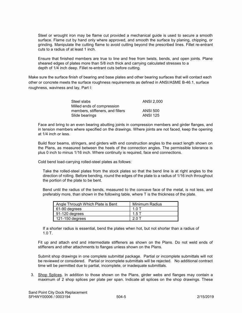
Sand Point City Dock Replacement SFHWY00006 / 0003194 504-5 2/15/2019
Steel or wrought iron may be flame cut provided a mechanical guide is used to secure a smooth surface. Flame cut by hand only where approved, and smooth the surface by planing, chipping, or grinding. Manipulate the cutting flame to avoid cutting beyond the prescribed lines. Fillet re-entrant cuts to a radius of at least 1 inch. Ensure that finished members are true to line and free from twists, bends, and open joints. Plane sheared edges of plates more than 5/8 inch thick and carrying calculated stresses to a depth of 1/4 inch deep. Fillet re-entrant cuts before cutting.
Make sure the surface finish of bearing and base plates and other bearing surfaces that will contact each other or concrete meets the surface roughness requirements as defined in ANSI/ASME B-46.1, surface roughness, waviness and lay, Part I:
Steel slabs ANSI 2,000 Milled ends of compression members, stiffeners, and fillers ANSI 500 Slide bearings ANSI 125
Face and bring to an even bearing abutting joints in compression members and girder flanges, and in tension members where specified on the drawings. Where joints are not faced, keep the opening at 1/4 inch or less. Build floor beams, stringers, and girders with end construction angles to the exact length shown on the Plans, as measured between the heels of the connection angles. The permissible tolerance is plus 0 inch to minus 1/16 inch. Where continuity is required, face end connections. Cold bend load-carrying rolled-steel plates as follows:
Take the rolled-steel plates from the stock plates so that the bend line is at right angles to the direction of rolling. Before bending, round the edges of the plate to a radius of 1/16 inch throughout the portion of the plate to be bent. Bend until the radius of the bends, measured to the concave face of the metal, is not less, and preferably more, than shown in the following table, where T is the thickness of the plate.
Angle Through Which Plate is Bent Minimum Radius 61-90 degrees 1.0 T 91-120 degrees 1.5 T 121-150 degrees 2.0 T
If a shorter radius is essential, bend the plates when hot, but not shorter than a radius of 1.0 T.
Fit up and attach end and intermediate stiffeners as shown on the Plans. Do not weld ends of stiffeners and other attachments to flanges unless shown on the Plans. Submit shop drawings in one complete submittal package. Partial or incomplete submittals will not be reviewed or considered. Partial or incomplete submittals will be rejected. No additional contract time will be permitted due to partial, incomplete, or inadequate submittals.
3. Shop Splices. In addition to those shown on the Plans, girder webs and flanges may contain a
maximum of 2 shop splices per plate per span. Indicate all splices on the shop drawings. These

Sand Point City Dock Replacement SFHWY00006 / 0003194 504-6 2/15/2019
splices are subject to approval and are subject to the following limitations:
Make splices complete penetration butt welds. Grind flange splices flush. Grind web splices flush on the outside face of exterior girders only. Grind parallel to the longitudinal axis of the girder. Do not place a bottom flange splice within the middle third of any span. Use tension flange splices only as shown on the Plans or as approved. Completely weld each element of a girder, such as flange or web, before attaching it to another element. Make all splices at least 6 inches from the nearest stiffener plate. Offset web and flange splices at least 6 inches.
4. Bolt Holes. Either drill or punch bolt holes. Make finished bolt holes 1/16 inch larger than the nominal
diameter of the bolt. Ensure holes are clean cut and without burrs or ragged edges. Material with poorly matched holes will be rejected.
When material forming parts of a member is composed of not more than 5 thicknesses of metal, and whenever the thickness of the metal is not greater than 3/4 inch for structural carbon steel or 5/8 inch for alloy steel, either punch or drill the holes to full size. When there are more than 5 thicknesses or when any of the main material is thicker than 3/4 inch in carbon steel, or 5/8 inch in alloy steel, or when required under paragraph 7 below, subpunch or subdrill the holes 3/16 inch smaller. After assembling, ream them to size or drill them from the solid to full size. For punched holes, the diameter of the die must not exceed the diameter of the punch by more than 1/16 inch. Ream any holes that must be enlarged to admit bolts. Ream holes cylindrical and perpendicular to the member. Direct reamers mechanically, where practicable. Ream and drill using twist drills. Assemble connecting parts requiring reamed or drilled holes and securely hold them while reaming or drilling them. Match mark them before disassembling. Subpunch (or subdrill if required) holes for field connections and field splices of arch members, continuous beams, towers (each face), bents, plate girders, and rigid frames while assembled in the shop. Obtain approval of the assembly, including camber, alignment, and accuracy of holes and milled joints before beginning reaming. Subpunch and ream holes for floor beam and stringer field end connections to a steel template, or ream them while assembled. When partial assembly is permitted ream holes for web member connections with steel templates. When using templates to ream field connections of web members of an arch, bent or tower, mill or scribe at least one end of each web member normal to the long axis of the member. Accurately set the templates at both ends from this milled or scribed end. Ream or drill the full size of the field connection through templates after carefully locating the templates as to position and angle and firmly bolting them. Use exact duplicate templates used to ream matching members or the opposite faces of one member. Accurately locate templates for connections that duplicate so that like members are duplicates and require no matchmarking. Accurately punch holes full-size, subpunch them, or subdrill them so that after assembling (before

Sand Point City Dock Replacement SFHWY00006 / 0003194 504-7 2/15/2019
reaming), a cylindrical pin 1/8 inch smaller in diameter than the nominal size of the punched hole may be entered perpendicular to the face of the member, without drifting, in at least 75 percent of the contiguous holes in the same plane. If the requirement is not fulfilled, the badly punched pieces will be rejected. If any hole will not pass a pin 3/16 inch smaller in diameter than the nominal size of the punched hole, the material will be rejected. Ream or drill holes so that 85 percent of the holes in any contiguous group after being reamed or drilled show no offset greater than 1/32 inch between adjacent thicknesses of metal. Provide in steel templates hardened steel bushings in holes accurately dimensioned from the center lines of the connection as inscribed on the template. Use the center lines to locate accurately the template from the milled or scribed ends of the members.
5. Bolted Connections, High-Strength Bolts. Unless otherwise noted in the plans, determine bolt
lengths by adding the values given in Table 504-1 to the total thickness of connected material. These values compensate for thickness of nut, bolt point, and washers. Add 5/32 inch to the grip length per each additional flat washer. Adjust the total length to the next longer 1/4 inch increment up to a 5 inch length and to the next longer 1/2 inch increment for lengths over 5 inches. Unless otherwise permitted by the Engineer, the maximum length of bolt shall extend out no more than 1-inch from the face of the tightened nut or jam nut.
Fit bolted parts solidly together when assembling them and do not separate them by gaskets or other interposed compressible material. Place hardened washers under the turned element.
TABLE 504-1
BOLT LENGTH DETERMINATION
Bolt Diameter (inches)
Added Length (inches)
1/2 11/16 5/8 7/8 3/4 1 7/8 1-1/8 1 1-1/4
1-1/8 1-1/2 1-1/4 1-5/8
Keep assembled joint surfaces, including those adjacent to washers, free of scale and excess galvanizing. Clean off dirt, loose rust, burrs, and other defects that would prevent the parts from seating. Keep contact surfaces free of oil, paint, or lacquer. When the outer face of the bolted parts has a slope of more than 1:20, use a smooth beveled washer in contact with the sloped surface. Unless noted otherwise, all ASTM A325 bolts shall be installed snug-tight per AISC RCSC requirements.
6. Welding. Perform all welding and Nondestructive Examination (NDE) as specified or shown on the
Plans. All welding shall be performed per the latest AWS D1.1 by welders qualified per AWS for the type and position of the welds.
At least 30 days prior to welding, submit for approval a welding plan stamped and signed by an American Welding Society Certified Welding Inspector per QC1 (CWI) responsible for the Quality Control (QC) and consisting of the following documents

Sand Point City Dock Replacement SFHWY00006 / 0003194 504-8 2/15/2019
a. Quality control personnel qualifications including CWI number b. Welding Procedure Specifications (WPS) using forms in AWS D1.1, Sample Welding
Forms c. Procedure Qualification Records (PQR) when applicable, using forms in AWS D1.1, Sample
Welding Forms d. Welder Performance Qualification Records (WPQR) using forms in AWS D1.1, Sample
Welding Forms with documentation of current welder certification e. Type and extent of NDE to be conducted, as required in the specifications f. Sample daily inspection sheet
The Contractor shall provide a Certified Welding Inspector (CWI) to inspect all welds. All welds shall be 100% visually inspected. In addition, unless noted otherwise, 10% of all CJP shop welds shall be tested by UT examination or other NDT methods approved by the Engineer. Such tests shall be performed by an independent qualified third party inspector. The Contractor shall submit weld inspection / NDT reports to the Engineer for review. Any weld failing inspection shall be repaired at the Contractor’s expense, which will include the cost for retesting. The Department may provide additional inspection of shop and field welds as required. The Contractor shall be responsible for all repairs required as a result of additional Department inspections. Acceptance criteria for all weld inspections shall conform to AWS D1.1 criteria for statically loaded structures. Rebar welding shall be performed and accepted per AWS D1.4 criteria for reinforcing steel. Do not weld or tack brackets, clips, shipping devices or other material not required by the Contract documents to the permanent structure, unless shown on the working drawings and approved by the Engineer.
7. Fenders. All Energy Absorbers and UHMW-PE Panels shall be constructed to the dimensions, limits, and installed at the locations shown on the Drawings.
Contractor shall verify fitment of fender panels with fender pin piles prior to shipment from the fabrication facility.
504-3.02 ERECTION. 1. General. Provide the falsework and all tools, machinery, and appliances, including drift pins and
fitting-up bolts, needed to perform the work efficiently. Erect the structural steel, remove the temporary construction, and do the work to complete the structure, as required by the Contract Documents. Make temporary field welds to structural steel according to the procedures required by these Specifications. Steel with sharp kinks or bends will be rejected.
2. Handling and Storing Materials. Store material on skids above the ground. Keep it clean and properly drained. Place girders and beams upright and shore them. Adequately support long members, such as columns and chords, on skids to prevent injury from deflection.
3. Falsework. Use falsework according to Section 512.
4. Erection Plan. Submit an erection plan for approval. Submit the erection plan not less than 30 days prior to erecting the structural steel. Do not erect structural steel without the written approval of the Engineer.

Sand Point City Dock Replacement SFHWY00006 / 0003194 504-9 2/15/2019
The erection plan must include, but is not limited to the following:
a. Drawings indicating geometry, member sizes, material properties, foundations capacities, design assumptions, and other relevant information required to erect the structural steel.
b. Support and lifting reactions for each stage of the erection procedure. c. Equipment type, size, capacity, position, work radius and other relevant information. d. Schedule, duration of each portion of work and other timing considerations.
The erection plan shall conform to the requirements of the Contract Documents. Do not induce buckling or other instabilities at any time during shipping, handling or erection. Handling and erection procedures shall be conducted in such a manner as to avoid damaging the protective coating or paint system. Submit changes needed to accommodate the erection plan for approval. Do not submit shop drawings until the Engineer has approved the erection plan. Submit the erection plan in one complete submittal package. Partial or incomplete submittals will not be reviewed or considered. Partial or incomplete submittals will be rejected. No additional contract time will be permitted due to partial, incomplete, or inadequate submittals. Do not deviate from the approved erection plan without the written permission of the Engineer. The approval of the Engineer shall not be considered as relieving the Contractor of the responsibility for the safety of his method or equipment or from carrying out the Work in full accordance with the Plans and specifications
5. Assembling Steel. Accurately assemble the parts as shown on the Plans and follow match- marks.
Handle the material carefully to avoid bending, breaking, or otherwise damaging the parts. Do not hammer if doing so will injure or distort the members. Clean bearing surfaces and surfaces to be in permanent contact before assembling the members.
6. Attachment of Formwork. When approved, use 1-inch maximum diameter holes in steel girder webs
for attaching formwork. Place holes 6 inches minimum clear distance from all horizontal or vertical welds and space them at least 4 feet center to center. Drill or subpunch and ream holes. Do not provide empty bolt holes. Fill empty holes with tensioned high- strength bolts.
Include in the request enough detail of the formwork for determining the stresses that will be imposed on the girder.
7. Piling. Installation of the piling shall conform to the requirements of Section 505 – Piling.
8. East Catwalk Platform Demolition. Contractor shall verify all existing dimensions, elevations,
and member sizes prior to fabrication and construction. Notify the Department immediately if any discrepancies are found. Demolish portions of the existing platform as shown in the Plans. Any damaged components, other than those shown to be removed, shall be repaired or replaced using methods approved by the Engineer and at no additional cost to the Department.
504-3.03 APPLICATION AND REPAIR OF PROTECTIVE COATINGS.
1. Galvanizing Application. See Subsection 716-2.07
2. Spray Metalizing Application. See Subsection 716-2.09

Sand Point City Dock Replacement SFHWY00006 / 0003194 504-10 2/15/2019
3. Paint Application. See Subsection 708.2.01
4. Protection of Coatings. Contractor shall take necessary means to protect coatings during transportation, handling, welding, cutting and installation.
5. Repair of Coatings, General. Damaged coatings, including that removed for welding, welds, cuts, gouges or other holidays in the coatings shall be repaired by the Contractor at no additional cost to the Department.
6. Repair of Galvanizing/Metalizing. Shop repair of galvanizing/metallizing shall be done by means of spray metallizing. Field repair damaged galvanizing by spray metallizing if damage is over 100 square inches in area. A galvanizing repair stick such as REGALV by Rotometals, Galva-Guard by San Diego Galvanizing, or Engineer approved equal may be used for field repair if the damaged area is less than 100 square inches. Contractor shall submit repair materials and methods to the engineer for review and approval. All repairs shall meet ASTM A780 Standard Practice for Repair of Damaged and Uncoated Areas of Hot-Dip Galvanized Coatings.
Galvanizing repair stick shall be zinc alloy. Prepare damaged galvanizing with a grinder and then abrade the entire surface with a wire brush where application of the galvanizing repair is required. Clean the surface to remove all grease, oil and surface deposits. Heat the local area to the manufacturer suggested temperature and apply repair stick in such a manner to achieve a minimum of 10 mil total final thickness.
504-3.04 CLEANUP. Upon completion and before final acceptance of the structure, remove falsework and falsework piling down to 2 feet below the finished ground line. 504-4.01 METHOD OF MEASUREMENT. Section 109. The bid schedule contains lump sum or unit pay items for the respective steel and composite structures to be incorporated into this project. Steel or other material quantities shall not be measured separately for payment. Measurement shall be made as a lump sum unit as noted on the bid schedule. Measurement shall include furnishing and installing all field and shop fabricated materials, components and assemblies as shown on the Drawings, complete-in-place. Painting or protective coating are considered subsidiary and will not be measured separately for payment. 504-5.01 BASIS OF PAYMENT. The contract price includes the cost of labor, materials, equipment and subsidiaries necessary for the Work, complete-in-place and accepted as shown on the Drawings. If changes or additions in the work are ordered by the Engineer, which will vary the weight of steel to be furnished, the contract lump sum price will be adjusted as provided in the General Provisions. However, no additional payment will be made for increases in structural steel quantities made necessary by the Contractor’s means and methods of fabrication or erection. 504(1a) Structural Steel (Dock). At the contract unit price shown on the bid schedule, for work, including furnishing, fabricating, and erecting, including all subsidiary work and materials required. This item shall include all other material fabrication and installation required to complete the bullrail, swing gates, catwalks, East catwalk platform, bollards, ladders, and other miscellaneous steel appurtenances as shown in the Drawings. UHMW bearing pads, reflective lettering, gate casters, and other non-steel materials are considered subsidiary. 504(1b) Structural Steel (Dolphin Cap). At the contract unit price shown on the bid schedule, for work, including furnishing, fabricating, and erecting, including all subsidiary work and materials required. The following items shall be considered subsidiary to the structure: all steel, connecting hardware, connected ladders, bollards, coatings, and other material fabrication and installation required to complete the mooring dolphin as shown on the Drawings. Dolphin Piles and Fins will be paid under Section 505 Pay

Sand Point City Dock Replacement SFHWY00006 / 0003194 504-11 2/15/2019
Items. 504(2) Dock Fender System. At the contract price shown on the bid schedule, for work, including furnishing, fabricating, and erecting, including all subsidiary work and materials required. The following items shall be considered subsidiary to the structure: all UHMW Panels, rubber energy absorbers, pin piles and sleeve pile fabrication and installation, rebar, welding, coatings, walers, tees, HSS, high strength chain and other materials, fabrication and installation required to complete the fender units as shown on the Drawings. Payment will be made under:
Pay Item Pay Unit 504(1a) Structural Steel (Dock) Lump Sum 504(1b) Structural Steel (Dolphin Cap) Lump Sum 504(2) Dock Fender System Lump Sum

Sand Point City Dock Replacement SFHWY00006 / 0003194 505-1 2/15/2019
Replace Section 505 with the following:
SECTION 505 PILING
505-1.01 DESCRIPTION. Furnish and drive piles, and assist in pile testing.
505-1.02 DEFINITIONS.
BEARING CAPACITY. The required axial resistance, in units of force, to be achieved during pile installation. CUT-OFF. The cut off end of a pile, or cutting a pile end at the finish elevation.
DRIVECAP. A pile driver component that is used to transmit impact forces from the hammer ram to the pile top. The drivecap includes the anvil or striker plate, hammer cushion (capblock), helmet, and pile cushion, if used. (Also termed the driving head).
ESTIMATED PILE TIP ELEVATION. The elevation at which the Department expects the bearing capacity to be achieved.
FRESH HEADING. Cutting the end of a pile perpendicular to the long axis to remove damage, and to obtain a proper driving or splicing surface.
FOLLOWER. A pile driving aid placed between the helmet and the pile top when the pile head is below the reach of the hammer.
HAMMER CUSHION. A disk of material placed on top of the helmet but below the anvil or striker plate to relieve impact shock and provide protection for the hammer and pile.
HAMMER ENERGY:
Maximum Rated Hammer Energy. The theoretical maximum amount of gross energy that a pile driving hammer can generate.
Transferred Hammer Energy. The amount of energy transferred to the pile for a given blow accounting for friction energy during the ram down stroke, energy retained in the ram and drivecap during rebound, and other impact losses.
HELMET. A pile driver component that fits closely on top of the pile to ensure the impact force is transmitted uniformly across the top of the pile and concentric with the axis of the pile.
LEADS. Pile driver components used to maintain pile and hammer alignment during driving, and on which the pile hammer may travel. Types of leads include:
Fixed Leads. Pile driving leads that are attached at the top of the boom by a pivot and to the crane at the bottom with a brace. The pile is held at the top by the helmet and is guided at the bottom by the pile gate.
Semi-Fixed Leads. Pile driving leads that are attached at the top of the boom by a pivot and supported by the lead line. The lead can slide axially along the pivoted boom point and may be fitted with an extendable brace at the bottom of the leads.
Swinging Leads. Pile driving leads that are suspended from the boom by the cable and are not attached to the crane at the bottom with a brace. (Also known as offshore leads)
MINIMUM TIP ELEVATION. The minimum length of pile below the footing or finished ground elevation to which the pile must be driven.

Sand Point City Dock Replacement SFHWY00006 / 0003194 505-2 2/15/2019
OBSTRUCTION. An unanticipated object projecting within the path of the pile that causes pile refusal or impedes the pile's advance within required tolerances.
PILE GATE. A device at the base of the leads that is closed around the pile to maintain alignment.
REFUSAL. Refusal occurs when the approved hammer requires 15 or more blows to move the pile one inch while the hammer is operating at 80 percent efficiency or higher, or, when the pile yield stress is measured or calculated to be equal to or greater than 90 percent of the specified pile yield stress.
SUBSTRUCTURE UNIT. A unit of the substructure such as an abutment or pier that transmits loads directly from the superstructure to the ground.
TEST PILE. A pile that has a high-strain dynamic test performed on it.
TEMPLATE. A structure affixed to the ground used to maintain proper pile alignment during driving.
WAVE EQUATION ANALYSIS. A numerical method of analysis for the behavior of driven piles that predicts the pile capacity versus blow count relationship (bearing graph) and pile driving stress. Wave equation analysis is performed using a commercially available wave equation analysis program (WEAP) with a version dated 2005 or later. 505-2.01 MATERIALS. Use materials that conform to the following:
Structural Steel Piles Section 715 Concrete Infill Section 501 Miscellaneous Steel Section 504
505-2.02 PILES. Furnish piles sufficient in length to obtain the bearing capacity and to extend to the estimated pile tip elevation specified in the Contract documents. Furnish additional pile length, at no additional cost, to provide for fresh heading and to suit the method of installation. Piles shall be delivered full length or field spliced in accordance with approved welding and galvanizing repair procedures. Splices shall be a minimum of 40-ft apart, unless otherwise approved by the Engineer. No additional compensation shall be made for splicing piles to make up the pile lengths shown on the Plans. Pile Splices shall be full-strength butt-welded with backing rings per AWS Specifications. Care shall be taken that piling remain in straight alignment through splices. No piece of pile less than 10 feet in length shall be spliced onto a pile. All welding shall be performed per the requirements of Section 504 and AWS D1.1. The Contractor shall verify fitment of fender panels with fender pin piles prior to fabrication. Reference pile schedule and Subsection 715-2.02.2 for driving shoe requirements. 505-2.03 PROTECTIVE COATINGS. All pile shall be hot-dipped galvanized full length per Section 716-2.07 unless otherwise noted.
CONSTRUCTION REQUIREMENTS
505-3.01 PILE DRIVING EQUIPMENT. 1. Pile Driving System. Pile driving hammers, and supporting equipment shall be selected by the
Contractor subject to review by the Engineer, prior to mobilizing to the project site. The pile driving equipment shall be suitably sized to achieve the design embedment and ultimate bearing capacities identified in the plans. Equipment shall be provided to drive through new and existing core and armor

Sand Point City Dock Replacement SFHWY00006 / 0003194 505-3 2/15/2019
rock. The Contractor shall assume drilling equipment will be necessary for installation and cleanout of all piles. The Contractor shall mobilize and have drilling equipment onsite during all pile installation. A vibratory hammer shall be used to drive piles to the maximum extent possible. Determine the pile bearing capacity by driving the pile a minimum of 5 feet with an impact hammer. Pile ultimate bearing capacities shall be determined solely by the Engineer. Use pile driver leads that allow the hammer to move freely. Do not use followers to drive piles.
Fit the pile driving hammer with a cast-steel driving head (or similar device) that is recommended in the hammer manufacturer’s guidelines, is compatible with the pile, and aligns concentrically and fits closely with the top of the pile.
Any hammer that causes damage to the piles during driving operations shall be substituted with an acceptable alternative hammer at no additional expense. Impact hammer shall be supplied with new cap block cushions, which shall be changed at the manufacturer’s recommended interval. The submitted pile driving plan shall include manufacturer’s recommendations and information on hammer cushion. Do not use wood, wire rope, or asbestos hammer cushions.
Use only equipment included in the approved pile driving plan. The Engineer may inspect the pile driving equipment for conformance with the approved pile driving plan after it has been mobilized to the site and prior to beginning pile driving operations. Remove and replace pile driving equipment the Engineer determines does not conform with the approved pile driving plan, at no extra cost to the Department and with no adjustment to contract time.
2. Pile Driving Plan. Submit a detailed work plan including technical narrative and illustrations for all
pile driving systems. The plan shall be submitted no less than 30 days prior to the anticipated start of pile driving. Include in the pile driving plan:
a. A completed Pile Driving Equipment Data form (Form 25D-098).
b. Manufacturer’s catalog cuts, specifications, manuals, guidelines, and technical bulletins
for all pile driving equipment to be used.
c. Limitations and capacities of listed equipment. Including, but not limited to: Crane capacity and maximum reach with the specified hammer and maximum pile length, pile driving hammer rated energy, etc.
d. Manufacturer’s recommendations and information on hammer cushion
e. A description of the techniques to be used for ensuring proper placement and alignment of
the piles, obtaining the bearing capacity, and advancing the piles to the estimated pile tip elevation. Especially with regard to driving through core and armor rock.
f. Method of cleanout for all piles.
g. Alternate methods of pile installation in the event obstructions are encountered.
h. Shop Drawings and configuration for pile driving template(s).
i. A wave equation analysis for each pile driving system (see 505-3.01-3).
The Engineer will base approval of the pile driving hammer on the wave equation analysis submitted by the Contractor and the requirements in this Subsection. The Department will verify the wave equation analysis using the computer program “GRLWEAP” and GRLWEAP industry standard hammer input data.

Sand Point City Dock Replacement SFHWY00006 / 0003194 505-4 2/15/2019
The Engineer’s approval of the pile driving plan will not relieve the Contractor of responsibility for:
j. removing and replacing piles damaged during pile driving operations,
k. obtaining the bearing capacity specified in the Contract, or
l. meeting pile tip elevation specified in the Contract documents.
Do not mobilize pile driving equipment to the site without an approved pile driving plan.
Submit all revisions to the approved pile driving plan to the Engineer for approval. For all pile driving equipment not previously identified in the pile driving plan, include in the submittal all of the information required above for the pile driving plan. Explain to the Engineer, in writing, which portions of the approved pile driving plan will be superseded by the revision and which portions remain unchanged. Allow at least 5 days for the Engineer’s approval of pile driving plan revisions.
3. Wave Equation Analysis. Perform a wave equation analysis for all pile driving systems used to drive
piling according to the requirements of this subsection and the user’s manual for the program. Verify that the pile driving system proposed does not produce pile stresses greater than 90-percent of the yield stress at the bearing capacity specified in the plans. Also verify that the rate of pile penetration is 100-blows per foot or less at the bearing capacity specified in the plans.
Unless otherwise specified in the Contract, or directed by the Engineer, use the following default values and the applicable values from Table 1 as input to the wave equation analysis program:
Output option (IOUT) 0 Factor of safety applied to (Rult) 1.0 Type of damping Smith Residual stress option No
TABLE 505-1
HAMMER EFFICIENCIES USED IN HAMMER APPROVAL
Hammer Type For Analysis of
Driving Rate For Analysis of Driving Stresses
Single acting diesel hammers 0.72 0.84 Closed-ended diesel hammers 0.72 0.84 Single acting air/steam hammers 0.60 0.70 Double acting air/steam hammers 0.45 0.53 Hydraulic hammers or other external combustion hammers having ram velocity monitors that may be used to assign an equivalent stroke.
0.85
1.00
505-3.02 PILE TESTING AND PILE DRIVING CRITERIA. The Contractor shall hire an Independent Third-Party Tester to perform high-strain dynamic testing to set criteria for monitoring pile driving performance and the resistance of the pile during driving. Perform additional pile testing as required to confirm hammer-system efficiency; pile driving stresses, and pile integrity. Attend a meeting with the Engineer at least 14 days prior to the beginning of pile driving operations to evaluate and discuss the test pile program. Give the Engineer 7 days advance notice before driving each test pile. Perform the high-strain dynamic testing in accordance with ASTM D4945. Piles tested using high-strain dynamic testing may be incorporated into the work.

Sand Point City Dock Replacement SFHWY00006 / 0003194 505-5 2/15/2019
Test the first pile driven at each pile gridline (a minimum of four total). Do not drive any production piles on the pile gridline until the test pile has been driven to the bearing capacity and minimum tip elevation specified in the Contract documents. Attach testing instruments near the top of the test pile through drilled and threaded holes. When the pile is driven to the point where the testing instruments need to be removed from the lower pile section, they will be reattached to the top of the newly spliced section. Furnish the testing equipment and labor necessary to mount the testing instruments to the pile. Provide a reasonable and safe means of access to the top of the test pile after the pile is placed in the leads. Drive each test pile to the bearing capacity and minimum tip elevation specified in the Contract documents as indicated by the driving criteria. Record driving data for the test pile and submit to the Department for acceptance. If an obstruction is encountered during driving of the test pile, testing will stop on that pile and the next pile driven at the substructure unit will be designated as a test pile. If a pile is driven to estimated tip elevation and the driving data does not support the conclusion that the bearing capacity has been obtained, the Engineer may direct testing of additional piles and/or suspension of pile driving operations and require the Contractor to restrike the pile with the Engineer present. Perform the restrike with a warmed-up hammer with the energy or fuel setting adjusted to the position indicated in the approved pile driving plan. Strike the test pile with 60 consecutive blows or until the pile penetrates an additional 3 inches, whichever comes first. The Engineer may terminate the re-strike at any point during the testing. If the results from the high-strain dynamic testing are acceptable to the Engineer, drive the remaining piles at the substructure unit using the driving criteria developed from the high-strain dynamic testing. The Engineer will provide the driving criteria within 1 day of receiving test results. If the results from high-strain dynamic testing are not acceptable to the Engineer, proceed as per the written direction of the Engineer. Account for the entire allotted equipment installation time required by the Engineer in the progress schedule submitted under Subsection 108-1.03 or Section 646, as applicable. Suspension of pile driving operations at a testing location to allow for testing instrument installation or a re-strike of a test pile is not a suspension of work per Subsection 108-1.06 and additional contract time will not be allowed. 505-3.03 DRIVING PILES. Drive all piles to the capacities and minimum tip elevations specified in the plans. Pile ultimate bearing capacities shall be determined by the Engineer. Pile installation restrictions and monitoring requirements are described in the Environmental Commitments & Permits contained in Appendix B of the bid documents. These are incorporated by reference to this section. All pile installations shall be conducted with the Engineer present. The Contractor shall assist the Engineer in monitoring the pile driving. The Contractor shall mark each pile with one-foot increments, with every five-foot increment numbered. For determination of pile refusal or capacity, the Contractor shall mark the piles with 1-inch increments during the final drive. The marks shall be visible and readable from all sides of the pile above local extreme low tide level. Provide notification to Engineer a minimum of 24 hours prior to any pile installation. If a bearing pile is driven to the estimated tip elevation and the Engineer determines that the required capacity has not been obtained, the Engineer may direct the Contractor to continue pile driving operation until adequate capacity is obtained. 1. Placement and Alignment. Ensure proper placement and alignment of the piles. The Engineer will
reject piles that are bent or otherwise damaged by forcing the pile into the leads or template.
Piles shall be placed within 1% of specified vertical alignment and within 2 inches of specified location at cut-off, unless otherwise noted. Fender pin piles shall be installed as indicated on the plans in such a manner to allow installation of the fender panel without binding.

Sand Point City Dock Replacement SFHWY00006 / 0003194 505-6 2/15/2019
2. Protection of New Concrete. When driving a pile near concrete placed within 28 days, ensure the
distance between the pile being driven and the nearest edge of concrete is not less than the distance determined by the following formula:
D = C√𝐸
Where: D = Distance in feet E = Maximum rated hammer energy in foot-pounds C = Vibration coefficient shown in Table 505-2 based on the number of calendar days after concrete placement
TABLE 505-2
VIBRATION COEFFICIENT
Concrete Age (days)
Coefficient
1 0.34 2 0.23 3 0.18 4 0.15 5 0.13 6 0.12
7-9 0.11 10-13 0.10 14-20 0.09 21-28 0.08
3. Obstructions. Obstructions may be encountered below mudline during pile driving. Any obstructions
encountered within ten (10) feet of the existing mudline shall be removed at no additional cost to the Department. In the event that obstructions are encountered or extend below ten (10) feet from mudline elevation, and removal is required, the Contractor shall do so in accordance with Subsection 104-1.03. The Contractor shall be prepared to immediately remove obstructions in the event they are encountered, or shall alternatively move to other contract Work so as to prevent delays.
4. Concrete Filled Pipe Piles. After driving pile, clean out the pile to the bottom of concrete elevation specified in the Contract documents per Section 515. If there is a delay between cleanout and placing concrete, verify that the soil level in the pile has not rebounded before placing concrete.
505-3.04 SPLICES, EXTENSIONS AND BUILD-UPS. Pile supply lengths indicated on the Drawings were determined based upon geotechnical investigations of the area. Should actual conditions vary and additional driving be required such that the supply length shown in the Drawings for a particular pile is not adequate, Contractor shall splice a contingent length of pipe pile onto the pile being driven and continue driving until refusal is reached. The contingent length of pile shall be pipe pile meeting the requirements of this section and furnished under Item 505(5) – Furnish Contingency Pile, as shown on the Drawings. Contractor shall notify the Engineer, in writing, immediately if the supplied length of pile is insufficient for a particular location and receive approval from the Department prior to proceeding with additional splicing and driving.

Sand Point City Dock Replacement SFHWY00006 / 0003194 505-7 2/15/2019
All additional splicing and additional pile driving shall be performed in accordance with the Drawings and this Section. 505-3.05 DEFECTIVE PILES. Use a pile driving method which does not damage the pile. Do not manipulate the piles to force them into proper position. Correct damaged or improperly driven piles using a method approved by the Engineer. Drive down all piles pushed up by driving adjacent piles or by any other cause. Approved methods may include one of the following:
1. Withdraw and replace the pile with a new and, when necessary, longer pile.
2. Splice or build up the pile.
505-3.06 CUTTING OFF PILES. Cut off the piles at the elevations indicated on the Plans. Ensure that all injured material is removed.
When steel piles are shown embedded in concrete footings or pile caps, cut off piles within -1/2 inch to +3 inches of the plan embedment, but do not interfere with reinforcing steel or other items embedded in concrete. When steel pipe piles are shown cutoff below concrete footings or pile caps, cut off piles within -1/2 inch to +1/2 inch of the plan elevation. In pile bents with steel cap beams, make accurate cut-offs to ensure full bearing between the caps and piles. 505-3.07 IN-WATER WORK RESTRICTIONS. All requirements regarding pile driving, other in-water work activities and monitoring requirements set forth by the project permit requirements shall be followed. 505-3.08 CLEANUP. All Steel pipe pile cutoffs on this Project shall become the property of the Contractor. 505-4.01 METHOD OF MEASUREMENT. Section 109 and as follows: Furnish Piles. The sum of the supply lengths of the piles which are incorporated into the completed structure. Drive Piles. The number of piles driven which are incorporated into the completed structure. Fins. The number of fins installed, in place in the completed structure. Painting or protective coating are considered subsidiary and will not be measured separately fo r payment. 505-5.01 BASIS OF PAYMENT. Furnish Piles. The contract price includes pile materials delivered to the site, pile shoes, reinforced tips and casing. Unused pile lengths removed by cut-offs and fresh heading are subsidiary. The payment amount will be calculated using the quantity of pile indicated on the bid schedule. Additional Fin materials and fabrication will be paid under 505 (10). Drive Piles. The contract price includes: 1. All related work required to drive the piles to the minimum tip elevation and bearing capacities,
including: pile crew time (including payroll and administrative additives), equipment costs, and other fixed or variable items incurred during pile driving, the construction of temporary work platforms, fresh heading, splicing, restrike, pile cleanout and cutting off.
2. This work also includes High Strain Dynamic Testing as performed by an Independent Third Party
Inspector.

Sand Point City Dock Replacement SFHWY00006 / 0003194 505-8 2/15/2019
Pay Item Pay Unit 505(5a) Furnish Structural Steel Piles (30”x0.500”) Linear Foot 505(5b) Furnish Structural Steel Piles (24”x0.500”) Linear Foot 505(6a) Drive Structural Steel Piles (30”x0.500”) Each 505(6b) Drive Structural Steel Piles (24”x0.500”) – Fender Pin Pile Each 505(6c) Drive Structural Steel Piles (24”x0.500”) – Dolphin Pile Each 505(10) Fin Pile Tips Each
Sand Point City Dock Replacement SFHWY00006 / 0003194 514-1 2/15/2019
SECTION 514 CATHODIC PROTECTION
514-1.01 DESCRIPTION. This specification defines the requirements for the preparation and installation of galvanic pier anodes on the Sand Point DOT Dock, in Sand Point Alaska. This Work includes, but is not limited to, the furnishing, fabricating, installation, and verification/commissioning of all materials shown on drawings A01 to A04 pertaining to anodes used for corrosion protection of the structure.
514-1.02 REFERENCES. A. National Association of Corrosion Engineers (NACE)
a. SP0176-2007 Corrosion Control of Submerged Areas of Permanently Installed Steel Offshore Structures Associated with Petroleum Production.
b. SP0169-2007 Control of External Corrosion on Underground or Submerged Metallic Piping Systems.
514-1.03 SUBMITTALS. The Contractor shall submit the following for approval, prior to procuring materials:
A. Manufacturer’s Product and Catalog Cut Information: Product data and catalog cut information shall be submitted for each item listed in this specification. Product information shall include the manufacturer’s name, recommended installation instructions (if any) and sufficient information to demonstrate that the materials meet the requirements of the drawings and specifications. Where more than one item or catalog number appears on a catalog cut, the applicable item(s) proposed for use shall be clearly identified.
B. Drawings: The Contractor shall maintain accurate as-built drawings of the cathodic protection system installations over the course of the construction project. Drawings shall be legibly revised to show the location of anode placements, below ground splice locations, cable routing, distances from piping and appurtenances/dock structure. Completed as-built drawing originals and two additional copy sets shall be submitted to the City of Sand Point Harbor Master or their designated Project Representative.
C. CP Commissioning Report: Two copies of the cathodic protection (CP) testing and commissioning data shall be submitted to the City of Sand Point Harbor Master or their designated Project Representative. The report shall document CP surveyor name(s) and valid NACE certification(s), all collected test data, final test locations, commissioning results, and system testing/activation date(s). One copy shall be submitted electronically (PDF scanned format) with a second hard-copy print version submitted for the facility archive.
514-1.04 QUALITY CONTROL.
Qualifications. Contractor’s must have a valid Contractor’s license issued by the State of Alaska and a minimum of two years’ experience installing cathodic protection systems.
Drawings. The cathodic protection system drawings are based on best available information and are not scaled for exact locations unless otherwise noted or dimensioned on a specific drawing or detail.
Exothermic Welds: Unless specified herein, the cad weld manufacturer’s printed recommendations and instructions for handling, surface preparation, and application of exothermic welds shall be strictly observed.
Inspection. It is the Contractor’s responsibility to perform work to the requirements of this specification and to conduct the necessary inspections and tests to ensure proper installation and compliance. The on-site Field Engineer may conduct any inspection deemed necessary to verify compliance.
Sand Point City Dock Replacement SFHWY00006 / 0003194 514-2 2/15/2019
514-1.05 DELIVERY, STORAGE AND HANDLING.
A. Inspect all cathodic protection materials upon delivery to verify components are of the proper make, model and size (as specified herein and on the project drawings); are free of damage; and are provided in sufficient quantities to complete the project as designed.
B. Store all cathodic protection materials in a dry, protected location to prevent impact, spark and weather-related damage.
514-2.01 MATERIALS. All materials shall be the sizes shown on the Drawings.
Pier Anodes (Row B, C, D, Dolphins & Fenders). 175-lb anodes will be installed on piles A through C. 313-lb anodes will be installed on the D piles, dolphins, fenders, and pin piles. The 175-lb anodes shall 24 inches long, 9 inches wide, and 9.5 inches tall. The 313-lb anodes shall be 77 inches long, 7.5 inches wide, and 6.5 tall. All anodes shall be aluminum alloy with the following properties:
A. Use weld-on, high efficiency sacrificial aluminum alloy anodes for cold water.
B. Use anodes with the following metallurgical composition as percentage of total anode weight:
Element Percent by Weight a. Iron (Fe): 0.13% maximum b. Copper (Cu): 0.006% maximum c. Zinc (Zn): 2.8% to 6.5% d. Silicon (Si): 0.008% to 0.2% e. Indium (In): 0.01% to 0.025% f. Aluminum (Al): Remainder (99.85% purity minimum) g. Mercury (Hg): 0% h. Lead (Pb): 0%
C. Electrochemical capacity greater than or equal to 1,150 A-hr/lb.
D. Consumption rate less than or equal to 7.6 lbs/A-yr.
E. Open circuit potential more electronegative than or equal to -1.05 V (Ag/AgCl), referenced to a silver-silver chloride (Ag/AgCl) hall-cell.
F. The steel core for anodes shall be ASTM A36 or Engineer-approved equal for mild steel bar stock. Anode core shall be bent to accommodate welding attachment to piling.
G. The anode material shall be cast within four (4) hours of blasting the steel core.
H. Approved Manufacturers: a. Farwest Corrosion Control b. Mesa Cathodic Protection c. Or Approved Equal
Anodes shall conform to NACE SP0387. Contractor shall submit a manufacturer’s certificate of conformity and proof that the furnished materials conform to the specified requirements contained in NACE SP0387 for Engineer review and approval 7 days prior to shipment. The label or listing by the specified agency will be acceptable evidence of such compliance. List the specific alloy constituents, electrochemical capacity, consumption rate, open circuit potential, dimensions, and attachment method. The Contractor shall submit steel fabrication and anode shop drawings 14 days prior to fabrication.

Sand Point City Dock Replacement SFHWY00006 / 0003194 514-3 2/15/2019
If anodes are not stored inside a building, tarps or similar protection shall be used to protect anodes from inclement weather.
Soil Anodes (Row A). Prepackaged anodes shall be magnesium type and size listed on the Drawings and have the following properties:
A. Use anodes with the following metallurgical composition as percentage of total anode weight: Element Percent by Weight
a. Aluminum 0.01 percent (max.) b. Manganese 0.50 to 1.30 percent. c. Copper 0.02 percent (max.) d. Silicon 0.05 percent (max.) e. Nickel 0.001 percent (max.) f. Iron 0.03 percent (max.) g. Others 0.05 percent (max. each) or 0.3 percent (max. total) h. Magnesium Remainder
B. Anodes shall be cast with a galvanized steel rod core, silver soldered to HMWPE cable and fully sealed at the connection interface. Anode ingots shall be 48 pound high-potential magnesium in accordance with ASTM G97. They shall be 5.5 inches wide, 5.75 inches tall, and 30.125 inches long,
C. Anodes shall be prepackaged in a permeable cotton sack with a low resistance backfill consisting of 75 percent gypsum, 20 percent bentonite, and 5 percent sodium sulfate. The sack will be 8 wide by 38 inches long and weigh 100 pounds.
D. The prepackaged backfill material shall have a grain size that is 100 percent capable of passing through a 20-mesh screen with 50 percent retained by a 100-mesh screen.
E. Anodes shall be equipped with 50 feet of No. 10 AWG lead wire. Lead wire conductor shall be stranded copper with 600-volt red HMWPE insulation in accordance with ASTM D1248, Type 1, Class C.
F. Approved Manufacturers: a. Farwest Corrosion Control b. Mesa Cathodic Protection c. Or Approved Equal
Exothermic Weld Connections. Charges and Molds: Exothermic weld charges and molds shall be appropriately sized for the specific connection application per manufacturer recommendations. Connection applications shall include pipe-to-test lead installations.
Approved exothermic weld manufactures include a. Erico Cadweld b. Continental Industries ThermOweld c. approved equal.
Exothermic welds shall be covered with an approved encapsulation cap for piping connections. Pipe-to-Test Lead Encapsulation:
a. Royston Handy Cap XL IP b. Continental Industries ThermOcap PC c. Approved Equal
Weld Materials. All filler metal shall conform to applicable AWS welding codes, meet charpy impact criteria of 20 ft.-lb. at -20˚F, and shall have a maximum carbon content of 0.20%.

Sand Point City Dock Replacement SFHWY00006 / 0003194 514-4 2/15/2019
CONSTRUCTION REQUIREMENTS
514-3.01 FABRICATION & ERECTION. Individual stand-off anodes shall be installed at the depths and specified length/size indicated on the Drawings. Locations and/or depths may be adjusted to clear obstructions or mudline with the approval of the Engineer.
Anode Installation. Prior to installation carefully lay out all anodes, and inspect for damage. Note damage to the anodes and bring to the attention of the on-site Field Engineer to determine if damaged materials are to be used, repaired, or rejected. Keep spare anodes on site and ready for immediate substitution. Care should be taken to ensure that anodes are not broke or damaged during staging or installation.
A. Pier Row A (Above Water Welding). Excavate anode installation locations and install prepackaged anodes horizontally at a minimum of two feet deep and 10 feet southeast from the Row A piles . Remove the protective plastic covers from the prepackaged magnesium anodes and inspect for damage to the permeable cloth sacks, anode lead wires, and lead wire connections. Anodes with saturated/hardened backfill material, exposed ingots, or damaged lead wires are subject to rejection and should be replaced. Place each anode on a shallow layer (6-inches or greater) of 3/8 minus bedding material at the designated locations shown on the Project Drawings. Anode placement shall use a minimum 12-inch separation distance from foreign structures or piping (such as the water/sewer line) that may be present. Do not handle or lower anodes by their associated lead wire. Backfill the immediate area around each anode with 3/8-inch minus padding material, installed in six-inch lifts, leaving the upper surface of the anode bag exposed. Hand tamp each layer of soil around the anode (taking care not to strike the anode lead wire) to remove any voids that may be present. Wet each anode with a minimum of 10 gallons of water and allow adequate time for the gypsum/bentonite material to become saturated. Add additional water as required to fully saturate the gypsum/bentonite. Complete the soil padding installation with a final 6-inch layer of 3/8-inch minus material over the top of the exposed anode once water saturation has been completed. Install anode lead wires continuous and splice-free to the test station per the Project Drawings using sufficient slack to prevent cable damage should frost-jacking conditions be encountered. Anode lead wires shall be routed in a common cable trench and placed in the center of a 12-inch column of 3/8-inch minus bedding and padding material.
B. Pier Rows B, C, D, Dolphins & Fenders Anode Welding (Underwater Welding). Wet-welding of anode channels and individual stand-off anodes to sheet pile below water shall be performed by qualified welders/divers to current AWS D3.6 Class B standards. All wet-welding shall be performed by welders/divers qualified for the level of work to be performed. Contractor shall submit welder qualifications and procedures in accordance with Section 504-3.01. Grind localized area of sheet pile prior to welding to ensure metallic contact between anode channel and sheet pile. Remove marine growth as necessary for installation. Install aluminum pier anodes, using a minimum 5/16” fillet weld, per welding details and elevations noted on the Project Drawings. Installations shall be performed in accordance with NACE SP0176-2007 and the manufacturers’ instructions and this Specification. In case of conflict between the NACE standards and this Specification, abide by the provisions established in this Specification.
C. Diver Qualifications. Diving operations shall meet the requirements as outlined in the Association of Diving Contractors International (ADCI) Consensus Standards. Divers and support personnel shall be certified by ADCI for the level of work to be performed. The Contractor shall submit diver personnel qualifications listing ADCI certification number(s) 7 days prior diving operations.
D. Underwater Installation Documentation (Provided Visibility Allows). Video documentation of underwater installation/welding shall be submitted within 30 days of installation and prior to
Sand Point City Dock Replacement SFHWY00006 / 0003194 514-5 2/15/2019
final payment. The video shall include the description of the position of each anode/weld being documented.
514-3.02 FIELD QUALITY CONTROL. The Contractor is responsible for maintaining quality. Examine all on-site materials to verify proper components, manufacturers, sizes, quantities, storage and/or missing items prior to commencing work activities.
Inspect all cathodic protection anodes for defects or damage prior to installation. Bring any noted items to the attention of the on-site Field Engineer for evaluation.
Verify that all pending anode installation locations have been properly cleared and are free of residual materials that could prevent anode installation and/or impair system operation.
Provide photographic document of completed installations for no less than 5% of the pier anodes installed.
514-3.03 CATHODIC PROTECTION SYSTEM TESTING & COMMISSIONING. Prior to performing piling preparation and cleaning activities have their designated cathodic protection technician collect baseline Pile-to-Water potential measurements without the influence of cathodic protection sources. Commissioning the cathodic protection system includes:
A. Perform testing at each pile at three approximate depths using a silver-silver chloride reference electrode. Depth levels shall include water surface level (just below the water line), approximate mid-water level, and mudline (with reference electrode suspended immediately above the seafloor.
B. Verify that the pile anode installations have been completed and that all sources of impressed current cathodic protection have been temporarily deactivated.
C. Perform Pile-to-Water potential measurements at each pile location with the new piling anodes installed. Perform testing at each pile at three approximate depths using a silver-silver chloride reference electrode. Depth levels shall include water surface level (just below the water line), approximate mid-water level, and mudline (with reference electrode suspended above the seafloor).
D. Document times and approximate tide levels for each phase of testing performed.
E. All CP system testing and commissioning shall be performed by a NACE certified Cathodic Protection Technician (CP2) or greater and shall be conducted in accordance with NACE SP0176-2007 procedures.
F. Collected data, sketches and photographs shall be compiled in a CP System Commissioning Report and submitted to the Engineer.
514-4.01 METHOD OF MEASUREMENT. Section 109. Steel or other material quantities shall not be measured separately for payment. 514-5.01 BASIS OF PAYMENT. The contract price includes the cost of labor, materials, equipment, welding, steel channels, and incidentals necessary for the Work, complete-in-place and accepted as shown on the Drawings. Payment will be made under:
Pay Item Pay Unit 514(1) Pile Anodes Lump Sum

Sand Point City Dock Replacement SFHWY00006 / 0003194 515-1 2/15/2019
Replace Section 515 with the following:
SECTION 515 DRILLED SHAFTS
515-1.01 DESCRIPTION. Construct drilled shaft foundations where indicated in the plans. This work includes all labor, materials, equipment, incidentals and services necessary to perform all operations to complete drilled shaft installation.
515-1.02 QUALITY CONTROL. Provide a Quality Control Inspector to ensure that all materials, techniques and methods are suitable to meet or exceed the minimum requirements of the contract.
The Quality Control Inspector shall submit daily reports during drilled shaft installation and testing operations verifying the Contractor’s compliance with requirements of the contract. Include field measurement data, procedural discrepancies, installation problems, names of personnel, equipment usage data, and all other significant information in the daily reports.
515-1.03 QUALIFICATIONS. Experience is required for constructing drilled shafts of lengths similar to those indicated on the plans for three separate projects during the previous 5 years. Experience must include drilling in deep water (greater than 30 feet), drilling in soils with ground water, in soils with large boulders, and in rock.
515-1.04 GENERAL REQUIREMENTS AND SUBMITTALS. Submit the following documents for review and approval no more than one week after the Notice to Proceed:
1. Project Experience. Provide a list of three drilled shaft projects performed by the Drilled Shaft
Contractor that involved drilling in sand, gravel, large boulders and rock similar to those conditions expected at this project location. Provide the drilled shaft plans, logs of test holes, dates of work, type of work, description of work, and amount of work performed. Provide the name and telephone number of a contact person at the agency or company for which the work was completed.
2. Personnel Experience. Provide a list of the key personnel involved in the drilled shaft construction.
Include the name of the superintendent and of the superintendent’s assistants who will be performing and directing the actual drilling operations. Include a resume of each superintendent and assistant involved in drilled shaft construction indicating:
a. A minimum of 5 years’ experience in directing drilled shaft construction of which 2 years being in responsible charge or operating equipment proposed for this project.
b. The number of years of recent continuous relevant experience in performing similar drilling
operations and operating the contractor proposed equipment for this job.
c. Detailed recent relevant experience (three project minimum) including project description, date of work, actual work performed by individual, and a reference for each project including telephone number.
d. A list of relevant equipment operated including type of equipment and amount and nature of
experience. Only those personnel approved by the Engineer may work on the drilled shaft construction. The Engineer may suspend the drilled shaft work if the Contractor substitutes unauthorized personnel for authorized personnel during construction. If work is suspended due to unauthorized substitution of personnel, the Contractor shall be fully liable for all additional costs resulting from the suspension of work and no adjustment in contract time will be allowed.

Sand Point City Dock Replacement SFHWY00006 / 0003194 515-2 2/15/2019
3. Drilled Shaft Installation Plan. Submit a Drilled Shaft Installation Plan for review and approval no less than 45 days prior to the anticipated start of drilled shaft construction. Include the following:
a. Experience information identified in item numbers 1 and 2.
b. List the type, number and size of all proposed equipment, including cranes, barges, drills,
augers, bailing buckets, final cleaning equipment, desanding equipment, slurry pumps, tremies, concrete pumps, casings, grout pumps, etc. Include manufacturer’s recommended capacities for each piece of equipment. As appropriate, the narrative shall describe why the equipment was selected, and describe equipment suitability to the anticipated site and subsurface conditions. The narrative shall include a project history of the drilling equipment demonstrating the successful use of the equipment on shafts of equal or greater size in similar subsurface geotechnical conditions.
c. Details and methods required for construction including temporary work structures and
access roads.
d. Details of sequence of construction operations and sequence of shaft construction including dates and anticipated duration of work.
e. Details of shaft excavation methods.
f. Methods and equipment proposed to prevent displacement of casing throughout
construction.
g. Details for obstruction removal.
h. The casing grouting plan and procedure if required.
i. Details of proposed methods to clean shaft.
j. Details of shaft reinforcement, including methods to ensure centering/required cover, reinforcement cage integrity during placement, placement procedures, cage support, tie downs, etc.
k. Details of concrete placement, including proposed operational procedures for concrete
tremie or pump, concrete placement rates, initial concrete placement procedure, method for raising tremie during concrete placement, and overfilling of the shaft concrete. Provide method to be used to form a horizontal construction joint during concrete placement (for contingency only).
l. Action plan for correcting defects in the shaft. Defects include but are not limited to the
following: tilted casing, partially or completely collapsed casing, partially or completely collapsed reinforcement cage, improper concrete placement, and equipment failure.
m. Details of environmental control procedures used to prevent loss of slurry, concrete or other
shaft materials into waterways or other protected areas.
n. Wastewater and concrete disposal procedures.
o. Other information shown in the Plans, requested by the Engineer or deemed necessary by the Contractor.

Sand Point City Dock Replacement SFHWY00006 / 0003194 515-3 2/15/2019
The Engineer will evaluate the drilled shaft installation plan for conformance with the Contract Documents and will reject any portion of the plan that is unacceptable. Partial submittals will not be accepted for approval. Within 20 days after receipt of the complete plan, the Engineer will notify the Contractor of any additional information required and/or changes that may be necessary in the opinion of the Engineer to satisfy the Contract Documents. Submit agreed upon changes for reevaluation. The Engineer will notify the Contractor within 10 days after receipt of proposed changes of their acceptance or rejection. All approvals given by the Engineer are subject to trial and satisfactory performance in the field. Do not begin any drilled shaft work without an approved Drilled Shaft Installation Plan. Identify all Critical Path Schedule Items in the drilled shaft installation plan. Provide adequate lead time to obtain concrete mix design approval.
515-1.05 CERTIFICATIONS. Provide certification that all available geotechnical information provided by the Department has been reviewed and considered in the bid preparation.
515-2.01 MATERIALS. Use materials that conform to the following:
DS Concrete Section 501 Reinforcing Steel Section 503 Steel for Casing Section 505
CONSTRUCTION REQUIREMENTS
515-3.01 GENERAL METHODS AND EQUIPMENT. Perform the excavations required for the shafts through all materials encountered to the dimensions and elevations shown in the Contract Documents. Use methods and equipment suitable for the intended purpose and the materials encountered. Provide equipment capable of constructing shafts to a depth equal to the deepest shaft shown in the plans plus 10 feet or 20 percent, whichever is greater. Maintain a construction log during shaft excavation. Submit copies of the log daily. Resolve all differences in the production logs between the Engineer and the Contractor within 24 hours of submittal to the Engineer. Provide the log to the Department within 3 days of placing shaft concrete. Provide at least the following items in the log:
1. Description and approximate top and bottom elevation of each soil or rock material
encountered
2. Location of all obstructions and time spent removing the obstruction
3. Drilling rate, down thrust, and torque
4. Seepage or groundwater
5. Remarks and comments
515-3.02 CONSTRUCTION METHOD. Pipe piles shall be installed per Section 505 and serve as driven permanent casings. Any pile damaged from equipment shall be repaired or replaced at no cost to the Department. Piles shall be excavated and cleared to the elevations shown in the Plans and per Subsection 515-3.04. Install reinforcing steel per Subsection 515-3.07 and concrete infill per Subsection 515-3.09. 515-3.03 POSITION AND ALIGNMENT. Piles and concrete infill shall be installed to the locations and elevations shown in the plans. See Section 505 for pile driving tolerances.
515-3.04 EXCAVATIONS AND EQUIPMENT. Provide areas for the disposal of unsuitable materials and excess materials that are removed from shaft excavations, and dispose of them subject to permit
Sand Point City Dock Replacement SFHWY00006 / 0003194 515-4 2/15/2019
requirements and in a manner meeting all requirements pertaining to the approved storm water pollution prevention (SWPP) plan. Use excavation and drilling equipment having adequate capacity, power, torque, and downthrust to perform the work. Use excavation and overreaming tools of adequate design, size, and strength to perform the work. If the material encountered cannot be drilled using conventional earth augers and/or underreaming tools, provide special drilling equipment, including but not limited to rock augers, core barrels, rock tools, air tools, blasting materials, and other equipment as necessary to continue the shaft excavation to the size and depth required.
515-3.05 CASINGS. Pipe piles shall be installed per Section 505 and serve as driven permanent casings.
515-3.06 INSPECTION OF EXCAVATIONS. Do not enter the shaft. Inspect the excavations for the following: 1. Dimensions and Alignment. See Section 505 for pile driving tolerances.
2. Depth. Reference the depth of the shaft during drilling using marks on the Kelly bar or other suitable
methods. Measure final shaft depths with a suitable weighted tape or other approved methods after final cleaning.
3. Shaft Cleanliness Requirements. Clean the shaft so that at least 50 percent of the base of
each shaft has less than 3/4 inch of sediment at the time of concrete placement. Ensure that the maximum depth of sedimentary deposits or other debris does not exceed 1½ inches at any location on the bottom of the excavation. The Engineer will approve shaft cleanliness using a Shaft Inspection Device (SID) or other appropriate methods.
4. Casing. See Section 505 for pile inspection requirements
515-3.07 REINFORCING STEEL CONSTRUCTION AND PLACEMENT.
1. Reinforcement Cage Construction and Placement. Tie all intersections of drilled shaft reinforcing
steel with cross ties or "figure 8" ties. Use double strand ties or ties with larger tie wire when necessary. The Engineer will give final approval of the cage construction subject to satisfactory performance in the field.
Assemble and place as a single unit the cage of reinforcing steel consisting of; longitudinal bars, ties, spirals, cage stiffener bars, and all other components. Place the cage immediately after the Engineer inspects and accepts the shaft excavation and immediately prior to placing concrete. The Engineer will give final approval of the placement subject to satisfactory performance in the field.
2. Splicing Reinforcement Cage. If the bottom of the constructed shaft elevation is lower than the
bottom of the shaft elevation in the plans, extend a minimum of one half of the longitudinal bars required in the lower portion of the shaft the additional length. Continue the tie bars throughout the extra depth and extend the stiffener bars to the final depth. Splice the longitudinal bar extensions as required.
3. Support, Alignment, and Tolerance. Tie and support the reinforcing steel in the shaft so that the
reinforcing steel will remain within allowable tolerances.
Use concrete wheels or other approved, non-corrosive spacing devices near the bottom and at intervals not exceeding 15 feet up the shaft to ensure concentric spacing for the entire length of the cage. Do not use block or wire type spacers. Use a minimum of one spacer for each 30 inches of cage circumference. Check the elevation of the top of the steel cage before and after placing the concrete. If the cage is not maintained within the specified tolerances, correct it as approved by the Engineer. Do not construct additional shafts until modifying the reinforcement cage support in a manner satisfactory to the Engineer.

Sand Point City Dock Replacement SFHWY00006 / 0003194 515-5 2/15/2019
515-3.08 FLUID IN EXCAVATION AT TIME OF CONCRETE PLACEMENT. Prior to placing concrete in any shaft excavation, ensure that contaminated suspensions, which could impair the free flow of concrete from the tremie pipe, have not accumulated in the bottom of the shaft.
515-3.09 CONCRETE PLACEMENT. Place concrete in accordance with Section 501 and the requirements herein.
At no expense to the Department, furnish the additional drilled shaft concrete (over the theoretical amount required to fill the shaft as shown in the Plans) required to complete filling shafts larger than required by the Plans or authorized by the Engineer.
If the pressure head is lost during concrete placement for any reason, the Engineer may direct the Contractor to perform integrity testing at no expense to the Department.
Cure the top surface of the shaft in accordance with Section 501.
Pressure wash all concrete overflow from the outside surface of the shaft casing. Do not allow loose concrete and other debris generated during pressure washing the casing to flow into adjoining bodies of water. 515-3.10 CONSTRUCTION TOLERANCES. Conform to the following:
For a drilled shaft terminating in soil, the depth of sediment or debris shall be a maximum of 1 1/2 in. (38 mm). For a drilled shaft terminating in rock, the depth of sediment or debris shall be a maximum of 1/2 in. (13 mm). 1. See Section 505 for Piling Tolerances
2. See Section 503 for Reinforcing Steel Tolerances
3. See Section 501 for Concrete Tolerances
515-3.11 INSTRUMENTATION AND DATA COLLECTION. The Engineer may use a SID comprised of a television camera sealed inside a watertight jacket to inspect the bottoms of the shafts. Cooperate with the Engineer in using this device. Place the device in position for inspection and removing it after the inspection. Furnish 110 V single-phase current (minimum 30 A service), 220 V single-phase current (minimum 15 A service), and a 150 psi compressor (230 in3/s minimum) to operate the SID. 515-4.01 METHOD OF MEASUREMENT.
1. Drilled Shaft. This item will not be measured for payment.
515-5.01 BASIS OF PAYMENT.
Drilled Shaft Work shall include furnishing all necessary personnel, planning, equipment, and transportation to accomplish the work, unless otherwise stated. No separate payments shall be made for Drilled Shaft Work. Cost associated with Drilled Shafts shall be subsidiary to 501(9) DS Concrete.

Sand Point City Dock Replacement SFHWY00006 / 0003194 611-1 2/15/2019
Replace Section 611 with the following:
SECTION 611 RIPRAP
611-1.01 DESCRIPTION. Construct armor rock slope protection utilizing salvaged material from the existing shore protection and new material as shown on the Drawings.
MATERIALS
611-2.01 ROCK QUALITY. Rock shall be rough, angular, dense, sound and durable. Rounded rock will not be accepted for use on this project. Laboratory tests and visual geologic examinations shall be made to determine acceptability of materials. Rock shall be composed of hard, strong, durable materials that will not flake or deteriorate upon exposure to the action of water or atmosphere; shall not contain cracks, joints, faults, seams, laminations, planes of weakness, or bands of minerals or deleterious materials which would result in breakage during or after placement in the breakwater(s); and shall be free of expansive or other materials which would cause accelerated deterioration by exposure to project conditions. Materials shall meet the following test requirements for quality: Test results shall be submitted to the Engineer for approval 30 days prior to any transport of rock. The Contractor shall consider the duration required for performing the required testing during planning establishment of their construction schedule. Rock shall be tested as specified below:
1. Bulk Specific Gravity Range - All stone shall have a minimum bulk specific gravity, saturated surface dry (SSD), of 2.65 based upon water having a unit weight of 62.4 pounds per cubic foot. The method of test for bulk specific gravity (SSD) shall be ASTM D 6473.
2. Unit Weight and Absorption - The stone shall have an absorption value less than 2.5 percent unless other tests and service records show that the stone is satisfactory. The method of test for unit weight and absorption shall be ASTM D 6473, except the unit weight shall be calculated in accordance with Note No. 5 using bulk specific gravity, saturated surface dry.
3. Petrographic Examination - Stone shall be evaluated in accordance with ASTM C 295/C 295M. The procedure for examination shall include provisions appropriate for the examination of large stone in section 11 and the procedures required by ASTM D 4992, section 10 Petrographic Examination. The petrographic examination shall be used to identify micro fractures, seams, expansive minerals, or other defects which might cause accelerated deterioration from exposure to a harsh marine environment under freeze thaw conditions. The petrographer shall include a narrative in the report discussing the suitability of the rock for use as shore protection in a marine environment. The narrative shall address any qualities that might cause accelerated deterioration. The petrographic examination shall be done by a qualified petrographer with five or more years of experience in petrography.
4. Resistance to Freezing and Thawing - Stone shall have a maximum loss of 10 percent after 80 cycles when tested in accordance with ASTM D 5312/D 5312M. The sample shall consist of at least five pieces per lithologic (rock) unit. Testing shall be conducted on the largest possible rock and the test samples should be sawed so as to include at their edges as much of the surface of the material received for testing as possible. The report shall include “Before” and “After” color photographs as required in section 12.1.7 of the ASTM.
5. Resistance of Rock to Wetting and Drying - Stone shall have a maximum loss of 10 percent after 80 cycles when tested in accordance with ASTM D 5313/D 5313M. The sample shall consist of at least five pieces per lithologic (rock) unit. Testing shall be conducted on the largest possible rock and the test samples should be sawed so as to include at their edges as much of the surface of the

Sand Point City Dock Replacement SFHWY00006 / 0003194 611-2 2/15/2019
material received for testing as possible. The report shall include “Before” and “After” color photographs as required in section 11.1.7 of the ASTM.
6. Abrasion - Durability of stone shall be verified by testing in accordance with ASTM C 535, with a
maximum loss of 20% for Armor Rock when subjected to 1000 revolutions of the testing apparatus. Testing shall be conducted on aggregate meeting Grading 1.
7. Accelerated Expansion (Ethylene Glycol) - Stone shall be evaluated in accordance with COE CRD-C 148-69. Stone shall not exhibit any breakage unless other tests and service records show that the stone is satisfactory.
8. Tests - Testing shall be performed by an independent commercial test laboratory currently validated
by the Corps of Engineers and approved by the Engineer. A current list of commercial laboratories along with the test methods they are validated to perform is available at the Engineering Research and Development Center’s Materials Testing Center website: http://www.erdc.usace.army.mil/Media/FactSheets/FactSheetArticleView/tabid/9254/Article/476661/materials-testing-center.aspx
9. Rock Quality Acceptance - All rock will be accepted or rejected at the job site based on test results and visual geologic examination by the Engineer. Test results shall be furnished to the Engineer, 30 days minimum, prior to any transportation of rock. No further laboratory testing of rock will be necessary if results meet the requirements specified, and a continuous visual geologic examination of the rock by the Engineer indicates no change in rock type or quality from rock passing the laboratory tests. Rock exhibiting significant changes in type or quality will be rejected unless additional testing shows that the rock meets the specified requirements.
10. Curing - Quarried armor rock shall be stockpiled for a curing period of 45 days, unless the
Contractor can provide evidence that curing is unnecessary. The curing operations on freshly quarried stone are to allow it to release stored energy and moisture and to allow the stone to demonstrate that it will not fracture during the energy release and drying-out phase.
611-2.02 MATERIALS – ROCK GRADATION. The rock, after processing, shall be angular and conform to the size requirements indicated below. The length of any piece of armor rock shall not be greater than 2.5 times the lesser of the breadth or the thickness. Operations including loading, placement and stockpiling shall be conducted in a manner which will prevent breakage.
1. Class A Armor Rock – Shall be well graded with weights of individual stones ranging from at least 2,500 pounds to 4,200 pounds. At least 50% of the individual stones shall weigh more than 3,350 pounds.
2. Class B Armor Rock – Shall be well graded with 100% smaller than 1900 lbs., 5%-85% smaller than 285 lbs. and 0%-5% smaller than 200 lbs.
3. Core Rock – Shall be well graded with 100% smaller than 200 lbs., 0%-85% smaller than 15 lbs. and 0%-1% smaller than 1 lb.
CONSTRUCTION REQUIREMENTS
611-3.01 GENERAL. The existing slope protection shall be removed to the limits shown on the Drawings. All existing armor rock shown in the Drawings to be salvaged shall be set aside for later use in construction of the new slope protection. The armor rock slope protection shall be constructed to the minimum thickness, height and length indicated using new and salvaged material as shown in the Drawings.

Sand Point City Dock Replacement SFHWY00006 / 0003194 611-3 2/15/2019
The Contractor shall be responsible for monitoring weather reports and tides and taking preventative action against climatic conditions that may damage the structure. Embankment exposed prior to placement of permanent stone protection shall be at the Contractor's risk. In the event that an unprotected portion of the embankment is damaged, the damaged portion shall be replaced or reshaped, as approved by the Engineer, at no additional cost to the Department. The Contractor shall advise the Engineer of situations arising that may result in a possible interruption of the work.
611-3.02 PRODUCTION TESTING. The Contractor shall perform the following minimum rock gradation, size, and angularity tests. Samples shall be taken at the source of the materials, and at subsequent points during transport if directed. No failing tests shall count toward meeting the minimum number of representative tests. Tests shall be evenly spaced throughout production. Tests shall be by actual weighing per ASTM D5519, Test Method A. Results shall be provided to the Contracting Officer within 24 hours, or sooner if requested.
1. Class A Armor Rock - At least 5 representative tests. Each sample shall be approximately 20 cubic yards in volume. Tests for "A" Rock shall consist of weighing each individual rock within the sample. The total weight of the sample shall be divided by the number of rocks in the sample to determine the average rock weight.
2. Class B Armor Rock - At least 10 representative tests. Each sample shall be approximately 5 cubic yards in volume. Tests for "B" Rock shall consist of determining the total weight of all the rocks and the individual weight of each rock in the sample, respectively. Percent smaller by weight shall be determined by dividing the total weight of the sample into the sum of the total weight of the rocks smaller than the specified rock weight.
3. Core Rock - At least 10 representative tests. Test size shall be at least 2,000 pounds and the test shall be by actual weights. Tests for Core Rock shall consist of ·determining the total weight of all the rocks and the individual weight of each rock in the sample respectively. Percent smaller by weight shall be determined by dividing the total weight of the sample into the sum of the total weight of the rocks smaller than the specified rock weight.
4. Sizing - The Contractor shall display at least one typical rock in each of the following weight ranges, within easy sight of the quarry loading area and at the project site, to ensure proper sizing. The weight shall be clearly marked on each rock.
a. 15 lbs b. 145 to 155 lbs c. 190 to 210 lbs d. 240 to 260 lbs e. 275 to 300 lbs f. 1,500 lbs to 1700 lbs g. 1,800 lbs to 2,000 lbs h. 2,450 lbs to 2,650 lbs i. 3,000 lbs to 3,200 lbs
611-3.03 SALVAGED ARMOR ROCK. All salvaged Class “A” and Class “B” Armor rock shall be stockpiled, sorted and tested in accordance with the requirements of Subsections 611-2.02 and 611-3.02. No rock quality analysis is required for salvaged armor rock. Any rock that does not meet the technical specifications must be disposed of by the Contractor. Excavation of the existing Class “A” and Class “B” Armor Rock shall be performed in a manner that causes minimal disturbance to the underlying Core Rock. Care shall be taken to prevent deleterious materials from mixing with and/or contaminating the salvaged material during excavation. Contractor shall not use a means of excavation that will cause damage to the armor rock material to be salvaged.

Sand Point City Dock Replacement SFHWY00006 / 0003194 611-4 2/15/2019
Salvaged material shall be stockpiled at an approved location for future project use. The stockpiled material shall be protected from mixing with other construction materials being used for the project. Material shall be handled in a manner that prevents segregation and does not cause damage to the salvaged stone.
611-3.04 INSTALLATION OF CORE ROCK. All core rock shall be placed in accordance with Section 203 Excavation & Embankment.
611-3.05 INSTALLATION OF NEW SLOPE PROTECTION. Place the armor layer to the minimum thickness, height, length, and location indicated in the Drawings and at least two (2) stones thick. Placement shall be in a well graded mass with maximum interlocking and with the least practical amount of void spaces.
Placement. All materials shall be placed in such a manner as to produce a well-keyed mass of rock with individual pieces tightly in contact with each surrounding stone to achieve a well interlocked stone matrix, and with the least practicable amount of void spaces. The finished surface shall be free from pockets of single size rock. Placement of small rock to choke the spaces between large rock, or for leveling the surface, will not be permitted. Breaking of individual pieces in place by blasting or mechanical methods will not be permitted. Each class of rock shall be placed to the full course thickness at one operation and in such manner as to avoid displacing the underlying material. Placing by methods likely to cause segregation will not be permitted. The desired distribution of the various sizes of rock throughout the mass shall be obtained by selective loading at the quarry and by controlled placement of successive loads. Rearranging of individual pieces by mechanical equipment or by hand will be required to the extent necessary to correct deficiencies, and to provide a uniform, tightly knit slope. Materials that do not meet the specified requirements for size, quality, or distribution of sizes shall be removed and replaced with suitable materials. Armor Rock. Armor Rock shall be placed on the prepared slopes. All armor stones in the outer armor stone layer shall be placed individually with the long axis of each stone oriented perpendicular to the side slope, with staggered vertical joints, and arranged to secure maximum surface contact and interlock between adjacent stones in order to minimize void size, reduce movement of the stone, and protect underlying stone. Each individual stone shall have contact with adjacent stones on all faces in order to achieve maximum interlock. If necessary, stones shall be set aside until suitable fits for each stone are found in order to achieve maximum interlock. The finished work shall be a well-distributed mass, free of segregated pockets of either smaller or larger stone with a minimum of voids and a maximum of stone interlocking with stones making contact on all faces. The requirement is to achieve a random distribution of well interlocked stone. Re-handling of individual stones after initial placement should be anticipated and will be required to achieve the aforementioned requirements. Casting or dropping of stone from a height greater than one (1) foot or moving by drifting or manipulating down the slope is not permitted. Each type of stone shall be placed to the full course thickness at one operation and in such manner as to avoid displacing the underlying material. No slab-like stone shall be placed with its broadest dimension facing upward, parallel to the finish grade line. Placing by methods likely to cause segregation in terms of stone size or shape will not be permitted. Materials that do not meet the specified requirements for size, shape, quality, or distribution of sizes shall be removed and replaced with suitable materials. Any material displaced shall be replaced to the slopes, lines, and grades shown on the drawings. All stone shall be placed beginning at the bottom of the side slope (or toe of the repair template) and then continue up the slope to the crest with vertical stone-to-stone contact joints that are staggered between layers. The toe stone shall be securely placed within the existing breakwater surface. Toe stone shall be placed to take advantage of the tides to the maximum extent possible to provide the greatest visibility of the completed breakwater toe and tie-in to the existing breakwater slope.
Placing Equipment. Placing equipment shall be capable of placing breakwater stone individually without dropping the stone from more than 1 foot and in such a manner so as to not displace the underlying material. Stone placing equipment shall have adequate safe capacity to repair the breakwater to the lines, grades, and slopes shown. Size of equipment shall include consideration for handling overweight stones. The selected equipment shall be capable of placing the stone near its final position before release and be

Sand Point City Dock Replacement SFHWY00006 / 0003194 611-5 2/15/2019
capable of moving the stone if necessary to achieve maximum interlock with adjacent stones. The equipment used to place the armor stone on the breakwater must be capable of securely positioning the toe stone along the lowest point of the breakwater. A means shall be used for turning all stones placed above and below mean lower low water (MLLW) at least 90 degrees in both the horizontal and vertical planes, to the extent necessary for final positioning. An excavator with thumb attachment utilized for placing armor stone shall have sufficient reach and capability of placing and moving a maximum sized stone for positioning within the repair template shown on the drawings. The Operator of the stone placing equipment shall be experienced in breakwater stone placement.
611-3.06 SURVEYS. The Contractor shall perform and submit pre-construction, intermediate and post construction surveys of the armor rock revetment for determination of conformance to the specified grade and thicknesses shown in the Drawings. Intermediate surveys shall be performed upon completion of each course included in the armor revetment (i.e. Core Rock, Class “B” Armor Rock, and Class “A” Armor Rock).
All surveys shall be performed by a licensed surveyor and the in-water surveyor shall be normally engaged in the business of hydrographic surveying.
The Engineer shall be notified a minimum of 5 days prior to any surveys. The Engineer may be present during all surveys and may accompany the surveyor on board the survey vessel.
Cross-sections shall occur at 20 feet on-center and be perpendicular to the shore protection. Cross-sections shall capture all break points and extend a minimum of 20 feet beyond the toe, top and sides of the slope.
Surveys results shall be submitted for Engineer approval that the placement of each course of slope protection conforms to the Drawings prior to placement of the subsequent course. Deficiencies identified by the surveys shall be corrected before continuing with placement of subsequent courses of slope protection. Additional surveys may be required until placed material is to the limits indicated on the Drawings. Such additional surveys shall be performed at the Contractor’s expense.
Surveys shall conform to the following maximum allowable tolerances:
1. Land Surveying: plus or minus 0.02 feet horizontal, and plus or minus 0.1 feet vertical. 2. Hydrographic Surveying: plus or minus 0.2 feet horizontal, and plus or minus 0.5 feet vertical.
Survey tolerances shall not accumulate.
Surveys shall be performed in accordance with the above and as described in Section 642 – Construction Surveying and Monuments.
611-4.01 METHOD OF MEASUREMENT. Section 109.
611-5.01 BASIS OF PAYMENT . The contract price includes the cost of labor, materials, and equipment necessary to complete the work as shown on the Drawings.
Costs for removing, stockpiling, and placing existing Armor Rock shall be included in Item 611(4) – Salvaged Class A Armor Rock and Item 611(5) – Salvaged Class B Armor Rock.
Payment will be made under:
Pay Item Pay Unit 611(1) Class A Armor Rock Lump Sum 611(2) Class B Armor Rock Lump Sum 611(3) Core Rock Lump Sum 611(4) Salvaged Class A Armor Rock Lump Sum 611(5) Salvaged Class B Armor Rock Lump Sum
Sand Point City Dock Replacement SFHWY00006 / 0003194 615-1 2/15/2019
SECTION 615 STANDARD SIGNS
615-4.01 METHOD OF MEASUREMENT. Delete this subsection and add the following: Per Section 109. 615-5.01 BASIS OF PAYMENT. Delete this subsection and add the following: Sign posts bases, and mounting hardware is subsidiary. Payment will be made under:
Pay Item Pay Unit 615(7) Signs Lump Sum
Sand Point City Dock Replacement SFHWY00006 / 0003194 641-2 2/15/2019
SR STANDARD MODIFICATION
SECTION 641
EROSION, SEDIMENT, AND POLLUTION CONTROL 641-1.02 DEFINITIONS. CONSTRUCTION GENERAL PERMIT (CGP). Add the following: The CGP and Fact Sheet can be found at the following websites: http://dec.alaska.gov/water/wnpspc/stormwater/docs/2016_CGP_AKR10_Final_20151229.pdf http://dec.alaska.gov/water/wnpspc/stormwater/docs/2016_CGP_FS_AKR10_Final_20151229.pdf EROSION AND SEDIMENT CONTROL PLAN (ESCP). Replace the definition of ESCP with the following: The Department’s project specific document that illustrates measures to control erosion and sediment on the project. Use the Department’s ESCP as a starting point for developing the SWPPP. NON-ERODIBLE STOCKPILE. Add the following: For D-1 material as defined in Section 703-2.03, Table 703-2, is only considered stable on relatively flat slopes (no steeper than 4H:1V) when compacted in accordance with Section 203-3.04. SUPERINTENDENT. Replace the definition of Superintendent with the following: As defined in Subsection 101-1.03, and the Contractor’s duly authorized representative in accordance with the requirements of the CGP. TEMPORARY STABILIZATION. Add the following: Trackwalking alone is not considered temporary stabilization. 641-1.04 PERSONNEL QUALIFICATIONS. Replace the paragraph beginning “The SWPPP Manager must have…” with the following: The SWPPP Manager must have current certification as AK-CESCL and must have experience in erosion and sediment control as a SWPPP Manager, SWPPP Preparer, or equivalent meeting the below table. The SWPPP Manager must meet the authority requirements identified for the Storm Water Lead and Storm Water Inspector positions as defined in the CGP, Appendix C, Qualified Person. Provide documentation to the Engineer including project names, project timelines, and work responsibilities demonstrating the experience requirement.
SWPPP Manager Required Experience Total Project Disturbed Acreage <1 Acre 1 to < 5 acres 5 to < 20 acres ≥ 20 acres
Experience 0 years 1 year 2 years 5 years Add the following certificates as equivalent to AK-CESCL:
c. CESSWI, Certified Erosion, Sediment and Storm Water Inspector d. CPSWQ, Certified Professional in Storm Water Quality.
641-2.01 STORM WATER POLLUTION PREVENTION PLAN (SWPPP) REQUIREMENTS.
2. Developing the SWPPP. Delete the first paragraph and replace with the following:
Use the Department’s ESCP, Environmental commitments, and other Contract documents as a starting point for developing the SWPPP. The approved SWPPP will replace the ESCP. The ESCP is intended to guide contractors during the bidding process and assist in the preparation of the contractor’s SWPPP that must be approved prior to commencing construction after award. The contractor is responsible for the risk assessment analysis, planning, preparation and implementation of the SWPPP.

Sand Point City Dock Replacement SFHWY00006 / 0003194 641-3 2/15/2019
3. SWPPP Considerations and Contents. In the first paragraph of Item b., after “construction methods and
phasing” add the following: and include drawings showing each phase of the project with the BMPs implemented in the phase. In Item c. Temporary and Final Stabilization, delete the second paragraph, delete the numbered paragraphs (1) and (2), delete the paragraph following numbered paragraph (2), and replace with the following: Describe methods and time limits to initiate temporary and final soil stabilization.
641-2.04 RESPONSIBILITY AND AUTHORITY OF THE SUPERINTENDENT AND SWPPP MANAGER. Delete the paragraph following the numbered list and replace with the following: When Bid Item 641(7) is part of the Contract, the SWPPP Manager must have no duties or authority other than administration of SWPPP requirements, and must be physically present within the Project Zone or the project office, for at least eight hours per day while construction activities are occurring. 641-2.05 MATERIALS. Add the following to the first paragraph: Use materials meeting the requirements of the BMPs documented in the SWPPP. Add the following to the second paragraph: Do not use temporary seed for stabilization on finished slopes. 641-3.01 CONSTRUCTION REQUIREMENTS. Comply with the SWPPP and the requirements of the CGP Part 5.0.
1. Before Construction Activity may Begin. Delete the paragraph regarding winter construction activity,
and delete Items h and i. Add the following to the list of notices required to be posted:
(3) Name and 24 hour phone number of Superintendent or SWPPP Manager. 3. Pollutant and Hazardous Materials Reporting Requirements. Format the last two paragraphs left. They
are not subparts of Item g. 4. Corrective Action and Maintenance of BMPs. Replace Items e. and f. with the following:
e. If BMP maintenance is overdue as identified in 641-3.03.10. 5. Stabilization. Delete the first paragraph, delete Items a. through c., and replace with the following:
Stabilization may be accomplished using temporary or permanent measures. Initiate stabilization for areas with a mean annual precipitation of:
a. 40 inches or less, no later than the end of the next work day, following the day when the earth-disturbing activities have permanently ceased or have temporarily ceased and will not resume for fourteen days.
b. Greater than 40 inches, no later than the end of the next work day, following the day when the earth-disturbing activities have permanently ceased or have temporarily ceased and will not resume for seven days.
Delete the last paragraph and replace with the following: Within seven days of initiating final stabilization (CGP 4.5.1.4), either complete final stabilization or continue maintenance of work until final stabilization is complete. Complete temporary stabilization within fourteen days of initiating stabilization (CGP 4.5.1.2).
641-3.03 SWPPP INSPECTIONS, AMENDMENTS, REPORTS, AND LOGS. 2. Inspection Reports. In the last paragraph, replace all occurrences of “amendment memo” with
“addendum memo”. 4. Reduced Inspection Frequencies. Replace the second paragraph with the following: If the Engineer
approves and the entire site is stabilized, the frequency of inspections may be reduced to at least one inspection every month. At actively staffed sites, inspect within two business days of the end of a storm event that results in a discharge from the site.
5. Stabilization before Seasonal Thaw. Replace this subsection with the following: 5. Stabilization before Fall Freeze up and Spring Thaw.
Stabilize Construction Activities within the Project Zone with appropriate BMPs prior to the anticipated date of fall freeze up, in accordance with the CGP, Section 4.12.

Sand Point City Dock Replacement SFHWY00006 / 0003194 641-4 2/15/2019
Exceptions to stabilization prior to anticipated date of fall freeze up include: a. When stabilization activities are precluded by snow cover or frozen ground conditions prior to
the anticipated date of fall freeze up, or
b. When winter construction activity is authorized by the Engineer and conducted according to the contract.
Stabilize Construction Activities within the Project Zone with appropriate BMPs prior to spring thaw, as defined in the CGP.
10. Corrective Action Log. Add the following to the end of the paragraph beginning “Modification or replacement of a BMP…”: Overdue maintenance is when sediment from silt fences, check dams, berms, or other controls exceeds:
a. One-third (1/3) the distance up the above-ground height (unless a lower height is specified by the manufacturer) for silt fences;
b. One-half (1/2) the distance up the above-ground height (unless a lower height is specified by the manufacturer or BMP guidance manual) for storm water inlets, check dams, berms, or other control measure; or
c. For sediment traps and sediment ponds, when the design capacity has been reduced by fifty percent (50%).
641-5.01 BASIS OF PAYMENT. Item 641(3) Temporary Erosion, Sediment and Pollution Control. Replace with the following: At the Contract lump sum price for all work required to implement the SWPPP, except for work required due to:
a. a Differing Site Condition meeting 104-1.03, or b. an act beyond the Contractor’s control meeting items a through i in 108-1.06.3.
Item 641(5) Temporary Erosion Sediment and Pollution Control by Directive. Replace with the following: At the contingent sum prices specified in the Directive using time and materials to authorize the work, for all labor, supervision, materials, equipment, and incidentals to install, maintain, remove and dispose of temporary erosion, sedimentation, and pollution control BMPs, not covered by 641(3). Prices for this item will be by time and materials according to Subsection 109-1.05, or by mutual agreement between the Engineer and Contractor. All additional Erosion, Sediment, and Pollution Control Administration necessary due to this item will not be paid for separately but will be subsidiary to other bid items. SRM-19 01/31/2019

Sand Point City Dock Replacement SFHWY00006 / 0003194 642-1 2/15/2019
SECTION 642 CONSTRUCTION SURVEYING AND MONUMENTS
642-3.01 GENERAL. Delete the first sentence and replace with the following: All Construction surveys shall be performed by or under the direct supervision of a surveyor licensed in the State of Alaska. Furnish all stakes, templates, platforms, equipment, range markers, traffic control, straight-edges, and other devices and labor as may be required for checking and maintaining the required points, lines and grades and to lay out the work from the Control Points. Maintain control points until authorized to remove them. If such points are destroyed or disturbed they shall be re-established at no additional cost to the Department. Add the following after the first paragraph: Establish an accurate method of horizontal control approved by the Engineer before construction begins. Maintain the control system throughout the Project. If at any time the methods utilized fail to provide accurate location, the Contractor may be required to suspend work. Lay out the work from the Department established vertical control points and Contractor established horizontal control points. The Contractor is responsible for all required measurements taken from these points. Submit summary of experience and qualifications for the proposed surveyor and/or surveying techniques to the Engineer for approval prior to start of work. Offshore alignment and positioning of the work is required on this project. Personnel used for survey control and layout shall have demonstrated prior experience in the construction of marine structures and placement of driven piles. No pile driving activities shall be performed in the absence of survey control provided by the approved surveyor or surveying personnel. 642-5.01 BASIS OF PAYMENT. Delete subsection in its entirety and replace with the following: Construction surveying shall include furnishing all necessary personnel, equipment, and transportation, to accomplish the work, unless otherwise stated. No separate payments shall be made for construction surveying. Cost associated with construction surveying shall be included in the general cost of the Work.

Sand Point City Dock Replacement SFHWY00006 / 0003194 643-1 2/15/2019
SECTION 643 TRAFFIC MAINENTANCE
643-1.01 DESCRIPTION. Add the following: Existing ferry vessel traffic (vehicle and pedestrian) shall be safely accommodated during the period of construction. Coordinate all work in conjunction with published ferry schedules. Notify the City of Sand Point when and where construction activities will occur. Post public notices of construction activities at the City Office, Post Office, and at the Small Boat Harbor. 643-1.05 CONSTRUCTION PHASING PLAN. Add the following: The Construction Phasing Plan shall include narrative description of means and methods to maintain traffic flow between the existing City dock and Boat Harbor Road. 643-3.02 ROADWAY CHARACTERISTICS DURING CONSTRUCTION. Add the following: Maintain two-way traffic at all times on all existing roads and streets throughout duration of the project unless utilizing approved traffic control measures during construction. Maintain safe vehicle and pedestrian traffic that will not interrupt vessel arrivals and departures. Utilize temporary barricades, signing and other traffic controls that may be necessary to prevent unauthorized public entry at areas of ongoing or unfinished work. Also reference Sections 108-1.04 and 202-3.07. Vehicle staging lanes, public parking and other public use areas in and near the project work shall be clearly defined for the travelling public and shall be kept clear of the Contractors vehicles, materials and equipment.

Sand Point City Dock Replacement SFHWY00006 / 0003194 645-1 2/15/2019
Add the following Section: SECTION 645
TRAINING PROGRAM
645-1.01 DESCRIPTION. This Training Special Provision implements 23 CFR 230, Subpart A, Appendix B. As part of the Equal Employment Opportunity Affirmative Action Program, the Contractor shall provide on-the-job training aimed at developing full journey status in the type of trade or job classification involved. The number of individuals to be trained and the number of hours of training to be provided under this contract will be as shown on the bid schedule. 645-2.01 OBJECTIVE. Training and upgrading of minorities and women toward journey status is the primary objective of this program. The Contractor shall enroll minorities and/or women, where possible, and document good faith efforts prior to the hire of nonminority males in order to demonstrate compliance with this Training Special Provision. Specific good faith efforts required under this Section for the recruitment and employment of minorities and women are found in the Federal EEO Bid Conditions, Form 25A-301, items 6.b, 6.c, 6.d, 6.e, 6.i, 6.j and 6.l, located in the "green pages" of this document. 645-3.01 GENERAL. The Contractor shall determine the distribution of the required number of apprentices/trainees and the required number of hours of training among the various work classifications based upon the type of work to be performed, the size of the workforce in each trade or job classification, and the shortage of minority and female journey workers within a reasonable area of recruitment. Training will be provided in the skilled construction crafts unless the Contractor can establish prior to contract award that training in the skilled classifications is not possible on a project; if so, the Department may then approve training either in lower level management positions such as office engineers, estimators, and timekeepers, where the training is oriented toward construction applications, or in the unskilled classifications, provided that significant and meaningful training can be provided. Some offsite training is permissible as long as the training is an integral part of an approved training program and does not comprise a significant part of the overall training. Credit for offsite training hours indicated above may only be made to the Contractor where the apprentices/trainees are concurrently employed on the project and the Contractor does one or more of the following: contributes to the cost of the training, provides the instruction to the apprentice/trainee, or pays the apprentice's/trainee's wages during the offsite training period. Where feasible, 25 percent of apprentices or trainees in each occupation shall be in their first year of apprenticeship or training. Prior to award of the contract, the Contractor shall submit Form 25A-311, Training Utilization Report, indicating the training program to be used, the number of apprentices/trainees to be trained in each selected classification, the number of hours of training to be provided, and the anticipated starting time for training in each of the classifications. Training must begin within 2 weeks of the anticipated start date(s); unless otherwise authorized by a Directive. Such authorization will be made only after submission of documentation by the Contractor, and approval by the Engineer, of efforts made in good faith which substantiate the necessity for a change. Contractors may use a training program approved by the U.S. Department of Labor, Bureau of Apprenticeship & Training (USDOL/OA), or one developed by the Contractor and approved prior to contract award by the Alaska Department of Transportation and Public facilities (ADOT&PF) Training Program Representative, using Form 25A-310. The minimum length and type of training for each classification will be established in the training program selected by the Contractor. Training program approval by the Department for use under this section is on a project by project basis.

Sand Point City Dock Replacement SFHWY00006 / 0003194 645-2 2/15/2019
It is expected that each apprentice/trainee will begin training on the project as soon as feasible after start of work utilizing the skill involved and remain on the project as long as training opportunities exist or until training has been completed. It is not required that apprentices/trainees be continuously employed for the duration of the contract. If, in the judgment of the Contractor, an apprentice/trainee becomes proficient enough to qualify as a journey worker before the end of the prescribed training period and the Contractor employs that individual as a journey worker in that classification for as long as work in that area remains, the individual's training program will be considered completed and the balance of training hours required for that apprentice/trainee shall be waived. The Contractor shall furnish each ADOT&PF training program trainee a copy of the program (Form 25A- 310) to be followed during training on the project, and with a written certification showing the type and length of training completed on the project. Existing USDOL/BAT apprentices should already have a copy of their program. No employee shall be employed for credit as an apprentice/trainee in a classification in which that employee has previously worked at journey status or has previously completed a training course leading to journey status. The Contractor shall periodically review the training and promotion potential of minority and women employees and shall encourage eligible employees to apply for such training and promotion. The Contractor shall provide for the maintenance of records and the furnishing of periodic reports documenting the progress of each apprentice/trainee. The Contractor must submit Form 25A-313 by the 15th of each month and provide each ADOT&PF trainee written evaluation reports for each unit of training provided as established on Form 25A-310. 645-3.02 WAGES. Trainees in ADOT&PF approved training programs will be paid prevailing Davis-Bacon fringe benefits plus at least 60 (but less than 100) percent of the appropriate minimum journey rate specified in the contract for the first half of the training period, at least 75 (but less than 100) percent for the third quarter of the training period, and at least 90 (but less than 100) percent for the last quarter of the training period. Trainee wages shall be identified on Form 25A-310. Apprentices in USDOL/BAT training programs shall be paid in accordance with their approved program. Beginning wages of each trainee/apprentice enrolled in a Section 645 Training Program on the project shall be identified on Form 25A-312. 645-3.03 SUBCONTRACTS. In the event the Contractor subcontracts a portion of the work, he shall determine how many, if any, of the apprentices/trainees are to be trained by the subcontractor. Any such subcontracts shall include this Section 645, Form 25A-311 and Form 25A-310, where appropriate. However, the responsibility for meeting these training requirements remains with the Contractor; compliance or non-compliance with these provisions rests with the Contractor and sanctions and/or damages, if any, shall be applied to the Contractor in accordance with subsection 645-5.01, Basis of Payment. 645-4.01 METHOD OF MEASUREMENT. The Contractor will be credited for each approved apprentice/trainee employed on the project and reimbursed on the basis of hours worked, as listed in the certified payrolls. There shall be no credit for training provided under this section prior to the Contractor's submittal and approval by the Engineer of Form 25A-312 for each apprentice/trainee trained under this Section. Upon completion of each individual training program, no further measurement for payment shall be made.

Sand Point City Dock Replacement SFHWY00006 / 0003194 645-3 2/15/2019
645-5.01 BASIS OF PAYMENT. Payment will be made at the contract unit price for each hour of training credited. Where a trainee or apprentice, at the discretion of the Contractor, graduates early and is employed as a journey worker in accordance with the provisions of subsection 645-3.01, the Contractor will receive payment only for those hours of training actually provided. This payment will be made regardless of any other training program funds the Contractor may receive, unless such other funding sources specifically prohibit the Contractor from receiving other reimbursement. Payment for training in excess of the number of hours specified on the approved Form 25A-311, may be made only when approved by the Engineer through Change Order. Non-compliance with these specifications shall result in the withholding of progress payments until good faith efforts documentation has been submitted and acceptable remedial action has been taken. Payment will be at the end of the project following the completion of all training programs approved for the project. No payment or partial payment will be made to the Contractor if he fails to do any of the following and where such failure indicates a lack of good faith in meeting these requirements:
1. provide the required hours of training (as shown on the approved Form 25A-311),
2. train the required number of trainees/apprentices in each training program (as shown on the approved Form 25A-311), or
3. hire the apprentice/trainee as a journey worker in that classification upon completion of the training program for as long as work in that area remains.
Failure to provide the required training damages the effectiveness and integrity of this affirmative action program and thwarts the Department's federal mandate to bring women and minorities into the construction industry. Although precise damages to the program are impractical to calculate, they are at a minimum, equivalent to the loss to the individuals who were the intended beneficiaries of the program. Therefore, where the Contractor has failed, by the end of the project, to provide the required number of hours of training and has failed to submit acceptable good faith efforts documentation which establishes why he was unable to do so, the Contractor will be assessed an amount equal to the following damages to be deducted from the final progress payment:
Number of hours of training not provided, times the journey worker hourly scale plus benefits. The journey worker scale is that for the classification identified in the approved programs.
Payment will be made under:
Pay Item Pay Unit 645(1) Training Program Labor Hour

Sand Point City Dock Replacement SFHWY00006 / 0003194 647-1 2/15/2019
Add the following Section: SECTION 647
MARINE MAMMAL AND EIDER OBSERVATION
647-1.01 DESCRIPTION. The Contractor shall provide a sufficient number of qualified protected species observers (hereafter, "observers"), able to accurately identify protected species in Alaskan waters. The observers will be used to monitor the entire exclusion zone before and during all in-water construction and demolition activities. 647-2.01 OBSERVER QUALIFICATIONS. All observers must meet the qualification requirements of the permit documents. Submit qualifications to the Department for approval.
CONSTRUCTION REQUIREMENTS
647-3.01 OBSERVER EQUIPMENT. Distance markers will be installed at the extent of the exclusion zone. All observers shall be equipped as required by the permit documents. 647-3.02 OBSERVER PROTOCOLS. Protocols for observer methodology will be compiled based on the final project permits. Observers will follow these protocols as described and will consult with the Department regarding any situations not covered in the protocols or permit language. 647-3.03 CONSTRUCTION OBSERVATION. Observers will be positioned such that the entire monitoring zone is visible to them. Monitoring and exclusion zone radii may vary depending on current activity and species present. All requirements set forth in the project permits shall be adhered to. The Contractor will obtain permission from landowners as needed for the use of observer stations well positioned to provide sufficient visibility. Observers shall have no other primary duty than to watch for and report on events related to protected species. The observer will have the authority to stop construction if a protected species is observed entering the exclusion zone. Observers shall not work more than 12 hours in a 24-hour period in shifts that last no longer than 4 hours with at least 1 hour break between shifts. 647-3.04 OBSERVER RECORDS. Observers will log daily observations including the environmental and behavioral observations required in the permits. These logs will be included with interim and final reports as required by the permitting agencies. 647-3.05 REPORTING. Provide Observation Reporting to the Department meeting the frequency, content, and formatting requirements of the Permit Documents. Additionally provide weekly exposure summaries to the Department. 647-4.01 METHOD OF MEASUREMENT. Section 109. 647-5.01 BASIS OF PAYMENT. The Contract Price includes the cost of all labor, materials, training and equipment necessary to complete the Work described for Protected Species Observers. Payment for this work will be made under:
Pay Item Pay Unit 647(1) Marine Mammal and Eider Observation Lump Sum

Sand Point City Dock Replacement SFHWY00006 / 0003194 662-1 2/15/2019
Add the following Section:
662 SECTION ELECTRICAL POWER AND LIGHTING SYSTEM
662-1.01 DESCRIPTION.
A. The work includes power, lighting and special systems required for the marine and uplands installation. Provide complete electrical systems as indicated on the electrical drawings, ‘E sheets’. The following list identifies the major categories, systems, or items to be provided. Mention or omission of items in this paragraph shall not be construed or act to limit the performance of all work included on the drawings or required by the terms of the contract.
1. Uplands work includes the following: a) Provide power, lighting, photovoltaic (PV), and special systems for the new generator building including a new standby generator and all accessories. b) Provide new light poles in the uplands as shown. The locations of the new light poles are shown on civil drawings.
2. Marine work starts at the abutment and includes the following: a) Provide lighting on the dock as shown. The locations of the light poles are shown on the dock structural drawings.
B. Basic materials and methods: 1. Supporting devices for electrical components. 2. Electrical identification. 3. Concrete equipment bases. 4. Touchup painting.
C. Grounding of electrical systems and equipment. D. Conductors and cables. E. Raceways and boxes. F. Lighting control devices: Photoelectric relays, and multi-pole lighting relays and contactors. G. Individually mounted enclosed switches and circuit breakers. H. Panel boards, overcurrent protective devices, and associated auxiliary equipment rated 600 V and less. I. Lighting fixtures. J. Lighting poles. K. Control Devices. L. The generator set shall be a “turn key” item by one manufacturer complete with all additional equipment and requirements defined in the Plans and Specifications. M. Photovoltaic System. N. Stainless steel. All stainless steel shall be 316 stainless steel.
662-1.02 DEFINITIONS.
A. EMT: Electrical metallic tubing. B. FMC: Flexible metal conduit. C. LFMC: Liquidtight flexible metal conduit. D. RNC: Rigid nonmetallic conduit. E. LFNC: Liquidtight flexible nonmetallic conduit. F. RSC: Rigid steel conduit. G. PVC: Polyvinyl chloride. H. GFCI: Ground-fault circuit interrupter.

Sand Point City Dock Replacement SFHWY00006 / 0003194 662-2 2/15/2019
I. Standby Rating: Power output rating equal to the power the generator set delivers continuously under normally varying load factors for a duration of the interruption of the normal source power. Average power output is 70% of the standby power rating. Typical operation is 200 hours per year with maximum expected usage of 500 hours per year. Standby power in accordance with ISO8528. Fuel stop power in accordance with ISO3046. J. Operational Bandwidth: The total variation from the lowest to highest value of a parameter over the range of conditions indicated, expressed as a percentage of the nominal value of the parameter. K. Steady-State Voltage Modulation: The uniform cyclical variation of voltage within the operational bandwidth, expressed in Hertz or cycles per second. L. Equipment, Parts, and Materials: These terms are used to describe items to be purchased and installed on the project. These terms are used interchangeably. For example, if a requirement is stated for all materials it also applies to all parts and equipment as well. M. Stainless steel: 316 or 316L stainless steel. No 306 stainless steel.
662-1.03 SUBMITTALS.
A. Product Data: Provide all submittals within 45 days of the notice to proceed provided to the General Contractor. Provide submittals earlier if required to meet the project schedule. Provide submittals for all materials shown on the E series sheets whether there is a specification section pertaining to the materials or not. Provide catalog cut sheets showing configuration of the product, product dimensions, materials the product is made from, and all other information necessary to determine compliance with the specifications and features shown on the drawings for the product. Provide on the top of the catalog cut sheet where the product will be used on the project. For example an enclosure catalog cut sheet would be labeled “ Storage Building Data enclosure, keynote 40”. An arrow would show what size enclosure is being provided, what material it is made of, the back panel being provided, etc. For a conductor catalog cut sheet, an arrow would be provided for each size conductor being provided with a description of the circuits these conductors would be used for; for example “underground feeders and branch circuits” or “indoor feeders and branch circuits”. Provide catalog cut sheets for all parts to be used on the project. Provide hard copies of the submittals bound and indexed by specification section. The materials to be submitted on are not listed in the specifications. Provide catalog cut sheets on all materials for the project.
B. Technical Literature: For equipment such as generators, transfer switches, load bank and similar equipment, provide additional technical literature in order to show compliance with the specifications for the equipment. At each location in the technical literature where compliance with a specification requirement is shown, provide an arrow in the technical literature with the specification section no., paragraph no., etc. that is being complied with. For example, for a factory test report that shows the voltage variation for a 50% step load increase, an arrow will be provided pointing to the voltage variation with the specification reference (662-2.08, 2.3, para C). This shall be done for each specification requirement. Provide whatever literature is needed to show compliance with the specifications. For the generator, provide detailed drawings of the generator, sub base tank both plan and elevation views. Also provide drawings for the automatic transfer switch, silencer, etc. Provide a schematic wiring drawing showing the interconnection of the wiring between the generator, automatic transfer switch, and load bank to allow the system operate as described on the drawing and in the specifications.
C. Installation, Operations, and Maintenance Manuals: For all materials, provide installation, operations, and maintenance manuals where a manufacturer has created such a manual. If the manual consists of one paragraph in a cat cut sheet with installation instructions and nothing on operations or maintenance, then the cat cut sheet is sufficient. Provide hard copies of the installation, operations, and maintenance manuals bound and indexed by specification section.

Sand Point City Dock Replacement SFHWY00006 / 0003194 662-3 2/15/2019
D. Extra Materials: Provide the extra materials shown on the drawings. E. Submittal Log: Provide a log of all materials in the electrical work. Provide a column with an anticipated submittal submission date, a column with an approval date to be filled in, a column for a resubmittal date and a resubmittal approval date. The contractor shall track their own submittals including filling the dates in as they occur (submitted for approval date, date of initial submittal approval or rejection, etc.). The contractor shall provide an updated submittal log for all electrical materials each time they turn in a submittal. It is best to submit all materials at the same time; however, if some materials have long lead items and it is necessary to submit them early, that is acceptable. It is the contractor’s responsibility to submit the material submittals in a timely manner to allow them to be reviewed and approved in ample time to then order them and have them shipped to the site in time to be installed per the project schedule. The contractor shall review each submittal for compliance with the project documents. Do not merely pass them on from the distributor to the engineer. If it takes multiple submittals of the same materials to gain approval, this is the contractor’s problem, created by the contractor for not submitting materials that are in conformance with the contract documents.
662-1.04 QUALITY ASSURANCE.
A. Electrical Components, Devices, and Accessories: Listed and labeled as defined in NFPA 70, Article 100, by a testing agency and marked for intended use. B. The terms “Listed and Labeled”: As defined in the National Electrical Code, Article 100. C. Listing and Labeling Agency Qualifications: A “Nationally Recognized Testing Laboratory” (NRTL) as defined in OSHA Regulation 1910.7. D. Comply with NFPA 70. E. Comply with UL 467. F. Comply with NFPA 110. G. Enclosed switches and circuit breakers shall comply with NEMA AB 1 and NEMA KS 1. H. Panelboards shall comply with NEMA PB 2. I. Dry-type transformers shall comply with IEEE C 57.12.91.
GENSET A. Manufacturer Qualifications: Maintain a service center capable of emergency maintenance
and repairs at the Project with 18 hours' maximum response time. Manufacturer shall be ISO9001 certified.
B. Dealer Qualifications: The dealer shall maintain qualified factory trained service personnel. C. Testing Agency Qualifications: Testing agency as defined by OSHA in 29 CFR 1910.7 or a
member company of the International Electrical Testing Association and that is acceptable to authorities having jurisdiction.
D. Source Limitations: Obtain packaged engine generator and auxiliary components specified in this Section and the automatic transfer switch in specified in 662-2.15 through one source from a single manufacturer.
E. Electrical Components, Devices, and Accessories: Listed and labeled as defined in NFPA 70, Article 100, by a testing agency acceptable to authorities having jurisdiction.
F. Comply with NFPA 70. G. Engine Exhaust Emissions: Comply with applicable state and local government requirements.
662- 1.05 DELIVERY, STORAGE, AND HANDLING.
A. The generator, automatic transfer switch, automatic load bank, power panels, transformers, lighting, and all other material other than conduit shall be stored in a dry, heated location (between 50-80 degrees F) prior to being installed on the project site. Once equipment is installed in the generator building, the building shall be continuously heated and

Sand Point City Dock Replacement SFHWY00006 / 0003194 662-4 2/15/2019
kept dry. Keep all equipment in protective wrappings until they are installed. After installation, protect equipment from damage, dirt, dust and other construction debris, moisture, and any other contaminants. Keep all equipment and materials in new condition throughout the project. Replace all damaged equipment and materials. Once the project is completed and final punchlist items are complete, may the heat be removed from the building. Replace, do not repair any materials that are damaged during shipment, storage, installation, or after installation before final completion of the project.
662- 1.06 COORDINATION.
A. Sequence, coordinate, and integrate installing electrical materials and equipment for efficient flow of the work. B. Where electrical identification devices are applied to field-finished surfaces, coordinate installation of identification devices with completion of finished surface. C. Coordinate size and location of concrete equipment bases. Cast anchor-bolt inserts into bases. D. Coordinate installation of wall-mounting and structure-hanging supports. E. Arrange for chases, slots, and openings in building structure during progress of construction to allow for electrical installations. F. Coordinate connecting electrical systems with exterior underground utilities and services. Comply with requirements of governing regulations, utility requirements, and controlling agencies.
662-1.05 DEMOLITION.
A. No demolition of existing facilities is required.
662-2.01 MANUFACTURERS.
A. Any manufacturer that complies with the requirements of the contract documents for the products and complies with the “Buy America” requirements per 106-1.01 may be provided upon approved submittal.
662-2.02 BASIC MATERIALS.
A. GENERAL 1. All steel portions of electrical components, materials, equipment, fittings, hardware, supporting devices, etc. installed on the project except the interior of the generator building, shall be hot dipped galvanized steel or 316 stainless steel.
B. SUPPORTING DEVICES 1. Metal Items for use outdoors, in damp locations, or in corrosive environments: Hot-
dip galvanized steel, or 316 stainless steel. Metal items for use indoors shall be zinc plated. Painted Steel supporting devices shall not be used. Treat all cut ends of hot dipped galvanized components and all damage to galvanized surfaces with a hot applied repair stick and two coats of brush applied zinc rich paint. No non-metallic supporting devices, hardware, fittings, etc. unless specifically noted otherwise.
2. Slotted-Steel Channel Supports: Flange edges turned toward web, and 9/16-inch diameter slotted holes at a maximum of 2 inches o.c., in webs.
a) Coordinate with Drawings. b) Channel Thickness: Selected to suit structural loading.

Sand Point City Dock Replacement SFHWY00006 / 0003194 662-5 2/15/2019
c) Fittings and Accessories: Products of the same manufacturer as channel supports.
3. Raceway and Cable Supports: Manufactured clevis hangers, riser clamps, straps, threaded C-clamps with retainers, ceiling trapeze hangers, wall brackets, and spring-steel clamps or click-type hangers.
4. Pipe Sleeves: ASTM A 53, Type E, Grade A, Schedule 40, galvanized steel, plain ends.
5. Cable Supports for Vertical Conduit: Factory-fabricated assembly consisting of threaded body and insulating wedging plug for non-armored electrical cables in riser conduits. Plugs have number and size of conductor gripping holes as required to suit individual risers. Body constructed of malleable-iron casting with hot-dip galvanized finish.
6. Expansion Anchors: Carbon-steel wedge or sleeve type. 7. Toggle Bolts: All-steel springhead type. 8. Powder-Driven Threaded Studs: Heat-treated steel. 9. All hardware shall be hot dipped galvanized or 316 stainless steel.
C. ELECTRICAL IDENTIFICATION
1. Identification Devices: A single type of identification product for each application category. Use colors prescribed by ANSI A13.1, NFPA 70, and these Specifications.
2. Underground Warning Tape: Permanent, bright-colored, continuous-printed, vinyl tape with the following features:
a) Not less than 6 inches wide by 4 mils thick. b) Compounded for permanent direct-burial service. c) Embedded continuous metallic strip or core. d) Printed legend that indicates type of underground line.
3. Tape Markers for Wire: Vinyl or vinyl-cloth, self-adhesive, wraparound type with preprinted numbers and letters.
4. Engraved-Plastic Labels, Signs, and Instruction Plates: Engraving stock, melamine plastic laminate punched or drilled for mechanical fasteners 1/16-inch minimum thickness for signs up to 20 sq. in. and 1/8-inch minimum thickness for larger sizes. Engraved legend in white letters on black background.
5. Exterior Warning and Caution Signs: Comply with 29 CFR, Chapter XVII, Part 1910.145. Weather-resistant, non-fading, preprinted, cellulose-acetate butyrate signs with 0.0396-inch, galvanized-steel backing, with colors, legend, and size appropriate to the application. 1/4-inch grommets in corners for mounting.
6. Fasteners for Nameplates and Signs: Self-tapping, stainless-steel screws or No. 10/32 stainless-steel machine screws with nuts and flat and lock washers.
D. CONCRETE EQUIPMENT BASES 1. Concrete Forms and Reinforcement Materials: As specified in Section 501 & 503. 2. Concrete: Use Class A concrete with reinforcement.
E. TOUCHUP PAINTING
1. For Equipment: Equipment manufacturer's paint selected to match installed equipment finish.
2. Galvanized Surfaces: Zinc-rich paint recommended by item manufacturer. 662-2.03 GROUNDING OF ELECTRICAL SYSTEMS AND EQUIPMENT.
A. Available Manufacturers: See 662-2.01 B. Grounding Conductors
1. For insulated conductors, comply with 662-2.04 Conductors and Cables. 2. Material: Copper, only. 3. Equipment Grounding Conductors: Insulated with green-colored insulation.

Sand Point City Dock Replacement SFHWY00006 / 0003194 662-6 2/15/2019
4. Grounding Electrode Conductors: Stranded cable. 5. Underground Conductors: Bare, tinned, stranded, unless otherwise indicated. 6. Bare Copper Conductors: Comply with the following:
a) Solid Conductors: ASTM B 3. b) Assembly of Stranded Conductors: ASTM B 8. c) Tinned Conductors: ASTM B 33.
7. Copper Bonding Conductors: As follows: a) Bonding Cable: 28 kcmil, 14 strands of No. 17 AWG copper conductor, 1/4 inch in diameter. b) Bonding Conductor: No. 4 or No. 6 AWG, stranded copper conductor. c) Bonding Jumper: Bare copper tape, braided bare copper conductors, terminated with copper ferrules; 1-5/8 inches wide and 1/16 inch thick. d) Tinned Bonding Jumper: Tinned-copper tape, braided copper conductors, terminated with copper ferrules; 1-5/8 inches wide and 1/16 inch thick.
8. Connector Products a) Comply with IEEE 837 and UL 467; listed for use for specific types, sizes, and combinations of conductors and connected items. b) Bolted Connectors: Bolted-pressure-type connectors, or compression type. c) Crimped Connectors: High compression type, in kit form, and selected per manufacturers written instructions.
9. Grounding Electrodes a) Ground Rods: Copper-clad and 316 stainless steel. b) Ground Rods: Sectional type; 316 stainless steel c) Size: 3/4 in diameter by 120 inches long.
662–2.04 CONDUCTORS AND CABLES.
A. Conductors and Cables (600 volt, or less) 1. Available Manufacturers: See 662-2.01 2. Refer to 662-3.04 "Conductor and Insulation Applications" Article for insulation type,
cable construction, and ratings. 3. Conductor Material: Copper complying with NEMA WC 5; stranded for No. 8 AWG
and larger. 4. Conductor Insulation Types: Type XHHW, complying with NEMA WC 5. 5. Multi-conductor Cable for lighting circuits, controls, and other than data or fire alarm
circuits: Provide copper conductors with XHHW insulation and an overall PVC jacket listed for direct burial. Install in conduit.
6. Photovoltaic (PV) Circuits. Provide cables rated at 600V and specifically designed and listed for use on PV systems. Provide copper conductors.
B. CONNECTORS AND CABLES 1. Available Manufacturers: See 662-2.01 2. Description: Factory-fabricated connectors and splices of size, ampacity rating,
material, type, and class for application and service indicated. 3. Provide 316 stainless steel connectors with integral 316 stainless steel cable support
grips for all locations where a cable enters or leaves a conduit. 662–2.05 RACEWAYS AND BOXES.
A. Metal Conduit And Tubing 1. Use only Schedule 40 and 80 PVC per below. Use LFMC with a 316 stainless steel spiral where LFMC is allowed.
B. NONMETALLIC CONDUIT AND TUBING

Sand Point City Dock Replacement SFHWY00006 / 0003194 662-7 2/15/2019
1. Available Manufacturers: See 662-2.01 2. RNC: NEMA TC 2, Schedule 40 or 80 PVC as allowed, and Federal Specification W-
C-1094A. 3. RNC Fittings: Use rigid steel elbows, offsets, or other bends. 4. LFNC: UL 1660, Federal Specification WW-C-566C, and ANSI/NFPA 79. The
conduit, including fittings shall remain flexible to 0 degrees Fahrenheit, or lower. a) Provide LFNC with a smooth inner core of seamless, flexible PVC bonded to an outer covering of flexible material (PVC). A layer of woven nylon mesh shall be located between the inner and outer layers for mechanical reinforcement. This conduit shall be listed for 600 volt use, outdoor use, and Class I, Div. 2, Class II, Div. 1, & Class III, Div. 1 locations. The outer covering shall be resistant to oil products, mild acids, and sunlight. b) Provide 316 stainless steel connectors with integral 316 stainless steel conduit support grips for all locations where LFNC is terminated outdoors.
C. METAL WIREWAYS 1. Available Manufacturers: See 662-2.01 2. Material and Construction: 316 316 stainless steel, NEMA 4X. 3. Fittings and Accessories: Include couplings, offsets, elbows, expansion joints,
adapters, hold-down straps, end caps, and other fittings to match and mate with wireways as required for complete system.
4. Select features, unless otherwise indicated, as required to complete wiring system and to comply with NFPA 70.
5. Wireway Covers: Hinged type. 6. Finish: Manufacturer's standard enamel finish.
D. BOXES, ENCLOSURES, AND CABINETS 1. Available Manufacturers: See 662-2.01 2. Outlet and Device Boxes: PVC 3. Conduit Bodies: PVC with gasketed cover. 4. Hinged-Cover Enclosures: Type NEMA 4X 316 316 stainless steel outdoors, (NEMA
1 Indoors) with continuous hinge cover and flush latch. 5. Cabinets: NEMA Type 4X, 316 316 stainless steel box outdoors with removable
interior panel and removable front, finished inside and out with manufacturer's standard enamel. Hinged door in front cover with flush latch and concealed hinge. Key latch to match panelboards. Include metal barriers to separate wiring of different systems and voltage and include accessory feet where required for freestanding equipment. NEMA 1 indoors.
6. FACTORY FINISHES a) Finish: For raceway, enclosure, or cabinet components, provide manufacturer's standard paint applied to factory-assembled surface raceways, enclosures, and cabinets before shipping.
662-2.06 WIRING DEVICES.
A. MANUFACTURERS Wiring Devices: See 662-2.01
B. RECEPTACLES 1. Straight-Blade-Type Receptacles: Comply with NEMA WD 1, NEMA WD 6, DSCC W-
C-596G, and UL 498, 20 ampere, minimum. 2. Straight-Blade and Locking Receptacles: Industrial Heavy-Duty grade. 3. GFCI Receptacles: Straight blade, feed-through type, Industrial Heavy-Duty grade,
with integral NEMA WD 6, Configuration 5-20R duplex receptacle; complying with UL 498 and UL 943. Design units for installation in a 2-3/4-inch- deep outlet box without an adapter.
4. Industrial Heavy-Duty Pin and Sleeve Devices: Comply with IEC 309-1.

Sand Point City Dock Replacement SFHWY00006 / 0003194 662-8 2/15/2019
a) Pin and Sleeve receptacles and plugs shall be rated at voltage, amperage, and configuration as shown on the drawings.
SWITCHES 1. Single- and Double-Pole Switches: Comply with DSCC W-C-896F and UL 20, 20 amp
minimum or as noted.. 2. Snap Switches: Industrial Heavy-Duty grade, quiet type, 20A, 120V.
WALL PLATES 1. Single and combination types to match corresponding wiring devices.
a) On flush mounted j-boxes: PVC. b) On surface mounted j-boxes: PVC. c) Material for Wet Locations: Cast aluminum with spring-loaded lift cover, and
listed and labeled for use in "wet locations." Covers hinged to operate vertically.
FINISHES Color:
a) Wiring Devices: Ivory, unless otherwise indicated or required by NFPA 70.
662–2.07 LIGHTING CONTROL DEVICES.
A. MANUFACTURERS 1. Contactors and Relays: See 662-2.01 2. Photoelectric Relays: See 662-2.01
B. GENERAL LIGHTING CONTROL DEVICE REQUIREMENTS 1. Line-Voltage Surge Protection: Include in all 120, 277, and 480-V solid-state
equipment. Comply with UL 1449 and with ANSI C62.41 for Category A locations. C. PHOTOELECTRIC RELAYS
1. Description: Solid state, with single-pole, double-throw dry contacts rated to operate connected relay or contactor coils or microprocessor input, and complying with UL 773A.
2. Light-Level Monitoring Range: 0 to 3500 foot-candles with an adjustment for turn-on/turn-off levels.
3. Time Delay: Prevents false operation. 4. Outdoor Sealed Units: Weather tight housing, resistant to high temperatures and
equipped with sun-glare shield and ice preventer. D. MULTIPOLE CONTACTORS AND RELAYS
1. Description: Electrically operated and held, and complying with UL 508 and NEMA ICS 2.
a) Current Rating for Switching: UL listing or rating consistent with type of load served, including tungsten filament, inductive, and high-inrush ballast (ballasts with 15 percent or less total harmonic distortion of normal load current). b) Control Coil Voltage: Match control power source.
662–2.08 PACKAGED ENGINE GENERATORS 2.1 MANUFACTURERS
A. Available Manufacturers: The Genset and its accessories shall be provided by one manufacturer.
B. Manufacturers: See 662-2.01 2.2 ENGINE GENERATOR SET

Sand Point City Dock Replacement SFHWY00006 / 0003194 662-9 2/15/2019
A. Furnish a coordinated assembly of compatible components. B. Output Connections: Three phase, four wire. C. Safety Standard: Comply with ASME B15.1. D. Nameplates: Each major system component is equipped with a conspicuous nameplate of
component manufacturer. Nameplate identifies manufacturer of origin and address, and model and serial number of item.
E. Resistance to Seismic Forces: Supports for internal and external components, and fastenings for batteries, wiring, and piping are designed and constructed to withstand static or anticipated seismic forces, or both, in any direction. For each item, use a minimum force value equal to weight of item.
F. Limiting dimensions indicated for system components are not exceeded. G. Power Output Ratings: Nominal ratings as indicated, with capacity as required to operate as a
unit as evidenced by records of prototype testing. H. Skid: Adequate strength and rigidity to maintain alignment of mounted components without
depending on a concrete foundation. Skid is free from sharp edges and corners. Lifting attachments are arranged to facilitate lifting with slings without damaging any components.
I. Rigging Diagram: Inscribed on a metal plate permanently attached to skid. Diagram indicates location and lifting capacity of each lifting attachment and location of center of gravity.
2.3 GENERATOR-SET PERFORMANCE
A. Steady-State Voltage Operational Bandwidth: 4 percent of rated output voltage from no load to full load.
B. Steady-State Voltage Modulation Frequency: Less than 1 Hz. C. Transient Voltage Performance: Not more than 10 percent variation for 50 percent step-load
increase or decrease. Voltage recovers to remain within the steady-state operating band within three seconds.
D. Steady-State Frequency Operational Bandwidth: 0.5 percent of rated frequency from no load to full load.
E. Steady-State Frequency Stability: When system is operating at any constant load within rated load, there are no random speed variations outside the steady-state operational band and no hunting or surging of speed.
F. Transient Frequency Performance: Less than 5 percent variation for a 50 percent step-load increase or decrease. Frequency recovers to remain within the steady-state operating band within five seconds.
G. Output Waveform: At no load, harmonic content measured line to line or line to neutral does not exceed 5 percent total and 3 percent for single harmonics. The telephone influence factor, determined according to NEMA MG 1, shall not exceed 50.
H. Sustained Short-Circuit Current: For a three-phase, bolted short circuit at system output terminals, the system will supply a minimum of 250 percent of rated full-load current for not less than 10 seconds and then clear the fault automatically, without damage to any generator system component.
I. Start Time: Comply with NFPA 110, Type 10, system requirements. J. The generator shall be standby rated at 275 kVA, 0.8 power factor, 277/480V, 3-phase, 4 wire,
60 Hertz, including radiator fan and all parasitic loads.
2.4 SERVICE CONDITIONS
A. Environmental Conditions: Engine generator system withstands the following environmental conditions without mechanical or electrical damage or degradation of performance capability:
1. Ambient Temperature: -40 to +70 deg C. 2. Relative Humidity: 0 to 95 percent, 30 to 60 deg C. 3. Altitude: Sea level to 1000 feet (300 m). 4. IP22 protection

Sand Point City Dock Replacement SFHWY00006 / 0003194 662-10 2/15/2019
5. 5% salt spray, 48 hours, +38 deg C, 36.8V system voltage. 6. Shock: withstand 15G 7. Sinusoidal vibration 4.3G’s RMS, 24-1000Hz
2.5 ENGINE
A. General: Engine shall be diesel fueled, four cycle, water-cooled, while operating with nominal speed not exceeding 1800 RPM. The engine will utilize in-cylinder combustion technology.
B. Emissions: Engine shall comply with the State Emission regulations at the time of installation/commissioning. Actual engine emissions values must be in compliance with applicable EPA emissions standards per ISO 8178 - D2 Emissions Cycle at specified ekW / bHP rating. The in-cylinder engine technology must not permit unfiltered exhaust gas to be introduced into the combustion cylinder. Emissions requirements / certifications of this package: EPA TIER 3.
C. Comply with NFPA 37. D. Fuel: Fuel oil, Grade DF-2. E. Rated Engine Speed: 1800 rpm. F. Maximum Piston Speed for Four-Cycle Engines: 2250 fpm (11.4 m/s). G. Lubrication System: Pressurized by a positive-displacement pump driven from engine
crankshaft. The following items are mounted on engine or skid: 1. Filter and Strainer: Rated to remove 90 percent of particles 5 micrometers and smaller
while passing full flow. 2. Thermostatic Control Valve: Controls flow in system to maintain optimum oil
temperature. Unit is capable of full flow and is designed to be fail-safe. 3. Crankcase Drain: Arranged for complete gravity drainage to an easily removable
container with no disassembly and without use of pumps or siphons or special tools or appliances.
H. Engine Fuel System: Comply with NFPA 37. System includes the following: 1. Main Fuel Pump: Mounted on engine. Pump ensures adequate primary fuel flow
under starting and load conditions. 2. Relief/Bypass Valve: Automatically regulates pressure in fuel line and returns excess
fuel to source. I. Coolant Jacket Heater: Electric-immersion type, factory installed in coolant jacket system.
Comply with NFPA 110 requirements for Level 1 equipment. Sized to insure that Genset will start within the specified time period and ambient conditions.
2.6 GOVERNOR
A. Type: Electronic governor providing isochronous frequency regulation within +/- 0.5% for any constant load between no load and full load. The regulator shall be a totally solid state design and environmentally sealed.
2.7 ENGINE COOLING SYSTEM
A. Description: Closed loop, liquid cooled, with radiator factory mounted on engine generator-set skid and integral engine-driven coolant pump.
B. Radiator: Rated for specified coolant. C. Coolant: Solution of 50 percent ethylene-glycol-based antifreeze and 50 percent water, with
anticorrosion additives as recommended by engine manufacturer. D. Expansion Tank: Constructed of welded steel plate and equipped with gage glass and petcock. E. Temperature Control: Self-contained, thermostatic-control valve modulates coolant flow
automatically to maintain optimum constant coolant temperature as recommended by engine manufacturer.
F. Coolant Hose: Flexible assembly with inside surface of nonporous rubber and outer covering of aging-, ultraviolet-, and abrasion-resistant fabric.

Sand Point City Dock Replacement SFHWY00006 / 0003194 662-11 2/15/2019
1. Rating: 50-psig (345-kPa) maximum working pressure with 180 deg F (82 deg C) coolant, and noncollapsible under vacuum.
2. End Fittings: Flanges or steel pipe nipples with clamps to suit piping and equipment connections.
G. Provide a coolant heater.
2.8 FUEL SUPPLY SYSTEM
A. Comply with NFPA 30 and NFPA 37. B. Sub-base Mounted Fuel Oil Tank: Factory-installed and -piped, listed and labeled fuel oil tank.
Features include the following: 1. Mechanical reading fuel level gauge. 2. Capacity: Fuel for forty eight hours' continuous operation at 100 percent rated power
output. 3. Locking Fill cap. 4. Containment Provisions: Provide with double wall. 5. Tank shall be isolated from generator vibration. 6. Provide vent piping of black iron pipe with rust inhibiting paint. Provide a vent for the
fuel tank to the outside adjacent to the generator where directed by the ENGINEER. 7. Low fuel level alarm contacts and a fuel tank rupture alarm contact shall be provided.
C. The CONTRACTOR shall provide a full tank of diesel fuel for the completion of all testing. D. Fuel system shall be integral with the engine. In addition to the standard fuel filters provided by
the engine manufacturer, there shall also be installed a primary fuel filter/water separator in the fuel inlet line to the engine.
E. All fuel piping shall be black iron or flexible fuel hose rated for this service. No galvanized piping will be permitted. Flexible fuel lines shall be minimally rated for 300 deg F and 100 psi. Paint all piping with a rust resistant exterior paint. Prep per paint manufacturer’s instructions and recommendations including etch, primer, etc.
2.9 COMBUSTION-AIR-INTAKE SYSTEM
A. Air-Intake Silencer: Critical grade silencer, filter type provides filtration as recommended by engine manufacturer.
1. Mounting: factory installed, internally mounted within generator enclosure, at a location readily accessible for service. Complete with companion flanges, and flexible 316 stainless steel exhaust fitting properly sized per manufacturer recommendations.
2.10 STARTING SYSTEM
A. Description: DC electric starting system with positive engagement, motor voltage by manufacturer and including the following items:
1. Components: Sized so they will not be damaged during a full engine-cranking cycle with ambient temperature at maximum specified in "Environmental Conditions" Paragraph in "Service Conditions" Article above.
2. Cranking Motor: Heavy-duty unit that automatically engages and releases from engine flywheel without binding.
3. Cranking Cycle: 60 seconds. 4. Battery: A lead-acid storage battery set of the heavy-duty diesel starting type. Battery
voltage compatible with starting system. Adequate capacity within ambient temperature range specified in "Environmental Conditions" Paragraph in "Service Conditions" Article above to provide specified cranking cycle at least three times without recharging.
5. Battery Cable: Size as recommended by generator set manufacturer for cable length indicated. Include required interconnecting conductors and connection accessories.
6. Battery-Charging Alternator: Factory mounted on engine with solid-state voltage regulation and 35-A minimum continuous rating.

Sand Point City Dock Replacement SFHWY00006 / 0003194 662-12 2/15/2019
7. Battery Charger: Current-limiting, automatic-equalizing and float-charging type. Unit complies with UL 1236 and includes the following features:
a. Operation: Equalizing-charging rate of 10 A is initiated automatically after battery has lost charge until an adjustable equalizing voltage is achieved at battery terminals. Unit then automatically switches to a lower float-charging mode and continues operating in that mode until battery is discharged again.
b. Automatic Temperature Compensation: Adjusts float and equalizes voltages for variations in ambient temperature from minus 40 deg C to plus 60 deg C to prevent overcharging at high temperatures and undercharging at low temperatures.
c. Automatic Voltage Regulation: Maintains output voltage constant regardless of input voltage variations up to plus or minus 10 percent.
d. Ammeter and Voltmeter: Flush mounted in door. Meters indicate charging rates.
e. Safety Functions: Include sensing of abnormally low battery voltage arranged to close contacts providing low battery voltage indication on control and monitoring panel. Also include sensing of high battery voltage and loss of ac input or dc output of battery charger. Either condition closes contacts that provide a battery-charger malfunction indication at system control and monitoring panel.
f. Enclosure and Mounting: Mount within genset enclosure per Manufacturer recommendations.
2.12 CONTROL AND MONITORING Provide a fully solid-state, microprocessor based, generator set control. The control panel shall be
designed and built by the engine manufacturer. The control shall provide all operating, monitoring, and control functions for the generator set as follows: A. Functional Description: When the mode-selector switch on the control and monitoring panel is
in the automatic position, remote-control contacts in the automatic transfer switch initiate starting and stopping of the generator set. When the mode-selector switch is switched to the on position, the generator set manually starts. The off position of the same switch initiates generator-set shutdown. When the generator set is running, specified system or equipment failures or derangements automatically shut down the generator set and initiate alarms. Operation of a remote emergency-stop switch also shuts down the generator set. In the automatic mode, the generator shall have an adjustable cool down cycle that is initiated when the remote control contacts in the transfer switch open.
B. Configuration: Operating and safety indications, protective devices, basic system controls, and engine gauges are grouped on a common control and monitoring panel mounted on the generator set. Mounting method isolates the control panel from generator-set vibration.
C. Indicating and Protective Devices and Controls: Include the following: 1. AC voltmeter. 2. AC ammeter. 3. AC frequency meter. 4. DC voltmeter (alternator battery charging). 5. Engine-coolant temperature gage. 6. Engine lubricating-oil pressure gage. 7. Running-time meter. 8. Ammeter-voltmeter, phase-selector switch(es). 9. Generator-voltage adjusting rheostat. 10. H-O-A switch. 11. Overspeed shutdown device. 12. Coolant high-temperature shutdown device. 13. Coolant low-level shutdown device. 14. Oil low-pressure shutdown device.

Sand Point City Dock Replacement SFHWY00006 / 0003194 662-13 2/15/2019
15. Fuel tank high-level shutdown of fuel supply alarm. 16. Generator overload.
D. Supporting Items: Include sensors, transducers, terminals, relays, and other devices, and wiring required to support specified items. Locate sensors and other supporting items on engine, generator, or elsewhere as indicated. Where not indicated, locate to suit manufacturer's standard. Include the ability to operate six (6) programmable relay output signals, integral to the controller. The output relays shall be rated for 2A @ 30VDC.
E. Common Remote Strobe Light: Signal the occurrence of any events listed below without differentiating between event types. Locate weather proof strobe on the side of the generator building. Add an integral, audible alarm to the control panel of the generator.
1. Engine high-temperature shutdown. 2. Lube-oil low-pressure shutdown. 3. Overspeed shutdown. 4. Engine high-temperature prealarm. 5. Lube-oil low-pressure prealarm. 6. Fuel tank low level. 7. Overcrank shutdown. 8. Coolant low-temperature alarm. 9. Coolant high-temperature alarm. 10. Loss of coolant shutdown. 11. Emergency stop depressed shutdown. 12. Control switch not in auto position. 13. Battery-charger malfunction alarm. 14. Battery low-voltage alarm.
2.13 GENERATOR OVERCURRENT AND FAULT PROTECTION
A. Generator Circuit Breaker: Molded-case, electronic-trip type; 100 percent rated; complying with UL 489.
1. Tripping Characteristic: Adjustable long-time and short-time delay and instantaneous. 2. Trip Rating: Matched to generator thermal damage curve as closely as possible. 3. Shunt Trip: Connected to trip breaker when generator set is shut down by other
protective devices. See Plans for details. 4. Mounting: Breaker shall be housed in an extension terminal box which is isolated from
vibrations induced by the generator set. Provide with mechanical type lugs, sized for the circuit breaker feeders shown on the drawings, shall be supplied on the load side of the breaker.
5. Provide generator circuit breaker with ground fault interruption capability.
2.14 GENERATOR, EXCITER, AND VOLTAGE REGULATOR
A. Comply with NEMA MG 1 and specified performance requirements. B. Drive: Single bearing generator, generator shaft is directly connected to engine shaft. Exciter
is rotated integrally with generator rotor. C. Electrical Insulation: Class H. D. Stator-Winding Leads: Brought out to terminal box to permit future reconnection for other
voltages if required. E. Construction prevents mechanical, electrical, and thermal damage due to vibration, overspeed
up to 125 percent of rating, and heat during operation at 110 percent of rated capacity. F. Excitation uses no slip or collector rings, or brushes, and is arranged to sustain generator
output under short-circuit conditions as specified. G. Enclosure: Drip proof, self-ventilated. H. Instrument Transformers: Mounted within generator enclosure. I. Voltage Regulator: Solid-state type, separate from exciter, providing performance as specified.
1. Adjusting rheostat on control and monitoring panel provides plus or minus 5 percent adjustment of output- voltage operating band.

Sand Point City Dock Replacement SFHWY00006 / 0003194 662-14 2/15/2019
J. Strip Heater: Thermostatically controlled unit arranged to maintain stator windings above dew point.
K. Windings: Two-thirds pitch stator winding and fully linked amortisseur winding. L. Subtransient Reactance: 12 percent, maximum.
2.15 FINISHES
A. Generator Enclosure: All surfaces thoroughly cleaned prior to coatings. Manufacturer’s standard enamel over corrosion-resistant pretreatment and compatible standard primer. Manufacturer’s standard color.
2.16 SOURCE QUALITY CONTROL
A. Factory Tests: Include prototype testing. B. Prototype Testing: Performed on a separate engine generator set using same engine model,
constructed of identical or equivalent components and equipped with identical or equivalent accessories.
1. Generator Tests: Comply with IEEE 115. 2. Components and Accessories: Items furnished with installed unit that are not identical
to those on tested prototype have been tested to demonstrate compatibility and reliability.
C. Project-Specific Equipment Tests: Factory test engine generator set and other system components and accessories before shipment. Perform tests at rated load and power factor. Include the following tests.
1. Full load run. 2. Maximum power. 3. Voltage regulation. 4. Transient and steady-state governing. 5. Single-step load pickup. 6. Safety shutdown.
D. Observation of Factory Tests: Provide 14 days advance notice of tests and opportunity for observation of test by OWNER’s representatives.
E. Report factory test results within 10 days of completion of test. 662–2.09 INDIVIDUALLY MOUNTED ENCLOSED SWITCHES AND CIRCUIT BREAKERS.
A. MANUFACTURERS 1. Fusible Switches: See 662-2.01 2. Molded-Case Circuit Breakers: See 662-2.01
B. ENCLOSED SWITCHES 1. Enclosed, Non-fusible Switch: NEMA KS 1, Type HD, with lockable handle.
C. ENCLOSED CIRCUIT BREAKERS 1. Molded-Case Circuit Breaker: NEMA AB 1, with interrupting capacity to meet
available fault currents. a) Thermal-Magnetic Circuit Breakers: Inverse time-current element for low-level overloads and instantaneous magnetic trip element for short circuits. Adjustable magnetic trip setting for circuit-breaker frame sizes 250 A and larger.
2. Molded-Case Circuit-Breaker Features and Accessories: Standard frame sizes, trip ratings, and number of poles.
a) Lugs: Mechanical style suitable for number, size, trip ratings, and material of conductors. b) Shunt Trip: 120-V trip coil energized from separate circuit, set to trip at 75 percent of rated voltage.

Sand Point City Dock Replacement SFHWY00006 / 0003194 662-15 2/15/2019
D. ENCLOSURES 1. NEMA AB 1 and NEMA KS 1 to meet environmental conditions of installed location.
a) Outdoor Locations: NEMA 4X, 316 stainless steel. 662–2.10 PANELBOARDS.
A. MANUFACTURERS 1. Panelboards, Overcurrent Protective Devices, Controllers, Contactors, and Accessories: See 662-2.01
B. FABRICATION AND FEATURES 1. Front: Secured to box with concealed trim clamps. For surface-mounted fronts, match
box dimensions. Mount in NEMA 4X 316 stainless steel enclosure outdoors and NEMA 1 enclosure indoors.
2. Finish: Manufacturer's standard enamel finish over corrosion-resistant treatment or primer coat.
3. Directory Card: With transparent protective cover, mounted inside metal frame, inside panelboard door.
4. Bus: Hard-drawn copper, 98 percent conductivity. 5. Main and Neutral Lugs: Mechanical type suitable for use with conductor material. 6. Equipment Ground Bus: Adequate for feeder and branch-circuit equipment ground
conductors, bonded to box. 7. Future Devices: Mounting brackets, bus connections, and necessary appurtenances
required for future installation of devices. C. PANELBOARDS
1. Doors: Front mounted; secured with vault-type latch with tumbler lock; keyed alike. 2. Provide panel including overcurrent protective devices and all molded case circuit breakers with a 10,000 amps interrupting capacity min. Provide a higher AIC rating where shown on the drawings. 3. Main Overcurrent Protective Devices: Circuit breaker. 4. Branch overcurrent protective devices shall be one of the following:
a) Circuit-Breakers: Bolt-on circuit breakers, replaceable without disturbing adjacent units.
D. OVERCURRENT PROTECTIVE DEVICES 1. Molded-Case Circuit Breaker: NEMA AB 1, with interrupting capacity to meet available
fault currents shown on the drawings or 10,000 amps whichever is greater. a) Thermal-Magnetic Circuit Breakers: Inverse time-current element for low-level overloads, and instantaneous magnetic trip element for short circuits. Adjustable magnetic trip setting for circuit-breaker frame sizes 250 A and larger. b) Adjustable Instantaneous-Trip Circuit Breakers: Magnetic trip element with front-mounted, field-adjustable trip setting.
2. Molded-Case Circuit-Breaker Features and Accessories. Standard frame sizes, trip ratings, and number of poles.
a) Lugs: Mechanical style, suitable for number, size, trip ratings, and material of conductors.
662–2.11 DRY-TYPE TRANSFORMERS 600 V AND LESS.
A. MANUFACTURERS 1. Available Manufacturers: See 662-2.01
B. MATERIALS 1. Description: Factory-assembled and -tested, air-cooled units for 60-Hz service. 2. Cores: Grain-oriented, non-aging silicon steel. 3. Coils: Continuous windings without splices, except for taps.
a) Internal Coil Connections: Brazed or pressure type.

Sand Point City Dock Replacement SFHWY00006 / 0003194 662-16 2/15/2019
b) Coil Material: Copper. C. DISTRIBUTION TRANSFORMERS
1. Comply with NEMA ST 20, and list and label as complying with UL 1561. 2. Cores: One leg per phase. 3. Enclosure: 316 stainless steel, ventilated, raintight, with marine rating, NEMA 250,
Type 3R outdoors and NEMA 250, Type 1 indoors. 4. Insulation Class: 220 deg C, UL-component-recognized insulation system with a
maximum of 150 deg C rise above 40 deg C ambient temperature. 5. Taps for Transformers 25 kVA and Larger: Two 2.5 percent taps above and two 2.5
percent taps below normal full capacity. D. CONTROL AND SIGNAL TRANSFORMERS
1. Description: Self-cooled, two-winding dry type, rated for continuous duty, complying with NEMA ST 1, and listed and labeled as complying with UL 506.
2. Ratings: Continuous duty. If rating is not indicated, provide at least 50 percent spare capacity above connected peak load.
E. SOURCE QUALITY CONTROL 1. Test and inspect transformers according to IEEE C57.12.91.
662–2.12 LIGHTING FIXTURES.
A. MANUFACTURERS 1. The luminaire schedule in the drawings characterizes luminaires with features
desired for this facility. Substitutions of equal or better quality with the same salient features will be considered.
B. LUMINAIRES, GENERAL 1. Comply with IESNA RP-8 for parameters of lateral light distribution patterns indicated
for luminaires 2. LED Luminaires. Comply with requirements on the drawings. 3. Metal Parts: Free of burrs and sharp corners and edges. 4. Sheet Metal Components: Corrosion-resistant aluminum, unless otherwise indicated.
Form and support to prevent warping and sagging. 5. Housings: Rigidly formed, weather- and light-tight enclosures that will not warp, sag,
or deform in use. Provide filter/breather for enclosed luminaires. 6. Doors, Frames, and Other Internal Access: Smooth operating, free of light leakage
under operating conditions, and designed to permit relamping without use of tools. Designed to prevent doors, frames, lenses, diffusers, and other components from falling accidentally during relamping and when secured in operating position. Doors shall be removable for cleaning or replacing lenses. Designed to disconnect ballast when door opens.
7. Outdoor Exposed Hardware Material: 316 stainless steel. 8. Plastic Parts: High resistance to yellowing and other changes due to aging, exposure
to heat, and UV radiation. 9. Reflecting surfaces shall have minimum reflectance as follows, unless otherwise
indicated: a) White Surfaces: 85 percent. b) Specular Surfaces: 83 percent. c) Diffusing Specular Surfaces: 75 percent.
10. Lenses and Refractors Gaskets: Use heat- and aging-resistant resilient gaskets to seal and cushion lenses and refractors in luminaire doors.
C. FIXTURE SUPPORT COMPONENTS 1. Comply with Basic Electrical Materials and Methods for channel- and angle-iron
supports and nonmetallic channel and angle supports. D. FACTORY FINISHES
1. Finish: Manufacturer's standard paint applied to factory-assembled and -tested luminaire before shipping.

Sand Point City Dock Replacement SFHWY00006 / 0003194 662-17 2/15/2019
E. SOURCE QUALITY CONTROL 1. Factory test fixtures with ballasts and lamps; certify results for isofootcandle curves,
zonal lumen, average and minimum ratios, and electrical and energy-efficiency data for ballasts.
662–2.13 LIGHTING POLES.
Description: Comply with AASHTO LTS-3 for pole or other support structures, brackets, arms, appurtenances, base, and anchorage and foundation. Wind loads shall be in accordance with what is shown on the drawings. Manufacturers per 662-2.01.
B. Wind-Load Strength of Total Support Assembly: Adequate to carry support assembly plus
luminaires at indicated heights above grade with all equipment shown to be mounted to the pole at the wind loads shown on the drawings. Support assembly includes pole or other support structures, brackets, arms, appurtenances, base, and anchorage and foundation. 1. Strength Analysis: For each pole type and luminaire combination, multiply the actual
equivalent projected area of luminaires and brackets by a factor of 1.1 to obtain the equivalent projected area to be used in pole selection strength analysis.
C. Finish: Hot dipped galvanized with powder coating over hot dipped galvanize. Match finish
of pole/support structure for arm, bracket, and tenon mount materials. D. Mountings, Fasteners, and Appurtenances: Corrosion-resistant items compatible with
support components. 1. Materials: Will not cause galvanic action at contact points. 2. Mountings: Correctly position luminaire to provide indicated light distribution. 3. Anchor Bolts, Nuts, and Washers: Hot-dip galvanized after fabrication unless
stainless-steel items are indicated. 4. Anchor-Bolt Template: Plywood or steel.
E. Shafts and base plates for light poles shall conform to ASTM A572 Grade 50. Connecting bolts shall conform to ASTM F3125 Grade A325. Fasteners for handhole covers, bands on lighting brackets, and connector attachment brackets shall conform to ASTM F593. Steel used for light poles shall have a controlled silicon content of either 0.00 to 0.04 percent or 0.15 to 0.25 percent. Mill test certificates verifying the silicon content of the steel shall be submitted to both the galvanizer and the Engineer prior to beginning galvanizing operations.
F. Welding of poles and associated parts shall be in accordance with AWS D1.1/D1.1M, latest
edition Structural Welding Code. No welding, including tack and temporary welds shall be done in the shop or field unless the location of the welds is shown on the approved shop drawings reviewed and accepted by the Engineer. Welding procedures shall accompany the shop drawings submittal for the light pole. The procedures shall specifiy the type of equipment to be used, electrode selection, preheat requirements, base materials, and joint details. When the procedures are not prequalified by AWS or AASHTO, evidence of qualification tests shall be submitted. Welding shall not begin until the submittals have been approved. Nondestructive testing in addition to visual inspection shall be performed by the Contractor. Testing and inspection shall apply to welding performed in the shop and in the field. An independent firm shall perform the nondestructive testing and shall certify the poles are fabricated per the shop drawings and submittals, as well as contract requirements. All welds shall be 100% visually inspected. Visual inspection shall be performed before, during,

Sand Point City Dock Replacement SFHWY00006 / 0003194 662-18 2/15/2019
and after the completion of welding. Grind welds and polish all surfaces to a smooth, even finish prior to galvanizing.
G. Anchor bolts shall meet the requirements of ASTM F1554 and unless otherwise specified,
shall be grade 105 and shall conform to supplemental requirements S2, S3, and S4. Anchor bolts shall be hot dipped galvanized. Nuts for anchor bolts shall either conform to ASTM A563, Grade DH or AASHTO M292, Grade 2H. The bolts shall be tested by the manufacturer and inspected prior to shipping to the project site. The manufacturer shall provide a certificate of compliance for the anchor bolts, nuts, and washers with mill sheets stating the bolts, nuts, and washers have been manufactured per the applicable contract requirements including stating the requirements they have been manufacturered to.
H. Light poles and associated parts including anchor bolts and anchor plates shall be hot-dipp
galvanized in accordance with AASHTO M111 and ASSHTOM232. The hot dip galvanize shop shall provide a report of random samples of the readings of the mil thickness of the zinc. It shall be at least (3) mils. Each pole shaft end and base as well as base plate shall also be tested with readings provided in the report.
I. Powder coating shall be Polyester TGIC Powder coating, semi gloss smooth FS No. 27038
Black. The coating shall conform to the following requirements: Property Specification Range Gloss @ 60 deg ASTM D523 20% +/- 5% Direct Impact (inch lbs) ASTM D2794 120 in. lbs. Indirect Impact (inch lbs) ASTM D2794 120 in. lbs. Pencil Hardness ASTM D3363 2H Cross Hatch Adhesion ASTM D3359B 4B Flexibility (Conical Mandrel) D1737/D522 100% Specific Gravity ASTM D792 1.2 minimum The galvanized steel shall go through a 5 to 7 stage pretreatment per the powder coating
manufacturer and shall be degassed at 5 degrees above cure temperature to minimize gassing. All powder coating shall be preformed by a company with at least five years experience powder coating and shall provide a certification of completion stating the powder coating was performed per manufacturer’s requirements and above ASTM specifications with the required results.
662–2.14 CONTROL DEVICES.
A. RELAYS 1. Magnetic Control Relays: Machine Tool type relays with 600 volt, 10 ampere rated
contacts. Provide capability to accept pneumatic timing and latching attachments. Provide with NEMA or IEC rating.
2. Interposing Relays: Direct drive relays with 300 volt, 5 ampere, minimum rated contacts. Relays shall be rail mounted.
B. INDICATING LIGHTS, PUSHBUTTONS AND CONTROL SWITCHES 1. Push-Button Stations, Pilot Lights, and Selector Switches: NEMA ICS 2, 30.5 mm,
watertight/oil tight, corrosion resistant, heavy-duty type for non-hazardous outdoor and wet locations.
2. Indicating Lights: All pushbuttons shall be adapted to the voltage utilized. All shall utilize LED lamps with Push-To-Test feature.
3. Pushbuttons: All control switches shall have full guard, unless noted otherwise. 4. Selector Switches: All control switches shall have gloved hand knobs.

Sand Point City Dock Replacement SFHWY00006 / 0003194 662-19 2/15/2019
5. Emergency Stop & Lockout Pushbuttons: All pushbuttons shall be “push-pull” style requiring rotation to the pulled position. The heads shall be Red, mushroom style. Provide a padlock for the lockout position.
C. CONTROL PENDANTS 1. Pushbutton style pendant, 8 buttons, momentary contact, 1 speed. 2. Enclosure safety insulated, jam resistant, neoprene.
662-2.15 TRANSFER SWITCHES 2.1 MANUFACTURERS
A. Manufacturer shall be the same as for the genset. B. Manufacturers: Subject to compliance with requirements, provide products by one of the
following or equal: 1. Conventional Transfer Switches:
a. Cummins Onan; Cummins Power Generation. b. Caterpillar, Inc.; Engine Division. 2.2 GENERAL TRANSFER-SWITCH PRODUCT REQUIREMENTS A. Indicated Current Ratings: Apply as defined in UL 1008 for continuous loading and total system
transfer, including tungsten filament lamp loads not exceeding 30 percent of switch ampere rating, unless otherwise indicated.
B. Tested Fault-Current Closing and Withstand Ratings: Adequate for duty imposed by protective devices at installation locations in Project under the fault conditions indicated, based on testing according to UL 1008.
1. Where Transfer Switch Includes Internal Fault-Current Protection: Rating of switch and trip unit combination exceeds indicated fault-current value at installation location.
C. Annunciation, Control, and Programming Interface Components: Devices at transfer switches for communicating with remote programming devices, annunciators, or annunciator and control panels have communications capability matched with remote device.
D. Solid-State Controls: Repetitive accuracy of all settings is plus or minus 2 percent or better over an operating temperature range of minus 20 to plus 70 deg C.
E. Resistance to Damage by Voltage Transients: Components meet or exceed voltage-surge withstand capability requirements when tested according to IEEE C62.41. Components meet or exceed voltage-impulse withstand test of NEMA ICS 1.
F. Neutral Terminal: Solid and fully rated, unless otherwise indicated. G. Enclosures: General-purpose NEMA 250, Type 1, complying with NEMA ICS 6; UL 508,
unless otherwise indicated. H. Heater: Equip switches exposed to outdoor temperature and humidity conditions, and other
units indicated, with an internal heater. Provide thermostat within enclosure to control heater. I. Factory Wiring: Train and bundle factory wiring and label consistent with Shop Drawings, either
by color code or by numbered or lettered wire and cable tape markers at terminations. 1. Designated Terminals: Pressure type suitable for types and sizes of field wiring
indicated. 2. Power-Terminal Arrangement and Field-Wiring Space: Suitable for top, side, or bottom
entrance of feeder conductors as indicated. 3. Control Wiring: Equipped with lugs suitable for connection to terminal strips.
J. Electrical Operation: Accomplish by a nonfused, momentarily energized solenoid or electric-motor-operated mechanism, mechanically and electrically interlocked in both directions.
K. Switch Characteristics: Designed for continuous-duty repetitive transfer of full-rated current between active power sources.
1. Limitation: Switches using molded-case switches or circuit breakers or insulated-case circuit-breaker components are not acceptable.
2. Switch Action: Double throw; mechanically held in both directions.

Sand Point City Dock Replacement SFHWY00006 / 0003194 662-20 2/15/2019
3. Contacts: Silver composition or silver alloy for load-current switching. Conventional automatic transfer-switch units rated 225 A and greater have separate arcing contacts.
2.3 AUTOMATIC TRANSFER SWITCHES
A. Comply with Level 1 equipment according to NFPA 110. B. Switching Arrangement: Double-throw type, with a delay at neutral position pause or
intermediate position stop during normal functioning. C. Manual Switch Operation: Under load, with door closed and with either or both sources
energized. Transfer time is the same as for electrical operation. Control circuit automatically disconnects from electrical operator during manual operation.
D. Manual Switch Operation: Unloaded. Control circuit automatically disconnects from electrical operator during manual operation.
E. Signal-before-Transfer Contacts: A set of normally open/normally closed dry contacts operates in advance of retransfer to normal source. Interval is adjustable from 1 to 30 seconds.
F. Transfer Switches Based on Molded-Case-Switch Components: Comply with NEMA AB 1, UL 489, and UL 869A.
G. Delayed (programmed) transition: ATS shall have an adjustable programmed (delayed) transition transfer switch per NEMA MG-1. Pause shall be adjustable. Time delay occurs for both transfer directions.
H. Provide a three pole switch with a separate insulated neutral buss rated having the same ampere rating as the switch. Provide a separate ground buss with same rating as the switch ampere rating.
2.4 AUTOMATIC TRANSFER SWITCH FEATURES
A. Undervoltage Sensing for Each Phase of Normal Source: Senses low phase-to-ground voltage
on each phase. Pickup voltage is adjustable from 85 to 100 percent of nominal, and dropout voltage is adjustable from 70 to 90 percent of pickup value. Factory set for pickup at 90 percent and dropout at 80 percent.
B. Time delay for override of normal-source voltage sensing delays transfer and engine start signals. Adjustable from zero to ten seconds, and factory set for three second.
C. Voltage/Frequency Lockout Relay: Prevents premature transfer to generator set. Pickup voltage is adjustable from 85 to 100 percent of nominal. Factory set for pickup at 90 percent. Pickup frequency is adjustable from 90 to 100 percent of nominal. Factory set for pickup at 95 percent.
D. Time Delay for Retransfer to Normal Source: Adjustable from 0 to 60 minutes; factory set for 10 minutes. Provides automatic defeat of delay on loss of voltage or sustained undervoltage of emergency source, provided normal supply has been restored.
E. Test Switch: Simulates normal-source failure. F. Switch-Position Pilot Lights: Indicate source to which load is connected.
G. Source-Available Indicating Lights: Supervise sources via transfer-switch, normal- and
emergency-source sensing circuits. 1. Normal Power Supervision: Green light with nameplate engraved "Normal Source
Available." 2. Emergency Power Supervision: Red light with nameplate engraved "Emergency
Source Available." H. Unassigned Auxiliary Contacts: Two normally open single-pole, double-throw contacts for
each switch position, rated 10 A at 240-V ac. I. Transfer Override Switch: Overrides automatic retransfer control so automatic transfer switch
will remain connected to emergency power source regardless of condition of normal source. Pilot light indicates override status.
J. Engine Starting Contacts: One isolated, normally closed and one isolated, normally open, rated 10 A at 32-V dc minimum.

Sand Point City Dock Replacement SFHWY00006 / 0003194 662-21 2/15/2019
K. Engine Shutdown Contacts: Time delay adjustable from zero to five minutes; factory set for five minutes. Initiates shutdown at remote engine-generator controls after retransfer of load to normal source.
L. Engine-Generator Exerciser: Solid-state, programmable-time switch starts engine-generator set and transfers load to it from normal source for a preset time, then retransfers and shuts down engine after a preset cool-down period. Initiates exercise cycle at preset intervals adjustable from 7 to 28 days. Running periods are a minimum of 15 minutes. Exerciser features include the following:
1. Exerciser Transfer Selector Switch: Permits selection of exercise with and without load transfer.
2. Integral battery operation of time switch when normal control power is not available. 2.5 FINISHES
A. Enclosures: Manufacturer's standard enamel over corrosion-resistant pretreatment and
primer. 2.6 SOURCE QUALITY CONTROL
A. Factory Test Components, Assembled Switches, and Associated Equipment: Ensure proper
operation. Check transfer time and voltage, frequency, and time-delay settings for compliance with specified requirements. Perform dielectric strength test complying with NEMA ICS 1.
662– 3.01 ELECTRICAL EQUIPMENT INSTALLATION.
A. Materials and Components: Install level, plumb, and parallel and perpendicular to other structural systems and components, unless otherwise indicated. B. Equipment: Install to facilitate service, maintenance, and repair or replacement of components. Connect for ease of disconnecting, with minimum interference with other installations. C. Right of Way: Give to raceways and piping systems installed at a required slope.
662– 3.02 BASIC METHODS.
A. ELECTRICAL SUPPORTING DEVICE APPLICATION 1. Damp Locations and Outdoors: Hot-dip galvanized materials, or 316 stainless steel
materials, U-channel system components. 2. Inside generator building: Steel materials. 3. Support Clamps for PVC Raceways: Click-type clamp system. 4. Selection of Supports: Comply with manufacturers written instructions. 5. Strength of Supports: Adequate to carry present and future loads, times a safety
factor of at least four; minimum of 200-lb design load. B. SUPPORT INSTALLATION
1. Install support devices to securely and permanently fasten and support electrical components.
2. Install individual and multiple raceway hangers and riser clamps to support raceways. Provide U-bolts, clamps, attachments, and other hardware necessary for hanger assemblies and for securing hanger rods and conduits.
3. Support parallel runs of horizontal raceways together on trapeze- or bracket-type hangers.
4. Size supports for multiple raceway installations so capacity can be increased by a 25 percent minimum in the future.
5. Support individual horizontal raceways with separate, malleable-iron pipe hangers or clamps.

Sand Point City Dock Replacement SFHWY00006 / 0003194 662-22 2/15/2019
6. Install 1/4-inch diameter or larger threaded steel hanger rods, unless otherwise indicated.
7. Arrange supports in vertical runs so the weight of raceways and enclosed conductors is carried entirely by raceway supports, with no weight load on raceway terminals.
8. Simultaneously install vertical conductor supports with conductors. 9. Separately support cast boxes that are threaded to raceways and used for fixture
support. Support sheet metal boxes directly from the structure. 10. Install metal channel racks for mounting cabinets, panelboards, disconnect switches,
control enclosures, pull and junction boxes, transformers, and other devices, unless components are mounted directly to structural elements of adequate strength.
11. Securely fasten electrical items and their supports to structure, unless otherwise indicated. Perform fastening according to the following unless other fastening methods are indicated:
a) Wood: Fasten with wood screws or screw-type nails. b) New Concrete: Concrete inserts with machine screws and bolts. c) Steel: Welded threaded studs or spring-tension clamps on steel.
(1) Field Welding: Comply with AWS D1.1. d) Welding to steel structure may be used only for threaded studs, not for conduits, pipe straps, or other items. e) Light Steel: Sheet-metal screws. f) Fasteners: Select so the load applied to each fastener does not exceed 25 percent of its proof-test load.
C. IDENTIFICATION MATERIALS AND DEVICES 1. Provide identification labels on all equipment that has an enclosure (panels,
transformers, generator, transfer switches, load bank, battery charger, contactors, etc., all receptacles, all data jacks, data racks, and all other equipment other than luminaires, and conduit. Label all receptacles with the panel name and circuit number that feeds it. Label all junction box covers with the panel name and circuit nos. of the wiring contained in them. Label all fire alarm junction boxes with the circuits that are inside them. Install at locations for most convenient viewing without interference with operation and maintenance of equipment. In all vaults and enclosures other than panels, label all conductors with the panel no and circuit no that feeds them. For the ATS, etc., label the conductors according to the wiring diagram for the system.
2. Coordinate names, abbreviations, colors, and other designations used for electrical identification with corresponding designations indicated in the Contract Documents or required by codes and standards. Use consistent designations throughout Project.
3. Self-Adhesive Identification Products: Clean surfaces before applying. 4. Install continuous underground plastic markers during trench backfilling, for exterior
underground power, control, signal, and communication lines located directly above power and communication lines. Locate 6 to 8 inches below finished grade, unless shown otherwise in the drawings. If width of multiple lines installed in a common trench or concrete envelope does not exceed 16 inches, overall, use a single line marker.
5. Color-code 208/120-V system secondary service, feeder, and branch-circuit conductors throughout the secondary electrical system as follows:
a) Phase A: Black. b) Phase B: Red. c) Phase C: Blue.
6. Install warning, caution, and instruction signs where required to comply with 29 CFR, Chapter XVII, Part 1910.145, and where needed to ensure safe operation and maintenance of electrical systems and of items to which they connect. Install engraved plastic-laminated instruction signs with approved legend where instructions are needed for system or equipment operation. Install metal-backed butyrate signs for outdoor items.

Sand Point City Dock Replacement SFHWY00006 / 0003194 662-23 2/15/2019
7. Install engraved-laminated emergency-operating signs with white letters on red background with minimum 3/8-inch high lettering for emergency instructions on power transfer, load shedding, and other emergency operations.
D. CONCRETE BASES 1. Construct concrete bases of dimensions indicated, but not less than 4 inches larger, in
both directions, than supported unit. Follow supported equipment manufacturer's anchorage recommendations and setting templates for anchor-bolt and tie locations, unless otherwise indicated. Use Class A concrete with reinforcement.
E. PAINTING 1. Paint all surface mounted conduit and junction boxes to match surface they are mounted to.
662– 3.03 GROUNDING.
A. APPLICATION 1. Use only copper conductors for both insulated and bare grounding conductors in
direct contact with earth, concrete, masonry, crushed stone, and similar materials. 2. In raceways, use insulated equipment grounding conductors. 3. Crimp Connections: Use for connections to structural steel and for underground
connections. 4. Equipment Grounding Conductor Terminations: Use bolted pressure clamps. 5. Underground Grounding Conductors: Use tinned-copper conductor, No. 2/0 AWG
minimum. Bury at least 24 inches below grade. 6. Grounding Conductors on Dock: Use insulated tinned-copper conductor, installed in
conduit, No. 2/0 AWG minimum. B. EQUIPMENT GROUNDING CONDUCTORS
1. Comply with NFPA 70, Article 250, for types, sizes, and quantities of equipment grounding conductors, unless specific types, larger sizes, or more conductors than required by NFPA 70 are indicated.
2. Install equipment grounding conductors in feeders and circuits where shown in the drawings.
3. Nonmetallic Raceways: Install an equipment-grounding conductor in nonmetallic raceways.
C. INSTALLATION 1. Ground Rods: Install at least three rods spaced at least one-rod length from each
other and located at least the same distance from other grounding electrodes. a) Drive ground rods until tops are 2 inches below finished floor or final grade, unless otherwise indicated. b) Interconnect ground rods with grounding electrode conductors. Use crimp connectors. Make connections without exposing steel or damaging copper coating. c) Ground rods installed in salt water shall be 316 316 stainless steel.
2. Grounding Conductors: Route along shortest and straightest paths possible, unless otherwise indicated. Avoid obstructing access or placing conductors where they may be subjected to strain, impact, or damage.
3. Bonding Straps and Jumpers: Install so vibration by equipment mounted on vibration isolation hangers and supports is not transmitted to rigidly mounted equipment. Use exothermic-welded connectors for outdoor locations, unless a disconnect-type connection is required; then, use a bolted clamp. Bond straps directly to the basic structure taking care not to penetrate any adjacent parts. Install straps only in locations accessible for maintenance.
D. CONNECTIONS 1. General: Make connections so galvanic action or electrolysis possibility is minimized.
Select connectors, connection hardware, conductors, and connection methods so metals in direct contact will be galvanically compatible.

Sand Point City Dock Replacement SFHWY00006 / 0003194 662-24 2/15/2019
a) Use electroplated or hot-tin-coated materials to ensure high conductivity and to make contact points closer to order of galvanic series. b) Make connections with clean, bare metal at points of contact. c) Make aluminum-to-steel connections with stainless-steel separators and mechanical clamps. d) Make aluminum-to-galvanized steel connections with tin-plated copper jumpers and mechanical clamps. e) Coat and seal connections having dissimilar metals with inert material to prevent future penetration of moisture to contact surfaces.
2. Compression Connections: Comply with manufacturers written instructions. 3. Equipment Grounding Conductor Terminations: For No. 8 AWG and larger, use
pressure-type grounding lugs. No. 10 AWG and smaller grounding conductors may be terminated with winged pressure-type connectors.
4. Non-contact Metal Raceway Terminations: If metallic raceways terminate at metal housings without mechanical and electrical connection to housing, terminate each conduit with a grounding bushing. Connect grounding bushings with a bare grounding conductor to grounding bus or terminal in housing. Bond electrically non-continuous conduits at entrances and exits with grounding bushings and bare grounding conductors, unless otherwise indicated.
5. Tighten screws and bolts for grounding and bonding connectors and terminals according to manufacturer's published torque-tightening values. If manufacturer's torque values are not indicated, use those specified in UL 486A and UL 486B.
6. Compression-Type Connections: Use hydraulic compression tools to provide correct circumferential pressure for compression connectors. Use tools and dies recommended by connector manufacturer. Provide embossing die code or other standard method to make a visible indication that a connector has been adequately compressed on grounding conductor.
7. Moisture Protection: If insulated grounding conductors are connected to ground rods or grounding buses, insulate entire area of connection and seal against moisture penetration of insulation and cable.
662– 3.04 CONDUCTORS AND CABLES.
A. CONDUCTOR AND INSULATION APPLICATIONS 1. Exposed Feeders outdoors: Type XHHW single conductors in raceway. 2. Feeders Concealed in Concrete, below Slabs-on-Grade, or underground:
Type XHHW single conductors in raceway. Provide cable in raceway where shown. 3. Exposed Branch Circuits outdoors: Type XHHW single conductors in raceway. 4. Exposed Feeder and Branch Circuits indoors: Type XHHW in raceway. 5. Branch Circuits Concealed in Concrete, below Slabs-on-Grade, or underground:
Type XHHW single conductors in raceway. Provide cable in raceway where shown. 6. Coordinate conductor insulation temperature rating and ampacity rating with the
temperature and ampacity rating of their circuit protection devices. 7. Concealed Feeders and Branch circuits indoors: Type XHHW in raceway. 8. Concealed Feeders and Branch circuits outdoors in locations not discussed above:
Type XHHW in raceway. 9. All other wiring: Appropriate cable or conductor in raceway except grounding
electrode conductors may be routed outside of raceway where not exposed to physical damage.
B. INSTALLATION 1. Install single conductors in raceways, unless otherwise indicated. The raceway sizes
shown in the drawings are for copper conductors with XHHW type insulation. Maintain raceway sizes as shown or larger for conductors with other types of insulation, unless approved otherwise.

Sand Point City Dock Replacement SFHWY00006 / 0003194 662-25 2/15/2019
2. Utilize minimum wire sizes as follows, unless noted otherwise: a) No. 12 AWG for branch circuit wiring. b) No. 12 AWG for control circuit wiring. c) No. 12 AWG for luminaire wiring.
3. Use manufacturer-approved pulling compound or lubricant where necessary; compound used must not deteriorate conductor or insulation. Do not exceed manufacturer's recommended maximum pulling tensions and sidewall pressure values.
4. Use pulling means, including fish tape, cable, rope, and basket weave wire/cable grips that will not damage cables or raceway.
5. Install cables parallel and perpendicular to surfaces of exposed structural members, and follow surface contours where possible.
6. Maintain cable-bending radii in excess of those allowed by the manufacturer. 7. Support cables according to 662-3.02 Basic Electrical Methods. 8. Neatly bundle and form conductors to fan into terminals at regular intervals inside
panels, control panels, and terminal cabinets. 9. Identify and color-code conductors and cables.
C. CONNECTIONS 1. Tighten electrical connectors and terminals according to manufacturer's published
torque-tightening values. If manufacturer's torque values are not indicated, use those specified in UL 486A and UL 486B.
2. Make splices and taps that are compatible with conductor material and that possess equivalent or better mechanical strength and insulation ratings than un-spliced conductors.
a) Use oxide inhibitor in each splice and tap conductor for aluminum conductors, and for all conductors located in moist or corrosive environments.
3. Wiring at Outlets: Install conductor at each outlet, with at least 6 inches of slack. 4. Provide 316 stainless steel connectors with integral 316 stainless steel support grips where cable leaves conduit outdoors.
662– 3.05 RACEWAYS AND BOXES.
A. RACEWAY APPLICATION 1. Outdoors:
a) Exposed: Schedule 80 PVC RNC. b) Concealed: Schedule 80 PVC RNC. c) Connection to Vibrating Equipment (Including Transformers and Hydraulic, Pneumatic, Electric Solenoid, and between enclosures and equipment that move relative to each other due to tide and wave action): LFNC, LFMC where greater than 2 inch trade size. LFNC shall use fittings with built in 316 stainless steel cable grips to prevent conduit from pulling out of fittings when it moves. d) Boxes and Enclosures: NEMA 250, Type 4X, 316 316 stainless steel. e) The entire project shall be considered an outdoor space except for the interior of the generator building.
2. Outdoors, Underground: a) Single Run, Schedule 80 PVC RNC.
b) Grouped, Schedule 80 PVC RNC. c) Provide RSC elbows, only.
3. Indoors: a) Exposed: Schedule 40 PVC RNC. b) Concealed: Schedule 40 PVC RNT.

Sand Point City Dock Replacement SFHWY00006 / 0003194 662-26 2/15/2019
c) Connection to Vibrating Equipment (Including Transformers and Hydraulic, Pneumatic, Electric Solenoid, or Motor-Driven Equipment): LFNC, LFMC where greater than 2-inch trade size. d) Boxes and Enclosures: PVC.
4. Minimum Raceway Size: 1/2-inch trade size. 5. Raceway Fittings: Compatible with raceways and suitable for use and location.
a) Rigid Steel Conduit: Use threaded rigid steel conduit fittings, unless otherwise indicated. b) Provide 316 stainless steel connectors with integral 316 stainless steel support grips for all LFNC terminations outdoors.
B. INSTALLATION 1. Keep raceways at least 6 inches away from parallel runs of flues and steam or hot-
water pipes. 2. Complete raceway installation before starting conductor installation. 3. Support raceways as specified in Basic Methods paragraphs of this section. All
exposed conduit shall be secured within 12 inches of all terminations as well as per the National Electrical Code.
4. Install temporary closures to prevent foreign matter from entering raceways. 5. Make bends and offsets so inside diameter is not reduced. Keep legs of bends in the
same plane and keep straight legs of offsets parallel, unless otherwise indicated. 6. Install exposed raceways, and raceways within accessible spaces, parallel or at right
angles to nearby surfaces or structural members and follow surface contours as much as possible.
a) Run parallel or banked raceways together on common supports. b) Make parallel bends in parallel or banked runs. Use factory elbows only where elbows can be installed parallel; otherwise, provide field bends for parallel raceways.
7. Join raceways with fittings designed and approved for that purpose and make joints tight.
a) Use insulating bushings to protect conductors. 8. Tighten setscrews of threadless fittings with suitable tools. 9. Terminations:
a) Where raceways are terminated with locknuts and bushings, align raceways to enter squarely and install locknuts with dished part against box. Use two locknuts, one inside and one outside box. b) Where raceways are terminated with threaded hubs, screw raceways or fittings tightly into hub so end bears against wire protection shoulder. Where chase nipples are used, align raceways so coupling is square to box; tighten chase nipple so no threads are exposed.
10. Install pull wires in empty raceways. Use polypropylene or monofilament plastic line with not less than 200-lb tensile strength. Leave at least 12 inches of slack at each end of pull wire.
11. Flexible Connections: Use maximum of 72 inches of flexible conduit for equipment subject to vibration, noise transmission, or movement; and for all motors. Install separate ground conductor across flexible connections.
12. Install hinged-cover enclosures and cabinets plumb. Support at each corner. 662– 3.06 WIRING DEVICES.
A. INSTALLATION 1. Install devices and assemblies level and plumb. 2. Remove wall plates and protect devices and assemblies during painting.
B. CONNECTIONS 1. Ground equipment according to Grounding and Bonding paragraphs of this section. 2. Connect wiring according to Conductors and Cables paragraphs of this section.
Sand Point City Dock Replacement SFHWY00006 / 0003194 662-27 2/15/2019
3. Tighten electrical connectors and terminals according to manufacturer's published torque-tightening values. If manufacturer's torque values are not indicated, use those specified in UL 486A and UL 486B.
662– 3.07 LIGHTING CONTROL DEVICES.
A. INSTALLATION 1. Install equipment level and plumb and according to manufacturer's written
instructions. 2. Mount lighting control devices according to manufacturer's written instructions and
requirements in Basic Electrical Methods paragraphs. B. CONTROL WIRING INSTALLATION
1. Install wiring between sensing and control devices according to manufacturer's written instructions and as specified in Conductors and Cables.
2. Wiring Method: Install all wiring in raceway as specified in Raceways and Boxes paragraphs.
3. Bundle, train, and support wiring in enclosures. 4. Ground equipment. 5. Connections: Tighten electrical connectors and terminals according to
manufacturer's published torque-tightening values. If manufacturer's torque values are not indicated, use those specified in UL 486A.
662– 3.08 PACKAGED ENGINE GENERATOR. 3.1 EXAMINATION
A. Examine areas, equipment foundations, and conditions, with Installer present, for compliance with requirements for installation and other conditions affecting packaged engine generator performance.
1. Proceed with installation only after unsatisfactory conditions have been corrected. B. Examine roughing-in of cooling-system piping systems and electrical connections. Verify
actual locations of connections before packaged engine generator installation. 3.2 CONCRETE BASES
A. Install concrete bases of dimensions indicated on the plans. Increase as required to meet manufacturer recommendations for packaged engine generators.
3.3 INSTALLATION
A. Comply with packaged engine generator manufacturers' written installation and alignment instructions, and with codes for optional standby power systems.
B. Set packaged engine generator set on concrete bases. 1. Install generator-set on isolation mounting spring sets. Provide six minimum spring
sets, three on each side. Size each spring set to carry the percentage of the dead load and live load as recommended by the Genset and spring manufacturers.
C. Install packaged engine generator to provide access for periodic maintenance, including removal of drivers and accessories.
D. Electrical Wiring: Install electrical devices furnished by equipment manufacturers but not specified to be factory mounted.
1. Verify that electrical wiring is installed according to manufacturers' submittal and installation requirements in Division 16 Sections. Proceed with equipment startup only after wiring installation is satisfactory.

Sand Point City Dock Replacement SFHWY00006 / 0003194 662-28 2/15/2019
E. Program the generator as described herein and on the drawings. 3.4 CONNECTIONS
A. Piping installation requirements are as required by the Genset and equipment manufacturers and common trade practices. Drawings indicate general arrangement of piping and specialties. The following are specific connection requirements:
1. Install piping adjacent to packaged engine generator to allow service and maintenance. B Electrical wiring and connections are specified in Division 16 Section. C. Ground equipment.
1. Tighten electrical connectors and terminals according to manufacturer's published torque-tightening values. If manufacturer's torque values are not indicated, use those specified in UL 486A and UL 486B.
3.5 IDENTIFICATION
A. Identify system components according to Division 16 Section 16050 "Basic Electrical Materials and Methods."
3.6 FIELD QUALITY CONTROL
A. Manufacturer's Field Service: Engage a factory-authorized service representative to inspect field-assembled components and equipment installation, including piping and electrical connections, and to assist in testing. Report results in writing.
B. Testing: Perform field quality-control testing under the supervision of the manufacturer's factory-authorized service representative.
C. Tests: Include the following: 1. Tests recommended by manufacturer. 2. Perform tests required by code for optional standby generators that are additional to
those specified here including, but not limited to, the following: a. Single-step full-load pickup test. b. Simulated utility outage via opening service disconnect.
3. Battery Tests: Measure charging voltage and voltages between available battery terminals for full-charging and float-charging conditions. Check electrolyte level and specific gravity under both conditions. Test for contact integrity of all connectors. Perform an integrity load test and a capacity load test for the battery. Verify acceptance of charge for each element of battery after discharge. Verify measurements are within manufacturer's Specifications.
4. Battery-Charger Tests: Verify specified rates of charge for both equalizing and float-charging conditions.
5. System Integrity Tests: Methodically verify proper installation, connection, and integrity of each element of engine generator system before and during system operation. Check for air, exhaust, and fluid leaks.
7. Voltage and Frequency Transient Stability Tests: Use recording oscilloscope to measure voltage and frequency transients for 50 and 100 percent step-load increases and decreases, and verify that performance is as specified.
8. Harmonic-Content Tests: Measure harmonic content of output voltage under 25 percent and at 100 percent of rated linear load. Verify that harmonic content is within specified limits.
F. Coordinate tests with tests for transfer switches and run them concurrently. G. Retest: Correct deficiencies identified by tests and observations and retest until specified
requirements are met. H. Report results of tests and inspections in writing. Record adjustable relay settings and
measured insulation resistances, time delays, and other values and observations. Attach a label or tag to each tested component indicating satisfactory completion of tests.

Sand Point City Dock Replacement SFHWY00006 / 0003194 662-29 2/15/2019
I. Test instruments shall have been calibrated within the last 12 months, traceable to standards of the National Institute for Standards and Technology, and adequate for making positive observation of test results. Make calibration records available for examination on request.
3.7 COMMISSIONING
A. Battery Equalization: Equalize charging of battery cells according to manufacturer's written instructions. Record individual cell voltages.
B. Replace all blown fuses and any none functioning devices prior to completion of the project. 3.8 CLEANING
A. On completion of installation, inspect system components. Remove paint splatters and other spots, dirt, and debris. Repair damaged finish to match original finish. Clean components internally using methods and materials recommended by manufacturer.
3.9 DEMONSTRATION
A. Engage a factory-authorized service representative to train OWNER’s maintenance personnel to adjust, operate, and maintain packaged engine generators as specified below:
1. Coordinate this training with that for transfer switches. 2. Train OWNER’s maintenance personnel on procedures and schedules for starting and
stopping, using all features and functions of the equipment, and troubleshooting, servicing, and maintaining equipment.
3. Review data in maintenance manuals. 4. Schedule training with OWNER, through ENGINEER, with at least seven days
advance notice. 5. Minimum Instruction Period: Eight hours.
662– 3.09 INDIVIDUALLY MOUNTED ENCLOSED SWITCHES AND CIRCUIT BREAKERS.
A. EXAMINATION 1. Examine elements and surfaces to receive enclosed switches for compliance with
installation tolerances and other conditions affecting performance. a) Proceed with installation only after unsatisfactory conditions have been corrected.
B. IDENTIFICATION 1. Enclosure Nameplates: Label each enclosure with engraved metal or laminated-
plastic nameplate mounted with corrosion-resistant screws. C. CONNECTIONS
1. Install equipment-grounding connections for switches with ground continuity to main electrical ground bus.
2. Install power wiring. Install wiring between switches, and control and indication devices.
3. Tighten electrical connectors and terminals according to manufacturer's published torque-tightening values. If manufacturer's torque values are not indicated, use those specified in UL 486A and UL 486B.
662– 3.10 PANELBOARDS.
A. INSTALLATION
1. Install panelboards and accessories according to NEMA PB 1.1. 2. Mounting Heights: Top of trim 74 inches above finished floor, unless otherwise
indicated.

Sand Point City Dock Replacement SFHWY00006 / 0003194 662-30 2/15/2019
3. Mounting: Plumb and rigid without distortion of box. 4. Circuit Directory: Create a directory to indicate installed circuit loads after balancing
panelboard loads. Obtain approval before installing. Use a computer or typewriter to create directory; handwritten directories are not acceptable.
5. Install filler plates in unused spaces. 6. Wiring in Panelboard Gutters: Arrange conductors into groups and bundle and wrap
with wire ties. B. IDENTIFICATION
1. Panelboard Nameplates: Label each panelboard with engraved metal or laminated-plastic nameplate mounted with corrosion-resistant screws.
C. CONNECTIONS 1. Install equipment grounding connections for panelboards with ground continuity to
main electrical ground bus. 2. Tighten electrical connectors and terminals according to manufacturer's published
torque-tightening values. If manufacturer's torque values are not indicated, use those specified in UL 486A and UL 486B.
662– 3.11 DRY-TYPE TRANSFORMERS 600 V AND LESS.
A. EXAMINATION 1. Examine conditions for compliance with enclosure- and ambient-temperature
requirements for each transformer. 2. Verify that field measurements are as needed to maintain working clearances
required by NFPA 70 and manufacturer's written instructions. 3. Proceed with installation only after unsatisfactory conditions have been corrected.
B. INSTALLATION 1. Install wall-mounting transformers level and plumb with wall brackets fabricated by
transformer manufacturer. C. CONNECTIONS
1. Ground equipment according to Grounding and Bonding. 2. Connect wiring according to Conductors and Cables. 3. Tighten electrical connectors and terminals according to manufacturer's published
torque-tightening values. If manufacturer's torque values are not indicated, use those specified in UL 486A and UL 486B.
D. ADJUSTING 1. Record transformer secondary voltage at each unit for at least 48 hours of typical
occupancy period. Adjust transformer taps to provide optimum voltage conditions at secondary terminals. Optimum is defined as not exceeding nameplate voltage plus 10 percent and not being lower than nameplate voltage minus 5 percent. Submit recording and tap settings as test results.
2. Output Settings Report: Prepare written report recording output voltages and tap settings.
662– 3.12 LIGHTING FIXTURES.
A. INSTALLATION 1. Install lamps in each fixture. 2. Luminaire Attachment: Fasten to indicated structural supports. 3. Interior Fixtures: Set level, plumb, and square with ceilings and walls. Install lamps
in each fixture. B. CONNECTIONS
1. Tighten electrical connectors and terminals according to manufacturer's published torque-tightening values. If manufacturer's torque values are not indicated, use those specified in UL 486A and UL 486B.

Sand Point City Dock Replacement SFHWY00006 / 0003194 662-31 2/15/2019
662– 3.13 LIGHTING POLES.
A. ERECTION, GENERAL 1. Set reinforcement for anchor bolts, nuts, and washers according to anchor-bolt
templates furnished by pole manufacturer. 2. Install poles as follows:
a) Use web fabric slings (not chain or cable) to raise and set poles. b) Mount pole to foundation with leveling nuts, and tighten top nuts to torque level recommended by pole manufacturer. c) Secure poles level, plumb, and square.
B. GROUNDING 1. Ground metal poles/support structures.
a) Install grounding conductor pigtail in the base for connecting luminaire to grounding system.
2. Tighten electrical connectors and terminals according to manufacturer's published torque-tightening values. If manufacturer's torque values are not indicated, use those specified in UL 486A and UL 486B.
C. TRAINING 1. Provide training to the owner’s maintenance personnel on the operation of the tilt down light poles. Show them how to tilt the pole down and raise it again.
662– 3.14 FIELD QUALITY CONTROL.
A. General: Inspect installed components for damage and faulty work, including the following: 1. Supporting devices for electrical components. 2. Electrical identification. 3. Concrete bases. 4. Touchup painting.
B. Ground Testing: Perform the following field quality control testing. 1. After installing grounding system but before permanent electrical circuitry has been
energized, test for compliance with requirements. 2. Test completed grounding system at each location where a maximum ground-
resistance level is specified, and at service disconnect enclosure grounding terminal. Measure ground resistance not less than two full days after the last trace of precipitation, and without the soil being moistened by any means other than natural drainage or seepage and without chemical treatment or other artificial means of reducing natural ground resistance. Perform tests, by the fall-of-potential method according to IEEE 81. Describe measures taken to improve test results.
a) Equipment Rated 500 kVA and Less: 10 ohms. 3. Excessive Ground Resistance: If resistance to ground exceeds specified values,
notify Engineer promptly and include recommendations to reduce ground resistance. C. Conductor and Cable Testing: Perform the following field quality-control testing:
1. After installing conductors and cables and before electrical circuitry has been energized, test for compliance with requirements.
2. Perform each electrical test and visual and mechanical inspection stated in NETA ATS, Section 7.3.1. Certify compliance with test parameters.
D. Wiring Device Testing: Perform the following field tests and inspections and prepare test reports:
1. After installing wiring devices and after electrical circuitry has been energized, test for proper polarity, ground continuity, and compliance with requirements.
2. Test GFCI operation with both local and remote fault simulations according to manufacturer's written instructions.
3. Remove malfunctioning units, replace with new units, and retest as specified above. E. Lighting Control Testing: Schedule visual and mechanical inspections and electrical tests with at least seven days' advance notice.

Sand Point City Dock Replacement SFHWY00006 / 0003194 662-32 2/15/2019
1. Inspect control components for defects and physical damage, testing laboratory labeling, and nameplate compliance with the Contract Documents.
2. Electrical Tests: Use particular caution when testing devices containing solid-state components. Perform the following according to manufacturer's written instructions:
a) Continuity tests of circuits. b) Operational Tests: Set and operate devices to demonstrate their functions and capabilities in a methodical sequence that cues and reproduces actual operating functions.
(1) Include testing of devices under conditions that simulate actual operational conditions. Record control settings, operations, cues, and functional observations.
3. Correct deficiencies, make necessary adjustments, and retest. Verify that specified requirements are met.
F. Enclosed Switches And Circuit Breakers Testing: Prepare for acceptance tests as follows: 1. Test insulation resistance for each enclosed switch, component, and control circuit. 2. Test continuity of each line- and load-side circuit. 3. Testing: After installing enclosed switches and after electrical circuitry has been
energized, demonstrate product capability and compliance with requirements. a) Procedures: Perform each visual and mechanical inspection indicated in NETA ATS, Section 7.5. Certify compliance with test parameters. b) Correct malfunctioning units on-site, where possible, and retest to demonstrate compliance; otherwise, replace with new units and retest.
G. Panelboard Testing: Prepare for tests as follows: Test insulation resistance for each panelboard bus, component, connecting supply, feeder, and control circuit and test continuity of each circuit.
1. Testing: After installing panelboards and after electrical circuitry has been energized, demonstrate product capability and compliance with requirements.
a) Procedures: Perform each visual and mechanical inspection indicated in NETA ATS, Section 7.6 for molded-case circuit breakers. Certify compliance with test parameters. b) Correct malfunctioning units on-site, where possible, and retest to demonstrate compliance; otherwise, replace with new units and retest.
2. Infrared Scanning: After Substantial Completion, but not more than 60 days after Final Acceptance, perform an infrared scan of each panelboard. Remove panel fronts so joints and connections are accessible to portable scanner.
a) Instrument: Use an infrared scanning device designed to measure temperature or to detect significant deviations from normal values. Provide calibration record for device. b) Record of Infrared Scanning: Prepare a certified report that identifies panelboards checked and describes scanning results. Include notation of deficiencies detected, remedial action taken, and observations after remedial action.
H. Lighting Testing: Verify normal operation of lighting units after installing luminaires and energizing circuits with normal power source.
1. Inspect each installed fixture for damage. Replace damaged fixtures and components.
2. Prepare a written report of tests, inspections, observations, and verifications indicating and interpreting results. If adjustments are made to lighting system, retest to demonstrate compliance with standards.
662– 3.15 IDENTIFICATION.
A. Identify field-installed conductors, interconnecting wiring, and components; provide warning signs as specified in Basic Electrical Methods paragraphs.

Sand Point City Dock Replacement SFHWY00006 / 0003194 662-33 2/15/2019
662– 3.16 REFINISHING AND TOUCHUP PAINTING.
A. Refinish and touch up paint. B. Clean damaged and disturbed areas and apply primer, intermediate, and finish coats to suit the degree of damage at each location. C. Follow paint manufacturer's written instructions for surface preparation and for timing and application of successive coats. D. Repair damage to galvanized finishes with zinc-rich paint recommended by manufacturer. E. Repair damage to PVC or paint finishes with matching touchup coating recommended by manufacturer.
662– 3.17 CLEANING AND PROTECTION.
A. On completion of installation, including outlets, fittings, raceways, boxes, and devices, inspect exposed finish. Repair damaged finishes. Remove burrs, dirt, paint spots, and construction debris.
B. Protect equipment and installations and maintain conditions to ensure that coatings, finishes, and cabinets are without damage or deterioration at time of Substantial Completion.
662-3.18 – MAINTENANCE SERVICE.
A. Maintenance: At Substantial Completion, begin 12 months' full maintenance on genset and automatic transfer switch by skilled employees of the manufacturer's designated service organization. Include quarterly exercising to check for proper, starting, load transfer, and running under load. Include routine preventive maintenance as recommended by manufacturer and adjusting as required for proper operation. Maintenance agreements shall include parts and supplies as used in the manufacture and installation of original equipment, as well as generator parts and accessories, filters, recommended fluids, necessary labor, and travel expenses.
662-3.19 – TRANSFER SWITCHES 3.1 APPLICATION
A. Three-Pole Switches: Provide a three-pole switch.
3.2 INSTALLATION
A. Wall-Mounted Switch: Surface mount on wall. B. Identify components according to above sections.
3.3 CONNECTIONS
A. Ground equipment as indicated and as required by NFPA 70.
3.4 FIELD QUALITY CONTROL
A. Testing: Test transfer-switch products by operating them in all modes. Perform tests
recommended by manufacturer under the supervision of manufacturer's factory-authorized service representative. Correct deficiencies and report results in writing. Record adjustable relay settings.
B. Coordinate tests with tests of generator plant and run them concurrently.

Sand Point City Dock Replacement SFHWY00006 / 0003194 662-34 2/15/2019
C. Report results of tests and inspections in writing. Record adjustable relay settings and measured insulation and contact resistances and time delays. Attach a label or tag to each tested component indicating satisfactory completion of tests.
3.5 CLEANING
A. After completing equipment installation, inspect unit components. Remove paint splatters and
other spots, dirt, and debris. Repair damaged finish to match original finish. B. Clean equipment internally, on completion of installation, according to manufacturer's written
instructions. 3.6 DEMONSTRATION
A. Engage a factory-authorized service representative to train OWNER's personnel to adjust,
operate, and maintain transfer switches and related equipment as specified below: 1. Coordinate this training with that for generator equipment. 2. Train OWNER's maintenance personnel on procedures and schedules for starting and stopping, troubleshooting, servicing, and maintaining equipment. 3. Review data in maintenance manuals. 4. Schedule training with OWNER, through ENGINEER, with at least seven days' advance notice. 5. Provide a minimum of four hours of instruction.
662-3.20 PHOTOVOLTAIC SYSTEM. A. Provide a photovoltaic system as shown on the plans that automatically charges the generator
batteries. Provide a complete system that meets section 690 of the 2017 National Electrical Code. Provide additional materials, equipment and work from what is shown on the plans as necessary to provide a complete, operational system that is in compliance with the NEC.
B. Provide training to the OWNER’s maintenance personnel on maintenance and operations of the system including all features and functions of the equipment.
662– 4.01 METHOD OF MEASUREMENT.
A. Section 662 lump sum pay items will not be measured for payment. 662– 4.02 BASIS OF PAYMENT. The lump sum price paid for Item 662(1), Electrical System (Uplands) shall be considered full compensation for providing all labor, materials, equipment and incidentals necessary to furnish and install all of the electrical power, lighting, and special systems in conformance with the plans and specifications complete-in-place and accepted. Included is all work shown on the ‘E-series’ sheets for both power, lighting, and special systems including conduits, and conductors on the uplands to the abutment. This includes all earthwork, trenching and all other work not specifically designated to be performed by others. All other work from the uplands to the abutment subsidiary to complete the work shown on the E-series sheets or included in these specifications shall be paid for in this pay item and no additional payment shall be made. The lump sum price paid for Item 662(2), Electrical System (Marine) shall be considered full compensation for providing all labor, materials, equipment and incidentals necessary to furnish and install all of the electrical power and lighting systems in conformance with the plans and specifications complete-in-place and accepted. Included is all work shown on the ‘E-series’ sheets for power, lighting, and special systems including feeder conduits and conductors from the abutment seaward. This includes all work on all marine structures. All other work from the from the abutment seaward subsidiary to complete the work shown on the E-series sheets or included in these specifications shall be paid for in this pay item and no additional payment shall be made.

Sand Point City Dock Replacement SFHWY00006 / 0003194 662-35 2/15/2019
Payment will be made under:
Pay Item Unit 662 (1) Electrical System (Uplands) Lump Sum 662 (2) Electrical System (Marine) Lump Sum

Sand Point City Dock Replacement SFHWY00006 / 0003194 695-1 2/15/2019
Add the following Section: SECTION 695
GENERATOR BUILDING 695-1.01 DESCRIPTION. This Work includes the furnishing, assembling, and finishing of all materials shown on the Drawings and required for construction of the Generator Building. 695-2.01 SUBMITTALS. Submit the following items for review prior to fabrication or construction:
1. Product Data: For each type of process and factory fabricated product. Indicate component materials and dimensions and include construction and application details.
2. Material Certificates: For dimension lumber specified to comply with minimum allowable unit stresses. Indicate species and grade selected for each use and design values approved by the ALSC Board of Review.
3. Evaluation Reports: For the following, from ICC-ES: a. Wood-preservative-treated wood. b. Shear panels.
4. Shop Drawings: Show fabrication and installation details for trusses. a. Show location, pitch, span, camber, configuration, and spacing for each type of truss
required. b. Indicate sizes, stress grades, and species of lumber. c. Indicate locations, sizes, and materials for permanent bracing required to prevent buckling
of individual truss members due to design loads. d. Indicate type, size, material, finish, design values, orientation, and location of metal
connector plates. e. Show splice details.
5. Delegated-Design Submittal: For metal-plate-connected wood trusses indicated to comply with performance requirements and design criteria, including analysis data signed and sealed by the qualified Alaska registered professional engineer responsible for their preparation.
695-2.02 MATERIALS. All materials shall be the sizes shown on the Drawings.
1. Wood Products, General: a. Lumber: DOC PS 20 and applicable rules of grading agencies indicated. If no grading
agency is indicated, comply with the applicable rules of any rules-writing agency certified by the ALSC Board of Review. Grade lumber by an agency certified by the ALSC Board of Review to inspect and grade lumber under the rules indicated.
i. Factory mark each piece of lumber with grade stamp of grading agency. ii. For exposed lumber indicated to receive a stained or natural finish, mark grade
stamp on end or back of each piece. iii. Dress lumber, S4S.
b. Maximum Moisture Content of Lumber: 19 percent.
2. Wood-Preservative-Treated Lumber: a. Preservative Treatment by Pressure Process AWPA U1; Use Category UC3B.
i. Preservative Chemicals: Acceptable to authorities having jurisdiction and containing no arsenic or chromium.
b. Kiln-dry lumber after treatment to a maximum moisture content of 19 percent. Do not use material that is warped or that does not comply with requirements for untreated material.
c. Mark lumber with treatment quality mark of an inspection agency approved by the ALSC Board of Review.
d. Application: Treat items indicated on Drawings, and the following: i. Wood cants, nailers, curbs, equipment support bases, blocking, stripping, and
similar members in connection with roofing, flashing, vapor barriers, and waterproofing.
ii. Wood sills, sleepers, blocking, and similar concealed members in contact with masonry or concrete.

Sand Point City Dock Replacement SFHWY00006 / 0003194 695-2 2/15/2019
iii. Wood floor plates that are installed over concrete slabs-on-grade.
3. Dimension Lumber Framing: a. Non-Load-Bearing Interior Partitions: Construction or No. 2 grade.
i. Application: All interior partitions. ii. Species:
1. Southern pine or mixed southern pine; SPIB. 2. Northern species; NLGA. 3. Eastern softwoods; NeLMA. 4. Western woods; WCLIB or WWPA.
b. Framing Other Than Non-Load-Bearing Partitions: No. 2 grade. i. Application: Framing other than interior partitions. ii. Species:
1. Hem-fir; NLGA. 2. Douglas fir-larch; WCLIB or WWPA.
4. Miscellaneous Lumber:
a. General: Provide miscellaneous lumber indicated and lumber for support or attachment of other construction, including the following:
i. Blocking. ii. Nailers. iii. Cants. iv. Furring.
b. Dimension Lumber Items: Construction or No. 2 grade lumber of any species.
5. Wood Panel Products: a. Thickness: As needed to comply with requirements specified, but not less than thickness
indicated. b. Factory mark panels to indicate compliance with applicable standard.
6. Wall Sheathing:
a. Plywood Sheathing: Either DOC PS 1 or DOC PS 2, Exterior, Structural I sheathing. i. Nominal Thickness: Not less than 15/32 inch.
7. Metal Roofing and Siding:
a. Zinc-coated (galvanized) or aluminum-zinc coated steel sheet, minimum 26 gauge thickness. Prepainted by the coil-coating process to comply with ASTM A755/A755M. Submit colors for approval. Provide trim, flashing, soffit and other finishing products per manufacturer’s standard details.
8. Roof Sheathing: a. Plywood Sheathing: Either DOC PS 1 or DOC PS 2, Exterior, Structural I sheathing.
i. Span Rating: Not less than 40/20. ii. Nominal Thickness: Not less than 19/32 inch.
9. Fasteners: a. General: Fasteners shall be of size and type indicated and shall comply with requirements
specified in this article for material and manufacture. i. Where rough carpentry is exposed to weather, in ground contact, pressure-
preservative treated, or in area of high relative humidity, provide fasteners with hot-dip zinc coating complying with ASTM A 153/A 153M.
ii. For roof and wall sheathing, provide fasteners with hot-dip zinc coating complying with ASTM A 153/A 153M.
iii. Nails, Brads, and Staples: ASTM F 1667. iv. Provide fasteners for use with metal framing anchors that comply with written
recommendations of metal framing manufacturer.

Sand Point City Dock Replacement SFHWY00006 / 0003194 695-3 2/15/2019
v. Where trusses are exposed to weather, in ground contact, made from pressure-preservative treated wood, or in area of high relative humidity, provide fasteners with hot-dip zinc coating complying with ASTM A 153/A 153M.
b. Power-Driven Fasteners: Fastener systems with an evaluation report acceptable to authorities having jurisdiction, based on ICC-ES AC70.
10. Metal Framing Anchors: a. Allowable design loads, as published by manufacturer, shall comply with or exceed those
indicated. Manufacturer's published values shall be determined from empirical data or by rational engineering analysis and demonstrated by comprehensive testing performed by a qualified independent testing agency. Framing anchors shall be punched for fasteners adequate to withstand same loads as framing anchors
b. Galvanized-Steel Sheet: Hot-dip, zinc-coated steel sheet complying with ASTM A 653/A 653M, G60 coating designation.
i. Use for interior locations unless otherwise indicated. c. Hot-Dip, Heavy-Galvanized Steel Sheet: ASTM A 653/A 653M; structural steel (SS), high-
strength low-alloy steel Type A (HSLAS Type A), or high-strength low-alloy steel Type B (HSLAS Type B); G185 coating designation; and not less than 0.036 inch thick.
i. Use for wood-preservative-treated lumber and where indicated.
11. Truss Metal Connector Plates: a. General: Fabricate connector plates to comply with TPI 1. b. Hot-Dip Galvanized-Steel Sheet: ASTM A 653/A 653M; Structural Steel (SS), high-
strength low-alloy steel Type A (HSLAS Type A), or high-strength low-alloy steel Type B (HSLAS Type B); G60 coating designation; and not less than 0.036 inch thick.
i. Use for interior locations unless otherwise indicated.
12. Concrete: a. Materials & Installation per Section 501 finished as noted on the Plans.
13. Miscellaneous Materials:
a. Sill-Sealer Gaskets: Closed-cell neoprene foam, 1/4 inch thick, selected from manufacturer's standard widths to suit width of sill members indicated.
b. Adhesives for Gluing Sleepers to Concrete or Masonry: Formulation complying with ASTM D 3498 that is approved for use indicated by adhesive manufacturer.
c. Adhesives for Field Gluing Panels to Wood Framing: Formulation complying with APA AFG-01 that is approved for use with type of construction panel indicated by manufacturers of both adhesives and panels.
CONSTRUCTION REQUIREMENTS
695-3.01 ROUGH CARPENTRY
1. Installation, General a. Framing Standard: Comply with AF&PA's WCD 1, "Details for Conventional Wood Frame
Construction," unless otherwise indicated. b. Set rough carpentry to required levels and lines, with members plumb, true to line, cut, and
fitted. Fit rough carpentry accurately to other construction. Locate nailers, blocking, and similar supports to comply with requirements for attaching other construction.
c. Install metal framing anchors to comply with manufacturer's written instructions. Install fasteners through each fastener hole.
d. Do not splice structural members between supports unless otherwise indicated. e. Comply with AWPA M4 for applying field treatment to cut surfaces of preservative-treated
lumber. f. Securely attach rough carpentry work to substrate by anchoring and fastening as indicated,
complying with the following: g. Table 2304.9.1, "Fastening Schedule," in ICC's International Building Code (IBC).

Sand Point City Dock Replacement SFHWY00006 / 0003194 695-4 2/15/2019
2. Protection
a. Protect wood that has been treated with inorganic boron (SBX) from weather. If, despite protection, inorganic boron-treated wood becomes wet, apply EPA-registered borate treatment. Apply borate solution by spraying to comply with EPA-registered label.
b. Protect rough carpentry from weather. If, despite protection, rough carpentry becomes wet, apply EPA-registered borate treatment. Apply borate solution by spraying to comply with EPA-registered label.
695-3.02 SHEATHING 1. Installation, General
a. Delivery, Storage & Handling: Stack panels flat with spacers beneath and between each bundle to provide air circulation. Protect sheathing from weather by covering with waterproof sheeting, securely anchored. Provide for air circulation around stacks and under coverings.
b. Do not use materials with defects that impair quality of sheathing or pieces that are too small to use with minimum number of joints or optimum joint arrangement. Arrange joints so that pieces do not span between fewer than three support members.
c. Cut panels at penetrations, edges, and other obstructions of work; fit tightly against abutting construction unless otherwise indicated.
d. Securely attach to substrate by fastening as indicated, complying with the following: i. Table 2304.9.1, "Fastening Schedule," in the ICC's International Building Code. ii. ICC-ES evaluation report for fastener.
e. Use common wire nails unless otherwise indicated. Select fasteners of size that will not fully penetrate members where opposite side will be exposed to view or will receive finish materials. Make tight connections. Install fasteners without splitting wood.
f. Coordinate wall and roof sheathing installation with flashing and joint-sealant installation so these materials are installed in sequence and manner that prevent exterior moisture from passing through completed assembly.
g. Coordinate sheathing installation with installation of materials installed over sheathing so sheathing is not exposed to precipitation or left exposed at end of the workday when rain is forecast.
2. Wood Structural Panel Installation a. General: Comply with applicable recommendations in APA Form No. E30, "Engineered
Wood Construction Guide," for types of structural-use panels and applications indicated. b. Fastening Methods: Fasten panels as indicated below:
i. Wall Siding and Roof Sheathing: 1. Nail to wood framing. Apply a continuous bead of glue to framing members
at edges of wall sheathing panels. 2. Space panels 1/8 inch apart at edges and ends.
c. Seal sheathing joints according to sheathing manufacturer's written instructions. i. Apply elastomeric sealant to joints and fasteners and trowel flat. Apply sufficient
amount of sealant to completely cover joints and fasteners after troweling. Seal other penetrations and openings.
695-3.03 METAL-PLATE-CONNECTED WOOD TRUSSES 1. Definitions:
a. Metal-Plate-Connected Wood Trusses: Planar structural units consisting of metal-plate-connected members fabricated from dimension lumber and cut and assembled before delivery to Project site.
2. Quality Assurance: a. Metal Connector-Plate Manufacturer Qualifications: A manufacturer that is a member of
TPI and that complies with quality-control procedures in TPI 1 for manufacture of connector plates.

Sand Point City Dock Replacement SFHWY00006 / 0003194 695-5 2/15/2019
ii. Manufacturer's responsibilities include providing professional engineering services needed to assume engineering responsibility.
iii. Engineering Responsibility: Preparation of Shop Drawings and comprehensive engineering analysis by a qualified professional engineer.
b. Fabricator Qualifications: Shop that participates in a recognized quality-assurance program, complies with quality-control procedures in TPI 1, and involves third-party inspection by an independent testing and inspecting agency acceptable to Architect and authorities having jurisdiction.
3. Delivery, Storage, And Handling: a. Handle and store trusses to comply with recommendations in SBCA BCSI, "Building
Component Safety Information: Guide to Good Practice for Handling, Installing, Restraining, & Bracing Metal Plate Connected Wood Trusses."
i. Store trusses flat, off of ground, and adequately supported to prevent lateral bending.
ii. Protect trusses from weather by covering with waterproof sheeting, securely anchored.
iii. Provide for air circulation around stacks and under coverings. b. Inspect trusses showing discoloration, corrosion, or other evidence of deterioration.
Discard and replace trusses that are damaged or defective.
4. Performance Requirements: a. Delegated Design: Engage a qualified professional engineer, as defined below, to design
metal-plate-connected wood trusses. i. Professional Engineer Qualifications: A professional engineer who is legally
qualified to practice in jurisdiction where Project is located and who is experienced in providing engineering services of the kind indicated. Engineering services are defined as those performed for installations of the system, assembly, or product that are similar in material, design, and extent to those indicated for this Project.
b. Structural Performance: Metal-plate-connected wood trusses shall be capable of withstanding design loads within limits and under conditions indicated. Comply with requirements in TPI 1 unless more stringent requirements are specified.
i. Design Loads: 1. Dead: 20 psf top chord, 10 psf bottom chord 2. Live: 150 lb point load, located anywhere on truss 3. Snow: 25 psf 4. Wind Uplift: Ultimate Wind Speed = 160 mph, Exposure C
ii. Maximum Deflection under Design Loads: L/240 Transient, L/180 Total c. Comply with applicable requirements and recommendations of TPI 1, TPI DSB, and
SBCA BCSI. d. Wood Structural Design Standard: Comply with applicable requirements in AF&PA's
"National Design Specifications for Wood Construction" and its "Supplement." e. Minimum Chord Size for Roof Trusses: 2 by 6 inches nominal for top and bottom chords. f. Minimum Specific Gravity for Top Chords: 0.50.
5. Fabrication:
a. Cut truss members to accurate lengths, angles, and sizes to produce close-fitting joints. b. Fabricate metal connector plates to sizes, configurations, thicknesses, and anchorage
details required to withstand design loads for types of joint designs indicated. c. Assemble truss members in design configuration indicated; use jigs or other means to
ensure uniformity and accuracy of assembly, with joints closely fitted to comply with tolerances in TPI 1. Position members to produce design camber indicated.
i. Fabricate wood trusses within manufacturing tolerances in TPI 1. d. Connect truss members by metal connector plates located and securely embedded
simultaneously in both sides of wood members by air or hydraulic press. e. Correct deficiencies in Work that do not comply with the Contract Documents.

Sand Point City Dock Replacement SFHWY00006 / 0003194 695-6 2/15/2019
6. Installation:
a. Install wood trusses only after supporting construction is in place and is braced and secured.
b. Hoist trusses in place by lifting equipment suited to sizes and types of trusses required, exercising care not to damage truss members or joints by out-of-plane bending or other causes.
c. Install and brace trusses according to TPI recommendations and as indicated. d. Install trusses plumb, square, and true to line and securely fasten to supporting
construction. e. Space trusses as indicated; adjust and align trusses in location before permanently
fastening. f. Anchor trusses securely at bearing points; use metal truss tie-downs as applicable. Install
fasteners through each fastener hole in metal framing anchors according to manufacturer's fastening schedules and written instructions.
g. Securely connect each truss ply required for forming built-up girder trusses. h. Install and fasten permanent bracing during truss erection and before construction loads
are applied. Anchor ends of permanent bracing where terminating at walls or beams. i. Install bracing to comply with Section 680-3.01 “Rough Carpentry."
i. Install wood trusses within installation tolerances in TPI 1. j. Do not alter trusses in field. Do not cut, drill, notch, or remove truss members. k. Replace wood trusses that are damaged or do not comply with requirements.
i. Damaged trusses may be repaired according to truss repair details signed and sealed by the qualified professional engineer responsible for truss design, when approved by The Department.
7. Repairs and Protection:
a. Protect wood trusses from weather. If, despite protection, wood trusses become wet, apply EPA-registered borate treatment. Apply borate solution by spraying to comply with EPA-registered label.
b. Repair damaged galvanized coatings on exposed surfaces according to ASTM A 780/A 780M and manufacturer's written instructions.
8. Field Quality Control: a. Special Inspections: The Department will engage a qualified special inspector to perform
special inspections to verify that temporary installation restraint/bracing and the permanent individual truss member restraint/bracing are installed in accordance with the approved truss submittal package.
695-4.01 METHOD OF MEASUREMENT. Per Section 109. Individual material quantities shall not be measured separately for payment. Measurement shall be made for the installed and accepted building, and include furnishing and installing all materials, components and assemblies as shown on the Drawings, complete-in-place. Painting or protective coatings are considered subsidiary and will not be measured separately for payment. 695-5.01 BASIS OF PAYMENT. The contract price includes the cost of labor, materials, equipment and subsidiaries necessary for the Work, complete-in-place and accepted as shown on the Drawings. Payment will be made under:
Pay Item Pay Unit 695(1) Generator Building Lump Sum

Sand Point City Dock Replacement SFHWY00006 / 0003194 701-1 2/15/2019
SECTION 701 HYDRAULIC CEMENT AND SUPPLEMENTARY CEMENTITIOUS MATERIALS
701-2.03 GROUT. Replace this Subsection with the following: Non-shrink, non-corrosive, non-metallic, flowable, cement-based grout meeting ASTM C1107, except develop a 28-day compressive strength of at least 9,000 psi when tested according to AASHTO T 106 or ASTM C109.
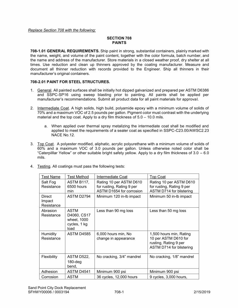
Sand Point City Dock Replacement SFHWY00006 / 0003194 708-1 2/15/2019
Replace Section 708 with the following:
SECTION 708 PAINTS
708-1.01 GENERAL REQUIREMENTS. Ship paint in strong, substantial containers, plainly marked with the name, weight, and volume of the paint content, together with the color formula, batch number, and the name and address of the manufacturer. Store materials in a closed weather proof, dry shelter at all times. Use reduction and clean up thinners approved by the coating manufacturer. Measure and document all thinner reduction with records provided to the Engineer. Ship all thinners in their manufacturer’s original containers.
708-2.01 PAINT FOR STEEL STRUCTURES.
1. General. All painted surfaces shall be initially hot dipped galvanized and prepared per ASTM D6386
and SSPC-SP16 using sweep blasting prior to painting. All paints shall be applied per manufacturer’s recommendations. Submit all product data for all paint materials for approval.
2. Intermediate Coat. A high solids, high build, polyamide epoxy with a minimum volume of solids of 70% and a maximum VOC of 2.5 pounds per gallon. Pigment color must contrast with the underlying material and the top coat. Apply to a dry film thickness of 5.0 – 10.0 mils.
a. When applied over thermal spray metalizing the intermediate coat shall be modified and applied to meet the requirements of a sealer coat as specified in SSPC-C23.00/AWSC2.23 NACE No.12.
3. Top Coat. A polyester modified, aliphatic, acrylic polyurethane with a minimum volume of solids of
60% and a maximum VOC of 3.0 pounds per gallon. Unless otherwise noted color shall be “Caterpilllar Yellow” or other suitable bright safety yellow. Apply to a dry film thickness of 3.0 – 6.0 mils.
4. Testing. All coatings must pass the following tests:
Test Name Test Method Intermediate Coat Top Coat Salt Fog Resistance
ASTM B117, 6500 hours min
Rating 10 per ASTM D610 for rusting, Rating 9 per ASTM D1654 for corrosion
Rating 10 per ASTM D610 for rusting, Rating 9 per ASTM D714 for blistering
Direct Impact Resistance
ASTM D2794 Minimum 120 in-lb impact Minimum 50 in-lb impact
Abrasion Resistance
ASTM D4060, CS17 wheel, 1000 cycles, 1 kg load
Less than 90 mg loss Less than 50 mg loss
Humidity Resistance
ASTM D4585 6,000 hours min, No change in appearance
1,500 hours min, Rating 10 per ASTM D610 for rusting, Rating 9 per ASTM D714 for blistering
Flexibility ASTM D522, 180-deg bend,
No cracking, 3/4” mandrel No cracking, 1/8” mandrel
Adhesion ASTM D4541 Minimum 900 psi Minimum 900 psi Corrosion ASTM 36 cycles, 12,000 hours 9 cycles, 3,000 hours,

Sand Point City Dock Replacement SFHWY00006 / 0003194 708-2 2/15/2019
Weathering D5894, Rating 10 per ASTM D610 for rusting, Rating 9 per ASTM D1654 for corrosion
Rating 10 per ASTM D610 for rusting, Rating 9 per ASTM D714 for blistering
708-2.02 PAINT FOR TIMBER. Meet A-A-3183, Paint, Latex (Acrylic Emulsion, Exterior).
708-2.03 PAINT FOR TRAFFIC MARKINGS. Use one of the following:
1. AASHTO M 248, Type F (Alkyd Resin), or
2. A-A-3183 Paint, Latex (Acrylic Emulsion, Exterior), or
3. The current State of Alaska DOT&PF maintenance specification for pavement marking paint.
708-2.04 PAINT FOR CONCRETE. Meet A-A-3183, Paint, Latex (Acrylic Emulsion, Exterior).

Sand Point City Dock Replacement SFHWY00006 / 0003194 709-1 2/15/2019
SECTION 709 REINFORCING STEEL AND WIRE ROPE
709-2.01 REINFORCING STEEL. Replace the following portions of this subjection:
1. Reinforcing Steel Bars. Furnish deformed reinforcing steel bars of the size as specified. Reinforcing steel shall be new billet stock ASTM A706 Grade 60 rebar, galvanized per ASTM A767 with chromating requirements of section 4.3 omitted. Galvanizing shall be performed after fabrication.
3. Epoxy Coated Reinforcing Steel Bars. No epoxy coated reinforcing shall be used on this project.
4. Steel Wire. Tie wire shall be galvanized 709-2.02 WIRE ROPE. Replace this subsection with the following: Meeting AASHTO M30, 3/4” TYPE 1, CLASS A, unless otherwise noted in the Plans. All wire rope shall be drawn galvanized. 709-2.03 BAR SUPPORTS. Replace the following portion of this subjection:
2. Metal Supports. Provide metal supports galvanized after fabrication according to AASHTO M 232 Class D.

Sand Point City Dock Replacement SFHWY00006 / 0003194 712-1 2/15/2019
SECTION 712 MISCELLANEOUS
712-2.20 CONCRETE ANCHORS. Replace Subsection 712-2.20.1 with the following:
1. Anchor Bolts. Use hot-dip galvanized anchor bolts meeting ASTM F1554, Grade 105, unless otherwise noted.

Sand Point City Dock Replacement SFHWY00006 / 0003194 715-1 2/15/2019
Replace Section 715 with the following:
SECTION 715 STEEL FOR PILES
715-2.01 SCOPE. Steel used for Structural Steel Piling and Sheet Piling.
715-2.02 GENERAL REQUIREMENTS. Furnish steel piles of the dimensions, weights, cross- sections, and grades specified. Meet the following:
1. Structural Steel Pipe Piling.
a. General. All materials shall meet the requirements below.
i. Carbon Equivalency (CE) for all steel pipe piles shall not exceed 0.45 based on the
following:
CE = C + (Mn + Si)
6+
(Cr + Mo + V)
5+
(Ni + Cu)
15
ii. Steel pipe piles shall have minimum Charpy V-Notch impact values of 15/12 (average/minimum) ft. lbs at +20° F in accordance with ASTM A673.
b. Straight Seam Pipe Pile. Straight seam steel pipe shall conform to one of the following:
i. ASTM A252, Grade 3, with a modified minimum yield strength (Fender Pin Piles:
65 ksi, All other piles: 50 ksi) and with weldable chemistry. Dimensional tolerance shall be per API 5L.
ii. API 5L: X65 – Fender Pin Piles, X52 – All other piles
c. Spiral Seam Pipe Pile. Spiral seam pipe will be permitted for diameters greater than 18 inches and shall conform to the following requirements:
i. Base metal for fender pin piles shall conform to ASTM A572 Grade 65, base metal
for all other piles conform to ASTM A572 Grade 50 or ASTM A709 Grade 50T3. Butt joints in the base metal shall be no closer than one pipe diameter from the pipe end.
ii. The Contractor shall ensure fit-up of spiral seam pipe to adjoining elements does not exceed the welding and erection tolerances specified in AWS D1.1 and AISC 303-05.
iii. The outside diameter at any point in a length of pipe shall be within ±3/16 inch of the nominal diameter. The maximum lateral offset measured from a straight chord line shall not exceed 0.2 percent of the pipe length, not to exceed 3/8 inch in any 40-foot length. Provide pile lengths within ±2 inches from the specified lengths.
iv. Fabricate pipe using the automatic submerged arc welding or automatic gas metal arc welding process. Prior to welding, submit for approval a welding plan in accordance with the Section 504-3.01.6.
v. Visually inspect 100 percent of seam welds on the interior and exterior surfaces.
Welds shall be acceptable if the criteria of AWS D1.1 Section 6, Table 6.1 are satisfied. Perform UT inspection of 10 percent of seam welds on each length of pipe using acceptance criteria of AWS D1.1 Section 6, Table 6.2.

Sand Point City Dock Replacement SFHWY00006 / 0003194 715-2 2/15/2019
vi. Evaluate the mechanical properties of the base metal and weld in accordance with ASTM A370 and AWS D1.1, including section 4.8.3. Perform destructive testing of a fabricated pipe section for each diameter of pipe furnished. A single test consists of:
vii. One base metal yield, one tensile, and one elongation test
viii. Two reduced section across the weld tensile tests
ix. One side bend weld test
x. The strength and elongation of the base metal shall be no less than the minimum values of the specified range. Evaluate the performance of the weld using the acceptance criteria of AWS D1.1.
2. Pile Driving Shoes. Use inside flange driving shoes as indicated in the drawings and conforming to the requirements of ASTM A148 Grade 90-60. Make each pile tip in one piece of heat treated cast steel. Weld tip reinforcing to the piles in conformance with the manufacturer's written directions unless otherwise noted in the Plans.
715-2.03 CERTIFICATION. Furnish a certified test report from the manufacturer or an independent testing laboratory containing a list of dimensional, chemical, metallurgical, electrical, physical, and other required test results of the specified material certifying that the product or assembly has passed all specified tests. Include the following:
1. the project name and number;
2. the manufacturer's name;
3. the name of the product or assembly;
4. a complete description of the material;
5. country of origin;
6. the lot, heat, or batch number that identifies the material;
7. all required test results for the specified material from the same lot, heat, or batch defined
in Subsection 715-2.02; and,
8. a statement, signed by a person having legal authority to act for the manufacturer or the independent testing laboratory, that the test results show that the product or assembly to be incorporated into the project has been sampled and tested and the samples have passed all specified tests.
For pipe manufactured to API 5L, submit an inspection certificate with test results according to API 5L 10.1.3.
715-2.04 MARKING. Tag, stencil, stamp, or otherwise mark all materials or assemblies furnished under certification to the project with the lot number, heat number, batch number, or other appropriate identification, which can be readily recognized and legible, and is identical to the accompanying certified test report.
For spiral welded pipe piles, mark each pipe on the inside surface and outside surface of both ends indicating: the fabricators name, type of steel, grade of steel, steel heat number, welding process, total

Sand Point City Dock Replacement SFHWY00006 / 0003194 715-3 2/15/2019
pipe weight or weight per lineal foot of pipe, length, nominal outside diameter, and nominal wall thickness.

Sand Point City Dock Replacement SFHWY00006 / 0003194 716-1 2/15/2019
Replace Section 716 with the following:
SECTION 716 STRUCTURAL & MISC STEEL
716-2.01 SCOPE. Steel used for structural and miscellaneous purposes.
716-2.02 GENERAL REQUIREMENTS. Meet the following: 1. Coating. Unless noted otherwise, all steel, pipe, and hardware shall be hot-dipped galvanized. Spray
metallizing may not be substituted for galvanizing without Engineer approval.
2. Delivery. General requirements for delivery of rolled steel plates, shapes, sheet piling, and bars for structural shall be per ASTM A6.
3. Steel Shapes & Plates. Unless noted otherwise, all structural steel shapes (W, HP, L, C, ST) and plates shall be ASTM A572 Grade 50, or approved equal. All structural steel greater than 1-inch or greater in thickness shall be 100% straight beam ultrasonically tested for laminations per ASTM A578 on a 6-inch grid and evaluated under Acceptance Standard – Level C. Plates not meeting the acceptance standard evaluation criteria shall be replaced with material meeting the specification.
HSS sections shall be ASTM A500 Grade B.
4. Filler Metal for Applicable Arc-Welding Electrodes. All filler metal shall conform to applicable AWS
welding codes. Electrodes shall be low-hydrogen, have a maximum carbon content of 0.20%, and meet charpy impact criteria of 20 ft.-lb. at -20˚F.
5. Stud Shear Connectors. Shear studs shall conform to ASTM A108 and A29 Grade 1015. Mechanical
properties shall conform to AWS D1.1 Mechanical Property Requirements for Studs Type B.
6. Raised Pattern Plate. Where raised pattern plate is shown on the Plans, use plates with a raised pattern surface meeting the following requirements:
a. Use diagonal type pattern, with the intersecting diagonals at right angles to one another. Use the same material for the raised portions of the pattern as the base metal of the plate. The raised pattern must be an inherent part of the plate. The pattern must be continuous throughout the surface of the plate and the projections along any diagonal must be spaced alternately with the projections along the normal diagonals.
b. Use plate with projections that are self-draining and self-cleaning and provide a skid- resistant
surface from all angles of approach. The projections must have flat tops and be designed not to chip, crack, split, or buckle at their intersection with the base metal.
716-2.03 FASTENERS. Unless noted otherwise, all bolts connecting steel to steel or steel to concrete shall be ASTM A325 and galvanized. All other bolts, all-thread rods, and anchor bolts shall be ASTM A307 and galvanized, unless otherwise noted. Galvanized washers shall be used in all areas where the bolt or head or nut will bear against concrete or against oversized holes in steel. An oversized hole is defined as being greater than 1/16 inch larger than the bolt diameter. Galvanized nuts and washers shall conform to the specification for the corresponding bolt. Galvanized malleable iron washers, plate washers or economy heads are required wherever bolt heads or nuts bear against wood.

Sand Point City Dock Replacement SFHWY00006 / 0003194 716-2 2/15/2019
716-2.04 STEEL GRID FLOORS. Meet ASTM A709, Grade 36. If the material is not galvanized, ensure the steel has a copper content of 0.2 percent minimum. Unless painting of floors is specified in the Special Provisions, open type floors must be galvanized. 716-2.05 MACHINE BOLTS. Meet ASTM A307 716-2.06 MISCELLANEOUS STEEL PIPE. Meet ASTM A252 Grade 3, or ASTM A53 Grade B, Type E or S, or ASTM A500 Grade B.
716-2.07 GALVANIZING. Hot-dipped galvanizing shall be performed in accordance with ASTM A385, A123, or A153. Galvanizing shall be performed after fabrication, and all holes required for galvanizing shall be repaired per AWS D1.1, unless otherwise approved by the Engineer. Subassemblies that may be subject to deformation during galvanizing may be galvanized separately and assembled after galvanizing with Engineer approval. All components shall be galvanized in as large of sizes practical. Assemblies or subassemblies too large for available galvanizing equipment may be galvanized in pieces then spliced/assembled after galvanizing with Engineer approval. Uncoated areas and splice areas shall be repaired per the project specifications. Damaged galvanizing including that removed for welding shall be repaired by the Contractor per Subsection 504-3.03. 716-2.08 CERTIFICATION. Furnish a Certified Test Report from the manufacturer or an independent testing laboratory containing a list of dimensional, chemical, metallurgical, electrical, physical, and other required test results of the specified material certifying that the product or assembly has passed all specified tests. Include the following:
1. the project name and number 2. the manufacturer's name 3. the name of the product or assembly 4. a complete description of the material 5. country of origin 6. the lot, heat, or batch number that identifies the material 7. all required test results for the specified material from the same lot, heat, or batch defined in
Subsection 716-2.08.6 8. an affidavit, signed by a person having legal authority to act for the manufacturer or the independent
testing laboratory, that the test results show that the product or assembly to be incorporated into the project has been sampled and tested and the samples have passed all specified tests.
Tag, stencil, stamp, or otherwise mark all materials or assemblies furnished under certification to the project with the lot number, heat number, batch number, or other appropriate identification, which can be readily recognized and legible, and is identical to the accompanying Certified Test Report. 716-2.09 SPRAY METALIZING. All spray metallizing shall be performed in accordance with AWS C2.23. Steel substrate shall be prepared to SSPC-SP 5/NACE No. 1 white metal blast finish with a minimum angular profile depth of 2.5 mils. After blasting, remove dust and spent abrasive from the surface by using oil-free pressurized air, brushing or vacuum cleaning. The steel surface temperature shall be at least 5 degrees Fahrenheit above the dew point of the ambient air temperature. For flame spraying, the initial starting area shall be preheated to 250 degrees Fahrenheit. Feedstock shall be 85/15 aluminum/zinc applied in several passes (approximately 2-4 mils/pass) to a minimum dry coating film thickness of 12 mils. During application, the spray gun shall be held perpendicular to the substrate at a stand-off distance of 6-10 inches. The Contractor shall periodically verify pass and total coating thickness. The finished metalized surface shall be top coated with a high solids polyurethane clear sealer

Sand Point City Dock Replacement SFHWY00006 / 0003194 716-3 2/15/2019
specific for marine submersion environments, applied to a minimum dry film thickness (DFT) of 2-3 mils and applied per Manufactures recommendations. Submit product data for Engineer review and approval 7 days prior to use. Tensile bond strength shall be measured per ASTM D4541 at the start of each shift, after any change to the application method, or every 500 square feet. The minimum tensile bond shall be 700 psi. Contractor shall submit metallizing equipment, blast media, feedstock material certification, application and quality control method for Engineer review and approval at least 10 days prior to beginning the work. 716-2.10 NON-SKID SURFACING. All steel walking surfaces, excluding ladder rungs, shall be spray metallized with a non-skid product in accordance with manufacturer’s recommendations and these specifications. Metal surfaces specified to be Non-Skid shall be thermal arc-sprayed with TH604 and/or TH605, as manufactured by Thermion, TRACLON 500 as manufactured by MBI Coatings, Duralcan 90/10 or 60/40 as manufactured by Alotec or Engineer approved equal to achieve a very aggressive surface profile. Blast surface and prep as required by Non-Skid coating manufacturer prior to Non-Skid coating application. Surfaces noted shall be sprayed to achieve a non-skid surface with peak to valley thickness of 75 to 15 mils.

Sand Point City Dock Replacement SFHWY00006 / 0003194 720-1 2/15/2019
SECTION 720 BEARINGS
720-2.03 POLYTETRAFLUOROETHYLENE (PTFE) BEARINGS. Delete the fourth from last paragraph of Subsection 720-2.03.2 Fabrication and replace with the following: Prepare and thermal spray metalize surfaces, except stainless steel surfaces, of bearings exposed to the atmosphere in the completed work. Prepare and metalize the surfaces according to Section 716-2.09.

APPENDIX A
CONSTRUCTION SURVEYING REQUIREMENTS


Alaska Department of Transportation and Public Facilities
Alaska Construction Surveying Requirements (US Customary Units)


Alaska Construction Surveying Requirements (US Customary Units)
Table of Contents
Description Page 1. Survey accuracy requirements
1
2. Survey frequency requirements
2
3. Typical section drawing
3
4. Survey point materials requirements
4
5. Typical alignment notes
5
6. Typical clearing notes
6
7. Typical level notes
7
8. Typical slope stake notes
8
9. Typical culvert notes
9
10. Typical culvert camber diagram
10
11. Typical blue or red tops and grade stake notes 11
Alaska Construction Surveying Requirements i June 2, 2003 (US Customary Units)
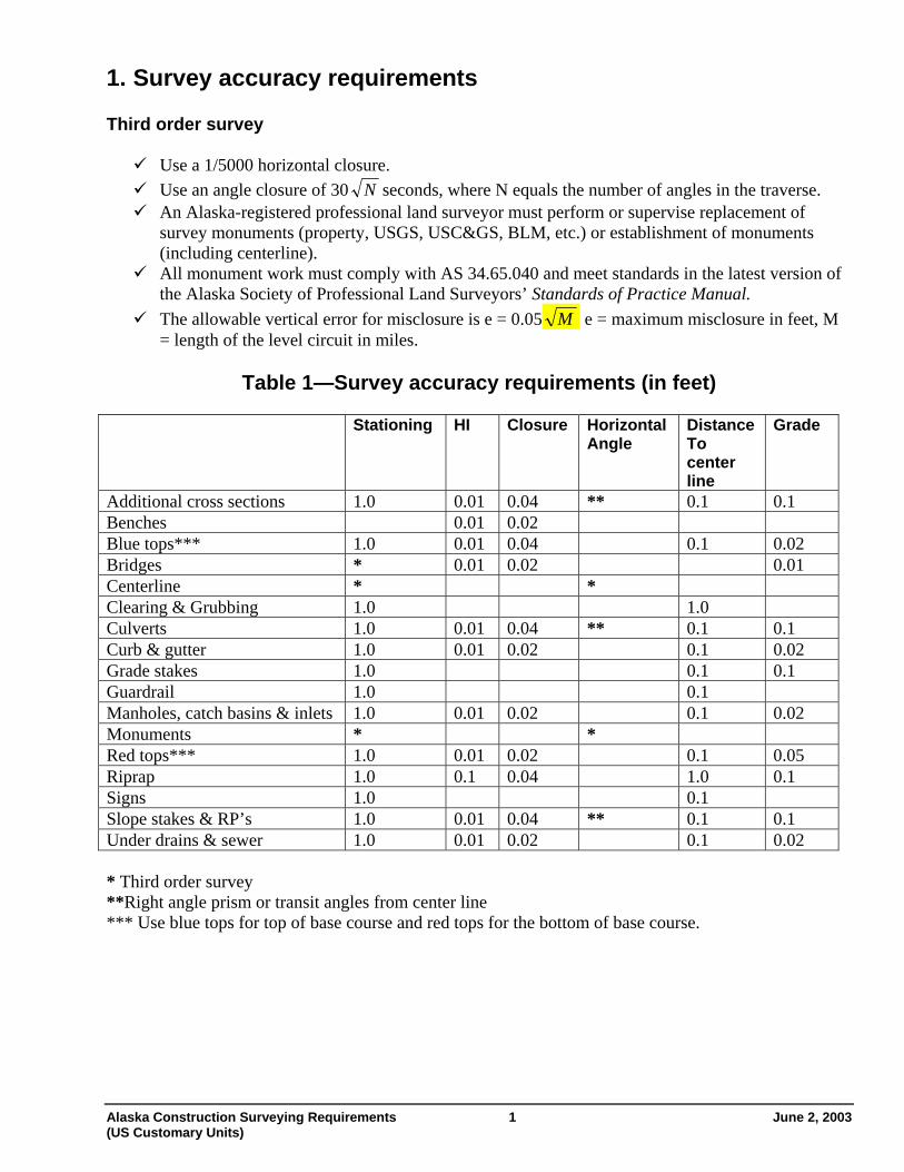
1. Survey accuracy requirements Third order survey
Use a 1/5000 horizontal closure. Use an angle closure of 30 N seconds, where N equals the number of angles in the traverse. An Alaska-registered professional land surveyor must perform or supervise replacement of
survey monuments (property, USGS, USC&GS, BLM, etc.) or establishment of monuments (including centerline). All monument work must comply with AS 34.65.040 and meet standards in the latest version of
the Alaska Society of Professional Land Surveyors’ Standards of Practice Manual. The allowable vertical error for misclosure is e = 0.05 M e = maximum misclosure in feet, M
= length of the level circuit in miles.
Table 1—Survey accuracy requirements (in feet) Stationing HI Closure Horizontal
Angle Distance To center line
Grade
Additional cross sections 1.0 0.01 0.04 ** 0.1 0.1 Benches 0.01 0.02 Blue tops*** 1.0 0.01 0.04 0.1 0.02 Bridges * 0.01 0.02 0.01 Centerline * * Clearing & Grubbing 1.0 1.0 Culverts 1.0 0.01 0.04 ** 0.1 0.1 Curb & gutter 1.0 0.01 0.02 0.1 0.02 Grade stakes 1.0 0.1 0.1 Guardrail 1.0 0.1 Manholes, catch basins & inlets 1.0 0.01 0.02 0.1 0.02 Monuments * * Red tops*** 1.0 0.01 0.02 0.1 0.05 Riprap 1.0 0.1 0.04 1.0 0.1 Signs 1.0 0.1 Slope stakes & RP’s 1.0 0.01 0.04 ** 0.1 0.1 Under drains & sewer 1.0 0.01 0.02 0.1 0.02 * Third order survey **Right angle prism or transit angles from center line *** Use blue tops for top of base course and red tops for the bottom of base course.
Alaska Construction Surveying Requirements 1 June 2, 2003 (US Customary Units)

1. Survey frequency requirements
Table 2—Survey frequency requirements (in feet) Tangents Curves Interchange
ramps Stake each per plan
See special instructions on sample notes
Additional cross sections * * * Bench marks X Blue tops 100 100** 25 X Blue tops within 100 feet both sides
of railroad track crossings and bridge approaches
25 25 25 X
Bridges X X Center line 100 100** 25 Clearing 100 100** 25 X Culverts X X Curb and gutter 25 25 25 Grade stakes 100 100** 50 Guardrail 25 25 25 Manholes, catch basins & inlets X Monuments X Red tops 100 100** 25 X Riprap 50 50 50 Signs X Slope stake / cross sections 100 100** 25 X Under drains and sewers 50 25 25 * Establish additional cross sections and slope stakes at all breaks in topography and where structures begin and end. **Curves shall be staked on 50-foot stations if the curve is greater than six degrees.
June 2, 2003 2 Alaska Construction Surveying Requirements (US Customary Units)

2. Typical Section Drawing
Alaska Construction Surveying Requirements 3 June 2, 2003 (US Customary Units)

3. Survey point materials requirements
These are minimum requirements; larger sizes may be necessary. Use only stakes with planed sides.
Table 3—Survey point materials requirements
24”
lath
or w
hisk
ers
2” x
2”
x 8”
hub
2” x
2”
x 12
” h
ub
1” x
2”
x 18
” st
ake
1” x
2”
x 24
” st
ake
48”
lath
Hub
and
tack
40d
nail
60d
nail
½”
x 24
” re
bar
Benchmarks
X
Blue tops X X Centerline P.C., P.T., P.O.T. X X X * X* Centerline reference points X X X * X * Centerline station X X Clearing X Culvert stake X X X Culvert stake references X X X Curb and gutter X X X Guardrail X Major structures X X * X * X X * X * Red tops X X Signs X Slope stake X X Slope stake references X X X * Optional depending on conditions, and to be determined by the Project Engineer.
June 2, 2003 4 Alaska Construction Surveying Requirements (US Customary Units)
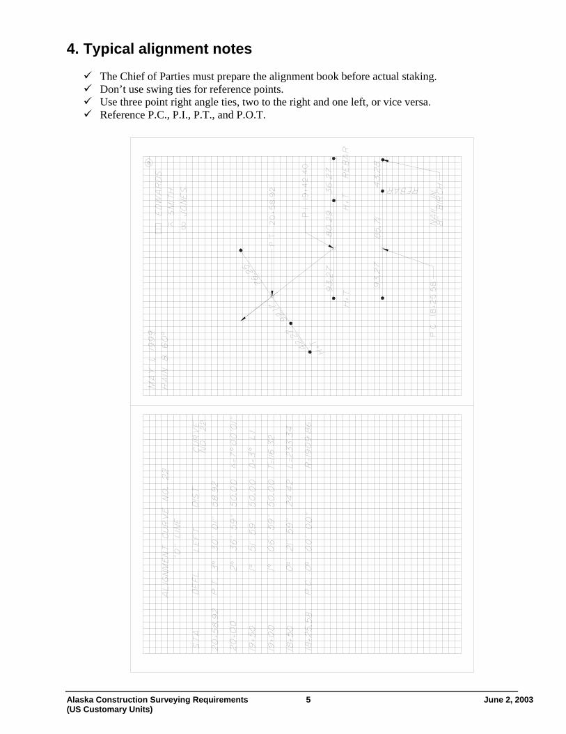
4. Typical alignment notes
The Chief of Parties must prepare the alignment book before actual staking. Don’t use swing ties for reference points. Use three point right angle ties, two to the right and one left, or vice versa. Reference P.C., P.I., P.T., and P.O.T.
Alaska Construction Surveying Requirements 5 June 2, 2003 (US Customary Units)

5. Typical clearing notes
Exclude areas not needing clearing. Draw a diagram as required to show unusual or confusing areas.
June 2, 2003 6 Alaska Construction Surveying Requirements (US Customary Units)

6. Typical level notes Balance back sights and foresights. Establish all benchmarks and take the centerline profile before doing any staking involving elevations. Don’t set benchmarks in utility poles. Don’t use side shots on benchmarks. Use the turn through method when establishing benchmarks. Re-check benchmarks after each major freeze/thaw cycle and/or any environmental event that may change the benchmark elevation. Do not use double rodding. Run separate level loops between all benchmarks. Set benchmarks in trees of at least six-inch diameter, unless approved by the Project Engineer.
Correct errors in benchmark elevations so they will not affect the elevations of succeeding benchmarks. Consult with the Project Engineer before
placing benchmarks in areas of permafrost or other unstable ground. Establish benchmarks at intervals and locations
consistent with good engineering practice, and generally not more than 1000 feet. Completely describe benchmarks when
establishing or re-establishing their elevation. Give centerline stationing, offset, benchmark projection, and observable benchmark characteristics. When checking into or out of benchmarks, note the book and page number that contains the most recent elevation establishment for that benchmark. Write the station on the top twelve inches facing
centerline, with numerals a minimum of one inch in height.
June 2, 2003 7 Alaska Construction Surveying Requirements (US Customary Units)

7. Typical slope stake notes Enter the station, elevations, shoulder distance or
ditch distances, and slope in the slope stake book before staking begins. In areas where slides or overbreak are anticipated,
extend the sections beyond the construction limits. Slope-stake each section that is cross-sectioned. Final re-cross sections are required where there
are overbreaks, undercuts, etc. Re-cross section book and page numbers shall be noted on the original cross-section and slope staking page for the relevant stations.
Use a hand level only for one turn up or down from the instrument. Clearly note hand level turns. Use a reference point that is 10-20 feet
beyond the slope stake. The reference point must show the cut or
fill to the slope stake and must include the slope stake information. Slope stake all abrupt changes in typical
sections. Position all laths to face centerline.
Include at least the following information on the stake: (1) where to begin the cut or fill (2) the slope ratio (3) the depth of cut or height of fill and (4) the station.
+
+
Alaska Construction Surveying Requirements 8 June 2, 2003 (US Customary Units)

8. Typical culvert notes
Show at least the following information on culvert stakes station size length type of pipe (e.g., 24” x 80’ CMP)
cut or fill from top of hub to inlet & outlet skew angle horizontal distance from hub to end of pipe gradient of pipe drop of pipe
Ensure that all culverts have a minimum camber equal to 1% of the length of the pipe, unless the Project Engineer directs otherwise. Develop a culvert camber diagram showing each section of pipe and its elevation and offset.
June 2, 2003 9 Alaska Construction Surveying Requirements (US Customary Units)

9. Typical culvert camber diagram
June 2, 2003 10 Alaska Construction Surveying Requirements (US Customary Units)

10. Typical blue or red tops and grade stake notes Place blue and red tops at each break in typical section and on centerline. Use blue tops for top of base course. Use red tops for the bottom of the base course. Evenly space red/blue tops at and between crown section break points with a maximum spacing of
25 feet between red/blue tops. Establish horizontal control from centerline references and vertical control from benchmarks. Place blue tops at the same interval as slope stakes. Stake all curve transitions.
Alaska Construction Surveying Requirements 11 June 2, 2003 (US Customary Units)

APPENDIX B
ENVIRONMENTAL COMMITMENTS & PERMITS


CONTRACTOR ENVIRONMENTAL COMMITMENTS Sand Point Dock Replacement SFHWY00006
August 6, 2018 The contractor shall comply with the terms and conditions of the USACE Nationwide Permit (to be obtained), the NMFS IHA Permit, and the USFWS Bald Eagle Permit (to be obtained) as well as the following: General Construction
• Comply with Section 641 specifications for Erosion, Sediment and Pollution Control.
• Comply with 641-1.03 specifications for Construction General Permit.
• Comply with Subsection 201-3.07 specifications for Control of Invasive Plant Species.
• Comply with 641-2.01 specifications for Storm Water Pollution and Prevention Plan (SWPPP) Requirements.
• Comply with 641-2.02 specifications for Hazardous Material Control Plan (HMCP)
Requirements.
• The contractor will include provisions for on-site containment equipment (absorbent booms) and personnel trained in their use in the DOT&PF approved HMCP.
• Comply with 641-2.03 specifications for Spill Preventions, Control and Countermeasure Plan (SPCC Plan) Requirements.
• If contaminated or hazardous materials are encountered during construction, the contractor will
stop all work in the vicinity of the contaminated site until the Alaska Department of Environmental Conservation (ADEC) is contacted and a corrective action plan is approved by ADEC and implemented.
• The contractor will regularly checked fuel hoses, oil drums, oil or fuel transfer valves and fittings, etc., for drips or leaks, and would be maintained and stored properly to prevent spills.
• The contractor will provide and maintain a spill clean-up kit on-site at all times, to be implemented as part of the SPCC Plan, as well as the HMCP and SWPPP, in the event of a spill or if any oil products are observed in the water.
• The contractor will use fill material that would consist of rock fill that is free of fine sediments to the extent practical. Fill material would also be free of invasive marine and terrestrial vegetation species.

Pile Driving Activities
• The contractor shall use a vibratory hammer when removing piles, if practicable.
• The contractor shall drive piles with a vibratory hammer, as practicable, except for final proofing which would require use of an impact hammer.
• The contractor shall limit drive piles intermittently only during daylight hours.
• The contractor shall implement the following ramp-up procedures to allow animals to leave the area prior to full sound exposure:
o for impact pile driving, provide an initial set of three strikes from the hammer followed by a 30-second waiting period; then two subsequent three-strike sets
Endangered Species and Marine Mammals
• All commitments can be found in Appendix B-1: Incidental Harassment Authorization and Endangered Species Act Section 7 Biological Opinion.
Monitoring and Reporting Protocols
• The contractor shall implement a marine wildlife observation area to avoid harm to Steller’s eiders and northern sea otter. The observation areas shall be centered on the location of in-water work activities for 30’ diameter piles and would extend for 500m from pipe pile driving for impact hammer and 300m for vibratory hammer and fill placement and for 24’ piles would extend for 300 m from pipe pile driving for impact hammer and 100 m for vibratory hammer.
• Marine wildlife monitoring of Steller’s eiders and northern sea otters will generally follow this protocol: o The wildlife observer must be able to identify the designated wildlife and be equipped with
binoculars, range finder, two-way radio communication with construction foreman/superintendent and log book
o If a designated species comes within the designated marine wildlife observation area, all in-water work will be halted immediately; work may resume when the animal moves outside the observation area on its own accord
o The observer will have the authority to stop pile driving if a designated marine species is observed within the observation area
o The observer will have no other primary duty than to watch for and report on events related to designated wildlife species listed
• Comply with Section 647 Specifications for Marine Mammal Monitoring. The contractor will
provide Marine Mammal Observers during all pile-driving activities. The Marine Mammal Monitoring Qualifications can be found in Appendix B-2. The Marine Mammal Monitoring Form can be found in Appendix B-3.

Appendix B-1: Incidental Harassment Authorization and Endangered Species Act Section 7 Biological Opinion


June 18, 2018 John Barnett, Regional Environmental Manager DOT&PF Southcoast Region 6860 Glacier Hwy. P.O. Box 112506 Juneau, Alaska 99811-2506 Re: Sand Point City Dock Replacement Project NMFS AKR-2017-9673/ FHWA #0003194/DOT #SFHWY00006; Project Modification Dear Mr. Barnett: On June 13, 2018, we received notification from the Alaska Department of Transportation and Public Facilities (ADOT & PF) that pile caps would not be used in the process of pile driving associated with the replacement of the Sand Point City Dock. ADOT & PF requested that we acknowledge this change and the removal of this mitigation measure that was included in our Biological Opinion for this project (AKR-2017-9673). While pile caps can result in a slightly reduced acoustic source level, the loss of impact energy delivered to the pile due to the cushion also results in a longer period of pile driving. During the course of our analysis of project effects, we did not take into account any reduced acoustic output that may be due to the use of pile caps, therefore the radii of Level B harassment zones referred to in our Biological Opinion remain unchanged. Furthermore, this change in the project description does not alter any part of our analysis in a way that would change our take estimates or our conclusions regarding project effects. We acknowledge this change in your project description, and no longer consider the use of pile cushions to be among the mitigation measures specified for this project.
Sincerely, James W. Balsiger, Ph.D. Administrator, Alaska Region
cc: Jill Taylor [email protected]

Endangered Species Act Section 7(a)(2) Biological Opinion
Replacement of the Sand Point City Dock and Associated Issuance of an Incidental Harassment Authorization in Sand Point, Alaska
NMFS Consultation Number: AKR-2017-9673
Action Agencies: Federal Highways Administration, Alaska Division Permits and Conservation Division, Office of Protected Resources, National
Marine Fisheries Service, NOAA
Affected Species and Effects Determinations:
Is the Action Likely To:
ESA-Listed Species Status
Adversely Affect: Jeopardize
the Species?
Destroy or Adversely
Modify Critical Habitat? Species CH
Steller Sea Lion, Western DPS (Eumetopias jubatus) Endangered Yes No No
No
Humpback Whale, Western
North Pacific DPS (Megaptera novaeangliae)
Endangered Yes N/A No
N/A
Humpback Whale, Mexico DPS
(Megaptera novaeangliae) Threatened Yes N/A No
N/A
Fin whale (Balaenoptera physalus) Endangered Yes N/A No N/A
Consultation Conducted by: Alaska Region, National Marine Fisheries Service, NOAA Issued by: ____________________________________________
James W. Balsiger, Ph.D. Administrator, Alaska Region
Date: ________10/10/17____________________________

NMFS IHA and FHWA Permit for Sand Point City Dock, Sand Point, Alaska. AKR-2017-9673
1
Contents
TABLES ................................................................................................................................................................... 3
FIGURES ................................................................................................................................................................. 3
1.0 Introduction ............................................................................................................................................... 6
1.1 Background .................................................................................................................................................... 6
1.2 Consultation History ...................................................................................................................................... 7
2.0. Description of the Action ............................................................................................................................ 7
2.1 Project Location ............................................................................................................................................. 9
2.2. Details of Construction Activities ................................................................................................................. 14 2.2.1. Dock Fill Placement .............................................................................................................................. 14 2.2.2. Removal and Installation of Piles ......................................................................................................... 15
2.3. Mitigation Measures.................................................................................................................................... 17 2.3.1. Non-Acoustic Project Impacts .............................................................................................................. 17 2.3.2. Acoustic Impacts of the Action ............................................................................................................ 18 2.3.3. Monitoring Zones................................................................................................................................. 20
3.0. Action Area .............................................................................................................................................. 22
4.0. Approach to the Assessment .................................................................................................................... 23
5.0. Status of the Species and Critical Habitat ................................................................................................. 25
5.1. Humpback Whale ......................................................................................................................................... 25 5.1.1. Status ................................................................................................................................................... 25 5.1.2. Description and Range ......................................................................................................................... 26 5.1.3. Abundance ........................................................................................................................................... 27 5.1.4. Distribution .......................................................................................................................................... 27 5.1.5. Hearing Ability and Vocalizations ........................................................................................................ 28 5.1.6 Critical Habitat ..................................................................................................................................... 28
5.2. Fin Whales ................................................................................................................................................... 28 5.2.1. Status ................................................................................................................................................... 28 5.2.2. Description and Range ......................................................................................................................... 29 5.2.3. Abundance ........................................................................................................................................... 30 5.2.4. Distribution .......................................................................................................................................... 30 5.2.5. Hearing Ability and Vocalizations ........................................................................................................ 31 5.2.6 Critical Habitat ..................................................................................................................................... 31
5.3. Steller Sea Lion (Western DPS) ..................................................................................................................... 31 5.3.1. Status ................................................................................................................................................... 31 5.3.2. Description and Range ......................................................................................................................... 31 5.3.3. Abundance ........................................................................................................................................... 32 5.3.4. Distribution .......................................................................................................................................... 32 5.3.5. Hearing Ability and Vocalizations ........................................................................................................ 35 5.3.6. Critical Habitat ..................................................................................................................................... 36
6.0. Environmental Baseline ............................................................................................................................ 37

NMFS IHA and FHWA Permit for Sand Point City Dock, Sand Point, Alaska. AKR-2017-9673
2
6.1. Humpback Whale ......................................................................................................................................... 38
6.2 Fin Whale ..................................................................................................................................................... 38
6.3. Steller Sea Lion ............................................................................................................................................. 39 6.3.1. Fisheries – Competition ....................................................................................................................... 40 6.3.2 Fisheries – Conditioning and Habituation ............................................................................................ 40
6.4 Factors Affecting Steller Sea Lions, Fin and Humpback Whales. ................................................................. 40 6.4.1. Climate Change .................................................................................................................................... 40 6.4.2. Fisheries - Incidental Take and Entanglement ..................................................................................... 41 6.4.3. Vessel Collision .................................................................................................................................... 43 6.4.4. Oil and Gas Development .................................................................................................................... 44 6.4.5. Harmful Algal Blooms (HABs) ............................................................................................................... 44 6.4.6. Anthropogenic Noise ........................................................................................................................... 46
6.5 Factors Affecting Steller Sea Lion Critical Habitat within the Action Area ................................................... 47
7.0. Effects of the Action ................................................................................................................................. 47
7.1. Stressors ....................................................................................................................................................... 48 7.1.1. Stressors Not Likely to Adversely Affect ESA-Listed Species and Critical Habitat ................................ 49 7.1.2. Stressors Likely to Adversely Affect ESA-Listed Species ...................................................................... 51
7.2. Exposure....................................................................................................................................................... 52 7.2.1. Underwater Sounds ............................................................................................................................. 52
7.3. Response ...................................................................................................................................................... 54 7.3.1. Threshold Shifts ................................................................................................................................... 54 7.3.2. Auditory Interference (Masking) ......................................................................................................... 55 7.3.3. Behavioral Responses .......................................................................................................................... 56 7.3.4. Physical and Physiological Effects ........................................................................................................ 57 7.3.5. Marine Mammal Prey .......................................................................................................................... 58 7.3.6. Response Summary ............................................................................................................................. 58
8.0. Cumulative Effects .................................................................................................................................... 58
9.0. Integration and Synthesis of Effects ......................................................................................................... 59
10.0. Conclusion ............................................................................................................................................ 60
11.0. Incidental Take Statement .................................................................................................................... 60
11.1. Amount or Extent of Take ........................................................................................................................ 61
11.2. Effect of the Take ..................................................................................................................................... 62
11.3. Reasonable and Prudent Measures ......................................................................................................... 62
11.4. Terms and Conditions .............................................................................................................................. 62
12.0. Conservation Recommendations .......................................................................................................... 65
13.0. Reinitiation Notice ................................................................................................................................ 66
14.0 Data Quality Act documentation and Pre-dissemination Review ............................................................. 66
14.1. Utility ....................................................................................................................................................... 66

NMFS IHA and FHWA Permit for Sand Point City Dock, Sand Point, Alaska. AKR-2017-9673
3
14.2. Integrity ................................................................................................................................................... 67
14.3. Objectivity ................................................................................................................................................ 67
15.0. Literature Cited .................................................................................................................................... 68
TABLES Table 1. Estimated number of days required for pile installation and removal. ........................................................ 15
Table 2. Pile details and estimated effort required for pile installation. .................................................................... 16
Table 3a. Calculated Level A harassment zone. .......................................................................................................... 18
Note: NMFS Alaska Region is not anticipating any Level A take of ESA-listed species; however, shutdowns will occur within the Level A take isopleths if a listed species approaches the zone. ........................................................ 19
Table 3b. Calculated Level B harassment zone. .......................................................................................................... 19
Table 4. Probability of encountering humpback whales from each DPS in the North Pacific Ocean (columns) in various feeding areas (rows). Adapted from Wade et al. (2016) (See also NMFS 2016c). .......................................... 26
Table 5. Steller sea lion non-pup counts at seven haulouts within 20 nautical miles of Sand Point, Alaska, in 2008, 2009, 2011, 2013, and 2014. ....................................................................................................................................... 35
Table 6. Summary of threats to Steller sea lion recovery, including the ages and sexes most vulnerable, frequency of threat occurrence, uncertainty of threat impact to recovery, feasibility of threat mitigation, and relative impact of threat to recovery. .................................................................................................................................................. 39
Table 7. Summary of most recent data available for western DPS Steller sea lion incidental mortalities associated with commercial fisheries in Alaska. ........................................................................................................................... 42
Table 8. Summary of Western U.S. Steller sea lion mortality and serious injury, by year and type, reported to the NMFS Alaska Region marine mammal stranding network and Alaska Department of Fish and Game in 2010-2014 (Helker et al. 2016). ..................................................................................................................................................... 43
Table 9. Representative noise levels of anthropogenic sources of noise commonly encountered in the proposed action area. .................................................................................................................................................................. 46
Table 10. Functional Marine Mammal Hearing Groups, Auditory Bandwidth1. ........................................................ 51
Table 11. PTS Onset thresholds for cetaceans and pinnipeds (from NMFS 2016b) .................................................... 51
Table 12. Summary of Estimated Takes for Replacement of the Sand Point City Dock .............................................. 52
FIGURES Figure 1. Site location and vicinity. ............................................................................................................................ 10
Figure 2. The area around Sand Point. ....................................................................................................................... 11
Figure 3. Aerial view of the “New Harbor” and existing City Dock. The replacement City Dock would be located at the bottom, center of this image, to the right of the existing City Dock. .................................................................... 12
Figure 4. Aerial view of the seafood processing facility and the City of Sand Point. .................................................. 12
Figure 5. Sand Point City Dock and Humboldt Harbor. ............................................................................................... 13
Figure 6. Sand Point City Dock replacement site plan drawing, aerial view (PND 2015)............................................ 14

NMFS IHA and FHWA Permit for Sand Point City Dock, Sand Point, Alaska. AKR-2017-9673
4
Figure 7. Underwater distances to level B harassment thresholds for all ESA-listed marine mammals in the proposed action during vibratory and impact installation of 30-inch piles (assuming no pile caps). ......................... 22
Figure 8. Generalized range of Steller sea lion, including rookery and haulout locations. ........................................ 33
Figure 9. Steller sea lion haulouts, and designated major haulouts and major rookeries near Sand Point, Alaska, and the Project action area ......................................................................................................................................... 34
Figure 10. Designated critical habitat for western DPS Steller sea lions. ................................................................... 37
Figure 11. Algal toxins detected in 13 species of marine mammals from southeast Alaska to the Arctic from 2004 to 2013 (Lefebvre et al. 2016). .................................................................................................................................... 46

NMFS IHA and FHWA Permit for Sand Point City Dock, Sand Point, Alaska. AKR-2017-9673
5
ACRONYM FULL NAME
BMPs Best Management Practices dB decibel
DOT&PF Alaska Department of Transportation and Public Facilities DPS distinct population segment ESA Endangered Species Act
FHWA Federal Highways Administration ft foot
HTL High Tide Line IHA incidental harassment authorization ITS incidental take statement kg kilogram
kHz kilohertz kts knots lb pound (weight)
MHWM Mean High Water Mark MMPA Marine Mammal Protection Act
nm nautical mile/s NMFS National Marine Fisheries Service NOAA National Oceanic and Atmospheric Administration
Observer protected species observer OCSP Open Cell Sheet Pile
Opinion this biological opinion Permits Division
NMFS Office of Protected Resources, Permits and Conservation Division
PR1 NMFS Office of Protected Resources, Permits and Conservation PND PND Engineers, Inc. p-p peak-to-peak PTS permanent threshold shift rms root mean square TTS temporary threshold shift μPa micropascal 0-p Zero-to-peak
USCG U.S. Coast Guard WQCP Water Quality Control Plan

NMFS IHA and FHWA Permit for Sand Point City Dock, Sand Point, Alaska. AKR-2017-9673
6
1.0 Introduction Section 7(a)(2) of the Endangered Species Act (ESA) of 1973, as amended (16 U.S.C. § 1536(a)(2)), requires Federal agencies to ensure that any action they authorize, fund, or carry out is not likely to jeopardize the continued existence of any endangered or threatened species or result in the destruction or adverse modification of critical habitat. When a Federal agency’s action may affect ESA-listed species or critical habitat, consultation with National Marine Fisheries Service (NMFS) and/or the U.S. Fish and Wildlife Service is required (50 CFR § 402.14(a)).
Section 7(b)(3) of the ESA requires that at the conclusion of consultation, NMFS and/or USFWS provide an opinion stating how the action will affect ESA-listed species and critical habitat under their jurisdiction (16 U.S.C. § 1536(b)(3)). If an incidental take is expected, section 7(b)(4) requires the consulting agency to provide an Incidental Take Statement (ITS) that specifies the impact of any incidental taking and includes reasonable and prudent measures to minimize such impacts and terms and conditions that must be complied with to implement those measures (16 U.S.C. § 1536(b)(4)).
The Alaska Department of Transportation and Public Facilities (DOT&PF), in cooperation with the Federal Highway Administration (FHWA), proposes to replace the existing City Dock in Sand Point, Alaska. The applicants will likely seek a permit for the proposed action under Section 404 of the Clean Water Act and Section 10 of the Rivers and Harbors Act from the U.S. Army Corps of Engineers, Alaska District (Corps). The NMFS Office of Protected Resources, Permits and Conservation Division (hereafter referred to as “the Permits Division” or PR1), proposes to issue an incidental harassment authorization (IHA) pursuant to section 101(a)(5)(D) of the Marine Mammal Protection Act of 1972, as amended (MMPA) (16 U.S.C. §§ 1361-1407), to DOT&PF and FHWA for harassment of marine mammals incidental to the Sand Point Dock replacement activities (82 FR 31400; July 6, 2017).
The NMFS Alaska Region (NMFS AK) consulted with the Permits Division and the FHWA/ DOT&PF on the proposed action. This document represents our biological opinion (Opinion) on the proposed action and effects on endangered and threatened species and designated critical habitat for one of those species.
The Opinion and Incidental Take Statement were prepared by NMFS in accordance with section 7(b) of the ESA (16 U.S.C. § 1536(b)), and implementing regulations at 50 CFR Part 402. The Opinion and Incidental Take Statement are in compliance with the Data Quality Act (44 U.S.C. § 3504(d)(1)) and underwent pre-dissemination review.
1.1 Background This Opinion considers the effects to ESA-listed species from the proposed FHWA funding and NMFS PR1 issuance of an IHA associated with replacement of the Sand Point dock. PR1 and FHWA/DOT&PF determined that this project will have no effect on North Pacific right whales (Eubalaena japonica). FHWA/ DOT&PF and NMFS Permits Division determined that the project is likely to adversely affect the endangered Western North Pacific Distinct Population Segment (DPS) humpback whale (Megaptera novaeangliae), the threatened Mexico DPS humpback whale (Megaptera novaeangliae), the endangered fin whale (Balaenoptera physalus), and the endangered western DPS Steller sea lion (Eumetopias jubatus). These action agencies further determined that the project may affect, but is not likely to adversely affect, designated

NMFS IHA and FHWA Permit for Sand Point City Dock, Sand Point, Alaska. AKR-2017-9673
7
critical habitat for Steller sea lions because the effects of the action to critical habitat are insignificant and are not likely to result in a measurable reduction of conservation value. The effects to these species and critical habitat will be analyzed in this consultation.
This Opinion is based on information provided to us in the updated April 2017 IHA application (HDR 2017b); the updated January 2017 Biological Assessment (HDR 2017a); the proposed IHA (82 FR 31400; July 6, 2017); emails and telephone conversations between NMFS Alaska Region and NMFS Permits Division staff, FHWA/DOT&PF staff, and HDR, Inc. staff (on behalf of the City of Sand Point); and other sources of information. A complete record of this consultation is on file at NMFS’s field office in Anchorage, Alaska.
1.2 Consultation History Our communication about this consultation is summarized as follows:
• July 5, 2016: Kick off meeting for the proposed action with the applicants, NMFS Permits Division, and NMFS Alaska Region.
• September 22, 2016: BA submitted to NMFS by FHWA/DOT&PF with letter requesting imitation of ESA Section 7 formal consultation.
• November 18, 2016: NMFS received notice from NMFS Permits Division that the project was updated to include 30-inch-diameter piles.
• January 25, 2017: HDR submitted revised IHA application and revised BA to NMFS Permits Division and NMFS Alaska Region. This included recalculated Level A and B harassment zones using the new NMFS guidance.
• February 10, 2017: Meeting between applicants and NMFS detailing changes to project design
• April 11, 2017: HDR submitted a revised IHA application and 4MP to NMFS Permits Division who then forwards it on to NMFS Alaska Region.
• June 7, 2017: letter sent from DOT&PF to NMFS Permits Division objecting to the dismissal by NMFS Permits Division of empirical sound measurements from Alaska SSV studies as being inadequate for the Sand Point IHA application. Multiple discussions ensue on which sound source levels to use and how this will impact take estimates.
• June 20, 2017: NMFS Permits Division provided updated take numbers for the IHA. • July 7, 2017: NMFS Permits Division requests the initiation of formal ESA consultation
on this action.
2.0. Description of the Action “Action” means all activities or programs of any kind authorized, funded, or carried out, in whole or in part, by Federal agencies (50 CFR § 402.02). Interrelated actions are those that are part of a larger action and depend on the larger action for their justification (50 CFR § 402.02). Interdependent actions are those that have no independent utility apart from the action under consideration (50 CFR § 402.02).
FHWA/DOT&PF proposes to construct a new dock in Sand Point, Alaska in 2018. The existing dock is 36 years old and is approaching the end of its useful design and operational life and cannot continue to be used for large vessels due to corrosion and wear. Further deterioration is expected and it will eventually need to be removed. Even though the replacement dock is in a

NMFS IHA and FHWA Permit for Sand Point City Dock, Sand Point, Alaska. AKR-2017-9673
8
slightly different location to the old dock, the old dock cannot be removed immediately because freight and ferry service would then be disrupted during construction of the replacement dock. The dock receives barge service from Seattle weekly throughout the year. The dock also regularly handles processed seafood. Given the lack of road access to Sand Point, the city dock is an essential component of infrastructure providing critical access between Sand Point and the Pacific Northwest region. Plans to remove the old dock are not solidified and will be contingent upon further funding. Impact and vibratory driving of piles and vibratory pile removal are expected to take place over a total of approximately 32 working days within a 5-month window from August 1, 2018 through December 31, 2018. However, due to the potential for unexpected delays, up to 40 working days may be required. DOT&PF is asking for the proposed IHA to be valid for a period of one year. Because the exact dates of construction are unknown until a contract can be awarded, we conservatively assumed the action will take place during months with the highest density of whales and sea lions. The new dock would be supported by approximately 52 round, 30-inch-diameter, 100-foot-long permanent steel pipe piles. Fender piles installed at the dock face would be 8 round, 24-inch-diameter, 80-foot-long permanent steel pipe piles. The single mooring dolphin would consist of 3 round, 24-inch-diameter, 120-foot-long permanent battered steel pipe piles. This equates to a total of 63 permanent piles. Up to 90 temporary piles would be installed and removed during construction of the dock and would be either H-piles or pipe piles with a diameter of less than 24 inches. Federal authorization and funding for the proposed action consists of the following:
• FHWA funding for replacing an existing dock and pilings; and • NMFS Permits Division’s proposed issuance of authorization for non-lethal takes of
marine mammals by Level B harassment (as defined by the MMPA) incidental to the dock and piling replacement project (82 FR 31400; July 6, 2017). NMFS Permits Division also proposes to authorize non-lethal takes of non-ESA-listed marine mammals by Level A harassment for this project, but none of the species for which Level A take is authorized (Hawaii DPS of humpback whales, harbor seals, and harbor porpoise) are listed under the ESA. Therefore, this ESA consultation will not discuss and evaluate any Level A harassment.
The IHA would extend from August 1, 2018, to July 31, 2019, and authorize the Level B incidental harassment of 960 Steller sea lions, 6 fin whales, and 4 ESA-listed humpback whales (the Hawaii DPS of humpback whales is also included in the proposed IHA take calculations for both Level A and Level B harassment but since they are not listed under the ESA they are not considered in this consultation), incidental to all components of the replacement and expansion of the Sand Point dock. Section 7.2 of this Opinion contains more information about the methods used to calculate take for Steller sea lions, fin whales, and humpback whales.
The IHA will incorporate the protected species mitigation and monitoring measures and reporting requirements from the applicant’s submitted Marine Mammal Monitoring Plan (MMP - See HDR 2017b), which are included as part of the project action.

NMFS IHA and FHWA Permit for Sand Point City Dock, Sand Point, Alaska. AKR-2017-9673
9
2.1 Project Location The Sand Point City Dock is located in the City of Sand Point, Alaska, at 55°20’06.6”N, 160°30’05.9”W, on the northwest side of Popof Island, in the Gulf of Alaska (Figure 1). The Sand Point City Dock is a multi-function dock and active ferry terminal located in Humboldt Harbor, on the southwest side of the City of Sand Point. The existing City Dock is located on the causeway of Sand Point’s “New Harbor” at the end of Boat Harbor Road, and the proposed replacement dock is proposed to be located immediately adjacent (southwest) to the existing City Dock along the causeway, which also serves as the breakwater for the New Harbor (Figure 2 and Figure 3). A small boat harbor is located immediately northeast of the City Dock. There is a seafood processing facility located approximately 410 meters (0.25 mile) north of the proposed dock (Figure 4 and Figure 5).

NMFS IHA and FHWA Permit for Sand Point City Dock, Sand Point, Alaska. AKR-2017-9673
10
Figure 1. Site location and vicinity.

NMFS IHA and FHWA Permit for Sand Point City Dock, Sand Point, Alaska. AKR-2017-9673
11
Figure 2. The area around Sand Point.

NMFS IHA and FHWA Permit for Sand Point City Dock, Sand Point, Alaska. AKR-2017-9673
12
Figure 3. Aerial view of the “New Harbor” and existing City Dock. The replacement City Dock would be located at the bottom, center of this image, to the right of the existing City Dock.
Figure 4. Aerial view of the seafood processing facility and the City of Sand Point.

NMFS IHA and FHWA Permit for Sand Point City Dock, Sand Point, Alaska. AKR-2017-9673
13
Figure 5. Sand Point City Dock and Humboldt Harbor.
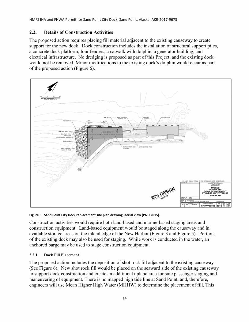
NMFS IHA and FHWA Permit for Sand Point City Dock, Sand Point, Alaska. AKR-2017-9673
14
2.2. Details of Construction Activities The proposed action requires placing fill material adjacent to the existing causeway to create support for the new dock. Dock construction includes the installation of structural support piles, a concrete dock platform, four fenders, a catwalk with dolphin, a generator building, and electrical infrastructure. No dredging is proposed as part of this Project, and the existing dock would not be removed. Minor modifications to the existing dock’s dolphin would occur as part of the proposed action (Figure 6).
Figure 6. Sand Point City Dock replacement site plan drawing, aerial view (PND 2015).
Construction activities would require both land-based and marine-based staging areas and construction equipment. Land-based equipment would be staged along the causeway and in available storage areas on the inland edge of the New Harbor (Figure 3 and Figure 5). Portions of the existing dock may also be used for staging. While work is conducted in the water, an anchored barge may be used to stage construction equipment.
2.2.1. Dock Fill Placement
The proposed action includes the deposition of shot rock fill adjacent to the existing causeway (See Figure 6). New shot rock fill would be placed on the seaward side of the existing causeway to support dock construction and create an additional upland area for safe passenger staging and maneuvering of equipment. There is no mapped high tide line at Sand Point, and, therefore, engineers will use Mean Higher High Water (MHHW) to determine the placement of fill. This

NMFS IHA and FHWA Permit for Sand Point City Dock, Sand Point, Alaska. AKR-2017-9673
15
fill would be placed above and below MHHW to increase the causeway’s areal extent and would be stabilized through the use of new and salvaged armor rock protection. Approximately 38,600 square feet of fill and 28,500 square feet of armor rock would be required for breakwater expansion. Shot rock fill deposition activities are not expected to generate underwater sound at levels that would result in Level A or Level B harassment. Therefore, this impact will not result in take of listed species and will not be discussed further. The impacts to animals from silt and other sedimentation are discussed in Section 7.1.1.
2.2.2. Removal and Installation of Piles
Following deposition of fill and prior to placement of armor rock, round steel piles would be installed to support the new city dock foundation and mooring dolphins. Table 1 illustrates the anticipated number of days required for installation and removal of various pile types.
Table 1. Estimated number of days required for pile installation and removal.
Activity Number of Piles Days Required
Support pile installation 52 13
Temporary pile installation and removal 90 15
Dolphin pile installation 3 2
Fender pile installation 8 2
Total Days 32
Total Days with 25% contingency 40
Pile driving and removal may occur for up to 4 hours and 40 minutes per day. As noted previously, the proposed project will require installation of 30-inch and 24-inch, permanent steel piles. This equates to a total of 63 permanent piles as shown in Table 2 below. It is anticipated that an ICE 44B or APE 200-6 model vibratory driver or equivalent and a Delmag D62 diesel impact hammer or equivalent would be used to install the piles. Project design engineers anticipate an impact strike rate of approximately 40 strikes per minute, based on substrate density, pile types, and hammer type, which equates to approximately 1,000 strikes for each 30-inch dock support pile, 400 strikes for each dolphin pile, and 120 strikes for each fender pile.
Permanent dock support piles would be installed using both vibratory and impact hammers; both methods of installation typically occur within the same day. Permanent piles are first installed with a vibratory hammer for approximately 45 minutes to insert the pile through the overburden sediment layer and into the bearing layer. The vibratory hammer is then replaced with the impact hammer, which is used to install the pile for the last 15 to 20 feet (approximately 25 minutes). Up to four permanent piles would be installed per day, for a total of 180 minutes of vibratory and 100 minutes of impact installation per day. Installation of permanent piles would require about 13 days of effort (52 permanent piles / 4 permanent piles per day = 13 days).
Installation of the eight fender piles is anticipated to occur over 2 days (after installation of all dock support piles), at a production rate of four fender piles per day (8 fender piles / 4 fender

NMFS IHA and FHWA Permit for Sand Point City Dock, Sand Point, Alaska. AKR-2017-9673
16
piles per day = 2 days). Each fender pile would require 30 minutes of vibratory installation and 3 minutes of impact installation, for a total of 120 minutes of vibratory and 12 minutes of impact installation each day. No temporary piles would be required for fender pile installation because they would be installed along the completed dock face.
Installation of three 24-inch permanent battered pipe piles for the dolphin would also require the installation and removal of four temporary piles (either <24 inch diameter or H-piles) to support the template. Installation of the dolphin piles will occur over 2 days, with one or two dolphin piles installed per day for a total of 3 dolphin piles. Thirty minutes of vibratory installation and 10 minutes of impact installation are anticipated per permanent dolphin pile, for a total of no more than 60 minutes of vibratory installation and 20 minutes of impact installation per day. Installation and removal of the temporary piles for the dolphin are included in the calculations for temporary piles above.
Two or more temporary piles would be used to support a template to facilitate installation of two to four permanent dock support piles. Template configuration, including the number of permanent piles that could be installed at once and the number of temporary piles required to support the template, would be determined by the contractor. Four additional temporary piles would support the template for the dolphin. In all, a maximum of 90 temporary piles would be installed and removed during construction of the dock and dolphin. Temporary piles would be either H-piles or pipe piles with a diameter of less than 24 inches.
Temporary piles would be installed and removed during construction of the dock by vibratory methods only. Removal and installation of the temporary piles that support the template typically occur within the same day, with additional time required for installation of the template structure, which would include welding, surveying the location, and other activities. Each temporary pile would be installed in approximately 15 minutes and removed in approximately 15 minutes. Up to six temporary piles would be installed and removed per day, for a total of up to 180 minutes of vibratory installation and removal per day. Installation of temporary piles, including those required to support construction of the dolphin, would require about 15 total days of effort (90 temporary piles / 6 temporary piles per day = 15 days). Total driving time for the proposed action would consist of approximately 22 hours of impact driving and 85 hours of vibratory driving and removal for all pile types.
Table 2. Pile details and estimated effort required for pile installation.
Pile Type Diameter Number of piles
Maximum piles per day
Hours per day
Estimated minutes per
pile
Anticipated days of effort1
Vibratory Installation or Removal Permanent support pile 30” 52 4 3 45 13
Permanent dolphin pile
24” 3 2 1 30 2
Permanent fender pile
24” 8 4 2 30 2
Installation, temporary support pile
<24” or H-pile 90 6 1.5 15 15

NMFS IHA and FHWA Permit for Sand Point City Dock, Sand Point, Alaska. AKR-2017-9673
17
Pile Type Diameter Number of piles
Maximum piles per day
Hours per day
Estimated minutes per
pile
Anticipated days of effort1
Removal, temporary support pile
<24” or H-pile 90 6 1.5 15 15
Impact Installation Permanent support pile 30” 52 4 1.667 25 13
Permanent dolphin pile 24” 3 2 0.33 10 2
Permanent fender pile 24” 8 4 0.20 3 2
1Vibratory and impact driving of each permanent pile will occur on the same day. Installation and removal of each temporary pile will occur on the same day.
Following initial pile installation of permanent dock support piles, the mud accumulation on the inside of each pile would be augured out and the piles filled with concrete to provide additional moment capacity and corrosion resistance. An auger with a crane-mounted rotary head would be used for pile clearing. The auguring activities are not anticipated to result in underwater sound levels that would meet Level A or Level B harassment criteria and, therefore, will not be discussed further.
2.3. Mitigation Measures
2.3.1. Non-Acoustic Project Impacts
The following measures (see HDR 2017b) will be incorporated by the applicants to minimize potential non-acoustic impacts from project activities:
• All exposed Project slopes and fills that are susceptible to erosion will be stabilized in accordance with the Project-specific Water Quality Control Plan.
• If contaminated or hazardous materials are encountered during construction, all work in the vicinity of the contaminated site will be stopped until the Alaska Department of Environmental Conservation (ADEC) is contacted and a corrective action plan is approved by ADEC and implemented.
• Fuel hoses, oil drums, oil or fuel transfer valves and fittings, etc., will be checked regularly for drips or leaks, and would be maintained and stored properly to prevent spills.
• The Contractor will provide and maintain a spill clean-up kit on-site at all times, to be implemented as part of the SPCC Plan, as well as the HMCP and WQCP, in the event of a spill or if any oil products are observed in the water.
• Work in waters of the U.S. will be conducted in accordance with the terms and conditions of the USACE permit to be obtained for the Project.
• Fill material would consist of rock fill that is free of fine sediments to the extent practical, to reduce suspended materials from entering the water column during tidal cycles. Fill material would also be free of invasive marine and terrestrial vegetation species.

NMFS IHA and FHWA Permit for Sand Point City Dock, Sand Point, Alaska. AKR-2017-9673
18
2.3.2. Acoustic Impacts of the Action
A series of measures (HDR 2017b, 82 FR 31400) will be incorporated by the applicants to minimize noise impacts associated with pile installation. These include;
• use of a sound attenuation device (i.e., pile caps) during impact driving of piles; • use standard soft-start, delay, and shut-down procedures; • Establishing and monitoring Level B harassment zones for impact and vibratory
driving as shown in Table 3. • Implementing shutdown measures if a marine mammal is detected within or
approaching the 100 m shutdown zone specified in the IHA; • Shutting down if ESA-listed cetaceans approach relevant Level A take isopleths as
shown in Table 3; and • For in-water heavy machinery work other than pile driving (e.g., standard barges, tug
boats, barge-mounted excavators), if a marine mammal comes within 10 m, operations shall cease and vessels shall reduce speed to the minimum level required to maintain steerage and safe working conditions.
DOT&PF (HDR 2017b) and the NMFS Permits Division (82 FR 31400) have established monitoring and reporting requirements for this project to minimize potential acoustic impacts from project activities. Briefly, qualified observers will be on-site before, during, and after in-water construction activity at land-based sites appropriate for monitoring harassment zones (as shown in Table 3). The plan includes:
• Required qualifications for two protected species observers (observers); • General methods by which observers will conduct monitoring activities; • Equipment required by observers; • Descriptions of the exclusion zones and areas that will be monitored; • Locations of the observers; • Monitoring techniques specific to pile-driving and removal; and • Observers monitor the Level A and B harassment zones for 30 minutes before, during,
and for 30 minutes after the proposed activities; and • Reporting requirements (i.e. final report and reporting injured and dead marine mammals
to the Office of Protected Resources and the Alaska Regional Stranding Coordinator using NMFS’s phased approach and suspending activities, if appropriate).
Table 3a. Calculated Level A harassment zone. Level A Harassment Zone (meters)
Activity Piles installed per day
Isopleths (m) Low frequency cetaceans (i.e. humpback and
fin whales)
Impact Installation 30”
4 1,430
3 1,180
2 900
1 570
Impact Installation 24” Dolphin 2 640

NMFS IHA and FHWA Permit for Sand Point City Dock, Sand Point, Alaska. AKR-2017-9673
19
Level A Harassment Zone (meters)
Activity Piles installed per day
Isopleths (m) Low frequency cetaceans (i.e. humpback and
fin whales)
1 400
Impact Installation 24” Fender
4 450
3 380
2 290
1 180
Note: NMFS Alaska Region is not anticipating any Level A take of ESA-listed species; however, shutdowns will occur within the Level A take isopleths if a listed species approaches the zone.
Table 4b. Calculated Level B harassment zone. Level B Harassment Zone (meters)
Activity Cetaceans and Pinnipeds (120 dB)
Vibratory Installation 30” 10,970
Vibratory Installation 24” Dolphin and Fender 5,420
Vibratory Installation and/or removal < 24” piles 5,420 Vibratory Installation H-piles 1,000
Activity Cetaceans and Pinnipeds (160 dB)
Impact Installation 30” 1,740
Impact Installation 24” Dolphin and Fender 1,590
Observers will collect data including:
• Date and time that monitored activity begins or ends; • Construction activities occurring during each observation period; • Detailed information about any implementation of shutdowns, including the distance of
animals to the pile and description of specific actions that ensued and resulting behavior of the animal, if any;
• Weather parameters (e.g., percent cover, visibility); • Water conditions (e.g., sea state, tide state); • Species, numbers, and, if possible, sex and age class of marine mammals; • Description of any observable marine mammal behavior patterns, including bearing and
direction of travel and distance from pile driving activity; • Distance from pile driving activities to marine mammals and distance from the marine
mammals to the observation point; • Locations of all marine mammal observations; and • Other human activity in the area.

NMFS IHA and FHWA Permit for Sand Point City Dock, Sand Point, Alaska. AKR-2017-9673
20
Full details about the above mitigation, monitoring and reporting elements that are being analyzed as part of the proposed action are presented in HDR (2017b) and the proposed IHA for this action (82 FR 31400).
2.3.3. Monitoring Zones
Under section 3(18)(A)(ii) of the MMPA, Level B harassment is defined as actions that have the potential to disturb a marine mammal or marine mammal stock in the wild by causing disruption of behavioral patterns, including, but not limited to, migration, breathing, nursing, breeding, feeding, or sheltering but which does not have the potential to injure a marine mammal or marine mammal stock in the wild.
Underwater - NMFS’s updated acoustic guidance does not address Level B harassment, or harassment from airborne noise. NMFS is in the process of developing guidance for behavioral disruption (Level B harassment). However, until such guidance is available, NMFS uses the following conservative thresholds of underwater sound pressure levels,1 expressed in root mean square (rms),2 from broadband sounds that cause behavioral disturbance, and referred to as Level B harassment under section 3(18)(A)(ii) of the MMPA (16 U.S.C. § 1362(18)(A)(ii)):
• impulsive sound: 160 dB re 1 μParms • continuous sound: 120 dB re 1μParms
NMFS currently uses a criterion of 100 dB re 20 µPa for in-air Level B harassment of pinnipeds other than harbor seals.3
For in-water sound transmission, the radius of the applicable Level B threshold is calculated by the equation:
RL = SL – TL (Log10 R)
where RL is the rms of received level of sound, SL is the rms source level, TL is the transmission loss coefficient, and R is the radius at which the source level will have attenuated to the desired (160, 120, or 100 dB) received level.
Table 3 presents the distances to the 160 or 120 dB Level B harassment thresholds calculated from the above formula. As noted in Table 3, calculated harassment zones extend out to almost 11 kilometers (for vibratory driving of 76 cm (30-inch) piles). However, sound would likely dissipate relatively rapidly in the shallow waters over soft seafloors in the action area. Additionally, portions of Popof Island and Unga Island would block much of the noise from propagating to its full extent through the marine environment as illustrated in Figure 7.
In-Air – During the installation of piles, the project has the potential to increase airborne noise levels, which could result in disturbance to pinnipeds at the surface of the water or hauled out
1 Sound pressure is the sound force per unit micropascals (μPa), where 1 pascal (Pa) is the pressure resulting from a force of one newton
exerted over an area of one square meter. Sound pressure level is expressed as the ratio of a measured sound pressure and a reference level. The commonly used reference pressure level in acoustics is 1 μPa, and the units for underwater sound pressure levels are decibels (dB) re 1 μPa.
2 Root mean square (rms) is the square root of the arithmetic average of the squared instantaneous pressure values.
3 http://www.westcoast.fisheries.noaa.gov/protected_species/marine_mammals/threshold_guidance.html. [this font size is 9 pt; above footnotes are 8 pt.]

NMFS IHA and FHWA Permit for Sand Point City Dock, Sand Point, Alaska. AKR-2017-9673
21
along the shoreline of Popof or Unga Islands. Most likely, airborne sound would cause behavioral responses. However, these animals are likely to have previously have been “taken” as a result of exposure to underwater sound above the behavioral harassment thresholds, which are in all cases larger than those associated with airborne sound. Thus, our analysis conservatively accounts for the potential of multiple exposures in water and in air, and the behavioral harassment of these animals will be accounted for in the estimates of potential take. Multiple instances of exposure to sound above NMFS’s thresholds for behavioral harassment are not believed to result in increased behavioral disturbance, in either nature or intensity of disturbance reaction. Cetaceans are not expected to be exposed to airborne sounds. Therefore, we do not believe that airborne sound will impact ESA-listed species for this proposed action, and airborne sound is not discussed further in this Opinion.

NMFS IHA and FHWA Permit for Sand Point City Dock, Sand Point, Alaska. AKR-2017-9673
22
Figure 7. Underwater distances to level B harassment thresholds for all ESA-listed marine mammals in the proposed action during vibratory and impact installation of 30-inch piles (assuming no pile caps).
3.0. Action Area The proposed action will take place in Sand Point, on Popof Island, Alaska (Figure 1) in the Shumagin Islands. The Sand Point City Dock is a multi-function dock and active ferry terminal located in Humboldt Harbor, on the southwest side of the City of Sand Point. The existing City Dock is located on the causeway of Sand Point’s “New Harbor” at the end of Boat Harbor Road, and the proposed replacement dock is proposed to be located immediately adjacent (southwest) to the existing City Dock along the causeway, which also serves as the breakwater for the New Harbor (Figures 2 and 3).
Humpback Whales HW & SSL

NMFS IHA and FHWA Permit for Sand Point City Dock, Sand Point, Alaska. AKR-2017-9673
23
“Action area” means all areas to be affected directly or indirectly by the Federal action and not merely the immediate area involved in the action (50 CFR § 402.02). For this reason, the action area is typically larger than the project area and extends out to a point where no measurable effects from the proposed action occur. The action area includes the area in which construction activities will take place (located at approximately 55°20’06.6”N x 160°30’05.9”W), and extends up to 11km (Table 10 and Figure 7) which is the maximum distance that pile installation noise associated with the project would be perceptible above ambient underwater conditions.
4.0. Approach to the Assessment Section 7(a)(2) of the ESA requires Federal agencies, in consultation with NMFS, to ensure that their actions are not likely to jeopardize the continued existence of endangered or threatened species, or adversely modify or destroy designated critical habitat (16 U.S.C. § 1536(a)(2)). The jeopardy analysis considers both survival and recovery of the species. The adverse modification analysis considers the impacts to the conservation value of the designated critical habitat.
“To jeopardize the continued existence of a listed species” means to engage in an action that reasonably would be expected, directly or indirectly, to reduce appreciably the likelihood of both the survival and recovery of a listed species in the wild by reducing the reproduction, numbers, or distribution of that species (50 CFR § 402.02). As NMFS explained when it promulgated this definition, NMFS considers the likely impacts to a species’ survival as well as likely impacts to its recovery. Further, it is possible that in certain, exceptional circumstances, injury to recovery alone may result in a jeopardy biological opinion (51 FR 19926, 19934 (June 3, 1986)).
Under NMFS’s regulations, the destruction or adverse modification of critical habitat “means a direct or indirect alteration that appreciably diminishes the value of critical habitat for the conservation of a listed species”; such “alterations may include, but are not limited to, those that alter the physical or biological features essential to the conservation of a species or that preclude or significantly delay development of such features” (50 CFR § 402.02).
The designation of critical habitat for Steller sea lions uses the term primary constituent element (PCE) or essential features. The new critical habitat regulations (81 FR 7414 (Feb. 11, 2016)) replace this term with physical or biological features (PBFs). The shift in terminology does not change the approach used in conducting a “destruction or adverse modification” analysis, which is the same regardless of whether the original designation identified PCEs, PBFs, or essential features. In this Opinion, we use the term PBF to mean PCE or essential feature, as appropriate for the specific critical habitat.
We use the following approach to determine whether the proposed action described in Section 2 is likely to jeopardize listed species or destroy or adversely modify critical habitat:
• Identify those aspects (or stressors) of the proposed action that are likely to have direct or indirect effects on listed species or critical habitat. As part of this step, we identify the action area – the spatial and temporal extent of these direct and indirect effects.
• Identify the rangewide status of the species and critical habitat likely to be adversely affected by the proposed action. This section describes the current status of each listed species and its critical habitat relative to the conditions needed for recovery. We determine the rangewide status of critical habitat by examining the condition of its PBFs - which were identified when the critical habitat was designated. Species and critical habitat status are discussed in Section 5 of this Opinion.

NMFS IHA and FHWA Permit for Sand Point City Dock, Sand Point, Alaska. AKR-2017-9673
24
• Describe the environmental baseline including: past and present impacts of Federal, state, or private actions and other human activities in the action area; anticipated impacts of proposed Federal projects that have already undergone formal or early section 7 consultation, and the impacts of state or private actions that are contemporaneous with the consultation in process. The environmental baseline is discussed in Section 6 of this Opinion.
• Analyze the effects of the proposed actions. Identify the listed species that are likely to co-occur with these effects in space and time and the nature of that co-occurrence (these represent our exposure analyses). In this step of our analyses, we try to identify the number, age (or life stage), and gender of the individuals that are likely to be exposed to stressors and the populations or subpopulations those individuals represent. NMFS also evaluates the proposed action’s effects on critical habitat features. The effects of the action are described in Section 7 of this Opinion with the exposure analysis described in Section 7.2 of this Opinion.
• Once we identify which listed species are likely to be exposed to an action’s effects and the nature of that exposure, we examine the scientific and commercial data available to determine whether and how those listed species are likely to respond given their exposure (these represent our response analyses). Response analysis is considered in Section 7.3 of this Opinion.
• Describe any cumulative effects. Cumulative effects, as defined in NMFS’s implementing regulations (50 CFR § 402.02), are the effects of future state or private activities, not involving Federal activities, that are reasonably certain to occur within the action area. Future Federal actions that are unrelated to the proposed action are not considered because they require separate section 7 consultation. Cumulative effects are considered in Section 8 of this Opinion.
• Integrate and synthesize the above factors to assess the risk that the proposed action poses to species and critical habitat. In this step, NMFS adds the effects of the action (Section 7) to the environmental baseline (Section 6) and the cumulative effects (Section 8) to assess whether the action could reasonably be expected to: (1) appreciably reduce the likelihood of both survival and recovery of the species in the wild by reducing its numbers, reproduction, or distribution; or (2) reduce the value of designated or proposed critical habitat for the conservation of the species. These assessments are made in full consideration of the status of the species and critical habitat (Section 5). Integration and synthesis with risk analyses occurs in Section 9 of this Opinion.
• Reach jeopardy and adverse modification conclusions. Conclusions regarding jeopardy and the destruction or adverse modification of critical habitat are presented in Section 10. These conclusions flow from the logic and rationale presented in the Integration and Synthesis Section 9 of this Opinion.
• If necessary, define a reasonable and prudent alternative to the proposed action. If, in completing the last step in the analysis, NMFS determines that the action under consultation is likely to jeopardize the continued existence of listed species or destroy or adversely modify designated critical habitat, NMFS must identify a reasonable and prudent alternative (RPA) to the action.

NMFS IHA and FHWA Permit for Sand Point City Dock, Sand Point, Alaska. AKR-2017-9673
25
5.0. Status of the Species and Critical Habitat This opinion examines the status of each species that would be adversely affected by the proposed action. The status is determined by the level of extinction risk that the listed species face, based on parameters considered in documents such as recovery plans, status reviews, and listing decisions. This informs the description of the species’ likelihood of both survival and recovery. The species status section also helps to inform the description of the species’ current “reproduction, numbers, or distribution” as described in 50 CFR 402.02. The opinion also examines the condition of critical habitat throughout the designated area, and discusses the current function of the essential PBFs that help to form that conservation value.
This section consists of narratives for each of the endangered and threatened species that occur in the action area and that may be adversely affected by the proposed action. In each narrative, we present a summary of information on the population structure and distribution of each species to provide a foundation for the exposure analyses that appear later in this opinion. Then we summarize information on the threats to the species and the species’ status given those threats to provide points of reference for the jeopardy determinations we make later in this opinion. That is, we rely on a species’ status and trend to determine whether or not an action’s direct or indirect effects are likely to increase the species’ probability of becoming extinct or failing to recover.
Species the action agencies determined likely to be adversely affected by the action include the endangered western North Pacific DPS humpback whale, the endangered fin whale, the threatened Mexico DPS humpback whale, and the endangered western DPS Steller sea lion. The action agencies also determined that the action is not likely to adversely affect designated critical habitat for Steller sea lion.
5.1. Humpback Whale We used information available in the most recent stock assessment (Muto et al. 2016), the most recent status review (Bettridge et al. 2015), the most recent global review (Fleming and Jackson 2011), NMFS species information (NMFS 2016a, NMML 2016b), and recent biological opinion (NMFS 2017) to summarize the status of the species, as follows.
5.1.1. Status
The humpback whale was listed as endangered under the Endangered Species Conservation Act (ESCA) on December 2, 1970 (35 FR 18319). Congress replaced the ESCA with the ESA in 1973, and humpback whales continued to be listed as endangered. NMFS recently conducted a global status review of humpback whales (Bettridge et al. 2015). After analysis and extensive public review, NMFS published a final rule on September 8, 2016 (81 FR 62260), recognizing 14 humpback whale DPSs, designating four of these as endangered and one as threatened, with the remaining nine not warranting ESA listing status. Wade et al. (2016) provides information on the basis for DPS designation and the status of each DPS in the North Pacific.
Based on an analysis of migration between winter mating/calving areas and summer feeding areas using photo-identification, Wade et al. (2016) concluded that whales feeding in Alaskan waters belong primarily to the Hawaii DPS (recovered), with small numbers of Western North Pacific DPS (endangered) and Mexico DPS (threatened) individuals. In the summer feedings areas (Aleutian Islands, Bering, Chukchi, and Beaufort Seas) that overlap with the action area of the Sand Point dock replacement project, Hawaii DPS individuals are estimated to comprise 86.5

NMFS IHA and FHWA Permit for Sand Point City Dock, Sand Point, Alaska. AKR-2017-9673
26
percent of the humpback whales present, Mexico DPS individuals 11.3 percent, and Western North Pacific DPS individuals 4.4 percent (Table 5). Critical habitat has not been designated for the western North Pacific or Mexico DPSs of humpback whales.
Additional information on humpback whale biology and natural history is available at: http://www.nmfs.noaa.gov/pr/species/mammals/whales/humpback-whale.html http://alaskafisheries.noaa.gov/pr/humpback http://www.fisheries.noaa.gov/pr/sars/pdf/stocks/alaska/2014/ak2014_humpback-wnp.pdf Table 5. Probability of encountering humpback whales from each DPS in the North Pacific Ocean (columns) in various feeding areas (rows). Adapted from Wade et al. (2016) (See also NMFS 2016c).
Summer Feeding Areas
North Pacific Distinct Population Segments in Alaska Western North Pacific
DPS (endangered)
Hawaii DPS (not listed)
Mexico DPS (threatened)
Kamchatka 100% 0% 0% Aleutian Islands, Bering, Chukchi, Beaufort
4.4% 86.5% 11.3%
Gulf of Alaska 0.5% 89.0% 10.5% Southeast Alaska / Northern BC 0% 93.9% 6.1%
NOTE: For the ESA-listed DPSs, these percentages reflect the upper limit of the 95% confidence interval of the probability of occurrence in order to give the benefit of the doubt to the species and to reduce the chance of underestimating potential takes.
5.1.2. Description and Range
Humpbacks are classified in the cetacean suborder Mysticeti, whales characterized by having baleen plates for filtering food from water, rather than teeth like the toothed whales (Odontoceti). The humpback whale is one of the larger baleen whales, weighing up to 25-40 tons (50,000-80,000 pounds; 22,000-36,000 kg) and up to 60 feet (18 m) long, with females larger than males. Newborns are about 15 feet (4.5 m) long and weigh about 1 ton (2,000 pounds; 900 kg). The species is well known for long pectoral fins, which can be up to 15 feet (4.6 m) long. The body coloration is primarily dark grey, but individuals have a variable amount of white on their pectoral fins and belly. This variation is so distinctive that tail fluke pigmentation patterns are used to identify individual whales, analogous to human fingerprints.
Humpbacks filter feed on tiny crustaceans (mostly krill), plankton, and small fish; they can consume up to 3,000 pounds (1,360 kg) of food per day. Several hunting methods involve using air bubbles to herd, corral, or disorient fish.
Humpback whales reach sexual maturity at 4-7 years, and their lifespan is probably around 50 years or more. The gestation period of humpback whales is 11 months, and calves are nursed for 12 months. The average calving interval is two to three years. Birthing occurs in low latitudes during winter months; feeding occurs primarily at high latitudes during summer months. Additional information on humpback whale biology and habitat is available at:
http://www.fisheries.noaa.gov/pr/species/mammals/whales/humpback-whale.html and
http://www.nmfs.noaa.gov/pr/sars/2013/ak2013_humpback-wnp.pdf.

NMFS IHA and FHWA Permit for Sand Point City Dock, Sand Point, Alaska. AKR-2017-9673
27
5.1.3. Abundance
The worldwide population of all humpback whales is estimated to be approximately 75,000 individuals. The abundances of the western North Pacific, Hawaii, and Mexico DPSs are estimated to be 1,000, 12,000, and 6,000 - 7,000, respectively. The abundance estimate for humpback whales in the Gulf of Alaska area is estimated to be 2,089 animals, which includes whales from the Hawaii DPS (89%), Mexico DPS (10.5%), and western North Pacific DPS (0.5%) (Wade et al. 2016, NMFS 2016c).
Population trends are not available for all humpback whale stocks or populations due to insufficient data, but populations appear to be growing in most areas. The growth rate for the western North Pacific DPS is estimated to be 6.9 percent annually, though humpback whales of this population remain rare in some parts of their former range. The growth rate of the Hawaii DPS is between 5.5 and 6.0 percent annually. The current growth rate of the Mexico DPS is unknown, although the population increased slightly between the 1990s and 2000s (Wade et al. 2016).
5.1.4. Distribution
General Humpback whales are widely distributed in the Atlantic, Indian, Pacific, and Southern Oceans. Nearly all populations undertake seasonal migrations from their tropical calving and breeding grounds in winter to their high-latitude feeding grounds in summer. Humpbacks may be seen at any time of year in Alaska, but most animals winter in temperate or tropical waters near Mexico, Hawaii, and in the western Pacific near Japan. In the spring, the animals migrate back to Alaska where food is abundant. They tend to concentrate in several areas, including Southeast Alaska, Prince William Sound, Kodiak, the Barren Islands at the mouth of Cook Inlet, and along the Aleutian Islands. The Chukchi Sea is the northernmost area for humpbacks during their summer feeding, although, in 2007, humpbacks were seen in the Beaufort Sea east of Barrow, which would suggest a northward expansion of their feeding grounds (Zimmerman and Karpovich 2008).
In the Project Area Both general and site-specific information indicate that humpback whales are present in the summer in the action area. Results of satellite tracking indicate that humpbacks frequently congregate in shallow, highly productive coastal areas of the North Pacific Ocean and Bering Sea. The waters surrounding the eastern Aleutian Islands and the Shumagin Islands are dominated by strong tidal currents, water-column mixing, and unique bathymetry; these factors are thought to concentrate the small fish and zooplankton that comprise the typical humpback diet in Alaska, creating a reliable and abundant food source for whales (Kennedy et al. 2014).
Specific to the project area, surveys from 2001 to 2004 estimated humpback whale abundance in the Shumagin Islands at between 410 and 593 individuals during the summer feeding season (July–August; Witteveen et al., 2004; Zerbini et al., 2006). Annual vessel-based, photo-identification surveys in the Shumagin Islands from 1999 to 2015 identified 654 unique individual humpback whales between June and September (Witteveen and Wynne 2017). Humpback whale abundance in the Shumagin Islands increased 6 percent per year between 1987 and 2003 (Zerbini et al., 2006). Humpback whales are occasionally observed in Popof Strait between Popof Island and Unga Island (HDR 2017a) and are known to feed in the waters west of

NMFS IHA and FHWA Permit for Sand Point City Dock, Sand Point, Alaska. AKR-2017-9673
28
the airport (HDR 2017a). They are unlikely to occur in the shallow waters of Humboldt Harbor proper (HDR 2017a) but may occur in Popof Strait in waters ensonified by pile driving and removal activities. Humpbacks are found in the Shumagin Islands from April or May through October or November, and peak feeding activity occurs between June and early September.
Large aggregations of humpback whales spend the summer and fall in the nearshore areas of the Alaska Peninsula, Gulf of Alaska, and Aleutian Islands. The waters of the western Gulf of Alaska support feeding populations of humpback whales (HDR 2017a). The Shumagin Islands are considered a biologically important area for feeding humpback whales in July and August (Ferguson et al., 2015).
5.1.5. Hearing Ability and Vocalizations
Because of the lack of captive subjects and logistical challenges of bringing experimental subjects into the laboratory, no direct measurements of mysticete hearing are available. Consequently, hearing in mysticetes is estimated based on other means such as vocalizations (Wartzok and Ketten, 1999), anatomy (Houser et al. 2001; Ketten 1997), behavioral responses to sound (Edds-Walton 1997), and nominal natural background noise conditions in their likely frequency ranges of hearing (Clark and Ellison 2004). The combined information from these and other sources strongly suggests that mysticetes are likely most sensitive to sound from perhaps tens of hertz to ~10 kHz. However, evidence suggests that humpbacks can hear sounds as low as 7 Hz (Southall et al. (2007), up to 24 kHz, and possibly as high as 30 kHz (Au et al. 2006; Ketten 1997).
Humpback whales produce a variety of vocalizations ranging from 0.02 to 10 kHz (Winn et al. 1970, Tyack and Whitehead 1983, Payne and Payne 1985, Silber 1986, Thompson et al. 1986, Richardson et al. 1995, Au 2000, Frazer and Mercado III 2000, Erbe 2002, Au et al. 2006, Vu et al. 2012). NMFS categorizes humpback whales in the low-frequency cetacean functional hearing group.
5.1.6 Critical Habitat
There is no critical habitat designated for the humpback whale.
5.2. Fin Whales We used information available in the recovery plan (NMFS 2010), the five-year review (NMFS 2011), NMFS species information (NMFS 2015e), recent stock assessment reports (Muto et al. 2016, Carretta et al. 2017, Hayes et al. 2017), the status report (COSEWIC 2005), and recent biological opinions (NMFS 2016d,e) to summarize the status of the species, as follows.
5.2.1. Status
The fin whale was listed as endangered under the ESCA on December 2, 1970 (35 FR 18319), and they remain endangered under the ESA. The fin whale is endangered because of past commercial whaling. Whaling does still occur for fin whales, though at a reduced level compared to historical numbers. In the Antarctic Ocean, fin whales were taken (including both landed and struck and lost whales) by Japanese whalers for scientific research under an Antarctic Special Permit. Between 2005/2006 and 2012/2013, 18 fin whales were taken (IWC 2017c). In 2014, the International Court of Justice issued a judgment ordering Japan to suspend their whaling

NMFS IHA and FHWA Permit for Sand Point City Dock, Sand Point, Alaska. AKR-2017-9673
29
activities after ruling that their activities could not be considered scientific. Iceland took 292 fin whales from 1986 to 1989 under a special permit (IWC 2017c).
The moratorium on whaling by IWC Member Nations in the Northern Hemisphere has ended legal commercial whaling for fin whales; however, fin whales are still killed commercially by countries that filed objections to the moratorium (i.e., Iceland and Norway). Iceland returned to commercial whaling of fin whales in 2006 and has taken 706 fin whales since that time (IWC 2017b). Norway has not returned to commercial whaling of fin whales.
Whaling for subsistence purposes still occurs for fin whales. Denmark has taken 368 fin whales in Greenland since 1985 for subsistence purposes (IWC 2017a).
In summary, since the moratorium on commercial whaling in 1985, 1,384 fin whales have been taken (i.e., landed or struck and lost).
Additional threats to the species include ship strikes, fisheries interactions (including entanglement), and noise, and are discussed in Section 6 of this opinion.
5.2.2. Description and Range
Fin whales are large baleen whales distinguished by a sleek, streamlined body and distinctive coloration pattern of black or dark brownish-gray back and sides with a white underside. The lifespan of fin whales is estimated to be 80 to 90 years. Sexual maturity is reached at six to 10 years of age. Their gestation period is less than one year, and calves are nursed for six to seven months. The average calving interval is two to three years. Birthing and mating occur in lower latitudes during the winter months.
Fin whales eat pelagic crustaceans (primarily krill) and schooling fish such as herring, walleye pollock, and capelin. Intense foraging occurs at high latitudes during the summer. Most foraging occurs in deeper off-shore waters, though fin whales may feed in water as shallow as 10 m if prey is present at the surface.
While the fin whale is listed as a single endangered species under the ESA, two subspecies of fin whale are recognized:
• B. p. physalus: occurs in the North Atlantic • B. p. quoyi (commonly called the Antarctic fin whale): occurs in the Southern
Hemisphere
Though not formally recognized as a subspecies, a third population of fin whale in the North Pacific is generally considered a separate, unnamed subspecies and a fourth subspecies, B. p. patachonica (as described by Dr. H. Burmeister [Gray 1865]), may exist in the mid-latitudes of the Southern Hemisphere (Clarke 2004).
Globally, fin whales are sub-divided into three major groups:
• Atlantic • Pacific • Southern Hemisphere
The two subspecies described above appear to be organized into separate populations within these groups, though there is a lack of consensus in the published literature as to population

NMFS IHA and FHWA Permit for Sand Point City Dock, Sand Point, Alaska. AKR-2017-9673
30
structure. Within the Atlantic and Pacific groups, the International Whaling Commission (IWC) and NMFS recognize different stocks and populations of fin whales. Within the Antarctic group, both organizations consider fin whales to belong to the subspecies B. p. quoyi. In the North Pacific, the IWC considers all fin whales to belong to one stock; however, under the MMPA, NMFS recognizes three stocks in U.S. Pacific waters:
• Northeast Pacific • California/Oregon/Washington • Hawaii
5.2.3. Abundance
Abundance data for stocks and populations in the Southern Hemisphere are limited and there are no reliable estimates available. The IWC (1979) estimated the Southern Hemisphere population to be 85,200 whales in 1978/1979; however NMFS considers this a poor estimate because of the calculation methods used.
Fin whales in the action area are members of the northeast Pacific stock. Abundance estimates are not available for all populations or stocks worldwide, though abundance estimates are available for stocks, or portions of stocks, within U.S. waters:
• Western North Atlantic: minimum population estimate is 1,234 whales • Northeast Pacific: provisional minimum population estimate of abundance west of the
Kenai peninsula is 1,368 • California/Oregon/Washington: minimum population estimate is 2,598 • Hawaii: minimum population estimate is 27 whales
Abundance appears to be increasing in Alaska (4.8 percent annually) and in the California/Oregon/Washington stock (3.5 percent annually). Trends are not available for other stocks due to insufficient data.
Though worldwide data are lacking, fin whales in the action area belong to a stock (Northeast Pacific) with a positive growth trend in Alaska, indicating this stock is resilient to current threats.
5.2.4. Distribution
General Fin whales are distributed widely in every ocean except the Arctic Ocean (though occasional sightings have been reported in recent years). In the North Pacific Ocean, fin whales occur in summer foraging areas in the Chukchi Sea, the Sea of Okhotsk, around the Aleutian Islands, and the Gulf of Alaska; in the eastern Pacific, they occur south to California; in the western Pacific, they occur south to Japan. Fin whales in the eastern Pacific winter from California south; in the western Pacific, they winter in the Sea of Japan, the East China and Yellow Seas, and the Philippine Sea.
In the Project Area Vessel-based line-transect surveys of coastal waters between Resurrection Bay and the central Aleutian Islands were completed in July and August from 2001 to 2003. Large concentrations of fin whales were found in the Semidi Islands, located midway between the Shumagin Islands and Kodiak Island just south of the Alaska Peninsula. The abundance of fin whales in the Shumagin

NMFS IHA and FHWA Permit for Sand Point City Dock, Sand Point, Alaska. AKR-2017-9673
31
Islands ranged from a low estimate of 604 in 2003 to a high estimate of 1,113 in 2002. The estimated density of fin whales in the western Gulf of Alaska was 0.007 whales per km2 (Zerbini et al. 2006). Fin whale density in the Shumagin Islands outside of the July and August survey period is unknown and they have not been observed in Humboldt Harbor. Fin whales have been observed on very rare occasions in the waters southwest of Sand Point between Unga and Popof islands, just west of the Sand Point airport (HDR 2017a).
Additional information on fin whales can be found at: http://www.fisheries.noaa.gov/pr/species/mammals/whales/fin-whale.html.
5.2.5. Hearing Ability and Vocalizations
Fin whales produce a variety of low-frequency sounds in the 0.01 to 0.2 kHz range (Watkins 1981, Watkins et al. 1987, Edds 1988, Thompson et al. 1992). NMFS categorizes fin whales in the low-frequency cetacean (i.e., baleen whale) functional hearing group. As a group, it is estimated that baleen whales can hear frequencies between 0.007 and 25 kHz (NOAA 2016b).
5.2.6 Critical Habitat
There is no critical habitat designated for the fin whale.
5.3. Steller Sea Lion (Western DPS) We used information available in the most recent stock assessment (Muto et al. 2016), the recovery plan (NMFS 2008), NMFS species information (NMFS 2015c, NMML 2015), and recent biological opinions (NMFS 2015a, b; 2017) to summarize the status of the species, as follows.
5.3.1. Status
The Steller sea lion was listed as a threatened species under the ESA on November 26, 1990 (55 FR 49204). In 1997, NMFS reclassified Steller sea lions as two DPSs based on genetic studies and other information (62 FR 24345); at that time the eastern DPS was listed as threatened and the western DPS was listed as endangered. On November 4, 2013, the eastern DPS was removed from the endangered species list (78 FR 66139). Information on Steller sea lion biology, threats, and habitat (including critical habitat) is available online at: http://alaskafisheries.noaa.gov/protectedresources/stellers/default.htm and in the revised Steller Sea Lion Recovery Plan (NMFS 2008), which can be accessed at: https://alaskafisheries.noaa.gov/pr/ssl-recovery-plan.
5.3.2. Description and Range
Steller sea lions are distributed throughout the northern Pacific Ocean, including coastal and inland waters in Russia (Kuril Islands and the Sea of Okhotsk), east to Alaska, and south to central California (Año Nuevo Island) (Figure 8).
Steller sea lions are the largest of the eared seals (Otariidae), though there is significant difference in size between males and females: males reach lengths of 3.3 m (10.8 ft) and can weigh up to 1,120 kg (2469 lb), and females reach lengths of 2.9 m (9.5 ft) and can weigh up to 350 kg (772 lb). Their fur is light buff to reddish brown and slightly darker on the chest and abdomen; their skin is black. Sexual maturity is reached and first breeding occurs between 3 and 8 years of age. Pupping occurs on rookeries in May and June, and females breed 11 days after

NMFS IHA and FHWA Permit for Sand Point City Dock, Sand Point, Alaska. AKR-2017-9673
32
giving birth. Implantation of the fertilized egg is delayed for about 3.5 months, and gestation occurs until the following May or June.
Most adult Steller sea lions occupy rookeries during pupping and breeding season. During the breeding season, most juvenile and non-breeding adults are at haulouts, though some may be present at or near rookeries. During the non-breeding season many Steller sea lions disperse from rookeries and increase their use of haulouts. Steller sea lions are not known to migrate, but individuals may disperse widely outside the breeding season (late May to early July). At sea, Steller sea lions commonly occur near the 200-m (656-ft) depth contour, but have been seen from near shore to well beyond the continental shelf (Kajimura and Loughlin 1988).
Steller sea lions are generalist predators. They eat a variety of fishes and cephalopods, and occasionally consume marine mammals and birds.
5.3.3. Abundance
The western DPS population declined approximately 75 percent from 1976 to 1990 (the year of ESA-listing). The western DPS population decreased another 40 percent between 1991 and 2000. The most recent comprehensive (pup and non-pup) abundance estimate for the western DPS is 82,516 sea lions. The minimum comprehensive population estimate of western DPS Steller sea lions in Alaska is 48,676 individuals. From 2000 to 2012, the western DPS population increased at an average rate of 1.7 percent annually for non-pups and 1.5 percent annually for pups, though considerable regional variation exists among populations; populations east of Samalga Pass are increasing at an average rate of 2.9 percent annually and populations west of Samalga Pass are decreasing at a rate of -1.5 percent annually (NMFS 2008). The action area for this project is located east of Samalga Pass.
5.3.4. Distribution
General Steller sea lions are distributed throughout the northern Pacific Ocean, including coastal and inland waters in Russia (Kuril Islands and the Sea of Okhotsk), east to Alaska, and south to central California (Año Nuevo Island) (Figure 8). Animals from the eastern DPS occur primarily east of Cape Suckling, Alaska (144° W) and animals from the endangered western DPS occur primarily west of Cape Suckling. The western DPS includes Steller sea lions that reside primarily in the central and western Gulf of Alaska, Aleutian Islands, and those that inhabit and breed in the coastal waters of Asia (e.g., Japan and Russia). The eastern DPS includes sea lions living primarily in southeast Alaska, British Columbia, California, and Oregon. The action area considered in this Opinion occurs in the range of the western DPS Steller sea lion.

NMFS IHA and FHWA Permit for Sand Point City Dock, Sand Point, Alaska. AKR-2017-9673
33
Figure 8. Generalized range of Steller sea lion, including rookery and haulout locations.
In the Project Area
Steller sea lions are the most obvious and abundant marine mammal in the portion of the action area near the Sand Point City Dock, and their abundance is highly correlated with seasonal fishing activity. Sea lions tend to congregate at the seafood processing facility during the pollock fishing seasons (HDR 2017a; Figure 9). There are four pollock fishing seasons: the “A” season starts on January 20, the “B” season starts on March 10, the “C” season starts on August 25, and the “D” season starts on October 1 (HDR 2017a). The end dates of these seasons are variable. Outside of the pollock seasons, there are few sea lions in the harbor. It is suspected that sea lions are feeding on salmon during the summer salmon runs, and are not present in high numbers around Sand Point (HDR 2017a).

NMFS IHA and FHWA Permit for Sand Point City Dock, Sand Point, Alaska. AKR-2017-9673
34
Figure 9. Steller sea lion haulouts, and designated major haulouts and major rookeries near Sand Point, Alaska, and the Project action area
The closest Steller sea lion haulout to the action area is located on Egg Island which is approximately 6 kilometers (3.7 nautical miles) from the action area. Recent counts have not recorded any Steller sea lions at this haulout (Fritz et al. 2016a, b; HDR 2017a), however, local anecdotal reports suggest that the haulout does experience some use (HDR 2017a). Researchers have noted as many as 10 sea lions at this haulout in May, although these observations are not part of systematic counts (HDR 2017a). There are six other haulouts within 20 nautical miles (37 kilometers) of Sand Point. Annual counts from the last 5 years of surveys at the nearby haulouts indicate that at least 300 to 500 sea lions are hauled out each year (Table 5). The closest pup-production site (which is designated as a haulout under the critical habitat rule) is located on

NMFS IHA and FHWA Permit for Sand Point City Dock, Sand Point, Alaska. AKR-2017-9673
35
Jude Island, approximately 38.9 kilometers (21 nautical miles ) west of Sand Point, which had average annual counts of 214 sea lion pups from 2009-2014 (Fritz et al. 2016a). Table 6. Steller sea lion non-pup counts at seven haulouts within 20 nautical miles of Sand Point, Alaska, in 2008, 2009, 2011, 2013, and 2014.
Location Distance from Project; nm (km)
Year 2008 2009 2011 2013 2014
Egg (Sand Point) 3.7 (6) 0 NA NA NA 0 Unga/Acheredin Pt. 16.4 (30.4) 202* NA 103* 9 107* Unga/Cape Unga 12.2 (22.6) 0 NA NA NA 0 Sea Lion Rocksa (Shumagins) 15.1 (28) 54* NA 169* 46* 97*
The Whalebacka 14.8 (27.4) 102* 103 123* 186* 190* The Haystacks 15.8 (29.3) 9 NA NA 72* 137* Nagai/Rock West of Cape Wedge 19.5 (36.1) 0 NA NA NA 0
a Denotes a major haulout as designated by NMFS (58 FR 45269) Source: Fritz et al. 2016b Notes: NA = no counts completed; * = average of two counts completed in that year
Abundant and predictable sources of food for sea lions in the Sand Point area include fishing gear, fishing boats and tenders, and seafood processing facilities that accept transfers of fish from offloading vessels. Sea lions have become accustomed to depredating fishing gear and raiding fishing vessels during fishing and offloading, and they follow potential sources of food in and around the harbor, waiting for opportunities to feed. The number of sea lions in the waters near Sand Point varies depending on the season and presence of commercial fishing vessels unloading their catch at the seafood processing facility. The Sand Point harbormaster and seafood processing plant foreman are the best available sources for information on sea lion abundance at Sand Point. Reports from these individuals suggest that sea lions are present in highest numbers during the pollock fishing seasons. Average counts at the seafood processing facility range from 4 to 12, but can occasionally reach as many as 20 sea lions. There are no notable differences in abundance between the four pollock seasons. Outside of the pollock seasons, sea lions may be present, but in small numbers, such as one or two. Sea lions also regularly visit other parts of Humboldt Harbor in search of opportunistic food sources, including the small boat harbor, the New Harbor, and City Dock (HDR 2017a).
Steller sea lions do not generally eat every day, but tend to forage every 1-2 days and return to haulouts to rest between foraging trips (Merrick and Loughlin 1997; Rehburg et al. 2009). The foraging habits of sea lions using the haulouts near Sand Point and throughout the Shumagin Islands are not well known, but it is reasonable to assume that given the abundance of readily available food, not every sea lion in the area visits the adjacent seafood processing plant every day. Based on numbers at the seafood processing facility it is conservatively estimated that about 12 unique individual sea lions likely occur in Humboldt Harbor each day during the pollock fishing seasons (HDR 2017a).
5.3.5. Hearing Ability and Vocalizations
The ability to detect sound and communicate underwater and in-air is important for a variety of Steller sea lion life functions, including reproduction and predator avoidance. NMFS categorizes Steller sea lions in the otariid pinniped functional hearing group. As a group, it is estimated that otariid pinnipeds can hear frequencies between 0.1 and 48 kHz in water (NMFS 2016b).

NMFS IHA and FHWA Permit for Sand Point City Dock, Sand Point, Alaska. AKR-2017-9673
36
5.3.6. Critical Habitat
NMFS designated critical habitat for Steller sea lions on August 27, 1993 (58 FR 45269; Figure 10). The following essential features were identified at the time of listing:
• Alaska rookeries, haulouts, and associated areas identified at 50 CFR § 226.202(a), including:
o Terrestrial zones that extend 914 m (3,000 ft) landward; o Air zones that extend 914 m (3,000 ft) above the terrestrial zone; o Aquatic zones that extend 914 m (3,000 ft) seaward from each major rookery and
major haulout east of 144° W. longitude; and o Aquatic zones that extend 37 km (23 mi) seaward from each major rookery o and major haulout west of 144° W. longitude; and
• Three special aquatic foraging areas identified at 50 CFR § 226.202(c):
o Shelikof Strait o Bogoslof o Seguam Pass
NMFS defines Steller sea lion critical habitat by a 20-nautical mile (nm) radius (straight-line distance) encircling a major haul-out or rookery.
The action area overlaps with the aquatic zones (i.e., designated critical habitat) for three designated major haulouts: Sea Lion Rocks (Shumagins), The Whaleback, and Jude. The dock site is outside the aquatic zone of the Jude Island haulout, but within the aquatic zones for the other two major haulouts (Figure 9). The major haulout at Sea Lion Rocks (Shumagins) is located approximately 28 kilometers (15.1 nautical miles) south of Sand Point. The major haulout at The Whaleback is located approximately 27.4 kilometers (14.8 nautical miles) east of Sand Point. The major haulout at Jude Island is located 39.6 kilometers (21.4 nautical miles) west of Sand Point. The action area does not overlap with the aquatic zone of any major rookery designated as critical habitat, nor does it overlap with the three designated offshore foraging areas. The closest major rookery designated as critical habitat is on the east side of Atkins Island, which is approximately 83.3 kilometers (45 nautical miles) southeast of Sand Point. Another major rookery is located about 85.2 kilometers (46 nautical miles) south of Sand Point on the southwest point of Chernabura Island (Figure 9).
At the time of designation, the following human activities (and their generalized area of occurrence) were identified as having the potential to “disrupt the essential life functions” that occur in critical habitat (58 FR 45269; Aug. 27, 1993):
• Wildlife viewing (primarily south-central and southeastern Alaska and California) • Boat and airplane traffic (throughout the range of the Steller sea lion) • Research activities (on permitted sites and during specified times throughout the year) • Commercial, recreational, and subsistence fisheries for groundfish, herring, salmon,
and invertebrates, e.g., crab, shrimp, sea urchins/cucumbers (throughout the range of the Stellar sea lion)
• Timber harvest (primarily southeastern and south-central Alaska) • Hard mineral extraction (primarily southeastern Alaska) • Oil and gas exploration (primarily Bering Sea and Gulf of Alaska)
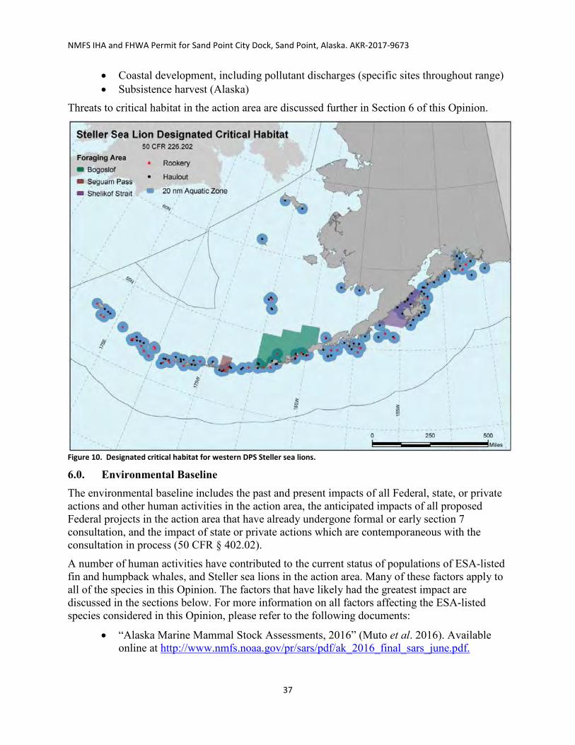
NMFS IHA and FHWA Permit for Sand Point City Dock, Sand Point, Alaska. AKR-2017-9673
37
• Coastal development, including pollutant discharges (specific sites throughout range) • Subsistence harvest (Alaska)
Threats to critical habitat in the action area are discussed further in Section 6 of this Opinion.
Figure 10. Designated critical habitat for western DPS Steller sea lions.
6.0. Environmental Baseline The environmental baseline includes the past and present impacts of all Federal, state, or private actions and other human activities in the action area, the anticipated impacts of all proposed Federal projects in the action area that have already undergone formal or early section 7 consultation, and the impact of state or private actions which are contemporaneous with the consultation in process (50 CFR § 402.02).
A number of human activities have contributed to the current status of populations of ESA-listed fin and humpback whales, and Steller sea lions in the action area. Many of these factors apply to all of the species in this Opinion. The factors that have likely had the greatest impact are discussed in the sections below. For more information on all factors affecting the ESA-listed species considered in this Opinion, please refer to the following documents:
• “Alaska Marine Mammal Stock Assessments, 2016” (Muto et al. 2016). Available online at http://www.nmfs.noaa.gov/pr/sars/pdf/ak_2016_final_sars_june.pdf.

NMFS IHA and FHWA Permit for Sand Point City Dock, Sand Point, Alaska. AKR-2017-9673
38
• “Status Review of the Humpback Whale (Megaptera novaeangliae) under the Endangered Species Act” (Bettridge et al. 2015). Available online at http://www.nmfs.noaa.gov/pr/species/Status%20Reviews/humpback_whale_sr_2015.pdf.
• “Status Review of the Fin Whale (Balaenoptera physalus) under the Endangered Species Act” (NMFS 2011). Available online at http://www.nmfs.noaa.gov/pr/pdfs/species/finwhale_5yearreview.pdf
• “Recovery plan for the Steller sea lion (Eumetopias jubatus). Revision.” (NMFS 2008). Available online at https://alaskafisheries.noaa.gov/sites/default/files/sslrpfinalrev030408.pdf.
6.1. Humpback Whale In the “Status Review of the Humpback Whale (Megaptera novaeangliae) under the Endangered Species Act,” Bettridge et al. (2015) identified and described major threats to each DPS of ESA-listed humpback whales.
The main human activities known to have affected the status of the ESA-listed western North Pacific DPS and Mexico DPS humpback whales in the vicinity of the action area include whaling, climate change, entanglement (principally in commercial fishing gear), shipping, coastal development such as port expansion, oil and gas development, and harmful algal blooms (HABs) (Bettridge et al. 2015). These activities may also have impacts to Steller sea lions and fin whales (with the exception of whaling for Steller sea lions) and will be discussed further in Section 6.4 of this Opinion.
Historically, commercial whaling represented the greatest threat to every population of humpback whales and ultimately led to listing humpback whales as an endangered species. From 1900 to 1965, nearly 30,000 whales were taken in whaling operations of the Pacific Ocean. Prior to that, an unknown number of humpback whales were taken (Perry et al. 1999). In 1965, the International Whaling Commission banned commercial hunting of humpback whales in the Pacific Ocean.
There are no reported takes of humpback whales from the western North Pacific or Mexico DPS by subsistence hunters in Alaska or Russia for the 2008-2012 period (Muto et al. 2016). However, on approximately May 12, 2016, a humpback whale was harvested, in violation of the Whaling Convention Act (WCA), near the Village of Toksook Bay, Alaska, which is about 400 miles north of Sand Point. The whale was reported to have been in the bay and became a target of opportunity by Alaska Natives who may have been unaware of the WCA.
6.2 Fin Whale In the “Status Review of the Fin Whale (Balaenoptera physalus) under the Endangered Species Act” NMFS (2011) identified and described major threats to fin whales.
The main human activities known to have affected the status of the endangered fin whale in the vicinity of the action area include competition with fisheries for resources, climate change, effects of anthropogenic noise, whaling, and ship collisions (NMFS 2011). These activities may also have impacts to Steller sea lions and humpback whales (with the exception of whaling for Steller’s sea lions) and will be discussed further in Section 6.4 of this Opinion.

NMFS IHA and FHWA Permit for Sand Point City Dock, Sand Point, Alaska. AKR-2017-9673
39
Between 1911 and 1985, 49,936 fin whales were reported taken in commercial whaling operations throughout the North Pacific (Mizroch et al. 2009), although newly revealed information about illegal Soviet catches indicates that the Soviets over-reported catches of about 1,200 fin whales, presumably to hide catches of other protected species (Doroshenko 2000). Subsistence hunters in Alaska and Russia have not been reported to take fin whales.
6.3. Steller Sea Lion In the revised Steller sea lion recovery plan (NMFS 2008), the recovery team identified and described 11 factors that may be threats to the recovery of the species (NMFS 2008). Table 6 shows the age class and sex most vulnerable to, and the frequency of occurrence of, each threat; the amount of uncertainty about each threat’s influence on Steller sea lion population dynamics; and the relative impact of each threat to the recovery of the species. Table 7. Summary of threats to Steller sea lion recovery, including the ages and sexes most vulnerable, frequency of threat occurrence, uncertainty of threat impact to recovery, feasibility of threat mitigation, and relative impact of threat to recovery.
Threat Age Class
Most Vulnerable
Sex Most Vulnerable
Frequency of Occurrence of
Threat
Uncertainty of Threat Impact to Recovery
Feasibility of
Mitigation
Relative Impact to Recovery
Alaska Native subsistence harvest
Adult M Medium Low High Low
Juvenile Competition with fisheries
Adult F High High High Potentially
high Juvenile M, F
Disease and parasites Adult F
High Medium Low Low Pup M, F
Disturbance due to research activities Pup M, F Medium Low High Low
Disturbance from vessel traffic and tourism
Pup M, F Medium Medium High Low
Entanglement in marine debris Juvenile M, F Medium Medium Medium Low
Environmental variability
Adult F High High Low Potentially
high Juvenile M, F
Illegal shooting Juvenile
M, F Low Medium Medium Low Adult
Incidental take due to active fishing gear interactions
Juvenile M, F Medium Medium Medium Low
Predation by killer whales
Juvenile M, F High High Low Potentially
high Pup
Toxic substances Adult F
High High Medium Medium Pup M, F
Table adapted from NMFS (2008).
In addition to the threats shown in Table 6, it is likely that Steller sea lions in the action area have become conditioned to associate fishing vessels with easy access to food. The factors that have likely had the greatest impact on western DPS Steller sea lions in the action area are discussed in the sections below. For more information on the threats and factors listed above, but

NMFS IHA and FHWA Permit for Sand Point City Dock, Sand Point, Alaska. AKR-2017-9673
40
not discussed in the sections below, please see the “Recovery Plan for the Steller Sea Lion” (NMFS 2008), available online at https://alaskafisheries.noaa.gov/pr/ssl-recovery-plan.
6.3.1. Fisheries – Competition
The potential impact of competition with fisheries, through localized reduction in the amount and quality of Steller sea lion prey species, has caused considerable debate among the scientific community. The primary issue of contention is whether fisheries reduce Steller sea lion prey biomass and quality at local and/or regional spatial scales that may lead to a reduction in Steller sea lion survival and reproduction, and if sustained, their recovery. The effect of fisheries on the distribution, abundance, and age structure of the Steller sea lion prey field, at the spatial scale of foraging sea lions and over short and long temporal scales, is largely unknown (NMFS 2008).
6.3.2 Fisheries – Conditioning and Habituation
Steller sea lions are likely drawn to the action area by the abundant and predictable sources of food provided by commercial fishing vessels and fish processing facilities. Sea lions are sighted more often when fishing boats are docked at facilities and are often observed foraging near fishing boats that are docked (NMFS 2016), suggesting sea lions in the Sand Point area are habituated to the presence of fishing vessels and are likely conditioned to associating fishing boats with easy access to food (80 FR 79822; Dec. 23, 2015).
6.4 Factors Affecting Steller Sea Lions, Fin and Humpback Whales.
6.4.1. Climate Change
Climate change is a factor potentially affecting the range-wide status of all species (including humans) and is of particular relevance for sub-Arctic and Arctic species. The general discussion in this section applies to all species addressed in this Opinion.
Since the 1950s the atmosphere and oceans have warmed, snow and sea ice have diminished in both areal extent and volume, sea level has risen, and concentrations of greenhouse gases have increased. The time period 1983-2012 was likely the warmest 30-year period in the northern hemisphere in the last 1400 years (IPCC 2013). There has been strong scientific consensus over the past two decades that atmospheric temperatures are increasing, affecting many of the earth’s climate-related processes (IPCC 1990; Houghton et al. 2001; Oreskes 2004; Frame and Stone 2013; NASA 2016). The overwhelming majority of climate scientists agree that human activities, especially the burning of fossil fuels (coal, oil, and gas), are responsible for most of the climate change currently being observed (NRC 2012).
Effects to marine ecosystems from increased atmospheric CO2 and climate change include ocean acidification, expanded oligotrophic gyres, and shifts in temperature, circulation, stratification, and nutrient input (Doney et al. 2012). Altered oceanic circulation and warming cause reduced subsurface oxygen concentrations (Keeling et al. 2010). These large-scale shifts have the potential to disrupt existing trophic pathways as change cascades from primary producers to top level predators (Doney et al. 2012, Salinger et al. 2013). Effects to marine mammals could result from changes in the distribution of temperatures suitable for rearing young, the distribution and abundance of prey, and the distribution and abundance of competitors or predators.
The potential impacts of climate and oceanographic change on whales and sea lions will likely affect habitat availability and food availability. Site selection for feeding, breeding, and whale

NMFS IHA and FHWA Permit for Sand Point City Dock, Sand Point, Alaska. AKR-2017-9673
41
migration may be influenced by factors such as ocean currents and water temperature. For example, there is some evidence from Pacific equatorial waters that sperm whale feeding success and, in turn, calf production rates are negatively affected by increases in sea surface temperature (Smith and Whitehead 1993, Whitehead 1997). Any changes in these factors could render currently used habitat areas unsuitable. Changes to climate and oceanographic processes may also lead to decreased prey productivity and different patterns of prey distribution and availability. Such changes could affect whales and sea lions that are dependent on those affected prey. Variations in sea-surface temperatures and the extent of sea-ice cover during the winter months have been linked to variations in the recruitment of krill (Euphausia superba) and the reproductive success of krill predators. Different species of whales will likely react to these changes differently. For example, range size, location, and whether or not specific range areas are used for different life history activities (e.g., feeding, breeding) are likely to affect how each species responds to climate change (Learmonth et al. 2006).
Climate change will affect pinnipeds on land where they rest and give birth to young, and at sea where they forage. On land, sea level rise and larger, more frequent storms may reduce or eliminate resting and birthing areas. (Learmonth et al. 2006; NPS 2016). Changes in ocean currents, ocean acidification, and other alterations in climate cycles such as changes in the frequency of El Nino events are likely to alter ocean food webs and affect the abundance and diversity of prey items. These changes may also affect susceptibility to diseases. Some changes may be positive. For example, new suitable habitats may become available for some species (Learmonth et al. 2006, NPS 2016).
The most pronounced warming is expected in the north, exceeding the estimate for mean global warming by a factor of 3, due in part to the “ice-albedo feedback loop.” As the reflective areas of Arctic ice and snow retreat, the northern latitudes absorb more heat, exacerbating the warming (NRC 2012). Climate change is projected to have substantial direct and indirect effects on individuals, populations, species, and the structure and function of marine, coastal, and terrestrial ecosystems in the foreseeable future (NRC 2012).
In summary, none of the future climactic changes discussed are expected to materially alter the environmental baseline of the action area over the temporal scope (one year) of the proposed action.
6.4.2. Fisheries - Incidental Take and Entanglement
Sand Point City Dock is an active public dock and ferry terminal. The adjacent property to the east of the City Dock is a small boat harbor, which was expanded in 2014 to accommodate 172 vessels and is home to the largest commercial fishing fleet in the Aleutian region (City of Sand Point 2017). Just north of the small boat harbor is a cold storage, fish meal, and fish-processing plant owned and operated by Trident Seafoods and Peter Pan Seafoods (see Figures 4 and 5). During open fishing seasons, the plant receives numerous commercial fishing vessels daily for offloading and processing of catch. Almost half the inhabitants of Sand Point support themselves by fishing and fish processing (City of Sand Point 2017).
Humpback Whales Humpback whales are killed or injured during interactions with commercial fishing gear and other entanglements, although the available evidence suggests that these interactions do not have

NMFS IHA and FHWA Permit for Sand Point City Dock, Sand Point, Alaska. AKR-2017-9673
42
population-level consequences for the listed humpback whale DPSs in the action area (Bettridge et al. 2015).
Along the Pacific coast of Canada, 40 humpback whales have been reported as entangled since 1980, four of which are known to have died (Ford et al. 2009, COSEWIC 2011). A photography study of humpback whales in southeastern Alaska in 2003 and 2004 found at least 53% of individuals showed some kind of scarring from entanglement (Neilson et al. 2005). However, very few stranding reports are received from areas west of Kodiak where this proposed action is occurring. Between 2008 and 2012, there were two mortalities of humpback whales near Dutch Harbor in the Bering Sea/Aleutian Islands pollock trawl fishery, and one mortality in the Bering Sea/Aleutian Islands flatfish trawl (Muto et al. 2016). The mean annual human-caused mortality and serious injury rate for 2008-2012 based on fishery and gear entanglements reported in the NMFS Alaska Regional Office stranding database is 0.3 (Muto et al. 2016). These events have not been attributed to a specific fishery (76 FR 73912; Nov. 29, 2011). No observers have been assigned to several fisheries that are known to interact with these listed humpback stocks, making the estimated mortality rate unreliable.
Fin Whales
One incidental mortality of a fin whale due to entanglement in the ground tackle of a commercial mechanical jig fishing vessel was reported to the NMFS Alaska Region in 2012 (Helker et al. 2016). Since observer data are not available for this fishery, this mortality results in a mean annual mortality and serious injury rate of 0.2 fin whales in 2010-2014 (Muto et al. 2016).
Steller Sea Lions
Commercial fisheries operate in and around Sand Point. Due to the presence of these fisheries that land at docks to off-load their catch, Steller sea lions frequently forage in this area. These conditions have contributed to habituation of Steller sea lions, and likely other marine species, to human presence, industrial/commercial uses, and associated noise-generating activities. The most recent minimum total annual incidental take of western DPS Steller sea lions associated with commercial fisheries is 30 individuals (Table 7). Table 8. Summary of most recent data available for western DPS Steller sea lion incidental mortalities associated with commercial fisheries in Alaska.
Fishery Name Year(s) Mean Annual Mortality Bering Sea/Aleutian Islands
Atka mackerel trawl 2010 – 2014 0.2 Flatfish trawl 2010 – 2014 5.8 Pacific cod trawl 2010 – 2014 0.8 Pacific cod longline 2010 – 2014 0.3 Pollock trawl 2010 – 2014 6.3
Gulf of Alaska Pacific cod longline 2010 – 2014 0.2 Pacific cod trawl 2010 – 2014 0.2 Sablefish longline 2010 – 2014 1.1
Prince William Sound Salmon drift gillnet 1990 – 1991 15 Salmon set gillnet 1990 0

NMFS IHA and FHWA Permit for Sand Point City Dock, Sand Point, Alaska. AKR-2017-9673
43
Fishery Name Year(s) Mean Annual Mortality Alaska Peninsula/Aleutian Islands
Salmon drift gillnet 1990 0 Cook Inlet
Salmon set gillnet 1999 – 2000 0 Salmon drift gillnet 1999 – 2000 0
Kodiak Island Salmon set gillnet 2002 0
MINIMUM TOTAL ANNUAL MORTALITY 29.9 Table adapted from Muto et al. (2016).
Take (in the form of serious injury or mortality) resulting from entanglement or hooking by fishing gear in the Bering Sea/Aleutian Islands groundfish fisheries, authorized from 2014 to 2016, was limited to a total of 42 Steller sea lions during that three-year period (NMFS 2014).
The most recent minimum total annual mortality of western DPS Steller sea lions reported to the NMFS stranding network is 4.2 individuals (Table 8). This estimate is considered a minimum because not all entangled animals strand and not all stranded animals are found or reported. Steller sea lions reported to the stranding network as having been shot are not included in this estimate, as they may result from animals struck and lost in the Alaska Native subsistence harvest. Table 9. Summary of Western U.S. Steller sea lion mortality and serious injury, by year and type, reported to the NMFS Alaska Region marine mammal stranding network and Alaska Department of Fish and Game in 2010-2014 (Helker et al. 2016).
Cause of injury 2010 2011 2012 2013 2014 Mean annual mortality
Hooked by Gulf of Alaska longline gear* 1 0 0 0 0 0.2
Hooked by Southcentral Alaska salmon troll gear* 0 1 0 0 1 0.4
Hooked by Alaska Peninsula troll gear* 0 0 0 1 0 0.2
Hooked by troll gear* 0 0 2 0 0 0.4
Entangled in unidentified fishing gear* 0 0 1 0 1 0.4
Entangled in marine debris 5 1 2 0 3 2.2
Struck by arrow 0 0 0 1 0 0.2
Entangled in commercial Kodiak salmon hatchery net 0 0 0 1 0 0.2
*Total in unknown (commercial, recreational, or subsistence) fisheries Total in marine debris Total due to other causes (arrow strike, entangled in hatchery net)
1.6 2.2 0.4
6.4.3. Vessel Collision
Sand Point is a busy port that is home to the largest commercial fishing fleet in the Aleutian Islands chain (City of Sand Point 2017). There is also some tug and barge traffic but no container ships visit (Nuka Research Planning Group, LLC and Cape International, Inc. 2006). During the summer and into the fall, the Alaska Marine Highway operates the M/V Tustumena ferry stopping in Sand Point four times per month.

NMFS IHA and FHWA Permit for Sand Point City Dock, Sand Point, Alaska. AKR-2017-9673
44
The City of Sand Point maintains two marinas, the Robert E. Galovin small boat harbor, expanded in 2014 to accommodate 172 vessels, and the “New Harbor” (Figure 5). The City of Sand Point and the Aleutians East Borough are currently seeking funds to install a complete float system and full electricity in the harbor. As previously described, there is a seafood processing facility on the north side of Humboldt Harbor (Figure 5). During open fishing seasons, the plant receives numerous commercial fishing vessels daily for offloading and processing of catch.
Vessel collisions with fin and humpback whales remain a management concern, given the increasing abundance of humpback whales foraging in Alaska, as well as the growing presence of marine traffic in Alaska’s coastal waters and in the Sand Point area with its increased marine infrastructure. Based on these factors, injury and mortality of humpback whales as a result of vessel strike may likely continue, or possibly increase, in the future (NMFS 2006b). The mean annual human-caused mortality and serious injury rate for 2010-2014 due to vessel collisions reported in Alaska is 3.1 humpbacks, an increase from the last reporting period (2008-2012). Most vessel collisions with humpbacks are reported from Southeast Alaska, and it is not known whether the difference in ship strike rates between Southeast Alaska and other portions of the humpback whale range in Alaska is due to differences in reporting, amount of vessel traffic, densities of animals, and/or other factors (Muto et al. 2016).
Fin whale mortality due to ship strikes in Alaska waters (one each in 2010 and 2014) has also been reported to the NMFS Alaska Region stranding network (Helker et al. 2016), resulting in a mean annual mortality and serious injury rate of 0.4 fin whales due to ship strikes in 2010-2014 (Muto et al. 2016).
Although risk of ship strike has not been identified as a significant concern for Steller sea lions (Loughlin and York 2000), the recovery plan for this species states that Steller sea lions may be more susceptible to ship strike mortality or injury in harbors or in areas where animals are concentrated (e.g., near rookeries or haulouts; NMFS 2008). Additionally, sea lions are sighted more often when fishing boats are docked at facilities and are often observed foraging near fishing boats that are docked (NMFS 2016), suggesting sea lions in the Sand Point area are habituated to the presence of fishing vessels and are likely conditioned to associating fishing boats with easy access to food. Such habituation could potentially lead to greater risk of inadvertent contact with vessel hulls or propellers.
6.4.4. Oil and Gas Development
There have been proposals to open oil exploration and drilling near the action area in the southeastern Bering Sea, notably in the North Aleutian Basin. While in 2010 this region was removed from consideration for oil and gas lease sales, if such activity were authorized in the future, the potential for spills and resulting direct contamination and effects to feeding areas would represent additional threats to all marine mammals in the area.
6.4.5. Harmful Algal Blooms (HABs)
Naturally occurring biotoxins from dinoflagellates and other toxins are known to exist within the range of these listed species and close to the action area (Figure 11). It is also possible that biotoxins played a role in the Unusual Mortality Event observed in the western Gulf of Alaska in 2015 (Desroches 2015; NOAA 2016). In 2015, increased mortality of large whales (including 11 fin whales, 14 humpback whales, 1 gray whale, and 4 unidentified cetaceans from May to mid-

NMFS IHA and FHWA Permit for Sand Point City Dock, Sand Point, Alaska. AKR-2017-9673
45
August 2015) was observed along the western Gulf of Alaska, including the areas around Kodiak Island, Afognak Island, Chirikof Island, the Semidi Islands, and the southern shoreline of the Alaska Peninsula (http://www.nmfs.noaa.gov/pr/health/mmume/faqs_2015_large_whale.html, accessed December 2016). On 20 August 2015, NMFS declared an Unusual Mortality Event for large whales in the western Gulf of Alaska; however, to date, no specific cause for the increased mortality has been identified. Although fin and humpback whale and Steller sea lion mortality as a direct result of exposure to biotoxins has not been documented to date in the action area, marine mammal mortality from HABs have been documented close by in Cold Bay, the Semidi Islands, and the Eastern Aleutians (Lefebvre et al. 2016) and it is reasonable to expect algal blooms could occur within the action area.
The occurrence of HABs in Alaska is expected to increase with the growth of various types of human-related activities, and with increasing water temperatures (Lefebvre et al. 2016). Increasing ocean temperatures are expected to exacerbate blooms of the Pseudo-nitzschia diatoms in Alaska waters. This marine phytoplankton produces the paralytic shellfish poisoning neurotoxin domoic acid (DA) which has been implicated in causing mortality of marine mammals. Lefebvre et al. (2016) found that, among 10 species of marine mammals, humpback whales accounted for half of the individuals that tested positive for saxitoxin (STX), another paralytic shellfish poisoning neurotoxin. Lefebvre et al. (2016) also found that 38% of humpbacks tested positive for DA, which was a lower rate than harbor seals, walrus, and harbor porpoise but higher than 8 other marine mammal species. The highest DA and STX concentrations were found in a humpback that died from a ship strike, which may not be a coincidence because STX and DA intoxication have been suggested to be a factor in the loss of ability to avoid ships and to be a cause of stranding. The humpbacks that tested positive for HABs were all sampled in Southeast Alaska; no humpbacks were sampled near the action area. However, Steller sea lions, as well as other marine mammals from the Aleutians, did test positive for HABs. The number of species and the extensive geographic range in which DA and STX were detected in the Lefebvre et al. (2016) study demonstrates that HABs are present throughout the Alaskan marine environment; thus the potential for health effects due to exposure is a possible threat for humpback whales and Steller sea lions. A DA outbreak is the suspected agent in the current mortality event of sea lions and other pinnipeds in California (Ritchie 2017).

NMFS IHA and FHWA Permit for Sand Point City Dock, Sand Point, Alaska. AKR-2017-9673
46
Figure 11. Algal toxins detected in 13 species of marine mammals from southeast Alaska to the Arctic from 2004 to 2013 (Lefebvre et al. 2016).
6.4.6. Anthropogenic Noise
Steller sea lions, fin and humpback whales in the action area are exposed to numerous sources of natural and anthropogenic noise. Natural sources of underwater noise include sea ice, wind, waves, precipitation, and biological noise from marine mammals, fishes, and crustaceans. Anthropogenic sources of noise include noise generated by vessels (used for fishing, construction, and transportation), aircraft, and marine and coastal construction. Commercial ships that frequent nearby shipping lanes can emit underwater sounds of over 120 dB re 1 µParms at distances of 3 km (1.86 mi) (McKenna et al. 2012). The area around the City Dock and Humboldt Harbor are frequented by fishing vessels and tenders; the M/V Tustumena, barges, tugboats; and other commercial and recreational vessels that use the small-boat harbor, City Dock, seafood processing plant, and which produce varying noise levels and frequency ranges (Table 9). Table 10. Representative noise levels of anthropogenic sources of noise commonly encountered in the proposed action area.
Noise Source Frequency Range (Hz) Underwater Noise Level (dB rms re 1 μPa @ 1m)
Small vessels 250–1,000 151–159 Tug pulling barge 1,000–5,000 145–170
Because responses to anthropogenic noise vary among species and individuals within species, it is difficult to determine long-term effects. Habituation can occur when an animal’s response to a stimulus wanes with repeated exposure, usually in the absence of unpleasant associated events (Wartzok et al. 2003). Habitat abandonment due to anthropogenic noise exposure has been found

NMFS IHA and FHWA Permit for Sand Point City Dock, Sand Point, Alaska. AKR-2017-9673
47
in terrestrial species (Francis and Barber 2013). Clark et al. (2009) identified increasing levels of anthropogenic noise as a habitat concern for whales because of its potential effect on their ability to communicate (i.e., masking). Some research (Parks 2003, McDonald et al. 2006, Parks 2009) suggests marine mammals compensate for masking by changing the frequency, source level, redundancy, and timing of their calls. However, the long-term implications of these adjustments, if any, are currently unknown.
Steller sea lions are sighted more often when fishing boats are docked and are often observed foraging near fishing boats that are docked at the Sand Point facilities, suggesting sea lions in the Sand Point area are habituated to the presence of fishing vessels and, presumably, to the presence of shipping vessels and noises associated with activities in and around Sand Point.
Coastal development, which may include projects such as port expansion or waterfront development, is ongoing in the action area. The City of Sand Point and the Aleutians East Borough are currently seeking funds to install a complete float system and full electricity in the new harbor. The design and construction of these features are part of the City of Sand Point Capital Improvement Plan priorities (HDR 2017a). Given continued human population growth in the region (Zador 2016), the threat can be expected to increase. Many of these developments generate noise at levels above NMFS harassment thresholds.
6.5 Factors Affecting Steller Sea Lion Critical Habitat within the Action Area The action area overlaps with the aquatic zones (i.e., designated critical habitat) for three designated major haulouts: Sea Lion Rocks, The Whaleback, and Jude (see Section 5.3.5 of this Opinion and Figure 9). The closest is The Whaleback at 27.4 kilometers (14.8 nautical miles) east of Sand Point and the proposed dock. The dock site itself is outside the aquatic zone of the Jude Island haulout. The action area does not overlap with the aquatic zone of any major rookery designated as critical habitat, nor does it overlap with the three designated offshore foraging areas. We expect the factors affecting the species as discussed in Section 6 of this Opinion (climate change, fisheries, vessel collisions, oil and gas development, HABs, and anthropogenic noise) have also affected critical habitat in the action area. The action is occurring in a busy port with constant disturbance to the critical habitat located within it. Boat and airplane traffic, fisheries for groundfish, herring, salmon, and invertebrates, and coastal development, including pollutant discharges are the factors in the action area most likely to have disrupted the essential life functions that occur in critical habitat. These factors have reduced the importance of the action area to the overall conservation value of critical habitat.
7.0. Effects of the Action “Effects of the action” means the direct and indirect effects of an action on the species or critical habitat, together with the effects of other activities that are interrelated or interdependent with that action that will be added to the environmental baseline. Indirect effects are those that are caused by the proposed action and are later in time, but still are reasonably certain to occur (50 CFR § 402.02).
This Opinion relies on the best scientific and commercial information available. We try to note areas of uncertainty, or situations where data is not available. In analyzing the effects of the action, NMFS gives the benefit of the doubt to the listed species by minimizing the likelihood of false negative conclusions (concluding that adverse effects are not likely when such effects are, in fact, likely to occur).

NMFS IHA and FHWA Permit for Sand Point City Dock, Sand Point, Alaska. AKR-2017-9673
48
We organize our effects analysis using a stressor identification – exposure – response – risk assessment framework for the proposed activities.
We conclude an Integration and Synthesis of Effects (section 9) that integrates information presented in the Status of the Species (section 5) and Environmental Baseline (section 6) of this Opinion with the results of our exposure and response analyses to estimate the probable risks the proposed action poses to endangered and threatened species.
The proposed activities of primary concern to ESA-listed humpback whales, fin whales, and Steller sea lions include exposure to sounds underwater from pile driving and removal. Associated factors such as exposure to airborne sounds from pile driving and removal, increased potential for vessel strike, pollution, and sedimentation during project construction are considered to have minimal effects, due to species life history and behavior, construction practices and mitigation measures incorporated into the project design. If any of these mitigation measures change then reinitiation of formal consultation is required (see Section 13.0 of this Opinion).
In analyzing effects to species, we consider the action’s timing, duration, nature of effect, and the frequency, intensity, and severity of disturbance. The timing of the activity likely will have no effect on breeding of Steller sea lions or fin or humpback whales, since they do not breed in the vicinity—humpbacks in the area breed primarily in Hawaiian waters in the winter, fin whales in the area primarily breed in Mexico in the winter, and the nearest major Steller sea lion rookery designated as critical habitat (east side of Atkins Island) is about 83.3 kilometers (45 nautical miles) southeast of Sand Point. There is some pup production on some of the haulouts, the closest being Jude Island, approximately 38.9 kilometers (21 nautical miles ) west of Sand Point, which had average annual counts of 214 sea lion pups from 2009-2014 (Fritz et al. 2016a). The action area represents a small portion of the geographic range of the species. Further, the project duration is one year. The new dock is intended to replace the primary function of the existing dock (Alaska Marine Highway System ferry and freight) and no added capacity is anticipated (pers. comm DOT&PF; 27 Sept. 2017). No increased vessel traffic is expected from this project; however, vessels previously anchoring in the harbor may be able to dock at either the new or existing dock (until it is removed) when space is available. Therefore, any impacts in the project area likely will not have long-term adverse impact on species’ distribution. Accordingly, we focus our analysis on the intensity and severity of effects to the species.
The proposed action is expected to result in non-lethal, non-injurious harassment of Steller sea lions, fin and humpback whales. The ESA does not define harassment, and NMFS has not defined this term through regulation pursuant to the ESA. NMFS recently developed interim guidance interpreting “harass” under the ESA to mean: “to create the likelihood of injury to wildlife by annoying it to such an extent as to significantly disrupt normal behavioral patterns which include, but are not limited to, breeding, feeding, or sheltering” (Weiting 2016). For the purposes of this consultation, any action that amounts to incidental harassment under the MMPA (16 U.S.C. § 1362(18)(A)) constitutes an incidental “take” under the ESA and must be authorized by the ITS (Section 11).
7.1. Stressors During the course of this consultation, we identified the following potential stressors from the proposed activities:

NMFS IHA and FHWA Permit for Sand Point City Dock, Sand Point, Alaska. AKR-2017-9673
49
• Underwater sounds from:
o Vibratory pile-driving and removal o Impact pile-driving
• Direct contact with: o Piles, during placement o Sound attenuation devices (pile caps), during placement and removal
• Vessel strike • Disturbance of sediment • Modification of critical habitat
Below we discuss each stressor’s potential to affect ESA-listed species.
7.1.1. Stressors Not Likely to Adversely Affect ESA-Listed Species and Critical Habitat
Based on a review of available information, we determined which of the possible stressors may occur, but are discountable or insignificant even when considered in combination with other stressors and, therefore, need not be evaluated further in this Opinion.
Direct Contact
Though it is possible that western DPS Steller sea lions, fin and humpback whales could come in direct contact with, and suffer injury from, piles and sound attenuation devices during their placement, the Level A shutdown zones (Table 3) implemented during construction (100m) will make these activities extremely unlikely to impact Steller sea lions or fin and humpback whales; therefore, we conclude the effects from this stressor are discountable.
Vessel Strike
Vessels will transit year-round and fin and humpback whales, and Steller sea lions are known to occur in the action area year-round. However, available information (see Section 6.4.3) does not indicate that vessel strikes of these species in the region have occurred and there is no indication that strikes will become a major source of injury or mortality in the action area. There have been 108 reports of whale-vessel collisions in Alaska waters between 1978 and 2011. Of these, 3 involved fin whale and 93 were humpback whales but none were in or close to the action area (Neilson et al. 2012). Most vessel collisions with humpbacks are reported from Southeast Alaska and all but two of the 108 reported strikes was east of 160oW (Neilson et al. 2012). Even if vessel-related deaths of fin and humpback whales in the waters outside of the action area, where strikes have been known to occur, were several times greater than observed levels, it would still be a small fraction of the total fin and humpback whale population. The risk of ship strike has not been identified as a significant concern for Steller sea lions (Loughlin and York 2000) and there are no reported vessel collisions or prop strikes of Steller sea lions in or near the action area. Therefore, we conclude the effects from this stressor for all three species are discountable.
Disturbance of Sediment
A small amount of sediment will be disturbed and may temporarily impact water quality during pile-driving and removal and fill placement in the upland area. This will occur in the area immediately surrounding these activities. Suspended sediments are not expected to persist in the

NMFS IHA and FHWA Permit for Sand Point City Dock, Sand Point, Alaska. AKR-2017-9673
50
area for more than a few hours because tidal action will sufficiently disperse them to a point where their concentration in the water column is not detectably different from surrounding waters. In addition, actions specified in a WQCP and associated BMPs (see Section 2.3.1 of this Opinion and HDR 2017a) would limit sedimentation. For these reasons, we do not expect this project will affect water quality to any measurable degree during construction, nor is it likely to cause future impacts that are measurably different from the existing environmental baseline. Therefore, we conclude the effects from this stressor are insignificant and discountable.
Modification of Critical Habitat
Replacement of the Sand Point City Dock would approximately double the footprint of municipal docks on the New Harbor causeway and additional upland area would be created through the expansion of the existing causeway. As such, a small amount of designated critical habitat for Steller sea lions would be modified from the existing condition due the addition of fill and armor rock, disturbance of the seafloor, and additional shading beneath the expanded dock. Changes are expected to be minor given the previously disturbed condition of the area and the minor amount of critical habitat affected within the action area.
There is no other permanent loss of critical habitat associated with the proposed project. While the action area overlaps with designated critical habitat (aquatic zones of three major haulouts; Sea Lion Rocks, The Whaleback, and Jude Island [see Figure 9]) the proposed dock is on the edge of critical habitat; the Sand Point dock is 27.4 km (14.8 nmi) from the nearest haulout (The Whaleback). The action area does not overlap with the aquatic zone of any major rookery designated as critical habitat, nor does it overlap with the three designated offshore foraging areas. The closest designated major rookery is on the east side of Atkins Island, which is approximately 83.3 kilometers (45 nautical miles) southeast of Sand Point (Figure 9).
Furthermore, the project is located within a well-developed port which does not currently function as high quality Steller sea lion habitat or foraging area. Although the action area meets the distance criteria used to define Steller sea lion critical habitat, it provides few if any of the physical and biological features required by the species.
It is extremely unlikely that the small modification of ecologically compromised critical habitat in an already highly developed area will diminish the role of that habitat for the survival and recovery of Steller sea lions, nor will that modification diminish the value of the entire area designated as critical habitat for Steller sea lions to any measurable degree; therefore, we conclude such effects from the modification of critical habitat to be insignificant in terms of the conservation value of Steller sea lion critical habitat.
Summary of Stressors Not Likely to Adversely Affect ESA-Listed Species
In conclusion, based on review of available information, we have determined that effects to western DPS Steller sea lions, fin whales, and western North Pacific and Mexico DPS humpback whales from direct contact, physical injury from pile-driving and removal, and vessel strike are extremely unlikely to occur. We consider the effects to western DPS Steller sea lions, fin and humpback whales from these stressors to be discountable.
We determined project-related disturbance of sediment will have insignificant effects on western DPS Steller sea lions, fin and humpback whales and the modification of Steller sea lion critical habitat related to this project will have insignificant effects on designated critical habitat.

NMFS IHA and FHWA Permit for Sand Point City Dock, Sand Point, Alaska. AKR-2017-9673
51
7.1.2. Stressors Likely to Adversely Affect ESA-Listed Species
The following sections analyze the stressors likely to adversely affect ESA-listed species: underwater sounds from vibratory pile-driving and removal, and impact pile-driving.
The frequencies emitted by vibratory and impact pile-driving are estimated to range from 0.01 to 1.5 kHz, mostly within the expected hearing range of Steller sea lions and fin and humpback whales (Table 10). For the purposes of this consultation we assume that all sounds produced by pile driving are within their expected hearing range as estimated by several studies (Southall et al. 2007, Ciminello et al. 2012). Table 11. Functional Marine Mammal Hearing Groups, Auditory Bandwidth1. Functional Hearing Group: ESA-Listed Species that May Occur in the Action Area
Estimated Auditory Bandwidth Southall et al. (2007) Ciminello et al. (2012)
Low-frequency (LF) cetaceans: humpback and fin whales 7 Hz to 22 kHz 5 Hz to 30 kHz Otariid Pinnipeds (in air): Steller sea lion 75 Hz to 30 kHz 100 Hz to 30 kHz Otariid Pinnipeds (in water): Steller sea lion 75 Hz to 75 kHz 100 Hz to 40 kHz
1 Estimated Lower to Upper Frequency Hearing Cut-off
Injury (Level A Harassment)
NMFS recently developed comprehensive guidance on sound levels likely to cause injury to marine mammals through onset of permanent and temporary thresholds shifts (PTS and TTS; Level A harassment) (81 FR 51693). Under the 2016 Technical Guidance (NMFS 2016b), NMFS divides marine mammals into five groups and presents thresholds for underwater sounds that cause PTS in each group (Table 11). NMFS presents these acoustic thresholds using dual metrics of cumulative sound exposure level (LE) and peak sound level (PK) for impulsive sounds and LE for non-impulsive sounds. Based on these criteria the action agencies anticipate no injury (Level A harassment) to ESA-listed western DPS Steller sea lions, fin whales, or western North Pacific or Mexico DPS humpback whales associated with this activity. Table 11. PTS Onset thresholds for cetaceans and pinnipeds (from NMFS 2016b)
PTS Onset Acoustic Thresholds* (Received Level)
Hearing Group Impulsive Non-impulsive
Low-Frequency (LF) Cetaceans Lpk,flat: 219 dB LE,MF,24h: 183 dB
LE,LF,24h: 199 dB
Mid-Frequency (MF) Cetaceans Lpk,flat: 230 dB LE,MF,24h: 185 dB
LE,MF,24h: 198 dB
High-Frequency (HF) Cetaceans Lpk,flat: 202 dB LE,HF,24h: 155 dB
LE,HF,24h: 173 dB
Phocid Pinnipeds (PW) (Underwater)
Lpk,flat: 218 dB LE,PW,24h: 185 dB
LE,PW,24h: 201 dB
Otariid Pinnipeds (OW) (Underwater)
Lpk,flat: 232 dB LE,OW,24h: 203 dB
LE,OW,24h: 219 dB
* Dual metric acoustic thresholds for impulsive sounds: Use whichever results in the largest isopleth for calculating PTS onset. If a non-impulsive sound has the potential of exceeding the peak sound pressure level thresholds associated with impulsive sounds, these thresholds should also be considered.

NMFS IHA and FHWA Permit for Sand Point City Dock, Sand Point, Alaska. AKR-2017-9673
52
Note: Peak sound pressure (Lpk) has a reference value of 1 µPa, and cumulative sound exposure level (LE) has a reference value of 1µPa2s. The subscript “flat” is being included to indicate peak sound pressure should be flat weighted or unweighted within the generalized hearing range. The subscript associated with cumulative sound exposure level thresholds indicates the designated marine mammal auditory weighting function (LF, MF, and HF cetaceans, and PW and OW pinnipeds) and that the recommended accumulation period is 24 hours. The cumulative sound exposure level thresholds could be exceeded in a multitude of ways (i.e., varying exposure levels and durations, duty cycle). When possible, it is valuable for action proponents to indicate the conditions under which these acoustic thresholds will be exceeded.
Behavioral Disturbance (Level B Harassment)
The modeled radii for vibratory pile-driving and removal, and impact pile-driving are presented in Table 3, in Section 2.3.2, of this Opinion and in the proposed IHA (82 FR 31400; July 6, 2017). As indicated in Table 3, the calculated radius of the 160 dB isopleth for impact pile driving is 1,740m for 30-inch piles and 1,590m for 24-inch piles. Calculated radii to the 120 dB isopleth for vibratory driving and removal is 10,970m for 30-inch pile, 5,420m for 18 and 24-inch pile, and 1,000m for H-piles.
7.2. Exposure Our exposure analyses are designed to identify the ESA-listed resources that are likely to co-occur with the action’s effects in space and time, as well as the nature of that co-occurrence. In this step of our analysis, we try to identify the number, age (or life stage), and sex of the individuals that are likely to be exposed to the action’s effects and the population(s) or subpopulation(s) those individuals represent.
7.2.1. Underwater Sounds
The number of marine mammals expected to be taken by behavioral harassment is usually calculated by multiplying the expected densities of marine mammals in the survey area by the area ensonified in excess of 120 and 160 dB re 1 µParms, though the method to calculate take may vary, depending on the information available. All of the marine mammal distribution data used to evaluate take in the action area (see Section 5 of this Opinion and 82 FR 31400; July 6, 2017) represent the best available scientific information. The Permits Division calculated exposures of marine mammals for use in the proposed IHA (82 FR 31400; July 6, 2017) and we have adopted them for our exposure analysis here.
Take estimates for Steller sea lions, fin and humpback whales are summarized in Table 11. Take estimates for all marine mammals in the action area were calculated using the following:
Table 12. Summary of Estimated Takes for Replacement of the Sand Point City Dock
Species Estimated Level B Take Estimated Level A take Western DPS Steller sea lions 960 0 Fin whales 6 0 All humpbacks 30 2

NMFS IHA and FHWA Permit for Sand Point City Dock, Sand Point, Alaska. AKR-2017-9673
53
Species Estimated Level B Take Estimated Level A take Western North Pacific DPS Humpback Whale
1 0
Mexico DPS Humpback Whale 3 0
Due to the project location, it is virtually certain that all estimated 960 endangered Steller sea lions potentially exposed to Level B harassment will be individuals of the endangered western DPS. Of the estimated six endangered fin whales potentially exposed to Level B harassment we expect all individuals will be from the Northeast Pacific stock. Humpback whales found in the Shumagin Islands are predominantly members of the Hawaii DPS, which are not listed under the ESA. However, based on a comprehensive photo-identification study, members of both the Western North Pacific DPS (ESA-listed as endangered) and Mexico DPS (ESA-listed as threatened) are known to occur in the Gulf of Alaska. Members of different DPSs are known to intermix on feeding grounds; therefore, all waters off the coast of Alaska should be considered to have ESA-listed humpback whales. According to Wade et al., (2016), the probability of encountering a humpback whale from the Western North Pacific DPS in the Gulf of Alaska is 0.5 percent (CV [coefficient of variation] = 0.001). The probability of encountering a humpback whale from the Mexico DPS is 10.5 percent (CV = 0.16). The remaining 89 percent (CV = 0.01) of individuals in the Gulf of Alaska are likely members of the Hawaii DPS (Wade et al., 2016). Therefore, of the 30 humpback whales potentially exposed to Level B harassment, it is estimated that 26 would be from the non-listed Hawaii DPS, three humpback whales would be from the threatened Mexico DPS, and one humpback whale would be from the endangered Western North Pacific DPS.
No Level A takes are expected or authorized for ESA-listed humpbacks. This is a reasonable assumption because, though our modeling suggests construction could cause two Level A takes of humpback whales, only 11% of humpbacks in the action area—or 0.2 of the potential Level A takes—are assumed to be from an ESA-listed population. Thus, if construction activities cause any Level A takes, it is far more likely such takes would impact individuals from the unlisted Hawaii DPS. In addition, the two Level A takes authorized in the IHA represent a conservative estimate of possible exposures to Level A harassment. Mitigation measures will markedly reduce the likelihood of any Level A takes because work will shut down if cetaceans are observed approaching the relevant Level A harassment isopleths (as shown in Table 3). Therefore, we conclude there is likely to be zero Level A takes of ESA-listed humpback whales. Further, even if we authorized one Level A take by harassment of an ESA-listed humpback in the ITS, that would not change our conclusion regarding the likelihood of the action to jeopardize the continued existence of any ESA-listed humpback DPS.
These are considered reasonable estimates of the number of ESA-listed marine mammal exposures to sound above the Level B harassment threshold that are likely to occur over the course of the project. However, they do not necessarily reflect the number of different animals exposed. For instance, because Steller sea lions likely associate fishing boats in Sand Point with reliable sources of food, there will almost certainly be some overlap in individuals present (and exposed) day-to-day. However each instance of exposure for these individuals will be recorded as a separate take. Moreover, because we anticipate that marine mammal observers will typically be unable to determine from field observations whether the same or different individuals are

NMFS IHA and FHWA Permit for Sand Point City Dock, Sand Point, Alaska. AKR-2017-9673
54
being exposed over the course of a workday, each observation of a marine mammal will be recorded as a new take, although an individual theoretically would only be considered as taken once in a given day.
Unlike Steller sea lions, fin and humpback whales are less likely to frequent the action area. Therefore, no assumptions can be made about the number of individual fin and humpback whales represented in the exposure estimates for fin whales and western North Pacific or Mexico DPS humpback whales.
We expect exposures to all marine mammals will be limited to Level B harassment. Mitigation measures (HDR 2017b and 82 FR 31400; July 6, 2017) will be employed so that any Steller sea lion, fin whale or humpback whale observed within the Level B zones (Table 3) will be monitored to ensure pile-driving operations will be shut down if they appear likely to enter the Level A harassment zones (Table 3). In addition, a shutdown zone will be established for all in-water work; 10m for in-water heavy machinery work and 100m for pile driving so that if a marine mammal enters, or is about to enter, this zone all work will cease. Furthermore, if a marine mammal is observed within the shutdown zone or Level A zone (if take is not authorized), a soft-start can only proceed if the animal is observed leaving the zone or has not been observed for 30 minutes (for fin and humpback whales) and 15 minutes (for sea lions).
7.3. Response Loud underwater sounds can result in physical effects on the marine environment that can affect marine organisms. Possible responses by western DPS Steller sea lions, fin whales, western North Pacific DPS humpback whales, and Mexico DPS humpback whales to the impulsive sound produced by impact pile-driving and continuous sound produced by vibratory pile-driving and removal considered in this analysis are:
• Threshold shifts • Auditory interference (masking) • Behavioral responses • Non-auditory physical or physiological effects
This analysis also considers information on the potential effects on prey of western DPS Steller sea lions, fin whales, and western North Pacific DPS and Mexico DPS humpback whales.
7.3.1. Threshold Shifts
Exposure of marine mammals to very strong sounds can result in physical effects, such as changes to sensory hairs in the auditory system, which may temporarily or permanently impair hearing. Temporary threshold shift (TTS) is a temporary hearing change and its severity is dependent upon the duration, frequency, sound pressure, and rise time of a sound (Finneran and Schlundt 2013). TTSs can last minutes to days. Full recovery is expected, and this condition is not considered a physical injury. At higher received levels, or in frequency ranges where animals are more sensitive, permanent threshold shift (PTS) can occur. When PTS occurs, auditory sensitivity is unrecoverable (i.e., permanent hearing loss). Both TTS and PTS can result from a single pulse or from accumulated effects of multiple pulses from an impulsive sound source (i.e., impact pile-driving) or from accumulated effects of non-pulsed sound from a continuous sound source (i.e., vibratory pile-driving and removal). In the case of exposure to multiple pulses, each

NMFS IHA and FHWA Permit for Sand Point City Dock, Sand Point, Alaska. AKR-2017-9673
55
pulse need not be as loud as a single pulse to have the same accumulated effect. TTS and PTS occur only in the sound frequencies to which an animal is exposed.
Data are lacking on effects to pinnipeds exposed to impulsive sounds (Southall et al. 2007, NMFS 2016b), and the energy levels required to induce TTS or PTS in pinnipeds are not known. Finneran et al. (2003) exposed two California sea lions to single underwater pulses up to 183 dB re 1 μPap-p
4 and found no measurable TTS following exposure. Southall et al. (2007) estimated TTS will occur in pinnipeds exposed to a single pulse of sound at 212 dB re 1 μPa0-p
5 and PTS
will occur at 218 dB re 1 μPa0-p. Kastak et al. (2005) indicated pinnipeds exposed to continuous sounds in water experienced the onset of TTS from 152 to 174 dB re 1 μParms.6 Southall et al. (2007) estimated PTS will occur in pinnipeds exposed to continuous sound pressure levels and single pulses of 218 dB re: 1 μPa0-p.
The sound exposures that elicit TTS in low-frequency cetaceans, like the fin and humpback whales, have not been measured (Southall et al. 2007). Since no published data exist on auditory effects of noise in either low- or high frequency cetaceans, data from mid-frequency cetaceans (i.e., beluga whales and bottlenose dolphins) are used as surrogates (Southall et al. 2007). Low-frequency cetaceans (mysticetes), based on their auditory anatomy (Wartzok and Ketten 1999) and ambient noise levels in the frequency ranges they use (Clark and Ellison 2004), almost certainly have poorer absolute sensitivity (i.e., higher thresholds) across much of their hearing range than do the mid-frequency species. Mid-frequency cetaceans experience TTS-onset at relatively high levels compared with their absolute hearing sensitivity at similar frequencies (i.e., high sensation levels), although it is not known whether this is similarly characteristic of low-frequency cetaceans. Using this surrogacy, Southall et al. (2007) estimated TTS will occur in low-frequency cetaceans exposed to single, multiple, and non-pulse sounds at sound pressure levels of 230 dB re: 1 μPa0-p.
It is possible that western DPS Steller sea lions and fin and humpback whales that remain in the Level B harassment zones (i.e., the areas ensonified to at least 160, but less than 190, dB re 1 µParms during impact pile-driving and at least 120, but less than 180, dB re 1 µParms during vibratory pile-driving) may experience TTS during project activities. However, it is highly unlikely that western DPS Steller sea lions or any fin or humpback whales will experience PTS during project activities because of the incorporation of shutdown measures if these species are seen entering or appear likely to enter the Level A harassment zones (i.e., the areas ensonified to at least 190 dB re 1 µParms during impact pile-driving and at least 180 dB re 1 µParms during vibratory pile-driving).
7.3.2. Auditory Interference (Masking)
Auditory interference, or masking, occurs when an interfering noise is similar in frequency and intensity, or is louder than, the auditory signal received by an animal while it is processing echolocation signals or listening for acoustic information from other animals (Francis and Barber 2013). Masking can interfere with an animal’s ability to gather acoustic information about its
4 Peak-to-peak. 5 Zero-to-peak. 6 Values originally reported as sound exposure level of 183 to 206 dB re 1 µPa2-s.

NMFS IHA and FHWA Permit for Sand Point City Dock, Sand Point, Alaska. AKR-2017-9673
56
environment, such as predators, prey, conspecifics, and other environmental cues (Francis and Barber 2013).
There are overlaps in frequencies between vibratory and impact pile-driving sounds and the expected hearing range of Steller sea lions, fin and humpback whales. The proposed activities could mask vocalizations or other important acoustic information. This could affect communication among individuals or affect their ability to receive information from their environment. However, the project activities will occur in a busy fishing port, an environment where masking from vessel sounds and dock activity likely occurs frequently. We expect any additional impacts that project activities may have to masking in the environment would be very small relative to the existing conditions.
7.3.3. Behavioral Responses
Steller sea lions, fin and humpback whales may exhibit a variety of behavioral changes in response to underwater sound, which can be generally summarized as:
• Modifying or stopping vocalizations • Changing from one behavioral state to another • Movement out of feeding or breeding areas
In cases where response is brief (i.e., changing from one behavior to another, relocating a short distance, or ceasing vocalization), effects are very unlikely to be significant at the population level, but could rise to the level of take by harassment of individual sea lions, fin or humpback whales.
Marine mammal responses to anthropogenic sound vary by species, state of maturity, prior exposure, current activity, reproductive state, time of day, and other factors (Ellison et al. 2012). This is reflected in a variety of aquatic, aerial, and terrestrial animal responses to anthropogenic noise that may ultimately have fitness consequences (Francis and Barber 2013).
The most likely response of humpback and fin whales to noise disturbance would be to avoid the area where pile installation and extraction noise is occurring (Malme et al. 1988; Richardson et al. 1995). A whale passing through the area might be momentarily disturbed and could exhibit a short-term change in movement or feeding behavior; however, any such response is expected to be temporary. We do not expect that fin whales or western North Pacific or Mexico DPS humpback whale response to construction sounds from this project will result in any long-term impacts to feeding, vocalization, or reproductive behavior.
Information on behavioral reactions of pinnipeds to in-water “impulsive” sound sources (multiple pulses) is known from exposures to small explosives used in fisheries interactions, impact pile driving, and seismic surveys. In general, exposure of pinnipeds in water to multiple pulses of sound pressure levels ranging from approximately 150 to 180 dB re 1µParms has limited potential to induce avoidance behavior (Southall et al. 2007).
Less information is available on behavioral reactions of pinnipeds in water to continuous sounds. Using data from pinniped exposures to acoustic harassment devices, a research tomography source, and underwater data communication sources, Southall et al. (2007) suggested that exposure to continuous sound sources with sound pressure levels between approximately 90 to 140 dB re 1 μPa have limited potential to induce strong behavioral responses in pinnipeds.

NMFS IHA and FHWA Permit for Sand Point City Dock, Sand Point, Alaska. AKR-2017-9673
57
It is difficult to estimate the behavioral responses, if any, that western DPS Steller sea lions, fin or humpback whales in the action area may exhibit in response to project activities. As we discussed in Sections 5 and 6 of this Opinion, it appears that western DPS Steller sea lions in Sand Point have become habituated to the presence of vessels in the busy harbor. Though the sounds that will be produced during project activities may not greatly exceed levels that Steller sea lions, fin or humpback whales already experience in the area, the sources proposed for use in this project (pile-drivers) are not among sound sources to which they are commonly exposed. Some Steller sea lions, and fin or humpback whales may find sounds produced by the project activities to be of greater annoyance than others and move out of the area or change from one behavioral state to another, while others may exhibit no apparent behavioral changes at all. Due to the level of existing anthropogenic activity in the area and the relatively short project duration, we do not expect project activities will significantly impact feeding, breeding, or resting opportunities for these species.
As noted above, Southall et al. (2007) report that sound levels up to 180 dB for impulsive sounds or 140 dB for continuous sounds had limited potential to induce avoidance behavior in pinnipeds. If used, these higher disturbance thresholds would result in disturbance isopleths greatly reduced from those provided in Table 3 and a resulting lower take estimates. However, for the purposes of this Opinion, we will consider ‘take’ for the purposes of the ESA as equivalent to Level B harassment as defined by the MMPA, for Steller sea lions, fin and humpback whales.
7.3.4. Physical and Physiological Effects
Individuals exposed to noise can experience stress and distress, where stress is an adaptive response that does not normally place an animal at risk, and distress is a stress response resulting in a biological consequence to the individual. Both stress and distress can affect survival and productivity (Curry and Edwards 1998, Cowan and Curry 2002, Herráez et al. 2007, Cowan and Curry 2008). Mammalian stress levels can vary by age, sex, season, and health status (St. Aubin et al. 1996, Gardiner and Hall 1997, Hunt et al. 2006, Keay et al. 2006, Romero et al. 2008).
Loud noises generally increase stress indicators in mammals (Kight and Swaddle 2011). During the time following September 11, 2001, shipping traffic and associated ocean noise decreased along the northeastern U.S. This decrease in ocean noise was associated with a significant decline in fecal stress hormones in North Atlantic right whales, suggesting that chronic exposure to increased noise levels, although not acutely injurious, can produce stress (Rolland et al. 2012). These levels returned to their previous level within 24 hours after the resumption of shipping traffic. Exposure to loud noise can also adversely affect reproductive and metabolic physiology (Kight and Swaddle 2011). In a variety of factors, including behavioral and physiological responses, females appear to be more sensitive or respond more strongly than males (Kight and Swaddle 2011).
Steller sea lions, fin and humpback whales use hearing as a primary way to gather information about their environment and for communication; therefore, we assume that limiting these abilities is stressful. Stress responses may also occur at levels lower than those required for TTS (NMFS 2006a); therefore, exposure to levels sufficient to trigger onset of PTS or TTS are expected to be accompanied by physiological stress responses (National Research Council 2003, NMFS 2006a).

NMFS IHA and FHWA Permit for Sand Point City Dock, Sand Point, Alaska. AKR-2017-9673
58
As discussed in the previous sections, we expect that Steller sea lion, fin and humpback whale individuals are not likely to experience PTS, but may experience TTS or masking, and may exhibit behavioral responses. They may also experience physiological changes in stress hormone levels from project activities. We expect that any project-related stress response will dissipate shortly after pile-driving activity ceases. We do not expect that potential occurrence of TTS or changes to stress hormone levels will result in harm to individuals.
7.3.5. Marine Mammal Prey
Anthropogenic noises may also have indirect, adverse effects on prey availability through lethal or sub-lethal damage, stress responses, or alterations in their behavior or distribution. Species-specific information about prey of Steller sea lions, fin and humpback whales in the action area is not available; however, we expect their prey will react to anthropogenic noise in manners similar to the fish and invertebrates described below.
Effects from exposure to high-intensity sound sources have been documented in fish and invertebrates, including stress (Santulli et al. 1999), injury (McCauley et al. 2003), TTS (Popper et al. 2005), and changes in balance (Dalen and Knutsen 1986). In general, we expect fish will be capable of moving away from project activities if they experience discomfort. We expect the area in which stress, injury, TTS, or changes in balance, of prey species could occur will be limited to a few meters directly around the pile-drivers. Prey species may startle and disperse when exposed to sounds from project activities, but we expect any disruptions will be temporary. Further, while Steller sea lions, fin and humpback whales are known to occur in Popof Strait, the area is not known to provide an unusually high level of marine prey species, and it represents a relatively small portion of both species’ range. We do not expect effects to prey species from the Sand Point Dock project will be sufficient to affect western DPS Steller sea lions, fin whales or western North Pacific DPS or Mexico DPS humpback whales.
7.3.6. Response Summary
Though project activities may cause TTS, brief interruptions in communications (masking), avoidance of the action area, and stress associated with these disruptions, we expect all effects to western DPS Steller sea lions, fin whales, and the western North Pacific and Mexico DPSs of humpback whales will be temporary. Prey species may experience stress, injury, TTS, changes in balance, or impacts from sedimentation in a small radius directly around the pile-drivers and drill or startle and disperse when exposed to sounds from project activities, but we do not expect these effects to prey species will be sufficient to affect western DPS Steller sea lions, fin whales, or western North Pacific DPS or Mexico DPS humpback whales.
8.0. Cumulative Effects “Cumulative effects” are those effects of future state or private activities, not involving Federal activities, that are reasonably certain to occur within the action area (50 CFR § 402.02). Future Federal actions that are unrelated to the proposed action are not considered in this section because they require separate consultation, per section 7 of the ESA.
We searched for information on non-Federal actions reasonably certain to occur in the action area. Any future dock or harbor projects would require permits from the U.S. Army Corps of Engineers, and possibly Incidental Harassment Authorizations from NMFS as well. We did not find any information about non-Federal actions other than what has already been described in the

NMFS IHA and FHWA Permit for Sand Point City Dock, Sand Point, Alaska. AKR-2017-9673
59
Environmental Baseline (Section 6 of this Opinion). We expect climate change, noise, fisheries, and toxic substances will continue to be the primary factors impacting western DPS Steller sea lions, fin whales, and the western North Pacific and Mexico DPSs of humpback whales in the action area.
9.0. Integration and Synthesis of Effects The narrative that follows integrates and synthesizes the information contained in the Status of the Species (Section 5), the Environmental Baseline (Section 6), and the Effects of the Action (Section 7) sections of this Opinion to assess the risk that the proposed activities pose to western DPS Steller sea lions, fin whales, and to the Mexico and western North Pacific DPSs of humpback whales.
The survival and recovery of western DPS Steller sea lions, fin whales, and the western North Pacific DPS humpback whales, and Mexico DPS humpback whales within the action area may be affected by:
• Climate change o Prey distribution
• Anthropogenic noise • Fisheries interactions
o Incidental take and entanglement o Conditioning and habituation to presence of commercial fishing vessels and
processors
Despite these pressures, available trend information indicates western DPS Steller sea lions populations east of Samalga Pass are increasing, and populations of fin whales, western North Pacific, and Mexico DPS humpback whales appear to be stable or increasing.
We concluded in the Effects of the Action (Section 7 of this Opinion) that western DPS Steller sea lions, fin whales, and the western North Pacific and Mexico DPSs of humpback whales may be harassed by the proposed activities. We expect a maximum of 960 instances in which Steller sea lions will be exposed to sounds of at least 160 dB re 1 µParms from impact pile-driving, and sounds of at least 120 dB re 1 µParms from vibratory pile-driving and removal (i.e., will be exposed to Level B harassment). We also expect a maximum of 6 instances in which fin whales, 1 instance in which western North Pacific DPS humpback whales, and 3 instances in which Mexico DPS humpback whales may be exposed to these sound levels.
We note this number does not reflect the maximum number of individuals that will be exposed. Instead, we expect some smaller number of individual Steller sea lions will be exposed to harassment multiple times over the duration of the project. The same may hold true for any fin or humpback whales that remain in the action area during project construction.
We expect these exposures may cause TTS, interruptions in communication (i.e., masking), and avoidance of the action area. We expect low-level stress responses will accompany behavioral responses. As indicated in Section 7 of this Opinion, we do not expect western DPS Steller sea lions, fin whales or humpback whales from the Mexico or western North Pacific DPSs exposed to these sounds will experience a reduction in numbers, reproduction, or distribution.

NMFS IHA and FHWA Permit for Sand Point City Dock, Sand Point, Alaska. AKR-2017-9673
60
Prey species may experience stress, injury, TTS, or changes in equilibrium and ability to remain upright in a radius of several meters directly around the pile-drivers, or they may startle and disperse when exposed to sounds from project activities. We do not expect these effects will limit prey available to western DPS Steller sea lions, fin whales, or western North Pacific DPS or Mexico DPS humpback whales.
We concluded in “Stressors Not Likely to Adversely Affect ESA-listed Species and Critical Habitat” (Section 7.1.1 of this Opinion) that the modification of a small amount of Steller sea lion critical habitat due to this project is likely to have insignificant effects on the function of critical habitat for Steller sea lions.
In summary, we do not expect exposure to any of the stressors related to the proposed project to reduce fitness in any individual western DPS Steller sea lion, fin whales, or ESA-listed humpback whales. Therefore, we do not expect consequences to the survival or recovery of western DPS Steller sea lions, fin whales, or ESA-listed humpback whales at the population or species level.
10.0. Conclusion After reviewing the current status of western DPS Steller sea lions, fin whales, western North Pacific DPS humpback whales, and Mexico DPS humpback whales, the environmental baseline for the action area, the anticipated effects of the proposed activities, and the possible cumulative effects, it is NMFS’s biological opinion that FHWA’s funding of the city dock improvements in Sand Point, Alaska and the Permits Division’s issuance of an IHA to FHWA/DOT&PF to replace the city dock in Sand Point, Alaska are not likely to jeopardize the continued existence of western DPS Steller sea lions, fin whales, western North Pacific DPS humpback whales, or Mexico DPS humpback whales, or destroy or adversely modify designated Steller sea lion critical habitat.
11.0. Incidental Take Statement Section 9 of the ESA prohibits the take of endangered species without special exemption. “Take” is defined as “to harass, harm, pursue, hunt, shoot, wound, kill, trap, capture or collect, or to attempt to engage in any such conduct” (16 U.S.C. § 1532). “Incidental take” is defined as “take that is incidental to, and not the purpose of, the carrying out of an otherwise lawful activity” (50 CFR § 402.02). Under the terms of ESA sections 7(b)(4) and 7(o)(2), taking that is incidental and not intended as part of the agency action is not considered to be prohibited taking under the ESA, provided that such taking is in compliance with the terms and conditions of this Incidental Take Statement.
Section 7(b)(4)(C) of the ESA specifies that in order to provide an Incidental Take Statement for an endangered or threatened species of marine mammal, the taking must be authorized under section 101(a)(5) of the MMPA. Accordingly, the terms of this Incidental Take Statement and the exemption from Section 9 of the ESA become effective only upon the issuance of MMPA authorization to take the marine mammals identified here. Absent such authorization, this Incidental Take Statement is inoperative.
The Terms and Conditions described below are nondiscretionary, and must be undertaken by the FHWA/DOT&PF and Permits Division so that they become binding conditions for the exemption in section 7(o)(2) to apply. Section 7(b)(4) of the ESA requires that when a proposed

NMFS IHA and FHWA Permit for Sand Point City Dock, Sand Point, Alaska. AKR-2017-9673
61
agency action is found to be consistent with section 7(a)(2) of the ESA and the proposed action may incidentally take individuals of ESA-listed species, NMFS will issue a statement that specifies the impact of any incidental taking of endangered or threatened species.
11.1. Amount or Extent of Take NMFS anticipates the proposed dock replacement project in Sand Point, Alaska, may result in the incidental take of ESA-listed species by behavioral disturbance (MMPA Level B harassment). There are no anticipated Level A takes of any ESA listed species or stock for this proposed action. As discussed in Section 2.0 and 7.2.1 of this Opinion, the proposed action is expected to take, by Level B harassment, 960 western DPS Steller sea lions, 6 endangered fin whales, 1 endangered western North Pacific DPS humpback whale, and 3 threatened Mexico DPS humpback whales. These numbers do not represent the take of individuals; rather they represent the number of instances of take, possibly with repeated take of some individuals in a given day or over multiple days during the project.
If unauthorized take occurs, (i.e., authorized Level B take exceeded or Level B take of any ESA-listed species other than western DPS Steller sea lions, fin whales, and western North Pacific DPS humpback whales, or Mexico DPS humpback whales, or Level A take of any ESA-listed species), it must be reported to NMFS Alaska Region within one business day to the contact listed in Item 3, below, and the FHWA/DOT&PF and Permits Division must immediately request reinitiation of section 7 consultation.
Level B harassment will occur by exposure to impulsive sound sources (i.e., impact pile-driving) with received sound levels of least 160 dB re 1 µParms and exposure to continuous sound sources (i.e., vibratory pile-driving and removal) with received sound levels of at least 120 dB re 1 µParms. The take estimate is based on the best available information of western DPS Steller sea lion, fin and humpback whale occurrence in Sand Point, not density; therefore, we do not provide separate estimates for take from impulsive and continuous sound sources. Incidental take will result from exposure to acoustic energy from pile-driving and will be in the form of harassment. Death or injury is not expected for any individual western DPS Steller sea lions or fin or humpback whales exposed to these sounds.
Harassment of these listed marine mammals is not expected when they are exposed to received sound level less than 160 dB re 1 µParms during impact pile-driving or received sound levels less than 120 dB re 1 µParms during vibratory pile-driving and removal; however, if overt reactions (e.g., strong startle responses or rapid departures from the area) by individuals occur at these received sound pressure levels, this may constitute take that is not covered in this Incidental Take Statement. As specified below, in the event of such reactions by listed species, the FHWA/DOT&PF and/or the Permits Division must contact NMFS Alaska Region to determine whether reinitiation of consultation is required.
Listed marine mammals observed within the Level B harassment zones identified in Table 3 during pile driving will be considered to be taken, regardless of subsequent shut-downs, or lack of observed behavioral reactions.
Any incidental take authorized in this consultation is restricted to the action as proposed. If the actual incidental take exceeds the predicted level or type, the FHWA/DOT&PF and NMFS Permits Division must reinitiate consultation. Likewise, if the action deviates from what is

NMFS IHA and FHWA Permit for Sand Point City Dock, Sand Point, Alaska. AKR-2017-9673
62
described in section 2 of this Opinion, the FHWA/DOT&PF and NMFS Permits Division must reinitiate consultation. All anticipated takes will be by harassment, as described previously, involving temporary changes in behavior. Take causing injury or death is not anticipated or authorized.
11.2. Effect of the Take In this Opinion, NMFS has determined that the level of incidental take is not likely to jeopardize the continued existence of any ESA-listed species, and we do not expect exposure to any of the stressors related to the proposed project to reduce fitness in any individual western DPS Steller sea lions, fin whales, or ESA-listed humpback whales.
11.3. Reasonable and Prudent Measures “Reasonable and prudent measures” are nondiscretionary measures to minimize the amount or extent of incidental take (50 CFR § 402.02). NMFS concludes the reasonable and prudent measures described below, along with its implementing terms and conditions, is necessary and appropriate to minimize and/or to monitor the amount of incidental take of western DPS Steller sea lions, fin whales, Mexico DPS humpback whales, and western North Pacific DPS humpback whales resulting from the proposed actions.
1) The FHWA/DOT&PF and Permits Division must require all project-associated personnel adhere to the project description and to the minimization and mitigation measures as they are presented in the IHA application, the final Biological Assessment, the Marine Mammal Monitoring and Mitigation Plan (see http://www.nmfs.noaa.gov/pr/permits/incidental/construction.htm#SandPoint_2017 ), and this Biological Opinion.
2) The FHWA/DOT&PF and Permits Division must require that marine mammal observations of, interactions with, and reactions to project activities are reported to NMFS AKR.
11.4. Terms and Conditions “Terms and conditions” implement the reasonable and prudent measures (50 CFR § 402.14(i)(1)(iv) and (i)(2)). These must be carried out for the exemption in section 7(o)(2) to apply.
To be exempt from the prohibitions of section 9 of the ESA, the FHWA/DOT&PF and Permits Division must require all contractors to comply with the following terms and conditions, which implement the reasonable and prudent measure described above and the mitigation measures set forth in this Opinion (see HDR 2017b and 82 FR 31400; July 6, 2017). These terms and conditions are non-discretionary. The FHWA/DOT&PF and NMFS Permits Division have a continuing duty to monitor the impacts of incidental take and must report the progress of the action and its impact on the species as specified in this incidental take statement (50 CFR § 402.14(3)). If the FHWA/DOT&PF or Permits Division: (1) fail to require the authorization holder to adhere to the terms and conditions of the Incidental Take Statement through enforceable terms that are added to the authorization, and/or (2) fail to retain oversight to ensure compliance with these terms and conditions, the protective coverage of section 7(o)(2) may lapse.

NMFS IHA and FHWA Permit for Sand Point City Dock, Sand Point, Alaska. AKR-2017-9673
63
1. To implement Reasonable and Prudent Measure #1, the FHWA/DOT&PF and Permits Division must ensure that the following are accurate and that adherence is required of project-associated personnel:
1.1. all portions of the description of the action (Section 2 of this Opinion);
1.2. all portions of the Sand Point City Dock Replacement Project Marine Mammal Monitoring and Mitigation Plan (HDR 2017b);
1.3. all mitigation measures, requirements and conditions described in the final Incidental Harassment Authorization.7 See http://www.nmfs.noaa.gov/pr/permits/incidental/construction.htm#SandPoint_2017
2. To implement Reasonable and Prudent Measure #2, the FHWA/DOT&PF and Permits Division must ensure that:
2.1.Observations of dead or impaired marine mammals are reported to NMFS AKR at the points of contact listed at 2.13 below. Such reports must include the following:
2.1.1. the species or description of the animal(s), 2.1.2. condition of the animal or carcass, 2.1.3. location (lat/long), date and time of first discovery, 2.1.4. observed behaviors (if alive), and 2.1.5. photo or video (if available).
2.2. If an ESA-listed marine mammal’s condition is a direct result of the project, NMFS must be notified, and work must stop until NMFS AKR is able to review the circumstances of the prohibited take.
2.3.If the lead observer determines that the injury or death of an ESA-listed marine mammal is not associated with or related to the activities authorized in the IHA (e.g., previously wounded animal, carcass with moderate to advanced decomposition, scavenger damage), the applicants must report the incident within 24 hours of the discovery.
2.4.Construction activities may continue while NMFS AKR reviews the circumstances of the incident and makes a final determination on the cause of the reported injury or death.
2.5.If cause of death is unclear, the applicants must immediately report the incident to NMFS AKR. Construction activities may continue while NMFS AKR reviews the circumstances of the incident and makes a final determination as to the cause of the reported injury or death. NMFS AKR will work with the applicants to determine whether additional mitigation measures or modifications to the activities are appropriate.
2.6.Care must be taken in handling dead specimens to preserve biological materials in the best possible state for later analysis of cause of death.
2.7.In preservation of biological materials from a dead animal, the finder (i.e. marine mammal observer) has the responsibility to ensure that evidence associated with the specimen is not unnecessarily disturbed.
7 Some of these terms and conditions are in addition to reporting requirements required by the Permits Division.

NMFS IHA and FHWA Permit for Sand Point City Dock, Sand Point, Alaska. AKR-2017-9673
64
2.8.Reports of dead or impaired marine mammals will be made to the NMFS AKR Protected Resources Division: Anchorage: (907) 271-5006 or Juneau: (907) 586-7235 during business hours (M-F 8:00-4:00) or to the 24 Hour Marine Mammal Stranding Hotline: (877) 925-7773 or (877) 9-AKR-PRD.
2.9.Monthly and Final Reports - Monthly observer reports, a final technical report, completed listed marine mammal observation record forms (developed by HDR), and an electronic copy of an Excel spreadsheet with all marine mammal observations must be provided.
2.9.1. Electronic spreadsheet observation records for ESA-listed marine mammals must include all reporting information specified below and must clearly summarize:
2.9.1.1. Number of listed animals taken; 2.9.1.2. Date, time, and location (lat/long) of each take; 2.9.1.3. Cause of the take (e.g., Steller sea lion, fin or humpback whale observed
within Level B zone during vibratory and impact pile driving); 2.9.1.4. Time the animal(s) entered the zone, and, if known, the time it exited the
zone; 2.9.1.5. Mitigation measures implemented prior to and after the animal entered the
zone.
2.10. Monthly reports must be provided by the 5th day of the subsequent month. The reporting period for each monthly observer report will be the entire calendar month. Completed observation record forms for listed marine mammal, in electronic format, will be provided to NMFS AKR at the points of contact listed at item 2.13 below.
2.11. Observer report data will be submitted in electronic spreadsheet format and will include the following for each listed marine mammal observation (or “sighting event” if repeated sightings are made of the same animal[s]): 2.11.1. Species, date, location (lat/long), and time for each sighting event
2.11.1.1. Number of animals per sighting event and number of adults/juveniles/calves/pups per sighting event
2.11.2. Primary, and, if observed, secondary behaviors of the listed marine mammals in each sighting event, focusing on behavioral reactions just prior to, or during, soft-start and shutdown procedures
2.11.3. Geographic coordinates for the observed animals, with the position recorded by using the most precise geographic coordinates practicable (coordinates must be recorded in decimal degrees, or similar defined coordinate convention)
2.11.4. Time of most recent pile-driving or other project activity prior to listed marine mammal observation
2.11.5. Any shut-downs that occurred due to listed species presence, 2.11.6. Environmental conditions as they existed during each sighting event,
including, but not limited to:
2.11.6.1. Beaufort Sea State 2.11.6.2. Weather conditions 2.11.6.3. Visibility (km/mi) 2.11.6.4. Lighting conditions

NMFS IHA and FHWA Permit for Sand Point City Dock, Sand Point, Alaska. AKR-2017-9673
65
2.11.6.5. Percentage of ice cover 2.12. A final technical report must be submitted to NMFS Alaska Region within 90 days
after the final pile has been driven, removed, or drilled for the project. The report must summarize all pile-driving and other project activities and results of listed marine mammal monitoring conducted during project activities. The report must include an electronic spreadsheet with all of the data as outlined in Items 2.12.1-2.12.7. The final technical report must include all elements from Items 2.1-2.11 above, as well as:
2.12.1. Summaries that include monitoring effort (e.g., total hours, total distances, and listed marine mammal distribution through the study period)
2.12.2. Analyses of the effects from various factors that influences detectability of marine mammals (e.g., sea state, number of observers, fog, glare, etc.)
2.12.3. Species composition, occurrence, and distribution of listed marine mammal sightings, including date, water depth, numbers, age/size/sex categories (if determinable), group sizes, and ice cover
2.12.4. Species composition, occurrence, and distribution of listed marine mammal takes, including date, water depth, numbers, age/size/sex categories (if determinable), group sizes, and ice cover
2.12.5. Analyses of effects of project activities on listed marine mammals 2.12.6. Number of Steller sea lions, fin and humpback whales observed (and taken)
during periods with and without project activities 2.12.7. Other variables that could affect detectability, such as:
2.12.7.1. Initial sighting distances versus project activity at time of sighting 2.12.7.2. Observed behaviors and movement types versus project activity at
time of sighting 2.12.7.3. Numbers of sightings/individuals seen versus project activity at
time of sighting 2.12.7.4. Listed marine mammal distribution around the action area versus
project activity at time of sighting 2.13. NMFS Contacts:
Monthly and final reports and reports of unauthorized take must be submitted to: NMFS Alaska Region, Protected Resources Division Verena Gill [email protected] 907-271-1937 or 907-271-5006
12.0. Conservation Recommendations Section 7(a)(1) of the ESA directs Federal agencies to use their authorities to further the purposes of the ESA by carrying out conservation programs for the benefit of endangered and threatened species (16 U.S.C. § 1536(a)(1)). Conservation recommendations are discretionary agency activities to minimize or avoid adverse effects of a proposed action on ESA-listed species or critical habitat, help implement recovery plans, or develop information (50 CFR § 402.02).
We offer the following conservation recommendation, which will provide information for future consultations involving the issuance of permits that may affect western DPS Steller sea lions, fin whales, Mexico DPS humpback whales, or western North Pacific DPS humpback whales:

NMFS IHA and FHWA Permit for Sand Point City Dock, Sand Point, Alaska. AKR-2017-9673
66
• Behavioral responses of listed marine mammals: We recommend that the Permits Division summarize findings from past IHA holders about behavioral responses of ESA-listed species to sounds from pile-driving and other sounds related to dock construction activities. Better understanding of how ESA-listed species have responded to sounds from past projects will inform our exposure and response analyses in the future.
In order for the NMFS Alaska Region to be kept informed of actions minimizing or avoiding adverse effects on, or benefiting, ESA-listed species or their habitats, the Permits Division should notify the NMFS Alaska Region of any conservation recommendations it implements.
13.0. Reinitiation Notice This concludes formal consultation on the FHWA’s funding of the Sand Point City Dock replacement and the NMFS Permits Division’s proposed issuance of an IHA for the Sand Point City Dock replacement project in Sand Point, Alaska. As provided in 50 CFR § 402.16, reinitiation of formal consultation is required where discretionary Federal agency involvement or control over the action has been retained (or is authorized by law) and if:
• The amount or extent of proposed take is exceeded. • New information reveals effects of the agency action that may affect ESA-listed
species or critical habitat in a manner, or to an extent, not considered in this opinion. • The agency action is subsequently modified in a manner that causes an effect to the
ESA-listed species or critical habitat not considered in this opinion. • A new species is ESA-listed or critical habitat designated that may be affected by the
action.
If the amount or extent of authorized take and/or effects to critical habitat is exceeded, the FHWA/DOT&PF and Permits Division must immediately request reinitiation of section 7 consultation.
14.0 Data Quality Act documentation and Pre-dissemination Review Section 515 of the Treasury and General Government Appropriations Act of 2001 (Public Law 106-554) (Data Quality Act (DQA)) specifies three components contributing to the quality of a document. They are utility, integrity, and objectivity. This Section of the Opinion addresses these DQA components, documents compliance with the DQA, and certifies that this Opinion has undergone pre-dissemination review.
14.1. Utility This document records the results of an interagency consultation. The information presented in this document is useful to NMFS, the FHWA/DOT&PF, and the general public. These consultations help to fulfill multiple legal obligations of the named agencies. The information is also useful and of interest to the general public as it describes the manner in which public trust resources are being managed and conserved. The information presented in these documents and used in the underlying consultations represents the best available scientific and commercial information and has been improved through interaction with the consulting agency.

NMFS IHA and FHWA Permit for Sand Point City Dock, Sand Point, Alaska. AKR-2017-9673
67
This consultation will be posted on the NMFS Alaska Region website: http://alaskafisheries.noaa.gov/pr/biological-opinions/. The format and name adhere to conventional standards for style.
14.2. Integrity This consultation was completed on a computer system managed by NMFS in accordance with relevant information technology security policies and standards set out in Appendix III, ‘Security of Automated Information Resources,’ Office of Management and Budget Circular A-130; the Computer Security Act; and the Government Information Security Reform Act.
14.3. Objectivity Standards: This consultation and supporting documents are clear, concise, complete, and unbiased, and were developed using commonly accepted scientific research methods. They adhere to published standards including the ESA Consultation Handbook, ESA Regulations, 50 CFR Part 402.
Best Available Information: This consultation and supporting documents use the best available information, as referenced in the literature cited section. The analyses in this Opinion contain more background on information sources and quality.
Referencing: All supporting materials, information, data, and analyses are properly referenced, consistent with standard scientific referencing style.
Review Process: This consultation was drafted by NMFS staff with training in ESA implementation, and reviewed in accordance with Alaska Region ESA quality control and assurance processes.
NMFS IHA and FHWA Permit for Sand Point City Dock, Sand Point, Alaska. AKR-2017-9673
68
15.0. Literature Cited Au, W. W. L. 2000. Hearing in whales and dolphins: An overview. Pages 1-42 in W. W. L. Au,
A. N. Popper, and R. R. Fay, editors. Hearing by Whales and Dolphins. Springer-Verlag, New York.
Au, W. W. L., A. A. Pack, M. O. Lammers, L. M. Herman, M. H. Deakos, and K. Andrews. 2006. Acoustic properties of humpback whale songs. Journal of the Acoustical Society of America 120:1103-1110.
Bettridge, S., Baker, C.S., Barlow, J., Clapham, P.J., Ford, M., Gouveia, D., Mattila, D.K., Pace III, R.M., Rosel, P.E., Silber, G.K. and Wade, P.R., 2015. Status Review of the Humpback Whale ( Megaptera novaeangliae) under the Endangered Species Act. NOAA Technical Memorandum NMFS. NOAA-TM-NMFSSWFSC-540. California: US Department of Commerce, National Oceanic and Atmospheric Administration, National Marine Fisheries Service, Southwest Fisheries Science Center.
Carretta, J. V., K. A. Forney, E. Oleson, D. W. Weller, A. R. Lang, J. Baker, M. M. Muto, B. Hanson, A. J. Orr, H. Huber, M. S. Lowry, J. Barlow, J. E. Moore, D. Lynch, L. Carswell, and R. L. Brownell Jr. 2017. U.S. Pacific marine mammal stock assessments: 2016. Technical Memorandum NOAA-TM-NMFS-SWFSC-577, Southwest Fisheries Science Center, National Marine Fisheries Service, National Oceanic and Atmospheric Administration, U.S. Department of Commerce.
Ciminello, C., R. Deavenport, T. Fetherston, K. Fulkerson, P. Hulton, D. Jarvis, B. Neales, J. Thibodeaux, J. Benda-Joubert, and A. Farak. 2012. Determination of Acoustic Effects on Marine Mammals and Sea Turtles for the Atlantic Fleet Training and Testing Environmental Impact Statement/Overseas Environmental Impact Statement. NUWCNPT Technical Report 12,071. Newport, Rhode Island: Naval Undersea Warfare Center Division.
City of Sand Point. 2017. City Website. Available from: http://www.sandpointak.com/ Accessed on: 19 July 2017.
Clark, C. W., and W.T. Ellison. 2004. Potential use of low-frequency sound by baleen whales for probing the environment: Evidence from models and empirical measurements. In J. A. Thomas, C. F. Moss, & M. Vater (Eds.), Echolocation in bats and dolphins (pp. 564-581). Chicago: University of Chicago Press.
Clark, C., W. T. Ellison, B. Southall, L. Hatch, S. M. Van Parijs, A. S. Frankel, D. Ponirakis, and G. C. Gagnon. 2009. Acoustic masking of baleen whale communications: potential impacts from anthropogenic sources. Page 56 Eighteenth Biennial Conference on the Biology of Marine Mammals, Quebec City, Canada.
Clarke, R. 2004. Pygmy fin whales. Marine Mammal Science 20:329-334. COSEWIC. 2005. COSEWIC assessment and update status report on the fin whale Balaenoptera
physalus in Canada. Committee on the Status of Endangered Wildlife in Canada, Ottawa, Ontario, Canada.
COSEWIC. 2011. COSEWIC assessment and status report on the humpback whale Megaptera novaeangliae North Pacific population in Canada. COSEWIC Committee on the Status of Endangered Wildlife in Canada.
Cowan, D. E., and B. E. Curry. 2008. Histopathology of the alarm reaction in small odontocetes. Journal of Comparative Pathology 139:24-33.

NMFS IHA and FHWA Permit for Sand Point City Dock, Sand Point, Alaska. AKR-2017-9673
69
Cowan, D. F., and B. E. Curry. 2002. Histopathological assessment of dolphins necropsied onboard vessels in the eastern tropical Pacific tuna fishery. Administrative Report LJ-02-24C, Southwest Fisheries Science Center, National Marine Fisheries Service, National Oceanic and Atmospheric Administration, U.S. Department of Commerce, La Jolla, California.
Curry, B. E., and E. F. Edwards. 1998. Investigation of the potential influence of fishery-induced stress on dolphins in the eastern tropical Pacific Ocean: research planning. NOAA Technical Memorandum NOAA-TM-NMFS-SWFSC-254, Southwest Fisheries Science Center, National Marine Fisheries Service, National Oceanic and Atmospheric Administration, U.S. Department of Commerce, La Jolla, California.
Dalen, J., and G. M. Knutsen. 1986. Scaring effects in fish and harmful effects on eggs, larvae and fry by offshore seismic explorations. Pages 93-102 in H. M. Merklinger, editor. Progress in Underwater Acoustics. Plenum, New York.
Desroches K. 2015. NOAA: Whale deaths in the Gulf are three times the average. KMXT Kodiak, Alaska Public Media, NPR, August 20, 2015. http://www.alaskapublic.org/2015/08/20/noaa-whale-deaths-in-the-gulf-are-three-times-the-average-2/
Doney, S. C., M. Ruckelshaus, J. E. Duffy, J. P. Barry, F. Chan, C. A. English, H. M. Galindo, J.M. Grebmeier, A. B. Hollowed, N. Knowlton, J. Polovina, N. N. Rabalais, W. J. Sydeman, and L. D. Talley. 2012. Climate change impacts on marine ecosystems. in C. A. Carlson, andS. J. Giovannoni, eds. Ann. Rev. Mar. Sci. 4: 11-37.
Doroshenko, N. V. 2000. Soviet whaling for blue, gray, bowhead and right whales in the North Pacific Ocean, 1961-1979, p. 96-103. In A. V. Yablokov and V. A. Zemsky (eds.), Soviet Whaling Data (1949-1979). Center for Russian Environmental Policy, Marine Mammal Council, Moscow.
Edds, P. L. 1988. Characteristics of finback Balaenoptera physalus vocalizations in the St. Lawrence Estuary. Bioacoustics 1:131-149.
Edds-Walton 1997. Acoustic communication signals of Mysticete whales. Bioacoustics 8:47-60. Ellison, W. T., B. L. Southall, C. W. Clark, and A. S. Frankel. 2012. A new context-based
approach to assess marine mammal behavioral responses to anthropogenic sounds. Conservation Biology 26:21-28.
Erbe, C. 2002. Hearing abilities of baleen whales. Atlantic report CR 2002-065. Contract Number: W7707-01-0828. Defence R&D Canada.
Ferguson, M., C. Curtice, J. Harrison, and S. Van Parijs. 2015. Biologically Important Areas for Cetaceans Within U.S. Waters – Overview and Rationale. Aquatic Mammals 2015, 41(1), 2-16.
Finneran, J. J., R. Dear, D. A. Carder, and S. H. Ridgway. 2003. Auditory and behavioral responses of California sea lions (Zalophus californianus) to single underwater impulses from an arc-gap transducer. Journal of the Acoustical Society of America 114:1667-1677.
Finneran, J. J., and C. E. Schlundt. 2013. Effects of fatiguing tone frequency on temporary threshold shift in bottlenose dolphins (Tursiops truncatus). Journal of the Acoustical Society of America 133:1819-1826.
Fleming, A. and Jackson, J., 2011. Global review of humpback whales (Megaptera novaeangliae). US Department of Commerce NOAA, National Marine Fisheries Service, Southwest Fisheries Science Center, editor. NOAA Technical Memorandum NMFS.

NMFS IHA and FHWA Permit for Sand Point City Dock, Sand Point, Alaska. AKR-2017-9673
70
Foote, A.D., R.W. Osborne, and A.R. Hoelzel. 2004. Whale-call response to masking boat noise. Nature 428:910.
Ford, J. K. B., A. L. Rambeau, R. M. Abernethy, M. D. Boogaards, L. M. Nichol, and L. D. Spaven. 2009. An assessment of the potential for recovery of humpback whales off the Pacific Coast of Canada.
Frame, D.J. and D.S. Stone. 2013. Assessment of the first consensus prediction on climate change. Nature Climate Change. 3:357–359.
Francis, C. D., and J. R. Barber. 2013. A framework for understanding noise impacts on wildlife: An urgent conservation priority. Frontiers in Ecology and the Environment 11:305-313.
Frazer, L. N., and E. Mercado III. 2000. A sonar model for humpback whale song. IEEE Journal of Oceanic Engineering 25:160-182.
Fristrup, K.M., L.T. Hatch, and C.W. Clark. 2003. Variation in humpback whale (Megaptera novaeangliae) song length in relation to low-frequency sound broadcasts. J.Acous. Soc. Amer. 113 (6):3411-3424.
Fritz, L., K. Sweeney, D. Johnson, and T. Gelatt. 2015. Memorandum re: results of Steller sea lion surveys in Alaska, June-July 2014. Alaska Ecosystem Program, National Marine Mammal Laboratory, Alaska Fisheries Science Center, National Marine Fisheries Service, National Oceanic and Atmospheric Administration, U.S. Department of Commerce, Seattle, Washington.
Fritz, L., K. Sweeney, M. Lynn, T. Gelatt, J. Gilpatrick, and R. Towell. 2016a. Counts of Alaska Steller sea lion pups conducted on rookeries in Alaska from 1961-06-22 to 2015-07-18 (NCEI Accession 0128189). Version 2.4. NOAA National Centers for Environmental Information. Dataset. Doi:10.7289/V5862DDR [24 June 2016].
Fritz, L., K. Sweeney, M. Lynn, T. Gelatt, J. Gilpatrick, and R. Towell. 2016b. Counts of Alaska Steller sea lion adults and juvenile (non-pup) conducted on rookeries and haulouts in Alaska Aleutian Islands, Bering Sea, and others from 1904-01-01 to 2015-07-18 (NCEI Accession 0128190). Version 1.3. NOAA National Centers for Environmental Information. Dataset. Doi:10.7289/V54F1NP1 [24 June 2016].
Gardiner, K. J., and A. J. Hall. 1997. Diel and annual variation in plasma cortisol concentrations among wild and captive harbor seals (Phoca vitulina). Canadian Journal of Zoology 75:1773-1780.
Gray, J. E. 1865. Dr. H. Burmeister on a new whale. Proceedings of the Zoological Society of London 33:190-195.
Hayes S.A., Josephson, K. Maze-Foley, and P. E. Rosel, editors. 2017. US Atlantic and Gulf of Mexico marine mammal stock assessments - 2016. NOAA Technical Memorandum NMFS-NE-241. Northeast Fisheries Science Center, National Marine Fisheries Service, National Oceanic and Atmospheric Administration, U.S. Department of Commerce, Woods Hole, Massachusetts.
Helker, V. T., M. M. Muto, and L. A. Jemison. 2016. Human-caused injury and mortality of NMFS-managed Alaska marine mammal stocks, 2010-2014. U.S. Dep. Commer., NOAA Tech. Memo. NMFS-AFSC-315, 89 p. DOI: 10.7289/V5/TM-AFSC-315.
Herráez, P., E. Sierra, M. Arbelo, J. R. Jaber, A. Espinosa de los Monteros, and A. Fernández. 2007. Rhabdomyolysis and myoglobinuric nephrosis (capture myopathy) in a striped dolphin. Journal of Wildlife Diseases 43:770-774.
HDR. 2017a. Biological assessment for the Sand Point City Dock Replacement Project. Assessment prepared by HDR, Inc., Anchorage, Alaska, on behalf of the Alaska

NMFS IHA and FHWA Permit for Sand Point City Dock, Sand Point, Alaska. AKR-2017-9673
71
Department of Transportation and Public Facilities for submission to Office of Protected Resources, National Marine Fisheries Service, National Oceanic and Atmospheric Administration, U.S. Department of Commerce, Silver Spring, Maryland, and Protected Resources Division, Alaska Region, National Marine Fisheries Service, National Oceanic and Atmospheric Administration, U.S. Department of Commerce, Anchorage, Alaska. 90pp
HDR. 2017b. Request for an incidental harassment authorization under the Marine Mammal Protection Act for the Sand Point City Dock Replacement Project. Application prepared by HDR, Inc., Anchorage, Alaska, on behalf of the Alaska Department of Transportation and Public Facilities, for submission to Office of Protected Resources, National Marine Fisheries Service, National Oceanic and Atmospheric Administration, U.S. Department of Commerce, Silver Spring, Maryland. 98pp plus Appendix
Houghton, J.T., Y. Ding, D.J. Griggs, M. Noguer, P.J. vander Linden, X. Dai, K. Maskell and C.A. Johnson. 2001. Climate Change 2001: The Scientific Basis.Contribution of Working Group I to the Third Assessment Report of the Intergovernmental Panel on Climate Change Published for the Intergovernmental Panel on Climate Change. Cambridge University Press. http://www.grida.no/climate/ipcc_tar/wg1/pdf/WG1_TAR-Front.pdf
Houser, D.S., D.A. Helweg and P.W.B. Moore. 2001. A Bandpass filter-bank model of auditory sensitivity in the humpback whale. Aquatic Mammals 27(2): 82-91.
Hunt, K. E., R. M. Rolland, S. D. Kraus, and S. K. Wasser. 2006. Analysis of fecal glucocorticoids in the North Atlantic right whale (Eubalaena glacialis). General and Comparative Endocrinology 148:260-272.
IPCC (Inter-Governmental Panel on Climate Change). 1990. Climate Change: The IPCC Scientific Assessment. J.T. Houghton, G. J. Jenkins, & J. J. Ephraums, eds. Cambridge Univ. Press. https://www.ipcc.ch/publications_and_data/publications_ipcc_first_assessment_1990_wg1.shtml
IPCC 2013: Climate Change 2013: The Physical Science Basis. Contribution of Working Group I to the Fifth Assessment Report of the Intergovernmental Panel on Climate Change T.F. Stocker, D. Qin, G.-K. Plattner, M. Tignor, S.K. Allen, J. Boschung, A. Nauels, Y. Xia, V. Bex and P.M. Midgley, eds. Cambridge University Press. 1535 pp. http://www.ipcc.ch/report/ar5/wg1/IWC. 2016a. Aboriginal subsistence whaling catches since 1985. International Whaling Commission.
IWC. 2017a. Aboriginal Subsistence Whaling Catches since 1985. IWC. 2017b. Catches under objection or under reservation since 1985. IWC. 2017c. Special Permit Catches since 1985. Kajimura, H., and T. R. Loughlin. 1988. Marine mammals in the oceanic food web of the eastern
subarctic Pacific. Bulletin of the Ocean Research Institute, University of Tokyo 26:187-223.
Kastak, D., B. L. Southall, R. J. Schusterman, and C. R. Kastak. 2005. Underwater temporary threshold shift in pinnipeds: Effects of noise level and duration. Journal of the Acoustical Society of America 118:3154-3163.
Keay, J. M., J. Singh, M. C. Gaunt, and T. Kaur. 2006. Fecal glucocorticoids and their metabolites as indicators of stress in various mammalian species: A literature review. Journal of Zoo and Wildlife Medicine 37:234-244.

NMFS IHA and FHWA Permit for Sand Point City Dock, Sand Point, Alaska. AKR-2017-9673
72
Keeling, R. F., A. Körtzinger, and N. Gruber. 2010. Ocean deoxygenation in a warming world. Ann. Rev. Mar. Sci. 2:199-229.
Kennedy, A. S., A. N. Zerbini, B. K. Rone, and P. J. Clapham. 2014. Individual variation in movements of satellite-tracked humpback whales Megaptera novaeangliae in the eastern Aleutian Islands and Bering Sea. Endangered Species Research 23:187-195.
Ketten, D.R. 1997. Structure and function in whale ears. Bioacoustics 8:103-137. Kight, C. R., and J. P. Swaddle. 2011. How and why environmental noise impacts animals: An
integrative, mechanistic review. Ecology Letters. Learmonth, J. A., C. D. Macleod, M. B. Santos, G. J. Pierce, H. Q. P. Crick, and R. A. Robinson.
2006. Potential effects of climate change on marine mammals. Oceanography and Marine Biology: An Annual Review 44:431-464.
Lefebvre, K. A., L. Quakenbush, E. Frame, K. Burek Huntington, G. Sheffield, R. Stimmelmayr, A. Bryan, P. Kendrick, H. Ziel, T. Goldstein, J. Snyder, T. Gelatt, F. Gulland, B. Dickerson, and V.A. Gill. 2016. Prevalence of Algal Toxins in Alaskan Marine Mammals Foraging in a Changing Arctic and Subarctic Environment. Harmful Algae 55: 13-24.
Loughlin, T. R., and A. E. York. 2000. An accounting of the sources of Steller sea lion, Eumetopias jubatus, mortality. Marine Fisheries Review 62:40-45.
Malme, C. L., B. Wursig, J. E. Bird, and P. Tyack. 1988. Observations of feeding gray whale responses to controlled industrial noise exposure. In: Sackinger, W. M. et al. (Eds) Port and Ocean Engineering Under Arctic Conditions. Volume II. University of Alaska, Fairbanks, AK Geophys. Inst.
McCauley, R. D., J. Fewtrell, and A. N. Popper. 2003. High intensity anthropogenic sound damages fish ears. Journal of the Acoustical Society of America 113:638-642.
McDonald, M. A., J. A. Hildebrand, and S. M. Wiggins. 2006. Increases in deep ocean ambient noise in the Northeast Pacific west of San Nicolas Island, California. Journal of the Acoustical Society of America 120:711-718.
McKenna, M. F., D. Ross, S. M. Wiggins, and J. A. Hildebrand. 2012. Underwater radiated noise from modern commercial ships. Journal of the Acoustical Society of America 131:92-103.
Merrick R.L., and T.R. Loughlin. 1997. Foraging behavior of adult female and young-of-the-year Steller sea lions in Alaskan waters. Canadian Journal of Zoology 75:776–786.
Mizroch, S. A., D. Rice, D. Zwiefelhofer, J. Waite, and W. Perryman. 2009. Distribution and movements of fin whales in the North Pacific Ocean. Mammal Rev. 39(3):193-227.
Muto, M. M., V. T. Helker, R. P. Angliss, B. A. Allen, P. L. Boveng, J. M. Breiwick, M. F. Cameron, P. J. Clapham, S. P. Dahle, M. E. Dahlheim, B. S. Fadely, M. C. Ferguson, L. W. Fritz, R. C. Hobbs, Y. V. Ivashchenko, A. S. Kennedy, J. M. London, S. A. Mizroch, R. R. Ream, E. L. Richmond, K. E. W. Shelden, R. G. Towell, P. R. Wade, J. M. Waite, and A. N. Zerbini. 2017. Alaska marine mammal stock assessments, 2016. U.S. Dep. Commer., NOAA Tech. Memo. NMFS-AFSC-355, 366 p. doi:10.7289/V5/TM-AFSC-355.
NCEI. 2016. State of the climate: global analysis for annual 2015. National Centers for Environmental Information, National Oceanic and Atmospheric Administration, U.S. Department of Commerce, Published online at: http://www.ncdc.noaa.gov/sotc/global/201513.

NMFS IHA and FHWA Permit for Sand Point City Dock, Sand Point, Alaska. AKR-2017-9673
73
Neilson, J., C. Gabriele, J. Straley, S. Hills, and J. Robbins. 2005. Humpback whale entanglement rates in southeast Alaska. Pages 203-204 Sixteenth Biennial Conference on the Biology of Marine Mammals, San Diego, California.
Neilson, J. L., Gabriele, C. M., Jensen, A. S., Jackson, K., and Straley, J. M. 2012. Summary of reported whale-vessel collisions in Alaskan waters. Journal of Marine Biology: doi:10.1155/2012/106282.
NMFS. 2006a. Endangered Species Act section 7 consultation biological opinion on the United States Navy's 2006 Rim-of-the-Pacific Joint Training Exercises. Office of Protected Resources, National Marine Fisheries ServiceNational Oceanic and Atmospheric Administration, U.S. Department of Commerce, Silver Spring, Maryland.
NMFS. 2006b. Biological Opinion on the Minerals Management Service’s Oil and Gas Leasing and Exploration Activities in the U.S. Beaufort and Chukchi Seas, Alaska; and Authorization of Small Takes Under the Marine Mammal Protection Act. U.S. Department of Commerce, National Oceanic and Atmospheric Administration, National Marine Fisheries Service, Alaska Regional Office, Anchorage, AK. June 16, 2006.
NMFS. 2008. Recovery plan for the Steller sea lion (Eumetopias jubatus). Revision. Office of Protected Resources, National Marine Fisheries Service, National Oceanic and Atmospheric Administration, U.S. Department of Commerce, Silver Spring, Maryland.
NMFS. 2010. Final recovery plan for the fin whale (Balaenoptera physalus). Office of Protected Resources, National Marine Fisheries Service, National Oceanic and Atmospheric Administration, U.S. Department of Commerce, Silver Spring, Maryland.
NMFS. 2011. 5-year review: summary and evaluation of fin whale (Balaenoptera physalus). Office of Protected Resources, National Marine Fisheries Service, National Oceanic and Atmospheric Administration, U.S. Department of Commerce, Silver Spring, Maryland.
NMFS. 2014. Endangered Species Act section 7 consultation biological opinion for authorization of the Alaska goundfish fisheries under the proposed revised Steller sea lion protection measures. Alaska Region, National Marine Fisheries Service, National Oceanic and Atmospheric Administration, U.S. Department of Commerce, Juneau, Alaska.
NMFS. 2015a. Endangered Species Act section 7(a)(2) biological opinion on the Kodiak Ferry Dock and terminal improvements. Consultation Number AKR-2015-9446, Alaska Region, National Marine Fisheries Service, National Oceanic and Atmospheric Administration, U.S. Department of Commerce, Juneau, Alaska.
NMFS. 2015b. Endangered Species Act: section 7 consultation biological opinion on the land survey and conveyance pursuant to section 14(h)(1) of the Alaska Native Claims Settlement Act, and issuance of an associated incidental take authorization pursuant to section 101(a)(5) of the Marine Mammal Protection Act. Consultation Number AKR-2015-9419, Alaska Region, National Marine Fisheries Service, National Oceanic and Atmospheric Administration, U.S. Department of Commerce, Juneau, Alaska.
NMFS. 2015c. Steller sea lion (Eumetopias jubatus). Office of Protected Resources, National Marine Fisheries Service, National Oceanic and Atmospheric Administration, U.S. Department of Commerce, http://www.fisheries.noaa.gov/pr/species/mammals/sealions/steller-sea-lion.html.
NMML. 2015d. Steller sea lion (Eumetopias jubatus). National Marine Mammal Laboratory, Alaska Fisheries Science Center, National Marine Fisheries Service, National Oceanic and Atmospheric Administration, U.S. Department of Commerce, http://www.afsc.noaa.gov/nmml/species/species_steller.php.

NMFS IHA and FHWA Permit for Sand Point City Dock, Sand Point, Alaska. AKR-2017-9673
74
NMFS. 2015e. Fin whale (Balaenoptera physalus). Office of Protected Resources, National Marine Fisheries Service, National Oceanic and Atmospheric Administration, U.S. Department of Commerce, http://www.fisheries.noaa.gov/pr/species/mammals/whales/fin-whale.html.
NMFS. 2016. Endangered Species Act section 7(a)(2) biological opinion on the Replacement of the UniSea, Inc. G1 Dock and Associated Proposed Issuance of an Incidental Harassment Authorization in Iliuliuk Harbor, Unalaska, Alaska. Consultation Number AKR-2016-9518, Alaska Region, National Marine Fisheries Service, National Oceanic and Atmospheric Administration, U.S. Department of Commerce, Juneau, Alaska.
NMFS. 2016a. Humpback whale (Megaptera novaeangliae). Office of Protected Resources, National Marine Fisheries Service, National Oceanic and Atmospheric Administration, U.S. Department of Commerce, http://www.nmfs.noaa.gov/pr/species/mammals/whales/humpback-whale.html
NMFS. 2016b. Technical Guidance for Assessing the Effects of Anthropogenic Sound on Marine Mammal Hearing: Underwater Acoustic Thresholds for Onset of Permanent and Temporary Threshold Shifts. U.S. Dept. of Commer., NOAA. NOAA Technical Memorandum NMFS-OPR-55, 178 p.
NMFS. 2016c. Alaska Region Guidance on Occurrence of Endangered Species Act (ESA) Listed Humpback Whales off Alaska. revised December 2, 2016. https://alaskafisheries.noaa.gov/sites/default/files/humpback_guidance.pdf
NMFS. 2016d. Endangered Species Act section 7(a)(2) biological opinion on the issuance of incidental harassment authorization under section 101(a)(5)(a) of the Marine Mammal Protection Act to Quintillion Subsea Operations LLC for the Proposed Subsea Fiber Optic Cable-laying Activities and Associated Proposed Issuance of an Incidental Harassment Authorization in the Bering, Chukchi, and Beaufort Seas, Alaska. AKR-2016-9555.
NMFS. 2016e. Final Environmental Impact Statement (EIS) on the Effects of Oil and Gas Activities in the Arctic Ocean: NOAA Fisheries.
NMFS 2017. Endangered Species Act section 7(a)(2) biological opinion on the issuance of incidental harassment authorization under section 101(a)(5)(a) of the Marine Mammal Protection Act to the City of Unalaska for the replacement of the Unalaska Marine Center Dock Positions III and IV and associated aroposed Issuance of an Incidental Harassment Authorization in Dutch Harbor, Unalaska, Alaska. AKR-2016-9588.
NMML. 2016b. Humpback whale (Megaptera novaeangliae). National Marine Mammal Laboratory, Alaska Fisheries Science Center, National Marine Fisheries Service, National Oceanic and Atmospheric Administration, U.S. Department of Commerce, http://www.afsc.noaa.gov/nmml/species/species_humpback.php
NOAA 2016. 2015-2016 Large Whale Unusual Mortality Event in the Western Gulf of Alaska. http://www.nmfs.noaa.gov/pr/health/mmume/large_whales_2015.html
NPS (National Park Service) 2016. Conserving Pinnipeds in Pacific Ocean Parks in response to climate change. https://www.nps.gov/articles/park-science-vol-28-no-2-summer-2011.htmNational
NRC (National Research Council) 2012. Climate Change: Evidence, Impacts, and Choices: Anserrs to common questions about the science of climate change. https://www.nap.edu/read/14673/chapter/1.

NMFS IHA and FHWA Permit for Sand Point City Dock, Sand Point, Alaska. AKR-2017-9673
75
Nuka Research Planning Group, LLC and Cape International, Inc. 2006. Vessel Traffic in the Aleutians Subarea. Updated report for the Alaska Department of Environmental Conservation. Contract 18-8003-28-09. 54pp. https://dec.alaska.gov/spar/perp/docs/060920vesselreport_s.pdf
Oreskes, N. 2004. The Scientific Consensus on Climate Change. Science. 306 (5702): 1686. Parks, S. E. 2003. Response of North Atlantic right whales (Eubalaena glacialis) to playback of
calls recorded from surface active groups in both the North and South Atlantic. Marine Mammal Science 19:563-580.
Parks, S. E. 2009. Assessment of acoustic adaptations for noise compensation in marine mammals. Office of Naval Research.
Payne, K., and R. Payne. 1985. Large scale changes over 19 years in songs of humpback whales in Bermuda. Zeitschrift fur Tierpsychologie 68:89-114.
Perry, S. L., D. P. DeMaster, and G. K. Silber. 1999. The Great Whales: History and Status of Six Species Listed as Endangered Under the U.S. Endangered Species Act of 1973: a special issue of the Marine Fisheries Review. Marine Fisheries Review 61:1-74.
PND. 2015. Sand Point City Dock Replacement Alternatives Analysis Report. Prepared for City of Sand Point. Prepared by PND Engineers. 22 July 2015.
Popper, A. N., M. E. Smith, P. A. Cott, B. W. Hanna, A. O. Macgillicray, M. E. Austin, and D. A. Mann. 2005. Effects of exposure to seismic airgun use on hearing of three fish species. Journal of the Acoustical Society of America 117:3958-3971.
Rehberg M.J, R.D. Andrews, U.G. Swain, and D.G. Calkins. 2009. Foraging behavior of adult female Steller sea lions during the breeding season in Southeast Alaska. Marine Mammal Science 25: 588–604.
Richardson, W. J., C. R. Greene Jr., C. I. Malme, and D. H. Thomson. 1995. Marine Mammals and Noise. Academic Press, San Diego, California.
Ritchie, E.I. 2017. 8th sea lion dies of 15 picked up in the last week by the Pacific Marine Mammal Center. Orange County Register, April 12, 2017. http://www.ocregister.com/2017/04/12/sea-lion-strandings-in-southern-california-signal-deadly-toxic-bloom-outbreak-experts-say/
Rolland, R. M., S. E. Parks, K. E. Hunt, M. Castellote, P. J. Corkeron, D. P. Nowacek, S. K. Wasser, and S. D. Kraus. 2012. Evidence that ship noise increases stress in right whales. Proceedings of the Royal Society of London Series B Biological Sciences 279:2363-2368.
Romero, L. M., C. J. Meister, N. E. Cyr, G. J. Kenagy, and J. C. Wingfield. 2008. Seasonal glucocorticoid responses to capture in wild free-living mammals. American Journal of Physiology-Regulatory Integrative and Comparative Physiology 294:R614-R622.
Santulli, A., A. Modica, C. Messina, L. Ceffa, A. Curatolo, G. Rivas, G. Fabi, and V. D'Amelio. 1999. Biochemical responses of European sea bass (Dicentrarchus labrax L.) to the stress induced by offshore experimental seismic prospecting. Marine Pollution Bulletin 38:1105-1114.
Silber, G. K. 1986. The relationship of social vocalizations to surface behavior and aggression in the Hawaiian humpback whales (Megaptera novaeangliae). Canadian Journal of Zoology 64:2075-2080.
Smith, S. C., and H. Whitehead. 1993. Variation in the feeding success and behavior of Galapagos sperm whales (Physeter macrocephalus) as they relate to oceanographic conditions. Canadian Journal of Zoology 71: 1991-1996.

NMFS IHA and FHWA Permit for Sand Point City Dock, Sand Point, Alaska. AKR-2017-9673
76
Southall, B. L., A. E. Bowles, W. T. Ellison, J. J. Finneran, R. L. Gentry, C. R. Greene Jr., D. Kastak, D. R. Ketten, J. H. Miller, P. E. Nachtigall, W. J. Richardson, J. A. Thomas, and P. L. Tyack. 2007. Marine mammal noise exposure criteria: Initial scientific recommendations. Aquatic Mammals 33:411-521.
Thompson, P. O., W. C. Cummings, and S. J. Ha. 1986. Sounds, source levels, and associated behavior of humpback whales, Southeast Alaska. Journal of the Acoustical Society of America 80:735-740.
Thompson, P. O., L. T. Findley, and O. Vidal. 1992. 20-Hz pulses and other vocalizations of fin whales, Balaenoptera physalus, in the Gulf of California, Mexico. Journal of the Acoustical Society of America 92:3051-3057.
Tyack, P., and H. Whitehead. 1983. Male competition in large groups of wintering humpback whales. Behaviour 83:132-154.
Vu, E. T., D. Risch, C. W. Clark, S. Gaylord, L. T. Hatch, M. A. Thompson, D. N. Wiley, and S. M. Van Parijs. 2012. Humpback whale song occurs extensively on feeding grounds in the western North Atlantic Ocean. Aquatic Biology 14:175-183.
Wade, P., T.J. Quinn II, J. Barlow, C. Scott Baker, A.M. Burdin, J. Calambokidis, P.J. Clapham, E.A. Falcone, J.K.B. Ford, C.M. Gabriele, D.K. Mattila, L. Rojas-Bracho, J.M. Straley, and B. Taylor. 2016. Estimates of abundance and migratory destination for North Pacific humpback whales in both summer feeding areas and winter mating and calving areas. International Whaling Commission Report SC/66b/IA/21
Wartzok, D. and D.R. Ketten. 1999. Marine mammal sensory systems, pp. 117-175. In: J.E. Reynolds, II and S.A. Rommel (eds.), Biology of marine mammals. Smithsonian Institute Press: Washington D.C.
Wartzok, D., A. N. Popper, J. Gordon, and J. Merrill. 2003. Factors affecting the responses of marine mammals to acoustic disturbance. Marine Technology Society Journal 37:6-15.
Watkins, W. A. 1981. Activities and underwater sounds of fin whales. Scientific Reports of the Whales Research Institute 33:83-117.
Watkins, W. A., P. Tyack, K. E. Moore, and J. E. Bird. 1987. The 20-Hz signals of finback whales (Balaenoptera physalus). Journal of the Acoustical Society of America 82:1901-1912.
Whitehead, H. 1997. Sea surface temperature and the abundance of sperm whale calves off the Galapagos Islands: implications for the effects of global warming. Reports of the international Whaling Commission 47: 941-944.
Winn, H. E., and N. E. Reichley. 1985. Humpback whale, Megaptera novaeangliae (Borowski, 1781). Pages 241-274 in S. H. Ridgway and S. R. Harrison, editors. Handbook of Marine Mammals. Academic Press, London, England.
Winn, H. E., P. J. Perkins, and T. C. Poulter. 1970. Sounds of the humpback whale. Pages 39-52 Seventh Annual Conference on Biological Sonar and Diving Mammals, Stanford Research Institute, Menlo Park, California.
Witteveen, B.H., J.M. Straley, O. von Ziegesar, D. Steel, and C.S. Baker. 2004. Abundance and mtDNA differentiation of humpback whales (Megaptera novaeangliae) in the Shumagin Islands, Alaska. Canadian Journal of Zoology 82: 1352-1359.
Witteveen, B.H., and K.M. Wynne. 2017. Site fidelity and movement of humpback whales (Megaptera novaeangliae) in the western Gulf of Alaska as revealed by photo-identification. Canadian Journal of Zoology, 95(3): 169-175.

NMFS IHA and FHWA Permit for Sand Point City Dock, Sand Point, Alaska. AKR-2017-9673
77
Zador, S. 2016. Ecosystem Considerations 2016. Status of the Aleutian Island Marine Ecosystem. North Pacific Fishery Management Council. 109 pp. Available from http://access.afsc.noaa.gov/reem/ecoweb/index.php?ID=31
Zerbini, A.N., J.M. Waite, J.L. Laake, and P.R. Wade. 2006. Abundance, trends, and distribution of baleen whales off Western Alaska and the Central Aleutian Islands. Deep-Sea Research 53: 1772–1790.
Zimmerman, T and S. Karpovich. 2008. Humpback Whale. Alaska Department of Fish and Game Fact Sheet. https://www.adfg.alaska.gov/static/education/wns/humpback_whale.pdf

Appendix B-2: Marine Mammal Monitoring Qualifications
Monitoring shall be conducted by qualified marine mammal observers (MMOs), who are trained biologists with the following minimum qualifications:
(i) Ability to conduct field observations and collect data according to assigned protocols;
(ii) Experience or training in the field identification of marine mammals, including the identification of behaviors;
(iii) Sufficient training, orientation, or experience with the construction operation to provide for personal safety during observations;
(iv) Writing skills sufficient to prepare a report of observations including but not limited to the number and species of marine mammals observed; dates and times when in-water construction activities were conducted; dates and times when in-water construction activities were suspended to avoid potential incidental injury from construction sound of marine mammals observed within a defined shutdown zone; and marine mammal behavior;
(v) Ability to communicate orally, by radio or in person, with project personnel to provide real-time information on marine mammals observed in the area as necessary; and
(vi) Observer CVs must be submitted and approved by NMFS. CVs shall be submitted to NMFS at [email protected].

Appendix B-3: Marine Mammal Monitoring Form

Marine Mammal Monitoring Plan
Sand Point City Dock Replacement Project State Project # SFHWY00006
April 2017 Revised February 2018
Prepared for: Alaska Department of Transportation and Public Facilities 6860 Glacier Highway Juneau, Alaska 99801 Prepared by: HDR 2525 C Street, Suite 500 Anchorage, Alaska 99503

This page intentionally left blank

Sand Point City Dock Replacement Project - Marine Mammal Monitoring and Mitigation Plan
i
CONTENTS Section Page
1.0 INTRODUCTION......................................................................................................................1
2.0 AVOIDANCE AND MINIMIZATION MEASURES ..................................................................2
2.1 Soft Starts ......................................................................................................................... 2 2.2 Harassment Zones ........................................................................................................... 2 2.3 Marine Mammal Monitoring.............................................................................................. 3
2.3.1 Monitoring Overview ............................................................................................ 3 2.3.2 Protected Species Observer Qualifications......................................................... 4
2.4 Data Collection ................................................................................................................. 4 2.4.1 Environmental Conditions and Construction Activity .......................................... 4 2.4.2 Sightings............................................................................................................... 5
3.0 REPORTING ............................................................................................................................7
Tables Table 2-1. Data attributes and definitions...................................................................................... 6 Figures Figure 2-1. Underwater distances to Level A harassment thresholds during impact
installation of one 24-inch dolphin pile per day ............................................................. 8 Figure 2-2. Underwater distances to Level A harassment thresholds during impact
installation of two 24-inch dolphin piles per day ............................................................ 9 Figure 2-3. Underwater distances to Level B harassment thresholds during impact and
vibratory installation of 24-inch dolphin piles ............................................................... 10 Figure 2-4. Underwater distances to Level A harassment thresholds during impact
installation of one 24-inch fender pile per day ............................................................. 11 Figure 2-5. Underwater distances to Level A harassment thresholds during impact
installation of two 24-inch fender piles per day ........................................................... 12 Figure 2-6. Underwater distances to Level A harassment thresholds during impact
installation of three 24-inch fender piles per day ......................................................... 13 Figure 2-7. Underwater distances to Level A harassment thresholds during impact
installation of four 24-inch fender piles per day ........................................................... 14 Figure 2-8. Underwater distances to Level B harassment thresholds during impact and
vibratory installation of 24-inch fender piles ................................................................ 15 Figure 2-9. Underwater distances to Level A harassment thresholds during impact
installation of one 30-inch pile per day ........................................................................ 16 Figure 2-10. Underwater distances to Level A harassment thresholds during impact
installation of two 30-inch piles per day ....................................................................... 17 Figure 2-11. Underwater distances to Level A harassment thresholds during impact
installation of three 30-inch piles per day .................................................................... 18 Figure 2-12. Underwater distances to Level A harassment thresholds during impact
installation of four 30-inch piles per day ...................................................................... 19 Figure 2-13. Underwater distances to Level B harassment thresholds during impact and
vibratory installation of 30-inch piles ............................................................................ 20

Sand Point City Dock Replacement Project - Marine Mammal Monitoring and Mitigation Plan
ii
Figure 2-14. Underwater distances to Level B harassment thresholds during impact and vibratory installation of H-piles ..................................................................................... 21
Attachments Attachment 1: Example Data Forms

Sand Point City Dock Replacement Project - Marine Mammal Monitoring and Mitigation Plan
iii
Acronyms and Abbreviations DOT&PF Alaska Department of Transportation and Public Facilities
FR Federal Register
IHA Incidental Harassment Authorization MMPA Marine Mammal Protection Act
NMFS National Marine Fisheries Service
PSO Protected Species Observer

Sand Point City Dock Replacement Project - Marine Mammal Monitoring and Mitigation Plan
iv
This page intentionally left blank

Sand Point City Dock Replacement Project - Marine Mammal Monitoring Plan
1
1.0 INTRODUCTION The Alaska Department of Transportation and Public Facilities (DOT&PF) will implement the following Marine Mammal Monitoring Plan during pile installation and removal for the Sand Point City Dock Replacement Project (Project) in Sand Point, Alaska. This Marine Mammal Monitoring Plan was prepared as part of the application for an Incidental Harassment Authorization (IHA) under the Marine Mammal Protection Act (MMPA), and in support of formal consultation with the National Marine Fisheries Service (NMFS) under Section 7 of the Endangered Species Act.
The Project will entail installation of piles in the marine environment and replacement of the existing City Dock with a new dock of similar size. The Project has the potential to generate elevated levels of underwater and in-air noise that could exceed Level A (injury) and Level B (disturbance) harassment thresholds established by NMFS under the new Technical Guidance (NMFS 2016) and the interim criteria (70 Federal Register [FR] 1871-1875), respectively.
Level A harassment is any act of pursuit, torment, or annoyance that has the potential to injure a marine mammal or marine mammal stock in the wild. Level B harassment is any act of pursuit, torment, or annoyance that has the potential to disturb a marine mammal or marine mammal stock in the wild by causing disruption of behavioral patterns, including, but not limited to, migration, breathing, nursing, breeding, feeding, or sheltering, but that does not have the potential to injure a marine mammal or marine mammal stock in the wild.
Steller sea lions (Eumetopias jubatus) from the western Distinct Population Segment, harbor seals (Phoca vitulina), harbor porpoises (Phocoena phocoena), Dall’s porpoises (Phocoenoides dalli), killer whales (Orcinus orca), humpback whales (Megaptera novaeangliae), fin whales (Balaenoptera physalus), gray whales (Eschrichtius robustus) and minke whales (B. acutorostrata) may occur in the Project area, and a small number of Level B and Level A takes was authorized for these marine mammals (see IHA).
This Marine Mammal Monitoring Plan describes the methods that have been developed to avoid, minimize and mitigate potential harassment to marine mammals during pile installation and removal, and to monitor and record the extent of harassment if it does occur.
This Marine Mammal Monitoring Plan must be used in conjunction with the Sand Point IHA, issued by NMFS on 13 October 2017, and the Sand Point Biological Opinion and Incidental Take Statement, issued by NMFS on 10 October 2017. All marine mammal monitoring must be conducted in compliance with the Project IHA, Biological Opinion, and Incidental Take Statement. If differences exist, the Project IHA, Biological Opinion, and Incidental Take Statement supersede this Marine Mammal Monitoring Plan.

Sand Point City Dock Replacement Project - Marine Mammal Monitoring Plan
2
2.0 AVOIDANCE AND MINIMIZATION MEASURES The full list of required avoidance, minimization, and mitigation measures can be found in the Project IHA. Avoidance and minimization measures described here include soft starts, establishment of Level A and Level B harassment zones, and marine mammal monitoring.
2.1 Soft Starts Soft start procedures are detailed in the Project IHA. At the beginning of the work day or when pile installation activities have been stopped for longer than 30 minutes, soft start (ramping up) procedures will be implemented for impact pile installation. A soft start involves starting the equipment for brief durations to provide marine mammals in the vicinity of a construction site with an audible warning of impending noise, giving them the opportunity to leave the area before noise reaches the threshold of disturbance.
2.2 Harassment Zones Shutting down before a marine mammal crosses an acoustic isopleth into a defined Level A or Level B harassment zone will be used to avoid take. If a shutdown does not occur, the marine mammal will be considered a take. All takes (potential exposures to defined sound levels) will be documented.
Distances to Level A and Level B harassment isopleths are listed in the Project IHA. Distances to the Level A harassment thresholds, as defined by NMFS in the Project IHA, vary by pile installation technique, and pile size and type (see IHA Table 2 for impact installation and Table 3 for vibratory installation and removal).
To avoid and minimize incidental Level A take, a shutdown zone of 100 meters will be used during monitoring for all marine mammals. Although every effort will be made to shut down before marine mammals enter the 100-meter shutdown zone, if the Level A isopleth for a species is smaller than 100 meters, take of that species will not occur unless individuals enter their respective Level A harassment zones (see IHA).
Distances to Level B harassment thresholds, as defined by NMFS in the Project IHA, vary by pile installation technique, and pile size and type (see Project IHA Table 4). For vibratory pile installation, Level B harassment isopleths range from 1.0 to 10.97 kilometers (Project IHA Table 4). For impact installation, Level B harassment isopleths range from 1.59 to 1.74 kilometers (Project IHA Table 4).
Land forms (including causeways and breakwaters) are impenetrable by underwater noise and create shadows where noise from construction will not be audible. At Sand Point, noise from vibratory and impact installation will be blocked from entering the small boat harbor and new harbor because of the existing breakwater and causeway. Noise produced during vibratory installation will also be impeded by the jut of land at Sand Point proper (now the Sand Point Airport), Unga Island, Range Island, and the land form where the City of Sand Point is located. Marine waters will not be monitored if they are located behind landmasses such as islands, headlands, breakwaters, or causeways that block transmission of sound.

Sand Point City Dock Replacement Project - Marine Mammal Monitoring Plan
3
2.3 Marine Mammal Monitoring Two Protected Species Observers (PSOs) will monitor for marine mammals during vibratory and impact pile installation. PSOs will search for, monitor, document, and track marine mammals around and within the Level A and Level B harassment zones (Figures 2-1 through 2-14). It should be noted that the titles Protected Species Observer and Marine Mammal Observer are intended to be synonymous for consultation, documentation, and construction purposes.
2.3.1 Monitoring Overview Pre-activity monitoring, monitoring during pile installation and removal, and post-activity monitoring must be conducted according to the descriptions in the Project IHA. PSOs will begin observations of the appropriate harassment zones 30 minutes prior to the start of pile installation, and will continue to observe for 30 minutes after completion of pile installation, as described in detail in the Project IHA. During monitoring, PSOs will scan the water every few minutes with high-quality binoculars, and use the naked eye to scan during the remainder of the time. A high-powered spotting scope will also be available for scanning greater distances, so that any marine mammals swimming toward the harassment zones can be observed.
PSOs will have no other construction-related tasks or responsibilities while monitoring for marine mammals. Each PSO will be trained in marine mammal identification and behaviors, and provided with reference materials to ensure standardized and accurate observations and data collection.
Before construction commences, PSOs will meet with the Contractor and DOT&PF to determine the most appropriate observation location(s) for monitoring during pile installation and removal. If necessary, observations may occur from two locations simultaneously. Potential observation locations include the existing City Dock, the airport, the fish processing facility, or the hillside located south of the Project site. Considerations will include:
• ability to see the harassment zones and maximize field of view;
• elevation and location;
• safety of the PSOs, construction crews, and other people present during construction;
• minimal interference with construction activities.
A clear authorization and communication system will be in place to ensure that both PSOs and the construction crew understand their respective roles and responsibilities. It is expected that if pile installation must be shut down to avoid take, the PSO will contact a designated member of the construction crew. PSOs and the construction manager will be equipped with a hand-held radio and/or phone, to ensure immediate communication of a shutdown. A “shutdown” is defined as a period of time when in-water noise from pile installation does not occur. All communications with the construction crew will be documented in the environmental conditions and construction activities log. Although it is the role of the PSOs to watch for marine mammals, DOT&PF construction personnel will be instructed to notify the PSOs immediately if they observe a marine mammal.

Sand Point City Dock Replacement Project - Marine Mammal Monitoring Plan
4
Specific aspects and protocols of marine mammal observations will also include:
• Monitoring distances will be measured with range finders.
• Distances to marine mammals will be based on the best estimate of the PSO, relative to known distances to objects in the vicinity and the use of the range finder.
• Bearings to marine mammals will be determined by using a compass.
2.3.2 Protected Species Observer Qualifications PSO qualifications are described in the Project IHA. At a minimum, all PSOs must be capable of spotting and identifying marine mammals and documenting applicable data during all types of weather, including rain, sleet, snow, and wind. All PSOs must also be comfortable with handling the authority to stop work when necessary. Qualifications include:
• Visual acuity (correction is permissible) sufficient to allow detection and identification of marine mammals at the water’s surface. Use of binoculars may be necessary to correctly identify the target to species.
• Demonstrated ability to conduct field observations and collect data according to assigned protocols (this may include academic training), including the ability to use a range finder and compass accurately to determine distances and directions to marine mammals.
• Experience or training in field identification of marine mammals. Sufficient training, orientation, or experience with construction operations to provide for personal safety during observations.
• Ability to communicate orally, by radio, or in person, with project personnel about marine mammals observed in the area.
• Ability to collect the required marine mammal observation data.
2.4 Data Collection 2.4.1 Environmental Conditions and Construction Activity Data collection and reporting are described in the Project IHA. The PSOs will also document environmental conditions, types of construction activities, types of nearby commercial activities, and any communications with the construction crew in the environmental conditions and construction activities log. Environmental conditions will be documented at the beginning and end of every monitoring period and every half hour, or as conditions change. Any nearby commercial activities that could influence marine mammal behavior will be documented at the time of a marine mammal sighting. These could include the presence and number of vessels offloading at the seafood processing facility or the number and type of vessels present throughout Humboldt Harbor and the small boat harbor. Data collected will also include the PSOs’ names; location of the observation station; time of observation; wave height; wind speed; amount and position of glare; weather conditions; and visibility (Table 2-1).
The PSOs will document the time of startup as well as shutdown. The PSOs will also document the reason for stopping work, time of shutdown, and type of pile driving or other in-water work

Sand Point City Dock Replacement Project - Marine Mammal Monitoring Plan
5
taking place. Additionally, all communications between a PSO and the construction crew will be documented.
Data collected regarding environmental conditions, marine mammal sightings, and mitigation measures will be entered into a spreadsheet. Each data entry will be checked for quality assurance and quality control. Upon request, the data will be submitted to NMFS along with the final monitoring report.
2.4.2 Sightings Authorized take by species is detailed in Table 1 of the Project IHA. Each marine mammal sighting will be documented on a sighting form, which consists of a data page/table and a map of where the marine mammal was observed (Attachment 1). Alternatively, data can be collected using a laptop, tablet or similar electronic device that is protected from wet weather. Regardless of the collection platform, data will consist of start and end times of each sighting; number of individuals; sex and age class, if possible; behavior and movement; distances from Project activities to the sighting; type of in-water activity at the time of sighting; and if and when Project activities were stopped in response to the sighting. Monitoring distances will be measured with range finders. PSOs will record if Level A and/or Level B take occurs, including the number of animals and species taken. To the extent practicable, the PSOs will record behavioral observations that may make it possible to determine if the same or different individuals are being taken as a result of Project activities over the course of a single day. While monitoring and tracking a sighting, PSOs will also continue to sweep the water with binoculars and the naked eye to identify other marine mammals potentially entering the area.

Sand Point City Dock Replacement Project - Marine Mammal Monitoring Plan
6
Table 2-1. Data attributes and definitions
Data Attribute Attribute Definition and Units Collected Start and End time of monitoring period Time monitoring by PSOs began and ended, without interruption.
Environmental Conditions Weather conditions Dominant weather conditions, collected every 30 minutes: sunny (S), partly
cloudy (PC), light rain (LR), steady rain (R), fog (F), overcast (OC), light snow (LS), snow (SN)
Wind speed In knots Wind direction From the north (N), northeast (NE), east (E), southeast (SE), south (S),
southwest (SW), west (W), northwest (NW)
Wave height Calm, ripples (up to 4 inches), small wavelets (up to 8 inches), large wavelets (up to 2 feet), small waves (up to 3 feet), moderate waves (up to 6 feet), large waves (up to 9 feet)
Cloud cover Amount of cloud cover (0–100%) Visibility Maximum distance at which a marine mammal could be sighted Glare Amount of water obstructed by glare (0–100%) and direction of glare (from
south, north, or another direction)
Tide Predicted hourly data information gathered from National Oceanic and Atmospheric Administration will be available on site
Construction and Communication Activities Time of event Time that construction activities and all communications between PSOs and
construction crews take place
Type of construction activity
Type of construction activity occurring, including ramp up, startup, shutdown, and type of pile installation technique
Communication Information communicated between PSOs and construction crew
Marine Mammal Sighting Data Time of initial and last sighting
Time the animals are initially and last sighted
Number of individuals Minimum and maximum number of animals counted; record the count the Wildlife Observer believes to be the most accurate
Sex and age, if possible Generally, numbers of females with pups or calves
Initial and final heading Direction animals are headed when initially and last sighted In-water construction activities at time of sighting
Type of construction activities occurring at time of sighting
Distance from marine mammal to construction activities
Distance from marine mammal to construction activities when initially sighted, closest approach to activities, and final sighting
Commercial activities at time of sighting
Description of nearby commercial activities occurring at time of sighting, such as presence and number of vessels offloading at seafood processing facility dock, number and type of vessels near by
Behavior Behaviors observed, indicating the primary and secondary behaviors Change in behavior Changes in behavior; indicate and describe
Group cohesion Orientation of animals within the group and the distance between animals

Sand Point City Dock Replacement Project - Marine Mammal Monitoring Plan
7
3.0 REPORTING Reporting requirements are outlined in the Project IHA. A draft report will be submitted to NMFS within 90 calendar days of the completion of marine mammal monitoring. A final report will be prepared and submitted to NMFS within 30 days following receipt of comments on the draft report from NMFS. The monitoring report will include a description of the monitoring protocol, summarize the data recorded during monitoring, and estimate the number of marine mammals that may have been harassed, including the total number extrapolated from observed animals across the entirety of relevant monitoring zones.
• Numbers of days of observations
• Lengths of observation periods
• Locations of observation station(s) used and dates of when each location was used
• Numbers, species, dates, group sizes, and locations of marine mammals observed
• Distances to marine mammal sightings, including closest approach to construction activities
• Descriptions of any observable marine mammal behavior in the Level A and Level B harassment zones
• Times of shutdown events including when work was stopped and resumed due to the presence of marine mammals or other reasons
• Descriptions of the type and duration of any pile installation work occurring and soft start procedures used while marine mammals were being observed
• Details of all shutdown events, and whether they were due to presence of marine mammals, inability to clear the hazard area due to low visibility, or other reasons
• Tables, text, and maps to clarify observations
An electronic copy of the data spreadsheet will be available to NMFS upon request.
If a marine mammal stranding is observed, NMFS or the U.S. Fish and Wildlife Service will be contacted immediately through the Alaska Marine Mammal Stranding Hotline (1-877-925-7773).

Sand Point City Dock Replacement Project - Marine Mammal Monitoring Plan
8
Figure 2-1. Underwater distances to Level A harassment thresholds during impact installation of one 24-inch dolphin pile per day

Sand Point City Dock Replacement Project - Marine Mammal Monitoring Plan
9
Figure 2-2. Underwater distances to Level A harassment thresholds during impact installation of two 24-inch dolphin piles per day

Sand Point City Dock Replacement Project - Marine Mammal Monitoring Plan
10
Figure 2-3. Underwater distances to Level B harassment thresholds during impact and vibratory installation of 24-inch dolphin piles

Sand Point City Dock Replacement Project - Marine Mammal Monitoring Plan
11
Figure 2-4. Underwater distances to Level A harassment thresholds during impact installation of one 24-inch fender pile per day

Sand Point City Dock Replacement Project - Marine Mammal Monitoring Plan
12
Figure 2-5. Underwater distances to Level A harassment thresholds during impact installation of two 24-inch fender piles per day

Sand Point City Dock Replacement Project - Marine Mammal Monitoring Plan
13
Figure 2-6. Underwater distances to Level A harassment thresholds during impact installation of three 24-inch fender piles per day

Sand Point City Dock Replacement Project - Marine Mammal Monitoring Plan
14
Figure 2-7. Underwater distances to Level A harassment thresholds during impact installation of four 24-inch fender piles per day

Sand Point City Dock Replacement Project - Marine Mammal Monitoring Plan
15
Figure 2-8. Underwater distances to Level B harassment thresholds during impact and vibratory installation of 24-inch fender piles

Sand Point City Dock Replacement Project - Marine Mammal Monitoring Plan
16
Figure 2-9. Underwater distances to Level A harassment thresholds during impact installation of one 30-inch pile per day

Sand Point City Dock Replacement Project - Marine Mammal Monitoring Plan
17
Figure 2-10. Underwater distances to Level A harassment thresholds during impact installation of two 30-inch piles per day
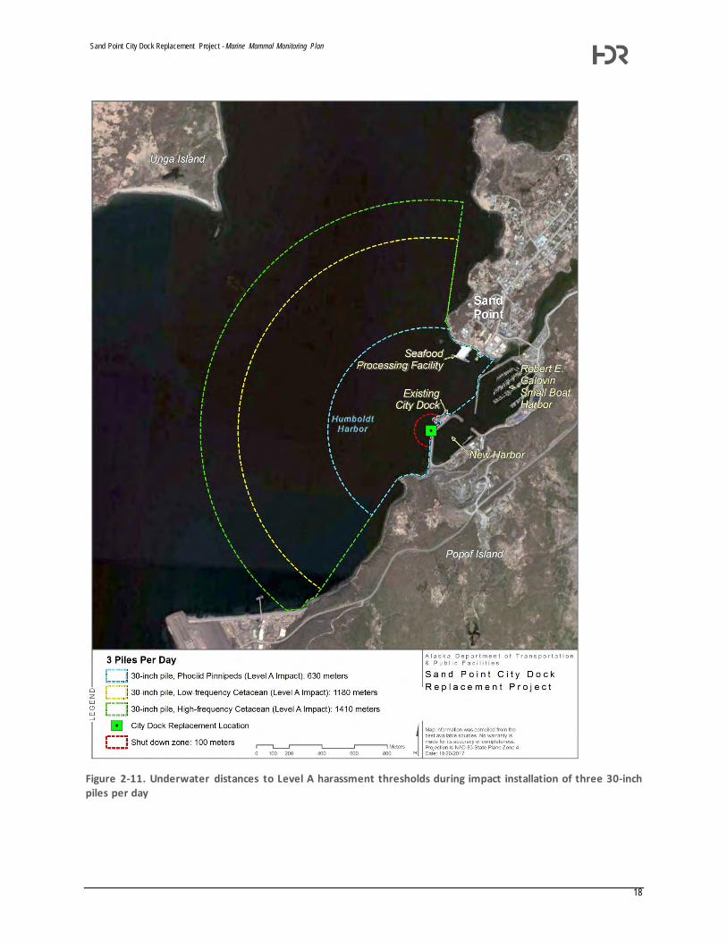
Sand Point City Dock Replacement Project - Marine Mammal Monitoring Plan
18
Figure 2-11. Underwater distances to Level A harassment thresholds during impact installation of three 30-inch piles per day

Sand Point City Dock Replacement Project - Marine Mammal Monitoring Plan
19
Figure 2-12. Underwater distances to Level A harassment thresholds during impact installation of four 30-inch piles per day

Sand Point City Dock Replacement Project - Marine Mammal Monitoring Plan
20
Figure 2-13. Underwater distances to Level B harassment thresholds during impact and vibratory installation of 30-inch piles

Sand Point City Dock Replacement Project - Marine Mammal Monitoring Plan
21
Figure 2-14. Underwater distances to Level B harassment thresholds during impact and vibratory installation of H-piles

Sand Point City Dock Replacement Project - Marine Mammal Monitoring Plan
Attachment 1: Example Data Forms

Sand Point City Dock Replacement Project - Marine Mammal Monitoring Plan

Sand Point City Dock Replacement Project - Marine Mammal Monitoring Plan

Department of Environmental Conservation
DIVISION OF WATER Wastewater Discharge Authorization Program
555 Cordova Street
Anchorage, Alaska 99501-2617
Main: 907.269.6285
Fax: 907.334.2415 www.dec.alaska.gov/water/wwdp August 3, 2018
Alaska Department of Transportation and Public Facilities (ADOT&PF) Attention: Mr. John Barnett P.O. Box 112506 Juneau, AK 99811-2506
Re: ADOT&PF, Sand Point Marine Dock POA-2018-253, Humboldt Harbor
Dear Mr. Barnett:
In accordance with Section 401 of the Federal Clean Water Act of 1977 and provisions of the Alaska
Water Quality Standards, the Department of Environmental Conservation (DEC) is issuing the
enclosed Certificate of Reasonable Assurance for placement of dredged and/or fill material in waters of
the U.S., including wetlands and streams, associated with the development of a high capacity marine
dock in Sand Point, Alaska.
DEC regulations provide that any person who disagrees with this decision may request an informal
review by the Division Director in accordance with 18 AAC 15.185 or an adjudicatory hearing in
accordance with 18 AAC 15.195 – 18 AAC 15.340. An informal review request must be delivered to the
Director, Division of Water, 555 Cordova Street, Anchorage, AK 99501, within 20 days of the permit
decision. Visit http://dec.alaska.gov/commish/review-guidance/ for information on Administrative
Appeals of Department decisions.
An adjudicatory hearing request must be delivered to the Commissioner of the Department of
Environmental Conservation, 410 Willoughby Avenue, Suite 303, PO Box 111800, Juneau, AK 99811-
1800, within 30 days of the permit decision. If a hearing is not requested within 30 days, the right to
appeal is waived.
By copy of this letter we are advising the U.S. Army Corps of Engineers of our actions and enclosing a
copy of the certification for their use.
Sincerely, James Rypkema Program Manager, Storm Water and Wetlands Enclosure: 401 Certificate of Reasonable Assurance cc: (with encl.)
Andy Mitzel, USACE, Soldotna Megan Marie, ADF&G
USFWS Field Office, Anchorage Heather Dean, EPA Operations, Anchorage
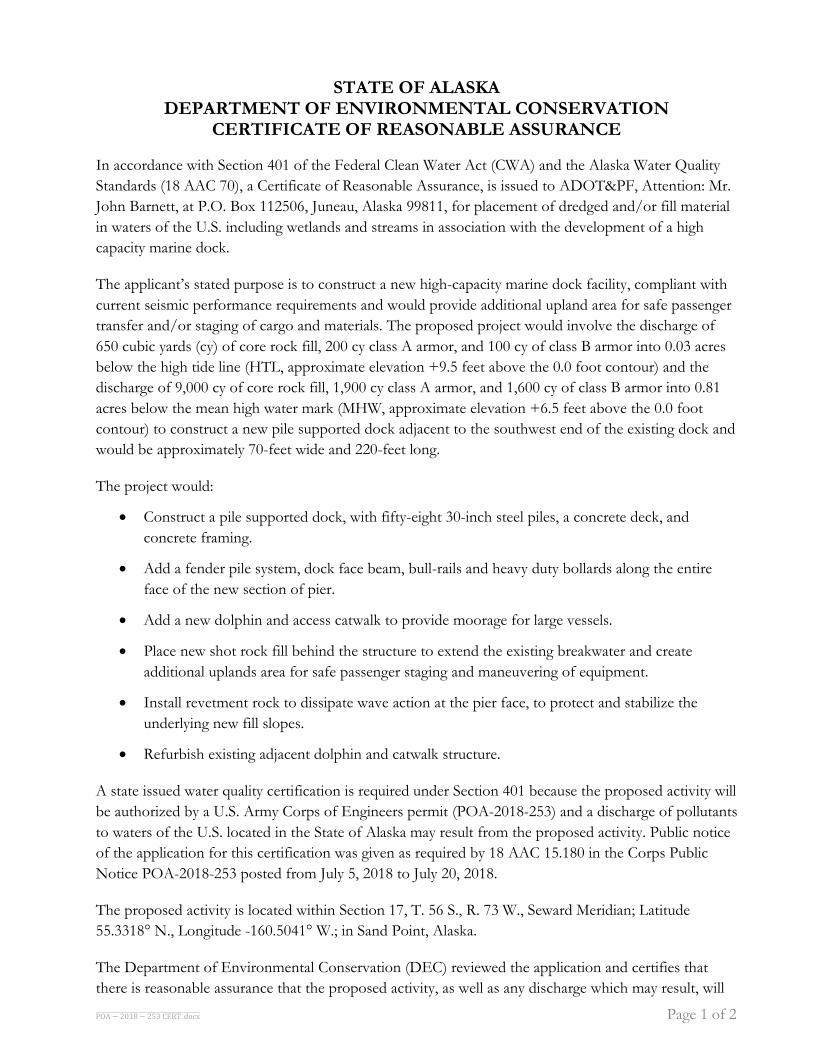
POA − 2018 − 253 CERT. docx Page 1 of 2
STATE OF ALASKA DEPARTMENT OF ENVIRONMENTAL CONSERVATION
CERTIFICATE OF REASONABLE ASSURANCE
In accordance with Section 401 of the Federal Clean Water Act (CWA) and the Alaska Water Quality
Standards (18 AAC 70), a Certificate of Reasonable Assurance, is issued to ADOT&PF, Attention: Mr.
John Barnett, at P.O. Box 112506, Juneau, Alaska 99811, for placement of dredged and/or fill material
in waters of the U.S. including wetlands and streams in association with the development of a high
capacity marine dock.
The applicant’s stated purpose is to construct a new high-capacity marine dock facility, compliant with
current seismic performance requirements and would provide additional upland area for safe passenger
transfer and/or staging of cargo and materials. The proposed project would involve the discharge of
650 cubic yards (cy) of core rock fill, 200 cy class A armor, and 100 cy of class B armor into 0.03 acres
below the high tide line (HTL, approximate elevation +9.5 feet above the 0.0 foot contour) and the
discharge of 9,000 cy of core rock fill, 1,900 cy class A armor, and 1,600 cy of class B armor into 0.81
acres below the mean high water mark (MHW, approximate elevation +6.5 feet above the 0.0 foot
contour) to construct a new pile supported dock adjacent to the southwest end of the existing dock and
would be approximately 70-feet wide and 220-feet long.
The project would:
Construct a pile supported dock, with fifty-eight 30-inch steel piles, a concrete deck, and
concrete framing.
Add a fender pile system, dock face beam, bull-rails and heavy duty bollards along the entire
face of the new section of pier.
Add a new dolphin and access catwalk to provide moorage for large vessels.
Place new shot rock fill behind the structure to extend the existing breakwater and create
additional uplands area for safe passenger staging and maneuvering of equipment.
Install revetment rock to dissipate wave action at the pier face, to protect and stabilize the
underlying new fill slopes.
Refurbish existing adjacent dolphin and catwalk structure.
A state issued water quality certification is required under Section 401 because the proposed activity will
be authorized by a U.S. Army Corps of Engineers permit (POA-2018-253) and a discharge of pollutants
to waters of the U.S. located in the State of Alaska may result from the proposed activity. Public notice
of the application for this certification was given as required by 18 AAC 15.180 in the Corps Public
Notice POA-2018-253 posted from July 5, 2018 to July 20, 2018.
The proposed activity is located within Section 17, T. 56 S., R. 73 W., Seward Meridian; Latitude
55.3318° N., Longitude -160.5041° W.; in Sand Point, Alaska.
The Department of Environmental Conservation (DEC) reviewed the application and certifies that
there is reasonable assurance that the proposed activity, as well as any discharge which may result, will

POA − 2018 − 253 CERT. docx Page 2 of 2
comply with applicable provisions of Section 401 of the CWA and the Alaska Water Quality Standards,
18 AAC 70, provided that the following additional measures are adhered to.
1. Reasonable precautions and controls must be used to prevent incidental and accidental discharge
of petroleum products or other hazardous substances. Fuel storage and handling activities for
equipment must be sited and conducted so there is no petroleum contamination of the ground,
subsurface, or surface waterbodies.
2. During construction, spill response equipment and supplies such as sorbent pads shall be
available and used immediately to contain and cleanup oil, fuel, hydraulic fluid, antifreeze, or
other pollutant spills. Any spill amount must be reported in accordance with Discharge
Notification and Reporting Requirements (AS 46.03.755 and 18 AAC 75 Article 3). The applicant
must contact by telephone the DEC Area Response Team for Central Alaska at (907) 269-3063
during work hours or 1-800-478-9300 after hours. Also, the applicant must contact by telephone
the National Response Center at 1-800-424-8802.
3. Construction equipment shall not be operated below the high tide line if equipment is leaking
fuel, oil, hydraulic fluid, or any other hazardous material. Equipment shall be inspected and
recorded in a log on a daily basis for leaks. If leaks are found, the equipment shall not be used and
pulled from service until the leak is repaired.
4. All work areas, material access routes, and surrounding wetlands involved in the construction
project shall be clearly delineated and marked in such a way that equipment operators do not
operate outside of the marked areas.
5. Excavated or fill material, including overburden, shall be placed so that it is stable, meaning after
placement the material does not show signs of excessive erosion. Indicators of excess erosion
include: gullying, head cutting, caving, block slippage, material sloughing, etc. The material must
be contained with siltation best management practices (BMPs) to preclude reentry into any waters
of the U.S., which includes wetlands.
6. Fill material must be clean sand, gravel or rock, free from petroleum products and toxic
contaminants in toxic amounts.
7. Any disturbed ground and exposed soil not covered with fill must be stabilized and re-vegetated
with endemic species, grasses, or other suitable vegetation in an appropriate manner to minimize
erosion and sedimentation, so that a durable vegetative cover is established in a timely manner.
This certification expires five (5) years after the date the certification is signed. If your project is not
completed by then and work under U.S. Army Corps of Engineers Permit will continue, you must
submit an application for renewal of this certification no later than 30 days before the expiration date
(18 AAC 15.100).
Date: August 3, 2018
James Rypkema, Program Manager Storm Water and Wetlands

Mr. Sean Baginski Principal PND Engineers, Inc. 1506 West 35th Avenue Anchorage, Alaska 99503
Dear Mr. Baginski:
DEPARTMENT OF THE ARMY ALASKA DISTRICT, U.S. ARMY CORPS OF ENGINEERS
P.O. BOX 6898 JBER, AK 99506-0898
October 1, 2018
The Alaska District of the U.S. Army Corps of Engineers (USACE) has completed its evaluation of your request, on behalf of the City of Sand Point, to construct a new public dock on the breakwater of Sand Point New Harbor pursuant to Section 14 of the Rivers and Harbors Act of 1899, 33 U.S.C. 408 (Section 408). This evaluation was performed in accordance with Engineer Circular (EC) 1165-2-216.
Based on this evaluation, the Alaska District is granting permission for the Sand Point Dock Replacement Project, including removal and salvage of existing armor rock, construction of an expanded fill area, placement of a new rock revetment and installation of piles through a portion of the existing breakwater slope, as specified in your submission seeking permission and subject to the special conditions enclosed.
For any questions regarding this Section 408 permission decision, please contact Julie Anderson, Chief, Operations Branch, at 907-753-5685 or [email protected].
Enclosures
cc: Glen Gardner, Mayor, City of Sand Point
Sincerely,
ords, P.E. Chief, Engineering and Construction
Division
Alvin Osterback, Mayor, Aleutians East Borough Andy Mitzel, USACE Regulatory Division

Enclosure 1 Section 408 permission letter conditions for the Sand Point Dock Replacement, Sand Point, Alaska:
GENERAL CONDITIONS 1. This permission authorizes only the City of Sand Point, as the requestor, to
undertake the activity described herein pursuant to Section 14 of the Rivers and Harbors Act of 1899, as amended (33 USC 408). This permission does not preclude the need to obtain other Federal, state, or local authorizations required by law. This permission does not grant any property rights or exclusive privileges, and the City of Sand Point must have appropriate real estate instruments in place prior to construction.
2. Without prior written approval of the Alaska District, the City of Sand Point shall
neither transfer nor assign this permission nor sublet the premises or any part thereof, nor grant any interest, privilege or license whatsoever in connection with this permission. Failure to comply with this condition shall constitute a noncompliance for which the permission may be revoked immediately by USACE.
3. The requestor understands and agrees that, if future operations by the United
States require the removal, relocation, or other alteration of the work herein authorized, or if, in the opinion of the Secretary of the Army or an authorized representative, said work shall cause unreasonable conditions and/or degradation of the USACE project authorized design, the requestor will be required upon due notice from the USACE, to remove, relocate, alter or correct the work, without expense to the United States. No claim shall be made against the United States on account of any such removal or alteration.
4. Any damage to other portions of any federal project(s) resulting from the
activities under this Section 408 permission shall be repaired at the City of Sand Point’s expense.
REEVALUATION OF PERMISSION
5. The Alaska District determination that the activity authorized by this permission
would not impair the usefulness of the federal project and would not be injurious to the public interest was made in reliance on the information provided.

6. The Alaska District, at its sole discretion, may reevaluate its decision to issue this permission at any time circumstances warrant, which may result in a determination that it is appropriate or necessary to modify or revoke this permission. Circumstances that could require a reevaluation include, but are not limited to, the following:
a. Failure to comply with the terms and conditions of this permission; b. Information provided in support of the application for permission proves
to have been inaccurate or incomplete; or c. Significant new information surfaces which the Alaska District did not
consider in reaching the original decision that the activity would not impair the usefulness of the federal project and would not be injurious to the public interest.
CONDUCT OF WORK UNDER THIS PERMISSION
7. Construction of the project must be in accordance with the Section 408 package
submitted by PND Engineers on behalf of the City of Sand Point on October 12, 2017 as updated on February 23, 2018 (PERMIT REVIEW drawings dated 2/22/2018 and revised Specification Section 207, Armor Revetment dated 2/23/2018) and on May 3, 2018 (DRAFT drawing sheets 5-8 dated 4/17/2018) with the following required revisions:
a) Add a layer of Class B Armor Rock between the layers of Class A Armor
Rock and Core Rock as shown in Section C (Existing Dock Improvements) and the associated detail (Typical Dock/Breakwater Interface Section) on Sheet S-5 the Sand Point Harbor Improvements As-Built Drawings dated November 20, 2007.
b) Detail 2 on Sheet 7 of the DRAFT Sand Point Dock Replacement drawings dated 4/17/2018 shall be modified to show that each layer of Class A and Class B Armor Rock shall touch the piles rather than using a rock hatch symbol that is not explicitly two layers of armor rock. The description of how the armor rock will be keyed in should also be updated to indicate that the revetment with the piling will be a well keyed mass. To the extent that is possible and practical, every rock surrounding the piles shall be touching the pile and be well keyed in with the surrounding revetment. Example photos are included in Enclosure 2.
c) Include a construction detail describing how the transition from the new rock for the revetment to the existing rock on the breakwater will be

accomplished. This should include how the transition will look in plan view and how to determine the extents of full rock removal.
d) In Specification Section 207-3.05 Installation of New Slope Protection, remove language about placing armor layer with “minimum voids” and replace with the requirement to place armor “with the least practical amount of void spaces.” Remove language about “without voids underneath any layer of rock” and add language that “Placement of small rock to choke the spaces between large rocks, or for leveling the surface will not be permitted.” See Rock Placement Requirements in Enclosure 2.
8. In accordance with PND DRAFT drawing sheets 5-8, dated 4/17/2018, the
required Class A armor rock layer thickness is 5.5 feet and the required Class B rock layer thickness is 2.5 feet.
9. The City of Sand Point must obtain written approval of those portions of the 100% design plans and specifications that pertain to breakwater deconstruction and reconstruction from the Alaska District prior to the start of breakwater work. Changes to the design with regard to the breakwater deconstruction or reconstruction to include rock testing, rock size, rock layer thickness, rock placement and/or pile driving shall be submitted to the Alaska District for approval.
10. The City of Sand Point is responsible for the stability of the breakwater
throughout construction. 11. The breakwater shall be re-built to USACE construction quality standards per the
rock placement specifications, example photographs and breakwater construction methods included in Enclosure 2. It is strongly recommended that the City of Sand Point ensure the contract construction personnel responsible for oversight of the breakwater re-construction are trained and knowledgeable in the standards of well-keyed rock placement. Non-conforming materials and/or rock placement will be considered a violation of the terms of this permission and shall be removed and replaced.
12. Notify the Alaska District at least fifteen (15) calendar days prior to the start of
breakwater work. The City of Sand Point shall allow the Alaska District to participate in any pre-construction meetings that pertain to breakwater deconstruction, construction and rock placement.

13. The right is reserved for the Alaska District to enter upon the premises to inspect the authorized work at any time deemed necessary to ensure the authorized work is being or has been accomplished in accordance with the terms and conditions of this letter of permission. At a minimum, the City of Sand Point, or its agent, shall allow Alaska District personnel to inspect the rock under the dock prior to installation of any cross-bracing and decking for the dock.
14. The City of Sand Point must provide the following documentation to the Alaska
District: • All pre-construction, intermediate and post construction surveys required by
Specification Section 207-3.06 dated 2/23/2018 furnished electronically in .pdf format within 5 days after completion of the survey. The Alaska District recommends the post construction survey be provided for Alaska District review prior to the City of Sand Point authorizing release of the construction contractor from the project site.
• All rock quality testing reports furnished electronically in .pdf format 5 days after completion.
• Daily quality control reports and five (5) daily photographs during
breakwater deconstruction and reconstruction.
• As-built drawings of the breakwater in electronic .pdf and Autodesk Civil 3D formats within 90 days after completion of construction. The as-built drawings shall depict each layer of material placed.
15. The City of Sand Point must notify the Alaska District at least fifteen (15)
calendar days before breakwater construction is complete to schedule a post-construction inspection. All rock placement shall be complete by the date of the post construction inspection. The Alaska District will not be responsible for any delays or impacts to the City of Sand Point’s contractor should the rock placement be incomplete requiring the scheduling of a subsequent post construction inspection.
16. The City of Sand Point is responsible for final contractual acceptance of the construction activities authorized by this permission. In the event of any deficiency in the design or construction of the requested activity, the City of Sand Point is solely responsible for taking remedial action to correct the deficiency. The Alaska District will verify compliance with the terms, conditions and construction standards required by this permission but has no privity of contract with the construction contractor hired by the City of Sand Point. The

City of Sand Point remains responsible for final project approval and release of the construction contractor.
POST ALTERATION RESPONSIBILITIES
17. Upon completion of the new city dock, federal maintenance of the Sand Point
New Harbor breakwater will be limited to those areas which can be reasonably accessed by rock-handling equipment from a marine floating plant or the breakwater causeway. Portions of the seaward side of the breakwater which are under or between the new and existing city docks may not be accessible for maintenance. Aleutians East Borough, as the non-federal sponsor responsible for local service facilities, is responsible for maintaining the roadway on the causeway and the causeway utility trench and its contents.

Enclosure 2 Rock Placement Requirements, Example Photos and USACE Breakwater Construction Methods

ENCLOSURE 2 – ROCK PLACEMENT REQUIREMENTS, PHOTOS AND USACE BREAKWATER CONSTRUCTION METHODS
PLACEMENT: All materials shall be placed in such a manner as to produce a well-keyed mass of rock with individual pieces tightly in contact with each surrounding stone to achieve a well interlocked stone matrix, and with the least practicable amount of void spaces. The finished surface shall be free from pockets of single size rock. Placement of small rock to choke the spaces between large rock, or for leveling the surface, will not be permitted. Breaking of individual pieces in place by blasting or mechanical methods will not be permitted. Each class of rock shall be placed to the full course thickness at one operation and in such manner as to avoid displacing the underlying material. Placing by methods likely to cause segregation will not be permitted. The desired distribution of the various sizes of rock throughout the mass shall be obtained by selective loading at the quarry and by controlled placement of successive loads. Rearranging of individual pieces by mechanical equipment or by hand will be required to the extent necessary to correct deficiencies, and to provide a uniform, tightly knit slope. Materials that do not meet the specified requirements for size, quality, or distribution of sizes shall be removed and replaced with suitable materials.
ARMOR ROCK: Armor Rock shall be placed on the prepared slopes. All armor stones in the outer armor stone layer shall be placed individually with the long axis of each stone oriented perpendicular to the side slope, with staggered vertical joints, and arranged to secure maximum surface contact and interlock between adjacent stones in order to minimize void size, reduce movement of the stone, and protect underlying stone. Each individual stone shall have contact with adjacent stones on all faces in order to achieve maximum interlock. If necessary, stones shall be set aside until suitable fits for each stone are found in order to achieve maximum interlock. The finished work shall be a well-distributed mass, free of segregated pockets of either smaller or larger stone with a minimum of voids and a maximum of stone interlocking with stones making contact on all faces. The requirement is to achieve a random distribution of well interlocked stone. Re-handling of individual stones after initial placement should be anticipated and will be required to achieve the aforementioned requirements. Casting or dropping of stone from a height greater than one (1) foot or moving by drifting or manipulating down the slope is not permitted. Each type of stone shall be placed to the full course thickness at one operation and in such manner as to avoid displacing the underlying material. No slab-like stone shall be placed with its broadest dimension facing upward, parallel to the finish grade line. Placing by methods likely to cause segregation in terms of stone size or shape will not be permitted. Materials that do not meet the specified requirements for size, shape, quality, or distribution of sizes shall be removed and replaced with suitable materials. Any material displaced shall be replaced to the slopes, lines, and grades shown on the drawings.
REPAIR ORDER: All stone shall be placed beginning at the bottom of the side slope (or toe of the repair template) and then continue up the slope to the crest with vertical stone-to-stone

contact joints that are staggered between layers. The toe stone shall be securely placed within the existing breakwater surface. Toe stone shall be placed to take advantage of the tides to the maximum extent possible to provide the greatest visibility of the completed breakwater toe and tie-in to the existing breakwater slope.
PLACING EQUIPMENT: Placing equipment shall be capable of placing breakwater stone individually without dropping the stone from more than 1 foot and in such a manner so as to not displace the underlying material. Stone placing equipment shall have adequate safe capacity to repair the breakwater to the lines, grades, and slopes shown. Size of equipment shall include consideration for handling overweight stones. The selected equipment shall be capable of placing the stone near its final position before release and be capable of moving the stone if necessary to achieve maximum interlock with adjacent stones. The equipment used to place the armor stone on the breakwater must be capable of securely positioning the toe stone along the lowest point of the breakwater. A means shall be used for turning all stones placed above and below mean lower low water (MLLW) at least 90 degrees in both the horizontal and vertical planes, to the extent necessary for final positioning. An excavator with thumb attachment utilized for placing armor stone shall have sufficient reach and capability of placing and moving a maximum sized stone for positioning within the repair template shown on the drawings. The Operator of the stone placing equipment shall be experienced in breakwater stone placement.

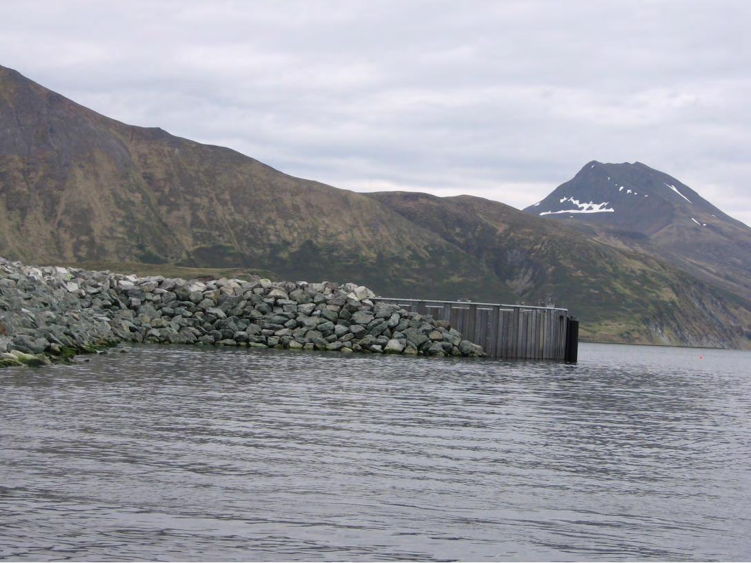


Work barge with crane
Rock barge with loader
Excavator on top of breakwater
Constructing a Breakwater from a Barge
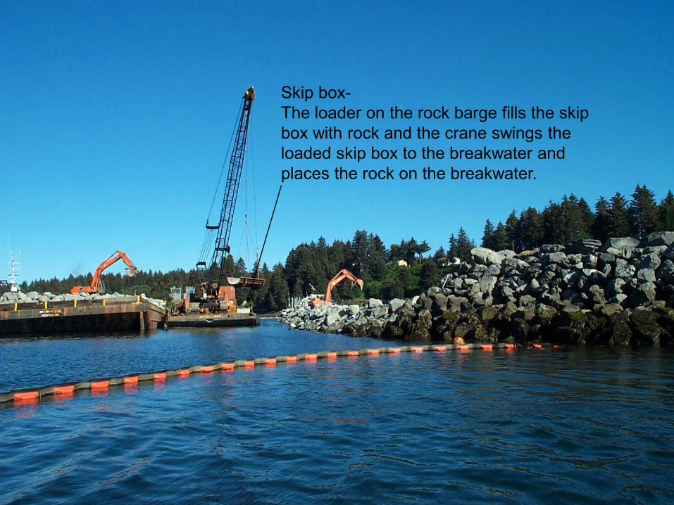
Skip box-The loader on the rock barge fills the skip box with rock and the crane swings the loaded skip box to the breakwater and places the rock on the breakwater.


Once the breakwater is built up above a certain water level an excavator can operate on top of the breakwater to place the armor rock


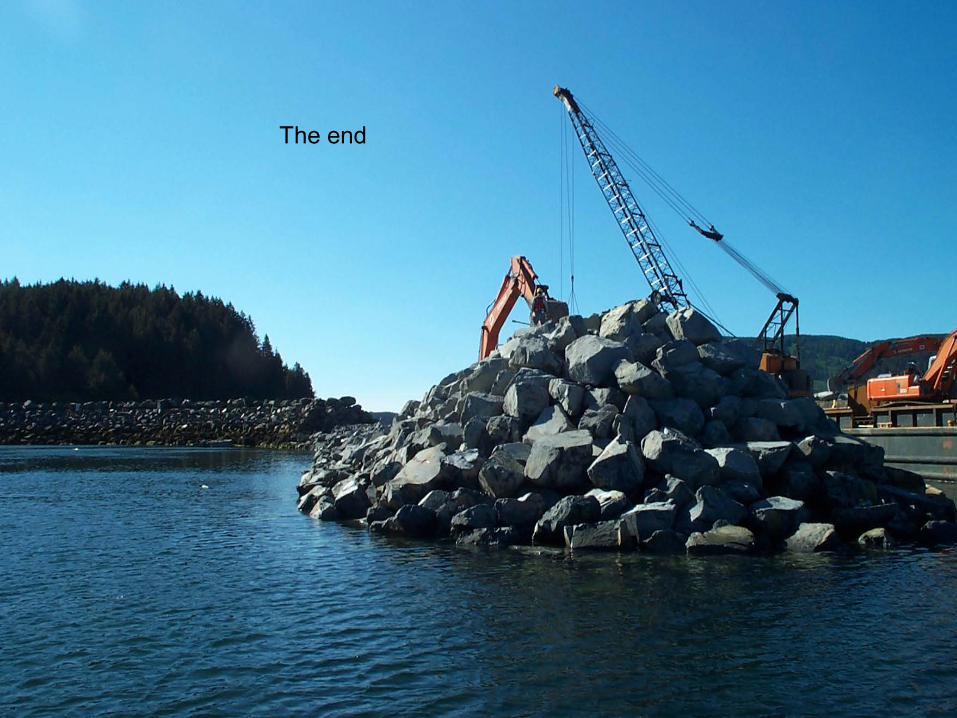
The end


APPENDIX C
MATERIALS CERTIFICATION LIST


* Unshaded boxes under QPL do not indicate that the materials are currently on that list. They indicate materials with potential for being on the QPL once qualified. 1 of 3
MATERIALS CERTIFICATION LISTProject Name
Project Number
Project Engineer SignatureUnshaded boxes indicate who approves the materials submittals. If two boxes not shaded, either approving authority may be used.
Specification CertificateMaterials Item Project Regional Design State Regional Qualified State Manufacturer/ Location
Engineer Materials or Engineer Bridge Traffic Products Materials or Remarks e.g.
QA Engineer of Record Engineer Engineer List (QPL) QA Engineer Binder #
501 STRUCTURAL CONCRETE
Concrete Mix Design, Class __ 501-2.02
503 REINFORCING STEEL
Reinforcing Steel 709-2.01
504 STEEL STRUCTURES
Grout 501-2.01
Structural Steel Shapes & Plates 504-2.01
Weld Materials 504-2.01
Bolts / Connection Hardware 504-2.01
Steel Grating 504-2.01
Rubber Fenders 504-2.01
Galvanizing 504-2.02
Anodes 504-2.01
Chain 504-2.01
UHMW Fabrications 504-2.01
Galvanizing Repair Alloys & Paints 504-3.03
505 PILING
Steel Pipe Piles 505-2.01
Pile Shoes 505-2.01
Sand Point Dock Replacement
SFHWY00006 / 0003194
Construction Design
2004 or Std. Mod. if noted
Statewide Materials

* Unshaded boxes under QPL do not indicate that the materials are currently on that list. They indicate materials with potential for being on the QPL once qualified. 2 of 3
Unshaded boxes indicate who approves the materials submittals. If two boxes not shaded, either approving authority may be used.
Specification CertificateMaterials Item Project Regional Design State Regional Qualified State Manufacturer/ Location
Engineer Materials or Engineer Bridge Traffic Products Materials or Remarks e.g.
QA Engineer of Record Engineer Engineer List (QPL) QA Engineer Binder #
Construction Design
2004 or Std. Mod. if noted
Statewide Materials
Galvanizing 505-2.03
642 CONSTRUCTION SURVEYING AND MONUMENTS
Monument Cases 642-2.01
Primary Monument 642-2.01
Secondary Monument 642-2.01
662 ELECTRICAL SYSTEM
Firestopping 662-2.01
Raceways 662-2.01
Identification 662-2.01
Conductors 662-2.01
Grounding 662-2.01
Light Switches 662-2.01
Receptacles 662-2.01
Boxes 662-2.01
Service Entrance Equipment 662-2.01
Generator
Panelboards 662-2.01
Disconnects 662-2.01
Contactors 662-2.01
Exterior Lighting Controls 662-2.01
Heat Tape 662-2.01
Concrete Sidewalk Box 662-2.01
Breakout Boxes 662-2.01

* Unshaded boxes under QPL do not indicate that the materials are currently on that list. They indicate materials with potential for being on the QPL once qualified. 3 of 3
Unshaded boxes indicate who approves the materials submittals. If two boxes not shaded, either approving authority may be used.
Specification CertificateMaterials Item Project Regional Design State Regional Qualified State Manufacturer/ Location
Engineer Materials or Engineer Bridge Traffic Products Materials or Remarks e.g.
QA Engineer of Record Engineer Engineer List (QPL) QA Engineer Binder #
Construction Design
2004 or Std. Mod. if noted
Statewide Materials
Heating Equipment 662-2.01
Overcurrent Protection 662-2.01
Cord Grips 662-2.01
Lighting Fixtures 662-2.01
Lamps 662-2.01
Ballasts 662-2.01
Spare Parts 662-2.01


APPENDIX D
EROSION AND SEDIMENT CONTROL PLAN


i
Erosion and Sediment Control Plan For
SAND POINT CITY DOCK REPLACEMENT SFHWY00006 / 0003194
Sand Point, Alaska
Alaska Department of Transportation & Public Facilities
Southcoast Region 6860 Glacier Highway
Juneau, Alaska USA 99801
ESCP Preparation Date: February 2019
The following Erosion and Sediment Control Plan (ESCP) has been prepared by the Alaska Department of Transportation and Public Facilities (DOT&PF) to assist bidders in successfully planning their construction means and methods to comply with the 2016 Alaska Construction General Permit (ACGP), United States Army Corps of Engineers (USACE) 404/10 Permit, Alaska Department of Environmental Conservation (ADEC) 401 Water Quality Certification, and other permits associated with this project. This document is not intended to be all inclusive of the best management practices (BMPs) that will be required to reduce the potential for sediment discharge during construction and comply with permit conditions or construction specifications. This ESCP is intended to guide contractors during the bidding process and assist in the preparation of the contractor’s Storm Water Pollution Prevention Plan (SWPPP) that must be approved prior to commencing construction after award. The contractor is responsible for the risk assessment analysis, planning, preparation and implementation of the SWPPP.

ii
TABLE OF CONTENTS SECTION 1 - GENERAL INFORMATION .................................................................................................... 1
1.0 Permittee (5.3.1) .................................................................................................................... 1 1.1 Operator(s)/Contractor(s) ....................................................................................... 1 1.2 Subcontractors ....................................................................................................... 1
2.0 Storm Water Contacts (5.3.2) ................................................................................................ 2 2.1 Contact Information for SWPPP Preparation ......................................................... 2
3.0 Project Information (5.3.3) ..................................................................................................... 2 3.1 Project Information ................................................................................................. 2 3.2 Project Site-Specific Conditions (5.3.3) ................................................................. 2 3.3 Reference Documents Available ............................................................................ 3
4.0 Nature of Construction Activity (5.3.4) ................................................................................... 3 4.1 Scope of Work........................................................................................................ 3 4.2 Project Function (5.3.4.1) ....................................................................................... 3 4.3 Sequence and Timing of Soil-disturbing Activities (5.3.4.2) .................................. 4 4.4 Size of property and total area expected to be disturbed (5.3.4.3) ........................ 4 4.5 Identification of all potential pollutant sources (5.3.4.5) ......................................... 5
5.0 Site Maps (5.3.5) ................................................................................................................... 5 6.0 Discharges ............................................................................................................................. 7
6.1 Locations of Other Industrial Storm Water Discharges (5.3.8) .............................. 7 6.2 Allowable Non-Storm Water Discharges (1.4.3; 4.3.7; 5.3.9) ................................ 7
SECTION 2 – COMPLIANCE WITH STANDARDS, LIMITS, AND OTHER APPLICABLE REQUIREMENTS ............................................................................................................................... 8 7.0 Documentation of Permit Eligibility Related to Total Maximum Daily Loads (3.2, 5.6) ........ 8
7.1 Identify Receiving Waters (5.3.3.3) ........................................................................ 8 7.2 Identify TMDLs (5.6.1) ........................................................................................... 8
8.0 Documentation of Permit Eligibility Related to Endangered Species (3.3, 5.7) ................... 9 8.1 Information on endangered or threatened species or critical habitat (5.7.1) ......... 9
9.0 Historic Properties (1.2, FOotnote) ........................................................................................ 9 10.0 Applicable federal, state, tribal, or local requirements (4.15) ............................................... 9
SECTION 3 – CONTROL MEASURES ...................................................................................................... 10 11.0 Control Measures/Best Management practices (4.0; 5.3.6) ................................................ 11
11.1 Delineate Site (4.2.1) ........................................................................................... 12 11.2 Minimize the Amount of Soil Exposed during Construction Activity (4.2.2) ......... 13 11.3 Maintain Natural Buffer Areas (4.2.3) .................... Error! Bookmark not defined. 11.4 Clearing Vegetation (4.2.4) .................................................................................. 14 11.5 Control Storm Water Discharges and Flow Rates (4.2.5) ................................... 14
11.5.1 Protect Steep Slopes (4.2.6).............................................................. 15 11.6 Storm Water Inlet Protection (4.3.1) .................................................................... 15 11.7 Water Body Protection (4.3.2) .............................................................................. 16 11.8 Down-Slope Sediment Controls (4.3.3) ............................................................... 17 11.9 Stabilized Construction Vehicle Access and Exit Points (4.3.4) .......................... 18 11.10 Dust Generation and Track-Out from Vehicles (4.3.5) ........................................ 18 11.11 Soil Stockpiles (4.3.6) .......................................................................................... 19 11.12 Sediment Basins (4.3.8) ....................................................................................... 20 11.13 Dewatering (4.4)................................................................................................... 20 11.14 Soil Stabilization (4.5) .......................................................................................... 21 11.15 Treatment Chemicals/Active Treatment Systems (4.6.1) .................................... 21
11.15.1 Treatment chemicals (4.6.1) .............................................................. 21 11.15.2 Treatment chemical use procedures (4.6.2) ...................................... 21 11.15.3 Application of treatment chemicals (4.6.3) ........................................ 21 11.15.4 Active Treatment System information (4.6.3.3) ................................. 22
11.16 Good Housekeeping Measures (4.8) ................................................................... 22

iii
11.16.1 Washing of Equipment and Vehicles and Wheel Wash-Down (4.8.1)22 11.16.2 Fueling and Maintenance Areas (4.8.2) ............................................ 22 11.16.3 Washout of Applicators/Containers used for Paint, Concrete, and
Other Materials (4.8.4) ....................................................................... 23 11.16.4 Fertilizer or pesticide use (4.8.5) ....................................................... 23 11.16.5 Storage, Handling, and Disposal of Construction Waste (4.8.6) ....... 24
11.17 Permanent/Post-Construction BMPs ................................................................... 24
SECTION 4 - INSPECTIONS, MONITORING, AND RECORDKEEPING ................................................. 26 12.0 Inspections (5.4; 6.0) ........................................................................................................... 26
12.1 Inspection schedules (5.4.1.2; 6.1; 6.2) ............................................................... 26 12.2 Inspection form or checklist (5.4.1.3; 6.7) ............................................................ 26 12.3 Corrective action procedures (5.4.1.4; 8.0) ......................................................... 26 12.4 Inspection recordkeeping (5.4.2) ......................................................................... 27
13.0 Monitoring Plan (If Applicable) (5.5; 7.0) ............................................................................. 27 13.1 Determination of Need for Monitoring Plan .......................................................... 27 13.2 Monitoring Plan Development ................................ Error! Bookmark not defined. 13.3 Monitoring Considerations ..................................... Error! Bookmark not defined.
14.0 Post-Authorization Records (5.8) ........................................................................................ 28 14.1 Additional Documentation Requirements (5.8.2) ................................................. 28
14.1.1 Records of employee training (4.14; 5.8.2.7) .................................... 28 15.0 Maintaining an Updated SWPPP (5.9) ................................................................................ 29
15.1 Log of SWPPP Modifications (5.9.2).................................................................... 29 15.2 Deadlines for SWPPP Modifications (5.9.3) ........................................................ 29
16.0 Additional SWPPP Requirements (5.10) ............................................................................. 29 16.1 Retention of SWPPP (5.10.1) .............................................................................. 29 16.2 Main entrance signage (5.10.2) ........................................................................... 29 16.3 Availability of SWPPP (5.10.3) ............................................................................. 29 16.4 Signature and certification (5.10.4) ...................................................................... 30

iv
APPENDICES
Those appendices that are marked with (ESCP) are to be populated by the Designer.
Appendix A – Site Maps and Drawings Appendix B – BMP Details Appendix C – Project Schedule Appendix D – Supporting Documentation– see Section 3.3
o TMDLs o Endangered Species o Historic Properties o DEC Non-Domestic Wastewater Plan Review No Objection Letter (if required) o DEC Dewatering Permit (if required) o Environmental Permits and Commitments
Appendix E – Delegation of Authority, Subcontractor Certifications, Project Staff Tracking and Personnel Qualifications
Appendix F – Permit Conditions o Copies of Signed Notices of Intent o Confirmations of Delivery of NOIs to DEC o Copies of Letters from DEC Authorizing Coverage, with DEC NOI Tracking Numbers o Copy of 2011 Alaska Construction General Permit
Appendix G – Grading and Stabilization Records Appendix H – Monitoring Plan (if applicable) and Reports Appendix I – Training Records Appendix J – Corrective Action Log and Delayed Action Item Reports Appendix K – Inspection Records Appendix L – SWPPP Preparer’s Site Visit Appendix M – SWPPP Amendment Log Appendix N – Daily Record of Rainfall Appendix O – Hazardous Material Control Plan (HMCP) Appendix P – Treatment Chemicals/Active Treatment Systems (if applicable) Appendix Q – Other:
o Anti-Degradation Analysis (if applicable) o Correspondence with Regulatory Agencies o Notices of Termination

EROSION AND SEDIMENT CONTROL PLAN (ESCP) 1 SAND POINT CITY DOCK REPLACEMENT SFHWY00006 / 0003194 REVISED 1/2016
SECTION 1 - GENERAL INFORMATION
1.0 PERMITTEE (5.3.1)
The Department of Transportation & Public Facilities (DOT&PF) will be a permittee for the project. Upon the approval of the contractor’s Storm Water Pollution Prevention Plan (SWPPP) by DOT&PF, the contractor will be required to submit a Notice of Intent (NOI) and obtain permit coverage as an operator. The contractor’s contact information, as well as contact information for all subcontractors must be included in the contractor’s SWPPP. All subcontractors will be required to sign a certification (DOT&PF Form 25D-105) demonstrating they have read the Alaska Construction General Permit (ACGP), the contractor’s SWPPP, and will adhere to their terms and conditions.
1.1 Operator(s)/Contractor(s)
Insert Company or Organization Name Insert Name Insert Address Insert City, State, Zip Code Insert Telephone Number Insert Fax/Email The contractor has day-to-day operational control over activities in the field, including subcontractors and implementation of the SWPPP. Alaska Department of Transportation and Public Facilities Insert Name P.O. Box 112506 Juneau, Alaska 99811-2506 Insert Telephone Number Insert Fax/Email DOT &PF has operational control over construction plans and specifications, including the ability to make modifications and ensure compliance with the SWPPP. Repeat as necessary. 1.2 Subcontractors
Insert Company or Organization Name Insert Name Insert Address Insert City, State, Zip Code Insert Telephone Number Insert Fax/Email Insert Area of Control Repeat as necessary to include all subcontractors.

EROSION AND SEDIMENT CONTROL PLAN (ESCP) 2 SAND POINT CITY DOCK REPLACEMENT SFHWY00006 / 0003194 REVISED 1/2016
2.0 STORM WATER CONTACTS (5.3.2)
Identify the qualified persons responsible for the following required positions (note: a small project may have all these responsibilities carried out by one person):
Superintendent; Storm Water Lead (5.3.2.1); SWPPP Preparer (5.3.2.2); Person(s) Conducting Inspections- Contractor’s SWPPP Manager and DOT&PF’s Storm Water Inspector (5.3.2.3); Person(s) Conducting Monitoring (if applicable, 5.3.2.4), and Person(s) Operating Active Treatment System (if applicable, 5.3.2.5).
Document that the named individuals are Qualified Persons as described in ACGP Appendix C and as required in Section 641-1.04, whichever is most stringent. Include documentation of qualifications in Appendix E of the SWPPP.
2.1 Contact Information for SWPPP Preparation
The following individuals may be contacted for questions when writing the SWPPP:
Name Phone Email Steven Thater (907) 465-1794 [email protected]
3.0 PROJECT INFORMATION (5.3.3)
3.1 Project Information
Project/Site Name: Sand Point City Dock Replacement
Project State Number/Federal Number: SFHWY00006 / 0003194
Project Street/Location: South Harbor Access Road, MP 0.5
City: Sand Point State: AK Zip Code: 99827
Borough or Subdivision: Aleutians East
Latitude/Longitude:
Latitude: Longitude:
1. 55 º 19 ' 53'' N (degrees, minutes, seconds) 1. 160 º 30 ' 17” W (degrees, minutes, seconds)
Method for determining latitude/longitude:
USGS topographic map (specify scale: _________) EPA Web site GPS
Other (please specify): STAR
3.2 Project Site-Specific Conditions (5.3.3)
Mean annual precipitation based on nearest weather station (inches): Based on the nearest weather station, Sand Point (508183), the mean annual precipitation at the project location is 44.68 inches. https://wrcc.dri.edu/cgi-bin/cliMAIN.pl?ak8183

EROSION AND SEDIMENT CONTROL PLAN (ESCP) 3 SAND POINT CITY DOCK REPLACEMENT SFHWY00006 / 0003194 REVISED 1/2016
Size of the 2-yr, 24-hr storm event (in inches): Based on NOAA Atlas 14, Volume 7 Point Precipitation Frequency Estimates for Sand Point, the nearest station to the project, the 2-year, 12-hour storm will produce 1.47 inches of rainfall. https://hdsc.nws.noaa.gov/hdsc/pfds/pfds_map_ak.html
Soil Type(s) and Slopes: The Sand Point City Dock facility is comprised of primarily unclassified fill over tideland with armor revetment on embankment slopes.
Landscape Topography: The site is part of an existing breakwater that serves to protect harbor infrastructure. The breakwater is level and approximately ¼ mile from the shoreline which consists of mountainous or steep topography.
Drainage patterns Drainage is conveyed via surface flow that drain to embankment and eventually to adjacent waters.
Type of Existing Vegetation: Tidelands.
Approximate growing season: According to the Regional Supplement to the Corps of Engineers Wetland Delineation Manual: Alaska Region (Version 2.0) there were no available data for this region. Growing season dates of April 25 to October 4, for Bristol Bay, were substituted.http://www.poa.usace.army.mil/Portals/34/docs/regulatory/Alaska%20Regional%20Supplement.pdf
Seeding Dates: None
Fall Freeze-Up and Spring Thaw Dates: Fall freeze-up is December and Spring thaw is May. https://wrcc.dri.edu/cgi-bin/cliMAIN.pl?ak8183
Clearing Window: None
Fish Window: None
Historic site contamination evident from existing site features and known past usage of the site: A search of the Alaska DEC Contaminated Sites database revealed no known contaminated sites adjacent to the project. http://www.dec.alaska.gov/spar/csp/db_search.htm
3.3 Reference Documents Available
Listed below are the reference documents (if any) available for this project. Please contact the Project Engineer for assistance in obtaining these documents.
4.0 NATURE OF CONSTRUCTION ACTIVITY (5.3.4)
4.1 Scope of Work
Describe the general scope of work for the project, major phases of construction and the major erosion & sediment control elements. Typically, this will be shown as a short list of bulleted phases or elements for construction of the job.
The proposed project would construct a new dock adjacent to the southwest end of the existing dock and would be approximately 70-ft wide and 220-ft long. The project would:

EROSION AND SEDIMENT CONTROL PLAN (ESCP) 4 SAND POINT CITY DOCK REPLACEMENT SFHWY00006 / 0003194 REVISED 1/2016
• Construct a pile supported dock with concrete deck and concrete framing. • Add a fender pile system, dock face beam, bull-rails and heavy duty bollards along the entire face
of the new section of pier. • Add a new dolphin and access catwalk to provide moorage for large vessels. • Place new shot rock fill behind the structure to extend the existing breakwater and create
additional uplands area for safe passenger staging and maneuvering of equipment. • Install revetment rock to dissipate wave action at the pier face, to protect and stabilize the
underlying new fill slopes. • Refurbish existing adjacent dolphin and catwalk structure.
4.2 Project Function (5.3.4.1)
Briefly describe the function of the construction activity (e.g., low-density residential, shopping mall, subdivision, airport, highway, etc.).
The existing Sand Point dock is used for cargo shipments and landing for passengers of the Alaska Marine Highway System (AMHS). The existing structure was constructed in 1983 and is nearing the end of its operational life due to corrosion and wear. The dock does not meet current code for seismic performance requirements. The proposed new dock would accommodate the demands of the community by providing a modern, high-capacity marine dock facility, compliant with current seismic performance requirements and would provide additional upland area for safe passenger transfer and/or staging of cargo and materials.
4.3 Sequence and Timing of Soil-disturbing Activities (5.3.4.2)
The contractor will be required to finish, with either temporary or final stabilization, individual areas prior to moving on to the next area. The contractor will be required to prepare a detailed schedule for review and approval prior to commencement of construction activities and is to be included in the SWPPP. The schedule will detail the sequence of activities and describe the stabilization schedule.
4.4 Size of property and total area expected to be disturbed (5.3.4.3)
The following are estimates of the construction site:
Description Number Remarks
Total project area: 1.13 acres
Construction-site area to be disturbed:
1.12 acres
Percentage impervious area BEFORE construction:
0 %
Runoff Coefficient BEFORE construction:
0.55

EROSION AND SEDIMENT CONTROL PLAN (ESCP) 5 SAND POINT CITY DOCK REPLACEMENT SFHWY00006 / 0003194 REVISED 1/2016
Percentage impervious area AFTER construction:
32 %
Runoff coefficient AFTER construction:
0.67
The values shown in the table above were calculated with the information available at the time of the final design. The contractor’s values will be different due to staging areas, batch plants, material stockpiles, etc. If a discrepancy is found, contact the Project Engineer to request further information.
4.5 Identification of all potential pollutant sources (5.3.4.5)
Identify and list all potential sources of pollution, including sediment, from construction materials and activities which may affect the quality of storm water discharges from the construction site.
Potential sources of sediment to storm water runoff:
The main sources of storm water runoff are material stockpiles and disturbed soils during construction of embankment and drainage improvements.
Potential pollutants and sources, other than sediment, to storm water runoff:
Trade Name Material Storm Water Pollutants Location Gas, diesel, oil Petroleum, oil and lubricants Equipment storage area, staging
area, fueling area Antifreeze and coolants Methanol, Ethylene glycol,
Propylene glycol Equipment storage area, staging area
Trash Paper, plastic, metal Waste storage area Waste Organic material Sanitation facilities
5.0 SITE MAPS (5.3.5)
The project plan sheets may be used to show these features on the ESCP sheets. A larger site map showing waters of the United States within 2,500 feet of the site boundary may be necessary if there is potential for project related storm water to impact the water bodies. This figure would be similar to a vicinity map, but with more detail in respect to water bodies.
The SWPPP must include a legible site map (or set of maps for large projects) showing the entire site and identifying the following site-specific information (if known at the time of design):

EROSION AND SEDIMENT CONTROL PLAN (ESCP) 6 SAND POINT CITY DOCK REPLACEMENT SFHWY00006 / 0003194 REVISED 1/2016
1. North arrow
2. Boundaries where earth-disturbing activities will occur, noting any phasing of construction activities (typically Right of Way), CGP 5.3.5.1.
3. Locations where earth-disturbing activities will occur, noting construction phasing, CGP 5.3.5.2
4. Location of areas that will not be disturbed and natural features to be preserved, CGP 5.3.5.3
5. Location of all storm water conveyances including ditches, pipes, and swales, CGP 5.3.5.4.
6. Locations of storm water inlet and outfalls, with a unique identification code for each outfall, CGP 5.3.5.5
7. Municipal separate storm sewer systems if present, CGP 5.3.5.6
8. Direction(s) of storm water flow and approximate slopes anticipated after grading activities, CGP 5.3.5.7
9. Locations where control measures will be or have been installed, CGP 5.3.5.8
10. Locations where exposed soils will be stabilized or have been stabilized, CGP 5.3.5.9
11. Locations where post-construction storm water controls will be or have been installed, CGP 5.3.5.10
12. Locations of support activities described in Part 1.4.2.3, CGP 5.3.5.11
13. Locations where authorized non-storm water will be used, including the types that will be used on-site, CGP 5.3.5.12
14. Locations and sources of run-on to the site from adjacent property that may contain quantities of pollutants (e.g., sediment, fertilizers and/or pesticides, paints, solvents, fuels) which could be exposed to rainfall, or snowmelt, and could be discharged your construction site, CGP 5.3.5.13
15. Locations of all waters of the US (including significant wetland areas e.g., 10,000 square feet or greater) on the site and those located within 2,500 feet of the site boundary that may be affected by storm water discharges from the site (see ESCP Section 7.1), CGP 5.3.5.14.
16. Location of existing public water system (PWS) drinking water protection areas (DWPA) for PWS sources (e.g. springs, wells, or surface water intakes) that intersect the boundary of the proposed project/permit area. The DWPAs can be found using the interactive web map application, “Alaska DEC Drinking Water Protection Areas”, located at http://dec.alaska.gov/das/GIS/apps.htm, CGP 5.3.5.15
17. Locations where storm water and/or authorized non-storm water discharges to waters of the U.S.(including wetlands) or an MS4, CGP 5.3.5.16
18. Sampling Point(s) (if applicable): A permittee subject to the requirements of Parts 3.2 must include the locations(s) of the storm water discharge sampling points(s). For a linear project, indicate which sampling points are considered substantial identical, in accordance with Part 7.3.4, CGP 5.3.5.17
19. Areas where final stabilization has been accomplished, CGP 5.3.5.18

EROSION AND SEDIMENT CONTROL PLAN (ESCP) 7 SAND POINT CITY DOCK REPLACEMENT SFHWY00006 / 0003194 REVISED 1/2016
6.0 DISCHARGES
Subject to compliance with the terms and conditions of the 2016 ACGP, the permittee is authorized to discharge pollutants in storm water discharges from the site.
Describe and identify the location of any known storm water discharges from the project area (5.3.8).
6.1 Locations of Other Industrial Storm Water Discharges (5.3.8)
The contractor is required to identify discharges from related support activities. Portable batch plants located on Department supplied property must be included in the contractor’s SWPPP and related inspections. If the DOT&PF is not a CGP operator for the site or sites listed in this subsection, then describe the sites and BMPs for them in a separate SWPPP2. In this section, explain which areas are covered within this SWPPP and which are covered within a separate SWPPP2. Also provide information on where the SWPPP2 is available for review.
6.2 Allowable Non-Storm Water Discharges (1.4.3; 4.3.7; 5.3.9)
The contractor must list all allowable non-storm water discharges and describe how the discharges will be minimized and managed to reduce pollution to storm water in the contractor’s SWPPP.

EROSION AND SEDIMENT CONTROL PLAN (ESCP) 8 SAND POINT CITY DOCK REPLACEMENT SFHWY00006 / 0003194 REVISED 1/2016
SECTION 2 – COMPLIANCE WITH STANDARDS, LIMITS, AND OTHER APPLICABLE REQUIREMENTS
VERIFY all information in Section 2 with your Environmental Analyst. The Environmental Document for your project will contain most of this information and should be used as a reference document to populate Section 2 sub-sections.
7.0 DOCUMENTATION OF PERMIT ELIGIBILITY RELATED TO TOTAL MAXIMUM DAILY LOADS (3.2, 5.6)
If the project is discharging into a water body with an EPA-established or approved Total Maximum Daily Load (TMDL), the project must implement measures to ensure the discharge of pollutants from the site is consistent with the assumptions and requirements of the TMDL. Refer to the 2016 ACGP for additional requirements.
The SWPPP must include documentation supporting a determination of permit eligibility with regard to waters that have a TMDL.
A search of the “Alaska’s Final 2012 Integrated Water Quality Monitoring and Assessment Report” found no listings or impairments for the Popof Strait.
7.1 Identify Receiving Waters (5.3.3.3)
Description of receiving waters: Tidal influenced coastal waters
Description of storm sewer and/or drainage systems: Storm water surface is discharged to tidal waters
Other: Insert Text
7.2 Identify TMDLs (5.6.1)
Is an EPA-established or approved TMDL published for the receiving water(s) listed in Section 7.1?
Yes No
If YES, list the TMDL(s) here. ACGP Section 3.2.1.1 references only TMDLs relating to turbidity or sediment generated by construction activity. Include a summary of consultations with state or federal TMDL authorities. Include correspondence or other supporting documentation in the appropriate appendix.
TMDL: N/A
Summary of consultation with state or federal TMDL authorities (5.6.2): N/A
Measures taken to ensure compliance with TMDL (5.6.3): N/A

EROSION AND SEDIMENT CONTROL PLAN (ESCP) 9 SAND POINT CITY DOCK REPLACEMENT SFHWY00006 / 0003194 REVISED 1/2016
8.0 DOCUMENTATION OF PERMIT ELIGIBILITY RELATED TO ENDANGERED SPECIES (3.3, 5.7)
8.1 Information on endangered or threatened species or critical habitat (5.7.1)
Are endangered or threatened species and critical habitats on or near the project area?
Yes No
Describe how this determination was made: USFWS threatened and endangers species database
Will species or habitat be adversely affected by storm water discharge (5.7.2)?
Yes No
Describe the species and/or critical habitat, if species or habitat will be affected by storm water discharge.
Provide summary of necessary measures (5.7.5): N/A
9.0 HISTORIC PROPERTIES (1.2, FOOTNOTE)
Are there any historic sites on or near the construction site?
Yes No
Describe how this determination was made: Consultation with the State Historic Preservation Office
If cultural or paleontological resources are discovered after the initial commencement of construction activities, work that would disturb such resources is to be stopped, and the Office of History and Archaeology, a Division of Parks and Outdoor Recreation of the Alaska Department of Natural Resources (http://dnr.alaska.gov/parks/oha/index.htm), is to be notified immediately at (907) 269-8721.
It is the Contractor’s responsibility, through the Project Engineer, to get clearance for material and disposal sites that have not been assessed during the Design phase of the project.
10.0 APPLICABLE FEDERAL, STATE, TRIBAL, OR LOCAL REQUIREMENTS (4.15)
Permittees must ensure that the storm water control measures implemented a the site are consistent with all applicable federal, state, tribal, or local, requirements for soil erosion control and storm water management.
Describe any other applicable federal, state, tribal, or local requirements that pertain to the project. Refer to the Environmental Document for this information.

EROSION AND SEDIMENT CONTROL PLAN (ESCP) 10 SAND POINT CITY DOCK REPLACEMENT SFHWY00006 / 0003194 REVISED 1/2016
SECTION 3 – CONTROL MEASURES
Describe the Best Management Practices (BMPs) to be implemented to control pollutants in storm water discharges. For each major activity identified:
• Clearly describe appropriate control measures.
• Describe general sequence during the construction process in which the measures will be implemented.
• Describe maintenance and inspection procedures to be undertaken for that specific BMP.
• Include protocols, thresholds, and schedules for cleaning, repairing, and/or replacing damaged or failing BMPs.
• Identify staff responsible for maintaining BMPs. (If your SWPPP is shared by multiple operators, indicate the operator responsible for each BMP).
• DOT&PF requires citations for the BMP manual or publication used to select and design the BMP, along with schematics or descriptions of the BMP. If no BMP manual or publication was used to select or design a given BMP then state “no BMP manual or publication was used”. BMP designs submitted by the contractor and approved by the Project Engineer may be used but still must state that no manual or publication was used.
Categorize each BMP under one of the following areas of BMP activity as described below:
1. Delineation of site (4.2.1)
2. Minimize the Amount of Soil Exposed during Construction Activity (4.2.2)
3. Maintain Natural Buffer Areas (4.2.3)
4. Clearing Vegetation (4.2.4)
5. Control Storm Water Discharges and Flow Rates (4.2.5)
6. Protect Steep Slopes (4.2.6)
7. Storm Water Inlet Protection Measures (4.3.1)
8. Water Body Protection Measures (4.3.2)
9. Down-Slope Sediment Controls (4.3.3)
10. Stabilized Construction Vehicle Access and Exist Points (4.3.4)
11. Dust Generation and Track-Out from Vehicles (4.3.5)
12. Soil Stockpiles (4.3.6)
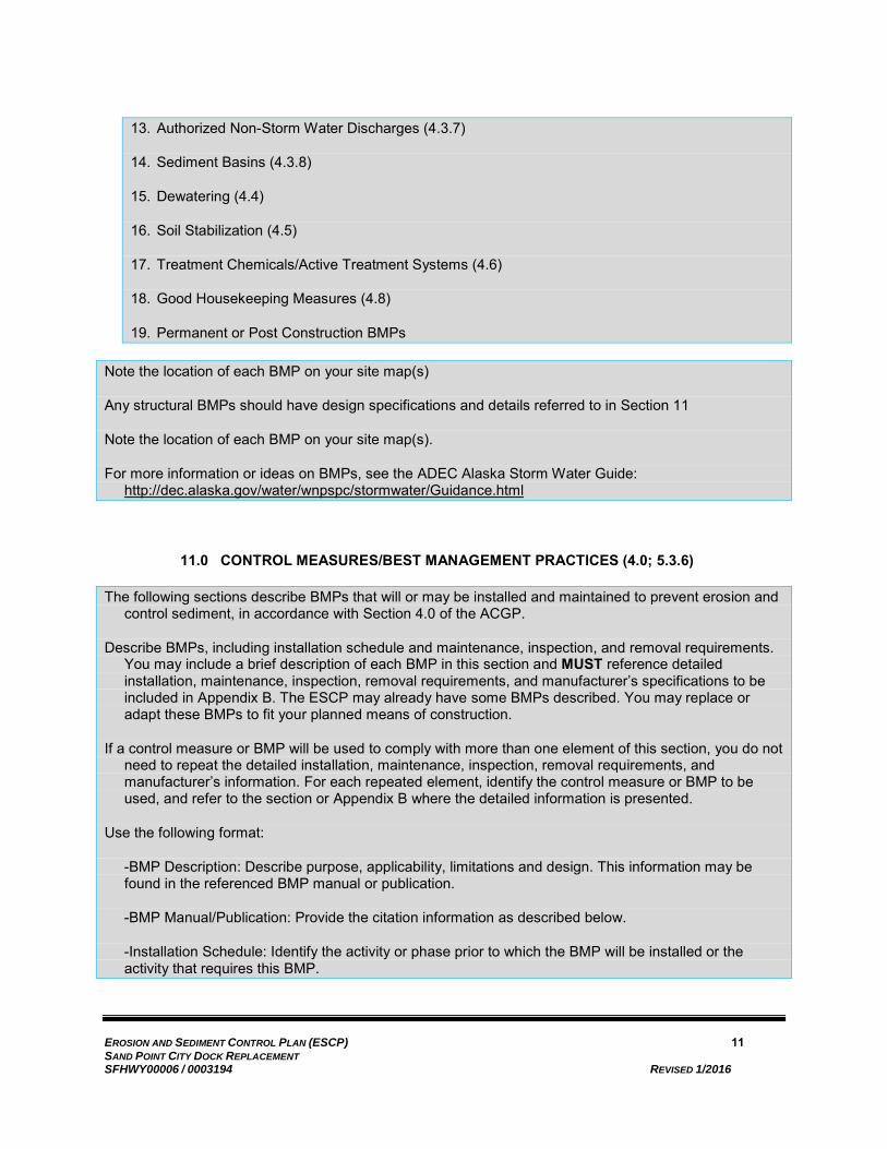
EROSION AND SEDIMENT CONTROL PLAN (ESCP) 11 SAND POINT CITY DOCK REPLACEMENT SFHWY00006 / 0003194 REVISED 1/2016
13. Authorized Non-Storm Water Discharges (4.3.7)
14. Sediment Basins (4.3.8)
15. Dewatering (4.4)
16. Soil Stabilization (4.5)
17. Treatment Chemicals/Active Treatment Systems (4.6)
18. Good Housekeeping Measures (4.8)
19. Permanent or Post Construction BMPs
Note the location of each BMP on your site map(s)
Any structural BMPs should have design specifications and details referred to in Section 11
Note the location of each BMP on your site map(s).
For more information or ideas on BMPs, see the ADEC Alaska Storm Water Guide: http://dec.alaska.gov/water/wnpspc/stormwater/Guidance.html
11.0 CONTROL MEASURES/BEST MANAGEMENT PRACTICES (4.0; 5.3.6)
The following sections describe BMPs that will or may be installed and maintained to prevent erosion and control sediment, in accordance with Section 4.0 of the ACGP.
Describe BMPs, including installation schedule and maintenance, inspection, and removal requirements. You may include a brief description of each BMP in this section and MUST reference detailed installation, maintenance, inspection, removal requirements, and manufacturer’s specifications to be included in Appendix B. The ESCP may already have some BMPs described. You may replace or adapt these BMPs to fit your planned means of construction.
If a control measure or BMP will be used to comply with more than one element of this section, you do not need to repeat the detailed installation, maintenance, inspection, removal requirements, and manufacturer’s information. For each repeated element, identify the control measure or BMP to be used, and refer to the section or Appendix B where the detailed information is presented.
Use the following format:
-BMP Description: Describe purpose, applicability, limitations and design. This information may be found in the referenced BMP manual or publication.
-BMP Manual/Publication: Provide the citation information as described below.
-Installation Schedule: Identify the activity or phase prior to which the BMP will be installed or the activity that requires this BMP.

EROSION AND SEDIMENT CONTROL PLAN (ESCP) 12 SAND POINT CITY DOCK REPLACEMENT SFHWY00006 / 0003194 REVISED 1/2016
-Maintenance and Inspection: Describe the thresholds and/or indicators for maintenance and protocols for inspecting the BMP.
-Describe the maintenance procedures. If using a BMP manual or publication, this information may be found there.
-Responsible Staff: The person(s) identified in Section 2 of this SWPPP will be responsible for ensuring compliance with the installation, maintenance, inspection, and removal of these control measures. If your SWPPP is shared by multiple operators, indicate the operator responsible for each BMP.
How to Cite a BMP Publication:
For all temporary control measures, including Good Housekeeping BMPs, identified in this section, DOT&PF requires citation for the BMP manual or publication used to select and design the BMP. If the BMP was designed specifically for the project and a manual or publication was not used, include the statement “No manual was used to select or design the BMP” and include information on the BMP’s design and placement in the ESCP.
Permanent BMPs do not need a citation. Permanent, or Post-Construction, BMPs are permanent features that have been included in the DOT&PF contract.
1) BMP Manuals: BMP manuals describe each BMP and outline details such as installation, design parameters, applicability/limitations, maintenance, and targeted pollutants. To cite a manual, include the title, author (individual or agency), date of publication, and attach the appropriate pages in Appendix B.
2) DOT&PF Specifications and Plan Sheets: The publication cited may be the DOT&PF contract specifications and plan sheets, provided that the minimum information regarding the BMP is included.
When the plans and specifications are used, the reference must include the sheet or page number and be included in Appendix B of the ESCP.
If the specifications and plan sheets do not provide the minimum information, the SWPPP Preparer must provide the missing information in the SWPPP. Any drawing or description developed by the ESCP Preparer must include the statement “No BMP manual or publication was used for this design.”
3) Manufacturer’s Specification Sheet: Referencing a manufacturer’s specification sheet is suitable only if it includes all the necessary information listed in the above subsection. When using the manufacturer’s specification sheet(s), provide the product name, manufacturer, date of copyright, and attach copies of the specification sheet(s) to the ESCP. It may also be helpful to provide the manufacturer’s website if the information was obtained online.
11.1 Delineate Site (4.2.1)
Describe measures (signs, flags, fences, stakes, etc.) to be used to delineate all areas where soil disturbing construction activities will occur; and specific areas that will be left undisturbed such as trees, boundaries of sensitive areas, or buffers established under Part 4.2.3.
BMP Description: BMP 54.00 Site Delineation
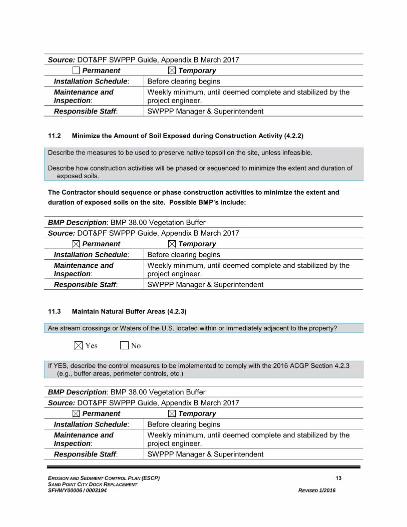
EROSION AND SEDIMENT CONTROL PLAN (ESCP) 13 SAND POINT CITY DOCK REPLACEMENT SFHWY00006 / 0003194 REVISED 1/2016
Source: DOT&PF SWPPP Guide, Appendix B March 2017 Permanent Temporary
Installation Schedule: Before clearing begins Maintenance and Inspection:
Weekly minimum, until deemed complete and stabilized by the project engineer.
Responsible Staff: SWPPP Manager & Superintendent
11.2 Minimize the Amount of Soil Exposed during Construction Activity (4.2.2)
Describe the measures to be used to preserve native topsoil on the site, unless infeasible.
Describe how construction activities will be phased or sequenced to minimize the extent and duration of exposed soils.
The Contractor should sequence or phase construction activities to minimize the extent and duration of exposed soils on the site. Possible BMP’s include:
BMP Description: BMP 38.00 Vegetation Buffer Source: DOT&PF SWPPP Guide, Appendix B March 2017 Permanent Temporary
Installation Schedule: Before clearing begins Maintenance and Inspection:
Weekly minimum, until deemed complete and stabilized by the project engineer.
Responsible Staff: SWPPP Manager & Superintendent
11.3 Maintain Natural Buffer Areas (4.2.3)
Are stream crossings or Waters of the U.S. located within or immediately adjacent to the property?
Yes No
If YES, describe the control measures to be implemented to comply with the 2016 ACGP Section 4.2.3 (e.g., buffer areas, perimeter controls, etc.)
BMP Description: BMP 38.00 Vegetation Buffer Source: DOT&PF SWPPP Guide, Appendix B March 2017 Permanent Temporary
Installation Schedule: Before clearing begins Maintenance and Inspection:
Weekly minimum, until deemed complete and stabilized by the project engineer.
Responsible Staff: SWPPP Manager & Superintendent

EROSION AND SEDIMENT CONTROL PLAN (ESCP) 14 SAND POINT CITY DOCK REPLACEMENT SFHWY00006 / 0003194 REVISED 1/2016
11.4 Clearing Vegetation (4.2.4)
Will vegetation clearing be initiated prior to obtaining authorization under the 2016 ACGP?
Yes No
*Note – Clearing of vegetation that disturbs the vegetative mat and exposes soil is prohibited prior to obtaining authorization under this permit. Operators shall use caution when clearing so as not to cause earth disturbance.
11.5 Control Storm Water Discharges and Flow Rates (4.2.5)
Describe control measures to comply with the ACGP (e.g., divert storm water around the site, slow down or contain storm water, install velocity dissipation devices along conveyance channels, install permanent storm water management controls prior to construction of site improvements to the extent practicable, etc.).
BMP Description: BMP 08.00 Culvert Inlet Protection Source: DOT&PF SWPPP Guide, Appendix B March 2017 Permanent Temporary
Installation Schedule: Prior to ground disturbing activities Maintenance and Inspection:
Weekly minimum, until deemed complete and stabilized by the project engineer.
Responsible Staff: SWPPP Manager & Superintendent
BMP Description: BMP 10.00 Fiber Rolls Source: DOT&PF SWPPP Guide, Appendix B March 2017 Permanent Temporary
Installation Schedule: Prior to ground disturbing activities Maintenance and Inspection:
Weekly minimum, until deemed complete and stabilized by the project engineer.
Responsible Staff: SWPPP Manager & Superintendent BMP Description: BMP 20.00 Silt Fence Source: DOT&PF SWPPP Guide, Appendix B March 2017 Permanent Temporary
Installation Schedule: Prior to ground disturbing activities Maintenance and Inspection:
Weekly minimum, until deemed complete and stabilized by the project engineer.

EROSION AND SEDIMENT CONTROL PLAN (ESCP) 15 SAND POINT CITY DOCK REPLACEMENT SFHWY00006 / 0003194 REVISED 1/2016
Responsible Staff: SWPPP Manager & Superintendent
11.5.1 Protect Steep Slopes (4.2.6)
Will steep slopes be present at the site during construction? Yes No
If YES, describe control measures to be implemented to comply with ACGP Section 4.2.6 (e.g., reduce continuous slope length, divert storm water around slopes, stabilized exposed areas, etc.).
BMP Description: BMP 10.00 Fiber Rolls Source: DOT&PF SWPPP Guide, Appendix B March 2017 Permanent Temporary
Installation Schedule: Prior to ground disturbing activities Maintenance and Inspection:
Weekly minimum, until deemed complete and stabilized by the project engineer.
Responsible Staff: SWPPP Manager & Superintendent BMP Description: BMP 17.00 Rock Armor Source: DOT&PF SWPPP Guide, Appendix B March 2017 Permanent Temporary
Installation Schedule: As slope is constructed Maintenance and Inspection:
Weekly minimum, until deemed complete and stabilized by the project engineer.
Responsible Staff: SWPPP Manager & Superintendent BMP Description: BMP 20.00 Silt Fence Source: DOT&PF SWPPP Guide, Appendix B March 2017 Permanent Temporary
Installation Schedule: Prior to ground disturbing activities Maintenance and Inspection:
Weekly minimum, until deemed complete and stabilized by the project engineer.
Responsible Staff: SWPPP Manager & Superintendent
11.6 Storm Water Inlet Protection (4.3.1)
Describe control measures (e.g., filter berms, perimeter controls, temporary diversion dikes, etc.) to be implemented to protect all inlets receiving storm water from the project during the duration of the project.
BMP Description: BMP 08.00 Culvert Inlet Protection Source: DOT&PF SWPPP Guide, Appendix B March 2017

EROSION AND SEDIMENT CONTROL PLAN (ESCP) 16 SAND POINT CITY DOCK REPLACEMENT SFHWY00006 / 0003194 REVISED 1/2016
Permanent Temporary Installation Schedule: Prior to ground disturbing activities Maintenance and Inspection:
Weekly minimum, until deemed complete and stabilized by the project engineer.
Responsible Staff: SWPPP Manager & Superintendent
BMP Description: BMP 10.00 Fiber Rolls Source: DOT&PF SWPPP Guide, Appendix B March 2017 Permanent Temporary
Installation Schedule: Prior to ground disturbing activities Maintenance and Inspection:
Weekly minimum, until deemed complete and stabilized by the project engineer.
Responsible Staff: SWPPP Manager & Superintendent
11.7 Water Body Protection (4.3.2)
Describe control measures (e.g. velocity dissipation devices in accordance with Part 4.2.5.4) selected to minimize discharge of sediment prior to entry into water bodies located on or immediately downstream of the site.
BMP Description: BMP 08.00 Culvert Inlet Protection Source: DOT&PF SWPPP Guide, Appendix B March 2017 Permanent Temporary
Installation Schedule: Prior to ground disturbing activities Maintenance and Inspection:
Weekly minimum, until deemed complete and stabilized by the project engineer.
Responsible Staff: SWPPP Manager & Superintendent
BMP Description: BMP 10.00 Fiber Rolls Source: DOT&PF SWPPP Guide, Appendix B March 2017 Permanent Temporary
Installation Schedule: Prior to ground disturbing activities Maintenance and Inspection:
Weekly minimum, until deemed complete and stabilized by the project engineer.
Responsible Staff: SWPPP Manager & Superintendent BMP Description: BMP 17.00 Rock Armor Source: DOT&PF SWPPP Guide, Appendix B March 2017

EROSION AND SEDIMENT CONTROL PLAN (ESCP) 17 SAND POINT CITY DOCK REPLACEMENT SFHWY00006 / 0003194 REVISED 1/2016
Permanent Temporary Installation Schedule: As slope is constructed Maintenance and Inspection:
Weekly minimum, until deemed complete and stabilized by the project engineer.
Responsible Staff: SWPPP Manager & Superintendent BMP Description: BMP 20.00 Silt Fence Source: DOT&PF SWPPP Guide, Appendix B March 2017 Permanent Temporary
Installation Schedule: Prior to ground disturbing activities Maintenance and Inspection:
Weekly minimum, until deemed complete and stabilized by the project engineer.
Responsible Staff: SWPPP Manager & Superintendent
BMP Description: BMP 38.00 Vegetation Buffer Source: DOT&PF SWPPP Guide, Appendix B March 2017 Permanent Temporary
Installation Schedule: Before clearing begins Maintenance and Inspection:
Weekly minimum, until deemed complete and stabilized by the project engineer.
Responsible Staff: SWPPP Manager & Superintendent
11.8 Down-Slope Sediment Controls (4.3.3)
Describe sediment controls (e.g., silt fence or temporary diversion dike) for any portion of the down-slope perimeter where storm water will be discharged from disturbed areas of the site.
BMP Description: BMP 38.00 Vegetation Buffer Source: DOT&PF SWPPP Guide, Appendix B March 2017 Permanent Temporary
Installation Schedule: Before clearing begins Maintenance and Inspection:
Weekly minimum, until deemed complete and stabilized by the project engineer.
Responsible Staff: SWPPP Manager & Superintendent
BMP Description: BMP 10.00 Fiber Rolls Source: DOT&PF SWPPP Guide, Appendix B March 2017 Permanent Temporary

EROSION AND SEDIMENT CONTROL PLAN (ESCP) 18 SAND POINT CITY DOCK REPLACEMENT SFHWY00006 / 0003194 REVISED 1/2016
Installation Schedule: Prior to ground disturbing activities Maintenance and Inspection:
Weekly minimum, until deemed complete and stabilized by the project engineer.
Responsible Staff: SWPPP Manager & Superintendent BMP Description: BMP 20.00 Silt Fence Source: DOT&PF SWPPP Guide, Appendix B March 2017 Permanent Temporary
Installation Schedule: Prior to ground disturbing activities Maintenance and Inspection:
Weekly minimum, until deemed complete and stabilized by the project engineer.
Responsible Staff: SWPPP Manager & Superintendent
11.9 Stabilized Construction Vehicle Access and Exit Points (4.3.4)
Describe location(s) of vehicle entrance(s) and exit(s), procedures to remove accumulated sediment off-site (i.e., vehicle tracking), and stabilization practices (i.e., stone pads and/or wash racks) to minimize off-site vehicle tracking of sediments and discharges to storm water.
BMP Description: BMP 23.00 & 24.00 Stabilized Construction Exit Source: DOT&PF SWPPP Guide, Appendix B March 2017 Permanent Temporary
Installation Schedule: Prior to ground disturbing activities Maintenance and Inspection:
Weekly minimum, until deemed complete and stabilized by the project engineer
Responsible Staff: SWPPP Manager & Superintendent BMP Description: BMP 36.00 & 37.00 Tire Wash Source: DOT&PF SWPPP Guide, Appendix B March 2017 Permanent Temporary
Installation Schedule: Prior to ground disturbing activities Maintenance and Inspection:
Weekly minimum, until deemed complete and stabilized by the project engineer
Responsible Staff: SWPPP Manager & Superintendent
11.10 Dust Generation and Track-Out from Vehicles (4.3.5)
Describe control measures to minimize the generation of dust and off-site vehicle tracking of sediment.

EROSION AND SEDIMENT CONTROL PLAN (ESCP) 19 SAND POINT CITY DOCK REPLACEMENT SFHWY00006 / 0003194 REVISED 1/2016
The contractor will be required to remove any debris including soil and rock from the roadway.
BMP Description: BMP 23.00 & 24.00 Stabilized Construction Exit Source: DOT&PF SWPPP Guide, Appendix B March 2017 Permanent Temporary
Installation Schedule: Prior to ground disturbing activities Maintenance and Inspection:
Weekly minimum, until deemed complete and stabilized by the project engineer
Responsible Staff: SWPPP Manager & Superintendent BMP Description: BMP 36.00 & 37.00 Tire Wash Source: DOT&PF SWPPP Guide, Appendix B March 2017 Permanent Temporary
Installation Schedule: Prior to ground disturbing activities Maintenance and Inspection:
Weekly minimum, until deemed complete and stabilized by the project engineer
Responsible Staff: SWPPP Manager & Superintendent
BMP Description: BMP 55.00 Street Sweeping Source: DOT&PF SWPPP Guide, Appendix B March 2017 Permanent Temporary
Installation Schedule: Prior to ground disturbing activities Maintenance and Inspection:
Weekly minimum, until deemed complete and stabilized by the project engineer
Responsible Staff: SWPPP Manager & Superintendent
11.11 Soil Stockpiles (4.3.6)
Will soil stockpiles be at the site during construction? Yes No
If YES, describe control measures intended to control sediment loss from the stockpiles (e.g., tarps or perimeter straw wattles). Show location(s) of stockpile(s) on site maps.
BMP Description: BMP 10.00 Fiber Rolls Source: DOT&PF SWPPP Guide, Appendix B March 2017 Permanent Temporary
Installation Schedule: Prior to placing stockpile Maintenance and Inspection:
Weekly minimum, until deemed complete and stabilized by the project engineer.
Responsible Staff: SWPPP Manager & Superintendent

EROSION AND SEDIMENT CONTROL PLAN (ESCP) 20 SAND POINT CITY DOCK REPLACEMENT SFHWY00006 / 0003194 REVISED 1/2016
BMP Description: BMP 20.00 Silt Fence Source: DOT&PF SWPPP Guide, Appendix B March 2017 Permanent Temporary
Installation Schedule: Prior to placing stockpile Maintenance and Inspection:
Weekly minimum, until deemed complete and stabilized by the project engineer.
Responsible Staff: SWPPP Manager & Superintendent BMP Description: BMP 12.00 Plastic Covering Source: DOT&PF SWPPP Guide, Appendix B March 2017 Permanent Temporary
Installation Schedule: Within 7 days of temporary cessation of work on the stockpile Maintenance and Inspection:
Weekly minimum, until deemed complete and stabilized by the project engineer.
Responsible Staff: SWPPP Manager & Superintendent
11.12 Sediment Basins (4.3.8)
Refer to ACGP Section 4.3.8 to determine if a sediment basin is required for your site.
Will a sediment basin be required during construction? Yes No
If YES, provide a brief description of the sediment basin here. Append detailed design information in appendices (e.g., calculated volume of runoff from a two-year, 24-hour storm, or other assumptions used to calculate appropriate sediment-basin size). Show location of sediment basin(s) on site maps. Note that sediment basins are required for common drainage locations with 10 or more acres disturbed at one time. Construction must be phased so that either no more than 10 acres (with a common drainage) is disturbed at one time or sediment basins are installed
Sediment basins are not anticipated for the proposed project
11.13 Dewatering (4.4)
Describe dewatering practices to be implemented if water must be removed from an area so construction activity can continue.
Will excavation dewatering be conducted during construction? Yes No
If YES and the dewatering will occur within 1500 feet of a contaminated site, review and comply with the ADEC Excavation Dewatering General Permit (AKG002000) or most current version, for specific requirements. If a NOI for coverage under the dewatering permit is submitted, attach it and ADECs response in Appendix D with a copy of the permit.

EROSION AND SEDIMENT CONTROL PLAN (ESCP) 21 SAND POINT CITY DOCK REPLACEMENT SFHWY00006 / 0003194 REVISED 1/2016
11.14 Soil Stabilization (4.5)
A permittee must stabilize all disturbed areas of the site to minimize on-site erosion and sedimentation and the resulting discharge of pollutants.
Soil stabilization initiation requirements vary depending on the mean annual precipitation for the site. Refer to ACGP Section 4.5 for specific requirements.
Describe temporary stabilization control measures and sequence of installation.
Describe final stabilization control measures and sequence of installation.
BMP Description: BMP 17.00 Rock Armor Source: DOT&PF SWPPP Guide, Appendix B March 2017 Permanent Temporary
Installation Schedule: As slope is constructed Maintenance and Inspection:
Weekly minimum, until deemed complete and stabilized by the project engineer.
Responsible Staff: SWPPP Manager & Superintendent
11.15 Treatment Chemicals/Active Treatment Systems (4.6.1)
The use of treatment chemicals to reduce erosion from the land or sediment in a storm water discharge is allowed provided all the requirements of ACGP Section 4.6 are met.
Will treatment chemicals be used to control erosion and/or sediment during construction?
Yes No
If YES, comply with ACGP Section 4.6 and complete the following subsections.
11.15.1 Treatment chemicals (4.6.1)
Describe what chemicals will be used and why the proposed chemicals are suitable for use at the site. Include information required by ACGP Section 4.6.1 in Appendix P. Use Appendix E to document the training for employees using treatment chemicals.
11.15.2 Treatment chemical use procedures (4.6.2)
Describe training for employees using treatment chemicals at the site. Document this training in either Appendix E (Personnel Qualifications) or Appendix I (Training Records).
11.15.3 Application of treatment chemicals (4.6.3)
The application of treatment chemicals shall be in combination with appropriate physical control measures to ensure effectiveness of treatment chemical.

EROSION AND SEDIMENT CONTROL PLAN (ESCP) 22 SAND POINT CITY DOCK REPLACEMENT SFHWY00006 / 0003194 REVISED 1/2016
Briefly describe treatment chemical application procedures to be used. Append detailed treatment chemical application procedures to this SWPPP in Appendix P.
11.15.4 Active Treatment System information (4.6.3.3)
A permittee who uses an Active Treatment System (ATS) as a control measure must submit information required by the ADEC for review at least 14 days prior to start of operation of the ATS at the project location. Specific submittal requirements can be found at the ADEC storm water website at http://www.dec.state.ak.us/water/wnpspc/stormwater/sw_construction.htm.
Will an ATS be used as a control measure at the site? Yes No
If YES, briefly describe the ATS process below and submit information required by ACGP Section 4.6.3.3 to the ADEC.
11.16 Good Housekeeping Measures (4.8)
A permittee must design, install, implement, and maintain effective good housekeeping measures to prevent and/or minimize the discharge of pollutants. A permittee must include appropriate measures for any of the following activities at the site.
11.16.1 Washing of Equipment and Vehicles and Wheel Wash-Down (4.8.1)
Will equipment and vehicle washing and/or wheel wash-down be conducted at the site?
Yes No
If YES, describe the control measures to be implemented to comply with ACGP 4.8.1.
BMP Description: BMP 36.00 & 37.00 Tire Wash Source: DOT&PF SWPPP Guide, Appendix B March 2017 Permanent Temporary
Installation Schedule: Prior to ground disturbing activities Maintenance and Inspection:
Weekly minimum, until deemed complete and stabilized by the project engineer
Responsible Staff: SWPPP Manager & Superintendent
11.16.2 Fueling and Maintenance Areas (4.8.2)
Describe equipment/vehicle fueling and maintenance practices to be implemented to control pollutants to storm water (e.g., secondary containment, drip pans, spill kits, etc.).
Describe spill prevention and control measures to be implemented, including ways to reduce the chance of spills, stop the source of spills, contain and clean up spills, dispose of materials contaminated by spills, and train personnel responsible for spill prevention and control.
Will equipment and vehicle fueling or maintenance be conducted at the site?

EROSION AND SEDIMENT CONTROL PLAN (ESCP) 23 SAND POINT CITY DOCK REPLACEMENT SFHWY00006 / 0003194 REVISED 1/2016
Yes No
If YES, describe the control measures to be implemented to comply with ACGP 4.8.2.
BMP Description: BMP 42.00 Vehicle/Equipment Storage, Maintenance & Fueling Source: DOT&PF SWPPP Guide, Appendix B March 2017 Permanent Temporary
Installation Schedule: During staging Maintenance and Inspection:
Weekly minimum, until deemed complete and stabilized by the project engineer
Responsible Staff: SWPPP Manager & Superintendent
11.16.3 Washout of Applicators/Containers used for Paint, Concrete, and Other Materials (4.8.4)
Describe location(s) and controls to minimize the potential for storm water pollution from washout areas for concrete mixers, paint, stucco, etc.
Will washout areas for trucks, applicators, or containers of concrete, paint, or other materials be used at the site? Yes No
If YES, describe control measures to be implemented to comply with ACGP Section 4.8.4.
BMP Description: BMP 06.00 Concrete Washout Source: DOT&PF SWPPP Guide, Appendix B March 2017 Permanent Temporary
Installation Schedule: During staging Maintenance and Inspection:
Weekly minimum, until deemed complete and stabilized by the project engineer
Responsible Staff: SWPPP Manager & Superintendent
11.16.4 Fertilizer or pesticide use (4.8.5)
Describe fertilizers and/or pesticides expected to be used and/or stored on-site and procedures for storage of materials to minimize exposure of the materials to storm water.
Will fertilizers or pesticides be used at the site? Yes No
If YES, describe control measures to be implemented to comply with ACGP Section 4.8.5.

EROSION AND SEDIMENT CONTROL PLAN (ESCP) 24 SAND POINT CITY DOCK REPLACEMENT SFHWY00006 / 0003194 REVISED 1/2016
11.16.5 Storage, Handling, and Disposal of Construction Waste (4.8.6)
Describe in general terms the type of construction and waste materials expected to be stored at the site, with updates as appropriate, and describe the measures for handling and disposal all wastes generated at the site, including clearing and demolition debris or other waste soils removed from the site, construction and domestic waste, hazardous or toxic waste, and sanitary waste. Refer to ACGP Sections 4.8.3 Staging and Material Storage Areas, and 4.8.6 Storage, Handling, and Disposal of Construction Waste.
Dispose of wastes generated as part of this project at appropriate facilities. Collect trash and debris in receptacles that are lidded to prevent wind and animals from dumping the trash. Locate portable toilets to avoid accidentally being tipped over. Stake or tie down toilets to prevent them being blown over. Choose locations that allow the service truck to cross only paved areas.
The locations of dumpsters or trash collection facilities, as well as portable toilets must be shown on the SWPPP maps.
Potential BMPs include:
BMP Description: BMP 41.00 Sanitary Waste Management Source: DOT&PF SWPPP Guide, Appendix B March 2017 Permanent Temporary
Installation Schedule: During staging Maintenance and Inspection:
Weekly minimum, until deemed complete and stabilized by the project engineer
Responsible Staff: SWPPP Manager & Superintendent
11.17 Permanent/Post-Construction BMPs
Describe any permanent/post-construction control measures that will be installed during the construction process AND have not been discussed elsewhere in the ESCP (permanent Soil Stabilization measures should be covered in Section 11.14).
Examples of these measures are:
• Biofilters
• Detention/Retention Devices
• Earth Dikes, Drainage Swales, and Lined Ditches
• Infiltration Basins
• Vegetated Strips and/or Swales

EROSION AND SEDIMENT CONTROL PLAN (ESCP) 25 SAND POINT CITY DOCK REPLACEMENT SFHWY00006 / 0003194 REVISED 1/2016

EROSION AND SEDIMENT CONTROL PLAN (ESCP) 26 SAND POINT CITY DOCK REPLACEMENT SFHWY00006 / 0003194 REVISED 1/2016
SECTION 4 - INSPECTIONS, MONITORING, AND RECORDKEEPING
12.0 INSPECTIONS (5.4; 6.0)
Minimum requirements for the locations and scope of site inspections are described in the 2016 ACGP Part 6.4.
Inspection requirements for linear projects are described in the 2016 ACGP Part 6.5.
Describe the frequency inspections will occur at your site, including any correlations to storm frequency and intensity.
Note that inspection details for particular BMPs should be included in Section 11 or appendices.
12.1 Inspection schedules (5.4.1.2; 6.1; 6.2)
Refer to 2016 ACGP Part 6.1 for inspection frequency requirements.
Required inspection frequency is based on mean annual precipitation for the site. Refer to Section 3.2 of the ESCP for annual precipitation data.
Identify dates of winter shutdown, if applicable. Refer to 2016 ACGP Appendix C for definitions of Winter Shutdown, Fall Freeze-Up, and Spring Thaw. See the “Fall Freeze Probabilities” for the weather station closest to the site on the website www.wrcc.dri.edu/summary/climsmak.html
Inspection frequency: For areas of the state where the mean annual precipitation is forty (40) inches or greater, or receives relatively continuous precipitation or sequential storm events, inspect at least once every seven (7) calendar days.
Justification for reduction in inspection frequency, if applicable: Insert Text
Estimated date of winter shutdown. For the purposes of this permit, means for planning purposes in the development of the SWPPP and initial planning of control measure maintenance the date in the fall that air temperatures will be predominately below freezing. It is the date in the fall that has an 80% probability that a minimum temperature below a threshold of 32.5 degrees Fahrenheit will occur on or after the given date. This date can be found by looking up the “Fall ‘Freeze’ Probabilities” for the weather station closest to the site on the website www.wrcc.dri.edu/summary/Climsmak.html. The inspections will be conducted jointly with Department personnel as directed by the project engineer. The schedule for site inspections will be established and updated daily as necessary to meet the requirements of the ACGP and provide the department with notice and opportunity to participate in the site inspection.
12.2 Inspection form or checklist (5.4.1.3; 6.7)
See Appendix K (Form 25D-100). The inspection form must be completed in its entirety.
12.3 Corrective action procedures (5.4.1.4; 8.0)
Identify how conditions found that require corrective action will be addressed:

EROSION AND SEDIMENT CONTROL PLAN (ESCP) 27 SAND POINT CITY DOCK REPLACEMENT SFHWY00006 / 0003194 REVISED 1/2016
The following guidelines apply for setting corrective action complete-by dates as required by the ACGP:
For conditions that are easily remedied (i.e., removal of tracked sediment, maintenance of control measures, or spill clean-up), the permittee must initiate appropriate steps to correct the problem within twenty-four (24) hours and correct the problem as soon as possible; or
If installation of a new control measure is needed or an existing control measure requires significant redesign and reconstruction or replacement, the permittee must install the new or modified measure and make it operational within seven (7) calendar days from the time of discovery of the need for the corrective action, unless it is not practicable.
Additionally, deadlines for completion of corrective actions shall be selected to protect water quality and prior to the next storm event unless impracticable.
Corrective Action Log
The corrective action log will document the following within 24 hours of discovery of any conditions listed in Part 8.1 of the ACGP:
• Date the problem was identified • Summary of corrective action taken or to be taken • Notice of whether SWPPP modifications were required as a result of this discovery or
corrective action • Date corrective action completed and name of person completing the action
Use Form 25D- 112 in Appendix J.
In the event there is a reason (outside of the project staff’s control) that a corrective action cannot practicably be completed by the set complete-by date, DOT&PF will complete a Delayed Action Item Report (Form 25D-113). This form will set a new complete-by date and document the reason that the previous date could not be met.
12.4 Inspection recordkeeping (5.4.2)
Records (including inspection reports, corrective action logs, delayed action item reports, grading and stabilization logs, amendment logs, staff tracking logs, rainfall logs, and training logs) will be maintained for a minimum period of at least three (3) years after the permit is terminated.
13.0 MONITORING PLAN (IF APPLICABLE) (5.5; 7.0)
13.1 Determination of Need for Monitoring Plan
Is there an EPA-established or approved TMDL for Clark Bay? Yes No
Is the receiving water listed as impaired for turbidity and/or sediment? Yes No
What is the acreage of the disturbance in the proposed construction project? 1.2

EROSION AND SEDIMENT CONTROL PLAN (ESCP) 28 SAND POINT CITY DOCK REPLACEMENT SFHWY00006 / 0003194 REVISED 1/2016
Is the disturbed acreage equal to or greater than 20 acres? Yes No
14.0 POST-AUTHORIZATION RECORDS (5.8)
Copy of Permit Requirements (5.8.1)
The contractor’s SWPPP must contain the following documents:
• Copy of 2016 ACGP (5.8.1.1); • Copy or signed and certified NOI form submitted to ADEC (5.8.1.2); • Upon receipt, a copy of letter from ADEC authorizing permit coverage, providing tracking number
(5.8.1.3)
These documents must be included in the appendices.
14.1 Additional Documentation Requirements (5.8.2)
A staff tracking log will be included in Appendix E to document any changes in personnel for the positions of Superintendent, Project Engineer, SWPPP Manager, and Inspectors.
The Grading and Stabilization Log, Form 25D-110 in Appendix G, will be filled out to satisfy the following ACGP requirements:
• Dates when grading activities occur (5.8.2.1.1)
• Description of the Grading Activity and Location (5.8.2.1.2)
• Dates when construction activities temporarily or permanently cease (5.8.2.1.3)
• Dates when stabilization measures are initiated (5.8.2.1.4)
• Description of stabilization measure (5.8.2.1.5)
For any portion of the site where a permittee has established temporary grading in that portion of the site and work will not resume for a period exceeding seven (7) days, temporary stabilization will be initiated by no later than the end of the next work day (4.5.1.1), and will be completed as soon as practicable, but no later than 14 calendar days after the initiation of soil stabilization measures.
For any portion of the site where a permittee has established final grading in that portion of the site and for areas where clearing, grading, excavating or other earth disturbing activities have permanently ceased, final stabilization measures will be initiated by no later than the end of the next work day (4.5.1.1). Within seven (7) calendar days of initiating final stabilization (as defined in Appendix C of the 2016 ACGP), the permittee will complete or continue maintenance for the conditions allowed in Part 4.5.1.5 of the ACGP.
Other requirements will be included as shown below:
• Copies of inspection reports (5.4.2; 5.8.2.4; insert in appendices). • Copies of monitoring reports, if applicable (5.8.2.4; insert in appendices). • Documentation of maintenance and repairs of control measures (5.8.2.8; insert in appendices). • Documentation of any corrective action taken at the site (5.8.2.9; insert in appendices).
14.1.1 Records of employee training (4.14; 5.8.2.7)
The contractor will be required to document staff and subcontractor training using DOT&PF construction form 25D-125. Copies of the current qualifications of the superintendent and SWPPP manager must be included in the contractor’s SWPPP.

EROSION AND SEDIMENT CONTROL PLAN (ESCP) 29 SAND POINT CITY DOCK REPLACEMENT SFHWY00006 / 0003194 REVISED 1/2016
General storm water and BMP awareness training for staff and subcontractors:
During safety meetings and schedule briefings corrective actions from the previous period will be reviewed. The contractor is encouraged to discuss timing of activities and stabilization requirements. Records of the training topics, attendees, and length must be maintained in the contractor’s SWPPP.
15.0 MAINTAINING AN UPDATED SWPPP (5.9)
The permittee must modify the SWPPP, including site map(s), in response to any of the following:
• whenever changes are made to construction plans, control measures, good housekeeping measures, monitoring plan (if applicable), or other activities at the site that are no longer accurately reflected in SWPPP (5.9.1.1);
• If inspections of site investigations by staff or by local, state, tribal, or federal officials determine SWPPP modifications are necessary for permit compliance (5.9.1.2); and
• To reflect any revisions to applicable federal, state, tribal, or local laws that affect control measures implemented at the construction site (5.9.1.3).
15.1 Log of SWPPP Modifications (5.9.2)
A permittee must keep a log showing dates, name of person authorizing the change, and a brief summary of changes for all significant SWPPP modifications (e.g., adding new control measures, changes in project design, or significant storm events that cause replacement of control measures). Use DOT&PF construction form 25D-114.
15.2 Deadlines for SWPPP Modifications (5.9.3)
Revisions to the SWPPP must be completed within seven days of the inspection that identified the need for a SWPPP modification or within seven days of substantial modifications to the construction plans or changes in site conditions.
16.0 ADDITIONAL SWPPP REQUIREMENTS (5.10)
16.1 Retention of SWPPP (5.10.1)
A copy of the SWPPP (including a copy of the permit), NOI, and acknowledgement letter from ADEC must be retained at the construction site.
16.2 Main entrance signage (5.10.2)
A sign or other notice must be posted conspicuously near the main entrance of the site. The sign or notice must include a copy of the completed NOI.
16.3 Availability of SWPPP (5.10.3)
The permittee must keep a current copy of the SWPPP at the site. The SWPPP must be made available to subcontractors, government and tribal agencies, and MS4 operators, upon request.

EROSION AND SEDIMENT CONTROL PLAN (ESCP) 30 SAND POINT CITY DOCK REPLACEMENT SFHWY00006 / 0003194 REVISED 1/2016
16.4 Signature and certification (5.10.4)
As co-permittees, the SWPPP is signed and certified by both the Contractor and by DOT&PF. DOT&PF requires the use of its forms, instead of those provided as examples in the DEC template. The Contractor must complete the SWPPP Contractor Certification (Form 25D-111) once DOT&PF approves the SWPPP and attach it in Section 16.4. Either the Contractor’s corporate officer or their duly authorized representative can certify the SWPPP. If a duly authorized representative certifies, the Delegation of Signature Authority form must be included in Appendix E.
Upon approval, DOT&PF will provide the Contractor with signed DOT&PF forms for the DOT&PF SWPPP Certification (Form 25D-109) and DOT&PF Delegation of Authority (Form 25D-107) for inclusion in the SWPPP.

EROSION AND SEDIMENT CONTROL PLAN (ESCP) 1 SAND POINT CITY DOCK REPLACEMENT SFHWY00006 / 0003194 REVISED 1/2016
APPENDIX D
SUPPORTING DOCUMENTATION
If your project has been determined by the SHPO to have “No Historic Properties Affected”, include the first page of the letter with the “No Historic Properties Affected” stamp. Do NOT include any information that could locate an environmentally sensitive area.


STATE OF ALASKA
DEPARTMENT OF TRANSPORTATION AND PUBLIC FACILITIES REQUIRED CONTRACT PROVISIONS
for FEDERAL-AID (FHWA) CONSTRUCTION CONTRACTS
Form 25D-55 H (Form FHWA-1273) (2/16) 1
FHWA-1273 -- Revised May 1, 2012 Supplement , Cargo Preference Act – Effective February 15, 2016
REQUIRED CONTRACT PROVISIONS
FEDERAL-AID CONSTRUCTION CONTRACTS I. General II. Nondiscrimination III. Nonsegregated Facilities IV. Davis-Bacon and Related Act Provisions V. Contract Work Hours and Safety Standards Act
Provisions VI. Subletting or Assigning the Contract VII. Safety: Accident Prevention VIII. False Statements Concerning Highway Projects IX. Implementation of Clean Air Act and Federal Water
Pollution Control Act X. Compliance with Governmentwide Suspension and
Debarment Requirements XI. Certification Regarding Use of Contract Funds for
Lobbying ATTACHMENTS A. Employment and Materials Preference for Appalachian Development Highway System or Appalachian Local Access Road Contracts (included in Appalachian contracts only) I. GENERAL 1. Form FHWA-1273 must be physically incorporated in each construction contract funded under Title 23 (excluding emergency contracts solely intended for debris removal). The contractor (or subcontractor) must insert this form in each subcontract and further require its inclusion in all lower tier subcontracts (excluding purchase orders, rental agreements and other agreements for supplies or services). The applicable requirements of Form FHWA-1273 are incorporated by reference for work done under any purchase order, rental agreement or agreement for other services. The prime contractor shall be responsible for compliance by any subcontractor, lower-tier subcontractor or service provider. Form FHWA-1273 must be included in all Federal-aid design-build contracts, in all subcontracts and in lower tier subcontracts (excluding subcontracts for design services, purchase orders, rental agreements and other agreements for supplies or services). The design-builder shall be responsible for compliance by any subcontractor, lower-tier subcontractor or service provider. Contracting agencies may reference Form FHWA-1273 in bid proposal or request for proposal documents, however, the Form FHWA-1273 must be physically incorporated (not referenced) in all contracts, subcontracts and lower-tier subcontracts (excluding purchase orders, rental agreements and other agreements for supplies or services related to a construction contract). 2. Subject to the applicability criteria noted in the following sections, these contract provisions shall apply to all work performed on the contract by the contractor's own organization and with the assistance of workers under the contractor's
immediate superintendence and to all work performed on the contract by piecework, station work, or by subcontract. 3. A breach of any of the stipulations contained in these Required Contract Provisions may be sufficient grounds for withholding of progress payments, withholding of final payment, termination of the contract, suspension / debarment or any other action determined to be appropriate by the contracting agency and FHWA. 4. Selection of Labor: During the performance of this contract, the contractor shall not use convict labor for any purpose within the limits of a construction project on a Federal-aid highway unless it is labor performed by convicts who are on parole, supervised release, or probation. The term Federal-aid highway does not include roadways functionally classified as local roads or rural minor collectors. II. NONDISCRIMINATION The provisions of this section related to 23 CFR Part 230 are applicable to all Federal-aid construction contracts and to all related construction subcontracts of $10,000 or more. The provisions of 23 CFR Part 230 are not applicable to material supply, engineering, or architectural service contracts. In addition, the contractor and all subcontractors must comply with the following policies: Executive Order 11246, 41 CFR 60, 29 CFR 1625-1627, Title 23 USC Section 140, the Rehabilitation Act of 1973, as amended (29 USC 794), Title VI of the Civil Rights Act of 1964, as amended, and related regulations including 49 CFR Parts 21, 26 and 27; and 23 CFR Parts 200, 230, and 633. The contractor and all subcontractors must comply with: the requirements of the Equal Opportunity Clause in 41 CFR 60-1.4(b) and, for all construction contracts exceeding $10,000, the Standard Federal Equal Employment Opportunity Construction Contract Specifications in 41 CFR 60-4.3. Note: The U.S. Department of Labor has exclusive authority to determine compliance with Executive Order 11246 and the policies of the Secretary of Labor including 41 CFR 60, and 29 CFR 1625-1627. The contracting agency and the FHWA have the authority and the responsibility to ensure compliance with Title 23 USC Section 140, the Rehabilitation Act of 1973, as amended (29 USC 794), and Title VI of the Civil Rights Act of 1964, as amended, and related regulations including 49 CFR Parts 21, 26 and 27; and 23 CFR Parts 200, 230, and 633. The following provision is adopted from 23 CFR 230, Appendix A, with appropriate revisions to conform to the U.S. Department of Labor (US DOL) and FHWA requirements. 1. Equal Employment Opportunity: Equal employment opportunity (EEO) requirements not to discriminate and to take affirmative action to assure equal opportunity as set forth under laws, executive orders, rules, regulations (28 CFR 35, 29 CFR 1630, 29 CFR 1625-1627, 41 CFR 60 and 49 CFR 27)

Form 25D-55 H (Form FHWA-1273) (2/16) 2
and orders of the Secretary of Labor as modified by the provisions prescribed herein, and imposed pursuant to 23 U.S.C. 140 shall constitute the EEO and specific affirmative action standards for the contractor's project activities under this contract. The provisions of the Americans with Disabilities Act of 1990 (42 U.S.C. 12101 et seq.) set forth under 28 CFR 35 and 29 CFR 1630 are incorporated by reference in this contract. In the execution of this contract, the contractor agrees to comply with the following minimum specific requirement activities of EEO:
a. The contractor will work with the contracting agency and the Federal Government to ensure that it has made every good faith effort to provide equal opportunity with respect to all of its terms and conditions of employment and in their review of activities under the contract. b. The contractor will accept as its operating policy the following statement:
"It is the policy of this Company to assure that applicants are employed, and that employees are treated during employment, without regard to their race, religion, sex, color, national origin, age or disability. Such action shall include: employment, upgrading, demotion, or transfer; recruitment or recruitment advertising; layoff or termination; rates of pay or other forms of compensation; and selection for training, including apprenticeship, pre-apprenticeship, and/or on-the-job training."
2. EEO Officer: The contractor will designate and make known to the contracting officers an EEO Officer who will have the responsibility for and must be capable of effectively administering and promoting an active EEO program and who must be assigned adequate authority and responsibility to do so. 3. Dissemination of Policy: All members of the contractor's staff who are authorized to hire, supervise, promote, and discharge employees, or who recommend such action, or who are substantially involved in such action, will be made fully cognizant of, and will implement, the contractor's EEO policy and contractual responsibilities to provide EEO in each grade and classification of employment. To ensure that the above agreement will be met, the following actions will be taken as a minimum:
a. Periodic meetings of supervisory and personnel office employees will be conducted before the start of work and then not less often than once every six months, at which time the contractor's EEO policy and its implementation will be reviewed and explained. The meetings will be conducted by the EEO Officer.
b. All new supervisory or personnel office employees will be given a thorough indoctrination by the EEO Officer, covering all major aspects of the contractor's EEO obligations within thirty days following their reporting for duty with the contractor.
c. All personnel who are engaged in direct recruitment for the project will be instructed by the EEO Officer in the contractor's procedures for locating and hiring minorities and women.
d. Notices and posters setting forth the contractor's EEO policy will be placed in areas readily accessible to employees, applicants for employment and potential employees.
e. The contractor's EEO policy and the procedures to implement such policy will be brought to the attention of
employees by means of meetings, employee handbooks, or other appropriate means. 4. Recruitment: When advertising for employees, the contractor will include in all advertisements for employees the notation: "An Equal Opportunity Employer." All such advertisements will be placed in publications having a large circulation among minorities and women in the area from which the project work force would normally be derived.
a. The contractor will, unless precluded by a valid bargaining agreement, conduct systematic and direct recruitment through public and private employee referral sources likely to yield qualified minorities and women. To meet this requirement, the contractor will identify sources of potential minority group employees, and establish with such identified sources procedures whereby minority and women applicants may be referred to the contractor for employment consideration.
b. In the event the contractor has a valid bargaining agreement providing for exclusive hiring hall referrals, the contractor is expected to observe the provisions of that agreement to the extent that the system meets the contractor's compliance with EEO contract provisions. Where implementation of such an agreement has the effect of discriminating against minorities or women, or obligates the contractor to do the same, such implementation violates Federal nondiscrimination provisions.
c. The contractor will encourage its present employees to refer minorities and women as applicants for employment. Information and procedures with regard to referring such applicants will be discussed with employees. 5. Personnel Actions: Wages, working conditions, and employee benefits shall be established and administered, and personnel actions of every type, including hiring, upgrading, promotion, transfer, demotion, layoff, and termination, shall be taken without regard to race, color, religion, sex, national origin, age or disability. The following procedures shall be followed:
a. The contractor will conduct periodic inspections of project sites to insure that working conditions and employee facilities do not indicate discriminatory treatment of project site personnel.
b. The contractor will periodically evaluate the spread of wages paid within each classification to determine any evidence of discriminatory wage practices.
c. The contractor will periodically review selected personnel actions in depth to determine whether there is evidence of discrimination. Where evidence is found, the contractor will promptly take corrective action. If the review indicates that the discrimination may extend beyond the actions reviewed, such corrective action shall include all affected persons.
d. The contractor will promptly investigate all complaints of alleged discrimination made to the contractor in connection with its obligations under this contract, will attempt to resolve such complaints, and will take appropriate corrective action within a reasonable time. If the investigation indicates that the discrimination may affect persons other than the complainant, such corrective action shall include such other persons. Upon completion of each investigation, the contractor will inform every complainant of all of their avenues of appeal. 6. Training and Promotion:

Form 25D-55 H (Form FHWA-1273) (2/16) 3
a. The contractor will assist in locating, qualifying, and
increasing the skills of minorities and women who are applicants for employment or current employees. Such efforts should be aimed at developing full journey level status employees in the type of trade or job classification involved.
b. Consistent with the contractor's work force requirements and as permissible under Federal and State regulations, the contractor shall make full use of training programs, i.e., apprenticeship, and on-the-job training programs for the geographical area of contract performance. In the event a special provision for training is provided under this contract, this subparagraph will be superseded as indicated in the special provision. The contracting agency may reserve training positions for persons who receive welfare assistance in accordance with 23 U.S.C. 140(a).
c. The contractor will advise employees and applicants for employment of available training programs and entrance requirements for each.
d. The contractor will periodically review the training and promotion potential of employees who are minorities and women and will encourage eligible employees to apply for such training and promotion. 7. Unions: If the contractor relies in whole or in part upon unions as a source of employees, the contractor will use good faith efforts to obtain the cooperation of such unions to increase opportunities for minorities and women. Actions by the contractor, either directly or through a contractor's association acting as agent, will include the procedures set forth below:
a. The contractor will use good faith efforts to develop, in cooperation with the unions, joint training programs aimed toward qualifying more minorities and women for membership in the unions and increasing the skills of minorities and women so that they may qualify for higher paying employment.
b. The contractor will use good faith efforts to incorporate an EEO clause into each union agreement to the end that such union will be contractually bound to refer applicants without regard to their race, color, religion, sex, national origin, age or disability.
c. The contractor is to obtain information as to the referral practices and policies of the labor union except that to the extent such information is within the exclusive possession of the labor union and such labor union refuses to furnish such information to the contractor, the contractor shall so certify to the contracting agency and shall set forth what efforts have been made to obtain such information.
d. In the event the union is unable to provide the contractor with a reasonable flow of referrals within the time limit set forth in the collective bargaining agreement, the contractor will, through independent recruitment efforts, fill the employment vacancies without regard to race, color, religion, sex, national origin, age or disability; making full efforts to obtain qualified and/or qualifiable minorities and women. The failure of a union to provide sufficient referrals (even though it is obligated to provide exclusive referrals under the terms of a collective bargaining agreement) does not relieve the contractor from the requirements of this paragraph. In the event the union referral practice prevents the contractor from meeting the obligations pursuant to Executive Order 11246, as amended, and these special provisions, such contractor shall immediately notify the contracting agency.
8. Reasonable Accommodation for Applicants / Employees with Disabilities: The contractor must be familiar with the requirements for and comply with the Americans with Disabilities Act and all rules and regulations established there under. Employers must provide reasonable accommodation in all employment activities unless to do so would cause an undue hardship. 9. Selection of Subcontractors, Procurement of Materials and Leasing of Equipment: The contractor shall not discriminate on the grounds of race, color, religion, sex, national origin, age or disability in the selection and retention of subcontractors, including procurement of materials and leases of equipment. The contractor shall take all necessary and reasonable steps to ensure nondiscrimination in the administration of this contract.
a. The contractor shall notify all potential subcontractors and suppliers and lessors of their EEO obligations under this contract.
b. The contractor will use good faith efforts to ensure subcontractor compliance with their EEO obligations. 10. Assurance Required by 49 CFR 26.13(b):
a. The requirements of 49 CFR Part 26 and the State DOT’s U.S. DOT-approved DBE program are incorporated by reference.
b. The contractor or subcontractor shall not discriminate on the basis of race, color, national origin, or sex in the performance of this contract. The contractor shall carry out applicable requirements of 49 CFR Part 26 in the award and administration of DOT-assisted contracts. Failure by the contractor to carry out these requirements is a material breach of this contract, which may result in the termination of this contract or such other remedy as the contracting agency deems appropriate. 11. Records and Reports: The contractor shall keep such records as necessary to document compliance with the EEO requirements. Such records shall be retained for a period of three years following the date of the final payment to the contractor for all contract work and shall be available at reasonable times and places for inspection by authorized representatives of the contracting agency and the FHWA.
a. The records kept by the contractor shall document the following: (1) The number and work hours of minority and non-minority group members and women employed in each work classification on the project;
(2) The progress and efforts being made in cooperation with unions, when applicable, to increase employment opportunities for minorities and women; and
(3) The progress and efforts being made in locating, hiring,
training, qualifying, and upgrading minorities and women;
b. The contractors and subcontractors will submit an annual report to the contracting agency each July for the duration of the project, indicating the number of minority, women, and non-minority group employees currently engaged in each work classification required by the contract work. This information is to be reported on Form FHWA-1391. The staffing data should

Form 25D-55 H (Form FHWA-1273) (2/16) 4
represent the project work force on board in all or any part of the last payroll period preceding the end of July. If on-the-job training is being required by special provision, the contractor will be required to collect and report training data. The employment data should reflect the work force on board during all or any part of the last payroll period preceding the end of July. III. NONSEGREGATED FACILITIES This provision is applicable to all Federal-aid construction contracts and to all related construction subcontracts of $10,000 or more. The contractor must ensure that facilities provided for employees are provided in such a manner that segregation on the basis of race, color, religion, sex, or national origin cannot result. The contractor may neither require such segregated use by written or oral policies nor tolerate such use by employee custom. The contractor's obligation extends further to ensure that its employees are not assigned to perform their services at any location, under the contractor's control, where the facilities are segregated. The term "facilities" includes waiting rooms, work areas, restaurants and other eating areas, time clocks, restrooms, washrooms, locker rooms, and other storage or dressing areas, parking lots, drinking fountains, recreation or entertainment areas, transportation, and housing provided for employees. The contractor shall provide separate or single-user restrooms and necessary dressing or sleeping areas to assure privacy between sexes. IV. DAVIS-BACON AND RELATED ACT PROVISIONS
This section is applicable to all Federal-aid construction projects exceeding $2,000 and to all related subcontracts and lower-tier subcontracts (regardless of subcontract size). The requirements apply to all projects located within the right-of-way of a roadway that is functionally classified as Federal-aid highway. This excludes roadways functionally classified as local roads or rural minor collectors, which are exempt. Contracting agencies may elect to apply these requirements to other projects.
The following provisions are from the U.S. Department of Labor regulations in 29 CFR 5.5 “Contract provisions and related matters” with minor revisions to conform to the FHWA-1273 format and FHWA program requirements.
1. Minimum wages
a. All laborers and mechanics employed or working upon the site of the work, will be paid unconditionally and not less often than once a week, and without subsequent deduction or rebate on any account (except such payroll deductions as are permitted by regulations issued by the Secretary of Labor under the Copeland Act (29 CFR part 3)), the full amount of wages and bona fide fringe benefits (or cash equivalents thereof) due at time of payment computed at rates not less than those contained in the wage determination of the Secretary of Labor which is attached hereto and made a part hereof, regardless of any contractual relationship which may be alleged to exist between the contractor and such laborers and mechanics.
Contributions made or costs reasonably anticipated for bona fide fringe benefits under section 1(b)(2) of the Davis-Bacon Act on behalf of laborers or mechanics are considered wages paid to such laborers or mechanics, subject to the provisions of paragraph 1.d. of this section; also, regular contributions made or costs incurred for more than a weekly period (but not less often than quarterly) under plans, funds, or programs which cover the particular weekly period, are deemed to be constructively made or incurred during such weekly period. Such laborers and mechanics shall be paid the appropriate wage rate and fringe benefits on the wage determination for the classification of work actually performed, without regard to skill, except as provided in 29 CFR 5.5(a)(4). Laborers or mechanics performing work in more than one classification may be compensated at the rate specified for each classification for the time actually worked therein: Provided, That the employer's payroll records accurately set forth the time spent in each classification in which work is performed. The wage determination (including any additional classification and wage rates conformed under paragraph 1.b. of this section) and the Davis-Bacon poster (WH–1321) shall be posted at all times by the contractor and its subcontractors at the site of the work in a prominent and accessible place where it can be easily seen by the workers.
b. (1) The contracting officer shall require that any class of laborers or mechanics, including helpers, which is not listed in the wage determination and which is to be employed under the contract shall be classified in conformance with the wage determination. The contracting officer shall approve an additional classification and wage rate and fringe benefits therefore only when the following criteria have been met:
(i) The work to be performed by the classification requested is not performed by a classification in the wage determination; and
(ii) The classification is utilized in the area by the construction industry; and
(iii) The proposed wage rate, including any bona fide fringe benefits, bears a reasonable relationship to the wage rates contained in the wage determination.
(2) If the contractor and the laborers and mechanics to be employed in the classification (if known), or their representatives, and the contracting officer agree on the classification and wage rate (including the amount designated for fringe benefits where appropriate), a report of the action taken shall be sent by the contracting officer to the Administrator of the Wage and Hour Division, Employment Standards Administration, U.S. Department of Labor, Washington, DC 20210. The Administrator, or an authorized representative, will approve, modify, or disapprove every additional classification action within 30 days of receipt and so advise the contracting officer or will notify the contracting officer within the 30-day period that additional time is necessary.
(3) In the event the contractor, the laborers or mechanics to be employed in the classification or their representatives, and the contracting officer do not agree on the proposed classification and wage rate (including the amount designated for fringe benefits, where appropriate), the contracting officer shall refer the questions, including the views of all interested parties and the recommendation of the contracting officer, to the Wage and Hour Administrator for

Form 25D-55 H (Form FHWA-1273) (2/16) 5
determination. The Wage and Hour Administrator, or an authorized representative, will issue a determination within 30 days of receipt and so advise the contracting officer or will notify the contracting officer within the 30-day period that additional time is necessary.
(4) The wage rate (including fringe benefits where appropriate) determined pursuant to paragraphs 1.b.(2) or 1.b.(3) of this section, shall be paid to all workers performing work in the classification under this contract from the first day on which work is performed in the classification.
c. Whenever the minimum wage rate prescribed in the contract for a class of laborers or mechanics includes a fringe benefit which is not expressed as an hourly rate, the contractor shall either pay the benefit as stated in the wage determination or shall pay another bona fide fringe benefit or an hourly cash equivalent thereof.
d. If the contractor does not make payments to a trustee or other third person, the contractor may consider as part of the wages of any laborer or mechanic the amount of any costs reasonably anticipated in providing bona fide fringe benefits under a plan or program, Provided, That the Secretary of Labor has found, upon the written request of the contractor, that the applicable standards of the Davis-Bacon Act have been met. The Secretary of Labor may require the contractor to set aside in a separate account assets for the meeting of obligations under the plan or program.
2. Withholding
The contracting agency shall upon its own action or upon written request of an authorized representative of the Department of Labor, withhold or cause to be withheld from the contractor under this contract, or any other Federal contract with the same prime contractor, or any other federally-assisted contract subject to Davis-Bacon prevailing wage requirements, which is held by the same prime contractor, so much of the accrued payments or advances as may be considered necessary to pay laborers and mechanics, including apprentices, trainees, and helpers, employed by the contractor or any subcontractor the full amount of wages required by the contract. In the event of failure to pay any laborer or mechanic, including any apprentice, trainee, or helper, employed or working on the site of the work, all or part of the wages required by the contract, the contracting agency may, after written notice to the contractor, take such action as may be necessary to cause the suspension of any further payment, advance, or guarantee of funds until such violations have ceased.
3. Payrolls and basic records
a. Payrolls and basic records relating thereto shall be maintained by the contractor during the course of the work and preserved for a period of three years thereafter for all laborers and mechanics working at the site of the work. Such records shall contain the name, address, and social security number of each such worker, his or her correct classification, hourly rates of wages paid (including rates of contributions or costs anticipated for bona fide fringe benefits or cash equivalents thereof of the types described in section 1(b)(2)(B) of the Davis-Bacon Act), daily and weekly number of hours worked, deductions made and actual wages paid. Whenever the Secretary of Labor has found under 29 CFR 5.5(a)(1)(iv) that
the wages of any laborer or mechanic include the amount of any costs reasonably anticipated in providing benefits under a plan or program described in section 1(b)(2)(B) of the Davis-Bacon Act, the contractor shall maintain records which show that the commitment to provide such benefits is enforceable, that the plan or program is financially responsible, and that the plan or program has been communicated in writing to the laborers or mechanics affected, and records which show the costs anticipated or the actual cost incurred in providing such benefits. Contractors employing apprentices or trainees under approved programs shall maintain written evidence of the registration of apprenticeship programs and certification of trainee programs, the registration of the apprentices and trainees, and the ratios and wage rates prescribed in the applicable programs.
b. (1) The contractor shall submit weekly for each week in which any contract work is performed a copy of all payrolls to the contracting agency. The payrolls submitted shall set out accurately and completely all of the information required to be maintained under 29 CFR 5.5(a)(3)(i), except that full social security numbers and home addresses shall not be included on weekly transmittals. Instead the payrolls shall only need to include an individually identifying number for each employee ( e.g. , the last four digits of the employee's social security number). The required weekly payroll information may be submitted in any form desired. Optional Form WH–347 is available for this purpose from the Wage and Hour Division Web site at http://www.dol.gov/esa/whd/forms/wh347instr.htm or its successor site. The prime contractor is responsible for the submission of copies of payrolls by all subcontractors. Contractors and subcontractors shall maintain the full social security number and current address of each covered worker, and shall provide them upon request to the contracting agency for transmission to the State DOT, the FHWA or the Wage and Hour Division of the Department of Labor for purposes of an investigation or audit of compliance with prevailing wage requirements. It is not a violation of this section for a prime contractor to require a subcontractor to provide addresses and social security numbers to the prime contractor for its own records, without weekly submission to the contracting agency..
(2) Each payroll submitted shall be accompanied by a “Statement of Compliance,” signed by the contractor or subcontractor or his or her agent who pays or supervises the payment of the persons employed under the contract and shall certify the following:
(i) That the payroll for the payroll period contains the information required to be provided under §5.5 (a)(3)(ii) of Regulations, 29 CFR part 5, the appropriate information is being maintained under §5.5 (a)(3)(i) of Regulations, 29 CFR part 5, and that such information is correct and complete;
(ii) That each laborer or mechanic (including each helper, apprentice, and trainee) employed on the contract during the payroll period has been paid the full weekly wages earned, without rebate, either directly or indirectly, and that no deductions have been made either directly or indirectly from the full wages earned, other than permissible deductions as set forth in Regulations, 29 CFR part 3;
(iii) That each laborer or mechanic has been paid not less than the applicable wage rates and fringe benefits or cash equivalents for the classification of work performed,

Form 25D-55 H (Form FHWA-1273) (2/16) 6
as specified in the applicable wage determination incorporated into the contract.
(3) The weekly submission of a properly executed certification set forth on the reverse side of Optional Form WH–347 shall satisfy the requirement for submission of the “Statement of Compliance” required by paragraph 3.b.(2) of this section.
(4) The falsification of any of the above certifications may subject the contractor or subcontractor to civil or criminal prosecution under section 1001 of title 18 and section 231 of title 31 of the United States Code.
c. The contractor or subcontractor shall make the records required under paragraph 3.a. of this section available for inspection, copying, or transcription by authorized representatives of the contracting agency, the State DOT, the FHWA, or the Department of Labor, and shall permit such representatives to interview employees during working hours on the job. If the contractor or subcontractor fails to submit the required records or to make them available, the FHWA may, after written notice to the contractor, the contracting agency or the State DOT, take such action as may be necessary to cause the suspension of any further payment, advance, or guarantee of funds. Furthermore, failure to submit the required records upon request or to make such records available may be grounds for debarment action pursuant to 29 CFR 5.12.
4. Apprentices and trainees
a. Apprentices (programs of the USDOL).
Apprentices will be permitted to work at less than the predetermined rate for the work they performed when they are employed pursuant to and individually registered in a bona fide apprenticeship program registered with the U.S. Department of Labor, Employment and Training Administration, Office of Apprenticeship Training, Employer and Labor Services, or with a State Apprenticeship Agency recognized by the Office, or if a person is employed in his or her first 90 days of probationary employment as an apprentice in such an apprenticeship program, who is not individually registered in the program, but who has been certified by the Office of Apprenticeship Training, Employer and Labor Services or a State Apprenticeship Agency (where appropriate) to be eligible for probationary employment as an apprentice.
The allowable ratio of apprentices to journeymen on the job site in any craft classification shall not be greater than the ratio permitted to the contractor as to the entire work force under the registered program. Any worker listed on a payroll at an apprentice wage rate, who is not registered or otherwise employed as stated above, shall be paid not less than the applicable wage rate on the wage determination for the classification of work actually performed. In addition, any apprentice performing work on the job site in excess of the ratio permitted under the registered program shall be paid not less than the applicable wage rate on the wage determination for the work actually performed. Where a contractor is performing construction on a project in a locality other than that in which its program is registered, the ratios and wage rates (expressed in percentages of the journeyman's hourly rate) specified in the contractor's or subcontractor's registered program shall be observed.
Every apprentice must be paid at not less than the rate specified in the registered program for the apprentice's level of progress, expressed as a percentage of the journeymen hourly rate specified in the applicable wage determination. Apprentices shall be paid fringe benefits in accordance with the provisions of the apprenticeship program. If the apprenticeship program does not specify fringe benefits, apprentices must be paid the full amount of fringe benefits listed on the wage determination for the applicable classification. If the Administrator determines that a different practice prevails for the applicable apprentice classification, fringes shall be paid in accordance with that determination.
In the event the Office of Apprenticeship Training, Employer and Labor Services, or a State Apprenticeship Agency recognized by the Office, withdraws approval of an apprenticeship program, the contractor will no longer be permitted to utilize apprentices at less than the applicable predetermined rate for the work performed until an acceptable program is approved.
b. Trainees (programs of the USDOL).
Except as provided in 29 CFR 5.16, trainees will not be permitted to work at less than the predetermined rate for the work performed unless they are employed pursuant to and individually registered in a program which has received prior approval, evidenced by formal certification by the U.S. Department of Labor, Employment and Training Administration.
The ratio of trainees to journeymen on the job site shall not be greater than permitted under the plan approved by the Employment and Training Administration.
Every trainee must be paid at not less than the rate specified in the approved program for the trainee's level of progress, expressed as a percentage of the journeyman hourly rate specified in the applicable wage determination. Trainees shall be paid fringe benefits in accordance with the provisions of the trainee program. If the trainee program does not mention fringe benefits, trainees shall be paid the full amount of fringe benefits listed on the wage determination unless the Administrator of the Wage and Hour Division determines that there is an apprenticeship program associated with the corresponding journeyman wage rate on the wage determination which provides for less than full fringe benefits for apprentices. Any employee listed on the payroll at a trainee rate who is not registered and participating in a training plan approved by the Employment and Training Administration shall be paid not less than the applicable wage rate on the wage determination for the classification of work actually performed. In addition, any trainee performing work on the job site in excess of the ratio permitted under the registered program shall be paid not less than the applicable wage rate on the wage determination for the work actually performed.
In the event the Employment and Training Administration withdraws approval of a training program, the contractor will no longer be permitted to utilize trainees at less than the applicable predetermined rate for the work performed until an acceptable program is approved.
c. Equal employment opportunity. The utilization of apprentices, trainees and journeymen under this part shall be in conformity with the equal employment opportunity

Form 25D-55 H (Form FHWA-1273) (2/16) 7
requirements of Executive Order 11246, as amended, and 29 CFR part 30.
d. Apprentices and Trainees (programs of the U.S. DOT).
Apprentices and trainees working under apprenticeship and skill training programs which have been certified by the Secretary of Transportation as promoting EEO in connection with Federal-aid highway construction programs are not subject to the requirements of paragraph 4 of this Section IV. The straight time hourly wage rates for apprentices and trainees under such programs will be established by the particular programs. The ratio of apprentices and trainees to journeymen shall not be greater than permitted by the terms of the particular program.
5. Compliance with Copeland Act requirements. The contractor shall comply with the requirements of 29 CFR part 3, which are incorporated by reference in this contract.
6. Subcontracts. The contractor or subcontractor shall insert Form FHWA-1273 in any subcontracts and also require the subcontractors to include Form FHWA-1273 in any lower tier subcontracts. The prime contractor shall be responsible for the compliance by any subcontractor or lower tier subcontractor with all the contract clauses in 29 CFR 5.5.
7. Contract termination: debarment. A breach of the contract clauses in 29 CFR 5.5 may be grounds for termination of the contract, and for debarment as a contractor and a subcontractor as provided in 29 CFR 5.12.
8. Compliance with Davis-Bacon and Related Act requirements. All rulings and interpretations of the Davis-Bacon and Related Acts contained in 29 CFR parts 1, 3, and 5 are herein incorporated by reference in this contract.
9. Disputes concerning labor standards. Disputes arising out of the labor standards provisions of this contract shall not be subject to the general disputes clause of this contract. Such disputes shall be resolved in accordance with the procedures of the Department of Labor set forth in 29 CFR parts 5, 6, and 7. Disputes within the meaning of this clause include disputes between the contractor (or any of its subcontractors) and the contracting agency, the U.S. Department of Labor, or the employees or their representatives.
10. Certification of eligibility.
a. By entering into this contract, the contractor certifies that neither it (nor he or she) nor any person or firm who has an interest in the contractor's firm is a person or firm ineligible to be awarded Government contracts by virtue of section 3(a) of the Davis-Bacon Act or 29 CFR 5.12(a)(1).
b. No part of this contract shall be subcontracted to any person or firm ineligible for award of a Government contract by virtue of section 3(a) of the Davis-Bacon Act or 29 CFR 5.12(a)(1).
c. The penalty for making false statements is prescribed in the U.S. Criminal Code, 18 U.S.C. 1001.
V. CONTRACT WORK HOURS AND SAFETY STANDARDS ACT
The following clauses apply to any Federal-aid construction contract in an amount in excess of $100,000 and subject to the overtime provisions of the Contract Work Hours and Safety Standards Act. These clauses shall be inserted in addition to the clauses required by 29 CFR 5.5(a) or 29 CFR 4.6. As used in this paragraph, the terms laborers and mechanics include watchmen and guards.
1. Overtime requirements. No contractor or subcontractor contracting for any part of the contract work which may require or involve the employment of laborers or mechanics shall require or permit any such laborer or mechanic in any workweek in which he or she is employed on such work to work in excess of forty hours in such workweek unless such laborer or mechanic receives compensation at a rate not less than one and one-half times the basic rate of pay for all hours worked in excess of forty hours in such workweek.
2. Violation; liability for unpaid wages; liquidated damages. In the event of any violation of the clause set forth in paragraph (1.) of this section, the contractor and any subcontractor responsible therefor shall be liable for the unpaid wages. In addition, such contractor and subcontractor shall be liable to the United States (in the case of work done under contract for the District of Columbia or a territory, to such District or to such territory), for liquidated damages. Such liquidated damages shall be computed with respect to each individual laborer or mechanic, including watchmen and guards, employed in violation of the clause set forth in paragraph (1.) of this section, in the sum of $10 for each calendar day on which such individual was required or permitted to work in excess of the standard workweek of forty hours without payment of the overtime wages required by the clause set forth in paragraph (1.) of this section.
3. Withholding for unpaid wages and liquidated damages. The FHWA or the contacting agency shall upon its own action or upon written request of an authorized representative of the Department of Labor withhold or cause to be withheld, from any moneys payable on account of work performed by the contractor or subcontractor under any such contract or any other Federal contract with the same prime contractor, or any other federally-assisted contract subject to the Contract Work Hours and Safety Standards Act, which is held by the same prime contractor, such sums as may be determined to be necessary to satisfy any liabilities of such contractor or subcontractor for unpaid wages and liquidated damages as provided in the clause set forth in paragraph (2.) of this section.
4. Subcontracts. The contractor or subcontractor shall insert in any subcontracts the clauses set forth in paragraph (1.) through (4.) of this section and also a clause requiring the subcontractors to include these clauses in any lower tier subcontracts. The prime contractor shall be responsible for compliance by any subcontractor or lower tier subcontractor with the clauses set forth in paragraphs (1.) through (4.) of this section.

Form 25D-55 H (Form FHWA-1273) (2/16) 8
VI. SUBLETTING OR ASSIGNING THE CONTRACT This provision is applicable to all Federal-aid construction contracts on the National Highway System. 1. The contractor shall perform with its own organization contract work amounting to not less than 30 percent (or a greater percentage if specified elsewhere in the contract) of the total original contract price, excluding any specialty items designated by the contracting agency. Specialty items may be performed by subcontract and the amount of any such specialty items performed may be deducted from the total original contract price before computing the amount of work required to be performed by the contractor's own organization (23 CFR 635.116).
a. The term “perform work with its own organization” refers to workers employed or leased by the prime contractor, and equipment owned or rented by the prime contractor, with or without operators. Such term does not include employees or equipment of a subcontractor or lower tier subcontractor, agents of the prime contractor, or any other assignees. The term may include payments for the costs of hiring leased employees from an employee leasing firm meeting all relevant Federal and State regulatory requirements. Leased employees may only be included in this term if the prime contractor meets all of the following conditions: (1) the prime contractor maintains control over the supervision of the day-to-day activities of the leased employees;
(2) the prime contractor remains responsible for the quality of the work of the leased employees;
(3) the prime contractor retains all power to accept or exclude individual employees from work on the project; and
(4) the prime contractor remains ultimately responsible for the payment of predetermined minimum wages, the submission of payrolls, statements of compliance and all other Federal regulatory requirements.
b. "Specialty Items" shall be construed to be limited to work
that requires highly specialized knowledge, abilities, or equipment not ordinarily available in the type of contracting organizations qualified and expected to bid or propose on the contract as a whole and in general are to be limited to minor components of the overall contract. 2. The contract amount upon which the requirements set forth in paragraph (1) of Section VI is computed includes the cost of material and manufactured products which are to be purchased or produced by the contractor under the contract provisions. 3. The contractor shall furnish (a) a competent superintendent or supervisor who is employed by the firm, has full authority to direct performance of the work in accordance with the contract requirements, and is in charge of all construction operations (regardless of who performs the work) and (b) such other of its own organizational resources (supervision, management, and engineering services) as the contracting officer determines is necessary to assure the performance of the contract. 4. No portion of the contract shall be sublet, assigned or otherwise disposed of except with the written consent of the contracting officer, or authorized representative, and such consent when given shall not be construed to relieve the contractor of any responsibility for the fulfillment of the contract. Written consent will be given only after the contracting agency has assured that each subcontract is
evidenced in writing and that it contains all pertinent provisions and requirements of the prime contract. 5. The 30% self-performance requirement of paragraph (1) is not applicable to design-build contracts; however, contracting agencies may establish their own self-performance requirements. VII. SAFETY: ACCIDENT PREVENTION This provision is applicable to all Federal-aid construction contracts and to all related subcontracts. 1. In the performance of this contract the contractor shall comply with all applicable Federal, State, and local laws governing safety, health, and sanitation (23 CFR 635). The contractor shall provide all safeguards, safety devices and protective equipment and take any other needed actions as it determines, or as the contracting officer may determine, to be reasonably necessary to protect the life and health of employees on the job and the safety of the public and to protect property in connection with the performance of the work covered by the contract. 2. It is a condition of this contract, and shall be made a condition of each subcontract, which the contractor enters into pursuant to this contract, that the contractor and any subcontractor shall not permit any employee, in performance of the contract, to work in surroundings or under conditions which are unsanitary, hazardous or dangerous to his/her health or safety, as determined under construction safety and health standards (29 CFR 1926) promulgated by the Secretary of Labor, in accordance with Section 107 of the Contract Work Hours and Safety Standards Act (40 U.S.C. 3704). 3. Pursuant to 29 CFR 1926.3, it is a condition of this contract that the Secretary of Labor or authorized representative thereof, shall have right of entry to any site of contract performance to inspect or investigate the matter of compliance with the construction safety and health standards and to carry out the duties of the Secretary under Section 107 of the Contract Work Hours and Safety Standards Act (40 U.S.C.3704). VIII. FALSE STATEMENTS CONCERNING HIGHWAY PROJECTS This provision is applicable to all Federal-aid construction contracts and to all related subcontracts. In order to assure high quality and durable construction in conformity with approved plans and specifications and a high degree of reliability on statements and representations made by engineers, contractors, suppliers, and workers on Federal-aid highway projects, it is essential that all persons concerned with the project perform their functions as carefully, thoroughly, and honestly as possible. Willful falsification, distortion, or misrepresentation with respect to any facts related to the project is a violation of Federal law. To prevent any misunderstanding regarding the seriousness of these and similar acts, Form FHWA-1022 shall be posted on each Federal-aid highway project (23 CFR 635) in one or more places where it is readily available to all persons concerned with the project: 18 U.S.C. 1020 reads as follows:

Form 25D-55 H (Form FHWA-1273) (2/16) 9
"Whoever, being an officer, agent, or employee of the United States, or of any State or Territory, or whoever, whether a person, association, firm, or corporation, knowingly makes any false statement, false representation, or false report as to the character, quality, quantity, or cost of the material used or to be used, or the quantity or quality of the work performed or to be performed, or the cost thereof in connection with the submission of plans, maps, specifications, contracts, or costs of construction on any highway or related project submitted for approval to the Secretary of Transportation; or Whoever knowingly makes any false statement, false representation, false report or false claim with respect to the character, quality, quantity, or cost of any work performed or to be performed, or materials furnished or to be furnished, in connection with the construction of any highway or related project approved by the Secretary of Transportation; or Whoever knowingly makes any false statement or false representation as to material fact in any statement, certificate, or report submitted pursuant to provisions of the Federal-aid Roads Act approved July 1, 1916, (39 Stat. 355), as amended and supplemented; Shall be fined under this title or imprisoned not more than 5 years or both." IX. IMPLEMENTATION OF CLEAN AIR ACT AND FEDERAL WATER POLLUTION CONTROL ACT This provision is applicable to all Federal-aid construction contracts and to all related subcontracts. By submission of this bid/proposal or the execution of this contract, or subcontract, as appropriate, the bidder, proposer, Federal-aid construction contractor, or subcontractor, as appropriate, will be deemed to have stipulated as follows: 1. That any person who is or will be utilized in the performance of this contract is not prohibited from receiving an award due to a violation of Section 508 of the Clean Water Act or Section 306 of the Clean Air Act. 2. That the contractor agrees to include or cause to be included the requirements of paragraph (1) of this Section X in every subcontract, and further agrees to take such action as the contracting agency may direct as a means of enforcing such requirements. X. CERTIFICATION REGARDING DEBARMENT, SUSPENSION, INELIGIBILITY AND VOLUNTARY EXCLUSION This provision is applicable to all Federal-aid construction contracts, design-build contracts, subcontracts, lower-tier subcontracts, purchase orders, lease agreements, consultant contracts or any other covered transaction requiring FHWA approval or that is estimated to cost $25,000 or more – as defined in 2 CFR Parts 180 and 1200. 1. Instructions for Certification – First Tier Participants: a. By signing and submitting this proposal, the prospective first tier participant is providing the certification set out below. b. The inability of a person to provide the certification set out below will not necessarily result in denial of participation in this
covered transaction. The prospective first tier participant shall submit an explanation of why it cannot provide the certification set out below. The certification or explanation will be considered in connection with the department or agency's determination whether to enter into this transaction. However, failure of the prospective first tier participant to furnish a certification or an explanation shall disqualify such a person from participation in this transaction. c. The certification in this clause is a material representation of fact upon which reliance was placed when the contracting agency determined to enter into this transaction. If it is later determined that the prospective participant knowingly rendered an erroneous certification, in addition to other remedies available to the Federal Government, the contracting agency may terminate this transaction for cause of default. d. The prospective first tier participant shall provide immediate written notice to the contracting agency to whom this proposal is submitted if any time the prospective first tier participant learns that its certification was erroneous when submitted or has become erroneous by reason of changed circumstances. e. The terms "covered transaction," "debarred," "suspended," "ineligible," "participant," "person," "principal," and "voluntarily excluded," as used in this clause, are defined in 2 CFR Parts 180 and 1200. “First Tier Covered Transactions” refers to any covered transaction between a grantee or subgrantee of Federal funds and a participant (such as the prime or general contract). “Lower Tier Covered Transactions” refers to any covered transaction under a First Tier Covered Transaction (such as subcontracts). “First Tier Participant” refers to the participant who has entered into a covered transaction with a grantee or subgrantee of Federal funds (such as the prime or general contractor). “Lower Tier Participant” refers any participant who has entered into a covered transaction with a First Tier Participant or other Lower Tier Participants (such as subcontractors and suppliers). f. The prospective first tier participant agrees by submitting this proposal that, should the proposed covered transaction be entered into, it shall not knowingly enter into any lower tier covered transaction with a person who is debarred, suspended, declared ineligible, or voluntarily excluded from participation in this covered transaction, unless authorized by the department or agency entering into this transaction. g. The prospective first tier participant further agrees by submitting this proposal that it will include the clause titled "Certification Regarding Debarment, Suspension, Ineligibility and Voluntary Exclusion-Lower Tier Covered Transactions," provided by the department or contracting agency, entering into this covered transaction, without modification, in all lower tier covered transactions and in all solicitations for lower tier covered transactions exceeding the $25,000 threshold. h. A participant in a covered transaction may rely upon a certification of a prospective participant in a lower tier covered transaction that is not debarred, suspended, ineligible, or voluntarily excluded from the covered transaction, unless it knows that the certification is erroneous. A participant is responsible for ensuring that its principals are not suspended, debarred, or otherwise ineligible to participate in covered transactions. To verify the eligibility of its principals, as well as the eligibility of any lower tier prospective participants, each participant may, but is not required to, check the Excluded Parties List System website (https://www.epls.gov/), which is compiled by the General Services Administration.

Form 25D-55 H (Form FHWA-1273) (2/16) 10
i. Nothing contained in the foregoing shall be construed to require the establishment of a system of records in order to render in good faith the certification required by this clause. The knowledge and information of the prospective participant is not required to exceed that which is normally possessed by a prudent person in the ordinary course of business dealings. j. Except for transactions authorized under paragraph (f) of these instructions, if a participant in a covered transaction knowingly enters into a lower tier covered transaction with a person who is suspended, debarred, ineligible, or voluntarily excluded from participation in this transaction, in addition to other remedies available to the Federal Government, the department or agency may terminate this transaction for cause or default. * * * * * 2. Certification Regarding Debarment, Suspension, Ineligibility and Voluntary Exclusion – First Tier Participants: a. The prospective first tier participant certifies to the best of its knowledge and belief, that it and its principals: (1) Are not presently debarred, suspended, proposed for debarment, declared ineligible, or voluntarily excluded from participating in covered transactions by any Federal department or agency; (2) Have not within a three-year period preceding this proposal been convicted of or had a civil judgment rendered against them for commission of fraud or a criminal offense in connection with obtaining, attempting to obtain, or performing a public (Federal, State or local) transaction or contract under a public transaction; violation of Federal or State antitrust statutes or commission of embezzlement, theft, forgery, bribery, falsification or destruction of records, making false statements, or receiving stolen property; (3) Are not presently indicted for or otherwise criminally or civilly charged by a governmental entity (Federal, State or local) with commission of any of the offenses enumerated in paragraph (a)(2) of this certification; and (4) Have not within a three-year period preceding this application/proposal had one or more public transactions (Federal, State or local) terminated for cause or default. b. Where the prospective participant is unable to certify to any of the statements in this certification, such prospective participant shall attach an explanation to this proposal. 2. Instructions for Certification - Lower Tier Participants: (Applicable to all subcontracts, purchase orders and other lower tier transactions requiring prior FHWA approval or estimated to cost $25,000 or more - 2 CFR Parts 180 and 1200) a. By signing and submitting this proposal, the prospective lower tier is providing the certification set out below. b. The certification in this clause is a material representation of fact upon which reliance was placed when this transaction was entered into. If it is later determined that the prospective lower tier participant knowingly rendered an erroneous certification, in addition to other remedies available to the Federal Government, the department, or agency with which
this transaction originated may pursue available remedies, including suspension and/or debarment. c. The prospective lower tier participant shall provide immediate written notice to the person to which this proposal is submitted if at any time the prospective lower tier participant learns that its certification was erroneous by reason of changed circumstances. d. The terms "covered transaction," "debarred," "suspended," "ineligible," "participant," "person," "principal," and "voluntarily excluded," as used in this clause, are defined in 2 CFR Parts 180 and 1200. You may contact the person to which this proposal is submitted for assistance in obtaining a copy of those regulations. “First Tier Covered Transactions” refers to any covered transaction between a grantee or subgrantee of Federal funds and a participant (such as the prime or general contract). “Lower Tier Covered Transactions” refers to any covered transaction under a First Tier Covered Transaction (such as subcontracts). “First Tier Participant” refers to the participant who has entered into a covered transaction with a grantee or subgrantee of Federal funds (such as the prime or general contractor). “Lower Tier Participant” refers any participant who has entered into a covered transaction with a First Tier Participant or other Lower Tier Participants (such as subcontractors and suppliers). e. The prospective lower tier participant agrees by submitting this proposal that, should the proposed covered transaction be entered into, it shall not knowingly enter into any lower tier covered transaction with a person who is debarred, suspended, declared ineligible, or voluntarily excluded from participation in this covered transaction, unless authorized by the department or agency with which this transaction originated. f. The prospective lower tier participant further agrees by submitting this proposal that it will include this clause titled "Certification Regarding Debarment, Suspension, Ineligibility and Voluntary Exclusion-Lower Tier Covered Transaction," without modification, in all lower tier covered transactions and in all solicitations for lower tier covered transactions exceeding the $25,000 threshold. g. A participant in a covered transaction may rely upon a certification of a prospective participant in a lower tier covered transaction that is not debarred, suspended, ineligible, or voluntarily excluded from the covered transaction, unless it knows that the certification is erroneous. A participant is responsible for ensuring that its principals are not suspended, debarred, or otherwise ineligible to participate in covered transactions. To verify the eligibility of its principals, as well as the eligibility of any lower tier prospective participants, each participant may, but is not required to, check the Excluded Parties List System website (https://www.epls.gov/), which is compiled by the General Services Administration. h. Nothing contained in the foregoing shall be construed to require establishment of a system of records in order to render in good faith the certification required by this clause. The knowledge and information of participant is not required to exceed that which is normally possessed by a prudent person in the ordinary course of business dealings. i. Except for transactions authorized under paragraph e of these instructions, if a participant in a covered transaction knowingly enters into a lower tier covered transaction with a person who is suspended, debarred, ineligible, or voluntarily excluded from participation in this transaction, in addition to other remedies available to the Federal Government, the

Form 25D-55 H (Form FHWA-1273) (2/16) 11
department or agency with which this transaction originated may pursue available remedies, including suspension and/or debarment. * * * * * Certification Regarding Debarment, Suspension, Ineligibility and Voluntary Exclusion--Lower Tier Participants: 1. The prospective lower tier participant certifies, by submission of this proposal, that neither it nor its principals is presently debarred, suspended, proposed for debarment, declared ineligible, or voluntarily excluded from participating in covered transactions by any Federal department or agency. 2. Where the prospective lower tier participant is unable to certify to any of the statements in this certification, such prospective participant shall attach an explanation to this proposal. * * * * * XI. CERTIFICATION REGARDING USE OF CONTRACT FUNDS FOR LOBBYING This provision is applicable to all Federal-aid construction contracts and to all related subcontracts which exceed $100,000 (49 CFR 20). 1. The prospective participant certifies, by signing and submitting this bid or proposal, to the best of his or her knowledge and belief, that: a. No Federal appropriated funds have been paid or will be paid, by or on behalf of the undersigned, to any person for influencing or attempting to influence an officer or employee of any Federal agency, a Member of Congress, an officer or employee of Congress, or an employee of a Member of Congress in connection with the awarding of any Federal contract, the making of any Federal grant, the making of any Federal loan, the entering into of any cooperative agreement, and the extension, continuation, renewal, amendment, or modification of any Federal contract, grant, loan, or cooperative agreement. b. If any funds other than Federal appropriated funds have been paid or will be paid to any person for influencing or attempting to influence an officer or employee of any Federal agency, a Member of Congress, an officer or employee of Congress, or an employee of a Member of Congress in connection with this Federal contract, grant, loan, or cooperative agreement, the undersigned shall complete and submit Standard Form-LLL, "Disclosure Form to Report Lobbying," in accordance with its instructions. 2. This certification is a material representation of fact upon which reliance was placed when this transaction was made or entered into. Submission of this certification is a prerequisite for making or entering into this transaction imposed by 31 U.S.C. 1352. Any person who fails to file the required certification shall be subject to a civil penalty of not less than $10,000 and not more than $100,000 for each such failure. 3. The prospective participant also agrees by submitting its bid or proposal that the participant shall require that the language of this certification be included in all lower tier subcontracts, which exceed $100,000 and that all such recipients shall certify and disclose accordingly.

Form 25D-55 H (Form FHWA-1273) (2/16) 12
ATTACHMENT A - EMPLOYMENT AND MATERIALS PREFERENCE FOR APPALACHIAN DEVELOPMENT HIGHWAY SYSTEM OR APPALACHIAN LOCAL ACCESS ROAD CONTRACTS This provision is applicable to all Federal-aid projects funded under the Appalachian Regional Development Act of 1965. 1. During the performance of this contract, the contractor undertaking to do work which is, or reasonably may be, done as on-site work, shall give preference to qualified persons who regularly reside in the labor area as designated by the DOL wherein the contract work is situated, or the subregion, or the Appalachian counties of the State wherein the contract work is situated, except: a. To the extent that qualified persons regularly residing in the area are not available. b. For the reasonable needs of the contractor to employ supervisory or specially experienced personnel necessary to assure an efficient execution of the contract work. c. For the obligation of the contractor to offer employment to present or former employees as the result of a lawful collective bargaining contract, provided that the number of nonresident persons employed under this subparagraph (1c) shall not exceed 20 percent of the total number of employees employed by the contractor on the contract work, except as provided in subparagraph (4) below. 2. The contractor shall place a job order with the State Employment Service indicating (a) the classifications of the laborers, mechanics and other employees required to perform the contract work, (b) the number of employees required in each classification, (c) the date on which the participant estimates such employees will be required, and (d) any other pertinent information required by the State Employment Service to complete the job order form. The job order may be placed with the State Employment Service in writing or by telephone. If during the course of the contract work, the information submitted by the contractor in the original job order is substantially modified, the participant shall promptly notify the State Employment Service. 3. The contractor shall give full consideration to all qualified job applicants referred to him by the State Employment Service. The contractor is not required to grant employment to any job applicants who, in his opinion, are not qualified to perform the classification of work required. 4. If, within one week following the placing of a job order by the contractor with the State Employment Service, the State Employment Service is unable to refer any qualified job applicants to the contractor, or less than the number requested, the State Employment Service will forward a certificate to the contractor indicating the unavailability of applicants. Such certificate shall be made a part of the contractor's permanent project records. Upon receipt of this certificate, the contractor may employ persons who do not normally reside in the labor area to fill positions covered by the certificate, notwithstanding the provisions of subparagraph (1c) above. 5. The provisions of 23 CFR 633.207(e) allow the contracting agency to provide a contractual preference for the use of mineral resource materials native to the Appalachian region.
6. The contractor shall include the provisions of Sections 1 through 4 of this Attachment A in every subcontract for work which is, or reasonably may be, done as on-site work.
Form 25D-55 H (Form FHWA-1273) (2/16) 13
SUPPLEMENT to Form FHWA -1273 CARGO PREFERENCE ACT REQUIREMENTS This provision requires compliance with the Cargo Preference Act (CPA) and its implementing regulations in 46 CFR 381 for all Federal Aid Projects awarded after February 15, 2016. In accordance with 46 CFR 381.7, the following language must be physically incorporated in each construction contract funded under Title 23 (excluding emergency contracts solely intended for debris removal). The contractor (or subcontractor) must insert this form in each subcontract and further require its inclusion in all lower tier subcontracts (excluding purchase orders, rental agreements and other agreements for supplies or services). The applicable requirements of 46 CFR 381.7 are incorporated by reference for work done under any purchase order, rental agreement or agreement for other services. The prime contractor shall be responsible for compliance by any subcontractor, lower-tier subcontractor or service provider. (a) Agreement Clauses. Use of United States-flag vessels: (1) Pursuant to Pub. L. 664 (43 U.S.C. 1241(b)) at least 50 percent of any equipment, materials or commodities procured, contracted for or otherwise obtained with funds granted, guaranteed, loaned, or advanced by the U.S. Government under this agreement, and which may be transported by ocean vessel, shall be transported on privately owned United States-flag commercial vessels, if available. (2) Within 20 days following the date of loading for shipments originating within the United States or within 30 working days following the date of loading for shipments originating outside the United States, a legible copy of a rated, ‘on-board’ commercial ocean bill-of-lading in English for each shipment of cargo described in paragraph (a)(1) of this section shall be furnished to both the Contracting Officer (through the prime contractor in the case of subcontractor bills-of-lading) and to the Division of National Cargo, Office of Market Development, Maritime Administration, Washington, DC 20590.” (b) Contractor and Subcontractor Clauses. Use of United States-flag vessels: The contractor agrees— (1) To utilize privately owned United States-flag commercial vessels to ship at least 50 percent of the gross tonnage (computed separately for dry bulk carriers, dry cargo liners, and tankers) involved, whenever shipping any equipment, material, or commodities pursuant to this contract, to the extent such vessels are available at fair and reasonable rates for United States-flag commercial vessels. (2) To furnish within 20 days following the date of loading for shipments originating within the United States or within 30 working days following the date of loading for shipments originating outside the United States, a legible copy of a rated, ‘on-board’ commercial ocean bill-of-lading in English for each shipment of cargo described in paragraph (b) (1) of this section to both the Contracting Officer (through the prime contractor in the case of subcontractor bills-of-lading) and to the Division of National Cargo, Office of Market Development, Maritime Administration, Washington, DC 20590. (3) To insert the substance of the provisions of this clause in all subcontracts issued pursuant to this contract.”


STATE OF ALASKA DEPARTMENT OF TRANSPORTATION AND PUBLIC FACILITIES SOUTHCOAST REGION - DESIGN AND ENGINEERING SERVICES
CHANGE TO INVITATION FOR BIDS - STATE AND FEDERAL WAGE RATES
Effective August 1, 2005, the Southcoast Region of the Department of Transportation and Public Facilities will no longer publish Federal and State Wage Rates in the Specifications for Construction Projects in the Invitation to Bid (ITB). The interested parties will now be responsible for downloading the most current wage rates from the appropriate websites. The websites will be published in the Table of Contents (TOC) and the following notice will appear on page two (2) of the ITB in Notice to Bidders. This notice will also appear in place of those wage rates. In the TOC and the Notice to Bidders on Page 2 of each ITB we will also inform you of the appropriate Federal category to use. "This project requires the use of either or both Federal and State Wage Rates. The most current version available on the websites must be used, as long as there are at least 10 full days before bids open. In other words, you do not have to use a State or Federal Wage Rate that changes the rates if it is less than ten (10) full days prior to bid opening and you have applied the last update. The Wage Rates are downloadable at the following websites: Federal Wage Rates: http://www.wdol.gov/dba.aspx#0. This project uses AK1 and AK6. State Wage Rates: http://146.63.75.50/lss/pamp600.htm." State Wage Rates are updated twice a year, usually April 1 and September 1. Federal Wage Rates may be updated every Friday. Once you have accessed your first Federal Wage Rate, you can also sign up for Alert Service by clicking the box at the bottom of the screen. You will be notified whenever changes to the Alaska Wage Rates are updated for bids that are in solicitation during those time periods. Bidders not using the correct wage rates will still be responsible for paying the correct wage. The applicable State and Federal Wage Rates will be published in hard copy only in the final Conformed Copies. By signature on the Bid Form, the bidder certifies that the correct and applicable wage rates have been applied. If you need help with downloading the Wage Rates, please contact Jeff Jenkins, Contracts Officer, at (907) 465-4420 and he will provide assistance with the setup.

Standard Drawings
The following Standard Drawings apply to this project: NONE
They can be downloaded from the following website: http://www.dot.state.ak.us/stwddes/dcsprecon/stddwgeng.shtml Standard Drawings will be published in hard copy only in the final Conformed Copies.
Copyright © 2022 FDOKUMEN