The Suitability of polyethylene terephthalate copolyester for ...
Upload
khangminh22Category
view
1download
0
DisclaimerThis standard is for use by architects, engineers, roofing contractors and owners of low slope roofing systems. SPRI, its members and employees do not warrant that this standard is proper and applicable under all conditions.
ANSI/SPRI IA-1 2021
Standard Field Test Procedure for Verifying the Suitability of Roof Substrates and Adhesives
Approved May 12, 2021
Copyright by SPRI 2021
465 Waverley Oaks RoadSuite 421Waltham, MA 02452
www.spri.org.
All Rights Reserved

Approved May 12, 2021
2
Standard Field Test Procedure for Verifying the Suitability of Roof Substrates and Adhesives
Table of Contents
Introduction 3
Definitions 3
Equipment 3
Test Procedure 3
Commentary 6
Appendix A 9
Insulation Adhesive Test Report Forms 10–12

Approved May 12, 2021
3
Standard Field Test Procedure for Verifying the Suitability of Roof Substrates and Adhesives
1.0 IntroductionThis standard specifies a field test procedure to verify the suitability of an existing roof substrate or roof assembly, and adhesive combination. The results generated from these tests provide the roof system manufacturer, design professional, and other interested parties with information necessary to determine if a substrate is compatible with the proposed adhesive. This testing procedure encompasses various types of insulation adhesives and substrates. (See Commentary 1.0)
2.0 DefinitionsAll words defined within this section are italicized throughout the standard.
2.1 Tare weightThe sum of the weights of all items used to connect the test sample to the load cell. Common items include, but are not limited to, plywood, attachment plate, fasteners, chain or rod, etc.
2.2 SubstrateThe surface upon which the insulation is adhered.
2.3 Attachment PlateA component of the testing equipment designed to facilitate the attachment of the test sample to the load applying device.
3.0 Equipment
3.1 Use a portable pull testing instrument capable of measuring pound force (lbf) or kilonewtons (kN) to an accuracy of ± 5 lbf (.0222 kN) (See Commentary 3.0). The instrument shall display the instantaneous load value achieved during a test pull. If the instrument reads in units other than pound force (lbf), the reading shall be converted to pound force (lbf).
3.2 The instrument shall have a dated calibration certificate showing the calibrated values for the full range of the load instrument. It shall be calibrated every 12 months or sooner if there is reason to suspect that it might be out of tolerance. Calibration shall be performed to a standard that is traceable to a nationally recognized source (ex: ANSI/NCSL Z540-1-1994).
4.0 Test Procedure
4.1 The test sample shall include the following components of the proposed new roof assembly: (See Figure A for an example of a test cross-section. See Commentary 4.1)
4.1.1 Substrate: Bare deck or existing roofing system (recover).
4.1.2 Vapor or air retarder if part of the design.
4.1.3 First insulation layer or cover board.
4.1.4 Attachment assembly.
4.2 The sample size shall be either 24 in. × 24 in. (610 mm × 610 mm) or 12 in. × 12 in. (305 mm × 305 mm). The insulation adhesive shall be applied according to the adhesive manufacturer’s specifications. Application of ribbon applied adhesive shall be applied equidistantly from the centerline of the test specimen (See Figures B and C). Any excess adhesive (overspray) that falls outside the sample area shall be cut away and removed from the test sample to ensure the results are not skewed. Any adhesive ribbons applied along the outside edge of the test sample shall be omitted from the test sample. (See Commentary 4.2)
4.3 The area chosen for the test shall be prepared in the same manner as proposed for the new roofing system’s assembly.
4.4 When the roofing project requires a tear-off of the existing roof assembly, the existing roofing materials shall be removed, exposing the substrate to be adhered to for the test.
4.5 This test shall not be performed when the substrate temperature is below freezing. (See Commentary 4.5)

Approved May 12, 2021
4
Standard Field Test Procedure for Verifying the Suitability of Roof Substrates and Adhesives
4.6 A test sample sized piece of CDX grade plywood (24 in. × 24 in. or 12 in. × 12 in.), minimum 2332 in.
(18.2 mm) thick, shall be adhered to the top of the insulation or cover-board with an appropriate bonding agent (could be insulation adhesive) following the bonding agents’ manufacturer’s specifications. The weight shall be measured and recorded for inclusion in the tare weight calculation.
4.6.1 If alternate means or material is selected for attachment plate it shall be sufficient to exceed the expected maximum performance of the assembly. The attachment plate selected shall be noted in the test report.
4.7 Means shall be provided to attach the plywood, (or other as appropriate), to the pull-test instrument sufficient to exceed the maximum limit of the pull tester load cell.
4.8 The assembly shall be allowed to cure at least the minimum time specified by the insulation adhesive manufacturer and a maximum of 28 days before the pull test is conducted.
4.9 When testing adhesive bond to an existing roof for a recover application cut a 2 in. (51 mm) to 3 in. (76 mm) wide strip through the roof assembly down to the roof deck around the outside edge of the test sample. Do not stand on the sample while cutting it and avoid walking on it. Remove the cut strip material. (See Commentary 4.9)
4.10 The pull-test instrument shall then be connected to the attachment plate.
4.11 The load shall be applied perpendicularly to the roof deck as follows:
4.11.1 For test samples 24 in. × 24 in. in size the test shall begin at a load of 120 lbf. (.5338 kN) plus the tare weight. For test samples 12 in. × 12 in. in size the test shall begin at a load of 30 lbf. (.1334 kN) plus the tare weight.
4.11.2 Hold each incremental load for 60 seconds (including the first). For test samples 24 in. × 24 in. in size increase the load in 60 lbf. (.2669 kN) increments. For test samples 12 in. × 12 in. in size increase the load in 15 lbf. (.0667 kN) increments. Continue until failure occurs.
4.11.3 Failure occurs when any component of the assembly loses connection to itself or subsequent components. Failure modes are described in 4.14. (See Commentary 4.11.3)
4.11.4 The maximum load value maintained for 60 seconds shall be recorded and converted to pounds per square foot (psf.) using a form similar to the form shown in Appendix A.
4.11.5 Perform a minimum of 4 pull tests for the first 50,000 square feet (4,650 square meters), and 2 additional pull tests for each additional 50,000 square feet (4,650 square meters) or portion thereof on each project. Test locations shall be selected in the corner and perimeter areas if conditions can not be replicated in the field of the roof. The tests shall not be performed in close proximity to one another to provide a representation of the entire roof area. Special caution and fall protection shall be implemented when testing in corner and perimeter areas. (See Commentary 4.11.5)
4.11.5.1 Deviation from the prescribed minimum number of uplift resistance tests shall be allowed when agreed upon by all involved parties. Deviations shall be recorded using Form C or comparable document. (See Commentary 4.11.5.1)
4.12 Each roof section with a different elevation, a different substrate, or a different surface condition shall be considered as an independent roof, and shall be tested independent of other roof sections in a manner consistent with 4.11.
4.13 The report shall include a roof plan identifying the location of each pull test. The roof plan shall be marked with the corresponding test number of each test sample. The plan need not be to scale.
4.14 Pull test readings and modes of failure (See Commentary C4.14) shall be recorded for each roof section. Some examples of failure modes are:
4.14.1 Adhesive from substrate: Loss of adhesive bond from substrate.
4.14.2 Cohesive: Fracture of adhesive structure.
Approved May 12, 2021
5
Standard Field Test Procedure for Verifying the Suitability of Roof Substrates and Adhesives
4.14.3 Insulation delamination: Facer separation from insulation core.
4.14.4 Insulation core fracture: Structural break-up of insulation core.
4.14.5 Insulation facer delamination: Facer separation from itself.
4.14.6 Deck failure: Structural breakup or delamination of roof deck.
4.14.7 Vapor barrier failure: Vapor barrier releases from substrate.
4.14.8 Existing roof delamination: Existing roof assembly separates from substrate or from itself.
4.14.9 Fixture failure: Fixturing (attachment plate) used to test sample separates from sample.
4.15 The actual instrument readings reflect the tare weight plus the pounds of force (lbf) resisted by the tested assembly. Actual pressure calculations shall be made by subtracting the tare weight from the instrument reading and dividing that number by the total area of the sample size tested. (a 24 in. × 24 in. test sample = 4 ft2 [0.37 m2]); (See Commentary 4.15)
4.16 Precision and BiasThere is not enough data available to establish precision and bias.
Approved May 12, 2021
6
Standard Field Test Procedure for Verifying the Suitability of Roof Substrates and Adhesives
Commentary to Standard Field Test Procedure for Determining the Uplift Resistance of Insulation and Insulation Adhesives over Various Substrates
This Commentary is not a part of the Standard Field Test Procedure for Determining the Uplift Resistance of Insulation and Insulation Adhesives over Various Substrates.
This Commentary consists of explanatory and supplementary material designed to assist the users in complying with the requirements. It is intended to create an understanding of the requirements through brief explanations of the reasoning employed in arriving at these requirements or to provide clarifications. The information contained in this Commentary is not part of this American National Standard (ANS) and has not been processed in accordance with ANSI’s requirements for an ANS. As such, Commentary may contain material that has not been subjected to public review or a consensus process. In addition, it does not contain requirements necessary for conformance with this standard.
The sections of the Commentary are numbered to correspond to the sections of the standard to which they refer. Since it is not necessary to have supplementary material for every section in the standard itself, there may be gaps in the numbering in the Commentary.
C1.0 IntroductionThis testing procedure is not applicable to ballasted roofs or existing roof assemblies containing mechanically fastened insulation, base sheets, or roof covers. This test method does not evaluate the securement of an existing roof deck.
C3.0 EquipmentThe load cell, test frame, and any other applicable test equipment should have load capacities that exceed the anticipated uplift loads or requirements.
C4.1 Test AreaPerform the test in areas where damaged is suspected or where water or other chemicals have infiltrated the roof system causing the roof deck or other components to deteriorate and cause lower pull values.
C4.2 Adhesive ApplicationWhen applying adhesive for test sample construction, care should be taken to follow the adhesive manufacturers specifications regarding ribbon width, ribbon spacing, board lay in time, and cure time. Adhesive ribbon spacing should not exceed test sample width.
C4.5 Temperature of TestConsult the insulation adhesive manufacturer concerning the application temperature limitations of the adhesive. Certain deck types (gypsum, cementitious wood fiber, or lightweight insulating concrete) may be affected by free water. Pull values obtained over decks in a frozen state may be elevated and therefore unreliable.
C4.9 Care should be taken not to disturb the test specimen.
C4.11.3 Determination of FailureFailure occurs at the substrate/first layer intersection or any other subsequent adhered intersections. It also occurs within the insulation itself, such as the facer lifting off or the core separating, or failure of the substrate. Separation of the test specimen from the plywood is not considered a failure of the adhesive. Record the value, as it may exceed the design value for the specific project.
C4.11.5 Use the lowest test value as the ultimate load resistance value unless it is shown to be an anomaly. Perform additional pull tests beyond the minimum number required under certain circumstances. These include, but are not limited to, occasions when:f pull values vary significantly.
f tests are performed in decks that are inherently less consistent such as existing roof cover, lightweight insulating concrete, cementitious wood fiber, and gypsum;.
f there exist multiple damaged or questionable areas.
f local building codes require additional tests.
f failure occurs at connection of test apparatus to plywood, but below required values.
Approved May 12, 2021
7
Standard Field Test Procedure for Verifying the Suitability of Roof Substrates and Adhesives
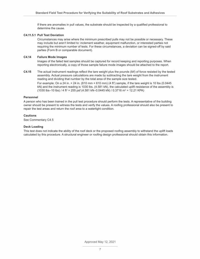
If there are anomalies in pull values, the substrate should be inspected by a qualified professional to determine the cause.
C4.11.5.1 Pull Test Deviation Circumstances may arise where the minimum prescribed pulls may not be possible or necessary. These may include but aren’t limited to: inclement weather, equipment malfunction, or interested parties not requiring the minimum number of tests. For these circumstances, a deviation can be signed-off by said parties (Form B or comparable document).
C4.14 Failure Mode ImagesImages of the failed test samples should be captured for record keeping and reporting purposes. When reporting electronically, a copy of those sample failure mode images should be attached to the report.
C4.15 The actual instrument readings reflect the tare weight plus the pounds (lbf) of force resisted by the tested assembly. Actual pressure calculations are made by subtracting the tare weight from the instrument reading and dividing that number by the total area of the sample size tested. For example: On a 24 in. × 24 in. (610 mm × 610 mm) (4 ft2) sample, if the tare weight is 10 lbs (0.0445 kN) and the instrument reading is 1030 lbs. (4.581 kN), the calculated uplift resistance of the assembly is (1030 lbs–10 lbs) / 4 ft2 = 255 psf (4.581 kN–0.0445 kN) / 0.3716 m2 = 12.21 KPA)
PersonnelA person who has been trained in the pull test procedure should perform the tests. A representative of the building owner should be present to witness the tests and verify the values. A roofing professional should also be present to repair the test areas and return the roof area to a watertight condition.
CautionsSee Commentary C4.5
Deck LoadingThis test does not indicate the ability of the roof deck or the proposed roofing assembly to withstand the uplift loads calculated by this procedure. A structural engineer or roofing design professional should obtain this information.

Approved May 12, 2021
8
Standard Field Test Procedure for Verifying the Suitability of Roof Substrates and Adhesives
Figure ACross Section of Assembly
Figure B Bead Placement Examples for 24" × 24" sample size
Figure C Bead Placement Examples for 12" × 12" sample size
Approved May 12, 2021
9
Standard Field Test Procedure for Verifying the Suitability of Roof Substrates and Adhesives
Appendix A Insulation Test Report
The following three pages contain Forms A, B and C. These forms or similar ones shall be used to report Mechanical Uplift Resistance of Insulation Adhesives test results.
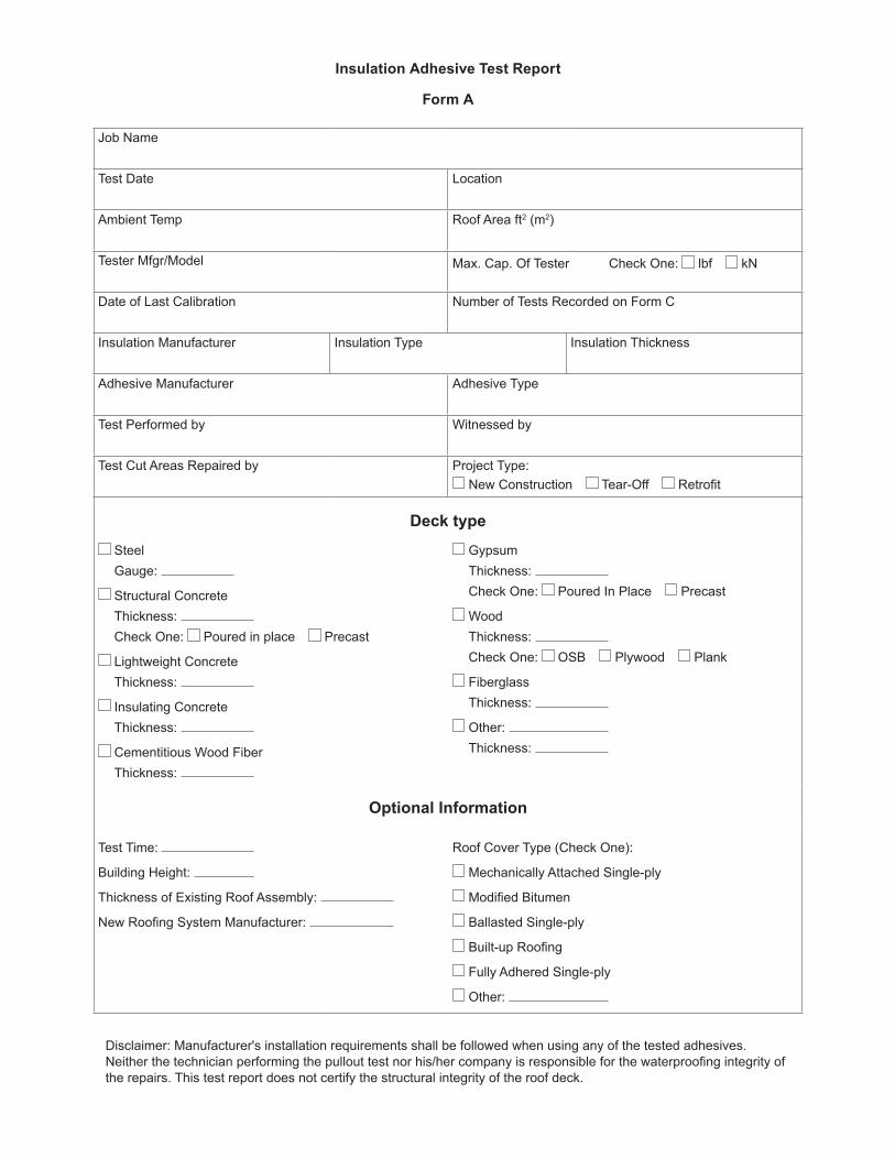
Insulation Adhesive Test Report
Form A
Job Name
Test Date Location
Ambient Temp Roof Area ft2 (m2)
Tester Mfgr/Model Max. Cap. Of Tester Check One: lbf kN
Date of Last Calibration Number of Tests Recorded on Form C
Insulation Manufacturer Insulation Type Insulation Thickness
Adhesive Manufacturer Adhesive Type
Test Performed by Witnessed by
Test Cut Areas Repaired by Project Type: New Construction Tear-Off Retrofit
Deck type
SteelGauge:
Structural ConcreteThickness: Check One: Poured in place Precast
Lightweight ConcreteThickness:
Insulating ConcreteThickness:
Cementitious Wood FiberThickness:
GypsumThickness: Check One: Poured In Place Precast
WoodThickness: Check One: OSB Plywood Plank
FiberglassThickness:
Other: Thickness:
Optional Information
Test Time:
Building Height:
Thickness of Existing Roof Assembly:
New Roofing System Manufacturer:
Roof Cover Type (Check One):
Mechanically Attached Single-ply
Modified Bitumen
Ballasted Single-ply
Built-up Roofing
Fully Adhered Single-ply
Other:
Disclaimer: Manufacturer's installation requirements shall be followed when using any of the tested adhesives. Neither the technician performing the pullout test nor his/her company is responsible for the waterproofing integrity of the repairs. This test report does not certify the structural integrity of the roof deck.

Insulation Adhesive Test Report
Form B
Job Name
Test Date
Roof Plan (Not to Scale) Identify where tests were performed, showing corresponding test number from Form C

Insulation Adhesive Test Report
Form C(Refer To the “Standard Field Test Procedure for Determining the Mechanical Uplift Resistance of Insulation Adhesives over Various Substrates” for full documentation)
Job Name
Test Date
➊ Tare Weight
A B C D E F
Test no. Location on roof(Roof plan on form B)
Measurement pounds force (lbf) (kN) ➋
Less Tare➌ = ➋–➊ lbf (kN)
Resistance➍ = ➌ ÷ 4.0 test sample area(24"×24" (610 mm × 610 mm)Sample size area = 4ft2)
Failure mode
1
2
3
4
5
6
7
8
9
10
Comments
Deviation from standard procedure authorized by:
Reason for deviation:
Copyright © 2022 FDOKUMEN