
stabilization of green sand system for moulding with current ...
96
STABILIZATION OF GREEN SAND SYSTEM FOR MOULDING WITH CURRENT PRODUCT MIX A dissertation submitted to National Institute of Technology, Jamshedpur in partial fulfillment of the requirement for the award of the degree of MASTER OF TECHNOLOGY In FOUNDRY TECHOLOGY By SHUBHAM SINGH RAJPUT Registration No. 2015PGMMFT09 UNDER THE ESTEEMED GUIDANCE OF Prof. Chandra Shekhar Choudhary Associate Professor Metallurgical & Materials Engineering Department National Institute of Technology Jamshedpur Mr. Madhu Bojja AGM, Foundry Div. TATA MOTORS Jamshedpur DEPARTMENT OF METALLURGICAL & MATERIALS ENGINEERING NATIONAL INSTITUTE OF TECHNOLOGY JAMSHEDPUR – 831014 JUNE 2017
-
Upload
khangminh22 -
Category
Documents
-
view
7 -
download
0
Transcript of stabilization of green sand system for moulding with current ...

STABILIZATION OF GREEN SAND SYSTEM FOR
MOULDING WITH CURRENT PRODUCT MIX
A dissertation submitted to National Institute of Technology, Jamshedpur in partial
fulfillment of the requirement for the award of the degree of
MASTER OF TECHNOLOGY
In
FOUNDRY TECHOLOGY
By
SHUBHAM SINGH RAJPUT
Registration No. 2015PGMMFT09
UNDER THE ESTEEMED GUIDANCE OF
Prof. Chandra Shekhar Choudhary
Associate Professor
Metallurgical & Materials
Engineering Department
National Institute of Technology
Jamshedpur
Mr. Madhu Bojja
AGM, Foundry Div.
TATA MOTORS
Jamshedpur
DEPARTMENT OF METALLURGICAL & MATERIALS ENGINEERING
NATIONAL INSTITUTE OF TECHNOLOGY
JAMSHEDPUR – 831014
JUNE 2017

Department of Metallurgical and Materials Engineering
NATIONAL INSTITUTE OF TECHNOLOGY
JAMSHEDPUR – 831014 INDIA
CERTIFICATE
This is to certify that thesis entitled “Stabilization of green sand system for moulding
with current product mix” being submitted by Shubham Singh Rajput to the National
Institute of Technology, Jamshedpur, for the award of the degree of MASTER OF
TECHNOLOGY in FOUNDRY TECHNOLOGY is a record of bonafide work carried
out under my supervision and guidance. I have examined the thesis and certify it worthy of
acceptance.
Mr. Madhu Bojja Shubham Singh Rajput
(AGM, Foundry Division, TATA MOTORS) 2015PGMMFT09
Dr. Ranjit Prasad Prof. Chandra Shekhar Choudhary
(HOD, MME) (Associate Professor, MME)

National Institute of Technology
Jamshedpur
BONAFIDE CERTIFICATE
This is to certify that the project entitled “STABILIZATION OF GREEN SAND
SYSTEM FOR MOULDING WITH CIRRENT PRODUCT MIX” is a bonafide record
of the work done by SHUBHAM SINGH RAJPUT (2015PGMMFT09) in partial
fulfillment of the requirements for the award of the Master degree in METALLURGICAL
AND MATERIALS ENGINEERING with specialization in “FOUNDRY
TECHNOLOGY” of the NATIONAL INSTITUTE OF TECHNOLOGY,
JAMSHEDPUR, during the year 2015-2017.
-------------------------------- ----------------------------
Prof. Chandra Shekhar Choudhary Dr. Ranjit Prasad
Signature of internal supervisor Signature of Head of Department
with Date and Official Seal
------------------------------------- ------------------------------
Signature of Internal Examiner Signature of External Examiner


iii
ACKNOWLEDGEMENT
The work presented in this master’s thesis is the result of collaboration between TATA
MOTORS, Jamshedpur and NATIONAL INSTITUTE OF TECHNOLOGY, Jamshedpur.
To start with, I am obliged to TATA MOTORS, Jamshedpur for considering me eligible
for internship in their prestigious organization. I would like to express my thankfulness to
Mr. Madhu Bojja for handing me over a project which enhanced my knowledge and
outlook manifold. His constant involvement coupled with his motivation led to the fine
completion of my project. I am also extremely indebted to Mr. B.C. Ghosh, who guided me
and carefully instructed me throughout the course of a whole year. Without his help, my
project would not have seen the light of day.
I humbly appreciate all other supporting staff at the Foundry Lab who paid heed to and
answered my queries related to the industry and made my experience in the plant a safe,
memorable and enjoyable one.
I express my deep sense of gratitude to, Mr. Chandra Shekhar Choudhary Associate
professor, Department of Metallurgical And Materials Engineering, NIT, Jamshedpur, for
their kind co-operation and support which I got during this work.
I express my sincere thanks to all my respected faculty members of Metallurgical And
Materials Engineering Department, National Institute of Technology, Jamshedpur
Last but not the least, I thank my parents and my fellow classmates who have always been
supportive and advised me to follow the right path and helped me make correct decisions
for my career.
Place: Jamshedpur Shubham Singh Rajput

iv
ABSTRACT
This project deals with the defects occurring in different product which are manufactured at
TATA motors and a practical approach to eliminate these defects, so that percentage of
rejection can be minimize and efficiency of plant can be increased. In TATA motors
different products like cylinder block CB6BT, cylinder head, gear box are manufactured in
foundry division, even in completely controlled process, defect in casting are observed and
hence casting process is also known as process of uncertainty which challenges explanation
about the cause of casting defects. Mainly cylinder block CB6BT has higher percentage of
rejection. There are mainly two defects in CB6BT due to which large numbers of castings
are rejected namely sand fusion & metal penetration which contribute nearly 40 – 50 % of
total defects. In 2015-16 rejection is 4.81% and during June 2017 to January 2017 rejection
percentage is higher (4.2% - 9.7%). Sand fusion and metal penetration are undesirable
since it results in reduction in the strength of the casting and bad finish of the casting
surface due to which the fettling department had to perform shot blasting for longer
duration to improve surface finish which is waste of time as well as money and also
product doesn’t meet desirable specification which are given by the customer. More than
hundred parameters are responsible for these defects and hence it is difficult to control
defect during casting. Therefore, these two defects and different properties of sand like
moisture content, active clay, etc. and the method to calculate them have been studied in
depth and grading of these defects have been done. We had approached in a well ordered
manner like detailed analysis of major defects & determine all causes, selection of root
cause, identify the solution and then implement them, if defects are eliminated then we had
made standard for that parameters, and if not, select the other cause. As we know only one
or two parameters are not responsible for defects, there are many, that’s why a balanced
between these parameters is necessary. Hence, we are able to minimize the defects and
achieve lower rejection percentage (5.22 %) than targeted which is 5.3 %.

v
TABLE OF CONTENTS
Page No.
Acknowledgement iii
Abstract iv
Table of Contents v
List of Figures ix
List of Table xi
CHAPTER- 1: INTRODUCTION 1
CHAPTER- 2: LITERATURE REVIEW
2.1 Basic of Casting
2.1.1 Casting
2.1.2 Pattern
2.1.3 Common Pattern Materials
2.1.4 Pattern Allowances
2.1.5 Core and Core Box
2.1.6 Mould
2.2 Moulding Sand
2.2.1 Silica Sand
2.2.2 Binder
2.2.3 Moisture
2.2.4 Additives
2.3 Properties of Moulding Sand
2.3.1 Refractoriness
2.3.2 Permeability
2.3.3 Cohesiveness
2.3.4 Green Strength
2.3.5 Dry Strength
2.3.6 Flowability or Plasticity
3
3
3
3
3
4
4
5
5
5
7
7
8
8
8
9
9
9
10
10

vi
2.3.7 Collapsibility
2.4 Schematic Sketch of Foundry Layout
2.5 Sand Casting Process
2.6 Defects In Casting
2.6.1 Defects Caused by Pattern and Moulding Box Equipment
2.6.2 Defects Due To Improper Moulding and Core
Material (Improper Sand Conditions)
2.6.3 Defects Caused By Moulding, Core Making, Gating, Etc.
2.6.4 Defects Occuring While Closing & Pouring Molds
2.6.5 Defects Caused By Molten Metal
2.6.6 Defects Occurring During Fettling
2.7 Foundry Division at Tata Motors
2.7.1 Foundry Lab
2.7.2 Pattern Shop
2.7.3 High Pressure Moulding Line
2.7.4 Dispatch Line
2.8 Rejection of Casting
2.8.1 Total Rejection for CB6BT
2.8.2 Total Rejection for CBCMVR
2.8.3 Total Rejection for 6BT Head Euro-III-4-Valve
2.8.4 Total Rejection for 6BT Head 2-Valve
2.8.5 Total Rejection for Gear Box 1150 Rear
2.9 Manufacturing Process of CB6BT
2.10 Literature Review
2.11 Sand Fusion
2.11.1 Causes
2.12 Metal Penetration
2.12.1 Causes
10
11
12
13
14
16
19
20
20
22
22
24
25
25
27
27
28
28
29
29
30
31
33
35
36
39
40

vii
CHAPTER- 3: EXPERIMENTAL INVESTIGATION
3.1 Methodology Used
3.2 Grading of Defects
3.2.1 Level 1
3.2.2 Level 2
3.2.3 Level 3
3.2.4 Level 4
3.2.5 Level 5
3.3 Data Collection
3.3.1 Data Collected at Shot Blasting Point
3.3.2 Data Collected at Foundry Lab
3.4 Tests Done at Foundry Lab
3.4.1 Preparation of standard test specimen
3.4.2 Test for Compactability
3.4.3 Test for Moisture Content
3.4.4 Test for Permeability
3.4.5 Green Strength (Compression, Tensile, Shear, Split)
3.4.6 Test for Shatter Index
3.4.7 Active Clay
3.4.8 Test for Volatile Matter 900 F(482 C)
3.4.9 Test for Loss on Ignition (LOI)
47
47
48
48
49
49
51
51
52
52
53
55
55
56
58
59
62
65
67
70
70
CHAPTER- 4: RESULT AND DISCUSSION
4.1 Sand Fusion and Metal Penetration with Different Parameters
4.2 Returned Sand Variation
4.3 Causes In Our Case and Steps Taken for Elimination of Defects
4.3.1 Extra Care is Taken In Handling of Core
4.4 Stabilization of Green Sand System
4.5 Prediction that Eliminate Defects
4.6 Comparison of Rejection
71
71
72
72
72
74
77
78

viii
CHAPTER- 5: CONCLUSION 80
REFERENCES 81

ix
List of Figure
FIG. NO. FIGURE CAPTIONS PAGE NO.
2.1 A Schematic Sketch Foundry Layout 11
2.2 A Schematic Diagram of Sand Casting
Process
12
2.3 Mismatch/Mould Shift 14
2.4 Casting with Flash Defect 15
2.5 Casting with Sand Drop Defect 17
2.6 Scab Defect 17
2.7 Casting with Metal Penetration 18
2.8 A schemati Hot Tear Defect 19
2.9 Porous Casting 22
2.10 A Schematic Diagram of Foundry Division
Product
23
2.11 A Schematic Diagram of Foundry Division 23
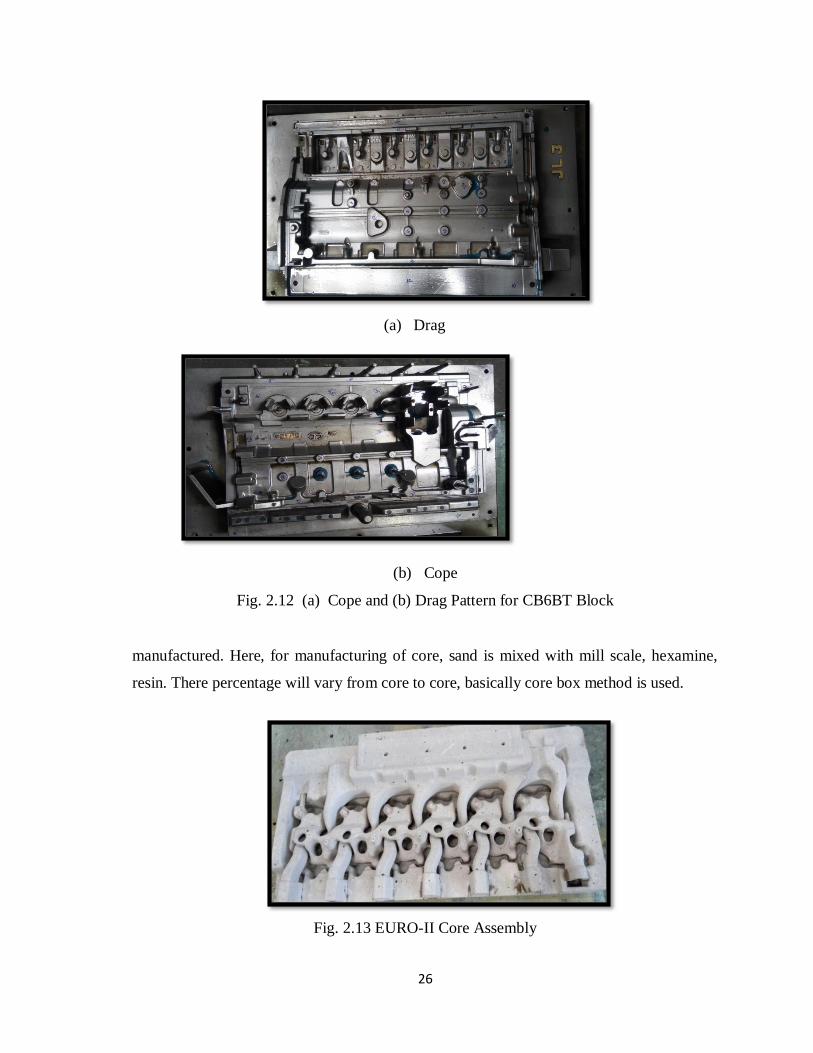
2.12 (a) Cope and (b) Drag Pattern for CB6BT
Block
26
2.13 EURO-II Core Assembly 26
2.14 Total Rejection Graph 28
2.15 Total Rejection For CB6BT 28
2.16 Total Rejection For CBCMVR 29
2.17 Total Rejection For 6BT Head Euro-III 4-
Valve
29
2.18 Total Rejection For 6BT Head 2-Valve 30
2.19 Total Rejection For GB1150 R 30
2.20 Manufacturing Process 31
2.21 Key Core CB6BT 32
2.22 Water Jacket With Base Core For CB6BT 32
2.23 Casting With Gating System 33
2.24 Shot Blasting 33
2.25 CB6BT with sand fusion 36
2.26 CB6BT with Metal Penetration Defect 40
x
3.1 A Schematic Procedure for Reducing
Casting Defects and Select Best Solution
47
3.2 Cope side of CB6BT with Level 1 49
3.3 Drag Side of CB6BT with Level 1 49
3.4 Cope side of CB6BT with Level 2 50
3.5 Drag side of CB6BT with Level 2 50
3.6 Cope side of CB6BT with Level 3 50
3.7 Drag side of CB6BT with Level 3 51
3.8 A schematic Cope Side of CB6BT with Level 4 51
3.9 Drag side of CB6BT with Level 4 52
3.10 Sand Rammer With Specimen Tube 56
3.11 (a) Tube Filler (b) Sand Rammer With
Compactabilty Tester
57
3.12 Permeabilty Meter 61
3.13 Motor Driven Universal Sand Strength
Machine (AFS)
63
3.14 Holders for Compression Strength Test 64
3.15 Holders for shear StrengthTest 64
3.16 Shatter Index Tester 66
3.17 Spot Test for End Point of Methylene Blue
Titration
68
3.18 Methylene Blue Active Clay Test Apparatus 69
4.1 Core dipped in wash for coating by hand 74
4.2 Man spraying wash on mould in moulding
line
74
4.3 Comparison of Total Rejection for all
product (a) Previous (b) Present
78
4.4 Comparison of Total Rejection for CB6BT
(a) previous (b) present
79

xi
List of Tables
Table No. Caption Page No.
3.1 Grading of Defects 48
3.2 Data Collected at Shot Blasting Point 53
3.3 Data Collected from Foundry Lab 54
4.1 Sand Fusion and Metal Penetration with
Different Parameters
71
4.2 Returned Sand Variation 72
4.3 Fundamental and Ideal Sand parameters of
prepared
75
4.4 (a) First Prediction (b) Second Prediction 76
4.5 (a) Third Prediction (b) Fourth Prediction 76
4.6 Prediction for A shift 76
4.7 Change in prediction for A shift 76
4.8 Values for A shift 77
4.9 Values for B shift 77
4.10 Values for C shift 77
5.1 Targeted and achieved value 80

xii

1
CHAPTER - 1.
INTRODUCTION
Castings play a very important role in manufacturing industry. Casting is mother process
major applications and uses of castings are in automobile industry, agricultural industry,
machinery etc. Casting is a 6000 year young process. Casting process is mentioned as
shilpashastra in several Sanskrit works and dhamatri (cupola), gharma aranmaya
(crucible), bhastri (blower) are the casting equipments mentioned in the Rig-Veda. The
major application of casting was in creating the God idols used for worshipping which can
be confirmed from the cast idols of Gods seen in our ancient temples. We hardly recognize
our daily close association with castings through these cast God idols we worship.
Cast Iron components are produced usually in large quantity by sand casting process and
give rise to thirty to forty different defects like sand and slag inclusion, blow holes, scab,
shrinkage etc. Sand fusion is a major defect and the mould material itself is responsible for
this defect. Component weakens because of sand inclusion and lack in properties like
soundness, high fluid pressure resistance, high bearing strength etc. and results in bad
surface finish. In a gray cast iron foundry, total rejection on an average is around 8 to 10
percent. Rejection due to sand fusion is about 30 to 40 percent of this amount that is 2 to 4
percent of the total rejection. This is a huge loss to the foundry considering wastage of the
large amount of heat energy in melting the material, remelting of scrap; handling and
inspection cost and has a demoralising effect on the employees. There are a large number
of parameters to be controlled while manufacturing the sand casting and are broadly
categorized as sand, moulding, melting and pouring parameters. Correct selection of
parameters responsible for sand fusion and metal penetration defect is very difficult task
and hence these defects are very difficult to control. In this work we had try to correct the
parameters and eliminate the defects.

2
The topic ‘stabilization of green sand system’ is being made the subject of this particular
study. As green sand system include sand and its properties, different additives and binder
and there amount which is been added. These are the main cause of defects that occur in
sand casting. The surface finish of a casting is dependent on the moulding process. The
mould materials as well as the moulding variables apart from other factors not related to
mould. The various factors are poor treatment of sand, use of different type of sand
particles used in moulding, accumulation of spend dead clay in the moulding sand, use of
badly compacted mould or cores due to sand moisture not thoroughly mixed or not
possessing sufficient flowability in clay bounded sand moulding, exceeding bench life of
sand moulds or sand cores, inadequate compaction of moulds or cores in normal moulding.
Pouring temperature of the molten metal to be poured into the mould. These are some of
the reasons for surface defects over castings.
In this particular session the problem of sand fusion and metal penetration is being
discussed in detail (how sand fusion and metal penetration occur and their causes). The
various possible factors for sand fusion, metal penetration and the practical ways to control
these factors are also discussed. Here, for controlling these defects there grading has been
done and data is collected. Further, for that particular day for which rejection/defects are
more all the properties, amount of additives and carbonaceous material for that casting are
compared with the properties and amount of additives, carbonaceous materials for casting
which have lower percentage of defects and then that particular parameter which is
different is varied so that defects are minimized. Various instruments/machines have been
used for calculating different properties of sand (moisture, active clay, permeability, GCS,
etc.). This particular study was conducted in TATA MOTORS, Jamshedpur.

3
CHAPTER - 2.
LITERATURE REVIEW
2.1 Basics of Casting
2.1.1 Casting
Casting process is one of the earliest metal shaping techniques known to human being. It
means pouring molten metal into a refractory mold cavity and allows it to solidify. The
solidified object is taken out from the mold either by breaking or taking the mold apart.
The solidified object is called casting and the technique followed in method is known as
casting process.
2.1.2 Pattern
A pattern is a model or the replica of the object (to be casted) with some allowances and/or
with core prints. It is embedded in molding sand and suitable ramming of molding sand
around the pattern is made. The pattern is then withdrawn for generating cavity (known as
mold) in molding sand. Thus it is a mould forming tool. When molten metal is poured into
the cavity, molten metal solidifies and produces a casting (product). A pattern prepares a
mold cavity for the purpose of making a casting. It may also possess projections known as
core prints for producing extra recess in the mould for placement of core to produce
hollowness in casting. The first step in casting is pattern making. The pattern is a made of
suitable material and is used for making cavity called mould in molding sand or other
suitable mould materials.
2.1.3 Common Pattern Materials
The common materials used for making patterns are wood, metal, plastic, plaster, wax or
mercury. The some important pattern materials are discussed as under.

4
2.1.4 Pattern Allowances
Pattern may be made from wood or metal and its color may not be same as that of the
casting. The material of the pattern is not necessarily same as that of the casting. Pattern
carries an additional allowance to compensate for metal shrinkage. It carries additional
allowance for machining. It carries the necessary draft to enable its easy removal from the
sand mass. It carries distortions allowance also. Due to distortion allowance, the shape of
casting is opposite to pattern. Pattern may carry additional projections, called core prints to
produce seats or extra recess in mold for setting or adjustment or location for cores in mold
cavity. It may be in pieces (more than one piece) whereas casting is in one piece. Sharp
changes are not provided on the patterns. These are provided on the casting with the help of
machining. Surface finish may not be same as that of casting. The size of a pattern is never
kept the same as that of the desired casting because of the fact that during cooling the
casting is subjected to various effects and hence to compensate for these effects,
corresponding allowances are given in the pattern. These various allowances given to
pattern can be enumerated as, allowance for shrinkage, allowance for machining, allowance
for draft, allowance for rapping or shake, allowance for distortion.
2.1.5 Core and Core Box
Cores are compact mass of core sand that when placed in mould cavity at required location
with proper alignment does not allow the molten metal to occupy space for solidification in
that portion and hence help to produce hollowness in the casting. The environment in
which the core is placed is much different from that of the mold. In fact the core has to
withstand the severe action of hot metal which completely surrounds it. Cores are classified
according to shape and position in the mold. There are various types of cores such as
horizontal core, vertical core, and balanced core.
Any kind of hollowness in form of holes and recesses in castings is obtained by the use of
cores. Cores are made by means of core boxes comprising of either single or in two parts.
Core boxes are generally made of wood or metal and are of several types. The main types
of core box are half core box, dump core box, split core box, etc.

5
2.1.6 Mould
A suitable and workable material possessing high refractoriness in nature can be used for
mould making. Thus, the mold making material can be metallic or non-metallic. For
metallic category, the common materials are cast iron, mild steel and alloy steels. In the
non-metallic group molding sands, plaster of paris, graphite, silicon carbide and ceramics
are included. But, out of all, the molding sand is the most common utilized non-metallic
molding material because of its certain inherent properties namely refractoriness, chemical
and thermal stability at higher temperature, high permeability and workability along with
good strength. Moreover, it is also highly cheap and easily available.
2.2 Moulding Sand
The general sources of receiving molding sands are the beds of sea, rivers, lakes, granular
elements of rocks, and deserts. Molding sands may be of two types namely natural or
synthetic. Natural molding sands contain sufficient binder. Whereas synthetic molding
sands are prepared artificially using basic sand molding constituents (silica sand in 88-
92%, binder 6-12%, water or moisture content 3-6%) and other additives in proper
proportion by weight with perfect mixing and mulling in suitable equipments.
The main constituents of molding sand involve silica sand, binder, moisture content and
additives.
2.2.1 Silica Sand
Silica sand in form of granular quarts is the main constituent of molding sand having
enough refractoriness which can impart strength, stability and permeability to molding and
core sand. But along with silica small amounts of iron oxide, alumina, lime stone,
magnesia, soda and potash are present as impurities. The silica sand can be specified
6
according to the size (small, medium and large silica sand grain) and the shape (angular,
sub-angular and rounded).
Effect of grain shape and size of silica sand
The shape and size of sand grains has a significant effect on the different properties of
molding and core sands. It determines the possibility of its application in various types of
foundry practice. The shape of foundry sand grains varies from round to angular. Some
sands consist almost entirely of grains of one shape, whereas others have a mixture of
various shapes. According to shape, foundry sands are classified as rounded, sub-angular,
angular and compound. Use of angular grains (obtained during crushing of rocks hard sand
stones) is avoided as these grains have a large surface area. However, a higher percentage
of binder is required to bring in the desired strength in the molding sand and core sand. For
good molding purposes, a smooth surfaced sand grains are preferred. Rounded shape silica
sand grain sands are best suited for making permeable molding sand. These grains
contribute to higher bond strength in comparison to angular grain. However, rounded silica
sand grains sands have higher thermal expandability and compactability than angular silica
grain sands. This is connected with the fact that the silica sand with rounded grains having
the greatest degree of close packing(contact surfaces between the individual grains) of
particles while sand with angular grains the worst. The green strength increases as the
grains become more rounded. As already mentioned above, the compactability increases
with rounded grains. The permeability or porosity property of molding sand and core sand
therefore, should increase with rounded grains and decrease with angular grains. Thus the
round silica sand grain size greatly influences the properties of molding sand. The
characteristics of sub-angular sand grains lie in between the characteristics of sand grains
of angular and rounded kind. Compound grains are cemented together such that they fail to
get separated when screened through a sieve. They may consist of round, sub-angular, or
angular sub-angular sand grains. Compound grains require higher amounts of binder and
moisture content also. These grains are least desirable in sand mixtures because they have a
tendency to disintegrate at high temperatures. Moreover the compound grains are cemented
together and they fail to separate when screened.

7
The grain size distribution has a significant effect on permeability. Silica sand containing
finer and a wide range of particle sizes will have low permeability as compared to those
containing grains of average fineness but of the same size i.e. narrow distribution. The
compactability is expressed by the green density obtained by three ram strokes. Finer the
sand, the lower is the compactability and vice versa. This results from the fact that the
specific surface increases as the grain size decreases. As a result, the number of points of
contact per unit of volume increases and this in turn raises the resistance to compacting.
The green strength has a certain tendency, admittedly not very pronounced, towards a
maximum with a grain size which corresponds approximately to the medium grain size. As
the silica sand grains become finer, the film of bentonite becomes thinner, although the
percentage of bentonite remains the same. Due to reducing the thickness of binder film, the
green strength is reduced. With very coarse grains, however, the number of grains and,
therefore, the number of points of contact per unit of volume decreases so sharply that the
green strength is again reduced. The sands with grains equal but coarser in size have
greater void space and have, therefore greater permeability than the finer silica sands. This
is more pronounced if sand grains are equal in size.
2.2.2 Binder
In general, the binders can be either inorganic or organic substance. In foundry shop, the
clay acts as binder which may be kaolonite, ball clay, fire clay, limonite, fuller’s earth and
bentonite. Binders included in the organic group are dextrin, molasses, cereal binders,
linseed oil and resins like phenol formaldehyde, urea formaldehyde etc. Organic binders
are mostly used for core making. Among all the above binders, the bentonite variety of clay
is the most common. However, this clay alone cannot develop bonds among sand grins
without the presence of moisture in molding sand and core sand.
2.2.3 Moisture
The amount of moisture content in the molding sand varies generally between 2 to 8
percent. This amount is added to the mixture of clay and silica sand for developing bonds.

8
This is the amount of water required to fill the pores between the particles of clay without
separating them. This amount of water is held rigidly by the clay and is mainly responsible
for developing the strength in the sand. The effect of clay and water decreases permeability
with increasing clay and moisture content. The green compressive strength first increases
with the increase in clay content, but after a certain value, it starts decreasing. For
increasing the molding sand characteristics some other additional materials besides basic
constituents are added which are known as additives.
2.2.4 Additives
Additives are the materials generally added to the molding and core sand mixture to
develop some special property in the sand. This reducing atmosphere results in any oxygen
in the poles becoming chemically bound so that it cannot oxidize the metal. It is usually
added in the molding sands for making molds for production of grey iron and malleable
cast iron castings. Sea coal is the fine powdered bituminous coal which positions its place
among the pores of the silica sand grains in molding sand and core sand. When heated, it
changes to coke which fills the pores and is unaffected by water: Because to this, the sand
grains become restricted and cannot move into a dense packing pattern. Thus, sea coal
reduces the mould wall movement and the permeability in mold and core sand and hence
makes the mold and core surface clean and smooth. Additives are added for gas cushion,
reduced atmosphere and improve collapsibility.
2.3 Properties of Moulding Sand
2.3.1 Refractoriness
Refractoriness is defined as the ability of molding sand to withstand high temperatures
without breaking down or fusing thus facilitating to get sound casting. It is a highly
important characteristic of molding sands. Refractoriness can only be increased to a limited
extent. Molding sand with poor refractoriness may burn on to the casting surface and no
smooth casting surface can be obtained. The degree of refractoriness depends on the SiO2
i.e. quartz content, and the shape and grain size of the particle. The higher the SiO2 content

9
and the rougher the grain volumetric composition the higher is the refractoriness of the
molding sand and core sand. Refractoriness is measured by the sinter point of the sand
rather than its melting point.
2.3.2 Permeability
It is also termed as porosity of the molding sand in order to allow the escape of any air,
gases or moisture present or generated in the mould when the molten metal is poured into
it. All these gaseous generated during pouring and solidification process must escape
otherwise the casting becomes defective. Permeability is a function of grain size, grain
shape, and moisture and clay contents in the molding sand. The extent of ramming of the
sand directly affects the permeability of the mould. Permeability of mold can be further
increased by venting using vent rods.
2.3.3 Cohesiveness
It is property of molding sand by virtue which the sand grain particles interact and attract
each other within the molding sand. Thus, the binding capability of the molding sand gets
enhanced to increase the green, dry and hot strength property of molding and core sand.
2.3.4 Green Strength
The green sand after water has been mixed into it, must have sufficient strength and
toughness to permit the making and handling of the mould. For this, the sand grains must
be adhesive, i.e they must be capable of attaching themselves to another body. Therefore,
sand grains having high adhesiveness will cling to the sides of the molding box. Also, the
sand grains must have the property known as cohesiveness i.e. ability of the sand grains to
stick to one another. By virtue of this property, the pattern can be taken out from the mould
without breaking and also the erosion of mould wall surfaces does not occur during the
flow of molten metal. The green strength also depends upon the grain shape and size,
amount and type of clay and the moisture content.

10
2.3.5 Dry Strength
As soon as the molten metal is poured into the mould, the moisture in the sand layer
adjacent to the hot metal gets evaporated and this dry sand layer must have sufficient
strength to its shape in order to avoid erosion of mould wall during the flow of molten
metal. The dry strength also prevents the enlargement of mould cavity cause by the
metallostatic pressure of the liquid metal.
2.3.6 Flowability or Plasticity
It is the ability of the sand to get compacted and behave like a fluid. It will flow uniformly
to all portions of pattern when rammed and distribute the ramming pressure evenly all
around in all directions. Generally sand particles resist moving around corners or
projections. In general, flowability increases with decrease in green strength, an, decrease
in grain size. The flowability also varies with moisture and clay content.
2.3.7 Collapsibility
After the molten metal in the mould gets solidified, the sand mould must be collapsible so
that free contraction of the metal occurs and this would naturally avoid the tearing or
cracking of the contracting metal. In absence of this property the contraction of the metal is
hindered by the mold and thus results in tears and cracks in the casting. This property is
highly desired in cores.

11
2.4 Schematic Sketch of Foundry Layout
Fig. 2.1 A Schematic Sketch Foundry Layout

12
2.5 Sand Casting Process
Pattern with mould box Spray/Wash/Facing Sand Moulding Sand
Cope & Drag Gatting Elements
Extra Sand Removed Sprue & Riser Pin Ramming
Molten Metal Poured & Casting
Fig. 2.2 A Schematic Diagram of Sand Casting Process

13
2.6 Defects In Casting
Under normal conditions, like all metallurgical products, casting also contain certain
imperfection which contribute to a normal quality variation. Such imperfection are taken as
defects or flaws when they affect the appearance or the satisfactory functioning of the
casting and the casting in turn do not come up to the quality and inspection standards being
applied. Defective casting offers an ever-present problem to the foundry industry,
Defective casting account for the normally higher losses incurred by the foundry. Casting
defects are usually not incidents; they occur because some steps in the manufacturing cycle
does not get properly controlled and somewhere goes wrong. A defect may be te result of a
single clearly defined cause or a combination of factors, in which box necessary preventive
measured are more obscure. Close control and standardization of all aspects of
manufacturing techniques offers the best defense against the occurrence of defects in
castings.
Classifications of Defects
Logically classification of casting defects presents great difficulties because of the wide
range of contributing cause; however a rough classification may be made by grouping the
defects under certain broad type of origin such as:
Defects caused by pattern and moulding box equipments.
Defects due to improper molding and core making material.
Defects due to improper sand mixing and distribution.
Defects caused by molding, core making and gating, etc.
Defects due to improper mold drying and core baking.
Defects occurring while closing and pouring the molds.
Defects caused by molten metal.

14
2.6.1 Defects Caused by Pattern and Moulding Box Equipment
Mismatch or Mould Shift
It produce a casting which does not match at the parting line. Fig. 2.3 Shows mould
shift.
There is mismatching of top and bottom parts of the casting at the mould joint
Causes
Worn or loose dowels in the pattern made in halves.
Faulty resting of top and bottom halves of pattern mounted on plates.
Fig. 2.3 Mismatch/Mould Shift
Fin, Flash and Strain
Fins, flash and strain usually occur at the parting line and result in excess metal
which has to be ground off. Flashes or fins commonly appears along the mould
joint at the place where the mould halves do not fit together properly because of
much wear of the flask halves or improper fastening of the cope to the drag.
Straining or movement of the mould makes a casting appreciably thicker than the
pattern. Fig. 2.4 shows flash defect.

15
Causes
Bottom boards are too flexible.
Pattern plates are not sufficiently rigid to keep straight during ramming.
Pattern having insufficient taper and thus requiring excessive rapping for their
withdrwal from sand results in fins at the joints.
Top part box inadequately weighted, that permit (cope) to lift slightly, when
poured, thereby causing flash along mould joint.
Fig. 2.4 Casting with Flash Defect
Crush
It is the displacement of sand while closing a mould, thereby deforming mould
surface.
A crush shows itself as an irregular sandy depression in the casting.
Causes
Excessive weighting of the green sand mould (cope portion).
Core print too small for the core or vice-versa.
Careless assembly of moulding box and cores.

16
2.6.2 Defects Due To Improper Moulding and Core Material (Improper
Sand Conditions)
Blowholes
Blowholes are smooth, round holes. If visible on the surface of a casting are called
open blows. Whereas those occurring below the surface of casting and not visible
from outside are termed as blowholes. They may occur in cluster or there may be
one large smooth depression, these are entrapped bubblers of gas with smooth
walls. Entrapment of air resulting due to pouring of liquid metal takes the form of
rounded contours or spherical cavities. Surface blows or inter granular cavities
appear in cope of the mould.
Causes
Excess moisture in the moulding sand.
Low permeability and excessive fine grain sands.
Rusted and damp chills, chaplets, core neither properly baked nor adequately
vented.
Extra hard rammed sand.
Drop
A drop occurs when cope surface cracks and break, thus the pieces of small sand
fall into the molten metal. Fig. 2.5 shows casting with sand drop defect.
Causes
Low green strength (owing to less, mulling time, moisture or clay content).
Low mold hardness (soft ramming).

17
Fig. 2.5 Casting with Sand Drop Defect
Scab
It occurs when a portion of the face of a mold lifts and metal flows underneath in
thin layer. In other words, liquid metal penetrates behind the surface layer of sand.
Fig. 2.6 showing scab defect.
Causes
Too fine sand, low permeability, high moisture content.
Uneven mold ramming, less fluidity producing local heating.
Fig. 2.6 Scab Defect

18
Pin-holes
Pinholes result when the hydrogen present in liquid metal evolves due to less
solubility during solidification resulting in triangular appearances, prevalent mostly
in thinner castings which are revealed after machining.
Causes
High moisture content, sand containing gas generating ingredients.
Metal mould reaction.
Metal Penetration and Rough Surface
Metal penetration is a condition in which the metal or metallic oxides have filled
the voids between the sand grain without displacing them. In general terms, true
penetration implies an openness of the mould surface. Fig. 2.7 shows metal
penetration.
Causes
High permeability, large grain size.
Low dry strength of sand, soft ramming.
Fig. 2.7 Casting with Metal Penetration

19
Hot Tears
Immediately after solidification, metals having low strengths; if at this stage, solid
shrinkage of the casting develops sufficiently high stresses, the metal fails with a
resulting hot tears. Fig. 2.8 shows casting having hot tear.
Fig. 2.8 Hot Tear Defect
Causes
Very hard ramming and therefore excessive mold hardness.
Insufficient collapsibility of core or of portion of mold.
Too much shrinkage of metal while solidification.
Faulty design causing some portion of casting to be restrained while cooling.
High sulphur content, too low pouring temperature.
2.6.3 Defects Caused By Moulding, Core Making, Gating, Etc.
Hot Tears, Shifts, Fin and Flash, Crush which are discussed above
Cold Laps (shuts) Misrun
If the molten metal is too cold or casting section is too thin (section sensitivity),
entire mould cavity may not be filled during pouring before the metal starts
solidifying and the result is misrun.

20
If the molten metal enters mold cavity through two or more ingates or otherwise if
two steams of metals which are too cold, physically meet in the mould cavity but do
not fuse together, they develop cold shut defect.
Causes
Too cold molten metal, too thin casting.
Too small gates, less fluidity.
2.6.4 Defects Occuring While Closing and Pouring the Molds
Mismatch, Misrun, Cold shuts, Crush are dicussed above.
Inclusion
Any separate undesirable foreign material present in the metal of a casting is known
as inclusion. An inclusion may be:
Oxides, slag, dirt, etc., which enter the mould cavity along metal during pouring.
Such inclusion should be skimmed off before poring metal into the mold cavity.
Sand cracked and broken from gating system, mold cavity, core. Sand sinks in
molten light metal and causes sand cavity in the drag whereas in heavier metal sand
either floats to the cope surface of the casting or becomes entrapped within the
casting itself.
2.6.5 Defects Caused By Molten Metal
Misrun, Cold shuts, Hot Tears are discussed above
Cut and Wash
Molten metal as it flows over the mould and core surface, erodes the same and
results in cut and wash.

21
The place from where the sand has been cut or washed is occupied by molten metal
and thus an excess metal appears on the casting surface in the form of rough spots,
these spots are scab.
Causes
Soft ramming, insufficient draft on pattern.
Insufficient bonded or overbaked cores, improper gating system.
Fusion
Sand may fuse and stick to the casting surface with the result rough glossy
appearance.
Causes
Lack of refractoriness of sand, too high molten metal temperature.
Faulty gating system.
Gas porosity, Gas holes
Gas porosity differs from blowholes which results due to the moulding sand having
low permeability, excessive moisture or having been rammed too hard.
Gas porosity is caused by the gases absorbed by the molten metal. The main gases
dissolved by practically all metal are, oxygen, nitrogen, hydrogen. Hydrogen is
responsible for gas porosity. Fig. 2.9 show porous casting.
As molten metal solidifies, many small voids distributed quite uniformly
throughout the metal are found and it is known as pin hole porosity.
Causes
Hydrogen or sulphur dioxide dissolved in molten metal.
Excessive high pouring temperature, low permeability

22
Fig. 2.9 Porous Casting
Swell
A swell is an enlargement of the mould cavity (hence that of the casting) due to
molten metal pressure on the wall and the sides.
Causes
Soft ramming, low mould strength.
Mould being not adequately supported.
2.6.6 Defects Occurring During Fettling
Sand and scale not properly removed from casting surface to be machined.
Sand not properly removed from cavity where oil is to be circulated.
Crack caused in brittle casting by too heavy grinding.
Chisel mark left on the castings.
2.7 Foundry Division at Tata Motors
Foundry division is the heart of Tata Motors as most of the products are manufactured here
only, and after that their respective assembly is done. Different products like cylinder block
(CB6BT) which is mainly consumed by Cummins, cylinder head, Gear Box are
manufactured under foundry division as shown in fig. 2.10.

23
Foundry Division Products
Cylinder Block Cylinder Heads Gear Box
CB6BT CBCMVR 497 CMVR 6BT CRDi Rear Front Intermediate
EURO-I EURO-II EURO-III EURO-I EURO-II
Fig. 2.10 A Schematic Diagram of Foundry Division Product
Foundry division have mainly 4 section namely foundry lab, pattern shop, high pressure
moulding line, dispatch line as shown in fig. 2.11.
Foundry Division
Foundry Lab Pattern Shop HPML Dispatch Line
Lab 1 Lab 2 CAD/CAM Quality Pattern Sec.
Scrap & Furnace HPML Core Mfg. & Assembly Fettling Shot Blasting Inspection
Fig. 2.11 A Schematic Diagram of Foundry Division

24
2.7.1 Foundry Lab
In lab there are different instrument/machine which are used for measuring different
properties of sand. This is most vital process as one can identify the causes which are
responsible for any defects, or if there is any variation in properties of sand which can
affect the casting can be determined here, like if moisture content will vary we can check
and quantify that change, in lab only. We can check the consistency of the prepared green
sand and determine if the green sand has the physical and chemical properties to produce
good castings. Poor quality sand can lead to a number of casting‐related defects. To ensure
the properties necessary to avoid casting defects and produce the quality we desire
consistently throughout the entire green sand system. Foundry lab test green sand daily for:
Compactibilty
Moisture
Specimen weight
Permeability
Green compression strength.
Dry compression strength
Methylene blue clay content
Total combustibles (LOI)
Volatiles at 900F (482C)
Shatter Index
Weight Tensile Strength
Different instruments like three ram machine, machine which is used for calculating green
compression strength and shear strength, for calculating shatter index, etc., are available in
the lab. Scrap which is used for making molten metal are also tested in lab, because for
every product there is particular range of different constituent in that scrap, example
percentage of phosphorus should not be more than 0.15% in scrap.

25
2.7.2 Pattern Shop
In pattern shop, patterns for different casting are available. If, any alternation or changes
are needed in pattern are done in pattern shop. Mainly cast iron pattern are used in Tata
Motors. Fig shows cope and drag for CB6BT. Apart from pattern shop under this shed we
have cad/cam section which plays an important role in providing different drawings of
casting with different views and necessary locations of casting with the help of which
inspection can be done easily. Inspection and quality control section view all the casting, if
there is any defect which cannot be tolerated casting will be rejected, and hence they have
the data for rejected casting.
2.7.3 High Pressure Moulding Line
All the casting process is done under this shed. HPML reduces man work and their
involvement and hence increases the efficiency of plant. Scrap is collected over here and
with the help of furnace it is converted into molten metal. On the other side in HPML sand,
binder (bentonite), additives (lustron) are mixed with water in correct proportion with the
help of mixture, and correct amount of these are maintained with the help of computerized
system. Now, pattern (Fig. 2.12 (a) Cope and (b) Drag Pattern for CB6BT Block) for
respective casting is loaded and with the help of belt drive mixture (sand, bentonite and
lustron) is send for filling the mould box which is fitted with the respective pattern and
ramming is done, both cope and drag are loaded in a plate and this plate do 180 degree
rotation. If cope is been fitted with the mould box sand filling, removal of extra sand,
ramming will be done simultaneously plate will do 180 degree rotation and drag will be
filled by sand and ramming will be done and cope will move forward, where wash is apply
so that molten metal will not penetrate into the mould or to improve collapsibility. At this
place each and every casting is given specific number and date. Then vents are provided
and core, chaplet, etc., are assembled in assembly line, then cope and drag will be fitted
together and finally molten metal is poured. Now this will be collected at the dispatch line
at fettling point. On the other side in HPML core are like inlet valve, outlet valve, inner
water jacket, outer water jacket, base core, key core, etc., are
26
(a) Drag
(b) Cope
Fig. 2.12 (a) Cope and (b) Drag Pattern for CB6BT Block
manufactured. Here, for manufacturing of core, sand is mixed with mill scale, hexamine,
resin. There percentage will vary from core to core, basically core box method is used.
Fig. 2.13 EURO-II Core Assembly

27
Base core are manufactured by cold box process. After this core are dipped in wash and
baked in furnace. In HPML there are different section where assembly of respective core is
done like for EURO-II head, base core, inlet, exhaust, water jacket are assembled. EURO-
II core assembly is shown in fig. 2.13. There is one section where inspection of heads are
done with the help of boroscope.
2.7.4 Dispatch Line
At dispatch line, first section is fettling section where casting arrives after pouring of
molten metal and solidification is done. Here, casting have gating system like sprue, riser
fuse with it, which has to be removed, this is done in fettling section and some casting
specially CB6BT castings are sent out for fettling. Now, another section is shot blasting
section, here castings in which sand firmly adhere to the casting is treated, sometimes on
consumer demands. Mainly blocks and sometimes heads are shot blasted (3-4 mm diameter
hardened steel balls are bombarded on the casting with the help of pressure). Further,
castings are inspected with the help of boroscope, and if required grinding is done. After
this castings are placed for inspection and if casting is passed it is ready to dispatch.
2.8 Rejection of Casting
In every foundry the main aim is to minimize the rejection of casting, indirectly to reduce
the defects. Rejection data of Tata Motors is given below. Below graph (fig.2.14) tells the
rejection of casting from 2010 to 2016 yearly and for 2016 month wise. For 2016 rejection
percentage is targeted for less than or equal to 3.5 which is shown by red color in graph.
But except for the month of may and june rejection percentage is higher than targeted
percentage and also for january 2017. This means that defects in the casting are more
during these month.

28
Fig. 2.14 Total Rejection Graph
2.8.1 Total Rejection For CB6BT
Fig. 2.15 Total Rejection For CB6BT
Fig. 2.15 shows total rejection for CB6BT. It can be observe from graph that except for the
month of may and june rejection percentage are higher than targeted . We can observe that
in CB6BT rejection is mainly due to defects namely sand fusion and metal penetration.
2.8.2 Total Rejection For CBCMVR
Fig. 2.16 shows total rejection graph for CBCMVR. We can observe that except for the
month of april rejection percentage is lower than targeted percentage

29
Fig. 2.16 Total Rejection For CBCMVR
. 2.8.3 Total Rejection For 6BT Head EURO-III 4-Valve
Fig. 2.17 Total Rejection For 6BT Head Euro-III 4-Valve
Fig. 2.17 shows total rejection for 6BT Head Euro-III 4 valve. We can observe from graph
that except for the month of june, july, september, october rejection percentage are higher
than targeted rejection percentage.
2.8.4 Total Rejection For 6BT Head 2-Valve
Fig. 2.18 shows graph of rejection for 6BT Head 2 valve. We can observe from graph that
for the month of april, july, august, november rejection percentage are higher than targeted
percentage. There is problem of jamming in heads due to which rejection percentage is
higher.

30
Fig. 2.18 Total Rejection For 6BT Head 2-Valve
2.8.5 Total Rejection For Gear Box 1150 Rear
Fig. 2.19 Total Rejection For GB1150 R
Fig. 2.19 shows rejection for GB 1150 R. We can observe from graph that for all months
rejection percentage are lower than targeted rejection percentage.
From above we can conclude that if we can minimize the jamming in heads and defects
namely sand fusion and metal penetration mainly in CB6BT we can minimize the rejection
percentage. This is the aim of my thesis to reduce sand fusion and metal penetration.

31
For eliminating sand fusion and metal penetration in casting, mainly in CB6BT we should
know its process of manufacturing from scrap to casting because sometimes defects may
occur due to wrong process or wrong habit (it include handling of core, applying wash, in
assembly line, etc.).
2.9 Manufacturing Process of CB6BT
Fig. 2.20 shows whole manufacturing process from scrap to casting for all the products.
But we had discus only CB6BT.
Fig. 2.20 Manufacturing Process
Firstly, raw material like metal for making molten metal, sand, bentonite, lustron for
making mould and mill scale, resin, hexamine for making core are purchased from vendor

32
and are placed at their respective place. Sample is collected and tested in lab. Now, scrap is
melted with the help of furnace and molten metal is ready for pouring at HPML.
On the other side, sand, bentonite, lustron are mixed in correct proportion with water with
the help of mulling machine, and sample of this mixture also is collected by lab person and
test for different properties like moisture, permeability, etc,. On the other section core for
CB6BT namely key core (fig. 2.21), base core, water jacket (fig. 2.22) are made then
pattern (fig. 2.12), core, mould are assembled at moulding assembly point, then molten
metal is poured, after solidification casting is taken out in which sprue, riser are fused (fig.
2.23) which are removed at the fettling point, then for good surface finish shot blasting (fig.
2.24)is done and grinding is also done if necessary, after inspection it is ready to dispatch.
Fig. 2.21 Key Core CB6BT
Fig. 2.22 Water Jacket With Base Core For CB6BT

33
But, during inspection it is found that rejection of a block is due to metal penetration and
sand fusion.
Fig. 2.23 Casting With Gating System
Fig. 2.24 Shot Blasting
Defects In Block
In block defects like blow hole, crush, scab, sand fusion, metal penetration are found. But,
percentage of sand fusion and metal penetration are higher.
2.10 Literature Review
We cannot eliminate defects theoretically as in practical we have to eliminate defects with
more constraints like we cannot change the whole process, we cannot take steps which are

34
expensive (we can use zircon sand instead of green sand for elimination of defects but it is
costly). Though this project is completely practical, some of research papers are discuss
below.
Meredith (1996) [4] explained the effect of variables and its control to produce defect free
castings. According to him, amount of ramming, jolting, squeezing, type of sand etc.
decides the compaction density of green sand, which is checked and controlled in terms of
mould hardness. He also observed that the strength of resin bonded sand is much more than
green sand thus will help in reduction of sand inclusion. According to Kumruoglu et al.
(2008), [5] moulding and melting parameters like amount of sand ramming, specifications
of the mould wall, type and quality of sand used, rate of metal pouring and its temperature
etc. important for getting good quality sand casting.
Deshmukh et al. (2009) [8] have discussed the problems like sand cut, wash, erosion etc.
which give rise to sand inclusion defect. The paper highlighted possible causes like
insufficient cohesive strength of sand, poor gating, defective drying of mould and core,
improper casting and mould design, poor green strength, improper alignment of mould
halves, careless pattern removal, failure to use nails and gaggers, poor condition of pattern,
varying strengths developed in different layers of mould. The precautions like gating
system redesign and relocation, mould cavity reinforcing, timely mould repair and due care
while moulding, provision of more draft, provision of aligning devices, correct pattern
stripping, use of nails and gaggers etc. should be taken to avoid the sand inclusion defect.
According to Brieger (2011), [6] sand inclusion is a result of breakage of core, feeder etc.
because of high compressive force, during complex shaped casting production. Woldert
(2011) [7] stated that the proper quality of moulding sand can be obtained by maintaining
the specific values of sand parameters like loss on ignition(LOI), sand temperature, residual
dust content etc. He related the quality of casting surface and binder consumption with
sand quality. Use of Furan resin sand moulds is suggested for getting high sand strength to
large size casting moulds which will avoid sand inclusion defect.

35
Studies have been performed to understand both qualitatively and quantitatively the
factors that cause burn-on and metal penetration. Svoboda [9] showed that burn-on
and penetration are caused by a combination of three modes. The first such mode is
liquid-state penetration of metal into the inter-granular voids of the mold. Liquid-state
penetration is governed by capillary forces and head height pressure: when the head
height pressure is greater than the surface tension resistive force, metal can penetrate into
the mold. The second mode of penetration is vapor-state penetration into the mold. The
metallic vapor penetrates the mold and subsequently condenses into liquid and then
solidifies. The solidified metal changes the surface tension properties, thereby aiding in
further liquid-state penetration described as the primary mode of penetration. The third
mode found by Svoboda is chemical reaction penetration, where complex oxides are
formed by the alloying elements, mold washes, and sand. Svoboda suggested methods of
reducing void sizes and changing chemistries of washes and sands to reduce the instances
of penetration and burn-on defects.
2.11 Sand Fusion
Fusion is a surface defect having a rough glossy appearance related to penetration of the
metal oxides acting as a flux on the sand. Many metal oxides, including iron oxides, have
an affinity for sand and react with it at relatively low temperature. When the oxides is
absorbed by the sand, the resulting fusion may merely create a hard cake or fused layer
which peel away from the casting leaving a smooth finish. If, however, the oxides remain
in contact with and are part of the metal casting surface, the fusion of oxides and silica
result in the rough glassy finish which require additional cleaning. It should be noted that
if the fused oxide-silica system continues and penetrate into the sand surface it is termed as
metal penetration. Fig. 2.25 shows CB6BT with sand fusion.

36
2.11.1 Causes
Casting and Pattern Design
Since fusion is a high temperature chemical reaction, the speed of reaction increases
as temperature increases. A design which create an unusually high temperature in
any part of core or mould will produce maximum fusion tendencies.
Fig. 2.25 CB6BT with sand fusion
Pattern Equipments
Pattern equipments so constructed as to promote uneven or soft ramming, modifies
the metal-sand relationship. This tends towards either high oxides formation or
greater metal penetration. These construction may be improper location of parting
line so as to induce soft ramming, improper location of sprue, riser and runner.
These may create small pockets of sand which are difficult to ram to proper density,
inadequate draft. This makes some pattern difficult to ram to proper hardness. Such
patterns are difficult to get at and the lack of draft forces the molder to soft ram in
order to avoid tearing up the sand when drawing the pattern.

37
Flask Equipment
Design and construction of flask equipment (size, proper placement of gates) which
promote uneven or soft ramming should be avoided.
Excessive cope height has a direct effect on metallostatic pressure and therefore,
upon the tendency towards fusion. This cause of penetration has increased in recent
years as the tendency to a universal flask size has increased.
Gating and Riser
The location of gates and riser which promotes localized overheating of the sand
has a direct effect upon the rate of the chemical reaction which is fusion. A sprue or
riser too close to the vertical surface not only creates soft spot but unusually high
sand temperature in these areas. The high temperature increases the rate of reaction
between metal oxide and sand.
Anything that causes excessive pressure increases the degree of contact between
metal and sand and there by converts a normal peel to a fused surface. Cope height
and pouring height (distance from ladle to mould) are obvious example. Slow
pouring type gates prolong the time of heating the mould, thereby increasing the
degree to which the sand is heated. This promotes fusion.
Incorrect gating ratio (sprue, runner, gate) permits metal oxidation during pouring,
increases the amount of oxide on the surface. As such, it increases the amount of
fusion product to be found on the casting surface.
An oversize riser neck which overheats the sand will increase the rate of fusion.
This, combined with the heat of riser itself often explains the fusion found near the
base of live riser.
A pouring cup or sprue, designed so as to cause aspiration of air creating oxidized
metal, has the same effect as of incorrect gating ratio since more metal oxides
promotes a greater fusion product.

38
Moulding Sand
A low sintering point or low fusion point of the sand grains indicates that they are
already fluxed. As result, further fluxing with metal oxide during pouring is easier
and quicker. In some cases, the sintering point is so low that fusion in the absence
of metal oxides occurs. In this case, it os doubtful whether or not such fused sand
would adhere to the casting. The presence of metal oxide on the casting surface is
probably necessary to develop the adherence defined as a fusion defect.
Any sand condition which promotes, excessive porosity of the mould surface can
cause fusion. Low density sand caused by improper distribution of the grains
increase the ease with which the metal oxide can adhere to the surface. Such low
density sand is also characteristic by low flowability and high permeability since
density and permeability are related.
Insufficient carbonaceous materials permit rapid metal oxide formation to takes
place. There must be enough of these materials to hold a reducing atmosphere down
to the temperature below which fusion cannot occur. Unfortunately, too much
carbonaceous materials may increase the demand for water and the excessive water
will more than offset the advantage of the higher carbon.
Core Practice
Too low sintering point of sand grains. Soft rammed cores.
Grain size is too large or improper distribution in uncoated cores.
A rough or porous core surface permits ready access to the metal oxides. The
surface of a core is usually the densest. If the surface is rough, abraded, or loose, an
abnormal fusion or penetration can result.
Insufficient or incorrect coating on those core designed for dipping or washing
permits penetration into the more open core body. Underbaked core may have a
weak skin or they may be such as to provide a high gas pressure during pouring.
A broken or disturbed core wash due to rough handling or handling while the core
wash is still wet exposes an open grain for fusion.

39
Insufficient penetration of the core wash can be due to grain size that is too fine or
incorrect Baume of wash and the type of wetting agent used.
Low hot strength of the core permits a break down of the core surface which is
conducive to metal oxide formation and fusion. The low strength may be because
the binder is too low in hot strength or the binder content is too low.
Dipped or sprayed cores that are not redried cause high moisture. The high
humidity atmosphere in the mould during pouring increases the rate of oxidation
and metal oxide formation.
Moulding and Pouring Practice
Soft or uneven ramming, uneven or insufficient or spraying of cores may lead to
fusion.
Excessive use of parting compounds and washes may cause trouble in one or two
ways. Liquid parting in excessive quantities weakens the mould surface and
promotes boiling action and erosion.
Excessive pouring height and temperature will overheat the sand, especially when
aggravated by any of the design practice. The higher sand temperature in turn aid in
reaching the required reaction temperature for fusion at the interface of mould and
metal.
2.12 Metal Penetration
Metal penetration is a condition in which the metal or metallic oxides have filled the voids
between the sand grain without displacing them. In general terms, true penetration implies
an openness of the mould surface. There are also occasion when apparent penetration occur
even with the dense surface such as from high pressure squeeze, shell core and moulds. It
should be noted that the definition also include the penetration of metal oxides. There has
been adequate demonstration of the fact that some penetration takes place as a movement
of metal oxides rather than of molten metal. It is important to recognize that metal also at
elevate temperature do have a measurable rate of oxidation when exposed to oxidizing

40
atmosphere. Some penetration defects can be shown to occur after metal has solidified but
still at an elevate temperature. The role of oxide penetration is one of the explanation for
these case in which metal appears to penetrate the minor porosity of the mould under
conditions which obviously are beyond the capability of metal fluidity. Studied have been
performed to understand both qualitatively and quantitatively the factors that cause metal
penetration. It is caused by three modes. The first such mode is liquid state penetration of
metal into inter granular voids of mould. Liquid state penetration is govern by capillary
forces and head height pressure: when head height pressure is greater than surface tension
resistive force, metal can penetrate into the mould. The second mode is vapor state
penetration into the mould. The metallic vapors penetrate into the mould and subsequently
condense into the liquid and then solidifies. The solidified metal changes the surface
tension property, thereby aiding in further liquid-state penetration described as the primary
mode of penetration. The mode is chemical reaction penetration, where complex oxides are
formed by the alloying element, mould wash, sand. Fig. 2.26 showing CB6BT with metal
penetration.
Fig. 2.26 CB6BT with Metal Penetration Defect
2.12.1 Causes
Casting and Pattern Design
Design is a contributing factor where sharp corners or protruding section are
necessary or sand section is necessary and surrounded by a heavy metal section.
41
These design permits a concentration of heat which ultimately destroy the normal
properties of the mould or core. Preliminary collapse of the surface permits ready
access to the metal or metal oxides. Some design require the use of special sand
such as zircon, olivine in order to develop resistance to excessive temperature.
Pattern Equipment
Pattern equipment constructed so as to promote uneven or soft ramming has a direct
effect upon the penetration problem by promoting an openness or mould porosity.
The most common errors in this respect are as follow
Improper location of the pattern on the plate results in sand pockets which are
difficult to ram. This may be a case of mounting the pattern too close to the flask
wall or mounting too many pattern on a single plate.
Improper location of sprue, riser and runner. It is common to have penetration and
swell on the same casting since the cause is the same.
Inadequate draft of less than 1.5 degree can result in a torn surface which permits
ready penetration of metal or metal oxides even in a mould f adequate overall
density.
Pattern equipment constructed to permit excessive metallostatic pressure is
illustrated by the effect of vertical versus horizontal mounting of a pattern. The
increased pressure imposes greater loads in the sand and may require special sand
or more dense moulding to offset the penetration pressure.
Flask Equipment
Design and construction of flask equipment which promotes uneven or soft
ramming may be a cause of flask distortion.
Excessive cope height. Penetration is always related to both resistance and pressure.
A mould which is adequate for low metal pressure may easily penetrate if the
pressure is increased. The pressure is related to metal density and cope height (a

42
heavy metal, such as steel, produces greater metal pressure than a light metal such
as aluminum for the same sprue height).
Gating and Riser
Location of gates and riser which promotes localized overheating of the sand leads
to premature destruction of the mould surface. This permits ready access to the
metal, or to metal oxides formed at elevated temperature. The following are typical
of this.
A sprue or riser too close to the mould surface creates a definite hot spot which is
aggravated by a tendency to soft ram in the same spot.
Anything which causes excessive pressure of metal during pouring will act to
promote penetration especially if the pressure is accompanied by high temperature.
Slow pouring retards solidification and, therefore, acts to prolong the time during
which the sand is exposed to high temperature.
Incorrect ratio of sprue, runner, gates, permitting metal oxidation during pouring
increases the amount of metal oxides and introduce fluxing action. Any part of the
gating system can be the cause unless all sections are full of metal at all time. The
so called pressure-ratio gating system minimizes problems because all sections are
full and oxygen has a minimum opportunity to contact the metal. Any form of
turbulence will increase the rate of oxidation. A non turbulent flow is therefore
desirable especially with metals showing a rapid rate of oxide formation.
An oversize riser neck which overheats the sand is a common problem. It is the
result of using a long connecting neck which freezes unless it is made oversize.
When lack of feeding results from faulty neck design, it is better to shorten the neck
to prevent freezing rather than making it oversize. The smaller neck has advantage
of reduce heating of the sand plus the reduced cost of chipping and grinding.
A pouring cup or sprue designed sa as to permit aspiration of air creating oxidized
metal, is a common cause of turbulence which promotes penetration by building up
the metal oxide film on the molten metal.

43
Moulding Sand
Any condition that promotes excessive porosity of the mould surface tends towards
penetration. In this regards, it must be recognized that porosity is a mould condition
and those inherent features of the sand which make it difficult to mould on the
equipment available are pertinent factors.
Improper distribution of sand grains may cause low density mould.
Low flowability and/or mouldability is related to many factors. It must be
remembered that the type of moulding must be considered. It is not possible to refer
to a single property of flowability since each moulding method applies energy
differently. What is best flowability for one type may be less desirable for an
entitrely different piece of equipment. The aspects of interest are as follows.
Moisture segregation will lead to poor mouldability and penetration in all type of
moulding. It is to be avoided because it is the cause of many other defects such as
blow holes, scabs, and inclusion, and is the result of poor mixing.
Poorly aerated sand is often a variation of moisture segregation. The sand grains
leaving the muller may be already premoulded which reduces the ability to be
mould under normal conditions. Such prearrangement of the sand grains can be
broken by some of riddling or aeration.
Insufficient coating of shell snad permits penetration of shell moulds by the simple
mechanism of localized low strength and open grain.
Excessive mould permeability is another way of saying open grain. Permeability
and density are function of each other. Low density is the same as high permeability
and vice-versa.
Insufficient carbonaceous material permits excessive metal oxide formation. It also
allow the oxide to wet the sand grain and penetrate easily. Oxidation of a casting
surface is exothermic promoting localized heating.

44
Core Practice
A grain size which is too large or improperly distributed in uncoated core is related
to moulding sand. It applies only to uncoated cores because it is assumed that a
wash, dip, or coating will conceal any openness in the core proper.
Soft rammed cores are of the same undesirable nature as soft rammed moulds. They
are often the most vital factor in this type of penetration. The actual openness of the
core or mould must be related to the potential density and the moulding process.
A rough or porous core surface creates the problem by its very nature. When the
metal or metal oxide wets such a surface, it can penetrate. This is especially true
where pressure is involved, such as in heavy metalsection, expansion metals (gray
ion) cast in permanent moulds. The rough or open surface is commonly related to
one of the following factors.
Insufficient or incorrect coating permits the penetration to occur because such a
coating is unable to protect the relatively open core underneath. Obviously, the
more open the core, the greater must be the care to protect it with adequate and
proper core wash, dip or coating.
Underbaked core can cause penetration from the gases and steam generated during
pouring.
A partially disintegrated core due to overbaking likewise produces a weak surface.
This may be simple miscalculation of the proper baking time ore temperature. It
may be related to an improper mix in the oven (large and small cores on the same
cycle) or poor heat distribution in the oven. Oven temperature indicator may be
faulty. Another common cause is a solid large core which overbakes on the surface
while the center is coming up to temperature. In large cores this can be avoided by
use of coke centers or other lightening techniques so the core can be removed
before the surface is destroyed or weakened to a low scratch hardness reading.
Core that have picked up moisture during store. It is particularly troublesome in
cores because the excessive moisture is not readily apparent. The core may look dry
and still carry a high moisture on the surface. It can usually be noticed by a scratch
hardness test on the suspected core.

45
Insufficient absorption of the core wash will allow direct penetration or will permit
the coating to peel away exposing the open grain core underneath. Such a peel also
act to promote boiling and penetration from the cause. Such insufficient penetration
is usually the result of: very fine grain size; incorrect Baume of wash.
Low hot strength due to sufficient clay in the wash or to a low binder content from
the use of too much solvent leads to penetration. Poorly cleaned and finished cores
provide penetration in a direct manner. Inspection of such core would prevent this
from occurring.
A dirty core box has a direct effect upon sand sticking to the box leaving an open
surface on the core. A good core has a smooth dense surface. Such a good surface is
important but is impossible with a dirty box.
Moulding and Core Practice
Moulding practice is often the prime cause of soft mould penetration. It may be a question
of carelessness or improper correlation of the machine and the mould. For example, using
an undersized machine for large mould can easily create a built-in soft ram unless the
moulder substitute laborious tucking, peening, ramming to compensate.
Uneven or insufficient coating or spraying of core applies to the mould. Excessive
use of washes may cause trouble in one of the two ways. Liquid parting in
excessive quantities weakens the mould surface and promotes boiling action and
erosion. Low fusion, dry parting permit a fusion of sand grains which is often
confused with true penetration.
When the Baume for the type of coating used is too low, absorption of the wash
occur. As a result, the wash may peel, chip permitting both direct penetration and
boil penetration.
Any combination of hot and cold materials (cores, moulds, chaplets, chills, etc.) can
set up condensation deposits of water. These can cause a boil type penetration and
can vastly increase the rate of oxide formation and subsequently metal oxide

46
penetration. This is a common cause of this type of penetration and a predominate
cause of had mould penetration.
Pouring Practice
Excessively high pouring temperature has a double effect. In first place, they tend
to be fluid. In second place, they oxidize rapidly and increase oxide penetration.
There is also a secondary effect in which the unusually high temperature rapidly
destroys the core or mould surface.
Excessive pouring height, like excessive cope height, creates unusually high metal
pressure and force the metal or oxide into the mould pores. It, therefore, aggravates
all conditions previously described in moulding sand, core practice and moulding
practice.

47
CHAPTER - 3.
EXPERIMENTAL INVESTIGATION
3.1 Methodology Used
Fig. 3.1 A Schematic Procedure for Reducing Casting Defects and Select Best Solution
Fig. 3.1 Showing methodology used for reducing defects and selects the best solution.
Firstly, defects are detected which occurs in CB6BT like scab, blow hole, mould erosion,
sand fusion, metal penetration and among these, sand fusion and metal penetration are two
major defects due to which rejection of CB6BT is higher which is 4.2 % minimum to 9.7 %
maximum. Further, detailed analysis of these two defects has been done and various causes
which are responsible for these two defects are studied. Then, root cause is selected and
solution for that is identify and among various solutions best solution is implemented and if
after implementation defects are reduced then standards are made for that process.

48
3.2 Grading of Defects
Grading of defect is done at shot blasting point. After fettling section, castings, mainly
CB6BT comes for shot blasting so that its surface can be finish to a desired level. At shot
blasting hardened small (3 – 4 mm diameter) steel balls are bombarded on the casting in a
confined region. Numbers of rounds in shot blasting is directly proportional to percentage
of defect i.e. if percentage of sand fused with the casting is more then number of rounds in
shot blasting is more. On the basis of this fact grading has been done. Defects are graded as
level 1, level 2, level 3, level 4, and level 5. Table 3.1 shows grading of defects.
Levels Percentage of Defect Rounds Required In
Shot Blasting
Level 1 0 – 20 1
Level 2 21 – 40 2
Level 3 41 – 60 3
Level 4 61 – 80 4
Level 5 81 – 100 5
Table 3.1 Grading Of Defects
3.2.1 Level 1
If casting needs only one round in shot blasting for cleaning then it is categorized as level
1, and it has 0 – 20 % of defect (fusion or penetration of sand). Fig. 3.2 Shows cope side of
CB6BT with level 1, in which it had taken only one round in shot blasting for cleaning.
Fig. 3.3 shows drag side of CB6BT with level 1. These castings are hang on the hanger,
maximum of six can be hag and at a fixed interval it rotate so that another hanger with
casting can enter in a confined region. Time of rotation vary from 120 – 300 seconds. After
shot blasting grinding is also done if necessary.

49
Fig. 3.2 Cope side of CB6BT with Level 1
Fig. 3.3 Drag Side of CB6BT with Level 1
3.2.2 Level 2
If casting needs two rounds in shot blasting for cleaning then it is categorized as level 2,
and it has 21 – 40 % of defect (fusion or penetration of sand). Fig. 3.4 Shows cope side of
CB6BT with level 2, in which it had taken two rounds in shot blasting for cleaning. Fig. 3.5
shows cope side.
3.2.3 Level 3
If casting needs three rounds in shot blasting for cleaning then it is categorized as level 3,
and it has 41 – 60 % of defect (fusion or penetration of sand). Fig. 3.6 Shows cope side of

50
CB6BT with level 3, in which it had taken two rounds in shot blasting for cleaning. Fig.
3.7 show drag side.
Fig. 3.4 Cope side of CB6BT with Level 2
Fig. 3.5 Drag side of CB6BT with Level 2
Fig. 3.6 Cope side of CB6BT with Level 3
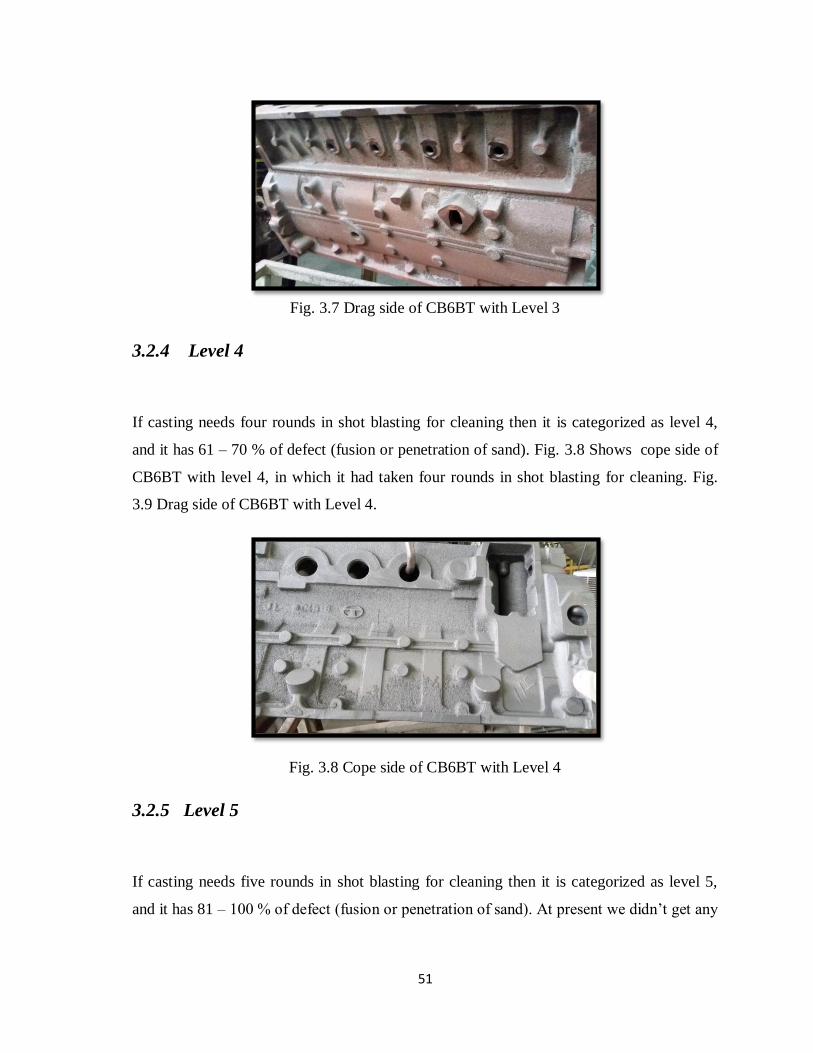
51
Fig. 3.7 Drag side of CB6BT with Level 3
3.2.4 Level 4
If casting needs four rounds in shot blasting for cleaning then it is categorized as level 4,
and it has 61 – 70 % of defect (fusion or penetration of sand). Fig. 3.8 Shows cope side of
CB6BT with level 4, in which it had taken four rounds in shot blasting for cleaning. Fig.
3.9 Drag side of CB6BT with Level 4.
Fig. 3.8 Cope side of CB6BT with Level 4
3.2.5 Level 5
If casting needs five rounds in shot blasting for cleaning then it is categorized as level 5,
and it has 81 – 100 % of defect (fusion or penetration of sand). At present we didn’t get any

52
castings having level 5 defects. But casting is an uncertain process in future we can get
that.
Fig. 3.9 Drag side of CB6BT with Level 4
3.3 Data Collection
3.3.1 Data Collected at Shot Blasting Point
Everyday ten castings are reviewed at shot blasting point and data of ten castings are
recorded as shown in table 3.2. For each and every product which has been made in
foundry division at Tata motors have particular date and number which was written on the
mould before pouring, with the help of which we can find the date at which metal is poured
and the number of that particular casting. In every foundry there are codes given for each
months. Example, if 12G16 is written on the casting it shows that particular product was
manufactured on July 12, 2016, and 331,123, etc,. Shows number of casting for that
particular batch.
In below figure, in block number column, the number of dots represents number of rounds
needed in shot blasting for cleaning. Example 7G16, 167 . represents that on July 13, 2016
casting poured on/ manufactured on July 7, 2016 having part number 167 arrived at shot
blasting point and it needed only one round in shot blasting for cleaning or it falls under
level 1 grade. If PREDICTED is written then it means that before it goes for shot blasting

53
only by seeing it, we had predicted the numbers of rounds needed for cleaning in shot
blasting. If predicted is followed by three dots then it means we had predicted that this
particular casting needs three rounds in shot blasting, it may also vary than actual numbers
of rounds. We had collected data for three months and almost every time our prediction is
right from this we can conclude that our grading is correct.
Table 3.2 Data Collected at Shot Blasting Point
3.3.2 Data Collected from Foundry Lab
Every day for each and every batch, sample is taken and different tests are done at foundry
lab. With the help of date of pouring and number, on the casting we can point out particular
casting properties which are tested by foundry man. At lab tests are done to calculate
permeability number, moisture percentage, GCS, active clay, shatter index, volatile matter,
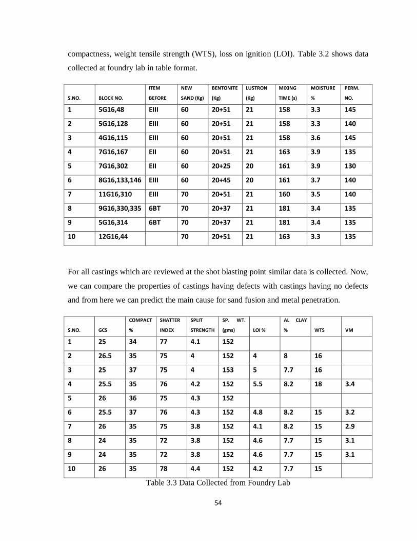
54
compactness, weight tensile strength (WTS), loss on ignition (LOI). Table 3.2 shows data
collected at foundry lab in table format.
S.NO. BLOCK NO.
ITEM
BEFORE
NEW
SAND (Kg)
BENTONITE
(Kg)
LUSTRON
(Kg)
MIXING
TIME (s)
MOISTURE
%
PERM.
NO.
1 5G16,48 EIII 60 20+51 21 158 3.3 145
2 5G16,128 EIII 60 20+51 21 158 3.3 140
3 4G16,115 EIII 60 20+51 21 158 3.6 145
4 7G16,167 EII 60 20+51 21 163 3.9 135
5 7G16,302 EII 60 20+25 20 161 3.9 130
6 8G16,133,146 EIII 60 20+45 20 161 3.7 140
7 11G16,310 EIII 70 20+51 21 160 3.5 140
8 9G16,330,335 6BT 70 20+37 21 181 3.4 135
9 5G16,314 6BT 70 20+37 21 181 3.4 135
10 12G16,44 70 20+51 21 163 3.3 135
For all castings which are reviewed at the shot blasting point similar data is collected. Now,
we can compare the properties of castings having defects with castings having no defects
and from here we can predict the main cause for sand fusion and metal penetration.
S.NO. GCS
COMPACT
%
SHATTER
INDEX
SPLIT
STRENGTH
SP. WT.
(gms) LOI %
AL CLAY
% WTS VM
1 25 34 77 4.1 152
2 26.5 35 75 4 152 4 8 16
3 25 37 75 4 153 5 7.7 16
4 25.5 35 76 4.2 152 5.5 8.2 18 3.4
5 26 36 75 4.3 152
6 25.5 37 76 4.3 152 4.8 8.2 15 3.2
7 26 35 75 3.8 152 4.1 8.2 15 2.9
8 24 35 72 3.8 152 4.6 7.7 15 3.1
9 24 35 72 3.8 152 4.6 7.7 15 3.1
10 26 35 78 4.4 152 4.2 7.7 15
Table 3.3 Data Collected from Foundry Lab

55
3.4 Tests Done at Foundry Lab
Different tests are done at foundry lab and different properties are calculated. In this
section we will discuss about the importance of properties of sand. Metalcasters have two
primary reasons for green sand testing:
To check the consistency of the prepared green sand.
To determine if the green sand has the physical and chemical properties to produce
good castings.
Poor quality sand can lead to a number of casting-related defects. To ensure the
properties necessary to avoid casting defects and produce the quality we desire
consistently throughout the entire green sand system, metalcasting facilities need to
test their green sand daily.
Physical Tests For Moulding Sand
3.4.1 Preparation of standard test specimen
Procedure
It is necessary that the specimen be prepared under standard conditions. To get
reproducible ramming conditions, a laboratory sand rammer is used along with a specimen
tube. Fig. 3.10 shows the set up of laboratory sand rammer. The measured amount of sand
is filled in the specimen tube, and a fixed weight of 6.35 to 7.25 Kg is allowed to fall on the
sand three times from a height of 50.8 ±0.125 mm. The specimen thus produced should
have a height of 50.8± 0.8 mm. To produce this size of specimen usually sand of 145 to
175 g would be required.

56
Fig. 3.10 Sand Rammer With Specimen Tube
3.4.2 Test for Compactability
The purpose of this test is to determine the percentage decrease in the height of a loose
mass of sand under the influence of compaction (i.e., how resistant is it to squeeze and
compaction. The compactability test tells you how wet or dry the green sand is and helps
control the most common green sand defects. It is directly related to the performance of the
green sand in the molding operation and reflects the degree of temper of the green sand. It
indicates how a fixed volume of green sand will react to a fixed energy input (such as
mulling or molding). Metalcasters want to select a compactability level high enough to
avoid cuts and washes, friable broken edges, hard-to-lift pockets, cope downs, crushes,
penetration, burn on and erosion scabbing. Yet, compactability must be low enough to
avoid oversized castings (due to mold wall movement), shrinks, blows, pin holes, super
voids, poor finish, expansion defects, gas and rough surfaces, shakeout problems and high
ramming resistance.

57
The compactability test is carried out in conjunction with a Sand Rammer. This test
measures the decrease in height of a riddled mass of sand, 4¾ inches (120 mm) high, under
the influence of a standard compacting force. The Compactability tester consists of a scale,
graduated 0 – 65% in units of 5, which fits into the hole on top of the Standard Sand
Rammer, and a tube filler comprising a ¼” (6.35 mm) mesh screen and funnel mounted on
a cast base shown in fig. 3.11. .
Installation
(a) Place a precision specimen tube and pedestal cup in position on the sand rammer.
Mount the scale on the top of the rammer frame using the ¼” (6.35 mm) drilled hole.
(b) Using the weight lifting lever, raise the plunger of the rammer until the bottom face of
the ram end is level with the top edge of the specimen tube.
(c) Move the scale up or down until the zero is in line with the top of the plunger shaft.
Lock the accessory in position by means of the 3/16” Allen screw located on the right-hand
side of the top of the rammer.
(a) (b)
Fig. 3.11 (a) Tube Filler (b) Sand Rammer With Compactabilty Tester

58
Procedure
(a) Position a specimen tube and pedestal cup on the tube filler beneath the funnel outlet.
Pass the sand to be tested through the screen until the specimen tube is filled.
(b) Strickle the sand level with the top of the tube with the strike-off blade. Remove the
specimen tube and pedestal cup and place in position on the sand rammer.
(c) Lower the plunger gently onto the sand and ram with three blows. Read percentage
compactability as indicated by the position of the top of the plunger shaft on the scale.
3.4.3 Test for Moisture Content
This test is used to determine the percentage of moisture in the molding sand. Moisture in
molding sand affects the plasticity of the clay bond, which controls most sand-related
defects. Moisture content of a green sand molding system is not an arbitrary number. It
must be maintained within a narrow range. The moisture content is affected by the
hydration of the binder composite, coating of the sand particles and muller efficiency with
regard to working and available bond. Moisture affects all other green sand properties and
is the most abused ingredient in green sand. The two major factors that affect moisture
requirement are the type and amount of clay and the type and amount of additives in the
green sand mix. Excess moisture will produce an oxidizing atmosphere in the mold,
promote excess gas evolution and lower permeability, cause high dry and hot strength,
reduce mold hardness and result in poor flowability of the sand. Insufficient water produces
dry friable green sand that is difficult to mold.
Procedure
The most accurate method of moisture determination is to dry out the sand and to note
weights before and after. The percentage of moisture can be calculated from the difference
in the weights, of the original moist and the consequently dried sand samples.
Calculate the percentage moisture by the following formula:

59
Moisture, percent = 𝐴
𝐵 x 100
Where,
A = loss of weight of the sand sample in g on heating.
B = weight in g of the sand sample taken.
Fifty grams of tempered sand accurately weighed and placed in the pan. The timer for the
blower of the moisture teller is set for the required time to dry the sand (approximately 5
min) and air at 110°C is blown over and through the sand. The sand is dried after this and
weighed again. Note the difference in the initial and final readings and determine the
percentage of moisture in the sand. Make the determination on three separate samples and
take the average of three test results as the moisture content of the sand.
3.4.4 Test for Permeability
Permeability is defined as that physical property of the moulded mass of sand mixture
which allows gas to pass through it. It is determined by measuring the quantity of air that
passes through a given sample of sand in a prescribed time and under standard condition.
Important factors in regulating the degree of permeability include sand grain size, shape,
distribution and type, binder composite quantity and the density to which the green sand
has been rammed, and moisture content. Low permeability will lead to a smooth casting
surface finish, but also could cause blows, pinholes and expansion defects. High
permeability reduces gas pressure but can result in mechanical penetration and a rough
surface finish. To determine permeability the AFS Standard sand specimen of 5.08 cm (2
inches) diameter and 5.08 cm in height is prepared by ramming the required quantity of
sand in a smooth surface tube with three blows of standard rammer. This sand specimen is
placed in the mercury cup of the permeability meter. The air drum is raised to take 2000
cm3 of air in to the air drum which will be indicated by the graduation on it. The whole air
is then allowed to escape through the sand specimen with a pressure of about 10 g/cm3 and
the time is recorded.

60
The permeability number of the sand sample can be calculated from the following
equation:
P = 𝑉ℎ𝑝𝐴𝑡
Where,
P = AFS standard permeability number
V = Volume of air in cm3 = 2000 cm3
h = Height of specimen in cm = 5.08 cm (or, 2 inches)
A = Cross sectional area of specimen in cm2 = 20.268 cm2
p = Air pressure in g/cm2 = 10 g/cm2
t = Time in minutes
The above equation may be simplified as
P = 3007.2
𝑡
Where,
t = time in seconds.
This Permeability Meter employs the orifice method for the rapid determination of sand
permeability. Air at a constant pressure is applied to a standard test specimen (in a
specimen tube), and the drop in pressure is measured on a pressure gauge, which is
calibrated directly in permeability numbers. Fig. 3.12 showing permeability meter.
Procedure
(a) Switch on blower motor by moving toggle switch to the “ON” position. Allow the
motor to run for at least one minute in order to obtain a stable reading on the gauge.

61
Fig. 3.12 Permeabilty Meter
(b) Select the orifice required for the sand sample to be tested. The general rule for
determining the orifice required is :-
(i) If the permeability number of the sample is over 50, use the large orifice
marked ‘L’.
(ii) If the permeability number of the sample is under 50, use the small orifice
marked ‘S’.
(c) Place the specimen tube with the sand sample uppermost over the centre post of the
Permeability meter. Rotate the knurled ring of the centre post anti-clockwise to seal the
specimen tube.
(d) Place the lever on the left-hand side of the permeability meter body in the “CHECK”
(forward) position. Adjust the motor speed control rheostat to obtain a pressure reading of
exactly 100 mm or ‘O’ permeability on the pressure gauge.
(e) Move the lever to the “TEST” (rear) position, and read permeability from the
appropriate scale according to the orifice in use.
(f) Return lever to its “CHECK” position and confirm that a pressure of 100 mm is still
recorded. Release the specimen tube by rotating the knurled ring in a clockwise direction.

62
3.4.5 Green Strength (Compression, Tensile, Shear, Split)
The Universal Sand Strength Machine, together with the appropriate accessories, will
determine the compression, shear, tensile, and splitting strengths of moulding and core
making materials by means of dead weight loading. This machine consists of four major
parts: frame, pendulum weight, pusher arm and motor. The pusher arm is driven by a
geared motor mounted on the pusher arm and coupled to the hand wheel shaft. The
pendulum weight swings on ball bearings and can be moved by the pusher arm, via a test
specimen, from a vertical position, through 90°, to a horizontal position, with a consequent
increase of load on the test specimen. A magnetic rider is moved up a calibrated scale by
the pendulum weight and indicates the point at which specimen collapse occurs. The
machine is calibrated in lb/in2 for 2 inch diameter x 2 inch height standard sand specimens.
Automatic operation is by means of push button stop/start control and micro-switches as
follows :-
(a) Reverse switch. This reverses the machine after the specimen has collapsed.
(b) Stop switch. This stops the machine when it returns to the zero position.
(c) Limit switch. This comes into operation if the specimen fails to collapse,
returning the pusher arm automatically to zero.
The accessories required for the determination of shear, dry, tensile, transverse and
splitting strengths are described separately. Fig. 3.13 shows motor driven universal sand
strength machine (AFS).
Procedure
Green Compression Strength
(a) Place the compression heads in the position shown on the illustration.

63
Fig. 3.13 Motor Driven Universal Sand Strength Machine (AFS)
(b) Raise the weight arm slightly and insert an AFS standard 2 inch diameter x 2 inch
height test specimen between the compression heads so that the face that was uppermost in
the ramming operation is facing the right-hand compression head. Care should be taken not
to damage the specimen.
(c) See that the magnetic rider is resting against the pusher plate and that there is at least
0.25 inch clearance between the rubber bumper and the lug on the weight arm. If this
clearance is not sufficient it means that the specimen is smaller than the permitted tolerance
and should be discarded.
(d) Press the “START” button. When the specimen collapses the machine will reverse and
return to zero automatically.
(e) Record the reading shown on the lower edge of the magnetic rider, reading the scale
designated “Green Compression Strength”. Remove the sand from the compression heads.
Fig. 3.14 Holders for GCS.
Green compression strength indicates the maximum compression stress the sand mixture is
capable of sustaining and is used to control the rate of clay addition to the green sand
system. The degree of mulling, sand to metal ratio, clay content, compactability range and
additive type affect green compression strength. Low green compression strength provides
good flowability but can result in broken molds and poor draws. Indicators of low strength

64
are low clay content, dry sand and poor mulling. High green compression strength means
stronger molds but difficulty in shakeout, poor casting dimensions, poor flowability, high
ramming resistance and higher cost. High clay content is an indicator of high strength.
Fig. 3.14 Holders for Compression Strength Test
Green Shear Strength
(a) Place the shear test heads in the lower position in the machine, with the head having the
half round holder attached to it in the pusher arm.
(b) Raise the weight arm slightly and insert an AFS standard 2 inch diameter x 2 inch
height specimen between the heads. Ensure that the magnetic rider is resting against the
pusher arm and that there is 0.25 inch clearance between the rubber bumper and the lug on
the weight arm.
(c) Press the “START” button. When the specimen shears the machine will reverse and
return to zero automatically.
(d) Read the lower edge of the magnetic rider on the scale designated “Green Shear”.
Remove the sand from the shear heads as shown fig. 3.15.
Fig. 3.15 Holders for shear StrengthTest

65
Compression and Dry Shear Strength
(a) Place either the compression heads or the shear heads in the top position of the
machine. This position increases the load applied by a factor of 5.
(b) Prepare AFS standard 2 inch diameter x 2 inch height test specimens in the usual way
and dry in an oven at 110 °C for 2 hours.
(c) When cool, place in position between test heads and adjust clearance between rubber
bumper and lug on weight arm to approximately 0.5 inch using the adjusting screw in the
pusher arm.
(d) Press the “START” button. When the specimen collapses the machine will reverse and
return to zero automatically.
(e) Read the scale designated “Dry Compression” or “Dry Shear” according to the test
heads being used. Remove the sand from the compression or shear heads.
The dry compression strength test determines the maximum compression load a dry sand is
capable of sustaining. It indicates the resistance of the mold to stresses during pouring and
casting cooling and the ease of shakeout. The higher the dry compression strength, the
greater the number of hard lumps present at shakeout.
An increase in moisture content, the type and amount of clay, rammed mold density and
excessive moisture significantly affect dry compression strength. Low dry compression
strength means easy shakeout by loose friable sand, cuts and washes, burn-in, inclusions
and erosion. High dry compression strength leads to stronger molds, but difficulty in
shakeout, loss of return sand, cracks and hot tears.
3.4.6 Test for Shatter Index
This equipment is designed to allow the free fall of an AFS Standard 2 inch diameter x 2
inch height specimen of moulding sand from a height of 6 feet onto a steel anvil as shown
fig. 3.16. By measuring the degree of disintegration of the specimen the toughness or
plasticity can be determined. The cast iron base of the unit is machined to accept a 13.2

66
mm mesh BS sieve and retaining pan. Through the centre of this assembly passes a solid
steel anvil which is covered by a removable cap onto which the sand specimen falls. Rising
vertically from the rear of the base is a 7 foot steel tube which carries the ejector
mechanism for the sand specimens.
Procedure
(a) Prepare an AFS Standard 2 inch diameter specimen in a precision specimen tube and
record the weight of sand used to form the specimen.
(b) Position the tube containing the sand specimen in the ejector mechanism, beneath the
plunger, with the specimen in the lower part of the tube. Pull the handle of the mechanism
downwards, slowly and evenly, so that the plunger enters the specimen tube and ejects the
sand specimen without giving it any downward impetus.
Fig. 3.16 Shatter Index Tester

67
(c) The sand specimen should strike the anvil squarely in the centre. If it does not, check
that the base is set level. Remove anvil cap, carefully lift off sieve assembly and remove
sieve from pan.
(d) For convenience, weigh the sand in the receiver and calculate the weight of sand
remaining on the sieve, including the cone of sand on the anvil cap, by subtracting this
weight from the total weight of the specimen.
Shatter Index = 𝑊𝑡.𝑜𝑓 𝑠𝑎𝑛𝑑 𝑟𝑒𝑚𝑎𝑖𝑛𝑖𝑛𝑔 𝑜𝑛 13.2 𝑚𝑚 𝑚𝑒𝑠ℎ 𝑠𝑖𝑒𝑣𝑒
𝑇𝑜𝑡𝑎𝑙 𝑤𝑡.𝑜𝑓 (𝑠𝑎𝑛𝑑)𝑠𝑝𝑒𝑐𝑖𝑚𝑒𝑛 x 100
3.4.7 Active Clay
The methylene blue test determines the capacity of clay to absorb cations from a solution,
and thereby predict how the clay will react. Clay may be a component of a drilling fluid, a
binder in foundry sand, or a component in another application. This test is based on the
property of clays known as cation-exchange capacity; clays can exchange some of their
ions for the ions of certain other chemicals. The number of ions available for this exchange
varies with different clays. For example, Western Bentonite, has more base exchange
capacity than Southern Bentonite. However, only the reactive portions of clays are
involved in the cation exchange process.
In this test, the clay particles are coated with methylene blue, giving them a distinct color
until all ions available in the clay cation exchange process have been used. Excess
methylene blue remains unaffected in solution around the particles and forms a blue-green
tint that radiates from the darker spot, similar to a halo. Development of the halo shows that
the total absorption capacity of the clay has been reached, and is noted as the endpoint.
Shown in fig. 3.17.
The methylene blue test is a simple, fast test for measuring the amount of effective binder in
foundry molding sands. This test produces accurate, reproducible results in 10 to 15 minutes.
Only reactive portions of clay participate in the cation exchange process. Finely ground

68
seacoal, wood flour, or cereal does not absorb methylene blue. The cation exchange capacity of
clays is destroyed when clays are exposed to high temperature. The degree of destruction is
depends on the temperature and time that the clay is exposed. A decrease in cation exchange
capacity is accompanied by a proportional decrease in bonding capacity. The altered portion of
depends on the temperature and time that the clay is exposed. A decrease in cation exchange
capacity is accompanied by a proportional decrease in bonding capacity. The altered portion of
the clay cannot be rehydrated, and bonding capacity cannot be restored. Since clay is the only
ingredient in a sand mix with cation-exchange capacity, a precise measurement of this property
is also a measure of the amount of effective binder in the sand.
Methylene blue is added to this sample until saturation, noted by the dye halo surrounding
the solids suspension.
Fig. 3.17 Spot Test for End Point of Methylene Blue Titration
Procedure
1. Pipette 50 ml of deionized water into the Erlenmeyer flask. Obtain a representative sample
of foundry sand. Accurately weigh 5 g of this foundry sand. Place in the Erlenmeyer flask with
the water.

69
2. Shake or stir thoroughly for 10 to 15 minutes. As an option, boil the mixture for 5 minutes.
Add 1 ½ ml to 2 ml of 5N sulfuric acid and shake vigorously for 20 to 30 seconds.
3. Add methylene blue in 1 ml increments. After each addition shake the flask briefly. Using a
stirring rod, place a drop of the fluid on the filter paper. Note the volume of methylene blue
titrated. If the end point has not been reached, a purple circle will appear on the filter paper.
4. Continue titrating until a blue-green halo appears around the purple circle on the filter paper.
When the halo first appears, shake the solution for two minutes to make sure that all the
methylene blue has been absorbed by the binder.
5. After two minutes, place another drop of liquid on the filter paper. If the halo is still present,
the end point has been reached. If the halo disappears, add 1 ml methylene blue and repeat the
filter paper test until the halo remains after two minutes of mixing.
6. Record the volume of methylene blue used to reach the endpoint with the help of table given
in fig. 3.18 (b).
Fig. 3.18 (a) Methylene Blue Active Clay Test Apparatus (b) Table to Calculate Active
Clay
Above Fig. 3.18 (a) shows Methylene Blue Active Clay Test Apparatus.

70
3.4.8 Test for Volatile Matter 900 F(482 C)
This method is used to determine the amount of material in the system sand or additives
that will volatize at a temperature of 900F (482C). Results from this and the LOI test are
used hand in hand. Low combustibles (as determined by the LOI test) and volatiles lead to
lower cost and less moisture required but also can result in poor casting peel, poor finish
and poor shakeout. High combustibles and volatiles cause lower expansion but can result in
pinholes, smoke, blows, brittle sand, higher cost and higher moisture requirements.
3.4.9 Test for Loss on Ignition (LOI)
Loss on ignition measures the weight change of a sample, consisting of weight losses and
weight gains, when a sample is fired at 1,800F (982C). This includes weight loss due to
volatization of organics, removal of chemically bound water, dissocation of inorganic
compounds (with one or more components given off as a gas), and weight gain due to
oxidation reactions. Loss on ignition determines the total amount of combustible material
in the green sand. The green sand sample is fired at 1,800F until it reaches a constant
weight. The quantity of gas forming materials in the green sand will affect casting results.
A high LOI may produce gas defects such as pinholes, blows and scabbing. In steel
castings, a high LOI could lead to carbon pickup on the casting surface. A low LOI can
lead to poor casting peel and a rough casting surface finish.
Above tests are done for moulding sand, same tests can be done for core sand also with
same procedure.

71
CHAPTER - 4.
Result and Discussion
4.1 Sand Fusion and Metal Penetration with Different
Parameters
From above collected data, literature review and observation below table 4.1 can be formed
in which different parameters are considered with respect to sand fusion and metal
penetration.
Parameters Sand Fusion Metal Penetration
High Mold Strength
NO YES/NO
High Pouring Temperature
YES YES
High Pouring Time
YES YES
Optimum Pouring Height
NO NO
Less Carbonaceous Material
YES YES
Less Hot Strength (Low Bentonite)
LESS YES
High Porosity/Less Density
YES YES
Optimum Mold Wash
NO NO
High Permeability
YES YES
Table 4.1 Sand Fusion and Metal Penetration with Different Parameters
Example, if mould strength is high then there will be no sand fusion but metal penetration
may occur, as earlier we had discussed modes of metal penetration, and there we had
studied that metal can penetrate into dense mould also. Similarly, if permeability is high
then metal can easily penetrate into mould.

72
4.2 Returned Sand Variation
Returned Produced Strength Bentonite Moisture Temperature
Block Block
Euro-III 6BT
Head
Block
Bake Drum Block
Table 4.2 Returned Sand Variation
Above table 4.2 shows returned sand variation. As we know good amount of returned sand
is mixed with new sand , bentonite, etc., In this case we are considering production of
block, from above collected data and by observing this table is formed. Above table shows
that the product manufactured just before the block varies the properties of sand mixture
used in production of CB6BT block. Example, if Euro-III 6BT head is manufacture in
previous batch and in next batch block is produced then sand from which head is
manufactured is used in another batch in which block is manufactured for which same sand
will be treated as returned sand then its strength and moisture will be increased, for
compensating this we have to add less amount of bentonite.
4.3 Causes In Our Case and Steps Taken for Elimination of
Defects
4.3.1 Extra Care is Taken In Handling of Core
Causes
Below are the points collected from the causes discussed above.

73
A rough or porous core surface permits ready access to the metal oxides. The
surface of a core is usually the densest. If the surface is rough, abraded, or loose, an
abnormal fusion or penetration can result.
Insufficient or incorrect coating on those cores designed for dipping or washing
permits penetration into the more open core body. Underbaked core may have a
weak skin or they may be such as to provide a high gas pressure during pouring.
A broken or disturbed core wash due to rough handling or handling while the core
wash is still wet exposes an open grain for fusion.
Insufficient penetration of the core wash can be due to grain size that is too fine or
incorrect Baume of wash and the type of wetting agent used.
Low hot strength of the core permits a breakdown of the core surface which is
conducive to metal oxide formation and fusion. The low strength may be because
the binder is too low in hot strength or the binder content is too low.
Dipped or sprayed cores that are not redried cause high moisture. The high
humidity atmosphere in the mould during pouring increases the rate of oxidation
and metal oxide formation.
Steps Taken
Cores are handled with the help of machine instead of hands.
Spray is applied carefully on the moulds in the moulding line.
Cores are redried in the oven before they are used in assembly line.
Correct Baume is maintained.
Cores should not posses porosity.
Fig. 4.1 shows handling of core by hand which is replaced by machine, with which more
precisely wash or coating may be applied.
Fig. 4.2 shows man spraying wash on mould in moulding line. On man side wash is not
applied properly due to which defects occurs.

74
Fig. 4.1 Core dipped in wash for coating by hand
Fig. 4.2 Man spraying wash on mould in moulding line
4.4 Stabilization of Green Sand System
Green system includes sand, bentonite, lustron. If we can correctly control these three
parameters and process then defect free casting can be achieved. But, as we know casting is
a process of uncertainity so it is very difficult to say that for that particular product this
should be amount of bentonite or lustron because casting depends upon environment
condition also. It is seen that during rainy season sand fusion and metal penetration are
more as casting absorb moisture from environment. But, there is standard range for all
parameters which is shown in table 4.3.

75
Sand Parameters Tolerance Range Value Range
Active Clay Tolerance range Total range from established
mean level capacity of the
Clay.
7.8% to 8.5% depending on
the swelling Index or
bonding
Total Clay ± 0.20 the sum of the Active Clay
+ Dead Clay should
normally be 11% -12%
Volatile Matter Volatile Matter Should
normally be 60% - 70% of
the LOI
Loss on Ignition ± 0.15 5.5% - 6.0% - in
conventional lines 4.5 –
5.0% in high pressure lines
Moisture (at moulding
machine)
± 0.15 3.8% - 4.0% in
Conventional Lines
3.2% to 3.7% in High
pressure lines
Table 4.3 Fundamental and Ideal Sand parameters of prepared sand
In casting we know that one parameter is related to many properties, like if we increase
amount of bentonite strength increased, active clay increased, etc. Similarly, if we vary
lustron then volatile matter vary. Hence we that predicted different values of bentonite and
lustron for different product. Initially we had increased the amount of bentonite but active
clay goes beyond standard values then we had decreased it. In Tata Motors there are two
mixture, old and new and there are three shifts namely A, B ,C. It is not necessary that
every foundry should follow above standards it may vary from foundry to foundry. Below
tables shows some prediction. In which we had changed amount of bentonite, lustron and
new sand for old and new mixture, firstly it is predicted for only one shift later we had
decided for all shifts. Table 4.4 shows first prediction and second prediction, there is large
change in bentonite as in first prediction we are getting more active clay, that’s why its
amount is decreased. Some time amount of bentonite reaches to 60 kg also. We had
predicted and stabilize the green sand system which is shown in table. 4.6 prediction values
for A shift for both old and new mixer and table 4.7 shows changes made in the same.

76
(a) (b)
Table 4.4 (a) First Prediction (b) Second Prediction
Table 4.5 (a) Third Prediction (b) Fourth Prediction
Old Mixture New Mixture
Bentonite Lustron Bentonite Lustron
Block 57 kg 17 kg 46 kg 14 kg
Other 51 kg 17 kg 41 kg 14 kg
Head 40 kg 19 kg 32 kg 15 kg
Sand 51 kg 40 kg
Table 4.6 Prediction for A shift
Old Mixture New Mixture
Bentonite Lustron Bentonite Lustron
Block 50 kg 17 kg 40 kg 14 kg
Other 45 kg 17 kg 36 kg 14 kg
Head 35 kg 19 kg 28 kg 15 kg
Sand 60 kg 48 kg
Table 4.7 Change in prediction for A shift
Bentonite Lustron
Block 46 kg 18 kg
Others 44 kg 17 kg
Bentonite Lustron
Block 54 kg 17 kg
Others 46 kg 16 kg
Bentonite Lustron
Block 58 kg 19 kg
Others 45 kg 19 kg
Bentonite Lustron
Block 54 kg 16 kg
Others 44 kg 16 kg

77
4.5 Prediction that Eliminate Defects
Below tables shows the final predicted values of amount of bentonite, lustron, new sand
considering both old and new mixture and all shifts for block and other products with
which defects are eliminated.
Old Mixture New Mixture
Bentonite Lustron Bentonite Lustron
Block 49 kg 17 kg 39 kg 14 kg
Other 44 kg 17 kg 35 kg 14 kg
Head 37 kg 19 kg 30 kg 15 kg
Sand 50 kg 40 kg
Table 4.8 Values for A shift
Old Mixture New Mixture
Bentonite Lustron Bentonite Lustron
Block 51 kg 18 kg 41 kg 14 kg
Other 47 kg 18 kg 38 kg 14 kg
Head 37 kg 20 kg 30 kg 16 kg
Sand 45 kg 36 kg
Table 4.9 Values for B shift
Old Mixture New Mixture
Bentonite Lustron Bentonite Lustron
Block 50 kg 17 kg 40 kg 14 kg
Other 46 kg 17 kg 37 kg 14 kg
Head 38 kg 19 kg 30 kg 16 kg
Sand 49 kg 40 kg
Table 4.10 Values for C shift

78
4.6 Comparison of Rejection
Below graph shows the comparison between previous total rejection and current total
rejection after predicted values are applied
(a)
(b)
Fig. 4.3 Comparison of Total Rejection for all product (a) Previous (b) Present
From above we observe that rejection percentage decreased from month of January
(predicted values are applied from january).
Below graph shows comparison between total rejection for CB6BT previously and total
rejection for CB6BT currently. From below graph we can observe that rejection percentage
decreases after the predicted values are applied.

79
(a)
(b)
Fig. 4.4 Comparison of Total Rejection for CB6BT (a) previous (b) present

80
CHAPTER 5.
CONCLUSION
In the study of block CB6BT mainly have two defects are responsible for higher
percentage of rejection namely sand fusion and metal penetration. Hence, there causes are
studied and causes which are responsible in our study are considered. Here, practically
defects are eliminated as we know in industries we have to eliminate the defects under
many constraints like we canot change the whole process and we cannot implement the
steps which increases the cost to company. So, we have to find the best solution
considering all constraints.
For elimaination of these defects, we had made changes like in handling of core,
application of wash carefully, etc,. We had measure various properties of sand and data is
collected from lab, at shot blasting point. Data is compared and standard values are set for
different products considering all shifts which are discussed above. After implementation
we had observe that percentage of rejections for CB6BT and overall rejections are reduced
and we have achieved percentage of rejection lower than targeted value.
Product Targeted Achieved
CB6BT 5.3 5.22
All 4.2 4.13
Table 5.1 Targeted and Achieved Value
81
REFERENCES
1. P.N. Rao (2000), Manufacturing Technology – Foundry, Forming and Welding
Tata McGraw-Hill Publishing Company Ltd., New Delhi.
2. Stefanescu, D.M., and Giese, S., “Cast Iron Penetration in Sand Molds, Part I:
Physics of Penetration Defects and Penetration Model,” ASF Transactions, Volume
104, pp. 1233-1248, 1996.
3. Stefanescu, D.M., and Giese, S., “Cast Iron Penetration in Sand Molds, Part II:
Experimental Evaluation of Some Main Parameters Responsible for Penetration,”
ASF Transactions, Volume 104, pp. 1249-1257, 1996.
4. Meredith, J. Factors which affect the soundness of graphitic Iron castings. Metal
Asia, 1996, pp. 15.
5. Kumruoglu, L. C. and Ӧzer, A. Investigation of Critical Liquid Fraction Factor in
Nodular Iron Castings by Computer Simulation. Journal of Materials Processing
Technology, 197, 2008, pp. 182–188.
6. Brieger, G. D. -I. Optimized Feeding Systems Increase Quality and Reduce
Finishing Costs. Casting Plant and Technology, 2, 2011, pp. 53.
7. Woldert, I. G. F. State of the Art Sand Regeneration System for Furan Resin Sand.
Casting Plant and Technology, 2, 2011, pp. 22–23.
8. Deshmukh, V. S., Divakar, P. and Sarda, S. S. Production of Quality Ferrous
Castings to Satisfy Global Customer, Souvenir NCAMT National conference on ‘
Advanced Manufacturing Techniques, Katra, J & K, 2009, pp. 55–56.
9. Svoboda, J.M., and Gieger, G.H. “Mechanisms of Metal Penetration in Foundry
Molds,” AFS Transactions, Volume 77, pp. 281-288, 1969.
10. Jain, P.L., “Principles of Foundry Technology”, Tata McGraw-Hill, New Delhi,

82
11. Surekha, B., Rao, D.H., Rao, G.K. And Vundavilli, P.R., “Design and Development
of Knowledge Bese Scheme for Chromite Based Resin Bonded Sand Core System”,
Procedia Material Science (ICMPC), Vol.6, pp.919-925,2014.
12. Rasik A Upadhye “ Optimization of Sand Casting Process Parameter Using
Taguchi Method in Foundry” IJERT Vol. 1 Issue 7,( September – 2012).
13. Tapan Roy “Analysis of Casting Defects in Foundry by Computerised Simulations
(CAE) - A New Approach along with Some Industrial Case Studies” Transaction of
61st Indian foundry congress 2013.
14. “Review of Casting Defect Analysis to Initiate the Improvement Process”A.P.More,
Dr.R.N.Baxi, Dr.S.B.Jaju Mechanical Engineering Department, G.H.Raisoni
College of Engineering, Nagpur. 440016 (India)
15. Art Spengler Lecture No.1 – Ductile Iron Society Publication”
16. Domingo Mery 2004 . et al .(2004), “Inspection of Aluminum Castings using
Classifier Fusion Strategies, Technical paper.
17. Kasim M. Daws et al (2008), “Selection of Metal Casting Processes: A Fuzzy
Approach” Jordan journal of mechanical and Industrial engineering Vol 2 March
2008 ISS 1995-6665 Pages 45.
18. Liu Limin1,Shan Zhongde1 et al.(2011)“Numerical simulation study on gating and
riser system of large complicated steel castings”.
19. Chen Zhilan ,Yang Renwei. et al.(2010), ““Numerical Simulation of Mould Filling
Process in Lost Foam Casting of Engine Cover” V12- 356 2010 IEEE, Journal of
Marine Engineering and Technology Vol 10, No 3, pp. 57-72.
20. Ashok Sharma and Elisabeth Gariboldi et al. (2003) “Study of casting defects in
Alluminium alloy Castings”Technical paper.
21. American foundry men’s society Foundry Sand Handbook