
st. joseph university college of engineering and technology ...
66
054 EC 65: Antenna & Wave Propagation ST. JOSEPH UNIVERSITY COLLEGE OF ENGINEERING AND TECHNOLOGY DEPARTMENT OF ELECTRICAL, ELECTRONICS AND COMMUNICATION ENGINEERING MODULE CODE: 054 EC 65 MODULE NAME: ANTENNAS and PROPAGATION UNIT THREE: SMALL ANTENNAS SYLLABUS 1. Loop antennas: Radiaon from a small loop and its radiaon resistance; Radiaon from a loop with circumference equal to wave-length; 2. Helical antennas; Normal mode of operaon; Axial mode of operaon; 3. Yagi-Uda antenna; 4. Log-periodic antennas; 5. Phased array; 6. Rhombic antennas; 7. Horn antennas; 8. Reflector antenna and their feed systems; 9. Micro-strip antennas; 10. Selecon of antenna based on frequency of operaon; 11. Antennas for special applicaons; Antennas for terrestrial mobile communicaons; GPR, Embedded antennas, UWB, Plasma antennas. UNIT – 3 SMALL ANTENNAS Page 1
-
Upload
khangminh22 -
Category
Documents
-
view
3 -
download
0
Transcript of st. joseph university college of engineering and technology ...

054 EC 65: Antenna & Wave Propagation
ST. JOSEPH UNIVERSITY COLLEGE OF ENGINEERING AND TECHNOLOGY
DEPARTMENT OF ELECTRICAL, ELECTRONICS AND COMMUNICATION
ENGINEERING
MODULE CODE: 054 EC 65 MODULE NAME: ANTENNAS and PROPAGATION
UNIT THREE: SMALL ANTENNAS
SYLLABUS
1. Loop antennas:
Radiation from a small loop and its radiation resistance;
Radiation from a loop with circumference equal to wave-length;
2. Helical antennas;
Normal mode of operation;
Axial mode of operation;
3. Yagi-Uda antenna;
4. Log-periodic antennas;
5. Phased array;
6. Rhombic antennas;
7. Horn antennas;
8. Reflector antenna and their feed systems;
9. Micro-strip antennas;
10. Selection of antenna based on frequency of operation;
11. Antennas for special applications;
Antennas for terrestrial mobile communications;
GPR,
Embedded antennas,
UWB,
Plasma antennas.
UNIT – 3 SMALL ANTENNAS Page 1
054 EC 65: Antenna & Wave Propagation
LOOP ANTENNAS:
Definition;
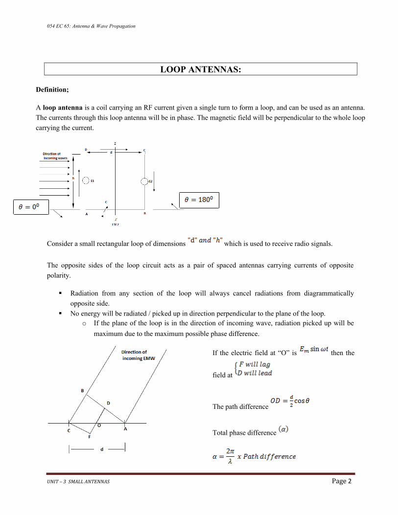
A loop antenna is a coil carrying an RF current given a single turn to form a loop, and can be used as an antenna.
The currents through this loop antenna will be in phase. The magnetic field will be perpendicular to the whole loop
carrying the current.
Consider a small rectangular loop of dimensions which is used to receive radio signals.
The opposite sides of the loop circuit acts as a pair of spaced antennas carrying currents of opposite
polarity.
Radiation from any section of the loop will always cancel radiations from diagrammatically
opposite side.
No energy will be radiated / picked up in direction perpendicular to the plane of the loop.o If the plane of the loop is in the direction of incoming wave, radiation picked up will be
maximum due to the maximum possible phase difference.
If the electric field at “O” is then the
field at
The path difference
Total phase difference
UNIT – 3 SMALL ANTENNAS Page 2
054 EC 65: Antenna & Wave Propagation
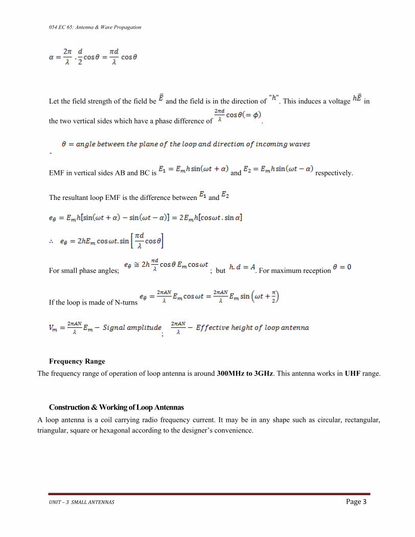
Let the field strength of the field be and the field is in the direction of . This induces a voltage in
the two vertical sides which have a phase difference of .
-
EMF in vertical sides AB and BC is and respectively.
The resultant loop EMF is the difference between and
For small phase angles; ; but . For maximum reception
If the loop is made of N-turns
;
Frequency Range
The frequency range of operation of loop antenna is around 300MHz to 3GHz. This antenna works in UHF range.
Construction & Working of Loop Antennas
A loop antenna is a coil carrying radio frequency current. It may be in any shape such as circular, rectangular,
triangular, square or hexagonal according to the designer’s convenience.
UNIT – 3 SMALL ANTENNAS Page 3

054 EC 65: Antenna & Wave Propagation
Types of loop antenna in existence;
i) Electrically small loop antennasA loop with dimensions small compared to the operating wave-length (small loop),- Currents are of the same magnitude and phase throughout the loop
ii) Electrically large loop antennasA loop with dimensions comparable with the operating wave-length,
Large loop antennas
Large loop antennas are also called as resonant antennas. They have high radiation efficiency. These antennas
have length nearly equal to the intended wavelength. L = λ
Where: L is the length of the antenna; λ is the wavelength
The main parameter of this antenna is its perimeter length, which is about a wavelength and should be an
enclosed loop. It is not a good idea to meander the loop so as to reduce the size, as that increases capacitive
effects and results in low efficiency.
a. Radiation from Small loop antennas
Small loop antennas are also called as magnetic loop antennas. These are less resonant. These are mostly
used as receivers.
These antennas are of the size of one-tenth of the wavelength. L = 10λλ
Where, L is the length of the antenna; λ is the wavelength;
The features of small loop antennas are −
A small loop antenna has low radiation resistance. If multi-turn ferrite core constructions are used,
then high radiation resistance can be achieved.
It has low radiation efficiency due to high losses.
Its construction is simple with small size and weight.
UNIT – 3 SMALL ANTENNAS Page 4
054 EC 65: Antenna & Wave Propagation
Due to its high reactance, its impedance is difficult to match with the transmitter. If loop antenna have to act as
transmitting antenna, then this impedance mis-match would definitely be a problem. Hence, these loop antennas
are better operated as receiver antennas.
Frequently Used Loops
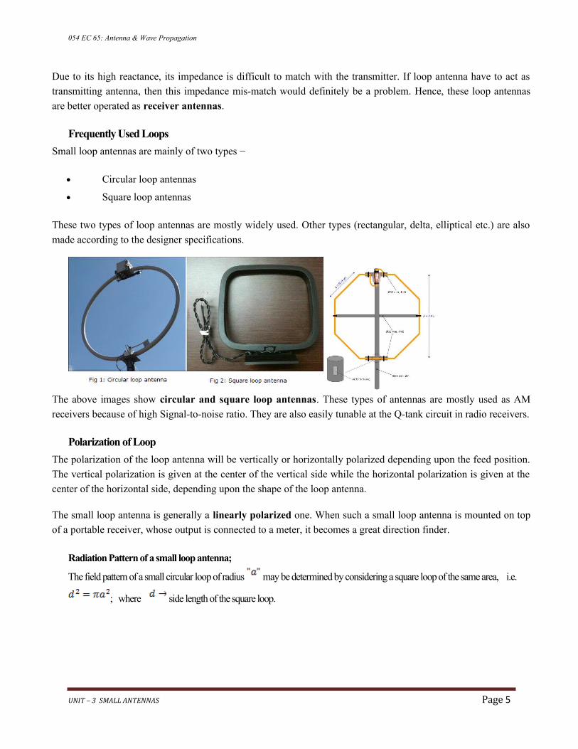
Small loop antennas are mainly of two types −
Circular loop antennas
Square loop antennas
These two types of loop antennas are mostly widely used. Other types (rectangular, delta, elliptical etc.) are also
made according to the designer specifications.
The above images show circular and square loop antennas. These types of antennas are mostly used as AM
receivers because of high Signal-to-noise ratio. They are also easily tunable at the Q-tank circuit in radio receivers.
Polarization of Loop
The polarization of the loop antenna will be vertically or horizontally polarized depending upon the feed position.
The vertical polarization is given at the center of the vertical side while the horizontal polarization is given at the
center of the horizontal side, depending upon the shape of the loop antenna.
The small loop antenna is generally a linearly polarized one. When such a small loop antenna is mounted on top
of a portable receiver, whose output is connected to a meter, it becomes a great direction finder.
Radiation Pattern of a small loop antenna;
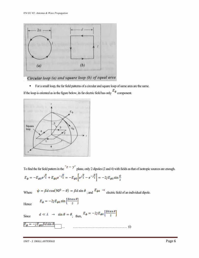
The field pattern of a small circular loop of radius may be determined by considering a square loop of the same area, i.e.
; where side length of the square loop.
UNIT – 3 SMALL ANTENNAS Page 5
054 EC 65: Antenna & Wave Propagation
For a small loop, the far field patterns of a circular and square loop of same area are the same.
If the loop is oriented as in the figure below, its far electric field has only component.
To find the far field pattern in the plane, only 2 dipoles (2 and 4) with fields as that of isotropic sources are enough.
Where ; and electric field of an individual dipole.
Hence
Since ; then,
… ………………………………………… (i)
UNIT – 3 SMALL ANTENNAS Page 6
054 EC 65: Antenna & Wave Propagation
To find far field of the individual dipole;
; since
;
Comparing the far field of the individual dipole with this;
Short dipole was oriented in , whereas here, it is oriented along ;
The angle in the dipole expression is measured from the dipole axis and is
Therefore: …………………………………………………(ii)
Substituting (ii) into (i)
Since the length of the dipole area of square loop,
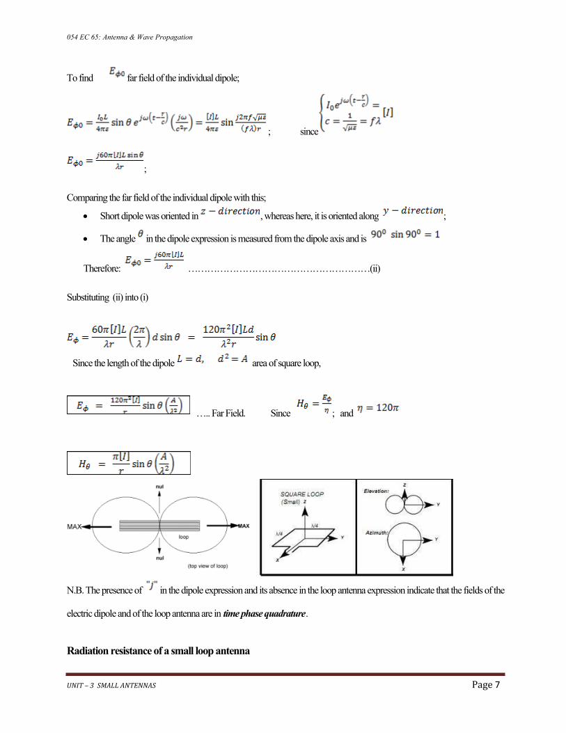
….. Far Field. Since ; and
N.B. The presence of in the dipole expression and its absence in the loop antenna expression indicate that the fields of the
electric dipole and of the loop antenna are in time phase quadrature.
Radiation resistance of a small loop antenna
UNIT – 3 SMALL ANTENNAS Page 7
054 EC 65: Antenna & Wave Propagation
Power radiated from the small loop is obtained by;
i) Get the total power radiated by integrating the Poynting vector of the far field over a large sphere;
Since
watts/m 2
ii) Equate this power to ; where:-
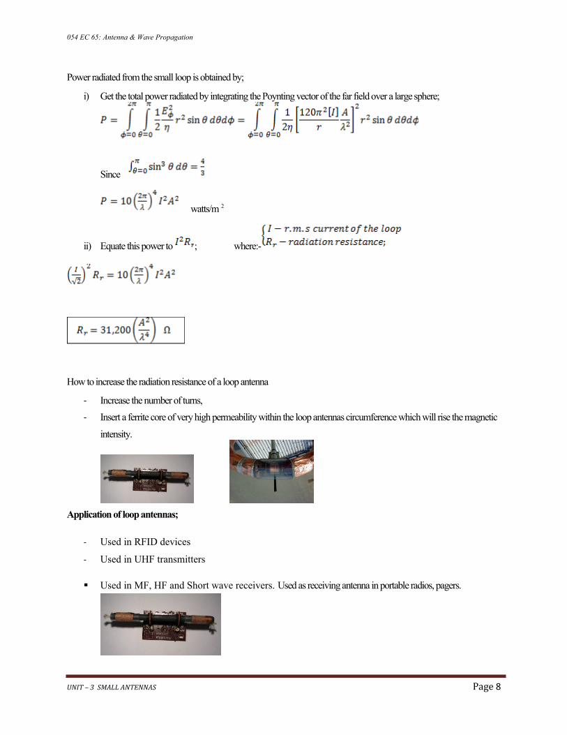
How to increase the radiation resistance of a loop antenna
- Increase the number of turns,
- Insert a ferrite core of very high permeability within the loop antennas circumference which will rise the magnetic
intensity.
Application of loop antennas;
- Used in RFID devices
- Used in UHF transmitters
Used in MF, HF and Short wave receivers. Used as receiving antenna in portable radios, pagers.
UNIT – 3 SMALL ANTENNAS Page 8

054 EC 65: Antenna & Wave Propagation
Used as probes for field measurements,
Used as directional antennas for radio navigation.
o Automatic Direction Finder (ADF) in aircrafts and Armature direction finding
The radiation pattern of these antennas will be same as that of short horizontal dipole antenna.
The radiation pattern for small, high-efficiency loop antennas is shown in the figure given above. The radiation
patterns for different angles of looping are also illustrated clearly in the figure. The tangent line at 0λ° indicates
vertical polarization, whereas the line with 90λ° indicates horizontal polarization.
Advantages
Compact in size
High directivity
Disadvantages
UNIT – 3 SMALL ANTENNAS Page 9
054 EC 65: Antenna & Wave Propagation
Impedance matching may not be always good
Has very high resonance quality factor
Suitable for low and medium frequencies except for a very small distance, (Unless modified),
Spurious induced voltages are produced if nearby loop, wires and conductors are present,
Transmission efficiency is very poor and hence cannot be used for transmission purposes.\,
It is subjected to antenna effect and night effect; (Google the meaning).
o Antenna effect; a distortion of the directional properties of a loop antenna by an input to
the direction-finding receiver due to the ground,
o Night effect; the effect of changed polarization on a loop antenna occurring at night.
b. Radiation from a loop with circumference equal to wave-length (Resonant loop antennas)
The large or resonant loop antenna can be seen as a folded dipole which has been reformed into a circle (orsquare, etc.).
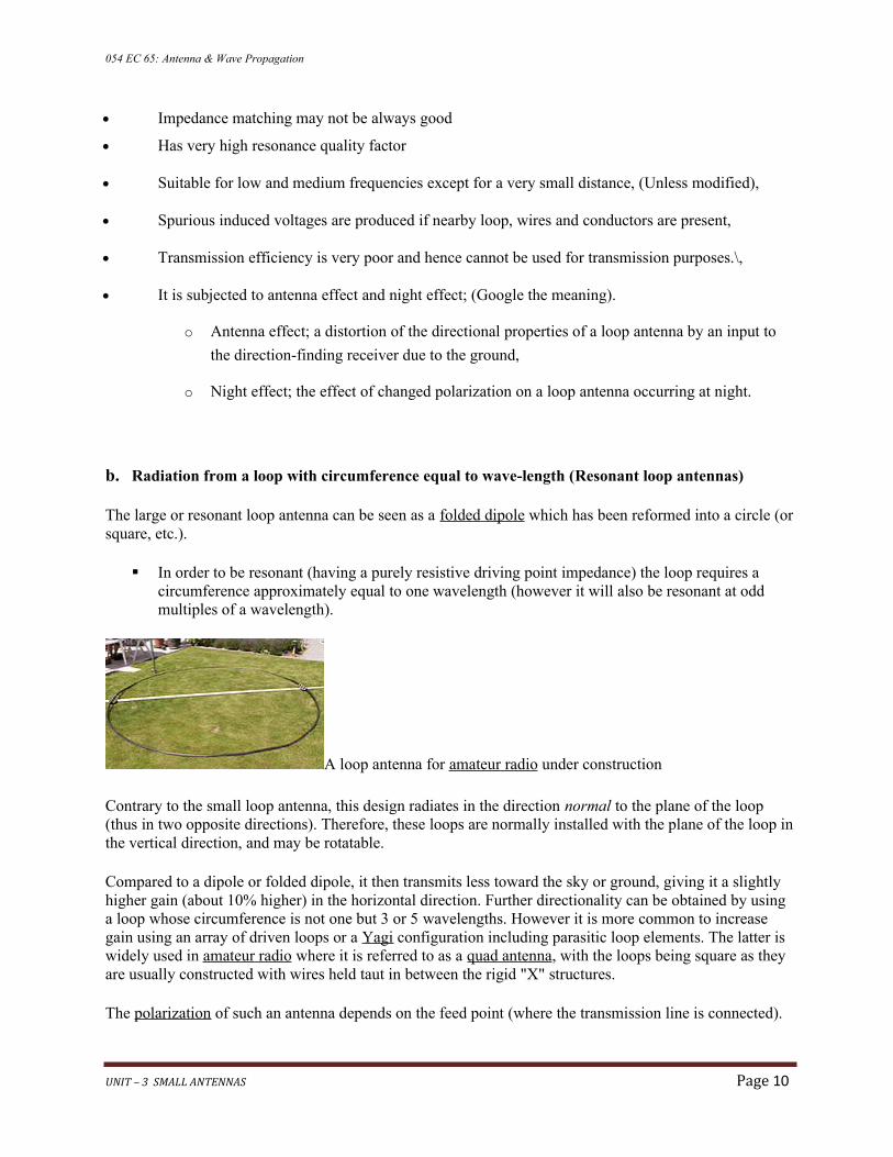
In order to be resonant (having a purely resistive driving point impedance) the loop requires a circumference approximately equal to one wavelength (however it will also be resonant at odd multiples of a wavelength).
A loop antenna for amateur radio under construction
Contrary to the small loop antenna, this design radiates in the direction normal to the plane of the loop (thus in two opposite directions). Therefore, these loops are normally installed with the plane of the loop inthe vertical direction, and may be rotatable.
Compared to a dipole or folded dipole, it then transmits less toward the sky or ground, giving it a slightly higher gain (about 10λ% higher) in the horizontal direction. Further directionality can be obtained by using a loop whose circumference is not one but 3 or 5 wavelengths. However it is more common to increase gain using an array of driven loops or a Yagi configuration including parasitic loop elements. The latter is widely used in amateur radio where it is referred to as a quad antenna, with the loops being square as they are usually constructed with wires held taut in between the rigid "X" structures.
The polarization of such an antenna depends on the feed point (where the transmission line is connected).
UNIT – 3 SMALL ANTENNAS Page 10
054 EC 65: Antenna & Wave Propagation
If a vertically oriented loop is fed at the bottom it will be horizontally polarized; feeding it from the side will make it vertically polarized.
HELICAL ANTENNAS;
Helical antenna is an example of wire antenna and itself forms the shape of a helix. This is a broadband
VHF and UHF antenna.
It is a ‘super-gain’ end fire array over a wide band,
It is non-critical w.r.t. conductor size and turn spacing,
Easy to be used in arrays because of negligible mutual impedance.
Frequency Range
The frequency range of operation of helical antenna is around 30MHz to 3GHz. This antenna works in
VHF and UHF ranges.
Construction & Working of Helical Antenna
UNIT – 3 SMALL ANTENNAS Page 11
054 EC 65: Antenna & Wave Propagation
Helical antenna or helix antenna is the antenna in which the conducting wire is wound in helical shape
and connected to the ground plate with a feeder line. It is the simplest antenna, which provides circularly
polarized waves. It is used in extra-terrestrial communications in which satellite relays etc., are involved.
UNIT – 3 SMALL ANTENNAS Page 12

The image shows a helical antenna system,
which is used for satellite communications.
These antennas require wider outdoor space.
It consists of a helix of thick copper wire or
tubing wound in the shape of a screw thread
used as an antenna in conjunction with a flat
metal plate called a ground plate. One end of the
helix is connected to the center conductor of the
cable and the outer conductor is connected to the
ground plate.
The radiation of helical antenna depends on the diameter of helix, the turn spacing and the pitch angle.
Pitch angle is the angle between a line tangent to the helix wire and plane normal to the helix axis.
where,
D is the diameter of helix. S is the turn spacing (centre
to centre).
α is the pitch angle.
Modes of Operation
The predominant modes of operation of a helical antenna are −
Normal or perpendicular mode of radiation (Broadside).
Axial or end-fire or beam mode of radiation
.
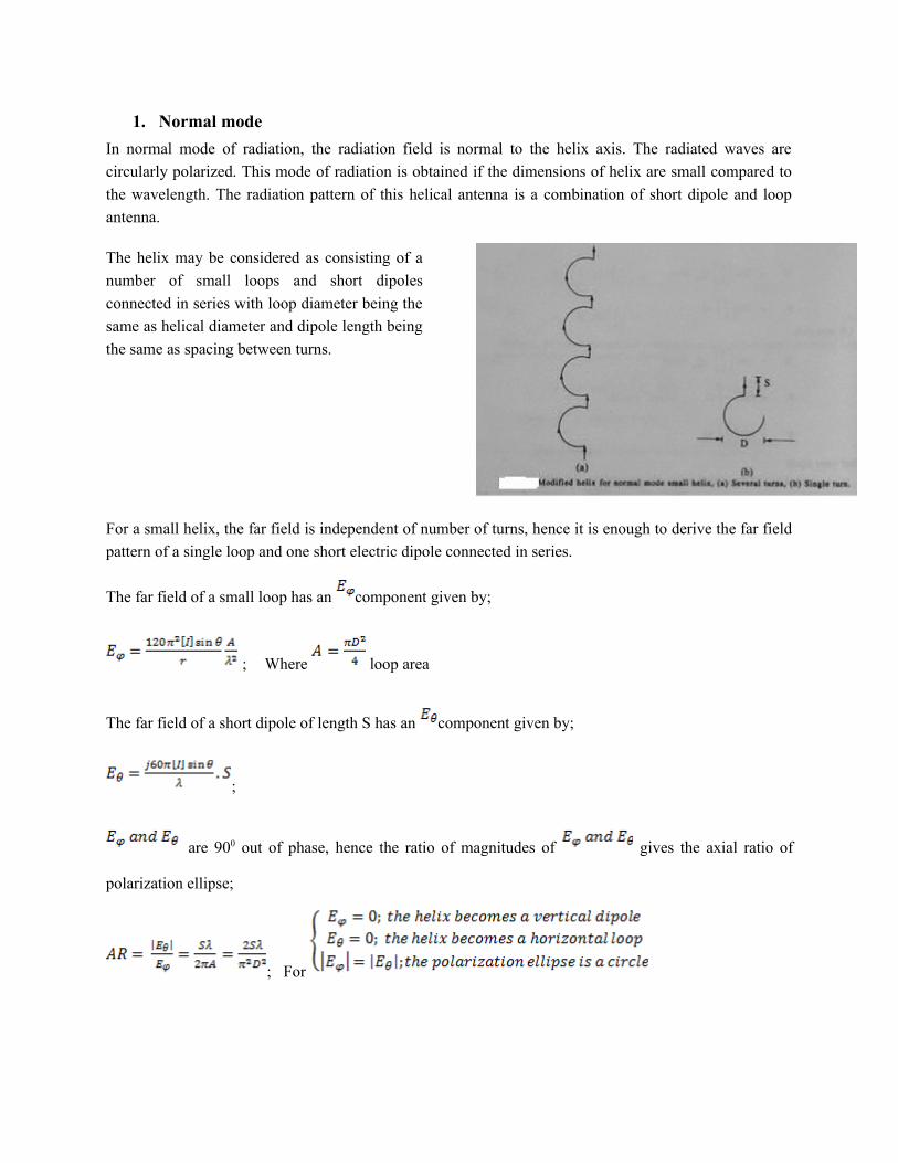
1. Normal mode
In normal mode of radiation, the radiation field is normal to the helix axis. The radiated waves are
circularly polarized. This mode of radiation is obtained if the dimensions of helix are small compared to
the wavelength. The radiation pattern of this helical antenna is a combination of short dipole and loop
antenna.
The helix may be considered as consisting of a
number of small loops and short dipoles
connected in series with loop diameter being the
same as helical diameter and dipole length being
the same as spacing between turns.
For a small helix, the far field is independent of number of turns, hence it is enough to derive the far field
pattern of a single loop and one short electric dipole connected in series.
The far field of a small loop has an component given by;
; Where loop area
The far field of a short dipole of length S has an component given by;
;
are 90λ0λ out of phase, hence the ratio of magnitudes of gives the axial ratio of
polarization ellipse;
; For

The above figure shows the radiation pattern for normal mode of radiation in helical antenna.
It depends upon the values of diameter of helix, D and its turn spacing, S.
Disadvantages of normal mode of operation;
1) Low radiation efficiency and
2) Narrow bandwidth. Hence,
Hence the normal mode of operation is hardly used.
2. Axial mode
The axial mode of operation is the most practical because it can achieve circular polarization over a wide
bandwidth and is more efficient.
In axial mode of radiation, the radiation is in the end-fire direction along the helical axis and the waves
are circularly or nearly circularly polarized. This mode of operation is obtained by raising the
circumference to the order of one wavelength (λ) and spacing of approximately λ/4. The radiation pattern
is broad and directional along the axial beam producing minor lobes at oblique angles.

Radiation pattern of a helix radiating in the axial modeTo derive the radiation pattern of a helix radiating in the axial mode, it is assumed that approximately a single travelling-wave of uniform amplitude is travelling along it.
Using the principle of pattern multiplication, the radiation pattern is the product of the pattern of
one turn and pattern of an array of point sources, where
The array factor of is given by;
; where ; …………………. (i)
; Where Relative phase velocity of wave propagating along the helix;
phase velocity; speed of light
If the fields from all sources are in phase at a point along the helix axis ( ), the radiation will be in
the axial mode.

- For the fields to be in phase in EFA requires that , where
The (-) sign results from the fact that the phase of source 2 is retarded by w.r.t. source1. Source 3 is
similarly retarded w.r.t. source 2, etc.
For an array to fire along its end, , hence
When
This is an approximate relation between turn-length and spacing required for a helix to radiate in the axialmode.
Since for a helix
The figure shows the radiation pattern for axial mode of radiation in helical antenna.
If this antenna is designed for right-handed circularly polarized waves, then it will not receive left-handed
circularly polarized waves and vice versa. This mode of operation is generated with great ease and is
more practically used.
Advantages Disadvantages
Simple design
Highest directivity
Wider bandwidth
Can achieve circular polarization
Can be used at HF & VHF bands also
Antenna is larger and requires more space
Efficiency decreases with number of turns
Applications
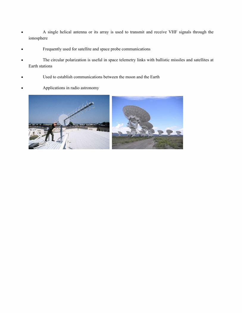
A single helical antenna or its array is used to transmit and receive VHF signals through the
ionosphere
Frequently used for satellite and space probe communications
The circular polarization is useful in space telemetry links with ballistic missiles and satellites at
Earth stations
Used to establish communications between the moon and the Earth
Applications in radio astronomy

YAGI-UDA ANTENNA;
Yagi-Uda antenna is the most commonly used type of antenna for TV reception over the last few
decades. It is the most popular and easy-to-use type of antenna with better performance, which is famous
for its high gain and directivity
Frequency range
The frequency range in which the Yagi-Uda antennas operate is around 30 MHz to 3GHz which belong
to the VHF and UHF bands.
Construction of Yagi-Uda Antenna
A Yagi-Uda antenna was seen on top of almost every house during the past decades. The parasitic
elements and the dipole together form this Yagi-Uda antenna.
The figure shows a Yagi-Uda antenna. It is seen that there are many directors placed to increase the
directivity of the antenna. The feeder is the folded dipole. The reflector is the lengthy element, which is at
the end of the structure.
The center rod like structure on which the elements are mounted is called as boom. The element to which
a thick black head is connected is the driven element to which the transmission line is connected
internally, through that black stud. The single element present at the back of the driven element is the
reflector, which reflects all the energy towards the direction of the radiation pattern. The other elements,
before the driven element, are the directors, which direct the beam towards the desired angle.
Designing
For this antenna to be designed, the following design specifications should be followed.

They are −
ELEMENT SPECIFICATION
Length of the Driven Element 0λ.458λ to 0λ.5λ
Length of the Reflector 0λ.55λ to 0λ.58λ
Length of the Director 1 0λ.45λ
Length of the Director 2 0λ.40λλ
Length of the Director 3 0λ.35λ
Spacing between Directors 0λ.2λ
Reflector to dipole spacing 0λ.35λ
Dipole to Director spacing 0λ.125λ
If the specifications given above are followed, one can design an Yagi-Uda antenna.
Radiation Pattern
The directional pattern of the Yagi-Uda antenna is highly directive as shown in the figure given below.
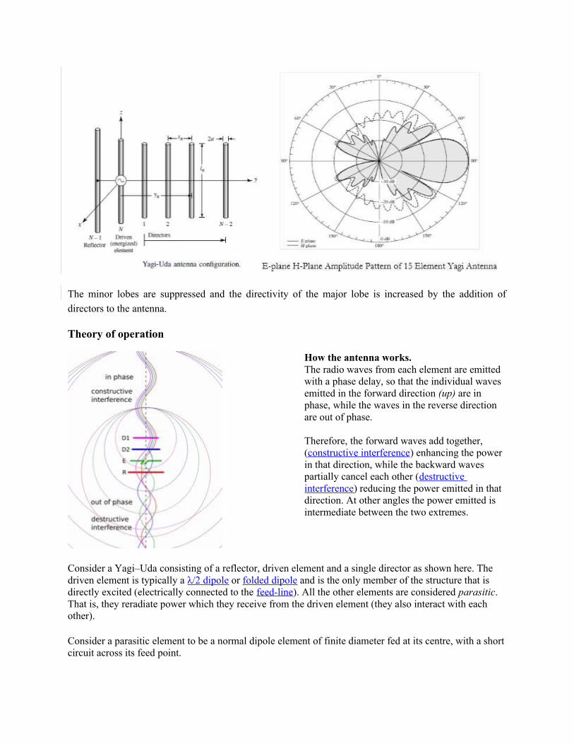
The minor lobes are suppressed and the directivity of the major lobe is increased by the addition of
directors to the antenna.
Theory of operation
How the antenna works. The radio waves from each element are emitted with a phase delay, so that the individual waves emitted in the forward direction (up) are in phase, while the waves in the reverse direction are out of phase.
Therefore, the forward waves add together, (constructive interference) enhancing the power in that direction, while the backward waves partially cancel each other (destructive interference) reducing the power emitted in that direction. At other angles the power emitted is intermediate between the two extremes.
Consider a Yagi–Uda consisting of a reflector, driven element and a single director as shown here. The driven element is typically a λ/2 dipole or folded dipole and is the only member of the structure that is directly excited (electrically connected to the feed-line). All the other elements are considered parasitic. That is, they reradiate power which they receive from the driven element (they also interact with each other).
Consider a parasitic element to be a normal dipole element of finite diameter fed at its centre, with a shortcircuit across its feed point.
A short circuit reflects all of the incident power 180λ degrees out of phase. So the parasitic element acts a superposition of a dipole element receiving power and sending it down a transmission line to a matched load, and a transmitter sending the same amount of power up the transmission line back toward the antenna element.
If the transmitted voltage wave were 180λ degrees out of phase with the received wave at that point, the superposition of the two voltage waves would give zero voltage, equivalent to shorting out the dipole at the feed-point (making it a solid element, as it is).
Thus a half-wave parasitic element radiates a wave 180λ° out of phase with the incident wave.
The parasitic element involved is not exactly resonant but is somewhat shorter (or longer) than λ/2 hence it modifies the phase of the element's current with respect to its excitation from the driven element.
The so-called reflector element, being longer than λ/2, has an inductive reactance which means the phase of its current lags the phase of the open-circuit voltage that would be induced by the received field.
The director element, on the other hand, being shorter than λ/2, has a capacitive reactance with the voltage phase lagging that of the current.
The elements are given the correct lengths and spacings so that the radio waves radiated by the driven element and those reradiated by the parasitic elements all arrive at the front of the antenna in phase, so they superpose and add, increasing signal strength in the forward direction.
In other words, the crest of the forward wave from the reflector element reaches the driven element just as the crest of the wave is emitted from that element.
These waves reach the first director element just as the crest of the wave is emitted from that element, and so on. The waves in the reverse direction interfere destructively, cancelling out, so the signal strength radiated in the reverse direction is small. Thus the antenna radiates a unidirectional beam of radio waves from the front (director end) of the antenna.
Analysis
Parasitic elements enhance the driven elements' radiation in one direction at the expense of the other.
These elements receive their energy from the field created by the driven element.
Consider that the parasitic element is also of length λ/2. Looking at the parasitic element as a dipole which has been shorted at the feed-point, we can see that if the parasitic element were to respond to the driven element with an open-circuit feed-point voltage in phase with that applied to the driven element (which we'll assume for now), then the reflected wave from the short circuitwould induce a current 180λ° out of phase with the current in the driven element.
This would tend to cancel the radiation of the driven element. However, due to the reactance caused by the length difference, the phase lag of the current in the reflector, added to this 180λ° lag, results in a phase advance, and vice versa for the director. Thus the directivity of the array indeed is in the direction towards the director.

Illustration of forward gain of a two element Yagi–Uda array using only a driven element (left) and a director (right);
The wave (green) from the driven element excites a current in the passive director which reradiates a wave (blue) having a particular phase shift. The addition of these waves (bottom) is increased in the forward direction, but leads to cancellation in the reverse direction.
Taking into account an additional phase delay due to the finite distance between the elements which further delays the phase of the currents in both the directors and reflector(s).
The wave generated by the driven element (green) propagates in both the forward and reverse directions (as well as other directions, not shown). - The director receives that wave slightly delayed in time (amounting to a phase delay of about
35°, and generating a current that would be out of phase with the driven element (thus an additional 180λ° phase shift), but which is further advanced in phase (by about 70λ°) due to the director's shorter length.
- In the forward direction the net effect is a wave emitted by the director (blue) which is about 110λ° (180λ°–70λ°) retarded with respect to that from the driven element (green), in this particular design.
These waves combine to produce the net forward wave (bottom, right) with amplitude slightly larger than the individual waves.
In the reverse direction, on the other hand, the additional delay of the wave from the director (blue) due tothe spacing between the two elements (about 35° of phase delay traversed twice) causes it to be about 180λ° (110λ° + 2 × 35°) out of phase with the wave from the driven element (green).
The net effect of these two waves, when added (bottom, left), is almost complete cancellation. The combination of the director's position and shorter length has thus obtained a unidirectional rather than the bidirectional response of the driven (half-wave dipole) element alone.
Advantages Disadvantages High gain is achieved.
High directivity is achieved.
Ease of handling and maintenance.
Less amount of power is wasted.
Broader coverage of frequencies.
Prone to noise.
Prone to atmospheric effects.
Applications
Mostly used for TV reception.
Used where a single-frequency application is needed.

LOG-PERIODIC ANTENNAS;
Definition;
A log-periodic antenna (LP) is a multi-element, directional, linearly polarized antenna designed to operateover a wide band of frequencies. A log-periodic antenna has properties which repeat periodically with the logarithm of the frequency, hence being frequency independent.
Construction
The dimensions increases in proportion to the distance from the origin, hence forming small-end directionand large-end direction
The LPDA normally consists of a series of dipoles known as "elements" positioned along a support boom lying along the antenna axis. The elements are spaced at intervals following a logarithmic function of the frequency, known as d or sigma.
The lengths of the elements correspond to resonance at different frequencies within the antenna's overall bandwidth. This leads to a series of ever-shorter dipoles towards the "front" of the antenna.
o The relationship between the lengths is a function known as tau. The ever-decreasing lengths makes the LPDA look, when viewed from the top, like a triangle or arrow with
the tip pointed in the direction of the peak radiation pattern. Sigma and tau ( are the
key design elements of the LPDA design.
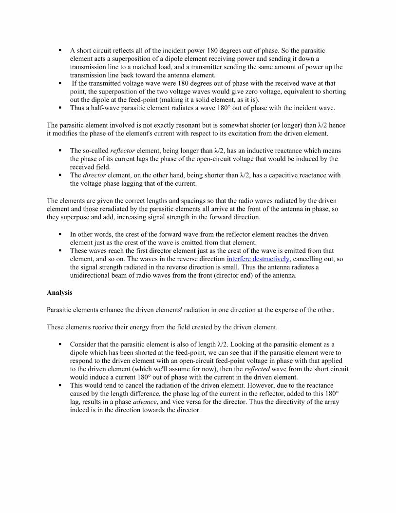
The dipole length (L) and spacings (R or S) are related as follows;

The scale factor or design ratio is given by ;
The scaling factor can also be written as; (where k > 1)
Plot of input impedance against logarithm of frequency
If two consecutive maxima of the impedance variations occur at frequencies , then the relation
between scaling factor and frequencies is given by;
or ; this shows that whatever properties a log periodic antenna is having at
frequency , the same properties will be repeated at frequencies , where
Adjacent elements are fed out of phase.
Every element in the LPDA design is "active", that is, connected electrically to the feed-line along with the other elements, though at any one frequency most of the elements draw little current from it.
Each successive element is connected in opposite phase to the active connection running as a transmissionline along the boom. For that reason, that transmission line can often be seen zig-zagging across the support boom holding the elements.
One common design ploy is to use two booms that also acts as the transmission line, mounting the dipoleson the alternate booms.
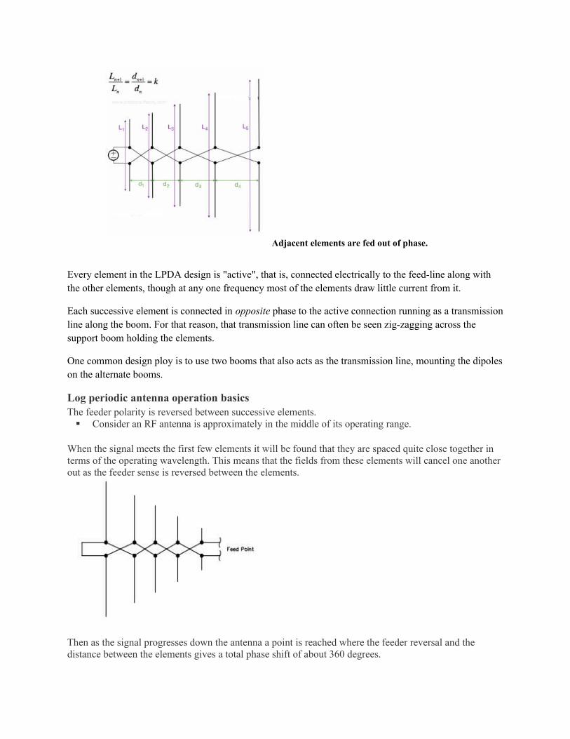
Log periodic antenna operation basicsThe feeder polarity is reversed between successive elements. Consider an RF antenna is approximately in the middle of its operating range.
When the signal meets the first few elements it will be found that they are spaced quite close together in terms of the operating wavelength. This means that the fields from these elements will cancel one anotherout as the feeder sense is reversed between the elements.
Then as the signal progresses down the antenna a point is reached where the feeder reversal and the distance between the elements gives a total phase shift of about 360λ degrees.

Regions of a log-periodic antenna
1. Transmission line region (inactive region)- Antenna elements are shorter than resonant length,
- Elements present a relatively high capacitance; hence current leads the base voltage supplied by transmission lines by 90λ0λ.
- Spacing between the elements is small
- Currents in elements of this region are small and hence small radiation in the backward direction towards the left.
2. Active regionDipole lengths are approximately of resonant length, hence impedance offered by dipoles in this region is resistive;
- Current is in phase with the base voltage, (the current slightly leads below resonance and slightly lags above resonance).
- The phase in a particular element leads approximately by 90λ0λ, such that the field radiated
from element reaches advanced by 90λ0λ and its field gets added to the field of
element.
- There is strong radiations towards the left and a little towards the right.
3. Reflective regionElement lengths are longer than the resonant length;
- Impedance becomes inductive and current in the elements lags the base voltage,- The base voltage supplied by the transmission line is now very much small as almost all
energy transmitted down the line has been attracted and radiated by the active region,
- The region presents a large reactive impedance to the line and thus a small amount of incident wave from active region is reflected back towards backward radiation.
The elements outside the active region receive little direct power.
Larger elements are resonant below the operational frequency and appear inductive.
Those in front resonate above the operational frequency and are capacitive.
Accordingly the element immediately behind the active region acts as a reflector and those in front act as directors. This means that the direction of maximum radiation is towards the feed point.
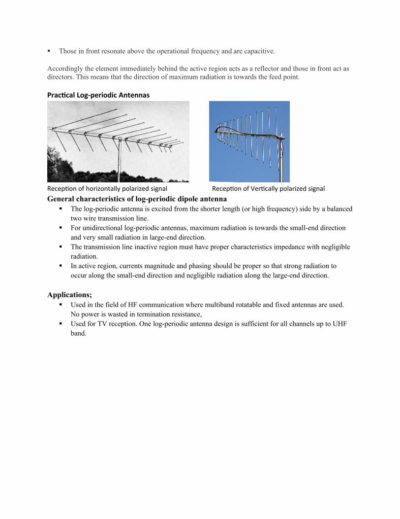
Practical Log-periodic Antennas
Reception of horizontally polarized signal Reception of Vertically polarized signal
General characteristics of log-periodic dipole antenna The log-periodic antenna is excited from the shorter length (or high frequency) side by a balanced
two wire transmission line. For unidirectional log-periodic antennas, maximum radiation is towards the small-end direction
and very small radiation in large-end direction. The transmission line inactive region must have proper characteristics impedance with negligible
radiation. In active region, currents magnitude and phasing should be proper so that strong radiation to
occur along the small-end direction and negligible radiation along the large-end direction.
Applications; Used in the field of HF communication where multiband rotatable and fixed antennas are used.
No power is wasted in termination resistance, Used for TV reception. One log-periodic antenna design is sufficient for all channels up to UHF
band.
PHASED ARRAY;
RHOMBIC ANTENNAS;
Definition
The Rhombic Antenna is an equilateral parallelogram shaped antenna. Generally, it has two opposite
acute angles. The tilt angle, θ is approximately equal to 90λ° minus the angle of major lobe. Rhombic
antenna works under the principle of travelling wave radiator. It is arranged in the form of a rhombus or
diamond shape and suspended horizontally above the surface of the earth.
Frequency Range
The frequency range of operation of a Rhombic antenna is around 3MHz to 300MHz. This antenna
works in HF and VHF ranges.
Construction of Rhombic Antenna
Rhombic antenna can be regarded as two V-shaped antennas connected end-to-end to form obtuse angles.
Due to its simplicity and ease of construction, it has many uses −
In HF transmission and reception
Commercial point-to-point communication
The construction of the rhombic antenna is in the form a rhombus, as shown in the figure.
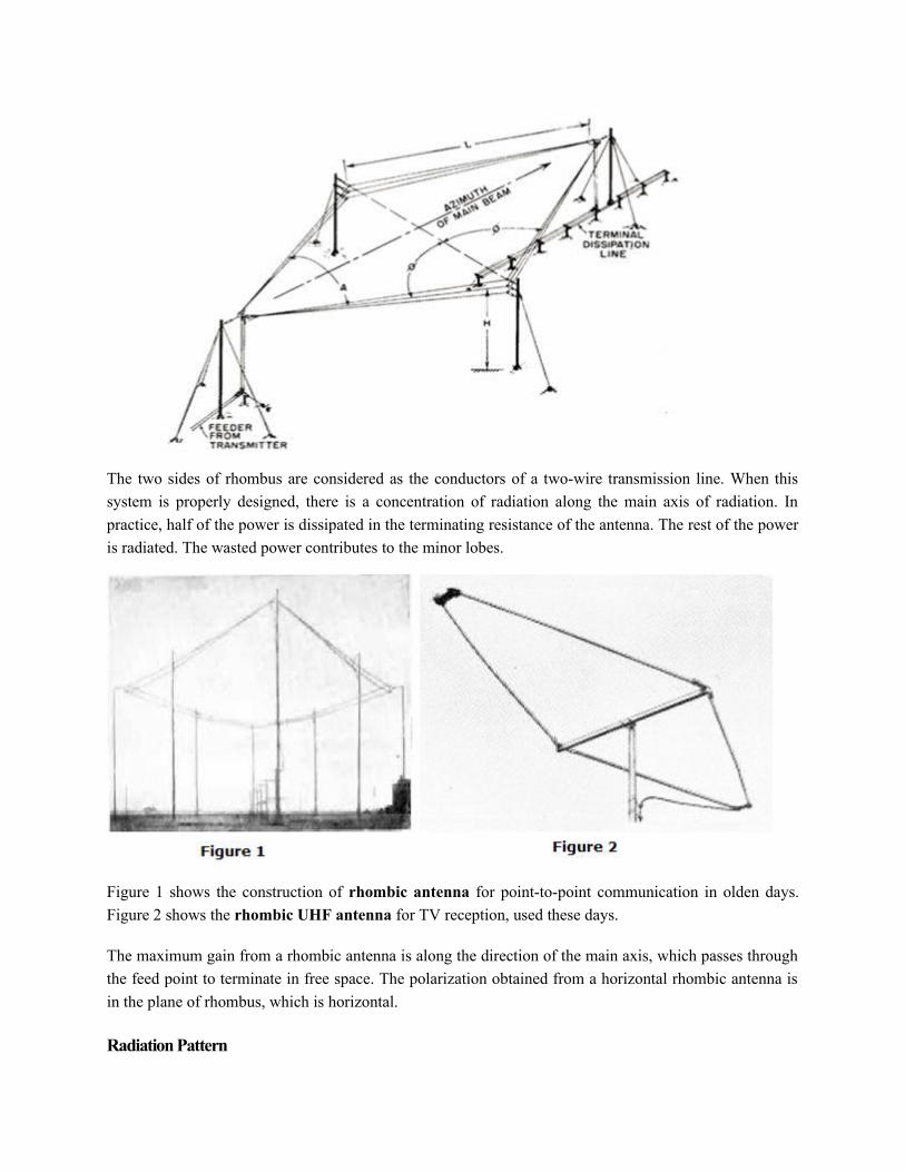
The two sides of rhombus are considered as the conductors of a two-wire transmission line. When this
system is properly designed, there is a concentration of radiation along the main axis of radiation. In
practice, half of the power is dissipated in the terminating resistance of the antenna. The rest of the power
is radiated. The wasted power contributes to the minor lobes.
Figure 1 shows the construction of rhombic antenna for point-to-point communication in olden days.
Figure 2 shows the rhombic UHF antenna for TV reception, used these days.
The maximum gain from a rhombic antenna is along the direction of the main axis, which passes through
the feed point to terminate in free space. The polarization obtained from a horizontal rhombic antenna is
in the plane of rhombus, which is horizontal.
Radiation Pattern
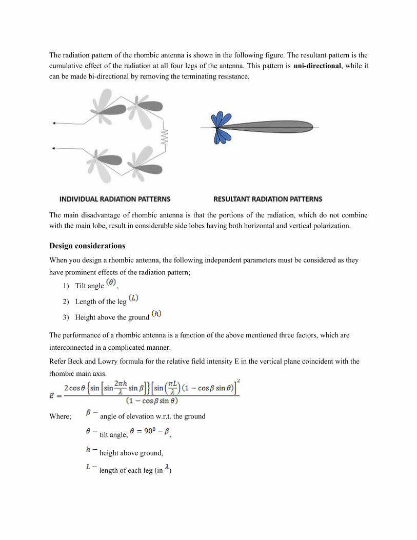
The radiation pattern of the rhombic antenna is shown in the following figure. The resultant pattern is the
cumulative effect of the radiation at all four legs of the antenna. This pattern is uni-directional, while it
can be made bi-directional by removing the terminating resistance.
The main disadvantage of rhombic antenna is that the portions of the radiation, which do not combine
with the main lobe, result in considerable side lobes having both horizontal and vertical polarization.
Design considerations
When you design a rhombic antenna, the following independent parameters must be considered as they
have prominent effects of the radiation pattern;
1) Tilt angle ,
2) Length of the leg
3) Height above the ground
The performance of a rhombic antenna is a function of the above mentioned three factors, which are
interconnected in a complicated manner.
Refer Beck and Lowry formula for the relative field intensity E in the vertical plane coincident with the
rhombic main axis.
Where; angle of elevation w.r.t. the ground
tilt angle, ,
height above ground,
length of each leg (in )
The above parameters may be chosen so that;
Maximum of the main lobe coincides with the desired elevation angle (Design alignment),
Maximum relative field intensity E for a constant antenna current is obtained at a desired
elevation angle (Maximum E-design)
Advantages Input impedance and radiation pattern
are relatively constant
Multiple rhombic antennas can be
connected
Simple and effective transmission
Disadvantages Wastage of power in terminating resistor
Requirement of large space
Reduced transmission efficiency
Applications Used in HF communications
Used in Long distance sky wave propagations
Used in point-to-point communications
Another method of using long wire is by bending and making the wire into a loop shaped pattern and
observing its radiation parameters. These types of antennas are termed as loop antennas.
HORN ANTENNAS;
To improve the radiation efficiency and directivity of the beam, the wave guide should be provided
with an extended aperture to make the abrupt discontinuity of the wave into a gradual transformation.
So that all the energy in the forward direction gets radiated. This can be termed as Flaring. Now, this
can be done using a horn antenna.
Frequency Range
The operational frequency range of a horn antenna is around 300MHz to 30GHz. This antenna works
in UHF and SHF frequency ranges.
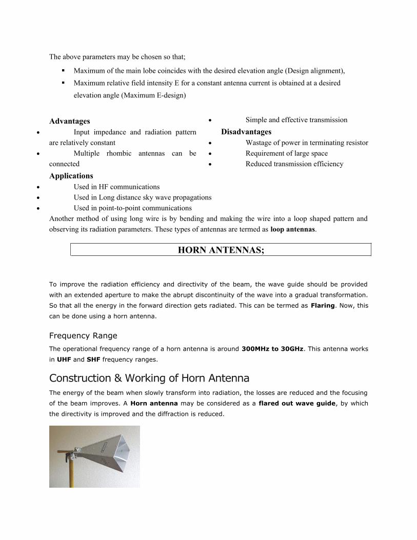
Construction & Working of Horn AntennaThe energy of the beam when slowly transform into radiation, the losses are reduced and the focusing
of the beam improves. A Horn antenna may be considered as a flared out wave guide, by which
the directivity is improved and the diffraction is reduced.

The above image shows the model of a horn antenna. The flaring of the horn is clearly shown. There
are several horn configurations out of which, three configurations are most commonly used.
Sectorial horn
This type of horn antenna, flares out in only one direction. Flaring in the direction of Electric vector
produces the sectorial E-plane horn. Similarly, flaring in the direction of Magnetic vector, produces
the sectorial H-plane horn.
Pyramidal horn
This type of horn antenna has flaring on both sides. If flaring is done on both the E & H walls of a
rectangular waveguide, then pyramidal horn antenna is produced. This antenna has the shape of a
truncated pyramid.
Conical horn
When the walls of a circular wave guide are flared, it is known as a conical horn. This is a logical
termination of a circular wave guide.
The above figures show the types of horn configurations, which were discussed earlier.
Flaring is an act that helps to match the antenna impedance with the free space impedance for better
radiation. It avoids standing wave ratio and provides greater directivity and narrower beam width. The
flared wave guide can be technically termed as Electromagnetic Horn Radiator.
Flare angle, Φ of the horn antenna is an important factor to be considered. If this is too small, then
the resulting wave will be spherical instead of plane and the radiated beam will not be directive.
Hence, the flare angle should have an optimum value and is closely related to its length.
Combinations
Horn antennas, may also be combined with parabolic reflector antennas to form special type of horn
antennas. These are −
Cass-horn antenna
Hog-horn or triply folded horn reflector
In Cass-horn antenna, radio waves are collected by the large bottom surface, which is parabolically
curved and reflected upward at 45° angle. After hitting top surface, they are reflected to the focal
point. The gain and beam width of these are just like parabolic reflectors.
In hog-horn antenna, a parabolic cylinder is joined to pyramidal horn, where the beam reaches apex
of the horn. It forms a low-noise microwave antenna. The main advantage of hog-horn antenna is that
its receiving point does not move, though the antenna is rotated about its axis.
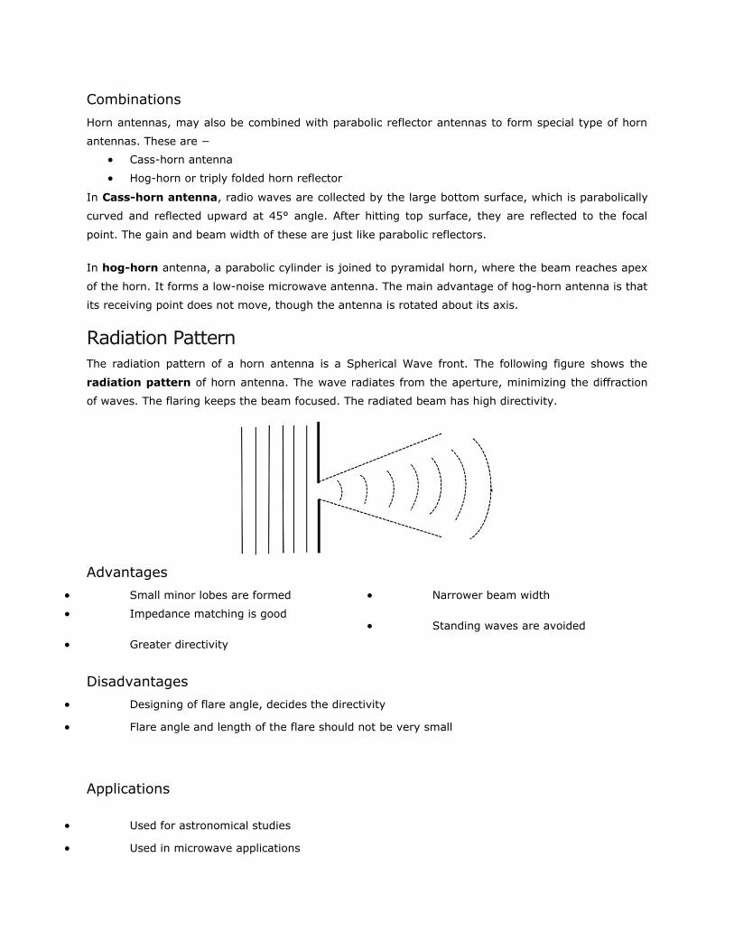
Radiation PatternThe radiation pattern of a horn antenna is a Spherical Wave front. The following figure shows the
radiation pattern of horn antenna. The wave radiates from the aperture, minimizing the diffraction
of waves. The flaring keeps the beam focused. The radiated beam has high directivity.
Advantages
Small minor lobes are formed
Impedance matching is good
Greater directivity
Narrower beam width
Standing waves are avoided
Disadvantages
Designing of flare angle, decides the directivity
Flare angle and length of the flare should not be very small
Applications
Used for astronomical studies
Used in microwave applications

REFLECTOR ANTENNA AND THEIR FEED SYSTEMS;
Parabolic Reflector AntennasParabolic Reflectors are Microwave antennas. For better understanding of these antennas, the concept of
parabolic reflector has to be discussed.
Frequency Range
The frequency range used for the application of Parabolic reflector antennas is above 1MHz. These
antennas are widely used for radio and wireless applications.
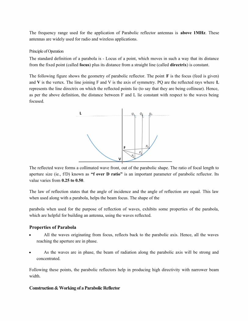
Principle of Operation
The standard definition of a parabola is - Locus of a point, which moves in such a way that its distance
from the fixed point (called focus) plus its distance from a straight line (called directrix) is constant.
The following figure shows the geometry of parabolic reflector. The point F is the focus (feed is given)
and V is the vertex. The line joining F and V is the axis of symmetry. PQ are the reflected rays where L
represents the line directrix on which the reflected points lie (to say that they are being collinear). Hence,
as per the above definition, the distance between F and L lie constant with respect to the waves being
focused.
The reflected wave forms a collimated wave front, out of the parabolic shape. The ratio of focal length to
aperture size (ie., f/D) known as “f over D ratio” is an important parameter of parabolic reflector. Its
value varies from 0.25 to 0.50.
The law of reflection states that the angle of incidence and the angle of reflection are equal. This law
when used along with a parabola, helps the beam focus. The shape of the
parabola when used for the purpose of reflection of waves, exhibits some properties of the parabola,
which are helpful for building an antenna, using the waves reflected.
Properties of Parabola
All the waves originating from focus, reflects back to the parabolic axis. Hence, all the waves
reaching the aperture are in phase.
As the waves are in phase, the beam of radiation along the parabolic axis will be strong and
concentrated.
Following these points, the parabolic reflectors help in producing high directivity with narrower beam
width.
Construction & Working of a Parabolic Reflector
If a Parabolic Reflector antenna is used for transmitting a signal, the signal from the feed, comes out of a
dipole or a horn antenna, to focus the wave on to the parabola. It means that, the waves come out of the
focal point and strike the Paraboloidal reflector. This wave now gets reflected as collimated wave front,
as discussed previously, to get transmitted.
The same antenna is used as a receiver. When the electromagnetic wave hits the shape of the parabola, the
wave gets reflected onto the feed point. The dipole or the horn antenna, which acts as the receiver antenna
at its feed, receives this signal, to convert it into electric signal and forwards it to the receiver circuitry.
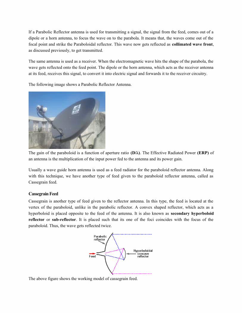
The following image shows a Parabolic Reflector Antenna.
The gain of the paraboloid is a function of aperture ratio (D/λ). The Effective Radiated Power (ERP) of
an antenna is the multiplication of the input power fed to the antenna and its power gain.
Usually a wave guide horn antenna is used as a feed radiator for the paraboloid reflector antenna. Along
with this technique, we have another type of feed given to the paraboloid reflector antenna, called as
Cassegrain feed.
Cassegrain Feed
Cassegrain is another type of feed given to the reflector antenna. In this type, the feed is located at the
vertex of the paraboloid, unlike in the parabolic reflector. A convex shaped reflector, which acts as a
hyperboloid is placed opposite to the feed of the antenna. It is also known as secondary hyperboloid
reflector or sub-reflector. It is placed such that its one of the foci coincides with the focus of the
paraboloid. Thus, the wave gets reflected twice.
The above figure shows the working model of cassegrain feed.
Working of a Cassegrain Antenna
When the antenna acts as a transmitting antenna, the energy from the feed radiates through a horn antenna
onto the hyperboloid concave reflector, which again reflects back on to the parabolic reflector. The signal
gets reflected into the space from there. Hence, wastage of power is controlled and the directivity gets
improved.
When the same antenna is used for reception, the electromagnetic waves strike the reflector, gets reflected
on to the concave hyperboloid and from there, it reaches to the feed. A wave guide horn antenna presents
there to receive this signal and sends to the receiver circuitry for amplification.
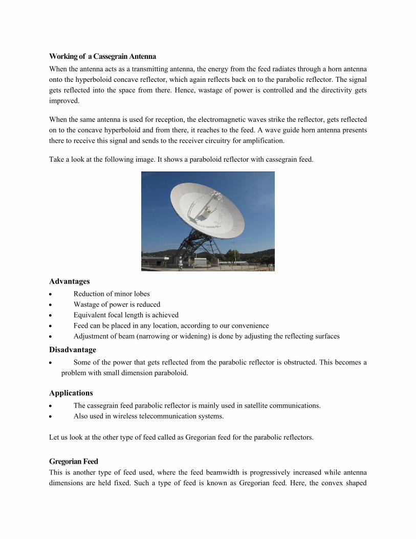
Take a look at the following image. It shows a paraboloid reflector with cassegrain feed.
Advantages
Reduction of minor lobes
Wastage of power is reduced
Equivalent focal length is achieved
Feed can be placed in any location, according to our convenience
Adjustment of beam (narrowing or widening) is done by adjusting the reflecting surfaces
Disadvantage
Some of the power that gets reflected from the parabolic reflector is obstructed. This becomes a
problem with small dimension paraboloid.
Applications
The cassegrain feed parabolic reflector is mainly used in satellite communications.
Also used in wireless telecommunication systems.
Let us look at the other type of feed called as Gregorian feed for the parabolic reflectors.
Gregorian FeedThis is another type of feed used, where the feed beamwidth is progressively increased while antenna
dimensions are held fixed. Such a type of feed is known as Gregorian feed. Here, the convex shaped
hyperboloid of cassegrain is replaced with a concave shaped paraboloid reflector, which is of course,
smaller in size
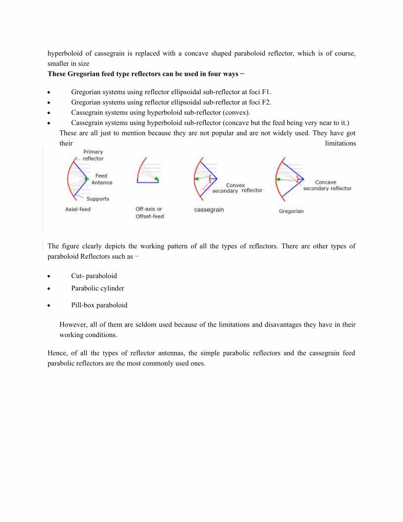
These Gregorian feed type reflectors can be used in four ways −
Gregorian systems using reflector ellipsoidal sub-reflector at foci F1.
Gregorian systems using reflector ellipsoidal sub-reflector at foci F2.
Cassegrain systems using hyperboloid sub-reflector (convex).
Cassegrain systems using hyperboloid sub-reflector (concave but the feed being very near to it.)
These are all just to mention because they are not popular and are not widely used. They have got
their limitations
The figure clearly depicts the working pattern of all the types of reflectors. There are other types of
paraboloid Reflectors such as −
Cut- paraboloid
Parabolic cylinder
Pill-box paraboloid
However, all of them are seldom used because of the limitations and disavantages they have in their
working conditions.
Hence, of all the types of reflector antennas, the simple parabolic reflectors and the cassegrain feed
parabolic reflectors are the most commonly used ones.

MICRO-STRIP ANTENNAS;
Definition
In telecommunication, a micro-strip antenna (also known as a printed antenna) usually means an antenna fabricated using micro-strip techniques on a printed circuit board (PCB). They are mostly used at microwave frequencies.
An individual micro-strip antenna consists of a patch of metal foil of various shapes (a patch antenna) on the surface of a PCB, with a metal foil ground plane on the other side of the board.
Most micro-strip antennas consist of multiple patches in a two-dimensional array. The antenna is usually connected to the transmitter or receiver through foil micro-strip transmission lines.
The radio frequency current is applied (or in receiving antennas the received signal is produced) between the antenna and ground plane.
- Micro-strip antennas have become very popular in recent decades due to their thin planar profile which can be incorporated into the surfaces of consumer products, aircraft and missiles; their easeof fabrication using printed circuit techniques; the ease of integrating the antenna on the same board with the rest of the circuit, and the possibility of adding active devices such as microwave integrated circuits to the antenna itself to make active antennas.
Micro-strip patch antennas (MPA) are antennas that are printed directly into the circuit board, hence easy
to be used in mobile circuits,
Characteristics;
- Low profile
A metal patch mounted at a ground level with a di-electric material in-between constitutes a
Micro strip or Patch Antenna,
- Easily fabricated,
- Very low size antennas having low radiation,
Construction & Working of Micro strip Antennas
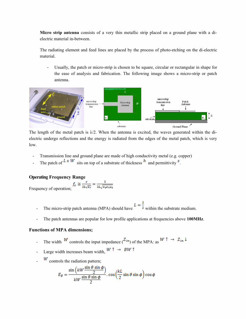
Micro strip antenna consists of a very thin metallic strip placed on a ground plane with a di-
electric material in-between.
The radiating element and feed lines are placed by the process of photo-etching on the di-electric
material.
- Usually, the patch or micro-strip is chosen to be square, circular or rectangular in shape for
the ease of analysis and fabrication. The following image shows a micro-strip or patch
antenna.
The length of the metal patch is λ/2. When the antenna is excited, the waves generated within the di-
electric undergo reflections and the energy is radiated from the edges of the metal patch, which is very
low.
- Transmission line and ground plane are made of high conductivity metal (e.g. copper)
- The patch of sits on top of a substrate of thickness and permittivity .
Operating Frequency Range
Frequency of operation;
- The micro-strip patch antenna (MPA) should have within the substrate medium.
- The patch antennas are popular for low profile applications at frequencies above 100MHz.
Functions of MPA dimensions;
- The width controls the input impedance ( ) of the MPA: as
- Large width increases beam width,
- controls the radiation pattern;
Where free space wave number
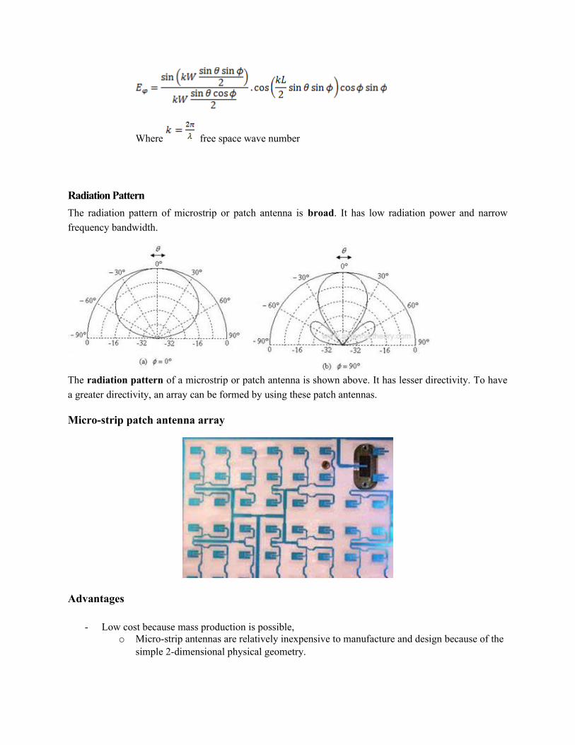
Radiation Pattern
The radiation pattern of microstrip or patch antenna is broad. It has low radiation power and narrow
frequency bandwidth.
The radiation pattern of a microstrip or patch antenna is shown above. It has lesser directivity. To have
a greater directivity, an array can be formed by using these patch antennas.
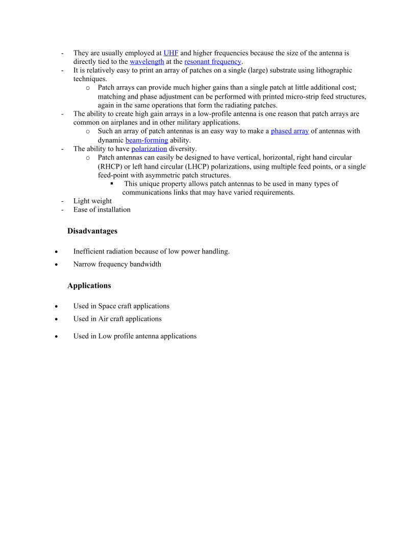
Micro-strip patch antenna array
Advantages
- Low cost because mass production is possible,o Micro-strip antennas are relatively inexpensive to manufacture and design because of the
simple 2-dimensional physical geometry.
- They are usually employed at UHF and higher frequencies because the size of the antenna is directly tied to the wavelength at the resonant frequency.
- It is relatively easy to print an array of patches on a single (large) substrate using lithographic techniques.
o Patch arrays can provide much higher gains than a single patch at little additional cost; matching and phase adjustment can be performed with printed micro-strip feed structures,again in the same operations that form the radiating patches.
- The ability to create high gain arrays in a low-profile antenna is one reason that patch arrays are common on airplanes and in other military applications.
o Such an array of patch antennas is an easy way to make a phased array of antennas with dynamic beam-forming ability.
- The ability to have polarization diversity. o Patch antennas can easily be designed to have vertical, horizontal, right hand circular
(RHCP) or left hand circular (LHCP) polarizations, using multiple feed points, or a singlefeed-point with asymmetric patch structures.
This unique property allows patch antennas to be used in many types of communications links that may have varied requirements.
- Light weight- Ease of installation
Disadvantages
Inefficient radiation because of low power handling.
Narrow frequency bandwidth
Applications
Used in Space craft applications
Used in Air craft applications
Used in Low profile antenna applications

SELECTION OF ANTENNA BASED ON FREQUENCY OFOPERATION;
So far we have discussed parameters and characteristics of antennas in general and specific antennas which are used for special functions.
While discussing these antennas, their application w.r.t. frequency has been highlighted which become the guidelines for selection of antenna based on frequency of operation.
i) Low frequencies
For practical antennas are of with
- It is impractical to use directivity at these frequencies otherwise a very large antennamight be required.
The main characteristics of low frequency antennas are;- Low attenuation rate,- Relatively stable propagation characteristics,
Applications;- Aeronautical and marine uses,- Navigational purposes – global
navigational coverage,- Communication systems,
Antennas in use
- Pulsed hyperbolic antennas (omega),- Medium range navigation aids
,
- Strategic communication systems atvery low frequency
ii) Broadcast frequencies;
Characteristics of broadcast frequencies;

The wavelengths of waves at these frequencies are very large ,
antennas cannot be mounted a few wavelengths above the earth to radiate space waves.- MW antennas have to be placed vertically so that they radiate vertically polarized signals. It is for
this reason why all MW antennas are installed vertically close to the ground.- The ground saves to increase the antenna height.
Antenna in use;- Self radiating MW Mast antenna (tower radiators)
Top loaded antenna Umbrella antenna T and inverted L antenna
iii) Medium frequencies,
Characteristics;In this band of frequency, the mode of propagation is sky-wave. - The angle of the antenna towards the sky is adjusted by positioning the antenna above the ground,- Attenuation is greater than of LF propagation.
Antenna used;Center-fed dipole folded dipole BSA
Rhombic antenna Three vertical radiators Three vertical radiators

iv) High frequencies (3 – 30 MHz);
Characteristics;HF (SW) get attenuated rapidly with distance as they travel close to the earth, therefore HF use sky-wave propagation.
- The most elementary antenna used in broadcasting of short waves is the dipole whose physical length is half its wavelength and it is center-fed.
Antennas used;- Ungrounded half wave antenna (for low)- Simple array like a Yagi-Uda,- Horizontal rhombic antenna (high directivity),
- Center-fed dipole for TV transmissions,
- For communication purposes;- Vertical whip antenna,- Fan dipole antenna,- Loop antenna
- Vertical flag pole- Horizontally polarized LPDAs
v) VHF and UHF (30- 300 and 300-3000 MHz).
Characteristics;Major usage of this part of frequency spectrum is line-of-sight (LOS) communication, e.g. in TV and FM broadcasting where horizontal polarization is used to radiate a circular pattern in the horizontal plane.
Antennas used;Half-wave antenna, corner reflectors,HF loops,Horns,Parabolas,
Slot radiators,Yagi arrays,Turn-style antennas
vi) Microwave frequencies
Due to LOS requirements, gain and directivity are the most important characteristics of the antennas used.Antennas used;
Horn (moderate D and G)

Parabolic reflector (high D) Lens antenna (extremely high D)
Selection of antenna based on frequency considering antenna advantages and disadvantages.
Dipole antenna: this antenna is a very simple chip and presents a good gain. The maindisadvantage is the large size at low frequency.
Whip antenna: this antenna presents good performance with a size lower than a dipoleantenna. A good ground plane is necessary to achieve good performance.
Loop antenna: loop antennas are cheap and not easily detuned by nearby handmovements. They have the disadvantage of having poor gain, to be very narrowbandand are difficult to tune.
Spiral antenna: spiral antennas have a size lower than a whip antenna and arewideband. On the negative side, these types of antennas are difficult to feed.
Helical antenna: helical antennas are very directive and have good gain. However, theyhave a bulky size and are easily detuned by nearby objects.
Microstrip antenna: microstrip antennas have the advantage of being very cheap andhave a simple and thin structure. As a negative, they are very large at low frequency.
Ceramic antenna: ceramic antennas have the advantage of being separate
components, have a small size and are less affected by environmental factors. The
main disadvantages are the high cost, the medium performance and the matching
function of the PCB size and shape of the ground plane.
Slot antenna: slot antennas have the advantage of size, design simplicity, robustness
and convenient adaption to mass production. The main disadvantage is the big
dimension for low frequency that makes the slot antenna difficult to manage for
frequencies lower than 433 MHz.
The matter of relative spacing and orientation between antennas is important because it affects land
area requirements and electrical performance. When transmitting, an antenna will transfer some of its
radiated energy to any other antenna in relatively close proximity, and this transferred energy will affect
the performance of the other antenna.

Ideally HF antennas of unlike functions, transmitting and receiving, should be separated by several
kilometres (some authorities stipulate a minimum distance of 24 kilometres) if the latter's performance
is not to be degraded due to interference from the former. This interference can be caused by adjacent
channel operation, harmonics, keying transients and parasitic oscillations. Also, cross modulation
products can be generated in HF pre-amplifiers and receivers by strong RF fields, even though normal
receiving frequencies are widely separated from the frequencies of such fields.
The amount of energy coupled between antennas of like functions, all receiving or all transmitting, can
be calculated accurately by solving the fundamental electromagnetic equations using a comprehensive
antenna analysis computer program. However, the following criteria serve as a useful reference for
planning purposes. All distances, unless otherwise noted, are based on the antenna's lowest design
frequency. The larger of the two distances in each case is used as the spacing distance. The points of
measurement are between the reference points listed for each type of antenna.
Horizontal Log Periodic Antenna - space two wavelengths from the main lobe and one wavelength
outside the main lobe, measured from the main supporting structure (midway between supporting
structures for two tower configurations).
Vertical Log Periodic Antenna - spacing requirements are the same as for horizontal log periodic
antennas.
Rotatable Log Periodic Antenna - space two wavelengths from horizontally polarized antennas. The
separation requirement from a vertically polarized antenna is determined by the spacing requirement of
the vertical antenna. In all cases, spacing must not be less than 45 metres.
Inverted Cone - space one wavelength measured from the antenna center.
Conical Monopole - spacing requirements are the same as for the inverted cones.
Sector Log Periodic - space two wavelengths measured from the main supporting structure.
short
wave
radio
.be
Shortwave
Radio
Broadcast
Antennas
Shortwave
Radio
Broadcast
Countries
Shortwave
Radio
Broadcast
Stations
Shortwave
Radio
Broadcast
Transmitters
Shortwave
Radio
Broadcast
Tubes

ANTENNAS FOR SPECIAL APPLICATIONS;
1. Antennas for terrestrial mobile communications;
Microwave frequencies are used for wireless communication as they penetrate ionosphere. They get
attenuated when used as ground waves as well as surface waves. Due to this reason microwave
communication is mainly LOS (Line of Sight) based communication.
Microwave communication systems are mainly classified into satellite systems and terrestrial systems.
Both of these systems require transmit part and receive part. The transmit system converts baseband
signal to microwave signal. The receive system converts microwave signal to baseband signal. The
baseband signal is multiplexed signal which carries number of individual low bandwidth signals such as
voice, data and video.Multiplexing is done either using TDM or FDM.
Terrestrial Communication System
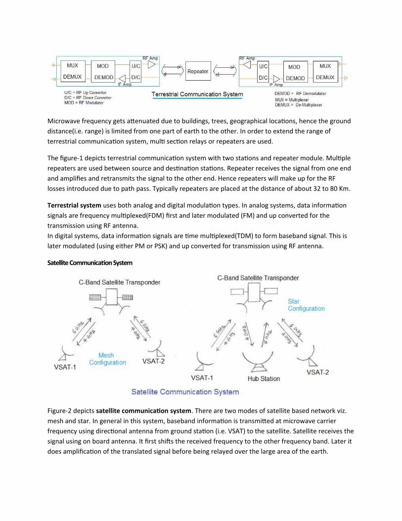
Microwave frequency gets attenuated due to buildings, trees, geographical locations, hence the ground
distance(i.e. range) is limited from one part of earth to the other. In order to extend the range of
terrestrial communication system, multi section relays or repeaters are used.
The figure-1 depicts terrestrial communication system with two stations and repeater module. Multiple
repeaters are used between source and destination stations. Repeater receives the signal from one end
and amplifies and retransmits the signal to the other end. Hence repeaters will make up for the RF
losses introduced due to path pass. Typically repeaters are placed at the distance of about 32 to 80 Km.
Terrestrial system uses both analog and digital modulation types. In analog systems, data information
signals are frequency multiplexed(FDM) first and later modulated (FM) and up converted for the
transmission using RF antenna.
In digital systems, data information signals are time multiplexed(TDM) to form baseband signal. This is
later modulated (using either PM or PSK) and up converted for transmission using RF antenna.
Satellite Communication System
Figure-2 depicts satellite communication system. There are two modes of satellite based network viz.
mesh and star. In general in this system, baseband information is transmitted at microwave carrier
frequency using directional antenna from ground station (i.e. VSAT) to the satellite. Satellite receives the
signal using on board antenna. It first shifts the received frequency to the other frequency band. Later it
does amplification of the translated signal before being relayed over the large area of the earth.
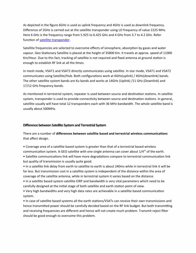
As depicted in the figure 6GHz is used as uplink frequency and 4GHz is used as downlink frequency.
Difference of 2GHz is carried out at the satellite transponder using LO frequency of value 2225 MHz.
Here 6 GHz is the frequency range from 5.925 to 6.425 GHz and 4 GHz from 3.7 to 4.2 GHz. Refer
function of satellite transponder.
Satellite frequencies are selected to overcome effects of ionosphere, absorption by gases and water
vapour. Geo Stationary Satellite is placed at the height of 35800 Km. It travels at approx. speed of 11000
Km/Hour. Due to this fact, tracking of satellite is not required and fixed antenna at ground station is
enough to establish RF link at all the times.
In mesh mode, VSAT1 and VSAT2 directly communicates using satellite. In star mode, VSAT1 and VSAT2
communicates using Satellite/Hub. Both configurations work at 6GHz(uplink) / 4GHz(downlink) bands.
The other satellite system bands are Ku bands and works at 14GHz (Uplink) /11 GHz (Downlink) and
17/12 GHz frequency bands.
As mentioned in terrestrial system, repeater is used between source and destination stations. In satellite
system, transponder is used to provide connectivity between source and destination stations. In general,
satellite usually will have total 12 transponders each with 36 MHz bandwidth. The whole satellite band is
usually about 500MHz.
Difference between Satellite System and Terrestrial System
There are a number of differences between satellite based and terrestrial wireless communications
that affect design.
• Coverage area of a satellite based system is greater than that of a terrestrial based wireless
communication system. A GEO satellite with one single antenna can cover about 1/4 th of the earth.
• Satellite communications link will have more degradations compare to terrestrial communication link
but quality of transmission is usually quite good.
• In a satellite link delay from earth to satellite to earth is about 240ms while in terrestrial link it will be
far less. But transmission cost in a satellite system is independent of the distance within the area of
coverage of the satellite antenna, while in terrestrial system it varies based on the distance.
• In a satellite based system satellite EIRP and bandwidth is very vital parameters which need to be
carefully designed at the initial stage of both satellite and earth station point of view.
• Very high bandwidths and very high data rates are achievable in a satellite based communication
system.
• In case of satellite based systems all the earth stations/VSATs can receive their own transmissions and
hence transmitted power should be carefully decided based on the RF link budget. But both transmitting
and receiving frequencies are different and hence will not create much problem. Transmit reject filter
should be good enough to overcome this problem.
2. Ground Penetrating Radar (GPR)
Meaning;
GPR is a geographical method that uses radar to image the surface by using electromagnetic radiations
in UHF/VHF to detect reflected signals from subsurface structure.
Working Principle;
GPR emits RF energy into the ground.
When RF energy encounters a buried object or boundary between materials having different permittivity, it become reflected/refracted/scattered back to the surface;
A receiving antenna records variations in the returning signal.
Operating frequency is a trade-off between resolution and penetration.
Low frequency penetrates more, but have low resolution.
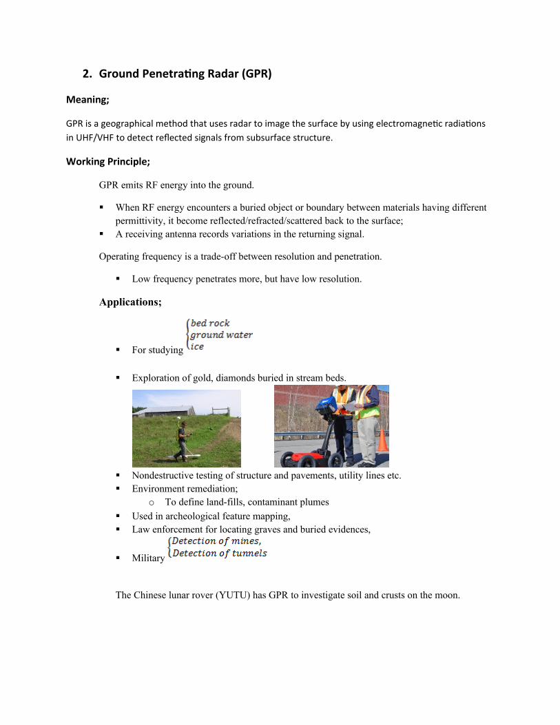
Applications;
For studying
Exploration of gold, diamonds buried in stream beds.
Nondestructive testing of structure and pavements, utility lines etc. Environment remediation;
o To define land-fills, contaminant plumes
Used in archeological feature mapping, Law enforcement for locating graves and buried evidences,
Military
The Chinese lunar rover (YUTU) has GPR to investigate soil and crusts on the moon.
Limitations;
High conductive material exhibits low penetration, Expertise is required in interpreting GPR surveys.
,
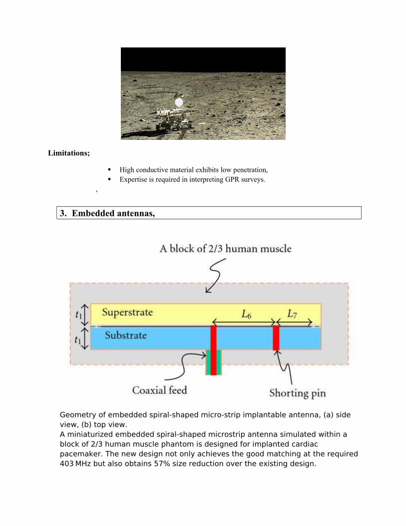
3. Embedded antennas,
Geometry of embedded spiral-shaped micro-strip implantable antenna, (a) side view, (b) top view.A miniaturized embedded spiral-shaped microstrip antenna simulated within a block of 2/3 human muscle phantom is designed for implanted cardiac pacemaker. The new design not only achieves the good matching at the required403 MHz but also obtains 57% size reduction over the existing design.
4. UWB,
Definition;
Ultra-wideband (UWB) is a radio technology that can use a very low energy level for short-range, high-bandwidth communications over a large portion of the radio spectrum.
Unlike spread spectrum, UWB transmits in a manner that does not interfere with conventional narrowband and carrier wave transmission in the same frequency band.
Ultra-wideband is a technology for transmitting information spread over a large bandwidth (>50λ0λ MHz); being able to share spectrum with other users.
Ultra wideband was formerly known as pulse radio, but currently UWB has been defined as an antenna transmission for which emitted signal bandwidth exceeds the lesser of 50λ0λ MHz or 20λ% of fractional bandwidth.
Theory
A significant difference between conventional radio transmissions and UWB is that conventional systems transmit information by varying the power level, frequency, and/or phase of a sinusoidal wave.
UWB transmissions transmit information by generating radio energy at specific time intervals and occupying a large bandwidth, thus enabling pulse-position or time modulation.
The information can also be modulated on UWB signals (pulses) by encoding the polarity of the pulse, its amplitude and/or by using orthogonal pulses.
UWB pulses can be sent sporadically at relatively low pulse rates to support time or position modulation, but can also be sent at rates up to the inverse of the UWB pulse bandwidth.
A valuable aspect of UWB technology is the ability for a UWB radio system to determine the "time of flight" of the transmission at various frequencies. This helps overcome multipath propagation, as atleast some of the frequencies have a line-of-sight trajectory.
Another feature of pulse-based UWB is that the pulses are very short (less than 60λ cm for a 50λ0λ MHz-wide pulse, less than 23 cm for a 1.3 GHz-bandwidth pulse)—so most signal reflections do not overlap the original pulse, and there is no multipath fading of narrowband signals
Two UWB technologies
Despite the single named used for the ultra wideband (UWB) transmissions, there are two very different technologies being developed.
Carrier free direct sequence ultra wideband technology: This form of ultra-wideband technology transmits a series of impulses. In view of the very short duration of the pulses, the spectrum of the signal occupies a very wide bandwidth.
MBOFDM, Multi-Band OFDM ultra wideband technology: This form of ultra wideband technology uses a wide band or multiband orthogonal frequency division multiplex (MBOFDM) signal that is effectively a 50λ0λ MHz wide OFDM signal. This is 50λ0λ MHz signal is then hopped in frequency to enable it to occupy a sufficiently high bandwidth.
Antenna systems
Distributed MIMO: To increase the transmission range, this system exploits distributed antennas among different nodes.
Multiple-antenna : Multiple-antenna systems (such as MIMO) have been used to increase system throughput and reception reliability. Since UWB has almost impulse-like channel response, a combination of multiple antenna techniques is preferable as well. Coupling MIMO spatial multiplexing with UWB's high throughput gives the possibility of short-range networks with multi-gigabit rates.
Applications
There is a wide number of applications that UWB technology can be used for. They range from data and voice communications through to radar and tagging. With the growing number of way in which wireless technology can be used, the list is likely to grow.
Although much of the hype about ultra wideband UWB has been associated with commercial applications, the technology is equally suited to military applications. One of the advantages is that with the pulses being spread over a wide spectrum they can be difficult to detect. This makes them ideal for covert communications.
Commercial:
High speed LAN / WAN ( >20λ Mbps)
Avoidance radar
Altimeter (aviation)
Tags for intelligent transport systems
Intrusion detection
Geolocation
Military:
Radar
Covert communications
Intrusion detection
Precision geo-location
Data links
With the growing level of wireless communications, ultra wide band UWB offers significant advantages in many areas. One of the main attractions for WAN / LAN applications is the very high data rates that can be supported

Ultra-wideband characteristics are well-suited to short-distance applications, such as PC peripherals.
Due to low emission levels permitted by regulatory agencies, UWB systems tend to be short-range indoor applications.
Due to the short duration of UWB pulses, it is easier to engineer high data rates; data rate may be exchanged for range by aggregating pulse energy per data bit (with integration or coding techniques).
High-data-rate UWB may enable wireless monitors, the efficient transfer of data from digital camcorders, wireless printing of digital pictures from a camera without the need for a personal computer and file transfers between cell-phone handsets and handheld devices such as portable media players.
UWB is used for real-time location systems; its precision capabilities and low power make it well-suited for radio-frequency-sensitive environments, such as hospitals. Another feature of UWB is its short broadcast time.
5. Plasma antennas.
Definition of plasma
Plasma is the fourth state of matter
Plasma is an ionized gas, a gas into which sufficient energy is provided to free electrons from atoms ormolecules and to allow both species; ions and electrons, to coexist.
Gases can become plasma’s in several ways, but all include pumping the gas with energy; A spark in a gas will create plasma. A hot gas passing through a big spark will turn the gas stream into plasma that can be useful. Plasma torches like that are used in industry to cut metals.
The sun’s enormous heat rips electrons off thehydrogen and helium molecules that make up
the sun. Essentially, the sun, like most stars, is agreat big ball of plasma.
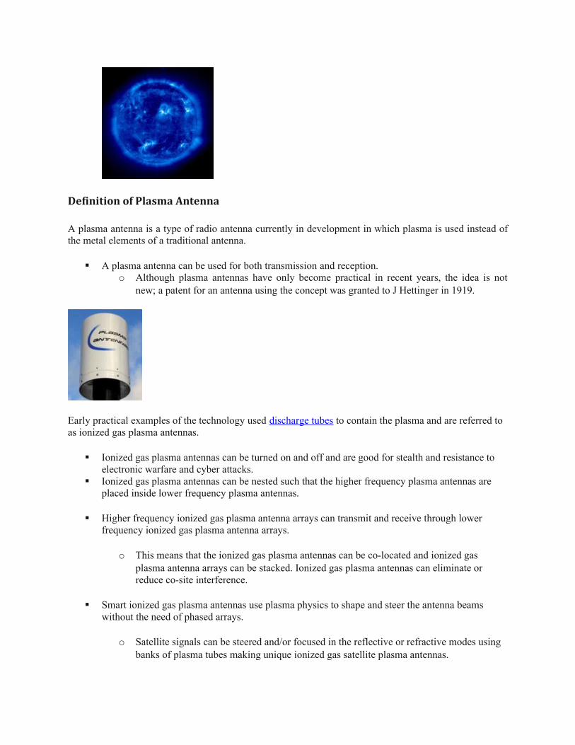
Definition of Plasma Antenna
A plasma antenna is a type of radio antenna currently in development in which plasma is used instead ofthe metal elements of a traditional antenna.
A plasma antenna can be used for both transmission and reception. o Although plasma antennas have only become practical in recent years, the idea is not
new; a patent for an antenna using the concept was granted to J Hettinger in 1919.
Early practical examples of the technology used discharge tubes to contain the plasma and are referred to as ionized gas plasma antennas.
Ionized gas plasma antennas can be turned on and off and are good for stealth and resistance to electronic warfare and cyber attacks.
Ionized gas plasma antennas can be nested such that the higher frequency plasma antennas are placed inside lower frequency plasma antennas.
Higher frequency ionized gas plasma antenna arrays can transmit and receive through lower frequency ionized gas plasma antenna arrays.
o This means that the ionized gas plasma antennas can be co-located and ionized gas plasma antenna arrays can be stacked. Ionized gas plasma antennas can eliminate or reduce co-site interference.
Smart ionized gas plasma antennas use plasma physics to shape and steer the antenna beams without the need of phased arrays.
o Satellite signals can be steered and/or focused in the reflective or refractive modes using banks of plasma tubes making unique ionized gas satellite plasma antennas.

Operation:
In an ionized gas plasma antenna, a gas is ionized to create plasma. Unlike gasses , plasmas have very high electrical conductivity so it is possible for radio frequency signals to travel through them so that they act as a driven element toradiate radio waves, or to receive them.
Alternatively the plasma can be used as a reflector or a lens to guide and focus radio waves from another source.
Solid-state antennas differ in that the plasma is created from electrons generated by activating thousands of diodes on a silicon chip.
Operating frequency
From 1 to 10λ GHz,
Advantages plasma antennas over metal antennas;
Plasma antennas are reconfigurable. o When one plasma antenna is de-energized, the antenna reverts to a dielectric tube, and
an antenna can transmit through it. This allows us to use several large antennas stacked over each other instead of several small antennas placed next to each other.
o This results in better sensitivity and directivity.
Plasma antenna is stealthy. When de-energized, the plasma antenna does not reflect incident, probing RADAR signals.
Plasma antenna is resistant to electronic warfare.
o An operating plasma antenna can be at the same time transparent and immune to incident high frequency, high power electronic warfare pulses.
o When plasma is highly energized, it behaves as a conductor. Antenna generates a localized concentration of plasma to form a plasma mirror that deflects RF beam launched from a central feed located at focus of mirror.
Characteristics of Plasma Antennas:
Gas ionizing process can manipulate resistance and when deionized, the gas has infiniteresistance and doesn’t interact with RF radiation.
o After sending pulse it can be deionized and eliminates “RINGING EFFECT”.

Operates up-to 90λGHZ It uses ionized gas as conducting material. The gas is ionized only at the time of transmission or reception. The design allows for extremely short pluses, important to many forms of digital communications
or radars.
Unique Feature of Plasma Antenna: One fundamental distinguishing feature of a plasma antenna is that the gas ionizing process. A second fundamental distinguishing feature is that after sending a pulse the plasma antenna can
be deionized.
Selectable Multi beam.
SLECTABEAM and REFLECTABEAM
SelectaBeam: Key Features Based on Beam forming technology. Avoid the need of alignment and realignment of fixed point to point links.
Same Benefits as that of Phased array antenna.
ReflectaBeam: Key Features, Operates up-to Frequencies of 90λGhz Design to provide high speed selection
At High Frequencies Applications it also include radar sensors and monitoring systems
Advantages of Selectabeam and Reflectabeam High directional gain: concentrates RF power to increase link budget, dramatically enhancing
network coverage and capacity. Low sidelobes reduce interference, enabling improved frequency re-use and substantially higher
utilization.
Wide bandwidth supports simultaneous multi-band or UWB operation from a single compactantenna.
High speed beam switching enables spatial time division multiplexing to boost spectral efficiencyand throughput.
Compact and lightweight form factor reduces site and mast costs, simplifies installation andminimizes environmental impact.

Maintenance free – auto-aligning with no moving parts and requires no calibration, minimizingtotal cost.
Microwave Communication By Plasma Antenna
Wi-Fi Wi Max Local Access Point
Advantages:- Wide band Multimedia Wireless local networks
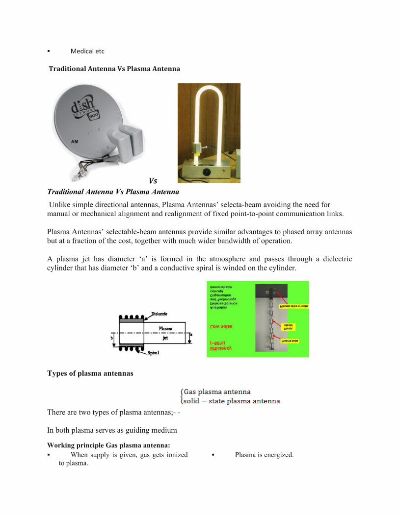
Medical etc
Traditional Antenna Vs Plasma Antenna
Vs Traditional Antenna Vs Plasma Antenna
Unlike simple directional antennas, Plasma Antennas’ selecta-beam avoiding the need for manual or mechanical alignment and realignment of fixed point-to-point communication links.
Plasma Antennas’ selectable-beam antennas provide similar advantages to phased array antennasbut at a fraction of the cost, together with much wider bandwidth of operation.
A plasma jet has diameter ‘a’ is formed in the atmosphere and passes through a dielectriccylinder that has diameter ‘b’ and a conductive spiral is winded on the cylinder.
Types of plasma antennas
There are two types of plasma antennas;- -
In both plasma serves as guiding medium
Working principle Gas plasma antenna: When supply is given, gas gets ionized
to plasma. Plasma is energized.

Behaves as a conductor.
Generation of localized plasma.
Plasma acts as a mirror.
Reflects the beam
Figure Showing Working Principle of Gas Plasma Antenna
Solid State Plasma Antenna:1. Employs thousands of diodes on a
silicon chip.2. Produces electron clouds when
charged.
3. These act as mirrors and reflect beam.
4. Uses beam forming technology.
5. Used for high frequencies.
6. Smaller in size.
7. Cheaper compared to gas plasmaantennas.
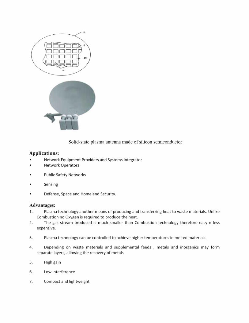
Solid-state plasma antenna made of silicon semiconductor
Applications: Network Equipment Providers and Systems Integrator Network Operators
Public Safety Networks
Sensing
Defense, Space and Homeland Security.
Advantages:1. Plasma technology another means of producing and transferring heat to waste materials. Unlike
Combustion no Oxygen is required to produce the heat.2. The gas stream produced is much smaller than Combustion technology therefore easy n less
expensive.
3. Plasma technology can be controlled to achieve higher temperatures in melted materials.
4. Depending on waste materials and supplemental feeds , metals and inorganics may formseparate layers, allowing the recovery of metals.
5. High gain
6. Low interference
7. Compact and lightweight
8. Wide bandwidth
9. Maintenance free
10. Perfect Reflector
Disadvantages:1. The air management system will have to be designed to form a seal between the inside and
outside of the unit to prevent the air emission of gases leaving the plasma unit as the plasma arcmelts the waste materials.
2. The graphite electrodes used to produce an arc and the lining of the treatment vessel orchamber are degraded and/or consumed gradually during the waste melting cycle.
3. Maintenance to repair or replace the unit components will require a unit thought out plan toprotect workers, to avoid spreading contamination, & to appropriately handle materials removedfrom the unit
UNIT – 3; SMALL ANTENNAS - REVIEW QUESTIONS
Part – A (2 – marks questions)
A1. Define a loop antenna with a sketch.A2. Point out areas of application of Yagi-Uda antennas.A3. Produce a technical definition of a log-periodic antenna.A4. State the frequency independent concept as applied to log-periodic antennas.A5. Tabulate some advantages and disadvantages of micro-strip antennas.A6. Mention areas of application of micro-strip antennas.A7. Describe briefly, with a sketch, (i) pyramidal horn; (ii) conical horn.A8. Identify the principal disadvantage of front-feed parabolic reflector antennas.A9. Point out advantages of Cassegrain feed system for parabolic reflector antennas.
A10λ. Mention advantages of off-set feed for parabolic reflectors.A11. Give reasons why microwave antennas are more directive.A12. Describe in brief, plasma antennas.A13.
Part – B (4 – marks questions)
B1. Point out applications of loop antennas.B2. Summarize measures that can be taken to improve the radiation resistance of a loop antenna.B3. Mention applications of loop antennas.
B4. Design a 4-element Yagi-Uda antenna to operate at 50λ0λ MHz fed by a 2-wire
transmission line.B5. Produce the analysis of a log-periodic dipole array.B6. Describe the basic configuration of a rhombic antenna wit a sketch.B7. Highlight the advantages and disadvantages of rhombic antennas.B8. Explain the basic geometry of a micro-strip antenna.B9. Produce a brief description of an off-set paraboloid reflector with a sketch.B10λ. Illustrate the location of an antenna in a mobile phone.B11. Explain the significant difference between conventional radio transmissions and UWB
technology.B12. Describe antenna systems used in UWB technology.B13. Criticize the application of loop antennas for transmission purposes.B14. Explain what do you understand by night effect in loop antennas.B15. Explain why a loop antenna may be subjected to antenna effect.B16. Differentiates modes of operation of a helical antenna.
Part – C (12 – marks questions)
C1. Explain the principle of operation of a loop antenna.C2. A circular loop frame has 150λ turns such that the periphery of each turn is 1.5 m. Determine the
maximum field strength so that a receiver tuned at 10λ MHz induces a voltage of 10λ mV.i) Consider a loop being oriented at 60λ0λ from the direction of the transmitter and the quality
factor (Q) of the loop being 85. C3. Design a loop antenna which induces a maximum e.m.f. of 0λ.55 mV across it at a frequency of
1 MHz when it is placed in a field region, when the rate of energy flow is 5 mV/m2.C4. Describe the geometrical structure of a Yagi-Uda antenna.C5. Explain the principle of operation of a Yagi-Uda antenna.C6. Design a 5-dipole array Yagi-Uda antenna to operate at 50λ0λ MHz, fed by a 30λ0λΩ, 2-wire
transmission line.C7. Calculate the relative electric field pattern in axial direction for a rhombic antenna of elevation
angle to be operated at (Ref. Yadava ex.5.18; pg 228)
C8. A pyramidal horn antenna of mouth length is fed by a rectangular wave guide in
mode. Determine the design parameters of the antenna at operating frequency of 2.5 GHz (Ref. Yadava ex.11.1; pg 40λ9)
C9. Infer the radiation mechanism of a horn antenna. (Ref. Yadava ex.11.8.; pg 413)C10λ. Using a sketch, explain probe feed of a micr0λ-strip. (Ref. Yadava; pg 448)
C11. Design a circular patch antenna of radius 2 cm on a dielectric substrate of to be
operated at . Determine;
i) Conductance of the antenna for directivity of 6 NV.ii) Quality factor for operating BW of 5%. . (Ref. Yadava ex.13.3.; pg 468)
C12. Infer helical antenna for G.P.S. applications. (Ref. Yadava; pg 435)C13. Write short notes on mobile phone slot antennas.C14. A loop antenna can be subjected to antenna effect as well as night effect;
Explain;(i) What do the mentioned phenomena mean?(ii) Why do the mentioned phenomena occur?