
SSIGL 24: Technical Specifications Preparation - SSI-KM Portal
110
NATIONAL GUIDELINES For Small Scale Irrigation Development in Ethiopia November 2018 Technical Specifications Preparation SSIGL 24 Addis Ababa
-
Upload
khangminh22 -
Category
Documents
-
view
84 -
download
0
Transcript of SSIGL 24: Technical Specifications Preparation - SSI-KM Portal

NATIONAL GUIDELINES
For Small Scale Irrigation Development in Ethiopia
November 2018
Technical Specifications Preparation
SSIGL 24
Addis Ababa


MINISTRY OF AGRICULTURE
National Guidelines for Small Scale Irrigation Development in Ethiopia
SSIGL 24: Technical Specifications Preparation
November 2018
Addis Ababa

National Guidelines for Small Scale Irrigation Development in Ethiopia
First Edition 2018
© MOA 2018
Ministry of Agriculture
Small-Scale Irrigation Development Directorate
P. O. Box 62347
Tel: +251-1-6462355
Fax: +251-1-6462355
Email: [email protected]
eDMS (intranet): MoA SSID DMS (http://172.28.1.188:8080/DMS/login.jsp)
Website: www.moa.gov.et
Financed by Agricultural Growth Program (AGP)
DISCLAIMER
Ministry of Agriculture through the Consultant and core reviewers from all relevant stakeholders included the
information to provide the contemporary approach about the subject matter. The information contained in the
guidelines is obtained from sources believed tested and reliable and are augmented based on practical
experiences. While it is believed that the guideline is enriched with professional advice, for it to be
successful, needs services of competent professionals from all respective disciplines. It is believed, the
guidelines presented herein are sound and to the expected standard. However, we hereby disclaim any
liability, loss or risk taken by individuals, groups, or organization who does not act on the information
contained herein as appropriate to the specific SSI site condition.
National Guidelines for Small Scale Irrigation Development MOA
SSIGL 24: Technical Specifications Preparation i
FORWARD
Ministry of Agriculture, based on the national strategic directions is striving to meet its commitments in which modernizing agriculture is on top of its highest priorities to sustain the rapid, broad-based and fair economic growth and development of the country. To date, major efforts have been made to remodel several important strategies and national guidelines by its major programs and projects. While efforts have been made to create access to irrigation water and promoting sustainable irrigation development, several barriers are still hindering the implementation process and the performance of the schemes. The major technical constrains starts from poor planning and identification, study, design, construction, operation, and maintenance. One of the main reasons behind this outstanding challenge, in addition to the capacity limitations, is that SSIPs have been studied and designed using many ad-hoc procedures and technical guidelines developed by various local and international institutions. Despite having several guidelines and manuals developed by different entities such as MoA (IDD)-1986, ESRDF-1997, MoWIE-2002 and JICA/OIDA-2014, still the irrigation professionals follow their own public sources and expertise to fill some important gaps. A number of disparities, constraints and outstanding issues in the study and design procedures, criteria and assumptions have been causing huge variations in all vital aspects of SSI study, design and implementation from region to region and among professionals within the same region and institutions due mainly to the lack of agreed standard technical guidelines. Hence, the SSI Directorate with AGP financial support, led by Generation consultant (GIRDC) and with active involvement of national and regional stakeholders and international development partners, these new and comprehensive national guidelines have been developed. The SSID guidelines have been developed by addressing all key features in a comprehensive and participatory manner at all levels. The guidelines are believed to be responsive to the prevalent study and design contentious issues; and efforts have been made to make the guidelines simple, flexible and adaptable to almost all regional contexts including concerned partner institution interests. The outlines of the guidelines cover all aspects of irrigation development including project initiation, planning, organizations, site identification and prioritization, feasibility studies and detail designs, contract administration and management, scheme operation, maintenance and management. Enforceability, standardization, social and environmental safeguard mechanisms are well mainstreamed in the guidelines, hence they shall be used as a guiding framework for engineers and other experts engaged in all SSI development phases. The views and actual procedures of all relevant diverse government bodies, research and higher learning institutions, private companies and development partners has been immensely and thoroughly considered to ensure that all stakeholders are aligned and can work together towards a common goal. Appropriately, the guidelines will be familiarized to the entire stakeholders working in the irrigation development. Besides, significant number of experts in the corresponding subject matter will be effectively trained nationwide; and the guidelines will be tested practically on actual new and developing projects for due consideration of possible improvement. Hence, hereinafter, all involved stakeholders including government & non-governmental organizations, development partners, enterprises, institutions, consultants and individuals in Ethiopia have to adhere to these comprehensive national guidelines in all cases and at all level whilst if any overlooked components are found, it should be documented and communicated to MOA to bring them up-to-date. Therefore, I congratulate all parties involved in the success of this effort, and urge partners and stakeholders to show a similar level of engagement in the implementation and stick to the guidelines over the coming years.
H.E. Dr. Kaba Urgessa State Minister, Ministry of Agriculture

National Guidelines for Small Scale Irrigation Development MOA
SSIGL 24: Technical Specifications Preparation ii
SMALL SCALE IRRIGATION DEVELOPMENT VISION
Transforming agricultural production from its dependence on rain-fed practices by creating reliable irrigation
system in which smallholder farmers have access to at least one option of water source to increase
production and productivity as well as enhance resilience to climate change and thereby ensure food
security, maintain increasing income and sustain economic growth.

National Guidelines for Small Scale Irrigation Development MOA
SSIGL 24: Technical Specifications Preparation iii
ACKNOWLEDGEMENTS
The preparation of SSIGLs required extensive inputs from all stakeholders and development partners.
Accordingly many professionals from government and development partners have contributed to the
realization of the guidelines. To this end MOA would like to extend sincere acknowledgement to all
institutions and individuals who have been involved in the review of these SSIGLs for their
comprehensive participation, invaluable inputs and encouragement to the completion of the guidelines.
There are just too many collaborators involved to name exhaustively and congratulate individually, as
many experts from Federal, regional states and development partners have been involved in one way
or another in the preparation of the guidelines. The contribution of all of them who actively involved in
the development of these SSIGLs is gratefully acknowledged. The Ministry believes that their
contributions will be truly appreciated by the users for many years to come.
The Ministry would like to extend its appreciation and gratitude to the following contributors:
Agriculture Growth Program (AGP) of the MoA for financing the development and publication of the guidelines.
The National Agriculture Water Management Platform (NAWMP) for overseeing, guidance and playing key supervisory and quality control roles in the overall preparation process and for the devotion of its members in reviewing and providing invaluable technical inputs to enrich the guidelines.
Federal Government and Regional States organizations and their staff for their untiring effort in reviewing the guidelines and providing constructive suggestions, recommendations and comments.
National and international development partners for their unreserved efforts in reviewing the guidelines and providing constructive comments which invaluably improved the quality of the guidelines.
Small-scale and Micro Irrigation Support Project (SMIS) and its team for making all efforts to have quality GLs developed as envisioned by the Ministry.
The MOA would also like to extend its high gratitude and sincere thanks to AGP‟s multi
development partners including the International Development Association (IDA)/World Bank, the
Canada Department of Foreign Affairs, Trade and Development (DFATD), the United States
Agency for International Development (USAID), the Netherlands, the European Commission (EC),
the Spanish Agency for International Development (AECID), the Global Agriculture and Food
Security Program (GAFSP), the Italy International Development Cooperation, the Food and
Agriculture Organization (FAO) and the United Nations Development Program (UNDP).
Moreover, the Ministry would like to express its gratitude to Generation Integrated Rural Development
Consultant (GIRDC) and its staff whose determined efforts to the development of these SSIGLs have
been invaluable. GIRDC and its team drafted and finalized all the contents of the SSIGLs as per
stakeholder suggestions, recommendations and concerns. The MoA recognizes the patience,
diligence, tireless, extensive and selfless dedication of the GIRDC and its staff who made this
assignment possible.
Finally, we owe courtesy to all national and International source materials cited and referred but
unintentionally not cited.
Ministry of Agriculture

National Guidelines for Small Scale Irrigation Development MOA
SSIGL 24: Technical Specifications Preparation iv
DEDICATIONS
The National Guidelines for Small Scale Irrigation Development are dedicated to Ethiopian smallholder
farmers, agro-pastoralists, pastoralists, to equip them with appropriate irrigation technology as we envision
them empowered and transformed.

National Guidelines for Small Scale Irrigation Development MOA
SSIGL 24: Technical Specifications Preparation v
LIST OF GUIDELINES
Part I. SSIGL 1: Project Initiation, Planning and Organization
Part II: SSIGL 2: Site Identification and Prioritization
Part III: Feasibility Study and Detail Design
SSIGL 3: Hydrology and Water Resources Planning
SSIGL 4: Topographic and Irrigation Infrastructures Surveying
SSIGL 5: Soil Survey and Land Suitability Evaluation
SSIGL 6: Geology and Engineering Geology Study
SSIGL 7: Groundwater Study and Design
SSIGL 8: Irrigation Agronomy and Agricultural Development Plan
SSIGL 9: Socio-economy and Community Participation
SSIGL 10: Diversion Weir Study and Design
SSIGL 11: Free River Side Intake Study and Design
SSIGL 12: Small Embankment Dam Study and Design
SSIGL 13: Irrigation Pump Facilities Study and Design
SSIGL 14: Spring Development Study and Design
SSIGL 15: Surface Irrigation System Planning and Design
SSIGL 16: Canals Related Structures Design
SSIGL 17: Sprinkler Irrigation System Study and Design
SSIGL 18: Drip Irrigation System Study and Design
SSIGL 19: Spate Irrigation System Study and Design
SSIGL 20: Quantity Surveying
SSIGL 21: Selected Application Software’s
SSIGL 22: Technical Drawings
SSIGL 23: Tender Document Preparation
SSIGL 24: Technical Specifications Preparation
SSIGL 25: Environmental & Social Impact Assessment
SSIGL 26: Financial and Economic Analysis

National Guidelines for Small Scale Irrigation Development MOA
SSIGL 24: Technical Specifications Preparation vi
Part IV: Contract Administration & Construction Management
SSIGL 27: Contract Administration
SSIGL 28: Construction Supervision
SSIGL 29: Construction of Irrigation Infrastructures
Part V: SSI Scheme Operation, Maintenance and Management
SSIGL 30: Scheme Operation, Maintenance and Management
SSIGL 31: A Procedural Guideline for Small Scale Irrigation Schemes Revitalization
SSIGL 32: Monitoring and Evaluation
Ancillary Tools for National Guidelines of Small Scale Irrigation Development
SSIGL 33: Participatory Irrigation Development and Management (PIDM)
SSIGL 34: Quality Assurance and Control for Engineering Sector Study and Design

National Guidelines for Small Scale Irrigation Development MOA
SSIGL 24: Technical Specifications Preparation vii
TABLE OF CONTENTS
FORWARD .......................................................................................................................... I
ACKNOWLEDGEMENTS ................................................................................................. III
LIST OF GUIDELINES ....................................................................................................... V
ACRONYMS ..................................................................................................................... XII
PREFACE ....................................................................................................................... XIII
UPDATING AND REVISIONS OF GUIDELINES ............................................................. XV
INTRODUCTION ......................................................................................................... 1 1
GENERAL .......................................................................................................................... 1 1.1
OBJECTIVE ...................................................................................................................... 1
SCOPE .............................................................................................................................. 1
SETTING OF THE GUIDELINE ...................................................................................... 1
BASICS OF TECHNICAL SPECIFICATIONS PREPARATION .................................. 3 2
GENERAL .......................................................................................................................... 3 2.1
PURPOSES OF SPECIFICATIONS .................................................................................. 3 2.2
TYPES OF SPECIFICATIONS .......................................................................................... 4 2.3
Manufacturer’s specification ........................................................................................ 4 2.3.1
Guide specification ...................................................................................................... 4 2.3.2
Standard specification ................................................................................................. 4 2.3.3
Contract (project) specification .................................................................................... 4 2.3.4
SPECIFICATION WRITING ............................................................................................... 5 2.4
SPECIFICATION LANGUAGE .......................................................................................... 6 2.5
GENERAL CONDITIONS AND SPECIFICATIONS .................................................... 7 3
DESCRIPTION OF THE PROJECT AREA AND LOCATION ............................................ 7 3.1
DESCRIPTION OF WORKS .............................................................................................. 7 3.2
SEQUENCE OF WORK..................................................................................................... 7 3.3
SURVEYING AND SETTING OUT WORKS ..................................................................... 9 3.4
CONSTRUCTION METHOD ............................................................................................. 9 3.5
MOBILISATION AND DEMOBILISATION ....................................................................... 10 3.6
Mobilization ................................................................................................................ 10 3.6.1
Demobilization ........................................................................................................... 10 3.6.2
Payment .................................................................................................................... 10 3.6.3
CONSTRUCTION CAMP AND CAMPING FACILITIES .................................................. 11 3.7
HOURS AND DAYS OF WORKING ................................................................................ 11 3.8
SIGN BOARD .................................................................................................................. 12 3.9
FENCING ......................................................................................................................... 12 3.10
Temporary fencing ..................................................................................................... 12 3.10.1
Permanent fencing .................................................................................................... 12 3.10.2
SUBMITTALS ............................................................................................................ 13 4
EMPLOYER‟S SUBMITTALS .......................................................................................... 13 4.1
Contract documents .................................................................................................. 13 4.1.1
Design drawings ........................................................................................................ 13 4.1.2
Specification .............................................................................................................. 13 4.1.3
CONTRACTOR‟S SUBMITTALS ..................................................................................... 13 4.2
Working drawings ...................................................................................................... 13 4.2.1
Shop drawings ........................................................................................................... 14 4.2.2

National Guidelines for Small Scale Irrigation Development MOA
SSIGL 24: Technical Specifications Preparation viii
Samples ..................................................................................................................... 15 4.2.3
As-built drawings ....................................................................................................... 15 4.2.4
Operation and maintenance manuals ........................................................................ 15 4.2.5
Payment .................................................................................................................... 16 4.2.6
CONSULTANT‟S SUBMITTALS ...................................................................................... 16 4.3
Project completion report ........................................................................................... 16 4.3.1
CONTRACT CLOSE OUT ......................................................................................... 19 5
INSPECTION ................................................................................................................... 19 5.1
TESTING ......................................................................................................................... 19 5.2
COMMISSIONING ........................................................................................................... 19 5.3
TRAINING ........................................................................................................................ 19 5.4
FINAL CLEANING ........................................................................................................... 20 5.5
CLEARING AND GRUBBING ................................................................................... 21 6
SCOPE ............................................................................................................................ 21 6.1
DESCRIPTION OF WORK .............................................................................................. 21 6.2
EXECUTION OF FROM CLEARING AND GRUBBING .................................................. 22 6.3
MEASUREMENT AND PAYMENT .................................................................................. 23 6.4
EXCAVATION ........................................................................................................... 25 7
GENERAL ........................................................................................................................ 25 7.1
SCOPE ............................................................................................................................ 25 7.2
CLASSIFICATION OF EXCAVATION MATERIALS ........................................................ 25 7.3
EXCAVATION EXTENT................................................................................................... 25 7.4
EXCAVATION TOLERANCES ........................................................................................ 26 7.5
TYPES OF EXCAVATION ............................................................................................... 26 7.6
DISPOSAL OF EXCAVATED MATERIAL ....................................................................... 29 7.7
MEASUREMENT AND PAYMENT .................................................................................. 29 7.8
EARTH FILL AND COMPACTION ............................................................................ 31 8
EMBANKMENT FILL AND COMPACTION ..................................................................... 31 8.1
Material for embankment fill ...................................................................................... 31 8.1.1
Execution of embankment fill and compaction .......................................................... 31 8.1.2
BACKFILL AND COMPACTION ...................................................................................... 32 8.2
Material for backfill ..................................................................................................... 32 8.2.1
Execution of backfill and compaction ........................................................................ 32 8.2.2
MEASUREMENT AND PAYMENT FOR EARTH FILL AND COMPACTION .................. 33 8.3
MASONRY WORK .................................................................................................... 35 9
SCOPE ............................................................................................................................ 35 9.1
STONE MASONRY WALLS ............................................................................................ 35 9.2
MATERIAL REQUIREMENTS FOR STONE MASONRY STRUCTURES ...................... 36 9.3
SUBMITTALS .................................................................................................................. 36 9.4
CONSTRUCTION REQUIREMENTS .............................................................................. 36 9.5
MEASUREMENT AND PAYMENT .................................................................................. 39 9.6
CONCRETEWORK ................................................................................................... 41 10
GENERAL ........................................................................................................................ 41 10.1
SCOPE ............................................................................................................................ 41 10.2
TYPES OF CONCRETE .................................................................................................. 41 10.3
Plain concrete ............................................................................................................ 41 10.3.1
Reinforced concrete .................................................................................................. 41 10.3.2
Cyclopean concrete ................................................................................................... 41 10.3.3
National Guidelines for Small Scale Irrigation Development MOA
SSIGL 24: Technical Specifications Preparation ix
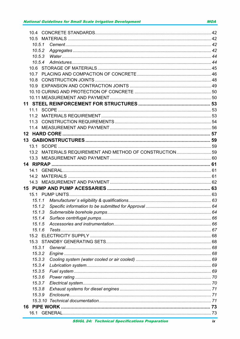
CONCRETE STANDARDS .............................................................................................. 42 10.4
MATERIALS .................................................................................................................... 42 10.5
Cement ...................................................................................................................... 42 10.5.1
Aggregates ................................................................................................................ 42 10.5.2
Water ......................................................................................................................... 44 10.5.3
Admixtures ................................................................................................................. 44 10.5.4
STORAGE OF MATERIALS ............................................................................................ 45 10.6
PLACING AND COMPACTION OF CONCRETE ............................................................ 46 10.7
CONSTRUCTION JOINTS .............................................................................................. 48 10.8
EXPANSION AND CONTRACTION JOINTS .................................................................. 49 10.9
CURING AND PROTECTION OF CONCRETE .............................................................. 50 10.10
MEASUREMENT AND PAYMENT .................................................................................. 50 10.11
STEEL REINFORCEMENT FOR STRUCTURES ..................................................... 53 11
SCOPE ............................................................................................................................ 53 11.1
MATERIALS REQUIREMENT ......................................................................................... 53 11.2
CONSTRUCTION REQUIREMENTS .............................................................................. 54 11.3
MEASUREMENT AND PAYMENT .................................................................................. 56 11.4
HARD CORE ............................................................................................................. 57 12
GABIONSTRUCTURES ............................................................................................ 59 13
SCOPE ............................................................................................................................ 59 13.1
MATERIALS REQUIREMENT AND METHOD OF CONSTRUCTION ............................ 59 13.2
MEASUREMENT AND PAYMENT .................................................................................. 60 13.3
RIPRAP ..................................................................................................................... 61 14
GENERAL ........................................................................................................................ 61 14.1
MATERIALS .................................................................................................................... 61 14.2
MEASUREMENT AND PAYMENT .................................................................................. 62 14.3
PUMP AND PUMP ACESSARIES ............................................................................ 63 15
PUMP UNITS ................................................................................................................... 63 15.1
Manufacturer`s eligibility & qualifications ................................................................... 63 15.1.1
Specific information to be submitted for Approval ..................................................... 64 15.1.2
Submersible borehole pumps .................................................................................... 64 15.1.3
Surface centrifugal pumps ......................................................................................... 66 15.1.4
Accessories and instrumentation ............................................................................... 66 15.1.5
Tests .......................................................................................................................... 67 15.1.6
ELECTRICITY SUPPLY .................................................................................................. 68 15.2
STANDBY GENERATING SETS ..................................................................................... 68 15.3
General ...................................................................................................................... 68 15.3.1
Engine ....................................................................................................................... 68 15.3.2
Cooling system (water cooled or air cooled) ............................................................. 69 15.3.3
Lubrication system ..................................................................................................... 69 15.3.4
Fuel system ............................................................................................................... 69 15.3.5
Power rating .............................................................................................................. 70 15.3.6
Electrical system ........................................................................................................ 70 15.3.7
Exhaust systems for diesel engines .......................................................................... 71 15.3.8
Enclosure ................................................................................................................... 71 15.3.9
Technical documentation ........................................................................................... 71 15.3.10
PIPE WORK .............................................................................................................. 73 16
GENERAL ........................................................................................................................ 73 16.1

National Guidelines for Small Scale Irrigation Development MOA
SSIGL 24: Technical Specifications Preparation x
MATERIALS OF PIPES ................................................................................................... 73 16.2
Steel pipes and fittings .............................................................................................. 73 16.2.1
Unplasticized PVC (UPVC) pipes and fittings ........................................................... 74 16.2.2
HDPE pipes and fittings ............................................................................................. 74 16.2.3
HANDLING OF PIPES ..................................................................................................... 74 16.3
INSTALLATION OF PIPELINES ...................................................................................... 74 16.4
Trench excavation ..................................................................................................... 74 16.4.1
Foundation and bedding ............................................................................................ 75 16.4.2
Installation ................................................................................................................. 75 16.4.3
Jointing and cutting .................................................................................................... 75 16.4.4
Curves and bends ..................................................................................................... 76 16.4.5
Protection .................................................................................................................. 76 16.4.6
Measurement and payment ....................................................................................... 77 16.4.7
ROAD NETWORKS .................................................................................................. 79 17
ACCESS ROADS ............................................................................................................ 79 17.1
FARM ROADS ................................................................................................................. 79 17.2
EXISTING PUBLIC ROADS ............................................................................................ 79 17.3
PAYMENT ....................................................................................................................... 79 17.4
MISCELLANEOUS .................................................................................................... 81 18
SCOPE ............................................................................................................................ 81 18.1
STRUCTURE DRAINS .................................................................................................... 81 18.2
General ...................................................................................................................... 81 18.2.1
Materials .................................................................................................................... 81 18.2.2
Installation ................................................................................................................. 81 18.2.3
Steel work .................................................................................................................. 82 18.2.4
TRASH RACK /SCREEN/ ................................................................................................ 82 18.3
STEEL PIPES AND VALVES .......................................................................................... 84 18.4
PAYMENT ....................................................................................................................... 86 18.5
REFERENCE MATERIALS.............................................................................................. 87

National Guidelines for Small Scale Irrigation Development MOA
SSIGL 24: Technical Specifications Preparation xi
LIST OF TABLES
Table 3-1: Construction sequence of diversion weir ......................................................................... 8
Table 3-2: Construction sequence of irrigation infrastructure ........................................................... 8
Table 3-3: Construction method ....................................................................................................... 9
Table 10-1: Summary of Concrete Standards and their Characteristics ........................................ 42
Table 10-2: Maximum amount of deleterious substances .............................................................. 43
Table 10-3: Grading of fine aggregate ............................................................................................ 43
Table 10-4: Nominal size and grading of coarse aggregate ........................................................... 44
Table 11-1: Mass of reinforcing bars (as recommended by the South African reinforced concrete
association) ................................................................................................................... 53
Table 11-2: Minimum concrete cover over reinforcement .............................................................. 56
Table 13-1: Rock size ..................................................................................................................... 59
Table 13-2: Coating of wire ............................................................................................................. 59
Table 13-3: Mesh size .................................................................................................................... 60
Table 14-1: Gradation requirements for riprap ............................................................................... 61

National Guidelines for Small Scale Irrigation Development MOA
SSIGL 24: Technical Specifications Preparation xii
ACRONYMS
AASHTO American Association State Highway and Transportation Officials
AGP Agricultural Growth Program
ASTM American Society for Testing And Materials
BOQ Bill of Quantities
BS British Standard
BS EN British Standard Euro code
EBCS Ethiopian Building Code Standard
EEPCO Ethiopian Electric Power Corporation
EN European Standard
ERA Ethiopian Road Authority
ETB Ethiopian Birr
GIRDC Generation Integrated Rural Development Consultant
GL Guideline
HCB Hallow Concrete Block
HDPE High Density Polyethylene
IS Indian Standard
IWUA Irrigation Water Users Association
m2 Square Meter
m3 Cubic Meters
MoANR Ministry of Agriculture and Natural Resources
PBOQ Priced Bill of Quantities
PVC Poly Venile Chloride
SSID Small Scale Irrigation Development
SSIP Small Scale Irrigation Project
TOR Term of Reference
TSCS Technical Specification Compliance Sheet

National Guidelines for Small Scale Irrigation Development MOA
SSIGL 24: Technical Specifications Preparation xiii
PREFACE
While irrigation development is at the top of the government‟s priority agendas as it is key to boost
production and improve food security as well as to provide inputs for industrial development.
Accordingly, irrigated land in different scales has been aggressively expanding from time to time.
To this end, to enhance quality delivery of small-scale irrigation development planning,
implementation and management, it has been decided to develop standard SSI guidelines that
must be nationally applied. In September 2017 the Ministry of Agriculture (MoA) had entrusted
Generation Integrated Rural Development Consultant (GIRDC) to prepare the National Small-
scale Irrigation Development Guidelines (SSIGLs).
Preparation of the SSIGLs for enhancing development of irrigated agriculture is recognized as one
of the many core initiatives of the MoA to improve its delivery system and achieve the targets in
irrigated agriculture and fulfill its mission for improving agricultural productivity and production. The
core objective of developing SSIGLs is to summarize present thinking, knowledge and practices to
enable irrigation practitioners to properly plan, implement and manage community managed SSI
schemes to develop the full irrigation potential in a sustainable manner.
As the SSIGLs are prepared based on national and international knowledge, experiences and
practices, and describe current and recommended practice and set out the national standard
guides and procedures for SSI development, they serve as a source of information and provide
guidance. Hence, it is believed that the SSIGLs will contribute to ensuring the quality and timely
delivery, operation and maintenance of SSI schemes in the country. The SSIGLs attempt to
explain and illustrate the important concepts, considerations and procedures in SSI planning,
implementation and management; and shall be used as a guiding framework for professionals
engaged in SSI development. Illustrative examples from within the country have been added to
enable the users understand the contents, methodologies presented in the SSIGLs.
The intended audiences of the SSIGLs are government organizations, NGOs, CSOs and the
private sector involved in SSI development. Professionally, the SSIGLs will be beneficial for
experienced and junior planners, experts, contractors, consultants, suppliers, investors, operators
and managers of SSI schemes. The SSIGLs will also serve as a useful reference for academia
and researchers involved and interested in SSI development. The SSIGLs will guide to ensure
that; planning, implementation and management of SSI projects is formalized and set procedures
and processes to be followed. As the SSIGLs provide information and guides they must be always
fully considered and applied by adapting them to the local specific requirements.
In cognizance with the need for quality SSIGLs, the MoA has duly considered quality assurance
and control during preparation of the guidelines. Accordingly, the outlines, contents and scope of
the SSIGLs were thoroughly discussed, reviewed and modified by NAWMP members (senior
professionals from public, national and international stakeholder) with key stakeholders in many
consultative meetings and workshops. Moreover, at each milestone of SSIGL preparation,
resource persons from all stakeholders reviewed and confirmed that SSIGLs have met the
demands and expectations of users.
Moreover, the Ministry has mobilized resource persons from key Federal, National Regional States
level stakeholders and international development partners for review, validation and endorsement
of the SSIGLs.

National Guidelines for Small Scale Irrigation Development MOA
SSIGL 24: Technical Specifications Preparation xiv
Several hundreds of experienced professionals (who are very qualified experts in their respective
fields) from government institutions, relevant private sector and international development partners
have significantly contributed to the preparation of the SSIGLs. They have been involved in all
aspects of the development of SSIGLs throughout the preparation process. The preparation
process included a number of consultation meetings and workshops: (i) workshop to review
inception report, (ii) workshop on findings of review of existing guidelines/manuals and proposed
contents of the SSIGLs, (iii) meetings to review zero draft SSI GLs, (iv) review workshop on draft
SSI GLs, (v) small group review meetings on thematic areas, (vi) small group consultation
meetings on its final presentation of contents and layout, (vii) consultation mini-workshops in the
National States on semi-final versions of the SSIGLs, and (viii) final write-shop for the appraisal
and approval of the final versions of SSIGLs.
The deliberations, concerns, suggestions and comments received from professionals have been
duly considered and incorporated by the GIRD Consultant in the final SSIGLs.
There are 34 separate guidelines which are categorized into the following five parts concurrent to
SSI development phases:
Part-I. Project Initiation, Planning and Organization Guideline which deals with key considerations
and procedures on planning and organization of SSI development projects.
Part-II. Site Identification and Prioritization Guideline which treats physical potential identification
and prioritization of investment projects. It presents SSI site selection process and
prioritization criteria.
Part-III. Feasibility Study and Detail Design Guidelines for SSID dealing with feasibility study and
design concepts, approaches, considerations, requirements and procedures in the study and
design of SSI systems.
Part-IV. Contract Administration and Construction Management Guidelines for SSI development
presents the considerations, requirements, and procedures involved in construction of
works, construction supervision and contract administration.
Part-V. SSI Scheme Management, Operation and Maintenance Guidelines which covers SSI
Scheme management and operation.
Moreover, Tools for Small Scale Irrigation development are also prepared as part of SSIGLs.
It is strongly believed and expected that; the SSIGLs will be quickly applied by all stakeholders
involved in SSI development and others as appropriate following the dissemination and
familiarization process of the guidelines in order to ensure efficient, productive and sustainable
irrigation development.
The SSIGLs are envisioned to be updated by incorporating new technologies and experiences
including research findings. Therefore, any suggestions, concerns, recommendations and
comments on the SSIGLs are highly appreciated and welcome for future updates as per the
attached format below. Furthermore, despite efforts in making all types of editorial works, there
may still errors, which similarly shall be handled in future undated versions.

National Guidelines for Small Scale Irrigation Development MOA
SSIGL 24: Technical Specifications Preparation xv
UPDATING AND REVISIONS OF GUIDELINES
The GLs are intended as an up-to-date or a live document enabling revisions, to be updated
periodically to incorporate improvements, when and where necessary; may be due to evolving
demands, technological changes and changing policies, and regulatory frameworks. Planning,
study and design of SSI development interventions is a dynamic process. Advancements in these
aspects are necessary to cope up with the changing environment and advancing techniques. Also,
based on observation feedbacks and experiences gained during application and implementation of
the guidelines, there might be a need to update the requirements, provisions and procedures, as
appropriate. Besides, day-by-day, water is becoming more and more valuable. Hence, for efficient
water development, utilization and management will have to be designed, planned and
constructed with a new set up of mind to keep pace with the changing needs of the time. It may,
therefore, be necessary to take up the work of further revision of these GLs.
This current version of the GLs has particular reference to the prevailing conditions in Ethiopia and
reflects the experience gained through activities within the sub-sector during subsequent years.
This is the first version of the SSI development GLs. This version shall be used as a starting point
for future update, revision and improvement. Future updating and revisions to the GLs are
anticipated as part of the process of strengthening the standards for planning, study, design,
construction, operation and management SSI development in the country.
Completion of the review and updating of the GLs shall be undertaken in close consultation with
the federal and regional irrigation institutions and other stakeholders in the irrigation sub-sector
including the contracting and consulting industry.
In summary, significant changes to criteria, procedures or any other relevant issues related to
technological changes, new policies or revised laws should be incorporated into the GLs from their
date of effectiveness. Other minor changes that will not significantly affect the whole nature of the
GLs may be accumulated and made periodically. When changes are made and approved, new
page(s) incorporating the revision, together with the revision date, will be issued and inserted into
the relevant GL section.
All suggestions to improve the GLs should be made in accordance with the following procedures:
I. Users of the GLs must register on the MOA website: Website: www.moa.gov.et
II. Proposed changes should be outlined on the GLs Change Form and forwarded with a
covering letter or email of its need and purpose to the Ministry.
III. Agreed changes will be approved by the Ministry on recommendation from the Small-scale
Irrigation Directorate and/or other responsible government body.
IV. The release date of the new version will be notified to all registered users and authorities.
Users are kindly requested to present their concerns, suggestions, recommendations and
comments for future updates including any omissions and/or obvious errors by completing the
following revisions form and submitting it to the Ministry. The Ministry shall appraise such requests
for revision and will determine if an update to the guide is justified and necessary; and when such
updates will be published. Revisions may take the form of replacement or additional pages. Upon
receipt, revision pages are to be incorporated in the GLs and all superseded pages removed.

National Guidelines for Small Scale Irrigation Development MOA
SSIGL 24: Technical Specifications Preparation xvi
Suggested Revisions Request Form (Official Letter or Email)
To: ---------------------------------------------------------------
From: -----------------------------------------------------------
Date: -----------------------------------------------------------
Description of suggested updates/changes: Include GL code and title, section title and #
(heading/subheading #), and page #.
GL Code and
Title
Date Sections/
Heading/Subheading/
Pages/Table/Figure
Explanation Comments (proposed
change)
Note that be specific and include suggested language if possible and include additional sheets for
comments, reference materials, charts or graphics.
GLs Change Action
Suggested Change Recommended Action Authorized by Date
Director for SSI Directorate: _______________________Date: ________________
The following table helps to track initial issuance of the guidelines and subsequent Updates/Versions and
Revisions (Registration of Amendments/Updates).
Revision Register
Version/Issue/Revision
No
Reference/Revised
Sections/Pages/topics
Description of
revision
(Comments)
Authorized
by
Date
National Guidelines for Small Scale Irrigation Development MOA
SSIGL 24: Technical Specifications Preparation 1
INTRODUCTION 1
GENERAL 1.1
This Technical Specification Guideline for SSID depicts the material quality and workmanship
requirement to be adopted and the overall quality of construction based on the required quality
achievement & performance of structures.
OBJECTIVE
The objective of this guideline is to provide guidance of technical specifications preparation for
Construction Works of Small Scale Irrigation Development.
SCOPE
This guideline covers the basics for technical specification preparation for SSID and standard
technical specification applicable for construction of Small Scale Irrigation Development. Based on
this guideline, designers shall prepare project specific technical specification during design phase.
SETTING OF THE GUIDELINE
Technical Specification Preparation Guideline for Small Scale Irrigation Development addressed
the issues in detail chapter by chapter. There are eighteen chapters having the following contents:
Chapter one presents introduction of the guideline and deals with the scope and setting out of the
guideline. Chapter two deals with technical specifications preparation basics giving guide notes
how to prepare a sound technical specification. Chapter three deal with general conditions and
specifications that should be included in a given technical specification.
Chapter four and five deal with submittals and contract close out respectively. Chapter six deal
with Clearing and Grubbing, whereas, technical specification of excavation as well as earth fill and
compaction aderessed in chapter seven and eight respectively.
Technical specification of masonry work, concret work, steel reinforcement for structures,
hardcore, gabion structures, and riprap presented through chapter nine to fourteen one after the
other. Chapter fifteen deals with technical specification of pump and pump accessories, whereas,
chapter sixteen for pipe works. Technical specification for road network & miscellaneous works are
presented in chapter seventeen and eighteen respectively.

National Guidelines for Small Scale Irrigation Development MOA
SSIGL 24: Technical Specifications Preparation 2

National Guidelines for Small Scale Irrigation Development MOA
SSIGL 24: Technical Specifications Preparation 3
BASICS OF TECHNICAL SPECIFICATIONS PREPARATION 2
GENERAL 2.1
The information that is needed for construction work is usually conveyed by two basic
communication lines. They are Drawings (pictorial) and Specifications (written). Specifications are devices for organizing the information depicted on the drawings and they are
written descriptions of the legal and technical requirements forming the contract documents.
Specification is defined as the designation or statement by which written instructions are given
distinguishing and/or limiting and describing the particular trade of work to be executed. Specifications are written based on the prepared design, drawings, general and scientific trends of
workmanship, quality expected, equipment involved and materials to be used for the particular
trade of work. The specifications should clearly specify: -
i. Type and quality of materials, equipments, labor or workmanship ii. Methods of fabrication, installation and erection iii. Standards, codes and tests iv. Allowance, submittals and substitutions v. Cost included, insurance and bonds vi. Project records and site facilities
Specifications should be clear, concise, and brief descriptions of what is required to execute the
proposed trade of work.
PURPOSES OF SPECIFICATIONS 2.2
The purpose of specifications generally includes but not limited to: -
1. Guide the bidder at the time of tendering to arrive at a reasonable cost for the work,
2. Provide guidance for execution and supervision of works,
3. Guide the contractor for the purchase of materials,
4. Serve as a part of contract document to limit and describe the rights and obligations of
each contracting parties,
5. Guide the bidder to identify his capacity to execute the work,
6. Serve as fabrication and installation guide for temporary and permanent works.
7. Guide the contractor for the purchase and/or hiring of equipments.
8. Serve for the owner to know what he/she is entitled to receive,
9. Serve for the manufacturers of construction materials, equipments, tools etc… to grade,
classify, and improve qualities of their produces,
10. Indirectly, the specifications are very much related to the legal considerations, insurance
considerations, bidding requirements, alternates and options, rights, obligations and
remedial measures for the contracting parties.
Note: In the events of conflicts between specification and drawings, the specification governs.

National Guidelines for Small Scale Irrigation Development MOA
SSIGL 24: Technical Specifications Preparation 4
TYPES OF SPECIFICATIONS 2.3
In general, specifications can be broadly classified into four categories as follows: -
Manufacturer’s specification 2.3.1
Manufacturers prepare specification of their product for the guidance of their users, which may
include property description and installation guidelines.
Guide specification 2.3.2
Specifications prepared by an individual or group of individuals based on manufacturer‟s
specifications, established trends of workmanship, service and laboratory tests and research
findings to be used as guidelines for preparation of contract specifications.
Standard specification 2.3.3
Standard specification is specification which is intended to be used as a reference standard in the
construction of a project. The guide specification which has been standardized by a recognized
authority is considered as standard specification.
Contract (project) specification 2.3.4
The specification prepared for a particular project to accompany the drawings and other contract
documents.
“Technical Specification and Methods of Measurement for Construction of Buildings”, of March
1991 is the standard specification which has been in use for many years as one of the contract
documents in our country. This material has the general requirement part and the specific part.
In the specific part the different trades of works (excavation and earth works, concrete works, etc.)
are described in details and the method of measurements are given. There are the following types of technical specifications:
Proprietary specifications 2.3.4.1
This specifications call for desired materials, producers, systems, and equipments by their trade
names and model numbers. For detailed descriptions reference should be made to manufacturer‟s
specifications.
Performance specifications 2.3.4.2
Performance specification: -
Specifications which define products based on desired end results which are performance oriented;
Most appropriate when new or unusual products or systems are required or when innovation is necessary; and
Testing methods and evaluation procedures for defining the required performances must be explicitly specified.

National Guidelines for Small Scale Irrigation Development MOA
SSIGL 24: Technical Specifications Preparation 5
Reference Specifications 2.3.4.3
Specifications which refer to levels of quality established by recognized testing authority or
standards set by quality control authorities. These specifications are also used in conjunction with
other types of specifications. EBC, ASTM, AASHTO, ES, IS, etc.
Example: - C-25 Concrete.
Descriptive specifications 2.3.4.4
Specifications which describe all components of products, their arrangements and methods of
assembly, physical and chemical properties, arrangement and relationship of parts and numerous
other details.
The specifier shall take total responsibility for the function and performance of the product.
Example: - “Supply and fix 40mm. thick flush wood door with hard wood frames and both sides
covered with best quality 4mm thick ply wood. Price includes approved quality lock, hinges, three
coats of varnish paint, door stopper and all necessary accessories to comply ES‟‟.
Cash allowance specifications 2.3.4.5
Cash Allowance Specifications are specifications meant to direct bidders to set aside a specified
amount of money to be applied to the construction work at the direction of the specifier.
Example: - “A lump sum of Ethiopian Birr 100,000.00 for mobilization of construction manpower,
materials and machineries.
SPECIFICATION WRITING 2.4
Specification writing embodies certain methods of presenting information and instructions. When
specifications are to be written, the following shall be taken into consideration:-
1. Specification writing require: - i. Visualization (having clear picture of the system),
ii. Research (to know the legal impact correctly),
iii. Clear thinking (understanding things directly without misleading), and
iv. Organizing (organizing what we know to write the specification).
2. Specification writing require professional ability to read drawings;
3. Specification writing require wide knowledge of the construction materials, various levels of
workmanship, different construction equipments and method of construction to be
employed;
4. Specifications use simple and clear language such that it can readily be understood;
5. Specifications shall be brief and short as much as possible (avoid long sentences without
punctuations);
6. Specifications shall include all items affecting the cost of the work;
7. Specifications shall be fair and do not attempt to throw all risks and responsibilities on one
of the parties signing the contract, the employer or the contractor;
8. Specifications shall avoid repetition of information shown on drawings to avoid mistakes and
duplications within the specifications and drawings; and

National Guidelines for Small Scale Irrigation Development MOA
SSIGL 24: Technical Specifications Preparation 6
9. Specifications shall not include inapplicable text and do not specify the impossible or
anything not intended to be enforced.
The following are useful references in Specification Writing: -
Codes and ordinances of governments, cities, or municipalities. For example, Ethiopian Building Code of Standards (EBCS);
Standards prepared by distinct societies and government agents. For example, ACI standards, ASTM standards, BS, ES;
Standards or model specifications prepared by manufacturers, professional societies, and government bodies. For example, Standard Technical Specification and Method of Measurement for Road Works, 2013. Ethiopian Road Authority;
Master specifications and previously written specifications; and
Information or experience acquired by personal observation and contact with trained or experienced people in the construction industry.
SPECIFICATION LANGUAGE 2.5
The specification writer should present his instructions regarding the particular work under
consideration in such a manner that: -
The drawings are more clearly interpreted, not duplicated;
Rights, obligations, and remedial measures shall be designated without ambiguity or prejudice; and
Clearly express the extent of works under consideration; therefore, the phraseology used in this regard shall be: -
a. Judged by its quality not its length, b. Should be concise and short and written with commonly used words, and c. Punctuations are important but their usage shall be limited to few.
Capitalizing the first letters is mandatory for the following expressions: -
i. Parties to the contract; e.g. Employer/Client/Contractor/Engineer, ii. Space within the building; e.g. Bed Room, Toilet, Living Room, and iii. Contract documents; e.g. Bill of Quantity, Working Drawing, Specification.
Minimize pronouns, better to repeat nouns. Minimize the use of symbols. Do not use foot notes, do
not underline within a sentence for emphasis.
Words shall be used as follows:-
shall in place of must; use “shall” for the duties of the contractor or the consultant to represent the word “must”;
“will” is used for the duties of the employer to represent the word “must”;
“must” – avoid the use of the word “must” and substitute by the word shall to prevent the inference of different degrees of obligation; and
Avoid the use of words which have indefinite meanings or limitless and ambiguous in their meanings. For example, any, either, same, similar, etc.

National Guidelines for Small Scale Irrigation Development MOA
SSIGL 24: Technical Specifications Preparation 7
GENERAL CONDITIONS AND SPECIFICATIONS 3
DESCRIPTION OF THE PROJECT AREA AND LOCATION 3.1
The project area and location shall be as specified in the bid document. For the description of
project area and location refer Part I. GL 1: Project Initiation, Planning and Organizations
Guideline for SSID and other guidelines as appropriate of this guideline.
DESCRIPTION OF WORKS 3.2
The principal items of work to be executed under the contract shall be indicated properly. The
works vary project to project based on water abstraction system, conveyance system, and
application system.
Most commonly the principal items of work to be executed under work Contract in SSID include
but are not limited to the following: -
1. Access and Service Road construction along main canals;
2. Road/Canal Crossing, Drainage Culvert construction;
3. Headwork/diversion weir & Pump (incorporating wing walls, intake structure, stilling basin/
apron, and downstream stone Rip-rap) construction;
4. Earthen Canal construction on main and secondary canals;
5. Tertiary canals‟ and drains‟ works;
6. On-farm Irrigation structures Division Boxes, Drop structures, Culverts, Cross drain
structure i.e. flume, Turn outs and off-takes) ;
7. Flood protection works
8. Installation of gates (that of sluice, intake, division boxes, turn outs and off-takes)
construction;
9. On-farm Drainage structures construction;
10. Other works associated with the above including any modifications carried out within the
terms of the Contract.
For the detail description of works refer Part I. GL 1: Project Initiation, Planning and Organizations
Guideline for SSID and other guidelines as appropriate of this guideline.
SEQUENCE OF WORK 3.3
Proposed sequence of work shall be as specified in the contract document. For a given small
scale irrigation construction project having water abstraction system of diversion weir, sequence of
work to be followed during construction period can be as given below. The smallest Serial No.
indicates the first work to be performed then the next higher Serial No. and so on. The proposal
sequence of the work may be changed on site owing to the availability of construction material,
machinery and weather conditions.
National Guidelines for Small Scale Irrigation Development MOA
SSIGL 24: Technical Specifications Preparation 8
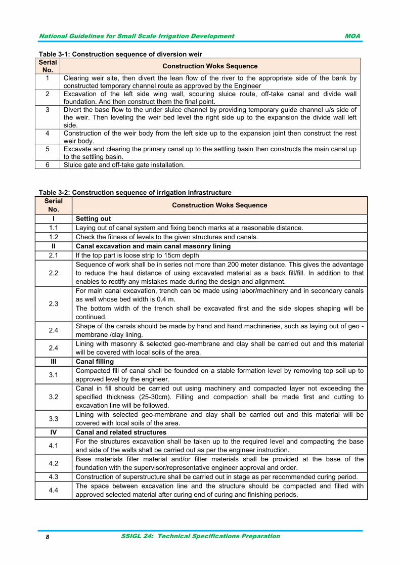
Table 3-1: Construction sequence of diversion weir
Serial No.
Construction Woks Sequence
1 Clearing weir site, then divert the lean flow of the river to the appropriate side of the bank by constructed temporary channel route as approved by the Engineer
2 Excavation of the left side wing wall, scouring sluice route, off-take canal and divide wall foundation. And then construct them the final point.
3 Divert the base flow to the under sluice channel by providing temporary guide channel u/s side of the weir. Then leveling the weir bed level the right side up to the expansion the divide wall left side.
4 Construction of the weir body from the left side up to the expansion joint then construct the rest weir body.
5 Excavate and clearing the primary canal up to the settling basin then constructs the main canal up to the settling basin.
6 Sluice gate and off-take gate installation.
Table 3-2: Construction sequence of irrigation infrastructure
Serial
No. Construction Woks Sequence
I Setting out
1.1 Laying out of canal system and fixing bench marks at a reasonable distance.
1.2 Check the fitness of levels to the given structures and canals.
II Canal excavation and main canal masonry lining
2.1 If the top part is loose strip to 15cm depth
2.2
Sequence of work shall be in series not more than 200 meter distance. This gives the advantage
to reduce the haul distance of using excavated material as a back fill/fill. In addition to that
enables to rectify any mistakes made during the design and alignment.
2.3
For main canal excavation, trench can be made using labor/machinery and in secondary canals
as well whose bed width is 0.4 m.
The bottom width of the trench shall be excavated first and the side slopes shaping will be
continued.
2.4 Shape of the canals should be made by hand and hand machineries, such as laying out of geo -
membrane /clay lining.
2.4 Lining with masonry & selected geo-membrane and clay shall be carried out and this material
will be covered with local soils of the area.
III Canal filling
3.1 Compacted fill of canal shall be founded on a stable formation level by removing top soil up to
approved level by the engineer.
3.2
Canal in fill should be carried out using machinery and compacted layer not exceeding the
specified thickness (25-30cm). Filling and compaction shall be made first and cutting to
excavation line will be followed.
3.3 Lining with selected geo-membrane and clay shall be carried out and this material will be
covered with local soils of the area.
IV Canal and related structures
4.1 For the structures excavation shall be taken up to the required level and compacting the base
and side of the walls shall be carried out as per the engineer instruction.
4.2 Base materials filler material and/or filter materials shall be provided at the base of the
foundation with the supervisor/representative engineer approval and order.
4.3 Construction of superstructure shall be carried out in stage as per recommended curing period.
4.4 The space between excavation line and the structure should be compacted and filled with
approved selected material after curing end of curing and finishing periods.

National Guidelines for Small Scale Irrigation Development MOA
SSIGL 24: Technical Specifications Preparation 9
SURVEYING AND SETTING OUT WORKS 3.4
The Contractor shall be responsible for the true and proper setting out of the works and for the
correctness of the positions, levels, dimensions and alignment of all parts of the works and for the
provisions of all necessary instruments, appliances and labor in connection therewith. If at any
time during the progress of the works, any error shall appear or arise in the position, levels,
dimensions or alignment of any part of the works, the Contractor, on being required to do so by the
Engineer, shall at his own expense rectify such error to the satisfaction of the Engineer.
The checking of any setting out or of any line or level by the Engineer shall not in any way relieve
the Contractor of his responsibility for correctness thereof. The Contractor shall carefully protect
and preserve all benchmarks, sight rails, pegs and other things used in setting out the works.
No separate payment will be made for this and the unit rates for the different items entered in the
Bill of Quantities are deemed to cover all such expenditure.
For detail of surveying and setting out works refer GL 4: Topographic and Irrigation Infrastructures
Surveying Guideline for SSID prepared as a part of this guideline.
CONSTRUCTION METHOD 3.5
The techniques used to build small scale irrigation infrastructures may be labour or machinery
based on the forms and scales of the work. The commonly adopted methods are as tabulated
under.
Table 3-3: Construction method
Serial No.
Type of work
The works to be done using
Machinery Labor
1 Earth Work
1.1 Clearing
1.2 All earth work, stripping top soil, excavation for foundation of major
structure and others excavation
1.3 Canal and small canal structures foundation excavation
1.4 Fill & compaction
2 Form Work
3 Concrete Work
3.1 Production of crushed aggregates
3.2 Mixing of concrete
3.3 Placing of concrete
3.4 Compaction of the concrete
3.4 Curing of casted concrete
4 Masonry Work
4.1 Masonry work
4.2 Cement Mortar mixing
5 Carpentry Work
6 Metal/Steel Works
7 Reinforcement bar Works
8 Finishing Works
9 Electro-Mechanical Works
10 Pipe Works
National Guidelines for Small Scale Irrigation Development MOA
SSIGL 24: Technical Specifications Preparation 10
MOBILISATION AND DEMOBILISATION 3.6
Mobilization 3.6.1
Mobilization is understood to be the full process of furnishing all staff, labour, materials, tools,
equipment and incidentals necessary to perform, complete and maintain all works required for
moving in to the Site and shall include:
i. Transport of all items of equipment to the sites where they are to be used in the Works and
their installations;
ii. Supply of construction materials;
iii. Mobilization of all staff and labour to the Site; and
iv. Erection of all temporary works for Contractor‟s facilities;
In other words, mobilization shall consist of preparatory work and operations including, but not
limited to, those necessary to the movement of personnel, equipment, supplies and incidentals to
the project site; and for all other work and operations which must be performed or costs incurred
prior to beginning work on the various items on the project site.
The Contractor‟s Programme shall include full details of her/his intended mobilization procedure.
This will ensure completion of the mobilization tasks given in paragraphs (i), (ii) and (iii) above
within the agreed specified date from the Start Date.
Demobilization 3.6.2
Demobilization shall consist of cleanup work and operations including, but not limited to, those
necessary to the removal of personnel, tools, equipment, and incidentals from the project site. It
should be communicated with potential stakeholders.
i. Demobilization of all staff and labour from the Site; and ii. Dismantling of the work site and removal of all installations, equipment and temporary works
so that the Site is left in a neat and tidy condition to the satisfaction of the Project Manager.
Similarly, the Contractor‟s Programme shall include full details of her/his intended demobilization
procedure.
Payment 3.6.3
Payment for mobilization and demobilization will be made at the lump sum price shown in the Priced
Bill of Quantities. Mobilization payment shall be in the proportion of mobilization performance with the approval of
the engineer.
The demobilization payment shall be effect with final payment upon completion of the contract and
removal of equipment and cleanup of the work areas to the satisfaction of the Engineer.

National Guidelines for Small Scale Irrigation Development MOA
SSIGL 24: Technical Specifications Preparation 11
CONSTRUCTION CAMP AND CAMPING FACILITIES 3.7
The contractor shall make arrangement as necessary for the housing, feeding and welfare of his
own employees and/or supervisor staffs by providing, servicing and maintaining a camp on the site
or sites approved by the Engineer, by other approved means. The contractor will not be permitted
to site such camps with in irrigable area.
The camp should be standard having social infrastructures structures and utilities agreed up on it,
such as: -
Offices for both contractor and supervisor,
Bed rooms for both contractor‟s and supervisor‟s staffs,
Kitchen,
Dining room,
Shower and toilet,
Potable water supply system if applicable,
Electrical system from locally available source national/local greed line, solar energy, generator, etc.
Contractually erected structures and/or buildings are the property of the Employer. Camp
constructed is a permanent work and will remain to be the property of the community. After
completion of the work, the camp and camping facility shall be used by the scheme IWUA.
All hutments and building erected by the contractor on the site at his own expenses, shall, from the
time of their erection until the completion of the works is the property of the employer and the
contractor shall not be demolished or remove any such buildings without the written permission of
the Engineer. But, on the completion of the works they shall become the property of the contractor
who shall remove them entirely with all drains and restore the surface of the land to its original
condition or other reasonable condition to the satisfaction of the Engineer.
The Contractor shall provide and maintain his own electrical supply. This supply must be adequate
to supply the areas set aside for the housing and offices of his own staff and those of the Engineer
and his staff. The Contractor shall provide and maintain all necessary temporary power and lighting and all
associated equipment for the duration of the Contract. Payment for Construction camp and camping facilities will be made based on price shown in the
Priced Bill of Quantities forming the contract.
HOURS AND DAYS OF WORKING 3.8
The Contractor shall plan her/his work on the basis of a five-day working week, or permissible by
as per local authorities and within the hours of 8:00 am and 6:00 pm. Should the Contractor
require additional working hours, or weekend working, he shall submit a request to the supervisor
engineer for permission to work extended hours, giving full reasons for the requests. Approval to
such requests will not be granted on a regular basis, but only in exceptional circumstances.
Notwithstanding the foregoing nothing in this Contract will restrict the Contractor undertaking any
tasks at any time where such tasks are essential for the saving of life or property or for the safety
of the Works, in which case the Contractor shall immediately advise the supervisor engineer.

National Guidelines for Small Scale Irrigation Development MOA
SSIGL 24: Technical Specifications Preparation 12
SIGN BOARD 3.9
The Contractor shall erect maximum two signboards as shown on the Drawings at the locations as
directed by the engineer. No other signboard or notices shall be erected or displayed on the Site,
other than those required for purposes of safety, without the written permission of the Project
Manager. Payment for signboard will be made based on price shown in the Priced Bill of Quantities forming
the contract.
FENCING 3.10
Temporary fencing 3.10.1
The Contractor shall erect, maintain and remove suitable and approved temporary fencing to
enclose such areas of land, (such as Supervisor‟s/Contractor‟s offices and yards, construction
works being carried out beside buildings, canal, or footpaths and any other place where the
Contractor‟s operations will endanger lives or public property), occupied by the Contractor within
the Site as may be necessary to implement his obligations under the Contract, to the satisfaction
of the Project Manager.
Permanent fencing 3.10.2
The Contractor shall erect, maintain and suitable and approved permanent fencing to enclose
permanent structures but not limited to: -
Pump and pump station,
Night Storage Reservoir, and
Along main canal (if required),
Permanent fence can be constructed using 2500mm long(100mm*100mm) precast concrete post
spaced every 2000mm center to center of the two consecutive poles with standard barbed wire.
Optionally, it can be made from 50mm*50mm*3mm angle iron with standard barbed weir. Payment shall be made in accordance with the agreed unite rate and the corresponding unit of
measurement in the contract.

National Guidelines for Small Scale Irrigation Development MOA
SSIGL 24: Technical Specifications Preparation 13
SUBMITTALS 4
EMPLOYER’S SUBMITTALS 4.1
Contract documents 4.1.1
The Contractor will be provided with full set of the Contract documents for his own use. A complete
set of Contract documents supplied by the Project Manager and all further instructions issued by him
shall be kept at all times by the Contractor on the Site and available to the Project Manager and his
staff.
Design drawings 4.1.2
The Drawings which are included in the bidding documents and which will form part of the Drawings
to be used for the construction of the Works show the work to be carried out in accordance with the
Contract in sufficient detail for the Contractor to fully plan his activities will be provided through
engineer.
The Contractor shall check the Drawings carefully and advise the engineer, in writing, of any
ambiguities, discrepancies, errors or omissions and a full instruction will be furnished to the
Contractor should any ambiguities, discrepancies, errors or omissions be found. The Contractor shall
be required to perform the work in accordance with such further instructions or issued Drawings.
Although the Drawings are prepared to scale, work shall be based upon dimensions shown on the
Drawings and not on dimensions scaled from the Drawings.
Specification 4.1.3
Specification is one of the contract documents. It will be provided for contractor through engineer to
be referred and adopted in the contract period by the contractor and the engineer.
The Contractor shall check the technical specification carefully and advise the engineer, in writing, of
any ambiguities, discrepancies, errors or omissions and a full instruction will be furnished to the
Contractor should any ambiguities, discrepancies, errors or omissions be found. The Contractor shall
be required to perform the work in accordance with such further issued technical specification.
CONTRACTOR’S SUBMITTALS 4.2
Working drawings 4.2.1
The Contractor shall prepare and submit to the Project Manager such working as may be
necessary to illustrate his proposed designs and method of working. These working drawings
shall: -
be prepared to appropriate scales and include plans, elevations and sections;
consist of an electronic copy of the drawing (if available), one print and one copy of design calculations, specification and parts catalogues;
be signed by a qualified engineer responsible for the design, checked and approved by the Contractor prior to submission;
Bear the title, Contract No. -------:

National Guidelines for Small Scale Irrigation Development MOA
SSIGL 24: Technical Specifications Preparation 14
The engineer shall signify his approval or request modifications. The Contractor shall modify the
designs and drawings, as may be required by the engineer.
The Works shall be constructed in accordance with the approved working Drawings a copy of such
Drawings shall be kept on the Site at all times until the completion of the Contract. All Drawings,
on which changes are made, shall have the revisions clearly marked and dated.
Construction of any portion of the Works shall not commence until the design and drawings have
been approved in writing by the Project Manager and thereafter no change shall be made to any
Drawings so approved without the permission of the Project
Shop drawings 4.2.2
The Contractor shall, in close consultation with the Engineer, prepare all the Shop Drawings
deemed necessary for the execution of the Works and shall submit the same for approval to the
Engineer well in advance to allow specified days in the contract for Engineer's checking and
approval. The approval procedure shall be agreed upon with the Engineer. Fabrication and
installation shall not proceed until the review is completed.
Where more than one type of shop drawing has been specified for one item, e.g., lay-out details,
and dimensional drawings, the shop drawings shall be submitted together, to enable the Engineer
to review the drawings as a package.
Shop drawings shall indicate the tag number of instruments and they shall clearly show the
features and details applicable to the equipment being supplied. Shop drawings shall be prepared
using accepted drafting techniques which will result in drawings of equal or better quality than the
contract drawings.
Catalogue pages or drawings applicable to an entire family or range of equipment will not be
accepted as shop drawings unless they are clearly marked up to show the pertinent data for the
particular materials.
Manufacturer's catalogues, manuals, or price lists will not be accepted as shop drawings, although
such material may be used as supplemental information to the shop drawings.
Shop drawings shall be detailed using the metric system. No shop drawings detailed using the
imperial system of dimensioning will be accepted.
If, after one review by the Engineer, the Contractor fails to submit correct shop drawings, the
Owner will be entitled to deduct from any payments due to the Contractor the additional costs to
the Owner of the engineering services incurred as a result of the Contractor's failure to submit
correct shop drawings.
National Guidelines for Small Scale Irrigation Development MOA
SSIGL 24: Technical Specifications Preparation 15
Samples 4.2.3
Samples, or as otherwise specified, shall be submitted to the Engineer for review of those products
and materials for which samples are required. Samples shall be submitted a minimum of thirty days
prior to the date for approval required by the Contractor for procurement of the materials.
Samples shall be submitted with complete information concerning manufacturer's data, applicable
standards, test results, and location of installation on the project.
Materials for which samples have been approved by the Engineer shall be used only in those areas
and locations for which the approval was granted. Materials for which samples have been rejected
shall not be delivered to the site, or if delivered, shall be removed promptly.
As-built drawings 4.2.4
On completion of the Works, the Contractor shall submit to the engineer As-built Drawings as
specified, including final reduced levels and size and height of the elements of the Works.
The As-built Drawings for the whole Works are to be produced by the Contractor and submitted to
the engineer as specified in Contract Document to scales approved by the Engineer. All „As-built‟
drawings shall be produced on A1 or A3 paper size using the AutoCAD drawing system. Two
paper copies of each drawing shall be submitted for review and approval by the Project Manager.
Following the correction of any errors or omissions identified by the Project Manager the
Contractor shall submit the final „As-built‟ drawings as: -
a) An electronic copy of each drawing; b) Three copies of all A1 drawings in bound albums; and c) Three copies of all A3 drawings (including reduced copies of the A1 drawings) in bound
albums. Final bar-bending schedules shall be submitted with corresponding bar-marks on approved „As-Built‟
drawings. Structural steel drawings, supplier‟s drawings, fabrication and shop drawings, large scale
detail drawings including all structural steel connection details not shown nor provided by Project
Manager, and any additional drawings, shall be prepared by Contractor and submitted together with
detailed design calculations.
A sample of the format of the As-Built drawing which contains title block, text and symbols, metric
units, drawing scales etc will be issued to the Contractor by the Project Manager and this shall
form the basis of presentations of As-Built drawings.
All costs related to the supply to the engineer of the mentioned number of drawings and
calculations shall be deemed to be included in the rates in the bill of quantities any extra copy of
the drawings and/or calculations which may be required, shall be supplied against the unit rate as
included in the bill of quantities.
Operation and maintenance manuals 4.2.5
The Contractor shall provide operating and maintenance instructions for Plant, including
instrumentation, to be supplied and installed under the Contract, it is intended that these instructions
will be incorporated in the Operator‟s Maintenance Manuals for the Works to be compiled by the
Engineer and to this end they shall be in loose leaf form on paper of A4 international size.

National Guidelines for Small Scale Irrigation Development MOA
SSIGL 24: Technical Specifications Preparation 16
Operating and maintenance manuals shall generally take the following form and shall contain the
following information: -
a. Step-by-step procedures for any operation likely to be carried out during the life of the
Plant;
b. Maintenance and troubleshooting information, including charts showing lubrication,
checking, testing and replacement procedures to be carried out daily, weekly, monthly and
at longer intervals;
c. Where applicable, fault location charts to facilitate tracing the cause of malfunction;
d. Technical details;
e. Description of the installation;
f. Final settings of relays, timers etc.
g. Complete parts list. The manuals shall have a hard cover bound with the name and title of the installation clearly marked
on it. The manual shall be properly indexed and contain dividers with tabs between each section. All
data must be organized in a neat and concise manner.
Payment 4.2.6
No additional payment will be made for any submittals. The cost of this work is deemed to be included
in the price tendered for the supply and installation of the items for which submittals are required.
CONSULTANT’S SUBMITTALS 4.3
Project completion report 4.3.1
The consultant shall provide a completion report and reference drawings at the end of the contract
in accordance with Consultants‟ terms of reference. This is generally taken to be the end of the
Defects Liability period.
It is therefore recommended that the Consultants be required to provide a Project Completion
Report at least two weeks before the intended Taking-Over inspection and that the report includes
the As-Built drawings, Irrigation infrastructure Inventory and the structures condition surveys.
The Project Completion Report should comprise but not necessarily be limited to the following:
The rationale for undertaking the project
A description of the project and its location
Details of the parties involved in the project
Details of the Funding Agencies
Comments on the general implementation of the works
Comments on problems encountered in the implementation of the works
Details of solutions to problems encountered
Comments on the project design
Details of all design changes with the rationale therefore
Maintenance requirements and additional work required
A financial statement

National Guidelines for Small Scale Irrigation Development MOA
SSIGL 24: Technical Specifications Preparation 17
At the time of taking over, the only information which will not be available for the report at this
stage will be the final financial details of the project and the information related to the Consultancy
contract which can be included in an addendum or revision of the report at the end of the Defects
Liability Period.
Therefore, on completion of the Defects Liability Period the Consultant should be required to
submit a final consolidated version of the Project Completion report containing all of the above
information in its finalized form plus the following:
All finalized Project Completion Report details
Details of the Consultant's Staff inputs
Details of the Consultant‟s supervision contract
Problems encountered by the Consultant in supervising the contract
Comments on the contract
Financial details of the Consultant's contract.

National Guidelines for Small Scale Irrigation Development MOA
SSIGL 24: Technical Specifications Preparation 18

National Guidelines for Small Scale Irrigation Development MOA
SSIGL 24: Technical Specifications Preparation 19
CONTRACT CLOSE OUT 5
INSPECTION 5.1
The Engineer will give the Contractor due notice of his intention to carry out any inspection of the
Works during the Defects Liability Period and the Contractor shall thereupon arrange for a
responsible representative to be present at the times, dates and locations named by the Project
Manager. This representative shall render all necessary assistance and take note of all matters to
which his attention is directed by the Project Manager.
TESTING 5.2
Testing of civil irrigation infrastructures and electro-mechanical equipment‟s shall be tested by the
contractor after successful installation in the presence of client, contractor, contractor and or
supplier representatives for the satisfaction of the engineer.
COMMISSIONING 5.3
Upon completion of all work and after completion of all tests the Contractor shall Commission the
Works by operating the Plant for a minimum of one week, taking a full record of all operational
parameters. The Contractor shall submit his detailed proposal for such commissioning tests to the
Project Manager for approval at least 56 Days before the intended start of the commissioning
period. The Project Manager shall instruct any modification to the commissioning procedures that
he considers necessary for the purpose of demonstrating the functionality of the Works. The
Contractor shall provide all consumables during the commissioning period.
TRAINING 5.4
Upon completion of all commissioning of the Works the Contractor shall instruct/and train the
Employer or his representative fully in operation, adjustment and maintenance of all Plant. Notice
for training days shall be given to the Employer in advance of the training period, along with a
detailed training programme, which is expected to take a minimum of two weeks. Trainers shall
have relevant vocational qualifications. During the training period the Contractor shall continue to
operate the Works subject to the requirements of the training programme. The Contractor shall
provide all consumables during the training period.
The Contractor shall be fully responsible for the operation of all Plant until the Employer
acknowledges having received all necessary instructions in the operation of the Plant.
Operating and maintenance instructions shall be submitted as drafts for examination and approved
by the Project Manager prior to final issue and shall be ready for issue prior to taking over of the
Works by the Employer.
Five copies of the operation and maintenance manual shall be supplied by the Contractor to the
Project Manager who will retain one copy and deliver the others to the Employer.
Completion will not be certified until the manuals are supplied Manufacturer‟s advertising literature,
and advertising catalogues will not be acceptable for operating and maintenance instructions, but
may be included for information.

National Guidelines for Small Scale Irrigation Development MOA
SSIGL 24: Technical Specifications Preparation 20
FINAL CLEANING 5.5
On completion of construction, the Contractor shall remove all temporary structures, rubbish, and
waste materials resulting from his operations.

National Guidelines for Small Scale Irrigation Development MOA
SSIGL 24: Technical Specifications Preparation 21
CLEARING AND GRUBBING 6
SCOPE 6.1
It covers the clearing of the site and grubbing necessary for the construction of the permanent and
temporary Works; and the removal and disposal of materials resulting from clearing and grubbing.
This work shall also include the preservation from injury or defacement of all vegetation and
objects designated to remain.
DESCRIPTION OF WORK 6.2
(a) Clearing
Where directed by the Engineer, clearing shall consist of the removal of all trees, brush, other
vegetation, rubbish, fences and all other undesirable material including the disposal of all material
resulting from the clearing and grubbing to a maximum depth of 150mm, except for boulders.
It shall also include the removal and disposal of structures that obtrude, encroach upon or
otherwise obstruct the work. This also includes the removal of signposts; the demolition and
removal of ditches; and the demolition and removal of any other masonry or concrete structures
that obstruct the work.
The moving of a certain amount of soil or gravel material may be unavoidable during the process
of clearing. Clearing shall include the removal of all rocks and boulders less than 0.15m3in size,
which are exposed or lying on the surface.
Any trees, structures or artifacts, either identified on the Drawings or noted on Site for care and
retention, shall be clearly marked off on the Site in a manner approved by the Engineer to avoid
accidental damage during construction operations. Should any such identified trees, structures or
artifacts be damaged inadvertently, or otherwise, the Contractor must report the same to the
Engineer in writing explaining any known reasons for the damage. Damage deemed to be caused
by the negligence of the Contractor shall be repaired at the Contractor‟s cost.
(b) Grubbing
Where directed by the Engineer, all stumps and roots larger than 75mm in diameter shall be
removed to a depth of not less than 500mm below the sub-grade level and a minimum of 300mm
below the cleared original ground level. Where the existing ground has to be compacted, all
stumps and roots including matted roots shall be removed to a depth of at least 200mm below the
cleared surface, except where otherwise specified or directed by the Engineer.
Except at borrow areas, the cavities resulting from the grubbing shall be backfilled with approved
material and compacted to a density not less than the density of the surrounding ground.
(c) Ground Surface Level after Clearing and Grubbing
All holes, ruts or other surface deformation remaining after clearing and grubbing should be
backfilled and compacted as directed by the Engineer to prevent the ponding of water. The cleared
areas may also require grading to improve drainage wherever possible.

National Guidelines for Small Scale Irrigation Development MOA
SSIGL 24: Technical Specifications Preparation 22
(d) Conservation of Topsoil
Where topsoil exists within the limits of the area to be cleared and/or grubbed, the Engineer shall
designate areas for removal of the topsoil together with any grass and other suitable vegetation. If
not used immediately, the topsoil shall be transported and deposited in stockpiles for later use.
(e) Conservation of Vegetation
Where provided for in the Contract, certain designated plants encountered in the reservoir area
buffer zone and borrow areas shall be carefully protected by the Contractor.
EXECUTION OF FROM CLEARING AND GRUBBING 6.3
(a) Areas to be cleared and/or grubbed
The headwork site, reservoir area, canal route as well as certain borrow areas may require to be
cleared and/or grubbed. The Engineer shall designate the areas to be cleared and such areas
shall not necessarily be limited to those mentioned herein. The Contractor shall note that in order
to avoid re-clearing, the clearing and/or grubbing may have to be done immediately before
subsequent construction activities.
The Contractor shall control the clearing and/or grubbing activities to ensure that the portion of the
headwork site, reservoir area, canal route as well as certain borrow areas reserve that falls outside
the limit, or such areas as the Engineer shall designate, shall not be cleared and/or grubbed.
The Contractor shall take the necessary precautions to prevent damage to structures and other
private or public property. In addition, the Contractor shall not clear or grub any other areas, or
shall not dispose of any material obtained from clearing and/or grubbing without the approval of
the Engineer.
No payment shall be made for any areas cleared and grubbed for temporary works at the
Contractor‟s own initiative.
(b) Trees
Individual trees, designated in writing by the Engineer, shall be left standing and undamaged. A
penalty equal to the amount specified in the Particular Specifications shall be imposed for every
such tree, which is unnecessarily removed or damaged.
(c) Disposal of material
Material obtained from clearing and/or grubbing shall be disposed of, as indicated by the Engineer,
in borrow pits or other suitable places and covered with soil or gravel. The burning of combustible
material will normally be permitted but may only be carried out with the prior written approval of the
Engineer. Care must be taken to observe any regulations related to air pollution.
All tree trunks and branches in excess of 150mm diameter shall be cleaned of secondary
branches; sawn into suitable lengths; and stacked at sites indicated by the Engineer. Such timber
shall not be used by the Contractor for any purpose and shall remain the property of the Employer
unless otherwise agreed with the Engineer.

National Guidelines for Small Scale Irrigation Development MOA
SSIGL 24: Technical Specifications Preparation 23
MEASUREMENT AND PAYMENT 6.4
The tendered rate for the specific measurement and payment item shall include the general
requirements. The unit of measurement for clearing and grubbing is the hectare (ha). The quantity
shall be taken as the area in hectares (to the nearest 0.1ha) designated by the Engineer and
cleared and grubbed in accordance with the contract. The measurement area for clearing and
grubbing shall be the plan area of the permanent Works. No deductions shall be made for
buildings or structures and existing carriageways shall not be measured.
The tendered rate shall include full compensation for all work necessary for the clearing of the
surface; the removal and grubbing of vegetation, bushes, trees, tree stumps and roots, including
any blasting; cutting of branches; backfilling and compaction of all holes and cavities; demolition,
breaking up and disposal of walls and superficial structures to existing ground level (except as
otherwise stated in the Contract); protection from damage of all vegetation and objects designated
to remain; and the removal, transporting and disposal of non-reusable material all as specified in
the contract.
Clearing and grubbing of borrow areas shall not be measured for payment. No clearing and
grubbing shall be measured for payment for work on structures where cutting or excavation is
indicated in the Drawings and is prescribed to be spoiled by the Engineer.
The rate shall include disposal of all material and no separate payment will be made for this item.

National Guidelines for Small Scale Irrigation Development MOA
SSIGL 24: Technical Specifications Preparation 24

National Guidelines for Small Scale Irrigation Development MOA
SSIGL 24: Technical Specifications Preparation 25
EXCAVATION 7
GENERAL 7.1
Excavation here is meant the act or process of digging out to the bottom level of structures as well
as canal bed levels
SCOPE 7.2
This section consists of excavation, disposal, shaping, or compaction of all material encountered
within the limits of the work. Excavation is required to found structure foundation, canal, and
ditches; to obtain material for small earth dams; to form the embankments of irrigation canals; to
produce a level road formation platform in virgin terrain.
CLASSIFICATION OF EXCAVATION MATERIALS 7.3
For the purpose of payment under the various items, excavated materials are classified as follows:
i. Hard rock (sound rock)
This classification covers the basaltic rock which is black or dark grey in color. This rock is very
hard. The normal means of excavation requires the uses of explosives. Where blasting is not
permitted the contractor shall use heavy duty rock breaking equipment.
ii. Soft rock
This classification covers primarily basaltic and ignimbrite rock. Its color is light grey. This rock is
commonly used for out block masonry. It is rather soft, can easily be hewn, and can be excavated
by means of sledge hammers, wedges and miners bars. This grade also includes altered or
weathered basaltic rock.
iii. Normal soil
Normal soil shall mean all material except rock, random rock and soft rock as defined above in (i)
and (ii).Soil shall include, but not necessarily be limited to, all geologically recent materials
overlying rock such as alluvium, black- cotton and talus; volcanic ash tuff, all layers of earth which
are cemented so that the soil becomes conglomerate, shall be considered as normal soil.
EXCAVATION EXTENT 7.4
Excess excavation performed by the contractor for any purpose or reason, except that order in
writing by the engineer, shall be at the expense of the contractor. All excavation for structures shall
be carried to foundation material satisfactory to the engineer regardless of whether the elevation
therefore is higher or lower than the elevation shown on the drawings. All necessary precautions
shall be taken to preserve the material below and beyond the lines of all excavation in undisturbed
conditions. All over excavation required by the engineer to be backfilled shall be back filled by the
contractor in the accordance with the instruction of engineer. Materials for use in the work shall be
carefully excavated to produce the material in form suitable for the work.

National Guidelines for Small Scale Irrigation Development MOA
SSIGL 24: Technical Specifications Preparation 26
EXCAVATION TOLERANCES 7.5
Excavation shall be performed within the tolerances for excavation limits indicated on the
drawings. Where no tolerances are indicated, excavation shall be performed to tolerances
established by the engineer as acceptable for the design and type of work involved. In case where
the structure or other governing criteria permit, the engineer may relax the tolerances to facilitate
construction.
TYPES OF EXCAVATION 7.6
Different types of excavation can be applicable for SSID as discussed below.
A. Excavation for canals, drains and open cuts
Excavation shall comprise and include all excavation for canals, either below or above water or
ground water-table, other than structural excavation and borrow excavation for embankment
construction, and shall be understood to include disposing of spoil and also hauling up to a
distance of 1000m measured in a straight line.
Canal and open cut excavation shall be of two general types in SSID, which shall be designated
as follows: -
Excavation for irrigation canals, and
Excavation for drains.
Excavation for drains includes excavation for those watercourses, which are designated as drains
in the drawings. In order to prevent flooding of the banks of the drain by water entering in
upstream sections, the Contractor shall leave temporary dams, until such a time that the drain
sections downstream can receive the drainage water.
Excavated soil shall be placed alongside embankments and if excess soil is available, it shall,
unless otherwise ordered, be placed in other embankment of canals, levees etc. requiring
additional fill as provided in the contract drawings and the bill of quantities.
The Contractor shall follow the Engineer‟s instruction with regard to the length of drains or amount
of bulk excavation, which shall be opened up at one time and follow the sequence of work
approved. In general the excavation shall begin from the lower drain in the region proceeding to
the upper while complying with periods of completion specified.
The Contractor shall prepare a plan of earthwork operations for each particular part of the works to
be constructed at one time detailing the location and programme of excavation in channels and of
placing in the embankments.
Excavation for new canals includes all canal excavation that is not designated as excavation for
drains.
B. Trench excavation
Trench excavation shall be performed by the use of hand tools and approved mechanical
equipment in such a manner as to minimize disturbance of the sides and bottom of the excavation.
Trenches for pipes shall be excavated to a sufficient depth to enable the pipe and specified joint,
bedding, haunching and surrounding to be accommodated. Unless otherwise stated, the width of
the trench shall be equal to the nominal diameter of the pipe plus 400 mm. The Contractor shall fill

National Guidelines for Small Scale Irrigation Development MOA
SSIGL 24: Technical Specifications Preparation 27
any over excavation beneath the pipe or bedding with well rammed selected general excavation
material not required for backfilling to spoil tips.
The sides of trenches shall be adequately supported at all times. Alternatively, where the
Contractor has elected and the Engineer has approved to excavate the trenches in open cut, the
Contractor shall ensure that the side slopes of the excavation are sufficient for stability. Where
rock or boulders are present in the sides or base of a trench in which a pipe is to be installed, the
trench shall be trimmied so that when the pipiline is laid, no projection of rock comes within
100mm of the outside of the pipe at any point. The over excavatd portion shall be backfilled with
approved granular material.
C. Excavation for structures
Excavation for structures shall comprise and include all excavation required in connection with all
structural work excluding excavation for the construction of stone pitching, dumped stones and
concrete lining.
The work covered by this paragraph of the specifications consists of furnishing all plant,
equipment, materials and labour and in performing all excavation in connection with the
construction of structures and in strict accordance with this section of the specifications and the
applicable drawings.
Pits and trenches for foundation of all structural work, shall be excavated to the levels and
dimensions shown on the drawings, or to such other levels as the Engineer may direct. Special
care shall be taken not to disturb the bottom of the excavation, and to ensure that the last 15cms
are excavated by hand just before the steel, concrete or masonry is placed.
The bottoms of all excavations shall be carefully leveled or shaped as indicated on the drawings,
and if necessary stepped or benched horizontally.
Any pockets of soft material, loose rock and fissures in the bottom of the pits and trenches shall be
removed and the cavities so formed filled with blinding concrete.
When any excavation has been made and trimmed to the levels and dimensions shown on the
drawings or as directed by the Engineer, the Engineer should be informed accordingly so that he
may inspect the completed pit or trench. No excavation shall be filled in or covered with concrete
unless they have been inspected, and the Contractor has been authorized to proceed with the
work. All surplus excavated materials from such excavations not required for refilling should be
deposited in embankments or otherwise disposed-of as directed.
All excavation shall be kept dry and all bailing or pumping, timbering, shoring, cross timbering,
cofferdams or other special appliances for supporting of sides that may be required, and filling,
ramming and disposal of surplus materials necessary in carrying out the excavations for
foundation pits and trenches, shall be included in the rate for structural excavation and will not be
paid for under separate rates in any other part of the bill.
Excavation to greater depth than indicated shall be brought to grade by placement of blinding
concrete and excavation to a greater width than is necessary shall be filled and tightly packed with
approved material.

National Guidelines for Small Scale Irrigation Development MOA
SSIGL 24: Technical Specifications Preparation 28
Water shall not be allowed to accumulate in excavations and all excavations shall be kept dry by
approved pumps or other means approved by the Engineer, until, in the opinion of the Engineer,
any masonry or concrete therein is sufficiently set and the backfilling is completed up to its natural
position.
The sides of the pits and trenches shall, when required, be adequately timbered and supported to
the satisfaction of the Engineer. Refilling of foundation pits and trenches shall be carried out after
the foundation and the structural works within the excavation have been inspected and approved
by the Engineer.
Unless otherwise directed by the Engineer, all filling shall consist of approved excavated materials,
deposited in layers not exceeding 15cm in depth and rammed and the moisture content shall be
adjusted to the approximate optimum moisture content for compaction.
D. Contact excavation for core
Excavation shall be carried out to reasonably sound rock, suitable to receive the impervious core
material. Contact length between the impervious core and rock at the main strucure shall be as
shown on the drawings.The suitable material excavated will be disposed as directed by the
engineer.
E. Dental excavation
Zones of unsatisfactory material below the foundation levels shown on the drawing which will
require excavation, may be encountered. All such matrial, regardless of character, shall be
removed and disposed of as directed by the Engineer. Dental excavation shall consist of the
removal of earth such as talus or alluvium or unsound rock such as soft, friable or highly weatherd
rock below the foundation or other base excavation lines indicated on the drawings or directed by
the Engineer for structures and for impervious earth-rock contact, and from locations such as
joints, fissures, pockets and between rock beds, where the use of power excavation equipment is
not practicable. Dental excavation shall not include removal of materials by pressure wahing and
shall not include excavation which is classified by the Engineer and paid for under aother Contract
item. Excavated areas covered in this clause shall be cleaned as as directed by the Engineer.
F. Excavation in borrow areas
In sections where the material required for the construction of the embankment is insufficient or
unsuitable, material shall be obtained from borrow areas as determined by the Engineer.
Where approved borrow material has markedly dissimilar characteristics, the source shall be
worked as directed by the Engineer.
The borrow pits and borrow areas shall have a depth of not more than 1.0 m below the ground
surface, and shall be finished and trimmed as the natural ground feature of the area. Finishing
and trimming of borrow pits and borrow areas shall take place after the canal excavation and
embankments are completed and the side slopes have been trimmed, and any excess material
has been disposed. Special care shall be taken in the excavation of the borrow pits in view of their
special significance for the drainage of surface water, so that the bottom shall have a regular and
uninterrupted gradient as directed by the Engineer.
No payment for overhaul shall be admissible if the average distance measured in a straight line
between the borrow area and the embankment area where the relevant material is placed

National Guidelines for Small Scale Irrigation Development MOA
SSIGL 24: Technical Specifications Preparation 29
amounts to less than 1000m except for areas found suitable for such purposes as discussed and
agreed with the Project Manager.
DISPOSAL OF EXCAVATED MATERIAL 7.7
All excavated material, so far as it is suitable, shall be available to meet the requirements for fill or
backfill or embankment fill. Any surplus material, whether or not temporarily allowed to be placed
within a stream area, shall be finally disposed of in such a manner as not to obstruct any stream
nor otherwise impair the efficiency or appearance of the Works, nor is it to endanger the partly
finished structure.
The Contractor shall transport and dispose of all excavated material not required for the Works.
The locations proposed by the Contractor for disposing or storing excavated materials, whether
temporarily or permanently, shall be subject to the approval of the Project Manager.
Excavated material shall be deposited in such places and in such a manner as not to cause
damage to any highway, services, property or agricultural land either within or outside the Site,
and so as to cause no impediment to the drainage of the Site or surrounding area.
MEASUREMENT AND PAYMENT 7.8
The measurement and payment for excavation shall be according to the type of excavated
materials and the depth of excavations as specified in the Priced Bill of Quantities forming the
contract. The item rate for payment of excavation shall include the disposition of material in the
specified manner.

National Guidelines for Small Scale Irrigation Development MOA
SSIGL 24: Technical Specifications Preparation 30

National Guidelines for Small Scale Irrigation Development MOA
SSIGL 24: Technical Specifications Preparation 31
EARTH FILL AND COMPACTION 8
This work shall consist of embankment fill and back fill around structures constructed in conformity
with the lines, grades, dimensions, and design shown on the Drawings; and in accordance with
this Specification.
EMBANKMENT FILL AND COMPACTION 8.1
Material for embankment fill 8.1.1
Fill materials shall be obtained from required excavations, from the borrow areas and from rock
quarries as indicated on the drawings and as specified in this section. All materials shall conform
to the requirements of the specifications, and their disposition in the embankments shall be as
shown on the drawings unless otherwise directed by the Engineer.
Execution of embankment fill and compaction 8.1.2
Embankment and levees shall be constructed to the lines and grades shown on the drawings or as
directed by the Engineer.
Material for construction of embankments shall be obtained from canal or drain excavation or from
borrow areas as directed by the Engineer.
Only material, which, in the opinion of the Engineer, is suitable for embankment construction shall
be used. Material, which has previously been compacted and thereafter excavated, shall not be
used for the construction of embankments.
The Engineer will designate which material shall be used for each section of embankment, and the
Contractor shall carry out the works accordingly.
Embankments shall be constructed of fill material of generally silty or clay soils placed in
successive layers over the full width of the cross-section and in such lengths as are suited to the
sprinkling, mixing and compaction methods employed.
Extra material shall be placed beyond the lines of the side slopes as indicated on the drawings to
ensure that the specified compaction is obtained throughout the final cross-section. Each layer
shall be spread to uniform depth by bulldozer, grader or other approved methods.
Prior to compaction, the depth of any one layer, including underlying scarified material, shall not
exceed more than 15 cm for pneumatic rolling. Clods of lumps shall be thoroughly broken up by
dicing, harrowing or other approved methods. The material shall be at the approximate optimum
moisture content for compaction when rolling begins.
Should the material be too dry, the required amount of water shall be applied uniformly, and
thoroughly mixed in the soil by blending, dicing and harrowing until uniform and satisfactory
moisture content is obtained throughout the total depth of the layer. Should the material be too
wet, it shall be aerated by blending, dicing, and harrowing until the moisture content is satisfactory.

National Guidelines for Small Scale Irrigation Development MOA
SSIGL 24: Technical Specifications Preparation 32
Each loose layer shall be thoroughly compacted by means of sheep-foot rollers and/or pneumatic rollers and/or other types of compactors as approved by the Engineer.
If backfill around structures cannot be placed and compacted by means of mechanical equipment such as, pneumatic rollers or other types of compactors or if, the Engineer so directs, the filling around the structures above the ground level shall be deposited in layers not exceeding 15cm in depth and compacted.
Rolling shall begin at the edge of the fill and progress toward the centreline with overlapping on successive trips by at least one half the width of the roller unit. The entire area being compacted shall be subject to a sufficient number of complete coverage, as above, to produce uniform compaction and a dry density of at least 95 % of Proctor maximum dry density at optimum moisture content.
Unless otherwise specified, the minimum acceptable density is 95 % of Proctor maximum density for silty and clayey soils and 70 % relative density for the minus 75mm (3 inch) fraction of pervious sand and gravel soils. For soils which are border-lined between the silty and clayey soils controlled by the proctor test and pervious sand and gravel soils controlled by the relative density test.
Each compacted layer must be approved by the Engineer prior to placing of the next loose layer. Where required by the Engineer, the surface of a compacted layer shall be loosened by dicing or harrowing before applying the next loose layer in order that the new material may bond satisfactorily.
After completion of the compaction of the embankment extra material placed beyond the side slopes, as indicated on the drawings or as directed, shall be re-excavated and removed from the embankment and deposited in borrow pits or in spoil deposits to such lines and grades as directed by the Engineer.
The final layer shall be finished smoothly to the required grades and cross-sections by blending and pneumatic rolling or by flat wheel (power) rolling. Slopes of embankments shall be trimmed accurately.
BACKFILL AND COMPACTION 8.2
Material for backfill 8.2.1
The local material can be used for compacted backfill, except where granular material is specified
as backfill. All materials used for compacted backfill of structures shall be approved by the
Engineer. The compacted backfill at the structures shall be completed as shown on the drawing
and as required by the Engineer. Backfill will not be placed at any of the structures until the
Engineer has inspected this part or parts and given his final acceptance.
Execution of backfill and compaction 8.2.2
Materials, which are designated for compacted backfill after dumping at required places, which
previously have been dried from water, shall be spread by hand or using light mechanical
equipment after approved by the Engineer.
The material shall be spread at approximately horizontal layers with thickness not more than 15
cm before compaction.
The material after dumping and during spreading shall be either dampened or dried in order to
obtain the required optimum moisture content.
Compaction of backfill shall be made using hand or mechanical tampers of approved type until a
density, of equal or higher degree is obtained as the fills compacted by heavy equipment. Parts of

National Guidelines for Small Scale Irrigation Development MOA
SSIGL 24: Technical Specifications Preparation 33
excavation works placed within 1.2m of the face of structures shall be compacted by tractors or
other heavy equipment on the condition that the approval by the Engineer is obtained.
The protecting surface layer of sand-gravel mix of thickness 15 cm shall be made, around the
structures and in other places if required by the Engineer. The Sand-gravel mix used for granular
backfill or protecting surface layer should be thoroughly placed and compacted. No additional
payment shall be made in regard to these works.
MEASUREMENT AND PAYMENT FOR EARTH FILL AND COMPACTION 8.3
Filling shall be measured as equal to the void to be filled. Any thickness stated shall be deemed to
be after compaction. Filling to excavations shall be measured in cubic meter. Payment will be
made at the contract unit prices per cubic meters.

National Guidelines for Small Scale Irrigation Development MOA
SSIGL 24: Technical Specifications Preparation 34

National Guidelines for Small Scale Irrigation Development MOA
SSIGL 24: Technical Specifications Preparation 35
MASONRY WORK 9
SCOPE 9.1
This work shall consist of stonework constructed with interlocking elements; generally mortared,
but can be constructed without mortar.
STONE MASONRY WALLS 9.2
Stone masonry walls shall be plain with dry joints or constructed with stones set in cement mortar
as indicated on the Drawings or as instructed by the Engineer. The minimum mass of stone shall
be 10kg. The minimum dimension of stone shall be 75mm.
(a) Dry stone masonry walls
A foundation trench shall be excavated down to rock, or to material of adequate bearing capacity
at a minimum depth of 300mm below ground level. All large stones shall be laid with the longest
dimension in the horizontal plane. Stones shall be individually placed to break joints, to provide a
minimum of voids, and shall be firmly bedded against adjoining stones. The spaces between the
larger stones shall be filled with spall securely rammed into place. The larger stones shall not bear
on the spall used to fill the voids. The top and ends of the wall shall be neatly finished with
selected coping stones laid with their largest dimension in the horizontal plane.
The finished surface of the wall shall present an even, tight and neat appearance with no stones
varying by more than 50mm from the specified surface grade or line. All stones shall be carefully
set with a bond stone provided at the rate of not less than one (1) to every square meter of
exposed face. Bond stones shall measure not less than 150mm by 150mm on the exposed face
and not less than 450mm in length; or the full thickness of the wall if the latter is less than 450mm.
Dry Stone Masonry Walls commonly used in spring protection especially at the spring eye
side to allow free flow of spring water.
(b) Cement mortared stone masonry walls
The walling shall be constructed as specified in (a), with the exception that the stones shall be
wetted and set in 3:1 sand/cement mortar. All large stones shall be laid with the longest dimension
in the horizontal plane. Exposed stones on the wall faces shall be cleaned of mortar by washing or
wire brushing. The mortar shall be flush-pointed to the approval of the Engineer. Weep holes shall
be provided as ordered and shall be cleaned of mortar and any other debris or obstruction that
may have entered during construction. The walling shall be protected from the elements and kept
moist for a minimum period of four (4) days after completion.
National Guidelines for Small Scale Irrigation Development MOA
SSIGL 24: Technical Specifications Preparation 36
MATERIAL REQUIREMENTS FOR STONE MASONRY STRUCTURES 9.3
(a) Stone
The stone shall be sound and durable, quarried, or recycled dismantled masonry, and shall be
subject to the Engineer's approval.
The stone shall preferably be native to the vicinity of the work and shall be of a kind that previous
use has proven to be satisfactory for the specified purpose. The stones shall be properly protected
at all times.
(i) Sizes and shapes
Each stone shall be free from depressions and projections that might weaken it or prevent it from
being properly bedded, and shall be of such shape as will meet both architecturally and structurally
the requirements specified.
When dimensions for stones are shown on the Drawings, they shall be of the size shown. When
no dimensions are shown on the Drawings, the stones shall be furnished in the sizes and face
areas necessary to produce the general characteristics and appearance as indicated on the
Drawings.
(ii) Dressing
The stone shall be dressed to remove any thin or weak portions.
(b) Quarry operations
Quarry operations and delivery of stone to the point of use shall be organized so as to insure
keeping deliveries well ahead of masonry operations.
A sufficiently large stock of stone of the kinds being used in the work shall be kept on the site at all
times, to permit adequate selection of stone by the masons.
(c) Mortar
Mortar shall consist of three parts by volume of fine aggregate or sand to one part by volume of
cement complying with the requirements.
SUBMITTALS 9.4
The following construction materials for masonry works shall be submitted by the contractor prior
to commencement of works, but not limited to: -
Portland cement: -Brand and Manufacturer‟s name.
Sand: -Location of sand quarry, and test data from certified laboratory.
CONSTRUCTION REQUIREMENTS 9.5
(a) Excavation and backfill
Excavation and backfill shall conform to the requirements specified in the contract.
(b) False work
Arch centering shall be constructed in accordance with construction drawings submitted by the
Contractor as required by the Conditions of Contact.

National Guidelines for Small Scale Irrigation Development MOA
SSIGL 24: Technical Specifications Preparation 37
Suitable wedges shall be provided for raising or lowering the forms to exact elevation and for
taking up any settlement occurring during loading. Centering shall be lowered gradually and
symmetrically so as to avoid over-stresses in the arch.
When directed, centering shall rest upon approved jocks in order to take up and correct any slight
settlement, which may occur after the placing of masonry has begun.
In general, centering shall be struck and the arch made self-supporting before the railing or coping
is placed. For filled spandrel arches such portions of the spandrel walls shall be left for
construction subsequent to the striking of centers as may be necessary to avoid jamming of the
expansion joints.
When, in the opinion of the Engineer, additional false work and bracing are necessary to hold the
stones in proper position, the Contractor shall construct such false work and bracing in a manner
satisfactory to the Engineer. Failure of the Engineer to order their construction shall not release the
Contractor from his obligation to build a satisfactory structure.
(c) Selection and placing
When the masonry is to be placed on a prepared foundation bed, the bed shall be firm and normal
to, or in steps normal to, the face of the wall, and shall have been approved by the Engineer
before any stone is placed. All loose, fractured or otherwise unsuitable material shall be removed
prior to the construction of masonry. The masonry structure shall be adequately keyed on sloping
surfaces.
When it is to be placed on foundation masonry, the bearing surface of this masonry shall be
cleaned thoroughly and wetted immediately before the mortar bed is spread.
All masonry shall be constructed by experienced workmen.
Face stones shall be set in random bond so as to produce the effect shown on the plans and to
correspond with the sample section approved by the Engineer.
Care shall be taken to prevent the bunching of small stones or stones of the same size. When
weathered or colored stones; or stones of varying texture are being used, care shall be exercised
to distribute the various kinds of stones uniformly throughout the exposed faces of the work.
Large stones shall be used for the bottom courses and large, selected, stones shall be used in the
corners. In general, the stones shall decrease in size from the bottom to the top of work.
All stones shall be cleaned thoroughly and wetted immediately before being set; and the bed
which is to receive them shall be clean and moistened before the mortar is spread. They shall be
laid with their longest faces horizontal in full beds of mortar; and the joints shall be flushed with
mortar.
(d) Pointing
The pointing or finishing of joints shall be as shown on the Drawings or as otherwise indicated by
the Engineer.
National Guidelines for Small Scale Irrigation Development MOA
SSIGL 24: Technical Specifications Preparation 38
When raked joints are called for, all mortar in exposed face joints and beds shall be raked out
squarely to the depth noted on the Drawings. Stone faces in the joints shall be cleaned free of
mortar.
When weather joints are called for, the beds shall be weather struck. The joints shall be slightly
raked to conform to the bed weather joint and in no case shall the mortar be flush with the faces of
the stones.
The mortar in joints on top surfaces shall be crowned slightly at the centre of the masonry to
provide drainage.
This sub-clause also applies to re-pointing in extension work or in the repair of the existing
masonry work. Cracks in the masonry of the existing bridges and culverts shall be repaired as
follows:
Deteriorated and loose mortar particles, dirt and other undesirable materials shall be raked free and loose stones shall be chopped out.
The joints shall be cleaned by wire brushing, sandblasting, or by other acceptable means, to the full depth of deteriorated mortar but in no case less than 75 mm.
Voids and cavities which are encountered shall be cleaned.
The surface texture of the exposed faces shall not be damaged.
The joints shall be dampened and filled completely with cement mortar, packed solidly into the joints and voids.
The masonry shall be kept damp during the repointing operations.
The masonry joints shall be finished to match the existing mortar joints and the stone work left clean and free of mortar droppings.
(e) Plastering of masonry walls
Where shown on the Drawings or called for by the Engineer, the Contractor shall plaster the
surface with cement mortar, consisting of one part cement to three parts of sand by volume to a
minimum thickness of 12 mm of plaster unless otherwise instructed by the Engineer.
(f) Weep holes
All walls and abutments shall be provided with weep holes.
Unless otherwise shown on the Drawings or directed by the Engineer, the weep holes shall be
placed at the lowest points where free outlets can be obtained and shall be spaced not more than
three (3) meters centre to centre (c/c).
Weep holes can be square, rectangular or circular in opening.
Alternatively, 100 mm diameter PVC circular pipe of appropriate length can be used. In this case,
the provision of 3m spacing c/c is replaced by 1.5m c/c spacing which shall be both horizontally
and vertically.
(g) Cleaning Exposed Faces
Immediately after being laid, and while the mortar is fresh, all face stone shall be thoroughly
cleaned of mortar stains and shall be kept clean until the work is completed.

National Guidelines for Small Scale Irrigation Development MOA
SSIGL 24: Technical Specifications Preparation 39
If ordered by the Engineer, the surface of the masonry shall be cleaned using wire brushes and an
approved acid before final acceptance.
MEASUREMENT AND PAYMENT 9.6
Stone masonry shall be measured in cubic meter. Payment will be made at the contract unit prices
per cubic meters complete in place and accepted.
The quantity of Plastering of Stone Masonry Walls to be paid shall be the square meter of wall
completed in place and accepted.

National Guidelines for Small Scale Irrigation Development MOA
SSIGL 24: Technical Specifications Preparation 40

National Guidelines for Small Scale Irrigation Development MOA
SSIGL 24: Technical Specifications Preparation 41
CONCRETEWORK 10
GENERAL 10.1
Concrete in this context is referred to a mixture of cement, sand, aggregate, and water in specific
proportions that hardens to a strong stony consistency over varying lengths of time. These
ingredients when filled in a form arranged in the desired shape form a stable structure. Thus,
appropriate proportions of such ingredients shall be kept as to the standard referred here so as to
obtain the required strength.
SCOPE 10.2
This covers the production, transporting, placing, testing, and curing of different classes of
concrete used in the Works where plain/mass, reinforced, or Cyclopean concrete as specified.
TYPES OF CONCRETE 10.3
Plain concrete 10.3.1
Plain concrete is concrete without reinforcementbars or wire.Plain concrete does not easily
withstand tensile and shear stresses caused by wind, earthquakes, vibrations, and other forces.
Therefore it is unsuitable in most structural applications.
Reinforced concrete 10.3.2
It is concrete in which steel is embedded in such a manner that the two materials act together in
resisting forces. That means, in reinforced concrete, the tensile strength of steel and the
compressive strength of concrete work together allow the member to sustain these stresses over
considerable spans.
Cyclopean concrete 10.3.3
Cyclopean concrete is concrete prepared as a result of usage of large stones as aggregate in
normal concrete (commonly 60% plain concrete and 40% large stones) for the objective of
producing relatively large amount of concrete for given cement content. The dosage of plain
concrete varies in accordance with the type of work.
The plain concrete to be used in this job shall have a minimum resistance of 180 kg/cm2on the
28th day the materials should be saturated before creating the mixture. Stony materials will comply
with the ASTM standard and dosage will be according to concrete design.
The large size of stones is termed as plums. The size of stones may be variable size between
100mm up to 300 mm. But, stone size ≤ 1/3 X (Least dimension of concrete mass).
There has restriction with volume of plums; this is Plums volume ≤ (20 ~30) % of volume of
finished concrete. The plums should be dispersed rationally throughout the concrete mass.
The construction procedure for cyclopean concrete is: -
A normal concrete layer (usually 15 centimeter depth) is placed on desired surface and then plums are spread manually on top thoroughly. The spaces between the stones will not be less than 5 centimeters in any of the rows and from structure edges. Another layer of concrete is placed above spread plums.

National Guidelines for Small Scale Irrigation Development MOA
SSIGL 24: Technical Specifications Preparation 42
Each layer of concrete is placed in such way that each plum has at least 100 mm concrete around it until the desired height is reached. Problem may arise with entrapped air beneath stones. Care has to be taken to avoid air void to work entire section of cyclopean concrete as one unit.
No adhering coating on plums is allowed as discontinuities in bond between plums and surrounding concrete may produce cracking and concrete becomes permeable.
Note: -To obtain good, strong, long-lasting and cheap concrete, the following items should be
closely monitored: -
Material Quality,
Dosage of components, and
Management, placing and concrete setting.
CONCRETE STANDARDS 10.4
Table 10-1: Summary of Concrete Standards and their Characteristics
Class Maximum Size of
Aggregate, mm
Compressive Strength
at 28 days (MPa)
Maximum Water
Cement Ratio
Minimum Cément
Content (kg/cm)
Slump
(mm)
C-5 20 5 - - 76+25
C-10 20 10 - - 75+25
C-20 40* 20 - 250 75+25
C-25 40* 25 0.5 300 75+25
C-30 40* 30 0.5 300 75+25
* Maximum aggregate size is 20mm for element less than 200mm thick.
MATERIALS 10.5
Cement 10.5.1
Cement shall be furnished package as approved by the Engineer. It shall be Portland cement and
shall conform to British standard. The cement shall be tested as tested as storage site in
accordance with the ASTM requirements. No cement shall be used until notice has been given by
the engineer that test results are satisfactory, but if unsatisfactory it shall be removed from the site
of work. Cement which has been in storage at project site longer that (4) four months shall not be
used until retest proves it shall be satisfactory.
During transportation of cement shall be completely protected from exposure moisture. Cement
which has been adversely affected by moisture as determined by the Engineer shall be rejected.
Cement shall be stored in dry weather tight and properly ventilated structure.
Aggregates 10.5.2
Aggregates shall be generally consists of natural sand and coarse aggregates consists of natural
gravel, or crushed gravel or combination thereof. The Contractor shall bring concrete aggregate
from approved location which is natural deposits or shall produce crushed aggregate from
approved location. The aggregates will be sampled as delivered to the mixer to determine
compliance with specification provision.
The shape of particles fine aggregate and in coarse aggregate shall be generally spherical or
cubical. The quantity of flat and elongated particles in the coarse aggregate, as defined and
determined by standard tests approved by the Engineer shall not exceed 25 %.

National Guidelines for Small Scale Irrigation Development MOA
SSIGL 24: Technical Specifications Preparation 43
Aggregates shall be stored at the site of work in such a manner as to prevent inclusion of foreign
materials in concrete. Sufficient aggregate shall be maintained at site at all times to permit
continues placement and completion of any lift of concrete started.
All fine and coarse aggregates shall be remaining in free draining basin at site for at least 6hours
before placing.
Aggregates as delivered to the mixers shall consist of clean and uncoated particles.Aggregates
shall not contain deleterious amounts of organic materials such as grass, timber or similar
materials as shown in Table below.
Table 10-2: Maximum amount of deleterious substances
Item Maximum Percentage by Mass
Fine Aggregate
Coarse Aggregate
Material passing 0.075 mm sieve 2.0 1.0
Lightweight material 2.0 2.0
Organic matter 0 0
Clay lumps 1.0 0.5
Other deleterious substances 2.0 1.0
(i) Fine Aggregate for Portland Cement Concrete.
Fine aggregate shall consist of natural sand, manufactured sand, or a combination of natural and
manufactured sand conforming to AASHTO M-6 Class B including the reactive aggregate
supplementary requirement, except as amended or supplemented by the following: -
Material passing a 0.075 mm sieve shall not exceed 3.0% when tested in accordance with AASHTO T-11.
The Sand Equivalent Value in accordance with AASHTO T-176 shall not be more than 75.
Lightweight fine aggregate shall conform to AASHTO M-195.
The fine aggregate grading shall comply with Table below. Table 10-3: Grading of fine aggregate
Sieve size (mm) Percentage of total mass passing sieve
10 100
4.76 95-100
2.38 68 - 86
1.19 47 - 65
0.59 27 - 42
0.30 9 - 20
0.15 0 - 7
0.075 0 - 2.5 (4.0)*
*Note: subject to approval by the Engineer.
In addition to the grading limits the fine aggregate as delivered to the mixer, shall have a fineness
modulus of not less than 2.3 or more than 3.10.
(ii) Coarse Aggregate for Portland Cement Concrete.
Coarse aggregate shall conform to AASHTO M-80 Class A, except as amended or supplemented
by the following: -

National Guidelines for Small Scale Irrigation Development MOA
SSIGL 24: Technical Specifications Preparation 44
The Los Angeles Abrasion value shall not exceed 40% when determined in accordance with the requirements of AASHTO T-96.
The adherent coating value shall not exceed 1.0% when determined in accordance with the requirements of FLH T-512.
For bridge decks or surface courses, aggregates known to polish, or carbonate aggregates containing less than 25% by mass of insoluble residue as determined by ASTM D 3042, shall not be used.
Lightweight coarse aggregate shall conform to AASHTO M-195.
The coarse aggregate grading shall comply with Table below. Table 10-4: Nominal size and grading of coarse aggregate
Nominal
Size (mm)
Percentage of total mass passing sieve
Sieve size (mm)
31.25 25 19 12.5 10 4.75 0.075
25 90 - 100 0 – 20 0 - 2 0 - 0.5
20 100 80 – 100 10 - 40 0 - 4 0 - 0.5
10 100 90- 100 40 -70 0 -15 0 - 0.5
Water 10.5.3
Water shall be clean and free from detrimental concentration of acids, alkalis, urine, salts, sugar,
and other organic or chemical substances.
If the water used is not obtained from a public drinking water main the Engineer may require the
Contractor to have the suitability of the water proved by tests carried out by an approved
laboratory.
Such tests shall comply with the requirements of AASHTO T-26 and in particular:
The total percentage of solids by weight shall not exceed 2.25%.
For reinforced concrete construction the requirements are:
Chloride (as Cl2) (ASTM D 512)400 ppm max.
Sulphates (as SO3) (ASTM D 516)500 ppm max.
Alkali Carbonates and Bicabonates750 ppm max
Total dissolved solid (ASTM D 1888)2000 ppm max.
pH7 to 9
Concrete made with water not meeting the requirements specified herein may be rejected for
inclusion in the Works.
Admixtures 10.5.4
Admixtures other than as specified below shall not be added except with written authorization from the Engineer:
Water-reducing admixture shall conform to BS5075: Part I.
Retarding admixtures shall conform to BS 5075: Part I.
All admixtures shall be non- chloride.

National Guidelines for Small Scale Irrigation Development MOA
SSIGL 24: Technical Specifications Preparation 45
STORAGE OF MATERIALS 10.6
(a) Cement
Cement, which is stored on site, shall be kept under cover, that provides adequate protection
against moisture and other factors which may promote deterioration.
When the cement is supplied in bags, they shall be closely and neatly stacked to a height not
exceeding twelve (12) bags and arranged so that they can be used in the order in which they were
delivered to the Site.
Storage of cement in bulk in silos or similar containers shall be permitted provided that the cement
drawn for use is measured by mass and not by volume.
Cement shall not be kept in storage for longer than six (6) weeks without the Engineer's
permission and different brands and/or types of the same brand shall be stored separately. Any
cement in storage which in the opinion of the Engineer is no longer satisfactory for whatever
reason shall be rejected and disposed of as directed by the Engineer.
The Contractor shall provide the Engineer with copies of all bills of loading for each consignment
of cement within three (3) days of its delivery to site and advise the Engineer of, but not limited to,
the following:
The source of the cement;
The tonnage, type and date on which the consignment is received;
The location where the cement is being stored.
The Contractor shall maintain a stock book inventory of all cement on site indicating the date of
arrival; storage location; distribution to and use at the various sites within the project; and the
tonnage of each type of cement available in storage.
The following shall also apply:
Only cement from a source and of a type approved by the Engineer shall be used;
The delivery of all consignments at the site or to storage shall be logged with information as indicated previously to the Engineer;
The test certificate from the supplier/manufacturer shall be submitted to the Engineer. However, this will not relieve the Contractor from testing the material as instructed by the Engineer;
The Engineer shall be entitled to reject any lot or thereof on account of improper storage or the initiation of setting of the cement in any bag prior to its use.
(b) Aggregates
Aggregates of different nominal sizes shall be stored separately and in such a way that
segregation is avoided. Intermixing of different materials and contamination by foreign matter shall
be avoided.
Aggregates exposed to a marine environment shall be covered to protect them from salt
contamination. Where concrete is batched on site, the aggregates shall be stored in bins with a
3.0m wide concrete apron slab constructed around the outer edge of the aggregated stockpile
area to prevent contamination during the process of tippling and hoisting the aggregate. The

National Guidelines for Small Scale Irrigation Development MOA
SSIGL 24: Technical Specifications Preparation 46
aggregates shall be tipped on the concrete apron slab. The storage bin shall have a concrete floor
of 150mm thickness.
(c) Storage capacity
The storage capacity provided and the amount of material stored (whether cement, aggregates, or
water) shall be sufficient to ensure that no interruptions to the progress of the work are occasioned
by lack of materials.
Special storage facility shall be provided for storing cement to ensure that cement does not get
exposed to moisture.
(d) Deteriorated material
Material that has deteriorated, or that has been contaminated or otherwise damaged, shall not be
used in concrete. Such materials shall be removed from the site without delay.
PLACING AND COMPACTION OF CONCRETE 10.7
(a) Placing
Before placing of concrete the structural excavation and backfill; design and construction of false-work and forms; construction of reinforcing steel; structural steel; bearing devices; jointing material; and miscellaneous items shall be performed to the satisfaction of the Engineer according to the relevant sections of these specifications.
Concrete shall not be placed until the forms; all materials to be embedded; and, for spread footings, the adequacy of the foundation material; have been inspected and approved by the Engineer.
Concrete shall be transported and placed in a manner that will prevent segregation or loss of constituent materials and contamination.
Concrete shall not be placed in any part of the works until the Engineer's approval has been given. If concreting is not started within 24 hours of approval being given, approval shall again be obtained from the Engineer.
Concreting operations shall only be carried out during daylight hours unless proper lighting arrangements have been made and lights are in working order by noon. Workmen shall not be allowed to work double shifts and the Contractor shall provide a fresh team for nightshifts.
The placing and compaction of concrete shall at all times be under the direct supervision of an experienced concrete supervisor.
Once concreting has begun it shall be carried out in a continuous process between construction or expansion joints.
The delivery rate; placing sequence; and methods shall be such that fresh concrete is always placed and consolidated against previously placed concrete before initial set has occurred in the previously placed concrete.
Concrete shall be placed within 15 minutes from completion of mixing and within one (1) hour from the start of mixing.
All excavations and other contact surfaces of an absorbent nature such as timber formwork shall be damp but no free water shall be permitted to remain on these surfaces. The formwork shall be cleaned internally.
The method of placement used shall not cause displacement of reinforcing steel or other embedded materials.
Re-tempering the concrete by adding water to the mix shall not be permitted.
Temporary form-spreader devices may be left in place until concrete placement precludes their need, after which they shall be removed.

National Guidelines for Small Scale Irrigation Development MOA
SSIGL 24: Technical Specifications Preparation 47
During and after placement of concrete, care shall be taken not to damage the concrete or break the bond with reinforcement.
Once the concrete is set, care shall be taken not to disturb the forms or reinforcing bars that project from the concrete until it is of sufficient strength to resist damage.
Normally concrete shall only be placed in the dry.
Placing concrete under water shall be allowed only in exceptional circumstances where in the opinion of the Engineer it is not feasible to dewater before placing.
No concrete shall be placed in flowing water.
Underwater placement of concrete is permitted only for seal concrete and drilled shafts. If other than seal concrete is used, the minimum cement content shall be increased by 10%.
The concrete mix used for underwater placing shall be specifically designed and approved for this purpose to ensure good flowability, plasticity, and cohesion. Increased sand and cement contents over normal mixes will usually be required.
Equipment used for placing of concrete shall have sufficient capacity that is designed and operated to prevent mix segregation and mortar loss. Equipment that causes vibrations that could damage the freshly placed concrete shall not be used.
Concrete shall be placed as near as possible to its final position. Concrete shall not be placed in horizontal layers greater than 450mm thick.
(b) Compaction
Concrete shall be fully compacted by approved means during and immediately after placing. It
shall be thoroughly worked against the formwork around the reinforcement tendons, ducts, and
embedded fittings and into corners to form a solid mass free from voids.
The concrete shall be free from honeycombing and planes of weakness and successive layers of
the same lift shall be thoroughly bonded together. In no case shall the depth of a lift exceed
600mm.
When placing operation would involve dropping the concrete more than 1.5 m, the concrete shall
be dropped through a tremie or chute as required.
Unless otherwise agreed by the Engineer concrete shall be compacted by means of vibrators.
Internal vibrators shall be capable of producing not less than 10000 cycles/minute and external
vibrators not less than 3000 cycles/minute. Sufficient stand-by vibrators shall be held available in
case of breakdown.
Vibrators shall be applied by experienced labour and over vibration resulting in segregation,
surface water and leakage shall be avoided. Contact with reinforcement and formwork shall, as far
as practicable be avoided when using internal vibrators. Concrete shall not be subjected to
disturbance by vibration within 4 to 24 hours after compaction.
Whenever vibration is applied externally, the design of the formwork and positioning of the vibrator
shall be such as to ensure efficient compaction and avoidance of surface blemishes all subject to
prior approval of the Engineer.
Special attention shall be given to the compaction of concrete in the anchorage zones and behind
the anchor plates and in all places where high concentrations of reinforcing steel or cables occur.
In such cases where the placing and compaction of concrete is difficult a mix containing small size
aggregate may be used but only with the approval of the Engineer and after a mix containing such
National Guidelines for Small Scale Irrigation Development MOA
SSIGL 24: Technical Specifications Preparation 48
aggregate has been designed and tested. Sufficient number of vibrators shall be provided to
consolidate each batch as it is placed.
External form vibrators shall be used only when the forms have been designed for external
vibration and when internal vibration is not possible.
The concrete shall be vibrated at the point of deposit and at uniformly spaced points not farther
apart than 1.5 times the radius over which the vibration is visibly effective.
Vibrators shall not be used to move concrete and shall be inserted vertically and withdrawn slowly
from the concrete.
The vibration shall be of sufficient duration and intensity to thoroughly consolidate the concrete,
but not to cause segregation and at any one point long enough to cause localized areas of grout to
form.
Reinforcement bars shall not be vibrated in order to vibrate the concrete.
CONSTRUCTION JOINTS 10.8
(a) General
Concreting shall be carried out continuously up to the construction joint shown on the Drawings or
as approved. Where concreting has to be interrupted due to an emergency (such as breakdown of
the mixing plant or the occurrence of unsuitable weather), a construction joint shall be formed at
the place of stoppage in the manner which will least impair the durability, appearance, and proper
functioning of the concrete.
Unless otherwise shown on the Drawings the exact position of horizontal construction joints shall
be marked on the formwork by means of grout checks in order to obtain truly horizontal joints.
(b) Preparation of surfaces
When the concrete has set and while it is still “green”, the surface film and all loose material on the
construction joint shall be removed by means of a water jet assisted by light brushing to expose
the aggregate, but without disturbing the aggregates and leaving a sound, irregular surface. Where
this is not possible the surface film should be removed after the concrete has hardened by
mechanical means appropriate to the degree of hardness to the concrete so as to expose the
aggregate and leave a sound, irregular surface. The roughened surface shall be washed with
clean water to remove all laitance, dirt, and loose particles.
(c) Placing fresh concrete at construction joints
When fresh concrete is placed the same day as the construction joint was formed the fresh
concrete shall be cast directly against the face of the construction joint.
When concreting recommences a day or more after the forming of the construction joint the
following procedure shall be followed: -
The construction joint shall be kept continuously wet for a period of at least two (2) hours before concreting starts but shortly before re-concreting, further application of water shall cease so that the surface is just damp when further concreting has to commence.

National Guidelines for Small Scale Irrigation Development MOA
SSIGL 24: Technical Specifications Preparation 49
Any dirt, excess water, and loose particles shall be removed prior to starting re-concreting.
For horizontal construction joint surfaces a freshly mixed slurry consisting of sand, cement and water mixed in the same proportions as used in the concrete shall be applied approximately10 mm thick in the construction joint surface immediately ahead of concreting. The slurry must still be in a plastic state when applied.
For vertical construction joint faces, a thin coat of a freshly mixed paste of neat cement and water, using as little water as is practical, shall be applied to the construction joint immediately ahead of concreting.
Epoxy resins specially designed for bonding old concrete to new shall be used at construction joints where so directed by the Engineer. The preparation of the construction joint surface and the application of the epoxy resin shall be strictly in accordance with the manufacturer‟s recommendations and the Engineer's instructions. The actual brand and type of resin used shall be subject to the Engineer's approval.
(d) Bonding
Unless otherwise shown on the plans, horizontal joints may be made without keys; and vertical
joints shall be constructed with shear keys. Surfaces of fresh concrete at horizontal joints
construction joints shall be rough floated sufficient to thoroughly consolidate the surface and
intentionally left in a roughened condition.
Shear keys shall consist of formed depression in the surface covering approximately one -third of
the contact surface. The forms for key shall be beveled so that removal will not damage the
concrete.
All construction joints shall be cleaned of surface laitance, curing compound and other foreign
materials before fresh concrete is placed against the surface of the joint.
(e) Bonding and doweling to existing structures
When new concrete is shown on the plans to be bonded to existing concrete structures, the
existing concrete shall be cleaned and flushed. When the plans show reinforcing dowels grouted
into holes drilled in the existing concrete at such construction joints, the holes shall be drilled by
methods that will not shatter or damage the concrete adjacent to the holes. The diameters of the
drilled holes shall be6 mm larger than the nominal diameter of the dowels unless shown otherwise
on the Drawings. The grout shall be neat cement paste of Portland cement and water. The water
content shall be not more than 15 liters per 50 kg of cement. Sufficient grout shall be placed in the
holes so that no voids remain after the dowels are inserted. Grout shall be cured for a period of at
least three (3) days or until the dowels are encased in concrete.
EXPANSION AND CONTRACTION JOINTS 10.9
(a) Open joints
Open joints shall be formed with a wooden strip, metal plate, or other approved material.
Joint forming material shall be removed without chipping or breaking the corners of the concrete.
Reinforcement shall not be extended across an open joint.

National Guidelines for Small Scale Irrigation Development MOA
SSIGL 24: Technical Specifications Preparation 50
(b) Filled joints
Pre-moulded expansion joint filler shall be cut to the shape and size of the surface being jointed.
The joint filler shall be secured on one surface of the joint using galvanized nails or other acceptable means and spliced according to the manufacturer's recommendations.
After form removal, all concrete or mortar that has sealed across the joint shall be removed and neatly cut.
(c) Steel joints
Plates, angles, or other structural shapes shall be fabricated accurately to conform to the concrete surface.
Joint opening shall be set to conform to the ambient temperature at the time of concrete placement.
The joints shall be securely fastened to keep them in the correct position.
(d) Water stops
Water stops shall be of copper, plastic or rubber water stops according to AASHTO requirements.
(e) Compression joint seals
One-piece compression joint seals shall be used for transverse joints and the longest practicable length for longitudinal joints.
Joints shall be cleaned and dried; and spalls and irregularities shall be removed.
A lubricant/adhesive shall be applied as a covering film to both sides of the seal immediately before installation.
The seal shall be compressed and placed in the joint as recommended by the manufacturer and the seal shall be in full contact with the joint walls throughout its length.
All seals that are twisted, curled, nicked or improperly formed shall be removed and discarded. All joint seals that elongate more than 5% of their original length when compressed shall be removed and reinstalled. All excess lubricant adhesive shall be removed before it dries.
CURING AND PROTECTION OF CONCRETE 10.10
All concrete shall be cured for a period of not less than 7 consecutive days. The curing methods
shall be approved by the Engineer. Unhardened concrete shall be protected from rain and flowing
water. Concrete shall be moist-cured by maintaining all surfaces continuously (not periodically) wet
for the duration of the entire curing period. Water for curing shall be clean and free from any
elements, which will cause staining, or discoloration of the concrete. Where forms of wood lagging
are used and left in place during curing, the lagging shall be kept wet at all times. Horizontal
construction joints and finished horizontal surface cured with sand shall be covered with minimum
uniform thickness of 5cmof sand, which shall be kept continuously saturated during entire curing
period.
MEASUREMENT AND PAYMENT 10.11
The unit of measurement for in situ cast concrete shall be the cubic meter of concrete in place.
Quantities shall be calculated from the dimensions shown on the Drawings or as authorized. No
deduction in volume measured for payment shall be made for the volume of any reinforcing steel,
inserts and pipes or conduits up to 150 mm in diameter embedded in the concrete.

National Guidelines for Small Scale Irrigation Development MOA
SSIGL 24: Technical Specifications Preparation 51
The tendered rate shall include full compensation for procuring and furnishing all the materials;
storing the materials; providing all plant; mixing, transporting, placing and compacting the
concrete; forming the inserts; construction joints (except mandatory construction joints) and
contraction joints; curing and protecting the concrete; repairing defective surfaces; and finishing
the concrete surfaces as specified.
Payment shall distinguish between the different classes of concrete.

National Guidelines for Small Scale Irrigation Development MOA
SSIGL 24: Technical Specifications Preparation 52

National Guidelines for Small Scale Irrigation Development MOA
SSIGL 24: Technical Specifications Preparation 53
STEEL REINFORCEMENT FOR STRUCTURES 11
SCOPE 11.1
This section covers the furnishing and placing of steel reinforcement in concrete structures.
MATERIALS REQUIREMENT 11.2
(a) Steel reinforcement
Deformed and plain carbon steel reinforcing bars shall conform to the requirements of AASHTO M-31 and ASTM A615.
Low alloy steel, deformed and plain billet steel bars, for concrete reinforcement shall be Grade 60 to ASTM A 706. The nominal area of the bar, as given in Table 1 of AASHTO M-31 or ASTM A 706, shall be used for computation.
Steel fabric reinforcement shall comply with AASHTO M-225, M-221 or M-54 as appropriate.
Hard drawn mild steel wire reinforcement shall comply with AASHTO M-55, welded steel wire fabric for concrete reinforcement.
Deformed steel wire for concrete reinforcement shall comply with AASHTO M-225 and cold drawn steel wire for concrete reinforcement shall comply with AASHTO M-32.
(b) Mass of reinforcing bars
The mass of Reinforcing Bars is shown in the Table 8302/1.The Contractor shall provide the manufacturer's chart for the exact calculations.
Table 11-1: Mass of reinforcing bars (as recommended by the South African reinforced concrete association)
Bar Diameter (mm) Mass (kg/m)
8 0.395
10 0.617
12 0.888
16 1.58
20 2.47
25 3.85
32 6.31
40 9.86
(c) Mechanical couplers
Mechanical couplers shall be used only if pre-approved or detailed in the contract documents or
authorised in writing by the Engineer. Such mechanical splices shall develop in tension or
compression, as required, at least 125% of the specified yield strength of the bar being spliced.
When requested by the Engineer, up to two field couplers out of each 100, or portion thereof,
placed in the work and chosen at random by the Engineer, shall be removed by the Contractor and
tested by the Engineer for compliance to the required 125% of the specified yield strength of the
bars being spliced
National Guidelines for Small Scale Irrigation Development MOA
SSIGL 24: Technical Specifications Preparation 54
(d) Supply and storage of materials
Steel reinforcement shall only be used from a source with prior approval of the Engineer. Steel
reinforcement shall be stacked off the ground and, in aggressive environments, protection shall be
provided in the form of sheds or tarpaulins. All reinforcement shall be rust free and the Engineer
shall be entitled to reject on inspection any reinforcement showing signs of rusting.
Different grades of reinforcement shall be stored in separate locations and shall be clearly
identified and logged. Steel delivered directly to site shall also be logged accordingly by the
Contractor.
Details of each consignment showing source of supply; manufacturer‟s certificate of test strength;
constituents (% carbon etc); and date of rolling shall be submitted to the Engineer. However, this
will not relieve the Contractor of any responsibility for testing the material as instructed by the
Engineer.
CONSTRUCTION REQUIREMENTS 11.3
(a) Equipment
The equipment used for the cutting, cropping and bending of the reinforcement shall be capable of
producing prefabricated or in-situ assemblies complying with the requirements of this Division.
(b) Bending of reinforcement
Reinforcement shall be cut and bent to the dimensions shown on the Drawings and in accordance with ACI 315.
All reinforcement shall be bent at temperatures in the range of 5ºC to 100ºC unless otherwise approved by the Engineer.
The Contractor shall submit a Bar Bending Schedule at least thirty (30) days prior to the placement of the reinforcement, for the Engineer's approval. All costs for the preparation of the schedule shall be incidental to the work.
No flame cutting of steel bars shall be permitted except with the approval of the Engineer.
Except as otherwise approved, all bars shall be bent cold and bending shall be done slowly, a steady, even pressure being used without jerk or impact.
If approved, hot bending of bars of at least 32 mm diameter will be permitted, provided that the bars do not depend for their strength on cold working.
When hot bending is approved, the bars shall be heated slowly to a cherry red heat (not above 840ºC) and after bending shall be allowed to cool slowly in air. Quenching with water shall not be permitted.
Reinforcing bars that have already been bent shall not be re-bent at the location of the original bend without the permission of the Engineer.
(c) Surface conditions
Immediately before the concrete is placed around the reinforcement, the reinforcement shall be
clean, free from mud, oil, grease, paint, loose rust, loose mill scale or any other substance that can
have an adverse chemical effect on the steel or concrete, or reduce the bond.
(d) Placing and fixing
Reinforcement shall be secured against displacement during the placement and compaction of the
concrete.

National Guidelines for Small Scale Irrigation Development MOA
SSIGL 24: Technical Specifications Preparation 55
Reinforcement shall be positioned as shown on the Drawings and accurately secured in these
positions within the specified tolerance by tying with wire or by the use of suitable clips or, where
permitted by the Engineer, by tack welding. The wire adjacent to permanently exposed faces and
the internal faces of hollow box superstructures shall be 1.2 mm diameter stainless steel.
Elsewhere 1.6 mm diameter soft annealed wire may be used.
Cover and spacer blocks required to support the reinforcement shall be as small as possible
consistent with their use and be of approved design and material. Projecting ends of ties or clips
shall not encroach into the concrete cover.
Where protruding bars are exposed to the elements for an indefinite period the bars shall be
adequately protected against corrosion and damage and shall be properly cleaned before being
permanently encased in concrete.
In members that are formed with sliding formwork, spacer "ladders" for the placing and fixing of the
wall reinforcement shall be used at spacing indicated on the Drawings or as directed by the
Engineer. The ladders shall consist of two 3.7 m long bars with lateral ties of 4 mm diameter
welded to them in the form of a ladder. The ties shall be spaced at multiples of horizontal bar
spacing in the wall, and be used to secure the horizontal reinforcement. The laps in the horizontal
reinforcement shall be staggered to ensure that no part of two laps in any four consecutive layers
lie in the same vertical plane.
(e) Cover
The term "cover" in this context shall mean the minimum clear thickness of concrete between the
surface of the reinforcement and face of the concrete.
The cover to any bar in an outer layer of reinforcement shall not be less than the minimum cover
shown on the Drawings and shall not exceed the minimum by more than 4% of the overall
dimension of the member, measured in the same direction, or by more than 20 mm, whichever is
the lesser. Where no cover is indicated, the minimum cover provided shall not be less than the
appropriate values shown in Table below.
The cover shall be increased by the expected depth of any surface treatment (eg when concrete is
bush-hammered or when rebates are provided).
Additional cover as directed by the Engineer shall be provided if porous aggregates are used.
Concrete spacer blocks shall be made with 5 mm maximum size aggregate and shall be of the
same strength and material source as the surrounding concrete. Tying wire complying with the
requirements of this clause shall be cast into the block for the purpose of tying it to the
reinforcement. The blocks shall be formed in specially manufactured moulds and the concrete
compacted in a table vibrator all to the approval of the Engineer.
Cover blocks or spacers required for ensuring that the specified cover is obtained shall be of a
material, shape, and design acceptable to the Engineer.
The Contractor shall provide adequate support to reinforcement by way of stools/chairs. The
stools/chairs shall be suitably robust, and fixed securely so that they cannot swivel or move. The
stools/chairs shall have sufficient strength to perform the required functions, taking into account
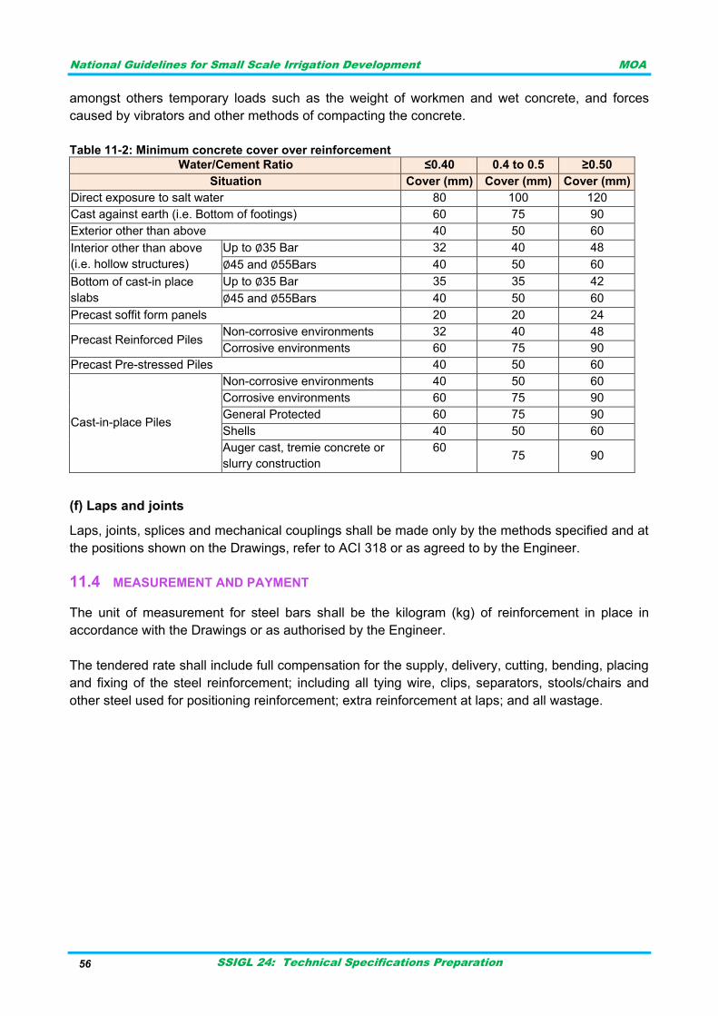
National Guidelines for Small Scale Irrigation Development MOA
SSIGL 24: Technical Specifications Preparation 56
amongst others temporary loads such as the weight of workmen and wet concrete, and forces
caused by vibrators and other methods of compacting the concrete.
Table 11-2: Minimum concrete cover over reinforcement
Water/Cement Ratio ≤0.40 0.4 to 0.5 ≥0.50
Situation Cover (mm) Cover (mm) Cover (mm)
Direct exposure to salt water 80 100 120
Cast against earth (i.e. Bottom of footings) 60 75 90
Exterior other than above 40 50 60
Interior other than above
(i.e. hollow structures)
Up to ∅35 Bar 32 40 48
∅45 and ∅55Bars 40 50 60
Bottom of cast-in place
slabs
Up to ∅35 Bar 35 35 42
∅45 and ∅55Bars 40 50 60
Precast soffit form panels 20 20 24
Precast Reinforced Piles Non-corrosive environments 32 40 48
Corrosive environments 60 75 90
Precast Pre-stressed Piles 40 50 60
Cast-in-place Piles
Non-corrosive environments 40 50 60
Corrosive environments 60 75 90
General Protected 60 75 90
Shells 40 50 60
Auger cast, tremie concrete or
slurry construction
60
75 90
(f) Laps and joints
Laps, joints, splices and mechanical couplings shall be made only by the methods specified and at
the positions shown on the Drawings, refer to ACI 318 or as agreed to by the Engineer.
MEASUREMENT AND PAYMENT 11.4
The unit of measurement for steel bars shall be the kilogram (kg) of reinforcement in place in
accordance with the Drawings or as authorised by the Engineer.
The tendered rate shall include full compensation for the supply, delivery, cutting, bending, placing
and fixing of the steel reinforcement; including all tying wire, clips, separators, stools/chairs and
other steel used for positioning reinforcement; extra reinforcement at laps; and all wastage.

National Guidelines for Small Scale Irrigation Development MOA
SSIGL 24: Technical Specifications Preparation 57
HARD CORE 12
Hardcore shall consist of broken rock, concrete or other approved hard material, clean and free
from extraneous matter. It shall be spread and leveled, watered and compacted, and then
blinded with a layer of fine material of grading 3mm to dust, watered and compacted all to the
Supervisor's approval.
Hardcore stone shall be place over soil to form foundation of the main structure. It is usually 20cm
to 25cm thick.
Stone for hard coring shall be obtained from an approved source. It shall be clean, hard, durable,
sound and free from impurities or decomposed rock. Stones shall be set in position with their
natural beds as near as possible to the horizontal. The commonly depth of hard coring is 20cm.
Measurement of hard core is in m2.
Bottom concrete work (if any) can be executed mix proportion for plain concrete of material as
recommended and stated in the specification. The commonly depth of bottom concrete work is
10cm. Measurement of bottom concrete work is in m3.

National Guidelines for Small Scale Irrigation Development MOA
SSIGL 24: Technical Specifications Preparation 58

National Guidelines for Small Scale Irrigation Development MOA
SSIGL 24: Technical Specifications Preparation 59
GABIONSTRUCTURES 13
SCOPE 13.1
This section covers the construction of gabion structures.
MATERIALS REQUIREMENT AND METHOD OF CONSTRUCTION 13.2
Construction materials for gabion walls and mattresses used in aprons for retaining walls, lining of
channels, revetments, and other anti-erosion structures in accordance with the Drawings or as
ordered by the Engineer are as discussed here under but not limited to:
Rock: stones or rock for filling gabions shall be clean, hard, sound, durable and un-weathered
boulders or rock fragments. It can be obtained from sources located by the Contractor and
approved by the Engineer.
No rock particles shall exceed the maximum size given in table below and at least 85% of the
rocks shall have a size equal to or above minimum size given in the table.
Table 13-1: Rock size
Depth of cage (mm) Minimum (mm) Maximum (mm)
0.2 75* or 95** 125
0.3 100 200
0.5 100 250
1.0 100 300
*Using 60 x 80 mm mesh
**Using 80 x 100 mm mesh
Source: ERA Standard Technical Specifications and Method of Measurement for Roadwork, 2013
Wire: All wire used in the fabrication of the gabions and in the wire operations during construction
shall be to ASTM A 910, Grade # 1010 or 1015, having a tensile strength of not less than 350
MPa. Cold drawn steel wire fabric shall meet the requirements of AASHTO M-55.
Galvanizing: All wire used in the fabrication of gabions shall be galvanized in accordance with the
provisions of ASTM A 641 with Class 3 coating or aluminized with a coating weight as per ASTM A
809 for Class A heavy galvanized mild steel wire. The minimum mass of the zinc- coating shall be
according to the figures shown in Table below.
Table 13-2: Coating of wire
Nominal diameter of coated wire (mm) Mass of coating (g/m2 surface area)
3.7-4.0 290
3.0-3.6 275
2.2-2.9 260
below 2.2 245
Source: ERA Standard Technical Specifications and Method of Measurement for Roadwork, 2013
The adhesion of the zinc coating to the wire shall be such that when the wire is wrapped six turns
round a mandrel of four times the diameter of the wire, it shall not flake or crack to such an extent
that any zinc can be removed by rubbing with bare fingers.

National Guidelines for Small Scale Irrigation Development MOA
SSIGL 24: Technical Specifications Preparation 60
Wire Mesh and Clip Fasteners: Wire mesh shall be hexagonal-woven mesh wherein the joints
are formed by twisting each pair of wires through three half turns. The tightness of the twisted
joints shall be such that a force of not less than 1.7 kN is required when pulling on one wire in
order to separate it from the other wire provided each wire is prevented from turning; and the
applied forces and the wire are all kept in the same plane. The diameter of the wire and the size of
mesh used shall be as shown in Table below.
Table 13-3: Mesh size
Depth of gabion (m) Mesh size (mm) Wire diameter (mm)
0.5 and over 80x100 2.5
100x120 2.7
0.2 -0.3 80x100 2.2
60x80 2.0
Source: ERA Standard Technical Specifications and Method of Measurement for Roadwork, 2013.
The shorter dimensions of the mesh shall be taken from centre to centre of the twisted joints, and
the larger dimensions shall be between the inside ends of twisted joints.
Alternatively; wire used in the body of the mesh shall not be thinner than 11-gauge for galvanized
baskets and 12-gauge for PVC coated baskets. Selvage wire shall not be less than 10 gauges,
and lacing and tie wire shall not be thinner than 13-gauge.Clip fasteners shall be galvanized
and/or PVC coated as required and may be of any type that provides positive lock when installed.
They shall be stronger than the mesh to which they are attached.
Galvanizing on the steel clips shall be in accordance with ASTM A 641 with a Class 3 coating, and
aluminizing shall be in accordance with ASTM A 809.
Gabions using PVC coated wire: When gabions using PVC coated wire is specified, the wire
used for the gabion mesh, and for wiring the gabions during construction shall be galvanized wire
as specified in Clause 9102(b) onto which is extruded a polyvinylchloride (PVC) coating. The
average thickness of the PVC coating shall be as specified, either 0.30 mm for use in mildly
corrosive conditions or 0.55 mm for use in marine and other severely corrosive or abrasive
conditions. The minimum thickness of the coatings shall be 0.25 mm and 0.4 mm respectively, and
the coatings shall be capable of resisting the deleterious effects of natural weather and salt-water
exposure. The PVC coated gabions shall be of a proven brand and the brand shall be subject to
the Engineer's approval.
GeotextiIe filter fabric: Where indicated on the Drawings or ordered by the Engineer, one layer of
approved geotextiIe material shall be placed on the prepared surface prior to the placing of
gabions. The material shall be placed as directed in vertical strips with a minimum overlap of 300
mm, and shall be properly fastened to prevent any movement or slipping during the placing of
gabions.
MEASUREMENT AND PAYMENT 13.3
The unit of measurement for gabion structure shall be the cubic meter (m3) of completed work in
accordance with the Drawings or as authorised by the Engineer.

National Guidelines for Small Scale Irrigation Development MOA
SSIGL 24: Technical Specifications Preparation 61
RIPRAP 14
GENERAL 14.1
Riprap shall consist of a course(s) of large rock placed on bank slopes and toes; river and
streambeds; and other localities where protection of this type may be required.
MATERIALS 14.2
Stone for riprap shall be hard field or quarry stone not susceptible to disintegration or excessive
weathering on exposure to the atmosphere or water. It shall be free from soft material such as
sand, clay, shale or organic material and shall not contain an excessive amount of elongated or
flakey stone.
The required size of stone shall be determined by the "critical mass" specified. At least 50% by
mass of the material comprising the riprap shall consist of stones having a mass heavier than the
critical mass and not more than 10% by mass of the material shall consist of stone having a mass
of less than 10% of the critical mass or more than 5 times the critical mass. The grading
requirements for riprap are shown in Table 1.
Table 14-1: Gradation requirements for riprap
Class Mean Diameter
(D50)
Critical
Mass (Kg)
Rock By
Mass (%) Mass (Kg)
Approximate Cubic
Dimension (mm)
1 125 5
20 10 – 15 150 – 200
30 5 – 10 125 – 150
40 0.5 – 5 50 – 125
10 0 – 0.5 0 – 50
2 175 10
20 25 – 50 200 – 250
30 10 – 25 150 – 200
40 1 – 10 75 – 150
10 0 – 1 0 – 75
3 300 50
20 100 – 150 350 – 400
30 50 – 100 250 – 350
40 5 – 50 125 – 250
10 0 – 5 0 – 125
4 400 100
20 250 – 350 450 – 500
30 100 – 250 350 – 450
40 10 – 100 150 – 350
10 0 – 10 0 – 150
5 500 350
20 700 – 1000 650 – 700
30 350 – 700 500 – 650
40 25 – 350 200 – 500
10 0 – 25 0 – 200
6 600 500
20
30
40
10
850 – 1600 700 – 850
500 – 850 550 – 700
50 – 500 250 – 550
0 – 50 0 – 250

National Guidelines for Small Scale Irrigation Development MOA
SSIGL 24: Technical Specifications Preparation 62
Two types of riprap are specified:
Packed riprap: where the rocks are individually packed;
Dumped riprap: where the stone is dumped and then spread by machines.
The surface of the areas to receive riprap shall be neatly trimmed to line and level and all loose
material compacted. The perimeters of riprap shall be protected by the construction of either rock-
filled trenches, walls, or other structures as may be required .Perimeter trenches shall normally be
backfilled with rock of the same size and quality as used in the construction of the riprap it adjoins.
Any cavities shall be filled with smaller material and the whole backfill shall be well consolidated.
(a) Filter BED
The filter bed shall consist of a layer(s) of permeable material placed on the prepared surface to
the required thickness and finished to an even surface and thickness after placing each layer.
Compaction of previous material will not be required. Care shall be taken neither to mix various
grades of filter materials nor to disturb material already placed when constructing subsequent
layers or riprap.
When the use of synthetic fiber filter fabric is required the material shall be placed on the prepared
surface, or on the filter backing as may be required. The overlap between adjacent sheets shall be
150mm unless otherwise specified. Care shall be taken not to damage the filter fabric when
placing subsequent layers; nor to expose the filter fabric when placing subsequent layers; nor to
expose the filter fabric to the sun for periods of more than a day before covering.
(b) Packed riprap
Packed riprap shall be constructed from rocks individually placed to break joints and firmly bedded
on the prepared surface. The spaces between larger stones shall be filled with spall and smaller
stones securely rammed into place. On inclined surfaces the rock shall be laid in long horizontal
lengths starting from the bottom and not in strips up the slope. The completed riprap shall present
an even, tight surface. Local surface irregularities of the riprap shall not exceed 150mm.
(c) Dumped riprap
Dumped riprap shall be constructed by dumping the stone on the prepared surfaces, spreading it
with a bulldozer, or other suitable earthmoving equipment, and trimming to the required lines and
levels. The material shall be placed in a manner that shall prevent segregation of the small and
larger stones. The final layer shall be tight with a minimum of voids.
MEASUREMENT AND PAYMENT 14.3
The unit of measurement shall be the cubic meter of riprap in place including rock in trench
backfill.
The rates tendered shall include full compensation for the preparation of surfaces, including
excavations,(but excluding excavations for trenches and bulk excavations), and for the furnishing,
transporting, handling, and placing of riprap.
Collectively the rates shall also include full compensation for all other incidentals necessary for
completing the work as specified.

National Guidelines for Small Scale Irrigation Development MOA
SSIGL 24: Technical Specifications Preparation 63
PUMP AND PUMP ACESSARIES 15
PUMP UNITS 15.1
The term “pumping unit” used hereinafter is deemed to mean a complete pump with all relevant
equipment complying with the General and Particular technical specification that includes electric
motor, connecting shafting, bearings, couplings, impellers, seals, accessories, base plate,
appurtenances and all associated equipment. All external electrical connections shall be part of
the unit and all required electrical equipment for the pumping units shall be furnished and installed
by the Contractor.
Manufacturer`s eligibility & qualifications 15.1.1
The supplier shall note that standards for workmanship, material and equipment, and references to
brand names or catalogue numbers designated by the clients Technical specifications are
intended to be descriptive only and not restrictive. The supplier may substitute alternative
standards, brand names and/or catalogue numbers in its offer, provided that it demonstrates to the
client‟s satisfaction that the substitutions are substantially equivalent or superior to those
designated in the Technical Specifications.
All pumping units shall be of approved design by standard organization make and product of
manufacturers who have manufactured and built equipment of similar type, size and capacity for at
least ten years, and who have sufficient time proven and test data to cover the design of the
equipment specified.
Upon request, the Contractor shall submit a list of references of the proposed manufacturer‟s
pumping equipment, including at least installations of design, capacity and service similar to the
equipment proposed to be furnished, which installations shall have been in successful operation.
All pumping units shall be designed and built for twenty-four (24) hours per day continuous service
at any and all points within the specified range of operation, without over-heating, cavitation,
excessive vibration or strain, and requiring only the degree of maintenance generally accepted as
normal for the specific type of pump required.
The Supplier shall submit full details of the proposed Manufacturer‟s ability to promptly fill
replacement orders as well as about his authorized representatives in Ethiopia for supplying spare
parts and for maintenance of pumping equipment.
The pump Manufacturer must possess or have readily available access to suitable testing facilities
adequate for performing the shop test required and here in after specified. The Contractor shall
submit a description of the proposed manufacturer‟s testing facilities, including hydraulic,
mechanical, electrical and periodical calibration provisions for all instruments. The documentary
evidence of the goods and services conformity to the bidding documents shall be in the form of
original manufacturer‟s brochure, literature, drawings and data to be furnished.
Failure to successfully comply with the preceding requirements will constitute grounds for
disqualification of the Pump Manufacturer and Contractor as well
National Guidelines for Small Scale Irrigation Development MOA
SSIGL 24: Technical Specifications Preparation 64
Poor performance of similar pumping equipment now in operation under the specified conditions of
service rating will constitute grounds for disqualification of the Pump Manufacturer unless such
poor performance has been corrected.
All information specially required by the above terms shall be submitted by the Contractor with his
Bid. Any additional information that may be required shall be submitted by the Contractor within
fourteen (14) calendar days of the issue of a written request thereof, unless otherwise specified.
Specific information to be submitted for Approval 15.1.2
(i) Characteristic curves:-
For each pump type and model (or pumping unit where overall efficiency is specified) the following
curves shall be provided for the acceptable flow range.
(a) Total Head (in meter) Vs Discharge (l/s, m3/horl/min)
(b) Pump Efficiency (in %) Vs Discharge (l/s)
(c) Power Vs Discharge (l/s)
(d) N.P.S.H. (meter) Vs Discharge (l/s)
For the pump specified, the Supplier shall first submit for approval their characteristic curves.
These shall be plotted on at least A4 graph paper. The curves shall regard the pump as a whole
(not per stage).
(ii) Drawings
The following drawings shall be submitted by the Contractor:
(a) Detailed workshop drawings necessary for final design of the structure, connected
piping and valves, pump drip and venting pipes, electrical connections, protective and
auxiliary equipment.
(b) Drawings of pump foundations, motor supports, bearing supports and foundation frames
(if recommended) presenting location, size and full details of foundation bolts. Weights
and forces on foundations shall be clearly shown on such drawings, so that the
structural design may be checked. Such forces shall be the maximum possible under
any conditions.
(c) Dimensioned assembly outline drawings of the complete pump, drive and all associated equipment, presenting plan, elevation and any other views or sections required, including scaled cross-section of the assembled pump, showing full details and materials.
Submersible borehole pumps 15.1.3
The pump and the motor shall be delivered as a single pumping unit completely assembled.
Submersible borehole pumps shall be of radial or mixed flow type, multi-stage units depending on
the specification suspended from surface plates by vertical discharge Riser pipes and driven by
submersible, water filled electric motors. The speed of these pump motors shall be no more than
2,900rpm at 50Hz

National Guidelines for Small Scale Irrigation Development MOA
SSIGL 24: Technical Specifications Preparation 65
The materials and the pump construction will be suitable for the groundwater quality characterized
mainly by:
sand content up to 50 g/m3
low pH, minimum 5
high CO2 content up to 100 g/1
The pump body shall be stainless steel for submersible pumps. The body shall be capable of
withstanding a hydraulic pressure, equal at least tones and a half (1.5) times the closed valve
head.
Bearings shall be positively retained within the pump body to prevent the possibility of the bearing
rotating; a press fit alone shall not be acceptable.
The pump shall be fitted with a suction case of a material suitable for the liquid being pumped and
shall be provided with long bearings to stabilize the shaft and motor shaft and to avoid radial thrust
on the motor bearing. A screen shall be incorporated having a minimum open area of four (4)
times the eye of the impeller.
The submersible motor shall be of the water filled, enclosed type suitable for continuous duty.
Motor performance shall be in accordance with the relevant section of IEC60034.
An expansion chamber or diaphragm shall be provided to relieve thermal expansion of the internal
motor fluid due to temperature, and shall provide motor internal and external pressure balance
under all conditions of temperature and pressure.
The bearings shall be water lubricated. The motor thrust bearing shall be capable of carrying the
thrust load corresponding to maximum head, operating with rotation in either direction.
The pump cable (in a length equal to pump installation depth +30 or 25m depend on the pump
house distance from boreholes) will be also a part of the delivery.
The borehole pump column (rising pipe) including discharge elbow shall be supplied and installed
together with the pump. It shall comprise a number of sections at the option of the Suppliers that
the total length may be adjusted by plus or minus 2m.
The well Head-plate shall be of a design which will ensure a water tight capping of the well and
shall be rigid and strong enough to support the en tire weight of the suspended parts when filled
with water. The plate shall provide suitable openings for all cables, well vent and water level
indicator/transmitter. There shall be provision to allow a manual to be used to confirm the water
level within the well.
The head-plate shall be fitted directly on to the upper portion of the inner casing by means of a
bolted flange.
The discharge connection (elbow) shall be flanged, at a diameter similar to the rising pipe, and
with a pressure rating consistent with the maximum surface pressure that can be delivered by the
pump.

National Guidelines for Small Scale Irrigation Development MOA
SSIGL 24: Technical Specifications Preparation 66
The discharge elbow shall be equipped with a discharge pressure gauge.
Surface centrifugal pumps 15.1.4
The pumps shall be provided with suction baskets or strainers, in order to prevent the ingress of
impurities from the suction sump. In addition, negative suction head pumps shall be provided with
foot valve. The strainer shall be constructed entirely of stainless steel and shall have an inlet area
equal to at least four (4) times the impeller inlet area.
The pump and the motor shall be mounted on a common rigid, reinforced steel base plate, and
directly coupled by means of a flexible spacer type coupling. The coupling and any other exposed
rotating parts shall be protected by appropriate guards. Priming funnels (if needed) shall be fitted
on each pump for priming. The pump design will include a hydraulic balance system. The pump
sealing shall be by means of a packed gland.
Lubrication arrangements shall be so designed that there shall be no contamination of the pumped
fluid.
The pumps and associated pipe work shall be, wherever possible, arranged so that air can be
completely expelled during priming. Where this is not possible, facilities shall be provided for the
removal of trapped air. Adequate facilities shall be provided for drainage of the pumps for
inspection purposes.
Accessories and instrumentation 15.1.5
(i) Air relief valves
Each pump shall be provided with air relief valve on the discharge pipe (if not otherwise specified).
The air relief valve shall be of the “aero-kinetic” double orifice type, allowing the air to flow out and
into the pipeline.
The air relief valves shall be mounted using isolating valves. The diameter of the air relief valve
and its isolation valve shall be sufficient to exhaust air during pump start-up and all other normal
operating conditions.
The air relief valve and its isolating valve shall be rated to at least one and a half (1.5) times the
shut- off pressure of the pumps.
(ii) Manometers (pressure gauges)
Pressure gauges shall be installed on both inlet and outlet pipes of any surface pump (new or
overhauled) and on the discharge of any borehole pump (new or overhauled). The manometers
shall be of Bourdon elastic tube type, directly activated by the flowing water (unsheathed).
The manometers shall be of “outdoor” protection class. They shall be mounted using
ascrewed½"3- way cock in order to ensure its drainage and isolation.
The manometers shall be of heavy duty type, anti-vibration, with at least a 100mm dial. The
pressure range shall be approximately 133% of the shut-off pressure of the pump.

National Guidelines for Small Scale Irrigation Development MOA
SSIGL 24: Technical Specifications Preparation 67
(iii) Flow Meters (water meters)
The flow meters shall be of “propeller” or “turbine” type, provided with totaliser, calibrated in metric
units. The indicator-totaliser shall be mounted in an easy readable position. The nominal pressure
rating of the flow meter shall take into account the shut-off pressure of the pump.
(iv) Valves and non-return valves
The valves shall be flanged. The non-return valves shall be flanged, swing type, without lever arm.
They shall be of cast steel, cast iron or bronze made. All the components shall be suitably
protected against corrosion. The rating shall take into consideration the shut-off pressure of the
pump.
(v) Pressure switch
Pressure switches shall have over range protection upto1.5 times the maximum anticipated line
pressure.
Internal parts shall be of stainless steel, bronze or other corrosion resistant material.
All pressure switches shall be supplied complete with isolating valves and calibration points to
enable calibration or removal without loss of fluid.
Pressure and differential pressure switches shall have contacts with separate „cut in‟ and„ cut out‟
pressure values.
The nominal pressure values at which pressure switches operate shall be fully adjustable over the
whole range of the instrument and the set value(s) shall be clearly indicated by means of a scale
and pointer.
Tests 15.1.6
(i) Factory tests
Each pumping unit shall be tested individually on the Manufacturer‟s premises in full accordance
with BSENISO9906 Grade2.
The pumps shall be tested complete, with all the bearings and directly driven auxiliaries, or, where
this is impracticable, the Contractor shall state the allowances to be made for losses incurred by
these items and shall demonstrate the accuracy of these allowances. The test of each pump shall
be carried out with its own motor.
Such tests shall show that the pump has the general characteristics of head, efficiency, power,
NPSH, and such other properties as they appear on the approved curves submitted. Such tests
shall also establish that the pump is free from overheating, cavitations, and that vibration is within
the specified tolerance over the specified range.
The pump shall be tested over the full working range, from closed valve condition to maximum
discharge point. Readings shall be taken at a minimum of five points, including one point within ±2
percent of the design duty point.

National Guidelines for Small Scale Irrigation Development MOA
SSIGL 24: Technical Specifications Preparation 68
Head/flow rate curve, pump efficiency/flow rate curve, power/flow rate curve and NPSH/flow rate
curve shall be drawn for each pump. For the production of these curves, the values of motor
efficiencies obtained during the motor tests may be used. The curves produced shall be used to
demonstrate that the pump shall be capable to meet the full range of operating conditions on site.
Pump casing shall be subject to a pressure test one and a half (1.5) times the maximum pressure
with the delivery valve closed. The positive suction head shall be taken into account in deciding
this pressure.
A relevant certificate shall be produced for each test, showing the readings obtained performance
calculations, the final results and full details of all instruments used, including serial number and
details of the calibration certificates.
(ii) Site tests after installation
Site test shall be carried out. The tests will be witnessed by Contracting Authority‟s, Supervisor‟s
and Contractor‟s representatives.
ELECTRICITY SUPPLY 15.2
The Contractor shall arrange for EEPCO (Inspectorate Division) to undertake any testing
and inspection necessary for the electricity supplies to be connected when required. On
completion of the tests and inspections, and not less than two (2) weeks prior to the power supply
being required, the Contractor shall submit to the Supervisor a copy of his Electrical Installation
Completion Certificate and of the EEPCO test certificates.
STANDBY GENERATING SETS 15.3
All equipment shall be supplied and delivered, designed, construction assembled and equipped in
accordance with the operating conditions specified.
General 15.3.1
The diesel generating sets shall consist of diesel engines and alternators mounted together on
common base plates. It shall be rated for continuous duty of twenty four (24) hours per day, for
operation under the climatic conditions and altitude as specified, and shall be rated at speed of
1,500rpm. The generating set shall be capable to deliver continuously 110% of its rated output for one hour in
every twelve (12) hours, without any part impaired.
Engine 15.3.2
Engine shall be industrial and designed for standby power rating 4 strokes, direct injection; natural
aspiration, water cooling with mechanical radiator and pusher air fan or air cooled; electric starting
with batteries and battery charger, oil filter, air filter, fuel filter, injection pump with mechanical rpm
governor, aspiration by means of feeding pump, alarm senders for low oil pressure and high
engine temperature.

National Guidelines for Small Scale Irrigation Development MOA
SSIGL 24: Technical Specifications Preparation 69
Cooling system (water cooled or air cooled) 15.3.3
(i) Water cooled
The engine shall be complete with a tropical capacity radiator for cooling the machine in tropical
ambient temperature, with an engine driven blower type heavy-duty cooling fan. The cooling
system shall be of the forced circulation type with engine mounted gear type coolant pump.
The closed circulating system shall include a direct acting thermostatic valve for automatically
controlling the engine temperature and for by passing the radiator for quick warm up. A block
heater shall be provided to keep the coolant/water mix at adequate temperature for easier starting
of the stand by diesel generator. The cooling system shall be of sufficient capacity to permit
continuous full load operation of the engine without boiling of the coolant at atmospheric air
temperatureofupto500C.
The radiator cooling air shall be exhausted to the atmosphere via a louvered opening and a
bellows connection to the radiator. A further louvered opening shall be providing to supply cooling
and charge air.
(ii) Air cooled
If air cooled the air blower capacity and the cooling fin arrangement shall be sufficient to permit
continuous full load operation of the engine without overheating the engine at atmospheric air
temperature of 500C. The velocity of cooling air should be sufficiently high to prevent formation of
dust deposits which could impair the cooling efficiency. The fins shall have adequate area for
prompt and efficient cooling.
Lubrication system 15.3.4
The lubrication system shall be powered by a mechanically driven gear type positive displacement
pump of sufficient capacity to operate at the specified ambient air temperature and altitude.
The system shall be equipped with suitable oil pump, dual centrifugal and replaceable full flow-
filters and suitably arranged oil passages in the cylinder block.
Full details regarding the type, capacity, pump and filters of the lubrication system shall be
submitted with the bid.
Fuel system 15.3.5
The fuel system shall ensure a continuous and clean supply of fuel. The engine shall be capable of
operating with fuels complying with clause A, B1 and B2 of BS2869. The fuel system shall have
primary fuel/water separator and filters of the fine wire mesh type.
A day tank complete with level indicator having capacity to provide minimum 12 hours running at
full load shall be provided with an automatic fuel transfer pump and emergency hand pump to fill
daily service tank from main storage tank. Fuel lines shall be black iron pipe, steel or copper to
avoid fuel contamination. The fuel system shall be located on the generator or bed plate and fully
within any acoustic or weather enclosure.

National Guidelines for Small Scale Irrigation Development MOA
SSIGL 24: Technical Specifications Preparation 70
The system shall incorporate easily accessible, interchangeable and readily removable injectors
and filters of adequate capacity.
The main storage fuel tank shall be fitted with a level indicator and filling, vent and drain
connections. It shall be installed with a sloping base with the drain at the lowest point to allow the
draining of accumulated water. The main tank shall also be fitted with an inspection hatch and
shall be located so as not to be affected by heat from the engine, exhaust pipe, or muffler.
Completespecificationdatarelatingtothedieselenginefuelsystemshallbesubmittedby Contractor.
Power rating 15.3.6
The power ratings are in accordance with the provisions of standard compatible (with BS, DIN or
ISO). The power rating of the engine is the active power expressed in KW available at the
terminals of the generating set at nominal voltage and frequency and under stationary applications
of ambient temperature ambient pressure and relative humidity.
Certified engine data showing, at least, net power, (continuous, intermittent and maximum) torque
performance curves, specific fuel consumption curve at specified site altitude above sea level shall
be submitted with the bid.
Cyclic irregularity of the engine/alternator combination shall not exceed that specified in
BSISO3046.
Electrical system 15.3.7
The engine shall be provided with a complete electrical charging, starting, electrical switch,
preheating switch and at least two keys.
The generator or alternator shall be the manufacturer‟s standard production model and shall be
adequate to provide service under normal operating conditions.
The generator shall be rated to ensure that it is possible to start any likely motor combination
under maximum load conditions. This requirement must be strictly observed and the successful
starting warranted.
The alternators shall be effectively cooled by open forced air ventilation. The ventilation openings
shall be screened against ingress of small insects and rodents.
Alternator bearings shall preferably be of the cartridge type, preventing contamination by dirt or
moisture when the alternator is dismantled. The bearings shall be grease lubricated. Easily
accessible nipples for re-greasing shall be provided.
All control panels shall be complete with a mains powered battery charger and battery. In the case
of an electric starting generator the battery shall be the starting battery and shall be rated
accordingly.

National Guidelines for Small Scale Irrigation Development MOA
SSIGL 24: Technical Specifications Preparation 71
The Control panel shall be a single integrated unit, mounted on the generator bed plate and shall
include provision for all generator services and power switching including such items as the fuel
transfer pump.
Exhaust systems for diesel engines 15.3.8
For permanent installations system shall be suspended from the walls and roof by suitable
brackets
andangletieswhichshallincludemountingstopreventthetransmissionofvibrationandnoisetothe
building.
The system shall be adequately lagged and fixed within the building. Where the roof is of
combustible material and the walls of the building are of incombustible material, the exhaust shall
be routed to atmosphere through the wall rather than the roof. Where both the walls and roof are
of combustible material, special care shall be taken to protect the building from the exhaust piping
and the hot gases discharged from it.
The exhaust system outlet section shall be horizontal and where possible it shall point in the
direction of the prevailing wind.
The exhaust system shall be adequately guarded and/or lagged to prevent accident al contact with
hop parts.
Enclosure 15.3.9
Unless otherwise specified the generator shall be supplied with an acoustic and weather
proof enclosure to suit the climatic conditions at the site.
Technical documentation 15.3.10
A manual shall be handed over prior to commissioning of the works .It will include a description,
installation and operation instructions, maintenance instructions with trouble-shooting (faultfinding)
details, drawings with identification numbers of parts, and parts identification list.
The manual shall cover the entire works provided or refurbished under the contract.

National Guidelines for Small Scale Irrigation Development MOA
SSIGL 24: Technical Specifications Preparation 72

National Guidelines for Small Scale Irrigation Development MOA
SSIGL 24: Technical Specifications Preparation 73
PIPE WORK 16
GENERAL 16.1
All pipe materials and fittings used shall conform, as a minimum, to the specifications contained in
this section. Should the contractor desire to use other materials not listed in these specifications,
written permission must be obtained from the Owner‟s Engineer. Specific types of pipe shall be
specified in the Schedule of Bid Items and/or the Special Provisions.
All material shall be free from defects impairing strength and durability and be of the best
commercial quality for the purposes specified. It shall have structural properties sufficient to safely
sustain or withstand strains and stresses to which it is normally subjected and be true to detail.
Pipes, fittings and valves shall be of the diameter and class of material as specified or shown on
the Drawings and their joints shall be completely watertight. All pipes, valves and pipe fittings shall
conform to the relevant standards. The Contractor shall if required forward to the Engineer
certificates showing that the materials have been tested and comply with the requirements of this
Specification and the relevant Standard.
Where the Contractor wishes to use a type of pipe not manufactured in the minimum internal
diameter indicated in the Contract, he may substitute the next larger diameter manufactured
subject to full compliance with the design requirements, clearance and cover.
The Contractor shall not use pipes and fittings supplied by more than one manufacturer, for each
material specified, without approval in writing by the Engineer. The manufacture of pipes, pipe
fittings and accessories shall be open to inspection by the Engineer at the manufacturer's works.
Pipes shall be ordered in the maximum lengths available to minimize the number of joints. The
Contractor shall be responsible for the supply of all materials in sufficient quantities and shall
ascertain the required quantities immediately prior to placing any order, especially for imported
goods.
MATERIALS OF PIPES 16.2
Steel pipes and fittings 16.2.1
Steel pipes shall be of the diameter and thickness as shown on the Drawings and shall comply
with BS3601.Steel pipes and fittings shall be coated both internally and externally with at least two
(2) layers of bitumen to BS3416 type 1, Class A. Unless otherwise specified steel pipes shall be
jointed by double flange joints or approved equivalent joints, and joints to fittings, structures, etc.
shall be flanged with PN16 flanges complying to BS4504.
Pipes for cutting shall be clearly identifiable. They shall be supplied rounded throughout their
length, and shall be used only as directed.
The Flanged Steel Pipe shall conform to the ASA Specification B16.l, Class 125 and Gaskets shall
be one-sixteenth inch thick ring gaskets of red sheet rubber.

National Guidelines for Small Scale Irrigation Development MOA
SSIGL 24: Technical Specifications Preparation 74
Unplasticized PVC (UPVC) pipes and fittings 16.2.2
Unplasticized PVC pipes and fittings for main distribution line shall comply with the relevant
provisions of EN 1452-1 and EN 1452-2 or equivalent. The pipe shall be legibly marked with the
following information: manufacturer's name or trade mark, Number of the system standard (EN
1452), material (PVC-U), Nominal outside diameter (dn x wall thickness en), Nominal pressure PN,
Manufacturer‟s information, and Number of the extrusion line. The marking shall conform to ENV
1452-6.
Unless otherwise specified joints for U-PVC pipes and fittings shall be flexible spigot and socket
joints in accordance to EN 1452-3:1999.
HDPE pipes and fittings 16.2.3
The High Density Polyethylene (HDPE) Pipe shall be made from base polymer and shall conform
to the requirements as specified in MS 1058 Part 1:2002.
HANDLING OF PIPES 16.3
The Contractor shall be responsible for the safe handling of all pipes, valves and pipe fittings.
When loading, unloading, or otherwise handling, the greatest care shall be taken to avoid shocks
likely to cause cracking, chipping or any other damage to pipes, valves or fittings or to their
coatings.
All pipes and fittings too heavy to be carried by hand shall be loaded and off-loaded only by means
of a crane or any other approved lifting and handling device, with slings or hooks suitably padded.
In this case recesses shall be dug beneath the invert to permit the slings or ropes to be properly
withdrawn.
Particular care shall be taken to ensure that sheeting and lining are intact before jointing pipes and
fittings. No pipes shall be rolled into place for lowering.
Before any piping is lowered into the trench, it shall be cleaned and examined for cracks, flaws etc.
whilst hanging in the sling, and to see that no earth or foreign matter is within the pipe barrel or
coupling. No protective cap, or disc or other appliance shall be removed permanently until the pipe
or fitting that it protects is about to be jointed.
Suitable measures shall be taken to prevent flotation or other movement before the works is
complete.
INSTALLATION OF PIPELINES 16.4
Trench excavation 16.4.1
The excavation of trenches for pipelines shall at any one time be limited to lengths previously
approved by the Engineer in writing. Except with the written approval of the Engineer, work on
each approved length shall be completed to the satisfaction of the Engineer before work on any
new length is commenced. Before commencing, the alignment of the pipeline shall be pegged out
and approved.

National Guidelines for Small Scale Irrigation Development MOA
SSIGL 24: Technical Specifications Preparation 75
Trenches for pipelines and cables, unless specified otherwise, shall be restricted, up to a level
300mm above the crown of the pipe
The Contractor shall provide and maintain an adequate support system for upholding the ground
actually encountered and the safety of adjacent structures, buildings, or utilities shall not be
affected.
Foundation and bedding 16.4.2
Unless specified otherwise, pipelines shall be laid in trenches excavated in the ground. Unless
unsuitable soil is encountered, trenches shall be excavated to the specified depth below the barrel
of the pipe.
Granular bedding of sand for pipes shall be placed by spreading and compacting granular bedding
material over the complete width of the pipe trench. Where pipes are jointed, bell holes of ample
dimensions shall be formed in the bedding to ensure that each pipe is uniformly supported
throughout the length of its barrel and to enable the joint to be made and inspected during testing.
After pipe laying additional material shall be placed and compacted by hand rammer in 150mm
layers equally on each side of the pipe as side support for the pipe.
Where pipes are laid on granular beds in ground with high groundwater level, puddled clay shall
be constructed at 25m intervals at the midpoint of an individual pipe. The puddled clay shall be
0.5m long and shall be recessed 300mm into the sides and base of the trench, and shall extend by
a minimum of 150mm above the top level of the granular material.
Installation 16.4.3
Installation of pipelines includes the supply, laying and jointing of pipes and fittings, construction of
beddings and foundations, manholes and other structures in the line, testing, and backfilling of
trenches, surface restoration and commissioning.
Installation of pipelines shall in principle follow the recommendations of EN 1452-6 or BS 8010
Code of Practice for Pipelines.
All plant, operation and haulage required from source of supply or store to bring the pipes, valves,
and other items to their place of stripping and laying, including any unloading into temporary
storage areas and any subsequent reloading for haulage to the place of laying shall be included in
the supply of pipes and fittings.
Jointing and cutting 16.4.4
All joints shall be flexible joints and comply with the relevant provisions of the appropriate British
Standard and shall be made to the manufacturer's recommendations and the Specifications
hereafter.
Flanged joints shall be properly aligned before any bolts are tightened. Gaskets for flanged joints
shall be of the inside-bolt-circle type. Jointing compounds shall not be used when making flanged
joints except that to facilitate the making of vertical joints. Gaskets may be secured temporarily to
one flange face by a minimum quantity of clear rubber solution. Bolt threads shall be threaded with

National Guidelines for Small Scale Irrigation Development MOA
SSIGL 24: Technical Specifications Preparation 76
graphite paste and the nuts shall be tightened evenly in diametrically opposed pairs. Nuts shall be
secured against loosening by vibration.
Rubber joint rings for water mains and drainage purposes shall be Types 1 and 2 respectively,
complying with the relevant provisions of BS 2494 and shall be obtained from the pipe
manufacturer. Joint lubricants for sliding joints and used for jointing water mains shall not impart to
water taste, color, or any effect known to be injurious to health, and shall be resistant to bacterial
growth and leaching.
Curves and bends 16.4.5
The pipes shall be laid in straight lines where possible. Curves of long radius shall be obtained by
deflection at the joints. The deflection of the joints for this purpose shall not be more than 50% of
the maximum deflection as specified by the pipe manufacturer for the relevant type of joint. Where
a required change of direction cannot be obtained by deflection of the joints, prefabricated bends
shall be used.
Concrete thrust blocks shall be provided where ordered by the Engineer, indicated on the
Drawings and at reducers, tee junctions, caps, etc. and curves or bends deflecting 11¼ degrees or
more. The type and size of thrust blocks shall be in accordance with the Drawings or as approved
by the Engineer. Concrete for thrust blocks shall be placed carefully against undisturbed earth or
rock and shall in no case give less than 150mm of cover to the pipe. When casting thrust blocks,
no couplings or joints shall be covered, and where timber shuttering has been used such timber
shall be removed before backfilling.
Protection 16.4.6
After excavation of the trench, placing and compacting the bedding, laying the pipe and concreting
the thrust blocks the pipe must be surrounded by fill or concrete.
The Contractor shall not cover up any pipe except U-PVC pipe until it has been inspected, tested
and approved. U-PVC may be covered to a depth of 150mm to reduce thermal movement if
immediate inspection and testing is not practicable.
Unless otherwise specified the pipe surround for concrete and U-PVC pipes shall be covered with
clay or concrete tiles of at least 40mm thickness and compression strength of 5N/mm².
The trench above the so finished pipe surround shall be filled with fill and shall be compacted flush
with ground level.
Where indicated on the Drawings, ordered by the Engineer and where pipes are surfacing or
having less than the required ground cover of 750mm and crossing roads serving vehicular traffic,
pipes shall be surrounded by concrete bedding of grade C-25.
Pipes to be surrounded by concrete shall be supported by precast concrete setting blocks not less
than 150mm deep covered with two layers of compressible packing of bitumen damp proof
sheeting complying with BS743. Concrete shall be placed on one side of the pipe and carefully
worked under the pipe without displacing the pipe. Then concrete shall be placed on both sides

National Guidelines for Small Scale Irrigation Development MOA
SSIGL 24: Technical Specifications Preparation 77
and on top of the pipe in one operation. The concrete cover shall at least be 150mm to the barrel
of the pipe.
Unless specified otherwise concrete shall not be reinforced and shall be interrupted over the full
section at intervals not exceeding 8.0 meters by compressible filler. The interruptions shall
coincide with the pipe joints.
Measurement and payment 16.4.7
The unit of measurement for pipe and fitting works shall be the meter (m) in place in accordance
with the Drawings or as authorised by the Engineer.
The tendered rate shall include full compensation for the supply, installation, testing and
commissioning.

National Guidelines for Small Scale Irrigation Development MOA
SSIGL 24: Technical Specifications Preparation 78

National Guidelines for Small Scale Irrigation Development MOA
SSIGL 24: Technical Specifications Preparation 79
ROAD NETWORKS 17
ACCESS ROADS 17.1
This will be expected to be cleared and grubbed by participation of communities of the project site.
Access road having 4m width 20cm root clearing, 25cm base selected material, and 5cm red ash
or 10cm compacted gravel surfacing will be constructed along the main canal to access the
headwork site and canal structures. These roads will be provided with Drainage Trench (ditch)
Excavation of same length but on the upstream of roads to prevent the roads and canals from
flood erosion. The same to road construction, trench excavation and drainage culverts will also be
done by the contractor/s as indicated on the drawing.
FARM ROADS 17.2
This work shall include the excavation of all types of earth material, backfilling, compaction,
forming embankments and slopes, etc., as is necessary for the completion of the Works. Thus the
nominated contractor/s will be supposed to construct all weather roads of which is 4m width 20cm
depth root clearing, spread & compaction of 25cm base selected material, and 5cm red ash or
10cm compacted gravel surfacing along secondary and/or tertiary canals to allow vehicles for
transportation of inputs and products and O&M purposes.
EXISTING PUBLIC ROADS 17.3
The Contractor shall ascertain for himself the practicability of using the existing public roads as
shown on the Drawings for access to the site.
The highways, roads and bridges have widely varying load limits, and the Contractor shall be
responsible for determining the load limits existing at the time and ensuring that his equipment
does not exceed such limits. Before moving any heavy construction traffic onto highways, roads
and bridges, the Contractor shall make suitable arrangements with the appropriate authorities and
obtain their approval for the passage of such traffic. Where the authorities require and specify any
special protection or strengthening to highways, roads or bridges, the Contractor shall submit to
the Project Manager his proposals for such work, after their approval by the authority concerned.
The Contractor shall be responsible for inspecting the existing tracks and shall make his own
assessment of the work necessary to bring them to the required standard for constructional traffic.
The Contractor shall take all reasonable precautions to ensure the safety of members of the public
using the access roads. The Contractor shall maintain access to properties adjacent to the tracks
at all times throughout the duration of the Contract.
The Contractor shall not drive tracked Equipment on any bituminous sealed road surface. Only
rubber tyre vehicles, conforming to applicable load restrictions, will be permitted to use bituminous
sealed roads.
PAYMENT 17.4
Payment for access and farm road will be made using the rate and unit of measurement shown in the
Priced Bill of Quantities forming the contract.

National Guidelines for Small Scale Irrigation Development MOA
SSIGL 24: Technical Specifications Preparation 80

National Guidelines for Small Scale Irrigation Development MOA
SSIGL 24: Technical Specifications Preparation 81
MISCELLANEOUS 18
SCOPE 18.1
This section covers furnishing and installing of structural drains, gates, steel pipe for intake
structure, valves, and other miscellaneous works connected with the structures.
STRUCTURE DRAINS 18.2
General 18.2.1
Under drainage and weep holes shall be provided for the main structure and canals along the side
walls of the chute as shown on the drawing. It shall also be provided under other canals and
structures as found necessary.
Materials 18.2.2
Pipes: Concrete pipes of the internal diameter sizes as specified on the drawings shall be used,
each piece shall be 30cms. Long with straight and shall be laid dry, pieces of pipe shall be laid
keeping 3 to 4mm space between the ends.
Material around the pipes: The material around the pipes shall consist of gravel clean and well
graded; D85 of material must be equal to or greater than twice the size of the opening between the
pips, as approved by the Engineer.
Installation 18.2.3
Trenching: Widths and depths of the trenches of drains shall be as indicated on the drawings and
where not indicated shall be of minimum width necessary for trenching shall be performed by
barring and wedging or any other approved method which will not damage the rock in the
foundations.
Pipe installation: Each pipe shall be carefully inspected before it is aid any defective or damaged
pipe shall be rejected. The laying of pipe shall precede upgrade beginning at the lower end of the
pipe line. Under no circumstances the pipe shall be laid in water and pipes shall not be laid when
the trench conditions are unsuitable for such work. Full responsibility for de-watering of trenches
during construction shall be borne by the Contractor. Pipes shall be laid to the lines and grades as
shown on the drawings. When pipe laying is inter interrupted the Contractor shall seal the ends of
the pipe line to prevent the entry of foreign matter. No back-fill shall be placed over or around the
pipe until the installation is approved by the Engineer.
Back filling: Before pipes are laid, graded gravel material as specified above shall be placed to
the depth as shown on the drawings or as directed by the Engineer. Care shall be taken to ensure
thorough compassion of the fill under the pipe. Material shall be placed along the side of the pipe
in layers not exceeding 10cm in the depth and shall be compacted by hand tamping.

National Guidelines for Small Scale Irrigation Development MOA
SSIGL 24: Technical Specifications Preparation 82
Steel work 18.2.4
Unless otherwise approved, steel and other metal work shall comply with British Standard
Specifications.
The measurement will be the calculated weights of the sections used based on the nominal
weights quoted by the manufacturers and no allowance will be made for rolling margins. No
adjustments will be made to the quantities to allow for bolts, washers, nuts, and bolt holes, lifting
holes, lifting lugs, weld metal and protective coatings.
The rates for structural steel work are to include for supply, fabrication where necessary,
transporting, handling, site working, welding, cutting and drilling, bolts, nuts, washers, plates,
packing and the like and all erection costs.
The rates are also to include for cleaning, all preparation and painting or galvanizing, where
specified, and where no separate items have been provided. The cost of all labors and materials
expended in making joints between adjacent members is to be covered by the rates.
TRASH RACK /SCREEN/ 18.3
General: The Contractor shall furnish, assemble and install trash racks or screens including
arrangements required for satisfactory installation.
Material specifications: All material used shall be of highest grade, free from defects and
imperfections, all material shall be of recent manufacture and unused and of classification and
grade designated on the drawings. Workmanship: a) General
Workmanship and finish shall be first class and equal to the best practice in modern fabrication
and machine shops. Before laying out, cutting or fabricating the work in any way, the material shall
be thoroughly straightened by methods that will not result in damage, except that sharp kinks or
bends in members to be straightened will be cause for rejection. Finished members shall be free
from kinks, bends. or winds. Shearing shall be accurately done, and all portions of the work neatly
finished. Bends, except for minor details, shall be made by approved dies or bending rolls. Where
heating is required, precautions shall be taken to avoid overheating the metal and it shall be
allowed to cool in such a manner as not to destroy the original properties of the metal. Holes for
drainage shall be provided in such horizontal or inclined members as may be subject to retention
of entrapped water. a) Dimensional tolerances for structural works
i) Structural work fabricated under this Contract and delivered to the work site in sub-
assemblies will have been fabricated to and shall be assembled in accordance with the
dimensional tolerance herein specified.
ii) Unless otherwise specifically authorized the major dimensions of any structure fabricated
of structural steel shall be within 3mm of the dimensions shown on the drawing.
Dimensions shall be measured by means of an approved calibrated steel tape of the same
temperature as the structure at the time of measurement. Unfairness of plate work shall
be held to a practicable minimum.

National Guidelines for Small Scale Irrigation Development MOA
SSIGL 24: Technical Specifications Preparation 83
c) Welding
i) All welding and work related thereto shall comply with the requirements of the American
Welding Society or the ASME Code applicable to the equipment being welded. All welds
shall be continuous unless otherwise approved by the Engineer and shall be made in such
a manner that residual shrinkage stresses will be reduced to a minimum.
ii) Members to be joined by welding shall be cut accurately size. The edges of the members
shall be sheared, flame cut or machined to suit the type of welding. The cut surfaces shall
expose sound metal free from defects. The surfaces of plates to be welded shall be free
from rust, grease and other foreign matter for a distance of at least 2cm back from edge of
the weld.
iii) All welding shall be performed by the electric are method. After being deposited, welds
shall be cleaned of slag and shall show uniform sections, smoothness of weld metal,
feather edges without overlap and free from porosity and clinkers. All pinholes, cracks and
other defects shall be repaired by chipping or grinding the defects to sound metal and re-
welding.
iv) Arc welding equipment shall be of a type approved by the Engineer that will produce
proper voltage, amperages and polarity for all uses and positions for which the electrodes
are suitable. Electrode shall conform to ASTM Designation A-2333 or similar.
d) Inspecting and testing during manufacture
The Engineer shall be entitled at all times during manufacture to inspect, examine and test on the
place of manufacture the materials and the workmanship of all equipment to be supplied under the
Contract. Such examination or testing if made shall not release the Contractor from any obligation
under the Contract.
Installation:
a) General
The Contractor shall assemble and stall the trash rack in accordance with the details shown on the
drawings or as directed by the Engineer.
b) Erection Equipment and Supplies
The Contractor shall furnish all equipment including but not limited to, lifting and erecting devices
and welding machines and supplies necessary for the erection of the gate and trash rack. The
Contractor shall furnish temporary supports, blocking bracing, jacks, anchor bolts and all similar
items necessary for the support of equipment. The Contractor shall lubricate all parts requiring
lubrication before operating any equipment.
Painting: All metal surfaces except those to be embedded in concrete shall be painted in
accordance with the provisions of this clause or as directed by the Engineer. All painting and
surface preparation work shall be carried out at the site. Surfaces to be painted that will be
inaccessible after installation. All oil, grease, dirt and rust preventive compound shall be removed
from the surface by the use of a suitable solvent and clean wiping material. Following the solvent
cleaning, surfaces to be painted shall be cleaned of all rust, mill scale, dirt and other foreign
substances. Immediately after cleaning, the surfaces shall be given the first coat of priming paint.
Surfaces of metal items which are not submerged in water shall be given one coat of priming paint
and two coats of Aluminum finish paint. Structural steel and miscellaneous metal works that will be

National Guidelines for Small Scale Irrigation Development MOA
SSIGL 24: Technical Specifications Preparation 84
submerged in water shall be given two coats of Red Lead priming paint and two coats of phonetic
resin aluminum finish paint.
So separate payment will be made for any of the painting of metal work performed under these
specifications and all costs therefore shall be included in the rate or amount tendered for the item
to which the painting is appurtenant.
STEEL PIPES AND VALVES 18.4
Steel pipes: Steel pipes and fittings shall be in accordance with BS 778 and shall be protected
internally and externally against corrosion by hot applied bitumen coatings to BS4147. All pipe
sections, which pass through walls of water retaining structures, shall incorporate integral paddle
flanges for building in and shall be left un-coated externally over the length encased in the
concrete. All internal coatings shall be of non-toxic material.
Valve-general: All valves shall be manufactured by specialist manufacturers and shall be of long-
proven design in regard to spindle, gland, seating, operating gear an electric motor actuator. In so
far as they are applicable, the requirements of BS 5163, BS 5133 and BS 5515 shall be observed
as appropriate.
The working pressure rating of valves shall be suitable for 120 % of the maximum pressure that
can be developed by the pump in the pipe work system plus the maximum pressure at the pump
inlet.
Except as otherwise specified or approved, valves shall be of double-flange cast iron construction
and shall be designed and tested to the declared Standard Specification. Non-ferrous materials
shall be used for valves and cocks of 50-mm normal bore and below. Such valves may be flanged
or internally threaded for screwed tube. Gland packing shall be entirely suitable for use in tropical
conditions.
Each valve shall have cast-in lettering showing maker, year of manufacture, nominal bore, rated
working pressure and the Standard with which the valve conforms and, where appropriate, an
arrow to indicate the direction of flow. In addition each sluice and butterfly valve shall be provided
with a complete set of operating gear as set out below.
Valve operation: Each valve shall be fitted with a hand-wheel and head-stock and shall be
suitable for operation by one man against the maximum working head. Valves shall be geared if
necessary to permit this and shall be closed by clockwise operation of the hand-wheel. Hand-
wheel shall be readily removable.
Where gearing is required for operation, the gear shall be machine cut and shall be fully enclose
with external greasing points. The position of valve hand-wheels and operating gear shall be
carefully arranged so as to afford easy operation from the adjacent floor or plat form level.
Valves having extended operating shafts shall be provided with all necessary lubricated support
brackets for the shafts extensions.
Sluice valve: Sluice valves of 50 mm to 600 mm shall comply with BS 5163. Sluice valves over
600 mm size shall be of an equivalent standard to those specified in BS 5163 and shall be of

National Guidelines for Small Scale Irrigation Development MOA
SSIGL 24: Technical Specifications Preparation 85
approved design and manufacture. Each valve shall have cast or stamped on the outside of its
body, the manufacturer‟s name, its size and its pressure rating.
Each valve shall be fitted with a hand-wheel. Manually operated valves shall be suitable for
operation by one man against the maximum working head. Valves shall be geared if necessary to
permit this and shall be closed by clockwise operation of hand-wheel. Hand-wheels shall be
readily removable. Geared actuators shall be of the enclosed type and easily lubricated in a cast
iron housing. Gland packing shall be entirely suitable for use in tropical country.
Butterfly /wing/ valves: Butterfly valves shall comply with BS 5155 and shall be of the drop tight
closure, short or wafer type body with flanged ends of the appropriate char, stainless steel
spindles. The valves shall have cast or ductile iron body and disc, and removable neoprene or
nitrile rubber sealing faces against stainless steel seats. Means of slinging shall be provided for
sizes of 300 mm dia. and larger.
Each electric motor and actuator shall be fitted with a hand-wheel, so arranged that the valve will
close by clockwise operations of the hand-wheel. Valves shall be geared for one-man operation
and shall be fitted with indicators. Hand-wheels shall be readily removable.
Check valves: All check valves complying with BS 5153 shall be of slanting disc type designed to
close rapidly without shock for the first 90% and gently for the remaining 10%. The valve covers
shall be of ample size to allow clear access to the valve seats when the valve is fully open. Each
check valve shall have the direction of flow, nominal pressure rating and size cast or stamped onto
the body.
Stop-log: The Contractor shall furnish stop-logs to close the diversion inlet after the construction
of the main Structure is completed. The stop-log shall be made of reinforced concrete capable of
withstanding reservoir water and other structures. The fabrication shall be approved by Engineer.
Water stops: Water stops shall be of the material and form shown on the drawings. No water stop
material shall be brought on site until the Contractor has submitted full details of the materials he
proposes to use; including samples and these has to be approved by the Engineer. All samples
shall be of adequate length for testing.
Water stops shall be made of materials of which are resistant to chlorides, sulphates or other
deleterious substances which may be present in the environment of the permanent works.
Rubber water stops may be of natural or synthetic rubber and shall have an elongation at breaking
stress of at least 500 per cent at 250 C and shall be capable of accommodating a transverse
movement of at least 50-mm.
Polyvinyl chloride (PVC) water stops shall be extruded from an unfilled plasticized PVC polymer or
copolymer, which does not contain any, reclaimed or scrap PVC. PVC water stops shall have an
elongation at breaking stress of at least 225 per cent at 250 C and shall be capable of
accommodating a transverse movement of at least 10 mm.
National Guidelines for Small Scale Irrigation Development MOA
SSIGL 24: Technical Specifications Preparation 86
Low modulus water stops shall be of rubber or PVC as described above but shall have an
elongation at breaking of at least 200 per cent at 250 C under a tensile stress of 6 N/mm2 and shall
be capable of accommodating a transverse movement of at least 50 mm.
Water stops shall be supplied in lengths as long as possible consistent with ease of handling and
construction requirements.
In rubber or plastic materials, joints other than butt joints shall be supplied ready-made by the
manufacturer. Butt joints shall be made on site in accordance with the manufacturer‟s instructions
and with equipment supplied for the purpose by the manufacturer.
Water stops materials shall be stored carefully on site to avoid damage and contamination with oil,
grease, or other pollutants. Rubber and plastic water stops shall be stored in cool well-ventilated
places away from direct sunlight.
Rubber and plastic water stops which are embedded in one side of a joint more than one month
before the scheduled date of placing concrete on the other side, shall be protected from the sun.
Water stops shall be firmly fixed in the form work so that they cannot be displaced during concrete
placing and shall be completely free of all dirt, grease, oil, etc. before placing concrete.
Concrete shall be placed carefully round water stops so as to avoid distortion or displacement and
shall be fully compacted. Where water stops lie in a horizontal or nearly horizontal plane the
Contractor shall ensure that no voids are left on the underside of the water stop.
Form work round water stops shall be carefully removed to avoid damage. If water stops suffer
any damage which cannot be properly repaired in situ the Engineer may require a section of
concrete to be removed and the water stop replaced.
PAYMENT 18.5
Payment for each work will be made at the unit prices, or otherwise, as shown in the Bill of Quantities.

National Guidelines for Small Scale Irrigation Development MOA
SSIGL 24: Technical Specifications Preparation 87
REFERENCE MATERIALS
GUIDELINE, Manuals & Standard Design of Small & Medium Scale Irrigation Projects in Ethiopia. Part III-B. Design Standards on Technical Specifications. The FDRE Ministry of Water Resources. July, 2002.
Standard Methods of Measurement for Building Works (Final Draft). The FDRE Ministry of Urban Development, Housing and Construction. June, 2014.
Standard Technical Specification and Method of Measurement for Road Works. The FDRE Ethiopian Road Authority. Addis Ababa, 2013.
Technical Specifications for Building Works (Final Draft). The FDRE Ministry of Urban Development, Housing and Construction. June, 2014.
Special References The following Standards, Code, Technical Specification documents can be referred while
preparing sound and matured project specific technical specification. It is available in soft copy
with MOANR. The reader also advised to use the recent version.
AASHTO
ASTM
BS
EBCS
EURO CODES
INDIAN STANDARD PRECAST CONCRETE CODES
IS REINFORCEMENT CODE
The Technical Specification and Method of Measurement by ERA, 2013
The Technical Specification and Method of Measurement by BaTCoDA, March 1991
MOC project Management office; Construction Project Management guidelines