SRX5800 Services Gateway Hardware Guide
574
SRX5800 Services Gateway Hardware Guide Published 2022-01-26
-
Upload
khangminh22 -
Category
Documents
-
view
2 -
download
0
Transcript of SRX5800 Services Gateway Hardware Guide

SRX5800 Services Gateway HardwareGuide
Published
2022-01-26

Juniper Networks, Inc.1133 Innovation WaySunnyvale, California 94089USA408-745-2000www.juniper.net
Juniper Networks, the Juniper Networks logo, Juniper, and Junos are registered trademarks of Juniper Networks, Inc.in the United States and other countries. All other trademarks, service marks, registered marks, or registered servicemarks are the property of their respective owners.
Juniper Networks assumes no responsibility for any inaccuracies in this document. Juniper Networks reserves the rightto change, modify, transfer, or otherwise revise this publication without notice.
SRX5800 Services Gateway Hardware GuideCopyright © 2022 Juniper Networks, Inc. All rights reserved.
The information in this document is current as of the date on the title page.
YEAR 2000 NOTICE
Juniper Networks hardware and software products are Year 2000 compliant. Junos OS has no known time-relatedlimitations through the year 2038. However, the NTP application is known to have some difficulty in the year 2036.
END USER LICENSE AGREEMENT
The Juniper Networks product that is the subject of this technical documentation consists of (or is intended for usewith) Juniper Networks software. Use of such software is subject to the terms and conditions of the End User LicenseAgreement ("EULA") posted at https://support.juniper.net/support/eula/. By downloading, installing or using suchsoftware, you agree to the terms and conditions of that EULA.
ii

Table of Contents
About This Guide | xv
1 Overview
SRX5800 Services Gateway System Overview | 2
SRX5800 Services Gateway Description | 2
Benefits of the SRX5800 Services Gateway | 2
SRX5800 Services Gateway Field-Replaceable Units | 3
SRX5800 Services Gateway Component Redundancy | 4
SRX5800 Chassis | 5
SRX5800 Services Gateway Chassis | 6
SRX5800 Services Gateway Physical Specifications | 9
SRX5800 Services Gateway Midplane Description | 11
SRX5800 Services Gateway Cable Manager Description | 14
SRX5800 Services Gateway Craft Interface Overview | 14
SRX5800 Services Gateway Craft Interface Alarm LEDs and Alarm Cutoff/Lamp Test Button | 15
SRX5800 Services Gateway Craft Interface Host Subsystem LEDs | 16
SRX5800 Services Gateway Craft Interface Power Supply LEDs | 16
SRX5800 Services Gateway Craft Interface Card OK/Fail LEDs | 17
SRX5800 Services Gateway Craft Interface Fan LEDs | 17
SRX5800 Services Gateway Craft Interface Online Buttons | 18
SRX5800 Services Gateway Craft Interface Alarm Relay Contacts | 21
SRX5800 Services Gateway Cooling System | 23
SRX5800 Power System | 26
SRX5800 Services Gateway Power System Overview | 27
SRX5800 Services Gateway Standard-Capacity AC Power Supply | 31
iii

SRX5800 Services Gateway Standard-Capacity AC Power Supply LEDs | 32
SRX5800 Services Gateway High-Capacity AC Power Supply | 33
SRX5800 Services Gateway High-Capacity AC Power Supply LEDs | 36
SRX5800 Services Gateway High-Capacity Second-Generation AC Power Supply | 37
SRX5800 Services Gateway AC Power Supply Specifications | 40
AC Power Cord Specifications for the SRX5800 Services Gateway | 41
Understanding Input Mode Switch (DIP Switch) Settings | 45
AC Power Circuit Breaker Requirements for the SRX5800 Services Gateway | 49
High-Voltage Second-Generation Universal (HVAC/HVDC) Power Supply for SRX5800 ServicesGateway | 50
High-Voltage Second-Generation Universal (HVAC/HVDC) Power Supply Specifications for theSRX5800 Services Gateway | 54
High-Voltage Second-Generation Universal (HVAC/HVDC) Power Cord Specifications for theSRX5800 Services Gateway | 55
High-Voltage Second-Generation Universal (HVAC/HVDC) Power Circuit Breaker Requirementsfor the SRX5800 Services Gateway | 58
SRX5800 Services Gateway Standard-Capacity DC Power Supply | 59
SRX5800 Services Gateway Standard-Capacity DC Power Supply LEDs | 60
SRX5800 Services Gateway High-Capacity DC Power Supply | 61
SRX5800 Services Gateway High-Capacity DC Power Supply LEDs | 64
SRX5800 Services Gateway DC Power Supply Specifications | 64
DC Power Cable Specifications for the SRX5800 Services Gateway | 66
DC Power Cable Lug Specifications for the SRX5800 Services Gateway | 67
DC Power Circuit Breaker Requirements for the SRX5800 Services Gateway | 67
DC Power Source Cabling for the SRX5800 Services Gateway | 68
SRX5800 Services Gateway Chassis Grounding Point Specifications | 69
SRX5800 Services Gateway Grounding Cable Specifications | 70
SRX5800 Services Gateway Grounding-Cable Lug Specification | 71
iv

SRX5800 Host Subsystem | 72
SRX5800 Services Gateway Host Subsystem Description | 72
Switch Control Board SRX5K-SCB Overview | 73
Switch Control Board SRX5K-SCB Specifications | 75
Switch Control Board SRX5K-SCBE Overview | 78
Switch Control Board SRX5K-SCBE Specifications | 81
Switch Control Board SRX5K-SCB3 Overview | 84
Switch Control Board SRX5K-SCB3 Specifications | 85
Switch Control Board SRX5K-SCB4 Overview | 87
Switch Control Board SRX5K-SCB4 Specifications | 89
Routing Engine SRX5K-RE-13-20 Overview | 92
Routing Engine SRX5K-RE-13-20 Specifications | 93
Routing Engine SRX5K-RE-1800X4 Overview | 97
Routing Engine SRX5K-RE-1800X4 Specifications | 99
Routing Engine SRX5K-RE3-128G Specifications | 102
SRX5800 Line Cards and Modules | 108
SRX5400, SRX5600, and SRX5800 Services Gateway Card Overview | 109
Cards Supported on SRX5400, SRX5600, and SRX5800 Services Gateways | 110
SRX5800 Services Gateway Card Cage and Slots | 116
SRX5800 Services Gateway SPC Description | 117
Services Processing Card SRX5K-SPC-2-10-40 Specifications | 118
Services Processing Card SRX5K-SPC-4-15-320 Specifications | 124
Services Processing Card SRX5K-SPC3 Specifications | 130
Modular Port Concentrator (SRX5K-MPC) Specifications | 134
MIC with 20x1GE SFP Interfaces (SRX-MIC-20GE-SFP) | 137
MIC with 10x10GE SFP+ Interfaces (SRX-MIC-10XG-SFPP) | 144
v

MIC with 1x100GE CFP Interface (SRX-MIC-1X100G-CFP) | 149
MIC with 2x40GE QSFP+ Interfaces (SRX-MIC-2X40G-QSFP) | 151
SRX5K-MPC3-40G10G Specifications | 152
SRX5K-MPC3-100G10G Specifications | 156
SRX5K-IOC4-10G Specifications | 160
SRX5K-IOC4-MRAT Specifications | 164
SRX5800 Services Gateway Interface Card Description | 168
I/O Card SRX5K-40GE-SFP Specifications | 171
I/O Card SRX5K-4XGE-XFP Specifications | 174
Flex I/O Card (SRX5K-FPC-IOC) Specifications | 177
Flex I/O Card Port Module SRX-IOC-16GE-SFP Specifications | 180
Flex I/O Card Port Module SRX-IOC-16GE-TX Specifications | 182
Flex I/O Card Port Module SRX-IOC-4XGE-XFP Specifications | 184
2 Site Planning, Preparation, and Specifications
Site Preparation Checklist for the SRX5800 Services Gateway | 187
SRX5800 Site Guidelines and Requirements | 188
SRX5800 Services Gateway Environmental Specifications | 188
General Site Guidelines | 189
Site Electrical Wiring Guidelines | 190
Clearance Requirements for SRX5800 Services Gateway Airflow and Hardware Maintenance | 191
SRX5800 Rack and Cabinet Requirements | 193
SRX5800 Services Gateway Rack-Mounting Hardware | 193
SRX5800 Services Gateway Rack Size and Strength Requirements | 193
Spacing of Rack-Mounting Bracket Holes for the SRX5800 Services Gateway | 194
Connection to Building Structure for the SRX5800 Services Gateway Rack | 195
SRX5800 Services Gateway Cabinet Size and Clearance Requirements | 195
vi

SRX5800 Services Gateway Cabinet Airflow Requirements | 195
Calculating Power Requirements for the SRX5800 Services Gateway | 196
SRX5800 Network Cable and Transceiver Planning | 211
Routing Engine Interface Cable and Wire Specifications for the SRX5800 Services Gateway | 211
Signal Loss in Multimode and Single-Mode Fiber-Optic Cable for the SRX5800 ServicesGateway | 212
Attenuation and Dispersion in Fiber-Optic Cable for the SRX5800 Services Gateway | 212
Calculating Power Budget for Fiber-Optic Cable for the SRX5800 Services Gateway | 213
Calculating Power Margin for Fiber-Optic Cable for the SRX5800 Services Gateway | 213
SRX5800 Alarm and Management Cable Specifications and Pinouts | 215
Alarm Relay Contact Wire Specifications for the SRX5800 Services Gateway | 215
Console Port Cable and Wire Specifications for the SRX5800 Services Gateway | 216
RJ-45 Connector Pinouts for the SRX5800 Services Gateway Routing Engine Ethernet Port | 216
RJ-45 Connector Pinouts for the SRX5800 Services Gateway Routing Engine Auxiliary andConsole Ports | 217
3 Initial Installation and Configuration
Overview of Installing the SRX5800 Services Gateway | 220
Unpacking the SRX5800 | 221
Tools and Parts Required to Unpack the SRX5800 Services Gateway | 221
Unpacking the SRX5800 Services Gateway | 222
Verifying the SRX5800 Services Gateway Parts Received | 223
Installing the SRX5800 Mounting Hardware | 226
Tools Required to Install the SRX5800 Services Gateway | 227
Installing the SRX5800 Services Gateway Mounting Hardware for a Four-Post Rack or Cabinet | 227
Installing the SRX5800 Services Gateway Mounting Hardware in an Open-Frame Rack | 228
Removing Components from the SRX5800 Chassis Before Installing It in the Rack | 232
Removing the Power Supplies Before Installing the SRX5800 Services Gateway Chassis | 232
Removing the Cable Manager Before Installing the SRX5800 Services Gateway Chassis | 233
vii

Removing Fan Trays Before Installing the SRX5800 Services Gateway Chassis | 234
Removing Cards Before Installing the SRX5800 Services Gateway Chassis | 237
Installing the SRX5800 Services Gateway Chassis in the Rack | 241
Reinstalling Components in the SRX5800 Services Gateway Chassis After Installing It in theRack | 242
Reinstalling Power Supplies After Installing the SRX5800 Services Gateway Chassis | 243
Reinstalling Fan Trays After Installing the SRX5800 Services Gateway Chassis | 244
Reinstalling Cards After Installing the SRX5800 Services Gateway Chassis | 246
Reinstalling the Cable Manager After Installing the SRX5800 Services Gateway Chassis | 249
Connecting the SRX5800 to External Devices | 251
Tools and Parts Required for SRX5800 Services Gateway Connections | 251
Connecting the SRX5800 Services Gateway to a Management Console or an Auxiliary Device | 251
Connecting the SRX5800 Services Gateway to a Network for Out-of-Band Management | 252
Connecting an SRX5800 Services Gateway to an External Alarm-Reporting Device | 253
Connecting Network Cables to SRX5800 Services Gateway IOCs and Port Modules | 255
Connecting the SRX5800 to Power | 257
Tools and Parts Required for SRX5800 Services Gateway Grounding and Power Connections | 257
Grounding the SRX5800 Services Gateway | 258
Connecting Power to an AC-Powered SRX5800 Services Gateway | 259
Connect Power to an SRX5800 Services Gateway with High-Capacity Second-GenerationPower Supplies | 262
Powering On an AC-Powered SRX5800 Services Gateway | 269
Connect Power to an SRX5800 Services Gateway with High-Voltage Second-GenerationUniversal (HVAC/HVDC) Power Supplies | 271
Connecting Power to a DC-Powered SRX5800 Services Gateway | 274
Powering On a DC-Powered SRX5800 Services Gateway | 276
Powering Off the SRX5800 Services Gateway | 278
Performing the Initial Software Configuration for the SRX5800 | 278
SRX5800 Services Gateway Software Configuration Overview | 279
viii

Initially Configuring the SRX5800 Services Gateway | 279
Performing Initial Software Configuration Using J-Web | 285
Configuring Root Authentication and the Management Interface from the CLI | 285
Configuring Interfaces, Zones, and Policies with J-Web | 287
4 Maintaining Components
Maintaining the SRX5800 Chassis | 291
Routine Maintenance Procedures for the SRX5800 Services Gateway | 291
Replacing the SRX5800 Services Gateway Craft Interface | 292
Disconnecting the Alarm Relay Wires from the SRX5800 Services Gateway Craft Interface | 292
Removing the SRX5800 Services Gateway Craft Interface | 293
Installing the SRX5800 Services Gateway Craft Interface | 294
Connecting the Alarm Relay Wires to the SRX5800 Services Gateway Craft Interface | 295
Maintaining the SRX5800 Cooling System | 296
Maintaining the Fan Trays on the SRX5800 Services Gateway | 296
Replacing an SRX5800 Services Gateway Fan Tray | 297
Removing an SRX5800 Services Gateway Fan Tray | 298
Installing an SRX5800 Services Gateway Fan Tray | 300
Maintaining the Air Filter on the SRX5800 Services Gateway | 303
Replacing the SRX5800 Services Gateway Air Filter | 304
Removing the SRX5800 Services Gateway Air Filter | 305
Installing the SRX5800 Services Gateway Air Filter | 306
Maintaining the SRX5800 Power System | 307
Maintaining SRX5800 Services Gateway Power Supplies | 307
Replacing an SRX5800 Services Gateway AC Power Supply or High-Voltage Second-GenerationUniversal (HVAC/HVDC) Power Supply | 309
Removing an SRX5800 Services Gateway AC Power Supply or High-Voltage Second-Generation Universal (HVAC/HVDC) Power Supply | 309
Installing an SRX5800 Services Gateway AC Power Supply or High-Voltage Second-Generation Universal (HVAC or HVDC) Power Supply | 313
Replacing an SRX5800 Services Gateway AC Power Supply Cord | 320
Disconnecting an SRX5800 Services Gateway AC Power Supply Cord | 320
ix

Connecting an SRX5800 Services Gateway AC Power Supply Cord | 321
Replacing an SRX5800 Services Gateway DC Power Supply | 323
Removing an SRX5800 Services Gateway DC Power Supply | 323
Installing an SRX5800 Services Gateway DC Power Supply | 326
Replacing an SRX5800 Services Gateway DC Power Supply Cable | 332
Disconnecting an SRX5800 Services Gateway DC Power Supply Cable | 332
Connecting an SRX5800 Services Gateway DC Power Supply Cable | 333
Upgrading an SRX5800 Services Gateway from Standard-Capacity to High-Capacity PowerSupplies | 336
Maintaining the SRX5800 Host Subsystem | 339
Maintaining the SRX5800 Services Gateway Host Subsystem and SCBs | 339
Taking the SRX5800 Services Gateway Host Subsystem Offline | 342
Operating and Positioning the SRX5800 Services Gateway SCB Ejectors | 342
Replacing an SRX5800 Services Gateway SCB | 343
Removing an SRX5800 Services Gateway SCB | 343
Installing an SRX5800 Services Gateway SCB | 345
Replacing the SRX5800 Services Gateway Routing Engine | 348
Removing the SRX5800 Services Gateway Routing Engine | 348
Installing the SRX5800 Services Gateway Routing Engine | 350
Low Impact Hardware Upgrade for SCB3 and IOC3 | 353
In-Service Hardware Upgrade for SRX5K-RE-1800X4 and SRX5K-SCBE or SRX5K-RE-1800X4and SRX5K-SCB3 in a Chassis Cluster | 370
Maintaining the SRX5800 Line Cards and Modules | 375
Maintaining Interface Cards and SPCs on the SRX5800 Services Gateway | 375
Replacing SRX5800 Services Gateway IOCs | 378
Removing an SRX5800 Services Gateway IOC | 378
Installing an SRX5800 Services Gateway IOC | 382
Replacing SRX5800 Services Gateway Flex IOCs | 386
Removing an SRX5800 Services Gateway Flex IOC | 386
Installing an SRX5800 Services Gateway Flex IOC | 388
x

Replacing SRX5800 Services Gateway Port Modules | 391
Removing an SRX5800 Services Gateway Port Module | 391
Installing an SRX5800 Services Gateway Port Module | 395
Replacing SRX5800 Services Gateway SPCs | 398
Removing an SRX5800 Services Gateway SPC | 398
Installing an SRX5800 Services Gateway SPC | 400
Replacing SPCs in an Operating SRX5400, SRX5600, or SRX5800 Services Gateways ChassisCluster | 406
In-Service Hardware Upgrade for SRX5K-SPC3 in a Chassis Cluster | 408
Maintaining MICs and Port Modules on the SRX5800 Services Gateway | 411
Replacing SRX5800 Services Gateway MICs | 412
Removing an SRX5800 Services Gateway MIC | 412
Installing an SRX5800 Services Gateway MIC | 414
Replacing SRX5800 Services Gateway MPCs | 418
Removing an SRX5800 Services Gateway MPC | 418
Installing an SRX5800 Services Gateway MPC | 421
Maintaining the SRX5800 Cables and Connectors | 424
Maintaining SRX5800 Services Gateway Network Cables | 425
Replacing the Management Ethernet Cable on an SRX5800 Services Gateway | 426
Replacing the SRX5800 Services Gateway Console or Auxiliary Cable | 427
Replacing an SRX5800 Services Gateway Network Interface Cable | 428
Removing an SRX5800 Services Gateway Network Interface Cable | 428
Installing an SRX5800 Services Gateway Network Interface Cable | 430
Replacing SRX5800 Services Gateway XFP and SFP Transceivers | 432
Removing an SRX5800 Services Gateway SFP or XFP Transceiver | 432
Installing an SRX5800 Services Gateway SFP or XFP Transceiver | 434
Replacing the SRX5800 Services Gateway Cable Manager | 435
Removing the SRX5800 Services Gateway Cable Manager | 435
Installing the SRX5800 Services Gateway Cable Manager | 437
Replacing a Routing Engine in an SRX Series High-End Chassis Cluster | 440
xi

Replacing a Routing Engine: USB Flash-Drive Method | 440
Replacing a Routing Engine: External SCP Server Method | 448
Replacing the Routing Engine: File Transfer Method | 454
5 Troubleshooting Hardware
Troubleshooting the SRX5800 | 463
Troubleshooting the SRX5800 Services Gateway with the Junos OS CLI | 463
Troubleshooting the SRX5800 Services Gateway with Chassis and Interface Alarm Messages | 464
Chassis Component Alarm Conditions on SRX5400, SRX5600, and SRX5800 ServicesGateways | 464
Troubleshooting the SRX5800 Services Gateway with Alarm Relay Contacts | 477
Troubleshooting the SRX5800 Services Gateway with the Craft Interface LEDs | 477
Troubleshooting the SRX5800 Services Gateway with the Component LEDs | 478
Troubleshooting the SRX5800 Services Gateway Cooling System | 478
Troubleshooting SRX5800 Services Gateway Interface Cards | 479
Troubleshooting SRX5800 Services Gateway MICs and Port Modules | 481
Troubleshooting SRX5800 Services Gateway SPCs | 482
Troubleshooting the SRX5800 Services Gateway Power System | 484
Behavior of the SRX5400, SRX5600, and SRX5800 Services Gateways When the SRX5K-SCBEand SRX5K-RE-1800X4 in a Chassis Cluster Fail | 490
6 Contacting Customer Support and Returning the Chassis or Components
Returning the SRX5800 Chassis or Components | 494
Contacting Customer Support | 494
Return Procedure for the SRX5800 Services Gateway | 495
Listing the SRX5800 Services Gateway Component Serial Numbers with the Command-LineInterface | 496
Locating the SRX5800 Services Gateway Chassis Serial Number Label | 498
Locating the SRX5800 Services Gateway Power Supply Serial Number Label | 498
Locating the SRX5800 Services Gateway Craft Interface Serial Number Label | 504
xii

Information You Might Need to Supply to JTAC | 504
Required Tools and Parts for Packing the SRX5800 Services Gateway | 505
Packing the SRX5800 Services Gateway for Shipment | 505
Packing SRX5800 Services Gateway Components for Shipment | 506
7 Safety and Compliance Information
General Safety Guidelines and Warnings | 510
Definitions of Safety Warning Levels | 511
Restricted Access Area Warning | 513
Fire Safety Requirements | 514
Qualified Personnel Warning | 516
Warning Statement for Norway and Sweden | 516
Installation Instructions Warning | 517
Chassis and Component Lifting Guidelines | 517
Ramp Warning | 518
Rack-Mounting and Cabinet-Mounting Warnings | 518
Grounded Equipment Warning | 523
Laser and LED Safety Guidelines and Warnings | 523
Radiation from Open Port Apertures Warning | 526
Maintenance and Operational Safety Guidelines and Warnings | 527
General Electrical Safety Guidelines and Warnings | 533
Prevention of Electrostatic Discharge Damage | 535
AC Power Electrical Safety Guidelines | 536
AC Power Disconnection Warning | 537
DC Power Electrical Safety Guidelines | 538
DC Power Disconnection Warning | 545
xiii

DC Power Grounding Requirements and Warning | 546
DC Power Wiring Sequence Warning | 547
DC Power Wiring Terminations Warning | 549
Multiple Power Supplies Disconnection Warning | 550
TN Power Warning | 551
Action to Take After an Electrical Accident | 551
SRX5800 Services Gateway Agency Approvals | 552
SRX5800 Services Gateway Compliance Statements for EMC Requirements | 554
Statements of Volatility for Juniper Network Devices | 556
xiv

About This Guide
Use this guide to install hardware and perform initial software configuration, routine maintenance, andtroubleshooting for the SRX5800 Services Gateway.
After completing the installation and basic configuration procedures covered in this guide, refer to theJunos OS documentation for information about further software configuration.
RELATED DOCUMENTATION
Getting Started Guide for the SRX5800 Services Gateway
SRX5400, SRX5600 and SRX5800 Services Gateway Card Reference
Safety Guide
Transceivers Supported on SRX5800 Services Gateways
xv

1CHAPTER
Overview
SRX5800 Services Gateway System Overview | 2
SRX5800 Chassis | 5
SRX5800 Services Gateway Cooling System | 23
SRX5800 Power System | 26
SRX5800 Host Subsystem | 72
SRX5800 Line Cards and Modules | 108

SRX5800 Services Gateway System Overview
IN THIS SECTION
SRX5800 Services Gateway Description | 2
Benefits of the SRX5800 Services Gateway | 2
SRX5800 Services Gateway Field-Replaceable Units | 3
SRX5800 Services Gateway Component Redundancy | 4
SRX5800 Services Gateway Description
The SRX5800 Services Gateway is a high-performance, highly scalable, carrier-class security device withmulti-processor architecture.
The services gateway provides 12 slots that you can populate with 2 or 3 Switch Control Boards (SCBs)and up to 12 additional cards of the following types:
• Services Processing Cards (SPCs) provide the processing capacity to run integrated services such asfirewall, IPsec, and IDP.
• Modular PIC Concentrators (MPCs) provide Ethernet interfaces that connect the services gateway toyour network.
• I/O cards (IOCs) provide Ethernet interfaces that connect the services gateway to your network.
• Flex IOCs are similar to IOCs, but have slots for port modules that allow you greater flexibility inadding different types of Ethernet ports to your services gateway.
For detailed information about the cards supported by the services gateway, see the SRX5400,SRX5600, and SRX5800 Services Gateway Card Reference at www.juniper.net/documentation/.
Benefits of the SRX5800 Services Gateway
• The SRX5800 Services Gateway is the market-leading security solution supporting up to 1.2 Tbpsfirewall throughput and latency as low as 32 microseconds for stateful firewall, 395 millionconcurrent sessions, and 1 Tbps IPS.
2
Equipped with the full range of advanced security services, massive performance, scalability, andflexibility make the SRX5800 ideal for securing large enterprise, hosted, or colocated data centers,mobile operator environments, densely consolidated processing environments, cloud and managedservice providers.
• IPS Capabilities - Juniper Networks IPS capabilities offer several unique features such as Protocoldecodes, Zero-day protection, Active/active traffic monitoring, and packet capture logging per ruleassure the highest level of network security.
• Content Security UTM Capabilities - The UTM services offered on the SRX5000 line of ServicesGateways include industry-leading antivirus, antispam, content filtering, and additional contentsecurity services.
The UTM services provide sophisticated protection from:
• Antivirus experts against malware attacks that can lead to data breaches and lost productivity.
• Advanced persistent threats perpetrated through social networking attacks and the latestphishing scams with sophisticated e-mail filtering and content blockers.
• Lost productivity and the impact of malicious URLs and extraneous or malicious content on thenetwork to help maintain bandwidth.
• Advanced Threat Prevention (ATP) - Juniper Sky ATP, a SaaS-based service, and the Juniper ATPAppliance, an on-premises solution:
• Protects enterprise users from a spectrum of advanced malware that exploits “zero-day”vulnerabilities.
• Proactively blocks malware communication channels.
• The Juniper ATP Appliance includes support for cloud-based e-mail services such as Office 365and Google Mail, and detects threats in SMB traffic.
• Single pane-of-glass management with Security Director and JSA Series integration.
SRX5800 Services Gateway Field-Replaceable Units
Field-replaceable units (FRUs) are services gateway components that can be replaced at the customersite. The services gateway uses the following types of FRUs:
Table 1 on page 4 lists the FRUs of the services gateway and the action to perform to install, remove,or replace an FRU.
3

Table 1: Field-Replaceable Units
Field-Replaceable Units (FRUs) Action
Air filter You need not power off the services gateway to install, remove, orreplace any of these FRUs.
Fan tray
Craft interface
AC and DC power supplies (if redundant)
SFP and XFP transceivers
IOCs Power off the services gateway to install, remove, or replace anyof these FRUs.
Flex IOCs
Port modules of the Flex IOCs
Routing Engine
SCBs
SPCs
MPCs
MICs
SRX5800 Services Gateway Component Redundancy
The following major hardware components are redundant:
4

• Switch Control Boards (SCBs)—The SRX5800 Services Gateway has two SCBs installed and you caninstall a third SCB for switch fabric redundancy. The SCB of the host subsystem functions as theprimary and the others function as backup. If the SCB of the host subsystem fails, one of the otherSCBs takes over as the primary.
NOTE: The SRX5800 Services Gateway supports a redundant SCB, provided the SCB is aSRX5K-SCBE (SCB2) running Junos OS Release 12.1X47-D15 and later, or a SRX5K-SCB3(SCB3) running Junos OS Release 15.1X49-D10 and later.The SRX5800 Services Gateway does not support a redundant SCB (third SCB) card if SRX5K-SPC-4-15-320 (SPC2) is installed with SCB1 (SRX5K-SCB). If you have installed a SPC2 on aSRX5800 Services Gateway with a redundant SCB1 card, make sure to remove the redundantSCB1 card.
• Power supplies—When powered by standard-capacity AC power supplies, a minimum of three powersupplies are required to supply power to a fully configured services gateway. All AC power suppliesshare the load evenly. The addition of a fourth power supply provides full power redundancy. If onepower supply fails in a redundant configuration, the three remaining power supplies provide fullpower.
When powered by DC power supplies or high-capacity AC power supplies, two power supplies arerequired to supply power to a fully configured services gateway. One power supply supportsapproximately half of the components in the services gateway, and the other power supply supportsthe remaining components. The installation of two additional power supplies provides full powerredundancy. If one or two power supplies fail, the remaining power supplies can provide full power tothe services gateway.
• Cooling system—The cooling system has redundant components, which are controlled by the hostsubsystem. If one of the fans fails, the host subsystem increases the speed of the remaining fans toprovide sufficient cooling for the services gateway indefinitely.
SRX5800 Chassis
IN THIS SECTION
SRX5800 Services Gateway Chassis | 6
SRX5800 Services Gateway Physical Specifications | 9
5

SRX5800 Services Gateway Midplane Description | 11
SRX5800 Services Gateway Cable Manager Description | 14
SRX5800 Services Gateway Craft Interface Overview | 14
SRX5800 Services Gateway Craft Interface Alarm LEDs and Alarm Cutoff/Lamp Test Button | 15
SRX5800 Services Gateway Craft Interface Host Subsystem LEDs | 16
SRX5800 Services Gateway Craft Interface Power Supply LEDs | 16
SRX5800 Services Gateway Craft Interface Card OK/Fail LEDs | 17
SRX5800 Services Gateway Craft Interface Fan LEDs | 17
SRX5800 Services Gateway Craft Interface Online Buttons | 18
SRX5800 Services Gateway Craft Interface Alarm Relay Contacts | 21
SRX5800 Services Gateway Chassis
The services gateway chassis is a rigid sheet metal structure that houses all the other services gatewaycomponents (see Figure 1 on page 7, Figure 2 on page 8, and Figure 3 on page 9). The chassismeasures 27.75 in. (70.49 cm) high, 17.37 in. (44.11 cm) wide, and 23.0 in. (58.42 cm) deep (from thefront-mounting flanges to the rear of the chassis). The chassis installs in 19-in. equipment racks or telcoopen-frame racks.
The chassis can be installed in standard 800-mm (or deeper) enclosed cabinets when powered bystandard-capacity power supplies, or in 1000-mm (or deeper) enclosed cabinets when powered by high-capacity power supplies.
Up to three services gateways can be installed in one standard (48 U) rack if the rack can handle theircombined weight, which can be greater than 1,134 lb (515 kg). See "SRX5800 Services GatewayPhysical Specifications" on page 9 for physical specifications for the SRX5800 Services Gateway.
Mounting hardware includes front-mounting flanges on the front of the chassis, and two center-mounting brackets attached to the center of the chassis.
WARNING: To meet safety and electromagnetic interference (EMI) requirements and toensure proper operation, you must properly ground the services gateway chassis beforeconnecting power. See "Grounding the SRX5800 Services Gateway" on page 258 forinstructions.
6

CAUTION: Before removing or installing components of a services gateway, attach anESD strap to an ESD point and place the other end of the strap around your bare wrist.Failure to use an ESD strap can result in damage to the services gateway.
Figure 1: Front View of a Fully Configured Services Gateway Chassis
7

Figure 2: Rear View of a Fully Configured AC-Powered Services Gateway Chassis
8

Figure 3: Rear View of a Fully Configured DC-Powered Services Gateway Chassis
SRX5800 Services Gateway Physical Specifications
Table 2 on page 9 summarizes the physical specifications for the services gateway chassis.
Table 2: Physical Specifications
Description Value
Chassis dimensions Height 27.75 in. (70.5 cm) high
Width 17.37 in. (44.1 cm) wide
9

Table 2: Physical Specifications (Continued)
Description Value
Depth, with standard-capacitypower supplies
23.0 in. (58.4 cm) deep from front-mountingbracket to chassis rear
27.8 in. (70.6 cm) total depth including cablemanagement system
Depth, with high-capacity ACpower supplies
25.5 in. (64.8 cm) deep from front-mountingbracket to chassis rear
30.3 in. (77.0 cm) total depth including cablemanagement system
Depth, with high-capacity DCpower supplies
27.8 in. (70.6 cm) deep from front-mountingbracket to chassis rear
32.6 in. (82.8 cm) total depth including cablemanagement system
Services gateway weight Chassis with midplane, fan tray, air filter, andcable manager: 150 lb (60.4 kg)
Maximum configuration: 400 lb (182 kg)
Routing Engine weight SRX5K-RE-13-20: 2.4 lb (1.1 kg)
SRX5K-RE-1800X4: 2.4 lb (1.1 kg)
SCB weight SRX5K-SCB: 9.6 lb (4.4 kg)
SRX5K-SCBE: 9.6 lb (4.4 kg)
SRK5K-SCB3: 10.14 lb (4.6 kg)
MPC weight (with two MICs) 13.1 lb (5.9 kg)
IOC weight 13.1 lb (5.9 kg)
Craft interface weight 1.1 lb (0.5 kg)
10

Table 2: Physical Specifications (Continued)
Description Value
Fan tray weight 4.2 lb (1.9 kg)
Air filter weight 1.0 lb (0.5 kg)
Cable management weight 0.3 lb (0.14 kg)
Standard-capacity DC power supply weight (only supported ondevices with SRX5K-SCB and SRX5K-RE-13-20)
3.8 lb (1.7 kg)
High-capacity DC power supply weight 12.0 lb (5.5 kg)
Standard-capacity AC power supply weight (only supported ondevices with SRX5K-SCB and SRX5K-RE-13-20)
5.0 lb (2.3 kg)
High-capacity AC power supply weight 12.0 lb (5.5 kg)
NOTE: For the weights of specific cards, Routing Engines, or port modules, see the SRX5400,SRX5600, and SRX5800 Services Gateway Card Guide at www.juniper.net/documentation/.
SRX5800 Services Gateway Midplane Description
The midplane is located toward the rear of the chassis and forms the rear of the card cage (see Figure 4on page 13). IOCs, SPCs, and SCBs install into the midplane from the front of the chassis, and thepower supplies install into the midplane from the rear of the chassis. The cooling system componentsalso connect to the midplane.
The midplane performs the following major functions:
• Data path—Data packets are transferred across the midplane between the IOCs and SPCs throughthe fabric ASICs on the SCBs.
11

• Power distribution—The power supplies are connected to the midplane, which distributes power toall the services gateway components.
• Signal path—The midplane provides the signal path to the IOCs, SCBs, SPCs, Routing Engine, andother system components for monitoring and control of the system.
12

The enhanced midplane supports Junos OS Release15.1X49-D10. It provides greater per-slot fabricperformance and signal integrity, along with error-free high speed data transfer, and it reduces cross-talk. The midplane supports link speeds up to 10 Gbps and is not field replaceable.
Figure 4: Midplane
13
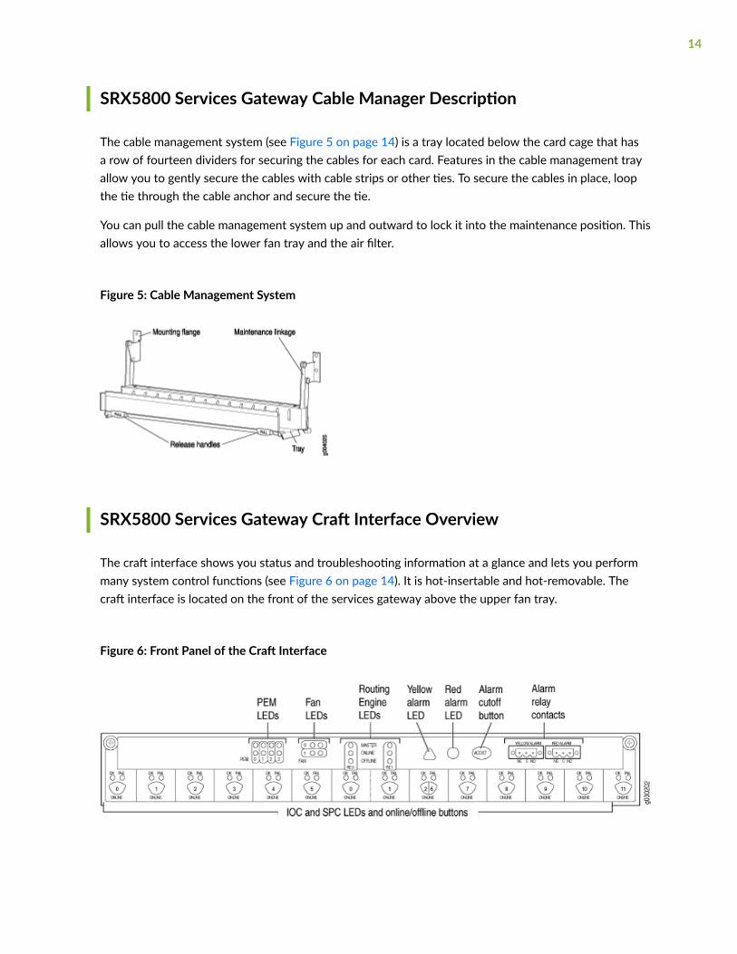
SRX5800 Services Gateway Cable Manager Description
The cable management system (see Figure 5 on page 14) is a tray located below the card cage that hasa row of fourteen dividers for securing the cables for each card. Features in the cable management trayallow you to gently secure the cables with cable strips or other ties. To secure the cables in place, loopthe tie through the cable anchor and secure the tie.
You can pull the cable management system up and outward to lock it into the maintenance position. Thisallows you to access the lower fan tray and the air filter.
Figure 5: Cable Management System
SRX5800 Services Gateway Craft Interface Overview
The craft interface shows you status and troubleshooting information at a glance and lets you performmany system control functions (see Figure 6 on page 14). It is hot-insertable and hot-removable. Thecraft interface is located on the front of the services gateway above the upper fan tray.
Figure 6: Front Panel of the Craft Interface
14

NOTE: The craft interface draws its power from the SCBs installed in the SCB slots 0, 1, and 2 atthe center of the card cage. At least one SCB must be installed in the services gateway for thecraft interface to obtain power.
SRX5800 Services Gateway Craft Interface Alarm LEDs and AlarmCutoff/Lamp Test Button
Two large alarm LEDs are located at the upper right of the craft interface. The circular red LED lights toindicate a critical condition that can result in a system shutdown. The triangular yellow LED lights toindicate a less severe condition that requires monitoring or maintenance. Both LEDs can be litsimultaneously. A condition that causes an LED to light also activates the corresponding alarm relaycontact on the craft interface.
To deactivate the red and yellow alarms, press the button labeled ACO/LT (for “alarm cutoff/lamp test”),which is located to the right of the alarm LEDs. Deactivating an alarm turns off both LEDs anddeactivates the device attached to the corresponding alarm relay contact on the craft interface.
Table 3 on page 15 describes the alarm LEDs and alarm cutoff button in more detail.
Table 3: Alarm LEDs and Alarm Cutoff/Lamp Test Button
Shape Color State Description
Red On steadily Critical alarm LED—Indicates a critical condition that can cause the deviceto stop functioning. Possible causes include component removal, failure, oroverheating.
Yellow On steadily Warning alarm LED—Indicates a serious but nonfatal error condition, suchas a maintenance alert or a significant increase in component temperature.
– – Alarm cutoff/lamp test button—Deactivates red and yellow alarms. Causesall LEDs on the craft interface to light (for testing) when pressed and held.
15

SRX5800 Services Gateway Craft Interface Host Subsystem LEDs
The host subsystem has three LEDs, located in the middle of the craft interface, that indicate its status.The LEDs labeled RE0 show the status of the Routing Engine and SCB in slot 0 .
The LEDs labeled RE1 show the status of the Routing Engine and SCB in slot 1. Table 4 on page 16describes the functions of the host subsystem LEDs.
Table 4: Host Subsystem LEDs
Label Color State Description
MASTER Green On steadily Host is functioning as the master.
ONLINE Green On steadily Host is online and is functioning normally.
OFFLINE Red On steadily Host is installed but the Routing Engine is offline.
Off Host is not installed.
SRX5800 Services Gateway Craft Interface Power Supply LEDs
Each power supply has two LEDs on the craft interface that indicate its status. The LEDs, labeled 0through 3, are located near the middle of the craft interface next to the PEM label. Table 5 on page 16describes the functions of the power supply LEDs on the craft interface.
Table 5: Power Supply LEDs on the Craft Interface
Label Color State Description
PEM Green On steadily Power supply is functioning normally.
Red On steadily Power supply has failed or power input has failed.
16

SRX5800 Services Gateway Craft Interface Card OK/Fail LEDs
Each slot in the card cage has a pair of LEDs on the craft interface that indicates the status of the cardinstalled in it. The card LEDs are located along the bottom edge of the craft interface and are labeled asfollows:
• 0 through 5 on the left
• 0 and 1 for the two center slots reserved for SCBs
• 2/6 and 7 through 11 on the right
Table 6 on page 17 describes the functions of the OK and Fail LEDs.
Table 6: Card OK/Fail LEDs
Label Color State Description
OK Green On steadily The card is functioning normally.
Blinking The card is transitioning online or offline.
Off The card is not online.
FAIL Red On steadily The card has failed.
SRX5800 Services Gateway Craft Interface Fan LEDs
Each fan LED is located on the top left of the craft interface. Table 7 on page 17 describes thefunctions of the fan LEDs.
Table 7: Fan LEDs
Label Color State Description
OK Green On steadily Fan tray is functioning normally.
17

Table 7: Fan LEDs (Continued)
Label Color State Description
FAIL Red On steadily Fan tray has failed.
SRX5800 Services Gateway Craft Interface Online Buttons
The craft interface has a row of Online/Offline buttons along its lower edge. Each button corresponds toone slot in the card cage. The Online/Offline buttons are only supported for slots containing MPCinterface cards. You can install MPCs into slots:
• SRX5400–Any slot except bottom slot 0
• SRX5600–Any slot except bottom slots 0 or 1
• SRX5800–Any slot except center slots 0 or 1
NOTE: The Online/Offline buttons are not supported for removal and replacement of SPCs orSCB.
CAUTION: While traffic is passing through the Services Gateway, particularly if thedevice is configured as part of a high availability (HA) cluster, we strongly recommendthat you do not push any of the Online/Offline buttons.
To take an MPC offline using the Online/Offline buttons:
1. Press and hold the corresponding card’s Online/Offline button on slot 1 on the craft interface. Thegreen OK/FAIL LED next to the button begins to blink. Hold until both the button’s LED and theMPC’s LED are off.
2. Issue the CLI show chassis fpc command to check the status of installed MPCs. As shown in the sampleoutput, the value Offline in the column labeled State indicates that the MPC in slot 1 is now offline:
user@host> show chassis fpc
Slot State (C) Total Interrupt DRAM (MB) Heap Buffer
18

0 Online 35 4 0 1024 13 25 1 Online 47 3 0 1024 13 25 2 Online 37 8 0 2048 18 14
An MPC can also be taken offline via CLI command:
user@host> request chassis fpc slot 2 offlinenode0:--------------------------------------------------------------------------Offline initiated, use "show chassis fpc" to verify
{primary:node0}
user@host> show chassis fpcnode0:-------------------------------------------------------------------------- Temp CPU Utilization (%) Memory Utilization (%)Slot State (C) Total Interrupt DRAM (MB) Heap Buffer 0 Online 35 7 0 1024 13 25 1 Online 46 4 0 1024 13 25 2 Offline ---Offlined by cli command---
After pushing MPC online button:
user@host> show chassis fpc Temp CPU Utilization (%) Memory Utilization (%)Slot State (C) Total Interrupt DRAM (MB) Heap Buffer 0 Online 34 5 0 1024 13 25 1 Online 46 3 0 1024 13 25 2 Offline ---Offlined by button press---
To bring an MPC back online using the Online/Offline buttons:
1. Press and hold the corresponding card’s Online/Offline button on slot 1 on the craft interface. Thegreen OK/FAIL LED next to the button and the MPC’s LED begins to blink. Hold until both thebutton’s LED and the MPC’s LED are green and steady.
19

2. Issue the CLI show chassis fpc command to check the status of installed MPCs. As shown in the sampleoutput, the value Online in the column labeled State indicates that the MPC in slot 1 is functioningnormally:
Verify if the MPC is offline:
user@host> show chassis fpcnode0:-------------------------------------------------------------------------- Temp CPU Utilization (%) Memory Utilization (%)Slot State (C) Total Interrupt DRAM (MB) Heap Buffer 0 Online 37 23 0 2048 19 14 1 Offline ---Offlined by cli command--- 2 Online 49 37 0 1024 14 25
The command output indicates the MPC is offline.
Bring the MPC online for the first time by using the following CLI command:
user@host> request chassis fpc slot 1 onlinenode0:--------------------------------------------------------------------------Online initiated, use "show chassis fpc" to verify
Verify that the MPC is online:
user@host> request chassis fpc slot 1 onlinenode 0node0:--------------------------------------------------------------------------FPC 1 already online
The command output indicates the MPC is online.
Confirm that the MPC in the chassis is online:
user@host> show chassis fpcnode0:-------------------------------------------------------------------------- Temp CPU Utilization (%) Memory Utilization (%)
20

Slot State (C) Total Interrupt DRAM (MB) Heap Buffer 0 Online 37 6 0 2048 19 14 1 Online 44 11 0 1024 23 29 2 Online 49 22 0 1024 14 25
SRX5800 Services Gateway Craft Interface Alarm Relay Contacts
The craft interface has two alarm relay contacts for connecting the device to external alarm devices (seeFigure 7 on page 21). Whenever a system condition triggers either the major or minor alarm on thecraft interface, the alarm relay contacts are also activated. The alarm relay contacts are located on theupper right of the craft interface.
Figure 7: Alarm Relay Contacts
The alarm relay contacts consist of two sets of connectors, one set for each of the two alarms (majorand minor). For each alarm color there are three connectors. Table 8 on page 21 describes thefunctions of the connectors.
Table 8: Alarm Relay Contact Functions
Contact Label Contact Name Function
NC Normally Closed Connects the alarm relay to an external alarm-reporting device that activateswhen the circuit between C and NC is closed.
C Current In Connects the alarm relay to the current source for the external alarm-reporting device.
21

Table 8: Alarm Relay Contact Functions (Continued)
Contact Label Contact Name Function
NO Normally Open Connects the alarm relay to an external alarm-reporting device that activateswhen the circuit between C and NC is open.
Table 9 on page 22 shows the electrical specifications for the alarm relay contacts.
Table 9: Alarm Relay Contact Electrical Specifications
Current Type
AC DC
Maximum Voltage 250 30
Maximum Current 8 A
Figure 8 on page 22 shows an example wiring diagram for a simple alarm reporting device. In this casethe device is a 12-volt light bulb that illuminates when the device encounters a condition that activatesthe major alarm LED and relay contacts. The alarm relay contacts can also be used to activate otherdevices such as bells or buzzers.
Figure 8: Example Alarm Reporting Device
22

SRX5800 Services Gateway Cooling System
The cooling system consists of the following components:
• Upper fan tray
• Bottom fan tray
• Air filter tray and air filter
The cooling system components work together to keep all services gateway components within theacceptable temperature range (see Figure 9 on page 24, Figure 10 on page 25, Figure 11 on page 25,Figure 12 on page 25, and Figure 13 on page 26). The services gateway has two fan trays located inthe front of the device that install horizontally above and below the card cage.
NOTE: In the Junos OS command-line interface (CLI):
• The show chassis hardware command output displays the fan trays as Fan Tray 0 for the upper fantray and Fan Tray 1 for the bottom fan tray.
• The show chassis environment command output displays the fan trays as Upper Fan Tray and BottomFan Tray.
Two different types of fan trays are available:
• The standard capacity fan tray has six fans that operate at 728 cubic feet per minute (CFM) at fullspeed and is adequate for services gateways in which standard-capacity power supplies are installed.
• The high-capacity fan tray has 12 fans that operate at 976 cubic feet per minute (CFM) at full speedand is required when high-capacity power supplies are installed. When high-capacity fan trays areinstalled, you must also install the high-capacity air filter tray.
23

The fan trays are interchangeable and are hot-insertable and hot-removable.
Figure 9: Airflow Through the Chassis
The host subsystem monitors the temperature of the device components. When the device is operatingnormally, the fans function at lower than full speed. If a fan fails or the ambient temperature rises abovea threshold, the speed of the remaining fans is automatically adjusted to keep the temperature withinthe acceptable range. If the ambient maximum temperature specification is exceeded and the systemcannot be adequately cooled, the Routing Engine shuts down the system by disabling output powerfrom each PEM.
24

There is a single air intake in the front of the services gateway. Air is pushed up through an air filter,through the card cage, and then through the upper fan tray where it combines in a common exhaustplenum and is exhausted out the upper rear of the system.
Figure 10: Standard-Capacity Fan Tray (Same Upper and Bottom)
Figure 11: High-Capacity Fan Tray (Same Upper and Bottom)
Figure 12: Air Filter
25

Figure 13: Standard-Capacity Air Filter Tray
Figure 14: High-Capacity Air Filter Tray
SRX5800 Power System
IN THIS SECTION
SRX5800 Services Gateway Power System Overview | 27
SRX5800 Services Gateway Standard-Capacity AC Power Supply | 31
SRX5800 Services Gateway Standard-Capacity AC Power Supply LEDs | 32
SRX5800 Services Gateway High-Capacity AC Power Supply | 33
SRX5800 Services Gateway High-Capacity AC Power Supply LEDs | 36
SRX5800 Services Gateway High-Capacity Second-Generation AC Power Supply | 37
SRX5800 Services Gateway AC Power Supply Specifications | 40
AC Power Cord Specifications for the SRX5800 Services Gateway | 41
Understanding Input Mode Switch (DIP Switch) Settings | 45
AC Power Circuit Breaker Requirements for the SRX5800 Services Gateway | 49
26

High-Voltage Second-Generation Universal (HVAC/HVDC) Power Supply for SRX5800 ServicesGateway | 50
High-Voltage Second-Generation Universal (HVAC/HVDC) Power Supply Specifications for the SRX5800Services Gateway | 54
High-Voltage Second-Generation Universal (HVAC/HVDC) Power Cord Specifications for the SRX5800Services Gateway | 55
High-Voltage Second-Generation Universal (HVAC/HVDC) Power Circuit Breaker Requirements for theSRX5800 Services Gateway | 58
SRX5800 Services Gateway Standard-Capacity DC Power Supply | 59
SRX5800 Services Gateway Standard-Capacity DC Power Supply LEDs | 60
SRX5800 Services Gateway High-Capacity DC Power Supply | 61
SRX5800 Services Gateway High-Capacity DC Power Supply LEDs | 64
SRX5800 Services Gateway DC Power Supply Specifications | 64
DC Power Cable Specifications for the SRX5800 Services Gateway | 66
DC Power Cable Lug Specifications for the SRX5800 Services Gateway | 67
DC Power Circuit Breaker Requirements for the SRX5800 Services Gateway | 67
DC Power Source Cabling for the SRX5800 Services Gateway | 68
SRX5800 Services Gateway Chassis Grounding Point Specifications | 69
SRX5800 Services Gateway Grounding Cable Specifications | 70
SRX5800 Services Gateway Grounding-Cable Lug Specification | 71
SRX5800 Services Gateway Power System Overview
The SRX5800 Services Gateway uses either AC or DC power supplies. The services gateway isconfigurable with two to four AC power supplies or two or four DC power supplies. The power suppliesconnect to the midplane, which distributes the different output voltages produced by the powersupplies to the services gateway components, depending on their voltage requirements.
Table 10 on page 28 describes the different types of power supplies available.
27

Table 10: Power Supply Type Summary
Power Supply Type Input Condition (IfAny)
MaximumOutput
Redundancy Power Distribution
AC standard-capacity 1700 W 3+1 Shared
AC high-capacity One AC input 1700 W 2+2 Zoned
Two AC inputs 4100 W
High-Capacity Second-Generation AC Power Supply
One AC input 2550 W
Two AC inputs 5100 W
High-Voltage Second-Generation Universal (HVAC/HVDC) Power Supply
5100 W
DC standard-capacity 1700 W
DC high-capacity One DC input 1700 W
Two DC inputs 4100 W
NOTE: The services gateway must be running Junos OS Release 10.4 or later in order to usehigh-capacity AC power supplies. The services gateway must be running Junos OS Release12.1X44-D10 or later in order to use high-capacity DC power supplies.
The services gateway must be running Junos OS Release 21.4R1 or later in order to use high-capacity second-generation AC and high-voltage second-generation universal (HVAC or HVDC)power supplies.
Redundant power supplies are hot-removable and hot-insertable. Each power supply is cooled by itsown internal cooling system.
28

NOTE: Devices configured from the factory with DC power supplies are shipped with a blankpanel installed over the power distribution modules. Devices configured with AC power supplieshave no blank panel.
CAUTION: The services gateway cannot be powered from AC and DC power suppliessimultaneously. The first type of power supply detected by the services gateway wheninitially powered on determines the type of power supply allowed by the servicesgateway. All installed power supplies of the other type are disabled by the servicesgateway. If you install a power supply of the other type while the services gateway isoperating, the services gateway disables the power supply and generates an alarm.
When the services gateway is powered by standard-capacity AC power supplies, the services gatewaycontains either three or four AC power supplies, located at the rear of the chassis in slots PEM0 throughPEM3 (left to right). Each power supply provides power to all components in the services gateway.When three power supplies are present, they share power almost equally within a fully populatedsystem. Four power supplies provide full power redundancy. If one power supply fails or is removed, theremaining power supplies instantly assume the entire electrical load without interruption. Three powersupplies provide the maximum configuration with full power for as long as the services gateway isoperational.
When the services gateway is powered by either standard- or high-capacity DC power supplies, or high-capacity AC power supplies, or by high-capacity second-generation AC power supplies, or high-voltagesecond-generation universal (HVAC or HVDC) power supplies power distribution within the chassis isdivided into zones, as described in Table 11 on page 29.
Table 11: SRX5800 Services Gateway Power Distribution (DC, or High-Capacity AC, or High-CapacitySecond-Generation AC, or High-Voltage Second-Generation Universal (HVAC/HVDC) Power Supplies)
Zone Power Supplies Provide Power To:
Zone 0 • PEM0
• PEM2
• Bottom fan tray
• IOC or SPC slots 6 through 11
• SCB slots 1 and 2
29

Table 11: SRX5800 Services Gateway Power Distribution (DC, or High-Capacity AC, or High-CapacitySecond-Generation AC, or High-Voltage Second-Generation Universal (HVAC/HVDC) Power Supplies)(Continued)
Zone Power Supplies Provide Power To:
Zone 1 • PEM1
• PEM3
• Upper fan tray
• IOC or SPC slots 0 through 5
• SCB slot 0
Figure 15 on page 30 shows the distribution of power from the power supplies to the chassiscomponents in an SRX5800 Services Gateway chassis powered by DC power supplies, or high-capacityAC power supplies, or high-capacity second-generation AC, or high-voltage second-generation universal(HVAC or HVDC) power supplies.
Figure 15: Power Distribution from DC, or High-Capacity AC, or High-Capacity Second-Generation AC,or High-Voltage Second-Generation Universal (HVAC/HVDC) Power Supplies in the SRX5800 ServicesGateway Chassis
30

NOTE: The craft interface draws its power from the SCBs installed in the SCB slots 0, 1, and 2 atthe center of the card cage. In the standard configuration, with SCBs in slots 0 and 1, the craftinterface is powered on even when one of the two zones loses power. But if the chassis only hasone SCB installed, the craft interface draws all of its power from that card, and consequently ispowered off if the zone in which that SCB is installed loses power.
You can install either two or four DC power supplies, or high-capacity AC power supplies, or high-capacity second-generation AC, or high-voltage second-generation universal (HVAC or HVDC) powersupplies. Two power supplies are required to power the two zones, while four power supplies providefull redundancy for both zones. The power supplies in slots PEM0 and PEM2 form a redundant pair, asdo the power supplies in slots PEM1 and PEM3. When two power supplies are installed for a zone, theyshare the load. If a power supply fails, its redundant power supply assumes the full load of that zonewithout interruption.
If you do install only two power supplies, they must be installed so that one is in an odd-numbered slotand the other is in an even-numbered slot. For example, you can install one high-capacity AC powersupply in each of the slots PEM0 and PEM1.
SRX5800 Services Gateway Standard-Capacity AC Power Supply
Each standard-capacity AC power supply has a corresponding AC appliance inlet located in the chassisdirectly above the power supply. Each inlet requires a dedicated AC power feed and a dedicated15 A (250 VAC) circuit breaker. See Figure 16 on page 32.
WARNING: To meet safety and electromagnetic interference (EMI) requirements and toensure proper operation, the services gateway chassis must be adequately grounded
31

before power is connected. See "Grounding the SRX5800 Services Gateway" on page258 for instructions.
Figure 16: Standard-Capacity AC Power Supply
SRX5800 Services Gateway Standard-Capacity AC Power Supply LEDs
Each standard-capacity AC power supply faceplate contains three LEDs that indicate the status of thepower supply (see Table 12 on page 32). The power supply status is also reflected in two LEDs on thecraft interface. In addition, a power supply failure triggers the red alarm LED on the craft interface.
Table 12: Standard Capacity AC Power Supply LEDs
Label Color State Description
AC OK Green Off AC power applied to power supply is not within the normal operating range.
On AC power applied to power supply is within the normal operating range.
DC OK Green Off DC power outputs generated by the power supply are not within the normaloperating ranges.
32

Table 12: Standard Capacity AC Power Supply LEDs (Continued)
Label Color State Description
On DC power outputs generated by the power supply are within the normal operatingranges.
PS FAIL Red Off Power supply is functioning normally.
On Power supply is not functioning normally. Check AC OK and DC OK LEDs for moreinformation.
SRX5800 Services Gateway High-Capacity AC Power Supply
High-capacity AC power supplies provide a maximum of 4100 W of power each. Two high-capacitypower supplies are required, and you can install four high-capacity power supplies for redundancy. Eachhigh-capacity AC power supply has two corresponding AC appliance inlets: one located in the chassisdirectly above the power supply and one located near the top edge of the power supply itself. For eachpower supply, you connect one power cord to the inlet on the chassis above the power supply and onepower cord to the inlet on the power supply itself. Each inlet you connect requires a dedicated ACpower feed and a dedicated 15 A (250 VAC) circuit breaker. See Figure 17 on page 35.
NOTE: The services gateway cannot be powered from standard-capacity and high-capacity ACpower supplies simultaneously. The one exception is during the process of replacing standard-capacity AC power supplies with high-capacity AC power supplies, when it is permissible to haveboth types installed briefly.
NOTE: The high-capacity power supply will operate with only one of its two AC inlets connectedto an AC power feed. However, its DC output will be limited to a maximum of 1700 W. Werecommend that you connect two AC power feeds to each high-capacity AC power supply.
33

NOTE: The services gateway must be running Junos OS Release 10.4 or later in order to usehigh-capacity AC power supplies.
Each high-capacity AC power supply has an input mode switch, covered by a small metal plate. Theinput mode switch tells the system the number of AC power feeds it should expect. The input modeswitch settings are described in Table 13 on page 34. The default setting is 1.
Table 13: High-Capacity AC Power Supply Input Mode Switch Settings
Mode Switch Setting AC Inputs Result
1 Both AC inlets powered AC output of 4100 W
AC OK LED lights
Only one AC inlet powered AC output of 1700 W
AC OK LED lights
0 Both AC inlets powered AC output of 4100 W
AC OK LED lights
Only one AC inlet powered AC output disabled
AC OK LED unlit
NOTE: We recommend that you set the input mode switch to 1 and connect two AC input feedsto each high-capacity AC power supply.
WARNING: To meet safety and electromagnetic interference (EMI) requirements and toensure proper operation, the services gateway chassis must be adequately grounded
34

before power is connected. See "Grounding the SRX5800 Services Gateway" on page258 for instructions.
Figure 17: High-Capacity AC Power Supply
35

SRX5800 Services Gateway High-Capacity AC Power Supply LEDs
Each high-capacity AC power supply faceplate contains four LEDs that indicate the status of the powersupply (see Table 14 on page 36). The power supply status is also reflected in two LEDs on the craftinterface. In addition, a power supply failure triggers the red alarm LED on the craft interface.
Table 14: High-Capacity AC Power Supply LEDs
Label Color State Description
AC-1 OK Green Off AC power applied to power supply at the upper appliance inlet is not within thenormal operating range.
On AC power applied to power supply at the upper appliance inlet is within the normaloperating range.
AC-2 OK Green Off AC power applied to power supply at the lower appliance inlet is not within thenormal operating range.
On AC power applied to power supply at the lower appliance inlet is within the normaloperating range.
DC OK Green Off DC power outputs generated by the power supply are not within the normaloperating ranges.
On DC power outputs generated by the power supply are within the normal operatingranges.
PS FAIL Red Off Power supply is functioning normally.
On Power supply is not functioning normally. Check the AC-1 OK, AC-2 OK, andDC OK LEDs for more information.
36

SRX5800 Services Gateway High-Capacity Second-Generation AC PowerSupply
IN THIS SECTION
SRX5800 Services Gateway High-Capacity Second-Generation AC Power Supply LEDs | 39
The SRX5800 Services Gateway can also be powered by four high-capacity second-generation ACpower supplies. The high-capacity second-generation power supplies must be installed in adjacent slotsin the chassis. They can operate in either one-feed mode or two-feed mode. The maximum inrushcurrent per feed for a high-capacity AC power supply is 38 A per feed at 264 VAC.
Figure 18: SRX5800 Services Gateway High-Capacity Second-Generation AC Power Supply
37

In the one-feed mode, the power supplies provide power at a reduced capacity (2550 W). In the two-feed mode, the power supplies provide power at full capacity (5100 W). To operate the SRX5800 at fullcapacity, you must use the two-feed mode. High-capacity second-generation AC power supplies requireone power cord per feed. Therefore, to operate the SRX5800 services gateway at full capacity, you needeight power cords.
Each high-capacity second-generation AC power supply accepts two AC feeds in two C19/C20 ACreceptacles, both receptacles are located on the power supply. Do not use the receptacle located on thechassis. For supported power cables, see "AC Power Cord Specifications for the SRX5800 ServicesGateway" on page 41.
When using the high-capacity second-generation AC power supplies in one-feed mode, plug one end ofthe power cord into the corresponding AC receptacle directly on the power supply and the other endinto an AC outlet. When using the high-capacity second-generation AC power supply in two-feed mode,you need two power cords. Plug both power cords into the AC receptacles on the power supply theother ends of the cable into AC outlets.
In high-capacity second-generation AC power supply configurations, there are two zones that providepower to specific components in the SRX5800 Services Gateway. Redundancy is 1+1 per zone. Table 15on page 38 lists the components that receive power for each zone in a high-capacity AC power supplyconfiguration.
Table 15: Zoning for High-Capacity Second-Generation Power Supplies in an SRX5800 ServicesGateway
Chassis PowerConfiguration
Zone Power Supply (PEM) Provide Power To
High-capacity second-generation AC powersupplies
Zone 0 • PEM0
• PEM2
• Bottom fan tray
• IOC or SPC slots 6through 11
• SCB slots 1 and 2
High-capacity second-generation AC powersupplies
Zone 1 • PEM1
• PEM3
• Upper fan tray
• IOC or SPC slots 0through 5
• SCB slot 0
38

SRX5800 Services Gateway High-Capacity Second-Generation AC Power SupplyLEDs
Each high-capacity second-generation AC power supply faceplate contains four LEDs that indicate thestatus of the power supply (see Figure 19 on page 39 and Table 16 on page 39).
Figure 19: High-Capacity Second-Generation AC Power Supply LEDs
Table 16: High-Capacity Second-Generation AC Power Supply LEDs
Label Color State Description
INP0 OK Green Off AC power applied to power supply is not within the normal operatingrange.
On AC power applied to power supply is within the normal operating range.
INP1 OK Green Off AC power applied to power supply is not within the normal operatingrange.
On AC power applied to power supply is within the normal operating range.
DC OK Green Off DC power outputs generated by the power supply are not within thenormal operating ranges.
39

Table 16: High-Capacity Second-Generation AC Power Supply LEDs (Continued)
Label Color State Description
On DC power outputs generated by the power supply are within the normaloperating ranges.
PS FAIL Red Off Power supply is functioning normally.
On Power supply is not functioning normally. Check AC OK and DC OKLEDs for more information.
SRX5800 Services Gateway AC Power Supply Specifications
Table 17 on page 40 lists the AC power supply electrical specifications for both the standard-capacity,high-capacity, and high-capacity second-generation AC power supply. Table 18 on page 41 lists the ACpower system electrical specifications.
Table 17: AC Power Supply Electrical Specifications
Item Specification
Standard-Capacity High-Capacity High-Capacity Second-Generation
Maximum outputpower
1700 W 4100 W (two AC inputs)
1700 W (one AC input)
5100 W (two AC inputs)
2550 W (one AC input)
AC input currentrating
11 A @ 240 VACmaximum
13 A @ 240 VAC maximum perAC input (26 A per powersupply when two AC inputs areused)
16 A @ 200 VAC maximum perAC input (32 A per power supplywhen two AC inputs are used)
AC input voltage Operating range: 200 to 240 VAC Operating range: 180 to 264VAC
40

Table 17: AC Power Supply Electrical Specifications (Continued)
Item Specification
Standard-Capacity High-Capacity High-Capacity Second-Generation
AC input linefrequency
50 to 60 Hz 47 to 63 Hz
Efficiency ~88%
NOTE: This value is at full load and nominal voltage.
~91%
NOTE: This value is at full loadand nominal voltage.
Table 18: AC Power System Specifications
Item Normal-Capacity
High-Capacity High-Capacity Second-Generation
Two AC inputsfor each powersupply
One AC inputfor each powersupply
Two AC inputsfor each powersupply
One AC inputfor each powersupply
Redundancy 3+1 2+2 2+2 2+2 2+2
Output power(maximum) persupply
1700 W 4100 W 1700 W 5100 W 2550 W
Output power(maximum) persystem
5100 W 8200 W 3400 W 1.2 KW 5100 W
AC Power Cord Specifications for the SRX5800 Services Gateway
Each AC power supply has a single AC appliance inlet located in the chassis directly above the powersupply that requires a dedicated AC power feed. Most sites distribute power through a main conduit
41

that leads to frame-mounted power distribution panels, one of which can be located at the top of therack that houses the services gateway. An AC power cord connects each power supply to the powerdistribution panel.
The services gateway is not shipped with AC power cords. You must order power cords separately usingthe model number shown in Table 19 on page 42. The C19 appliance coupler end of the cord insertsinto the AC appliance inlet coupler, type C20 (right angle) as described by International ElectrotechnicalCommission (IEC) standard 60320. The plug end of the power cord fits into the power source receptaclethat is standard for your geographical location.
Table 19 on page 42 provides specifications and Figure 20 on page 43 depicts the plug on the ACpower cord provided for each country or region.
Table 19: AC Power Cord Specifications
Country Model Number Electrical Specification Plug Type
Australia CBL-M-PWR-RA-AU 240 VAC, 50 Hz AC SAA/3
China CBL-M-PWR-RA-CH 220 VAC, 50 Hz AC PSB-10
Europe (except Denmark, Italy,Switzerland, and United Kingdom)
CBL-M-PWR-RA-EU 220 or 230 VAC, 50 Hz AC CEE 7/7
Italy CBL-M-PWR-RA-IT 230 VAC, 50 Hz AC CEI 23-16/VII
Japan CBL-M-PWR-RA-JP 220 VAC, 50 or 60 Hz AC NEMA L6-20P
North America CBL-M-PWR-RA-TWLK-US 250 VAC, 60 Hz AC NEMA L6-20P
42

Table 19: AC Power Cord Specifications (Continued)
Country Model Number Electrical Specification Plug Type
United Kingdom CBL-M-PWR-RA-UK 240 VAC, 50 Hz AC BS89/13
Figure 20: AC Plug Types
Each high-capacity second-generation (MX960-PSM-5K-AC) power supply has two AC appliance inletslocated in the power supply itself. Each receptacle requires a dedicated AC power feed and a dedicatedbreaker. Table 20 on page 44 provides specifications for the high-capacity second-generation PSM.
CAUTION: The bend radius for the power cord cables is 7 inches. Avoid bending thecable beyond it’s bend radius when dressing the cables into the cable channels on therack.
43
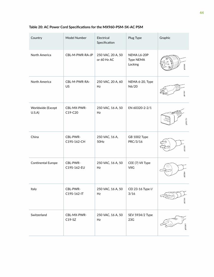
Table 20: AC Power Cord Specifications for the MX960-PSM-5K-AC PSM
Country Model Number ElectricalSpecification
Plug Type Graphic
North America CBL-M-PWR-RA-JP 250 VAC, 20 A, 50or 60 Hz AC
NEMA L6-20PType NEMALocking
North America CBL-M-PWR-RA-US
250 VAC, 20 A, 60Hz
NEMA 6-20, TypeN6/20
Worldwide (ExceptU.S.A)
CBL-MX-PWR-C19-C20
250 VAC, 16 A, 50Hz
EN 60320-2-2/1
China CBL-PWR-C19S-162-CH
250 VAC, 16 A,50Hz
GB 1002 TypePRC/3/16
Continental Europe CBL-PWR-C19S-162-EU
250 VAC, 16 A, 50Hz
CEE (7) VII TypeVIIG
Italy CBL-PWR-C19S-162-IT
250 VAC, 16 A, 50Hz
CEI 23-16 Type I/3/16
Switzerland CBL-MX-PWR-C19-SZ
250 VAC, 16 A, 50Hz
SEV 5934/2 Type23G
44

WARNING: The AC power cord for the services gateway is intended for use with theservices gateway only and not for any other use.
WARNING: To meet safety and electromagnetic interference (EMI) requirements and toensure proper operation, you must properly ground the services gateway chassis beforeconnecting power. See "Grounding the SRX5800 Services Gateway" on page 258 forinstructions.
CAUTION: Power cords and cables must not block access to services gatewaycomponents or drape where people could trip on them.
NOTE: In North America, AC power cords must not exceed 4.5 m (approximately 14.75 ft) inlength, to comply with National Electrical Code (NEC) Sections 400-8 (NFPA 75, 5-2.2) and210-52, and Canadian Electrical Code (CEC) Section 4-010(3). The cords listed in Table 19 onpage 42 are in compliance.
Understanding Input Mode Switch (DIP Switch) Settings
Each High-Capacity AC Power Supply and High-Capacity Second-Generation AC Power Supply has twoinput mode switches (DIP switches) on the faceplate. The DIP switches provide critical information tothe power management subsystem to help generate alarms in case of a feed failure or a wrongconnection. Each PSM has an LED per feed indicating whether the feed is active and whether the feedis properly connected. You must set the DIP switch on each high-capacity AC or high-capacity second-generation AC power supply according to how many feeds are connected. When one feed is connected,the system is running in reduced capacity mode. When two feeds are connected the system is running infull-capacity mode. Use these DIP switch settings:
• Position-0 indicates one AC feed is present
• Position-1 indicates two AC feeds are present
45

Refer to Figure 21 on page 46 and Figure 22 on page 46.
Figure 21: Setting the Input Mode Switch (DIP Switch)
Figure 22: Setting the Input Mode Switch (DIP Switch) on High-Capacity Second-Generation AC PSM
1— Position 1 indicates two AC feeds arepresent
2— Position 0 indicates one AC feeds is present
46
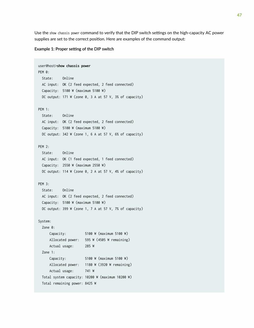
Use the show chassis power command to verify that the DIP switch settings on the high-capacity AC powersupplies are set to the correct position. Here are examples of the command output:
Example 1: Proper setting of the DIP switch
user@host>show chassis powerPEM 0: State: Online AC input: OK (2 feed expected, 2 feed connected) Capacity: 5100 W (maximum 5100 W) DC output: 171 W (zone 0, 3 A at 57 V, 3% of capacity) PEM 1: State: Online AC input: OK (2 feed expected, 2 feed connected) Capacity: 5100 W (maximum 5100 W) DC output: 342 W (zone 1, 6 A at 57 V, 6% of capacity) PEM 2: State: Online AC input: OK (1 feed expected, 1 feed connected) Capacity: 2550 W (maximum 2550 W) DC output: 114 W (zone 0, 2 A at 57 V, 4% of capacity) PEM 3: State: Online AC input: OK (2 feed expected, 2 feed connected) Capacity: 5100 W (maximum 5100 W) DC output: 399 W (zone 1, 7 A at 57 V, 7% of capacity) System: Zone 0: Capacity: 5100 W (maximum 5100 W) Allocated power: 595 W (4505 W remaining) Actual usage: 285 W Zone 1: Capacity: 5100 W (maximum 5100 W) Allocated power: 1180 W (3920 W remaining) Actual usage: 741 W Total system capacity: 10200 W (maximum 10200 W) Total remaining power: 8425 W
47

root@cland03> show chassis alarmsNo alarms currently active
In Example 1, PEM 0 is running at full capacity (5100 W) with two AC feeds expected and two AC feedsconnected. This indicates that the DIP switch is properly set to Position 1 since two AC feeds areconnected. The example also shows that PEM 2 is running at reduced capacity (2550 W) with one ACfeed expected and one AC feed connected. This indicates that the DIP switch is correctly set to Position0 since one feed is present.
Example 2 shows the show chassis power command output when the DIP switch is set improperly:
Example 2: Improper Setting of the DIP Switch
user@host>show chassis powerPEM 0: State: Online AC input: OK (2 feed expected, 2 feed connected) Capacity: 5100 W (maximum 5100 W) DC output: 114 W (zone 0, 2 A at 57 V, 2% of capacity) PEM 1: State: Online AC input: OK (2 feed expected, 2 feed connected) Capacity: 5100 W (maximum 5100 W) DC output: 342 W (zone 1, 6 A at 57 V, 6% of capacity) PEM 2: State: Present AC input: Check (2 feed expected, 1 feed connected) Capacity: 2550 W (maximum 2550 W) DC output: 114 W (zone 0, 2 A at 57 V, 4% of capacity) PEM 3: State: Online AC input: OK (2 feed expected, 2 feed connected) Capacity: 5100 W (maximum 5100 W) DC output: 399 W (zone 1, 7 A at 57 V, 7% of capacity) System: Zone 0: Capacity: 5100 W (maximum 5100 W) Allocated power: 595 W (4505 W remaining) Actual usage: 228 W
48

Zone 1: Capacity: 5100 W (maximum 5100 W) Allocated power: 1180 W (3920 W remaining) Actual usage: 741 W Total system capacity: 10200 W (maximum 10200 W) Total remaining power: 8425 W root@cland03> show chassis alarms1 alarms currently activeAlarm time Class Description2021-10-27 13:15:14 PDT Major PEM 2 Not OK
The PEM 0 status indicates the system is Online, the AC Input is OK, is running at full capacity (5100 W) withtwo AC feeds expected and two AC feeds connected. But notice the status for PEM 2. The State is Presentand the AC input is Check (2 feed expected, 1 feed connected). This indicates there is a mismatch between theDIP switch setting and the number of feeds connected. Therefore, the power supply is running atreduced capacity (2550 W). If PEM 1 should be running at full-capacity, verify that there are two feedsconnected to the power supplies and the DIP switch is set to position 1.
AC Power Circuit Breaker Requirements for the SRX5800 ServicesGateway
Each AC power supply has a single AC appliance inlet located in the chassis directly above the powersupply that requires a dedicated AC power feed. We recommend that you use a dedicated customer sitecircuit breaker rated for 15 A (250 VAC) minimum for each AC power supply, or as required by localcode.
Each high-capacity second-generation (MX960-PSM-5K-AC) power supply accepts two AC feeds in twounique AC receptacles. We recommend that you use a dedicated customer site circuit breaker rated for38 A (264 VAC) minimum for each high-capacity second generation AC power supply, or as required bylocal code.
Each power cord feed must have a dedicated circuit breaker.
49

High-Voltage Second-Generation Universal (HVAC/HVDC) Power Supplyfor SRX5800 Services Gateway
IN THIS SECTION
High-Voltage Second-Generation Universal (HVAC/HVDC) Power Supply LEDs | 53
The SRX5800 can be powered by four high-voltage second-generation universal power supplies(MX960-PSM-HV). The MX960-PSM-HV supports high-voltage alternating current (HVAC), or high-voltage direct current (HVDC). The MX960-PSM-HV power supplies must be installed in adjacent slotsin the chassis. The MX960-PSM-HV (HVAC/HVDC) power supply has one power inlet on front panel ofthe power supply rated at 30 A. The inlet requires a dedicated power feed and a dedicated breaker. Forall power supplies the circuit breaker protection should be designed according to National ElectricalCode (NEC) or any similar local standard based on maximum drawn current of the power supplyspecified in this document.
The MX960-PSM-HV (HVAC/HVDC) power supply configurations are zoned meaning that certaincomponents in the SRX5800 chassis are powered by specific power supplies.
50

Figure 23 on page 51 and Figure 24 on page 52 illustrates MX960-PSM-HV (HVAC/HVDC) powersupplies for the SRX5800.
Figure 23: MX960-PSM-HV (HVAC/HVDC) Power Supply
51

Each MX960-PSM-HV (HVAC/HVDC) power supply provides output power of 5100 W. Each powersupply has one receptacle, located on the power supply. Do not use the receptacle located on thechassis.
Figure 24: MX960-PSM-HV (HVAC/HVDC) Power Supplies Installed
1— Air exhaust 4— Power supply ejectors
2— Power distribution unit cover 5— Grounding points
3— Power supplies 6— ESD
The minimum number of power supplies must be present in the router at all times. Refer to Table 21 onpage 52.
Table 21: Minimum Number of Power Supplies Required for the SRX5800 Services Gateway
Configuration Minimum Required Number of Power Supplies Model Number
52

HVAC or HVDC One per zone x two zones = 2 power supplies MX960-PSM-HV
High-Voltage Second-Generation Universal (HVAC/HVDC) Power Supply LEDs
Each high-voltage second-generation universal (MX960-PSM-HV) power supply faceplate containsthree LEDs that indicate the status of the power supply (see Figure 25 on page 53). The power supplystatus is also reflected in two LEDs on the craft interface In addition, a power supply failure triggers thered alarm LED on the craft interface.
Figure 25: MX960-PSM-HV (HVAC/HVDC) Power Supply LEDs
Table 22: MX960-PSM-HV (HVAC/HVDC) Power Supply LEDs
Label Color State Description
INP OK Green Off AC power applied to power supply is not within the normal operatingrange.
On AC power applied to power supply is within the normal operating range.
DC OK Green Off DC power outputs generated by the power supply are not within thenormal operating ranges.
53
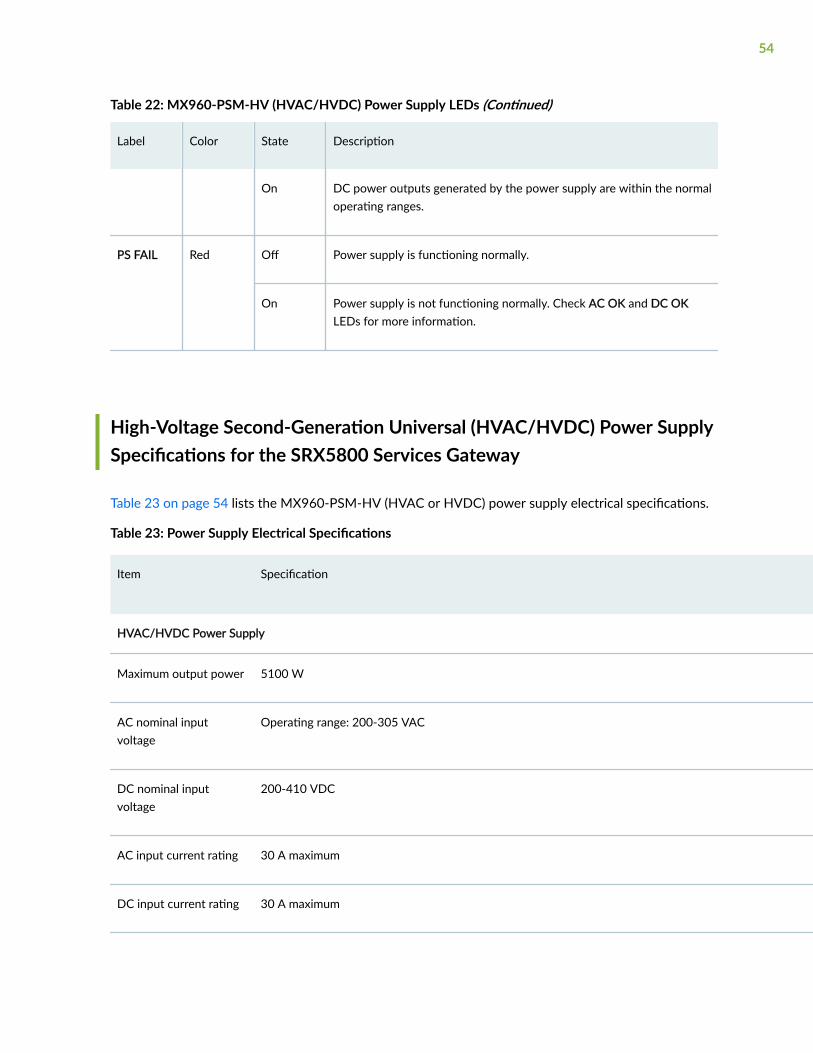
Table 22: MX960-PSM-HV (HVAC/HVDC) Power Supply LEDs (Continued)
Label Color State Description
On DC power outputs generated by the power supply are within the normaloperating ranges.
PS FAIL Red Off Power supply is functioning normally.
On Power supply is not functioning normally. Check AC OK and DC OKLEDs for more information.
High-Voltage Second-Generation Universal (HVAC/HVDC) Power SupplySpecifications for the SRX5800 Services Gateway
Table 23 on page 54 lists the MX960-PSM-HV (HVAC or HVDC) power supply electrical specifications.
Table 23: Power Supply Electrical Specifications
Item Specification
HVAC/HVDC Power Supply
Maximum output power 5100 W
AC nominal inputvoltage
Operating range: 200-305 VAC
DC nominal inputvoltage
200-410 VDC
AC input current rating 30 A maximum
DC input current rating 30 A maximum
54

Table 23: Power Supply Electrical Specifications (Continued)
Item Specification
Maximum AC inrushcurrent
70 A @ 264 VAC
Maximum DC inrushcurrent
70 A @ 410 VDC
Item High-voltage Second-Generation Universal Power Supply
Redundancy 2+2
Output power (maximum) per supply 5100 W
High-Voltage Second-Generation Universal (HVAC/HVDC) Power CordSpecifications for the SRX5800 Services Gateway
The MX960-PSM-HV (HVAC or HVDC) power supplies requires a high current cable assembly when setfor 30-A input. One end of the cable has an Anderson APP-400 connector, the other end of the cable isbare wire. See Figure 26 on page 56 and Table 24 on page 57. These cables are separately orderableand are not shipped automatically with MX960-PSM-HV orders. An example of the right-angle cableand connector is shown in Figure 28 on page 57. For connection to AC systems, Juniper provides a
55

cable with either a NEMA 30-A connector (Figure 26 on page 56) or an IEC 330P6W connector (Figure27 on page 56).
Figure 26: NEMA 30-A Connector
Figure 27: IEC 330P6W Connector
The MX960-PSM-HV (HVAC or HVDC) power supply has one C20 receptacles on front panel of thepower supply. The cover needs to be installed to cover C20 receptacles on PDM on top of the chassis.Input receptacle is APP 2007G type from Anderson rated 30 A 400V.
The high voltage alternating current (HVAC), and high voltage direct current (HVDC) have specific cordrequirements. Table 24 on page 57 provides specifications and plug standards on the power cordprovided for each country or region.
CAUTION: The bend radius for the power cord cables is 7 inches. Avoid bending thecable beyond its bend radius when dressing the cables into the cable channels on therack.
56

Table 24: 30-A Cabling Options
Spare Juniper Model Number Locale Cord Set Rating Connector
CBL-PWR2-332P6W-RA Continental Europe
AC power cord
30-A 250 VAC Anderson/right-angle to IEC332P6
CBL-PWR2-BARE-RA North America
HVAC/HVDC power cord
30-A, 400 VAC Anderson/right-angle to bare wire
CBL-PWR-SG4-RA U.S.A 30-A, 400 VAC SAF-D-GRID 400 right-angle (LH)
CBL-PWR-SG4 North America
AC jumper power cord
30-A, 400 VAC SAF-D-GRID 400 right-angle (LH)
CBL-PWR2-BARE North America
HVAC/HVDC power cord
30- A, 400 VAC Anderson/straight to bare wire
Figure 28: Right-Angle, Bare Cable with Anderson Connector
1— Black wire–Positive (+) 3— White wire–Negative
2— Green wire-Ground
57

WARNING: The AC power cord for the router is intended for use with the router onlyand not for any other use.
WARNING:
Translation from Japanese: The attached power cable is only for this product. Do notuse the cable for another product.
NOTE: In North America, AC power cords must not exceed 4.5 m (approximately 14.75 ft) inlength, to comply with National Electrical Code (NEC) Sections 400-8 (NFPA 75, 5-2.2) and210-52, and Canadian Electrical Code (CEC) Section 4-010(3). You can order AC power cordsthat are in compliance.
WARNING: The router is a pluggable type A equipment installed in restricted accesslocation. It has a separate protective earthing terminal (Metric [–M6] and English [–¼-20] screw ground lugs) provided on the chassis in addition to the grounding pin of thepower supply cord. This separate protective earth terminal must be permanentlyconnected to earth.
CAUTION: Power cords and cables must not block access to device components ordrape where people could trip on them.
High-Voltage Second-Generation Universal (HVAC/HVDC) Power CircuitBreaker Requirements for the SRX5800 Services Gateway
The circuit breaker protection on all the power supplies should be designed according to NationalElectrical Code (NEC) of country of system installation or any similar local standard based on maximumdrawn current of the power supply specified in this document.
58

Each high-voltage universal (MX960-PSM-HV) power supply has a single feed. The input AC or DCreceptacle inlet is located on front panel of the power supply.
Each power cord feed should have dedicated circuit breakers. We recommend that size of the circuitbreaker protection should be designed according to National Electrical Code (NEC) of country of systeminstallation or any similar local standard based on maximum drawn current of the power supply specifiedin this document.
CAUTION: Use a 2-pole circuit breaker rated at minimum of 125% of the rated currentper NEC or as local codes.
Primary Overcurrent Protection by the Building Circuit Breaker. This breaker mustprotect against excess current, short circuit, and earth grounding fault in accordancewith NEC which is ANSI/NFPA 70.
SRX5800 Services Gateway Standard-Capacity DC Power Supply
In the DC power configuration, the services gateway contains either two or four DC power supplies (seeFigure 29 on page 60), located at the lower rear of the chassis in slots PEM0 through PEM3 (left toright). You can upgrade your DC power system from two to four power supplies.
Four power supplies provide full redundancy. If a DC power supply fails, its redundant power supplytakes over without interruption.
59

Each DC power supply has a single DC input (–48 VDC and return) that requires a dedicated 80 A (–48 VDC) circuit breaker for the maximum hardware configuration.
Figure 29: Standard-Capacity DC Power Supply
SRX5800 Services Gateway Standard-Capacity DC Power Supply LEDs
Each standard-capacity DC power supply faceplate contains three LEDs that indicate the status of thepower supply (see Table 25 on page 60). The power supply status is also reflected in two LEDs on thecraft interface. In addition, a power supply failure triggers the red alarm LED on the craft interface.
Table 25: DC Power Supply LEDs
Label Color State Description
PWR OK Green Off Power supply is not functioning normally. Check the INPUT OK LED for moreinformation.
60

Table 25: DC Power Supply LEDs (Continued)
Label Color State Description
On Power supply is functioning normally.
BREAKER ON Green Off DC power supply circuit breaker is turned off.
On DC power supply circuit breaker is turned on.
INPUT OK Green Off DC input to the PEM is not present.
On DC input is present, and is connected in correct polarity.
Amber On DC input is present, but connected in reverse polarity.
SRX5800 Services Gateway High-Capacity DC Power Supply
High-capacity DC power supplies provide a maximum of 4100 W of power each. Two high-capacity DCpower supplies are required, and you can install four high-capacity DC power supplies for redundancy.Each high-capacity DC power supply has inlets for two DC power feeds. The four power connectors(-48V and RTN for each of the two inlets) are located behind a clear plastic cover near the bottom of thepower supply. Each DC power inlet you use requires a dedicated DC power feed and a dedicated 80 Acircuit breaker. See Figure 30 on page 63.
NOTE: The services gateway cannot be powered from standard-capacity and high-capacity DCpower supplies simultaneously. The one exception is during the process of replacing standard-capacity DC power supplies with high-capacity DC power supplies, when it is permissible to haveboth types installed briefly.
61

NOTE: The high-capacity power supply will operate with only one of its two DC inlets connectedto a DC power feed. However, its DC output will be limited to a maximum of 1700 W. Werecommend that you connect two DC power feeds to each high-capacity DC power supply.
NOTE: The services gateway must be running Junos OS Release 12.1X44-D10 or later in orderto use high-capacity DC power supplies.
Each high-capacity DC power supply has an input mode switch, covered by a small metal plate. Theinput mode switch tells the system the number of DC power feeds it should expect. The input modeswitch settings are described in Table 26 on page 62. The default setting is 1.
Table 26: High-Capacity DC Power Supply Input Mode Switch Settings
Mode Switch Setting DC Inputs Result
1 Both DC inlets powered DC output of 4100 W
DC OK LED lights
Only one DC inlet powered DC output of 1700 W
DC OK LED unlit
0 Both DC inlets powered DC output of 4100 W
DC OK LED lights
Only one DC inlet powered DC output disabled
DC OK LED unlit
NOTE: We recommend that you set the input mode switch to 1 and connect two DC input feedsto each high-capacity DC power supply.
62

WARNING: To meet safety and electromagnetic interference (EMI) requirements and toensure proper operation, the services gateway chassis must be adequately groundedbefore power is connected. See "Grounding the SRX5800 Services Gateway" on page258 for instructions.
Figure 30: High-Capacity DC Power Supply
63

SRX5800 Services Gateway High-Capacity DC Power Supply LEDs
Each high-capacity DC power supply faceplate contains four LEDs that indicate the status of the powersupply (see Table 27 on page 64). The power supply status is also reflected in two LEDs on the craftinterface. In addition, a power supply failure triggers the red alarm LED on the craft interface.
Table 27: High-Capacity DC Power Supply LEDs
Label Color State Description
INP0 OK Green Off DC power applied to the power supply at input INP0 is not within the normaloperating range.
On DC power applied to the power supply at input INP0 is within the normal operatingrange.
INP1 OK Green Off DC power applied to the power supply at input INP1 is not within the normaloperating range.
On DC power applied to the power supply at input INP1 is within the normal operatingrange.
DC OK Green Off DC power outputs generated by the power supply are not within the normaloperating ranges.
On DC power outputs generated by the power supply are within the normal operatingranges.
PS FAIL Red Off Power supply is functioning normally.
On Power supply is not functioning normally. Check the INP0 OK, INP1 OK, and DC OKLEDs for more information.
SRX5800 Services Gateway DC Power Supply Specifications
Table 28 on page 65 lists the DC power supply electrical specifications.
64

Table 28: DC Power Supply Electrical Specifications
Item Standard-Capacity High-Capacity
Two-Feed Mode One-Feed Mode
Maximum outputpower
2800 W 4100 W 1700 W
DC input voltage Nominal: –48 VDC
Operating range: –40 to –72 VDC
Nominal: –48 VDC
Operating range: –40 to –72 VDC
Nominal: –48 VDC
Operating range: –40 to–72 VDC
Maximum inputcurrent rating @ 40VDC
70 A 128 A for both feeds (66 Aand 62 A per feed)
52 A
DC nominal inputcurrent rating @48VDC
58 A maximum@–48 VDC(nominal)
104 A for both feeds (54 Aand 50 A per feed)
42 A
Efficiency 99% 86%
NOTE: This value is at full load and nominal voltage.
Internal CircuitBreaker
80 A – –
Table 29 on page 65 lists the power system electrical specifications.
Table 29: Power System Electrical Specifications
Item Normal-Capacity High-Capacity
Redundancy 2+2 2+2
Output power (maximum) per supply 2800 W Two-feed mode One-feed mode
65

Table 29: Power System Electrical Specifications (Continued)
Item Normal-Capacity High-Capacity
4100 W 1700 W
Output power (maximum) per system 5600 W 8200 W 3400 W
DC Power Cable Specifications for the SRX5800 Services Gateway
Table 30 on page 66 summarizes the specifications for the power cables, which you must supply.
Table 30: DC Power Cable Specifications
Cable Type Quantity Specification
Power Four 6-AWG (13.3 mm2) cables for eachpower supply
Minimum 60°C wire, or as required by the localcode
CAUTION: You must ensure that power connections maintain the proper polarity. Thepower source cables might be labeled (+) and (–) to indicate their polarity. There is nostandard color coding for DC power cables. The color coding used by the external DCpower source at your site determines the color coding for the leads on the power cablesthat attach to the terminal studs on each power supply.
66

DC Power Cable Lug Specifications for the SRX5800 Services Gateway
The accessory box shipped with the services gateway includes the cable lugs that attach to the terminalstuds of each power supply (see Figure 31 on page 67).
Figure 31: DC Power Cable Lug
CAUTION: Before services gateway installation begins, a licensed electrician mustattach a cable lug to the grounding and power cables that you supply. A cable with anincorrectly attached lug can damage the services gateway.
WARNING: The services gateway is a pluggable type A equipment installed in restrictedaccess location. It has a separate protective earthing terminal [Metric -M6 and English -¼-20 screw) ground lugs] provided on the chassis. This separate protective earthterminal must be permanently connected to earth.
DC Power Circuit Breaker Requirements for the SRX5800 ServicesGateway
If you plan to operate a maximally configured DC-powered services gateway with standard-capacitypower supplies, we recommend that you provision at least 116 A (58 A per feed) @ –48 VDC (nominal)for the system. Use a customer site circuit breaker rated according to respective National Electrical Codeand customer site internal standards to maintain proper level of protection for the current specifiedabove.
If you plan to operate a maximally configured DC-powered services gateway with high-capacity powersupplies, we recommend that you provision at least 208 A (104 A per supply) @ –48 VDC (nominal) forthe system. This is maximum current draw at –48 VDC when two power supplies are providing thepower to the system and the redundant power supplies are not supplying power or not present. Use a
67
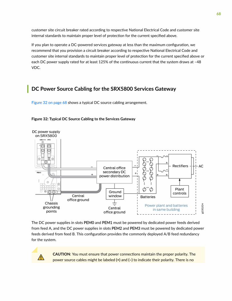
customer site circuit breaker rated according to respective National Electrical Code and customer siteinternal standards to maintain proper level of protection for the current specified above.
If you plan to operate a DC-powered services gateway at less than the maximum configuration, werecommend that you provision a circuit breaker according to respective National Electrical Code andcustomer site internal standards to maintain proper level of protection for the current specified above oreach DC power supply rated for at least 125% of the continuous current that the system draws at –48VDC.
DC Power Source Cabling for the SRX5800 Services Gateway
Figure 32 on page 68 shows a typical DC source cabling arrangement.
Figure 32: Typical DC Source Cabling to the Services Gateway
The DC power supplies in slots PEM0 and PEM1 must be powered by dedicated power feeds derivedfrom feed A, and the DC power supplies in slots PEM2 and PEM3 must be powered by dedicated powerfeeds derived from feed B. This configuration provides the commonly deployed A/B feed redundancyfor the system.
CAUTION: You must ensure that power connections maintain the proper polarity. Thepower source cables might be labeled (+) and (–) to indicate their polarity. There is no
68

standard color coding for DC power cables. The color coding used by the external DCpower source at your site determines the color coding for the leads on the power cablesthat attach to the terminal studs on each power supply.
WARNING: For field-wiring connections, use copper conductors only.
CAUTION: Power cords and cables must not block access to device components ordrape where people could trip on them.
SRX5800 Services Gateway Chassis Grounding Point Specifications
WARNING: To meet safety and electromagnetic interference (EMI) requirements and toensure proper operation, you must properly ground the services gateway chassis beforeconnecting power. See "Grounding the SRX5800 Services Gateway" on page 258 forinstructions.
CAUTION: Before services gateway installation begins, a licensed electrician mustattach cable lugs to the grounding and power cables that you supply. A cable with anincorrectly attached lug can damage the services gateway.
The services gateway chassis has two grounding points along the lower edge of the back panel. Eachgrounding point consists of two threaded holes spaced 0.625-in. (15.86-mm) apart (see Figure 33 onpage 70). The left grounding point fits M6 screws (European), and the right grounding point fitsUNC 1/4–20 screws (American). The accessory box shipped with the services gateway includes the
69

cable lug that attaches to the grounding cable and two UNC 1/4–20 screws used to secure thegrounding cable to the right-side grounding point on the services gateway.
Figure 33: SRX5800 Services Gateway Chassis Grounding Points
To ground the services gateway, you must connect a grounding cable to earth ground and then attach itto the chassis grounding point using the two screws provided.
NOTE: Additional grounding is provided to an AC-powered services gateway when you plug itspower supplies into grounded AC power receptacles.
SRX5800 Services Gateway Grounding Cable Specifications
The grounding cable that you provide must meet the specifications in Table 31 on page 71.
70

Table 31: Grounding Cable Specifications
Cable Type Quantity and Specification
Grounding One 6-AWG (13.3 mm2), minimum 60°C wire, or as required by the local code
WARNING: To meet safety and electromagnetic interference (EMI) requirements and toensure proper operation, you must properly ground the services gateway chassis beforeconnecting power. See "Grounding the SRX5800 Services Gateway" on page 258 forinstructions.
SRX5800 Services Gateway Grounding-Cable Lug Specification
The accessory box shipped with the services gateway includes the cable lug that attaches to thegrounding cable (see Figure 34 on page 71) and two UNC 1/4–20 screws used to secure the groundingcable to the grounding points.
Figure 34: Grounding Cable Lug
CAUTION: Before services gateway installation begins, a licensed electrician mustattach a cable lug to the grounding and power cables that you supply. A cable with anincorrectly attached lug can damage the services gateway.
NOTE: The same cable lug is used for the DC power cables.
71

SRX5800 Host Subsystem
IN THIS SECTION
SRX5800 Services Gateway Host Subsystem Description | 72
Switch Control Board SRX5K-SCB Overview | 73
Switch Control Board SRX5K-SCB Specifications | 75
Switch Control Board SRX5K-SCBE Overview | 78
Switch Control Board SRX5K-SCBE Specifications | 81
Switch Control Board SRX5K-SCB3 Overview | 84
Switch Control Board SRX5K-SCB3 Specifications | 85
Switch Control Board SRX5K-SCB4 Overview | 87
Switch Control Board SRX5K-SCB4 Specifications | 89
Routing Engine SRX5K-RE-13-20 Overview | 92
Routing Engine SRX5K-RE-13-20 Specifications | 93
Routing Engine SRX5K-RE-1800X4 Overview | 97
Routing Engine SRX5K-RE-1800X4 Specifications | 99
Routing Engine SRX5K-RE3-128G Specifications | 102
SRX5800 Services Gateway Host Subsystem Description
The host subsystem is composed of a Routing Engine installed in a Switch Control Board (SCB). The hostsubsystem provides the routing and system management functions of the services gateway. You mustinstall one host subsystem on the device. The host subsystem components are as follows:
• Switch Control Board
• SRX5K-SCB–from Junos OS Release 9.2 to 12.3X48
• SRX5K-SCBE–from Junos OS Release 12.1X47-D15 and later
• SRX5K-SCB3–from Junos OS Release 15.1X49-D10 and later
• SRX5K-SCB4–from Junos OS Release 19.3R1 and later
72

NOTE: SRX5K-SCB4 is not supported on SRX5400 Services Gateways.
• Routing Engine
• SRX5K-RE-13-20–from Junos OS Release 9.2 to 12.3X48
• SRX5K-RE-1800X4–from Junos OS Release 12.1X47-D15 and later
• SRX5K-RE3-128G–from Junos OS Release 19.3R1 and later
NOTE: You can only configure the following combination of Routing Engine and SCB within ahost subsystem:
• SRX5K-RE-13-20 and SRX5K-SCB
• SRX5K-RE-1800X4 and SRX5K-SCBE
• SRX5K-RE-1800X4 and SRX5K-SCB3
• SRX5K-RE-1800X4 and SRX5K-SCB4
• SRX5K-RE3-128G and SRX5K-SCB3 or SRX5K-SCB4
The host subsystem has three LEDs that display its status. The host subsystem LEDs are located in themiddle of the craft interface.
Switch Control Board SRX5K-SCB Overview
The Switch Control Board (SCB) provides the following functions:
• Powers on and powers off IOCs and SPCs
• Controls clocking, system resets, and booting
• Monitors and controls system functions, including fan speed, board power status, PDM status andcontrol, and the system front panel
• Provides interconnections to all the IOCs within the chassis through the switch fabrics integratedinto the SCB
73

When the SCB is part of a host subsystem, the Routing Engine installs directly into a slot on the SCB(see Figure 35 on page 74).
Figure 35: SRX5K-SCB
The SRX5800 Services Gateway has two SCBs installed and you can install a third SCB for switch fabricredundancy.
NOTE: The SRX5800 Services Gateway supports a redundant SCB, provided the SCB is aSRX5K-SCBE (SCB2) running Junos OS Release 12.1X47-D15 and later, SRX5K-SCB3 (SCB3)running Junos OS Release 15.1X49-D10 and later, or a SRX5K-SCB4 (SCB4) running Junos OSRelease 19.3R1 and later.The SRX5800 Services Gateway does not support a redundant SCB (third SCB) card if SRX5K-SPC-4-15-320 (SPC2) is installed with SCB1 (SRX5K-SCB). If you have installed a SPC2 on aSRX5800 Services Gateway with a redundant SCB1 card, make sure to remove the redundantSCB1 card.
SCBs install vertically into the front of the chassis. The SCB slots are located at the middle of the cardcage and are labeled 0, 1, and 2/6. If any slots are empty, you must install a blank panel.
SCBs installed in slots 0 and 1 provide nonredundant fabric connections. A SCB installed in slot 2/6, inconjunction with SCBs in slots 0 and 1, provides redundant fabrics. If no SCB is installed in slot 2/6, youmust install a blank panel in the slot (see Table 32 on page 75).
74
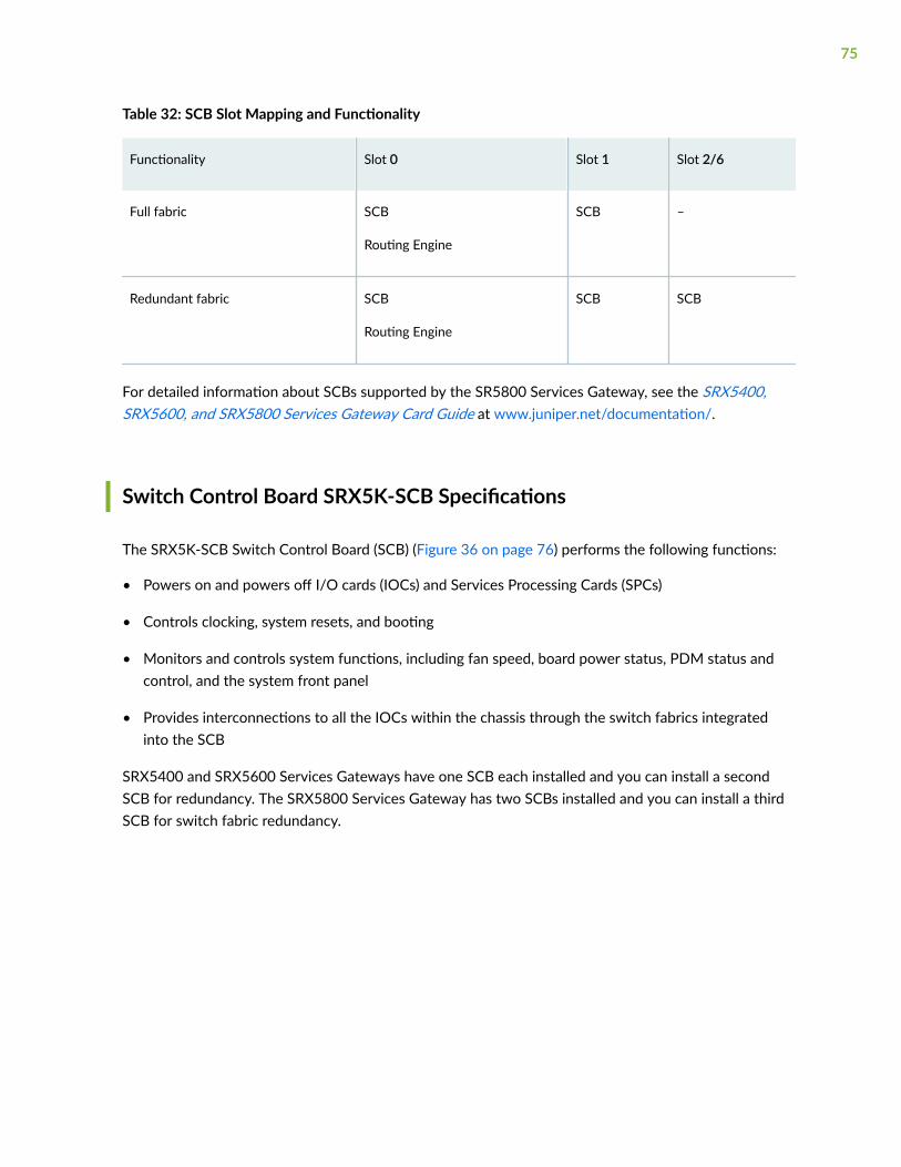
Table 32: SCB Slot Mapping and Functionality
Functionality Slot 0 Slot 1 Slot 2/6
Full fabric SCB
Routing Engine
SCB –
Redundant fabric SCB
Routing Engine
SCB SCB
For detailed information about SCBs supported by the SR5800 Services Gateway, see the SRX5400,SRX5600, and SRX5800 Services Gateway Card Guide at www.juniper.net/documentation/.
Switch Control Board SRX5K-SCB Specifications
The SRX5K-SCB Switch Control Board (SCB) (Figure 36 on page 76) performs the following functions:
• Powers on and powers off I/O cards (IOCs) and Services Processing Cards (SPCs)
• Controls clocking, system resets, and booting
• Monitors and controls system functions, including fan speed, board power status, PDM status andcontrol, and the system front panel
• Provides interconnections to all the IOCs within the chassis through the switch fabrics integratedinto the SCB
SRX5400 and SRX5600 Services Gateways have one SCB each installed and you can install a secondSCB for redundancy. The SRX5800 Services Gateway has two SCBs installed and you can install a thirdSCB for switch fabric redundancy.
75

The host subsystem is composed of a Routing Engine installed directly into a slot on the faceplate of theSCB. When there is no Routing Engine is a SCB, its slot must be covered with a blank panel.
Figure 36: Switch Control Board SRX5K-SCB
Each SCB consists of the following components:
• Chassis management Ethernet switch.
• I2C bus logic, used for low-level communication with each component.
• Component redundancy circuitry.
• Gigabit Ethernet switch that is connected to the embedded CPU complex on all components.
• Switch fabric—Provides the switching functions for the IOCs.
• Control FPGA—Provides the Peripheral Component Interconnect (PCI) interface to the RoutingEngine.
• 1000Base-T Ethernet controller—Provides a 1-Gbps Ethernet link between the Routing Engines.
• Ethernet switch—Provides 1-Gbps link speeds between the Routing Engine and the IOCs.
• Circuits for chassis management and control.
• Power circuits for the Routing Engine and SCB.
76

Description • SCB with slot for Routing Engine
• Maximum throughput: 75 Gbps per slot
Software release • Junos OS Release 9.2 and later
Cables and connectors Slot for Routing Engine
Controls None
Supported Slots • SRX5400–Only bottom slots 0 and 1/0
• SRX5600–Only bottom slots 0 and 1
• SRX5800–Only center slots 0, 1, and 2/6
Power Requirement 150 W
Weight Approximately 10 lb (4.5 kg)
LEDs OK/FAIL LED, one bicolor:
• Green–The SCB is operating normally.
• Red–The SCB has failed and is not operating normally.
• Off–The SCB is powered down.
FABRIC ONLY LED:
• Green–The SCB is operating in fabric-only mode.
• Off–The SCB is operating in fabric/control board mode.
FABRIC ACTIVE LED:
• Green–The fabric is in active mode.
77

Serial Number Location The serial number label is located as shown in Figure 37 on page 78.
Figure 37: SCB Serial Number Label
Switch Control Board SRX5K-SCBE Overview
The SRX5000 line enhanced Switch Control Board (SRX5K-SCBE) caters to high-end security marketsrequiring support for higher capacity traffic. The SRX5K-SCBE provides greater interface density (slotand capacity scale) and improved services.
78

Some key attributes of the SRX5K-SCBE are:
• A bandwidth of 120 Gbps per slot with redundant fabric support and improved fabric performanceby using the next-generation fabric (XF) chip.
• A centralized clocking architecture that supports clock cleanup and distribution. The Stratum 3 clockmodule performs clock monitoring, filtering, and holdover in a centralized chassis location.
• Full performance with fabric redundancy for higher capacity line cards such as the SRX5K-MPC.
79

The Routing Engine installs directly into a slot on the SRX5K-SCBE as shown in Figure 38 on page 80.
Figure 38: SRX5K-SCBE
80

Switch Control Board SRX5K-SCBE Specifications
IN THIS SECTION
SRX5K-SCBE LEDs | 83
Each SRX5K-SCBE consists of the following components:
• I2C bus logic for low-level communication with each component
• Component redundancy circuitry
• Control Board/Routing Engine primary-role mechanism
• Gigabit Ethernet switch that is connected to the embedded CPU complex on all components
• Switch fabric to provide the switching functions for the MPCs
• 1000BASE-T Ethernet controller to provide a 1-Gbps Ethernet link between the Routing Engines
• Power circuits for the Routing Engine and the SRX5K-SCBE
• LEDs—Provides status of the SRX5K-SCBE and clocking interface
Description • SRX5K-SCBE with slot for Routing Engine
• Maximum throughput: 120 Gbps per slot
Software release Junos OS Release 12.1X47-D15 and later
Cables and connectors Slot for Routing Engine
Controls None
81

Supported slots • SRX5400–Only bottom slots 0 and 1/0
• SRX5600–Only bottom slots 0 and 1
• SRX5800–Only center slots 0, 1, and 2/6
Power requirement • 160 W at 131º F (55º C)
• 130 W at 104º F (40º C)
• 120 W at 77º F (25º C)
Weight 9.6 lb (4.4 kg) with Routing Engine
82

Serial number location The serial number label is located as shown in Figure 39 on page 83.
Figure 39: SRX5K-SCBE Serial Number Label
SRX5K-SCBE LEDs
Table 33 on page 84 describes the SRX5K-SCBE LEDs and their states.
83

Table 33: SRX5K-SCBE LEDs
Label Color State Description
FABRICACTIVE
Green On steadily Fabric is in active mode.
FABRICONLY
Green On steadily SRX5K-SCBE operates infabric-only mode.
None Off SRX5K-SCBE operates infabric/control board mode.
OK/FAIL Green On steadily SRX5K-SCBE is online.
Red On steadily SRX5K-SCBE has failed.
None Off SRX5K-SCBE is offline.
Switch Control Board SRX5K-SCB3 Overview
The SRX5K-SCB3 (SCB3) caters to high-end security markets requiring support for higher capacitytraffic, greater interface density (slot and capacity scale), and improved services. The SCB3 is supportedon SRX5400, SRX5600, and SRX5800 Services Gateways.
The SCB3 supports the standard midplane and the enhanced midplane.
Some key attributes of the SCB3 are:
• With the existing midplane and fabric link speed of 8.36 Gbps, supports a bandwidth of 205 Gbpsper slot with redundant fabric support and 308 Gbps per slot without redundancy.
• With the enhanced midplane and fabric link speed of 10.2 Gbps, supports a bandwidth of 249 Gbpsper slot with redundant fabric support and 374 Gbps per slot without redundancy with the enhancedmidplane
• Improved fabric performance with the next-generation fabric (XF2) chip.
• Full performance with fabric redundancy for higher-capacity line cards.
84

• Support for MPC line cards such as SRX5K-MPC (IOC2) and IOC3 (SRX5K-MPC3-40G10G orSRX5K-MPC3-100G10G) only.
• Two 10-Gigabit Ethernet SFP+ ports (These ports are disabled and reserved for future use).
The Routing Engine installs directly into a slot on the SCB3, as shown in Figure 40 on page 85.
Figure 40: SRX5K-SCB3
Switch Control Board SRX5K-SCB3 Specifications
IN THIS SECTION
SRX5K-SCB3 LEDs | 87
Each SRX5K-SCB3 (SCB3) consists of the following components:
• I2C bus logic for low-level communication with each component
• Component redundancy circuitry
• Control Board/Routing Engine primary-role mechanism
• Gigabit Ethernet switch that is connected to the embedded CPU complex on all components
• Switch fabric to provide the switching functions for the MPCs
• Control field-programmable gate array (FPGA) to provide the Peripheral Component Interconnect(PCI) interface to the Routing Engine
• Circuits for chassis management and control
• Power circuits for the Routing Engine and SCB3
85

• LEDs to provides status of the SCB3
Description SCB3 with slot for Routing Engine
Software release Junos OS Release 15.1X49-D10 and later
Cables and connectors Slot for Routing Engine
Controls None
Supported slots • SRX5400–Only bottom slots 0 and 1/0
• SRX5600–Only bottom slots 0 and 1
• SRX5800–Only center slots 0, 1, and 2/6
Power requirement 300 W
Weight 9.6 lb (4.4 kg) with Routing Engine
Serial number location The serial number label is located as shown in Figure 41 on page 86.
Figure 41: SRX5K-SCB3 Serial Number Label
86

SRX5K-SCB3 LEDs
Table 34 on page 87 describes the SCB3 LEDs and their states.
Table 34: SRX5K-SCB3 LEDs
Label Color State Description
FABRIC ACTIVE Green On steadily Fabric is in active mode.
OK/FAIL Green On steadily SCB3 is online.
Red On steadily SCB3 has failed.
– Off SCB3 is offline.
LINK Green On steadily Port is enabled and link is established.
– Off Port is disabled or no link is established.
Switch Control Board SRX5K-SCB4 Overview
The SRX5K-SCB4 (SCB4) Enhanced Switch Control Board provides improved fabric performance andbandwidth capabilities for high-capacity line cards using the ZF-based switch fabric. The SCB4 issupported on SRX5600 and SRX5800 Services Gateways, but not supported on SRX5400 ServicesGateways.
The SCB4 supports the standard and the enhanced midplane.
Some key attributes of the SCB4 are:
• With the SRX5K-SCB4 Switch Control Board, Increased Fabric Bandwidth mode is the default modeon the SRX5600 and SRX5800 Services Gateways and the services gateways will use six activeplanes without any spare planes.
• With the Redundant Fabric mode, the SRX5600 and SRX5800 Services Gateways will use four activeplanes and will have two spare planes.
• Full performance with fabric redundancy for higher-capacity line cards.
87

• Two 10-Gigabit Ethernet SFP+ ports (These ports are disabled and reserved for future use).
Increased Fabric Bandwidth mode is the default fabric mode of SCB4. In this mode you must install twoSCB4s in SRX5600 and three SCB4s in SRX5800 Services Gateways/Chassis clusters.
You can change the fabric mode of SCB4 from Increased Fabric Bandwidth mode to Redundant Fabricmode using the CLI. If you change the fabric mode of SCB4 to Redundant Fabric mode you must installtwo SCB4s in SRX5600 and you can install either two or three SCB4s in SRX5800 Services Gateways.
If you are upgrading from SCB3 (Redundant Fabric mode is the default fabric mode in SCB2 and SCB3)to SCB4 and installing only two SCB4s, you must have Junos OS 19.3R1 or later and change the defaultfabric mode of SCB4s to Redundant Fabric mode by using the CLI.
NOTE: To achieve maximum throughput on an SRX5800 Services Gateway, you must install onlytwo SCB4s (configured in redundant fabric mode) in a fully loaded chassis (for example: 3x IOC4+ 7x SPC3 + 2x RE3 + 2x SCB4). If you install three SCB4s into the fully loaded chassis (forexample: 3x IOC4 + 7x SPC3 + 2x RE3 + 3x SCB4) the chassis will hit chassis power limit and oneof the line cards will go offline due to power shortage.
You can change the fabric mode by following one of these two methods:
1. Use the CLI command request chassis fabric mode <increased-bandwidth|redundant-fabric>
2. Save the change in the Configuration file
set chassis fabric redundancy-mode increased-bandwidthset chassis fabric redundancy-mode redundant
88

The Routing Engine installs directly into a slot on the SCB4, as shown in Figure 42 on page 89.
Figure 42: SRX5K-SCB4
Switch Control Board SRX5K-SCB4 Specifications
IN THIS SECTION
SRX5K-SCB4 LEDs | 91
SRX5K-SCB4 (SCB4) consists of the following components:
• LEDs to provides status of the SCB4.
89

• Circuits for chassis management and control.
• Power circuits for the Routing Engine and SCB4.
Description SCB4 with slot for SRX5K-RE-1800X4 and SRX5K-RE3-128G Routing Engines
Software release Junos OS Release 19.3R1 and later
Cables and connectors Slot for Routing Engine
Controls None
Supported slots • SRX5400–Not supported
• SRX5600–Only bottom slots 0 and 1
• SRX5800–Only center slots 0, 1, and 2/6
Power requirement At different temperatures:
• 55° C: 425 W
• 40° C: 400 W
• 25° C: 385 W
Cooling requirement For efficient and reliable power and cooling, you must install SRX Series high-capacitypower supplies and fan trays in the SRX Series chassis.
Weight and Dimensions • Weight: 13.6 lb (6.2 kg)
• Width: 15.7 in (39.87 cm)
• Depth: 21.2 in (53.85 cm)
• Height: 1.2 in (3.05 cm)
90

Serial number location The serial number label is located as shown in Figure 43 on page 91.
Figure 43: SRX5K-SCB4 Serial Number Label
SRX5K-SCB4 LEDs
Table 35 on page 91 describes the SCB4 LEDs and their states.
Table 35: SRX5K-SCB4 LEDs
Label Color State Description
OK/FAIL Green On steadily SCB4 is online.
91

Table 35: SRX5K-SCB4 LEDs (Continued)
Label Color State Description
Red On steadily SCB4 has failed.
– Off SCB4 is offline.
FABRIC
ACTIVE Green On steadily The switch fabric on this board is in Active mode.
ONLY Green On steadily The switch is in Fabric-Only mode.
LINK (XGE port) Green On steadily SFP+ port is enabled and link is established.
– Off SFP+ port is disabled or no link is established.
GPS Green On steadily Indicates the status of the GPS clocking interface, and the link is OK.
Yellow Blinking Activity on the clocking interface.
Routing Engine SRX5K-RE-13-20 Overview
The Routing Engine is an Intel-based PC platform that runs Junos OS. Software processes that run onthe Routing Engine maintain the routing tables, manage the routing protocols used on the device,control the device interfaces, control some chassis components, and provide the interface for systemmanagement and user access to the device.
You must install at least one Routing Engine in the services gateway. You can install a second RoutingEngine if both Routing Engines are running Junos OS Release 10.0 or later.
A second Routing Engine is required if you are using the dual chassis cluster control link feature availablein Junos OS Release 10.0 and later. The second Routing Engine does not perform all the functions of aRouting Engine and does not improve resiliency or redundancy. The second Routing Engine and theSwitch Control Board (SCB) in which it is installed do not constitute a host subsystem. The only function
92

of the second Routing Engine is to enable the hardware infrastructure that enables the Chassis ClusterControl 1 port on the Services Processing Card (SPC) used for chassis cluster control links.
If you install only one Routing Engine in the services gateway, you must install it in the slot in the frontpanel of SCB0. If you install a second Routing Engine to use the dual chassis cluster control link feature,you install it in the slot in the front panel of SCB1 (see Figure 44 on page 93).
A USB port on the Routing Engine accepts a USB memory card that allows you to load Junos OS.
Figure 44: SRX5K-RE-13-20 Routing Engine
For detailed information about the Routing Engines supported by the services gateway, see theSRX5400, SRX5600, and SRX5800 Services Gateway Card Reference at www.juniper.net/documentation/.
Routing Engine SRX5K-RE-13-20 Specifications
The SRX5K-RE-13-20 Routing Engine (Figure 45 on page 94) is an Intel-based PC platform that runsthe Junos operating system (Junos OS). Software processes that run on the Routing Engine maintain therouting tables, manage the routing protocols used on the device, control the device interfaces, control
93
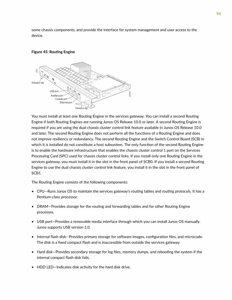
some chassis components, and provide the interface for system management and user access to thedevice.
Figure 45: Routing Engine
You must install at least one Routing Engine in the services gateway. You can install a second RoutingEngine if both Routing Engines are running Junos OS Release 10.0 or later. A second Routing Engine isrequired if you are using the dual chassis cluster control link feature available in Junos OS Release 10.0and later. The second Routing Engine does not perform all the functions of a Routing Engine and doesnot improve resiliency or redundancy. The second Routing Engine and the Switch Control Board (SCB) inwhich it is installed do not constitute a host subsystem. The only function of the second Routing Engineis to enable the hardware infrastructure that enables the chassis cluster control 1 port on the ServicesProcessing Card (SPC) used for chassis cluster control links. If you install only one Routing Engine in theservices gateway, you must install it in the slot in the front panel of SCB0. If you install a second RoutingEngine to use the dual chassis cluster control link feature, you install it in the slot in the front panel ofSCB1.
The Routing Engine consists of the following components:
• CPU—Runs Junos OS to maintain the services gateway's routing tables and routing protocols. It has aPentium-class processor.
• DRAM—Provides storage for the routing and forwarding tables and for other Routing Engineprocesses.
• USB port—Provides a removable media interface through which you can install Junos OS manually.Junos supports USB version 1.0.
• Internal flash disk—Provides primary storage for software images, configuration files, and microcode.The disk is a fixed compact flash and is inaccessible from outside the services gateway.
• Hard disk—Provides secondary storage for log files, memory dumps, and rebooting the system if theinternal compact flash disk fails.
• HDD LED—Indicates disk activity for the hard disk drive.
94

• Management ports—Each Routing Engine has one 10/100-Mbps Ethernet port for connecting to amanagement network, and two asynchronous serial ports—one for connecting to a console and onefor connecting to a modem or other auxiliary device. The interface ports are labeled AUX, CONSOLE,and ETHERNET.
• EEPROM—Stores the serial number of the Routing Engine.
• Extractor clips—Used for inserting and extracting the Routing Engine.
• Captive screws—Secures the Routing Engine in place.
The Routing Engine boots from the storage media in this order: the USB device (if present), then theinternal flash disk, then the hard disk, then the LAN.
NOTE: For specific information about Routing Engine components (for example, the amount ofDRAM), issue the show chassis routing-engine command.
Description Routing Engine for SRX5400, SRX5600, and SRX5800 Services Gateways
Software release • Junos OS Release 9.2 and later
• Junos OS Release 10.0 and later required to install a second Routing Engine
Cables andconnectors
AUX—Connects the Routing Engine to a laptop, a modem, or another auxiliary devicethrough a cable with an RJ-45 connector.
CONSOLE—Connects the Routing Engine to a system console through a cable with an RJ-45connector.
ETHERNET—Connects the Routing Engine through an Ethernet connection to amanagement LAN (or any other device that plugs into an Ethernet connection) for out-of-band management.
Controls • RESET button—Reboots the Routing Engine when pressed
• ONLINE/OFFLINE Button—Not supported in the current release
95
Supported Slots Front panel slot in an SCB installed in:
• SRX5400: Bottom slot 0
• SRX5600: Bottom slots 0 or 1
• SRX5800: Center slots 0 or 1
NOTE: The services gateway host subsystem Routing Engine must be installed in the SCB inslot 0. A Routing Engine installed in an SCB in slot 1 only enables dual control links in chassiscluster configurations.
PowerRequirement
90 W
Weight Approximately 2.4 lb (1.1 kg)
LEDs HDD LED:
• Blinking green–The Routing Engine hard disk is functioning normally.
MASTER LED:
• Blue–The Routing Engine is Primary.
NOTE: The SRX5400, SRX5600, and SRX5800 Services Gateways do not support asecondary or backup Routing Engine, so the MASTER LED should always be lit.
OK/FAIL LED, one bicolor:
• Off–The Routing Engine is operating normally.
• Red–The Routing Engine has failed and is not operating normally.
ONLINE LED:
• Blinking green–The Routing Engine is coming online.
• Steady green–The Routing Engine is functioning normally.
96

Serial NumberLocation
The serial number label is located on the right side of the top of the Routing Engine asshown in Figure 46 on page 97
Figure 46: SRX5K-RE-13-20 Serial Number Label
Routing Engine SRX5K-RE-1800X4 Overview
IN THIS SECTION
SRX5K-RE-1800X4 Routing Engine Boot Sequence | 98
The enhanced Routing Engine is an Intel-based PC platform that runs Junos OS. Software processes thatrun on the Routing Engine maintain the routing tables, manage the routing protocols used on the device,control the device interfaces, control some chassis components, and provide the interface for systemmanagement and user access to the device.The Routing Engine must be installed directly into the
97

SRX5K-SCBE. A USB port on the Routing Engine accepts a USB memory device that allows you to loadJunos OS. Figure 47 on page 98 shows the Routing Engine.
Figure 47: SRX5K-RE-1800X4 Routing Engine
Three ports located on the Routing Engine connect to one or more external devices on which systemadministrators can issue Junos OS CLI commands to manage the services gateway.
The ports function as follows:
• AUX–Connects the Routing Engine to a laptop, modem, or other auxiliary device through a serialcable with an RJ-45 connector.
• CONSOLE–Connects the Routing Engine to a system console through a serial cable with an RJ-45connector.
• ETHERNET–Connects the Routing Engine through an Ethernet connection to a management LAN (orany other device that plugs into an Ethernet connection) for out-of-band management. The port usesan autosensing RJ-45 connector to support 10/100/1000 Mbps connections. Two small LEDs on thebottom of the port indicate the connection in use: the LED flashes yellow or green for a10/100/1000 Mbps connection, and the LED is light green when traffic is passing through the port.
The solid-state drive (SSD) slots located on the Routing Engine provide secondary storage for log files,for generating core files, and for rebooting the system if the CompactFlash card fails. Currently, SRX5K-RE-1800X4 only supports one 128-GB SSD.
SRX5K-RE-1800X4 Routing Engine Boot Sequence
The services gateway is shipped with three copies of the Junos OS preinstalled on the Routing Engine inthe following locations:
98

• On the CompactFlash card in the Routing Engine
• On the SSD in the Routing Engine
• On a USB flash drive that can be inserted into the slot on the Routing Engine faceplate
The Routing Engine boots from the storage media in this order: the USB device (if present), theCompactFlash card, the solid-state drive (SSD), and then the LAN. Normally, the services gateway bootsfrom the copy of the software on the CompactFlash card.
Routing Engine SRX5K-RE-1800X4 Specifications
IN THIS SECTION
SRX5K-RE-1800X4 LEDs | 101
Each Routing Engine consists of the following components:
• CPU—Runs Junos OS to maintain the routing tables and routing protocols.
• DRAM—Provides storage for the routing and forwarding tables and for other Routing Engineprocesses.
• USB port—Provides a removable media interface through which you can install the Junos OSmanually. Junos OS supports USB version 1.0 and 2.0.
• CompactFlash card—Provides primary storage for software images, configuration files, andmicrocode. The CompactFlash card is fixed and is inaccessible from outside the device.
• Solid-state drive (SSD)—Provides secondary storage for log files, for generating core files, and forrebooting the system if the CompactFlash card fails.
• Interface ports—The AUX, CONSOLE, and ETHERNET ports provide access to management devices.Each Routing Engine has one 10/100/1000-Mbps Ethernet port for connecting to a managementnetwork, and two asynchronous serial ports—one for connecting to a console and one for connectingto a modem or other auxiliary device.
• EEPROM—Stores the serial number of the Routing Engine.
• Reset button—Reboots the Routing Engine when pressed.
99

• Online/Offline button—Takes the Routing Engine online or offline when pressed.
• Extractor clips—Inserts and extracts the Routing Engine.
• Captive screws—Secures the Routing Engine in place.
Description Routing Engine for SRX5400, SRX5600, and SRX5800 Services Gateways
Software release Junos OS Release 12.1X47-D15 and later
Cables andconnectors
Slot for Routing Engine
• AUX–Connects the Routing Engine to a laptop, a modem, or another auxiliary devicethrough a cable with an RJ-45 connector.
• CONSOLE–Connects the Routing Engine to a system console through a cable with anRJ-45 connector.
• ETHERNET–Connects the Routing Engine through an Ethernet connection to amanagement LAN (or any other device that plugs into an Ethernet connection) for out-of-band management.
Controls RESET button–Reboots the Routing Engine when pressed.
Supported slots Front panel slot in an SCB installed in:
• SRX5400: Bottom slot 0
• SRX5600: Bottom slots 0 or 1
• SRX5800: Center slots 0 or 1
NOTE: The services gateway host subsystem Routing Engine must be installed in the SCBin slot 0. A Routing Engine installed in an SCB in slot 1 only enables dual control links inchassis cluster configurations.
Powerrequirement
90 W
Weight 2.4 lb (1.1 kg)
100

Serial numberlocation
The serial number label is located as shown in Figure 48 on page 101.
Figure 48: SRX5K-RE-1800X4 Serial Number Label
SRX5K-RE-1800X4 LEDs
Each Routing Engine has four LEDs that indicate its status. The LEDs, labeled MASTER, STORAGE,ONLINE, and OK/FAIL, are located directly on the faceplate of the Routing Engine. Table 36 on page101 describes the Routing Engine LEDs and their states.
Table 36: SRX5K-RE-1800X4 LEDs
Label Color State Description
MASTER Blue On steadily Routing Engine is the primary.
STORAGE Green Blinking Indicates activity on the SSDor CompactFlash card.
101

Table 36: SRX5K-RE-1800X4 LEDs (Continued)
Label Color State Description
ONLINE Green Blinking Routing Engine is transitioningonline.
None On steadily Routing Engine is functioningnormally.
OK/FAIL Red On steadily Routing Engine has failed.
Routing Engine SRX5K-RE3-128G Specifications
IN THIS SECTION
SRX5K-RE3-128G Routing Engine Components | 105
SRX5K-RE3-128G Routing Engine LEDs | 106
SRX5K-RE3-128G Routing Engine Boot Sequence | 107
The Routing Engine maintains the routing tables, manages the routing protocols used on the device,controls the device interfaces, controls some chassis components, and provides the interfaces for systemmanagement and user access to the device.
Figure 49 on page 102 shows the SRX5K-RE3-128G Routing Engine.
Figure 49: SRX5K-RE3-128G Routing Engine Front View
102

1— Extractor clips 6— ONLINE/OFFLINE button
2— Auxiliary port (AUX) 7— SSD LEDs—DISK1 and DISK2
3— Console port (CONSOLE) 8— USB ports—USB1 and USB2
4— Management port (MGMT) 9— RESET button
5— Routing Engine status LEDs—ONLINE, OK/FAIL, and MASTER
10— SSD card slot cover
Description Routing Engine for SRX5400, SRX5600, and SRX5800 Services Gateways, based on Intel’sHaswell-EP CPU with 6 cores, and 128GB of DDR4 memory. It provides increased controlplane performance and scalability along with virtualization features in the SRX Series 5000line of chassis.
Software release Junos OS Release 19.3R1 and later
Cables andconnectors
Slot for Routing Engine
• AUX–Connects the Routing Engine to a laptop, a modem, or another auxiliary devicethrough a cable with an RJ-45 connector.
• CONSOLE–Connects the Routing Engine to a system console through a cable with anRJ-45 connector.
• MGMT–Connects the Routing Engine through an Ethernet connection to a managementLAN (or any other device that plugs into an Ethernet connection) for out-of-bandmanagement.
Controls RESET button–Reboots the Routing Engine when pressed.
103

Supported slots Front panel slot in an SCB installed in:
• SRX5400: Bottom slot 0
• SRX5600: Bottom slots 0 or 1
• SRX5800: Center slots 0 or 1
NOTE: The services gateway host subsystem Routing Engine must be installed in the SCB inslot 0. A Routing Engine installed in an SCB in slot 1 only enables dual control links in chassiscluster configurations.
NOTE: In the SRX5600 or SRX5800 Services Gateways chassis cluster configurations, dualcontrol links functionality is not supported if you mix SRX5K-RE-1800X4 and SRX5K-RE3-128G Routing Engines. To support dual control links you have to install two SRX5K-RE3-128Gs.
Powerrequirement
110 W
Weight 2.69 lb (1.22 kg)
104

Serial numberlocation
The serial number label is located as shown in Figure 50 on page 105.
Figure 50: SRX5K-RE3-128G Serial Number Label
SRX5K-RE3-128G Routing Engine Components
Each Routing Engine consists of the following components:
• CPU—Runs Junos OS to maintain the routing tables and routing protocols.
• EEPROM—Stores the serial number of the Routing Engine.
• DRAM—Provides storage for the routing and forwarding tables and for other Routing Engineprocesses.
• One 10-Gigabit Ethernet interface between the Routing Engine and Switch Control Board.
• Extractor clips—Control the locking system that secures the Routing Engine.
• Interface ports—The AUX, CONSOLE, and MGMT ports provide access to management devices. EachRouting Engine has one 10/100/1000-Mbps Ethernet port for connecting to a management
105

network, and two asynchronous serial ports—one for connecting to a console and one for connectingto a modem or other auxiliary device.
NOTE: The control interface names differ based on the routing engine:
• For RE2, the control interfaces are displayed as em0 and em1.
• For RE3, the control interfaces are displayed as ixlv0 and igb0.
For more information, see show chassis cluster interfaces.
• Status LEDs—Table 37 on page 106 describes the functions of the ONLINE, OK/FAIL, MASTER,DISK1, and DISK2 LEDs.
• ONLINE/OFFLINE button—Takes the Routing Engine online or offline when pressed.
NOTE: The ONLINE/OFFLINE button must be pressed for a minimum of 4 seconds.
• USB1 and USB2 ports—Provide a removable media interface through which you can install Junos OSmanually. Junos OS supports USB versions 3.0, 2.0, and 1.1.
• RESET button—Reboots the Routing Engine when pressed.
• SSD1 (primary) and SSD2 (secondary) Solid-state drives (SSD)—Two 200-GB each slim solid-statedrives that provide storage for software images, configuration files, microcode, log files, and memorydumps. The Routing Engine reboots from SSD2 when boot from primary SSD1 fails.
• Captive screws—Secures the Routing Engine.
SRX5K-RE3-128G Routing Engine LEDs
Each Routing Engine has four LEDs that indicate its status. The LEDs, labeled ONLINE, OK/FAIL,MASTER, DISK1, and DISK2, are located directly on the faceplate of the Routing Engine. Table 37 onpage 106 describes the Routing Engine LEDs and their states.
Table 37: SRX5K-RE3-128G Routing Engine LEDs
Label Color State Description
ONLINE Green Blinking slowly Routing Engine is in the process of booting BIOS and the host OS.
106

Table 37: SRX5K-RE3-128G Routing Engine LEDs (Continued)
Label Color State Description
Blinking rapidly Routing Engine is in the process of booting Junos OS.
- Off Routing Engine is not online or not functioning normally.
OK/FAIL Green On steadily Routing Engine is powering up.
Yellow On steadily Routing Engine is not powering up, which indicates failure.
MASTER Blue On steadily This Routing Engine is the primary Routing Engine.
DISK1 Green Blinking Indicates presence of disk activity.
- Off There is no disk activity.
DISK2 Green Blinking Indicates presence of disk activity.
- Off There is no disk activity.
SRX5K-RE3-128G Routing Engine Boot Sequence
Booting in a SRX5K-RE3-128G Routing Engine follows this sequence—the USB device, SSD1, SSD2, andLAN. SSD1 is the primary boot device. The boot sequence is tried twice for SSD1 and SSD2.
107

SRX5800 Line Cards and Modules
IN THIS SECTION
SRX5400, SRX5600, and SRX5800 Services Gateway Card Overview | 109
Cards Supported on SRX5400, SRX5600, and SRX5800 Services Gateways | 110
SRX5800 Services Gateway Card Cage and Slots | 116
SRX5800 Services Gateway SPC Description | 117
Services Processing Card SRX5K-SPC-2-10-40 Specifications | 118
Services Processing Card SRX5K-SPC-4-15-320 Specifications | 124
Services Processing Card SRX5K-SPC3 Specifications | 130
Modular Port Concentrator (SRX5K-MPC) Specifications | 134
MIC with 20x1GE SFP Interfaces (SRX-MIC-20GE-SFP) | 137
MIC with 10x10GE SFP+ Interfaces (SRX-MIC-10XG-SFPP) | 144
MIC with 1x100GE CFP Interface (SRX-MIC-1X100G-CFP) | 149
MIC with 2x40GE QSFP+ Interfaces (SRX-MIC-2X40G-QSFP) | 151
SRX5K-MPC3-40G10G Specifications | 152
SRX5K-MPC3-100G10G Specifications | 156
SRX5K-IOC4-10G Specifications | 160
SRX5K-IOC4-MRAT Specifications | 164
SRX5800 Services Gateway Interface Card Description | 168
I/O Card SRX5K-40GE-SFP Specifications | 171
I/O Card SRX5K-4XGE-XFP Specifications | 174
Flex I/O Card (SRX5K-FPC-IOC) Specifications | 177
Flex I/O Card Port Module SRX-IOC-16GE-SFP Specifications | 180
Flex I/O Card Port Module SRX-IOC-16GE-TX Specifications | 182
Flex I/O Card Port Module SRX-IOC-4XGE-XFP Specifications | 184
108

SRX5400, SRX5600, and SRX5800 Services Gateway Card Overview
The cards described in this guide let you upgrade and customize your SRX5400, SRX5600, or SRX5800Services Gateway to suit the needs of your network. The following types of cards are available for theSRX5400, SRX5600, and SRX5800 Services Gateways:
• I/O cards (IOCs) provide additional physical network connections to the services gateway. Theirprimary function is to deliver data packets arriving on the physical ports to the Services ProcessingCards (SPCs) and to forward data packets out the physical ports after services processing.
• Flex IOCs have two slots for port modules that add additional physical network connections to theservices gateway. Like IOCs, their primary function is to deliver data packets arriving on the physicalports to the SPCs and to forward data packets out the physical ports after services processing.
• Modular Port Concentrators (MPCs) have slots on the front panel that accept smaller cards calledModular Interface Cards (MICs). Each MIC has one or more physical interfaces on it. An MPC withMICs installed functions in the same way as a regular I/O card (IOC), but allows greater flexibility inadding different types of Ethernet ports to your services gateway. MPCs and MICs are similar in formand function to Flex IOCs and port modules. However, the two use different form-factors, so youcannot install port modules in an MPC, nor can you install MICs in a Flex IOC.
• Services Processing Cards (SPCs) provide the processing power to run integrated services such asfirewall, IPsec and IDP. All traffic traversing the services gateway is passed to an SPC to have servicesprocessing applied to it.
• Switch Control Boards (SCBs) power on and power off IOCs and SPCs; control clocking and systemresets; and control booting, monitor, and system functions. Each SCB has a slot in the front panel fora Routing Engine.
Although the following modules are not cards in the sense of having a form-factor that fits the card cageof the SRX5400, SRX5600, and SRX5800 Services Gateway, this guide also addresses the followingmodules that fit into certain SRX5400, SRX5600, and SRX5800 Services Gateway cards:
• Routing Engines fit into slots in SCBs and maintain the routing tables, manage the routing protocolsused on the device, control the device interfaces and some chassis components, and provide theinterface for system management and user access to the device.
• Port modules fit into slots in Flex IOCs and add additional physical network interface ports to theservices gateway.
• Modular Interface Cards (MICs) fit into slots in MPCs and add additional physical network interfaceports to the services gateway. MPCs and MICs are similar in form and function to Flex IOCs and portmodules. However, the two use different form-factors, so you cannot install port modules in an MPC,nor can you install MICs in a Flex IOC.
109

Cards Supported on SRX5400, SRX5600, and SRX5800 ServicesGateways
Table 38 on page 110 describes the cards and other modules supported on the SRX5400, SRX5600, andSRX5800 Services Gateways.
Table 38: Supported Cards for SRX5400, SRX5600, and SRX5800 Services Gateways
Card Name and ModelNumber
Earliest Supported Junos OS Release Last Supported JunosOS Release
SRX5400 SRX5600 and SRX5800 SRX5400, SRX5600, andSRX5800
SPCs
"Services Processing CardSRX5K-SPC-2-10-40Specifications" on page 118
Not supported 9.2 12.3X48
"Services Processing CardSRX5K-SPC-4-15-320Specifications" on page 124
12.1X46-D10 12.1X44-D10
"Services Processing CardSRX5K-SPC3 Specifications"on page 130
18.2R1-S1 18.2R1-S1
Interface Cards
"I/O Card SRX5K-40GE-SFPSpecifications" on page 171
Not supported 9.2 12.3X48
"I/O Card SRX5K-4XGE-XFPSpecifications" on page 174
Not supported 9.2 12.3X48
"Flex I/O Card (SRX5K-FPC-IOC) Specifications" on page177
Not supported 10.2 12.3X48
110

Table 38: Supported Cards for SRX5400, SRX5600, and SRX5800 Services Gateways (Continued)
Card Name and ModelNumber
Earliest Supported Junos OS Release Last Supported JunosOS Release
SRX5400 SRX5600 and SRX5800 SRX5400, SRX5600, andSRX5800
"Modular Port Concentrator(SRX5K-MPC) Specifications"on page 134
12.1X46-D10 12.1X46-D10
"SRX5K-MPC3-40G10GSpecifications" on page 152
15.1X49-D10 15.1X49-D10
"SRX5K-MPC3-100G10GSpecifications" on page 156
15.1X49-D10 15.1X49-D10
"SRX5K-IOC4-10GSpecifications" on page 160
19.3R1 19.3R1
"SRX5K-IOC4-MRATSpecifications" on page 164
19.3R1 19.3R1
SCBs
"Switch Control BoardSRX5K-SCB Specifications"on page 75
12.1X46-D10 9.2 12.3X48
"Switch Control BoardSRX5K-SCBE Specifications"on page 81
12.1X47-D15 12.1X47-D15
"Switch Control BoardSRX5K-SCB3 Specifications"on page 85
15.1X49-D10 15.1X49-D10
111

Table 38: Supported Cards for SRX5400, SRX5600, and SRX5800 Services Gateways (Continued)
Card Name and ModelNumber
Earliest Supported Junos OS Release Last Supported JunosOS Release
SRX5400 SRX5600 and SRX5800 SRX5400, SRX5600, andSRX5800
"Switch Control BoardSRX5K-SCB4 Specifications"on page 89
Not supported 19.3R1
Other modules
"Flex I/O Card Port ModuleSRX-IOC-16GE-SFPSpecifications" on page 180
Not supported 10.2
"Flex I/O Card Port ModuleSRX-IOC-16GE-TXSpecifications" on page 182
Not supported 10.2
"Flex I/O Card Port ModuleSRX-IOC-4XGE-XFPSpecifications" on page 184
Not supported 10.2
"MIC with 1x100GE CFPInterface (SRX-MIC-1X100G-CFP)" on page149
12.1X46-D10 12.1X46-D10
"MIC with 2x40GE QSFP+Interfaces (SRX-MIC-2X40G-QSFP)" on page 151
12.1X46-D10 12.1X46-D10
"MIC with 10x10GE SFP+Interfaces (SRX-MIC-10XG-SFPP)" on page 144
12.1X46-D10 12.1X46-D10
112

Table 38: Supported Cards for SRX5400, SRX5600, and SRX5800 Services Gateways (Continued)
Card Name and ModelNumber
Earliest Supported Junos OS Release Last Supported JunosOS Release
SRX5400 SRX5600 and SRX5800 SRX5400, SRX5600, andSRX5800
"MIC with 20x1GE SFPInterfaces (SRX-MIC-20GE-SFP)" on page 137
12.1X47-D10 12.1X47-D10
"Routing Engine SRX5K-RE-13-20 Specifications" onpage 93
12.1X46-D10 9.2 12.3X48
"Routing Engine SRX5K-RE-1800X4 Specifications"on page 99
12.1X47-D15 12.1X47-D15
"Routing Engine SRX5K-RE3-128G Specifications" onpage 102
19.3R1 19.3R1
113

Figure 51 on page 115 is an interoperability matrix that describes the compatibility between variousinterface cards for the SRX5400, SRX5600, and SRX5800 Services Gateways.
114

Figure 51: Interoperability Matrix for SRX5400, SRX5600, and SRX5800 Services Gateways
115

SRX5800 Services Gateway Card Cage and Slots
The card cage is the set of 14 vertical slots in the front of the chassis where you install cards. The slotsare numbered from left to right. Table 39 on page 116 describes the types of cards that you can installinto each slot.
Table 39: SRX5800 Services Gateway Card Cage Slots
Card Cage Slot Eligible Cards
SPC SPC3 IOC, Flex IOC, or MPC SCB IOC3 & IOC4
0 (leftmost) X X X
1 X X X X
2 X X X X
3 X X X X
4 X X X X
5 X X X X
0 X
1 X
2/6 X X X X X
7 X X X X
8 X X X X
9 X X X X
116

Table 39: SRX5800 Services Gateway Card Cage Slots (Continued)
Card Cage Slot Eligible Cards
SPC SPC3 IOC, Flex IOC, or MPC SCB IOC3 & IOC4
10 X X X X
11 (rightmost) X X
NOTE: For operational and cooling efficiency in SRX5800 Services Gateways, we recommendthat slot 0 and 11 be filled last.
SRX5800 Services Gateway SPC Description
The Services Processing Card (SPC) has Services Processing Units (SPUs), which provide the processingpower to run integrated services such as firewall, IPsec, and IDP (see Figure 52 on page 118). All traffictraversing the services gateway is passed to an SPU to have services processing applied to it. Traffic isintelligently distributed by interface cards to SPUs for services processing.
The services gateway must have one SPC installed.
You can install an SPC in any of the slots that are not reserved for Switch Control Board (SCB). If a slot isnot occupied by a card, you must install a blank panel to shield the empty slot and to allow cooling air tocirculate properly through the device.
117

Figure 52 on page 118 shows a typical SPC supported on the services gateway.
Figure 52: Typical SPC
For detailed information about SPCs supported by the services gateway, see the SRX5400, SRX5600,and SRX5800 Services Gateway Card Reference at www.juniper.net/documentation/.
Services Processing Card SRX5K-SPC-2-10-40 Specifications
The SRX5K-SPC-2-10-40 Services Processing Card (SPC) contains two Services Processing Units (SPUs),which provide the processing power to run integrated services such as firewall, IPsec, and IDP (seeFigure 53 on page 119). All traffic traversing the services gateway is passed to an SPU to have servicesprocessing applied to it. Traffic is intelligently distributed by I/O cards (IOCs) to SPUs for servicesprocessing.
The services gateway must have at least one SPC installed. You can install additional SPCs to increaseservices processing capacity.
118

You can install SPCs in any of the slots that are not reserved for Switch Control Boards (SCBs). If a slot isnot occupied by a card, you must install a blank panel to shield the empty slot and to allow cooling air tocirculate properly through the device.
Figure 53 on page 119 shows a typical SPC supported on the services gateway.
Figure 53: Services Processing Card SRX5K-SPC-2-10-40
Each SPC consists of the following components:
• SPC cover, which functions as a ground plane and a stiffener.
• Two small form-factor pluggable (SFP) chassis cluster control ports for connecting multiple devicesinto a redundant chassis cluster. See Chassis Cluster User Guide for SRX Series Devices for moreinformation about connecting and configuring redundant chassis clusters.
CAUTION: If you face a problem running a Juniper Networks device that uses a third-party optic or cable, the Juniper Networks Technical Assistance Center (JTAC) can help
119

you diagnose the source of the problem. Your JTAC engineer might recommend thatyou check the third-party optic or cable and potentially replace it with an equivalentJuniper Networks optic or cable that is qualified for the device.
• Fabric interfaces.
• Two Gigabit Ethernet interfaces that allow control information, route information, and statistics to besent between the Routing Engine and the CPU on the SPCs.
• Two interfaces from the SCBs that enable the boards to be powered on and controlled.
• Physical SPC connectors.
• Midplane connectors and power circuitry.
• Processor subsystem, which includes a 1.2-GHz CPU, system controller, and 1 GB of SDRAM.
• LEDs on the faceplate that indicate the SPC and SPU status.
Description SPC with two SPUs
Software release • Junos OS Release 9.2 and later
Cables andconnectors
CHASSIS CLUSTER CONTROL 0 and CHASSIS CLUSTER CONTROL 1–SFP ports forcontrol links in chassis cluster configurations.
Supported SFP transceivers:
1000BASE-LH (model numbers SRX-SFP-1GE-LH, SRX-SFP-1GE-LH-ET)
1000BASE-LX (model numbers SRX-SFP-1GE-LX, SRX-SFP-1GE-LX-ET)
1000BASE-SX (model numbers SRX-SFP-1GE-SX, SRX-SFP-1GE-SX-ET)
Controls None
Supported Slots • SRX5600–Any slot, except the bottom slots 0 or 1 which are reserved for SCB/RE.
• SRX5800–Any slot, except the slots 0 or 1 which are reserved for SCB/RE.
Power Requirement Maximum 351 W
120

Weight Approximately 13 lb (5.9 kg)
121
LEDs OK/FAIL LED, one bicolor:
• Steady green–The SPC is operating normally.
• Red–The SPC has failed and is not operating normally.
• Off–The SPC is powered down.
STATUS LED, one tricolor for each of the two SPUs SPU 0 and SPU 1:
• Green–The SPU is operating normally.
• Amber–The SPU is initializing.
• Red–The SPU has encountered an error or a failure.
• Off–The SPU is offline. If all four SPUs are offline, it is safe to remove the SPC from thechassis.
SERVICE LED, one bicolor for each of the two SPUs, SPU 0 and SPU 1:
• Green–Service is running on the SPU under acceptable load.
• Amber–Service on the SPU is overloaded.
• Off–Service is not running on the SPU.
HA LED, one tricolor:
NOTE: The HA LED is lit only if the SPC has a control link, otherwise it is off.
Sometimes even after the control link is removed from the SPC, the HA LED would lit.Power cycle both the nodes to turn off the LED,
• Green (bold)–Clustering is operating normally. All cluster members and monitored linksare available, and no error conditions are detected.
• Green (blinking)–Data transfer between the nodes.
• Red–A critical alarm is present on clustering. A cluster member is missing orunreachable, or the other node is no longer part of a cluster because it has beendisabled by the dual membership and detection recovery process in reaction to acontrol link or fabric link failure.
• Amber–All cluster members are present, but an error condition has compromised theperformance and resiliency of the cluster. The reduced bandwidth could cause packetsto be dropped or could result in reduced resiliency because a single point of failuremight exist. The error condition might be caused by:
122

• The loss of chassis cluster links which causes an interface monitoring failure.
• An error in an SPU or NPU.
• Failure of the spu-monitoring or cold-sync-monitoring processes.
• A chassis cluster IP monitoring failure.
LINK/ACT LED, one for each of the two ports CHASSIS CLUSTER CONTROL 0 andCHASSIS CLUSTER CONTROL 1:
• Green (flickering)–Chassis cluster control port link is active.
• Off–No link.
ENABLE LED, one for each of the two ports CHASSIS CLUSTER CONTROL 0 andCHASSIS CLUSTER CONTROL 1:
• Green–The chassis cluster control port is enabled.
• Off–The chassis cluster control port is disabled.
Serial NumberLocation
The serial number label is located as shown in Figure 54 on page 123.
Figure 54: Serial Number Label (IOC Shown, Other Cards Similar)
123

Services Processing Card SRX5K-SPC-4-15-320 Specifications
The SRX5K-SPC-4-15-320 Services Processing Card (SPC) contains four Services Processing Units(SPUs), which provide the processing power to run integrated services such as firewall, IPsec, and IDP(see Figure 55 on page 125). All traffic traversing the services gateway is passed to an SPU to haveservices processing applied to it. Traffic is intelligently distributed by I/O cards (IOCs) to SPUs forservices processing.
The services gateway must have at least one SPC installed. You can install additional SPCs to increaseservices processing capacity.
You can install SPCs in any of the slots that are not reserved for Switch Control Boards (SCBs). If a slot isnot occupied by a card, you must install a blank panel to shield the empty slot and to allow cooling air tocirculate properly through the device.
If your services gateway contains a mix of SRX5K-SPC-4-15-320 SPCs and earlier SRX5K-SPC-2-10-40SPCs, an SRX5K-SPC-4-15-320 SPC must occupy the lowest-numbered slot of any SPC in the chassis.
124

This configuration ensures that the center point (CP) function is performed by the faster and higher-performance SPC type.
Figure 55: Services Processing Card SRX5K-SPC-4-15-320
Each SPC consists of the following components:
• SPC cover, which functions as a ground plane and a stiffener.
• Two small form-factor pluggable (SFP) chassis cluster control ports for connecting multiple devicesinto a redundant chassis cluster. See Chassis Cluster User Guide for SRX Series Devices for moreinformation about connecting and configuring redundant chassis clusters.
CAUTION: If you face a problem running a Juniper Networks device that uses a third-party optic or cable, the Juniper Networks Technical Assistance Center (JTAC) can helpyou diagnose the source of the problem. Your JTAC engineer might recommend that
125
you check the third-party optic or cable and potentially replace it with an equivalentJuniper Networks optic or cable that is qualified for the device.
• Fabric interfaces.
• Two Gigabit Ethernet interfaces that allow control information, route information, and statistics to besent between the Routing Engine and the CPU on the SPCs.
• Two interfaces from the SCBs that enable the boards to be powered on and controlled.
• Physical SPC connectors.
• Midplane connectors and power circuitry.
• Processor subsystem, which includes a 1.2-GHz CPU, system controller, and 1 GB of SDRAM.
• LEDs on the faceplate that indicate the SPC and SPU status.
Description SPC with four SPUs
Software release • Junos OS Release 12.1X44-D10 and later
Cables andconnectors
CHASSIS CLUSTER CONTROL 0 and CHASSIS CLUSTER CONTROL 1–SFP ports for controllinks in chassis cluster configurations.
Supported SFP transceivers:
1000BASE-LH (model numbers SRX-SFP-1GE-LH, SRX-SFP-1GE-LH-ET)
1000BASE-LX (model numbers SRX-SFP-1GE-LX, SRX-SFP-1GE-LX-ET)
1000BASE-SX (model numbers SRX-SFP-1GE-SX, SRX-SFP-1GE-SX-ET)
Controls None
Supported Slots • SRX5400–Any slot, except the bottom slot 0 which is reserved for SCB/RE.
• SRX5600–Any slot, except the bottom slots 0 or 1 which are reserved for SCB/RE.
• SRX5800–Any slot, except the slots 0 or 1 which are reserved for SCB/RE.
126

PowerRequirement
475 W typical, 585 W maximum
NOTE:
• In the SRX5600 and SRX5800 Services Gateways, you must have high-capacity powersupplies (either AC or DC) and high-capacity fan trays installed in the services gateway inorder to install and use SRX5K-SPC-4-15-320 SPCs. If you do not have high-capacitypower supplies and fan trays installed, the services gateway will log an alarm conditionwhen it recognizes the SRX5K-SPC-4-15-320 SPCs.
• On SRX5600 Services Gateways with AC power supplies, we recommend that you usehigh-line (220v) input power to ensure the device has adequate power to supportSRX5K-SPC-4-15-320 SPCs.
Weight Approximately 18 lb (8.3 kg)
127

LEDs OK/FAIL LED, one bicolor:
• Steady green–The SPC is operating normally.
• Red–The SPC has failed and is not operating normally.
• Off–The SPC is powered down.
STATUS LED, one tricolor for each of the four SPUs SPU 0 through SPU 3:
• Green–The SPU is operating normally.
• Amber–The SPU is initializing.
• Red–The SPU has encountered an error or a failure.
• Off–The SPU is offline. If all four SPUs are offline, it is safe to remove the SPC from thechassis.
SERVICE LED, one bicolor for each of the four SPUs SPU 0 through SPU 3:
• Green–Service is running on the SPU under acceptable load.
• Amber–Service on the SPU is overloaded.
• Off–Service is not running on the SPU.
HA LED, one tricolor:
• Green–Clustering is operating normally. All cluster members and monitored links areavailable, and no error conditions are detected.
• Red–A critical alarm is present on clustering. A cluster member is missing or unreachable,or the other node is no longer part of a cluster because it has been disabled by the dualmembership and detection recovery process in reaction to a control-link or fabric-linkfailure.
• Amber–All cluster members are present, but an error condition has compromised theperformance and resiliency of the cluster. The reduced bandwidth could cause packets tobe dropped or could result in reduced resiliency because a single point of failure mightexist. The error condition might be caused by:
• The loss of chassis cluster links which causes an interface monitoring failure.
• An error in an SPU or NPU.
• Failure of the spu-monitoring or cold-sync-monitoring processes.
128

• A chassis cluster IP monitoring failure.
• Off–The node is not configured for clustering or it has been disabled by the dualmembership and detection recovery process in reaction to a control link or fabric linkfailure.
LINK/ACT LED, one for each of the two ports CHASSIS CLUSTER CONTROL 0 and CHASSISCLUSTER CONTROL 1:
• Green–Chassis cluster control port link is active.
• Off–No link.
ENABLE LED, one for each of the two ports CHASSIS CLUSTER CONTROL 0 and CHASSISCLUSTER CONTROL 1:
• Green–The chassis cluster control port is enabled.
• Off–The chassis cluster control port is disabled.
Serial NumberLocation
The serial number label is located as shown in Figure 56 on page 129.
Figure 56: Serial Number Label (IOC Shown, Other Cards Similar)
129

Services Processing Card SRX5K-SPC3 Specifications
The SRX5K-SPC3 Services Processing Card (SPC) contains two Services Processing Units (SPUs) with128GB of memory per SPU, that provide the processing power to run integrated services such asfirewall, IPsec, and IDP (see Figure 57 on page 130). All traffic traversing the services gateway is passedto an SPU to have services processing applied to it. Traffic is intelligently distributed by I/O cards (IOCs)to SPUs for services processing.
The services gateway must have at least one SPC installed. You can install additional SPCs to increaseservices processing capacity.
SPCs cannot be installed in slots that are reserved for Switch Control Boards (SCBs) or in slot 11 on theSRX5800. If a slot is not occupied by a card, you must install a blank panel to shield the empty slot andto allow cooling air to circulate properly through the device.
NOTE: Your services gateway cannot have a mix of SRX5K-SPC-2-10-40 SPCs and SRX5K-SPC3SPCs. Starting with Junos OS release 18.2R2 and then 18.4R1 but not 18.3R1, you can have amix of SRX5K-SPC-4-15-320 SPCs and SRX5K-SPC3 SPCs.
Figure 57: Services Processing Card SRX5K-SPC3
Each SPC consists of the following components:
• SPC cover, which functions as a ground plane and a stiffener.
• Two 10–Gigabit Ethernet small form-factor pluggable plus (SFP+) chassis cluster control ports forconnecting multiple devices into a redundant chassis cluster. See the Chassis Cluster User Guide forSRX Series Devices for more information about connecting and configuring redundant chassisclusters.
CAUTION: If you face a problem running a Juniper Networks device that uses a third-party optic or cable, the Juniper Networks Technical Assistance Center (JTAC) can helpyou diagnose the source of the problem. Your JTAC engineer might recommend that
130

you check the third-party optic or cable and potentially replace it with an equivalentJuniper Networks optic or cable that is qualified for the device.
• Fabric interfaces
• One Gigabit Ethernet switch that provides control connectivity to the Routing Engine.
• Two interfaces from the SCBs that enable the boards to be powered on and controlled.
• Physical SPC connectors
• Midplane connectors and power circuitry.
• Processor subsystem, which includes a 2.3-GHz CPU, system controller, and two 128 GB solid state-drives (SSDs).
• LEDs on the faceplate that indicate the SPC and SPU status.
Description SPC with two SPUs of 256 GB memory.
Software release • Junos OS Release 18.2R1-S1
Cables andconnectors
HA0 and HA1 SFP+ ports for control links in chassis cluster configurations.
Supported transceivers:
• 10GBASE–LR: transceiver model number SRX-SFP-10GE-LR
• 10GBASE–SR: transceiver model number SRX-SFP-10GE-SR
Controls None
Supported Slots • SRX5400–Any slot, except the bottom slot 0 which is reserved for SCB/RE.
• SRX5600–Any slot, except the bottom slots 0 or 1 which are reserved for SCB/RE.
• SRX5800–Any slot, except slot 11, and the slots 0 or 1 which are reserved for SCB/RE.
131

PowerRequirement
650 W maximum
NOTE:
• In the SRX5600 and SRX5800 Services Gateways, you must have high-capacity powersupplies (either AC or DC) and high-capacity fan trays installed in the services gateway inorder to install and use SRX5K-SPC3 SPCs. If you do not have high-capacity powersupplies and fan trays installed, the services gateway will log an alarm condition when itrecognizes the SRX5K-SPC3 SPCs.
• On SRX5600 Services Gateways with AC power supplies, we recommend that you usehigh-line (220v) input power to ensure the device has adequate power to supportSRX5K-SPC3 SPCs.
Weight Approximately 18 lb (8.3 kg)
132

LEDs OK/FAIL LED, one bicolor:
• Steady green–The SPC is operating normally.
• Red–The SPC has failed and is not operating normally.
• Off–The SPC is powered down.
STATUS LED, one tricolor for each SPU SPU 0 and SPU 1:
• Off–The SPU is offline.
• Blinking Amber–The SPU is initializing.
• Green–The SPU initialization is done and it is operating normally.
• Red–The SPU has encountered an error or a failure.
SERVICE LED, one tricolor for each SPU SPU 0 and SPU 1:
• Off–The SPU is offline.
• Blinking Red–The SPU initialization is done.
• Blinking Amber–Service is initializing on the SPU.
• Green–Service is running on the SPU under acceptable load.
• Solid Red–Service encountered an error or a failure.
HA LED, one tricolor:
• Green–Clustering is operating normally. All cluster members and monitored links areavailable, and no error conditions are detected.
• Red–A critical alarm is present on clustering. A cluster member is missing or unreachable,or the other node is no longer part of a cluster because it has been disabled by the dualmembership and detection recovery process in reaction to a control-link or fabric-linkfailure.
• Amber–All cluster members are present, but an error condition has compromised theperformance and resiliency of the cluster. The reduced bandwidth could cause packets tobe dropped or could result in reduced resiliency because a single point of failure mightexist. The error condition might be caused by:
• The loss of chassis cluster links which causes an interface monitoring failure.
133

• An error in an SPU or NPU.
• Failure of the spu-monitoring or cold-sync-monitoring processes.
• A chassis cluster IP monitoring failure.
• Off–The node is not configured for clustering or it has been disabled by the dualmembership and detection recovery process in reaction to a control link or fabric linkfailure.
LINK/ACT LED, one for each of the two ports CHASSIS CLUSTER CONTROL 0 and CHASSISCLUSTER CONTROL 1:
• Green–Chassis cluster control port link is active.
• Off–No link.
Modular Port Concentrator (SRX5K-MPC) Specifications
The SRX5K-MPC (see Figure 58 on page 135) is an interface card with two slots that accept MICs.These MICs add Ethernet ports to your services gateway. An MPC with MICs installed functions in thesame way as a regular IOC but allows you to add different types of Ethernet ports to your servicesgateway. MPCs and MICs are similar in form and function to Flex IOCs and port modules. However, thetwo use different form-factors, so you cannot install port modules in an MPC, nor can you install MICs ina Flex IOC.
You must install at least one interface card in the services gateway. The interface card can be of any ofthe available IOC, Flex IOC, or MPC types. You can add just one MIC; or you can add two MICs of thesame or different types.
You can install MPCs in any of the slots that are not reserved for Switch Control Boards (SCBs).
If a slot in the SRX5400, SRX5600, or SRX5800 Services Gateway card cage is not occupied by a card,you must install a blank panel to shield the empty slot and to allow cooling air to circulate properly
134

through the services gateway. If a slot in an MPC is not occupied by a MIC, you must install a blankpanel in the empty MIC slot to shield it and to allow cooling air to circulate properly through the MPC.
Figure 58: SRX5K-MPC
NOTE: When installing an SRX5K-MPC in an SRX5600 or SRX5800 Services Gateway:
• If the session-distribution-mode has not been explicitly configured using the CLI command:
user@host set security forwarding-process application-services session-distribution-mode
The SRX5K-MPC defaults to hash-based mode automatically even if existing SRX5K-MPC ornon-MPCs are installed. You cannot set the session-distribution-mode to normal.
135

• If the session-distribution-mode has been explicitly configured to normal, and the MIC is installedin the device, then the SRX5K-MPC will remain offline, and the services gateway generates amajor alarm and logs the event for troubleshooting. You must explicitly configure the session-distribution-mode using the CLI command:
user@host set security forwarding-process application-services session-distribution-modehash-based
When installing an SRX5K-MPC in an SRX5400 Services Gateway, the session-distribution-modewill only function when hash-based mode is configured or set as the default. The normal mode isnot supported.
A 9% drop is observed for PPS (throughput) when moving from session mode to hash mode (forSRX5K-MPC or non-MPCs), whereas no drop in performance is observed on CPS (connection persecond) and session capacity numbers.
For more information about the CLI command, see the Junos OS documentation atwww.juniper.net/documentation/.
Description • MPC with slots for two MICs
• Maximum throughput:
75 Gbps per slot from Junos OS Release 12.1X46-D10 and later
120 Gbps per slot from Junos OS Release 12.1x47-D15 and later
Software release Junos OS Release 12.1x46-D10
Cables andconnectors
Slots for two MICs
Controls One ejector knob each for MIC slots 0 and 1. Pull the ejector knob to unseat and partiallyeject the adjacent MIC.
Supported slots • SRX5400–Any slot except bottom slot 0
• SRX5600–Any slot except bottom slots 0 or 1
• SRX5800–Any slot except center slots 0 or 1
136

Powerrequirement
Maximum of 570 W for the MPC with two MICs, including applicable transceivers.
NOTE:
• To install and use SRX5K-MPCs in the SRX5600 and SRX5800 Services Gateways, youmust have high-capacity power supplies (either AC or DC) and high-capacity fan traysinstalled in the services gateways. All models of SRX5400 Services Gateways alreadyinclude high-capacity supplies. If you do not have high-capacity power supplies and fantrays installed, the services gateway will log an alarm condition when it recognizes theSRX5K-MPCs.
• On SRX5400 and SRX5600 Services Gateways with AC power supplies, we recommendthat you use high-line (220 V) input power to ensure that the devices have adequatepower to support SRX5K-MPCs.
Weight Approximately 10 lb (4.5 kg) without MICs
LEDs OK/FAIL LED, one bicolor:
• Green–The MPC is operating normally.
• Blinking green–The MPC is transitioning to online or offline.
• Red–The MPC has failed and is not operating normally.
• Off–The MPC is powered down.
Serial numberlocation
The serial number label is yellow and is located on the opposite side of the card.
MIC with 20x1GE SFP Interfaces (SRX-MIC-20GE-SFP)
You use Modular Interface Cards (MICs) and Modular Port Concentrators (MPCs) to add differentcombinations of Ethernet interfaces to your services gateway to suit the specific needs of your network.
137
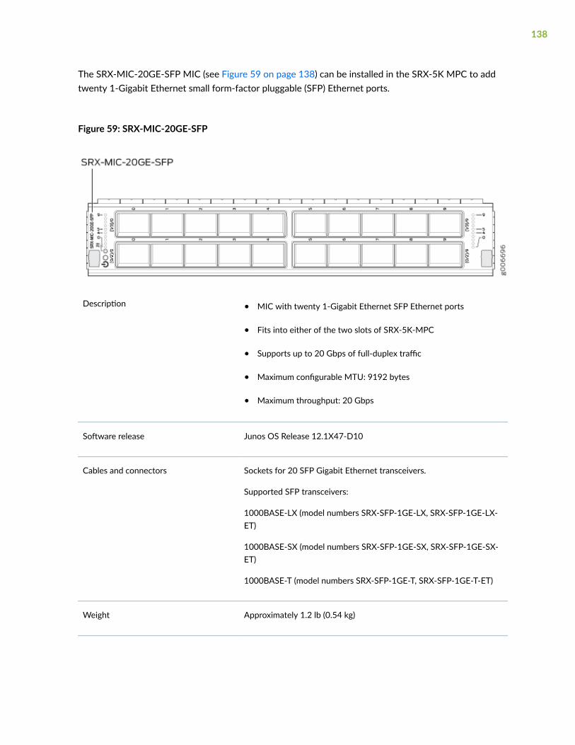
The SRX-MIC-20GE-SFP MIC (see Figure 59 on page 138) can be installed in the SRX-5K MPC to addtwenty 1-Gigabit Ethernet small form-factor pluggable (SFP) Ethernet ports.
Figure 59: SRX-MIC-20GE-SFP
Description • MIC with twenty 1-Gigabit Ethernet SFP Ethernet ports
• Fits into either of the two slots of SRX-5K-MPC
• Supports up to 20 Gbps of full-duplex traffic
• Maximum configurable MTU: 9192 bytes
• Maximum throughput: 20 Gbps
Software release Junos OS Release 12.1X47-D10
Cables and connectors Sockets for 20 SFP Gigabit Ethernet transceivers.
Supported SFP transceivers:
1000BASE-LX (model numbers SRX-SFP-1GE-LX, SRX-SFP-1GE-LX-ET)
1000BASE-SX (model numbers SRX-SFP-1GE-SX, SRX-SFP-1GE-SX-ET)
1000BASE-T (model numbers SRX-SFP-1GE-T, SRX-SFP-1GE-T-ET)
Weight Approximately 1.2 lb (0.54 kg)
138

LEDs OK/FAIL LED, one bicolor:
• Green–MIC is operating normally.
• Red–MIC has failed.
• Off–MIC is powered down.
LINK LED, single color, one per SFP port:
• Green–Link is active.
• Off–Link is inactive.
139

Port and Interface Numbering Each MPC accepts up to two MICs. SRX-MIC-20GE-SFP is a 20-portGigabit Ethernet MIC with SFP.
Each port on a MIC corresponds to a unique interface name in theCLI.
In the syntax of an interface name, a hyphen (-) separates the mediatype from the MPC number (represented as an FPC in the CLI). TheMPC slot number corresponds to the first number in the interface.The second number in the interface corresponds to the logical PICnumber. The last number in the interface matches the port number onthe MIC. Slashes (/) separate the MPC number from the logical PICnumber and port number:
type-fpc/pic/port
• type—Media type, which identifies the network device. Forexample:
• ge—Gigabit Ethernet interface
• so—SONET/SDH interface
• xe—10-Gigabit Ethernet interface
For a complete list of media types, see Interface NamingOverview.
• fpc—Slot in which the MPC is installed in an SRX5400, SRX5600,or SRX5800 Services Gateway.
• pic—Two Logical PICs on the MIC, numbered 0 or 1 when installedin the first slot, and 2 or 3 when installed in the second slot.
• port—Port number.
Figure 60 on page 141 shows the SRX-MIC-20GE-SFP MIC installedin slot 0 of an MPC in slot 2 of an SRX5400, SRX5600, or SRX5800Services Gateway.
140
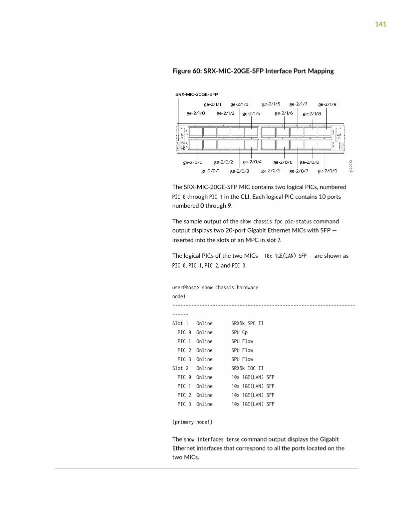
Figure 60: SRX-MIC-20GE-SFP Interface Port Mapping
The SRX-MIC-20GE-SFP MIC contains two logical PICs, numberedPIC 0 through PIC 1 in the CLI. Each logical PIC contains 10 portsnumbered 0 through 9.
The sample output of the show chassis fpc pic-status commandoutput displays two 20-port Gigabit Ethernet MICs with SFP —inserted into the slots of an MPC in slot 2.
The logical PICs of the two MICs— 10x 1GE(LAN) SFP — are shown asPIC 0, PIC 1, PIC 2, and PIC 3.
user@host> show chassis hardwarenode1:--------------------------------------------------------------------------Slot 1 Online SRX5k SPC II PIC 0 Online SPU Cp PIC 1 Online SPU Flow PIC 2 Online SPU Flow PIC 3 Online SPU FlowSlot 2 Online SRX5k IOC II PIC 0 Online 10x 1GE(LAN) SFP PIC 1 Online 10x 1GE(LAN) SFP PIC 2 Online 10x 1GE(LAN) SFP PIC 3 Online 10x 1GE(LAN) SFP
{primary:node1}
The show interfaces terse command output displays the GigabitEthernet interfaces that correspond to all the ports located on thetwo MICs.
141

user@host> show interfaces terse
Interface Admin Link Proto Local Remotegr-0/0/0 up upip-0/0/0 up uplt-0/0/0 up upge-2/0/0 up upge-2/0/1 up downge-2/0/2 up downge-2/0/3 up downge-2/0/4 up downge-2/0/5 up upge-2/0/6 up downge-2/0/7 up downge-2/0/8 up upge-2/0/9 up upge-2/1/0 up downge-2/1/1 up upge-2/1/2 up downge-2/1/3 up downge-2/1/4 up upge-2/1/5 up downge-2/1/6 up downge-2/1/7 up downge-2/1/8 up upge-2/1/9 up upge-2/2/0 up downge-2/2/1 up downge-2/2/2 up downge-2/2/3 up downge-2/2/4 up downge-2/2/5 up downge-2/2/6 up downge-2/2/7 up downge-2/2/8 up downge-2/2/9 up downge-2/3/0 up downge-2/3/1 up downge-2/3/2 up downge-2/3/3 up downge-2/3/4 up downge-2/3/5 up downge-2/3/6 up downge-2/3/7 up down
142

ge-2/3/8 up downge-2/3/9 up down
Serial number location The serial number label is yellow and is located as shown in Figure 61on page 143.
Figure 61: SRX-MIC-20GE-SFP Serial Number Label
NOTE: The serial number for the mezzanine card is shown only forreference and is never used for any purpose.
143

MIC with 10x10GE SFP+ Interfaces (SRX-MIC-10XG-SFPP)
You use MICs and MPCs to add different combinations of Ethernet interfaces to your services gatewayto suit the specific needs of your network. The SRX-MIC-10XG-SFPP (see Figure 62 on page 144) canbe installed in an MPC to add ten 10-Gigabit Ethernet SFP+ ports.
Figure 62: SRX-MIC-10XG SFPP
Description • MIC with ten SFP+ 10-Gigabit Ethernet ports
• Fits into MPC
• Supports up to 100 Gbps of full-duplex traffic
• Maximum configurable MTU: 9192 bytes
• Maximum throughput: 100 Gbps
Software release Junos OS Release 12.1X46-D10
Cables andconnectors
Sockets for ten 10-Gbps SFP+ transceivers
See Hardware Compatibility Tool for the transceivers supported.
Supported slots Either slot in SRX5K-MPC
Weight Approximately 1.6 lb (0.7 kg)
144

LEDs OK/FAIL LED, one bicolor:
• Green–The MIC is operating normally.
• Red–The MIC has failed and is not operating normally.
• Off–The MIC is powered down.
LINK LED, single color:
• Green–The link is active.
• Off–No link.
145
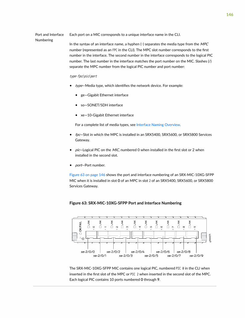
Port and InterfaceNumbering
Each port on a MIC corresponds to a unique interface name in the CLI.
In the syntax of an interface name, a hyphen (-) separates the media type from the MPCnumber (represented as an FPC in the CLI). The MPC slot number corresponds to the firstnumber in the interface. The second number in the interface corresponds to the logical PICnumber. The last number in the interface matches the port number on the MIC. Slashes (/)separate the MPC number from the logical PIC number and port number:
type-fpc/pic/port
• type—Media type, which identifies the network device. For example:
• ge—Gigabit Ethernet interface
• so—SONET/SDH interface
• xe—10-Gigabit Ethernet interface
For a complete list of media types, see Interface Naming Overview.
• fpc—Slot in which the MPC is installed in an SRX5400, SRX5600, or SRX5800 ServicesGateway.
• pic—Logical PIC on the MIC, numbered 0 when installed in the first slot or 2 wheninstalled in the second slot.
• port—Port number.
Figure 63 on page 146 shows the port and interface numbering of an SRX-MIC-10XG-SFPPMIC when it is installed in slot 0 of an MPC in slot 2 of an SRX5400, SRX5600, or SRX5800Services Gateway.
Figure 63: SRX-MIC-10XG-SFPP Port and Interface Numbering
The SRX-MIC-10XG-SFPP MIC contains one logical PIC, numbered PIC 0 in the CLI wheninserted in the first slot of the MPC or PIC 2 when inserted in the second slot of the MPC.Each logical PIC contains 10 ports numbered 0 through 9.
146

The sample output of the show chassis fpc pic-status command displays two 10-port 10-Gigabit Ethernet MICs with SFP+ — inserted into the slots of an MPC in slot 2.
The logical PICs of the two MICs— 10x 10GE SFP+ — are shown as PIC 0 and PIC 2.
user@host> show chassis fpc pic-status
Slot 1 Online SRX5k SPC II PIC 0 Online SPU Cp PIC 1 Online SPU Flow PIC 2 Online SPU Flow PIC 3 Online SPU FlowSlot 2 Online SRX5k IOC II PIC 0 Online 10x 10GE SFP+ PIC 2 Online 10x 10GE SFP+
The show interfaces terse command output displays the 10–Gigabit Ethernet interfacesthat correspond to the 10 ports located on each MIC.
user@host> show interfaces terse
Interface Admin Link Proto Local Remotegr-0/0/0 up upip-0/0/0 up uplt-0/0/0 up upxe-2/0/0 up upxe-2/0/1 up upxe-2/0/2 up upxe-2/0/2.0 up up inet 131.131.131.2/24 inet6 1300::2/64 fe80::224:dcff:fe20:b94c/64 multiservicexe-2/0/3 up upxe-2/0/4 up upxe-2/0/5 up upxe-2/0/6 up upxe-2/0/6.0 up up inet 141.141.141.1/24 inet6 1400::1/64 fe80::224:dcff:fe20:b950/64 multiservicexe-2/0/7 up downxe-2/0/8 up downxe-2/0/9 up downxe-2/2/0 up downxe-2/2/1 up downxe-2/2/2 up down
147

xe-2/2/3 up downxe-2/2/4 up downxe-2/2/5 up downxe-2/2/6 up downxe-2/2/7 up downxe-2/2/8 up downxe-2/2/9 up down
Serial numberlocation
The serial number label is yellow and located as shown in Figure 64 on page 148.
Figure 64: SRX-MIC-10XG-SFPP Serial Number Label
148

MIC with 1x100GE CFP Interface (SRX-MIC-1X100G-CFP)
You use MICs and MPCs to add different combinations of Ethernet interfaces to your services gatewayto suit the specific needs of your network. The SRX-MIC-1X100G-CFP (see Figure 65 on page 149) canbe installed in an MPC to add one 100-Gigabit Ethernet CFP port.
Figure 65: SRX-MIC-1X100G-CFP
Description • MIC with one CFP 100-Gigabit Ethernet port
• Fits into MPC
• Supports up to 100 Gbps of full-duplex traffic
• Maximum configurable MTU: 9192 bytes
• Maximum throughput: 100 Gbps
Software release Junos OS Release 12.1X46-D10
Cables andconnectors
One socket for a 100-Gigabit CFP transceiver.
Supported CFP transceivers:
• 100GBASE-LR4 (model number: SRX-CFP-100G-LR4)
• 100GBASE-SR10 (model number: SRX-CFP-100G-SR10)
Supported slots Either slot in SRX5K-MPC
Weight Approximately 1.6 lb (0.7 kg)
149

LEDs OK/FAIL LED, one bicolor:
• Green–The MIC is operating normally.
• Red–The MIC has failed and is not operating normally.
• Off–The MIC is powered down.
LINK LED, single color:
• Green–The link is active.
• Off–No link.
Serial numberlocation
The serial number label is yellow and located as shown in Figure 66 on page 150.
Figure 66: SRX-MIC-1X100G-CFP Serial Number Label
150

MIC with 2x40GE QSFP+ Interfaces (SRX-MIC-2X40G-QSFP)
You use MICs and MPCs to add different combinations of Ethernet interfaces to your services gatewayto suit the specific needs of your network. The SRX-MIC-2X40G-QSFP (see Figure 67 on page 151) canbe installed in an MPC to add two 40-Gigabit quad small form-factor pluggable (QSFP+) Ethernet ports.
Figure 67: SRX-MIC-2X40G QSFP
Description • MIC with two QSFP+ Ethernet ports
• Fits into MPC
• Supports up to 80 Gbps of full-duplex traffic
• Maximum configurable MTU: 9192 bytes
• Maximum throughput: 80 Gbps
Software release Junos OS Release 12.1X46-D10
Cables and connectors Sockets for two QSFP+ 40-Gigabit Ethernet fiber-optic transceivers.
Supported QSFP+ transceiver:
40GBASE-SR4 (model number SRX-QSFP-40G-SR4)
40GBASE-LR4 (model number SRX-QSFP-40G-LR4)
Supported slots Either slot in SRX5K-MPC
Weight Approximately 1.6 lb (0.7 kg)
151

LEDs OK/FAIL LED, one bicolor:
• Green–The MIC is operating normally.
• Red–The MIC has failed and is not operating normally.
• Off–The MIC is powered down.
LINK LED, single color, one per QSFP+ port:
• Green–The link is active.
• Off–No link.
Serial number location The serial number label is yellow and typically located as shown inFigure 68 on page 152.
Figure 68: SRX-MIC-2X40G-QSFP Serial Number Label
SRX5K-MPC3-40G10G Specifications
The SRX5K-MPC3-40G10G (IOC3) is an interface card that provides 10 Gigabit Ethernet and 40 GigabitEthernet interfaces, with a Packet Forwarding Engine that provides a 240 Gbps line rate. This interfacecard is supported on SRX5400, SRX5600, and SRX5800 Services Gateways. See Figure 69 on page 153.
152

NOTE: These cards do not support plug-in Modular Interface Cards (MICs).
All ports on the interface card have dual-color LEDs for reporting link status.
The interface card also supports hot-pluggable optical modules.
Figure 69: SRX5K-MPC3-40G10G
If a slot in the SRX5400, SRX5600, or SRX5800 Services Gateway card cage is not occupied by a card,you must install a blank panel to shield the empty slot and to allow cooling air to circulate properlythrough the services gateway.
Description • Fixed-configuration MPC with six 40-Gigabit Ethernet ports and twenty-four 10-GigabitEthernet ports
• Maximum throughput: 240 Gbps
• Maximum configurable MTU: 9192 bytes
Software release Junos OS Release 15.1X49-D10 and later
Supported Slots • SRX5400 – Any slot, except the bottom slot 0 which is reserved for SCB/RE.
• SRX5600 – Any slot, except the bottom slots 0 or 1 which are reserved for SCB/RE.
• SRX5800 – Any slot, except the middle slots 0, 1, and 2/6 which are reserved forSCB/RE and slots 0 (left most) and 11 (right most).
NOTE: You can use the 2/6 slot to install an interface card if an SCB is not alreadyinstalled in it.
153

Cables andconnectors
Sockets for 40-Gbps and 10-Gbps SFP+ transceivers
See Hardware Compatibility Tool for the transceivers supported.
Powerrequirements
Typical: 9.68 A @ 48 V (460 W)
At different temperatures:
• 55° C: 607 W
• 40° C: 541 W
• 25° C: 511 W
Weight 21 lb (9.52 kg)
Hardwarefeatures
• Line-rate throughput of up to 240 Gbps
• Supports up to 32,000 queues per-slot
• LAN-PHY mode at 10.3125 Gbps on a per-port basis
• The ports are labeled as:
• 10-Gigabit Ethernet ports: 0/0 through 0/11 and 1/0 through 1/11
• 40-Gigabit Ethernet ports: 2/0 through 2/2 and 3/0 through 3/2
154

Software features • Optical diagnostics and related alarms
• Two packet-forwarding engines, PFE0 and PFE1. PFE0 hosts PIC0 and PIC2. PFE1 hostsPIC1 and PIC3.
• Configurable LAN-PHY mode options per 10-Gigabit Ethernet port
• Intelligent oversubscription services
NOTE: At any one time you can have only one of the following PIC combinations poweredon:
• PIC0 & PIC1
• PIC0 & PIC3
• PIC2 & PIC1
• PIC2 & PIC3
If you configure any of the following invalid PIC combinations, the chassis will set PIC0 &PIC1 combination online.
• PIC0 & PIC2
• PIC1 & PIC3
LEDs OK/FAIL LED, one bicolor:
• Solid green—MPC is functioning normally.
• Blinking green—MPC is transitioning online or offline.
• Red—MPC has failed.
10-Gigabit Ethernet LINK LED, one green per port:
• Green—Link is up.
• Off—Link is down or disabled.
40-Gigabit Ethernet LINK LED, one bicolor per port:
• Green—Link is up.
• Amber—Link is disabled.
• Off—Link is down.
155

Serial NumberLocation
The serial number label is located as shown in Figure 70 on page 156.
Figure 70: SRX5K-MPC3-40G10G Serial Number Label
SRX5K-MPC3-100G10G Specifications
The SRX5K-MPC3-100G10G (IOC3) is an interface card that provides 100 Gigabit Ethernet and 10Gigabit Ethernet interfaces, with a Packet Forwarding Engine that provides a 240 Gbps line rate. Thisinterface card is supported on SRX5400, SRX5600, and SRX5800 Services Gateways. See Figure 71 onpage 157.
156

NOTE: These cards do not support plug-in Modular Interface Cards (MICs).
All ports on the interface card have dual-color LEDs for reporting link status.
The interface card also supports hot-pluggable optical modules.
Figure 71: SRX5K-MPC3-100G10G
If a slot in the SRX5400, SRX5600, or SRX5800 Services Gateway card cage is not occupied by a card,you must install a blank panel to shield the empty slot and to allow cooling air to circulate properlythrough the services gateway.
Description • Fixed-configuration MPC with two 100-Gigabit Ethernet ports and four 10-GigabitEthernet ports
• Maximum throughput: 240 Gbps
• Maximum configurable MTU: 9192 bytes
Software release Junos OS Release 15.1X49-D10 and later
Supported Slots • SRX5400 – Any slot, except the bottom slot 0 which is reserved for SCB/RE.
• SRX5600 – Any slot, except the bottom slots 0 or 1 which are reserved for SCB/RE.
• SRX5800 – Any slot, except the middle slots 0, 1, and 2/6 which are reserved forSCB/RE and slots 0 (left most) and 11 (right most).
NOTE: You can use the 2/6 slot to install an interface card if an SCB is not alreadyinstalled in it.
Cables andconnectors
Sockets for 100-Gbps and 10-Gbps SFP+ transceivers
See Hardware Compatibility Tool for the transceivers supported.
157

Powerrequirements
• Typical: 10.52 A @ 48 V (505 W)
At different temperatures:
• 55° C: 607 W
• 40° C: 541 W
• 25° C: 511 W
Weight 21 lb (9.52 kg)
Hardware features • Line-rate throughput of up to 240 Gbps
• Supports up to 32,000 queues per-slot
• LAN-PHY mode at 10.3125 Gbps on a per-port basis
The ports are labeled as:
• 10-Gigabit Ethernet ports: 0/0, 0/1, 2/0, and 2/1
• 100-Gigabit Ethernet ports: 1/0 and 3/0
Software features • Configurable LAN-PHY mode options per 10-Gigabit Ethernet port
• Optical diagnostics and related alarms
• Intelligent oversubscription services
158

LEDs OK/FAIL LED, one bicolor:
• Solid green—MPC is functioning normally.
• Blinking green—MPC is transitioning online or offline.
• Red—MPC has failed.
10-Gigabit Ethernet LINK LED, one bicolor per port:
• Green—Link is up.
• Amber—Link is disabled.
• Off—Link is down or disabled.
100-Gigabit Ethernet LINK LED, one bicolor per port:
• Green—Link is up.
• Amber—Link is disabled.
• Off—Link is down.
159

Serial NumberLocation
The serial number label is located as shown in Figure 72 on page 160.
Figure 72: SRX5K-MPC3-100G10G Serial Number Label
SRX5K-IOC4-10G Specifications
SRX5K-IOC4-10G is a fixed-configuration interface card with a Packet Forwarding Engine that provides400-Gbps line rate. This interface card provides scalability in bandwidth and services to the SRX5400,SRX5600 and SRX5800 Services Gateways. See Figure 73 on page 161.
160

NOTE: SRX5K-IOC4-10G cards do not support plug-in Modular Interface Cards (MICs).
Figure 73: SRX5K-IOC4-10G
If a slot in the SRX5400, SRX5600, or SRX5800 Services Gateway card cage is not occupied by a card,you must install a blank panel to shield the empty slot and to allow cooling air to circulate properlythrough the services gateway.
Description • Fixed-configuration IOC with forty 10-Gbps portspeeds
• Maximum throughput: 400-Gbps
• Maximum configurable MTU: 9192 bytes
Software release Junos OS Release 19.3R1 and later
Supported slots • SRX5400—Any slot, except the bottom slots 0 and1/0, which are reserved for SCB/RE.
NOTE: Slot 1/0 is a dual purpose slot. You caninstall SRX5K-IOC4-10G in slot 1/0 if an SCB is notalready installed in it.
• SRX5600—Any slot, except the bottom slots 0 and1, which are reserved for SCB/RE.
• SRX5800—Any slot, except the middle slots 0, 1,and 2/6, which are reserved for SCB/RE, and slots0 (most left) and 11 (most right).
NOTE: Slot 2/6 is a dual purpose slot. You caninstall SRX5K-IOC4-10G in slot 2/6 if an SCB is notalready installed in it.
161

Cables and connectors See Hardware Compatibility Tool for the transceiverssupported.
Power requirements • Typical: 405 W
At different temperatures:
• 131° F (55° C): 500 W
• 104° F (40° C): 465 W
• 75° F (25° C): 430 W
Weight 17 lb (7.7 kg)
Hardware features • Junos Trio chipsets for increased scaling forbandwidth, subscribers, and services
• Forty 10-Gigabit Ethernet ports. The ports supportSFP+ transceivers.
• Requires high-capacity power supplies and high-capacity fan trays.
• The ports are labeled as (seeFigure 73 on page161):
• 0/0 through 0/9
• 0/10 through 0/19
• 1/0 through 1/9
• 1/10 through 1/19
162

Software features • Application security
• Application Layer Gateway (ALG)
• Attack detection and prevention
• Class of service (CoS)
• Equal-cost multipath (ECMP) load balancing
• GPRS Tunneling Protocol (GTP)
• High availability (chassis cluster)
• Intrusion detection and prevention (IDP)
• IPsec VPN
• Layer 2 transparent mode
• Logical systems
• Network Address Translation (NAT)
• Routing protocols (BFD, BGP, IGMP, IS-IS, MLD,Multicast, OSPF, PIM, RIP, and SCTP)
• SSL proxy
• Tenant systems
• Unified threat management (UTM)
LEDs OK/FAIL LED, one bicolor:
• Steady green—IOC is functioning normally.
• Yellow—IOC has failed.
LINK LED, one green per port:
• Steady green—Link is up.
• Off—Link is down or disabled.
163

Serial Number Location The serial number label is located as shown in Figure74 on page 164.
Figure 74: SRX5K-IOC4-10G Serial NumberLabel
SRX5K-IOC4-MRAT Specifications
SRX5K-IOC4-MRAT is a fixed-configuration interface card with a Packet Forwarding Engine thatprovides up to 480-Gbps (240-Gbps per PIC slot) line rate. This interface card provides scalability inbandwidth and services to the SRX5400, SRX5600, and SRX5800 Services Gateways. See Figure 75 onpage 164.
NOTE: SRX5K-IOC4-MRAT cards do not support plug-in Modular Interface Cards (MICs).
Figure 75: SRX5K-IOC4-MRAT
164

If a slot in the SRX5400, SRX5600, or SRX5800 Services Gateway card cage is not occupied by a card,you must install a blank panel to shield the empty slot and to allow cooling air to circulate properlythrough the services gateway.
Description • Fixed-configuration IOC with 10-Gbps, 40-Gbps,and 100-Gbps port speeds
• Maximum throughput: up to 480 Gbps (240 Gbpsper PIC slot)
• Maximum configurable MTU: 9192 bytes
Software release Junos OS Release 19.3R1 and later
Supported Slots • SRX5400—Any slot, except the bottom slots 0 and1/0, which are reserved for SCB/RE.
NOTE: Slot 1/0 is a dual purpose slot. You caninstall SRX5K-IOC4-MRAT in slot 1/0 if an SCB isnot already installed in it.
• SRX5600—Any slot, except the bottom slots 0 and1, which are reserved for SCB/RE.
• SRX5800—Any slot, except the middle slots 0, 1,and 2/6, which are reserved for SCB/RE, and slots0 (most left) and 11 (most right).
NOTE: Slot 2/6 is a dual purpose slot. You caninstall SRX5K-IOC4-MRAT in slot 2/6 if an SCB isnot already installed in it.
Cables and connectors See Hardware Compatibility Tool for the transceiverssupported.
Power requirements At different temperatures:
• 131° F (55° C): 500 W
• 104° F (40° C): 465 W
• 75° F (25° C): 430 W
165

Weight 15.7 lb (7.12 kg)
Hardware features • Junos Trio chipsets for increased scaling forbandwidth, subscribers, and services
• Twelve Gigabit Ethernet ports that can beconfigured as 40-Gigabit Ethernet port or as 4X10-Gigabit Ethernet port using a breakout cable. Theports support quad small-form factor pluggableplus (QSFP+) transceivers.
• Four out of the twelve ports can be configured as100-Gigabit Ethernet ports. Port numbers 0/2, 0/5,1/2 and 1/5 are the four 100-Gigabit Ethernetports.
• You can configure different combination of portspeeds as long as the aggregate capacity per groupof six ports labeled 0/0 through 0/5 does notexceed 240 Gbps. Similarly, aggregate capacity pergroup of the other six ports labeled 1/0 through1/5 should not exceed 240 Gbps.
• Requires high-capacity power supplies and high-capacity fan trays.
• The ports are labeled as (see Figure 75 on page164):
• 10-Gigabit Ethernet or 40-Gigabit Ethernetports:
0/0, 0/1, 0/2 100G, 0/3, 0/4, 0/5 100G, 1/0,1/1, 1/2 100G, 1/3, 1/4, and 1/5 100G
• 100-Gigabit Ethernet ports:
0/2 100G, 0/5 100G, 1/2 100G and 1/5 100G
NOTE: Only ports marked 100G support 100-Gigabit Ethernet speed using QSFP28 transceivers.
166

Software features • Application security
• Application Layer Gateway (ALG)
• Attack detection and prevention
• Class of service (CoS)
• Equal-cost multipath (ECMP) load balancing
• GPRS Tunneling Protocol (GTP)
• High availability (chassis cluster)
• Intrusion detection and prevention (IDP)
• IPsec VPN
• Layer 2 transparent mode
• Logical systems
• Network Address Translation (NAT)
• Routing protocols (BFD, BGP, IGMP, IS-IS, MLD,Multicast, OSPF, PIM, RIP, and SCTP)
• SSL proxy
• Tenant systems
• Unified threat management (UTM)
LEDs OK/FAIL LED, one bicolor:
• Steady green—IOC is functioning normally.
• Yellow—IOC has failed.
LINK LED, one green per port (4 per QSFP+ cage):
• Steady green—Link is up.
• Off—Link is down or disabled.
167

Serial Number Location The serial number label is located as shown in Figure76 on page 168.
Figure 76: SRX5K-IOC4-MRAT Serial NumberLabel
SRX5800 Services Gateway Interface Card Description
Interface cards are cards that support physical interfaces that you use to connect the services gatewayto your data network. Three different types of interface cards are available:
• I/O Cards (IOCs) have fixed interface ports on the front panel of the card.
• Flex I/O Cards (Flex IOCs) have slots on the front panel that accept smaller cards called portmodules. Each port module has two or more physical interfaces on it. A Flex IOC with installed portmodules functions in the same way as a regular IOC, but allows greater flexibility in adding differenttypes of Ethernet ports to your services gateway.
• Modular Port Concentrators (MPCs) have slots on the front panel that accept smaller cards calledModular Interface Cards (MICs). Each MIC has one or more physical interface on it. An MPC withMICs installed functions in the same way as a regular I/O card (IOC), but allows greater flexibility inadding different types of Ethernet ports to your services gateway. MPCs and MICs are similar in formand function to Flex IOCs and port modules. However, the two use different form-factors, so youcannot install port modules in an MPC, nor can you install MICs in a Flex IOC.
For all interface card types, the card assembly combines packet forwarding and Ethernet interfaces on asingle board. The interface cards interface with the power supplies and Switch Control Boards (SCBs).
168

You can install interface cards in any of the slots that are not reserved for SCBs. If a slot is not occupiedby a card, you must install a blank panel to shield the empty slot and to allow cooling air to circulateproperly through the services gateway.
Figure 77 on page 169 shows typical IOCs supported on the services gateway.
Figure 77: Typical IOCs
169

Figure 78 on page 170 shows a Flex IOC with two typical port modules installed.
Figure 78: Flex IOC with Port Modules
170

Figure 79 on page 171 shows an MPC.
Figure 79: SRX5K-MPC
For detailed information about the interface cards, port modules, and MICs supported by the servicesgateway, see the SRX5400, SRX5600, and SRX5800 Services Gateway Card Reference atwww.juniper.net/documentation/.
I/O Card SRX5K-40GE-SFP Specifications
The SRX5K-40GE-SFP I/O card (IOC) is optimized for Ethernet density and supports 40 GigabitEthernet ports (see Figure 80 on page 172). The IOC assembly combines packet forwarding andEthernet interfaces on a single board, with four 10-Gbps Packet Forwarding Engines. Each PacketForwarding Engine consists of one I-chip for Layer 3 processing and one Layer 2 network processor. TheIOCs interface with the power supplies and Switch Control Boards (SCBs).
171
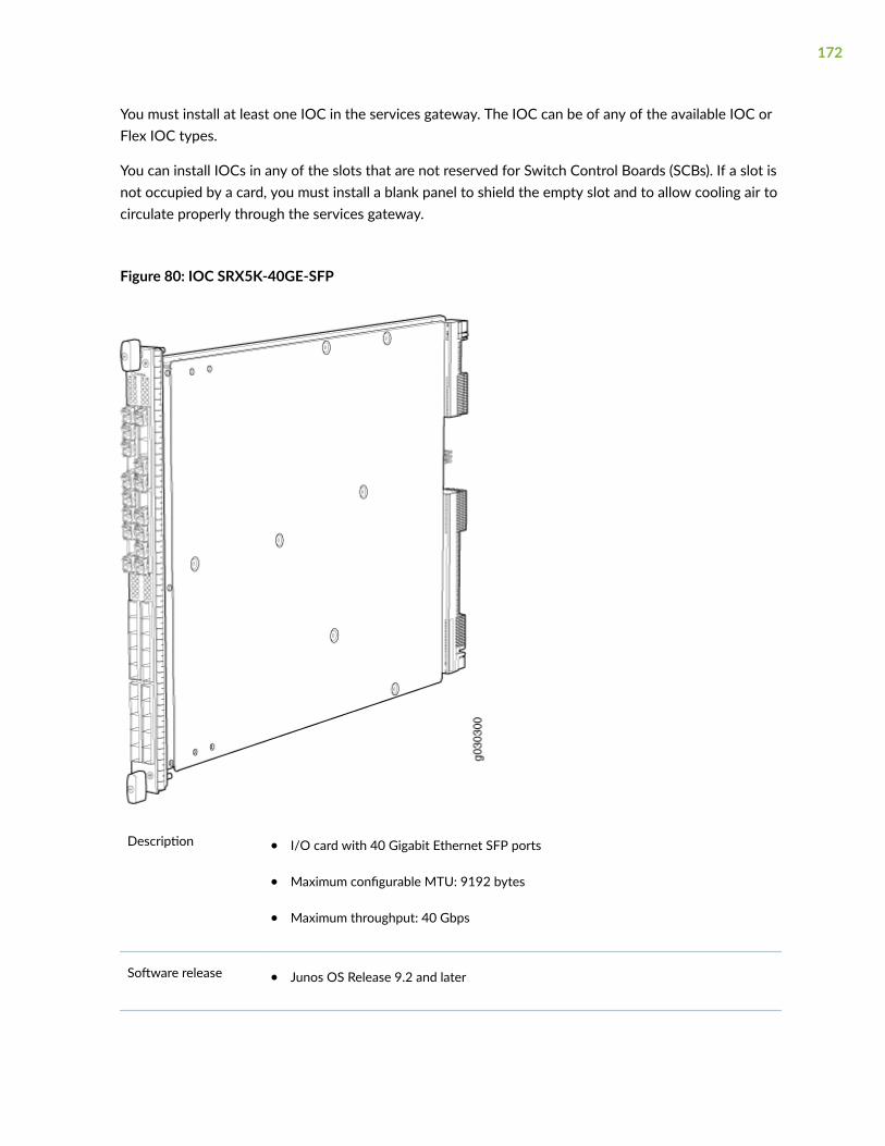
You must install at least one IOC in the services gateway. The IOC can be of any of the available IOC orFlex IOC types.
You can install IOCs in any of the slots that are not reserved for Switch Control Boards (SCBs). If a slot isnot occupied by a card, you must install a blank panel to shield the empty slot and to allow cooling air tocirculate properly through the services gateway.
Figure 80: IOC SRX5K-40GE-SFP
Description • I/O card with 40 Gigabit Ethernet SFP ports
• Maximum configurable MTU: 9192 bytes
• Maximum throughput: 40 Gbps
Software release • Junos OS Release 9.2 and later
172

Cables andconnectors
40 Gigabit Ethernet SFP ports
Supported SFP transceivers:
1000BASE-LH (model numbers SRX-SFP-1GE-LH, SRX-SFP-1GE-LH-ET)
1000BASE-LX (model numbers SRX-SFP-1GE-LX, SRX-SFP-1GE-LX-ET)
1000BASE-SX (model numbers SRX-SFP-1GE-SX, SRX-SFP-1GE-SX-ET)
1000BASE-T (model numbers SRX-SFP-1GE-T, SRX-SFP-1GE-T-ET)
Controls None
Supported Slots • SRX5600–Any slot except bottom slots 0 or 1
• SRX5800–Any slot except center slots 0, 1, or 2/6
Power Requirement 312 W typical, 365 W maximum
Weight Approximately 13 lb (5.9 kg)
LEDs OK/FAIL LED, one bicolor:
• Steady green–The IOC is operating normally.
• Red–The IOC has failed and is not operating normally.
• Off–The IOC is powered down.
173

Serial NumberLocation
The serial number label is located as shown in Figure 81 on page 174.
Figure 81: Serial Number Label (IOC Shown, Other Cards Similar)
I/O Card SRX5K-4XGE-XFP Specifications
The SRX5K-4XGE-XFP I/O card (IOC) supports four 10-Gigabit Ethernet ports (see Figure 82 on page175). The IOC assembly combines packet forwarding and Ethernet interfaces on a single board, withfour 10-Gbps Packet Forwarding Engines. Each Packet Forwarding Engine consists of one I-chip forLayer 3 processing and one Layer 2 network processor. The IOCs interface with the power supplies andSwitch Control Boards (SCBs).
You must install at least one IOC in the services gateway. The IOC can be of any of the available IOC orFlex IOC types.
174

You can install IOCs in any of the slots that are not reserved for Switch Control Boards (SCBs). If a slot isnot occupied by a card, you must install a blank panel to shield the empty slot and to allow cooling air tocirculate properly through the services gateway.
Figure 82: IOC SRX5K-4XGE-XFP
Description • I/O card with four 10-Gigabit Ethernet XFP ports
• Maximum configurable MTU: 9192 bytes
• Maximum throughput: 40 Gbps
Software release • Junos OS Release 9.2 and later
175
Cables and connectors Four 10-Gbps XFP ports
Supported XFP transceivers:
10GBASE-ER (model numbers SRX-XFP-10GE-ER and SRX-XFP-10GE-ER-ET )
10GBASE-LR (model numbers SRX-XFP-10GE-LR and SRX-XFP-10GE-LR-ET
10GBASE-SR (model numbers SRX-XFP-10GE-SR and SRX-XFP-10GE-SR-ET )
Controls None
Supported Slots • SRX5600–Any slot except bottom slots 0 or 1
• SRX5800–Any slot except center slots 0, 1, or 2
Power Requirement 312 W typical, 365 W maximum
Weight Approximately 13 lb (5.9 kg)
LEDs OK/FAIL LED, one bicolor:
• Steady green–The IOC is operating normally.
• Red–The IOC has failed and is not operating normally.
• Off–The IOC is powered down.
176

Serial NumberLocation
The serial number label is located as shown in Figure 83 on page 177.
Figure 83: SRX5K-4XGE-XFP Serial Number Label
Flex I/O Card (SRX5K-FPC-IOC) Specifications
The SRX5K-FPC-IOC Flex I/O card (Flex IOC) (Figure 84 on page 178) is an IOC with two slots thataccept port modules that add Ethernet ports to your services gateway. A Flex IOC with installed portmodules functions in the same way as a regular IOC, but allows greater flexibility in adding differenttypes of Ethernet ports to your services gateway.
Each Flex IOC has a processor subsystem, which includes a 1.2-GHz CPU, a system controller, 1 GBSDRAM, and two Packet Forwarding Engines with a maximum throughput of 10 Gbps each.
You must install at least one IOC in the services gateway. The IOC can be of any of the available IOC orFlex IOC types.
177

You can install Flex IOCs in any of the slots that are not reserved for Switch Control Boards (SCBs). If aslot is not occupied by a card, you must install a blank panel to shield the empty slot and to allow coolingair to circulate properly through the services gateway.
Figure 84: Flex IOC with Typical Port Modules
Description • Flex IOC with slots for two port modules
• Maximum throughput: 10 Gbps (per PFE)
Software release • Junos OS Release 9.5R1 and later
Cables and connectors Slots for two port modules
Controls None
178

Supported Slots • SRX5600–Any slot except bottom slots 0 or 1
• SRX5800–Any slot except center slots 0, 1, or 2/6
Power Requirement 312 W typical, 365 W maximum (includes port modules)
Weight Approximately 10 lb (4.5 kg)
LEDs OK/FAIL LED, one bicolor:
• Steady green–The Flex IOC is operating normally.
• Red–The Flex IOC has failed and is not operating normally.
• Off–The Flex IOC is powered down.
Serial Number Location The serial number label is located as shown in Figure 85 on page 179.
Figure 85: Serial Number Label (IOC Shown, Other Cards Similar)
179

Flex I/O Card Port Module SRX-IOC-16GE-SFP Specifications
You use port modules and Flex I/O Cards (Flex IOCs) to add different combinations of small form-factorpluggable transceiver (SFP), 10-gigabit SFP transceiver (XFP), and copper ports to your services gatewayto suit the specific needs of your network. The SRX-IOC-16GE-SFP port module (Figure 86 on page180) installs into a Flex IOC to add sixteen 10/100/1000 Ethernet SFP ports.
Figure 86: Flex IOC Port Module SRX-IOC-16GE-SFP
Description • Port module with 16 Gigabit Ethernet SFP ports
• Maximum throughput: 10 Gbps
• Oversubscription ratio: 1.6:1
• Maximum configurable MTU: 9192 bytes
Software release • Junos OS Release 9.5R1 and later
Cables andconnectors
16 Gigabit Ethernet SFP ports
Supported SFP transceivers:
1000BASE-LH (model numbers SRX-SFP-1GE-LH, SRX-SFP-1GE-LH-ET)
1000BASE-LX (model numbers SRX-SFP-1GE-LX, SRX-SFP-1GE-LX-ET)
1000BASE-SX (model numbers SRX-SFP-1GE-SX, SRX-SFP-1GE-SX-ET)
1000BASE-T (model numbers SRX-SFP-1GE-T, SRX-SFP-1GE-T-ET)
Controls ONLINE Button–The ONLINE button on the port module front panel toggles the portmodule online and offline
180

Supported Slots Either slot in SRX5K-FPC-IOC Flex IOC
Weight Approximately 1.6 lb (0.7 kg)
LEDs OK/FAIL LED, one bicolor:
• Steady green–The port module is operating normally.
• Red–The port module has failed and is not operating normally.
• Off–The port module is powered down.
LINK LED, single color, one per port:
• Steady green–The link is active.
• Off–No link.
TX/RX LED, single color, one per port:
• Blinking Green–The port is receiving or transmitting data.
• Off–No activity.
Serial NumberLocation
The serial number label is located as shown in Figure 87 on page 181.
Figure 87: Port Module SRX-IOC-16GE-SFP Serial Number Label
181

Flex I/O Card Port Module SRX-IOC-16GE-TX Specifications
You use port modules and Flex I/O Cards (Flex IOCs) to add different combinations of small form-factorpluggable transceiver (SFP), 10-gigabit SFP transceiver (XFP), and copper ports to your services gatewayto suit the specific needs of your network. The SRX-IOC-16GE-TX port module (Figure 88 on page 182)installs into a Flex IOC to add sixteen 10/100/1000 Ethernet RJ-45 copper ports.
Figure 88: Flex IOC Port Module SRX-IOC-16GE-TX
Description • Port module with sixteen 10/100/1000 Ethernet RJ45 ports
• Maximum throughput: 10 Gbps
• Oversubscription ratio: 1.6:1
• Maximum configurable MTU: 9192 bytes
Software release • Junos OS Release 9.5R1 and later
Cables andconnectors
Sixteen RJ-45 1-Gbps ports
Controls ONLINE Button–The ONLINE button on the port module front panel toggles the portmodule online and offline.
Supported Slots Either slot in SRX5K-FPC-IOC Flex IOC
Weight Approximately 1.6 lb (0.7 kg)
182

LEDs OK/FAIL LED, one bicolor:
• Steady green–The port module is operating normally.
• Red–The port module has failed and is not operating normally.
• Off–The port module is powered down.
LINK LED, single color, one per port:
• Steady green–The link is active.
• Off–No link.
TX/RX LED, single color, one per port:
• Blinking green–The port is receiving or transmitting data.
• Off–No activity.
Serial NumberLocation
The serial number label is located as shown in Figure 89 on page 183.
Figure 89: Port Module SRX-IOC-16GE-TX Serial Number Label
183

Flex I/O Card Port Module SRX-IOC-4XGE-XFP Specifications
You use port modules and Flex I/O Cards (Flex IOCs) to add different combinations of small form-factorpluggable transceiver (SFP), 10-gigabit SFP transceiver (XFP), and copper ports to your services gatewayto suit the specific needs of your network. The SRX-IOC-4XGE-XFP port module (Figure 90 on page184) installs into a Flex IOC to add four 10-Gigabit Ethernet XFP ports.
Figure 90: Flex IOC Port Module SRX-IOC-4XGE-XFP
Description • Port module with four 10-Gigabit Ethernet XFP ports
• Maximum throughput: 10 Gbps
• Oversubscription ratio: 4:1
• Maximum configurable MTU: 9192 bytes
Software release • Junos OS Release 9.5R1 and later
Cables andconnectors
4 XFP Ethernet ports
Supported XFP transceivers:
10GBASE-ER (model numbers SRX-XFP-10GE-ER and SRX-XFP-10GE-ER-ET )
10GBASE-LR (model numbers SRX-XFP-10GE-LR and SRX-XFP-10GE-LR-ET
10GBASE-SR (model numbers SRX-XFP-10GE-SR and SRX-XFP-10GE-SR-ET )
Controls ONLINE Button–The ONLINE button on the port module front panel toggles the portmodule online and offline
184

Supported Slots Either slot in SRX5K-FPC-IOC Flex IOC
Weight Approximately 1.6 lb (0.7 kg)
LEDs OK/FAIL LED, one bicolor:
• Steady green–The port module is operating normally.
• Red–The port module has failed and is not operating normally.
• Off–The port module is powered down.
LINK LED, single color, one per port:
• Steady green–The link is active.
• Off–No link.
Serial NumberLocation
The serial number label is located as shown in Figure 91 on page 185.
Figure 91: Port Module SRX-IOC-4XGE-XFP Serial Number Label
185

2CHAPTER
Site Planning, Preparation, andSpecifications
Site Preparation Checklist for the SRX5800 Services Gateway | 187
SRX5800 Site Guidelines and Requirements | 188
SRX5800 Rack and Cabinet Requirements | 193
Calculating Power Requirements for the SRX5800 Services Gateway | 196
SRX5800 Network Cable and Transceiver Planning | 211
SRX5800 Alarm and Management Cable Specifications and Pinouts | 215

Site Preparation Checklist for the SRX5800 ServicesGateway
The checklist in Table 40 on page 187 summarizes the tasks you need to perform when preparing a sitefor services gateway installation.
Table 40: Site Preparation Checklist
Item or Task For More Information ... PerformedBy
Date
Verify that environmental factors suchas temperature and humidity do notexceed services gateway tolerances.
"SRX5800 Services Gateway EnvironmentalSpecifications " on page 188
Plan rack or cabinet location, includingrequired space clearances.
"Clearance Requirements for SRX5800 ServicesGateway Airflow and Hardware Maintenance"on page 191
Select the type of rack or cabinet. "SRX5800 Services Gateway Cabinet Size andClearance Requirements" on page 195,"SRX5800 Services Gateway Rack Size andStrength Requirements" on page 193
If a rack is used, secure rack to floorand building structure.
"Connection to Building Structure for theSRX5800 Services Gateway Rack" on page 195
Acquire cables and connectors.
Locate sites for connection of systemgrounding.
DC Power Electrical Safety Guidelines andWarnings
Measure distance between externalpower sources and services gatewayinstallation site.
187

Table 40: Site Preparation Checklist (Continued)
Item or Task For More Information ... PerformedBy
Date
Calculate the optical power budget andoptical power margin.
"Calculating Power Budget for Fiber-OpticCable for the SRX5800 Services Gateway" onpage 213,"Calculating Power Margin for Fiber-Optic Cable for the SRX5800 ServicesGateway" on page 213
SRX5800 Site Guidelines and Requirements
IN THIS SECTION
SRX5800 Services Gateway Environmental Specifications | 188
General Site Guidelines | 189
Site Electrical Wiring Guidelines | 190
Clearance Requirements for SRX5800 Services Gateway Airflow and Hardware Maintenance | 191
SRX5800 Services Gateway Environmental Specifications
Table 41 on page 188 specifies the environmental specifications required for normal services gatewayoperation. In addition, the site should be as dust-free as possible.
Table 41: Services Gateway Environmental Specifications
Description Value
Altitude No performance degradation to 10,000 ft (3048 m)
188

Table 41: Services Gateway Environmental Specifications (Continued)
Description Value
Relative humidity Normal operation ensured in relative humidity range of 5% to 90%, noncondensing
Temperature Normal operation ensured in temperature range of 32°F (0°C) to 104°F (40°C)
Nonoperating storage temperature in shipping crate: –40°F (–40°C) to 158°F (70°C)
Seismic Tested to meet Telcordia Technologies Zone 4 earthquake requirements
Maximum thermal output Standard-Capacity AC and DC power supplies
• AC power: 20,160, BTU/hour (5912 W)
• DC power: 17,057 BTU/hour (5002 W)
NOTE: These specifications are estimates and subject to change.
High-Capacity AC and DC power supplies
• AC power: 32,780 BTU/hour (9608 W)
• DC power: 33,482 BTU/hour (9813 W)
NOTE: These specifications are estimates and subject to change.
NOTE: Install the services gateway only in restricted areas, such as dedicated equipment roomsand equipment closets, in accordance with Articles 110-16, 110-17, and 110-18 of the NationalElectrical Code, ANSI/NFPA 70.
General Site Guidelines
Efficient device operation requires proper site planning and maintenance and proper layout of theequipment, rack or cabinet, and wiring closet.
189

To plan and create an acceptable operating environment for your device and prevent environmentallycaused equipment failures:
• Keep the area around the chassis free from dust and conductive material, such as metal flakes.
• Follow prescribed airflow guidelines to ensure that the cooling system functions properly and thatexhaust from other equipment does not blow into the intake vents of the device.
• Follow the prescribed electrostatic discharge (ESD) prevention procedures to prevent damaging theequipment. Static discharge can cause components to fail completely or intermittently over time.
• Install the device in a secure area, so that only authorized personnel can access the device.
Site Electrical Wiring Guidelines
Table 42 on page 190 describes the factors you must consider while planning the electrical wiring atyour site.
WARNING: You must provide a properly grounded and shielded environment and useelectrical surge-suppression devices.
Avertissement Vous devez établir un environnement protégé et convenablement mis àla terre et utiliser des dispositifs de parasurtension.
Table 42: Site Electrical Wiring Guidelines
Site WiringFactor
Guidelines
Signalinglimitations
If your site experiences any of the following problems, consult experts in electrical surgesuppression and shielding:
• Improperly installed wires cause radio frequency interference (RFI).
• Damage from lightning strikes occurs when wires exceed recommended distances or passbetween buildings.
• Electromagnetic pulses (EMPs) caused by lightning damage unshielded conductors andelectronic devices.
190

Table 42: Site Electrical Wiring Guidelines (Continued)
Site WiringFactor
Guidelines
Radiofrequencyinterference
To reduce or eliminate RFI from your site wiring, do the following:
• Use a twisted-pair cable with a good distribution of grounding conductors.
• If you must exceed the recommended distances, use a high-quality twisted-pair cable withone ground conductor for each data signal, when applicable.
Electromagneticcompatibility
If your site is susceptible to problems with electromagnetic compatibility (EMC), particularlyfrom lightning or radio transmitters, seek expert advice.
Some of the problems caused by strong sources of electromagnetic interference (EMI) are:
• Destruction of the signal drivers and receivers in the device
• Electrical hazards as a result of power surges conducted over the lines into the equipment
Clearance Requirements for SRX5800 Services Gateway Airflow andHardware Maintenance
When planning the installation site, you need to allow sufficient clearance around the rack (see Figure92 on page 192):
• For the cooling system to function properly, the airflow around the chassis must be unrestricted.
• A minimum of 3 in. (7.62 cm) clearance must be provided behind the power supplies for airflow.
• For service personnel to remove and install hardware components, there must be adequate space atthe front and back of the services gateway. At least 24 in. (61 cm) is required both in front of andbehind the services gateway. NEBS GR-63 recommends that you allow at least 30 in. (76.2 cm)behind the services gateway.
• Airflow must always be from front to back with respect to the rack. If the device has side to rearairflow, then provisions must be made to ensure that fresh air from the front of the rack is suppliedto the inlets, and exhaust exits the rear of the rack. The device must not interfere with the cooling ofother systems in the rack. Fillers must be used as appropriate in the rack to ensure there is no
191

recirculation of heated exhaust air back to the front of the rack. Care must also be taken aroundcables to ensure that there is no leakage of air in situations where recirculation might result.
Figure 92: Chassis Dimensions and Clearance Requirements for the Services Gateway
RELATED DOCUMENTATION
SRX5800 Services Gateway Agency Approvals | 552
SRX5800 Services Gateway General Safety Guidelines and Warnings
SRX5800 Services Gateway Fire Safety Requirements and Fire Suppression Equipment
SRX5800 Services Gateway Definition of Safety Warning Levels
General Electrical Safety Guidelines and Warnings
192

SRX5800 Rack and Cabinet Requirements
IN THIS SECTION
SRX5800 Services Gateway Rack-Mounting Hardware | 193
SRX5800 Services Gateway Rack Size and Strength Requirements | 193
Spacing of Rack-Mounting Bracket Holes for the SRX5800 Services Gateway | 194
Connection to Building Structure for the SRX5800 Services Gateway Rack | 195
SRX5800 Services Gateway Cabinet Size and Clearance Requirements | 195
SRX5800 Services Gateway Cabinet Airflow Requirements | 195
SRX5800 Services Gateway Rack-Mounting Hardware
The rack-mounting hardware for the SRX5800 Services Gateway includes:
• The large mounting shelf for mounting in four-post racks, cabinets, and open-frame racks
• The small mounting shelf for front-mounting in a four-post rack or cabinet
• Front-mounting flanges on the front of the chassis for front-mounting in a four-post rack or cabinet
• Two center-mounting brackets attached to the center of the chassis for center-mounting in an open-frame rack. For an open-frame rack, center-mounting is preferable because of the more evendistribution of weight.
SRX5800 Services Gateway Rack Size and Strength Requirements
The size, strength, and location of the rack must accommodate the services gateway's weight andexternal dimensions. The location of the rack must allow for the clearance requirements specified in"Clearance Requirements for SRX5800 Services Gateway Airflow and Hardware Maintenance" on page191.
The chassis is 17.37 in. (44.11 cm) wide. The services gateway is designed for installation in a standard19-in. rack, as defined in Cabinets, Racks, Panels, and Associated Equipment (document numberEIA-310-D) published by the Electronics Industry Association (http://www.eia.org). The spacing of the
193

holes between the left and right front-mounting flanges and center-mounting brackets is 18.31 in(465 mm) apart. However, the inside spacing between the rack rails must allow sufficient space for thewidth of the chassis.
With the use of adapters or approved wing devices to narrow the opening between the rails, theservices gateway can fit into a 600-mm-wide rack, as defined in the four-part Equipment Engineering(EE); European telecommunications standard for equipment practice (document numbers ETS 300 119-1through 119-4) published by the European Telecommunications Standards Institute (http://www.etsi.org).
Observe these guidelines:
• The rack must have sufficient vertical usable space to accommodate the height of the servicesgateway: 27.75 in. (70.49 cm) high (approximately 16 U). You can stack three services gateways in arack that is at least 48 U (89.3 in. or 2.24 m) in height.
NOTE: A U is the standard rack unit defined in Cabinets, Racks, Panels, and AssociatedEquipment.
• The location of the rack must provide sufficient space to accommodate the depth of the servicesgateway. The chassis depth from the front mounting flange to the rear of the power supply rangesfrom 23.0 in. (58.4 cm) to 27.8 in. (70.6 cm) depending on the type of power supply installed.
• The rack must be strong enough to support the weight of the fully configured services gateway, up to400 lb (182 kg). If you stack three fully configured services gateways, it must be capable ofsupporting up to 1,200 lb (545 kg).
Spacing of Rack-Mounting Bracket Holes for the SRX5800 ServicesGateway
The services gateway can be mounted in any rack that provides holes or hole patterns spaced at 1 U(1.75 in.) increments. The mounting brackets used to attach the chassis to a rack are designed (as perEIA-310-D specifications) to fasten to holes spaced at those distances.
194

Connection to Building Structure for the SRX5800 Services GatewayRack
Always secure the rack to the structure of the building. If your geographical area is subject toearthquakes, bolt the rack to the floor. For maximum stability, also secure the rack to ceiling brackets.
SRX5800 Services Gateway Cabinet Size and Clearance Requirements
The minimum size cabinet that can accommodate the device depends on the type of power suppliesinstalled:
• If only standard-capacity power supplies are installed, the services gateway will fit inside a standard600 mm wide by 800 mm deep cabinet.
• If high-capacity AC or DC power supplies are installed, the services gateway must be installed in acabinet that is at least 600 mm wide by 1000 mm deep.
See "Clearance Requirements for SRX5800 Services Gateway Airflow and Hardware Maintenance" onpage 191 for chassis width and depth dimensions. A cabinet larger than the minimum requirementprovides better airflow and reduces the chance of overheating. To accommodate a single device, thecabinet must be at least 16 U high. If you provide adequate cooling air and airflow clearance, you canstack three devices in a cabinet that has at least 48 U (84 in. or 2.13 m) of usable vertical space.
SRX5800 Services Gateway Cabinet Airflow Requirements
When you mount the services gateway in a cabinet, you must ensure that ventilation through thecabinet is sufficient to prevent overheating. Following is a list of requirements to consider when planningfor chassis cooling:
• Ensure that the cool air supply you provide through the cabinet can adequately dissipate the thermaloutput of the device.
• Ensure that the cabinet allows the chassis hot exhaust air to exit from the cabinet withoutrecirculating into the device. An open cabinet (without a top or doors) that employs hot air exhaustextraction from the top allows the best airflow through the chassis. If the cabinet contains a top ordoors, perforations in these elements assist with removing the hot air exhaust.
• Install the device as close as possible to the front of the cabinet so that the cable managementsystem just clears the inside of the front door. This maximizes the clearance in the rear of the cabinetfor critical airflow.
195

• Route and dress all cables to minimize the blockage of airflow to and from the chassis.
Calculating Power Requirements for the SRX5800Services Gateway
The information in this topic helps you determine which power supplies are suitable for variousconfigurations, as well as which power supplies are not suitable because output power is exceeded. Youdetermine suitability by subtracting the total power draw from the maximum output of the powersupplies. Afterward, the required input current is calculated. Finally, you calculate the thermal output.
We recommend that you provision power according to the maximum input current listed in the powersupply electrical specifications (see "SRX5800 Services Gateway AC Power Supply Specifications" onpage 40 and "SRX5800 Services Gateway DC Power Supply Specifications" on page 64).
Use the following procedures to calculate the power requirement:
1. Calculate the power requirement.
2. Evaluate the power budget.
3. Calculate input power.
4. Calculate thermal output (BTUs) for cooling requirements.
The SRX5800 Services Gateway chassis with normal-capacity AC power supplies has one overall zone.The SRX5800 Services Gateway Chassis with high-capacity AC power supplies or either standard- orhigh-capacity DC power supplies is zoned. Zoning means that certain components are powered byspecific power supplies (see Table 43 on page 197 and Figure 93 on page 197 for information onzoning). When calculating power requirements, be sure that there is adequate power for each zone.
Three AC power supplies are mandatory for a SRX5800 Services Gateway chassis with normal-capacityAC power supplies.
196

Table 43: SRX5800 Services Gateway Zoning
Zone Power Supply (PEM) Components Receiving Power
Zone 0 PEM 0 or 2 • Bottom fan tray
• IOC/SPC slots 6 through 11
• SCB slots 1 through 2
Zone 1 PEM 1 or 3 • Upper fan tray
• IOC/SPC slots 0 through 5
• SCB slot 0
Figure 93: Power Distribution from DC and High-Capacity AC Power Supplies in the SRX5800 ServicesGateway Chassis
Sample configuration for SRX5800 Services Gateway chassis with SRX5K-SCB (SCB1) and SRX5K-RE-13-20 (RE1) or with SRX5K-SCBE (SCB2) and SRX5K-RE-1800X4 (RE2):
197

• Four high-capacity AC power supplies (using two feeds for each power supply); two supplies areactive, two are redundant.
• Two Switch Control Boards (SCBs) with Routing Engines.
• Two SRX5K-MPC (IOC2) Modular Port Concentrator, with two Modular Interface Cards (MICs).
• SRX5K-SPC-4-15-320 (SPC2) Services Processing Cards
NOTE: You must have high-capacity power system (either AC or DC power supplies) andhigh-capacity cooling system (upper and bottom fan trays) installed in the services gateway inorder to install and use SPC2. If you do not have high-capacity power supplies and fan traysinstalled, the services gateway will log an alarm condition when it recognizes the SPC.
• High-capacity cooling system (upper and bottom fan trays).
1. Calculate the power requirements (usage) as shown in Table 44 on page 198.
Table 44: Sample Power Requirements for an SRX5800 Services Gateway with SRX5K-SCB (SCB1)and SRX5K-RE-13-20 (RE1) or with SRX5K-SCBE (SCB2) and SRX5K-RE-1800X4 (RE2)
ChassisComponent
Part Number PowerRequirement
Zone 0 Power Zone 1 Power
Base system SRX5800BASE-HC-AC
50 W 25 W 25 W
High-capacitycooling system
SRX5800-HC-FAN 320 W * 2 = 640W
320 W 320 W
SPC - slots 0through 4
SPC2 585W * 5 = 2925W
2925 W
MPC - slot 5 IOC2 with twoMICs
570 W 570 W
SCB 0 - slot 0 SCB1 with RE1
or
SCB2 with RE2
150 W
90 W
240 W
198

Table 44: Sample Power Requirements for an SRX5800 Services Gateway with SRX5K-SCB (SCB1)and SRX5K-RE-13-20 (RE1) or with SRX5K-SCBE (SCB2) and SRX5K-RE-1800X4 (RE2) (Continued)
ChassisComponent
Part Number PowerRequirement
Zone 0 Power Zone 1 Power
SCB 1- slot 1 SCB1 with RE1
or
SCB2 with RE2
150 W
90 W
240 W
SCB 2/MPC - slot2/6
IOC2 with twoMICs
570 W 570 W
SPC - slots 7through 11
SPC2 585W * 5 = 2925W
2925 W
Total power requirement SRX5800 high-capacity AC (notzoned) 8070 W
Zone 0 total: 4080W
Zone 1 total: 4080W
For the power consumption specifications of specific SRX5800 services gateway cards, see theSRX5400, SRX5600, and SRX5800 Services Gateway Card Guide at www.juniper.net/documentation/.
2. Evaluate the power budget, including the budget for each zone, if applicable. In this step, we checkthe required power against the maximum output power of available power supply options.
Table 45 on page 199 lists the power supplies, their maximum output power, and unused power (or apower deficit).
Table 45: Calculating Power Budget for SRX5800 Services Gateway with SRX5K-SCB (SCB1) andSRX5K-RE-13-20 (RE1) or with SRX5K-SCBE (SCB2) and SRX5K-RE-1800X4 (RE2)
Power Supply Maximum OutputPower of PowerSupply
Maximum OutputPower for System
Zone 0 UnusedPower1
Zone 1 Unused Power2
SRX5800 AC high-capacity
4100 W (twofeeds)
8200 W (twofeeds)
4100-4080=20W
4100-4080=20 W
199

Table 45: Calculating Power Budget for SRX5800 Services Gateway with SRX5K-SCB (SCB1) andSRX5K-RE-13-20 (RE1) or with SRX5K-SCBE (SCB2) and SRX5K-RE-1800X4 (RE2) (Continued)
Power Supply Maximum OutputPower of PowerSupply
Maximum OutputPower for System
Zone 0 UnusedPower1
Zone 1 Unused Power2
SRX5800 DC high-capacity
4100 W (twofeeds)
8200 W (twofeeds)
4100-4080=20W
4100-4080=20 W
1 For this configuration, output power is 4080 W.
2 For this configuration, output power is 4080 W.
3. Calculate input power. In this step, the input power requirements for the example configuration arecalculated. To do this, divide the total output requirement by the efficiency of the power supply asshown in Table 46 on page 200 .
Table 46: Calculating Input Power for SRX5800 Services Gateway with SRX5K-SCB (SCB1) andSRX5K-RE-13-20 (RE1) or with SRX5K-SCBE (SCB2) and SRX5K-RE-1800X4 (RE2)
Power Supply Power Supply Efficiency1 Input Power Requirement
SRX5800 AC high-capacity ~88 % Zone 0: 4080/0.88= 4636 W
Zone 1: 4080/0.88= 4636 W
SRX5800 DC high-capacity 86 % Zone 0: 4080/0.86= 4744 W
Zone 1: 4080/0.86= 4744 W
1 These values are at full load and nominal voltage.
4. Calculate thermal output (BTUs) for the system. To calculate this value, add the total input powerrequirement (in watts) for the two zones together and multiply the sum by 3.41 as shown in Table 47on page 201.
200

Table 47: Calculating Thermal Output for SRX5800 Services Gateway with SRX5K-SCB (SCB1) andSRX5K-RE-13-20 (RE1) or with SRX5K-SCBE (SCB2) and SRX5K-RE-1800X4 (RE2)
Power Supply Thermal Output (BTUs per hour)
SRX5800 AC high-capacity (4636 + 4636) * 3.41 = 31,617 BTU/hr
SRX5800 DC high-capacity (4744 + 4744) * 3.41 = 32,354 BTU/hr
Sample configuration for SRX5800 Services Gateway chassis with SRX5K-SCB3 (SCB3) and SRX5K-RE-1800X4 (RE2):
• Four high-capacity AC power supplies (using two feeds for each power supply); two supplies areactive, two are redundant.
• Two Switch Control Boards (SCBs) with Routing Engines.
• Two IOC3s (SRX5K-MPC3-40G10G and SRX5K-MPC3-100G10G) Modular Port Concentrator.
• SPC2 Services Processing Card
NOTE: You must have high-capacity power supplies (either AC or DC) and high-capacity fantrays installed in the services gateway in order to install and use SPC2. If you do not havehigh-capacity power supplies and fan trays installed, the services gateway will log an alarmcondition when it recognizes the SPC.
• High-capacity cooling system (upper and bottom fan trays).
1. Calculate the power requirements (usage) as shown in Table 48 on page 201.
Table 48: Sample Power Requirements for an SRX5800 Services Gateway SCB3, IOC3, and RE2
ChassisComponent
Part Number PowerRequirement
Zone 0 Power Zone 1 Power
Base system SRX5800BASE-HC-AC 50 W 25 W 25 W
High-capacitycooling system
SRX5800-HC-FAN 320 W * 2 = 640W
320 W 320 W
201

Table 48: Sample Power Requirements for an SRX5800 Services Gateway SCB3, IOC3, and RE2(Continued)
ChassisComponent
Part Number PowerRequirement
Zone 0 Power Zone 1 Power
SPC - slots 0through 3
SPC2 585 W * 4= 2340W
2340 W
slot 4 Empty
MPC - slot 5 SRX5K-MPC3-100G10G 607 W 607 W
SCB 0 - slot 0 SCB3 with RE2 300 W
90 W
390 W
SCB 1 - slot 1 SCB3 with RE2 300 W
90 W
390 W
SCB 2/MPC - slot2/6
SRX5K-MPC3-40G10G 607 W 607 W
SPC - slots 7through 10
SPC2 585 W * 4 =2340 W
2340 W
slot 11 Empty
Total power requirement SRX5800 high-capacity AC (notzoned) 7364 W
Zone 0 total:3682 W
Zone 1 total:3682 W
For the power consumption specifications of specific SRX5800 services gateway cards, see theSRX5400, SRX5600, and SRX5800 Services Gateway Card Guide at www.juniper.net/documentation/.
2. Evaluate the power budget, including the budget for each zone, if applicable. In this step, we checkthe required power against the maximum output power of available power supply options.
202

Table 49 on page 203 lists the power supplies, their maximum output power, and unused power (or apower deficit).
Table 49: Calculating Power Budget for SRX5800 Services Gateway with SCB3, IOC3,and RE2
Power Supply Maximum OutputPower of PowerSupply
Maximum OutputPower for System
Zone 0 UnusedPower1
Zone 1 UnusedPower2
SRX5800 AC high-capacity
4100 W (twofeeds)
8200 W (twofeeds)
4100-3682=418 W 4100-3682=418 W
SRX5800 DC high-capacity
4100 W (twofeeds)
8200 W (twofeeds)
4100-3682=418 W 4100-3682=418 W
1 For this configuration, output power is 3682 W.
2 For this configuration, output power is 3682 W.
3. Calculate input power. In this step, the input power requirements for the example configuration arecalculated. To do this, divide the total output requirement by the efficiency of the power supply asshown in Table 50 on page 203.
NOTE: Normal-capacity AC and DC power supplies are not included in the following table,because their power budget was exceeded in the sample configuration.
Table 50: Calculating Input Power for SRX5800 Services Gateway with SCB3, IOC3, and RE2
Power Supply Power Supply Efficiency1 Input Power Requirement
SRX5800 AC high-capacity ~88 % Zone 0: 3682/0.88= 4184 W
Zone 1: 3682/0.88= 4184 W
SRX5800 DC high-capacity 86 % Zone 0: 3682/0.86= 4281 W
Zone 1: 3682/0.86= 4281 W
203

1 These values are at full load and nominal voltage.
4. Calculate thermal output (BTUs) for the system. To calculate this value, add the total input powerrequirement (in watts) for the two zones together and multiply the sum by 3.41 as shown in Table 51on page 204 .
Table 51: Calculating Thermal Output for SRX5800 Services Gateway with SCB3, IOC3, and RE2
Power Supply Thermal Output (BTUs per hour)
SRX5800 AC high-capacity (4184 + 4184) * 3.41 = 28,535 BTU/hr
SRX5800 DC high-capacity (4281 + 4281) * 3.41 = 29,196 BTU/hr
Sample configuration for SRX5800 Services Gateway chassis with six SRX5K-SPC-2-10-40 (SPC2), oneSRX5K-SPC3 (SPC3), three SRX5K-IOC4-10G, and two SRX5K-SCB4s (SCB4) with two SRX5K-RE3-128Gs (RE3):
• Four high-capacity AC power supplies (using two feeds for each power supply); two supplies areactive, two are redundant.
• Two SRX5K-SCB4s (SCB4) with two SRX5K-RE3-128Gs (RE3) installed in slot number SCB 0 andSCB 1 of the chassis.
NOTE: The two SCB4s fabric mode must be changed from default fabric mode to redundantfabric mode.
• Three SRX5K-IOC4-10Gs (IOC4) Modular Port Concentrator
• Six SPC2s & one SPC3 Services Processing Cards
NOTE: You must have high-capacity power supplies (either AC or DC) and high-capacity fantrays installed in the services gateway in order to install and use SPC2 and SPC3. If you donot have high-capacity power supplies and fan trays installed, the services gateway will log analarm condition when it recognizes the SPC.
• High-capacity cooling system (upper and bottom fan trays)
1. Calculate the power requirements (usage) as shown in Table 52 on page 205.
204

Table 52: Sample Power Requirements
ChassisComponent
Part Number PowerRequirement
Zone 0 Power Zone 1 Power
Base system SRX5800BASE-HC-AC 50 W 25 W 25 W
High-capacitycooling system
SRX5800-HC-FAN 320 W * 2 = 640W
320 W 320 W
SPC - slots 0 SPC3 650 W 650 W
SPC - slots 1through 3
SPC2 585 W * 3= 1755W
1755 W
slot 4 Empty
MPC - slot 5 SRX5K-IOC4-10G 500 W 500 W
SCB 0 (For Zone 1) SCB4 with RE3 425 W
110 W
535 W
SCB 1 (For Zone 0) SCB4 with RE3 425 W
110 W
535 W
MPC - SCB 2 / slot6
SRX5K-IOC4-10G 500 W 500 W
MPC - slot 7 SRX5K-IOC4-10G 500 W 500 W
SPC - slots 8through 10
SPC2 585 W * 3= 1755W
1755 W
slot 11 Empty
205

Table 52: Sample Power Requirements (Continued)
ChassisComponent
Part Number PowerRequirement
Zone 0 Power Zone 1 Power
Total power requirement SRX5800 (notzoned) 7420 W
Zone 0 total:3635 W
Zone 1 total:3785 W
2. Evaluate the power budget, including the budget for each zone, if applicable. In this step, we checkthe required power against the maximum power output of the available power supply options.
Table 53 on page 206 lists the power supplies, their maximum power output, and unused power (or apower deficit).
Table 53: Calculating Power Budget
Power Supply Maximum PowerOutput of a PowerSupply
Maximum PowerOutput of aSystem
Zone 0 UnusedPower1
Zone 1 UnusedPower2
SRX5800 AC high-capacity
4100 W (with twofeeds)
8200 W (2+2 withtwo feeds)
4100-3635=465 Wunused power
4100-3785=315 Wunused power
SRX5800 DC high-capacity
4100 W (with twofeeds)
8200 W (2+2 withtwo feeds)
4100-3635=465 Wunused power
4100-3785=315 Wunused power
1 For this configuration, power output is 3635 W.
2 For this configuration, power output is 3785 W.
3. Calculate input power. In this step, the input power requirements for the example configuration arecalculated. To do this, divide the total power output requirement by the efficiency of the powersupply as shown in Table 54 on page 206.
Table 54: Calculating Input Power
Power Supply Power Supply Efficiency1 Input Power Requirement
SRX5800 AC high-capacity ~88 % Zone 0: 3635/0.88= 4131 W
206

Table 54: Calculating Input Power (Continued)
Power Supply Power Supply Efficiency1 Input Power Requirement
Zone 1: 3785/0.88= 4301 W
SRX5800 DC high-capacity 86 % Zone 0: 3635/0.86= 4227 W
Zone 1: 3785/0.86= 4401 W
1 These values are at full load and nominal voltage.
4. Calculate thermal output (BTUs) for the system. To calculate this value, add the total input powerrequirement (in watts) for the two zones together and multiply the sum by 3.41 as shown in Table 55on page 207 .
Table 55: Calculating Thermal Output
Power Supply Thermal Output (BTUs per hour)
SRX5800 AC high-capacity (4131 + 4301) * 3.41 = 18,797 BTU/hr
SRX5800 DC high-capacity (4227 + 4401) * 3.41 = 19,234 BTU/hr
Sample configuration for SRX5800 Services Gateway chassis with six SRX5K-SPC-2-10-40 (SPC2), oneSRX5K-SPC3 (SPC3), three SRX5K-IOC4-MRAT, and two SRX5K-SCB4s (SCB4) with two SRX5K-RE3-128Gs (RE3):
• Four high-capacity AC power supplies (using two feeds for each power supply); two supplies areactive, two are redundant.
• Two SRX5K-SCB4s (SCB4) with two SRX5K-RE3-128Gs (RE3) installed in slot number SCB 0 andSCB 1 of the chassis.
NOTE: The two SCB4s fabric mode must be changed from default fabric mode to redundantfabric mode.
• Three SRX5K-IOC4-MRATs (IOC4) Modular Port Concentrator
207

• Six SPC2s & one SPC3 Services Processing Cards
NOTE: You must have high-capacity power supplies (either AC or DC) and high-capacity fantrays installed in the services gateway in order to install and use SPC2 and SPC3. If you donot have high-capacity power supplies and fan trays installed, the services gateway will log analarm condition when it recognizes the SPC.
• High-capacity cooling system (upper and bottom fan trays)
NOTE: The high-capacity cooling system satisfies cooling requirements of SPC2 & SPC3 andmust be used for proper cooling.
1. Calculate the power requirements (usage) as shown in Table 56 on page 208.
Table 56: Sample Power Requirements
ChassisComponent
Part Number PowerRequirement
Zone 0 Power Zone 1 Power
Base system SRX5800BASE-HC-AC 50 W 25 W 25 W
High-capacitycooling system
SRX5800-HC-FAN 320 W * 2 = 640W
320 W 320 W
SPC - slots 0 SPC3 650 W 650 W
SPC - slots 1through 3
SPC2 585 W * 3= 1755W
1755 W
slot 4 Empty
MPC - slot 5 SRX5K-IOC4-MRAT 545 W 545 W
SCB 0 (For Zone 1) SCB4 with RE3 425 W
110 W
535 W
208

Table 56: Sample Power Requirements (Continued)
ChassisComponent
Part Number PowerRequirement
Zone 0 Power Zone 1 Power
SCB 1 (For Zone 0) SCB4 with RE3 425 W
110 W
535 W
MPC - SCB 2 / slot6
SRX5K-IOC4-MRAT 545 W 545 W
MPC - slot 7 SRX5K-IOC4-MRAT 545 W 545 W
SPC - slots 8through 10
SPC2 585 W * 3= 1755W
1755 W
slot 11 Empty
Total power requirement SRX5800 (notzoned) 7555 W
Zone 0 total:3725 W
Zone 1 total:3830 W
2. Evaluate the power budget, including the budget for each zone, if applicable. In this step, we checkthe required power against the maximum power output of the available power supply options.
Table 57 on page 209 lists the power supplies, their maximum power output, and unused power (or apower deficit).
Table 57: Calculating Power Budget
Power Supply Maximum PowerOutput of a PowerSupply
Maximum PowerOutput of aSystem
Zone 0 UnusedPower1
Zone 1 UnusedPower2
SRX5800 AC high-capacity
4100 W (with twofeeds)
8200 W (2+2 withtwo feeds)
4100-3725=375 Wunused power
4100-3830=270 Wunused power
SRX5800 DC high-capacity
4100 W (with twofeeds)
8200 W (2+2 withtwo feeds)
4100-3725=375 Wunused power
4100-3830=270 Wunused power
209

1 For this configuration, power output is 3725 W.
2 For this configuration, power output is 3830 W.
3. Calculate input power. In this step, the input power requirements for the example configuration arecalculated. To do this, divide the total power output requirement by the efficiency of the powersupply as shown in Table 58 on page 210.
Table 58: Calculating Input Power
Power Supply Power Supply Efficiency1 Input Power Requirement
SRX5800 AC high-capacity ~88 % Zone 0: 3725/0.88= 4233 W
Zone 1: 3830/0.88= 4352 W
SRX5800 DC high-capacity 86 % Zone 0: 3725/0.86= 4331 W
Zone 1: 3830/0.86= 4453 W
1 These values are at full load and nominal voltage.
4. Calculate thermal output (BTUs) for the system. To calculate this value, add the total input powerrequirement (in watts) for the two zones together and multiply the sum by 3.41 as shown in Table 59on page 210 .
Table 59: Calculating Thermal Output
Power Supply Thermal Output (BTUs per hour)
SRX5800 AC high-capacity (4233 + 4352) * 3.41 = 19,073 BTU/hr
SRX5800 DC high-capacity (4331 + 4453) * 3.41 = 19,516 BTU/hr
210

SRX5800 Network Cable and Transceiver Planning
IN THIS SECTION
Routing Engine Interface Cable and Wire Specifications for the SRX5800 Services Gateway | 211
Signal Loss in Multimode and Single-Mode Fiber-Optic Cable for the SRX5800 Services Gateway | 212
Attenuation and Dispersion in Fiber-Optic Cable for the SRX5800 Services Gateway | 212
Calculating Power Budget for Fiber-Optic Cable for the SRX5800 Services Gateway | 213
Calculating Power Margin for Fiber-Optic Cable for the SRX5800 Services Gateway | 213
Routing Engine Interface Cable and Wire Specifications for the SRX5800Services Gateway
Table 60 on page 211 lists the specifications for the cables that connect to management ports and thewires that connect to the alarm relay contacts.
Table 60: Cable and Wire Specifications for Routing Engine Management and Alarm Interfaces
Port Cable Specification Cable/Wire Supplied MaximumLength
Routing EngineReceptacle
Routing Engineconsole orauxiliaryinterface
RS-232 (EIA-232) serialcable
One 6-ft (1.83-m) lengthwith RJ-45/DB-9connectors
6 ft (1.83 m) RJ-45 socket
Routing EngineEthernetinterface
Category 5 cable orequivalent suitable for100Base-T operation
One 15-ft (4.57-m) lengthwith RJ-45/RJ-45connectors
328 ft (100 m) RJ-45autosensing
211

Signal Loss in Multimode and Single-Mode Fiber-Optic Cable for theSRX5800 Services Gateway
Multimode fiber is large enough in diameter to allow rays of light to reflect internally (bounce off thewalls of the fiber). Interfaces with multimode optics typically use LEDs as light sources. LEDs are notcoherent sources, however. They spray varying wavelengths of light into the multimode fiber, whichreflects the light at different angles. Light rays travel in jagged lines through a multimode fiber, causingsignal dispersion. When light traveling in the fiber core radiates into the fiber cladding, higher-ordermode loss (HOL) results. Together these factors limit the transmission distance of multimode fibercompared to single-mode fiber.
Single-mode fiber is so small in diameter that rays of light can reflect internally through one layer only.Interfaces with single-mode optics use lasers as light sources. Lasers generate a single wavelength oflight, which travels in a straight line through the single-mode fiber. Compared with multimode fiber,single-mode fiber has higher bandwidth and can carry signals for longer distances. It is consequentlymore expensive.
Attenuation and Dispersion in Fiber-Optic Cable for the SRX5800Services Gateway
Correct functioning of an optical data link depends on modulated light reaching the receiver withenough power to be demodulated correctly. Attenuation is the reduction in power of the light signal as itis transmitted. Attenuation is caused by passive media components, such as cables, cable splices, andconnectors. While attenuation is significantly lower for optical fiber than for other media, it still occurs inboth multimode and single-mode transmission. An efficient optical data link must have enough lightavailable to overcome attenuation.
Dispersion is the spreading of the signal in time. The following two types of dispersion can affect anoptical data link:
• Chromatic dispersion—The spreading of the signal in time resulting from the different speeds of lightrays.
• Modal dispersion—The spreading of the signal in time resulting from the different propagation modesin the fiber.
For multimode transmission, modal dispersion, rather than chromatic dispersion or attenuation, usuallylimits the maximum bit rate and link length. For single-mode transmission, modal dispersion is not afactor. However, at higher bit rates and over longer distances, chromatic dispersion rather than modaldispersion limits maximum link length.
212

An efficient optical data link must have enough light to exceed the minimum power that the receiverrequires to operate within its specifications. In addition, the total dispersion must be less than the limitsspecified for the type of link in Telcordia Technologies document GR-253-CORE (Section 4.3) andInternational Telecommunications Union (ITU) document G.957.
When chromatic dispersion is at the maximum allowed, its effect can be considered as a power penaltyin the power budget. The optical power budget must allow for the sum of component attenuation,power penalties (including those from dispersion), and a safety margin for unexpected losses.
Calculating Power Budget for Fiber-Optic Cable for the SRX5800Services Gateway
To ensure that fiber-optic connections have sufficient power for correct operation, you need to calculatethe link's power budget, which is the maximum amount of power it can transmit. When you calculatethe power budget, you use a worst-case analysis to provide a margin of error, even though all the partsof an actual system do not operate at the worst-case levels. To calculate the worst-case estimate ofpower budget (PB), you assume minimum transmitter power (PT) and minimum receiver sensitivity (PR):
PB = PT – PR
The following hypothetical power budget equation uses values measured in decibels (dB) and decibelsreferred to one milliwatt (dBm):
PB = PT – PR
PB = –15 dBm – (–28 dBm)
PB = 13 dB
Calculating Power Margin for Fiber-Optic Cable for the SRX5800Services Gateway
After calculating a link's power budget, you can calculate the power margin (PM), which represents theamount of power available after subtracting attenuation or link loss (LL) from the power budget (PB). Aworst-case estimate of PM assumes maximum LL:
PM = PB – LL
A PM greater than zero indicates that the power budget is sufficient to operate the receiver.
213

Factors that can cause link loss include higher-order mode losses, modal and chromatic dispersion,connectors, splices, and fiber attenuation. Table 61 on page 214 lists an estimated amount of loss for thefactors used in the following sample calculations. For information about the actual amount of signal losscaused by equipment and other factors, see your vendor documentation.
Table 61: Estimated Values for Factors That Cause Link Loss
Link-Loss Factor Estimated Link-Loss Value
Higher-order mode losses Single-mode—None
Multimode—0.5 dB
Modal and chromatic dispersion Single-mode—None
Multimode—None, if product of bandwidth and distance is less than 500MHz–km
Connector 0.5 dB
Splice 0.5 dB
Fiber attenuation Single-mode—0.5 dB/km
Multimode—1 dB/km
The following example uses the estimated values in Table 61 on page 214 to calculate link loss (LL) for a2 km-long multimode link with a power budget (PB) of 13 dB:
• Fiber attenuation for 2 km @ 1.0 dB/km= 2 dB
• Loss for five connectors @ 0.5 dB per connector = 5(0.5 dB) = 2.5 dB
• Loss for two splices @ 0.5 dB per splice =2(0.5 dB) = 1 dB
• Higher-order loss = 0.5 dB
• Clock recovery module = 1 dB
The power margin (PM) is calculated as follows:
PM = PB – LL
PM = 13 dB – 2 km (1.0 dB/km) – 5 (0.5 dB) – 2 (0.5 dB) – 0.5 dB [HOL] – 1 dB [CRM]
214

PM = 13 dB – 2 dB – 2.5 dB – 1 dB – 0.5 dB – 1 dB
PM = 6 dB
The following sample calculation for an 8 km-long single-mode link with a power budget (PB) of 13 dBuses the estimated values from Table 61 on page 214 to calculate link loss (LL) as the sum of fiberattenuation (8 km @ 0.5 dB/km, or 4 dB) and loss for seven connectors (0.5 dB per connector, or3.5 dB). The power margin (PM) is calculated as follows:
PM = PB – LL
PM = 13 dB – 8 km (0.5 dB/km) – 7 (0.5 dB)
PM = 13 dB – 4 dB – 3.5 dB
PM = 5.5 dB
In both examples, the calculated power margin is greater than zero, indicating that the link has sufficientpower for transmission and does not exceed the maximum receiver input power.
SRX5800 Alarm and Management CableSpecifications and Pinouts
IN THIS SECTION
Alarm Relay Contact Wire Specifications for the SRX5800 Services Gateway | 215
Console Port Cable and Wire Specifications for the SRX5800 Services Gateway | 216
RJ-45 Connector Pinouts for the SRX5800 Services Gateway Routing Engine Ethernet Port | 216
RJ-45 Connector Pinouts for the SRX5800 Services Gateway Routing Engine Auxiliary and ConsolePorts | 217
Alarm Relay Contact Wire Specifications for the SRX5800 ServicesGateway
Table 62 on page 216 lists the specifications for the wires that connect to the alarm relay contacts.
215

Table 62: Cable and Wire Specifications for Alarm Interfaces
Port Cable Specification Cable/Wire Supplied
Alarm relay contacts Wire with gauge between 28-AWG and 14-AWG (0.08 and2.08 mm2)
No
Console Port Cable and Wire Specifications for the SRX5800 ServicesGateway
Table 63 on page 216 lists the specifications for the cable that connects a CONSOLE port on theRouting Engine to a management console.
Table 63: Cable and Wire Specifications for Routing Engine Management and Alarm Interfaces
Port Cable Specification Cable/Wire Supplied MaximumLength
Receptacle
Routing Engineconsole orauxiliary interface
RS-232 (EIA-232)serial cable
One 6-ft (1.83-m) lengthwith RJ-45/DB-9connectors
6 ft (1.83 m) RJ-45/DB-9 plug
RJ-45 Connector Pinouts for the SRX5800 Services Gateway RoutingEngine Ethernet Port
The port on the Routing Engine labeled ETHERNET is an autosensing 10/100-Mbps Ethernet RJ-45receptacle that accepts an Ethernet cable for connecting the Routing Engine to a management LAN (orother device that supports out-of-band management). Table 64 on page 217 describes the RJ-45connector pinout.
216

Table 64: RJ-45 Connector Pinout for the Routing Engine ETHERNET Port
Pin Signal
1 TX+
2 TX-
3 RX+
4 Termination network
5 Termination network
6 RX-
7 Termination network
8 Termination network
RJ-45 Connector Pinouts for the SRX5800 Services Gateway RoutingEngine Auxiliary and Console Ports
The ports on the Routing Engine labeled AUX and CONSOLE are asynchronous serial interfaces thataccept an RJ-45 connector. The ports connect the Routing Engine to an auxiliary or consolemanagement device. Table 65 on page 217 describes the RJ-45 connector pinout.
Table 65: RJ-45 Connector Pinout for the AUX and CONSOLE Ports
Pin Signal Description
1 RTS Request to Send
217

Table 65: RJ-45 Connector Pinout for the AUX and CONSOLE Ports (Continued)
Pin Signal Description
2 DTR Data Terminal Ready
3 TXD Transmit Data
4 Ground Signal Ground
5 Ground Signal Ground
6 RXD Receive Data
7 DSR/DCD Data Set Ready
8 CTS Clear to Send
218

3CHAPTER
Initial Installation and Configuration
Overview of Installing the SRX5800 Services Gateway | 220
Unpacking the SRX5800 | 221
Installing the SRX5800 Mounting Hardware | 226
Connecting the SRX5800 to External Devices | 251
Connecting the SRX5800 to Power | 257
Performing the Initial Software Configuration for the SRX5800 | 278

Overview of Installing the SRX5800 ServicesGateway
To install the SRX5800 Services Gateway:
1. Prepare your installation site as described in "Site Preparation Checklist for the SRX5800 ServicesGateway" on page 187.
2. Review the safety guidelines explained in SRX5800 Services Gateway General Safety Guidelinesand Warnings.
3. Unpack the services gateway and verify the parts.
a. "Unpacking the SRX5800 Services Gateway" on page 222
b. "Verifying the SRX5800 Services Gateway Parts Received" on page 223
4. Install the mounting hardware.
• "Installing the SRX5800 Services Gateway Mounting Hardware for a Four-Post Rack or Cabinet"on page 227
• "Installing the SRX5800 Services Gateway Mounting Hardware in an Open-Frame Rack" on page228
5. Remove components from the services gateway chassis as described in "Removing Componentsfrom the SRX5800 Chassis Before Installing It in the Rack" on page 232.
6. Lift the services gateway on to the rack as described in "Installing the SRX5800 Services GatewayChassis in the Rack" on page 241.
7. Reinstall components into the services gateway chassis as described in "Reinstalling Components inthe SRX5800 Services Gateway Chassis After Installing It in the Rack" on page 242.
8. Connect cables to the network and external devices.
• "Connecting the SRX5800 Services Gateway to a Management Console or an Auxiliary Device"on page 251
• "Connecting the SRX5800 Services Gateway to a Network for Out-of-Band Management" onpage 252
• "Connecting the Alarm Relay Wires to the SRX5800 Services Gateway Craft Interface" on page292
9. Connect the grounding cable as described in "Grounding the SRX5800 Services Gateway" on page258.
220

WARNING: To meet safety and electromagnetic interference (EMI) requirementsand to ensure proper operation, you must properly ground the services gatewaychassis before connecting power.
10. Connect the AC power cord or DC power cables:
• "Connecting Power to an AC-Powered SRX5800 Services Gateway" on page 259
• "Connecting Power to a DC-Powered SRX5800 Services Gateway " on page 274
11. Power on the services gateway:
• "Powering On an AC-Powered SRX5800 Services Gateway" on page 269
• "Powering On a DC-Powered SRX5800 Services Gateway " on page 276
12. Perform the initial system configuration as described in "Initially Configuring the SRX5800 ServicesGateway" on page 279.
Unpacking the SRX5800
IN THIS SECTION
Tools and Parts Required to Unpack the SRX5800 Services Gateway | 221
Unpacking the SRX5800 Services Gateway | 222
Verifying the SRX5800 Services Gateway Parts Received | 223
Tools and Parts Required to Unpack the SRX5800 Services Gateway
To unpack the services gateway and prepare for installation, you need the following tools:
• Phillips (+) screwdriver, number 2
• 1/2-in. or 13-mm open-end or socket wrench to remove bracket bolts from the shipping pallet
• Blank panels to cover any slots not occupied by a component
221

Unpacking the SRX5800 Services Gateway
The services gateway is shipped in a wooden crate. A wooden pallet forms the base of the crate. Theservices gateway chassis is bolted to this pallet. A cardboard accessory box and a Getting Started Guideare also included in the shipping crate.
The shipping container measures 33 in. (83.8 cm) high, 30.25 in. (76.8 cm) wide, and 43.25 in. (109.9 cm)deep. The total weight of the container containing the services gateway and accessories can range from270 lb (122.5 kg) to 475 lb (215.5 kg).
NOTE: The services gateway is maximally protected inside the shipping crate. Do not unpack ituntil you are ready to begin installation.
To unpack the services gateway, follow these steps (see Figure 94 on page 223):
1. Move the shipping crate to a staging area as close to the installation site as possible, where youhave enough room to remove the components from the chassis. While the chassis is bolted to thepallet, you can use a forklift or pallet jack to move it.
2. Position the shipping crate with the arrows pointing up.
3. Open all the latches on the shipping crate.
4. Remove the front door of the shipping crate cover and set it aside.
5. Slide the remainder of the shipping crate cover off the pallet.
6. Remove the foam covering the top of the services gateway.
7. Remove the accessory box and the SRX5800 Services Gateway Getting Started Guide.
8. Verify the parts received as described in "Verifying the SRX5800 Services Gateway Parts Received"on page 223.
9. Remove the vapor corrosion inhibitor (VCI) packs attached to the pallet, being careful not to breakthe VCI packs open.
10. To remove the brackets holding the chassis on the pallet, use a 1/2-in. socket wrench and anumber 2 Phillips screwdriver to remove the bolts and screws from the brackets.
11. Store the brackets and bolts inside the accessory box.
222

12. Save the shipping crate cover, pallet, and packing materials in case you need to move or ship theservices gateway at a later time.
Figure 94: Contents of the Shipping Crate
Verifying the SRX5800 Services Gateway Parts Received
A packing list is included in each shipment. Check the parts in the shipment against the items on thepacking list. The packing list specifies the part numbers and descriptions of each part in your order.
If any part is missing, contact a customer service representative.
A fully configured services gateway contains the services gateway chassis with installed components,listed in Table 66 on page 224, and an accessory box, which contains the parts listed in Table 67 on page225. The parts shipped with your services gateway can vary depending on the configuration youordered.
223

Table 66: Parts List for a Fully Configured Services Gateway
Component Quantity
Chassis, including midplane, craft interface, and rack-mounting brackets
1
IOCs, Flex IOCs, and MPCs Up to 11
SPCs Up to 11
Routing Engines 1 or 2
SCBs Up to 3
Power supplies Up to 4
Fan trays 2
Air filter 1
Air filter tray 1
Getting Started Guide 1
Large mounting shelf 1
Small mounting shelf 1
Blank panels for slots without components installed One blank panel for each slot not occupied by acomponent
224

Table 67: Accessory Box Parts List
Part Quantity
Screws to mount chassis 14
Screws to connect grounding cable (1/4-20 thread, 1/2 in. length) 2
Split washers for connecting grounding cable 2
DC power terminal Lugs, 6-AWG 8
RJ-45 cable, with RJ-45 Jack to socket DB-9, to connect the device through the serial port 1
Terminal block plug, 3 pole, 5.08 mm spacing, 12A, to connect the device alarms 2
720-029106 Assy, Cbl, Fiber Optic, Duplex, LC/LC, Multimode, 3 m, UL94V-0 2
740-011613 SFP, GbE, 850 nm, 550 m Reach, SX, DDM, -10°C to 85°C Temp 2
Label, accessories contents, SRX5800 1
USB flash drive with Junos OS 1
Read me first document 1
Affidavit for T1 connection 1
Juniper Networks Product Warranty 1
End User License Agreement 1
Document sleeve 1
225

Table 67: Accessory Box Parts List (Continued)
Part Quantity
3" x 5" pink bag 2
9" x 12" pink bag, ESD 2
Accessory Box, 19 x 12 x 3" 1
Ethernet cable, RJ-45/RJ-45, 4-pair stranded UTP, Category 5E, 15' 1
ESD wrist strap with cable 1
Installing the SRX5800 Mounting Hardware
IN THIS SECTION
Tools Required to Install the SRX5800 Services Gateway | 227
Installing the SRX5800 Services Gateway Mounting Hardware for a Four-Post Rack or Cabinet | 227
Installing the SRX5800 Services Gateway Mounting Hardware in an Open-Frame Rack | 228
Removing Components from the SRX5800 Chassis Before Installing It in the Rack | 232
Installing the SRX5800 Services Gateway Chassis in the Rack | 241
Reinstalling Components in the SRX5800 Services Gateway Chassis After Installing It in the Rack | 242
"Initially Configuring the SRX5800 Services Gateway" on page 279
226

Tools Required to Install the SRX5800 Services Gateway
To install the services gateway, you need the following tools:
• Mechanical lift
• Phillips (+) screwdrivers, number 2
• Electrostatic discharge (ESD) grounding wrist strap
Installing the SRX5800 Services Gateway Mounting Hardware for a Four-Post Rack or Cabinet
If you are installing the services gateway in a front-mount four-post rack or cabinet, you must first installthe large mounting shelf, followed by the small mounting shelf.
Table 68 on page 227 specifies the holes in which you insert cage nuts and screws to install themounting hardware required in a four-post or cabinet rack (an X indicates a mounting hole location). Thehole distances are relative to one of the standard “U” divisions on the rack. The bottom of all mountingshelves is at 0.04 in. (0.02 U) above a “U” division.
Table 68: Four-Post Rack or Cabinet Mounting Hole Locations
Hole Distance Above “U” Division Large Shelf Small Shelf
3 1.51 in. (3.8 cm) 0.86 U X
2 0.88 in. (2.2 cm) 0.50 U X X
1 0.25 in. (0.6 cm) 0.14 U X
To install the mounting shelves (see Figure 95 on page 228):
1. On the front rack rails, install cage nuts in the holes specified in Table 68 on page 227 for the largeshelf.
2. On the front of each front rack rail, partially insert a mounting screw into the hole containing thelowest cage nut.
3. Install the large shelf on the front rack rails. Rest the bottom slot of each ear on a mounting screw.
4. Partially insert a mounting screw into the top hole in each ear of the large shelf.
227

5. Tighten all the screws completely.
6. On the rear rack rails, install cage nuts in the holes specified in Table 68 on page 227 for the smallshelf.
7. On the back of each rear rack rail, partially insert a mounting screw into the hole containing thelowest cage nut.
8. Install the small shelf on the back rack rails. Rest the bottom slot of each ear on a mounting screw.The small shelf installs on the back of the rear rails, extending toward the center of the rack. Thebottom of the small shelf should align with the bottom of the large shelf.
9. Partially insert screws into the open holes in the ears of the small shelf.
10. Tighten all the screws completely.
Figure 95: Installing the Mounting Hardware for a Four-Post Rack or Cabinet
Installing the SRX5800 Services Gateway Mounting Hardware in anOpen-Frame Rack
Before installing the services gateway in an open-frame rack, install the large mounting shelf on the rack.The small mounting shelf is not needed.
228

If you are front-mounting the services gateway, also remove the center-mounting brackets located oneach side of the chassis.
Table 69 on page 229 specifies the holes in which you insert screws to install the mounting hardware inan open-frame rack (an X indicates a mounting hole location). The hole distances are relative to one ofthe standard “U” divisions on the rack. For reference, the bottom of all mounting shelves is at0.04 in. (0.02 U) above a “U” division.
Table 69: Open-Frame Rack Mounting Hole Locations
Hole Distance Above “U” Division Large Shelf
30 17.26 in. (43.8 cm) 9.86 U X
27 15.51 in. (39.4 cm) 8.86 U X
24 13.76 in. (34.9 cm) 7.86 U X
21 12.01 in. (30.5 cm) 6.86 U X
18 10.26 in. (26.0 cm) 5.86 U X
15 8.51 in. (21.6 cm) 4.86 U X
12 6.76 in. (17.1 cm) 3.86 U X
9 5.01 in. (12.7 cm) 2.86 U X
6 3.26 in. (8.3 cm) 1.86 U X
3 1.51 in. (3.8 cm) 0.86 U X
2 0.88 in. (2.2 cm) 0.50 U X
1 0.25 in. (0.6 cm) 0.14 U
To install the large mounting shelf (see Figure 96 on page 231):
229

1. On the rear of each rack rail, partially insert a mounting screw into the highest hole specified in Table69 on page 229 for the large shelf.
2. Install the large shelf on the rack. Hang the shelf over the mounting screws using the keyhole slotslocated near the top of the large shelf flanges.
3. Partially insert screws into the open holes in the ears of the large shelf.
230

4. Tighten all the screws completely.
Figure 96: Installing the Mounting Hardware for an Open-Frame Rack
After the mounting hardware is installed, proceed to "Installing the SRX5800 Services Gateway Chassisin the Rack" on page 241.
231

Removing Components from the SRX5800 Chassis Before Installing It inthe Rack
IN THIS SECTION
Removing the Power Supplies Before Installing the SRX5800 Services Gateway Chassis | 232
Removing the Cable Manager Before Installing the SRX5800 Services Gateway Chassis | 233
Removing Fan Trays Before Installing the SRX5800 Services Gateway Chassis | 234
Removing Cards Before Installing the SRX5800 Services Gateway Chassis | 237
Before installing the services gateway in the rack, you must first remove components from the chassis tomake it light enough to safely maneuver into the rack. With components removed, the chassis weighsapproximately 150 lb (68 kg). You reinstall the components into the chassis after it is installed in therack.
Removing the Power Supplies Before Installing the SRX5800 Services GatewayChassis
Remove the leftmost power supply first and then work your way to the right. To remove each AC or DCpower supply (see Figure 3):
1. Attach an ESD grounding strap to your bare wrist, and connect the strap to one of the ESD points onthe chassis.
2. Switch off the services gateway power supplies:
• For an AC-powered services gateway, move the AC input switch on the chassis above each ACpower supply to the off (O) position. If the services gateway is equipped with high-capacity ACpower supplies, you must also move the AC input switch on each power supply to the off (O)position.
• For DC-powered services gateway, move the DC circuit breaker on each power supply faceplateto the off (O) position.
We recommend switching off the power supplies even though they are not connected to powersources.
3. While grasping the handle on the power supply faceplate with one hand, use your other hand to pullthe spring-loaded locking pin in the release lever away from the chassis and turn the release levercounterclockwise until it stops.
232

4. Let go of the locking pin in the release lever. Ensure that the pin is seated inside the correspondinghole in the chassis.
5. Pull the power supply straight out of the chassis.
WARNING: Do not touch the power connector on the top of the power supply. It cancontain dangerous voltages.
Figure 97: Removing a Power Supply Before Installing the Services Gateway (Standard-Capacity PowerSupply Shown, High-Capacity Similar)
Removing the Cable Manager Before Installing the SRX5800 Services GatewayChassis
To remove the cable manager (see Figure 4):
1. Attach an ESD grounding strap to your bare wrist, and connect the strap to one of the ESD points onthe chassis.
2. Using a 7/16-in. nut driver, unscrew the nuts on the corners of the cable manager.
233

3. Grasp the bottom of the cable manager and pull it straight out from the studs on the front of thechassis.
Figure 98: Removing the Cable Manager
Removing Fan Trays Before Installing the SRX5800 Services Gateway Chassis
To remove the upper or bottom fan tray (see Figure 5 and Figure 6, which illustrate the upper andbottom fan trays):
234

1. Attach an ESD grounding strap to your bare wrist, and connect the strap to one of the ESD points onthe chassis.
2. Loosen the captive screw on each side of the fan tray faceplate.
3. Grasp both sides of the fan tray and pull it out approximately 1 to 3 inches.
4. Press on the two latches located on the inside of the fan tray to release the fan tray from the chassis.
235

5. Place one hand under the fan tray to support it and pull the fan tray completely out of the chassis.
Figure 99: Removing an Upper Fan Tray
236

Figure 100: Removing the Bottom Fan Tray
Removing Cards Before Installing the SRX5800 Services Gateway Chassis
The services gateway holds up to twelve cards (IOCs, Flex IOCs, MPCs, SCBs, and SPCs), which areinstalled horizontally in the front of the device. Each card weighs up to 18.3 lb (8.3 kg), be prepared toaccept its full weight.
To remove a card (see Figure 7):
1. Have ready an antistatic mat for the card. Also have ready rubber safety caps for each port using anoptical interface on the card that you are removing.
2. Attach an ESD grounding strap to your bare wrist, and connect the strap to one of the ESD points onthe chassis.
3. Label the cables connected to each port on the card so that you can later reconnect the cables to thecorrect ports.
237

4. If a card uses fiber-optic cable, immediately cover each transceiver and the end of each cable with arubber safety cap. Arrange the disconnected cables in the cable management system, to prevent thecables from developing stress points.
LASER WARNING: Do not look directly into a fiber-optic transceiver or into the ends offiber-optic cables. Fiber-optic transceivers and fiber-optic cables connected to atransceiver emit laser light that can damage your eyes.
CAUTION: Do not leave a fiber-optic transceiver uncovered except when you areinserting or removing cable. The safety cap keeps the port clean and preventsaccidental exposure to laser light.
CAUTION: Avoid bending a fiber-optic cable beyond its minimum bend radius. An arcsmaller than a few inches in diameter can damage the cable and cause problems thatare difficult to diagnose.
5. For SCBs, observe these points regarding the ejector handles:
• When removing or inserting an SCB, ensure that the SCBs or blank panels in adjacent slots arefully inserted to avoid hitting them with the ejector handles. The ejector handles require that alladjacent components be completely inserted so the ejector handles do not hit them, which couldresult in damage.
• The ejector handles have a center of rotation and need to be stored toward the center of theboard. Ensure the long ends of the ejectors located at both the top and the bottom of the boardare vertical and pressed as far as possible toward the center of the board. Once you have installedan SCB, place the ejector handles in their proper position, vertically and toward the center of theboard. To avoid blocking the visibility of the LEDs, position the ejectors over the PARK icon.
• To insert or remove the SCB card, slide the ejector across the SCB horizontally, rotate it, and slideit again another quarter of a turn. Turn the ejector again and repeat as necessary. Use the indexingfeature to maximize leverage and to avoid hitting any adjacent components.
6. Simultaneously turn both the ejector handles counterclockwise to unseat the card.
7. Grasp the handles and slide the card straight out of the card cage halfway.
8. Place one hand around the front of the card and the other hand under it to support it. Slide the IOCcompletely out of the chassis, and place it on the antistatic mat or in the electrostatic bag.
238

CAUTION: The weight of the card is concentrated in the back end. Be prepared toaccept the full weight—up to 13.1 lb (5.9 kg)—as you slide the card out of the chassis.
When the card is out of the chassis, do not hold it by the ejector handles, bus bars, oredge connectors. They cannot support its weight.
239

Do not stack cards on top of one another after removal. Place each one individually inan electrostatic bag or on its own antistatic mat on a flat, stable surface.
Figure 101: Removing a Card (IOC Shown, Other Card Types Similar)
240

Installing the SRX5800 Services Gateway Chassis in the Rack
Because of the services gateway’s size and weight—up to 400 lb (182 kg) depending on theconfiguration—you must install the services gateway using a mechanical lift.
CAUTION: Before front mounting the services gateway in a rack, have a qualifiedtechnician verify that the rack is strong enough to support the services gateway'sweight and is adequately supported at the installation site.
To install the services gateway using a lift (see Figure 102 on page 242):
1. Ensure the rack is in its permanent location and is secured to the building. Ensure that the installationsite allows adequate clearance for both airflow and maintenance.
2. Load the services gateway onto the lift, making sure it rests securely on the lift platform.
3. Using the lift, position the services gateway in front of the rack or cabinet, centering it in front of themounting shelves.
4. Lift the chassis approximately 0.75 in. above the surface of the mounting shelves and position it asclose as possible to the shelves.
5. Carefully slide the services gateway onto the mounting shelves so that the bottom of the chassis andthe mounting shelves overlap by approximately two inches.
6. Slide the services gateway onto the mounting shelves until the center-mounting brackets or front-mounting flanges contact the rack rails. The shelves ensure that the holes in the center-mountingbrackets and the front-mounting flanges of the chassis align with the holes in the rack rails.
7. Move the lift away from the rack.
8. To install the services gateway in an open-frame rack, install a mounting screw into each of the openmounting holes aligned with the rack, starting from the bottom.
241

9. Visually inspect the alignment of the services gateway. If the services gateway is installed properly inthe rack, all the mounting screws on one side of the rack should be aligned with the mounting screwson the opposite side and the services gateway should be level.
Figure 102: Installing the Services Gateway in the Rack
NOTE: This illustration depicts the services gateway being installed in an open-frame rack.
Reinstalling Components in the SRX5800 Services Gateway Chassis AfterInstalling It in the Rack
IN THIS SECTION
Reinstalling Power Supplies After Installing the SRX5800 Services Gateway Chassis | 243
Reinstalling Fan Trays After Installing the SRX5800 Services Gateway Chassis | 244
242

Reinstalling Cards After Installing the SRX5800 Services Gateway Chassis | 246
Reinstalling the Cable Manager After Installing the SRX5800 Services Gateway Chassis | 249
After the services gateway is installed in the rack, reinstall the removed components before booting andconfiguring the services gateway. You reinstall components first in the rear of the chassis, and then inthe front:
Reinstalling Power Supplies After Installing the SRX5800 Services Gateway Chassis
Reinstall the rightmost power supply first and then work your way to the left. To reinstall the AC or DCpower supplies, follow this procedure for each power supply (see Figure 9, which shows the installationof the DC power supplies):
1. Attach an ESD grounding strap to your bare wrist, and connect the strap to one of the ESD points onthe chassis.
Verify that the power supplies are switched off:
• For an AC-powered services gateway, verify that the AC input switch on the chassis above eachAC power supply is in the off (O) position. If the services gateway is equipped with high-capacityAC power supplies, also verify that the AC input switch on each power supply is in the off (O)position.
• For DC-powered services gateway, verify that the DC circuit breaker on each power supplyfaceplate is in the off (O) position.
We recommend verifying that the power supplies are switched off even though they are notconnected to power sources.
2. Ensure that the release lever below the empty power supply slot is locked in the counterclockwiseposition (see Figure 9).
If necessary, pull the spring-loaded locking pin in the release lever away from the chassis and turn therelease lever counterclockwise until it stops. Let go of the locking pin in the release lever. Ensure thatthe pin is seated inside the corresponding hole in the chassis.
3. Using both hands, slide the power supply straight into the chassis until the power supply is fullyseated in the chassis slot. The power supply faceplate should be flush with any adjacent powersupply faceplates.
The small tab on the metal housing that is controlled by the release lever must be inside of thecorresponding slot at the bottom of the power supply. This tab is used to pull the power supply downin the chassis slot, prior to removing the power supply.
243

4. While firmly pushing the handle on the power supply faceplate with one hand, use your other handto pull the spring-loaded locking pin in the release lever away from the chassis and turn the releaselever clockwise until it stops.
5. Let go of the locking pin in the release lever. Ensure that the pin is seated inside the correspondinghole in the chassis.
Figure 103: Reinstalling a Power Supply (Standard-Capacity Shown, High-Capacity Similar)
Reinstalling Fan Trays After Installing the SRX5800 Services Gateway Chassis
To reinstall the fan trays (see Figure 10 and Figure 11):
1. Attach an ESD grounding strap to your bare wrist, and connect the strap to one of the ESD points onthe chassis.
2. Grasp the fan tray on each side and insert it straight into the chassis. Note the correct orientation bythe "this side up" label on the top surface of the fan tray.
3. Tighten the captive screws on each side of the fan tray faceplate to secure it in the chassis.
244

4. Lower the standard cable manager back into position, if necessary.
Figure 104: Installing an Upper Fan Tray
245

Figure 105: Installing the Bottom Fan Tray
Reinstalling Cards After Installing the SRX5800 Services Gateway Chassis
To reinstall cards (IOCs, Flex IOCs, MPCs, SPCs, and SCBs (see Figure 12):
1. Attach an ESD grounding strap to your bare wrist, and connect the strap to one of the ESD pointson the chassis.
2. Take each card to be installed out of its electrostatic bag and identify the slot on the card cagewhere it will be connected.
3. Verify that each fiber-optic port has a rubber safety cap covering the transceiver. If it does not,cover the transceiver with a safety cap.
4. Locate the slot in the card cage in which you plan to install the card.
5. Ensure the card is right-side up, with the text on the faceplate of the card facing upward.
246

6. Lift the card into place and carefully align first the bottom, then the top of the card with the guidesinside the card cage.
7. Slide the card all the way into the card cage until you feel resistance.
8. For SCBs, observe these points regarding the ejector handles:
• When removing or inserting an SCB, ensure that the SCBs or blank panels in adjacent slots arefully inserted to avoid hitting them with the ejector handles. The ejector handles require that alladjacent components be completely inserted so the ejector handles do not hit them, whichcould result in damage.
• The ejector handles have a center of rotation and need to be stored toward the center of theboard. Ensure the long ends of the ejectors located at both the top and the bottom of the boardare vertical and pressed as far as possible toward the center of the board. Once you haveinstalled an SCB, place the ejector handles in their proper position, vertically and toward thecenter of the board. To avoid blocking the visibility of the LEDs,position the ejectors over thePARK icon.
• To insert or remove the SCB card, slide the ejector across the SCB horizontally, rotate it, andslide it again another quarter of a turn. Turn the ejector again and repeat as necessary. Use theindexing feature to maximize leverage and to avoid hitting any adjacent components.
9. Grasp both ejector handles and rotate them simultaneously clockwise until the card is fully seated.
10. Insert the appropriate cable into the cable connector ports on each card. Secure each cable so thatit is not supporting its own weight. Place excess cable out of the way in a neatly coiled loop, usingthe cable management system. Placing fasteners on a loop helps to maintain its shape.
CAUTION: Do not let fiber-optic cables hang free from the connector. Do not allowthe fastened loops of a cable to dangle, which stresses the cable at the fasteningpoint.
247

CAUTION: Avoid bending a fiber-optic cable beyond its minimum bend radius. Anarc smaller than a few inches in diameter can damage the cable and cause problemsthat are difficult to diagnose.
Figure 106: Installing an IOC
248

Reinstalling the Cable Manager After Installing the SRX5800 Services GatewayChassis
To reinstall the cable manager (see Figure 13):
1. Attach an ESD grounding strap to your bare wrist, and connect the strap to one of the ESD points onthe chassis.
2. Position the cable manager on the studs on the lower front of the chassis.
3. Insert the nuts on the corners in the cable manager onto the studs on the chassis.
249

4. Using a 7/16-in. nut driver, tighten the nuts securely.
Figure 107: Reinstalling the Cable Manager
250

Connecting the SRX5800 to External Devices
IN THIS SECTION
Tools and Parts Required for SRX5800 Services Gateway Connections | 251
Connecting the SRX5800 Services Gateway to a Management Console or an Auxiliary Device | 251
Connecting the SRX5800 Services Gateway to a Network for Out-of-Band Management | 252
Connecting an SRX5800 Services Gateway to an External Alarm-Reporting Device | 253
Connecting Network Cables to SRX5800 Services Gateway IOCs and Port Modules | 255
Tools and Parts Required for SRX5800 Services Gateway Connections
To connect the device to management devices and IOCs, you need the following tools and parts:
• Phillips (+) screwdrivers, numbers 1 and 2
• 2.5-mm flat-blade (-) screwdriver
• 2.5 mm Phillips (+) screwdriver
• Electrostatic discharge (ESD) grounding wrist strap
Connecting the SRX5800 Services Gateway to a Management Console oran Auxiliary Device
To use a system console to configure and manage the Routing Engine, connect it to the appropriateCONSOLE port on the Routing Engine. To use a laptop, modem, or other auxiliary device, connect it tothe AUX port on the Routing Engine. Both ports accept a cable with an RJ-45 connector. One serialcable with an RJ-45 connector and a DB-9 connector is provided with the services gateway. To connecta device to the CONSOLE port and another device to the AUX port, you must supply an additionalcable.
To connect a management console or auxiliary device:
251
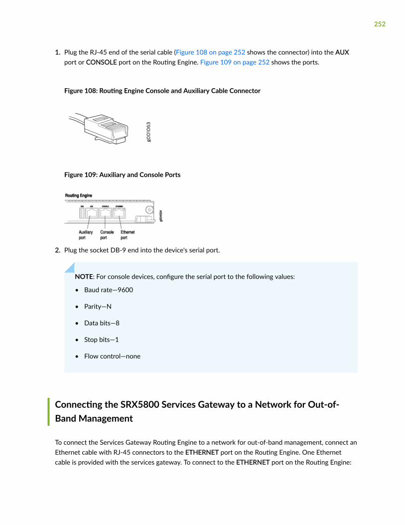
1. Plug the RJ-45 end of the serial cable (Figure 108 on page 252 shows the connector) into the AUXport or CONSOLE port on the Routing Engine. Figure 109 on page 252 shows the ports.
Figure 108: Routing Engine Console and Auxiliary Cable Connector
Figure 109: Auxiliary and Console Ports
2. Plug the socket DB-9 end into the device's serial port.
NOTE: For console devices, configure the serial port to the following values:
• Baud rate—9600
• Parity—N
• Data bits—8
• Stop bits—1
• Flow control—none
Connecting the SRX5800 Services Gateway to a Network for Out-of-Band Management
To connect the Services Gateway Routing Engine to a network for out-of-band management, connect anEthernet cable with RJ-45 connectors to the ETHERNET port on the Routing Engine. One Ethernetcable is provided with the services gateway. To connect to the ETHERNET port on the Routing Engine:
252

1. Plug one end of the Ethernet cable (Figure 110 on page 253 shows the connector) into theETHERNET port on the Routing Engine. Figure 111 on page 253 shows the port.
2. Plug the other end of the cable into the network device.
Figure 110: Routing Engine Ethernet Cable Connector
Figure 111: Ethernet Port
Connecting an SRX5800 Services Gateway to an External Alarm-Reporting Device
To connect the services gateway to external alarm-reporting devices, attach wires to the RED andYELLOW relay contacts on the craft interface. (See Figure 112 on page 253.) A system condition thattriggers the red or yellow alarm LED on the craft interface also activates the corresponding alarm relaycontact.
Figure 112: Alarm Relay Contacts
253

The terminal blocks that plug into the alarm relay contacts are supplied with the services gateway. Theyaccept wire of any gauge between 28-AWG and 14-AWG (0.08 and 2.08 mm2), which is not provided.Use the gauge of wire appropriate for the external device you are connecting.
To connect an external device to an alarm relay contact (see Figure 112 on page 253):
1. Prepare the required length of wire with gauge between 28-AWG and 14-AWG (0.08 and 2.08 mm2).
2. While the terminal block is not plugged into the relay contact, use a 2.5-mm flat-blade screwdriver toloosen the small screws on its top. With the small screws on its top facing upward, insert wires intothe slots in the front of the block based on the wiring for the external device. Tighten each screw tosecure the corresponding wire.
3. Plug the terminal block into the relay contact, and use a 2.5-mm flat-blade screwdriver to tighten thescrews on the face of the block. See Figure 113 on page 254.
Figure 113: Connecting an External Alarm-Reporting Device
4. Attach the other end of the wires to the external device.
To attach a reporting device for the other kind of alarm, repeat the procedure.
254

Connecting Network Cables to SRX5800 Services Gateway IOCs andPort Modules
To connect the IOCs, MPCs, and port modules to the network (see Figure 114 on page 256):
1. Have ready a length of the type of cable used by the component.
2. Remove the rubber safety plug from the cable connector port.
LASER WARNING: Do not look directly into a fiber-optic transceiver or into the ends offiber-optic cables. Fiber-optic transceivers and fiber-optic cables connected to atransceiver emit laser light that can damage your eyes.
CAUTION: Do not leave a fiber-optic transceiver uncovered except when inserting orremoving a cable. The safety cap keeps the port clean and prevents accidentalexposure to laser light.
3. Insert the cable connector into the cable connector port on the faceplate.
NOTE: The XFP cages and optics on the components are industry standard parts that havelimited tactile feedback for insertion of optics and fiber. You need to insert the optics andfiber firmly until the latch is securely in place.
4. Arrange the cable in the standard or extended cable manager to prevent it from dislodging ordeveloping stress points. Secure the cable so that it is not supporting its own weight as it hangs tothe floor. Place excess cable out of the way in a neatly coiled loop. Placing fasteners on the loophelps to maintain its shape.
CAUTION: Avoid bending a fiber-optic cable beyond its minimum bend radius. An arcsmaller than a few inches in diameter can damage the cable and cause problems thatare difficult to diagnose.
255

CAUTION: Do not let fiber-optic cables hang free from the connector. Do not allowthe fastened loops of a cable to dangle, which stresses the cable at the fastening point.
Figure 114: Attaching a Cable to an IOC
256

Connecting the SRX5800 to Power
IN THIS SECTION
Tools and Parts Required for SRX5800 Services Gateway Grounding and Power Connections | 257
Grounding the SRX5800 Services Gateway | 258
Connecting Power to an AC-Powered SRX5800 Services Gateway | 259
Connect Power to an SRX5800 Services Gateway with High-Capacity Second-Generation PowerSupplies | 262
Powering On an AC-Powered SRX5800 Services Gateway | 269
Connect Power to an SRX5800 Services Gateway with High-Voltage Second-Generation Universal (HVAC/HVDC) Power Supplies | 271
Connecting Power to a DC-Powered SRX5800 Services Gateway | 274
Powering On a DC-Powered SRX5800 Services Gateway | 276
Powering Off the SRX5800 Services Gateway | 278
"Connecting Power to an AC-Powered SRX5800 Services Gateway" on page 259
Tools and Parts Required for SRX5800 Services Gateway Grounding andPower Connections
To ground and provide power to the services gateway, you need the following tools and parts:
• Phillips (+) screwdrivers, numbers 1 and 2
• 2.5-mm flat-blade (–) screwdriver
• 7/16-in. hexagonal-head external drive socket wrench, or nut driver, with a torque range between23 lb-in. (2.6 Nm) and 25 lb-in. (2.8 Nm) tightening torque, for tightening nuts to terminal studs oneach power supply on a DC-powered services gateway.
• Wire cutters
• Electrostatic discharge (ESD) grounding wrist strap
257

Grounding the SRX5800 Services Gateway
WARNING: To meet safety and electromagnetic interference (EMI) requirements and toensure proper operation, you must properly ground the services gateway chassis beforeconnecting power. You must install the SRX500 device in a restricted-access locationand ensure that the chassis is always properly grounded. The SRX500 device has a two-hole protective grounding terminal provided on the chassis. See Figure 115 on page259. Under all circumstances, use this grounding connection to ground the chassis. ForAC-powered systems, you must also use the grounding wire in the AC power cord alongwith the two-hole grounding lug connection. This tested system meets or exceeds allapplicable EMC regulatory requirements with the two-hole protective groundingterminal.
You ground the services gateway by connecting a grounding cable to earth ground and then attaching itto one of the chassis grounding points using two screws. You must provide the grounding cable (thecable lug is supplied with the services gateway).
1. Verify that a licensed electrician has attached the cable lug provided with the services gateway to thegrounding cable.
2. Attach an ESD grounding strap to your bare wrist and connect the strap to an approved site ESDgrounding point. See the instructions for your site.
3. Ensure that all grounding surfaces are clean and brought to a bright finish before groundingconnections are made.
4. Connect the grounding cable to a proper earth ground.
5. Detach the ESD grounding strap from the site ESD grounding point.
6. Attach an ESD grounding strap to your bare wrist, and connect the strap to one of the ESD points onthe chassis.
7. Place the grounding cable lug over one of the two grounding points. The right pair is sized for UNC1/4-20 screws and 1/4 in. split washers, which are provided in the accessory box. The left pair issized for M6 metric screws. If you wish to use the metric-sized grounding point, you must provideappropriate screws and split washers.
258

8. Secure the grounding cable lug to the grounding point, first with the washers, and then with thescrews as shown in Figure 115 on page 259.
Figure 115: Connecting the Grounding Cable
9. Dress the grounding cable and verify that it does not touch or block access to services gatewaycomponents, and that it does not drape where people could trip on it.
Connecting Power to an AC-Powered SRX5800 Services Gateway
WARNING: To meet safety and electromagnetic interference (EMI) requirements and toensure proper operation, you must properly ground the services gateway chassis beforeconnecting power. See "Grounding the SRX5800 Services Gateway" on page 258 forinstructions.
259

CAUTION: Do not mix AC and DC power supplies within the same services gateway.Damage to the services gateway might occur.
You connect AC power to the device by attaching power cords from the AC power sources to the ACappliance inlets located on the chassis above the power supplies. If the services gateway is powered byhigh-capacity power supplies, you also connect AC feeds to AC appliance inlets located on the powersupplies themselves. The power cords are not provided with the services gateway; you must order themseparately.
To connect the AC power cords to the services gateway (see Figure 116 on page 261 and Figure 117 onpage 262):
1. Locate or obtain the power cords you will use with the services gateway. The power cords must havea plug appropriate for your geographical location.
2. Attach an ESD grounding strap to your bare wrist, and connect the strap to one of the ESD points onthe chassis.
3. Move the AC input switch on the chassis above each power supply to the off (O) position. If theservices gateway is equipped with high-capacity AC power supplies, you must also move the ACinput switch on each power supply to the off (O) position.
4. For each installed AC power supply, connect a power cord to the appliance inlet on the chassisdirectly above the power supply.
5. If your services gateway is equipped with high-capacity AC power supplies, you must also connect apower cord to the appliance inlet located on each power supply.
6. Insert the power cord plugs into an external AC power source receptacle.
NOTE: Each power supply must be connected to a dedicated AC power feed and a dedicatedcustomer site circuit breaker. We recommend that you use a 15 A (250 VAC) minimum, or asrequired by local code.
7. Dress the power cords appropriately. Verify that the power cords do not block the air exhaust andaccess to services gateway components, or drape where people could trip on them.
260

8. Repeat Step 3 through Step 7 for the remaining power supplies.
Figure 116: Connecting AC Power to the Services Gateway (Standard-Capacity Power Supplies)
261

Figure 117: Connecting AC Power to the Services Gateway (High-Capacity Power Supplies)
Connect Power to an SRX5800 Services Gateway with High-CapacitySecond-Generation Power Supplies
A minimum of two AC nominal 220 VAC 20 amp power cords are required for this procedure.
To install and power on an SRX5800 Services Gateway with High-Capacity Second-Generation AC(MX960-PSM-5K-AC) power supply, use the following procedure.
262

1. Verify that the power switch on the power supply is in the off (O) position.
2. Ensure that the release lever below the empty power supply slot is locked in the counterclockwiseposition (see Figure 118 on page 263).
Figure 118: SRX5800 Services Gateway with High-Capacity Second Generation AC PowerSupplies Installed
If necessary, pull the spring-loaded locking pin in the release lever away from the chassis and turnthe release lever counterclockwise until it stops. Let go of the locking pin in the release lever.Ensure that the pin is seated inside the corresponding hole in the chassis.
3. On the power supply, rotate the metal cover away from the input mode switch to expose theswitch.
263

4. Move the input mode switch to position 0 if you plan to connect one feed, or position 1 if you planto connect two feeds (see Figure 119 on page 264).
Figure 119: SRX5800 High-Capacity Second-Generation AC Power Input Mode Switch
1— 1 (if you connect two feeds) 2— 0 (if you connect one feed)
CAUTION: Do not use a pencil, because fragments can break off and cause damageto the power supply.
5. Using both hands, slide the power supply straight into the chassis until the power supply is fullyseated in the chassis slot. The power supply faceplate will protrude beyond the chassis.
The small tab on the metal housing that is controlled by the release lever must be inside of thecorresponding slot at the bottom of the power supply (see Figure 118 on page 263). This tab isused to pull the power supply down in the chassis slot, prior to removing the power supply.
6. While firmly pushing the handle on the power supply faceplate with one hand, use your other handto pull the spring-loaded locking pin in the release lever away from the chassis and turn the releaselever clockwise until it stops.
7. Let go of the locking pin in the release lever. Ensure that the pin is seated inside the correspondinghole in the chassis.
8. Make sure the cover is attached on the power distribution unit on the chassis.
9. Make sure the grounding cable is attached, See .
10. Locate a power cord with the type of plug appropriate for your geographical location (see ).
11. Plug the power cord into the corresponding appliance inlet located in the chassis directly on thepower supply. If using the power supply in two-feed mode, plug the second power cord into thereceptacle on the power supply.
264

Using a screwdriver, tighten the screw on the retainer to prevent the AC cord from getting lose. SeeFigure 120 on page 266.
NOTE: Each power supply must be connected to a dedicated AC power feed and adedicated customer site circuit breaker.
265

NOTE: To use high-capacity second-generation AC power supplies with full capacity youhave to switch them to two feed mode and use two power cords per power supply. SeeFigure 120 on page 266.
Figure 120: SRX5800 with One High-Capacity Second-Generation AC Power Feed Connected
266

Figure 121: SRX5800 with Both High-Capacity Second-Generation AC Power Feeds Connected
12. Dress the power cords appropriately. Verify that the power cord does not block the air exhaust andaccess to router components, and that they do not drape where people could trip on them.
267

13. Move the AC input switch above the power supply to the on (—) position. See Figure 122 on page268. This is the only switch you have to turn on.
Figure 122: SRX5800 with High-Capacity Second-Generation AC Power Supplies Input Switch
14. If the power supply is correctly installed and functioning normally, the IN1 OK, IN2 OK (two-feedmode only) DC OK LEDs light steadily, and the PS FAIL LED is not lit. See Table 70 on page 268.
Table 70: High-Capacity Second-Generation AC Power Supply DIP Switch Position and LEDsBehaviour
ConnectedInputs
DIP SwitchPosition
LEDs
INP0 OK INP1 OK DC OK PS FAIL
INP0connected,INP1disconnected
0 (1 input) Green Off Green Off
INP0disconnected,INP1connected
0 (1 input) Off Green Green Off
268

Table 70: High-Capacity Second-Generation AC Power Supply DIP Switch Position and LEDsBehaviour (Continued)
ConnectedInputs
DIP SwitchPosition
LEDs
INP0 OK INP1 OK DC OK PS FAIL
INP0connected,INP1connected
0 (1 input) Green Green Green Off
INP0connected,INP1disconnected
1 (2 inputs) Green Off Off Red
INP0disconnected,INP1connected
1 (2 inputs) Off Green Off Red
INP0connected,INP1connected
1 (2 inputs) Green Green Green Off
15. Repeat steps 1-12 for installing power supplies in the other slot as required.
Powering On an AC-Powered SRX5800 Services Gateway
To power on an AC-powered services gateway:
1. Verify that the power supplies are fully inserted in the chassis.
2. Verify that each AC power cord is securely inserted into its appliance inlet.
3. Verify that an external management device is connected to one of the Routing Engine ports (AUX,CONSOLE, or ETHERNET).
4. Turn on the power to the external management device.
269

5. Switch on the dedicated customer site circuit breakers. Follow the ESD and safety instructions foryour site.
6. Attach an ESD grounding strap to your bare wrist, and connect the strap to one of the ESD pointson the chassis.
7. Switch the AC switch in the chassis above each power supply to the on (—) position.
8. If the services gateway has high-capacity power supplies installed, you must also move the ACswitch at the top of each power supply to the on (|) position.
9. Verify the following LED indications for each installed power supply:
• For standard-capacity AC power supplies, verify that the AC OK and DC OK LEDs light steadilyand the PS FAIL LED is not lit.
• For high-capacity AC power supplies, verify that the DC OK LED lights steadily, and the PS FAILLED is not lit. In addition, the AC-1 OK LED should light green steadily if the upper AC feed (onthe chassis above the power supply) is connected and receiving power, and the AC-2 OK LEDshould light green steadily if the lower AC feed (on the power supply itself) is connected andreceiving power.
NOTE: After a power supply is powered on, it can take up to 60 seconds for statusindicators—such as the status LEDs on the power supply and the show chassis commanddisplay—to indicate that the power supply is functioning normally. Ignore error indicatorsthat appear during the first 60 seconds.
If any of the status LEDs indicates that the power supply is not functioning normally, repeat theinstallation and cabling procedures.
10. On the external management device connected to the Routing Engine, monitor the startup processto verify that the system has booted properly.
NOTE: If the system is completely powered off when you power on the power supply, theRouting Engine boots as the power supply completes its startup sequence. Normally, theservices gateway boots from the Junos OS imageon the CompactFlash card.
After you have powered on a power supply, wait at least 60 seconds before you power itoff.
270

Connect Power to an SRX5800 Services Gateway with High-VoltageSecond-Generation Universal (HVAC/HVDC) Power Supplies
To install and power on an High-Voltage Second-Generation Universal (HVAC/HVDC) power supply, usethe following procedure.
1. Verify that the power switch on the power supply is in the off (O) position.
2. Ensure that the release lever below the empty power supply slot is locked in the counterclockwiseposition (see Figure 123 on page 271).
Figure 123: SRX5800 Services Gateway with High-Voltage Second-Generation Universal (HVACor HVDC) Installed
271

If necessary, pull the spring-loaded locking pin in the release lever away from the chassis and turnthe release lever counterclockwise until it stops. Let go of the locking pin in the release lever.Ensure that the pin is seated inside the corresponding hole in the chassis.
3. On the power supply, rotate the metal cover away from the input mode switch to expose theswitch.
4. Using both hands, slide the power supply straight into the chassis until the power supply is fullyseated in the chassis slot. The power supply faceplate protrudes beyond the chassis.
The small tab on the metal housing that is controlled by the release lever must be inside of thecorresponding slot at the bottom of the power supply. This tab is used to pull the power supplydown in the chassis slot, prior to removing the power supply.
5. While firmly pushing the handle on the power supply faceplate with one hand, use your other handto pull the spring-loaded locking pin in the release lever away from the chassis and turn the releaselever clockwise until it stops.
6. Let go of the locking pin in the release lever. Ensure that the pin is seated inside the correspondinghole in the chassis.
7. Make sure the cover is attached on the power distribution unit on the chassis on the high-voltagesecond-generation universal (HVAC or HVDC) power supply.
8. Make sure the grounding cable is attached,
9. Locate a power cord with the type of plug appropriate for your geographical location.
10. Plug the power cord into the corresponding appliance inlet located in the chassis directly on thepower supply.
272

NOTE: Each power supply must be connected to a dedicated power feed and a dedicatedcustomer site circuit breaker.
Figure 124: SRX5800 Services Gateway with One High-Voltage Second-Generation (HVAC orHVDC) Power Feed Connected
11. Dress the power cords appropriately. Verify that the power cord does not block the air exhaust andaccess to router components, and that they do not drape where people could trip on them.
273

12. Move the input switch above the power supply to the on (—) position.
Figure 125: High-Voltage Second-Generation (HVAC or HVDC)MX960 AC Power Input ModeSwitch
13. If the power supply is correctly installed and functioning normally, the INP OK, DC OK LEDs lightsteadily, and the PS FAIL LED is not lit.
14. Repeat steps 1-12 for installing power supplies in slots 1, 2, and 3, where required.
Connecting Power to a DC-Powered SRX5800 Services Gateway
WARNING: Before performing DC power procedures, ensure that power is removedfrom the DC circuit. To ensure that all power is off, locate the circuit breaker on thepanel board that services the DC circuit, switch the circuit breaker to the off position,and tape the switch handle of the circuit breaker in the off position.
WARNING: To meet safety and electromagnetic interference (EMI) requirements and toensure proper operation, you must properly ground the services gateway chassis beforeconnecting power. See "Grounding the SRX5800 Services Gateway" on page 258 forinstructions.
CAUTION: Do not mix AC and DC power supplies within the same services gateway.Damage to the services gateway might occur.
274

You connect DC power to the services gateway by attaching power cables from the external DC powersources to the terminal studs on the power supply faceplates. You must provide the power cables (thecable lugs are supplied with the services gateway).
To connect the DC source power cables to the services gateway:
1. Switch off the dedicated customer site circuit breakers. Ensure that the voltage across the DCpower source cable leads is 0 V and that there is no chance that the cable leads might becomeactive during installation.
2. Attach an ESD grounding strap to your bare wrist, and connect the strap to one of the ESD pointson the chassis.
3. Move the DC circuit breaker on the power supply faceplate to the off (O) position.
4. Remove the clear plastic cover protecting the terminal studs on the faceplate.
5. Verify that the DC power cables are correctly labeled before making connections to the powersupply. In a typical power distribution scheme where the return is connected to chassis ground atthe battery plant, you can use a multimeter to verify the resistance of the –48V and RTN DC cablesto chassis ground:
• The cable with very large resistance (indicating an open circuit) to chassis ground is –48V.
• The cable with very low resistance (indicating a closed circuit) to chassis ground is RTN.
CAUTION: You must ensure that power connections maintain the proper polarity.The power source cables might be labeled (+) and (–) to indicate their polarity.There is no standard color coding for DC power cables. The color coding used bythe external DC power source at your site determines the color coding for the leadson the power cables that attach to the terminal studs on each power supply.
6. Remove the nuts and washers from the terminal studs. (Use a 7/16-in. nut driver or socket wrench.)
7. Secure each power cable lug to the terminal studs, first with the split washer, then with the nut (seeFigure 126 on page 276). Apply between 23 lb-in. (2.6 Nm) and 25 lb-in. (2.8 Nm) of torque to eachnut. (Use a 7/16-in. nut driver or socket wrench.)
a. Secure each positive (+) DC source power cable lug to the RTN (return) terminal.
b. Secure each negative (–) DC source power cable lug to the –48V (input) terminal.
The DC power supplies in slots PEM0 and PEM1 must be powered by dedicated power feedsderived from feed A, and the DC power supplies in slots PEM2 and PEM3 must be powered bydedicated power feeds derived from feed B. This configuration provides the commonly deployedA/B feed redundancy for the system.
8. For standard-capacity DC power supplies, secure each DC power cable to its strain relief bracket asfollows:
275

a. Loosen the captive screw on the cable restraint on the lower edge of the power supplyfaceplate.
b. Route the positive and negative DC power cables through the left and right sides of the cablerestraint.
c. Tighten the cable restraint captive screw to hold the power cables in place.
9. Replace the clear plastic cover over the terminal studs on the faceplate.
10. Verify that the power cables are connected correctly, that they are not touching or blocking accessto services gateway components, and that they do not drape where people could trip on them.
11. Repeat Steps 3 through 10 for the remaining power supplies.
Figure 126: Connecting DC Power to the Services Gateway (Standard-Capacity SHown, High-CapacitySimilar)
Powering On a DC-Powered SRX5800 Services Gateway
To power on a DC-powered services gateway:
1. Verify that an external management device is connected to one of the Routing Engine ports (AUX,CONSOLE, or ETHERNET).
2. Turn on the power to the external management device.
3. Verify that the power supplies are fully inserted in the chassis.
276

4. Verify that the source power cables are connected to the appropriate terminal: the positive (+)source cable to the return terminal (labeled RTN) and the negative (–) source cable to the inputterminal (labeled –48V).
5. Switch on the dedicated customer site circuit breakers to provide power to the DC power cables.Follow your site’s procedures.
6. Check the INPUT OK LED is lit steadily green to verify that power is present.
7. If power is not present:
• Verify that the fuse is installed correctly and turn on the breaker at the battery distribution fuseboard or fuse bay.
• Check the voltage with a meter at the terminals of the power supply for correct voltage leveland polarity.
8. Attach an ESD grounding strap to your bare wrist, and connect the strap to one of the ESD pointson the chassis.
9. Move the DC circuit breaker on the DC power supplies to the on (|) position.
10. Verify that the BREAKER ON LED is lit green steadily.
11. Verify that the PWR OK LED is lit green steadily, indicating the power supply is correctly installedand functioning normally.
NOTE: After a power supply is powered on, it can take up to 60 seconds for statusindicators—such as the status LEDs on the power supply and the show chassis commanddisplay—to indicate that the power supply is functioning normally. Ignore error indicatorsthat appear during the first 60 seconds.
If any of the status LEDs indicates that the power supply is not functioning normally, repeat theinstallation and cabling procedures .
12. On the external management device connected to the Routing Engine, monitor the startup processto verify that the system has booted properly.
NOTE: If the system is completely powered off when you power on the power supply, theRouting Engine boots as the power supply completes its startup sequence. Normally, theservices gateway boots from the Junos OS image on the CompactFlash card.
After powering on a power supply, wait at least 60 seconds before turning it off.
277

Powering Off the SRX5800 Services Gateway
NOTE: After powering off a power supply, wait at least 60 seconds before turning it back on.
To power off the services gateway:
1. On the external management device connected to the Routing Engine, issue the request system haltoperational mode command. The command shuts down the Routing Engine cleanly, so its stateinformation is preserved.
user@host> request system halt
2. Wait until a message appears on the console confirming that the operating system has halted.
For more information about the command, see Junos OS System Basics and Services CommandReference at www.juniper.net/documentation/.
3. Attach an ESD grounding strap to your bare wrist, and connect the strap to one of the ESD points onthe chassis.
4. Switch off the power supplies:
• For an AC-powered services gateway, move the AC input switch on the chassis above each ACpower supply to the off (O) position. If the services gateway is equipped with high-capacity ACpower supplies, you must also move the AC input switch on each power supply to the off (O)position.
• For a DC-powered services gateway, move the DC circuit breaker on each DC power supplyfaceplate to the off (O) position.
Performing the Initial Software Configuration for theSRX5800
IN THIS SECTION
SRX5800 Services Gateway Software Configuration Overview | 279
Initially Configuring the SRX5800 Services Gateway | 279
278

Performing Initial Software Configuration Using J-Web | 285
SRX5800 Services Gateway Software Configuration Overview
The services gateway is shipped with the Junos operating system (Junos OS) preinstalled and ready tobe configured when the device is powered on. There are three copies of the software: one on aCompactFlash card (if installed) in the Routing Engine, one on the hard disk in the Routing Engine, andone on a USB flash drive that can be inserted into the slot in the Routing Engine faceplate.
When the device boots, it first attempts to start the image on the USB flash drive. If a USB flash drive isnot inserted into the Routing Engine or the attempt otherwise fails, the device next tries theCompactFlash card (if installed), and finally the hard disk.
You configure the services gateway by issuing Junos OS command-line interface (CLI) commands, eitheron a console device attached to the CONSOLE port on the Routing Engine, or over a telnet connectionto a network connected to the ETHERNET port on the Routing Engine.
Gather the following information before configuring the device:
• Name the device will use on the network
• Domain name the device will use
• IP address and prefix length information for the Ethernet interface
• IP address of a default router
• IP address of a DNS server
• Password for the root user
Initially Configuring the SRX5800 Services Gateway
This procedure connects the device to the network but does not enable it to forward traffic. Forcomplete information about enabling the device to forward traffic, including examples, see theappropriate Junos OS configuration guides.
To configure the software:
1. Verify that the device is powered on.
279

2. Log in as the root user. There is no password.
3. Start the CLI.
root# cliroot@>
4. Enter configuration mode.
configure [edit]root@#
5. Set the root authentication password by entering either a cleartext password, an encryptedpassword, or an SSH public key string (DSA or RSA).
[edit]root@# set system root-authentication plain-text-passwordNew password: password Retype new password: password
6. Configure an administrator account on the device. When prompted, enter the password for theadministrator account.
[edit]root@# set system login user admin class super-user authentication plain-text-password New password: password Retype new password: password
7. Commit the configuration to activate it on the device.
[edit]root@# commit
8. Log in as the administrative user you configured in Step 6.
280

9. Configure the name of the device. If the name includes spaces, enclose the name in quotationmarks (“ ”).
configure [edit]admin@# set system host-name host-name
10. Configure the IP address and prefix length for the Ethernet management interface on the servicesgateway’s Routing Engine.
[edit]admin@# set interfaces fxp0 unit 0 family inet address address/prefix-length
11. Configure the traffic interface.
[edit]admin@# set interfaces ge-6/2/0 unit 0 family inet address address/prefix-lengthadmin@# set interfaces ge-6/3/5 unit 0 family inet address address/prefix-length
12. Configure the default route.
[edit]admin@# set routing-options static route 0.0.0.0/0 next-hop gateway
13. Configure basic security zones and bind them to traffic interfaces.
[edit]admin@# set security zones security-zone trust interfaces ge-6/3/5 admin@# set security zones security-zone untrust interfaces ge-6/2/0
14. Configure basic security policies.
[edit]admin@# set security policies from-zone trust to-zone untrust policy policy-name match source-address any destination-address any application any root@# set security policies from-zone trust to-zone untrust policy policy-name then permit
281

15. Check the configuration for validity.
[edit]admin@# commit checkconfiguration check succeeds
16. Commit the configuration to activate it on the device.
[edit]admin@# commitcommit complete
17. Optionally, display the configuration to verify that it is correct.
admin@# show## Last changed: 2008-05-07 22:43:25 UTCversion "9.2I0 [builder]";system { autoinstallation; host-name henbert; root-authentication { encrypted-password "$1$oTVn2KY3$uQe4xzQCxpR2j7sKuV.Pa0"; ## SECRET-DATA } login { user admin { uid 928; class super-user; authentication { encrypted-password "$1$cdOPmACd$QvreBsJkNR1EF0uurTBkE."; ## SECRET-DATA } } } services { ssh; web-management { http { interface ge-0/0/0.0; } } } syslog {
282

user * { any emergency; } file messages { any any; authorization info; } file interactive-commands { interactive-commands any; } } license { autoupdate { url https://ae1.juniper.net/junos/key_retrieval; } }}interfaces { ge-0/0/0 { unit 0; } ge-6/2/0 { unit 0 { family inet { address 5.1.1.1/24; } } } ge-6/3/5 { unit 0 { family inet { address 192.1.1.1/24; } } } fxp0 { unit 0 { family inet { address 192.168.10.2/24; } } }}
283

routing-options { static { route 0.0.0.0/0 next-hop 5.1.1.2; }}security { zones { security-zone trust { interfaces { ge-6/3/5.0; } } security-zone untrust { interfaces { ge-6/2/0.0; } } } policies { from-zone trust to-zone untrust { policy bob { match { source-address any; destination-address any; application any; } then { permit; } } } }}
18. Commit the configuration to activate it on the device.
[edit]admin@# commit
284

19. Optionally, configure additional properties by adding the necessary configuration statements. Thencommit the changes to activate them on the device.
[edit]admin@# commit
20. When you have finished configuring the device, exit configuration mode.
[edit]admin@# exitadmin@host>
Performing Initial Software Configuration Using J-Web
IN THIS SECTION
Configuring Root Authentication and the Management Interface from the CLI | 285
Configuring Interfaces, Zones, and Policies with J-Web | 287
Configuring Root Authentication and the Management Interface from the CLI
Before you can use J-Web to configure your device, you must access the CLI to perform the initialconfiguration.
To configure root authentication and the management interface:
1. Log in as root. There is no password.
2. Start the CLI and enter configuration mode.
root@% cliroot@>configureroot@#
285

3. Set the root authentication password by entering a cleartext password, an encrypted password, or anSSH public key string (DSA or RSA).
[edit]root@# set system root-authentication plain-text-passwordNew password: passwordRetype new password: password
4. Commit the configuration to activate it on the device.
[edit]root@# commit
5. Configure the IP address and prefix length for the Ethernet management interface on the device.
[edit]root@# set interfaces fxp0 unit 0 family inet address address/prefix-length
6. Configure the default route.
[edit]root@# set routing-options static route 0.0.0.0/0 next-hop gateway
7. Enable Web access to launch J-Web.
[edit]root@# set system services web-management http
8. Commit the configuration changes.
[edit]root@# commit
286

Configuring Interfaces, Zones, and Policies with J-Web
IN THIS SECTION
Configuring the Hostname | 287
Configuring Interfaces | 288
Configuring Zones and Assigning Interfaces | 288
Configuring Security Policies | 289
You can configure hostnames, interfaces, zones, and security policies using J-Web.
NOTE: You cannot use J-Web to configure SRX5400, SRX5600, and SRX5800 ServicesGateways in Junos OS Release 15.1X49-D10.
Before you begin:
• Ensure you have configured the IP address, root authentication, and default route. See "PerformingInitial Software Configuration Using J-Web " on page 285
• Enable HTTP on the device to access J-Web. See "Performing Initial Software Configuration Using J-Web " on page 285
Configure the device with J-Web using the following procedures.
Configuring the Hostname
To configure the hostname:
1. Launch a Web browser from the management device.
2. Enter the IP address of the device in the URL address field.
3. Specify the default username as root and enter the password. See "Performing Initial SoftwareConfiguration Using J-Web " on page 285.
4. Click Log In. The J-Web Dashboard page appears.
5. Select Configure>System Properties>System Identity, and then select Edit. The Edit System Identitydialog box appears.
6. Enter the hostname and click OK.
7. Select Commit Options>Commit to apply the configuration changes.
287

You have successfully configured the hostname for the system.
Configuring Interfaces
To configure two physical interfaces:
1. From the J-Web Dashboard page, select Configure>Interfaces and select a physical interface youwant to configure.
2. Select Add>Logical Interface. The Add interface dialog box appears.
3. Set Unit = 0.
4. Select the check box for IPv4 Address to enable IPv4 addressing.
5. Click Add and enter the IPv4 address.
6. Click OK.
A message appears after your configuration changes are validated successfully.
7. Click OK.
8. Select Commit Options>Commit to apply the configuration changes.
A message appears after your configuration changes are applied successfully.
9. Click OK.
You have successfully configured the physical interface. Repeat these steps to configure the secondphysical interface for the device.
Configuring Zones and Assigning Interfaces
To assign interfaces within a trust zone and an untrust zone:
1. From the J-Web Dashboard page, select Configure>Security>Zones/Screens and click Add. The AddZone dialog box appears.
2. In the Main tab, enter trust for zone name and enter the description.
3. Set the zone type to Security.
4. Select the interfaces listed under Available and move them under Selected.
5. Click OK.
A message appears after your configuration changes are validated successfully.
6. Click OK.
7. Select Commit Options>Commit to apply the configuration changes.
A message appears after your configuration changes are applied successfully.
8. Click OK.
9. Repeat Step 1 through Step 8 and assign another interface to an untrust zone.
You have successfully configured interfaces in a trust zone and in an untrust zone.
288

Configuring Security Policies
To configure security policies:
1. From the J-Web Dashboard page, select Configure>Security>Security Policy and click Add. The AddPolicy dialog box appears.
2. In the Policy tab, enter the policy name and set the policy action to permit. Then select Zone and setthe From Zone to trust and the To Zone to untrust.
3. Configure the source IP address by selecting any listed under Available and moving it under Selected.
4. Configure the destination IP address by selecting any listed under Available and moving it underSelected.
5. Configure the application by selecting any listed under Available and moving it under Selected.
6. Click OK.
A message appears after your configuration changes are validated successfully.
7. Click OK.
8. Select Commit Options>Commit to apply the configuration changes.
A message appears after your configuration changes are applied successfully.
9. Click OK.
You have successfully configured the security policy.
289

4CHAPTER
Maintaining Components
Maintaining the SRX5800 Chassis | 291
Maintaining the SRX5800 Cooling System | 296
Maintaining the SRX5800 Power System | 307
Maintaining the SRX5800 Host Subsystem | 339
Maintaining the SRX5800 Line Cards and Modules | 375
Maintaining the SRX5800 Cables and Connectors | 424
Replacing a Routing Engine in an SRX Series High-End Chassis Cluster | 440

Maintaining the SRX5800 Chassis
IN THIS SECTION
Routine Maintenance Procedures for the SRX5800 Services Gateway | 291
Replacing the SRX5800 Services Gateway Craft Interface | 292
Routine Maintenance Procedures for the SRX5800 Services Gateway
IN THIS SECTION
Purpose | 291
Action | 291
Purpose
For optimum services gateway performance, perform preventive maintenance procedures regularly.
Action
• Inspect the installation site for moisture, loose wires or cables, and excessive dust. Make sure thatairflow is unobstructed around the device and into the air intake vents.
• Check the status-reporting devices on the craft interface—System alarms and LEDs.
• Inspect the air filter at the bottom front of the services gateway, replacing it every six months foroptimum cooling system performance. Do not run the device for more than a few minutes withoutthe air filter in place.
291

Replacing the SRX5800 Services Gateway Craft Interface
IN THIS SECTION
Disconnecting the Alarm Relay Wires from the SRX5800 Services Gateway Craft Interface | 292
Removing the SRX5800 Services Gateway Craft Interface | 293
Installing the SRX5800 Services Gateway Craft Interface | 294
Connecting the Alarm Relay Wires to the SRX5800 Services Gateway Craft Interface | 295
To replace the craft interface, perform the following procedures in sequence:
Disconnecting the Alarm Relay Wires from the SRX5800 Services Gateway CraftInterface
Before you begin disconnecting the alarm relay wires from the services gateway and an alarm-reportingdevice:
• Ensure you understand how to prevent electrostatic discharge (ESD) damage. See Prevention ofElectrostatic Discharge Damage.
Ensure that you have the following available:
• ESD grounding strap
• 2.5-mm flat-blade screwdriver
To disconnect the alarm relay wires from the services gateway and an alarm-reporting device (see Figure1):
1. Disconnect the existing wire at the external device.
2. Attach an ESD grounding strap to your bare wrist, and connect the strap to one of the ESD points onthe chassis.
3. Using a 2.5-mm flat-blade screwdriver, loosen the small screws on the face of the terminal block andremove the block from the relay contact.
292

4. Using the 2.5-mm flat-blade screwdriver, loosen the small screws on the side of the terminal block.Remove existing wires from the slots in the front of the block.
Figure 127: Alarm Relay Contacts
Removing the SRX5800 Services Gateway Craft Interface
Before you begin removing the craft interface from the services gateway:
• Ensure you understand how to prevent electrostatic discharge (ESD) damage. See Prevention ofElectrostatic Discharge Damage.
Ensure that you have the following available:
• ESD grounding strap
• Phillips (+) number 2 screwdriver
To remove the craft interface (see Figure 2):
1. Attach an ESD grounding strap to your bare wrist, and connect the strap to one of the ESD points onthe chassis.
2. Detach any external devices connected to the craft interface.
3. Using the Phillips (+) number 2 screwdriver loosen the captive screws at the left and right corners ofthe craft interface faceplate.
4. Grasp the craft interface faceplate and carefully tilt it toward you until it is horizontal.
293

5. Disconnect the ribbon cable from the back of the faceplate by gently pressing on both sides of thelatch with your thumb and forefinger. Remove the craft interface from the chassis.
Figure 128: Removing the Craft Interface
Installing the SRX5800 Services Gateway Craft Interface
Before you begin installing the craft interface into the services gateway:
• Ensure you understand how to prevent electrostatic discharge (ESD) damage. See Prevention ofElectrostatic Discharge Damage.
Ensure that you have the following available:
• ESD grounding strap
• Phillips (+) number 2 screwdriver
To install the craft interface (see Figure 3):
1. Attach an ESD grounding strap to your bare wrist, and connect the strap to one of the ESD points onthe chassis.
2. Grasp the craft interface with one hand and hold the bottom edge of the craft interface with theother hand to support its weight.
3. Orient the ribbon cable so that it plugs into the connector socket. The connector is keyed and can beinserted only one way.
4. Align the bottom of the craft interface with the sheet metal above the card cage and press it intoplace.
294

5. Using the Phillips (+) number 2 screwdriver tighten the screws on the left and right corners of thecraft interface faceplate.
6. Reattach any external devices connected to the craft interface.
Figure 129: Installing the Craft Interface
Connecting the Alarm Relay Wires to the SRX5800 Services Gateway Craft Interface
Before you begin connecting the alarm relay wires to the services gateway and an alarm-reportingdevice :
• Ensure you understand how to prevent electrostatic discharge (ESD) damage. See Prevention ofElectrostatic Discharge Damage.
Ensure that you have the following available:
• ESD grounding strap
• 2.5-mm flat-blade screwdriver
To connect the alarm relay wires between a services gateway and an alarm-reporting device (see Figure4):
1. Prepare the required length of replacement wire with gauge between 28-AWG and 14-AWG (0.08and 2.08 mm2).
2. Insert the replacement wires into the slots in the front of the block. Use a 2.5-mm flat-bladescrewdriver to tighten the screws and secure the wire.
295

3. Attach an ESD grounding strap to your bare wrist, and connect the strap to one of the ESD points onthe chassis.
4. Plug the terminal block into the relay contact, and use a 2.5-mm flat-blade screwdriver to tighten thescrews on the face of the block.
5. Attach the other end of the wires to the external device.
Figure 130: Alarm Relay Contacts
Maintaining the SRX5800 Cooling System
IN THIS SECTION
Maintaining the Fan Trays on the SRX5800 Services Gateway | 296
Replacing an SRX5800 Services Gateway Fan Tray | 297
Maintaining the Air Filter on the SRX5800 Services Gateway | 303
Replacing the SRX5800 Services Gateway Air Filter | 304
Maintaining the Fan Trays on the SRX5800 Services Gateway
IN THIS SECTION
Purpose | 297
Action | 297
296

Purpose
For optimum cooling, verify the condition of the fans.
Action
• Monitor the status of the fans. A fan tray contains multiple fans that work in unison to cool theservices gateway components. If one fan fails, the host subsystem adjusts the speed of the remainingfans to maintain proper cooling. A major alarm is triggered when a fan fails, and a minor alarm andmajor alarm is triggered when a fan tray is removed.
• To display the status of the cooling system, issue the show chassis environment command.
user@host> show chassis environment
NOTE: In the Junos OS command-line interface (CLI):
• The show chassis environment command output displays the fan trays as Upper Fan Tray andBottom Fan Tray.
• The show chassis hardware command output displays the fan trays as Fan Tray 0 for the upperfan tray and Fan Tray 1 for the bottom fan tray.
NOTE: The fan numbers are stamped into the fan tray sheet metal next to each fan.
Replacing an SRX5800 Services Gateway Fan Tray
IN THIS SECTION
Removing an SRX5800 Services Gateway Fan Tray | 298
Installing an SRX5800 Services Gateway Fan Tray | 300
297

The fan trays are hot-insertable and hot-removable. To replace a fan tray, perform the followingprocedures in sequence:
Removing an SRX5800 Services Gateway Fan Tray
Before you begin to remove the fan tray:
• Ensure you understand how to prevent electrostatic discharge (ESD) damage. See Prevention ofElectrostatic Discharge Damage.
Ensure that you have the following available:
• ESD grounding strap
• Phillips (+) number 2 screwdriver
NOTE: To prevent overheating, install the replacement fan tray immediately after removing theexisting fan tray. Do not operate the services gateway for more than two minutes without bothfan trays installed.
To remove the upper or bottom fan tray (see Figure 1 and Figure 2):
1. Attach an ESD grounding strap to your bare wrist, and connect the strap to one of the ESD points onthe chassis.
2. Reposition the cable manager before removing the bottom front fan tray:
a. Unwrap any cables on the cable manager and remove the cables from the tray. Arrange the cablesso that they do not block the front of the cable manager and tray, and secure them withtemporary fasteners so that they are not supporting their own weight as they hang from theconnector.
b. Simultaneously pull the two releases labeled PULL on the cable manager. Lift it up and outward tolock it in place.
3. Using the Phillips (+) number 2 screwdriver loosen the captive screw on each side of the fan trayfaceplate.
4. Grasp both sides of the fan tray and pull it out approximately 1 to 3 inches.
WARNING: To avoid injury, keep tools and your fingers away from the fans as you slidethe fan module out of the device. The fans might still be spinning.
5. Pause for approximately 15 seconds to allow the fans to stop spinning.
6. When the fans stop spinning, press on the two latches located on the inside of the fan tray.
7. Place one hand under the fan tray to support it and pull the fan tray completely out of the chassis.
298

8. Proceed to "Installing an SRX5800 Services Gateway Fan Tray" on page 297 to install thereplacement fan tray.
Figure 131: Removing an Upper Fan Tray (Standard-Capacity Shown, High-Capacity Similar)
299

Figure 132: Removing the Bottom Fan Tray (Standard-Capacity Shown, High-Capacity Similar)
Installing an SRX5800 Services Gateway Fan Tray
Before you begin to install the fan tray:
• Ensure you understand how to prevent electrostatic discharge (ESD) damage. See Prevention ofElectrostatic Discharge Damage.
Ensure that you have the following available:
• ESD grounding strap
• Phillips (+) number 2 screwdriver
300

NOTE: To prevent overheating, install the replacement fan tray immediately after removing theexisting fan tray. Do not operate the services gateway for more than two minutes without bothfan trays installed.
To install a fan tray (see Figure 3 and Figure 4):
1. Attach an ESD grounding strap to your bare wrist, and connect the strap to one of the ESD points onthe chassis.
2. Grasp the fan tray on each side and insert it straight into the chassis. Note the correct orientation bythe "this side up" label on the top surface of the fan tray.
3. Using the Phillips (+) number 2 screwdriver tighten the captive screws on each side of the fan trayfaceplate to secure it in the chassis.
301

4. Lower the cable manager back into position, if necessary.
Figure 133: Installing an Upper Fan Tray (Standard-Capacity Shown, High-Capacity Similar)
302

Figure 134: Installing the Bottom Fan Tray (Standard-Capacity Shown, High-Capacity Similar)
Maintaining the Air Filter on the SRX5800 Services Gateway
IN THIS SECTION
Purpose | 304
Action | 304
303

Purpose
For optimum cooling, verify the condition of the air filters.
Action
• Regularly inspect the air filter. A dirty air filter restricts airflow in the unit, impeding the ventilation ofthe chassis. The filter degrades over time. Periodically replace the filter in use, as well as spares. Werecommend that you replace the filter every six months. Discard used filters, do not attempt to cleanand reuse them.
NOTE: Air filters will not be replaced by Juniper Networks under the Juniper NetworksHardware Replacement Support Plan, you need to purchase them for replacement.
CAUTION: Always keep the air filter in place while the services gateway is operating.Because the fans are very powerful, they could pull small bits of wire or other materialsinto the services gateway through the unfiltered air intake. This could damage theservices gateway components.
• The shelf life of polyurethane filter varies from two years to five years depending on the storageconditions. Store in a cool, dry, and dark environment. Wrap the media in plastic and store in anenvironment with relative humidity between 40%- 80% and temperature between 40°F (4° C) to90°F (32° C). Note that if the material flakes, or becomes brittle when rubbed or deformed, it is nolonger usable.
Replacing the SRX5800 Services Gateway Air Filter
IN THIS SECTION
Removing the SRX5800 Services Gateway Air Filter | 305
Installing the SRX5800 Services Gateway Air Filter | 306
304

You should change the air filter every six months. To replace the air filter, perform the followingprocedures in sequence:
Removing the SRX5800 Services Gateway Air Filter
Before you begin to remove the air filter:
• Ensure you understand how to prevent electrostatic discharge (ESD) damage. See Prevention ofElectrostatic Discharge Damage.
Ensure that you have the following available:
• ESD grounding strap
CAUTION: Do not run the services gateway for more than two minutes without the airfilter in place.
CAUTION: Always keep the air filter in place while the services gateway is operating,except during replacement. Because the fans are very powerful, they could pull smallbits of wire or other materials into the services gateway through the unfiltered airintake. This could damage the services gateway components.
To remove the air filter (see Figure 5):
1. Attach an ESD grounding strap to your bare wrist, and connect the strap to one of the ESD points onthe chassis.
2. Unwrap any cables on the cable manager and remove the cables from the tray. Arrange the cables sothat they do not block the front of the cable manager and tray, and secure them with temporaryfasteners so that they are not supporting their own weight as they hang from the connector.
CAUTION: Do not let fiber-optic cables hang free from the connector. Do not allowthe fastened loops of a cable to dangle, which stresses the cable at the fastening point.
3. Simultaneously pull the two releases labeled PULL on the cable manager. Lift it up and outward tolock it in place to access the air filter.
4. Slide the air filter tray out of the chassis.
305

5. Lift the air filter out of the air filter tray.
Figure 135: Removing the Air Filter (Standard-Capacity Filter Tray Shown, High-Capacity Similar)
Installing the SRX5800 Services Gateway Air Filter
Before you begin to install the air filter:
• Ensure you understand how to prevent electrostatic discharge (ESD) damage. See Prevention ofElectrostatic Discharge Damage.
Ensure that you have the following available:
• ESD grounding strap
You should change the air filter every six months.
To install the air filter (see Figure 6):
1. Attach an ESD grounding strap to your bare wrist, and connect the strap to one of the ESD points onthe chassis.
2. Ensure the air filter is right side up.
3. Place the air filter into the air filter tray.
4. Insert the air filter tray into the chassis by sliding it straight into the chassis until it stops.
5. Lower the cable manager back into position.
6. Rearrange the cables in the cable manager.
Figure 136: Installing the Air Filter Standard-Capacity Filter Tray Shown, High-Capacity Similar)
306
Maintaining the SRX5800 Power System
IN THIS SECTION
Maintaining SRX5800 Services Gateway Power Supplies | 307
Replacing an SRX5800 Services Gateway AC Power Supply or High-Voltage Second-Generation Universal(HVAC/HVDC) Power Supply | 309
Replacing an SRX5800 Services Gateway AC Power Supply Cord | 320
Replacing an SRX5800 Services Gateway DC Power Supply | 323
Replacing an SRX5800 Services Gateway DC Power Supply Cable | 332
Upgrading an SRX5800 Services Gateway from Standard-Capacity to High-Capacity Power Supplies | 336
Maintaining SRX5800 Services Gateway Power Supplies
IN THIS SECTION
Purpose | 307
Action | 307
Purpose
For optimum services gateway performance, verify the condition of the power supplies.
Action
On a regular basis:
307

• To check the status of the power supplies, issue the show chassis environment pem command. The outputis similar to the following:
user@host> show chassis environment pemPEM 0 status: State Online Temperature OK AC Input: OK DC Output Voltage Current Power Load 50 6 300 17PEM 1 status: State Online Temperature OK AC Input: OK DC Output Voltage Current Power Load 50 3 150 8
• Make sure that the power and grounding cables are arranged so that they do not obstruct access toother services gateway components.
• Routinely check the status LEDs on the power supply faceplates and the craft interface to determineif the power supplies are functioning normally.
• Check the red and yellow alarm LEDs on the craft interface. Power supply failure or removal triggersan alarm that causes one or both of the LEDs to light. You can display the associated error messagesby issuing the following command:
user@host> show chassis alarms
• Periodically inspect the site to ensure that the grounding and power cables connected to the deviceare securely in place and that there is no moisture accumulating near the device.
308

Replacing an SRX5800 Services Gateway AC Power Supply or High-Voltage Second-Generation Universal (HVAC/HVDC) Power Supply
IN THIS SECTION
Removing an SRX5800 Services Gateway AC Power Supply or High-Voltage Second-GenerationUniversal (HVAC/HVDC) Power Supply | 309
Installing an SRX5800 Services Gateway AC Power Supply or High-Voltage Second-GenerationUniversal (HVAC or HVDC) Power Supply | 313
To replace an AC or High-Voltage Second-Generation Universal (HVAC/HVDC) power supply, performthe following procedures:
Removing an SRX5800 Services Gateway AC Power Supply or High-Voltage Second-Generation Universal (HVAC/HVDC) Power Supply
Before you remove a power supply, be aware of the following:
NOTE: The minimum number of power supplies must be present in the services gateway at alltimes.
CAUTION: To maintain proper cooling and prevent thermal shutdown of the operatingpower supply unit, each power supply slot must contain either a power supply or ablank panel. If you remove a power supply, you must install a replacement power supplyor a blank panel shortly after the removal.
NOTE: After powering off a power supply, wait at least 60 seconds before turning it back on.
Before you begin to remove the AC power supply:
• Ensure you understand how to prevent electrostatic discharge (ESD) damage. See Prevention ofElectrostatic Discharge Damage.
Ensure that you have the following available:
• ESD grounding strap
309

To remove an AC power supply (see Figure 1):
1. Switch off the dedicated customer site circuit breaker for the power supply, and remove the powercord from the AC power source. If the services gateway is equipped with high-capacity AC powersupplies, remove both of the power cords for the power supply. Follow the ESD and disconnectioninstructions for your site.
2. Attach an ESD grounding strap to your bare wrist, and connect the strap to one of the ESD points onthe chassis.
3. Move the AC input switch on the chassis above the AC power supply to the off (O) position. If theservices gateway is equipped with high-capacity AC power supplies you must also move the ACinput switch on the power supply itself to the off (O) position.
4. While grasping the handle on the power supply faceplate with one hand, use your other hand to pullthe spring-loaded locking pin in the release lever away from the chassis and turn the release levercounterclockwise until it stops.
5. Let go of the locking pin in the release lever. Ensure that the pin is seated inside the correspondinghole in the chassis.
6. Pull the power supply straight out of the chassis. The power supply can weigh up to 12 lb (5.5 kg). Beprepared to accept its full weight.
Figure 137: Removing an AC Power Supply (Standard-Capacity Shown, High-Capacity Similar)
310

WARNING: Do not touch the power connector on the top of the power supply (seeFigure 2). It can contain dangerous voltages.
Figure 138: Top of the Power Supply Showing Midplane Connector
311

Figure 139: Removing a High-Capacity Second-Generation AC Power Supply
312

Figure 140: Removing a High-Voltage Second-Generation Universal (HVAC/HVDC) Power Supply
Installing an SRX5800 Services Gateway AC Power Supply or High-Voltage Second-Generation Universal (HVAC or HVDC) Power Supply
Before you begin to install an AC high-voltage second-generation universal (HVAC/HVDC) powersupply:
• Ensure you understand how to prevent electrostatic discharge (ESD) damage. See Prevention ofElectrostatic Discharge Damage.
Ensure that you have the following available:
• ESD grounding strap
To install an AC the high-voltage second-generation universal (HVAC/HVDC) power supply:
313

1. Attach an ESD grounding strap to your bare wrist, and connect the strap to one of the ESD pointson the chassis.
2. If you have not already done so, move the AC input switch in the chassis above the empty powersupply slot to the off (O) position.
314

3. For each high-capacity or high-capacity second-generation AC power supply, move the input modeswitch to position 0 for one feed or position 1 for two feeds (see Figure 5). We recommend thatyou use two AC power feeds and set the mode input switch to 1.
Figure 141: High-Capacity AC Power Supply Input Mode Switch
Figure 142: High-Capacity Second-Generation AC Power Supply Input Mode Switch
315

NOTE: Do not use a pencil to set the mode switch, because fragments can break off andcause damage to the power supply.
4. If you are installing a high-capacity, or high-capacity second-generation AC, or high-voltage second-generation universal (HVAC or HVDC) power supply, move the AC input switch on the faceplate ofthe power supply itself to the off (O) position.
5. Ensure that the release lever below the empty power supply slot is locked in the counterclockwiseposition (see Figure 7).
If necessary, pull the spring-loaded locking pin in the release lever away from the chassis and turnthe release lever counterclockwise until it stops. Let go of the locking pin in the release lever.Ensure that the pin is seated inside the corresponding hole in the chassis.
6. Using both hands, slide the power supply straight into the chassis until the power supply is fullyseated in the chassis slot. The power supply faceplate should be flush with any adjacent powersupply faceplates.
316

The small tab on the metal housing that is controlled by the release lever must be inside of thecorresponding slot at the bottom of the power supply (see Figure 7). This tab is used to pull thepower supply down in the chassis slot, prior to removing the power supply.
Figure 143: Installing an AC Power Supply (Standard-Capacity Shown, High-Capacity Similar)
317

7. While firmly pushing the handle on the power supply faceplate with one hand, use your other handto pull the spring-loaded locking pin in the release lever away from the chassis and turn the releaselever clockwise until it stops.
Figure 144: Installing a High-Capacity Second-Generation AC Power Supply
318

Figure 145: Installing a High-Voltage Second-Generation Universal (HVAC or HVDC) PowerSupply
8. Let go of the locking pin in the release lever. Ensure that the pin is seated inside the correspondinghole in the chassis.
9. If you are installing a high-capacity power supply, connect a power cord to the appliance inlet at thetop edge of the power supply. For more information, see "Connecting an SRX5800 ServicesGateway AC Power Supply Cord" on page 320.
10. Move the AC input switch in the chassis above the power supply to the on (—) position.
11. If you are installing a high-capacity, or high-capacity second-generation AC, or high-voltage second-generation universal (HVAC or HVDC) power supply, move the AC input switch on the faceplate ofthe power supply itself to the on (1) position.
12. Verify the following LED indications for each installed power supply:
• For standard-capacity AC power supplies, verify that the AC OK and DC OK LEDs light steadilyand the PS FAIL LED is not lit.
319

• For high-capacity AC power supplies, verify that the DC OK LED lights steadily and the PS FAILLED is not lit. In addition, the AC-1 OK LED should light green steadily if the upper AC feed (onthe chassis above the power supply) is connected and receiving power, and the AC-2 OK LEDshould light green steadily if the lower AC feed (on the power supply itself) is connected andreceiving power.
• For high-capacity second-generation AC power supplies, verify that the DC OK LED lightssteadily and the PS FAIL LED is not lit. In addition, the IN-1 OK LED should light green steadily ifthe upper AC feed (on the chassis above the power supply) is connected and receiving power,and the IN-2 OK LED should light green steadily if the lower AC feed (on the power supplyitself) is connected and receiving power.
• For high-voltage second-generation universal (HVAC/HVDC) AC power supplies, verify that theINP OK and DC OK LEDs light steadily and the PS FAIL LED is not lit.
NOTE: After a power supply is powered on, it can take up to 60 seconds for statusindicators—such as the status LEDs on the power supply and the show chassis commanddisplay—to indicate that the power supply is functioning normally. Ignore error indicatorsthat appear during the first 60 seconds.
If any of the status LEDs indicates that the power supply is not functioning normally, repeat theinstallation and cabling procedures.
Replacing an SRX5800 Services Gateway AC Power Supply Cord
IN THIS SECTION
Disconnecting an SRX5800 Services Gateway AC Power Supply Cord | 320
Connecting an SRX5800 Services Gateway AC Power Supply Cord | 321
To replace an SRX5800 Services Gateway AC power supply cord, perform the following procedures:
Disconnecting an SRX5800 Services Gateway AC Power Supply Cord
Before you begin to disconnect an AC power supply cord:
320

• Ensure you understand how to prevent electrostatic discharge (ESD) damage. See Prevention ofElectrostatic Discharge Damage.
Ensure that you have the following available:
• ESD grounding strap
To disconnect an AC power cord:
1. Attach an ESD grounding strap to your bare wrist, and connect the strap to one of the ESD points onthe chassis.
2. Move the AC input switch nearest to the appliance inlet for the power cord you are replacing to theoff (O) position:
• For standard-capacity AC power supplies, there is only one AC input switch for each powersupply; it is located next to the appliance inlet on the chassis above the power supply.
• For high-capacity AC power supplies, there is one AC input switch for each of the two applianceinlets. One is located next to the AC inlet on the chassis above the power supply, and the other islocated next to the appliance inlet on the power supply itself.
3. Unplug the power cord from the power source receptacle.
4. Unplug the power cord from the appliance inlet on the chassis or power supply.
Connecting an SRX5800 Services Gateway AC Power Supply Cord
Before you begin to connect an AC power supply cord:
• Ensure you understand how to prevent electrostatic discharge (ESD) damage. See Prevention ofElectrostatic Discharge Damage.
Ensure that you have the following available:
• ESD grounding strap
NOTE: Power cords are not supplied with the services gateway. You must order the power cordsseparately.
To connect an AC power cord:
1. Locate a replacement power cord with the type of plug appropriate for your geographical location.
2. Attach an ESD grounding strap to your bare wrist, and connect the strap to one of the ESD points onthe chassis.
3. Verify that the AC input switch nearest to the appliance inlet for the power cord you are replacing isin the off (O) position:
321

• For standard-capacity AC power supplies, there is only one AC input switch for each powersupply; it is located next to the appliance inlet on the chassis above the power supply.
• For high-capacity AC power supplies, there is one AC input switch for each of the two applianceinlets. One switch is located next to the AC inlet on the chassis above the power supply, and theother is located next to the appliance inlet on the power supply itself.
4. Plug the replacement power cord into the corresponding appliance inlet.
5. Insert the power cord plug into an external AC power source receptacle.
NOTE: Each power supply must be connected to a dedicated AC power feed and a dedicatedcustomer site circuit breaker. We recommend that you use a 15 A (250 VAC) minimum, or asrequired by local code.
6. Dress the power cord appropriately. Verify that the power cord does not block the air exhaust andaccess to services gateway components, or drape where people could trip on it.
7. Move the AC input switch nearest to the appliance inlet for the power cord you are replacing to theon (|) position:
• For standard-capacity AC power supplies, there is only one AC input switch for each powersupply; it is located next to the appliance inlet on the chassis above the power supply.
• For high-capacity AC power supplies, there is one AC input switch for each of the two applianceinlets. One is located next to the AC inlet on the chassis above the power supply, and the other islocated next to the appliance inlet on the power supply itself.
8. Verify the following LED indications for the power supply for which you replaced the power cord:
• For standard-capacity AC power supplies, verify that the AC OK and DC OK LEDs light steadilyand the PS FAIL LED is not lit.
• For high-capacity AC power supplies, verify that the DC OK LED lights steadily and the PS FAILLED is not lit. In addition, the AC-1 OK LED should light green steadily if the upper AC feed (onthe chassis above the power supply) is connected and receiving power, and the AC-2 OK LEDshould light green steadily if the lower AC feed (on the power supply itself) is connected andreceiving power.
If any of the status LEDs indicates that the power supply is not functioning normally, repeat theinstallation and cabling procedures.
322

Replacing an SRX5800 Services Gateway DC Power Supply
IN THIS SECTION
Removing an SRX5800 Services Gateway DC Power Supply | 323
Installing an SRX5800 Services Gateway DC Power Supply | 326
To replace a DC power supply, perform the following procedures:
Removing an SRX5800 Services Gateway DC Power Supply
Before you remove a power supply, be aware of the following:
NOTE: The minimum number of power supplies must be present in the services gateway at alltimes.
WARNING: Before performing DC power procedures, ensure that power is removedfrom the DC circuit. To ensure that all power is off, locate the circuit breaker on thepanel board that services the DC circuit, switch the circuit breaker to the off position,and tape the switch handle of the circuit breaker in the off position.
CAUTION: To maintain proper cooling and prevent thermal shutdown of the operatingpower supply unit, each power supply slot must contain either a power supply or ablank panel. If you remove a power supply, you must install a replacement power supplyor a blank panel shortly after the removal.
NOTE: After powering off a power supply, wait at least 60 seconds before turning it back on.
Before you begin to remove a DC power supply:
• Ensure you understand how to prevent electrostatic discharge (ESD) damage. See Prevention ofElectrostatic Discharge Damage.
Ensure that you have the following available:
323

• ESD grounding strap
• 7/16–in. nut driver or socket wrench
To remove a DC power supply (see Figure 10):
1. Switch off the dedicated customer site circuit breaker for the power supply being removed. Followyour site's procedures for ESD.
2. Make sure that the voltage across the DC power source cable leads is 0 V and that there is nochance that the cables might become active during the removal process. If the services gateway isequipped with high-capacity DC power supplies, check both pairs of DC leads to make sure that thevoltage is 0 V.
3. Verify that the INPUT OK LEDs on the power supply to be removed are not lit.
4. Attach an ESD grounding strap to your bare wrist, and connect the strap to one of the ESD pointson the chassis.
5. Move the DC circuit breaker on the power supply faceplate to the off (O) position.
6. Remove the clear plastic cover protecting the terminal studs on the faceplate.
7. Remove the nuts and washers from the terminal studs. (Use a 7/16-in. nut driver or socket wrench.)
8. Remove the cable lugs from the terminal studs.
9. Loosen the captive screw on the cable restraint on the lower edge of the power supply faceplate.
10. Carefully move the power cables out of the way.
11. While grasping the handle on the power supply faceplate with one hand, use your other hand topull the spring-loaded locking pin in the release lever away from the chassis and turn the releaselever counterclockwise until it stops.
12. Let go of the locking pin in the release lever. Ensure that the pin is seated inside the correspondinghole in the chassis.
324

13. Pull the power supply straight out of the chassis. The power supply can weigh up to 12 lb (5.5 kg).Be prepared to accept its full weight.
Figure 146: Removing a DC Power Supply from the Services Gateway (Standard-Capacity Shown,High-Capacity Similar)
325

WARNING: Do not touch the power connector on the top of the power supply (seeFigure 11). It can contain dangerous voltages.
Figure 147: Top of the Power Supply Showing Midplane Connector
Installing an SRX5800 Services Gateway DC Power Supply
Before you begin to install a DC power supply:
• Ensure you understand how to prevent electrostatic discharge (ESD) damage. See Prevention ofElectrostatic Discharge Damage.
Ensure that you have the following available:
• ESD grounding strap
• 7/16–in. nut driver or socket wrench
WARNING: Before performing DC power procedures, ensure that power is removedfrom the DC circuit. To ensure that all power is off, locate the circuit breaker on thepanel board that services the DC circuit, switch the circuit breaker to the off position,and tape the switch handle of the circuit breaker in the off position.
To install a DC power supply (see Figure 12):
1. Verify that the power switch on the power supply is in the off (O) position.
326

2. Attach an ESD grounding strap to your bare wrist, and connect the strap to one of the ESD pointson the chassis.
3. Move the switch or circuit breaker on the power supply faceplate to the off (O) position.
4. For a high-capacity DC power supply, configure the power supply for the number of DC feeds:
a. Rotate the metal cover away from the input mode switch to expose the switch.
b. Move the input mode switch to position 0 for one feed or position 1 for two feeds.
NOTE: The high-capacity DC power supply will operate with only one of its two DC inputsconnected to a power feed. However, its DC output will be limited to a maximum of 1700W. We recommend that you connect two DC power feeds to each high-capacity DC powersupply.
5. Ensure that the voltage across the DC power source cable leads is 0 V and that there is no chancethat the cable leads might become active during installation.
6. Ensure that the release lever below the empty power supply slot is locked in the counterclockwiseposition (see Figure 12).
If necessary, pull the spring-loaded locking pin in the release lever away from the chassis and turnthe release lever counterclockwise until it stops. Let go of the locking pin in the release lever.Ensure that the pin is seated inside the corresponding hole in the chassis.
7. Using both hands, slide the power supply straight into the chassis until the power supply is fullyseated in the chassis slot.
327

The small tab on the metal housing that is controlled by the release lever must be inside of thecorresponding slot at the bottom of the power supply (see Figure 12). This tab is used to pull thepower supply down in the chassis slot, prior to removing the power supply.
Figure 148: Installing a DC Power Supply (Standard Capacity Shown, High-Capacity Similar)
8. While firmly pushing the handle on the power supply faceplate with one hand, use your other handto pull the spring-loaded locking pin in the release lever away from the chassis and turn the releaselever clockwise until it stops.
9. Let go of the locking pin in the release lever. Ensure that the pin is seated inside the correspondinghole in the chassis.
10. Remove the clear plastic cover protecting the terminal studs on the faceplate.
11. Remove the nuts and washers from the terminal studs.
12. Secure each power cable lug to the terminal studs, first with the split washer, then with the nut.
CAUTION: You must ensure that power connections maintain the proper polarity.The power source cables might be labeled (+) and (–) to indicate their polarity.There is no standard color coding for DC power cables. The color coding used by
328

the external DC power source at your site determines the color coding for the leadson the power cables that attach to the terminal studs on each power supply.
For a standard-capacity power supply:
a. Attach the positive (+) DC source power cable lug to the RTN (return) terminal.
b. Attach the negative (–) DC source power cable lug to the –48V (input) terminal.
c. Apply between 23 lb-in. (2.6 Nm) and 25 lb-in. (2.8 Nm) of torque to each nut (see Figure 13).
Figure 149: Connecting DC Power to a Standard-Capacity DC Power Supply
For a high-capacity power supply:
a. On INP0, attach the positive (+) DC source power cable lug to the RTN (return) terminal. Repeatthis step for INP1 if using two feeds.
b. On INP0 attach the negative (–) DC source power cable lug to the –48V (input) terminal. Repeatthis step for INP1 if using two feeds.
329

c. Apply between 23 lb-in. (2.6 Nm) and 25 lb-in. (2.8 Nm) of torque to each nut (see Figure 14).
Figure 150: Connecting DC Power to a High-Capacity DC Power Supply
CAUTION: Ensure that each power cable lug seats flush against the surface of theterminal block as you are tightening the nuts. Ensure that each nut is properlythreaded onto the terminal stud. The nut should be able to spin freely with yourfingers when it is first placed onto the terminal stud. Applying installation torque tothe nut when improperly threaded may result in damage to the terminal stud.
CAUTION: The maximum torque rating of the terminal studs on the DC powersupply is 36 in-lb. (4.0 Nm). The terminal studs may be damaged if excessive torqueis applied. Use only a torque-controlled driver or socket wrench to tighten nuts onthe DC power supply terminal studs.
NOTE: The DC power supplies in slots PEM0 and PEM1 must be powered by dedicatedpower feeds derived from feed A, and the DC power supplies in PEM2 and PEM3 must be
330

powered by dedicated power feeds derived from feed B. This configuration provides thecommonly deployed A/B feed redundancy for the system.
13. For standard-capacity DC power supplies, secure each DC power cable to its strain relief bracket asfollows:
a. Loosen the captive screw on the cable restraint on the lower edge of the power supplyfaceplate.
b. Route the positive and negative DC power cables through the left and right sides of the cablerestraint.
c. Tighten the cable restraint captive screw to hold the power cables in place.
14. Replace the clear plastic cover over the terminal studs on the faceplate.
15. Verify that the power cabling is correct, that the cables are not touching, and that they do not blockaccess to services gateway components or drape where people could trip on them.
16. Switch on the dedicated customer site circuit breaker.
17. Verify that the input LEDs on the power supply indicate that the DC power is connected properly:
• For a standard-capacity power supply, verify that the INPUT OK LED on the power supply is litsteadily.
• For a high-capacity power supply, verify that the INP0 OK or INP1 OK LEDs on the powersupply are lit green steadily. If using two feeds, verify that both INP0 OK and INP1 OK LEDs onthe power supply are lit steadily
NOTE: An input LED will be lit amber if that input’s voltage is in reverse polarity. Check thepolarity of the power cables to fix the condition
18. Move the switch or circuit breaker on the DC power supply to the on (|) position .
19. Verify that the output LEDs on the power supply indicate that it is operating properly:
• For a standard-capacity power supply, verify that the BREAKER ON and PWR OK LEDs are litsteadily.
• For a high-capacity power supply, verify that the DC OK LED is lit, and that the PS FAIL LED isnot lit.
331

Replacing an SRX5800 Services Gateway DC Power Supply Cable
IN THIS SECTION
Disconnecting an SRX5800 Services Gateway DC Power Supply Cable | 332
Connecting an SRX5800 Services Gateway DC Power Supply Cable | 333
To replace an SRX5800 Services Gateway DC power supply cable, perform the following procedures:
Disconnecting an SRX5800 Services Gateway DC Power Supply Cable
Before you begin to disconnect a DC power supply cable:
• Ensure you understand how to prevent electrostatic discharge (ESD) damage. See Prevention ofElectrostatic Discharge Damage.
Ensure that you have the following available:
• ESD grounding strap
• 7/16–in. nut driver or socket wrench
WARNING: Before performing DC power procedures, ensure that power is removedfrom the DC circuit. To ensure that all power is off, locate the circuit breaker on thepanel board that services the DC circuit, switch the circuit breaker to the off position,and tape the switch handle of the circuit breaker in the off position.
To disconnect a power cable for a DC power supply:
1. Switch off the dedicated customer site circuit breaker for the power supply being removed. Followyour site's procedures for ESD.
2. Make sure that the voltage across the DC power source cable leads is 0 V and that there is nochance that the cables might become active during the removal process.
3. Verify that the input LEDs on the power supply are not lit (INPUT OK for a standard-capacitypower supply, INP0 OK and INP1 OK for a high-capacity power supply).
4. Remove the power cable from the external DC power source.
5. Attach an ESD grounding strap to your bare wrist, and connect the strap to one of the ESD pointson the chassis.
6. Move the DC circuit breaker on the power supply faceplate to the off (O) position.
332

7. Remove the clear plastic cover protecting the terminal studs on the faceplate.
8. Remove the nut and washer from the terminal studs. (Use a 7/16–in. nut driver or socket wrench.)
9. Remove the cable lug from the terminal studs.
10. For a standard-capacity power supply, loosen the captive screw on the cable restraint on the loweredge of the power supply faceplate.
11. Carefully move the power cable out of the way.
Connecting an SRX5800 Services Gateway DC Power Supply Cable
Before you begin to connect a DC power supply cable:
• Ensure you understand how to prevent electrostatic discharge (ESD) damage. See Prevention ofElectrostatic Discharge Damage.
Ensure that you have the following available:
• ESD grounding strap
• 7/16–in. nut driver or socket wrench
WARNING: Before performing DC power procedures, ensure that power is removedfrom the DC circuit. To ensure that all power is off, locate the circuit breaker on thepanel board that services the DC circuit, switch the circuit breaker to the off position,and tape the switch handle of the circuit breaker in the off position.
To connect a power cable for a DC power supply:
1. Locate a replacement power cable that meets the specifications defined in "DC Power CableSpecifications for the SRX5800 Services Gateway" on page 66.
2. Verify that a licensed electrician has attached a cable lug to the replacement power cable.
3. Verify that the input LEDs on the power supply are not lit (INPUT OK for a standard-capacitypower supply, INP0 OK and INP1 OK for a high-capacity power supply).
333

4. Secure the power cable lug to the terminal studs, first with the split washer, then with the nut.Apply between 23 lb-in. (2.6 Nm) and 25 lb-in. (2.8 Nm) of torque to each nut (see Figure 15 andFigure 16).
Figure 151: Connecting Power Cables to a Standard Capacity DC Power Supply
334

Figure 152: Connecting DC Power Cables to a High-Capacity DC Power Supply
5. For standard-capacity DC power supplies, secure each DC power cable to its strain relief bracket asfollows:
a. Loosen the captive screw on the cable restraint on the lower edge of the power supplyfaceplate.
b. Route the positive and negative DC power cables through the left and right sides of the cablerestraint.
c. Tighten the cable restraint captive screw to hold the power cables in place.
6. Verify that the DC power cable is connected correctly, that it does not touch or block access toservices gateway components, and that it does not drape where people could trip on it.
7. Replace the clear plastic cover over the terminal studs on the faceplate.
8. Attach the power cable to the DC power source.
9. Turn on the dedicated customer site circuit breaker to the power supply.
10. Verify that the input LEDs on the power supply are lit (INPUT OK for a standard-capacity powersupply, INP0 OK and INP1 OK for a high-capacity power supply).
11. Move the DC circuit breaker on the power supply to the on (|) position and verify that the outputLEDs on the power supply indicate that it is operating properly:
• For a standard-capacity power supply, verify that the BREAKER ON and PWR OK LEDs are litsteadily.
335

• For a high-capacity power supply, verify that the DC OK LED is lit, and that the PS FAIL LED isnot lit.
Upgrading an SRX5800 Services Gateway from Standard-Capacity toHigh-Capacity Power Supplies
You can replace the standard-capacity power supplies in the SRX5800 Services Gateway with either twoor four high-capacity power supplies of the same input type (AC or DC). Two high-capacity powersupplies provide adequate power for a fully loaded chassis; installing four high-capacity power suppliesprovides redundancy in case one power supply in either zone fails. You do not need to power off thedevice to upgrade to high-capacity power supplies.
NOTE: The services gateway cannot be powered from standard-capacity and high-capacitypower supplies simultaneously. The one exception is during the process of replacing standard-capacity power supplies with high-capacity power supplies, when it is permissible to have bothtypes installed briefly.
CAUTION: The services gateway cannot be powered from AC and DC power suppliessimultaneously. The first type of power supply detected by the services gateway wheninitially powered on determines the type of power supply allowed by the servicesgateway. All installed power supplies of the other type are disabled by the servicesgateway. If you install a power supply of the other type while the services gateway isoperating, the services gateway disables the power supply and generates an alarm.
The following procedures describe how to upgrade from standard-capacity power supplies to high-capacity power supplies of the same input type (AC or DC) without interrupting power to the servicesgateway components. Choose the procedure that matches your services gateway configuration:
To upgrade a services gateway that has three or four standard-capacity AC power supplies to two orfour high-capacity AC power supplies:
CAUTION: Limit to five minutes or less the time during which standard-capacity ACpower supplies and high-capacity AC power supplies are installed in the servicesgateway at the same time.
1. Ensure that the services gateway is running Junos OS Release 10.4 or later. Earlier Junos OSreleases do not support high-capacity AC power supplies.
336

2. If you have not already done so, replace both standard-capacity fan trays with high-capacity fantrays. Also replace the standard-capacity air filter with a high-capacity air filter. For moreinformation, see "Replacing an SRX5800 Services Gateway Fan Tray" on page 297 and "Replacingthe SRX5800 Services Gateway Air Filter" on page 304.
3. Check the LEDs on all of the installed power supply faceplates to ensure that they are operatingproperly.
4. If there are four standard-capacity AC power supplies installed, remove the standard-capacity ACpower supply installed in the PEM0 slot. See "Removing an SRX5800 Services Gateway AC PowerSupply" on page 309 for instructions on removing AC power supplies. If there are only threestandard-capacity AC power supplies installed in the services gateway, proceed to the next step.
5. Install a high-capacity AC power supply in the vacant slot in the back of the chassis. See "Installingan SRX5800 Services Gateway AC Power Supply" on page 309 for instructions on installing ACpower supplies.
6. Check the LEDs on the high-capacity AC power supply faceplate to ensure that it is operatingproperly.
7. Identify the slot for the next high-capacity AC power supply:
• If the slot you installed the power supply into in 5 is PEM0 or PEM2, install the next high-capacity AC power supply in either slot PEM1 or PEM3
• If the slot you installed the power supply into in 5 is PEM1 or PEM3, install the next high-capacity AC power supply in either slot PEM0 or PEM2
8. Remove the standard-capacity AC power supply from the slot you identified in step7. See"Removing an SRX5800 Services Gateway AC Power Supply" on page 309 for instructions onremoving AC power supplies.
9. Install a high-capacity AC power supply in the slot you identified in Step 7. See "Installing anSRX5800 Services Gateway AC Power Supply" on page 309 for instructions on installing AC powersupplies.
10. Check the LEDs on both high-capacity AC power supply faceplates to ensure that they areoperating properly.
11. Remove the remaining two standard-capacity AC power supply from the services gateway. See"Removing an SRX5800 Services Gateway AC Power Supply" on page 309 for instructions onremoving AC power supplies.
12. If you are upgrading to four high-capacity AC power supplies to achieve 2+2 redundancy, installhigh-capacity AC power supplies in the slots you vacated in Step 11. See "Installing an SRX5800Services Gateway AC Power Supply" on page 309 for instructions on installing AC power supplies.
13. Check the LEDs on all installed high-capacity AC power supply faceplates to ensure that they areoperating properly.
To upgrade a services gateway that has two standard-capacity DC power supplies to two or four high-capacity DC power supplies:
337

1. Ensure that the services gateway is running Junos OS Release 12.1X44-D10 or later. Earlier JunosOS releases do not support high-capacity DC power supplies.
2. If you have not already done so, replace both standard-capacity fan trays with high-capacity fantrays. Also replace the standard-capacity air filter with a high-capacity air filter. For more information,see "Replacing an SRX5800 Services Gateway Fan Tray" on page 297 and "Replacing the SRX5800Services Gateway Air Filter" on page 304.
3. Install high-capacity DC power supplies in the two empty PEM slots in the back of the chassis. See"Installing an SRX5800 Services Gateway DC Power Supply" on page 323 for instructions oninstalling DC power supplies.
4. Check the LEDs on the faceplate of each of the new power supplies to confirm that they areoperating properly.
5. Remove both of the standard-capacity power supplies from the services gateway. See "Removing anSRX5800 Services Gateway DC Power Supply" on page 323 for instructions on removing DC powersupplies.
6. If you are installing four high-capacity DC power supply to achieve 2+2 redundancy, install high-capacity DC power supplies in the slots vacated in Step "5" on page 338.
7. Check the LEDs on the faceplate of each of the new power supplies to confirm that they areoperating properly.
To upgrade a services gateway that has four standard-capacity DC power supplies to two or four high-capacity DC power supplies:
1. Ensure that the services gateway is running Junos OS Release 12.1X44-D10 or later. Earlier JunosOS releases do not support high-capacity DC power supplies.
2. If you have not already done so, replace both standard-capacity fan trays with high-capacity fantrays. Also replace the standard-capacity air filter with a high-capacity air filter. For moreinformation, see "Replacing an SRX5800 Services Gateway Fan Tray" on page 297 and "Replacingthe SRX5800 Services Gateway Air Filter" on page 304.
3. Check the LEDs on all four power supply faceplates to ensure that they are operating properly.
4. Remove the standard-capacity power supply from slot PEM0. See "Removing an SRX5800 ServicesGateway DC Power Supply" on page 323 for instructions on removing DC power supplies.
5. Install a high-capacity DC power supply in the PEM0 slot in the back of the chassis. See "Installingan SRX5800 Services Gateway DC Power Supply" on page 323 for instructions on installing DCpower supplies.
6. Repeat Step "4" on page 338 and Step "5" on page 338 to replace the standard-capacity DC powersupply in the PEM1 slot with a high-capacity DC power supply.
338

7. Check the LEDs on the faceplate of each of the new power supplies to confirm that they areoperating properly.
8. Remove the two standard-capacity power supplies from the PEM2 and PEM3 slots. See "Removingan SRX5800 Services Gateway DC Power Supply" on page 323 for instructions on removing DCpower supplies.
9. If you are upgrading to four high-capacity DC power supplies to achieve 2+2 redundancy, installhigh-capacity DC power supplies in the PEM2 and PEM3 slots. See "Installing an SRX5800 ServicesGateway DC Power Supply" on page 323 for instructions on installing DC power supplies.
10. Check the LEDs on the faceplate of each of the new power supplies to confirm that they areoperating properly.
Maintaining the SRX5800 Host Subsystem
IN THIS SECTION
Maintaining the SRX5800 Services Gateway Host Subsystem and SCBs | 339
Taking the SRX5800 Services Gateway Host Subsystem Offline | 342
Operating and Positioning the SRX5800 Services Gateway SCB Ejectors | 342
Replacing an SRX5800 Services Gateway SCB | 343
Replacing the SRX5800 Services Gateway Routing Engine | 348
Low Impact Hardware Upgrade for SCB3 and IOC3 | 353
In-Service Hardware Upgrade for SRX5K-RE-1800X4 and SRX5K-SCBE or SRX5K-RE-1800X4 and SRX5K-SCB3 in a Chassis Cluster | 370
Maintaining the SRX5800 Services Gateway Host Subsystem and SCBs
IN THIS SECTION
Purpose | 340
339

Action | 340
Purpose
For optimum services gateway performance, verify the condition of the host subsystem and anyadditional SCBs. The host subsystem comprises an SCB and a Routing Engine installed into a slot in theSCB.
Action
On a regular basis:
• Check the LEDs on the craft interface to view information about the status of the Routing Engines.
• Check the LEDs on the SCB faceplate.
• Check the LEDs on the Routing Engine faceplate.
• To check the status of the Routing Engine, issue the show chassis routing-engine command. The outputis similar to the following:
user@host> show chassis routing-engine
Routing Engine status: Slot 0: Current state Master Election priority Master (default) Temperature 36 degrees C / 96 degrees F CPU temperature 33 degrees C / 91 degrees F DRAM 2048 MB Memory utilization 12 percent CPU utilization: User 1 percent Background 0 percent Kernel 4 percent Interrupt 0 percent Idle 94 percent Model RE-S-1300 Serial ID 1000697084 Start time 2008-07-11 08:31:44 PDT
340
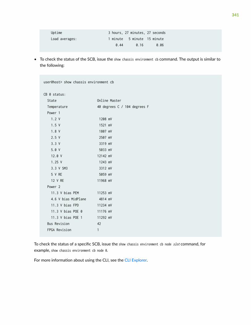
Uptime 3 hours, 27 minutes, 27 seconds Load averages: 1 minute 5 minute 15 minute 0.44 0.16 0.06
• To check the status of the SCB, issue the show chassis environment cb command. The output is similar tothe following:
user@host> show chassis environment cb
CB 0 status: State Online Master Temperature 40 degrees C / 104 degrees F Power 1 1.2 V 1208 mV 1.5 V 1521 mV 1.8 V 1807 mV 2.5 V 2507 mV 3.3 V 3319 mV 5.0 V 5033 mV 12.0 V 12142 mV 1.25 V 1243 mV 3.3 V SM3 3312 mV 5 V RE 5059 mV 12 V RE 11968 mV Power 2 11.3 V bias PEM 11253 mV 4.6 V bias MidPlane 4814 mV 11.3 V bias FPD 11234 mV 11.3 V bias POE 0 11176 mV 11.3 V bias POE 1 11292 mV Bus Revision 42 FPGA Revision 1
To check the status of a specific SCB, issue the show chassis environment cb node slot command, forexample, show chassis environment cb node 0.
For more information about using the CLI, see the CLI Explorer.
341

Taking the SRX5800 Services Gateway Host Subsystem Offline
The host subsystem is composed of an SCB with a Routing Engine installed in it. You take the hostsubsystem offline and bring it online as a unit. Before you replace an SCB or a Routing Engine, you musttake the host subsystem offline. Taking the host subsystem offline causes the device to shut down.
To take the host subsystem offline:
1. On the console or other management device connected to the Routing Engine that is paired with theSCB you are removing, enter CLI operational mode and issue the following command. The commandshuts down the Routing Engine cleanly, so its state information is preserved:
user@host> request system halt
2. Wait until a message appears on the console confirming that the operating system has halted.
For more information about the command, see Junos OS System Basics and Services CommandReference at www.juniper.net/documentation/.
NOTE: The SCB might continue forwarding traffic for approximately 5 minutes after therequest system halt command has been issued.
Operating and Positioning the SRX5800 Services Gateway SCB Ejectors
• When removing or inserting an SCB, ensure that the SCBs or blank panels in adjacent slots are fullyinserted to avoid hitting them with the ejector handles. The ejector handles require that all adjacentcomponents be completely inserted so the ejector handles do not hit them, which could result indamage.
• The ejector handles have a center of rotation and need to be stored toward the center of the board.Ensure the long ends of the ejectors located at both the top and the bottom of the board are verticaland pressed as far as possible toward the center of the board. Once you have installed an SCB, placethe ejector handles in their proper position, vertically and toward the center of the board. To avoidblocking the visibility of the LEDs,position the ejectors over the PARK icon.
• To insert or remove the SCB card, slide the ejector across the SCB horizontally, rotate it, and slide itagain another quarter of a turn. Turn the ejector again and repeat as necessary. Use the indexingfeature to maximize leverage and to avoid hitting any adjacent components.
342

• Operate both ejector handles simultaneously. The insertion force on an SCB is too great for oneejector.
Replacing an SRX5800 Services Gateway SCB
IN THIS SECTION
Removing an SRX5800 Services Gateway SCB | 343
Installing an SRX5800 Services Gateway SCB | 345
Before replacing an SCB, read the guidelines in "Operating and Positioning the SRX5800 ServicesGateway SCB Ejectors" on page 342. To replace an SCB, perform the following procedures:
NOTE: The procedure to replace an SCB applies to the SRX5K-SCB, SRX5K-SCBE, SRX5K-SCB3,and SRX5K-SCB4.
Removing an SRX5800 Services Gateway SCB
Before you begin to remove a SCB:
• Ensure you understand how to prevent electrostatic discharge (ESD) damage. See Prevention ofElectrostatic Discharge Damage.
Ensure that you have the following available:
• ESD grounding strap
• Replacement SCB or blank panel
• Antistatic mat
To remove an SCB (see Figure 1):
NOTE: The SCB and Routing Engine are removed as a unit. You can also remove the RoutingEngine separately.
343

CAUTION: Before removing an SCB, ensure that you know how to operate the ejectorhandles properly to avoid damage to the equipment.
1. If you are removing an SCB from a chassis cluster, deactivate the fabric interfaces from any of thenodes.
NOTE: The fabric interfaces should be deactivated to avoid failures in the chassis cluster.
user@host# deactivate interfaces fab0user@host# deactivate interfaces fab1user@host# commit
2. Power off the services gateway using the command request system power-off.
user@host# request system power-off
NOTE: Wait until a message appears on the console confirming that the services stopped.
3. Physically turn off the power and remove the power cables from the chassis.
4. Place an electrostatic bag or antistatic mat on a flat, stable surface.
5. Attach an ESD grounding strap to your bare wrist, and connect the strap to one of the ESD pointson the chassis.
6. Rotate the ejector handles simultaneously counterclockwise to unseat the SCB.
7. Grasp the ejector handles and slide the SCB about halfway out of the chassis.
8. Place one hand underneath the SCB to support it and slide it completely out of the chassis.
9. Place the SCB on the antistatic mat.
344
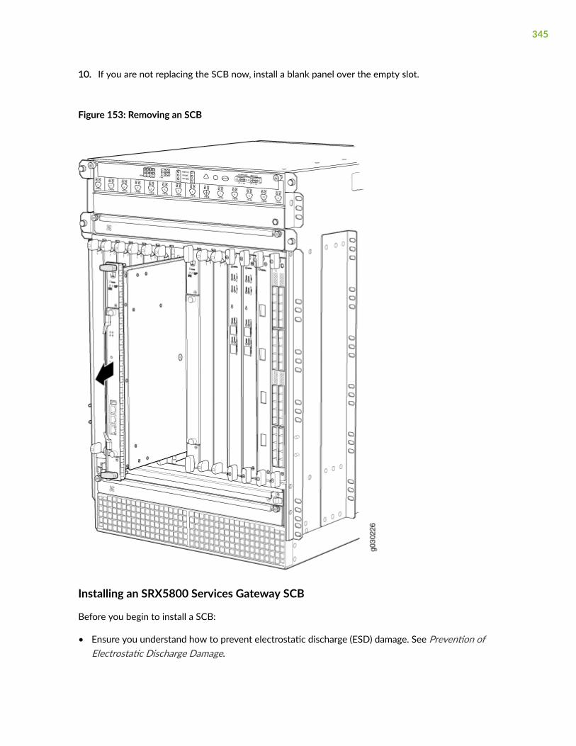
10. If you are not replacing the SCB now, install a blank panel over the empty slot.
Figure 153: Removing an SCB
Installing an SRX5800 Services Gateway SCB
Before you begin to install a SCB:
• Ensure you understand how to prevent electrostatic discharge (ESD) damage. See Prevention ofElectrostatic Discharge Damage.
345

Ensure that you have the following available:
• ESD grounding strap
To install an SCB (see Figure 2):
1. Attach an ESD grounding strap to your bare wrist, and connect the strap to one of the ESD pointson the chassis.
2. Power off the services gateway using the command request system power-off.
user@host# request system power-off
NOTE: Wait until a message appears on the console confirming that the services stopped.
3. Physically turn off the power and remove the power cables from the chassis.
4. Carefully align the sides of the SCB with the guides inside the chassis.
5. Slide the SCB into the chassis until you feel resistance, carefully ensuring that it is correctly aligned.
6. Grasp both ejector handles and rotate them simultaneously clockwise until the SCB is fully seated.
7. Place the ejector handles in the proper position, vertically and toward the center of the board.
8. Connect the power cables to the chassis and power on the services gateway.
9. To verify that the SCB is functioning normally, check the LEDs on its faceplate. The green OK/FAILLED should light steadily a few minutes after the SCB is installed. If the OK/FAIL LED is red,remove and install the SCB again. If the OK/FAIL LED still lights steadily, the SCB is not functioningproperly. Contact your customer support representative.
To check the status of the SCB:
user@host> show chassis environment cb
10. If you installed an SCB into a chassis cluster, through the console of the newly installed SCB put thenode back into cluster and reboot.
user@host> set chassis cluster cluster-id X node Y reboot
where x is the cluster ID and Y is the node ID
346

11. Activate the disabled fabric interfaces.
user@host# activate interfaces fab0user@host# activate interfaces fab1user@host# commit
Figure 154: Installing an SCB
347

Replacing the SRX5800 Services Gateway Routing Engine
IN THIS SECTION
Removing the SRX5800 Services Gateway Routing Engine | 348
Installing the SRX5800 Services Gateway Routing Engine | 350
To replace the Routing Engine, perform the following procedures:
NOTE: The procedure to replace a Routing Engine applies to SRX5K-RE-13-20, SRX5K-RE-1800X4, and SRX5K-RE-128G.
Removing the SRX5800 Services Gateway Routing Engine
Before you begin to remove a routing engine:
• Ensure you understand how to prevent electrostatic discharge (ESD) damage. See Prevention ofElectrostatic Discharge Damage.
Ensure that you have the following available:
• ESD grounding strap
• Replacement routing engine or blank panel
• Antistatic mat
• Phillips (+) number 2 screwdriver
CAUTION: Before you replace a Routing Engine, you must take the host subsystemoffline.
To remove the Routing Engine (see Figure 3):
1. Take the host subsystem offline as described in "Taking the SRX5800 Services Gateway HostSubsystem Offline" on page 342.
2. Place an electrostatic bag or antistatic mat on a flat, stable surface.
3. Attach an ESD grounding strap to your bare wrist, and connect the strap to one of the ESD points onthe chassis.
348

4. Using the Phillips (+) number 2 screwdriver loosen the captive screws at each end of the RoutingEngine faceplate.
5. Flip the ejector handles outward to unseat the Routing Engine.
6. Grasp the Routing Engine by the ejector handles and slide it about halfway out of the chassis.
7. Place one hand underneath the Routing Engine to support it and slide it completely out of thechassis.
8. Place the Routing Engine on the antistatic mat.
Figure 155: Removing the Routing Engine
349

Installing the SRX5800 Services Gateway Routing Engine
Before you begin to install a routing engine:
• Ensure you understand how to prevent electrostatic discharge (ESD) damage. See Prevention ofElectrostatic Discharge Damage.
Ensure that you have the following available:
• ESD grounding strap
• Phillips (+) number 2 screwdriver
To install a Routing Engine into an SCB (see Figure 4):
NOTE: If you install only one Routing Engine in the service gateway, you must install it in SCBslot 0 of service gateway chassis.
1. If you have not already done so, take the host subsystem offline. See "Taking the SRX5800 ServicesGateway Host Subsystem Offline" on page 342.
2. Attach an ESD grounding strap to your bare wrist, and connect the strap to one of the ESD pointson the chassis.
3. Ensure that the ejector handles are not in the locked position. If necessary, flip the ejector handlesoutward.
4. Place one hand underneath the Routing Engine to support it.
5. Carefully align the sides of the Routing Engine with the guides inside the opening on the SCB.
6. Slide the Routing Engine into the SCB until you feel resistance, and then press the Routing Engine'sfaceplate until it engages the connectors.
7. Press both of the ejector handles inward to seat the Routing Engine.
8. Using the Phillips (+) number 2 screwdriver tighten the captive screws on the top and bottom of theRouting Engine faceplate.
9. Power on the services gateway.
The Routing Engine might require several minutes to boot.
After the Routing Engine boots, verify that it is installed correctly by checking the RE0 and RE1LEDs on the craft interface. If the services gateway is operational and the Routing Engine isfunctioning properly, the green ONLINE LED lights steadily. If the red FAIL LED lights steadilyinstead, remove and install the Routing Engine again. If the red FAIL LED still lights steadily, theRouting Engine is not functioning properly. Contact your customer support representative.
350

To check the status of the Routing Engine, use the CLI command:
user@host> show chassis routing-engineRouting Engine status: Slot 0: Current state Master ...
351

For more information about using the CLI, see the CLI Explorer.
Figure 156: Installing the Routing Engine
10. If the Routing Engine was replaced on one of the nodes in a chassis cluster, then you need to copycertificates and key pairs from the other node in the cluster:
a. Start the shell interface as a root user on both nodes of the cluster.
352

b. Verify files in the /var/db/certs/common/key-pair folder of the source node (other node in thecluster) and destination node (node on which the Routing Engine was replaced) by using thefollowing command:
ls -la /var/db/certs/common/key-pair/
c. If the same files exist on both nodes, back up the files on the destination node to a differentlocation. For example:
root@SRX-B% pwd /var/db/certs/common/key-pair root@SRX-B% ls -la total 8 drwx------ 2 root wheel 512 Jan22 15:09 drwx------ 7 root wheel 512 Mar 26 2009 -rw-r--r-- 1 root wheel 0 Jan 22 15:09 test root@SRX-B%mv test test.old root@SRX-B% ls -la total 8 drwx------ 2 root wheel 512 Jan 22 15:10 drwx------ 7 rootwheel 512 Mar 26 2009 -rw-r--r-- 1 root wheel 0 Jan 22 15:09 test.old root@SRX-B%
d. Copy the files from the /var/db/certs/common/key-pair folder of the source node to the samefolder on the destination node.
NOTE: Ensure that you use the correct node number for the destination node.
e. In the destination node, use the ls –la command to verify that all files from the /var/db/certs/common/key-pair folder of the source node are copied.
f. Repeat Step b through Step e for the /var/db/certs/common/local and /var/db/certs/common/certification-authority folders.
Low Impact Hardware Upgrade for SCB3 and IOC3
Before you begin the LICU procedure, verify that both services gateways in the cluster are running thesame Junos OS release.
NOTE: You can perform the hardware upgrade using the LICU process only.
You must perform the hardware upgrade at the same time as the software upgrade from JunosOS Release 12.3X48-D10 to 15.1X49-D10.
If your device is part of a chassis cluster, you can upgrade SRX5K-SCBE (SCB2) to SRX5K-SCB3 (SCB3)and SRX5K-MPC (IOC2) to IOC3 (SRX5K-MPC3-100G10G or SRX5K-MPC3-40G10G) using the low-impact hardware upgrade (LICU) procedure, with minimum downtime. You can also follow thisprocedure to upgrade SCB1 to SCB2, and RE1 to RE2.
In the chassis cluster, the primary device is depicted as node 0 and the secondary device as node 1.
353

Follow these steps to perform the LICU.
1. Ensure that the secondary node does not have an impact on network traffic by isolating it from thenetwork when LICU is in progress. For this, disable the physical interfaces (RETH child interfaces)on the secondary node.
For SRX5400 Services Gatewaysadmin@cluster#set interfaces xe-5/0/0 disable admin@cluster#set interfaces xe-5/1/0 disableFor SRX5600 Services Gatewaysadmin@cluster#set interfaces xe-9/0/0 disable admin@cluster#set interfaces xe-9/0/4 disableFor SRX5800 Services Gatewaysadmin@cluster#set interfaces xe-13/0/0 disable admin@cluster#set interfaces xe-13/1/0 disable
2. Disable SYN bit and TCP sequence number checking for the secondary node to take over.
admin@cluster#set security flow tcp-session no-syn-checkadmin@cluster#set security flow tcp-session no-sequence-check
3. Commit the configuration.
root@#commit
4. Disconnect control and fabric links between the devices in the chassis cluster so that nodes runningdifferent Junos OS releases are disconnected. For this, change the control port and fabric port toerroneous values. Fabric ports must be set to any FPC number and control ports to any non-IOCport. Issue the following commands:
admin@cluster#delete chassis cluster control-portsadmin@cluster#set chassis cluster control-ports fpc 10 port 0 <<<<<<< non-SPC port admin@cluster#set chassis cluster control-ports fpc 22 port 0 <<<<<<< non-SPC port admin@cluster#delete interfaces fab0admin@cluster#delete interfaces fab1 admin@cluster#set interfaces fab0 fabric-options member-interfaces xe-4/0/5 <<<<<<< non-IOC port admin@cluster#set interfaces fab1 fabric-options member-interfaces xe-10/0/5<<<<<<< non-IOC port
354

5. Commit the configuration.
root@#commit
NOTE: After you commit the configuration, the following error message appears:Connection to node1 has been broken error:remote unlock-configuration failed on node1due to control plane communication break.
Ignore the error message.
6. Upgrade the Junos OS release on the secondary node from 12.3X48-D10 to 15.1X49-D10.
admin@cluster#request system software add <location of package/junos filename> no-validate no-copy
7. Power on the secondary node.
admin@cluster#request system reboot
See:
• Powering On an AC-Powered SRX5400 Services Gateway
• Powering On a DC-Powered SRX5400 Services Gateway
• Powering On an AC-Powered SRX5600 Services Gateway
• Powering On a DC-Powered SRX5600 Services Gateway
• "Powering On an AC-Powered SRX5800 Services Gateway" on page 269
• "Powering On a DC-Powered SRX5800 Services Gateway " on page 276
8. Perform the hardware upgrade on the secondary node by replacing SCB2 with SCB3, IOC2 withIOC3, and the existing midplane with the enhanced midplane.
Following these steps while upgrading the SCB:
To upgrade the Routing Engine on the secondary node:
a. Before powering off the secondary node, copy the configuration information to a USB device.
b. Replace RE1 with RE2 and upgrade the Junos OS on RE2.
c. Upload the configuration to RE2 from the USB device.
355

For more information about mounting the USB drive on the device, refer to KB articlesKB12880 and KB12022 from the Knowledge Base.
Perform this step when you upgrade the MPC.
356

a. Configure the control port, fabric port, and RETH child ports on the secondary node.
[edit]
root@clustert# show | display set | grep delete
delete groups global interfaces fab1
delete groups global interfaces fab0
delete interfaces reth0
delete interfaces reth1
delete interfaces xe-3/0/5 gigether-options redundant-parentreth0
delete interfaces xe-9/0/5 gigether-options redundant-parentreth0
delete interfaces xe-3/0/9 gigether-options redundant-parentreth
delete interfaces xe-9/0/9 gigether-options redundant-parentreth0
[edit]root@clustert# show | display set | grep fabset groups global interfaces fab1 fabric-options member-interfaces
357

xe-9/0/2 set groups global interfaces fab0 fabric-options member-interfacesxe-3/0/2
[edit]root@clustert# show | display set | grep reth0set chassis cluster redundancy-group 1 ip-monitoring familyinet 44.44.44.2 interface reth0.0 secondary-ip-address 44.44.44.3set interfaces xe-3/0/0 gigether-options redundant-parentreth0set interfaces xe-9/0/0 gigether-options redundant-parentreth0set interfaces reth0 vlan-taggingset interfaces reth0 redundant-ether-options redundancy-group1set interfaces reth0 unit 0 vlan-id 20set interfaces reth0 unit 0 family inet address 44.44.44.1/8
[edit]root@clustert# show | display set | grep reth1set interfaces xe-3/0/4 gigether-options redundant-parentreth1set interfaces xe-9/0/4 gigether-options redundant-parentreth1set interfaces reth1 vlan-tagging set interfaces reth1 redundant-ether-options redundancy-group1 set interfaces reth1 unit 0 vlan-id 30set interfaces reth1 unit 0 family inet address 55.55.55.1/8
9. Verify that the secondary node is running the upgraded Junos OS release.
root@cluster> show version node1
Hostname: <displays the hostname>Model: <displays the model number>
358

Junos: 15.1X49-D10JUNOS Software Release [15.1X49-D10]
root@cluster> show chassis cluster status
Monitor Failure codes: CS Cold Sync monitoring FL Fabric Connection monitoring GR GRES monitoring HW Hardware monitoring IF Interface monitoring IP IP monitoring LB Loopback monitoring MB Mbuf monitoring NH Nexthop monitoring NP NPC monitoring SP SPU monitoring SM Schedule monitoring CF Config Sync monitoring
Cluster ID: 1Node Priority Status Preempt Manual Monitor-failures
Redundancy group: 0 , Failover count: 1node0 0 lost n/a n/a n/a node1 100 primary no no None
Redundancy group: 1 , Failover count: 3node0 0 lost n/a n/a n/a node1 150 primary no no None
root@cluster>show chassis fpc pic-status node1Slot 1 Online SRX5k IOC II PIC 0 Online 1x 100GE CFP PIC 2 Online 2x 40GE QSFP+Slot 2 Online SRX5k SPC II PIC 0 Online SPU Cp PIC 1 Online SPU Flow PIC 2 Online SPU Flow PIC 3 Online SPU FlowSlot 3 Online SRX5k IOC II PIC 0 Online 10x 10GE SFP+ PIC 2 Online 2x 40GE QSFP+Slot 4 Online SRX5k SPC II PIC 0 Online SPU Flow
359

PIC 1 Online SPU Flow PIC 2 Online SPU Flow PIC 3 Online SPU FlowSlot 5 Online SRX5k IOC II PIC 0 Online 10x 10GE SFP+ PIC 2 Online 2x 40GE QSFP+
10. Verify configuration changes by disabling interfaces on the primary node and enabling interfaces onthe secondary.
For SRX5400 Services Gatewaysadmin@cluster#set interfaces xe-2/0/0 disable admin@cluster#set interfaces xe-2/1/0 disableadmin@cluster#delete interfaces xe-5/0/0 disableadmin@cluster#delete interfaces xe-5/1/0 disableFor SRX5600 Services Gatewaysadmin@cluster#set interfaces xe-2/0/0 disable admin@cluster#set interfaces xe-2/0/4 disableadmin@cluster#delete interfaces xe-9/0/0 disableadmin@cluster#delete interfaces xe-9/0/4 disableFor SRX5800 Services Gatewaysadmin@cluster#set interfaces xe-1/0/0 disable admin@cluster#set interfaces xe-1/1/0 disableadmin@cluster#delete interfaces xe-13/0/0 disableadmin@cluster#delete interfaces xe-13/1/0 disable
11. Check the configuration changes.
root@#commit check
12. After verifying, commit the configuration.
root@#commit
Network traffic fails over to the secondary node.
360

13. Verify that the failover was successful by checking the session tables and network traffic on thesecondary node.
admin@cluster#show security flow session summary admin@cluster#monitor interface traffic
14. Upgrade the Junos OS release on the primary node from 12.3X48-D10 to 15.1X49-D10.
admin@cluster#request system software add <location of package/junos filename> no-validate no-copy
Ignore error messages pertaining to the disconnected cluster.
15. Power on the primary node.
admin@cluster#request system reboot
See:
• Powering On an AC-Powered SRX5400 Services Gateway
• Powering On a DC-Powered SRX5400 Services Gateway
• Powering On an AC-Powered SRX5600 Services Gateway
• Powering On a DC-Powered SRX5600 Services Gateway
• "Powering On an AC-Powered SRX5800 Services Gateway" on page 269
• "Powering On a DC-Powered SRX5800 Services Gateway " on page 276
16. Perform the hardware upgrade on the primary node by replacing SCB2 with SCB3, IOC2 with IOC3,and the existing midplane with the enhanced midplane.
Perform the following steps while upgrading the SCB.
To upgrade the Routing Engine on the primary node:
a. Before powering off the secondary node, copy the configuration information to a USB device.
b. Replace RE1 with RE2 and upgrade the Junos OS on RE2.
c. Upload the configuration to RE2 from the USB device.
For more information about mounting the USB drive on the device, refer to KB articlesKB12880 and KB12022 from the Knowledge Base.
Perform this step when you upgrade the MPC.
361

a. Configure the control port, fabric port, and RETH child ports on the primary node.
[edit]root@clustert# show | display set | grep deletedelete groups global interfaces fab1delete groups global interfaces fab0delete interfaces reth0delete interfaces reth1delete interfaces xe-3/0/5 gigether-options redundant-parentreth0delete interfaces xe-9/0/5 gigether-options redundant-parentreth0delete interfaces xe-3/0/9 gigether-options redundant-parentreth0delete interfaces xe-9/0/9 gigether-options redundant-parentreth0
[edit]root@clustert# show | display set | grep fabset groups global interfaces fab1 fabric-options member-interfacesxe-9/0/2 set groups global interfaces fab0 fabric-options member-interfacesxe-3/0/2
[edit]root@clustert# show | display set | grep reth0set chassis cluster redundancy-group 1 ip-monitoring familyinet 44.44.44.2 interface reth0.0 secondary-ip-address 44.44.44.3set interfaces xe-3/0/0 gigether-options redundant-parentreth0set interfaces xe-9/0/0 gigether-options redundant-parentreth0set interfaces reth0 vlan-taggingset interfaces reth0 redundant-ether-options redundancy-group1set interfaces reth0 unit 0 vlan-id 20set interfaces reth0 unit 0 family inet address 44.44.44.1/8
362

[edit]root@clustert# show | display set | grep reth1set interfaces xe-3/0/4 gigether-options redundant-parentreth1set interfaces xe-9/0/4 gigether-options redundant-parentreth1set interfaces reth1 vlan-tagging set interfaces reth1 redundant-ether-options redundancy-group1 set interfaces reth1 unit 0 vlan-id 30set interfaces reth1 unit 0 family inet address 55.55.55.1/8
17. Verify that the primary node is running the upgraded Junos OS release, and that the primary nodeis available to take over network traffic.
root@cluster> show version node1
Hostname: <displays the hostname>Model: <displays the model number>Junos: 15.1X49-D10JUNOS Software Release [15.1X49-D10]
root@cluster> show chassis cluster status
Monitor Failure codes: CS Cold Sync monitoring FL Fabric Connection monitoring GR GRES monitoring HW Hardware monitoring IF Interface monitoring IP IP monitoring LB Loopback monitoring MB Mbuf monitoring NH Nexthop monitoring NP NPC monitoring SP SPU monitoring SM Schedule monitoring CF Config Sync monitoring
Cluster ID: 1Node Priority Status Preempt Manual Monitor-failures
Redundancy group: 0 , Failover count: 1
363

node0 0 lost n/a n/a n/a node1 100 primary no no None
Redundancy group: 1 , Failover count: 3node0 0 lost n/a n/a n/a node1 150 primary no no None
root@cluster>show chassis fpc pic-status node1Slot 1 Online SRX5k IOC II PIC 0 Online 1x 100GE CFP PIC 2 Online 2x 40GE QSFP+Slot 2 Online SRX5k SPC II PIC 0 Online SPU Cp PIC 1 Online SPU Flow PIC 2 Online SPU Flow PIC 3 Online SPU FlowSlot 3 Online SRX5k IOC II PIC 0 Online 10x 10GE SFP+ PIC 2 Online 2x 40GE QSFP+Slot 4 Online SRX5k SPC II PIC 0 Online SPU Flow PIC 1 Online SPU Flow PIC 2 Online SPU Flow PIC 3 Online SPU FlowSlot 5 Online SRX5k IOC II PIC 0 Online 10x 10GE SFP+ PIC 2 Online 2x 40GE QSFP+
18. Check the configuration changes.
root@#commit check
19. After verifying, commit the configuration.
root@#commit
364

20. Verify configuration changes by disabling interfaces on the secondary node and enabling interfaceson the primary.
For SRX5400 Services Gatewaysadmin@cluster#set interfaces xe-5/0/0 disableadmin@cluster#set interfaces xe-5/1/0 disableadmin@cluster#delete interfaces xe-2/0/0 disable admin@cluster#delete interfaces xe-2/1/0 disableFor SRX5600 Services Gatewaysadmin@cluster#set interfaces xe-9/0/0 disableadmin@cluster#set interfaces xe-9/0/4 disableadmin@cluster#delete interfaces xe-2/0/0 disable admin@cluster#delete interfaces xe-2/0/4 disableFor SRX5800 Services Gatewaysadmin@cluster#set interfaces xe-13/0/0 disableadmin@cluster#set interfaces xe-13/1/0 disableadmin@cluster#delete interfaces xe-1/0/0 disable admin@cluster#delete interfaces xe-1/1/0 disable
Network traffic fails over to the primary node.
21. To synchronize the devices within the cluster, reconfigure the control ports and fabric ports withthe correct port values on the secondary node.
admin@cluster#delete chassis cluster control-ports admin@cluster#set chassis cluster control-ports fpc 1 port 0admin@cluster#set chassis cluster control-ports fpc 13 port 0admin@cluster#delete interfaces fab0 admin@cluster#delete interfaces fab1 admin@cluster#set interfaces fab0 fabric-options member-interfaces xe-3/0/2 admin@cluster#set interfaces fab1 fabric-options member-interfaces xe-9/0/2
22. Commit the configuration.
root@#commit
23. Power on the secondary node.
admin@cluster#request system reboot
See:
365

• Powering On an AC-Powered SRX5400 Services Gateway
• Powering On a DC-Powered SRX5400 Services Gateway
• Powering On an AC-Powered SRX5600 Services Gateway
• Powering On a DC-Powered SRX5600 Services Gateway
• "Powering On an AC-Powered SRX5800 Services Gateway" on page 269
• "Powering On a DC-Powered SRX5800 Services Gateway " on page 276
a. When you power on the secondary node, enable the control ports and fabric ports on theprimary node, and reconfigure them with the correct port values.
admin@cluster#delete chassis cluster control-ports admin@cluster#set chassis cluster control-ports fpc 1 port 0admin@cluster#set chassis cluster control-ports fpc 13 port 0admin@cluster#delete interfaces fab0 admin@cluster#delete interfaces fab1 admin@cluster#set interfaces fab0 fabric-options member-interfaces xe-3/0/2 admin@cluster#set interfaces fab1 fabric-options member-interfaces xe-9/0/2
24. Commit the configuration.
root@#commit
25. After the secondary node is up, verify that it synchronizes with the primary node.
admin@cluster#delete interfaces xe-4/0/5 disableadmin@cluster#delete interfaces xe-10/0/5 disable
26. Enable SYN bit and TCP sequence number checking for the secondary node.
admin@cluster#delete security flow tcp-session no-syn-checkadmin@cluster#delete security flow tcp-session no-sequence-check
27. Commit the configuration.
root@#commit
366

28. Verify the Redundancy Group (RG) states and their priority.
root@cluster>show versionnode0:--------------------------------------------------------------------------Hostname: <displays the hostname>Model: <displays the model number>Junos: 15.1X49-D10JUNOS Software Release [15.1X49-D10]
node1:--------------------------------------------------------------------------Hostname: <displays the hostname>Model: <displays the model>Junos: 15.1X49-D10JUNOS Software Release [15.1X49-D10]
After the secondary node is powered on, issue the following command:
root@cluster>show chassis fpc pic-statusnode0:--------------------------------------------------------------------------Slot 1 Online SRX5k IOC II PIC 0 Online 1x 100GE CFP PIC 2 Online 2x 40GE QSFP+Slot 2 Online SRX5k SPC II PIC 0 Online SPU Cp PIC 1 Online SPU Flow PIC 2 Online SPU Flow PIC 3 Online SPU FlowSlot 3 Online SRX5k IOC3 24XGE+6XLG PIC 0 Online 12x 10GE SFP+ PIC 1 Online 12x 10GE SFP+ PIC 2 Offline 3x 40GE QSFP+ PIC 3 Offline 3x 40GE QSFP+Slot 4 Online SRX5k SPC II PIC 0 Online SPU Flow PIC 1 Online SPU Flow PIC 2 Online SPU Flow PIC 3 Online SPU FlowSlot 5 Online SRX5k IOC II
367

PIC 0 Online 10x 10GE SFP+ PIC 2 Online 10x 10GE SFP+ node1: --------------------------------------------------------------------------Slot 1 Online SRX5k IOC II PIC 0 Online 1x 100GE CFP PIC 2 Online 2x 40GE QSFP+Slot 2 Online SRX5k SPC II PIC 0 Online SPU Cp PIC 1 Online SPU Flow PIC 2 Online SPU Flow PIC 3 Online SPU FlowSlot 3 Online SRX5k IOC3 24XGE+6XLG PIC 0 Online 12x 10GE SFP+ PIC 1 Online 12x 10GE SFP+ PIC 2 Offline 3x 40GE QSFP+ PIC 3 Offline 3x 40GE QSFP+Slot 4 Online SRX5k SPC II PIC 0 Online SPU Flow PIC 1 Online SPU Flow PIC 2 Online SPU Flow PIC 3 Online SPU FlowSlot 5 Online SRX5k IOC II PIC 0 Online 10x 10GE SFP+ PIC 2 Online 2x 40GE QSFP+
root@cluster> show chassis cluster status CS Cold Sync monitoring FL Fabric Connection monitoring GR GRES monitoring HW Hardware monitoring IF Interface monitoring IP IP monitoring LB Loopback monitoring MB Mbuf monitoring NH Nexthop monitoring NP NPC monitoring SP SPU monitoring SM Schedule monitoring CF Config Sync monitoring Cluster ID: 1Node Priority Status Preempt Manual Monitor-failures
Redundancy group: 0 , Failover count: 0
368

node0 250 primary no no None node1 100 secondary no no None
Redundancy group: 1 , Failover count: 0node0 254 primary no no None node1 150 secondary no no None
root@cluster>show security monitoring node0:-------------------------------------------------------------------------- Flow session Flow session CP session CP session FPC PIC CPU Mem current maximum current maximum--------------------------------------------------------------------------- 2 0 0 11 0 0 1999999 104857600 2 1 2 5 289065 4194304 0 0 2 2 2 5 289062 4194304 0 0 2 3 2 5 289060 4194304 0 0 4 0 2 5 289061 4194304 0 0 4 1 2 5 281249 4194304 0 0 4 2 2 5 281251 4194304 0 0 4 3 2 5 281251 4194304 0 0
node1:-------------------------------------------------------------------------- Flow session Flow session CP session CP session FPC PIC CPU Mem current maximum current maximum--------------------------------------------------------------------------- 2 0 0 11 0 0 1999999 104857600 2 1 0 5 289065 4194304 0 0 2 2 0 5 289062 4194304 0 0 2 3 0 5 289060 4194304 0 0 4 0 0 5 289061 4194304 0 0 4 1 0 5 281249 4194304 0 0 4 2 0 5 281251 4194304 0 0 4 3 0 5 281251 4194304 0 0
369

Enable the traffic interfaces on the secondary node.
root@cluster> show interfaces terse | grep reth0 xe-3/0/0.0 up up aenet --> reth0.0xe-3/0/0.32767 up up aenet --> reth0.32767xe-9/0/0.0 up up aenet --> reth0.0 xe-9/0/0.32767 up up aenet --> reth0.32767reth0 up upreth0.0 up up inet 44.44.44.1/8 reth0.32767 up up multiservice
root@cluster> show interfaces terse | grep reth1xe-3/0/4.0 up up aenet --> reth1.0xe-3/0/4.32767 up up aenet --> reth1.32767xe-9/0/4.0 up up aenet --> reth1.0 xe-9/0/4.32767 up up aenet --> reth1.32767reth1 up upreth1.0 up up inet 55.55.55.1/8 reth1.32767 up up multiservice
For more information about LICU, refer to KB article KB17947 from the Knowledge Base.
In-Service Hardware Upgrade for SRX5K-RE-1800X4 and SRX5K-SCBEor SRX5K-RE-1800X4 and SRX5K-SCB3 in a Chassis Cluster
Ensure that the following prerequisites are completed before you begin the ISHU procedure:
• Replace all interface cards such as IOCs and Flex IOCs as specified in Table 71 on page 370.
Table 71: List of Interface Cards for Upgrade
Cards to Replace Replacement Cards for Upgrade
SRX5K-40GE-SFP SRX5K-MPC and MICs
370

Table 71: List of Interface Cards for Upgrade (Continued)
Cards to Replace Replacement Cards for Upgrade
SRX5K-4XGE-XFP SRX5K-MPC and MICs
SRX5K-FPC-IOC SRX5K-MPC and MICs
SRX5K-RE-13-20 SRX5K-RE-1800X4
SRX5K-SCB SRX5K-SCBE
SRX5K-SCBE SRX5K-SCB3
• Verify that both services gateways in the cluster are running the same Junos OS versions; release12.1X47-D15 or later for SRX5K-SCBE with SRX5K-RE-1800X4 and 15.1X49-D10 or later forSRX5K-SCB3 with SRX5K-RE-1800X4. For more information on cards supported on the servicesgateways see "Cards Supported on SRX5400, SRX5600, and SRX5800 Services Gateways" on page110.
For more information about unified in-service software upgrade (unified ISSU), see Upgrading BothDevices in a Chassis Cluster Using an ISSU.
If your device is part of a chassis cluster, using the in-service hardware upgrade (ISHU) procedure youcan upgrade:
• SRX5K-SCB with SRX5K-RE-13-20 to SRX5K-SCBE with SRX5K-RE-1800X4
NOTE: Both the services gateways must have the same Junos OS version 12.3X48.
• SRX5K-SCBE with SRX5K-RE-1800X4 to SRX5K-SCB3 with SRX5K-RE-1800X4
NOTE: You cannot upgrade SRX5K-SCB with SRX5K-RE-13-20 directly to SRX5K-SCB3 withSRX5K-RE-1800X4.
371

NOTE: We strongly recommend that you perform the ISHU during a maintenance window, orduring the lowest possible traffic as the secondary node is not available at this time.
Ensure to upgrade the SCB and Routing Engine at the same time as the following configurationsare only supported:
• SRX5K-RE-13-20 and SRX5K-SCB
• SRX5K-RE-1800X4 and SRX5K-SCBE
• SRX5K-RE-1800X4 and SRX5K-SCB3
NOTE: While performing the ISHU, in the SRX5800 service gateway, the second SCB cancontain a Routing Engine but the third SCB must not contain a Routing Engine. In the SRX5600services gateway, the second SCB can contain a Routing Engine.
To perform an ISHU:
1. Export the configuration information from the secondary node to a USB or an external storagedevice.
For more information about mounting the USB on the device, refer to KB articles KB12880 andKB12022 from the Knowledge Base.
2. Power off the secondary node.
See, Powering Off the SRX5400 Services Gateway, Powering Off the SRX5600 Services Gateway,or "Powering Off the SRX5800 Services Gateway" on page 278.
3. Disconnect all the interface cards from the chassis backplane by pulling them out of the backplaneby 6” to 8” (leaving cables in place).
4. Replace the SRX5K-SCBs with SRX5K-SCBEs, or SRX5K-SCBEs with SRX5K-SCB3s and SRX5K-RE-13-20s with SRX5K-RE-1800X4s based on the chassis specifications.
5. Power on the secondary node.
See:
• Powering On an AC-Powered SRX5400 Services Gateway
• Powering On a DC-Powered SRX5400 Services Gateway
• Powering On an AC-Powered SRX5600 Services Gateway
• Powering On a DC-Powered SRX5600 Services Gateway
• "Powering On an AC-Powered SRX5800 Services Gateway" on page 269
372

• "Powering On a DC-Powered SRX5800 Services Gateway " on page 276
6. After the secondary node reboots as a standalone node, configure the same cluster ID as in theprimary node.
root@>set chassis cluster cluster-id 1 node 1
7. Install the same Junos OS software image on the secondary node as on the primary node andreboot.
NOTE: Ensure that the Junos OS version installed is release 12.1X47-D15 or later forSRX5K-RE-1800X4 & SRX5K-SCBE and 15.1X49-D10 or later for SRX5K-RE-1800X4 &SRX5K-SCB3.
8. After the secondary node reboots, import all the configuration settings from the USB to the node.
For more information about mounting the USB on the device, refer to KB articles KB12880 andKB12022 from the Knowledge Base.
9. Power off the secondary node.
See Powering Off the SRX5400 Services Gateway, Powering Off the SRX5600 Services Gateway,or "Powering Off the SRX5800 Services Gateway" on page 278.
10. Re-insert all the interface cards into the chassis backplane.
NOTE: Ensure the cards are inserted in the same order as in the primary node, and maintainconnectivity between the control link and fabric link.
11. Power on the node and issue this command to ensure all the cards are online:
user@host> show chassis fpc pic-status
After the node boots, it must join the cluster as a secondary node. To verify, issue the followingcommand
admin@cluster> show chassis cluster status
NOTE: The command output must indicate that the node priority is set to a non-zero value,and that the cluster contains a primary node and a secondary node.
373

12. Initiate Redundancy Group (RG) failover to the upgraded node, manually, so that it is assigned to allRGs as a primary node.
For RG0, issue the following command:
admin@cluster> request chassis cluster failoverredundancy-group 0 node 1
For RG1, issue the following command:
admin@cluster> request chassis cluster failoverredundancy-group 1 node 1
Verify that all RGs are failed over by issuing the following command:
admin@cluster> show chassis cluster status
13. Verify the operations of the upgraded secondary node by performing the following:
• To ensure all FPC’s are online, issue the following command:
admin@cluster> show chassis fpc pic-status
• To ensure all RG’s are upgraded and the node priority is set to a non-zero value, issue thefollowing command:
admin@cluster> show chassis cluster status
• To ensure that the upgraded primary node receives and transmits data, issue the followingcommand:
admin@cluster> monitor interface traffic
• To ensure sessions are created and deleted on the upgraded node, issue the following command:
admin@cluster> show security monitoring
14. Repeat Step 1 through 12 for the primary node.
374

15. To ensure that the ISHU process is completed successfully, check the status of the cluster byissuing the following command:
admin@cluster> show chassis cluster status
For detailed information about chassis cluster, see the Chassis Cluster User Guide for SRX SeriesDevices at www.juniper.net/documentation/.
Maintaining the SRX5800 Line Cards and Modules
IN THIS SECTION
Maintaining Interface Cards and SPCs on the SRX5800 Services Gateway | 375
Replacing SRX5800 Services Gateway IOCs | 378
Replacing SRX5800 Services Gateway Flex IOCs | 386
Replacing SRX5800 Services Gateway Port Modules | 391
Replacing SRX5800 Services Gateway SPCs | 398
Replacing SPCs in an Operating SRX5400, SRX5600, or SRX5800 Services Gateways Chassis Cluster | 406
In-Service Hardware Upgrade for SRX5K-SPC3 in a Chassis Cluster | 408
Maintaining MICs and Port Modules on the SRX5800 Services Gateway | 411
Replacing SRX5800 Services Gateway MICs | 412
Replacing SRX5800 Services Gateway MPCs | 418
Maintaining Interface Cards and SPCs on the SRX5800 Services Gateway
IN THIS SECTION
Purpose | 376
Action | 376
375

Purpose
For optimum services gateway performance, verify the condition of the Services Processing Cards(SPCs) and interface cards (IOCs, Flex IOCs and MPCs). The services gateway can have up to 11 SPCsand interface cards. To maintain SPCs and interface cards, perform the following procedures regularly.
Action
On a regular basis:
• Check the LEDs on the craft interface corresponding to the slot for each SPC and interface card. Thegreen LED labeled OK lights steadily when a card is functioning normally.
• Check the OK/FAIL LED on the faceplate of each SPC and interface card. If the card detects a failure,it sends an alarm message to the Routing Engine.
• Issue the CLI show chassis fpc command to check the status of installed cards. As shown in the sampleoutput, the value Online in the column labeled State indicates that the card is functioning normally:
user@host> show chassis fpc Temp CPU Utilization (%) Memory Utilization (%)Slot State (C) Total Interrupt DRAM (MB) Heap Buffer 0 Online 41 9 0 1024 15 57 1 Online 43 5 0 1024 16 57 2 Online 43 11 0 1024 16 57 3 Empty 4 Empty 5 Online 42 6 0 1024 16 57
For more detailed output, add the detail option. The following example does not specify a slotnumber, which is optional:
user@host> show chassis fpc detail
Slot 0 information: State Online Temperature 41 degrees C / 105 degrees F Total CPU DRAM 1024 MB Total RLDRAM 256 MB Total DDR DRAM 4096 MB Start time: 2007-07-10 12:28:33 PDT
376

Uptime: 1 hour, 33 minutes, 52 secondsSlot 1 information: State Online Temperature 43 degrees C / 109 degrees F Total CPU DRAM 1024 MB Total RLDRAM 256 MB Total DDR DRAM 4096 MB Start time: 2007-07-10 12:28:38 PDT Uptime: 1 hour, 33 minutes, 47 secondsSlot 2 information: State Online Temperature 43 degrees C / 109 degrees F Total CPU DRAM 1024 MB Total RLDRAM 256 MB Total DDR DRAM 4096 MB Start time: 2007-07-10 12:28:40 PDT Uptime: 1 hour, 33 minutes, 45 secondsSlot 5 information: State Online Temperature 42 degrees C / 107 degrees F Total CPU DRAM 1024 MB Total RLDRAM 256 MB Total DDR DRAM 4096 MB Start time: 2007-07-10 12:28:42 PDT Uptime: 1 hour, 33 minutes, 43 seconds
• Issue the CLI show chassis fpc pic-status command. The slots are numbered 0 through 5, bottom to top:
user@host> show chassis fpc pic-status
Slot 0 Online SRX5k DPC 40x 1GE PIC 0 Online 10x 1GE RichQ PIC 1 Online 10x 1GE RichQ PIC 2 Online 10x 1GE RichQ PIC 3 Online 10x 1GE RichQSlot 1 Online SRX5k DPC 40x 1GE PIC 0 Online 10x 1GE RichQ PIC 1 Online 10x 1GE RichQ PIC 2 Online 10x 1GE RichQ PIC 3 Online 10x 1GE RichQSlot 2 Online SRX5k DPC 40x 1GE
377

PIC 0 Online 10x 1GE RichQ PIC 1 Online 10x 1GE RichQ PIC 2 Online 10x 1GE RichQ PIC 3 Online 10x 1GE RichQSlot 3 Online SRX5k SPC PIC 0 Offline PIC 1 OfflineSlot 4 Online SRX5k SPC PIC 0 Offline PIC 1 Offline
For further description of the output from the command, see Junos OS System Basics and ServicesCommand Reference at www.juniper.net/documentation/.
Replacing SRX5800 Services Gateway IOCs
IN THIS SECTION
Removing an SRX5800 Services Gateway IOC | 378
Installing an SRX5800 Services Gateway IOC | 382
To replace an IOC, perform the following procedures:
Removing an SRX5800 Services Gateway IOC
Before you begin to remove an IOC:
• Ensure you understand how to prevent electrostatic discharge (ESD) damage. See Prevention ofElectrostatic Discharge Damage.
Ensure that you have the following available:
• ESD grounding strap
• Replacement IOC or IOC blank panel
• Antistatic mat for the IOC
378

• Rubber safety caps for the transceivers
• Dust covers to cover the ports
An IOC weighs up to 13.1 lb (5.9 kg). Be prepared to accept its full weight.
To remove an IOC (see Figure 1):
1. Attach an ESD grounding strap to your bare wrist, and connect the other end of the strap to an ESDgrounding point.
2. Label the cables connected to each port on the IOC so that you can later reconnect the cables tothe correct ports.
3. Use one of the following methods to take the IOC offline:
• Press and hold the corresponding IOC online button on the craft interface. The green OK LEDnext to the button begins to blink. Hold the button down until the LED goes off.
• Issue the following CLI command:
user@host>request chassis fpc slot slot-number offline
For more information about the command, see Junos OS System Basics and Services CommandReference at https://www.juniper.net/documentation/.
4. Power off the services gateway using the command request system power-off.
user@host# request system power-off
NOTE: Wait until a message appears on the console confirming that the services stopped.
5. Physically turn off the power and remove the power cables from the chassis.
6. Remove the cables from the IOC.
LASER WARNING: Do not look directly into a fiber-optic transceiver or into the endsof fiber-optic cables. Fiber-optic transceivers and fiber-optic cables connected to atransceiver emit laser light that can damage your eyes.
379

CAUTION: Do not leave a fiber-optic transceiver uncovered except when you areinserting or removing cable. The safety cap keeps the port clean and preventsaccidental exposure to laser light.
CAUTION: Avoid bending a fiber-optic cable beyond its minimum bend radius. Anarc smaller than a few inches in diameter can damage the cable and cause problemsthat are difficult to diagnose.
7. Immediately cover each optical transceiver and the end of each fiber-optic cable with a rubbersafety cap.
8. Cover the ports on the IOC with dust covers if you remove the optical transceivers from the IOC.
9. Arrange the disconnected cables in the cable manager to prevent the cables from developing stresspoints.
10. Simultaneously turn both of the ejector handles counterclockwise to unseat the IOC.
11. Grasp the handles and slide the IOC straight out of the card cage halfway.
12. Place one hand around the front of the IOC and the other hand under it to support it. Slide the IOCcompletely out of the chassis, and place it on the antistatic mat or in the electrostatic bag.
CAUTION: The weight of the IOC is concentrated in the back end. Be prepared toaccept the full weight—up to 13.1 lb (5.9 kg)—as you slide the IOC out of thechassis.
When the IOC is out of the chassis, do not hold it by the ejector handles, bus bars,or edge connectors. They cannot support its weight.
Do not stack IOC on top of one another after removal. Place each one individuallyin an electrostatic bag or on its own antistatic mat on a flat, stable surface.
13. If you are not reinstalling an IOC into the empy slot within a short time, install a blank IOC panelover the slot to maintain proper airflow in the card cage.
380

CAUTION: After removing an IOC from the chassis, wait at least 30 seconds beforereinserting it, removing an IOC from a different slot, or inserting an IOC into adifferent slot.
Figure 157: Removing an IOC
381

Installing an SRX5800 Services Gateway IOC
Before you begin to install an IOC:
• Ensure you understand how to prevent electrostatic discharge (ESD) damage. See Prevention ofElectrostatic Discharge Damage.
Ensure that you have the following available:
• ESD grounding strap
• Antistatic mat for the IOC
• Rubber safety caps for the transceivers
An IOC weighs up to 13.1 lb (5.9 kg). Be prepared to accept its full weight.
To install an IOC (see Figure 2):
1. Attach an ESD grounding strap to your bare wrist, and connect the other end of the strap to an ESDgrounding point.
2. Power off the services gateway using the command request system power-off.
user@host# request system power-off
NOTE: Wait until a message appears on the console confirming that the services stopped.
3. Physically turn off the power and remove the power cables from the chassis.
4. Place the IOC on an antistatic mat or remove it from its electrostatic bag.
5. Identify the slot on the services gateway where it will be installed.
6. Verify that each transceiver is covered by a rubber safety cap. If it is not, cover the transceiver witha safety cap.
7. Orient the IOC so that the faceplate faces you.
8. Lift the IOC into place and carefully align the top and bottom edges of the IOC with the guidesinside the card cage.
9. Slide the IOC all the way into the card cage until you feel resistance.
10. Grasp both ejector handles and rotate them clockwise simultaneously until the IOC is fully seated.
11. Remove the rubber safety cap from each fiber-optic transceiver and cable.
382
LASER WARNING: Do not look directly into a fiber-optic transceiver or into the endsof fiber-optic cables. Fiber-optic transceivers and fiber-optic cables connected to atransceiver emit laser light that can damage your eyes.
12. Insert the cables into the cable connector ports on each IOC (see Figure 3).
13. Arrange the cable in the cable manager to prevent it from dislodging or developing stress points.Secure the cable so that it is not supporting its own weight as it hangs to the floor. Place excesscable out of the way in a neatly coiled loop. Placing fasteners on the loop helps to maintain itsshape.
CAUTION: Do not let fiber-optic cables hang free from the connector. Do not allowthe fastened loops of a cable to dangle, which stresses the cable at the fasteningpoint.
CAUTION: Avoid bending a fiber-optic cable beyond its minimum bend radius. Anarc smaller than a few inches in diameter can damage the cable and cause problemsthat are difficult to diagnose.
14. Connect the power cables to the chassis.
15. Power on the services gateway.
16. Use one of the following methods to bring the IOC online:
• Press and hold the corresponding IOC online button on the craft interface until the green OKLED next to the button lights steadily, in about 5 seconds.
• Issue the following CLI command:
user@host>request chassis fpc slot slot-number online
For more information about the command, see Junos OS System Basics and Services CommandReference at https://www.juniper.net/documentation/.
CAUTION: After the OK LED turns green, wait at least 30 seconds beforeremoving the IOC again, removing an IOC from a different slot, or inserting anIOC in a different slot.
383

You can also verify that the IOC is functioning correctly by issuing the show chassis fpc andshow chassis fpc pic-status commands.
Figure 158: Installing an IOC
384

Figure 159: Attaching a Cable to an IOC
385
Replacing SRX5800 Services Gateway Flex IOCs
IN THIS SECTION
Removing an SRX5800 Services Gateway Flex IOC | 386
Installing an SRX5800 Services Gateway Flex IOC | 388
To replace a Flex IOC, perform the following procedures:
Removing an SRX5800 Services Gateway Flex IOC
Before you begin to remove a Flex IOC:
• Ensure you understand how to prevent electrostatic discharge (ESD) damage. See Prevention ofElectrostatic Discharge Damage.
Ensure that you have the following available:
• ESD grounding strap
• Replacement Flex IOC or Flex IOC blank panel
• Antistatic mat for the Flex IOC
A Flex IOC weighs up to 13.1 lb (5.9 kg). Be prepared to accept the full weight of the card as you removeit.
To remove a Flex IOC (see Figure 4):
1. Attach an ESD grounding strap to your bare wrist, and connect the other end of the strap to an ESDgrounding point.
2. Use one of the following methods to take the Flex IOC offline:
• Press and hold the corresponding online button on the craft interface. The green OK LED next tothe button begins to blink. Hold the button down until the LED goes off.
• Issue the following CLI command:
user@host>request chassis fpc slot slot-number offline
For more information about the command, see Junos OS System Basics and Services CommandReference at www.juniper.net/documentation/.
386

3. Power off the services gateway using the command request system power-off.
user@host# request system power-off
NOTE: Wait until a message appears on the console confirming that the services stopped.
4. Physically turn off the power and remove the power cables from the chassis.
5. If you have not already done so, remove the port modules installed in the Flex IOC. See "Removingan SRX5800 Services Gateway Port Module" on page 391.
6. Simultaneously turn both of the ejector handles counterclockwise to unseat the Flex IOC.
7. Grasp the handles and slide the Flex IOC straight out of the card cage halfway.
8. Place one hand around the front of the Flex IOC and the other hand under it to support it. Slide theFlex IOC completely out of the chassis, and place it on the antistatic mat or in the electrostatic bag.
CAUTION: The weight of the Flex IOC is concentrated in the back end. Be prepared toaccept the full weight—up to 13 lb (5.9 kg)—as you slide the Flex IOC out of thechassis.
When the Flex IOC is out of the chassis, do not hold it by the ejector handles, bus bars,or edge connectors. They cannot support its weight.
Do not stack Flex IOCs on top of one another after removal. Place each oneindividually in an electrostatic bag or on its own antistatic mat on a flat, stable surface.
9. If you are not reinstalling a replacement card into the empty slot within a short time, install a blankpanel over the slot to maintain proper airflow in the card cage.
387

CAUTION: After removing an IOC from the chassis, wait at least 30 seconds beforereinserting it, removing an IOC from a different slot, or inserting an IOC into a differentslot.
Figure 160: Removing a Flex IOC
Installing an SRX5800 Services Gateway Flex IOC
Before you begin to install a Flex IOC:
388

• Ensure you understand how to prevent electrostatic discharge (ESD) damage. See Prevention ofElectrostatic Discharge Damage.
Ensure that you have the following available:
• ESD grounding strap
• Antistatic mat for the Flex IOC
NOTE: Your services gateway must be running Junos version 9.5R1 or later in order to recognizeFlex IOCs and port modules.
To install a Flex IOC (see Figure 5):
1. Attach an ESD grounding strap to your bare wrist, and connect the other end of the strap to an ESDgrounding point.
2. Power off the services gateway using the command request system power-off.
user@host# request system power-off
NOTE: Wait until a message appears on the console confirming that the services stopped.
3. Physically turn off the power and remove the power cables from the chassis.
4. Place the Flex IOC on an antistatic mat or remove it from its electrostatic bag.
5. Identify the slot on the services gateway where you will install the Flex IOC.
6. If you have not already done so, remove the blank panel from the slot where you are installing theFlex IOC.
7. Orient the Flex IOC so that the faceplate faces you, the text on the card is right-side up, and theEMI strip is on the right-hand side.
8. Lift the Flex IOC into place and carefully align first the bottom and then the top of the card with theguides inside the card cage.
389

9. Slide the Flex IOC all the way into the card cage until you feel resistance.
Figure 161: Installing a Flex IOC
10. Grasp both ejector handles and rotate them clockwise simultaneously until the Flex IOC is fullyseated.
11. Connect the power cables to the chassis.
12. Power on the services gateway.
13. Use one of the following methods to bring the Flex IOC online:
• Press and hold the corresponding online button on the craft interface until the green OK LEDnext to the button lights steadily, in about 5 seconds.
390

• Issue the following CLI command:
user@host>request chassis fpc slot slot-number online
For more information about the command, see Junos OS System Basics and Services CommandReference at www.juniper.net/documentation/.
CAUTION: After the OK LED turns green, wait at least 30 seconds before removingthe card again, removing a card from a different slot, or inserting a card in adifferent slot.
Replacing SRX5800 Services Gateway Port Modules
IN THIS SECTION
Removing an SRX5800 Services Gateway Port Module | 391
Installing an SRX5800 Services Gateway Port Module | 395
To replace a port module, perform the following procedures:
Removing an SRX5800 Services Gateway Port Module
Before you begin to remove a port module:
• Ensure you understand how to prevent electrostatic discharge (ESD) damage. See Prevention ofElectrostatic Discharge Damage.
Ensure that you have the following available:
• ESD grounding strap
• Phillips (+) number 1 screwdriver
• Replacement port module or blank panel
• Antistatic mat for the port module
391

• Rubber safety caps for the transceivers
• Dust covers to cover the ports
Port modules are installed in Flex IOCs in the services gateway card cage. A port module weighs up to1.6 lb (0.7 kg). Be prepared to accept its full weight when you remove or install a port module.
To remove a port module (see Figure 6):
1. Attach an ESD grounding strap to your bare wrist, and connect the other end of the strap to an ESDgrounding point.
2. Label the cables connected to each port on the port module so that you can later reconnect thecables to the correct ports.
3. Use one of the following methods to take the port module offline:
• Insert a pointed tool into the ONLINE pinhole on the front panel of the port module to press thebutton behind it. Hold the button down until the OK/FAIL LED goes off.
• Issue the following CLI command:
user@host>request chassis fpc-slot slot-number pic-slot slot-number offline
For more information about the command, see Junos OS System Basics and Services CommandReference at www.juniper.net/documentation/.
4. Power off the services gateway.
5. Disconnect the cables from the port module. If the port module uses fiber-optic cable, immediatelycover each transceiver and the end of each cable with a rubber safety cap. Arrange thedisconnected cables in the cable management system to prevent the cables from developing stresspoints.
LASER WARNING: Do not look directly into a fiber-optic transceiver or into the endsof fiber-optic cables. Fiber-optic transceivers and fiber-optic cables connected to atransceiver emit laser light that can damage your eyes.
CAUTION: Do not leave a fiber-optic transceiver uncovered except when you areinserting or removing cable. The safety cap keeps the port clean and preventsaccidental exposure to laser light.
392

CAUTION: Avoid bending a fiber-optic cable beyond its minimum bend radius. Anarc smaller than a few inches in diameter can damage the cable and cause problemsthat are difficult to diagnose.
6. Cover the ports on the port module with dust covers, if you remove the optical transceivers fromthe IOC.
7. Using the Phillips (+) number 1 screwdriver loosen the captive screws that retain the port module inits slot in the Flex IOC.
8. Grasp the captive screws and slide the port module straight out of the Flex IOC halfway.
393

9. Place one hand around the front of the port module and the other hand under it to support it. Slidethe port module completely out of the Flex IOC, and place it on the antistatic mat or in theelectrostatic bag.
Figure 162: Removing a Port Module
10. If you are not reinstalling a port module into the empty slot within a short time, install a blank panelover the slot to maintain proper airflow in the card cage.
394
CAUTION: After removing a port module from the chassis, wait at least 30 secondsbefore reinserting it, removing a port module from a different slot, or inserting aport module into a different slot.
Installing an SRX5800 Services Gateway Port Module
Before you begin to install a port module:
• Ensure you understand how to prevent electrostatic discharge (ESD) damage. See Prevention ofElectrostatic Discharge Damage.
Ensure that you have the following available:
• ESD grounding strap
• Phillips (+) number 1 screwdriver
• Rubber safety caps for transceivers
To install a port module into a Flex IOC (see Figure 7):
1. Attach an ESD grounding strap to your bare wrist, and connect the other end of the strap to an ESDgrounding point.
2. Power off the services gateway.
3. Place the port module on an antistatic mat or remove it from its electrostatic bag.
4. Verify that each fiber-optic transceiver is covered with a rubber safety cap. If it is not, cover thetransceiver with a safety cap.
5. If necessary, remove the blank panel covering the slot in the Flex IOC where you are installing theport module.
6. Orient the port module so that the faceplate faces you.
7. Lift the port module into place and carefully align the top and bottom edges of the port modulewith the guides inside the Flex IOC.
8. Slide the port module all the way into the Flex IOC until it is fully seated.
395

9. Using the Phillips (+) number 1 screwdriver tighten both captive screws to secure the port modulein the Flex IOC.
Figure 163: Installing a Port Module
10. If the port module uses fiber-optic interfaces, remove the rubber safety cap from each transceiverand cable.
LASER WARNING: Do not look directly into a fiber-optic transceiver or into the endsof fiber-optic cables. Fiber-optic transceivers and fiber-optic cables connected to atransceiver emit laser light that can damage your eyes.
396

11. Insert the appropriate cables into the cable connector ports on each port module. Secure the cablesso that they are not supporting their own weight. Place excess cable out of the way in a neatlycoiled loop, using the cable management system. Placing fasteners on a loop helps to maintain itsshape.
CAUTION: Do not let fiber-optic cables hang free from the connector. Do not allowthe fastened loops of a cable to dangle, which stresses the cable at the fasteningpoint.
CAUTION: Avoid bending a fiber-optic cable beyond its minimum bend radius. Anarc smaller than a few inches in diameter can damage the cable and cause problemsthat are difficult to diagnose.
12. Power on the services gateway.
13. Use one of the following methods to take the port module online:
• Insert a pointed tool into the ONLINE pinhole on the front panel of the port module to press thebutton behind it. Hold the button down until the OK/FAIL LED at the opposite end of the frontpanel lights green steadily, in about 5 seconds.
• Issue the following CLI command:
user@host>request chassis fpc-slot slot-number pic-slot slot-number online
For more information about the command, see Junos OS System Basics and Services CommandReference at www.juniper.net/documentation/.
CAUTION: After the OK/FAIL LED turns green, wait at least 30 seconds beforeremoving the port module again, removing a port module from a different slot, orinserting a port module in a different slot.
You can also verify that the port module is functioning correctly by issuing the show chassis fpc andshow chassis fpc pic-status commands.
397

Replacing SRX5800 Services Gateway SPCs
IN THIS SECTION
Removing an SRX5800 Services Gateway SPC | 398
Installing an SRX5800 Services Gateway SPC | 400
To replace an SPC, perform the following procedures:
Removing an SRX5800 Services Gateway SPC
Before you begin to remove a SPC:
• Ensure you understand how to prevent electrostatic discharge (ESD) damage. See Prevention ofElectrostatic Discharge Damage.
Ensure that you have the following available:
• ESD grounding strap
• Replacement SPC or blank panel
• Antistatic mat
• Rubber safety caps for transceivers
An SPC weighs up to 18.3 lb (8.3 kg). Be prepared to accept its full weight.
To remove an SPC (see Figure 8):
1. Attach an ESD grounding strap to your bare wrist, and connect the strap to one of the ESD points onthe chassis.
2. Power off the services gateway using the command request system power-off.
user@host# request system power-off
NOTE: Wait until a message appears on the console confirming that the services stopped.
3. Physically turn off the power and remove the power cables from the chassis.
398

4. Label the cables connected to each port on the SPC so that you can later reconnect the cables to thecorrect ports.
5. Disconnect the cables from the SPC. If the SPC uses fiber-optic cable, immediately cover eachtransceiver and the end of each cable with a rubber safety cap. Arrange the disconnected cables inthe cable management system to prevent the cables from developing stress points.
LASER WARNING: Do not look directly into a fiber-optic transceiver or into the ends offiber-optic cables. Fiber-optic transceivers and fiber-optic cables connected to atransceiver emit laser light that can damage your eyes.
CAUTION: Do not leave a fiber-optic transceiver uncovered except when you areinserting or removing cable. The safety cap keeps the port clean and preventsaccidental exposure to laser light.
CAUTION: Avoid bending a fiber-optic cable beyond its minimum bend radius. An arcsmaller than a few inches in diameter can damage the cable and cause problems thatare difficult to diagnose.
CAUTION: Do not let fiber-optic cables hang free from the connector. Do not allowthe fastened loops of a cable to dangle, which stresses the cable at the fastening point.
6. Simultaneously turn both of the ejector handles counterclockwise to unseat the SPC.
7. Grasp the handles and slide the SPC straight out of the card cage halfway.
8. Place one hand around the front of the SPC and the other hand under it to support it. Slide the SPCcompletely out of the chassis, and place it on the antistatic mat or in the electrostatic bag.
CAUTION: The weight of the SPC is concentrated in the back end. Be prepared toaccept the full weight—up to 18.3 lb (8.3 kg)—as you slide the SPC out of the chassis.
When the SPC is out of the chassis, do not hold it by the ejector handles, bus bars, oredge connectors. They cannot support its weight.
Do not stack SPCs on top of one another after removal. Place each one individually inan electrostatic bag or on its own antistatic mat on a flat, stable surface.
399

9. If you are not reinstalling an SPC into the empty slot within a short time, install a blank panel over theslot to maintain proper airflow in the card cage.
Figure 164: Removing an SPC
Installing an SRX5800 Services Gateway SPC
Before you begin to install a SPC:
• Ensure you understand how to prevent electrostatic discharge (ESD) damage. See Prevention ofElectrostatic Discharge Damage.
400

Ensure that you have the following available:
• ESD grounding strap
• Antistatic mat
• Rubber safety caps for transceivers
To install an SPC (see Figure 9):
1. Attach an ESD grounding strap to your bare wrist, and connect the strap to one of the ESD pointson the chassis.
2. Power off the services gateway using the command request system power-off.
user@host# request system power-off
NOTE: Wait until a message appears on the console confirming that the services stopped.
3. Physically turn off the power and remove the power cables from the chassis.
4. Place the SPC on an antistatic mat or remove it from its electrostatic bag.
5. Identify the slot on the services gateway where it will be installed.
6. Verify that each fiber-optic transceiver is covered with a rubber safety cap. If it does not, cover thetransceiver with a safety cap.
7. Orient the SPC so that the faceplate faces you, the text on the card is right-side up, and the EMIstrip is on the right-hand side.
8. Lift the SPC into place and carefully align first the bottom and then the top of the card with theguides inside the card cage.
9. Slide the SPC all the way into the card cage until you feel resistance.
10. Grasp both ejector handles and rotate them clockwise simultaneously until the SPC is fully seated.
11. If the SPC uses fiber-optic cable, remove the rubber safety cap from each transceiver and cable.
LASER WARNING: Do not look directly into a fiber-optic transceiver or into the endsof fiber-optic cables. Fiber-optic transceivers and fiber-optic cables connected to atransceiver emit laser light that can damage your eyes.
12. Insert the appropriate cables into the cable connector ports on each SPC (see Figure 10). Securethe cables so that they are not supporting their own weight. Place excess cable out of the way in aneatly coiled loop, using the cable management system. Placing fasteners on a loop helps tomaintain its shape.
401
CAUTION: Do not let fiber-optic cables hang free from the connector. Do not allowthe fastened loops of a cable to dangle, which stresses the cable at the fasteningpoint.
CAUTION: Avoid bending a fiber-optic cable beyond its minimum bend radius. Anarc smaller than a few inches in diameter can damage the cable and cause problemsthat are difficult to diagnose.
13. Connect the power cables to the chassis.
14. Power on the services gateway.
402

15. Verify that the SPC is functioning correctly by issuing the show chassis fpc and show chassis fpc pic-status commands.
Figure 165: Installing an SPC
403

Figure 166: Attaching a Cable to an SPC
NOTE: To install additional SPCs in a services gateway that is part of a chassis cluster, it mustmeet the following conditions.
• Each services gateway must already have at least two SPCs installed in it.
• To add first-generation SRX5K-SPC-2-10-40 SPCs, both of the services gateways in thecluster must be running Junos OS Release 11.4R2S1, 12.1R2, or later.
404

• To add second-generation SRX5K-SPC-4-15-320 SPCs, both of the services gateways in thecluster must be running Junos OS Release 12.1X44-D10, or later.
• To add next-generation SRX5K-SPC3 SPCs, both of the services gateways in the cluster mustbe running Junos OS Release 18.2R1-S1, or later.
• You must install SPCs of the same type and in the same slots in both of the services gatewaysin the cluster. Both services gateways in the cluster must end up with the same physicalconfiguration of SPCs.
• If you are only adding first-generation SRX5K-SPC-2-10-40 SPCs to the chassis, you mustinstall them so that the new SPCs are not the SPCs with the lowest-numbered slots in thechassis. For example, if the chassis already has two SPCs with one SPC each in slots 2 and 3,you cannot install additional SPCs in slots 0 or 1 using this procedure.
• If you are adding second-generation SRX5K-SPC-4-15-320 SPCs to the chassis, you mustinstall the new SPCs so that a second-generation SRX5K-SPC-4-15-320 SPC is the SPC in theoriginal lowest-numbered slot. For example, if the chassis already has two first-generationSPCs installed in slots 2 and 3, you must install SRX5K-SPC-4-15-320 SPCs in slots 0 or 1.You will need to make sure that an SRX5K-SPC-4-15-320 SPC is installed in the slot providingcentral point (CP) functionality so that the CP functionality is performed by an SRX5K-SPC-4-15-320 SPC.
• If you are adding next-generation SRX5K-SPC3 SPCs to the chassis, you must install the newSPCs so that a next-generation SRX5K-SPC3 SPC is the SPC in the original lowest-numberedslot. For example, if the chassis already has two second-generation SPCs installed in slots 2and 3, you must install SRX5K-SPC3 SPCs in slots 0 or 1. You will need to make sure that anSRX5K-SPC3 SPC is installed in the slot providing central point (CP) functionality so that theCP functionality is performed by an SRX5K-SPC3 SPC.
NOTE: Your services gateway cannot have a mix of SRX5K-SPC-2-10-40 SPCs andSRX5K-SPC3 SPCs, but starting with Junos OS release 18.2R2 and then 18.4R1 butnot 18.3R1 you can have a mix of SRX5K-SPC-4-15-320 SPCs and SRX5K-SPC3 SPCs.
• If you are adding the second-generation SRX5K-SPC-4-15-320 SPCs or the next-generationSRX5K-SPC3 SPCs to a services gateway, the services gateway must already be equippedwith high-capacity power supplies and fan trays, and the high-capacity air filters. See"Upgrading an SRX5800 Services Gateway from Standard-Capacity to High-Capacity PowerSupplies" on page 336 for more information.
During this installation procedure, you must shut down both devices, one at a time.
405

Replacing SPCs in an Operating SRX5400, SRX5600, or SRX5800Services Gateways Chassis Cluster
If your Services Gateway is part of an operating chassis cluster, you can replace the first-generationSRX5K-SPC-2-10-40 SPCs with the second generation SRX5K-SPC-4-15-320 SPCs by incurring aminimum downtime on your network. But when you are replacing the SRX5K-SPC-2-10-40 or SRX5K-SPC-4-15-320 SPCs with the SRX5K-SPC3 SPCs, there will be no downtime in your network.
NOTE: SRX5K-SPC-2-10-40 SPC is not supported on SRX5400 Services Gateway.
To replace SPCs in a services gateway that is part of a chassis cluster, it must meet the followingconditions:
• Each services gateway must have at least one SPC installed. The installation may warrant additionalSPCs if the number of sessions encountered is greater than the session limit of one SPC.
• If the chassis cluster is operating in active-active mode, you must transition it to active-passive modebefore using this procedure. You transition the cluster to active-passive mode by making one nodeprimary for all redundancy groups.
• To replace first-generation SRX5K-SPC-2-10-40 SPCs, both of the services gateways in the clustermust be running Junos OS Release 11.4R2S1, 12.1R2, or later.
• To replace second-generation SRX5K-SPC-4-15-320 SPCs, both of the services gateways in thecluster must be running Junos OS Release 12.1X44-D10, or later.
• To replace next-generation SRX5K-SPC3 SPCs, both of the services gateways in the cluster must berunning Junos OS Release 18.2R1-S1, or later.
• You must install SPCs of the same type and in the same slots in both of the services gateways in thecluster. Both services gateways in the cluster must have the same physical configuration of SPCs.
• If you are replacing an existing first-generation SRX5K-SPC-2-10-40 SPC with a second-generationSRX5K-SPC-4-15-320 SPC, you must install the new SPC so that the second-generation SRX5K-SPC-4-15-320 SPC is the SPC with the lowest-numbered slot. For example, if the chassis has SPCsinstalled in slots 2 and 3, then you must replace the SPC in slot 2 first. This ensures that the centralpoint (CP) functionality is performed by an SRX5K-SPC-4-15-320 SPC.
• If you are adding next-generation SRX5K-SPC3 SPCs to the chassis, you must install the new SPCsso that a next-generation SRX5K-SPC3 is the SPC in the original lowest-numbered slot. For example,if the chassis already has two second-generation SPCs installed in slots 2 and 3, you must installSRX5K-SPC3 SPCs in slots 0 or 1. You will need to make sure that an SRX5K-SPC3 SPC is installed in
406

the slot providing central point (CP) functionality so that the CP functionality is performed by anSRX5K-SPC3 SPC.
NOTE: Your services gateway cannot have a mix of SRX5K-SPC-2-10-40 SPCs and SRX5K-SPC3 SPCs, but starting with Junos OS release 18.2R2 and then 18.4R1 but not 18.3R1 youcan have a mix of SRX5K-SPC-4-15-320 SPCs and SRX5K-SPC3 SPCs.
• If you are adding the second-generation SRX5K-SPC-4-15-320 SPCs or the next-generation SRX5K-SPC3 SPCs to a services gateway, the services gateway must already be equipped with high-capacitypower supplies and fan trays, and the high-capacity air filters. See Upgrading an SRX5600 ServicesGateway from Standard-Capacity to High-Capacity Power Supplies or Upgrading an SRX5600Services Gateway from Standard-Capacity to High-Capacity Power Supplies for more information.
If your installation does not meet these criteria, use the procedure in Installing an SRX5400 ServicesGateway SPC, or Installing an SRX5600 Services Gateway SPC, or "Installing an SRX5800 ServicesGateway SPC" on page 398 to install SPCs in your services gateway.
NOTE: During this installation procedure, you must shut down both devices, one at a time.During the period when one device is shut down, the remaining device operates without abackup. If that remaining device fails for any reason, you incur network downtime until yourestart at least one of the devices.
To replace SPCs in an Services Gateway cluster without incurring downtime:
1. Use the console port on the Routing Engine to establish a CLI session with one of the devices in thecluster.
2. Use the show chassis cluster status command to determine which services gateway is currentlyprimary, and which services gateway is secondary, within the cluster.
3. If the device with which you established the CLI session in Step 2 is not the secondary node in thecluster, use the console port on the device that is the secondary node to establish a CLI session.
4. Use the show chassis fpc pic-status command to check the status of all the cards on both thenodes.
5. In the CLI session for the secondary services gateway, use the request system power off commandto shut down the services gateway.
6. Wait for the secondary services gateway to shut down completely and than remove the powercables from the chassis.
7. Remove the SPC from the powered-off services gateway using the procedure in Removing anSRX5400 Services Gateway SPC, or Removing an SRX5600 Services Gateway SPC, or "Removingan SRX5800 Services Gateway SPC" on page 398.
407

8. Install the new SPC or SPCs in the powered-off services gateway using the procedure in Installingan SRX5400 Services Gateway SPC, or Installing an SRX5600 Services Gateway SPC, or "Installingan SRX5800 Services Gateway SPC" on page 398.
9. Insert the power cables to the chassis and power on the secondary services gateway and wait for itto finish starting.
10. Reestablish the CLI session with the secondary node device.
11. Use the show chassis fpc pic-status command to make sure that all of the cards in the secondarynode chassis are back online.
12. Use the show chassis cluster status command to make sure that the priority for all redundancygroups is greater than zero.
13. Use the console port on the device that is the primary node to establish a CLI session.
14. In the CLI session for the primary node device, use the request chassis cluster failover command tofail over each redundancy group that has an ID number greater than zero.
15. In the CLI session for the primary node device, use the request system power off command to shutdown the services gateway. This action causes redundancy group 0 to fail over onto the otherservices gateway, making it the active node in the cluster.
16. Repeat Step 7 and Step 8 to replace or install SPCs in the powered-off services gateway.
17. Power on the services gateway and wait for it to finish starting.
18. Use the show chassis fpc pic-status command on each node to confirm that all cards are online andboth services gateways are operating correctly.
19. Use the show chassis cluster status command to make sure that the priority for all redundancygroups is greater than zero.
In-Service Hardware Upgrade for SRX5K-SPC3 in a Chassis Cluster
If your device is part of a chassis cluster, you can install SRX5K-SPC3 (SPC3), using the In-ServiceHardware Upgrade (ISHU) procedure and avoid network downtime.
NOTE: This ISHU procedure will not replace any existing Services Processing Cards (SPC), it willguide you to install an additional SPC3 card in a chassis cluster.
NOTE: We strongly recommend that you perform the ISHU during a maintenance window, orduring the lowest possible traffic as the secondary node is not available at this time.
408

To install SPC3s in a services gateway that is part of a chassis cluster using the ISHU procedure,the following conditions have to be met:
• Each services gateway must have at least one SPC3 installed. ISHU is not supported if youwant to add SPC3s into a node that only contains SRX5K-SPC-4-15-320s (SPC2).
• Starting in Junos OS Release 19.4R1, ISHU for SRX5K-SPC3 is supported on all SRX5000 lineof devices chassis cluster:
• If the chassis has only one SPC3, you can only install one more SPC3 by using the ISHUprocedure.
• If the chassis already has two SPC3 cards, you cannot install any more SPC3 cards by usingthe ISHU procedure.
• If the chassis already has three or more SPC3 cards, you can install additional SPC3 cardsby using the ISHU procedure.
• Installing SPC3s to the chassis cluster must not change the central point (CP) functionalitymode from Combo CP mode to Full CP mode.
When there are two or less than two SPC3s in the chassis, the CP mode is Combo CP mode.More than two SPC3s in the chassis, the CP mode is Full CP mode.
• If the chassis cluster is operating in active-active mode, you must transition it to active-passive mode before using this procedure. You transition the cluster to active-passive modeby making one node primary for all redundancy groups.
• When you are adding a new SPC3 to a chassis, it must be installed in the higher-numberedslot than any other installed SPCs in the chassis.
• The services gateway must already be equipped with high-capacity power supplies and fantrays, and the high-capacity air filters. See Upgrading an SRX5600 Services Gateway fromStandard-Capacity to High-Capacity Power Supplies or Upgrading an SRX5600 ServicesGateway from Standard-Capacity to High-Capacity Power Supplies for more information.
During this installation procedure, you must shut down both devices, one at a time. During theperiod when one device is shut down, the other device operates without a backup. If that otherdevice fails for any reason, you incur network downtime until you restart at least one of thedevices.
To add SPC3s in an Services Gateway cluster without incurring downtime:
1. Use the console port on the Routing Engine to establish a CLI session with one of the devices in thecluster.
409

2. Use the show chassis cluster status command to determine which services gateway is currentlyprimary, and which services gateway is secondary, within the cluster.
3. If the device with which you established the CLI session in Step 2 is not the secondary node in thecluster, use the console port on the device that is the secondary node to establish a CLI session.
4. Use the show chassis fpc pic-status command to check the status of all the cards on both thenodes.
5. In the CLI session for the secondary services gateway, use the request system power off commandto shut down the services gateway.
6. Wait for the secondary services gateway to shut down completely and than remove the powercables from the chassis.
7. Install the new SPC3 or SPC3s in the powered-off services gateway using the procedure inInstalling an SRX5400 Services Gateway SPC, or Installing an SRX5600 Services Gateway SPC, or"Installing an SRX5800 Services Gateway SPC" on page 398.
8. Insert the power cables to the chassis and power on the secondary services gateway and wait for itto finish starting.
9. Reestablish the CLI session with the secondary node device.
10. Use the show chassis fpc pic-status command to make sure that all of the cards in the secondarynode chassis are back online.
11. Use the show chassis cluster status command to make sure that the priority for all redundancygroups is greater than zero.
12. Use the console port on the device that is the primary node to establish a CLI session.
13. In the CLI session for the primary node device, use the request chassis cluster failover command tofail over each redundancy group that has an ID number greater than zero.
14. In the CLI session for the primary node device, use the request system power off command to shutdown the services gateway. This action causes redundancy group 0 to fail over onto the otherservices gateway, making it the active node in the cluster.
15. Repeat Step 7 to install SPC3s in the powered-off services gateway.
16. Power on the services gateway and wait for it to finish starting.
17. Use the show chassis fpc pic-status command on each node to confirm that all cards are online andboth services gateways are operating correctly.
18. Use the show chassis cluster status command to make sure that the priority for all redundancygroups is greater than zero.
410

Maintaining MICs and Port Modules on the SRX5800 Services Gateway
IN THIS SECTION
Purpose | 411
Action | 411
Purpose
For optimum services gateway performance, verify the condition of the MICs installed in MPCs, andport modules installed in Flex IOCs.
Action
On a regular basis:
• Check the LEDs on MIC and port modules faceplates. The meaning of the LED states differs forvarious port modules. If the Flex IOC that houses the port modules detects a port modules failure,the Flex IOC generates an alarm message to be sent to the Routing Engine.
• Issue the CLI show chassis fpc pic-status command. The port module and MIC slots in an FPC arenumbered from 0 through 1, bottom to top:
user@host> show chassis fpc pic-statusSlot 0 Online SRX5k SPC PIC 0 Online SPU Cp-Flow PIC 1 Online SPU FlowSlot 3 Online SRX5k DPC 4X 10GE PIC 0 Online 1x 10GE(LAN/WAN) RichQ PIC 1 Online 1x 10GE(LAN/WAN) RichQ PIC 2 Online 1x 10GE(LAN/WAN) RichQ PIC 3 Online 1x 10GE(LAN/WAN) RichQSlot 5 Online SRX5k FIOC PIC 0 Online 16x 1GE TX PIC 1 Online 4x 10GE XFP
For further description of the output from the command, see Junos OS System Basics and ServicesCommand Reference at www.juniper.net/documentation/.
411

Replacing SRX5800 Services Gateway MICs
IN THIS SECTION
Removing an SRX5800 Services Gateway MIC | 412
Installing an SRX5800 Services Gateway MIC | 414
To replace an MIC, perform the following procedures:
Removing an SRX5800 Services Gateway MIC
The MICs are located in the MPCs installed in the front of the services gateway. A MIC weighs less than2 lb (0.9 kg).
Before you begin to remove a MIC:
• Ensure you understand how to prevent electrostatic discharge (ESD) damage. See Prevention ofElectrostatic Discharge Damage.
Ensure that you have the following available:
• ESD grounding strap
• Antistatic mat
• Replacement MIC or blank panel
• Rubber safety caps for transceivers
To remove a MIC:
1. Place an electrostatic bag or antistatic mat on a flat, stable surface to receive the MIC.
2. Attach an ESD grounding strap to your bare wrist, and connect the other end of the strap to an ESDgrounding point.
3. Power off the services gateway.
4. Label the cables connected to the MIC so that you can later reconnect each cable to the correct MIC.
5. Disconnect the cables from the MIC. If the MIC uses fiber-optic cable, immediately cover eachtransceiver and the end of each cable with a rubber safety cap.
412

LASER WARNING: Do not look directly into a fiber-optic transceiver or into the ends offiber-optic cables. Fiber-optic transceivers and fiber-optic cables connected to atransceiver emit laser light that can damage your eyes.
CAUTION: Do not leave a fiber-optic transceiver uncovered except when you areinserting or removing cable. The safety cap keeps the port clean and preventsaccidental exposure to laser light.
6. Arrange the cable to prevent it from dislodging or developing stress points. Secure the cable so that itis not supporting its own weight as it hangs to the floor. Place excess cable out of the way in a neatlycoiled loop.
CAUTION: Avoid bending a fiber-optic cable beyond its minimum bend radius. An arcsmaller than a few inches in diameter can damage the cable and cause problems thatare difficult to diagnose.
7. On the MPC, pull the ejector knob that is adjacent to the MIC you are removing away from the MPCfaceplate. The ejector knob is located between the MIC and the rotational knob that retains the MPC
413

in the services gateway card cage. Pulling the ejector knob unseats the MIC from the MPC andpartially ejects it. See Figure 11.
Figure 167: Removing a MIC
8. Grasp the handles on the MIC faceplate, and slide the MIC out of the MPC card carrier. Place it in theelectrostatic bag or on the antistatic mat.
9. If you are not reinstalling a MIC into the emptied MIC slot within a short time, install a blank MICpanel over the slot to maintain proper airflow in the MPC card cage.
Installing an SRX5800 Services Gateway MIC
Before you begin to install a MIC:
414

• Ensure you understand how to prevent electrostatic discharge (ESD) damage. See Prevention ofElectrostatic Discharge Damage.
Ensure that you have the following available:
• ESD grounding strap
• Rubber safety caps for transceivers
NOTE: If your services gateway is part of a chassis cluster, you may be able to install MICs in theservices gateways in the cluster without incurring downtime on your network. See InstallingMPCs and MICs in an Operating SRX5800 Services Gateway Chassis Cluster for moreinformation.
To install a MIC:
1. Attach an ESD grounding strap to your bare wrist, and connect the other end of the strap to an ESDgrounding point.
2. If you have not already done so, power off the services gateway.
3. If the MIC uses fiber-optic cable, verify that a rubber safety cap is over each transceiver on thefaceplate. Install a cap if necessary.
415

4. On the MPC, pull the ejector knob that is adjacent to the MIC you are installing away from theMPC faceplate. The ejector knob is located between the MIC and the rotational knob that retainsthe MPC in the services gateway card cage. See Figure 12.
Figure 168: Installing a MIC
5. Align the rear of the MIC with the guides located at the corners of the MIC slot.
6. Slide the MIC into the MPC until it is firmly seated in the MPC. The ejector knob will automaticallymove in towards the faceplate to lock the MIC in position as it seats.
If the MIC does not seat properly in the slot, pull the ejector knob all the way out and try again toseat the MIC. The MIC will not seat properly unless the ejector knob is all the way when you startto insert the MIC.
416

CAUTION: Slide the MIC straight into the slot to avoid damaging the componentson the MIC.
7. After the MIC is seated in its slot, verify that the ejector knob is engaged by pushing it all the wayin toward the MPC faceplate.
8. If the MIC uses fiber-optic cable, remove the rubber safety cap from each transceiver and the endof each cable.
LASER WARNING: Do not look directly into a fiber-optic transceiver or into the endsof fiber-optic cables. Fiber-optic transceivers and fiber-optic cables connected to atransceiver emit laser light that can damage your eyes.
CAUTION: Do not leave a fiber-optic transceiver uncovered except when you areinserting or removing cable. The safety cap keeps the port clean and preventsaccidental exposure to laser light.
9. Insert the appropriate cables into the cable connectors on the MIC.
10. Arrange each cable to prevent the cable from dislodging or developing stress points. Secure thecable so that it is not supporting its own weight as it hangs to the floor. Place excess cable out ofthe way in a neatly coiled loop.
CAUTION: Do not let fiber-optic cables hang free from the connector. Do not allowthe fastened loops of a cable to dangle, which stresses the cable at the fasteningpoint.
CAUTION: Avoid bending a fiber-optic cable beyond its minimum bend radius. Anarc smaller than a few inches in diameter can damage the cable and cause problemsthat are difficult to diagnose.
11. Power on the services gateway. The OK LED on the power supply faceplate should blink, then lightsteadily.
12. Verify that the MPC and MICs are functioning correctly by issuing the show chassis fpc and showchassis fpc pic-status commands.
417

Replacing SRX5800 Services Gateway MPCs
IN THIS SECTION
Removing an SRX5800 Services Gateway MPC | 418
Installing an SRX5800 Services Gateway MPC | 421
To replace an MPC, perform the following procedures:
Removing an SRX5800 Services Gateway MPC
An MPC installs vertically in the front of the services gateway. A fully configured MPC can weigh up to18.35 lb (8.3 kg). Be prepared to accept its full weight.
Before you begin to remove a MPC:
• Ensure you understand how to prevent electrostatic discharge (ESD) damage. See Prevention ofElectrostatic Discharge Damage.
Ensure that you have the following available:
• ESD grounding strap
• Replacement MPC or blank panel
• Antistatic mat
• Rubber safety caps for transceivers
To remove an MPC:
1. Attach an ESD grounding strap to your bare wrist, and connect the other end of the strap to an ESDgrounding point.
2. Power off the services gateway.
3. Label the cables connected to each MIC on the MPC so that you can later reconnect the cables tothe correct MICs.
4. Disconnect the cables from the MICs installed in the MPC.
418

LASER WARNING: Do not look directly into a fiber-optic transceiver or into the endsof fiber-optic cables. Fiber-optic transceivers and fiber-optic cables connected to atransceiver emit laser light that can damage your eyes.
CAUTION: Do not leave a fiber-optic transceiver uncovered except when insertingor removing a cable. The safety cap keeps the port clean and prevents accidentalexposure to laser light.
CAUTION: Avoid bending a fiber-optic cable beyond its minimum bend radius. Anarc smaller than a few inches in diameter can damage the cable and cause problemsthat are difficult to diagnose.
5. If a MIC uses fiber-optic cable, immediately cover each transceiver and the end of each cable with arubber safety cap.
6. Arrange the disconnected cables in the cable management brackets to prevent the cables fromdeveloping stress points.
7. Simultaneously turn both the ejector handles counterclockwise to unseat the MPC.
419

8. Grasp the handles, and slide the MPC straight out of the card cage halfway. See Figure 13.
Figure 169: Removing an MPC
9. Place one hand around the front of the MPC (the MIC housing) and the other hand under it tosupport it. Slide the MPC completely out of the chassis, and place it on the antistatic mat or in theelectrostatic bag.
420

CAUTION: The weight of the MPC is concentrated in the back end. Be prepared toaccept the full weight—up to 18.35 lb (8.3 kg)—as you slide the MPC out of thechassis.
When the MPC is out of the chassis, do not hold it by the ejector handles, bus bars,or edge connectors. They cannot support its weight.
Do not stack MPCs on top of one another after removal. Place each one individuallyin an electrostatic bag or on its own antistatic mat on a flat, stable surface.
10. If necessary, remove each installed MIC from the MPC. See "Removing an SRX5800 ServicesGateway MIC" on page 412.
11. After you remove each MIC, immediately place it on an antistatic mat or in an electrostatic bag.
12. If you are not reinstalling an MPC into the emptied line card slots within a short time, install a blankpanel over each slot to maintain proper airflow in the card cage.
Installing an SRX5800 Services Gateway MPC
An MPC installs vertically in the front of the services gateway. A fully configured MPC can weigh up to18.35 lb (8.3 kg). Be prepared to accept its full weight.
NOTE: If your services gateway is part of a chassis cluster, you may be able to install MPCs in theservices gateways in the cluster without incurring downtime on your network. See InstallingMPCs and MICs in an Operating SRX5800 Services Gateway Chassis Cluster for moreinformation.
Before you begin to install a MPC:
• Ensure you understand how to prevent electrostatic discharge (ESD) damage. See Prevention ofElectrostatic Discharge Damage.
Ensure that you have the following available:
• ESD grounding strap
• Antistatic mat
• Rubber safety caps for transceivers
To install an MPC:
1. Attach an ESD grounding strap to your bare wrist, and connect the other end of the strap to an ESDgrounding point.
2. If you have not already done so, power off the services gateway.
421

3. Place the MPC on an antistatic mat.
4. Take each MIC to be installed in the replacement MPC out of its electrostatic bag, and identify theslot on the MPC where it will be connected.
5. Verify that each fiber-optic MIC has a rubber safety cap covering the MIC transceiver. If it does not,cover the transceiver with a safety cap.
6. Install each MIC into the appropriate slot on the MPC. See "Installing an SRX5800 ServicesGateway MIC" on page 412.
7. Locate the slot in the card cage in which you plan to install the MPC.
8. Orient the MPC so that the faceplate faces you.
9. Lift the MPC into place, and carefully align the sides of the MPC with the guides inside the cardcage. See Figure 14.
422

CAUTION: When the MPC is out of the chassis, do not hold it by the ejectorhandles, bus bars, or edge connectors. They cannot support its weight.
Figure 170: Installing an MPC
10. Slide the MPC all the way into the card cage until you feel resistance.
11. Grasp both ejector handles, and rotate them clockwise simultaneously until the MPC is fully seated.
12. If any of the MICs on the MPC connect to fiber-optic cable, remove the rubber safety cap fromeach transceiver and cable.
423

LASER WARNING: Do not look directly into a fiber-optic transceiver or into the endsof fiber-optic cables. Fiber-optic transceivers and fiber-optic cables connected to atransceiver emit laser light that can damage your eyes.
13. Insert the appropriate cable into the cable connector ports on each MIC on the MPC. Secure thecables so that they are not supporting their own weight. Place excess cable out of the way in aneatly coiled loop, using the cable management system. Placing fasteners on a loop helps tomaintain its shape.
CAUTION: Do not let fiber-optic cables hang free from the connector. Do not allowthe fastened loops of a cable to dangle, which stresses the cable at the fasteningpoint.
CAUTION: Avoid bending a fiber-optic cable beyond its minimum bend radius. Anarc smaller than a few inches in diameter can damage the cable and cause problemsthat are difficult to diagnose.
14. Power on the services gateway. The OK LED on the power supply faceplate should blink, then lightsteadily.
15. Verify that the MPC is functioning correctly by issuing the show chassis fpc and show chassis fpc pic-status commands.
Maintaining the SRX5800 Cables and Connectors
IN THIS SECTION
Maintaining SRX5800 Services Gateway Network Cables | 425
Replacing the Management Ethernet Cable on an SRX5800 Services Gateway | 426
Replacing the SRX5800 Services Gateway Console or Auxiliary Cable | 427
Replacing an SRX5800 Services Gateway Network Interface Cable | 428
Replacing SRX5800 Services Gateway XFP and SFP Transceivers | 432
424

Replacing the SRX5800 Services Gateway Cable Manager | 435
Maintaining SRX5800 Services Gateway Network Cables
IN THIS SECTION
Purpose | 425
Action | 425
Purpose
For optimum services gateway performance, verify the condition of the network cables.
Action
On a regular basis:
• Use the cable manager to support cables and prevent cables from dislodging or developing stresspoints (see Figure 171 on page 425).
Figure 171: Cable Manager
• Place excess cable out of the way in the cable manager. Do not allow fastened loops of cable todangle from the connector or cable manager, because this stresses the cable at the fastening point.Putting fasteners on the loops helps to maintain their shape.
425

• Keep the cable connections clean and free of dust and other particles, which can cause drops in thereceived power level. Always inspect cables and clean them if necessary before connecting aninterface.
• Label both ends of the cables to identify them.
The following guidelines apply specifically to fiber-optic cables:
• When you unplug a fiber-optic cable, always place a rubber safety plug over the transceiver on theIOC or port module faceplate and on the end of the cable.
• Anchor fiber-optic cables to avoid stress on the connectors. Be sure to secure fiber-optic cables sothat they do not support their own weight as they hang to the floor. Never let fiber-optic cable hangfree from the connector.
• Avoid bending fiber-optic cable beyond its bend radius. An arc smaller than a few inches can damagethe cable and cause problems that are difficult to diagnose.
• Frequent plugging and unplugging of fiber-optic cable into and out of optical instruments can causedamage to the instruments that is expensive to repair. Instead, attach a short fiber extension to theoptical equipment. Any wear and tear due to frequent plugging and unplugging is then absorbed bythe short fiber extension, which is easy and inexpensive to replace.
• Keep fiber-optic cable connections clean. Small microdeposits of oil and dust in the canal of thetransceiver or cable connector could cause loss of light, reducing signal power and possibly causingintermittent problems with the optical connection.
To clean the transceivers, use an appropriate fiber-cleaning device, such as RIFOCS Fiber OpticAdaptor Cleaning Wands (part number 946). Follow the directions for the cleaning kit you use.
After you clean an optical transceiver, make sure that the connector tip of the fiber-optic cable isclean. Use only an approved alcohol-free fiber-optic cable cleaning kit, such as the Opptex Cletop-SFiber Cleaner. Follow the directions for the cleaning kit you use.
Replacing the Management Ethernet Cable on an SRX5800 ServicesGateway
One Ethernet cable with RJ-45 connectors is provided with the services gateway.
Before you begin to replace the management ethernet cable:
• Ensure you understand how to prevent electrostatic discharge (ESD) damage. See Prevention ofElectrostatic Discharge Damage.
Ensure that you have the following available:
426

• ESD grounding strap
To replace the cable connected to the ETHERNET port:
1. Attach an ESD grounding strap to your bare wrist, and connect the other end of the strap to an ESDgrounding point.
2. Press the tab on the connector and pull the connector straight out of the port. Figure 172 on page427 shows the connector.
3. Disconnect the cable from the network device.
4. Plug one end of the replacement cable into the ETHERNET port. Figure 173 on page 427 shows theport.
5. Plug the other end of the cable into the network device.
Figure 172: Cable Connector
Figure 173: Ethernet Port
Replacing the SRX5800 Services Gateway Console or Auxiliary Cable
Before you begin to replace the console or auxiliary Cable:
• Ensure you understand how to prevent electrostatic discharge (ESD) damage. See Prevention ofElectrostatic Discharge Damage.
Ensure that you have the following available:
• ESD grounding strap
To use a system console to configure and manage the Routing Engine, connect it to the CONSOLE porton the Routing Engine. To use a laptop, modem, or other auxiliary device, connect it to the AUX port on
427

the Routing Engine. Both ports accept a cable with an RJ-45 connector. One RJ-45/DB-9 cable isprovided with the services gateway. If you want to connect a device to both ports, you must supplyanother cable.
To replace a cable connected to a management console or auxiliary device:
1. Attach an ESD grounding strap to your bare wrist, and connect the other end of the strap to an ESDgrounding point.
2. Press the tab on the connector and pull the connector straight out of the port.
3. Disconnect the cable from the console or auxiliary device.
4. Plug the RJ-45 end of the replacement serial cable into the CONSOLE or AUX port. Figure 174 onpage 428 shows the external device ports on the Routing Engine.
5. Plug the DB-9 socket end into the console or auxiliary device's serial port.
Figure 174: Auxiliary and Console Ports
Replacing an SRX5800 Services Gateway Network Interface Cable
IN THIS SECTION
Removing an SRX5800 Services Gateway Network Interface Cable | 428
Installing an SRX5800 Services Gateway Network Interface Cable | 430
To replace a network interface cable connected to an IOC, port module, or MIC, perform the followingprocedures:
Removing an SRX5800 Services Gateway Network Interface Cable
Before you begin removing the network interface cable from the services gateway:
428

• Ensure you understand how to prevent electrostatic discharge (ESD) damage. See Prevention ofElectrostatic Discharge Damage.
Ensure that you have the following available:
• ESD grounding strap
• Rubber safety caps
Removing and installing network interface cables does not affect services gateway function, except thatthe component does not receive or transmit data while its cable is disconnected.
To remove a fiber-optic cable from a network interface on an IOC, port module, or MIC:
1. If the component connects to fiber-optic cable, have ready a rubber safety cap for each cable andtransceiver.
2. If removing all cables connected to the component, use one of the following methods to take thecomponent offline:
• To take a port module offline :
• Press the online/offline button on the port module. Use a narrow-ended tool that fits insidethe opening that leads to the button. Press and hold the button until the port module LEDgoes out (about 5 seconds).
• Issue the following CLI command:
user@host> request chassis pic fpc-slot fpc-slot pic-slot port-module-slot offline
For more information about the command, see Junos OS System Basics and ServicesCommand Reference at www.juniper.net/documentation/.
• To take an interface card offline :
• Press and hold the corresponding online button on the craft interface. The green OK LED nextto the button begins to blink. Hold the button down until the LED goes off.
• Issue the following CLI command:
user@host>request chassis fpc slot slot-number offline
For more information about the command, see Junos OS System Basics and ServicesCommand Reference at www.juniper.net/documentation/.
3. Unplug the cable from the cable connector port. If the network interface uses fiber-optic cable,immediately cover each transceiver and the end of each cable with a rubber safety cap.
429

LASER WARNING: Do not look directly into a fiber-optic transceiver or into the ends offiber-optic cables. Fiber-optic transceivers and fiber-optic cables connected to atransceiver emit laser light that can damage your eyes.
CAUTION: Do not leave a fiber-optic transceiver uncovered except when you areinserting or removing cable. The safety cap keeps the port clean and preventsaccidental exposure to laser light.
4. Remove the cable from the cable manager and detach it from the destination port.
Installing an SRX5800 Services Gateway Network Interface Cable
Before you begin installing a network interface cable:
• Ensure you understand how to prevent electrostatic discharge (ESD) damage. See Prevention ofElectrostatic Discharge Damage.
Ensure that you have the following available:
• ESD grounding strap
To install a fiber-optic cable on a network interface on an IOC, port module, or MIC:
1. Have ready a length of the type of cable used by the component.
2. If the cable connector port is covered by a rubber safety plug, remove the plug.
LASER WARNING: Do not look directly into a fiber-optic transceiver or into the ends offiber-optic cables. Fiber-optic transceivers and fiber-optic cables connected to atransceiver emit laser light that can damage your eyes.
CAUTION: Do not leave a fiber-optic transceiver uncovered except when you areinserting or removing cable. The safety cap keeps the port clean and preventsaccidental exposure to laser light.
3. Insert the cable connector into the cable connector port on the component faceplate.
4. Arrange the cable in the cable manager to prevent it from dislodging or developing stress points.Secure the cable so that it is not supporting its own weight as it hangs to the floor. Place excess cableout of the way in a neatly coiled loop. Placing fasteners on the loop helps to maintain its shape.
430

CAUTION: Avoid bending a fiber-optic cable beyond its minimum bend radius. An arcsmaller than a few inches in diameter can damage the cable and cause problems thatare difficult to diagnose.
CAUTION: Do not let fiber-optic cables hang free from the connector. Do not allowthe fastened loops of a cable to dangle, which stresses the cable at the fastening point.
5. Insert the other end of the cable into the destination port.
6. Repeat the previous steps for any additional cables.
7. If the component is offline (its failure indicator LED is lit), use one of the following methods to bring itonline.
• To bring an IOC or MPC online:
• Press and hold the corresponding IOC or MPC online button on the craft interface until thegreen OK LED next to the button lights steadily, in about 5 seconds.
• Issue the following CLI command:
user@host>request chassis fpc slot slot-number online
For more information about the command, see Junos OS System Basics and ServicesCommand Reference at www.juniper.net/documentation/.
• To bring a port module online:
• Press the port module online button until the PIC LED lights green. Use a narrow-ended toolthat fits inside the opening that leads to the button.
• Issue the following CLI command:
user@host>request chassis pic fpc-slot fpc-slot pic-slot pic-slot online
For more information about the command, see Junos OS System Basics and ServicesCommand Reference at www.juniper.net/documentation/.
The normal functioning indicator LED confirms that the component is online. You can also verifycorrect IOC functioning by issuing the show chassis fpc command or correct PIC functioning by issuingthe show chassis fpc pic-status command.
431

Replacing SRX5800 Services Gateway XFP and SFP Transceivers
IN THIS SECTION
Removing an SRX5800 Services Gateway SFP or XFP Transceiver | 432
Installing an SRX5800 Services Gateway SFP or XFP Transceiver | 434
To replace an XFP or SFP transceiver, perform the following procedures:
Removing an SRX5800 Services Gateway SFP or XFP Transceiver
Before you begin to remove a SFP or XFP transceiver:
• Ensure you understand how to prevent electrostatic discharge (ESD) damage. See Prevention ofElectrostatic Discharge Damage.
Ensure that you have the following available:
• ESD grounding strap
• Replacement transceiver or transceiver slot plug
• Antistatic mat
• Rubber safety cap for the transceiver
• Needle-nose pliers
Transceivers are installed in a MIC or SPC. Transceivers are hot-insertable and hot-removable. Removinga transceiver does not interrupt the functioning of the card, but the removed transceiver no longerreceives or transmits data.
To remove a transceiver (see Figure 5):
1. Attach an ESD grounding strap to your bare wrist, and connect the other end of the strap to an ESDgrounding point.
2. Label the cables connected to the transceiver so that you can reconnect them correctly later.
432

LASER WARNING: Do not look directly into a fiber-optic transceiver or into the endsof fiber-optic cables. Fiber-optic transceivers and fiber-optic cables connected to atransceiver emit laser light that can damage your eyes.
WARNING: Do not leave a fiber-optic transceiver uncovered except when insertingor removing a cable. The rubber safety cap keeps the port clean and preventsaccidental exposure to laser light.
3. Remove the cable connector from the transceiver. Cover the transceiver and the end of each fiber-optic cable connector with a rubber safety cap immediately after disconnecting the fiber-opticcables.
4. Carefully arrange the disconnected cable in the cable manager to prevent the cable fromdeveloping stress points.
CAUTION: Avoid bending a fiber-optic cable beyond its minimum bend radius. Anarc smaller than a few inches in diameter can damage the cable and cause problemsthat are difficult to diagnose.
5. Using needle-nose pliers, open the ejector lever on the transceiver completely to unlock thetransceiver. See Figure 5.
CAUTION: Make sure that you open the ejector lever completely until you hear itclick. This prevents damage to the transceiver.
6. Grasp the transceiver ejector lever and pull the transceiver approximately 0.5 in. (1.3 cm) out of theport.
433

7. Using your fingers, grasp the body of the transceiver and pull it straight out of the port.
Figure 175: Removing a Transceiver
1— Ejector lever
8. Place a rubber safety cap over the transceiver.
9. Place the removed transceiver on an antistatic mat or in an electrostatic bag.
10. If you are not replacing the transceiver, insert transceiver slot plug into the card.
CAUTION: After removing a transceiver from the card, wait at least 30 seconds beforereinserting it or inserting a transceiver into a different socket.
Installing an SRX5800 Services Gateway SFP or XFP Transceiver
Before you begin to install a SFP or XFP transceiver:
• Ensure you understand how to prevent electrostatic discharge (ESD) damage. See Prevention ofElectrostatic Discharge Damage.
Ensure that you have the following available:
• ESD grounding strap
• Rubber safety cap for the transceiver
Transceivers that are installed in an MIC or SPC. Transceivers are hot-insertable and hot-removable.Removing a transceiver does not interrupt the functioning of the card, but the removed transceiver nolonger receives or transmits data.
CAUTION: If you face a problem running a Juniper Networks device that uses a third-party optic or cable, the Juniper Networks Technical Assistance Center (JTAC) can helpyou diagnose the source of the problem. Your JTAC engineer might recommend that
434

you check the third-party optic or cable and potentially replace it with an equivalentJuniper Networks optic or cable that is qualified for the device.
To install a transceiver:
1. Attach an electrostatic discharge (ESD) grounding strap to your bare wrist, and connect the strap toone of the ESD points on the chassis.
2. Take each transceiver to be installed out of its electrostatic bag and identify the slot on thecomponent where it will be installed.
3. Verify that each transceiver is covered by a rubber safety cap. If it is not, cover the transceiver with asafety cap.
4. Carefully align the transceiver with the slots in the component. The connectors should face thecomponent.
5. Slide the transceiver until the connector is seated in the component slot. If you are unable to fullyinsert the transceiver, make sure the connector is facing the right way.
6. Close the ejector handle of the transceiver.
7. Remove the rubber safety cap from the transceiver and insert the cable into the transceiver.
8. Verify that the status LEDs on the component faceplate indicate that the transceiver is functioningcorrectly.
Replacing the SRX5800 Services Gateway Cable Manager
IN THIS SECTION
Removing the SRX5800 Services Gateway Cable Manager | 435
Installing the SRX5800 Services Gateway Cable Manager | 437
To replace the cable manager, perform the following procedures:
Removing the SRX5800 Services Gateway Cable Manager
Before you begin to remove cable manager:
• Ensure you understand how to prevent electrostatic discharge (ESD) damage. See Prevention ofElectrostatic Discharge Damage.
435

Ensure that you have the following available:
• ESD grounding strap
• 7/16 in. (11 mm) nut driver
To remove the cable manager (see Figure 6):
1. Attach an ESD grounding strap to your bare wrist, and connect the strap to one of the ESD points onthe chassis.
2. Using a 7/16-in. nut driver, unscrew the nuts on the corners of the cable manager.
436

3. Grasp the bottom of the cable manager and pull it straight out from the studs on the front of thechassis.
Figure 176: Removing the Cable Manager
Installing the SRX5800 Services Gateway Cable Manager
Before you begin installing the standard cable manager:
437

• Ensure you understand how to prevent electrostatic discharge (ESD) damage. See Prevention ofElectrostatic Discharge Damage.
Ensure that you have the following available:
• ESD grounding strap
• 7/16 in. (11 mm) nut driver
To install the cable manager (see Figure 7):
1. Attach an ESD grounding strap to your bare wrist, and connect the strap to one of the ESD points onthe chassis.
2. Position the standard cable manager on the studs on the lower front of the chassis.
3. Insert the nuts on the corners in the standard cable manager onto the studs on the chassis.
438

4. Using a 7/16 in. (11 mm)nut driver, tighten the nuts securely.
Figure 177: Installing the Cable Manager
439

Replacing a Routing Engine in an SRX Series High-End Chassis Cluster
IN THIS SECTION
Replacing a Routing Engine: USB Flash-Drive Method | 440
Replacing a Routing Engine: External SCP Server Method | 448
Replacing the Routing Engine: File Transfer Method | 454
You can replace a Routing Engine on a node in a chassis cluster by using one of the following methods:
Replacing a Routing Engine: USB Flash-Drive Method
The following are the prerequisites and assumptions for this procedure:
• Console and SSH access are available.
• Firmware package is available on the USB flash drive and the firmware version matches the versionof Junos OS currently installed on the device. Use the show version command to identify the Junos OSversion. You can download the firmware from https://support.juniper.net/support/downloads/
• The chassis cluster has only two redundancy groups (RG0 and RG1) configured.
This procedure includes the steps for replacing the Routing Engine on node 0 of a chassis cluster setup.You can follow the same steps to replace the Routing Engine on node 1.
To replace a Routing Engine on node 0 of a chassis cluster using a USB flash drive:
1. Prepare to shut down node 0:
a. Perform a manual failover of the redundancy groups (RGs) from node 0 to node 1.
Fail over RG1:
root@node0> request chassis cluster failoverredundancy-group 1 node 1
440

Fail over RG0:
root@node0> request chassis cluster failoverredundancy-group 0 node 1
b. Verify that both RGs are active on node 1 after the failover:
root@node0> show chassis cluster status{secondary:node0} root@node0> show chassis cluster statusMonitor Failure codes: CS Cold Sync monitoring FL Fabric Connection monitoring GR GRES monitoring HW Hardware monitoring IF Interface monitoring IP IP monitoring LB Loopback monitoring MB Mbuf monitoring NH Nexthop monitoring NP NPC monitoring SP SPU monitoring SM Schedule monitoring CF Config Sync monitoring RE Relinquish monitoring Cluster ID: 1Node Priority Status Preempt Manual Monitor-failures
Redundancy group: 0 , Failover count: 1node0 129 secondary no no None node1 255 primary no no None
Redundancy group: 1 , Failover count: 1node0 129 secondary no no None node1 255 primary no no None
c. Check whether any licenses are installed:
root@node0> show system licenses{secondary:node0} root@node0> show system licensesLicense usage: Licenses Licenses Licenses Expiry Feature name used installed needed subscriber-acct 0 1 0 permanent subscriber-auth 0 1 0 permanent
441

subscriber-addr 0 1 0 permanent subscriber-vlan 0 1 0 permanent subscriber-ip 0 1 0 permanent scale-subscriber 0 1000 0 permanent scale-l2tp 0 1000 0 permanent scale-mobile-ip 0 1000 0 permanent
Licenses installed: License identifier: xxxxxxxxxx License version: 2 Features: subscriber-acct - Per Subscriber Radius Accounting permanent subscriber-auth - Per Subscriber Radius Authentication permanent subscriber-addr - Address Pool Assignment permanent subscriber-vlan - Dynamic Auto-sensed Vlan permanent subscriber-ip - Dynamic and Static IP permanent
d. If licenses are installed, copy the output of the show system license keys command into a file:
root@node0> show system license keys
2. Back up the Routing Engine configuration and scripts (if any) on node 0 to a USB flash drive:
a. Access the UNIX-level shell on node 0:
root@node0>start shell user root{secondary:node0} root@node0> start shell user rootPassword:root@node0%
b. Before you mount the USB flash drive, list all the directories with names starting with da in thedev folder:
root@node0% ls /dev/da*root@node0% ls /dev/da*
442

/dev/da0 /dev/da0s1c /dev/da0s2a /dev/da0s3 /dev/da0s3e/dev/da0s1 /dev/da0s1f /dev/da0s2c /dev/da0s3c/dev/da0s1a /dev/da0s2 /dev/da0s2f /dev/da0s3d
c. Insert the USB flash drive in the USB port.
The following output is displayed:
root@node0% umass1: TOSHIBA TransMemory, rev 2.00/1.00, addr 3da2 at umass-sim1 bus 1 target 0 lun 0da2: <TOSHIBA TransMemory 5.00> Removable Direct Access SCSI-0 deviceda2: 40.000MB/s transfersda2: 983MB (2013184 512 byte sectors: 64H 32S/T 983C)
d. List all the directories with names starting with da in the dev folder, and identify the USB drive.
root@node0% ls /dev/da*root@node0% ls /dev/da*/dev/da0 /dev/da0s1c /dev/da0s2a /dev/da0s3 /dev/da0s3e/dev/da0s1 /dev/da0s1f /dev/da0s2c /dev/da0s3c /dev/da2/dev/da0s1a /dev/da0s2 /dev/da0s2f /dev/da0s3d /dev/da2s1
In this example, the USB flash drive is /dev/da2s1.
e. Create a directory to mount the USB flash drive:
root@node0% mkdir /var/tmp/usb
f. Mount the USB flash drive to the /var/tmp/usb directory:
root@node0% mount -t msdosfs /dev/da2s1/var/tmp/usb
g. Save the configuration on node 0 to the tmp folder:
root@node0% cli show configuration | save/var/tmp/config[date]
443

h. Copy the configuration file to the USB flash drive:
root@node0% cp /var/tmp/config[date] /var/tmp/usb/config[date]
i. Check whether any scripts are referenced in the configuration:
root@node0> show configuration system scripts{secondary:node0}root@node0> show configuration system scriptsset system scripts commit file interface-monitoring-check.slaxset system scripts op file srx-monitor.xsl
root@node0> show configuration event-options{secondary:node0}root@node0> show configuration event-optionsset event-options generate-event 60s time-interval 60set event-options policy NAT-POOL-UTIL events 60sset event-options policy NAT-POOL-UTIL then event-script srx-nat-bucket-overload.slax arguments utilization-threshold 90set event-options policy NAT-POOL-UTIL then event-script srx-nat-bucket-overload.slax arguments pool GLOBALset event-options event-script traceoptions file escript.log size 1m files 2set event-options event-script traceoptions flag outputset event-options event-script file srx-monitor-addbook-policy-count.slax
j. If any scripts are referenced in the configuration, back up these scripts:
root@node0% cp -r /var/db/scripts/ /var/tmp/usb/scripts/
k. Verify the files copied to the USB flash drive:
root@node0% ls /var/tmp/usb
l. Unmount the USB flash drive:
root@node0% umount /var/tmp/usb
444

m. Remove the USB flash drive.
n. Exit the shell.
root@node0% exit
3. Install the replacement Routing Engine:
a. Power off node 0:
root@node0> request system power-off
b. Wait until a message appears on the console confirming that the services have stopped, andthen physically turn off the power.
c. Label and disconnect all the cables connected to node 0.
d. Replace the Routing Engine.
e. To prevent a split-brain scenario (where the control link is connected while both the nodes are inthe primary state), reconnect only the console cable and the cable to the fxp0 interface. Leavethe rest of the cables disconnected.
f. Ensure that the status of the control link and fabric link on node 1 is down:
root@node1> show chassis cluster interfaces{primary:node1}root@node1> show chassis cluster interfacesControl link status: DownControl interfaces:Index Interface Monitored-Status Internal-SA Security0 em0 Down Disabled Disabled1 em1 Down Disabled DisabledFabric link status: DownControl interfaces:Name Child-Interface Status Security (Physical/Monitored)fab0 xe-11/0/3 Down / Down Disablefab0
g. Power on node 0.
4. Load the configuration file, firmware, and scripts file on the new Routing Engine:
445

a. Insert the USB flash drive into the USB port on node 0, and access the UNIX-level shell on node0:
root@node0> start shell user root
b. Copy the configuration file, firmware, and scripts file from the USB:
root@node0% cp /var/tmp/usb/config[date] /var/tmp/config[date]root@node0% cp /var/tmp/usb/junos version /var/tmp/junos versionroot@node0% cp -r /var/tmp/usb/scripts//var/db/scripts/
c. Unmount the USB flash drive:
root@node0% umount /var/tmp/usb
d. Remove the USB flash drive.
e. Exit the shell.
root@node0% exit
5. Configure the Routing Engine:
a. Load the firmware:
root@node0>request software add /var/tmp/junos-release-domestic.tgz reboot
The device reboots and comes up with the intended Junos OS version.
b. (Optional) Apply the licenses that you backed up in step 1:
root@node0> request system license addterminal
See Adding New Licenses (CLI Procedure)
446

c. Load and commit the configuration:
root@node0> configure sharedroot@node0# load override /var/tmp/filenameroot@node0# commitroot@node0# exit
6. Check the status of all the FPCs and PICs, and ensure that all the FPCs and PICs are online.
root@node0>show chassis fpc pic-status
7. Halt node 0 from the console:
root@node0>request system halt
8. Wait until a message appears on the console confirming that the services have stopped, and thenconnect all the cables to node 0.
9. Boot up node 0 by pressing any key on the console.
10. Check the chassis cluster status on node 1:
root@node1> show chassis cluster status
Node 0 comes up and becomes the secondary node on both RG0 and RG1. Wait until the node 0priority on RG1 changes to the configured value.
11. Verify that sessions are showing up on node 0, and that the number of sessions on node 0 is nearlyequal to the number of sessions on the primary node, node 1:
root@node1> show security monitoring
12. If the cluster is healthy, reset the cluster priorities:
root@node1> request chassis cluster failoverreset redundancy-group 1root@node1> request chassis cluster failoverreset redundancy-group 0
447

Replacing a Routing Engine: External SCP Server Method
The following are the assumptions and prerequisites for this procedure:
• Console access and SSH access are available.
• The chassis cluster has only two redundancy groups (RG0 and RG1) configured.
This procedure includes the steps for replacing the Routing Engine on node 0 of a chassis cluster setup.You can follow the same steps to replace the Routing Engine on node 1.
To replace a Routing Engine on node 0 of a chassis cluster using an external Secure Copy Protocol (SCP)server:
1. Prepare to shut down node 0:
a. Perform a manual failover of the redundancy groups (RGs) from node 0 to node 1.
Fail over RG1:
root@node0> request chassis cluster failoverredundancy-group 1 node 1
Fail over RG0:
root@node0> request chassis cluster failoverredundancy-group 0 node 1
b. Verify that both RGs are active on node 1 after the failover::
root@node0> show chassis cluster status{secondary:node0} root@node0> show chassis cluster statusMonitor Failure codes: CS Cold Sync monitoring FL Fabric Connection monitoring GR GRES monitoring HW Hardware monitoring IF Interface monitoring IP IP monitoring LB Loopback monitoring MB Mbuf monitoring NH Nexthop monitoring NP NPC monitoring SP SPU monitoring SM Schedule monitoring CF Config Sync monitoring RE Relinquish monitoring Cluster ID: 1
448

Node Priority Status Preempt Manual Monitor-failures
Redundancy group: 0 , Failover count: 1node0 129 secondary no no None node1 255 primary no no None
Redundancy group: 1 , Failover count: 1node0 129 secondary no no None node1 255 primary no no None
c. Check whether any licenses are installed:
root@node0> show system licenses{secondary:node0} root@node0> show system licensesLicense usage: Licenses Licenses Licenses Expiry Feature name used installed needed subscriber-acct 0 1 0 permanent subscriber-auth 0 1 0 permanent subscriber-addr 0 1 0 permanent subscriber-vlan 0 1 0 permanent subscriber-ip 0 1 0 permanent scale-subscriber 0 1000 0 permanent scale-l2tp 0 1000 0 permanent scale-mobile-ip 0 1000 0 permanent
Licenses installed: License identifier: xxxxxxxxxx License version: 2 Features: subscriber-acct - Per Subscriber Radius Accounting permanent subscriber-auth - Per Subscriber Radius Authentication permanent subscriber-addr - Address Pool Assignment permanent subscriber-vlan - Dynamic Auto-sensed Vlan permanent subscriber-ip - Dynamic and Static IP permanent
449

d. If licenses are installed, copy the output of the show system license keys command into a file:
root@node0> show system license keys
2. Back up the Routing Engine configuration:
a. Save the configuration to the tmp folder:
root@node0> editroot@node0# save /var/tmp/config[date]
b. Access the UNIX-level shell on node 0:
root@node0> start shell user root
c. Copy the configuration file to an external server with SCP enabled:
root@node0% scp /var/tmp/node0-config-yyyy-mm-dd root@server-ip:/node0-config-yyyy-mm-dd
d. Check whether any scripts are referenced in the configuration:
root@node0> show configuration system scripts{secondary:node0} root@node0> show configuration system scriptsset system scripts commit file interface-monitoring-check.slaxset system scripts op file srx-monitor.xsl
root@node0> show configuration event-options{secondary:node0} root@node0> show configuration event-optionsset event-options generate-event 60s time-interval 60set event-options policy NAT-POOL-UTIL events 60sset event-options policy NAT-POOL-UTIL then event-script srx-nat-bucket-overload.slax arguments utilization-threshold 90set event-options policy NAT-POOL-UTIL then event-script srx-nat-bucket-overload.slax arguments pool GLOBALset event-options event-script traceoptions file escript.log size 1m files 2
450

set event-options event-script traceoptions flag outputset event-options event-script file srx-monitor-addbook-policy-count.slax
e. If any scripts are referenced in the configuration, back up these scripts:
root@node0% scp /var/db/scripts/commit/commit-script.slaxroot@server-ip: /commit-script.slax
f. Verify the saved configuration on the external SCP server.
g. Exit the shell.
root@node0% exit
3. Install the replacement Routing Engine:
a. Power off node 0:
root@node0> request system power-off
b. Wait until a message appears on the console confirming that the services have stopped, andthen physically turn off the power.
c. Label and disconnect all the cables connected to node 0.
d. Replace the Routing Engine.
e. To prevent a split-brain scenario (where the control link is connected while both the nodes are inthe primary state), reconnect only the console cable and the cable to the fxp0 interface. Leavethe rest of the cables disconnected.
f. Ensure that the status of the control link and fabric link on node 1 is down:
root@node1> show chassis cluster interfaces{primary:node1}root@node1> show chassis cluster interfaces Control link status: DownControl interfaces:Index Interface Monitored-Status Internal-SA Security0 em0 Down Disabled Disabled1 em1 Down Disabled DisabledFabric link status: Down
451

Control interfaces:Name Child-Interface Status Security (Physical/Monitored)fab0 xe-11/0/3 Down / Down Disablefab0
g. Power on node 0.
4. Load the configuration file and scripts on the new Routing Engine:
a. Log in to the Routing Engine on node 0 from the console.
b. Configure the IP address for the fxp0 interface, and add the necessary route to access theexternal server:
root@node0> editroot@node0# set system services sshroot@node0# set interfaces fxp0 unit 0family inet address ip-address maskroot@node0# set system root-authenticationplain-text-password
The chassis cluster information is stored in the Switch Control Board (SCB). The device comesup with the cluster enabled and does not allow a commit without the cluster port configuration.Apply the node 1 port configuration on node 0.
You can view the control port configuration from node 1:
root@node1>show configuration chassis clustercontrol-ports | display set
c. Commit the configuration:
root@node0# commit
NOTE: Management and basic routing configuration are complete at this point. You canverify the reachability of the external server from the node by using the ping command.
452

d. Exit configuration mode:
root@node0# exitroot@node0>
e. Load the Junos OS image from the external server:
root@node0> start shell user rootroot@node0% cd /var/tmp root@node0% scp root@server-ip: junos-release-domestic.tgz /var/tmp/root@node0% cliroot@node0>request system software add/var/tmp/junos-release-domestic.tgz reboot
The device reboots and comes up with the intended Junos OS version.
f. Copy the configuration file from the external SCP server:
root@node0% scp root@server-ip: /node0-config-yyyy-mm-dd /var/tmp/node0-config-yyyy-mm-dd
g. (Optional) If you backed up scripts, then restore the scripts from the external SCP server:
root@node0% scp root@server-ip: /commit-script.slax /var/db/scripts/commit/commit-script.slax
h. (Optional) Apply the licenses that you backed up in step 1:
root@node0>request system license add terminal
See Adding New Licenses (CLI Procedure)
i. Load the configuration:
root@node0> configure sharedroot@node0# load override /var/tmp/node0-config-yyyy-mm-ddroot@node0# commitroot@node0# exit
453

5. Check the status of all the FPCs and PICs, and ensure that all the FPCs and PICs are online.
root@node0>show chassis fpc pic-status
6. Halt node 0 from the console:
root@node0> request system halt
7. Wait until a message appears on the console confirming that the services have stopped, and thenconnect all the cables to node 0.
8. Boot up node 0 by pressing any key on the console.
9. Check the chassis cluster status on node 1:
root@node1> show chassis cluster status
Node 0 comes up and becomes the secondary node on both RG0 and RG1. Wait until the node 0priority on RG1 changes to the configured value.
10. Verify that sessions are showing up on node 0, and that the number of sessions on node 0 is nearlyequal to the number of sessions on the primary node, node 1:
root@node1> show security monitoring
11. If the cluster is healthy, reset the cluster priorities:
root@node1> request chassis cluster failoverreset redundancy-group 1root@node1> request chassis cluster failoverreset redundancy-group 0
Replacing the Routing Engine: File Transfer Method
To replace and configure a Routing Engine by transferring files from another node in a chassis cluster(node 0 is used as an example):
1. Ensure that the firmware image is available on node 1 in the /var/tmp folder. You can download thefirmware from https://support.juniper.net/support/downloads/.
454

2. Save a local copy of the configuration in the /var/tmp folder on node 1:
user@node1# show configuration | save /var/tmp/cfg-node1
3. Prepare to shut down node 0:
a. Perform a manual failover of the redundancy groups (RGs) from node 0 to node 1.
Fail over RG1:
root@node0> request chassis cluster failoverredundancy-group 1 node 1
Fail over RG0:
root@node0> request chassis cluster failoverredundancy-group 0 node 1
b. Verify that both RGs are active on node 1 after the failover:
root@node0> show chassis cluster status{secondary:node0} root@node0> show chassis cluster statusMonitor Failure codes: CS Cold Sync monitoring FL Fabric Connection monitoring GR GRES monitoring HW Hardware monitoring IF Interface monitoring IP IP monitoring LB Loopback monitoring MB Mbuf monitoring NH Nexthop monitoring NP NPC monitoring SP SPU monitoring SM Schedule monitoring CF Config Sync monitoring RE Relinquish monitoring Cluster ID: 1Node Priority Status Preempt Manual Monitor-failures
Redundancy group: 0 , Failover count: 1node0 129 secondary no no None node1 255 primary no no None
Redundancy group: 1 , Failover count: 1
455

node0 129 secondary no no None node1 255 primary no no None
c. Check whether any licenses are installed:
root@node0> show system licenses{secondary:node0} root@node0> show system licensesLicense usage: Licenses Licenses Licenses Expiry Feature name used installed needed subscriber-acct 0 1 0 permanent subscriber-auth 0 1 0 permanent subscriber-addr 0 1 0 permanent subscriber-vlan 0 1 0 permanent subscriber-ip 0 1 0 permanent scale-subscriber 0 1000 0 permanent scale-l2tp 0 1000 0 permanent scale-mobile-ip 0 1000 0 permanent
Licenses installed: License identifier: xxxxxxxxxx License version: 2 Features: subscriber-acct - Per Subscriber Radius Accounting permanent subscriber-auth - Per Subscriber Radius Authentication permanent subscriber-addr - Address Pool Assignment permanent subscriber-vlan - Dynamic Auto-sensed Vlan permanent subscriber-ip - Dynamic and Static IP permanent
d. If licenses are installed, copy the output of the show system license keys command into a file:
root@node0> show system license keys
456

e. Check whether any scripts are referenced in the configuration:
root@node0> show configuration system scripts{secondary:node0}root@node0> show configuration system scriptsset system scripts commit file interface-monitoring-check.slaxset system scripts op file srx-monitor.xsl
root@node0> show configuration event-options{secondary:node0}root@node0> show configuration event-optionsset event-options generate-event 60s time-interval 60set event-options policy NAT-POOL-UTIL events 60sset event-options policy NAT-POOL-UTIL then event-script srx-nat-bucket-overload.slax arguments utilization-threshold 90set event-options policy NAT-POOL-UTIL then event-script srx-nat-bucket-overload.slax arguments pool GLOBALset event-options event-script traceoptions file escript.log size 1m files 2set event-options event-script traceoptions flag outputset event-options event-script file srx-monitor-addbook-policy-count.slax
f. If any scripts are referenced in the configuration, then back up these scripts:
root@node0# scp /var/db/scripts/commit/commit-script.slaxroot@node1-fxp0-ip: /commit-script.slax
4. Install the replacement Routing Engine:
a. Power off node 0:
root@node0> request system power-off
b. Wait until a message appears on the console confirming that the services have stopped, andthen physically turn off the power.
c. Label and disconnect all the cables connected to node 0.
d. Replace the Routing Engine.
457

e. To prevent a split-brain scenario (where the control link is connected while both the nodes are inthe primary state), reconnect only the console cable and the cable to the fxp0 interface. Leavethe rest of the cables disconnected.
f. Ensure that the status of the control link and fabric link on node 1 is down:
root@node1> show chassis cluster interfaces{primary:node1}root@node1> show chassis cluster interfacesControl link status: DownControl interfaces:Index Interface Monitored-Status Internal-SA Security0 em0 Down Disabled Disabled1 em1 Down Disabled DisabledFabric link status: DownControl interfaces:Name Child-Interface Status Security (Physical/Monitored)fab0 xe-11/0/3 Down / Down Disablefab0
g. Power on node 0.
5. Load the configuration file and scripts on the new Routing Engine:
a. Log in to the Routing Engine on node 0 from the console.
b. Configure the root password and the IP address for the fxp0 interface. Do not commit theconfiguration.
NOTE: You need not configure a gateway as the assumption is that the fxp0 interfaceson both nodes are in the same subnet.
root@node0> editroot@node0# set system root-authentication plain-text-passwordNew password: type password hereRetype new password: retype password hereroot@node0# set interfaces fxp0 unit 0family inet address IP-address
458

The chassis cluster information is stored in the Switch Control Board (SCB). The device comesup with the cluster enabled and does not allow a commit without the cluster port configuration.Apply the node 1 port configuration on node 0.
You can view the control port configuration from node 1:
root@node1> show configuration chassiscluster control-ports | display set
c. Commit the configuration:
root@node0# commit
d. Exit configuration mode:
root@node0# exitroot@node0>
e. Copy the image and configuration from node 1 to node 0 using Secure Copy Protocol (SCP). Usethe IP address configured for the node 0 fxp0 interface in Step 5.
root@node1>scp /var/tmp/image-file root@node0-fxp0-ip:/var/tmp/root@node1>scp /var/tmp/cfg-node1 root@node0-fxp0-ip:/var/tmp/
f. Update the Junos OS image on the Routing Engine to the required version:
root@node1>request system software add/var/tmp/junos-release-domestic.tgz reboot
The device reboots and comes up with the intended Junos OS version.
g. (Optional) Copy the scripts that you backed up in Step 3 from node 1:
root@node1>scp /var/db/scripts/op/op-script.slaxroot@node0-fxp0-ip: /var/db/scripts/op/
459

h. (Optional) Apply the licenses that you backed up in Step 3:
root@node0> request system license addterminal
See Adding New Licenses (CLI Procedure).
i. Load the configuration:
root@node0> load override /var/tmp/cfg-node1root@node0> commit
Verify that the configuration commits without any error.
6. Check the status of all the FPCs and PICs, and ensure that all the FPCs and PICs are online:
root@node0>show chassis fpc pic-status
7. Halt node 0 from the console:
root@node0>request system halt
8. Wait until a message appears on the console confirming that the services have stopped, and thenconnect all the disconnected cables.
9. Boot up node 0 by pressing any key on the console.
10. Check the chassis cluster status on node 1:
root@node1>show chassis cluster status
Node 0 comes up and becomes the secondary node on both RG0 and RG1. Wait until the node 0priority on RG1 changes to the configured value.
11. Verify that sessions are showing up on node 0, and that the number of sessions on node 0 is nearlyequal to the number of sessions on the primary node, node 1:
root@node1>show security monitoring
460

12. If the cluster is healthy, reset the cluster priorities:
root@node1>request chassis cluster failoverreset redundancy-group 1root@node1>request chassis cluster failoverreset redundancy-group 0
461

5CHAPTER
Troubleshooting Hardware
Troubleshooting the SRX5800 | 463

Troubleshooting the SRX5800
IN THIS SECTION
Troubleshooting the SRX5800 Services Gateway with the Junos OS CLI | 463
Troubleshooting the SRX5800 Services Gateway with Chassis and Interface Alarm Messages | 464
Chassis Component Alarm Conditions on SRX5400, SRX5600, and SRX5800 Services Gateways | 464
Troubleshooting the SRX5800 Services Gateway with Alarm Relay Contacts | 477
Troubleshooting the SRX5800 Services Gateway with the Craft Interface LEDs | 477
Troubleshooting the SRX5800 Services Gateway with the Component LEDs | 478
Troubleshooting the SRX5800 Services Gateway Cooling System | 478
Troubleshooting SRX5800 Services Gateway Interface Cards | 479
Troubleshooting SRX5800 Services Gateway MICs and Port Modules | 481
Troubleshooting SRX5800 Services Gateway SPCs | 482
Troubleshooting the SRX5800 Services Gateway Power System | 484
Behavior of the SRX5400, SRX5600, and SRX5800 Services Gateways When the SRX5K-SCBE and SRX5K-RE-1800X4 in a Chassis Cluster Fail | 490
Troubleshooting the SRX5800 Services Gateway with the Junos OS CLI
The Junos OS command-line interface (CLI) is the primary tool for controlling and troubleshootingservices gateway hardware, Junos OS, routing protocols, and network connectivity. CLI commandsdisplay information from routing tables, information specific to routing protocols, and information aboutnetwork connectivity derived from the ping and traceroute utilities.
You enter CLI commands on one or more external management devices connected to ports on theRouting Engine.
For information about using the CLI to troubleshoot Junos OS, see the appropriate Junos OSconfiguration guide.
463

Troubleshooting the SRX5800 Services Gateway with Chassis andInterface Alarm Messages
When the Routing Engine detects an alarm condition, it lights the major or minor alarm LED on the craftinterface as appropriate. To view a more detailed description of the alarm cause, issue theshow chassis alarms CLI command:
user@host> show chassis alarms
There are two classes of alarm messages:
• Chassis alarms—Indicate a problem with a chassis component such as the cooling system or powersupplies.
• Interface alarms—Indicate a problem with a specific network interface.
Chassis Component Alarm Conditions on SRX5400, SRX5600, andSRX5800 Services Gateways
IN THIS SECTION
Backup Routing Engine Alarms | 475
Table 72 on page 464 lists the alarms that the chassis components can generate on SRX5400, SRX5600,and SRX5800 Services Gateways.
Table 72: Chassis Component Alarm Conditions on SRX5400, SRX5600, and SRX5800 ServicesGateways
Chassis Component Alarm Condition Remedy Alarm Severity
Air filters Change air filter. Change air filter. Yellow
464

Table 72: Chassis Component Alarm Conditions on SRX5400, SRX5600, and SRX5800 ServicesGateways (Continued)
Chassis Component Alarm Condition Remedy Alarm Severity
Alternative media The Services Gateway boots froman alternate boot device, the harddisk. The CompactFlash card istypically the primary boot device.The Routing Engine boots fromthe hard disk when the primaryboot device fails.
Open a support case using theCase Manager link at https://www.juniper.net/support/ orcall 1-888-314-5822 (toll free,US & Canada) or1-408-745-9500 (from outsidethe United States).
Yellow
Craft interface The craft interface has failed. Replace failed craft interface. Red
Interface Cards(MPC/IOC/Flex IOC)
An interface card is offline. Check the card. Remove andreinsert the card. If this fails,replace failed card.
Yellow
An interface card has failed. Replace failed card. Red
An interface card has beenremoved.
Insert card into empty slot. Red
Volt Sensor Fail Reboot the specified card. Red
Service ProcessingCard (SPC)
Abnormal exit in the current flowsessions of an SPU.
Open a support case using theCase Manager link at https://www.juniper.net/support/ orcall 1-888-314-5822 (toll free,US & Canada) or1-408-745-9500 (from outsidethe United States).
Red
CPU Digital Thermal Sensor (DTS)of the SPC reaches high or overtemperature threshold.
Check the status of all fan trays. Red
465

Table 72: Chassis Component Alarm Conditions on SRX5400, SRX5600, and SRX5800 ServicesGateways (Continued)
Chassis Component Alarm Condition Remedy Alarm Severity
FPC airflow temperature sensorsin SRX5K-SPC3 reach high orover or crosses fire temperaturethreshold.
Check the status of all fan trays. Red
FPC airflow temperature sensorsin SRX5K-SPC3 read/accessfailure.
If the alarm is presentconsistently, then it indicates ahardware issue.
Open a support case using theCase Manager link at https://www.juniper.net/support/ orcall 1-888-314-5822 (toll free,US & Canada) or1-408-745-9500 (from outsidethe United States).
Yellow
SRX5K-SPC3 checks for missingdevices during boot and reports.
Open a support case using theCase Manager link at https://www.juniper.net/support/ orcall 1-888-314-5822 (toll free,US & Canada) or1-408-745-9500 (from outsidethe United States).
Red
466

Table 72: Chassis Component Alarm Conditions on SRX5400, SRX5600, and SRX5800 ServicesGateways (Continued)
Chassis Component Alarm Condition Remedy Alarm Severity
SRX5K-SPC3 LTC Firm WareVersion Mismatch. LEDs on thefront panel of the chassis indicatemajor alarm.
To manually upgrade the LTCFirmware Version:
1. Issue the CLI show chassisalarm command to checkwhich FPC slot is raising theLTC FW Version Mismatchalarm.
2. Issue the CLI show systemfirmware command to checkthe current LTC firmwareversion, if a new verision ofLTC firmware is available forthe SRX5K-SPC3 card, andthe firmware status is OK.
3. If there is a new version ofLTC firmware, issue the CLIcommand request systemfirmware upgrade pic fpc-slot x pic-slot x tag x toupgrade the LTC firmware onthe SRX5K-SPC3 card.
4. Issue the CLI command showsystem firmware to confirmthe status of the SRX5K-SPC3 LTC firmware isUPGRADED SUCCESSFULLY.
5. Re-boot the ServicesGateway.
Red
467

Table 72: Chassis Component Alarm Conditions on SRX5400, SRX5600, and SRX5800 ServicesGateways (Continued)
Chassis Component Alarm Condition Remedy Alarm Severity
Memory faults: DIMM failuresand ECC errors.
Open a support case using theCase Manager link at https://www.juniper.net/support/ orcall 1-888-314-5822 (toll free,US & Canada) or1-408-745-9500 (from outsidethe United States).
Red
Real Time Clock battery failure. Open a support case using theCase Manager link at https://www.juniper.net/support/ orcall 1-888-314-5822 (toll free,US & Canada) or1-408-745-9500 (from outsidethe United States).
Red
SSDs on the SRX5K-SPC3missing or read/write to SSD isfailing or SSD file system corrupt.
Replace the SSD.
or
Open a support case using theCase Manager link at https://www.juniper.net/support/ orcall 1-888-314-5822 (toll free,US & Canada) or1-408-745-9500 (from outsidethe United States).
Red
OPMC Boot FPGA Faults Open a support case using theCase Manager link at https://www.juniper.net/support/ orcall 1-888-314-5822 (toll free,US & Canada) or1-408-745-9500 (from outsidethe United States).
Red
468
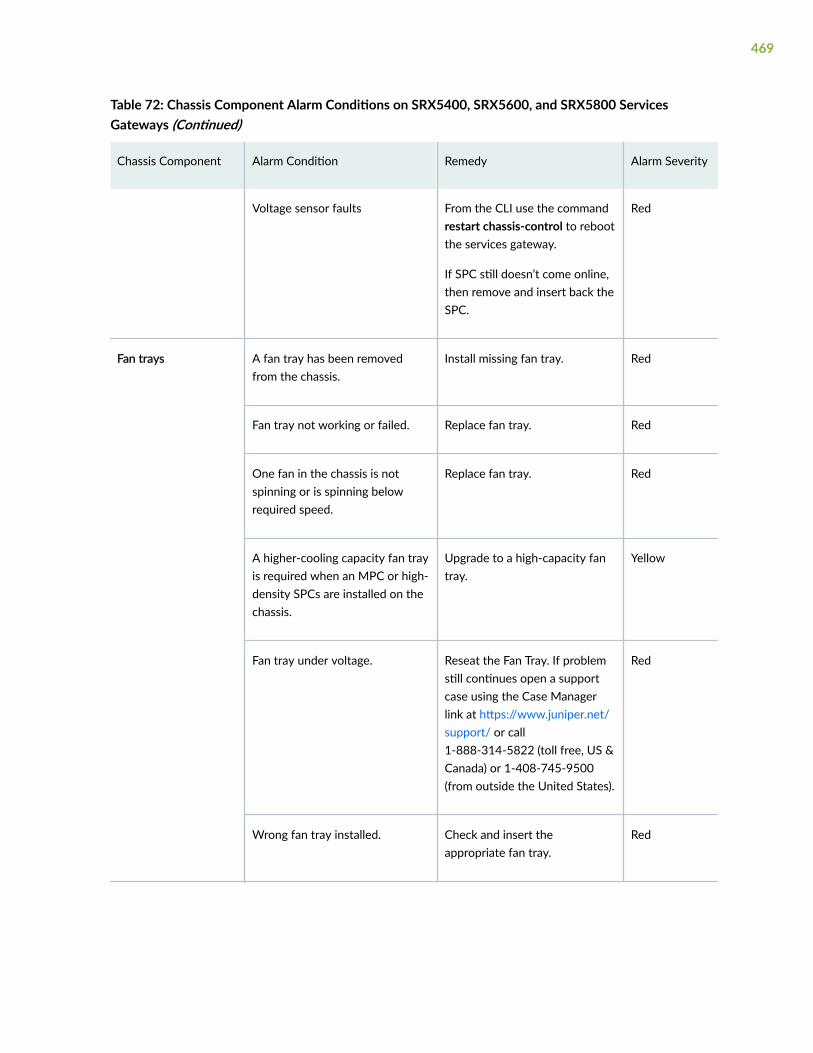
Table 72: Chassis Component Alarm Conditions on SRX5400, SRX5600, and SRX5800 ServicesGateways (Continued)
Chassis Component Alarm Condition Remedy Alarm Severity
Voltage sensor faults From the CLI use the commandrestart chassis-control to rebootthe services gateway.
If SPC still doesn’t come online,then remove and insert back theSPC.
Red
Fan trays A fan tray has been removedfrom the chassis.
Install missing fan tray. Red
Fan tray not working or failed. Replace fan tray. Red
One fan in the chassis is notspinning or is spinning belowrequired speed.
Replace fan tray. Red
A higher-cooling capacity fan trayis required when an MPC or high-density SPCs are installed on thechassis.
Upgrade to a high-capacity fantray.
Yellow
Fan tray under voltage. Reseat the Fan Tray. If problemstill continues open a supportcase using the Case Managerlink at https://www.juniper.net/support/ or call1-888-314-5822 (toll free, US &Canada) or 1-408-745-9500(from outside the United States).
Red
Wrong fan tray installed. Check and insert theappropriate fan tray.
Red
469

Table 72: Chassis Component Alarm Conditions on SRX5400, SRX5600, and SRX5800 ServicesGateways (Continued)
Chassis Component Alarm Condition Remedy Alarm Severity
In SRX5800 Services Gateway,mix of fan trays.
Insert the appropriate fan trays. Red
In SRX5800 Services Gateway,wrong fan tray installed on thetop.
Check and insert theappropriate fan tray.
Red
Host subsystem A host subsystem has beenremoved.
Insert host subsystem intoempty slot.
Yellow
A host subsystem has failed. Replace failed host subsystem. Red
Power supplies A power supply has beenremoved from the chassis.
Insert power supply into emptyslot.
Yellow
A power supply has a hightemperature.
Replace failed power supply orpower entry module.
Red
A power supply input has failed. Check power supply inputconnection.
Red
A power supply output has failed. Check power supply outputconnection.
Red
A power supply has failed. Replace failed power supply. Red
Invalid AC power supplyconfiguration.
When two AC power suppliesare installed, insert one powersupply into an odd-numberedslot and the other power supplyinto an even-numbered slot.
Red
470

Table 72: Chassis Component Alarm Conditions on SRX5400, SRX5600, and SRX5800 ServicesGateways (Continued)
Chassis Component Alarm Condition Remedy Alarm Severity
Invalid DC power supplyconfiguration.
When two DC power suppliesare installed, insert one powersupply into an odd-numberedslot and the other power supplyinto an even-numbered slot.
Red
Mix of AC and DC powersupplies.
Do not mix AC and DC powersupplies. For DC power, removethe AC power supply. For ACpower, remove the DC powersupply.
Red
Not enough power supplies. Install an additional powersupply.
Red
Routing Engine Excessive framing errors onconsole port.
An excessive framing error alarmis triggered when the defaultframing error threshold of 20errors per second on a serial portis exceeded.
This might be caused by a faultyserial console port cableconnected to the device.
Replace the serial cableconnected to the device.
If the cable is replaced and noexcessive framing errors aredetected within 5 minutes fromthe last detected framing error,the alarm is clearedautomatically.
Yellow
Error in reading or writing harddisk.
Reformat hard disk and installbootable image. If this fails,replace failed Routing Engine.
Yellow
Error in reading or writingCompactFlash card.
Reformat CompactFlash cardand install bootable image. Ifthis fails, replace failed RoutingEngine.
Yellow
471

Table 72: Chassis Component Alarm Conditions on SRX5400, SRX5600, and SRX5800 ServicesGateways (Continued)
Chassis Component Alarm Condition Remedy Alarm Severity
System booted from defaultbackup Routing Engine. If youmanually switched primary role,ignore this alarm condition.
Install bootable image on defaultprimary Routing Engine. If thisfails, replace failed RoutingEngine.
Yellow
System booted from hard disk. Install bootable image onCompactFlash card. If this fails,replace failed Routing Engine.
Yellow
CompactFlash card missing inboot list.
Replace failed Routing Engine. Red
Hard disk missing in boot list. Replace failed Routing Engine. Red
Routing Engine failed to boot. Replace failed Routing Engine. Red
The Ethernet managementinterface (fxp0 or em0) on theRouting Engine is down.
• Check the interface cableconnection.
• Reboot the system.
• If the alarm recurs, open asupport case using the CaseManager link at https://www.juniper.net/support/ orcall 1-888-314-5822 (tollfree, US & Canada) or1-408-745-9500 (fromoutside the United States)
Red
System Control Board(SCB)
An SCB has been removed. Insert SCB into empty slot. Yellow
An SCB temperature sensor alarmhas failed.
Replace failed SCB. Yellow
472

Table 72: Chassis Component Alarm Conditions on SRX5400, SRX5600, and SRX5800 ServicesGateways (Continued)
Chassis Component Alarm Condition Remedy Alarm Severity
An SCB has failed. Replace failed SCB. Red
An SCB throughput decreased. • Check fabric plane summaryif all 4 fabric planes areonline.
• This alarm could be raisedbefore all fabric planes arebrought up. It will be clearedafter at least 4 planes are up.
• If all planes are up and stillseeing alarms, raise a caseusing the Case Manager linkat https://www.juniper.net/support/ or call1-888-314-5822 (toll free,US & Canada) or1-408-745-9500 (fromoutside the United States)
Yellow
Temperature The chassis temperature hasexceeded 55 degrees C(131 degrees F), the fans havebeen turned on to full speed, andone or more fans have failed.
• Check room temperature.
• Check air filter and replaceit.
• Check airflow.
• Check fan.
Yellow
The chassis temperature hasexceeded 65 degrees C(149 degrees F), and the fanshave been turned on to fullspeed.
• Check room temperature.
• Check air filter and replaceit.
• Check airflow.
• Check fan.
Yellow
473
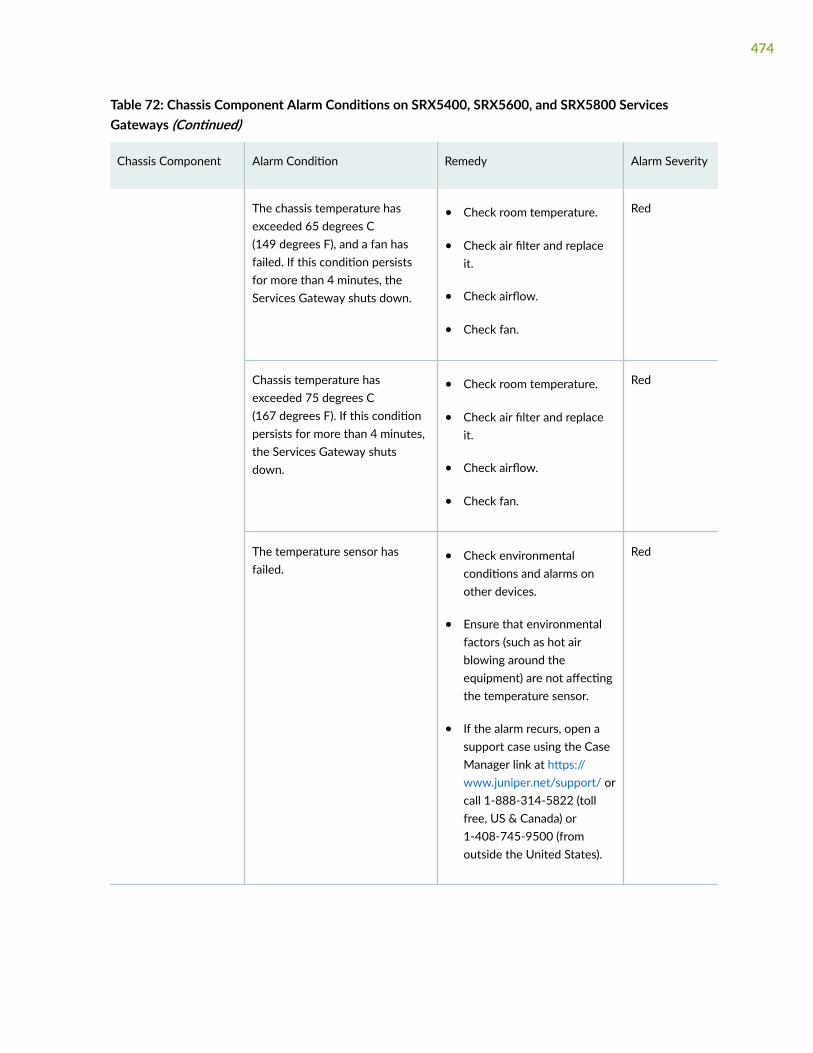
Table 72: Chassis Component Alarm Conditions on SRX5400, SRX5600, and SRX5800 ServicesGateways (Continued)
Chassis Component Alarm Condition Remedy Alarm Severity
The chassis temperature hasexceeded 65 degrees C(149 degrees F), and a fan hasfailed. If this condition persistsfor more than 4 minutes, theServices Gateway shuts down.
• Check room temperature.
• Check air filter and replaceit.
• Check airflow.
• Check fan.
Red
Chassis temperature hasexceeded 75 degrees C(167 degrees F). If this conditionpersists for more than 4 minutes,the Services Gateway shutsdown.
• Check room temperature.
• Check air filter and replaceit.
• Check airflow.
• Check fan.
Red
The temperature sensor hasfailed.
• Check environmentalconditions and alarms onother devices.
• Ensure that environmentalfactors (such as hot airblowing around theequipment) are not affectingthe temperature sensor.
• If the alarm recurs, open asupport case using the CaseManager link at https://www.juniper.net/support/ orcall 1-888-314-5822 (tollfree, US & Canada) or1-408-745-9500 (fromoutside the United States).
Red
474

Backup Routing Engine Alarms
For Services Gateways with primary and backup Routing Engines, a primary Routing Engine cangenerate alarms for events that occur on a backup Routing Engine. Table 73 on page 475 lists chassisalarms generated for a backup Routing Engine.
NOTE: Because the failure occurs on the backup Routing Engine, alarm severity for some events(such as Ethernet interface failures) is yellow instead of red.
NOTE: For information about configuring redundant Routing Engines, see the Junos OS HighAvailability Library for Routing Devices.
Table 73: Backup Routing Engine Alarms
Chassis Component Alarm Condition Remedy Alarm Severity
Alternative media The backup Routing Engine bootsfrom an alternate boot device, thehard disk. The CompactFlash cardis typically the primary bootdevice. The Routing Engine bootsfrom the hard disk when theprimary boot device fails.
Open a support case using theCase Manager link at https://www.juniper.net/support/ orcall 1-888-314-5822 (toll free,US & Canada) or1-408-745-9500 (from outsidethe United States).
Yellow
Boot Device The boot device (CompactFlashor hard disk) is missing in boot liston the backup Routing Engine.
Replace failed backup RoutingEngine.
Red
475

Table 73: Backup Routing Engine Alarms (Continued)
Chassis Component Alarm Condition Remedy Alarm Severity
Ethernet The Ethernet managementinterface (fxp0 or em0) on thebackup Routing Engine is down.
• Check the interface cableconnection.
• Reboot the system.
• If the alarm recurs, open asupport case using the CaseManager link at https://www.juniper.net/support/ orcall 1-888-314-5822 (tollfree, US & Canada) or1-408-745-9500 (fromoutside the United States).
Yellow
FRU Offline The backup Routing Engine hasstopped communicating with theprimary Routing Engine.
Open a support case using theCase Manager link at https://www.juniper.net/support/ orcall 1-888-314-5822 (toll free,US & Canada) or1-408-745-9500 (from outsidethe United States).
Yellow
Hard Disk Error in reading or writing harddisk on the backup RoutingEngine.
Reformat hard disk and installbootable image. If this fails,replace failed backup RoutingEngine.
Yellow
Multibit Memory ECC The backup Routing Enginereports a multibit ECC error.
• Reboot the system with theboard reset button on thebackup Routing Engine.
• If the alarm recurs, open asupport case using the CaseManager link at https://www.juniper.net/support/ orcall 1-888-314-5822 (tollfree, US & Canada) or1-408-745-9500 (fromoutside the United States).
Yellow
476

Troubleshooting the SRX5800 Services Gateway with Alarm RelayContacts
The craft interface has two alarm relay contacts for connecting the services gateway to external alarmdevices. Whenever a system condition triggers either the major or minor alarm on the craft interface,the alarm relay contacts are also activated. The alarm relay contacts are located on the upper right ofthe craft interface.
Troubleshooting the SRX5800 Services Gateway with the Craft InterfaceLEDs
The craft interface is the panel on the front of the services gateway located above the card cage thatcontains LEDs and buttons that allow you to troubleshoot the device.
LEDs on the craft interface include the following:
• Alarm LEDs—One large red circular LED and one large yellow triangular LED, located on the upperright of the craft interface, indicate two levels of alarm conditions. The circular red LED lights toindicate a critical condition that can result in a system shutdown. The triangular yellow LED lights toindicate a less severe condition that requires monitoring or maintenance. Both LEDs can be litsimultaneously. A condition that causes an alarm LED to light also activates the corresponding alarmrelay contact on the craft interface.
• Host subsystem LEDs—Three LEDs, MASTER, ONLINE, and OFFLINE, indicate the status of the hostsubsystem. A green MASTER LED indicates that the host is functioning as primary. The ONLINE LEDindicates the host is online. The OFFLINE LED indicates the host is offline. The host subsystem LEDsare located on the left of the craft interface and are labeled RE0 and RE1.
• Power supply LEDs—Two LEDs (PEM) indicate the status of each power supply. Green indicates thatthe power supply is functioning normally. Red indicates that the power supply is not functioningnormally. The power supply LEDs are located in the center of the craft interface, and are labeled 0through 3.
• Card OK/Fail LEDs—Two LEDs, OK and FAIL, indicate the status of the card in each slot in the cardcage. Green indicates OK and red indicates a failure. The card OK/Fail LEDs are located along thebottom of the craft interface, and are labeled 0 through 5, 2/6, and 7 through 11.
• SCB LEDs—Two LEDs, OK and FAIL, indicate the status of each SCB. Green indicates OK and redindicates a failure. The SCB LEDs are located in the center of the craft interface along the bottom,and are labeled 0 and 1.
477

• Fan LEDs—Two LEDs indicate the status of each fan tray. Green indicates OK and red indicates a fanfailure. The fan LEDs are located on the upper left of the craft interface.
Troubleshooting the SRX5800 Services Gateway with the ComponentLEDs
The following LEDs are located on various services gateway components and display the status of thosecomponents:
• Card LED—One LED labeled OK/FAIL on each card in the card cage indicates the card’s status.
• MIC and port module LED—One LED labeled OK/FAIL on each MIC installed in an MPC, and eachport module installed in a Flex IOC indicates the MIC or port module’s status.
• SCB LEDs—Three LEDs, labeled FABRIC ACTIVE, FABRIC ONLY, and OK/FAIL , on each SCBfaceplate indicate the status of the SCB. If no LEDs are lit, the master Routing Engine might still bebooting, or the SCB is not receiving power.
• Routing Engine LEDs—Four LEDs, labeled MASTER, HDD, ONLINE, and FAIL on the Routing Enginefaceplate indicate the status of the Routing Engine and hard disk drive.
• Power supply LEDs—Three or four LEDs on each power supply faceplate indicate the status of thatpower supply.
Troubleshooting the SRX5800 Services Gateway Cooling System
IN THIS SECTION
Problem | 478
Solution | 479
Problem
Description
The fans in a fan tray are not functioning normally.
478

Solution
Follow these guidelines to troubleshoot the fans:
• Check the fan LEDs and alarm LEDs on the craft interface.
• If the major alarm LED on the craft interface lights, use the CLI to get information about the sourceof an alarm condition: user@host> show chassis alarms.
If the CLI output lists only one fan failure, and the other fans are functioning normally, the fan is mostlikely faulty and you must replace the fan tray.
• Place your hand near the exhaust vents at the side of the chassis to determine whether the fans arepushing air out of the chassis.
• If the fan tray is removed, a minor alarm and a major alarm occur.
• The following conditions automatically cause the fans to run at full speed and also trigger theindicated alarm:
• A fan fails (major alarm).
• The services gateway temperature exceeds the “temperature warm” threshold (minor alarm).
• The temperature of the services gateway exceeds the maximum (“temperature hot”) threshold(major alarm and automatic shutdown of the power supplies).
Troubleshooting SRX5800 Services Gateway Interface Cards
IN THIS SECTION
Problem | 479
Solution | 480
Problem
Description
The interface cards (IOCs, Flex IOCs, or MPCs) are not functioning normally.
479

Solution
• Monitor the green LED labeled OK on the craft interface corresponding to the slot as soon as aninterface card is seated in an operating services gateway.
The Routing Engine downloads the interface card’s software to it under two conditions: the interfacecard is present when the Routing Engine boots Junos OS, and the interface card is installed andrequested online through the CLI or push button on the front panel. The interface card then runsdiagnostics, during which the OK LED blinks. When the interface card is online and functioningnormally, the OK LED lights green steadily.
• Make sure the interface card is properly seated in the midplane. Check that each ejector handle hasbeen turned clockwise and is tight.
• Check the OK/FAIL LED on the interface card and OK and FAIL LEDs for the slot on the craftinterface. When the interface card is online and functioning normally, the OK LED lights greensteadily.
• Issue the CLI show chassis fpc command to check the status of installed interface cards. As shown inthe sample output, the value Online in the column labeled State indicates that the interface card isfunctioning normally:
user@host> show chassis fpc Temp CPU Utilization (%) Memory Utilization (%)Slot State (C) Total Interrupt DRAM (MB) Heap Buffer 0 Online 41 9 0 1024 15 57 1 Online 43 5 0 1024 16 57 2 Online 43 11 0 1024 16 57 3 Empty 4 Empty 5 Online 42 6 0 1024 16 57
For more detailed output, add the detail option. The following example does not specify a slotnumber, which is optional:
user@host> show chassis fpc detail
Slot 0 information: State Online Temperature 41 degrees C / 105 degrees F Total CPU DRAM 1024 MB Total RLDRAM 256 MB
480

Total DDR DRAM 4096 MB Start time: 2007-07-10 12:28:33 PDT Uptime: 1 hour, 33 minutes, 52 secondsSlot 1 information: State Online Temperature 43 degrees C / 109 degrees F Total CPU DRAM 1024 MB Total RLDRAM 256 MB Total DDR DRAM 4096 MB Start time: 2007-07-10 12:28:38 PDT Uptime: 1 hour, 33 minutes, 47 secondsSlot 2 information: State Online Temperature 43 degrees C / 109 degrees F Total CPU DRAM 1024 MB Total RLDRAM 256 MB Total DDR DRAM 4096 MB Start time: 2007-07-10 12:28:40 PDT Uptime: 1 hour, 33 minutes, 45 secondsSlot 5 information: State Online Temperature 42 degrees C / 107 degrees F Total CPU DRAM 1024 MB Total RLDRAM 256 MB Total DDR DRAM 4096 MB Start time: 2007-07-10 12:28:42 PDT Uptime: 1 hour, 33 minutes, 43 seconds
For further description of the output from the command, see Junos OS System Basics and ServicesCommand Reference at www.juniper.net/documentation/.
Troubleshooting SRX5800 Services Gateway MICs and Port Modules
IN THIS SECTION
Problem | 482
Solution | 482
481

Problem
Description
The MICs or port modules are not functioning normally.
Solution
• Check the status of each port on a port module by looking at the LED located on the port modulefaceplate.
• Check the status of a port module by issuing the show chassis fpc pic-status CLI command. The portmodule slots in the Flex IOC are numbered from 0 through 1:
user@host> show chassis fpc pic-statusSlot 0 Online SRX5k SPC PIC 0 Online SPU Cp-Flow PIC 1 Online SPU FlowSlot 3 Online SRX5k DPC 4X 10GE PIC 0 Online 1x 10GE(LAN/WAN) RichQ PIC 1 Online 1x 10GE(LAN/WAN) RichQ PIC 2 Online 1x 10GE(LAN/WAN) RichQ PIC 3 Online 1x 10GE(LAN/WAN) RichQSlot 5 Online SRX5k FIOC PIC 0 Online 16x 1GE TX PIC 1 Online 4x 10GE XFP
For further description of the output from the command, see Junos OS System Basics and ServicesCommand Reference at www.juniper.net/documentation/.
Troubleshooting SRX5800 Services Gateway SPCs
IN THIS SECTION
Problem | 483
Solution | 483
482

Problem
Description
A Services Processing Card (SPC) is not functioning normally.
Solution
• Make sure the SPC is properly seated in the midplane. Check that each ejector handle has beenturned clockwise and is tight.
• Issue the CLI show chassis fpc command to check the status of installed SPCs. As shown in the sampleoutput, the value Online in the column labeled State indicates that the SPC is functioning normally:
user@host> show chassis fpc
Slot State (C) Total Interrupt DRAM (MB) Heap Buffer 0 Online 35 4 0 1024 13 25 1 Online 47 3 0 1024 13 25 2 Online 37 8 0 2048 18 14
For more detailed output, add the detail option. The following example does not specify a slotnumber, which is optional:
user@host> show chassis fpc detail
Slot 0 information: State Online Temperature 35 Total CPU DRAM 1024 MB Total RLDRAM 259 MB Total DDR DRAM 4864 MB Start time: 2013-12-10 02:58:16 PST Uptime: 1 day, 11 hours, 59 minutes, 15 seconds Max Power Consumption 585 WattsSlot 1 information: State Online Temperature 47 Total CPU DRAM 1024 MB Total RLDRAM 259 MB
483

Total DDR DRAM 4864 MB Start time: 2013-12-10 02:55:30 PST Uptime: 1 day, 12 hours, 2 minutes, 1 second Max Power Consumption 585 WattsSlot 2 information: State Online Temperature 37 Total CPU DRAM 2048 MB Total RLDRAM 1036 MB Total DDR DRAM 6656 MB Start time: 2013-12-10 02:58:07 PST Uptime: 1 day, 11 hours, 59 minutes, 24 seconds Max Power Consumption 570 Watts
For further description of the output from the command, see Junos OS System Basics and ServicesCommand Reference at www.juniper.net/documentation/.
Troubleshooting the SRX5800 Services Gateway Power System
IN THIS SECTION
Problem | 484
Solution | 484
Problem
Description
The power system is not functioning normally.
Solution
• Check the LEDs on each power supply faceplate.
• If an AC power supply is correctly installed and functioning normally, the AC OK and DC OK LEDslight steadily, and the PS FAIL LED is not lit.
484

• If a DC power supply is correctly installed and functioning normally, the PWR OK, BREAKER ON,and INPUT OK LEDs light steadily.
• Issue the CLI show chassis environment pem command to check the status of installed power supplies. Asshown in the sample output, the value Online in the rows labeled State indicates that each of thepower supply is functioning normally:
user@host> show chassis environment pemPEM 0 status: State Online Temperature OK DC Input: OK DC Output Voltage(V) Current(A) Power(W) Load(%) 57 14 798 19 PEM 1 status: State Online Temperature OK DC Input: OK DC Output Voltage(V) Current(A) Power(W) Load(%) 57 13 741 18
If a power supply is not functioning normally, perform the following steps to diagnose and correct theproblem:
• If a major alarm condition occurs, issue the show chassis alarms command to determine the source ofthe problem.
• Check that the AC input switch (—) or DC circuit breaker (|) is in the on position and that the powersupply is receiving power.
• Verify that the source circuit breaker has the proper current rating. Each power supply must beconnected to a separate source circuit breaker.
• Verify that the AC power cord or DC power cables from the power source to the services gatewayare not damaged. If the insulation is cracked or broken, immediately replace the cord or cable.
• Connect the power supply to a different power source with a new power cord or power cables. If thepower supply status LEDs indicate that the power supply is not operating normally, the power supplyis the source of the problem. Replace the power supply with a spare.
• If all power supplies have failed, the system temperature might have exceeded the threshold, causingthe system to shut down.
485

NOTE: If the system temperature exceeds the threshold, Junos OS shuts down all powersupplies so that no status is displayed.
Junos OS also can shut down one of the power supplies for other reasons. In this case, theremaining power supplies provide power to the services gateway, and you can still view thesystem status through the CLI or display.
To restart a high-capacity AC power supply after a shut down due to an over-temperature situation:
1. Move the power switch on the power supply to the off (o) position.
2. Turn off power to where the AC line goes into the power distribution module (PDM) area.
3. Wait for the power supply LEDs to fade out and for the fans inside the power supply toshutdown. This can take up to 10 seconds.
CAUTION: Do not attempt to power-on the power supply if the LED is still lit andthe fan is still running. If you do, the services gateway will not reboot.
4. Turn on power to where the AC line goes into the power distribution module (PDM) area.
5. Move the power switch on the power supply to the on (|) position.
6. Verify that the LEDs on the power supply faceplate are properly lit.
7. Issue the CLI show chassis environment pem command and verify the State is ONLINE and theTemperature is OK.
To restart a high-capacity DC power supply after a shut down due to an over-temperature situation:
1. Switch off the circuit breaker(s) on the DC distribution panel to remove power to the chassis andpower supplies.
2. Switch on the circuit breaker(s) on the distribution panel to power up the chassis and powersupplies.
NOTE: The power switch on the power supplies is not part of the outer or inner DCcircuits and therefore does not need to be switched off when restarting the chassis.
486

NOTE: If output power is not load-balancing correctly in the same zone on a services gatewaywith a high-capacity AC or DC power supply module, connect two feeds and change the DIPswitch to 1 to boost the voltage on the power supply module.
Each High Capacity AC or DC power supply accepts two AC or DC feeds in two unique AC or DCreceptacles. It is possible to operate with one feed, but there is a reduction in the power supply output.The DIP switch must be set according to the number of AC or DC feeds that are present for the powersupply.
Figure 178: AC Power Input Mode Switch
• Position – 0 indicates that only one AC or DC feed is provided.
• Position – 1 indicates that two AC or DC feeds are provided.
The following example shows what should be the DIP switch position based on the number of AC or DCinput feeds expected and connected to the PEM:
1. Issue the CLI show chassis power command and check how many feeds are connected.
487

The sample out put below is the output of a chassis with AC power supplies:
user@host# run show chassis powerPEM 0: State: Online AC input: OK (2 feed expected, 2 feed connected) Capacity: 4100 W (maximum 4100 W) DC output: 798 W (zone 0, 14 A at 57 V, 19% of capacity)
PEM 1: State: Online AC input: OK (1 feed expected, 2 feed connected) Capacity: 1700 W (maximum 4100 W) DC output: 741 W (zone 1, 13 A at 57 V, 43% of capacity)
PEM 2: State: Empty Input: Absent
PEM 3: State: Empty Input: Absent
System: Zone 0: Capacity: 4100 W (maximum 4100 W) Allocated power: 1255 W (2845 W remaining) Actual usage: 798 W Zone 1: Capacity: 1700 W (maximum 4100 W) Allocated power: 1090 W (610 W remaining) Actual usage: 741 W Total system capacity: 5800 W (maximum 8200 W) Total remaining power: 3455 W
The output of the show chassis power command shows that; on PEM 0 two AC input feeds are expectedand two AC input feeds are connected and on PEM 1 one AC input feed is expected and two ACinput feeds are connected.
488

2. Issue the show chassis alarms command to see if there are any active alarms and the position of thePEM DIP switch.
> show chassis alarms 1 alarms currently activeAlarm time Class Description2017-01-23 05:05:17 PST Minor PEM 1 Dipswitch 0 Feed Connection 2
The output of the show chassis alarms command shows one active alarm on PEM 1 and the position ofthe DIP switch as 0.
In this example output, there is an alarm on PEM 1 because there is a need of only one AC feed butthe PEM 1 is connected with two AC feeds and the DIP switch position is 0.
3. Change the PEM 1 DIP switch position to 1. This should clear the alarm.
NOTE: Changing the DIP switch position does not impact traffic. However, it is alwaysrecommended to do so in a maintenance window.
4. Issue the CLI show chassis power command and check the output to see if the number of feedsexpected on PEM 1 is the same as the feeds connected.
# run show chassis powerPEM 0: State: Online AC input: OK (2 feed expected, 2 feed connected) Capacity: 4100 W (maximum 4100 W) DC output: 741 W (zone 0, 13 A at 57 V, 18% of capacity)
PEM 1: State: Online AC input: OK (2 feed expected, 2 feed connected) Capacity: 4100 W (maximum 4100 W) DC output: 741 W (zone 1, 13 A at 57 V, 18% of capacity)
PEM 2: State: Empty Input: Absent
PEM 3: State: Empty
489

Input: Absent
System: Zone 0: Capacity: 4100 W (maximum 4100 W) Allocated power: 1255 W (2845 W remaining) Actual usage: 741 W Zone 1: Capacity: 4100 W (maximum 4100 W) Allocated power: 1090 W (3010 W remaining) Actual usage: 741 W Total system capacity: 8200 W (maximum 8200 W) Total remaining power: 5855 W
The output of the show chassis power command shows that the number of feeds on PEM 1 expected isthe same as the feeds connected.
5. Issue the CLI show chassis alarms command to check if the alarm is removed.
> show chassis alarms No alarms currently active
The output of the show chassis alarms command shows no active alarms.
Behavior of the SRX5400, SRX5600, and SRX5800 Services GatewaysWhen the SRX5K-SCBE and SRX5K-RE-1800X4 in a Chassis Cluster Fail
It is important to understand the behavior of the SRX5400, SRX5600, and SRX5800 Services Gatewayswhen the Switch Control Board (SRX5K-SCBE) and Routing Engine (SRX5K-RE-1800X4) in the chassiscluster fail.
NOTE: This procedure is also applicable for SCB3 except that SCB3 redundancy is supported.
NOTE: We strongly recommend that you perform the ISHU during a maintenance window, orduring the lowest possible traffic as the secondary node is not available at this time.
490

NOTE: The SRX5K-SCBE and SRX5K-RE-1800X4 are not hot-swappable.
NOTE: Four fabric planes must be active at any time in a chassis cluster. If fewer than four fabricplanes are active, then the Redundancy Group (RG1+) will fail over to the secondary node.
Table 74 on page 491 shows the minimum fabric plane requirements for the SCB.
Table 74: Expected Device Behavior and Minimum SRX5K-SCBE and Fabric Plane Requirements
Platform Number ofSRX5K-SCBs
ActivePlanes
RedundantPlanes
Expected Behavior After the SCB andRouting Engine are Removed
SRX5400 1 4 (virtual) 0 (virtual) If the SCB in the primary node fails, thedevice will fail over to the secondary nodeas the primary node powers off.
SRX5600 2 4 (virtual) 4 (virtual) If the active SCB in the primary node fails,the behavior of the device does not changeas the redundant SCB becomes activeprovided all four fabric planes are in goodcondition.
If the second SCB in the primary node fails,the device will fail over to the secondarynode as the primary node powers off.
SRX5800 3 4 2 This device supports one SCB for two fabricplanes, providing a redundancy of threeSCBs. If the active SCB fails, the devicebehavior does not change as the remainingtwo SCBs fulfill the requirement to have fourfabric planes.
If the second SCB also fails, no spare planesare available in the chassis triggering inter-chassis redundancy. Therefore, RG1+ will failover to the secondary node.
491

NOTE: In SRX5600 and SRX5800 Services Gateways, failover does not happen when thesecondary Routing Engine in slot 1 fails, while the SCB in slot 1 is inactive.
For detailed information about chassis cluster, see the Chassis Cluster User Guide for SRX SeriesDevices at www.juniper.net/documentation/.
492

6CHAPTER
Contacting Customer Support andReturning the Chassis or Components
Returning the SRX5800 Chassis or Components | 494

Returning the SRX5800 Chassis or Components
IN THIS SECTION
Contacting Customer Support | 494
Return Procedure for the SRX5800 Services Gateway | 495
Listing the SRX5800 Services Gateway Component Serial Numbers with the Command-Line Interface | 496
Locating the SRX5800 Services Gateway Chassis Serial Number Label | 498
Locating the SRX5800 Services Gateway Power Supply Serial Number Label | 498
Locating the SRX5800 Services Gateway Craft Interface Serial Number Label | 504
Information You Might Need to Supply to JTAC | 504
Required Tools and Parts for Packing the SRX5800 Services Gateway | 505
Packing the SRX5800 Services Gateway for Shipment | 505
Packing SRX5800 Services Gateway Components for Shipment | 506
Contacting Customer Support
Once you have located the serial numbers of the services gateway or component, you can return theservices gateway or component for repair or replacement. For this, you need to contact JuniperNetworks Technical Assistance Center (JTAC).
You can contact JTAC 24 hours a day, 7 days a week, using any of the following methods:
• On the Web: Using the Service Request Manager link at https://support.juniper.net/support/
• By telephone:
• From the US and Canada: 1-888-314-JTAC
• From all other locations: 1-408-745-9500
NOTE: If contacting JTAC by telephone, enter your 12-digit service request numberfollowed by the pound (#) key if this is an existing case, or press the star (*) key to berouted to the next available support engineer.
494

Return Procedure for the SRX5800 Services Gateway
If a problem cannot be resolved by the JTAC technician, a Return Materials Authorization (RMA) isissued. This number is used to track the returned material at the factory and to return repaired or newcomponents to the customer as needed.
NOTE: Do not return any component to Juniper Networks, Inc. unless you have first obtained anRMA number. Juniper Networks, Inc. reserves the right to refuse shipments that do not have anRMA. Refused shipments will be returned to the customer via collect freight.
For more information about return and repair policies, see the customer support Web page at https://www.juniper.net/support/guidelines.html .
To return a services gateway or component to Juniper Networks for repair or replacement:
1. Determine the part number and serial number of the services gateway or component. For the serialnumber locations of cards and modules such as MPCs, SPCs, port modules and Routing Engines, seethe SRX5400, SRX5600, and SRX5800 Services Gateway Card Reference at www.juniper.net/documentation/.
2. Obtain a Return Materials Authorization (RMA) number from JTAC.
NOTE: Do not return the services gateway or any component to Juniper Networks unless youhave first obtained an RMA number. Juniper Networks reserves the right to refuse shipmentsthat do not have an RMA. Refused shipments are returned to the customer via collect freight.
3. Pack the services gateway or component for shipping.
For more information about return and repair policies, see the customer support webpage at https://www.juniper.net/support/guidelines.html .
For product problems or technical support issues, open a support case using the Case Manager link athttps://support.juniper.net/support/ or call 1-888-314-JTAC (within the United States) or1-408-745-9500 (outside the United States).
495

Listing the SRX5800 Services Gateway Component Serial Numbers withthe Command-Line Interface
Before contacting Juniper Networks, Inc. to request a Return Materials Authorization (RMA), you mustfind the serial number on the services gateway or component. To display all of the services gatewaycomponents and their serial numbers, enter the following command-line interface (CLI) command:
user@host> show chassis hardware
Hardware inventory:Item Version Part number Serial number DescriptionChassis JN10B7ACDAGA SRX 5800Midplane REV 03 710-013698 TR0813 SRX 5800 BackplaneFPM Board REV 03 710-014974 KC3418 Front Panel DisplayPDM Rev 03 740-013110 QCS1122501L Power Distribution ModulePEM 1 Rev 03 740-013682 QCS1130409T PS 1.7kW; 200-240VAC inPEM 2 Rev 03 740-013682 QCS1130409M PS 1.7kW; 200-240VAC inRouting Engine 0 REV 06 740-015113 1000697051 RE-S-1300CB 0 REV 07 710-013385 KC0433 SRX5k SCBCB 1 REV 07 710-013385 KC0259 SRX5k SCBFPC 6 REV 03 750-020235 JS4722 SRX5k DPC 40x 1GE CPU REV 06 710-013713 JZ4019 DPC PMB PIC 0 BUILTIN BUILTIN 10x 1GE RichQ Xcvr 0 REV 01 740-011782 PAQ2K01 SFP-SX Xcvr 1 REV 01 740-014132 61531018 SFP-T Xcvr 2 REV 01 740-013111 7303709 SFP-T Xcvr 4 REV 01 740-011782 PAQ2JZP SFP-SX Xcvr 5 REV 01 740-013111 8043356 SFP-T Xcvr 6 REV 01 740-013111 8043257 SFP-T Xcvr 7 REV 01 740-013111 8043300 SFP-T Xcvr 8 REV 01 740-013111 8043215 SFP-T Xcvr 9 REV 01 740-013111 8043184 SFP-T PIC 1 BUILTIN BUILTIN 10x 1GE RichQ Xcvr 0 0 NON-JNPR AM0619193B SFP-SX Xcvr 9 0 NON-JNPR AJ054100PH SFP-SX PIC 2 BUILTIN BUILTIN 10x 1GE RichQ Xcvr 1 REV 01 740-014132 61522010 SFP-T Xcvr 2 REV 01 740-013111 7303481 SFP-T Xcvr 4 REV 01 740-011782 PAQ2K0H SFP-SX Xcvr 5 REV 01 740-013111 8043179 SFP-T
496

Xcvr 6 REV 01 740-013111 7522572 SFP-T Xcvr 7 REV 01 740-013111 8043157 SFP-T Xcvr 8 REV 01 740-013111 7522678 SFP-T Xcvr 9 REV 01 740-013111 7522683 SFP-T PIC 3 BUILTIN BUILTIN 10x 1GE RichQ Xcvr 0 0 NON-JNPR AJ06080TKC SFP-SX Xcvr 9 0 NON-JNPR AJ06020HSJ SFP-SXFPC 7 BB_P2_28 710-013699 JS4812 SRX5k SPC CPU REV 06 710-013713 KA7426 DPC PMB PIC 0 BUILTIN BUILTIN SPU Cp PIC 1 BUILTIN BUILTIN SPU FlowFan Tray 0 REV 04 740-014971 TP1433 Fan TrayFan Tray 1 REV 04 740-014971 TP1636 Fan Tray
Most components also have a small rectangular serial number ID label (see Figure 179 on page 497)attached to the component body.
Figure 179: Serial Number ID Label
497
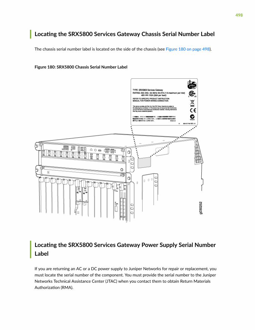
Locating the SRX5800 Services Gateway Chassis Serial Number Label
The chassis serial number label is located on the side of the chassis (see Figure 180 on page 498).
Figure 180: SRX5800 Chassis Serial Number Label
Locating the SRX5800 Services Gateway Power Supply Serial NumberLabel
If you are returning an AC or a DC power supply to Juniper Networks for repair or replacement, youmust locate the serial number of the component. You must provide the serial number to the JuniperNetworks Technical Assistance Center (JTAC) when you contact them to obtain Return MaterialsAuthorization (RMA).
498

The location of the serial number labels on Standard-Capacity and High Capacity AC or DC powersupplies is explained below:
• AC Power Supplies:
• Standard-Capacity AC Power Supply—The serial number label is on the AC power supplyfaceplate under the on/off switch. See Figure 181 on page 499.
Figure 181: Standard-Capacity AC Power Supply Serial Number Label
• High-Capacity AC Power Supply—The serial number label is on the top of the AC power supply.See Figure 182 on page 499.
Figure 182: High-Capacity AC Power Supply Serial Number Label
499

• High-Capacity Second-Generation AC Power Supply—The serial number label is under the on/offswitch of the power supply. See Figure 183 on page 500.
Figure 183: High-Capacity Second-Generation AC Power Supply Serial Number Label
500

• High-Voltage Second-Generation Universal (HVAC/HVDC) Power Supply—The serial number labelis under the on/off switch of the power supply. See Figure 184 on page 501.
Figure 184: High-Voltage Second-Generation Universal (HVAC/HVDC) Power Supply SerialNumber Label
DC power Supplies:
501

• Standard-Capacity DC Power Supply—The serial number label is on the DC power supplyfaceplate under the circuit breaker switch. See Figure 185 on page 502.
Figure 185: Standard-Capacity DC Power Supply Serial Number Label
502

• High-Capacity DC Power Supply—The serial number label is on the top of the DC power supply.See Figure 186 on page 503.
Figure 186: High-Capacity DC Power Supply Serial Number Label
503
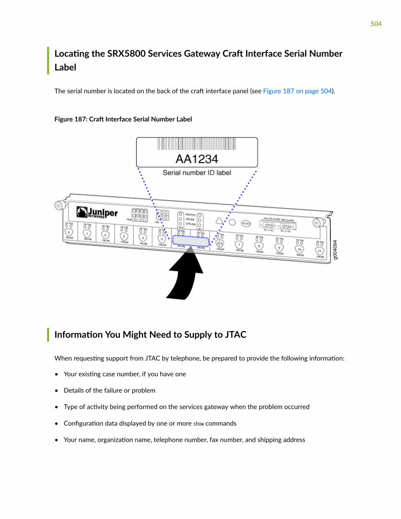
Locating the SRX5800 Services Gateway Craft Interface Serial NumberLabel
The serial number is located on the back of the craft interface panel (see Figure 187 on page 504).
Figure 187: Craft Interface Serial Number Label
Information You Might Need to Supply to JTAC
When requesting support from JTAC by telephone, be prepared to provide the following information:
• Your existing case number, if you have one
• Details of the failure or problem
• Type of activity being performed on the services gateway when the problem occurred
• Configuration data displayed by one or more show commands
• Your name, organization name, telephone number, fax number, and shipping address
504

Required Tools and Parts for Packing the SRX5800 Services Gateway
To remove components from the services gateway or the services gateway from a rack, you need thefollowing tools and parts:
• 2.5-mm flat-blade (–) screwdriver, for detaching alarm relay terminal block
• 7/16-in. (11 mm) nut driver
• Blank panels to cover empty slots
• Electrostatic bag or antistatic mat, for each component
• Electrostatic discharge (ESD) grounding wrist strap
• Flat-blade (–) screwdriver
• Mechanical lift, if available
• Phillips (+) screwdrivers, numbers 1 and 2
• Rubber safety cap for fiber-optic interfaces or cable
• Wire cutters
Packing the SRX5800 Services Gateway for Shipment
To pack the services gateway for shipment:
1. Retrieve the shipping crate and packing materials in which the services gateway was originallyshipped. If you do not have these materials, contact your Juniper Networks representative aboutapproved packaging materials.
2. On the console or other management device connected to the primary Routing Engine, enter CLIoperational mode and issue the following command to shut down the services gateway software.
user@host> request system halt
Wait until a message appears on the console confirming that the operating system has halted.
For more information about the command, see Junos OS System Basics and Services CommandReference at www.juniper.net/documentation/.
3. Attach an ESD grounding strap to your bare wrist, and connect the strap to one of the ESD pointson the chassis.
505

4. Shut down power to the services gateway by pressing the AC input switch or DC circuit breaker forall power supplies to the off (O) position.
5. Disconnect power from the services gateway.
6. Remove the cables that connect to all external devices.
7. Remove all field replaceable units (FRUs) from the services gateway.
8. Remove the services gateway chassis from the rack:
• If you are using a mechanical lift, place the lift platform under the chassis, unscrew and removethe mounting screws from the rack, and move the chassis to the shipping crate.
• If you are not using a mechanical lift and the chassis weight is fully supported by a shelf oranother device, unscrew and remove the mounting screws from the rack. Three people can thenlift the chassis and move it to the shipping crate.
• If you are not using a mechanical lift and the chassis weight is not fully supported by a shelf oranother device, three people should grasp the chassis while a fourth person unscrews andremoves the mounting screws from the rack. The three lifters can then move the chassis to theshipping container.
9. Place the services gateway in the shipping crate or onto the pallet. If on a pallet, bolt the servicesgateway to the pallet.
10. Cover the services gateway with an ESD bag and place the packing foam on top of and around theservices gateway.
11. Replace the accessory box on top of the packing foam.
12. Securely tape the box closed or place the crate cover over the services gateway.
13. Write the RMA number on the exterior of the box to ensure proper tracking.
Packing SRX5800 Services Gateway Components for Shipment
Follow these guidelines for packing and shipping individual components of the services gateway:
• When you return a component, make sure that it is adequately protected with packing materials andpacked so that the pieces are prevented from moving around inside the carton.
• Use the original shipping materials if they are available.
• Place the individual component in an electrostatic bag.
• Write the Return Materials Authorization (RMA) number on the exterior of the box to ensure propertracking.
506

CAUTION: Do not stack any of the services gateway components during packing.
507

7CHAPTER
Safety and Compliance Information
General Safety Guidelines and Warnings | 510
Definitions of Safety Warning Levels | 511
Restricted Access Area Warning | 513
Fire Safety Requirements | 514
Qualified Personnel Warning | 516
Warning Statement for Norway and Sweden | 516
Installation Instructions Warning | 517
Chassis and Component Lifting Guidelines | 517
Ramp Warning | 518
Rack-Mounting and Cabinet-Mounting Warnings | 518
Grounded Equipment Warning | 523
Laser and LED Safety Guidelines and Warnings | 523
Radiation from Open Port Apertures Warning | 526
Maintenance and Operational Safety Guidelines and Warnings | 527
General Electrical Safety Guidelines and Warnings | 533
Prevention of Electrostatic Discharge Damage | 535
AC Power Electrical Safety Guidelines | 536
AC Power Disconnection Warning | 537
DC Power Electrical Safety Guidelines | 538
DC Power Disconnection Warning | 545

DC Power Grounding Requirements and Warning | 546
DC Power Wiring Sequence Warning | 547
DC Power Wiring Terminations Warning | 549
Multiple Power Supplies Disconnection Warning | 550
TN Power Warning | 551
Action to Take After an Electrical Accident | 551
SRX5800 Services Gateway Agency Approvals | 552
SRX5800 Services Gateway Compliance Statements for EMC Requirements | 554
Statements of Volatility for Juniper Network Devices | 556

General Safety Guidelines and Warnings
The following guidelines help ensure your safety and protect the device from damage. The list ofguidelines might not address all potentially hazardous situations in your working environment, so bealert and exercise good judgment at all times.
• Perform only the procedures explicitly described in the hardware documentation for this device.Make sure that only authorized service personnel perform other system services.
• Keep the area around the device clear and free from dust before, during, and after installation.
• Keep tools away from areas where people could trip over them while walking.
• Do not wear loose clothing or jewelry, such as rings, bracelets, or chains, which could become caughtin the device.
• Wear safety glasses if you are working under any conditions that could be hazardous to your eyes.
• Do not perform any actions that create a potential hazard to people or make the equipment unsafe.
• Never attempt to lift an object that is too heavy for one person to handle.
• Never install or manipulate wiring during electrical storms.
• Never install electrical jacks in wet locations unless the jacks are specifically designed for wetenvironments.
• Operate the device only when it is properly grounded.
• Follow the instructions in this guide to properly ground the device to earth.
• Replace fuses only with fuses of the same type and rating.
• Do not open or remove chassis covers or sheet-metal parts unless instructions are provided in thehardware documentation for this device. Such an action could cause severe electrical shock.
• Do not push or force any objects through any opening in the chassis frame. Such an action couldresult in electrical shock or fire.
• Avoid spilling liquid onto the chassis or onto any device component. Such an action could causeelectrical shock or damage the device.
• Avoid touching uninsulated electrical wires or terminals that have not been disconnected from theirpower source. Such an action could cause electrical shock.
510

• Some parts of the chassis, including AC and DC power supply surfaces, power supply unit handles,SFB card handles, and fan tray handles might become hot. The following label provides the warningof the hot surfaces on the chassis:
• Always ensure that all modules, power supplies, and cover panels are fully inserted and that theinstallation screws are fully tightened.
Definitions of Safety Warning Levels
The documentation uses the following levels of safety warnings (there are two Warning formats):
NOTE: You might find this information helpful in a particular situation, or you might overlook thisimportant information if it was not highlighted in a Note.
CAUTION: You need to observe the specified guidelines to prevent minor injury ordiscomfort to you or severe damage to the device.
Attention Veillez à respecter les consignes indiquées pour éviter toute incommodité oublessure légère, voire des dégâts graves pour l’appareil.
LASER WARNING: This symbol alerts you to the risk of personal injury from a laser.
Avertissement Ce symbole signale un risque de blessure provoquée par rayon laser.
WARNING: This symbol means danger. You are in a situation that could cause bodilyinjury. Before you work on any equipment, be aware of the hazards involved withelectrical circuitry and be familiar with standard practices for preventing accidents.
Waarschuwing Dit waarschuwingssymbool betekent gevaar. U verkeert in een situatiedie lichamelijk letsel kan veroorzaken. Voordat u aan enige apparatuur gaat werken,
511

dient u zich bewust te zijn van de bij elektrische schakelingen betrokken risico's en dientu op de hoogte te zijn van standaard maatregelen om ongelukken te voorkomen.
Varoitus Tämä varoitusmerkki merkitsee vaaraa. Olet tilanteessa, joka voi johtaaruumiinvammaan. Ennen kuin työskentelet minkään laitteiston parissa, ota selvääsähkökytkentöihin liittyvistä vaaroista ja tavanomaisista onnettomuuksienehkäisykeinoista.
Avertissement Ce symbole d'avertissement indique un danger. Vous vous trouvez dansune situation pouvant causer des blessures ou des dommages corporels. Avant detravailler sur un équipement, soyez conscient des dangers posés par les circuitsélectriques et familiarisez-vous avec les procédures couramment utilisées pour éviterles accidents.
Warnung Dieses Warnsymbol bedeutet Gefahr. Sie befinden sich in einer Situation, diezu einer Körperverletzung führen könnte. Bevor Sie mit der Arbeit an irgendeinemGerät beginnen, seien Sie sich der mit elektrischen Stromkreisen verbundenen Gefahrenund der Standardpraktiken zur Vermeidung von Unfällen bewußt.
Avvertenza Questo simbolo di avvertenza indica un pericolo. La situazione potrebbecausare infortuni alle persone. Prima di lavorare su qualsiasi apparecchiatura, occorreconoscere i pericoli relativi ai circuiti elettrici ed essere al corrente delle pratichestandard per la prevenzione di incidenti.
Advarsel Dette varselsymbolet betyr fare. Du befinner deg i en situasjon som kan føretil personskade. Før du utfører arbeid på utstyr, må du vare oppmerksom på defaremomentene som elektriske kretser innebærer, samt gjøre deg kjent med vanligpraksis når det gjelder å unngå ulykker.
Aviso Este símbolo de aviso indica perigo. Encontra-se numa situação que lhe poderácausar danos físicos. Antes de começar a trabalhar com qualquer equipamento,familiarize-se com os perigos relacionados com circuitos eléctricos, e com quaisquerpráticas comuns que possam prevenir possíveis acidentes.
¡Atención! Este símbolo de aviso significa peligro. Existe riesgo para su integridad física.Antes de manipular cualquier equipo, considerar los riesgos que entraña la corrienteeléctrica y familiarizarse con los procedimientos estándar de prevención de accidentes.
Varning! Denna varningssymbol signalerar fara. Du befinner dig i en situation som kanleda till personskada. Innan du utför arbete på någon utrustning måste du varamedveten om farorna med elkretsar och känna till vanligt förfarande för att förebyggaskador.
512

Restricted Access Area Warning
WARNING: The services gateway is intended for installation in restricted access areas.A restricted access area is an area to which access can be gained only by servicepersonnel through the use of a special tool, lock and key, or other means of security,and which is controlled by the authority responsible for the location.
Waarschuwing Dit toestel is bedoeld voor installatie op plaatsen met beperkte toegang.Een plaats met beperkte toegang is een plaats waar toegang slechts doorservicepersoneel verkregen kan worden door middel van een speciaal instrument, eenslot en sleutel, of een ander veiligheidsmiddel, en welke beheerd wordt door deoverheidsinstantie die verantwoordelijk is voor de locatie.
Varoitus Tämä laite on tarkoitettu asennettavaksi paikkaan, johon pääsy on rajoitettua.Paikka, johon pääsy on rajoitettua, tarkoittaa paikkaa, johon vain huoltohenkilöstöpääsee jonkin erikoistyökalun, lukkoon sopivan avaimen tai jonkin muun turvalaitteenavulla ja joka on paikasta vastuussa olevien toimivaltaisten henkilöiden valvoma.
Attention Cet appareil est à installer dans des zones d'accès réservé. Ces dernières sontdes zones auxquelles seul le personnel de service peut accéder en utilisant un outilspécial, un mécanisme de verrouillage et une clé, ou tout autre moyen de sécurité.L'accès aux zones de sécurité est sous le contrôle de l'autorité responsable del'emplacement.
Warnung Diese Einheit ist zur Installation in Bereichen mit beschränktem Zutrittvorgesehen. Ein Bereich mit beschränktem Zutritt ist ein Bereich, zu dem nurWartungspersonal mit einem Spezialwerkzeugs, Schloß und Schlüssel oder andererSicherheitsvorkehrungen Zugang hat, und der von dem für die Anlage zuständigenGremium kontrolliert wird.
Avvertenza Questa unità deve essere installata in un'area ad accesso limitato. Un'areaad accesso limitato è un'area accessibile solo a personale di assistenza tramiteun'attrezzo speciale, lucchetto, o altri dispositivi di sicurezza, ed è controllatadall'autorità responsabile della zona.
Advarsel Denne enheten er laget for installasjon i områder med begrenset adgang. Etområde med begrenset adgang gir kun adgang til servicepersonale som bruker etspesielt verktøy, lås og nøkkel, eller en annen sikkerhetsanordning, og det kontrolleresav den autoriteten som er ansvarlig for området.
Aviso Esta unidade foi concebida para instalação em áreas de acesso restrito. Uma áreade acesso restrito é uma área à qual apenas tem acesso o pessoal de serviço autorizado,
513

que possua uma ferramenta, chave e fechadura especial, ou qualquer outra forma desegurança. Esta área é controlada pela autoridade responsável pelo local.
¡Atención! Esta unidad ha sido diseñada para instalarse en áreas de acceso restringido.Área de acceso restringido significa un área a la que solamente tiene acceso el personalde servicio mediante la utilización de una herramienta especial, cerradura con llave, oalgún otro medio de seguridad, y que está bajo el control de la autoridad responsabledel local.
Varning! Denna enhet är avsedd för installation i områden med begränsat tillträde. Ettområde med begränsat tillträde får endast tillträdas av servicepersonal med ett specielltverktyg, lås och nyckel, eller annan säkerhetsanordning, och kontrolleras av denauktoritet som ansvarar för området.
RELATED DOCUMENTATION
Definitions of Safety Warning Levels
General Safety Guidelines and Warnings
Qualified Personnel Warning
Prevention of Electrostatic Discharge Damage
Fire Safety Requirements
IN THIS SECTION
Fire Suppression | 515
Fire Suppression Equipment | 515
In the event of a fire emergency, the safety of people is the primary concern. You should establishprocedures for protecting people in the event of a fire emergency, provide safety training, and properlyprovision fire-control equipment and fire extinguishers.
In addition, you should establish procedures to protect your equipment in the event of a fire emergency.Juniper Networks products should be installed in an environment suitable for electronic equipment. We
514

recommend that fire suppression equipment be available in the event of a fire in the vicinity of theequipment and that all local fire, safety, and electrical codes and ordinances be observed when youinstall and operate your equipment.
Fire Suppression
In the event of an electrical hazard or an electrical fire, you should first turn power off to the equipmentat the source. Then use a Type C fire extinguisher, which uses noncorrosive fire retardants, to extinguishthe fire.
Fire Suppression Equipment
Type C fire extinguishers, which use noncorrosive fire retardants such as carbon dioxide and Halotron™,are most effective for suppressing electrical fires. Type C fire extinguishers displace oxygen from thepoint of combustion to eliminate the fire. For extinguishing fire on or around equipment that draws airfrom the environment for cooling, you should use this type of inert oxygen displacement extinguisherinstead of an extinguisher that leaves residues on equipment.
Do not use multipurpose Type ABC chemical fire extinguishers (dry chemical fire extinguishers). Theprimary ingredient in these fire extinguishers is monoammonium phosphate, which is very sticky anddifficult to clean. In addition, in the presence of minute amounts of moisture, monoammoniumphosphate can become highly corrosive and corrodes most metals.
Any equipment in a room in which a chemical fire extinguisher has been discharged is subject topremature failure and unreliable operation. The equipment is considered to be irreparably damaged.
NOTE: To keep warranties effective, do not use a dry chemical fire extinguisher to control a fireat or near a Juniper Networks device. If a dry chemical fire extinguisher is used, the unit is nolonger eligible for coverage under a service agreement.
We recommend that you dispose of any irreparably damaged equipment in an environmentallyresponsible manner.
515

Qualified Personnel Warning
WARNING: Only trained and qualified personnel should install or replace the device.
Waarschuwing Installatie en reparaties mogen uitsluitend door getraind en bevoegdpersoneel uitgevoerd worden.
Varoitus Ainoastaan koulutettu ja pätevä henkilökunta saa asentaa tai vaihtaa tämänlaitteen.
Avertissement Tout installation ou remplacement de l'appareil doit être réalisé par dupersonnel qualifié et compétent.
Warnung Gerät nur von geschultem, qualifiziertem Personal installieren oderauswechseln lassen.
Avvertenza Solo personale addestrato e qualificato deve essere autorizzato ad installareo sostituire questo apparecchio.
Advarsel Kun kvalifisert personell med riktig opplæring bør montere eller bytte ut detteutstyret.
Aviso Este equipamento deverá ser instalado ou substituído apenas por pessoaldevidamente treinado e qualificado.
¡Atención! Estos equipos deben ser instalados y reemplazados exclusivamente porpersonal técnico adecuadamente preparado y capacitado.
Varning! Denna utrustning ska endast installeras och bytas ut av utbildad ochkvalificerad personal.
Warning Statement for Norway and Sweden
WARNING: The equipment must be connected to an earthed mains socket-outlet.
Advarsel Apparatet skal kobles til en jordet stikkontakt.
Varning! Apparaten skall anslutas till jordat nätuttag.
516

Installation Instructions Warning
WARNING: Read the installation instructions before you connect the device to a powersource.
Waarschuwing Raadpleeg de installatie-aanwijzingen voordat u het systeem met devoeding verbindt.
Varoitus Lue asennusohjeet ennen järjestelmän yhdistämistä virtalähteeseen.
Avertissement Avant de brancher le système sur la source d'alimentation, consulter lesdirectives d'installation.
Warnung Lesen Sie die Installationsanweisungen, bevor Sie das System an dieStromquelle anschließen.
Avvertenza Consultare le istruzioni di installazione prima di collegare il sistemaall'alimentatore.
Advarsel Les installasjonsinstruksjonene før systemet kobles til strømkilden.
Aviso Leia as instruções de instalação antes de ligar o sistema à sua fonte de energia.
¡Atención! Ver las instrucciones de instalación antes de conectar el sistema a la red dealimentación.
Varning! Läs installationsanvisningarna innan du kopplar systemet till dessströmförsörjningsenhet.
Chassis and Component Lifting Guidelines
• Before moving the device to a site, ensure that the site meets the power, environmental, andclearance requirements.
• Before lifting or moving the device, disconnect all external cables and wires.
• As when lifting any heavy object, ensure that most of the weight is borne by your legs rather thanyour back. Keep your knees bent and your back relatively straight. Do not twist your body as you lift.Balance the load evenly and be sure that your footing is firm.
• Use the following lifting guidelines to lift devices and components:
517

• Up to 39.7 lb (18 kg): One person.
• 39.7 lb (18 kg) to 70.5 lb (32 kg): Two or more people.
• 70.5 lb (32 kg) to 121.2 lb (55 kg): Three or more people.
• Above 121.2 lb (55 kg): Material handling systems (such as levers, slings, lifts and so on) must beused. When this is not practical, specially trained persons or systems must be used (riggers ormovers).
Ramp Warning
WARNING: When installing the device, do not use a ramp inclined at more than 10degrees.
Waarschuwing Gebruik een oprijplaat niet onder een hoek van meer dan 10 graden.
Varoitus Älä käytä sellaista kaltevaa pintaa, jonka kaltevuus ylittää 10 astetta.
Avertissement Ne pas utiliser une rampe dont l'inclinaison est supérieure à 10 degrés.
Warnung Keine Rampen mit einer Neigung von mehr als 10 Grad verwenden.
Avvertenza Non usare una rampa con pendenza superiore a 10 gradi.
Advarsel Bruk aldri en rampe som heller mer enn 10 grader.
Aviso Não utilize uma rampa com uma inclinação superior a 10 graus.
¡Atención! No usar una rampa inclinada más de 10 grados.
Varning! Använd inte ramp med en lutning på mer än 10 grader.
Rack-Mounting and Cabinet-Mounting Warnings
Ensure that the rack or cabinet in which the device is installed is evenly and securely supported. Unevenmechanical loading could lead to a hazardous condition.
518

WARNING: To prevent bodily injury when mounting or servicing the device in a rack,take the following precautions to ensure that the system remains stable. The followingdirectives help maintain your safety:
• The device must be installed in a rack that is secured to the building structure.
• The device should be mounted at the bottom of the rack if it is the only unit in therack.
• When mounting the device on a partially filled rack, load the rack from the bottomto the top with the heaviest component at the bottom of the rack.
• If the rack is provided with stabilizing equipment, install the stabilizers beforemounting or servicing the device in the rack.
Waarschuwing Om lichamelijk letsel te voorkomen wanneer u dit toestel in een rekmonteert of het daar een servicebeurt geeft, moet u speciale voorzorgsmaatregelennemen om ervoor te zorgen dat het toestel stabiel blijft. De onderstaande richtlijnenworden verstrekt om uw veiligheid te verzekeren:
• De Juniper Networks switch moet in een stellage worden geïnstalleerd die aan eenbouwsel is verankerd.
• Dit toestel dient onderaan in het rek gemonteerd te worden als het toestel het enigein het rek is.
• Wanneer u dit toestel in een gedeeltelijk gevuld rek monteert, dient u het rek vanonderen naar boven te laden met het zwaarste onderdeel onderaan in het rek.
• Als het rek voorzien is van stabiliseringshulpmiddelen, dient u de stabilisatoren temonteren voordat u het toestel in het rek monteert of het daar een servicebeurtgeeft.
Varoitus Kun laite asetetaan telineeseen tai huolletaan sen ollessa telineessä, onnoudatettava erityisiä varotoimia järjestelmän vakavuuden säilyttämiseksi, jottavältytään loukkaantumiselta. Noudata seuraavia turvallisuusohjeita:
• Juniper Networks switch on asennettava telineeseen, joka on kiinnitettyrakennukseen.
• Jos telineessä ei ole muita laitteita, aseta laite telineen alaosaan.
519

• Jos laite asetetaan osaksi täytettyyn telineeseen, aloita kuormittaminen senalaosasta kaikkein raskaimmalla esineellä ja siirry sitten sen yläosaan.
• Jos telinettä varten on vakaimet, asenna ne ennen laitteen asettamista telineeseentai sen huoltamista siinä.
Avertissement Pour éviter toute blessure corporelle pendant les opérations de montageou de réparation de cette unité en casier, il convient de prendre des précautionsspéciales afin de maintenir la stabilité du système. Les directives ci-dessous sontdestinées à assurer la protection du personnel:
• Le rack sur lequel est monté le Juniper Networks switch doit être fixé à la structuredu bâtiment.
• Si cette unité constitue la seule unité montée en casier, elle doit être placée dans lebas.
• Si cette unité est montée dans un casier partiellement rempli, charger le casier debas en haut en plaçant l'élément le plus lourd dans le bas.
• Si le casier est équipé de dispositifs stabilisateurs, installer les stabilisateurs avant demonter ou de réparer l'unité en casier.
Warnung Zur Vermeidung von Körperverletzung beim Anbringen oder Warten dieserEinheit in einem Gestell müssen Sie besondere Vorkehrungen treffen, umsicherzustellen, daß das System stabil bleibt. Die folgenden Richtlinien sollen zurGewährleistung Ihrer Sicherheit dienen:
• Der Juniper Networks switch muß in einem Gestell installiert werden, das in derGebäudestruktur verankert ist.
• Wenn diese Einheit die einzige im Gestell ist, sollte sie unten im Gestell angebrachtwerden.
• Bei Anbringung dieser Einheit in einem zum Teil gefüllten Gestell ist das Gestell vonunten nach oben zu laden, wobei das schwerste Bauteil unten im Gestellanzubringen ist.
• Wird das Gestell mit Stabilisierungszubehör geliefert, sind zuerst die Stabilisatorenzu installieren, bevor Sie die Einheit im Gestell anbringen oder sie warten.
Avvertenza Per evitare infortuni fisici durante il montaggio o la manutenzione di questaunità in un supporto, occorre osservare speciali precauzioni per garantire che il sistema
520

rimanga stabile. Le seguenti direttive vengono fornite per garantire la sicurezzapersonale:
• Il Juniper Networks switch deve essere installato in un telaio, il quale deve esserefissato alla struttura dell'edificio.
• Questa unità deve venire montata sul fondo del supporto, se si tratta dell'unica unitàda montare nel supporto.
• Quando questa unità viene montata in un supporto parzialmente pieno, caricare ilsupporto dal basso all'alto, con il componente più pesante sistemato sul fondo delsupporto.
• Se il supporto è dotato di dispositivi stabilizzanti, installare tali dispositivi prima dimontare o di procedere alla manutenzione dell'unità nel supporto.
Advarsel Unngå fysiske skader under montering eller reparasjonsarbeid på denneenheten når den befinner seg i et kabinett. Vær nøye med at systemet er stabilt.Følgende retningslinjer er gitt for å verne om sikkerheten:
• Juniper Networks switch må installeres i et stativ som er forankret tilbygningsstrukturen.
• Denne enheten bør monteres nederst i kabinettet hvis dette er den eneste enheten ikabinettet.
• Ved montering av denne enheten i et kabinett som er delvis fylt, skal kabinettetlastes fra bunnen og opp med den tyngste komponenten nederst i kabinettet.
• Hvis kabinettet er utstyrt med stabiliseringsutstyr, skal stabilisatorene installeres førmontering eller utføring av reparasjonsarbeid på enheten i kabinettet.
Aviso Para se prevenir contra danos corporais ao montar ou reparar esta unidade numaestante, deverá tomar precauções especiais para se certificar de que o sistema possuium suporte estável. As seguintes directrizes ajudá-lo-ão a efectuar o seu trabalho comsegurança:
• O Juniper Networks switch deverá ser instalado numa prateleira fixa à estrutura doedificio.
• Esta unidade deverá ser montada na parte inferior da estante, caso seja esta a únicaunidade a ser montada.
521

• Ao montar esta unidade numa estante parcialmente ocupada, coloque os itens maispesados na parte inferior da estante, arrumando-os de baixo para cima.
• Se a estante possuir um dispositivo de estabilização, instale-o antes de montar oureparar a unidade.
¡Atención! Para evitar lesiones durante el montaje de este equipo sobre un bastidor,oeriormente durante su mantenimiento, se debe poner mucho cuidado en que elsistema quede bien estable. Para garantizar su seguridad, proceda según las siguientesinstrucciones:
• El Juniper Networks switch debe instalarse en un bastidor fijado a la estructura deledificio.
• Colocar el equipo en la parte inferior del bastidor, cuando sea la única unidad en elmismo.
• Cuando este equipo se vaya a instalar en un bastidor parcialmente ocupado,comenzar la instalación desde la parte inferior hacia la superior colocando el equipomás pesado en la parte inferior.
• Si el bastidor dispone de dispositivos estabilizadores, instalar éstos antes de montaro proceder al mantenimiento del equipo instalado en el bastidor.
Varning! För att undvika kroppsskada när du installerar eller utför underhållsarbete pådenna enhet på en ställning måste du vidta särskilda försiktighetsåtgärder för attförsäkra dig om att systemet står stadigt. Följande riktlinjer ges för att trygga dinsäkerhet:
• Juniper Networks switch måste installeras i en ställning som är förankrad ibyggnadens struktur.
• Om denna enhet är den enda enheten på ställningen skall den installeras längst nedpå ställningen.
• Om denna enhet installeras på en delvis fylld ställning skall ställningen fyllas nedifrånoch upp, med de tyngsta enheterna längst ned på ställningen.
• Om ställningen är försedd med stabiliseringsdon skall dessa monteras fast innanenheten installeras eller underhålls på ställningen.
522

Grounded Equipment Warning
WARNING: This device must be properly grounded at all times. Follow the instructionsin this guide to properly ground the device to earth.
Waarschuwing Dit apparaat moet altijd goed geaard zijn. Volg de instructies in dezegids om het apparaat goed te aarden.
Varoitus Laitteen on oltava pysyvästi maadoitettu. Maadoita laite asianmukaisestinoudattamalla tämän oppaan ohjeita.
Avertissement L’appareil doit être correctement mis à la terre à tout moment. Suivez lesinstructions de ce guide pour correctement mettre l’appareil à la terre.
Warnung Das Gerät muss immer ordnungsgemäß geerdet sein. Befolgen Sie dieAnweisungen in dieser Anleitung, um das Gerät ordnungsgemäß zu erden.
Avvertenza Questo dispositivo deve sempre disporre di una connessione a massa.Seguire le istruzioni indicate in questa guida per connettere correttamente il dispositivoa massa.
Advarsel Denne enheten på jordes skikkelig hele tiden. Følg instruksjonene i denneveiledningen for å jorde enheten.
Aviso Este equipamento deverá estar ligado à terra. Siga las instrucciones en esta guíapara conectar correctamente este dispositivo a tierra.
¡Atención! Este dispositivo debe estar correctamente conectado a tierra en todomomento. Siga las instrucciones en esta guía para conectar correctamente estedispositivo a tierra.
Varning! Den här enheten måste vara ordentligt jordad. Följ instruktionerna i den härguiden för att jorda enheten ordentligt.
Laser and LED Safety Guidelines and Warnings
IN THIS SECTION
General Laser Safety Guidelines | 524
523

Class 1 Laser Product Warning | 524
Class 1 LED Product Warning | 525
Laser Beam Warning | 526
Juniper Networks devices are equipped with laser transmitters, which are considered a Class 1 LaserProduct by the U.S. Food and Drug Administration and are evaluated as a Class 1 Laser Product per EN60825-1 requirements.
Observe the following guidelines and warnings:
General Laser Safety Guidelines
When working around ports that support optical transceivers, observe the following safety guidelines toprevent eye injury:
• Do not look into unterminated ports or at fibers that connect to unknown sources.
• Do not examine unterminated optical ports with optical instruments.
• Avoid direct exposure to the beam.
LASER WARNING: Unterminated optical connectors can emit invisible laser radiation. Thelens in the human eye focuses all the laser power on the retina, so focusing the eyedirectly on a laser source—even a low-power laser—could permanently damage the eye.
Avertissement Les connecteurs à fibre optique sans terminaison peuvent émettre unrayonnement laser invisible. Le cristallin de l’œil humain faisant converger toute lapuissance du laser sur la rétine, toute focalisation directe de l’œil sur une source laser, —même de faible puissance—, peut entraîner des lésions oculaires irréversibles.
Class 1 Laser Product Warning
LASER WARNING: Class 1 laser product.
524

Waarschuwing Klasse-1 laser produkt.
Varoitus Luokan 1 lasertuote.
Avertissement Produit laser de classe I.
Warnung Laserprodukt der Klasse 1.
Avvertenza Prodotto laser di Classe 1.
Advarsel Laserprodukt av klasse 1.
Aviso Produto laser de classe 1.
¡Atención! Producto láser Clase I.
Varning! Laserprodukt av klass 1.
Class 1 LED Product Warning
LASER WARNING: Class 1 LED product.
Waarschuwing Klasse 1 LED-product.
Varoitus Luokan 1 valodiodituote.
Avertissement Alarme de produit LED Class I.
Warnung Class 1 LED-Produktwarnung.
Avvertenza Avvertenza prodotto LED di Classe 1.
Advarsel LED-produkt i klasse 1.
Aviso Produto de classe 1 com LED.
¡Atención! Aviso sobre producto LED de Clase 1.
Varning! Lysdiodprodukt av klass 1.
525

Laser Beam Warning
LASER WARNING: Do not stare into the laser beam or view it directly with opticalinstruments.
Waarschuwing Niet in de straal staren of hem rechtstreeks bekijken met optischeinstrumenten.
Varoitus Älä katso säteeseen äläkä tarkastele sitä suoraan optisen laitteen avulla.
Avertissement Ne pas fixer le faisceau des yeux, ni l'observer directement à l'aided'instruments optiques.
Warnung Nicht direkt in den Strahl blicken und ihn nicht direkt mit optischen Gerätenprüfen.
Avvertenza Non fissare il raggio con gli occhi né usare strumenti ottici per osservarlodirettamente.
Advarsel Stirr eller se ikke direkte p strlen med optiske instrumenter.
Aviso Não olhe fixamente para o raio, nem olhe para ele directamente com instrumentosópticos.
¡Atención! No mirar fijamente el haz ni observarlo directamente con instrumentos ópticos.
Varning! Rikta inte blicken in mot strålen och titta inte direkt på den genom optiskainstrument.
Radiation from Open Port Apertures Warning
LASER WARNING: Because invisible radiation might be emitted from the aperture of theport when no fiber cable is connected, avoid exposure to radiation and do not stare intoopen apertures.
Waarschuwing Aangezien onzichtbare straling vanuit de opening van de poort kan komenals er geen fiberkabel aangesloten is, dient blootstelling aan straling en het kijken in openopeningen vermeden te worden.
526

Varoitus Koska portin aukosta voi emittoitua näkymätöntä säteilyä, kun kuitukaapelia ei olekytkettynä, vältä säteilylle altistumista äläkä katso avoimiin aukkoihin.
Avertissement Des radiations invisibles à l'il nu pouvant traverser l'ouverture du portlorsqu'aucun câble en fibre optique n'y est connecté, il est recommandé de ne pas regarderfixement l'intérieur de ces ouvertures.
Warnung Aus der Port-Öffnung können unsichtbare Strahlen emittieren, wenn keinGlasfaserkabel angeschlossen ist. Vermeiden Sie es, sich den Strahlungen auszusetzen, undstarren Sie nicht in die Öffnungen!
Avvertenza Quando i cavi in fibra non sono inseriti, radiazioni invisibili possono essereemesse attraverso l'apertura della porta. Evitate di esporvi alle radiazioni e non guardatedirettamente nelle aperture.
Advarsel Unngå utsettelse for stråling, og stirr ikke inn i åpninger som er åpne, fordi usynligstråling kan emiteres fra portens åpning når det ikke er tilkoblet en fiberkabel.
Aviso Dada a possibilidade de emissão de radiação invisível através do orifício da via deacesso, quando esta não tiver nenhum cabo de fibra conectado, deverá evitar an EXposiçãoà radiação e não deverá olhar fixamente para orifícios que se encontrarem a descoberto.
¡Atención! Debido a que la apertura del puerto puede emitir radiación invisible cuando noexiste un cable de fibra conectado, evite mirar directamente a las aperturas para noexponerse a la radiación.
Varning! Osynlig strålning kan avges från en portöppning utan ansluten fiberkabel och dubör därför undvika att bli utsatt för strålning genom att inte stirra in i oskyddade öppningar.
Maintenance and Operational Safety Guidelines andWarnings
IN THIS SECTION
Battery Handling Warning | 528
Jewelry Removal Warning | 529
Lightning Activity Warning | 530
527

Operating Temperature Warning | 531
Product Disposal Warning | 532
While performing the maintenance activities for devices, observe the following guidelines and warnings:
Battery Handling Warning
WARNING: Replacing a battery incorrectly might result in an explosion. Replace abattery only with the same or equivalent type recommended by the manufacturer.Dispose of used batteries according to the manufacturer's instructions.
Waarschuwing Er is ontploffingsgevaar als de batterij verkeerd vervangen wordt.Vervang de batterij slechts met hetzelfde of een equivalent type dat door de fabrikantaanbevolen is. Gebruikte batterijen dienen overeenkomstig fabrieksvoorschriftenweggeworpen te worden.
Varoitus Räjähdyksen vaara, jos akku on vaihdettu väärään akkuun. Käytä vaihtamiseenainoastaan saman- tai vastaavantyyppistä akkua, joka on valmistajan suosittelema.Hävitä käytetyt akut valmistajan ohjeiden mukaan.
Avertissement Danger d'explosion si la pile n'est pas remplacée correctement. Ne laremplacer que par une pile de type semblable ou équivalent, recommandée par lefabricant. Jeter les piles usagées conformément aux instructions du fabricant.
Warnung Bei Einsetzen einer falschen Batterie besteht Explosionsgefahr. Ersetzen Siedie Batterie nur durch den gleichen oder vom Hersteller empfohlenen Batterietyp.Entsorgen Sie die benutzten Batterien nach den Anweisungen des Herstellers.
Advarsel Det kan være fare for eksplosjon hvis batteriet skiftes på feil måte. Skift kunmed samme eller tilsvarende type som er anbefalt av produsenten. Kasser bruktebatterier i henhold til produsentens instruksjoner.
Avvertenza Pericolo di esplosione se la batteria non è installata correttamente.Sostituire solo con una di tipo uguale o equivalente, consigliata dal produttore. Eliminarele batterie usate secondo le istruzioni del produttore.
528

Aviso Existe perigo de explosão se a bateria for substituída incorrectamente. Substituaa bateria por uma bateria igual ou de um tipo equivalente recomendado pelo fabricante.Destrua as baterias usadas conforme as instruções do fabricante.
¡Atención! Existe peligro de explosión si la batería se reemplaza de manera incorrecta.Reemplazar la baterían EXclusivamente con el mismo tipo o el equivalenterecomendado por el fabricante. Desechar las baterías gastadas según las instruccionesdel fabricante.
Varning! Explosionsfara vid felaktigt batteribyte. Ersätt endast batteriet med sammabatterityp som rekommenderas av tillverkaren eller motsvarande. Följ tillverkarensanvisningar vid kassering av använda batterier.
Jewelry Removal Warning
WARNING: Before working on equipment that is connected to power lines, removejewelry, including rings, necklaces, and watches. Metal objects heat up when connectedto power and ground and can cause serious burns or can be welded to the terminals.
Waarschuwing Alvorens aan apparatuur te werken die met elektrische leidingen isverbonden, sieraden (inclusief ringen, kettingen en horloges) verwijderen. Metalenvoorwerpen worden warm wanneer ze met stroom en aarde zijn verbonden, en kunnenernstige brandwonden veroorzaken of het metalen voorwerp aan de aansluitklemmenlassen.
Varoitus Ennen kuin työskentelet voimavirtajohtoihin kytkettyjen laitteiden parissa, otapois kaikki korut (sormukset, kaulakorut ja kellot mukaan lukien). Metalliesineetkuumenevat, kun ne ovat yhteydessä sähkövirran ja maan kanssa, ja ne voivat aiheuttaavakavia palovammoja tai hitsata metalliesineet kiinni liitäntänapoihin.
Avertissement Avant d'accéder à cet équipement connecté aux lignes électriques, ôtertout bijou (anneaux, colliers et montres compris). Lorsqu'ils sont branchés àl'alimentation et reliés à la terre, les objets métalliques chauffent, ce qui peut provoquerdes blessures graves ou souder l'objet métallique aux bornes.
Warnung Vor der Arbeit an Geräten, die an das Netz angeschlossen sind, jeglichenSchmuck (einschließlich Ringe, Ketten und Uhren) abnehmen. Metallgegenständeerhitzen sich, wenn sie an das Netz und die Erde angeschlossen werden, und könnenschwere Verbrennungen verursachen oder an die Anschlußklemmen angeschweißtwerden.
529

Avvertenza Prima di intervenire su apparecchiature collegate alle linee di alimentazione,togliersi qualsiasi monile (inclusi anelli, collane, braccialetti ed orologi). Gli oggettimetallici si riscaldano quando sono collegati tra punti di alimentazione e massa: possonocausare ustioni gravi oppure il metallo può saldarsi ai terminali.
Advarsel Fjern alle smykker (inkludert ringer, halskjeder og klokker) før du skal arbeidepå utstyr som er koblet til kraftledninger. Metallgjenstander som er koblet tilkraftledninger og jord blir svært varme og kan forårsake alvorlige brannskader ellersmelte fast til polene.
Aviso Antes de trabalhar em equipamento que esteja ligado a linhas de corrente, retiretodas as jóias que estiver a usar (incluindo anéis, fios e relógios). Os objectos metálicosaquecerão em contacto com a corrente e em contacto com a ligação à terra, podendocausar queimaduras graves ou ficarem soldados aos terminais.
¡Atención! Antes de operar sobre equipos conectados a líneas de alimentación, quitarselas joyas (incluidos anillos, collares y relojes). Los objetos de metal se calientan cuandose conectan a la alimentación y a tierra, lo que puede ocasionar quemaduras graves oque los objetos metálicos queden soldados a los bornes.
Varning! Tag av alla smycken (inklusive ringar, halsband och armbandsur) innan duarbetar på utrustning som är kopplad till kraftledningar. Metallobjekt hettas upp när dekopplas ihop med ström och jord och kan förorsaka allvarliga brännskador; metallobjektkan också sammansvetsas med kontakterna.
Lightning Activity Warning
WARNING: Do not work on the system or connect or disconnect cables during periodsof lightning activity.
Waarschuwing Tijdens onweer dat gepaard gaat met bliksem, dient u niet aan hetsysteem te werken of kabels aan te sluiten of te ontkoppelen.
Varoitus Älä työskentele järjestelmän parissa äläkä yhdistä tai irrota kaapeleitaukkosilmalla.
Avertissement Ne pas travailler sur le système ni brancher ou débrancher les câblespendant un orage.
530

Warnung Arbeiten Sie nicht am System und schließen Sie keine Kabel an bzw. trennenSie keine ab, wenn es gewittert.
Avvertenza Non lavorare sul sistema o collegare oppure scollegare i cavi durante untemporale con fulmini.
Advarsel Utfør aldri arbeid på systemet, eller koble kabler til eller fra systemet når dettordner eller lyner.
Aviso Não trabalhe no sistema ou ligue e desligue cabos durante períodos de mautempo (trovoada).
¡Atención! No operar el sistema ni conectar o desconectar cables durante el transcursode descargas eléctricas en la atmósfera.
Varning! Vid åska skall du aldrig utföra arbete på systemet eller ansluta eller koppla losskablar.
Operating Temperature Warning
WARNING: To prevent the device from overheating, do not operate it in an area thatexceeds the maximum recommended ambient temperature. To prevent airflowrestriction, allow at least 6 in. (15.2 cm) of clearance around the ventilation openings.
Waarschuwing Om te voorkomen dat welke switch van de Juniper Networks router danook oververhit raakt, dient u deze niet te bedienen op een plaats waar de maximaleaanbevolen omgevingstemperatuur van 40° C wordt overschreden. Om te voorkomendat de luchtstroom wordt beperkt, dient er minstens 15,2 cm speling rond de ventilatie-openingen te zijn.
Varoitus Ettei Juniper Networks switch-sarjan reititin ylikuumentuisi, sitä ei saa käyttäätilassa, jonka lämpötila ylittää korkeimman suositellun ympäristölämpötilan 40° C. Etteiilmanvaihto estyisi, tuuletusaukkojen ympärille on jätettävä ainakin 15,2 cm tilaa.
Avertissement Pour éviter toute surchauffe des routeurs de la gamme JuniperNetworks switch, ne l'utilisez pas dans une zone où la température ambiante estsupérieure à 40° C. Pour permettre un flot d'air constant, dégagez un espace d'au moins15,2 cm autour des ouvertures de ventilations.
Warnung Um einen Router der switch vor Überhitzung zu schützen, darf dieser nicht ineiner Gegend betrieben werden, in der die Umgebungstemperatur das empfohlene
531

Maximum von 40° C überschreitet. Um Lüftungsverschluß zu verhindern, achten Siedarauf, daß mindestens 15,2 cm lichter Raum um die Lüftungsöffnungen herum freibleibt.
Avvertenza Per evitare il surriscaldamento dei switch, non adoperateli in un locale cheecceda la temperatura ambientale massima di 40° C. Per evitare che la circolazionedell'aria sia impedita, lasciate uno spazio di almeno 15.2 cm di fronte alle aperture delleventole.
Advarsel Unngå overoppheting av eventuelle rutere i Juniper Networks switch Disseskal ikke brukes på steder der den anbefalte maksimale omgivelsestemperaturenoverstiger 40° C (104° F). Sørg for at klaringen rundt lufteåpningene er minst 15,2 cm(6 tommer) for å forhindre nedsatt luftsirkulasjon.
Aviso Para evitar o sobreaquecimento do encaminhador Juniper Networks switch, nãoutilize este equipamento numa área que exceda a temperatura máxima recomendada de40° C. Para evitar a restrição à circulação de ar, deixe pelo menos um espaço de 15,2 cmà volta das aberturas de ventilação.
¡Atención! Para impedir que un encaminador de la serie Juniper Networks switch serecaliente, no lo haga funcionar en un área en la que se supere la temperatura ambientemáxima recomendada de 40° C. Para impedir la restricción de la entrada de aire, deje unespacio mínimo de 15,2 cm alrededor de las aperturas para ventilación.
Varning! Förhindra att en Juniper Networks switch överhettas genom att inte användaden i ett område där den maximalt rekommenderade omgivningstemperaturen på 40° Cöverskrids. Förhindra att luftcirkulationen inskränks genom att se till att det finns frittutrymme på minst 15,2 cm omkring ventilationsöppningarna.
Product Disposal Warning
WARNING: Disposal of this device must be handled according to all national laws andregulations.
Waarschuwing Dit produkt dient volgens alle landelijke wetten en voorschriften teworden afgedankt.
Varoitus Tämän tuotteen lopullisesta hävittämisestä tulee huolehtia kaikkiavaltakunnallisia lakeja ja säännöksiä noudattaen.
532

Avertissement La mise au rebut définitive de ce produit doit être effectuéeconformément à toutes les lois et réglementations en vigueur.
Warnung Dieses Produkt muß den geltenden Gesetzen und Vorschriften entsprechendentsorgt werden.
Avvertenza L'eliminazione finale di questo prodotto deve essere eseguita osservando lenormative italiane vigenti in materia
Advarsel Endelig disponering av dette produktet må skje i henhold til nasjonale lover ogforskrifter.
Aviso A descartagem final deste produto deverá ser efectuada de acordo com osregulamentos e a legislação nacional.
¡Atención! El desecho final de este producto debe realizarse según todas las leyes yregulaciones nacionales
Varning! Slutlig kassering av denna produkt bör skötas i enlighet med landets alla lagaroch föreskrifter.
General Electrical Safety Guidelines and Warnings
WARNING: Certain ports on the device are designed for use as intrabuilding (within-the-building) interfaces only (Type 2 or Type 4 ports as described in GR-1089-CORE)and require isolation from the exposed outside plant (OSP) cabling. To comply withNEBS requirements and protect against lightning surges and commercial powerdisturbances, the intrabuilding ports must not be metallically connected to interfacesthat connect to the OSP or its wiring. The intrabuilding ports on the device are suitablefor connection to intrabuilding or unexposed wiring or cabling only. The addition ofprimary protectors is not sufficient protection for connecting these interfacesmetallically to OSP wiring.
Avertissement Certains ports de l’appareil sont destinés à un usage en intérieuruniquement (ports Type 2 ou Type 4 tels que décrits dans le document GR-1089-CORE)et doivent être isolés du câblage de l’installation extérieure exposée. Pour respecter lesexigences NEBS et assurer une protection contre la foudre et les perturbations detension secteur, les ports pour intérieur ne doivent pas être raccordés physiquementaux interfaces prévues pour la connexion à l’installation extérieure ou à son câblage. Les
533

ports pour intérieur de l’appareil sont réservés au raccordement de câbles pour intérieurou non exposés uniquement. L’ajout de protections ne constitue pas une précautionsuffisante pour raccorder physiquement ces interfaces au câblage de l’installationextérieure.
CAUTION: Before removing or installing components of a device, connect anelectrostatic discharge (ESD) grounding strap to an ESD point and wrap and fasten theother end of the strap around your bare wrist. Failure to use an ESD grounding strapcould result in damage to the device.
Attention Avant de retirer ou d’installer des composants d’un appareil, raccordez unbracelet antistatique à un point de décharge électrostatique et fixez le bracelet à votrepoignet nu. L’absence de port d’un bracelet antistatique pourrait provoquer des dégâtssur l’appareil.
• Install the device in compliance with the following local, national, and international electrical codes:
• United States—National Fire Protection Association (NFPA 70), United States National ElectricalCode.
• Other countries—International Electromechanical Commission (IEC) 60364, Part 1 through Part 7.
• Evaluated to the TN power system.
• Canada—Canadian Electrical Code, Part 1, CSA C22.1.
• Suitable for installation in Information Technology Rooms in accordance with Article 645 of theNational Electrical Code and NFPA 75.
Peut être installé dans des salles de matériel de traitement de l’information conformément àl’article 645 du National Electrical Code et à la NFPA 75.
• Locate the emergency power-off switch for the room in which you are working so that if an electricalaccident occurs, you can quickly turn off the power.
• Make sure that grounding surfaces are cleaned and brought to a bright finish before groundingconnections are made.
• Do not work alone if potentially hazardous conditions exist anywhere in your workspace.
• Never assume that power is disconnected from a circuit. Always check the circuit before starting towork.
• Carefully look for possible hazards in your work area, such as moist floors, ungrounded powerextension cords, and missing safety grounds.
534

• Operate the device within marked electrical ratings and product usage instructions.
• To ensure that the device and peripheral equipment function safely and correctly, use the cables andconnectors specified for the attached peripheral equipment, and make certain they are in goodcondition.
You can remove and replace many device components without powering off or disconnecting power tothe device, as detailed elsewhere in the hardware documentation for this device. Never installequipment that appears to be damaged.
Prevention of Electrostatic Discharge Damage
Device components that are shipped in antistatic bags are sensitive to damage from static electricity.Some components can be impaired by voltages as low as 30 V. You can easily generate potentiallydamaging static voltages whenever you handle plastic or foam packing material or if you movecomponents across plastic or carpets. Observe the following guidelines to minimize the potential forelectrostatic discharge (ESD) damage, which can cause intermittent or complete component failures:
• Always use an ESD wrist strap when you are handling components that are subject to ESD damage,and make sure that it is in direct contact with your skin.
If a grounding strap is not available, hold the component in its antistatic bag (see Figure 188 on page536) in one hand and touch the exposed, bare metal of the device with the other hand immediatelybefore inserting the component into the device.
WARNING: For safety, periodically check the resistance value of the ESD groundingstrap. The measurement must be in the range 1 through 10 Mohms.
Avertissement Par mesure de sécurité, vérifiez régulièrement la résistance du braceletantistatique. Cette valeur doit être comprise entre 1 et 10 mégohms (Mohms).
• When handling any component that is subject to ESD damage and that is removed from the device,make sure the equipment end of your ESD wrist strap is attached to the ESD point on the chassis.
If no grounding strap is available, touch the exposed, bare metal of the device to ground yourselfbefore handling the component.
• Avoid contact between the component that is subject to ESD damage and your clothing. ESDvoltages emitted from clothing can damage components.
535

• When removing or installing a component that is subject to ESD damage, always place it component-side up on an antistatic surface, in an antistatic card rack, or in an antistatic bag (see Figure 188 onpage 536). If you are returning a component, place it in an antistatic bag before packing it.
Figure 188: Placing a Component into an Antistatic Bag
CAUTION: ANSI/TIA/EIA-568 cables such as Category 5e and Category 6 can getelectrostatically charged. To dissipate this charge, always ground the cables to a suitableand safe earth ground before connecting them to the system.
Attention Les câbles ANSI/TIA/EIA-568, par exemple Cat 5e et Cat 6, peuventemmagasiner des charges électrostatiques. Pour évacuer ces charges, reliez toujours lescâbles à une prise de terre adaptée avant de les raccorder au système.
AC Power Electrical Safety Guidelines
The following electrical safety guidelines apply to AC-powered devices:
• Note the following warnings printed on the device:
“CAUTION: THIS UNIT HAS MORE THAN ONE POWER SUPPLY CORD. DISCONNECT ALLPOWER SUPPLY CORDS BEFORE SERVICING TO AVOID ELECTRIC SHOCK.”
536
“ATTENTION: CET APPAREIL COMPORTE PLUS D'UN CORDON D'ALIMENTATION. AFIN DEPRÉVENIR LES CHOCS ÉLECTRIQUES, DÉBRANCHER TOUT CORDON D'ALIMENTATION AVANTDE FAIRE LE DÉPANNAGE.”
• AC-powered devices are shipped with a three-wire electrical cord with a grounding-type plug thatfits only a grounding-type power outlet. Do not circumvent this safety feature. Equipment groundingmust comply with local and national electrical codes.
• You must provide an external certified circuit breaker (2-pole circuit breaker or 4-pole circuit breakerbased on your device) rated minimum 20 A in the building installation.
• The power cord serves as the main disconnecting device for the AC-powered device. The socketoutlet must be near the AC-powered device and be easily accessible.
• For devices that have more than one power supply connection, you must ensure that all powerconnections are fully disconnected so that power to the device is completely removed to preventelectric shock. To disconnect power, unplug all power cords (one for each power supply).
Power Cable Warning (Japanese)
WARNING: The attached power cable is only for this product. Do not use the cable for another product.
AC Power Disconnection Warning
WARNING: Before working on the device or near power supplies, unplug all the powercords from an AC-powered device.
Waarschuwing Voordat u aan een frame of in de nabijheid van voedingen werkt, dient ubij wisselstroom toestellen de stekker van het netsnoer uit het stopcontact te halen.
Varoitus Kytke irti vaihtovirtalaitteiden virtajohto, ennen kuin teet mitäänasennuspohjalle tai työskentelet virtalähteiden läheisyydessä.
537

Avertissement Avant de travailler sur un châssis ou à proximité d'une alimentationélectrique, débrancher le cordon d'alimentation des unités en courant alternatif.
Warnung Bevor Sie an einem Chassis oder in der Nähe von Netzgeräten arbeiten,ziehen Sie bei Wechselstromeinheiten das Netzkabel ab bzw.
Avvertenza Prima di lavorare su un telaio o intorno ad alimentatori, scollegare il cavo dialimentazione sulle unità CA.
Advarsel Før det utføres arbeid på kabinettet eller det arbeides i nærheten avstrømforsyningsenheter, skal strømledningen trekkes ut på vekselstrømsenheter.
Aviso Antes de trabalhar num chassis, ou antes de trabalhar perto de unidades defornecimento de energia, desligue o cabo de alimentação nas unidades de correntealternada.
¡Atención! Antes de manipular el chasis de un equipo o trabajar cerca de una fuente dealimentación, desenchufar el cable de alimentación en los equipos de corriente alterna(CA).
Varning! Innan du arbetar med ett chassi eller nära strömförsörjningsenheter skall du förväxelströmsenheter dra ur nätsladden.
DC Power Electrical Safety Guidelines
IN THIS SECTION
DC Power Electrical Safety Guidelines | 539
DC Power Disconnection Warning | 540
DC Power Grounding Requirements and Warning | 541
DC Power Wiring Sequence Warning | 542
DC Power Wiring Terminations Warning | 543
538

DC Power Electrical Safety Guidelines
The following electrical safety guidelines apply to a DC-powered services gateway:
• A DC-powered services gateway is equipped with a DC terminal block that is rated for the powerrequirements of a maximally configured services gateway. To supply sufficient power, terminate theDC input wiring on a facility DC source capable of supplying at least 15 A @ -48 VDC for the system.We recommend that the 48 VDC facility DC source be equipped with a circuit breaker rated at15 A (-48 VDC) minimum, or as required by local code. Incorporate an easily accessible disconnectdevice into the facility wiring. In the United States and Canada, the -48 VDC facility should beequipped with a circuit breaker rated a minimum of 125% of the power provisioned for the input inaccordance with the National Electrical Code in the US and the Canadian Electrical Code in Canada.Be sure to connect the ground wire or conduit to a solid office (earth) ground. A closed loop ring isrecommended for terminating the ground conductor at the ground stud.
• Run two wires from the circuit breaker box to a source of 48 VDC. Use appropriate gauge wire tohandle up to 15 A.
• A DC-powered services gateway that is equipped with a DC terminal block is intended only forinstallation in a restricted access location. In the United States, a restricted access area is one inaccordance with Articles 110-16, 110-17, and 110-18 of the National Electrical Code ANSI/NFPA70.
NOTE: Primary overcurrent protection is provided by the building circuit breaker. This breakershould protect against excess currents, short circuits, and earth faults in accordance with NECANSI/NFPA70.
• Ensure that the polarity of the DC input wiring is correct. Under certain conditions, connections withreversed polarity might trip the primary circuit breaker or damage the equipment.
• For personal safety, connect the green and yellow wire to safety (earth) ground at both the servicesgateway and the supply side of the DC wiring.
• The marked input voltage of -48 VDC for a DC-powered services gateway is the nominal voltageassociated with the battery circuit, and any higher voltages are only to be associated with floatvoltages for the charging function.
• Because the services gateway is a positive ground system, you must connect the positive lead to theterminal labeled RETURN, the negative lead to the terminal labeled -48V, and the earth ground tothe chassis grounding points.
539

DC Power Disconnection Warning
WARNING: Before performing any of the following procedures, ensure that power isremoved from the DC circuit. To ensure that all power is off, locate the circuit breakeron the panel board that services the DC circuit, switch the circuit breaker to the OFFposition, and tape the switch handle of the circuit breaker in the OFF position.
Waarschuwing Voordat u een van de onderstaande procedures uitvoert, dient u tecontroleren of de stroom naar het gelijkstroom circuit uitgeschakeld is. Om u ervan teverzekeren dat alle stroom UIT is geschakeld, kiest u op het schakelbord destroomverbreker die het gelijkstroom circuit bedient, draait de stroomverbreker naar deUIT positie en plakt de schakelaarhendel van de stroomverbreker met plakband in deUIT positie vast.
Varoitus Varmista, että tasavirtapiirissä ei ole virtaa ennen seuraavien toimenpiteidensuorittamista. Varmistaaksesi, että virta on KATKAISTU täysin, paikanna tasavirrastahuolehtivassa kojetaulussa sijaitseva suojakytkin, käännä suojakytkin KATKAISTU-asentoon ja teippaa suojakytkimen varsi niin, että se pysyy KATKAISTU-asennossa.
Attention Avant de pratiquer l'une quelconque des procédures ci-dessous, vérifier quele circuit en courant continu n'est plus sous tension. Pour en être sûr, localiser ledisjoncteur situé sur le panneau de service du circuit en courant continu, placer ledisjoncteur en position fermée (OFF) et, à l'aide d'un ruban adhésif, bloquer la poignéedu disjoncteur en position OFF.
Warnung Vor Ausführung der folgenden Vorgänge ist sicherzustellen, daß dieGleichstromschaltung keinen Strom erhält. Um sicherzustellen, daß sämtlicher Stromabgestellt ist, machen Sie auf der Schalttafel den Unterbrecher für dieGleichstromschaltung ausfindig, stellen Sie den Unterbrecher auf AUS, und kleben Sieden Schaltergriff des Unterbrechers mit Klebeband in der AUS-Stellung fest.
Avvertenza Prima di svolgere una qualsiasi delle procedure seguenti, verificare che ilcircuito CC non sia alimentato. Per verificare che tutta l'alimentazione sia scollegata(OFF), individuare l'interruttore automatico sul quadro strumenti che alimenta il circuitoCC, mettere l'interruttore in posizione OFF e fissarlo con nastro adesivo in taleposizione.
Advarsel Før noen av disse prosedyrene utføres, kontroller at strømmen er frakobletlikestrømkretsen. Sørg for at all strøm er slått AV. Dette gjøres ved å lokaliserestrømbryteren på brytertavlen som betjener likestrømkretsen, slå strømbryteren AV ogteipe bryterhåndtaket på strømbryteren i AV-stilling.
540

Aviso Antes de executar um dos seguintes procedimentos, certifique-se que desligou afonte de alimentação de energia do circuito de corrente contínua. Para se assegurar quetoda a corrente foi DESLIGADA, localize o disjuntor no painel que serve o circuito decorrente contínua e coloque-o na posição OFF (Desligado), segurando nessa posição amanivela do interruptor do disjuntor com fita isoladora.
¡Atención! Antes de proceder con los siguientes pasos, comprobar que la alimentacióndel circuito de corriente continua (CC) esté cortada (OFF). Para asegurarse de que todala alimentación esté cortada (OFF), localizar el interruptor automático en el panel quealimenta al circuito de corriente continua, cambiar el interruptor automático a laposición de Apagado (OFF), y sujetar con cinta la palanca del interruptor automático enposición de Apagado (OFF).
Varning! Innan du utför någon av följande procedurer måste du kontrollera attströmförsörjningen till likströmskretsen är bruten. Kontrollera att all strömförsörjning ärBRUTEN genom att slå AV det överspänningsskydd som skyddar likströmskretsen ochtejpa fast överspänningsskyddets omkopplare i FRÅN-läget.
DC Power Grounding Requirements and Warning
An insulated grounding conductor that is identical in size to the grounded and ungrounded branchcircuit supply conductors, but is identifiable by green and yellow stripes, is installed as part of the branchcircuit that supplies the unit. The grounding conductor is a separately derived system at the supplytransformer or motor generator set.
WARNING: When installing the services gateway, the ground connection must alwaysbe made first and disconnected last.
Waarschuwing Bij de installatie van het toestel moet de aardverbinding altijd het eersteworden gemaakt en het laatste worden losgemaakt.
Varoitus Laitetta asennettaessa on maahan yhdistäminen aina tehtävä ensiksi jamaadoituksen irti kytkeminen viimeiseksi.
Attention Lors de l'installation de l'appareil, la mise à la terre doit toujours êtreconnectée en premier et déconnectée en dernier.
Warnung Der Erdanschluß muß bei der Installation der Einheit immer zuerst hergestelltund zuletzt abgetrennt werden.
541

Avvertenza In fase di installazione dell'unità, eseguire sempre per primo il collegamentoa massa e disconnetterlo per ultimo.
Advarsel Når enheten installeres, må jordledningen alltid tilkobles først og frakobles sist.
Aviso Ao instalar a unidade, a ligação à terra deverá ser sempre a primeira a ser ligada, ea última a ser desligada.
¡Atención! Al instalar el equipo, conectar la tierra la primera y desconectarla la última.
Varning! Vid installation av enheten måste jordledningen alltid anslutas först ochkopplas bort sist.
DC Power Wiring Sequence Warning
WARNING: Wire the DC power supply using the appropriate lugs. When connectingpower, the proper wiring sequence is ground to ground, +RTN to +RTN, then -48 V to-48 V. When disconnecting power, the proper wiring sequence is -48 V to -48 V, +RTNto +RTN, then ground to ground. Note that the ground wire should always beconnected first and disconnected last.
Waarschuwing De juiste bedradingsvolgorde verbonden is aarde naar aarde, +RTN naar+RTN, en -48 V naar – 48 V. De juiste bedradingsvolgorde losgemaakt is en -48 V naar– 48 V, +RTN naar +RTN, aarde naar aarde.
Varoitus Oikea yhdistettava kytkentajarjestys on maajohto maajohtoon, +RTN varten+RTN, -48 V varten – 48 V. Oikea irrotettava kytkentajarjestys on -48 V varten – 48 V,+RTN varten +RTN, maajohto maajohtoon.
Attention Câblez l'approvisionnement d'alimentation CC En utilisant les crochetsappropriés à l'extrémité de câblage. En reliant la puissance, l'ordre approprié de câblageest rectifié pour rectifier, +RTN à +RTN, puis -48 V à -48 V. En débranchant lapuissance, l'ordre approprié de câblage est -48 V à -48 V, +RTN à +RTN, a alors rectifiépour rectifier. Notez que le fil de masse devrait toujours être relié d'abord et débranchépour la dernière fois. Notez que le fil de masse devrait toujours être relié d'abord etdébranché pour la dernière fois.
Warnung Die Stromzufuhr ist nur mit geeigneten Ringösen an das DC Netzteilanzuschliessen. Die richtige Anschlusssequenz ist: Erdanschluss zu Erdanschluss, +RTNzu +RTN und dann -48V zu -48V. Die richtige Sequenz zum Abtrennen der
542

Stromversorgung ist -48V zu -48V, +RTN zu +RTN und dann Erdanschluss zuErdanschluss. Es ist zu beachten dass der Erdanschluss immer zuerst angeschlossen undals letztes abgetrennt wird.
Avvertenza Mostra la morsettiera dell alimentatore CC. Cablare l'alimentatore CCusando i connettori adatti all'estremità del cablaggio, come illustrato. La correttasequenza di cablaggio è da massa a massa, da positivo a positivo (da linea ad L) e danegativo a negativo (da neutro a N). Tenere presente che il filo di massa deve semprevenire collegato per primo e scollegato per ultimo.
Advarsel Riktig tilkoples tilkoplingssekvens er jord til jord, +RTN til +RTN, -48 V til – 48V. Riktig frakoples tilkoplingssekvens er -48 V til – 48 V, +RTN til +RTN, jord til jord.
Aviso Ate con alambre la fuente de potencia cc Usando los terminales apropiados en elextremo del cableado. Al conectar potencia, la secuencia apropiada del cableado semuele para moler, +RTN a +RTN, entonces -48 V a -48 V. Al desconectar potencia, lasecuencia apropiada del cableado es -48 V a -48 V, +RTN a +RTN, entonces molió paramoler. Observe que el alambre de tierra se debe conectar siempre primero ydesconectar por último. Observe que el alambre de tierra se debe conectar siempreprimero y desconectar por último.
¡Atención! Wire a fonte de alimentação de DC Usando os talões apropriados naextremidade da fiação. Ao conectar a potência, a seqüência apropriada da fiação émoída para moer, +RTN a +RTN, então -48 V a -48 V. Ao desconectar a potência, aseqüência apropriada da fiação é -48 V a -48 V, +RTN a +RTN, moeu então para moer.Anote que o fio à terra deve sempre ser conectado primeiramente e desconectado porúltimo. Anote que o fio à terra deve sempre ser conectado primeiramente edesconectado por último.
Varning! Korrekt kopplingssekvens ar jord till jord, +RTN till +RTN, -48 V till – 48 V.Korrekt kopplas kopplingssekvens ar -48 V till -48 V, +RTN till +RTN, jord till jord.
DC Power Wiring Terminations Warning
WARNING: When stranded wiring is required, use approved wiring terminations, suchas closed-loop or spade-type with upturned lugs. These terminations should be theappropriate size for the wires and should clamp both the insulation and conductor.
Waarschuwing Wanneer geslagen bedrading vereist is, dient u bedrading te gebruikendie voorzien is van goedgekeurde aansluitingspunten, zoals het gesloten-lus type of het
543

grijperschop type waarbij de aansluitpunten omhoog wijzen. Deze aansluitpuntendienen de juiste maat voor de draden te hebben en dienen zowel de isolatie als degeleider vast te klemmen.
Varoitus Jos säikeellinen johdin on tarpeen, käytä hyväksyttyä johdinliitäntää,esimerkiksi suljettua silmukkaa tai kourumaista liitäntää, jossa on ylöspäin käännetytkiinnityskorvat. Tällaisten liitäntöjen tulee olla kooltaan johtimiin sopivia ja niiden tuleepuristaa yhteen sekä eristeen että johdinosan.
Attention Quand des fils torsadés sont nécessaires, utiliser des douilles terminaleshomologuées telles que celles à circuit fermé ou du type à plage ouverte avec cossesrebroussées. Ces douilles terminales doivent être de la taille qui convient aux fils etdoivent être refermées sur la gaine isolante et sur le conducteur.
Warnung Wenn Litzenverdrahtung erforderlich ist, sind zugelasseneVerdrahtungsanschlüsse, z.B. Ringoesen oder gabelförmige Kabelschuhe mit nach obengerichteten Enden zu verwenden. Diese Abschlüsse sollten die angemessene Größe fürdie Drähte haben und sowohl die Isolierung als auch den Leiter festklemmen.
Avvertenza Quando occorre usare trecce, usare connettori omologati, come quelli aocchiello o a forcella con linguette rivolte verso l'alto. I connettori devono avere lamisura adatta per il cablaggio e devono serrare sia l'isolante che il conduttore.
Advarsel Hvis det er nødvendig med flertrådede ledninger, brukes godkjenteledningsavslutninger, som for eksempel lukket sløyfe eller spadetype medoppoverbøyde kabelsko. Disse avslutningene skal ha riktig størrelse i forhold tilledningene, og skal klemme sammen både isolasjonen og lederen.
Aviso Quando forem requeridas montagens de instalação eléctrica de cabo torcido, useterminações de cabo aprovadas, tais como, terminações de cabo em circuito fechado eplanas com terminais de orelha voltados para cima. Estas terminações de cabo deverãoser do tamanho apropriado para os respectivos cabos, e deverão prendersimultaneamente o isolamento e o fio condutor.
¡Atención! Cuando se necesite hilo trenzado, utilizar terminales para cableshomologados, tales como las de tipo "bucle cerrado" o "espada", con las lengüetas deconexión vueltas hacia arriba. Estos terminales deberán ser del tamaño apropiado paralos cables que se utilicen, y tendrán que sujetar tanto el aislante como el conductor.
Varning! När flertrådiga ledningar krävs måste godkända ledningskontakter användas,t.ex. kabelsko av sluten eller öppen typ med uppåtvänd tapp. Storleken på dessakontakter måste vara avpassad till ledningarna och måste kunna hålla både isoleringenoch ledaren fastklämda.
544

RELATED DOCUMENTATION
Action to Take After an Electrical Accident
General Electrical Safety Guidelines and Warnings
AC Power Electrical Safety Guidelines
DC Power Disconnection Warning
WARNING: Before performing any of the DC power procedures, ensure that power isremoved from the DC circuit. To ensure that all power is off, locate the circuit breakeron the panel board that services the DC circuit, switch the circuit breaker to the OFFposition, and tape the device handle of the circuit breaker in the OFF position.
Waarschuwing Voordat u een van de onderstaande procedures uitvoert, dient u tecontroleren of de stroom naar het gelijkstroom circuit uitgeschakeld is. Om u ervan teverzekeren dat alle stroom UIT is geschakeld, kiest u op het schakelbord destroomverbreker die het gelijkstroom circuit bedient, draait de stroomverbreker naar deUIT positie en plakt de schakelaarhendel van de stroomverbreker met plakband in deUIT positie vast.
Varoitus Varmista, että tasavirtapiirissä ei ole virtaa ennen seuraavien toimenpiteidensuorittamista. Varmistaaksesi, että virta on KATKAISTU täysin, paikanna tasavirrastahuolehtivassa kojetaulussa sijaitseva suojakytkin, käännä suojakytkin KATKAISTU-asentoon ja teippaa suojakytkimen varsi niin, että se pysyy KATKAISTU-asennossa.
Avertissement Avant de pratiquer l'une quelconque des procédures ci-dessous, vérifierque le circuit en courant continu n'est plus sous tension. Pour en être sûr, localiser ledisjoncteur situé sur le panneau de service du circuit en courant continu, placer ledisjoncteur en position fermée (OFF) et, à l'aide d'un ruban adhésif, bloquer la poignéedu disjoncteur en position OFF.
Warnung Vor Ausführung der folgenden Vorgänge ist sicherzustellen, daß dieGleichstromschaltung keinen Strom erhält. Um sicherzustellen, daß sämtlicher Stromabgestellt ist, machen Sie auf der Schalttafel den Unterbrecher für dieGleichstromschaltung ausfindig, stellen Sie den Unterbrecher auf AUS, und kleben Sieden Schaltergriff des Unterbrechers mit Klebeband in der AUS-Stellung fest.
Avvertenza Prima di svolgere una qualsiasi delle procedure seguenti, verificare che ilcircuito CC non sia alimentato. Per verificare che tutta l'alimentazione sia scollegata
545

(OFF), individuare l'interruttore automatico sul quadro strumenti che alimenta il circuitoCC, mettere l'interruttore in posizione OFF e fissarlo con nastro adesivo in taleposizione.
Advarsel Før noen av disse prosedyrene utføres, kontroller at strømmen er frakobletlikestrømkretsen. Sørg for at all strøm er slått AV. Dette gjøres ved å lokaliserestrømbryteren på brytertavlen som betjener likestrømkretsen, slå strømbryteren AV ogteipe bryterhåndtaket på strømbryteren i AV-stilling.
Aviso Antes de executar um dos seguintes procedimentos, certifique-se que desligou afonte de alimentação de energia do circuito de corrente contínua. Para se assegurar quetoda a corrente foi DESLIGADA, localize o disjuntor no painel que serve o circuito decorrente contínua e coloque-o na posição OFF (Desligado), segurando nessa posição amanivela do interruptor do disjuntor com fita isoladora.
¡Atención! Antes de proceder con los siguientes pasos, comprobar que la alimentacióndel circuito de corriente continua (CC) esté cortada (OFF). Para asegurarse de que todala alimentación esté cortada (OFF), localizar el interruptor automático en el panel quealimenta al circuito de corriente continua, cambiar el interruptor automático a laposición de Apagado (OFF), y sujetar con cinta la palanca del interruptor automático enposición de Apagado (OFF).
Varning! Innan du utför någon av följande procedurer måste du kontrollera attströmförsörjningen till likströmskretsen är bruten. Kontrollera att all strömförsörjning ärBRUTEN genom att slå AV det överspänningsskydd som skyddar likströmskretsen ochtejpa fast överspänningsskyddets omkopplare i FRÅN-läget.
DC Power Grounding Requirements and Warning
An insulated grounding conductor that is identical in size to the grounded and ungrounded branchcircuit supply conductors but is identifiable by green and yellow stripes is installed as part of the branchcircuit that supplies the device. The grounding conductor is a separately derived system at the supplytransformer or motor generator set.
WARNING: When you install the device, the ground connection must always be madefirst and disconnected last.
Waarschuwing Bij de installatie van het toestel moet de aardverbinding altijd het eersteworden gemaakt en het laatste worden losgemaakt.
546

Varoitus Laitetta asennettaessa on maahan yhdistäminen aina tehtävä ensiksi jamaadoituksen irti kytkeminen viimeiseksi.
Avertissement Lors de l'installation de l'appareil, la mise à la terre doit toujours êtreconnectée en premier et déconnectée en dernier.
Warnung Der Erdanschluß muß bei der Installation der Einheit immer zuerst hergestelltund zuletzt abgetrennt werden.
Avvertenza In fase di installazione dell'unità, eseguire sempre per primo il collegamentoa massa e disconnetterlo per ultimo.
Advarsel Når enheten installeres, må jordledningen alltid tilkobles først og frakobles sist.
Aviso Ao instalar a unidade, a ligação à terra deverá ser sempre a primeira a ser ligada, ea última a ser desligada.
¡Atención! Al instalar el equipo, conectar la tierra la primera y desconectarla la última.
Varning! Vid installation av enheten måste jordledningen alltid anslutas först ochkopplas bort sist.
DC Power Wiring Sequence Warning
WARNING: Wire the DC power supply using the appropriate lugs. When connectingpower, the proper wiring sequence is ground to ground, +RTN to +RTN, then –48 V to –48 V. When disconnecting power, the proper wiring sequence is –48 V to –48 V, +RTNto +RTN, then ground to ground. Note that the ground wire must always be connectedfirst and disconnected last.
Waarschuwing De juiste bedradingsvolgorde verbonden is aarde naar aarde, +RTN naar+RTN, en –48 V naar – 48 V. De juiste bedradingsvolgorde losgemaakt is en –48 naar –48 V, +RTN naar +RTN, aarde naar aarde.
Varoitus Oikea yhdistettava kytkentajarjestys on maajohto maajohtoon, +RTN varten+RTN, –48 V varten – 48 V. Oikea irrotettava kytkentajarjestys on –48 V varten – 48 V,+RTN varten +RTN, maajohto maajohtoon.
Avertissement Câblez l'approvisionnement d'alimentation CC En utilisant les crochetsappropriés à l'extrémité de câblage. En reliant la puissance, l'ordre approprié de câblage
547

est rectifié pour rectifier, +RTN à +RTN, puis –48 V à –48 V. En débranchant lapuissance, l'ordre approprié de câblage est –48 V à –48 V, +RTN à +RTN, a alors rectifiépour rectifier. Notez que le fil de masse devrait toujours être relié d'abord et débranchépour la dernière fois. Notez que le fil de masse devrait toujours être relié d'abord etdébranché pour la dernière fois.
Warnung Die Stromzufuhr ist nur mit geeigneten Ringösen an das DC Netzteilanzuschliessen. Die richtige Anschlusssequenz ist: Erdanschluss zu Erdanschluss, +RTNzu +RTN und dann -48V zu -48V. Die richtige Sequenz zum Abtrennen derStromversorgung ist -48V zu -48V, +RTN zu +RTN und dann Erdanschluss zuErdanschluss. Es ist zu beachten dass der Erdanschluss immer zuerst angeschlossen undals letztes abgetrennt wird.
Avvertenza Mostra la morsettiera dell alimentatore CC. Cablare l'alimentatore CCusando i connettori adatti all'estremità del cablaggio, come illustrato. La correttasequenza di cablaggio è da massa a massa, da positivo a positivo (da linea ad L) e danegativo a negativo (da neutro a N). Tenere presente che il filo di massa deve semprevenire collegato per primo e scollegato per ultimo.
Advarsel Riktig tilkoples tilkoplingssekvens er jord til jord, +RTN til +RTN, –48 V til –48 V. Riktig frakoples tilkoplingssekvens er –48 V til – 48 V, +RTN til +RTN, jord til jord.
Aviso Ate con alambre la fuente de potencia cc Usando los terminales apropiados en elextremo del cableado. Al conectar potencia, la secuencia apropiada del cableado semuele para moler, +RTN a +RTN, entonces –48 V a –48 V. Al desconectar potencia, lasecuencia apropiada del cableado es –48 V a –48 V, +RTN a +RTN, entonces molió paramoler. Observe que el alambre de tierra se debe conectar siempre primero ydesconectar por último. Observe que el alambre de tierra se debe conectar siempreprimero y desconectar por último.
¡Atención! Wire a fonte de alimentação de DC Usando os talões apropriados nanEXtremidade da fiação. Ao conectar a potência, a seqüência apropriada da fiação émoída para moer, +RTN a +RTN, então –48 V a –48 V. Ao desconectar a potência, aseqüência apropriada da fiação é –48 V a –48 V, +RTN a +RTN, moeu então para moer.Anote que o fio à terra deve sempre ser conectado primeiramente e desconectado porúltimo. Anote que o fio à terra deve sempre ser conectado primeiramente edesconectado por último.
Varning! Korrekt kopplingssekvens ar jord till jord, +RTN till +RTN, –48 V till –48 V.Korrekt kopplas kopplingssekvens ar –48 V till –48 V, +RTN till +RTN, jord till jord.
548

DC Power Wiring Terminations Warning
WARNING: When stranded wiring is required, use approved wiring terminations, suchas closed-loop or spade-type with upturned lugs. These terminations must be theappropriate size for the wires and must clamp both the insulation and conductor.
Waarschuwing Wanneer geslagen bedrading vereist is, dient u bedrading te gebruikendie voorzien is van goedgekeurde aansluitingspunten, zoals het gesloten-lus type of hetgrijperschop type waarbij de aansluitpunten omhoog wijzen. Deze aansluitpuntendienen de juiste maat voor de draden te hebben en dienen zowel de isolatie als degeleider vast te klemmen.
Varoitus Jos säikeellinen johdin on tarpeen, käytä hyväksyttyä johdinliitäntää,esimerkiksi suljettua silmukkaa tai kourumaista liitäntää, jossa on ylöspäin käännetytkiinnityskorvat. Tällaisten liitäntöjen tulee olla kooltaan johtimiin sopivia ja niiden tuleepuristaa yhteen sekä eristeen että johdinosan.
Avertissement Quand des fils torsadés sont nécessaires, utiliser des douilles terminaleshomologuées telles que celles à circuit fermé ou du type à plage ouverte avec cossesrebroussées. Ces douilles terminales doivent être de la taille qui convient aux fils etdoivent être refermées sur la gaine isolante et sur le conducteur.
Warnung Wenn Litzenverdrahtung erforderlich ist, sind zugelasseneVerdrahtungsabschlüsse, z.B. für einen geschlossenen Regelkreis oder gabelförmig, mitnach oben gerichteten Kabelschuhen zu verwenden. Diese Abschlüsse sollten dieangemessene Größe für die Drähte haben und sowohl die Isolierung als auch den Leiterfestklemmen.
Avvertenza Quando occorre usare trecce, usare connettori omologati, come quelli aocchiello o a forcella con linguette rivolte verso l'alto. I connettori devono avere lamisura adatta per il cablaggio e devono serrare sia l'isolante che il conduttore.
Advarsel Hvis det er nødvendig med flertrådede ledninger, brukes godkjenteledningsavslutninger, som for eksempel lukket sløyfe eller spadetype medoppoverbøyde kabelsko. Disse avslutningene skal ha riktig størrelse i forhold tilledningene, og skal klemme sammen både isolasjonen og lederen.
Aviso Quando forem requeridas montagens de instalação eléctrica de cabo torcido, useterminações de cabo aprovadas, tais como, terminações de cabo em circuito fechado eplanas com terminais de orelha voltados para cima. Estas terminações de cabo deverãoser do tamanho apropriado para os respectivos cabos, e deverão prendersimultaneamente o isolamento e o fio condutor.
549

¡Atención! Cuando se necesite hilo trenzado, utilizar terminales para cableshomologados, tales como las de tipo "bucle cerrado" o "espada", con las lengüetas deconexión vueltas hacia arriba. Estos terminales deberán ser del tamaño apropiado paralos cables que se utilicen, y tendrán que sujetar tanto el aislante como el conductor.
Varning! När flertrådiga ledningar krävs måste godkända ledningskontakter användas,t.ex. kabelsko av sluten eller öppen typ med uppåtvänd tapp. Storleken på dessakontakter måste vara avpassad till ledningarna och måste kunna hålla både isoleringenoch ledaren fastklämda.
Multiple Power Supplies Disconnection Warning
WARNING: The network device has more than one power supply connection. Allconnections must be removed completely to remove power from the unit completely.
Waarschuwing Deze eenheid heeft meer dan één stroomtoevoerverbinding; alleverbindingen moeten volledig worden verwijderd om de stroom van deze eenheidvolledig te verwijderen.
Varoitus Tässä laitteessa on useampia virtalähdekytkentöjä. Kaikki kytkennät onirrotettava kokonaan, jotta virta poistettaisiin täysin laitteesta.
Avertissement Cette unité est équipée de plusieurs raccordements d'alimentation. Poursupprimer tout courant électrique de l'unité, tous les cordons d'alimentation doiventêtre débranchés.
Warnung Diese Einheit verfügt über mehr als einen Stromanschluß; um Strom gänzlichvon der Einheit fernzuhalten, müssen alle Stromzufuhren abgetrennt sein.
Avvertenza Questa unità ha più di una connessione per alimentatore elettrico; tutte leconnessioni devono essere completamente rimosse per togliere l'elettricità dall'unità.
Advarsel Denne enheten har mer enn én strømtilkobling. Alle tilkoblinger må kobles heltfra for å eliminere strøm fra enheten.
Aviso Este dispositivo possui mais do que uma conexão de fonte de alimentação deenergia; para poder remover a fonte de alimentação de energia, deverão serdesconectadas todas as conexões existentes.
550

¡Atención! Esta unidad tiene más de una conexión de suministros de alimentación; paraeliminar la alimentación por completo, deben desconectarse completamente todas lasconexiones.
Varning! Denna enhet har mer än en strömförsörjningsanslutning; alla anslutningarmåste vara helt avlägsnade innan strömtillförseln till enheten är fullständigt bruten.
TN Power Warning
WARNING: The device is designed to work with a TN power system.
Waarschuwing Het apparaat is ontworpen om te functioneren met TNenergiesystemen.
Varoitus Koje on suunniteltu toimimaan TN-sähkövoimajärjestelmien yhteydessä.
Avertissement Ce dispositif a été conçu pour fonctionner avec des systèmesd'alimentation TN.
Warnung Das Gerät ist für die Verwendung mit TN-Stromsystemen ausgelegt.
Avvertenza Il dispositivo è stato progettato per l'uso con sistemi di alimentazione TN.
Advarsel Utstyret er utfomet til bruk med TN-strømsystemer.
Aviso O dispositivo foi criado para operar com sistemas de corrente TN.
¡Atención! El equipo está diseñado para trabajar con sistemas de alimentación tipo TN.
Varning! Enheten är konstruerad för användning tillsammans med elkraftssystem av TN-typ.
Action to Take After an Electrical Accident
If an electrical accident results in an injury, take the following actions in this order:
1. Use caution. Be aware of potentially hazardous conditions that could cause further injury.
2. Disconnect power from the device.
551

3. If possible, send another person to get medical aid. Otherwise, assess the condition of the victim,then call for help.
SRX5800 Services Gateway Agency Approvals
IN THIS SECTION
Compliance Statement for Argentina | 553
The services gateway complies with the following standards:
• Safety
• EN 60825-1 Safety of Laser Products - Part 1: Equipment Classification, Requirements and User'sGuide
• CSA 60950-1 Safety of Information Technology Equipment
• UL 60950-1 Safety of Information Technology Equipment
• EN 60950-1 Safety of Information Technology Equipment
• IEC 60950-1 Safety of Information Technology Equipment (with country deviations)
• EMC/EMI/ETSI
• AS/NZS CISPR22 (Australia/New Zealand)
• FCC Part 15 Class A USA Radiated Emissions
• EN 55022 Class A European Radiated Emissions
• VCCI Class A Japanese Radiated Emissions
• ETSI EN-300386 V1.3.3 Telecom Network Equipment. Electromagnetic CompatibilityRequirements
• Immunity
• EN 55024 +A1+A2 Information Technology Equipment Immunity Characteristics
• EN-61000-3-2 Power Line Harmonics
552

• EN-61000-3-3 +A1 +A2 +A3 Power Line Voltage Fluctuations and Flicker
• EN-61000-4-2 +A1 +A2 Electrostatic Discharge
• EN-61000-4-3 +A1+A2 Radiated Immunity
• EN-61000-4-4 Electrical Fast Transients
• EN-61000-4-5 Surge
• EN-61000-4-6 Immunity to Conducted Disturbances
• EN-61000-4-11 Voltage Dips and Sags
• NEBS
• GR-63-CORE: NEBS, Physical Protection
• GR-1089-CORE: EMC and Electrical Safety for Network Telecommunications Equipment
• SR-3580: NEBS Criteria Levels (Level 3 Compliance)
Compliance Statement for Argentina
EQUIPO DE USO IDÓNEO.
RELATED DOCUMENTATION
In Case of Electrical Accident
General Electrical Safety Guidelines and Warnings
DC Power Electrical Safety Guidelines and Warnings
553

SRX5800 Services Gateway Compliance Statementsfor EMC Requirements
IN THIS SECTION
Canada | 554
European Community | 554
Israel | 555
Japan | 555
United States | 555
Canada
This Class A digital apparatus complies with Canadian ICES-003.
Cet appareil numérique de la classe A est conforme à la norme NMB-003 du Canada.
European Community
This is a Class A product. In a domestic environment this product may cause radio interference in whichcase the user may be required to take adequate measures.
554

Israel
The preceding translates as follows:
This product is Class A. In residential environments, the product may cause radio interference, and insuch a situation, the user may be required to take adequate measures.
Japan
The preceding translates as follows:
This is a Class A product. In a domestic environment this product may cause radio interference in whichcase the user may be required to take adequate measures.
VCCI-A
United States
The services gateway has been tested and found to comply with the limits for a Class A digital device ofthe FCC Rules. These limits are designed to provide reasonable protection against harmful interferencewhen the equipment is operated in a commercial environment. This equipment generates, uses, and canradiate radio frequency energy and, if not installed and used in accordance with the instruction manual,may cause harmful interference to radio communications. Operation of this equipment in a residentialarea is likely to cause harmful interference in which case the user will be required to correct theinterference at his own expense.
555

Statements of Volatility for Juniper NetworkDevices
A statement of volatility (SoV)—sometimes known as letter of volatility (LoV)—identifies the volatile andnon-volatile storage components in Juniper Networks devices, and describes how to remove non-volatile storage components from the device.
NOTE: Individual FRUs do not have separate SoV or LoV documents. They are covered in the SoVor LoV of the Juniper Networks device in which they are installed.
NOTE: Statements of volatility are not available for all Juniper Networks devices.
CTP Series:
• CTP150
• CTP2000
EX Series:
• EX2200 and EX2200-C
• EX2300-24P, EX2300-24T, and EX2300-24T-DC
• EX2300-48P and EX2300-48T
• EX2300-C
• EX3300
• EX3400-24P, EX3400-24T, EX3400-24T-DC
• EX3400-48P, EX3400-48T, EX3400-48T-AFI
• EX4200
• EX4300
• EX4300-48MP
• EX4400
556

1. EX4400-24T
2. EX4400-24P
3. EX4400-24MP
4. EX4400-48T
5. EX4400-48P
6. EX4400-48MP
7. EX4400-48F
• EX4500
• EX4550
• EX4600
• EX8200
• EX9251
• EX9253
• XRE200 External Routing Engine
LN Series:
• LN1000–CC
MX Series:
• M7i
• M7i Compact Forwarding Engine Board (CFEB)
• M40e and M10i
• M320
• MX5, MX10, MX40, and MX80
• MX104
• MX204
• MX240, MX480, and MX960
• MX10003
557

• RE-A-2000 Route Engine
• RE-S-X6-64G Routing Engine
QFX Series:
• QFX3008-I
• QFX3100
• QFX3500
• QFX3600
• QFX5100-24Q
• QFX5100-48S
• QFX5100-48T
• QFX5110-32Q
• QFX5110-48S
• QFX5200
• QFX5200-32C
• QFX10008 and QFX10016
SRX Series:
• SRX100
• SRX110
• SRX210B
• SRX210H-POE
• SRX210H-P-MGW
• SRX220
• SRX240H
• SRX240H-POE
• SRX300
• SRX320
558

• SRX340 and SRX345
• SRX550
• SRX650
• SRX1400
• SRX1500
• SRX3400 and SRX3600
• SRX4200
• SRX4600
• SRX5400, SRX5600, and SRX5800
• SRX-MP-1SERIAL
• SSG-520M
T Series:
• RE-A-2000 Route Engine
559