SRM VALLIAMMAI ENGINEERING COLLEGE (Autonomous ...
23
SRM VALLIAMMAI ENGINEERING COLLEGE (Autonomous institution) SRM Nagar, Kattankulathur – 603 203 DEPARTMENT OF ELECTRONICS AND INSTRUMENTATION ENGINEERING QUESTION BANK III SEMESTER 1909307– APPLIED FLUID DYNAMICS AND THERMO DYNAMICS Regulation – 2019 Academic Year 2021 – 22 Prepared by Ms.Sony Priyanka D, Asst. Professor (O.G.) – Mechanical Engineering
-
Upload
khangminh22 -
Category
Documents
-
view
3 -
download
0
Transcript of SRM VALLIAMMAI ENGINEERING COLLEGE (Autonomous ...

SRM VALLIAMMAI ENGINEERING COLLEGE
(Autonomous institution)
SRM Nagar, Kattankulathur – 603 203
DEPARTMENT OF
ELECTRONICS AND INSTRUMENTATION ENGINEERING
QUESTION BANK
III SEMESTER
1909307– APPLIED FLUID DYNAMICS AND THERMO DYNAMICS
Regulation – 2019
Academic Year 2021 – 22
Prepared by
Ms.Sony Priyanka D, Asst. Professor (O.G.) – Mechanical Engineering
SRM VALLIAMMAI ENGINEERING COLLEGE
(An Autonomous Institution) SRM Nagar, Kattankulathur – 603 203.
DEPARTMENT OF ELECTRONICS AND INSTRUMENTATION ENGINEERING
QUESTION BANK
SUBJECT : 1909307– APPLIED FLUID DYNAMICS AND THERMO DYNAMICS
SEM / YEAR: III Semester / II Year EIE
UNIT I - BASIC CONCEPT OF FLUID MECHANICS & FLOW OF FLUIDS
Introduction – classification - types of fluids – properties - laws of pressure - atmospheric, gauge,
absolute pressure, pressure measurement – manometers - mechanical gauges. Head of a liquid -
Bernoulli’s theorem - orifice and venturimeter.
PART A
Q
No
Questions BT
Level
Competence
1. Define surface tension and capillarity 1 Remember
2. When is a fluid considered steady and when it is unsteady? 1 Remember
3. Identify absolute pressure in terms of gauge pressure,
atmospheric pressure and vacuum pressure.
1 Remember
4. Where inverted U – tube differential manometer is used? Why? 1 Remember
5. Name some Newtonian and Non – Newtonian fluids. 1 Remember
6. Summarize the three dimensional flow (Steady and Unsteady)
mathematically.
2 Understand
7. Differentiate kinematic viscosity with dynamic viscosity. 2 Understand
8. Relate temperature with dynamic viscosity of gases and liquids. 2 Understand
9. Define the term buoyancy. 1 Remember
10. Show different types of mouthpieces. 3 Apply
11. Calculate the diameter of the soap bubble formed when the
inside pressure is 5N/m2 above the atmospheric pressure. If
surface tension in the soap bubble is 0.0125 N/m.
3 Apply
12. Relate specific gravity with density. 2 Understand
13. Classify the different types of orifices. 2 Understand
14. Differentiate absolute pressure from gauge pressure. 2 Understand
15. Point out the phenomena responsible for capillary rise or fall. 1 Remember
16. Contrast ideal and real fluids. 1 Remember
17. What is viscosity? 1 Remember
18. Compare uniform flow and non‐uniform flow 2 Understand
19. Summarize the Bernoulli’s theorem mathematically. 2 Understand
20. Modify the height of water column into pressure. 6 Create
PART B 1. i)
ii)
Name and explain any four properties of hydraulic fluid.(8)
What is the difference between dynamic viscosity and
kinematic viscosity? State their units of measurements.(5)
1
1
Remember
Remember
2. i)
ii)
List out the assumptions made and limitations of Bernoulli’s
equation.(4)
Calculate the density, specific weight and weight of one litre
of petrol of specific gravity 0.7.(9)
1
4
Remember
Analyze
3. i)
ii)
Explain the working principle of any one pressure gauge
with neat sketch.(8)
What do you mean by single column manometers? How are
they used for the measurements of pressure?(5)
1
1
Remember
Remember
4. Classify manometers. Illustrate each type of manometer with neat
sketches. (13)
2 Understand
5. i)
ii)
Explain the property viscosity in detail.(4)
A 0.5 m shaft rotates in a sleeve under lubrication with
viscosity 5 poise at 200 rpm. Calculate the power lost for a
length of 100 mm if the thickness of the oil is 1 mm.(9)
1
5
Remember
Evaluate
6. i)
ii)
Where orifices and mouth pieces are preferred? Discuss.(4)
Formulate Bernoulli’s equation for steady flow of an
incompressible fluid.(9)
1
6
Remember
Create
7. i)
A plate 0.025 mm distant from a fixed plate, moves at 60
cm/s and requires a force of 2 N per unit area to maintain
this speed. Estimate the fluid viscosity between the
5
Evaluate
ii)
plates.(8)
How fluids are classified? Explain.(5)
2
Understand
8. i)
ii)
Express Euler's equation of motion for flow along a
stream line (with derivation).(9)
What are the assumptions involved in Euler’s equation.(4)
2
2
Understand
Understand
9. A U- Tube manometer is used to measure the pressure of water
in a pipe line, which is in excess of atmospheric pressure. The
right limb of the manometer contains mercury and is open to
water in the main line, if the difference in level of mercury in the
limbs of U tube is 10 cm and the free surface of mercury is in
level with the centre of the pipe. If the pressure of water in pipe
line is reduced to 9810 N/m2, Calculate the new difference in the
level of mercury. Sketch the arrangements in both cases. (13)
5 Evaluate
10. i)
ii)
Differentiate Venturimeter and Orifice meter.(5)
A horizontal Venturimeter with inlet diameter 200 mm and
throat diameter 100 mm is employed to measure the flow of
water. The reading of the differential manometer connected to the
inlet is 180 mm of mercury. If Cd = 0.98, calculate the rate of
flow.(8)
2
4
Understand
Analyze
11. i)
ii)
Write short notes on Capillarity and surface tension.(6)
The water is flowing through a pipe having diameters 20
cm and 10 cm at section 1 and 2 respectively. The rate of
flow through pipe is 35 litres/sec. The section 1 is 6 m
above datum and section 2 is 4 m above the datum. If the
pressure at section 1 is 39.24 N/cm2, find the intensity of
pressure at section 2.(7)
1
6
Remember
Create
12. Horizontal pipe carrying water is gradually tapering. At one
section the diameter is 150 mm and flow velocity is 1.5 m/s. If
the drop in pressure is 1.104 bar at a reduced section, measure
the diameter of that section. If the drop is 5 kN/m2
, what will be
the diameter? — Neglect losses.(13)
5 Evaluate
13. i)
ii)
Summarize about atmospheric pressure, vacuum pressure
and absolute pressure.(5)
Examine the discharge through a tapered drainage pipe of
diameters at the inlet and exits are 1000 mm and 500 mm
respectively. The water surface is 2 m above the centre of
the inlet and exit is 3 m above the free surface of the water.
The pressure at the exit is 250 mm of Hg vacuum. The
friction loss between the inlet and exit of the pipe is 1/10 of
the velocity head at the exit.(8)
2
3
Understand
Apply
14. Explain the classification and theory of different types of
mechanical gauges for pressure measurement.(13)
1 Remember
PART C 1. Write Bernoulli’s theorem. Discuss any two applications of
Bernoulli’s theorem in detail.(15)
6 Create
2. A pipe 200 m long slopes down at 1 in 100 and tapers from 600
mm diameter at the higher end to 300 mm diameter at the lower
end, and carries 100 litres / sec of oil having specific gravity 0.8.
If the pressure gauge at the higher end reads 60 kN/m2,
determine the velocities at the two ends and also the pressure at
the lower end. Neglect all losses (15).
5 Evaluate
3. A 30 cm x 15 cm venturimeter is provided in a vertical pipe
line carrying oil of specific gravity 0.9, the flow being upwards.
The difference in elevation of the throat section and entrance
section of the venturimeter is 30 cm. The differential U tube
mercury manometer shows a gauge deflection of 25 cm.
Evaluate: (a) the discharge of oil. (b) The pressure difference
between the entrance section and the throat section. Take Cd =
0.98 and specific gravity of mercury as 13.6.(15)
6 Create
4. Calculate the dynamic viscosity of oil which is used for
lubrication between square plate of size 0.8m x 0.8 m and an
inclined plane with angle of inclination 30˚. The weight of the
5 Evaluate

square plate is 300 N and it slide down the inclined plane with a
uniform velocity of 0.3m/s. The thickness of the oil film is 1.5
mm.(15)

UNIT II - DIMENSIONAL ANALYSIS
Introduction – dimensions - dimensional analyses - Rayleigh’s and Buckingham’s method.
PART A
Q
No
Questions BT
Level
Competence
1. Define fundamental units and derived units with example. 1 Remember
2. Quote Dimensionally Homogeneous equation with an example. 1 Remember
3. List out the advantages of Dimensional analysis. 1 Remember
4. Quote the dimensions of the following Physical Quantities:
(i) Pressure (ii) Surface Tension
1 Remember
5. Define the term dimensional analysis. 1 Remember
6. What are the methods of dimensional analysis? 1 Remember
7. Describe the Rayleigh’s method for dimensional analysis. 1 Remember
8. Summarize the Buckingham’s π – theorem. 2 Understand
9. Apply dimensional homogeneity for the equation v = u + at. 3 Apply
10. What do you mean by repeating variables? 1 Remember
11. How to calculate the number of π terms while applying
Buckingham’s π theorem.
3 Apply
12. How are the repeating variables selected for dimensional
analysis?
3 Apply
13. Illustrate how the equations are derived in Raleigh’s method. 1 Remember
14. Give the dimensions of: i) Force ii) Viscosity . 1 Remember
15. Compare Rayleigh’s method with Buckingham’s method. 2 Understand
16. Point out the important limitations of dimensional analysis. 1 Remember
17. Give the dimensions of: i) Power ii) Kinematic viscosity. 2 Understand
18. Find the dimensions of: i) Angular velocity ii) Angular
acceleration.
2 Understand
19. Determine the dimensions of: i) Discharge ii) Specific weight. 2 Understand
20. Find the dimensions of: i) Surface tension ii) Shear stress. 2 Understand
PART B 1. i)
List out the criteria for selecting repeating variable in
dimensional analysis.(7)
1
Remember
ii) Write a short note on dimensional homogeneity with
suitable examples.(6)
2 Understand
2. The pressure difference (ΔP) in a pipe of diameter D and length
L, due to viscous flow depends on the velocity V, viscosity µ
and density ρ using Buckingham’s π – theorem, deduce the
expression for ΔP.(13)
4
Analyze
3. The resisting force(R) of a supersonic flight can be considered as
dependent upon the length of the air craft ‘l’, velocity ‘v’ , air
viscosity ‘μ’, air density ‘ρ’ and bulk modulus of air is ’k’.
Express the functional relationship between these variables and
the resisting force. By using Rayleigh’s method.(13)
4
Analyze
4. The efficiency (η) of a fan depends on ρ (density), μ
(viscosity) of the fluid, ω (angular velocity), d (diameter of
rotor) and Q (discharge). Give η in terms of non‐dimensional
parameters. Use Buckingham's π theorem.(13)
4
Analyze
5. Explain the step by step procedure of Buckingham’s π –
theorem with suitable example.(13)
1 Remember
6. Using Buckingham's π‐ theorem, Develop the expression for
velocity through a circular orifice in a pipe as,
v = √(2gH) f {d/ H , μ/ρvH}
where v is the velocity through orifice of diameter d and H is
the head causing the flow and ρ and μ are the density and
dynamic viscosity of the fluid passing through the orifice and g
is acceleration due to gravity.(13)
4 Analyze
7. i)
ii)
Explain the Rayleigh’s method of dimensional analysis with
an example.(9)
List out the advantages of dimensional analysis.(4)
4
1
Analyze
Remember
8. Using Buckingham’s π- theorem, show that the velocity through
a circular orifice in a pipe is given by
Q=√𝟐𝒈𝑯 Ф [ 𝑫/ 𝑯 , µ/ 𝝆 𝑯 ]
4
Analyze
where v is the velocity through orifice of diameter d and H is
the head causing the flow and ρ and μ are the density and
dynamic viscosity of the fluid passing through the orifice and g
is acceleration due to gravity.(13)
9. The efficiency ɳ of a fan depends on density ρ, dynamic
viscosity µ of the fluid, angular velocity ω, diameter D of the
rotor and the discharge Q. Express ɳ in terms of dimensionless
parameters. Use Buckingham's π theorem.(13)
4 Analyze
10. The power developed by hydraulic machines is found to depend
on the head H, flow rate Q, density ρ, Speed N, runner diameter
D and acceleration due to gravity g. Obtain suitable
dimensionless parameters to correlate experimental results.(13)
4 Analyze
11. The capillary rise h is found to be influenced by the tube
diameter D, density ρ, gravitational acceleration g and surface
tension σ, determine the dimensional parameters for the
correlation of experimental results.(13)
5 Evaluate
12. A partially submerged body is towed in water. The resistance R
to its motion depends on the density ρ, the viscosity µ of water,
length l of the body, velocity v of the body and the acceleration
due to gravity g. Express the functional relationship between
these variables and resisting force. Using Rayleigh’s method.(13)
4 Analyze
13. The resisting force(R) of a supersonic flight can be considered as
dependent upon the length of the air craft ‘l’, velocity ‘v’ , air
viscosity ‘μ’, air density ‘ρ’ and bulk modulus of air is ’k’.
Express the functional relationship between these variables and
the resisting force. Use Buckingham's π theorem.(13)
5
Evaluate
14. A partially submerged body is towed in water. The resistance R
to its motion depends on the density ρ, the viscosity µ of water,
length l of the body, velocity v of the body and the acceleration
due to gravity g. Express the functional relationship between
these variables and resisting force. Buckingham's π theorem.(13)
5 Evaluate

PART C 1. Using Buckingham's π –theorem, show that the discharge Q
consumed by an oil ring is given by, 𝑸 = 𝑵� 汴𝟑 Ф [ 𝝁/𝝆𝑵𝒅𝟐 ,
𝝈/𝝆𝑵𝟐𝒅𝟑 , 𝝎/𝝆𝑵𝟐𝒅 ] where d is the internal diameter of the ring,
N id rotational speed, ρ is density, viscosity μ, σ is surface
tension and ω is the specific weight of oil.(15)
6 Create
2. The power P developed by a water turbine depends on the
rotational speed N, operating head H, gravity g, diameter D and
width B of the runner, density ρ and viscosity µ of water. Show
by dimensional analysis that,
𝑃 = ρ𝐷5𝑁3𝛷[ 𝐻/𝐷 , 𝐷/𝐵 , ρ𝐷 2𝑁/µ , 𝑁𝐷/√𝑔𝐻 ] (15)
5 Evaluate
3. Derive on the basis of dimensional analysis suitable parameters
to present the thrust developed by a propeller. Assume that the
thrust P depends upon the angular velocity ω, speed of advance
V, diameter D, dynamic viscosity µ, mass density ρ, elasticity of
the fluid medium which can be denoted by the speed of sound in
the medium C.(15)
5 Evaluate
4. The efficiency ɳ of a fan depends on density ρ, dynamic
viscosity µ of the fluid, angular velocity ω, diameter D of the
rotor and the discharge Q. Express ɳ in terms of dimensionless
parameters. By using Rayleigh’s method.(15)
6 Create

UNIT III - PUMPS AND TURBINES
Introduction - types of pumps - reciprocating pump - construction details - co-efficient of
discharge – slip - power required - centrifugal pump – classification - working principle -
specific speed – turbines – classification – working principle
PART A
Q
No
Questions BT
Level
Competence
1. Define slip of reciprocating pump. 1 Remember
2. Where air‐vessels are used? Why? 2 Understand
3. List out various Roto dynamic pumps. 1 Remember
4. Name the parts of a centrifugal pump. 1 Remember
5. Where impulse turbine is preferred? 1 Remember
6. Label the parts of single acting reciprocating pump with simple
sketch.
2 Understand
7. Differentiate Francis turbine from Kaplan turbine. 2 Understand
8. Discuss briefly about indicator diagram. 1 Remember
9. Define percentage of slip of reciprocating pump. 1 Remember
10. Classify the different types of turbines. 2 Understand
11. Explain specific speed of a turbine. 1 Remember
12. Point out the functions of a draft tube. 1 Remember
13. Compare turbines with pumps. 2 Understand
14. Select the type of turbine for low head power plants and high
head power plants.
1 Remember
15. What is an air vessel? 1 Remember
16. Combine the velocity triangles of inlet and outlet of centrifugal
pump.
1 Remember
17. Find the expression for the head lost due to friction in suction
and delivery pipe of reciprocating pump.
2 Understand
18. Define cavitations. 1 Remember
19. What do you understand by the term Priming? 2 Understand
20. List the parts of double acting reciprocating pump with simple
sketch.
2 Understand

PART B 1. i)
ii)
Describe the working principle of single acting
reciprocating pump with neat sketch.(9)
Tabulate the differences between reciprocating pump and
centrifugal pump.(4)
1
1
Remember
Remember
2. i)
ii)
Define and classify pumps.(3)
Describe the construction and working principle of
centrifugal pump with neat sketch.(10)
1
2
Remember
Understand
3. i)
ii)
Draw and explain the velocity triangle of centrifugal
pump.(8)
Draw and discuss about the performance curves of
centrifugal pump.(5)
2
2
Understand
Understand
4. Examine t h e theoretical discharge, coefficient of d i s c h a r g e ,
s l i p a n d t h e percentage slip of a single acting reciprocating
pump running at 50 rpm, delivers 0.01 m3/s of water. The
diameter of the piston is 200 mm and stroke of 400 mm.(13)
5 Evaluate
5. The diameter and stroke of a single acting reciprocating pump
are 120 mm and 300 mm respectively. The water is lifted by a
pump through a total head of 25 m. The diameter and length of
delivery pipe are 100 mm and 20 mm respectively. Calculate:
(i) Theoretical discharge and theoretical power required to run
the pump if its speed is 60rpm.(4)
(ii) Percentage slip, if the actual discharge is 2.35 1/s.(4)
(iii) The acceleration head at the beginning and middle of the
delivery stroke.(5)
5 Evaluate
6. Give short notes on following
i)Indicator diagram of single acting reciprocating pump.(5)
ii)Priming of pump.(4)
iii)Specific speed of pump.(4)
1
Remember
7. Deduce the expression for the following:
i)Specific speed of pump(4)
2 Understand

ii)Power required to drive reciprocating pump(4)
iii)Coefficient of discharge in reciprocating pump(5)
8. A double acting reciprocating pump running at 60 rpm is
discharging 1.5 m3 of water per minute. The pump has a stroke
length of 400 mm. The diameter of the piston is 250 mm. The
delivery and suction heads are 20 m and 5 m respectively.
Predict (Find) the power required to drive the pump and the slip
of the pump.(13)
5
Evaluate
9. i)
ii)
Discuss about cavitations, its causes, effects and
prevention.(9)
Differentiate impulse turbine from reaction turbine.(4)
2
2
Understand
Understand
10. i)
ii)
Summarize the importance of draft tube in hydraulic
turbines.(3)
List the classification of turbines and explain the working of
Pelton wheel with neat sketch.(10)
2
1
Understand
Remember
11. i)
ii)
Explain the construction and working of Francis turbine
with neat sketch.(10)
Differentiate Francis turbine from Kaplan turbine.(3)
1
2
Remember
Understand
12. Compare and contrast Francis turbine and Pelton wheel with
simple sketches.(13)
2 Understand
13. i)
ii)
Define Specific speed of turbine.(3)
Explain the working principle of Kaplan turbine with neat
sketch.(10)
2
1
Understand
Remember
14. i)
ii)
Give short note on air vessels.(4)
Explain the working principle of double acting
reciprocating pump with a neat sketch.(9)
2
2
Understand
Understand
PART C 1. i)
ii)
IIustrate an inward and an outward flow reaction turbine.(7)
Appraise the significance of specific speed in pumps and
turbines.(8)
2
6
Understand
Create
2. The diameter and length of a suction pipe of a single acting 5 Evaluate
reciprocating pump are 10 cm and 5 m respectively. The pump
has a plunger diameter of 15 cm and a stroke length of 35 cm.
The centre of the pump is 3 m above the water surface in the
sump. The atm. Pressure head is 10.3 m of water and the
pump runs at 50 rpm. Collect (Find), (i) pressure head due to
Acceleration at the beginning of the suction stroke. (ii)
Maximum pressure head due to Acceleration and (iii) pressure
head in the cylinder at the beginning and end of the suction
stroke. (15)
3. i)
ii)
A single acting reciprocating pump has a bore of 200 mm
and a stroke of 350 mm and runs at 45 rpm. The suction
head is 8 m and the delivery head is 20 m. Evaluate the
theoretical discharge of water and power required. If slip is
10%, what is the actual flow rate?(10)
Explain the term Priming. Why is it necessary?(5)
5
1
Evaluate
Remember
4. Design the construction and working principle of single acting
and double reciprocating pump with indicator diagram.(15)
6 Create
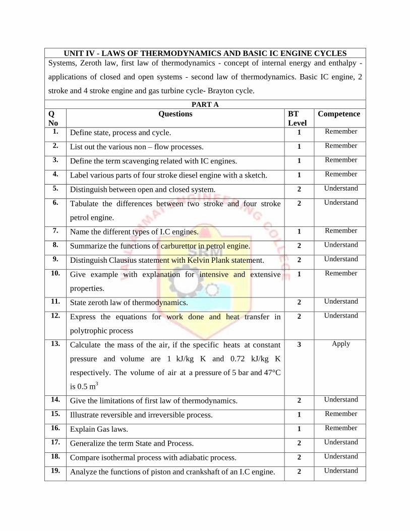
UNIT IV - LAWS OF THERMODYNAMICS AND BASIC IC ENGINE CYCLES
Systems, Zeroth law, first law of thermodynamics - concept of internal energy and enthalpy -
applications of closed and open systems - second law of thermodynamics. Basic IC engine, 2
stroke and 4 stroke engine and gas turbine cycle- Brayton cycle.
PART A
Q
No
Questions BT
Level
Competence
1. Define state, process and cycle. 1 Remember
2. List out the various non – flow processes. 1 Remember
3. Define the term scavenging related with IC engines. 1 Remember
4. Label various parts of four stroke diesel engine with a sketch. 1 Remember
5. Distinguish between open and closed system. 2 Understand
6. Tabulate the differences between two stroke and four stroke
petrol engine.
2 Understand
7. Name the different types of I.C engines. 1 Remember
8. Summarize the functions of carburettor in petrol engine. 2 Understand
9. Distinguish Clausius statement with Kelvin Plank statement. 2 Understand
10. Give example with explanation for intensive and extensive
properties.
1 Remember
11. State zeroth law of thermodynamics. 2 Understand
12. Express the equations for work done and heat transfer in
polytrophic process
2 Understand
13. Calculate the mass of the air, if the specific heats at constant
pressure and volume are 1 kJ/kg K and 0.72 kJ/kg K
respectively. The volume of air at a pressure of 5 bar and 47°C
is 0.5 m3
3 Apply
14. Give the limitations of first law of thermodynamics. 2 Understand
15. Illustrate reversible and irreversible process. 1 Remember
16. Explain Gas laws. 1 Remember
17. Generalize the term State and Process. 2 Understand
18. Compare isothermal process with adiabatic process. 2 Understand
19. Analyze the functions of piston and crankshaft of an I.C engine. 2 Understand

20. What is perpetual motion machine of first kind? 2 Understand
PART B 1. i)
ii)
Describe the following: a) Enthalpy, b) Entropy(4)
0.336 of gas at 10 bar and 150oC expands adiabatically,
until its pressure is 4 bar. It is then compressed,
isothermally, to its original volume. Evaluate the final
temperature and pressure of the gas. Also evaluate the
change in internal energy. Take Cp= 0.996 kJ/kg K; and
Cv= 0.703 kJ/kg K.(9)
1
5
Remember
Evaluate
2. Derive the expression for work done in the open cycle gas
turbine with regeneration and explain the importance of
regeneration.(13)
2 Understand
3. Explain the working principle of four stroke petrol engine with
suitable sketches. And draw the P-V diagram for the four stroke
petrol engine.(13)
1
Remember
4. Explain the working principle of two stroke petrol engine with
suitable sketches. And draw the P-V diagram for the two stroke
petrol engine.(13)
1
Remember
5. Air enters the compressor of an open cycle constant pressure gas
turbine at a pressure of 1 bar and temperature 200 C. The
pressure of the air after compression is 4 bar. The isentropic
efficiencies of compressor and turbine are 80% and 85%
respectively. The air-fuel ratio used is 90:1. If the flow rate of air
is 3 kg/s, find a) Power developed, b) Thermal efficiency of the
cycle. Assume Cp=1 kJ/kg K and γ=1.4 of air and gases calorific
value of fuel=41800kJ/kg.(13)
3
Apply
6. Examine the efficiency of an open circuit constant pressure gas
turbine plant with the following specifications. The extreme of
pressure and temperature in plant are 1 bar, 5.25 bar and 25°C
and 560°C respectively. The isentropic efficiency of the turbine
is 88% and that of the compressor is 84%.(13)
3 Apply
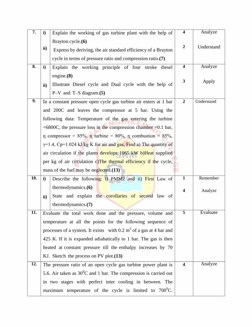
7. i)
ii)
Explain the working of gas turbine plant with the help of
Brayton cycle.(6)
Express by deriving, the air standard efficiency of a Brayton
cycle in terms of pressure ratio and compression ratio.(7)
4
2
Analyze
Understand
8. i)
ii)
Explain the working principle of four stroke diesel
engine.(8)
Illustrate Diesel cycle and Dual cycle with the help of
P–V and T–S diagram.(5)
4
3
Analyze
Apply
9. In a constant pressure open cycle gas turbine air enters at 1 bar
and 200C and leaves the compressor at 5 bar. Using the
following data: Temperature of the gas entering the turbine
=6800C, the pressure loss in the compression chamber =0.1 bar,
ɳ compressor = 85%, ɳ turbine = 80%, ɳ combustion = 85%,
γ=1.4, Cp=1.024 kJ/kg K for air and gas, Find a) The quantity of
air circulation if the plants develops 1065 kW b)Heat supplied
per kg of air circulation c)The thermal efficiency if the cycle,
mass of the fuel may be neglected.(13)
2 Understand
10. i)
ii)
Describe the following: i) PMM2 and ii) First Law of
thermodynamics.(6)
State and explain the corollaries of second law of
thermodynamics.(7)
1
4
Remember
Analyze
11. Evaluate the total work done and the pressure, volume and
temperature at all the points for the following sequence of
processes of a system. It exists with 0.2 m3 of a gas at 4 bar and
425 K. If it is expanded adiabatically to 1 bar. The gas is then
heated at constant pressure till the enthalpy increases by 70
KJ. Sketch the process on PV plot.(13)
5 Evaluate
12. The pressure ratio of an open cycle gas turbine power plant is
5.6. Air taken as 300C and 1 bar. The compression is carried out
in two stages with perfect inter cooling in between. The
maximum temperature of the cycle is limited to 7000C.
4 Analyze
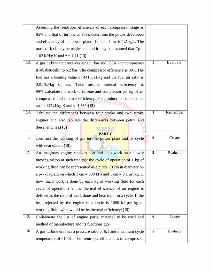
Assuming the isentropic efficiency of each compressor stage as
85% and that of turbine as 90%, determine the power developed
and efficiency of the power plant, if the air flow is 1.2 kg/s. The
mass of fuel may be neglected, and it may be assumed that Cp =
1.02 kJ/kg K and γ = 1.41.(13)
13. A gas turbine unit receives air at 1 bar and 300K and compresses
it adiabatically to 6.2 bar. The compressor efficiency is 88%.The
fuel has a heating value of 44186kJ/kg and the fuel air ratio is
0.017kJ/kg of air. Take turbine internal efficiency is
90%.Calculate the work of turbine and compressor per kg of air
compressed and thermal efficiency. For product of combustion,
cp =1.147kJ/kg K and γ=1.333.(13)
5
Evaluate
14. Tabulate the differences between four stroke and two stroke
engines and also tabulate the differences between petrol and
diesel engines.(13)
1
Remember
PART C 1. construct the working of gas turbine power plant and its cycle
with neat sketch.(15)
6
Create
2. An imaginary engine receives heat and does work on a slowly
moving piston at such rate that the cycle of operation of 1 kg of
working fluid can be represented as a circle 10 cm in diameter on
a p-v diagram on which 1 cm = 300 kPa and 1 cm = 0.1 m3/kg. 1.
how much work is done by each kg of working fluid for each
cycle of operation? 2. the thermal efficiency of an engine is
defined as the ratio of work done and heat input in a cycle. If the
heat rejected by the engine in a cycle is 1000 kJ per kg of
working fluid, what would be its thermal efficiency?(15)
5 Evaluate
3. Collaborate the list of engine parts, material to be used and
method of manufacture and its functions.(15)
6 Create
4. A gas turbine unit has a pressure ratio of 6:1 and maximum cycle
temperature of 6100C. The isentropic efficiencies of compressor
5 Evaluate

and turbine are 80% and 82% respectively. Calculate the power
output in KW of an electric generator geared to the turbine when
the air enters the compressor at 150C at the rate of 16kg/s. Take
Cp=1.005kJ/kg K and γ=1.4 for the compression process, and
take Cp=1.11kJ/kg K and γ=1.333 for the expansion process.(15)
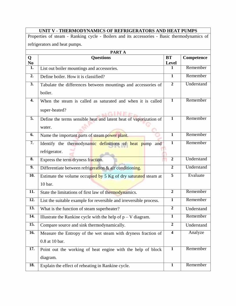
UNIT V - THERMODYNAMICS OF REFRIGERATORS AND HEAT PUMPS
Properties of steam - Ranking cycle - Boilers and its accessories - Basic thermodynamics of
refrigerators and heat pumps.
PART A
Q
No
Questions BT
Level
Competence
1. List out boiler mountings and accessories. 1 Remember
2. Define boiler. How it is classified? 1 Remember
3. Tabulate the differences between mountings and accessories of
boiler.
2 Understand
4. When the steam is called as saturated and when it is called
super‐heated?
1 Remember
5. Define the terms sensible heat and latent heat of vaporization of
water.
1 Remember
6. Name the important parts of steam power plant. 1 Remember
7. Identify the thermodynamic definitions of heat pump and
refrigerator.
1 Remember
8. Express the term dryness fraction. 2 Understand
9. Differentiate between refrigeration & air conditioning. 2 Understand
10. Estimate the volume occupied by 5 Kg of dry saturated steam at
10 bar.
5 Evaluate
11. State the limitations of first law of thermodynamics. 2 Remember
12. List the suitable example for reversible and irreversible process. 1 Remember
13. What is the function of steam superheater? 2 Understand
14. Illustrate the Rankine cycle with the help of p – V diagram. 1 Remember
15. Compare source and sink thermodynamically. 2 Understand
16. Measure the Entropy of the wet steam with dryness fraction of
0.8 at 10 bar.
4 Analyze
17. Point out the working of heat engine with the help of block
diagram.
1 Remember
18. Explain the effect of reheating in Rankine cycle. 1 Remember
19. Recommend the parts required to improve the efficiency of a
steam power plant.
2 Understand
20. Modify heat pump into refrigerator with the help of block
diagram.
4 Analyze
PART B 1. i)
ii)
Describe the construction and working of a Water tube
boiler with neat sketch.(9)
Classify boilers with examples.(4)
1
1
Remember
Remember
2. i)
ii)
Describe the characteristics of high pressure boilers.(4)
Explain the construction and working of any one high
pressure boiler with neat sketch.(9)
1
1
Remember
Remember
3. Illustrate the Rankine cycle with p – V and H – S diagram
and derive the efficiency of steam power plant.(13)
3
Apply
4. One kg of steam at 10 bar exists at the following conditions:
Wet and 0.8 dry, dry and saturated and at a temperature of
199.90C. Interpret the data using steam tables and find the
enthalpy, specific volume, density, internal energy and entropy at
each case. Take CPS= 2.25 kJ/kg.(13)
3
Apply
5. Consider a steam power plant operating on the ideal Rankine
cycle. Steam enters the turbine at 3 mPa and 623 K and is
condensed in the condenser at a pressure of 10 kPa. Measure (i)
the thermal efficiency of this power plant, (ii) the thermal
efficiency if steam is superheated to 873 K instead of 623 K.(13)
3
Apply
6. A simple Rankine Cycle works between pressure 28 bar and
0.06 bar, the initial condition of steam being dry Saturated.
Calculate the Cycle Efficiency, Work Ratio and SFC.(13)
3 Apply
7. i)
ii)
Discuss about boiler accessories with examples.(5)
Explain the function of pressure gauge and fusible plug.(8)
2
2
Understand
Understand 8. i)
ii)
Estimate the internal energy and enthalpy of steam when the
steam conditions at 10 bar are i) 0.8% dry and ii) 320°C.(8)
Explain the function of economizer and super heater used in
3
2
Apply
Understand

boilers.(5)
9. In a steam power plant the condition of steam at inlet to the
steam turbine is 20 bar and 300˚C and the condenser pressure is
0.1 bar. Two feed water heaters operate at optimum
temperatures. Determine (1) The quality of steam at turbine
exhaust (2) Network per kg of steam (3) Cycle efficiency (4) The
steam rate. Neglect pump work. (13)
5
Evaluate
10. i)
ii)
Calculate the efficiency of a steam power plant operating
on Rankine cycle between pressure limits of 30 bar and
0.04 bar. Steam at turbine inlet is dry saturated.(7)
Point out the quantity of heat required to produce 1 kg of
steam at a pressure of 6 bar and at a temperature of 25°C
When the steam is wet having a dryness fraction of
0.9.(6)
4
4
Analyze
Analyze
11. A reversible heat engine operates between two reservoirs at
temperatures 700ᴼC and 50ᴼC. The engine drives a reversible
refrigerator which operates between reservoirs at temperatures
of 500C and 25
0C. The heat transfer to the engine is 2500 kJ and
the net work output of the combined engine refrigerator plant is
400 kJ. Determine the heat transfer to the refrigerant and the net
heat transfer to the reservoir at 500C.(13)
5 Evaluate
12. Steam at 50 bar and 400○C expands in a Rankine cycle to 0.34
bar. For a mass flow rate of 150 kg/s of steam, determine Power
developed, Thermal efficiency and Specific steam
consumption.(13)
4 Analyze
13. Steam at 480○C, 90 bar is supplied to a Rankine cycle. It is
reheated to 12 bar and 480○C. the minimum pressure is 0.07 bar.
Calculate the work output and the cycle efficiency using steam
tables with and without considering the pump work.(13)
5
Evaluate
14. The steam conditions at inlet to the turbine are 42 bar and 500˚C,
and the condenser pressure is 0.035bar. Assume that the steam is
5
Evaluate
just dry saturated on leaving the first turbine, and is reheated to
its initial temperature. Calculated the Rankine cycle efficiency
and specific steam consumption with reheating by neglecting the
pump work using Mollier chart.(13)
PART C 1. Explain the working principle of steam power plant with the
help of P-V and T-S diagrams. How do you design the
efficiency of the steam power plant to be improved?(15)
6 Create
2. Why boiler mountings are essential in a boiler? Design the
different mountings with neat sketch.(15)
6 Create
3. IIlustrate in detail the methods of increasing the thermal
efficiency of a Rankine cycle.(15)
5 Evaluate
4. In a Rankine Cycle, the steam at inlet to the turbine is saturated
at a pressure of 35 bar and the exhaust pressure is 0.2 bar.
Determine i. The pump work ii. The turbine work iii. The
condenser heat flow iv. The dryness at the end of expansion.
Assume flow rate of 9.5kg/s.(15)
5 Evaluate