SRI CHANDRASEKHARENDRA SARASWATHI VISWA MAHA ...
94
SRI CHANDRASEKHARENDRA SARASWATHI VISWA MAHA VIDYALAYA (University Established under section 3 of UGC Act, 1956) DEPARTMENT OF MECHANICAL ENGINEERING Name of the Course : Flexible Manufacturing Systems (FMS) Name of the unit : PLANNING, SCHEDULING AND CONTROL Topic – Title : Introduction to FMS– development of manufacturing systems 1.Objectives and Outcomes: To understand the modern manufacturing systems. Upon successful completion, the student should be able to understand the Flexible manufacturing system and its application 2. Pre-Test - MCQ type: 1. The following is the preliminary stage of Production planning (A) Capacity planning (B) Material requirements planning (C) Scheduling (D) Product development and design 2. The following is the source(s) for developing new or improved product (A) Research and Development department of the enterprise (B) Consumer suggestions and Complaints (C) Other competitive products in the market (D) All of the above 3. Product cost can be reduced by considering the following aspect(s) at the design stage (A) Minimum number of operations (B) Unnecessary tight tolerance should not be provided (C) Design should consist of standard parts (D) All of the above 3. Prerequisites: The basic knowledge about the planning and manufacturing process.
-
Upload
khangminh22 -
Category
Documents
-
view
1 -
download
0
Transcript of SRI CHANDRASEKHARENDRA SARASWATHI VISWA MAHA ...

SRI CHANDRASEKHARENDRA SARASWATHI VISWA MAHA
VIDYALAYA
(University Established under section 3 of UGC Act, 1956)
DEPARTMENT OF MECHANICAL ENGINEERING
Name of the Course : Flexible Manufacturing Systems (FMS)
Name of the unit : PLANNING, SCHEDULING AND CONTROL
Topic – Title : Introduction to FMS– development of manufacturing
systems
1.Objectives and Outcomes:
To understand the modern manufacturing systems.
Upon successful completion, the student should be able to understand the
Flexible manufacturing system and its application
2. Pre-Test - MCQ type:
1. The following is the preliminary stage of Production planning (A) Capacity planning
(B) Material requirements planning
(C) Scheduling
(D) Product development and design
2. The following is the source(s) for developing new or improved product (A) Research and Development department of the enterprise
(B) Consumer suggestions and Complaints
(C) Other competitive products in the market
(D) All of the above
3. Product cost can be reduced by considering the following aspect(s) at the design stage (A) Minimum number of operations
(B) Unnecessary tight tolerance should not be provided
(C) Design should consist of standard parts
(D) All of the above
3. Prerequisites:
The basic knowledge about the planning and manufacturing process.

4. Theory Behind:
INTRODUCTION:
In the middle of 1960s, market competition became more intense. During 1960 to 1970 cost was
the primary concern. Later quality became the priority. As the market became more and more
complex, speed of delivery became something customer also needed. A new
formulated (Customizability). The companies have to adapt to the environment in which they
operate, to be more flexible in their operations and to satisfy different market segments. Thus the
innovation of FMS became related to the effort of ga
FMS is a manufacturing technology. Secondly, FMS is a philosophy. “System” is the key word.
Philosophically, FMS incorporates a system view of manufacturing. The buzzword for today’s
manufacturer is “agility”. An agile manufacturer is one who is the fastest to the market, operates
with the lowest total cost and has the greatest ability to “delight” its customers. FMS is simply one
way that manufacturers are able to achieve this agility
A flexible manufacturing system (FMS) is an arrangement of machines ... interconnected by a
transport system. The transporter carries work to the machines on pallets or other interface units so
that work-machine registration is accurate, rapid and automatic. A central computer con
machines and transport system.
The basic components of FMS are:
1. Workstations
2. Automated Material Handling and Storage system.
3. Computer Control System
1. Workstations:
In present day application these workstations are typically comput
(CNC) machine tools that perform machining operation on families of parts. Flexible
In the middle of 1960s, market competition became more intense. During 1960 to 1970 cost was
the primary concern. Later quality became the priority. As the market became more and more
complex, speed of delivery became something customer also needed. A new
formulated (Customizability). The companies have to adapt to the environment in which they
operate, to be more flexible in their operations and to satisfy different market segments. Thus the
innovation of FMS became related to the effort of gaining competitive advantage. First of all,
FMS is a manufacturing technology. Secondly, FMS is a philosophy. “System” is the key word.
Philosophically, FMS incorporates a system view of manufacturing. The buzzword for today’s
agile manufacturer is one who is the fastest to the market, operates
with the lowest total cost and has the greatest ability to “delight” its customers. FMS is simply one
way that manufacturers are able to achieve this agility
system (FMS) is an arrangement of machines ... interconnected by a
transport system. The transporter carries work to the machines on pallets or other interface units so
machine registration is accurate, rapid and automatic. A central computer con
The basic components of FMS are:
2. Automated Material Handling and Storage system.
3. Computer Control System
In present day application these workstations are typically computer numerical control
(CNC) machine tools that perform machining operation on families of parts. Flexible
In the middle of 1960s, market competition became more intense. During 1960 to 1970 cost was
the primary concern. Later quality became the priority. As the market became more and more
complex, speed of delivery became something customer also needed. A new strategy was
formulated (Customizability). The companies have to adapt to the environment in which they
operate, to be more flexible in their operations and to satisfy different market segments. Thus the
ining competitive advantage. First of all,
FMS is a manufacturing technology. Secondly, FMS is a philosophy. “System” is the key word.
Philosophically, FMS incorporates a system view of manufacturing. The buzzword for today’s
agile manufacturer is one who is the fastest to the market, operates
with the lowest total cost and has the greatest ability to “delight” its customers. FMS is simply one
system (FMS) is an arrangement of machines ... interconnected by a
transport system. The transporter carries work to the machines on pallets or other interface units so
machine registration is accurate, rapid and automatic. A central computer controls both
er numerical control
(CNC) machine tools that perform machining operation on families of parts. Flexible

manufacturing systems are being designed with other type of processing equipments
including inspection stations, assembly works and sheet metal presses. The various
workstations are (i) Machining centers (ii) Load and unload stations (iii) Assembly work
stations (iv) Inspection stations (v) Forging stations (vi) Sheet metal processing, etc.
2. Automated Material Handling and Storage system:
The various automated material handling systems are used to transport work parts and
subassembly parts between the processing stations, sometimes incorporating storage into
function. The various functions of automated material handling and storage system are (i)
Random and independent movement of work parts between workstations (ii) Handling of a
variety of work part configurations (iii) Temporary storage (iv) Convenient access for
loading and unloading of work parts (v) Compatible with computer control
3. Computer Control System:
It is used to coordinate the activities of the processing stations and the material handling
system in the FMS. The various functions of computer control system are: (i) Control of
each work station (ii) Distribution of control instruction to work station (iii) Production
control (vi) Traffic control (v) Shuttle control (vi) Work handling system and monitoring
(vii) System performance monitoring and reporting
OBJECTIVES OF AN FMS:
A study, carried out with West Germany manufacturing has shown the major aims of
installing an FMS to be:
Decreased Lead Times
Increased Through put
Increased machine utilization
Improved Due Date Reliability
Decreased Store Inventors Levels n
Decreased Work in Progress
Increased Quality
AIMS OF FMS
To reduce costs
Better utilization of the production equipment reduction of stocks (ex: Work in
progress— capital shorter through put times)
Reduction of piece part unit costs.
To increase Technical Performance:
Increased production levels

Greater product mixture
Simultaneous product mixture manufacturing
Integration of the production system into the factory’s logistical system
Smaller batch sizes
Shorter or zero change over or reset of times
To improve Order Development:
Shorter lead times/deliv
Determination of production capacities
To assist future Corporate Security:
Increased Competitiveness
Increased Quality
Improved Company Image
5.Applications / Simulation / Related Laboratory example
The FMS is most suited for the mid
6.MCQ- post-test
1. From the following which is the main components of Flexible manufacturing system (FMS).a) Main frame computer b) Automated guided vehicle c) Material handling system d) All of the above 2. The type in which the range or universe of part styles that can be produced on the systema) Mix flexibility b) Production flexibility c) Volume flexibility d) Product flexibility 3. FMS can be classified basing ona) Kinds of operation they perform
duct mixture
Simultaneous product mixture manufacturing
Integration of the production system into the factory’s logistical system
Smaller batch sizes
Shorter or zero change over or reset of times
To improve Order Development:
Shorter lead times/delivery times
Determination of production capacities
To assist future Corporate Security:
Increased Competitiveness
Increased Quality
Improved Company Image
5.Applications / Simulation / Related Laboratory example
The FMS is most suited for the mid variety, mid value production range.
. From the following which is the main components of Flexible manufacturing system (FMS).
ype in which the range or universe of part styles that can be produced on the system
. FMS can be classified basing on a) Kinds of operation they perform
Integration of the production system into the factory’s logistical system
. From the following which is the main components of Flexible manufacturing system (FMS).
ype in which the range or universe of part styles that can be produced on the system

b) Number of machines c) Level of flexibility d) All of the above 4. One of the classifications of FMS based on number of machines in the system a) Flexible manufacturing cell b) Random-order FMS c) Dedicated FMS d) None of the above 5. The appropriate layout, when the application consists exclusively of in-sequence moves is a) Rectangular layout b) Loop layout c) In-line layout d) U-shape layout 7.Conclusion
Understood basics of manufacturing process.
Understood about the various types of Flexible manufacturing systems.
The importance of FMS in various applications in types of productions.
8.References
Jha.N.K., “Handbook of flexible manufacturing systems”, Academic Press Inc., 1991
9.Audio/ video - if any
https://youtu.be/tiarT1YS-lM
10. Assignments
Define FMS? and explain the various components of FMS?

Topic – Title : Types of flexibility
1.Objectives and Outcomes:
To understand about various types of flexibilities and its approaches
2. Pre-Test - MCQ type:
1. The type in which the range or universe of part styles that can be produced on the system
a) Mix flexibility
b) Production flexibility
c) Volume flexibility
d) Product flexibility
2. ____ is a highly automated group of GT machine cell.
a) Flexible manufacturing system
b) Group technology
c) Automated system
d) None of the above
3. From the following which is the main components of Flexible manufacturing system(FMS).
a) Main frame computer
b) Automated guided vehicle
c) Material handling system
d) All of the above
4. One of the classification of FMS based on number of machines in the system
a) Flexible manufacturing cell
b) Random-order FMS
c) Dedicated FMS
d) None of the above
5. FMS can be classified basing on
a) Kinds of operation they perform
b) Number of machines
c) Level of flexibility
d) All of the above
3. Prerequisites:
The basic knowledge about the flexibility and its types.

4. Theory Behind:
Different approaches to flexibility and their meanings are shown Table
There are three levels of manufacturing flexibility.
(a) Basic flexibilities
Machine flexibility: The ease with which a machine can process various operations.
Material handling flexibility: A measure of the ease with which different part types can be
transported and properly positioned at the various machine tools in a system
Operation flexibility: A measure of the ease with which alternative operation sequences can be
used for processing a part type FMS
(b) System flexibilities
Volume flexibility: A measure
volumes of the existing part types
Expansion flexibility: The ability to build a system and expand it incrementally
Routing flexibility: A measure of the alternative paths that a part can e
through a system for a given process plan
Process flexibility: A measure of the volume of the set of part types that a system can produce
without incurring any setup
Product flexibility: The volume of the set of part types that can be m
with minor setup
(c) Aggregate flexibilities
Program flexibility:The ability of a system to run for reasonably long periods without external
intervention Production flexibility: The volume of the set of part types that a system can
produce without major investment in capital equipment
Market flexibility: The ability of a system to efficiently adapt to changing market conditions
Different approaches to flexibility and their meanings are shown Table
There are three levels of manufacturing flexibility.
The ease with which a machine can process various operations.
Material handling flexibility: A measure of the ease with which different part types can be
sported and properly positioned at the various machine tools in a system
Operation flexibility: A measure of the ease with which alternative operation sequences can be
used for processing a part type FMS
A measure of a system’s capability to be operated profitably at different
volumes of the existing part types
Expansion flexibility: The ability to build a system and expand it incrementally
Routing flexibility: A measure of the alternative paths that a part can effectively follow
through a system for a given process plan
Process flexibility: A measure of the volume of the set of part types that a system can produce
Product flexibility: The volume of the set of part types that can be manufactured in a system
The ability of a system to run for reasonably long periods without external
flexibility: The volume of the set of part types that a system can
oduce without major investment in capital equipment
Market flexibility: The ability of a system to efficiently adapt to changing market conditions
The ease with which a machine can process various operations.
Material handling flexibility: A measure of the ease with which different part types can be
Operation flexibility: A measure of the ease with which alternative operation sequences can be
of a system’s capability to be operated profitably at different
Expansion flexibility: The ability to build a system and expand it incrementally
ffectively follow
Process flexibility: A measure of the volume of the set of part types that a system can produce
anufactured in a system
The ability of a system to run for reasonably long periods without external
flexibility: The volume of the set of part types that a system can
Market flexibility: The ability of a system to efficiently adapt to changing market conditions

DIFFERENT TYPES OF FMS:
The different types of FMS are
Sequential FMS
Random FMS
Dedicated FMS
Engineered FMS
Modular FMS
Sequential FMS: It manufactures one-piece part batch type and then planning and preparation is
carried out for the next piece part batch type to be manufactured. It operates like a small batch
flexible transfer line.
Random FMS: It manufactures any random mix of piece part types at any one time.
Dedicated FMS: It continually manufactures, for extended periods, the same but limited mix of
piece part batch types.
Engineered FMS: It manufactures the same mix of part types throughout its lifetime.
Modular FMS: A modular FMS, with a sophisticated FMS host, enables and FMS user to expand
their FMS capabilities in a stepwise fashion into any of the previous four types of FMS.
A flexible manufacturing system (FMS) is an arrangement of machines ... interconnected by a
transport system. The transporter carries work to the machines on pallets or other interface units so
that work-machine registration is accurate, rapid and automatic. A central computer controls both
machines and transport system.
6.MCQ- post-test
1. Process technologies differ in their flexibility capabilities and economics and will therefore be
appropriate for different parts of the volume-variety matrix. Flexible manufacturing systems are
usually:
Mid variety , mid volume
High variety , low volume
Mid variety, high volume
Low variety, mid volume
2. Another form of process technology is dedicated systems. Dedicated systems are usually placed
on the volume–variety matrix
Mid variety, mid volume
High variety, low volume
Mid variety, high volume

Low variety, High volume
3. Flexibility, easy access to other users, shared databases and software
Local area network
Extranet
Internet
Expert systems
4. How does FMS classified based on level of flexibility
Production flexibility
Machine flexibility
Product flexibility
All of the above
7.Conclusion
Understood about the flexibility.
Understood about the various levels of flexibility.
Known about various types ofFMS
8.References
Jha.N.K., “Handbook of flexible manufacturing systems”, Academic Press Inc., 1991
9.Audio/ video - if any
https://youtu.be/tiarT1YS-lM
10. Assignments
Define flexibility? and explain the various levels of flexibility?
Explain about various types of FMS?

Topic – Title : single product scheduling problem
1.Objectives and Outcomes:
To understand about scheduling problems on single product
2. Pre-Test - MCQ type:
1. From which of the following is not the main element of Flexible manufacturing system.
a) Work handling system b) Material handling system c) Tool handling system d) Main frame computer
2. From the following in which FMS layout robots are used as material handling system.
a) Ladder layout
b) Open field layout
c) Loop layout
d) Robot centered layout
3. From the following what is the full form of AGV?
a) Automatic Guided Vehicle
b) Automated Gas Vehicle
c)Automated Guided Vehicle
d) None of the above
4. Overall FMS scheduling problem was structured as
a) An aggregate scheduling problem
b) Real-time scheduling problem
c) Both (a) and (b)
d) None of the above
3. Prerequisites:
The basic knowledge about the scheduling problems.
4. Theory Behind:
One of the most difficult problems arising in flexible manufacturing systems(FMSs) is the
scheduling problem. Scheduling may refer to the following subsystems of a flexible
manufacturing system: fabrication, machining, and assembly.

Kusiak (1988) presented a hierarchical approach linking the machining and assembly system,
where the overall FMS scheduling problem was structured as an aggregate scheduling (upper
level) problem and real-time scheduling (lower level) problem. At the aggregate level the
scheduling problem was modelled as the two-machine flow shop problem and solved by Johnson's
algorithm (Johnson, 1954). To solve the real-time scheduling problem, a heuristic algorithm was
developed.
Consider a flexible manufacturing system that consists of a machining subsystem and an assembly
subsystem. The two subsystems are linked by a material handling carrier, for example, an
automated guided vehicle (AGV), as shown in Figure 1. Consider an example product C with
parts to be machined and then assembled (Figure 2). It consists of subassembly Au final assembly
A2 , and three parts, Λ , Pi, P3. Parts Ρχ and P2 are to be machined before the subassembly Ai is
obtained. Assembling P3 and Ax results in the product C (final assembly A2 in Figure 2).
The precedences among machining and assembly operations for the product can be represented by
a directed graph (digraph) shown in Figure 3. In this digraph any node of degree 1, i.e., with the
number of edges incident to the node equal to 1, denotes a part; and any node of degree greater
than 1 denotes a subassembly or a final product.

The Single-Product Scheduling Problem
Consider a digraph representation of the product which consists of a number of parts and
subassemblies. In the digraph each node is labeled (a,b,c), where a is the machining time, b is the
subassembly time, and c is the level of depth of the node considered. The level of depth is
assigned as follows: value 0 is assigned to the root node (for example, node A2 in Figure 3) and,
working backward from the root node to the initial nodes (i.e., nodes P\,P2 , and P3 ), values of
increment 1 are assigned. Digraph G from Figure 3 with labeled nodes is illustrated in Figure 5.
Before an algorithm for solving the single-product scheduling problem will be developed, a
definition and two theorems are presented.
Definition A simple digraph Gs is a digraph in which each node of a degree greater than 1 has at
most one preceding node of a degree greater than 1 [see Figure 6(a)]. Consequently, a complex
digraph G is a digraph which is not a simple digraph [see Figure 6(b)].
Based on the preceding definition, it is obvious that any complex digraph can be decomposed into
simple subdigraphs by removing a number of nodes corresponding to the final assembly or
subassemblies.
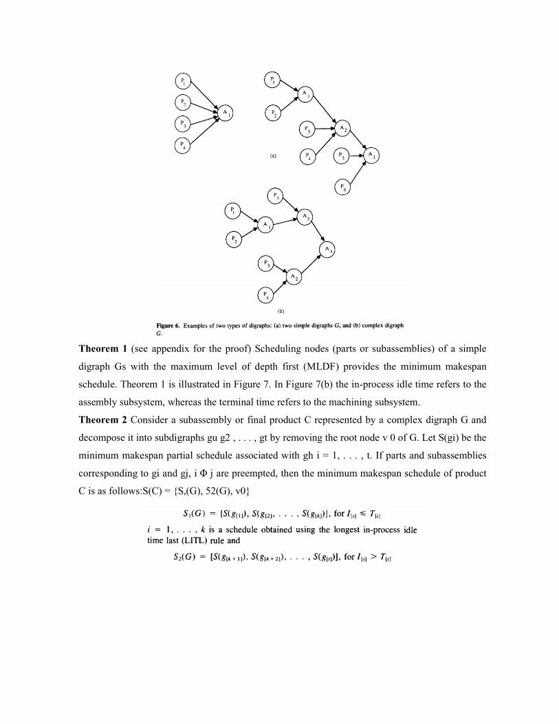
Theorem 1 (see appendix for the proof) Scheduling nodes (parts or subassemblies) of a simple
digraph Gs with the maximum level of depth first (MLDF) provides the minimum makespan
schedule. Theorem 1 is illustrated in Figure 7. In Figure 7(b) the in-process idle time refers to the
assembly subsystem, whereas the terminal time refers to the machining subsystem.
Theorem 2 Consider a subassembly or final product C represented by a complex digraph G and
decompose it into subdigraphs gu g2 , . . . , gt by removing the root node v 0 of G. Let S(gi) be the
minimum makespan partial schedule associated with gh i = 1, . . . , t. If parts and subassemblies
corresponding to gi and gj, i Φ j are preempted, then the minimum makespan schedule of product
C is as follows:S(C) = {S,(G), 52(G), v0}

i = k+l, k + 2, .. . , ί is a schedule obtained using the longest terminal time first (LTTF) rule The
proof of this theorem follows from the considerations presented in Kurisu (1976). Based on
Theorems 1 and 2, Algorithm 1 is developed.
Algorithm 1 (The Single-Product Scheduling Problem)
Step 1. Label all nodes of the digraph G representing the structure of the product considered. If G
is a simple digraph, use the MLDF rule to generate optimal schedule of product C, stop;
otherwise, go to step 2.
Step 2. Remove root node v0 from G and decompose it into subdigraphs gt l = 1, . . . , L. If all gt
are simple digraphs, set k = 0 and go to step 3; otherwise, decompose each gi which is not a
simple digraph into a simple digraph by removing its root node. Let νj denote a root node which
has been removed, j = 1, . . . , J. (Note that, for convenience, the removed nodes are numbered in
the increasing order starting from the root node of G.) Set k = J and go to step 3.
Step 3. Let gik denote the simple subdigraphs associated with vk. Use the MLDF rule to generate
the minimum makespan partial schedule S(gik) for each subdigraph gik, i = 1, . . . , Nk , where Nk is
the number of subdigraphs obtained after vk has been removed.
Step 4. For each partial schedule S(gik) obtained in step 3, determine
(i) the in-process idle time Iik
(ii) the terminal time Tik, i = 1, . . . , Nk
Step 5. Separate the S(gik) into two lists:
List 1 schedules S(gik) such that Iik ≤Tik
List 2 schedules S(gik) such that Iik> Tik, = 1, . . .
Step 6. Use the LITL rule to generate

Then generate the partial schedule S(gk) = [S1(gk), S2 (gk ), vk ]
Step 7. If vk = v0, then S(C) = S(g0 ) is the optimal schedule, stop; otherwise, go to step 8.
Step 8. Consider S(gk ) as a simple subdigraph schedule and calculate Ik and Tk . Set k = k — 1
and go to step 3.
6.MCQ- post-test
1. Real-time scheduling problem is also called as a) Johnson’s algorithm b) Heuristic algorithm c) Warnock algorithm d) None of the above
2. From the following which is the function of material handling system used in FMS. a) Handling of parts with different variety b) Independent movement of part between stations c) Both (a) and (b) d) None of the above
3. Scheduling parts and subassemblies belonging to a single product
a) Single – product scheduling problem b) N – product scheduling problem c) Single – batch scheduling problem d) N – batch scheduling problem
4. An aggregate scheduling problem is also called as
a) Johnson’s algorithm
b) Heuristic algorithm
c) Warnock algorithm
d) None of the above
7.Conclusion
Understood about the single product scheduling problem.
8.References
Jha.N.K., “Handbook of flexible manufacturing systems”, Academic Press Inc., 1991
9.Audio/ video - if any
10. Assignments
Explain in detail about various steps involved in single product scheduling problem?

Topic – Title : single batch and n-batch scheduling problem
1.Objectives and Outcomes:
To understand about scheduling problems on single batch and n -batch.
2. Pre-Test - MCQ type:
1. The ultimate objective of the product is (A) To provide a new look
(B) Utilizing existing manpower
(C) To monopolize the market
(D) All of the above
2. Based on their field of application, manufactured goods can be classified as (A) Primary, Secondary and Tertiary
(B) Consumer, Capital and Defense
(C) Essential, Market and Standard
(D) Primary, Luxury and Consumer
3. The following aspect of product is concerned with the ease and efficiency of the product performance (A) Functional aspect
(B) Operational aspect
(C) Durability aspect
(D) Aesthetic aspect
4. In which of the following type the manufacturing cost may go up (A) Standardization
(B) Simplification
(C) Diversification
(D) All of the above
5. Product ______ is the ultimate objective of variety reduction (A) Simplification
(B) Standardization
(C) Specialization
(D) All of the above
3. Prerequisites:
The basic knowledge about the single batch and n-batch scheduling problems.

4. Theory Behind:
The Single-Batch Scheduling Problem
The algorithm for solving the single-batch scheduling problem is based on Algorithm 1. The
single-product schedule is repeated η times, where η is the number of products in a batch.
Algorithm 3 (The Single-Batch Scheduling Problem)
Step 1. Using Algorithm 1, determine the schedule S(C) for the single product scheduling
problem.
Step 2. Determine the schedule S(B) for the single-batch scheduling problem by repeating n times
the schedule S(C).
Prob:1 Develop the optimal schedule S(B) for η = 5 identical products based on the following
data:
and precedence constraints:
p1, p2 A1
p3 A1 A2
Step 1. Solving the single-product scheduling problem, the following schedule is obtained: S(C) = {(P1,P2 ,A1),P3 ,A2 }
Step 2. The optimal schedule S(B) is generated as follows:
The N-Batch Scheduling Problem
In this section, an algorithm for solving the N-batch scheduling problem is developed. The N-
batch scheduling problem can be decomposed into Ν singlebatch scheduling problems. To solve
this problem, the following algorithm is used.
Algorithm 4 (The N-Batch Scheduling Problem)
Step 1. Using Algorithm 2, determine the schedule S(NC) for the N product scheduling problem.

Step 2. Determine the schedule S(NB) for the N-batch scheduling problem by repeating ni times
each schedule S(Ci ) in S(NC), where ni is a batch size of product Ci.
The above algorithm is illustrated in Example
Develop the optimal schedule for the Ν = 4 batch scheduling problem. The batch sizes of each product are as follows:
The structure of each product is shown in Figure
The aggregate schedules generated by the algorithms presented can be used by the knowledge-based scheduling system (KBSS) discussed later in the chapter. The aggregate schedules impose due dates that may be input to the scheduling algorithm embedded into the KBSS. Another possibility is to incorporate the data provided by the aggregate schedules into the priority rules of the KBSS.

6.MCQ- post-test
1. Scheduling parts and subassemblies for a batch of n identical products
a) Single – product scheduling problem b) N – product scheduling problem c) Single – batch scheduling problem d) N – batch scheduling problem
2. Scheduling parts and subassemblies for n distinct products
a) Single – product scheduling problem b) N – product scheduling problem c) Single – batch scheduling problem d) N – batch scheduling problem
3. Scheduling parts and subassemblies n batches of product
a) Single – product scheduling problem b) N – product scheduling problem c) Single – batch scheduling problem d) N – batch scheduling problem
4. To incorporate the data provided by the aggregate schedules into
a) Priority rules of the KBSS b) Non priority rules of the KBSS c) No Priority rules of the KBSS d) None of the other options
7.Conclusion
Understood about the singlebatch and n-batch product scheduling problem.
8.References
Jha.N.K., “Handbook of flexible manufacturing systems”, Academic Press Inc., 1991
9.Audio/ video - if any
10. Assignments
Explain in detail about algorithms 3 and 4 in single batch and n-batch scheduling problem?
With suitable example?

Topic – Title : Knowledge-based scheduling system
1.Objectives and Outcomes:
To understand about Knowledge-based scheduling system.
2. Pre-Test - MCQ type:
1.What is the full form of AS/RS in FMS?
a) Automated storage and recovery system b) Automatic storage and rotary system c) Automated storage and retrieval system d) Automated storage and regenerative system
2. From the following in which FMS layout workstations are arranged in a loop.
a) Ladder layout
b) In line layout
c) Loop layout
d) None of the above
3. Which of the following types of layout configurations is/are used in FMS?
a) In-line
b) Loop
c) Ladder
d) All of the above
4. In which of the following type the manufacturing cost may go up
(A) Standardization
(B) Simplification
(C) Diversification
(D) All of the above
3. Prerequisites:
The basic knowledge about the Knowledge-based scheduling systemscheduling problems.
4. Theory Behind:
Knowledge-Based Scheduling System
Numerical algorithms have traditionally been used for solving scheduling problems. The approach
presented in this section involves not only algorithms but also declarative and procedural
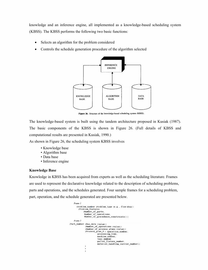
knowledge and an inference engine, all implemented as a knowledge-based scheduling system
(KBSS). The KBSS performs the following two basic functions:
Selects an algorithm for the problem considered
Controls the schedule generation procedure of the algorithm selected
The knowledge-based system is built using the tandem architecture proposed in Kusiak (1987).
The basic components of the KBSS is shown in Figure 26. (Full details of KBSS and
computational results are presented in Kusiak, 1990.)
As shown in Figure 26, the scheduling system KBSS involves
• Knowledge base • Algorithm base • Data base • Inference engine
Knowledge Base
Knowledge in KBSS has been acquired from experts as well as the scheduling literature. Frames
are used to represent the declarative knowledge related to the description of scheduling problems,
parts and operations, and the schedules generated. Four sample frames for a scheduling problem,
part, operation, and the schedule generated are presented below.

Frame 1 characterizes a scheduling problem considered and is used to select an appropriate
scheduling algorithm. Knowledge represented by Frames 2 and 3 is used to generate schedules
and select alternative process plans. Frame 4, representing the schedules generated, is used for
rescheduling. The procedural knowledge of the knowledge-based system is in the form of
production rules. To handle different problems the production rules are divided into following
three classes:
Class 1 selects an appropriate algorithm to solve the problem considered.
Class 2 controls the procedure of selecting alternative process plans and modifying the sequence
of the priority rules in the heuristic algorithm.
Class 3 evaluates the schedules obtained and performs rescheduling. Several sample production
rules in each class are presented below.
Class 1 Rule 11
IF the scheduling problem considered is a two-machine flow shop problem THEN solve it using the Johnson algorithm (Kusiak, 1986).
Rule 12 IF the scheduling problem involves less than 5 resources AND number of operations is less than 60 AND alternative process plans are not available
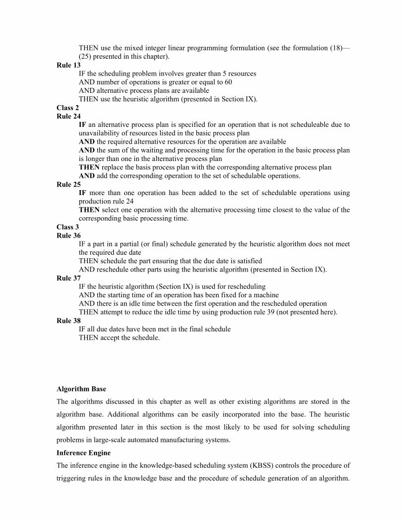
THEN use the mixed integer linear programming formulation (see the formulation (18)—(25) presented in this chapter).
Rule 13 IF the scheduling problem involves greater than 5 resources AND number of operations is greater or equal to 60 AND alternative process plans are available THEN use the heuristic algorithm (presented in Section IX).
Class 2 Rule 24
IF an alternative process plan is specified for an operation that is not scheduleable due to unavailability of resources listed in the basic process plan AND the required alternative resources for the operation are available AND the sum of the waiting and processing time for the operation in the basic process plan is longer than one in the alternative process plan THEN replace the basis process plan with the corresponding alternative process plan AND add the corresponding operation to the set of schedulable operations.
Rule 25 IF more than one operation has been added to the set of schedulable operations using production rule 24 THEN select one operation with the alternative processing time closest to the value of the corresponding basic processing time.
Class 3 Rule 36
IF a part in a partial (or final) schedule generated by the heuristic algorithm does not meet the required due date THEN schedule the part ensuring that the due date is satisfied AND reschedule other parts using the heuristic algorithm (presented in Section IX).
Rule 37 IF the heuristic algorithm (Section IX) is used for rescheduling AND the starting time of an operation has been fixed for a machine AND there is an idle time between the first operation and the rescheduled operation THEN attempt to reduce the idle time by using production rule 39 (not presented here).
Rule 38 IF all due dates have been met in the final schedule THEN accept the schedule.
Algorithm Base
The algorithms discussed in this chapter as well as other existing algorithms are stored in the
algorithm base. Additional algorithms can be easily incorporated into the base. The heuristic
algorithm presented later in this section is the most likely to be used for solving scheduling
problems in large-scale automated manufacturing systems.
Inference Engine
The inference engine in the knowledge-based scheduling system (KBSS) controls the procedure of
triggering rules in the knowledge base and the procedure of schedule generation of an algorithm.

One of the greatest advantages of the tandem system architecture is the simplicity of the inference
engine. The inference engine in KBSS employs a forward chaining control strategy. In a given
class of rules it attempts to fire all the rules which are related to the context considered. If a rule is
triggered, that is, the conditions are true, then the actions of the rule triggered are carried out.
Some rules stop the search of the inference engine and switch the control process to the algorithm.
The inference engine maintains a list of the rules which have been fired. This list is called
"explain." The rules in "explain" are placed in the order that they were fired. The list forms a basis
for building an explanation facility.
6.MCQ- post-test
1. In the scheduling system KBSS involves
Knowledge base Algorithm base Data base All of the above
2. The other existing algorithms are stored in the
Algorithm base Data base
Knowledge base
None of the other options 3. One of the greatest advantages of the tandem system architecture is
Knowledge base Algorithm base Data base Simplicity of the inference engine
4. The inference engine in the knowledge-based scheduling system (KBSS) controls
Triggering rules in the knowledge base
Schedule generation
Selectsan algorithm
All of the above 7.Conclusion
Understood about the knowledge based scheduling system.
8.References
Jha.N.K., “Handbook of flexible manufacturing systems”, Academic Press Inc., 1991
9.Audio/ video - if any
10. Assignments
Explain in detail about knowledge based scheduling system?

Name of the Course : Flexible Manufacturing Systems (FMS)
Name of the unit : COMPUTER CONTROL AND SOFTWARE
Topic – Title : Introduction – composition of FMS– hierarchy of
computer control –computer control ofwork center and assembly lines
1. Objectives and Outcomes:
To understand about composition of FMS and computer controlled FMS with
assembly lines.
2. Prerequisites:
The basic knowledge about the composition and computer controlled FMS
3. Theory:
Introduction: In today's environment, even large industries are forced to introduce new
and improved products more frequently to maintain or increase their share of the world
market. The increasing pace of technological development and the fierce competition
require industries to introduce high-quality products at competitive prices. Hard
automation and inflexible manufacturing facilities can result in delays and higher costs for
introduction of new products. However, manufacturing facilities with flexible automation
can react to changing market environments by producing products with the desired quality
and costs. Computer control of machines and material handling systems makes a
manufacturing facility more flexible since simple software changes can produce a variety
of different parts from the same manufacturing facility.
Composition of FMS:
Figure 1 is a schematic of a generic discrete manufacturing facility for a product. It
contains a main assembly line and a series of subassembly lines, feeding subassemblies at
the correct locations within the main manufacturing process. Each assembly line is made
up of several work centers. The number of work centers in an assembly line is a function
of the number of discrete manufacturing steps required to produce the assembly. Each
work center consists of machines and robots. The types of machines installed in a work
center are dictated by the manufacturing processes performed in it. The movement of the
work product within the work center is shown via robots in Figure 1. The work centers are
shown to be logistically interconnected via conveyor belts. Interwork center logistics can
also be accomplished by robots, automated guided vehicles (AGVs), and so on. In a fully
automated manufacturing line, every element is computer-controlled. Controlling the
isolated automated machine or the hard automated section of a line is much simpler than

control of the entire automated line. It requires a tightly coupled information system with
the manufacturing environment.
The information system consists of such elements as order entry systems, quality systems,
maintenance and engineering systems, and so on. In the absence of human intervention, the
computer-controlled manufacturing facility also requires a periodic statistical check at
several logical points within the process with predefined statistical norms to ensure the
quality of the resultant product. Practically speaking, even in a fully automated line, as
shown in Figure 1, a handful of operators/engineers are required to troubleshoot the
machines and maintain the flow of production. Especially in a fully automated line, it is
also important to have the design of the product, the quality of incoming material, the
design of the equipment, and systems such that the product can be produced with zero
defects. A well-designed automated line avoids automation of waste (unnecessary motion,
processing, product movement, etc.). Also, every member of the automated line must
produce product at a consistent, common beat (takt time). Takt is a German word meaning
the tempo or beat in music. Takt time is used in just-in-time or continuous flow
manufacturing to coordinate the total production at a consistent pace. This beat determines
the rate of production. To produce a variety of end products, the product design must be
modular. Each module is produced at a work center or subassembly line. Ideally, the
change in software should be able to alter the functionality and/or the composition of the
module/subassembly. Figure 1 also shows the hierarchy of the computer control in an
FMS. Depending upon the product design, FMSs may range anywhere from a single work
center to the fully automated facility shown in Figure 1.
Hierarchy of computer control:

One of the early applications of a digital computer in an industrial facility was for plant
monitoring and supervisory control, as documented by Garrett and McHenry (1981).
Figure 2 shows an evolution of the use of digital computers in industrial processes.
As illustrated in Figure 2, Dupont-Gatelmand (1981) documented that the next step in
evolution after the supervisory control is the computer numerical control (CNC) of the
machines followed by direct digital control (DDC) for a group of multiple numerical
control (NC) machines.
In the DDC, as written by Lukas (1986), a computer reads and directly processes
measurements,, calculates the proper control outputs, and sends the control commands to
the activation devices. In the initial implementations of DDC, backup analog control
systems were used to avoid the ill effects of computer failures. In spite of the early
computer hardware reliability problems, DDC demonstrated many advantages over analog
control systems. They included the use of complex logic to calculate more accurately the
control command values, ease of data logging, data trending, alarming, and so on. It also
avoided the common problem of set-point drifts associated with analog devices. Several
different system architectures evolved for the DDC systems in the late 1970s.
However, a central computer was a dominant feature of all the variations of these
architectures. The single largest disadvantage of these architectures, as pointed out before,
was the single-point failure of the central computer, which could shut down the process. It
necessitated the expense of a second computer as backup. Another disadvantage was that
the software for the central computer was very complex and required a team of
software/hardware experts to change and maintain the software. It also had limited
expansion capability and, when the expansions were made, they were very expensive.
In the mid 1960s the distributed control system architecture was brought forward as
a viable option. The technology to implement the DDC in a costeffective manner was not
available until the early 1970s. The price of computers decreased significantly and
personal computers could be used economically on the factory floor. A number of
production lines with distributed control systems have begun to emerge since the late
1970s.
In the mid 1960s the distributed control system architecture was brought forward as
a viable option. The technology to implement the DDC in a cost effective manner was not
available until the early 1970s. The price of computers decreased significantly and
personal computers could be used economically on the factory floor. A number of
production lines with distributed control systems have begun to emerge since the late
1970s.

As shown in Figure 1, every work center has a dedicated control computer. The
work center computer is responsible for making production happen in its work center. It
communicates with each tool and robot and downloads the programs, resulting in
appropriate commands for all equipment. It is also responsible for ascertaining the health
of all the components in the work center. The next level in the hierarchy of computer
control is the subassembly/main assembly line computer. In general, this computer
coordinates and controls the manufacturing activities within a section of the manufacturing
facility. This computer communicates to each work-center computer the type of product to
be made and all the appropriate commands. It also serves as a backup to any one of the
failed work-center computers in its jurisdiction.
As shown in Figure 1, the supervisory computer is at the highest level in the
hierarchy of computer control. This computer does overall production planning and
scheduling and communicates with the subassembly/main assembly line computers
(Koren, 1983). In the event of the failure of any of the subassembly/main assembly
computers, the supervisory computer takes over the tasks of the failed computer. The key
for producing economically different products or part numbers from the automated line
shown in Figure 1 is the flexibility provided by the computer control. Simple software
changes can dictate the automated manufacturing line to produce different part numbers by
changing the number of subassemblies, the manufacturing process in designated work
centers, and the logistics flow of the parts.
Computer control ofwork center
The task of controlling total production in an FMS plant is the management of a complex
set of machines interconnected with the automated parts transfer mechanisms. To control a
real-time process, the computer must do the following,

1. Process Control Commands: The control computer must have the software
capability to direct the hardware devices to do their tasks. The hardware includes the actual
machines that perform the manufacturing operations and the logistics mechanisms.
2. Process-Initiated Interrupts: The control computer must receive and respond to
the signals received from the process. Depending upon the importance of the signal, the
computer may have to abort its current operation and perform a priority task.
3. Periodic Time-Initiated Events: The control computer must periodically collect
management and status information. This is important for creating a history base and
performing trend analyses.
4. System and Program-Initiated Events: The work-center computer is connected to
subassembly/main assembly control computer. Therefore, it must handle communication
and data transfer with the higher level computers.
Figure 3 shows a set of control functions the work-center control computer must
perform, A brief description of each of these control functions is given in the remainder of
this section
3. Programmable Device Support: The control computer is responsible for
downloading the part programs to the devices in the work center that have their own
control computers. The downloading is coordinate to the work-center production schedule.
4. Tool Management: This control function includes management of all reusable
resources such as drills, bits, gauges, and so on, with the work center. It should keep the
inventory of all tools and monitor tool wear.
5. Maintenance: The work-center control computer must keep track of the health of
each piece of equipment within the work center. This includes keeping a maintenance
history and creating preventive maintenance schedules. The maintenance function is
directly related to the availability of the work center for production.

6. Material Handling: The control computer is responsible for the flow of material
into the work center, movement of material within it, and the flow of material exiting it. As
shown in Figure 1, the devices used for material handling are the conveyors, robots,
AGVs, and so on.
7. Statistical Process Control: In a completely automated FMS plant, it is necessary
to perform a statistical check within the work center to a predefined statistical norm. The
control computer must perform such checks periodically and take appropriate actions to
correct any variations in the manufacturing process within the work center.
8. Communication: The control computer must communicate with every device
within the work center. It must also communicate with the subassembly/main assembly
computer. Orderly and accurate communication is needed to avoid costly waste. The exact
product schedule will be communicated to the work-center computer by the
subassembly/main assembly computer.
9. Monitoring: The control computer serves as an alert and indefatigable
supervisor. The most important monitoring task is that of process monitoring. This usually
requires that the control computer establishes the status of the instruments and the process
variables, the status of the equipment within the work center, and the status of the product
itself. The control computer can also monitor indirect measurements, as shown by Savas
(1985). These measurements are a function of several directly monitored process attributes.
The computer supervision is an important function in producing a defect-free product in a
work center.
10. Data Logging and Alarming: The work-center control computer must collect
and store the information about all the devices in the work center and the significant events
that take place in it. These data will be used to create preventive maintenance schedules
and keep the processing capabilities of the devices current. The data can be uploaded to the
subassembly/main assembly computer for trend analysis. The data can be used for the
alarm management function.
Computer Control in Subassembly/ Main Assembly Lines
The control computer in a manufacturing line communicates with the workcenter control
computers and ensures scheduled production through its line. The subassembly/main
assembly line control computer receives its production schedule from the FMS supervisory
computer. The primary functions of the subassembly/main assembly line control
computers are as follows.
1. Monitor Production Performance: The subassembly/main assembly line control
computer must monitor the production performance of each work-center control computer

in its jurisdiction. If the work-center control computer fails, the subassembly/main
assembly line control computer has the responsibility to function as a backup control
computer. Therefore, it must be capable of performing the control functions of the work-
center control computer given in Section IV.
2. Database Management: The subassembly/main assembly line control computer receives
and stores all the process and device-related data in its database, as pointed out by
(Meister, 1987). It manipulates these data and uploads them to the FMS supervisory
control computer for generating production plans.
3. Production Scheduling: The subassembly/main assembly line control computer receives
primary production and two backup production schedules each day from the FMS
supervisory control computer. This process is described in Section VI. The
subassembly/main assembly control computer utilizes the backup production schedule in
the anomalous operating conditions. It communicates such operating conditions to work-
center computers as well as to the FMS supervisory control computer.
4. Alarm Management Section: The subassembly/main assembly line control computer is
responsible for the alarm management system. The control computer must keep log of the
reasons for all the alarms in all the work centers in its jurisdiction.
6.MCQ- post-test
1. The software that is used to control the computer’s work flow, organize its data and perform
house- keeping functions is known as
a) Operating software
b) Graphics software
c) Application software
d) Programming software
Answer: a
2. The software that performs the data entry, design, analysis, drafting and manufacturing
functions is known as
a) Operating software
b) Graphics software
c) Application software
d) Programming software
Answer: c
3. The software that enables to implement custom application or modify the system for specialized
needs is known as

a) Operating software
b) Graphics software
c) Application software
d) Programming software
Answer: d
4. Control loop unit of M.C.U is always
a) A hardware unit
b) A software unit
c) A control unit
d) None of the mentioned
Answer: a
5. The linking of computer with a communication system is called
a) Networking
b) Pairing
c) Interlocking
d) Assembling
Answer: a
6. A system using an automated work cell controlled by electronic signals from a common
centralised computer facility is called
a) Adaptive control system
b) Robotics
c) Flexible manufacturing system (FMS)
d) Automatic guided vehicle (AGV) system
Answer: c
7. Process technologies differ in their flexibility capabilities and economics and will therefore, be
appropriate for different parts of the volume-variety matrix. Flexible manufacturing systems are
usually
a) High variety and low volume
b) Mid variety and mid volume
c) Low variety and mid volume
d) Mid variety and high volume
Answer: b
8. The purpose of an adaptive control is
a) To optimize production rate

b) To optimize production quantity
c) To minimize cost
d) All of the above
Answer: d
9. What is the full form of CDU?
a) Control Display Unit
b) Combined Display Unit
c) Checkered Display Unit
d) Cost Display Unit
Answer: a
10. DDC means
a) Direct digital control
b) Differential digital control
c) Display data control
d) None of the above
Answer: a
7.Conclusion
Understood about the composition of FMS and hierarchy of computer control and
computer control of work center and assembly lines
8.References
Jha.N.K., “Handbook of flexible manufacturing systems”, Academic Press Inc., 1991
9.Audio/ video - if any
10. Assignments
Explain in detail about composition of FMS?
Explain in detail about hierarchy of computer control system in FMS?
What’s the computer must follow to control the real time process?
What is the primary functions of the subassembly/main assembly line control computers?
Topic – Title: FMS supervisory computer control – types of softwarespecification and
selection – trends.
1.Objectives and Outcomes:
To understand about FMS supervisory computer control and types of software specification
2. Prerequisites:

The basic knowledge aboutFMS supervisory computer control and types of softwarespecification
3. Theory:
As the name implies, the supervisory computer supervises and controls production throughout the
entire manufacturing facility. This is the highest and most important level in the hierarchy of
computer control. At this level, the demands for various parts are analyzed. Knowing the process
involved in the manufacture of each product and the capacity of each of the equipment, a
production schedule is created. Simulations are run to understand the capacity pinch-point
operations.
An overview of the important control functions of the supervisory computer are presented.
1. Production Planning: Production planning necessarily begins with the analysis of firm
demands for each product and the forecast of future sales. The supervisory computer database
necessarily contains the description of the production process for each product and the tool
capacity in each subassembly/main assembly line. A preliminary production plan for the facility is
created for the rolling day that will accommodate the firm and projected demands.
2. Simulation: The demands for each product within the production plan should be
simulated to understand the pinch-point resources and the intricate subtleties for the product
changeover requirements. "What if" scenarios should also be simulated to create alternative
production plans. They should include tool failures, part shortages, or quality problems. The data
used should be based upon the historical data stored in the supervisory computer. The simulation
effort may be very complex since a product may be able to take alternative routes made possible
by the FMS. Buzacolt (1983) described a basic philosophy to develop models to estimate
performance and key technical issues of FMS. If the preliminary production plan does not appear
feasible, the production planning step described above may have to be repeated.
3. Master Production Schedule: A detailed production schedule for each day within the
rolling week is created for the preliminary production plan, as well as two backup production
plans using the "what if" analysis. The details of the master production schedule include the
sampling/verification plan for each subassembly and for the final assembly for quality. Fox (1982)
gave an overview of the FMS software control functions for variable missions and scheduling
procedures. The master production schedule must be accurate. It will be downloaded each day to
the subassembly/main assembly computers and it dictates the total production operations within
the FMS.
4. Capacity Analysis: The supervisory computer must determine the unused capacity in
each subassembly area. This unused capacity may be utilized to produce spare parts such as field
replaceable units (FRUs). Also, the supervisory computer must schedule preventive maintenance
consistent with the utilization of the equipment. Kumar and Vannelli (1986) presented a flexible
decision process to help balance the capacity of work centers.
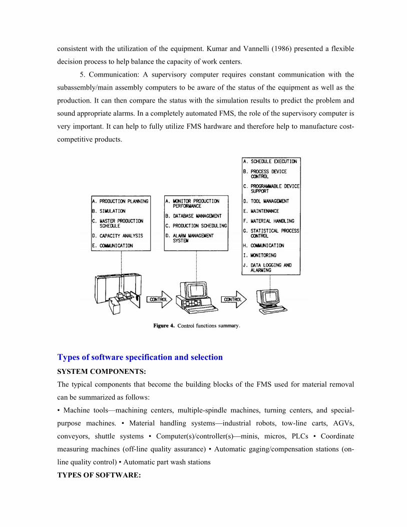
5. Communication: A supervisory computer requires constant communication with the
subassembly/main assembly computers to be aware of the status of the equipment as well as the
production. It can then compare the status with the simulation results to predict the problem and
sound appropriate alarms. In a completely automated FMS, the role of the supervisory computer is
very important. It can help to fully utilize FMS hardware and therefore help to manufacture cost-
competitive products.
Types of software specification and selection
SYSTEM COMPONENTS:
The typical components that become the building blocks of the FMS used for material removal
can be summarized as follows:
• Machine tools—machining centers, multiple-spindle machines, turning centers, and special-
purpose machines. • Material handling systems—industrial robots, tow-line carts, AGVs,
conveyors, shuttle systems • Computer(s)/controller(s)—minis, micros, PLCs • Coordinate
measuring machines (off-line quality assurance) • Automatic gaging/compensation stations (on-
line quality control) • Automatic part wash stations
TYPES OF SOFTWARE:

Software for FMS can be divided into three broad categories: design, extrinsic functions, and
intrinsic functions. The design software is used to identify the major components of the system
concept, to evaluate design sensitivities and trade-offs for a given concept, and to demonstrate that
the system is capable of meeting the planned production requirements. Some of the extrinsic and
intrinsic functions that support the FMS are displayed in Figure 2. Software for the extrinsic
functions is used to plan and control the functions that take place outside the physical boundaries
of the FMS. Software for the intrinsic functions is used to load and control the components within
the physical boundaries of the FMS.
A. DESIGN FUNCTIONS
1. Capacity Planning: Capacity planning is concerned with planning the needed manpower and
machine resources to meet the master schedule during a specified time frame. The capacity of a
system determines the amount of product that can be produced in a given time period. Capacity
planning also is considered to be a refinement procedure wherein the long-range schedule is
adjusted to the manufacturing needs of the nearer future. The output of capacity planning can be
an input to material requirements planning and other scheduling activities.
Role of Software
Capacity planning software is used to evaluate the impact of specified production levels on the
resources provided through the FMS. It can be used to establish limits for the quantities of the
various parts planned for the FMS and the limits on the mix of these quantities for the available
machines, tooling and fixturing, and part pallets. It also can be used to evaluate the impact of
introducing new part numbers into the FMS and identifying the changes that may be needed to
accommodate the additional load. Considerations Capacity planning software can be used to
evaluate factors that influence the capacity requirements for the FMS—factors such as the
following:

• Minimum system requirements for part family demand • Effect of change in part mix and
demand levels • Effect of change in planning horizon • Effect on schedule of down machines or
tool shortage • Labor support required for various schedules (e.g., part programming, load/unload,
tool replacement, setup, inspection, and maintenance) • Minimum number of shifts required to
meet schedule • Capability to make up lost production
2. Simulation: Simulation has become an important tool when new manufacturing processes are
conceived or existing ones are to be altered. A simulation can be described as a software tool that
consists of methods, activities, and resources. A simulation model for an FMS can be conceived as
a four-level hierarchy: basic components, machine control, scheduling, and order processing and
planning. The "basic components" are found at the lowest level of the hierarchy and consist of the
machine tools, material handling equipment, inspection systems, and support equipment. The
primary action at the basic components level is to implement instructions received from the next
level. At the machine control level, data are gathered and instructions are implemented on the
basis of higher level goals and current events. Communication between machines and equipment
at this level is limited. At the scheduling level, future actions are planned and supervisory
decisions are made. Primary and secondary process routings are determined for each part. When
problems occur, rescheduling is done and new instructions are issued to continue operation of the
FMS. At the order processing and planning level, orders are generated and processed. Order status
is maintained and operational statistics are calculated (e.g., processing times, equipment
utilization, buffer use, tool changes).
Role of Software
The five main purposes of using simulation for FMS are to evaluate capacity and equipment
utilization of the system, to identify the bottlenecks in the system, to compare the performance of
alternative designs, to ensure that no fundamental weaknesses exist in the FMS design, and to
develop operating strategies for work scheduling and job sequencing. The simulation experiment
may help answer questions such as those concerning system reserves, sensitivity to failure, wear,
and process alternatives. Experiments also may be conducted to search for a more efficient layout,
to test the effect of component failures, and to observe traffic congestion with respect to the
number of part carriers and buffer sizes.
Types of software specification
A) SOFTWARE DESIGN REQUIREMENTS
For software to be effective, it must meet the requirements that are defined based on its purpose
and how well it does its intended job. The requirements can be expressed in the form of absolute

and functional specifications. The specifications provide a basis for detailing requirements for the
software and can be used as a checklist against which various alternatives can be evaluated.
1. Absolute Specifications
In outline form, the absolute specifications include
a. Detailed specification, including
1. FMS characteristics 2. Program code
3. Computer hardware 4. Production capacity
b. Effective user interface
1. Minimal training requirements 2. Multiuser capability 3. Fast execution/response time
c. Software design 1. Modular structure 2. Design for growth (use existing data and upward compatible) 3.
Interface to other software (other applications and management information software) d. Field verification and test e. Effective documentation (consistent with software version; tailored to user; easy to find
information; clear, concise writing style; ample figures and tables; troubleshooting guide; flowcharts and variable dictionary) 1. Training manual/tutorial 2. User reference 3. Programmer reference.
2. Functional Specifications
Considerations for the functional specifications include a. Deliverables versus cost
1. Purchase package (basic package and optional packages) 2. Tech support and software service 3. Availability of source code 4. Upward compatible updates and enhancements 5. Documentation 6. Training 7. Hardware and support equipment
b. Quality 1. Vendor credibility (including on-time delivery) 2. Reliability
c. Programming 1. Program language (high level versus assembly; standard versus nonstandard) 2.
Structure of program 3. Error recovery 4. Security 5. Diagnostic aids 6. Access to database, 7. Interfaces to other applications 8. Graphics display
d. Control applications 1. CNC part program 2. Traffic control 3. Shuttle control 4. Tool control (including
wear monitor and replacement transactions) 5. Quality control e. Management applications
1. Scheduling 2. Production control 3. System monitoring
f. Reports
1. Management 2. Operational
B. DOCUMENTATION

An important consideration in the selection of a software product to support the FMS is the quality
of the documentation that comes with the software. Four criteria can be used to judge the quality
of documentation: availability, suitability, accessibility, and readability.
1. Availability: Is documentation available? Some software products come with little or no formal
documentation. While this practice may be acceptable for simple programs, the need for a high-
quality user's manual should be satisfied by the supplier.
2. Suitability: What information does the user need? Obviously, the answer to this question
depends on who the user is. A common mistake made by suppliers of software is to put the entire
documentation into a single (often unwieldy or even unusable) manual. After a careful analysis of
each user's needs, the developer of the documentation should "align each manual's content with
the tasks and interests of particular readers."
3. Accessibility: Can the user find the needed information? Perhaps the documentation contains
the information that answers the user's questions, but can the user find the information in an
acceptable way? If the paths through the documentation are complex and cumbersome, even a
skillful user may get lost. "User manuals that are both suitable and accessible
4. Readability: How easily and accurately can the documentation be understood? User manuals of
the highest quality require professional editing. The language used should be clear, concise, and
communicate in a way that the user can gain the greatest understanding in the least amount of
time. The reader should not have to read and reread (. . . and reread) the material to gain the
needed understanding, often stumbling over language and editorial errors.
C. SOFTWARE SOURCE ALTERNATIVES
Software systems for FMS are obtained from three basic sources: a vendor, a consultant, or an in-
house development. Each alternative has both advantages and disadvantages.
1. Vendor: A qualified vendor, often the hardware supplier, can supply software that has been
field-tested and that can be upgraded as improvements and enhancements (both in software and in
the FMS hardware) become available. The vendor also provides technical support to train
personnel to use the software and to correct problems that arise during use of the software.
Vendor-supplied software is expensive and usually cannot be modified by the user.
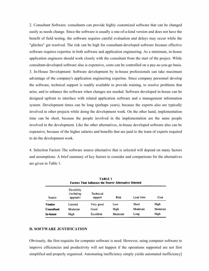
2. Consultant Software: consultants can provide highly customized software that can be changed
easily as needs change. Since the software is usually a one-of-a-kind version and does not have the
benefit of field testing, the software requires careful evaluation and delays may occur while the
"glitches" get resolved. The risk can be high for consultant-developed software because effective
software requires expertise in both software and application engineering. As a minimum, in-house
application engineers should work closely with the consultant from the start of the project. While
consultant-developed software also is expensive, costs can be controlled on a pay-as-you-go basis.
3. In-House Development: Software development by in-house professionals can take maximum
advantage of the company's application engineering expertise. Since company personnel develop
the software, technical support is readily available to provide training, to resolve problems that
arise, and to enhance the software when changes are needed. Software developed in-house can be
designed upfront to interface with related application software and a management information
system. Development times can be long (perhaps years), because the experts also are typically
involved in other projects while doing the development work. On the other hand, implementation
time can be short, because the people involved in the implementation are the same people
involved in the development. Like the other alternatives, in-house developed software also can be
expensive, because of the higher salaries and benefits that are paid to the team of experts required
to do the development work.
4. Selection Factors The software source alternative that is selected will depend on many factors
and assumptions. A brief summary of key factors to consider and comparisons for the alternatives
are given in Table 1.
D. SOFTWARE JUSTIFICATION
Obviously, the first requisite for computer software is need. However, using computer software to
improve efficiencies and productivity will not happen if the operations supported are not first
simplified and properly organized. Automating inefficiency simply yields automated inefficiency]

Like other investments or expenses, the expenditure for computer software requires financial
justification. Reasons for acquiring the software can be identified that will produce (tangible) hard
benefits, but other reasons produce only (intangible) soft benefits. Because the soft benefits that
come from the use of computer software rarely can be quantified, traditional cost-justification
procedures generally are inadequate for FMS software. Without considering the intangible
benefits, the calculated return on investment from the purchase of software cannot compete with
other investment opportunities.
E. SOFTWARE SUPPLIERS
Many software suppliers provide computer software packages for FMS or those that perform the
tasks that support the operation of the FMS. The list of companies cited in Table 4 is not intended
to be comprehensive but rather, a representative sample of the types of software available. Where
appropriate, the products available from the companies are referenced to the three general types of
software for FMS.
6.MCQ- post-test
1. Which one is the highest level in the hierarchy of computer control a) Direct digital control b) Direct numerical control c) Computer numerical control d) Supervisory computer control Answer: d 2. Which one is the function of supervisory control? a) Production planning b) Simulation c) Master production schedule d) All of the above Answer: d 3. Master schedule is prepared for a) Single product continuous production b) Multi product batch production c) Assembly product continuous production d) Single product batch production Answer: c 4. ____________ system is one in which all work pieces follow the same path through the system.

a) Single station b) Sequential flow c) Random flow d) Steady flow Answer: b 5. ____________ system is one in which the work pieces do not move through the system. a) Single station b) Sequential flow c) Random flow d) Steady flow Answer: a 6. ____________ system is one in which the material handling equipment can simultaneously move work pieces from any machine to any other machine in any sequence. a) Single station b) Sequential flow c) Random flow d) Steady flow Answer: c 7. In which of the software used in FMS. a) Design functions b) Extrinsic functions c) Intrinsic functions d) All of the above Answer: d 8. Design functions include___________ a) Capacity planning b) Simulation c) Knowledge based systems d) All of the above Answer: d 9. Capacity planning is concerned with a) How many machines required b) How much labour required c) Both (a) and (b) d) None of the above Answer: c 10. Computer-based controllers a) Should be built in a modular fashion wherever possible b) Are very difficult to change c) Are very flexible

d) Both (a) and (c) Answer: d
7.Conclusion
Understood about the FMS supervisory computer control
Learnt about various types of software specification and selection
Flexibility in manufacturing systems provides an opportunity to capitalize on basic
strengths of a company to ensure long-term leadership in manufacturing cost, products,
and service to customers. It is important to keep in mind that flexibility comes in many
types and degrees, and success will come only to the extent that the proper flexibility is
specified for each situation. Implementation of flexible manufacturing systems involves
development of various manufacturing concepts from which a few specific alternatives are
selected, and then evaluated so that a single alternative can be selected and implemented
8. References
Jha.N.K., “Handbook of flexible manufacturing systems”, Academic Press Inc., 1991
9.Audio/ video - if any
10. Assignments
Explain in detail about the important control functions of the FMS supervisory computer?
Explain in detail about types of software’s used in FMS?
What are the specifications to be provided for detailing requirements for the software?
Name of the Course : Flexible Manufacturing Systems (FMS)
Name of the unit : FMS SIMULATION AND DATA BASE (UNIT III)
Topic – Title : Application of simulation – model of FMS–
simulation software – limitation
1.Objectives and Outcomes:
To understand about application of simulation and model of FMS, various software software’s
with its limitations
2. Prerequisites:
The purpose of this chapter is to introduce to the reader the various aspects of the use of
simulation models to analyze FMSs. References to some of the past simulation studies as applied
to FMSs, and the steps involved in a simulation are presented. The basic knowledge
aboutsimulations software and its applications

3. Theory:
Computer simulation has become a very popular tool in the analysis and design of manufacturing
systems (Law, 1986). In the simulation of an existing or proposed manufacturing system, the
analyst builds a model of the system which captures the features to be studied. Some of the
features of the system include jobs or products to be processed, material inputs, relevant
processing variables, and resources utilized. The analyst then directs the model to mimic the
behavior of the system under real or assumed conditions, and collects information to be used in
computing the performance measures of the system. A simulation model of the system can be
constructed and run under different dispatching rules. Records are kept on variables such as the
time between arrival of jobs, the waiting time in queues, the time jobs spend in the system, and the
time each machine is idle, blocked, or busy. These records are then used to compute system
performance measures under each dispatching rule such as the mean number of products at each
buffer (queue), the mean number of jobs in the system (work-in-process inventory), the mean
daily production rate of each product type, the mean time each product spends in the system,
machine utilization, and other relevant measures.
Application of simulation:
In numerous studies, simulation has proved to be an effective technique for analyzing and
evaluating an existing or proposed manufacturing system. Simulation studies during the early
design phase of a manufacturing system implementation tend to focus on equipment and material
handling requirements. The output of these simulation studies aids in the design of the system
specifications. Caruso and Dessouky (1987) developed a simulation model of a proposed FMS
system that assembles instrument panels. The system consists of an automated storage and
retrieval system feeding several robotic assembly cells. The results of the simulation model aid in
the design of the system specifications. Godziela (1986) uses simulation to evaluate performance
of a proposed system to support certain levels of production activity.
Simulation models of existing systems frequently are used to test different control and dispatching
strategies. For example, Chang et al. (1985) use simulation to evaluate different dispatching rules
in an FMS. By carefully controlling the use of generated random numbers, the authors implement
an appropriate experimental design to identify significant differences between the various
dispatching rules.
Simulation Modeling Process
The simulation modeling process involves several interwoven steps.
These steps are 1. Stating the project's objective(s) 2. Building the abstract model 3. Software
selection 4. Input analysis 5. Building the simulation model 6. Model verification 7. Model
validation 8. Output analysis.

1. STATING THE PROJECT'S OBJECTIVE(S): Before the simulation model is built, a clear
statement of objectives must be defined. The objective of the study determines the level of
detail to include in the model. For example, if the objective is to determine the capacity of a
manufacturing line, product aggregation may be appropriate. However, if the objective is to
evaluate different production schedules, product aggregation is not appropriate. If the study
involves a comparison of different alternatives, it is necessary to specify the criteria for
comparison and evaluation of the alternatives generated.
2. BUILDING THE ABSTRACT MODEL: A thorough understanding of system operations is
required to abstract the real world into a model. Building an abstract model involves
determining which operations are to be included in the model and the boundaries of the model.
The level of detail included in the model is closely related to the objective(s) of the simulation
study. Medeiros (1989) suggests developing a process flowchart to show the product flow.
There are several advantages of developing an abstract model before building the simulation
model. As more complexity is added to the model, the simulation software that is currently
being used may not be satisfactory. As a result, a new simulation model might have to be
developed using a different simulation software tool. The abstract model can serve as the
starting point for the new model. Conversely, if the simulation software tool has not yet been
selected, the abstract model can aid in selecting the appropriate software package. Section V
presents some commercially available simulation software tools.
3. INPUT ANALYSIS: Input analysis involves data collection and the selection of probability
distribution(s). Reliable data in the form needed for simulation purposes are often not
immediately available (Carson, 1986). Some methods of obtaining the required data are 1.
Time studies 2. Examination of historical records 3. The client's or an expert's best guess 4.
A vendor's claims.
4. BUILDING THE SIMULATION MODEL: The level of detail to include in the model is an
important consideration in building a simulation model. The more detail included in the
model, the more time that is required for data collection, programming, and computer
processing time. Section IV illustrates building a simulation model using SLAM II (Pritsker,
1987) for an FMS.
5. MODEL VERIFICATION: Verifying the simulation model means to check if the simulation
model is designed to the model specifications and is behaving as intended. Several techniques
used to verify a simulation model are the trace output, graphical animation, and summary
statistics. The trace output is a listing of the events that are performed by the model. An
animation is a graphical model of the simulation. It is generally easier to verify the model with

a visual tool such as an animation than it is to look at a computer listing of the events (trace
output). Developing an animation model adds an extra step to the simulation process.
6. MODEL VALIDATION: If the system being modeled currently exists, the results of the
simulation model and the real world can be compared. If the system does not exist, it is more
difficult to validate the model. However, a domain expert can be asked to look at the
simulation results to see if they make sense. The same tools used for model verification can be
used for model validation.
7. OUTPUT ANALYSIS: Effectiveness of the simulation output analysis is governed by the
design of the simulation experiment and the study's objective(s). Parameters that need to be
determined include the number of runs, simulation run length, and initialization warm-up
period.
Model of FMS
Some of the concepts involved in modeling modern FMSs.
A. STATEMENT OF OBJECTIVES
Company XYZ is considering investing in a manufacturing system. The decision whether to
invest in the new system depends on the system's expected performance level. As a result,
management has authorized a simulation study to predict the following statistics: 1. The mean
number of jobs in the queue and the mean delay in the queue for each workstation 2. The mean
time in the system for each job type 3. The proportion of time that machines are processing
jobs, blocked, and idle for each machine group 4. The utilization of the transporter 5. The
mean time a job waits for transporter pick-up These statistics will be used to help management
decide whether or not to invest in the system.
B. SYSTEM DESCRIPTION
A manufacturing shop consists of a receiving/shipping station and five workstations,
workstations 1, 2, . . ., 5 consist of 3, 3, 4, 4, and 1 identical machines, respectively. The
distances (in feet) between the six workstations (the receiving/shipping station is station 6) are
shown in Table 1. The time between arrival of jobs is an exponential random variable with a
mean of 0.25 h. Jobs are of type 1, 2, or 3 with probabilities 0.3, 0.5, and 0.2, respectively.
Each job enters the system at the receiving station, travels to workstations on its route, and
then leaves the system at the shipping station. Table 2 shows the job routings.

C. MODEL DEVELOPMENT
The simulation model is developed using SLAM II (see Appendix A for the model code). The
entities of the system are the jobs. The workstations and transporter are modeled as resources.
To verify and validate the model, a trace of the simulation events is created. Examination of
the trace shows that the simulation model behaves according to the system description. To
determine the length of the initialization bias, the average number of jobs waiting at
workstation 1 is plotted over time.
Figure 3 shows this plot. From the diagram, the initialization bias is determined to be 500 h.
Statistics are cleared after 500 h. As suggested in Section III, eight simulation runs are made.
Each simulation run is 200 days (1300 h) after statistics are cleared.
D. DISCUSSION OF RESULTS
The job statistics are contained in Table 4. Type-2 jobs have the highest average daily
production rate of 13.10 jobs with a standard deviation of 0.21jobs. Type-3 jobs stay in the
system the longest with an average time in the system of 10 h and a standard deviation of 1.3
h. A 95% confidence interval of time in the system from the eight simulation runs for type-3
jobs is (8.94, 11.06) h. The upper limit can be used to set delivery due dates for type-3 jobs.
The transporter is busy 29% of the time, and requests wait on the average 0.61 min for the
transporter. These results indicate that one transporter is sufficient to meet the current demand.

Simulation Software
Discrete event simulation can be implemented using most programming languages. But today
most simulation models are written using special purpose languages that contain basic utilities
needed to perform most simulations.
A. GENERAL-PURPOSE COMPUTER LANGUAGES: FORTRAN was the most
popular language for simulation modeling in the 1970s because of its ability to handle numeric
computations conveniently and efficiently. In recent years, PASCAL and C have emerged as
competitors to FORTRAN. These relatively newer general-purpose languages provide data
structures that make the abstraction process easier. An advantage in using a general-purpose
language is the ability to analyze a large number of problems since the user defines and
develops all the model constructs. However, a major disadvantage is that a significant amount
of computer code must be written to manage the simulation model and collect statistics.
General-purpose simulation languages are designed to reduce the amount of user programming.
Basic utilities are provided to manage the simulation model and collect statistics.
B. GENERAL-PURPOSE SIMULATION LANGUAGES: General-purpose simulation
languages aid users by providing utilities that handle repetitive tasks such as initialization and
time advancement. Some examples of general-purpose simulation languages are GPSS
(Gordon, 1975), SLAM II (Pritsker, 1987), SIMSCRIPT (CACI, 1983), and SIMAN (Pegden,
1985). These simulation languages contain collections of FORTRAN subroutines with a set of
control statement used to invoke them. The system-provided subroutines reduce the amount of
code a modeler has to write when building a model. Utilities offered by some of the popular
general-purpose simulation languages include 1. Automatic queue management, including
generation of statistics on average waiting time, maximum waiting time, and average queue
length 2. A generator of uniformly distributed pseudorandom numbers used to support samples
from probability distributions such as Normal and Poisson 3. Provisions to control the number
of runs, the length of a simulation run, and time to clear statistics 4. Automatic generation of

entity arrivals to the system 5. Collection of statistics (i.e., mean, standard deviation, minimum,
maximum, etc.) for chosen variables 6. An optional animation capability
C. SPECIAL-PURPOSE SIMULATION PACKAGES Special-purpose simulation
packages have been developed for modeling manufacturing systems. MAP/1 (Wortman and
Miner, 1986) and SIMFACTORY (Klein, 1986) are two such packages. These packages use
high-level building blocks to provide a user-friendly interface. XCELL (Jones and Maxwell,
1986) has a graphics interface. Building simulation models from these packages is easy and
usually faster than using a general-purpose simulation language. However, these packages are
designed to analyze only manufacturing systems and are limited to certain decision rules.
Since the packages are fixed in the view of the world they take, using the package to model a
different view may be difficult.
D. SELECTION OF SIMULATION SOFTWARE: Personal computers (PCs) have
recently become attractive platforms for running FMS simulations due to the availability of
large memory and 16-bit (or more) microprocessors. Most of the general-purpose simulation
packages discussed earlier have PC versions of their mainframe software. These versions
usually have additional interactive and graphics utilities. A comprehensive catalog of
simulation software appears in the October issue of Simulation, published by the Society of
Computer Simulation. Industrial Engineering magazine, a publication of the Institute of
Industrial Engineers, also publishes special issues devoted to simulation.
Limitations of Simulation
Simulation modeling is not without its limitations. Since any model is an abstraction of reality,
the modeler may ignore some of the details and focus only on those most relevant to the
problem at hand. The results should be evaluated in the context of the assumptions made (or
the details ignored). Not all questions can be addressed by simulation. While it is a good tool
for evaluating a number of alternative system designs, the modeler must generate the data for
the alternatives (or corne up with alternatives). Unlike optimization techniques, simulation
does not pick an optimum solution to a problem. The simulation study is a time-consuming
process and requires the modeler to have skills in the following areas: data analysis, statistics,
programming, and project management. Consequently, simulation is appropriate as an analysis
tool when the system is too complex to be studied by performing a data analysis or by building
an analytical model.
6.MCQ- post-test
1. Choose the basic element for an automated machine tool
a) Logic
b) NC tape programming

c) Software
d) Workstation
Answer: a
2. "Automatic placement and withdrawal of parts and products into and from designated
places in a warehouse" describes
a) AGV
b) CAD/CAM
c) CIM
d) ASRS
Answer: d
3. The process capability of a machine is defined as the capability of the machine to
a) Produces a definite volume of work per minute
b) Perform definite number of operations
c) Produce a job at a definite spectrum of speed
d) Holds a definite spectrum of tolerance and surface finish
Answer: a
4. In the digraph, each node is labeled (a, b, c) where ‘a’ is ________
a) Machining time
b) Assembly time
c) Sub assembly time
d) Level of depth of the node
Answer: a
5. MLDF means
a) Maximum level of depth first
b) Minimum level of depth first
c) Mean level of depth first
d) All of the above
Answer: a
6. The most significant advantage of U-shaped layout is:
a) Cost minimization
b) Easy handling of process
c) Increased flexibility in work
d) All of the above
7.Conclusion

During the design phase of an FMS, a simulation analysis can aid in evaluating the design. The
results of the simulation model can aid in determining the required number and location of
machines, the location and size of the buffers, and the appropriate type of material handling
system. After the FMS has been installed into the manufacturing environment, continuous
improvement of the system is needed to fully utilize its resources and meet the production goals.
For example, a simulation model can be used to analyze different scheduling strategies without
disturbing system operation. A wide range of simulation software tools are available to make the
programming task easier. Selection of the appropriate software tool depends on the application. In
building the simulation model, careful consideration must be given to model validity and
statistical issues.
8. References
Jha.N.K., “Handbook of flexible manufacturing systems”, Academic Press Inc., 1991
9.Audio/ video - if any
10. Assignments
Explain in detail about Model of FMS?
What are the applications of simulations?
Explain in detail about simulation software?
Topic – Title: Manufacturingdata systems – data flow – FMS database systems
1. Objectives and Outcomes:
To understand about manufacturing data systems and data flow.
To learn about various database systems in FMS.
2. Prerequisites:
The basic knowledge about manufacturing data systems and database in FMS
3. Theory Behind:
A database is a necessary and integral part of any flexible manufacturing system (FMS). The most
basic function of a database in an FMS is providing storage and availability of information needed
to control the manufacturing process. In performing this role, the database handles information
needed for essentially all tasks of controlling the FMS. These include planning machine loading
and management of the software used to control programmable manufacturing equipment such as
numerically controlled (NC) machines. Also, databases function to interface the FMS with other
computer-centered manufacturing systems such as material requirements planning (MRP II),
computer-aided design (CAD), computer-aided manufacturing (CAM), and inventory control

systems. See Figure 1. Databases and software are designed together and are inseparable. For a
successful FMS implementation, good database design is a must. First, it is important to
understand what a database is. It is much more than simply a large computer file. A file is a
collection of data. It may be organized so that it is retrievable only in the order in which it was
stored (sequential) or so that it can be retrieved in any order desired (random). In general, a file
contains just one type of data (e.g., a list of items in inventory) and all records are laid out in the
same way. A database differs in many respects, because a database
Is likely to contain many files. It is much more than simply a computerized filing cabinet. Works
in conjunction with application software to create a manufacturing data system supporting the
factory operation. Is frequently designed to be able to serve many applications concurrently, in a
coordinated fashion; the FMS may share a database with other parts of the business.

Manufacturing Data Systems:
A manufacturing data system (MDS) acts as the link between the abstract, computerized worlds of
sales, engineering, and production control, and the real world where actual products are built. The
MDS carries out the diverse functions of computer-aided process planning (CAPP), scheduling,

inventory control, and manufacturing requirements planning (MRP). The FMS database is part of
the interface between the MDS and the factory floor. Figure 1 shows the layout of a typical MDS
and how it fits into the overall MIS used to operate the business. Note the flows of information
between various subsystems. Individual companies will have more or less computerization of
information flows depending on their situation. (Sometimes a database on paper or a verbal data
flow works just as well as the computer version). These data flows ultimately direct
manufacturing to produce the desired quantities and product mix. Sophisticated systems will also
incorporate capabilities to optimize production. This may include such subsystems as machine
loading optimization, automatic routing of work-in-process, and even product mix control to
maximize profit.
Generally, each subsystem of any MIS can act as a data source and as a data receiver. The MDS
receives orders from other parts of the MIS regarding what products should be produced. The
MDS can also be a rich source of data on the manufacturing process. With proper design, the
MDS can be structured to provide management and manufacturing engineering with valuable
feedback on production rates, machine downtime, plant efficiency, inventory, and many other
plant conditions. The MDS forms the environment in which the FMS database operates. The FMS
database cannot be considered in isolation because it depends on the MDS for input.
Manufacturing Data Flow:
A. OVERVIEW
Refer again to Figure 1, noting the overall flow of information in a manufacturing operation. Note
how the FMS acts as a data receiver primarily, but also as a data source. In a typical system, these
databases and software modules would be distributed across several machines, with data flows
traveling across communication lines. Section VI discusses distribution of data and functionality
through a system hierarchy. In the FMS, automation of data flow is as important as automation of
material flow. While manufacturing is being performed, the software which controls the operation
requires rapid access to information to make decisions.
A necessary part of FMS database design, therefore, is a detailed articulation of the procedures
which will ensure data availability and integrity. For example, a master production scheduling
program needs information on customer orders and/or inventory stocking requirements, material
availability, and capacity (including machine/cell availability) to develop a manufacturing
schedule. Even more information is required if the scheduler is to perform any optimization.

Manufacturing data systems often consist of a mixture of batch and real-time processing
operations. Clearly, it is necessary to lay out a plan for synchronizing certain processing activities
which load the pertinent databases. This also must include contingency plans to cope with
computer downtime.
B. UPSTREAM-DOWNSTREAM ISSUES
From the notion that FMS is primarily a data recipient it follows that somewhere data must be
created. A number of automated systems provide these data, but also human-driven systems are
affected. The CAD area is one in which changes from traditional operating procedures are needed
to make FMS effective. In the past, CAD groups were often operated basically as electronic
drafting shops. There is a growing awareness, however, that CAD procedures and the
responsibilities of upstream engineering sections need to change significantly if full advantage is
to be taken of FMS capabilities. Specific implications of this include • The product and the
process to build it must be designed concurrently, by a closely knit team. • CAD groups must
often do some extra work that they did not do before so that their data will be useful to CAM and
FMS. This means absorbing new costs and leadtimes. • Product design groups need to develop a
much-increased understanding of design issues related to producibility, quality, and reliability. •
Reorganization of engineering activities should be considered at the executive staff level so that
the above points can be considered in the management reward structure.
The Flexible Manufacturing System Database System
The typical FMS will require a combination of databases and complementary software systems
which manipulate them. This section discusses commonly needed system areas and design
methods for customizing a system for a specific FMS. Additionally, it is important to plan data
exchange with other MDSs and treatment of specialty areas unique to a particular business.
MAJOR SOFTWARE/DATABASE SUBSYSTEMS: Since software to control the FMS and
FMS databases are tightly linked, they must be considered together. It will also often be found
that specific databases have data interactions with multiple applications. An application may also
access and update several databases. Because of this, it is vital to consider areas of required
functionality rather than considering databases or software in isolation. A high level of
automation in FMS control requires a fairly complete complement of "upstream" manufacturing
database subsystems Refer to Figure 10. Major software/database functions which may be
required for the operation of an FMS include the following:

Computer-aided process planning (CAPP)lwork scheduling includes accepting order
information from the MIS, planning production, scheduling machines, possibly optimizing
the schedule. A machine capacity database is a vital part of this application area, as is a
calendar system to allow rational scheduling of operations.
Component and process databases are used by CAD and CAM groups for product and
process design. These are far upstream from the FMS, but can have a big impact on FMS
productivity due to the fundamental relationship between product and process design.
• NC and robot program control operates in conjunction with off-line programming and
scheduling. It ensures that software to drive NC machines and robots is available and
downloaded to the machines when required by the schedule. It may be coordinated with
contingency management to assist equipment in recovering from glitches such as dropped
parts. This may also include a system to make setup information readily accessible to plant
personnel for machines that require manual settings to switch between parts.

• Decision support systems (DSSs) use data drawn from several database areas to assist in
running the FMS. This may be information supplied to scheduling algorithms or to humans
who are optimizing FMS operation manually. Typical areas in which DSSs are used
include parts selection, batching and balancing, managing of tools, dispatching of work
orders, simulation, and queueing. There may be several DSSs at different points in the
hierarchy; for example, the top-level mainframe would handle dividing orders into batches
(longer-term decisions), whereas an FMS-level DSS would deal with reallocation of
capacity due to machine downtime.
• Off-line programming allows development of NC programs (tool path creation), robot
programs, and often simulation to observe the actions of completed programs. Also
included is a system to convert (translate) programs into the finished form required by the
specific brand(s) of robot or NC machine being used. Software to perform these functions
is among the most complex of the FMS operation, and numerous databases are involved,
including databases for tools, materials, products, robots, NC machines, manufacturability,
kinematics, and others.
• Status monitoring is a real-time and/or a regularly scheduled function which provides
feedback on how well manufacturing is operating. This may be used primarily for keeping
watch on the automated systems or may also be used for building up a historical database
to analyze for downtime, mean-time-between-failures, and productivity. Communications
will be involved, interrogating information stored in local programmable controllers and
computers while gathering data centrally. A complete status monitoring plan must also
include a plan for how these data will be used (do not collect them without a clear idea of
how to make use of them).
• Inventory data are needed to allow planning of manufacturing based on materials on
hand. Finished goods inventory may or may not be closely linked with the FMS. If
automatic guided vehicles (AGVs) and automatic material handling systems are used,
inventory data management is generally integrated with FMS control.
• Material handling, if handled by automated systems or AGVs, must be linked in real time
to the FMS operation. As with contingency management, handling of exceptions will be a
major part of the design. This application involves primarily control software rather than
database manipulation.
• Ancillary process data refers to a collection of databases of highly specialized
information (e.g., tool wear rates, machinability, material characteristics, speeds, and
feeds) which may be used by various applications such as scheduling and optimization,

CAD, and CAM. In more sophisticated systems, this type of information may be captured
as rules in a knowledge base and used in conjunction with expert systems for optimization.
• Order information provides input to scheduling, and also forms a basis of information on
which to base material requirements planning and just-in-time production control systems.
SUPPORTING DATABASE SYSTEMS Interconnection and timing of FMS database
systems, subsystems, and control require supporting activities and capabilities as follows:
• Communications will be a mix of networking (numerous technical approaches are
available; local area networks are often used in some form, with specialized capabilities for
the factory environment), direct computer-to-computer communication (e.g., RS-232
asynchronous or bisynchronous), and simple on-off levels. Local area networks (LANs)
must be planned to have sufficient capability and speed, and can be a major factor in
cost/performance. Interconnections between computer systems take on a major role if
remote computersystems are doing part of the data preparation for the FMS, such as
scheduling, creating pick lists, or handling just-in-time production control. Avoid being at
the mercy of leased-line vendors to be able to run the factory.
• Contingency management and standby operation may form a significant part of the
software effort to avoid complete loss of manufacturing capability in the event of failures.
Some manual intervention will usually be required. Automated contingency management
may be handled as part of a decision support system, as previously discussed (changing
order size, order deletion, modify pallet contents, empty or load buffer store, etc.) or
simply provide a means to notify an operator of a problem and allow some manual
operation.
• Data backup allows the saving of database information to avoid loss of work in case of
lost computer files.
• Remote diagnostics allow the user to test computer equipment at a distance. This is useful
for tracking down the source of field failures from a central location.
SYSTEM DESIGN AND DATA FLOW PLANNING 1. System Engineering for a
Flexible Manufacturing System Database Layout It is possible to buy flexible
manufacturing systems and many of the software packages needed to support them.
Database structure, however, is best designed in-house, to ensure a good fit with the
business. At a minimum, even if the FMS database system is designed by a consultant, the
user should be closely involved and take an active part in developing the functional
specification. The design of a database system and its associated software systems uses
many of the same well-defined design techniques that are used for designing systems in

general, and in particular, data processing systems, manufacturing/factory systems, and
communication systems. System engineering techniques and standardized data system
design methodologies are applicable. To achieve computerintegrated manufacturing
(CIM), it is necessary to take a systems approach, designing the entire system as an
integrated unit, including the required specialty areas, and considering the system's total
life cycle. Otherwise there is a significant risk that the CAD, CAM, MDS, and FMS areas
will each end up as islands of automation. Part of the systems approach also should include
the development of a data dictionary which defines all data fields (including length,
format, and content). This reduces duplicative effort in building systems, as the same data
format is adopted company wide for each field.
Refer to Figure 11, which illustrates allocation of database/system functionality down
through a factory data processing hierarchy. Note that allocation of required database
storage and software functionality often tracks closely with the allocation of manufacturing
task responsibility. Individual computer systems are designed around the needs of the
manufacturing functions they perform. Typically, a manufacturing cell will be coordinated
by a single computer which is part of a local area network. Individual machines, transfer
lines, conveyors, and ancillary equipment will be controlled by programmable controllers
which are downloadable from the cell computer (or the local area network). In this
scenario, functionality of the individual manufacturing machines is limited to a subset of
their potential capability, but is designed to be sufficient to handle the required range of
products being manufactured. It is also possible to design a system for even greater
flexibility by using computers.

Figure 12 shows a possible system design for the functional hierarchy of Figure 11, using
two LANs. Note that the office/engineering network is separate from the factory network.
This isolation prevents factory-type problemsLAN downtime due to welding next to a
remodulator) from immediately affecting the entire network.
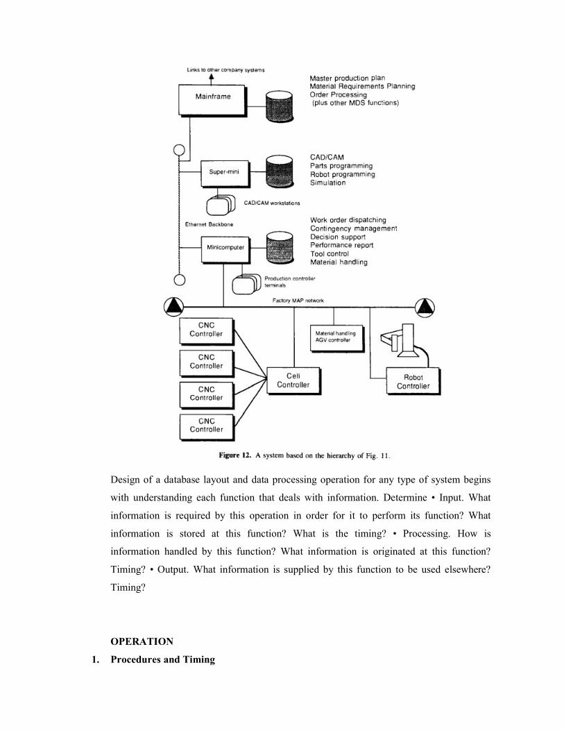
Design of a database layout and data processing operation for any type of system begins
with understanding each function that deals with information. Determine • Input. What
information is required by this operation in order for it to perform its function? What
information is stored at this function? What is the timing? • Processing. How is
information handled by this function? What information is originated at this function?
Timing? • Output. What information is supplied by this function to be used elsewhere?
Timing?
OPERATION
1. Procedures and Timing

An FMS database operation is an application where a data processing function must be tightly
linked to factory floor timing requirements. Written procedures must be developed accordingly,
and a schedule developed to ensure that needed data processing operations are completed when
required. When starting up a new FMS database system, begin testing as early as possible in the
development phase. This will require the use of program stubs to simulate the actions of
software which has not yet been written. This will also provide a test of the procedures
themselves and provide more opportunity for production personnel to gain familiarity with the
new systems. Gradual loading of databases and testing with subsets of the production
information is preferable to performing a massive database load and attempting to begin full
processing all at once. The FMS databases may be stable (changing infrequently, such as the
capacity of a machine) or very volatile (changing frequently, such as a production schedule).
The more volatile a database is, the greater its need for maintenance. In any case, each database
must have a designated owner who takes responsibility for ensuring its correctness. Updates to
volatile databases may be handled automatically, by downloading or processing of transactions
from another system, but a human must still take responsibility for database integrity.
2. Synchronization of Distributed Databases:
Contingency Planning A distributed database system will always have some planned
redundancy. This is needed to allow some independent processing to take place, eliminate a
central computer as a single point of failure, and enhance performance. Redundancy frequently
means, however, that differences will arise between databases which are supposed to be
identical (at least, identical in certain fields).
Planning for FMS database
What is the best allocation of intelligence down through a hierarchy of functional flow of
computer control system? What databases will be at what level? Effectiveness of operation will
be strongly influenced by the communications method. • Will there be planned data
redundancy, and if so, how will reconciliation be handled? Will there be one master database
which will be considered the "most correct?" • Will there be manual inputs? If so, will there be
time delays (computer awaiting human input) due to relatively light manpower in a highly
automated factory? • Have database operations been included in the simulation of FMS during
its design stages? • How much data must be sent over communication networks to support
system operation? Can network capacity handle it? • If a LAN is acting as a real-time link
between a database system and production equipment, will system response time be quick
enough? (Failure here can mean equipment/product damage.) • Contingencies: If the database
becomes quite inaccurate due to problems, glitches, and so on, how will FMS operation be
restored? Develop detailed error recovery procedures. • The combination of database

complexity, software complexity, and computer performance can combine to result in operation
slow enough to disrupt FMS operation. Has a sensitivity analysis been performed as part of
system design and simulation to determine where fast computer response times are required to
maintain FMS throughput?
6.MCQ- post-test
1. The knowledge base describes
a) The world model and partially constructed schedules
b) The transformational effects of actions that map statesto other states
c) Both (a) and (b)
d) None of the above
Answer: b
2. Simulation in FMS is
a) Concerned with determining man power and equipment resources are required to meet
MPS
b) A model of a manufacturing process or system that can be used to emulate it
c) Both (a) and (b)
d) None of the above
Answer: b
3. Software design requirements can be expressed in the form of
a) Absolute and functional specifications
b) Absolute and service specifications
c) Normal and functional specifications
d) Normal and service specifications
Answer: a
4. FMC means
a) Flexible Manufacturing Control
b) Flexible Manufacturing Cell
c) Flexible Machine Cell
d) All of the above
5. Frequent and significant changes possible in
a) Dedicated FMS
b) Random order FMS
c) Both (a) and (b)
d) None of the above

Answer: b
7. Conclusion:
Databases and the software that interacts with them are a key element of a flexible
manufacturing system. A systems approach must be followed to integrate FMS databases and
systems with the rest of the manufacturing data system. Wellestablished system design
methodologies are available to aid in this task. System design for FMS database systems
includes more than just database layouts, however. Requirements for system operation imposed
by realities of the manufacturing environment include considerations of speed and allocation of
functionality through a manufacturing hierarchy which may include everything from
mainframes to programmable controllers. Also, staffing and organizational considerations must
be taken into account to ensure effective data preparation for the needs of FMS.
8. References
Jha.N.K., “Handbook of flexible manufacturing systems”, Academic Press Inc., 1991
9.Audio/ video - if any
10. Assignments
Explain in detail about manufacturing data systems?
Explain in detail about FMS data base systems?
Name of the Course : Flexible Manufacturing Systems (FMS)
Name of the unit: GROUP TECHNOLOGY AND JUSTIFICATION OF
FMS(UNIT IV)
Topic – Title : Introduction – matrix formulation – mathematical
programming formulation –graphformulation
1. Objectives and Outcomes:
To understand about group technology and machines cell.
To learn about various formations to model GT.
2. Prerequisites:
The basic knowledge about group technology
3. Theory Behind:
The basic idea of group technology (GT) is to decompose a manufacturing system into
subsystems. Introduction of GT in manufacturing has the following advantages (Kusiak, 1990):
1. Reduced production lead time (20-88%) 2. Reduced work-in-process (up to 88%)3. Reduced
labor (15-25%) 4. Reduced tooling (20-30%) 5. Reduced rework and scrap materials (15-75%)

6. Reduced setup time (20-60%) 7. Reduced order time delivery (13-136%) 8. Improved human
relations 9. Reduced paper work
There are at least four crucial factors which support this thesis:
• Volume of information: Volume of information in a large-scale automated manufacturing
system is typically large and it is too expensive to effectively process information without the
system's decomposition.
• Material handling system: In a typical automated manufacturing system, automated material
handling carriers are used, for example automated guided vehicles (AGVs) or robots. Each of
the two carriers tends a limited number of machines. This limitation for AGVs is imposed by
the following: 1. Maximum number of trips that an AGV can make per time unit. 2. AGV
guidance path, for example, a wire, which one should avoid to intersect by another guidance
path within the AGV s working area. An AGV while approaching an intersection slows down
and this in turn reduces its utilization.
• Technological requirements: Some machines have to be grouped together due to
technological requirements, for example, a forging machine and a heat treatment station.
• Management: Although in most of the currently operating automated manufacturing systems,
the degree of automation is higher than in the classical manufacturing systems, humans will be,
for a long time, part of these new manufacturing systems. Due to the limited size of each
machine cell, a cellular manufacturing system is easier to manage than a functionally organized
system. It seems that this view has been given especially serious consideration in Europe and
Japan. The initial sections of this chapter focus on models and algorithms developed for GT.
There are two basic methods used for solving the GT problem: classification and cluster
analysis.
A. CLASSIFICATION METHOD
The classification method is used to group parts into part families based on their design
features. There are two variations of the classification method: visual method and coding
method.
1. Visual Method: The visual method is a semisystematic procedure where parts are grouped
according to the similarity of the geometric shape, as shown in Figure 1, where 10 parts have
been grouped into 4 part families. Grouping parts using the visual method is dependent on the
personal preference. Therefore, this method is applicable in cases where the number of parts is
rather limited.

2. Coding Method: In the coding method, parts can be classified on the basis of the following
features: 1. Geometric shape and complexity 2. Dimensions 3. Type of material 4. Shape of raw
material 5. Required accuracy of the finished part
Using a coding system, each part is assigned a numerical and/or alphabetical code. Each digit
of this code represents a feature of a part. The currently available coding systems differ with
respect to the depth of coverage of the preceding five features. For example, a coding system
may provide more information on the shape and dimension of a part, whereas another may
emphasize accuracy of the part.
There are three basic types of coding systems: monocode, poly code, and hybrid. An example
of a monocode system is illustrated in Figure 2. Features of each part are matched with the list
of features corresponding to each node of the three and a part code is generated. Since the
monocode system has a tree structure, a digit selected at a particular node depends on the digit
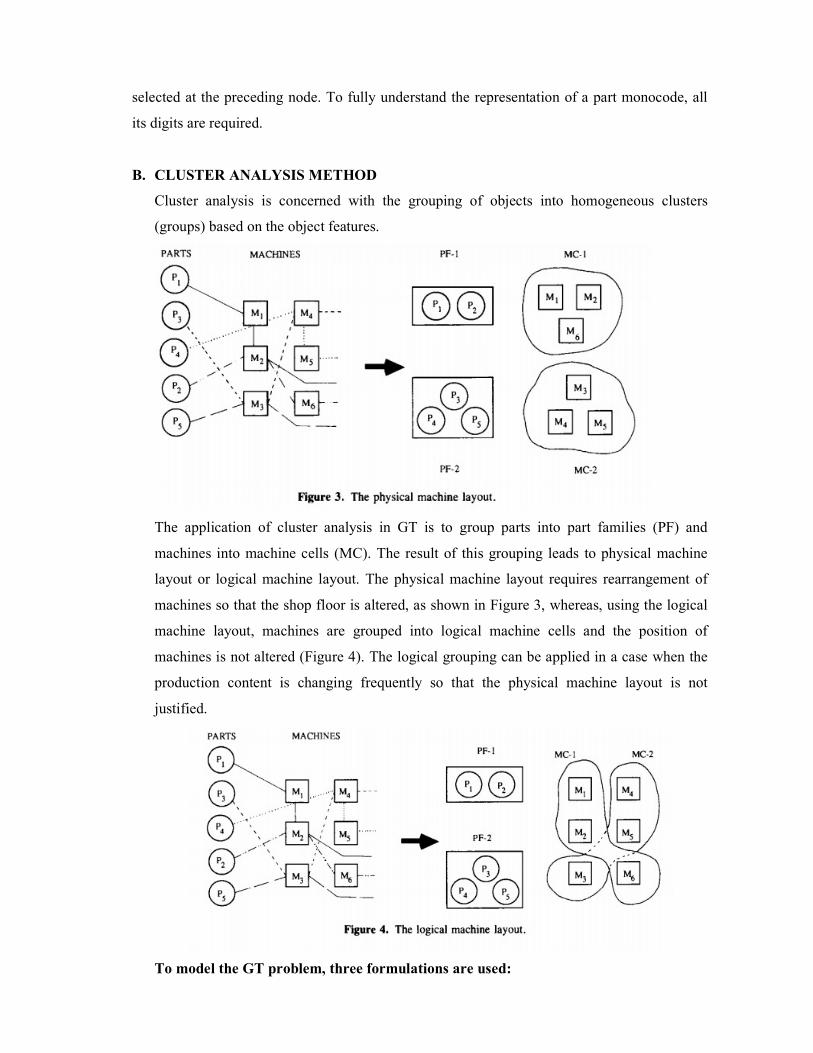
selected at the preceding node. To fully understand the representation of a part monocode, all
its digits are required.
B. CLUSTER ANALYSIS METHOD
Cluster analysis is concerned with the grouping of objects into homogeneous clusters
(groups) based on the object features.
The application of cluster analysis in GT is to group parts into part families (PF) and
machines into machine cells (MC). The result of this grouping leads to physical machine
layout or logical machine layout. The physical machine layout requires rearrangement of
machines so that the shop floor is altered, as shown in Figure 3, whereas, using the logical
machine layout, machines are grouped into logical machine cells and the position of
machines is not altered (Figure 4). The logical grouping can be applied in a case when the
production content is changing frequently so that the physical machine layout is not
justified.
To model the GT problem, three formulations are used:

• Matrix formulation
• Mathematical programming formulation
• Graph formulation
Matrix formulation
In the matrix formulation, a machine-part incidence matrix is constructed. The machine-part
incidence matrix consists of 0,1 entries, where an entry 1 (0) indicates that machine / is used (not
used) to process part j . Typically, when an initial machine-part incidence matrix [a^] is
constructed, clusters of machines and parts are not visible. Clustering algorithms allows one to
transform an initial incidence matrix into a more structured (possibly block diagonal) form. To
illustrate the clustering concept, consider the machine-part incidence Matrix (1)
Two machine cells (clusters) MC-1 = {2, 4}, MC-2 = {1, 3}, and two corresponding part families
PF-1 {1, 3}, PF-2 = {2, 4, 5} are visible in Matrix (2). Clustering of a binary incidence matrix
may result in the following two categories of clusters: (1) mutually separable and (2) partially
separable. The two categories of clusters are presented in Matrices (2) and (3)
Matrix (3) cannot be separated into two disjoint clusters because of part 5, which is to be
machined in two cells MC-1 and MC-2. Removing part 5 from Matrix (3) results in the
decomposition of Matrix (3) into two separable machine cells MC-1 = {1,2}, MC-2 = {3, 4} and
two part families PF-1 = {1,2} and PF-2 = {3,4}. The two clusters are called partially separable
clusters. To deal with the bottleneck part 5, one of the following three actions can be taken: 1. It
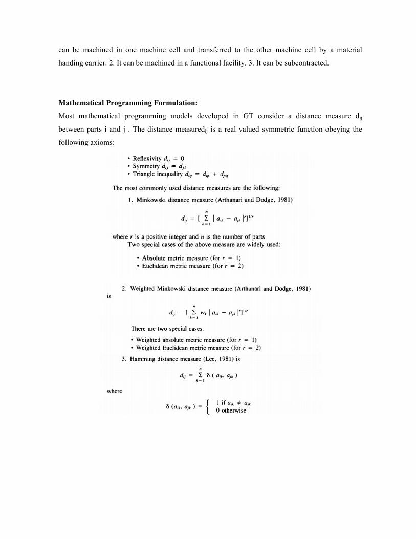
can be machined in one machine cell and transferred to the other machine cell by a material
handing carrier. 2. It can be machined in a functional facility. 3. It can be subcontracted.
Mathematical Programming Formulation:
Most mathematical programming models developed in GT consider a distance measure dij
between parts i and j . The distance measuredij is a real valued symmetric function obeying the
following axioms:

Graph Formulation:
In the graph formulation, the incidence matrix is represented by a graph. The following three type
of graphs can be used: bipartite, transition, and boundary.
A. BIPARTITE GRAPH: In the bipartite graph, one set of nodes represents parts and the other
machines. In order to discuss the application of bipartite graphs to GT, consider the graph in
Figure 8 representing the incidence matrix (1). It can be seen that the bipartite graph in Figure
8 decomposes into two disjoint bipartite graphs shown in Figure 9.

6. Post MCQ:
1.From the following in which type of GT code chain type structure is used?
a) Poly code
b) Hybrid code
c) Mono code
d) None of the above
Answer: a
2. Form code in OPITZ parts classification and coding system defines
a) Design attributes
b) Manufacturing attributes
c) Both (a) and (b)
d) None of the above
Answer: a
3.Grouping the production equipment into machine cells, where each cell specializes in the
production of a part family, is
a) Cellular manufacturing
b) Batch manufacturing
c) Machine cell manufacturing
d) None of the above

Answer: a
4. From the following which is type of GT code?
a) Mono code
b) Poly code
c) Hybrid code
d) All of the above
Answer: d
7.Conclusion
Understood about the group technology and machine cell
Learnt about various formulations of group technology
8.References
Jha.N.K., “Handbook of flexible manufacturing systems”, Academic Press Inc., 1991
9.Audio/ video - if any
10. Assignments
Explain the various methods used for solving the GT problem?
Explain in detail about various formulations of GT?
Topic – Title: knowledge based system for group technology, application of possibility
distributions in FMS systems justification.
1. Objectives and Outcomes:
To understand about knowledge based system for group technology.
To learn about various application of possibility distributions in FMS systems
justification.
2. Prerequisites:
The basic knowledge about knowledge based system in FMS
3. Theory Behind:
In this section, a formulation of the group technology problem that generalizes all the models
discussed in the previous sections is presented. Rather than the binary matrix the matrix [ttj]
where il7 ^ 0 is the processing time of part number j on machine number / is considered. The
formulation involves also some constraints, which are typical to flexible manufacturing
environments and have not been considered in the previous sections. The group technology
problem in flexible manufacturing systems can be loosely formulated as follows (Kusiak,
1987b): Determine machine cells and part families with a minimum number of parts visiting
more than one machine cell, and select a suitable material handling carrier with the minimum
corresponding cost subject to the following constraints:
Constraint C1 : Processing time available at each machine is not exceeded.

Constraint C2: Upper limit on the frequency of trips of material handling carriers for each
machine cell is not exceeded.
Constraint C3: Number of machines in each machine cell does not exceed its upper limit or
alternatively the dimension (e.g., the length) of each machine cell is not exceeded.
The above formulation of the GT problem is not only computationally complex, but also
involves constraints that are difficult to handle by any algorithm alone. Therefore, to solve the
above problem, a knowledge-based system has been developed.
STRUCTURE OF THE KNOWLEDGE-BASED SYSTEM
In this section, a tandem knowledge-based system for group technology (KBGT) is
considered. All models and algorithms discussed in the previous sections can be incorporated
into its model and algorithm base. A group technology problem that could be modeled by any
of the models discussed would be solved by a suitable algorithm. To simplify further
considerations, only one clustering algorithm presented in Section D is embedded into the
KBGT. The algorithm is suitable for solving the group technology problem in flexible
manufacturing systems as well as its special cases. The KBGT considered has the structure
shown in Figure 10. The KBGT consists of five components:
• Database • Knowledge base • Inference engine • Request processor • Clustering algorithm
Database:
The global database contains information about the current problem represented in a form of
objects and frames. It is a nonmonotonic database, since the objects are modified by the clustering
algorithm and the knowledge-based subsystem (KBS). The content of the database is either
provided by the user as input data, or generated by the system. A list of objects and frames in the
data base is as follows:

In cases when processing times are not available, by default the matrix is a Ο- incidence matrix,
i.e., p-time is 0. • Current machine is a machine that the system has selected for possible inclusion
in the machine cell currently being formed. • List of candidate machines is a list of candidate
machines to be included in the machine cell currently being formed.
• List of temporary candidate machines is a list of all machines such that the parts that are
processed on the current machine are also processed on one or more of these machines. Moreover,
these machines are not on the list of candidate machines.
• Part waiting list is a list of parts that have been removed from the machine-part incidence matrix.
• List of bottleneck machines is a list of all bottleneck machines.
• List of temporary bottleneck machines is a list of machines that are considered to be temporary
bottleneck machines. These machines may become nonbottleneck machines after some parts have
been removed from the machinepart incidence matrix.
• List of machines not used (same as discussed earlier in the subsection on the output data from
KBGT).
• MC-k (machine cell k) is a list of machine numbers in the current machine cell.
• PF-k (part family k) is a list of part numbers in the current part family.
THE KNOWLEDGE-BASED SUBSYSTEM

As illustrated in Figure 10, the knowledge-based subsystem consists of three components:
knowledge base, inference engine, and request processor.
1. Knowledge Base
The knowledge base in KBGT contains production rules, which have been acquired from three
experts in group technology and the literature. In the implementation of KBGT discussed in
this chapter, the knowledge base consists of three classes of production rules:
• Preprocessing rules
• Current machine rules
• Machine cell rules
The preprocessing rules deal with the initialization of objects in the database that are not
provided by the user. The current machine rules check the appropriateness of a current
machine to the machine cell being formed, for example, whether the current machine is a
bottleneck machine. The machine cell rules deal with each machine cell which has been
formed. Machine cell rules check for violation of constraints and remove parts violating them.
Structuring of rules into separate classes has two advantages. First, the search for applicable
rules is more efficient since the inference engine attempts to fire only rules that are relevant to
the current context. Second, the modularity of a rule base makes it more understandable, and
easy for modification.
2. Inference Engine
One of the greatest advantages of the tandem system architecture is the simplicity of the
inference engine. The inference engine in KBS employs a forward-chaining control strategy.
In a given class of rules, it attempts to fire all the rules which are related to the context
considered. If a rule is triggered, that is, the conditions are true, the actions of the triggered
rule are carried out. However, some rules, for example Rule 201, Rule 202, and Rule 203, stop
the search of the knowledge base and send a message to the algorithm.
3. Request Processor
The request processor facilitates the interaction between the algorithm and KBS. Based on
each request of the algorithm, the request processor calls the inference engine and selects a
suitable class of rules to be searched by the inference engine.
CLUSTERING ALGORITHM
Algorithm

Step 0. Set iteration number k = 1. Construct machine-part incidence matrix. Send a request to
KBS for preprocessing.
Step 1. Select a machine (row of machine-part incidence matrix) that processes the maximum
number of parts and is not in the list of temporary bottleneck machines. Place the selected
machine in the list of candidate machines.
Step 2. From the list of candidate machines, select a machine which is the most similar to
machine cell MC-k. If machine cell MC-Α: is empty, choose the machine selected in step 1.
Draw a horizontal line hi where i is the selected machine number.
Step 3. For each entry crossed once by the horizontal line draw a vertical line Vj. Parts
indicated by the vertical lines are potential candidates for part family PF-k. For each entry tij>
0 crossed by a vertical line νj add the corresponding machines, which are not in the list of
candidate machines to the list of temporary candidate machines. Remove the current machines
from the list of candidate machines.
Step 4. KB S analyzes the current machine selected and takes one of the following two
actions: • Go to step 5 (include the current machine in MC-k) • Go to step 1 (do not include it)
Step 5. Add the machine considered to machine cell MC-k. Add the corresponding part
numbers to part family PF-fc. If the list of candidate machines is empty, go to step 6;
otherwise, go to step 2.
Step 6. KBS analyzes machine cell MC-k for violations of constraints C1-C3 and attempts to
satisfy the constraints. Remove machine cell MC-Α: and part family PF-& from the machine-
part incidence matrix.
Step 7. If the machine-part incidence matrix is not empty, increment k by 1 and go to step 1;
otherwise, STOP.
Application of possibility distributions in FMS systems justification.
The characteristics of possibility distributions make them an ideal paradigm with which to
incorporate uncertainty into both the tactical and strategic phases of an FMS justification. The
basic FMS justification approach used here will be as described in Choobineh (1986), where
the tactical justification portion consists of a present-value analysis of shorter term,
quantifiable economic factors.
These factors can include first costs:
• Initial investment • Installation costs • Engineering costs • Tooling, fixtures, etc. • Facility
modifications

and annual benefits: • Direct labor savings • Material savings • Energy savings • Standard
overhead reduction • Inventory cost reduction • Quality improvements • Other annual
benefits/costs
Additional factors that must be obtained include interest rate estimates, tax rates, and
equipment life.
7.Conclusion
Understood about knowledge based system for group technology
Learnt about various application of possibility distributions in FMS systems
8.References
Jha.N.K., “Handbook of flexible manufacturing systems”, Academic Press Inc., 1991
9.Audio/ video - if any
10. Assignments
Explain the various components of knowledge-based subsystem?
What are the application of possibility distributions in FMS systems?
Name of the Course : Flexible Manufacturing Systems (FMS)
Name of the unit : APPLICATIONS OF FMS AND FACTORY OF THE
FUTURE (UNIT V)
Topic – Title : FMS application in machining, sheet metal fabrication,
prismatic component production

1. Objectives and Outcomes:
To understand about FMS applications in Machining and sheet metal fabrication
To understand about FMS applications in prismatic component production
2. Prerequisites:
The basic knowledge about FMS application in machining areas.
3. Theory:
FMS application in machining
A. CATEGORY
The FMS at the General Dynamics (GD) facility in Fort Worth, Texas, has been selected in
this category. This FMS is used for machining of discrete parts (Parker, 1987).
B. INTRODUCTION
This FMS was developed as a result of the combined efforts of GD and the Air Force Wright
Aeronautical Laboratories/Materials Laboratory (AFWAL/ML). As this FMS is a part of a
overall computer integrated manufacturing (CIM) architecture or strategy, it cannot be labeled
as an island of automation. Also, this FMS is important because it is both a commercial and a
research and development venture. One of the goals of this FMS was to advance the American
machine tool and factory automation industries. Westinghouse Automation Division was the
main supplier.
C. PHYSICAL CONFIGURATION
DeVlieg Machine Co. supplied the machine tools for this FMS, which is comprised of six,
five-axis DeVlieg 430R machining centers. The pallet changers at the front of each machine
automatically perform pallet exchanges between the AGV, pallet queueing stations, and the
machine bed. A second pallet changer at the rear of the machine tool is used to exchange tool
carousel pallets with the AGV. Part dimensions are inspected on LK Tool horizontal-arm
coordinate measuring machines (CMM), which are fully integrated with the FMS to provide
for unattended operations. Cutting tools are stored in a central tool crib. Required tools are
manually loaded on a tool pallet carousel. When these tools are loaded, a pallet changer in the
tool crib automatically loads the tool pallet onto an AGV for delivery to the appropriate
machine. At the machine, a GMF robot loads these tools into the tool magazine and unloads
dull or unneeded tools to be returned to the tool crib. The entire basic FMS is controlled by a
cell control system based on artificial intelligence (AI) and distributed processing technology.
Automated scheduling and control has been achieved. The FMS control system is linked with
plant-level control systems to achieve integration of FMS operations in the overall factory.
D. OPERATIONAL DESCRIPTION

Parts are loaded to fixtures at one of two load/unload stands. Fixtures are permanently
mounted to tooling cube tombstones, which in turn are mounted on part pallets. The
fixture/cube/pallet assemblies are stored in a pallet storage area. This assembly is retrieved by
the tracked automatic pallet changer (APC) and delivered to one of the two load/unload stands.
At this place it is picked up by an AGV
E. MACHINING CENTERS
The DeVlieg machines used in this FMS are unique as they have several built-in features to
facilitate unmanned or unattended operations. These CNC machines have five-axis capability
and are equipped with an automatic tool changer.
F. INTEGRATED INSPECTION EQUIPMENT
This FMS uses CMM manufactured by LK Tools. Inspection is considered an important part
of FMS operations and thus is fully integrated in FMS. The CMM has several special features
to achieve integration. The FMS parts are machined on a horizontal spindle machining center
and remain on the same fixture for inspection. To utilize the same horizontal fixture, the CMM
is designed with a horizontal arm. This is a deviation from conventional practice of vertically
oriented, gantry robot-type CMMs. The standard CMM rotary table is modified so that the
DeVlieg pallet changer can automatically perform load and unload operations. Additional
flexibility has been achieved by using an automatic probe changer. This is necessary as a large
variety of FMS parts cannot be inspected using only a single stylus probe or sensor.
Conventional touch type and the recent laser probes are both used in the system. Inspection
data collected by CMM are transferred to the FMS controller. At the FMS controller, statistical
analysis is performed. The data are subsequently passed to plant-level quality assurance
systems.
G. MATERIAL HANDLING SYSTEM
The system is comprised of two battery-operated AGVs and pallet changers. The AGV was
supplied by Control Engineering, a subsidiary of Jervis B. Webb Company. The pallet
changers were supplied by DeVlieg, the supplier of machine tools. The AGVs can
automatically charge batteries through contact plates mounted on the floor at two system
locations; as batteries can be charged any time the vehicles are idle. This method is known as
"opportunity" charging. This has enabled the FMS to operate with only two AGVs. Standard
DeVlieg pallet receiving tables are installed on top of the table lifting mechanism of the AGV,
which is completely passive during the pallet changing operation. A pallet changer does all the
work of sliding a pallet onto the AGV or removing the pallet from it. The AGVs are used to
transport both part pallets and tool pallets in the FMS. The pallet with tools or parts appears

exactly the same to the AGV. Fixtures are permanently set up on pallets. They are changed
only for repair or modifications.
H. CONTROL SYSTEM
The control system essentially determines the performance level of the complete FMS. This
control system also integrates FMS operation within the plant. The system has been designed
to optimize the performance of the FMS and at the same time achieve integration with the rest
of the plant. The system architecture is shown in Figure 1. The control system software and
hardware are described in the following sections.
FMS application in sheet metal fabrication:
A. CATEGORY
This FMS at the General Electric facility in Salisbury, North Carolina, is used for fabricating
sheet metal enclosures and associated components for electrical equipment (Runewicz, 1987).
B. INTRODUCTION
This is one of the pioneering applications of FMS technology to sheet metal fabrication. By
producing over 300 parts, a true flexibility of production has been achieved. Parts produced
are rather simple as compared to parts produced in the FMSs for aerospace application
described previously. This indicates that cost-effective application of FMS technology does
not depend on the complexity of the parts.
C. PHYSICAL CONFIGURATION
A schematic of the FMS physical configuration is given in Figure 2. The FMS can be divided
into the following parts: CI shearing center, line 1, line 2, line 3, line 4, and material handling
system.

1. CI Shearing Center
This is an entry point for all the incoming sheet metal stock. The shearing center receives a
daily production schedule. The sheets are loaded onto the loading tables and the large sheets
are then cut into smaller sheets and transferred through a magnetic conveyor system and
stacked onto a roller surface until the shear has completed packing requirements. After the
stack has been completed, it is transferred to the required line. An ink jet system is used to
trace the sheets. The pack distribution system consists of seven stackers or scissor tables. The
stackers lift and traverse by using roller surfaces fixed to the ground. Other roller surfaces are
used as buffers between the shear and individual lines.
2. Line One
As mentioned above, sheet metal stock is stacked and transferred to individual lines. A
magnetic destacker is used to transfer one sheet at a time from the pack to the line. The
following machines are in each line: punching and shearing machine, panel bending machine,
and embossing station. An embossing operation is required on only a few parts and hence the
embossing station either performs the operation or simply transfer parts to the exit conveyor.
3. Line Two
Line two is quite similar to line one. This line has only two machines: punching and shearing,
and bending. The difference between the punching operation in line one and line two is that
the punching head in line two uses a special head to draw holes or both holes and knockouts.
A vertical storage unit is used as a buffer between the punching and bending operations. After
a final forming operation on the bending machine, sheets are transferred to the exit conveyor.
4. Line Three
Line three is used to produce many small parts with an overall volume of over 1 million per
year. The shearing machine in this line is similar to the shearing machine in line two, and in

addition there are five embossing units. This line has significantly more job-routing flexibility
as some parts are processed through the punching machine only, while others can be processed
through all three machines. Smaller parts are transferred by an underground conveyor to a bin
system that automatically sorts the parts for use in the final assembly. Some parts that require
a bending operation are transferred between the lines on a cross conveyor to line two. The
system also has the flexibility to transfer parts to a programmable press brake.
5. Line Four
The configuration of the punching machine is identical to that of other lines. Five double
embossing units are added to the punching line. This line also includes a 100-metric-ton
hydraulic press which can bend up to 32 different parts automatically.
6. Material Handling System
An automated conveyor-based elaborate system is used for material handling. These
conveyors link each machine together. As described above, machines within each line are
interconnected. A cross conveyor connects all four lines. The cross conveyor is used when it is
necessary to transfer sheets between the lines. The cross transfer facility has increased
flexibility of the system and ensured cost-effective utilization of the machinery. Scrap removal
is an integrated part of this system. Scrap removal conveyors run under all punching machines.
At the shearing center there are two large scrap containers. Scrap is automatically separated
into mild steel and galvanized and is stored separately into two containers.
7. Conclusion:
Understood about FMS applications in Machining and sheet metal fabrication
8.References
Jha.N.K., “Handbook of flexible manufacturing systems”, Academic Press Inc., 1991
9.Audio/ video - if any
10. Assignments
Explain in detail about FMS applications in Machining and sheet metal fabrication?

Topic – Title: FMS development towards factories of the future – artificialintelligence and
expert systems in FMS – design philosophy and characteristics for future
1. Objective:
To understand FMS development towards factories of future
To know about artificial intelligence and expert systems in FMS
To learn about the design philosophy and characteristics of future
2. Prerequisites:
The basic knowledge about FMS developments in future.
3. Pre MCQ:
1. Flexible manufacturing systems (FMS) are reported to have a number of benefits. Which of the
following is not a reported benefit of FMS?
a) More flexible than the manufacturing systems they replace
b) Increased quality
c) Lead-time and throughput time reduction
d) Increased utilization
Answer: a
2. The FMS is a vital component of an aircraft’s __________
a) Electronics
b) Electricals
c) Hydraulics
d) Avionics
Answer: d
3. From the following which is not the application of AGV.
a) Truck loading and unloading
b) To change the tool
c) Material transfer
d) Paper roll tractor
Answer: b
4.Which of the following is an advantage of using an expert system development tool?
a) Imposed structure
b) Knowledge engineering assistance
c) Rapid prototyping
d) All of the above
Answer: d

4. Theory:
FMS development towards factories of the future
The increasing importance of information flow planning and development is shown in Figure 1. It
is likely that in a few years half of the work involved with FMS projects as a whole will be taken
up with this aspect. This is in line with findings by the consultancy company, McKinsey, which
forecasts a 50% software component in FMS, making this sector the decisive market segment in
factory automation of the 1990s.
The demand for development resources aimed at FMS elements will not decrease in the future.
Many FMS components are commercially available now, so that one might expect the main task
of an FMS project to consist of the accurate planning and arrangement of known components.
More and more development tasks for FMS are still arising, however. The implementation of
software in particular remains a major problem. Standardization of interfaces is one way of
reducing the expense for adaptation. The main task, however, is the reduction of the number of
interfaces.
It is not only parts, and possibly tools, which need to be transported in flexible manufacturing
systems. The automated clearance and disposal of chips from machining is a task which did not
occur on working schedules previously and which was often left out of consideration until the
automation stage. Here many detail problems have to be solved. A single chip at the wrong spot
can disrupt automated machining and material flow and can bring the whole system to a standstill.
Attention to supposedly unimportant things such as chip flow and the provision of suitable
technical and organizational measures to deal with them may be key factors for the failure-free
operation and running of the material flow in future FMS. Not only the project contents but also
the products to be manufactured in FMS have changed. Since 1980, development efforts have

been aimed at the design of FMS for turning, welding, and sheet metal working (Figure 2). The
special problems of sheet metal working with regard to flexible manufacturing have resulted in an
average difference of one generation between part manufacturing and sheet metal working. There
is thus a great potential for improvement.
Artificialintelligence and expert systems in FMS:
COMPUTER-AIDED PLANNING AS A CENTRAL PLANNING AREA
Since essential tasks in the conceptual and operative phases of the manufacturing system are
the responsibility of operations planning, considerable interaction can be noted, especially
between process planning and the economical introduction of flexible manufacturing systems.
Thus operations planning determines the investment costs for processing and material flow
facilities, as well as manufacturing system operating costs (Roth et al., 1988). During the
planning and configuring of flexible manufacturing systems, work plans are important for
analysis of the current status and the future workpiece spectrum. As such they form the basis
for new manufacturing concepts (Figure 9). In addition to the representative workpiece
spectrum, the process plans must be prepared in the initiation phase for all workpieces to be
processed in the flexible manufacturing system. Also, a multitude of special requirements must
be considered in respect of the manageable complexity of workpieces or machine tool process
reliability, with low staffing levels. A process plan update is often carried out during

adaptation of construction or process times on new manufacturing concepts with higher
productivity.
A fundamental consideration of changed chucking situations or of a changed tool requirement
occurs in very few cases. In the course of planning activities for a flexible manufacturing
system, as the long-term task of operations planning, it is necessary to retain detailed
knowledge obtained about manufacturing possibilities.
BASIC TASKS AND METHODS OF PROCESS PLANNING Within the production
development process, operations planning represents the link between product definition in
design and product realization in manufacture. Computer aids can be classified into the
following four basic types: 1. Repeat planning: The simplest type of process planning, slight or
form changes on plans already existing. However, no new planning data prepared. 2. Variation
planning: Already existing standard process plans are used as a basis for planning workpieces
within corresponding part families and planned from the resulting geometry or quantity
variations. 3. Similar planning: By means of the plan of a workpiece with similar geometry and
manufacturing technology, planning takes place by change and adaption of individual process
operations.
INTEGRATION INTO THE INTERNAL INFORMATION FLOW CONCEPT

The efficiency of a manufacturing area, and particularly the means of manufacture, has
increased considerably in recent years. By contrast, the immediately adjacent areas have been
largely excluded from this development despite the considerable contribution they make to
the overall costs. In this respect, it would appear that too much emphasis has been placed on
rationalization and automation of production as a way of optimizing the manufacturing
process as a whole. While CAD systems and databanks with subject characteristics are well
established, computer-assisted process planning is still in its infancy.
KNOWLEDGE-BASED PLANNING AIDS
1. Decision Table Systems
Decision table systems represent a preliminary stage in the direction of automatic systems
for process plan preparation. As an aid, they offer procedures from manual dialog-oriented
plan preparation, through semiautomatic functions, to fully automatic process plan
generation. By means of decision table technology, intelligent dialog can be achieved with
reduced input expense. Above all, however, projection of the process plan logic
contributes to raw material operations, machine and processing stock determination, and
time study. Furthermore, the required hierarchical construction of the system contributes
considerably to the systemization of planning activities. With the aid of decision table
generating and interpreting programs, the tables can be generated and modified relatively
easily.
2. Expert Systems
In comparison to conventional systems and as an extension of decision table systems,
expert systems make it possible to process planning knowledge in the form of rules and
facts. Knowledge is no longer in firmly programmed or tabular form, but given to the
knowledge base without a rigid structure. The finishing of this planning knowledge takes
place through a so-called inference component, which deduces results for a specific
application from the user's input. In recent years, process plan preparation has been
tackled intensively with the help of expert systems, especially by universities. However, at
this point only a few implementable formulations are known. They are nevertheless
promising, particularly in the area of rotational workpieces. Expert systems are ideal for
planning tasks in particular, not least as a result of the planner's method of working, which
involves breaking down a problem initially into a number of subtasks and devising partial
solutions for each of these tasks. When all the alternatives are considered together, a large
number of combinations present themselves. All-purpose software aids are incapable of
handling this profusion of concepts, and planners are obliged to resort to knowledgebased
problem-solving techniques. From the planner's procedures in new planning, a model can

be defined consisting of five planning steps (Figure 10). This is valid for planning the total
part spectrum, with individual workpieces run through repeatedly.
Construction of the expert system, itself composed of dialog and inference components
and a knowledge base, is identified through the tie-up to the CAD system and the
knowledge base divided up in different modules (Figure 11). The dialog component
represents the interface to the user not only in the actual course of planning, but supports

the user as an aid in form recognition. This calls for an intrinsic and discriminating
inference process in the planning segment.
Design philosophy and characteristics for future:
MACHINE TOOLS IN FLEXIBLE MANUFACTURING SYSTEMS
What will be the main characteristics of flexible manufacturing systems in the 1990s? A survey
recently carried out by the Fraunhofer Institute for Manufacturing Engineering and Automation on
FMSs already partially installed, planned in detail, or designed conceptually for the 1990s showed
that an impressive range of all kinds and sizes of FMS is planned in Germany in the coming years
(Figure 13). Although lathes and machine centers will still remain the kind of machine tools used
most frequently in future FMSs, one-third also involve grinding machines and nearly one-half
contain other machine tools (Figure 14). Looking at additional operations to be included into
FMS, Figure 15 shows that there is a great need for "system machines of the next generation"
which should also be available for non-chip-forming operations and adaptable to the material flow
and information flow interfaces within FMS. Efforts are being made in the development of system
to further automate tool handling in FMS (Figure 16).

Even now the technology exists to delivertools within the FMS using mobile robots and AG Vs.
Sensor technology and related algorithms will progress. Thus it will be possible to predict tool
wear and tool breakage more accurately. Inspection of workpieces will also be a target for FMS
suppliers as links between coordinate measuring machines and FMS control are refined and fully
exploited. Some experts predict breakthroughs allowing more inspection to be performed on the
machine tools themselves. Advances in adaptive control will continue. Automated compensation
at the machine tool for drive axis error and the effect of misalignment forces, workpiece weight,
temperature, and machine component wear will also improve. The link between CAD and CAM
will be increasingly exploited. Designers will create families of parts designed specifically for
efficient machining using FMS technology. The future will also bring new sophistication in FMS
operating software. Start-up procedures will be easier and less time-consuming.

Much work will be done to automate fixture storage and retrieval systems to lessen the work of
setup and tear-down. Further advances will emerge in serialization. Every tool, fixture, pallet, cart,
or other transportable element of an FMS can be identified and tracked for improved overall
system control (Figure 17). Application of bar-code scanners and other identification technologies
will increase. To date, most machine tools and their peripherals have not been prepared for these
purposes. For this reason, presently FMSs contain a multitude ofdifferent workpiece and tool
carriers, pallets, and other handling devices which considerably complicate investment to a hardly
affordable amount. "System machines of the next generation" should therefore use common
standards and interfaces not only for material flow, but also, and not less important, for
information flow.
MODULAR DESIGN OF FLEXIBLE MANUFACTURING SYSTEM CONTROL
SOFTWARE
The key to flexibility is software. Controls and software can represent as much as one-third to
one-half of the total investment of a complex system. Because of this, and to provide a "learning-
by-doing" possibility in a step-bystep approach from automation islands to integrated systems,
modular design of software packages will be absolutely indispensable. These packages will be
assembled in different combinations, according to different individual applications and needs.
Figure 18 shows the main goals stated in the survey mentioned above and the resulting
requirements for FMS control.

Furthermore, FMS controls and software have to be compatible with business information
systems, so that they can successfully interact with the overall system using a common database
for design, manufacturing, and all other tasks within the entire operation, thus becoming a step
toward and a part of computerintegrated manufacturing (CIM) in the automated factory of the
future.
FUTURE COOPERATION IN THE FACTORY AUTOMATION MARKET
The most frequently asked question is, "What kind of general supplier should one turn to for an
overall factory automation concept?" The manufacturer of existing commercial data processing
systems? The CNC and DNC machine tool supplier? Or an independent systems and software
house? The choice is not easy—the leap from hitherto isolated computer applications to CIM is
as great as that from a company car to a company plane, something which would certainly not
be ordered from the former car supplier (although there are companies who make both cars and
planes!). The question will probably stay unanswered in the next decade. It might be important,
however, to remember that there are two essential prerequisites for successful extending right
down to the factory floor: a sophisticated software concept and the skilled knowledge of
production procedures within the company and on the shop floor itself. The latter at least
should be provided by the usercompany at the planning stage, no matter whether a general
supplier for the integrated overall solution or various component manufacturers are involved in
the project. This entails familiarity with all specific components, especially with "system
machines of the next generation," which in spite of all CIM discussions will continue to play an
important role in the success of manufacturing companies.

7. Post MCQ:
1. The first widely-used commercial form of Artificial Intelligence (Al) is being used in many
popular products like microwave ovens, automobiles and plug in circuit boards for desktop
PCs. It allows machines to handle vague information with a deftness that mimics human
intuition. What is the name of this Artificial Intelligence?
a) Boolean logic
b) Human logic
c) Fuzzy logic
d) Functional logic
Answer: c
2. Volume of work produced in a FMS environment is determined from
a) Number of machine used in the FMS
b) Type of material handling equipment used in FMS
c) Type of layout used in FMS
d) All of the above
Answer: d
3. Strong Artificial Intelligence is
a) The embodiment of human intellectual capabilities within a computer
b) A set of computer programs that produce output that would be considered to reflect
intelligence if it were generated by humans
c) The study of mental faculties through the use of mental models implemented on a computer
d) All of the above
Answer: a
4. FMS has three major components
a) Machining/turning centres, robots and computers
b) Machining/turning centres, material handling system and computer control system
c) Machining/turning centres, CMM, robots and computer control system
d) None of the above
Answer: b
5. Automated vehicle is an example of ______
a) Supervised learning
b) Unsupervised learning
c) Active learning
d) Reinforcement learning
Answer: a

7. Conclusion:
Understood about FMS development towards factories of future
Learnt about artificial intelligence and expert systems in FMS
Learnt about the design philosophy and characteristics of future
9. References
Jha.N.K., “Handbook of flexible manufacturing systems”, Academic Press Inc., 1991
9.Audio/ video - if any
10. Assignments
Explain in detail about FMS development towards factories of future?
Explain in detail about artificial intelligence and expert systems in FMS?
Explain in detail about design philosophy and characteristics of future