EC660 - Pandian Saraswathi Yadav Engineering College
23
PANDIAN SARASWATHI YADAV ENGINEERING COLLEGE Department of Electronics and Communication Engineering Subject Code/Subject: EC6602 – ANTENNA AND WAVE PROPAGATION Branch/Year/Semester: ECE / III / 06 Regulation : 2013 Staff In-charge: Mrs.P.Padmasri, AP/ECE FUNDAMENTALS OF RADIATION Unit-I Part - A 1.Define gain and directivity of an antenna..(APRIL/MAY 2011) Gain of the antenna is defined as the ratio of maximum power radiation intensity in a given direction to the maximum radiation intensity of a reference antenna. Power gain is defined as the ratio of maximum power radiated by a test antenna to the maximum power radiated by a reference antenna. 2.What is the significance of radiation resistance of an antenna? (APRIL/MAY 2011) It is defined as the fictitious resistance which when inserted in series with the antenna will consume the same amount of power as it is actually radiated. The antenna appears to the transmission line as a resistive component and this is known as the radiation resistance. The radiation resistance of a half wave dipole is given by Rr=73 ohm 3.Define effective aperture of an antenna. (NOV/DEC 2011) It is the area over which the power is extracted from the incident wave and delivered to the load is called effective aperture. 4. Define antenna efficiency? (NOV/DEC 2011) The efficiency of an antenna is defined as the ratio of power radiated to the total input power supplied to the antenna. Antenna efficiency = Power radiated / Total input power
-
Upload
khangminh22 -
Category
Documents
-
view
1 -
download
0
Transcript of EC660 - Pandian Saraswathi Yadav Engineering College
PANDIAN SARASWATHI YADAV ENGINEERING COLLEGE
Department of Electronics and Communication Engineering
Subject Code/Subject: EC6602 – ANTENNA AND WAVE PROPAGATION
Branch/Year/Semester: ECE / III / 06
Regulation : 2013
Staff In-charge: Mrs.P.Padmasri, AP/ECE
FUNDAMENTALS OF RADIATION
Unit-I
Part - A
1.Define gain and directivity of an antenna..(APRIL/MAY 2011)
Gain of the antenna is defined as the ratio of maximum power radiation intensity in a given
direction to the maximum radiation intensity of a reference antenna.
Power gain is defined as the ratio of maximum power radiated by a test antenna to the
maximum power radiated by a reference antenna.
2.What is the significance of radiation resistance of an antenna? (APRIL/MAY 2011)
It is defined as the fictitious resistance which when inserted in series with the antenna
will consume the same amount of power as it is actually radiated. The antenna appears to the
transmission line as a resistive component and this is known as the radiation resistance.
The radiation resistance of a half wave dipole is given by Rr=73 ohm
3.Define effective aperture of an antenna. (NOV/DEC 2011)
It is the area over which the power is extracted from the incident wave and delivered
to the load is called effective aperture.
4. Define antenna efficiency? (NOV/DEC 2011)
The efficiency of an antenna is defined as the ratio of power radiated to the total input
power supplied to the antenna.
Antenna efficiency = Power radiated / Total input power
5.What is meant by reciprocity Theorem.? (NOV/DEC 2009)
If an e.m.f is applied to the terminals of an antenna no.1 and the current measured at the
terminals of the another antenna no.2, then an equal current both in amplitude and phase will be
obtained at the terminal of the antenna no.1 if the same emf is applied to the terminals of antenna
no2.
6.Define Half power Beam width. (NOV/DEC2012)
HPBW is the angular width measured on the major lobe of radiation pattern between points
where the radiated power has fallen to half of its maximum value. It is otherwise called as 3 dB
beamwidth.
7.What are field and Power pattern in antenna radiation pattern? (NOV/DEC 2013)
If the radiation from the antenna is expressed in terms of the field strength in spherical
coordinate system, then the radiation pattern is called Field pattern.
If the radiation from the antenna is expressed in terms of the power per unit area, then
the radiation pattern is called Field pattern.
8.What are the dBi and dBd? Write their significance.(NOV/DEC 2013)
dBi and dBd are used to measure the focusing power (gain) of antennas. MaxStream
specifies all antennas in dBi only.
dBi is a measurement that compares the gain of an antenna with respect to an isotropic
radiator (a theoretical antenna that disperses incoming energy evenly over the surface of an
imaginary sphere.)
dBd compares the gain of an antenna to the gain of a reference dipole antenna (defined as
2.15 dBi gain).
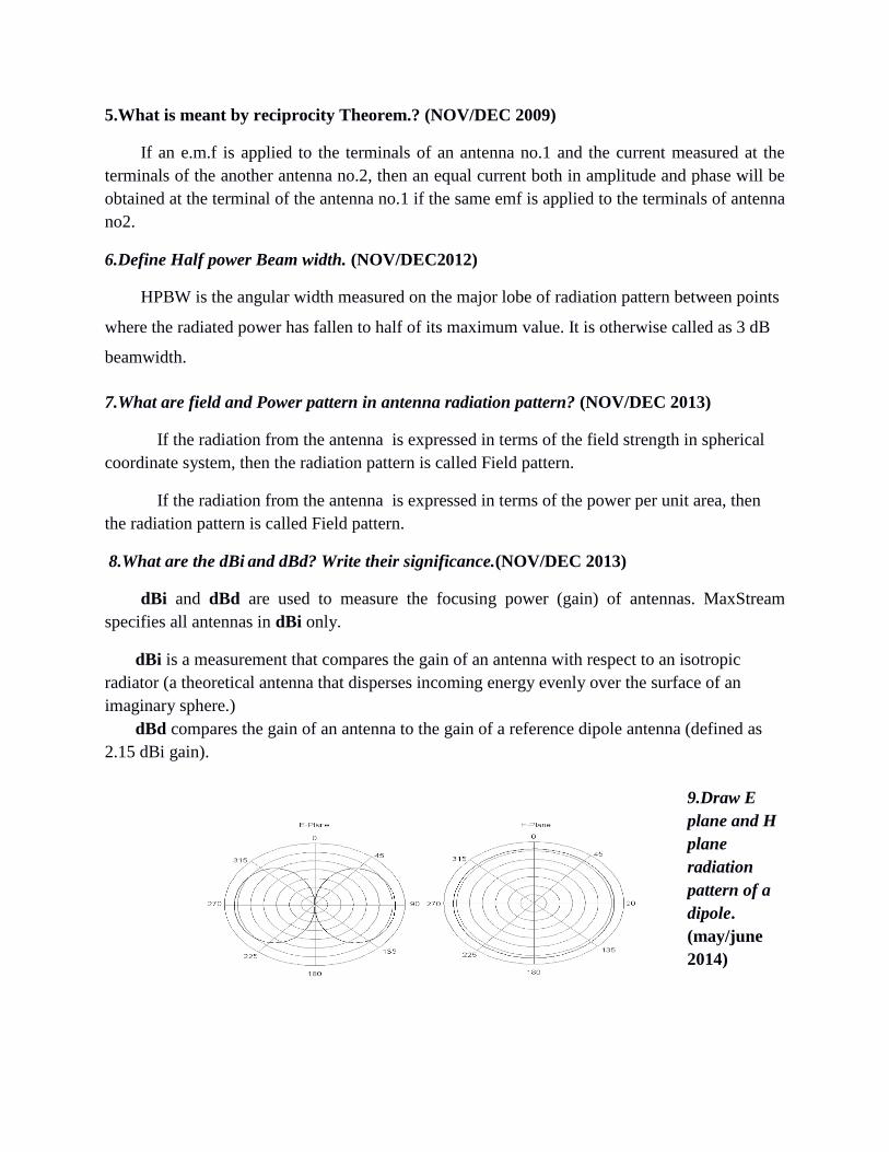
9.Draw E
plane and H
plane
radiation
pattern of a
dipole.
(may/june
2014)
10.Define directivity and effective aperture of an antenna. (may/june 2012)
The directivity of an antenna is equal to the ratio of the maximum power density P(θ,φ)
max to its average value over a sphere as observed in the far field of an antenna.
D = P(θ,φ)max / P(θ,φ)av. Directivity from Pattern.
D = 4π / ΩA. . Directivity from beam area(ΩA )
11.What is an elementary dipole and how does is differ from the infinitesimal
dipole.(may/june 2013)
The infinitesimal dipole is a dipole whose length l∆is much smaller than the wavelength λ
of the excited wave, i.e.∆ l<<λ (Δl< λ< 50).
The infinitesimal dipole is equivalent to a current element I∆l, where I∆l=dQ/dt* ∆l
12.What is the effective half wave dipole operating at 1 GHz? (may/june 2013)
The half-wave dipole antenna is just a special case of the dipole antenna, but its important
enough that it will have its own section. Note that the "half-wave" term means that the length of
this dipole antenna is equal to a half-wavelength at the frequency of operation.
To make it crystal clear, if the antenna is to radiate at 1 GHz, what size should the half-
wavelength dipole be?
One wavelength at 1 GHz is λ= c / f = 0.3 meters. Hence, the half-wavelength dipole
antenna's length is 0.15 meters.
13. Define self impedance (APRIL/MAY 2011)
Self impedance of an antenna is defined as its input impedance with all other antennas are
completely removed i.e away from it.
14.Define Aperture efficiency.(NOV/DEC 2010)
The ratio of the effective aperture to the physical aperture is the aperture efficiency. i.e
Aperture efficiency = η ap = A e / A p (dimensionless).

15.Define Directivity.(NOV/DEC 2009)
The directivity of an antenna is equal to the ratio of the maximum power density P(θ,φ)
max to its average value over a sphere as observed in the far field of an antenna.
D = P(θ,φ)max / P(θ,φ)av. Directivity from Pattern.
D = 4π / ΩA. . Directivity from beam area(ΩA )
16.What is meant by cross field?(APRIL/MAY 2013)
Normally the electric field E is perpendicular to the direction of wave propagation. In
some situation the electric field E is parallel to the wave propagation that condition is called
Cross field
17.Define Beam efficiency. (NOV/DEC 2009)
The total beam area ( WA) consists of the main beam area (W M ) plus the minor lobe
area (W m) . Thus WA= WM+W m.
The ratio of the main beam area to the total beam area is called beam efficiency. Beam
efficiency = SM=W M/ W A.
18.Define mutual impedance.(APRIL/MAY 2012)
The presence of near by antenna no.2 induces a current in the antenna no.1 indicates that
presence of antenna no.2 changes the impedance of the antenna no.1.This effect is called mutual
coupling and results in mutual impedance.
19.What is meant by isotropic radiator?(APRIL/MAY 2012)
A isotropic radiator is a fictitious radiator and is defined as a radiator which radiates
fieldsuniformly in all directions. It is also called as isotropic source or omni directional radiator
or simply unipole.
20.What is meant by effective height?
The effective height h of an antenna is the parameter related to the aperture.It may be
defined as
the ratio of the induced voltage to the incident field. H= V / E.
21.What is meant by front to back ratio.?
It is defined as the ratio of the power radiated in desired direction to the power radiated in

the opposite direction. i.e FBR = Power radiated in desired direction / power radiated in the
opposite direction
22.Define different types of aperture.
Effective aperture(A e ).: It is the area over which the power is extrated from the incident
wave and delivered to the load is called effective aperture.
Scattering aperture(A s .): It is the ratio of the reradiated power to the power density of the
incident wave.
Loss aperture. (A e ).: It is the area of the antenna which dissipates power as heat.
Collecting aperture. (A e ).: It is the addition of above three apertures.
Physical aperture. (A p ).: This aperture is a measure of the physical size of the antenna.
23.Define an antenna.
Antenna is a transition device or a transducer between a guided wave and a free space
wave or vice versa. Antenna is also said to be an impedance transforming device.
24.What are the field zone?
The fields around an antenna ay be divided into two principal regions.
i. Near field zone (Fresnel zone)
ii. Far field zone (Fraunhofer zone)
25.What is meant by Polarization?
The polarization of the radio wave can be defined by direction in which the electric
vector E is aligned during the passage of atleast one full cycle. Also polarization can also be
defined the physical orientation of the radiated electromagnetic waves in space. The polarization
are three types. They are Elliptical polarization ,circular polarization and linear polarization.
26.What is meant by Beam Area.?
The beam area or beam solid angle or Ω A of an antenna is given by the normalized power
pattern over a sphere.
Ω A = ∫ ∫ 4π P n ( θ,φ ) dΩ
Where dΩ = Sin θ d θ .dφ
27. State Poynting theorem.

It states that the vector product of electric field intensity vector E and the magnetic filed
intensity vector H at any point is a measure of the rate of energy flow per unit area at that
point.The direction of power flow is perpendicular to both the electric field and magnetic field
components.
PART – B
1.Derive the Electric and magnetic field quantities of Hertzian dipole(16) (APRIL/MAY 2011)
(NOV/DEC 2012)
2.Explain the following terms with respect to antenna:
(i) Polarization (4)
(ii) Effective aperture (3)
(iii) Directivity (3)
(iv) Antenna temperature (3)
(v) Radiation pattern. (3) (APRIL/MAY 2011)
3.What are Hertizian dipoles? Derive the Electric and magnetic field Quantities of infinitesimal
dipole and radiation pattern. (16) (NOV/DEC 2011)
4.Explain the parameters of an antenna:
(i) Beam solid angle
(ii) Radiation pattern
(iii) Gain
(iv) Polarization
(v) Bandwidth. (16) (NOV/DEC 2011)
5.Define and explain in detail the terms “Radiation Resistance”, “Gain”, “diversity”, “effective
aperture” and “polarization” of an Antenna. (16) (NOV/DEC 2012)
6.(I) Derive the radiation resistance of an oscillating electric dipole. (8)
(ii) Define and explain the polarization and its significance in antenna Analysis. (8)
(NOV/DEC 2013)
7.(I) State and prove Lorentz Reciprocity theorem for antennas. (8) (NOV/DEC 2013)
(ii)Define
(1) Gain
(2) Directivity
(3) Antenna temperature
8. Explain about Antenna Impedance. (8) (NOV/DEC 2013)
APERTURE AND SLOT ANTENNAS
Unit-II
PART - A
1.What are the applications of loop antenna? (APRIL/MAY 2011)
i. Used in radio receivers
ii. Used in aircraft receivers
iii. Used in direction finding
iv. Used in WHF transmitter
2.Define pattern multiplication. (APRIL/MAY 2011)(NOV/DEC 2011)
The total field pattern of an array of non isotropic but similar sources is the
product of the
i) individual source pattern and
ii) The array pattern of isotropic point sources each located at the phase center of the
individual source having the same amplitude and phase.
While the total phase pattern is the sum of the phase patterns of the individual source
pattern and array pattern.
3.Why is loop antenna called as magnetic dipole? (NOV/DEC 2011)
The small loop antenna is also known as a magnetic loop since it behaves electrically as a
coil (inductor) with a small but non-negligible radiation resistance due to its finite size. It can be
analyzed as coupling directly to the magnetic field (opposite to the principle of a Hertzian
dipole which couples directly to the electric field) in the near field, which itself gives rise to an
electric field through Faraday's law of induction and a full blown electromagnetic wave in the
far field. .
4.State the principle of pattern Multiplication. (NOV/DEC2012)

The pattern multiplication principle states that the radiation patterns of an array of N
identical antennas is equal to the product of the element pattern Fepattern of one of the
antennas) and the array pattern Fa.
. where Fa
is the pattern obtained upon replacing all of the
actual antennas with isotropic sources.
5. What are the conditions to obtain end fire array pattern? (NOV/DEC2012)
An array is said to be end fire if the phase angle is such that it makes maximum radiation in the
line of array i.e. 0degree &180 degree
For end fire array Ψ=0 & φ=0 degree & 180 degree
6.Mention the features of radiation pattern multiplication principle. (NOV/DEC2012)
Provides a speedy method for sketching the radiation patterns of complicated arrays just by
inspection.
7.Compare short dipole from half wave dipole. (may/june 2014)
The short dipole antenna is one that is short when compared to a wavelength at the operating
frequency. Typically a short dipole antenna is taken to be one that is less than a tenth of a
wavelength long. However this is very much a 'rule of thumb' and slightly different definitions
may appear in various quarters. The short dipole antenna consists of two co-linear conductors
that are placed end to end, but with a small gap between them for the feeder.
The half wave dipole is the most widely used version of the dipole antenna or aerial. As the
name implies, the half wave dipole is a half wavelength long. The antenna is the shortest
resonant length that can be used for a resonant dipole.
8.What are the advantages of antenna arrays? (may/june 2014)
They can provide the capability of a steerable beam (radiation direction change) as in
smart antennas.
They can provide a high gain (array gain) by using simple antenna elements.
They provide a diversity gain in multipath signal reception.
They enable array signal processing.
9.Calculate the radiaton resistance of λ/8 wire dipole in free space. (may/june 2012)
10.what is Hansen-Woodyard array (may/june 2012)

One of the shortcomings of end-fire arrays (EFA) is their relatively broad HPBW as
compared to broadside arrays. To enhance the directivity of an end-fire array, Hansen and
Woodyard proposed that the phase shift of an ordinary EFA . Beta=+_ Kd
11. What is meant by array.?
An antenna is a system of similar antennas oriented similarly to get greater
directivity in a desired direction
12. What is collinear array?(NOV/DEC 2009)
In this array the antenna elements are arranged coaxially by mounting the elements end to
end in straight line or stacking them one over the other with radiation pattern circular
symmetry. Eg. Omnidirectional antenna.
13.What is Parasitic array.?
In this array the elements are fed parasitically to reduce the problem of feed line. The power
is given to one element from that other elements get by electro magnetic coupling. Eg. Yagi
uda antenna
14.What is the need for the Binomial array.?
i). In uniform linear array as the array length is increased to increase the directivity, the
secondarylobes also occurs.
ii) For certain applications, it is highly desirable that secondary lobes should be
eliminatedcompletely or reduced to minimum desirable level compared to main lobes.
16.What is meant by similar Point sources.?
Whenever the variation of the amplitude and the phase of the field with respect to the absolute
angle for any two sources are same then they are called similar point sources. The maximum
amplitudes
17.What are Electrically Small loop antennas?(NOV/DEC 2009)
Electrically Small loop antennas is one in which the overall length of the loop is less than one-
tenth of the wavelength. Electrically Small loop antennas have small radiation resistances that
are usually smaller than their loop resistances. They are very poor radiators and seldom
employed for transmission in radio communication.
18.What is duality of antenna.?

It is defined as an antenna is a circuit device with a resistance and temperature on the one
hand and the space device on the other with radiation patterns, beam angle ,directivity gain and
aperture.
19. Distinguish between Active and passive arrays.(NOV/DEC 2010)
Active Arrays consists of elements of which is driven by a physical feed.
Passive arrays consists of one element actively driven and others couple to it electromagnetically
through the near field.
20. Distinguish between isotropic source and omni directional source.(NOV/DEC 2010)
An isotropic source radiates equally in all directions in both azimuth and elevation angles. Power
density is uniformly distributed around a large sphere centered on the antenna.
21. What is a Short Dipole?
A short dipole is one in which the field is oscillating because of the oscillating voltage and
current. It is called so, because the length of the dipole is short and the current is almost
constant throughtout the entire length of the dipole. It is also called as Hertzian Dipole which is
a hypothetical antenna and is defined as a short isolated conductor carrying uniform alternating
current.
22. List the arrays used for array tapering
Binomial Array:Tapering follows the coefficient of binomial series
Dolph Tchebycheff Array: Tapering follows the coefficient of Tchebycheff
polynomial
23.What is the difference between isotropic and non- isotropic source
Isotropic source radiates energy in all directions but non-isotropic source radiates
energy only in some desired directions.
Isotropic source is not physically realizable but non-isotropic source is physically
realizable.
24.Define Side Lobe Ratio
Side Lobe Ratio is defined as the ratio of power density in the principal or main lobe to
the power density of the longest minor lobe.
PART – B

1.Deduce the field quantities and draw radiation pattern for a half Wavelength dipole. (16)
(APRIL/MAY 2011) (NOV/DEC 2011)
2.Two identical vertical radiators are spaced 4/λ =d meters apart and fed With currents of equal
magnitude but with a phase different „β‟. Evaluate the resultant radiation for β=0ο and thereby
identify the Direction of maximum radiation. (16) (APRIL/MAY 2011)
3.Derive the near field and far field electric and magnetic component of Finite length dipole and
obtain the radiation pattern for various value Of the length (16) ( NOV/DEC 2012)
4.An antenna array consists of two identical isotropic radiators spaced By a distance of d=λ /4
meters and fed with currents of equal Magnitude but with a phase difference „β‟. Evaluate the
resultant Radiation for β=0ο and thereby identify the direction of maximum Radiation (16)
(NOV/DEC 2011)
5.Explain the radiation mechanism of microwave horn antenna With diagram. (16) (NOV/DEC
2011)
6.for a 2 element linear antenna array separated by a distance d=3λ /4, derive the field quantities
and draw its radiation pattern for the phase difference of 45ο. (16) (NOV/DEC 2012)
7.Explain the principle of rectangular horn antenna with a neat sketch. Draw various types of
horn structure. (16) (NOV/DEC 2012)
8.(i)Explain the difference between half wave dipole and quarter Wave monopole antenna. (6)
(NOV/DEC 2013)
(ii) Derive the directivity of half wave dipole antenna. (10) (NOV/DEC 2013)
9.(I) Explain about loop antenna and discuss the radiation pattern. (8) (NOV/DEC 2013)
(ii) Derive array factor of an uniform linear array. Explain the Significance of array factor. (8)
(NOV/DEC 2013)
ANTNNA ARRAYS
Unit-III
PART - A
1.State Huygens principle. (APRIL/MAY 2011) (NOV/DEC2012)
The Huygen‟s principle states that each point of an advancing wavefront is in fact the center
of a fresh disturbance and the source of a new train of waves.

2.What are the features of pyramidal horn antenna? (APRIL/MAY 2011)
If flaring is done along both the walls (E&H), then it is called pyramidal antenna. Features
are
they have no resonant elements
they can operate over a wide range of frequencies
wide bandwidth.
The usable bandwidth of horn antennas is typically of the order of 10:1, and can be
up to 20:1
The input impedance is slowly varying over this wide frequency range, allowing low
voltage standing wave ratio (VSWR) over the bandwidth
The gain of horn antennas ranges up to 25 dBi, with 10 - 20 dBi being typical.
3. State Babinet’s principle. (NOV/DEC 2011)
Babinet‟s principle states that when the field behind a screen with an opening is added to the
field of a complementary structure, the sum is equal to the field when there is not screen
4.What are the limitations of Lens antenna? (NOV/DEC 2011)
i. Flexible in design
ii. Feed and feed support do not obstruct the aperture
iii. Used for wide frequency range
5.What are the merits and applications of offset feed reflector antenna?(NOV/DEC 2012)
High gain: Parabolic reflector antennas are able to provide very high levels of gain. The
larger the 'dish' in terms of wavelengths, the higher the gain.
High directivity: As with the gain, so too the parabolic reflector or dish antenna is able
to provide high levels of directivity. The higher the gain, the narrower the beamwidth.
This can be a significant advantage in applications where the power is only required to be
directed over a small area. This can prevent it, for example causing interference to other
users, and this is important when communicating with satellites because it enables
satellites using the same frequency bands to be separated by distance or more particularly
by angle at the antenna.
6.What are the features of slot antenna? (NOV/DEC2012)
The slot antenna consists of a radiator formed by cutting a narrow slot in a large metal
surface.
The shape and size of the slot, as well as driving frequency determine the radiation
pattern.
Slot antennas are often used at UHF and microwave frequencies instead of line antennas
when greater control of the radiation pattern is required.
Slot antennas are widely used in radar antennas, for the sector antennas used for cell
phone base stations, and are often found in standard desktop microwave sources used for
research purposes.
7.Mention any two application of helical antenna. (NOV/DEC2012)
i.Used in radio astronomy.
ii.Used for satellite and space communication.
8. what is called method of imaging? (may/june 2014)
The image theory states that a given charge configuration above an infinite grounded perfect
conducting plane may be replaced by the charge configuration itself, its image and an
equipotential surface in place of the conducting plane.
9.State field equivalence principle. (may/june 2014)
The field equivalence principle replaces an aperture antenna with equivalent currents that
produce radiation fields equivalent to those from the antenna.
10.State uniqueness theorem. (may/june 2012)
Uniquencess theorem states that for a given set of sources and boundary conditions in a lossy
medium, the solution to maxwell's equation is unique. Consider a source free Volume V in an
isotropic homogeneous medium bounded by a surface S. Let(E1,H1) be the fields inside the

volume V. The fields are produced by a set of sources external to the volume V. Let (E2,H2) be
another possible set of fields in the volume V.
11.What are the field zones? (may/june 2012)
In general, the space surrounding an antenna is divided into field regions or Zones defined
as: near-field region (reactive/evanescent near-field), radiating (Fresnel) near-field, transition
zone (intermediate-field region) and the far-field (Fraunhofer) region.
12. What is a Short Dipole?
A short dipole is one in which the field is oscillating because of the oscillating voltage and
current. It is called so, because the length of the dipole is short and the current is almost
constant throughtout the entire length of the dipole. It is also called as Hertzian Dipole which is
a hypothetical antenna and is defined as a short isolated conductor carrying uniform alternating
current.
13.what are the advantages of stepped dielectric lens antenna?
i) It is mechanically strong
ii) Reduced weight
iii) Less power dissipated
14. Mention the uses of lens antenna?
i) Unstepped dielectric lens is a wideband antenna as its shape does not depend on the
wavelength and hence it can be used over a wide frequency range. However this is not true for
dielectric lens antenna which is frequency sensitive. Typical bandwidth for unstepped and
stepped lens antennas are 12% and 5% respectively.
ii) both reflectors and lens antennas are commonly used above 1000MHz. Lens antenna is
microwave device. So it is preferred to be used usually above 3000MHz and not below it.
15. what is back lobe radiation?
Some radiation from the primary radiator occur in the forward direction in addition to the
desired parallel beam. This is known as back lobe radiation.
16. what are the different methods of feeding slot antennas?
Slot antennas can be fed by
1. Waveguide fed slot
2. boxed in slot
3. coaxial transmission lines
17.Define corner reflector.
A corner reflector is a retro reflector consisting of two or three mutually perpendicular,
intersecting flat surfaces which reflects electromagnetic waves back towards the sources.
18.Which antenna is complementary to the slot antenna?
The dipole antenna is complementary the slot antenna. The metal and air regions of the slot
are interchanged for the dipole.
PART – B
1.Explain the radiation mechanism of slot antenna with diagram. (16) (APRIL/MAY 2011)
2.Explain the special features of reflector antenna and discuss on different
3. Types of feed used with neat diagram. (16) (APRIL/MAY 2011)
4.Explain the special features of parabolic reflector antenna and discuss on different types of
feed used with neat diagram. (16 (NOV/DEC 2011) (NOV/DEC 2012)
5.With a neat sketch, explain the construction and operation of Multi element Yagi-Uda
antenna. (16)
6.With necessary illustrations explain the radiation characteristics Of multi element log periodic
antenna and mention it‟s possible Applications. (16) (NOV/DEC 2012)
7.Draw and explain the function of helical antenna and various Modes of radiation. Highlight
some of its applications. (16) (NOV/DEC 2012)
8.(i)Explain the image theory and its application in details. (8) (NOV/DEC 2013)
(ii) Explain the construction and principle of pyramidal horn Antenna. A pyramidal horn antenna
having aperture Dimensions of a=5.2cm and b=3.8cm is used at a frequency of10 GHz. Calculate
its gain and half power beam widths. (8) (NOV/DEC 2013)
9.(i)Discuss the various feed techniques for rectangular patch antenna with neat diagrams. (8)
(NOV/DEC 2013)
(ii) Find the diameter of a dish antenna that will form a beam having 0.5 Deg half power
beam width (HPBW) at a frequency of 8.2 GHz Assuming an efficiency constant of 0.6,
calculate the antenna gain And effective aperture.(8) (NOV/DEC 2013)
SPECIAL ANTENNAS
UNIT-IV
PART - A
1.What are the applications of micro-strip antenna? (April/May 2011)
Used in spacecraft and aircraft systems.
Used for beam scanning and beam steering purposes.
2.Why is log periodic antenna called so? (Nov/Dec 2011)
The geometry of log periodic antenna is so chosen that electrical properties must repeat
periodically with logarithm of the frequency.
3.What are the features of microstrip antenna? (Nov/Dec 2011)
Linear and circular polarizations are possible.
Small size and weight.
Narrow beam of radiation.
Ease of installation and fabrication.
The feed lines and matching networks can be fabricated simultaneously with the
antenna structure.
4.What are the features of anechoic chamber? (Nov/Dec 2012)
Anechoic chamber is an indoor chamber.
The chamber walls,ceiling and floor are filled with RF energy absorbers except at the
location of transmitting antenna and antenna under test(AUT).
It is ideal for small antennas.
It simulates a reflection less free space and allows all-weather antenna measurements
in a controlled environment.

The test area is isolated from interfering signals much better than at outdoor ranges.
5.What is difference between yagi uda antenna log periodic dipole array?(Nov/Dec 2012)
Yagi uda antenna:
Yagi uda antenna has unidirectional beam of moderate directivity with light
weight,low cost and simplicity in feed system design.
It provides gain of the order of 8db or front to back ratio of about 20 db.
If three elements array(i.e.,one reflector,one driven element and one director)is
used,then such type of yagi-uda antenna is generally referred to as beam antenna.
Log periodic antenna:
For unidirectional log periodic antenna,the structure fires in backward direction and
forward direction is very small or zero.
For bidirectional log periodic antenna,the maximum radiation is in broadside
direction.
6.Why frequency independent antenna are called so? (May/June 2014)
An antenna in which the impedance,radiation pattern and directivity remain constant as a
function of frequency is called as frequency independent antenna. E.g. log periodic antenna.
7.Mention any two application of turnstile antenna? (May/June 2014)
FM transmission
Television broadcasting.
8.Draw the
diagram of
rhombic
antenna
and its
radiation
characteris
tics.
(may/june
2012)

9.Mention the types of feeding structures used for microstrip patch antennas. (may/june 2013)
The feeding Structures used for Microstrip Patch antennas are square, circular, elliptical,
rectangular or any shape through small diameter coaxial line.
10.Design a 3 elements Yagi-Uda antenna to operate at a frequency of 200MHz. (may/june
2013)
11. What do you meant by parasitic element?
The passive elements which are not connected directly to the transmission line but are
electrically coupled are called as parasitic elements.
12. Why folded dipole antenna is used in Yagi Uda antenna?
The folded dipole has high input impedence. If the distance between driven and parasitic
element is reduced, it will load the driven element, so input impedance of driven element
reduces. But this will be compensated i.e., raised by folded dipole.
13. What is beam antenna?
If three element array i.e., 1 reflector, 1 driven element and 1 director are used, then such
type of yagi uda antenna is referred as beam antenna.
14. What is LPDA?
LPDA means log periodic dipole array. It is defined as an antenna whose electrical
properties repeat periodically with logarithmic of the frequency.
15. Define Rhombic antenna.
An antenna which consists of 4 straight wires, arranged in the shape of diamond,
suspended horizontally above the surface of the earth is called as Rhombic antenna. It is
otherwise called as Diamond antenna or Travelling Wave Antenna.

16. What are the applications of log periodic antenna?
i. HF communication.
ii. Television Reception
iii. All round monitoring.
17. What are the limitations of Rhombic antenna?
It needs larger space for installation.
Due to minor lobes transmission efficiency is low.
18. What are the important parameters to be considered for the design of an helical
antenna?
i. Beam width
ii. Gain
iii. Axial ratio
iv. Impedence
19. What is biconical antenna?
The biconical is a double cone antenna which is driven by potential charge or an
alternating magnetic field at the vertex. In this antenna, both the cones face in opposite direction.
20. State the principle of turnstile antenna.
Two half wave dipoles placed at right angle to each other in the same plane are excited
90 degree out of phase with each other and produces circular pattern in the plane of turnstile.
21. What are the two types of feed for a turnstile antenna?
i. Two dipoles are connected to seperate non resonant line of unequal length.
ii. By introducing reactance in series with one of the dipole, quadrature phase current are
produced.
22. What is multi flar helix?
A multi flar helical antenna is an antenna constructed by using more than 1 conductor.
23. What are the advantages of helical antenna?
i. Very simple

ii. High Directivity
iii. Wide band operation is possible
iv. Circular polarization is obtained
24. What are the 2 methods used for impedance measurement?
i. Bridge Methods for Low frequencies
ii. Slotted line or standing wave ratio method for high frequencies
PART – B
1.With a neat sketch, explain the construction and operation of Helical Antenna. (16)
(APRIL/MAY 2011)
2.Explain the principle of operation of Yagi-Uda array with neat Schematic diagram.(16)
(APRIL/MAY 2011)
3.With necessary illustrations explain the radiation characteristics Of microstrip antenna and
mention its possible application. (16) (NOV/DEC 2011)
4.(i)Explain important features of ground wave propagation? (10)
(ii)Explain the terms:
(1) Optimum working frequency
(2) Skip distance
(3) Virtual height. (6) (NOV/DEC 2011) (NOV/DEC 2012)
5.(I) Differentiate V antenna from rhombic antenna. Explain their Construction and principles in
detail. (8) (NOV/DEC 2013)
(ii)Explain the design details of log periodic dipole antenna. (8) (NOV/DEC 2013)
6.(i)Draw a neat block diagram for antenna radiation pattern Measurement. Explain the
procedure in detail. (10) (NOV/DEC 2013)
(ii) Give an account on “Helical antenna” (6) (NOV/DEC 2013)
PROPAGATION OF RADIO WAVES
UNIT-V
1.Define Maximum usable frequency? (April/May 2011)
Maximum usable frequency MUF is defined as the frequency which can be reflected back to
earth for some specific angle of incidence.
f muf=fc sec i
where, fc-> critical frequency
i->angle of incidence
2.What is meant by Faraday rotation? (April/May 2011)(Nov/Dec 2011)
Any linearly polarized wave may be considered as the vector sum of two anti rotating
circularly polarized waves. If such a wave propagates in the direction of magnetic field,then the
two circularly polarized components will travel at different phase velocities and thus the plane of
polarization will rotate with distance. This phenomenon is known as Faraday's rotation.
3.Define critical frequency?(Nov/Dec 2011)
The critical frequency fc of an ionized layer is defined as the highest frequency which can be
reflected by a particular layer at vertical incidence. It is different for different layer.
Fc=9 root of Nm Mhz
Where ,Nm->Maximum electron density in the layer.
4.What is meant by skip distance?(Nov/Dec 2012)
Skip distance defined as the minimum distance from the transmitter at which a skywave of
given frequency is returned to earth by the ionosphere.
5.What is gyro frequency?(Nov/Dec 2012)
Gyro frequency fg is defined as the frequency whose period is equal to the period of
revolution of an electron in its circular orbit under the influence of earth‟s magnetic flux B.
Fg=Be/2pi m.
6.Differentiate virtual height from actual height? (May/June 2014)
The virtual height will always be greater than actual height.If the virtual height is known,it is
easy to calculate the angle of incidence required for the wave to return to earth at a desired point.

7.Define skip distance and virtual height? (May/June 2012)
Skip distance:Skip distance as the minimum distance from the transmitter at which a sky wave
of given frequency is retured to earth by the ionosphere.
Virtual height: Virtual height is defined as the height to which a short pulse of energy sent
vertically upward and travelling with the speed of light would reach taking the same two ways
travel time as does the actual pulse reflected from the layer.
8. What is sporadic E layer in Ionosphere?
Sporadic E layer is an anomolous ionization layer in Ionosphere. It is usually occur in the
form of clouds, varying size from 1km to several 100 km across
9. Define Whistlers.
Whistlers are the transient electromagnetic disturbances which occurs naturally.
10. Mention the types of whistlers.
i. Long whistlers
ii. Short whistlers
iii. Noise whistlers
11. Define LOS distance.
Line of Sight distance is a distance in which both the transmitting and receiving antenna
can usually see each other.
12. What are the 2 components present in spacewave?
i. Direct wave
ii. Indirect wave
13. What is Multi Hop Propagation?
The converge of transmission distance between transmitter an d receiver in more than on
hop (jump) is called as multi hop propagation.
PART - B
1.(i)Explain the mechanism of ionosphere propagation. (8)(APRIL/MAY 2011) (NOV/DEC
2011)
(ii)How does the earth affect ground wave propagation?(8) (APRIL/MAY 2011)

2.(i)Explain the terms: 1. Optimum working frequency 2. Duct propagation 3. Virtual height
(10)
(ii) What are the effects of earth magnetic field? (6)
3. (i) Explain the structure of the ionosphere with neat diagram. (6) (NOV/DEC 2012)
(ii)Why do we use high frequency waves in sky wave propagation? Explain the mechanism of
propagation.(10)
4.(i)Discuss the factors that are involved in the propagation of radio Waves (6) (NOV/DEC
2013)
(ii) Draw a 2 ray model of sky wave propagation and explain it in Detail (10) (NOV/DEC 2013)
5.(i)Derive the characteristic equation of ionosphere (8) (NOV/DEC 2013)
(ii)Define and explain
(1) Skip zone
(2) MUF
(3) Multihop propagation
(4) Whistlers (8) (NOV/DEC 2013)
6.Describe the troposphere and explain how ducts can be used for Microwave propagation. (10)
(NOV/DEC 2012)