SPORTY'S® Instrument Rating Airman Certification Standards
126
06/17 SPORTY’S ® WHAT YOU SHOULD KNOW ® SERIES ACS STUDY GUIDE Instrument Rating Airman Certification Standards for Airplane Cross-Referenced to Sporty’s Interactive Video Course Sporty’s Academy, Inc. Clermont County/Sporty’s Airport Batavia, OH 45103 1995, 2017, by Sporty’s Academy, Inc. All Rights Reserved Printed in the United States of America ISBN 978-0-9830729-9-7 For additional copies, reorder #M292A Call: 1 (USA) 800.SPORTYS (776.7897) Fax: 1 (USA) 800.359.7794 1 (USA) 513.735.9200 sportys.com
-
Upload
khangminh22 -
Category
Documents
-
view
4 -
download
0
Transcript of SPORTY'S® Instrument Rating Airman Certification Standards

06/17
SPORTY’S®
WHAT YOU SHOULD KNOW ® SERIES
ACS STUDY GUIDE
Instrument RatingAirman Certification Standards
forAirplane
Cross-Referencedto
Sporty’s Interactive Video CourseSporty’s Academy, Inc.
Clermont County/Sporty’s AirportBatavia, OH 45103
1995, 2017, by Sporty’s Academy, Inc.All Rights Reserved
Printed in the United States of AmericaISBN 978-0-9830729-9-7
For additional copies, reorder #M292A
Call: 1 (USA) 800.SPORTYS (776.7897)
Fax: 1 (USA) 800.359.77941 (USA) 513.735.9200
sportys.com

(Intentionally Left Blank)
Sporty’s Complete Flight Training Course
ACS Study Guide Page i
Table of Contents
Table of ContentsPreface ............................................................................................................................................................ v
Conventions Used in This Manual .............................................................................................................. vi
FAA References Used in This Manual ........................................................................................................ vi
Section 1 - Instrument Rating Airman Certification Standards - Airplane with Video Cross-Reference ......................................................................................................................... 1-1
I. Preflight Preparation .......................................................................................................................1-1A. Pilot Qualifications _____________________________________________________________________ 1-1B. Weather Information ____________________________________________________________________ 1-2C. Cross-Country Flight Planning ____________________________________________________________ 1-3
II. Preflight Procedures ........................................................................................................................1-4A. Aircraft Systems Related to IFR Operations _________________________________________________ 1-4B. Aircraft Flight Instruments and Navigation Equipment _________________________________________ 1-4C. Instrument Flight Deck Check ____________________________________________________________ 1-5
III. Air Traffic Control Clearances And Procedures ..........................................................................1-6A. Compliance with Air Traffic Control Clearances ______________________________________________ 1-6B. Holding Procedures _____________________________________________________________________ 1-7
IV. Flight By Reference To Instruments ..............................................................................................1-8A. Instrument Flight _______________________________________________________________________ 1-8B. Recovery from Unusual Flight Attitudes ____________________________________________________ 1-8
V. Navigation Systems ..........................................................................................................................1-9A. Intercepting and Tracking Navigational Systems and DME Arcs _________________________________ 1-9B. Departure, En route and Arrival Operations _________________________________________________ 1-10
VI. Instrument Approach Procedures ................................................................................................1-11A. Nonprecision Approach ________________________________________________________________ 1-11B. Precision Approach ____________________________________________________________________ 1-12C. Missed Approach _____________________________________________________________________ 1-13D. Circling Approach _____________________________________________________________________ 1-14E. Landing from an Instrument Approach _____________________________________________________ 1-15
VII. Emergency Operations ..................................................................................................................1-16A. Loss of Communications _______________________________________________________________ 1-16B. One engine inoperative during straight-and-level flight and turns (AMEL, AMES) __________________ 1-16C. Instrument Approach and Landing with an Inoperative Engine (Simulated) (AMEL, AMES) __________ 1-17D. Approach with Loss of Primary Flight Instrument Indicators ___________________________________ 1-17
VIII. Postflight Procedures .....................................................................................................................1-18A. Checking Instruments and Equipment _____________________________________________________ 1-18
Supplemental ACS Information ..............................................................................................................1-19(ACS) Foreword ___________________________________________________________________________ 1-19Airman Certification Standards Concept ________________________________________________________ 1-19Using the ACS ____________________________________________________________________________ 1-20
What You Should Know
Page ii Instrument Rating
Table of Contents
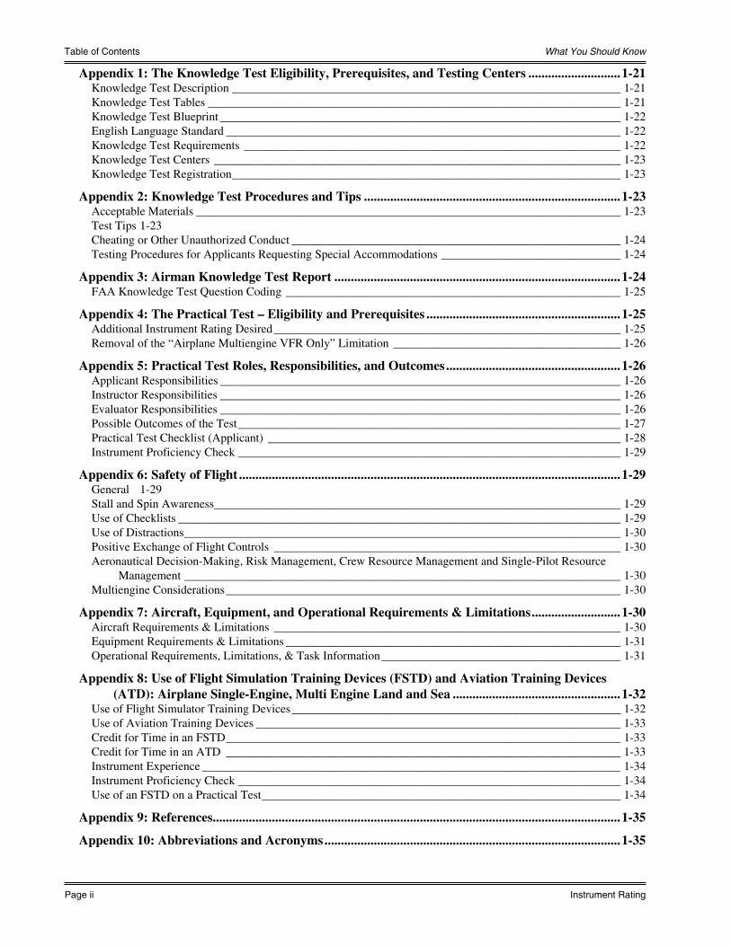
Appendix 1: The Knowledge Test Eligibility, Prerequisites, and Testing Centers ............................1-21Knowledge Test Description _________________________________________________________________ 1-21Knowledge Test Tables _____________________________________________________________________ 1-21Knowledge Test Blueprint ___________________________________________________________________ 1-22English Language Standard __________________________________________________________________ 1-22Knowledge Test Requirements _______________________________________________________________ 1-22Knowledge Test Centers ____________________________________________________________________ 1-23Knowledge Test Registration _________________________________________________________________ 1-23
Appendix 2: Knowledge Test Procedures and Tips ..............................................................................1-23Acceptable Materials _______________________________________________________________________ 1-23Test Tips 1-23Cheating or Other Unauthorized Conduct _______________________________________________________ 1-24Testing Procedures for Applicants Requesting Special Accommodations ______________________________ 1-24
Appendix 3: Airman Knowledge Test Report .......................................................................................1-24FAA Knowledge Test Question Coding ________________________________________________________ 1-25
Appendix 4: The Practical Test – Eligibility and Prerequisites ...........................................................1-25Additional Instrument Rating Desired __________________________________________________________ 1-25Removal of the “Airplane Multiengine VFR Only” Limitation ______________________________________ 1-26
Appendix 5: Practical Test Roles, Responsibilities, and Outcomes .....................................................1-26Applicant Responsibilities ___________________________________________________________________ 1-26Instructor Responsibilities ___________________________________________________________________ 1-26Evaluator Responsibilities ___________________________________________________________________ 1-26Possible Outcomes of the Test ________________________________________________________________ 1-27Practical Test Checklist (Applicant) ___________________________________________________________ 1-28Instrument Proficiency Check ________________________________________________________________ 1-29
Appendix 6: Safety of Flight ....................................................................................................................1-29General 1-29Stall and Spin Awareness ____________________________________________________________________ 1-29Use of Checklists __________________________________________________________________________ 1-29Use of Distractions _________________________________________________________________________ 1-30Positive Exchange of Flight Controls __________________________________________________________ 1-30Aeronautical Decision-Making, Risk Management, Crew Resource Management and Single-Pilot Resource
Management _________________________________________________________________________ 1-30Multiengine Considerations __________________________________________________________________ 1-30
Appendix 7: Aircraft, Equipment, and Operational Requirements & Limitations ...........................1-30Aircraft Requirements & Limitations __________________________________________________________ 1-30Equipment Requirements & Limitations ________________________________________________________ 1-31Operational Requirements, Limitations, & Task Information ________________________________________ 1-31
Appendix 8: Use of Flight Simulation Training Devices (FSTD) and Aviation Training Devices (ATD): Airplane Single-Engine, Multi Engine Land and Sea ...................................................1-32
Use of Flight Simulator Training Devices _______________________________________________________ 1-32Use of Aviation Training Devices _____________________________________________________________ 1-33Credit for Time in an FSTD __________________________________________________________________ 1-33Credit for Time in an ATD __________________________________________________________________ 1-33Instrument Experience ______________________________________________________________________ 1-34Instrument Proficiency Check ________________________________________________________________ 1-34Use of an FSTD on a Practical Test ____________________________________________________________ 1-34
Appendix 9: References............................................................................................................................1-35
Appendix 10: Abbreviations and Acronyms ..........................................................................................1-35

Sporty’s Complete Flight Training Course
ACS Study Guide Page iii
Table of Contents
Volume 1 - Instrument Flying Fundamentals ..........................................................................................2-1Requirements ______________________________________________________________________________ 2-1The Practical Test __________________________________________________________________________ 2-1Instruments ________________________________________________________________________________ 2-1Fundamental Skills__________________________________________________________________________ 2-2Illusions in Flight ___________________________________________________________________________ 2-2
Volume 2 - Air Traffic Control and IFR ..................................................................................................2-4Separation ________________________________________________________________________________ 2-4Air Traffic Control __________________________________________________________________________ 2-4Navaid Service Volumes _____________________________________________________________________ 2-5En Route 2-5Flight Plans _______________________________________________________________________________ 2-5
Volume 3 - Instrument Approaches ..........................................................................................................2-9Approach & Landing Charts __________________________________________________________________ 2-9Precision Approaches ________________________________________________________________________ 2-9Nonprecision Approaches ___________________________________________________________________ 2-11Approaches with Vertical Guidance (APV) _____________________________________________________ 2-11Runway Lighting Systems ___________________________________________________________________ 2-11Circling Approaches _______________________________________________________________________ 2-11Radar Approaches _________________________________________________________________________ 2-11Approach Standards ________________________________________________________________________ 2-12Procedure Turns ___________________________________________________________________________ 2-12Timed Approaches _________________________________________________________________________ 2-12Missed Approaches ________________________________________________________________________ 2-12Holding 2-13
Volume 4 - En Route IFR.........................................................................................................................2-38Charts and Airways ________________________________________________________________________ 2-38Airway Limits and Minimums ________________________________________________________________ 2-38Instrument Departure Procedures (DPs) ________________________________________________________ 2-38Standard Terminal Arrivals (STARs) __________________________________________________________ 2-39Transition Areas ___________________________________________________________________________ 2-39Alternate Airports _________________________________________________________________________ 2-39Weather Data _____________________________________________________________________________ 2-39
Volume 5 - Weather for IFR ....................................................................................................................2-59Thunderstorms ____________________________________________________________________________ 2-59Turbulence _______________________________________________________________________________ 2-59Structural Icing ____________________________________________________________________________ 2-60Weather Minimums ________________________________________________________________________ 2-60Fog 2-61
Volume 6 - Advanced IFR........................................................................................................................2-62Supplemental Oxygen ______________________________________________________________________ 2-62Area Navigation __________________________________________________________________________ 2-62GPS 2-62Horizontal Situation Indicator (HSI) ___________________________________________________________ 2-62Distance Measuring Equipment (DME) ________________________________________________________ 2-62

What You Should Know
Page iv Instrument Rating
Table of Contents
Volume 7 - FARs and Your Instrument Test .........................................................................................2-64Special Clearances _________________________________________________________________________ 2-64Composite Flight Plans _____________________________________________________________________ 2-64VOR Equipment Checks ____________________________________________________________________ 2-64Federal Aviation Regulations ________________________________________________________________ 2-65NOTAMs ________________________________________________________________________________ 2-66Two-Way Radio Communications Failure ______________________________________________________ 2-66Contact and Visual Approaches _______________________________________________________________ 2-67Microbursts ______________________________________________________________________________ 2-67Weather Data _____________________________________________________________________________ 2-67Radio Magnetic Indicator (RMI) ______________________________________________________________ 2-68Automated Terminal Information Service (ATIS) ________________________________________________ 2-68Partial Panel ______________________________________________________________________________ 2-68Attitude Indicator Errors ____________________________________________________________________ 2-69
Section 3 - Appendices and Supplemental Material ........................................................................ 3-1
Appendix A – More about the Instrument Systems Preflight Procedures ............................................3-1
Appendix B – More about Holding ...........................................................................................................3-2
Appendix C – Airspeed Changes and Rate Climbs & Descents .............................................................3-3
Appendix D – Use of MFD and Other Graphical Navigation Displays in Instrument Operations ....3-4
Appendix E – Single-Pilot Resource Management ..................................................................................3-4
Appendix F – Instructor Certification for Instrument Rating Knowledge Test ..................................3-6

Sporty’s Complete Flight Training Course
ACS Study Guide Page v
Preface
PrefaceSporty’s What You Should Know® Complete Flight Training course for the Instrument Rating has been designed to completely prepare you for instrument flying. This series is an effective tool in understanding instrument flying, and can be used as self-study for pilots working on their instrument rating or by previously rated pilots as a refresher course.
The subject matter is presented in a logical sequence that parallels the flight instruction you will be receiving. This sequence is also the best way to prepare for the FAA computerized knowledge exam. This book is not a substitute for the videos, but a supplement to help you completely prepare for your knowledge test, oral and practical exams, and to become a better pilot.
This study guide is arranged into two major sections.
The first section contains the Instrument Rating Airman Certification Standards for Airplane with a video cross-reference. This section is intended to be used as a review prior to your oral and practical exams. It also may be used as a supplemental index to the videos. It relates the various elements of the ACS to the appropriate Sporty’s video volumes and segments for further review.
The second section contains supplemental material that you should study after watching each video volume. This information will support the subjects presented by the related videos and will provide reinforcing notes or may be used as a quick reference. Some of these subsections have an additional group of illustrations applicable to the instructional material on that video and/or FAA test questions found on the video. Please note, most of the approach charts have been taken directly from the FAA’s computer testing supplement. Many charts are not in the current format but this is what you may see on the FAA test. When the FAA updates their materials, Sporty’s Academy will update these charts in this book and in the questions found on the videos. The material in the training portion of Sporty’s videos is up to date with current standards.
Most video segments conclude with a set of optional interactive FAA test questions, answers, and explanations. Some of the questions refer to illustrations that are included on the DVDs, online course, or in the iOS app . The more complex illustrations are also reproduced in this book, after the notes for that volume.
There are also additional approach charts in this book that are not part of any test question, but are included to help you follow along with the VOR and NDB segments of Volume 3, and the GPS approaches in Volume 6.
This study guide is not intended to stand alone. It is a part of the total training package supplied with Sporty’s What You Should Know Complete Flight Training course for the Instrument Rating.
Maximum benefit can be derived from this course by following the instructions below:
After viewing each video segment, answer any FAA test questions that follow. The answers and explanations are provided with each question.
After finishing a Sporty’s Video Volume, read the notes subsection for that particular volume. The notes will reinforce key concepts from the videos through illustrations and explanations of these points.
Take the review test for that volume (the last item on the DVD main menu). This test combines all of the quiz questions from each segment and provides you with a score for gauging your progress. Select appropriate subject matter questions to practice in the online and iOS courses.
When you have finished the review test for a video volume, go on to the next volume, or review the video if you need more exposure to certain areas. Repetition of this process can greatly enhance your ability to understand difficult topics.
Best of luck with your studies and welcome to your new adventure.
Sporty’s Academy, StaffJune, 2017Batavia, Ohio

What You Should Know
Page vi Instrument Rating
Conventions and References
Conventions Used in This ManualThe Instrument Rating Airman Certification Standards (ACS) with Video Cross-Reference contains the text of the ACS with references to information that may be found in Sporty’s Complete Flight Training Course for the Instrument Rating for each element. The cross-reference will appear in the following format:A number indicating the video volume will be followed by a period and number indicating the segment within the
video. For example, 3.1 would indicate to refer to Segment 1 of Video Volume 3 from the course.If a video reference is enclosed in parentheses, this indicates the DVD segment number is slightly different than the
online course and iOS app segment number and the DVD information is in the parentheses. (The DVDs, online course, and iOS app for the course contain the same video content at the time of production. The numbering is slightly different on the DVDs due to an Introductory segment of each DVD being labeled as a separate Segment 1. This introductory material is included with the first lesson segment on the online and iOS versions thus causing the segment numbers to be different by one.)
Sporty’s Complete Flight Training Course utilizes the building block method of learning. This method assumes that you already have the knowledge of a Private Pilot and does not re-teach certain Private Pilot basics. Private Pilot knowledge elements that are evaluated in the Instrument ACS are referenced to Sporty’s Complete Learn to Fly Course. The references to these videos are proceeded with the letters “Pvt”. Appendices and pages within this study guide and the POH/AFM for your airplane are also referenced.
FAA References Used in This ManualMany of the references below were used by the FAA in preparing the ACS and in the preparation of this manual. Most of the references listed are books and may be purchased from Sporty’s by calling 1.800.SPORTYS (776.7897) from the USA or by logging on to http://www.sportys.com.
14 CFR Part 43 Maintenance, Preventive Maintenance, Rebuilding, and Alteration14 CFR Part 61 Certification: Pilots and Flight Instructors14 CFR Part 91 General Operating and Flight Rules14 CFR Part 97 Standard Instrument Approach ProceduresNTSB Part 830 Notification and Reporting of Aircraft Accidents and IncidentsFAA-H-8083-1 Aircraft Weight and Balance HandbookFAA-H-8083-3 Airplane Flying HandbookFAA-H-8083-15 Instrument Flying HandbookFAA-H-8083-16 Instrument Procedures HandbookFAA-H-8083-25 Pilot’s Handbook of Aeronautical KnowledgeAC 00-6 Aviation WeatherAC 00-45 Aviation Weather ServicesAC 00-54 Pilot Wind Shear GuideAC 60-28 English Language Skill Standards Required by 14 CFR parts 61, 63, and 65AC 61-65 Certification: Pilots and Flight InstructorsAC 61-67 Stall Spin Awareness TrainingAC 61-84 Role of Preflight PreparationAC 61-134 General Aviation Controlled Flight into Terrain AwarenessAC 90-45 Approval of Area Navigation Systems for Use in the U.S. National Airspace System AC 90-48 Pilots’ Role in Collision AvoidanceAC 90-94 Guidelines for Using Global Positioning System Equipment for IFR En Route and Terminal Operations and for Nonprecision Instrument Approaches in the U.S. National Airspace SystemAC 91-13 Cold Weather Operation of AircraftAC 91-43 Unreliable Airspeed IndicationsAC 91-55 Reduction of Electrical Systems Failure Following Engine Starting AC 120-51 Crew Resource Management TrainingAIM Aeronautical Information ManualCFIT Training Aid website: http://www.faa.gov/training_testing/training/media/cfit/volume1/titlepg.pdfChart Supplements (formerly A/FD Airport/Facility Directory)NOTAMs Notices to Airmen POH/AFM - Pilot Operating Handbook/Approved Flight Manual (or Airplane Flight Manual)En Route, DP, STAR, and Approach Charts and Legends

Sporty’s Complete Flight Training Course
ACS Study Guide Page 1-1
Instrument Rating ACS with Video Cross-Reference
Section 1 - Instrument Rating Airman Certification Standards - Airplane with Video Cross-Reference
I. PREFLIGHT PREPARATION
Task a. PiloT QualificaTions
RefeRences 14 CFR part 61; FAA-H-8083-2, FAA-H-8083-15
objecTive To determine the applicant exhibits satisfactory knowledge, risk management, and skills associated with the requirements to act as PIC under instrument flight rules.
VideoVolume.Segment
knowledge The applicant demonstrates understanding of:
IR.I.A.K1 Certification requirements, recency of experience, and record keeping. 6.5, 7.6 (6.6, 7.7)
IR.I.A.K2 Privileges and limitations.
Risk ManageMenT
The applicant demonstrates the ability to identify, assess and mitigate risks, encompassing:
IR.I.A.R1 Failure to distinguish proficiency versus currency.
IR.I.A.R2 Failure to set personal minimums.
IR.I.A.R3 Failure to ensure fitness for flight and physiological factors that might affect the pilot’s ability to fly under instrument conditions.
IR.I.A.R4 Flying unfamiliar aircraft, or operating with unfamiliar flight display systems, and avionics.
skills The applicant demonstrates the ability to:
IR.I.A.S1 Apply requirements to act as PIC under Instrument Flight Rules (IFR) in a scenario given by the evaluator.

What You Should Know
Page 1-2 Instrument Rating
Instrument Rating ACS with Video Cross-Reference
I. PREFLIGHT PREPARATION
Task b. weaTheR infoRMaTion
RefeRences 14 CFR part 91; FAA-H-8083-25, AC 00-6; AC 00-45, AIM
objecTive To determine the applicant exhibits satisfactory knowledge, risk management, and skills associated with obtaining, understanding, and applying weather information for a flight under IFR.
VideoVolume.Segment
knowledge The applicant demonstrates understanding of:
IR.I.B.K1 Acceptable sources of weather data for flight planning purposes.
IR.I.B.K2 Weather products and resources utilized for preflight planning, current and forecast weather for departure and en route operations and arrival phases of flight.
IR.I.B.K3 Meteorology applicable to the departure, en route, alternate, and destination for flights conducted under IFR in Instrument Meteorological Conditions (IMC) to include expected climate and hazardous conditions such as:
IR.I.B.K3a a. Atmospheric composition and stability
IR.I.B.K3b b. Wind (e.g. crosswind, tailwind, wind shear, etc.)
IR.I.B.K3c c. Temperature
IR.I.B.K3d d. Moisture/precipitation
IR.I.B.K3e e. Weather system formation, including air masses and fronts
IR.I.B.K3f f. Clouds
IR.I.B.K3g g. Turbulence
IR.I.B.K3h h. Thunderstorms and microbursts
IR.I.B.K3i i. Icing and freezing level information
IR.I.B.K3j j. Fog
IR.I.B.K3k k. Frost
IR.I.B.K4 Flight deck displays of digital weather and aeronautical information.
Risk ManageMenT
The applicant demonstrates the ability to identify, assess and mitigate risks, encompassing:
IR.I.B.R1 Factors involved in making a valid go/no-go decision, to include:
IR.I.B.R1a a. Circumstances that would make diversion prudent
IR.I.B.R1b b. Hazardous weather conditions to include known or forecast icing
IR.I.B.R1c c. Personal weather minimums
IR.I.B.R2 Limitations of:
IR.I.B.R2a a. Onboard weather equipment
IR.I.B.R2b b. Aviation weather reports and forecasts
IR.I.B.R2c c. Inflight weather resources
skills The applicant demonstrates the ability to:
IR.I.B.S1 Use available aviation weather resources to obtain an adequate weather briefing.
IR.I.B.S2 Discuss the implications of at least three of the conditions listed in K3a through K3k above, using actual weather or weather conditions in a scenario provided by the evaluator.
IR.I.B.S3 Correlate weather information to make a competent go/no-go decision.
IR.I.B.S4 Determine whether an alternate airport is required, and, if required, whether the selected alternate airport meets regulatory requirements.
4.12, 4.13, 5.9 (4.13, 4.14, 5.10), ACS Study
Guide Page 2-56
Sporty’s Complete Flight Training Course
ACS Study Guide Page 1-3
Instrument Rating ACS with Video Cross-Reference
I. PREFLIGHT PREPARATION
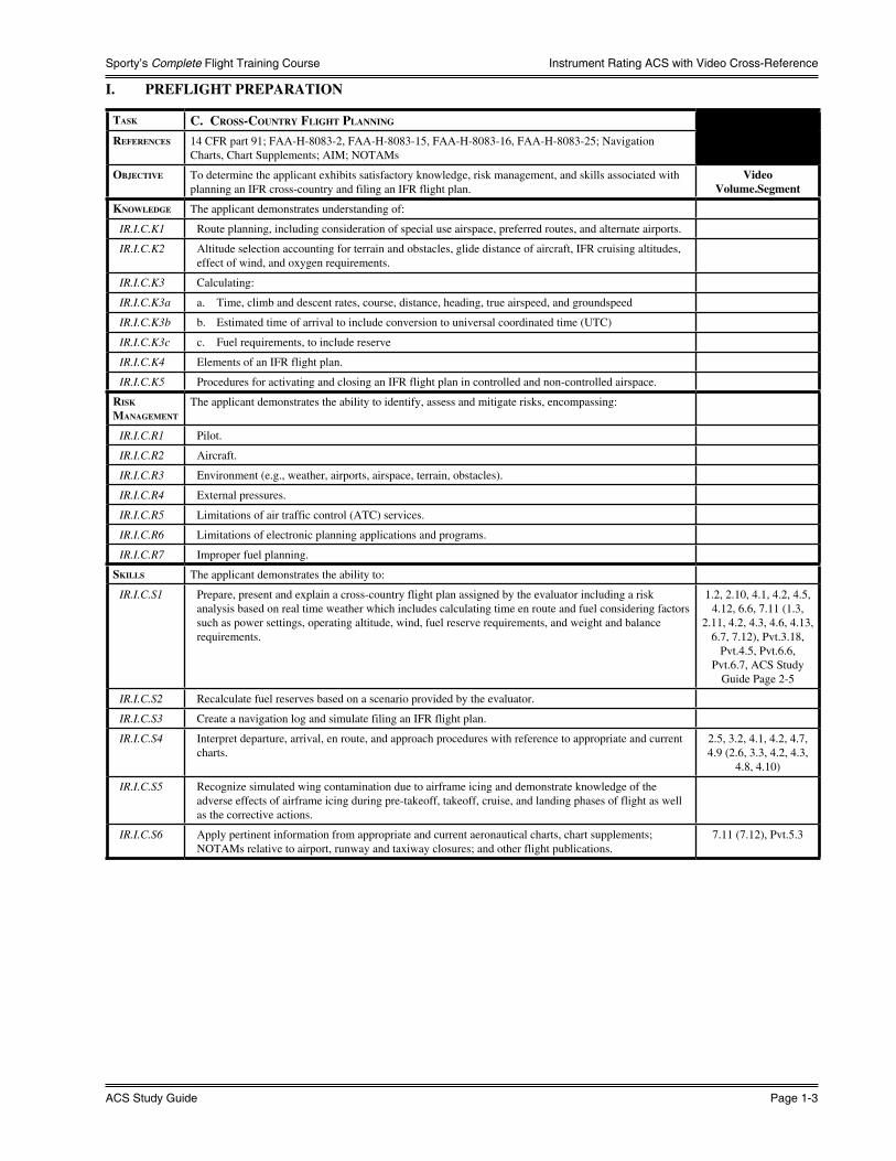
Task c. cRoss-counTRy flighT Planning
RefeRences 14 CFR part 91; FAA-H-8083-2, FAA-H-8083-15, FAA-H-8083-16, FAA-H-8083-25; Navigation Charts, Chart Supplements; AIM; NOTAMs
objecTive To determine the applicant exhibits satisfactory knowledge, risk management, and skills associated with planning an IFR cross-country and filing an IFR flight plan.
VideoVolume.Segment
knowledge The applicant demonstrates understanding of:
IR.I.C.K1 Route planning, including consideration of special use airspace, preferred routes, and alternate airports.
IR.I.C.K2 Altitude selection accounting for terrain and obstacles, glide distance of aircraft, IFR cruising altitudes, effect of wind, and oxygen requirements.
IR.I.C.K3 Calculating:
IR.I.C.K3a a. Time, climb and descent rates, course, distance, heading, true airspeed, and groundspeed
IR.I.C.K3b b. Estimated time of arrival to include conversion to universal coordinated time (UTC)
IR.I.C.K3c c. Fuel requirements, to include reserve
IR.I.C.K4 Elements of an IFR flight plan.
IR.I.C.K5 Procedures for activating and closing an IFR flight plan in controlled and non-controlled airspace.
Risk ManageMenT
The applicant demonstrates the ability to identify, assess and mitigate risks, encompassing:
IR.I.C.R1 Pilot.
IR.I.C.R2 Aircraft.
IR.I.C.R3 Environment (e.g., weather, airports, airspace, terrain, obstacles).
IR.I.C.R4 External pressures.
IR.I.C.R5 Limitations of air traffic control (ATC) services.
IR.I.C.R6 Limitations of electronic planning applications and programs.
IR.I.C.R7 Improper fuel planning.
skills The applicant demonstrates the ability to:
IR.I.C.S1 Prepare, present and explain a cross-country flight plan assigned by the evaluator including a risk analysis based on real time weather which includes calculating time en route and fuel considering factors such as power settings, operating altitude, wind, fuel reserve requirements, and weight and balance requirements.
1.2, 2.10, 4.1, 4.2, 4.5, 4.12, 6.6, 7.11 (1.3,
2.11, 4.2, 4.3, 4.6, 4.13, 6.7, 7.12), Pvt.3.18,
Pvt.4.5, Pvt.6.6, Pvt.6.7, ACS Study
Guide Page 2-5
IR.I.C.S2 Recalculate fuel reserves based on a scenario provided by the evaluator.
IR.I.C.S3 Create a navigation log and simulate filing an IFR flight plan.
IR.I.C.S4 Interpret departure, arrival, en route, and approach procedures with reference to appropriate and current charts.
2.5, 3.2, 4.1, 4.2, 4.7, 4.9 (2.6, 3.3, 4.2, 4.3,
4.8, 4.10)
IR.I.C.S5 Recognize simulated wing contamination due to airframe icing and demonstrate knowledge of the adverse effects of airframe icing during pre-takeoff, takeoff, cruise, and landing phases of flight as well as the corrective actions.
IR.I.C.S6 Apply pertinent information from appropriate and current aeronautical charts, chart supplements; NOTAMs relative to airport, runway and taxiway closures; and other flight publications.
7.11 (7.12), Pvt.5.3

What You Should Know
Page 1-4 Instrument Rating
Instrument Rating ACS with Video Cross-Reference
II. PREFLIGHT PROCEDURES
Task a. aiRcRafT sysTeMs RelaTed To ifR oPeRaTions
RefeRences 14 CFR parts 61, 91; FAA-H-8083-2, FAA-H-8083-15; AFM; AC 91-74objecTive To determine the applicant exhibits satisfactory knowledge, risk management, and skills associated with
anti-icing and de-icing systems.Video
Volume.Segmentknowledge The applicant demonstrates understanding of:
IR.II.A.K1 The general operational characteristics and limitations of applicable anti-icing and deicing systems, including airframe, propeller, intake, fuel, and pitot-static systems.
POH/AFM
Risk ManageMenT
The applicant demonstrates the ability to identify, assess and mitigate risks, encompassing:
IR.II.A.R1 Pilots with little or no experience with flight in icing conditions.IR.II.A.R2 Limitations of anti-icing and deicing systems. POH/AFM
skills The applicant demonstrates the ability to:IR.II.A.S1 Demonstrate familiarity with anti- or de-icing procedures and/or information published by the
manufacturer that is specific to the aircraft used on the practical test.
II. PREFLIGHT PROCEDURES
Task b. aiRcRafT flighT insTRuMenTs and navigaTion eQuiPMenT
RefeRences 14 CFR parts 61, 91; FAA-H-8083-15; AIMobjecTive To determine the applicant exhibits satisfactory knowledge, risk management, and skills associated with
managing instruments appropriate for an IFR flight.Video
Volume.Segmentknowledge The applicant demonstrates understanding of:
IR.II.B.K1 General operation of their aircraft’s applicable flight instrument system(s) including:IR.II.B.K1a a. Pitot-static instrument system: altimeter, airspeed indicator, vertical speed indicator 1.4, 7.9, 7.10 (1.5,
7.10, 7.11), Pvt.3.7, Pvt.3.13
IR.II.B.K1b b. Gyroscopic/electric/vacuum instrument system: attitude indicator, heading indicator, turn-and-slip indicator/turn coordinator
1.3, 1.4, 1.8, 1.10, 6.2, 7.9, 7.10 (1.4, 1.5, 1.9, 1.11, 6.3, 7.10, 7.11)
IR.II.B.K1c c. Electrical systems, electronic flight instrument displays (PFD, MFD), transponder 2.12 (2.13), Appendix D
IR.II.B.K1d d. Magnetic compass 1.11 (1.11), Pvt.6.3IR.II.B.K2 The general operation of their aircraft’s applicable navigation system(s) including:IR.II.B.K2a a. VOR, DME, ILS, marker beacon receiver/indicators 2.2, 2.4, 3.2, 3.3, 3.4,
3.8, 6.2 (2.3, 2.5, 3.3, 3.4, 3.5, 3.9, 6.3),
Pvt.5.7, ACS Study Guide Page 2-59
IR.II.B.K2b b. RNAV, GPS, Wide Area Augmentation System (WAAS), FMS, autopilot 2.4, 6.2, 6.4, 6.12, 6.13 (2.5, 6.3, 6.5, 6.13,
6.14), Pvt.5.8, POH/AFM
Risk ManageMenT
The applicant demonstrates the ability to identify, assess and mitigate risks, encompassing:
IR.II.B.R1 Failure to monitor and manage automated systems.IR.II.B.R2 The difference between approved and non-approved navigation devices.IR.II.B.R3 Common failure modes of flight and navigation instruments.IR.II.B.R4 The limitations of electronic flight bags.IR.II.B.R5 Failure to ensure currency of navigation databases.
skills The applicant demonstrates the ability to:IR.II.B.S1 Operate and manage installed instruments and navigation equipment.

Sporty’s Complete Flight Training Course
ACS Study Guide Page 1-5
Instrument Rating ACS with Video Cross-Reference
II. PREFLIGHT PROCEDURES
Task c. insTRuMenT flighT deck check
RefeRences 14 CFR part 91; FAA-8083-2, FAA-H-8083-3, FAA-H-8083-15, FAA-H-8083-25; AC 91.21-1; POH/AFM
objecTive To determine the applicant exhibits satisfactory knowledge, risk management, and skills associated with conducting a preflight check on the aircraft instruments necessary for an IFR flight.
VideoVolume.Segment
knowledge The applicant demonstrates understanding of:
IR.II.C.K1 Purpose of performing an instrument flight deck check and how to detect possible defects. 7.4, 7.6, 7.9 (7.5, 7.7, 7.10), Appendix A
IR.II.C.K2 IFR airworthiness, to include aircraft inspection requirements and required equipment for IFR flight.
IR.II.C.K3 Required procedures, documentation, and limitations of flying with inoperative equipment.
Risk ManageMenT
The applicant demonstrates the ability to identify, assess and mitigate risks, encompassing:
IR.II.C.R1 Operating with inoperative equipment.
IR.II.C.R2 Operating with outdated navigation publications or databases.
skills The applicant demonstrates the ability to:
IR.II.C.S1 Perform preflight inspection by following the checklist appropriate to the aircraft and determine that the aircraft is in a condition for safe instrument flight, to include communications equipment, navigation equipment, and databases appropriate to the aircraft flown, magnetic compass, heading indicator, attitude indicator, altimeter, turn-and-slip indicator/turn coordinator, vertical speed indicator, airspeed indicator, clock, power source for gyro instruments, pitot heat, electronic flight instrument display, traffic awareness/warning/avoidance system, terrain awareness/warning/alert system, FMS, and autopilot.
4.10 (4.11), Appendix A

What You Should Know
Page 1-6 Instrument Rating
Instrument Rating ACS with Video Cross-Reference
III. AIR TRAFFIC CONTROL CLEARANCES AND PROCEDURES
Task a. coMPliance wiTh aiR TRaffic conTRol cleaRances
RefeRences 14 CFR parts 61, 91; FAA-H-8083-15; AIM
objecTive To determine the applicant exhibits satisfactory knowledge, risk management, and skills associated with ATC clearances and procedures.Note: The ATC clearance may be an actual or simulated ATC clearance based upon the flight plan.
VideoVolume.Segment
knowledge The applicant demonstrates understanding of:
IR.III.A.K1 Elements and procedures related to ATC clearances and pilot/controller responsibilities for departure, en route, and arrival phases of flight including clearance void times.
IR.III.A.K2 PIC emergency authority.
IR.III.A.K3 Lost communication procedures and procedures for flights outside of radar environments. 7.7, 7.8 (7.8, 7.9)
Risk ManageMenT
The applicant demonstrates the ability to identify, assess and mitigate risks, encompassing:
IR.III.A.R1 Failure to fully understand an ATC clearance.
IR.III.A.R2 Inappropriate, incomplete, or incorrect ATC clearances.
IR.III.A.R3 ATC clearance inconsistent with aircraft performance and/or navigation capability.
IR.III.A.R4 ATC clearance intended for other aircraft with similar call signs.
skills The applicant demonstrates the ability to:
IR.III.A.S1 Correctly copy, read back, interpret, and comply with simulated and/or actual ATC clearances in a timely manner using standard phraseology as provided in the Aeronautical Information Manual.
2.7, 7.11, 7.13 (2.8, 7.12, 7.14)
IR.III.A.S2 Correctly set communication frequencies, navigation systems (identifying when appropriate), and transponder codes in compliance with the ATC clearance.
IR.III.A.S3 Use the current and appropriate navigation publications. 2.9, 4.2, 4.7, 4.9 (2.10, 4.3, 4.8, 4.10)
IR.III.A.S4 Perform the appropriate aircraft checklist items relative to the phase of flight.
IR.III.A.S4 Intercept all courses, radials, and bearings appropriate to the procedure, route, or clearance in a timely manner.
IR.III.A.S5 Maintain the applicable airspeed within ±10 knots; headings within ±10°; altitude within ±100 feet; and tracks a course, radial, or bearing within ¾-scale deflection of the CDI.
1.2 (1.3)
IR.III.A.S6 Demonstrate single-pilot resource management skills (SRM). Appendix E
Sporty’s Complete Flight Training Course
ACS Study Guide Page 1-7
Instrument Rating ACS with Video Cross-Reference
III. AIR TRAFFIC CONTROL CLEARANCES AND PROCEDURES
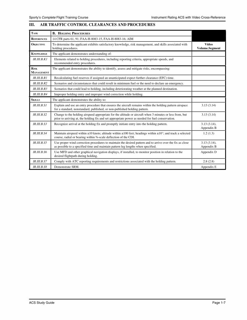
Task b. holding PRoceduRes
RefeRences 14 CFR parts 61, 91; FAA-H-8083-15, FAA-H-8083-16; AIM
objecTive To determine the applicant exhibits satisfactory knowledge, risk management, and skills associated with holding procedures.
VideoVolume.Segment
knowledge The applicant demonstrates understanding of:
IR.III.B.K1 Elements related to holding procedures, including reporting criteria, appropriate speeds, and recommended entry procedures.
Risk ManageMenT
The applicant demonstrates the ability to identify, assess and mitigate risks, encompassing:
IR.III.B.R1 Recalculating fuel reserves if assigned an unanticipated expect further clearance (EFC) time.
IR.III.B.R2 Scenarios and circumstances that could result in minimum fuel or the need to declare an emergency.
IR.III.B.R3 Scenarios that could lead to holding, including deteriorating weather at the planned destination.
IR.III.B.R4 Improper holding entry and improper wind correction while holding.
skills The applicant demonstrates the ability to:
IR.III.B.S1 Explain and use an entry procedure that ensures the aircraft remains within the holding pattern airspace for a standard, nonstandard, published, or non-published holding pattern.
3.13 (3.14)
IR.III.B.S2 Change to the holding airspeed appropriate for the altitude or aircraft when 3 minutes or less from, but prior to arriving at, the holding fix and set appropriate power as needed for fuel conservation.
3.13 (3.14)
IR.III.B.S3 Recognize arrival at the holding fix and promptly initiate entry into the holding pattern. 3.13 (3.14), Appendix B
IR.III.B.S4 Maintain airspeed within ±10 knots; altitude within ±100 feet; headings within ±10°; and track a selected course, radial or bearing within ¾-scale deflection of the CDI.
1.2 (1.3)
IR.III.B.S5 Use proper wind correction procedures to maintain the desired pattern and to arrive over the fix as close as possible to a specified time and maintain pattern leg lengths when specified.
3.13 (3.14), Appendix B
IR.III.B.S6 Use MFD and other graphical navigation displays, if installed, to monitor position in relation to the desired flightpath during holding.
Appendix D
IR.III.B.S7 Comply with ATC reporting requirements and restrictions associated with the holding pattern. 2.8 (2.8)
IR.III.B.S8 Demonstrate SRM. Appendix E
What You Should Know
Page 1-8 Instrument Rating
Instrument Rating ACS with Video Cross-Reference
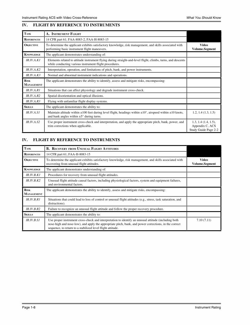
IV. FLIGHT BY REFERENCE TO INSTRUMENTS
Task a. insTRuMenT flighT
RefeRences 14 CFR part 61; FAA-8083-2, FAA-H-8083-15
objecTive To determine the applicant exhibits satisfactory knowledge, risk management, and skills associated with performing basic instrument flight maneuvers.
VideoVolume.Segment
knowledge The applicant demonstrates understanding of:
IR.IV.A.K1 Elements related to attitude instrument flying during straight-and-level flight, climbs, turns, and descents while conducting various instrument flight procedures.
IR.IV.A.K2 Interpretation, operation, and limitations of pitch, bank, and power instruments.
IR.IV.A.K3 Normal and abnormal instrument indications and operations.
Risk ManageMenT
The applicant demonstrates the ability to identify, assess and mitigate risks, encompassing:
IR.IV.A.R1 Situations that can affect physiology and degrade instrument cross-check.
IR.IV.A.R2 Spatial disorientation and optical illusions.
IR.IV.A.R3 Flying with unfamiliar flight display systems.
skills The applicant demonstrates the ability to:
IR.IV.A.S1 Maintain altitude within ±100 feet during level flight, headings within ±10°, airspeed within ±10 knots, and bank angles within ±5° during turns.
1.2, 1.4 (1.3, 1.5)
IR.IV.A.S2 Use proper instrument cross-check and interpretation, and apply the appropriate pitch, bank, power, and trim corrections when applicable.
1.3, 1.4 (1.4, 1.5),Appendix C, ACS
Study Guide Page 2-2
IV. FLIGHT BY REFERENCE TO INSTRUMENTS
Task b. RecoveRy fRoM unusual flighT aTTiTudes
RefeRences 14 CFR part 61; FAA-H-8083-15
objecTive To determine the applicant exhibits satisfactory knowledge, risk management, and skills associated with recovering from unusual flight attitudes.
VideoVolume.Segment
knowledge The applicant demonstrates understanding of:
IR.IV.B.K1 Procedures for recovery from unusual flight attitudes.
IR.IV.B.K2 Unusual flight attitude causal factors, including physiological factors, system and equipment failures, and environmental factors.
Risk ManageMenT
The applicant demonstrates the ability to identify, assess and mitigate risks, encompassing:
IR.IV.B.R1 Situations that could lead to loss of control or unusual flight attitudes (e.g., stress, task saturation, and distractions).
IR.IV.B.R2 Failure to recognize an unusual flight attitude and follow the proper recovery procedure.
skills The applicant demonstrates the ability to:
IR.IV.B.S1 Use proper instrument cross-check and interpretation to identify an unusual attitude (including both nose-high and nose-low), and apply the appropriate pitch, bank, and power corrections, in the correct sequence, to return to a stabilized level flight attitude.
7.10 (7.11)
Sporty’s Complete Flight Training Course
ACS Study Guide Page 1-9
Instrument Rating ACS with Video Cross-Reference
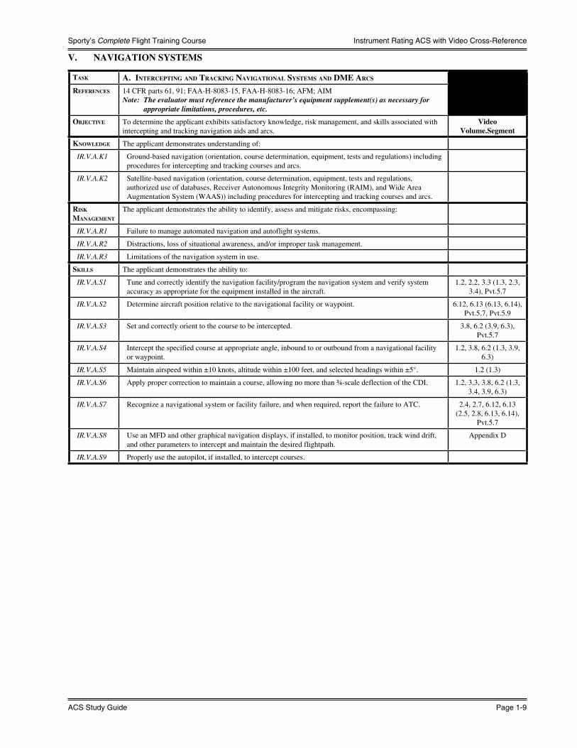
V. NAVIGATION SYSTEMS
Task a. inTeRcePTing and TRacking navigaTional sysTeMs and dMe aRcs
RefeRences 14 CFR parts 61, 91; FAA-H-8083-15, FAA-H-8083-16; AFM; AIMNote: The evaluator must reference the manufacturer’s equipment supplement(s) as necessary for
appropriate limitations, procedures, etc.
objecTive To determine the applicant exhibits satisfactory knowledge, risk management, and skills associated with intercepting and tracking navigation aids and arcs.
VideoVolume.Segment
knowledge The applicant demonstrates understanding of:
IR.V.A.K1 Ground-based navigation (orientation, course determination, equipment, tests and regulations) including procedures for intercepting and tracking courses and arcs.
IR.V.A.K2 Satellite-based navigation (orientation, course determination, equipment, tests and regulations, authorized use of databases, Receiver Autonomous Integrity Monitoring (RAIM), and Wide Area Augmentation System (WAAS)) including procedures for intercepting and tracking courses and arcs.
Risk ManageMenT
The applicant demonstrates the ability to identify, assess and mitigate risks, encompassing:
IR.V.A.R1 Failure to manage automated navigation and autoflight systems.
IR.V.A.R2 Distractions, loss of situational awareness, and/or improper task management.
IR.V.A.R3 Limitations of the navigation system in use.
skills The applicant demonstrates the ability to:
IR.V.A.S1 Tune and correctly identify the navigation facility/program the navigation system and verify system accuracy as appropriate for the equipment installed in the aircraft.
1.2, 2.2, 3.3 (1.3, 2.3, 3.4), Pvt.5.7
IR.V.A.S2 Determine aircraft position relative to the navigational facility or waypoint. 6.12, 6.13 (6.13, 6.14), Pvt.5.7, Pvt.5.9
IR.V.A.S3 Set and correctly orient to the course to be intercepted. 3.8, 6.2 (3.9, 6.3), Pvt.5.7
IR.V.A.S4 Intercept the specified course at appropriate angle, inbound to or outbound from a navigational facility or waypoint.
1.2, 3.8, 6.2 (1.3, 3.9, 6.3)
IR.V.A.S5 Maintain airspeed within ±10 knots, altitude within ±100 feet, and selected headings within ±5°. 1.2 (1.3)
IR.V.A.S6 Apply proper correction to maintain a course, allowing no more than ¾-scale deflection of the CDI. 1.2, 3.3, 3.8, 6.2 (1.3, 3.4, 3.9, 6.3)
IR.V.A.S7 Recognize a navigational system or facility failure, and when required, report the failure to ATC. 2.4, 2.7, 6.12, 6.13 (2.5, 2.8, 6.13, 6.14),
Pvt.5.7
IR.V.A.S8 Use an MFD and other graphical navigation displays, if installed, to monitor position, track wind drift, and other parameters to intercept and maintain the desired flightpath.
Appendix D
IR.V.A.S9 Properly use the autopilot, if installed, to intercept courses.

What You Should Know
Page 1-10 Instrument Rating
Instrument Rating ACS with Video Cross-Reference
V. NAVIGATION SYSTEMS
Task b. dePaRTuRe, en RouTe and aRRival oPeRaTions
RefeRences 14 CFR parts 61, 91; FAA-H-8083-15, FAA-H-8083-16; AC 91-74; AFM; AIM
objecTive To determine the applicant exhibits satisfactory knowledge, risk management, and skills associated with IFR departure, en route, and arrival operations.
VideoVolume.Segment
knowledge The applicant demonstrates understanding of:
IR.V.B.K1 Elements related to ATC routes, including departure procedures (DPs) and associated climb gradients; arrival procedures (STARs) and associated constraints; and instrument approach procedures (IAPs).
IR.V.B.K2 Pilot/controller responsibilities, communication procedures, and ATC services available to pilots.
Risk ManageMenT
The applicant demonstrates the ability to identify, assess and mitigate risks, encompassing:
IR.V.B.R1 Failure to communicate with ATC or follow published procedures.
IR.V.B.R2 Failure to recognize limitations of traffic avoidance equipment.
IR.V.B.R3 Failure to use see and avoid techniques when possible.
skills The applicant demonstrates the ability to:
IR.V.B.S1 Select, identify (as necessary) and use the appropriate communication and navigation facilities associated with the proposed flight.
IR.V.B.S2 Perform the appropriate aircraft checklist items relative to the phase of flight.
IR.V.B.S3 Use the current and appropriate navigation publications for the proposed flight.
IR.V.B.S4 Establish two-way communications with the proper controlling agency, use proper phraseology and comply, in a timely manner, with all ATC instructions and airspace restrictions as well as exhibit adequate knowledge of communication failure procedures.
IR.V.B.S5 Intercept all courses, radials, and bearings appropriate to the procedure, route, or clearance in a timely manner.
IR.V.B.S6 Comply with all applicable charted procedures.
IR.V.B.S7 Maintain airspeed within ±10 knots, altitude within ±100 feet, and selected headings within ±10° and apply proper correction to maintain a course, allowing no more than ¾-scale deflection of the CDI.
IR.V.B.S8 Update/interpret weather in flight.
IR.V.B.S9 Explain and use flight deck displays of digital weather and aeronautical information, as applicable.
IR.V.B.S10 Demonstrate SRM. Appendix E

Sporty’s Complete Flight Training Course
ACS Study Guide Page 1-11
Instrument Rating ACS with Video Cross-Reference
VI. INSTRUMENT APPROACH PROCEDURES
Task a. nonPRecision aPPRoach
RefeRences 14 CFR parts 61, 91; FAA-H-8083-15, FAA-H-8083-16; IAP, AIM
objecTive To determine the applicant exhibits satisfactory knowledge, risk management, and skills associated with performing nonprecision approach procedures.Note: See Appendix 7: Aircraft, Equipment, and Operational Requirements & Limitations for related
considerations.
VideoVolume.Segment
knowledge The applicant demonstrates understanding of:
IR.VI.A.K1 Procedures and limitations associated with a nonprecision approach, including the differences between Localizer Performance (LP) and Lateral Navigation (LNAV) approach guidance.
IR.VI.A.K2 Navigation system annunciations expected during an RNAV approach.
Risk ManageMenT
The applicant demonstrates the ability to identify, assess and mitigate risks, encompassing:
IR.VI.A.R1 Failure to follow prescribed procedures (e.g., to prevent descending below the minimum descent altitude (MDA) without proper visual references).
IR.VI.A.R2 Deteriorating weather conditions on approach.
IR.VI.A.R3 An unstable approach, including excessive descent rates.
IR.VI.A.R4 Failure to ensure proper aircraft configuration during an approach and missed approach.
IR.VI.A.R5 Failure to manage automated navigation and auto flight systems.
skills The applicant demonstrates the ability to:
IR.VI.A.S1 Accomplish the appropriate nonprecision instrument approaches as selected by the evaluator. 3.2 (3.3)
IR.VI.A.S2 Establish two-way communications with ATC, as appropriate, to the phase of flight or approach segment, and uses proper communication phraseology.
2.7, 3.2 (2.8, 3.3)
IR.VI.A.S3 Select, tune, identify, and confirm the operational status of navigation equipment to be used for the approach.
1.2, 3.2, 3.3, 6.13 (1.3, 3.3, 3.4, 6.14), Pvt.5.7
IR.VI.A.S4 Comply with all clearances issued by ATC or the evaluator. 3.7, 3.9, 7.13 (3.8, 3.10, 7.14)
IR.VI.A.S5 Recognize if any flight instrumentation is inaccurate or inoperative, and take appropriate action. 1.10, 2.7, 7.10 (1.11, 2.8, 7.11)
IR.VI.A.S6 Advise ATC or the evaluator of any inability to comply with a clearance. 7.13 (7.14)
IR.VI.A.S7 Establish the appropriate aircraft configuration and airspeed considering turbulence and wind shear, and complete the aircraft checklist items appropriate to the phase of the flight.
4.10, 7.1 (4.11, 7.2)
IR.VI.A.S8 Maintain altitude within ±100 feet, heading within ±10°, and maintain airspeed within ±10 knots prior to beginning the final approach segment.
1.2 (1.3)
IR.VI.A.S9 Apply adjustments to the published MDA and visibility criteria for the aircraft approach category when required (e.g., by NOTAMs, inoperative aircraft and ground navigation equipment, inoperative visual aids associated with the landing environment, National Weather Service (NWS) reporting factors and criteria).
3.2, 4.8, 4.9, 7.11 (3.3, 4.9, 4.10, 7.12)
IR.VI.A.S10 Establish a stabilized approach with a rate of descent and track that will ensure arrival at the MDA prior to reaching the missed approach point (MAP).
1.2, 3.8, 4.9 (1.3, 3.9, 4.10)
IR.VI.A.S11 Maintain no more than a ¾-scale deflection of the CDI, and maintain airspeed within ±10 knots of desired value while on the final approach segment.
1.2, 3.3 (1.3, 3.4)
IR.VI.A.S12 Maintain the MDA, when reached, within +100 feet, −0 feet to the MAP. 1.2, 3.2 (1.3, 3.3)
IR.VI.A.S13 Execute the missed approach procedure when the required visual references for the intended runway are not distinctly visible and identifiable at the MAP.
1.2, 3.2, 5.9 (1.3, 3.3, 5.10)
IR.VI.A.S14 Execute a normal landing from a straight-in or circling approach when instructed by the evaluator.
IR.VI.A.S15 Use an MFD and other graphical navigation displays, if installed, to monitor position, track wind drift and other parameters to maintain desired flightpath.
Appendix D

What You Should Know
Page 1-12 Instrument Rating
Instrument Rating ACS with Video Cross-Reference
VI. INSTRUMENT APPROACH PROCEDURES
Task b. PRecision aPPRoach
RefeRences 14 CFR parts 61, 91; FAA-H-8083-15, FAA-H-8083-16; IAP; AIM
objecTive To determine the applicant exhibits satisfactory knowledge, risk management, and skills associated with performing precision approach procedures.Note: See Appendix 7: Aircraft, Equipment, and Operational Requirements & Limitations for related
considerations.
VideoVolume.Segment
knowledge The applicant demonstrates understanding of:
IR.VI.B.K1 Procedures and limitations associated with a precision approach, including determining required descent rates and adjusting minimums in the case of inoperative equipment.
Risk ManageMenT
The applicant demonstrates the ability to identify, assess and mitigate risks, encompassing:
IR.VI.B.R1 Failure to immediately initiate the missed approach at Decision Altitude (DA)/Decision Height (DH) if the required visual references are not visible.
IR.VI.B.R2 Deteriorating weather conditions on approach.
IR.VI.B.R3 An unstable approach including excessive descent rates.
IR.VI.B.R4 Failure to ensure proper aircraft configuration during an approach and missed approach.
IR.VI.B.R5 Failure to manage automated navigation and auto flight systems.
skills The applicant demonstrates the ability to:
IR.VI.B.S1 Conduct the precision instrument approach(es) selected by the examiner.
IR.VI.B.S2 Establish two-way communications with ATC appropriate for the phase of flight or approach segment, and use proper communication phraseology.
2.7, 3.2 (2.8, 3.3)
IR.VI.B.S3 Select, tune, identify, and confirm the operational status of navigation equipment to be used for the approach procedure.
3.2, 3.3, 3.4 (3.3, 3.4, 3.5)
IR.VI.B.S4 Comply with all clearances issued by ATC or the evaluator. 3.7, 3.9, 7.13 (3.8, 3.10, 7.14)
IR.VI.B.S5 Recognize if any flight instrumentation is inaccurate or inoperative, and take appropriate action.
IR.VI.B.S6 Advise ATC or the evaluator of any inability to comply with a clearance. 7.13 (7.14)
IR.VI.B.S7 Establish the appropriate aircraft configuration and airspeed considering turbulence and wind shear, and complete the aircraft checklist items appropriate to the phase of the flight.
4.10, 7.1 (4.11, 7.2)
IR.VI.B.S8 Maintain altitude within ±100 feet, heading within ±10°, and maintain airspeed within ±10 knots prior to beginning the final approach segment.
1.2 (1.3)
IR.VI.B.S9 Apply adjustments to the published DA/DH and visibility criteria for the aircraft approach category when required (e.g., by NOTAMs, Inoperative aircraft and ground navigation equipment, inoperative visual aids associated with the landing environment, NWS reporting factors and criteria).
3.2, 3.4, 4.8, 4.9, 7.11 (3.3, 3.5, 4.9, 4.10,
7.12)
IR.VI.B.S10 Establish a predetermined rate of descent at the point where vertical guidance begins, which approximates that required for the aircraft to correctly follow the vertical guidance.
3.4 (3.5)
IR.VI.B.S11 Maintain a stabilized final approach from the Final Approach Fix (FAF) to DA/DH allowing no more than ¾-scale deflection of either the vertical or lateral guidance indications and maintain the desired airspeed within ±10 knots.
1.2, 3.3, 3.4 (1.3, 3.4, 3.5)
IR.VI.B.S12 Immediately initiate the missed approach when at the DA/DH, and the required visual references for the runway are not unmistakably visible and identifiable.
1.2, 3.2, 5.9 (1.3, 3.3, 5.10)
IR.VI.B.S13 Transition to a normal landing approach (missed approach for seaplanes) only when the aircraft is in a position from which a descent to a landing on the runway can be made at a normal rate of descent using normal maneuvering.
IR.VI.B.S14 Maintain vertical and lateral guidance within ¾-scale deflection of the indicators during the visual descent from DA/DH to a point over the runway where vertical or lateral guidance must be abandoned to accomplish a normal landing.
IR.VI.B.S15 Use an MFD and other graphical navigation displays, if installed, to monitor position, track wind drift and other parameters to maintain desired flightpath.
Appendix D

Sporty’s Complete Flight Training Course
ACS Study Guide Page 1-13
Instrument Rating ACS with Video Cross-Reference
VI. INSTRUMENT APPROACH PROCEDURES
Task c. Missed aPPRoach
RefeRences 14 CFR parts 61, 91; FAA-H-8083-15; IAP; AIM
objecTive To determine the applicant exhibits satisfactory knowledge, risk management, and skills associated with performing a missed approach procedure.
VideoVolume.Segment
knowledge The applicant demonstrates understanding of:
IR.VI.C.K1 Elements related to missed approach procedures and limitations associated with standard instrument approaches, including while using a FMS and/or autopilot, if equipped.
Risk ManageMenT
The applicant demonstrates the ability to identify, assess and mitigate risks, encompassing:
IR.VI.C.R1 Failure to follow prescribed procedures.
IR.VI.C.R2 Holding, diverting, or electing to fly the approach again.
IR.VI.C.R3 Failure to ensure proper aircraft configuration during an approach and missed approach.
IR.VI.C.R4 Factors that might lead to executing a missed approach procedure before the missed approach point or to a go-around below DA/MDA.
IR.VI.C.R5 Failure to manage automated navigation and auto flight systems.
skills The applicant demonstrates the ability to:
IR.VI.C.S1 Initiate the missed approach promptly by applying power, establishing a climb attitude, and reducing drag in accordance with the aircraft manufacturer’s recommendations.
POH/AFM
IR.VI.C.S2 Report to ATC upon beginning the missed approach procedure. 2.5, 2.7 (2.6, 2.8)
IR.VI.C.S3 Comply with the published or alternate missed approach procedure. 3.2 (3.3)
IR.VI.C.S4 Advise ATC or the evaluator of any inability to comply with a clearance, restriction, or climb gradient. 7.13 (7.14)
IR.VI.C.S5 Follow the recommended checklist items appropriate to the missed approach/go-around procedure. 4.10 (4.11)
IR.VI.C.S6 Request, if appropriate, ATC clearance to the alternate airport, clearance limit, or as directed by the evaluator.
2.7 (2.8)
IR.VI.C.S7 Maintain the recommended airspeed within ±10 knots; heading, course, or bearing within ±10°; and altitude(s) within ±100 feet during the missed approach procedure.
1.2 (1.3)
IR.VI.C.S8 Use an MFD and other graphical navigation displays, if installed, to monitor position and track to help navigate the missed approach.
Appendix D
IR.VI.C.S8 Demonstrate SRM. Appendix E

What You Should Know
Page 1-14 Instrument Rating
Instrument Rating ACS with Video Cross-Reference
VI. INSTRUMENT APPROACH PROCEDURES
Task d. ciRcling aPPRoach
RefeRences 14 CFR parts 61, 91; FAA-H-8083-15; IAP; AIM
objecTive To determine the applicant exhibits satisfactory knowledge, risk management, and skills associated with performing a circling approach procedure.
VideoVolume.Segment
knowledge The applicant demonstrates understanding of:
IR.VI.D.K1 Elements related to circling approach procedures and limitations including approach categories and related airspeed restrictions.
Risk ManageMenT
The applicant demonstrates the ability to identify, assess and mitigate risks, encompassing:
IR.VI.D.R1 Failure to follow prescribed circling approach procedures.
IR.VI.D.R2 Executing a circling approach at night and/or with marginal visibility.
IR.VI.D.R3 Losing visual contact with an identifiable part of the airport.
IR.VI.D.R4 Failure to manage automated navigation and auto flight systems.
IR.VI.D.R5 Failure to maintain an appropriate airspeed while circling.
IR.VI.D.R6 Low altitude maneuvering/stall/spin.
IR.VI.D.R7 Executing an improper missed approach after the MAP while circling.
skills The applicant demonstrates the ability to:
IR.VI.D.S1 Select and comply with the circling approach procedure considering turbulence, wind shear, and the maneuvering capabilities of the aircraft.
3.14 (3.15)
IR.VI.D.S2 Confirm the direction of traffic and adhere to all restrictions and instructions issued by ATC or the evaluator.
3.14 (3.15)
IR.VI.D.S3 Avoid circling beyond visibility requirements and maintain the appropriate circling altitude until in a position from which a descent to a normal landing can be made.
3.14 (3.15)
IR.VI.D.S4 Maneuver the aircraft after reaching the MDA on a flightpath that will permit a normal landing on a runway.
IR.VI.D.S5 Maintain altitude +100 feet, -0 feet until a descent to a normal landing can be made. The runway selected must require at least a 90° change of direction from the final approach course to align the aircraft for landing.
IR.VI.D.S6 Demonstrate SRM. Appendix E

Sporty’s Complete Flight Training Course
ACS Study Guide Page 1-15
Instrument Rating ACS with Video Cross-Reference
VI. INSTRUMENT APPROACH PROCEDURES
Task e. landing fRoM an insTRuMenT aPPRoach
RefeRences 14 CFR parts 61, 91; FAA-H-8083-15; AIM
objecTive To determine the applicant exhibits satisfactory knowledge, risk management, and skills associated with performing the procedures for a landing from an instrument approach.
VideoVolume.Segment
knowledge The applicant demonstrates understanding of:
IR.VI.E.K1 Elements related to the pilot’s responsibilities, and the environmental, operational, and meteorological factors that affect landing from a straight-in or circling approach.
IR.VI.E.K2 Airport signs, markings and lighting, to include approach lighting systems.
Risk ManageMenT
The applicant demonstrates the ability to identify, assess and mitigate risks, encompassing:
IR.VI.E.R1 Attempting to land from an unstable approach.
IR.VI.E.R2 Flying below the glidepath.
IR.VI.E.R3 Transitioning from instrument to visual references for landing.
skills The applicant demonstrates the ability to:
IR.VI.E.S1 Transition at the DA/DH, MDA, or visual descent point VDP to a visual flight condition, allowing for safe visual maneuvering and a normal landing.
3.15 (3.16)
IR.VI.E.S2 Adhere to all ATC or evaluator advisories, such as NOTAMs, wind shear, wake turbulence, runway surface, braking conditions, and other operational considerations.
IR.VI.E.S3 Complete the appropriate checklist items for the pre-landing and landing phase. 4.10 (4.11)
IR.VI.E.S4 Maintain positive aircraft control throughout the complete landing maneuver.
IR.VI.E.S5 Demonstrate SRM. Appendix E
What You Should Know
Page 1-16 Instrument Rating
Instrument Rating ACS with Video Cross-Reference
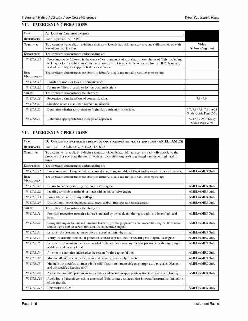
VII. EMERGENCY OPERATIONS
Task a. loss of coMMunicaTions
RefeRences 14 CFR parts 61, 91; AIM
objecTive To determine the applicant exhibits satisfactory knowledge, risk management, and skills associated with loss of communications.
VideoVolume.Segment
knowledge The applicant demonstrates understanding of:
IR.VII.A.K1 Procedures to be followed in the event of lost communication during various phases of flight, including techniques for reestablishing communications, when it is acceptable to deviate from an IFR clearance, and when to begin an approach at the destination.
Risk ManageMenT
The applicant demonstrates the ability to identify, assess and mitigate risks, encompassing:
IR.VII.A.R1 Possible reasons for loss of communication.
IR.VII.A.R2 Failure to follow procedures for lost communications.
skills The applicant demonstrates the ability to:
IR.VII.A.S1 Recognize a simulated loss of communication. 7.8 (7.9)
IR.VII.A.S2 Simulate actions to re-establish communication.
IR.VII.A.S3 Determine whether to continue to flight plan destination or deviate. 7.7, 7.8 (7.8, 7.9), ACS Study Guide Page 2-66
IR.VII.A.S4 Determine appropriate time to begin an approach. 7.7 (7.8), ACS Study Guide Page 2-66
VII. EMERGENCY OPERATIONS
Task b. one engine inoPeRaTive duRing sTRaighT-and-level flighT and TuRns (aMel, aMes)RefeRences 14 CFR 61; FAA-H-8083-15; FAA-H-8083-3
objecTive To determine the applicant exhibits satisfactory knowledge, risk management and skills associated the procedures for operating the aircraft with an inoperative engine during straight-and-level flight and in turns.
knowledge The applicant demonstrates understanding of:
IR.VII.B.K1 Procedures used if engine failure occurs during straight-and-level flight and turns while on instruments. AMEL/AMES Only
Risk ManageMenT
The applicant demonstrates the ability to identify, assess and mitigate risks, encompassing:
IR.VII.B.R1 Failure to correctly identify the inoperative engine. AMEL/AMES Only
IR.VII.B.R2 Inability to climb or maintain altitude with an inoperative engine AMEL/AMES Only
IR.VII.B.R3 Low altitude maneuvering/stall/spin. AMEL/AMES Only
IR.VII.B.R4 Distractions, loss of situational awareness, and/or improper task management. AMEL/AMES Only
skills The applicant demonstrates the ability to:
IR.VII.B.S1 Promptly recognize an engine failure simulated by the evaluator during straight-and-level flight and turns.
AMEL/AMES Only
IR.VII.B.S2 Recognize engine failure and simulate feathering of the propeller on the inoperative engine. (Evaluator should then establish a zero-thrust on the inoperative engine).
AMEL/AMES Only
IR.VII.B.S3 Establish the best engine-inoperative airspeed and trim the aircraft. AMEL/AMES Only
IR.VII.B.S4 Verify the accomplishment of prescribed checklist procedures for securing the inoperative engine. AMEL/AMES Only
IR.VII.B.S5 Establish and maintain the recommended flight attitude necessary for best performance during straight-and-level and turning flight.
AMEL/AMES Only
IR.VII.B.S6 Attempt to determine and resolve the reason for the engine failure. AMEL/AMES Only
IR.VII.B.S7 Monitor all engine control functions and make necessary adjustments. AMEL/AMES Only
IR.VII.B.S8 Maintain the specified altitude within ±100 feet, or minimum sink as appropriate, airspeed ±10 knots, and the specified heading ±10°.
AMEL/AMES Only
IR.VII.B.S9 Assess the aircraft’s performance capability and decide an appropriate action to ensure a safe landing. AMEL/AMES Only
IR.VII.B.S10 Avoid loss of aircraft control, or attempted flight contrary to the engine-inoperative operating limitations of the aircraft.
IR.VII.B.S11 Demonstrate SRM. AMEL/AMES Only

Sporty’s Complete Flight Training Course
ACS Study Guide Page 1-17
Instrument Rating ACS with Video Cross-Reference
VII. EMERGENCY OPERATIONS
Task c. insTRuMenT aPPRoach and landing wiTh an inoPeRaTive engine (siMulaTed) (aMel, aMes)
RefeRences 14 CFR parts 61,91; FAA-H-8083-3, FAA-H-8083-15
objecTive To determine that the applicant exhibits satisfactory knowledge, risk management, and skills associated with executing a published instrument approach with one engine inoperative.
knowledge The applicant demonstrates understanding of:
IR.VII.C.K1 Instrument approach procedures with one engine inoperative. AMEL/AMES Only
Risk ManageMenT
The applicant demonstrates the ability to identify, assess, and mitigate risks, encompassing:
IR.VII.C.R1 Failure to plan for engine failure during approach and landing. AMEL/AMES Only
IR.VII.C.R2 Distractions, loss of situational awareness, and/or improper task management. AMEL/AMES Only
IR.VII.C.R3 Single engine performance. AMEL/AMES Only
skills The applicant demonstrates the ability to:
IR.VII.C.S1 Recognize engine failure, set the engine controls, reduce drag, identify and verify the inoperative engine, and simulate feathering of the propeller on the inoperative engine. (Evaluator should then establish a zero-thrust on the inoperative engine).
AMEL/AMES Only
IR.VII.C.S2 Reduce drag by establishing and maintaining a bank angle and inclinometer ball displacement toward the operating engine and configuring the aircraft, as required for best performance in straight-and-level flight and during the approach phase.
AMEL/AMES Only
IR.VII.C.S3 Follow the manufacturer’s recommended emergency procedures. AMEL/AMES Only
IR.VII.C.S4 Monitor the operating engine and make necessary adjustments. AMEL/AMES Only
IR.VII.C.S5 Request and follow an actual or a simulated ATC clearance for an instrument approach. AMEL/AMES Only
IR.VII.C.S6 Maintain altitude within 100 feet, airspeed within ±10 knots if within the aircraft’s capability, and heading ±10°.
AMEL/AMES Only
IR.VII.C.S7 Establish a rate of descent that will ensure arrival at the MDA or DH/DA with the airplane in a position from which a descent to a landing on the intended runway can be made, either straight in or circling as appropriate.
AMEL/AMES Only
IR.VII.C.S8 On final approach segment, maintain vertical and lateral guidance within ¾-scale deflection. AMEL/AMES Only
IR.VII.C.S9 Avoid loss of aircraft control, or attempted flight contrary to the engine-inoperative operating limitations of the aircraft.
AMEL/AMES Only
IR.VII.C.S10 Comply with the published criteria for the aircraft approach category when circling. AMEL/AMES Only
IR.VII.C.S11 Complete the appropriate checklist. AMEL/AMES Only
VII. EMERGENCY OPERATIONS
Task d. aPPRoach wiTh loss of PRiMaRy flighT insTRuMenT indicaToRs
RefeRences 14 CFR parts 61, 91; FAA-H-8083-15; IAP
objecTive To determine the applicant exhibits satisfactory knowledge, risk management, and skills associated with performing an approach with the loss of primary flight control instruments.
VideoVolume.Segment
knowledge The applicant demonstrates understanding of:
IR.VII.D.K1 Recognizing if primary flight instruments are inaccurate or inoperative, and advising ATC or the evaluator.
IR.VII.D.K2 Common failure modes of vacuum and electric attitude instruments and how to correct or minimize the effect of their loss.
Risk ManageMenT
The applicant demonstrates the ability to identify, assess and mitigate risks, encompassing:
IR.VII.D.R1 Use of secondary flight displays when primary displays have failed.
IR.VII.D.R2 Failure to maintain aircraft control.
IR.VII.D.R3 Distractions, loss of situational awareness, and/or improper task management.
skills The applicant demonstrates the ability to:
IR.VII.D.S1 Advise ATC or evaluator if unable to comply with a clearance. 7.13 (7.14)
IR.VII.D.S2 Complete a nonprecision instrument approach without the use of the primary flight instruments using the skill elements of the nonprecision approach Task (See Area of Operation VI, Task A).
1.10 (1.11)
IR.VII.D.S3 Demonstrate SRM. Appendix E

What You Should Know
Page 1-18 Instrument Rating
Instrument Rating ACS with Video Cross-Reference
VIII. POSTFLIGHT PROCEDURES
Task a. checking insTRuMenTs and eQuiPMenT
RefeRences 14 CFR parts 61, 91
objecTive To determine the applicant exhibits satisfactory knowledge, risk management, and skills associated with checking flight instruments and equipment during postflight.
VideoVolume.Segment
knowledge The applicant demonstrates understanding of:
IR.VIII.A.K1 Procedures for checking the functionality of all installed instruments and navigation equipment. Appendix A
Risk ManageMenT
The applicant demonstrates the ability to identify, assess and mitigate risks, encompassing:
IR.VIII.A.R1 Failure to perform a proper postflight inspection and properly document aircraft discrepancies.
skills The applicant demonstrates the ability to:
IR.VIII.A.S1 Conduct a postflight inspection, and document discrepancies and servicing requirements, if any. Appendix A
Sporty’s Complete Flight Training Course
ACS Study Guide Page 1-19
Instrument Rating ACS with Video Cross-Reference
Supplemental ACS InformationThe following information is from the Instrument Rating Airman Certification Standards and may useful in your preparation.
(ACS) Foreword
The Federal Aviation Administration (FAA) has published the Instrument Rating Airplane Airman Certification Standards (ACS) document to communicate the aeronautical knowledge, risk management, and flight proficiency standards for the instrument rating in the airplane category, single-engine land and sea; and multiengine land and sea classes. This ACS incorporates and supersedes FAA-S-ACS-8 Instrument Rating – Airplane Airman Certification Standards, Change 1.
The FAA views the ACS as the foundation of its transition to a more integrated and systematic approach to airman certification. The ACS is part of the Safety Management System (SMS) framework that the FAA uses to mitigate risks associated with airman certification training and testing. Specifically, the ACS, associated guidance, and test question components of the airman certification system are constructed around the four functional components of an SMS:• Safety Policy that defines and describes aeronautical knowledge, flight proficiency, and risk management as
integrated components of the airman certification system;• Safety Risk Management processes through which internal and external stakeholders identify and evaluate
regulatory changes, safety recommendations, and other factors that require modification of airman testing and training materials;
• Safety Assurance processes to ensure the prompt and appropriate incorporation of changes arising from new regulations and safety recommendations; and
• Safety Promotion in the form of ongoing engagement with both external stakeholders (e.g., the aviation training industry) and FAA policy divisions.
The FAA has developed this ACS and its associated guidance in collaboration with a diverse group of aviation training experts. The goal is to drive a systematic approach to all components of the airman certification system, including knowledge test question development and conduct of the practical test. The FAA acknowledges and appreciates the many hours that these aviation experts have contributed toward this goal. This level of collaboration, a hallmark of a robust safety culture, strengthens and enhances aviation safety at every level of the airman certification system.
/s/ May 17, 2017
John S. DuncanDirector, Flight Standards Service
Airman Certification Standards Concept
The goal of the airman certification process is to ensure the applicant possesses knowledge, ability to manage risks, and skill consistent with the privileges of the certificate or rating being exercised, in order to act as Pilot-in-Command (PIC).
In fulfilling its responsibilities for the airman certification process, the Federal Aviation Administration (FAA) Flight Standards Service (AFS) plans, develops, and maintains materials related to airman certification training and testing. These materials have included several components. The FAA knowledge test measures mastery of the aeronautical knowledge areas listed in Title 14 of the Code of Federal Regulations (14 CFR) part 61. Other materials, such as handbooks in the FAA-H-8083 series, provide guidance to applicants on aeronautical knowledge, risk management, and flight proficiency.
Safe operations in today’s National Airspace System (NAS) require integration of aeronautical knowledge, risk management, and flight proficiency standards. To accomplish these goals, the FAA drew upon the expertise of organizations and individuals across the aviation and training community to develop the Airman Certification Standards (ACS). The ACS integrates the elements of knowledge, risk management, and skill listed in 14 CFR part 61 for each airman certificate or rating. It thus forms a more comprehensive standard for what an applicant must know, consider, and do for the safe conduct and successful completion of each Task to be tested on both the qualifying FAA knowledge test and the oral and flight portions of the practical test.
Through the ground and flight portion of the practical test, the FAA expects evaluators to assess the applicant’s mastery of the topic in accordance with the level of learning most appropriate for the specified Task. The oral questioning will continue throughout the entire practical test. For some topics, the evaluator will ask the applicant to describe or explain. For other items, the evaluator will assess the applicant’s understanding by providing a scenario that requires the applicant
What You Should Know
Page 1-20 Instrument Rating
Instrument Rating ACS with Video Cross-Reference
to appropriately apply and/or correlate knowledge, experience, and information to the circumstances of the given scenario. The flight portion of the practical test requires the applicant to demonstrate knowledge, risk management, flight proficiency, and operational skill in accordance with the ACS.
Note: As used in the ACS, an evaluator is any person authorized to conduct airman testing (e.g., an FAA Aviation Safety Inspector (ASI), Designated Pilot Examiner (DPE), or other individual authorized to conduct a test for a certificate or rating.)
Using the ACS
The ACS consists of Areas of Operation arranged in a logical sequence, beginning with Preflight Preparation and ending with Postflight Procedures. Each Area of Operation includes Tasks appropriate to that Area of Operation. Each Task begins with an Objective stating what the applicant should know, consider, and/or do. The ACS then lists the aeronautical knowledge, risk management, and skill elements relevant to the specific Task, along with the conditions and standards for acceptable performance. The ACS uses Notes to emphasize special considerations. The ACS uses the terms “will” and “must” to convey directive (mandatory) information. The term “may” denotes items that are recommended but not required. The References for each Task indicate the source material for Task elements. For example, in Tasks such as “Current and forecast weather for departure, arrival, and en route phases of flight” (IR.I.B.K1), the applicant should be prepared for questions on any weather product presented in the references for that Task.
The abbreviation(s) within parentheses immediately following a Task refer to the category and/or class aircraft appropriate to that Task. The meaning of each abbreviation is as follows:
ASEL: Airplane – Single-Engine Land
ASES: Airplane – Single-Engine Sea
AMEL: Airplane – Multiengine Land
AMES: Airplane – Multiengine Sea
Note: When administering a test based on this ACS, the Tasks appropriate to the class airplane (ASEL, ASES, AMEL, or AMES) used for the test must be included in the plan of action. The absence of a class indicates the Task is for all classes.
Each Task in the ACS is coded according to a scheme that includes four elements. For example:
IR.I.C.K4:IR = Applicable ACS (Instrument Rating – Airplane)I = Area of Operation (Preflight Preparation)C = Task (Cross-Country Flight Planning)K4 = Task Element Knowledge 4 (Elements of an IFR flight plan.)
Knowledge test questions are linked to the ACS codes, which will soon replace the system of Learning Statement Codes (LSC). After this transition occurs, the Airman Knowledge Test Report (AKTR) will list an ACS code that correlates to a specific Task element for a given Area of Operation and Task. Remedial instruction and re-testing will be specific, targeted, and based on specified learning criteria. Similarly, a Notice of Disapproval for the practical test will use the ACS codes to identify the deficient Task elements.
The current knowledge test management system does not have the capability to print ACS codes. Until a new test management system is in place, the LSC (e.g., “PLT058”) code will continue to be displayed on the AKTR. The LSC codes are linked to references leading to broad subject areas. By contrast, each ACS code is tied to a unique Task element in the ACS itself. Because of this fundamental difference, there is no one-to-one correlation between LSC codes and ACS codes.
Because all active knowledge test questions for the Instrument Rating Airplane (IRA) knowledge test have been aligned with the corresponding ACS, evaluators can continue to use LSC codes in conjunction with the ACS for the time being. The evaluator should look up the LSC code(s) on the applicant’s AKTR in the Learning Statement Reference Guide. After noting the subject area(s), the evaluator can use the corresponding Area(s) of Operation/Task(s) in the ACS to narrow the scope of material for retesting, and to evaluate the applicant’s understanding of that material in the context of the appropriate ACS Area(s) of Operation and Task(s).
Applicants for a combined Private Pilot Certificate with Instrument Rating, in accordance with 14 CFR part 61, section 61.65 (a) and (g), must pass all areas designated in the Private Pilot Airplane (PAR) ACS and the Instrument Rating

Sporty’s Complete Flight Training Course
ACS Study Guide Page 1-21
Instrument Rating ACS with Video Cross-Reference
Airplane (IRA) ACS. Examiners need not duplicate Tasks. For example, only one preflight demonstration would be required; however, the Preflight Task from the IRA ACS would be more extensive than the Preflight Task from the PAR ACS to ensure readiness for Instrument Flight Rules (IFR) flight.
A combined checkride should be treated as one practical test, requiring only one application and resulting in only one temporary certificate, disapproval notice, or letter of discontinuance, as applicable. Failure of any Task will result in a failure of the entire test and application. Therefore, even if the deficient maneuver was instrument related and the performance of all visual flight rules (VFR) Tasks was determined to be satisfactory, the applicant will receive a notice of disapproval.
The applicant must pass the IRA knowledge test before taking the instrument rating practical test. The practical test is conducted in accordance with the ACS that is current as of the date of the test. Further, the applicant must pass the ground portion of the practical test before beginning the flight portion. The ground portion of the practical test allows the evaluator to determine whether the applicant is sufficiently prepared to advance to the flight portion of the practical test. The oral questioning will continue throughout the entire practical test.
The FAA encourages applicants and instructors to use the ACS when preparing for knowledge tests and practical tests. The FAA will revise the ACS as circumstances require.
Appendix 1: The Knowledge Test Eligibility, Prerequisites, and Testing CentersKnowledge Test Description
The knowledge test is an important part of the airman certification process. Applicants must pass the knowledge test before taking the practical test.
The knowledge test consists of objective, multiple-choice questions. There is a single correct response for each test question. Each test question is independent of other questions. A correct response to one question does not depend upon, or influence, the correct response to another.
Knowledge Test Tables
Test Code
Test Name Number of Questions
Age Allotted Time
Passing Score
AIF Flight Instructor Instrument Airplane (Added Rating)* 20 16 1.0 70
FIH Flight Instructor Instrument Helicopter 50 16 2.5 70
FII Flight Instructor Instrument Airplane 50 16 2.5 70
HIF Flight Instructor Instrument Helicopter (Added Rating)* 20 16 1.0 70
ICH Instrument Rating Helicopter Canadian Conversion 40 15 2.0 70
ICP Instrument Rating Airplane Canadian Conversion 40 15 2.0 70
IFP Instrument Rating Foreign Pilot 50 n/a 2.5 70
IGI Ground Instructor Instrument 50 16 2.5 70
IRA Instrument Rating Airplane 60 15 2.5 70
IRH Instrument Rating Helicopter 60 15 2.5 70
*See Rating Table Appendix 4
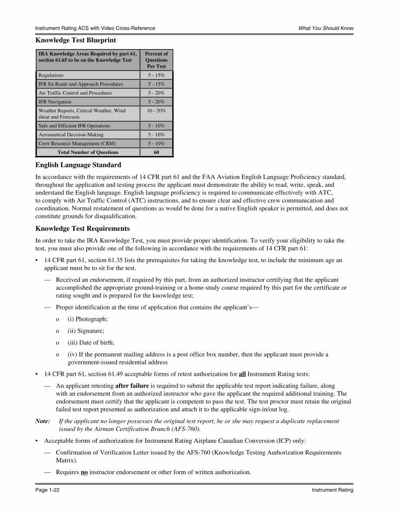
What You Should Know
Page 1-22 Instrument Rating
Instrument Rating ACS with Video Cross-Reference
Knowledge Test Blueprint
IRA Knowledge Areas Required by part 61, section 61.65 to be on the Knowledge Test
Percent of Questions Per Test
Regulations 5 - 15%
IFR En Route and Approach Procedures 5 - 15%
Air Traffic Control and Procedures 5 - 20%
IFR Navigation 5 - 20%
Weather Reports, Critical Weather, Wind shear and Forecasts
10 - 20%
Safe and Efficient IFR Operations 5 - 10%
Aeronautical Decision-Making 5 - 10%
Crew Resource Management (CRM) 5 - 10%
Total Number of Questions 60
English Language Standard
In accordance with the requirements of 14 CFR part 61 and the FAA Aviation English Language Proficiency standard, throughout the application and testing process the applicant must demonstrate the ability to read, write, speak, and understand the English language. English language proficiency is required to communicate effectively with ATC, to comply with Air Traffic Control (ATC) instructions, and to ensure clear and effective crew communication and coordination. Normal restatement of questions as would be done for a native English speaker is permitted, and does not constitute grounds for disqualification.
Knowledge Test Requirements
In order to take the IRA Knowledge Test, you must provide proper identification. To verify your eligibility to take the test, you must also provide one of the following in accordance with the requirements of 14 CFR part 61:
• 14 CFR part 61, section 61.35 lists the prerequisites for taking the knowledge test, to include the minimum age an applicant must be to sit for the test.
— Received an endorsement, if required by this part, from an authorized instructor certifying that the applicant accomplished the appropriate ground-training or a home-study course required by this part for the certificate or rating sought and is prepared for the knowledge test;
— Proper identification at the time of application that contains the applicant’s—
o (i) Photograph;
o (ii) Signature;
o (iii) Date of birth;
o (iv) If the permanent mailing address is a post office box number, then the applicant must provide a government-issued residential address
• 14 CFR part 61, section 61.49 acceptable forms of retest authorization for all Instrument Rating tests:
— An applicant retesting after failure is required to submit the applicable test report indicating failure, along with an endorsement from an authorized instructor who gave the applicant the required additional training. The endorsement must certify that the applicant is competent to pass the test. The test proctor must retain the original failed test report presented as authorization and attach it to the applicable sign-in/out log.
Note: If the applicant no longer possesses the original test report, he or she may request a duplicate replacement issued by the Airman Certification Branch (AFS-760).
• Acceptable forms of authorization for Instrument Rating Airplane Canadian Conversion (ICP) only:
— Confirmation of Verification Letter issued by the AFS-760 (Knowledge Testing Authorization Requirements Matrix).
— Requires no instructor endorsement or other form of written authorization.

Sporty’s Complete Flight Training Course
ACS Study Guide Page 1-23
Instrument Rating ACS with Video Cross-Reference
Knowledge Test Centers
The FAA authorizes hundreds of knowledge testing center locations that offer a full range of airman knowledge tests. For information on authorized testing centers and to register for the knowledge test, contact one of the providers listed at www.faa.gov.
Knowledge Test Registration
When you contact a knowledge testing center to register for a test, please be prepared to select a test date, choose a testing center, and make financial arrangements for test payment when you call. You may register for test(s) several weeks in advance, and you may cancel in accordance with the testing center’s cancellation policy.
Appendix 2: Knowledge Test Procedures and TipsBefore starting the actual test, the testing center will provide an opportunity to practice navigating through the test. This practice or tutorial session may include sample questions to familiarize the applicant with the look and feel of the software. (e.g., selecting an answer, marking a question for later review, monitoring time remaining for the test, and other features of the testing software.)
Acceptable Materials
The applicant may use the following aids, reference materials, and test materials, as long as the material does not include actual test questions or answers:
Acceptable Materials Unacceptable Materials Notes
Supplement book provided by proctor Written materials that are handwritten, printed, or electronic
Testing centers may provide calculators and/or deny the use of personal calculators.
All models of aviation-oriented calculators or small electronic calculators that perform only arithmetic functions
Electronic calculators incorporating permanent or continuous type memory circuits without erasure capability.
Unit Member (proctor) may prohibit the use of your calculator if he or she is unable to determine the calculator’s erasure capability
Calculators with simple programmable memories, which allow addition to, subtraction from, or retrieval of one number from the memory; or simple functions, such as square root and percentages
Magnetic Cards, magnetic tapes, modules, computer chips, or any other device upon which pre-written programs or information related to the test can be stored and retrieved
Printouts of data must be surrendered at the completion of the test if the calculator incorporates this design feature.
Scales, straightedges, protractors, plotters, navigation computers, blank log sheets, holding pattern entry aids, and electronic or mechanical calculators that are directly related to the test
Dictionaries Before, and upon completion of the test, while in the presence of the Unit Member, actuate the ON/OFF switch or RESET button, and perform any other function that ensures erasure of any data stored in memory circuits
Manufacturer’s permanently inscribed instructions on the front and back of such aids, e.g., formulas, conversions, regulations, signals, weather data, holding pattern diagrams, frequencies, weight and balance formulas, and air traffic control procedures
Any booklet or manual containing instructions related to use of test aids
Unit Member makes the final determination regarding aids, reference materials, and test materials
Test Tips
When taking a knowledge test, please keep the following points in mind:• Carefully read the instructions provided with the test.• Answer each question in accordance with the latest regulations and guidance publications.• Read each question carefully before looking at the answer options. You should clearly understand the problem
before trying to solve it.• After formulating a response, determine which answer option corresponds with your answer. The answer you choose
should completely solve the problem.• Remember that only one answer is complete and correct. The other possible answers are either incomplete or
erroneous.• If a certain question is difficult for you, mark it for review and return to it after you have answered the less difficult
questions. This procedure will enable you to use the available time to maximum advantage.• When solving a calculation problem, be sure to read all the associated notes.• For questions involving use of a graph, you may request a printed copy that you can mark in computing your
answer. This copy and all other notes and paperwork must be given to the testing center upon completion of the test.

What You Should Know
Page 1-24 Instrument Rating
Instrument Rating ACS with Video Cross-Reference
Cheating or Other Unauthorized Conduct
To avoid test compromise, computer testing centers must follow strict security procedures established by the FAA and described in FAA Order 8080.6 (as amended), Conduct of Airman Knowledge Tests. The FAA has directed testing centers to terminate a test at any time a test unit member suspects that a cheating incident has occurred.
The FAA will investigate and, if the agency determines that cheating or unauthorized conduct has occurred, any airman certificate or rating you hold may be revoked. You will also be prohibited from applying for or taking any test for a certificate or rating under 14 CFR part 61 for a period of one year.
Testing Procedures for Applicants Requesting Special Accommodations
An applicant with learning or reading disability may request approval from the Airman Testing Standards Branch (AFS-630) through the local Flight Standards District Office (FSDO) or International Field Office/International Field Unit (IFO/IFU) to take airman knowledge test using one of the three options listed below, in preferential order:
Option 1: Use current testing facilities and procedures whenever possible.
Option 2: Use a self-contained, electronic device which pronounces and displays typed-in words (e.g., the Franklin Speaking Wordmaster®) to facilitate the testing process.
Note: The device should consist of an electronic thesaurus that audibly pronounces typed-in words and presents them on a display screen. The device should also have a built-in headphone jack in order to avoid disturbing others during testing.
Option 3: Request the proctor’s assistance in reading specific words or terms from the test questions and/or supplement book. To prevent compromising the testing process, the proctor must be an individual with no aviation background or expertise. The proctor may provide reading assistance only (i.e., no explanation of words or terms). When an applicant requests this option, the FSDO or IFO/IFU inspector must contact AFS-630 for assistance in selecting the test site and assisting the proctor. Before approving any option, the FSDO or IFO/IFU inspector must advise the applicant of the regulatory certification requirement to be able to read, write, speak, and understand the English language.
Appendix 3: Airman Knowledge Test ReportImmediately upon completion of the knowledge test, the applicant receives a printed Airman Knowledge Test Report (AKTR) documenting the score with the testing center’s raised, embossed seal. The applicant must retain the original AKTR. The instructor must provide instruction in each area of deficiency and provide a logbook endorsement certifying that the applicant has demonstrated satisfactory knowledge in each area. When taking the practical test, the applicant must present the original AKTR to the evaluator, who is required to assess the noted areas of deficiency during the oral portion of the practical test.
An AKTR expires 24 calendar months after the month the applicant completes the knowledge test. If the AKTR expires before completion of the practical test, the applicant must retake the knowledge test.
To obtain a duplicate AKTR due to loss or destruction of the original, the applicant can send a signed request accompanied by a check or money order for $12.00, payable to the FAA to:
Federal Aviation AdministrationAirmen Certification Branch, AFS-760P.O. Box 25082Oklahoma City, OK 73125
To obtain a copy of the application form or a list of the information required, please see the Airman Certification Branch (AFS-760) web page.
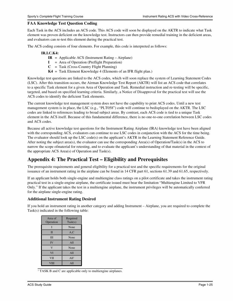
Sporty’s Complete Flight Training Course
ACS Study Guide Page 1-25
Instrument Rating ACS with Video Cross-Reference
FAA Knowledge Test Question Coding
Each Task in the ACS includes an ACS code. This ACS code will soon be displayed on the AKTR to indicate what Task element was proven deficient on the knowledge test. Instructors can then provide remedial training in the deficient areas, and evaluators can re-test this element during the practical test.
The ACS coding consists of four elements. For example, this code is interpreted as follows:
IR.I.C.K4:IR = Applicable ACS (Instrument Rating – Airplane)I = Area of Operation (Preflight Preparation)C = Task (Cross-Country Flight Planning)K4 = Task Element Knowledge 4 (Elements of an IFR flight plan.)
Knowledge test questions are linked to the ACS codes, which will soon replace the system of Learning Statement Codes (LSC). After this transition occurs, the Airman Knowledge Test Report (AKTR) will list an ACS code that correlates to a specific Task element for a given Area of Operation and Task. Remedial instruction and re-testing will be specific, targeted, and based on specified learning criteria. Similarly, a Notice of Disapproval for the practical test will use the ACS codes to identify the deficient Task elements.
The current knowledge test management system does not have the capability to print ACS codes. Until a new test management system is in place, the LSC (e.g., “PLT058”) code will continue to bedisplayed on the AKTR. The LSC codes are linked to references leading to broad subject areas. By contrast, each ACS code is tied to a unique Task element in the ACS itself. Because of this fundamental difference, there is no one-to-one correlation between LSC codes and ACS codes.
Because all active knowledge test questions for the Instrument Rating Airplane (IRA) knowledge test have been aligned with the corresponding ACS, evaluators can continue to use LSC codes in conjunction with the ACS for the time being. The evaluator should look up the LSC code(s) on the applicant’s AKTR in the Learning Statement Reference Guide. After noting the subject area(s), the evaluator can use the corresponding Area(s) of Operation/Task(s) in the ACS to narrow the scope ofmaterial for retesting, and to evaluate the applicant’s understanding of that material in the context of the appropriate ACS Area(s) of Operation and Task(s).
Appendix 4: The Practical Test – Eligibility and PrerequisitesThe prerequisite requirements and general eligibility for a practical test and the specific requirements for the original issuance of an instrument rating in the airplane can be found in 14 CFR part 61, sections 61.39 and 61.65, respectively.
If an applicant holds both single-engine and multiengine class ratings on a pilot certificate and takes the instrument rating practical test in a single-engine airplane, the certificate issued must bear the limitation “Multiengine Limited to VFR Only.” If the applicant takes the test in a multiengine airplane, the instrument privileges will be automatically conferred for the airplane single-engine rating.
Additional Instrument Rating Desired
If you hold an instrument rating in another category and adding Instrument – Airplane, you are required to complete the Task(s) indicated in the following table:
Area of Operation
Required Task(s)
I None
II A,C
III None
IV All
V None
VI All
VII All1
VIII All
1 TASK B and C are applicable only to multiengine airplanes.

What You Should Know
Page 1-26 Instrument Rating
Instrument Rating ACS with Video Cross-Reference
Removal of the “Airplane Multiengine VFR Only” Limitation
The removal of the “Airplane Multiengine VFR Only” limitation, at the private pilot or commercial pilot certificate level, requires an applicant to satisfactorily perform the following Area of Operation and Tasks from the Instrument Rating‒Airplane ACS in a multiengine airplane that has a manufacturer’s published VMC speed.
VII. Emergency Operations
Task B: One Engine Inoperative during Straight-and-Level Flight and Turns (AMEL, AMES)
Task C: Instrument Approach and Landing with an Inoperative Engine (Simulated) (AMEL, AMES)
Appendix 5: Practical Test Roles, Responsibilities, and OutcomesApplicant Responsibilities
The applicant is responsible for mastering the established standards for knowledge, risk management, and skill elements in all Tasks appropriate to the certificate and rating sought. The applicant should use this ACS, its references, and the Applicant’s Practical Test Checklist in this Appendix in preparation to take the practical test.
Instructor Responsibilities
The instructor is responsible for training the applicant to meet the established standards for knowledge, risk management, and skill elements in all Tasks appropriate to the certificate and rating sought. The instructor should use this ACS and its references as part of preparing the applicant to take the practical test and, if necessary, in retraining the applicant to proficiency in all subject(s) missed on the knowledge test.
Evaluator Responsibilities
An Evaluator is:• Aviation Safety Inspector (ASI)• Pilot examiner (other than administrative pilot examiners);• Training center evaluator (TCE);• Chief instructor, assistant chief instructor or check instructor of pilot school holding examining authority; or• Instrument Flight Instructor (CFII) conducting an instrument proficiency check (IPC).
The evaluator who conducts the practical test is responsible for determining that the applicant meets the established standards of aeronautical knowledge, skills (flight proficiency), and risk management for the Tasks in the appropriate ACS. This responsibility also includes verifying the experience requirements specified for a certificate or rating.
Prior to beginning the practical test, the evaluator must also determine that the applicant meets FAA Aviation English Language Proficiency Standard by verifying that he or she can understand ATC instructions and communicate in English at a level that is understandable to ATC and other pilots. The evaluator should use the procedures outlined in the AC 60-28, English Language Skill Standards required by 14 CFR parts 61, 63, and 65 (current version) when evaluating the applicant’s ability to meet the standard.
The evaluator must develop a Plan of Action (POA), written in English, to conduct the practical test. It must include all of the required Areas of Operation and Tasks. The POA must include a scenario that evaluates as many of the required Areas of Operation and Tasks as possible. As the scenario unfolds during the test, the evaluator will introduce problems and emergencies that the applicant must manage. The evaluator has the discretion to modify the POA in order to accommodate unexpected situations as they arise. For example, the evaluator may elect to suspend and later resume a scenario in order to assess certain Tasks.
In the integrated ACS framework, the Areas of Operation contain Tasks that include “Knowledge” elements (such as K1), “risk management” elements (such as R1), and “skill” elements (such as S1). Knowledge and risk management elements are primarily evaluated during the knowledge testing phase of the airman certification process. The evaluator must assess the applicant on all skill elements for each Task included in each Area of Operation of the ACS, unless otherwise noted. The evaluator administering the practical test has the discretion to combine Tasks/elements as appropriate to testing scenarios.
Sporty’s Complete Flight Training Course
ACS Study Guide Page 1-27
Instrument Rating ACS with Video Cross-Reference
The required minimum elements to include in the POA, unless otherwise noted, from each applicable Task are as follows:• at least one knowledge element;• at least one risk management element;• all skill elements; and• any Task elements in which the applicant was shown to be deficient on the knowledge test.
Note: Task elements added to the POA on the basis of being listed on the AKTR may satisfy the other minimum Task element requirements. The missed items on the AKTR are not required to be added in addition to the minimum Task element requirements.
There is no expectation for testing every knowledge element and risk management element in a Task, but the evaluator has discretion to sample as needed to ensure the applicant’s mastery of that Task.
Unless otherwise noted in the Task, the evaluator must test each item in the skills section by asking the applicant to perform each one. As safety of flight conditions permit, the evaluator may use questions during flight to test knowledge and risk management elements not evident in the demonstrated skills. To the greatest extent practicable, evaluators must test the applicant’s ability to apply and correlate information, and use rote questions only when they are appropriate for the material being tested. If the Task includes an element with sub-elements, the evaluator may choose the primary element and select at least one sub-element to satisfy the requirement that at least one knowledge element be selected, For example, if the evaluator chooses IR.I.B.K3, he or she must select a sub-element like IR.I.B.K3d to satisfy the requirement to select one knowledge element.
Possible Outcomes of the Test
There are three possible outcomes of the practical test: (1) Temporary Airman Certificate (satisfactory), (2) Notice of Disapproval (unsatisfactory), or (3) Letter of Discontinuance.
If the evaluator determines that a Task is incomplete, or the outcome is uncertain, the evaluator may require the applicant to repeat that Task, or portions of that Task. This provision does not mean that instruction, practice, or the repetition of an unsatisfactory Task is permitted during the practical test.
If the evaluator determines the applicant’s skill and abilities are in doubt, the outcome is unsatisfactory and the evaluator must issue a Notice of Disapproval.
Satisfactory Performance
Satisfactory performance requires that the applicant:• demonstrate the Tasks specified in the Areas of Operation for the certificate or rating sought within the established
standards;• demonstrate mastery of the aircraft by performing each Task successfully;• demonstrate proficiency and competency in accordance with the approved standards;• demonstrate sound judgment and exercise aeronautical decision-making/risk management; and• demonstrate competence in crew resource management in aircraft certificated for more than one required pilot crew
member, or single-pilot competence in an airplane that is certificated for single-pilot operations.
Satisfactory performance will result in the issuance of a temporary certificate.
Unsatisfactory Performance
If, in the judgment of the evaluator, the applicant does not meet the standards for any Task, the applicant fails the Task and associated Area of Operation. The test is unsatisfactory, and the evaluator issues a Notice of Disapproval.
When the evaluator issues a Notice of Disapproval, he or she must list the ACS code associated with the Area of Operation in which the application did not meet the standard. The Notice of Disapproval must also list the Area(s) of Operation not tested, and the number of practical test failures. If the applicant’s inability to meet English language requirements contributed to the failure of a Task, the evaluator should note “English Proficiency” on the Notice of Disapproval.
The evaluator or the applicant may end the test if the applicant fails a Task. The evaluator may continue the test only with the consent of the applicant, and the applicant is entitled to credit only for those Areas of Operation and the associated Tasks satisfactorily performed. Though not required, the evaluator has discretion to reevaluate any Task, including those previously passed, during the retest.

What You Should Know
Page 1-28 Instrument Rating
Instrument Rating ACS with Video Cross-Reference
Typical areas of unsatisfactory performance and grounds for disqualification include:• Any action or lack of action by the applicant that requires corrective intervention by the evaluator to maintain safe
flight.• Failure to use proper and effective visual scanning techniques to clear the area before and while performing
maneuvers.• Consistently exceeding tolerances stated in the skill elements of the Task.• Failure to take prompt corrective action when tolerances are exceeded.• Failure to exercise risk management.
Discontinuance
When it is necessary to discontinue a practical test for reasons other than unsatisfactory performance (e.g., equipment failure, weather, illness), the evaluator must return all test paperwork to the applicant. The evaluator must prepare, sign, and issue a Letter of Discontinuance that lists those Areas of Operation the applicant successfully completed and the date the test must be completed. The evaluator should advise the applicant to present the Letter of Discontinuance to the evaluator when the practical test resumes in order to receive credit for the items successfully completed. The Letter of Discontinuance becomes part of the applicant’s certification file.
Practical Test Checklist (Applicant)
Appointment with Evaluator
Evaluator’s Name: _____________________________
Location: ____________________________________
Date/Time: ____________________________________
ACCEPTABLE AIRCRAFT Aircraft Documents:
Airworthiness Certificate Registration Certificate Operating Limitations
Aircraft Maintenance Records: Logbook Record of Airworthiness Inspections and AD Compliance
Pilot’s Operating Handbook, FAA-Approved Aircraft Flight Manual
PERSONAL EQUIPMENT View-limiting device Current Aeronautical Charts (May be electronic) Computer and Plotter Flight Plan Form Flight Plan Form and Flight Logs (printed or electronic) Chart Supplements, U.S., Airport Diagrams and Appropriate Publications (regulations, AIM, etc.)
PERSONAL RECORDS Identification - Photo/Signature ID Pilot Certificate Current Medical Certificate Completed FAA Form 8710-1, Airman Certificate and/or Rating Application with Instructor’s Signature or
completed IACRA form Original Knowledge Test Report Pilot Logbook with appropriate Instructor Endorsements FAA Form 8060-5, Notice of Disapproval (if applicable) Letter of Discontinuance (if applicable) Approved School Graduation Certificate (if applicable) Examiner’s Fee (if applicable)

Sporty’s Complete Flight Training Course
ACS Study Guide Page 1-29
Instrument Rating ACS with Video Cross-Reference
Instrument Proficiency Check
14 CFR part 61, section 61.57(d) sets forth the requirements for an instrument proficiency check (IPC). Instructors and evaluators conducting an IPC must ensure the pilot meets the standards established in this ACS. A representative number of Tasks must be selected to assure the competence of the applicant to operate in the IFR environment. As a minimum, the applicant must demonstrate the ability to perform the Tasks listed in the table below. The person giving the check should develop a scenario that incorporates as many required Tasks as practical to assess the pilot’s ADM and risk management skills.
Guidance on how to conduct an IPC is found in Advisory Circular 61-98, Currency Requirements and Guidance for the Flight Review and Instrument Proficiency Check. You may obtain a copy at: http://www.faa.gov.
Area of Operation
IPC (Proficiency Check)2
I None
II None
III B
IV B
V A
VI All
VII3 B, C, D
VIII All
2 AATDs can be utilized for the majority of the IPC as specified in the Letter of Authorization issued for the device. However, the circling approach, the landing Task, and the multiengine airplane Tasks must be accomplished in an aircraft or FFS (Level B, C, or D). A BATD cannot be used for any part of the IPC.
3 Tasks B and C are applicable only to multiengine airplanes.
Appendix 6: Safety of FlightGeneral
Safety of flight must be the prime consideration at all times. The evaluator, applicant, and crew must be constantly alert for other traffic. If performing aspects of a given maneuver, such as emergency procedures, would jeopardize safety, the evaluator will ask the applicant to simulate that portion of the maneuver. The evaluator will assess the applicant’s use of visual scanning and collision avoidance procedures throughout the entire test.
Stall and Spin Awareness
During flight training and testing, the applicant and the instructor or evaluator must always recognize and avoid operations that could lead to an inadvertent stall or spin.
Use of Checklists
Throughout the practical test, the applicant is evaluated on the use of an appropriate checklist.
Assessing proper checklist use depends upon the specific Task. In all cases, the evaluator should determine whether the applicant appropriately divides attention and uses proper visual scanning. In some situations, reading the actual checklist may be impractical or unsafe. In such cases, the evaluator should assess the applicant’s performance of published or recommended immediate action “memory” items along with his or her review of the appropriate checklist once conditions permit.
In a single-pilot airplane, the applicant should demonstrate the crew resource management (CRM) principles described as single-pilot resource management (SRM). Proper use is dependent on the specific Task being evaluated. The situation may be such that the use of the checklist while accomplishing elements of an Objective would be either unsafe or impractical in a single-pilot operation. In this case, a review of the checklist after the elements have been accomplished is appropriate. Use of a checklist should also consider visual scanning and division of attention at all times.

What You Should Know
Page 1-30 Instrument Rating
Instrument Rating ACS with Video Cross-Reference
Use of Distractions
Numerous studies indicate that many accidents have occurred when the pilot has been distracted during critical phases of flight. The evaluator should incorporate realistic distractions during the flight portion of the practical test to evaluate the pilot’s situational awareness and ability to utilize proper control technique while dividing attention both inside and outside the flight deck.
Positive Exchange of Flight Controls
There must always be a clear understanding of who has control of the aircraft. Prior to flight, the pilots involved should conduct a briefing that includes reviewing the procedures for exchanging flight controls.
The FAA recommends a positive three-step process for exchanging flight controls between pilots:• When one pilot seeks to have the other pilot take control of the aircraft, he or she will say, “You have the flight
controls.”• The second pilot acknowledges immediately by saying, “I have the flight controls.”• The first pilot again says, “You have the flight “controls,” and visually confirms the exchange.
Pilots should follow this procedure during any exchange of flight controls, including any occurrence during the practical test. The FAA also recommends that both pilots use a visual check to verify that the exchange has occurred. There must never be any doubt as to who is flying the aircraft.
Aeronautical Decision-Making, Risk Management, Crew Resource Management and Single-Pilot Resource Management
Throughout the practical test, the evaluator must assess the applicant’s ability to use sound aeronautical decision-making procedures in order to identify hazards and mitigate risk. The evaluator must accomplish this requirement by reference to the risk management elements of the given Task(s), and by developing scenarios that incorporate and combine Tasks appropriate to assessing the applicant’s risk management in making safe aeronautical decisions. For example, the evaluator may develop a scenario that incorporates weather decisions and performance planning.
In assessing the applicant’s performance, the evaluator should take note of the applicant’s use of CRM and, if appropriate, SRM. CRM/SRM is the set of competencies that includes situational awareness, communication skills, teamwork, task allocation, and decision-making within a comprehensive framework of standard operating procedures (SOP). SRM specifically refers to the management of all resources onboard the aircraft as well as outside resources available to the single pilot.
Deficiencies in CRM/SRM almost always contribute to the unsatisfactory performance of a Task. While evaluation of CRM/SRM may appear to be somewhat subjective, the evaluator should use the risk management elements of the given Task(s) to determine whether the applicant’s performance of the Task(s) demonstrates both understanding and application of the associated risk management elements.
Multiengine Considerations
For multiengine practical tests conducted in the airplane, the evaluator must discuss with the applicant during the required preflight briefing the methods for simulating an engine failure in accordance with the aircraft manufacturer’s recommended procedures.
Practical tests conducted in an FSTD can only be accomplished as part of an approved curriculum or training program. Any limitations on powerplant failure will be noted in that program.
Appendix 7: Aircraft, Equipment, and Operational Requirements & LimitationsAircraft Requirements & Limitations
14 CFR part 61, section 61.45 prescribes the required aircraft and equipment for a practical test. The regulation states the minimum aircraft registration and airworthiness requirements as well as the minimum equipment requirements, to include the minimum required controls.
An applicant may accomplish an instrument-airplane rating practical test in a multiengine airplane that is limited to center thrust. There is no need to place the “Limited to Center Thrust” limitation on the applicant’s pilot certificate, provided the airplane multiengine land rating is not limited to center thrust. If the applicant’s airplane multiengine land rating is limited to center thrust then the limitation will already be on the pilot certificate.

Sporty’s Complete Flight Training Course
ACS Study Guide Page 1-31
Instrument Rating ACS with Video Cross-Reference
If the aircraft presented for the practical test has inoperative instruments or equipment, it must be addressed in accordance with 14 CFR part 91, section 91.213. If the aircraft can be operated in accordance with 14 CFR part 91, section 91.213, then it must be determined if the inoperative instruments or equipment are required to complete the practical test.
Equipment Requirements & Limitations
The equipment examination should be administered before the flight portion of the practical test, but it must be closely coordinated and related to the flight portion. In a training core curriculum that has been approved under 14 CFR part 142, the evaluator may accept written evidence of the equipment exam, provided that the Administrator has approved the exam and authorized the individual who administers it.
Consistent with 14 CFR part 61, section 61.45 (b) and (d), the aircraft must have:• the flight instruments necessary for controlling the aircraft without outside references,• the radio equipment required for ATC communications, and• the ability to perform instrument approach procedures• GPS equipment must be instrument certified and contain the current database.
To assist in management of the aircraft during the practical test, the applicant is expected to demonstrate automation management skills by utilizing installed equipment such as autopilot, avionics and systems displays, and/or flight management system (FMS). The evaluator is expected to test the applicant’s knowledge of the systems that are installed and operative during both the oral and flight portions of the practical test.
If the practical test is conducted in an aircraft, the applicant is required by 14 CFR part 61, section 61.45(d)(2) to provide an appropriate view limiting device acceptable to the evaluator. The applicant and the evaluator should establish a procedure as to when and how this device should be donned and removed, and brief this procedure before the flight. The device must be used during all testing that requires flight “solely by reference to instruments.” This device must prevent the applicant from having visual reference outside the aircraft, but it must not restrict the evaluator’s ability to see and avoid other traffic.
Operational Requirements, Limitations, & Task Information
VI. Instrument Approach Procedures
A stabilized approach is characterized by a constant angle, constant rate of descent approach profile ending near the touchdown point, where the landing maneuver begins.
If the practical test is conducted in an airplane equipped with an approach-approved RNAV or GPS system or FSTD that is equipped to replicate an approved RNAV or GPS system, the applicant must demonstrate approach proficiency using that system. If the applicant has contracted for training in an approved course that includes GPS training, and the airplane/FSTD has a properly installed and operable GPS, the applicant must demonstrate GPS approach proficiency.
Localizer performance with vertical guidance (LPV) minimums with a decision altitude (DA) greater than 300 feet height above touchdown (HAT) may be used as a nonprecision approach; however, due to the precision of its glidepath and localizer-like lateral navigation characteristics, an LPV minimums can be used to demonstrate precision approach proficiency if the DA is equal to or less than 300 feet HAT.
The standard is to allow no more than a ¾ scale deflection of either the vertical or lateral deviation indications during the final approach. As markings on flight instruments vary, a ¾ scale deflection of either vertical or lateral guidance is deemed to occur when it is displaced three-fourths of the distance that it may be deflected from the indication representing that the aircraft is on the correct flight path.
Task A. Nonprecision Approach
The evaluator will select nonprecision approaches representative of the type that the applicant is likely to use. The choices must use at least two different types of navigational aids.
Examples of acceptable nonprecision approaches include: VOR, VOR/DME, LOC procedures on an ILS, LDA, RNAV (RNP) or RNAV (GPS) to LNAV, LNAV/VNAV or LPV line of minima as long as the LPV DA is greater than 300 feet HAT. The equipment must be installed and the database must be current and qualified to fly GPS-based approaches.

What You Should Know
Page 1-32 Instrument Rating
Instrument Rating ACS with Video Cross-Reference
The applicant must accomplish at least two nonprecision approaches in simulated or actual weather conditions.• One must include a procedure turn or, in the case of a GPS-based approach, a Terminal Arrival Area (TAA)
procedure.• At least one must be flown without the use of autopilot and without the assistance of radar vectors. The yaw damper
and flight director are not considered parts of the autopilot for purposes of this Task.• If the equipment allows, at least one should be conducted without vertical guidance.• One is expected to be flown with reference to backup or partial panel instrumentation or navigation display,
depending on the aircraft’s instrument avionics configuration, representing the failure mode(s) most realistic for the equipment used.
Task B. Precision Approach
The applicant must accomplish a precision approach to the decision altitude (DA) using aircraft navigational equipment for centerline and vertical guidance in simulated or actual instrument conditions. Acceptable instrument approaches for this part of the practical test are the ILS and GLS. In addition, if the installed equipment and database is current and qualified for IFR flight and approaches to LPV minima, an LPV minima approach can be flown to demonstrate precision approach proficiency if the LPV DA is equal to or less than 300 feet HAT.
Appendix 8: Use of Flight Simulation Training Devices (FSTD) and Aviation Training Devices (ATD): Airplane Single-Engine, Multi Engine Land and Sea
Use of Flight Simulator Training Devices
14 CFR part 61, section 61.4, Qualification and approval of flight simulators and flight training devices, states in paragraph (a) that each full flight simulator (FFS) and flight training device (FTD) used for training, and for which an airman is to receive credit to satisfy any training, testing, or checking requirement under this chapter, must be qualified and approved by the Administrator for—
(1) the training, testing, and checking for which it is used;
(2) each particular maneuver, procedure, or crewmember function performed; and
(3) the representation of the specific category and class of aircraft, type of aircraft, particular variation within the type of aircraft, or set of aircraft for certain flight training devices.
14 CFR part 60 prescribes the rules governing the initial and continuing qualification and use of all Flight Simulator Training Devices (FSTD) used for meeting training, evaluation, or flight experience requirements for flight crewmember certification or qualification.
An FSTD is defined in 14 CFR part 60 as an FFS or FTD:
Full Flight Simulator (FFS)—a replica of a specific type, make, model, or series aircraft. It includes the equipment and computer programs necessary to represent aircraft operations in ground and flight conditions, a visual system providing an out-of-the-flight deck view, a system that provides cues at least equivalent to those of a three-degree-of-freedom motion system, and has the full range of capabilities of the systems installed in the device as described in part 60 of this chapter and the qualification performance standard (QPS) for a specific FFS qualification level. (part 1)
Flight Training Device (FTD)—a replica of aircraft instruments, equipment, panels, and controls in an open flight deck area or an enclosed aircraft flight deck replica. It includes the equipment and computer programs necessary to represent aircraft (or set of aircraft) operations in ground and flight conditions having the full range of capabilities of the systems installed in the device as described in part 60 of this chapter and the QPS for a specific FTD qualification level. (part 1)
The FAA National Simulator Program (NSP) qualifies Level A-D FFSs and Level 4 – 74 FTDs. In addition, each operational rule part identifies additional requirements for the approval and use of FSTDs in a training program.5
Use of an FSTD for the completion of the instrument-airplane rating practical test is permitted only when accomplished in accordance with an FAA approved curriculum or training program. Use of an FSTD for the completion of an instrument proficiency check is also permitted when accomplished in accordance with an FAA approved curriculum or training program.

Sporty’s Complete Flight Training Course
ACS Study Guide Page 1-33
Instrument Rating ACS with Video Cross-Reference
4 The FSTD qualification standards in effect prior to part 60 defined a Level 7 FTD for airplanes (see Advisory Circular 120-45A, Airplane Flight Training Device Qualification, 1992). This device required high fidelity, airplane specific aerodynamic and flight control models similar to a Level D FFS, but did not require a motion cueing system or visual display system. In accordance with the “grandfather rights” of 14 CFR part 60, section 60.17, these previously qualified devices will retain their qualification basis as long as they continue to meet the standards under which they were originally qualified. There is only one airplane Level 7 FTD with grandfather rights that remains in the U.S. As a result of changes to part 60 that were published in the Federal Register in March 2016, the airplane Level 7 FTD was reinstated with updated evaluation standards. The new Level 7 FTD will require a visual display system for qualification. The minimum qualified Tasks for the Level 7 FTD are described in Table B1B of Appendix B of part 60.
5 14 CFR part 121, section 121.407; part 135, section 135.335; part 141, section 141.41; and part 142, section 142.59.
Use of Aviation Training Devices
14 CFR part 61, section 61.4(c) states the Administrator may approve a device other than an FFS or FTD for specific purposes. Under this authority, the FAA’s General Aviation and Commercial Division provide approval for aviation training devices (ATD).
Advisory Circular (AC) 61-136A, FAA Approval of Aviation Training Devices and Their Use for Training and Experience, provides information and guidance for the required function, performance, and effective use of ATDs for pilot training and aeronautical experience (including currency). FAA issues a letter of authorization (LOA) to an ATD manufacturer approving an ATD as a basic aviation training device (BATD) or an advanced aviation training device (AATD). The LOA will be valid for a five year period with a specific expiration date and include the amount of credit a pilot may take for training and experience.
Aviation Training Device (ATD)—a training device, other than an FFS or FTD, that has been evaluated, qualified, and approved by the Administrator. In general, this includes a replica of aircraft instruments, equipment, panels, and controls in an open flight deck area or an enclosed aircraft cockpit. It includes the hardware and software necessary to represent a category and class of aircraft (or set of aircraft) operations in ground and flight conditions having the appropriate range of capabilities and systems installed in the device as described within the AC for the specific basic or advanced qualification level.
Basic Aviation Training Device (BATD)—provides an adequate training platform for both procedural and operational performance Tasks specific to instrument experience and the ground and flight training requirements for the Private Pilot Certificate and instrument rating per 14 CFR parts 61 and 141.
Advanced Aviation Training Device (AATD)—provides an adequate training platform for both procedural and operational performance Tasks specific to the ground and flight training requirements for the Private Pilot Certificate, Instrument Rating, Commercial Pilot Certificate, Airline Transport Pilot (ATP) Certificate, and Flight Instructor Certificate per 14 CFR parts 61 and 141. It also provides an adequate platform for Tasks required for instrument experience and the instrument proficiency check.
Note: ATDs cannot be used for practical tests, aircraft type specific training, or for an aircraft type rating; therefore the use of an ATD for the instrument – airplane rating practical test is not permitted. An AATD, however, may be used for some of the required Tasks of an instrument proficiency check as further explained in this appendix.
Credit for Time in an FSTD
14 CFR part 61, section 61.65 specifies the minimum aeronautical experience requirements for a person applying for an instrument rating. Paragraph (d) specifies the time requirements for an instrument-airplane rating, which includes specific experience requirements that must be completed in an airplane. Paragraph (h) of this section specifies the amount of credit a pilot can take for time in an FFS or FTD. For those that received training in programs outside of 14 CFR part 142, section 61.65(h)(2)6 applies. For those pilots that received training through a 14 CFR part 142 program, section 61.65(h)(1) applies.
6As part of program approval, 14 CFR part 141 training providers must also adhere to the requirements for permitted time in an FFS, FTD, or ATD per Appendix C to 14 CFR part 141.
Credit for Time in an ATD
14 CFR part 61, section 61.65 specifies the minimum aeronautical experience requirements for a person applying for an instrument rating. Paragraph (d) specifies the time requirements for an instrument-airplane rating, which includes specific experience requirements that must be completed in an airplane. Paragraph (i) specifies the maximum instrument

What You Should Know
Page 1-34 Instrument Rating
Instrument Rating ACS with Video Cross-Reference
time in an ATD a pilot may credit towards the instrument rating aeronautical experience requirements. Paragraph (j) specifies the maximum instrument time a pilot may credit in any combination of an FFS, FTD, and ATD.
In order to credit the time, the ATD must be FAA-approved and the instrument time must be provided by an authorized instructor. AC 61-136A, states the LOA for each approved ATD will indicate the credit allowances for pilot training and experience, as provided under 14 CFR parts 61 and 141. Time with an instructor in a BATD and an AATD may be credited towards the aeronautical experience requirements for the instrument-airplane rating as specified in the LOA for the device used. It is recommended that applicants who intend to take credit for time in a BATD or an AATD towards the aeronautical experience requirements for the instrument-airplane rating obtain a copy of the LOA for each device used so they have a record for how much credit may be taken. For additional information on the logging of ATD time reference AC 61-136A, see Appendix 4.
Instrument Experience
14 CFR part 61, section 61.57 provides the recent flight experience requirements to serve as a PIC. Paragraph (c) specifies the necessary instrument experience required to serve as a PIC under IFR. The experience may be gained in an airplane, an FSTD, or an ATD. Refer to the subparagraphs of 14 CFR part 61, section 61.57(c) to determine the experience needed, which varies depending upon whether an airplane, FSTD, ATD, or combination of airplane and training devices are used.
Instrument Proficiency Check
If a person fails to meet the experience requirements of 14 CFR part 61, section 61.57(c), a pilot may only establish instrument currency through an instrument proficiency check as described in 14 CFR section 61.57(d). An FSTD may be used as part of an approved curriculum to accomplish all or portions of this check. If specified in its LOA, an AATD may be used to complete most of the required Tasks. However, the circling approach, the landing Task, and the multiengine airplane Tasks must be accomplished in an aircraft or FFS (Level B, C, or D). A BATD cannot be used for an instrument proficiency check. See the Instrument Proficiency Check table in Appendix 5 for additional information.
Use of an FSTD on a Practical Test
14 CFR part 61, section 61.45 specifies the required aircraft and equipment that must be provided for a practical test unless permitted to use an FFS or FTD for the flight portion. 14 CFR part 61, section 61 64 provides the criteria for using an FSTD for a practical test. Specifically, paragraph (a) states –
If an applicant for a certificate or rating uses a flight simulator or flight training device for training or any portion of the practical test, the flight simulator and flight training device—
(1) Must represent the category, class, and type (if a type rating is applicable) for the rating sought; and
(2) Must be qualified and approved by the Administrator and used in accordance with an approved course of training under 14 CFR part 141 or 142 of this chapter; or under 14 CFR part 121 or part 135 of this chapter, provided the applicant is a pilot employee of that air carrier operator.
Therefore, practical tests or portions thereof, when accomplished in an FSTD, may only be conducted by FAA aviation safety inspectors (ASI), aircrew program designees (APD) authorized to conduct such tests in FSTDs in 14 CFR parts 121 or 135, qualified personnel and designees authorized to conduct such tests in FSTDs for 14 CFR part 141 pilot school graduates, or appropriately authorized 14 CFR part 142 Training Center Evaluators (TCE).
In addition, 14 CFR part 61, section 61.64(b) states if an airplane is not used during the practical test for a type rating for a turbojet airplane (except for preflight inspection), an applicant must accomplish the entire practical test in a Level C or higher FFS and the applicant must meet the specific experience criteria listed. If the experience criteria cannot be met, the applicant can either—
(f)(1) […] complete the following s on the practical test in an aircraft appropriate to category, class, and type for the rating sought: Preflight inspection, normal takeoff, normal instrument landing system approach, missed approach, and normal landing; or
(f)(2) The applicant’s pilot certificate will be issued with a limitation that states: “The [name of the additional type rating] is subject to pilot-in-command limitations,” and the applicant is restricted from serving as pilot-in-command in an aircraft of that type.
When flight Tasks are accomplished in an airplane, certain Task elements may be accomplished through “simulated” actions in the interest of safety and practicality. However, when accomplished in an FFS or FTD, these same actions

Sporty’s Complete Flight Training Course
ACS Study Guide Page 1-35
Instrument Rating ACS with Video Cross-Reference
would not be “simulated.” For example, when in an airplane, a simulated engine fire may be addressed by retarding the throttle to idle, simulating the shutdown of the engine, simulating the discharge of the fire suppression agent, if applicable, and simulating the disconnection of associated electrical, hydraulic, and pneumatics systems. However, when the same emergency condition is addressed in an FSTD, all Task elements must be accomplished as would be expected under actual circumstances.
Similarly, safety of flight precautions taken in the airplane for the accomplishment of a specific maneuver or procedure (such as limiting altitude in an approach to stall or setting maximum airspeed for an engine failure expected to result in a rejected takeoff) need not be taken when an FSTD is used. It is important to understand that, whether accomplished in an airplane or FSTD, all Tasks and elements for each maneuver or procedure must have the same performance standards applied equally for determination of overall satisfactory performance.
Appendix 9: ReferencesThis ACS is based on the following 14 CFR parts, FAA guidance documents, manufacturer’s publications, and other documents.
Reference Title
14 CFR part 61 Certification: Pilots, Flight Instructors, and Ground Instructors
14 CFR part 68 Requirements for Operating Certain Small Aircraft Without a Medical Certificate
14 CFR part 91 General Operating and Flight Rules
AC 00-6 Aviation Weather
AC 00-45 Aviation Weather Services
AC 60-28 English Language Skill Standards Required by 14 CFR parts 61, 63 and 65
AC 91-74 Pilot Guide: Flight in Icing Conditions
AC 91.21-1 Use of Portable Electronic Devices Aboard Aircraft
AFM Airplane Flight Manual
AIM Aeronautical Information Manual
FAA-H-8083-2 Risk Management Handbook
FAA-H-8083-3 Airplane Flying Handbook
FAA-H-8083-15 Instrument Flying Handbook
FAA-H-8083-16 Instrument Procedures Handbook
FAA-H-8083-25 Pilot’s Handbook of Aeronautical Knowledge
IAP Instrument Approach Procedures
POH/AFM Pilot’s Operating Handbook/FAA-Approved Airplane Flight Manual
Other Chart Supplements
Navigation Charts
NOTAMS
Note: Users should reference the current edition of the reference documents listed above. The current edition of all FAA publications can be found at www.faa.gov.
Appendix 10: Abbreviations and AcronymsThe following abbreviations and acronyms are used in the ACS.
Abb./Acronym Definition Abb./Acronym Definition
14 CFR Title 14 of the Code of Federal Regulations KOEL Kinds of Operation Equipment List
AATD Advanced Aviation Training Device LAHSO Land and Hold Short Operations
AC Advisory Circular LDA Localizer-Type Directional Aid
ACS Airman Certification Standards LOA Letter of Authorization
AD Airworthiness Directive LOC ILS Localizer
ADF Automatic Direction Finder LPV Localizer Performance with Vertical Guidance
ADM Aeronautical Decision-Making LSC Learning Statement Codes

What You Should Know
Page 1-36 Instrument Rating
Instrument Rating ACS with Video Cross-Reference
Abb./Acronym Definition Abb./Acronym Definition
AELP Aviation English Language Proficiency MAP Missed Approach Point
AFM Airplane Flight Manual MDA Minimum Descent Altitude
AFS Flight Standards Service MEL Minimum Equipment List
AGL Above Ground Level MFD Multi-functional Displays
AIM Aeronautical Information Manual NAS National Airspace System
AKTR Airman Knowledge Test Report NOD Notice of Disapproval
ALD Available Landing Distance NOTAMs Notices to Airmen
AMEL Airplane Multiengine Land NSP National Simulator Program
AMES Airplane Multiengine Sea NTSB National Transportation Safety Board
AOA Angle of Attack NWS National Weather System**
AOO Area of Operation PA Private Airplane
ASEL Airplane Single-Engine Land PAR Private Pilot Airplane
ASES Airplane Single-Engine Sea PAT Private Pilot Airplane/Recreational Pilot – Transition
ASI Aviation Safety Inspector PCP Private Pilot Canadian Conversion
ATC Air Traffic Control PFD Primary Flight Display
ATD Aviation Training Device PIC Pilot-in-Command
ATP Airline Transport Pilot POA Plan of Action
BATD Basic Aviation Training Device POH Pilot’s Operating Handbook
CDI Course Deviation Indicator PTS Practical Test Standards
CFIT Controlled Flight Into Terrain QPS Qualification Performance Standard
CFR Code of Federal Regulations RAIM Receiver Autonomous Integrity Monitoring
CG Center of Gravity RMP Risk Management Process
CP Completion Phase RNAV Area Navigation
CRM Crew Resource Management RNP Required Navigation Performance
CTP Certification Training Program SAE Specialty Aircraft Examiner
DA Decision Altitude SFRA Special Flight Rules Area
DH Decision Height SIAP Standard Instrument Approach Procedure
DME Distance Measuring Equipment SMS Safety Management System
DP Departure Procedures SOP Standard Operating Procedures
DPE Designated Pilot Examiner SRM Single-Pilot Resource Management
ELT Emergency Locator Transmitter SRM Safety Risk Management
FAA Federal Aviation Administration STAR Standard Terminal Arrival
FADEC Full Authority Digital Engine Control SUA Special Use Airspace
FFS Full Flight Simulator TAF Terminal Forecast
FMS Flight Management System TAS True Airspeed
FSB Flight Standardization Board TCH Threshold Crossing Height
FSDO Flight Standards District Office TEM Threat and Error Management
FSTD Flight Simulation Training Device TFR Temporary Flight Restrictions
FTD Flight Training Device UTC Coordinated Universal Time
GBAS Ground Based Augmentation System VA Maneuvering speed
GBAS GLS Ground Based Augmentation Landing System VDP Visual Descent Point
GNSS Global Navigation Satellite System VFE Maximum flap extended speed
GPS Global Positioning System VFR Visual Flight Rules
HAT Height Above Threshold (Touchdown) VMC Visual Meteorological Conditions
HSI Horizontal Situation Indicator VMC Minimum Control Speed with the Critical Engine Inoperative
IA Inspection Authorization VNE Never exceed speed
IAP Instrument Approach Procedure VOR Very High Frequency Omnidirectional Range

Sporty’s Complete Flight Training Course
ACS Study Guide Page 1-37
Instrument Rating ACS with Video Cross-Reference
Abb./Acronym Definition Abb./Acronym Definition
IFO International Field Office VS Stall Speed
IFR Instrument Flight Rules VX Best Angle of Climb Speed
IFU International Field Unit VY Best Rate of Climb Speed
ILS Instrument Landing System VSSE Safe, intentional one-engine-inoperative speed. Originally known as safe single-engine speed
IMC Instrument Meteorological Conditions VXSE Best angle of climb speed with one engine inoperative
IPC Instrument Rating Airplane Canadian Conversion
VYSE Best rate of climb speed with one engine inoperative
IPC Instrument Proficiency Check VSO Stalling Speed or the Minimum Steady Flight Speed in the Landing Configuration
IR Instrument Rating WAAS Wide Area Augmentation System
IRA Instrument Rating Airplane
**Sporty’s Academy Editor’s Note: NWS should be National Weather Service

(Intentionally Left Blank)

Sporty’s Complete Flight Training Course
ACS Study Guide Page 2-1
Instrument Rating Video Study Guide – Volume 1
Section 2 - Instrument Rating Video Study GuideThe following pages should be used as reinforcing material while reviewing the various video volumes.
Please remember these notes cannot serve as a substitute for the instruction contained in the video. They are intended to reinforce essential material from the What You Should Know Series and will assist you in learning these subjects.
Volume 1 - Instrument Flying FundamentalsRequirements
1) The requirements for the instrument rating are listed in 14 CFR §61.65. This regulation includes a description of both flight and ground instruction requirements. In order to be eligible for the instrument rating, you must:
a) Hold a current private pilot certificate and have at least 50 hours of cross-country flight time as pilot in command. 40 hours of actual or simulated instrument flight time is necessary. Of these 40 hours, 15 must be must be given by an authorized instrument instructor in the aircraft category for which the instrument rating is sought. 20 hours may be in an approved flight simulator or flight training device. Of these 20 hours, up to 10 may be in an approved PC-based aviation training device. One instrument cross-country of at least 250 nautical miles, with an instrument approach at each airport, and the completion of three different kinds of instrument approaches.
b) Pass the knowledge test. This examination covers Regulations, Aircraft Instruments, Radio Navigation, Flight Planning, En Route and Approach Procedures, and Weather. Practice knowledge test questions are available on each DVD. Online access to all the known FAA airplane questions is included as a bonus with the Sporty’s package. The online program allows the questions to be accessed by topic or as a practice test to simulate the FAA knowledge test. The questions may also be accessed as on-screen flash cards through the online program. Additional practice may be obtained at any time through sportys.com/faatest.
c) Pass the practical and oral portions of the examination. The criteria for these tests are discussed in the Instrument Rating Practical Test Standards found in Section 1 of this book.
The Practical Test
1) The practical examination is structured to resemble an actual flight under instrument conditions. You must have a thorough knowledge of aviation weather, the airplane systems and instruments, ATC system, and cross-country planning, including a knowledge of the aircraft’s performance characteristics.
a) Refer to Section 1 of this study guide for additional details regarding the practical test.
InstrumentsPITCH INSTRUMENTS BANK INSTRUMENTS POWER INSTRUMENTS
Airspeed Indicator Heading Indicator Airspeed Indicator
Attitude Indicator Attitude Indicator Tachometer
Altimeter Turn indicator Manifold Pressure Gauge
Vertical Speed Indicator
1) Pitch
a) The attitude indicator gives a direct indication of pitch attitude.
b) Given a constant power setting, the altimeter, airspeed indicator, and vertical speed indicator indirectly indicate pitch attitude.
c) Pitch corrections should be made using the attitude indicator, and should be made as half (100 ft. or less correction), full (more than 100 ft. correction), and one and one half bar width corrections. Pitch corrections to maintain level flight should be smaller than during VFR flying.
d) The Vertical Speed Indicator is used only as a secondary indication due to the lag time associated with its readings, and is not required for not-for-hire IFR flight.

What You Should Know
Page 2-2 Instrument Rating
Instrument Rating Video Study Guide – Volume 1
2) Bank
a) The attitude indicator gives direct indication of bank attitude.
b) The heading indicator and turn indicator indirectly indicate bank attitude.
c) The heading indicator is the primary bank indication instrument in straight and level flight. The magnetic compass should be used in case of heading indicator failure.
d) The turn coordinator measures the rate of turn and rate of roll, which is movement around the longitudinal axis. It does not give a direct indication of the bank angle.
e) Small bank deviations are most easily detected by the banking scale and center index on the attitude indicator.
f) For heading corrections of 5˚ or less, use rudder pressure to return to course. For corrections of more than 5˚, a coordinated turn should be made.
Fundamental Skills
1) Instrument Cross-Check (Instrument Scan).
a) Scanning Errors:
i) Omission, or the neglect of an instrument or instruments, usually occurs when an attitude change is made without checking performance instruments. For example, leveling off from a climb by establishing level flight on the attitude indicator, and ignoring the altimeter.
ii) Emphasis of one instrument over other instruments is also detrimental to precision flight.
iii) Fixation on a particular instrument tends to occur when approaching an altitude during climbs (altimeter) or approaching a heading during turns (heading indicator).
2) Instrument Interpretation.
3) Aircraft Control.
Illusions in Flight
1) Illusions in flight can lead to spatial disorientation and/or landing errors. Illusions rank among the most common factors cited as contributing to fatal aircraft accidents.
2) Illusions Leading to Spatial Disorientation can be prevented only by visual reference to reliable flight instruments.
a) The leans - An abrupt correction of a banked attitude, which has been entered too slowly to stimulate the motion sensing system in the inner ear, creates the illusion of banking in the opposite direction.
b) Coriolis illusion - An abrupt head movement in a prolonged constant rate turn that has ceased stimulating the motion sensing system can create the illusion of rotation or movement in an entirely different axis.
c) Graveyard spin - A proper recovery from a spin that has ceased stimulating the motion sensing system can create the illusion of spinning in the opposite direction.
d) Graveyard spiral - An observed loss of altitude during a coordinated constant-rate turn that has ceased stimulating the motion sensing system can create the illusion of being in a descent with the wings level.
e) Somatogravic illusion - A rapid acceleration during takeoff can create the illusion of being in a nose up attitude.
f) Inversion illusion - An abrupt change from climb to straight and level flight can create the illusion of tumbling backwards.
g) Elevator illusion - An abrupt upward vertical acceleration, usually by an updraft, can create the illusion of being in a climb.
h) False horizon - Sloping cloud formations, an obscured horizon, a dark scene spread with ground lights and stars, and certain geometric patterns of ground lights can create illusions of not being aligned correctly with the actual horizon.
i) Autokinesis - In the dark, a static light will appear to move about when stared at for many seconds.
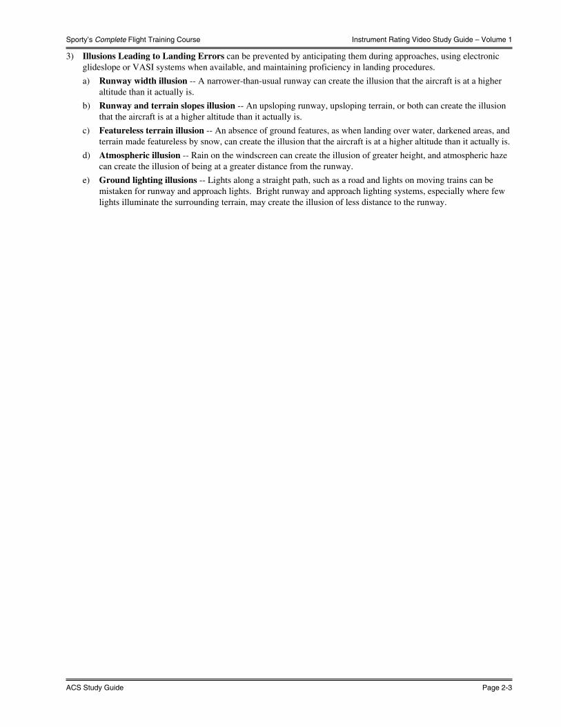
Sporty’s Complete Flight Training Course
ACS Study Guide Page 2-3
Instrument Rating Video Study Guide – Volume 1
3) Illusions Leading to Landing Errors can be prevented by anticipating them during approaches, using electronic glideslope or VASI systems when available, and maintaining proficiency in landing procedures.
a) Runway width illusion -- A narrower-than-usual runway can create the illusion that the aircraft is at a higher altitude than it actually is.
b) Runway and terrain slopes illusion -- An upsloping runway, upsloping terrain, or both can create the illusion that the aircraft is at a higher altitude than it actually is.
c) Featureless terrain illusion -- An absence of ground features, as when landing over water, darkened areas, and terrain made featureless by snow, can create the illusion that the aircraft is at a higher altitude than it actually is.
d) Atmospheric illusion -- Rain on the windscreen can create the illusion of greater height, and atmospheric haze can create the illusion of being at a greater distance from the runway.
e) Ground lighting illusions -- Lights along a straight path, such as a road and lights on moving trains can be mistaken for runway and approach lights. Bright runway and approach lighting systems, especially where few lights illuminate the surrounding terrain, may create the illusion of less distance to the runway.
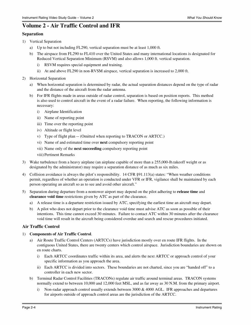
What You Should Know
Page 2-4 Instrument Rating
Instrument Rating Video Study Guide – Volume 2
Volume 2 - Air Traffic Control and IFRSeparation
1) Vertical Separation
a) Up to but not including FL290, vertical separation must be at least 1,000 ft.
b) The airspace from FL290 to FL410 over the United States and many international locations is designated for Reduced Vertical Separation Minimum (RSVM) and also allows 1,000 ft. vertical separation.
i) RSVM requires special equipment and training.
ii) At and above FL290 in non-RVSM airspace, vertical separation is increased to 2,000 ft.
2) Horizontal Separation
a) When horizontal separation is determined by radar, the actual separation distances depend on the type of radar and the distance of the aircraft from the radar antenna.
b) For IFR flights made in areas outside of radar control, separation is based on position reports. This method is also used to control aircraft in the event of a radar failure. When reporting, the following information is necessary:
i) Airplane Identification
ii) Name of reporting point
iii) Time over the reporting point
iv) Altitude or flight level
v) Type of flight plan -- (Omitted when reporting to TRACON or ARTCC.)
vi) Name of and estimated time over next compulsory reporting point
vii) Name only of the next succeeding compulsory reporting point
viii) Pertinent Remarks
3) Wake turbulence from a heavy airplane (an airplane capable of more than a 255,000-lb.takeoff weight or as designated by the administrator) may require a separation distance of as much as six miles.
4) Collision avoidance is always the pilot’s responsibility. 14 CFR §91.113(a) states: “When weather conditions permit, regardless of whether an operation is conducted under VFR or IFR, vigilance shall be maintained by each person operating an aircraft so as to see and avoid other aircraft.”
5) Separation during departure from a nontower airport may depend on the pilot adhering to release time and clearance void time restrictions given by ATC as part of the clearance.
a) A release time is a departure restriction issued by ATC, specifying the earliest time an aircraft may depart.
b) A pilot who does not depart prior to the clearance void time must advise ATC as soon as possible of their intentions. This time cannot exceed 30 minutes. Failure to contact ATC within 30 minutes after the clearance void time will result in the aircraft being considered overdue and search and rescue procedures initiated.
Air Traffic Control
1) Components of Air Traffic Control.a) Air Route Traffic Control Centers (ARTCCs) have jurisdiction mostly over en route IFR flights. In the
contiguous United States, there are twenty centers which control airspace. Jurisdiction boundaries are shown on en route charts.
i) Each ARTCC coordinates traffic within its area, and alerts the next ARTCC or approach control of your specific information as you approach the area.
ii) Each ARTCC is divided into sectors. These boundaries are not charted, since you are “handed off” to a controller in each new sector.
b) Terminal Radar Control Facilities (TRACONs) regulate air traffic around terminal areas. TRACON systems normally extend to between 10,000 and 12,000 feet MSL, and as far away as 30 N.M. from the primary airport.
i) Non-radar approach control usually extends between 3000 & 4000 AGL. IFR approaches and departures for airports outside of approach control areas are the jurisdiction of the ARTCC.

Sporty’s Complete Flight Training Course
ACS Study Guide Page 2-5
Instrument Rating Video Study Guide – Volume 2
2) Federal Airways – Airways are typically eight nautical miles wide, and may classified by altitude.
a) Airways based upon ground based navaids with a midpoint segment or a changeover point more than 51 N.M. from a navaid will be wider than 8 N.M. for the portion of the airway which exceeds this 51 N.M. limit. This additional width is based upon a 4.5º angle from the navaid on each side the airway centerline.
b) Victor Airways are VOR airways used below 18,000 ft MSL.
c) L/MF airways (colored airways) are predicated solely on L/MF navigation aids and are depicted in brown on aeronautical charts and are identified by color name and number.
d) Jet Routes are VOR airways used from 18,000 ft MSL to and including FL 450.
e) Published Area Navigation (RNAV) routes require RNAV capability. At and above 18,000 ft. MSL, these routes are known as Q-Routes over the United States. Below 18,000 ft. MSL, these routes over the United States are known as T-Routes.
3) Air Traffic Service (ATS) Routes- The term “ATS route” is a generic term that includes “VOR Federal airways,” “colored Federal airways,” “alternate airways,” “jet routes,” “Military Training Routes,” “named routes,” and “RNAV routes.” The term “ATS route” does not replace these more familiar route names, but serves only as an overall title when listing the types of routes that comprise the United States route structure.
Navaid Service Volumes
1) Low-altitude navaids are used for navigation below 18,000 feet MSL. Their service volume is 40 N.M., so that maximum distance between VOR stations on a direct flight is 80 N.M.
2) High-Altitude navaids are used for navigation for all altitude strata. Up to 14,500 feet MSL, the service volume is 40 N.M. From 14,500 feet MSL up to but not including 18,000 feet MSL, the service volume increases to 100 N.M. From 18,000 feet MSL to FL450, service volume increases to 130 N.M., while above FL 450 service volume decreases to 100 N.M.
3) MEA, or the Minimum En Route Altitude, is the lowest altitude between radio fixes, which assures satisfactory navigation signal coverage and minimum obstacle clearance requirements. The MEA applies to the total width of the airway.
4) MOCA, or the Minimum Obstruction Clearance Altitude, is the lowest altitude which assures clearance requirements over obstacles within the boundaries a VOR airway, an off-airway route, or a route segment centerline, and assures acceptable navigation signal coverage within 22 N.M. of a navaid.
a) If both a MEA and a MOCA are prescribed for a particular route or route segment, a person may operate an aircraft below the MEA down to, but not below, the MOCA, provided the applicable navigation signals are available. For aircraft using VOR for navigation, this applies only when the aircraft is within 22 N.M. of that VOR (based on the reasonable estimate by the pilot operating the aircraft of that distance).
5) OROCA, or the Off-Route Obstruction Clearance Altitude, provides obstruction clearance while traveling off of federal airways. This altitude may not provide signal coverage from ground-based navigational aids, air traffic control radar, or communications coverage.
En Route
1) Direct routes are flights between navaids, airports, or waypoints that do not have an airway between them, and have not been checked for VOR interference.
2) When changing altitude, controllers expect climb or descent to be made as rapidly as possible until within 1000 feet of the new assigned altitude. The last 1000 feet should be made between 500 and 1,500 fpm.
a) The controller should be notified any time you are unable to:
i) Maintain a climb or descent of at least 500 fpm
ii) Maintain the cruising true airspeed specified on the flight plan within 5% or 10 knots, whichever is greater.
Flight Plans
1) According to 14 CFR §91.169, no person may operate an aircraft IFR in controlled airspace unless a flight plan has been filed.
a) No clearance is required or available in uncontrolled airspace (class G).

What You Should Know
Page 2-6 Instrument Rating
Instrument Rating Video Study Guide – Volume 2
Domestic Flight Plan Form
2) Items necessary on an Domestic IFR flight plan:
a) Type of Flight Plan -- IFR, VFR, or DVFR.
b) Aircraft Identification Number.
c) Aircraft Type -- Transponder, RNAV, and DME information is also included in this item. Special equipment suffix letters are listed in the AIM, Table 5-1-3. The AIM chart has been reproduced on the following page.
d) True Airspeed -- Reported in knots.
e) Departure Point.f) Departure Time -- Estimated time should be filled out upon filing. Actual time will be recorded after
departure.
g) Cruising Altitude -- This is the requested en route altitude for the first leg of the trip, and therefore a different altitude may be assigned. File odd altitudes for eastbound flights (0˚ - 179˚) magnetic and even altitudes for westbound flights (180˚ - 359˚).
h) Route of Flight -- By airways, navaids, or waypoints.
i) Destination Airport and City.
j) Estimated Time En Route -- This should be figured as the estimated time over the point of first intended landing.
k) Remarks -- Enter only those pertinent to ATC if any.
l) Fuel on Board -- Usable fuel available given in hours and minutes at the cruising airspeed listed in box 4.
m) Alternate Airport -- For a precision approach procedure, the alternate must be forecast to have at the estimated time of arrival at least a 600 foot ceiling and 2 statute miles visibility; for a nonprecision or APV approach, the alternate must be forecast to have at least an 800 foot ceiling and 2 statute miles of visibility. If the alternate has no instrument approach, VFR conditions must be forecast from the MEA to landing.
i) NOTE: An alternate airport is not required if the first airport of intended landing has an instrument approach and is forecast to have at least a 2,000 foot ceiling and 3 miles of visibility for at least one hour before and after the estimated time of arrival.
n) Pilot’s Full Name, Address, Telephone, and Aircraft Home Base.
o) Number of Persons on Board.
p) Color of Aircraft.q) Destination Contact and Telephone – Optional.
3) Flight plans should be filed at least 30 minutes before the estimated time of departure (ETD). Flight plans are normally kept by ATC for at least one hour after ETD.

Sporty’s Complete Flight Training Course
ACS Study Guide Page 2-7
Instrument Rating Video Study Guide – Volume 2
4) IFR flight plans are automatically closed upon landing when the destination airport has an operating control tower. For flights to airports without an operating control tower, the pilot is responsible for initiating cancellation of the flight plan. According to the AIM, paragraph 5-1-14, the flight plan can be closed either:
a) After landing at an airport if there is a functioning FSS or other means of direct communications with ATC, or,
b) While still airborne and in contact with ATC when weather conditions permit. This method is preferable to closing the flight plan by telephone after landing, since it frees the airspace immediately for use by other aircraft.
Aircraft equipment suffixes.
Navigation Capability Transponder Capability Suffix
RVSM
No GNSS, No RNAV Transponder with Mode C /W
RNAV, No GNSS Transponder with Mode C /Z
GNSS Transponder with Mode C /L
No RVSM
No DMENo Transponder /X
Transponder with no Mode C /T
Transponder with Mode C /U
DME
No Transponder /D
Transponder with no Mode C /B
Transponder with Mode C /A
TACAN
No Transponder /M
Transponder with no Mode C /N
Transponder with Mode C /P
RNAV, no GNSS
No Transponder /Y
Transponder with no Mode C /C
Transponder with Mode C /I
GNSS
No Transponder /V
Transponder with no Mode C /S
Transponder with Mode C /G
5) Review AIM 5−1−9. International Flight Plan (FAA Form 7233−4)−IFR Flights (For Domestic or International Flights) for more information on the flight plan form intended to replace the current domestic form
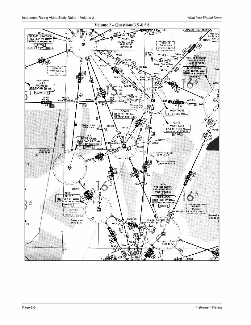
What You Should Know
Page 2-8 Instrument Rating
Instrument Rating Video Study Guide – Volume 2
Volume 2 – Questions 3.5 & 5.8

Sporty’s Complete Flight Training Course
ACS Study Guide Page 2-9
Instrument Rating Video Study Guide – Volume 3
Volume 3 - Instrument ApproachesThe goal of an instrument approach is to transition an IFR aircraft from the en route system to a point where the airport runway is in sight, where it can complete the landing procedure visually. IFR approaches are categorized as precision, nonprecision, or an approach with vertical guidance.
Approach & Landing Charts
1) Approach charts are very detailed, and give all information needed for the approach procedures. Each approach chart is broken down into multiple sections:
a) The Pilot Briefing Information section is used when preparing for the approach. It contains a summary of the information needed for the approach. It includes NAVAID, final approach course, and airport information as appropriate; a Remarks section with any special advisories of which the pilot should be aware; a textual version of the Missed Approach instructions; and a listing of the pertinent communication frequencies.
b) The Planview is used for the initial approach segment and gives a bird’s eye view of the approach.
c) The Profile view is used after the approach has started. It gives information concerning altitudes at different locations on the approach and includes an iconic representation of the Missed Approach instructions.
d) The Minimums section is used near the end of an approach, and contains information about the minimum flight visibility and minimum altitude that can be achieved before a decision is made concerning the success of the approach.
e) The Airport Sketch gives a view of all runways and taxiways on the airport.
Precision Approaches
1) Precision approaches are flown at an angle of descent. The purpose of an instrument approach is to bring an aircraft down through clouds to a point where the runway is visible. If the runway is not visible at a certain altitude on a precision approach, a missed approach must be flown. This altitude is called the Decision Altitude (DA). At this MSL altitude on the glideslope, the decision must be made either to continue the approach or to fly a missed approach. Decision Height (DH) is the height above the threshold elevation where this decision must be made.
2) Decision Altitude (DA) is referenced to mean sea level (MSL) and Decision Height (DH) is referenced to the threshold elevation.
3) Precision approaches are standard instrument approaches with glideslope information meeting the precision standards of ICAO Annex 10; for example, the Instrument Landing System (ILS), Microwave Landing System (MLS), and Precision Approach Radar (PAR). ILS is by far the most common; MLS and PAR are rare.
a) An approach that provides glidepath deviation information but does not meet the precision requirements of ICAO Annex 10, is termed an Approach with Vertical Guidance (APV).
4) Guidance information for ILS is provided by the localizer for left/right guidance, and the glideslope for up/down guidance.
5) The Localizer.
a) The Localizer is an electronic extension of the centerline of the runway, and operates within the frequency range of 108.10 to 111.95. Their three-letter identification codes are always preceded by the letter “I” for easy identification. Localizers are adjusted so that the signal is 700 feet wide at the approach end of the runway. Due to varying runway lengths, the width of the localizer signal varies between 3˚ and 6˚.
i) A Localizer Directional Aid, or LDA, is a localizer that is not aligned with the centerline of the runway.
ii) A Simplified Directional Facility, or SDF, is much like an LDA, but is less precise, measuring either 6˚ or 12˚ wide. SDF identifiers are not preceded by the letter “I”. Glideslopes are not installed with SDFs. An SDF is NOT a precision approach.
b) Heading corrections should be 5˚ or less unless you have a full-scale deflection. Also, as you approach the runway, the localizer gets smaller. Therefore, corrections should be proportionally smaller.
c) Localizers normally emit signals in two directions, called the Front Course and the Back Course. The front course is used for the ILS approach. The back course is only usable when an approach procedure has been approved for it. The back course is marked on the chart in large bold letters. The back course inbound instrument indications are opposite of those for a front course approach.

What You Should Know
Page 2-10 Instrument Rating
Instrument Rating Video Study Guide – Volume 3
6) The Glideslope.
a) The Glideslope provides vertical navigation. Glideslope frequencies are paired with localizer frequencies, and most receivers are designed to automatically select the appropriate glideslope frequency when a localizer frequency is selected. Typical glideslopes are positioned to give a 3˚ descent angle (318 feet per nautical mile), and usually have a threshold crossing height of 55 feet. The glideslope is extremely precise, and a full scale deflection either above or below is equal to a 0.7˚ or greater deviation from the centerline.
b) With an increase in groundspeed, the descent rate must be increased in order to maintain the glideslope. Conversely, with a decrease in groundspeed, the descent rate must be decreased. The table below can be used to compute the descent per minute given an approximate groundspeed and angle of descent.
c) NOTE: SINCE GLIDESLOPE INDICATIONS CAN BE RECEIVED ANYWHERE AROUND THE ANTENNA, THE GLIDESLOPE SHOULD ONLY BE USED WHEN THE APPROACH CHART SPECIFIES A GLIDESLOPE.
Rate of Descent Table
7) Range information is provided by marker beacons. Marker beacons transmit a signal straight up. All marker beacons transmit on 75 megahertz.
a) Outer Markers are normally located between 4 and 7 miles from the approach end of the runway. It is normally located at or near the glideslope intercept altitude. The outer marker transmits dashes at a rate of 2 per second, and the three light marker indicator illuminates a blue light.
b) Middle Markers are located about 3500 feet from the approach end of the runway. It is normally located at or near the decision altitude along the glideslope. The middle marker transmits alternating dots and dashes at a rate of 95 pairs per second, and the middle marker illuminates the amber light. Middle markers may be found on existing ILS installations but are no longer considered standard for new installations.

Sporty’s Complete Flight Training Course
ACS Study Guide Page 2-11
Instrument Rating Video Study Guide – Volume 3
Runway Markings - Used on Runways Served by Precision Instrument Approaches
Nonprecision Approaches
1) Nonprecision approaches include RNAV (GPS-Lateral Navigation {LNAV}, WAAS-Localizer Performance {LP}, & VOR-DME RNAV), VOR, NDB, TACAN, LDA, and SDF approaches. Nonprecision approaches do not provide glideslope information. Instead of a Decision Altitude, a nonprecision approach has a Minimum Descent Altitude or MDA. This altitude is flown in level flight until the airport is in sight or until a missed approach is begun.
Approaches with Vertical Guidance (APV)
1) APV approaches provide lateral and vertical guidance but do not meet ICAO Annex 10 standards required for precision approaches. These include Lateral Navigation / Vertical Navigation (LNAV/VNAV), Localizer Performance with Vertical guidance (LPV), and LDA with glideslope
Runway Lighting Systems
1) Touchdown Zone Lights are placed on either edge of the runway at the approach end. The system normally extends 3,000 feet along the runway, and lights are placed at 100-foot intervals.
2) Runway Centerline Lighting begins 75 feet from the landing threshold and ends 75 feet from the opposite end of the runway. They are spaced 50 feet apart.
Circling Approaches
1) A Circling Approach is a maneuver initiated by the pilot to align the aircraft with the runway for landing when a straight-in landing from an instrument approach is not possible. In order to fly a circling approach, the pilot must have ATC authorization and must have established the required visual reference to the airport. The minimums for a circling approach are listed in the minimums section of the approach chart. Navigation is visual.
Radar Approaches
1) A radar approach is an approach where the air traffic controller issues instructions, for pilot compliance, based on aircraft position in relation to the final approach course and the distance from the end of the runway as displayed on the controller’s radar display. These may be given to any aircraft upon request and may be offered to pilots of aircraft in distress or to expedite traffic. There are two types of radar approaches. Each type may be performed at airports where minimums are published for the particular type of approach.
2) A Precision Approach Radar (PAR) approach is one where the controller provides highly accurate navigational guidance for runway alignment and elevation. Pilots will be given headings to fly, and are told when to expect glide path interception and when to begin descent. This information is provided until the aircraft reaches the published decision altitude, and radar service is automatically terminated upon completion of the approach.
3) An Airport Surveillance Radar (ASR) approach is one in which a controller provides navigational guidance only, with no controller service for elevation. The pilot is furnished headings for runway centerline alignment as well as range information. Information pertaining to the commencement of descent to the MDA and when the aircraft is at the missed approach point is furnished as well. If requested by the pilot, the controller will furnish recommended altitudes each mile from the runway.
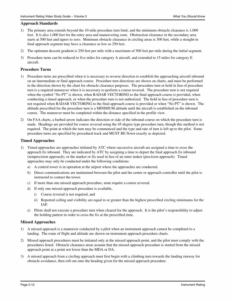
What You Should Know
Page 2-12 Instrument Rating
Instrument Rating Video Study Guide – Volume 3
Approach Standards
1) The primary area extends beyond the 10-mile procedure turn limit, and the minimum obstacle clearance is 1,000 feet. It is also 1,000 feet for the entry area and maneuvering zone. Obstruction clearance in the secondary area starts at 500 feet and tapers to zero. Minimum obstacle clearance in circling areas is 300 feet, while a straight-in final approach segment may have a clearance as low as 250 feet.
2) The optimum descent gradient is 250 feet per mile with a maximum of 500 feet per mile during the initial segment.
3) Procedure turns can be reduced to five miles for category A aircraft, and extended to 15 miles for category E aircraft.
Procedure Turns
1) Procedure turns are prescribed when it is necessary to reverse direction to establish the approaching aircraft inbound on an intermediate or final approach course. Procedure turn directions are shown on charts, and must be performed in the direction shown by the chart for obstacle clearance purposes. The procedure turn or hold in lieu of procedure turn is a required maneuver when it is necessary to perform a course reversal. The procedure turn is not required when the symbol “No PT” is shown, when RADAR VECTORING to the final approach course is provided, when conducting a timed approach, or when the procedure turn is not authorized. The hold in lieu of procedure turn is not required when RADAR VECTORING to the final approach course is provided or when “No PT” is shown. The altitude prescribed for the procedure turn is a MINIMUM altitude until the aircraft is established on the inbound course. The maneuver must be completed within the distance specified in the profile view.
2) On FAA charts, a barbed arrow indicates the direction or side of the inbound course on which the procedure turn is made. Headings are provided for course reversal using the 45-degree type procedure turn, though this method is not required. The point at which the turn may be commenced and the type and rate of turn is left up to the pilot. Some procedure turns are specified by procedural track and MUST BE flown exactly as depicted.
Timed Approaches
1) Timed approaches are approaches initiated by ATC where successive aircraft are assigned a time to cross the approach fix inbound. They are indicated by ATC by assigning a time to depart the final approach fix inbound (nonprecision approach), or the marker or fix used in lieu of an outer maker (precision approach). Timed approaches may only be conducted under the following conditions:
a) A control tower is in operation at the airport where the approaches are conducted.
b) Direct communications are maintained between the pilot and the center or approach controller until the pilot is instructed to contact the tower.
c) If more than one missed approach procedure, none require a course reversal.
d) If only one missed approach procedure is available,
i) Course reversal is not required, and
ii) Reported ceiling and visibility are equal to or greater than the highest prescribed circling minimums for the IAP.
e) Pilots shall not execute a procedure turn when cleared for the approach. It is the pilot’s responsibility to adjust the holding pattern in order to cross the fix at the prescribed time.
Missed Approaches
1) A missed approach is a maneuver conducted by a pilot when an instrument approach cannot be completed to a landing. The route of flight and altitude are shown on instrument approach procedure charts.
2) Missed approach procedures must be initiated only at the missed approach point, and the pilot must comply with the procedures listed. Obstacle clearance areas assume that the missed approach procedure is started from the missed approach point at a point not lower than the MDA or DA.
3) A missed approach from a circling approach must first begin with a climbing turn towards the landing runway for obstacle avoidance, then roll out onto the heading given for the missed approach procedure.

Sporty’s Complete Flight Training Course
ACS Study Guide Page 2-13
Instrument Rating Video Study Guide – Volume 3
Holding
1) A holding pattern is used whenever an aircraft is cleared to a fix other than the destination airport and delay is expected. If a holding pattern is charted and the controller does not issue complete holding instructions, the pilot is expected to hold as depicted on the appropriate chart. If it is not charted, or if the controller wishes a holding pattern other than that published to be flown, the controller will issue complete holding instructions.
2) An ATC clearance requiring an aircraft to hold where the pattern is not charted will include the following information:
a) Direction of holding from the fix in terms of the eight cardinal compass points (N, NE, etc.)
b) Holding fix
c) Radial, course, bearing, airway or route on which the aircraft is to hold
d) Leg length in miles if DME or RNAV is used. (Leg length will be specified in minutes on pilot request or if the controller considers it necessary).
e) Direction of turn if either:
i) Left turns are to be made
ii) Clarification is requested by the pilot
iii) Clarification is deemed necessary by the controller
f) Time to expect further clearance and other delay information
3) Maximum holding pattern speed limits:
ALTITUDE (MSL) AIRSPEED (KIAS)
MHA-6,000’ 200
6,000’-14,000’ 230
14,000’ and above 265

What You Should Know
Page 2-14 Instrument Rating
Instrument Rating Video Study Guide – Volume 3
Volume 3 – Riverton VOR Runway 10
NW
-1, 13 JAN
2011 to 10 FEB
2011
NW
-1, 1
3 JA
N 2
011
to 1
0 FE
B 2
011
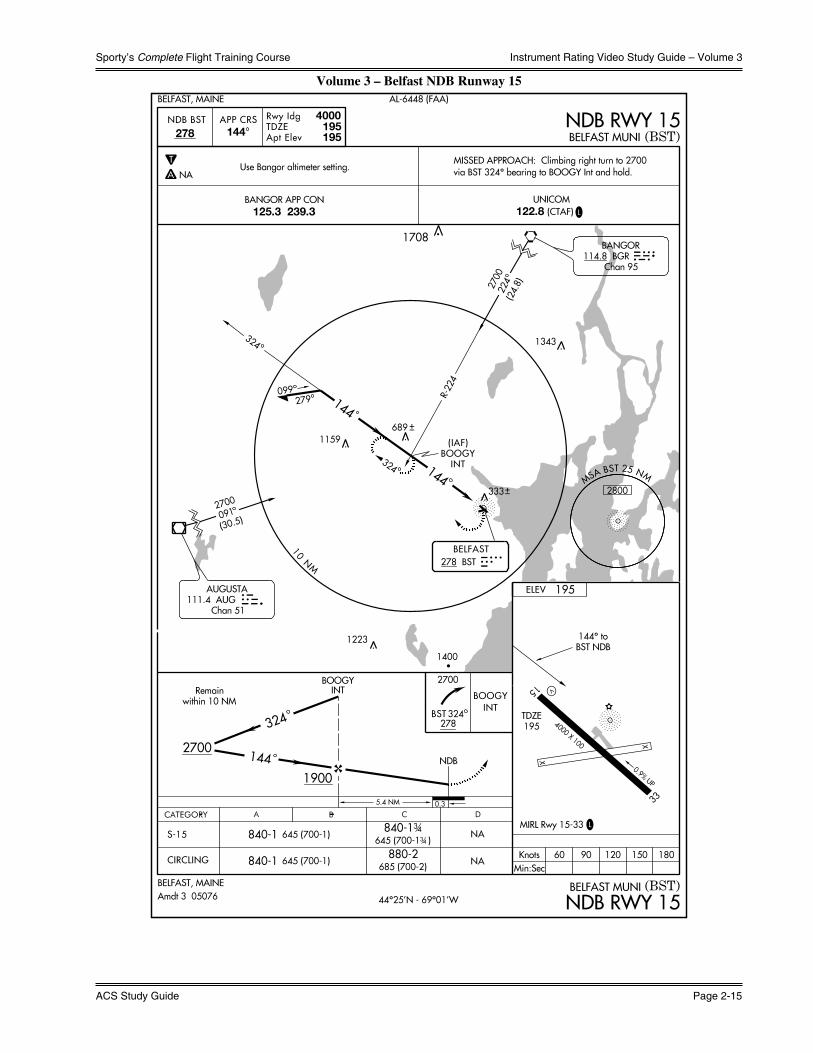
Sporty’s Complete Flight Training Course
ACS Study Guide Page 2-15
Instrument Rating Video Study Guide – Volume 3
Volume 3 – Belfast NDB Runway 15
NE
-1, 12 MA
Y 2005 to 09 JU
N 2005 N
E-1
, 12
MA
Y 2
005
to 0
9 JU
N 2
005

What You Should Know
Page 2-16 Instrument Rating
Instrument Rating Video Study Guide – Volume 3
Volume 3 / 6 – Cincinnati West RNAV (GPS) Runway 19
EC
-2, 11 FEB
2010 to 11 MA
R 2010
EC
-2, 1
1 FE
B 2
010
to 1
1 M
AR
201
0
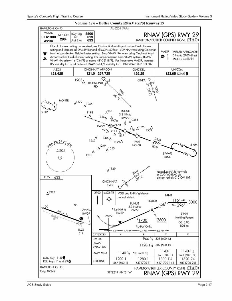
Sporty’s Complete Flight Training Course
ACS Study Guide Page 2-17
Instrument Rating Video Study Guide – Volume 3
Volume 3 / 6 – Butler County RNAV (GPS) Runway 29
EC
-2, 14 JAN
2010 to 11 FEB
2010
EC
-2, 1
4 JA
N 2
010
to 1
1 FE
B 2
010

What You Should Know
Page 2-18 Instrument Rating
Instrument Rating Video Study Guide – Volume 3
Volume 3 / 6 – Gene Snyder VOR or GPS A
SE
-1, 14 JAN
2010 to 11 FEB
2010
SE
-1, 1
4 JA
N 2
010
to 1
1 FE
B 2
010

Sporty’s Complete Flight Training Course
ACS Study Guide Page 2-19
Instrument Rating Video Study Guide – Volume 3
Volume 3 – Question 3.2

What You Should Know
Page 2-20 Instrument Rating
Instrument Rating Video Study Guide – Volume 3
Volume 3 – Question 3.3

Sporty’s Complete Flight Training Course
ACS Study Guide Page 2-21
Instrument Rating Video Study Guide – Volume 3
Volume 3 – Question 3.4

What You Should Know
Page 2-22 Instrument Rating
Instrument Rating Video Study Guide – Volume 3
Volume 3 – Question 3.5

Sporty’s Complete Flight Training Course
ACS Study Guide Page 2-23
Instrument Rating Video Study Guide – Volume 3
Volume 3 – Question 3.6

What You Should Know
Page 2-24 Instrument Rating
Instrument Rating Video Study Guide – Volume 3
Volume 3 – Question 5.6
Sporty’s Complete Flight Training Course
ACS Study Guide Page 2-25
Instrument Rating Video Study Guide – Volume 3
Volume 3 – Question 5.7
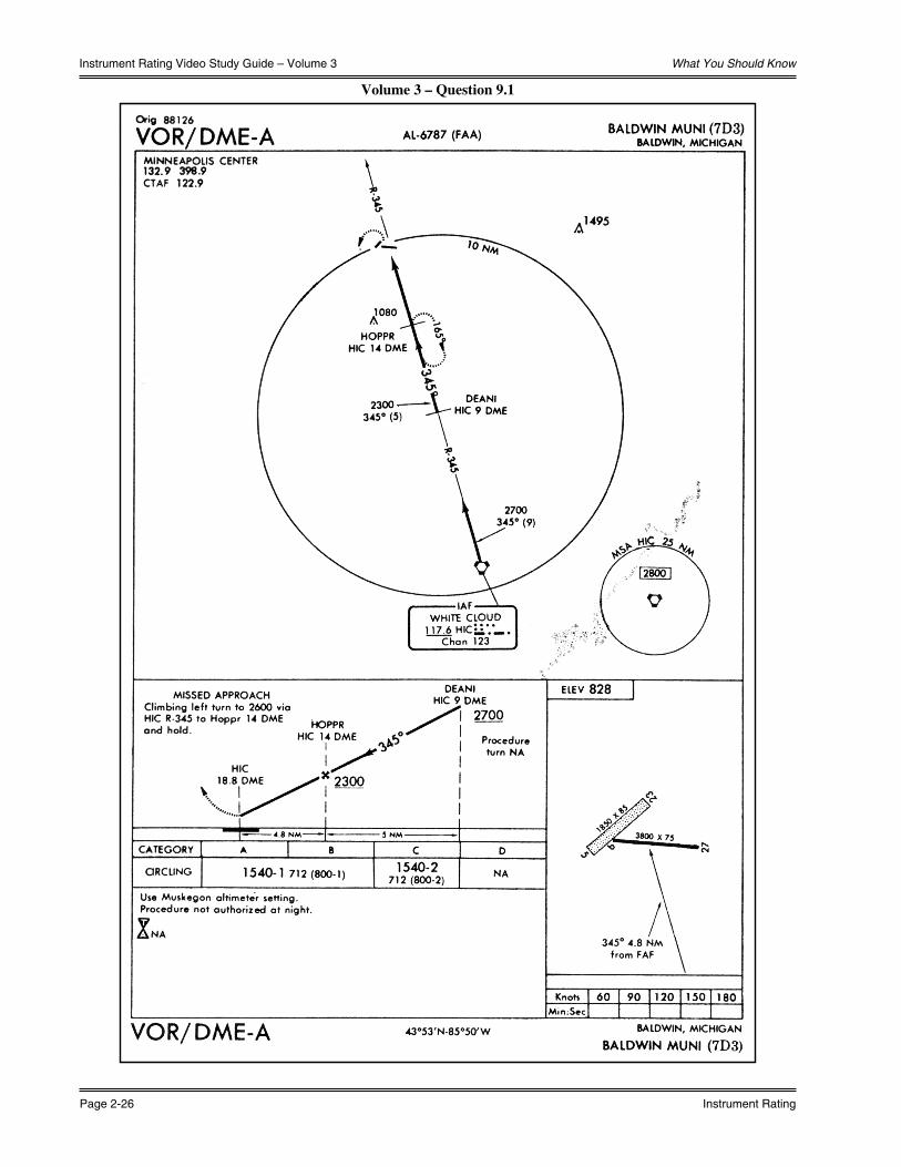
What You Should Know
Page 2-26 Instrument Rating
Instrument Rating Video Study Guide – Volume 3
Volume 3 – Question 9.1
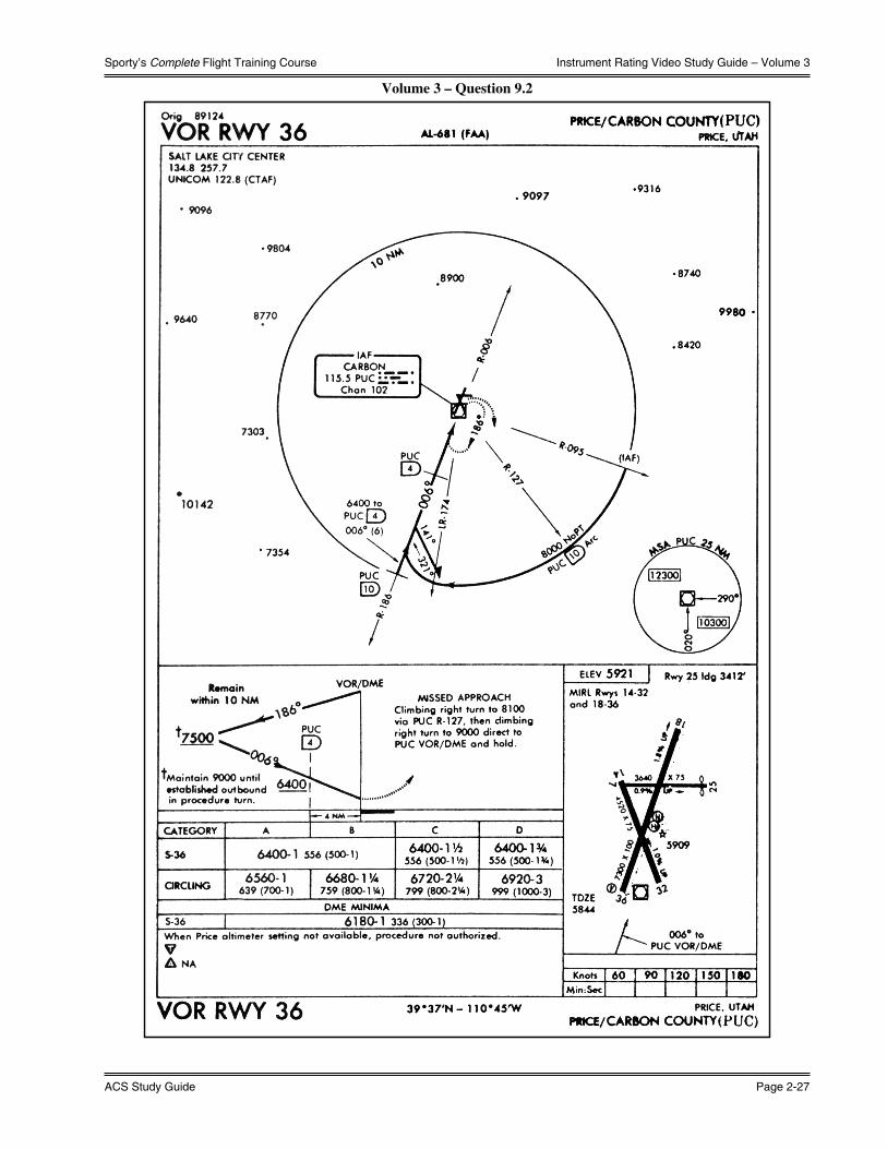
Sporty’s Complete Flight Training Course
ACS Study Guide Page 2-27
Instrument Rating Video Study Guide – Volume 3
Volume 3 – Question 9.2

What You Should Know
Page 2-28 Instrument Rating
Instrument Rating Video Study Guide – Volume 3
Volume 3 – Question 10.2

Sporty’s Complete Flight Training Course
ACS Study Guide Page 2-29
Instrument Rating Video Study Guide – Volume 3
Volume 3 – Question 10.3
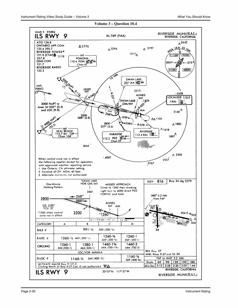
What You Should Know
Page 2-30 Instrument Rating
Instrument Rating Video Study Guide – Volume 3
Volume 3 – Question 10.4

Sporty’s Complete Flight Training Course
ACS Study Guide Page 2-31
Instrument Rating Video Study Guide – Volume 3
Volume 3 – Question 10.5

What You Should Know
Page 2-32 Instrument Rating
Instrument Rating Video Study Guide – Volume 3
Volume 3 – Question 13.1

Sporty’s Complete Flight Training Course
ACS Study Guide Page 2-33
Instrument Rating Video Study Guide – Volume 3
Volume 3 – Question 15.2

What You Should Know
Page 2-34 Instrument Rating
Instrument Rating Video Study Guide – Volume 3
Volume 3 – Question 16.4

Sporty’s Complete Flight Training Course
ACS Study Guide Page 2-35
Instrument Rating Video Study Guide – Volume 3
Vol
ume
3 –
Que
stio
n 18
.1

What You Should Know
Page 2-36 Instrument Rating
Instrument Rating Video Study Guide – Volume 3
Volume 3 – Question 18.1
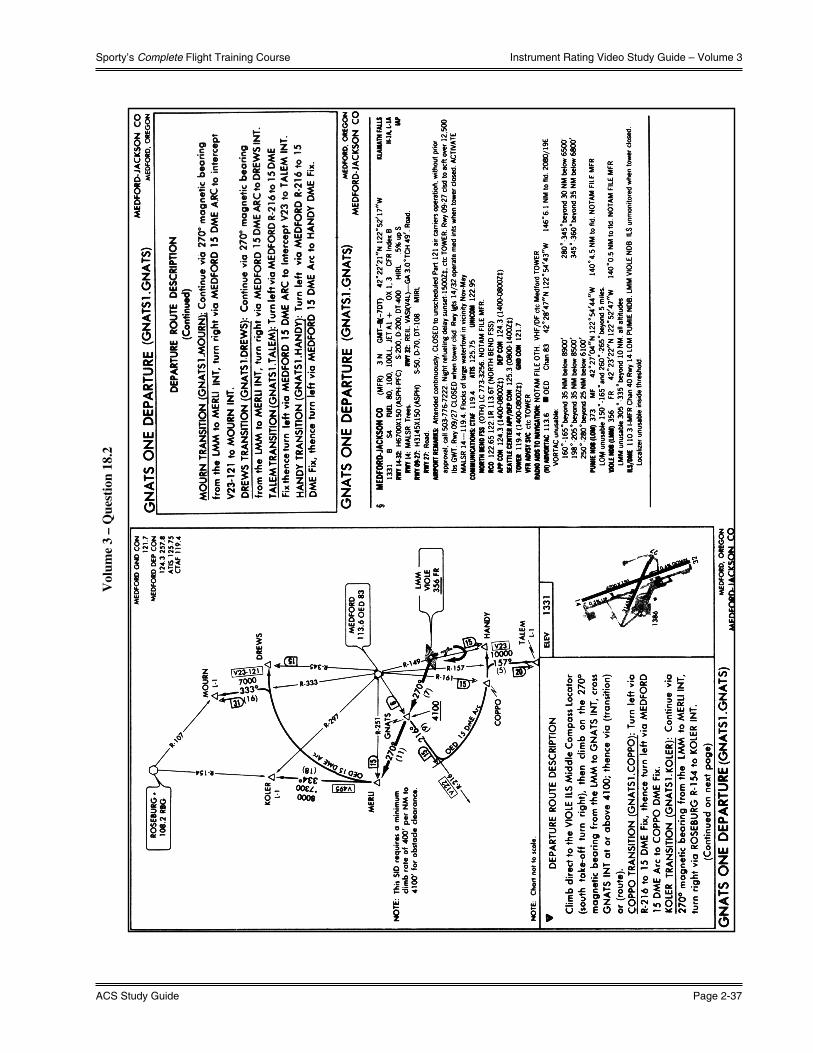
Sporty’s Complete Flight Training Course
ACS Study Guide Page 2-37
Instrument Rating Video Study Guide – Volume 3
Vol
ume
3 –
Que
stio
n 18
.2

What You Should Know
Page 2-38 Instrument Rating
Instrument Rating Video Study Guide – Volume 4
Volume 4 - En Route IFRCharts and Airways
1) Low Altitude En Route Charts (L Charts) contain information for IFR flights on Victor Airways and T-Routes. Generally, Victor Airways are numbered even when they run east-west and odd when they run north-south. Victor Airways and T-Routes extend up to but do not include 18,000 ft. MSL.
2) High Altitude En Route Charts (H Charts) contain information on High Altitude Airways; the Jet Routes and Q-Routes. High Altitude Airways begin at 18,000 ft. MSL and continue up to FL450. Airplanes flying above FL450 fly point to point, called direct navigation.
3) Area Charts are printed for areas congested with airways and navigation information. Areas that have published area charts are denoted on the L charts. L charts depict all the necessary information for flight through the area, while Area Charts contain the information necessary for arrivals and departures inside the area.
Airway Limits and Minimums
1) The MOCA, or Minimum Obstruction Clearance Altitude is at least 1000 ft. above the highest obstruction within 4 N.M. of the airway centerline. In mountainous terrain, the clearance is increased to 2000 ft, although under certain circumstances, it can be dropped to 1500 ft. It also allows for a satisfactory navigational signal when within 22 N.M. of a station. On off-airway direct flights, pilots are responsible for obstacle clearance. Fixes named on direct flights are compulsory reporting points.
2) The MEA, or Minimum En Route Altitude, allows for obstacle clearance and satisfactory navigational signal reception throughout the airway, and for the identification of fixes on the airway.
a) Some fixes cannot be identified at the MEA. This is because the signal from the side station cannot be received at the MEA. An MRA, or Minimum Reception Altitude, is published for these fixes.
b) An MEA Gap denotes a break in the navigation signal coverage, or a signal, which does not meet airway standards. When flying through an MEA gap, the proper heading should be maintained until reception resumes.
c) An MCA, or Minimum Crossing Altitude is the lowest altitude at which an aircraft may cross a fix when transitioning to a higher MEA.
3) MAAs, or Maximum Authorized Altitudes, are applied to some Victor Airways in order to keep aircraft out of conflicting airspace, such as overhanging layers of Class B airspace.
4) COPs, or Changeover Points, are points along the airway between two adjacent navigational facilities or waypoints where a switch in navigational aid should occur. Midpoint COPs are not charted, COPs located other than at midpoints are denoted on the chart. The COP on a course that changes direction is located at the bend in the airway.
5) Preferred Routes are established between busier airports, and are set up to increase efficiency and capacity. They normally extend through more than one ARTCC, and are recommended, not required. Preferred Routes are listed in the Airport/Facility Directory.
Instrument Departure Procedures (DPs)
1) An Instrument Departure Procedure is an ATC coded departure procedure that has been established at certain airports to simplify clearance delivery procedures. DPs are published by the National Aeronautical Charting Office in the Terminal Procedures Publication. There are two basic types of DPs:
a) Obstacle Departure Procedures (ODPs).
i) Printed either textually or graphically.
ii) Provide obstruction clearance via the least onerous route from the terminal area to the en route structure.
iii) May be flown without ATC clearance unless an alternate DP has been specifically assigned by ATC.
b) Standard Instrument Departures (SIDs).
i) Always printed graphically.
ii) ATC procedures printed for pilot/controller use in graphic form to provide obstruction clearance and a transition from the terminal area to the en route structure.
iii) Primarily designed for system enhancement and to reduce pilot/controller workload.
iv) ATC clearance must be received prior to flying a SID.

Sporty’s Complete Flight Training Course
ACS Study Guide Page 2-39
Instrument Rating Video Study Guide – Volume 4
Standard Terminal Arrivals (STARs)
1) A Standard Terminal Arrival is issued as a transition from a point en route to an approach position, and is used to simplify clearance delivery procedures. STARs are published by the National Aeronautical Charting Office in the Terminal Procedures Publication.
Transition Areas
1) Transition areas are Class E airspace areas extending upward from 700 feet or more AGL when designated in conjunction with an instrument approach procedure, or from 1,200 feet AGL or more when designated in conjunction with airway route structures or segments. They are designated to maintain controlled airspace while transitioning between the terminal and en route environments, and, unless specified otherwise, terminate at the base of the overlying controlled airspace.
a) The term “Transition Areas” is generally no longer used. These Class E areas are now described by the phrase, “Airspace used for transition.” The older term still appears in some FAA information, including the Instrument Knowledge Test, and is included here for completeness.
Alternate Airports
1) Fuel Requirements -- 14 CFR §91.167 requires that an aircraft operating in IFR conditions, given weather reports and forecasts, must have enough fuel to:
a) Complete the flight to the first airport of intended landing, and
b) Fly from that airport to the alternate airport, and thereafter,
c) Fly for another 45 minutes at cruising speed
2) Alternate Airport Minimums -- For flight planning purposes, 14 CFR §91.169 requires that an airport must have the following standard terminal forecast minimums at the ETA in order to be used as an alternate:
a) For a precision approach, a 600 foot ceiling and 2 statute miles visibility.
b) For a nonprecision approach, an 800 foot ceiling and 2 statute miles visibility. While APV approaches are not considered in the regulation, they are generally considered nonprecision for alternate planning purposes.
c) For a non-instrument approach, there must be a forecast for VFR conditions from the MEA until landing.
3) An alternate is not mandatory if the first airport of intended landing has an IAP and has been forecast to have at least a 2000 foot ceiling and 3 miles of visibility for at least one hour before and one hour after the ETA.
4) It is not necessary to go to the specified alternate airport if unable to land at the intended destination.
Weather Data
1) Area Forecasts cover a fairly large area; six cover the contiguous United States. They are a good source of information for en route conditions. Area Forecasts are issued three times per day, and include a 12-hour forecast, as well as a 6-hour outlook. They are divided into four sections:
a) Communications and Product Headers
b) Precautionary Statements
c) Synopsis
d) VFR Clouds and Weather
2) Terminal Aerodrome Forecasts predict weather conditions expected within 5 S.M. of the terminal. Use of the code “VC” (vicinity) applies to weather conditions expected to occur from between 5 to 10 S.M. from the airport. TAFs are issued four times daily at 0000Z, 0600Z, 1200Z and 1800Z and usually cover a 24 or 30-hour period.
What You Should Know
Page 2-40 Instrument Rating
Instrument Rating Video Study Guide – Volume 4
3) Winds Aloft Forecasts provide an estimate of wind direction and speed, as well as temperature for certain altitudes. The conditions are normally given in a six-digit code, with the first two digits representing tens of degrees of wind direction. The two middle digits represent the wind speed, and the final two digits (separated by a plus or minus sign) represent the temperature. The wind direction is given in reference to true north, wind speed is given in knots, and temperature is given in Celsius.
a) NOTE: Since wind direction and speed must conform to a four digit code, special codes are used for light and variable winds, as well as wind speeds that are over 99 knots. Light and variable winds are depicted in the four digit code as “9900”. For windspeeds over 99 knots, 50 is added to the wind direction digits. For example, for a wind from 230˚ with a speed of 108 knots will be depicted in the four digit code as “7308”.
4) Aviation Routine Weather Report, or METAR report, as the name implies, is an actual observation taken from the surface of the airport every hour. If rapid changes occur in the weather, special report observations are taken. Surface Weather Observations will contain any of the following information that is pertinent to the observation:
a) Type of Report -- METAR or SPECI (special)
b) Station designator -- ICAO identifier
c) Time of report -- reported in UTC
d) Wind information -- Direction in tens of degrees from true north and wind speed in knots
e) Visibility -- reported in statute miles or Runway Visual Range (RVR) in feet
f) Weather and obstructions to visibility
g) Sky condition -- Height of ceiling and other layers, and amount of coverage of layers
h) Temperature and dew point -- reported in degrees Celsius
i) Altimeter setting -- given in inches of mercury
j) Remarks -- any significant data not reported above
i) NOTE: Pertinent observation information is broadcast over ATIS.
5) Pilot Reports (PIREPs) give actual conditions encountered by aircraft in flight. PIREPs usually contain information concerning cloud tops, icing, visibility, and turbulence. Also called Aircraft Reports (AIREPs).
6) AIRMETs are warnings of weather hazards that, although of possible interest to all aircraft, are of special interest to light aircraft. AIRMETs are issued for moderate icing and turbulence, high surface winds, and low visibility areas.
7) SIGMETs are weather advisories that deal with weather significant to the safety of all aircraft. They cover severe and extreme turbulence, severe icing, widespread sandstorms and dust as well as volcanic eruptions. SIGMETs are available from FSS. Convective SIGMETs are issued specifically for tornadoes, severe and/or embedded thunderstorms, lines of thunderstorms, strong thunderstorms with a large area of coverage, and areas of hail 3/4 inch in diameter or greater.
8) Weather Depiction Charts are computer prepared from METARs to give a broad overview of observed flying category conditions at the valid time of the chart. This computer-prepared chart is valid at the time of the plotted data, and is prepared at 3-hour intervals.

Sporty’s Complete Flight Training Course
ACS Study Guide Page 2-41
Instrument Rating Video Study Guide – Volume 4
Vol
ume
4 –
Que
stio
n 2.
1

What You Should Know
Page 2-42 Instrument Rating
Instrument Rating Video Study Guide – Volume 4
Vol
ume
4 –
Que
stio
n 2.
3
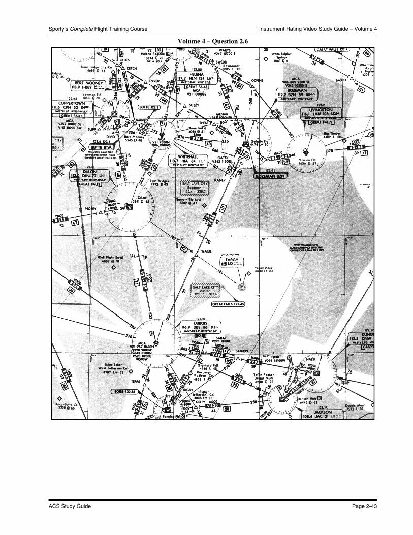
Sporty’s Complete Flight Training Course
ACS Study Guide Page 2-43
Instrument Rating Video Study Guide – Volume 4
Volume 4 – Question 2.6

What You Should Know
Page 2-44 Instrument Rating
Instrument Rating Video Study Guide – Volume 4
Vol
ume
4 –
Que
stio
n 2.
7

Sporty’s Complete Flight Training Course
ACS Study Guide Page 2-45
Instrument Rating Video Study Guide – Volume 4
Vol
ume
4 –
Que
stio
ns 2
.8 &
3.1

What You Should Know
Page 2-46 Instrument Rating
Instrument Rating Video Study Guide – Volume 4
Vol
ume
4 –
Que
stio
n 3.
2

Sporty’s Complete Flight Training Course
ACS Study Guide Page 2-47
Instrument Rating Video Study Guide – Volume 4
Vol
ume
4 –
Que
stio
n 8.
1

What You Should Know
Page 2-48 Instrument Rating
Instrument Rating Video Study Guide – Volume 4
Volume 4 – Questions 8.3 & 8.4

Sporty’s Complete Flight Training Course
ACS Study Guide Page 2-49
Instrument Rating Video Study Guide – Volume 4
Volume 4 – Question 9.1

What You Should Know
Page 2-50 Instrument Rating
Instrument Rating Video Study Guide – Volume 4
Volume 4 – Question 9.3

Sporty’s Complete Flight Training Course
ACS Study Guide Page 2-51
Instrument Rating Video Study Guide – Volume 4
Volume 4 – Question 10.1

What You Should Know
Page 2-52 Instrument Rating
Instrument Rating Video Study Guide – Volume 4
Volume 4 – Question 10.2

Sporty’s Complete Flight Training Course
ACS Study Guide Page 2-53
Instrument Rating Video Study Guide – Volume 4
Volume 4 – Question 10.3

What You Should Know
Page 2-54 Instrument Rating
Instrument Rating Video Study Guide – Volume 4
Volume 4 – Question 10.4

Sporty’s Complete Flight Training Course
ACS Study Guide Page 2-55
Instrument Rating Video Study Guide – Volume 4
Vol
ume
4 –
Que
stio
n 10
.5
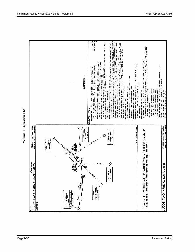
What You Should Know
Page 2-56 Instrument Rating
Instrument Rating Video Study Guide – Volume 4
Vol
ume
4 –
Que
stio
n 10
.6
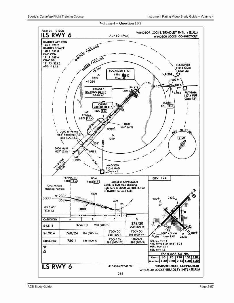
Sporty’s Complete Flight Training Course
ACS Study Guide Page 2-57
Instrument Rating Video Study Guide – Volume 4
Volume 4 – Question 10.7
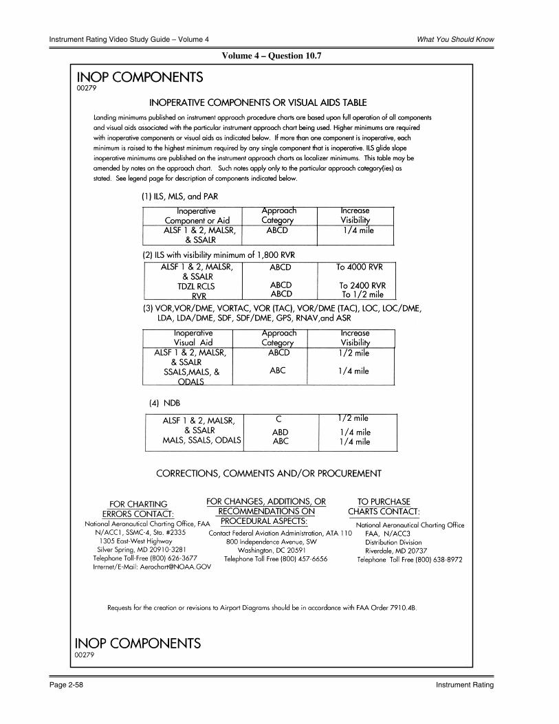
What You Should Know
Page 2-58 Instrument Rating
Instrument Rating Video Study Guide – Volume 4
Volume 4 – Question 10.7

Sporty’s Complete Flight Training Course
ACS Study Guide Page 2-59
Instrument Rating Video Study Guide – Volume 5
Volume 5 - Weather for IFRThunderstorms
1) High relative humidity, unstable air from the base to high levels, and a lifting force to set the cycle in motion are necessary for thunderstorm formation. The life cycle of a thunderstorm progresses through three stages, though it must be remembered that these stages apply only to cells. A storm cloud usually contains many such cells, all in different stages of development.
a) The Cumulus Stage -- Each thunderstorm begins as a cumulus cloud, though few cumulus clouds develop into thunderstorms. This stage is characterized by a prevailing updraft that commonly reaches a speed of 3,000 feet per minute, and is strongest at higher altitudes during the later parts of the stage. Temperatures within the storm at this stage are higher than the surrounding air. Water droplets remain quite small during this updraft, but cause an icing hazard as temperatures decrease.
b) The Mature Stage -- The transition to this stage is marked by surface precipitation. As the water droplets increase in size, they slow the updraft and cause a downdraft to occur. Updrafts remain, and may increase in speed to over 6,000 fpm, while the downdraft can exceed 2,500 fpm. These opposite drafts occur in very close proximity to each other, and cause very severe shear.
c) The Dissipating Stage -- This stage arrives when the downdrafts have occupied all of the storm except the very top, where updrafts still persist. In this stage, the anvil top becomes apparent and precipitation ceases.
2) Types of thunderstorms:
a) Air Mass Thunderstorms -- These thunderstorms form as a result of movement of different air masses, usually as a result of surface heating. They tend to be weaker in intensity and shorter in duration, but are still extremely dangerous to aircraft.
b) Frontal and Prefrontal Thunderstorms -- These occur along and ahead of fronts, and may be embedded in other clouds. Therefore, these present a special risk for pilots, since visual circumnavigation is impossible. Frontal thunderstorms tend to be larger in size, intensity, and duration than air mass thunderstorms. Frontal and prefrontal thunderstorms may also be classified as Steady State or Severe thunderstorms.
3) Flying in the vicinity of thunderstorms is extremely dangerous, since they contain many elements that are detrimental to airplanes. Turbulence occurs not only in the thunderstorms, but around them, also. The AIM states that turbulence can occur as far away as twenty miles from a severe thunderstorm.
Turbulence
1) Turbulence Reporting Criteria:
a) Light Turbulence -- Causes slight, erratic changes in attitude and altitude. Occupants may feel a slight strain against seat belts, and unsecured objects may move slightly. A light, rhythmic bumpiness is called Light Chop.
b) Moderate Turbulence -- Changes in attitude and altitude occur, but the airplane remains in positive control at all times. Occupants feel a definite strain on seat belts, and unsecured objects are dislodged. Turbulence similar to light chop that is more intense, but does not cause appreciable changes in altitude or attitude should be reported as Moderate Chop.
c) Severe Turbulence -- Causes large, abrupt changes in attitude and altitude, as well as a greatly varying indicated airspeed. May cause temporary loss of control. Occupants are forced violently against seat belts, and unsecured objects are tossed about.
d) Extreme Turbulence -- Aircraft is violently tossed about, and control is practically impossible. May cause structural damage to aircraft.
2) Since the intensity of the effect of turbulence relies on the size of the airplane encountering the turbulence, it is necessary to give the type of aircraft when reporting turbulence. A small airplane will report turbulence as stronger than a large airplane.

What You Should Know
Page 2-60 Instrument Rating
Instrument Rating Video Study Guide – Volume 5
3) Types of Turbulence:
a) Convective turbulence is nearly always present on warm days and is most active when winds are light. It is especially heavy over mountains and high deserts in the west, and is strongest in the mid-afternoon.
b) Wind shear is a change in wind speed and/or wind direction in a short distance resulting in a tearing or shearing effect, and occurs in both horizontal and vertical directions. This is especially hazardous near the surface.
4) An airplane’s maneuvering speed is a mathematically calculated speed at which the airplane will stall as the limit load factor is reached. It is directly proportional to the weight of the airplane, and therefore increases as the weight increases. Most handbooks give the maneuvering speed for maximum gross weight. Since the maneuvering speed is lower than the cruising speed, the airplane should be slowed down when entering stronger turbulence.
Structural Icing
1) The effects of structural icing can be dangerous. Icing will cause lift for a given angle of attack to decrease, thrust to decrease, and drag and weight to increase. Therefore, in conditions of icing, the stall speed for the airplane will rise sharply.
2) Structural icing occurs when flying through areas containing supercooled water droplets, or droplets below freezing temperature, but still in liquid form. Therefore, visible moisture is necessary for icing to occur. The rate at which ice accumulates depends upon the amount of liquid water, the size of the supercooled drops, airspeed, and size and shape of the airfoil.
3) The most severe icing will take place in areas where there is mechanical lifting. The severity of ice is directly related to the stability of the air. Therefore, icing encountered in turbulence will likely be very severe.
4) There are two main types of icing, which may appear together as Mixed Ice.
a) Clear ice occurs when supercooled droplets freeze slowly after contacting the airplane’s surface. Since more of the trapped air escapes from the droplet after contact, clear ice is more solid and smoother than rime ice. Although it does not spoil the airflow as quickly as rime ice, it is much more difficult to remove due to its solidity.
b) Rime ice occurs when supercooled droplets freeze instantaneously upon contact with the airplane’s surface. This causes air to become trapped in the ice, and makes the surface rough and milky in color. Rime ice is easy to remove, but will cause the airflow to lose efficiency fairly rapidly because of its roughness. Rime ice is usually found in stratus clouds in ambient temperatures at freezing or below. Rime ice is possible at temperatures below -10˚ C.
5) Icing is often found in dynamically changing weather conditions. Therefore, PIREPs concerning icing are useful only if they are fairly recent. Also, icing reports are more useful when reported by airplanes with airspeeds similar to yours.
6) Test data indicate that ice, snow, or frost formations having a thickness and surface roughness similar to medium or course sandpaper on the leading edge and upper surface of a wing can reduce wing lift by as much as 30% and increase drag by 40%.
7) The roughness of frost spoils the smooth flow of air over the airfoil causing a slowing of the air. Even a small amount of frost can cause early airflow separation resulting in a loss of lift.
Weather Minimums
1) NOTE: Weather minimums for takeoff do not apply to not-for-hire flight operations. Instrument approach minimums do apply to all aircraft and operations. The minimums that follow are a general overview. Refer to the published approach chart for the approach to be flown in conjunction with the NOTAMs to determine the actual minimums.
2) ILS Approach Minimums:
a) 1/2 mile visibility is required for most approaches, although some approaches require only 1800 feet of runway visual range. Others require more.
b) Decision height is usually 200 feet above the runway touchdown zone.

Sporty’s Complete Flight Training Course
ACS Study Guide Page 2-61
Instrument Rating Video Study Guide – Volume 5
3) Nonprecision Approach Minimums:
a) VOR and Localizer Approaches:
i) May be as low as 1/2 mile visibility.
ii) Minimum Descent Altitudes (MDAs) from 400 to 600 feet AGL. The lowest possible MDA for a VOR approach is 250 feet AGL.
b) NDB Approaches:
i) May be as low as 1/2 mile visibility.
ii) MDA as low as 350 feet AGL.
4) APV Approach Minimums:
a) Visibility can be as low as 1/2 mile.
b) Decision height can be as low as 200 feet above the runway touchdown zone.
5) RVR -- The Runway Visual Range is measured from the base of the approach end of the runway, and is reported in hundreds of feet. It represents the horizontal distance a pilot will see down the runway from the approach end. It is a horizontal measurement, not a slant measurement.
6) More accidents occur during approaches than during any other time in IFR flights, and data from these accidents suggests that descent past the MDA or DA was intentional, and was therefore caused by pilots pushing the approach to catch sight of the runway, or by pilots who believed the runway was in sight.
7) Accidents also occur often when multiple approaches are made, where the pilot will try progressively harder to make a successful approach, even though there is no visibility at the MDA.
Fog
1) Radiation fog is caused by cooling of the land surface, which is then commuted to the surrounding air. Radiation fog usually occurs on clear nights when the temperature – dew point spread is small, and winds are very light. It also forms or thickens right after sunrise.
2) Advection fog is a coastal fog, it occurs when warm, moist air moves over a relatively cold surface in moderate wind conditions. Heavier winds will lift the fog, forming a stratus cloud. It is very difficult to forecast when advection fog will clear.
3) Upslope fog is produced by air cooling as it expands moving up a slope. It will also form in moderate winds, as heavy winds will produce stratus or stratocumulus clouds instead of fog.
4) Note: Fog (FG) is reported only when the visibility is less than 5/8 S.M., otherwise mist (BR) is reported. Total obscurations of vertical visibility are reported in the format “VVhhh” where VV denotes vertical visibility and “hhh” is the vertical visibility in hundreds of feet. There is no provision in the METAR code to report partial obscurations.
a) Example: 1/8SM FG VV006
i) Horizontal visibility one eighth of a mile in fog, vertical visibility 600 feet.

What You Should Know
Page 2-62 Instrument Rating
Instrument Rating Video Study Guide – Volume 6
Volume 6 - Advanced IFRSupplemental Oxygen
1) According to 14 CFR §91.211, at cabin pressure altitudes above 12,500 feet MSL up to and including 14,000 feet MSL, the flight crew must be provided with and use supplemental oxygen for any part of the flight at those altitudes that is more than 30 minutes in duration. At cabin pressure altitudes above 14,000 feet MSL, supplemental oxygen is required for the flight crew during the entire flight time at those altitudes. Above 15,000 feet MSL, each occupant must be provided with supplemental oxygen for the duration of the flight above that altitude.
Area Navigation
1) RNAV, or Area navigation, provides enhanced navigational capability to the pilot. RNAV equipment can compute the airplane position, actual track, and groundspeed, and then provide meaningful information relative to a route of flight selected by the pilot. Typical equipment will provide the pilot with distance, time, bearing, and crosstrack error relative to the selected “TO” or “active” waypoint and the selected route. Several navigational systems with different navigational performance characteristics are capable of providing area navigational functions. Present day RNAV includes INS, VOR/DME, and GPS.
GPS
1) GPS, or Global Positioning System, uses travel time of signals from different satellites. This gives the position of the airplane in terms of latitude and longitude. This information, along with information on the destination or fixes along a route, is used by the computer in the on-board receiver to compute bearing to the next point in the flight plan, or the destination, as well as the actual track, groundspeed, estimated time en route, and the desired track based on the flight plan. GPS units can be approved for IFR en route, terminal, and approach navigation using either stand-alone GPS approaches, or overlays of existing nonprecision approaches. The installation must be specifically approved by the FAA for IFR use.
2) VOR/DME RNAV and GPS systems both show deviation from course in linear terms, where VOR deviation is shown in angular terms. For example, a one dot cross track error on a VOR indicates that the airplane is two degrees off course. The same error would indicate one mile off course when using one of the other navigational systems in en route flying. When GPS is used for an approach, the sensitivity of the cross track error indication increases as the airplane closes on the destination.
Horizontal Situation Indicator (HSI)
1) The Horizontal Situation Indicator is a combination of two instruments, the vertical azimuth card heading indicator, and the VOR/ILS indicator. The course deviation bar operates with a VOR/LOC navigation receiver or GPS unit to indicate left or right deviations from the course selected, and moves left or right in the same manner that the angular movement of a conventional VOR/LOC needle indicates deviation from course. Desired course for a VOR is selected by rotating the course-indicating arrow in relation to the heading azimuth card with the course set knob. The triangle shows if the course is to or from the station.
2) The HSI gives you a pictorial presentation, as if you were above the aircraft looking down, and displays the aircraft, course selected, and relative navaid location.
Distance Measuring Equipment (DME)
1) DME is used in conjunction with VORs and, on rare occasions, NDBs. As the name implies, DME will tell you distance from the appropriate station. The mileage readout is in nautical miles and is the direct distance from the aircraft to the DME ground facility. This is commonly referred to as the slant-range distance. The difference between a measured distance on the surface and the DME slant-range distance is known as slant-range error, and is smallest at low altitude and long range. The error is greatest when the aircraft is directly over the ground facility. To consider readings accurate, you should be at least one nautical mile from the station for each 1,000 feet above the station.

Sporty’s Complete Flight Training Course
ACS Study Guide Page 2-63
Instrument Rating Video Study Guide – Volume 6
2) According to 14 CFR §91.205, an aircraft must be equipped with approved DME when operating at or above FL 240 when using VORs for navigation. If the DME fails above this altitude, the pilot shall notify ATC immediately, and then may continue operations at and above FL 240 to the next airport of intended landing at which repairs or replacement of the equipment can be made.
a) NOTE: IFR approved GPS may be used as a substitute for DME, and satisfies the DME requirement of 14 CFR §91.205.
Volume 6 – Question 10.5

What You Should Know
Page 2-64 Instrument Rating
Instrument Rating Video Study Guide – Volume 7
Volume 7 - FARs and Your Instrument TestSpecial Clearances
1) “VFR-On-Top” Clearance -- An ATC authorization for an IFR aircraft to operate in VFR conditions at any appropriate VFR altitude above the MEA for the route. The “VFR-on-top” clearance must be requested by the pilot, and permits the pilot to select an altitude of his choice in lieu of an assigned altitude. However, the pilot still must report changes in altitude to ATC. On this clearance, ATC may or may not offer traffic advisories, and it is the sole responsibility of the pilot to see and avoid other aircraft.
2) Cruise Clearance -- Used in place of “maintain.” “Cruise” assigns a block of airspace from the minimum IFR altitude up to and including the altitude specified in the cruise clearance. The pilot may level off at any intermediate altitude within this block of airspace. Climb/descent within the block is to be made at the discretion of the pilot. However, once the pilot starts descent and verbally reports leaving an altitude in the block, he may not return to that altitude without additional ATC clearance.
3) Abbreviated Clearance -- Given by ATC when an IFR flight plan can be approved with little or no revision. A controller will issue an abbreviated clearance by stating “cleared to (destination) as filed;” however, this clearance does not include approval of the requested altitude, only course. Altitude will always be given in the clearance. If a DP is assigned, the name of the DP and transition will be given.
4) Clearances from Non-Towered Airports -- If surface radio communication with ATC is possible, the clearance would be given over the radio. If no radio communication from ATC is possible, the clearance would be received over the telephone. Clearances given to airplanes departing from non-towered airports include time parameters for the takeoff; the earliest the airplane may take off is the release time, and it must have departed before the void time. If departure has not taken place before the void time, ATC must be notified as soon as possible, but no later than 30 minutes after the void time, when the search and rescue process will begin.
Composite Flight Plans
1) A Composite flight plan specifies VFR operation for one portion of flight and IFR for another portion, either of which may be first. The pilot must request the closing of the VFR portion of the flight plan regardless of the type of facility being communicated with.
VOR Equipment Checks
1) In order to conduct IFR flights, VOR receivers must have been operationally checked and found within the permissible indicated bearing error limits within the past 30 days. Each person making a VOR operational check must record the date, place, bearing error and then sign the entry. The entry should be made in the aircraft log or other record.
2) Use of an FAA-operated or approved test signal (VOT), or a specific point on the airport surface designated as a VOR system checkpoint. The maximum permissible bearing error for these methods is ±4˚. With the receiver tuned to a VOT and the CDI centered, the selector should read either “360˚ from” or “180˚ to.” If authorized in the A/FD, a VOT may be used while airborne. Criteria for use of a specified surface checkpoint will be defined in the A/FD.
3) Use of a specifically designated airborne checkpoint. The maximum permissible bearing error for this method is ±6˚, and should be used only when a VOT or surface checkpoint or signal is unavailable.
4) For airplanes with dual system VORs installed, the test may be conducted by checking one system against the other. Both systems should be tuned to the same VOR ground facility and the indicated bearings to the station noted. The maximum permissible difference between the two indicated bearings is 4˚. A dual VOR check may be performed either on the ground or while airborne.
5) NOTE: Each dot on a VOR receiver represents a 2˚ deviation. Also, when tuning to a VOR, if an identifier is absent, the station is undergoing routine maintenance, and while there may be a signal, it could give erroneous indications.

Sporty’s Complete Flight Training Course
ACS Study Guide Page 2-65
Instrument Rating Video Study Guide – Volume 7
Federal Aviation Regulations
1) According to 14 CFR §61.51(g), instrument flight time may only be logged when the pilot operates the aircraft solely by reference to instruments, under actual or simulated instrument flight conditions. An authorized instructor may log instrument time when conducting instrument flight instruction in actual instrument flight conditions. Logbook entries must include location and type of each instrument approach accomplished, and the name of the safety pilot if required.
2) According to 14 CFR §61.57(c), no pilot may act as pilot in command under IFR conditions or conditions less than VFR unless the pilot has completed the following in an airplane, representative simulator, or representative FTD in the previous six calendar months:
a) At least six instrument approaches, holding procedures, intercepting and tracking courses through the use of navigation systems; or
b) Passed an instrument proficiency check as prescribed in 14 CFR §61.57(d).
3) Currency may also be maintained in an Advance Training Device (ATD) or in a combination of the airplane, simulator, FTD, and/or ATD. ATD and combination criteria may vary from the items listed in 2)a) above.
4) Any pilot who does not meet these recent experience requirements cannot serve as pilot in command under IFR, nor in weather less than prescribed VFR minimums. If a pilot has completed the requirements within the previous twelve months, he may maintain or regain currency by completing the items listed in 2)a) above or by completing an instrument proficiency check. If a pilot has NOT completed the requirements within the previous twelve months, he may only regain currency by passing an instrument proficiency check in the category of aircraft involved. The check may be given by an FAA inspector, an FAA-approved check pilot, or an authorized instructor.
5) According to 14 CFR §61.133, commercial pilots must hold an instrument rating in order to carry passengers for hire on cross-country flights of more than 50 nautical miles, or to carry passengers for hire at night.
6) An airplane used for IFR flight must be equipped with the following instruments in addition to those required for VFR day and night flight:
a) Two way radio communications system and navigational equipment appropriate to the ground facilities to be used; if a transponder is required, it must have been inspected and found to comply with FAA standards within the preceding 24 months.
b) A gyroscopic rate-of-turn indicator.
c) A slip-skid indicator.
d) A sensitive altimeter adjustable for barometric pressure, The altimeter and static pressure system must have been inspected and approved for IFR flight within the past 24 months.
e) A clock displaying hours, minutes, and seconds with a sweep-second pointer or digital presentation.
f) A generator or alternator of adequate capacity.
g) A gyroscopic pitch and bank indicator (artificial horizon).
h) A gyroscopic direction indicator (directional gyro or equivalent).
7) According to 14 CFR §91.215 (b), an aircraft must be equipped with an operable 4096 code transponder having altitude reporting capability (Mode C) in order to be operated in the following airspace:
a) Class A airspace.
b) In Class B airspace and within 30 N.M. of a primary Class B airport.
c) In and above Class C airspace.
d) At and above 10,000 feet MSL excluding the airspace at and below 2,500 feet AGL.
8) A pilot must have a photo identification in his physical possession or readily accessible in the aircraft when exercising the privileges of a pilot certificate. The photo identification must be one of the following:
a) Valid U.S. driver’s license.
b) U.S. issued federal or state identification card.
c) U.S. Armed Forces’ identification card.
d) Official passport.
e) Credential that authorizes unescorted access to a security identification display area at an airport regulated under 49 CFR part 1542.
f) Other form of identification that the Administrator finds acceptable.

What You Should Know
Page 2-66 Instrument Rating
Instrument Rating Video Study Guide – Volume 7
NOTAMs
1) A NOTAM, or Notice to Airmen, contains time-critical aeronautical information that is of either a temporary nature or not sufficiently known in advance to permit publication on aeronautical charts or in other operational publications. It receives immediate dissemination via the National NOTAM System.
2) FDC NOTAMs deal with regulatory information, including amendments to approach procedures, or changes in current aeronautical charts. They are available from FSS.
3) NOTAM (D) or Distant NOTAMs are disseminated for all navigational facilities, all public use airports, and may contain information such as taxiway closures, airport rotating beacon outages. They are distributed automatically by appending to the hourly weather reports. They are available at air traffic facilities and FSS. Indefinite duration D-NOTAMs are published in Class II NOTAMs Publication.
4) Pointer NOTAMs are issued by a flight service station to highlight or point out another NOTAM, such as an FDC NOTAM or NOTAM (D). This type of NOTAM will assist users in cross-referencing important information that may not be found under an airport or NAVAID identifier.
5) Military NOTAMs pertain to U.S. Air Force, Army, Marine,and Navy NAVAIDs/airports that are part of the NAS.
6) Distant and Pointer NOTAMs use common keywords to classify the individual NOTAM.
a) AD – Aerodrome
b) AIRSPACE – Airspace
c) APRON – Apron
d) CHART – Chart
e) COM – Communications
f) DATA – Data
g) IAP – Instrument Approach Procedure
h) NAV – Navigation Aids
i) (O) – Other Aeronautical Information
j) OBST – Obstructions
k) ODP – Obstacle Departure Procedure
l) ROUTE – Route
m) RWY – Runway
n) SECURITY – Security
o) SID – Standard Instrument Departure
p) SPECIAL – Special
q) STAR – Standard Terminal Arrival
r) SVC – Services
s) TWY – Taxiway
t) (U) – Unverified Aeronautical Information
u) VFP – Visual Flight Procedure
Two-Way Radio Communications Failure
1) UNDER VFR CONDITIONS -- If radio communications failure occurs under VFR conditions, or if VFR conditions are encountered after the failure, the pilot should continue the flight under VFR and land as soon as practicable.
2) UNDER IFR CONDITIONS -- If radio communications failure occurs under IFR conditions, the pilot should continue the flight according to the following:
a) Route:
i) The last route assigned by an ATC clearance; or
ii) If being radar vectored, by the direct route from the point of radio failure to the fix, route, or airway specified in the vector clearance; or
iii) In the absence of an assigned route, by the route that ATC has advised may be expected in a further clearance; or
iv) In the absence of an assigned route or a route that ATC has advised may be expected in a further clearance, by the route filed in the flight plan.
b) Altitude:
i) At the highest of the following altitudes or flight levels for the route segment being flown:
ii) The altitude or flight level assigned in the last ATC clearance received;
iii) The minimum altitude (converted, if appropriate, to minimum flight level as prescribed in 14 CFR §91.121(c)) for IFR operations; or
iv) The altitude or flight level ATC has advised may be expected in a further clearance.

Sporty’s Complete Flight Training Course
ACS Study Guide Page 2-67
Instrument Rating Video Study Guide – Volume 7
c) Leave Clearance Limit:
i) When the clearance limit is a fix from which an approach begins, commence descent or descent and approach as close as possible to the expect further clearance time if one has been received, or if one has not been received, as close as possible to the estimated time of arrival as calculated from the filed or amended (with ATC) estimated time en route.
ii) If the clearance limit is not a fix from which an approach begins, leave the clearance limit at the expect further clearance time if one has been received, or if none has been received, upon arrival over the clearance limit, and proceed to a fix from which an approach begins and commence descent or descent and approach as close as possible to the estimated time of arrival as calculated from the filed or amended (with ATC) estimated time en route.
3) TRANSPONDER OPERATION:
a) Squawk Code 7600
Contact and Visual Approaches
1) Contact Approach -- If an aircraft on an IFR flight plan has at least 1 mile visibility, is clear of clouds, and can reach the destination airport under those conditions, a contact approach may be requested. This approach allows the aircraft to deviate from the published approach procedure and proceed to the destination airport by ground reference. A contact approach must be specifically requested by the pilot and authorized by ATC.
2) Visual Approach -- The visual approach authorization is initiated by ATC to expedite incoming IFR traffic, and is either accepted or rejected by the pilot. This approach also allows the aircraft to deviate from the published approach procedure, and therefore the clearance cannot be issued by ATC unless the aircraft can approach and land in VFR conditions.
Microbursts
1) Microbursts are small, intense downdrafts of air. The downdrafts produce damaging winds as the air spreads outward in all directions from the downdraft center upon reaching the surface. Although they are normally associated with mature thunderstorm activity, microbursts can occur in weaker, convective clouds that have little or no precipitation reaching the ground.
2) Due to the effect of the ground upon the downdrafts, microbursts contain both vertical and horizontal shear in a very small area. Since they occur near the ground, they are extremely hazardous.
3) Downdraft is normally less than 1 mile in diameter, and can be as strong as 6,000 feet per minute. At about 1,000-3,000 feet AGL, the air transitions to a horizontal outflow. This outflow can be as great as 2 1/2 miles in diameter.
4) As an airplane enters a microburst, it can have a headwind as great as 45 knots, which will turn to a tailwind of 45 knots after the center of the downdraft is passed. Therefore, the shear can be as much as 90 knots.
5) A microburst will tend to be short in duration, and will seldom last longer than 15 minutes from the time it strikes the surface to dissipation. It is not uncommon, however, for microburst activity to continue for as long as an hour, since multiple microburst activity in an area is not unusual.
Weather Data
1) The Forecast Winds and Temperatures Aloft Chart is prepared for eight levels, and is available daily as 12-hour progs valid at 1200Z and 0000Z. Levels below 18,000 feet are true altitudes, while levels above 18,000 feet are pressure altitudes. Temperatures are Celsius and arrows with pennants & barbs give wind direction & speed. The arrow points in the general direction of the wind, while the number by the end of the arrow denotes the middle digit of wind direction. A triangular pennant denotes 50 knots of wind, and each barb is 10 knots. Half a barb is 5 knots.
Examples of Plotted Temperature and Wind:
What You Should Know
Page 2-68 Instrument Rating
Instrument Rating Video Study Guide – Volume 7
2) The Low Level Significant Weather Prog Chart consists of two panels. The two panels are 12- and 24-hour progs of significant weather from the surface to 24,000 feet. Conditions shown are forecast for valid time of chart. Low-level significant weather prog charts are issued four times daily.
a) The Surface Prognostics, which were once included on a 4-panel prog, have been separated into individual product panels with a simplified color coding, explained on the chart, to show precipitation type and probability.
3) The Convective Outlook (AC) describes the prospects for general and severe thunderstorm activity. There are four forecasts: Day 1 Convective Outlook (first 24 hours), Day 2 Convective Outlook (next 24 hours), Day 3 Convective Outlook (the 24 hours after the Day 2 period), and Day 4-8 Convective Outlook (single outlook with 5 days of information). The Day 1 & Day 2 forecasts describe areas in which there is a slight, moderate, or high risk of severe thunderstorms, as well as areas of general (non-severe) thunderstorms. The Day 3 forecast shows the same basic information without the “general” forecast. The Day 4-8 forecast shows severe weather areas with a 30% or higher probability for severe thunderstorms during the forecast period. The times of issuance for Day 1 are 0600Z, 1300Z, 1630Z, 2000Z, and 0100Z. The initial Day 2 issuance is at 1:00AM CST/CDT and updated at 1730Z. The Day 3 and Day 4-8 are issued once per day.
Radio Magnetic Indicator (RMI)
1) The Radio Magnetic Indicator consists of a rotating compass card, a single-barred bearing indicator, and a double-barred bearing indicator. Each bearing indicator can be switched to display information on either a VOR or ADF station. The compass card, actuated by the aircraft’s compass system, rotates as the aircraft turns. The magnetic heading of the aircraft is always directly under the index at the top of the instrument. The pointers indicate the course to the station. Radials from the station are read at the tail of the pointer.
Automated Terminal Information Service (ATIS)
1) ATIS is the continuous broadcast of recorded non-control information in select high activity terminal areas. Its purpose is to improve controller effectiveness and to relieve frequency congestion by automating the repetitive transmission of essential but routine information. ATIS broadcasts are updated upon receipt of any official weather, regardless of content change and reported values. A new recording will also be made when there is a change in other pertinent data such as runway change, instrument approach in use, etc.
Partial Panel
1) A vacuum or pressure pump failure will cause the attitude and heading indicators to give incorrect information, if they are powered by this system. The attitude indicator will show pump failure first, and will eventually end up showing nose down banked attitude. Upon failure, these instruments should be covered to avoid distraction.
2) It is imperative to include all direct and indirect indicators in the instrument scan, since a disagreement between instruments is an indication of instrument failure. Also, upon failure, the indirect instruments must be used to control the airplane.
3) When blocking of the pitot system occurs, two situations can develop:
a) If the ram air input to the pitot head is blocked, the indicated airspeed may drop to zero.
b) If the ram air input and the drain hole are blocked, the pressure is trapped in the system and the airspeed indicator will react as an altimeter. During level flight, airspeed indication will not change; during climb, airspeed indication will increase; and during descent, airspeed indication will decrease.
4) In many unpressurized aircraft, an alternate source of static pressure is provided for emergency use. If the alternate source is vented inside the airplane, where static pressure is usually lower than outside static pressure, selection of the alternate source may result in the following instrument indications:
a) altimeter indicating higher than actual;
b) indicated airspeed greater than actual;
c) vertical speed indicating a momentary climb.

Sporty’s Complete Flight Training Course
ACS Study Guide Page 2-69
Instrument Rating Video Study Guide – Volume 7
Attitude Indicator Errors
1) A normal turn causes precession of the gyro toward the inside of the turn. After roll out, the miniature aircraft will indicate a slight nose up attitude and bank in the opposite direction. The precession error is normally between 3˚ and 5˚, and is corrected by the erecting mechanism.
2) A skidding turn precesses the gyro toward the inside of the turn. After return of the aircraft to straight-and-level, coordinated flight, the miniature aircraft shows a bank in the direction opposite the skid.
3) During a normal turn, acceleration causes an indication of a climb, while deceleration induces a precession error indicating a nose-down attitude.
Volume 7 – Questions 2.3 & 2.4

What You Should Know
Page 2-70 Instrument Rating
Instrument Rating Video Study Guide – Volume 7
Volume 7 – Question 4.2
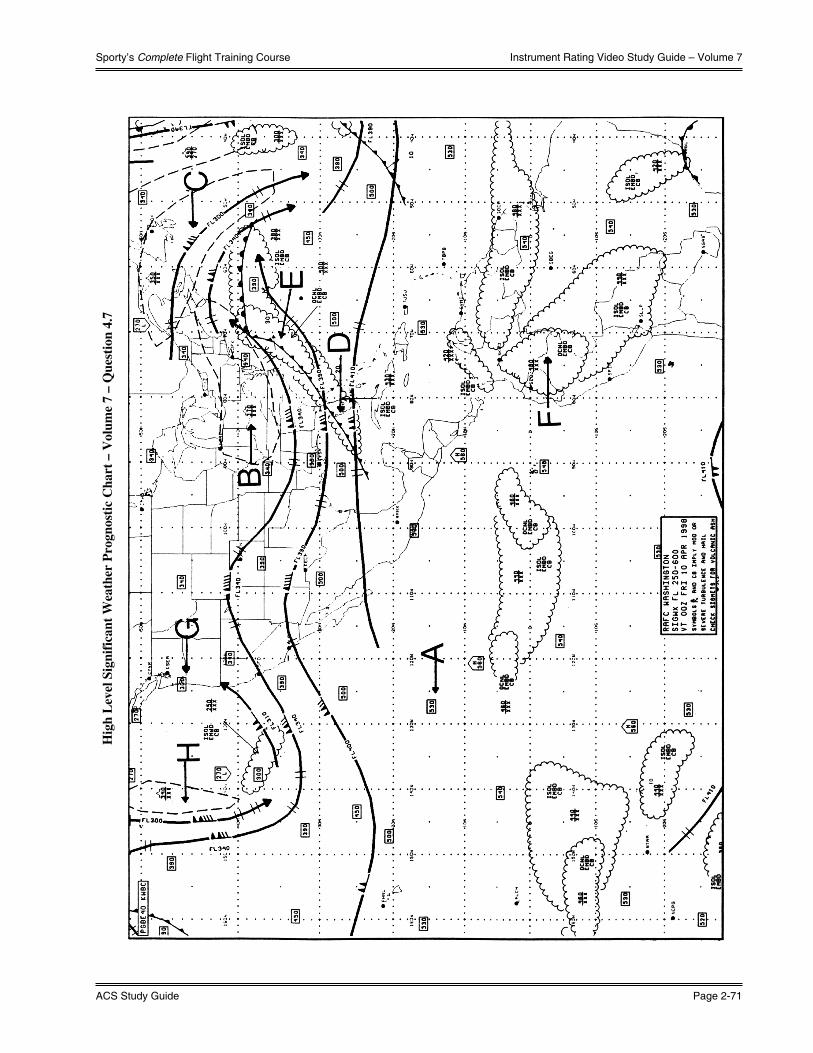
Sporty’s Complete Flight Training Course
ACS Study Guide Page 2-71
Instrument Rating Video Study Guide – Volume 7
Hig
h L
evel
Sig
nifi
cant
Wea
ther
Pro
gnos
tic
Cha
rt –
Vol
ume
7 –
Que
stio
n 4.
7

What You Should Know
Page 2-72 Instrument Rating
Instrument Rating Video Study Guide – Volume 7
Low
-Lev
el S
igni
fica
nt W
eath
er P
rogn
osti
c C
hart
– V
olum
e 7
– Q
uest
ion
4.8

Sporty’s Complete Flight Training Course
ACS Study Guide Page 2-73
Instrument Rating Video Study Guide – Volume 7
Volume 7 – Question 8.2

(Intentionally Left Blank)
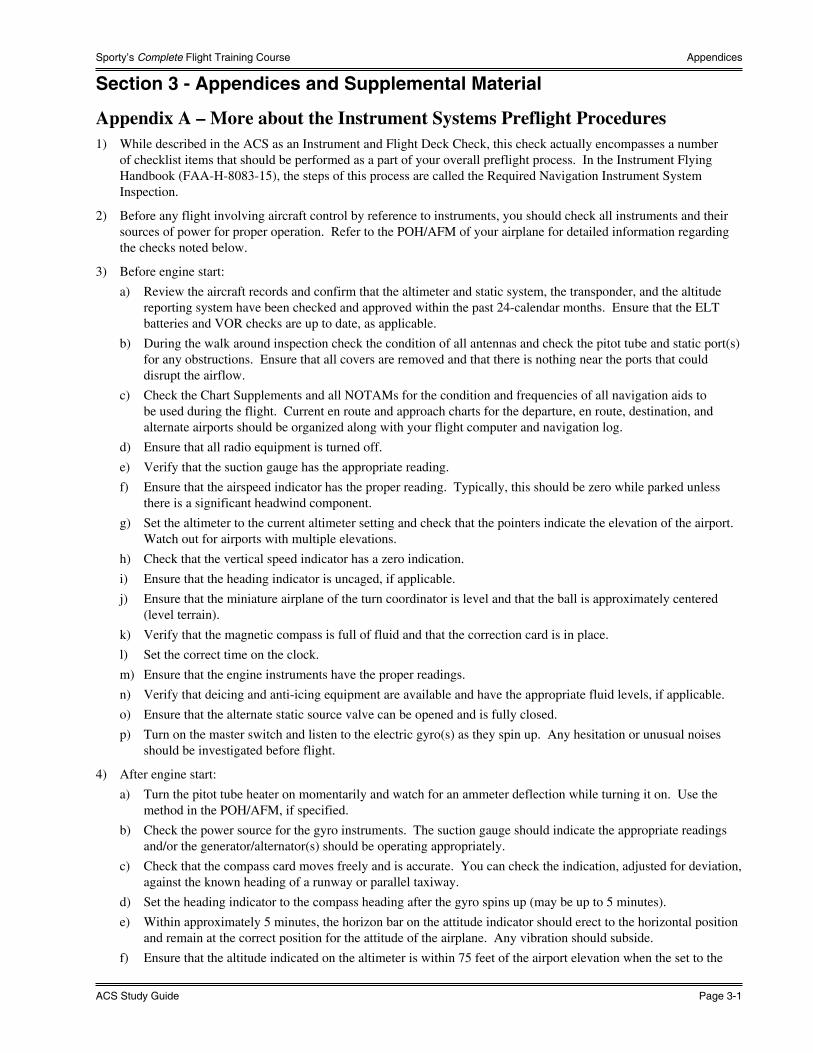
Sporty’s Complete Flight Training Course
ACS Study Guide Page 3-1
Appendices
Section 3 - Appendices and Supplemental Material
Appendix A – More about the Instrument Systems Preflight Procedures1) While described in the ACS as an Instrument and Flight Deck Check, this check actually encompasses a number
of checklist items that should be performed as a part of your overall preflight process. In the Instrument Flying Handbook (FAA-H-8083-15), the steps of this process are called the Required Navigation Instrument System Inspection.
2) Before any flight involving aircraft control by reference to instruments, you should check all instruments and their sources of power for proper operation. Refer to the POH/AFM of your airplane for detailed information regarding the checks noted below.
3) Before engine start:
a) Review the aircraft records and confirm that the altimeter and static system, the transponder, and the altitude reporting system have been checked and approved within the past 24-calendar months. Ensure that the ELT batteries and VOR checks are up to date, as applicable.
b) During the walk around inspection check the condition of all antennas and check the pitot tube and static port(s) for any obstructions. Ensure that all covers are removed and that there is nothing near the ports that could disrupt the airflow.
c) Check the Chart Supplements and all NOTAMs for the condition and frequencies of all navigation aids to be used during the flight. Current en route and approach charts for the departure, en route, destination, and alternate airports should be organized along with your flight computer and navigation log.
d) Ensure that all radio equipment is turned off.
e) Verify that the suction gauge has the appropriate reading.
f) Ensure that the airspeed indicator has the proper reading. Typically, this should be zero while parked unless there is a significant headwind component.
g) Set the altimeter to the current altimeter setting and check that the pointers indicate the elevation of the airport. Watch out for airports with multiple elevations.
h) Check that the vertical speed indicator has a zero indication.
i) Ensure that the heading indicator is uncaged, if applicable.
j) Ensure that the miniature airplane of the turn coordinator is level and that the ball is approximately centered (level terrain).
k) Verify that the magnetic compass is full of fluid and that the correction card is in place.
l) Set the correct time on the clock.
m) Ensure that the engine instruments have the proper readings.
n) Verify that deicing and anti-icing equipment are available and have the appropriate fluid levels, if applicable.
o) Ensure that the alternate static source valve can be opened and is fully closed.
p) Turn on the master switch and listen to the electric gyro(s) as they spin up. Any hesitation or unusual noises should be investigated before flight.
4) After engine start:
a) Turn the pitot tube heater on momentarily and watch for an ammeter deflection while turning it on. Use the method in the POH/AFM, if specified.
b) Check the power source for the gyro instruments. The suction gauge should indicate the appropriate readings and/or the generator/alternator(s) should be operating appropriately.
c) Check that the compass card moves freely and is accurate. You can check the indication, adjusted for deviation, against the known heading of a runway or parallel taxiway.
d) Set the heading indicator to the compass heading after the gyro spins up (may be up to 5 minutes).
e) Within approximately 5 minutes, the horizon bar on the attitude indicator should erect to the horizontal position and remain at the correct position for the attitude of the airplane. Any vibration should subside.
f) Ensure that the altitude indicated on the altimeter is within 75 feet of the airport elevation when the set to the

What You Should Know
Page 3-2 Instrument Rating
Appendices
current altimeter setting. If off by more than 75 feet, recheck the instrument in the runup area using the TDZE for the runway as the basis for comparison to verify that the error is not related to variations in field elevation. If still off by more than 75 feet, the accuracy is questionable and the problem should be referred to a repair station.
g) Check that the vertical speed indicator has a zero indication. If not, have it adjusted or use the ground indication as zero while in flight.
h) Ensure that the carburetor heat is functional and in the off position, if applicable.
i) Verify that the radio equipment is operating properly and set as desired.
i) Communication radios can be checked during calls to clearance delivery, ground, and tower at controlled fields and should be checked with the UNICOM at other airports.
ii) VORs may be checked on the ground at some locations.
iii) An ADF may be checked against a nearby NDB or radio station while on the ground if the weather permits reception of a signal.
iv) The Localizer portion of the ILS may be checked on the ground if the airport has an ILS or other type of Localizer transmitter on the field. The instrument will show the side of the course on which you are currently located.
v) A GPS should pass its self-checks, have an appropriate indication, and show the correct location. The database should be up to date if being used for approaches. Waypoints used for navigation should be verified as correct if the database is not up to date.
j) Ensure that deicing and anti-icing equipment is operational.
5) During taxi and takeoff:
a) The turn coordinator should show proper turn indications during taxi turns and be level while straight. The ball should move freely and in the direction opposite the turn.
b) The heading indicator should turn during taxi turns with minimal precession. Recheck the heading before takeoff and ensure that it agrees with the runway heading (within 5°).
c) Ensure that the attitude indicator remains level during straight taxiing and does not tip more than 5° during turns. If not, it should be considered unreliable. Adjust the miniature airplane to a level flight attitude for the type of airplane and your seat position.
6) During and after engine shut down:
a) Note any abnormal instrument indications.
b) Listen for grinding or other unusual noises as the gyros spin down.
7) Postflight:
a) Recheck the antennas and pitot-static sources while tying down the airplane.
b) Document the failure or malfunction of any equipment or part of the aircraft and ensure that it is fixed as required (or that the appropriate parties are notified).
8) The Instrument Systems Preflight (and postflight) Procedures should be thorough but with practice and the development of a smooth flow, they shouldn’t take up too much extra time. When in doubt about the condition of an instrument, it is best to err on the side of caution and stay on the ground until it can be fixed or until VFR conditions prevail.
Appendix B – More about Holding1) When ATC requires you to hold, they will assign you a fix as a part of your holding clearance. This fix may be a
navaid, an intersection, a DME distance from a navaid, or some other waypoint that you are capable of identifying based upon the equipment in your aircraft.
2) Upon arrival at the fix, an appropriate entry, which keeps your aircraft within the protected airspace for the holding pattern, should be made promptly.
3) When holding in wind, a symmetrical racetrack pattern will likely not be possible.
a) You should compensate for the known wind except when turning.

Sporty’s Complete Flight Training Course
ACS Study Guide Page 3-3
Appendices
b) Adjust the timing of the outbound leg to achieve the required time for the inbound leg.
i) Standard inbound leg at and below 14,000 feet – 1 minute.
ii) Standard inbound leg above 14,000 feet – 1.5 minute.
iii) Other time values may be assigned by ATC.
4) Holding legs may be the standard time based procedures or they may be DME based.
a) Basic entry and holding procedures for DME holding are the same as time based holding.
b) The DME distance for the outbound leg is given as part of the holding clearance.
c) Use the DME distance readout as the end of the outbound leg.
Appendix C – Airspeed Changes and Rate Climbs & Descents1) As indicated in Volume 1 of the course, you should develop a knowledge of the pitch, power, and configuration
combinations for the airplane you are flying that will produce various level flight airspeeds, climbs at various airspeeds and rates, and descents at various airspeeds and rates. You can create an index card with this information to act as a reminder in flight.
2) Changing your airspeed while in straight-and-level and turning flight will typically be accomplished through changes in the power setting. Introduction of drag producing devices may also be used in some aircraft and configurations but we will concentrate on the power setting.
a) Adjust the power to the setting that you have previously determined will produce the desired airspeed.
b) Adjust the pitch attitude to maintain altitude as the airspeed changes.
c) Utilize the airspeed indicator as your primary power instrument and the altimeter as your primary pitch instrument as the speed is changing.
d) Fine tune your power and pitch settings as the airplane stabilizes at the new airspeed.
e) Adjust the trim to relieve the control pressures.
3) Constant rate climbs are entered in a manner similar to constant-airspeed climbs.
a) Increase the power to the approximate setting required for the desired rate of climb.
b) While increasing the power, raise the nose to the approximate pitch attitude required for the desired rate of climb.
c) During the transition to the climb, use the airspeed indicator as your primary pitch instrument.
d) Once the vertical speed indicator stabilizes, use this as your primary pitch instrument and the airspeed indicator as your primary power instrument.
e) Adjust the trim to relieve the control pressures.
f) Lead your level-off by 10% of your climb rate and adjust the pitch and power to the appropriates settings for your desired straight-and-level airspeed.
4) Constant rate descents are entered in a manner similar to constant-airspeed descents.
a) Adjust the pitch and power to slow the airplane to the approximate descent airspeed desired while maintaining straight-and-level flight.
b) Decrease the power further to the approximate setting required for the desired rate of descent.
c) While decreasing the power, lower the nose to the approximate pitch attitude required for the desired rate of descent.
d) Once the vertical speed indicator stabilizes, use this as your primary pitch instrument and the airspeed indicator as your primary power instrument.
e) Adjust the trim to relieve the control pressures.
f) Lead your level-off and adjust the pitch and power to the appropriates settings for your desired straight-and-level airspeed.

What You Should Know
Page 3-4 Instrument Rating
Appendices
Appendix D – Use of MFD and Other Graphical Navigation Displays in Instrument Operations
1) Multifunction Displays (MFD) and other graphical navigation displays, as might be found on a GPS navigator’s Map page, are effective tools for situational awareness during instrument operations.
a) You must understand the operation of the system to utilize it safely and efficiently in actual instrument conditions. Ensure that the map orientation and range have been set appropriately, otherwise, the information may be confusing or imprecise.
b) Do not allow yourself to become overly dependent on these systems to the detriment of basic instrument skills. You should back up your use of these systems with traditional chart information (paper or electronic).
c) Do not use the graphical display as your primary source for course deviation information. Utilize the CDI display appropriate for your navigation source.
2) When using a graphical display for holding procedures, intercepting and tracking navigational systems and DME arcs, precision & nonprecision approaches, and missed approach procedures, set the range of the display to a small enough value to be useful. The scale should allow you to see any significant deviations from the course. Consider the following range guidance:
a) For holding with 4 NM or 1 minute legs, 5 to 10 NM range.
b) For initial course intercepts in the en route environment, 10 to 20 NM range.
c) For tracking a course in the terminal environment, 10 to 20 NM range.
d) For tracking an approach course, 5 to 10 NM range should be your maximum setting.
3) Utilize the graphical display to improve situational awareness in the instrument environment. It can be useful for determining your position in relation to the course, waypoints, airports, and, in some cases, terrain and obstacles.
4) Many graphical displays include a trend vector to show you where your airplane will be in a certain period of time. The trend vector can be useful in determining the effectiveness of your crab angle or course intercept angle.
a) When tracking a course, if the trend vector and the course line align, your crab angle is correct. If the trend vector diverges from the course line, adjust your crab angle to realign the trend vector. With practice, this can often be accomplished before any deviation from the course is apparent on the CDI.
b) The trend vector can also provide information on the quality of an intercept. Use it to determine if your planned or an ATC heading will put your aircraft on course before or after a desired waypoint or if you will intercept the course at all.
5) Some graphical displays show published holding patterns. This can be an aid when determining the method for entry and for recognizing drift when flying the pattern.
6) Remember to utilize a graphical display as it was intended. Use it for “Big Picture” information in situational awareness. Use it as a supplement to your primary navigation instruments and distance measuring equipment (DME or GPS). Use it to backup and verify your understanding of other information in the cockpit.
Appendix E – Single-Pilot Resource Management1) The FAA defines Single-Pilot Resource Management (SRM) as “The ability for a pilot to manage all resources
effectively to ensure the outcome of the flight is successful.”
2) SRM integrates the following:
a) Situational Awareness
b) Flight Deck Resource Management
c) Task Management
d) Aeronautical Decision-making (ADM) and Risk Management
3) Situational awareness is the accurate perception of operational and environmental factors that affect the flight. It is a logical analysis based upon the machine, external support, environment, and the pilot. It is knowing what is going on.
4) Flight Deck Resource Management requires the effective use of all available resources: human, equipment, and information.

Sporty’s Complete Flight Training Course
ACS Study Guide Page 3-5
Appendices
a) Human resources include everyone routinely working with the pilot to ensure flight safety.
b) Equipment in many of today’s aircraft includes automated flight and navigation systems. These automatic systems, while providing relief from many routine flight deck tasks, present a different set of problems for pilots.
c) Information workloads and automated systems, such as autopilots, need to be properly managed to ensure a safe flight.
5) Effective Task Management requires a pilot to properly prioritize and handle information and duties during the flight. Without appropriate task management, a pilot may exceed his capacity to handle the information and operations.
6) The FAA defines Aeronautical Decision-Making (ADM) as “a systematic approach to the mental process used by pilots to consistently determine the best course of action in response to a given set of circumstances.” The ADM process addresses all aspects of decision making in the flight deck and identifies the steps involved in good decision making. While the ADM process will not eliminate errors, it will help the pilot recognize errors, and in turn enable the pilot to manage the error to minimize its effects. These steps are:
a) Identifying personal attitudes hazardous to safe flight;
b) Learning behavior modification techniques;
c) Learning how to recognize and cope with stress;
d) Developing risk assessment skills;
e) Using all resources; and
f) Evaluating the effectiveness of one’s ADM skills.
7) An understanding of the decision-making process provides a pilot with a foundation for developing ADM skills. The FAA teaches several models for this process including:
a) The “3P” model - Perceive, Process, Perform
i) Perceive the given set of circumstances for a flight;
ii) Process by evaluating their impact on flight safety; and
iii) Perform by implementing the best course of action.
b) The DECIDE model - Detect, Estimate, Choose, Identify, Do, Evaluate
i) Detect the fact that a change has occurred that requires attention
ii) Estimate the significance of the change to the flight
iii) Choose a safe outcome for the flight
iv) Identify plausible actions & their risks to control the change
v) Do the best option
vi) Evaluate the effect of the action on the change and on progress of the flight
8) Hazardous attitudes, which contribute to poor pilot judgment, can be effectively counteracted by redirecting that hazardous attitude so that correct action can be taken. Research has identified five hazardous attitudes that can affect a pilot’s judgment, as well as antidotes for each of these five attitudes. ADM addresses the following:
a) Anti-authority (“Don’t tell me!”) - Follow the rules; they are usually right
b) Impulsivity (“Do something quickly!”) - Not so fast…think first
c) Invulnerability (“It won’t happen to me!”) - It could happen to me
d) Macho (“I can do it!”) - Taking chances is foolish
e) Resignation (“What’s the use?”) - I’m not helpless. I can make a difference

What You Should Know
Page 3-6 Instrument Rating
Appendices
Appendix F – Instructor Certification for Instrument Rating Knowledge TestNOTE: The endorsement below is representative of that required by 14 CFR §61.35 and §61.65(a)(4) and MUST be
made in the applicant’s logbook.
INSTRUCTOR CERTIFICATION
INSTRUMENT RATING KNOWLEDGE TEST
I certify I have reviewed the home study curriculum of (First name, MI, Last name) on the required training of §61.65(b). I have determined he/she is prepared for the Instrument Rating knowledge test.
Date:
Signed:
Certificate #:
Expires: