SPL Meter: Sound Pressure Level Meter Software Development on a Smartphone
Upload
khangminh22Category
view
1download
0
SPL_
SB_1
9011
2_V1
Interlube Systems Ltd - Heavy Duty Industrial Lubrication Systems
UK Headquarters: Interlube Systems Ltd
St Modwen Road, Parkway Industrial Estate, Plymouth, Devon, England PL6 8LH
Tel: +44 (0)1752 676000 Fax: +44 (0)1752 676001 [email protected] www.interlubesystems.com
Interlube (USA)
Interlube Systems Inc. (USA), Mid States Building, 4696 Wadsworth Road, Dayton, Ohio 45414, USA
Tel: +1 (937) 276 4507 Tel: +1 (888) 488 5823 Fax: +1 (937) 276 4518 [email protected] www.interlubeusa.com
Interlube (Malaysia)
Sdn Bhd, No 30 Jalan Apollo U5/189, Bandar Pinggiran Subang, Seksven U5, 40150 Shah Alam, Selangor, Malaysia
Tel: +603 7845 56577 / +603 78316577 Fax: +603 7845 5377 [email protected] www.interlubesystems.com
Interlube (China)
Southern International Plaza, Shi Xia Bei 3rd Street, Futian District, Shen Zhen 518035, China
Tel: 0755 21517791 Fax: 0755 21517769 [email protected] www.interlubesystems.co.cn
Interlube (Brazil)
836 Arnaldo Magniccaro St, Zip 04691-060, Villa GEA-São, Paulo-sp-Brazil
Tel: +55 117791 2496 www.interlubesystems.br.com
Part of the HDI range of lubrication systems
SPL + XPL RANGEProgressive Divider Valves
Global Distribution
Inte
rlube
Manufacturing and Distributing throughout the World
Othe
r Pro
duct
s
Visit our Website
SPL Range – Progressive Divider Valves1 Interlube Systems Ltd • web: www.interlubesystems.com • e-mail: [email protected] 2
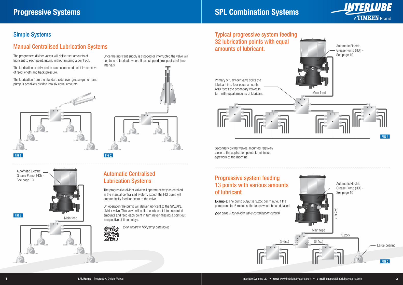
Progressive Systems
Typical progressive system feeding 32 lubrication points with equal amounts of lubricant.Manual Centralised Lubrication Systems
The progressive divider valves will deliver set amounts of lubricant to each point, inturn, without missing a point out.
The lubrication is delivered to each connected point irrespective of feed length and back pressure.
The lubrication from the standard side lever grease gun or hand pump is positively divided into six equal amounts.
Automatic Centralised Lubrication SystemsThe progressive divider valve will operate exactly as detailed in the manual centralised system, except the HDI pump will automatically feed lubricant to the valve.
On operation the pump will deliver lubricant to the SPL/XPL divider valve. This valve will split the lubricant into calculated amounts and feed each point in turn never missing a point out irrespective of time delays.
(See separate HDI pump catalogue)
SPL Combination Systems
FIG 5
FIG 3
FIG 4
Primary SPL divider valve splits the lubricant into four equal amounts AND feeds the secondary valves in turn with equal amounts of lubricant.
Secondary divider valves, mounted relatively close to the application points to minimise pipework to the machine.
Simple Systems
Main feed
Progressive system feeding 13 points with various amounts of lubricantExample: The pump output is 3.2cc per minute. If the pump runs for 6 minutes, the feeds would be as detailed.
(See page 3 for divider valve combination details)
(3.2cc)
(6.4cc)(9.6cc)Large bearing
(19.
2cc)
Main feed
Automatic Electric Grease Pump (HDI) - See page 10
Automatic Electric Grease Pump (HDI) - See page 10
Automatic Electric Grease Pump (HDI) - See page 10
FIG 2FIG 1
Once the lubricant supply is stopped or interrupted the valve will continue to lubricate where it last stopped, irrespective of time intervals.
Main feed

SPL Range – Progressive Divider Valves3 Interlube Systems Ltd • web: www.interlubesystems.com • e-mail: [email protected] 4
7 8
5 6
3 4
1 2
x2
x27 8
5 6
3 4
1 2x1
x1
x1
x1
5 6
3 4
1 2
SPL Outputs SPL Specifications
SPL06 - 6 Outlet ValveFig 6 illustrates the SPL06 valve splitting the lubricant into two equal amounts.
Range
Specifications
SPL08 - 8 Outlet ValveFig 7 illustrates the SPL08 valve splitting the lubricant into four equal amounts.
SPL08 - 8 Outlet ValveFig 8 illustrates the SPL valve splitting the lubricant into four single and two double amounts.
When an outlet is plugged off using an SPL blanking plug, the lubricant is automatically directed internally to the port below.
Note: Outlets 1 and 2 must never be plugged. Always use SPL blanking plugs and SPL check valves.
Outlet Combinations Standard SPL Progressive Divider Valves for Grease or Oil
Examples below showing the outlet feeds (in cm3/stroke)
FIG 8
FIG 9
FIG 6
FIG 7
SPL Plug x 4
SPL Check Valve x 2
IN
x3 x3
IN
x2 x2
x2 x2
IN
0.2
0.2
0.2
0.27 8
5 6
3 4
1 20.2
0.4
0.2
IN
0.8
7 8
5 6
3 4
1 20.4
0.4
IN
0.6
0.4
9 10
7 8
5 6
3 4
1 20.8
0.2
IN
Model OutletsInlet Thread
Indicator Pin
Max Oil Volume/Min* A B C D E F
SPL066 Outlets
1/8” BSP (Female)
No 200cm3 60 60 30 54 20 6.6
SPL06K Yes 200cm3 60 60 30 54 20 6.6
SPL088 Outlets
No 600cm3 60 75 30 69 20 6.6
SPL08K Yes 600cm3 60 75 30 69 20 6.6
SPL1010 Outlets
No 700cm3 60 90 30 84 20 6.6
SPL10K Yes 700cm3 60 90 30 84 20 6.6
SPL1212 Outlets
No 800cm3 60 105 30 99 20 6.6
SPL12K Yes 800cm3 60 105 30 99 20 6.6
*SPL Valves will only work with grease and oil **All tests carried out with NGG2 grease at ambient temp
Note: All SPL Progressive Divider Valves must be used with approved lubricants/ Lubricants with solids/additives are not recommended
*Volume is approximate and can vary depending on oil viscosity and operating temperature.
MaterialMax Operation Pressure
Min Operation Pressure Max Grease Viscosity* Min Oil Viscosity* Output/Stroke/Outlet
Carbon Steel 370 BAR (5365psi) 17 BAR (247psi) NLGI2 68Cst 0.2 cc / 0.12 cu in
SPL10 Valve**
A
E
C
BD
F
Each SPL divider valve can be installed using the accessories shown. For best results, and to eliminate any possibility of damage or proof operation of the system, only SPL parts should be used.
Outlets which are not required should be closed with SPL closure plugs. If an outlet is closed, the adjacent outlet on the same side delivers a double quantity of lubricant. Note: outlets 1 and 2 of SPL divider valves must never be closed.
When an outlet is closed in the pump with one of the closure plugs, lubricant is automatically redirected internally to the next adjacent outlet in ascending numerical order.
FIG 10
SPL-CP-10
SPL-CP-10
XPL-CP-10
Note: Never plug ports 1 and 2 off.

SPL Range – Progressive Divider Valves5 Interlube Systems Ltd • web: www.interlubesystems.com • e-mail: [email protected] 6
XPL Combination Systems XPL Cross Port Divider
Primary XPL divider valve splits the lubricant into 3 equal amounts - feeding each secondary valve.
Automatic Electric Grease Pump (HDI) - See page 10
FIG 11Main feed
2 x SPL-CP-10 divider valve plugs used to divert the grease
1 x XPL-CP-10 plug used to plug off a grease outlet when the grease is crossported
SPL-CV-06 check valves fitted to all outlets
Secondary divider valves
Typical Progressive System (XPL)Feeding 18 Lubrication Points with Equal Amounts of Lubricant
Progressive System Feeding 14 Lubricant Points with Various Amounts of LubricantExample: The pump output is 3.2cc per min if the pump runs for 6 minute, the feed would as detailed
Fig 15 illustrates the plug in position with copper disc, not allowing the grease to be cross ported.
Fig 16 illustrates the internal disc being removed and the plug sealed with copper washer to allow for cross porting. Each XPL valves is supplied with copper washers to allow for cross porting.
Automatic Electric Grease Pump (HDI) - See page 10
19.2cc
SPL Plug x 2
XPL Plug x 3
9.6cc
4.84.8
3.2
1.21.2 0.6
All 0.6 All 0.60.61.2
3.23.2
FIG 12
FIG 13
FIG 14
FIG 15 FIG 16
7 8
5 6
3 4
1 2
5 6
3 4
1 2
XPL06 - 6 Outlet ValveFig 13 illustrates the XPL cross porting divider valve splitting the grease into set amounts:
Port 3 = x4 Port 1 = x2
Note: This means the middle disc has been removed allowing the grease to be cross ported
XPL08 - 8 Outlet ValveFig 14 illustrates the XPL valve splitting the grease as follows:
Port 1 = x2 Port 2 = x2 Port 4 = x3 Port 7 = x1
Note: If cross porting use the XPL divider valve plug. Never plug ports 1 and 2 off.
Outlet Combinations
Outlet Combinations
SPL Plug
SPL Plug
XPL Plug
XPL Plug
IN
x2x4
IN
x2
x2 x3
x1

SPL Range – Progressive Divider Valves7 Interlube Systems Ltd • web: www.interlubesystems.com • e-mail: [email protected] 8
Part No. Description
SPL-CV-LL M10x1 Check Valve Body
SPL-CN-6-LL 6mm o.d Coupling Nut
SPL-OL-6-LL 6mm o.d Olive
Part No. Description
SPL-CP-10 Closure Plug
XPL-CP-10 Closure Plug for XPL Valves
Part No. Description
SPL-PA SPL Proximity Adaptor
SPL-PS Proximity Switch
Part No. Description Thread Size
SPL-BP6 Weld Plate 2 x M6x1
SPL-BP8 Weld Plate 2 x M6x1
SPL-BP10 Weld Plate 2 x M6x1
SPL-BP12 Weld Plate 2 x M6x1
Part No. Description
Bolt M6x35 M6 Cap Head Bolt 35mm Long
Bolt M6x40 M6 Cap Head Bolt 40mm Long
Bolt M6x45 M6 Cap Head Bolt 45mm Long
Bolt M6x75 M6 Cap Head Bolt 75mm Long
M6 Washer M6 Spring Washer
M6 Nut M6 Hex Head Nut
Check Valve Outlet Fittings
Installation Information
Closure Plug
SPL Flow Indicator Sensors
SPL Weld Plates (6mm thick)
Cap Head Bolts
SPL System AccessoriesXPL Specifications
Standard XPL Progressive Divider Valves for Grease and Oil
Each XPL divider valve can be installed using accessories shown. For best results, and to eliminate any possibility of damage or poor operation of the system only Interlube parts should be used.
(a) = 6mm O.D check valve outlet (b) = SPL plug for sequential diverting of the SPL valves (c) = XPL plug for cross porting
SpecificationsModel Outlets
Inlet Thread
Indicator Pin
Max Oil Volume/Min* A B C D E F
XPL066 Outlets
1/8” BSP (Female)
No 200cm3 60 60 30 54 20 6.6
XPL06K Yes 200cm3 60 60 30 54 20 6.6
XPL088 Outlets
No 600cm3 60 75 30 69 20 6.6
XPL08K Yes 600cm3 60 75 30 69 20 6.6
XPL1010 Outlets
No 700cm3 60 90 30 84 20 6.6
XPL10K Yes 700cm3 60 90 30 84 20 6.6
XPL1212 Outlets
No 800cm3 60 105 30 99 20 6.6
XPL12K Yes 800cm3 60 105 30 99 20 6.6
*XPL Valves will only work with grease and oil **All tests carried out with NGG2 grease at ambient temp
Note: All XPL Progressive Divider Valves must be used with approved lubricants/ Lubricants with solids/additives are not recommended
*Volume is approximate and can vary depending on oil viscosity and operating temperature.
MaterialMax Operation Pressure
Min Operation Pressure Max Grease Viscosity* Min Oil Viscosity* Output/Stroke/Outlet
Carbon Steel 370 BAR (5365psi) 17 BAR (247psi) NLGI2 68Cst 0.2 cc / 0.12 cu in
XPL10K Valve**
A
E
C
BD
F
SPL-CP-10
SPL-CP-10
XPL-CP-10

SPL Range – Progressive Divider Valves9 Interlube Systems Ltd • web: www.interlubesystems.com • e-mail: [email protected] 10
SPL Accessories Progressive Installations
Part No. DescriptionCF6-1-6 6mm o.d x M6x1 Male Connector
CF6-1-8 6mm o.d x M8x1 Male Connector
CF6-1-10 6mm o.d x M10x1 Male Connector
CF6-1-1/4 6mm o.d x 1/4" BSPT Male Connector
CF6-1-1/8 6mm o.d x 1/8" BSPT Male Connector
Part No. Description
CF6-2-6 6mm o.d x M6x1 Male Connector
CF6-2-8 6mm o.d x M8x1 Male Connector
CF6-2-10 6mm o.d x M10x1 Male Connector
CF6-2-1/8 6mm o.d x 1/8" BSPT Male Connector
CF6-2-1/4 6mm o.d x 1/4" BSPT Male Connector
Part No. Description Burst Pressure
TML-8.6-2.3F 8.6mm x o.d 2.3mm Wall Tube Grease Filled 400 BAR
TML-8.6-2.3U 8.6mm x o.d 2.3mm Wall Tube Unfilled 400 BAR
TML-12.0-2.5F 12mm x o.d 2.3mm Wall Tube Grease Filled 400 BAR
TML-12.0-2.5U 12mm x o.d 2.3mm Wall Tube Unfilled 400 BAR
Part No. Description Burst Pressure
TSL-6.0-1.5F 6mm o.d x 1.5mm Wall Grease Filled 250 BAR
TSL-6.0-1.5U 6mm o.d x 1.5mm Wall Grease Unfilled 250 BAR
Part No. Description Tube
TML-8.6-FE Re-usable Sleeve 8.6mm ø
TML-8.6-ST Re-usable Stud - 6mm o.d 8.6mm ø
TML-8.6-ST-90 Re-usable Stud - 6mm o.d (90°) 8.6mm ø
TML-12-0-FE Re-usable Sleeve 12mm ø
TML-12.0-ST Re-usable Stud - 6mm o.d 12mm ø
Straight Compression Fittings
Elbow Compression Fittings
Secondary Feed Line Tube (Polyamide Nylon)
Re-usable Studs (Inserts) and Sleeves (Ferrules) for Main Line Braided Tube 8.6mm+
Main Feed Line Tube (Braided) Typical Applications such as:-
Chassis/Agricultural
Mobile Plant
Industrial
Case Loading Shovel
Cultivator
Food Industry
Grease Spray Systems
Trailed Press
Sprayer
Steel Industry
Chassis
Copyright © 2022 FDOKUMEN