SpectraMax Plus384, 190, 340PC384, and VersaMax User ...
55
0112-0126 B October 2018 SpectraMax® Plus 384 SpectraMax® 190 SpectraMax® 340PC384 VersaMax™ Microplate Spectrophotometers User Guide
-
Upload
khangminh22 -
Category
Documents
-
view
0 -
download
0
Transcript of SpectraMax Plus384, 190, 340PC384, and VersaMax User ...

0112-0126 BOctober 2018
SpectraMax® Plus 384SpectraMax® 190SpectraMax® 340PC384VersaMax™Microplate Spectrophotometers
User Guide

VersaMax, SpectraMax 340PC384, 190, Plus 384 Microplate Readers User Guide
2 0112-0126 B
This document is provided to customers who have purchased Molecular Devices equipment, software,reagents, and consumables to use in the operation of such Molecular Devices equipment, software,reagents, and consumables. This document is copyright protected and any reproduction of thisdocument, in whole or any part, is strictly prohibited, except as Molecular Devices may authorize inwriting.Software that may be described in this document is furnished under a non-transferrable license. It isagainst the law to copy, modify, or distribute the software on any medium, except as specificallyallowed in the license agreement. Furthermore, the license agreement may prohibit the softwarefrom being disassembled, reverse engineered, or decompiled for any purpose.
Portions of this document may make reference to other manufacturers and/or their products, whichmay contain parts whose names are registered as trademarks and/or function as trademarks of theirrespective owners. Any such usage is intended only to designate those manufacturers’ products assupplied by Molecular Devices for incorporation into its equipment and does not imply any right and/orlicense to use or permit others to use such manufacturers’ and/or their product names as trademarks.Each product is shipped with documentation stating specifications and other technical information.Molecular Devices products are warranted to meet the stated specifications. Molecular Devices makesno other warranties or representations express or implied, including but not limited to, the fitness ofthis product for any particular purpose and assumes no responsibility or contingent liability, includingindirect or consequential damages, for any use to which the purchaser may put the equipmentdescribed herein, or for any adverse circumstances arising therefrom. The sole obligation of MolecularDevices and the customer's sole remedy are limited to repair or replacement of the product in theevent that the product fails to do as warranted.
For research use only. Not for use in diagnostic procedures.The trademarks mentioned herein are the property of Molecular Devices, LLC or their respective owners. These trademarks may notbe used in any type of promotion or advertising without the prior written permission of Molecular Devices, LLC.
Patents: http://www.moleculardevices.com/patents
Product manufactured by Molecular Devices, LLC.3860 N. First Street, San Jose, California, 95134, United States of America.Molecular Devices, LLC is ISO 9001 registered.©2018 Molecular Devices, LLC.All rights reserved.

0112-0126 B 3
Contents
Safety Information 4
Warnings, Cautions, Notes, and Tips 4
Chapter 1: Introduction 8
Computer Integration 8
Plate Controls 9
Temperature Regulation 11
Chapter 2: Setting Up the Instrument 13
Connecting Instrument Cables 14
Chapter 3: Getting Started 16
Control Panel 16
GeneralWorkflow 17
Chapter 4: Absorbance Read Mode 19
PathCheck Pathlength Measurement Technology 20
Read Types 24
Chapter 5: Maintenance 25
Cleaning the Instrument 25
Replacing Fuses 26
Before You Move the Instrument 28
Chapter 6: Troubleshooting 29
Opening the Drawer Manually 33
Obtaining Support 34
Appendix A: Instrument Specifications 35
SpectraMax Plus 384 Specifications 36
SpectraMax 340PC384 Specifications 41
SpectraMax 190 Specifications 45
VersaMax Specifications 49
Electromagnetic Compatibility 52
Appendix B: Accessories 53

VersaMax, SpectraMax 340PC384, 190, Plus 384 Microplate Readers User Guide
4 0112-0126 B
Safety Information
Information about the safe use of the instrument from Molecular Devices® includes anunderstanding of the user-attention statements in this guide, the safety labels on theinstrument, precautions to follow before you operate the instrument, and precautions tofollowwhile you operate the instrument.Make sure that everyone involved with the operation of the instrument has:
Received instruction in general safety practices for laboratories.Received instruction in specific safety practices for the instrument.Read and understood all Safety Data Sheets (SDS) for all materials being used.
Read and observe all warnings, cautions, and instructions. Themost important key to safetyis to operate the instrument with care.
WARNING! If the instrument is used in a manner not specified by MolecularDevices, the protection provided by the equipment might be impaired.
Warnings, Cautions, Notes, and TipsAll warning symbols are framed within a yellow triangle. An exclamation mark is used formost warnings. Other symbols can warn of other types of hazards such as biohazard,electrical, or laser safety warnings as are described in the text of the warning. Follow therelated safety information.The following user attention statements might be displayed in the text ofMolecular Devicesuser documentation. Each statement implies the amount of observation or recommendedprocedure.
WARNING! A warning indicates a situation or operation that could causepersonal injury if precautions are not followed.
CAUTION! A caution indicates a situation or operation that could cause damage tothe instrument or loss of data if correct procedures are not followed.
Note: A note calls attention to significant information.
Tip: A tip provides useful information or a shortcut, but is not essential to thecompletion of a procedure.

Safety Information
0112-0126 B 5
Symbols on the Instrument
Each safety label found on the instrument contains an alert symbol that indicates the type ofpotential safety hazard.
Symbol Indication
Consult the product documentation.
Potential biohazard.
Potential lifting hazard. To prevent injury, use a minimum of two people to lift theinstrument.
Potential heat hazard.
Required in accordance with the Waste Electrical and Electronic Equipment (WEEE)Directive of the European Union. It indicates that you must not discard this electrical orelectronic product or its components in domestic household waste or in the municipalwaste collection system.For products under the requirement of the WEEE directive, contact your dealer orlocal Molecular Devices office for the procedures to facilitate the proper collection,treatment, recovery, recycling, and safe disposal of the device.
- - California proposition 65 requires businesses to providewarnings to Californians about significant exposures to chemicals that cause cancer, birthdefects, or other reproductive harm.

VersaMax, SpectraMax 340PC384, 190, Plus 384 Microplate Readers User Guide
6 0112-0126 B
Electrical Safety
To prevent electrical injuries and property damage, inspect all electrical equipment beforeuse and report all electrical deficiencies. Contact Molecular Devices technical support forequipment service that requires the removal of covers or panels.To prevent electrical shock, use the supplied power cord and connect to a properlygrounded wall outlet.To ensure sufficient ventilation and provide access to disconnect power from theinstrument, maintain a 20 cm to 30 cm (7.9 in. to 11.8 in.) gap between the rear of theinstrument and the wall.Power off the instrument when not in use.
Chemical and Biological Safety
Normal operation of the instrument can involve the use ofmaterials that are toxic,flammable, or otherwise biologically harmful. When you use such materials, observe thefollowing precautions:
Handle infectious samples based on good laboratory procedures and methods toprevent the spread of disease.Observe all cautionary information printed on the original containers of solutions beforetheir use.Dispose of all waste solutions based on the waste disposal procedures of your facility.Operate the instrument in accordance with the instructions outlined in this guide, andtake all the required precautions when using pathological, toxic, or radioactivematerials.Splashing of liquids can occur. Take applicable safety precautions, such as using safetyglasses and wearing protective clothing, when working with potentially hazardousliquids.Observe the applicable cautionary procedures as defined by your safety officer whenusing hazardous materials, flammable solvents, toxic, pathological, or radioactivematerials in or near a powered-up instrument.
WARNING! Never use the instrument in an environment where potentiallydamaging liquids or gases are present.

Safety Information
0112-0126 B 7
Moving Parts Safety
The instrument contains moving parts that can cause injury. Under normal conditions, theinstrument is designed to protect you from thesemoving parts.
WARNING! If the instrument is used in a manner not specified by MolecularDevices, the protection provided by the equipment might be impaired.
To prevent injury:Never try to exchange labware, reagents, or tools while the instrument is operating.Never try to physically restrict themoving components of the instrument.
Note: Observe all warnings and cautions listed for all external devices attached to or inuse during the operation of the instrument. See the applicable user guide for theoperating and safety procedures of that device.
CAUTION! Never touch the optic mirrors, lenses, filters, or cables. The optics areextremely delicate, and critical to the function of the instrument.

0112-0126 B 8
Chapter 1: Introduction
The SpectraMax® 340PC384, SpectraMax® 190, and VersaMax™microplatespectrophotometers provide rapid and sensitivemeasurements of a variety of analytesacross a wide range of concentrations. The SpectraMax® Plus 384 adds the ability to readcuvettes. These instruments measure the optical density (OD) of samples at selectedwavelengths in a single read mode.
SpectraMax Plus 384 reads 96-well plates, 384-well plates, and cuvettes.SpectraMax 190 reads 96-well plates.SpectraMax 340PC384 reads 96-well plates and 384-well plates.VersaMax reads 96-well plates.
The high sensitivity and flexibility of these instruments make them useful for applications inthe fields of biochemistry, cell biology, immunology, molecular biology, and microbiology.Typical applications include ELISA, nucleic acid, protein, enzymatic type homogeneous andheterogeneous assays, microbial growth, endotoxin testing, and pipettor calibration.The instruments support the UV and Visible Absorbance read modewith the following readtypes.
Endpoint: at a single point in time.Kinetic: over a specified period of time.Spectrum: over a specified wavelength range.
The shake feature enables you to mix the contents of the wells in a plate before each readcycle, which makes it possible to perform kinetic analysis of solid-phase, enzyme-mediatedreactions (shake is not critical for liquid-phase reactions).Temperature controls enable the instrument to regulate the temperature of the platechamber from 4°C above ambient to 45°C.
Documentation
Computer IntegrationEach Molecular Devices microplate reader is shipped with a license key for the SoftMax® ProData Acquisition and Analysis Software that you install on the computer that you use tooperate the instrument. The SoftMax Pro Software provides integrated instrument control,data display, and statistical data analysis.You should install the SoftMax Pro Software on the computer before you set up theinstrument. Please be aware that some updates to the SoftMax Pro Software require apurchase. Contact Molecular Devices before you update the software. To download thelatest version of the software, visit:https://www.moleculardevices.com/products/microplate-readers/acquisition-and-analysis-software/softmax-pro-software#Order.
1

VersaMax, SpectraMax 340PC384, 190, Plus 384 Microplate Readers User Guide
9 0112-0126 B
Note: For information about the computer specifications that are required to run thesoftware, the software installation and licensing instructions, and the directions tocreate the software connection between the computer and the instrument, see theSoftMax Pro Data Acquisition and Analysis Software Installation Guide.
To prevent data loss, turn off all sleep and hibernation settings for the hard disk, the CPU,and the USB ports. Disable automatic Windows updates. UpdateWindows manually whenyou do not use the computer to control an instrument. You can set these options inWindows Control Panel.You can connect the instrument to a printer and operate the instrument in stand alonemode to run basic Absorbance read mode Endpoint read type protocols. In stand alonemode, the instrument control panel enables you to adjust the temperature and thewavelength to do fixed point plate reads. For the SpectraMax Plus 384 you can do fixed pointcuvette reads. Stand alonemode is not available for the VersaMax.To run protocols that require advanced acquisition settings or to run Absorbance read modeKinetic read type and Spectrum read type protocols, you must connect the instrument to acomputer and use the SoftMax Pro Software to operate the instrument.
Plate ControlsThe plate drawer is located on the right side of the instrument and slides in and out of theplate chamber. Use the instrument control panel or the SoftMax Pro Software to open andclose the plate drawer.The arrow in the following image points to the plastic pusher that holds the plate in placewhen the drawer is closed. Located in the front left corner of the drawer, this is also wherewell A1 should be for reads.
Plate drawer operation is dependent on the incubator setting:The drawer closes for each read.When you open the drawer, if the incubator is off, the drawer remains open.When you open the drawer, if the incubator is on, the drawer closes after approximately10 seconds to maintain temperature control within the plate chamber.
Do not obstruct themovement of the drawer. If you must retrieve a plate after an errorcondition or power outage and the drawer does not open, you can open the drawermanually. See Opening the Drawer Manually on page 33.

Chapter 1: Introduction
0112-0126 B 10
SpectraMax Plus 384 reads 96-well plates, 384-well plates and strip-well plates, andcuvettes.SpectraMax 190 reads 96-well and strip-well plates.SpectraMax 340PC384 reads 96-well plates and 384-well plates and strip-well plates.VersaMax reads 96-well and strip-well plates.
When you do reads at wavelengths below 340 nm, you must use special UV-transparent,disposable or quartz plates to allow transmission of the deep UV spectra.Not all manufacturers' plates are the samewith regard to design, materials, or configuration.Temperature uniformity within the platemay vary depending on the type of plate used.
CAUTION! To prevent damage to the instrument, the height of the platemust notexceed 25 mm, including the lid if the plate is lidded.
ShakeThe software enables you to define settings to shake the plate linearly along the long axis atpreset intervals to mix of the contents of the wells.
Endpoint read type: Settings enable you to shake the plate for a definable number ofseconds and then read at all selected wavelengths.Kinetic read type: Settings enable you to shake the plate for a definable number ofseconds before the initial read, and/or for a definable number of seconds before eachsubsequent read.
Use of shake is recommended for ELISAs and other solid-phase, enzyme-mediated reactionsto enhance accuracy.
Cuvette Chamber
The cuvette chamber on the SpectraMax Plus 384 is located at the right front of theinstrument. You manually lift up the lid over the chamber to insert or remove a cuvette. Thechamber contains springs that position the cuvette in the proper alignment for a read. Youmust manually close the cuvette door before you initiate a read.Handle cuvettes on the frosted sides only. Place the cuvette into the chamber so that the“reading” (clear) sides face left and right.

VersaMax, SpectraMax 340PC384, 190, Plus 384 Microplate Readers User Guide
11 0112-0126 B
The guidelines for cuvette use in the instrument are the same as those that apply to anyhigh-quality spectrophotometer. You must ensure that themeniscus is comfortably abovethe light beam in standard cuvettes and that the sample chamber in a microcuvette isaligned properly with the beam. The light beam is 0.625 in (15.87mm) above the cuvettebottom.The instrument can accommodate standard-height (45mm), 1-cm cuvettes and 12 x 75mmtest tubes when used with the test tube cover. The instrument does not accept short (25mm high)microcuvettes. See Accessories on page 53.Not all manufacturers’ cuvettes are the samewith regard to design, materials, orconfiguration. Temperature uniformity within the cuvettemay vary depending on the typeof cuvette you use.
Temperature RegulationThe instrument contains an incubator that enables you to control the temperature in theplate chamber for Endpoint read type protocols. When you power on the instrument theincubator is off. The temperature in the plate chamber is ambient and isothermal.The instrument is designed to regulate the temperature of the plate chamber from 4°Cabove ambient to 45°C. The instrument control panel and the SoftMax Pro Software enableyou to turn the incubator on and off to adjust the plate chamber temperature. Thetemperature set point defaults to 37.0°C at start-up.The instrument control panel displays the temperature in the plate chamber except for theSpectraMax Plus 384where the instrument control panel displays the cuvette chambertemperature. Use the SoftMax Pro Software to view the plate chamber temperature for theSpectraMax Plus 384.Typically, the plate chamber reaches 37.0°C in less than 30minutes. The plate chambertemperature is maintained at the set point until you to turn temperature regulation off.Temperature regulation and control of the plate chamber is achieved through electricheaters, a fan, efficient insulation, and temperature sensors. The heaters are located in theplate chamber, which is insulated to maintain the temperature set point. The sensors aremounted inside the chamber and measure the air temperature.Accuracy of the temperature set point is guaranteed only if the set point is at least 4°C aboveambient. If the temperature set point is lower than the ambient temperature, the chambertemperature remains at ambient. Temperature regulation is controlled by heaters only and,therefore, cannot cool the temperature to a setting lower than ambient. Additionally, thehighest setting (45°C) can be achieved only if the ambient temperature is greater than 20°C.Should you turn the incubator back on after a momentary shutdown, allow about tenminutes for the control algorithm to fully stabilize the plate chamber temperature.The temperature feedback closed-loop control algorithms measure the chamber airtemperature, compare it to the temperature set point, and use the difference to calculatethe regulation of the heating cycles. This technique results in accurate, precise control of thechamber temperature with a temperature variation of the air inside the chamber of less than1.0°C. The temperature uniformity within the plate depends on its design and composition.

Chapter 1: Introduction
0112-0126 B 12
The temperature sensors detect the temperature of the air inside the chamber, not thetemperature of the samples in the plate. If you use the instrument to warm the samples, usea seal or lid on the plate to prevent evaporation of the sample. The seal or lid also helps tomaintain a uniform temperature. It can take an hour or more for a prepared sample toequilibrate inside the plate chamber. You can speed up equilibration by pre-warming thesample and the assay reagents to the desired temperature before you place the plate in thechamber. Validate the data quality to determine whether the seal or lid can stay on the platefor the read.

0112-0126 B 13
Chapter 2: Setting Up the Instrument
Before you unpack and set up the instrument, prepare a dry, flat work area that hassufficient space for the instrument, host computer, and required cables. To provide accessfor disconnecting power from the instrument, maintain a 20 cm to 30 cm (7.9 in. to 11.8 in.)gap between the rear of the instrument and the wall. To ensure sufficient ventilation, do notblock the ventilation grid on the right side of the instrument.
WARNING! Potential lifting hazard. To prevent injury, use a minimum of twopeople to lift the instrument.
The package contains the instrument and accessories to set up the instrument:SoftMax Pro Software, product key, and installation guideInstrument Installation GuideUSB computer connection cableAC power adapterParallel printer connection cable
For a complete list of the package contents, see the enclosed packing list.The packaging is designed to protect the instrument during shipment. Tape is placed on thecuvette door and the plate drawer to protect the instrument from damage during shipment.
CAUTION! Do not touch or loosen screws or parts other than those specificallydesignated in the instructions. Doing so could causemisalignment and possibly voidthe warranty.
Note: Retain the shipping box and all packing materials for future transport needs.
CAUTION! When transporting the instrument, warranty claims are void if damageduring transport is caused by improper packaging.
To unpack the instrument:1. Check the box for damage that occurred during transportation. Inform the supplier
immediately and keep the damaged packaging.2. Open the top of the box.3. Lift the accessories tool box and the instrument from the package and place the
instrument on a level surface.4. Remove the packing material from both ends of the instrument and set the instrument
down carefully.
2

VersaMax, SpectraMax 340PC384, 190, Plus 384 Microplate Readers User Guide
14 0112-0126 B
Connecting Instrument CablesThe power cord and USB cable connect to the ports on the rear of the instrument.Illustration Part Number Description
5064799 USB computer connection cable, 3 meter (9.8 foot)
4400-0002 or 4400-0036 Power cord, 1 meter (3.3 foot)
Note: Before you connect or disconnect the power cord, make sure that the powerswitch that is on the rear of the instrument is in the Off position.
1. Make sure that the power switch that is on the rear of the instrument is in theOff position.
2. To use a computer to operate the instrument, connect the appropriate end of thesupplied USB cable to the USB port that is on the rear of the instrument, and thenconnect the other end to a USB port on the computer.
3. To operate the instrument in standalonemode, connect one end of the 25-pin parallelcable to the printer port, and then connect the other end to the printer.
4. Load paper into the printer according to themanufacturer's instructions and connectthe printer's power cord.
5. Connect the supplied power adapter to the power port that is on the rear of theinstrument, and then connect the other end to a grounded electrical wall outlet.

Chapter 2: Setting Up the Instrument
0112-0126 B 15
6. Turn the instrument around so that the front of the instrument now faces you.
Note: Ensure no cables run beneath the instrument.
7. Remove the tape from the cuvette door on the SpectraMax Plus 384.8. Power on the instrument and wait for the plate drawer to open.9. Remove the tape and protective covering from the drawer subplate.

0112-0126 B 16
Chapter 3: Getting Started
Now that you installed the SoftMax Pro Software software on the computer, removed thetape from the drawer and the cuvette port, and connected the cables, it is time to getstarted.
WARNING! Never use the instrument in an environment where potentiallydamaging liquids or gases are present.
1. Set the power switch on the rear of the instrument to the On position. Wait for theinstrument to complete its diagnostic check and the plate drawer opens.
2. Start the software on the computer. To start the software under normal conditions, waitfor the instrument to complete the start-up sequence, and then double-click theSoftMax Pro icon on the desktop to start the program.
Power off the instrument when not in use.
Control PanelWhen you connect the instrument to a computer that runs the SoftMax Pro Software, youuse the computer to definemost instrument settings within the software. You can optionallyuse the instrument control panel in conjunction with the SoftMax Pro Software to open theplate drawer, to adjust the temperature, and to adjust the wavelength settings. See theSoftMax Pro Data Acquisition and Analysis Software User Guide.When you connect the instrument to a printer and operate it in stand alonemode, theinstrument control panel enables you to run basic Absorbance read mode protocols. Theinstrument control panel consists of a 2-x-20-character LCD and the following buttons.
Temp On/Off - For the Endpoint read type, press to turn the incubator on or off. Whenthe incubator is on, the set temperature and the actual temperature display in the LCD.Temperature settings are not applicable for the Kinetic and Spectrum read types.Temp and - Press to adjust the plate chamber temperature by 0.1°C increments.Press and hold to rapidly adjust the temperature in 1°C increments.λ and - Press to adjust the wavelength by 1 nm. Press and hold to rapidly adjust thewavelength in 10 nm increments. Wavelength settings are not available for theVersaMax.96/384 - For the SpectraMax 340PC384, press to select to read a 96-well plate or a 384-well plate.REF - For the SpectraMax Plus 384, press to do a Cuvette Reference correction methodread of buffer, water, or air taken in the cuvette that is used as I0 to calculate Absorbanceor % Transmittance with the PathCheck Pathlength Measurement Technology. If noreference read is taken, the instrument uses the I0 values stored in the instrumentfirmware. See PathCheck Pathlength Measurement Technology on page 20.
3

VersaMax, SpectraMax 340PC384, 190, Plus 384 Microplate Readers User Guide
17 0112-0126 B
Read Cuvette - For the SpectraMax Plus 384, press to initiate the sample read of thecuvette.Read - For the SpectraMax 190 and SpectraMax 340PC384, press to initiate the plate readwhen you operate the instrument in stand alonemode. Data is sent to the printer port.% T/A - For the SpectraMax Plus 384, press to change the display of cuvette databetween percent transmission and absorbance.Drawer - Press to open or close the plate drawer.
General WorkflowNow that you have powered on the instrument and are familiar with the control panel youare ready to use the instrument.
CAUTION! Use of organic solvents can cause harm to the optics in the instrument.Extreme caution is recommended when you use organic solvents. Always use a platelid and do not place a plate that contains thesematerials in the plate chamber forprolonged periods of time. Damage caused by the use of incompatible or aggressivesolvents is NOT covered by the instrument warranty.
SoftMax Pro Software WorkflowFor this workflow you connect the instrument to the computer on which you install theSoftMax Pro Software. See the SoftMax Pro Data Acquisition and Analysis Software UserGuide or application help for detailed instructions.1. Power on the computer.2. Start the SoftMax Pro Software and connect the software to the instrument.3. Use the computer to define the protocol settings including read type, wavelengths, plate
type, read area, detection speed, temperature, shake, and kinetic timing.4. Use the computer to open the plate drawer or manually lift the cuvette chamber door. If
you adjust the chamber temperature, the drawer closes after approximately 10 secondsto maintain temperature control.
5. Place the plate on the plate slide for a plate read (well A1 on the front left of the drawer)or place the cuvette into the cuvette chamber for a cuvette read (springs hold thecuvette in place). Handle cuvettes on the frosted sides only. Place the cuvette into thechamber so that the “reading” (clear) sides face left and right.
6. Use the computer to close the plate drawer or manually close the cuvette door.7. Use the computer to start the read.8. The computer displays the read data and the plate drawer opens.
Chapter 3: Getting Started
0112-0126 B 18
Stand Alone ModeFor this workflow you connect the instrument to a printer. The instrument control panel onthe SpectraMax 190 and the SpectraMax 340PC384 enable you to do an Absorbance readmode Endpoint read type of a plate. The instrument control panel on the SpectraMax Plus384 enables you to do an Absorbance read mode Endpoint read type of a cuvette. Standalonemode is not available for the VersaMax.
Note: Due to the continuous changes in printer technology and printer obsolescence,Molecular Devices does not recommend relying on printing in standalonemode.
1. Power on the instrument and the connected printer.2. Use the instrument control panel to set the wavelength and temperature for the read.
Wait for the plate chamber or cuvette chamber to reach the set temperature.3. Use the instrument control panel to open the plate drawer or manually lift the cuvette
chamber door. If you adjust the chamber temperature, the drawer closes afterapproximately 10 seconds to maintain temperature control.
4. Place the plate on the plate slide for a plate read (well A1 on the front left of the drawer)or place the cuvette into the cuvette chamber for a cuvette read (springs hold thecuvette in place). Handle cuvettes on the frosted sides only. Place the cuvette into thechamber so that the “reading” (clear) sides face left and right.
5. Use the instrument control panel to close the plate drawer or manually close the cuvettedoor.
6. Use the instrument control panel to start the read.

0112-0126 B 19
Chapter 4: Absorbance Read Mode
The instrument uses the Absorbance (ABS) read mode to measure the Optical Density (OD)of the sample solutions.Absorbance is the quantity of light absorbed by a solution. To measure absorbanceaccurately, it is necessary to eliminate light scatter. If there is no turbidity, thenabsorbance = optical density.
A = log10(I0 /I) = –log10(I/I0) where I0 is intensity of the incident light before it enters the sample divided by the light afterit passes through the sample, and A is themeasured absorbance.The temperature-independent PathCheck® Pathlength Measurement Technologynormalizes your absorbance values to a 1 cm path length based on the near-infraredabsorbance of water.The instrument enables you to choose whether to display absorbance data as OpticalDensity (OD) or %Transmittance (%T) in the Reduction dialog.Optical DensityOptical density (OD) is the quantity of light passing through a sample to a detector relative tothe total quantity of light available. Optical Density includes absorbance of the sample pluslight scatter from turbidity and background. You can compensate for background usingblanks.A blank well contains everything used with the sample wells except the chromophore andsample-specific compounds. Do not use an empty well for a blank.Some applications are designed for turbid samples, such as algae or other micro-organismsin suspension. The reported OD values for turbid samples are likely to be different when readby different instruments.For optimal results, you should run replicates for all blanks, controls, and samples. In thiscase, the blank value that will be subtracted is the average value of all blanks.% Transmittance%Transmittance is the ratio of transmitted light to the incident light for absorbance reads.
T = I/I0%T = 100T
where I is the intensity of light after it passes through the sample and I0 is incident lightbefore it enters the sample.Optical Density and %Transmittance are related by the following formulas:
%T = 102–OD
OD = 2 – log10(%T)The factor of two comes from the fact that %T is expressed as a percent of the transmittedlight and log10(100) = 2.
4

VersaMax, SpectraMax 340PC384, 190, Plus 384 Microplate Readers User Guide
20 0112-0126 B
When in %Transmittance analysis mode, the instrument converts the rawOD valuesreported by the instrument to %Transmittance using the above formula. All subsequentcalculations are done on the converted numbers.
Applications of AbsorbanceAbsorbance-based detection is commonly used to evaluate changes in color or turbidity,permitting widespread use including ELISAs, protein quantitation, endotoxin assays, andcytotoxicity assays.
PathCheck Pathlength Measurement TechnologyThe temperature-independent PathCheck® Pathlength Measurement Technologynormalizes your absorbance values to a 1 cm path length based on the near-infraredabsorbance of water.The Beer–Lambert law states that absorbance is proportional to the distance that lighttravels through the sample:
A = εcLwhere A is the absorbance, ε is themolar absorptivity of the sample, c is the concentration ofthe sample, and L is the pathlength. The longer the pathlength, the higher the absorbance.Microplate readers use a vertical light path so the distance of the light through the sampledepends on the volume. This variable pathlength makes it difficult to do extinction-basedassays and makes it confusing to compare results between microplate readers andspectrophotometers.The standard pathlength of a 1 cm cuvette is the conventional basis to quantify the uniqueabsorptivity properties of compounds in solution. Quantitative analysis can be done on thebasis of extinction coefficients, without standard curves (for example, NADH-based enzymeassays). When you use a cuvette, the pathlength is known and is independent of samplevolume, so absorbance is directly proportional to concentration when there is nobackground interference.In a plate, pathlength is dependent on the liquid volume, so absorbance is proportional toboth the concentration and the pathlength of the sample. Standard curves are often used todetermine analyte concentrations in vertical-beam photometry of unknowns, yet errors canstill occur from pipetting the samples and standards. The PathCheck technology determinesthe pathlength of aqueous samples in the plate and normalizes the absorbance in each wellto a pathlength of 1 cm. This way of correcting themicrowell absorbance values is accurateto within ±4% of the values obtained directly in a 1 cm cuvette.

Chapter 4: Absorbance Read Mode
0112-0126 B 21
Horizontal light path
Vertical light path
Cuvette Microplate wells
PathCheck technology normalizes the data acquired from an Absorbance read modeEndpoint read type to a 1 cm pathlength, correcting the OD for each well to the valueexpected if the sample were read in a 1 cm cuvette. The instrument uses the factory installedWater Constant to obtain the 1 cm values. For the SpectraMax Plus 384 you can read acuvette that contains deionized water or buffer to use the Cuvette Reference correctionmethod (typically not necessary when you use aqueous solutions with minimal alcohol, salt,or organic solvent content).
Water ConstantThe PathCheck technology is based on the absorbance of water in the near infrared spectralregion (between 900 nm and 1000 nm). If the sample is completely aqueous, has no turbidityand has a low salt concentration (less than 0.5M), theWater Constant correction method issufficient. TheWater Constant is determined for each instrument during manufacture and isstored in the instrument.
Cuvette ReferenceThe SpectraMax Plus 384 supports the Cuvette Reference correction method for solventsthat do not absorb in the 900 nm to 1000 nm range.
Note: The Cuvette Reference correction method that the software uses with thePathCheck Pathlength Measurement Technology is different from the reference readof a cuvette that occurs when you click the Ref button in the Cuvette Set section toolbar.
Use the Cuvette Reference correction method if the sample contains an organic solvent suchas ethanol or methanol. When you add a non-interfering solvent to the aqueous sample, thewater absorbance decreases proportionally to the percentage of organic solvent present. Forexample, 5% ethanol decreases the water absorbance by 5% and results in a 5%underestimation of the pathlength. To minimize the error, put the samewater/solventmixture in a cuvette and use the Cuvette Reference.

VersaMax, SpectraMax 340PC384, 190, Plus 384 Microplate Readers User Guide
22 0112-0126 B
Place a standard 1 cm cuvette that contains the aqueous/solvent mixture you use for theplate samples into the cuvette port. The cuvettemust be in place when you read the plate.When you click Read, the instrument first makes the 900 nm and 1000 nm measurements inthe cuvette and then makes the designated measurements in the plate. The softwaretemporarily stores the cuvette values and uses the cuvette values in the PathCheckcalculations for the plate samples.The Cuvette Reference data does not display in a Cuvette Set section. The software uses theCuvette Reference data for PathCheck Pathlength Measurement Technology calculations onthe data the instrument collects from the plate. You can use the accessors in the FormulaEditor dialog to obtain these values. See the !PathCheckLm1000 and !PathCheckLm900accessor in the SoftMax Pro Data Acquisition and Analysis Software Formula ReferenceGuide.
Note: After you read a plate with PathCheck technology turned on, the softwarestores PathCheck information permanently in the document. You can apply or notapply PathCheck technology to the absorbance values. If you do select to usePathCheck technology for the plate read, you cannot apply the PathCheck PathlengthMeasurement Technology feature after the read.
Eliminating Pathlength Independent Component
RawODmeasurements of plate samples include both pathlength-dependent components(sample and solvent) and a pathlength-independent component (OD of platematerial). Thepathlength-independent component must be eliminated from the calculation to get validresults that have been normalized by the PathCheck technology. You can do this using aplate blank or using a plate background constant.Use a Plate BlankYou can use this method if all samples in the plate are the same volume and the read doesnot depend on the PathCheck technology to correct for variability in volumes.1. Designate a minimum of one well (preferably several) as Plate Blank.2. Pipette buffer (for example, your samplematrix) into those wells and read along with the
samples. Do not use an empty well for a blank.The instrument automatically subtracts the average of the blank wells from each of thesamples. The OD of the platematerial is subtracted as part of the blank.
3. Select the Use Plate Blank check box in the Data Reduction dialog.Use a Plate Background ODIf your sample volumes are not identical or if you choose not to use a Plate Blank, then youmust use a Plate Background OD. Omitting a Plate Background OD results in artificially highvalues after being normalized by the PathCheck technology.To determine the Plate Background OD:1. Fill a clean plate with water.2. Read at the wavelengths you will use for the samples.
Chapter 4: Absorbance Read Mode
0112-0126 B 23
The average OD value is the Plate Background OD. If you intend to read your samples atmore than one wavelength, there should be a corresponding number of Plate BackgroundOD values for each wavelength.
Note: It is important that you put water in the wells and do not read a dry plate forthe Plate Background OD. A dry plate has a slightly higher OD value than a water filledplate because of differences in refractive indices. Use of a dry plate results inPathCheck technology normalized values that are lower than 1 cm cuvette values.
Interfering Substances
Material that absorbs in the 900 nm to 1000 nm spectral region could interfere withPathCheck technology measurements. Fortunately, there are fewmaterials that do interfereat the concentrations generally used.Turbidity is themost common interference. If you can detect turbidity in your sample, youshould not use the PathCheck technology. Turbidity elevates the 900 nm measurementmore than the 1000 nm measurement and causes an erroneously low estimate ofpathlength. Use of the Cuvette Reference does not reliably correct for turbidity.Samples that are highly colored in the upper-visible spectrum might have absorbance thatextends into the near-infrared (NIR) spectrum and can interfere with the PathChecktechnology. Examples include Lowry assays, molybdate-based assays, and samples thatcontain hemoglobins or porphyrins. In general, if the sample is distinctly red or purple, youshould check for interference before you use the PathCheck technology.To determine possible color interference:
Measure the OD at 900 nm and 1000 nm (both measured with air reference).Subtract the 900 nm value from the 1000 nm value.
Do the same for pure water.If the delta OD for the sample differs significantly from the delta OD for water, then youshould not use the PathCheck technology.Organic solvents could interfere with the PathCheck technology if they have absorbance inthe region of the NIR water peak. Solvents such as ethanol and methanol do not absorb inthe NIR region, so they do not interfere, except for causing a decrease in the waterabsorbance to the extent of their presence in the solution. If the solvent absorbs between900 nm and 1000 nm, the interference would be similar to the interference of highly coloredsamples. If you add an organic solvent other than ethanol or methanol, you should run aSpectrum scan between 900 nm and 1000 nm to determine if the solvent would interferewith the PathCheck technology.

VersaMax, SpectraMax 340PC384, 190, Plus 384 Microplate Readers User Guide
24 0112-0126 B
Read TypesThe instrument supports the following read types:
Endpoint Read TypeIn an endpoint read type, a read of each plate well is taken in the center of each well, at asingle wavelength or at multiple wavelengths. Raw data values are reported as opticaldensity (OD), % transmittance (%T), or relative fluorescence units (RFU), or relativeluminescence units (RLU).
Kinetic Read TypeIn a kinetic read type, the instrument collects data over timewith multiple readings taken inthe center of each well at regular intervals. To achieve the shortest possible interval forkinetic reads, choose wavelengths in ascending order.The software can do the following calculations based on raw data: VMax, VMax per Sec, Timeto VMax, and Onset Time. Kinetic reads can be single wavelength or multiple wavelengthreadings.The kinetic read type can collect data points in time intervals of seconds, minutes, or hours(up to 99 hours).Kinetic analysis has many advantages to determine the relative activity of an enzyme indifferent types of plate assays, including ELISAs and the purification and characterization ofenzymes and enzyme conjugates. Kinetic analysis is capable of providing improved dynamicrange, precision, and sensitivity relative to endpoint analysis.
Spectrum Read TypeA spectrum read measures optical density (OD), %Transmittance (%T), relative fluorescenceunits (RFU), or relative luminescence units (RLU) across a spectrum ofwavelengths.Spectrum reads aremade using the scanning monochromators of the instrument.
SpectraMax Plus 384 -Wavelengths from 190 nm to 1000 nmSpectraMax 190 -Wavelengths from 190 nm to 850 nmSpectraMax 340PC384 -Wavelengths 340 nm to 840 nmVersaMax - Not applicable

0112-0126 B 25
Chapter 5: Maintenance
Perform only themaintenance tasks described in this guide. Contact a Molecular Devicesservice engineer to inspect and perform a preventivemaintenance service on the instrumenteach year. See Obtaining Support on page 34.Before you operate the instrument or perform maintenance operations, make sure you arefamiliar with the safety information in this guide. See Safety Information on page 4.
CAUTION! Maintenance procedures other than those specified in this guidemust beperformed by Molecular Devices. When service is required, contact Molecular Devicestechnical support.
Cleaning the InstrumentObserve the cleaning procedures outlined in this guide for the instrument.
WARNING! BIOHAZARD. It is your responsibility to decontaminate componentsof the instrument before you request service by a service engineer or you returnparts to Molecular Devices for repair. Molecular Devices does not accept itemsthat have not been decontaminated where applicable to do so. If parts arereturned, they must be enclosed in a sealed plastic bag that states that thecontents are safe to handle and are not contaminated.
WARNING! BIOHAZARD. Always wear gloves when you operade theinstrument and when you perform cleaning procedures that could involve contactwith either hazardous or biohazardous materials or fluids.
Do the following before you clean equipment that has been exposed to hazardous material:Contact the applicable Chemical and Biological Safety personnel.Review the Chemical and Biological Safety information contained in this guide. SeeChemical and Biological Safety on page 6.
Should fluids spill in the drawer area when the drawer is out, they are directed to a tray atthe bottom of the instrument, from which they exit to the bench or counter beneath theinstrument. Wipe up any spills immediately.To clean the instrument, use disinfectant wipes according to the supplier instructions.Disinfect the entire instrument outer surface with an emphasis on the following areas youwill handle when packing, unpacking, and servicing the instrument:
Plate CarrierCuvette Chamber (SpectraMax Plus 384)Instrument TopCover Edges
5

VersaMax, SpectraMax 340PC384, 190, Plus 384 Microplate Readers User Guide
26 0112-0126 B
Underneath Between Instrument FeetRear Edges (do not damage the warranty seal)
Always turn the power off and disconnect the power cord from themain power sourcebefore you use liquids to clean the instrument.
Periodically clean the outside surfaces of the instrument using a cloth or sponge that hasbeen lightly dampened with water.If required, clean the surfaces using a mild soap solution diluted with water or a glasscleaner and then wipe with a damp cloth or sponge to remove all residue.If needed, clean the plate drawer using a cloth or sponge that has been lightly dampenedwith water.If a bleach solution has been used, wipe the instrument using a lint-free cloth that hasbeen lightly dampened with water to remove the bleach residue.
CAUTION! Do not use abrasive cleaners. Do not spray cleaner directly onto theinstrument or into any openings. Do not let water or other fluids drip inside theinstrument.
Clean Fan FilterThe fan filter on the bottom of the instrument requires periodic cleaning. The frequency ofcleaning depends on the cleanliness of the lab and could range from once a month to onceevery six months.1. Remove the plate or adapter from the plate drawer.2. Power off the instrument.3. Remove the power cord and cables from the back of the instrument.4. Turn the instrument over so that it rests upside down flat on the bench.5. Pop the black fan cover off and remove the filter.6. Clean the filter by blowing clean, canned air through it or by rinsing it — first with water
and then with alcohol.7. Allow the filter to dry completely.8. Place the clean, dry filter over the fan and replace the black cover.9. Turn the instrument right side up.10. Reconnect the power cord and cables to the instrument.
Replacing FusesIf the instrument does not seem to get power after you switch it on, check to see whetherthe power cord is securely plugged into a functioning power outlet and to the power port onthe rear of the instrument.If the power failed while the instrument was on, verify that the power cord is not loose ordisconnected and that power to the power outlet is functioning properly.If these checks fail to remedy the loss of power, replace the fuses. You can obtainreplacement fuses from Molecular Devices.

Chapter 5: Maintenance
0112-0126 B 27
CAUTION! Do not touch or loosen screws or parts other than those specificallydesignated in the instructions. Doing so could causemisalignment and possibly voidthe warranty.
The fuses are located in the fuse carrier which is part of the power switch on the rear of theinstrument.
To replace the fuses:
WARNING! HIGH VOLTAGE Always turn off the power and disconnect thepower cord from the main power source before you do a maintenance procedurethat requires removal of a panel or cover or disassembly of an interior instrumentcomponent.
1. Power off the instrument.2. Unplug the power cord from the power port.3. Use a small slot-head screwdriver to gently press on the carrier-release tab and then pull
the fuse carrier to remove it from the instrument.
4. Gently pull the old fuses from the carrier by hand.
5. Gently place new fuses into the carrier by hand.6. Press the fuse carrier into the instrument until the carrier snaps into place.7. Plug the power cord into the power port.8. Turn on power to the instrument.
Note: If the instrument still does not power on after you change the fuses, contactMolecular Devices technical support.

VersaMax, SpectraMax 340PC384, 190, Plus 384 Microplate Readers User Guide
28 0112-0126 B
Before You Move the InstrumentBefore you move the instrument, make sure that the new location is a dry, flat work areathat has sufficient space for the instrument, host computer, and required cables.
CAUTION! When transporting the instrument, warranty claims are void if improperpacking results in damage to the instrument.
To minimize the possibility of damage during storage or shipment, you should pack theinstrument in the original packaging materials. Correctly repacking the instrument includesfollowing applicable decontamination procedures and packing instructions.
Note: If you must store the instrument, then store it in a dry, dust-free,environmentally controlled area.
Packing the Instrument
The original packaging is designed to protect the instrument during shipment.
CAUTION! When transporting the instrument, warranty claims are void if damageduring transport is caused by improper packaging.
To pack the instrument:1. Make sure the plate drawer and cuvette chamber are empty.2. Place tape to hold the cuvette chamber door closed.3. Place the instrument back in the plastic bag.4. Place the packing material on both ends of the instrument.5. Place the instrument and the accessories tool box into the original instrument shipping
box.6. Seal the top of the box with packing tape.
0112-0126 B 29
Chapter 6: Troubleshooting
Do only themaintenance described in this guide. Maintenance procedures other than thosespecified in this guidemust be done by qualified Molecular Devices personnel only. SeeObtaining Support on page 34.
WARNING! BIOHAZARD: It is your responsibility to decontaminate theinstrument, as well as any accessories, before requesting service by MolecularDevices representatives and before returning the instrument or any components toMolecular Devices Corporation.
Error Codes and ResolutionsFatal Error codes display on the instrument control panel LCD display when a situation arisesthat requires attention that is significant enough to stop a read in progress. Warningmessages indicate a situation that requires attention but is not sufficient to stop or prevent aread. Thesemessages are logged in the error buffer. Examples of situations that might causewarning messages are lowmemory, entries out of range, or operations that could result inloss of data. Thesemessages are generally self-explanatory. For assistance regarding warningmessages, contact your local Molecular Devices representative.
Error Code ClassificationsNot all error messages are listed here.
Error CodeRanges
Possible Causes
100-199 Errors possibly caused by unrecognized commands sent from the computer to theinstrument.
200-299 Errors probably due to a main board failure or an error in the firmware code. Most ofthese errors require the assistance of Technical Support.
300-399 Instrument errors due to either a main board failure or other system failure. Most ofthese errors require the assistance of Technical Support.
400-499 Errors caused by a motor motion failure. Most of these errors require the assistance ofTechnical Support.
500-599 Errors due to failure or improper initialization of the instruments non-volatile memory(NVRAM). All of these errors require the assistance of Technical Support.
Some errors are considered fatal if they are detected during power up. The instrumentaborts the power up sequence and displays FATAL ERROR on the LCD panel.If the instrument functions normally when you use the SoftMax Pro Software, no errorsshould be in the buffer (except error number 100).The following table lists the unrecognized errors sent from the computer.
6

VersaMax, SpectraMax 340PC384, 190, Plus 384 Microplate Readers User Guide
30 0112-0126 B
ErrorCode
Error Message Notes
100 command notfound
Command string not recognized.
101 invalid argument Command argument not recognized.
102 too manyarguments
Too many arguments after command.
103 not enougharguments
Missing arguments.
104 input line too long Too many characters in the input line.
105 command invalid,system busy
Instrument could not perform the command because it was busy doinganother task.
106 command invalid,measurement inprogress
Instrument could not perform command because a measurement wasin progress.
107 no data to transfer Inputting transfer when there is no data in the buffer.
108 data buffer full Too many data sets in the buffer. Can be caused by setting up a longkinetic read then disconnecting computer or the SoftMax Pro Softwareis preempted by another application.
109 error bufferoverflow
More than 65 errors in the buffer, clear the buffer.
110 stray light cuvette,door open?
Cuvette door open while doing a read.
111 invalid readsettings

Chapter 6: Troubleshooting
0112-0126 B 31
FirmwareError Codes
Error Message Notes
200 assert failed Firmware error.
201 bad error number Firmware error.
202 receive queueoverflow
Caused by external device sending too much data overserial port and ignoring flow control.
203 serial port parity error Parity bit error detected with incoming serial data.
204 serial port overrunerror
Caused by host computer sending too much data andignoring the flow control signal.
205 serial port framingerror
206 cmd generated toomuch output
Firmware error.
207 fatal trap Instrument error. Instrument locks up.
208 RTOS error Firmware error.
209 stack overflow Firmware error.
210 unknown interrupt Firmware error.

VersaMax, SpectraMax 340PC384, 190, Plus 384 Microplate Readers User Guide
32 0112-0126 B
HardwareErrorCodes
Error Message Notes
300 thermistorfaulty
Unable to read a reasonable thermistor value. Thermistor faulty ordisconnected, main board problem, or ambient temperature out ofrange.
301 safetemperaturelimit exceeded
A temperature of over 50°C detected on one or more of the 4thermistors. Temperature is shut off and remains off until asuccessful completion of power-up reset.
302 low light Not enough light detected to make an accurate measurement. Ifdoing a cuvette read, the cuvette door may be open.
303 unable to caldark current
Too much stray light detected on powerup, faulty or disconnectedpre-amp boards.
304 signal levelsaturation
During a cuvette read, could be due to cuvette door being open.
305 reference levelsaturation
During a cuvette read, could be due to cuvette door being open.
306 plate air cal fail,low light
Minimum signal/reference ratio not met during air calibration.
307 cuv air ref fail
308 stray light Light leak in read chamber or cuvette door open. Could also be afaulty pre-amp board.
309 front panel notresponding
LCD front panel bad or disconnected.
312 gain calibrationfailed
Power-up calibration and check of signal path gain is out of tolerance.Could be due to bad or disconnected pre-amp or excessive straylight.
313 reference gaincheck fail
Power-up check of the reference amplifier gain out of tolerance.Could be due to bad or disconnected pre-amp board or excessivestray light.
314 low lamp levelwarning
315 can't find zeroorder
On power-up, grating motor could not find zero-order homeposition.
316 grating motordriver faulty
Grating motor did not move to where it was commanded to in areasonable time.
317 monitor ADCfaulty

Chapter 6: Troubleshooting
0112-0126 B 33
Motion ErrorCodes
ErrorMessage
Notes
400 carriagemotion error
Carriage did not move to either of its photo interrupts in areasonable time, or cannot find its photo interrupt.
401 filter wheelerror
Filter wheel did not move to its photo interrupt in a reasonabletime, or cannot find its photo interrupt.
402 grating error Grating did not move to its photo interrupt in a reasonable time, orcannot find its photo interrupt.
403 stage error Stage did not move to its photo interrupt in a reasonable time, orcannot find its photo interrupt.
NVRAM Error Codes Error Message Notes
500 NVRAM CRC corrupt The CRC for the NVRAM data is corrupt.
501 NVRAMGrating cal data bad Grating calibration data is unreasonable.
502 NVRAM Cuvette air cal dataerror
Cuvette air calibration data isunreasonable.
503 NVRAM Plate air cal data error Plate air calibration data is unreasonable.
504 NVRAM Carriage offset error Carriage offset data is unreasonable.
505 NVRAM Stage offset error Stage offset data is unreasonable.
506 NVRAM Battery Time to replace the NVRAM battery (U3).
For all other error messages, contact your local Molecular Devices representative forassistance.
Opening the Drawer ManuallyIf an error occurs while the drawer is closed and you need to remove a plate.
If the drawer does not open, turn power to the instrument off and then on again.If the drawer remains closed, turn the incubator off (if it was on).If the drawer still remains closed, power off the instrument and unplug the power cord.Then try to use a blunt, flat object (such as a spatula) to open the door. With your indexfinger, pull the plate drawer out of the instrument (do not force the drawer) and removethe plate. This action will not harm the instrument, but should only be taken if the firsttwo options fail to open the drawer.
If you are still unable to open the drawer, contact your local Molecular Devicesrepresentative.

VersaMax, SpectraMax 340PC384, 190, Plus 384 Microplate Readers User Guide
34 0112-0126 B
Obtaining SupportMolecular Devices is a leading worldwidemanufacturer and distributor of analyticalinstrumentation, software, and reagents. We are committed to the quality of our productsand to fully supporting our customers with the highest level of technical service.Our Support website, www.moleculardevices.com/service-support, has a link to theKnowledge Base, which contains technical notes, software upgrades, safety data sheets, andother resources. If you still need assistance after consulting the Knowledge Base, you cansubmit a request to Molecular Devices Technical Support.Please have your instrument serial number or Work Order number, and your softwareversion number available when you call.

0112-0126 B 35
Appendix A: Instrument Specifications
Thermal specifications for plates apply to flat-bottom plates with isolated wells. All otherplate specifications apply to standard 96-well polystyrene flat-bottom plates. MolecularDevices provides validation documentation for software and hardware, as well asabsorbance, fluorescence, and luminescence detection test tools with its SpectraTest®
solutions. The SpectraTest line ofmicroplate reader validation packages provide automatedand comprehensive validation of a microplate reader's optical performance.
PartNumber
Item Name Compatible Instruments
0200-6117
SpectraTest ABS1Absorbance ValidationPlate
SpectraMax iD3, iD5, i3x, i3, M2, M2e, M3, M4, M5, M5e, Plus384, 340PC 384, 190, ABS, ABS Plus, VersaMax, FlexStation 3
0200-5060
SpectraTest FL1Fluorescence ValidationPlate
Gemini EM, Gemini XPS, SpectraMax iD3, iD5, i3x, i3, M2, M2e,M3, M4, M5, M5e, FlexStation 3
0200-6186
SpectraTest LM1LuminescenceValidation Plate
SpectraMax iD3, iD5, i3x, i3, M3, M4, M5, M5e, SpectraMax L,FlexStation 3
0200-2420
Cuvette AbsorbanceValidation Set
SpectraMax Plus 384, ABS Plus, M2, M2e, M3, M4, M5, M5e
0200-7200
Multi-Mode ValidationPlate
FilterMaxF3, FilterMaxF5, SpectraMax Paradigm, iD5*, i3, i3x** Specific read modes or cartridges.
Validation Packages Part Numbers
A

VersaMax, SpectraMax 340PC384, 190, Plus 384 Microplate Readers User Guide
36 0112-0126 B
SpectraMax Plus 384 SpecificationsPerformance specifications for cuvette reads apply to aqueous solutions that have solutemolal concentrations less than 0.4M. When you apply pathlength compensation to plateabsorbancemeasurements, agreement with cuvette absorbancemeasurements for thesame solution requires that the solution volume in the plate well is between 100 μL and 300μL.
Item Description
Wavelength range 190 nm to 1000 nm
Wavelength selection Monochromator tunable in 1 nm increments
Wavelength bandwidth ≤ 2.0 nm full width half maximum
Wavelength accuracy ±1.0 nm across wavelength range
Wavelength repeatability ±0.2 nm
Photometric range 0 to 4.000 OD
Photometric resolution 0.001 OD
Photometric accuracy linearity (plate),0-2.0 OD
190-1000 nm < ± 1.0% and ± 0.006 OD
Photometric accuracy linearity (cuvette),0-2.0 OD
190-1000 nm < ± 1.0% and ± 0.005 OD
Photometric precision (repeatability) 190-1000 nm < ± 1.0% and ± 0.003 OD
Stray light ≤ 0.05% at 230 nm
Photometric stabilization Instantaneous
Photometric drift None (continuous referencing of monochromatic input)
Calibration Automatic before every endpoint read and before thefirst kinetic read
Optical alignment None required
Light source Xenon flash lamp (5 Watts)
Average lamp lifetime 1 billion flashes
Illumination Top down (plates); horizontal (cuvettes)
Photodetector Silicon photodiode
Photometric Performance SpectraMax Plus 384

Appendix A: Instrument Specifications
0112-0126 B 37
Item Description
Standalone Single wavelength Absorbance or %Transmittance read of the cuvette (or testtube)
SoftMax ProSoftware
Express data as Absorbance or %TransmittanceSingle wavelength read of plate and/or cuvetteMultiple wavelength (up to six) read of plate or cuvetteKinetic read type and kinetic graphics of plate and/or cuvetteSpectrum read type (190–1000 nm) of plate and/or cuvette
Photometric Analysis Modes SpectraMax Plus 384
Item 96-Wells 384-Wells
Endpoint standard read*Measurementconditions: endpoint,column priority (for dual-wavelengthmeasurements), calibrateoff.
9 seconds single wavelength19 seconds dual wavelength 425 & 650nm
29 seconds single wavelength
59 seconds dual wavelength425 & 650 nm
Endpoint speed read*Measurementconditions: endpoint,column priority (for dual-wavelengthmeasurements), calibrateoff.
5 seconds single wavelength12 seconds dual wavelength 425 & 650nm
16 seconds single wavelength
34 seconds dual wavelength425 & 625
Kinetic read intervals 9 seconds minimum interval betweenreads single wavelength1 column, 2-second minimum intervalbetween readsSingle wavelength
29 seconds minimum intervalbetween readssingle wavelength
Measurement Time for Plates (calibration off) SpectraMax Plus 384

VersaMax, SpectraMax 340PC384, 190, Plus 384 Microplate Readers User Guide
38 0112-0126 B
Item Description
Endpoint 1 second single wavelength
Kinetic 2 seconds minimum interval between reads single wavelength
Measurement Time for Cuvettes (calibration off) SpectraMax Plus 384
Item Description
Plate: normal scan 33*K nm/min (8-well strip)21*K nm/min (16-well strip)
Plate: speed scan 135*K nm/min (8-well strip)77*K nm/min (16-well strip)
Cuvette: normal scan 45*K nm/min
Cuvette: speed scan 130*K nm/min
Scan Speed (*K = wavelength interval) SpectraMax Plus 384
Item Description
Read chamber Isothermal when temperature regulation is not enabled
Range 4°C above ambient to 45°C when temperature regulation enabled.The ambient temperature must be >20°C to achieve temperatureregulation at 45°C.
Resolution ± 0.1°C
Accuracy ± 1.0°C for plate chamber and cuvette chamber
Temperature uniformityat equilibrium
± 0.5°C at 37°C
Chamber warm-up time 15–30 minutes (measured on air) after initiation of temperatureregulation
Temperature regulation 4 sensors
Drift ± 0.2°C (regulated)
Temperature regulationdiagnostics
Temperature regulation system is continuously monitored and updated
Evaporation Plate lid required to minimize evaporative cooling
Recommended plate Flat-bottom plates with isolated wells and lid
Temperature Regulation SpectraMax Plus 384

Appendix A: Instrument Specifications
0112-0126 B 39
Item Description
Shake modes Selectable: off, once prior to any read, and once prior to and betweenkinetic reads
Shake duration Selectable: 1 to 999 seconds (three-second default)
Shake SpectraMax Plus 384
Item Description
Plates Standard and half-area 96-well flat-bottomed plates (0.3 mL). 384-wellflat bottomed plates. Polystyrene plates for wavelengths above 340 nm;UV transparent plates above 220 nm; quartz plates above 190 nm.
Cuvettes Standard height (45 mm) cells with 10 mm pathlength (12.5 mm x 12.5mm outside) with minimum inside width of 4 mm (typical for 3 mLvolume cells).
Test tubes 12 x 75 mm test tubes with test tube cover, read in the cuvettechamber.
Compatibility SpectraMax Plus 384
Item Description
Display 2-x-20-character back lit LCD
Control panel 8-key membrane keypad
Self-diagnosis Continuous on-board diagnostics
Spill control Drawer mechanism and read chamber assembly protected fromaccidental spillage by drainage ports
Computer interface USB cable
Printer interface Parallel 25-pin to Centronics (double shielding required)
Supported plates All 96-well and strip-well plates, including lids
General Instrument SpectraMax Plus 384
Item Description
Operating temperature 15°C to 40°C
Operating Humidity 0 to 70%, non-condensing
Storage temperature -20°C to 65°C
Environmental (for indoor use only) SpectraMax Plus 384
VersaMax, SpectraMax 340PC384, 190, Plus 384 Microplate Readers User Guide
40 0112-0126 B
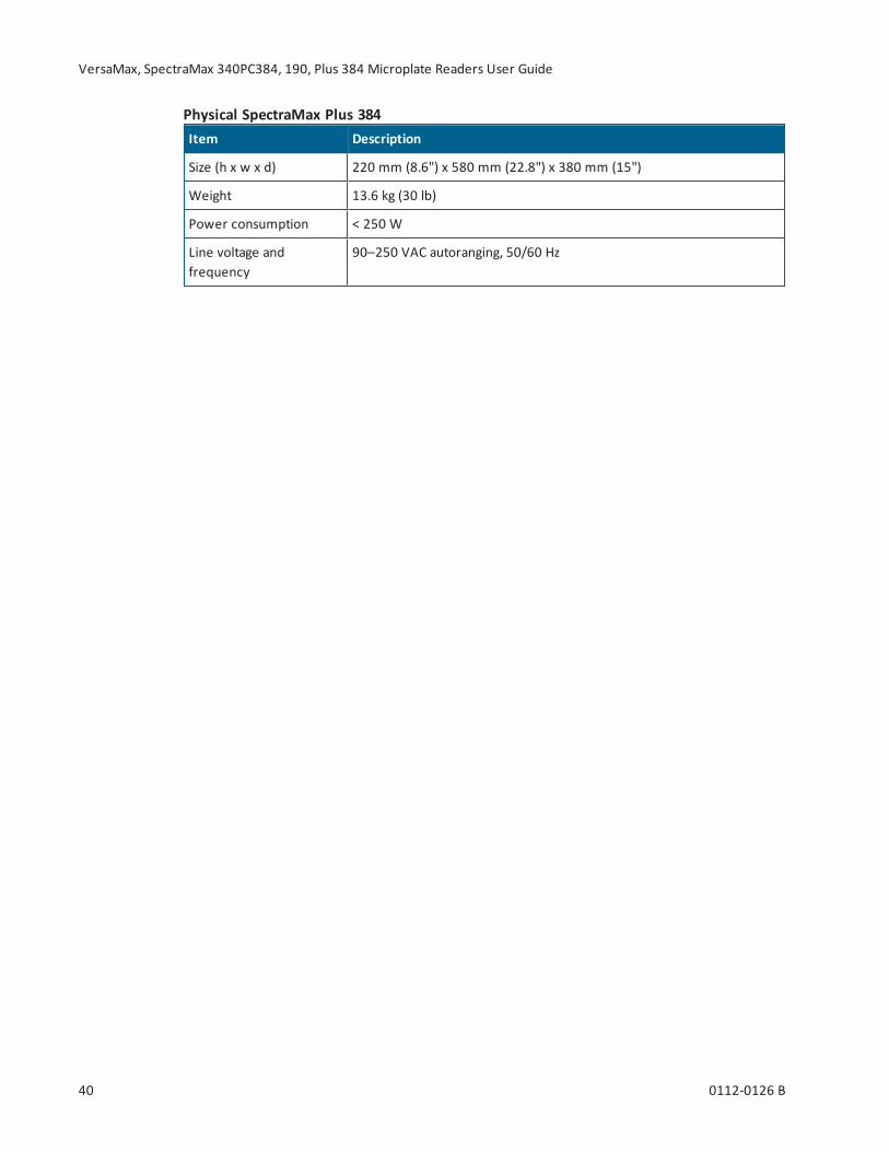
Item Description
Size (h x w x d) 220 mm (8.6") x 580 mm (22.8") x 380 mm (15")
Weight 13.6 kg (30 lb)
Power consumption < 250 W
Line voltage andfrequency
90–250 VAC autoranging, 50/60 Hz
Physical SpectraMax Plus 384
Appendix A: Instrument Specifications
0112-0126 B 41
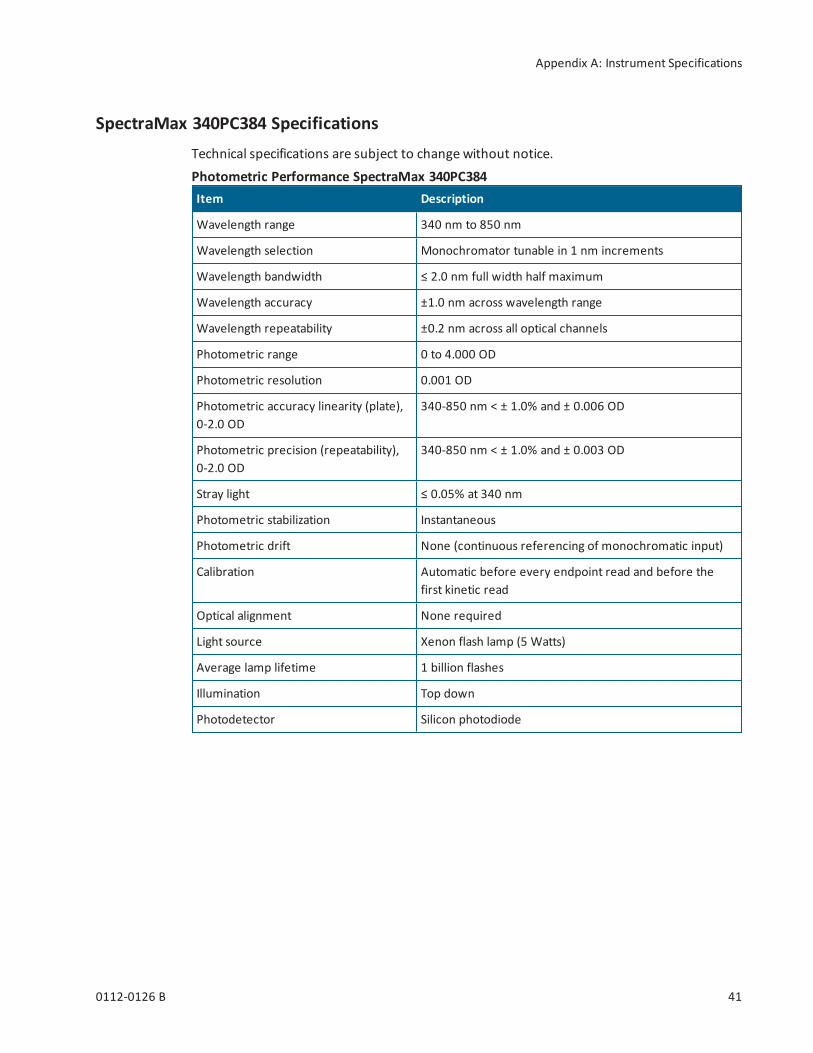
SpectraMax 340PC384 SpecificationsTechnical specifications are subject to change without notice.
Item Description
Wavelength range 340 nm to 850 nm
Wavelength selection Monochromator tunable in 1 nm increments
Wavelength bandwidth ≤ 2.0 nm full width half maximum
Wavelength accuracy ±1.0 nm across wavelength range
Wavelength repeatability ±0.2 nm across all optical channels
Photometric range 0 to 4.000 OD
Photometric resolution 0.001 OD
Photometric accuracy linearity (plate),0-2.0 OD
340-850 nm < ± 1.0% and ± 0.006 OD
Photometric precision (repeatability),0-2.0 OD
340-850 nm < ± 1.0% and ± 0.003 OD
Stray light ≤ 0.05% at 340 nm
Photometric stabilization Instantaneous
Photometric drift None (continuous referencing of monochromatic input)
Calibration Automatic before every endpoint read and before thefirst kinetic read
Optical alignment None required
Light source Xenon flash lamp (5 Watts)
Average lamp lifetime 1 billion flashes
Illumination Top down
Photodetector Silicon photodiode
Photometric Performance SpectraMax 340PC384

VersaMax, SpectraMax 340PC384, 190, Plus 384 Microplate Readers User Guide
42 0112-0126 B
Item Description
Standalone Single wavelength Absorbance or %Transmittance read of the plate
SoftMax ProSoftware
Express data as Absorbance or %TransmittanceSingle wavelength read of plateMultiple wavelength (up to six) read of plateKinetic read type and kinetic graphics of plateSpectrum read type (340–850 nm) of plate
Photometric Analysis Modes SpectraMax 340PC384
Item 96-wells 384-wells
Endpoint standard read 9 seconds single wavelength19 seconds dual wavelength 425 & 650nm
29 seconds single wavelength59 seconds dual wavelength425 & 650 nm
Kinetic read intervals 9 seconds minimum interval betweenreads single wavelength1 column, 2-second minimum intervalbetween readsSingle wavelength
29 seconds minimum intervalbetween readssingle wavelength
Measurement Time (calibration off) SpectraMax 340PC384
Item Description
Plate: normal scan 33*K nm/min (8-well strip)21*K nm/min (16-well strip)
Plate: speed scan 135*K nm/min (8-well strip)77*K nm/min (16-well strip)
Scan Speed (*K = wavelength interval) SpectraMax 340PC384

Appendix A: Instrument Specifications
0112-0126 B 43
Item Description
Read chamber Isothermal when temperature regulation is not enabled
Range 4°C above ambient to 45°C when temperature regulation enabled.The ambient temperature must be >20°C to achieve temperatureregulation at 45°C.
Resolution ± 0.1°C
Accuracy ± 1.0°C for plate chamber
Temperature uniformityat equilibrium
± 0.5°C at 37°C
Chamber warm-up time 15–30 minutes (measured on air) after initiation of temperatureregulation
Temperature regulation 4 sensors
Drift ± 0.2°C (regulated)
Temperature regulationdiagnostics
Temperature regulation system is continuously monitored and updated
Evaporation Plate lid required to minimize evaporative cooling
Recommended plate Flat-bottom plates with isolated wells and lid
Temperature Regulation SpectraMax 340PC384
Item Description
Shake modes Selectable: off, once prior to any read, and once prior to and betweenkinetic reads
Shake duration Selectable: 1 to 999 seconds (three-second default)
Shake SpectraMax 340PC384
Item Description
Plates Standard and half-area 96-well flat-bottomed plates (0.3 mL). 384-wellflat bottomed plates. Polystyrene plates for wavelengths above 340 nm;UV transparent plates above 220 nm; quartz plates above 190 nm.
Compatibility SpectraMax 340PC384

VersaMax, SpectraMax 340PC384, 190, Plus 384 Microplate Readers User Guide
44 0112-0126 B
Item Description
Display 2-x-20-character back lit LCD
Control panel 8-key membrane keypad
Self-diagnosis Continuous on-board diagnostics
Spill control Drawer mechanism and read chamber assembly protected fromaccidental spillage by drainage ports
Computer interface USB cable
Printer interface Parallel 25-pin to Centronics (double shielding required)
Supported plates All 96-well and strip-well plates, including lids
General Instrument SpectraMax 340PC384
Item Description
Operating temperature 5°C to 40°C
Operating altitude < 2000 m
Installation category II
Pollution Degree 2
Operating humidity < 80%
Storage temperature -20°C to 65°C
Environmental (for indoor use only) SpectraMax 340PC384
Item Description
Size (h x w x d) 220 mm (8.6") x 580 mm (22.8") x 380 mm (15")
Weight 13.6 kg (30 lb)
Power consumption < 250 W
Line voltage andfrequency
90–250 VAC autoranging, 50/60 Hz
Physical SpectraMax 340PC384

Appendix A: Instrument Specifications
0112-0126 B 45
SpectraMax 190 SpecificationsTechnical specifications are subject to change without notice.
Item Description
Wavelength range 190 nm to 850 nm
Wavelength selection Monochromator tunable in 1 nm increments
Wavelength bandwidth ≤ 2.0 nm full width half maximum
Wavelength accuracy ±1.0 nm across wavelength range
Wavelength repeatability ±0.2 nm across all optical channels
Photometric range 0 to 4.000 OD
Photometric resolution 0.001 OD
Photometric accuracy linearity (plate),0-2.0 OD
190-850 nm < ± 1.0% and ± 0.006 OD
Photometric precision (repeatability),0-2.0 OD
190-850 nm < ± 1.0% and ± 0.003 OD
Stray light ≤ 0.05% at 340 nm
Photometric stabilization Instantaneous
Photometric drift None (continuous referencing of monochromatic input)
Calibration Automatic before every endpoint read and before thefirst kinetic read
Optical alignment None required
Light source Xenon flash lamp (5 Watts)
Average lamp lifetime 1 billion flashes
Illumination Top down
Photodetector Silicon photodiode
Photometric Performance SpectraMax 190
Item Description
Standalone Single wavelength Absorbance read of the plate
SoftMax ProSoftware
Express data as Absorbance or %TransmittanceSingle wavelength read of plateMultiple wavelength (up to six) read of plateKinetic read type and kinetic graphics of plateSpectrum read type (190–850 nm) of plate
Photometric Analysis Modes SpectraMax 190
VersaMax, SpectraMax 340PC384, 190, Plus 384 Microplate Readers User Guide
46 0112-0126 B
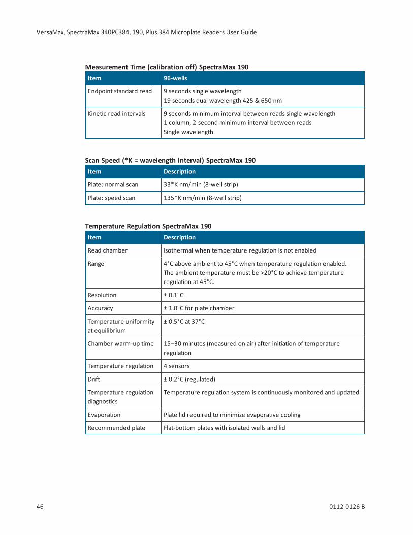
Item 96-wells
Endpoint standard read 9 seconds single wavelength19 seconds dual wavelength 425 & 650 nm
Kinetic read intervals 9 seconds minimum interval between reads single wavelength1 column, 2-second minimum interval between readsSingle wavelength
Measurement Time (calibration off) SpectraMax 190
Item Description
Plate: normal scan 33*K nm/min (8-well strip)
Plate: speed scan 135*K nm/min (8-well strip)
Scan Speed (*K = wavelength interval) SpectraMax 190
Item Description
Read chamber Isothermal when temperature regulation is not enabled
Range 4°C above ambient to 45°C when temperature regulation enabled.The ambient temperature must be >20°C to achieve temperatureregulation at 45°C.
Resolution ± 0.1°C
Accuracy ± 1.0°C for plate chamber
Temperature uniformityat equilibrium
± 0.5°C at 37°C
Chamber warm-up time 15–30 minutes (measured on air) after initiation of temperatureregulation
Temperature regulation 4 sensors
Drift ± 0.2°C (regulated)
Temperature regulationdiagnostics
Temperature regulation system is continuously monitored and updated
Evaporation Plate lid required to minimize evaporative cooling
Recommended plate Flat-bottom plates with isolated wells and lid
Temperature Regulation SpectraMax 190
Appendix A: Instrument Specifications
0112-0126 B 47
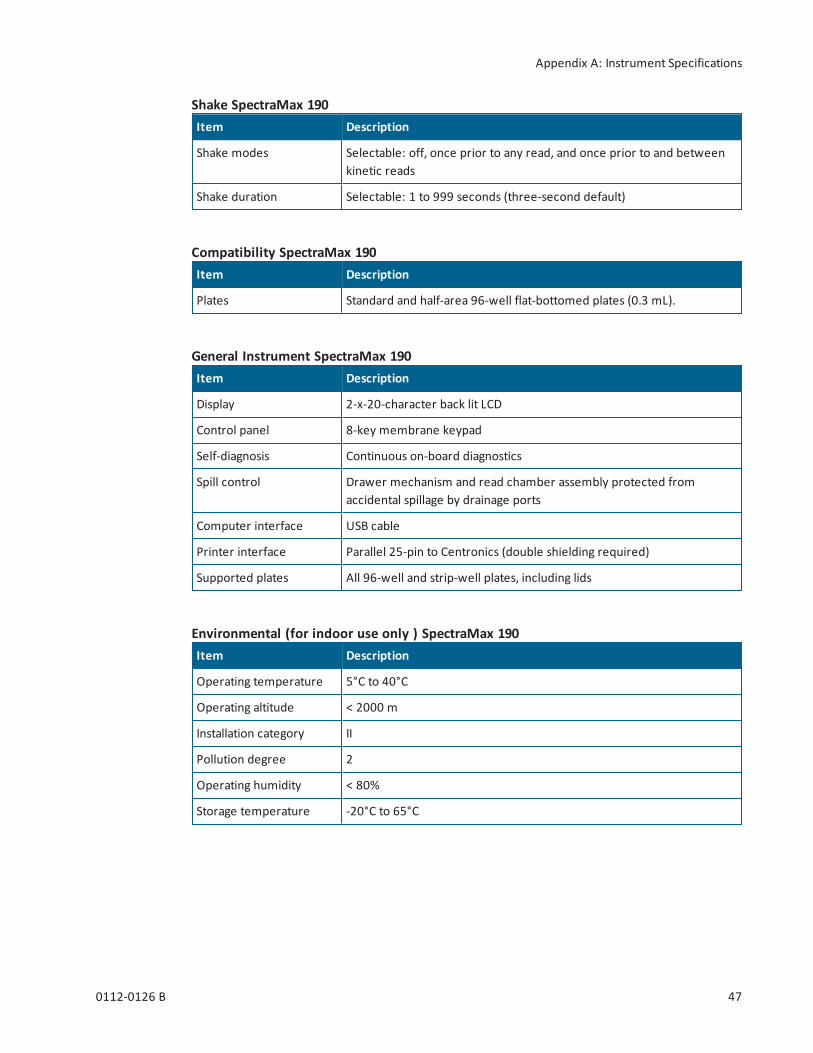
Item Description
Shake modes Selectable: off, once prior to any read, and once prior to and betweenkinetic reads
Shake duration Selectable: 1 to 999 seconds (three-second default)
Shake SpectraMax 190
Item Description
Plates Standard and half-area 96-well flat-bottomed plates (0.3 mL).
Compatibility SpectraMax 190
Item Description
Display 2-x-20-character back lit LCD
Control panel 8-key membrane keypad
Self-diagnosis Continuous on-board diagnostics
Spill control Drawer mechanism and read chamber assembly protected fromaccidental spillage by drainage ports
Computer interface USB cable
Printer interface Parallel 25-pin to Centronics (double shielding required)
Supported plates All 96-well and strip-well plates, including lids
General Instrument SpectraMax 190
Item Description
Operating temperature 5°C to 40°C
Operating altitude < 2000 m
Installation category II
Pollution degree 2
Operating humidity < 80%
Storage temperature -20°C to 65°C
Environmental (for indoor use only ) SpectraMax 190

VersaMax, SpectraMax 340PC384, 190, Plus 384 Microplate Readers User Guide
48 0112-0126 B
Item Description
Size (h x w x d) 220 mm (8.6") x 580 mm (22.8") x 380 mm (15")
Weight 13.6 kg (30 lb)
Power consumption < 250 W
Line voltage andfrequency
90–250 VAC autoranging, 50/60 Hz
Physical SpectraMax 190

Appendix A: Instrument Specifications
0112-0126 B 49
VersaMax SpecificationsTechnical specifications are subject to change without notice.
Item Description
Wavelength range 340 nm to 850 nm
Wavelength selection Monochromator tunable in 1 nm increments
Wavelength bandwidth ≤ 2.0 nm full width half maximum
Wavelength accuracy ±1.0 nm across wavelength range
Wavelength repeatability ±0.2 nm across all optical channels
Photometric range 0 to 4.000 OD
Photometric resolution 0.001 OD
Photometric accuracy linearity (plate),0-2.0 OD
340-850 nm < ± 1.0% and ± 0.006 OD
Photometric precision (repeatability),0-2.0 OD
340-850 nm < ± 1.0% and ± 0.003 OD
Stray light ≤ 0.05% at 340 nm
Photometric stabilization Instantaneous
Photometric drift None (continuous referencing of monochromatic input)
Calibration Automatic before every endpoint read and before thefirst kinetic read
Optical alignment None required
Light source Xenon flash lamp (5 Watts)
Average lamp lifetime 1 billion flashes
Illumination Top down
Photodetector Silicon photodiode
Photometric Performance VersaMax
Item Description
SoftMax ProSoftware
Express data as Absorbance or %TransmittanceSingle wavelength read of plateDual wavelength read of plateKinetic read type and kinetic graphics of plate
Photometric Analysis Modes VersaMax

VersaMax, SpectraMax 340PC384, 190, Plus 384 Microplate Readers User Guide
50 0112-0126 B
Item 96-wells
Endpoint standard read 9 seconds single wavelength19 seconds dual wavelength 425 & 650 nm
Kinetic read intervals 9 seconds minimum interval between reads single wavelength1 column, 2-second minimum interval between readsSingle wavelength
Measurement Time (calibration off) VersaMax
Item Description
Read chamber Isothermal when temperature regulation is not enabled
Range 4°C above ambient to 45°C when temperature regulation enabled.The ambient temperature must be >20°C to achieve temperatureregulation at 45°C.
Resolution ± 0.1°C
Accuracy ± 1.0°C for plate chamber
Temperature uniformityat equilibrium
± 0.5°C at 37°C
Chamber warm-up time 15–30 minutes (measured on air) after initiation of temperatureregulation
Temperature regulation 4 sensors
Drift ± 0.2°C (regulated)
Temperature regulationdiagnostics
Temperature regulation system is continuously monitored and updated
Evaporation Plate lid required to minimize evaporative cooling
Recommended plate Flat-bottom plates with isolated wells and lid
Temperature Regulation VersaMax
Item Description
Shake modes Selectable: off, once prior to any read, and once prior to and betweenkinetic reads
Shake duration Selectable: 1 to 999 seconds (three-second default)
Shake VersaMax
Item Description
Plates Standard and half-area 96-well flat-bottomed plates (0.3 mL).
Compatibility VersaMax

Appendix A: Instrument Specifications
0112-0126 B 51
Item Description
Display 2-x-20-character back lit LCD
Control panel 8-key membrane keypad
Self-diagnosis Continuous on-board diagnostics
Spill control Drawer mechanism and read chamber assembly protected fromaccidental spillage by drainage ports
Computer interface USB cable
Printer interface Parallel 25-pin to Centronics (double shielding required)
Supported plates All 96-well and strip-well plates, including lids
General Instrument VersaMax
Item Description
Operating temperature 5°C to 40°C
Operating altitude < 2000 m
Installation category II
Pollution degree 2
Operating humidity < 80%
Storage temperature -20°C to 65°C
Environmental VersaMax (for indoor use only)
Item Description
Size (h x w x d) 220 mm (8.6") x 580 mm (22.8") x 380 mm (15")
Weight 13.6 kg (30 lb)
Power consumption < 250 W
Line voltage andfrequency
90–250 VAC autoranging, 50/60 Hz
Physical VersaMax
VersaMax, SpectraMax 340PC384, 190, Plus 384 Microplate Readers User Guide
52 0112-0126 B
Electromagnetic Compatibility
Regulatory for Canada (ICES/NMB-001:2006)This ISM device complies with Canadian ICES-001.Cet appareil ISM est confomre à la norme NMB-001 du Canada.
ISM Equipment Classification (Group 1, Class A)This equipment is designated as scientific equipment for laboratory use that intentionallygenerate and/or use conductively coupled radio-frequency energy for internal functioning,and are suitable for use in all establishments, other than domestic and those directlyconnected to a low voltage power supply network which supply buildings used for domesticpurposes.
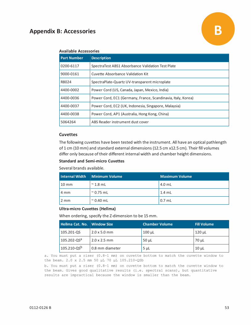
0112-0126 B 53
Appendix B: Accessories
Part Number Description
0200-6117 SpectraTest ABS1 Absorbance Validation Test Plate
9000-0161 Cuvette Absorbance Validation Kit
R8024 SpectraPlate-Quartz UV-transparent microplate
4400-0002 Power Cord (US, Canada, Japan, Mexico, India)
4400-0036 Power Cord, EC1 (Germany, France, Scandinavia, Italy, Korea)
4400-0037 Power Cord, EC2 (UK, Indonesia, Singapore, Malaysia)
4400-0038 Power Cord, AP1 (Australia, Hong Kong, China)
5064264 ABS Reader instrument dust cover
Available Accessories
CuvettesThe following cuvettes have been tested with the instrument. All have an optical pathlengthof 1 cm (10mm) and standard external dimensions (12.5 cm x12.5 cm). Their fill volumesdiffer only because of their different internal width and chamber height dimensions.Standard and Semi-micro CuvettesSeveral brands available.
Internal Width Minimum Volume Maximum Volume
10 mm ~ 1.8 mL 4.0 mL
4 mm ~ 0.75 mL 1.4 mL
2 mm ~ 0.40 mL 0.7 mL
Ultra-micro Cuvettes (Hellma)When ordering, specify the Z-dimension to be 15mm.
Hellma Cat. No. Window Size Chamber Volume Fill Volume
105.201-QS 2.0 x 5.0 mm 100 μL 120 μL
105.202-QSa 2.0 x 2.5 mm 50 μL 70 μL
105.210-QSb 0.8 mm diameter 5 μL 10 μL
a. You must put a riser (0.8–1 mm) on cuvette bottom to match the cuvette window tothe beam. 2.0 x 2.5 mm 50 μL 70 μL 105.210-QSb
b. You must put a riser (0.8–1 mm) on cuvette bottom to match the cuvette window tothe beam. Gives good qualitative results (i.e. spectral scans), but quantitativeresults are impractical because the window is smaller than the beam.
B

VersaMax, SpectraMax 340PC384, 190, Plus 384 Microplate Readers User Guide
54 0112-0126 B
Standard, Semi-micro, and Microcuvettes (Hellma)
Item Standard Semi-Micro Micro
Hellma Cat. No. 100 104 105.004 104.002 108.002 105
InternalDimensions
10 x 10 4 x 10 4 x 10 2 x 10 2 x 10 2 x 10
Fill Volume 4 mL 1.4 mL 600 μL 700 μL 500 μL 300 μL
Ultra-Micro Cuvettes (Hellma)
Hellma Cat. No. 105.200 105.201 105.202 105.210
OpticalPathlength
10 mm 10 mm 10 mm 10 mm
Fill Volume 180 μL 120 μL 70 μL 10 μL

www.moleculardevices.com
The trademarks used herein are the property of Molecular Devices, LLC or their respective owners.Specifications subject to change without notice. Patents: www.moleculardevices.com/productpatentsFOR RESEARCH USE ONLY. NOT FOR USE IN DIAGNOSTIC PROCEDURES
©2018 Molecular Devices, LLC.All rights reserved.0112-0126 B