Specification of Building Works - IIS Windows Server
19
-
Upload
khangminh22 -
Category
Documents
-
view
2 -
download
0
Transcript of Specification of Building Works - IIS Windows Server


BUILDING NOMINATION
BUILDING TYPE
SINGLE DWELLING
DUAL OCCUPANCY
MEDIUM DENSITY UNITS
FARM SHEDCONSTRUCTION
CAVITY BRICK
BRICK VENEER
SINGLE BRICK
□ VILLA OR TOWNHOUSE □
□ GARAGE □
□ RETAIL BUILDING □
□ □
□ TIMBER FRAMEDizf
STEEL FRAMED □
□ STEEL CLAD □
INDUSTRIAL BUILDING
OFFICE BUILDING
ADDITION
A. A.C.BLOCK/PANEL
MASONRY BLOCK
CONCRETE PANEL
*
THE ERECTION AND COMPLETION OF BUILDING AT:(State land identification).................................. .............. ............................................... ,...................................................................ADDRESS:............... .................. ................................. 7?.^^*. .>................................... .............. ....... ‘........................................................................
TOWN/AREA:............ .................................................................................................................. '............................!.....................................................
MUNICIPALITY / SHIRE / CITY:..............2...........................................................................................POST CODE.3z&^3zT...........
FOR:...................tTY^-fr... cV .......frY... .(rrYYYY.^•tYYtT....................... Hereinafter called the Proprietor or Owner.
The builder must ensure that relative drawings, plans and construction comply with the prescribed construction, the Local Government Act, the National Construction Code and that the work and services performed by the Builder are to the satisfaction of the Proprietor and Lending Authorities.INSPECTION NOTICEThis is to apply only if inspections are required by the Lending Authority. The building is to be inspected by the Society or Bank Representative at the following stages of construction and the Builder is to give the Lending Authority and Owner at least (2) clear working days notice that inspections are required.
1. When trenches for footings have been prepared or rock surfaces scabbled and in the case of reinforced concrete footings, when reinforcement and depth pegs have been placed in position just prior to placing of concrete. Footings must not be commenced until the trenches have been inspected and approved by the Society Representative.
2. On completion of floor, wall and roof framing with noggins in position and veneer walling, but before flooring is cut down, roof covering is laid and wall linings and sheetings are secured.
3. When the internal wall coverings have been secured and fixing out commenced apron mouldings must not be fixed until flashings have been inspected and approved.
4. ON COMPLETION OF BUILDING. The owner is cautioned that if works have advanced beyond these stages without the requisite notices being given, inspections made and unsatisfactory conditions are discovered later, the offer of a loan or the terms and conditions of a loan may be varied by the lending authority.
REGULATIONS AND NOTICES: The builder is to comply with the National Construction Code as amended and as applicable to the particular State or Territory in which the building is being constructed and the requirements of legally constituted Authorities for local Government and/or Services. The Builder is to give all notices, obtain all permits and pay all fees required by such Authorities. Where materials, components, design factors and construction methods comply with the Performance Requirements of the National Construction Code these may be accepted by approval authorities as an alternative as per the Deemed to Satisfy Provisions.
INSURANCE: Insurance of the works against fire will be effected as nominated in the Building Contract. The Builder shall at his own expense adequately insure against Public Risk and arrange indemnification in respect of his liability under the Workers' Compensation Act, Work Cover and other regulations as applicable.
WORK, HEALTH fit SAFETY: Workplaces: Regulations of the Work Health & Safety Act as applicable in the State in which the building work is to proceed are to be complied with. Under the Act if a structure is to be used as, or at a workplace it must be designed to be without risk to health and safety by including testing and analysis, addressing the suitability of the design for the ultimate use of the structure as well as materials, method of construction, maintenance and future demolition. The builder is to comply with the regulations of the Work Health and Safety Act 2011 for all construction on site. If the structure will'be used as or at a workplace, a Safety Report is to accompany plans and specifications and be distributed to the Builder, Certifier or Council and the Client.
VISIT THE SITE: Builders tendering are to visit the site and satisfy themselves as to the nature and extent of the work, the facilities available and any difficulties entailed in the execution of the said works. No amount above the accepted price will be allowed because of work arising due to neglect of this precaution, or assumptions made.
FLOOD HAZARD AREAS: NCC Vol. 1 part B 1.4 or Vol. 2 part 3.10.3: Where a building is to be erected in a Rood Hazard Area defined by an Appropriate Authority; the floor level of a non-habitable room shall not be greater than 1m below the height of the Flood Hazard Level for that area. Freeboard height of the Flood Hazard Level must be established and the Habitable Floor level of the bunding must be constructed above the Flood Hazard Level. See fig. 1.1.5 of NCC Vol. 2, 2013. An acceptable construction manual for buildings in a Flood Hazard Area is the ‘ABCB Standard for Construction of Buildings in Flood Hazard Areas'.
LABOUR AND MATERIALS: The Builder is to provide all materials, labour, fittings arid plant required to construct and complete the work. Materials shall be of the standard specified and workmanship in each trade shall be performed by tradesmen of that particular trade and in conformity with current good building practice.
SET OUT: The Builder shall be responsible for the accuracy and clear delineation of the site boundaries and location of the buildings there on. The Builder is to set out and maintain the works in accordance with the drawings. Figured dimensions are to be taken in preference to scale.
PLANS AND SPECIFICATIONS: Any work indicated on the plans and not in the specification or vice versa, and any item not shown on either plans or specifications but which is obviously necessary as part of proper construction ana/or finish, is to be considered as so shown or specified and is to be duly done as part of the contract. Any variations to plans or specifications are to be agreed and recorded by the proprietor and the builder/contractor.
ADDITIONAL BUILDING REQUIREMENTS: All instructions for extra work or additional requirements must be in writing. Dated and signed copies of instructions shall be retained by both the owner and the builder.
PLANS ON JOB: The builder must at all times maintain on the job a legible copy of the plans and specifications, bearing the approval of the Municipal Authority concerned or Principal Certifying Authority.
NCC: Where NCC is referenced in this specification then that nomination refers to the National Construction Code BCA Vol.1 and Vol.2 or RCA Vol. 3
STANDARDS: Where an Australian Standard (AS) or Australian New Zealand Standard (AS/NZS) is nominated in this specification then that nomination refers to the latest revision of that Standard unless the National construction Code references a different revision.
EARTHWORKS AND EXCAVATIONS: All earthworks shall be designed and constructed in accordance with the drawings and guidelines of AS3798 . Stormwater and other surface water drainage by underground piping or surface diversions shall be in accordance with AS/NZS3500.All siteworks shall be in accordance with the Environmental Planning ana Assessment Act and Regulations for site works for the erection of a building, safeguarding excavations, backfilling, preventing soil movement and supporting neighbouring buildings. Drainage requirements must be determined according to the soil classifications of NCC Vol. 2 part 3.1.1 and part 3.1.2.
FOOTINGS AND PIERS: Excavate for all footings, piers, etc. to dimensions and minimum depth shown on plans or otherwise specified, or to depths necessary to secure solid bottoms and even bearing throughout similar strata. Bottoms of excavations to be level and stepped where necessary to follow ground slopes and achieve solid bottoms on foundation acceptable.. Grade, fill and ram where necessary to receive concrete floors where shown on ground level.At completion of footings, all excavations to be filled, well rammed to ground level and surplus soil spread as directed. All seepage and soakage water to be effectively dealt with and diverted clear of the building. Excavate for and lay agricultural drains to back of walls retaining earth and to any other sections of foundations as may be necessary and/or directed.
ROCK EXCAVATIONS: Should rock of any type be encountered in excavation of the works, unless its existence is known and allowed for, the cost of its removal is to be considered as an extra to the contract and charged for at a rate per cubic metre as indicated in the schedule of rates. The Proprietor is to be notified when any rock is encountered in excavations.
1
CONCRETE; NCC Vol. 'I part B1.4 or Vol. 2 part 3.2,3 All structural concrete shall be mixed and in compliance with AS3600, and unless, otherwise specified on Engineers drawings, shall be of N20 grade. _The concrete shall be supplied by an approved firm and delivery dockets shall be kept on the job for inspection by the proprietor if he. so desires. The concrete for minor works, where strength of concrete is not critical, such as paving on solid groun.d, may have a minimum compressive strength of -15.MPA it unreinforced and 20 MPA if reinforced. Alternatively, such concrete may be mixed on site Where the aggregate proportions and water/cement ratio can be controlled so that the required compressive strengths can be obtained.All concrete work shall comply with the AS3600. Maximum slump shall be 80mm unless otherwise specified by Engineer.Concrete shall be carefully handled and placed to avoid segregation and shall be adequately compacted. Reinforcing mesh fabric to AS/NZS467 and all reinforcing bars mild steel grade unless otherwise specified.
FOOTINGS: NCC Vol. 2 parts 3.2.3, 3.2.4 and 3.2.5 Where sites have soils or foundations of reactive nature or problem sites footings shall be approved by a practising structural engineer and in the case of known highly swelling soils or other unstable soils special precautions may have to be taken in the design and construction or concrete footings. In the case of concrete suspended floors to first floor it will be necessary for size of footings to be specified by a practising structural engineer. Footing sizes to be as per AS2870 or designed by an engineer.
TERMITE MANAGEMENT SYSTEM: NCC Vol. 2 part 3.1.3 or Vol.1 part B 1.4 (i) Where the building is being erected in a prescribed termite area and protection is required by regulation of local government or state authority then protection against subterranean termites shall be installed in accordance with AS 3660. Details of method of protection to be used shall be submitted where required, prior to commencement of building works. Written certification, signed by the installer, that the method used and the manufacturers specification complies with the Australian Standard shall be provided to the relevant authority and owner where required. A durable notice must be permanently fixed in a prominent location in the building prior to its occupation indicating: 1. The method and date of installation of the system and the need to inspect and maintain the system on a regular basis. 2. Where a chemical barrier is used, the life expectancy as listed on the National Registration Authority label and recommended date of renewal. Note that AS3660 and NCC lists the minimum acceptable level of protection only. Owners and/or builders may specify and install additional protection if desired
PATHS: (see AS 3727 for guide to residential pavement construction). Provide paths as indicated on plans. Concrete to be as previously specified and surfaced with wooden float. Car tracks to be a minimum of 100mm thick and paths a minimum of 75mm. Provide expansion joints in paths at a maximum spacing of 1200mm with bitumen impregnated felt joining strips the full thickness of concrete with tooled v-joints above same.
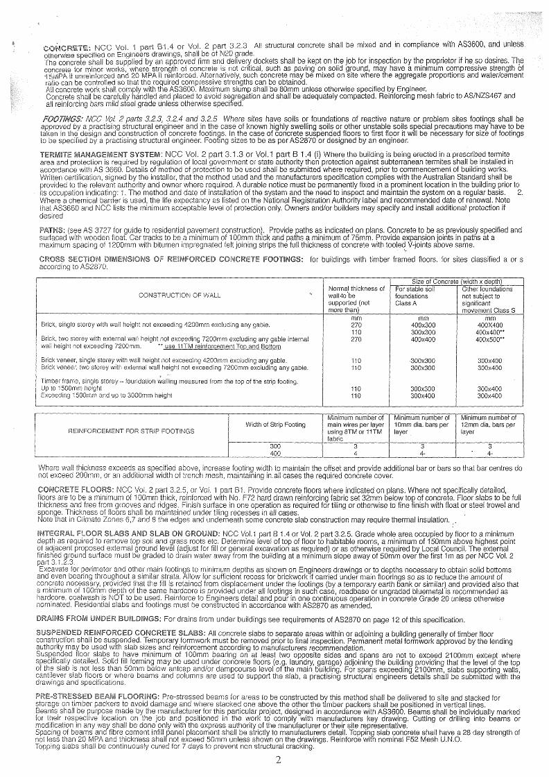
CROSS SECTION DIMENSIONS OF REINFORCED CONCRETE FOOTINGS: for buildings with timber framed floors, for sites classified a or s according to AS2870.
Size of Concrete (width x depth)
CONSTRUCTION OF WALLNormal thickness of wall'to’be supported (not more than)
For stable soil foundationsGlass A
Other foundations not subject to significant movement Class S
mm mm mmBrick, single storey with wall height not exceeding 4200mm excluding any gable. 270 400x300 400X400
110 300x300 400x400“Brick, two storey with external wall height not exceeding 7200mm excluding any gable internal wall height not exceeding 7200mm. “ use 11TM reinforcement Tod and Bottom
270 400x400 400x500“
Brick veneer, single storey with wall height not exceeding 4200mm excluding any gable. 110 300x300 300x400Brick veneer, two storey with external wall height not exceeding 7200mm excluding any gable. 110 300x300 300x400
Timber frame, single storey - foundation walling measured from the top of the strip footing.Up to 1500mm height 110 300x300 300x400Exceeding 1500mm and up to 3000mm height 110 300x400 300x400
Minimum number of Minimum number of Minimum numbef ofWidth of Strip Footing main wires per layer 10mm dia. bars per 12mm dia. bars per
REINFORCEMENT FOR STRIP FOOTINGS using 8TM or 11TM fabric
layer layer
300 3 3 3400 4 4- 4-
Where wall thickness exceeds as specified above, increase footing width to maintain the offset and provide additional bar or bars so that bar centres do not exceed 200mm, or an additional width of trench mesh, maintaining in.all cases the required concrete cover.
CONCRETE FLOORS: NCC Vol. 2 part 3.2.5, or Vol. 1 part B1. Provide concrete floors where indicated on plans. Where not specifically detailed, floors are to be a minimum of 100mm thick, reinforced with No. F72 hard drawn reinforcing fabric set 32mm below top of concrete. Floor slabs to be full thickness and free from grooves and ridges. Finish surface in one operation as required for tiling or otherwise to fine finish with float or steel trowel and sponge. Thickness of floors shall be maintained under tiling recesses in ail cases.Note that in Climate Zones 6,7 and 8 the edges and underneath some concrete slab construction may require thermal insulation.
INTEGRAL FLOOR SLABS AND SLAB ON GROUND: NCC Vol. 1 part B 1.4 or Vol. 2 part 3.2.5. Grade whole area occupied by floor to a minimum depth as required to remove top soil and grass roots etc. Determine level of top of floor to habitable rooms, a minimum of 150mm above highest point of adjacent proposed external ground level (adjust for fill or general excavation as required) or as otherwise required by Local Council. The external finished ground surface must be graded to drain water away from the building at a minimum slope away of 50mm over the first 1m as per NCC Vol. 2 part 3.1.2.3.Excavate for perimeter and other main footings to minimum depths as shown on Engineers drawings or to depths necessary to obtain solid bottoms
and even bearing throughout a similar strata. Allow for sufficient recess for brickwork if carried under main floorings so as to reduce the amount of concrete necessary, provided that the fill is retained from displacement under the footings (by a temporary earth bank or similar) and provided also that a minimum of 100mm depth of the same hardcore is provided under all footings in such case, roadbase or ungraded bluemetal is recommended as hardcore, coalwashis NOT to be used. Reinforce to Engineers detail and pour in one continuous operation in concrete Grade 20 unless otherwise nominated. Residential slabs and footings must be constructed in accordance with AS2870 as amended.
DRAINS FROM UNDER BUILDINGS: For drains from under buildings see requirements of AS2870 on page 12 of this specification.
SUSPENDED REINFORCED CONCRETE SLABS: All concrete slabs to separate areas within or adjoining a building generally of timber floor construction shall be suspended. Temporary formwork must be removed prior to final inspection. Permanent metal formwork approved by the (ending authority may be used with slab sizes and reinforcement according to manufacturers recommendation.Suspended floor slabs to have minimum of 100mm bearing on at least two opposite sides and spans are not to exceed 2100mm except where specifically detailed. Solid fill forming may be used under concrete floors (e.g. laundry, garage) adjoining the building providing that the level of the top of the slab is not less than 50mm below antcap and/or dampcourse level of the main building. For spans exceeding 2100mm, slabs supporting walls, cantilever slab floors or where beams and columns are used to support the slab, a practising structural engineers details shall be submitted with the drawings and specifications.
PRE-STRESSED BEAM FLOORING: Pre-stressed beams for areas to be constructed by this method shall be delivered to site and stacked for storage on timber packers to avoid damage and where stacked one above the other the timber packers shall be positioned in vertical lines.Beams shall be purpose made by the manufacturer for this particular project, designed in accordance with AS3600. Beams shall be individually marked for their respective location on the job and positioned in the work to comply with manufacturers key drawing. Cutting or drilling into beams or modification in any way shall be done only with the express authority of the manufacturer or their site representative.Spacing of beams and fibre cement infill panel placement shall be strictly to manufacturers detail. Topping slab concrete shall have a 28 day strength of not less than 20 MPA and thickness shall not exceed 50mm unless shown on the drawings. Reinforce with nominal F52 Mesh U.N.O.Topping slabs shall be continuously cured for 7 days to prevent non structural cracking.
2

BRICK AND BIOCKW0RK:( Construction of masonry buildings shall be as per AS3700 or AS4773)
CLAY BRICKS : To be sound, hard, of well burnt clay and shale to comply with AS1225 ‘Burnt clay and shale building bricks'
SAND LIME BRICKS: To Comply with AS1654 ‘Calcium Silicate Bricks’ and have a transverse strength no less than as per Specification AS1640
CONCRETE BLOCKS OR BRICKS: To comply with AS4455 Masonry Building Blocks/Paver.
CEMENT MORTAR: To be one part fresh cement to 3 parts sand.
L1WIE MORTAR: To be one part lime to 3 parts sand. Lime to be well slaked before use.
COMPO MORTAR: To be one part cement, one part lime and 6 parts sand. All bricks to be well wetted before use. This not to apply to textured bricks. Footing courses to be grouted solid with cement mortar. Ail brickwork to be properly bonded, laid on full bed and all perpends filled. All piers are to be built solid and each course grouted as work proceeds. Beds and joints to be kept to a reasonable thickness. Finish all, exposed brickwork faces with neat joints as directed by Designer or Owner.
BUILD THE FOLLOWING IN CEMENT MORTAR: See AS3700 or AS4773. All brickwork to underside of floor bearers level. All 110mm thick brickwork, all copings, steps, brick balustrade walls, sills, piers, wing walls, retaining walls. Brick Fences on alignment and/or brickwork under timber fencing also concrete blocks or bricks. Build compo mortar: All other brickwork, including concrete masonry.
SLEEPER PIERS: 230 x 230mm up to 1.5 high, footings are to be two courses of 350mm work. Where pier height exceeds 1.5m up to a maximum of 2.4m footings are to be two courses of 470 work and lower portion of pier to be 350 x 350. Concrete footings must be 500mm square and 200mm thick for an effective supported floor area of not more than 20m2. All footings must have Engineers details for soil other than class A or S.
ENGAGED PIERS: To be minimum of 230 x 350 (including wall thickness) spaced at not more than 1.8m centres up to 2700 high to support floor bearers and at similar centres to stiffen walls supporting concrete slabs. All stack bonded piers to be anchored to walls with specified wall ties every fourth course. Areas with design wind speeds greater than N2 must be vertically reinforced with at least 1 off Y12 bar, tied to the footing.
VENEER WALLS: To be 110mm Brickwork built in Compo Mortar on foundation walls as previously specified. Internal faces to be 38mm minimum from timber frames. Build in wall ties opposite each alternate stud, four courses above level of bottom plate, then every fourth course and spaced not more than 460mm horizontally and 6i0mm vertically or 610mm horizontally and 460mm vertically, ties to be left open for attachment to studs. A cavity space of between 38mm and 50mm must be maintained throughout. Where thermal insulation is required to comply with Energy Efficiency requirements, clear cavity spaces must be maintained. Cavities and weep holes to be clean and clear at damp course level. All mortar droppings to be caught on paper or other material and removed before internal linings are fixed. Mortar joints on inside face of walls (cavity side) to be flush with brickwork.
SINGLE LEAF MASONRY: Garage walls etc. Footings as per NCC part 3.2.5 engaged piers and reinforcing to be as per part 3.3.1.
ACCESS: Adequate access in the external foundation wall must be provided with a weatherproof lockable door and crawl access is to be provided to all under floor areas.
VENTILATION: NCC Vol.1 pjrts F1 to 12 or Vol. 2 part 3.4.1 sub-floor areas shall be ventilated by means of evenly distributed openings with an unobstructed area of 6000mm per lineal metre of external wall as a minimum dependent on the relative humidity of the area. Where particle board flooring is used the unobstructed area shall be as recommended by the manufacturer. Ventilation of internal walls snail be a minimum of 22000mm 2/m run of wall. Vents to be immediately below bearers and similarly provide vents under verandah floors and suspended floor slabs. Sufficient cross ventilation to be provided through all walls below floors. No section of the under-floor area should be so constructed that is will hold pockets of still air. Appropriate special provision to be made where a gas bath heater is installed. Ventilation may be varied by Local Council.
BRICK REINFORCEMENT: In full brick cavity walls at two courses above level of the highest opening built into each 110mm thickness one continuous strand of 64 wide galvanised metai reinforcement lapped 100mm at joints and full width of layer at intersections.
ANT CAPS: To all brickwork and piers, at the level of underside of floorbearers, ant capping of 0.5mm gauge galvanised steel or other approved metal is to be set, projecting 38mm beyond the internal faces of all brickwork and turned down at a 45 degree angle, lapped 13mm and soldered or crimped at all joints and corners so as to provide a continuous and effective barrier against termites throughout the length of the material. Whole of house protection against subterranean termite attack shall be installed in accordance with AS 3660.
TIES: Wall ties complying with AS/NZS2699 shall be used for all tie requirements. Corrosion protection and installation of wall ties is to comply with AS3700 or AS4773.
STEPS: If shown on plan in bricks to match other exposed brickwork. To be built in solid work or where side walls are provided in consolidated filling. Treads are to be brick on edge, or pre cast concrete units with a maximum of 355mm going and a maximum of 190mm and minimum of 115mm rises.
LINTELS: Galvanised lintels (of steel not less than grade 300MPa as per AS/NZS 4100) to comply with spans as required are to have(I) long legs vertical (ii) each angle or flat to carry a maximum 110mm wall tnickness (iii) minimum bearing lengths shall be :- (a) clear spans up to 1 metre - 100mm min. (b) clear spans over 1 metre - 150mm min. (iv) there must be not less than 3 courses of brickwork over openings and (v) all loads must be uniformly distributed.
Note that corrosion protection for lintels and built in structural members must comply with requirements of AS3700 orAS4773.
FIREPLACE CHIMNEY and FLUES: NCC Vol. 2 part 3.2.5.5. and 3.7.3. Reinforced concrete footings 300mm wider all round than brick construction to be provided. Non combustible material to be used for upper surface of hearth with a minimum thickness of 155mm and shall extend not less than 300mm beyond the front of the fireplace opening and not (ess that 150mm beyond each side of the opening. Local council or structural engineer may vary this requirement. Mild steel bars or angles of suitable sizes and with a 110mm bearing at each end to support work over openings. Up to the level of 300mm above the underside of the arch or lintel, the back and sides of the fireplace to be constructed in two separate sections of solid masonry minimum 190mm thick not including cavity. Concrete masonry not permitted in construction of inner section, balance of walling to be minimum of 90mm thick. Flue to be rendered minimum 12mm thick. Mix; 1 cement, 2 lime, 10 sand or L.C. approved material. Chimney stack is to be not less than the height of the main roof ridge and is to be built in compo mortar. The chimney/flue of an appliance that burns timber, coal or solid fuel shall be provided with a damper or flap sealer. An 0.6mm galvanised steel tray, in one piece, holed for flue is to be set at level of one course above roof covering on the high side of the roof. The internal edges are to be shaped to form a quadrant gutter 25mm wide, sweated at comers. The tray is to project a minimum of 25mm beyond the external faces of brickwork turned up and/or down as required. Where-the tray is turned up, a clearance of at least 6mm is to be maintained between the brickwork and the tray. Provide weep holes by leaving open vertical joints in brickwork above tray. Rake joints in brickwork ready to receive flashing to be provided by Plumber. A loose brick must be left on the back of the chimney stack. This brick must not be set until after the tray/cavities have been cleared of all mortar droppings and inspected.
HEATING APPLIANCES: Heating appliances installed in brick or blockwork surrounds shall be in conformance with AS 2918 as applicable
DAMPCOURSE AND WEATHERPROOFING OF MASONRY: Provide a continuous run of L.C. Approved dampcourse material to full width of wall thickness^ on all brickwork at level not higher than bottom of floor bearers and engaged piers. Dampcourse material is to be run in long lengths, lapped minimum 100mm at joints and full width at all intersections. To wall surrounding concrete and/or solid floors an additional run of dampcourse is to be laid, one full course above floor level and stepped down to meet lower dampcourse where other walls abut walls of bathroom, shower recess or laundry. Damp proof courses and flashings shall be installed to give performance as specified in AS/NZS 2904.
VERMIN PROOFING: 13mm mesh galvanised bird wire to be built into brickwork and taken across cavity and secured to cavity face of inner wail at bottom plate level..
FLASHING: L.C. approved dampcourse material to be built in under all window sills 25mm at back of wood sill and 50mm at each end of same. Flashing to be bent down across cavity and built 25mm into veneer wall. L.C. approved dampcourse material to be built in over all exposed window and external door openings.
3

WEEP HOLES: Perpend joints are to be left open in exterior brick walls spaced approx. 600mm in course immediately over flashings of all exposed openings* and to brick retaining walls, fender walls etc. as required. See requirements of AS3959-2009 for protection of weep holes in bush fire areas.
RETAINING WALLS: Retaining walls not specifically detailed, and foundation walling required to retain earth, are to be a minimum of 230mm thick, up to a height of 750mm of retained earth. Cavity walls used to retain earth are to have the leaf adjacent to the retained earth a minimum of 230mm thick, to a maximum of 900mm of retained earth height. All to be properly bonded (see 'Bonded Walls') and provide with a properly constructed agricultural drain to the earth side of retaining wall. For walls in excess of the above heights of retained earth, an (Engineers detail will be required.
BONDED WALL: Solid brick walls more than one brick width, which are used to retain earth or are otherwise noted as 'Bonded Walls', shall be bonded throughout the thickness of the wall by either header bricks or equivalent tying. Where header bricks are used, every sixth course shall be a header course or there shall be at least one header or equivalent tie to every 0.13sq metres (every third course at 480mm centres). Walls 350mm or more in thickness shall have overlapping headers or ties to provide a continuous tie through the wall.
CAVITY WALLS: Walls indicated as cavity walls to be constructed with two leaves 110mm thick spaced nominally at 60mm apart. Where thermal insulation is required to comply with Energy Efficiency requirements clear cavity spaces must be maintained. Connect the two leaves with wall ties as per AS2699 set nominally 600mm apart in every fifth course.. Keep ties clean of mortar droppings and cavity clear as work proceeds.
STRAPS: To full brick cavity walls, secure door and window frames with 1.6mm galvanised iron straps set in brickwork. Straps to be 25mm wide and at least 300mm long, where practicable and spaced at a maximum of five courses apart. Set 25mm x 1.6mm galvanised iron straps 1800 apart and 1200mm down cavity with ends turned 75mm into brickwork to secure wall top plates.
COMPLETION: Clean all cavities. Wait upon and make good after other trades. Replace all damaged and defective bricks. Clean all exposed brickwork with diluted spirits of salts, or as otherwise recommended by brick manufacturers, wash down with clean water and leave free from cement and mortar stains.
CONCRETE BRICK Mortar - For normal conditions to consist of:Above Dampcourse: 1. part cement Below Dampcourse: 1. part cement
2. parts lime or lime putty 1. part lime or lime putty9. parts clean sand 6. parts clean sand
Mortar mixes must comply with A.S. 3700 or AS4773The substitution of other plasticisers for lime is not recommended. Under no circumstances should the proportion of cement be increased.
JOINTS: Finish all external brickwork and internal feature walls with joints as directed. Finish all other brickwork with neat struck joints.
JOINT REINFORCEMENT AND ARTICULATION JOINTS: In addition to reinforcement over openings as later specified provide joint reinforcement in bed joints at vertical spacings not exceeding 600mm. Control joints, providing a continuous vertical separation through the entire thickness of the waif, are to be provided where indicated on plans or where walls exceed 9m in length, as close as practical building will permit. Reinforcement not to extend across control joints.
AUTOCLAVED AERATED CONCRETE BLOCKS:Lightweight blockwork shall be Autoclaved Aerated Concrete blocks consisting of sand, cement and lime and shall be installed to areas as indicated on drawings. Site provisions for storage of materials and for the mixing of adhesive shall be as recommended by the manufacturer.
WORKMANSHIP: Fixings, fastenings, anchors, lugs and the like shall be of a type approved by the manufacturer and shall transmit the loads and stresses imposed and ensure the rigidity of the assembly. Block laying shall be in accordance with the manufacturers current published specifications.
TOLERANCES: Maximum planar misalignment is not to exceed 2mm along butt joints. The thickness and width of walls shall not vary by more than 5mm from design sizes. Deviation from plumb, level or dimensional angle must not exceed 5mm per 3.5m of length of member or 6mm in total run.
INSTALLATIONS: All lightweight blockwork shall be installed using thin bed adhesive mortar to all horizontals and perpends. The first course must be made true and level using a normal thick bed mortar with thin bed adhesive to fully seal the perpends. All thin bed adhesive shall be applied using a recommended notched trowel to obtain an even distribution of adhesive to achieve joint thickness of 2-3mm. All lightweight blockwork shall be laid in a format that a vertical joint of the lower course must be staggered at least 100mm relative to the vertical joint of the overlaying course. A slip/joint bond breaker must be installed between the first course and the footings or slab on all internal and external walls to allow for differential movement between the blocks and the supporting structure. Build in as necessary all flashings, reinforcements, arch bars, lintels, frames, straps, bolts, lugs, wall ties, metalwork, precast units, sills, joists and the like. Carefully set out and leave openings for other trades to eliminate cutting.
COMPLETION: On completion clean out all blocks, mortar, droppings, debris etc. and remove all scaffolding, make good all put-log holes and other blemishes and leave all work In perfect condition and protect until handover.
CONCRETE BLOCK and REINFORCED MASONRY: AS 3700 - or as an alternative AS4773All masonry units shall comply with AS1500 ‘Hollow Load Bearing Concrete Units’. Masonry shall be stacked on planks off the ground and in wet weather shall be covered with tarpaulins or otherwise kept dry. At the end of each days work the top of the wall shall be covered with tar paper, polyethylene sheets or by other means protected from becoming excessively wet. Masonry units shall not be dampened prior to laying, and shall be laicf in ary state.
MORTAR: Mortar shall comply with AS 3700 or AS4773. . Plasticisers may be used when approved and where tests show the mortar with plasticisers meets the requirements of these specifications.
CONSTRUCTION BEDDING: All face and end joints shall be fully filled with mortar and joints shall be squeezed tight. Slushing of mortar into joints shall not be permitted. The first course of blocks shall be laid in a full bed of mortar.
JOINTS: Joints on all exposed surfaces shall be as specified. The joint shall be formed by striking the mortar flush and after it has partially set, tooling with the proper shaped tool to adequately compact the surface. The tool shall be of sufficient length to form a straight line free from waves. Internal joints shall be ironed. Where flush joints are left exposed, they shall be first compacted, then repointed and excess mortar removed. Joints shall be 10mm thick unless otherwise specified or directed.
ARTICULATION JOINTS: Shall be located where shown and shall form a continuous vertical break from top to bottom of wall or from bond beam. Provision shall be made for adequate lateral stability. Joint shall be filled with mortar, raked back 16mm and pointed with a non-hardening plastic filler. Mo reinforcing shall be carried across control joint. Articulated joints over garage doors are prohibited unless brickwork is reinforced or lateral support is provided”.
JOINT REINFORCEMENT: Reinforce every 600mm in height and in the two courses immediately above and below window openings. Lap mesh at least 150mm at all joints and intersections except at articulation and expansion joints where a slip joint may be required.
BRACING DURING CONSTRUCTION: Masonry walls constructed in locations where they may be exposed to high winds during erection shall not be built higher than ten times their thickness unless adequately braced, or unless provision is made for prompt installation of permanent bracing such as intermediate floor or roof structure. Back filling shall not be placed against foundation walls or retaining walls before mortar or grouting has sufficiently hardened, or before wall has been permanently braced to withstand horizontal pressure.
WEATHERPROOFING: All concrete masonry walls exposed to the weather or below ground level shall be adequately water proofed, using an approved paint or other coating and applied in accordance with the directions of the manufacturer.
CLEANING: During the progress of the work every effort shall be made to keep walls that are exposed clean. Mortar smears shall be allowed to dry for a short period and then be removed by trowel or suitable brush or both. Care shall be taken to avoid damage to the mortar joint when brushing. Mortar burrs shall be promptly removed. At the conclusion of the work, walls shall be cleaned, all scaffolding ana debris removed and the wall left in a good clean condition.
4

BUSHFIRE PRONE AREAS NCC Vol.1 parts G 5.0, 5.1, 5.2. or NCC Vol. 2 part 3.7.4. Site assessment and preparation, construction of and maintenance of Class 1 buildings and decks and Class 10a buildings in a Bushfire Prone Area are required to comply with the provisions of AS3959 as applicable and BCA 3.7.4.
NSW VARIATIONS:Performance requirement is satisfied for-Class 1 buildings or Class 10 buildings and decks if constructed in accordance with the following:- To comply with AS3959 except for Section 9 'Construction for Bushfire Attack level FZ (BAL-FZ)'. Buildings subject to BAL-FZ must comply with Specific Conditions of Development Consent for construction at this level of fire threat.OR Consultation with NSW Rural Fire Service under Section 79BAof the Environmental Planning and Assessment Act 1979 OR As modified by Development Consent Issued under Section 10OB of the Rural Fire Act 1997.Building applications in NSW require 'Statement of Environmental Effects (SEE)' and a 'Bushfire Assessment Report' to be submitted with any DA (Development Application) where Class 1 or 10 building construction is proposed in Bush Fire Prone Areas. Details of areas are available from Council 'Bushfire Prone Land Maps'. ('Single dwelling Application Kits to aid in submitting a Bushfire Assessment Report are available at (www.rfs.nsw.gov.au) The current 'Planning for Bushfire Protection. Appendix 3 -Site Assessment for Bushfire Attack' is April 2010 edition.
VICTORIAN VARIATIONS:Under Victorian Planning Provisions, applicants requiring to construct a Class 1a building on Bushfire prone land are required to implement standard conditions as per the Country Fire Authority (CFA) publication 'Building in a Wildfire Management Overlay Applicants Kit 2007'.Other standard conditions may also apply where building work is to be constructed on a site in the same location on land where a Class 1a building was damaged or destroyed by bushfire that occurred after 1 January 2009 OR the allotment is in a WMD under the local planning scheme.Standard conditions are:
® a static water tank is to be installed (not required if an alternative water supply either swimming pool, lake or a dam containing 10,000 litres is located within 60 metres of the proposed Class 1 a building, and a fire brigade vehicle can get within 4 metres of the water supply.
® Access for emergency vehicles is to be supplied.© I he Bushfire Attack level (BAL) shall be maintained to that nominated in the application for the building permit.
The standard condition details are to be confirmed with schedules 1,2 or 3 as nominated by the Relevant Building Surveyor (RBS).
TASMANIAN VARIATIONS:NCC Vol. 2 clauses 3.7.4.0 is amended by the addition of clauses NCC Tas. 3.7.4.1. <-Vehicle access to a class 1 building and tne fire fighting water supply point must be provided by an access road that complies with requirements for a Modified 4C Access Road as listecfin those clauses.NCC Vol. 2 Tas. 3.7.4.2. A water supply to all the exterior elements of a Class 1 building in a designated bushfire prone area must be within 120m of a fire hydrant with a minimum flow rate of 600L per minute at a minimum pressure of 200 kPaOR a water supply available at all times of a least 10.000L for each separate building. This supply can be a tank, swimming pool, lake or dam.SEE ALSO - NCC Tas. Appendix additions 1.1 and 1.2 non combustible roof coverings listed on page 13 of this specification.
NOTE: Normal Australian Standards specify requirements for construction and if AS3959 does not specify construction of a particular element for bushfire protection then the normal AS (Australian Standard) will apply for construction of those elements.Where a building is to be constructed more than 100 metres away from a bushfire hazard the bushfire construction requirements of AS3959 do not normally apply. Clarification of the site requirements should be obtained from the local authority.
BUSHFIRE ATACK LEVEL (BAL):. Where a building is to be constructed in a Bushfire Prone Area, the BAL index (eg BAL-19, BAL-29 etc) shall be determined for the site. If the building has different BAL hazard requirements for different facades, then the highest BAL construction requirements will be used to determine the appropriate construction. Other facade requirements may be reduced by one level of construction unless subject to the same bushfire attack level.
ENERGY EFFICIENCY : NCC Vol. 1 part J or NCC Vol. 2 part 3.12Performance provisions of the BCA Part 2.6 requires that a building must have a level of thermal performance so that greenhouse gas emissions are reduced using energy efficiently This level of thermal performance must facilitate the efficient use of energy for cooling and heating. This will be achieved by selection of materials and methods of construction of Building Fabric, External Glazing, Building sealing. Air movement and service as best suited to the particular Climatic Zone in which the building is sited. A building must have an energy rating of not less than 6 stars complying with the ABCB protocol for House Energy Rating (Note: in NSW, for Class 1 and 10 buildings subject to BASIX the Energy Efficiency Provisions of NCC as varied by the NSW Appendix apply). Map of Australian Climate Zones for Thermal Design can be viewed on the Australian Building Code Board website at: www.abcb.gov.auR-Value is the Thermal Resistance of a component to heat and cold movement. Thermal movement is upwards or downwards through a roof or a combination of both.
THERMAL RESISTANCE: minimum TOTAL R-Value required for various climatic zones-roofs with solar absorptance value qreater than 0.6BUILDING COMPONENT CLIMATE ZONEROOFS & CEILINGS 1 | 2 - Altitude less than 300 2 - Altitude 300m or more | 3 4 | 5 | 6 | 7 | 8Direction of heat flow Downwards Downwards and upwards UpwardsMinimum Total R-Value required 5.1 | 5.1 5.1 | 5.1 5.1 f 5.1 | 5.1 | 5.1 | 6.3
CLIMATE ZONE 8 requires specific insulation to be the placed against the edges and under concrete of slab on ground construction.Added insulation to achieve minimum R-Values for various climate zones can be: (a) Reflective Insulation or (b) Bulk insulation or a combination of both. Reflective Insulation must be installed with not less than 20mm air space between the more reflective side and a building lining or cladding (note: cavity clearances are not to be reduced) and closely fitted against any penetration and or door/window frame, be adequately supported ana overlapped to adjoining sheet not less than 150mm.Bulk insulation must be installed so that it maintains its position by not slumping and forming voids and must abut other installation or building members. Care should be taken that insulation does not interfere with the safety or performance of services, fittings or electrical components. Insulation as manufactured must comply with AS/NZS4859.1.
R-VALUE OF INSULATION TO BE ADDED TO BUILDING COMPONENT TO MEET TOTAL R-VALUE REQUIREDROOF CLIMATE ZONETYPE ROOFS 1,2
Below 300mAHD altitude
1,2at or over300m AHD
3 4 5 6 7 8
Minimum required Total R-Value for roofs 5.1 5.1 5.1 5.1 5.1 5.1 5.1 6.3FLAT ROOF, SKILLION ROOF AND CATHEDRAL CEILING -CEILING LINING UNDER RAFTERS - UNVENTILATEDMETAL Total R-Value of roof materials 0.48 down 0.36 up 0.48 down 0.36 up 0.36 upwards
Minimum R-Value of insulation to add 4.62 down 4.72 up 4.62 down 4.72 up 4.72 4.72 4.72 4.72 4.72 5.94FLAT ROOF, SKILLION ROOF AND CATHEDRAL CEILING - CEILING ON TOP OF EXPOSED RAFTERS- UNVENTILATEDTILED Total R-Value of roof materials 0.44 down 038 up 0.44,down 0.38 up 0.38upwards
Minimum R-Value of insulation to add 4.66 down 4.72 up 4.72 4.72 4.72 4.72 4.72 4.72 5.92FLAT CEILING WITH PITCHED ROOF - CAVITY ROOF SPACE -VENTILATEDTILED Total R-Value of roof materials 0.74 down 0.23 up 0.74 down 0.23 up 0.23 upwards
Minimum R-Value of insulation to add 4.36 down 4.87 up 4.36 down 4.87 up 4.87 4.87 4.87 4.87 4.87 6.07FLAT CEILING WITH PITCHED ROOF- CAVITY ROOF SPACE -UNVENTILATEDTILED Total R-Value of roof materials 0.56 down 0.41 .0.56 down 0.41 up 0.41 upwards
Minimum R-Value of insulation to add 4.54 down 4.69 up 4.54 down 4.69 up 4.69 4.69 4.69 4.69 4.69 5,89FLAT CEILING WITH PITCHED ROOF—CAVITY ROOF SPACE - VENTILATEDMETAL Total R-Value of roof materials 0.72 down 0.21 up 0.72 down 0.21 up 0.21 upwards
Minimum R-Value of insulation to add 4.38 down 4.89 up 4.38 down 4.89 up 4.89 4.89 4.89 4.89 4.89 6.09FLAT CEILING WITH PITCHED ROOF - CAVITY ROOF SPACE - UNVENTILATEDMETAL Total R-Value of roof materials 0.54 down 0.39up 0.54 down 0.39up 0.39upwards
Minimum R-Value of insulation to add 4.56 down 4.71 up 4.56 down 4.71 up 4.71 4.71 4.71 4.71 4.71 5.91
5

A roof must achieve the minimum Total R-Value specified. In Climate Zones 1,2,3 ,4 and 5 a pitched roof with a flat ceiling must have a Solar Absorbance value less than 0.55, RBM installed below the roof and the roof space ventilated by roof, gable, eaves or ridge vents that allow an unobstructed air flow with no dead air spaces, Vents must have a total fixed open area of not less than 1% of the ceiling area. OR not less than 2 wind driven ventilators in association with fixed vents subject to approval.
TYPICAL SOLAR ABSQRPTANCE VALUES OF COLOURED ROOFS
Slate (dark grey) 0.9 Light Grey 0,45Red, Green 0.75 Zinc Aluminium (dull) 0.55 off white 0.35Yellow, Buff 0.6 Galvanised steel (dull) 0.55 Light Cream 0.3
R-VALUE OF INSULATION TO BE ADDED TO BUILDING COMPONENT TO MEET TOTAL R-VALUE REQUIRED
TYPICAL WALL CONSTRUCTION R- VALUESCLIMATE ZONE
1,2,3,4,5 ,6 7 8Minimum required Total R - Value for Walls 2.8 2.8 2.8 3.8Total R-Value of Wall Materials 0.48
(A) Weatherboard: minimum 70mm Timber Frame Minimum R-Value of insulation to add 2.36 2.36 2.36 3.32Total R-Value of Wall Materials 0.42
(B) Cement or Metal Sheet 70mm timber frame Minimum R-Value of insulation to add 2.38 2.38 2.38 3.38Total R-Value of Wall Materials 0.56
(C) Clay Masonry Veneer minimum 110mm Veneer Minimum R-Value of insulation to add 2.24 2.24 2.24 3.24Total R-Value of Wall Materials 0.54
(D) Concrete Block Masonry minimum 140mm Masonry Minimum R-Value of insulation to add 2.27 2.27 2.27 3.27Total R-Value of Wall Materials 0.69
(E) Cavity Clay Masonry 110 ext. veneer, 90mm internal (min) Minimum R-Value of insulation to add 2.11 2.11 2.11 I 3.11Total R-Value of Wall Materials 0.53
(F) External insulated Clay Masonry Minimum 110 mm masonry Minimum'R-Value of insulation to add 2.27 2.27 2.27 2.3Total R-Value of Wall Materials 0.46
(G) External insulated Concrete Masonry minimum 140mm thick Minimum R-Value of insulation to add 2.34 , 2.34 2.34 3.34Total R-Value of Wall Materials 2.42
(H) Autoclaved Aerated Masonry minimum 200mm thick Minimum R-Value of insulation to add , 0.38 0.38 0.38 1.38
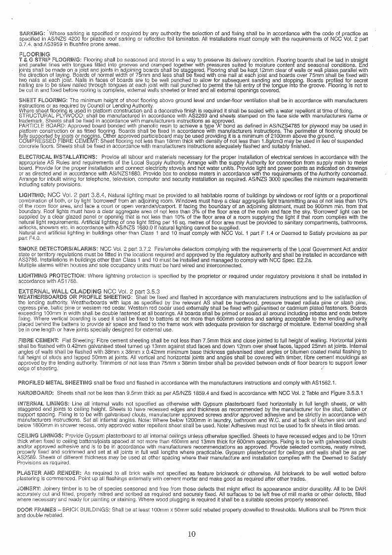
EXTERNAL WALLSAn external wall must achieve the minimum Total R-Value for the relevant Climate Zone or in Climate Zones 1,2 and 3 can be shaded by a verandah, balcony, carport eaves and gutter or the like with a reduction of 0.4 to the minimum Total R Value required. The horizontal projection from the external face of the building must be not less than one quarter of the overall height of the wall measured from the internal floor vertically to the underside of the projection. This applies to all stories. NOTE: In Climate Zones 4,,5,6,7 and 8 all wails must achieve a surface density of not less than 220 Kg/m2 and in Climate Zone 6 be constructed on a flooring system that is in direct contact of ground i.e. concrete slab or in Climate Zones 6,7, and 8 incorporate insulation with an R-Value not less than f .0 to the edges and underneath the slab.These requirements to not apply to South facing walls in Climate Zones 1,2 and 3 south of latitude 20° south
Weatherboard cladding
Sluds S dogging? ,.. -
i
j
i AcWed_{VVa|ue options !— Sheet insulation » i-----insulation
Type A
Fibre cemert sheet.Studs & Hoggings j
\ ‘-Plasterboard
»: —Shoot hsulaikm | i insutetkm I
Type B
ENERGY EFFICIENT EXTERNAL GLAZING: NCC Vol. 2 part 3.12.2, or Vol. 1 parts J 1.5 and Spec. J1.5
This part of the NCC applies to Class 1 buildings and class 10a buildings with a conditioned space.‘Acceptable Construction Practice: The effective glazing area of a building must not exceed the percentages of the building area as per NCC Table 3.12.2.1. This table defines the maximum effective glazing area (Total glazed area of all windows in a storey) as a percentage of the total floor area of a storey. The glazing area limits listed provide only the minimal protection against overheating (heat flow into the building via the glazing) and heat loss (through the glazing) in cold conditions. The neat loss or gain can be controlled by sitting of windows, shading, use of protective films, double glazing with air or gas fill in a sealed unit, and size of windows. Window manufacturers can supply windows to suit the requirements for the site Climate Zone and the window construction depends on shading of the glazed area by verandahs, balcony, fixed canopies etc. or a shading device. A shading device must restrict at least 80% of the solar radiation when in use and can be a shutter, blind, vertical or horizontal screen with blades, battens, slats etc. and be adjustable by the building occupants. Where necessary the nomination of glazing types, window locations, shading etc. should be carried out by an approved specialist.
NSW requirements to comply with BASIX Specifications are selectable in NatHERS 2.32A
CARPENTRY:Ail timber shall comply with the appropriate standard as listed below. Timber sizes shall be selected so that the building as constructed complies with AS1170.2 or AS4055 for serviceability and Design Wind Gust Velocities (permissible stress) of 33 M/s minimum. Substitution of some members may be required for higher Gust Wind Velocities ana advice of local authorities Building Department or Structural Engineer should be sought as whether design to N3 or higher is required.
STRESS GRADES:Visually Stress Graded Timber: Timbers whose species or place of growth is known may be visually graded for quality in accordance AS 2082. Mechanically Stress Graded Timber of required stress grade according to AS/NZS 1748 may be used regardless of species. Where seasoned timber is required timber shall be regarded as seasoned only if its moisture content does not exceed 18 per cent.
6

FRAMING: NCC Vol. 2 part 3.4.3.limber sizes in this specification are based on AS1684.4 Simplified Non-eyclonic areas with restrictions as follows: Maximum wind classification N2 (33m/s) - maximum roof pitch 30°- maximum building width 12.0m - maximum rafter overhang 750mm - maximum wall height at ext. walls, floor to celling 2400mm. The sizes are for information only and should not be used for construction. All design for a structure within these limits should be carried out to AS 1684.4NOTE: for wind classification N3 (W41N) and N4 AA/50N) Non-cyclonic areas with building widths 12.0m and up to 16.0m and with roof slopes exceeding 30° and up to 35°, design according to AS1684.2 is required. For construction in Cyclonic Areas, wind classification C1 to C3 refer to AS 1684.3. See updated Standard : Wind loads for housing AS4055-2012
CUTTING, ASSEMBLY AND ERECTION OF FRAMING ABOVE GROUND FLOOR LEVEL:Where framing is cut, assembled and erected on site, particular care should be taken that member sizes and fixings are designed to comply with stress grades for the particular number of stories and roof loads according to AS1684.
FRAWiiNG: NCC Vol. 2 part 3.4 applies to all dwelling framing.
FLOOR FRAMING: Ground floor timbers shall be only of hardwood, cypress pine or pressure treated Radiata or Canada Pine below a height of 300mm above finished ground level and must not be built into brickwork. Subfloor ventilation shall conform to NCC Vol. 2 part 3.4.1. In Bushfire Prone Areas special conditions apply. Where termite barriers need to be inspected, 400mm clearance is required between the underside of bearer and ground surface. Sub floor ventilation shall be as per NCC Vol. 2 part 3.4.1
BEARERS AND JOISTS: Bearers and joists shall be installed to comply with AS1684 as amended for timber components or AS3620 for lightweight steel framing sections or as per the NASH alternatives. (See page 9 for steel framing)
ANT CAPS: To all brickwork and piers, at the level of underside of floorbearers, a capping of 0.5mm gauge galvanised steel or other approved metal is to be set, projecting 38mm beyond the internal faces of all brickwork and turned down at a 45 degree angle, lapped 13mm and soldered or crimped at all joints and corners so as to provide a continuous and effective barrier against termites throughout the length of the material. Whole of house protection against subterranean termite attack shall be installed in accordance with AS 3660.
EAVES BEAMS AND VERANDAH PLATESl Eaves beams and verandah plates shall be provided to support rafters or trusses over full height openings or recesses in walls or over verandahs or porches covered by main roof structure. Any reduction m nominal size through mill dressing or scalloping shall be allowed for so that the minimum size listed is not reduced. The ends of eaves beams and verandah plates that are supported on stud walls shall be carried by studs or stud groups as for heads for equivalent spans. End fixing shall provide resistance to uplift or displacement. Verandah Posts to be not less than 100mm x 100mm in timber F11. If supporting roof loads they shall be as per AS 1684.
EAVES: Project rafters to give a soffit at eaves of directed width and fix 200 x 25mm timber fascia or colourbond steel as directed. Where eaves are boxed in, soffit bearers (sprockets) of 50 x 38mm shall be provided, spaced to suit eaves lining and attached directly to outer ends of rafters. In brick veneer buildings the inner ends of soffit bearers shall be fixed to the frame so as to be 20mm or more clear above top of brickwork at time of construction In solid masonry buildings the inner ends of soffit bearers shall be located by means of 50 x 25mm hangers from rafters or wall plates.In Bushfire Prone Areas fascias and eaves linings have special requirements.
ROOFING BATTENS: Supporting roofing only. (Note: roofing battens are not suitable for the safe support of workers prior to fixing roof cladding). Battens should be continuous over a minimum of two spans and their design to suit rafter/truss spacing and batten spacing must be in accordance with AS1684 for the allowable roof mass.
MANHOLE:Trim as required between ceiling joists or trusses for manhole 600 x 400mm minimum size. Line the opening and provide a suitable cover.
PREFABRICATED TIMBER WALL FRAMES AND TRUSSESWhere prefabricated frames and/or trusses are used for construction of the building, the manufacturers certification of construction according to AS1684.2 or AS1684.4 for the building on the particular site must be obtained. Where certification is attached to truss or framing members the certification labels shall be left in place after erection for approval by the appropriate Building Surveyor, P.C.A, or Council Authority. Timber trusses purpose manufactured for this project and engineer designed according to AS1720.1 are to be spaced at centres as directed, erected and fixed in accordance with the manufacturers instructions as approved. Support only on ends or designed bearing points where directed. Where spacing of trusses exceeds 600mm centres provide intermediate ceiling joists in 100mm x 38mm hardwood (in F7) or 100mm x 50mm (in F8) supported from hangers at maximum of 2100 centres. Hanging beams shall be supported not more than 600mm from bottom chord panel points unless hangers are provided to nearest top chord panel points.
MASSES OF TYPICAL ROOF CONSTRUCTION
MASS OF ROOF MATERIAL10 kg/m2 Steel sheet roofing 0.50mm thick and battens20 kg/m2 Metal sheet tiles or medium gauge steel sheet roofing , battens, 12mm softwood ceiling lining, sarking and lighweight insulation
30 kg/m2 Steel sheet roofing 0.775mm thick, 13mm plaster ceiling, roof and ceiling battens, sarking and lightweight insulation40 kg/m2 Steel sheet roofing 0.75 thick, battens, graded purlins and high density fibreboard ceiling lining60 kg/m2 Terracotta or concrete tiles and battens75 kg/m2 Terracotta or concrete tiles, roofing and ceiling battens, 10mm plasterboard, sarking and insulation90 kg/m2 Terracotta or concrete tiles, purlins, roofing and ceiling battens, 19mm hardwood ceiling lining, sarking and insulation
DEFINITIONS: Spacing - Where this term is used the measurement shall be the centre-to-centre distance between members.Span - Where this term is used the measurement shall be the face-to-face distance between members.
Reference is made to effective roof spans in the tables - the span is an indicator of the mass of roof being carried by the outer wall members.
SPAN
•.. So,
TRUSSED ROOFROOF WITH LOADBEARING RIDGEBEAMS AND WALLS

TABLES OF TIMBER SIZES_______________ SINGLE STOREY TILED ROOF_____________________ SINGLE STOREY SHEET ROOFFraming.Member Unseasoned Seasoned Unseasoned SeasonedStud Height 2400 Span F8 F5 MGP10 MGP12 F8 F5 MGP10 MGP12BEARERS-
. Strutted roof - max. rafter span 3000 @ 1800 spaGing continuous 1500 100 x 75 2/120 x 35 2/120x35 2/90 x 35 100x75 2/90x35 2/90 x 35 2/90 x 35over two or more spans-!oad 1800 125x75 2/140x35 2/120x35 2/90 x 35 125x75 2/120x35 2/120x35 2/90x35bearing.Trussed Roof 9.0 Span. Externa! 1500 175 x 75 2/170 x 35 2/140x35 2/140x35 125x75 2/120x35 2/120x35 2/90x35Wail 1800 spacing continuous over 1800 150 x 75 2/190 x 35 2/190x35 2/140x35 200 x 75 2/190x35 2/190x35 2/170x35two or more spans-load bearing. JOISTS-450 spacing-continuous over two 1800 125 x 38 120 x 45 120x35 120x35 125x38 120x45 120x35 120x35or more spans
900 100x75 2/90 x 35 90x45 90x35 100x50 2/90x35 90x45 90x35LINTELS*- 1200 125x75 2/120x35 120x45 2/90x45 125x50 140x45 2/90 X 45 2/90x35Trussed Roof 9000 Span 1500 175x75 2/140 x 45 2/120x45 2/120x45 150x50 2/120x35 2/140x35 2/90 x 45
1800 200 x 75 2/170 x 45 2/170x35 2/140x35 150x75 2/140x35 2/120x35 2/120x352100 225 x 75 2/240 x 35 2/170x45 2/170x35 175x75 2/170X35 170x45 2/120x452400 275 x 75 2/240 x 35 2/240 x 35 .2/190x45 200 x 75 2/170x45 2/170x35 2/140x453000 2/290 x 45 2/290 X 35 2/240 X 45 250 x 75 2/240 X 35 2/190x45 2/190x353600 — 2/290 x 45 --------- 2/290 X 45 2/290x35 2/240 x 45
UNCOUPLED ROOF WITH LOADBEARING RIDGEBEAMS AND/OR WALLS Rafters supporting roof and ceiling loads - non coupled cathedral roof single span
Rafter Unseasoned SeasonedRafter Span Spacing F5 F7 F8 F11 F5 MGP10 MGP12 F17Tiled Roof Ceiled 3000 600 200 x 38 200 x 50 175 x 50 175x50 175x45 140x45 140x45 140x35
Overhang 750 750 750 750 750 750 750 7503600 600 250 x 50 225 X 50 225 x 50 200 x 50 240 x 35 170x45 170x45 170x35
Overhang 750 750 750 750 750 750 . 750 7504200 600 275 x 50 275 x 50 250 x 50 250 x 50 240 x 45 240 x 35 190x45 190x45
Overhang 750 750 750 750 750 750 750 7504800 600 275 x 75 275 X 75 300 x 50 275 X 50 290 X 35 240 X 45 240 x 35 240 X 35
Overhang5400 600
750 750300 x 75
750300 x 75
750 '275 x 75
••750 750290 x 35
750290 X 35
750240 x 45
Overhang 750 750 750 750 750 750
Sheet Roof Ceiled 3000 900 175 x 50 175x50 175 x 50 150x50 140x45 140x35 120x45 120x45
Overhang 750 750 750 750 750 750 750 7503600 900 225 x 50 200 x 50 200 x 50 200 x 50 170x45 170x35 140x45 140x45
Overhang 750 750 750 750 750 750 750 7504200 900 250 X 50 250 X 50 225 x 50 225 x 50 240 x 35 190x45 170x45 170x45
Overhang 750 750 750 750 750 750 750 7504800 900 300 x 50 275 x 50 275 x 50 250 x 50 240 x 45 240 x 35 190 x 45 190x45
Overhang 750-- 750 750 750 750 750 750 7505400 900 300 x 75 275x75 300 x 50 275 x 50 290 x 35 240 x 45 240 x 35 240 x 35
Overhang 750 750 750 750 750 750 750 750
NOTE:1. Allowable overhangs are based on a maximum birdsmouth depth of D/3. Where rafters are not birdsmouthed, the allowable overhang may be
increased to 30% of the single span for that member, provided that the overhang does not exceed 50% of the actual backspan.2. Overhang limits are only applicable where rafter ends are supported by a structural fascia.
Sizes shown in tables in this specification are intended only as a guide to the size and stress grade for a particular member of a building frame. All timber framing should be designed and constructed in accordance with AS1684.2 and/or AS1684.4
Sizes in this specification are based on AS1684.4 Simplified Non-cycionic areas, with restrictions as follows:-® Maximum wind classification N2 (33m/s) ® Maximum Roof pitch 30° • Maximum building width 12.0m
Where a building exceeds the restrictions as listed above, design to comply with AS 1684.2 will allow wind speeds up to N4 (50 m/s), roof slope up to 35°and building widths up to 16.0m.
PERMANENT BRACING OF WALLS AS PER AS1684.2 This section 'Permanent Bracing of walls as per AS 1684 shows typical bracing applicable to timber frame construction as explanatory information only.
TYPE 'A' UNITS (Design racking resistance of 2kN). The following bracing units are deemed satisfactory type 'A' braces:-1. A pair of diagonal timber or metal section braces in opposite directions from each end of the wall as per fig (A) OR galvanised metal tensioned strap
bracing as per fig. (B).2'. Single diagonal timber or metal section brace as per figure (C).3. A 900mm minimum wide panel of structural plywood as per figure (D)
Type ‘A’ Bracing - Pair of diagonals from each end of wallTimber Metal Section Tensioned Straps
50mm x 19mm for studs up to 2.7m tong75mm x 19mm for studs over 2.7m long Fixing: galvanised flat head nail 2.8mm dia. x 50mm long to each plate and stud.
18mm x 16mm x 1.2mm min. galvanisedangle brace fixed with one 2.8mm dia. x 30 long galvanised flat head nail to each plate and stud edge.
Flat galvanised straps 0.8mm thick x 20 wide.Fixings: one galvanised flat head nail 2.8mm dia. x 30mm long to each plate and stud edge. Tension straps.
Type ‘A’ Bracing - Single diagonal at end of wall.Timber Metal Section
75mm x 19mm min. fixed with two 2.8mm dia. x 50mm long flathead galvanised mails to each stud and plate.
Galvanised angle brace fixed with two 2.8mm dia. x 30 long galvanisedflat head nails to each plate and stud
Type 'B‘ Units (design racking resistance of 4kN. The following bracing units are deemed to be satisfactory type 'B' braces1. A pair of diagonal galvanised metal tension straps of minimum nominal dimension 30mm x 0.8mm in opposing directions on one side of
timber frame. Ends of straps shall be bent over top and bottom faces of plates and fixed with four 3.15mm dia. x 30mm long galvanised flat head nails. Braces shall be fixed to stud edges with two similar nails to each crossing. End studs of braces section shall be strapped to top and bottom plates with 30mm x 0.8mm galvanised strap looped over plate and fixea to studs with four galvanised flat head nails 3.15mm dia. x 30mm long each end of loop.
2. A 900mm minimum wide panel of structural plywood as shown in figure (D). Fixed as follows:Plywood stress grade F8 Stud spacing 450mm to be 7mm thick ply. Stud spacing 600mm to be 9mm thick ply.Plywood stress grade F11 Stud spacing 450mm to be 6mm thick ply. Stud spacing 600mm to be 7mm thick ply.Plywood stress grade F14 Stud spacing 450mm to be 4mm thick ply. Stud spacing 600mm to be 6mm thick ply.
Fixing: 2.8mm dia. x 30mm long galvanised flat head nails at 50mm centres along top and bottom plates, 150mm centres along vertical edges and300mm centres along intermediate studs.
8

Brace and Strap,~<r....... connection
see Detail 2
30 deg..min to
.60 deg. max
Galvanized metal strap 30mm x 0.8mm as per
Detail 2 or single straps both sides with three nails each strap end or equivalent proprietory framing anchors or nail plate fasteners
fig (C)
Brace and strap -........• connection see Detail 1
Galvanized metal strap 30mm x 0.8mm as perDetail 1 or single straps both ______sides with four nails each strap end or equivalent proprietory framing anchors or nail plate fasteners
figEDETAIL 1
Galvanlzed metal strap 30mm x 0.8mm looped over plate and fixed to stud with.three galvanized flat head nails 2.8mm'dia x30mm long each end
DETAIL 2Diagrams as shown and explanation of the various types of bracings are not intended to specify bracing requirements for any timber frame construction. All bracing requirements for a particular design in timber framing must be determined in accordance with Section 8 of AS1684.2 or AS 1684.4 as applicable.
TIEDOWN REQUIREMENTS: NCC Vol. 2 tables 3.4.3 Tie down requirements for timber frame construction can be determined from AS1684.4 Section 9 for maximum design gust wind speeds of 33m/sec. For wind speeds in excess of 33m/sec, design as perASI684.2 is required.Tie down fixings should be determined for the following connections:a) bearers to piers d) studs to bottom and top plates a) battens and/or purlins to raftersb) floor joists to bearers e) rafters to top plates h) collar ties to raftersc) Bottom plates to floor joists or concrete slabs f) rafters to ceiling joists I) verandah plates and eaves beams to posts
NOTE: Special fastening requirements are required for type ‘A1 and B1 wall bracing for connections (c) and (d) above.
CYCLONIC AND OTHER HIGH WIND AREAS NCC Vol. 2 part 3.10.1 or Vol. 1 part B1Where buildings are to be constructed in regions B, C, and D as per AS/NZS1170.2 and AS1170.2 compliance with the AS1170.2 Minimum Design Loads on Structures or AS4055 Australian Wind Loads for Housing.NOTE: High wind areas exist outside of cyclone regions B,C and u. Clarification of the category at the site should be sought from local authorities. Cyclonic Regions of Australia and Tasmania are shown on Map BCAfig. 3.10.1.4
STEEL CONSTRUCTION, FRAMING AND OR TRUSSES: NCC Vol. 2 part 3.4.2 or Vol. 1 part B1MATERIALS: All framing sections shall be manufactured from galvanised steel conforming to AS 1397. Galvanised materials up to 3.2mm thick shall have minimum coating mass of 200 g/m2. Design, fabrication and fixing shall be as per recommendations of the component manufacturer. Design for Residential and Low Rise Steel Framing may conform to NASH standard as alternative to AS3623.
FABRICATION AND ERECTION: All structural components fabricated into frames and/or trusses and shall be cut accurately to length to fit firmly against abutting members and held so until fastened. Studs shall be seated squarely in bottom plates with webs at 90deg. to tne face of the wail ana accurately located, plumbed and securely fixed to top and bottom plates. Multiple studs shall be used as specified at concentrated load points. Plates shall be securely spliced to maintain continuity. Splices in studs are not permitted. Structurally adequate heads shall be fitted over openings in walls. All frames shall be adequately braced for transport and resist wind loads in service. Preferred fastening is by MIG welding. Ail welds shall be cleaned and painted with zinc rich paint. The bottom plate shall be securely fastened to sub floor at centres as recommended and all site connections shall be as specified in design manual. Holes for electrical wiring, other cables and plumbing services shall be max. 33mm dia. flanged holes. Service pipes shall be effectively separated from framing by lagging and be securely fixed in cavities. Permanent electrical earthing of a steel frame building snail be carried out in accordance with the requirements of the local electrical authority. Where power tools are used on site, temporary earthing to the frame shall be made during construction. On completion of framing all debris shall be removed from cavities and bottom plates. Domestic metal framing shall be designed to comply with the load combinations as per AS3623.
STRUCTURAL STEEL - NCC Vol. 2 part 3.4.4 or Vol. 1 part B1: All steel work is to be fabricated to details as shown on engineers drawings and in accordance with AS4100 Steel Structures or AS/NZS 4600 Cold-formed Steel structures. Corrosion protection of built in structural members such as lintels, shelf angles, connectors etc., (other than wall ties) are to be in accordance with AS3700 or AS 4773 parts 1 and 2.
PURLINS AND GIRTS: To roof and walls of building provide purlins and girts as required according to engineers details. Cover roof and walls of building in full length sheets complete with all necessary flashings, cappings etc. Secure as recommended by manufacturer and provide panels of selected translucent sheeting as indicated or directed.
ROOFING - NCC Vol. 2 part 3.5.1 or Vol. 1 part F1.5TILE ROOFING: Provide ail roofs with first quality roofing tiles. Where the pitch of rafters is less than 200, the roof shall be sarked with either 2 ply bituminous felt or double faced aluminium foil covered reinforced fabric as per AS/NZS 4200. Between 12 and 15 degrees slope, perimeter of roof shall be provided with an anti ponding board or device to ensure that all water will be discharged into eaves gutter, a clear space must be provided between edge of the device and the lowest side of the first batten so as to allow a free flow of water into the gutter. . Where one section.of the roof discharges into a lower section, the discharge is to be widely distributed, and the roof is to be fully sarked. Elsewhere, where a spreader is used the roof shall be sarked from the point of discharge to Eaves with a minimum width of 1800mm approved sarking. Cover all ridges and hips with capping, starters and apex caps necessary and bed all capping and verge tiles on lime mortar and point with coloured cement mortar.
TERRA COTTA TILES: To be glazed and manufactured in accordance with AS 2049. To be fixed to battens in accordance with AS2050.
CONCRETE TILES: To conform to AS2049, AS4046 and AS2050 and to be produced by manufacturers who provide a comprehensive guarantee. Tiles are to have an end lap of not less than 75mm. Fixing to be as per AS2050.
FIXING ROOF TILES: NCC Vol. 2, fig. 3.5.1.1 defines the areas and fastening requirements for all tiled roofs in any area with a Design Wind Speed up to and including N3. Specific requirements now exist within a 1.2m band parallel to ridges, hips, edges and barges extending towards the field of the roof.
CORRUGATED FIBRE CEMENT ROOFING: To conform to and fixed in accordance with AS1562 Pt.2. Minimum pitch of roof is to be 1:8 for large corrugations and 1:11 where the rafter length can be covered with a single sheet. Where pitch of roof is less than 1:6 in the case of large corrugations and 1:4.5 in the case of small corrugation end laps shall be at least 225mm and sealed. Sheets to be fixed with galvanised round head screws and felt washers set in mastic to each run of battens with side and end laps or other approved method in accordance with manufacturers instructions. All necessary accessories are to be provided and the roof is to be adequately birdproofed.
PROFILED STEEL ROOF: NCC Vol. 2 part 3.5.1 All metal sheet to be material as nominated on drawings. AH necessary accessories to be provided and fixed according to manufacturers recommendations. Roof is to be bird proofed. Sheet fixings and spacings are to be strictly as per manufacturers recommendations for the design wind speed for the area. Design and installation shall be in accordance with AS/NZS 1562. Cover roof of building in full length sheets complete with all necessary flashings and cappings etc. Secure as recommended by manufacturer and provide panels of selected translucent sheeting as indicated or directed.
9
. SARKING: Where sarking is specified or required by any authority the selection of and fixing shall be in accordance with the code of practice as specified in AS/NZS 4200 for pliable roof sarking or reflective foil laminates. All installations must comply with the requirements of NCC Vol. 2 part 3.7.4. and AS3959 in Bushfire prone areas.
FLOORINGT & G STRIP FLOORING: Flooring shall be seasoned and stored in a way to preserve its delivery condition. Flooring boards shall be laid in straight and parallel lines with tongues fitted into grooves and cramped together with pressures suited to moisture content and seasonal conditions. End joints shall be made on a joist and joints in adjoining boards shall be staggered. Flooring shall be kept 12mm clear of walls or wall plates parallel with the direction of laying. Boards of normal width of 75mm and less shall be fixed with one nail at each joist and boards over 75mm shall be fixed with two nails at each joist. Nails in faces of boards are to be well punched to allow for subsequent sanding and stopping. Boards profiled for secret nailing are to be skew nailed through tongues at each joist with nail punched to permit the full entry of the tongue into the groove. Flooring is not to be cut in and fixed before roofing is complete, external walls sheeted or lined and all external openings covered.
SHEET FLOORING: The minimum height of sheet flooring above ground level and under-floor ventilation shall be in accordance with manufacturers instructions or as required by Council or Lending Authority.Where sheet flooring is used in platform construction ana a decorative finish is required it shall be sealed with a water repellent at time of fixing. STRUCTURAL PLYWOOD: shall be manufactured in accordance with AS2269 and sheets stamped on the face side with manufacturers name or trademark. Sheets shall be fixed in accordance with manufacturers instructions as approved.PARTICLE BOARD: Approved board bonded with phenolic resin to achieve a type 'A' bond as defined in AS/NZS4785 for plywood may be used in platform construction or as fitted flooring. Boards shall be fixed in accordance with manufacturers instructions. The perimeter of flooring should be fully supported by joists or noggins. Other approved particleboard may be used providing it is a minimum of 2100mm above the ground. COMPRESSED FIBRE CEMEMT: Sheet flooring not less than 18mm thick with density of not less than 1.8g/cm3 may be used in lieu of suspended concrete floors. Sheets shall be fixed in accordance with manufacturers instructions adequately flashed ana suitably finished.
ELECTRICAL INSTALLATIONS: Provide all labour and materials necessary for the proper installation of electrical services in accordance with the appropriate AS Rules and requirements of the Local Supply Authority. Arrange with the supply Authority for connection from supply main to meter board. Provide for the proper installation and connect electricity stove/s and hot water unit/s. Provide light and power points as indicated on drawings or as directed and in accordance with AS/NZS 1680. Provide box to enclose meters in accordance with the requirements of the Authority concerned. Arrange for inbuilt wiring for telephone, television, computer and security installation as required. AS/NZS 3000 specifies the minimum requirements including safety provisions.
LIGHTING; NCC Vol. 2 part 3.8.4, Natural lighting must be provided to all habitable rooms of buildings by windows or roof lights or a proportional combination of both, or by light 'borrowed' from an adjoining room. Windows must have a clear aggregate light transmitting area of not less than 10% of the room floor area, and face a court or open verandah/carport. If facing the boundary of an adjoining allotment, must be 900mm min. from that boundary. Roof lights must have a clear aggregate area of not less than 3% of the floor area of the room and face the sky. 'Borrowed1 light can be supplied by a clear glazed panel or opening that is not less than 10% of the floor area of a room supplying the light if that room complies with the natural light requirements. Artificial lighting of one light fitting per 16 sq. metres of floor area must be provided to sanitary compartments, bathrooms, airlocks, showers etc. in accordance with AS/NZS 1680.0 if natural lighting cannot be supplied.Natural and artificial lighting in buildings other than Class 1 and 10 must comply with NCC Vol. 1 part F 1.4 or Deemed to Satisfy provisions as per part F4.0.
SMOKE DETECTORS/ALARMS: NCC Vol. 2 part 3.7.2 Fire/smoke detectors complying with the requirements of the Local Government Act and/or state or territory regulations must be fitted in the locations required and approved by the regulatory authority and shall be installed in accordance with AS3786. Installations in buildings other than Class 1 and 10 must be installed and managed to comply with NCC Spec. E2.2a.Multiple alarms within houses and sole occupancy units must be hard wired and interconnected.
LIGHTNING PROTECTION: Where lightning protection is specified by the proprietor or required under regulatory provisions it shall be installed in accordance with AS 1768.
EXTERNAL WALL CLADDING NCC Vol. 2 part 3.5.3WEATHERBOARDS OR PROFILE SHEETING: Shall be fixed and flashed in accordance with manufacturers instructions and to the satisfaction of the lending authority. Weatherboards with laps as specified by the relevant AS shall be hardwood, pressure treated radiata pine or slash pine, cypress pine, baltic pine or western red cedar. Western red cedar used externally shall be fixed with galvanised or cadmium plated fasteners. Boards exceeding 100mm in width shall be double fastened at all bearings. All boards shall be primed or sealed all around including rebates and ends before fixing. Where vertical boarding is used it shall be fixed to battens at not more than 600mm centres and sarking acceptable to the lending authority placed behind the battens to provide air space and fixed to the frame work with adequate provision for discharge of moisture. External boarding shall be in one length or have joints specially designed for external use.
FIBRE CEMENT: Flat Sheeting: Fibre cement sheeting shall be not less than 7.5mm thick and close jointed to full height of walling. Horizontal joints shall be flashed with 0.42mm galvanised steel turned up 13mm against stud faces and down 12mm over sheet faces, lapped 25mm at joints. Internal angles of walls shall be flashed with 38mm x 38mm x 0.42mm minimum base thickness galvanised steel angles or bitumen coated metal flashing to full height of studs and lapped 50mm at joints. All vertical and horizontal joints and angles shall be covered with timber, fibre cement mouldings as approved by the lending authority. Trimmers of not less than 75mm x 38mm timber shall be provided between ends of floor bearers to support lower edge of sheeting.'
PROFILED METAL SHEETING shall be fixed and flashed in accordance with the manufacturers instructions and comply with AS 1562.1.
HARDBOARD: Sheets shall not be less than 9.5mm thick as per AS/NZS 1859.4 and fixed in accordance with NCC Voi. 2 Table and Figure 3.5.3.1
INTERNAL LININGS: Line all internal walls not specified as otherwise with Gypsum plasterboard fixed horizontally in full length sheets, or with staggered end joints to ceiling height. Sheets to have recessed edges and thickness as recommended by the manufacturer for the stud, batten or support spacing. Fixing is to be with galvanised clouts, manufacturer approved screws and/or approved adhesive and be strictly in accordance with manufacturers instructions. Set all internal angles. Note: Where below 1200mm in laundry, bathroom and W.C. and at back of kitchen sink unit and below 1800mm in shower recess, only approved water repellent sheet shall be used. Note: Adhesives must not be used to fix sheets in tiled areas.
CEILING LININGS: Provide Gypsum plasterboard to all internal ceilings unless otherwise specified. Sheets to have recessed edges and to be 10mm thick when fixed to ceiling battens/joists spaced at not more than 450mm and 13mm thick for 600mm spacings. Fixing is to be with galvanised clouts and/or approved adhesive and is to be in accordance with manufacturers recommendations as approved. Provide selected cornices, neatly mitred, properly fixed and scrimmed and set at all joints in full wall lengths where practicable. Gypsum plasterboard for ceilings and wails shall be as per AS2589. Sheets of different thickness may be used at other spacing where their manufacture and installation complies with the Deemed to Satisfy Provisions as required.
PLASTER AND RENDER: As required to all brick walls not specified as feature brickwork or otherwise. All brickwork to be well wetted before plastering is commenced. Point up all flashings externally with cement mortar and make good as required after other trades.
JOINERY: Joinery timber is to be of species seasoned and free from those defects that might effect its appearance and/or durability. Ail to be DAR accurately cut and fitted, properly mitred and scribed as required and securely fixed. All surfaces to be left free of mill marks or other defects, filled where necessary and ready for painting or staining. Where wood plugging is required it shall be a suitable species properly seasoned.
DOOR FRAMES - BRICK BUILDINGS: Shall be at least 100mm x 50mm solid rebated properly dowelled to thresholds. Mullions shall be 75mm thick and double rebated.
10

JAMB LININGS - INTERIOR DOORS ALL BUILDINGS, EXTERIOR DOORS TIMBER FRAMED AND BRICK VENEER:Linings shall be a minimum of 38mm thick solid rebated to all door openings. Where return plaster reveals occur linings shall be 75mm x 50mm rebated. In brick veneer and timber framed construction 12mm clearance shall be provided over jamb linings to external openings. Linings to openings not having doors or to have swing doors are to be 25mm thick timber. Other proprietory linings may be approved by the owner.
DOORS: Fit accurately to door frame. Hang external doors with three 88mm steel butts and internal doors unless otherwise specified with two 88mm steel butts. External doors shall not be less than 2040mm x 820mm x 40mm thick. Where sheeted with plywood, waterproof plywood only shall be used. All framed glazed doors (external or internal) shall be minimum of 40mm thick. Internal doors shall be minimum of 35mm thick and free of warping.
PROTECTION OF OPEN-ABLE WINDOWS: (Against Falling From) NCC Vol. 2 part 3.9.2.S, NCC Vol.1 part 2.2c: If a floor or exterior surface is 2m or more below a window in a bedroom, the window must comply with the following:- ‘the open-able portion of the window must have a device to restrict the opening, or a screen with secure attachment fittings’. The window and or screen is to comply with the requirements of NCC Vol. 2 part 3.9.2.5 (a) and (b)'. If the lowest level of any window opening is greater than 1.7m above the room floor, no protection is required.Open-able windows in a bedroom with a floor level greater than 2m above an exterior surface level below must have a barrier or wall with a height not less than 865mm above the room floor with no horizontal climbing elements.In a room where the room floor under an open able window is 4m or more above an exterior floor or surface beneath, special conditions apply NCC Vol. 2 part 3.9.2.5 (c) and (d).
WINDOWS : All framed windows shall be installed in accordance with AS2047-48 for Aluminium windows and AS2047 for timber windows.
STAIRS, HANDRAILS AND BALUSTRADES: NCC Vol. 2 parts 3.9.1 and 3.9.2 Stairways shall be constructed to the layout as shown on plans with treads of equal dimensions except where shown or where winders are required. All risers in any flight shall be of equal height. All flights shall have a minimum of 2 and not more than 18 risers. Relationship of riser to going shall be between 1:2 and 1:1.35 unless otherwise directed or as permitted in AS1657. Balustrades shall be provided to all landings, ramps, decks, roofs and other elevated platforms where the vertical distance from that level is more than 1 metre above the adjoining floor or finished ground level. Height of the balustrade must be a minimum of 1 metre above landings etc. and not less than 865mm above the nosings of any stair treads or floor of a ramp. Openings in balustrades (decorative of otherwise) and space between treads, e.g. riser opening must not allow a 125 mm dia. sphere to pass through. Resistance to loading forces of a balustrade must be in accordance with AS 1170. Where balustrades are constructed of tensioned wires provision shall be made to maintain the wire tensions.
ACCESS AND MOBILITY: Where access and mobility requirements are to be addressed in the construction of a new building, AS1428 General Requirements for Access - New Building Work contains the minimum design requirements to enable access for people with disabilities. The design must comply with ‘Access to Premises Standards 201 O' as referenced in the NCC. A link for advice on the 'Disability (Access to Premises)- Building Standards 2010' can be found at www.wsttas.qov.au/industries/publications.SEE -NCC Vol. 2 : South Australian appendix additions 5.1 and 5.2: Access for Disabled People as listed on page 13 of this specification.
SLIP RESISTANCE: Materials to be used for surfaces of floors, stair landings, steps and ndsings shall be in accordance with the classifications for Slip Resistance as apply in AS4586 and HB 198.
PLUMBING AND DRAINING: National Construction Code Vol. 3 PCA( Plumbing Code of Australia)
EAVES GUTTERS VALLEY GUTTERS AND DOWNPiPES: Eaves gutters and downpipes of material and finish as nominated on drawings shall be installed as per manufacturers specification to all eaves as required with falls to downpipes in positions shown. All items shall be of material compatible with roof covering and to comply with AS/NZS 2179 for metal and AS1273 for UPVC components.
FLASHINGS: Flash around chimney stacks, exhaust flues and wherever else required with approved flashings dressed well down onto roof slopes and taken vertically at least 75mm. Eaves gutters, valleys and roof flashings shall be selected from materials compatible with each other and the roof covering to prevent bi-metallic corrosion. (See BHP publications TB8, TB15). Use of lead for flashings, gutters, downpipes and roofing is prohibited if the roof will collect potable water. NOTE: Where ridge and hip tiles are fixed with proprietary mechanical clips NCC vol. 2 fig. 3.5.1.1 ana fig 3.5.1.2 shows details for mechanical fastening-ridge clip ana dry or pointed valleys and hips.
WATER SERVICES: Where a reticulated water supply is available all work shall be carried out by a licensed water plumber. All water supply installations shall be carried out in accordance with National Construction Code Vol. 3 (APC).
RETICULATED RECYCLED WATER: Where a utility supplied reticulated recycled water supply is connected as a dual reticulation it is important that no cross connection between the potable and recycled water can occur. There must be at least one external tap for each system and the recycled water system must have lilac coloured components. Identification markings and signage shall be installed as per AS1319 and AS1345. Recycled water cannot be used for human consumption or contact, household cleaning, personal washing or irrigation where fruit and crops are eaten raw or
■ unprocessed.
WET AREAS: NCC Vol. 2 part 3.8.1: Building elements in wet areas must be water resistant and/or waterproof as listed in table 3.8.1.1 of the NCC Vol. 2 and constructed in accordance with AS3740. Water resistance or Waterproofing varies in respect of different building elements such as:- floors and horizontal surfaces, walls, wall junctions and joints, wall and floor junctions and penetrations.
See - NCC: South Australia appendix additions 3.1 and 3.2: Wet area floors as listed on page 13 of this specification.
HOT WATER SERVICE: All installations must comply with AS3500.4 Provide from H/water unit with selected tubing to points necessary. Terminate with taps selected. Provide inlet stopcock to hot water unit. Storage water heater selection and installation is to be as per AS 1056.
GAS SERVICE: The whole of the work is to be carried out as per requirements of the Local Supply Authority. The plumber is to be responsible for the gas service from boundary alignment, including fixing of the meter and cover for same. Installations for bottled gas supply shall comply with the relevant standard. Gas installations shall comply with 'Gas Safety Regulations and Act' and AS5601.
HEATING APPLIANCES NCC Vol 2 part 3.7.3: Domestic type Oil, Gas and Solid Fuel heater installations shall comply with AS/NZS2918 ‘Domestic solid fuel burning appliances - Installation’: Installation of gas fired appliances shall be carried out by a licensed gas plumber.
SEWERED AREAS: Provide a drainage system from pedestal pan and from wastes of all fittings unless a grey water system is to be installed and connect to the sewer main, where shown on site plan all to be in accordance with the rules and requirements of the Authority for Water Supply and Sewerage. Provide at least one gully outside the building. The Authority Certificate to be produced at Completion of the Work.
UNSEWERED AREAS: Provide a drainage system from all fittings and from grease trap in accordance with the requirements of the Local Authority concerned. Excavate for drains to provide even falls throughout and a minimum cover of 300mm. Lay 100mm socketed vitrified clay, P V C or HDPA pipes to take discharge from wastes of washtubs, bath, shower, washbasin and grease trap. All pipes to be completely jointed with rubber rings or solvent cement as approved. All drain lines to be laid so that water is discharged into an absorption trench provided in position shown on plan. Provide an approved grease trap with lid in position shown to take the water from kitchen sink. Top of trap to be 75mm above finished ground or nearby concrete paving level. All drainage work from fittings to the drainage line outside the building is to be in accordance with the rules and requirements of the Water Supply and Sewerage Authority for sewered areas. The Authority 'Special Inspection' Certificate of the work is to be produced by the builder. All plumbing and drainage shall be in accordance with the Code of Practice for state or territory and regulating local government area.
GREYWATER REUSE SYSTEMS:Where a greywater reuse system is proposed the installation shall comply with the following Australian Standards and Codes: AS 1546 parts 1 and 3: AS1547: NSW Health 1998 AWTS guideline: NSW Health 2000 Domestic greywater treatment guidelines and sewered single domestic premises. An on site greywater reuse system is not permitted in Reticulated Recycled water areas. Domestic Greywater Treatment Systems (DGTS) and Aerated Wastewater Treatment Systems (AWTS) require a certificate of accreditation from NSW Health.
SEPTIC SYSTEM: Provide and install septic system in position nominated by the proprietor together with a holding tank and length of absorption trench installed in accordance with the manufacturers instructions and the requirements of the Local Authority to comply with AS1546 part T.
11
STORM WATER TREATMENT METHODS; Provide roof water drains from downpipes and from grates in paving where shown on site plan. Drains to be 1QQmm socketed vitrified clay pipes or PVC laid to an even and regular fall so as to have a minimum cover or 150mm. Drains to discharge into street gutter where possible. Where outlets are shown within the site they are to discharge at least 3000mm clear of the building into rubble packing 600mm diameter and 600mm deep. Acceptable solutions for stormwater drainage to be as per AS/NZS3500 part 3. Stormwater treatment systems should satisfy the following performance requirements
1. Conserve Water 2. Prevent Increases In Flooding/Erosion 3. Maintain water balance 4. Control Stormwater Pollution. Systems suitable for detached dwellings are:- Roof/rainwater tanks: Detention devices: Infiltration devices and Filter strips. These are also suitable for multi-dwelling developments in addition to Stormwater tanks and Bio retention devices.
RAIN WATER TANKS; Install rainwater tanks of selected material on slab or support as nominated by tank manufacturer. Rainwater tanks may be trickle topped up (max. 2litres/minute) from a potable water supply main and internally reticulated. A dual supply system should have no direct or indirect connection between the mains potable supply and the rainwater tank supply. In ground concrete tanks may be installed as an option with a suitable pressure pump and a testable backflow prevention device as per AS/NZS2845.1 Where an above ground tank is connected to internal reticulation, a meter with a dual check valve is to be installed and a visible air gap between the mains supply and the rainwater tank as per AS3500 and AS2845.2.1. (See NSW Health circular: Use of rainwater tanks where a reticulated mains water supply is available).
See.-: NCC: SOUTH AUSTRALIA appendix additions SA 2.1 and 2.2: Water efficiency as listed on page 13 of this specification.
DRAINS FROM UNDER BUILDINGS: NOTE- AS 2870: All stormwater, sanitary drainage or other discharge pipes emerging from under a building footing or slab or attached to a building shall have a flexible joint incorporated into the pipework outside the footing or slab and within 1 metre of the building perimeter.
NOTE: Drain pipes must not be taken through the footings of the building. All seepage and soakage water is to be effectively dealt with and diverted clear of the buildings as shown on site plan. Trenches for drains, where running parallel to the building must not be within 600mm of the footings of the building.
WALL AND FLOOR TILES: For guidance on installation of ceramic tiles see recommendations as set out in AS3958 parts 1 and 2.
WALLS; Cover the following wall faces with selected glazed tiles: To shower recess to a height of 1800mrp-To bathroom generally to a height of 135mm. To enclosing of bath and hobsTo bath recess: to a height of 1350mm. To WC to height of one row of tiles or as directed
Above kitchen sink/s and cooking area/s allow for four rows tiles. Finish at top and salient angles with round edge tiles. Provide vent tiles and selected recess fittings. Tiles to be fixed to a backing of Fibre Cement with approved adhesive. Areas for tiles can be increased by proprietors direction or as noted on plans.
FLOORS: Cover floors of bathroom, shower recess, WC and ES with selected tiles, set in cement mortar or approved adhesive and graded to give an even and adequate fall to floor waste.
PAINTING: All paints, stains, varnishes and water colours are to be of approved brands as selected. Materials used for priming and undercoating are to be' the same brand as the finishing paints or as recommended by the manufacturers of the finishes used. All finishing colours are to be selected by the proprietor. Do all necessary stopping after the priming has been applied. Rub down all surfaces to a smooth finish prior the application of eacn successive coat of paint. External joinery or other exposed woodwork to have a clear plastic finish is to be treated with a priming oil containing wood preservative and a water repellent.
EXTERNALLY: All external woodwork to be given one coat of primer, one coat of oil based undercoat and one coat of gloss finish enamel or to be given one coat of clear primer, one coat of flat clear plastic and one coat of clear plastic.
PRIMING WEATHERBOARDS: Any pine is to be primed all round as well as on the ends. Before fixing; hardwood, cypress pine, radiata pine and Oregon are to be primed on external faces including rebates. Pressure treated Canada pine is to be primed at ends before fixing.
IRONWORK: Eaves, gutters, downpipes, exposed service pipes and wrought iron etc. to be cleaned and primed and give one coat of gloss paint all round.
FIBRE CEMENT: Clean and prepare all external fibre cement surfaces and finish with two coats of water based paint.
INTERNALLY: All exposed woodwork in kitchen, bathroom, laundry WC EC to be prepared primed and then given one undercoat and finished with one coat of full gloss paint or to be stained and finished with two coats of clear liquid plastic as selected.
CEILINGS: To be given one coat of sealer and two coats of paint. The finishing coat of bathroom, laundry, and kitchen ceilings to be semi- gloss (unless directed otherwise).
WALLS: All rooms except bathroom, laundry and kitchen to be given one coat of sealer and two coats of water based paint. To bathroom, kitchen, WC EC and laundry where no tiled or pre surfaced material is required, walls are to be given one coat of sealer, one coat of undercoat and one coat of gloss oil paint system.
GLAZING: NCC Vol. 1 parts B 1.4, D 3.12, F 1.13 or NCC Vol. 2 part 3.6All sashes, doors, fixed lights and other glass in building shall be selected and installed by procedures as set out in AS1288 and/or AS2047 for type, thickness and'area of glass according to wind loading, human impact and other considerations for glazing in frames of timber;' steel, stainless steel, aluminium and bronze according to type of frame, height of building and glazing compound and for design and glazing of unframed toughened glass assemblies. Specific attention snoula be made to the selection of frame materials, glazing, location in walls and orientation to the path of the sun for various climate zones. Where windows are not shaded by roof eaves or other building projections, advice by an approved specialist or manufacturer should be sought to ensure that all installations comply with the Energy Efficiency requirements of the NCC. (Or BASIX in NSW).
FENCING: Provide paling fence 1500mm height to side and rear boundaries. Posts to be 125 x 50mm in sawn approved durable hardwood, morticed for two rails and sunk into ground 600mm at maximum of 2700 mm. Posts at angles in fencing to be 125mm square. Well ram around posts. Where rock is encountered posts are to be set in concrete. Fit two rows of 75 x 50mm hardwood rails into mortises. Cover fram mg with hardwood palings. Double nail to rails at top and bottom. Cut line at top and lop corners. All timber in ground or concrete to be well tarred or treated with an approved preservative. Allow for repairing any existing recommendations of the manufacturer. Provide front fencing as directed
SWIMMING POOLS: Swimming pool access is to comply with NCC Vol. 2, F 2.5.2 (a) and (b) in conjunction with the Swimming Pools Act 1992 and Swimming pool Regulation 2008. This applies to any wading pool, spa, or swimming pool with a depth of water exceeding 300mm. See AS 1926 ‘Swimming Pool Safety-Safety Barriers for Swimming Pools'.
See- NCC AUSTRALIAN CAPITAL TERRITORY appendix addition ACT 6.1: Pool construction as listed on page 13 of this specification.
See- NCC TASMANIA appendix additions TAS 2.1 and 2.2: Reticulation and filtration as listed on page 13 of this specification.
ALPINE AREAS: For buildings to be constructed in an alpine area, compliance with the requirements of NCC part 3.7.5. is required. Alpine areas are areas above Australian Height Datum (AHD) as follows:- NSW, VIC, ACT above 1,200 metres AHD. TASMANIA above 900 metres AHD. For sub alpine areas where significant snow loads may occur see BCA fig. 3.7.5.2. Where snow loads may be applied to a building design according to AS1170.3 is required, (see NCC 3.11.3)
CLIMATE ZONES: Climate Zone classifications for various localities are shown in NCC Vol. 2 2014 Table 1.1.2. Thermal design requirements for climate zones should be as per NCC fig. 1.1.4
EARTHQUAKE: Earthquake probability shall be determined according to NCC Vol. 2 part 3.11.3 and loading requirements are to be designed to comply with AS 1170.4
12

LANDSCAPING: The area to be landscaped shall comply with the landscape plan and requirements of the Local Council Authorities. Appropriate landscape design will reduce water usage in lawns and gardens by up to 50%. Selection of native indigenous plants suited to the local micro climate along with exotic species from California, South Africa and the Mediterranean will normally require minimal maintenance and water use. (BASIX website: see table D.2.1 for indigenous plants in various local government areas for NSW use).
CAR PARKING: All car parking and loading bays to be kerbed, guttered, sealed, drained, line marked and landscaped. Drainage of surface water into neighbouring properties is NOT permitted except where an easement is obtained. All car parks shall comply with the provision of Local Council Authorities.
COMPLETION: The building shall be completed in every trade. Sashes, doors, locks and all other equipment shall be checked and left in a satisfactory operating condition. Timber floors shall be at least rough sanded. Where fine sanding is specified see CA39: Code of practice for sanding interior wooden floors. All plant, surplus materials and rubbish is to be removed from site. Gutters and drains shall be cleared and the building generally to be left clean and fit for occupation.The Builder is to furnish the Owner with:
1. Notification of Completion 4. Certificate from Sewerage Authority re-sanitary drainage2. All Keys for all doors 5. Invoices for all PC items required3. Certificate of termite protection treatment
It is the responsibility of the builder to arrange any inspections necessary by Local Council, Waterboard or Lending Authorities and/or Principal Certifying Authority.It is the responsibility of the Owner to apply to Local Supply Authorities for connection of Electricity from mains to meter box.
APPENDIX ADDITIONS OF NCC VoS. 2 AS APPLICABLE FOR SEPARATE AUSTRALIAN STATES
AUSTRALIAN CAPITAL TERRITORY
ACT 2.1 ACT 2.2 ACT 3.1
ACT 3.2
ACT 6.1
Regulatory provisions for control of litter that can be blown around and off building sites.Construction practice for storage and subsequent regular removal of building waste from project sites. Performance provisions for access, hygienic and safe storage of solid waste if stored in an occupied building prior to collection. Design of areas, screening, disposal and logistics commensurate with the building use must be addressed.Requirements of ACT 3.1 can be satisfied if garbage facilities comply with the Development Control Code for Best Practice Waste Management in the ACT.In addition to the requirements of NCC Vol. 2 part 3.9.3 the type of pumps, means of egress, emptying and backwash facilities are required for indoor and outdoor pools with a volume greater than 10M5'
NEW SOUTH WALES
Class 1 buildings must have (if BASIX does not apply) Thermal Breaks between metal framing and cladding of a minimum thickness to reduce energy loss.
P 2.6.1 (b) A building must have a level of sealing against air leakage to facilitate the efficient use of energy for artificialheating and cooling appropriate to use, internal environment and location of the building.
SOUTH AUSTRALIA
SA 2.1 and 2.2
SA 3.1 and 3.2
SA 5.1 and 5.2
SA 6.1
TASMANIA
TAS 1.1
TAS 2 TAS 2.1 TAS 2.2
Applies to new buildings and extensions to Class 1 buildings. Where a roof catchment is over 50M2 the building must have an additional water supply other than mains supply plumbed to water closets, laundry cold water outlets and water operated heaters. Requirements exist for tank volume, stands and mosquito proof non- degradable inlet screens.Wet areas are to be self draining, fitted with floor wastes and have specified grades. Exemptions apply if vessels have inbuilt overflow protection or permanent open trapped waste connections.Requires safe and dignified access to buildings and services and facilities within the buildings and safe routes from road boundaries for wheelchair use.Where Class 1 buildings require Disabled Access; paths of travel must not include stairs or impediments and the building layout must include one closet pan, washbasin and shower for disabled persons.Space between buildings must be sufficient to allow safe access for inspection and maintenance to prevent harbouring vermin, create a fire hazard or bridge termite barriers. SA 6.2 lists required set-backs and minimum access widths.
Fire safety objective to prevent spread of fire from burning airborne embers by provision of non combustible roof coverings. TAS 1.2 lists recommended materials to comply with the requirements of TAS 1.1.Applies to swimming or wading pools with a volume of 15M3or more and a depth exceeding 300mm.Pools must be provided with an adequate circulation, filtration and disinfection system that is safe to use. Provides details of a satisfactory system to comply with the requirements of TAS 2.1 and lists circulation frequency and minimum operational times .
WESTERN AUSTRALIA
WA 2.1 Potable water meaning and definition is described in the Water Efficiency Labelling and Standards Act 2005.WA2.2 Performance requirements list water use efficiency, water loss prevention and hot water use efficiency and
features requirements appropriate to geographic location, availability and function of the building. This applies to Class 1 buildings, associated Class 10a buildings and associated swimming pools.
WA 2.3 Lists acceptable construction with WELS ratings for tap fittings, shower heads and sanitary flushing systems.Swimming pool covers and blankets designed to reduce evaporation and accredited to the requirements of the Smart Approved Water Mark Scheme are to be used.Heated water use efficiency requires that all outlets and pipes are installed in accordance with AS/NZS 3500 Plumbing and Drainage Part 4 Heated Water Services and NCC Vol 3 (PCA) as applicable.
13

BASIX: The Building Sustainability index. - NSW (only)
For Classl and 10 buildings subject to BASIX, the NCC energy provisions of Part 2.6 and Part 3.12 of NCC BCA 2009 as varied by the NSW Appendix are applicable. Trie National House Energy Rating Software (NatHERS) now requires Class 1 buildings to have a 6 Star Rating.
A BASIX Certificate must be submitted with a Development Application, Complying Development Certificate and Construction Certificate Application for all of NSW for new homes and for some alterations and additions.
Data required to Complete a BASIX Assessment is described in the BASIX Data Input checklist and this should be used in conjunction with the BASIX Assessment Tool.
Generation of a BASIX Certificate can only be made in the NSW Department of Infrastructure, Planning and Natural Resources BASIX websitewww.basix.nsw.gov.au
ADDITIONAL BUILDING REQUIREMENTS: All instructions for work extra to that shown on the plans or additional requirements must be inwriting. Verbal instructions must be confirmed in writing, dated and signed by the Owner and the Builder with a copy held by each.
This is the specification referred to in the contract between.........................................................................................................................OWNERS
and............................................................................................................................................................................................................... BUILDER
Dated........... /.............../.
OWNER BUILDER
BUILDERS LICENCE No.
14

MASONRY CONSTRUCTION Clay Bricks □ Face Commons 0 Stone 0
4 Concrete Bricks □ Concrete Blocks □ AAC Blocks 0 AAC Panels 0
Rendered Bagged □ Painted 0
MORTAR JOINTS Colour......................... ■-/ Ironed □ Flush 0 Raked 0
SILLS Brick 0 Quarry Tiles □EXTERNAL WALL SHEETING Timber Cladding □ Fibre Cement Cladding 0 Metal Cladding 0 PVCAdnyl d
Type............................ "111/ Type.......................... Type.....................Type...... .^CSf......
FLOOR CONSTRUCTION Timber 0 Concrete u Pre.Str. Beam Floor 0 Steel 0
FLOORING T & G 0/ Species.................... Compressed FC SheetO Structural Plywood 0
Particle Board 0 Tiles: Ceramic □ Terra Cotta 0 Quarry 0
DECKING Treated Pine Other.........................
WALL FRAMES Timber Hardwood □ Pine 0 H.S.Galv. Steel 0
Structural Steel Off site prefabricated □ Onsite cut/assembled 0
ROOF CONSTRUCTION Pitched Roof 2 Exposed Rafters □ Oregon 0 Hardwood 0
Roof Trusses a Raked Ceiling □ Pine 0 Steel Framing 0
Flat/Skillion a
ROOF COVER Concrete Tiles Terra Cotta Tiles □ Shingles/Slate 0 Corrugated FC 0Zincalume □ Coiorbond □ Polycarbonate 0 Profile....................
THERMAL INSULATION Roof/ceiling □ Reflective Insulation Rating R..^•.......hh....... Bulk Insulation Rating R..................
Walls □ Reflective Insulation Rating R...j -f Bulk Insulation Rating R..................
Floors 5/ Reflective Insulation Rating R..^) Bulk Insulation Rating R..................
INTERNAL WALL LININGS Gypsum Plasterboard FC Sheeting □ Timber Panelling 0 Cement Render 0Face Brick □ Other........................
WET AREA LININGS WR Gyp. Plasterboarc■4 Villaboard □ Timber Panelling 0 Laminated Panel 0CEILINGS Gypsum Plasterboard □ Timber Panelling □ FC Sheeting 0CORNICE Type.............. fcrt?.....■0 Size........................... .mm
DOOR JAMBS Timber Galvanised Steel .. 0WINDOWS Timber □ Aluminium u Type/Man uf actu rer.................. hr?
FLYSCREENS Timber □ Aluminium □ Other 0JOINERY Timber* □ Species..................... Stained/Polished 0 Other......................
Architrave Size........... .mm Skirting Size............. ..mm Material...............
Kitchen Cupboards.... Stained 0 ■ Painted 0
Front Door Type......... Stained 0 Painted 0
Other External Doors Type....... Stained 0 Painted 0
Internal Doors Type.... Stained 0 Painted 0
Garage Door Type..... Size..... ................ ...... mm Colour............ .........
EXTERNAL STAIRS Timber U/ Steel u Concrete 0 Brick 0
INTERNAL STAIRS Timber 0 Steel □ Concret □ Brick 0
as manufactured by.... Balustrade type ..
ELECTRICIAN Provide: Light Points........... hr./.... Single Switches.......h......... Two way switches.... .17......Power Outlets....... tlfH.... Single.... hr Double...................02..........
Light fittings......... Smoke Detectors...,.-2?...... Exhaust Fans........ ...................
ROOF PLUMBER Quad Gutters(size.....) iLK Box Gutters □ Sheerline Gutters □ 0
GUTTERS/DOWNPIPES Downpipes 100 x 50K
100 x 75 □ 100x100 0 Round........ .......... dia
Coiorbond ET PVC □ Copper □ Zincalume 0
Aluminium □ Galvanised
WATER SERVICE Copper pipe □ PVC Pipe Ef Flex, pipe system 0RETICULATED RECYCLED WATER All Reticulation Systems for Recycled Water must have Lilac Coloured components anc1 markings.RAINWATER STORAGE TANKS Type............................ Size............................,(ki) Nos...................... Pressure Pump 0STORMWATER STORAGETANKS Type............................. Size........................... ■<ki)
HOT WATER SERVICE Electric U Gas □ Solar □
Mains Pressure □ Gravity Fed Cylinder capacity litresINTERNAL SEWER SERVICE Copper 0 PVC ET
DRAINER Sewer connection O' Septic System □ Aerated System 0 Greywater diversion 0PVC pipes □ Vitrified clay pipes □ Copper pipes □
FENCING Brick □ Paling □ Rail □ Brushwood 0Front Boundary □ Side Boundary □ Rear Boundary 0 Coiorbond 0As manufactured by... Type ...................
POOL Type............................. Inground U Above Ground 0 Pool Cover 0
This Schedule is to be fully completed. Items applicable should be marked - items with blank spaces will NOT be included in the works
PROPRIETOR. BUILDER. DATE........... /................. /..........
15

SCHEDULE OF RATES / P.C. ALLOWANCES AND MATERIALS
items model or type prime cost1. CONCRETE PIERS TO FOOTINGS......................................................................................................... $.....................
2. ROCK EXCAVATION: per cubic metre...................................................................................................... $.....................
3. AGRICULTURAL DRAINS: per lin. metre.................................................................................................. $.....................
4. STORMWATER.......................................................................................................................................... $.....................
5. SEWER CONNECTIONS.......................................................................................................................... $.....................
6. CERAMICTILES WALLS...............PER M2 S/O ......................................................................... $.....................
S/0=SUPPLY ONLY FLOORS............PER M2 S/O ......................................................................... $.....................
QUARRY $......... PER M2 S/O .......................................................................... $.....................
7. SEPTIC INSTALLATIONS......................................................................................................................... $.....................
8. GREYWATER TREATMENT INSTALLATION........................................................... -.............................. $.....................
9. BATHROOM VANITY & CABINET............................................................................................................. $.....................
10. EN-SUITE VANITY & CABINET............................................................................................................... $....... •.............
11. BASIN......................................................................................................................................................... $.....................
13. TOWEL RAILS.......................................................................................................................................... $.....................
14. SOAP HOLDERS........................................................................................................................... ........... $.....................
15. MIRRORS................................................................................................................................................. $........... ,.........
16. TOILET SUITES........................................................................................................................................ $.....................
17. SHOWER SCREENS............................................................................................................................... $.....................
18. LAUNDRY TUB......................................................................................................................................... . $.....................
19. STAINLESS STEEL SINK......................................................................................................................... $......................
20. KITCHEN CUPBOARDS........................... .............................................................................................. $.....................
22. HOTPLATES............................................................................................................................................ $.....................
23. STOVE....................................................................................................................................................... $.....................
24. DISHWASHER.................. ....................................................................................................................... $.....................
25. EXHAUST FANS....................................................................................................................................... $.....................
26. RANGE HOOD.......................................................................................................................................... $.....................
27. HOT WATER UNIT.................................................................................................................................... $.....................
28. SMOKE/FIRE DETECTORS.................................................................................... ............................... $.....................
29. PHONE WIRING/FAX WIRING............... ................................................................................................ $ ......................
30. T.V. WIRING/COMPUTER WIRING.......................................................................................... ............... $.....................
31. INTERCOM WIRING.......................................................... .................................................................... . $...... ........ .....
32. SECURITY INSTALLATION...................................................................................................................... $.....................
33. AIR CONDITIONING, SINGLE UNIT........................................................................................................ $......... -..........
34. INTERNAL VACUUM SYSTEM................................................................................................................ $.....................
35. FRONT GATE..................................................................................................................................... ...... $.....................
36. FRONT FENCE........... ............................................................................................................................. $•....................
37. CLOTHES HOIST.................................................................................. ............................................... $............ .
38. CONCRETE PATHS per lin. metre......................................................................................................... $....... ....... —
39. GARAGE DOORS (remote controlled).................................'................................................................. $......... ..... ......
40. LANDSCAPING (As per Design Supplied).................................. ............................................... .......... $......... ............
41. UNIT PAVING........................................................................................................................................... $.....................
42. RAINWATER TANKS................................................................................................................................ $.....................
43. RETICULATED RECYCLED WATER SYSTEM..................................................................................... $.....................
Where there are additional items or different types of the same item a duplicate list should be added and agreed on by the proprietor and builder.
NOTE: The builder is to allow Prime Costs amounts of items set out in this Schedule above. All items to be selected by Owner. The Builders tender is to include the provision of all items, including the cost of cartage, freight, fixing and fitting afe part of his contract. Adjustment for substituted fittings will be made on the basis of the prevailing retail price.
PROPRIETOR........................................................................... DATE ................../........... ......../..
BUILDER........................................................................ .......... DATE......... .............................. /.
16

Access:4 Mobility and Disabled.......
underfloor.........................Additional Requirements..............Alarms - smoke............................Ant caps........................................Alpine Areas.................................Approval to Occupy.......................Articulated joints...........................Autoclaved aerated blocks...........Australian Plumbing Code............
BASIX...........................................Bearers.........................................Bracing
during construction..........framing.............................
Bricks and bloclcwork....................Brick
bonds...............................■ joints ................................
reinforcement...................ties...................................straps...............................weepholes........................
Bushfire provisions.......................
Carparks.......................................Carpentry......................................Cavity walls..................................Ceiling linings...............................Cement mortar.............................Chimneys.....................................Climate Zones..............................Compo mortar...............................Concrete-General.........................
block.................................brick.................................cleaning............................floors................................footings general..............footing (dimensions)........tiles (roof)........................
Completion...................................Cyclone areas...............................
Dampcourse.................................Doors .........................................Diagrams -Wall insulation............Disabled Access............ ...............Drains...........................................
Earthworks and excavations........Earthquake...................................Eaves .................................... .
beams & verandah plates, gutter, valleys, downpipes
Electrical Installations...................Energy efficiency..........................Engaged piers..............................Excavation....................................External wall cladding..................
Insulation..........................
Fencing................................Fireplaces............................Fibre cement
cladding...................roofing.................
Flashingsbrickwork.................chimneys................roof ..............
wet rooms................
Flooringframing...................tongue and groovedsheet.......................
Footings and piers...............
Flood Hazard Areas........................... ... 111 Flues ............................................ ... 3
3 Framing............................................... ... 61,1410 Gas Service....................................... ... 11
3, 7 Glazing12 energy efficiency.................... ... 613 general.................................. ... 12
4 Greywater re use systems.................. ... 11411 Heating appliances............................ ...3,11
High wind areas................................. ... 95,14 Hot water services.............................. ... 11
7Inspection notices.............................. ... 1
4 Insulation............................................ ... 59 Insurance............................................ ... 12 Integral floor slab................................ ... 2
Internal linings.................................... ... 1044 Joinery ............................................... ... 103 Joints3 articulated.............................. ... 44 brickwork............................... ... 43 Joists ........................................ .. 75
Labour and materials.......................... ... 113 Landscaping....................................... 3
6 Lighting............................................... ... 104 Lightning protection............................ ... 10
10 Linings3 Walls..................................... ... 103 Ceilings.................................. ... 10
13 Lintels ............................................... ... 321 Mortar ................................... ........... ... 4
2,3 Masonry............................................. ... 42-3 weatherproofing............. ....... ... 4
4 Manhole............................................. ... 72 Masses of roof construction................ ... 72 Materials - nomination............ .......... ... 1529 National Construction Code................ ... 1
12 Australian State Appendix Additions... ... 139 NatHERS............................................ .. 13
3 Painting...... ........................................ ... 1211 Paths .......... t...................... ........ ... 2
6 PCA ............ !.................................. ...1,1111 Permanent bracing - walls....... ......... ... 812 Plans and specifications..................... ... 1
on job .................................... ... 11 Plaster ............................................... ... 10
13 Plumbing and draining........................ ... 117 Prefabricated walls and trusses......... ... 77 Prestressed beam flooring..... ............ ... 2
11 Prime cost listing................................ ... 1610 Protection against Falling................... ... 11
5,6 Purlins and girts............................... ... 931 Rainwater tanks.......... . 1 o
10 Recycled water.................................. ... 116 Regulations and notices..................... ... 1
Reinforced:12 concrete footings.......... . ... 1
3 slabs...................................... ... 2masonry................................. ... 4
10 Reinforcement10 brick........... ...................... . ... 3
concrete...................... ......... ... 13 Render............................................... ... 103 Retaining walls.,........ ............................ 4
11 Reticulated recycled water................. ... 1111 Rock excavation............................... . ... 1
Roof construction................................... 8Roofing ............. ................. ................ ... 9
7 Battens.................................. ... 710 Material types........................ ... 9102
Sand lime bricks................................... 2Schedule of rates / PC allowances....... 16Septic system....................................... 11Set out .................................................. 1Sewered areas...................................... 11Sheet flooring........................................ 10Single leaf masonry.............................. 3Sleeper piers........................................ 3Slip Resistance (floors etc.)................... 11Special walls.......................................... 3Smoke detectors................................... 10Solar absorption values......................... 6Stairs
handrails and balustrade......... 11Standards.......................... 1State appendix Additions....................... 13Steel
framing, trusses........................ 9roofing...................................... 9structural.................................. 9
Steps brick......................................... 3Stormwater treatment........................... 12Stress grade - timber............................ 6Structural steel...................................... 9Suspended reinforced concrete slabs... 2Swimming pool access......................... 12
Tables - roofing timber sizes................ 8Termite Management System............... 2Terra Cotta tiles.................................... 9Tie down requirements......................... 9Tile roofing............................................. 9Tiles
Fixing....................................... 9wall........................................... 12floor.......................................... 12
Timber stress grades............................ 7
Unsewered areas........... ...................... 11
Veneer walls......................................... 3Ventilation
Basix........................................ 13underfloor................................. 3
Vermin proofing.................................... 3Visit site................................................. 1
WallsCladding................................... 10insulation.......... ....... 6insulation diagrams.................. 6internal linings............... 10special - brick etc..................... 3ties.................. 3veneer.......... ......... 3
Wall and floor tile.............................. 12Water services........... ...... 11Weatherboard...................................... 10Weather proofing
concrete block.......................... 4masonry.............. 3
Weepholes............................................ 3Water Efficiency Labellingand Standards Act 2005.................... 11,13Wetroom flashings...... .................... 11Wind classification..... . 6Windows & frames................................ 11Window protection against falling......... 11Work Health and Safety (workplaces).... 1